Embed Size (px)
Citation preview

1
Beam Forming Networks Design Using Bi-dimensional Double Fast Fourier Transforms
Diego Betancourt (1), Piero Angeletti (2), Carlos del Río Bocio (1)
(1) PUBLIC UNIVERSITY OF NAVARRA
Campus Arrosadia, E-31006 Pamplona (Navarra), Spain [email protected] , [email protected] (+ 34 948 169326)
(2) EUROPEAN SPACE AGENCY Keplerlaan 1 - 2200 AG - Noordwijk ZH - The Netherlands
[email protected] (+31 71 565 8502)
The Two-Dimensional Double Fast-Fourier-Transform Beam-Forming-Network (2D-Double-FFT-BFN) concept is introduced. This system, based on Fourier Transform properties, is studied to be applied in Spaceborne multibeam reflector antennas. A characterization of the system is reported and preliminary results show how this architecture can be used to effectively implement beamforming networks for Array-Fed-Reflector systems.
I. Introduction Antenna systems based on reflectors have a broad field of applications over the telecommunications satellite
industry. Several space applications have been developed in few past years based in this technology [1]. In the same way, this subject has been object of innumerable studies and research activity. Broadly speaking, a typical reflector based antenna system has three main components: a Beam Forming Network (BFN), a Feed Cluster and a Reflector. It is easy to establish that among them exist a high technological interaction, that is, depending on the antenna architecture selected to work with, is conditioned the BFN associated to it, and vice versa.
A typical setup for a feed cluster is made, for instance, with Horn Antennas [2], these radiating elements have demonstrated a high performance for a huge number of applications. Nevertheless, in recent applications like multiple-beam based systems, Horn based feed clusters solutions present limitations in terms of compactness (i.e. number of required reflectors). This drawback, in the majority of cases, are due to the required radiating area of the horn antennas to achieve efficient spill-over performances that made it impossible to space out the radiating elements sufficiently close to obtain the desired beam lattice.
One possible solution could be to change the type of primary feeds used to illuminate the reflector, so for instance, an array of electrically small radiating elements could have the same radiation properties of a larger Horn antenna and the single-feed-per-beam feed cluster could be replaced by an array of such radiating elements with each element participating to the formation of different beams. However, a system of these characteristics, termed Array Fed Reflector (AFR), brings with it several challenges related on how to feed the array without increasing the complexity of the system, and at same time, fulfill all the requirements of a set of single-feed-per-beam antennas (typically 3/4) in a single reflector architecture. Henceforth, the problem is translated to the BFN field. In this context, there exist several technologies for Multiple-beam based systems; the most efficient ones are based on the Butler Matrix concept and Fast Fourier Transform techniques [3-5]. These methods have been broadly studied, and therefore, we will use theirs well know results in the application proposed.
The system that is introduced here is a Two-Dimensional Beam-Forming-Network that uses the properties of the Fast Fourier Transform to give more flexibility to the BFN, making possible the overlapping of the beams at aperture plane, thus, improving the whole radiation characteristics of the system.

2
II. Double FFT-BFN The system consists on two backed FFT-Circuits interconnected between them by a reduced group of namely
“Useful signals”. Figure 1 shows the schematic model for 1-D double FFT-BFN. A complete system is composed by a set of feeding points that feed a FFT module of dimension MxM. From the M available outputs that result from this block, are selected only k, the rest of outputs are discarded. The set of useful signals are now used as feed for the second FFT block, at this time, with dimensions NxN. After the second FFT block we obtain the desired amplitude and phase necessary to feed a sub-array of radiating elements.
From Fourier Transform Theory we are able to use the Reciprocal Property to model the behavior observed in the double FFT-BFN. To know, if it is applied twice a DFT over a sequence of N elements, it results in the same sequence translated in space.
Additionally, from the radiating point of view, it is mandatory that for all excited elements at aperture plane the phase be equal. Otherwise, either the beams could be pointed out from objective or present aberrations, since we are working with a reflector antenna, our main objective is to enable a smooth movement of the beam around the focal point of the reflector, not to introduce scan in each beam.
Considering the setup proposed in Figure 1, it is necessary to characterize the useful signal set, as it define several properties of the system. Firstly, after the second FFT block a reduce number of active-elements with the same phase is expected. Then, the set of useful signals must complies [5],
0,..., 1N k kF F for k N∗− = = − (1)
On the other hand, a very well know result of DFT, the Zero Padding, can help us at time to chose how many of such useful signals are needed to interconnect the two FFT stages in a double FFT-BFN. Therefore, the effect of adding zeros to a given sequence lead to increase the resolution of the DFT of this sequence, so, in our case, as far we maintain the condition set in (1) the elements excited at aperture plane will have the same phase, as is expected.
12
M-1M
12
M-1M
21
N-1N
21
N-1N
FFTMxM
FFTNxN
amplitudePhase
Feed Points
Useful Signals Aperture Plane
Phase
amplitude
ReflectorAntenna
12
M-1M
12
M-1M
21
N-1N
21
N-1N
FFTMxM
FFTNxN
12
M-1M
12
M-1M
21
N-1N
21
N-1N
FFTMxM
FFTNxN
amplitudePhase
Feed Points
Useful Signals Aperture Plane
Phase
amplitude
ReflectorAntenna
Figure 1 - Schematic representation of a 1-D Double FFT-BFN
III. Two Dimensional FFT-BFN – Architecture Definition The BFN based on the application of twice transformation over a unique input signal are designed to perform a
physical movement of the spot beam defined at aperture plane. All the result obtained up to now can be extended to the 2-D case. For simplicity it will be assumed that all theorems and conditions defined for 1-D case apply for the 2-D case. A schematic of the 2-D FFT-BFN is shown in Figure 2. To avoid confusions with the 1-D case, in a 2-D Double FFT-BFN system a 2-D FFT of MxM means that in this block is realized a DFT of a matrix of size MxM, that has as a result another Matrix of size MxM. In the same way, the useful signals are now a sub-matrix of the first FFT block, which generally has kxk dimensions.

3
Figure 2 - Schematic representation of a 2-D Double FFT-BFN
As can be deduced, in the 2-D case the elements excited at aperture plane after performing the two FFTs define
an area, termed the Illuminated Area. This area involves a reduce set of elements whose amplitude and phase are defined by the calculus of a 2-D Double FFT-BFN. As is expected, they are real, that is, all elements included in such area are in phase as for they did for 1D case.
IV. Two Dimensional FFT-BFN – Analysis The main objective of this study is to analyze the characteristic of a 2-D Double FFT-BFN. The analysis is made
observing the effect in behavior when is changed one ore several parameters of the system.
Effect of the useful signal set size Based on (1) and using the formulations proposed in [6] it is easy to implement a 2-D DFT. The main design
goal is the management of the sub-matrix of Useful Signals taking into account the characteristics defined in (1). In Figure3 are shown two typical sub-matrix of useful signals that can be used as interconnection signals for a 2-D Double FFT-BFN with M=8, and N>=8, respectively.
Figure 3 - Example of Sub-matrixes of useful signals

4
(a) (b)
Figure 4 - 2-D Double FFT-BFN amplitude at aperture plane, M=8, N=64 (a) k=3, (b) k=5
The effect of changing the size of the useful signals size (changing k) is shown in Figure 4, thus as greater is the
value of k, as smaller is the illuminated area on the aperture plane. In broad terms, the analyzed system represents a BFN that feed and control 256 antennas using 64 possible beam configurations. The value of the size of the Useful Signals (k) is fixed to 3 or 5.
Overlapping Beams Taking into account the number of active elements excited at aperture plane, Figure 5 shows amplitude contour
plots of different beam excitations on the aperture plane. This helps to simplify and to understand better the shape and final position of the illuminated area over the radiating elements aperture plane. The size of illuminated area depends directly from the value of k and, for instance, when k is set to 5 there are about 21 active elements, while, for k equal to 3 there are about 36 elements active in the illuminated area.
(a) (b)
Figure 5 - Overlapped beams at aperture plane. Illuminated areas for a 2-D Double FFT-BFN with M=8, N=16, (a) k=3, (b) k=5. The feeding points are generated randomly.

5
Results shown in Figure 5 confirm the possibility of BFN architecture to overlap beams excitations while making possible the reduction in complexity of the system due to the complexity advantage intrinsic to the FFT butterfly structure.
Shaping of the Illuminated-Area Amplitudes This section studies the effect obtained by modifying the amplitudes of radiant elements of a specific illuminated
area in the aperture plane. One of the aims, together with the reduction of interconnection between the two FFT blocks of a Double FFT-BFN, is to provide an additional degree of freedom in controlling the amplitude excitation of the beam. It is worth noting that applying a control process over the set of reduced element, like is the Useful Signals set, is more efficient in terms complexity.
FFTMxM
FFTNxN
Feed Points
Useful Signals
Aperture Plane
AmplitudeControl
FFTMxM
FFTNxN
Feed Points
Useful Signals
Aperture Plane
AmplitudeControl
Figure 6 - A Double FFT-BFN with Amplitude Control Unit over the Useful Signal Set.
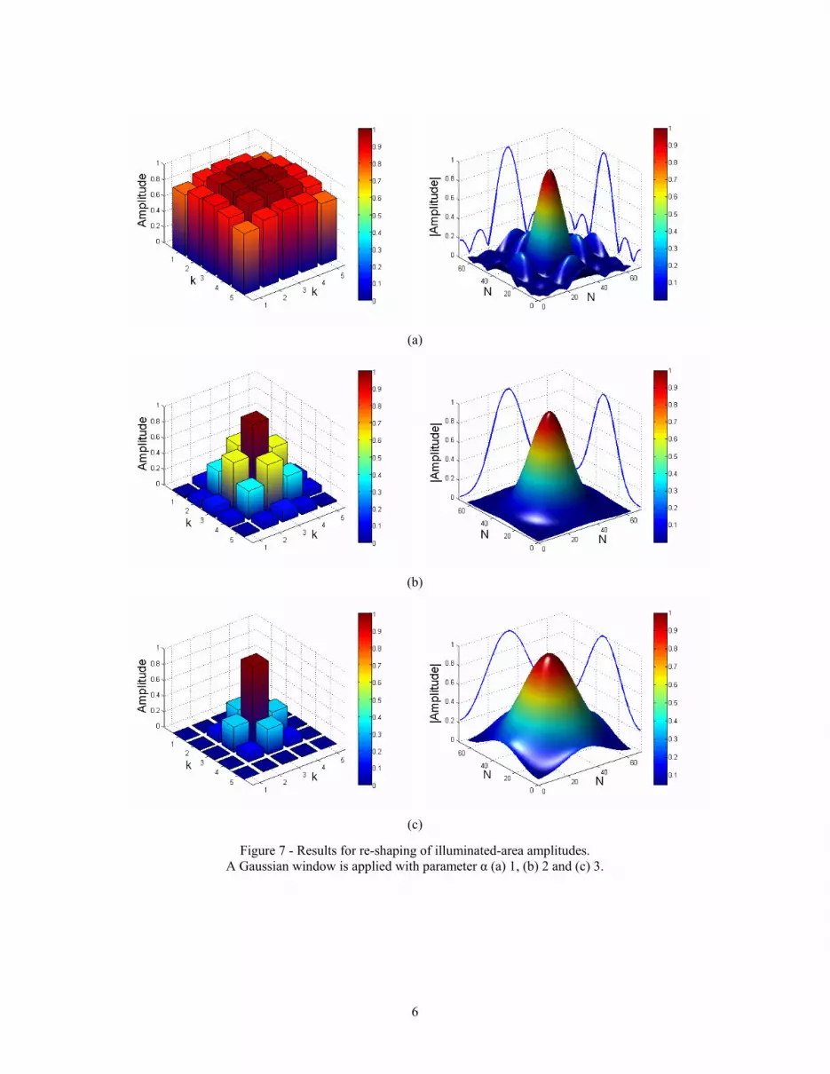
The analyses shown in Fig 7 are relevant to the composite primary field (far-field of a single beam excitation).
The variations of the shape of the composite primary field are achieved applying different Amplitude Control (i.e, Gaussian Shape Window) to the Matrix of signals that interconnect the two FFTs. The examples of Fig 7 concern a Double FFT-BFN of dimensions M=8, k=5 and N=64. The results at the aperture plane are shown for several values of Gaussian Window with parameter α, from 1 to 3.
V. Conclusions The paper presented the basic concepts of a novel reflector antenna feeding system, the 2D Double FFT-BFN. A
characterization study of this system has been reported. The proposed beam forming architecture is amenable to analog, digital and hybrid analog/digital
implementation. In particular it exploits the complexity savings inherent to FFT (i.e. Butler-like matrices in the analog domain) architecture.
References
[1] K. Kona, K. Bahadori, and Y. Rahmat-Samii, “Stacked Microstrip-Patch Arrays as Alternative Feeds for Spaceborne Reflector Antennas,” IEEE Ant. And Prop. Magazine, Vol. 49, No. 6, Dec. 2007
[2] C. A. Balanis, Antenna Theory Analysis and Design, 3rd Edition, Wiley, 2005 [3] J. Shelton, ‘Multiple-Feed Systems for Objectives” IEEE Trans. On Antennas and Propagation, Vol. 13 , No. 6, November
1965 [4] F. Kira and T. Hori, “Beam Forming Network Design for Cluster Feeding of Highly Functional Scanning Antenna,” IEICE
Trans. Commun., Vol. E84-B, No. 9, September 2001 [5] F. Kira, N. Honma, K. Cho, “Beam Forming Network Design Using Microstrip Lens For Cluster Feeding,” IEEE
International Symposium on Phased Arrays Systems and Technology, 2003 [6] R. Bracewell, The Fourier Transform and its Applications, 2nd Edition, Mc-Graw-Hill, 1965
6
(a)
(b)
(c)
Figure 7 - Results for re-shaping of illuminated-area amplitudes. A Gaussian window is applied with parameter α (a) 1, (b) 2 and (c) 3.


