Embed Size (px)
Citation preview
Computer Numerical Control Products
P Series Servo Motor
Maintenance Manual
GFZ-65235EN/02 October 1997
GFL-001
Warnings, Cautions, and Notesas Used in this Publication
Warning
Warning notices are used in this publication to emphasize that hazardous voltages, currents,temperatures, or other conditions that could cause personal injury exist in this equipment ormay be associated with its use.
In situations where inattention could cause either personal injury or damage to equipment, aWarning notice is used.
Caution
Caution notices are used where equipment might be damaged if care is not taken.
NoteNotes merely call attention to information that is especially significant to understanding andoperating the equipment.
This document is based on information available at the time of its publication. While effortshave been made to be accurate, the information contained herein does not purport to cover alldetails or variations in hardware or software, nor to provide for every possible contingency inconnection with installation, operation, or maintenance. Features may be described hereinwhich are not present in all hardware and software systems. GE Fanuc Automation assumesno obligation of notice to holders of this document with respect to changes subsequently made.
GE Fanuc Automation makes no representation or warranty, expressed, implied, or statutorywith respect to, and assumes no responsibility for the accuracy, completeness, sufficiency, orusefulness of the information contained herein. No warranties of merchantability or fitness forpurpose shall apply.
©Copyright 1997 GE Fanuc Automation North America, Inc.
All Rights Reserved.
FANUC SERVO MOTOR series FANUC SERVO MOTOR AMPLIFIER series
SAFETY PRECAUTIONS
This “Safety Precautions” section describes the precautions which must be observed to ensure safety when using FANUC servo motors (including spindle motors) and servo amplifiers (including spindle amplifiers). Users of any servo motor or amplifier model are requested to read the “Safety Precautions” carefully before using the servo motor or amplifier. The users are also requested to read an applicable specification manual carefully and understand each function of the motor or amplifier for correct use. The users are basically forbidden to do any behavior or action not mentioned in the “Safety Precautions.” They are invited to ask FMC previously about what behavior or action is prohibited.
Contents
.
DEFINITION OF WARNING, CAUTION, AND NOTE . . . . . . , . . . . . . . . , . m a. a.. . . . , s-3
I. FANUC SERVO MOTOR series l mmmmmmmmmmmmmm~mmmmmmmmmmmmmmm mmammom s-5
1. WARNING ............................................................ s-7
2. CAUTION ............................................................. s-9
3. NOTE.. .............................................................. s-10
II. FANUC SERVO MOTOR AMPLIFIER series mmmmmmmmmm~mmmmmmmmmmmmmmmm s-l 3
1. WARNINGS AND CAUTIONS RELATING TO MOUNTING ................. s-15
2. WARNINGS AND CAUTIONS RELATING TO A PILOT RUN ................ s-20
3. WARNINGS AND CAUTIONS RELATING TO MAINTENANCE .............. s-22
s-l
SAFETY PRECAUTIONS (FANUC SERVO MOTOR series)
1 WARNING . . . . . . . . . . . +.,.,.....,.....,.,., . ~~.~~.~.~~,.~..,.~~~~~~~~~.~ t ,.~.~.,.,.,.,.,.,.,.,.~.,.~., ,...,._. . . . . . . . . . . . . . . . . . . . . . . . . . . . .,.,.,...,.,.,.~.,.. ..,,..~.~.,.,...,.,.~.~...~.,. ._.,.,.,.,.,.,.....,.,.,.,,,. t .,., ,.,.,._., . . . . . . . . . . ._. . .:.~i..:....:.-:;.... ,.:. . . ..i. ,.,.:. .,.::. ..::..:: . . a,... ~:::::.:.:.:.:.:.:.:.~:.:.:.:.:.:.:.:.:.:.:.:.::::::::::::::~~.:::~::::.~:,::::: :,:,: :,:,:.:.,+.. ..,.,.,.,._. .; .j,.,.,.,.,...,.,.,.~.,,........,.,.,.~.~...,...~.,.....,.~.,.,.,. . . . . . . ..‘.‘.‘.‘.‘.‘.‘.‘.‘..~.~.‘.‘.‘.~.’. .‘.‘.‘.~.‘....,’ ~.-.~.‘.~.‘.‘.~.‘.‘.‘,~.~.‘.‘.‘.’.’. . . ...‘.’ ‘...‘.‘.‘.‘.‘.‘.‘.~:.~.:.~~~.~ .:.:.:.:.:.:.:.:.:.:.:.:.:.:.~:.:.:.:.:.:.:.:.:.:.~~~.:.:.:.:.:....... . . . , , . . . . . .,.............,.......,. . . . . . . . ~,“....::.‘.‘.,.:.~ .,.,...,....... _.,.,.,... . ” . . ~.~.~.‘_~_~.‘.‘.‘.‘. .:.:.:.:.: :.:.:.: .: ‘.... :.:.~:.:.‘.‘.‘.‘.‘.‘.‘..,....‘.......’. . . . . . . . . . . . . . . . . . *. . . . . . . . . . . . . . . . . . . . . . . . . . . . . . . ,.. . . . . . . . . . . . . . . . : :: :: f:‘..:‘:‘. ..’ ‘....... .: :.:.>:*: :.:.::. ._.ii;ii,...i~.,.,. .: .,.,._...... ;, . . . . ... . ..,.,. . . .,.,.,.,...,.,.,.,.,. .,.,. . .._ . . _. . . . . . . . , . .;:+:.:.:.:.:.: .,..,. ~:.:.:.:.:.:.~:.:.....‘.... *.. .:.., :. ::..::: .::..:: .. ::: ..‘.‘. .,.;,.,.. ,.,.,.. ,...; .,. .,.,‘............,.~.~.,.,.,.,.,.~.,.,.........~..., . . . .. . . . .‘.‘. . . . . . . . . . . . . . . . . . .‘.‘.:.:.:.::::::::::.+> ,... . . . . , . . . . .v.::.> . . . . . . . . . . .,._.,.,_ . . . . . . . . .._.... . . . . . . . . . . . . . . . . . . . . . . . . . . . > :.,.,._.~.~.~,_.~.~.~.,,,.,. . . .‘.‘,‘.‘.‘.‘.:.:.:.:.~:.:.:.: .,.,,,,,.....;. _, . . . . . . ~.‘.~.~.~...~.~_~... . . , . ,...,... .,........-,...............,.....,............ . . . . . . ,.,.,. . . . . . . . . . . . . . . . . . . . . . . . . . . . . :. ‘...‘.‘.‘.‘. . . . . . . _.. . . . . . . . _. . I.. . _, . .‘.‘.‘.‘.:.:.: :,:.:.:.:.:.:.:.‘.~~:.:.:: . . . . . . . . . . ..~._... >:.I : I,:.: : : : . . .;,.:....... . . . . . . . . . . . . . . . . . . . . . . . . . . . . . . . . .,.,.~.~.,.~.,.,.,.,.,.~.~.,.,.~.,.~.,.~.~.,.,.,.,.,.~.~.,.~.~.,.,.,.~. _.,.,.,. . . . . . .,.,. .,.,._.,...,.i....,.,.,.,...,.,.,.....,.~...,.,. .,. .,.,...,., ,.....,.....~...,.:..,.;,......:.: ,:,:, >: ,+:.:.:,.. >:.:.:.:.:,:+: .:.:.:+:..,.. .: . . . . . . . . . . . . . . . . . . . . . . ~. . . . . . .i..:.., .., ‘.‘.‘.‘.:.:.:.. ,.,._.,.,.,.,.,.,. .,.,...,.... I ..,.,.,.,.,.,. I .,.,.,...~.~.~.,.,.,.,.,.,. . . . I . . . .,.I .,.........,.,._.,.,.,.....,..., . . .,.‘.‘. .‘.‘._..... . ..‘.‘.b’.‘...‘.‘.. ‘.‘.>:...:.:...:.:: :.:.:.:.:.:.:.:.:.:::: ::.:.:.:: .,.,., ,.,._.,.~.,.~.,.,.,.,. .,.,.... . . . ..,...,.,..._.,.,...~.............~.,.,. .,.,.,., >:,. . . . . .,.,.~............._ .:... . . . . ., ._ . . ,. ,. . ,. . . . . . ..L..~.‘.~.~.‘.‘. . . . . . ..,. .,...... .‘,‘,‘.‘.:.~:.:,:.:,:,:.~.~.~.~.~~ I......._._., ““““,‘.‘.‘.:.:.:.:,:,:::~:‘.:.:‘.:.~~ ,.,,~.~,,,~.~.,.~.,.,.~,~, ;,:,>: . . . . . . ‘.,‘,‘.“‘...‘,:,.‘.:.:.~::.~~~‘.~.~.~.~.~~.~.~~~.~.~.~.~.~~.~.~.‘.~.“.~. ,.:‘:‘:‘: ‘:‘:‘:‘:““.‘,‘.“” ,,,.,...,.,.,._.,...... . ..).,.,.,, .,+:.:.:.:.:.: :.:.:.~:.:.:.:.:.:.:.:.:.~: . . . . . . . . . . . . .,.,.,.,..._._.,...........,. . ...‘.....,.. . . . .,.,.,......., ., . . . . . . . . . . . . . . . . . . . . ..,.,.; :.:.: >>:.:.:.:.:.:.:.,. .,...........,.,,,...,.,...,...........,...~.,......., . . . ‘.‘.‘.‘.‘.:.:.: :.:.:.:.:.:.:.~:.‘.:.:.:.~:.: :.:.:.:.:.:.:+: >:,:.: :.: :.:.:... .,.,,~.,.,.~,,._,..,.,.,.,. . . . . . . . . . . . . . . . . . . . . . . . . . . . . . . ,.,., . . . . . . . .,.~,,...,.........~.,.~.,. . . . . . . .,.:.‘.:.:.~:.:.:.:.:.~~:.:. .‘.:.:.~:.:.:.‘.‘.‘.‘.‘.‘.‘.‘. . ‘.‘. .‘. . . . . . .,...,.,.,..._._.,.........,.,. .,.,.,.,.... . . . . . . . . . . .:.:.~:.:.:.:.:.:.~::.:.:.:.: :,>.:.:.::,.:.> ,.,.,.,.~.,.... ,. . . . , . . . .‘...‘.‘.. .,.,..‘.‘. .,. . . . . . . . .._. . . ‘.‘.‘,‘.‘,‘.‘.‘.:.:.:.~.~.~.~.~.~,~.~.~’.~ . . . . . . .‘. .‘.‘.“..,’ . ._.;; .P.‘...‘. . . ,,, . ,.;;,..._.;, .., .., ,.,.,. .,..., . . . . . . . . . . . :.,: .,.,. >:...:.: :.:.‘.:.‘.,. .,.,.... . . . . . . . . . . ..,.:.:..: ...::.. . . . . ..‘........,‘............‘. . . . . . ,._., ., . ,. . . ‘.. ‘.‘.‘.‘.‘.‘:.:‘:.‘:.:.:.:.:.:.: .,.,.,.,.,..._... :.*:.:.:.:.: :.::.: :.:.:.‘.:.>:.:.:.:.:.:.:.:.:.:.: .,.....,....‘...‘.‘.~.~.~,~,~,~,~ :,:,:,,.,. ~ ,;..,. .,. .,. .,.,...,.~.,.,.~.~.,.~.,.,. .,.. #.......,..... .,.,.,.....,.,...,.,.,.,. :.:.:.:..:...‘.‘:.‘.‘.‘. . .;, . . . _.,....... :i.,.,.,., ,.. ,.,. . . . . . . ,., ,... . . .;..... . ‘.:.:.:.:.:.:,:.: :.:.:.,::. . . . . . . . . ..‘_ ‘...‘...‘...‘...‘....... . . . . .: ,.,., .,... . . . . . . . . . . . . . . . .:...:.:.:.:.:.:.:.:.:.:.:.:.:.~:.:.:...:.:.:.:::,::~.:.:.~ :,:,: . . :: ..’ ‘.‘. .>:.‘,.L%‘.‘.%‘.’ ‘.’ ‘:.‘.‘.:.:.:. : ~.‘.~.‘i.‘.‘.‘.’ ‘........ ‘..~‘...‘,,.,. .,.,.,., ~ . . . . . . . . . . . . .,.,., . . . . . . , . . . . . . . . . . . . . . . . . . . . . . ..,.. . ..:, . . . . . . . .*.......,.,..~....,. . . . . . . . . . . . . , ..,i_.,.,.,.,.i.. :.: .,.,.i..,.,.,....._.,.,.,.,. . . . . . . . . . . . . . . . . . . . . . . . . . . . . . . . :::. ,‘,‘,“‘:“.‘.‘.‘.‘.~.~.~.~.~,: >:,:‘:.,.:.:. . ~,~...~.....~,~.~_~ . . . . . . . . . . . , . ;,.,...,. . . . . . ..:_.,. . .,.. ‘1.._........... . . . ~:.~:.:.:,:.:.:.,.:.:. .~,~_~.~..~.~.’ . . . . . . . ..+............. . . . . . . . . ,...,.....,.......,.,.,.,..................... :.:.:.:.:.>:.:.:.:.::.:.:.:.:.:.:.:.:.:.: . . . . . . . .,...,.....,.,. :.~~:.:.~:.:.~:.~.:.:.:.‘. .,.,.,.,.............,. . .,.....;;,.,, . :..:.... . . . ..’ ‘.“‘.“““:‘:‘:“...‘.:.:.:,: :,: ; :.:.:.:. _.. . .,.,. .,: :,:,: :._,: .,_,. ‘. :: . . . . . . . . . . . . . . yy.‘.‘,‘.:.:., :.: :.:.>:.:.:. ..’ >:.‘...:f .,-,-:.~.~:..:: ._.,. .,.::,........ . . . . . . . . . . . . . . . . . . . . . . . . . ..,.......,.,. .,...,.,., . . . . ,...,...,. . . .,.,.......(..., ,... . . . . . . . . . . . ,..~.~.‘.~.~.~.~.~.~.~.‘.~.~.~.~.~.’.~.’.~. . .:.:.: :: :.:.,+y.. . ..~.....‘.. . . . . :.,::...... .,~.~.~.~.~.~,~...‘.~.~.... ,.,., .,.,. . . ..; ,.,. .,... ~::~:~:.:.:~::.~ .;i, . . . . . . . . . ~.~..~~~~~.~...~.~.~.~.~,~,.,~,.~~~~~~’~~~~~~~~~~ “““‘.‘.“.‘.~~:.~:.~: .,...,..............,,.,.,.,.,.,.,.,. . . . . . . . ::....: . . . . . . . . . . . . . . . . . . . . . . . . . . . . . . . . . . . . ,...,.,. :.:.:.: . . . . . . . . . ,.,.,.,. :.:.....‘.‘.“.‘.‘:.‘...‘. :. ..,.,. ._.:. .,.,... . . . . . . . . . . . . . . . . . . . . . . . .:.:,;.:.:: :.:.::::::,I:.::::::::.:::,:~::!,:,:.:.:.:.:.:.:. .,.i::....... . ..‘.‘.‘.~‘.~~~~‘.‘_~.~..~..~.~. . . . ...‘.‘.‘...‘.. :.:.:::::,:.::::.:.:: :.,.:.,, . ,:,.;,. . .,., ,.. _.,.,...,.,. .;,.,.,. . . . ...:, : .,.,. :..,:,:,: :,: :.:.:.:. .,.,...,.,., . . . . . . . . ::. . . . . . . . . . . .._....... .,.‘.:.:.: >: :.:.:.~:.:.:.:.‘:.:.:.::::.: .,., :. .~.~.~,~.~,~.~,~ . . . . . . . . ..‘....... . , . .,.,.,._.,._.,.,.....,.,.~ .:.‘.:.:.:.:.‘.‘.~.‘.‘.~.~.‘.~.:.~.:.’.~.:.~.’.:.‘.‘.‘.~.~.~.’.~.:.~.:.~.~.~.:.‘.~.~ : :.‘.:.‘.‘.:.:.‘.‘.‘.:...:.:,~,..’.’.’. ,.,.,.;_..,.,. , . . . . . .,.,. .,. . ,,. . . ...‘.... ‘,F ‘.‘.~.‘.:.‘,:.‘.‘,:.“.‘.‘.‘.‘.‘.’~.: :.‘.‘.‘.: :::,:,: :.:.‘:‘::::+x:: ::.:.:+:.::x. . . . . .,. .,. ..,‘:: :: :: ::: ::::. ‘.:.:.:,~:,:,:,:,:,:~~ . . .:.. . ‘.~.~.....~,~.~.~.~,~~ . ...‘.. . . . :.:_:.:,, :.:.:.:.: :,:,::~:::~:.:::,::::::::,:.:.:.:.:.:.~:.:.:.:,~~.:.: : >:. .:.‘.,.:.:.:.: >:.:.>:.:.:.,.‘. .‘...... . . . . . . . . . . . . . . . . . . . . ..;:. . . . ._...,., ..;_._.,.,. .,.,. ._ ., . . . ,. . . ., . . .,, ,....,. . . . :.:...: :,. . . . . . . . . . . . . . :.. . . . . . . . .:.:.::,:. %..y.. . . . . .,.,.,.,.,. . . . . ._._. . . . . . . . . .,., .::~~~~.,,....,.,.....,.,.... .:. . . ,,.
1 WARNING 1
Be safely dressed when handling a motor.
Wear safety shoes and gloves when handling a motor to avoid damage on any sharp edge or protrusion. Be aware that high levels of electrical current are present in operating motors and use suitable precautions.
Use a crane or lift to move a motor from one place to another.
Motors are heavy. When moving them, use a crane or lift as required. (For the weight of motors, refer to their respective specification manuals.) When moving a motor using a crane or lift, use a hanging bolt if the motor has a corresponding tapped hole, or textile rope if it has no tapped hole. If a motor is attached with a machine or any other heavy stuff, do not use a hanging bolt to move the motor as the hanging bolt and/or motor may get broken. When moving a motor, be careful not to apply excessive force to its windings as the windings may break and/or their insulation may be damaged.
Do not touch a motor with a wet hand or while standing on a wet surface.
A failure to observe this caution is very dangerous because you may get electric shocks.
Before starting to connect a motor to electric wires, make sure they are isolated from an electric power source.
A failure to observe this caution is very dangerous because you may get electric shocks.
Do not store any flammable material near a motor.
Motors are connected to a power line, and may get hot. A flammable object placed near a motor, may be ignited, catch fire, or explode.
Be sure to ground the motor frame.
To avoid electric shocks, be sure to connect the motor grounding terminal in the motor power connector to the grounding system of the machine.
Do not ground a motor power wire terminal or short-circuit it to another power wire terminal.
A failure to observe this caution may cause electric. shocks or burned wiring.
* Some motors require a special connection such as a winding changeover. Refer to their respective motor specification manuals for details.
s-7
SAFETY PRECAUTIONS (FANUC SERVO MOTOR series)
0
0
a
a
a
0
a
a
, 0
Connect power wires securely so that they will not get loose.
A failure to observe this caution may cause a wire to be disconnected, resulting in a ground fault, short circuit, or electric shock.
Do not supply power to the motor while any terminal is exposed.
A failure to observe this caution is very dangerous because you may get electric shocks if your body or any conductive object touches an exposed terminal.
Do not get close to a rotary section of a motor when it is rotating.
A rotating part may catch your cloths or fingers. Before starting a motor, ensure that there are no loose objects that can fly away (such as a key) on the motor shaft.
Before touching a motor, shut off the power to it.
Even if a motor is not rotating, there may be a voltage across the terminals of the motor. Especially before touching a power supply connection, take sufficient precautions. Otherwise you may get electric shocks.
Do not touch any terminal of a motor for a while (at least 5 minutes) after the power to the motor is shut off.
High voltage remains across power line terminals of a motor for a while after the power to the motor is shut off. So, do not touch any terminal or connect it to any other equipment. Otherwise, you may get electric shocks or the motor and/or equipment may get damaged.
To drive a motor, use a specified amplifier and parameters.
An incorrect combination of a motor, amplifier, and parameters may cause the motor to behave unexpectedly. This is dangerous, and the motor may get damaged.
Do not touch a motor when it is running or immediately after it stops.
A motor may get hot when it is running. Do not touch the motor before it gets cool enough. Otherwise, you may get burned.
Be careful not get your hair or cloths caught in a fan.
Be careful especially for a fan used to generate an inward air flow. Be careful also for a fan even when the motor is stopped, because it continues to rotate while the amplifier is turned on.
Ensure that motors and related components are mounted securely.
If a motor or its component slips out of place or comes off when the motor is running, it is very dangerous.
s--8
SAFETY PRECAUTIONS (FANUC SERVO MOTOR series)
2 CAUTION . . . ..- . . . . . . . . . . . . ..i_.............................,.......................... . . . . . . . . . . . . . . . . . . . . . . . . . . . . . . . . . . . . . . . . . . . . . . . . . . . . . . . . . . . . * ,.........,.,._.... . . . . . . . . . . . . . . . . . . . . . . . . . . . . . . . . .,.,.,.............,.,..... I .,.,.i~.~...~.,.,.,.,.,,,.,.,., ,.;,.,...,. .,.,. .; . . . . . . . . ii.......,.. * . . . . . . . . . . ..,.,.....,...... ,.. . . . . . . . . ..i.................. . . . . . . . . . . . . . . . . . . . . . . . . . . . . . . . . . . . . . . . ..f........ . . . . . . . ,.,.,.,.,...,...,.....,.. . . . . . . . . . . . . . . . . . . . . . . . . . . . . . . . . . . . . . . . . . . . ,.,.,.,.,.~.i~.....,.,.,...~.....,.,.~...,.~.....~...~.,.,.....~.,...~.~.......,.~.,.,.,.,.. 9 . . . . . . . . . ...............................) ..,.,...,.,...........;............,..............., I ........,.......,.......,...,.. ....;,.,.,.,.,... .:_ * . , . . . , . . . . . . .,.,.,.,.,.,. :.~:~:.:.:.:.:.:.:.:.:.: . . . . . . . ..~.~.............~.~...~.........,.....~...~.~.~.~...,.~.~.~.~.~.....,.~.~...~.......~.,.,.,.,.,.,.~.~.~.~.~.......,.,.~.~...,...............,.,.,.,.~.,.,.......~ . ,...........,...f........,........ I ..,.,.,...,.,.,........ . . . . . . . ,.,., .,. .,.,., < .:.:.:.:.:.:.~..:.:.:.::.:.:.:.:.:.:.:.:.:.:.:.:.~~:.:.:.~:.:.:.~:.:.~~:.:.:.:,:,~..:.:.:.:.:.:.:.~.:.:.:.:.:.:.~:.~:.:.:.~:.:.:.:.:,:.:.:.~:.:.:.:,:.:.:.:.:.~.:.:.~....:.:.~.:.:.:.:,~~,~~.:,:.:.:.:.:.~.~.~.:.~ : : : : : : . ._. . . . . . . . . *. . . . . . : : : : : : :;,:;,:,‘;; ,‘,‘:‘:‘,.: .,‘: : : .,,:. ~: ,:,:,:.,....,.,.,. . . . . . . . . , . . . . . , . , . . . . . . . . . . . . . . . . . . . . . . . . . . . . . . . . . . . . . . . . . . . . . . . . . . . . . . . . . . . . . . .‘.‘.‘.‘.‘.‘.‘.‘.‘.:.:.:.:.:...~:.:.:.:.:.:.:,:.:.:.~:.:. .:.:.:.~:.:.:.:.~:.:.~:.:.:.:.:.:.~:.~~:.:.:.:.:.‘,.~,.:.:.:.:.:.:.:.::.:.:.:... :::j::::;::::::::::::::::::::::::::::::~~~::::::::::::::::~::::::::::::~::~~:~:::::::::::::::~::~::~::::::~::::;::::::;....’....,....~:.:.:.:.:,:.:.:.:.~:. . . . . . . . . . . . . . . . . . . . . . . . . . . . . . ‘I.‘.‘.‘.‘...‘.....-.....-.......’.............................’.‘...................‘.......’.. . . . . . . . . . . . . . ..‘.....‘.‘...‘...‘.....‘.‘.‘.‘.’.’...... . . . . . . . . . . . “.‘.‘.‘.:.:.:.‘.: Z,.... ‘.‘.:.:.:.:.:.~:.~:.:.:.:.~:.:.~:.:,:,:~:::::::::::::::::::::.~,:,~:.:.,.:.:.:.~:.:.:.:.:,:.~.:.:...~~:.:.:.:.: : :.:.:.~~:.:.~:.:.:.:.:.~:.:.:.~:.:.:.:.:.~~:.:.:.~~:.:.:.:.~~:,:,:.:.:.:.:.:.:...~: .,........ . . . . . . . . . . . . . . . . . . . . . . . . . . . . , . . . . . . . . . . * .~.~“~‘~‘+:~:, ~~ :,:. ~ .,..,.,.., ~ . . . . . . . . . . . . . . . . ,.,...,.....,... :.:.:.:.:.~~~:.:f.:.:.~:.~:.:.:.:.:.:.:.:.:.:.:.:.:.:.:.:.:.:.:.:.:.:.:.:.:.~~,.:.:.‘.:.: : . . . . . . I ..*.,.,., . . . t . . . . . . . . . . . . . . . . . . . . . . . . . . . . . . . . . . . . . . . . . . .,.,......._.. . . . .,,. . .,.,...;,.. . ..,. .,.,. 1. .:.~.:...:.:.:.:.:.:.:.:.:.~:.:.:.~~:.~:.:.:.:.:.:.:.~:.:.:.~.~~:.:.:.:.:.:.:.:.:.:.:.~.:.:.:.~.:.:.:.:.?:.:.~:.:.: .,...,.~.r.~.~.~.......,.,.,.,.,.,.......,.................~.......,.,..., . . . . . . . . . . . . * . . . . . . . ...,., . . . . . . . . . . 5~~..................................................................................................r.....,....,.,.................I.. . . . . . . . . . . . . ..- . . . . . . . . . . . ..‘...‘........ . . . . . . . -......i...... . . . . . . . . ..L......... . . . . . . . . . . . . . . . . . . . . . . . . . . . . . . . . . . . . . . . . . . . . . . . ..:... . . . . . . . . . . . . . . . . . . . ..I....................... . . . . . . . . . . . . . * . . . . . . ..i. . . . . . . . . . . ..............., ,...;...., . . . . . . . . . , . . . . . . . . . . . . . . . : : : : : : : : : : : : : : : . . . . . . . . . .,.,......... ,. . . . ,... . . :, :, :, :, :, : ,: ,: . . ‘,‘,“,‘,‘.‘.‘.‘.‘..,.,:.~.~.~: :... ....... ....:. * :..,...... *,..*.. .‘........,.. :.:.:.;.:.:i”:,:,:,:.:.~~:.:.:.~.:.:.:.:.:.:.:.~; ..,...... ... ....... . . . . . . . . , . .,...*...... ,.,.....Z,...............,...,.,.,. . . . . . 9 . * . . . . . . . . . . . . . . . . . . . . .,.,. . , .,~:.‘.:,.,.,.~..‘~.....,. . . . . . . . . . . . . * . . ._., . ..,...,.,. :.:.:.:.: .:.:.:.:~:.:.:.:.:.:.~~:.:.:.:.:.:.:.:.:.:.:.~.:.:.:.:,:.~:.:.~:.~.:.:.:.:.~.:.:.:.~.:.~.:,:.~..:.:.:.~..:.:.~..~..~,:.~:,:.:.:.:.:.:~:.:.~..:.:.:.~:.~:.:.:.:.~:.:.~.:.:.~~:.:.:.:.:.:.~..:...:.:.:.:.:.;,:.:.~.:.....:.~:.:.:.:.~~~.:,~ .,.,. ..:.~.:.:,~.:~:~..:.:.:.:~,:::::::::::i::::::~.~::~~,::~.~.:::~~.~~,:::.:,.:...... ,.... .i..:..;,...i..:..: I... .r............:.:.:.:.:.‘.~:.~:.:.:.:.:’:’:”.’.............’...’.‘.‘.‘.‘.‘. . . . . . . . . . . . . . . . . ‘. . . . ..‘.C....S......‘.. . . ‘.5’.:.:.‘:.:.y . . . . . . . . . . . . . . . . . . . . . . . . . . . . . . . . . . . . . . . . . . . . . . . . . . . . . ..-............. . . . . . . . . . . . . . . . . . . . . . . . . . . . . . . . . . . . . . . . . . . . . . . . . . . . . . . . . . . . . . . . . . . . . . ......................................................................... . . . . . . ..a..: .i.~.~.~...~.~...~.-.-...~.‘.~.’ .,.,...,.....,.,.,. .,. .,. . . . . . . . . . . . . . . . . . . . . . . . . . .,. . . . . . . . ..~.~.~.~.............,.........~,.,,.....,...: i... ..‘i . . . . . . ..t. .L.... ..i. .::.. ,...,. -..:........i........ . . . . . . . . 5.....,...,...,......~........,.. . . . . . . . . . . . . . . . , . . . . . . .‘.‘.:.:+:.:,:.‘. i. . . . . . . . ..~.‘.‘C~ ~,~,~.~:.~,~.~.~.~r~.~.~.~.~.~.~.~.’.’.~,~.~.~.~.~.~.~.~.~.~ ‘.‘.‘.‘:‘,‘,‘,‘~‘.‘~‘~‘~‘~’ ..‘: :.;‘:‘:‘:‘:‘,‘,‘: . . . . . . * . . . . . . . . . . . . . . . . * . . . * . . . . . . . . . . . . . . . . . . . . . . . . . . . . . . . . . . . . . . . . . . . . . . . . . . . . . .,.~:.~:.:.::.~:.~:.:.:.:.~:.:.:.:.:.:.:.:.:.:.‘.‘.‘..,..’... . . . . . . , . . . . . . . . . . . . . . . . . . . ..ZI........................,. .,.,. . . . ..,.......,.,.,...,.,... . . .,.,.,.,.....i..i,...,.....,...,.,.,.,.........,... .,. .,.,.,. . . . . ..*.... . ...‘..... . . . . . . . . . . . . . . . . ..‘.......‘.‘...‘................... . . . . . . . . . . . . . . . . . . . . . . . . . . . . . . . . . . . . . . . . . . . , .,. .,. . .,. . . . .,.I.,...,..~,,.,’ :. . . . . . . . . . . . .i..,.............,...,.,.,. . . . . . . . . .‘.~...........‘.~.~.....~.~.‘.‘.’.........~.~.~.~.~.~.......~.~....,....‘.‘.‘.‘.‘.‘.‘.~...’.’ ‘.......‘. . . . . . . , . . . . . . . . . . . . 9 . . . . . :,:. ‘.‘.‘.‘.‘“.‘.‘.~.:.:.‘...‘...‘.~...~.~...~...~.~.~.‘.~.....~.~.’.......:.~~.:.:.:.:.:.:.:.:.~:.:.:.:.:.:.:.:.~.:.:.~:.:.:.:.:.~:.:.:.:,:.:.:.:.:.:.:.:.:.:.~:.:.:.: :.:,:,‘.:.:.‘:.~~~:.~.:.~:.:,~~:.:.:.:.:.:.:.:.:.:.,.:. .:.‘:,:,:.:.:,:+ .,. ,..,. ,. . . . . ..~.........,.,.,.,,.......,....~.~....... :.:.:.:.:.:.:.:.:.:.‘.~:.:.:.:,:.:.:.:.~~:.~.:.‘.......‘.. ..,.. . . . . . , . , . . . . . . . . . . . ..L.. . . . . . . .,.,.,. . . . .,.,.........,.......,.,...~.....................,.,. . . . . . . . . . .,.,.....,., . . . . ..-..........2........r’:,.....: . . . . . . . . . . . . . . . . . . . . . . . ..S.... . . . . . . . . . . . . . . . . . . . . . . . . . * . . . . . . . . . . . . . . . . . . . ..~...~.,.,.,.,.,.....~.~.~..., . . . . . ..+.....*..._.. . . .,.,. .,.,.,., #.. . . . .., . . .,.,. . . . . . . . . . . . . * _.,............ ..,.........................~.,...,.,...,...~.~.....~.~.~.~. . . . . . . . . . . . . . . . . . . . , . . . . . . ._* ,.,...,.....,. . . . . . . . . . . . . . . . . . . . . . . . . . . . . . . . . :.:... . . . . . . . . . . . . . . . . . . . . . . . . . ‘.:.‘.:.:.:.:.“. . . . ,.,., . , ,, . ,.,... . . . . . . . . . . . . . . . ..)......... . . . . . . . . . . . . . . . . . . . . . . . . . . . . . ..~.............. . . . . . ..,.,...,.. + ......*.2..*...*. . . . . . . . . . . . . . . . . . . . . . . . . . . . . . . . . . . . . . . . .._............. .,.,....., * ,.,.......,...,._.,...,. . . . . . ..‘.‘.......‘...............‘.‘.’.’...... . . . . . . . . . . . ..‘.‘.‘.....:.:::.:,:.:.:.‘:::..::..:.:.:...~ ,...:,, ::‘,:.‘.:.~:.:.:.:.~:,~. . . . . . . . ..I.‘.‘.‘.~.....~.........~.~.~.’.’.’.~.......~.‘...‘.~.... . . . . . . . . . . . . *. . . . . * . . f . . . . . , . . . . . . .f’ . . . . . . . . . . ..y.....>:.: . . . . . . . . . . . . . . . . . . . . . . . . . . . . . . . . . . . . . . ..~......................... . . . . . . . . . . . . . . ..Z~.Z....................~................., . .,. .,. . . . . . .,.,.,. ,. . . . . . . . .,.,.,..... . . . . . . .,. .,.,. ‘,: .,.,.,. ., “‘.‘.‘.“:.:.:‘:.::~:::::‘:” ,. . ., . ., . ,., . . . . . .,. ., . ,. .,...,.,. . . . . . . . .,._. .,., . . .,. . . . ,,., ._., . . . . . . .,.,.,.,.,.,. . . . . . . .._ . ._.,. . . . . . .,.,.,.,.,.; I ._.,.. . . . . . ,. ,. ; _. . . . . . . . .._...... * . . . . . . .._.... 9,. .,.,.;,. .,. .,.,.,. . ., ..,.
FANUC motors are designed for use with machines. Do not use them for any other purpose.
If a FANUC motor is used for an unintended purpose, it may cause an unexpected symptom or trouble. If you want to use a motor for an unintended purpose, previously consult with FANUC.
Ensure that a base or frame on which a motor is mounted is strong enough.
Motors are heavy. If a base or frame on which a motor is mounted is not strong enough, it is impossible to achieve the required precision.
Be sure to connect motor cables correctly.
An incorrect connection of a cable cause abnormal heat generation, equipment malfunction, or failure. Always use a cable with an appropriate current carrying capacity (or thickness). For how to connect cables to motors, refer to their respective specification manuals.
Ensure that motors are cooled if they are those that require forcible cooling.
If a motor that requires forcible cooling is not cooled normally, it may cause a failure or trouble. For a fan-cooled motor, ensure that it is not clogged or blocked with dust and dirt. For a liquid-cooled motor, ensure that the amount of the liquid is appropriate and that the liquid piping is not clogged. For both types, perform regular cleaning and inspection.
When attaching a component having inertia, such as a pulley, to a motor, ensure that any imbalance hetween the motor and component is minimized.
If there is a large imbalance, the motor may vibrate abnormally, resulting in the motor being damaged.
Be sure to attach a key to a motor with a keyed shaft.
If a motor with a keyed shaft runs with no key attached, it may impair torque transmission or cause imbalance, resulting in the motor being damaged.
s-9
SAFETY PRECAUTIONS (FANUC SERVO MOTOR series)
3 NOTE . . . . . . . . . . . . . . . . . . . . . . . . . . . . . . . . . ..~.......,.,.,.,...~.,.....,...~. ,.,... . . . . . . . . . . . . . . . . . . . . . . . . . . . . . . . . . . . . . . ..i...‘.‘...L. . . . . . . . ..-.....‘...‘.....i....... e...... ‘.‘.‘.‘.‘,:.:.:.:.p: . . . . . . . . . . . . . . . . . . . . . . . . . . . . . . . . . . . . . . . ~:,;.:.:.:.~:.:.~‘.~:.:.:.:.~:.:.:.~:.:.:.:.~:.:.:.:.:.:.:.:.:,:.~.:.:.~:.:...:,:.:.:.:.:...:.:.:.~ . . . . . . . ..,... ;..... .::..:.. ..,. ‘,‘,‘,‘.‘,‘,‘,‘.:.~.~.~.~.~.~...~.~,~,;.~.~.~,~,.~.~.~,~~.~.~.~.‘.~.~.~.~,~.~,~,~.~~.~.~~~.~.~.~~:.~~.~.~.:.:.~.:.:.:.:.~,~:.:.:.:.:.:.:.:.:. .:.‘.:.‘.‘.:.‘.‘.‘:‘:‘:~ :‘:‘:‘f;’ ‘.‘.‘.;.:.:.:.:.‘.:.:.:.:.:.:: : : : : : : : : :: : :: : : ~:.:.:.:.:.~:.~..:.:.:.:.:.~.:.~:.~::.:.:.:.:.~ : . . . . . . . . . . . . . . . . . . . . . . . . . . . . . . .~.~i.‘.~.~.~.~.~.~.~.~.~.~.~.~.~.~.~.’,’.~.~.~.~.~.~.~...~.~.’.~... . , . * , . , . . . * * I . . , * . . . . . . . . . . . . . . . . . . . . . . . * ..,.~.....,...,.........,......,~,,...~.,.~.~.~.~ . . . . . . . . ..~...~...................~.......,,....,.,.,... .,., .,:,:,: ,:,:,.,,,r~.~~~, . . . . . . . . . . . . ..‘.’ ” ~~.~........,.............I.................,...............,.Z,,,,~_~.~_~.i~~, .%. .:....:i....:..:. ‘:‘:‘~‘:‘:‘:‘:‘:‘:‘.‘.....~................ . . . . . . ..,.... ,.....~...:.:.:.........‘.‘... . . . . . . . . . : ::: ::.:~>: . . . . . . . . . . . . . . . . . . . . . . . * . . . . . . . . . . . . . . . . . f.. . . . . . . . . *. . . . . * . . . . . . . . . * . . . . . . . . . ..A.. . . . . . . . . . . . , , . . . . . . . . . . . . , . . . . . . . . . . . . . . . . .,...~.,.i,.~.~,,.,.,.,.,.,.,. :.:.:+>:.: .,.,.,...,.........,...,...,.,. . . . . ..‘,...,.,...,...,........,..,.,.,. .,........ . .;..,.......,.......,.....,...,.,.......... . . ..‘“.....“.....‘.‘.~...~.....~.~.~.~.~.~.~. >>:.:~ :..,:, . . ..S’.‘.. . . . . . . . . . . . . . . . . i.5 i... . . . . . . . . ..i.. G.................. . ,....., :.:.:.~:,:.~:.:.:.:.:.:.:.:.:.:.:,:.:.:.:.:,:.:.: . . * . . . . . ..~.~.~.,...,.,.~.,.,.....~.....~.~.,.,...,.~.,...,.~,~.~.,.~.~...~.~...,.,.,.~.~ . . ,.. . . . . . . . . . . . . . . . . . . . . . . . . . . . . . . . . . . . . . . . . . . . . . . . . . . . . . . . . . . . . . . . . . . . * ,...*,,. . . . . .,..........C.........................,... . . . . . . ..,.,..., . . . . . . ..I.. . . . . . . . . . . . . . . . . . . . . . . . . . : . . . . . . . . . . . . . . . . . . . . . . . . . . . . . . . . . . . . . . . . . . . . . . . . . . . . . . . . . . . . . . . . . . * 5 . . . ,” . . . *. . . . . . ..‘.‘.‘... , . , . . . . . . . . . . . . . , . *. *. . . . , . . . . . . . . . . . .,. .,.,.,.,. :.:.:.:.:.:.:: . . . . . . . . . , . . . . . . . . . . . . . . . . . . . . . . ..*. . . . . . . . . . .I.~.~.~...~,~.....~.~.‘.......~.~ ..,...:. ~..:.........‘........:.~,..:.:.:.:.~.~:.:.~ ~‘.~.~.~.~,‘.‘.‘.‘.~:.“.‘.~.‘.~.~:.~.~.~.~. . . . . . . . . , .‘.‘.‘.‘.‘.‘.‘.‘,“‘.......:.~~.;.:.:.:.:.:.: . . . . . . , . . . . . . . . . . . . . . . . . . . . . . . . . . . . . . . . . . . . . . . * ,.;....,.,...... * ..,.......... * . . . . . . . . . . . . . . ..,.,. . . ,., . :.?:.:.:.:.~:.:.~:.~:.~:.:.:.:.:.:.:.:.:.:.:.:.~:.:.:,:.:.:.:.~:.:.:.~~~~~~:.:,~.: :.:.:.:, ~~:‘:.:.:.:.‘.. :.:.:.>:.:A”. . . . . . . . . . . . . . . . . . . . . . . . . I. . ...,.,,,.,.._i,,, . . . . . . . . . . . . . ..‘.......‘...........................’...... . . . . . . . . . . . ..r............................:.:. . . . . . . . . . . . . . . . . . . . . . . . . . . . . . . . . . . . . . . . . . . . . ..._.......................,,.. .,.~.,.~.~,,.~.~.~.~.~.,.,.,. ,,.L...,..........,.,. L’.. . . . . . . . . . . . . . . . . . . . . . . . . . . . . . . . . . , . . . . . . . . . . . . . . . . . . . ...‘.‘... ..:: ..‘.......’ ~. . .~.~:.~.~.~r:.~.~.~:.~.~.~.~.~.~:.:. ~.~.~.~*~.~ii.~.~.~...~,~.~.~.~.~,’.~.’.~.~.’. . . . .~.~.~.,.~.~.,.~.~.~.~.~.~...,~,.~~~.,.~.~.~. ‘.‘.‘.‘.‘.‘.“‘.‘.‘.....‘.‘.‘.~.......’.’...’.’.‘.:.~:.:.:.:.~~: :.~~:.~~:.~.‘...............~.....’...’...”.’.’. .,. . . .,._.,.,.,.,.i, . . . . . * . . . . . . . . . . . . . . .,. ,........,......., ._...,...,.,.;, .,.,.,...... ..,.,...+...,.,.,. . . . . . . . . . . . . . . . . . . . . . . . . . . . . . . . . . . . . . . . . . . . . . . . . . . . . . . . . . . . . . . ..f................................ :.:.:.:,:::::y . .:.:o:.:.:.:.~:.:.:.:.:.:.:.~:.:.:.:.~.:.~.:,~:.:.:.:.:.:.:.:.:.:.. . . . . . . . . . . . . . . . . .,.,.,.. . . . . . . . . . . . . . . , .,.,,..,.,. .,,......,...,...,...,.,... ~~~:.:.:.:.‘.:‘:.:.:.~.:.......‘:.’.’.’.’.’.’. ..a.* . . . . . . . . ..‘.‘................. . 1.. . . . . . . . , . . . . . . . . . . . . . . . . . . . . . . . . . . . . . . . . . . . . . . . . . . . . . . . . . . . . . . . . . . . . ..~........ . . . , . . . . . . . . . . . . . ,...., . . . . : : :.:.:.:.:.:.:.>:.:.: : . . . . . . . .“‘.‘.‘.‘.‘.‘.‘.‘.‘...‘.‘.‘.‘...’.............:.:.:.:.:.: . . . . . . . . . . . . . . . . . . . . .,...,.,._._ ,.,.........,.,.,..., . . ..,...........,.,.........,.............,.,... . . . . . . . . . . . . .,..,,,.,, . . . . . . . . . . . . . . . . . . . . . . . . . . . . . . . . . . . . . . . . . . . . . . . . . . . . . . . . . . . . . . . . . . . . . . . . . . . . . . . . . . . . . . . . . . . . . . . . . . . . . . . . #.... . . . . . . . . . . . . . . . . . . :,:.:.:.:.:.‘.:.:.:.‘.~.:.:,:,:.: ~~:.:.:.:.:.:.:.f~~~:,:.~~~:.:.:.:.:.:.:.:.:.:.:.~:.:.:.:.:...’.‘.. . ‘...‘I’. . . . . . . . . ..,.,...........,........ ..,., , . . . . . . . . . . . . . . . . . . . . . ............... ....,.*.,.,.,.,. . . . . . . . . . . . . . . . . . . . . . . . . . . . . . . , . , . . . . . . . . . . . . , . . * . . . . . . . . . . . . . . . . . . . . . . . . . . . . . . . . . . . . :.:.:,:.:;,I;.:.:.:.:.:.:.:.:.:.:~~.:.:.:.:.:.~:::::.::::.:.: . . . . . . . : : : : : ” . ‘.... . ...‘.‘.‘.. . . . . . . . . . . . . . . . . . ..*. . . . . . . . . . . . . . . . . . . . . . . . _, ..,.,.,.,. .,.....,.......,.,. . .,.,.;,.... ,.,...,. . . ::.........-................:............ . . . . . . . ..S........S...l...........:.:......: .,.......,.,.: . . . . . . . . .,.,.~.~.~.~.,...,.,.,.,.~. :.: :.;,:.:. :.:.>>:,, .., . . . . . . . . . . . . . . . . . . . . . . . . . . . . . . . . . . . . . . . . . . . . . . . . . . .,.,.,.,.,.,. . . . . . . . .?.‘...‘.‘...‘.... . . . . . . . . ..‘.‘.....‘............ . . . . . . . . . . . . . . . . . . . . . . . . . . . . . . ..-;..,.... . . . .:.:.~.:.~.:.:.~~.:.~.~.~.:.~:.:.:.~.:.:.:.~:.:.:.:.:.: * . ~.~‘~~.~~.~~~.~.~.~.~.~.~.~.~.~...~.~.,.~.~.~~ , * . . . . . . . . . . . . . . . . ..~................ :.:.:.:.:.>:.:.>:.:.:.y.>: .,.:..................,...,. .,...,.,.............~.~.......,.,...,...,.... . ..*...,.,‘,. .,.;,.........;......,. . . : . . . . . . . . . f . *. . . - I, . . . ..i..*. . . . . . . . , . . . . . . . . . . . . . . . . . . . . ‘,~:.~ :.:+:, ~ :.,_ ..,.,.........,.........,.,.,. . . . . . :.:.:.:.:.;.: :.:.:.:.=.>::.‘..:’ ..,...,.,.,...,......,......,.....,.....,........................................ ,.,.,.,.,...;. F ,:..,..:,:,:, > :.:,:,:;. . . . . . . . . ..~...................~.....,.,.......,.~.....~...~.~.~.~.~.....,.,.,...,...~...~.,.~...,.,.,. ‘,.,.,.,.......,.....,.,. : . . . . . . . . . . . . . . . . . . . . . . ,.. . . . . . . . . . . . . ,...... . ~.:‘:.:.:.:,:.:.:.:.~:.:.:.:.:,:.:.:,:.:.:.:.~:.:.:.:.~:.~:.:,~~.:.:.:.:.:.:.:.:.:.:,:.:.:.:.:.~~:.:.~:.:.:.:.:.:.:.:,~: . . . . . ..r...........................................,......., . . . . . . . . .._........ ,.......,...................,.,.,.,.,.... . _.,.*..:,: ,:,./.., . . . . . . . . . . . . . . . ::.:.:.:.::.:.::.:.:.. ‘: . ,.. ..,. .,... . . . . ..‘.......‘. .‘.‘.‘.‘.‘.‘...‘.“‘.‘.~.:.‘:.~..:.~.:.:.~.:.:.:.:.:.:.:.:.:.:.:.~.:.~:.:.:.:.:.:.:.:.:.:.~:.:.:.:.:.:.~:.~:.:.:...: . . . . . . . . . . . . . ..::. ::..:::..: . . . . ,.:.:.‘.:.:.:.:.:.:.:.~.:.~:.:.:.:.:.:.:.:.:.:.:.:.:.:.:.:.:.:.:.;.:.~:,:.:.:.:.: :.:.:.:.>:.:.:.>:.: ‘. . . . . . . < . . . 9 . , . , . . . . . . . . . . . . . . . . . . . . . . . . . . . . . . . . . . . . . . . . . . ..‘.‘.....................................................~.~. ~ :.:.:.:.:, ~ :,:,:.:. >:.. .:.>: . . . . . . . . . . . . . . . . . . . . . . . ..‘.‘...‘.. ‘.‘.‘.‘.‘.....‘.‘.‘..,......‘.‘.’....... .‘.‘.‘.y.> ,.,... .,.,.,.,...~.~.~.~.,.,.,...,.,.~.~...~.~.,.~...~.,.~.,.,.,.~.~~......,.,...,..... .:.... >:.>:.>:.:.:. . . . . . . . . . . . . . . . . . . . . . . . ‘,‘,.,...,‘......,.............,...,...,.....................,...,.......... ,,.:. > :.;,:,:,:.: :,:.,.:: : ._*,.,.,.,. .; . . .,.....,. :.~.:,‘.‘.‘.‘.:.:.:.:.:,:.:...~.:...:.:.:,:.:.~~.~...:...:.:.~.~.~.:.~.:..., . . . . ..%....... . . . . . . a.. . . . . . . .f.. . . . . . . . . . . . . . . . . . . . , . . . . y.:.>: .:...... . . . . , . . . . . . . . . . , . . . . . . . ., ‘. . . . :.. . . .‘.‘.‘.‘.‘.‘.‘“.~~:.:.~~: :.: :. . . . . ‘.‘.y+ .,.... s.... ..:. :...: ._.; . .,. . .,, .,, . .,. .,. . . .,..... ._.,.,. . . .,.,. ..* * .,. . .,.,*,. ._._., . ,. .,. . . . . s,.,. *_. . . . . .; .; . . . . . . . . . . . . _, . . *. ‘. . . . . . . . ‘...‘.....‘... . , . . . . . . . . . . . . . . . . . . . . . . . . .,.,.,. .,.,:........,...,.,.,.,.,..: ,.,.... y ..,:.:,.,. . . . . . . . * . . . . . . . . . . . . ., . , . .,.,,.. . .,. .,., _. .,a,. . .,. ., .;.. ._._. . .,. . . . . . . . . . ..*.,...,... .,. .,...,.+..... .,. s+:.._. . .,, .,,,,_.t,,, ._, ,,
NOTE
Do not step or sit on a motor.
If you step or sit on a motor, it may get deformed or broken. Do not put a motor on another unless they are in packages.
When storing a motor, put it in a dry (non-condensing) location at room temperature (0 to 40 OC).
If a motor is stored in a humid or hot place, its components may get damaged or deteriorated. In addition, store a motor in such a position that its shaft is held horizontal and its terminal box is at the top.
Do not remove a nameplate from a motor.
If a nameplate comes off, be careful not to lose it. If the nameplate is lost, the motor becomes unidentifiable, resulting in maintenance becoming impossible.
Do not apply shocks to a motor or cause scratches to it.
If a motor is subjected to shocks or is scratched, its components may be adversely affected, resulting in normal operation being impaired. Be very careful when handling plastic portions, sensors, and windings, because they are very liable to break. Especially, avoid lifting a motor by pulling its plastic portion, winding, or power cable.
Do not conduct dielectric strength or insulation test for a detector.
Such a test can damage elements in the detector.
When testing the winding or insulation resistance of a motor, satisfy the conditions stipulated in IEC34.
Testing a motor under a condition more severe than those specified in IEC34 may damage the motor.
Do not disassemble a motor.
Disassembling a motor may cause a failure or trouble in it. If disassembly is needed because of maintenance or repair, please contact a service representative of FANUC.
Do not modify a motor.
Do not modify a motor unless directed by FANUC. Modifying a motor may cause a failure or trouble in it.
S-10

SAFETY PRECAUTIONS (FANUC SERVO MOTOR series)
NOTE
Use a motor under an appropriate environmental condition.
Using a motor in an adverse environment may cause a failure or trouble in it. Refer to their respective specification manuals for details of the operating and environmental conditions for motors.
Do not apply a commercial power source voltage directly to a motor.
Applying a commercial power source voltage directly to a motor may result in its windings being burned. Be sure to use a specified amplifier for supplying voltage to the motor.
For a motor with a terminal box, make a conduit hole in the terminal box in a specified position.
When making a conduit hole, be careful not to break or damage unspecified portions. Refer to an applicable specification manual.
Before using a motor, measure its winding and insulation resistances, and make sure they are normal.
Especially for a motor that has been stored for a prolonged period of time, conduct these checks. A motor may deteriorate depending on the condition under which it is stored or the time during . which it is stored. For the winding resistances of motors, refer to their respective specification manuals, or ask FANUC. For insulation resistances, see the following table.
To use a motor as long as possible, perform periodic maintenance and inspection for it, and check its winding and insulation resistances.
Note that extremely severe inspections (such as dielectric strength tests) of a motor may damage its windings. For the winding resistances of motors, refer to their respective specification manuals, or ask FANUC. For insulation resistances, see the following table.
s-11
SAFETY PRECAUTIONS (FANUC SERVO MOTOR series)
1 MOTbR lNSUtiTlOi RESISTANCE MEASUREMENT 1
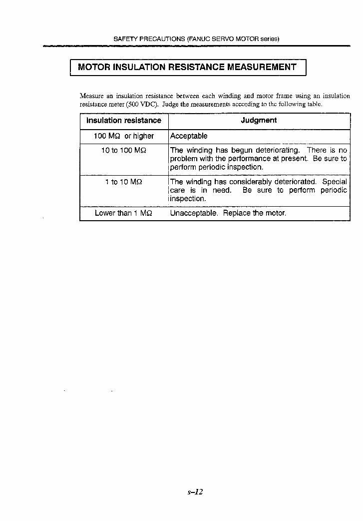
Measure an insulation resistance between each winding and motor frame using an insulation resistance meter (500 VDC). Judge the measurements according to the following table.
Insulation resistance Judgment L
100 M&2 or higher Acceptable
IOtolOOMQ The winding has begun deteriorating. There is no problem with the performance at present. Be sure to perform periodic inspection.
1 tolOMS2 The winding has considerably deteriorated. Special care is in need. Be sure to perform periodic inspection.
Lower than 1 MS2 Unacceptable. Replace the motor.
s-12
II. FANUC SERVO MOTOR AMPLIFIER series
s-13
SAFETY PRECAUTIONS (FANUC SERVO MOTOR AMPLIFIER series)
1 WARNINGS AND CAUTIONS RELATING TO MOUNTING .,.......:..,...,.....,.............,., * ,.,. ..,.............~.....,.,.,.,.,.,...,.~..., ,.,.,..,.,.,.,.,.,.,., * ..,.. * .,.,.,.,.,..., I ..,.~.,...,.,.,...,.,.~.~.~.,.,.~.,.,.,.,.,.,.,.~.~.,.~.,.,.,.~.,.~.,.~.~.,.~.,.,.,.,.,.,.,.,.,.~.~ ,.,.,.,.,.,.,.,.~.~.,.,.,.,.,.,.,. .;,. . . . . . . . . . I . . . . . . . . . I .*...,.,.,..,.... * . . ..~.~.........,.,.,.,...,.~.......,... . ..~...,.,.~.............,.,. .,...,...i....... . . . . . . . . . . . . . . . ..‘.. . . ..‘.‘.~...~.‘.‘.~.‘.‘.‘..~.~. . . . . :.‘.‘.:.:.:.:.:.:.“:.:.‘.:.~:.:.:.:.:.:.:.:.:.~:.:.~.‘.........’.‘.......‘.....‘.~.~.~.‘.‘..,..’..,....:.:.:.~:,:,: : 1.: :.>:.:.:.:.:.:.:,: :,~:,~:.:.~,:.‘.‘::,~.~:.~.~,.,.:.~ . . . . . ~.~,~,..~..,~.~.~.~.~.~,~,~ . . .: :... t... . . . , . . .,.,.,.~.,.,,~., ,.,... .,. , . . . . . . . . . . . . . . . . . . . . , . ..“““..... .‘..“...‘..‘“..““‘“..“‘..‘“..“..’..”....””’~.~’~‘,...~“‘,.,’,.,...~.....~.~~,.,~~ ; ,...,... ,.,....., . ..,.... ‘.‘.~.‘.‘.‘,‘.‘.~.~,~.~.~.~.~.~.~.~,~.~.~ ‘,‘.‘,‘,‘.‘.“,‘.‘.‘,.....,~.~..,~,~.~.~.~.~~.~., .~.,.~.,.~.,.~...,...,...,.,.,.,., . . . . . . .,.,.,,.....,.. ,.,.,....,.i,.,.,.,.~.~.,,.,.,..~.,,~,,,,~, . . . . ,. ,. ..: . . . ...‘. .‘.‘.‘.‘.‘:...:.:.:.:.:.:.;.:.‘.:.:.:.: :: : : : : : . . . . ,., ,.: I.‘.........‘... . . . . . . . . . _., ,.,, . . . . . . . . . . , .,.: .,.,.,.......,.,.,.,. . . . . . . . . . . . . . . . ..,., ~.~,~,..~....,i~.. .,.; .,.. .:...... .,. ,.,.,., . . . . . . . . . . . ...*. . . . * ‘.‘,‘.‘.‘.‘.‘.‘.: .,.,.,.....,.. . . . . . . .:.:.:.:.>:.‘.‘.:‘.: :+: . . . . . . . . . . . ~ .,.,.,.,.,.,.,.,.,.,...,.,. ;...., . .: . . . . . . . . . . . . . . . . . . . . . .‘i.:.:.~:.:.:.::.~~:......:. . . . . . . . . . . . . . . ,::::: ::, . ‘.‘.‘.‘.‘.‘.‘.‘.‘.‘.~.~,..~.~.~.~.~.~.~.~.~.~.~.~.~.~.~~.~.~...~.~.~.~~~.~.~ .,.~.,.,.i~.i,.i~.il,.,.,‘,.,.i,.,.ii~.~.~.,.~.,.,.i,.,.,.,. .: .,... :.:.:.~:.:.:.~:.:.:.~.:...:.:.: :.:.:.:. .:.:.:.‘.:.:.: .,.:,:.:.:.:.:.:.:.1: .,.,. .,.,.,.,.;, .._._.,.,. . :. . . .‘.‘.‘.‘.~...‘.‘.~.‘.‘.‘.‘.‘.~.. ‘..... .:.:.: . . . . . . . . . . . . . . . . . . . . . . . . . . .‘. .‘.‘.‘.‘#........ .‘.‘.‘...‘. ::. ‘. . , . . . .,,..,,, . . . . . . . y.:.:.>:.:.:.:.: :.:.>:.:.,.: .,.,.,.,.........,.,.,. . ..;. . . .,. . . . . , . . . . . . . . . . . . . . . ., _.,,....,.,...,. . . . . . . . ._.,.,.,.,. . . . ;;_.,.,.,.,.,..., . . . . . . . . . . . . . . .,.......,.,.,.,.,. .,.,.,:. ~ :.:. ~ :.:, ~: : : . . . . : : . . . . _,. . . . 1 .‘.‘...‘.’ . . ..‘.‘...‘....... . . . . . . . . . . . . .,.,.i,...,.~,,.,.,_ .,.~:.:,:.:.:.:.:.:.: .,.,. . .,.,.,..., . .,.,._...,. ., . ,. ,...,...,. :...:,:,: 1.: :.:‘:.:‘:.‘.‘~‘~‘~‘.“““““““““” . .,...,.,.,.........~.,...,.,.,.,.,.,.,...,...~..... . , .‘...‘.‘.....‘. . . . . . . . . . . . ., . ,.....,.,.,.,.,.,.,.,.,.,. :.>:.:: :.:.:.‘.‘.‘.:.:.:.:.:..‘.‘.‘. .:.:.::; ‘.~...~.~.‘.~.‘.‘.‘.‘.‘.‘.‘.~.~.~.~.~,’.~.~.~.’.‘.~.~.~.~ .:....::. ;..: ‘,~...~.‘.~.~.~.~.~.~.~ .‘. . . .‘. . ‘. . . . .’ .’ ..‘:.‘.-. . . . . . . . . . . . .:: : :: : :::::::: : ‘.’ ‘.“:.:.:.:.:.:.:.: .,.,. :.:.:.: .,.,.,.....~...~.,.,.~. . . . . . .~.,.~.~.,.,.,,..,.,.~.,.,...,..., . . . . . . . . . . . . . . . . . . . . . . . . . . . . . . . . . . . . . . .,.,.,.i~.~.~...~.,.~.,.,.,.,.,.~.~.,.,.,~..,.,.,.,.,.~. . . . . . . . . . . . . . . . . . . . . . . . . . . . . ...‘... :: ~...‘.‘.~,‘.‘.~.~.~.~.‘.~.. . . . . . . . . . . . . . . . . . .,.,.,., ,.,. . .; .,.,.,....:: 1.: ,.,..... >:,: :.:.:.:.:.,.~.‘.‘.‘.. . . ..~.......‘.~.~.~.~.‘.. . . . . . . . . . . . . . .~.~..,..‘.~.~,.. . . . . . . . . . . . . . . . . . . ..,.. ~,....~.~.....~.~.~ .;.. . . . . . . . . . . . . . . . ..‘.‘...............‘..... ._.,.,.....,._:,:_ :,~ :,:,:. ~ :,:,:,:,‘~..‘_.,‘,‘,‘):.:.:.>:.:.:.: :.:.y. . . ~ . . .:........::. . . , . . . . . . . . . . . . . . .,.....,.,,..,. .;,.,. _~,,.l,~,....~.,.,. . . . . . . . . . . . . . . . . ‘.‘.‘.‘.~:.;,:.:.:.:.:.:.:.:.‘.:.’...: . ..i..+.........,...,.,.........,.,.,.....,., . . . . . . . . .,...... ,.... ‘.‘,‘.‘,‘.‘.‘.‘,‘.‘...~.~.~....,~.~,~,~.~ .~.~.~.~.,..,~.,,~‘,.~.~,~,,.,.. . . . . . . . . . . . . ‘.~.~.~.‘.~.~.~.~.‘.~.~.~.~.~.~,’.’.~.~.~.~.’.~.‘.~.~.~.‘.~.~.’.‘.‘.~.‘.‘.~.~ ..~.‘...‘.....‘.‘...‘.~.‘.... ..‘.....‘...‘.‘... . , . . . . . . . , . .:.: ~‘,.,.~‘_‘,.,.,‘~.,.~.,.,.~.,.,.~.~.~.~~~.,~,~ :. . . . . . . . . . . : ::: : : : : .‘...‘...\..’ ‘.‘.‘.‘.‘.‘.‘.‘.‘.:.:.:: ::.::.:::::: :‘:‘:::::‘:y,: :.: : :::i,.~.~.~.~.~ .i .:...*i.._.. ..:::.. ,.i. . . . . :.... ..,.. . ..i.~~......~...... ,..., . . . . . . . ..I... . . . . . . . . . . . . . . . . . . . . . . . . . . . . . . . . . . . . . . . . . . . . . . . . . . . . . . . . ..Z ‘1. .ii..,‘. . , . . . , . I.. . , . . . . . . . ,.. . : ‘:.~:.:.:,:-‘;:.:.~:...~.‘.‘.:.‘.’.’.~.’: ‘.‘...‘.’ . . . . . . ..‘.‘.~.‘.‘.‘.‘.‘.~.......‘.~.‘.~. ~ . . . . :.:.:.>:.:.>:.:.:.y :.:.:. .C’.‘.. . ..’ ” . ...., ;; ~..‘.‘.‘.‘.‘.‘.‘.:.:.::::‘::::::::::::::~~:.:.~~ ,..,.,.;, . _, .,. .,.,., ., . . . . . . . . . . . . . . . . . . . . . . . . . . . . . . . . .:..... ...,,.,,..,..,.,.i . . . . ~ , . . . . .::... . . . .‘.‘.......‘.‘.‘.‘... . . . . . . . ,...,.,., ;,. . . . . .,.,.,.,.L,.,. . . .; .I.‘.‘.‘.‘.‘.‘...‘.‘.‘. . . . r...,...,.~.,.~.,.,. . .i.....:;.. ~..,~,‘.~.i..~.~...~.......~ .:......... . . .,. .~.‘.‘.~...~...~..,‘.‘...‘.‘.‘.~.’.’.~.. ..‘. . . . . , . . ..*...: . . . . . . . . . . . .,...,. .,*:.._.,~..:.. ..,., . . . . . . . . . . . . . . :.......-.. . . . . . ..‘...‘.‘........ . . . .. I...’ .’ ~ ‘.:.:.:.:.:.:.:.:.:.:.:~:~:~.....~.~...,.~.~,~:.~~:.:.:.:.:.:.:.~:.:.:,~:.:.:.:.:.:.~.~.~.’.~.~...~. ~.‘.‘.~.‘.‘.~.~..,......~.‘.‘.‘.’.~.~...’~ . f . . . . . .,..., _...,.,...,.,...,.,. .,.~.~.~.,.~I~.~.,.,.,.,.,.~.~.~.,.,., _.;;,. ... ‘.~.‘.~.~.~.‘.~.‘.‘.‘.~.‘.~.~.‘~.~.~.’.~.’.’.’.:.:.: . ..).......,.,...,.......,. .,.,.j,.,.,.~.,.,.,.~... . . . ‘......‘. . ..‘.‘.‘. .‘.‘.I....*...‘. .:.:.:.>:.: :.: .,.,. :.:.,.‘. .,., ,., ,.,.,...,. .,.:.:.: :., . ..,.,...,... :.:.:.:...:.~:.‘.‘.‘.:.:.‘.:.:.. . . . . . . . .,.,.,...,.,.,,,.,.,.~. . . . . . . . . . . . . . .‘_ . . . . . . . . . .;,.,. >: . . . . . >:.:.>:. :. . . . I . . . . . . .,.,.,.,.,., . . . . . . . . . . . .2.’ ~:.‘.‘...:.:.‘.~.... ....‘.. ‘. :. . . ..t..,.~.,.,.,l,.,.~.~.,.,.,.,.~.,.,. .,.,.......,...,. .,.,.,.,.,.i..i,.,,,.,.,. .,.,.i..i...._._.,...,.,. .,.,..... . .,.~.,.,.~...~.,.,.,.,. .,.;, ..;. ~‘,.,‘,.,‘:..,.~.,.....,.~.,~.~,~,~,~,~~~. > :.:. . . . . . . . . .,... .,.,..., . . . :. . . .,.,.,,,,,.,,.,, (.,.~_,.~._.,.,,~,~.,.~.~.,.: .;,, .: .,,.. :,>:.:.:.:.:...:. . , . , , . . . . . :: . . . .‘.‘.‘.’ ..... ..‘.‘. .‘.‘.‘.‘.‘...’ ‘.‘.:.: . . . . , . . . . .‘.‘.‘.‘.:,~:.:‘.:.:.:.:.:.~:.~. . . .,...; . . . .~.:.:.~:.:.:,:.:.:.~.~.~.~:.~.~,~,~.~.~.~.~.~.~.‘:. .‘.....’ : ::.>::. I .:.:+:.:::::,:::: :,:.: :::,::::: >:.I.:. . :: ‘...~.‘.‘.‘.‘.~.‘.‘. .,.,.~.~.,._.,.,.,.,.,.~.,.,.,.,,~.~.,.,.,.,.,.,.,.,.,.ii~.t~.i_.,.,.,. . * . .,. _.,. .,.:.:.‘. .,. ,... . . .‘.,.‘. :.: :.‘.‘.‘.:.‘.‘.‘. . .,. .,. .,.,. . .,. . .,.,.,._,t.,. .,..,. .,.,.,. .,.~. . . . . . .~.l...,...,.~.,.,.,.,. :.>: :.:.;:.:.:.:.:.:.. . . ..i..... ..‘.......‘.....‘....... . ..::.>:+:.?‘.‘.,., .,.....:.. ,.,.. .:,. . . . . . .:,., . . . . . . . . . . . . ,~..,.,~,~.~.. . . . . . . . . . . . . . . . . . . . . . . . . . . . . . . . . . . . . . . . ...‘. . . . . . . . . . ..‘..... . . . . . ...‘.... . . . . ..‘.‘.‘.‘. . . . .,...,....,............,.,.,...,.,. :.:.:.:.:.>:.:.:.: .,.........,.... . . . ,.,.,...,.,.,. .,.,., . .., ,.,.,.,. .,.,.,., . . . . . . . . . ,.,.,. . . . .._.....,.,.~...,.~.,.,.,. .,.,.,.,.,...,.,., ,.....,. .‘.‘,:.‘.:.:.‘.:.‘.‘.‘.‘.:..;,~.~,. . . . . .._..........‘.‘, ..:: ,._.. . . . . . . . . ‘.‘.‘.‘.‘.‘.‘.~:3:.~:.:.:...‘.‘.~:.’..... . . . . . . . ...‘. . . . . . . . . . ..l..................,.,... .,.,. . . . . . . . . . . . . . . . . . . . . . . . ..-. ..:..,...,...,..: .:~:~.,‘,:~‘~.;~‘~‘,.,:,.,: : . . . . . ,., . . . . I . :: : : : : . . . . . . . . . . . . . . .,.,.,.,. I ., . . . . . . . . .~ :.:.I.: . . . . . . . :,y,: ..; . . . . . . . .,. . . . . . . . . . . . . . . . . .,,,.,.,.,. .,.,. .,.,.,. :,‘.:.~.:.‘,:.‘.:.‘.‘.~.~.~.~.~.~.~.~.~,~.~.~:,:. .,.,. .,. .,.,, . . . .:: ~,~.~.‘.~.~,:.:~.,.:.:.:,:,~~.~.~.~~.~:.~.~.~,.:.~.~..,~.~. :,;,:‘::.“’ ,... . . .,. . . .
1 WARNING 1
l
0 d
0
0
0
0
0
0
Before starting to connect an amplifier to electric wires, make sure they are isolated from an electric power source.
A failure to observe this caution is very dangerous because you may get electric shocks.
Be sure to connect all cables, which are connected to an amplifier, correctly.
An incorrect connection may cause electrical stock or equipment malfunction or equipment failure.
Securely ground the amplifier and motor.
To avoid electrical shock, be sure to connect the ground terminal and metal frame of the amplifier and the ground terminal and metal frame of the motor to ground. Refer to the section “installation” in the description manual of motor and amplifier for each series.
Check the part number of the amplifier.
Check that the delivered amplifier is as originally ordered.
Mount a ground fault interrupter.
To guard against fire and electric shock, fit the factory power supply or machine with a ground fault interrupter (designed for use with an inverter).
Be aware of the weight of the amplifier and other components.
Control motor amplifiers and AC reactors are heavy. When transporting them or mounting them in the cabinet, therefore, be careful not to injure yourself or damage the equipment. Be particularly careful not to jam your fingers between the cabinet and amplifier.
Never ground or short-circuit either the power supply lines or power lines.
Protect the lines from any stress such as bending. Handle the ends appropriately.
Ensure that the power supply lines, power lines, and signal lines are securely connected.
A loose screw, loose connection, or the like will cause a motor malfunction or overheating, or a ground fault.
S-15

SAFETY PRECAUTIONS (FANUC SERVO MOTOR AMPLIFIER series)
Insulate all exposed parts that are charged.
Never touch the regenerative discharge resistor or heat sink directly.
The surface of the heat sink and regenerative discharge unit may become extremely hot. Never touch them directly. An appropriate gaurd should also be considered.
Close the amplifier cover before applying power.
Leaving the cover open presents a danger of electric shock.
Do not disassemble the amplifier,
Ensure that the cables used for the power supply lines and power lines are of the appropriate diameter and temperature ratings.
Do not apply an excessively large force to plastic parts.
If a plastic section breaks, it may cause internal damage, thus interfering with normal operation. The edge of a broken section is likely to be sharp and, therefore, presents a risk of injury.
s-16
SAFETY PRECAUTIONS (FANUC SERVO MOTOR AMPLIFIER series)
Do not step or sit on the amplifier.
Also, do not stack unpacked amplifiers on top of each other.
Use the amplifier in an appropriate environment.
See the allowable ambient temperatures and other requirements, given in the corresponding descriptions.
Protect the amplifier from corrosive or conductive mist or drops of water.
Use a filter if necessary.
Protect the amplifier from impact.
Do not place anything on the amplifier.
Do not block the air inlet to the heat sink.
A deposit of coolant, oil mist, or chips on the air inlet will result in a reduction in the cooling efEiciency. In some cases, the required efficiency cannot be achieved. The deposit may also lead to a reduction in the useful life of the semiconductors. Especially, when outside air is drawn in, mount filters on both the air inlet and outlet. These filters must be replaced regularly. So, an easy-to-replace type of filter should be used.
Before connecting the power supply wiring, check the supply voltage.
Check that the supply voltage is within the range specified in this manual, then connect the power supply lines.
Ensure that the combination of motor and amplifier is appropriate.
Ensure that valid parameters are specified.
Specifying an invalid parameter for the combination of motor and amplifier may not only prevent normal operation of the motor but also result in damage to the amplifier.
Ensure that the amplifier and peripheral equipment are securely connected.
Check that the magnetic contactor, circuit breaker, and other devices mounted outside the amplifier are securely connected to each other and that those devices are securely connected to the amplifier.
Check that the amplifier is securely mounted in the power magnetics cabinet.
If any clearance is left between the power magnetics cabinet and the surface on which the amplifier is mounted, dust entering the gap may build up and prevent the normal operation of the amplifier.
s-l 7
SAFETY PRECAUTIONS (FANUC SERVO MOTOR AMPLIFIER series)
1 CAUTION 1
l Apply appropriate countermeasures against noise.
Adequate countermeasures against noise are required to maintain normal operation of the amplifier. For example, signal lines must be routed away from power supply lines and power lines.
s-18
SAFETY PRECAUTIONS (FANUC SERVO MOTOR AMPLIFIER series)
NOTE
Keep the namepl ate clearly visible.
Keep the legend on the nameplate clearly visible.
After unpacking the amplifier, carefully check for any damage.
Mount the amplifier in a location where it can be easily accessed to allow periodic inspection and daily maintenance.
Leave sufficient space around the machine to enable maintenance to be performed easily.
Do not place any heavy objects such that they would interfere with the opening of the doors.
Keep the parameter table and spare parts at hand.
Also, keep the specifications at hand. These items must be stored in al location where they can
be retrieved immediately.
Provide adequate shielding.
A cable to be shielded must be securely connected to the ground plate, using a cable clamp or
the like.
s-19

SAFETY PRECAUTIONS (FANUC SERVO MOTOR AMPLIFIER series)
1 CAUTION 1
0
0
0
0
Note whether an alarm status relative to the amplifier is displayed at power-up or during operation.
If an alarm is displayed, take appropriate action as explained in the maintenance manual. If the work to be done requires that the door of the power magnetics cabinet be left open, the workmust be carried out by a person trained in the maintenance of the machine or equipment. Note that if some alarms are forcibly reset to enable operation to continue, the amplifier may be damaged. Take appropriate action according to the contents of the alarm.
Before operating the motor for the first time, mount and adjust the position and speed detectors.
Following the instructions given in the maintenance manual, adjust the position and speed detectors for the spindle so that an appropriate waveform is obtained. If the detectors are not properly adjusted, the motor may not rotate normally or the spindle may fail to stop as desired.
If the motor makes any abnormal noise or vibration while operating, stop it immediately.
Note that if operation is continued in spite of there being some abnormal noise or vibration, the amplifier may be damaged. Take appropriate corrective action, then resume operation.
Observe the ambient temperature and output rating requirements.
The continuous output rating or continuous operation period of some amplifiers may fall as the ambient temperature increases. If the amplifier is used continuously with an excessive load applied, the amplifier may be damaged.
s-21

SAFETY PRECAUTIONS (FANUC SERVO MOTOR AMPLIFIER series)
3 WARNINGS AND CAUTIONS RELATING TO MAINTENANCE . . . . . . . . . . . . . . . . . . . . . . . . . . . . . . . . . . . . . . . . . . . . . . . . . . . . . . . . . . . . . . . . . . . . ...*..... _ . . . . . . . . . . . . . . . . . . . . . . . . . . . . . . . . . . . . . . . . . . . . . . . . . . . . . . . . . . . . . . . . . . . . . . . . . . . . . . . . . . .,.,.~.,.,...............~...,.,.,.~.~.~...,.~.~.~...,.~.~.,.~..........,,...,.,.~.,...,...............,. .,.,...,.,.........,.,..., . . . . . . . . . . :.:.:.:.~I:.:.:.:,:.:.:.:.~:.:.:.:.:.:.~: :: : : : : : : : ::: . . . . . . . ..~......._...........~..........................~.~ . . . . . . . . . . . . . . . . . ., . . . . . . . . . . . . . . . . . . . . . . . . . . . . . * . *. . . . . * . . . . . * . : :: ::: : : : : : ‘.‘.:.:.~:.:.:.:.~~~:.:.~:.:.~~:.:.~~:.:.~.:.:,:.:.:.~:.:.:.:.:,:.:.:.:.~~:.: . . . . . . . . . . . . . . . . . . . . . . . . . . . . . . . . . . . . . . . . . . . . . . . . . . . . . . . . . . . . . . . . . . . . . . . . . . . . . . . . ..L................... . . . . . . . . . . . . . . . . . . . . . . . . . . . . . . . . . . . . . . . . . . . . . . . . . ................... I ......,., . ..~.....+.......~.....,...,.,.,...........,.....,...~.................,...,.,.,...,........ . :.>:;.>:.:: . . . . . . . . . . . . . . . . . . . . . . . . . . . . . . . ..~................................................................................. :.:‘:‘.‘.......‘...‘...................’......,......................‘.........................’.. . . . . . . . . . . . . . . . ..‘.....‘........ . . . . . . . . . . ..ii... .I....,.... .,......‘..........,... . . . . . . . . . . . . . ..,...,., * .....i,.,.,. ~.~.“.‘.‘,‘,:.‘.‘_‘..:.~.~,. ,.... . . . . . . . .::.. . . . I.. . . . . . . . . . . . . . . .,. . . . . . :.:.~:.:‘.:.:.:.:.:.:.:.:.:.:.:.:.:.~:.:.:.:.:.:.:.~ : . . . . . . . . ..‘.‘..i... . . . . . . . . . . . . . . . . . , . . . ..,.,. . . . . . . . . . . . . .~,-,‘.~.~.~.‘.~;.~.~.~.‘.~.~.~.~~.~.’:.’.’.’.’.‘.~. , . . .,. . . . . . . .~.,.~.,.,.,.,.~.,.~.~.~.~.~.~.,.,.,.,.,.,.,.,.~.~.~...,...,.~.~.....,.~.~.......~.~.~.~.~.~.,.,.,.,...~.~.~.....~.~.,.~.,.~.~.,.,.~.~.~.~.~.~.~.~.~.~.,.,.,.~.,.~.~.~.~.~.~.~.~.~.~.,.,.,.,.~ .:.:.‘.‘.‘.‘.‘.‘.‘.‘;: . . . . . . . . . . . . . . . . . . . . . . . . . . . . . . . . . . . . . . . . . . . . . . *. . . . . . . . . . . . . . . . . . . . . . . . . . . . . . ..+...i_._.............................................,., . . . . . . . . . . I . . . . ..‘........l...........‘...............’........ . . . . . . . . . ..l...‘...... . . . . . . . . . . . . . . . . . . . . . ..S....... . . . . . .,*.....I...*‘.*.. . . . . . . . ‘............ . . . . . . . . . . . . . . . . . ..‘.‘.‘...........‘....... ‘....,:.:.:.:.:.:.:.:.5:,.:.: ..‘,......._.,.....,.,....... :.:.: > ..~.,.,.,.~.,.~.~.,_......~...~..,,.,.~...~.~.........~...,...,.,..., ,.,.,....._.. . ..~.~.,...,...,.~.,.~.....~.~.~.,.,.,.~.~.~.,.~.,.~.~.~.~.~.,.~.~.~.~.~.~.~.~.~.~.~.~.~.,.,.~.~.~.~.~.~.~.~.~.,.~.~.~.,.~.~.~.,.~.~.~.~.~.,.,. : :’ . . . . . . :::;:.‘.~.~;.~.~.‘:.~.~...:.:.:.:.:.:.~.,~.:.:.: . . . . . :.::.“.:,>:.:.: . . . . . . . . . . . . . . . . . . . . . . . . . . . . . . . . . . . . . . . . :“..:.:.:.:.:.:.~.5.?..:.:.:.:.:.~..:.:,~.~..:.:.;.~.:.:.:.:.:.~.:.:.~ i....,.2.,..i2_.............,.....................,...........,. . . _. .,, . . . . . _. . . . . . . . . . . . . . . . . . . . , . . , . . . ,x,>> :+; ,:.._.L,.,.,.,.................,.,.....,.~.,.................~.~............,........~.....,.....~...............,.,.~.,..... . . . . . . . . .‘.‘...... ‘...‘.‘...~.....‘.....~f .
. . ,.,.,.,.. . . .~.~...V...~.~...~.‘.~...~.~.~.~,~,..~.~.~.~.. . . . . . . . . . . . . . . . . . . . . . . . . . . . . . . . . . . . . .j..:.. ..,.. . . . . . . .I...... Li. . ...,. ..,.. . . . . . . . . . . . . . . . . . . . . . . . . . . . . . . . . . . . . . . . . . . . . . . . . . . . . . . . . . . . . . . . . ..~.......~.......... . ..‘.. . . . . . . . . . ‘.............‘.‘.........‘.........’.....’.~...‘.. ..:. ‘.‘...‘.‘.‘.‘.‘.‘.‘.‘...‘.....:.:.~:.:.:.:.:.:.:.:.:.:.~:.’.~:.:.,.:.:.:.:.~:.:.:.:.:.~:.:.:.:.:.:.:.:.:.:.~:.:.~:.:.:::.:.:.~:.:.:.:.:.:.~...~. . . . . . . . . . . . . . . . . . . .:., . . ..~.....~...... . . .._ .: . . . . . ..,..:.. . . . . . ~.~....,....~.~.....~...... . . . . . -:.... . . . . . . . . . . . . . . . . . . . . . . . . . . . . . . . . . . . . . . . . . . . .*. . .,.,.,.,.,.~.,...~.....~.~.....,.~.~.,.,.,.,.~.~.....~.~. _ .<.......,...... . . . . . . . . .~..~~...,.~.~.,.,...~.~.......~.,.~...,.,.,.~,..~.~.~.~.~...,.,..,.~.~.~.~.~.~.~.~.~.~.~.,.,.~.~.~.~.,.~.~.~.~.~.,.~.,.~.~.~.~.~.~.,.~.~.,.~.~.~.,.~.~.~.~.~.,.~.~.,.,.~.,.~.~.~.~.,.~.~.~.,. . ..i..,.~,,.........,.,.,.,.~.,.,.,.~.~...~.....,.,.,.,.,.,........,~ f :,:,:,:,:,:. ~ :,:....,.,...,...,.....,. . . . . . . * . . . . . . * . . . . . . . . . . . . . . . ( . . y.:...:.: .,...,.,.................~.........,..,........~...........,...,...,.,..., . . . . . . . . . . . . . . . . . . . . . . . . . . . . . . . . . . . . . . . . . . . . . . . . . . . . . . . . . . . . . . . . . . . . . . . . . . . . . . . . . . . . . . . . . . . ..~.~.....~~............................. : : : : .‘.......... ‘.....~.~.‘.‘.‘.~.........~...~.~.’.~.’.’.~...~...........’, .‘...‘.cr................‘...‘...........::::::::::::~:::::::::::::.:.:.:.:.:.~:.. . . . . . . . . I . . . . . . . . . . . . . _ . . . :: ::: f:” :.>:+:.:.:.:... .‘.‘.‘.‘.‘.‘.‘.‘.‘.‘.‘...........’...’...’.’.’.‘.‘.‘.........’.............‘.‘.‘.‘.:.:.:.:.~~:.~~:.~~:.:.:.:.. . . ..~.........~....,~.,.~.~.~. >:.>:+ :,:.:.:.:.:. :‘:.:.:.:. ~ :.:+):. ~ :.:.:+:* ;+ :.:.:. ~ :.:, ~ :.:. > :.:.:.:+:.: ‘::g~~.~~.‘~.~~~:~:~.~:~:~~.~.~.~.~~.~:~~,~.~.~.~.~~~~~~.~.~~~~:~~:~.~~~.~.~~~.~~~.~~,~~~~~:~~~:~~:~,~,~:~~.~:~.~~~~~~.~:~:~~~~~~.~:~:~:~~:~:~,:~~~~~~:~:~,,~~ :: ~~f.~.‘:.~.~.‘.‘.~.‘.‘.~.~.~.~.‘.~.~.~.’.’.’.~.‘.~.‘.~.~.~.~.~.~.‘.‘.‘.‘.‘.‘.’ .: . . . . . *. . . “‘.‘~‘.‘.‘.‘.‘.‘.‘.‘.‘.‘...‘.‘.‘.~.........~.’.~.‘.‘.~.~...~.~.:.:.:.~:.:.:.:.:.:.~.........~:.:.:.:.:.~ :.:.=p>: .,.,.,..... _ .r.~.~.,.~.,.~.~.,.~.~.~.~.~.~.~.~.~.~.,.,.,.,.~.~,~.,.,.,,~.~.~.~.~.~.~.,.~.,.,.,.~,~.~.~,~.~.~.,.,.~.~.~.,., . . . . . ..:.: . . . . . . . . . . . . . . . . . . . . . . . . . . . . . . . . . . . . . . . ..~...........~.....~...~.......~.~.~.........~...................~.~.~...~...~...........~.~...................~ ..,.,.,.,....._.......... +.,.~.,.,.,.......,.,...,.,.,.,.,.,.~...~.,.~...,.~...,.,.,.......~.... . . . . . . . . . . . . . . * ,..I.. . . . . . . ...* ,.,.,.,.,...~.~.~.~.~...,.,.....,............ . . . . . . . . . . . ~._.~._.,.~.,.,.,.,.~.~,~.,.,..,..,.,. :.:.:.:.~,:.:,~.:.:.:.:.~.~.~.~.~.~,~,~.~,~.~.~.~.~.~.;.~,~.~ :,:,:,:.:.:.:.~:.‘:,: ..-...... ,.... . . . . . . . . . . ...*. . . . . . . . . . . . . . . . . . . . . . . . . . . . . . -:.:.:.:.:‘:.~:.:.:.:.:.:.~:.:............. .‘.‘.~.~.~.~.~.~.~.‘.‘.‘.~.~.~.‘.’.~.~.~.~.~.~.~.~.~.~.~.~.~.~.~.~.~.-.~.‘.~.‘.~.~.‘.‘.~.‘.~.~,~.~.~.~.~.~.~.~.‘.~.~.~.~.~.~.~.~.~ -. :.~:.:.:.:.:.~:.:.:.:.?:.:.:.:.~:.:.~~:.~:.:.~:.:.:.:.:.~:.:.:.:.:.:.~~~~:.~.:.:.:.~:.:.:.:.:.~:.:.:.:.:.:.~:.:.~.:.:.:.~:.:.:.:.:.:.:.:.:.:.~~:.:.~:.:.:.:.:.:.:,:.:.:.:.:.~:.:.~.:.:.:.:.:.:.:.~:.:.:.~~~~.:.:.:.~:.~.:.:.~~~:.‘. . . . . :,:.:.:.~:.‘,:.‘.‘.~...........~...~.’.~.’.~.~ _. . . . . . . ‘.:.~:,:,:,:.:.~:.:.:.:.:.:,:.:,:.~~:.:.:.:.~~:,:.:.:,~:.:.: . . . . . . . . . . ‘.:.~.:.:.~:,:.~:.:.:.:.:.:.:.:.:.:...’...... . . . . . ‘...‘.‘........,. . . . . . ‘.‘.‘.. . . ...’ . . . . . . .._.. . . . . . ..L.‘.... . . . . . . . . . . . . . . . . . . . . . . . . . . _.....,....S............ 1.. . . . . . . . . . . . . . . . . . ., ‘.:.:.~:.:.:.~:.:.:.:.:.:.~.:.:.~.~.~...:.:.:.~.:.:,:.~.~.:.’.:.:...:.~.~.:.:.:.:.:.:.~:.:.:.:.:,:.:,:.:.~.:.: .~.,‘,.,.,...,...,...,., ., . . . . ..~,~.~...~. . . . . . . . . . . . . . ,.....,...:.: . , ... . . . . . . .,.:+......., . . . . . . . . . . . . . : : : . . .. *. . ‘.’ ‘.‘.‘.‘.‘.‘.‘.‘.‘.‘.~.~.~.~.~.~.~.~.~...’.’.’.~.~.~.~.~.~.~.~.~.~.~.~.~.~.‘,~.~.~.~.~.~.~.~.~.~.~~,~.~ :.p.:.,. .,._. .,_,,,.,.,. .,., . . . . . . . . . . . . . . . . . . . . . . . . . . . ‘.:.:.‘:.:,:.:.:.:,:.~: . . . . . . . . . . . . . . . . . . . . . . . . . . . . . . . . . . . . . . . . . . . . . . . . . . . . . . . . ..~.~.~.....................~.. . . . . . . . . . . . . . . . . . . . . . . . . . . . . . ..i....... . . . . . . . . .,.. . . . . . . . ,., . ._ . . . . . . . . . . . . . . . . . ., . . ., .‘.:.‘.:.:.~.~:.:.:.:.:.:.:...:.:.~:.:.:.:.~:.:.~.~.:.: .,.,.,.,.....,....._. . . .‘.,.,. ~‘:.:.:.:.:.:.:.:.‘:.:.‘.:.:.:,~.:.~.~...~:.~ .:.:.‘.“‘.‘.‘.‘.‘.‘.........:...:...’.:.:.:,:.~:. . . . . . . . . . . .
1 WARNING 1
Read the maintenance manual carefully and ensure that you are totally familiar with its contents.
The maintenance manual describes daily maintenance and the procedures to be followed in the event of an alarm being issued. The operator must be familiar with these descriptions.
Notes on replacing a fuse or PC board
Before starting the replacement work, ensure that the circuit breaker protecting the power magnet& cabinet is open.
Check that the red LED that indicates that charging is in progress is not lit. The position of the charging LED on each model of amplifier is given in this manual. While the LED is lit, hazardous voltages are present inside the unit, and thus there is a danger of electric shock.
Some PC board components become extremely hot. Be careful not to touch these components.
Ensure that a fuse having an appropriate rating is used.
Check the specification code of a PC board to be replaced. If a modification drawing number is indicated, contact FANUC before replacing the PC board. Also, before and after replacing a PC board, check its pin settings.
After replacing the fuse, ensure that the screws are firmly tightened. For a socket-type fuse, ensure that the fuse is inserted correctly.
After replacing the PC board, ensure that it is securely connected.
Ensure that all power lines, power supply lines, and connectors are securely connected.
Take care not to lose any screws.
When removing the case or PC board, take care not to lose any screws. If a screw is lost inside the nit and the power is turned on, the machine may be damaged.
Notes on replacing the battery of the absolute pulse coder
Replace the battery only while the power is on. If the battery is replaced while the power is turned off, the stored absolute positioning data will be lost. Some series servo amplifier modules have batteries in their servo amplifiers. To replace the battery of any of those models, observe the following procedure: Open the door of the power magnetics cabinet; Leave the control power of the power supply module on; Placethe machine in the emergency stop state so that the power being input to the amplifier is shut off; Then, replace the battery. Replacement work should be done only by a person who is trained in the related maintenance and safety requirements. The power magnet& cabinet in which the servo amplifier is mounted has a high-voltage section. This section presents a severe risk of electric shock.
s-22
SAFETY PRECAUTIONS (FANUC SERVO MOTOR AMPLIFIER series)
1 WARNING 1
Check the number of any alarm.
If the machine stops upon an alarm being issued, check the alarm number. Some alarms indicate that a component must be replaced. If the power is reconnected without first replacing the failed component, another component may be damaged, making it difficult to locate the original cause of the alarm.
Before resetting an alarm, ensure that the original cause of the alarm has been removed.
Contact FANUC whenever a question relating to maintenance arises.
Notes on removing the amplifier
Before removing the amplifier, first ensure that the power is shut off. Be careful not to jam your fingers between the power magnetics cabinet and amplifier.
s-23

SAFETY PRECAUTIONS (FANUC SERVO MOTOR AMPLIFIER series)
Ensure that all required components are mounted.
When replacing a component or PC board, check that all components, including the snubber capacitor, are correctly mounted. If the snubber capacitor is not mounted, for example, the IPM will be damaged.
Tighten all screws firmly.
Check the specification code of the fuse, PC board, and other components.
When replacing a fuse or PC board, first check the specification code of the fuse or PC board, then mount it in the correct position. The machine will not operate normally if a fuse or PC board having other than the correct specification code is mounted, or if a fuse or PC board is mounted in the wrong position.
Mount the correct cover.
The cover on the front of the amplifier carries a label indicating a specification code. When mounting a previously removed front cover, take care to mount it on the unit from which it was removed.
Notes on cleaning the heat sink and fan
I) A dirty heat sink or fan results in reduced semiconductor cooling efficiency, which degrades reliability. Periodic cleaning is necessary.
2) Using compressed air for cleaning scatters the dust. A deposit of conductive dust on the amplifier or peripheral equipment will result in a failure.
3) To clean the heat sink, do so only after turning the power off and ensuring that the heat sink has cooled to room temperature. The heat sink becomes extremely hot, such that touching it during operation or immediately after power-off is likely to cause a burn. Be extremely careful when touching the heat sink.
s-24

SAFETY PRECAUTIONS (FANUC SERVO MOTOR AMPLIFIER series)
NOTE
Ensure that the battery connector is correctly inserted.
If the power is shut off while the battery connector is not connected correctly, the absolute position data for the machine will be lost.
Store the manuals in a safe place.
The manuals should be stored in a location where they can be accessed immediately if required during maintenance work.
Notes on contacting FANUC
Inform FANUC of the details of an alarm and the specification code of the amplifier so that any components required for maintenance can be quickly secured, and any other necessary action can be taken without delay.
s-25
B-65235EN/O2 Table of Contents
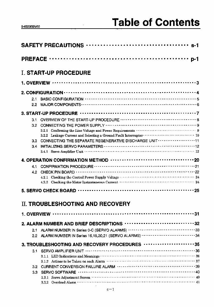
SAFETY PRECAUTIONS l mmmmmm~mmmm8~m8m8mmmmmammmmmmmmmmmm s-l
PREFACE mmmmmmmmmmmmmmmmmmmmmmmmm8mmmmmmmmmmmmmmmmmmm8mmm P-l
I .
1 m
2 .
3 8
4 l
5.
OVERVIEW mommmmmmmmmommmmmmmmmmmmmmmmmmmmmmmmmmmmmmmmmmmmmmmmmmmm8mmmmm 3
CONFIGURATION mmmmmmmmmmmmmmmmmmmmmmmmmmmmmm8mmmmmmmmmmmm8mmmmmmmmmmmmm 4 2.1 BASIC CONFIGURATION .*............................*............................. 5
2.2 MAJOR COMPONENTS . . . . . . . . . . . . . . . . . . . ...*..........*.........................*.. 6
START-UP PROCEDURE mmmmmmmmmmmmmmmmmmmmmmmmmmmmmmmmmmmmmmmmmmmm8mmmmm 7
3.1 OVERVIEW OF THE START-UP PROCEDURE . . . . . . . . . . . . . . . . . . . ..*................... 8
3.2 CONNECTING THE POWER SUPPLY . . . . . . . . . . . . . . . . . . . . . . . . . . . . . . . . . . . . . . . . . . . . . . . . . 9 3.21 Confirming the Line Voltage and Power Requirements . . . . . . . . . . . . . . . . . . . . . . . . . . . . . . . . . . . . 9
3.2.2 Leakage Current and Selecting a Ground Fault Interrupter . . . . . . . . . . . . . . . . . . . . . . . . . . . . . . . 10
3.3 CONNECTING THE SEPARATE REGENERATIVE DISCHARGE UNIT. . . . . . . . . l . . . l . . . . = .I1
3.4 INITIALIZING SERVO PARAMETERS ..,...,.......................................... 12 3.4.1 Servo Ampliiier Unit . . . . . . . . . . . . . . . . . . . . . . . . . . . . . . . . . . . . . . . . . . . . . . . . . . . . ..*........... 12
OPERATION CONFIRMATION METHOD l mmmmmmmmmmmmmmmmmmmmmmmmmmmmmmmmm88 - 20 4.1 CONFIRMATION PROCEDURE mmmmmmmmmmmmmmmmmmmmmmmmmmmmmmmmmmmmmmmmmmmm*mmmmmmmmm 21
4.2 CHECK PIN BOARD . . . . . . . . . . . . . . . . . . . . . . . . . . . . . . . . . . . . . . . . . . . . . . . . . . . . . . . . . . . . . . . . 22
4.2.1 Checking the Control Power Supply Voltage . . . . . . . . . . . . . . . . . . . . . . . . . . . . . . . . . . . . . . . . . . . . . 24
4.2.2 Checking the Motor Instantaneous Current . . . . . . . . . . . . . . . . . . . . . . . . . . . . . . . . . . . . . . . . . . . . . 24
SERVO CHECK BOARD mmmmmm~mmmmmmmmmmmmmmmmmm8mmmmmmmmmmmmmmmmmmm8mmmm 25
II. TROUBLESHOOTING AND RECOVERY
1 l OVERVIEW mmmm88mmmmmm8m8mmm8mmmmmmmmmmmmmmmmmmm8mmmmmmmmmmmmm8mmmmmmmm 31
2. ALARM NUMBER AND BRIEF DESCRIPTIONS mmmmmmmmmmmmmmmommmmmmmmmmmmm8 32
2.1 ALARM NUMBER IN Series O-C (SERVO ALARMS) ..*................................. 33
2.2 ALARM NUMBER IN Series 16,18,20,21 (SERVO ALARMS) . . . . . . . . . . . . ..‘.............. 34
3. TROUBLESHOOTING AND RECOVERY PROCEDURES n l l l l l l n l n l = = l l = l l = = = = 35 3.1
32 .
33 .
SERVO AMPLIFIER UNIT ........................................................... 36
3.1.1 LED Indications and Meanings ......................................................... 36
3.1.2 ActionstobeTakenoneachAlarm ..................................................... 37
CURRENT CONVERSION FAILURE ALARM .......................................... 39
SERVO SOFTWARE ............................................................... 40
3.3.1 Servo Adjustment Screen .............................................................. 40 3.3.2 OverloadAl- ....................................................................... 41
c-l
B-65235EfW02 PREFACE
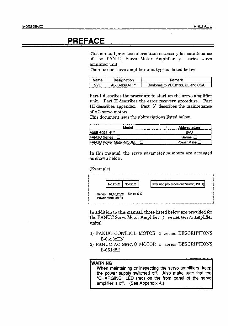
PREFACE
This manual provides information necessary for maintenance of the FANUC Servo Motor Amplifier ,8 series servo amplifier unit. There is one servo amplifier unit type,as listed below.
I Name I Desianation 1 Remark I 1 SVU 1 A06B-6093-H*** 1 Conforms to VDE0160, ULand CSA. 1
Part I describes the procedure to start up the servo ampljlfier unit. Part II describes the error recovery procedure. Part III describes appendex. Part N describes the maintenance of AC servo motors. This document uses the abbreviations listed below.
Model Abbreviation
A06B-6093-H*** svu
FANUC Series 0 Series III
IFANUC Power Mate -MODEL q I Power Mate-D 1
In this manual, the servo parameter numbers are arranged as shown below.
(Example)
Series 16,18,20,21 Series 0-C Power Mate-D/F/H
r.r.............r.........................-.......~........--......-....-.....................,
: .
:
: l :
Overload protection coefficient(OVC1) ! : : : : : : : : ; : ,..,...................,............,.....---.....-...........-.................-...............:
In addition to this manual, those listed below are provided for the FANUC Servo Motor Amplifier p series (servo amplifier units) *
1) FANUC CONTROL MOTOR ,8 series DESCRIPTIONS B-65232EN
2) FANUC AC SERVO MOTOR CY series DESCRIPTIONS B-65142E
WARNING When maintaining or inspecting the servo amplifiers, keep the power supply switched off. Also make sure that the “CHARGING” LED (red) on the front panel of the servo amplifier is off. (See Appendix A.)

I l START-UP PROCEDURE
E65235EN/02 START-UP PROCEDURE 1. OVERVIEW
1 OVERVIEW .
This part provides information necessary to confirm the system configuration and start up the servo amplifier units:
(1) Configuration (2) Start-up procedure (3) Operation confirmation procedure
- 3 -

2. CONFIGURATION START-UP PROCEDURE B-65235ENiO2
2 CONFlGlJFiATlON
- 4 -
B-65235EtW02 START-UP PROCEDURE 2. CONFIGURATION
21 I BASIC CONFIGURATION *
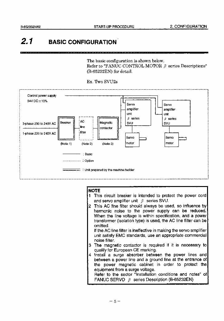
The basic configuration is shown below. Refer to “FANUC CONTROL MOTOR p series Descriptions” (B-65232EN) for detail.
Ex.Two SVU2s
: : . : : : : . : Control power supply : I I : ; : : : 24V DCt-10%
(Note 1)
! - .
(Note 2) (Note 3)
: Basic
_._.. _-_..-..- : option
‘I Servo
1 amplifier
unit
p series
SW
l
b Servo
motor
: Unit prepared by the machine builder
Servo amplifier
unit
p series
svu
I
Servo -r motor
: . : :
NOTE 1 This circuit breaker is intended to protect the power cord
and servo amplifier unit ,8 series SVU. 2 This AC line filter should always be used, so influence by
harmonic noise to the power supply can be reduced. When the line voltage is within specification, and a power transformer (isolation type) is used, the AC line filter can be omitted. If the AC line filter is ineffective in making the servo amplifier unit satisfy EMC standards, use an appropriate commercial noise filter.
3 The magnetic contactor is required if it is necessary to qualify for European CE marking.
4 Install a surge absorber between the power lines and between a power line and a ground line at the entrance of the power magnetic cabinet in order to protect the equipment from a surge voltage. Refer to the sector “Installation conditions and notes” of FANUC SERVO p series Description (B65232EN)
- 5 -
2. CONFIGURATION START-UP PROCEDURE B-65235EN/02
22 I MAJOR COMPONENTS
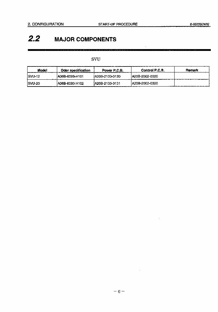
SW
Model
svu-12
svu-20 ,
1
Oder specification Power P.C.B. Control P.C.B. Remark
A06B-6093-H 101 A20B-2 100-0130 A20B-2002-0320
A06B-60930HI 02 A20B-2100-0131 A20802002-0320
- 6 -

B-65235ElWO2 START-UP PROCEDURE 3. STARTdJP PROCEDURE
3 START-UP PROCEDURE
- 7 -
3. START-UP PROCEDURE START-UP PROCEDURE ES-65235ElWO2
31 I OVERVIEW OF THE START4P PROCEDURE
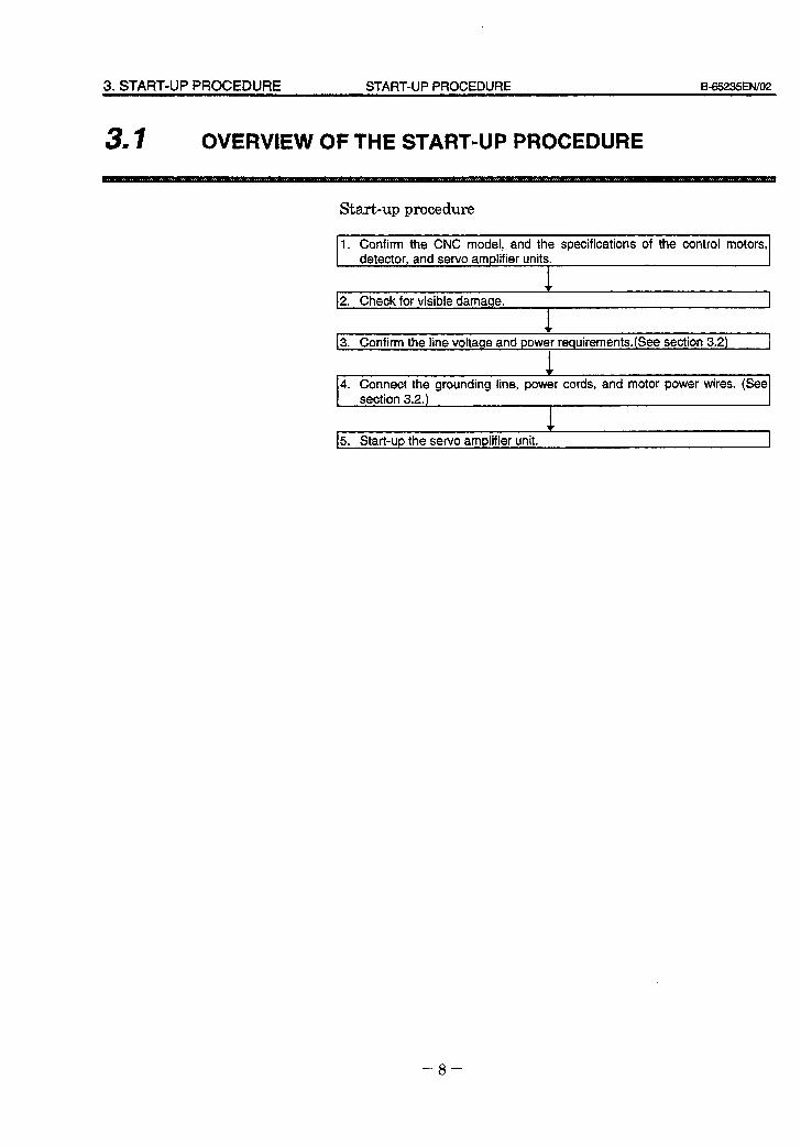
Start-up procedure
I 1. Confirm the CNC model, and the specifications of the control motors, detector. and servo amolifier units. I
_~_~~ ~ 12. Check for visible damaqe.
13. Confirm the line voltage and power requirements.(See section 3.2) I
t 4. Connect the grounding line, power cords, and motor power wires. (See
section 3.2.)
15. Start-up the servo amplifier unit. I
- 8 -
B-65235ElW02 START-UP PROCEDURE 3. START-UP PROCEDURE
32 I CONNECTING THE POWER SUPPLY
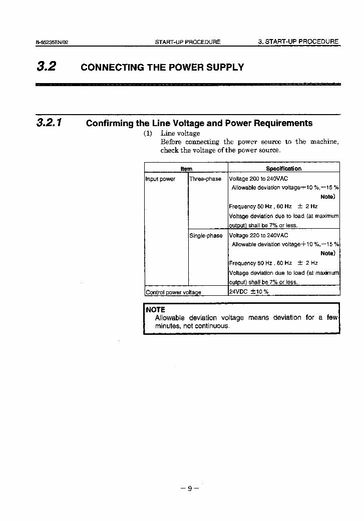
3.2, I Confirming the Line Voltage and Power Requirements (1) Line voltage
Before connecting the power source to the machine, check the voltage of the power source.
ttem
Input power
t
_~__ Three-phase
Single-phase
IControl bower voltaae
Specification
Voltage 200 to 240VAC
Allowable deviation voltage+1 0 %;15 %
Note)
Frequency 50 Hz, 60 Hz k 2 Hz
Voltage deviation due to load (at maximum
output) shall be 7% or less.
Voltage 220 to 240VAC
Allowable deviation voltage-t-1 0 %,-I 5 %
Note)
Frequency 50 Hz, 60 Hz zk 2 Hz
Voltage deviation due to load (at maximum
output) shall be 7% or less.
24VDC t10 %
NOTE Allowable deviation voltage means deviation for a few minutes, not continuous.
- 9 -
3. START-UP PROCEDURE START-UP PROCEDURE B-65235ENiO2
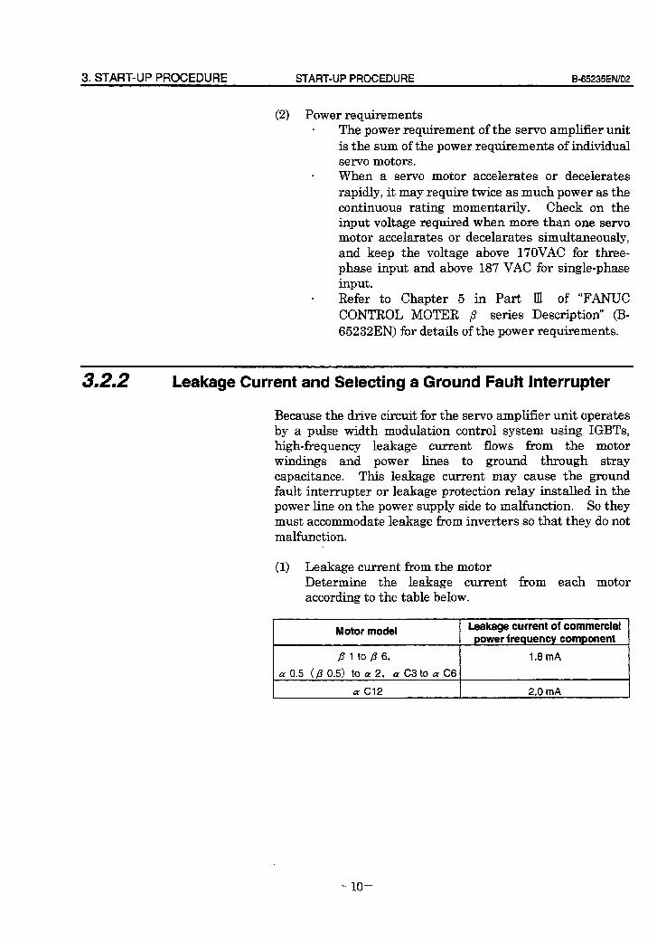
(2) Power requirements . The power requirement of the servo amplifier unit
is the sum of the power requirements of individual servo motors.
. When a servo motor accelerates or decelerates rapidly, it may require twice as much power as the continuous rating momentariIy. Check on the input voltage required when more than one servo motor accelarates or decelarates simultaneously, and keep the voltage above 17OVAC for three- phase input and above 187 VAC for single-phase input.
. Refer to Chapter 5 in Part Ill of “FANUC CONTROL MOTER p series Description’ (B- 65232EN) for details of the power requirements.
3.2.2 Leakage Current and Selecting a Ground Fault Interrupter
Because the drive circuit for the servo amplifier unit operates by a pulse width modulation control system using IGBTs, high-f?equency leakage current flows from the motor windings and power lines to ground through stray capacitance. This leakage current may cause the ground fault interrupter or leakage protection relay installed in the power line on the power supply side to malfunction. So they must accommodate leakage from inverters so that they do not malfunction.
(1) Leakage current from the motor Determine the leakage current from each motor according to the table below.
Motor model Leakage current of commercial Dower freauencv component
B 1 to B 6,
cy 0.5 (B 0.5) to cy 2, a C3 to a C6
1.8 mA
a Cl2 2.0 mA .
- 10 -
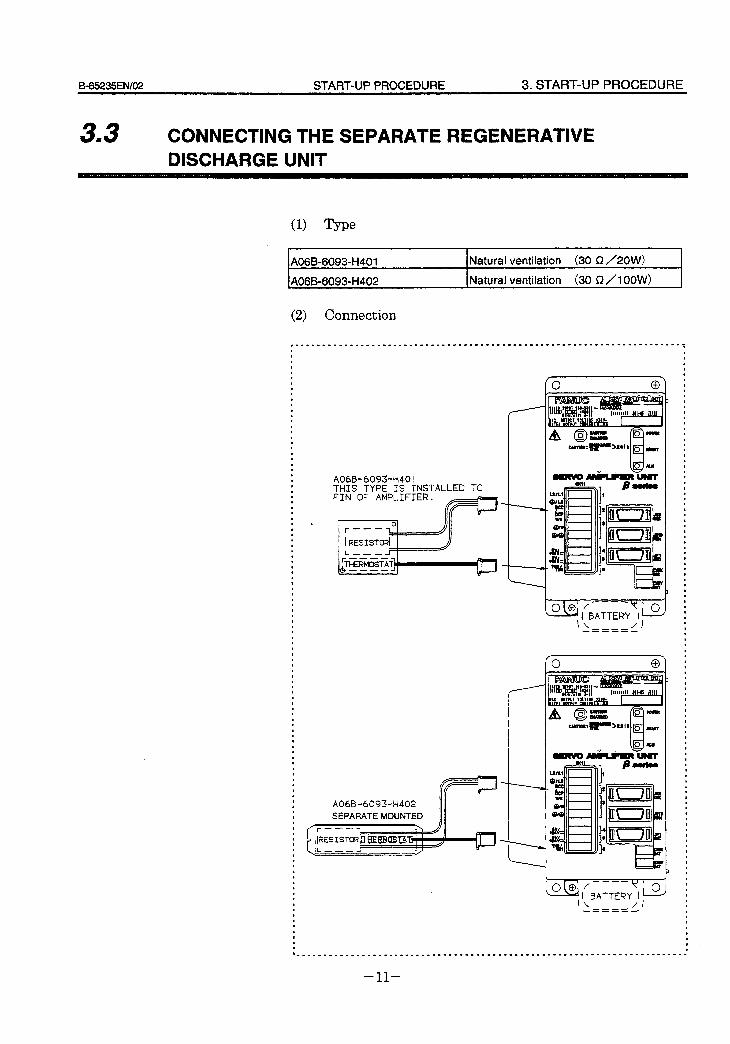
B-65235ENf02 START-UP PROCEDURE 3. START-UP PROCEDURE
33 I CONNECTING THE SEPARATE REGENERATIVE DISCHARGE UNIT
(1) Type
A06B-60931H401 Natural ventilation (30 R /2OW)
A06B-60930H402 Natural ventilation (30 $2 /I OOW>
(2) Connection
A06B-6093~t-l401 THIS TYPE IS INSTALLED TO FIN OF AMPLIFIER.
. 0 -
;RFSISTORl L ---
A06B-6093+402
SEPARATE MOUNTED
O@ /----~ i 0, I BATTERY 1
\\ /I A----
------
o@ /---7’ 0 - 1 BATTERY )I.
\\ /I --- -=----
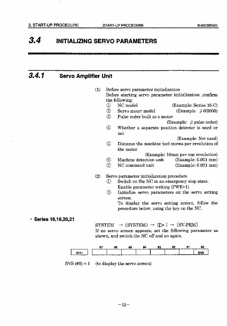
3. START-UP PROCEDURE START-UP PROCEDURE B=65235EN/O2
34 I INITIALIZING SERVO PARAMETERS
3.4. I Servo Amplifier Unit
(1) Before servo parameter initialization Before starting servo parameter initialization ,confirm the following: @ NC model (Example: Series 16-C)
@ Servo motor model (Example: ,8 612000)
@ Pulse coder built in a motor (Example: ,8 pulse coder)
@ Whether a separate position detector is used or not
(Example: Not used) @ Distance the machine tool moves per revolution of
the motor (Example: 1Omm per one revolution)
@ Machine detection unit (Example: 0.001 mm) @ NC command unit (Example: 0.001 mm)
(2) Servo parameter initialization procedure @ Switch on the NC in ari emergency stop state.
Enable parameter writing (PVVE=l) @ Initialize servo parameters on the servo setting
screen. To display the servo setting screen, follow the procedure below, using the key on the NC.
l Series 16,18,20,21 SYSTEM - [SYSTEM) - [I>) - (SV-PRMI If no servo screen appears, set the following parameter as shown, and switch the NC off and on again.
, 3,,, ] #7 #6 #5 #4 #3 #a #I s”y ,
c
SVS (#O) = 1 (to display the servo screen)
-12-
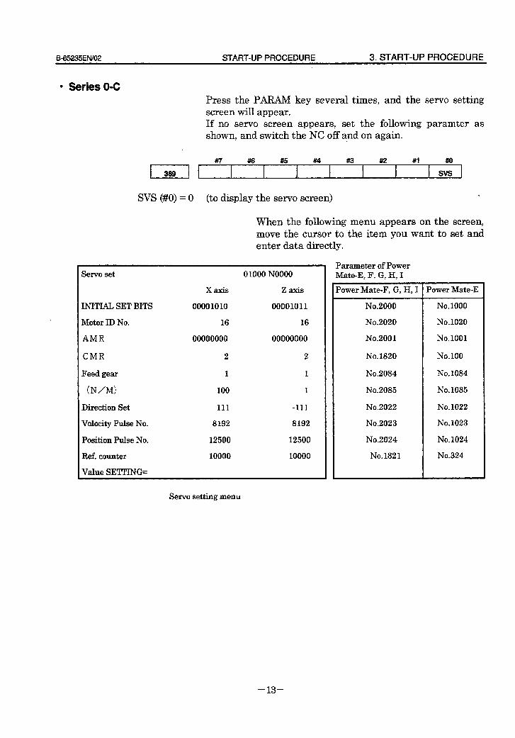
B-65235EN/O2 START-UP PROCEDURE 3. START-UP PROCEDURE
l Series O-C Press the PARANT key several times, and the servo setting screen will appear. If no servo screen ,appears, set the following paramter as shown, and switch the NC off and on again.
, 389 , #7 4% #5 #I4 #3 ##2 #1 ,,” 1
1
SVS (#O) = 0 (to display the servo screen) .
When the following menu appears on the screen, move the cursor to the item you want to set and enter data directly.
Servo set
INITIAL SET BITS
Motor ID No.
AMR
CMR
Feed gear
(N/M>
Direction Set
Velocity Pulse No.
Position Pulse No.
Ref. counter
Value SETTING=
XZ3XiS
00001010
16
00000000
2
1
100
111
8192
12500
10000
0 1000 NO000
ZZXXiS
00001011
16
00000000
2
1
1
-111
8192
12500
10000
Parameter of Power Mate-E, F, G, H, I
Power Mate-F, G, H, I 1 Power Mate-E
No.2000
No.2020
No.200 1
No. 1820
No.2084
No.2085
No.2022
No.2023
No.2024
No.1821
No. 1000
No. 1020
No.1001
No. 100
No. 1084
No. 1085
No. 1022
No. 1023
No. 1024
No.324
Servo setting menu
- 13 -
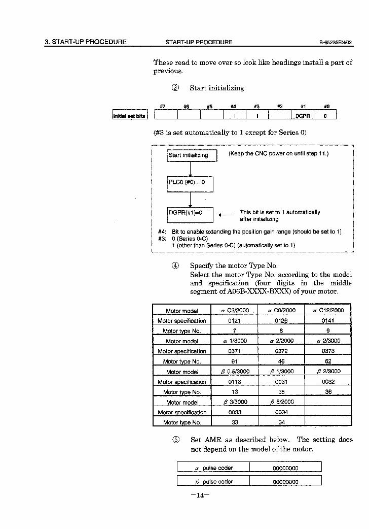
3. STARTiUP PROCEDURE START-UP PROCEDURE B-65235EfW02
These read to move over so look like headings install a part of previous.
@I Start initializing
(#3 is set automatically to 1 except for Series 0)
,......r....r.*...rr-.......................................................~.................~....~.................-.......~.....~..............................r............,
: .
: : : . Start initializing (Keep the CNC power on until step 11.) i : : : : : : : : . : : . : : : : + : : : . : : . : . PLCO (#0) = 0 ! : : . : : : : : : : : . : : : : . : : i z i : : : : . DGPR(#I )=0 This bit is set to 1 automatically + : : : : . : : after initializing : : : : : . : i #4: Bit to enable extending the position gain range (should be set to 1) i f #3: 0 (Series O-C)
: : : : : 1 (other than Series O-C) (automatically set to 1) : : : : : : t-..............................................................................................................................................................................I
@ Specify the motor Type No. Select the motor Type No. according to the model and specification (four digits in the middle segment of AOGB-XXXX-BXXX) of your motor.
Motor model a C3/2000 CY C6/2000 cy c12/2000
Motor sDecif icat ion 0121 0126 0141
Motor type No. 7 8 9
Motor model Q! l/3000 a 212000 a 2/3000
Motor specificat ion 0371 0372 0373
61 46 62 Motor type No.
Motor model p 0.5/3000 p l/3000 fi 2/3000
Motor specification 0113 0031 0032 .
Motor type No. 13 35 36
Motor model fi 3/3000 p 6/2000
Motor specification 0033 0034
Motor type No. 33 34 I
@ Set AMR as described below. The setting does not depend on the model of the motor.
a pulse coder 00000000 1
fl pulse coder
- 14 -
00000000
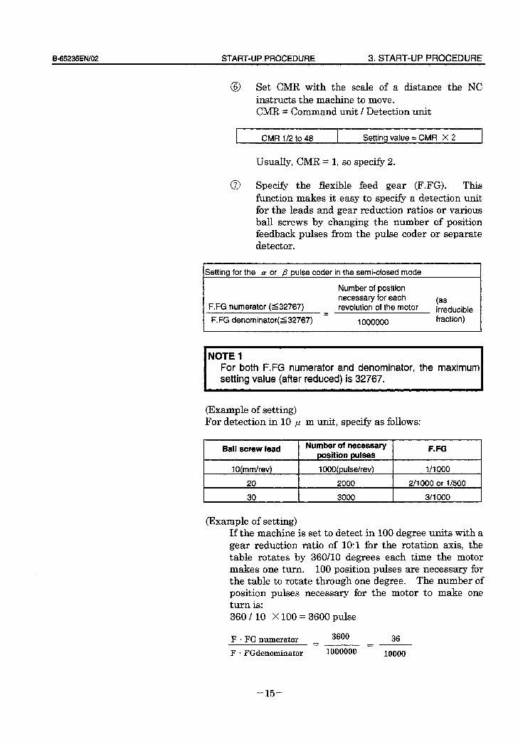
B65235ENiO2 START-UP PROCEDURE 3. START-UP PROCEDURE
@ Set CMR with the scale of .a distance the NC instructs the machine to move. CMR = Command unit / Detection unit
CMR l/2 to 48 Setting value = CMR X 2
Usually, CMR = 1, so specify 2.
@ Specify the flexible feed gear (F.FG). This function makes it easy to specify a detection unit for the leads and gear reduction ratios or various ball screws by changing the number of position feedback pulses from the pulse coder or separate detector.
Setting for the LY or p pulse coder in the semi-closed mode
Number of position necessary for each
F.FG numerator (s32767) revolution of the motor (as irreducible
F.FG denominator((32767) = 1000000 fraction)
NOTE 1 For both F.FG numerator and denominator, the maximum setting value (after reduced) is 32767.
(Example of setting) For detection in 10 p m unit, specify as follows:
Ball screw lead
lO(mm/rev)
20
Number of necessary position pulses
1 OOO(pulse/rev)
2000
F.FG
1/1000
2/l 000 or l/500
I 30 I 3000 I 3/ 1000 I
(Example of setting) If the machine is set to detect in 100 degree units with a gear reduction ratio of 1O:l for the rotation axis, the table rotates by 360/10 degrees each time the motor makes one turn. 100 position pulses are necessary for the table to rotate through one degree. The number of position pulses necessary for the motor to make one turn is: 360 / 10 X 100 = 3600 pulse
F l FG numerator 3600 36 = F l FGdenominator 1000000 = l()()OO
-15-
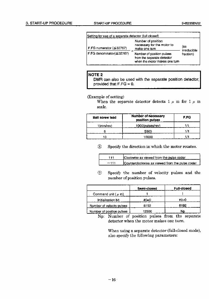
3. START-UP PROCEDURE START-UP PROCEDURE B_65235EN/02
Setting for use of a separate detector (full closed) Number of position
F.FG numerator (132767) necessary for the motor to make one turn (as
= Number of position pulses irreducible
F. FG denominator( s32767) fraction) from the separate detector when the motor makes one turn
NOTE 2 DMR can also be used with the separate position detector, provided that F.FG = 0.
(Example of setting) When the separate detector detects 1 p m for 1 p m scale.
I Ball screw lead I
Number of necessary F.FG oosition wlses
1 (mm/rev)
5
1 OOO(puIses/rev)
5000
l/l
l/l
10 10000 l/l
@ Specify the direction in‘which the motor rotates.
I
111 Clockwise as viewed from the pulse coder
-111 Counterclockwise as viewed from the pulse coder
@ Specify the number of velocity pulses and the number of position pulses.
I I Semi-closed I Full-closed I
. Command unit (p m) 1 1
Initialization bit #O=O #O=O
Number of velocity pulses 8192 8192
c Number of position pulses 12500 Np
Np: Number of position pulses from the separate detector when the motor makes one turn.
When using a separate detector (full-closed mode), also specify the following parameters:
- 16 -
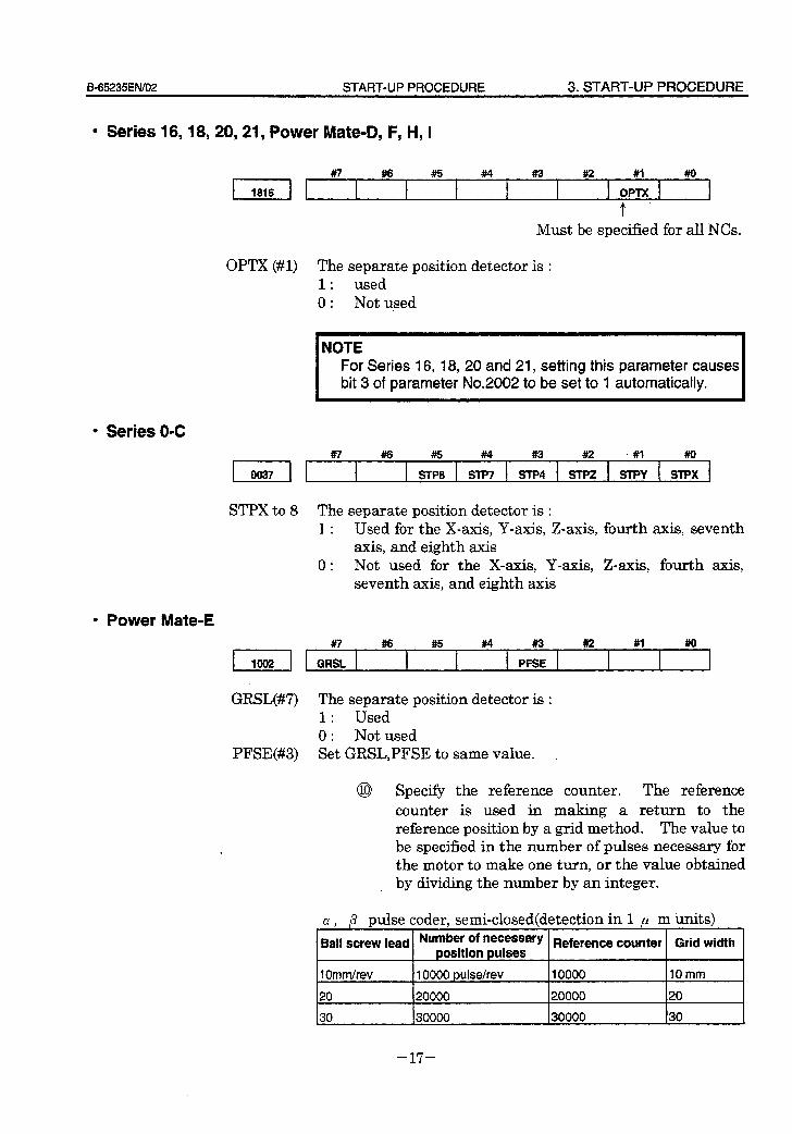
B65235EfWO2 START-UP PROCEDURE 3. START-UP PROCEDURE
l Series 16,18,20,21 y Power Mate-D, F, H, I
Must be specified for all NCs.
OPTX (#l) The separate position detector is : 1 . . used 0 : Not used
I NOTE For Series 16, 18, 20 and 21, setting this parameter causes bit 3 of parameter No.2002 to be set to 1 automatically.
l Series O-C
STPX to 8 The separate position detector is : 1 : Used for the X-axis, Y-axis, Z-axis, fourth axis, seventh
axis, and eighth axis 0 : Not used for the X-axis, Y-axis, Z-axis, fourth axis,
seventh axis, and eighth axis
l Power Mate-E
GRSL(#7) The separate position detector is : 1 : Used 0 : Not used
PFSE(#S) Set GRSL,PFSE to same value.
@ Specify the reference counter. The reference counter is used in making a return to the reference position by a grid method. The value to be specified in the number of pulses necessary for the motor to make one turn, or the value obtained by dividing the number by an integer.
CY , ,8 pulse coder, semi-closed(detection in 1 p m units) 1 I 1 Ball screw lead Number of necessary Reference counter Grid width
position pulses
1 Ommhev 10000 pulse/rev 10000 10mm
20 20000 20000 20
30 30000 30000 30
- 17 -
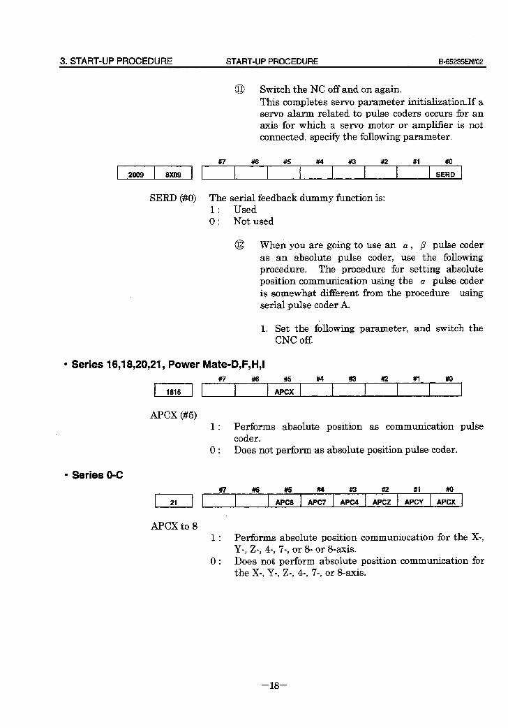
3.START-UPPROCEDURE START-UP PROCEDURE B-65235EfWOZ
2009 8X09
SERD (#O)
0 Switch the NC off and on again. This completes servo parameter initialization.If a servo alarm related to pulse coders occurs for an axis for which a servo motor or amplifier is not connected, specify the following parameter.
#7 #I6 #5 #M #i-3 #I2 #l #o t SERD .
The serial feedback dummy function is: 1 : Used 0 : Not used
@ When you are going to use an CY , p pulse coder as an absolute pulse coder, use the following procedure. The procedure for setting absolute position communication using the Q) pulse coder is somewhat different from the procedure using serial pulse coder A.
1. Set the following parameter, and switch the CNC off.
l Series 16,18,20,21 9 Power Mate-D,F,H,I , ,8,5 , #7
APCX(#5) 1 : Performs absolute position as communication pulse
coder. 0 : Does not perform as absolute position pulse coder.
l Series 0-C
1 : Performs absolute position communiocation for the X-, Y-, Z-, 4-, 7-, or 8- or S-axis.
0 : Does not perform absolute position communication for the X-, Y-, Z-, 4, 70, or &axis.
- 18 -
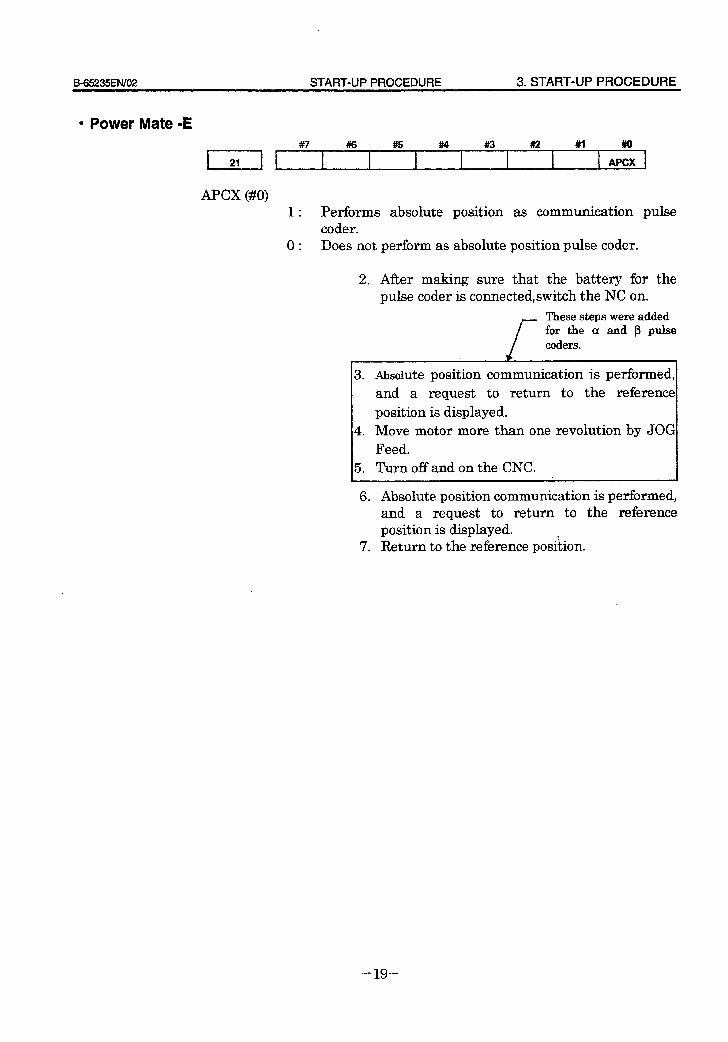
B_65235EN/OZ START-UP PROCEDURE 3. START-UP PROCEDURE
l Power Mate -E , *, , _ #7 #6 #5 #4 #3 #I2 #I ##OX
APCX (#O) 1 : Performs absolute position
coder. 0 : Does not perform as absolute
2. After making sure 1 1 .
as communication pulse
position pulse coder.
that the battery for the pulse coder 1s connected,switch the NC on.
f
These steps were added for the a and p pulse coders.
3 .
4.
5 .
Absolute position communication is performed, and a request to return to the reference
position is displayed. Move motor more than one revolution by JOG Feed. Turn off and on the CNC.
6. Absolute position communication is performed, and a request to return to the reference position is displayed.
7. Return to the reference position.
- 19 -
4. OPERATION CONFIRMATION METHOD START-UP PROCEDURE B-65235EN/02
4, OPERATION CONFIRMATION METHOD
- 20 -
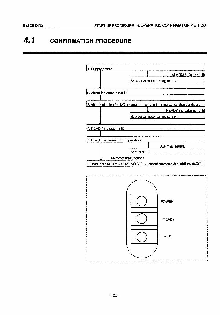
6-65235ElW02 START-UP PROCEDURE 4. OPERATION CONFIRMATION MRHOD
41 I CONFIRMATION PROCEDURE
1. Supply power
ALARM indicator is lit.
See servo motor tuning screen. rl
,2. Alarm indicator is not lit. I
3. After confirming the NC parameters, release the emergency stop condition.
READY indicator is not lit.
See servo motor tuning screen.
4. READY indicator is lit. I
I 5. Check the servo motor operation. I
Alarm is issued.
SeePart II.
The motor malfunctions.
6. Refer to “FANUC AC SERVO MOTOR R! series Parameter Manual (B6515OE).”
POWER
REP n” WY : : .
. : . : : .
ALM
- 21 -
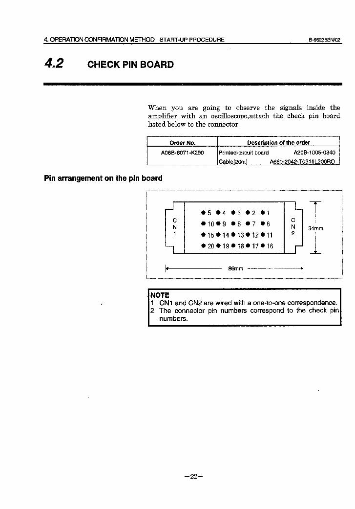
4. OPERATION CONFIRMATION METHOD START-UP PROCEDURE B-65235ElWO2
42 I CHECK PIN BOARD
When you are going to observe the signals inside the amplifier with an oscilloscope,attach the check pin board listed below to the connector,
Order No.
A06B-6071 OK290
Description of the order
Printed-circuit board A2OB-1005-0340
Cable(20m) A660020420TO31 #L200RO
Pin arrangement on the pin board
i . : : : : : : : : : : : : : i : : : : : : : : : : : : : : . : :
r C N 1
l-
l 5 04 03 02 l l
WO.9 l 8 07 l 6
W5.14@13*12@11
l 20 l 19.18 l 17.16
L C N 2
-I-
-T- 34mm
1
: : 11 86mm .~q . : : : : : I
. . . . . . . . . . . . . . . . . . . . . . . . . . . . . . . . . . . . . . . . . . . . . . . . . . . . . . . . . . . . . . . . . . . . . . . . . . . . . . . . . . . . . . . . . . . . . . . . . . . . . . . . . . . . . . . . . . . . . . . . ............-..........................................~ : :
NOTE 1 CNl and CN2 are wired with a one-to-one correspondence. 2 The connector pin numbers correspond to the check pin
numbers.
- 22 -
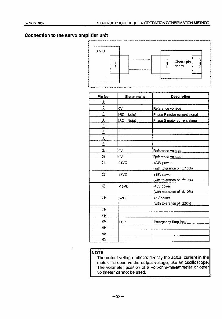
B=65235EN/O2 START-UP PROCEDURE 4. OPEFWION CONFIRMATION MtrHOD
Connection to the servo amplifier unit . . . . . . . . . . . . ..-........................-........................................-.........................................-....................................*................. : : : . : : : 1 ; : : : . svu : : : . : : : J . C : : X . N Check pin s : . board : 5 1 2 : . : : . . 4 : : : : . I
Pin No. Signal name Description
0 ov Reference voltage
IRC Note)
ISC Note)
Phase R motor current signal
Phase S motor current signal
@ OV Reference voltage
. @ OV Reference voltage
0 24VC +24V power
(with tolerance of zk 10%)
@ 15vc +lSV power
(with tolerance of Al 0%) -
I
-15vc
WC
,-I 5V power
(with tolerance of *lo%)
+5V power
(with tolerance of &5%)
ESP I Emergency Stop Input
NOTE The output voltage reflects directly the actual current in the motor. To observe the output voltage, use an oscilloscope. The voltmeter position of a volt-ohm-milliammeter or other voltmeter cannot be used.
- 23 -
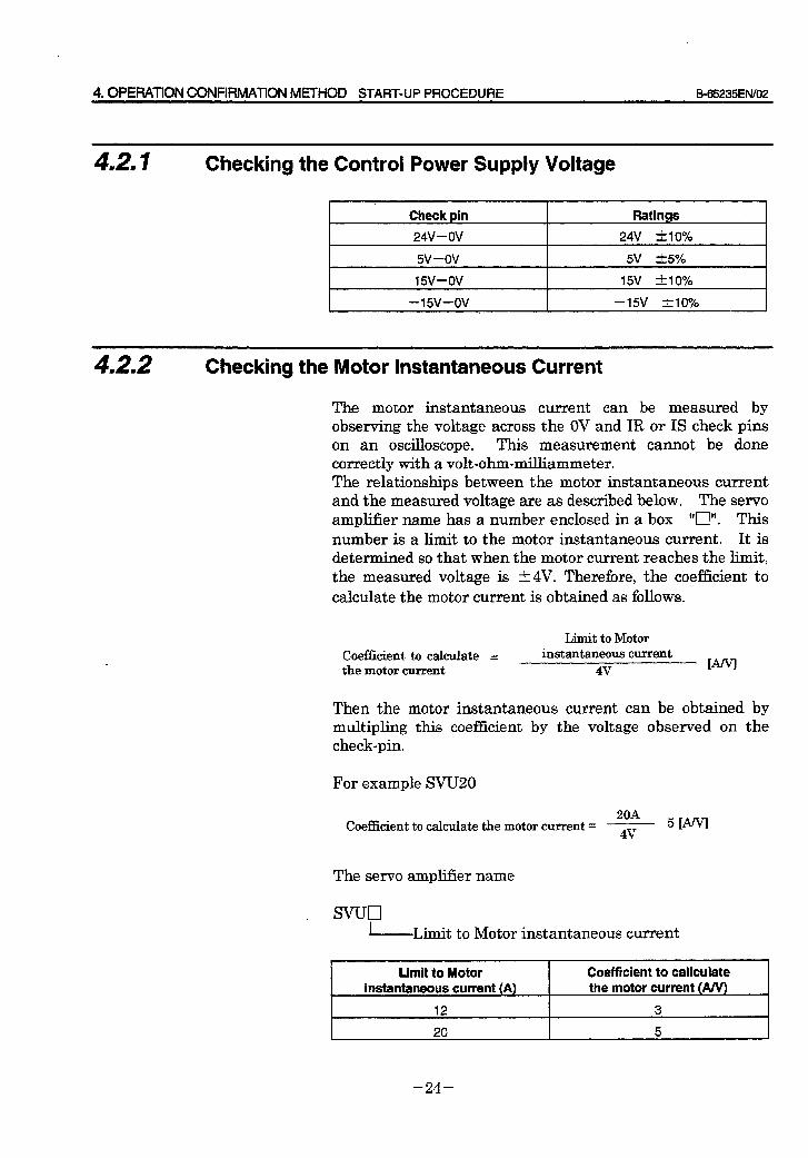
4.OPEF?ATlON CONFRMATION METHOD START-UP PROCEDURE B-65235ENiO2
4,3. I Checking the Control Power Supply Voltage
Check pin
24V-OV
Ratings
24V &IO%
5V-OV 5V t5%
I5V-ov 15v tlo%
I --15v-ov 1 -15v &IO% 1
4.2.2 Checking the Motor Instantaneous Current
The motor instantaneous current can be measured by observing the voltage across the OV and IR or IS check pins on an oscilloscope. This measurement cannot be done correctly with a volt-ohm-milliammeter. The relationships between the motor instantaneous current and the measured voltage are as described below. The servo amplifier name has a number enclosed in a box “n”. This number is a limit to the motor instantaneous current. It is determined so that when the motor current reaches the limit, the measured voltage is t4V. Therefore, the coefficient to calculate the motor current is obtained as follows.
Coefficient to calculate = the motor current
Limit to Motor instantaneous current
4v
Then the motor instantaneous current can be obtained by multipling this coefficient by the voltage observed on the check-pin.
For example SVUZO
20A Coefficient to calculate the motor current = 7 5 WV
The servo ampl.iCer name
, svucl -Limit to Motor instantaneous current
-~~ Limit to Motor
instantaneous current (A)
12
Coefficient to caliculate the motor current (A/V)
3
- 24 -
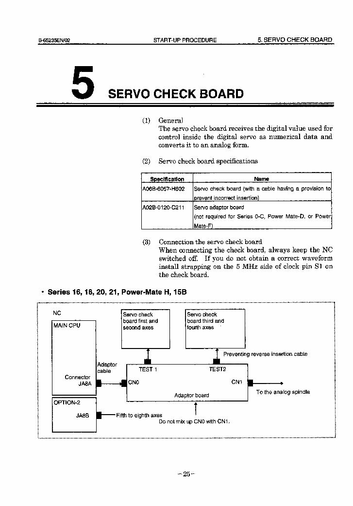
B65235ENl02 START-UP PROCEDURE 5. SERVO CHECK BOARD
5 SERVO CHECK BOARD
(1) General The servo check board receives the digital value used for control inside the digital servo as numerical data and converts it to an analog form.
(2) Servo check board specifications
Specification Name
A06B-60570H602 Servo check board (with a cable having a provision to
prevent incorrect insertion)
AOZB-0120~C211 Servo adaptor board
(not required for Series O-C, Power Mate-D, or Power
Mate-F)
(3) Connection the servo check board When connecting the check board, always keep the NC switched off. If you do not obtain a correct waveform install strapping on the 5 MHz side of clock pin Sl on the check board.
l Series 16,18,20,21 y Power-Mate H, 158
i : : : : : NC : : Servo check : . .
MAIN CPU
Servo check board first and second axes
board third and fourth axes .
I ; . : .
Connector JA8A
Preventing reverse insertion cable
Adaptor cable TEST 1 TEST2
CNO CNI )
I Adaptor board To the analog spindle
Fifth to eighth axes Do not mix up CNO with CNI .
: : . : : : : . : : : : : : : : : : : i ; . . : : : . . : : . : : . : . : . : : : : . : . : :
- 25 -
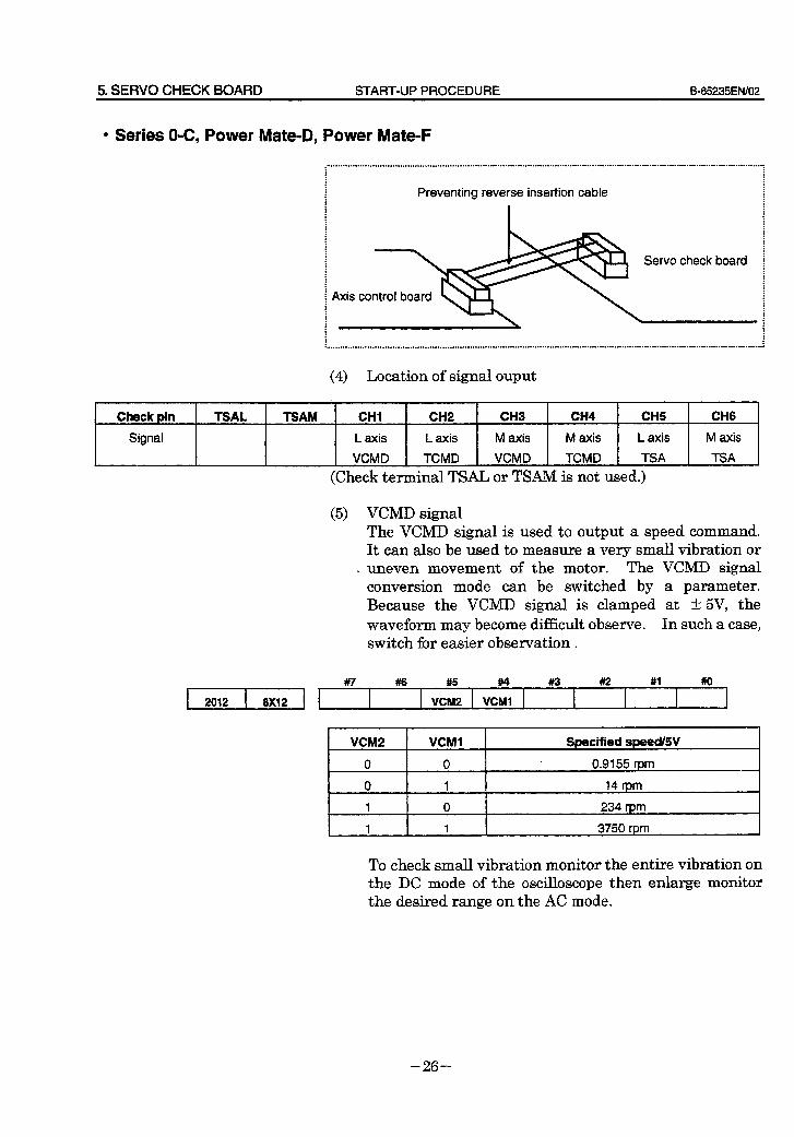
5. SERVO CHECK BOARD START-UP PROCEDURE B-65235ENl02
l Series O-C, Power Mate-D, Power Mate-F
.“...“‘....‘...........................~..~...........................................................................-..-............................-......-...-.............:
: : . .
: .
: :
: :
: : . : Preventing reverse insertion cable : : : : : : : : : : : : . : : . : : : :
Servo check board i : : : : . : : . . : : : : : : : : : . . : : : : ..r..............................~......~......................*.................-.............................-.................-...............-...-..........~.......--......,
(4) Location of signal ouput
Check pin
Signal
TSAL TSAM CHI CH2 CH3 CH4 CHS CH6
L axis L axis M axis M axis L axis M axis
VCMD TCMD VCMD TCMD TSA TSA
(Check terminal TSAL or TSAM is not used.)
(5) VCMD signal The VCMD signal is used to output a speed command. It can also be used to measure a very small vibration or
. uneven movement of the motor. The VCMD signal conversion mode can be switched by a parameter. Because the VCMD signal is clamped at t 5V, the waveform may become difficult observe. In such a case, switch for easier observation .
2012 8X12
#7 #I6 #5 #4 #I3 ##2 #I #o
VCM2 VCMl I
VCM2 VCMI
0 0
0 1
Specified speed/W
0.9155 rpm
14 rpm
1 0 234 rpm
1 1 I 3750 rpm
To check small vibration monitor the entire vibration on the DC mode of the oscilloscope then enlarge monitor the desired range on the AC mode.
- 26 -
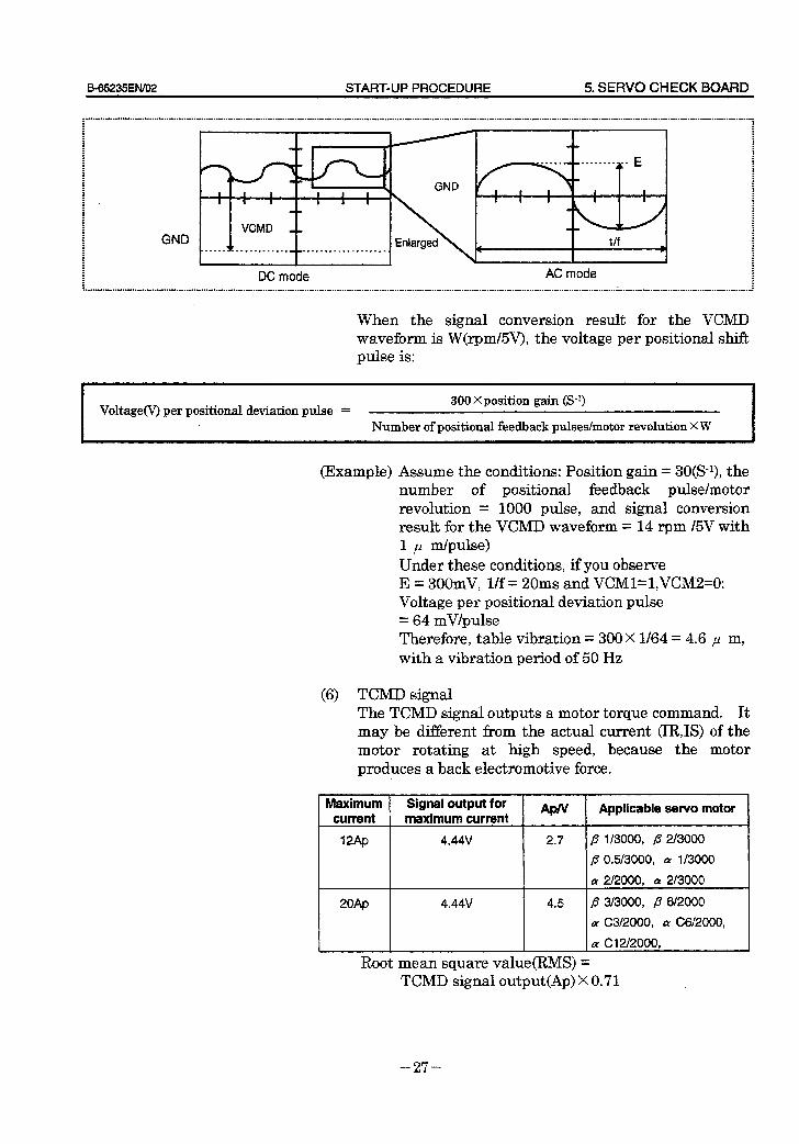
B_65235EN/O2 START-UP PROCEDURE 5. SERVO CHECK BOARD
DC mode AC mode
When the signal conversion result for the VCMD waveform is W(rpm&V), the voltage per positional shift pulse is:
Voltage(V) per positional deviation pulse = 300 X position gain (S-l)
Number of positional feedback pulses/motor revolution X W
(Example) Assume the conditions: Position gain = 3O(S-9, the number of positional feedback pulse/motor revolution = 1000 pulse, and signal conversion result for the VCMD waveform = 14 rpm l5V with 1 p m/pulse) Under these conditions, if you observe E = 300mV, l/f = 20ms and VCMl=l,VCM2=0: Voltage per positional deviation pulse = 64 mV/pulse Therefore, table vibration = 300X l/64 = 4.6 p m, with a vibration period of 50 Hz
(6) TCMD signal The TCMD signal outputs a motor torque command. It may be different from the actual current (IRIS) of the motor rotating at high speed, because the motor produces a back electromotive force.
20Ap 4.44v
I I
n A 1
2.7 fi 1/3000, p 2l3000
fi 0.5/3000, QI l/3000
cy 2J2000, cy 2/3000
4.5 fl 3/3000, p 6l2000
a C3/2000, a C6/2000,
a CWZOOO,
Root mean square value(RMS) = TCMD signal output X 0.7 1
APN I
Applicable servo motor I
- 27 -
5. SERVO CHECK BOARD START-UP PROCEDURE B-65235EN/02
(7) TSA signal The TSA signal outputs a motor speed.
Signal conversion 3750 rpm / 5V
If the TSA signal is clamped at 5V, check whether the following parameter is specified.
l
2115 - Not used k
Be sure to specify 0.
- 28 -

B_65235EN/O2 TROUBLESHOOTING AND RECOVERY 1. OVERVIEW
1 OVERVIEW *
This part describes troubleshooting and recovery procedures. Each item should be carefully followed to find the cause of trouble and take necessary actions.
First, check the alarm No. (Servo tuning screen on the CNC) to find the cause of trouble by referring to Section 2. Second, take appropriate actions according to Section 3.
- 31 -

2. ALARM NUMBER AND BRIEF DESCRPTIONS TROUBLESHOOTING AND RECOVERY B-65235ElW02
ALARM NUMBER AND BRIEF DESCRIPTIONS
- 32 -
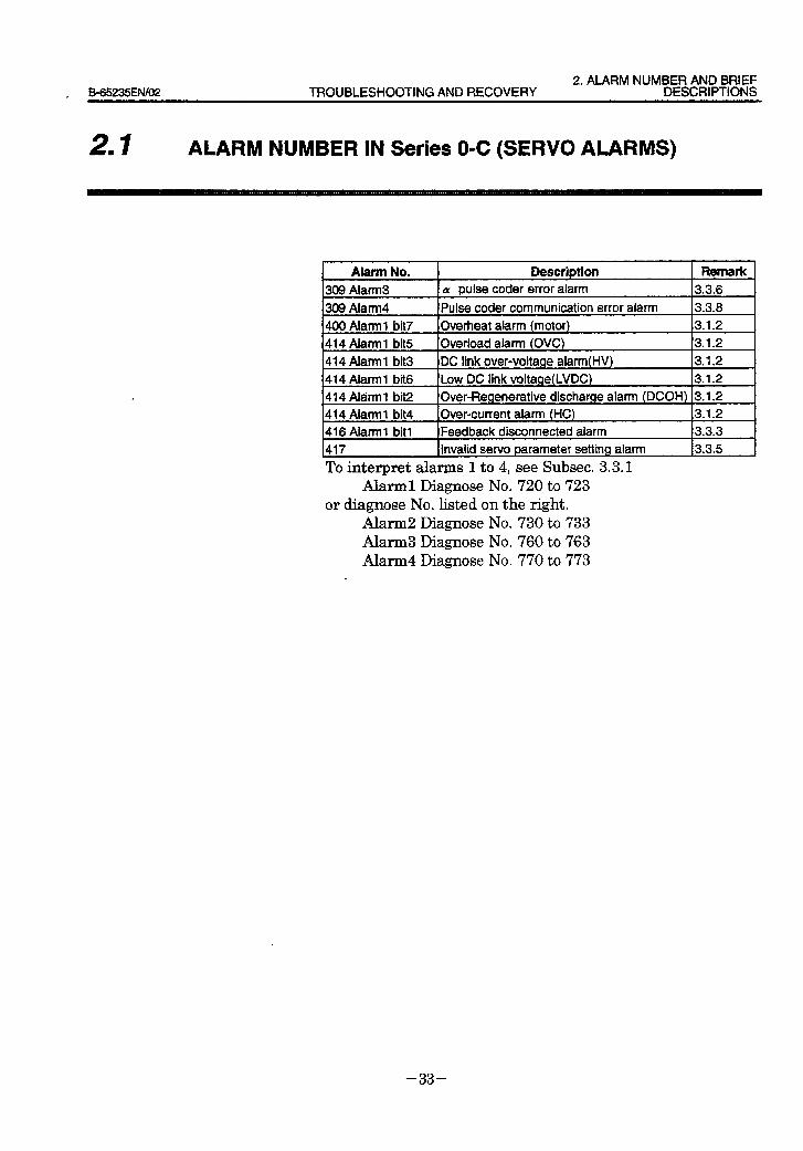
2. ALARM NUMBER AND BRIEF _ 8-65235EtWO2 TROUBLESHOOTING AND RECOVERY DESCRIPTIONS
21 I ALARM NUMBER IN Series O-C (SERVO ALARMS)
Alarm No. Description Remark
309 Alarm3 CY pulse coder error alarm 3.3.6
309 Alarm4 Pulse coder communication error alarm 3.3.8
400 Alarm1 bit7 Overheat alarm (motor) 3.1.2
414 Alarm 1 bit5 Overload alarm (OVC) 3.1.2
414 Alarm 1 bit3 DC link over-voltage alarm 3.1.2
414 Alarm1 bit6 Low DC link voltage(LVDC) 3.1.2
414 Alarm1 bit2 Over-Regenerative discharge alarm (DCOH) 3.1.2
414 Alarm 1 bit4 Over-current alarm (HC) 3.1.2
416 Alarm I bit1 Feedback disconnected alarm 3.3.3
417 Invalid servo parameter setting alarm 3.3.5
To interpret alarms 1 to 4, see Subset. 3.3.1 Alarm1 Diagnose No. 720 to 723
or diagnose No. listed on the right. Alarm2 Diagnose No. 730 to 733 Alarm3 Diagnose No. 760 to 763 Alarm4 Diagnose No. 770 to 773
.
- 33 -
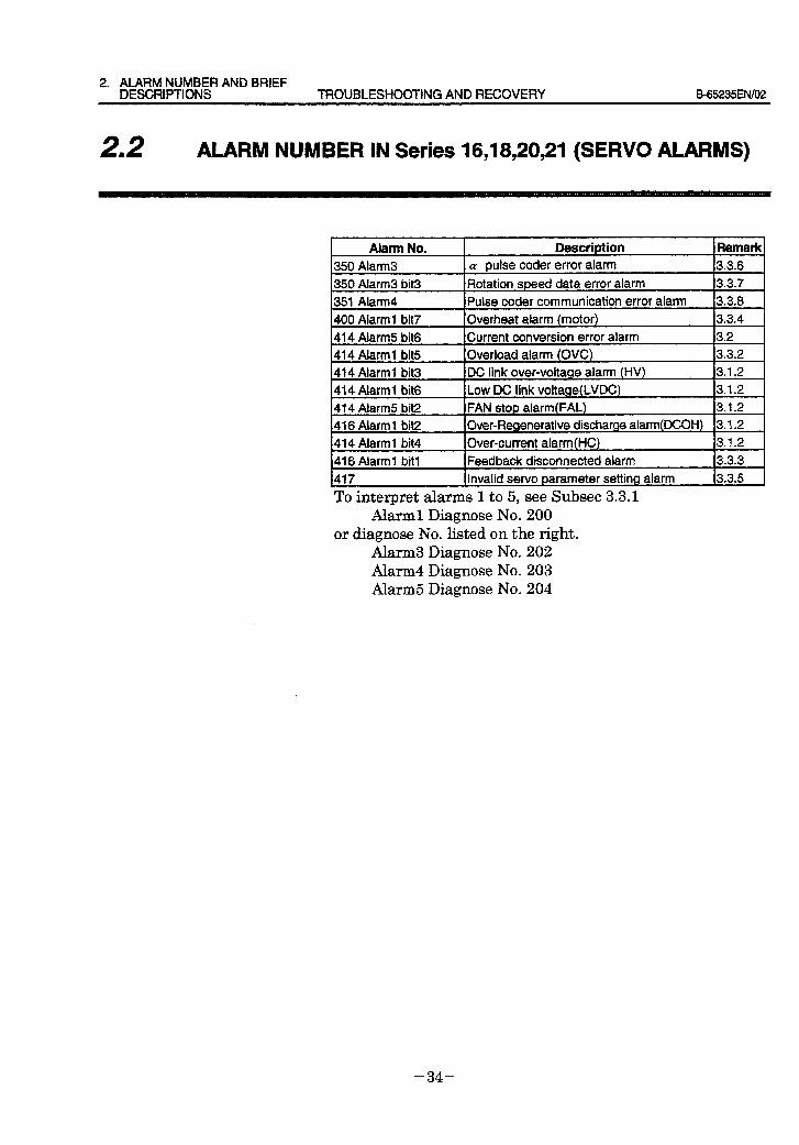
2. ALARM NUMBER AND BRIEF DESCRIPTIONS TROUBLESHOOTING AND RECOVERY B65235EN/O2
22 I ALARM NUMBER IN Series 16,18;20,21 (SERVO ALARMS)
Alarm No. Description 350 Alarm3 CY pulse coder error alarm
Remark 3.3.6
350 Alarm3 bit3 Rotation speed data error alarm 3.3.7
351 Alarm4 Pulse coder communication error alarm 3.3.8
400 Alarm1 bit7 Overheat alarm (motor) 3.3.4
414 Alarm5 bit6 Current conversion error alarm 3.2
414 Alarm1 bit5 Overload alarm (OVC) 3.3.2
414 Alarm 1 bit3 DC link over-voltage alarm (HV) 3.1.2
414 Alarm I bit6 Low DC link voltage(LVDC) 3.1.2
414 Alarm5 bit2 FAN stop alarm (FAL) 3.1.2
416 Alarm1 bit2 Over-Regenerative discharge alarrn(DCOH) 3.1.2
414 Alarm 1 bit4 Over-current alarm 3.1.2
416 Alarm1 bit1 Feedback disconnected alarm 3.3.3
417 Invalid servo parameter setting alarm 3.3.5
To interpret alarms 1 to 5, see Subset 3.3.1 Ahml Diagnose No. 200
or diagnose No. listed on the right. Alarm3 Diagnose No. 202 Alarm4 Diagnose No. 203 Alarm5 Diagnose No. 204
- 34 -
3. TROUBLESHOOTING AND 565235EIVO2 TROUBLESHOOTING AND RECOVERY RECOVERY PROCEDURES
3 TROUBLESHOOTING AND RECOVERY PROCEDURES
- 35 -
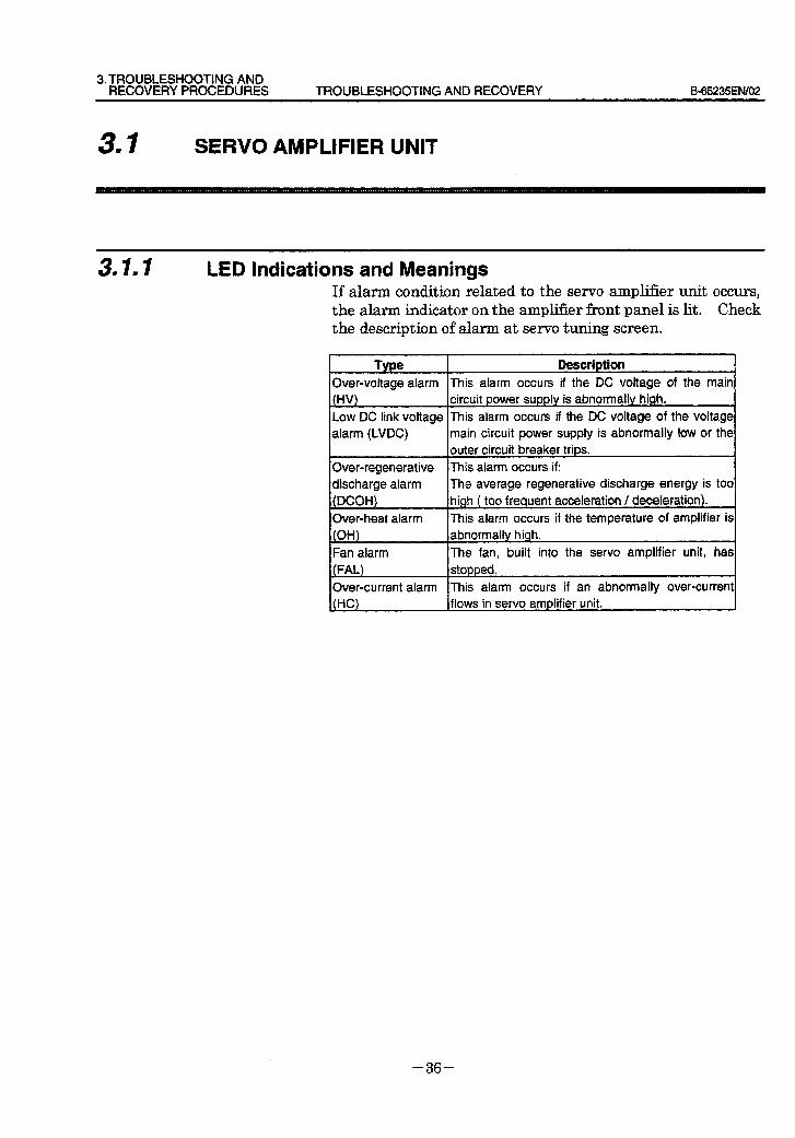
3:TROUBLESHOOTING AND RECOVERYPROCEDURES TROUBLESHOOTING AND RECOVERY Eb65235EN/02
31 I SERVO AMPLIFIER UNIT
3.1.1 LED Indications and Meanings If alarm condition related to the servo amplifier unit occurs, the alarm indicator on the amplifier front panel is lit. Check the description of alarm at servo tuning screen.
Type Description 4 Over-voltage alarm (HW
Low DC link voltage
alarm (LVDC)
Over-regenerative
discharge alarm
(DCOH)
Over-heat alarm (OH)
Fan alarm The fan, built into the servo amplifier unit, has
(FAL) stopped.
Over-current alarm This alarm occurs if an abnormally over-current (HC) flows in servo amplifier unit.
This alarm occurs if the DC voltage of the main circuit power supply is abnormally high.
This alarm occurs if the DC voltage of the voltage main circuit power supply is abnormally low or the
outer circuit breaker trips.
This alarm occurs if:
The average regenerative discharge energy is too
high ( too frequent acceleration / deceleration).
This alarm occurs if the temperature of amplifier is abnormally high.
- 36 -
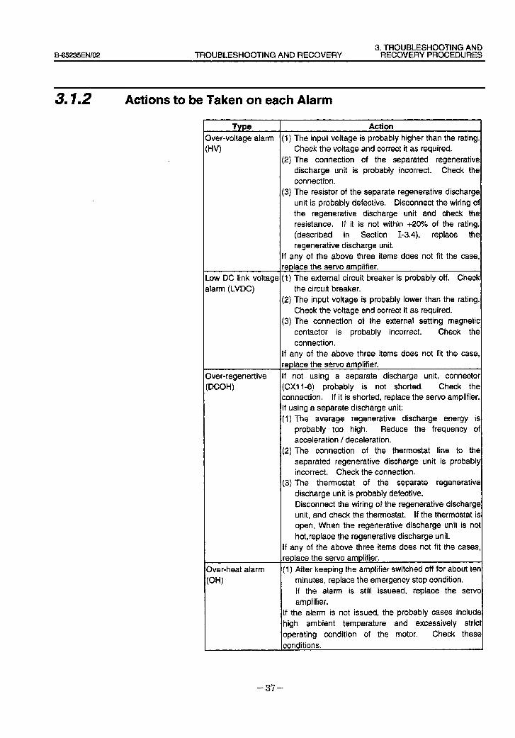
3. TROUBLESHOOTING AND B-65235EN/O2 TROUBLESHOOTING AND RECOVERY RECOVERY PROCEDURES
3.1.2 Actions to be Taken on each Alarm
Twe
M+voltage alarm
:HV)
_ow DC link voltage (1) The external circuit breaker is probably off. Check alarm (LVDC) the circuit breaker.
3ver-regenertive :DCOH)
Dver-heat alarm
(OHI
Action I (1) The input voltage is probably higher than the rating.
Check the voltage and correct it as required. (2) The connection of the separated regenerative
discharge unit is probably incorrect. Check the
connection. (3) The resistor of the separate regenerative discharge
unit is probably defective. Disconnect the wiring of the regenerative discharge unit and check the resistance. If it is not within +20% of the rating.
(described in Section I-3.4), replace the regenerative discharge unit.
If any of the above three items does not fit the case, replace the servo amplifier.
(2) The input voltage is probably lower than the rating. Check the voltage and correct it as required.
(3) The connection of the external setting magnetic
contactor is probably incorrect. Check the
connection. If any of the above three items does not fit the case, replace the servo amplifier.
If not using a separate discharge unit, connector (CXI I-6) probably is not shorted. Check the connection. If it is shorted, replace the servo amplifier. If using a separate discharge unit:
(1)
(2)
(3)
The average regenerative discharge energy is probably too high. Reduce the frequency of acceleration / deceleration.
The connection of the thermostat line to the separated regenerative discharge unit is probably incorrect. Check the connection. The thermostat of the separate regenerative discharge unit is probably defective. Disconnect the wiring of the regenerative discharge unit, and check the thermostat. If the thermostat is open, When the regenerative discharge unit is not
hot,replace the regenerative discharge unit.
If any of the above three items does not fit the cases,1
replace the servo amplifier.
(1) After keeping the amplifier switched off for about ten
minutes, replace the emergency stop condition.
If the alarm is still issueed, replace the servo amplifier.
If the alarm is not issued, the probably cases include high ambient temperature and excessively strict
operating condition of the motor. Check these
conditions.
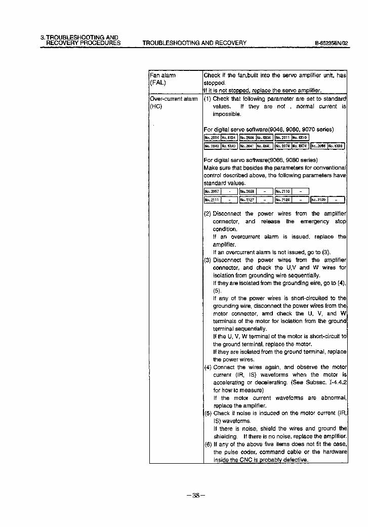
3.TROUBLESHOOTlNG AND RECOVERY PROCEDURES TROUBLESHOOTING AND RECOVERY B65235EfWO2
=an alarm Check if the fan,built into the servo amplifier unit, has IFAL) stopped.
If it is not stopped, replace the servo amplifier.
3ver-current alarm (1) Check that following parameter are set to standard
:HC) values. If they are not , normal current is impossible.
For digital servo software(9046, 9060, 9070 series) ~1~1~1 No 2004 No 8X04 No 2006 No 8X06 No 2011 No 8X10
~I~~~J No 2040 No 8X40 No 2041 No 8X41 No 2074 No 8X74 No 2098 No 8X98
For digital servo software(9066, 9080 series) Make sure that besides the parameters for conventional control described above, the following parameters have
standard values. )No.l_lI[
~I-IJNo.2127~lJINo.l
(2) Disconnect the power wires from the amplifier
connector, and release the emergency stop condition. If an overcurrent alarm is issued, replace the
amplifier.
If an overcurrent alarm is not issued, go to (3). (3) Disconnect the power wires from the amplifier
connector, and check the U,V and W wires for isolation from grounding wire sequentially. If they are isolated from the grounding wire, go to (4),
(5) . If any of the power wires is short-circuited to the
grounding wire, disconnect the power wires from the motor connector, amd check the U, V, and W terminals of the motor for isolation from the ground terminal sequentially. If the U, V, W terminal of the motor is short-circuit tc
the ground terminal, replace the motor. If they are isolated from the ground terminal, replace the power wires.
(4) Connect the wires again, and observe the motor current (IR, IS) waveforms when the motor is
accelerating or decelerating. (See Subset. I-4.4.2
for how to measure) If the motor current waveforms are abnormal,
replace the amplifier. (5) Check if noise is induced on the motor current (IR
IS) waveforms.
If there is noise, shield the wires and ground the
shielding. If there is no noise, replace the amplifier
(6) If any of the above five items does not fit the case
the pulse coder, command cable or the hardware inside the CNC is probably defective.
- 38 -
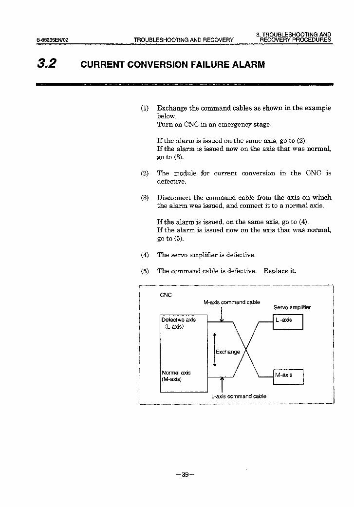
3. TROUBLESHOOTING AND B-65235ENi02 TROUBLESHOOTING AND RECOVERY RECOVERY PROCEDURES
32 I CURRENT CONVERSION FAILURE ALARM
Exchange the command cables as shown in the example below. Turn on CNC in an emergency stage.
If the alarm is issued on the same axis, go to (2). If the alarm is issued now on the axis that was normal, go to (3).
The module for current conversion in the CNC is defective.
Disconnect the command cable from the axis on which the alarm was issued, and connect it to a normal axis.
If the alarm is issued, If the alarm is issued go to (5).
The servo amplifier is defective.
on the same axis, go to (4). now on the axis that was normal,
The command cable is defective. Replace it.
,.........................................................._..........__.~...~................_..__.~..........~..~..................~...-...............~...................-... : : E : : : : CNC : .
i : : : : : : : : : : : : . : : : : . : : : : . : : : . : . : : . . : : : : . : : : : : : : . : : : :
M-axis command cable Servo amplifier
Defective axis V
~ 1
L -axis (L-axis) ,
I
Exchange
Normal axis (M-axis)
M-axis m
c
L-axis command cable
- 39 -
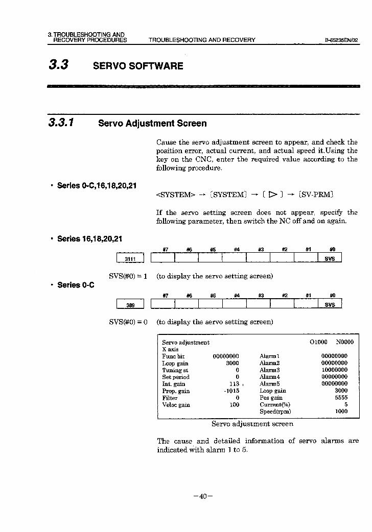
3. TROUBLESHOOTING AND RECOVERY PROCEDURES TROUBLESHOOTING AND RECOVERY B-65235ElW02
33 I SERVO SOFTWARE
3.3. I Servo Adjustment Screen
Cause the servo adjustment screen to appear, and check the position error, actual current, and actual speed it.Using the key on the CNC, enter the required value according to the following procedure.
l Series O-C,1 6,18,20,21 <SYSTEM> - [SYSTEM) - ( I> ) - [SV-PRM)
If the servo setting screen does not appear, specify the following parameter, then switch the NC off and on again.
l Series 16,18,20,21
l Series O-C
, 3,,, 1 #7 #6 #5 #4 #3 #I2 #1
SVS(#O) = 1 (to display the servo setting screen)
, 389 , #7 ##6 #5 #4 #I3 #2 #l ,,” ,
SVS(#O) = 0 (to display the servo setting screen)
- Servo adjustment 01000 NO000 XaxiS
Func bit 00000000 Alarm1 00000000 Loop gain 3000 Alarm2 00000000 Tuning st 0 Alarm3 10000000 Set period 0 . Alarm4 00000000 ht. gain 113 I Alarm5 00000000 Prop. gain -1015 Loop gain 3000 l?ilter 0 Pos gain 5555 Veloc gain 100 Current(%) 5
Speedhm) 1000
Servo adjustment screen
The cause and detailed information of servo alarms are indicated with alarm 1 to 5.
- 40 -
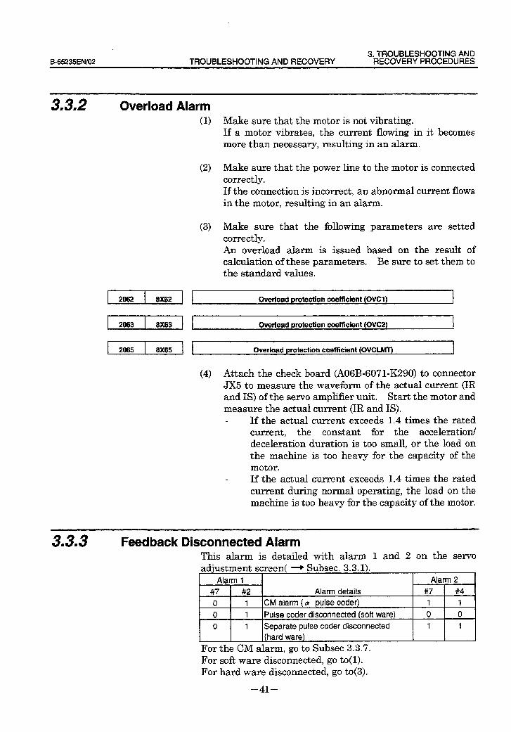
3. TROUBLESHOOTING AND B-65235EiW02 TROUBLESHOOTING AND RECOVERY RECOVERY PROCEDURES
3.3.2 Overload Alarm
2062 8X62
2063 8X63
2065 8X65 Overload protection coefficient (OVCLMT)
(1) Make sure that the motor is not vibrating. If a motor vibrates, the current flowing in it becomes more than necessary, resulting in an alarm.
(2) Make sure that the power line to the motor is connected correctly. If the connection is incorrect, an abnormal current flows in the motor, resulting in an alarm.
(3) Make sure that the following parameters are setted correctly. An overload alarm is issued based on the result of calculation of these parameters. Be sure to set them to the standard values.
l
Overload protection coefficient (OVCl)
Overload protection coefficient (OVC2)
(4) Attach the check board (A06B-6071X290) to connector JX5 to measure the waveform of the actual current (IR and IS) of the servo amplifier unit. Start the motor and measure the actual current (IR and IS).
If the actual current exceeds 1.4 times the rated current, the constant for the acceleration/ deceleration duration is too small, or the load on the machine is too heavy for the capacity of the motor. If the actual current exceeds 1.4 times the rated current during normal operating, the load on the machine is too heavy for the capacity of the motor.
3.3‘3 Feedback Disconnected Alarm This alarm is detailed with alarm 1 and 2 on the servo adjustment screen( -+ Subset. 3.3.1).
Alarm 1 Alarm 2
#7 #2 Alarm details #7 #4
0 1 CM alarm ( LY pulse coder) 1 1
0 1 Pulse coder disconnected (soft ware) 0 0 ,
0 1 Separate pulse coder disconnected 1 1
(hard ware)
For the CM alarm, go to Subsec 3.3.7. For soft ware disconnected, go to(l). For hard ware disconnected, go to(3).
- 41 -
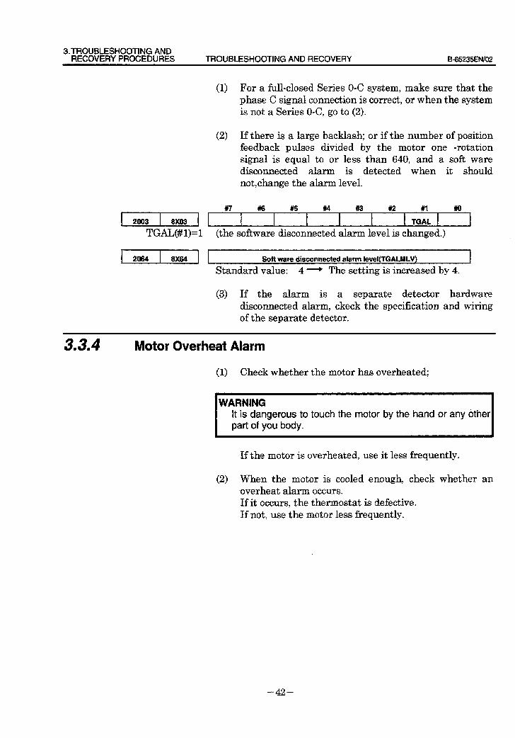
3.TROUBLESHOOTING AND RECOVERY PROCEDURES TROUBLESHOOTING AND RECOVERY B-65235EfV02
2003 8X03
TGAL(#l)=l
2064 8X64
(1) For a Ml-closed Series O-C system, make sure that the phase C signal connection is correct, or when the system is not a Series O-C, go to (2).
(2) If there is a large backlash; or if the number of position feedback pulses divided by the motor one -rotation signal is equal to or less than 640, and a soft ware disconnected alarm is detected when it should notchange the alarm level.
#7 #6 #5 #4 #3 #2 #I #lo
TGAL
(the software disconnected alarm level is changed.)
Soft ware disconnected alarm level(TGALMLV)
Standard value: 4 - The setting is increased by 4.
(3) If the alarm is a separate detector hardware disconnected alarm, ckeck the specification and wiring of the separate detector.
3.3.4 Motor Overheat Alarm
(1) Check whether the motor has overheated;
WARNING It is dangerous to touch the motor by the hand or any other part of you body.
If the motor is overheated, use it less frequently.
(2) When the motor is cooled enough, check whether an xoverheat alarm occurs. If it occurs, the thermostat is defective. If not, use the motor less frequently.
- 42 -
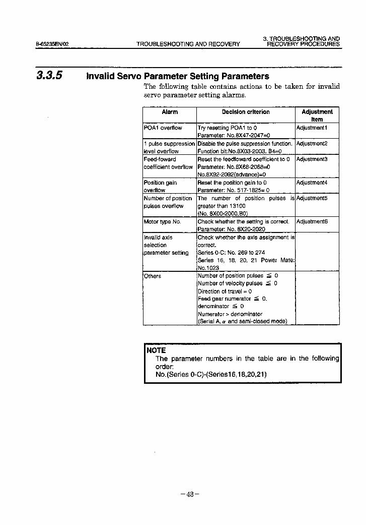
3. TROUBLESHOOTING AND B-65235EN/OZ TROUBLESHOOTING AND RECOVERY RECOVERYPROCEDURES
3m3.5 Invalid Servo Parameter Setting Parameters The following table contains actions to be taken for invalid servo parameter setting alarms.
Alarm Decision criterion Adjustment item
POAI overflow Try resetting POAI to 0 Parameter: No.8X47-2047=0
Adjustment 1
I pulse suppression Disable the pulse suppression function. Adjustment2 level overflow Function bit:No.8X03-2003, B4=0
Feed-foward Reset the feedfoward coefficient to 0 Adjustment3 coefficient overflow Parameter: No.8>(68-206830
No.8X92-2092(advance)=O
Position gain Reset the position gain to 0 Adjustment4
overflow Parameter: No. 517-I 825= 0
Number of position The number of position pulses is Adjustment5
pulses overflow greater than 13100 (No. 8x0002000,BO)
Motor type No. Check whether the setting is correct. Adjustment6 Parameter: No. 8X20-2020
lnval id axis Check whether the axis assignment is selection correct. parameter setting Series O-C: No. 269 to 274
Series 16, 18, 20, 21 Power Mate:
No. 1023
Others Number of position pulses 5 0 Number of velocity pulses ( 0
Direction of travel = 0 Feed gear numerator 5 0, denominator ( 0
Numerator > denominator (Serial A. ti and semi-closed mode)
NOTE The parameter numbers in the table are in the following order: No.(Series O-C)-(Series16,18,20,21)
- 43 -
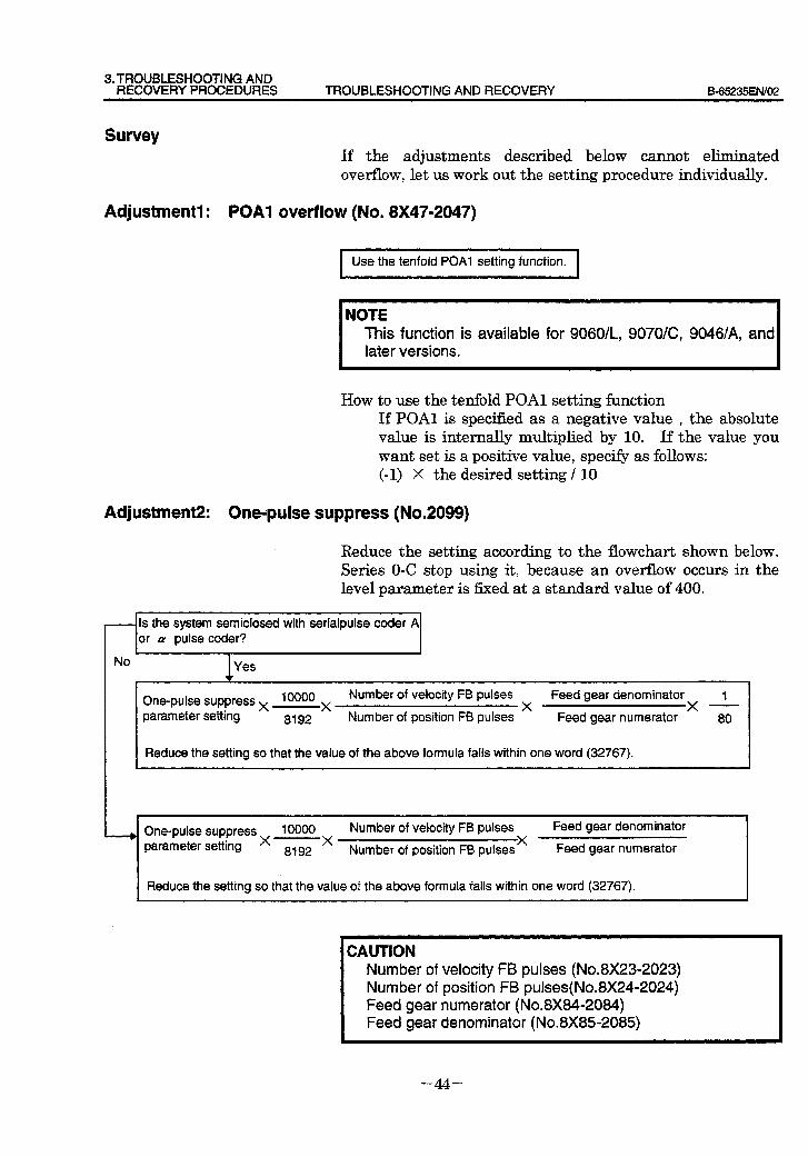
3. TROUBLESHOOTING AND RECOVERY PROCEDURES TROUBLESHOOTING AND RECOVERY B-65235ENf02
Survey If the adjustments described below cannot eliminated overflow, let us work out the setting procedure individually.
Adjustment1 : POAl overflow (No. 8X47-2047)
Use the tenfold POAI setting function.
NOTE This function is available for 9060/L, 9070/C, 9046/A, and later versions.
How f to use the tenfold POAl setting function If POAl is specified as a negative value , the absolute value is internally multiplied by 10. If the value you want set is a positive value, specify as follows: (-1) X the desired setting / 10
AdjustmeW: One-pulse suppress (No.2099)
Reduce the setting according to the flowchart shown below. Series O-C stop using it, because an overflow occurs in the level parameter is fixed at a standard value of 400.
Is the system semiclosed with serialpulse coder A of a pulse coder? W
No I Yes
One-pulse suppress x 10000 x Number of velocity FB pulses x Feed gear denominator x 1
parameter setting 8192 Number of position FB pulses Feed gear numerator 80
Reduce the setting so that the value of the above formula fails within one word (32767).
--~ One-pulse suppress x 10000 x Number of velocity FB pulses x Feed gear denominator
8192 Number of position FB pulses Feed gear numerator
I Reduce the setting so that the value of the above formula falls within one word (32767). I
CAUTION Number of velocity FB pulses (No.8X23-2023) Number of position FB pulses(No.8X24-2024) Feed gear numerator (No.8X84-2084) Feed gear denominator (No.8X852085)
- 44 -
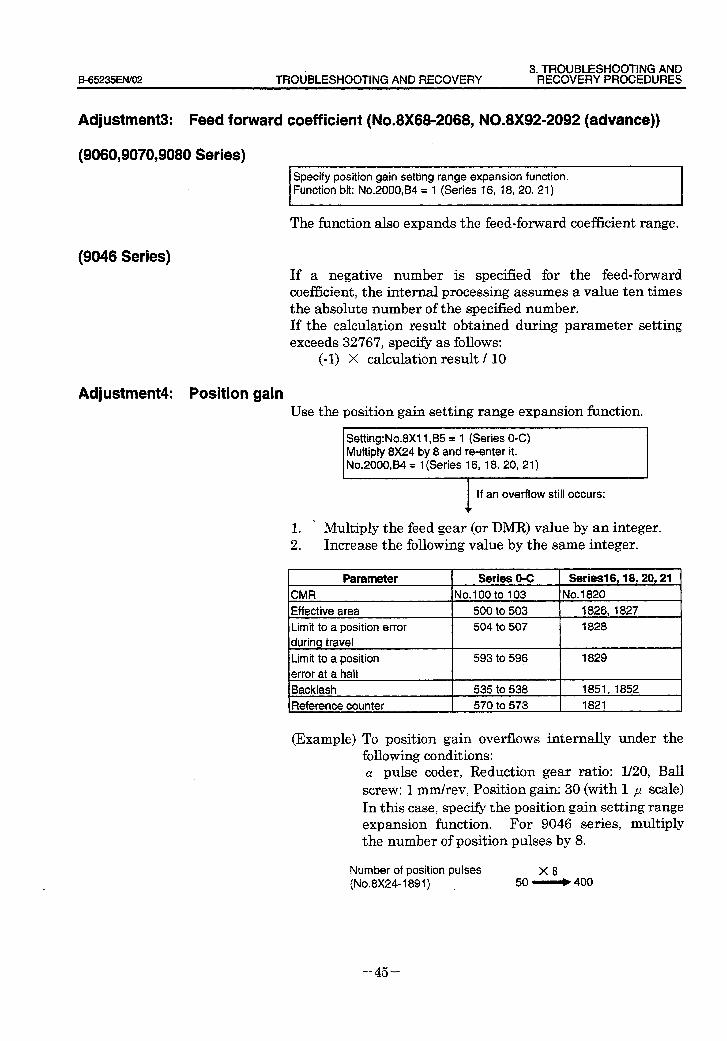
3. TROUBLESHOOTING AND B_65235EN/02 TROtiBLESHOOTlNG AND RECOVERY RECOVERY PROCEDURES
AcJjustment3: Feed forward coefficient (No.8X68-2068, N0.8X92=2092 (advance))
(9060,9070,9080 Series) Specify position gain setting range expansion function. Function bit: No.ZOOO,B4 = 1 (Series 16, 18, 20, 21)
The fknction also expands the feed-forward coefficient range.
(9046 Series) If a negative number is specified for the feed-forward coefficient, the internal processing assumes a value ten times the absolute number of the specified number. If the calculation result obtained during parameter setting exceeds 32767, specify as follows:
(-1) X calculation result / 10
Adjustment4: Position gain Use the position gain setting range expansion function.
Setting:No.8Xll ,B5 = 1 (Series O-C) Multiply 8X24 by 8 and re-enter it. No.2000,84 = 1 (Series 16, 18, 20, 21)
If an overflow still occurs: f
. 1 . Multiply the feed gear (or DMRJ value by an integer. 2 . Increase the following value by the same integer.
Parameter CMR
Effective area
Limit to a position error
during travel
Limit to a position
error at a halt
Backlash
Reference counter
Series 0-C Seriesl6,18,20,21 No.100 to 103 No. 1820
500 to 503 1826,1827
504 to 507 1828
593 to 596 1829
535 to 538 1851,1852
570 to 573 1821
(Example) To position gain overflows internally under the following conditions: CY pulse coder, Reduction gear ratio: l/20, Ball screw: 1 mm/rev, Position gain: 30 (with 1 p scale) In this case, specify the position gain setting range expansion function. For 9046 series, multiply the number of position pulses by 8,
Number of position pulses X8 (No.8X24-1891) 50 - 400
- 45 -
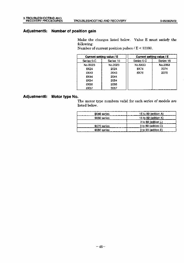
3. TROUBLESHOOTING AN0 RECOVERY PROCEDURES TROUBLESHOOTING AN0 RECOVERY B65235EfW02
Adjustment5 Number of position gain
Make the changes listed below. Value E must satisfy the following: Number of current position pulses / E < 13100.
Current setting value / E Current setting value / E Series O-C Series 16 Series O-C Series 16
No.8X23 No.2023 No.8X53 No.2053
8X24 2024 8X74 2074
8X43 2043 8X76 2076
Adjustment& Motor type No. The motor type numbers valid for each series of models are listed below,
9046 series 15 to 89 (edition A)
9060 series 15 to 89 (edition K)
3 to 89 (edition L)
9070 series 3 to 89 (edition C)
9080 series 3 to 93 (edition E)
- 46 -
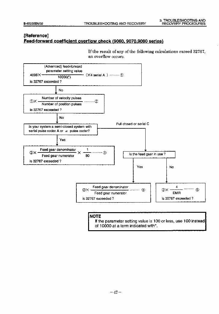
3. TROUBLESHOOTING AND B-65235EN/O2 TROUBLESHOOTING AND RECOVERY RECOVERY PROCEDURES
[Reference] Feed-forward coefficient overflow check ~9060,9070,9080 series)
If the result of any of the following calculations exceed 32767, an overflow occurs.
(Advanced) feed-forward parameter setting value
4096X 10000(i)
(X4 serial A ) -0------ 0
is 32767 exceeded ? t
NO w I
OX Number of velocity pulses
.--*-*-- Number of position pulses
0
is 32767 exceeded ?
No f Full closed or serial C
Is your system a semi-closed system with 1
I serial pulse coder A or CY pulse coder? 1
I Yes
Feed gear denominator 1 OX X .-, . . . . -...
Feed gear numerator 80 0
I is 32767 exceeded ?
@,
Yes No
1 OX
Feed gear denominator ..W.---- @
Feed gear numerator
I is 32767 exceeded ?
4 OX
. . . .._I. 0
DMR
is 32767 exceeded ?
NOTE If the parameter setting value is 100 or less, use 100 instead of 10000 at a term indicated with*.
-47-
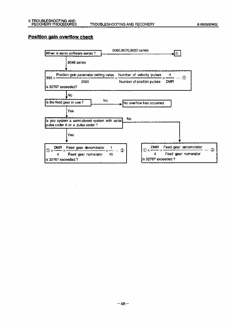
3. TROUBLESHOOTING AND RECOVERY PROCEDURES TROUBLESHOOTING AND RECOVERY B=65235EN/02
Position aain overflow check
. When is servo software series ?
9060,9070,9080 series
9046 series
I Position gain parameter setting value Number of velocity pulses 4 655 x X X - . . . 0
I 2000 Number of position pulses DMR
is 32767 exceeded?
ipulse coder A or a pulse coder ?
I Yes
1 No
Is the feed gear in use ?
Yes
No ) No overflow has occurred.
Is you system a semi-closed system with serial
0 DMR Feed gear denominator 1
X- X x- l ** Q
4 Feed gear numerator 10
is 32767 exceeded ?
DMR Feed gear denominator @x-----x . . . 0
4 Feed gear numerator is 32767 exceeded ?
- 48 -
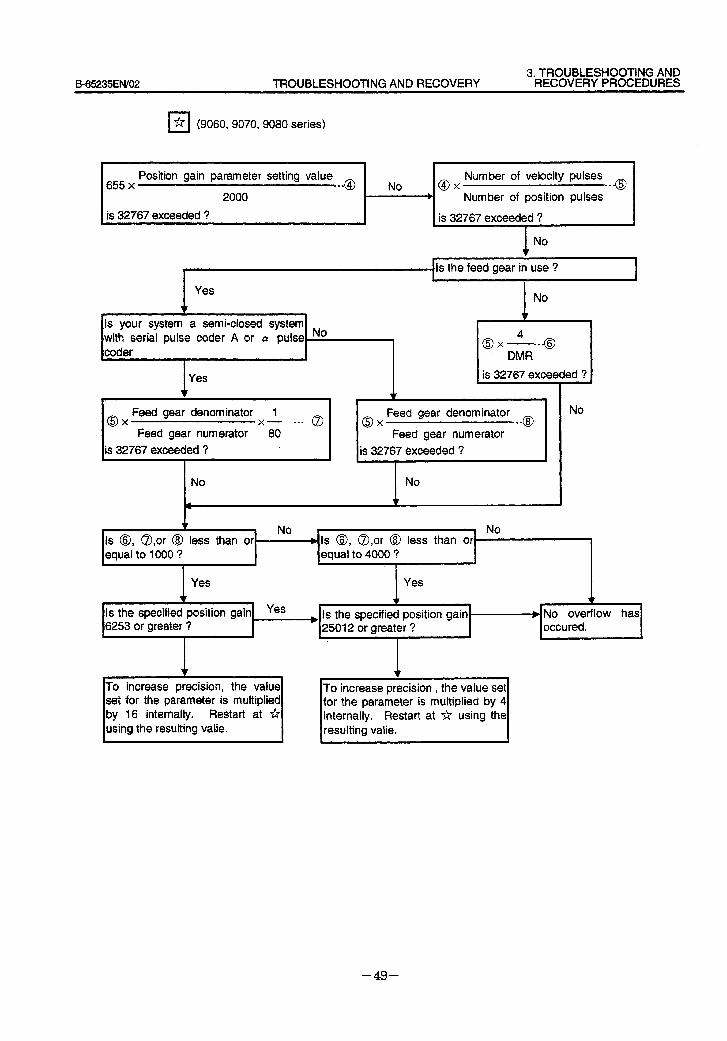
3. TROUBLESHOOTING AND B-65235ENi02 TROUBLESHOOTING AND RECOVERY RECOVERY PROCEDURES
q * (9060, 9070, 9080 series)
655 x Position gain parameter setting value
. . . @ 2000
is 32767 exceeded ?
No @ Number of velocity pulses
X . . . 0 Number of position pulses
is 32767 exceeded ?
No ‘I
Is the feed gear in use ? I I I
Yes
v Is your system a semi-closed system with serial pulse coder A or LY pulse No #
is 32767 exceeded ?
0 Feed gear denominator 1
X x- .-* @ 0 Feed gear denominator
X . . . @ Feed gear numerator 80 Feed gear numerator
is 32767 exceeded ? is 32767 exceeded ?
No I No
No
z No - No Is 8, a,or @ less than or b Is 8, a,or @ less than or I
equal to 1000 ? equal to 4000 ? / 4
Yes Yes
f \ v Is the specified position gain Yes
\ , b Is the specified position gain + No overflow has
6253 or greater ? 25012 or greater ? occured.
I I
Lr
* precision, the value
set for the parameter is multiplied by 16 internally. Restart at * using the resulting valie.
To increase precision , the value set For the parameter is multiplied by 4 internally. Restart at * using the resulting valie.
- 49 -
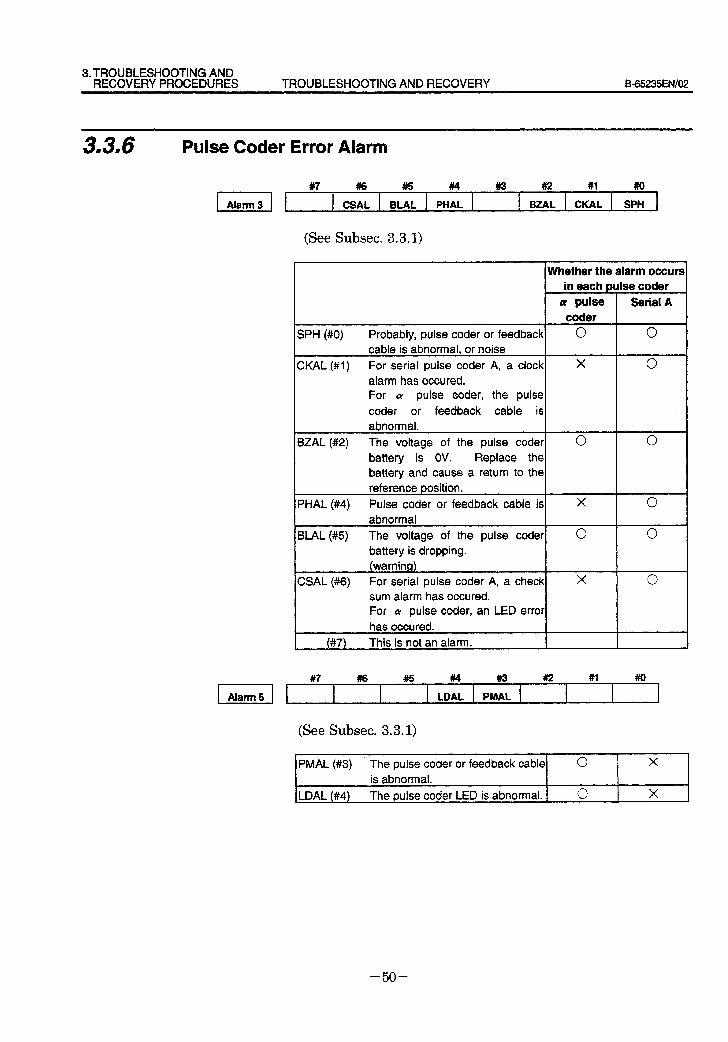
3. TROUBLESHOOTING AND RECOVERY PROCEDURES TROUBLESHOOTING AND RECOVERY B-65235EfW02
3.3m6 Pulse Coder Error Alarm
II #7 cs: EL: lw: * B,“, 2L sit
(See Subset. 3.3.1)
Whether the alarm occurs in each pulse coder
Q! pulse Serial A coder
SPH (#O) Probably, pulse coder or feedback 0 0 cable is abnormal, or noise
CKAL (#I) For serial pulse coder A, a clock X 0 alarm has occured. For a pulse coder, the pulse
coder or feedback cable is
abnormal.
BZAL (#2) The voltage of the pulse coder 0 0 battery is OV. Replace the
battery and cause a return to the reference position.
PHAL (#4) Pulse coder or feedback cable is X 0 abnormal
BLAL (#5) The voltage of the pulse coder 0 0 battery is dropping. (warning)
CSAL (#6) For serial pulse coder A, a check X 0 sum alarm has occured. For cz pulse coder, an LED error
has occured.
(#7) This is not an alarm.
#7 a6 #5 #4 #a #2 #l #o
El 4
LDAL PMAL _ l
(See Subset. 3.3.1)
PMAL (#3) The pulse coder or feedback cable 0 X
is abnormal.
LDAL (#4) The pulse coder LED is abnormal. 0 X
- 50 -
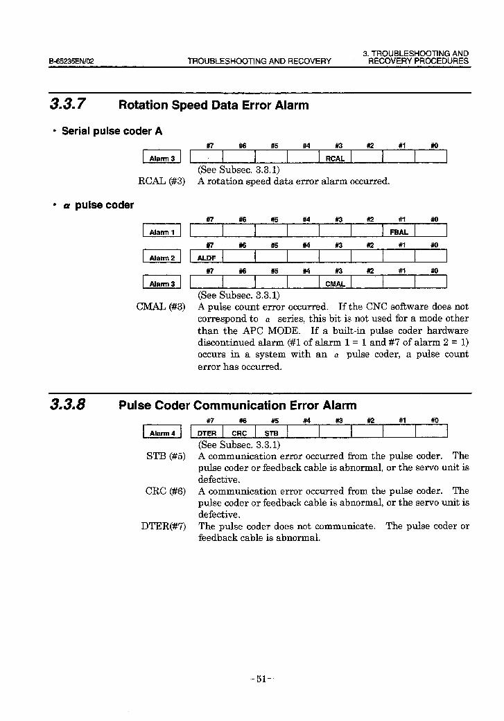
3. TROUBLESHOOTING AND B-65235EtWO2 TROUBLESHOOTING AND RECOVERY RECOVERY PROCEDURES
3.3.7 Rotation Speed Data Error Alarm
l Serial pulse coder A
I] : ” #6 #5 M F?c: * #I #I0 1 (See Subset. 3.3.1)
RCAL (#3) A rotation speed data error alarm occurred.
l a pulse coder
II IL #6 #5 WI #3 #2 #’ #o II . #7 #I6 #& #4 CMIII *. #’ #O
(See Subset. 3.3.1) CMAL (#3) A pulse count error occurred. If the CNC software does not
correspond to CY series, this bit is not used for a mode other than the APC MODE. If a built-in pulse coder hardware discontinued alarm (#l of alarm 1 = 1 and #I of alarm 2 = 1) occurs in a system with an CY pulse coder, a pulse count error has occurred.
3.3.8 Pulse Coder Communication Error Alarm
(See Subset. 3.3.1) STB (#5) A communication error occurred from the pulse coder. The
pulse coder or feedback cable is abnormal, or the servo unit is defective.
CRC (#6) A communication error occurred from the pulse coder. The pulse coder or feedback cable is abnormal, or the servo unit is defective.
DTER(#7) The pulse coder does not communicate. The pulse coder _or feedback cable is abnormal.
- 51 -

4. REPLACING THE FUSE TROUBLESHOOTING AND RECOVERY B_65235EN/02
4 REPLACING THE FUSE
WARNING
Replacement procedure
/
When replacing the fuse, keep the power supply switched off. Also make sure that the “CHARGING” LED (red) on the servo amplifier front panel is off.
1 Remove the plastic cover. 2 Replace the fuse near the connector (CXll) on the P.C.B.
(A20B-2100-0130 to -01311. (See APDendix A.1
Use Name Qty. Specification I For control power F6OO 1
I I
FANUC: A06B-6073X250
SUPPlY MAKER: LM32, DC48V, F3.2A
I 1 Daito
- 52 -
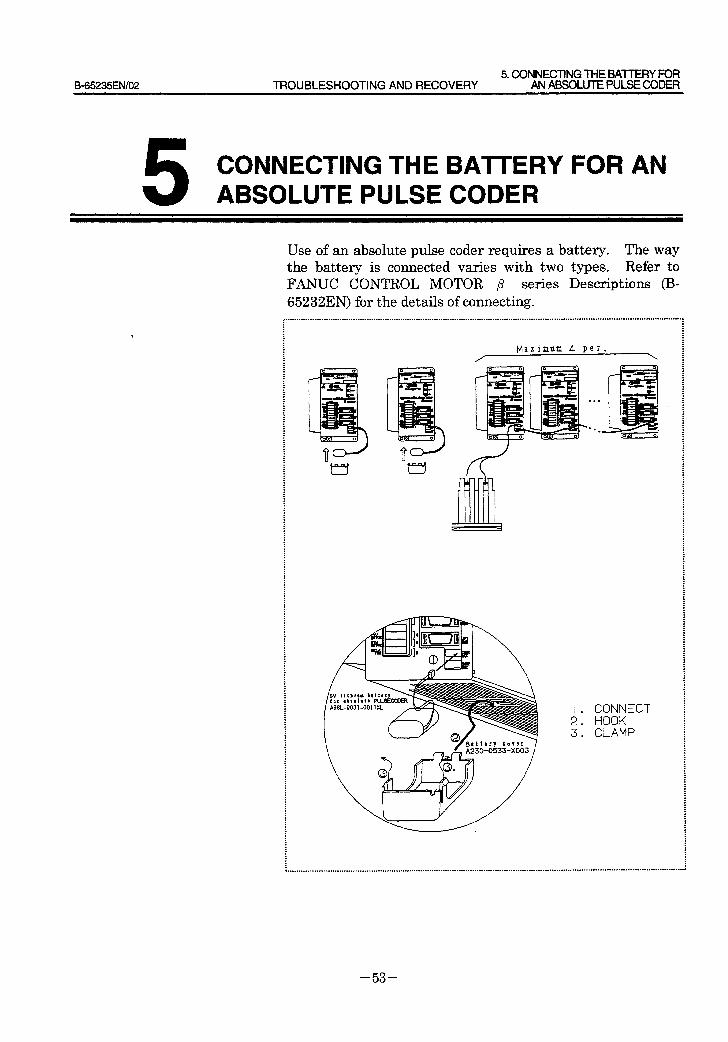
B-65235ENlOZ 5. CONNECTlNG THE BAmY FOR
TROUBLESHOOTlNG AND RECOVERY AN ABSOLUTE PULSE CODER
CONNECTING THE BATTERY FOR AN ABSOLUTE PULSE CODER
Use of an absolute pulse coder requires a battery. The way the battery is connected varies with two types. Refer to FANUC CONTROL MOTOR ,8 series Descriptions (IS- 65232EN) for the details of connecting.
,...................................._......................_.............~~..~..~...-.....~..-...........................................-.....-.............................-.. I . : : : : . : : : : : : : . . : : : : . : : : : . : . : . . : : : . : : : : : : : : . . : . . : : : . . : : : . : : . : : . : . : : : : : : . . : : : : : : : . : . : : . . : : : . : : . : : : : . : . : : : : . : : : : : i : : : : : . . : : : : : : . : : : : : : 3 : : : :
Maximum 4 per.
I . CONNECT 2. HOOK 3. CLAMP
- 53 -

Ill n MOTOR MAINTENANCE
B_65235EN/02 MOTOR MAINTENANCE 1. AC SERVO MOTOR MAINTENANCE
1 AC SERVO MOTOR MAINTENANCE
Generally, p series servo motors have no parts that wear out or that must be replaced periodically, unlike DC servo motors, which have brushes that must be replaced periodically. However, you should perform periodic maintenance for servo motors so as to keep their initial performance as long as possible and to prevent breakdowns. Therefore, we recommend that you inspect the servo motors periodically according to the descriptions given below.
- 57 -
1. AC SERVO MOTOR MAINTENANCE MOTOR MAINTENANCE B-65235ENl02
II I RECEIVING AND KEEPING AC SERVO MOTORS
When you receive an ,8 series servo motor, make sure that: . The motor is exactly the one you ordered, in terms of
model, shaft, and detector specifications. . No damage has been caused to the motor. . The shaft can be rotated by the hand normally. . The brake works normally. . There are no loose bolts or screws.
The servo motors should be kept indoors as a rule. The storage temperature range is -20 to +60°c.
Do not place or install p series servo motors in the place where: . It is extremely humid and dew is prone to form. . There is a steep change in temperature. . There is constant vibration, which may cause damage to
the shaft bearings. . There is excessive dust or trash.
Because FANUC inspects servo motors strictly before shipment, you do not have to inspect them when you receive them.
- 58 -
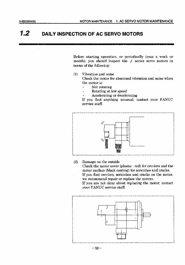
B=65235EN/O2 MOTOR MAINTENANCE 1. AC SERVO MOTOR MAINTENANCE
12 I DAILY INSPECTION OF AC SERVO MOTORS
Before starting operation, or periodically (once a week or month), you should inspect the p series servo motors in terms of the following:
(1) Vibration and noise Check the motor for abnormal vibration and noise when the motor is:
Not rotating m Rotating at low speed
Accelerating or decelerating If you find anything unusual, contact your FANUC service staff.
,.~.....-........-.......-........-....-.......... : . :
. . . . . . . . . . . . . . . . . . . ..-.............--....-.............-...................-.........................................................
(2) Damage on the outside Check the motor cover (plastic : red) for crevices and the motor surface (black coating) for scratches and cracks. If you find crevices, scratches and cracks on the motor, we recommend repair or replace the motors. If you are not clear about replacing the motor, contact your FANUC service staff.
,............r.......-........................................................-...........~...................-..............................-......-.--......-....~.....~......,
: :
: .
: : .
.
i
: .
: -I :
: : . : : : : : :
I ) /j :
: T : : : : : r I : -_ * d
: I . : : : : . . : : : :
i : . . . i : . :
i
: : : . . : : . : : : : : : : : . : : : . : : . : : : .
I
: :
: :
: :
. . . . . . . . . . . . . . . . . . . . . . . . . . . . . . . . . . . . . . .._......._...................................~.............................................................................................
- 59 -
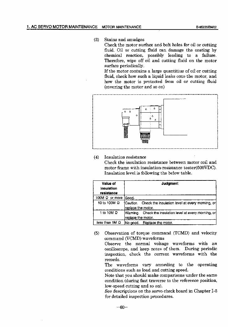
1. AC SERVO MOTOR MAINTENANCE MOTOR MAINTENANCE B_65235EN/O2
(3) Stains and smudges Check the motor surface and bolt holes for oil or cutting fluid. Oil or cutting fluid can damage the coating by chemical reaction, possibly leading to a failure. Therefore, wipe off oil and cutting fluid on the motor surface periodically. If the motor contains a large quantitius of oil or cutting fluid, check how such a liquid leaks onto the motor, and how the motor is protected from oil or cutting fluid (covering the motor and so on)
. . . . . . . . . . . . . . . . . . . . . . . . . . . . . . . . . . . . . . . . . . . . . . . . . . . . . . . . . . . . . . . . . . . . . . . . . . . . . . . . . . . . . . . . . . . . . . . . . . . . . . . . . . . . . . . . . . . . . . . . ......................................................... .
,.........r.........................................-............................................................................................................................
(4) Insulation resistance *
Check the insulation resistance between motor coil and motor frame with insulation-resistance tester(50OVDC). Insulation level is following the below table.
Value of insulation
Judgment
IOOM R or more Good.
10 to 1OOM Q Caution. Check the insulation ievel at every morning, or
replace the motor.
1 to IOM Q Warning. Check the insulation level at every morning, or
replace the motor.
less than 1 M S2 No good. Replace the motor.
(5) Observation of torque command (TCMD) and velocity command (VCMD) waveforms Observe the normal voltage waveforms with an oscilloscope, and keep notes of them. During periodic inspection, check the current waveforms with the records. The waveforms vary according to the operating conditions such as load and cutting speed. Note that you should make comparisons under the same condition (during fast traverse to the reference position, low-speed cutting and so on). See descriptions on the servo check board in Chapter I-5 for detailed inspection procedures.
- 60 -
&65235EN/02 MOTOR MAINTENANCE 1. AC SERVO MOTOR MAINTENANCE
(6) Overheating Attach a thermolabel on the motor surface and check it visually to see if the motor becomes too hot during normal operation.
WARNING * Temperature on the motor surface can exceed 80°C under some conditions. Therefore, never touch the motor during operation.
- 61 -
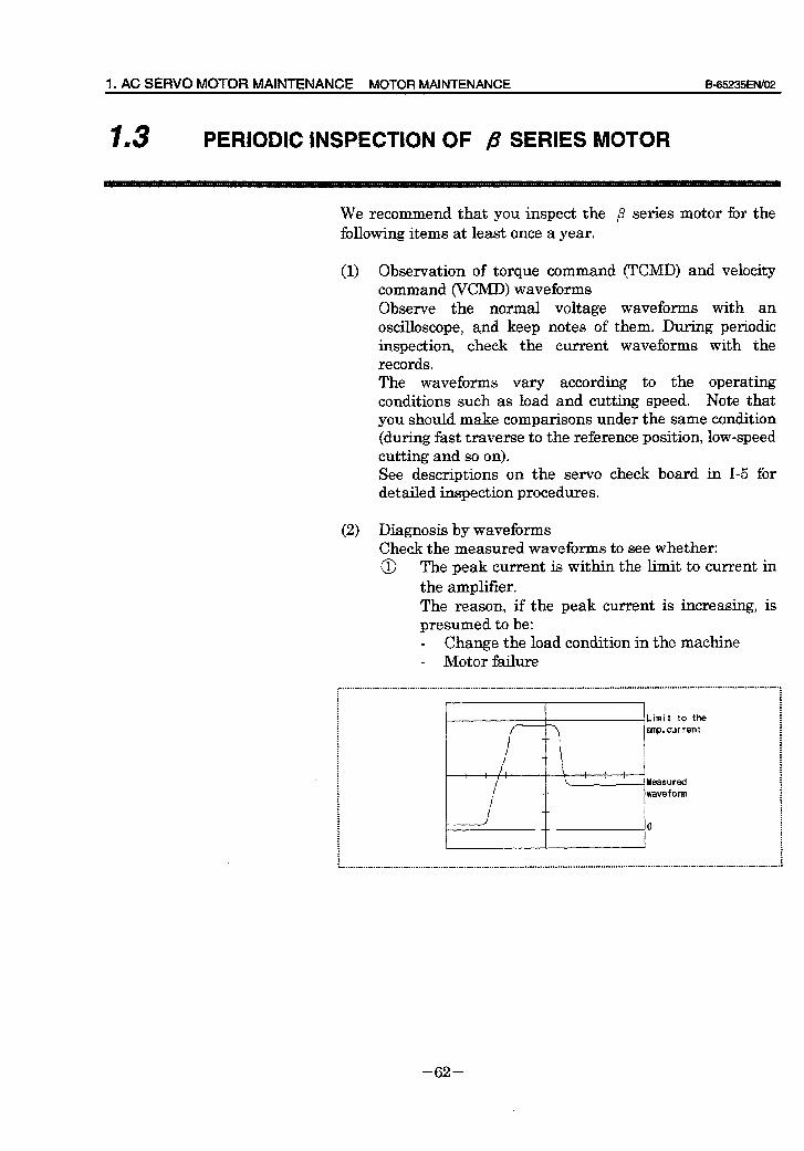
1. AC SERVO MOTOR MAINTENANCE MOTOR MAINTENANCE B-65235EN/O2
13 I PERIODIC INSPECTION OF /3 SERIES MOTOR
We recommend that you inspect the p series motor for the following items at least once a year.
(1) Observation of torque command (TCMD) and velocity command (VCMD) waveforms Observe the normal voltage waveforms with an oscilloscope, and keep notes of them. During periodic inspection, check the current waveforms with the records. The waveforms vary according to the operating conditions such as load and cutting speed. Note that you should make comparisons under the same condition (during fast traverse to the reference position, low-speed cutting and so on). See descriptions on the servo check board in I-5 for detailed inspection procedures.
(2) Diagnosis by waveforms Check the measured waveforms to see whether: @ The peak current is within the limit to current in
the amplifier. The reason, if the peak current is increasing, is presumed to be: - Change the load condition in the machine - Motor failure
- 62 -
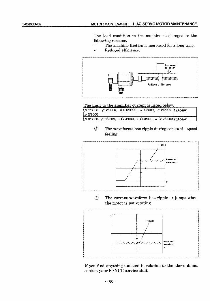
B-65235EIWO2 MOTOR MAINTENANCE 1. AC SERVO MOTOR MAINTENANCE
The load condition in the machine is changed to the following reasons.
- The machine friction is increased for a long time. Reduced efficiency.
~................................................................................................................................................................................ : :
. : : . . . . . . . . . . . . . . . . . . . . . . . . . . . . . . . . . . . . . . . . . . . . . . . . . . . . . . . . . . . . . . . . . . . . . . . . . . . . . . . . . . . . . . . . . . . . . . . . . . . . . . . . . . . . . . . . . . . . . . . . ........................................................~
The limit to the ampliher current is listed below. h
I p l/3000, fi 2/3000, fi 0.5/3000, LY l/3000, cy 2i2000, 12Apeak a 2i3000
1 R 3i3000. R 612000. a C3/2000. a C6f2000, a CW2000~20Aoeak
1
@ The waveforms has ripple during constant - speed feeling.
,................................................................................................................................................................................ . : : . : Ripple : : : : . . : : : : : : : : : : : : : . : : . : : : . Measured : : . waveform : : . : : . I
. : : . . : : : : : : : : : . : : : : . : . : : . : : 0
. : : : : . : : : : : : : . . . . . . . . . . . . . . . . . . . . . . . . . . . . . . . . . . . . . . . . . . . . . . . . . . . . . . . . . . . . . . . . . . . . . . . . . . . . . . . . . . . . . . . . . . . . . . . . . . . . . . . . . . . . . . . . . . . . . . . . ........................................................~
@ The current waveform has ripple or jumps when the motor is not rotating
,..............................................................................................................................................................................., : : : :
Measured waveform
0
: . . . . . . . . . . . . . . . . . . . . . . . . . . . . . . . . . . . . . . . . . . . . . . . . . . . . . . . . . . . . . . . . . . . . . . . . . . . . . . . . . . . . . . . . . . . . . . . . . . . . . . . . . . . . . . . . . . . . . . . . ........................................................ i
If you find anything unusual in relation to the above items, contact your FANUC service staff.
- 63 -
1. AC SERVO MOTOR MAINTENANCE MOTOR MAINTENANCE B45235EfWO2
14 m REPLACING THE PULSE CODER
The pulse coder in the p series servo motor is mounted on the motor shaft directly. Therefore, can not replace the pulse coder. When the pulse coder is detective, replace the motor.
- 64 -
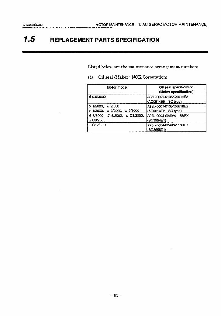
0_65235EN/O2 MOTOR MAINTENANCE 1. AC SERVO MOTOR MAINTENANCE
15 I REPLACEMENT PARTS SPECIFICATION
Listed below are the mamtenance arrangement numbers.
(1) Oil seal (Maker : NOK Corporation)
Motor model Oil seal specification (Maker specification)
flo.5/3000 A98L-0001-0135/C0514E5 (AC0514E5 SC type)
fi l/3000, fi Z/300 A98100001 -0135/CO616E2
a l/3000, cy 2/2000, cy 2/3000 (AC0616E2 SC type)
p 3/3000, p 612000, (x G312000, A98100004-0249/A1188RX LY G6f2000 (BG3554El) a GWZOOO A98100004-0249/A1189RX
(BC3555El)
- 65 -

APPENDIX
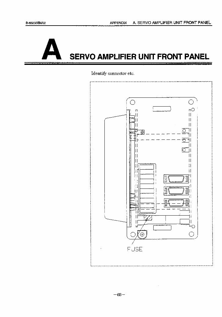
B-65235ENlO2 APPENDIX A. SERVO AMPLIFIER UNIT FRONT PANEL
A SERVO AMPLIFIER UNIT FRONT PANEL
Identify connector etc.
: : : . : . : : : : : . : . : : : : : : . : : : : . : . : : : : : : : : l .
I : . : : . : : . : : : : : : : : : : : : : : . : . : : : . . : : . : : : . : . . : : : : . : : . : : : : . . : : : : : : : : : : : : : . . : . : . : : : : : . : . : : i . : : : : : : : : : : : : . : : : : . : : : : :
FUSE
. . . . ..r......s....s............w......... ..,...............................,....,..~....................~..................~.........-.............-...........-...-....--..-...--,
- 69 -

6. MOTOR PARAMETER LIST APPENDIX B=65235EN/02
B MOTOR PARAMETER LIST
- 70 -
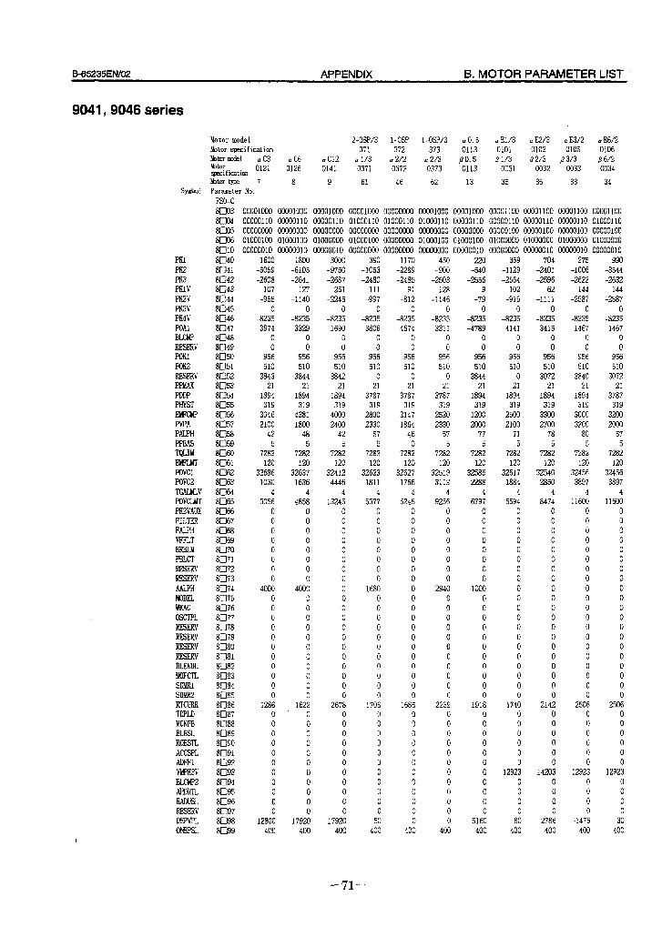
B=65235EN/02 APPENDIX B. MOTOR PARAMETER LIST *
9041 y 9046 series
Motor model z-OSP/3 l -OSP 1 -OSP/3 a0.5 a El/3 a E2/3 a E3/2 aE6/2 Motor specification 371 372 373 0113 0101 0102 0105 0106 !&or model a C3 aC6 a Cl2 a l/3 a2/2 a 2/3 b&or
PO.5 p1/3 p2/3 /33/3 p6/2 specification 0121 0126 0141 0371 0372 0373 0113 0031 0032 0033 0034
bbtor type 7 8 9 61 46 62 13 35 36 33 34 Parameter No. FSO-C 8UO3 00001000 00001000 00001000 00001000 00000000 00001000 00001000 00001100 00001100 00001100 00001100 8clO4 00000110 00000110 00000110 01000110 01000110 01000110 00000110 00000110 00000110 00000110 01000110 SC]05 00000000 00000000 00000000 00000000 00000000 00000000 00000000 00000100 00000100 00000100 00000100 8clO6 01000100 01000100 01000000 01000100 00000000 01000100 01000100 01000000 01000000 01000000 01000000 8010 00000010 00000010 00000010 00000000 00000000 00000000 00000010 00000000 00000010 00000010 00000010 8040 1600 1800 3000 390 1170 450 220 359 704 275 990 8041 -5059 -6105 -9750 -1053 -2289 -900 -540 -1129 -2401 -1006 -3544 8042 -2608 -2641 -2687 -2480 -2485 -2503 -2556 -2564 -2596 -2622 -2632 8043 107 127 251 111 91 128 9 102 62 144 144 8044 -955 -1140 -2245 -997 -812 -1146 -79 -916 -1111 -2587 -2587 8045 0 0 0 0 0 0 0 0 0 0 0 8n46 -8235 -8235 -8235 -8235 -8235 -8235 -8235 -8235 -8235 -8235 -8235 8047 3974 3329 1690 3806 4674 3311 -4789 4141 3415 1467 1467 8048 0 0 0 0 0 0 0 0 0 0 0 8049 0 0 0 0 0 0 0 0 0 0 0 SU50 956 956 956 956 956 956 956 956 956 956 956 8051 510 510 510 510 510 510 510 510 510 510 510 8052 3843 3844 3842 0 0 0 3844 0 3072 3840 3072 8053 21 21 21 21 21 21 21 21 21 21 21 8054 1894 1894 1894 3787 3787 3787 1894 1894 1894 1894 3787 8055 319 319 319 319 319 319 319 319 319 319 319 8056 3046 4381 4000 2800 2147 2520 1200 2500 3300 3000 3200 8057 2100 1800 2400 2330 1864 2330 2000 2100 2700 3200 2000 SD58 42 48 42 57 46 57 77 71 78 80 57 8059 5 5 5 5 0 5 5 5 5 5 5 8060 7282 7282 7282 7282 7282 7282 7282 7282 7282 7282 7282 8061 120 120 120 120 120 120 120 120 120 120 120 8062 32686 32637 32412 32623 32627 32519 32585 32617 32540 32456 32456 8063 1030 1636 4446 1811 1766 3112 2288 1884 2850 3897 3897 81364 4 4 4 4 4 4 4 4 4 4 4 8065 3056 4858 13245 5377 5245 9256 6797 5594 8474 11600 11600 8066 0 0 0 0 0 0 0 0 0 0 0 8D67 0 0 0 0 0 0 0 0 0 0 0 8cl68 0 0 0 0 0 0 0 0 0 0 0 8069 0 0 0 0 0 0 0 0 0 0 0 8lJ70 0 0 0 0 0 0 0 0 0 0 0 8071 0 0 0 0 0 0 0 0 0 0 0 8072 0 0 0 0 0 0 0 0 0 0 0 8573 0 0 0 0 0 0 0 0 0 0 0 8074 4000 4000 0 1680 0 2940 1000 0 0 0 0 8075 0 0 0 0 0 0 0 0 0 0 0 8076 0 0 0 0 0 0 0 0 0 0 0 8077 0 0 0 0 0 0 0 0 0 0 0 8078 0 0 0 0 0 0 0 0 0 0 0 8079 0 0 0 0 0 0 0 0 0 0 0 8080 0 0 0 0 0 0 0 0 0 0 0 8081 0 0 0 0 0 0 0 0 0 0 0 8082 0 0 0 0 0 0 0 0 0 0 0 8083 0 0 0 0 0 0 0 0 0 0 0 8084 0 0 0 0 0 0 0 0 0 0 0 8D85 0 0 0 0 0 0 0 0 0 0 0 8086 1286 1622 2678 1706 1685 2239 1918 1740 2142 2506 2506 8087 0 0 0 0 0 0 0 0 0 0 0 8088 0 0 0 0 0 0 0 0 0 0 0 8089 0 0 0 0 0 0 0 0 0 0 0 8090 0 0 0 0 0 0 0 0 0 0 0 8091 0 0 0 0 0 0 0 0 0 0 0 8092 0 0 0 0 0 0 0 0 0 0 0 SU93 0 0 0 0 0 0 0 12923 14203 12923 12923 8094 0 0 0 0 0 0 0 0 0 0 0 8095 0 0 0 0 0 0 0 0 0 0 0 8096 0 0 0 0 0 0 0 0 0 0 0 8097 0 0 0 0 0 0 0 0 0 0 0 8098 12800 17920 17920 50 0 0 5160 80 -2786 -1476 30 8099 400 400 400 400 400 400 400 400 400 400 400
PK1 PK2 PK3 PKN PK2V PK3V PK4V POAl BLCMP RESERV FQKl Ffx2 RESERV PPMAX PDDP PHYST EMFCMP PVPA PALPH PPBAS TQLIM
PoVCl Fovc2 TGALbUV POVCLMT PIWAUX FILTER FALPH VFFLT ERBLM PBLCI' RESERV RESFN AALPH MODEL WKAC OSCTPL RESERV RESERV RESERV RESFN BLENDL MOFCTL SD!&1 SDMRZ RTCURR TDPLD MCNFB BLBSL ROB!% ACCSPL ADFR VMPK3V EILCMPZ AHDRTL RADUSL RESERV DEPVPL ONEPSL
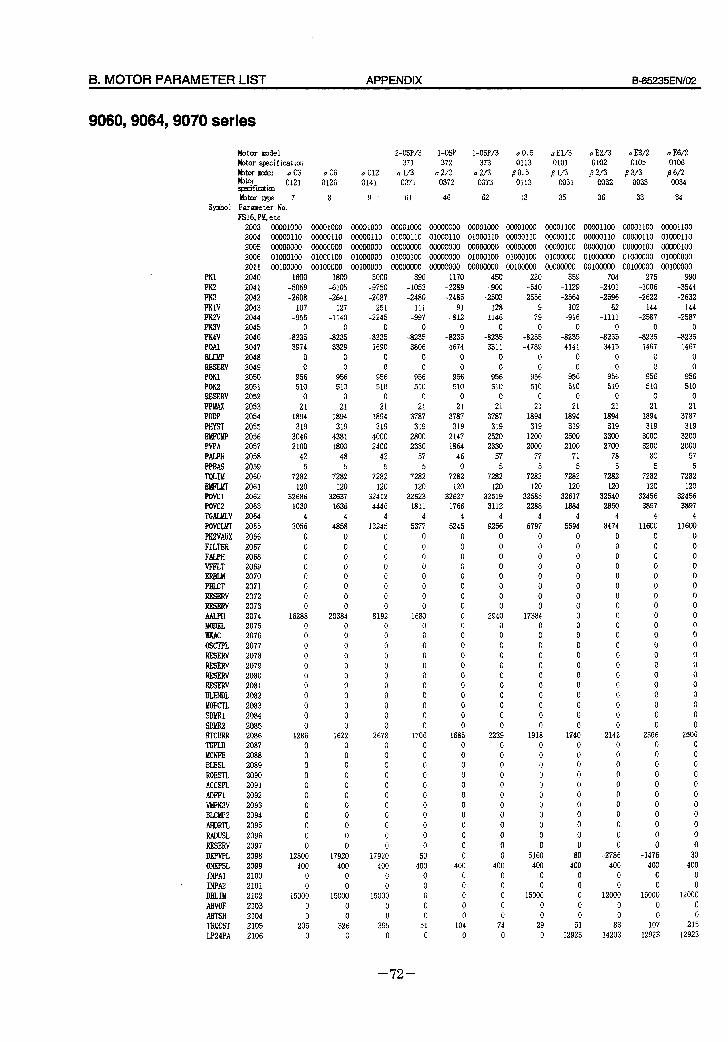
8. MOTOR PARAMETER LIST APPENDIX B-65235EfWO2
9060,9064,9070 series
Motor model !&or specification
h&or m&d a C3 kt0r sp3zifiolticn 0121
bbtor type 7
Symbol Parameter No.
FS16, PM, e tc
a C6
0126
8
a Cl2
0141
9 *
2-OSP/3 l-O% 1 -OSP/3 a0.5 a El/3 a E2/3 a E3/2 a E6/2 371 372 373 0113 0101 0102 0105 0106
a l/3 a 212 a 213 PO.5 /3 l/3 p 2/3 p 3/3 B 6/i 0371 0372 0373 0113 0031 0032 0033 0034
61 46 62 13 35 36 33 34
PKl
PK2
PK3
PKlV PK2V
PK3V PK4V
POAl
RESERV
POKl
POKZ RESERV
PPUX
PDDP
PHYST E!imMP PVPA
PALPH PPBAS TQLIM
POVCl
POVC2
TGALMLV
POVCLW
PK2VAUX
FILTER
FALPH WFLT
ERBLM
PBLCT RESERV RESERV AALPH MODEL JKAC OSCTPL RESERV RESERV RESERV RESERV BLENDL MOFCIL SDbiRl SDMR2 HTCURR TDPLD MCNFB BLBSL
ROBSCL ACCSPL ADFFl WPK3V
BLCMP2
AHDRTL
RADUSL
RESERV DEPVPL ONEPSL INPAl INPA DBLIM ABVOF ABTSH TRQCST LP24PA
2003
2004
2005
2006
2011 2040 2041 2042 2043 2044 2045
2046
2047
2048
2049
2050
2051 2052
2053
2054
2055
2056 2057
2058
2059
2060
2061 2062
2063
2064
2065
2066
2067
2068
2069
2070
2071
2072 2073
2074 2075
2076
2077
2078
2079
2080
2081
2082
2083
2084
2085
2086 2087
2088
2089
2090
2091
2092
2093
2094
2095
2096
2097
2098
2099
2100
2101
2102
2103
2104
2105
2106
00001000 00001000 00001000 00001000 00000000 00001000 00001000 00001100 00001100 00001100 00001100
00000110 00000110 00000110 01000110 01000110 01000110 00000110 00000110 00000110 00000110 01000110
00000000 00000000 00000000 00000000 00000000 00000000 00000000 00000100 00000100 00000100 00000100
01000100 01000100 01000000 01000100 00000000 01000100 01000100 01000000 01000000 01000000 01000000
00100000 00100000 00100000 00000000 00000000 00000000 00100000 00000000 00100000 00100000 00100000 1600 1800
-5059 -6105 -2608 -2641
107 127 -955 -1140
0 0
-8235 -8235 3974 3329
0 0
0 0
956 956
510 510 0 0
21 21 1894 1894
319 319
3046 4381
2100 1800
42 48
5 5
7282 7282
120 120 32686 32637
1030 1636
4 4
3056 4858
0 0
0 0 0 0 0 0 0 0
0 0
0 0
0 0 16288 20384
0 0
0 0
0 0 0 0 0 0 0 0
0 0 0 0
0 0
0 0 0 0
1286 1622 0 0
0 0
0 0
0 0 0 0 0 0 0 0
0 0
0 0
0 0
0 0
12800 17920
400 400 0 0 0 0
15000 15000
0 0
0 0
205 326 0 0
3000 -9750 -2687 251
-2245 0
-8235 1690 0 0
956 510 0 21
1894 319 4000 2400 42 5
7282 120
32412 4446
4 13245
0 0 0 0 0 0 0 0
8192 0 0 0 0 0 0 0 0 0 0 0
2678 0 0 0 0 0 0 0 0 0 0 0
17920 400
0
0
15000
0
0
395 0
390
- 1053
-2480
111 -997
0
-8235
3806
0
0
956
510 0
21
3787
319
2800
2330
57
5
7282
120 32623
1811
4
5377
0
0
0
0 0
0
0
0
1680 0 0
0
0
0
0
0
0
0
0
0
1706
0 0
0
0
0
0
0
0
0
0
0
50
400 0
0
0
0
0
51
0
1170
-2289
-2485
91 -812
0
-8235
4674
0 0
956
510 0
21
3787
319 2147
1864
46
0
7282
120 32627
1766
4
5245
0
0
0
0 0
0
0
0 0
0 0
0
0
0
0
0 0
0
0
0
1685 0
0
0
0
0
0
0
0
0
0
0
0
400
0
0
0
0
0
104
0
450
-900
-2503
128
-1146 0
-8235
3311
0
0
956
510 0
21
3787
319
2520
2330
57
5
7282
120
325 19 3112
4
9256
0
0
0
0
0 0
0 0
2940 0 0
0
0
0
0
0
0
0
0
0
2239
0 0
0
0
0
0
0
0
0
0
0
0
400
0
0
0
0
0 74
0
220 -540 -2556
9 -79 0
-8235 -4789
0 0
956 510 0 21
1894 319 1200 2000 77 5
7282 120
32585 2288
4 6797
0 0 0 0 0 0 0 0
17384 0 0 0 0 0 0 0 0 0 0 0
1918 0 0 0 0 0 0 0 0 0 0 0
5160 400 0 0
15000 0 0 29 0
359
-1129 -2564 102 -916
0 -8235 4141
0 0
956 510 0 21
1894 319 2500 2100 71 5
7282 120
32617 1884 4
5594 0 0 0 0 0 0 0 0 0 0 0 0 0 0 0 0 0 0 0 0
1740 0 0 0 0 0 0 0 0 0 0 0 80 400 0 0 0 0 0 51
12923
704 -2401 -2596
62 -1111
0 -3235 3415
0 0
956 510 0 21
1894 319 3300 2700 78 5
7282 120
32540 2850
4 8474
0 0 0 0 0 0 0 0 0 0 0 0 0 0 0 0 0 0 0 0
2142 0 0 0 0 0 0 0 0 0 0 0
-2786 400 0 0
12000 0 0 83
14203
275 -1006 -2622 144
-2587 0
-8235 1467 0 0
956 510 0 21
1894 319 3000 3200 80 5
7282 120
32456 3897
4 11600
0 0 0 0 0 0 0 0 0 0 0 0 0 0 0 0 0 0 0 0
2506 0 0 0 0 0 0 0 0 0 0 0
-1476 400 0 0
15000 0 0
107 12923
990
-3544 -2632 144
-2587 0
-8235 1467 0 0
956 510 0 21
3787 319 3200 2000 57 5
7282 120
32456 3897
4 11600
0 0 0 0 0 0 0 0 0 0 0 0 0 0 0 0 0 0 0 0
2506 0 0 0 0 0 0 0 0 0 0 0 30 400 0 0
12000 0 0
215 12923
- 72 -
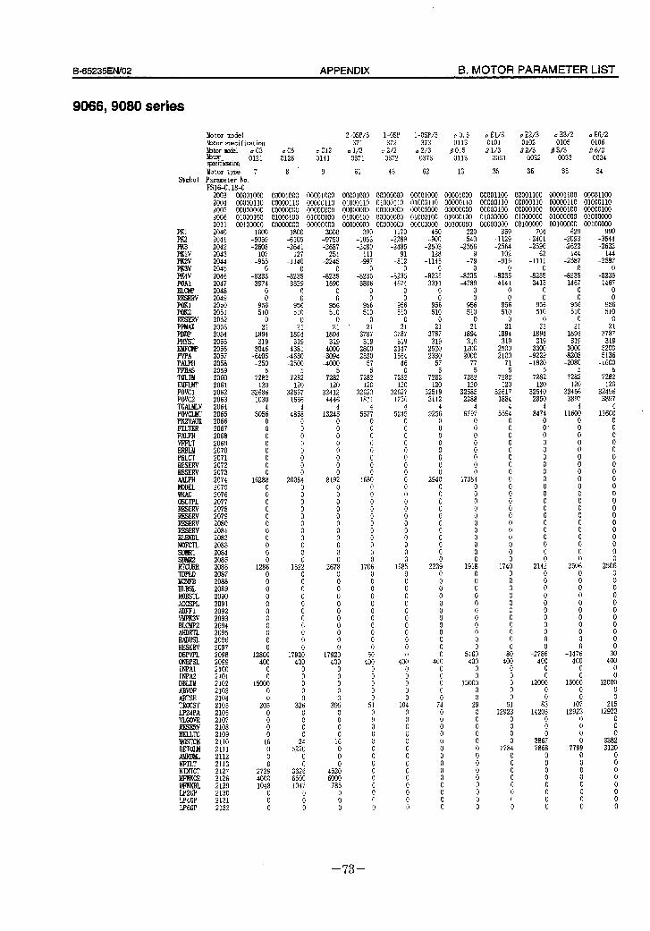
B=65235EN/O2 APPENDIX B. MOTOR PARAMETER LIST
9066,908O series
Symbo 1
PKl
;: PKlV PK2V PK3V
!!Y BLCW RESERV PoKl POK2 RESERV PP!dAx PDDP PHYST
PVPA PALPH PPBAS TOLIM
POVCl POVC2 TGALMLV POVCLMr PK2VAUX FILTER FALF’H VFFLT ERBLh! PBLCT RESERV RESERV
i%!! WKAC OSCTPL
RESERV
=: MOFCIL SDMRl SDMR2 RTCURR TDPLD MCNFB BLBSL ROBSTL ACCSPL ADFFl VMPK3V BLCW2 AHDRTL
EE DEPVPL ONEPSL INPAl INPA DBLIM ABVOF ABTSH TROCST LP24PA VLGOVR RESERV BELLTC MGSTCM DETOLM Ah!RDML NFILT NINTCT MFPJKCE
LP4GP LPGGP
Motor model hbtor specification
EkYY+-l a C3
gecif icatkn 0121
Motor type 7 Parameter No. FSlG-C, 18-C
2 -OSP/3 l-OSP 1 -OSP/3 a 0.5 a El/3 a E2/3 u E3/2 a E6/2 371 372 373 0113 0101 0102 0105 0106
a C6 a Cl2 al/3 a 2/Z a2/3 ao.5 L?l1/3 a Z/3 P 3/3 P 6/2 0126 0141 0371 0372 0373 0113 0031 0032 0033 0034
8. 9 61 46 ii2 . 13 35 36 33 34
2003 2004 2005 2006 2011 2040 2041 2042 2043 2044 2045 2046 2047 2048 2049 2050 2051 2052 2053 2054 2055 2056 2057 2058
2060 2061 2062 2063 2064 2065 2066 2067 2068 2069 2070 2071 2072 2073 2074 2075 2076 2077 2078 2079 2080 2081 2082 2083 2084 2085 2086 2087 2088 2089 2090 2091 2092 2093 2094 2095 2096 2097 2098 2099 2100 2101 2102 2103 2104 2105 2106 2107 2108 2109 2110 2111 2112 2113 2127 2128 2129 2130 2131 2132
00001000 00001000 00001000 00001000 00000000 00001000 00001000 00001100 00001100 00001100 00001100 00000110 00000110 00000110 01000110 01000110 01000110 00000110 00000110 00000110 00000110 01000110 00000000 00000000 00000000 00000000 00000000 00000000 00000000 00000100 00000100 00000100 00000100 01000100 01000100 01000000 01000100 00000000 01000100 01000100 01000000 01000000 01000000 01000000 00100000 00000000 00000000 00000000 00000000 00000000 00100000 00000000 00100000 00100000 0010oooo
1600 -5059 -2608 107 -955
-823: 3974
0 0
956 510 0
18;: 319 3046 -6405 -250
728; 120
32686 1030
305:
:
i 0
ii
162ai
:
i 0 0
i 0 0
12aE 0
t
i 0
ii
i
1280: 400
ii 15000
i 205 0
ii
1: 0
i 2729 4000 1048
: 0
1800 -6105 -2641
127 -1140
-823;
iii 956 510 0
18:: 319 4381 -4630 -2500
728; 120
32637 1636
4 4858
0
iTI
Fi
i
2038: 0
;
i
i
i 0
162; 0
Fl
i 0
i 0
i 17920 400
; 0
i 326 0 0
i
52:; 0
332: 6500 1047
i 0
3000 -9750 -2687
251 -2245
-823: 1690
: 956 510
0
1aG 319 4000 -3094 -4000
5 7282 120
32412 4446
1324:
;
i
i
i al92
0
i
i
i 0 0 0
267:
i 0 0
ii
ii
ii! 0
17920 400 0
i
i 395 0
ii 0 16
i 0
4520 6000 785
i 0
390 - 1053 -2480 111 -997
-823;
380:
95: 510
0
37;: 319
2800 2330
57 5
7282 120
32623 iaii
53747 0
i 0
!i 0
168: 0
;
i
i 0
i 0
1706 0
i
ii
i
i 0 0 50 400
;
; 0 51 0
i
i 0
1
i
i 0 0
1170 -2289 -2485
-8;;
-823: 4674
; 956 510 0
37;: 319 2147 1864 46 0
7282 120
32627 1766
524:
;
i
i
iii 0
i
i 0
i 0
i
16805
ii
ii
i
i 0
i 0
400
i
; 0
104
i
ii
!!I
!I 0
i
i 0
450 -900 -2503 128
-1146
-823: 3311
i 956 510 0
37% 319 2520 2330 57
728; 120
32519 3112
925:
i
i 0
;
294:
i
i 0
ii 0
i
223: 0
Fi 0
i 0
iii
i 0
400 0
ii
i 74
ifi
: 0 0
ii
i 0
i
220 -540
-2556 9
-79
-823: -4789
: 956 510
2: 1894 319
1200 2000 77
728; 120
32585 2288
679; 0
i
i
i
1738:
i
i 0
i 0
i
191; 0
: 0
ii 0
i 0
516: 400 0
1500: 0
2: 0
;
i
i
i 0
0" 0
990 -3544 -2632 144
-2587
-823: 1467
ii 956 510 0
37:: 319 3200 -5136 -1600
5 7282 120
32456 3897
4 11600 .
0
:
: 0 0
:
:
z 0
:
: 0
250:
i
ii 0
:
i 0
3: 400 0
l2OOi
i 215
12923 0
ti
0 0
359 -1129 -2564
102 -916
-823; 4141
: 956 510
2’: 1894
319 2500 2100
71
728; 120
32617 la84
559:
:
:
:
: 0
:
: 0
0” 0
:
174:
: 0
: 0
:
;
ai 400
1
; 0
129;:
i
; 7784
i
i
i 0 0
704 -2401 -2596
62 -1111
-823: 3415
0
9506 510
2: 1894 319 3300 -9229 -1820
728; 120
32540 2850
847: 0 0'
i
ii
: 0
:
i 0
:
"0 0
214; 0
i
i 0
i
;
-278: 400
; 12000
; a3
14203 0
i 3867 7868
0
i 0
i 0 0
629 -2093 -2622 144
-2587
-823: 1467
i 956 510 0
18:: 319 3000 -8208 -2080
728; 120
32456 3897
1160: 0
i
i
ii
ii 0 0 0
z
:
ii 0
250: 0 0 0
: 0
ii 0
i -1476 400 0
1500:
i 107
12923 0
i
77909 0
z 0
i 0 0
3120 0
?I 0
ii 0 0
- 73 -
C. FSSB APPENDIX B-65235EN/O2
C FSSB
- 74 -
&65235EN/02 APPENDIX C. FSSB
Cl L GENERAL
The ,Q series SERVO AMPLIFIER UNIT with FSSB is used with the new optical interface FSSB. The specifkations of this /? series amplifier is same that of the current SVCJ except for the interface.
The differences between /3 series amplifier with FSSB and the current model are shown below.
- 75 -
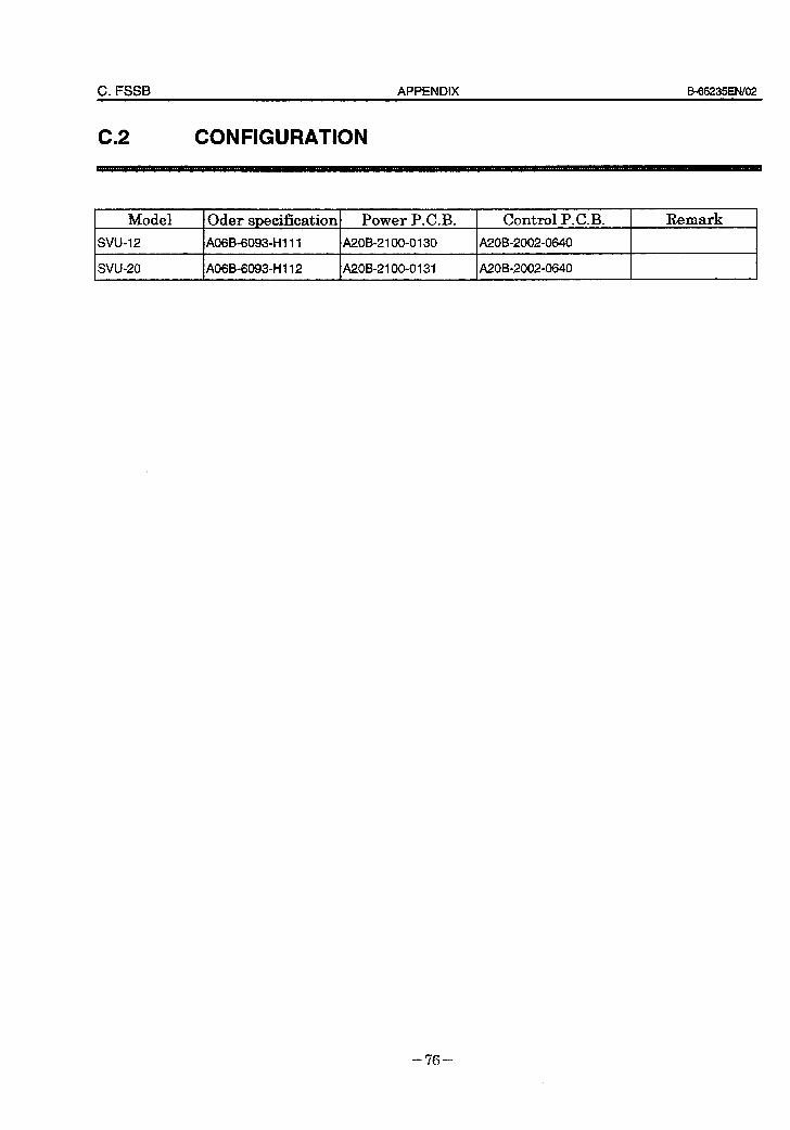
C. FSSB APPENDIX B-65235EN/O2
c.2 CONFIGURATION
Model
SW-1 2
Oder specification/ Power P.C.B. Control P.C.B. Remark
A06B-60930HI 11 A2OB-2 100-0130 A20B-2002-0640
svu-20 I A06B-6093-H 112 I A2OB-2100-0131 I A20B-2002-0640 I I
- 76 -
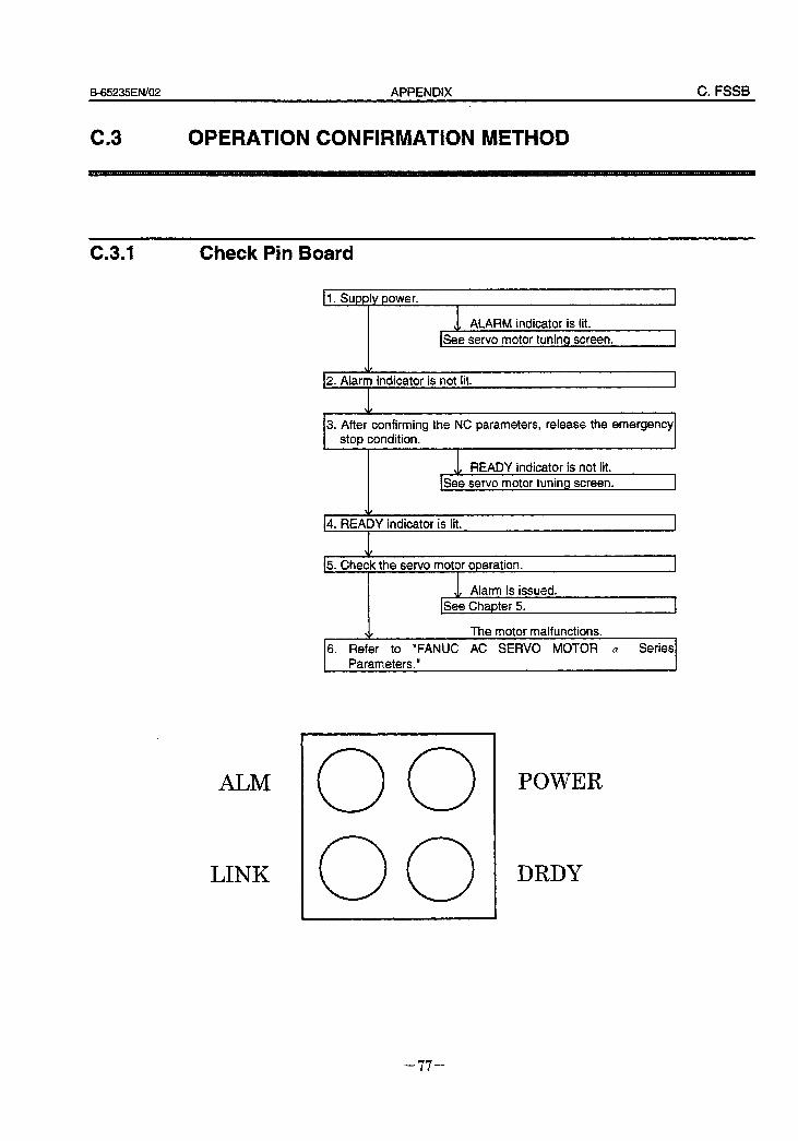
B_65235EN/02 APPENDIX C. FSSB
c3 8 OPERATION CONFIRMATION METHOD
C.3.1 Check Pin Board
II. Supply power.
w ALARM indicator is lit. ISee servo motor tuning screen.
\I/
12. Alarm indicator is not lit. I
3. After confirming the NC parameters, release the emergency stop condition.
v READY indicator is not lit. ee servo motor tuning screen. I
14. READY indicator is tit.
I
15. Check the servo motor operation. I
w Alarm is issued. ISee Chapter 5. 1
V The motor malfunctions.
6. Refer to “FANUC AC SERVO MOTOR CY Series Parameters.” 4
ALM 0 0 POWER
LINK 0 0 DRDY
- II -
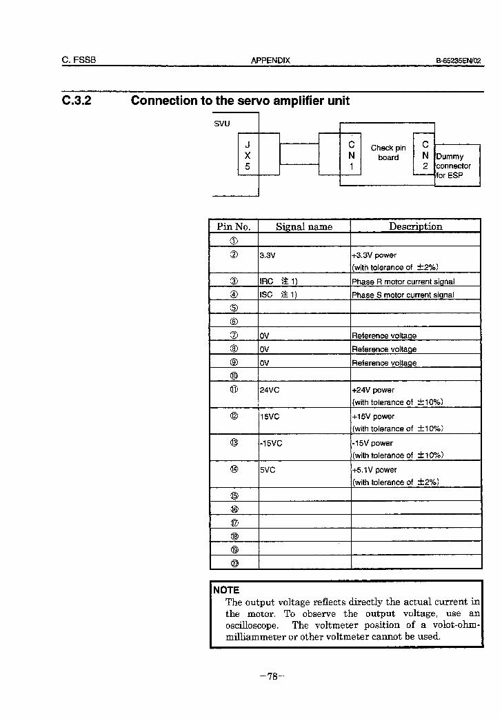
C. FSSB APPENDIX f3-65235EN/O2
C.3.2 Connection to the servo amplifier unit I
svu t
J X 5
C N
Check pin c board
i
N I 2
Dummy connector For ESP
Pin No. Signal name I Description
3.3v
IRC ?& 1)
ISC $2 1)
+3.3V power
(with tolerance of &2%)
Phase R motor current signal
Phase S motor current signal
ov ov
ov
24VC
Reference voltage
Reference voltage
Reference voltage
+24V power
(with tolerance of ~10%)
5vc +5.lV power
(with tolerance of &2%)
NOTE The output voltage reflects directly the actual current in the motor. To observe the output voltage, use an oscilloscope. The voltmeter position of a volot-ohm- milliammeter or other voltmeter cannot be used.
- 78 -
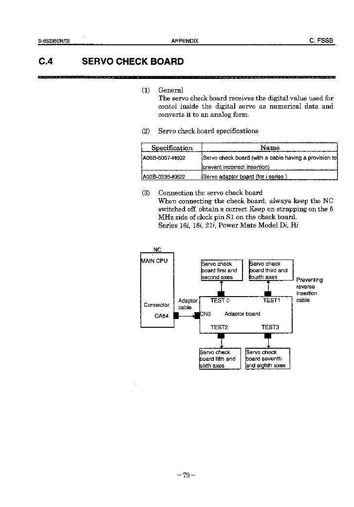
B65235EN/02 APPENDIX C. FSSB
SERVO CHECK BOARD
(1) General The servo check board receives the digital value used for contol inside the digital servo as numerical data and converts it to an analog form.
(2) Servo check board specifications
I Snecification I Name
Servo check board (with a cable having a provision to
prevent incorrect insertion)
AOZB-0236-K822 Servo adaptor board (for i series )
(3) Connection the servo check board When connecting the check board, always keep the NC switched off. obtain a correct Keep on strapping on the 5 MHz side of clock pin Sl on the check board. Series 16i, 18i, 21i, Power Mate Model Di, Hi
NC .
MAIN CPU
Adaptor TEST 0 TEST1 Connector cable
CA54 *NO Adaptor board
I J I TEST2 TEST3
Preventing reverse insertion cable
- 79 -
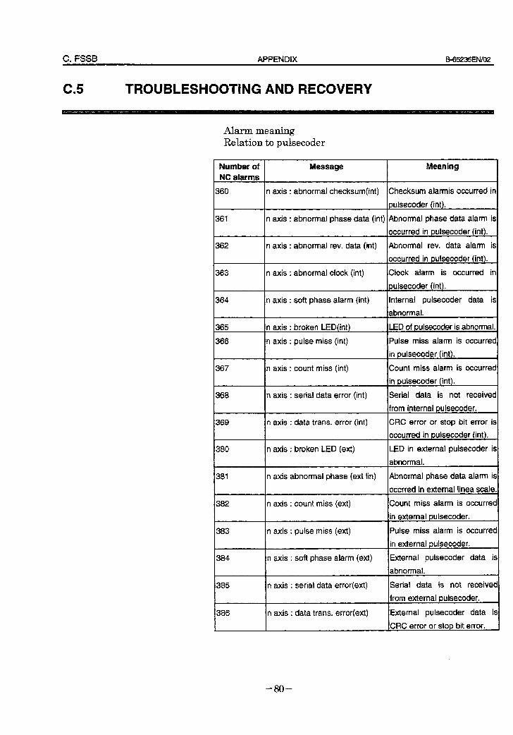
C. FSSB APPENDIX E3-65235EtV02
c5 D TROUBLESHOOTING AND RECOVERY
Alarm meaning Relation to pulsecoder
Number of Message Meaning NC alarms
360 n axis : abnormal checksum(int) Checksum alarmis occurred in
pulsecoder (int).
361 n axis : abnormal phase data (int) Abnormal phase data alarm is
occurred in pulsecoder (int).
362 n axis : abnormal rev. data (int) Abnormal rev. data alarm is
occurred in pulsecoder (int).
363 n axis : abnormal clock (int) Clock alarm is occurred in
pulsecoder (int).
364 n axis : soft phase alarm (int) internal pulsecoder data is
abnormal.
365 n axis : broken LED(int) LED of pulsecoder is abnormal.
366 n axis : pulse miss (int) Pulse miss alarm is occurred
in pulsecoder (int).
367 n axis : count miss (int) Count miss alarm is occurred
in pulsecoder (int).
368 n axis : serial data error (int) Serial data is not received
from internal pulsecoder.
369 n axis : data trans. error (int) CRC error or stop bit error is
Ioccurred in ouisecoder (int). !
380 n axis : broken LED (ext) LED in external pulsecoder is
abnormal.
381
382
n axis abnormal phase (ext iin) Abnormal phase data alarm is
occrred in external linea scale.
n axis : count miss (ext) Count miss alarm is occurred
in external oulsecoder.
383
!384 I
n axis : pulse miss (ext)
n axis : soft phase alarm (ext)
Pulse miss alarm is occurred
in external pulsecoder. 4
External pulsecoder data is
abnormal.
385 n axis : serial data error(ext)
386 n axis : data trans. error(ext)
Serial data is not received
from external pulsecoder. A
External pulsecoder data is
CRC error or stab bit error.
- 80 -
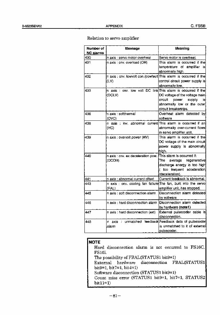
B-65235ENiOZ APPENDIX C. FSSB
Relation to servo amplifier
Number of NC alarms
430
431
432
433
436
438
439
440
445
446
447
448
Message Meaning
n axis : servo motor overheat IServo motor is overheat.
n axis : cnv. overioad (OH) This alarm is occurred if the temperature of amplifier is abnotmaliv hiah.
n axis : cnv. lowvolt con./powfault This alarm is occurred if the
(LV) control circuit power supply is
abnormally low.
n axis : cnv. low volt DC link This alarm is occurred if the
(DCLV) DC voltage of the voltage main circuit power supply is abnormally low or the outer circuit breakertrios.
n axis : softthermal
(OVC) I Overheat alarm detected by
software
n axis : inv. abnormal current This alarm is occurred if an
(HC) abnormally over-current flows in servo amolifier unit.
n axis : overvolt power (HV) This alarm is occurred if the DC voltage of the main circuit
power supply is abnormally Ihigh.
n axis : cnv. ex deceleration pow. This alarm is occurred if:
(DCOH) The average regenerative discharge energy is too high
( too frequent acceleration /deceleration).
n axis : abnormal current offset Current feedback is abnormal.
n axis : cnv. cooling fan failure The fan, built into the servo
(FAL) amplifier unit, has stopped.
n axis : soft disconnection alarm Disconnection alarm detected bv software
n axis : hard disconnection alarm Disconnection alarm detected by hardware (notel)
n axis : hard disconnection (ext) External pulsecoder cable is disconnection.
n axis : unmatched feedback Feedback data of pulsecoder
alarm is unmatched to it of external oulsecoder.
NOTE Hard disconnection alarm is not occurred to FS16C, FS 16i.
The possibility of FBAL(STATUS1 bit9=1) External hardware disconnection FBAL(STATUS 1 bit9=1, bit7=1, bit4=1) Software disconnection (STATUS1 bit9=1) Count miss error (STATUS1 bit9=1, bit7=1, STATUS2 bit 11~1)
- 81 -
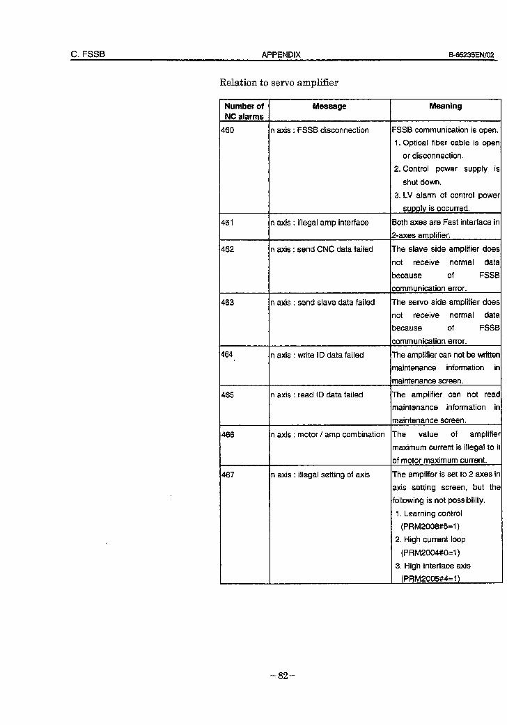
C. FSSB APPENDIX B65235EN/O2
Relation to servo amplifier
Number of Message Meaning NC alarms
460 n axis : FSSB disconnection FSSB communication is open.
1. Optical fiber cable is open
or disconnection.
2. Control power supply is
shut down.
$61
262
463
464 .
465
466
467
3. LV alarm of control power
supply is occurred.
n axis : illegal amp interface Both axes are Fast interface in
Z-axes amplifier.
n axis : send CNC data failed The slave side amplifier does
not receive normal data
because of FSSB
communication error.
n axis : send slave data failed The servo side amplifier does
not receive normal data
because of FSSB
communication error.
n axis : write ID data failed The amplifier can not be writter
maintenance information ir
maintenance screen.
n axis : read ID data failed The amplifier can not reac
maintenance information ir
maintenance screen.
n axis : motor / amp combination The value of amplifiel
maximum current is illegal to iI
of motor maximum current.
n axis : illegal setting of axis The amplifer is set to 2 axes ir
axis setting screen, but the
following is not possibility.
1. Learning control
(PRM2008#5=1)
2. High current loop
(PRM2004#0=1)
3. High interface axis
(PRM2005#4=1)
- 82 -
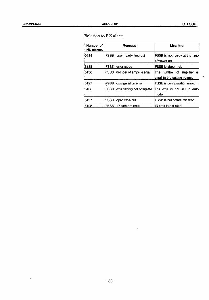
ES65235ENiO2 APPENDIX C. FSSB
Relation to P/S alarm
Number of Message Meaning NC alarms
5134 FSSB : open ready time out FSSB is not ready at the time
of power on.
5135 FSSB : error mode FSSB is abnormal.
5136
5137
FSSB : number of amps is small The number of amplifier is I small to the setting numer.
FSSB : confiauration error FSSB is confiauration error.
5138 FSSB : axis setting not complete The axis is not set in auto
mode.
5197 FSSB : open time out FSSB is not communication.
5198 FSSB : ID data not read ID data is not read.
- 83 -
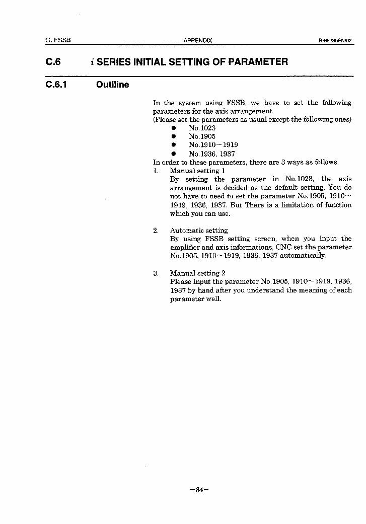
C. FSSB APPENDIX B-65235EhV02
C.6 i SERIES INITIAL SETTING OF PARAMETER
C.6.1 Outlline
In the system using FSSB, we have to set the following parameters for the axis arrangement. (Please set the parameters as usual except the following ones)
l No. 1023 l No. 1905 l No.1910-1919 m No. 1936, 1937
In order to these parameters, there are 3 ways as follows. 1 l Manual setting 1
By setting the parameter in No.1023, the axis arrangement is decided as the default setting. You do not have to need to set the parameter No.1905, 1910- 1919, 1936, 1937, But There is a limitation of function which you can use.
2 . Automatic setting By using FSSB setting screen, when you input the ampliher and axis informations, CNC set the parameter No. 1905, 19 10 - 19 19, 1936, 1937 automatically.
3 . Manual setting 2 Please input the parameter No. 1905, 1910- 1919, 1936, 1937 by hand after you understand the meaning of each parameter well.
- 84 -
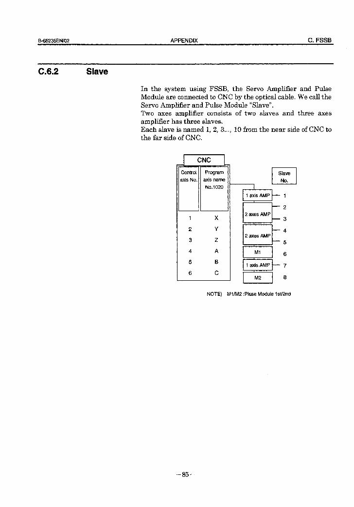
B-65235ENlO2 APPENDIX C. FSSB
C.6.2 Slave
In the system using FSSB, the Servo Amplifier and Pulse Module are connected to CNC by the optical cable. We call the Servo Amplifier and Pulse Module “Slave”. Two axes amplifier consists of two slaves and three axes amplifier has three slaves. Each slave is named 1, 2, 3..., 10 fkom the near side of CNC to the far side of CNC.
Program
axis name
No.1 020
4- CNC 1
I 1axisAMP - 1
-2
2 axes AMP -3
I
-4 2 axes AMP
-5 I f Ml 6 i
1axisAMP - 7 I
M2 8
NOTE) Ml/M2 :Pluse Module W2nd
- 85 -
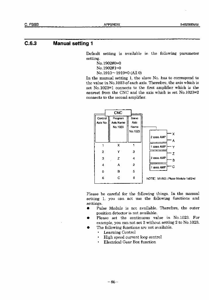
C. FSSB APPENDIX 5-65235ENf02
C.6.3 Manual setting 1
Default setting is available in the following parameter setting.
No. 1902#0=0 No. 1902#1=0 No.l910-1919=0 (All 0)
In the manual setting 1, the slave No. has to correspond to the value in No.1023 of each axis. Therefore, the axis which is set No.10234 connects to the first amplifier which is the nearest from the CNC and the axis which is set No.1023=2 connects to the second amplifier.
CNC
Control Program Servo
Axis No. Axis Name Axis
No.1 020 Name
No. 1023
- 1 X 1
2 Y 3
3 Z 4
4 A 2
5 B 5
6 C 6
IlaxesAMPky
12axesAMPrz
/laxesAMPkc
NOTE) Ml/M2 : Pluse Module IsV2nd
Please be careful for the following things. In the manual setting 1, you can not use the following functions and settings. l Pulse Module is not available. Therefore, the outer
position detector is not available. 0 Please set the continuous value in No.1023. For
example, you can not set 3 without setting 2 to No.1023. l The following functions are not available.
l Learning Control l High speed current loop control l Electrical Gear Box function
- 86 -
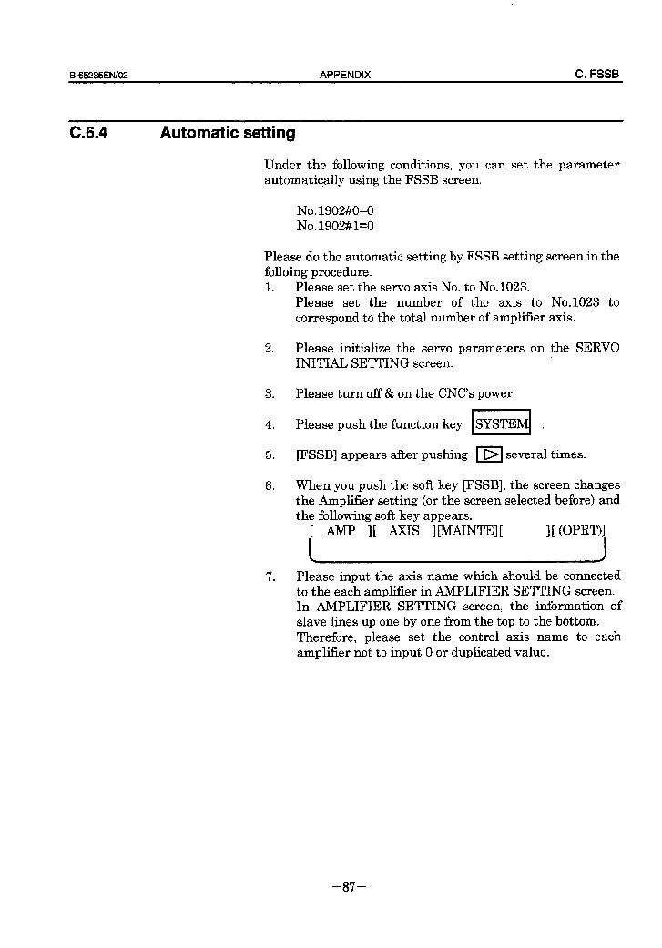
9-65235ENl02 APPENDIX C. FSSB
Please do the automatic setting by FSSB setting screen in the folloing procedure. 1 . Please set the servo axis No. to No.1023.
Please set the number of the axis to No.1023 to correspond to the total number of amplifier axis.
2 .
3 .
4 .
5 *
6 .
Please initialize the servo parameters on the SERVO INITIAL SETTING screen.
Please turn off & on the CNC’s power. /
Please push the function key SYSTEM .
FSSB] appears after pushing 1 r>J several times.
When you push the soft key FSSB], the screen changes the AmplZier setting (or the screen selected before) and the following soft key appears.
II AMP IE AxIS IWNTW I[ WRT)I I I
7 . Please input the axis name which should be connected to the each amplifier in AMPLIFIER SETTING screen. In AMPLIFIER SETTING screen, the information of slave lines up one by one from the top to the bottom. Therefore, please set the control axis name to each amplifier not to input 0 or duplicated value.
~~_ __ ~_~
C.6.4 Automatic setting
Under the following conditions, you can set the parameter automatically using the FSSB screen.
No. 1902#0=0 No.1902#1=0
- 87 -
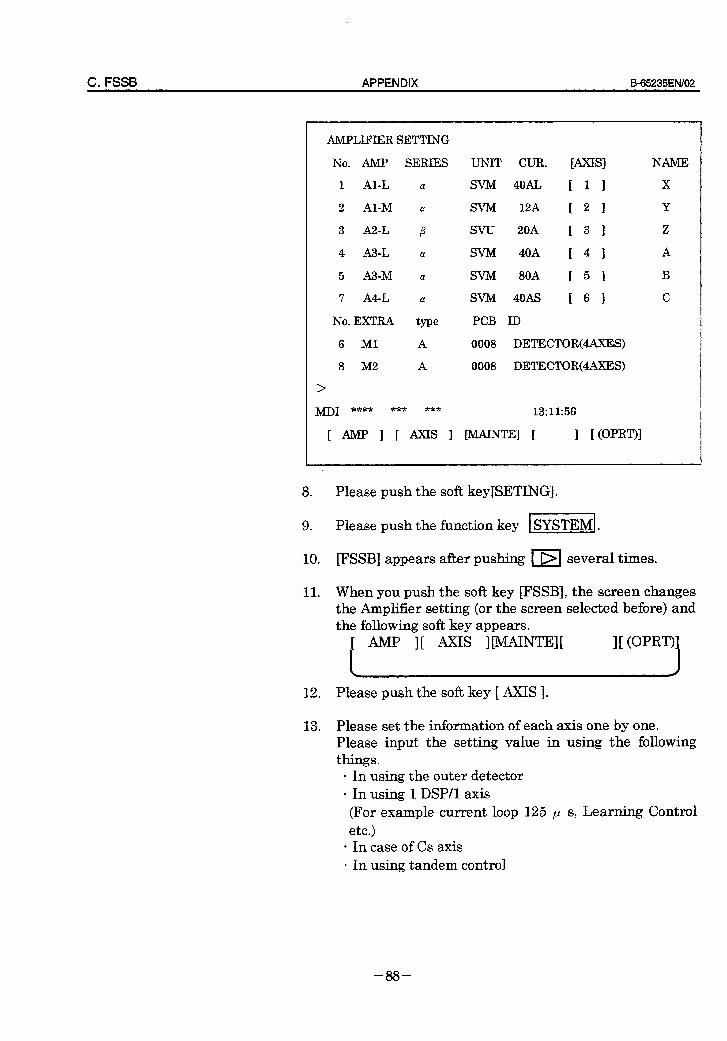
C. FSSB APPENDIX 6=65235EN/O2
AMPLIFIER SETTING
No. AMP SERIES UNIT CUR. [AXTSI NAME
1 Al-L CY SVM 4oAL c 1 1 X
2 Al-M a SVMI 12A [ 2 1 Y
3 A2-L p SW 20A [ 3 1 z
4 A3-L a SVM 40A c 4 1 A
5 A3-M CY SVM BOA 1 5 1 B
7 A4-L a SW 4oAs 1 6 3 C
No. EXTRA type PCB ID
6 Ml A 0008 DETEKTOR(4AXEiS)
8 M2 A 0008 DETECTOR(4AXES)
>
&/j-D1 **** *** *** 13:11:56
[ AMI? 1 [ AXE 1 CMAINTEI [ 1 HOpRT)I
8 . Please push the soft key[SETING].
9 . Please push the function key SYSTEM .
10. @?SSB] appears after pushing 1 r>I several times.
11. When you push the soft key FSSB], the screen changes the Amplifier setting (or the screen selected before) and the following soft key appears.
1 AMP I[ AxIS IWNTEI[ III (OPJw I
12. Please push the soft key [ AXIS ]-
13. Please set the information of each axis one by one. Please input the setting value in using the following things.
l In using the outer detector 9 In using 1 DSP/l axis (For example current loop 125 p s, Learning Control etc.)
l In case of Cs axis l In using tandem control
- 88 -
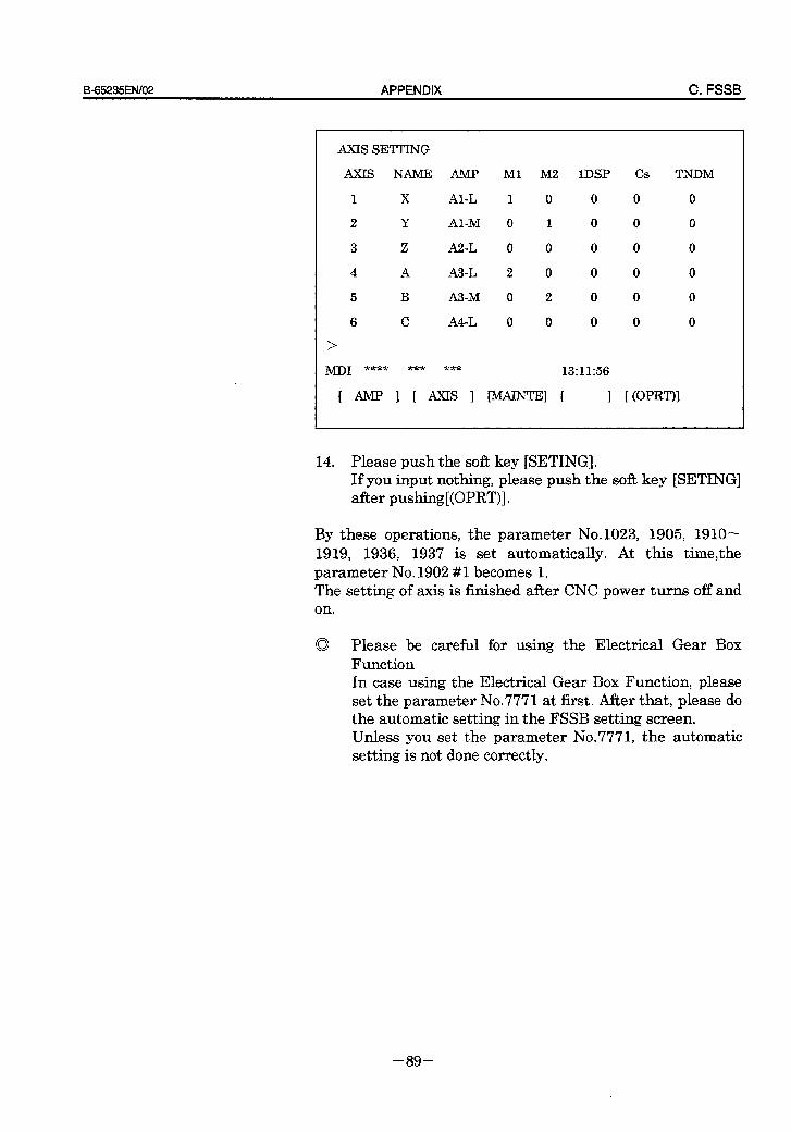
B-65235ElW02 APPENDIX C. FSSB
AXE SETTING
AXIS NAME AMP Ml M2 1DSP Cs TNDM
1 x Al-L 1 0 0 0 0
2 Y Al-M 0 1 0 0 0
3 z A2-L 0 0 0 0 0
4 A A3-L 2 0 0 0 0
5 B A3-M 0 2 0 0 0
6 C A4-L 0 0 0 0 0
>
MDI **** *** *** 13:11:56
E AMP I 1 AxIs 1 WW [ 1 E (OPWI
14. Please push the soft key [SETING]. If you input nothing, please push the soft key [SETING] after pushing[(OPRT)].
By these operations, the parameter No.1023, 1905, 1910- 1919, 1936, 1937 is set automatically. At this time&he parameter No.1902 #l becomes 1. The setting of axis is finished after CNC power turns off and OIL
0 Please be careful for using the Electrical Gear Box Function In case using the Electrical Gear Box Function, please set the parameter No.7771 at first. After that, please do the automatic setting in the FSSB setting screen. Unless you set the parameter No.7771, the automatic setting is not done correctly.
- 89 -
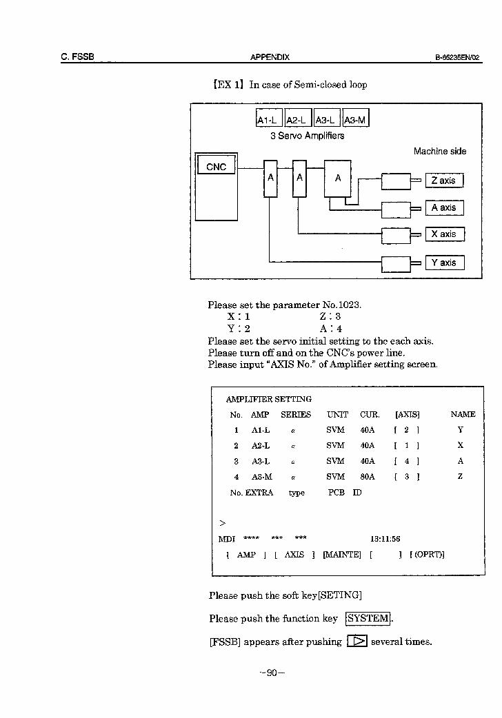
C. FSSB APPENDIX B-65235ENiO2
[EX 1) In case of Semi-closed loop
3 Servo Amplifiers
4
I CNC
Machine side t t-
A A A ,
=qzzq
Please set the parameter No.1023. x: 1 z:3
Y:2 A:4
Please set the servo initial setting to the each axis. Please turn off and on the CNC’s power line. Please input “AXIS No.” of Amplifier setting screen.
AMPLIFIIZRSETTING
No. AMI' SERIES UNIT CUR. [AXIS1 NAME
1 Al-L CT SVM 40A [ 21 Y
2 AZ-L a SVM 40A c 1 I x
3 A3-L a SVM 40A r 4 1 A
4 A3-M a SVM SOA 1 3 1 z
No.EXTRA type PCB ID
>
M-J)1 *** *** *** 13:11:56
[ AMP 1 [ AxIs 1 IMAINTEI 1 1 I:(oPRT)I
Please push the soft key[SETING]
Please push the function key
FSSB] appears afier pushing
- 90 -
ISYSTEM].
El several times.
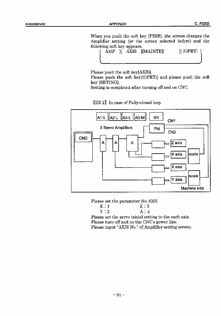
B-65235EfW02 APPENDIX C. FSSB
When you push the soft key FSSB], the screen changes the Amplifier setting (or the screen selected before) and the following soft key appears.
[ AMP IC AXE IWNTEI[ I[ mm 1
Please push the soft key[AXIS]. Please push the soft key[(OPRT)] and please push the soft key [SETING]. Setting is completed after turning off and on CNC.
[EX 2) In case of Fully-closed loop
3 Servo Amplifiers
Machine side
Please set the parameter No.1023. x: 1 z:3 Y:2 A:4
Please set the servo initial setting to the each axis. Please turn off and on the CNC’s power line. Please input “AXIS No.” of Amplifier setting screen.
- 91 -
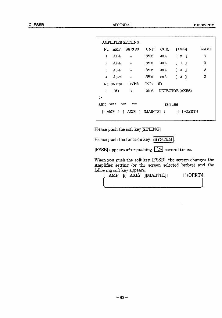
C. FSSB APPENDIX B-65235EN/02
AMPLIFIER SETTING
No. AMF’ SERIES
1 Al-L a
2 A2-L cy
3 A3-L a!
4 A3-M a
No. EXTRA TYPE
5 Ml A
>
&/J-D1 **** *** ***
I AMP 1 [ AxIs I
UNIT CUR. [AXIS1
SVM 40A E 2 1
SVM 40A [ 1 1
SVM 40A [ 4 1
SVM BOA [ 3 1
PCB ID
0008 DETECTOR (AXES)
NAME
Y
x
A
z
13:11:56
Please push the soft key[SETING]
Please push the function key ISYSTEMI.
FSSB] appears after pushing 1 DI several times.
When you push the soft key FSSB], the screen changes the Amplifier setting (or the screen selected before) and the following soft key appears.
c AMP IC AxIS IIMAINTW I[ (OPRT)I
- 92 -
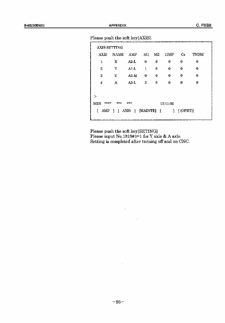
B=65235EN/O2 APPENDIX C. FSSB
Please push the soft key[AXIS].
AXIS SETTING
AXIS NAME AMP Ml MZ 1DSP Cs TNDM
1 X AZ-L 0 0 0 0 0
2 'Y Al-L 1 0 0 0 0
3 z A3-M 0 0 0 0 0
4 A A3-L 2 0 0 0 0
>
MD1 **** *** *** 13:11:56
[ AMP 1 E AxIs 1 [MAINTEl 1 1 [ @pRT)I
- 93 -
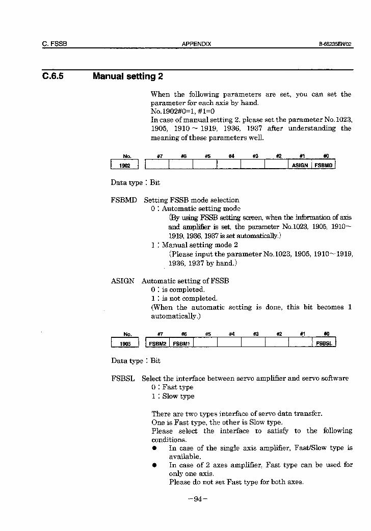
C. FSSB APPENDIX B-65235EfWO2
C.6.5 Manual setting 2
When the following parameters are set, you can set the parameter for each axis by hand. No.1902#0=1, #l=O In case of manual setting 2, please set the parameter No.1023, 1905, 1910 - 1919, 1936, 1937 after understanding the
meaning of these parameters well.
#7 #6 #5 #t4 #3 #a #I ##o
I I ASIGN FSBMD
Data type 1 Bit
FSBMD Setting FSSB mode selection 0 1 Automatic setting mode
(By using FSSB setting screen, when the information of axis and ampEer is set, the parameter No.1023, 1905, 1910- 1919,1936,1937 is set automatically.)
1 1 Manual setting mode 2 (Please input the parameter No. 1023, 1905, 1910- 1919, 1936, 1937 by hand.)
ASIGN Automatic setting of FSSB 0 : is completed. 1 1 is not completed. (When the automatic setting is done, this bit becomes 1 automatically.)
#7 #I6 #5 #4 #a #2 #l #o
FSBM2 FSBMI FSBSL
Data type 1 Bit
FSBSL Select the interface between servo amplifier and servo software 0 1 Fast type 1: Slow type
There are two types interface of servo data transfer. One is Fast type, the other is Slow type. Please select the interface to satisfy to the following conditions. a In case of the single axis amplifier, Fast/Slow type is
available. 0 In case of 2 axes amplifier, Fast type can be used for
only one axis. Please do not set Fast type for both axes.
- 94 -
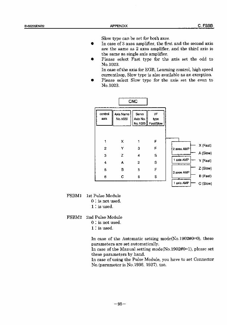
B_65235EN/O2 APPENDIX C. FSSB
Slow type can be set for both axes. a In case of 3 axes amplifier, the first and the second axis
are the same as 2 axes amplifier, and the third axis is the same as single axis amplifier.
l Please select Fast type for the axis set the odd to No. 1023. In case of the axis for EGB, Learning control, high speed currentloop, Slow type is also available as an exception.
l Please select Slow type for the axis set the even to No. 1023.
1 X 1 F
2 Y 3 F
3 z 4 S
4 A 2 S
5 B 5 F
6 C 6 S
FSBMl 1st Pulse Module 0 1 is not used. 1 1 is used.
FSBM2 2nd Pulse Module 0 1 is not used. 1 : is used.
I
- X (Fast) 2 axes AMP
I - A (Slow)
1 axiS AMP - Y (Fast) I
- z (Slow)
12arAMpk B (Fast)
p=-f c (Slow)
In case of the Automatic setting mode(No.1902#0=0), these parameters are set automatically. In case of the Manual setting mode(No.1902#0=1), please set these parameters by hand. In case of using the Pulse Module, you have to set Connector No.(parameter is No.1936, 193’7) too.
- 95 -
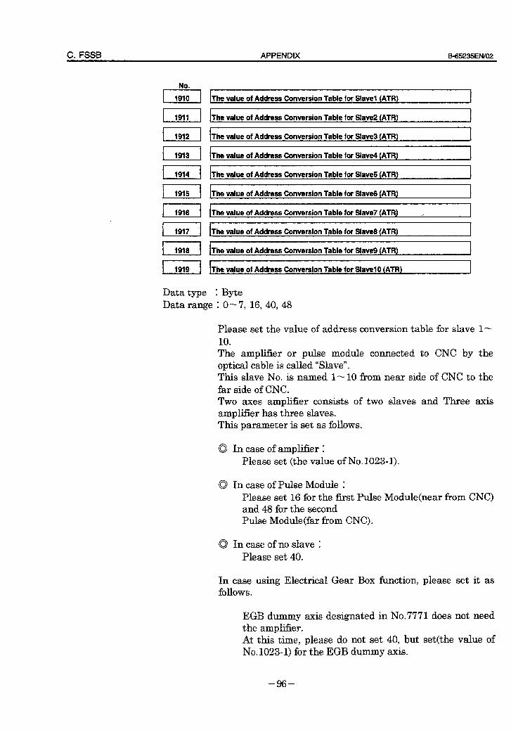
C. FSSB APPENDIX 565235EfWO2
. I*1 The value of Address Conversion Table for Slave1 (ATR)
The value of Address Conversion Table for Slave2 (ATR) J
The value of Address Conversion Table for Slave3 (ATR) ,
The value of Address Conversion Table for Slave4 (ATR)
The value of Address Conversion Table for Slave5 (ATR)
The value of Address Conversion Table for Slave6 (ATR)
The value of Address Conversion Table for Slave7 (ATFI)
The value of Address Conversion Table for Slave8 (ATR)
The value of Address Conversion Table for Slave9 (ATR)
The value of Address Conversion Table for Slave10 (ATR)
Data type 1 Byte Data range : O-7,16,40,48
Please set the value of address conversion table for slave l- 10 Tie ampl.Zer or pulse module connected to CNC by the optical cable is called “Slave”. This slave No. is named l- 10 firom near side of CNC to the far side of CNC. Two axes amplifier consists of two slaves and Three axis amplifier has three slaves. This parameter is set as follows.
0 In case of amplifier 1
Please set (the value of No. 1023-l).
0 In case of Pulse Module 1
Please set 16 for the fkrst Pulse Module(near fkom CNC) and 48 for the second Pulse Module(far from CNC).
0 In case of no slave 1
Please set 40.
In case using Electrical Gear Box function, please set it as follows.
EGB dummy axis designated in No.7771 does not need the amplifier. At this time, please do not set 40, but set(the value of N0.1023~1) for the EGB dummy axis.
- 96 -
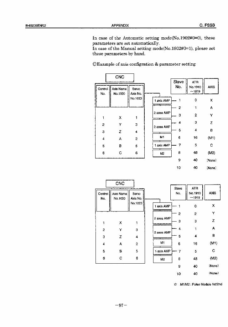
B=65235EN/OZ APPENDIX C. FSSB
In case of the Automatic setting mode(No.1902#0=0), these parameters are set automatically. In case of the Manual setting mode(No.1902#0=1), please set these parameters by hand.
aExample of axis configration & parameter setting
1 X I
2 Y 3
3 z 4
4 A 2
5 B 5
6 C 6
1 X 1
2 Y 3
3 z 4
4 A 2
5 B 5
6 C 6
1
r- Slave No .
IaxisAMP - 1 I
-2
2 axes AMP -3
,
-4
2 axes AMP -5 1
Ml 6
l--axis 7
9
IO
Slave
No.
12axesAMPL ‘,
t- 4
2 axes AMP 1-5
I 1
Ml 6 c \
I I axis AMP t 7
jl 8 9
IO
ATR
No.1910
-1919
0 X
I A
2 Y
3 z
4 B
16 WV
5 c
48 W)
40 (None)
40 (None)
I[ ATR
No.1910
-1919
0 X
2 Y
3 z
1 A
4 B
16 ww
5 C
48 uw
40 (None)
40 (None)
AXIS
-A Ml/M2 : Pulse Module IstY2nd
- 97 -
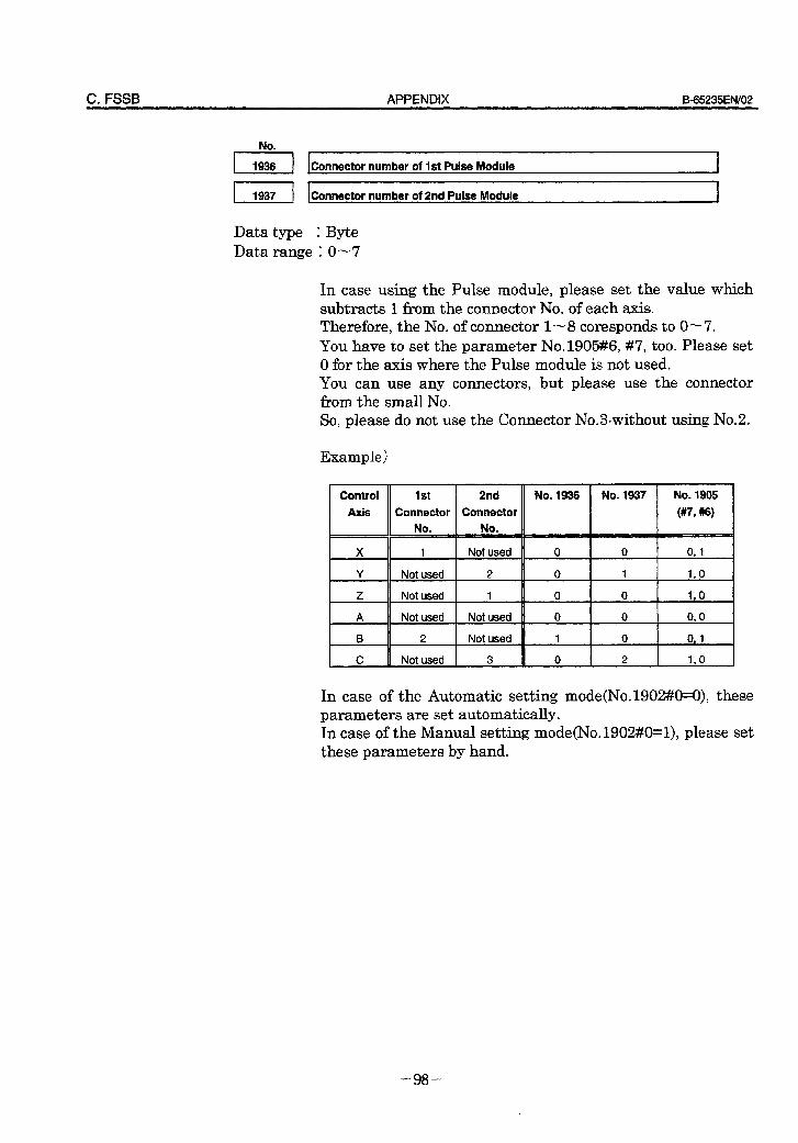
C. FSSB APPENDIX B=65235EN/O2
number of 2nd Pulse IModule
Data type 1 Byte Data range 1 0- 7
In case using the Pulse module, please set the value which subtracts 1 from the connector No. of each axis. Therefore, the No. of connector 1- 8 coresponds to O-7. You have to set the parameter No.1905#6, #7, too. Please set 0 for the axis where the Pulse module is not used. You can use any connectors, but please use the connector from the small No. So, please do not use the Connector No.30without using No.2.
Example)
Control Axis
Z
A E B
C
1 Not used
Not used 2
Not used 1
Not used Not used
2 Not used
Not used 3
No. 1936 No. 1937
I I
No. 1905
(#7, *I
0 I 0 I 0. 1
+-k-t+- In case of the Automatic setting mode(No.1902#0=0), these parameters are set automatica&. In case of the Manual setting mode(No.1902#0=1), please set these parameters by hand.
- 98 -
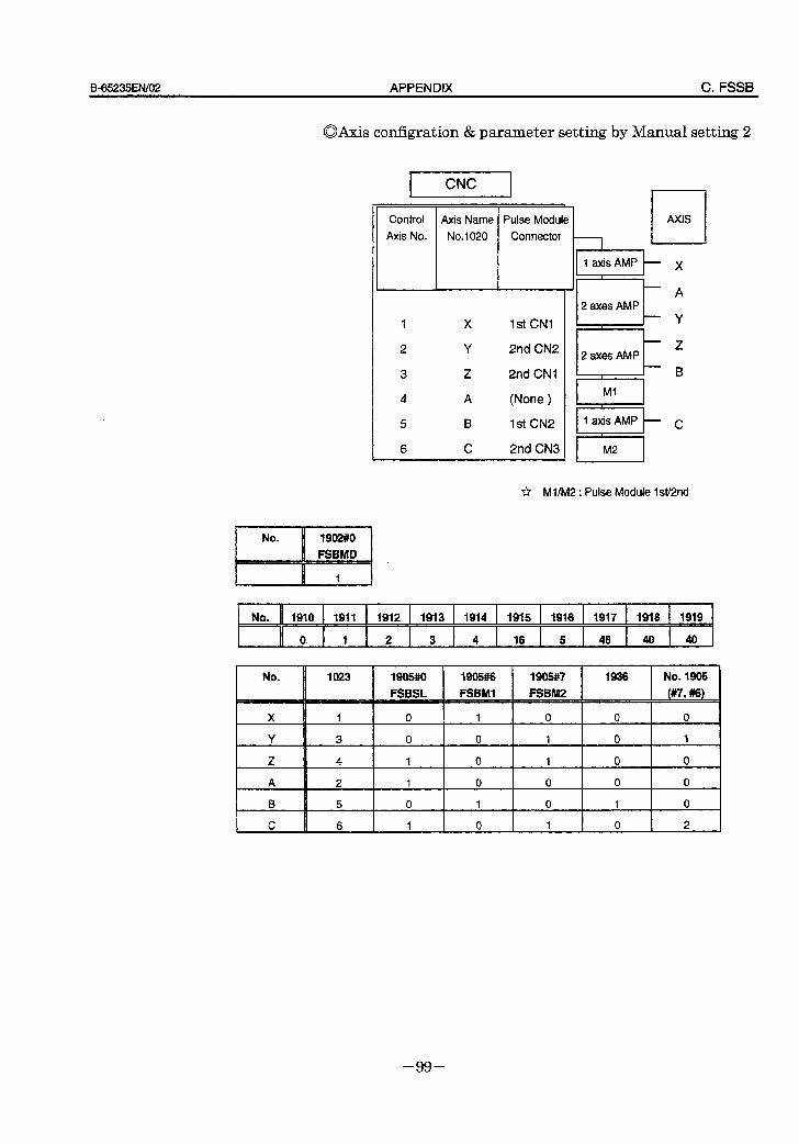
B_65235EN/O2 APPENDIX C. FSSB
aAxis configration & parameter setting by Manual setting 2
- Control
Axis No.
1st CNI
2nd CN2
2nd CNI
(None )
1st CN2
2nd CN3
1 1 axis AMP E x
I M2 I
r?T Ml/M2 : Pulse Module W2nd
/““%I , .
No. 1910 1911 1912 1913 1914 1915 1916 1917 1918 1919
0 1 2 3 4 16 5 48 40 40
No. 1023 19owo 1905% 1905#? 1936 No. 1905
FSBSL FSBMI FSBM2 (#7, #6)
X 1 0 1 0 0 0
Y 3 0 0 1 0 1
z 4 1 0 1 0 0
A 2 1 0 0 0 0
B 5 0 I 0 1 0
C 6 1 0 1 0 2
- 99 -
B-65235ENi02 Index
LED indications and meanings, 36
<A>
AC servo motor maintenance, 57
Actions to be taken on each alarm, 37
Alarm number brief descriptions, 32
Alarm number in Series O-C (SERVO ALARMS), 33
Alarm number in Series 16,18,20,21 (SERVO ALARMS), 34
Automatic setting, 87
<B>
Basic configuration, 5
cc>
Check pin board, 22,77
Checking the control power supply voltage, 24
Checking the motor instantaneous current, 24
Configuration, 4, 76
Confirmation procedure, 21
Confirming the line voltage and power requirements, 9
Connecting the battery for an absolute pulse coder, 53
Connecting the power supply, 9
Connecting the separate regenerative discharge unit, 11
Connection to the servo amplifier unit, 78
Current conversion failure alarm, 39
Daily inspection of AC servo motors, 59
<F>
Feedback disconnected alarm, 41
FSSB, 74
<I>
i series initial setting of parameter, 84
Initializing servo parameters, 12
Invalid servo parameter setting parameters, 43
CL>
Leakage current and selecting a ground fault interrupter, 10
CM>
Major components, 6
Manual setting 1,86
Manual setting 2, 94
Motor overheat alarm, 42
Motor parameter list, 70
CO>
Operation confirmation method, 20,77
Overload alarm, 41
overview of the start-up procedure, 8
<P>
Periodic inspection of /? series motor, 62
Pulse coder communication error alarm, 51
Pulse coder error alarm, 50
CR>
Receiving and keeping AC servo motors, 58
Replacement parts specification, 65
Replacing the fuse, 52
Replacing the pulse coder, 64
Rotation speed data error alarm, 51
es> Servo adjustment screen, 40
Servo amplifier unit, 12, 36
Servo amplifier unit front panel, 69
Servo check board ,25, 79
Servo software, 40
Slave, 85
Start-un nrocedure, 7
CT>
Troubleshooting and recovery, 80
Troubleshooting and recovery procedures, 35
i-l
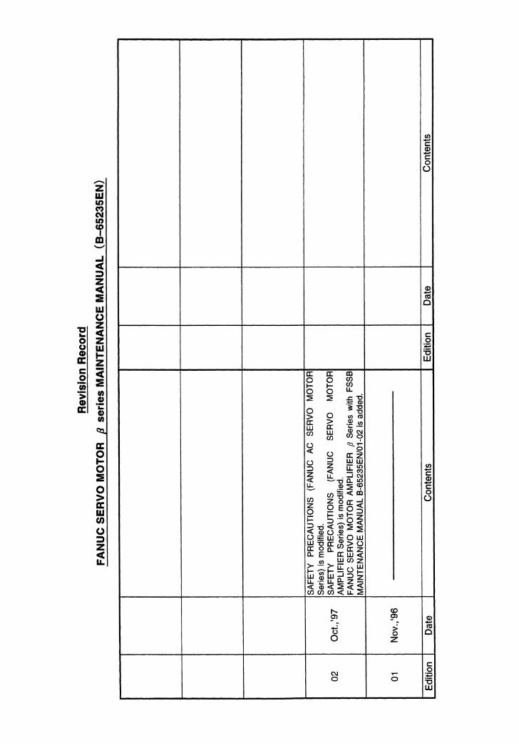
· No part of this manual may bereproduced in any form.
· All specifications and designsare subject to change withoutnotice.


