Embed Size (px)
Citation preview

Bevel Buddybox 4
Catalogue 991361/EN-06/2018

Bevel Buddybox 4 - 991361/EN-06/2018

Table of Contents
Mounting Positions ...................................................... Mounting, Terminal box, Direction of Rotation For Y1, F1, G1, K1 Mounting ............................... For Y2, F2, G2, V2 Mounting ............................... For Y3, G3, F3 Mounting .................................... For Y4, G4, F4 Mounting .................................... For Y5, F5, G5 Mounting .................................... For Y6, F6, G6 Mounting ..................................... For Wall and Ceiling Mounting ............................ Terminal Box and Cable Port ..............................
Allowable Maximum Output Torque .............................. Allowable Radial and Axial Load .................................. Moment of Inertia / GD2 ...............................................
Table of Contents ......................................................... FEATURES .................................................................
Standard Motor and Reducer Combinations ............... Frame Size .................................................................. Actual Reduction Ratios .............................................. Product Range of Motor .............................................. Standard Specification ................................................
Selection Procedure Gearmotors .......................................................... Reducers ............................................................. Load Factors Continuous Duty Operation ................................. Start / Stop Operation ......................................... Understanding Selection Tables .................................. Nomenclatures ............................................................
REDUCER SECTIONSelection Tables Important Notes ........................................... Quick Reference Guide ............................... 60Hz Input (1750, 1165, 870, 580rpm) ........ 50Hz Input (1450, 980, 720, 50rpm) ............ Low Speed (Higher Ratios) .......................... Dimension Sheets Important Notes ........................................... Quick Reference Guide ................................ Hollow Shaft and Case Mount Type ............. Flange Mount Type ...................................... Foot Mount Type .......................................... Supplementary Dimensions X-Adaptor (Single Reduction) ...................... X-Adaptor (Double Reduction) .................... J-Adaptor (Single Reduction) ...................... J-Adaptor (Double Reduction) .....................
Quick Reference Guide ........................................Detail dimension of Input Shaft End ..................... Detail dimension of Output Shaft End ................... Lubrication ............................................................ Handling Precautions - Solid Shaft Units ............. Handling Precautions - Hollow Shaft Units .......... .. Shrink Disc (Option) ............................................. Taper Grip Bush (Option) ..................................... Torque Arm ........................................................... Construction Drawings .........................................
General Information .............................................Technical Data ..................................................... Application ........................................................... Brake Motor Data ................................................. Typical brakemotor wiring .................................... Brakemotor ........................................................... Range of application ............................................. Mechanical Features ............................................ Brake motor assembly .......................................... Motor Options .......................................................
SPECIFICATION AND PRODUCT RANGE
SELECTION PROCEDURE AND NOMENCLATURE
MOUNTING OPTIONS
TORQUE, RADIAL AND AXIAL LOADS, MOMENT OF INERTIA
GEAR MOTOR SELECTION TABLES AND DIMENSIONS
TECHNICAL DATA AND OPTIONS
MOTOR INFORMATION
Important Notes ............................................................ Quick Reference Guide ................................................ Gearmotor Selection Tables ......................................... Dimension Sheets Important Notes ................................................... Size 4A ................................................................ Size 4B ................................................................ Size 4C ................................................................ Size 4D ................................................................ Size 4E ................................................................ Size 4F ................................................................ Supplementary Dimensions Hollow Shaft with Flange Mount .......................... Solid Shaft with Flange Mount ............................. Solid Shaft with Foot Mount .................................
2 1
88
6 6 4
1012
14151718
19
2021222324252629
303241
494950
109110112114116118120
122124126
128128129150172
183183184188192
196197201203
207206
208209213214217219221224
225
228227
231232233235237240241
Bevel Buddybox 4 - 991361/EN-06/2018 1

Bevel Buddybox Reducer & Gearmotor
Compact but High Radial Load CapacityMore compact than a typical right angle gearmotors in the same class. Also, the allowable radial load is significantly increased by use of an FCD housing.
Single lubrication chamberSimple, Single Reservoir Oil Lubrication for Easy Maintenance and Higher Performance
OIL OILTypical right angle shaft gearmotors in the same class.
Long life and excellent shock resistanceThe input stage uses our Cyclo speed reducer or planetary gear which provides greater shock resistance than helical gears and provides a longer operating life.
The gear tooth profile enables the sharing of the load by a number of teeth.
Planetary gearCyclo
Load concentrated in one or fewteeth
Helical gear
Features
BBB4
Flexible configurations
• Shaft Options:
Keyed Hollow
Shrink Disc
Solid Shaft
Keyless Taper
Grip Bushing
• Mounting Options:
Flange
Foot
Shaft
Universal Housing
ns:
ing
Cyclo or Planetary Input provides high overload capacity
and exceptional reliability
Choice of Input
Integral motor and
IEC motor adapter,
models available
Unique Splined Connection
ensures more durable and dependable power transmission than typical keyed connections
100% Hardened Steel
Internal Components
provide long life, smooth
operation and superior
strength
Tapered Bearings
Resist axial and radial
loads simultaneously
Filtered Breather
protects unit lubrication
from contaminants
Double Output Seals
Prevent leaks and exclude
contaminants
Bevel Buddybox 4 - 991361/EN-06/20182

Wide Variety of Application Products and Options
Global SupportEasy maintenanceThis construction uses the Cyclo speed reducer for easy disassembly and repair, allowing for better serviceability.This also makes service support at your local service center possible.
BBB4 reducers and gearmotors can be manufactured according to optimum specifications in the country and region of use.With our global network, maintenance and a replacement can be supported locally.
GOST-R StandardsEC DirectivesCSA StandardsUL Standards CCC Standards
Product DescriptionThe Bevel Buddybox 4 (BBB4) built by Sumitomo is a robust, state of the art mid-sized family of speed reducers and gearmotors. Building on more than 80 years of successful Cyclo experience in virtually every application and industry, the result is an extremely compact, efficient and reliable unit in a very power-dense package. The BBB4 has a unique combination of features that results in a highly reliable, efficient and durable gearbox. The all-steel internal construction, in conjunction with the Cyclo or planetary gear inputs, and ductile iron housing provide unmatched ruggedness.
In addition, the full array of input accessories and output mounting styles provides an amazing ability to customize the product to fit nearly any requirement. These options include solid shaft, hollow bore, shrink disc, free input shaft, integral motor, and IEC adapter.
Features & Benefits• 100% Hardened Steel Rotating Components
~ Provide high efficiency, long life and exceptional reliability• Cycloidal or Planetary Input
~Unmatched capability to handle overloads• Double Output Seals
~Four seal lips on every unit virtually eliminates the possibility of leaks
• Dimensionally Interchangeable with proceding BBB-3 series
~ Simple, economical retrofits• Patented Taper-Grip Bushing
~ Simple, keyless shaft mounting
Specifications SummaryRatios: 11:1 to 26000:1 and greater Torque Capacity: 17400 NmMotor Power: 0,12kW ~ 55kW
Mounting: Keyed Hollow Shaft, Keyless TaperGrip
Bush, Foot, Flange, Face, Shrink Disc
Options: Integral Gearmotor, Hollow Input,
J-adaptor, Shrik Disc
Motor Standards: IEC, CE, CCC, JIS, NEMA, UL, CSA, GOST-R,
etc
Popular Input and Output Options
Keyed Hollow Bore
Taper-Grip Bushing
Solid Output Shaft
Shrink Disc
Bevel Buddybox 4 - 991361/EN-06/2018 3
Bevel Buddybox 4 - 991361/EN-06/20184
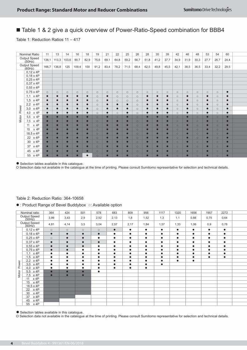
Table 1 & 2 give a quick overview of Power-Ratio-Speed combination for BBB4Table 1: Reduction Ratios 11 – 417
Nominal Ratio 11 13 14 16 18 19 21 22 25 26 28 35 39 42 46 48 53 54 60Output Speed
(50Hz) 138,1 113,3 103,6 90,7 82,9 75,6 69,1 64,8 59,2 56,7 51,8 41,2 37,7 34,9 31,9 30,3 27,7 26,7 24,4
Output Speed (60Hz) 166,7 136,8 125 109,4 100 91,2 83,4 78,2 71,5 68,4 62,5 49,8 45,5 42,1 38,5 36,5 33,4 32,2 29,5
0,12 x 4P 0,18 x 4P 0,25 x 4P 0,37 x 4P 0,55 x 4P 0,75 x 4P 1,1 x 4P 1,5 x 4P 2,2 x 4P 3,0 x 4P 4,0 x 4P 5,5 x 4P 7,5 x 4P 11 x 4P 15 x 4P 18,5 x 4P 22 x 4P 30 x 4P 37 x 4P 45 x 4P 55 x 4P
Selection tables available in this catalogue. O Selection data not available in the catalogue at the time of printing. Please consult Sumitomo representative for selection and technical details.
Table 2: Reduction Ratio: 364-10658: Product Range of Bevel Buddybox : Available option
Nominal ratio 364 424 501 578 683 809 956 1117 1320 1656 1957 2272Output Speed
(50Hz) 3,99 3,43 2,9 2,52 2,13 1,8 1,52 1,3 1,1 0,88 0,75 0,64
Output Speed (60Hz) 4,81 4,14 3,5 3,04 2,57 2,17 1,84 1,57 1,33 1,06 0,9 0,78
0,12 x 4P 0,18 x 4P 0,25 x 4P 0,37 x 4P 0,55 x 4P 0,75 x 4P 1,1 x 4P 1,5 x 4P 2,2 x 4P 3,0 x 4P 4,0 x 4P 5,5 x 4P 7,5 x 4P 11 x 4P 15 x 4P 18,5 x 4P 22 x 4P 30 x 4P 37 x 4P 45 x 4P 55 x 4P
Mot
or P
ower
Mot
or P
ower
Selection tables available in this catalogue. O Selection data not available in the catalogue at the time of printing. Please consult Sumitomo representative for selection and technical details.
Product Range: Standard Motor and Reducer Combinations

Bevel Buddybox 4 - 991361/EN-06/2018 5
67 74 80 88 93 102 112 123 138 151 163 179 189 207 227 249 278 305 417 Nominal Ratio
21,6 19,8 18,2 16,6 15,7 14,3 13 11,9 10,6 9,7 8,9 8,2 7,7 7,1 6,4 5,9 5,3 4,8 3,5 Output Speed (50Hz)
26,1 23,9 21,9 20 18,9 17,3 15,7 14,3 12,8 11,7 10,8 9,9 9,3 8,5 7,8 7,1 6,3 5,8 4,3 Output Speed (60Hz)
0,12 x 4P 0,18 x 4P 0,25 x 4P 0,37 x 4P
0,55 x 4P 0,75 x 4P
1,1 x 4P 1,5 x 4P 2,2 x 4P 3,0 x 4P 4,0 x 4P 5,5 x 4P 7,5 x 4P 11 x 4P 15 x 4P 18,5 x 4P 22 x 4P 30 x 4P 37 x 4P 45 x 4P
55 x 4P
2559 2944 3511 4365 5177 6472 7228 8880 10658 Nominal ratio0,57 0,5 0,42 0,34 0,29 0,23 0,21 0,17 0,14 Output Speed
(50Hz)0,69 0,6 0,5 0,41 0,34 0,28 0,25 0,2 0,17 Output Speed
(60Hz) 0,12 x 4P
0,18 x 4P 0,25 x 4P 0,37 x 4P 0,55 x 4P 0,75 x 4P 1,1 x 4P
1,5 x 4P 2,2 x 4P 3,0 x 4P 4,0 x 4P 5,5 x 4P 7,5 x 4P 11 x 4P 15 x 4P 18,5 x 4P 22 x 4P 30 x 4P 37 x 4P 45 x 4P 55 x 4P
Motor Power
Notes: 1. Calculation of output speed is
based on the following input speeds.
50Hz: 1450 rpm60Hz: 1750 rpm
2. Combination in these tables are guide only. Refer to selection tables for gearmotors (page 50 to 107) or reducers (page129 to 181) for details.
3. Reduction ratios shown above are nominal ratios and output speeds are based on these ratios. Refer to pages 6 and 7 for actual reduction ratio.
4. Refer to Sumitomo Hyponic
Neo as alternative product for this range.
5. Refer to Sumitomo Paramax
as alternative product for this range.
Motor Pow
er
Product Range: Standard Motor and Reducer Combinations

Bevel Buddybox 4 - 991361/EN-06/20186
Table 3: Frame SizesBevel Single + Cyclo Single or Planetary Gear Single Reduction Type Bevel Single + Cyclo Double Reduction Type
4A100 4B120 4C140 4D160 4E170 4F180 4A10DA 4B12DA 4C14DA 4D16DA 4E17DA 4F18DA4A105 4B125 4C145 4D165 4E175 4F185 4A12DA 4B12DB 4C14DB 4D16DB 4E17DB 4F18DB4A110 4B140 4C160 4D170 4E180 4F190 4A12DB 4B14DA 4C14DC 4D17DA 4E17DC 4F19DA4A115 4B145 4C165 4D175 4E185 4F195 4B14DB 4C16DA 4D17DB 4E18DA 4F19DB4A120 4B160 4C170 4D180 4E190 4C16DB 4D17DC 4E18DB4A125 4B165 4C175 4D185 4E195 4D18DA 4E19DA4A140 4D18DB 4E19DB4A145
Table 4: Bevel Single + Planetary Gear Single (Reduction Ratio: 11~18)
Nominal Ratio Frame Size 4A10 4A12 4A144B14
4B164C16
4C174D17
4D184E18
4E194F19
11Actual Ratio 10,50 10,50 10,89 10,85 10,86 10,50 10,82Output Stage (Bevel) 3,5 3,5 3,5 3,5 3,5 3,5 3,5Input Stage (Planetary Gear) 3,000 3,000 3,110 3,100 3,103 3,000 3,091
13Actual Ratio 12,99 12,80 12,95 12,80 13,09 13,09 13,01Output Stage (Bevel) 3,2 3,2 3,2 3,2 3,2 3,2 3,2Input Stage (Planetary Gear) 4,059 4,000 4,047 4,000 4,091 4,091 4,067
14Actual Ratio 14,21 14,00 14,16 14,00 14,32 14,32 14,23Output Stage (Bevel) 3,5 3,5 3,5 3,5 3,5 3,5 3,5Input Stage (Planetary Gear) 4,059 4,000 4,047 4,000 4,091 4,091 4,067
16Actual Ratio 15,36 15,65 16,00 16,26 16,17 15,63 15,47Output Stage (Bevel) 3,2 3,2 3,2 3,2 3,2 3,2 3,2Input Stage (Planetary Gear) 4,800 4,890 5,000 5,080 5,053 4,886 4,833
18Actual Ratio 16,80 17,12 17,50 17,78 17,68 17,10 16,92Output Stage (Bevel) 3,5 3,5 3,5 3,5 3,5 3,5 3,5Input Stage (Planetary Gear) 4,800 4,890 5,000 5,080 5,053 4,886 4,833
Table 5: Bevel Single + Cyclo Reducer Single (Reduction Ratio: 19~417)Nominal Ratio 19 21 22 25 26 28 35 39 42 46 48Actual Ratio 19,2 21,0 22,4 24,5 25,6 28,0 35,2 38,5 41,6 45,5 48,0 Output Stage (Bevel) 3,2 3,5 3,2 3,5 3,2 3,5 3,2 3,5 3,2 3,5 3,2Input Stage (Cyclo) 6 6 7 7 8 8 11 11 13 13 15
Nominal Ratio 53 54 60 67 74 80 88 93 102 112 123Actual Ratio 52,5 54,4 59,5 67,2 73,5 80,0 87,5 92,8 101,5 112,0 122,5 Output Stage (Bevel) 3,5 3,2 3,5 3,2 3,5 3,2 3,5 3,2 3,5 3,2 3,5Input Stage (Cyclo) 15 17 17 21 21 25 25 29 29 35 35
Nominal Ratio 138 151 163 179 189 207 227 249 278 305 417Actual Ratio 137,6 150,5 163,2 178,5 188,8 206,5 227,2 248,5 278,4 304,5 416,5Output Stage (Bevel) 3,2 3,5 3,2 3,5 3,2 3,5 3,2 3,5 3,2 3,5 3,5Input Stage (Cyclo) 43 43 51 51 59 59 71 71 87 87 119
Table 6: Bevel Single + Cyclo Reducer Double (Reduction Ratio: 364~10658)Nominal Ratio 364 424 501 578 683 809 956 1117 1320 1656 1957Actual Ratio 364,0 423,5 500,5 577,5 682,5 808,5 955,5 1116,5 1319,5 1655,5 1956,5 Output Stage 3,5 3,5 3,5 3,5 3,5 3,5 3,5 3,5 3,5 3,5 3,5Input Stage (Cyclo) 104 121 143 165 195 231 273 319 377 473 559(Intermediate Part × Input Part) (13×8) (11×11) (13×11) (15×11) (15×13) (21×11) (21×13) (29×11) (29×13) (43×11) (43×13)
Nominal Ratio 2272 2559 2944 3511 4365 5177 6472 7228 8880 10658Actual Ratio 2271,5 2558,5 2943,5 3510,5 4364,5 5176,5 6471,5 7227,5 8879,5 10657,5 Output Stage 3,5 3,5 3,5 3,5 3,5 3,5 3,5 3,5 3,5 3,5Input Stage (Cyclo) 649 731 841 1003 1247 1479 1849 2065 2537 3045(Intermediate Part × Input Part) (59×11) (43×17) (29×29) (59×17) (43×29) (87×17) (43×43) (59×35) (59×43) (87×35)Notes: 1. Consult us for other available reduction ratios. 2. Some ratios may not be available for certain frame sizes, consult us.
Frame Size and Actual Reduction Ratios

Bevel Buddybox 4 - 991361/EN-06/2018 7
Nominal Ratio 387 403 420 435 441 458 476 525 528 538 541 557 588 598Actual Ratio 387,2 403,2 420,0 435,2 441,0 457,6 476,0 525,0 528,0 537,6 540,8 556,8 588,0 598,4 Output Stage (Bevel) 3,2 3,2 3,5 3,2 3,5 3,2 3,5 3,5 3,2 3,2 3,2 3,2 3,5 3,2Input Stage (Cyclo) 121 126 120 136 126 143 136 150 165 168 169 174 168 187(Intermediate Part×Input Part) (11×11) (21×6) (15×8) (17×8) (21×6) (13×11) (17×8) (25×6) (15×11) (21×8) (13×13) (29×6) (21×8) (17×11)
Nominal Ratio 609 624 640 655 672 707 720 739 774 788 812 816 826 874Actual Ratio 609,0 624,0 640,0 654,5 672,0 707,2 720,0 739,2 773,5 787,5 812,0 816,0 825,6 873,6 Output Stage (Bevel) 3,5 3,2 3,2 3,5 3,2 3,2 3,2 3,2 3,5 3,5 3,5 3,2 3,2 3,2Input Stage (Cyclo) 174 195 200 187 210 221 225 231 221 225 232 255 258 273(Intermediate Part×Input Part) (29×6) (15×13) (25×8) (17×11) (35×6) (17×13) (15×15) (21×11) (17×13) (15×15) (29×8) (17×15) (43×6) (21×13)
Nominal Ratio 893 896 903 925 963 980 1008 1012 1021 1040 1071 1103 1138 1142Actual Ratio 892,5 896,0 903,0 924,8 962,5 980,0 1008,0 1011,5 1020,8 1040,0 1071,0 1102,5 1137,5 1142,4 Output Stage (Bevel) 3,5 3,2 3,5 3,2 3,5 3,5 3,2 3,5 3,2 3,2 3,5 3,5 3,5 3,2Input Stage (Cyclo) 255 280 258 289 275 280 315 289 319 325 306 315 325 357(Intermediate Part×Input Part) (17×15) (35×8) (43×6) (17×17) (25×11) (35×8) (21×15) (17×17) (29×11) (25×13) (51×6) (21×15) (25×13) (21×17)
Nominal Ratio 1200 1204 1206 1232 1239 1250 1306 1313 1348 1360 1392 1411 1428 1456Actual Ratio 1200,0 1204,0 1206,4 1232,0 1239,0 1249,5 1305,6 1312,5 1347,5 1360,0 1392,0 1411,2 1428,0 1456,0 Output Stage (Bevel) 3,2 3,5 3,2 3,2 3,5 3,5 3,2 3,5 3,5 3,2 3,2 3,2 3,5 3,2Input Stage (Cyclo) 375 344 377 385 354 357 408 375 385 425 435 441 408 455(Intermediate Part×Input Part) (25×15) (43×8) (29×13) (35×11) (59×6) (21×17) (51×8) (25×15) (35×11) (25×17) (29×15) (21×21) (51×8) (35×13)
Nominal Ratio 1488 1510 1514 1523 1544 1578 1593 1652 1670 1680 1726 1789 1795 1818Actual Ratio 1487,5 1510,4 1513,6 1522,5 1543,5 1577,6 1592,5 1652,0 1670,4 1680,0 1725,5 1788,8 1795,2 1817,6 Output Stage (Bevel) 3,5 3,2 3,2 3,5 3,5 3,2 3,5 3,5 3,2 3,2 3,5 3,2 3,2 3,2Input Stage (Cyclo) 425 472 473 435 441 493 455 472 522 525 493 559 561 568(Intermediate Part×Input Part) (25×17) (59×8) (43×11) (29×15) (21×21) (29×17) (35×13) (59×8) (87×6) (35×15) (29×17) (43×13) (51×11) (71×8)
Nominal Ratio 1827 1838 1904 1949 1964 1988 2000 2064 2077 2083 2132 2188 2227 2258Actual Ratio 1827,0 1837,5 1904,0 1948,8 1963,5 1988,0 2000,0 2064,0 2076,8 2082,5 2131,5 2187,5 2227,2 2257,5 Output Stage (Bevel) 3,5 3,5 3,2 3,2 3,5 3,5 3,2 3,2 3,2 3,5 3,5 3,5 3,2 3,5Input Stage (Cyclo) 522 525 595 609 561 568 625 645 649 595 609 625 696 645(Intermediate Part×Input Part) (87×6) (35×15) (35×17) (29×21) (51×11) (71×8) (25×25) (43×15) (59×11) (35×17) (29×21) (25×25) (87×8) (43×15)
Nominal Ratio 2320 2339 2352 2436 2448 2454 2499 2538 2573 2678 2685 2691 2734 2774Actual Ratio 2320,0 2339,2 2352,0 2436,0 2448,0 2454,4 2499,2 2537,5 2572,5 2677,5 2684,5 2691,2 2733,5 2774,4 Output Stage (Bevel) 3,2 3,2 3,2 3,5 3,2 3,2 3,2 3,5 3,5 3,5 3,5 3,2 3,5 3,2Input Stage (Cyclo) 725 731 735 696 765 767 781 725 735 765 767 841 781 867(Intermediate Part×Input Part) (29×25) (43×17) (35×21) (87×8) (51×15) (59×13) (71×11) (29×25) (35×21) (51×15) (59×13) (29×29) (71×11) (51×17)
Nominal Ratio 2800 2832 2890 2954 3035 3062 3063 3098 3161 3210 3231 3248 3350 3408Actual Ratio 2800,0 2832,0 2889,6 2953,6 3034,5 3062,4 3062,5 3097,5 3160,5 3209,6 3230,5 3248,0 3349,5 3408,0 Output Stage (Bevel) 3,2 3,2 3,2 3,2 3,5 3,2 3,5 3,5 3,5 3,2 3,5 3,2 3,5 3,2Input Stage (Cyclo) 875 885 903 923 867 957 875 885 903 1003 923 1015 957 1065(Intermediate Part×Input Part) (35×25) (59×15) (43×21) (71×13) (51×17) (87×11) (35×25) (59×15) (43×21) (59×17) (71×13) (35×29) (87×11) (71×15)
Nominal Ratio 3427 3440 3553 3619 3728 3749 3763 3862 3920 3965 3990 4080 4176 4225Actual Ratio 3427,2 3440,0 3552,5 3619,2 3727,5 3748,5 3762,5 3862,4 3920,0 3964,8 3990,4 4080,0 4176,0 4224,5 Output Stage (Bevel) 3,2 3,2 3,5 3,2 3,5 3,5 3,5 3,2 3,2 3,2 3,2 3,2 3,2 3,5Input Stage (Cyclo) 1071 1075 1015 1131 1065 1071 1075 1207 1225 1239 1247 1275 1305 1207(Intermediate Part×Input Part) (51×21) (43×25) (35×29) (87×13) (71×15) (51×21) (43×25) (71×17) (35×35) (59×21) (43×29) (51×25) (87×15) (71×17)
Nominal Ratio 4288 4337 4463 4568 4720 4771 4816 5163 5219 5268 5475 5680 5712 5846Actual Ratio 4287,5 4336,5 4462,5 4567,5 4720,0 4771,2 4816,0 5162,5 5218,5 5267,5 5475,2 5680,0 5712,0 5846,4 Output Stage (Bevel) 3,5 3,5 3,5 3,5 3,2 3,2 3,2 3,5 3,5 3,5 3,2 3,2 3,2 3,2Input Stage (Cyclo) 1225 1239 1275 1305 1475 1491 1505 1475 1491 1505 1711 1775 1785 1827(Intermediate Part×Input Part) (35×35) (59×21) (51×25) (87×15) (59×25) (71×21) (43×35) (59×25) (71×21) (43×35) (59×29) (71×25) (51×35) (87×21)
Nominal Ratio 5917 5989 6213 6248 6395 6589 6608 6960 7018 7207 7613 7676 7952 8074Actual Ratio 5916,8 5988,5 6212,5 6247,5 6394,5 6588,8 6608,0 6960,0 7017,6 7206,5 7612,5 7675,5 7952,0 8073,6 Output Stage (Bevel) 3,2 3,5 3,5 3,5 3,5 3,2 3,2 3,2 3,2 3,5 3,5 3,5 3,2 3,2Input Stage (Cyclo) 1849 1711 1775 1785 1827 2059 2065 2175 2193 2059 2175 2193 2485 2523(Intermediate Part×Input Part) (43×43) (59×29) (71×25) (51×35) (87×21) (71×29) (59×35) (87×25) (51×43) (71×29) (87×25) (51×43) (71×35) (87×29)
Nominal Ratio 8118 8323 8698 8831 9104 9629 9744 9770 10532 10686 11139 11587 11971 12184Actual Ratio 8118,4 8323,2 8697,5 8830,5 9103,5 9628,8 9744,0 9769,6 10531,5 10685,5 11139,2 11587,2 11971,2 12183,5 Output Stage (Bevel) 3,2 3,2 3,5 3,5 3,5 3,2 3,2 3,2 3,5 3,5 3,2 3,2 3,2 3,5Input Stage (Cyclo) 2537 2601 2485 2523 2601 3009 3045 3053 3009 3053 3481 3621 3741 3481(Intermediate Part×Input Part) (59×43) (51×51) (71×35) (87×29) (51×51) (59×51) (87×35) (71×43) (59×51) (71×43) (59×59) (71×51) (87×43) (59×59)
Nominal Ratio 12674 13094 13405 14198 14662 15530 16131 16426 17644 17966 19766 21620 24221 26492Actual Ratio 12673,5 13093,5 13404,8 14198,4 14661,5 15529,5 16131,2 16425,6 17643,5 17965,5 19766,4 21619,5 24220,8 26491,5 Output Stage (Bevel) 3,5 3,5 3,2 3,2 3,5 3,5 3,2 3,2 3,5 3,5 3,2 3,5 3,2 3,5Input Stage (Cyclo) 3621 3741 4189 4437 4189 4437 5041 5133 5041 5133 6177 6177 7569 7569(Intermediate Part×Input Part) (71×51) (87×43) (71×59) (87×51) (71×59) (87×51) (71×71) (87×59) (71×71) (87×59) (87×71) (87×71) (87×87) (87×87)
Notes: 1. Selection Tables for these ratios may not be available in the catalogue, Please consult us for availablity and technical details, 2. The available models or frame sizes may be limited, 3. Consult us for the rated and allowable values of the torque, radial load, and other technical information, 4. Consult us for higher reduction ratios and ratios that are not shown in these tables,
Table 6A: Other available reduction ratios.
Frame Size and Actual Reduction Ratios

Bevel Buddybox 4 - 991361/EN-06/20188
Table 7: Standard Specifications of MotorItem Speci cation
Motor Speci cation Standard Motor (from 0,75kW IE3 Motor) Motor with Built-In Brake (IE1 Motor)
Thre
e Ph
ase
Mot
or
Capacity 0,12kW×4P ~ 55kW×4P 0,12kW×4P~30kW×4P FB Brake
Protection Standard Motor: IP55 (outdoor) Motor with Built-In Brake: IP44 (indoor) Standard; IP55 (outdoor) Option
Enclosure Totally enclosed fan cooled type (or totally enclosed non-ventilated type for 0,12kW×4P )Power Source 50Hz: 220V~240V / 380V~420VThermal Class Class F: 0,12KW~55kWTime Rating Continuous
Terminal Box Position and Lead Wire Direction Refer to pages 20 to 29
Lead Wires 6 wires: 0,12KW~55kW ( - startup for 5,5KW & above) 8 wires: 0,12KW~30kW ( - startup for 5,5KW & above)Standards IEC IEC
Notes: 1. Cousult us for non-standard motor specifications. 2. Consult us if the - startup is necessary for non-standard voltage classes.
Table 8: Standard Specification of Reduction SectionItem Speci cations
Lubrication Method
Output gear section: Oil lubricatedInput gear section (CYCLO Reducer): Oil or grease lubricated
Reduction Method
Output section: Bevel gearInput section: Internal planetary gear with trochoidal curved tooth pro le (CYCLO Drive) or simple planetary tooth mechanism (* planetary for ratio 11~18 only)
Rotation direction Refer to pages 20 to 29
Table 9: Common SpecificationsItem Speci cations
Ambient Conditions
Installation LocationOutdoor (a little dust, not splashed with water). Vibration: 1G or less
Ambient Temperature -10~40oCAmbient Humidity 85% or less
Elevation 1000 m or less above sea level
AtmosphereWell ventilated location, free of dust, corrosive gases, explosive gases, vapors, and the like
Method of Mounting Note 4 Horizontal or vertical (to be designated at the time of order)
Method of Coupling with Driven MachineShaft mount, coupling, gear, chain sprocket, or pulley belt, etc.
Coating Quality: 2-K PURColor: Capriblue, RAL 5019
Note: 4. Consult us if the mounting location contains a slope of 1 degree or more.
Standard Specifications

Bevel Buddybox 4 - 991361/EN-06/2018 9

Bevel Buddybox 4 - 991361/EN-06/201810
The flowchart below is a guide for selection of BBB4 Gearmotor. Consult us for any questions about the procedure.
Step 1: Determination of Operating Conditions Determine the following parameters before starting selection: Application Operation hours per day Continuous operation or operation with frequent Level of shock load start and stop Mounting direction (output shaft direction) and mounting con guration Motor capacity (kW) and output speed or reduction ratio Speci cations for motor (e.g., power supply frequency, voltage, and with/without brake) Radial load and axial load Other ambient conditions (temperature, humidity, indoor or outdoor, and others)
Start/stop repeated
Select load factor based on load characteristics by machine (page 14, Table 10 & 11)
For selection based on startup/stop frequency (page 15, Table 12)
Check allowable thermal capacity of motor (C×Z) (page 15, Table 13)
Check allowable work E0
Select motor capacity
Select output speed and reduction ratio
Check output torque TL ToutTL: Load torque, Tout: Output torque
With brakeWithout brake
Check radial load (Selection Table) Check radial and axial load
Radial load position: 200mm from shaft end for hollow shaft or from shaft midpoint for solid shaft
Shock load: None
Radial load position: Other than the left or
Shock load applied
Is only radialload applied on
shaftNO
YES
Shaft load is withinAllowable Radial Load Pro of
slow speed shaft
Increase reducer frame size by one size, or use heavy
radial load type
Determine reducer frame sizeLoad factor Reducer service factor (SF)
NO
YES
Check slow speed shaft direction, mounting style, and lubrication method
Check dimensions
Check ambient conditions
Check motor speci cations
Determine nomenclature and complete selection
Procedure
From pages 14 and 15, select the load factor matching your application.For operation with repeated starts and stops, check the allowable thermal capacity of the motor on page 15. For a motor with brake, refer to page 16 to ensure that the braking work is within the allowable work E0.Check the brake torque on page 231.
In the selection tables beginning page 50, go to the page that contains the selection table indicating your motor capacity.
Select the cell that contains a value closest to the output speed or reduction ratio which you are looking for.Check whether the output torque is sufficient for your usage. If the output torque is not sufficient, select one size larger motor capacity.From the selection table, select the combination with a service factor (SF) larger than the load factor which you selected.
Check whether only the radial load is applied on the slow speed shaft. If axial load is applicable, make calculation referring to pages 32 to 40.
Refer to page 32 and make calculation, depending on where the radial load is applied, or whether any shock load is applied.*1. The allowable radial load for slow speed shaft in the
selection table is the value obtained when the load position is at the midpoint of the shaft.
*2. If the initial tension is applied by using the chain, V-belt, synchronous belt or the like, these tensions should be included in the radial load.
Check whether the calculated radial load does not exceed the allowable radial load of the output shaft.
Check whether the selected combination matches the output shaft direction, mounting style, and lubrication method you are looking for.Check the dimensions. Consult us if they do not match your requirement.Refer to page 8 for standard specification and ambient conditions. Consult us if your requirement is different.
Check the motor specification on page 8. Consult us if your requirement is different.
Determine the nomenclature for the selected model referring to "Nomenclature" on page 18. Now, the selection process is complete.Verify the maximum torque for startup and stop.
YES
Check the strength of output shaft and coupler, including key surface pressure.
S tep 4 : De te rm ina t i on o f Nomenclature and Completion of Selection
Step 3: Check
Step 2: Model Selection
Refer to page 12 for selection procedure of reducers.
Selection Procedure: Gearmotors

Bevel Buddybox 4 - 991361/EN-06/2018 11
Operating Parameters:
Application: Chain conveyor
Operation pattern: Continuous operation
Operation hours per day: 24 operation hours/day
Load power: 1,3kW
Output speed: 21,6r/min
Method of connection with driven shaft:Chain sprocket
Initial tension = 0
Sprocket pitch circle radius: R = 70mm
Load position: Midpoint of shaft
Level of shock load None
Mounting direction (output shaft direction), mounting style
Motor speci cations
Power frequency : 50Hz
Voltage : 400V
Brake : None
Others Outdoor type
Ambient conditions
Ambient temperature 40oC, indoor
Horizontal, foot mount, and shaft direction left (seen from the motor)
This example selects the model based on the above operation conditions.
Operation conditions, selection, and calculation results Reference pages in this catalog
Select the load factorLoad characteristics for chain conveyor application Uniform load (U)Load factor = 1,20 (U, 24 operation hours/day)
Select the motor capacityLoad factor = 1,3kW Motor capacity = 1.5kW
Select the output speedInput speed 50Hz, output speed 21,6r/min 1450/21,6 = Reduction ratio 67
Check the output torque
TL= 9550×1,3 (kW) ×67=574Nm 612Nm OK 1450
TL Load torque Determine the reducer frame size
Load factor = 1,2 1,27 Reducer frame size and reduction ratio: 2-4A100-67
Check the radial loadPr=TL / R Pro / CfPr=574(Nm) / 0.07(m)=8200(N) 25000(N) / 1=25000(N) OK
Check the output shaft direction, mounting style, and lubrication methodOutput shaft direction: Horizontal; Mounting style: Foot mount Type: LHHM
Check the dimensionsUse the Dimension Tables.
Check the ambient conditionsAmbient temperature: 20oC OK
Check the motor speci cations400V 50Hz, outdoor type OK as the standard
Determine the nomenclature
Determine the nomenclature as: LHHM2-4A100L-K1-67
Now the selection is complete.
Pages 14Table 11Table 10
Page 227
Page 64
Page 64
Page 64
Page 32Page 64
Page 18
Page 110
Page 8
Page 8
Page 18
Load Characteristic Table by MachineLoad Factor
Motor Information
Gearmotor Selection Table
Gearmotor Selection Table
Gearmotor Selection Table
Allowable Radial and Axial LoadGearmotor Selection Table
Nomenclature
Dimension Table
Standard Speci cation
Product Range of Motors
Nomenclature
Below is an example of model selection that follows the selection procedure detailed on page 10.
Selection Procedure: Gearmotors

Bevel Buddybox 4 - 991361/EN-06/201812
Select models using the flow chart below. Consult us for questions about the selection procedure.
Step 2: Model Selection
Step 3: Check
Determine the following conditions before starting selection: Application Level of shock load Continuous operation or operation with frequent Mounting direction (direction of output shaft) and mounting
Load torque TL Other ambient conditions (temperature, humidity, indoor or Radial load and axial load outdoor, and other environments) Operation hours per day
Step 4: Determination of Nomenclature and Completion of Selection
Step 1: Determination of Operating Conditions
Select load factor
Select input speed
Select output speed and reduction ratio
Calculate actual transmitted torque TLn TLn = TL × [Load factor]
Determine frame sizeActual transmitted torque TLn Allowable output torque of reducer Tout
Is only the radial load applied on shaft
TL:Load torque
Radial load position: Shaft midpointShock load: None
Check radial load Check radial and axial load
Radial load position: Outward from shaft midpointor
Shock load: Applied
NO
YES
Shaft load is within Allowable Radial Load Pro of slow
speed shaft
Increase reducer frame size by 1
size, or use heavy radial load type
NO
YES
Check slow speed shaft direction, mounting style, and lubrication method
Check dimensions
Check ambient conditions
Determine nomenclature and complete selection
Check the strength of input and output shafts and the coupler (key surface pressure etc.)
Procedure
From pages 14 and 15, select the load factor matching the application.
On the reducer selection table section following page 128, refer to the page corresponding to the input speed you wish to select.
Select the cell containing a value closest to the output speed or reduction ratio you are looking for.
* Consult us if the input shaft is vertically downward, because the selection tables on page 128 and later are inapplicable in that case.Calculate the actual transmitted torque from the load torque and load factor.
From the selection table, select the reduction ratio and frame size that the allowable output torque is larger than the actual transmitted torque.
Check whether only the radial load is applied on the reducer's input and output shafts. If the axial load is also applied on them, make calculation referring to pages 32 to 40.
Refer to the factor on page 32, depending on where the radial load is applied and whether shock load is applied or not, and convert the value.*1 The output shaft allowable radial load in the selection table is
a value satisfied when the load position is at the midpoint of the shaft.
*2 If the initial tension is applied using the chain, V-belt, synchronous belt, or the like, these tensions should be included in the radial load.
Check whether the calculated radial load exceeds the allowable radial load of the output shaft.
Check whether the selected combination matches the output shaft direction, mounting style, and lubrication method you are looking for.
Check the dimensions. Consult us if they do not match your requirement.
By referring to "Standard Specifications" on page 8 check whether the selected combination matches the ambient conditions, etc.
Determine the nomenclature for the selected model referring to "Nomenclature" on page 18. Now, the selection process is complete.
Check with the maximum torque for startup and stop.
Selection Procedure: Reducers

Bevel Buddybox 4 - 991361/EN-06/2018 13
Below is an example of selection following the procedure on page 12.
Operation conditionsApplication: Chain conveyor Connection with machine :Operation pattern: Continuous operation Output side: Chain sprocket24 operation hours/day Sprocket pitch circle radius: R=80mm
Load torque: 700Nm Load position: Midpoint of shaft; Initial tension = 0Input speed: 1450 rpm Input side: CouplingOutput speed: 16,5 rpm Level of shock load: None
Mounting direction (output shaft direction), mounting styleHorizontal, foot mount, solid
shaft; and shaft direction is left
viewed from the motor.
Operation conditions, selection, and calculation results Reference page in this catalog
Select the load factor Pages 14 and 15Load characteristics for chain conveyor application Uniform load (U) Table 11 Load characteristics by machineLoad factor = 1,20 (U, 24 operation hours/day) Table 10 Reducer Load Factor
Select the input speed1450rpm
Select the output speedInput speed 1450rpm, output speed 16,5rpm 1450/16,5 = Reduction ratio 88
Calculate the actual transmitted torqueTnL=700 (Nm)×1,2=840 (Nm)
Determine the reducer frame sizeTnL Tout 840 (Nm) 889 (Nm) Page 150 Reducer selection table
Reducer frame size: 4A105
Check the radial loadOutput side:Pr=TL / R Pro / Cf Page 32 Allowable Radial and Axial LoadPr=700(Nm) / 0.080(m =8750(N) 22000(N) / 1=22000(N) OK Page 150 Reducer Selection TableInput side:No radial load because of coupling connection.
Check the output shaft direction, mounting style, and lubrication methodOutput shaft direction: Horizontal; Mounting style: Foot mount Type: LHH Page 18 Nomenclature
Check the dimensionsUse the Dimension Tables. Page 184 Dimension Tables
Check the ambient conditionsAmbient temperature: 20oC
Determine the nomenclature
Determine the nomenclature as: LHH-4A105L-K1-88 Page 18 Nomenclature
Now the selection is complete.
This example selects the model based on the above operation conditions.
Selection Procedure: Reducers

Bevel Buddybox 4 - 991361/EN-06/201814
Remarks: *Consult factory. **To be selected on basis of 24 hr. service only.Note: Table above contains reference value. Names and mechanical characteristics of the actual machine may differ from the table above.
1. Please refer to Tables 10 & 11 for recommended load factor modifiers for continuous duty applications.2. The values on the selection tables are based on an operation of 10 hours per day with uniform load.3. For applications with start/stop operations, please refer to page 15.
Recommended Load Factor by Application.[Load Factor] U: Uniform load M: Moderate shock H: Heavy shockTable 10 Reducer Load Factor
Daily duty~3 hours/day ~10 hours/day ~24 hours/day
U M H U M H U M HLoad Factor 0,80 1,00 1,35 1,00 1,20 1,50 1,20 1,35 1,60
Table 11 Recommended Load Classifications
Type of APPLICATION
Type of APPLICATION
Type of LOAD
Type of LOAD
Type of LOAD
Type of LOAD
Type of APPLICATION
Type of APPLICATION
*AeratorAgitators. pure liquids ....................................U liquids & solids .............................. M liquids-variable density ................. MBlowers centrifugal ......................................U lobe ............................................... M vane ...............................................UBrewing & Distilling bottling machinery..........................U brew kettles, cont. duty ..................U cookers-cont. duty .........................U mash tubs-cont. duty .....................U scale hopper, frequent starts ........ MCan Filling Machines ..................... U*Cane Knives .................................MCar Dumpers ................................. HCar Pullers .....................................MClarifiers ........................................ UClassifiers ......................................MClay Working Machinery brick press .....................................H briquette machine ..........................H clay working machinery ................ M pug mill ......................................... MCompressors centrifugal ......................................U lobe ............................................... M reciprocating, multi-cylinder .......... M reciprocating, single-cylinder .........HConveyors-UniformlyLoaded or Fed apron ..............................................U assembly ........................................U belt .................................................U bucket ............................................U chain ..............................................U flight ...............................................U oven ...............................................U screw .............................................UConveyors-Heavy DutyNot Uniformly Fed apron ............................................. M assembly ....................................... M belt ............................................... M bucket ........................................... M chain ............................................. M flight .............................................. M *live roll ............................................ oven .............................................. M reciprocating ..................................H screw ............................................ M shaker ............................................HCranes (Except for Dry Dock Cranes) main hoists....................................... *bridge travel.................................... *trolley travel ....................................Crusher ore ..................................................H stone ..............................................H **sugar .......................................... MDredges cable reels .................................... M conveyors ..................................... M cutter head drives ..........................H jig drives.........................................H maneuvering winches ................... M pumps ........................................... M screen drive ...................................H stackers ........................................ M utility winches................................ M*Dry Dock Cranes
Elevators bucket - uniform load .....................U bucket - heavy load ...................... M bucket - cont. .................................U centrifugal discharge......................U escalators ......................................U freight ............................................ M gravity discharge............................U *man lifts .......................................... *passenger .......................................**Extruders (Plastics) blow molders................................. M coating ...........................................U film .................................................U pipe ................................................U pre-plasticizers .............................. M rods ................................................U sheet ..............................................U tubing .............................................UFans centrifugal ......................................U *cooling towers ................................ induced draft ..................................U *forced draft ..................................... induced draft ................................. M large (mine, etc.) ........................... M large (industrial) ............................ M light (small diameter) .....................UFeeders apron ............................................. M belt ................................................ M disc ................................................U reciprocating ..................................H screw ............................................ MFood industry beet slicer ..................................... M cereal cooker .................................U dough mixer .................................. M meat grinders ................................ MGenerators (not welding) ............... UHammer mills ................................ HHoists heavy duty .....................................H medium duty ................................. M skip hoist ....................................... MLaundry Washers reversing ....................................... MLaundry Tumblers ..........................MLine Shaft driving processing equipment ....... M light ................................................U other line shafts .............................ULumber Industry barkers-hydraulic- mechanical....................................H burner conveyor ............................ M chain saw & drag saw ...................H chain transfer .................................H craneway transfer ..........................H de-barking drum.............................H edger feed..................................... M gang feed .......................................H green chain ................................... M live rolls ..........................................H log haul-locline ...............................H log haul-well type ...........................H log turning device ..........................H main log conveyor .........................H off bearing rolls ............................. M planer feed chains ........................ M planer floor chains ........................ M planer tilting hoist .......................... M re-saw merry- go-round conveyor M roll cases........................................H
slab conveyor.................................H small waste-conveyor-belt .............U small waste-conveyor-chain ......... M sorting table .................................. M tipple hoist conveyor ..................... M tipple hoist drive ............................ M transfer conveyors ........................ M transfer rolls .................................. M tray drive ....................................... M trimmer feed.................................. M waste conveyor ............................. MMachine Tools bending roll ................................... M punch press-gear driven ................H *notching press-belt driven .............. plate planers ..................................H tapping machine ............................H other machine tools main drives .................................. M auxiliary drives ..............................UMetal Mills draw bench carriage &
main drive ..................................... M forming machines ..........................H *pinch, dryer & scrubber rolls,
reversing .......................................... slitters ........................................... M table conveyors-non-reversing group
drives ............................................ M individual drives .............................H *table conveyors-reversing .............. wire drawing & flattening machine M wire winding machine ................... MMills, Rotary Type **ball ............................................. M **cement kilns ............................... M **dryers & coolers ......................... M kilns ............................................... M **pebble ........................................ M **rod , plain & wedge bar.............. M tumbling barrels .............................HMixers concrete mixers, cont. .................. M concrete mixers, intermittent ........ M constant density .............................U variable density ............................. MOil Industry chillers ........................................... M *oil well pumping .............................. paraffin filter press ........................ M rotary kilns .................................... MPaper Mills agitators (mixers) .......................... M barker-auxiliaries-hydraulic ........... M barker-mechanical ........................ M barking drum ..................................H beater & pulper ............................. M bleacher .........................................U calenders ...................................... M calenders-super .............................H converting machine, except cutters,
platers ........................................... M conveyors ......................................U couch ............................................ M cutters-platers ................................H cylinders ........................................ M dryers ............................................ MPaper Mills felt stretcher .................................. M felt whipper ....................................H jordans ...........................................H log haul ..........................................H presses ..........................................U pulp machine reel ......................... M stock chests .................................. M
suction roll......................................U washers & thickeners ................... M winders ..........................................U*Printing PressesPullers barge haul ......................................HPumps centrifugal ......................................U proportioning ................................. M reciprocating single acting, 3 or more
cylinders ........................................ M double acting, 2 or more cylinders M *single acting, 1 or 2 cylinders......... *double acting, single cylinder ......... rotary-gear type .............................U rotary-lobe, vane ............................URubber & Plastics Industries **crackers ......................................H laboratory equipment .................... M **mixing mills .................................H **refiners ....................................... M **rubber calenders ........................ M **rubber mill (2 on line) ................. M **rubber mill (3 on line) ..................U **sheeter ....................................... M *tire building machines .................... *tire & tube press openers ............... **tubers & strainers ....................... M **warming mills ............................. MSand Muller ...................................MScreens air washing.....................................U rotary-stone or gravel ................... M traveling water intake .....................USewage Disposal Equipment bar screens ....................................U chemical feeders............................U collectors, circuline or straightline .........................................U dewatering screws ........................ M grit collectors..................................U scum breakers .............................. M slow or rapid mixers...................... M sludge collectors ............................U thickeners ..................................... M vacuum filters................................ MSlab Pushers .................................M*Steering GearStokers .......................................... USugar Industry **cane knives ................................ M **crushers ..................................... M **mills .............................................HTextile Industry batchers ........................................ M calendars ...................................... M cards ............................................. M dry cans. ....................................... M dryers ............................................ M dyeing machinery.......................... M *knitting machines............................ looms ............................................ M mangles ........................................ M nappers ......................................... M pads .............................................. M *range drives.................................... slashers ........................................ M soapers ......................................... M spinners ........................................ M tenter frames................................. M washers ........................................ M winders ......................................... M*Windlass
Load Factor for Continuous Duty Operation

Bevel Buddybox 4 - 991361/EN-06/2018 15
For recommended Load Factor Modifications for Frequent Start-Stop Operation,refer to tables 12,13 and 14.
Note: 1. The number of starts-stops includes brake or clutch operation times. 2. Consult us when starting under loaded conditions. 3. Consult us if the start/stop frequency exceeds 500 times/hour, because brake for high frequency may be required.
I : Allowable ratio of Moment of Inertia (GD2) 0,3Load Factor II : Allowable ratio of Moment of Inertia (GD2) 3 III: Allowable ratio of Moment of Inertia (GD2) 10
Check that the C×Z value obtained in Steps [1] to [3] below is within the allowable CZ value in the appropriate motor capacity and %ED values in Table 14.
[1] Obtain C using following formulas:
JM : Moment of inertia of motor [kg·m2]JL : Converted value at motor shaft; total moment of inertia
excluding motor [kg·m2]
GDM2
; GD2 of motor [Nm2]GDL
2 ; Total GD2 at the motor shaft excluding motor [kgf·m2]
Table 12 Number of Starts-Stops and Load Factor for Standard Motors <0,75kW and Brake Motors
Number of starts-stops [times/hour]
~3 hours/day ~10 hours/day ~24 hours/dayI II III I II III I II III
~10 0,80 1,00 1,20 1,00 1,10 1,35 1,20 1,25 1,50~200 0,85 1,10 1,30 1,10 1,30 1,50 1,25 1,50 1,65~500 0,90 1,20 1,40 1,15 1,45 1,60 1,30 1,60 1,75
Table 14 Allowable Thermal Capacity of Motor (C×Z)Motor Output
[kW]Allowable C×Z Moment of Inertia of Motor [kg·m2] GD2 of Motor [kgf·m2]
(35%ED or less) (35% ED over~50% ED or less)
(50% ED over~80% ED or less)
(80% ED over~100% ED or less) Standard With brake Standard With brake
0,12 3200 3000 2000 1200 0,00033 0,00035 0,0013 0,00140,18 2200 2800 2800 2500 0,00050 0,00055 0,002 0,00220,25 2200 2800 2800 2500 0,00050 0,00055 0,002 0,00220,37 1800 2200 1500 1500 0,00065 0,00068 0,0026 0,00270,55 1800 2200 1500 1500 0,00101 0,00111 0,00405 0,004450,75 1400 1400 800 500 0,00235 0,00130 0,00942 0,00521,1 1400 1400 800 500 0,00337 0,00208 0,0135 0,00831,5 1200 1200 500 400 0,00391 0,00235 0,0156 0,00942,2 1000 900 400 200 0,00880 0,00373 0,0352 0,01493,0 1000 900 400 200 0,0100 0,00810 0,0400 0,03254,0 800 800 800 700 0,0194 0,00958 0,0777 0,03835,5 300 300 200 150 0,0291 0,01253 0,116 0,05017,5 400 350 300 300 0,0409 0,03025 0,164 0,12111 200 200 150 150 0,0561 0,04100 0,224 0,164
[Gravitational units] C=GDM
2+ GDL2
GDM2
The ratio of Moment of Inertia (The ratio of GD2) = Total Moment of Inertia (GD2) as seen from the motor shaft Moment of Inertia (GD2) of motor
(To next page)
C=JM + JL
JM
[International System of Units]
Table 13 Number of Starts-Stops and Load Factor for Standard Motors (IE3) >0,55kW
Number of starts-stops [times/hour]
~3 hours/day ~10 hours/day ~24 hours/dayI II III I II III I II III
1 0,80 0,95 1,20 1,00 1,15 1,40 1,20 1,30 1,50~3 0,80 1,00 1,25 1,00 1,20 1,45 1,20 1,35 1,55~10 0,80 1,10 1,30 1,00 1,30 1,50 1,20 1,45 1,65~60 0,80 1,20 1,40 1,00 1,40 1,60 1,20 1,65 1,80
Load Factor for Start/Stop Operation

Bevel Buddybox 4 - 991361/EN-06/201816
[2] Obtain the number of startup times per hour Z [times/hr].
(a) If the startup takes place n times for every cycle (i.e., nr [times/cycle]), and the operation and pause times for one cycle are ta [sec] and tb [sec] respectively,
3600nrZ r = [times/hr]t a + t b
(b) If inching takes place ni times for every cycle (ta+tb) (i.e., ni [times/cycle]), it is converted into the number of inching times Zi per hour.
3600nrZ i = [times/hr]t a + t b
(c) Obtain the number of times per hour Z [times/hr] from (a) and (b) above.
1 3600 1Z =Z r + Z i = (n r+ ni) [times/hr]2 t a + t b 2
[3] Obtain C×Z.
Obtain the product of the C value obtained in Step [1] and the Z value obtained in Step [2], i.e., C×Z.
[4] Duty rate %ED
t a ED = ×100t a + t b
Table 15 Allowable Work of Motor Brake E0 Unit : E0(J/min)
kW(4P) 0,12 0,18 / 0,25 0,37 0,55 / 0,75 1,1 / 1,5 2,2 3,0 / 4,0Brake Type FB-01A1 FB-02A1 FB-05A1 FB-1B FB-2B FB-3B FB-5B
Allowable Work E0 1080 1080 1080 1620 2580 3360 6900
kW(4P) 5,5 7,5 11 15 18,5 / 22 / 30Brake Type FB-8B FB-10B FB-15B FB-20 FB-30
Allowable Work E0 6900 10800 10800 22440 22440
[5] Check the brake torque on page 231.
Load Factor for Start/Stop Operation

Bevel Buddybox 4 - 991361/EN-06/2018 17
18,1 729 23900 1,11 21,9 604 25000 1,11 2 - 4A105 - 80 11023900 1,48 25000 1,48 2 - 4A115 - 80 11023900 1,77 25000 1,77 2 - 4A120 - 80 11042100 2,06 40100 2,06 2 - 4B120 - 80 11242100 2,64 40100 2,64 2 - 4B125 - 80 112
16,6 797 23200 1,11 20,0 660 24600 1,11 2 - 4A105 - 88 11023200 1,48 24600 1,48 2 - 4A115 - 88 11023200 1,62 24600 1,62 2 - 4A120 - 88 11043000 2,06 41100 2,06 2 - 4B120 - 88 11243000 2,64 41100 2,64 2 - 4B125 - 88 112
14,3 925 21500 1,06 17,2 766 23500 1,06 2 - 4A105 - 102 110
1,5 kWFrequency Hz 50Hz 60HzMotor poles P 4
Motor speed n1 r/min 1450 1750Reduction ratio 80 364
50Hz 60Hz Model (refer to page 18)
Dimensional Drawing
Page
Output Speed
n2
OutputTorque
Tout
Allowable Radial Load of Output Shaft
Pro
SFGOutput Speed
n2
OutputTorque
Tout
Allowable Radial Load of Output Shaft
Pro
SFG Capacity Symbol
- Frame Size
- Reduction Ratio
r/min Nm N r/min Nm N
IMPORTANT :Please refer to page 49 for Gearmotor Selection Table notes.
Output Speed [rpm]
Input speed [rpm] (motor frequency, number of poles)
Important notes on using selection tablesMotor capacity [kW]
SF (Service Factor)Dimensional Drawing Page
Note that each reduction ratio in the "Type" column is the nominal reduction ratio.
* The output speed is calculated from the actual reduction ratio,except for ratios 11 to 18 where representative reduction ratio is used (as the actual reduction ratio for these ratios vary with frame size.)
Gearmotor: Below illustration describes the main fields of each selection tables on page 50 onwards.
Reducer: Below illustration describes the main fields of each selection tables on page 128 onwards.
Sizen1 1450 980 720 50
Ratio i
n2 [rpm]
P1 [kW]
Tout [Nm]
Pro [N]
n2 [rpm]
P1 [kW]
Tout [Nm]
Pro [N]
n2 [rpm]
P1 [kW]
Tout [Nm]
Pro [N]
n2 [rpm]
Tout [Nm]
Pro [N]
4D160[Dimension Drawings
from page 184]
54 26,9 13,1 4330 66200 18,2 11,2 5470 72500 13,4 8,2 5450 81200 1,0 5450 8310060 24,2 13,1 4720 67100 16,4 11,2 5960 73400 12,0 8,2 5960 79700 0,9 5960 7970067 21,7 12,9 5260 68300 14,7 9,1 5450 78300 10,8 6,7 5450 83100 0,8 5450 8310074 19,6 12,9 5760 69100 13,3 9,1 5960 79400 9,8 6,7 5960 79700 0,7 5960 7970080 18,2 9,9 4790 74300 12,3 7,6 5450 83100 9,0 5,6 5450 83100 0,7 5450 8310088 16,5 9,9 5240 75500 11,2 7,6 5960 79700 8,2 5,6 5960 79700 0,6 5960 7970093 15,6 9,6 5390 76600 10,6 6,5 5450 83100 7,8 4,8 5450 83100 0,6 5460 83100
102 14,3 9,6 5890 77600 9,7 6,6 5960 79700 7,1 4,8 5960 79700 0,5 5960 79700112 13,0 8,1 5450 81800 8,8 5,5 5450 83100 6,5 4,0 5450 83100 0,5 5450 83100123 11,8 8,1 5960 79700 8,0 5,5 5960 79700 5,9 4,0 5960 79700 0,5 5960 79700138 10,6 6,5 5390 83400 7,1 4,4 5390 83400 5,3 3,2 5380 83400 0,4 5380 83400151 9,6 6,5 5890 80200 6,5 4,4 5890 80200 4,8 3,2 5890 80200 0,4 5890 80200163 8,9 5,5 5450 83100 6,1 3,7 5450 83100 4,5 2,7 5450 83100 0,4 5460 83100179 8,1 5,5 5960 79700 5,5 3,8 5960 79700 4,1 2,8 5960 79700 0,3 5960 79700
IMPORTANT: Please refer to page 128 for Reducer Selection Table notes.
Frame size Ratio Technical Speci cations
Input Speed
Understanding Selection Tables
Bevel Buddybox 4 - 991361/EN-06/201818
L1
H2
Y3
M4 8
B129 10
Y111
46135
36
4A1057
Integrated Motor Type
Reducer with free Input Shaft
(Hollow Bore) Left Side Right Side Both Side
With Motor Adaptor
With Motor Adaptor & Motor Input Hollow & Motor
Input Hollow
3 Mounting Style
U HHollow Shaft Type Solid Shaft Type, Case Mount Solid Shaft Type, Flange Mount Plug-in Shaft, Foot Mount
Gea
rmot
orR
educ
er
Y F
4
XM
Red
ucer
Gea
rmot
or M JM
5 Special SpecificationsStandard Specification
Special Specification S
6 Motor Capacity Symbol
Capacity SymbolkW
Capacity SymbolkW
1H
2 3 4 8
Capacity SymbolkW
10 15
2015
25 3022
7555
4030
5037
6045
4-Pole
7 Frame Size
12 With/Without Brake With brake B
Without brake
9 Shaft SpecificationMetric Size (Standard)
Taper Grip Metric Size M
10 Suffix
11 Mounting Position
13 Reduction Ratio
Standard Specification SVServo Motor
TLWith Torque Limiter
Note Note R
8 Output Shaft Projection
T
11
2 Output Shaft Direction
H V WG
earm
otor
Red
ucer
Output shaft direction: Horizontal
Output shaft direction: Vertical (hollow shaft) or vertically downward (solid)
Output shaft direction: Vertically upward (solid shaft)
Bevel Buddybox Reducer: LProduct Symbol
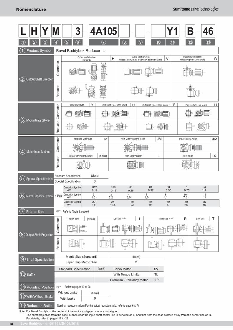
Note: For Bevel Buddybox, the centers of the motor and gear case are not aligned.The shaft projection from the case surface near the input shaft center line is denoted as L, and that from the case surface away from the center line as R.For details, refer to pages 19 to 28.
J
L
X
Red
ucer
Gea
rmot
or
Motor Input Method(blank)
(blank)
(blank)
Refer to Table 3, page 6
Refer to pages 19 to 28
(blank)
(blank)
(blank)
Nominal reduction ration (For the actual reduction ratio, refer to page 6 & 7)
012 018 04 08 1030,12
1,5 2,2 3,0 4,0 5,5 7,5 11
18,5
0,18 0,25 0,37 0,55 0,75 1,16
Premium - E ciency Motor EP
Nomenclature

Bevel Buddybox 4 - 991361/EN-06/2018 19
Example 1(Gearmotor): Example 2(Reducer):LHYM2 - 4A105 - Y1 - 88 LHF - 4C140L - F1 - 67
L : Model - Bevel Buddybox L : Model - Bevel BuddyboxH : Output shaft direction - Horizontal H : Output shaft direction - HorizontalY : Mounting style - Hollow shaft, shaft mount F : Mounting style - Flange mountM2 4A105 : Frame size - 4A105Y1 : Mounting position - Y188 : Reduction ratio - 88
1. Mounting position and nomenclature 2. Positional Relationship between the Motor Center and Gear CaseCheck the mounting con guration relative to the mechanical equipment.The mounting position symbol denotes the mounting surface and mounting style of the reducer. For details, refer to items 2 and 3 on this page and pages 19 to 29.(The gure below shows mounting positions of hollow shaft units as typical examples.)
Mechanical Equipment
Y1 or Y3
Y5 or Y6
Y1 or Y3
Y5 or Y6
Y2
Y4
The centers of the motor and gear case are not aligned.
G1G2
G2
G1
Positional Relationship between the motor center and gear case(Dimension G2 > G1)
Thus, the gearmotor can be mounted in two manners, except for some mounting styles. For example, mounting position Y3 against Y1 and mounting position Y6 against Y5 are installed with the gear case rotated 180 degrees relative to the motor; the relative position to the mechanical equipment can be changed.
Example: Di erences between mounting positions Y5 and Y6
Y5 The center of motor is nearer to the mechanical equipment.Mechanical Equipment
Y6 The center of motor is nearer to the opposite end of the mechanical equipment.Mechanical Equipment
3. Mounting StylesCheck the mounting style (The gures below show the mounting styles with mounting position symbols 1. Foot mount, wall mount and ceiling mount are also available (pages 26 to 28).
LHYM- YHollow Shaft, Shaft Mount
Hollow Shaft,Flange Mount
LHYM- FSolid Shaft,
Flange Mount
LHFM- L FSolid Shaft,Foot Mount
LHHM- L KSolid Shaft,Case Mount
LHUM- L Y
Example of Nomenclatures
Motor equipped, Power : 2 HP (1,5kW): 4C140 : Frame size - 4C140L : Output shaft projection - L side (refer to page 18)F1 : Mounting position - F167 : Reduction ratio - 67
Mounting Positions

Bevel Buddybox 4 - 991361/EN-06/201820
●The standard terminal box position is N33, and the cable port direction is N3A.The terminal box position and the cable port direction can be changed in 90-degree steps. Refer to page 29.
●The centers of the motor and gear case are not aligned(dimension G2 > G1).
●The reducer shape varies with the type. For some types, the motor diameter islarger than the gear case. Be sure to check that there is no interference withmounting surface caused by the terminal box, motor, DC dimension, etc.
[Reference]In mounting positions Y3, F3, and G3, the gear case is assembled in a positioninverted (i.e., rotated by 180 degrees) relative to the motor, thus the relativeposition to the mechanical equipment is different from Y1, F1, G1. This alsochanges the positions of the terminal box, oil filler, etc.(Refer to page 22).
LHYM- -Y1LHYM- -Y1
LHYM- -G1
LHFM- L-F1 LHFM- R-G1
LHYM- -F1
Hollow shaftShaft Mount
Solid ShaftCase Mount
Hollow shaftFlange Mount
Solid ShaftFoot Mount
LHUM- R-Y1LHUM- L-Y1
Solid ShaftFlange Mount
N35
N34
N36
N33
N3A
Mounting Positions Y1,G1,K1 Mounting Positions Y1,F1,K1N35
N36
N33N34
N3A
Rotation direction of motor or input shaft Note 1, 2
Standard terminal box position and cable port direction
A
Reduction Ratio19 305
Reduction Ratio11 18
364 10658
A
Reduction Ratio19 305
Reduction Ratio11 18
364 10658
A
Reduction Ratio19 305
Reduction Ratio11 18
364 10658
A
Reduction Ratio19 305
Reduction Ratio11 18
364 10658
Reduction Ratio19 305
Reduction Ratio11 18
364 10658
A
Reduction Ratio19 305
Reduction Ratio11 18
364 10658
A
Reduction Ratio19 305
Reduction Ratio11 18
364 10658
A
Reduction Ratio19 305
Reduction Ratio11 18
364 10658
Y
G1G2
G2G1
Up
Down
Up
Down
Up
Down
Up
Down
Up
Down
Up
Down
Up
Down
Up
Down
LHHM- R-K1 Output Shaft Rotation Direction
Output Shaft Rotation Direction
Output Shaft Rotation Direction
Output Shaft Rotation Direction
A
Reduction Ratio19 305
Reduction Ratio11 18
364 10658
Up
Down
LHHM- L-K1 Output Shaft Rotation Direction
Output Shaft Rotation Direction
Output Shaft Rotation Direction
Output Shaft Rotation Direction
Output Shaft Rotation Direction
Output Shaft Rotation Direction
Reduction Ratio19 305
Reduction Ratio11 18
364 10658
Up
Down
Mounting Positions Y1 F1 G1 K1
Oil gaugeDrain portOil fillerAir vent plug
MarksNotes: 1. The motor rotation direction shown here is for Sumitomo motors with the wiring as shown on page 226.2. The rotation direction of the output shaft (viewed from A) is shown assuming that the rotation direction of the motor or input shaft is
counter clockwise when viewed from fan end. If the rotation direction of the motor or input shaft is clockwise, the rotation direction of the output shaft is reversed.
3. The oil gauge location is shown in the drawings above. Be sure to designate the location when making the order if the oil gauge needs to be located on opposite side or both sides.
Mounting,Terminal Box Positions and Direction of Rotation

Bevel Buddybox 4 - 991361/EN-06/2018 21
Mounting Positions Y2 F2 G2 V2
Oil gaugeDrain portOil fillerAir vent plug
MarksNotes: 1. The motor rotation direction shown here is for Sumitomo motors with the wiring as shown on page 226.2. The rotation direction of the output shaft (viewed from A) is shown assuming that the rotation direction of the motor or input shaft is counter clockwise when viewed from fan end. If the rotation direction of the motor or input shaft is clockwise, the rotation direction of the output shaft is reversed.3. The oil gauge location is shown in the drawings above. The oil gauge location can be changed in 90 degrees steps in a horizontal direction.
In this case, the oil filler, air vent and piping are also changed, because the oil gauge, oil filler and air vent are put on the same piping. Be sure to designate the location when making the order if the oil gauge location needs to be changed.
X
LHYM- -Y2
LHHM- L-V2 LHHM- R-V2
N33 N34
N35
N36N3A
Mounting Positions Y2,F2,V2
A
A
A
Mounting Positions Y2,G2,V2
N34 N33
N35
N36
G1G2
G1G2
●The standard terminal box position is N33, and the cable port direction is N3A.The terminal box position and the cable port direction can be changed in90-degree steps. Refer to page 29.
Rotation direction of motor or input shaft Note 1, 2
Standard terminal box position and cable port direction
●The centers of the motor and gear case are not aligned (dimension G2 > G1).●The reducer shape varies with the type. For some types, the motor diameter is larger than the gear case. Be sure to check that there is no interference with mounting surface caused by the terminal box, motor, DC dimension part, etc.
Hollow shaftShaft Mount
Solid ShaftCase Mount
Hollow shaftFlange Mount
Solid ShaftFoot Mount
Solid ShaftFlange Mount
N3A
Up
Down
Up
Down
Up
Down
Output Shaft Rotation Direction
Output Shaft Rotation Direction
Output Shaft Rotation Direction
Output Shaft Rotation Direction
Output Shaft Rotation Direction
Output Shaft Rotation Direction
Output Shaft Rotation Direction
Output Shaft Rotation Direction
Output Shaft Rotation Direction
Output Shaft Rotation Direction
A
Reduction Ratio19 305
Reduction Ratio11 18
364 10658
A
Reduction Ratio19 305
Reduction Ratio11 18
364 10658
A
Reduction Ratio19 305
Reduction Ratio11 18
364 10658
A
Reduction Ratio19 305
Reduction Ratio11 18
364 10658
A
Reduction Ratio19 305
Reduction Ratio11 18
364 10658
LHFM- L-F2
A
Up
Down
LHYM- -F2
A
Up
Down
LHUM- L-Y2
A
Up
Down
LHFM- R-G2
A
Up
Down
LHYM- -G2
A
Up
Down
LHUM- R-Y2
A
Up
Down
LHYM- -Y2
A
Up
Down
A
Reduction Ratio19 305
Reduction Ratio11 18
364 10658
A
Reduction Ratio19 305
Reduction Ratio11 18
364 10658
A
Reduction Ratio19 305
Reduction Ratio11 18
364 10658
A
Reduction Ratio19 305
Reduction Ratio11 18
364 10658
A
Reduction Ratio19 305
Reduction Ratio11 18
364 10658
Mounting,Terminal Box Positions and Direction of Rotation

Bevel Buddybox 4 - 991361/EN-06/201822
Oil gaugeDrain portOil fillerAir vent plug
Marks
X
LHYM- -Y3 LHYM- -Y3
LHUM- R-Y3 LHUM- L-Y3
LHYM- -G3LHYM- -F3
LHFM- R-G3 LHFM- L-F3
XMounting Positions Y3,G3
N35
N36
N33N34
N3A
Mounting Positions Y3,F3N35
N36
N33N34
N3A
Y
Y
A
A
A
A
A
A
A
A
G1G2
G1 G2
●The standard terminal box position is N33, and the cable port direction is N3A.The terminal box position and the cable port direction can be changed in 90-degree steps. Refer to page 29.
Rotation direction of motor or input shaft Note 1, 2
Standard terminal box position and cable port direction
●The centers of the motor and gear case are not aligned(dimension G2 > G1).
●The reducer shape varies with the type. For some types, the motor diameter islarger than the gear case. Be sure to check that there is no interference withmounting surface caused by the terminal box, motor, DC dimension part, etc.
[Reference]In mounting positions Y1, F1, and G1, the gear case is assembled in a positioninverted (i.e., rotated by 180 degrees) relative to the motor, the relative positionto the mechanical equipment is different from Y3, F3 and G3. This also changesthe positions of the terminal box, oil filler, etc.(Refer to page 20).
Hollow shaftShaft Mount
Solid ShaftCase Mount
Hollow shaftFlange Mount
Solid ShaftFoot Mount
Solid ShaftFlange Mount
Up
Down
Up
Down
Up
Down
Up
Down
Up
Down
Up
Down
Up
Down
Up
Down
Output Shaft Rotation Direction
Output Shaft Rotation Direction
Output Shaft Rotation Direction
Output Shaft Rotation Direction
Output Shaft Rotation Direction
Output Shaft Rotation Direction
Output Shaft Rotation Direction
Output Shaft Rotation Direction
A
Reduction Ratio19 305
Reduction Ratio11 18
364 10658
A
Reduction Ratio19 305
Reduction Ratio11 18
364 10658
A
Reduction Ratio19 305
Reduction Ratio11 18
364 10658
A
Reduction Ratio19 305
Reduction Ratio11 18
364 10658
A
Reduction Ratio19 305
Reduction Ratio11 18
364 10658
A
Reduction Ratio19 305
Reduction Ratio11 18
364 10658
A
Reduction Ratio19 305
Reduction Ratio11 18
364 10658
A
Reduction Ratio19 305
Reduction Ratio11 18
364 10658
Mounting Positions Y3 G3 F3
Notes: 1. The motor rotation direction shown here is for Sumitomo motors with the wiring as shown on page 226.2. The rotation direction of the output shaft (viewed from A) is shown assuming that the rotation direction of the motor or input shaft is counter clockwise when viewed from fan end. If the rotation direction of the motor or input shaft is clockwise, the rotation direction of the output shaft is reversed.3. The oil gauge location is shown in the drawings above. Be sure to designate the location when making the order if the oil gauge needs to be located on opposite side or both sides.
Mounting,Terminal Box Positions and Direction of Rotation

Bevel Buddybox 4 - 991361/EN-06/2018 23
Mounting Positions Y4 G4 F4
Oil gaugeDrain portOil fillerAir vent plug
MarksNotes: 1. The motor rotation direction shown here is for with the wiring as shown on page 226.2. The rotation direction of the output shaft (viewed from A) is shown assuming that the rotation direction of the motor or input shaft is counter clockwise when viewed from fan end. If the rotation direction of the motor or input shaft is clockwise, the rotation direction of the output shaft is reversed.3. The oil gauge location is only as per the drawing above. The opposite side location is not available.
LHYM- -Y4
X
LHYM- -G4
LHFM- R-G4
LHYM- -F4
LHFM- L-F4
LHUM- R-Y4 LHUM- L-Y4
LHYM- -Y4
Y
A
A
A
A
A
A
A
A
X
N35
N34
N36
N33
N35
N36
N33N34
Mounting Positions Y4,G4 Mounting Positions Y4,F4
Y
A
Reduction Ratio19 305
Reduction Ratio11 18
364 10658
G1 G2G1 G2
●The standard terminal box position is N33, and the cable port direction is N3A.The terminal box position and the cable port direction can be changed in 90-degree steps. Refer to page 29.
Rotation direction of motor or input shaft Note 1, 2
Standard terminal box position and cable port direction
●The centers of the motor and gear case are not aligned (dimension G2 > G1).●The reducer shape varies with the type. For some types, the motor diameter is larger
than the gear case. Be sure to check that there is no interference with mounting surfacecaused by the terminal box, motor, DC dimension part, etc.
Hollow shaftShaft Mount
Solid ShaftCase Mount
Hollow shaftFlange Mount
Solid ShaftFlange Mount
Up
Down
Up
Down
Up
Down
Up
Down
Up
Down
Up
Down
Up
Down
Up
Down
N3A
A
Reduction Ratio19 305
Reduction Ratio11 18
364 10658
A
Reduction Ratio19 305
Reduction Ratio11 18
364 10658
A
Reduction Ratio19 305
Reduction Ratio11 18
364 10658
A
Reduction Ratio19 305
Reduction Ratio11 18
364 10658
A
Reduction Ratio19 305
Reduction Ratio11 18
364 10658
A
Reduction Ratio19 305
Reduction Ratio11 18
364 10658
A
Reduction Ratio19 305
Reduction Ratio11 18
364 10658
Output Shaft Rotation Direction
Output Shaft Rotation Direction
Output Shaft Rotation Direction
Output Shaft Rotation Direction
Output Shaft Rotation Direction
Output Shaft Rotation Direction
Output Shaft Rotation Direction
Output Shaft Rotation Direction
Mounting,Terminal Box Positions and Direction of Rotation

Bevel Buddybox 4 - 991361/EN-06/201824
Oil gaugeDrain portOil fillerAir vent plug
MarksNotes: 1. The motor rotation direction shown here is for Sumitomo motors with the wiring as shown on page 226.2. The rotation direction of the output shaft (viewed from A) is shown assuming that the rotation direction of the motor or input shaft is counter clockwise when viewed from fan end. If the rotation direction of the motor or input shaft is clockwise, the rotation direction of the output shaft is reversed.3. The oil gauge location is shown in the drawings above. Be sure to designate the location when making the order if the oil gauge needs to be located on opposite side or both sides.
[Reference]In mounting positions Y6, F6, and G6, the gear case is mounted in a position inverted(i.e., rotated by 180 degrees) relative to the motor, thus the relative position to themechanical equipment is different from Y5, F5, and G5. This also changes the positionsof the terminal box, oil filler, etc.(Refer to page 25).
XX Mounting Positions Y5,G5
LVYM- -Y5
LVYM- -G5
LWFM- R-G5
LWUM- R-Y5
LVYM- -Y5
LVYM- -F5
LVFM- L-F5
LVUM- L-Y5
N3A
N36N35
N34
N33
Y
Y
A
A
A
A
A
A
A
A
A
Reduction Ratio19 305
Reduction Ratio11 18
364 10658
A
Reduction Ratio19 305
Reduction Ratio11 18
364 10658
A
Reduction Ratio19 305
Reduction Ratio11 18
364 10658
A
Reduction Ratio19 305
Reduction Ratio11 18
364 10658
A
Reduction Ratio19 305
Reduction Ratio11 18
364 10658
A
Reduction Ratio19 305
Reduction Ratio11 18
364 10658
A
Reduction Ratio19 305
Reduction Ratio11 18
364 10658
A
Reduction Ratio19 305
Reduction Ratio11 18
364 10658
G1G2
G1G2
Mounting Positions Y5,F5
N33
N34
N36N35
N3A
●The standard terminal box position is N33, and the cable port direction is N3A.The terminal box position and the cable port direction can be changed in 90-degree steps. Refer to page 29.
Rotation direction of motor or input shaft Note 1, 2
Standard terminal box position and cable port direction
●The centers of the motor and gear case are out of alignment (dimension G2 > G1).●The reducer shape varies with the type. For some types, the motor diameter is larger
than the gear case. Be sure to check that there is no interference with mounting surface caused by the terminal box, motor, DC dimension part, or any other component.
Hollow shaftShaft Mount
Solid ShaftCase Mount
Hollow shaftFlange Mount
Solid ShaftFlange Mount
Up
Down
Up
Down
Up
Down
Up
Down
Up
Down
Up
Down
Up
Down
Up
Down
Output Shaft Rotation Direction
Output Shaft Rotation Direction
Output Shaft Rotation Direction
Output Shaft Rotation Direction
Output Shaft Rotation Direction
Output Shaft Rotation Direction
Output Shaft Rotation Direction
Output Shaft Rotation Direction
Mounting Positions Y5 F5 G5
Mounting,Terminal Box Positions and Direction of Rotation

Bevel Buddybox 4 - 991361/EN-06/2018 25
Oil gaugeDrain portOil fillerAir vent plug
MarksNotes: 1. The motor rotation direction shown here is for Sumitomo motors with the wiring as shown on page 226.
2. The rotation direction of the output shaft (viewed from A) is shown assuming that the rotation direction of the motor or input shaft is counter clockwise when viewed from fan end. If the rotation direction of the motor or input shaft is clockwise, the rotation direction
of the output shaft is reversed.3. The oil gauge location is shown in the drawings above. Be sure to designate the location when making the order if the oil gauge needs to be located on opposite side or both sides.
Mounting Positions Y6,F6
X
XMounting Positions Y6,G6
N3A
N35N36
N33
N34
N35N36
N33
N34
N3A
YY
G1
G2
G1
G2
●The standard terminal box position is N33, and the cable port direction is N3A.The terminal box position and the cable port direction can be changed in 90-degree steps. Refer to page 29.
Rotation direction of motor or input shaft Note 1, 2
Standard terminal box position and cable port direction
●The centers of the motor and gear case are out of alignment (dimension G2 > G1).●The reducer shape varies with the type. For some types, the motor diameter is
larger than the gear case. Be sure to check that there is no interference with mounting surface caused by the terminal box, motor, DC dimension, etc.
[Reference]In mounting positions Y5, F5, and G5, the gear case is mounted in a position inverted(i.e., rotated by 180 degrees) relative to the motor, thus the relative position to themechanical equipment is different from Y6, F6, and G6. This also changes the positionsof the terminal box, oil filler, etc.(Refer to page 24).
LVYM- -Y6
LVYM- -F6
LWFM- L-F6
LWUM- L-Y6
LVYM- -Y6
LVYM- -G6
LVFM- R-G6
LVUM- R-Y6
A
A
A
A
A
A
A
A
A
Reduction Ratio19 305
Reduction Ratio11 18
364 10658
A
Reduction Ratio19 305
Reduction Ratio11 18
364 10658
A
Reduction Ratio19 305
Reduction Ratio11 18
364 10658
A
Reduction Ratio19 305
Reduction Ratio11 18
364 10658
A
Reduction Ratio19 305
Reduction Ratio11 18
364 10658
A
Reduction Ratio19 305
Reduction Ratio11 18
364 10658
A
Reduction Ratio19 305
Reduction Ratio11 18
364 10658
A
Reduction Ratio19 305
Reduction Ratio11 18
364 10658
Hollow shaftShaft Mount
Solid ShaftCase Mount
Hollow shaftFlange Mount
Solid ShaftFlange Mount
Up
Down
Up
Down
Up
Down
Up
Down
Up
Down
Up
Down
Up
Down
Up
Down
Output Shaft Rotation Direction
Output Shaft Rotation Direction
Output Shaft Rotation Direction
Output Shaft Rotation Direction
Output Shaft Rotation Direction
Output Shaft Rotation Direction
Output Shaft Rotation Direction
Output Shaft Rotation Direction
Mounting Positions Y6 F6 G6
Mounting,Terminal Box Positions and Direction of Rotation

Bevel Buddybox 4 - 991361/EN-06/201826
Wall and Ceiling Mount Types (W3, V1, K3, V3,K2, W2, K4, W4)
These are wall mount type reducers which are mounted on wall or ceiling in horizontal or upside-down posture.The positions of the lubrication-related parts are matched with each mount type. Consult us if you desire a reducer conforming to this speci cation.
Applicable models
Solid shaft foot mount
Wall/Ceiling Mount Type [1]
Oil gaugeDrain portOil fillerAir vent
Marks
The centers of the motor and gear case are not aligned (dimension G2 > G1).The reducer shape varies with model. For some models, the motor diameter is larger than the gear case. Be sure to check that there is no interference with mounting surface caused by the terminal box, motor, DC dimension part, or any other component.
[Reference]For mount positions K3 and V3, the gear case is assembled in the position rotated 180 degrees
mechanical equipment.
Note: 1. The motor's rotational direction is for those Sumitomo motors that have a wiring shown on page 226. 2. Each of the above drawings shows the output shaft's rotational direction (viewed from A) assuming that the motor's or input shaft's rotational direction is counter clockwise when viewed from fan end. If the motors or input shafts rotational direction is counterclockwise, the output shafts rotational direction is reversed. 3. The oil gauge location is shown in the drawings above. Be sure to designate the location when making the order if the oil gauge needs to be located on opposite side or both sides.
●The terminal box position of the standard reducer is N33, and the cable port directionis N3A. Their directions can be changed in 90-degree steps. Refer to page 29.
X
N35
N34
N36
N33
Rotational direction of motor or input shaft (Notes 1 and 2)
Standard terminal box position / cable port direction
Y
N35
N34
N36
N33
Mounting Position W3,V1 Mounting Position K3,V3
N3A N3A
G2 G1
G1 G2
LHHM-ML-W3 Output shaft rotational directionA
Reduction ratio19 305
Reduction ratio11 18
364 10658
LHHM-MR-K3A
Reduction ratio19 305
Reduction ratio11 18
364 10658
Output shaft rotational direction
LHHM-ML-V1 Output shaft rotational directionA
Reduction ratio19 305
Reduction ratio11 18
364 10658
LHHM-MR-V3A
Reduction ratio19 305
Reduction ratio11 18
364 10658
Output shaft rotational direction
LHHM-MR-W3 A
Reduction ratio19 305
Reduction ratio11 18
364 10658
Output shaft rotational direction
19 305
Reduction ratio11 18
364 10658
LHHM-MR-V1A
Reduction ratio19 305
Reduction ratio11 18
364 10658
Output shaft rotational direction
LHHM-ML-V3 Output shaft rotational directionA
Reduction ratio19 305
Reduction ratio11 18
364 10658
Mounting,Terminal box Positions and Direction of Rotation

Bevel Buddybox 4 - 991361/EN-06/2018 27
Solid shaft foot mount
Wall Mount Type [2]
Oil gaugeDrain portOil fillerAir vent
MarksNote: 1. The motor's rotational direction is for those Sumitomo motors that have a wiring shown on page 226. 2. Each of the above drawings shows the output shaft's rotational direction (viewed from A) assuming that the motor's or input shaft's
rotational direction is counter clockwise when viewed from fan end. If the motor's or input shaft's rotational direction is clockwise, the output shaft's rotational direction is reversed. 3. The oil gauge location is shown in the drawings above. The oil gauge location can be changed in 90 degrees steps in a horizontal
direction in case of mounting position K2 and W2. In this case, the oil filler, air vent and piping are also changed, because the oil gauge, oil filler and air vent are put on the same piping. Be sure to designate the location when making the order if the oil gauge location needs to be changed. In case of mounting position W4 and K4, the oil gauge location can not be changed.
●The terminal box position of the standard reducer is N33, and the cable port directionis N3A. Their directions can be changed in 90-degree steps. Refer to page 29.
Rotational direction of motor or input shaft (Notes 1 and 2)
Standard terminal box position / cable port direction
XMounting Position Mounting Position
G2 G1 G1 G2
The centers of the motor and gear case are out of alignment (dimension G2 > G1).The reducer shape varies with model. For some models, the motor diameter is larger than the gear case. Be sure to check that there is no interference with mounting surface caused by the terminal box, motor, DC dimension part, or any other component.
[Reference]For mount positions W2 and K4, the gear case is assembled in the position rotated 180 degrees
mechanical equipment.
LHHM-ML-K2Output shaft rotational direction
A
Reduction ratio19 305
Reduction ratio11 18
364 10658
LHHM-MR-W2
A
Reduction ratio19 305
Reduction ratio11 18
364 10658
Output shaft rotational direction
LHHM-ML-W4A
Reduction ratio19 305
Reduction ratio11 18
364 10658
Output shaft rotational direction
LHHM-MR-K2A
Reduction ratio19 305
Reduction ratio11 18
364 10658
Output shaft rotational direction
LHHM-ML-W2 Output shaft rotational directionA
Reduction ratio19 305
Reduction ratio11 18
364 10658
LHHM-ML-K4Output shaft rotational direction
A
Reduction ratio19 305
Reduction ratio11 18
364 10658
Mounting,Terminal box Positions and Direction of Rotation

Bevel Buddybox 4 - 991361/EN-06/201828
Wall Mount Type [3]
Solid shaft foot mount
LWHM-ML-K6 Output shaft rotational directionA
Reduction ratio19 305
Reduction ratio11 18
364 10658
Oil gaugeDrain portOil fillerAir vent
Marks
Y
G2
G1
G1
G2
●The terminal box position of the standard reducer is N33, and the cable port directionis N3A. Their directions can be changed in 90-degree steps. Refer to page 29.
Rotational direction of motor or input shaft (Notes 1 and 2)
Standard terminal box position / cable port direction
X
N35
N34
N36
N33
N3A N33
N35
N34
N36
N3A
Mounting Position Mounting Position
Note: 1. The motor's rotational direction is for those Sumitomo motors that have a wiring shown on page 226. 2. Each of the above drawings shows the output shaft's rotational direction (viewed from A) assuming that the motor's or input shaft's
rotational direction is counter clockwise. If the motor's or input shaft's rotational direction is clockwise, the output shaft's rotational direction is reversed. 3. The oil gauge location is shown in the drawings above. Be sure to designate the location when making the order if the oil gauge needs
to be located on opposite side or both sides.
The centers of the motor and gear case are not aligned (dimension G2 > G1).The reducer shape varies with model. For some models, the motor diameter is larger than the gear case. Be sure to check that there is not any interference with mounting surface caused by the terminal box, motor, DC dimension part, or any other component.
[Reference]For mount positions V6 and K6, the gear case is assembled in the position rotated 180 degrees
mechanical equipment.
LVHM-ML-V5 Output shaft rotational directionA
Reduction ratio19 305
Reduction ratio11 18
364 10658
LVHM-MR-V6A
Reduction ratio19 305
Reduction ratio11 18
364 10658
Output shaft rotational direction
LVHM-ML-K5 Output shaft rotational directionA
Reduction ratio19 305
Reduction ratio11 18
364 10658
LVHM-MR-K6A
Reduction ratio19 305
Reduction ratio11 18
364 10658
Output shaft rotational direction
LWHM-MR-V5A
Reduction ratio19 305
Reduction ratio11 18
364 10658
Output shaft rotational direction
LWHM-ML-V6 Output shaft rotational directionA
Reduction ratio19 305
Reduction ratio11 18
364 10658
LWHM-MR-K5A
Reduction ratio19 305
Reduction ratio11 18
364 10658
Output shaft rotational direction
Mounting,Terminal box Positions and Direction of Rotation

Bevel Buddybox 4 - 991361/EN-06/2018 29
The terminal box position or cable port direction of the motor can be selected in 90-degree steps relative to the standard position or direction. Designate the position or direction when making the order.(The terminal box position cannot be changed after shipment. Be sure to designate it when making the order.)
indicates the cable port direction.
Combinations of Terminal Box Positions and Cable Port Directions
Mounting PositionItem to Designate
1 2 3 4 5 6
Mounting Position N33 N33 N33 N33 N33 N33Cable Port Direction N3A N3A N3A N3A N3A N3AMounting Position N34 N34 N34 N34 N34 N34
Cable Port Direction N3A N3A N3A N3A N3A N3AMounting Position N35 N35 N35 N35 N35 N35
Cable Port Direction N3A N3A N3A N3A N3D N3AMounting Position N36 N36 N36 N36 N36 N36
Cable Port Direction N3A N3A N3A N3A N3A N3D
: Standard terminal box position or cable port direction: Semi-standard terminal box position or cable port direction
Although the semi-standard combinations are de ned as above, other combinations of terminal box positions and cable port directions are also available.
N33 N34 N35 N36
N3A
N3B
N3C
N3D
Cab
le P
ort D
irect
ion
Symbol Terminal box position (viewed from the output shaft when the motor is horizontally located)
Terminal Box and Cable Port

Bevel Buddybox 4 - 991361/EN-06/201830
Reduction Ratio
Frame size 11 13 14 16 18 21 22 25 28 35 39 46 53 60
4A100 290 353 386 442 483 580 849 776 849 849 849 8494A105 290 353 386 442 483 580 938 955 1050 1020 1020 10204A110 657 1220 1120 1220 1220 1220 12204A115 657 1290 1290 1290 1290 1290 12904A120 934 1140 1250 1290 1290 1240 1290 1290 1290 1290 1290 1290 1290 12904A125 934 1140 1250 1290 1290 1240 1290 1290 1290 1290 1290 1290 1290 12904A140 1290 1290 1290 1290 1290 1290 1290 1290 1290 1290 1290 1290 1290 12904A145 1290 1290 1290 1290 1290 1290 1290 1290 1290 1290 1290 1290 1290 12904B120 934 1140 1250 1420 1560 1240 1610 1760 1780 1630 1780 1780 1780 17704B125 934 1140 1250 1420 1560 1240 1610 1760 1950 1930 2110 2140 2140 21404B140 1460 1780 1950 2230 2440 2440 2570 2570 2570 2570 2570 2570 2570 25704B145 1460 1780 1950 2230 2440 2440 2570 2570 2570 2570 2570 2570 2570 25704B160 1850 2250 2470 2570 2570 2570 2570 2570 2570 2570 2570 2570 2570 25704B165 1850 2250 2470 2570 2570 2570 2570 2570 2570 2570 2570 2570 2570 25704C140 1460 1780 1950 2230 2440 2440 3120 3140 3900 3800 4160 4160 4160 41604C145 1460 1780 1950 2230 2440 2440 3120 3410 3900 4010 4390 4650 4610 46504C160 3260 3980 4350 4970 5140 4500 4900 5140 5140 5140 5140 5140 5140 51404C165 3260 3980 4350 4970 5140 4500 4900 5140 5140 5140 5140 5140 5140 51404C170 3980 4850 4900 5140 4960 4590 4900 5140 5140 5140 5140 5140 5140 5140 4C175 3980 4850 4900 5140 4960 4590 4900 5140 5140 5140 5140 5140 5140 5140 4D160 3260 3980 4350 4970 5440 4500 5450 5960 5960 5450 5960 5960 5960 5960 4D165 3260 3980 4350 4970 5440 4500 5610 6140 6340 6520 7130 7130 7130 7130 4D170 3980 4850 5300 6060 6630 6310 7860 8590 8590 7860 8590 8580 8590 8590 4D175 3980 4850 4900 5140 4960 4590 4900 5140 5140 5140 5140 5140 5140 5140 4D180 5270 6420 7030 8030 8780 7950 7530 8240 8380 8720 8720 8720 8720 8720 4D185 5270 6420 7030 8030 8780 8060 7650 8370 8480 8720 8720 8720 8720 8720 4E170 3980 4850 5300 6060 6630 6310 7860 8590 8590 7860 8590 8580 8590 8590 4E175 3980 4850 5300 6060 6630 6310 8470 9260 8840 9780 9830 9830 9830 9830 4E180 5270 6420 7030 8030 8780 7950 7530 8240 8380 9830 9830 9830 9830 9830 4E185 5270 6420 7030 8030 8780 8060 7650 8370 8480 9830 9830 9830 9830 9830 4E190 9830 9830 9830 12300 12200 9830 9350 9830 9830 9830 9830 9830 9830 9830 4E195 9830 9830 9830 12300 12200 9830 9550 9830 9830 9830 9830 9830 9830 9830 4F180 5270 6420 7030 8030 8780 7950 7530 8240 8380 12600 13800 13800 13800 13800 4F185 5270 6420 7030 8030 8780 8060 7650 8370 8480 14900 16300 16700 16700 17000 4F190 11000 12500 14300 15600 17000 9950 9350 10200 10400 18000 17400 17400 17400 17400 4F195 11000 12500 14300 15600 17000 10100 9550 10400 10600 18000 17400 17400 17400 17400
Notes: 1. This table lists the mechanical rated torque of Bevel Buddybox, i.e., the allowable values of the peak torque that is applied to the output shaft, for example during startup, stop etc. For torque values during normal operation, please refer to the selection tables.
2. Consult us for the values for reduction ratio not shown in the above table and for ratio more than 305.
Allowable Maximum Output Torque

Bevel Buddybox 4 - 991361/EN-06/2018 31
Reduction RatioFrame size 67 74 80 88 102 112 123 151 179 207 249 305 Unit: Nm
4A100 776 849 776 849 849 776 849 849 849 849 849 8494A105 932 1020 932 1020 1020 932 1020 1020 1010 1010 897 10204A110 1120 1220 1120 1220 1220 1120 1220 1220 1220 1220 1220 12204A115 1290 1290 1290 1290 1290 1290 1290 1290 1290 1290 1290 12904A120 1290 1290 1290 1290 1290 1290 1290 1290 1290 1290 1290 12904A125 1290 1290 1290 1290 1290 1290 1290 1290 1290 1290 1290 12904A140 1290 1290 1290 1290 1290 1290 1290 1290 1290 1290 1290 12904A145 1290 1290 1290 1290 1290 1290 1290 1290 1290 1290 1290 12904B120 1620 1770 1630 1780 1770 1630 1780 1780 1780 1780 1780 17804B125 1960 2140 1960 2140 2140 1960 2140 2140 2140 2140 2010 21404B140 2570 2570 2570 2570 2570 2570 2570 2570 2570 2570 2570 25704B145 2570 2570 2570 2570 2570 2570 2570 2570 2570 2570 2570 25704B160 2570 2570 2570 2570 2570 2570 2570 2570 2570 2570 2570 25704B165 2570 2570 2570 2570 2570 2570 2570 2570 2570 2570 2570 25704C140 3800 4160 3800 4160 4160 3800 4160 4160 4160 4160 4160 41604C145 4160 4550 4250 4650 4650 4250 4650 4650 4650 4650 4500 42404C160 5140 5140 5140 5140 5140 5140 5140 5140 5140 5140 5140 51404C165 5140 5140 5140 5140 5140 5140 5140 5140 5140 5140 5140 51404C170 5140 5140 5140 5140 5140 5140 5140 5140 5140 5140 5140 5140 4C175 5140 5140 5140 5140 5140 5140 5140 5140 5140 5140 5140 5140 4D160 5450 5960 5450 5960 5960 5450 5960 5890 5960 5960 5960 5960 4D165 6520 7130 6520 7130 7130 6520 7130 7130 7130 7130 7130 6970 4D170 7860 8590 7860 8590 8590 7860 8590 8590 8590 8590 8590 8590 4D175 5140 5140 5140 5140 5140 5140 5140 5140 5140 5140 5140 5140 4D180 8720 8720 8720 8720 8720 8720 8720 8720 8720 8720 8720 8720 4D185 8720 8720 8720 8720 8720 8720 8720 8720 8720 8720 8720 8720 4E170 7860 8590 7860 8590 8590 7860 8590 8590 8590 8590 8590 8590 4E175 9780 9830 9780 9830 9830 9780 10700 10700 10700 10700 10700 10700 4E180 9830 9830 9830 9830 9830 11600 11600 11600 11600 11600 11600 11600 4E185 9830 9830 9830 9830 9830 11600 11600 11600 11600 11600 11600 11600 4E190 9830 9830 9830 9830 9830 11600 11600 11600 11600 11600 11600 11600 4E195 9830 9830 9830 9830 9830 11600 11600 11600 11600 11600 11600 11600 4F180 12500 13700 12600 13800 13800 12600 13800 13800 13800 13700 13700 13800 4F185 15500 17000 15500 16900 17000 15500 17000 17000 17000 17000 15300 17000 4F190 18000 17400 18000 17400 17400 18000 17400 17400 17400 17400 17400 17400 4F195 18000 17400 18000 17400 17400 18000 17400 17400 17400 17400 17400 17400
Notes: 1. This table lists the mechanical rated torque of Bevel Buddybox, i.e., the allowable values of the peak torque that is applied to the output shaft, for example during startup, stop etc. For torque values during normal operation, please refer to the selection tables. 2. Consult us for the values for reduction ratio not shown in the above table and for ratio more than 305.
Allowable Maximum Output Torque

Bevel Buddybox 4 - 991361/EN-06/201832
Neither the radial nor axial load must exceed the allowable range when a gear or pulley is coupled with Bevel Buddybox reducer,
1, Output Shaft Radial and Axial LoadCheck the radial and axial load on the output shaft using formulas 1 to 3 below:
1 Radial load Pr Pr T R Pro Pa Pao Cf Fs
: Actual radial load [N]: Actual transmitted torque [Nm] on the output shaft of the reducer: Pitch circle radius [m] of sprocket, gear, pulley, etc,: Allowable radial load [N] (refer to Selection Table or Tables 18 and 19): Actual axial load [N]: Allowable axial load [N] (Table 20): Coupling factor (Table 16): Shock factor (Table 17)
Pr = T Pro [N]R Cf Fs
2 Axial load Pa
Pa Pao [N]Cf Fs
3 When radial and axial load co-exist:
Pr Pa( Pro + Pao ) Cf Fs 1
When the radial load exceeds the allowable value, reselect with a larger frame size,Consult us when using for application with extremely high startup frequency,
Table 16 Coupling Factor Cf Table 17 Shock Factor Fs
Coupling Method Cf Degree of Shock Fs
Chain 1 Practically no shock 1
Gears 1,25 Light shock 1~1,2
V-Belt 1,5 Severe shock 1,4~1,6
Calculate the detailed intermediate values listed in Tables 18 to 19 by using the interpolation method,
[Example of Calculating the Intermediate Values by Interpolation]
Allowable radial load
For the conditions of hollow shaft type, frame size 4A100, output speed 30r/min, L=28mm, the allowable radial load in the output shaft radial load position is calculated as follows:
25000-2430025000 - 30-25 × (28 -25) =24580 [N]
Allowable axial load
For the conditions of frame size 4B125 and output speed 36r/min, the allowable axial load on the output shaft is calculated as follows:
18900-1650018900 - 45-35 × (36 -35) =18660 [N]
Allowable Radial and Axial Load

Bevel Buddybox 4 - 991361/EN-06/2018 33
"L" indicates the distance from the hollow shaft end to the point of radial load.
If the output shaft is a both-end shaft:If Pr1 and Pr2 are in the same direction, select a model so thatPro Pr1 andPro Pr2.Consult us if the Pr1 and Pr2 are in different directions.
2. Allowable Radial Load - Hollow Shaft[Conditions]
No axial load is acting.
The flange is mounted in the same direction as the shaft direction. Consult us if it is mounted in the reverse direction.
For foot mount, the foot mount plate is mounted to the ground or ceiling. Consult us if wall mount is used.
The strength class of mounting bolts is 12.9.
Table 18-A: Hollow Shaft Type, Allowable Radial Load Pro (Sizes A and B) [Unit]: N
Frame Size L mmOutput Shaft Speed r/min
5 10 20 30 35 45 50 60 75 90
4A10 4A11 4A12 4A14
20 33500 33500 30100 25800 24300 22000 21100 19500 17800 1650025 32800 32800 29200 25000 23600 21300 20400 19000 17300 1600030 32000 32000 28300 24300 22900 20700 19800 18400 16800 1550035 31400 31400 27500 23600 22200 20100 19300 17900 16300 1510040 30700 30700 26800 23000 21600 19600 18800 17400 15900 1470045 30100 30100 26100 22400 21100 19100 18300 17000 15500 1430050 29500 29500 25400 21800 20500 18600 17800 16500 15100 1390060 28300 28300 24200 20700 19500 17700 16900 15700 14300 1320070 27300 27300 23100 19800 18600 16900 16200 15000 13700 1260080 26300 26300 22000 18900 17800 16100 15400 14300 13000 1210090 25200 25200 21100 18100 17000 15400 14800 13700 12500 11600
4B12 4B14 4B16
20 55100 52100 40100 34100 32000 28800 27600 25500 23000 2120025 54100 50800 39100 33300 31200 28100 26900 24800 22500 2070030 52200 49600 38200 32500 30500 27500 26300 24300 22000 2020035 49900 48500 37300 31700 29800 26800 25700 23700 21400 1970040 47700 47400 36500 31000 29100 26200 25100 23200 21000 1930045 45800 45800 35700 30400 28500 25700 24500 22700 20500 1880050 44000 44000 34900 29700 27900 25100 24000 22200 20100 1840060 40700 40700 33400 28500 26700 24100 23000 21300 19200 1770070 38000 38000 32100 27300 25700 23100 22100 20400 18500 1700080 35500 35500 30900 26300 24700 22200 21300 19600 17800 1630090 33400 33400 29800 25300 23800 21400 20500 18900 17100 15700
100 31500 31500 28700 24400 23000 20700 19800 18200 16500 15200120 28300 28300 26800 22800 21400 19300 18400 17000 15400 14200
* The mark of each frame size represents 0, 5, DA, DB, or DC.
Allowable Radial and Axial Load

Bevel Buddybox 4 - 991361/EN-06/201834
Table 18-B: Hollow Shaft Type, Allowable Radial Load Pro (Sizes C and D) [Unit]: N
Frame Size L mmOutput Shaft Speed r/min
5 10 20 30 35 45 50 60 75 90
4C14 4C16 4C17
20 78300 70000 52700 44200 41200 36600 34800 31800 28300 2560025 76900 68400 51600 43200 40300 35800 34000 31100 27700 2510030 75600 67000 50500 42300 39400 35000 33300 30400 27100 2450035 74400 65500 49400 41400 38600 34300 32600 29800 26500 2400040 73200 64200 48400 40500 37800 33600 31900 29100 26000 2350045 72000 62900 47400 39700 37000 32900 31300 28500 25400 2300050 70800 61600 46400 38900 36300 32200 30600 28000 24900 2260060 68400 59200 44600 37400 34900 31000 29500 26900 24000 2170070 63900 57100 43000 36000 33600 29900 28400 25900 23100 2090080 60000 55000 41500 34700 32400 28800 27400 25000 22300 2020090 56600 53100 40000 33500 31300 27800 26400 24100 21500 19500
100 53500 51400 38700 32400 30200 26900 25500 23300 20800 18800120 48300 48200 36300 30400 28300 25200 23900 21900 19500 17600140 44000 44000 34200 28600 26700 23700 22500 20600 18300 16600
4D16 4D17 4D18
20 102000 102000 76700 64300 59900 53300 50600 46300 41200 3730025 101000 99900 75300 63100 58800 52300 49700 45400 40400 3660030 99200 98100 73900 61900 57800 51300 48800 44600 39700 3600035 97800 96300 72600 60800 56700 50400 47900 43800 39000 3530040 96400 94600 71300 59800 55700 49500 47100 43000 38300 3470045 95100 93000 70100 58700 54800 48700 46300 42300 37600 3410050 93800 91400 68900 57700 53800 47900 45500 41500 37000 3350060 91300 88400 66600 55800 52100 46300 44000 40200 35800 3240070 88900 85600 64500 54100 50400 44800 42600 38900 34600 3140080 86700 82900 62500 52400 48800 43400 41300 37700 33600 3040090 84600 80400 60600 50800 47400 42100 40000 36600 32600 29500
100 81500 78100 58900 49300 46000 40900 38900 35500 31600 28600120 73900 73800 55600 46600 43500 38600 36700 33600 29900 27100140 67600 67600 52700 44200 41200 36600 34800 31800 28300 25700160 62300 62300 50100 42000 39200 34800 33100 30200 26900 24400
* The mark of each frame size represents 0, 5, DA, DB, or DC.
Allowable Radial and Axial Load

Bevel Buddybox 4 - 991361/EN-06/2018 35
Table 18-C: Hollow Shaft Type, Allowable Radial Load Pro (Sizes E and F) [Unit]: N
Frame Size L mmOutput Shaft Speed r/min
5 10 20 30 35 45 50 60 75 90
4E17 4E18 4E19
20 103000 103000 103000 86900 81200 72500 69000 63200 56600 5140025 102000 102000 102000 85500 79800 71200 67800 62100 55600 5060030 100000 100000 99800 84000 78500 70000 66700 61100 54700 4970035 98900 98900 98200 82600 77200 68900 65600 60100 53800 4890040 97600 97600 96600 81300 75900 67700 64500 59100 52900 4810045 96400 96400 95000 80000 74700 66700 63500 58100 52000 4730050 95100 95100 93500 78700 73600 65600 62500 57200 51200 4660060 92800 92800 90700 76300 71300 63600 60600 55500 49700 4520070 90500 90500 88000 74100 69200 61700 58800 53800 48200 4380080 88400 88400 85500 71900 67200 59900 57100 52300 46800 4260090 86300 86300 83100 69900 65300 58300 55500 50800 45500 41400
100 84400 84400 80800 68000 63500 56700 54000 49400 44200 40200120 80700 80700 76600 64500 60300 53800 51200 46900 42000 38200140 77400 77400 72900 61300 57300 51100 48700 44600 39900 36300160 74300 74300 69500 58500 54600 48700 46400 42500 38000 34600
4F18 4F19
20 134000 134000 134000 134000 132000 118000 113000 103000 92700 84500 25 133000 133000 133000 133000 130000 117000 111000 102000 91400 83300 30 131000 131000 131000 131000 129000 115000 109000 100000 90100 82100 35 130000 130000 130000 130000 127000 113000 108000 99100 88800 81000 40 128000 128000 128000 128000 125000 112000 106000 97700 87600 79900 45 127000 127000 127000 127000 123000 110000 105000 96400 86400 78800 50 126000 126000 126000 126000 122000 109000 104000 95100 85200 77700 60 123000 123000 123000 123000 118000 106000 101000 92600 83000 75700 70 121000 121000 121000 121000 115000 103000 98300 90200 80900 73700 80 118000 118000 118000 118000 113000 101000 95800 88000 78900 71900 90 116000 116000 116000 116000 110000 98100 93500 85800 77000 70100
100 116000 116000 116000 115000 107000 95800 91300 83800 75100 68500 120 114000 114000 114000 109000 102000 91500 87100 80000 71700 65400 140 105000 105000 105000 105000 97900 87500 83400 76500 68600 62500 160 102000 102000 102000 100000 93900 83900 79900 73300 65800 59900
* The mark of each frame size represents 0, 5, DA, DB, or DC.
Allowable Radial and Axial Load

Bevel Buddybox 4 - 991361/EN-06/201836
3. Allowable Radial Load - Solid Shaft[Conditions]
No axial load is acting.
The flange is mounted in the same direction as the shaft direction. Consult us if it is mounted in the reverse direction.
For foot mount, the foot mount plate is mounted to the ground or ceiling. Consult us if wall mount is used.
The strength class of mounting bolts is 12.9.
Table 19-A: Solid Shaft Type, Allowable Radial Load Pro (Sizes A and B) [Unit]: N
Frame Size L mmOutput Shaft Speed r/min
5 10 20 30 35 45 50 60 75 90
4A10 4A11 4A12 4A14
20 33500 33500 28800 24500 23000 20700 19800 18300 16500 1520025 30000 30000 27900 23800 22300 20100 19200 17700 16000 1470030 25000 25000 25000 23100 21700 19500 18600 17200 15600 1430035 21400 21400 21400 21400 21100 19000 18100 16700 15100 1390040 18700 18700 18700 18700 18700 18400 17600 16300 14700 1350045 16700 16700 16700 16700 16700 16700 16700 15900 14300 1320050 15000 15000 15000 15000 15000 15000 15000 15000 14000 1280060 12500 12500 12500 12500 12500 12500 12500 12500 12500 1220070 10700 10700 10700 10700 10700 10700 10700 10700 10700 1070080 9370 9370 9370 9370 9370 9370 9370 9370 9370 937090 8330 8330 8330 8330 8330 8330 8330 8330 8330 8330
4B12 4B14 4B16
20 55100 47400 35300 29400 27300 24100 22800 20700 18300 1650025 54100 46200 34500 28700 26700 23500 22300 20200 17900 1610030 53100 45100 33700 28000 26000 23000 21800 19800 17500 1570035 47900 44100 32900 27400 25400 22500 21300 19300 17100 1530040 41900 41900 32200 26700 24900 21900 20800 18900 16700 1500045 37300 37300 31500 26200 24300 21500 20300 18500 16300 1470050 33500 33500 30800 25600 23800 21000 19900 18100 16000 1430060 28000 28000 28000 24500 22800 20100 19100 17300 15300 1370070 24000 24000 24000 23600 21900 19300 18300 16600 14700 1320080 21000 21000 21000 21000 21000 18600 17600 16000 14100 1270090 18600 18600 18600 18600 18600 17900 17000 15400 13600 12200
100 16800 16800 16800 16800 16800 16800 16400 14900 13100 11800120 14000 14000 14000 14000 14000 14000 14000 13900 12300 11000
* The mark of each frame size represents 0, 5, DA, DB, or DC.
"L" indicates the distance from the output shaft end to the point of radial load.
If the output shaft is a both-end shaft:If Pr1 and Pr2 are in the same direction, select a model so that
Consult us if Pr1 and Pr2 are in different directions.
Allowable Radial and Axial Load

Bevel Buddybox 4 - 991361/EN-06/2018 37
Table 19-B: Solid Shaft Type, Allowable Radial Load Pro (Sizes C and D) [Unit]: N
Frame Size L mmOutput Shaft Speed r/min
5 10 20 30 35 45 50 60 75 90
4C14 4C16 4C17
20 78300 66700 49400 40800 37900 33300 31500 28400 25000 2230025 76900 65200 48300 39900 37000 32500 30800 27800 24400 2180030 75600 63800 47300 39100 36200 31800 30100 27200 23900 2130035 74400 62400 46200 38200 35400 31200 29500 26600 23400 2090040 73200 61100 45300 37400 34700 30500 28800 26100 22900 2040045 72000 59900 44400 36700 34000 29900 28300 25500 22400 2000050 69100 58700 43500 36000 33300 29300 27700 25000 22000 1960060 57600 56400 41800 34600 32000 28200 26600 24100 21100 1890070 49400 49400 40300 33300 30900 27100 25600 23200 20300 1820080 43200 43200 38800 32100 29800 26200 24700 22400 19600 1750090 38400 38400 37500 31000 28700 25300 23900 21600 18900 16900
100 34500 34500 34500 30000 27800 24400 23100 20900 18300 16400120 28800 28800 28800 28100 26000 22900 21600 19600 17200 15300140 24700 24700 24700 24700 24500 21500 20400 18400 16200 14400
4D16 4D17 4D18
20 102000 96000 71000 58600 54200 47600 44900 40500 35500 3160025 101000 94300 69700 57500 53200 46700 44100 39800 34800 3100030 99200 92500 68400 56400 52200 45800 43300 39000 34200 3040035 97800 90900 67200 55400 51300 45000 42500 38300 33600 2990040 96400 89300 66000 54400 50400 44200 41700 37700 33000 2940045 95100 87700 64800 53500 49500 43400 41000 37000 32400 2890050 93800 86200 63700 52600 48700 42700 40300 36400 31900 2840060 85400 83400 61600 50800 47100 41300 39000 35200 30800 2740070 73200 73200 59700 49200 45600 40000 37800 34100 29800 2660080 64100 64100 57800 47700 44200 38700 36600 33000 28900 2570090 56900 56900 56100 46300 42800 37600 35500 32000 28000 25000
100 51300 51300 51300 44900 41600 36500 34500 31100 27200 24200120 42700 42700 42700 42500 39300 34500 32600 29400 25700 22900140 36600 36600 36600 36600 36600 32700 30900 27900 24400 21700160 32000 32000 32000 32000 32000 31100 29300 26500 23200 20600
* The mark of each frame size represents 0, 5, DA, DB, or DC.
Allowable Radial and Axial Load

Bevel Buddybox 4 - 991361/EN-06/201838
Table 19-C: Solid Shaft Type, Allowable Radial Load Pro (Sizes E and F) [Unit]: N
Frame Size L mmOutput Shaft Speed r/min
5 10 20 30 35 45 50 60 75 90
4E17 4E18 4E19
20 103000 103000 100000 84000 78300 69500 66000 60200 53600 4850025 102000 102000 98600 82500 76900 68300 64900 59200 52700 4760030 100000 100000 96900 81100 75600 67200 63800 58200 51800 4680035 98900 98900 95300 79800 74400 66000 62700 57200 50900 4610040 97600 97600 93800 78500 73200 65000 61700 56300 50100 4530045 96400 96400 92300 77200 72000 63900 60700 55400 49300 4460050 95100 95100 90800 76000 70900 62900 59800 54500 48500 4390060 92800 92800 88100 73700 68700 61000 57900 52900 47000 4260070 90500 90500 85500 71500 66700 59200 56200 51300 45600 4130080 88400 88400 83000 69500 64700 57500 54600 49800 44300 4010090 86300 86300 80700 67500 62900 55900 53100 48400 43100 39000
100 84400 84400 78500 65700 61200 54400 51600 47100 41900 37900120 74900 74900 74400 62300 58100 51600 49000 44700 39800 36000140 64200 64200 64200 59200 55200 49000 46600 42500 37800 34200160 56200 56200 56200 56200 52600 46700 44400 40500 36000 32600
4F18 4F19
20 134000 134000 134000 134000 133000 119000 114000 104000 93400 85200 25 133000 133000 133000 133000 131000 117000 112000 103000 92100 83900 30 131000 131000 131000 131000 130000 116000 110000 101000 90700 82700 35 130000 130000 130000 130000 128000 114000 109000 99800 89500 81500 40 128000 128000 128000 128000 126000 113000 107000 98400 88200 80400 45 127000 127000 127000 127000 124000 111000 106000 97000 87000 79300 50 126000 126000 126000 126000 122000 109000 104000 95700 85800 78200 60 123000 123000 123000 123000 119000 107000 102000 93200 83600 76200 70 121000 121000 121000 121000 116000 104000 98900 90800 81400 74200 80 118000 118000 118000 118000 113000 101000 96400 88500 79400 72300 90 116000 116000 116000 116000 111000 98700 94100 86300 77400 70600
100 116000 116000 116000 115000 108000 96400 91800 84300 75600 68900 120 114000 114000 114000 110000 103000 92000 87600 80400 72100 65700 140 105000 105000 105000 105000 98500 88000 83800 76900 69000 62900 160 95700 95700 95700 95700 94300 84300 80300 73700 66100 60200
* The mark of each frame size represents 0, 5, DA, DB, or DC.
Allowable Radial and Axial Load

Bevel Buddybox 4 - 991361/EN-06/2018 39
4. Allowable Axial Load
No radial load must be acting.The strength class of mounting bolts must be 12.9.
Table 20: Allowable Axial Load (Common to Hollow and Solid Shafts) [Unit]: N
Frame SizeOutput Shaft Speed r/min
5 10 20 30 35 45 50 60 75 904A10 , 4A11 4A12 , 4A14
22100 22100 22100 20400 18900 16500 15600 14000 12200 10800
4B12 , 4B14 4B16
41500 39300 27700 21900 19900 16700 15400 13300 10900 9010
4C14 , 4C16 4C17
64800 48500 32800 25000 22200 17900 16200 13300 10000 7450
4D16 , 4D17 4D18
92600 66100 44400 33500 29700 23700 21400 17400 12800 9210
4E17 , 4E18 4E19
93300 91500 63600 49600 44700 37100 34100 29100 23200 18700
4F18 , 4F19 150000 150000 109000 87500 79900 68200 63600 55800 46800 39800
* The mark of each frame size represents 0, 5, DA, DB, or DC. -
5. Input Shaft Radial LoadCheck the input shaft radial load using the following formula:
Pr Pro [N]Lf Cf Fs
Pr : Pro : Lf : Cf : Fs :
Actual radial load [N]Allowable radial load [N]Load location factor (Table 21)Coupling factor (Table 16)Shock factor (Table 17)
Table 21: Radial Load Location Factors for Input Shaft Lf
Frame SizeLoad location L mm
5 10 15 20 25 30 35 40 45 50 60 70 80 90 1004A10DA, 4A12DA, 4B12DA, 4B14DA, 4C14DA 0,73 0,91 1,20 1,60 2,00 - - - - - - - - - -
4A12DB, 4B12DB, 4B14DB, 4C14DB, 4C16DA, 4D16DA, 4D17DA, 4E17DA 0,88 0,96 1,20 1,59 2,00 2,38 - - - - - - - - -4A100, 4A105, 4C14DC, 4D16DB, 4D17DB, 4D18DA, 4E17DB, 4E18DA, 4F18DA 0,91 0,97 1,20 1,59 2,00 2,38 - - - - - - - - -
4A110, 4A115 0,91 0,97 1,20 1,59 2,00 2,38 - - - - - - - - -4A120, 4A125, 4B120, 4B125, 4D17DC, 4E17DC, 4E19DA, 4F19DA - 0,81 0,93 1,14 1,41 1,67 1,96 2,22 - - - - - - -
4A140, 4A145, 4B140, 4B145, 4C140, 4C145, 4D18DB, 4E18DB, 4E19DB, 4F18DB, 4F19DB - 0,78 0,89 1,00 1,23 1,45 1,69 1,92 2,13 - - - - - -4B160, 4B165, 4C160, 4C165, 4D160, 4D165 - 0,92 0,95 0,98 1,05 1,18 1,28 1,41 1,52 1,64 1,85 - - - -4C170, 4C175, 4D170, 4D175, 4E170, 4E175 - - 0,93 0,96 0,99 1,05 1,16 1,28 1,39 1,49 1,72 1,92 2,17 - -4D180, 4D185, 4E180, 4E185, 4F180, 4F185 - - - 0,93 0,96 0,99 1,05 1,15 1,25 1,35 1,56 1,75 1,96 2,17 -
4E190, 4E195, 4F190, 4F195 - - - 0,93 0,95 0,98 1,00 1,09 1,16 1,25 1,41 1,59 1,75 1,92 2,08
L
Pr
Lo
If L = Lo/2,Lf = 1.
Allowable Radial and Axial Load

Bevel Buddybox 4 - 991361/EN-06/201840
Table 22: Allowable Radial load for Input Shaft Pro [Unit]: N
(Cf, Lf, Fs = 1)
Frame Size Reduction RatioInput Speed r/min
1750 1450 1165 980 870 720 580
4A10DA, 4A12DA, 4B12DA, 4B14DA, 4C14DA
364 - 5177, 7228, 10658 196 147 147 196 196 196 196
1849, 2537 49,1 49,1 49,1 49,1 49,1 147 196
4A12DB, 4B12DB, 4B14DB, 4C14DB All 294 294 294 294 294 294 294
4C16DA, 4D16DA, 4D17DA, 4E17DA All 196 196 196 196 245 245 294
4A100, 4A105, 4C14DC, 4D16DB, 4D17DB, 4D18DA, 4E17DB, 4E18DA, 4F18DA
11 - 39 , 54 - 578 , 809, 11171656 , 2272 - 10658 441 441 491 540 589 589 589
42, 46, 48, 53, 683, 956, 1320, 1957 441 343 441 491 491 540 589
4A110, 4A11519 - 28 , 67 - 305 441 343 441 491 491 540 589
35 - 60 196 196 196 196 245 245 294
4A120, 4A125, 4B120, 4B125, 4D17DC, 4E17DC, 4E19DA, 4F19DA
11 - 60 , 364 - 2559 , 3511 , 5177 590 690 740 780 880 880 880
67 - 305 , 2944 , 4365 , 6472 - 10658 540 440 490 540 590 880 880
4D18DB, 4E18DB, 4E19DB, 4F18DB, 4F19DB11 - 74 1370 1370 1370 1520 1620 1720 1860
80 - 305 1280 1280 1280 1370 1470 1570 1770
4A140, 4A145, 4B140, 4B145, 4C140, 4C145
11 - 28 1370 1370 1370 1520 1620 1720 1860
35 - 74 1230 980 1080 1180 1230 1320 1470
80 , 88 1080 1130 1180 1280 1320 1370 1470
93 - 305 540 590 590 690 690 690 1080
4B160, 4B165, 4C160, 4C165, 4D160, 4D16511 - 88 , 163 - 207 1770 1770 1960 2060 2160 2160 2160
93 - 151 , 227 - 305 1080 1180 1280 1370 1370 1570 1770
4C170, 4C175, 4D170, 4D175, 4E170, 4E175 All 2060 2060 2260 2260 2350 2450 2650
4D180, 4D185, 4E180, 4E185, 4F180, 4F185 All 2750 2550 2750 2940 3040 3340 3430
4E190, 4E195, 4F190, 4F19535 - 88 3040 3040 3240 3530 3630 3920 3920
93 - 305 2650 2550 2840 2940 3140 3340 3630
Allowable Radial and Axial Load

Bevel Buddybox 4 - 991361/EN-06/2018 41
1. Moment of Inertia / GD2 and starting timeFor successful starting of a driven machine, the starting torque must be sufficiently larger than the load torque and the motor torque must consistently be greater than the load torque, including the period from the start of operation to reaching the full load speed).The difference between the motor torque and load torque in starting operation is referred to as the accelerating torque. If the average accelerating torque is taken as Ta [N·m], the starting time to the rotating speed n [r/min], i.e., ts(s), is calculated with the moment of inertia or GD2 by using the following formulas:
ts = 9.55·Ta (S) ts = 375·Ta (S)
Where, JM: Motor’s moment of inertia, including brake drum kgm2] JC: Cyclo reducer’s moment of inertia [kgm2] JL: Driven machine’s moment of inertia (including coupling and pulley) converted to the value at the motor shaft [kgm2] GD2: GD2 of motor, including brake drum [kgfm2] GD2: GD2 of Cyclo reducer [kgfm2] GD2: Driven machine’s GD2 (including coupling and pulley) converted to the value at the motor shaft [kgfm2]
Average Accelerating Torque TaThe average accelerating torque refers to the average of the difference between the motor and load torque as shown in the right graph, that is, the average of the actual torque required to accelerate the load. For determining the starting time, both the motor torque and load torque curves are necessary. However, because it is extremely difficult to determine the average accelerating torque, the average accelerating torque at the actual load torque is calculated as below.For starting with the full voltage, the average load torque over the starting period, Ta [Nm] is calculated approximately.
Ta 0.8 2 TL (Nm)
Furthermore, the average load torque over the starting period, TL [Nm] is approximately expressed as follows if the full load torque is TL [Nm]:
For constant torque load·····························TL TL NmFor square of reduced torque load················TL 0.34TL Nm
M
C
L
Motor torque
Accelerating torque
Load torque
Speed N
Torq
ue T
Ts
Ta
Tm
TL
0 nL ns
Ts : Starting torqueTm : Maximum torque (Stalling Torque)Ta : Accelerating torqueTL : Full load torquens : Synchronous rotating speednL : Full load rotating speed
Torque CurveTs+Tm
(JM+JC+JL)·n (GD2+GD2+GD2)·nM C L
Moment of Inertia / GD2

Bevel Buddybox 4 - 991361/EN-06/201842
2. Calculation of Moment of Inertia J(1) Moment of Inertia of Rotating Motion
If the axis of rotation passes through the center of gravity: If the axis of rotation does not pass through the center of gravity:
D mM kg
J= 18 MD2 [kg·m2]
D mR m
M kg
J= M4 ( 1
2 D2+4R2) [kg·m2]
d m
D m
M kgJ= 1
8 M (D2+d2) [kg·m2]
R m
b m
M kg
a mJ= M
4 ( a2+b2
3 +4R2 ) [kg·m2]
M kg
b m
a m
J= 112M (a2+b2) [kg·m2]
L m
M kg
c m
J= 112 M (4L2+C2) [kg·m2]
(2) Moment of Inertia of Rectilinear Motion (at Loaded Shaft)
General applicationD mV m/min
Ns r/min
M kg J= ( VNs ) 2
= D2 [kg·m2]
Horizontal motion by conveyor
D m
D m
V m/minM3 kg
M4 kg
M1 kg M2 kg
Ns r/min J= ( M1+M2
2 +M3+M4 ) D2 [kg·m2]
Horizontal motion by lead screw
V m/min
M kg
Lead P(m/rev)
Ns r/min J= ( VNs) 2
= ( P ) 2 [kg·m2]
Vertical motion by hoistD m V m/min
M1 kg
M2 kgNs r/min
J= M1D2
4 + 18 M2D
2 [kg·m2]
(3) Conversion to the value at Motor Shaft (Input Shaft)
M4
14
M4
M4
M4
JL
Ns1(r/min)
Motor shaft (input shaft)
Loaded shaft Z: Total reduction ratio
Ns2(r/min) JL = ( Ns2
Ns1) 2
JR = 2
JR ( )1
ZMoment of inertia of load JR
Moment of Inertia / GD2

Bevel Buddybox 4 - 991361/EN-06/2018 43
3. Calculation of GD2
(1) GD2 of Rotating Motion
If the axis of rotation passes through the center of gravity: If the axis of rotation does not pass through the center of gravity:
D mW kgf
GD2= 12 WD2
[kgf·m2]D m
R m
W kgf
GD2= W ( 12 D2+4R2) [kgf·m2]
d m
D m
W kgf
GD2= 12 W (D2+d2) [kgf·m2]
R m
b m
a m
W kgfGD2= W ( a2+b2
3 +4R2) [kgf·m2]
W kgf
b m
a mGD2= 1
3 W (a2+b2) [kgf·m2]
L m
c m
W kgfGD2= 1
3 W (4L2+C2) [kgf·m2]
(2) GD2 of Rectilinear Motion (at Loaded Shaft)
General application
D mV m/min
N rpm
W kgf GD2=W ( V
N) 2
=WD2 [kgf·m2]
Horizontal motion by conveyor
D m
D m
V m/minW3 kgf
W4 kgf
W1 kgf W2 kgf
N rpm GD2= ( W1+W2
2+W3+W4 ) D2 [kgf·m2]
Horizontal motion by lead screw
V m/min
W kgf
P(m/rev)Lead P(m/rev)
N rpm GD2=W ( VN)
2
=W ( P )2
[kgf·m2]
Vertical motion by hoistD m V m/min
W1 kgf
W2 kgfN rpm
GD2=W1D2+ 1
2 W2D2 [kgf·m2]
(3) Conversion to the value at Motor Shaft (Input Shaft)
GDL2= ( N2
N1) 2
GD2= 2
GD2( )1Z
GDL2 N1(rpm)
N2(rpm)GD2 of load
Motor shaft (input shaft)
Loaded shaft Z: Total reduction ratio
Moment of Inertia / GD2

Bevel Buddybox 4 - 991361/EN-06/201844
4. Moment of Inertia / GD2 of Bevel BuddyboxThe tables below list the values of the moment of inertia and GD2 at input shaft of Bevel Buddybox.These tables are for reduction ratios 11~305. Consult us for reduction ratios of 364 or more.
J (moment of inertia) [ 10-4 kg-m2]GD2 [ 10-4 kgf-m2]
Frame sizeReduction ratio
11 13 14 16 18 21 22 25 28J GD2 J GD2 J GD2 J GD2 J GD2 J GD2 J GD2 J GD2 J GD2
4A10 4,60 18,4 2,86 11,4 2,64 10,6 1,78 7,12 1,72 6,86 1,35 5,41 - - - - 0,884 3,54 4A11 - - - - - - - - - - 2,08 8,31 - - - - 1,44 5,74 4A12 11,3 45,2 6,89 27,6 6,67 26,7 4,99 20,0 4,84 19,4 3,74 15,0 4,21 16,9 4,14 16,6 2,89 11,5 4A14 24,4 97,4 15,5 62,0 15,3 61,1 11,0 44,1 10,9 43,5 9,87 39,5 10,2 40,7 10,1 40,4 6,65 26,6 4B12 15,3 61,3 9,48 37,9 8,93 35,7 6,72 26,9 4,31 17,3 4,75 19,0 5,06 20,2 4,88 19,5 3,45 13,8 4B14 28,4 113 18,2 72,8 17,7 70,6 12,8 51,2 12,4 49,8 11,0 43,9 11,1 44,3 10,9 43,6 7,27 29,1 4B16 81,0 324 52,1 208 51,6 206 35,5 142 35,1 141 26,1 105 29,5 118 29,3 117 18,0 72,2 4C14 40,1 160 26,4 105 24,6 98,3 18,1 72,6 11,6 46,4 14,2 56,6 13,8 55,4 13,2 53,0 9,06 36,2 4C16 93,4 373 60,8 243 59,0 236 40,9 164 39,7 159 29,2 117 32,1 129 31,6 126 19,8 79,0 4C17 161 644 102 410 101 403 77,2 309 76,0 304 69,8 279 68,3 273 67,7 271 51,4 206 4D16 - - - - - - - - - - 36,8 147 39,0 156 37,1 149 24,0 96,1 4D17 200 801 129 516 123 494 94,5 378 90,9 364 77,5 310 75,3 301 73,4 294 55,7 223 4D18 304 1218 155 618 149 596 107 426 103 411 107 429 92,2 369 90,3 361 77,5 310 4E17 - - - - - - - - - - 89,2 357 84,7 339 82,0 328 62,3 249 4E18 351 1405 182 729 174 697 126 504 120 481 119 476 102 406 98,9 395 84,0 336 4E19 551 2203 300 1198 291 1166 207 828 201 805 225 901 190 760 187 749 166 664 4F18 522 2086 286 1142 272 1087 200 801 190 762 155 618 130 519 125 500 104 416 4F19 686 2744 383 1534 369 1478 266 1066 257 1026 263 1054 220 880 215 861 187 750
Frame sizeReduction ratio
35 39 46 53 60 67 74 80 88J GD2 J GD2 J GD2 J GD2 J GD2 J GD2 J GD2 J GD2 J GD2
4A10 0,544 2,18 0,514 2,06 0,475 1,90 0,414 1,65 0,297 1,19 0,314 1,26 0,306 1,22 0,275 1,10 0,270 1,08 4A11 1,05 4,19 1,02 4,07 0,891 3,56 0,813 3,25 0,760 3,04 0,665 2,66 0,657 2,63 0,634 2,54 0,628 2,51 4A12 1,78 7,12 1,75 7,00 1,85 7,39 1,72 6,89 1,29 5,16 1,45 5,80 1,44 5,77 1,33 5,33 1,33 5,31 4A14 4,71 18,8 4,68 18,7 3,77 15,1 3,40 13,6 3,01 12,0 2,56 10,3 2,56 10,2 2,38 9,52 2,38 9,50 4B12 2,12 8,49 2,05 8,20 2,06 8,24 1,88 7,53 1,42 5,66 1,54 6,18 1,52 6,10 1,40 5,60 1,38 5,54 4B14 5,08 20,3 5,01 20,0 4,01 16,0 3,58 14,3 3,14 12,6 2,67 10,7 2,65 10,6 2,45 9,81 2,44 9,75 4B16 12,9 51,6 12,8 51,3 11,3 45,2 10,1 40,5 8,53 34,1 7,79 31,2 7,77 31,1 7,25 29,0 7,23 28,9 4C14 6,20 24,8 5,96 23,8 4,69 18,8 4,09 16,3 3,54 14,2 2,97 11,9 2,91 11,6 2,67 10,7 2,62 10,5 4C16 14,0 55,9 13,7 54,9 12,0 47,8 10,6 42,5 8,91 35,6 8,08 32,3 8,02 32,1 7,46 29,8 7,41 29,6 4C17 38,9 155 38,6 155 36,1 144 31,9 128 30,5 122 28,4 114 28,3 113 27,3 109 27,2 109 4D16 16,8 67,1 16,0 64,0 13,6 54,3 11,8 47,3 9,86 39,4 8,85 35,4 8,64 34,5 8,00 32,0 7,85 31,4 4D17 41,7 167 40,9 164 37,7 151 33,1 133 31,4 126 29,1 117 28,9 116 27,8 111 27,7 111 4D18 62,8 251 62,1 248 55,4 221 48,7 195 46,0 184 43,5 174 43,3 173 40,1 161 40,0 160 4E17 45,5 182 44,4 178 40,2 161 35,0 140 32,9 132 30,2 121 29,9 120 28,6 114 28,3 113 4E18 66,7 267 65,5 262 57,8 231 50,6 202 47,4 190 44,5 178 44,2 177 40,9 164 40,7 163 4E19 142 568 141 563 129 518 123 490 117 468 109 435 108 433 105 421 105 420 4F18 78,1 312 76,2 305 65,4 262 56,3 225 51,9 208 47,7 191 47,1 189 43,1 172 42,7 171 4F19 154 616 152 609 138 550 129 515 122 487 112 448 111 446 108 430 107 429
Frame sizeReduction ratio
102 112 123 151 179 207 249 305J GD2 J GD2 J GD2 J GD2 J GD2 J GD2 J GD2 J GD2
4A10 0,19 0,75 0,172 0,69 0,17 0,676 0,154 0,618 0,206 0,824 0,138 0,552 0,196 0,785 0,131 0,523 4A11 0,60 2,42 0,577 2,31 0,57 2,30 0,559 2,24 0,541 2,16 0,536 2,14 0,529 2,12 0,525 2,10 4A12 0,94 3,74 0,887 3,55 0,88 3,54 0,838 3,35 1,16 4,64 0,795 3,18 1,12 4,50 0,763 3,05 4A14 2,18 8,72 2,11 8,42 2,10 8,41 1,97 7,87 1,92 7,66 1,91 7,66 1,86 7,45 1,85 7,41 4B12 0,98 3,91 0,921 3,68 0,91 3,65 0,857 3,43 1,17 4,69 0,805 3,22 1,13 4,53 0,768 3,07 4B14 2,23 8,90 2,14 8,57 2,14 8,54 1,99 7,96 1,93 7,73 1,93 7,70 1,87 7,48 1,86 7,43 4B16 6,41 25,7 6,15 24,6 6,14 24,6 5,88 23,5 5,77 23,1 5,80 23,2 5,54 22,2 5,46 21,8 4C14 2,36 9,45 2,25 9,01 2,23 8,92 2,05 8,21 1,98 7,90 1,96 7,84 1,89 7,58 1,87 7,49 4C16 6,54 26,2 6,26 25,0 6,23 24,9 5,94 23,8 5,81 23,2 5,83 23,3 5,56 22,2 5,47 21,9 4C17 25,7 103 25,4 102 25,4 102 24,6 98,3 24,3 97,0 23,9 95,8 23,8 95,3 23,7 94,9 4D16 6,87 27,5 6,53 26,1 6,46 25,8 6,09 24,3 5,92 23,7 5,90 23,6 5,62 22,5 5,51 22,0 4D17 26,0 104 25,7 103 25,6 103 24,7 98,9 24,4 97,4 24,0 96,1 23,9 95,5 23,8 95,0 4D18 38,0 152 37,4 150 37,4 149 36,2 145 35,2 141 34,9 140 34,6 138 34,4 137 4E17 26,5 106 26,1 104 26,0 104 25,0 99,8 24,5 98,1 24,1 96,6 24,0 95,9 23,8 95,2 4E18 38,5 154 37,8 151 37,7 151 36,5 146 35,3 141 35,0 140 34,7 139 34,4 138 4E19 102 407 98,9 396 98,8 395 97,1 388 96,0 384 95,2 381 94,6 378 94,1 376 4F18 40,0 160 38,9 156 38,7 155 37,2 149 35,8 143 35,4 142 34,9 140 34,6 138 4F19 103 413 100 400 99,9 400 97,9 391 96,6 386 95,6 382 94,9 380 94,3 377
Notes: 1. The mark of each frame size contains 0 or 5. 2. Table 23 does not include the moment of inertia or GD2 values of any motor. To calculate the moment of inertia or GD2 for the gearmotor type, add the GD2 of motor (Table 24) to the value listed in the table. 3. Consult us for the moment of inertia and GD2 for a reduction ratio of 364 or more. 4. The above values are subject to change without notice.
Table 23-A: Moment of Inertia / GD2 of Bevel Buddybox (Hollow Shaft Type)
Moment of Inertia / GD2
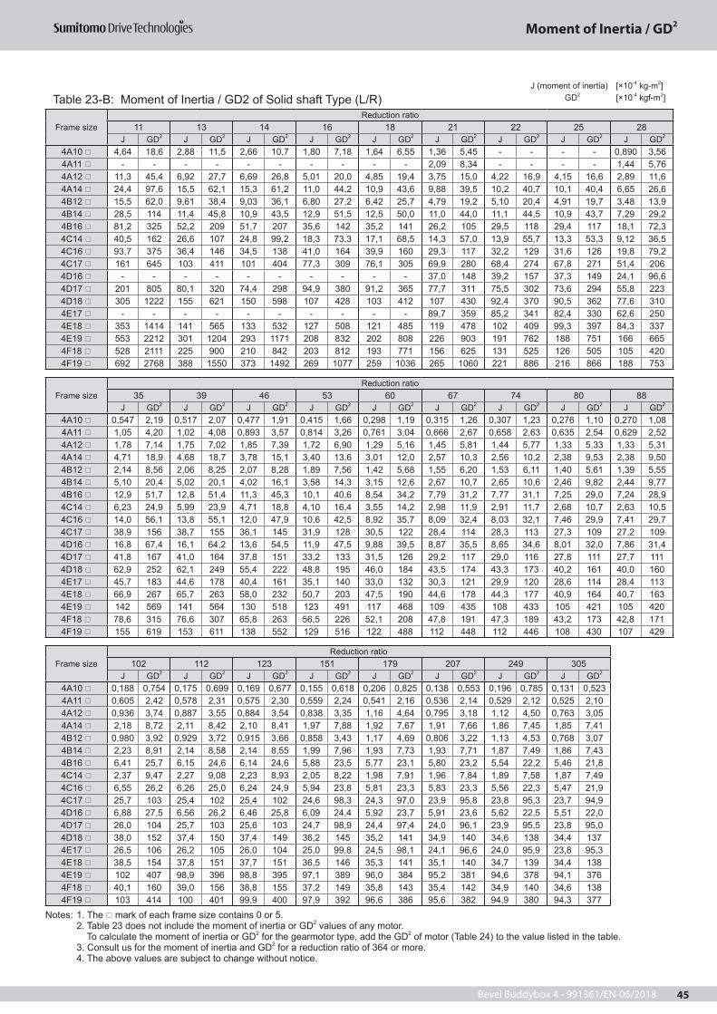
Bevel Buddybox 4 - 991361/EN-06/2018 45
J (moment of inertia) [×10-4 kg-m2]
GD2 [×10-4 kgf-m2]
Frame sizeReduction ratio
11 13 14 16 18 21 22 25 28J GD2 J GD2 J GD2 J GD2 J GD2 J GD2 J GD2 J GD2 J GD2
4A10 4,64 18,6 2,88 11,5 2,66 10,7 1,80 7,18 1,64 6,55 1,36 5,45 - - - - 0,890 3,56 4A11 - - - - - - - - - - 2,09 8,34 - - - - 1,44 5,76 4A12 11,3 45,4 6,92 27,7 6,69 26,8 5,01 20,0 4,85 19,4 3,75 15,0 4,22 16,9 4,15 16,6 2,89 11,6 4A14 24,4 97,6 15,5 62,1 15,3 61,2 11,0 44,2 10,9 43,6 9,88 39,5 10,2 40,7 10,1 40,4 6,65 26,6 4B12 15,5 62,0 9,61 38,4 9,03 36,1 6,80 27,2 6,42 25,7 4,79 19,2 5,10 20,4 4,91 19,7 3,48 13,9 4B14 28,5 114 11,4 45,8 10,9 43,5 12,9 51,5 12,5 50,0 11,0 44,0 11,1 44,5 10,9 43,7 7,29 29,2 4B16 81,2 325 52,2 209 51,7 207 35,6 142 35,2 141 26,2 105 29,5 118 29,4 117 18,1 72,3 4C14 40,5 162 26,6 107 24,8 99,2 18,3 73,3 17,1 68,5 14,3 57,0 13,9 55,7 13,3 53,3 9,12 36,5 4C16 93,7 375 36,4 146 34,5 138 41,0 164 39,9 160 29,3 117 32,2 129 31,6 126 19,8 79,2 4C17 161 645 103 411 101 404 77,3 309 76,1 305 69,9 280 68,4 274 67,8 271 51,4 206 4D16 - - - - - - - - - - 37,0 148 39,2 157 37,3 149 24,1 96,6 4D17 201 805 80,1 320 74,4 298 94,9 380 91,2 365 77,7 311 75,5 302 73,6 294 55,8 223 4D18 305 1222 155 621 150 598 107 428 103 412 107 430 92,4 370 90,5 362 77,6 310 4E17 - - - - - - - - - - 89,7 359 85,2 341 82,4 330 62,6 250 4E18 353 1414 141 565 133 532 127 508 121 485 119 478 102 409 99,3 397 84,3 337 4E19 553 2212 301 1204 293 1171 208 832 202 808 226 903 191 762 188 751 166 665 4F18 528 2111 225 900 210 842 203 812 193 771 156 625 131 525 126 505 105 420 4F19 692 2768 388 1550 373 1492 269 1077 259 1036 265 1060 221 886 216 866 188 753
Frame sizeReduction ratio
35 39 46 53 60 67 74 80 88J GD2 J GD2 J GD2 J GD2 J GD2 J GD2 J GD2 J GD2 J GD2
4A10 0,547 2,19 0,517 2,07 0,477 1,91 0,415 1,66 0,298 1,19 0,315 1,26 0,307 1,23 0,276 1,10 0,270 1,08 4A11 1,05 4,20 1,02 4,08 0,893 3,57 0,814 3,26 0,761 3,04 0,666 2,67 0,658 2,63 0,635 2,54 0,629 2,52 4A12 1,78 7,14 1,75 7,02 1,85 7,39 1,72 6,90 1,29 5,16 1,45 5,81 1,44 5,77 1,33 5,33 1,33 5,31 4A14 4,71 18,9 4,68 18,7 3,78 15,1 3,40 13,6 3,01 12,0 2,57 10,3 2,56 10,2 2,38 9,53 2,38 9,50 4B12 2,14 8,56 2,06 8,25 2,07 8,28 1,89 7,56 1,42 5,68 1,55 6,20 1,53 6,11 1,40 5,61 1,39 5,55 4B14 5,10 20,4 5,02 20,1 4,02 16,1 3,58 14,3 3,15 12,6 2,67 10,7 2,65 10,6 2,46 9,82 2,44 9,77 4B16 12,9 51,7 12,8 51,4 11,3 45,3 10,1 40,6 8,54 34,2 7,79 31,2 7,77 31,1 7,25 29,0 7,24 28,9 4C14 6,23 24,9 5,99 23,9 4,71 18,8 4,10 16,4 3,55 14,2 2,98 11,9 2,91 11,7 2,68 10,7 2,63 10,5 4C16 14,0 56,1 13,8 55,1 12,0 47,9 10,6 42,5 8,92 35,7 8,09 32,4 8,03 32,1 7,46 29,9 7,41 29,7 4C17 38,9 156 38,7 155 36,1 145 31,9 128 30,5 122 28,4 114 28,3 113 27,3 109 27,2 109 4D16 16,8 67,4 16,1 64,2 13,6 54,5 11,9 47,5 9,88 39,5 8,87 35,5 8,65 34,6 8,01 32,0 7,86 31,4 4D17 41,8 167 41,0 164 37,8 151 33,2 133 31,5 126 29,2 117 29,0 116 27,8 111 27,7 111 4D18 62,9 252 62,1 249 55,4 222 48,8 195 46,0 184 43,5 174 43,3 173 40,2 161 40,0 160 4E17 45,7 183 44,6 178 40,4 161 35,1 140 33,0 132 30,3 121 29,9 120 28,6 114 28,4 113 4E18 66,9 267 65,7 263 58,0 232 50,7 203 47,5 190 44,6 178 44,3 177 40,9 164 40,7 163 4E19 142 569 141 564 130 518 123 491 117 468 109 435 108 433 105 421 105 420 4F18 78,6 315 76,6 307 65,8 263 56,5 226 52,1 208 47,8 191 47,3 189 43,2 173 42,8 171 4F19 155 619 153 611 138 552 129 516 122 488 112 448 112 446 108 430 107 429
Frame sizeReduction ratio
102 112 123 151 179 207 249 305J GD2 J GD2 J GD2 J GD2 J GD2 J GD2 J GD2 J GD2
4A10 0,188 0,754 0,175 0,699 0,169 0,677 0,155 0,618 0,206 0,825 0,138 0,553 0,196 0,785 0,131 0,523 4A11 0,605 2,42 0,578 2,31 0,575 2,30 0,559 2,24 0,541 2,16 0,536 2,14 0,529 2,12 0,525 2,10 4A12 0,936 3,74 0,887 3,55 0,884 3,54 0,838 3,35 1,16 4,64 0,795 3,18 1,12 4,50 0,763 3,05 4A14 2,18 8,72 2,11 8,42 2,10 8,41 1,97 7,88 1,92 7,67 1,91 7,66 1,86 7,45 1,85 7,41 4B12 0,980 3,92 0,929 3,72 0,915 3,66 0,858 3,43 1,17 4,69 0,806 3,22 1,13 4,53 0,768 3,07 4B14 2,23 8,91 2,14 8,58 2,14 8,55 1,99 7,96 1,93 7,73 1,93 7,71 1,87 7,49 1,86 7,43 4B16 6,41 25,7 6,15 24,6 6,14 24,6 5,88 23,5 5,77 23,1 5,80 23,2 5,54 22,2 5,46 21,8 4C14 2,37 9,47 2,27 9,08 2,23 8,93 2,05 8,22 1,98 7,91 1,96 7,84 1,89 7,58 1,87 7,49 4C16 6,55 26,2 6,26 25,0 6,24 24,9 5,94 23,8 5,81 23,3 5,83 23,3 5,56 22,3 5,47 21,9 4C17 25,7 103 25,4 102 25,4 102 24,6 98,3 24,3 97,0 23,9 95,8 23,8 95,3 23,7 94,9 4D16 6,88 27,5 6,56 26,2 6,46 25,8 6,09 24,4 5,92 23,7 5,91 23,6 5,62 22,5 5,51 22,0 4D17 26,0 104 25,7 103 25,6 103 24,7 98,9 24,4 97,4 24,0 96,1 23,9 95,5 23,8 95,0 4D18 38,0 152 37,4 150 37,4 149 36,2 145 35,2 141 34,9 140 34,6 138 34,4 137 4E17 26,5 106 26,2 105 26,0 104 25,0 99,8 24,5 98,1 24,1 96,6 24,0 95,9 23,8 95,3 4E18 38,5 154 37,8 151 37,7 151 36,5 146 35,3 141 35,1 140 34,7 139 34,4 138 4E19 102 407 98,9 396 98,8 395 97,1 389 96,0 384 95,2 381 94,6 378 94,1 376 4F18 40,1 160 39,0 156 38,8 155 37,2 149 35,8 143 35,4 142 34,9 140 34,6 138 4F19 103 414 100 401 99,9 400 97,9 392 96,6 386 95,6 382 94,9 380 94,3 377
Notes: 1. The mark of each frame size contains 0 or 5. 2. Table 23 does not include the moment of inertia or GD2 values of any motor. To calculate the moment of inertia or GD2 for the gearmotor type, add the GD2 of motor (Table 24) to the value listed in the table. 3. Consult us for the moment of inertia and GD2 for a reduction ratio of 364 or more. 4. The above values are subject to change without notice.
Table 23-B: Moment of Inertia / GD2 of Solid shaft Type (L/R)
Moment of Inertia / GD2

Bevel Buddybox 4 - 991361/EN-06/201846
J (moment of inertia) [×10-4 kg-m2]
GD2 [×10-4 kgf-m2]
Frame sizeReduction ratio
11 13 14 16 18 21 22 25 28J GD2 J GD2 J GD2 J GD2 J GD2 J GD2 J GD2 J GD2 J GD2
4A10 4,83 19,3 3,01 12,1 2,77 11,1 1,89 7,55 1,72 6,86 1,41 5,65 - - - - 0,917 3,67 4A11 - - - - - - - - - - 2,14 8,54 - - - - 1,47 5,88 4A12 10,2 40,7 7,05 28,2 6,80 27,2 5,09 20,4 4,93 19,7 3,80 15,2 4,27 17,1 4,18 16,7 2,92 11,7 4A14 21,3 85,3 15,7 62,6 15,4 61,7 11,1 44,5 11,0 43,9 9,93 39,7 10,2 40,8 10,1 40,5 6,68 26,7 4B12 16,0 63,9 9,92 39,7 9,29 37,2 7,01 28,0 6,59 26,4 4,91 19,6 5,20 20,8 5,00 20,0 3,54 14,2 4B14 29,0 116 18,6 74,5 18,0 72,0 13,1 52,3 12,7 50,7 11,1 44,5 11,2 44,9 11,0 44,1 7,36 29,4 4B16 70,0 280 52,5 210 51,9 208 35,8 143 35,4 141 26,3 105 29,6 119 29,4 118 18,1 72,6 4C14 41,5 166 27,3 109 25,4 102 18,8 75,1 17,5 70,0 14,5 58,1 14,2 56,7 13,5 54,1 9,27 37,1 4C16 94,8 379 61,8 247 59,8 239 41,5 166 40,3 161 29,5 118 32,5 130 31,8 127 20,0 79,8 4C17 140 560 103 414 102 406 77,8 311 76,5 306 70,2 281 68,7 275 68,0 272 51,6 206 4D16 - - - - - - - - - - 37,6 150 39,7 159 37,7 151 24,5 97,9 4D17 203 813 131 524 125 501 95,9 384 92,0 368 78,3 313 75,6 302 74,0 296 56,2 225 4D18 242 968 157 627 151 603 108 432 104 416 108 432 92,9 372 90,9 363 77,9 312 4E17 - - - - - - - - - - 90,9 363 86,2 345 83,2 333 63,2 253 4E18 358 1432 187 746 178 711 129 516 123 491 121 482 103 414 100 400 85,0 340 4E19 446 1785 304 1216 295 1180 210 841 204 815 227 908 192 766 188 754 167 668 4F18 534 2134 293 1173 278 1113 206 822 195 780 158 631 135 540 127 509 106 423 4F19 587 2346 391 1565 376 1504 272 1088 261 1045 266 1066 223 891 218 870 189 757
Frame sizeReduction ratio
35 39 46 53 60 67 74 80 88J GD2 J GD2 J GD2 J GD2 J GD2 J GD2 J GD2 J GD2 J GD2
4A10 0,565 2,26 0,532 2,13 0,487 1,95 0,423 1,69 0,304 1,22 0,320 1,28 0,311 1,24 0,279 1,12 0,273 1,09 4A11 1,07 4,27 1,03 4,14 0,903 3,61 0,822 3,29 0,767 3,07 0,671 2,68 0,662 2,65 0,638 2,55 0,632 2,53 4A12 1,80 7,21 1,77 7,07 1,86 7,44 1,73 6,93 1,30 5,19 1,46 5,82 1,45 5,79 1,34 5,35 1,33 5,32 4A14 4,73 18,9 4,70 18,8 3,79 15,1 3,41 13,6 3,01 12,0 2,57 10,3 2,56 10,2 2,39 9,54 2,38 9,52 4B12 2,18 8,72 2,10 8,39 2,09 8,38 1,91 7,64 1,44 5,74 1,56 6,24 1,54 6,15 1,41 5,64 1,39 5,58 4B14 5,14 20,6 5,06 20,2 4,04 16,2 3,60 14,4 3,16 12,6 2,68 10,7 2,66 10,6 2,46 9,86 2,45 9,79 4B16 13,0 51,9 12,9 51,5 11,3 45,4 10,2 40,6 8,55 34,2 7,81 31,2 7,78 31,1 7,26 29,0 7,24 29,0 4C14 6,33 25,3 6,07 24,3 4,77 19,1 4,15 16,6 3,59 14,3 3,01 12,0 2,94 11,7 2,69 10,8 2,64 10,6 4C16 14,1 56,4 13,8 55,4 12,0 48,1 10,7 42,7 8,96 35,8 8,12 32,5 8,05 32,2 7,48 29,9 7,43 29,7 4C17 39,0 156 38,7 155 36,2 145 32,0 128 30,5 122 28,4 114 28,3 113 27,3 109 27,2 109 4D16 17,0 68,2 16,2 64,9 13,7 55,0 12,0 47,8 10,0 39,8 8,93 35,7 8,70 34,8 8,05 32,2 7,89 31,6 4D17 42,0 168 41,2 165 37,9 152 33,3 133 31,5 126 29,2 117 29,0 116 27,9 111 27,7 111 4D18 63,1 252 62,3 249 55,5 222 48,8 195 46,1 184 43,6 174 43,3 173 40,2 161 40,0 160 4E17 46,1 184 44,9 180 40,6 162 35,3 141 33,1 132 30,4 121 30,0 120 28,7 115 28,4 114 4E18 67,3 269 66,0 264 58,2 233 50,9 203 47,7 191 44,7 179 44,4 177 41,0 164 40,8 163 4E19 143 570 141 565 130 519 123 491 117 469 109 435 108 434 105 421 105 420 4F18 79,1 317 77,1 308 66,1 264 56,8 227 52,3 209 48,0 192 47,4 190 43,3 173 42,9 172 4F19 155 621 153 612 138 553 129 517 122 489 112 449 112 447 108 431 107 429
Frame sizeReduction ratio
102 112 123 151 179 207 249 305J GD2 J GD2 J GD2 J GD2 J GD2 J GD2 J GD2 J GD2
4A10 0,191 0,762 0,174 0,696 0,171 0,683 0,156 0,622 0,207 0,828 0,139 0,555 0,197 0,786 0,131 0,524 4A11 0,607 2,43 0,579 2,32 0,576 2,30 0,560 2,24 0,541 2,17 0,537 2,15 0,530 2,12 0,526 2,10 4A12 0,938 3,75 0,889 3,56 0,886 3,54 0,839 3,35 1,16 4,64 0,795 3,18 1,13 4,50 0,763 3,05 4A14 2,18 8,73 2,11 8,43 2,10 8,42 1,97 7,88 1,92 7,67 1,92 7,66 1,86 7,45 1,85 7,41 4B12 0,985 3,94 0,926 3,71 0,918 3,67 0,860 3,44 1,18 4,70 0,807 3,23 1,13 4,53 0,769 3,07 4B14 2,23 8,93 2,15 8,59 2,14 8,56 1,99 7,97 1,93 7,73 1,93 7,71 1,87 7,49 1,86 7,43 4B16 6,42 25,7 6,16 24,6 6,15 24,6 5,88 23,5 5,77 23,1 5,80 23,2 5,54 22,2 5,46 21,8 4C14 2,38 9,51 2,27 9,06 2,24 8,96 2,06 8,24 1,98 7,92 1,96 7,85 1,90 7,59 1,87 7,50 4C16 6,56 26,2 6,27 25,1 6,24 25,0 5,94 23,8 5,82 23,3 5,83 23,3 5,56 22,3 5,47 21,9 4C17 25,7 103 25,4 102 25,4 102 24,6 98,3 24,3 97,0 23,9 95,8 23,8 95,3 23,7 94,9 4D16 6,90 27,6 6,56 26,2 6,48 25,9 6,10 24,4 5,93 23,7 5,91 23,7 5,62 22,5 5,51 22,0 4D17 26,0 104 25,7 103 25,7 103 24,7 99,0 24,4 97,5 24,0 96,1 23,9 95,6 23,8 95,0 4D18 38,0 152 37,5 150 37,4 150 36,2 145 35,2 141 34,9 140 34,6 138 34,4 137 4E17 26,6 106 26,2 105 26,0 104 25,0 99,9 24,5 98,2 24,2 96,6 24,0 95,9 23,8 95,3 4E18 38,6 154 37,9 151 37,7 151 36,5 146 35,4 141 35,1 140 34,7 139 34,4 138 4E19 102 407 98,9 396 98,8 395 97,1 389 96,0 384 95,2 381 94,6 379 94,1 376 4F18 40,2 161 39,0 156 38,8 155 37,2 149 35,9 143 35,4 142 34,9 140 34,6 138 4F19 103 414 100 401 100 400 97,9 392 96,6 386 95,6 382 94,9 380 94,3 377
Notes: 1. The mark of each frame size contains 0 or 5. 2. Table 23 does not include the moment of inertia or GD2 values of any motor. To calculate the moment of inertia or GD2 for the gearmotor type, add the GD2 of motor (Table 24) to the value listed in the table. 3. Consult us for the moment of inertia and GD2 for a reduction ratio of 364 or more. 4. The above values are subject to change without notice.
Table 23-C: Moment of Inertia / GD2 of BBB, both-end shaft (T) type
Moment of Inertia / GD2

Bevel Buddybox 4 - 991361/EN-06/2018 47
5. Moment of Inertia of Motors·GD2
Table 24: Moment of Inertia·GD2 of Three Phase Motors[4P Motor] Unit: JM (Moment of Inertia) (kg·m2) GD2
M (kgf·m2)
kW×P0,12kW×4P 0,18kW×4P 0,25kW×4P 0,37kW×4P 0,55kW×4P 0,75kW×4P
JM GD2M JM GD2
M JM GD2M JM GD2
M JM GD2M JM GD2
M
Standard 0,000325 0,0013 0,000500 0,0020 0,000500 0,0020 0,000650 0,0026 0,00101 0,0041 0,00235 0,00942With Brake 0,000350 0,0014 0,000550 0,0022 0,000550 0,0022 0,000675 0,0027 0,00111 0,0045 0,00130 0,0052
kW×P1,1kW×4P 1,5kW×4P 2,2kW×4P 3,0kW×4P 4,0kW×4P 5,5kW×4P
JM GD2M JM GD2
M JM GD2M JM GD2
M JM GD2M JM GD2
M
Standard 0,00337 0,0135 0,00391 0,0156 0,00880 0,0352 0,0100 0,0400 0,0194 0,0777 0,0291 0,116With Brake 0,00208 0,0083 0,00235 0,0094 0,00373 0,0149 0,00810 0,0325 0,00958 0,0383 0,0125 0,0501
kW×P7,5kW×4P 11kW×4P 15kW×4P 18,5W×4P 22kW×4P 30kW×4P
JM GD2M JM GD2
M JM GD2M JM GD2
M JM GD2M JM GD2
M
Standard 0,0409 0,164 0,0561 0,224 0,0995 0,398 0,256 1,02 0,256 1,02 0,326 1,31With Brake 0,0303 0,121 0,0410 0,164 0,107 0,428 0,243 0,972 0,243 0,972 0,262 1,05
kW×P37kW×4P 45kW×4P 55kW×4P
JM GD2M JM GD2
M JM GD2M
Standard 0,390 1,56 0,731 2,92 0,864 3,46With Brake - - - - - -
[6P Motor]
kW×P18.5W×6P 22kW×6P 30kW×6P
JM GD2M JM GD2
M JM GD2M
Standard 0,451 1,81 0,451 1,81 1,06 4,23With Brake 0,375 1,50 0,375 1,50 0,488 1,95
kW×P37kW×6P 45kW×6P 55kW×6P
JM GD2M JM GD2
M JM GD2M
Standard 1,19 4,75 1,32 5,27 3,16 12,6With Brake - - - - - -
Moment of Inertia / GD2

Bevel Buddybox 4 - 991361/EN-06/201848

Bevel Buddybox 4 - 991361/EN-06/2018 49
0,12 500,18 510,25 520,37 540,55 560,75 591,1 611,5 642,2 673,0 704,0 735,5 767,5 7911 8315 8818,5 9222 9630 10037 10245 10555 106
Selection Tables for Three Phase Gearmotors
Selection Tables for GearmotorsImportant Notes :Following notes must be considered when using selection tables from page 50 to 107. 1. For the nomenclature of models listed on the selection table, refer to page 18. 2.Consult us if the mounting position is Y4, F4, G4, K4 or W4 (motor is faced down), because these selection tables are not applicable.3.Allowable duty cycle of models with mark in the model column is 75% ED (10 min. cycle) in case of mounting positions Y2, F2, G2, K2, V2 or W2. 4.In Allowable Radial Load of Output Shaft (Pro) column, the values for hollow shaft type are those at 20mm away from the shaft end face, and the values for solid shaft type are those at the midpoint of the output shaft. If the load position is other than these, or for the allowable thrust load, refer to pages 32 to 40.5. The lubrication method depends on the model. For details, refer to "Lubrication" on pages 209 to 212.6. The output shaft speeds (n2) are based on the motor speed (n1). For details of the motor speeds, refer to page 227.7. The reduction ratios are nominal. The output speed values (n2) are calculated based on the actual reduction ratios. (The output speeds in case of reduction ratios 11 to 18 are calculated based on the nominal reduction ratio because the actual ratio of 11 to 18 depends on the frame size). For the actual reduction ratios, refer to page 6.8. Consult us for the combinations and reduction ratios not listed in the selection tables.9. The contents of the tables are subject to change without prior notice.
Power (kW) Page

Bevel Buddybox 4 - 991361/EN-06/201850
Selection Table for Gearmotors
0,12 kWFrequency Hz 50Hz 60HzMotor poles P 4
Motor speed n1 r/min 1450 1750Reduction ratio 683 10658
50Hz 60Hz Model (refer to page 18)
Dimensional Drawing
Page
Output Speed
n2
OutputTorque
Tout
Allowable Radial Load of Output Shaft
Pro
SFGOutput Speed
n2
OutputTorque
Tout
Allowable Radial Load of Output Shaft
Pro
SFG Capacity Symbol
- Frame Size
- Reduction Ratio
r/min Nm N r/min Nm N2,12 472 26300 2,17 2,56 391 26600 2,61 012 - 4A10DA - 683 1101,79 559 25900 1,83 2,16 463 26300 2,20 012 - 4A10DA - 809 110
25900 2,31 26300 2,78 012 - 4A12DA - 809 1101,79 559 25900 2,31 2,16 463 26300 2,78 012 - 4A12DA - 809 1101,52 661 25200 1,54 1,83 547 25900 1,87 012 - 4A10DA - 956 110
25200 1,95 25900 2,36 012 - 4A12DA - 956 1101,30 772 24400 1,33 1,57 640 25400 1,59 012 - 4A10DA - 1117 110
24400 1,67 25400 2,02 012 - 4A12DA - 1117 1101,10 912 23100 1,12 1,33 756 24500 1,35 012 - 4A10DA - 1320 110
23100 1,42 24500 1,71 012 - 4A12DA - 1320 11043200 2,35 43700 2,83 012 - 4B12DA - 1320 112
0,876 1145 20300 0,89 1,06 949 22700 1,08 012 - 4A10DA - 1656 11020300 1,13 22700 1,36 012 - 4A12DA - 1656 11042300 1,88 43100 2,26 012 - 4B12DA - 1656 11242300 2,24 43100 2,71 012 - 4B14DA - 1656 112
0,741 1356 16700 0,76 0,894 1121 20600 0,91 012 - 4A10DA - 1957 11016700 0,95 20600 1,15 012 - 4A12DA - 1957 11041300 1,58 42400 1,91 012 - 4B12DA - 1957 11241300 1,90 42400 2,29 012 - 4B14DA - 1957 112
0,638 1572 10700 0,83 0,770 1296 17700 0,99 012 - 4A12DA - 2272 11040100 1,37 41600 1,65 012 - 4B12DA - 2272 11240100 1,63 41600 1,98 012 - 4B14DA - 2272 112
0,567 1764 38800 1,21 0,684 1464 40700 1,46 012 - 4B12DA - 2559 11238800 1,45 40700 1,75 012 - 4B14DA - 2559 112
0,493 2040 36700 1,05 0,595 1692 39400 1,28 012 - 4B12DA - 2944 11236700 1,27 39400 1,53 012 - 4B14DA - 2944 11268900 2,29 69800 2,38 012 - 4C14DA - 2944 114
0,413 2424 32700 0,88 0,499 2016 36900 1,07 012 - 4B12DA - 3511 11232700 1,06 36900 1,28 012 - 4B14DA - 3511 11267600 1,92 69000 2,32 012 - 4C14DA - 3511 11467600 2,12 69000 2,56 012 - 4C16DA - 3511 114
0,332 3024 23700 0,71 0,401 2496 31800 0,86 012 - 4B12DA - 4365 11223700 0,85 31800 1,03 012 - 4B14DA - 4365 11265200 1,54 67300 1,87 012 - 4C14DA - 4365 11465200 1,70 67300 2,06 012 - 4C16DA - 4365 11495000 2,37 96000 2,86 012 - 4D16DA - 4365 116
0,280 3576 62300 1,18 0,338 2964 65400 1,43 012 - 4C14DA - 5177 11462300 1,43 65400 1,73 012 - 4C16DA - 5177 11493600 1,95 95100 2,35 012 - 4D16DA - 5177 11693600 2,43 95100 2,94 012 - 4D17DA - 5177 116
0,201 5004 51800 0,93 0,242 4140 58800 1,13 012 - 4C14DA - 7228 11451800 1,03 58800 1,24 012 - 4C16DA - 7228 11488700 1,43 91900 1,73 012 - 4D16DA - 7228 11688700 1,74 91900 2,11 012 - 4E17DA - 7228 11697600 2,14 99000 2,58 012 - 4E18DA - 7228 116
0,136 7368 75900 0,95 0,164 6108 83600 1,14 012 - 4D16DA - 10658 11675900 1,18 83600 1,43 012 - 4D17DA - 10658 11693600 1,45 95700 1,75 012 - 4E17DA - 10658 11693600 1,58 95700 1,90 012 - 4E18DA - 10658 116
IMPORTANT :Please refer to page 49 for Gearmotor Selection Table notes.

Bevel Buddybox 4 - 991361/EN-06/2018 51
Selection Table for Gearmotors
0,18 kWFrequency Hz 50Hz 60HzMotor poles P 4
Motor speed n1 r/min 1450 1750Reduction ratio 179 2944
50Hz 60Hz Model (refer to page 18)
Dimensional Drawing
Page
Output Speed
n2
OutputTorque
Tout
Allowable Radial Load of Output Shaft
Pro
SFGOutput Speed
n2
OutputTorque
Tout
Allowable Radial Load of Output Shaft
Pro
SFG Capacity Symbol
- Frame Size
- Reduction Ratio
r/min Nm N r/min Nm N
IMPORTANT :Please refer to page 49 for Gearmotor Selection Table notes.
8,12 195 27100 3,11 9,80 162 27200 3,11 018 - 4A100 - 179 1107,02 226 27000 2,87 8,47 187 27100 2,87 018 - 4A100 - 207 1105,84 272 26800 2,42 7,04 225 27000 2,42 018 - 4A100 - 249 110
26800 2,81 27000 3,12 018 - 4A105 - 249 1104,76 333 26500 2,41 5,75 275 26800 2,41 018 - 4A100 - 305 110
26500 2,80 26800 3,14 018 - 4A105 - 305 1103,98 378 26100 2,27 4,81 313 26500 2,27 018 - 4A10DA - 364 1103,48 455 25800 1,17 4,20 377 26300 1,17 018 - 4A100 - 417 110
25800 1,59 26300 1,59 018 - 4A105 - 417 1103,42 439 25700 2,27 4,13 364 26200 2,27 018 - 4A10DA - 424 110
25700 2,93 26200 3,54 018 - 4A12DB - 424 1102,90 519 25000 1,97 3,50 430 25800 2,27 018 - 4A10DA - 501 110
25000 2,27 25800 2,27 018 - 4A12DA - 501 11025000 2,49 25800 3,00 018 - 4A12DB - 501 110
2,51 599 24200 1,71 3,03 497 25200 2,06 018 - 4A10DA - 578 11024200 2,16 25200 2,27 018 - 4A12DA - 578 11043600 2,27 43900 2,27 018 - 4B12DA - 578 112
2,12 708 22800 1,44 2,56 587 24300 1,74 018 - 4A10DA - 683 11022800 1,82 24300 2,20 018 - 4A12DA - 683 11043100 2,27 43600 2,27 018 - 4B12DA - 683 11243100 3,03 43600 3,66 018 - 4B12DB - 683 112
1,79 839 20700 1,22 2,16 695 23000 1,47 018 - 4A10DA - 809 11020700 1,53 23000 1,86 018 - 4A12DA - 809 11042400 2,27 43200 2,27 018 - 4B12DA - 809 11242400 2,56 43200 3,09 018 - 4B12DB - 809 11242400 3,07 43200 3,70 018 - 4B14DB - 809 112
1,52 990 17300 1,03 1,83 822 21000 1,24 018 - 4A10DA - 956 11017300 1,30 21000 1,57 018 - 4A12DA - 956 11041500 2,17 42500 2,27 018 - 4B12DA - 956 11241500 2,59 42500 3,13 018 - 4B14DB - 956 112
1,30 1161 11600 1,11 1,57 963 18100 1,34 018 - 4A12DA - 1117 11040300 1,86 41700 2,23 018 - 4B12DA - 1117 11240300 2,22 41700 2,68 018 - 4B14DB - 1117 112
1,10 1368 38400 1,57 1,33 1134 40500 1,89 018 - 4B12DA - 1320 11238400 1,88 40500 2,27 018 - 4B14DA - 1320 11269500 2,27 70200 2,27 018 - 4C14DA - 1320 114
0,876 1719 34200 1,26 1,06 1422 37800 1,51 018 - 4B12DA - 1656 11234200 1,50 37800 1,81 018 - 4B14DA - 1656 11268100 2,27 69300 2,27 018 - 4C14DA - 1656 11468100 2,72 69300 3,28 018 - 4C14DB - 1656 11468100 2,99 69300 3,61 018 - 4C16DA - 1656 114
0,741 2034 29000 1,06 0,894 1683 34700 1,28 018 - 4B12DA - 1957 11229000 1,27 34700 1,53 018 - 4B14DA - 1957 11266600 2,27 68200 2,27 018 - 4C14DA - 1957 11466600 2,30 68200 2,78 018 - 4C14DB - 1957 11466600 2,53 68200 3,06 018 - 4C16DA - 1957 116
0,638 2358 21000 0,91 0,770 1953 30500 1,10 018 - 4B12DA - 2272 11264600 1,98 67000 2,27 018 - 4C14DA - 2272 11464600 2,18 67000 2,63 018 - 4C16DA - 2272 11494700 3,03 95900 3,67 018 - 4D16DA - 2272 114
0,567 2655 4890 0,97 0,684 2196 25400 1,17 018 - 4B14DA - 2559 11262600 1,76 65600 2,12 018 - 4C14DA - 2559 11262600 1,93 65600 2,33 018 - 4C16DA - 2559 11493700 2,70 95200 3,26 018 - 4D16DA - 2559 11493700 3,29 95200 3,97 018 - 4D17DA - 2559 116
0,493 3051 59300 1,53 0,595 2529 63500 1,59 018 - 4C14DA - 2944 11459300 1,69 63500 2,03 018 - 4C16DA - 2944 11492100 2,34 94100 2,82 018 - 4D16DA - 2944 11692100 2,86 94100 3,44 018 - 4D17DA - 2944 116

Bevel Buddybox 4 - 991361/EN-06/201852
Selection Table for Gearmotors
0,280 5373 8580 0,96 0,338 4446 40800 1,16 018 - 4C16DA - 5177 11477300 1,30 84500 1,57 018 - 4D16DA - 5177 11677300 1,62 84500 1,96 018 - 4D17DA - 5177 11694000 1,99 96000 2,40 018 - 4E17DA - 5177 11894000 2,16 96000 2,61 018 - 4E18DA - 5177 118133000 3,17 135000 3,82 018 - 4F18DA - 5177 120
0,201 7497 49700 0,96 0,242 6210 68800 1,16 018 - 4D16DA - 7228 11649700 1,17 68800 1,40 018 - 4D17DA - 7228 11689300 1,42 92100 1,72 018 - 4E17DA - 7228 11889300 1,54 92100 1,87 018 - 4E18DA - 7228 118129000 2,27 131000 2,74 018 - 4F18DA - 7228 120
0,136 11070 67000 0,97 0,164 9180 85600 1,17 018 - 4E17DA - 10658 11867000 1,04 85600 1,27 018 - 4E18DA - 10658 118122000 1,54 126000 1,86 018 - 4F18DA - 10658 120
0,18 kWFrequency Hz 50Hz 60HzMotor poles P 4
Motor speed n1 r/min 1450 1750Reduction ratio 3511 10658
50Hz 60Hz Model (refer to page 18)
Dimensional Drawing
Page
Output Speed
n2
OutputTorque
Tout
Allowable Radial Load of Output Shaft
Pro
SFGOutput Speed
n2
OutputTorque
Tout
Allowable Radial Load of Output Shaft
Pro
SFG Capacity Symbol
- Frame Size
- Reduction Ratio
r/min Nm N r/min Nm N0,413 3645 53100 1,28 0,499 3015 59600 1,54 018 - 4C14DA - 3511 114
53100 1,41 59600 1,70 018 - 4C16DA - 3511 11489300 1,97 92200 2,37 018 - 4D16DA - 3511 11689300 2,40 92200 2,89 018 - 4D17DA - 3511 11697800 2,93 99200 3,54 018 - 4E17DA - 3511 11897800 3,19 99200 3,84 018 - 4E18DA - 3511 118
0,332 4527 39300 1,03 0,401 3753 51700 1,24 018 - 4C14DA - 4365 11439300 1,13 51700 1,37 018 - 4C16DA - 4365 11484000 1,58 88700 1,91 018 - 4D16DA - 4365 11684000 1,92 88700 2,32 018 - 4D17DA - 4365 11695900 2,37 97600 2,86 018 - 4E17DA - 4365 11895900 2,57 97600 3,09 018 - 4E18DA - 4365 118
0,25 kWFrequency Hz 50Hz 60HzMotor poles P 4
Motor speed n1 r/min 1450 1750Reduction ratio 179 501
50Hz 60Hz Model (refer to page 18)
Dimensional Drawing
Page
Output Speed
n2
OutputTorque
Tout
Allowable Radial Load of Output Shaft
Pro
SFGOutput Speed
n2
OutputTorque
Tout
Allowable Radial Load of Output Shaft
Pro
SFG Capacity Symbol
- Frame Size
- Reduction Ratio
r/min Nm N r/min Nm N8,12 271 26900 2,24 9,80 225 27100 2,24 03 - 4A100 - 179 1107,02 313 26800 2,06 8,47 260 27000 2,06 03 - 4A100 - 207 110
26800 2,72 27000 2,83 03 - 4A105 - 207 1105,84 377 26500 1,74 7,04 313 26800 1,74 03 - 4A100 - 249 110
26500 2,02 26800 2,24 03 - 4A105 - 249 11026500 2,68 26800 2,68 03 - 4A110 - 249 110
4,76 462 26000 1,73 5,75 383 26500 1,73 03 - 4A100 - 305 11026000 2,01 26500 2,26 03 - 4A105 - 305 11026000 2,64 26500 2,64 03 - 4A110 - 305 110
3,98 524 25400 1,63 4,81 435 26100 1,63 03 - 4A10DA - 364 11025400 2,46 26100 2,97 03 - 4A12DB - 364 110
3,48 632 24800 0,84 4,20 524 25600 0,84 03 - 4A100 - 417 11024800 1,14 25600 1,14 03 - 4A105 - 417 110
3,42 610 24700 1,63 4,13 506 25600 1,63 03 - 4A10DA - 424 11024700 2,11 25600 2,55 03 - 4A12DB - 424 110
2,90 721 23600 1,42 3,50 597 24800 1,63 03 - 4A10DA - 501 11023600 1,63 24800 1,63 03 - 4A12DA - 501 11023600 1,79 24800 2,16 03 - 4A12DB - 501 11043400 2,97 43800 3,59 03 - 4B12DB - 501 112
IMPORTANT :Please refer to page 49 for Gearmotor Selection Table notes.
IMPORTANT :Please refer to page 49 for Gearmotor Selection Table notes.

Bevel Buddybox 4 - 991361/EN-06/2018 53
Selection Table for Gearmotors
0,25 kWFrequency Hz 50Hz 60HzMotor poles P 4
Motor speed n1 r/min 1450 1750Reduction ratio 578 4365
50Hz 60Hz Model (refer to page 18)
Dimensional Drawing
Page
Output Speed
n2
OutputTorque
Tout
Allowable Radial Load of Output Shaft
Pro
SFGOutput Speed
n2
OutputTorque
Tout
Allowable Radial Load of Output Shaft
Pro
SFG Capacity Symbol
- Frame Size
- Reduction Ratio
r/min Nm N r/min Nm N2,51 832 22200 1,23 3,03 689 23900 1,48 03 - 4A10DA - 578 110
22200 1,55 23900 1,63 03 - 4A12DA - 578 11042900 1,63 43500 1,63 03 - 4B12DA - 578 11242900 2,58 43500 3,11 03 - 4B12DB - 578 112
2,12 983 19800 1,04 2,56 815 22400 1,25 03 - 4A10DA - 683 11019800 1,31 22400 1,58 03 - 4A12DA - 683 11042200 1,63 43000 1,63 03 - 4B12DA - 683 11242200 2,18 43000 2,63 03 - 4B12DB - 683 11242200 2,61 43000 3,15 03 - 4B14DB - 683 112
1,79 1160 15700 0,88 2,16 965 20100 1,06 03 - 4A10DA - 809 11015700 1,11 20100 1,34 03 - 4A12DA - 809 11041100 1,63 42300 1,63 03 - 4B12DA - 809 11241100 1,84 42300 2,22 03 - 4B12DB - 809 11241100 2,21 42300 2,66 03 - 4B14DB - 809 112
1,52 1380 6830 0,94 1,83 1140 16300 1,13 03 - 4A12DA - 956 11039600 1,56 41300 1,63 03 - 4B12DA - 956 11239600 1,87 41300 2,25 03 - 4B14DB - 956 112
1,30 1610 37600 1,33 1,57 1330 39900 1,61 03 - 4B12DA - 1117 11237600 1,60 39900 1,93 03 - 4B14DB - 1117 11269200 2,90 70000 3,50 03 - 4C14DB - 1117 114
1,10 1900 34300 1,13 1,33 1580 37900 1,36 03 - 4B12DA - 1320 11234300 1,35 37900 1,63 03 - 4B14DA - 1320 11268100 1,63 69300 1,63 03 - 4C14DA - 1320 11468100 2,45 69300 2,96 03 - 4C14DB - 1320 114
0,876 2390 26600 0,90 1,06 1980 33300 1,08 03 - 4B12DA - 1656 11226600 1,08 33300 1,30 03 - 4B14DA - 1656 11265900 1,63 67800 1,63 03 - 4C14DA - 1656 11465900 1,96 67800 2,36 03 - 4C14DB - 1656 11465900 2,16 67800 2,60 03 - 4C16DA - 1656 114
0,741 2820 13900 0,91 0,894 2340 27600 1,10 03 - 4B14DA - 1957 11263400 1,63 66200 1,63 03 - 4C14DA - 1957 11463400 1,82 66200 2,20 03 - 4C16DA - 1957 11494100 2,54 95400 3,06 03 - 4D16DA - 1957 116
0,638 3270 60200 1,42 0,770 2710 64100 1,63 03 - 4C14DA - 2272 11460200 1,57 64100 1,90 03 - 4C16DA - 2272 11492500 2,18 94400 2,64 03 - 4D16DA - 2272 11692500 2,66 94400 3,22 03 - 4D17DA - 2272 116
0,567 3690 56700 1,26 0,684 3050 61800 1,53 03 - 4C14DA - 2559 11456700 1,39 61800 1,68 03 - 4C16DA - 2559 11490900 1,94 93300 2,34 03 - 4D16DA - 2559 11690900 2,37 93300 2,86 03 - 4D17DA - 2559 11698500 2,90 99800 3,50 03 - 4E17DA - 2559 116
0,493 4240 50900 1,10 0,595 3510 58200 1,14 03 - 4C14DA - 2944 11450900 1,21 58200 1,46 03 - 4C16DA - 2944 11488400 1,68 91600 2,03 03 - 4D16DA - 2944 11688400 2,06 91600 2,48 03 - 4D17DA - 2944 11697400 2,52 98900 3,05 03 - 4E17DA - 2944 11897400 2,74 98900 3,30 03 - 4E18DA - 2944 118
0,413 5060 38800 0,92 0,499 4190 51500 1,11 03 - 4C14DA - 3511 11438800 1,02 51500 1,23 03 - 4C16DA - 3511 11483800 1,41 88600 1,70 03 - 4D16DA - 3511 11683800 1,72 88600 2,08 03 - 4D17DA - 3511 11695800 2,12 97500 2,55 03 - 4E17DA - 3511 11895800 2,29 97500 2,77 03 - 4E18DA - 3511 118
0,332 6290 74600 1,14 0,401 5210 82800 1,37 03 - 4D16DA - 4365 11674600 1,39 82800 1,67 03 - 4D17DA - 4365 11693300 1,70 95500 2,05 03 - 4E17DA - 4365 11893300 1,84 95500 2,23 03 - 4E18DA - 4365 118132000 2,70 134000 3,26 03 - 4F18DA - 4365 120132000 2,77 134000 3,34 03 - 4F19DA - 4365 120
IMPORTANT :Please refer to page 49 for Gearmotor Selection Table notes.

Bevel Buddybox 4 - 991361/EN-06/201854
Selection Table for Gearmotors
0,37 kWFrequency Hz 50Hz 60HzMotor poles P 4
Motor speed n1 r/min 1450 1750Reduction ratio 112 424
50Hz 60Hz Model (refer to page 18)
Dimensional Drawing
Page
Output Speed
n2
OutputTorque
Tout
Allowable Radial Load of Output Shaft
Pro
SFGOutput Speed
n2
OutputTorque
Tout
Allowable Radial Load of Output Shaft
Pro
SFG Capacity Symbol
- Frame Size
- Reduction Ratio
r/min Nm N r/min Nm N12,9 252 26900 2,64 15,6 208 27100 2,64 04 - 4A100 - 112 110
26900 3,24 27100 3,24 04 - 4A105 - 112 11011,8 276 26800 2,64 14,3 228 27000 2,64 04 - 4A100 - 123 110
26800 3,24 27000 3,24 04 - 4A105 - 123 1109,63 339 26500 2,11 11,6 280 26800 2,11 04 - 4A100 - 151 110
26500 2,92 26800 2,92 04 - 4A105 - 151 1108,12 401 26200 1,51 9,80 332 26600 1,51 04 - 4A100 - 179 110
26200 2,10 26600 2,10 04 - 4A105 - 179 11026200 2,55 26600 2,55 04 - 4A110 - 179 11026200 3,01 26600 3,01 04 - 4A115 - 179 11026200 3,22 26600 3,22 04 - 4A120 - 179 110
7,02 464 25800 1,39 8,47 385 26300 1,39 04 - 4A100 - 207 11025800 1,84 26300 1,91 04 - 4A105 - 207 11025800 2,32 26300 2,32 04 - 4A110 - 207 11025800 2,74 26300 2,74 04 - 4A115 - 207 11025800 2,78 26300 2,78 04 - 4A120 - 207 110
5,84 559 25000 1,18 7,04 463 25800 1,18 04 - 4A100 - 249 11025000 1,37 25800 1,51 04 - 4A105 - 249 11025000 1,81 25800 1,81 04 - 4A110 - 249 11025000 2,05 25800 2,05 04 - 4A115 - 249 11025000 2,31 25800 2,31 04 - 4A120 - 249 11043900 2,58 44100 2,58 04 - 4B120 - 249 112
4,76 685 23800 1,17 5,75 567 25000 1,17 04 - 4A100 - 305 11023800 1,36 25000 1,52 04 - 4A105 - 305 11023800 1,78 25000 1,78 04 - 4A110 - 305 11023800 1,88 25000 1,88 04 - 4A115 - 305 11043400 2,55 43800 2,55 04 - 4B120 - 305 112
3,98 776 22100 1,10 4,81 643 23900 1,10 04 - 4A10DA - 364 11022100 1,66 23900 2,01 04 - 4A12DB - 364 11042900 2,76 43500 3,33 04 - 4B12DB - 364 112
3,42 903 19900 1,10 4,13 748 22500 1,10 04 - 4A10DA - 424 11019900 1,43 22500 1,72 04 - 4A12DB - 424 11042200 2,35 43000 2,84 04 - 4B12DB - 424 11242200 2,84 43000 3,44 04 - 4B14DB - 424 112
0,25 kWFrequency Hz 50Hz 60HzMotor poles P 4
Motor speed n1 r/min 1450 1750Reduction ratio 5177 10658
50Hz 60Hz Model (refer to page 18)
Dimensional Drawing
Page
Output Speed
n2
OutputTorque
Tout
Allowable Radial Load of Output Shaft
Pro
SFGOutput Speed
n2
OutputTorque
Tout
Allowable Radial Load of Output Shaft
Pro
SFG Capacity Symbol
- Frame Size
- Reduction Ratio
r/min Nm N r/min Nm N0,280 7460 62400 0,94 0,338 6180 75600 1,13 03 - 4D16DA - 5177 116
62400 1,17 75600 1,41 03 - 4D17DA - 5177 11691000 1,43 93600 1,73 03 - 4E17DA - 5177 11891000 1,56 93600 1,88 03 - 4E18DA - 5177 118130000 2,28 133000 2,75 03 - 4F18DA - 5177 120130000 2,33 133000 2,82 03 - 4F19DA - 5177 120
0,201 10400 85100 1,03 0,242 8630 88700 1,24 03 - 4E17DA - 7228 11885100 1,11 88700 1,34 03 - 4E18DA - 7228 118125000 1,63 128000 1,97 03 - 4F18DA - 7228 120125000 1,67 128000 2,02 03 - 4F19DA - 7228 120
0,136 15400 117000 1,11 0,164 12700 121000 1,34 03 - 4F18DA - 10658 120117000 1,13 121000 1,37 03 - 4F19DA - 10658 120
IMPORTANT :Please refer to page 49 for Gearmotor Selection Table notes.
IMPORTANT :Please refer to page 49 for Gearmotor Selection Table notes.

Bevel Buddybox 4 - 991361/EN-06/2018 55
Selection Table for Gearmotors
0,37 kWFrequency Hz 50Hz 60HzMotor poles P 4
Motor speed n1 r/min 1450 1750Reduction ratio 501 2944
50Hz 60Hz Model (refer to page 18)
Dimensional Drawing
Page
Output Speed
n2
OutputTorque
Tout
Allowable Radial Load of Output Shaft
Pro
SFGOutput Speed
n2
OutputTorque
Tout
Allowable Radial Load of Output Shaft
Pro
SFG Capacity Symbol
- Frame Size
- Reduction Ratio
r/min Nm N r/min Nm N2,90 1064 16000 0,96 3,50 884 20300 1,10 04 - 4A10DA - 501 110
16000 1,10 20300 1,10 04 - 4A12DA - 501 11041200 2,01 42300 2,42 04 - 4B12DB - 501 11241200 2,41 42300 2,91 04 - 4B14DB - 501 112
2,51 1230 9600 1,05 3,03 1018 17300 1,10 04 - 4A12DA - 578 11039900 1,10 41500 1,10 04 - 4B12DA - 578 11239900 1,74 41500 2,10 04 - 4B12DB - 578 11239900 2,09 41500 2,52 04 - 4B14DB - 578 112
IMPORTANT :Please refer to page 49 for Gearmotor Selection Table notes.
2,12 1452 37900 1,10 2,56 1203 40100 1,10 04 - 4B12DA - 683 11237900 1,47 40100 1,78 04 - 4B12DB - 683 11237900 1,76 40100 2,13 04 - 4B14DB - 683 11269300 3,17 70100 3,84 04 - 4C14DB - 683 114
1,79 1721 34800 1,10 2,16 1425 38200 1,10 04 - 4B12DA - 809 11234800 1,49 38200 1,79 04 - 4B14DB - 809 11268300 2,64 69400 3,19 04 - 4C14DB - 809 114
1,52 2035 29900 1,05 1,83 1693 35200 1,10 04 - 4B12DA - 956 11229900 1,26 35200 1,52 04 - 4B14DB - 956 11266800 2,24 68400 2,70 04 - 4C14DB - 956 11466800 2,52 68400 3,05 04 - 4C16DA - 956 114
1,30 2377 22200 0,90 1,57 1970 31100 1,09 04 - 4B12DA - 1117 11222200 1,08 31100 1,31 04 - 4B14DB - 1117 11264900 1,96 67100 2,37 04 - 4C14DB - 1117 11464900 2,16 67100 2,61 04 - 4C16DA - 1117 11494800 3,01 95900 3,62 04 - 4D16DA - 1117 116
1,10 2812 61900 1,10 1,33 2331 65200 1,10 04 - 4C14DA - 1320 11461900 1,65 65200 2,00 04 - 4C14DB - 1320 11461900 1,83 65200 2,21 04 - 4C16DA - 1320 11493400 2,54 95000 3,06 04 - 4D16DA - 1320 11693400 3,10 95000 3,74 04 - 4D17DA - 1320 116
0,876 3534 55500 1,10 1,06 2923 61100 1,10 04 - 4C14DA - 1656 11455500 1,46 61100 1,76 04 - 4C16DA - 1656 11490400 2,02 92900 2,44 04 - 4D16DA - 1656 11690400 2,46 92900 2,98 04 - 4D17DA - 1656 11698300 3,03 99600 3,65 04 - 4E17DA - 1656 118
0,741 4172 47500 1,10 0,894 3460 56200 1,10 04 - 4C14DA - 1957 11487000 1,72 90700 2,06 04 - 4D16DA - 1957 11687000 2,09 90700 2,52 04 - 4D17DA - 1957 11696900 2,56 98400 3,09 04 - 4E17DA - 1957 11896900 2,78 98400 3,35 04 - 4E18DA - 1957 118
0,638 4847 35200 0,96 0,770 4015 49700 1,10 04 - 4C14DA - 2272 11482600 1,48 87900 1,78 04 - 4D16DA - 2272 11682600 1,81 87900 2,17 04 - 4D17DA - 2272 11695400 2,21 97200 2,67 04 - 4E17DA - 2272 11895400 2,40 97200 2,89 04 - 4E18DA - 2272 118
0,567 5458 13800 0,94 0,684 4523 41800 1,14 04 - 4C16DA - 2559 11477900 1,31 84800 1,58 04 - 4D16DA - 2559 11677900 1,60 84800 1,92 04 - 4D17DA - 2559 11694100 1,96 96100 2,37 04 - 4E17DA - 2559 11894100 2,13 96100 2,56 04 - 4E18DA - 2559 118133000 3,11 135000 3,76 04 - 4F18DA - 2559 120133000 3,19 135000 3,85 04 - 4F19DA - 2559 120
0,493 6281 70000 1,14 0,595 5199 80000 1,37 04 - 4D16DA - 2944 11670000 1,39 80000 1,68 04 - 4D17DA - 2944 11692400 1,71 94700 2,05 04 - 4E17DA - 2944 11892400 1,85 94700 2,23 04 - 4E18DA - 2944 118132000 2,70 134000 3,28 04 - 4F18DA - 2944 120132000 2,77 134000 3,34 04 - 4F19DA - 2944 120

Bevel Buddybox 4 - 991361/EN-06/201856
Selection Table for Gearmotors
0,55 kWFrequency Hz 50Hz 60HzMotor poles P 4
Motor speed n1 r/min 1450 1750Reduction ratio 80 249
50Hz 60Hz Model (refer to page 18)
Dimensional Drawing
Page
Output Speed
n2
OutputTorque
Tout
Allowable Radial Load of Output Shaft
Pro
SFGOutput Speed
n2
OutputTorque
Tout
Allowable Radial Load of Output Shaft
Pro
SFG Capacity Symbol
- Frame Size
- Reduction Ratio
r/min Nm N r/min Nm N18,1 267 26900 2,31 21,9 221 27100 2,31 08 - 4A100 - 80 11016,6 292 26800 2,31 20,0 242 27000 2,31 08 - 4A100 - 88 11014,3 339 26700 2,20 17,2 281 26900 2,20 08 - 4A100 - 102 110
26700 2,89 26900 2,89 08 - 4A105 - 102 11012,9 374 26500 1,77 15,6 310 26800 1,77 08 - 4A100 - 112 110
26500 2,18 26800 2,18 08 - 4A105 - 112 11026500 2,73 26800 2,73 08 - 4A110 - 112 110
11,8 409 26300 1,77 14,3 339 26700 1,77 08 - 4A100 - 123 11026300 2,18 26700 2,18 08 - 4A105 - 123 11026300 2,73 26700 2,73 08 - 4A110 - 123 110
9,63 503 25800 1,42 11,6 416 26300 1,42 08 - 4A100 - 151 11025800 1,96 26300 1,96 08 - 4A105 - 151 11025800 2,36 26300 2,36 08 - 4A110 - 151 110
8,12 596 25100 1,02 9,80 494 25800 1,02 08 - 4A100 - 179 11025100 1,41 25800 1,41 08 - 4A105 - 179 11025100 1,72 25800 1,72 08 - 4A110 - 179 11025100 2,02 25800 2,02 08 - 4A115 - 179 11043900 2,96 44100 3,13 08 - 4B120 - 179 112
7,02 690 24300 0,94 8,47 571 25300 0,94 08 - 4A100 - 207 11024300 1,24 25300 1,29 08 - 4A105 - 207 11024300 1,56 25300 1,56 08 - 4A110 - 207 11024300 1,87 25300 1,87 08 - 4A120 - 207 11043600 2,36 43900 2,36 08 - 4B120 - 207 112
5,84 830 22800 0,92 7,04 688 24300 1,02 08 - 4A105 - 249 11022800 1,22 24300 1,22 08 - 4A110 - 249 11022800 1,38 24300 1,38 08 - 4A115 - 249 11022800 1,55 24300 1,55 08 - 4A120 - 249 11043100 1,74 43600 1,74 08 - 4B120 - 249 11243100 2,07 43600 2,18 08 - 4B125 - 249 112
0,37 kWFrequency Hz 50Hz 60HzMotor poles P 4
Motor speed n1 r/min 1450 1750Reduction ratio 3511 7228
50Hz 60Hz Model (refer to page 18)
Dimensional Drawing
Page
Output Speed
n2
OutputTorque
Tout
Allowable Radial Load of Output Shaft
Pro
SFGOutput Speed
n2
OutputTorque
Tout
Allowable Radial Load of Output Shaft
Pro
SFG Capacity Symbol
- Frame Size
- Reduction Ratio
r/min Nm N r/min Nm N0,413 7483 53600 0,95 0,499 6207 70800 1,16 04 - 4D16DA - 3511 116
53600 1,17 70800 1,41 04 - 4D17DA - 3511 11689700 1,43 92500 1,73 04 - 4E17DA - 3511 11889700 1,55 92500 1,87 04 - 4E18DA - 3511 118129000 2,27 132000 2,74 04 - 4F18DA - 3511 120129000 2,32 132000 2,81 04 - 4F19DA - 3511 120
0,332 9343 85800 1,15 0,401 7715 89300 1,38 04 - 4E17DA - 4365 11885800 1,24 89300 1,50 04 - 4E18DA - 4365 118126000 1,83 129000 2,21 04 - 4F18DA - 4365 120126000 1,87 129000 2,26 04 - 4F19DA - 4365 120
0,280 11008 71600 0,97 0,338 9148 86200 1,17 04 - 4E17DA - 5177 11871600 1,05 86200 1,26 04 - 4E18DA - 5177 118123000 1,55 126000 1,86 04 - 4F18DA - 5177 120123000 1,58 126000 1,90 04 - 4F19DA - 5177 120
0,201 15448 115000 1,10 0,242 12765 120000 1,33 04 - 4F18DA - 7228 120115000 1,12 120000 1,36 04 - 4F19DA - 7228 120
IMPORTANT :Please refer to page 49 for Gearmotor Selection Table notes.
IMPORTANT :Please refer to page 49 for Gearmotor Selection Table notes.

Bevel Buddybox 4 - 991361/EN-06/2018 57
Selection Table for Gearmotors
0,55 kWFrequency Hz 50Hz 60HzMotor poles P 4
Motor speed n1 r/min 1450 1750Reduction ratio 80 809
50Hz 60Hz Model (refer to page 18)
Dimensional Drawing
Page
Output Speed
n2
OutputTorque
Tout
Allowable Radial Load of Output Shaft
Pro
SFGOutput Speed
n2
OutputTorque
Tout
Allowable Radial Load of Output Shaft
Pro
SFG Capacity Symbol
- Frame Size
- Reduction Ratio
r/min Nm N r/min Nm N18,1 267 26900 2,31 21,9 221 27100 2,31 08 - 4A100 - 80 11016,6 292 26800 2,31 20,0 242 27000 2,31 08 - 4A100 - 88 11014,3 339 26700 2,20 17,2 281 26900 2,20 08 - 4A100 - 102 110
26700 2,89 26900 2,89 08 - 4A105 - 102 11012,9 374 26500 1,77 15,6 310 26800 1,77 08 - 4A100 - 112 110
26500 2,18 26800 2,18 08 - 4A105 - 112 11026500 2,73 26800 2,73 08 - 4A110 - 112 110
11,8 409 26300 1,77 14,3 339 26700 1,77 08 - 4A100 - 123 11026300 2,18 26700 2,18 08 - 4A105 - 123 11026300 2,73 26700 2,73 08 - 4A110 - 123 110
9,63 503 25800 1,42 11,6 416 26300 1,42 08 - 4A100 - 151 11025800 1,96 26300 1,96 08 - 4A105 - 151 11025800 2,36 26300 2,36 08 - 4A110 - 151 110
8,12 596 25100 1,02 9,80 494 25800 1,02 08 - 4A100 - 179 11025100 1,41 25800 1,41 08 - 4A105 - 179 11025100 1,72 25800 1,72 08 - 4A110 - 179 11025100 2,02 25800 2,02 08 - 4A115 - 179 11043900 2,96 44100 3,13 08 - 4B120 - 179 112
7,02 690 24300 0,94 8,47 571 25300 0,94 08 - 4A100 - 207 11024300 1,24 25300 1,29 08 - 4A105 - 207 11024300 1,56 25300 1,56 08 - 4A110 - 207 11024300 1,87 25300 1,87 08 - 4A120 - 207 11043600 2,36 43900 2,36 08 - 4B120 - 207 112
5,84 830 22800 0,92 7,04 688 24300 1,02 08 - 4A105 - 249 11022800 1,22 24300 1,22 08 - 4A110 - 249 11022800 1,38 24300 1,38 08 - 4A115 - 249 11022800 1,55 24300 1,55 08 - 4A120 - 249 11043100 1,74 43600 1,74 08 - 4B120 - 249 11243100 2,07 43600 2,18 08 - 4B125 - 249 112
4,76 1020 20100 0,92 5,75 843 22600 1,03 08 - 4A105 - 305 11020100 1,27 22600 1,27 08 - 4A115 - 305 11042300 1,72 43000 1,72 08 - 4B120 - 305 11242300 1,87 43000 2,05 08 - 4B125 - 305 11242300 2,53 43000 2,53 08 - 4B140 - 305 112
3,98 1150 16000 1,12 4,81 956 20300 1,35 08 - 4A12DB - 364 11041200 1,85 42300 2,24 08 - 4B12DB - 364 11241200 2,23 42300 2,69 08 - 4B14DB - 364 11270500 2,76 70900 2,76 08 - 4C14DB - 364 114
3,42 1340 9010 0,96 4,13 1110 17000 1,16 08 - 4A12DB - 424 11039900 1,58 41400 1,91 08 - 4B12DB - 424 11239900 1,91 41400 2,31 08 - 4B14DB - 424 11270000 2,76 70600 2,76 08 - 4C14DB - 424 114
1,79 2560 22500 0,84 2,16 2120 31200 1,01 08 - 4B12DB - 809 11222500 1,00 31200 1,21 08 - 4B14DB - 809 11264900 1,78 67200 2,15 08 - 4C14DB - 809 11464900 2,01 67200 2,42 08 - 4C16DA - 809 11494800 2,76 96000 2,76 08 - 4D16DA - 809 116
2,90 1590 37800 1,35 3,50 1310 40100 1,63 08 - 4B12DB - 501 11237800 1,62 40100 1,96 08 - 4B14DB - 501 11269300 2,76 70100 2,76 08 - 4C14DB - 501 114
2,51 1830 35200 1,17 3,03 1520 38400 1,41 08 - 4B12DB - 578 11235200 1,40 38400 1,69 08 - 4B14DB - 578 11268400 2,53 69500 2,76 08 - 4C14DB - 578 11468400 2,76 69500 2,76 08 - 4C16DA - 578 114
2,12 2160 30600 0,99 2,56 1790 35600 1,20 08 - 4B12DB - 683 11230600 1,19 35600 1,43 08 - 4B14DB - 683 11267000 2,13 68500 2,58 08 - 4C14DB - 683 11467000 2,38 68500 2,76 08 - 4C16DA - 683 11495900 2,76 96700 2,76 08 - 4D16DA - 683 116
IMPORTANT :Please refer to page 49 for Gearmotor Selection Table notes.

Bevel Buddybox 4 - 991361/EN-06/201858
Selection Table for Gearmotors
0,55 kWFrequency Hz 50Hz 60HzMotor poles P 4
Motor speed n1 r/min 1450 1750Reduction ratio 956 5177
50Hz 60Hz Model (refer to page 18)
Dimensional Drawing
Page
Output Speed
n2
OutputTorque
Tout
Allowable Radial Load of Output Shaft
Pro
SFGOutput Speed
n2
OutputTorque
Tout
Allowable Radial Load of Output Shaft
Pro
SFG Capacity Symbol
- Frame Size
- Reduction Ratio
r/min Nm N r/min Nm N1,52 3030 62000 1,50 1,83 2510 65200 1,81 08 - 4C14DB - 956 114
62000 1,70 65200 2,05 08 - 4C16DA - 956 11493400 2,36 95000 2,76 08 - 4D16DA - 956 11693400 2,88 95000 3,47 08 - 4D17DB - 956 116
1,30 3540 58000 1,32 1,57 2930 62700 1,59 08 - 4C14DB - 1117 11491500 2,02 93700 2,44 08 - 4D16DA - 1117 11691500 2,46 93700 2,76 08 - 4D17DA - 1117 116
1,10 4180 51600 1,11 1,33 3470 58700 1,35 08 - 4C14DB - 1320 11488700 1,71 91800 2,05 08 - 4D16DA - 1320 11688700 2,08 91800 2,52 08 - 4D17DA - 1320 11697500 2,56 99000 2,76 08 - 4E17DA - 1320 11897500 2,77 99000 3,35 08 - 4E18DA - 1320 118
0,876 5250 35000 0,89 1,06 4350 49600 1,07 08 - 4C14DB - 1656 11482600 1,36 87800 1,64 08 - 4D16DA - 1656 11682600 1,66 87800 2,01 08 - 4D17DA - 1656 11695400 2,04 97200 2,46 08 - 4E17DA - 1656 11895400 2,21 97200 2,67 08 - 4E18DA - 1656 118
0,741 6200 75400 1,15 0,894 5140 83300 1,39 08 - 4D16DA - 1957 11675400 1,41 83300 1,70 08 - 4D17DA - 1957 11693500 1,73 95600 2,08 08 - 4E17DA - 1957 11893500 1,87 95600 2,26 08 - 4E18DA - 1957 118133000 2,75 134000 3,31 08 - 4F18DA - 1957 120133000 2,81 134000 3,39 08 - 4F19DA - 1957 120
0,638 7200 65500 0,99 0,770 5970 77300 1,20 08 - 4D16DA - 2272 11665500 1,21 77300 1,46 08 - 4D17DA - 2272 11691500 1,49 94000 1,79 08 - 4E17DA - 2272 11891500 1,61 94000 1,94 08 - 4E18DA - 2272 118131000 2,36 133000 2,85 08 - 4F18DA - 2272 120131000 2,42 133000 2,92 08 - 4F19DA - 2272 120
0,567 8110 53300 0,88 0,684 6720 70600 1,06 08 - 4D16DA - 2559 11653300 1,08 70600 1,30 08 - 4D17DA - 2559 11689700 1,32 92500 1,59 08 - 4E17DA - 2559 11889700 1,43 92500 1,73 08 - 4E18DA - 2559 118129000 2,09 132000 2,53 08 - 4F18DA - 2559 120129000 2,15 132000 2,59 08 - 4F19DA - 2559 120
0,493 9330 25200 0,94 0,595 7730 58900 1,13 08 - 4D17DA - 2944 11687300 1,15 90500 1,38 08 - 4E17DA - 2944 11887300 1,24 90500 1,50 08 - 4E18DA - 2944 118127000 1,82 130000 2,20 08 - 4F18DA - 2944 120127000 1,87 130000 2,25 08 - 4F19DA - 2944 120
0,413 11100 80800 0,96 0,499 9220 87500 1,16 08 - 4E17DA - 3511 11880800 1,04 87500 1,26 08 - 4E18DA - 3511 118124000 1,53 127000 1,84 08 - 4F18DA - 3511 120124000 1,56 127000 1,89 08 - 4F19DA - 3511 120
0,332 13800 38100 0,84 0,401 11500 77200 1,01 08 - 4E18DA - 4365 118120000 1,23 124000 1,48 08 - 4F18DA - 4365 120120000 1,26 124000 1,52 08 - 4F19DA - 4365 120
0,280 16400 115000 1,04 0,338 13600 120000 1,25 08 - 4F18DA - 5177 120115000 1,06 120000 1,28 08 - 4F19DA - 5177 120
IMPORTANT :Please refer to page 49 for Gearmotor Selection Table notes.

Bevel Buddybox 4 - 991361/EN-06/2018 59
Selection Table for Gearmotors
0,75 kWFrequency Hz 50Hz 60HzMotor poles P 4
Motor speed n1 r/min 1450 1750Reduction ratio 60 424
50Hz 60Hz Model (refer to page 18)
Dimensional Drawing
Page
Output Speed
n2
OutputTorque
Tout
Allowable Radial Load of Output Shaft
Pro
SFGOutput Speed
n2
OutputTorque
Tout
Allowable Radial Load of Output Shaft
Pro
SFG Capacity Symbol
- Frame Size
- Reduction Ratio
r/min Nm N r/min Nm N24,4 271 26900 2,65 29,4 225 27100 2,65 1 - 4A100 - 60 11021,6 306 26800 2,53 26,0 254 27000 2,57 1 - 4A100 - 67 11019,7 335 26700 2,53 23,8 277 26900 2,57 1 - 4A100 - 74 11018,1 364 26500 1,69 21,9 302 26800 1,69 1 - 4A100 - 80 110
26500 2,23 26800 2,23 1 - 4A105 - 80 11026500 2,55 26800 2,55 1 - 4A110 - 80 11026500 2,96 26800 2,96 1 - 4A115 - 80 110
16,6 399 26400 1,69 20,0 330 26700 1,69 1 - 4A100 - 88 11026400 2,23 26700 2,23 1 - 4A105 - 88 11026400 2,55 26700 2,55 1 - 4A110 - 88 11026400 2,96 26700 2,96 1 - 4A115 - 88 110
14,3 462 26000 1,61 17,2 383 26500 1,61 1 - 4A100 - 102 11026000 2,12 26500 2,12 1 - 4A105 - 102 11026000 2,53 26500 2,53 1 - 4A110 - 102 11026000 2,79 26500 2,79 1 - 4A115 - 102 110
12,9 510 25700 1,30 15,6 423 26300 1,30 1 - 4A100 - 112 11025700 1,60 26300 1,60 1 - 4A105 - 112 11025700 2,00 26300 2,00 1 - 4A110 - 112 11025700 2,41 26300 2,41 1 - 4A115 - 112 11025700 2,53 26300 2,53 1 - 4A120 - 112 110
11,8 558 25400 1,30 14,3 462 26000 1,30 1 - 4A100 - 123 11025400 1,60 26000 1,60 1 - 4A105 - 123 11025400 2,00 26000 2,00 1 - 4A110 - 123 11025400 2,31 26000 2,31 1 - 4A115 - 123 110
9,63 685 24300 1,04 11,6 568 25300 1,04 1 - 4A100 - 151 11024300 1,44 25300 1,44 1 - 4A105 - 151 11024300 1,88 25300 1,88 1 - 4A115 - 151 11043600 2,55 44000 2,55 1 - 4B120 - 151 112
8,12 813 23000 1,03 9,80 674 24400 1,03 1 - 4A105 - 179 11023000 1,26 24400 1,26 1 - 4A110 - 179 11023000 1,48 24400 1,48 1 - 4A115 - 179 11023000 1,59 24400 1,59 1 - 4A120 - 179 11043200 2,17 43600 2,29 1 - 4B120 - 179 11243200 2,63 43600 3,04 1 - 4B125 - 179 112
7,02 940 21300 0,91 8,47 779 23400 0,94 1 - 4A105 - 207 11021300 1,15 23400 1,15 1 - 4A110 - 207 11021300 1,35 23400 1,35 1 - 4A115 - 207 11042600 1,73 43300 1,73 1 - 4B120 - 207 11242600 2,16 43300 2,16 1 - 4B125 - 207 11242600 2,73 43300 2,73 1 - 4B140 - 207 112
5,84 1130 115 17900 1,01 7,04 938 21300 1,01 1 - 4A115 - 249 11017900 1,14 21300 1,14 1 - 4A120 - 249 11041700 1,28 42600 1,28 1 - 4B120 - 249 11241700 1,52 42600 1,60 1 - 4B125 - 249 11241700 2,27 42600 2,27 1 - 4B145 - 249 112
4,76 1390 142 10300 0,93 5,75 1150 17600 0,93 1 - 4A115 - 305 11040100 1,26 41600 1,26 1 - 4B120 - 305 11240100 1,37 41600 1,51 1 - 4B125 - 305 11240100 1,85 41600 1,85 1 - 4B145 - 305 11270100 2,64 70600 2,64 1 - 4C140 - 305 114
3,98 1570 160 37900 1,36 4,81 1300 40100 1,64 1 - 4B12DB - 364 11237900 1,63 40100 1,97 1 - 4B14DB - 364 11269300 2,03 70100 2,03 1 - 4C14DB - 364 11469300 2,96 70100 3,57 1 - 4C14DC - 364 114
3,42 1830 187 35200 1,16 4,13 1520 38400 1,40 1 - 4B12DB - 424 11235200 1,40 38400 1,69 1 - 4B14DB - 424 11268400 2,03 69500 2,03 1 - 4C14DB - 424 11468400 2,40 69500 2,89 1 - 4C14DC - 424 11468400 2,81 69500 3,39 1 - 4C16DB - 424 114
IMPORTANT :Please refer to page 49 for Gearmotor Selection Table notes.

Bevel Buddybox 4 - 991361/EN-06/201860
Selection Table for Gearmotors
0,75 kWFrequency Hz 50Hz 60HzMotor poles P 4
Motor speed n1 r/min 1450 1750Reduction ratio 501 2559
50Hz 60Hz Model (refer to page 18)
Dimensional Drawing
Page
Output Speed
n2
OutputTorque
Tout
Allowable Radial Load of Output Shaft
Pro
SFGOutput Speed
n2
OutputTorque
Tout
Allowable Radial Load of Output Shaft
Pro
SFG Capacity Symbol
- Frame Size
- Reduction Ratio
r/min Nm N r/min Nm N2,90 2160 30600 0,99 3,50 1790 35600 1,20 1 - 4B12DB - 501 112
30600 1,19 35600 1,43 1 - 4B14DB - 501 11267000 2,03 68500 2,03 1 - 4C14DB - 501 11467000 2,38 68500 2,87 1 - 4C16DB - 501 114
2,51 2500 24200 0,86 3,03 2070 32000 1,04 1 - 4B12DB - 578 11224200 1,03 32000 1,24 1 - 4B14DB - 578 11265300 1,85 67400 2,03 1 - 4C14DB - 578 11465300 2,06 67400 2,49 1 - 4C16DB - 578 11495000 2,87 96100 3,45 1 - 4D16DB - 578 116
2,12 2950 4750 0,87 2,56 2440 25300 1,05 1 - 4B14DB - 683 11262600 1,56 65600 1,89 1 - 4C14DB - 683 11462600 1,74 65600 2,03 1 - 4C16DA - 683 11493700 2,03 95200 2,03 1 - 4D16DA - 683 11693700 2,43 95200 2,92 1 - 4D16DB - 683 11693700 2,96 95200 3,57 1 - 4D17DB - 683 116
1,79 3490 58400 1,30 2,16 2900 62900 1,57 1 - 4C14DB - 809 11491700 2,03 93800 2,03 1 - 4D16DA - 809 11691700 2,50 93800 3,01 1 - 4D17DB - 809 116
1,52 4130 52200 1,10 1,83 3420 59000 1,33 1 - 4C14DB - 956 11452200 1,24 59000 1,50 1 - 4C16DA - 956 11488900 1,73 92000 2,03 1 - 4D16DA - 956 11697700 2,03 99100 2,03 1 - 4E17DA - 956 11897700 2,59 99100 3,13 1 - 4E17DB - 956 11897700 2,81 99100 3,39 1 - 4E18DA - 956 118
1,30 4830 42800 0,97 1,57 4000 53600 1,17 1 - 4C14DB - 1117 11442800 1,07 53600 1,29 1 - 4C16DA - 1117 11485200 1,48 89500 1,79 1 - 4D16DA - 1117 11685200 1,81 89500 2,03 1 - 4D17DA - 1117 11696300 2,03 97900 2,03 1 - 4E17DA - 1117 11896300 2,22 97900 2,68 1 - 4E17DB - 1117 11896300 2,40 97900 2,90 1 - 4E18DA - 1117 118
1,10 5700 22600 0,82 1,33 4730 44400 0,99 1 - 4C14DB - 1320 11479400 1,25 85800 1,51 1 - 4D16DA - 1320 11679400 1,53 85800 1,85 1 - 4D17DA - 1320 11694500 1,88 96500 2,03 1 - 4E17DA - 1320 11894500 2,03 96500 2,45 1 - 4E18DA - 1320 118133000 2,99 135000 3,60 1 - 4F18DA - 1320 120
0,876 7160 66000 1,00 1,06 5930 77600 1,21 1 - 4D16DA - 1656 11666000 1,22 77600 1,47 1 - 4D17DA - 1656 11691600 1,50 94100 1,80 1 - 4E17DA - 1656 11891600 1,62 94100 1,96 1 - 4E18DA - 1656 118131000 2,37 133000 2,87 1 - 4F18DA - 1656 120131000 2,43 133000 2,93 1 - 4F19DA - 1656 120
0,741 8460 47400 0,85 0,894 7010 67700 1,02 1 - 4D16DA - 1957 11647400 1,03 67700 1,24 1 - 4D17DA - 1957 11689000 1,27 91900 1,53 1 - 4E17DA - 1957 11889000 1,37 91900 1,66 1 - 4E18DA - 1957 118129000 2,01 131000 2,43 1 - 4F18DA - 1957 120129000 2,06 131000 2,48 1 - 4F19DA - 1957 120
0,638 9820 86300 1,09 0,770 8130 89700 1,32 1 - 4E17DA - 2272 11886300 1,18 89700 1,43 1 - 4E18DA - 2272 118126000 1,73 129000 2,09 1 - 4F18DA - 2272 120126000 1,77 129000 2,14 1 - 4F19DA - 2272 120
0,567 11100 81500 0,97 0,684 9160 87600 1,17 1 - 4E17DA - 2559 11881500 1,05 87600 1,27 1 - 4E18DA - 2559 118124000 1,53 127000 1,85 1 - 4F18DA - 2559 120124000 1,57 127000 1,90 1 - 4F19DA - 2559 120
IMPORTANT :Please refer to page 49 for Gearmotor Selection Table notes.

Bevel Buddybox 4 - 991361/EN-06/2018 61
Selection Table for Gearmotors
0,75 kWFrequency Hz 50Hz 60HzMotor poles P 4
Motor speed n1 r/min 1450 1750Reduction ratio 2944 4365
50Hz 60Hz Model (refer to page 18)
Dimensional Drawing
Page
Output Speed
n2
OutputTorque
Tout
Allowable Radial Load of Output Shaft
Pro
SFGOutput Speed
n2
OutputTorque
Tout
Allowable Radial Load of Output Shaft
Pro
SFG Capacity Symbol
- Frame Size
- Reduction Ratio
r/min Nm N r/min Nm N0,493 12700 60500 0,84 0,595 10500 84900 1,02 1 - 4E17DA - 2944 118
60500 0,91 84900 1,10 1 - 4E18DA - 2944 118121000 1,33 125000 1,61 1 - 4F18DA - 2944 120121000 1,37 125000 1,65 1 - 4F19DA - 2944 120
0,413 15200 117000 1,12 0,499 12600 122000 1,35 1 - 4F18DA - 3511 120117000 1,15 122000 1,38 1 - 4F19DA - 3511 120
0,332 18900 111000 0,90 0,401 15600 116000 1,09 1 - 4F18DA - 4365 120111000 0,92 116000 1,11 1 - 4F19DA - 4365 120
1,1 kWFrequency Hz 50Hz 60HzMotor poles P 4
Motor speed n1 r/min 1450 1750Reduction ratio 11 80
50Hz 60Hz Model (refer to page 18)
Dimensional Drawing
Page
Output Speed
n2
OutputTorque
Tout
Allowable Radial Load of Output Shaft
Pro
SFGOutput Speed
n2
OutputTorque
Tout
Allowable Radial Load of Output Shaft
Pro
SFG Capacity Symbol
- Frame Size
- Reduction Ratio
r/min Nm N r/min Nm N138 70,1 17800 2,14 167 58,1 16900 2,14 1H - 4A100 - 11 110
17800 2,89 16900 2,89 1H - 4A105 - 11 110113 85,5 18900 2,14 137 70,8 17900 2,14 1H - 4A100 - 13 110
18900 2,89 17900 2,89 1H - 4A105 - 13 110104 93,5 19400 2,14 125 77,5 18400 2,14 1H - 4A100 - 14 110
19400 2,89 18400 2,89 1H - 4A105 - 14 11090,6 107 20100 2,14 109 88,6 19100 2,14 1H - 4A100 - 16 110
20100 2,89 19100 2,89 1H - 4A105 - 16 11082,9 117 20600 2,14 100 96,9 19500 2,14 1H - 4A100 - 18 110
20600 2,89 19500 2,89 1H - 4A105 - 18 11069,0 140 21700 2,14 83,3 116 20600 2,14 1H - 4A100 - 21 110
21700 2,89 20600 2,89 1H - 4A105 - 21 11051,8 187 23400 2,14 62,5 155 22300 2,14 1H - 4A100 - 28 110
23400 2,89 22300 2,89 1H - 4A105 - 28 11041,2 235 24900 2,14 49,7 195 23700 2,14 1H - 4A100 - 35 110
24900 2,89 23700 2,89 1H - 4A105 - 35 11037,7 257 25500 2,14 45,5 213 24300 2,14 1H - 4A100 - 39 110
25500 2,89 24300 2,89 1H - 4A105 - 39 11031,9 304 26600 2,14 38,5 252 25400 2,14 1H - 4A100 - 46 110
26600 2,89 25400 2,89 1H - 4A105 - 46 11027,6 351 26600 2,14 33,3 291 26300 2,14 1H - 4A100 - 53 110
26600 2,89 26300 2,89 1H - 4A105 - 53 11024,4 397 26400 1,81 29,4 329 26700 1,81 1H - 4A100 - 60 110
26400 2,24 26700 2,24 1H - 4A105 - 60 11026400 2,89 26700 2,89 1H - 4A110 - 60 110
21,6 449 26100 1,73 26,0 372 26500 1,75 1H - 4A100 - 67 11026100 2,07 26500 2,13 1H - 4A105 - 67 11026100 2,47 26500 2,47 1H - 4A110 - 67 11026100 2,83 26500 2,83 1H - 4A115 - 67 11026100 2,87 26500 2,87 1H - 4A120 - 67 110
19,7 491 25900 1,73 23,8 407 26300 1,75 1H - 4A100 - 74 11025900 2,07 26300 2,13 1H - 4A105 - 74 11025900 2,47 26300 2,47 1H - 4A110 - 74 11025900 2,63 26300 2,63 1H - 4A120 - 74 110
8,1 534 25600 1,15 21,9 443 26100 1,15 1H - 4A100 - 80 11025600 1,52 26100 1,52 1H - 4A105 - 80 11025600 1,74 26100 1,74 1H - 4A110 - 80 11025600 2,02 26100 2,02 1H - 4A115 - 80 11025600 2,41 26100 2,41 1H - 4A120 - 80 11042900 2,81 40800 2,81 1H - 4B120 - 80 112
IMPORTANT :Please refer to page 49 for Gearmotor Selection Table notes.
IMPORTANT :Please refer to page 49 for Gearmotor Selection Table notes.

Bevel Buddybox 4 - 991361/EN-06/201862
Selection Table for Gearmotors
1,1 kWFrequency Hz 50Hz 60HzMotor poles P 4
Motor speed n1 r/min 1450 1750Reduction ratio 88 364
50Hz 60Hz Model (refer to page 18)
Dimensional Drawing
Page
Output Speed
n2
OutputTorque
Tout
Allowable Radial Load of Output Shaft
Pro
SFGOutput Speed
n2
OutputTorque
Tout
Allowable Radial Load of Output Shaft
Pro
SFG Capacity Symbol
- Frame Size
- Reduction Ratio
r/min Nm N r/min Nm N16,6 584 25200 1,15 20,0 484 25900 1,15 1H - 4A100 - 88 110
25200 1,52 25900 1,52 1H - 4A105 - 88 11025200 1,74 25900 1,74 1H - 4A110 - 88 11025200 2,02 25900 2,02 1H - 4A115 - 88 11025200 2,21 25900 2,21 1H - 4A120 - 88 11043900 2,81 41800 2,81 1H - 4B120 - 88 112
14,3 678 24400 1,10 17,2 562 25400 1,10 1H - 4A100 - 102 11024400 1,45 25400 1,45 1H - 4A105 - 102 11024400 1,73 25400 1,73 1H - 4A110 - 102 11024400 1,90 25400 1,90 1H - 4A115 - 102 11043600 2,61 43500 2,72 1H - 4B120 - 102 112
12,9 748 23700 0,89 15,6 620 24900 0,89 1H - 4A100 - 112 11023700 1,09 24900 1,09 1H - 4A105 - 112 11023700 1,36 24900 1,36 1H - 4A110 - 112 11023700 1,65 24900 1,65 1H - 4A115 - 112 11023700 1,72 24900 1,72 1H - 4A120 - 112 11043400 2,15 43800 2,26 1H - 4B120 - 112 11243400 2,62 43800 2,89 1H - 4B125 - 112 112
11,8 818 22900 0,89 14,3 678 24400 0,89 1H - 4A100 - 123 11022900 1,09 24400 1,09 1H - 4A105 - 123 11022900 1,36 24400 1,36 1H - 4A110 - 123 11022900 1,58 24400 1,58 1H - 4A115 - 123 11043100 2,15 43600 2,26 1H - 4B120 - 123 11243100 2,62 43600 2,89 1H - 4B125 - 123 112
9,63 1010 20300 0,98 11,6 833 22700 0,98 1H - 4A105 - 151 11020300 1,18 22700 1,18 1H - 4A110 - 151 11020300 1,28 22700 1,28 1H - 4A115 - 151 11042300 1,74 43100 1,74 1H - 4B120 - 151 11242300 2,13 43100 2,16 1H - 4B125 - 151 11242300 2,56 43100 2,56 1H - 4B140 - 151 112
8,12 1190 16600 1,01 9,80 988 20600 1,01 1H - 4A115 - 179 11016600 1,08 20600 1,08 1H - 4A120 - 179 11041300 1,48 42400 1,56 1H - 4B120 - 179 11241300 1,79 42400 2,07 1H - 4B125 - 179 11241300 2,16 42400 2,16 1H - 4B140 - 179 112
7,02 1380 10700 0,92 8,47 1140 17700 0,92 1H - 4A115 - 207 11010700 0,94 17700 0,94 1H - 4A125 - 207 11040100 1,18 41600 1,18 1H - 4B120 - 207 11240100 1,47 41600 1,47 1H - 4B125 - 207 11240100 1,86 41600 1,86 1H - 4B145 - 207 11270100 2,69 70600 2,69 1H - 4C140 - 207 11470100 2,89 70600 3,32 1H - 4C145 - 207 114
5,84 1660 37900 1,04 7,04 1380 40100 1,09 1H - 4B125 - 249 11237900 1,55 40100 1,55 1H - 4B145 - 249 11269300 2,21 70100 2,21 1H - 4C140 - 249 11469300 2,38 70100 2,75 1H - 4C145 - 249 114
4,76 2030 33900 0,94 5,75 1690 37600 1,03 1H - 4B125 - 305 11233900 1,26 37600 1,26 1H - 4B145 - 305 11268000 1,80 69200 1,80 1H - 4C140 - 305 11468000 1,96 69200 2,25 1H - 4C145 - 305 11468000 2,53 69200 2,53 1H - 4C160 - 305 114
3,98 2310 28100 0,93 4,81 1910 34200 1,12 1H - 4B12DB - 364 11228100 1,11 34200 1,34 1H - 4B14DB - 364 11266300 1,38 68100 1,38 1H - 4C14DB - 364 11466300 2,02 68100 2,44 1H - 4C14DC - 364 11466300 2,23 68100 2,69 1H - 4C16DB - 364 114
IMPORTANT :Please refer to page 49 for Gearmotor Selection Table notes.

Bevel Buddybox 4 - 991361/EN-06/2018 63
Selection Table for Gearmotors
1,52 6060 76600 1,18 1,83 5020 84000 1,38 1H - 4D16DA - 956 11676600 1,38 84000 1,38 1H - 4D17DA - 956 11676600 1,44 84000 1,74 1H - 4D17DB - 956 11693800 1,77 95900 2,13 1H - 4E17DB - 956 11893800 1,92 95900 2,31 1H - 4E18DA - 956 118133000 2,81 135000 2,89 1H - 4F18DA - 956 120133000 2,81 135000 3,39 1H - 4F18DB - 956 120133000 2,87 135000 3,47 1H - 4F19DA - 956 120
1,30 7080 66900 1,01 1,57 5860 78100 1,22 1H - 4D16DA - 1117 11666900 1,23 78100 1,38 1H - 4D17DA - 1117 11691800 1,38 94200 1,38 1H - 4E17DA - 1117 11891800 1,51 94200 1,82 1H - 4E17DB - 1117 11891800 1,64 94200 1,98 1H - 4E18DA - 1117 118131000 2,40 133000 2,89 1H - 4F18DA - 1117 120131000 2,40 133000 2,90 1H - 4F18DB - 1117 120131000 2,46 133000 2,97 1H - 4F19DA - 1117 120
1,10 8360 49100 0,86 1,33 6930 68500 1,03 1H - 4D16DA - 1320 11649100 1,04 68500 1,26 1H - 4D17DA - 1320 11689200 1,28 92100 1,38 1H - 4E17DA - 1320 11889200 1,39 92100 1,67 1H - 4E18DA - 1320 118129000 2,04 131000 2,45 1H - 4F18DA - 1320 120129000 2,08 131000 2,51 1H - 4F19DA - 1320 120
0,876 10500 85000 1,02 1,06 8700 88500 1,23 1H - 4E17DA - 1656 11885000 1,11 88500 1,33 1H - 4E18DA - 1656 118125000 1,62 128000 1,95 1H - 4F18DA - 1656 120125000 1,66 128000 2,00 1H - 4F19DA - 1656 120
0,741 12400 65300 0,86 0,894 10300 85400 1,04 1H - 4E17DA - 1957 11865300 0.94 85400 1.13 1H - 4E18DA - 1957 118122000 1.37 126000 1.65 1H - 4F18DA - 1957 120122000 1.40 126000 1.69 1H - 4F19DA - 1957 120
2,51 3660 56900 1,26 3,03 3030 62000 1,38 1H - 4C14DB - 578 11456900 1,38 62000 1,38 1H - 4C16DA - 578 11491000 1,95 93400 2,35 1H - 4D16DB - 578 11691000 2,38 93400 2,87 1H - 4D17DB - 578 11698600 2,89 99800 2,89 1H - 4E17DB - 578 118
2,12 4330 49800 1,06 2,56 3580 57600 1,29 1H - 4C14DB - 683 11449800 1,19 57600 1,38 1H - 4C16DA - 683 11487900 1,38 91300 1,38 1H - 4D16DA - 683 11687900 1,65 91300 1,99 1H - 4D16DB - 683 11687900 2,02 91300 2,43 1H - 4D17DB - 683 11697300 2,47 98700 2,89 1H - 4E17DB - 683 11897300 2,68 98700 3,24 1H - 4E18DB - 683 118
1,79 5130 37500 0,89 2,16 4250 50800 1,07 1H - 4C14DB - 809 11437500 1,00 50800 1,21 1H - 4C16DA - 809 11483400 1,38 88300 1,38 1H - 4D16DA - 809 11683400 1,70 88300 2,05 1H - 4D17DB - 809 11695700 2,09 97400 2,52 1H - 4E17DB - 809 11895700 2,26 97400 2,73 1H - 4E18DA - 809 118134000 2,89 136000 2,89 1H - 4F18DA - 809 120
1,1 kWFrequency Hz 50Hz 60HzMotor poles P 4
Motor speed n1 r/min 1450 1750Reduction ratio 424 1957
50Hz 60Hz Model (refer to page 18)
Dimensional Drawing
Page
Output Speed
n2
OutputTorque
Tout
Allowable Radial Load of Output Shaft
Pro
SFGOutput Speed
n2
OutputTorque
Tout
Allowable Radial Load of Output Shaft
Pro
SFG Capacity Symbol
- Frame Size
- Reduction Ratio
r/min Nm N r/min Nm N3,42 2680 19000 0,96 4,13 2220 29600 1,16 1H - 4B14DB - 424 112
64200 1,38 66700 1,38 1H - 4C14DB - 424 11464200 1,64 66700 1,97 1H - 4C14DC - 424 11464200 1,91 66700 2,31 1H - 4C16DB - 424 11494500 2,66 95700 2,89 1H - 4D16DB - 424 11694500 2,89 95700 2,89 1H - 4D17DB - 424 116
2,90 3170 61000 1,38 3,50 2630 64600 1,38 1H - 4C14DB - 501 11461000 1,62 64600 1,96 1H - 4C16DB - 501 11492900 2,25 94600 2,72 1H - 4D16DB - 501 11699600 2,89 101000 2,89 1H - 4E17DB - 501 118
IMPORTANT :Please refer to page 49 for Gearmotor Selection Table notes.

Bevel Buddybox 4 - 991361/EN-06/201864
Selection Table for Gearmotors
0.638 14400 15900 0.81 0.770 11900 71600 0.97 1H - 4E18DA - 2272 118119000 1.18 123000 1.43 1H - 4F18DA - 2272 120119000 1.21 123000 1.46 1H - 4F19DA - 2272 120
0.567 16200 115000 1.05 0.684 13400 120000 1.26 1H - 4F18DA - 2559 120115000 1.07 120000 1.29 1H - 4F19DA - 2559 120
0.493 18700 111000 0.91 0.595 15500 117000 1.10 1H - 4F18DA - 2944 120111000 0.93 117000 1.13 1H - 4F19DA - 2944 120
1,1 kWFrequency Hz 50Hz 60HzMotor poles P 4
Motor speed n1 r/min 1450 1750Reduction ratio 2272 2944
50Hz 60Hz Model (refer to page 18)
Dimensional Drawing
Page
Output Speed
n2
OutputTorque
Tout
Allowable Radial Load of Output Shaft
Pro
SFGOutput Speed
n2
OutputTorque
Tout
Allowable Radial Load of Output Shaft
Pro
SFG Capacity Symbol
- Frame Size
- Reduction Ratio
r/min Nm N r/min Nm N
1,5 kWFrequency Hz 50Hz 60HzMotor poles P 4
Motor speed n1 r/min 1450 1750Reduction ratio 11 74
50Hz 60Hz Model (refer to page 18)
Dimensional Drawing
Page
Output Speed
n2
OutputTorque
Tout
Allowable Radial Load of Output Shaft
Pro
SFGOutput Speed
n2
OutputTorque
Tout
Allowable Radial Load of Output Shaft
Pro
SFG Capacity Symbol
- Frame Size
- Reduction Ratio
r/min Nm N r/min Nm N138 95,6 17700 1,57 167 79,2 16800 1,57 2 - 4A100 - 11 110
17700 2,12 16800 2,12 2 - 4A105 - 11 110113 117 18700 1,57 137 96,6 17700 1,57 2 - 4A100 - 13 110
18700 2,12 17700 2,12 2 - 4A105 - 13 110104 128 19200 1,57 125 106 18200 1,57 2 - 4A100 - 14 110
19200 2,12 18200 2,12 2 - 4A105 - 14 11090,6 146 19900 1,57 109 121 18900 1,57 2 - 4A100 - 16 110
19900 2,12 18900 2,12 2 - 4A105 - 16 11080,6 159 20400 1,57 97,2 132 19400 1,57 2 - 4A100 - 18 110
20400 2,12 19400 2,12 2 - 4A105 - 18 11069,0 191 21400 1,57 83,3 158 20300 1,57 2 - 4A100 - 21 110
21400 2,12 20300 2,12 2 - 4A105 - 21 11021400 2,61 20300 2,61 2 - 4A115 - 21 110
51,8 255 23100 1,57 62,5 211 22000 1,57 2 - 4A100 - 28 11023100 2,12 22000 2,12 2 - 4A105 - 28 11023100 2,61 22000 2,61 2 - 4A115 - 28 110
41,2 321 24400 1,57 49,7 266 23300 1,57 2 - 4A100 - 35 11024400 2,12 23300 2,12 2 - 4A105 - 35 11024400 2,61 23300 2,61 2 - 4A115 - 35 110
37,7 351 25000 1,57 45,5 291 23900 1,57 2 - 4A100 - 39 11025000 2,12 23900 2,12 2 - 4A105 - 39 11025000 2,61 23900 2,61 2 - 4A115 - 39 110
31,9 414 26000 1,57 38,5 343 24900 1,57 2 - 4A100 - 46 11026000 2,12 24900 2,12 2 - 4A105 - 46 11026000 2,60 24900 2,60 2 - 4A115 - 46 110
27,6 478 25900 1,57 33,3 396 25800 1,57 2 - 4A100 - 53 11025900 2,12 25800 2,12 2 - 4A105 - 53 11025900 2,60 25800 2,60 2 - 4A115 - 53 11025900 2,70 25800 2,70 2 - 4A120 - 53 110
24,4 542 25500 1,33 29,4 449 26100 1,33 2 - 4A100 - 60 11025500 1,64 26100 1,64 2 - 4A105 - 60 11025500 2,38 26100 2,38 2 - 4A115 - 60 110
21,6 612 25000 1,27 26,0 507 25700 1,29 2 - 4A100 - 67 11025000 1,52 25700 1,56 2 - 4A105 - 67 11025000 2,07 25700 2,07 2 - 4A115 - 67 11025000 2,11 25700 2,11 2 - 4A120 - 67 11040300 2,64 38400 2,64 2 - 4B120 - 67 112
19,7 669 24500 1,27 23,8 555 25400 1,29 2 - 4A100 - 74 11024500 1,52 25400 1,56 2 - 4A105 - 74 11024500 1,93 25400 1,93 2 - 4A115 - 74 11041200 2,64 39300 2,64 2 - 4B120 - 74 112
IMPORTANT :Please refer to page 49 for Gearmotor Selection Table notes.
IMPORTANT :Please refer to page 49 for Gearmotor Selection Table notes.

Bevel Buddybox 4 - 991361/EN-06/2018 65
Selection Table for Gearmotors
12,9 1020 20000 1,00 15,6 845 22600 1,00 2 - 4A110 - 112 11020000 1,26 22600 1,26 2 - 4A120 - 112 11042200 1,58 43000 1,66 2 - 4B120 - 112 11242200 1,92 43000 2,12 2 - 4B125 - 112 11242200 2,52 43000 2,52 2 - 4B140 - 112 112
11,8 1120 18300 0,80 14,3 925 21500 0,80 2 - 4A105 - 123 11018300 1,00 21500 1,00 2 - 4A110 - 123 11018300 1,16 21500 1,16 2 - 4A115 - 123 11041800 1,58 42700 1,66 2 - 4B120 - 123 11241800 1,92 42700 2,12 2 - 4B125 - 123 11241800 2,30 42700 2,30 2 - 4B140 - 123 112
9,63 1370 11000 0,94 11,6 1140 17800 0,94 2 - 4A115 - 151 11040200 1,27 41600 1,27 2 - 4B120 - 151 11240200 1,56 41600 1,59 2 - 4B125 - 151 11240200 1,87 41600 1,87 2 - 4B140 - 151 11269900 2,63 66700 2,63 2 - 4C140 - 151 114
8,12 1630 38200 1,09 9,80 1350 40300 1,15 2 - 4B120 - 179 11238200 1,31 40300 1,52 2 - 4B125 - 179 11238200 1,58 40300 1,58 2 - 4B140 - 179 11269400 2,29 69600 2,29 2 - 4C140 - 179 11469400 2,47 69600 2,81 2 - 4C145 - 179 114
7,02 1880 35700 1,08 8,47 1560 38700 1,08 2 - 4B125 - 207 11235700 1,37 38700 1,37 2 - 4B140 - 207 11268600 1,97 69600 1,97 2 - 4C140 - 207 11468600 2,12 69600 2,43 2 - 4C145 - 207 11468600 2,73 69600 2,73 2 - 4C160 - 207 11496700 2,95 97200 2,95 2 - 4D160 - 207 116
18,1 729 23900 1,11 21,9 604 25000 1,11 2 - 4A105 - 80 11023900 1,48 25000 1,48 2 - 4A115 - 80 11023900 1,77 25000 1,77 2 - 4A120 - 80 11042100 2,06 40100 2,06 2 - 4B120 - 80 11242100 2,64 40100 2,64 2 - 4B125 - 80 112
16,6 797 23200 1,11 20,0 660 24600 1,11 2 - 4A105 - 88 11023200 1,48 24600 1,48 2 - 4A115 - 88 11023200 1,62 24600 1,62 2 - 4A120 - 88 11043000 2,06 41100 2,06 2 - 4B120 - 88 11243000 2,64 41100 2,64 2 - 4B125 - 88 112
14,3 925 21500 1,06 17,2 766 23500 1,06 2 - 4A105 - 102 11021500 1,40 23500 1,40 2 - 4A115 - 102 11042700 1,91 42600 1,99 2 - 4B120 - 102 11242700 2,31 42600 2,51 2 - 4B125 - 102 11242700 2,78 42600 2,78 2 - 4B140 - 102 112
1,5 kWFrequency Hz 50Hz 60HzMotor poles P 4
Motor speed n1 r/min 1450 1750Reduction ratio 80 364
50Hz 60Hz Model (refer to page 18)
Dimensional Drawing
Page
Output Speed
n2
OutputTorque
Tout
Allowable Radial Load of Output Shaft
Pro
SFGOutput Speed
n2
OutputTorque
Tout
Allowable Radial Load of Output Shaft
Pro
SFG Capacity Symbol
- Frame Size
- Reduction Ratio
r/min Nm N r/min Nm N
5,84 2260 30800 1,14 7,04 1880 35800 1,14 2 - 4B140 - 249 11267100 1,62 68600 1,62 2 - 4C140 - 249 11467100 1,75 68600 2,02 2 - 4C145 - 249 11467100 2,27 68600 2,27 2 - 4C160 - 249 11495900 2,31 96700 2,31 2 - 4D160 - 249 116
4,76 2770 20600 0,93 5,75 2300 30300 0,93 2 - 4B140 - 305 11264500 1,44 66900 1,65 2 - 4C145 - 305 11464500 1,85 66900 1,85 2 - 4C160 - 305 11494600 2,15 95800 2,31 2 - 4D160 - 305 11694600 2,51 95800 2,60 2 - 4D165 - 305 116
3,98 3150 61200 1,01 4,81 2610 64700 1,01 2 - 4C14DB - 364 11461200 1,48 64700 1,79 2 - 4C14DC - 364 11461200 1,63 64700 1,97 2 - 4C16DB - 364 11493000 2,12 94700 2,12 2 - 4D16DB - 364 11693000 2,27 94700 2,74 2 - 4D16DC - 364 11693000 2,77 94700 3,34 2 - 4D17DC - 364 116
IMPORTANT :Please refer to page 49 for Gearmotor Selection Table notes.
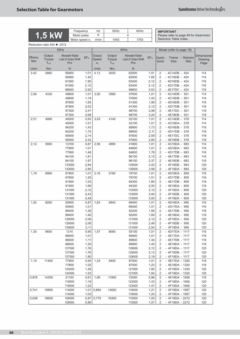
Bevel Buddybox 4 - 991361/EN-06/201866
Selection Table for Gearmotors
1,79 6990 67800 1,01 2,16 5790 78700 1,01 2 - 4D16DA - 809 11667800 1,25 78700 1,51 2 - 4D17DB - 809 11691900 1,53 94300 1,85 2 - 4E17DB - 809 11891900 1,66 94300 2,00 2 - 4E18DA - 809 118131000 2,12 133000 2,12 2 - 4F18DA - 809 120131000 2,43 133000 2,94 2 - 4F18DB - 809 120131000 2,49 133000 3,00 2 - 4F19DA - 809 120
1,52 8260 50900 0,87 1,83 6840 69400 1,01 2 - 4D16DA - 956 11650900 1,01 69400 1,01 2 - 4D17DA - 956 11689400 1,30 92200 1,56 2 - 4E17DB - 956 11889400 1,40 92200 1,69 2 - 4E18DA - 956 118129000 2,06 131000 2,12 2 - 4F18DA - 956 120129000 2,06 131000 2,49 2 - 4F18DB - 956 120129000 2,11 131000 2,54 2 - 4F19DA - 956 120
1,30 9650 1210 0,90 1,57 8000 55100 1,01 2 - 4D17DA - 1117 11686600 1,01 89900 1,01 2 - 4E17DA - 1117 11886600 1,11 89900 1,34 2 - 4E17DB - 1117 11886600 1,20 89900 1,45 2 - 4E18DA - 1117 118127000 1,76 129000 2,12 2 - 4F18DA - 1117 120127000 1,76 129000 2,13 2 - 4F18DB - 1117 120127000 1,80 129000 2,18 2 - 4F19DA - 1117 120
1,10 11400 77800 0,94 1,33 9450 87000 1,01 2 - 4E17DA - 1320 11877800 1,02 87000 1,23 2 - 4E18DA - 1320 118124000 1,49 127000 1,80 2 - 4F18DA - 1320 120124000 1,53 127000 1,84 2 - 4F19DA - 1320 120
0,876 14300 21100 0,81 1,06 11900 72500 0,98 2 - 4E18DA - 1656 118119000 1,19 123000 1,43 2 - 4F18DA - 1656 120119000 1,22 123000 1,47 2 - 4F19DA - 1656 120
0,741 16900 114000 1,01 0,894 14000 119000 1,21 2 - 4F18DA - 1957 120114000 1,03 119000 1,24 2 - 4F19DA - 1957 120
0,638 19600 109000 0,87 0,770 16300 115000 1,05 2 - 4F18DA - 2272 120109000 0,89 115000 1,07 2 - 4F19DA - 2272 120
2,90 4330 49800 1,01 3,50 3580 57600 1,01 2 - 4C14DB - 501 11449800 1,19 57600 1,43 2 - 4C16DB - 501 11487900 1,65 91300 1,99 2 - 4D16DB - 501 11687900 2,02 91300 2,12 2 - 4D17DB - 501 11697300 2,47 98700 2,98 2 - 4E17DC - 501 11897300 2,68 98700 3,24 2 - 4E18DB - 501 118
2,51 4990 40000 0,93 3,03 4140 52100 1,01 2 - 4C14DB - 578 11440000 1,01 52100 1,01 2 - 4C16DA - 578 11484200 1,43 88900 1,73 2 - 4D16DB - 578 11684200 1,75 88900 2,11 2 - 4D17DB - 578 11695900 2,14 97600 2,59 2 - 4E17DC - 578 11895900 2,32 97600 2,80 2 - 4E18DB - 578 118
2,12 5900 13700 0,87 2,56 4890 41800 1,01 2 - 4C16DA - 683 11477900 1,01 84800 1,01 2 - 4D16DA - 683 11677900 1,48 84800 1,78 2 - 4D17DB - 683 11694100 1,81 96100 2,12 2 - 4E17DB - 683 11894100 1,97 96100 2,37 2 - 4E18DB - 683 118133000 2,84 135000 3,43 2 - 4F18DB - 683 120133000 2,95 135000 3,56 2 - 4F19DA - 683 120
3.42 3660 56900 1.01 4.13 3030 62000 1.01 2 - 4C14DB - 424 11456900 1.40 62000 1.69 2 - 4C16DB - 424 11491000 1.95 93400 2.12 2 - 4D16DB - 424 11691000 2.12 93400 2.12 2 - 4D17DB - 424 11698600 2.92 99800 3.53 2 - 4E17DC - 424 118
1,5 kWFrequency Hz 50Hz 60HzMotor poles P 4
Motor speed n1 r/min 1450 1750Reduction ratio 424 2272
50Hz 60Hz Model (refer to page 18)
Dimensional Drawing
Page
E ciency Motor
OutputTorque
Tout
Allowable Radial Load of Output Shaft
Pro
SFGOutput Speed
n2
OutputTorque
Tout
Allowable Radial Load of Output Shaft
Pro
SFG Capacity Symbol
- Frame Size
- Reduction Ratio
r/min Nm N r/min Nm N
IMPORTANT :Please refer to page 49 for Gearmotor Selection Table notes.

Bevel Buddybox 4 - 991361/EN-06/2018 67
Selection Table for Gearmotors
31,9 608 25000 1,07 38,5 504 24000 1,07 3 - 4A100 - 46 11025000 1,45 24000 1,45 3 - 4A105 - 46 11025000 1,61 24000 1,61 3 - 4A110 - 46 11025000 1,77 24000 1,77 3 - 4A115 - 46 11025000 2,12 24000 2,12 3 - 4A120 - 46 11035600 2,30 33900 2,30 3 - 4B120 - 46 11235600 2,69 33900 2,69 3 - 4B125 - 46 112
27,6 701 24200 1,07 33,3 581 24800 1,07 3 - 4A100 - 53 11024200 1,45 24800 1,45 3 - 4A105 - 53 11024200 1,61 24800 1,61 3 - 4A110 - 53 11024200 1,77 24800 1,77 3 - 4A115 - 53 11024200 1,84 24800 1,84 3 - 4A120 - 53 11036800 2,30 35200 2,30 3 - 4B120 - 53 11236800 2,69 35200 2,69 3 - 4B125 - 53 112
138 140 17500 1,07 167 116 16600 1,07 3 - 4A100 - 11 11017500 1,45 16600 1,45 3 - 4A105 - 11 11017500 4,36 16600 4,36 3 - 4A120 - 11 110
113 171 18400 1,07 137 142 17500 1,07 3 - 4A100 - 13 11018400 1,45 17500 1,45 3 - 4A105 - 13 11018400 4,36 17500 4,36 3 - 4A120 - 13 110
104 187 18900 1,07 125 155 17900 1,07 3 - 4A100 - 14 11018900 1,45 17900 1,45 3 - 4A105 - 14 11018900 4,36 17900 4,36 3 - 4A120 - 14 110
90,6 214 19500 1,07 109 177 18600 1,07 3 - 4A100 - 16 11019500 1,45 18600 1,45 3 - 4A105 - 16 11019500 4,36 18600 4,36 3 - 4A120 - 16 110
82,9 234 20000 1,07 100 194 19000 1,07 3 - 4A100 - 18 11020000 1,45 19000 1,45 3 - 4A105 - 18 11020000 4,36 19000 4,36 3 - 4A120 - 18 110
69,0 281 20900 1,07 83,3 232 19900 1,07 3 - 4A100 - 21 11020900 1,45 19900 1,45 3 - 4A105 - 21 11020900 1,61 19900 1,61 3 - 4A110 - 21 11020900 1,78 19900 1,78 3 - 4A115 - 21 11020900 2,97 19900 2,97 3 - 4A120 - 21 110
64,7 299 21200 2,97 78,1 248 20300 2,97 3 - 4A120 - 22 11059,2 327 21700 2,97 71,4 271 20700 2,97 3 - 4A120 - 25 11051,8 374 22400 1,07 62,5 310 21400 1,07 3 - 4A100 - 28 110
22400 1,45 21400 1,45 3 - 4A105 - 28 11022400 1,61 21400 1,61 3 - 4A110 - 28 11022400 1,78 21400 1,78 3 - 4A115 - 28 11022400 2,97 21400 2,97 3 - 4A120 - 28 110
41,2 470 23600 1,07 49,7 390 22600 1,07 3 - 4A100 - 35 11023600 1,45 22600 1,45 3 - 4A105 - 35 11023600 1,61 22600 1,61 3 - 4A110 - 35 11023600 1,78 22600 1,78 3 - 4A115 - 35 11023600 2,30 22600 2,30 3 - 4A120 - 35 11023600 2,69 22600 2,69 3 - 4A125 - 35 11023600 2,74 22600 2,74 3 - 4A140 - 35 110
37,7 514 24100 1,07 45,5 426 23100 1,07 3 - 4A100 - 39 11024100 1,45 23100 1,45 3 - 4A105 - 39 11024100 1,61 23100 1,61 3 - 4A110 - 39 11024100 1,78 23100 1,78 3 - 4A115 - 39 11024100 2,30 23100 2,30 3 - 4A120 - 39 11024100 2,51 23100 2,51 3 - 4A125 - 39 11034100 2,69 32500 2,69 3 - 4B125 - 39 112
2,2 kWFrequency Hz 50Hz 60HzMotor poles P 4
Motor speed n1 r/min 1450 1750Reduction ratio 11 60
50Hz 60Hz Model (refer to page 18)Dimensional
Drawing Page
Output Speed
n2
OutputTorque
Tout
Allowable Radial Load of Output Shaft
Pro
SFGOutput Speed
n2
OutputTorque
Tout
Allowable Radial Load of Output Shaft
Pro
SFG Capacity Symbol
- Frame Size
- Reduction Ratio
r/min Nm N r/min Nm N
24,4 795 23200 1,12 29,4 659 24600 1,12 3 - 4A105 - 60 11023200 1,45 24600 1,45 3 - 4A110 - 60 11023200 1,62 24600 1,62 3 - 4A115 - 60 11038000 2,22 36300 2,30 3 - 4B120 - 60 11238000 2,57 36300 2,57 3 - 4B125 - 60 112
IMPORTANT :Please refer to page 49 for Gearmotor Selection Table notes.

Bevel Buddybox 4 - 991361/EN-06/201868
Selection Table for Gearmotors
7.02 2760 21000 0.93 8.47 2290 30500 0.93 3 - 4B140 - 207 11264600 1.35 67000 1.35 3 - 4C140 - 207 11464600 1.45 67000 1.66 3 - 4C145 - 207 11464600 1.86 67000 1.86 3 - 4C160 - 207 11494700 2.01 95900 2.01 3 - 4D160 - 207 11694700 2.59 95900 2.61 3 - 4D165 - 207 116
5.84 3320 61100 1.10 7.04 2750 64700 1.10 3 - 4C140 - 249 11461100 1.19 64700 1.38 3 - 4C145 - 249 11461100 1.55 64700 1.55 3 - 4C160 - 249 11493000 2.15 94700 2.57 3 - 4D165 - 249 116
14,3 1360 11600 0,95 17,2 1120 18100 0,95 3 - 4A115 - 102 11040300 1,30 41100 1,36 3 - 4B120 - 102 11240300 1,58 41100 1,71 3 - 4B125 - 102 11240300 1,90 41100 1,90 3 - 4B140 - 102 11261600 2,70 58800 2,70 3 - 4C140 - 102 114
12,9 1500 39200 1,08 15,6 1240 41000 1,13 3 - 4B120 - 112 11239200 1,31 41000 1,45 3 - 4B125 - 112 11239200 1,72 41000 1,72 3 - 4B140 - 112 11263100 2,85 60300 3,42 3 - 4C145 - 112 114
11,8 1640 38100 1,08 14,3 1360 40300 1,13 3 - 4B120 - 123 11238100 1,31 40300 1,45 3 - 4B125 - 123 11238100 1,57 40300 1,57 3 - 4B140 - 123 11264500 2,37 61600 2,37 3 - 4C140 - 123 11464500 2,85 61600 3,14 3 - 4C145 - 123 114
9,63 2010 34200 1,06 11,6 1670 37800 1,08 3 - 4B125 - 151 11234200 1,28 37800 1,28 3 - 4B140 - 151 11267600 1,79 64700 1,79 3 - 4C140 - 151 11467600 2,12 64700 2,45 3 - 4C145 - 151 11467600 2,56 64700 2,56 3 - 4C160 - 151 11496400 2,93 97000 3,39 3 - 4D160 - 151 116
8,12 2380 28900 0,90 9,80 1980 34600 1,04 3 - 4B125 - 179 11228900 1,08 34600 1,08 3 - 4B140 - 179 11266500 1,56 67300 1,56 3 - 4C140 - 179 11466500 1,68 67300 1,92 3 - 4C145 - 179 11466500 2,16 67300 2,16 3 - 4C160 - 179 11495600 2,99 96500 3,42 3 - 4D165 - 179 116
2,2 kWFrequency Hz 50Hz 60HzMotor poles P 4
Motor speed n1 r/min 1450 1750Reduction ratio 67 249
50Hz 60Hz Model (refer to page 18)
Dimensional Drawing
Page
Output Speed
n2
OutputTorque
Tout
Allowable Radial Load of Output Shaft
Pro
SFGOutput Speed
n2
OutputTorque
Tout
Allowable Radial Load of Output Shaft
Pro
SFG Capacity Symbol
- Frame Size
- Reduction Ratio
r/min Nm N r/min Nm N21,6 898 21900 1,04 26,0 744 23800 1,06 3 - 4A105 - 67 110
21900 1,24 23800 1,24 3 - 4A110 - 67 11021900 1,44 23800 1,44 3 - 4A120 - 67 11039000 1,80 37300 1,80 3 - 4B120 - 67 11239000 2,18 37300 2,22 3 - 4B125 - 67 11239000 2,86 37300 2,86 3 - 4B140 - 67 112
19,7 982 20700 1,04 23,8 814 23000 1,06 3 - 4A105 - 74 11020700 1,31 23000 1,31 3 - 4A115 - 74 11039900 2,18 38200 2,22 3 - 4B125 - 74 11239900 2,62 38200 2,62 3 - 4B140 - 74 112
18,1 1070 19200 0,87 21,9 886 22100 0,87 3 - 4A110 - 80 11019200 1,01 22100 1,01 3 - 4A115 - 80 11019200 1,21 22100 1,21 3 - 4A120 - 80 11040600 1,40 38900 1,40 3 - 4B120 - 80 11240600 1,80 38900 1,80 3 - 4B125 - 80 11240600 2,40 38900 2,40 3 - 4B140 - 80 112
16,6 1170 17100 0,87 20,0 969 20900 0,87 3 - 4A110 - 88 11017100 1,01 20900 1,01 3 - 4A115 - 88 11017100 1,10 20900 1,10 3 - 4A120 - 88 11041400 1,40 39800 1,40 3 - 4B120 - 88 11241400 1,80 39800 1,80 3 - 4B125 - 88 11241400 2,20 39800 2,20 3 - 4B140 - 88 112
IMPORTANT :Please refer to page 49 for Gearmotor Selection Table notes.

Bevel Buddybox 4 - 991361/EN-06/2018 69
Selection Table for Gearmotors
1,30 14200 27800 0,82 1,57 11700 74100 0,99 3 - 4E18DA - 1117 118119000 1,20 123000 1,45 3 - 4F18DA - 1117 120119000 1,20 123000 1,45 3 - 4F18DB - 1117 120119000 1,23 123000 1,48 3 - 4F19DA - 1117 120
1,10 16700 115000 1,02 1,33 13900 120000 1,23 3 - 4F18DA - 1320 120115000 1,04 120000 1,26 3 - 4F19DA - 1320 120
0,876 21000 90200 0,81 1,06 17400 113000 0,98 3 - 4F18DA - 1656 12090200 0,83 113000 1,00 3 - 4F19DA - 1656 120
3,98 4610 46000 1,01 4,81 3820 55400 1,22 3 - 4C14DC - 364 11446000 1,11 55400 1,34 3 - 4C16DB - 364 11486400 1,89 90300 2,28 3 - 4D17DC - 364 11696700 2,32 98300 2,80 3 - 4E17DC - 364 11896700 2,51 98300 3,03 3 - 4E18DB - 364 118
3,42 5370 32200 0,82 4,13 4450 48300 0,99 3 - 4C14DC - 424 11432200 0,96 48300 1,16 3 - 4C16DB - 424 11481700 1,33 87300 1,45 3 - 4D16DB - 424 11681700 1,62 87300 1,96 3 - 4D17DC - 424 11695200 1,99 97000 2,41 3 - 4E17DC - 424 11895200 2,16 97000 2,61 3 - 4E18DB - 424 118
2,90 6350 74100 1,13 3,50 5260 82500 1,36 3 - 4D16DB - 501 11674100 1,37 82500 1,45 3 - 4D17DB - 501 11693200 1,45 95400 1,45 3 - 4E17DB - 501 11893200 1,69 95400 2,04 3 - 4E17DC - 501 11893200 1,83 95400 2,21 3 - 4E18DB - 501 118132000 2,63 134000 3,17 3 - 4F18DB - 501 120132000 2,74 134000 3,31 3 - 4F19DB - 501 120
2,51 7320 64100 0,98 3,03 6070 76500 1,18 3 - 4D16DB - 578 11664100 1,19 76500 1,44 3 - 4D17DB - 578 11691300 1,45 93800 1,45 3 - 4E17DB - 578 11891300 1,58 93800 1,91 3 - 4E18DB - 578 118131000 2,29 133000 2,76 3 - 4F18DB - 578 120131000 2,38 133000 2,87 3 - 4F19DB - 578 120
2,12 8650 43600 0,83 2,56 7170 65900 1,00 3 - 4D16DB - 683 11643600 1,01 65900 1,22 3 - 4D17DB - 683 11688600 1,24 91600 1,45 3 - 4E17DB - 683 11888600 1,34 91600 1,62 3 - 4E18DB - 683 118128000 1,94 131000 2,34 3 - 4F18DB - 683 120128000 2,01 131000 2,43 3 - 4F19DB - 683 120
1,79 10300 85400 1,04 2,16 8490 88900 1,26 3 - 4E17DB - 809 11885400 1,13 88900 1,37 3 - 4E18DA - 809 118126000 1,45 129000 1,45 3 - 4F18DA - 809 120126000 1,66 129000 2,00 3 - 4F18DB - 809 120126000 1,70 129000 2,05 3 - 4F19DA - 809 120
1,52 12100 69300 0,88 1,83 10000 85900 1,07 3 - 4E17DB - 956 11869300 0,96 85900 1,16 3 - 4E18DA - 956 118122000 1,40 126000 1,45 3 - 4F18DA - 956 120122000 1,40 126000 1,70 3 - 4F18DB - 956 120122000 1,44 126000 1,73 3 - 4F19DA - 956 120
2,2 kWFrequency Hz 50Hz 60HzMotor poles P 4
Motor speed n1 r/min 1450 1750Reduction ratio 305 1656
50Hz 60Hz Model (refer to page 18)
Dimensional Drawing
Page
Output Speed
n2
OutputTorque
Tout
Allowable Radial Load of Output Shaft
Pro
SFGOutput Speed
n2
OutputTorque
Tout
Allowable Radial Load of Output Shaft
Pro
SFG Capacity Symbol
- Frame Size
- Reduction Ratio
r/min Nm N r/min Nm N4,76 4070 55000 0,90 5,75 3370 60800 0,90 3 - 4C140 - 305 114
55000 0,98 60800 1,13 3 - 4C145 - 305 11455000 1,26 60800 1,26 3 - 4C160 - 305 11490200 1,46 92800 1,58 3 - 4D160 - 305 11690200 1,71 92800 1,77 3 - 4D165 - 305 116
IMPORTANT :Please refer to page 49 for Gearmotor Selection Table notes.

Bevel Buddybox 4 - 991361/EN-06/201870
Selection Table for Gearmotors
27,6 956 21100 1,18 33,3 792 23200 1,18 4 - 4A110 - 53 11021100 1,30 23200 1,30 4 - 4A115 - 53 11035800 1,69 34300 1,69 4 - 4B120 - 53 11235800 1,97 34300 1,97 4 - 4B125 - 53 11235800 2,69 34300 2,69 4 - 4B140 - 53 112
24,4 1080 18900 1,06 29,4 898 21900 1,06 4 - 4A110 - 60 11018900 1,19 21900 1,19 4 - 4A115 - 60 11036700 1,63 35300 1,69 4 - 4B120 - 60 11236700 1,89 35300 1,89 4 - 4B125 - 60 11236700 2,37 35300 2,37 4 - 4B140 - 60 112
21,6 1220 15800 1,04 26,0 1010 20100 1,04 4 - 4A115 - 67 11037600 1,32 36200 1,32 4 - 4B120 - 67 11237600 1,60 36200 1,63 4 - 4B125 - 67 11237600 2,10 36200 2,10 4 - 4B140 - 67 11254300 2,89 51900 2,89 4 - 4C140 - 67 114
19,7 1340 12300 0,96 23,8 1110 18400 0,96 4 - 4A115 - 74 11038400 1,32 36900 1,32 4 - 4B120 - 74 11238400 1,60 36900 1,63 4 - 4B125 - 74 11238400 1,92 36900 1,92 4 - 4B140 - 74 11255500 2,89 53100 2,89 4 - 4C140 - 74 114
138 191 17200 1,06 167 158 16400 1,06 4 - 4A105 - 11 11017200 3,20 16400 3,20 4 - 4A120 - 11 110
113 233 18100 1,06 137 193 17200 1,06 4 - 4A105 - 13 11018100 3,20 17200 3,20 4 - 4A120 - 13 110
104 255 18500 1,06 125 211 17600 1,06 4 - 4A105 - 14 11018500 3,20 17600 3,20 4 - 4A120 - 14 110
90,6 291 19100 1,06 109 242 18200 1,06 4 - 4A105 - 16 11019100 3,20 18200 3,20 4 - 4A120 - 16 110
82,9 319 19500 1,06 100 264 18600 1,06 4 - 4A105 - 18 11019500 3,20 18600 3,20 4 - 4A120 - 18 110
69,0 383 20400 1,18 83,3 317 19500 1,18 4 - 4A110 - 21 11020400 1,31 19500 1,31 4 - 4A115 - 21 11020400 2,18 19500 2,18 4 - 4A120 - 21 11020400 2,50 19500 2,50 4 - 4A125 - 21 110
64,7 408 20600 2,18 78,1 338 19800 2,18 4 - 4A120 - 22 11020600 2,50 19800 2,50 4 - 4A125 - 22 110
59,2 446 21100 2,18 71,4 370 20200 2,18 4 - 4A120 - 25 11021100 2,50 20200 2,50 4 - 4A125 - 25 11021100 2,89 20200 2,89 4 - 4A140 - 25 110
51,8 510 21700 1,18 62,5 423 20800 1,18 4 - 4A110 - 28 11021700 1,31 20800 1,31 4 - 4A115 - 28 11021700 2,18 20800 2,18 4 - 4A120 - 28 11021700 2,50 20800 2,50 4 - 4A125 - 28 11021700 2,53 20800 2,53 4 - 4A140 - 28 110
41,2 641 22700 1,18 49,7 531 21900 1,18 4 - 4A110 - 35 11022700 1,31 21900 1,31 4 - 4A115 - 35 11022700 1,69 21900 1,69 4 - 4A120 - 35 11022700 1,97 21900 1,97 4 - 4A125 - 35 11022700 2,01 21900 2,01 4 - 4A140 - 35 110
37,7 701 23100 1,18 45,5 581 22300 1,18 4 - 4A110 - 39 11023100 1,31 22300 1,31 4 - 4A115 - 39 11023100 1,69 22300 1,69 4 - 4A120 - 39 11023100 1,84 22300 1,84 4 - 4A125 - 39 11033300 3,66 31800 3,66 4 - 4B140 - 39 112
31,9 829 22800 1,18 38,5 687 23000 1,18 4 - 4A110 - 46 11022800 1,30 23000 1,30 4 - 4A115 - 46 11022800 1,56 23000 1,56 4 - 4A120 - 46 11034600 1,69 33100 1,69 4 - 4B120 - 46 11234600 1,97 33100 1,97 4 - 4B125 - 46 11234600 3,10 33100 3,10 4 - 4B140 - 46 112
3,0 kWFrequency Hz 50Hz 60HzMotor poles P 4
Motor speed n1 r/min 1450 1750Reduction ratio 11 74
50Hz 60Hz Model (refer to page 18)
Dimensional Drawing
Page
Output Speed
n2
OutputTorque
Tout
Allowable Radial Load of Output Shaft
Pro
SFGOutput Speed
n2
OutputTorque
Tout
Allowable Radial Load of Output Shaft
Pro
SFG Capacity Symbol
- Frame Size
- Reduction Ratio
r/min Nm N r/min Nm N
IMPORTANT :Please refer to page 49 for Gearmotor Selection Table notes.

Bevel Buddybox 4 - 991361/EN-06/2018 71
Selection Table for Gearmotors
11,8 2230 31300 0,96 14,3 1850 36000 1,06 4 - 4B125 - 123 11231300 1,15 36000 1,15 4 - 4B140 - 123 11262200 1,74 59800 1,74 4 - 4C140 - 123 11462200 2,09 59800 2,30 4 - 4C145 - 123 11462200 2,30 59800 2,30 4 - 4C160 - 123 11494800 2,67 90400 3,22 4 - 4D160 - 123 116
9,63 2740 21500 0,94 11,6 2270 30700 0,94 4 - 4B140 - 151 11264700 1,31 62500 1,31 4 - 4C140 - 151 11464700 1,56 62500 1,80 4 - 4C145 - 151 11464700 1,87 62500 1,87 4 - 4C160 - 151 11494700 2,15 95200 2,48 4 - 4D160 - 151 11694700 2,60 95200 2,64 4 - 4D165 - 151 116
8,12 3250 61600 1,14 9,80 2690 64600 1,14 4 - 4C140 - 179 11461600 1,23 64600 1,41 4 - 4C145 - 179 11461600 1,58 64600 1,58 4 - 4C160 - 179 11493200 1,83 94900 1,92 4 - 4D160 - 179 11693200 2,19 94900 2,51 4 - 4D165 - 179 11693200 2,55 94900 2,68 4 - 4D170 - 179 11693200 2,68 94900 2,68 4 - 4D175 - 179 11693200 2,68 94900 3,24 4 - 4D180 - 179 116
7,02 3760 57800 1,06 8,47 3120 62500 1,22 4 - 4C145 - 207 11457800 1,37 62500 1,37 4 - 4C160 - 207 11491400 1,47 93600 1,47 4 - 4D160 - 207 11691400 1,90 93600 1,92 4 - 4D165 - 207 11691400 2,21 93600 2,32 4 - 4D170 - 207 11691400 2,32 93600 2,32 4 - 4D175 - 207 11691400 2,32 93600 2,80 4 - 4D180 - 207 11698400 2,76 99700 2,76 4 - 4E175 - 207 118
5,84 4530 50200 0,87 7,04 3750 57800 1,01 4 - 4C145 - 249 11450200 1,14 57800 1,14 4 - 4C160 - 249 11488100 1,58 91400 1,88 4 - 4D165 - 249 11688100 1,93 91400 1,93 4 - 4D175 - 249 11688100 1,93 91400 2,32 4 - 4D180 - 249 11696900 2,33 98400 2,38 4 - 4E175 - 249 11896900 2,56 98400 2,93 4 - 4E180 - 249 11896900 2,56 98400 3,09 4 - 4E185 - 249 118135000 2,93 137000 2,93 4 - 4F180 - 249 120
18,1 1460 38900 1,03 21,9 1210 37500 1,03 4 - 4B120 - 80 11238900 1,32 37500 1,32 4 - 4B125 - 80 11238900 1,76 37500 1,76 4 - 4B140 - 80 11256600 2,30 54200 2,30 4 - 4C140 - 80 11456600 2,64 54200 2,64 4 - 4C145 - 80 114
16,6 1590 38400 1,03 20,0 1320 38300 1,03 4 - 4B120 - 88 11238400 1,32 38300 1,32 4 - 4B125 - 88 11238400 1,61 38300 1,61 4 - 4B140 - 88 11257800 2,30 55400 2,30 4 - 4C140 - 88 11457800 2,64 55400 2,64 4 - 4C145 - 88 114
14,3 1850 36000 0,96 17,2 1530 39000 1,00 4 - 4B120 - 102 11236000 1,16 39000 1,26 4 - 4B125 - 102 11236000 1,39 39000 1,39 4 - 4B140 - 102 11259800 1,98 57300 1,98 4 - 4C140 - 102 11459800 2,51 57300 2,51 4 - 4C145 - 102 11459800 2,78 57300 2,78 4 - 4C160 - 102 114
12,9 2040 33900 0,96 15,6 1690 37600 1,06 4 - 4B125 - 112 11233900 1,26 37600 1,26 4 - 4B140 - 112 11261000 1,74 58600 1,74 4 - 4C140 - 112 11461000 2,09 58600 2,51 4 - 4C145 - 112 11461000 2,52 58600 2,52 4 - 4C160 - 112 11492600 2,67 88300 3,22 4 - 4D160 - 112 116
3,0 kWFrequency Hz 50Hz 60HzMotor poles P 4
Motor speed n1 r/min 1450 1750Reduction ratio 80 249
50Hz 60Hz Model (refer to page 18)
Dimensional Drawing
Page
Output Speed
n2
OutputTorque
Tout
Allowable Radial Load of Output Shaft
Pro
SFGOutput Speed
n2
OutputTorque
Tout
Allowable Radial Load of Output Shaft
Pro
SFG Capacity Symbol
- Frame Size
- Reduction Ratio
r/min Nm N r/min Nm N
IMPORTANT :Please refer to page 49 for Gearmotor Selection Table notes.
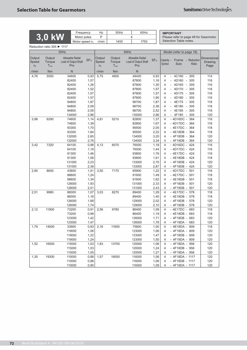
Bevel Buddybox 4 - 991361/EN-06/201872
Selection Table for Gearmotors
4,76 5550 34600 0,93 5,75 4600 49400 0,93 4 - 4C160 - 305 11482400 1,07 87800 1,16 4 - 4D160 - 305 11682400 1,26 87800 1,30 4 - 4D165 - 305 11682400 1,52 87800 1,57 4 - 4D170 - 305 11682400 1,57 87800 1,57 4 - 4D175 - 305 11682400 1,57 87800 1,90 4 - 4D180 - 305 11694800 1,87 96700 1,87 4 - 4E175 - 305 11894800 2,09 96700 2,38 4 - 4E180 - 305 11894800 2,09 96700 2,52 4 - 4E185 - 305 118134000 2,86 135000 2,86 4 - 4F185 - 305 120
3,98 6290 74600 1,14 4,81 5210 82800 1,37 4 - 4D16DC - 364 11674600 1,39 82800 1,67 4 - 4D17DC - 364 11693300 1,70 95500 2,05 4 - 4E17DC - 364 11893300 1,84 95500 2,22 4 - 4E18DB - 364 118132000 2,65 134000 3,20 4 - 4F18DB - 364 120132000 2,76 134000 3,34 4 - 4F19DB - 364 120
3,42 7320 64100 0,98 4,13 6070 76500 1,18 4 - 4D16DC - 424 11664100 1,19 76500 1,44 4 - 4D17DC - 424 11691300 1,46 93800 1,76 4 - 4E17DC - 424 11891300 1,58 93800 1,91 4 - 4E18DB - 424 118131000 2,23 133000 2,70 4 - 4F18DB - 424 120131000 2,38 133000 2,87 4 - 4F19DB - 424 120
2,90 8650 43600 1,01 3,50 7170 65900 1,22 4 - 4D17DC - 501 11688600 1,24 91600 1,49 4 - 4E17DC - 501 11888600 1,34 91600 1,62 4 - 4E18DB - 501 118128000 1,93 131000 2,33 4 - 4F18DB - 501 120128000 2,01 131000 2,43 4 - 4F19DB - 501 120
2,51 9980 86000 1,07 3,03 8270 89400 1,29 4 - 4E17DC - 578 11886000 1,16 89400 1,40 4 - 4E18DB - 578 118126000 1,68 129000 2,02 4 - 4F18DB - 578 120126000 1,74 129000 2,10 4 - 4F19DB - 578 120
2,12 11800 73200 0,91 2,56 9780 86400 1,09 4 - 4E17DC - 683 11873200 0,98 86400 1,19 4 - 4E18DB - 683 118123000 1,42 126000 1,71 4 - 4F18DB - 683 120123000 1,47 126000 1,78 4 - 4F19DA - 683 120
1,79 14000 33900 0,83 2,16 11600 75800 1,00 4 - 4E18DA - 809 118119000 1,06 123000 1,06 4 - 4F18DA - 809 120119000 1,22 123000 1,47 4 - 4F18DB - 809 120119000 1,24 123000 1,50 4 - 4F19DA - 809 120
1,52 16500 115000 1,03 1,83 13700 120000 1,06 4 - 4F18DA - 956 120115000 1,03 120000 1,24 4 - 4F18DB - 956 120115000 1,05 120000 1,27 4 - 4F19DA - 956 120
1,30 19300 110000 0,88 1,57 16000 116000 1,06 4 - 4F18DA - 1117 120110000 0,88 116000 1,06 4 - 4F18DB - 1117 120110000 0,90 116000 1,09 4 - 4F19DA - 1117 120
3,0 kWFrequency Hz 50Hz 60HzMotor poles P 4
Motor speed n1 r/min 1450 1750Reduction ratio 305 1117
50Hz 60Hz Model (refer to page 18)
Dimensional Drawing
Page
Output Speed
n2
OutputTorque
Tout
Allowable Radial Load of Output Shaft
Pro
SFGOutput Speed
n2
OutputTorque
Tout
Allowable Radial Load of Output Shaft
Pro
SFG Capacity Symbol
- Frame Size
- Reduction Ratio
r/min Nm N r/min Nm N
IMPORTANT :Please refer to page 49 for Gearmotor Selection Table notes.

Bevel Buddybox 4 - 991361/EN-06/2018 73
Selection Table for Gearmotors
24,4 1449 12300 0,90 29,4 1200 18400 0,90 6 - 4A115 - 60 11035700 1,22 34400 1,27 6 - 4B120 - 60 11235700 1,42 34400 1,42 6 - 4B125 - 60 11235700 1,78 34400 1,78 6 - 4B140 - 60 11251800 2,53 49600 2,53 6 - 4C140 - 60 114
21,6 1632 36400 0,99 26,0 1351 35200 0,99 6 - 4B120 - 67 11236400 1,19 35200 1,22 6 - 4B125 - 67 11236400 1,57 35200 1,57 6 - 4B140 - 67 11253300 2,16 51000 2,16 6 - 4C140 - 67 11453300 2,37 51000 2,75 6 - 4C145 - 67 114
19,7 1784 37000 0,99 23,8 1481 35800 0,99 6 - 4B120 - 74 11237000 1,19 35800 1,22 6 - 4B125 - 74 11237000 1,44 35800 1,44 6 - 4B140 - 74 11254400 2,16 52100 2,16 6 - 4C140 - 74 11454400 2,37 52100 2,75 6 - 4C145 - 74 114
4,0 kWFrequency Hz 50Hz 60HzMotor poles P 4
Motor speed n1 r/min 1450 1750Reduction ratio 11 74
50Hz 60Hz Model (refer to page 18)
Dimensional Drawing
Page
Output Speed
n2
OutputTorque
Tout
Allowable Radial Load of Output Shaft
Pro
SFGOutput Speed
n2
OutputTorque
Tout
Allowable Radial Load of Output Shaft
Pro
SFG Capacity Symbol
- Frame Size
- Reduction Ratio
r/min Nm N r/min Nm N138 255 16900 2,40 167 211 16200 2,40 6 - 4A120 - 11 110
16900 2,75 16200 2,75 6 - 4A125 - 11 110113 311 17800 2,40 137 257 17000 2,40 6 - 4A120 - 13 110
17800 2,75 17000 2,75 6 - 4A125 - 13 110104 341 18200 2,40 125 282 17400 2,40 6 - 4A120 - 14 110
18200 2,75 17400 2,75 6 - 4A125 - 14 11090,6 388 18700 2,40 109 322 17900 2,40 6 - 4A120 - 16 110
18700 2,75 17900 2,75 6 - 4A125 - 16 11082,9 425 19100 2,40 100 352 18300 2,40 6 - 4A120 - 18 110
19100 2,75 18300 2,75 6 - 4A125 - 18 11069,0 510 19900 0,98 83,3 423 19100 0,98 6 - 4A115 - 21 110
19900 1,64 19100 1,64 6 - 4A120 - 21 11019900 1,88 19100 1,88 6 - 4A125 - 21 11019900 2,53 19100 2,53 6 - 4A140 - 21 110
64,7 544 20100 1,64 78,1 451 19300 1,64 6 - 4A120 - 22 11020100 1,88 19300 1,88 6 - 4A125 - 22 11020100 2,37 19300 2,37 6 - 4A140 - 22 110
59,2 595 20500 1,64 71,4 493 19700 1,64 6 - 4A120 - 25 11020500 1,88 19700 1,88 6 - 4A125 - 25 11020500 2,16 19700 2,16 6 - 4A140 - 25 110
51,8 680 21100 0,98 62,5 563 20300 0,98 6 - 4A115 - 28 11021100 1,64 20300 1,64 6 - 4A120 - 28 11021100 1,88 20300 1,88 6 - 4A125 - 28 110
41,2 855 21900 0,98 49,7 708 21200 0,98 6 - 4A115 - 35 11021900 1,27 21200 1,27 6 - 4A120 - 35 11021900 1,48 21200 1,48 6 - 4A125 - 35 11021900 1,51 21200 1,51 6 - 4A140 - 35 11031900 3,01 30600 3,01 6 - 4B140 - 35 112
37,7 935 22200 0,98 45,5 775 21600 0,98 6 - 4A115 - 39 11022200 1,27 21600 1,27 6 - 4A120 - 39 11022200 1,38 21600 1,38 6 - 4A125 - 39 11032600 1,48 31200 1,48 6 - 4B125 - 39 11232600 2,75 31200 2,75 6 - 4B140 - 39 112
31,9 1103 20000 0,97 38,5 916 22200 0,97 6 - 4A115 - 46 11020000 1,17 22200 1,17 6 - 4A120 - 46 11033800 1,27 32500 1,27 6 - 4B120 - 46 11233800 1,48 32500 1,48 6 - 4B125 - 46 11233800 2,32 32500 2,32 6 - 4B140 - 46 112
27,6 1276 16900 0,97 33,3 1056 20700 0,97 6 - 4A115 - 53 11016900 1,01 20700 1,01 6 - 4A120 - 53 11034800 1,27 33500 1,27 6 - 4B120 - 53 11234800 1,48 33500 1,48 6 - 4B125 - 53 11234800 2,02 33500 2,02 6 - 4B140 - 53 112
IMPORTANT :Please refer to page 49 for Gearmotor Selection Table notes.

Bevel Buddybox 4 - 991361/EN-06/201874
Selection Table for Gearmotors
4.0 kWFrequency Hz 50Hz 60HzMotor poles P 4
Motor speed n1 r/min 1450 1750Reduction ratio 80 207
50Hz 60Hz Model (refer to page 18)
Dimensional Drawing
Page
Output Speed
n2
OutputTorque
Tout
Allowable Radial Load of Output Shaft
Pro
SFGOutput Speed
n2
OutputTorque
Tout
Allowable Radial Load of Output Shaft
Pro
SFG Capacity Symbol
- Frame Size
- Reduction Ratio
r/min N·m N r/min N·m N18,1 1946 36600 0,99 21,9 1611 36300 0,99 6 - 4B125 - 80 112
36600 1,32 36300 1,32 6 - 4B140 - 80 11255300 1,72 53100 1,72 6 - 4C140 - 80 11455300 1,98 53100 1,98 6 - 4C145 - 80 11455300 2,46 53100 2,46 6 - 4C160 - 80 11455300 2,65 53100 2,65 6 - 4C165 - 80 114
16,6 2130 34700 0,99 20,0 1762 36900 0,99 6 - 4B125 - 88 11234700 1,21 36900 1,21 6 - 4B140 - 88 11256500 1,72 54200 1,72 6 - 4C140 - 88 11456500 1,98 54200 1,98 6 - 4C145 - 88 11456500 2,41 54200 2,41 6 - 4C160 - 88 11485800 2,46 81900 2,46 6 - 4D160 - 88 116
14,3 2465 30600 0,87 17,2 2043 35600 0,94 6 - 4B125 - 102 11230600 1,05 35600 1,05 6 - 4B140 - 102 11258200 1,49 56000 1,49 6 - 4C140 - 102 11458200 1,89 56000 1,89 6 - 4C145 - 102 11458200 2,08 56000 2,08 6 - 4C160 - 102 11489000 2,39 85000 2,63 6 - 4D160 - 102 116
12,9 2724 26500 0,94 15,6 2259 33300 0,94 6 - 4B140 - 112 11259200 1,30 57100 1,30 6 - 4C140 - 112 11459200 1,56 57100 1,89 6 - 4C145 - 112 11459200 1,89 57100 1,89 6 - 4C160 - 112 11491100 2,00 87100 2,41 6 - 4D160 - 112 11691100 2,40 87100 2,85 6 - 4D165 - 112 116
11,8 2973 21200 0,86 14,3 2465 30600 0,86 6 - 4B140 - 123 11260300 1,30 58200 1,30 6 - 4C140 - 123 11460300 1,56 58200 1,73 6 - 4C145 - 123 11460300 1,73 58200 1,73 6 - 4C160 - 123 11493100 2,00 89000 2,41 6 - 4D160 - 123 11693100 2,40 89000 2,85 6 - 4D165 - 123 116
9,63 3654 60700 0,98 11,6 3027 60500 0,98 6 - 4C140 - 151 11460700 1,17 60500 1,35 6 - 4C145 - 151 11460700 1,41 60500 1,41 6 - 4C160 - 151 11492800 1,61 93500 1,86 6 - 4D160 - 151 11692800 1,95 93500 1,98 6 - 4D165 - 151 11692800 2,27 93500 2,39 6 - 4D170 - 151 11692800 2,39 93500 2,39 6 - 4D175 - 151 11692800 2,39 93500 2,88 6 - 4D180 - 151 116
8,12 4335 55600 0,93 9,80 3589 61100 1,05 6 - 4C145 - 179 11455600 1,18 61100 1,18 6 - 4C160 - 179 11490400 1,38 93000 1,43 6 - 4D160 - 179 11690400 1,65 93000 1,89 6 - 4D165 - 179 11690400 1,91 93000 2,01 6 - 4D170 - 179 11690400 2,01 93000 2,01 6 - 4D175 - 179 11690400 2,01 93000 2,42 6 - 4D180 - 179 11697900 2,47 99300 2,67 6 - 4E175 - 179 11897900 2,67 99300 3,00 6 - 4E180 - 179 11897900 2,67 99300 3,23 6 - 4E185 - 179 118
7,02 5016 48900 0,80 8,47 4151 57100 0,92 6 - 4C145 - 207 11448900 1,03 57100 1,03 6 - 4C160 - 207 11487500 1,10 91100 1,10 6 - 4D160 - 207 11687500 1,42 91100 1,43 6 - 4D165 - 207 11687500 1,66 91100 1,74 6 - 4D170 - 207 11687500 1,74 91100 1,74 6 - 4D175 - 207 11687500 1,74 91100 2,10 6 - 4D180 - 207 11696600 2,07 98200 2,07 6 - 4E175 - 207 11896600 2,31 98200 2,44 6 - 4E180 - 207 11896600 2,31 98200 2,79 6 - 4E185 - 207 118135000 2,44 137000 2,44 6 - 4F180 - 207 120
IMPORTANT :Please refer to page 49 for Gearmotor Selection Table notes.

Bevel Buddybox 4 - 991361/EN-06/2018 75
Selection Table for Gearmotors
4,0 kWFrequency Hz 50Hz 60HzMotor poles P 4
Motor speed n1 r/min 1450 1750Reduction ratio 249 956
50Hz 60Hz Model (refer to page 18)
Dimensional Drawing
Page
Output Speed
n2
OutputTorque
Tout
Allowable Radial Load of Output Shaft
Pro
SFGOutput Speed
n2
OutputTorque
Tout
Allowable Radial Load of Output Shaft
Pro
SFG Capacity Symbol
- Frame Size
- Reduction Ratio
r/min Nm N r/min Nm N5,84 6032 33900 0,85 7,04 5005 49000 0,85 6 - 4C160 - 249 114
82200 1,18 87600 1,42 6 - 4D165 - 249 11682200 1,38 87600 1,44 6 - 4D170 - 249 11682200 1,44 87600 1,44 6 - 4D175 - 249 11682200 1,44 87600 1,74 6 - 4D180 - 249 11694800 1,75 96700 1,79 6 - 4E175 - 249 11894800 1,92 96700 2,20 6 - 4E180 - 249 11894800 1,92 96700 2,32 6 - 4E185 - 249 118134000 2,45 135000 2,45 6 - 4F185 - 249 120
4,76 7395 72800 0,80 5,75 6130 81700 0,87 6 - 4D160 - 305 11672800 0,94 81700 0,97 6 - 4D165 - 305 11672800 1,17 81700 1,17 6 - 4D175 - 305 11672800 1,17 81700 1,42 6 - 4D180 - 305 11692200 1,41 94600 1,41 6 - 4E175 - 305 11892200 1,57 94600 1,79 6 - 4E180 - 305 11892200 1,57 94600 1,90 6 - 4E185 - 305 118131000 2,15 133000 2,15 6 - 4F185 - 305 120131000 2,43 133000 2,94 6 - 4F190 - 305 120
3,98 8389 58500 0,85 4,81 6951 73400 1,03 6 - 4D16DC - 364 11658500 1,04 73400 1,26 6 - 4D17DC - 364 11690400 1,28 93100 1,54 6 - 4E17DC - 364 11890400 1,38 93100 1,67 6 - 4E18DB - 364 118130000 1,99 132000 2,40 6 - 4F18DB - 364 120130000 2,07 132000 2,51 6 - 4F19DB - 364 120
3,42 9762 34700 0,90 4,13 8086 62100 1,08 6 - 4D17DC - 424 11687900 1,09 91000 1,32 6 - 4E17DC - 424 11887900 1,18 91000 1,43 6 - 4E18DB - 424 118128000 1,67 130000 2,03 6 - 4F18DB - 424 120128000 1,79 130000 2,16 6 - 4F19DB - 424 120
2,90 11568 84600 0,93 3,50 9557 88200 1,12 6 - 4E17DC - 501 11884600 1,01 88200 1,21 6 - 4E18DB - 501 118125000 1,44 128000 1,75 6 - 4F18DB - 501 120125000 1,51 128000 1,82 6 - 4F19DB - 501 120
2,51 13297 66600 0,80 3,03 11027 85500 0,97 6 - 4E17DC - 578 11866600 0,87 85500 1,05 6 - 4E18DB - 578 118122000 1,26 126000 1,52 6 - 4F18DB - 578 120122000 1,30 126000 1,58 6 - 4F19DB - 578 120
2,12 15784 118000 1,06 2,56 13081 123000 1,29 6 - 4F18DB - 683 120118000 1,11 123000 1,33 6 - 4F19DA - 683 120
1,79 18595 114000 0,80 2,16 15459 119000 0,80 6 - 4F18DA - 809 120114000 0,92 119000 1,10 6 - 4F18DB - 809 120114000 0,93 119000 1,13 6 - 4F19DA - 809 120
1,52 22054 99400 0,87 1,83 18270 114000 0,80 6 - 4F18DA - 956 12099400 0,78 114000 0,93 6 - 4F18DB - 956 12099400 0,79 114000 0,95 6 - 4F19DA - 956 120
IMPORTANT :Please refer to page 49 for Gearmotor Selection Table notes.

Bevel Buddybox 4 - 991361/EN-06/201876
Selection Table for Gearmotors
5,5 kWFrequency Hz 50Hz 60HzMotor poles P 4
Motor speed n1 r/min 1450 1750Reduction ratio 11 60
50Hz 60Hz Model (refer to page 18)
Dimensional Drawing
Page
Output Speed
n2
OutputTorque
Tout
Allowable Radial Load of Output Shaft
Pro
SFGOutput Speed
n2
OutputTorque
Tout
Allowable Radial Load of Output Shaft
Pro
SFG Capacity Symbol
- Frame Size
- Reduction Ratio
r/min Nm N r/min Nm N138 351 16300 1,75 167 291 15600 1,75 8 - 4A120 - 11 110
16300 2,00 15600 2,00 8 - 4A125 - 11 11016300 3,33 15600 3,68 8 - 4A145 - 11 110
113 428 17000 1,75 137 354 16300 1,75 8 - 4A120 - 13 11017000 2,00 16300 2,00 8 - 4A125 - 13 110
104 468 17300 1,75 125 387 16700 1,75 8 - 4A120 - 14 11017300 2,00 16700 2,00 8 - 4A125 - 14 11017300 2,76 16700 2,76 8 - 4A140 - 14 110
90,6 534 17800 1,75 109 443 17100 1,75 8 - 4A120 - 16 11017800 2,00 17100 2,00 8 - 4A125 - 16 11017800 2,41 17100 2,41 8 - 4A140 - 16 110
82,9 584 18100 1,75 100 484 17500 1,75 8 - 4A120 - 18 11018100 2,00 17500 2,00 8 - 4A125 - 18 11018100 2,21 17500 2,21 8 - 4A140 - 18 110
69,0 701 18600 1,19 83,3 581 18100 1,19 8 - 4A120 - 21 11018600 1,37 18100 1,37 8 - 4A125 - 21 11018600 1,84 18100 1,84 8 - 4A140 - 21 11027300 2,36 26100 2,36 8 - 4B140 - 21 11227300 2,75 26100 2,75 8 - 4B145 - 21 112
64,7 748 18800 1,19 78,1 620 18200 1,19 8 - 4A120 - 22 11018800 1,37 18200 1,37 8 - 4A125 - 22 11018800 1,72 18200 1,72 8 - 4A140 - 22 11027600 2,36 26500 2,36 8 - 4B140 - 22 11227600 2,75 26500 2,75 8 - 4B145 - 22 112
59,2 818 19100 1,19 71,4 678 18500 1,19 8 - 4A120 - 25 11019100 1,37 18500 1,37 8 - 4A125 - 25 11019100 1,58 18500 1,58 8 - 4A140 - 25 11028200 2,36 27100 2,36 8 - 4B140 - 25 11228200 2,75 27100 2,75 8 - 4B145 - 25 112
51,8 935 19400 1,19 62,5 775 18900 1,19 8 - 4A120 - 28 11019400 1,37 18900 1,37 8 - 4A125 - 28 11029000 2,36 27900 2,36 8 - 4B140 - 28 11229000 2,75 27900 2,75 8 - 4B145 - 28 112
41,2 1180 17000 1,08 49,7 974 19500 1,08 8 - 4A125 - 35 11017000 1,10 19500 1,10 8 - 4A140 - 35 11030300 2,19 29200 2,19 8 - 4B140 - 35 11244100 2,36 42200 2,36 8 - 4C140 - 35 11444100 2,75 42200 2,75 8 - 4C145 - 35 114
37,7 1290 14000 1,00 45,5 1070 19200 1,00 8 - 4A125 - 39 11030800 1,08 29800 1,08 8 - 4B125 - 39 11230800 2,00 29800 2,00 8 - 4B140 - 39 11245100 2,36 43200 2,36 8 - 4C140 - 39 11445100 2,75 43200 2,75 8 - 4C145 - 39 114
31,9 1520 31700 1,08 38,5 1260 30700 1,08 8 - 4B125 - 46 11231700 1,69 30700 1,69 8 - 4B140 - 46 11246800 2,36 44900 2,36 8 - 4C140 - 46 11446800 2,75 44900 2,75 8 - 4C145 - 46 114
27,6 1750 32400 1,08 33,3 1450 31500 1,08 8 - 4B125 - 53 11232400 1,47 31500 1,47 8 - 4B140 - 53 11248200 2,18 46300 2,18 8 - 4C140 - 53 11448200 2,64 46300 2,65 8 - 4C145 - 53 11448200 2,93 46300 2,93 8 - 4C160 - 53 114
24,4 1990 32900 1,03 29,4 1650 32100 1,03 8 - 4B125 - 60 11232900 1,29 32100 1,29 8 - 4B140 - 60 11249400 1,84 47600 1,84 8 - 4C140 - 60 11449400 2,18 47600 2,18 8 - 4C145 - 60 11449400 2,38 47600 2,38 8 - 4C160 - 60 11449400 2,59 47600 2,59 8 - 4C165 - 60 114
IMPORTANT :Please refer to page 49 for Gearmotor Selection Table notes.
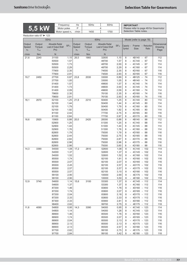
Bevel Buddybox 4 - 991361/EN-06/2018 77
Selection Table for Gearmotors
5,5 kWFrequency Hz 50Hz 60HzMotor poles P 4
Motor speed n1 r/min 1450 1750Reduction ratio 67 123
50Hz 60Hz Model (refer to page 18)
Dimensional Drawing
Page
Output Speed
n2
OutputTorque
Tout
Allowable Radial Load of Output Shaft
Pro
SFGOutput Speed
n2
OutputTorque
Tout
Allowable Radial Load of Output Shaft
Pro
SFG Capacity Symbol
- Frame Size
- Reduction Ratio
r/min Nm N r/min Nm N
14,3 3390 54000 1,08 17,2 2810 52600 1,08 8 - 4C140 - 102 11454000 1,37 52600 1,37 8 - 4C145 - 102 11454000 1,52 52600 1,52 8 - 4C160 - 102 11485500 1,74 82100 1,91 8 - 4D160 - 102 11685500 2,07 82100 2,07 8 - 4D165 - 102 11685500 2,45 82100 2,57 8 - 4D170 - 102 11685500 2,57 82100 2,57 8 - 4D175 - 102 11685500 2,57 82100 3,10 8 - 4D180 - 102 11699100 2,90 100000 2,90 8 - 4E175 - 102 11899100 2,90 100000 3,50 8 - 4E180 - 102 118
12,9 3740 54600 1,14 15,6 3100 53300 1,37 8 - 4C145 - 112 11454600 1,37 53300 1,37 8 - 4C160 - 112 11487200 1,46 83800 1,76 8 - 4D160 - 112 11687200 1,74 83800 2,07 8 - 4D165 - 112 11687200 2,04 83800 2,18 8 - 4D170 - 112 11687200 2,33 83800 2,33 8 - 4D175 - 112 11687300 2,33 83900 2,81 8 - 4D180 - 112 11698400 2,62 99700 2,75 8 - 4E175 - 112 118
11,8 4090 54800 0,95 14,3 3390 54000 0,95 8 - 4C140 - 123 11454800 1,14 54000 1,26 8 - 4C145 - 123 11488900 1,46 85500 1,76 8 - 4D160 - 123 11688900 1,74 85500 2,07 8 - 4D165 - 123 11688900 2,04 85500 2,13 8 - 4D170 - 123 11688900 2,13 85500 2,13 8 - 4D175 - 123 11688900 2,13 85500 2,57 8 - 4D180 - 123 11697700 2,62 99100 2,75 8 - 4E175 - 123 11897700 2,84 99100 3,42 8 - 4E180 - 123 118
IMPORTANT :Please refer to page 49 for Gearmotor Selection Table notes.
21,6 2240 31100 1,15 26,0 1860 32600 1,15 8 - 4B140 - 67 11250500 1,57 48700 1,57 8 - 4C140 - 67 11450500 1,73 48700 2,00 8 - 4C145 - 67 11450500 2,29 48700 2,29 8 - 4C160 - 67 11477900 2,35 74500 2,35 8 - 4D160 - 67 11677900 2,91 74500 2,93 8 - 4D165 - 67 116
19,7 2450 27700 0,87 23,8 2030 33000 0,89 8 - 4B125 - 74 11227700 1,05 33000 1,05 8 - 4B140 - 74 11251400 1,57 49600 1,57 8 - 4C140 - 74 11451400 1,73 49600 2,00 8 - 4C145 - 74 11451400 2,09 49600 2,09 8 - 4C160 - 74 11479600 2,35 76100 2,35 8 - 4D160 - 74 11679600 2,91 76100 2,93 8 - 4D165 - 74 116
18,1 2670 52100 1,25 21,9 2210 50400 1,25 8 - 4C140 - 80 11452100 1,44 50400 1,44 8 - 4C145 - 80 11452100 1,79 50400 1,79 8 - 4C160 - 80 11452100 1,92 50400 1,92 8 - 4C165 - 80 11481100 2,44 77700 2,75 8 - 4D165 - 80 11681100 2,84 77700 2,87 8 - 4D170 - 80 116
16,6 2920 15900 0,88 20,0 2420 28300 0,88 8 - 4B140 - 88 11252900 1,25 51300 1,25 8 - 4C140 - 88 11452900 1,44 51300 1,44 8 - 4C145 - 88 11452900 1,76 51300 1,76 8 - 4C160 - 88 11482800 1,79 79300 1,79 8 - 4D160 - 88 11682800 2,44 79300 2,75 8 - 4D165 - 88 11682800 2,84 79300 2,87 8 - 4D170 - 88 11682800 2,98 79300 2,98 8 - 4D175 - 88 11682800 2,98 79300 3,60 8 - 4D180 - 88 116

Bevel Buddybox 4 - 991361/EN-06/201878
Selection Table for Gearmotors
5,5 kWFrequency Hz 50Hz 60HzMotor poles P 4
Motor speed n1 r/min 1450 1750Reduction ratio 151 424
50Hz 60Hz Model (refer to page 18)
Dimensional Drawing
Page
Output Speed
n2
OutputTorque
Tout
Allowable Radial Load of Output Shaft
Pro
SFGOutput Speed
n2
OutputTorque
Tout
Allowable Radial Load of Output Shaft
Pro
SFG Capacity Symbol
- Frame Size
- Reduction Ratio
r/min Nm N r/min Nm N9,63 5030 43700 0,85 11,6 4160 54100 0,98 8 - 4C145 - 151 114
43700 1,02 54100 1,02 8 - 4C160 - 151 11485500 1,17 89200 1,35 8 - 4D160 - 151 11685500 1,42 89200 1,44 8 - 4D165 - 151 11685500 1,65 89200 1,73 8 - 4D170 - 151 11685500 1,73 89200 1,73 8 - 4D175 - 151 11685500 1,73 89200 2,09 8 - 4D180 - 151 11695900 2,05 97600 2,05 8 - 4E175 - 151 11895900 2,31 97600 2,75 8 - 4E180 - 151 11895900 2,31 97600 2,79 8 - 4E185 - 151 118135000 2,75 136000 2,75 8 - 4F180 - 151 120
8,12 5960 24200 0,86 9,80 4940 44900 0,86 8 - 4C160 - 179 11479700 1,00 86000 1,05 8 - 4D160 - 179 11679700 1,20 86000 1,37 8 - 4D165 - 179 11679700 1,39 86000 1,46 8 - 4D170 - 179 11679700 1,46 86000 1,46 8 - 4D175 - 179 11679700 1,46 86000 1,77 8 - 4D180 - 179 11694000 1,79 96000 1,95 8 - 4E175 - 179 11894000 1,95 96000 2,18 8 - 4E180 - 179 11894000 1,95 96000 2,35 8 - 4E185 - 179 118133000 2,18 135000 2,18 8 - 4F180 - 179 120133000 2,75 135000 2,75 8 - 4F185 - 179 120
7,02 6900 72300 0,80 8,47 5710 81400 0,80 8 - 4D160 - 207 11672300 1,03 81400 1,05 8 - 4D165 - 207 11672300 1,20 81400 1,26 8 - 4D170 - 207 11672300 1,26 81400 1,26 8 - 4D175 - 207 11672300 1,26 81400 1,53 8 - 4D180 - 207 11692100 1,51 94500 1,51 8 - 4E175 - 207 11892100 1,68 94500 1,77 8 - 4E180 - 207 11892100 1,68 94500 2,03 8 - 4E185 - 207 118131000 1,77 133000 1,77 8 - 4F180 - 207 120131000 2,18 133000 2,18 8 - 4F185 - 207 120131000 2,61 133000 2,78 8 - 4F190 - 207 120131000 2,61 133000 3,15 8 - 4F195 - 207 120
5,84 8300 56900 0,86 7,04 6880 72500 1,03 8 - 4D165 - 249 11656900 1,05 72500 1,05 8 - 4D175 - 249 11656900 1,05 72500 1,27 8 - 4D180 - 249 11689300 1,27 92200 1,30 8 - 4E175 - 249 11889300 1,40 92200 1,60 8 - 4E180 - 249 11889300 1,40 92200 1,69 8 - 4E185 - 249 118129000 1,60 131000 1,60 8 - 4F180 - 249 120129000 1,78 131000 1,78 8 - 4F185 - 249 120129000 2,17 131000 2,45 8 - 4F190 - 249 120129000 2,17 131000 2,62 8 - 4F195 - 249 120
4,76 10200 1210 0,86 5,75 8430 55100 0,86 8 - 4D175 - 305 1161210 0,86 55100 1,03 8 - 4D180 - 305 116
85600 1,02 89100 1,02 8 - 4E175 - 305 11885600 1,14 89100 1,30 8 - 4E180 - 305 11885600 1,14 89100 1,38 8 - 4E185 - 305 118126000 1,56 129000 1,56 8 - 4F185 - 305 120126000 1,77 129000 2,14 8 - 4F190 - 305 120
3,98 11500 76300 0,93 4,81 9560 86800 1,12 8 - 4E17DC - 364 11876300 1,01 86800 1,21 8 - 4E18DB - 364 118123000 1,45 127000 1,75 8 - 4F18DB - 364 120123000 1,51 127000 1,82 8 - 4F19DB - 364 120
3,42 13400 47900 0,86 4,13 11100 80800 1,04 8 - 4E18DB - 424 118120000 1,22 124000 1,47 8 - 4F18DB - 424 120120000 1,30 124000 1,56 8 - 4F19DB - 424 120
IMPORTANT :Please refer to page 49 for Gearmotor Selection Table notes.

Bevel Buddybox 4 - 991361/EN-06/2018 79
Selection Table for Gearmotors
5,5 kWFrequency Hz 50Hz 60HzMotor poles P 4
Motor speed n1 r/min 1450 1750Reduction ratio 364 683
50Hz 60Hz Model (refer to page 18)
Dimensional Drawing
Page
Output Speed
n2
OutputTorque
Tout
Allowable Radial Load of Output Shaft
Pro
SFGOutput Speed
n2
OutputTorque
Tout
Allowable Radial Load of Output Shaft
Pro
SFG Capacity Symbol
- Frame Size
- Reduction Ratio
r/min Nm N r/min Nm N3,98 11500 76300 0,93 4,81 9560 86800 1,12 8 - 4E17DC - 364 118
76300 1,01 86800 1,21 8 - 4E18DB - 364 118123000 1,45 127000 1,75 8 - 4F18DB - 364 120123000 1,51 127000 1,82 8 - 4F19DB - 364 120
3,42 13400 47900 0,86 4,13 11100 80800 1,04 8 - 4E18DB - 424 118120000 1,22 124000 1,47 8 - 4F18DB - 424 120120000 1,30 124000 1,56 8 - 4F19DB - 424 120
2,90 15900 116000 1,05 3,50 13100 121000 1,27 8 - 4F18DB - 501 120116000 1,10 121000 1,32 8 - 4F19DB - 501 120
2,51 18300 112000 0,92 3,03 15200 117000 1,10 8 - 4F18DB - 578 120112000 0,95 117000 1,15 8 - 4F19DB - 578 120
2,12 21600 79200 0,80 2,56 17900 113000 0,97 8 - 4F19DA - 683 120
7,5 kWFrequency Hz 50Hz 60HzMotor poles P 4
Motor speed n1 r/min 1450 1750Reduction ratio 11 22
50Hz 60Hz Model (refer to page 18)
Dimensional Drawing
Page
Output Speed
n2
OutputTorque
Tout
Allowable Radial Load of Output Shaft
Pro
SFGOutput Speed
n2
OutputTorque
Tout
Allowable Radial Load of Output Shaft
Pro
SFG Capacity Symbol
- Frame Size
- Reduction Ratio
r/min Nm N r/min Nm N138 478 15600 1,28 167 396 15100 1,28 10 - 4A120 - 11 110
15600 1,47 15100 1,47 10 - 4A125 - 11 11015600 2,44 15100 2,53 10 - 4A140 - 11 11022500 2,53 21500 2,53 10 - 4B140 - 11 11222500 2,93 21500 2,93 10 - 4B145 - 11 112
113 583 16200 1,28 137 483 15600 1,28 10 - 4A120 - 13 11016200 1,47 15600 1,47 10 - 4A125 - 13 11016200 2,20 15600 2,21 10 - 4A140 - 13 11023600 2,53 22600 2,53 10 - 4B140 - 13 11223600 2,93 22600 2,93 10 - 4B145 - 13 112
104 638 16400 1,28 125 528 15900 1,28 10 - 4A120 - 14 11016400 1,47 15900 1,47 10 - 4A125 - 14 11016400 2,02 15900 2,02 10 - 4A140 - 14 11024100 2,53 23100 2,53 10 - 4B140 - 14 11224100 2,93 23100 2,93 10 - 4B145 - 14 112
90,6 729 16700 1,28 109 604 16300 1,28 10 - 4A120 - 16 11016700 1,47 16300 1,47 10 - 4A125 - 16 11016700 1,77 16300 1,77 10 - 4A140 - 16 11024800 2,53 23800 2,53 10 - 4B140 - 16 11224800 2,93 23800 2,93 10 - 4B145 - 16 112
82,9 797 16900 1,28 100 660 16500 1,28 10 - 4A120 - 18 11016900 1,47 16500 1,47 10 - 4A125 - 18 11016900 1,62 16500 1,62 10 - 4A140 - 18 11025300 2,53 24300 2,53 10 - 4B140 - 18 11225300 2,93 24300 2,93 10 - 4B145 - 18 112
69,0 956 17300 1,00 83,3 792 16900 1,00 10 - 4A125 - 21 11017300 1,35 16900 1,35 10 - 4A140 - 21 11026200 1,73 25200 1,73 10 - 4B140 - 21 11226200 2,01 25200 2,01 10 - 4B145 - 21 11226200 2,69 25200 2,69 10 - 4B160 - 21 112
64,7 1020 17300 1,00 78,1 845 17000 1,00 10 - 4A125 - 22 11017300 1,26 17000 1,26 10 - 4A140 - 22 11026500 1,73 25500 1,73 10 - 4B140 - 22 11226500 2,01 25500 2,01 10 - 4B145 - 22 11226500 2,52 25500 2,52 10 - 4B160 - 22 11238600 2,71 36900 2,71 10 - 4C160 - 22 114
IMPORTANT :Please refer to page 49 for Gearmotor Selection Table notes.
IMPORTANT :Please refer to page 49 for Gearmotor Selection Table notes.

Bevel Buddybox 4 - 991361/EN-06/201880
Selection Table for Gearmotors
7,5 kWFrequency Hz 50Hz 60HzMotor poles P 4
Motor speed n1 r/min 1450 1750Reduction ratio 25 74
50Hz 60Hz Model (refer to page 18)
Dimensional Drawing
Page
Output Speed
n2
OutputTorque
Tout
Allowable Radial Load of Output Shaft
Pro
SFGOutput Speed
n2
OutputTorque
Tout
Allowable Radial Load of Output Shaft
Pro
SFG Capacity Symbol
- Frame Size
- Reduction Ratio
r/min Nm N r/min Nm N59.2 1120 17500 1.00 71.4 925 17200 1.00 10 - 4A125 - 25 110
17500 1.16 17200 1.16 10 - 4A140 - 25 11026900 1.73 26000 1.73 10 - 4B140 - 25 11226900 2.01 26000 2.01 10 - 4B145 - 25 11226900 2.30 26000 2.30 10 - 4B160 - 25 11239400 2.71 37700 2.71 10 - 4C160 - 25 114
31,9 2070 29300 1,24 38,5 1720 28800 1,24 10 - 4B140 - 46 11244700 1,73 43100 1,73 10 - 4C140 - 46 11444700 2,01 43100 2,01 10 - 4C145 - 46 11444700 2,48 43100 2,48 10 - 4C160 - 46 11469100 2,63 66100 2,63 10 - 4D160 - 46 116
27,6 2390 28800 1,07 33,3 1980 29200 1,07 10 - 4B140 - 53 11245800 1,60 44300 1,60 10 - 4C140 - 53 11445800 1,93 44300 1,94 10 - 4C145 - 53 11445800 2,15 44300 2,15 10 - 4C160 - 53 11471400 2,49 68400 2,49 10 - 4D160 - 53 11671400 2,99 68400 3,01 10 - 4D165 - 53 116
24,4 2710 22300 0,95 29,4 2250 29500 0,95 10 - 4B140 - 60 11246700 1,35 45300 1,35 10 - 4C140 - 60 11446700 1,60 45300 1,60 10 - 4C145 - 60 11446700 1,75 45300 1,75 10 - 4C160 - 60 11446700 1,90 45300 1,90 10 - 4C165 - 60 11473400 2,51 70400 2,51 10 - 4D165 - 60 116
21,6 3060 47400 1,15 26,0 2540 46200 1,15 10 - 4C140 - 67 11447400 1,27 46200 1,47 10 - 4C145 - 67 11447400 1,68 46200 1,68 10 - 4C160 - 67 11475300 1,72 72300 1,72 10 - 4D160 - 67 11675300 2,13 72300 2,15 10 - 4D165 - 67 11675300 2,48 72300 2,60 10 - 4D170 - 67 11675300 2,85 72300 2,85 10 - 4D175 - 67 11675400 2,85 72400 3,44 10 - 4D180 - 67 116
51,8 1280 14400 1,01 62,5 1060 17400 1,01 10 - 4A140 - 28 11027600 1,73 26700 1,73 10 - 4B140 - 28 11227600 2,02 26700 2,02 10 - 4B145 - 28 11240600 2,63 38900 2,63 10 - 4C160 - 28 114
41,2 1600 28500 1,60 49,7 1330 27700 1,60 10 - 4B140 - 35 11242500 1,73 40900 1,73 10 - 4C140 - 35 11442500 2,01 40900 2,01 10 - 4C145 - 35 11442500 2,63 40900 2,63 10 - 4C160 - 35 114
37,7 1750 28800 1,47 45,5 1450 28100 1,47 10 - 4B140 - 39 11243300 1,73 41700 1,73 10 - 4C140 - 39 11443300 2,01 41700 2,01 10 - 4C145 - 39 11443300 2,63 41700 2,63 10 - 4C160 - 39 11443300 2,93 41700 2,93 10 - 4C165 - 39 114
19,7 3350 48100 1,15 23,8 2770 46900 1,15 10 - 4C140 - 74 11448100 1,27 46900 1,47 10 - 4C145 - 74 11448100 1,54 46900 1,54 10 - 4C160 - 74 11476800 1,72 73800 1,72 10 - 4D160 - 74 11676800 2,13 73800 2,15 10 - 4D165 - 74 11676800 2,48 73800 2,60 10 - 4D170 - 74 11676800 2,60 73800 2,60 10 - 4D175 - 74 11676800 2,60 73800 3,14 10 - 4D180 - 74 11699200 2,94 98000 2,94 10 - 4E175 - 74 11899200 2,94 98000 3,54 10 - 4E180 - 74 118
IMPORTANT :Please refer to page 49 for Gearmotor Selection Table notes.

Bevel Buddybox 4 - 991361/EN-06/2018 81
Selection Table for Gearmotors
7,5 kWFrequency Hz 50Hz 60HzMotor poles P 4
Motor speed n1 r/min 1450 1750Reduction ratio 80 123
50Hz 60Hz Model (refer to page 18)
Dimensional Drawing
Page
Output Speed
n2
OutputTorque
Tout
Allowable Radial Load of Output Shaft
Pro
SFGOutput Speed
n2
OutputTorque
Tout
Allowable Radial Load of Output Shaft
Pro
SFG Capacity Symbol
- Frame Size
- Reduction Ratio
r/min Nm N r/min Nm N18,1 3640 48400 1,05 21,9 3020 47300 1,05 10 - 4C145 - 80 114
48400 1,31 47300 1,31 10 - 4C160 - 80 11448400 1,41 47300 1,41 10 - 4C165 - 80 11478000 1,79 75100 2,01 10 - 4D165 - 80 11678000 2,08 75100 2,11 10 - 4D170 - 80 11678000 2,39 75100 2,39 10 - 4D175 - 80 11678100 2,39 75100 2,89 10 - 4D180 - 80 11698600 2,60 99900 2,60 10 - 4E175 - 80 11898600 2,70 99900 3,21 10 - 4E180 - 80 11898600 2,70 99900 3,26 10 - 4E185 - 80 118
16,6 3990 48900 1,05 20,0 3300 48000 1,05 10 - 4C145 - 88 11448900 1,29 48000 1,29 10 - 4C160 - 88 11479400 1,31 76600 1,31 10 - 4D160 - 88 11679400 1,79 76600 2,01 10 - 4D165 - 88 11679400 2,08 76600 2,11 10 - 4D170 - 88 11679400 2,19 76600 2,19 10 - 4D175 - 88 11679400 2,19 76600 2,64 10 - 4D180 - 88 11697900 2,47 99300 2,47 10 - 4E175 - 88 11897900 2,47 99300 2,98 10 - 4E180 - 88 118
14,3 4620 49100 1,00 17,2 3830 48700 1,00 10 - 4C145 - 102 11449100 1,11 48700 1,11 10 - 4C160 - 102 11481600 1,27 78800 1,40 10 - 4D160 - 102 11681600 1,52 78800 1,52 10 - 4D165 - 102 11681600 1,80 78800 1,89 10 - 4D170 - 102 11681600 1,89 78800 1,89 10 - 4D175 - 102 11681600 1,89 78800 2,28 10 - 4D180 - 102 11696700 2,13 98300 2,13 10 - 4E175 - 102 11896700 2,13 98300 2,57 10 - 4E180 - 102 118135000 2,60 137000 2,60 10 - 4F180 - 102 120
IMPORTANT :Please refer to page 49 for Gearmotor Selection Table notes.
12,9 5100 42500 1,01 15,6 4230 49000 1,01 10 - 4C160 - 112 11482900 1,07 80200 1,29 10 - 4D160 - 112 11682900 1,28 80200 1,52 10 - 4D165 - 112 11682900 1,49 80200 1,60 10 - 4D170 - 112 11682900 1,71 80200 1,71 10 - 4D175 - 112 11683000 1,71 80300 2,06 10 - 4D180 - 112 11695700 1,92 97500 2,01 10 - 4E175 - 112 11895700 2,27 97500 2,51 10 - 4E180 - 112 11895700 2,27 97500 2,74 10 - 4E185 - 112 118134000 2,47 136000 2,51 10 - 4F180 - 112 120
11,8 5580 34000 0,84 14,3 4620 49100 0,92 10 - 4C145 - 123 11482200 1,07 81600 1,29 10 - 4D160 - 123 11682200 1,28 81600 1,52 10 - 4D165 - 123 11682200 1,49 81600 1,56 10 - 4D170 - 123 11682200 1,56 81600 1,56 10 - 4D175 - 123 11682200 1,56 81600 1,89 10 - 4D180 - 123 11694800 1,92 96700 2,01 10 - 4E175 - 123 11894800 2,08 96700 2,51 10 - 4E180 - 123 118134000 2,47 135000 2,51 10 - 4F180 - 123 120

Bevel Buddybox 4 - 991361/EN-06/201882
Selection Table for Gearmotors
7,5 kWFrequency Hz 50Hz 60HzMotor poles P 4
Motor speed n1 r/min 1450 1750Reduction ratio 151 207
50Hz 60Hz Model (refer to page 18)
Dimensional Drawing
Page
Output Speed
n2
OutputTorque
Tout
Allowable Radial Load of Output Shaft
Pro
SFGOutput Speed
n2
OutputTorque
Tout
Allowable Radial Load of Output Shaft
Pro
SFG Capacity Symbol
- Frame Size
- Reduction Ratio
r/min Nm N r/min Nm N9,63 6850 72700 0,86 11,6 5680 81600 0,99 10 - 4D160 - 151 116
72700 1,04 81600 1,05 10 - 4D165 - 151 11672700 1,21 81600 1,27 10 - 4D170 - 151 11672700 1,27 81600 1,27 10 - 4D175 - 151 11672700 1,27 81600 1,54 10 - 4D180 - 151 11692200 1,51 94600 1,51 10 - 4E175 - 151 11892200 1,69 94600 2,01 10 - 4E180 - 151 11892200 1,69 94600 2,04 10 - 4E185 - 151 118131000 2,01 133000 2,01 10 - 4F180 - 151 120131000 2,48 133000 2,51 10 - 4F185 - 151 120131000 2,63 133000 2,79 10 - 4F190 - 151 120131000 2,63 133000 3,17 10 - 4F195 - 151 120
8,12 8130 59100 0,88 9,80 6740 73700 1,00 10 - 4D165 - 179 11659100 1,02 73700 1,07 10 - 4D170 - 179 11659100 1,07 73700 1,07 10 - 4D175 - 179 11659100 1,07 73700 1,29 10 - 4D180 - 179 11689700 1,32 92500 1,43 10 - 4E175 - 179 11889700 1,43 92500 1,60 10 - 4E180 - 179 11889700 1,43 92500 1,72 10 - 4E185 - 179 118129000 1,60 132000 1,60 10 - 4F180 - 179 120129000 2,01 132000 2,01 10 - 4F185 - 179 120129000 2,21 132000 2,43 10 - 4F190 - 179 120129000 2,21 132000 2,67 10 - 4F195 - 179 120
7,02 9400 37500 0,88 8,47 7790 63200 0,93 10 - 4D170 - 207 11637500 0,93 63200 0,93 10 - 4D175 - 207 11637500 0,93 63200 1,12 10 - 4D180 - 207 11687100 1,11 90300 1,11 10 - 4E175 - 207 11887100 1,23 90300 1,30 10 - 4E180 - 207 11887100 1,23 90300 1,49 10 - 4E185 - 207 118127000 1,30 130000 1,30 10 - 4F180 - 207 120127000 1,60 130000 1,60 10 - 4F185 - 207 120127000 1,91 130000 2,04 10 - 4F190 - 207 120127000 1,91 130000 2,31 10 - 4F195 - 207 120
5,84 11300 83300 0,93 7,04 9380 87200 0,95 10 - 4E175 - 249 11883300 1,02 87200 1,17 10 - 4E180 - 249 11883300 1,02 87200 1,24 10 - 4E185 - 249 118124000 1,17 127000 1,17 10 - 4F180 - 249 120124000 1,31 127000 1,31 10 - 4F185 - 249 120124000 1,59 127000 1,80 10 - 4F190 - 249 120124000 1,59 127000 1,92 10 - 4F195 - 249 120
IMPORTANT :Please refer to page 49 for Gearmotor Selection Table notes.
7,02 9400 37500 0,88 8,47 7790 63200 0,93 10 - 4D170 - 207 11637500 0,93 63200 0,93 10 - 4D175 - 207 11637500 0,93 63200 1,12 10 - 4D180 - 207 11687100 1,11 90300 1,11 10 - 4E175 - 207 11887100 1,23 90300 1,30 10 - 4E180 - 207 11887100 1,23 90300 1,49 10 - 4E185 - 207 118127000 1,30 130000 1,30 10 - 4F180 - 207 120127000 1,60 130000 1,60 10 - 4F185 - 207 120127000 1,91 130000 2,04 10 - 4F190 - 207 120127000 1,91 130000 2,31 10 - 4F195 - 207 120

Bevel Buddybox 4 - 991361/EN-06/2018 83
Selection Table for Gearmotors
7,5 kWFrequency Hz 50Hz 60HzMotor poles P 4
Motor speed n1 r/min 1450 1750Reduction ratio 249 501
50Hz 60Hz Model (refer to page 18)
Dimensional Drawing
Page
Output Speed
n2
OutputTorque
Tout
Allowable Radial Load of Output Shaft
Pro
SFGOutput Speed
n2
OutputTorque
Tout
Allowable Radial Load of Output Shaft
Pro
SFG Capacity Symbol
- Frame Size
- Reduction Ratio
r/min Nm N r/min Nm N5,84 11300 83300 0,93 7,04 9380 87200 0,95 10 - 4E175 - 249 118
83300 1,02 87200 1,17 10 - 4E180 - 249 11883300 1,02 87200 1,24 10 - 4E185 - 249 118124000 1,17 127000 1,17 10 - 4F180 - 249 120124000 1,31 127000 1,31 10 - 4F185 - 249 120124000 1,59 127000 1,80 10 - 4F190 - 249 120124000 1,59 127000 1,92 10 - 4F195 - 249 120
4,76 13900 53000 0,84 5,75 11500 83000 0,95 10 - 4E180 - 305 11853000 0,84 83000 1,01 10 - 4E185 - 305 118119000 0,95 124000 0,95 10 - 4F180 - 305 120119000 1,15 124000 1,15 10 - 4F185 - 305 120119000 1,30 124000 1,57 10 - 4F190 - 305 120
3,98 15700 116000 1,06 4,81 13000 121000 1,28 10 - 4F18DB - 364 120116000 1,11 121000 1,33 10 - 4F19DB - 364 120
3,42 18300 112000 0,89 4,13 15200 117000 1,08 10 - 4F18DB - 424 120112000 0,95 117000 1,15 10 - 4F19DB - 424 120
2,90 21600 79200 0,80 3,50 17900 113000 0,97 10 - 4F19DB - 501 120
11 kWFrequency Hz 50Hz 60HzMotor poles P 4
Motor speed n1 r/min 1450 1750Reduction ratio 11 14
50Hz 60Hz Model (refer to page 18)
Dimensional Drawing
Page
Output Speed
n2
OutputTorque
Tout
Allowable Radial Load of Output Shaft
Pro
SFGOutput Speed
n2
OutputTorque
Tout
Allowable Radial Load of Output Shaft
Pro
SFG Capacity Symbol
- Frame Size
- Reduction Ratio
r/min Nm N r/min Nm N138 701 14400 1,00 167 581 14100 1,00 15 - 4A125 - 11 110
14400 1,66 14100 1,84 15 - 4A145 - 11 11021600 2,00 20800 2,00 15 - 4B145 - 11 11221600 2,30 20800 2,30 15 - 4B160 - 11 11221600 2,64 20800 2,64 15 - 4B165 - 11 11231200 2,73 29700 2,73 15 - 4C165 - 11 114
113 855 14700 1,00 137 708 14400 1,00 15 - 4A125 - 13 11014700 1,50 14400 1,51 15 - 4A140 - 13 11022400 1,73 21600 1,73 15 - 4B140 - 13 11222400 2,00 21600 2,00 15 - 4B145 - 13 11222400 2,30 21600 2,30 15 - 4B160 - 13 11222400 2,64 21600 2,64 15 - 4B165 - 13 11232600 2,73 31200 2,73 15 - 4C165 - 13 114
IMPORTANT :Please refer to page 49 for Gearmotor Selection Table notes.
IMPORTANT :Please refer to page 49 for Gearmotor Selection Table notes.
104 935 14800 1,00 125 775 14600 1,00 15 - 4A125 - 14 11014800 1,38 14600 1,38 15 - 4A140 - 14 11022800 1,73 22000 1,73 15 - 4B140 - 14 11222800 2,00 22000 2,00 15 - 4B145 - 14 11222800 2,30 22000 2,30 15 - 4B160 - 14 11222800 2,54 22000 2,64 15 - 4B165 - 14 11233300 2,73 31900 2,73 15 - 4C165 - 14 114

Bevel Buddybox 4 - 991361/EN-06/201884
Selection Table for Gearmotors
90,6 1070 14900 1,00 109 886 14700 1,00 15 - 4A125 - 16 11014900 1,21 14700 1,21 15 - 4A140 - 16 11023300 1,73 22600 1,73 15 - 4B140 - 16 11223300 2,00 22600 2,00 15 - 4B145 - 16 11223300 2,25 22600 2,30 15 - 4B160 - 16 11223300 2,25 22600 2,40 15 - 4B165 - 16 11234300 2,30 32900 2,30 15 - 4C160 - 16 11434300 2,73 32900 2,73 15 - 4C165 - 16 114
82,9 1170 14900 1,00 100 969 14800 1,00 15 - 4A125 - 18 11014900 1,10 14800 1,10 15 - 4A140 - 18 11023700 1,73 23000 1,73 15 - 4B140 - 18 11223700 2,00 23000 2,00 15 - 4B145 - 18 11223700 2,15 23000 2,20 15 - 4B160 - 18 11235000 2,30 33600 2,30 15 - 4C160 - 18 11435000 2,73 33600 2,73 15 - 4C165 - 18 114
69,0 1400 9600 0,92 83,3 1160 14900 0,92 15 - 4A140 - 21 11024300 1,18 23700 1,18 15 - 4B140 - 21 11224300 1,37 23700 1,37 15 - 4B145 - 21 11224300 1,83 23700 1,83 15 - 4B160 - 21 11236300 2,30 35000 2,30 15 - 4C160 - 21 11436300 2,73 35000 2,73 15 - 4C165 - 21 114
64,7 1500 1290 0,86 78,1 1240 14900 0,86 15 - 4A140 - 22 11024400 1,18 23800 1,18 15 - 4B140 - 22 11224400 1,37 23800 1,37 15 - 4B145 - 22 11224400 1,72 23800 1,72 15 - 4B160 - 22 11236800 1,85 35400 1,85 15 - 4C160 - 22 11436800 2,19 35400 2,19 15 - 4C165 - 22 114
59,2 1640 24700 1,18 71,4 1360 24200 1,18 15 - 4B140 - 25 11224700 1,37 24200 1,37 15 - 4B145 - 25 11224700 1,57 24200 1,57 15 - 4B160 - 25 11237400 1,85 36100 1,85 15 - 4C160 - 25 11437400 2,19 36100 2,19 15 - 4C165 - 25 11437400 2,94 36100 3,14 15 - 4C175 - 25 114
51,8 1870 25000 1,18 62,5 1550 24600 1,18 15 - 4B140 - 28 11225000 1,37 24600 1,37 15 - 4B145 - 28 11238300 1,79 37100 1,79 15 - 4C160 - 28 11438300 2,19 37100 2,19 15 - 4C165 - 28 11438300 2,67 37100 2,75 15 - 4C170 - 28 114
41,2 2350 25300 1,09 49,7 1950 25000 1,09 15 - 4B140 - 35 11239700 1,18 38600 1,18 15 - 4C140 - 35 11439700 1,37 38600 1,37 15 - 4C145 - 35 11439700 1,79 38600 1,79 15 - 4C160 - 35 11462600 2,19 60000 2,19 15 - 4D165 - 35 11662600 2,51 60000 2,51 15 - 4D170 - 35 11662600 2,74 60000 2,74 15 - 4D175 - 35 116
37,7 2570 25400 1,00 45,5 2130 25200 1,00 15 - 4B140 - 39 11240300 1,18 39200 1,18 15 - 4C140 - 39 11440300 1,37 39200 1,37 15 - 4C145 - 39 11440300 1,79 39200 1,79 15 - 4C160 - 39 11440300 2,00 39200 2,00 15 - 4C165 - 39 11463800 2,19 61300 2,19 15 - 4D165 - 39 11663800 2,51 61300 2,51 15 - 4D170 - 39 11663800 2,74 61300 2,74 15 - 4D175 - 39 116
IMPORTANT :Please refer to page 49 for Gearmotor Selection Table notes. 11 kW
Frequency Hz 50Hz 60HzMotor poles P 4
Motor speed n1 r/min 1450 1750Reduction ratio 16 39
50Hz 60Hz Model (refer to page 18)
Dimensional Drawing
Page
Output Speed
n2
OutputTorque
Tout
Allowable Radial Load of Output Shaft
Pro
SFGOutput Speed
n2
OutputTorque
Tout
Allowable Radial Load of Output Shaft
Pro
SFG Capacity Symbol
- Frame Size
- Reduction Ratio
r/min Nm N r/min Nm N

Bevel Buddybox 4 - 991361/EN-06/2018 85
Selection Table for Gearmotors
31,9 3040 10500 0,85 38,5 2520 25400 0,85 15 - 4B140 - 46 11241100 1,18 40200 1,18 15 - 4C140 - 46 11441100 1,37 40200 1,37 15 - 4C145 - 46 11441100 1,69 40200 1,69 15 - 4C160 - 46 11466000 1,79 63500 1,79 15 - 4D160 - 46 11666000 2,05 63500 2,05 15 - 4D165 - 46 11666000 2,48 63500 2,48 15 - 4D170 - 46 11666000 2,74 63500 2,74 15 - 4D175 - 46 11666000 2,87 63500 3,38 15 - 4D180 - 46 116
27,6 3510 41600 1,09 33,3 2910 40900 1,09 15 - 4C140 - 53 11441600 1,32 40900 1,33 15 - 4C145 - 53 11441600 1,47 40900 1,47 15 - 4C160 - 53 11467900 1,70 65500 1,70 15 - 4D160 - 53 11667900 2,04 65500 2,05 15 - 4D165 - 53 11667900 2,32 65500 2,32 15 - 4D170 - 53 11667900 2,49 65500 2,49 15 - 4D175 - 53 11667900 2,49 65500 2,95 15 - 4D180 - 53 11691200 2,74 87400 2,74 15 - 4E175 - 53 11891200 2,80 87400 2,95 15 - 4E180 - 53 11891200 2,80 87400 3,38 15 - 4E185 - 53 118137000 2,95 138000 2,95 15 - 4F180 - 53 120
24,4 3970 42000 1,09 29,4 3290 41400 1,09 15 - 4C145 - 60 11442000 1,19 41400 1,19 15 - 4C160 - 60 11442000 1,29 41400 1,29 15 - 4C165 - 60 11469400 1,71 67100 1,71 15 - 4D165 - 60 11669400 1,79 67100 1,79 15 - 4D170 - 60 11669400 2,19 67100 2,19 15 - 4D175 - 60 11669400 2,19 67100 2,65 15 - 4D180 - 60 11693800 2,47 90000 2,78 15 - 4E180 - 60 11893800 2,47 90000 2,99 15 - 4E185 - 60 118136000 2,78 137000 2,78 15 - 4F180 - 60 120
21,6 4490 42100 1,15 26,0 3720 41700 1,15 15 - 4C160 - 67 11470700 1,45 68500 1,46 15 - 4D165 - 67 11670700 1,69 68500 1,77 15 - 4D170 - 67 11670700 1,94 68500 1,94 15 - 4D175 - 67 11670800 1,94 68600 2,34 15 - 4D180 - 67 11696100 2,15 92400 2,19 15 - 4E175 - 67 11896200 2,19 92400 2,64 15 - 4E180 - 67 118135000 2,73 137000 2,73 15 - 4F180 - 67 120
19,7 4910 42200 0,86 23,8 4070 42000 1,00 15 - 4C145 - 74 11442200 1,05 42000 1,05 15 - 4C160 - 74 11471800 1,17 69700 1,17 15 - 4D160 - 74 11671800 1,45 69700 1,46 15 - 4D165 - 74 11671800 1,69 69700 1,77 15 - 4D170 - 74 11671800 1,78 69700 1,78 15 - 4D175 - 74 11671800 1,78 69700 2,14 15 - 4D180 - 74 11696100 2,00 94200 2,00 15 - 4E175 - 74 11896100 2,00 94200 2,42 15 - 4E180 - 74 118135000 2,73 136000 2,73 15 - 4F180 - 74 120
IMPORTANT :Please refer to page 49 for Gearmotor Selection Table notes.
11 kWFrequency Hz 50Hz 60HzMotor poles P 4
Motor speed n1 r/min 1450 1750Reduction ratio 46 74
50Hz 60Hz Model (refer to page 18)
Dimensional Drawing
Page
Output Speed
n2
OutputTorque
Tout
Allowable Radial Load of Output Shaft
Pro
SFGOutput Speed
n2
OutputTorque
Tout
Allowable Radial Load of Output Shaft
Pro
SFG Capacity Symbol
- Frame Size
- Reduction Ratio
r/min Nm N r/min Nm N

Bevel Buddybox 4 - 991361/EN-06/201886
Selection Table for Gearmotors
27,6 3510 41600 1,09 33,3 2910 40900 1,09 15 - 4C140 - 53 11441600 1,32 40900 1,33 15 - 4C145 - 53 11441600 1,47 40900 1,47 15 - 4C160 - 53 11467900 1,70 65500 1,70 15 - 4D160 - 53 11667900 2,04 65500 2,05 15 - 4D165 - 53 11667900 2,32 65500 2,32 15 - 4D170 - 53 11667900 2,49 65500 2,49 15 - 4D175 - 53 11667900 2,49 65500 2,95 15 - 4D180 - 53 11691300 2,74 87400 2,74 15 - 4E175 - 53 11891200 2,80 87400 2,95 15 - 4E180 - 53 11891200 2,80 87400 3,38 15 - 4E185 - 53 118137000 2,95 138000 2,95 15 - 4F180 - 53 120
24,4 3970 42000 1,09 29,4 3290 41400 1,09 15 - 4C145 - 60 11442000 1,19 41400 1,19 15 - 4C160 - 60 11442000 1,29 41400 1,29 15 - 4C165 - 60 11469400 1,71 67100 1,71 15 - 4D165 - 60 11669400 1,79 67100 1,79 15 - 4D170 - 60 11669400 2,19 67100 2,19 15 - 4D175 - 60 11669400 2,19 67100 2,65 15 - 4D180 - 60 11693800 2,47 90000 2,78 15 - 4E180 - 60 11893800 2,47 90000 2,99 15 - 4E185 - 60 118136000 2,78 137000 2,78 15 - 4F180 - 60 120
21,6 4490 42100 1,15 26,0 3720 41700 1,15 15 - 4C160 - 67 11470700 1,45 68500 1,46 15 - 4D165 - 67 11670700 1,69 68500 1,77 15 - 4D170 - 67 11670700 1,94 68500 1,94 15 - 4D175 - 67 11670800 1,94 68600 2,34 15 - 4D180 - 67 11696100 2,15 92400 2,19 15 - 4E175 - 67 11896200 2,19 92400 2,64 15 - 4E180 - 67 118135000 2,73 137000 2,73 15 - 4F180 - 67 120
19,7 4910 42200 0,86 23,8 4070 42000 1,00 15 - 4C145 - 74 11442200 1,05 42000 1,05 15 - 4C160 - 74 11471800 1,17 69700 1,17 15 - 4D160 - 74 11671800 1,45 69700 1,46 15 - 4D165 - 74 11671800 1,69 69700 1,77 15 - 4D170 - 74 11671800 1,78 69700 1,78 15 - 4D175 - 74 11671800 1,78 69700 2,14 15 - 4D180 - 74 11696100 2,00 94200 2,00 15 - 4E175 - 74 11896100 2,00 94200 2,42 15 - 4E180 - 74 118135000 2,73 136000 2,73 15 - 4F180 - 74 120
18,1 5340 38500 0,96 21,9 4430 42100 0,96 15 - 4C165 - 80 11472600 1,22 70600 1,37 15 - 4D165 - 80 11672600 1,42 70600 1,44 15 - 4D170 - 80 11672600 1,63 70600 1,63 15 - 4D175 - 80 11672700 1,63 70700 1,97 15 - 4D180 - 80 11695200 1,77 95900 1,77 15 - 4E175 - 80 11895200 1,84 95900 2,19 15 - 4E180 - 80 11895200 1,84 95900 2,22 15 - 4E185 - 80 118134000 2,19 136000 2,19 15 - 4F180 - 80 120134000 2,74 136000 2,74 15 - 4F185 - 80 120
IMPORTANT :Please refer to page 49 for Gearmotor Selection Table notes. 11 kW
Frequency Hz 50Hz 60HzMotor poles P 4
Motor speed n1 r/min 1450 1750Reduction ratio 53 80
50Hz 60Hz Model (refer to page 18)
Dimensional Drawing
Page
Output Speed
n2
OutputTorque
Tout
Allowable Radial Load of Output Shaft
Pro
SFGOutput Speed
n2
OutputTorque
Tout
Allowable Radial Load of Output Shaft
Pro
SFG Capacity Symbol
- Frame Size
- Reduction Ratio
r/min Nm N r/min Nm N

Bevel Buddybox 4 - 991361/EN-06/2018 87
Selection Table for Gearmotors
14,3 6780 73300 1,04 17,2 5620 73200 1,04 15 - 4D165 - 102 11673300 1,23 73200 1,29 15 - 4D170 - 102 11673300 1,29 73200 1,29 15 - 4D175 - 102 11673300 1,29 73200 1,55 15 - 4D180 - 102 11692400 1,45 94700 1,45 15 - 4E175 - 102 11892400 1,45 94700 1,75 15 - 4E180 - 102 118132000 1,77 134000 1,77 15 - 4F180 - 102 120132000 2,19 134000 2,19 15 - 4F185 - 102 120132000 2,65 134000 2,79 15 - 4F190 - 102 120132000 2,65 134000 3,20 15 - 4F195 - 102 120
12,9 7480 66600 0,87 15,6 6200 73900 1,04 15 - 4D165 - 112 11666600 1,02 73900 1,09 15 - 4D170 - 112 11666600 1,17 73900 1,17 15 - 4D175 - 112 11666600 1,17 74100 1,41 15 - 4D180 - 112 11691000 1,31 93500 1,37 15 - 4E175 - 112 11891000 1,55 93500 1,71 15 - 4E180 - 112 11891000 1,55 93500 1,87 15 - 4E185 - 112 118130000 1,68 133000 1,71 15 - 4F180 - 112 120130000 2,05 133000 2,05 15 - 4F185 - 112 120130000 2,21 133000 2,21 15 - 4F190 - 112 120130000 2,41 133000 2,74 15 - 4F195 - 112 120
11,8 8180 58400 0,87 14,3 6780 73300 1,04 15 - 4D165 - 123 11658400 1,02 73300 1,07 15 - 4D170 - 123 11658400 1,07 73300 1,07 15 - 4D175 - 123 11658400 1,07 73300 1,29 15 - 4D180 - 123 11689600 1,31 92400 1,37 15 - 4E175 - 123 11889600 1,42 92400 1,71 15 - 4E180 - 123 118129000 1,68 132000 1,71 15 - 4F180 - 123 120129000 2,05 132000 2,05 15 - 4F185 - 123 120129000 2,20 132000 2,21 15 - 4F190 - 123 120129000 2,20 132000 2,65 15 - 4F195 - 123 120
9,63 10100 14900 0,87 11,6 8330 56400 0,87 15 - 4D175 - 151 11614900 0,87 56400 1,05 15 - 4D180 - 151 11685800 1,03 89300 1,03 15 - 4E175 - 151 11885800 1,15 89300 1,37 15 - 4E180 - 151 11885800 1,15 89300 1,39 15 - 4E185 - 151 118126000 1,37 129000 1,37 15 - 4F180 - 151 120126000 1,69 129000 1,71 15 - 4F185 - 151 120126000 1,79 129000 1,90 15 - 4F190 - 151 120126000 1,79 129000 2,16 15 - 4F195 - 151 120
IMPORTANT :Please refer to page 49 for Gearmotor Selection Table notes.
16,6 5840 27600 0,88 20,0 4840 42200 0,88 15 - 4C160 - 88 11473600 1,22 71700 1,37 15 - 4D165 - 88 11673600 1,42 71700 1,44 15 - 4D170 - 88 11673600 1,49 71700 1,49 15 - 4D175 - 88 11673600 1,49 71700 1,80 15 - 4D180 - 88 11694200 1,68 96200 1,68 15 - 4E175 - 88 11894200 1,68 96200 2,03 15 - 4E180 - 88 11894200 1,68 96200 2,03 15 - 4E185 - 88 11894200 1,68 96200 2,03 15 - 4E190 - 88 11894200 1,68 96200 2,03 15 - 4E195 - 88 118133000 2,19 135000 2,19 15 - 4F180 - 88 120133000 2,74 135000 2,74 15 - 4F185 - 88 120
11 kWFrequency Hz 50Hz 60HzMotor poles P 4
Motor speed n1 r/min 1450 1750Reduction ratio 88 151
50Hz 60Hz Model (refer to page 18)
Dimensional Drawing
Page
Output Speed
n2
OutputTorque
Tout
Allowable Radial Load of Output Shaft
Pro
SFGOutput Speed
n2
OutputTorque
Tout
Allowable Radial Load of Output Shaft
Pro
SFG Capacity Symbol
- Frame Size
- Reduction Ratio
r/min Nm N r/min Nm N
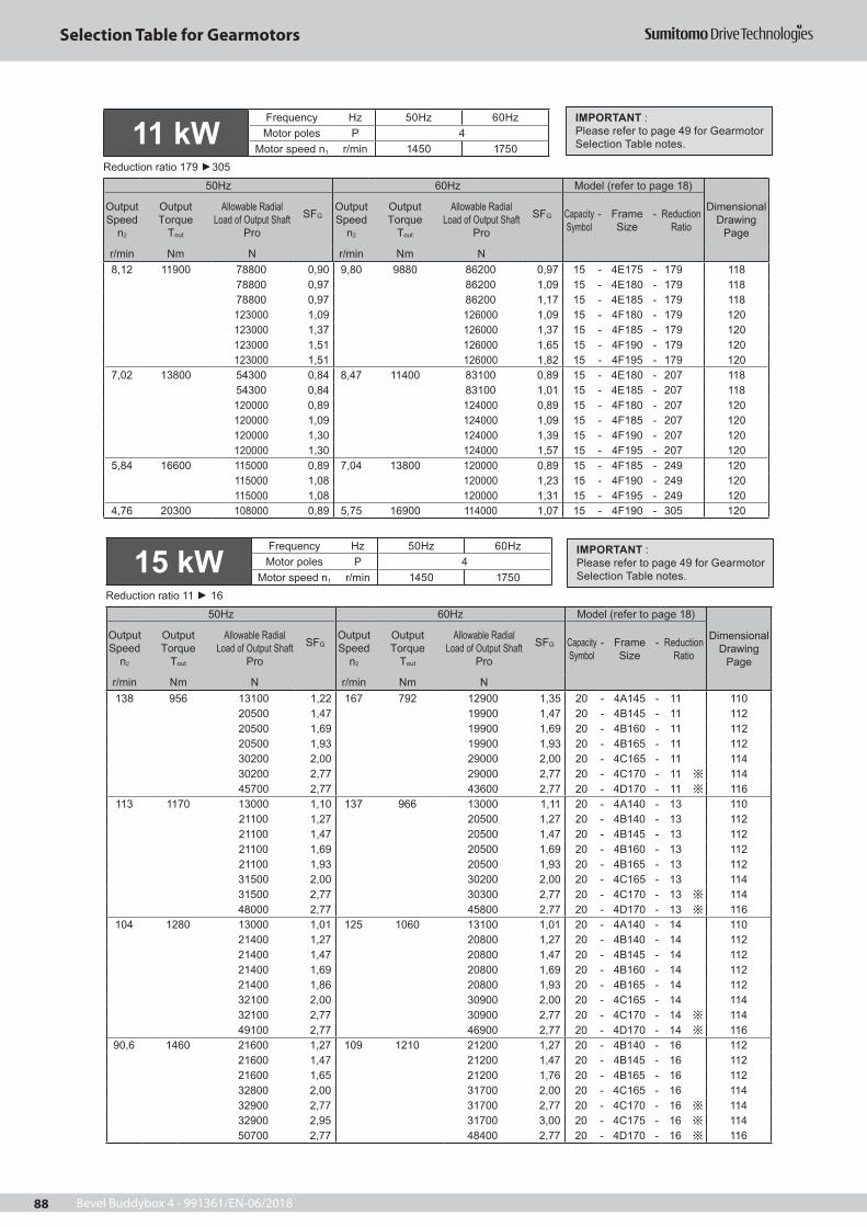
Bevel Buddybox 4 - 991361/EN-06/201888
Selection Table for Gearmotors
8,12 11900 78800 0,90 9,80 9880 86200 0,97 15 - 4E175 - 179 11878800 0,97 86200 1,09 15 - 4E180 - 179 11878800 0,97 86200 1,17 15 - 4E185 - 179 118123000 1,09 126000 1,09 15 - 4F180 - 179 120123000 1,37 126000 1,37 15 - 4F185 - 179 120123000 1,51 126000 1,65 15 - 4F190 - 179 120123000 1,51 126000 1,82 15 - 4F195 - 179 120
7,02 13800 54300 0,84 8,47 11400 83100 0,89 15 - 4E180 - 207 11854300 0,84 83100 1,01 15 - 4E185 - 207 118120000 0,89 124000 0,89 15 - 4F180 - 207 120120000 1,09 124000 1,09 15 - 4F185 - 207 120120000 1,30 124000 1,39 15 - 4F190 - 207 120120000 1,30 124000 1,57 15 - 4F195 - 207 120
5,84 16600 115000 0,89 7,04 13800 120000 0,89 15 - 4F185 - 249 120115000 1,08 120000 1,23 15 - 4F190 - 249 120115000 1,08 120000 1,31 15 - 4F195 - 249 120
4,76 20300 108000 0,89 5,75 16900 114000 1,07 15 - 4F190 - 305 120
15 kWFrequency Hz 50Hz 60HzMotor poles P 4
Motor speed n1 r/min 1450 1750Reduction ratio 11 16
50Hz 60Hz Model (refer to page 18)
Dimensional Drawing
Page
Output Speed
n2
OutputTorque
Tout
Allowable Radial Load of Output Shaft
Pro
SFGOutput Speed
n2
OutputTorque
Tout
Allowable Radial Load of Output Shaft
Pro
SFG Capacity Symbol
- Frame Size
- Reduction Ratio
r/min Nm N r/min Nm N138 956 13100 1,22 167 792 12900 1,35 20 - 4A145 - 11 110
20500 1,47 19900 1,47 20 - 4B145 - 11 11220500 1,69 19900 1,69 20 - 4B160 - 11 11220500 1,93 19900 1,93 20 - 4B165 - 11 11230200 2,00 29000 2,00 20 - 4C165 - 11 11430200 2,77 29000 2,77 20 - 4C170 - 11 11445700 2,77 43600 2,77 20 - 4D170 - 11 116
113 1170 13000 1,10 137 966 13000 1,11 20 - 4A140 - 13 11021100 1,27 20500 1,27 20 - 4B140 - 13 11221100 1,47 20500 1,47 20 - 4B145 - 13 11221100 1,69 20500 1,69 20 - 4B160 - 13 11221100 1,93 20500 1,93 20 - 4B165 - 13 11231500 2,00 30200 2,00 20 - 4C165 - 13 11431500 2,77 30300 2,77 20 - 4C170 - 13 11448000 2,77 45800 2,77 20 - 4D170 - 13 116
104 1280 13000 1,01 125 1060 13100 1,01 20 - 4A140 - 14 11021400 1,27 20800 1,27 20 - 4B140 - 14 11221400 1,47 20800 1,47 20 - 4B145 - 14 11221400 1,69 20800 1,69 20 - 4B160 - 14 11221400 1,86 20800 1,93 20 - 4B165 - 14 11232100 2,00 30900 2,00 20 - 4C165 - 14 11432100 2,77 30900 2,77 20 - 4C170 - 14 11449100 2,77 46900 2,77 20 - 4D170 - 14 116
90,6 1460 21600 1,27 109 1210 21200 1,27 20 - 4B140 - 16 11221600 1,47 21200 1,47 20 - 4B145 - 16 11221600 1,65 21200 1,76 20 - 4B165 - 16 11232800 2,00 31700 2,00 20 - 4C165 - 16 11432900 2,77 31700 2,77 20 - 4C170 - 16 11432900 2,95 31700 3,00 20 - 4C175 - 16 11450700 2,77 48400 2,77 20 - 4D170 - 16 116
IMPORTANT :Please refer to page 49 for Gearmotor Selection Table notes.
IMPORTANT :Please refer to page 49 for Gearmotor Selection Table notes.
11 kWFrequency Hz 50Hz 60HzMotor poles P 4
Motor speed n1 r/min 1450 1750Reduction ratio 179 305
50Hz 60Hz Model (refer to page 18)
Dimensional Drawing
Page
Output Speed
n2
OutputTorque
Tout
Allowable Radial Load of Output Shaft
Pro
SFGOutput Speed
n2
OutputTorque
Tout
Allowable Radial Load of Output Shaft
Pro
SFG Capacity Symbol
- Frame Size
- Reduction Ratio
r/min Nm N r/min Nm N

Bevel Buddybox 4 - 991361/EN-06/2018 89
Selection Table for Gearmotors
15 kWFrequency Hz 50Hz 60HzMotor poles P 4
Motor speed n1 r/min 1450 1750Reduction ratio 18 39
50Hz 60Hz Model (refer to page 18)
Dimensional Drawing
Page
Output Speed
n2
OutputTorque
Tout
Allowable Radial Load of Output Shaft
Pro
SFGOutput Speed
n2
OutputTorque
Tout
Allowable Radial Load of Output Shaft
Pro
SFG Capacity Symbol
- Frame Size
- Reduction Ratio
r/min Nm N r/min Nm N
64,7 2040 22100 1,01 78,1 1690 21900 1,01 20 - 4B145 - 22 11222100 1,26 21900 1,26 20 - 4B160 - 22 11234700 1,35 33700 1,35 20 - 4C160 - 22 11434700 2,26 33700 2,26 20 - 4C170 - 22 11434700 2,32 33700 2,47 20 - 4C175 - 22 11454700 2,47 52400 2,47 20 - 4D175 - 22 11654700 2,77 52500 2,77 20 - 4D180 - 22 116
59,2 2230 22200 1,01 71,4 1850 22100 1,01 20 - 4B145 - 25 11222200 1,15 22100 1,15 20 - 4B160 - 25 11235200 1,35 34300 1,35 20 - 4C160 - 25 11435200 1,61 34300 1,61 20 - 4C165 - 25 11435200 2,15 34300 2,30 20 - 4C175 - 25 11455800 2,26 53500 2,26 20 - 4D170 - 25 11655800 2,47 53500 2,47 20 - 4D175 - 25 11655800 2,77 53500 2,77 20 - 4D180 - 25 116
51,8 2550 22100 1,01 62,5 2110 22200 1,01 20 - 4B145 - 28 11235800 1,31 35000 1,31 20 - 4C160 - 28 11435800 1,61 35000 1,61 20 - 4C165 - 28 11435800 1,96 35000 2,02 20 - 4C170 - 28 11457300 2,26 55100 2,26 20 - 4D170 - 28 11657300 2,47 55100 2,47 20 - 4D175 - 28 11657300 2,77 55100 2,77 20 - 4D180 - 28 11676600 2,77 73200 2,77 20 - 4E180 - 28 118
41,2 3210 36500 1,01 49,7 2660 35900 1,01 20 - 4C145 - 35 11436500 1,31 35900 1,31 20 - 4C160 - 35 11436500 1,60 35900 1,60 20 - 4C165 - 35 11459800 1,84 57700 1,84 20 - 4D170 - 35 11659800 2,01 57700 2,01 20 - 4D175 - 35 11659900 2,65 57800 2,77 20 - 4D180 - 35 11680700 2,77 77300 2,77 20 - 4E180 - 35 118
37,7 3510 36800 1,01 45,5 2910 36300 1,01 20 - 4C145 - 39 11436800 1,31 36300 1,31 20 - 4C160 - 39 11436800 1,47 36300 1,47 20 - 4C165 - 39 11460900 1,61 58800 1,61 20 - 4D165 - 39 11660900 1,84 58800 1,84 20 - 4D170 - 39 11660900 2,01 58800 2,01 20 - 4D175 - 39 11660900 2,44 58800 2,77 20 - 4D180 - 39 11682200 2,77 78900 2,77 20 - 4E180 - 39 11882200 2,80 78900 3,00 20 - 4E185 - 39 11882200 2,80 78900 3,37 20 - 4E190 - 39 11882200 2,80 78900 3,38 20 - 4E195 - 39 118137000 2,77 137000 2,77 20 - 4F180 - 39 120
82,9 1590 21900 1,27 100 1320 21500 1,27 20 - 4B140 - 18 11221900 1,47 21500 1,47 20 - 4B145 - 18 11221900 1,58 21500 1,61 20 - 4B160 - 18 11233400 1,69 32300 1,69 20 - 4C160 - 18 11433400 2,00 32300 2,00 20 - 4C165 - 18 11433400 2,76 32300 2,77 20 - 4C170 - 18 11433400 2,76 32300 3,00 20 - 4C175 - 18 11451800 2,77 49500 2,77 20 - 4D170 - 18 116
69,0 1910 22100 1,01 83,3 1580 21900 1,01 20 - 4B145 - 21 11222100 1,34 21900 1,34 20 - 4B160 - 21 11234400 1,69 33400 1,69 20 - 4C160 - 21 11434400 2,00 33400 2,00 20 - 4C165 - 21 11434400 2,26 33400 2,26 20 - 4C170 - 21 11434400 2,40 33400 2,47 20 - 4C175 - 21 11453900 2,77 51700 2,77 20 - 4D180 - 21 116
IMPORTANT :Please refer to page 49 for Gearmotor Selection Table notes.
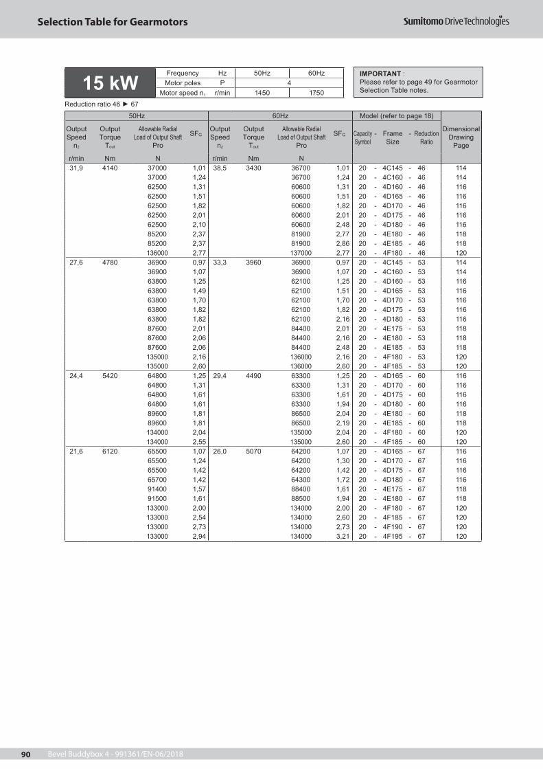
Bevel Buddybox 4 - 991361/EN-06/201890
Selection Table for Gearmotors
31,9 4140 37000 1,01 38,5 3430 36700 1,01 20 - 4C145 - 46 11437000 1,24 36700 1,24 20 - 4C160 - 46 11462500 1,31 60600 1,31 20 - 4D160 - 46 11662500 1,51 60600 1,51 20 - 4D165 - 46 11662500 1,82 60600 1,82 20 - 4D170 - 46 11662500 2,01 60600 2,01 20 - 4D175 - 46 11662500 2,10 60600 2,48 20 - 4D180 - 46 11685200 2,37 81900 2,77 20 - 4E180 - 46 11885200 2,37 81900 2,86 20 - 4E185 - 46 118136000 2,77 137000 2,77 20 - 4F180 - 46 120
27,6 4780 36900 0,97 33,3 3960 36900 0,97 20 - 4C145 - 53 11436900 1,07 36900 1,07 20 - 4C160 - 53 11463800 1,25 62100 1,25 20 - 4D160 - 53 11663800 1,49 62100 1,51 20 - 4D165 - 53 11663800 1,70 62100 1,70 20 - 4D170 - 53 11663800 1,82 62100 1,82 20 - 4D175 - 53 11663800 1,82 62100 2,16 20 - 4D180 - 53 11687600 2,01 84400 2,01 20 - 4E175 - 53 11887600 2,06 84400 2,16 20 - 4E180 - 53 11887600 2,06 84400 2,48 20 - 4E185 - 53 118135000 2,16 136000 2,16 20 - 4F180 - 53 120135000 2,60 136000 2,60 20 - 4F185 - 53 120
24,4 5420 64800 1,25 29,4 4490 63300 1,25 20 - 4D165 - 60 11664800 1,31 63300 1,31 20 - 4D170 - 60 11664800 1,61 63300 1,61 20 - 4D175 - 60 11664800 1,61 63300 1,94 20 - 4D180 - 60 11689600 1,81 86500 2,04 20 - 4E180 - 60 11889600 1,81 86500 2,19 20 - 4E185 - 60 118134000 2,04 135000 2,04 20 - 4F180 - 60 120134000 2,55 135000 2,60 20 - 4F185 - 60 120
21,6 6120 65500 1,07 26,0 5070 64200 1,07 20 - 4D165 - 67 11665500 1,24 64200 1,30 20 - 4D170 - 67 11665500 1,42 64200 1,42 20 - 4D175 - 67 11665700 1,42 64300 1,72 20 - 4D180 - 67 11691400 1,57 88400 1,61 20 - 4E175 - 67 11891500 1,61 88500 1,94 20 - 4E180 - 67 118133000 2,00 134000 2,00 20 - 4F180 - 67 120133000 2,54 134000 2,60 20 - 4F185 - 67 120133000 2,73 134000 2,73 20 - 4F190 - 67 120133000 2,94 134000 3,21 20 - 4F195 - 67 120
IMPORTANT :Please refer to page 49 for Gearmotor Selection Table notes. 15 kW
Frequency Hz 50Hz 60HzMotor poles P 4
Motor speed n1 r/min 1450 1750Reduction ratio 46 67
50Hz 60Hz Model (refer to page 18)
Dimensional Drawing
Page
Output Speed
n2
OutputTorque
Tout
Allowable Radial Load of Output Shaft
Pro
SFGOutput Speed
n2
OutputTorque
Tout
Allowable Radial Load of Output Shaft
Pro
SFG Capacity Symbol
- Frame Size
- Reduction Ratio
r/min Nm N r/min Nm N

Bevel Buddybox 4 - 991361/EN-06/2018 91
Selection Table for Gearmotors
18,1 7290 66400 1,04 21,9 6040 65500 1,05 20 - 4D170 - 80 11666400 1,20 65500 1,20 20 - 4D175 - 80 11666500 1,20 65600 1,44 20 - 4D180 - 80 11691400 1,30 91200 1,30 20 - 4E175 - 80 11891400 1,35 91300 1,61 20 - 4E180 - 80 11891400 1,35 91300 1,63 20 - 4E185 - 80 118131000 1,61 133000 1,61 20 - 4F180 - 80 120131000 2,01 133000 2,01 20 - 4F185 - 80 120131000 2,35 133000 2,35 20 - 4F190 - 80 120131000 2,47 133000 2,70 20 - 4F195 - 80 120
16,6 7970 61100 0,89 20,0 6600 66100 1,01 20 - 4D165 - 88 11661100 1,04 66100 1,05 20 - 4D170 - 88 11661100 1,09 66100 1,09 20 - 4D175 - 88 11661100 1,09 66100 1,32 20 - 4D180 - 88 11690000 1,23 92600 1,23 20 - 4E175 - 88 11890000 1,23 92600 1,49 20 - 4E180 - 88 118130000 1,61 132000 1,61 20 - 4F180 - 88 120130000 2,01 132000 2,01 20 - 4F185 - 88 120130000 2,26 132000 2,35 20 - 4F190 - 88 120130000 2,26 132000 2,70 20 - 4F195 - 88 120
14,3 9250 41000 0,94 17,2 7660 64700 0,94 20 - 4D175 - 102 11641000 0,94 64700 1,14 20 - 4D180 - 102 11687400 1,06 90600 1,06 20 - 4E175 - 102 11887400 1,06 90600 1,28 20 - 4E180 - 102 118127000 1,30 130000 1,30 20 - 4F180 - 102 120127000 1,61 130000 1,61 20 - 4F185 - 102 120127000 1,95 130000 2,05 20 - 4F190 - 102 120127000 1,95 130000 2,35 20 - 4F195 - 102 120
12,9 10200 - 0,86 15,6 8450 54700 1,03 20 - 4D180 - 112 11685500 0,96 89000 1,01 20 - 4E175 - 112 11885500 1,14 89000 1,25 20 - 4E180 - 112 11885500 1,14 89000 1,37 20 - 4E185 - 112 118126000 1,23 129000 1,25 20 - 4F180 - 112 120126000 1,51 129000 1,51 20 - 4F185 - 112 120126000 1,62 129000 1,62 20 - 4F190 - 112 120126000 1,76 129000 2,01 20 - 4F195 - 112 120
19,7 6690 66200 1,07 23,8 5550 65000 1,07 20 - 4D165 - 74 11666200 1,24 65000 1,30 20 - 4D170 - 74 11666200 1,30 65000 1,30 20 - 4D175 - 74 11666200 1,30 65000 1,57 20 - 4D180 - 74 11692500 1,47 90000 1,47 20 - 4E175 - 74 11892500 1,47 90000 1,77 20 - 4E180 - 74 118132000 2,00 134000 2,00 20 - 4F180 - 74 120132000 2,54 134000 2,60 20 - 4F185 - 74 120132000 2,69 134000 2,73 20 - 4F190 - 74 120132000 2,69 134000 3,21 20 - 4F195 - 74 120
IMPORTANT :Please refer to page 49 for Gearmotor Selection Table notes. 15 kW
Frequency Hz 50Hz 60HzMotor poles P 4
Motor speed n1 r/min 1450 1750Reduction ratio 74 112
50Hz 60Hz Model (refer to page 18)
Dimensional Drawing
Page
Output Speed
n2
OutputTorque
Tout
Allowable Radial Load of Output Shaft
Pro
SFGOutput Speed
n2
OutputTorque
Tout
Allowable Radial Load of Output Shaft
Pro
SFG Capacity Symbol
- Frame Size
- Reduction Ratio
r/min Nm N r/min Nm N

Bevel Buddybox 4 - 991361/EN-06/201892
Selection Table for Gearmotors
11,8 11200 83600 0,96 14,3 9250 87400 1,01 20 - 4E175 - 123 11883600 1,04 87400 1,25 20 - 4E180 - 123 118124000 1,23 127000 1,25 20 - 4F180 - 123 120124000 1,51 127000 1,51 20 - 4F185 - 123 120124000 1,61 127000 1,62 20 - 4F190 - 123 120124000 1,61 127000 1,95 20 - 4F195 - 123 120
9,63 13700 55800 0,85 11,6 11400 83200 1,01 20 - 4E180 - 151 11855800 0,85 83200 1,02 20 - 4E185 - 151 118120000 1,01 124000 1,01 20 - 4F180 - 151 120120000 1,24 124000 1,25 20 - 4F185 - 151 120120000 1,31 124000 1,39 20 - 4F190 - 151 120120000 1,31 124000 1,58 20 - 4F195 - 151 120
8,12 16300 115000 1,01 9,80 13500 120000 1,01 20 - 4F185 - 179 120115000 1,11 120000 1,21 20 - 4F190 - 179 120115000 1,11 120000 1,34 20 - 4F195 - 179 120
7,02 18800 111000 0,96 8,47 15600 117000 1,02 20 - 4F190 - 207 120111000 0,96 117000 1,15 20 - 4F195 - 207 120
138 1180 19600 1,37 167 977 19100 1,37 25 - 4B160 - 11 11219600 1,57 19100 1,57 25 - 4B165 - 11 11229400 1,62 28300 1,62 25 - 4C165 - 11 11429400 2,24 28300 2,24 25 - 4C170 - 11 11429400 2,43 28300 2,43 25 - 4C175 - 11 11445000 2,24 43000 2,24 25 - 4D170 - 11 11645000 2,43 43000 2,43 25 - 4D175 - 11 11645000 2,89 43000 2,89 25 - 4D180 - 11 116
113 1440 19900 1,37 137 1190 19500 1,37 25 - 4B160 - 13 11219900 1,57 19500 1,57 25 - 4B165 - 13 11230400 1,62 29400 1,62 25 - 4C165 - 13 11430500 2,24 29400 2,24 25 - 4C170 - 13 11430500 2,43 29400 2,43 25 - 4C175 - 13 11447200 2,24 45100 2,24 25 - 4D170 - 13 11647200 2,43 45100 2,43 25 - 4D175 - 13 11647200 2,89 45100 2,89 25 - 4D180 - 13 116
104 1570 20100 1,37 125 1300 19800 1,37 25 - 4B160 - 14 11220100 1,51 19800 1,57 25 - 4B165 - 14 11230900 1,62 29900 1,62 25 - 4C165 - 14 11430900 2,24 29900 2,24 25 - 4C170 - 14 11430900 2,43 29900 2,43 25 - 4C175 - 14 11448100 2,24 46100 2,24 25 - 4D170 - 14 11648100 2,43 46100 2,43 25 - 4D175 - 14 11648100 2,89 46100 2,89 25 - 4D180 - 14 116
90,6 1800 20200 1,34 109 1490 20000 1,43 25 - 4B165 - 16 11231600 1,62 30600 1,62 25 - 4C165 - 16 11431600 2,24 30700 2,24 25 - 4C170 - 16 11431600 2,39 30700 2,43 25 - 4C175 - 16 11449600 2,24 47500 2,24 25 - 4D170 - 16 11649600 2,43 47500 2,43 25 - 4D175 - 16 11649600 2,89 47500 2,89 25 - 4D180 - 16 116
82,9 1970 20300 1,28 100 1630 20100 1,31 25 - 4B160 - 18 11232000 1,37 31100 1,37 25 - 4C160 - 18 11432000 1,62 31100 1,62 25 - 4C165 - 18 11432000 2,24 31100 2,24 25 - 4C170 - 18 11432000 2,24 31100 2,43 25 - 4C175 - 18 11450600 2,24 48500 2,24 25 - 4D170 - 18 11650600 2,43 48500 2,43 25 - 4D175 - 18 11650600 2,89 48500 2,89 25 - 4D180 - 18 116
IMPORTANT :Please refer to page 49 for Gearmotor Selection Table notes.
IMPORTANT :Please refer to page 49 for Gearmotor Selection Table notes.
15 kWFrequency Hz 50Hz 60HzMotor poles P 4
Motor speed n1 r/min 1450 1750Reduction ratio 123 207
50Hz 60Hz Model (refer to page 18)
Dimensional Drawing
Page
Output Speed
n2
OutputTorque
Tout
Allowable Radial Load of Output Shaft
Pro
SFGOutput Speed
n2
OutputTorque
Tout
Allowable Radial Load of Output Shaft
Pro
SFG Capacity Symbol
- Frame Size
- Reduction Ratio
r/min Nm N r/min Nm N
18,5 kWFrequency Hz 50Hz 60HzMotor poles P 4
Motor speed n1 r/min 1450 1750Reduction ratio 11 18
50Hz 60Hz Model (refer to page 18)
Dimensional Drawing
Page
Output Speed
n2
OutputTorque
Tout
Allowable Radial Load of Output Shaft
Pro
SFGOutput Speed
n2
OutputTorque
Tout
Allowable Radial Load of Output Shaft
Pro
SFG Capacity Symbol
- Frame Size
- Reduction Ratio
r/min Nm N r/min Nm N

Bevel Buddybox 4 - 991361/EN-06/2018 93
Selection Table for Gearmotors
69,0 2360 20200 1,09 83,3 1950 20300 1,09 25 - 4B160 - 21 11232800 1,37 32000 1,37 25 - 4C160 - 21 11432800 1,62 32000 1,62 25 - 4C165 - 21 11432800 1,83 32000 1,83 25 - 4C170 - 21 11432800 1,95 32000 2,00 25 - 4C175 - 21 11452500 2,00 50500 2,00 25 - 4D175 - 21 11652500 2,24 50500 2,24 25 - 4D180 - 21 11652500 2,43 50500 2,43 25 - 4D185 - 21 11670200 2,74 67100 2,74 25 - 4E190 - 21 11870200 2,97 67100 2,97 25 - 4E195 - 21 118
64,7 2520 20100 1,02 78,1 2090 20200 1,02 25 - 4B160 - 22 11232900 1,10 32200 1,10 25 - 4C160 - 22 11432900 1,30 32200 1,30 25 - 4C165 - 22 11432900 1,83 32200 1,83 25 - 4C170 - 22 11453200 2,00 51200 2,00 25 - 4D175 - 22 11653200 2,24 51200 2,24 25 - 4D180 - 22 11653200 2,43 51200 2,43 25 - 4D185 - 22 11671200 2,74 68200 2,74 25 - 4E190 - 22 11871200 2,97 68200 2,97 25 - 4E195 - 22 118
59,2 2750 20000 0,93 71,4 2280 20300 0,93 25 - 4B160 - 25 11233300 1,10 32600 1,10 25 - 4C160 - 25 11433300 1,30 32600 1,30 25 - 4C165 - 25 11433300 1,75 32600 1,87 25 - 4C175 - 25 11454100 1,83 52200 1,83 25 - 4D170 - 25 11654100 2,00 52200 2,00 25 - 4D175 - 25 11654100 2,24 52200 2,24 25 - 4D180 - 25 11654100 2,43 52200 2,43 25 - 4D185 - 25 11672700 2,43 69600 2,43 25 - 4E185 - 25 11872700 2,74 69600 2,74 25 - 4E190 - 25 11872700 2,97 69600 2,97 25 - 4E195 - 25 118
51,8 3150 33600 1,06 62,5 2610 33100 1,06 25 - 4C160 - 28 11433600 1,30 33100 1,30 25 - 4C165 - 28 11433600 1,59 33100 1,63 25 - 4C170 - 28 11455400 1,83 53600 1,83 25 - 4D170 - 28 11655400 2,00 53600 2,00 25 - 4D175 - 28 11655400 2,24 53600 2,24 25 - 4D180 - 28 11655400 2,43 53600 2,43 25 - 4D185 - 28 11674900 2,24 71800 2,24 25 - 4E180 - 28 11874900 2,43 71800 2,43 25 - 4E185 - 28 11874900 2,74 71800 2,74 25 - 4E190 - 28 11874900 2,97 71800 2,97 25 - 4E195 - 28 118131000 2,97 124000 2,97 25 - 4F195 - 28 120
41,2 3950 33700 1,06 49,7 3280 33600 1,06 25 - 4C160 - 35 11433700 1,30 33600 1,30 25 - 4C165 - 35 11457500 1,49 55800 1,49 25 - 4D170 - 35 11657500 1,63 55800 1,63 25 - 4D175 - 35 11657500 2,15 55800 2,24 25 - 4D180 - 35 11678500 2,24 75500 2,24 25 - 4E180 - 35 11878500 2,43 75500 2,43 25 - 4E185 - 35 11878500 2,49 75500 2,74 25 - 4E190 - 35 11878500 2,49 75500 2,97 25 - 4E195 - 35 118136000 2,43 132000 2,43 25 - 4F185 - 35 120136000 2,74 132000 2,74 25 - 4F190 - 35 120136000 2,97 132000 2,97 25 - 4F195 - 35 120
IMPORTANT :Please refer to page 49 for Gearmotor Selection Table notes. 18,5 kW
Frequency Hz 50Hz 60HzMotor poles P 4
Motor speed n1 r/min 1450 1750Reduction ratio 21 35
50Hz 60Hz Model (refer to page 18)
Dimensional Drawing
Page
Output Speed
n2
OutputTorque
Tout
Allowable Radial Load of Output Shaft
Pro
SFGOutput Speed
n2
OutputTorque
Tout
Allowable Radial Load of Output Shaft
Pro
SFG Capacity Symbol
- Frame Size
- Reduction Ratio
r/min Nm N r/min Nm N

Bevel Buddybox 4 - 991361/EN-06/201894
Selection Table for Gearmotors
37,7 4330 33700 1,06 45,5 3580 33800 1,06 25 - 4C160 - 39 11433700 1,19 33800 1,19 25 - 4C165 - 39 11458300 1,30 56700 1,30 25 - 4D165 - 39 11658300 1,49 56700 1,49 25 - 4D170 - 39 11658300 1,63 56700 1,63 25 - 4D175 - 39 11658300 1,98 56700 2,24 25 - 4D180 - 39 11679900 2,24 77000 2,24 25 - 4E180 - 39 11879900 2,27 77000 2,43 25 - 4E185 - 39 11879900 2,27 77000 2,74 25 - 4E190 - 39 118136000 2,24 135000 2,24 25 - 4F180 - 39 120136000 2,43 135000 2,43 25 - 4F185 - 39 120136000 2,74 135000 2,74 25 - 4F190 - 39 120136000 2,97 135000 2,97 25 - 4F195 - 39 120
31,9 5110 33400 1,01 38,5 4240 33800 1,01 25 - 4C160 - 46 11459500 1,22 58100 1,22 25 - 4D165 - 46 11659500 1,48 58100 1,48 25 - 4D170 - 46 11659500 1,63 58100 1,63 25 - 4D175 - 46 11659500 1,71 58100 2,01 25 - 4D180 - 46 11682400 1,92 79600 2,24 25 - 4E180 - 46 11882400 1,92 79600 2,32 25 - 4E185 - 46 118134000 2,24 136000 2,24 25 - 4F180 - 46 120134000 2,43 136000 2,43 25 - 4F185 - 46 120134000 2,74 136000 2,74 25 - 4F190 - 46 120134000 2,97 136000 2,97 25 - 4F195 - 46 120
27,6 5900 26100 0,87 33,3 4890 33500 0,87 25 - 4C160 - 53 11460300 1,01 59200 1,01 25 - 4D160 - 53 11660300 1,21 59200 1,22 25 - 4D165 - 53 11660300 1,38 59200 1,38 25 - 4D170 - 53 11660300 1,48 59200 1,48 25 - 4D175 - 53 11660300 1,48 59200 1,75 25 - 4D180 - 53 11684400 1,63 81700 1,63 25 - 4E175 - 53 11884400 1,67 81700 1,75 25 - 4E180 - 53 11884400 1,67 81700 2,01 25 - 4E185 - 53 118133000 1,75 135000 1,75 25 - 4F180 - 53 120133000 2,11 135000 2,11 25 - 4F185 - 53 120133000 2,74 135000 2,74 25 - 4F190 - 53 120133000 2,97 135000 2,97 25 - 4F195 - 53 120
24,4 6680 60800 1,02 29,4 5540 60000 1,02 25 - 4D165 - 60 11660800 1,06 60000 1,06 25 - 4D170 - 60 11660800 1,30 60000 1,30 25 - 4D175 - 60 11660800 1,30 60000 1,57 25 - 4D180 - 60 11686000 1,47 83500 1,65 25 - 4E180 - 60 11886000 1,47 83500 1,77 25 - 4E185 - 60 118132000 1,65 134000 1,65 25 - 4F180 - 60 120132000 2,06 134000 2,11 25 - 4F185 - 60 120132000 2,69 134000 2,74 25 - 4F190 - 60 120132000 2,69 134000 2,97 25 - 4F195 - 60 120
IMPORTANT :Please refer to page 49 for Gearmotor Selection Table notes. 18,5 kW
Frequency Hz 50Hz 60HzMotor poles P 4
Motor speed n1 r/min 1450 1750Reduction ratio 39 60
50Hz 60Hz Model (refer to page 18)
Dimensional Drawing
Page
Output Speed
n2
OutputTorque
Tout
Allowable Radial Load of Output Shaft
Pro
SFGOutput Speed
n2
OutputTorque
Tout
Allowable Radial Load of Output Shaft
Pro
SFG Capacity Symbol
- Frame Size
- Reduction Ratio
r/min Nm N r/min Nm N

Bevel Buddybox 4 - 991361/EN-06/2018 95
Selection Table for Gearmotors
21,6 7550 61000 1,01 26,0 6260 60500 1,05 25 - 4D170 - 67 11661000 1,16 60500 1,16 25 - 4D175 - 67 11661100 1,16 60600 1,39 25 - 4D180 - 67 11687200 1,28 85000 1,30 25 - 4E175 - 67 11887400 1,30 85100 1,57 25 - 4E180 - 67 118130000 1,62 132000 1,62 25 - 4F180 - 67 120130000 2,06 132000 2,11 25 - 4F185 - 67 120130000 2,22 132000 2,22 25 - 4F190 - 67 120130000 2,38 132000 2,60 25 - 4F195 - 67 120
19,7 8260 57400 0,87 23,8 6840 60900 0,87 25 - 4D165 - 74 11657400 1,01 60900 1,05 25 - 4D170 - 74 11657400 1,06 60900 1,06 25 - 4D175 - 74 11657400 1,06 60900 1,27 25 - 4D180 - 74 11688300 1,19 86200 1,19 25 - 4E175 - 74 11888300 1,19 86200 1,44 25 - 4E180 - 74 118129000 1,62 131000 1,62 25 - 4F180 - 74 120129000 2,06 131000 2,11 25 - 4F185 - 74 120129000 2,18 131000 2,22 25 - 4F190 - 74 120129000 2,18 131000 2,60 25 - 4F195 - 74 120
18,1 8990 46100 0,97 21,9 7450 61000 0,97 25 - 4D175 - 80 11646100 0,97 61100 1,17 25 - 4D180 - 80 11688000 1,05 87100 1,05 25 - 4E175 - 80 11888000 1,09 87200 1,30 25 - 4E180 - 80 11888000 1,09 87200 1,32 25 - 4E185 - 80 11888000 1,09 87200 1,32 25 - 4E195 - 80 118128000 1,30 130000 1,30 25 - 4F180 - 80 120128000 1,63 130000 1,63 25 - 4F185 - 80 120128000 1,90 130000 1,90 25 - 4F190 - 80 120128000 2,00 130000 2,19 25 - 4F195 - 80 120
16,6 9830 25300 0,89 20,0 8140 58900 1,07 25 - 4D180 - 88 11686300 1,00 88200 1,00 25 - 4E175 - 88 11886300 1,00 88200 1,21 25 - 4E180 - 88 118126000 1,30 129000 1,30 25 - 4F180 - 88 120126000 1,63 129000 1,63 25 - 4F185 - 88 120126000 1,83 129000 1,90 25 - 4F190 - 88 120126000 1,83 129000 2,19 25 - 4F195 - 88 120
14,3 11400 83100 0,86 17,2 9450 87000 0,86 25 - 4E175 - 102 11883100 0,86 87000 1,04 25 - 4E180 - 102 118124000 1,05 127000 1,05 25 - 4F180 - 102 120124000 1,30 127000 1,30 25 - 4F185 - 102 120124000 1,58 127000 1,66 25 - 4F190 - 102 120124000 1,58 127000 1,91 25 - 4F195 - 102 120
12,9 12600 71500 0,92 15,6 10400 85100 1,02 25 - 4E180 - 112 11871500 0,92 85100 1,11 25 - 4E185 - 112 118122000 1,00 125000 1,02 25 - 4F180 - 112 120122000 1,22 125000 1,22 25 - 4F185 - 112 120122000 1,31 125000 1,31 25 - 4F190 - 112 120122000 1,43 125000 1,63 25 - 4F195 - 112 120
IMPORTANT :Please refer to page 49 for Gearmotor Selection Table notes. 18,5 kW
Frequency Hz 50Hz 60HzMotor poles P 4
Motor speed n1 r/min 1450 1750Reduction ratio 67 112
50Hz 60Hz Model (refer to page 18)
Dimensional Drawing
Page
Output Speed
n2
OutputTorque
Tout
Allowable Radial Load of Output Shaft
Pro
SFGOutput Speed
n2
OutputTorque
Tout
Allowable Radial Load of Output Shaft
Pro
SFG Capacity Symbol
- Frame Size
- Reduction Ratio
r/min Nm N r/min Nm N

Bevel Buddybox 4 - 991361/EN-06/201896
Selection Table for Gearmotors
11,8 13800 54900 0,84 14,3 11400 83100 1,02 25 - 4E180 - 123 11854900 0,84 83100 1,02 25 - 4E185 - 123 118120000 1,00 124000 1,02 25 - 4F180 - 123 120120000 1,22 124000 1,22 25 - 4F185 - 123 120120000 1,31 124000 1,31 25 - 4F190 - 123 120120000 1,31 124000 1,58 25 - 4F195 - 123 120
9,63 16900 114000 0,82 11,6 14000 119000 0,82 25 - 4F180 - 151 120114000 1,01 119000 1,02 25 - 4F185 - 151 120114000 1,06 119000 1,13 25 - 4F190 - 151 120114000 1,06 119000 1,28 25 - 4F195 - 151 120
8,12 20100 109000 0,82 9,80 16600 115000 0,82 25 - 4F185 - 179 120109000 0,90 115000 0,98 25 - 4F190 - 179 120109000 0,90 115000 1,08 25 - 4F195 - 179 120
22 kWFrequency Hz 50Hz 60HzMotor poles P 4
Motor speed n1 r/min 1450 1750Reduction ratio 11 16
50Hz 60Hz Model (refer to page 18)
Dimensional Drawing
Page
Output Speed
n2
OutputTorque
Tout
Allowable Radial Load of Output Shaft
Pro
SFGOutput Speed
n2
OutputTorque
Tout
Allowable Radial Load of Output Shaft
Pro
SFG Capacity Symbol
- Frame Size
- Reduction Ratio
r/min Nm N r/min Nm N138 1400 18600 1,15 167 1160 18300 1,15 30 - 4B160 - 11 112
18600 1,32 18300 1,32 30 - 4B165 - 11 11228500 1,36 27600 1,36 30 - 4C165 - 11 11428500 1,89 27600 1,89 30 - 4C170 - 11 11428500 2,05 27600 2,05 30 - 4C175 - 11 11444300 1,89 42400 1,89 30 - 4D170 - 11 11644300 2,05 42400 2,05 30 - 4D175 - 11 11644300 2,43 42400 2,43 30 - 4D180 - 11 11644300 2,73 42400 2,73 30 - 4D185 - 11 116
113 1710 18800 1,15 137 1420 18600 1,15 30 - 4B160 - 13 11218800 1,32 18600 1,32 30 - 4B165 - 13 11229400 1,36 28500 1,36 30 - 4C165 - 13 11429400 1,89 28600 1,89 30 - 4C170 - 13 11429400 2,05 28600 2,05 30 - 4C175 - 13 11446300 1,89 44400 1,89 30 - 4D170 - 13 11646300 2,05 44400 2,05 30 - 4D175 - 13 11646300 2,43 44400 2,43 30 - 4D180 - 13 11646300 2,73 44400 2,73 30 - 4D185 - 13 116
104 1870 18800 1,15 125 1550 18700 1,15 30 - 4B160 - 14 11218800 1,27 18700 1,32 30 - 4B165 - 14 11229800 1,36 29000 1,36 30 - 4C165 - 14 11429800 1,89 29000 1,89 30 - 4C170 - 14 11429800 2,05 29000 2,05 30 - 4C175 - 14 11447200 1,89 45300 1,89 30 - 4D170 - 14 11647200 2,05 45300 2,05 30 - 4D175 - 14 11647200 2,43 45300 2,43 30 - 4D180 - 14 11647200 2,73 45300 2,73 30 - 4D185 - 14 116
90,6 2140 18700 1,13 109 1770 18800 1,15 30 - 4B160 - 16 11218700 1,13 18800 1,20 30 - 4B165 - 16 11230300 1,15 29600 1,15 30 - 4C160 - 16 11430300 1,36 29600 1,36 30 - 4C165 - 16 11430300 1,89 29600 1,89 30 - 4C170 - 16 11430300 2,01 29600 2,05 30 - 4C175 - 16 11448500 1,89 46700 1,89 30 - 4D170 - 16 11648500 2,05 46700 2,05 30 - 4D175 - 16 11648500 2,43 46700 2,43 30 - 4D180 - 16 11648500 2,73 46700 2,73 30 - 4D185 - 16 116
IMPORTANT :Please refer to page 49 for Gearmotor Selection Table notes.
IMPORTANT :Please refer to page 49 for Gearmotor Selection Table notes.
18,5 kWFrequency Hz 50Hz 60HzMotor poles P 4
Motor speed n1 r/min 1450 1750Reduction ratio 123 179
50Hz 60Hz Model (refer to page 18)
Dimensional Drawing
Page
Output Speed
n2
OutputTorque
Tout
Allowable Radial Load of Output Shaft
Pro
SFGOutput Speed
n2
OutputTorque
Tout
Allowable Radial Load of Output Shaft
Pro
SFG Capacity Symbol
- Frame Size
- Reduction Ratio
r/min Nm N r/min Nm N

Bevel Buddybox 4 - 991361/EN-06/2018 97
Selection Table for Gearmotors
22 kWFrequency Hz 50Hz 60HzMotor poles P 4
Motor speed n1 r/min 1450 1750Reduction ratio 18 35
50Hz 60Hz Model (refer to page 18)
Dimensional Drawing
Page
Output Speed
n2
OutputTorque
Tout
Allowable Radial Load of Output Shaft
Pro
SFGOutput Speed
n2
OutputTorque
Tout
Allowable Radial Load of Output Shaft
Pro
SFG Capacity Symbol
- Frame Size
- Reduction Ratio
r/min Nm N r/min Nm N
69,0 2810 31100 1,15 83,3 2320 30600 1,15 30 - 4C160 - 21 11431100 1,36 30600 1,36 30 - 4C165 - 21 11431100 1,54 30600 1,54 30 - 4C170 - 21 11431100 1,64 30600 1,68 30 - 4C175 - 21 11451100 1,68 49300 1,68 30 - 4D175 - 21 11651100 1,89 49300 1,89 30 - 4D180 - 21 11651100 2,05 49300 2,05 30 - 4D185 - 21 11668900 2,30 66100 2,30 30 - 4E190 - 21 11868900 2,50 66100 2,50 30 - 4E195 - 21 118
64,7 2990 31100 0,92 78,1 2480 30700 0,92 30 - 4C160 - 22 11431100 1,10 30700 1,10 30 - 4C165 - 22 11431100 1,54 30700 1,54 30 - 4C170 - 22 11431100 1,59 30700 1,68 30 - 4C175 - 22 11451600 1,68 49900 1,68 30 - 4D175 - 22 11651700 1,89 50000 1,89 30 - 4D180 - 22 11651700 2,05 50000 2,05 30 - 4D185 - 22 11669900 2,30 67000 2,30 30 - 4E190 - 22 11869900 2,50 67000 2,50 30 - 4E195 - 22 118
59,2 3270 31300 1,10 71,4 2710 31000 1,10 30 - 4C165 - 25 11431300 1,47 31000 1,57 30 - 4C175 - 25 11452500 1,68 50800 1,68 30 - 4D175 - 25 11652500 1,89 50800 1,89 30 - 4D180 - 25 11652500 2,05 50800 2,05 30 - 4D185 - 25 11671200 2,05 68400 2,05 30 - 4E185 - 25 11871200 2,30 68400 2,30 30 - 4E190 - 25 11871200 2,50 68400 2,50 30 - 4E195 - 25 118
51,8 3740 31400 1,10 62,5 3100 31300 1,10 30 - 4C165 - 28 11431400 1,34 31300 1,37 30 - 4C170 - 28 11453600 1,54 52000 1,54 30 - 4D170 - 28 11653600 1,68 52000 1,68 30 - 4D175 - 28 11653600 1,89 52000 1,89 30 - 4D180 - 28 11653600 2,05 52000 2,05 30 - 4D185 - 28 11673200 1,89 70400 1,89 30 - 4E180 - 28 11873200 2,05 70400 2,05 30 - 4E185 - 28 11873200 2,30 70400 2,30 30 - 4E190 - 28 11873200 2,50 70400 2,50 30 - 4E195 - 28 118129000 2,50 123000 2,50 30 - 4F195 - 28 120
41,2 4700 30900 1,09 49,7 3900 31200 1,09 30 - 4C165 - 35 11455100 1,25 53800 1,25 30 - 4D170 - 35 11655100 1,37 53800 1,37 30 - 4D175 - 35 11655200 1,81 53900 1,89 30 - 4D180 - 35 11676300 1,89 73700 1,89 30 - 4E180 - 35 11876300 2,05 73700 2,05 30 - 4E185 - 35 11876300 2,09 73700 2,30 30 - 4E190 - 35 11876300 2,09 73700 2,50 30 - 4E195 - 35 118135000 2,05 130000 2,05 30 - 4F185 - 35 120135000 2,30 130000 2,30 30 - 4F190 - 35 120135000 2,50 130000 2,50 30 - 4F195 - 35 120
82,9 2340 18700 1,07 100 1940 18800 1,10 30 - 4B160 - 18 11230600 1,15 30000 1,15 30 - 4C160 - 18 11430600 1,36 30000 1,36 30 - 4C165 - 18 11430600 1,88 30000 1,89 30 - 4C170 - 18 11430600 1,88 30000 2,05 30 - 4C175 - 18 11449400 1,89 47600 1,89 30 - 4D170 - 18 11649400 2,05 47600 2,05 30 - 4D175 - 18 11649400 2,43 47600 2,43 30 - 4D180 - 18 11649400 2,73 47600 2,73 30 - 4D185 - 18 11666200 2,73 63300 2,73 30 - 4E185 - 18 118
IMPORTANT :Please refer to page 49 for Gearmotor Selection Table notes.

Bevel Buddybox 4 - 991361/EN-06/201898
Selection Table for Gearmotors
37,7 5140 30700 1,00 45,5 4260 31200 1,00 30 - 4C165 - 39 11455700 1,10 54500 1,10 30 - 4D165 - 39 11655700 1,25 54500 1,25 30 - 4D170 - 39 11655700 1,37 54500 1,37 30 - 4D175 - 39 11655700 1,67 54500 1,89 30 - 4D180 - 39 11677500 1,89 75000 1,89 30 - 4E180 - 39 11877500 1,91 75000 2,05 30 - 4E185 - 39 11877500 1,91 75000 2,30 30 - 4E190 - 39 118134000 1,89 133000 1,89 30 - 4F180 - 39 120134000 2,05 133000 2,05 30 - 4F185 - 39 120134000 2,30 133000 2,30 30 - 4F190 - 39 120134000 2,50 133000 2,50 30 - 4F195 - 39 120
31,9 6080 20100 0,85 38,5 5040 30800 0,85 30 - 4C160 - 46 11420100 0,85 30800 0,85 30 - 4C165 - 46 11456400 1,24 55600 1,24 30 - 4D170 - 46 11656400 1,37 55600 1,37 30 - 4D175 - 46 11656400 1,43 55600 1,69 30 - 4D180 - 46 11679600 1,62 77200 1,89 30 - 4E180 - 46 11879600 1,62 77200 1,95 30 - 4E185 - 46 118133000 1,89 135000 1,89 30 - 4F180 - 46 120133000 2,05 135000 2,05 30 - 4F185 - 46 120133000 2,30 135000 2,30 30 - 4F190 - 46 120133000 2,50 135000 2,50 30 - 4F195 - 46 120
27,6 7010 56800 1,02 33,3 5810 56300 1,03 30 - 4D165 - 53 11656800 1,16 56300 1,16 30 - 4D170 - 53 11656800 1,24 56300 1,24 30 - 4D175 - 53 11656800 1,24 56200 1,47 30 - 4D180 - 53 11681100 1,37 79000 1,37 30 - 4E175 - 53 11881100 1,40 79000 1,47 30 - 4E180 - 53 11881100 1,40 79000 1,69 30 - 4E185 - 53 118131000 1,47 133000 1,47 30 - 4F180 - 53 120131000 1,77 133000 1,77 30 - 4F185 - 53 120131000 2,30 133000 2,30 30 - 4F190 - 53 120131000 2,50 133000 2,50 30 - 4F195 - 53 120
24,4 7950 56800 0,86 29,4 6590 56700 0,86 30 - 4D165 - 60 11656800 1,10 56700 1,10 30 - 4D175 - 60 11656800 1,10 56700 1,32 30 - 4D180 - 60 11682300 1,24 80500 1,39 30 - 4E180 - 60 11882300 1,24 80500 1,49 30 - 4E185 - 60 118130000 1,39 132000 1,39 30 - 4F180 - 60 120130000 1,74 132000 1,77 30 - 4F185 - 60 120130000 2,26 132000 2,30 30 - 4F190 - 60 120130000 2,26 132000 2,50 30 - 4F195 - 60 120
21,6 8980 46200 0,97 26,0 7440 56700 0,97 30 - 4D175 - 67 11646200 0,97 56800 1,17 30 - 4D180 - 67 11683100 1,07 81600 1,10 30 - 4E175 - 67 11883200 1,09 81700 1,32 30 - 4E180 - 67 118128000 1,36 130000 1,36 30 - 4F180 - 67 120128000 1,73 130000 1,77 30 - 4F185 - 67 120128000 1,86 130000 1,86 30 - 4F190 - 67 120128000 2,00 130000 2,19 30 - 4F195 - 67 120
IMPORTANT :Please refer to page 49 for Gearmotor Selection Table notes. 22 kW
Frequency Hz 50Hz 60HzMotor poles P 4
Motor speed n1 r/min 1450 1750Reduction ratio 39 67
50Hz 60Hz Model (refer to page 18)
Dimensional Drawing
Page
Output Speed
n2
OutputTorque
Tout
Allowable Radial Load of Output Shaft
Pro
SFGOutput Speed
n2
OutputTorque
Tout
Allowable Radial Load of Output Shaft
Pro
SFG Capacity Symbol
- Frame Size
- Reduction Ratio
r/min Nm N r/min Nm N
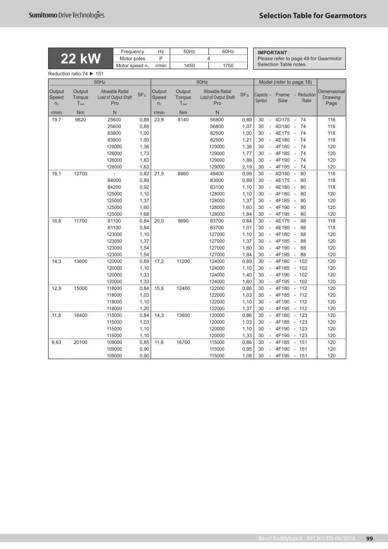
Bevel Buddybox 4 - 991361/EN-06/2018 99
Selection Table for Gearmotors
22 kWFrequency Hz 50Hz 60HzMotor poles P 4
Motor speed n1 r/min 1450 1750Reduction ratio 74 151
50Hz 60Hz Model (refer to page 18)
Dimensional Drawing
Page
Output Speed
n2
OutputTorque
Tout
Allowable Radial Load of Output Shaft
Pro
SFGOutput Speed
n2
OutputTorque
Tout
Allowable Radial Load of Output Shaft
Pro
SFG Capacity Symbol
- Frame Size
- Reduction Ratio
r/min Nm N r/min Nm N19,7 9820 25600 0,89 23,8 8140 56800 0,89 30 - 4D175 - 74 116
25600 0,89 56800 1,07 30 - 4D180 - 74 11683800 1,00 82500 1,00 30 - 4E175 - 74 11883800 1,00 82500 1,21 30 - 4E180 - 74 118126000 1,36 129000 1,36 30 - 4F180 - 74 120126000 1,73 129000 1,77 30 - 4F185 - 74 120126000 1,83 129000 1,86 30 - 4F190 - 74 120126000 1,83 129000 2,19 30 - 4F195 - 74 120
18,1 10700 - 0,82 21,9 8860 48400 0,99 30 - 4D180 - 80 11684000 0,89 83000 0,89 30 - 4E175 - 80 11884200 0,92 83100 1,10 30 - 4E180 - 80 118125000 1,10 128000 1,10 30 - 4F180 - 80 120125000 1,37 128000 1,37 30 - 4F185 - 80 120125000 1,60 128000 1,60 30 - 4F190 - 80 120125000 1,68 128000 1,84 30 - 4F195 - 80 120
16,6 11700 81100 0,84 20,0 9690 83700 0,84 30 - 4E175 - 88 11881100 0,84 83700 1,01 30 - 4E180 - 88 118123000 1,10 127000 1,10 30 - 4F180 - 88 120123000 1,37 127000 1,37 30 - 4F185 - 88 120123000 1,54 127000 1,60 30 - 4F190 - 88 120123000 1,54 127000 1,84 30 - 4F195 - 88 120
14,3 13600 120000 0,89 17,2 11200 124000 0,89 30 - 4F180 - 102 120120000 1,10 124000 1,10 30 - 4F185 - 102 120120000 1,33 124000 1,40 30 - 4F190 - 102 120120000 1,33 124000 1,60 30 - 4F195 - 102 120
12,9 15000 118000 0,84 15,6 12400 122000 0,86 30 - 4F180 - 112 120118000 1,03 122000 1,03 30 - 4F185 - 112 120118000 1,10 122000 1,10 30 - 4F190 - 112 120118000 1,20 122000 1,37 30 - 4F195 - 112 120
11,8 16400 115000 0,84 14,3 13600 120000 0,86 30 - 4F180 - 123 120115000 1,03 120000 1,03 30 - 4F185 - 123 120115000 1,10 120000 1,10 30 - 4F190 - 123 120115000 1,10 120000 1,33 30 - 4F195 - 123 120
9,63 20100 109000 0,85 11,6 16700 115000 0,86 30 - 4F185 - 151 120109000 0,90 115000 0,95 30 - 4F190 - 151 120109000 0,90 115000 1,08 30 - 4F195 - 151 120
IMPORTANT :Please refer to page 49 for Gearmotor Selection Table notes.

Bevel Buddybox 4 - 991361/EN-06/2018100
Selection Table for Gearmotors
138 1910 26600 1,00 167 1580 26000 1,00 40 - 4C165 - 11 11426600 1,38 26000 1,38 40 - 4C170 - 11 11426600 1,50 26000 1,50 40 - 4C175 - 11 11442700 1,38 41000 1,38 40 - 4D170 - 11 11642700 1,50 41000 1,50 40 - 4D175 - 11 11642700 1,78 41000 1,78 40 - 4D180 - 11 11642700 2,00 41000 2,00 40 - 4D185 - 11 11657000 2,28 54500 2,28 40 - 4E190 - 11 11857000 2,50 54500 2,50 40 - 4E195 - 11 118
113 2330 27100 1,00 137 1930 26600 1,00 40 - 4C165 - 13 11427100 1,38 26700 1,38 40 - 4C170 - 13 11427100 1,50 26700 1,50 40 - 4C175 - 13 11444300 1,38 42800 1,38 40 - 4D170 - 13 11644300 1,50 42800 1,50 40 - 4D175 - 13 11644300 1,78 42800 1,78 40 - 4D180 - 13 11644300 2,00 42800 2,00 40 - 4D185 - 13 11659600 2,28 57200 2,28 40 - 4E190 - 13 11859600 2,50 57200 2,50 40 - 4E195 - 13 118
104 2550 27300 1,00 125 2110 26900 1,00 40 - 4C165 - 14 11427300 1,38 26900 1,38 40 - 4C170 - 14 11427300 1,50 26900 1,50 40 - 4C175 - 14 11445100 1,38 43500 1,38 40 - 4D170 - 14 11645100 1,50 43500 1,50 40 - 4D175 - 14 11645100 1,78 43500 1,78 40 - 4D180 - 14 11645100 2,00 43500 2,00 40 - 4D185 - 14 11660800 2,28 58300 2,28 40 - 4E190 - 14 11860800 2,50 58300 2,50 40 - 4E195 - 14 118
90,6 2910 27400 1,00 109 2420 27100 1,00 40 - 4C165 - 16 11427400 1,38 27200 1,38 40 - 4C170 - 16 11427400 1,47 27200 1,50 40 - 4C175 - 16 11446100 1,38 44600 1,38 40 - 4D170 - 16 11646100 1,50 44600 1,50 40 - 4D175 - 16 11646100 1,78 44600 1,78 40 - 4D180 - 16 11646100 2,00 44600 2,00 40 - 4D185 - 16 11662600 2,28 60100 2,28 40 - 4E190 - 16 11862600 2,50 60100 2,50 40 - 4E195 - 16 118
82,9 3190 27500 1,00 100 2640 27300 1,00 40 - 4C165 - 18 11427500 1,38 27300 1,38 40 - 4C170 - 18 11427500 1,38 27300 1,50 40 - 4C175 - 18 11446700 1,38 45300 1,38 40 - 4D170 - 18 11646700 1,50 45300 1,50 40 - 4D175 - 18 11646700 1,78 45300 1,78 40 - 4D180 - 18 11646700 2,00 45300 2,00 40 - 4D185 - 18 11663700 2,00 61300 2,00 40 - 4E185 - 18 11863700 2,28 61300 2,28 40 - 4E190 - 18 11863700 2,50 61300 2,50 40 - 4E195 - 18 118112000 2,50 107000 2,50 40 - 4F195 - 18 135
30 kWFrequency Hz 50Hz 60HzMotor poles P 4
Motor speed n1 r/min 1450 1750Reduction ratio 11 22
50Hz 60Hz Model (refer to page 18)
Dimensional Drawing
Page
Output Speed
n2
OutputTorque
Tout
Allowable Radial Load of Output Shaft
Pro
SFGOutput Speed
n2
OutputTorque
Tout
Allowable Radial Load of Output Shaft
Pro
SFG Capacity Symbol
- Frame Size
- Reduction Ratio
r/min Nm N r/min Nm N
69,0 3830 27300 1,00 83,3 3170 27500 1,00 40 - 4C165 - 21 11447900 1,23 46700 1,23 40 - 4D175 - 21 11647900 1,38 46700 1,38 40 - 4D180 - 21 11647900 1,50 46700 1,50 40 - 4D185 - 21 11666000 1,69 63600 1,69 40 - 4E190 - 21 11866000 1,83 63600 1,83 40 - 4E195 - 21 118
64,7 4080 27100 1,13 78,1 3380 27400 1,13 40 - 4C170 - 22 11427100 1,16 27400 1,23 40 - 4C175 - 22 11448200 1,23 47000 1,23 40 - 4D175 - 22 11648200 1,38 47100 1,38 40 - 4D180 - 22 11648200 1,50 47100 1,50 40 - 4D185 - 22 11666700 1,69 64400 1,69 40 - 4E190 - 22 11866700 1,83 64400 1,83 40 - 4E195 - 22 118
IMPORTANT :Please refer to page 49 for Gearmotor Selection Table notes.

Bevel Buddybox 4 - 991361/EN-06/2018 101
Selection Table for Gearmotors
30 kWFrequency Hz 50Hz 60HzMotor poles P 4
Motor speed n1 r/min 1450 1750Reduction ratio 25 53
50Hz 60Hz Model (refer to page 18)
Dimensional Drawing
Page
Output Speed
n2
OutputTorque
Tout
Allowable Radial Load of Output Shaft
Pro
SFGOutput Speed
n2
OutputTorque
Tout
Allowable Radial Load of Output Shaft
Pro
SFG Capacity Symbol
- Frame Size
- Reduction Ratio
r/min Nm N r/min Nm N
27,6 9560 33500 0,91 33,3 7920 49600 0,91 40 - 4D175 - 53 11633500 0,91 49600 1,08 40 - 4D180 - 53 11673800 1,00 72900 1,00 40 - 4E175 - 53 11873800 1,03 72900 1,08 40 - 4E180 - 53 11873800 1,03 72900 1,24 40 - 4E185 - 53 118127000 1,08 130000 1,08 40 - 4F180 - 53 120127000 1,30 130000 1,30 40 - 4F185 - 53 120127000 1,69 130000 1,69 40 - 4F190 - 53 120127000 1,83 130000 1,83 40 - 4F195 - 53 120
31,9 8290 49400 1,00 38,5 6870 49800 1,00 40 - 4D175 - 46 11649400 1,05 49800 1,24 40 - 4D180 - 46 11673200 1,19 72000 1,38 40 - 4E180 - 46 11873200 1,19 72000 1,43 40 - 4E185 - 46 118129000 1,38 131000 1,38 40 - 4F180 - 46 120129000 1,50 131000 1,50 40 - 4F185 - 46 120129000 1,69 131000 1,69 40 - 4F190 - 46 120129000 1,83 131000 1,83 40 - 4F195 - 46 120
59,2 4460 48700 1,13 71,4 3700 47700 1,13 40 - 4D170 - 25 11648700 1,23 47700 1,23 40 - 4D175 - 25 11648700 1,38 47700 1,38 40 - 4D180 - 25 11648700 1,50 47700 1,50 40 - 4D185 - 25 11667800 1,50 65600 1,50 40 - 4E185 - 25 11867800 1,69 65600 1,69 40 - 4E190 - 25 11867800 1,83 65600 1,83 40 - 4E195 - 25 118
51,8 5100 26300 0,98 62,5 4230 27100 1,01 40 - 4C170 - 28 11449300 1,13 48400 1,13 40 - 4D170 - 28 11649300 1,23 48400 1,23 40 - 4D175 - 28 11649300 1,38 48400 1,38 40 - 4D180 - 28 11649300 1,50 48400 1,50 40 - 4D185 - 28 11669200 1,38 67100 1,38 40 - 4E180 - 28 11869200 1,50 67100 1,50 40 - 4E185 - 28 11869200 1,69 67100 1,69 40 - 4E190 - 28 11869200 1,83 67100 1,83 40 - 4E195 - 28 118126000 1,83 120000 1,83 40 - 4F195 - 28 120
41,2 6410 49600 1,00 49,7 5310 49300 1,00 40 - 4D175 - 35 11649700 1,33 49400 1,38 40 - 4D180 - 35 11671400 1,38 69600 1,38 40 - 4E180 - 35 11871400 1,50 69600 1,50 40 - 4E185 - 35 11871400 1,53 69600 1,69 40 - 4E190 - 35 11871400 1,53 69600 1,83 40 - 4E195 - 35 118132000 1,50 127000 1,50 40 - 4F185 - 35 120132000 1,69 127000 1,69 40 - 4F190 - 35 120132000 1,83 127000 1,83 40 - 4F195 - 35 120
37,7 7010 49800 1,00 45,5 5810 49600 1,00 40 - 4D175 - 39 11649800 1,22 49600 1,38 40 - 4D180 - 39 11672100 1,38 70500 1,38 40 - 4E180 - 39 11872100 1,40 70500 1,50 40 - 4E185 - 39 11872100 1,40 70500 1,69 40 - 4E190 - 39 118131000 1,38 129000 1,38 40 - 4F180 - 39 120131000 1,50 129000 1,50 40 - 4F185 - 39 120131000 1,69 129000 1,69 40 - 4F190 - 39 120131000 1,83 129000 1,83 40 - 4F195 - 39 120
IMPORTANT :Please refer to page 49 for Gearmotor Selection Table notes.

Bevel Buddybox 4 - 991361/EN-06/2018102
Selection Table for Gearmotors
37 kWFrequency Hz 50Hz 60HzMotor poles P 4
Motor speed n1 r/min 1450 1750Reduction ratio 11 11
50Hz 60Hz Model (refer to page 18)
Dimensional Drawing
Page
Output Speed
n2
OutputTorque
Tout
Allowable Radial Load of Output Shaft
Pro
SFGOutput Speed
n2
OutputTorque
Tout
Allowable Radial Load of Output Shaft
Pro
SFG Capacity Symbol
- Frame Size
- Reduction Ratio
r/min Nm N r/min Nm N138 2360 25000 1,12 167 1950 24600 1,12 50 - 4C170 - 11 114
25000 1,22 24600 1,22 50 - 4C175 - 11 11441300 1,12 39900 1,12 50 - 4D170 - 11 11641300 1,22 39900 1,22 50 - 4D175 - 11 11641300 1,44 39900 1,44 50 - 4D180 - 11 11641300 1,62 39900 1,62 50 - 4D185 - 11 11655700 1,85 53500 1,85 50 - 4E190 - 11 11855700 2,03 53500 2,03 50 - 4E195 - 11 118
24,4 10800 74000 0,80 29,4 8980 73600 0,80 40 - 4E175 - 60 11874000 0,91 73600 1,02 40 - 4E180 - 60 11874000 0,91 73600 1,09 40 - 4E185 - 60 118125000 1,02 128000 1,02 40 - 4F180 - 60 120125000 1,27 128000 1,30 40 - 4F185 - 60 120125000 1,66 128000 1,69 40 - 4F190 - 60 120125000 1,66 128000 1,83 40 - 4F195 - 60 120
21,6 12200 73800 0,80 26,0 10100 73900 0,97 40 - 4E180 - 67 118122000 1,27 126000 1,30 40 - 4F185 - 67 120122000 1,37 126000 1,37 40 - 4F190 - 67 120122000 1,47 126000 1,60 40 - 4F195 - 67 120
19,7 13400 120000 1,00 23,8 11100 124000 1,00 40 - 4F180 - 74 120120000 1,27 124000 1,30 40 - 4F185 - 74 120120000 1,34 124000 1,37 40 - 4F190 - 74 120120000 1,34 124000 1,60 40 - 4F195 - 74 120
18,1 14600 118000 0,80 21,9 12100 123000 0,80 40 - 4F180 - 80 120118000 1,00 123000 1,00 40 - 4F185 - 80 120118000 1,17 123000 1,17 40 - 4F190 - 80 120118000 1,24 123000 1,35 40 - 4F195 - 80 120
16,6 15900 116000 0,80 20,0 13200 121000 0,80 40 - 4F180 - 88 120116000 1,00 121000 1,00 40 - 4F185 - 88 120116000 1,13 121000 1,17 40 - 4F190 - 88 120116000 1,13 121000 1,35 40 - 4F195 - 88 120
14,3 18500 112000 0,80 17,2 15300 117000 0,80 40 - 4F185 - 102 120112000 0,97 117000 1,02 40 - 4F190 - 102 120112000 0,97 117000 1,17 40 - 4F195 - 102 120
12,9 20400 108000 0,81 15,6 16900 114000 0,81 40 - 4F190 - 112 120108000 0,88 114000 1,00 40 - 4F195 - 112 120
IMPORTANT :Please refer to page 49 for Gearmotor Selection Table notes.
IMPORTANT :Please refer to page 49 for Gearmotor Selection Table notes.
30 kWFrequency Hz 50Hz 60HzMotor poles P 4
Motor speed n1 r/min 1450 1750Reduction ratio 60 112
50Hz 60Hz Model (refer to page 18)
Dimensional Drawing
Page
Output Speed
n2
OutputTorque
Tout
Allowable Radial Load of Output Shaft
Pro
SFGOutput Speed
n2
OutputTorque
Tout
Allowable Radial Load of Output Shaft
Pro
SFG Capacity Symbol
- Frame Size
- Reduction Ratio
r/min Nm N r/min Nm N

Bevel Buddybox 4 - 991361/EN-06/2018 103
Selection Table for Gearmotors
37 kWFrequency Hz 50Hz 60HzMotor poles P 4
Motor speed n1 r/min 1450 1750Reduction ratio 13 35
50Hz 60Hz Model (refer to page 18)
Dimensional Drawing
Page
Output Speed
n2
OutputTorque
Tout
Allowable Radial Load of Output Shaft
Pro
SFGOutput Speed
n2
OutputTorque
Tout
Allowable Radial Load of Output Shaft
Pro
SFG Capacity Symbol
- Frame Size
- Reduction Ratio
r/min Nm N r/min Nm N
104 3150 25100 1,12 125 2610 25100 1,12 50 - 4C170 - 14 11425100 1,22 25100 1,22 50 - 4C175 - 14 11443200 1,12 42000 1,12 50 - 4D170 - 14 11643200 1,22 42000 1,22 50 - 4D175 - 14 11643200 1,44 42000 1,44 50 - 4D180 - 14 11643200 1,62 42000 1,62 50 - 4D185 - 14 11659100 1,85 56900 1,85 50 - 4E190 - 14 11859100 2,03 56900 2,03 50 - 4E195 - 14 118
90,6 3590 24900 1,12 109 2980 25100 1,12 50 - 4C170 - 16 11424900 1,19 25100 1,22 50 - 4C175 - 16 11443900 1,12 42800 1,12 50 - 4D170 - 16 11643900 1,22 42800 1,22 50 - 4D175 - 16 11643900 1,44 42800 1,44 50 - 4D180 - 16 11643900 1,62 42800 1,62 50 - 4D185 - 16 11660600 1,85 58500 1,85 50 - 4E190 - 16 11860600 2,03 58500 2,03 50 - 4E195 - 16 118
82,9 3930 24700 1,12 100 3260 25000 1,12 50 - 4C170 - 18 11424700 1,12 25000 1,22 50 - 4C175 - 18 11444400 1,12 43400 1,12 50 - 4D170 - 18 11644400 1,22 43400 1,22 50 - 4D175 - 18 11644400 1,44 43400 1,44 50 - 4D180 - 18 11644400 1,62 43400 1,62 50 - 4D185 - 18 11661600 1,62 59500 1,62 50 - 4E185 - 18 11861600 1,85 59500 1,85 50 - 4E190 - 18 11861600 2,03 59500 2,03 50 - 4E195 - 18 118110000 2,03 106000 2,03 50 - 4F195 - 18 120
69,0 4720 45100 1,12 83,3 3910 44300 1,12 50 - 4D180 - 21 11645100 1,22 44300 1,22 50 - 4D185 - 21 11663400 1,37 61500 1,37 50 - 4E190 - 21 11863400 1,49 61500 1,49 50 - 4E195 - 21 118
113 2880 25100 1,12 137 2380 25000 1,12 50 - 4C170 - 13 11425100 1,22 25000 1,22 50 - 4C175 - 13 11442600 1,12 41300 1,12 50 - 4D170 - 13 11642600 1,22 41300 1,22 50 - 4D175 - 13 11642600 1,44 41300 1,44 50 - 4D180 - 13 11642600 1,62 41300 1,62 50 - 4D185 - 13 11658100 1,85 55900 1,85 50 - 4E190 - 13 11858100 2,03 55900 2,03 50 - 4E195 - 13 118
64,7 5030 45200 1,12 78,1 4170 44600 1,12 50 - 4D180 - 22 11645200 1,22 44600 1,22 50 - 4D185 - 22 11664000 1,37 62200 1,37 50 - 4E190 - 22 11864000 1,49 62200 1,49 50 - 4E195 - 22 118
59,2 5500 45400 1,12 71,4 4560 45000 1,12 50 - 4D180 - 25 11645400 1,22 45000 1,22 50 - 4D185 - 25 11664800 1,22 63100 1,22 50 - 4E185 - 25 11864800 1,37 63100 1,37 50 - 4E190 - 25 118
51,8 6290 45500 1,12 62,5 5210 45300 1,12 50 - 4D180 - 28 11645500 1,22 45300 1,22 50 - 4D185 - 28 11665800 1,12 64300 1,12 50 - 4E180 - 28 11865800 1,22 64300 1,22 50 - 4E185 - 28 11865800 1,37 64300 1,37 50 - 4E190 - 28 11865800 1,49 64300 1,49 50 - 4E195 - 28 118123000 1,49 118000 1,49 50 - 4F195 - 28 120
41,2 7910 45000 1,08 49,7 6550 45400 1,12 50 - 4D180 - 35 11667100 1,12 66100 1,12 50 - 4E180 - 35 11867100 1,22 66100 1,22 50 - 4E185 - 35 11867100 1,24 66100 1,37 50 - 4E190 - 35 11867100 1,24 66100 1,49 50 - 4E195 - 35 118128000 1,22 123000 1,22 50 - 4F185 - 35 120128000 1,37 123000 1,37 50 - 4F190 - 35 120128000 1,49 123000 1,49 50 - 4F195 - 35 120
IMPORTANT :Please refer to page 49 for Gearmotor Selection Table notes.

Bevel Buddybox 4 - 991361/EN-06/2018104
Selection Table for Gearmotors
37,7 8650 44600 0,99 45,5 7170 45300 1,12 50 - 4D180 - 39 11667400 1,12 66600 1,12 50 - 4E180 - 39 11867400 1,14 66600 1,22 50 - 4E185 - 39 11867400 1,14 66600 1,37 50 - 4E190 - 39 118128000 1,12 126000 1,12 50 - 4F180 - 39 120128000 1,22 126000 1,22 50 - 4F185 - 39 120128000 1,37 126000 1,37 50 - 4F190 - 39 120128000 1,49 126000 1,49 50 - 4F195 - 39 120
31,9 10200 67600 0,96 38,5 8470 67300 1,12 50 - 4E180 - 46 11867600 0,96 67300 1,16 50 - 4E185 - 46 118126000 1,12 129000 1,12 50 - 4F180 - 46 120126000 1,22 129000 1,22 50 - 4F185 - 46 120126000 1,37 129000 1,37 50 - 4F190 - 46 120126000 1,49 129000 1,49 50 - 4F195 - 46 120
27,6 11800 67300 0,83 33,3 9770 67600 0,88 50 - 4E180 - 53 11867300 0,83 67600 1,01 50 - 4E185 - 53 118123000 0,88 126000 0,88 50 - 4F180 - 53 120123000 1,05 126000 1,05 50 - 4F185 - 53 120123000 1,37 126000 1,37 50 - 4F190 - 53 120123000 1,49 126000 1,49 50 - 4F195 - 53 120
24,4 13400 120000 0,83 29,4 11100 124000 0,83 50 - 4F180 - 60 120120000 1,03 124000 1,05 50 - 4F185 - 60 120120000 1,35 124000 1,37 50 - 4F190 - 60 120120000 1,35 124000 1,49 50 - 4F195 - 60 120
21,6 15100 117000 0,81 26,0 12500 122000 0,81 50 - 4F180 - 67 120117000 1,03 122000 1,05 50 - 4F185 - 67 120117000 1,11 122000 1,11 50 - 4F190 - 67 120117000 1,19 122000 1,30 50 - 4F195 - 67 120
19,7 16500 115000 0,81 23,8 13700 120000 0,81 50 - 4F180 - 74 120115000 1,03 120000 1,05 50 - 4F185 - 74 120115000 1,09 120000 1,11 50 - 4F190 - 74 120115000 1,09 120000 1,30 50 - 4F195 - 74 120
18,1 18000 113000 0,81 21,9 14900 118000 0,81 50 - 4F185 - 80 120113000 0,95 118000 0,95 50 - 4F190 - 80 120113000 1,00 118000 1,09 50 - 4F195 - 80 120
16,6 19700 110000 0,81 20,0 16300 115000 0,81 50 - 4F185 - 88 120110000 0,92 115000 0,95 50 - 4F190 - 88 120110000 0,92 115000 1,09 50 - 4F195 - 88 120
IMPORTANT :Please refer to page 49 for Gearmotor Selection Table notes. 37 kW
Frequency Hz 50Hz 60HzMotor poles P 4
Motor speed n1 r/min 1450 1750Reduction ratio 39 88
50Hz 60Hz Model (refer to page 18)
Dimensional Drawing
Page
Output Speed
n2
OutputTorque
Tout
Allowable Radial Load of Output Shaft
Pro
SFGOutput Speed
n2
OutputTorque
Tout
Allowable Radial Load of Output Shaft
Pro
SFG Capacity Symbol
- Frame Size
- Reduction Ratio
r/min Nm N r/min Nm N

Bevel Buddybox 4 - 991361/EN-06/2018 105
Selection Table for Gearmotors
138 2870 23100 0,92 167 2380 23000 0,92 60 - 4C170 - 11 11423100 1,00 23000 1,00 60 - 4C175 - 11 11439700 0,92 38500 0,92 60 - 4D170 - 11 11639700 1,00 38500 1,00 60 - 4D175 - 11 11639700 1,19 38500 1,19 60 - 4D180 - 11 11639700 1,33 38500 1,33 60 - 4D185 - 11 11654300 1,52 52300 1,52 60 - 4E190 - 11 11854300 1,67 52300 1,67 60 - 4E195 - 11 118
45 kWFrequency Hz 50Hz 60HzMotor poles P 4
Motor speed n1 r/min 1450 1750Reduction ratio 11 25
50Hz 60Hz Model (refer to page 18)
Dimensional Drawing
Page
Output Speed
n2
OutputTorque
Tout
Allowable Radial Load of Output Shaft
Pro
SFGOutput Speed
n2
OutputTorque
Tout
Allowable Radial Load of Output Shaft
Pro
SFG Capacity Symbol
- Frame Size
- Reduction Ratio
r/min Nm N r/min Nm N
113 3500 22800 0,92 137 2900 23000 0,92 60 - 4C170 - 13 11422800 1,00 23000 1,00 60 - 4C175 - 13 11440600 0,92 39700 0,92 60 - 4D170 - 13 11640600 1,00 39700 1,00 60 - 4D175 - 13 11640600 1,19 39700 1,19 60 - 4D180 - 13 11640600 1,33 39700 1,33 60 - 4D185 - 13 11656300 1,52 54400 1,52 60 - 4E190 - 13 11856300 1,67 54400 1,67 60 - 4E195 - 13 118
104 3830 22500 0,92 125 3170 23000 0,92 60 - 4C170 - 14 11422500 1,00 23000 1,00 60 - 4C175 - 14 11441000 0,92 40200 0,92 60 - 4D170 - 14 11641000 1,00 40200 1,00 60 - 4D175 - 14 11641000 1,19 40200 1,19 60 - 4D180 - 14 11641000 1,33 40200 1,33 60 - 4D185 - 14 11657100 1,52 55300 1,52 60 - 4E190 - 14 11857100 1,67 55300 1,67 60 - 4E195 - 14 118
90,6 4370 22000 0,92 109 3620 22700 0,92 60 - 4C170 - 16 11422000 0,98 22700 1,00 60 - 4C175 - 16 11441400 0,92 40800 0,92 60 - 4D170 - 16 11641400 1,00 40800 1,00 60 - 4D175 - 16 11641400 1,19 40800 1,19 60 - 4D180 - 16 11641400 1,33 40800 1,33 60 - 4D185 - 16 11658300 1,52 56600 1,52 60 - 4E190 - 16 11858300 1,67 56600 1,67 60 - 4E195 - 16 118
82,9 4780 21500 0,92 100 3960 22400 0,92 60 - 4C170 - 18 11421500 0,92 22400 1,00 60 - 4C175 - 18 11441700 0,92 41100 0,92 60 - 4D170 - 18 11641700 1,00 41100 1,00 60 - 4D175 - 18 11641700 1,19 41100 1,19 60 - 4D180 - 18 11641700 1,33 41100 1,33 60 - 4D185 - 18 11659100 1,33 57500 1,33 60 - 4E185 - 18 11859100 1,52 57500 1,52 60 - 4E190 - 18 11859100 1,67 57500 1,67 60 - 4E195 - 18 118108000 1,67 104000 1,67 60 - 4F195 - 18 135
69,0 5740 41800 0,92 83,3 4750 41700 0,92 60 - 4D180 - 21 11641800 1,00 41700 1,00 60 - 4D185 - 21 11660400 1,12 59100 1,12 60 - 4E190 - 21 11860400 1,22 59100 1,22 60 - 4E195 - 21 118
64,7 6120 41800 0,92 78,1 5070 41700 0,92 60 - 4D180 - 22 11641800 1,00 41700 1,00 60 - 4D185 - 22 11660800 1,12 59600 1,12 60 - 4E190 - 22 11860800 1,22 59600 1,22 60 - 4E195 - 22 118
59,2 6690 41600 0,92 71,4 5550 41800 0,92 60 - 4D180 - 25 11641600 1,00 41800 1,00 60 - 4D185 - 25 11661300 1,00 60200 1,00 60 - 4E185 - 25 11861300 1,12 60200 1,12 60 - 4E190 - 25 11861300 1,22 60200 1,22 60 - 4E195 - 25 118
IMPORTANT :Please refer to page 49 for Gearmotor Selection Table notes.

Bevel Buddybox 4 - 991361/EN-06/2018106
Selection Table for Gearmotors
51,8 7650 41200 0,92 62,5 6340 41700 0,92 60 - 4D180 - 28 11641200 1,00 41700 1,00 60 - 4D185 - 28 11661900 0,92 61000 0,92 60 - 4E180 - 28 11861900 1,00 61000 1,00 60 - 4E185 - 28 11861900 1,12 61000 1,12 60 - 4E190 - 28 11861900 1,22 61000 1,22 60 - 4E195 - 28 118119000 1,22 115000 1,22 60 - 4F195 - 28 120
41,2 9620 62100 0,92 49,7 7970 62000 0,92 60 - 4E180 - 35 11862100 1,00 62000 1,00 60 - 4E185 - 35 11862100 1,02 62000 1,12 60 - 4E190 - 35 11862100 1,02 62000 1,22 60 - 4E195 - 35 118124000 1,00 120000 1,00 60 - 4F185 - 35 120124000 1,12 120000 1,12 60 - 4F190 - 35 120124000 1,22 120000 1,22 60 - 4F195 - 35 120
37,7 10500 62000 0,92 45,5 8720 62100 0,92 60 - 4E180 - 39 11862000 0,93 62100 1,00 60 - 4E185 - 39 11862000 0,93 62100 1,12 60 - 4E190 - 39 11862000 0,93 62100 1,13 60 - 4E195 - 39 118125000 0,92 122000 0,92 60 - 4F180 - 39 120125000 1,00 122000 1,00 60 - 4F185 - 39 120125000 1,12 122000 1,12 60 - 4F190 - 39 120125000 1,22 122000 1,22 60 - 4F195 - 39 120
31,9 12400 122000 0,92 38,5 10300 125000 0,92 60 - 4F180 - 46 120122000 1,00 125000 1,00 60 - 4F185 - 46 120122000 1,12 125000 1,12 60 - 4F190 - 46 120122000 1,22 125000 1,22 60 - 4F195 - 46 120
27,6 14300 119000 0,87 33,3 11900 123000 0,87 60 - 4F185 - 53 120119000 1,12 123000 1,12 60 - 4F190 - 53 120119000 1,22 123000 1,22 60 - 4F195 - 53 120
24,4 16300 115000 0,85 29,4 13500 120000 0,87 60 - 4F185 - 60 120115000 1,11 120000 1,12 60 - 4F190 - 60 120115000 1,11 120000 1,22 60 - 4F195 - 60 120
21,6 18400 112000 0,85 26,0 15200 117000 0,87 60 - 4F185 - 67 120112000 0,91 117000 0,91 60 - 4F190 - 67 120112000 0,98 117000 1,07 60 - 4F195 - 67 120
19,7 20100 109000 0,85 23,8 16600 115000 0,87 60 - 4F185 - 74 120109000 0,90 115000 0,91 60 - 4F190 - 74 120109000 0,90 115000 1,07 60 - 4F195 - 74 120
18,1 21900 94000 0,82 21,9 18100 112000 0,90 60 - 4F195 - 80 120
138 3510 20700 0,82 167 2910 21100 0,82 75 - 4C175 - 11 11437600 0,82 36900 0,82 75 - 4D175 - 11 11637600 0,97 36900 0,97 75 - 4D180 - 11 11637600 1,09 36900 1,09 75 - 4D185 - 11 11652400 1,24 50700 1,24 75 - 4E190 - 11 11852400 1,36 50700 1,36 75 - 4E195 - 11 118
IMPORTANT :Please refer to page 49 for Gearmotor Selection Table notes.
IMPORTANT :Please refer to page 49 for Gearmotor Selection Table notes.
45 kWFrequency Hz 50Hz 60HzMotor poles P 4
Motor speed n1 r/min 1450 1750Reduction ratio 28 80
50Hz 60Hz Model (refer to page 18)
Dimensional Drawing
Page
Output Speed
n2
OutputTorque
Tout
Allowable Radial Load of Output Shaft
Pro
SFGOutput Speed
n2
OutputTorque
Tout
Allowable Radial Load of Output Shaft
Pro
SFG Capacity Symbol
- Frame Size
- Reduction Ratio
r/min Nm N r/min Nm N
55 kWFrequency Hz 50Hz 60HzMotor poles P 4
Motor speed n1 r/min 1450 1750Reduction ratio 11 11
50Hz 60Hz Model (refer to page 18)
Dimensional Drawing
Page
Output Speed
n2
OutputTorque
Tout
Allowable Radial Load of Output Shaft
Pro
SFGOutput Speed
n2
OutputTorque
Tout
Allowable Radial Load of Output Shaft
Pro
SFG Capacity Symbol
- Frame Size
- Reduction Ratio
r/min Nm N r/min Nm N

Bevel Buddybox 4 - 991361/EN-06/2018 107
Selection Table for Gearmotors
55 kWFrequency Hz 50Hz 60HzMotor poles P 4
Motor speed n1 r/min 1450 1750Reduction ratio 13 67
50Hz 60Hz Model (refer to page 18)
Dimensional Drawing
Page
Output Speed
n2
OutputTorque
Tout
Allowable Radial Load of Output Shaft
Pro
SFGOutput Speed
n2
OutputTorque
Tout
Allowable Radial Load of Output Shaft
Pro
SFG Capacity Symbol
- Frame Size
- Reduction Ratio
r/min Nm N r/min Nm N
41,2 11800 56000 0,82 49,7 9740 56800 0,82 75 - 4E185 - 35 11856000 0,84 56800 0,92 75 - 4E190 - 35 11856000 0,84 56800 1,00 75 - 4E195 - 35 118118000 0,82 115000 0,82 75 - 4F185 - 35 120118000 0,92 115000 0,92 75 - 4F190 - 35 120118000 1,00 115000 1,00 75 - 4F195 - 35 120
37,7 12900 120000 0,82 45,5 10700 117000 0,82 75 - 4F185 - 39 120120000 0,92 117000 0,92 75 - 4F190 - 39 120120000 1,00 117000 1,00 75 - 4F195 - 39 120
31,9 15200 117000 0,82 38,5 12600 119000 0,82 75 - 4F185 - 46 120117000 0,92 119000 0,92 75 - 4F190 - 46 120117000 1,00 119000 1,00 75 - 4F195 - 46 120
27,6 17500 113000 0,92 33,3 14500 118000 0,92 75 - 4F190 - 53 120113000 1,00 118000 1,00 75 - 4F195 - 53 120
24,4 19900 109000 0,91 29,4 16500 115000 0,92 75 - 4F190 - 60 120109000 0,91 115000 1,00 75 - 4F195 - 60 120
21,6 22400 85100 0,80 26,0 18600 111000 0,88 75 - 4F195 - 67 120
113 4280 19900 0,82 137 3540 20600 0,82 75 - 4C175 - 13 11438200 0,82 37700 0,82 75 - 4D175 - 13 11638200 0,97 37700 0,97 75 - 4D180 - 13 11638200 1,09 37700 1,09 75 - 4D185 - 13 11654000 1,24 52500 1,24 75 - 4E190 - 13 11854000 1,36 52500 1,36 75 - 4E195 - 13 118
104 4680 19400 0,82 125 3870 20300 0,82 75 - 4C175 - 14 11438300 0,82 37900 0,82 75 - 4D175 - 14 11638300 0,97 37900 0,97 75 - 4D180 - 14 11638300 1,09 37900 1,09 75 - 4D185 - 14 11654700 1,24 53300 1,24 75 - 4E190 - 14 11854700 1,36 53300 1,36 75 - 4E195 - 14 118
90,6 5340 2600 0,80 109 4430 19700 0,82 75 - 4C175 - 16 11438400 0,82 38200 0,82 75 - 4D175 - 16 11638400 0,97 38200 0,97 75 - 4D180 - 16 11638400 1,09 38200 1,09 75 - 4D185 - 16 11655500 1,24 54300 1,24 75 - 4E190 - 16 11855500 1,36 54300 1,36 75 - 4E195 - 16 118
82,9 5840 38300 0,82 100 4840 38400 0,82 75 - 4D175 - 18 11638300 0,97 38400 0,97 75 - 4D180 - 18 11638300 1,09 38400 1,09 75 - 4D185 - 18 11656000 1,09 54900 1,09 75 - 4E185 - 18 11856000 1,24 54900 1,24 75 - 4E190 - 18 11856000 1,36 54900 1,36 75 - 4E195 - 18 118105000 1,36 101000 1,36 75 - 4F195 - 18 118
69,0 7010 37800 0,82 83,3 5810 38300 0,82 75 - 4D185 - 21 11656800 0,92 56000 0,92 75 - 4E190 - 21 11856800 1,00 56000 1,00 75 - 4E195 - 21 118
64,7 7480 37500 0,82 78,1 6200 38200 0,82 75 - 4D185 - 22 11656900 0,92 56300 0,92 75 - 4E190 - 22 11856900 1,00 56300 1,00 75 - 4E195 - 22 118
59,2 8180 36900 0,82 71,4 6780 37900 0,82 75 - 4D185 - 25 11657000 0,82 56700 0,82 75 - 4E185 - 25 11857000 0,92 56700 0,92 75 - 4E190 - 25 11857000 1,00 56700 1,00 75 - 4E195 - 25 118
51,8 9350 57000 0,82 62,5 7750 57000 0,82 75 - 4E185 - 28 11857000 0,92 57000 0,92 75 - 4E190 - 28 11857000 1,00 57000 1,00 75 - 4E195 - 28 118115000 1,00 111000 1,00 75 - 4F195 - 28 120
IMPORTANT :Please refer to page 49 for Gearmotor Selection Table notes.

Bevel Buddybox 4 - 991361/EN-06/2018108

Bevel Buddybox 4 - 991361/EN-06/2018 109
Dimensional Drawings for Gearmotors
Supplementary Dimensions: 122
124
126
4A 110 4B 112 4C 114 4D 116 4E 118 4F 120
Shaft Mounted Gearmotors:
Size Page
Page
Important Notes :
1. All the dimension values (except for shaft diameter and main mounting sections) on the dimensional drawings in this catalog are the maximum values determined considering the concavo-convex portions on each section. Thus, they may somewhat differ from those of the actual products.2. Consult us for the dimensions of any portions not specified on the dimensional drawings.3. The dimensional drawings on this catalog are subject to change without prior notice.4. Perform the final confirmation on the dimension of product with our manufacturing specification.
Bevel + Cyclo Single StageBevel + Cyclo Double Stage
Hollow Shaft with Flange Mount :
Solid Shaft with Flange Mount :
Solid Shaft with Foot Mount :

Bevel Buddybox 4 - 991361/EN-06/2018110
Dimensional Drawings
Mounting Position
Mounting Position
Note: Consult us for dimensions of mounting positions other than Y1 and Y2.
Frame Size
C E
F K
Z d
Q1 F1
Q2 E1
MMT P G1
G2HH1
D b t
D1 D2 D3
M1 m n
VTS LA
D4 h
D5
S l
S1 l1
4A10
110 114
184 18
35 18
23 160
35 150
216245 5 96
111276141
55 16
59,3
85 58
175
85 2,2 30
130M12 155
130 4
104
M10 17
M12 20
4A10DA 4A11 4A12 4A12DA 4A12DB 4A14
ll1
Y1
Y2
Supplementary Dimensions:
Hollow Shaft with Flange Mount : L YM - .....- F1 / G1 - Reduction Ratio --> Page 122 - 123
Solid Shaft with Flange Mount : L FM - .....- F1 / G1 - Reduction Ratio --> Page 124 - 125
Solid Shaft with Foot Mount : L HM - .....- K1 - Reduction Ratio --> Page 126 - 127
Shaft Mounted Gearmotors
3Ph Motors : L YM - 4A10 ~ 4A14 - (-B) - Reduction Ratio : L YM - 4A10DA ~ 4A12DB- (-B)- Reduction Ratio
Example:

Bevel Buddybox 4 - 991361/EN-06/2018 111
Dimensional Drawings
Frame Size
Motor capacity
kWx4P
J(Std)
J(Brake)
DM
(Std) DM Ø (Brake)
L (Std)
L (Brake)
Weight (Std)
Weight (Brake)
CFDC
GK GL GH
4A12DA
0,12 114 114
124 124
558576
6263
297 204
- 203 290
0,18 114 114
124 124
583615
6364
0,25 114 114
124 124
583615
6364
0,37 114 114
124 124
603635
6465
4A12DB
0,18 114 114
124 124
595627
6668
309 204
- 203 299
0,25 114 114
124 124
595627
6668
0,37 114 114
124 124
615647
6769
0,55 143 143
151 151
656699
7073
0,75 154 143
158 151
700700
7073
4A14
2,2 174 155
184 173
668728
8887
265 230
134 231 244
3 174 166
184 212
682760
91101
4 190 166
222 212
700760
99101
5,5 190 166
222 212
743804
115108
7,5 230 211
260 251
781850
127131
11 230 211
260 251
843910
133144
15 262 261
9051037
169221
Frame Size
Motor capacity
kWx4P
J(Std)
J(Brake)
DM
(Std) DM Ø (Brake)
L (Std)
L (Brake)
Weight (Std)
Weight (Brake)
CFDC
GK GL GH
4A10
0,18 114 114
124 124
523555
5355
237 150
96 152 220
0,25 114 114
124 124
523555
5355
0,37 114 114
124 124
543575
5556
0,55 143 143
151 151
584627
5861
0,75 154 143
158 151
628627
6361
1,1 159 148
167 160
655679
6767
1,5 159 148
167 160
655679
6867
2,2 174 155
184 173
676700
7573
3 174 166
184 212
679768
7886
4A10DA
0,12 114 114
124 124
546564
5455
285 150
- 152 278
0,18 114 114
124 124
571603
5556
0,25 114 114
124 124
571603
5556
0,37 114 114
124 124
591623
5657
4A11
0.25 114 114
124 124
551582
5960
248 162
102 174 228
0,37 114 114
124 124
551582
5960
0,55 143 143
151 151
591634
6063
0,75 154 143
158 151
635634
6963
1,1 159 148
167 160
662686
7269
1,5 159 148
167 160
662686
7469
2,2 174 155
184 173
659707
7975
3 174 166
184 212
673751
9088
4 190 166
222 212
686751
9188
4A12
0,37 114 114
124 124
555587
6366
244 204
134 203 226
0,55 143 143
151 151
591634
6467
0,75 154 143
158 151
634634
7167
1,1 159 148
167 160
661686
7473
1,5 159 148
167 160
661686
7573
2,2 174 155
184 173
646707
8179
3 174 166
184 212
660739
8493
4 190 166
222 212
683739
9393
5,5 190 166
222 212
726783
108100
7,5 230 211
260 251
770814
123120
11 230 211
260 251
832874
129134
Shaft Mounted Gearmotors
1 Mark in model nomenclature represents output shaft direction symbol H, V or W. For details, please refer to Nomenclature page (Page 18).
2 Mark in model nomenclature represents motor capacity symbol.3 Mark in frame size number represents "0" or "5".4 in model nomenclature refers to the mounting position symbol. For details please refer to pages 19 to 28.5 Output bore diameters (keyed bores) are manufactured to H8 tolerances according
to DIN EN ISO 286-2.6 Keys and keyways are manufactured according to DIN 6885-1 (Parallel Key, Standard Class).7 The weight values indicated in the tables are for hollow shaft units. 8 Dimensions and weights are subject to change without prior notice.
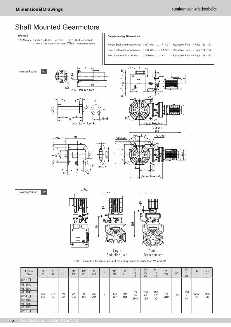
Bevel Buddybox 4 - 991361/EN-06/2018112
Dimensional Drawings
Frame Size
C E
F K
Z d
Q1 F1
Q2 E1
MMT P G1
G2HH1
D b t
D1 D2 D3
M1 m n
VTS LA
D4 h
D5
S l
S1 l 1
4B12
130 142
214 23
40 22
27 195
35 190
259291 5 122
127306161
6518
69,4
100 68
199
100 2,7 30
145M12 175
150 4
114
M12 20
M16 26
4B12DA4B12DA4B12DB4B14 4B14DA4B14DB4B14DC4B16
ll1
Mounting Position
Mounting Position
Y1
Y2
Supplementary Dimensions:
Hollow Shaft with Flange Mount : L YM - .....- F1 / G1 - Reduction Ratio --> Page 122 - 123
Solid Shaft with Flange Mount : L FM - .....- F1 / G1 - Reduction Ratio --> Page 124 - 125
Solid Shaft with Foot Mount : L HM - .....- K1 - Reduction Ratio --> Page 126 - 127
3Ph Motors : L YM - 4B12 ~ 4B16 - (-B) - Reduction Ratio : L YM - 4B12DA ~ 4B14DB- (-B)- Reduction Ratio
Example:
Shaft Mounted Gearmotors
Note: Consult us for dimensions of mounting positions other than Y1 and Y2

Bevel Buddybox 4 - 991361/EN-06/2018 113
Dimensional Drawings
FrameSize
Motor Capacity
kWx4P
J(Std)
J(Brake)
DM
(Std) DM Ø (Brake)
L (Std)
L (Brake)
Weight (Std)
Weight (Brake)
CFDC
GK GL GH
4B12
0,37 114 114
124 124
611643
9192
280 204
134 203 63
0,55 143 143
151 151
647690
9295
0,75 154 143
158 151
691690
10095
1,1 159 148
167 160
718742
103101
1,5 159 148
167 160
718742
105101
2,2 174 155
184 173
703763
111107
3 174 166
184 212
717795
115121
4 190 166
222 212
740795
122121
5,5 190 166
222 212
783839
138128
4B12DA
0,12 114 114
124 124
615633
9192
334 204
- 203 327
0,18 114 114
124 124
640672
9293
0,25 114 114
124 124
640672
9293
0,37 114 114
124 124
660692
9394
4B12DB
0,18 114 114
124 124
652684
9597
346 204
- 203 336
0,25 114 114
124 124
652684
9597
0,37 114 114
124 124
672704
9698
0,55 143 143
151 151
713756
99102
0,75 154 143
158 151
756756
107102
1,1 159 148
167 160
783808
110107
4B14
0,55 143 143
151 151
665708
100103
298 230
134 231 276
0,75 154 143
158 151
708708
109103
1,1 159 148
167 160
735760
112109
1,5 159 148
167 160
735760
113109
2,2 174 155
184 173
720781
119114
3 174 166
184 212
734813
122128
4 190 166
222 212
752813
130128
5,5 190 166
222 212
795857
145135
7,5 230 211
260 251
833903
157158
11 230 211
260 251
895963
163171
15 262 261
317 323
9571089
199248
4B14DA
0,12 114 114
124 124
632650
9596
351 230
- 231 349
0,18 114 114
124 124
657689
9697
0,25 114 114
124 124
657689
9697
0,37 114 114
124 124
677709
9798
Frame Size
Motor capacity
kWx4P
J(Std)
J(Brake)
DM
(Std) DM Ø (Brake)
L (Std)
L (Brake)
Weight (Std)
Weight (Brake)
CFDC
GK GL GH
4B14DB
0,18 114 114
124 124
666698
9697
360 230
- 231 353"
0,25 114 114
124 124
666698
9697
0,37 114 114
124 124
686718
9798
0,55 143 143
151 151
736779
102104
0,75 154 143
158 151
772779
114104
4B16
7,5 230 211
260 251
866936
179180
326 300
168 261 293
11 230 211
260 251
928996
184192
15 262 261
317 323
9861118
222269
18,5 340 342
398 394
10921276
347368
22 340 342
398 394
10921276
347368
Shaft Mounted Gearmotors
1 Mark in model nomenclature represents output shaft direction symbol H, V or W. For details, please refer to Nomenclature page (Page 18).
2 Mark in model nomenclature represents motor capacity symbol.3 Mark in frame size number represents "0" or "5".4 in model nomenclature refers to the mounting position symbol. For details please refer to pages 19 to 28.5 Output bore diameters (keyed bores) are manufactured to H8 tolerances according
to DIN EN ISO 286-2.6 Keys and keyways are manufactured according to DIN 6885-1 (Parallel Key, Standard Class).7 The weight values indicated in the tables are for hollow shaft units. 8 Dimensions and weights are subject to change without prior notice.

Bevel Buddybox 4 - 991361/EN-06/2018114
Dimensional Drawings
Frame Size
C E
F K
Z d
Q1 F1
Q2 E1
MMT P G1
G2H
H1
D b t
D1 D2 D3
M1 m n
VTS LA
D4 h
D5
S l
S1 l 1
4C14
160 172
264 28
45 26
31213
50 220
285320 5 124
151364193
75 20
79,9
120 78
244
120 2,7 37
170M16 212
1805
138
M16 26
M2033
4C14DA4C14DB4C14DC4C16 4C16DA4C16DB4C17 4C17DC
ll1
Mounting Position
Mounting Position
Y1
Y2
Supplementary Dmensions:
Hollow Shaft with Flange Mount : L YM - .....- F1 / G1 - Reduction Ratio --> Page 122 - 123
Solid Shaft with Flange Mount : L FM - .....- F1 / G1 - Reduction Ratio --> Page 124 - 125
Solid Shaft with Foot Mount : L HM - .....- K1 - Reduction Ratio --> Page 126 - 127
3Ph Motors : L YM - 4C14 ~ 4C17 - (-B) - Reduction Ratio : L YM - 4C14DA ~ 4C16DB- (-B)- Reduction Ratio
Example:
Shaft Mounted Gearmotors
Note: Consult us for dimensions of mounting positions other than Y1 and Y2

Bevel Buddybox 4 - 991361/EN-06/2018 115
Dimensional Drawings
Frame Size
Motor capacity
kWx4P
J(Std)
J(Brake)
DM
(Std) DM Ø (Brake)
L (Std)
L (Brake)
Weight (Std)
Weight (Brake)
CFDC
GK GL GH
4C14
0,75 154 143
158 151
797795
157149
356 230
134 231 334
1,1 159 148
167 160
824847
160155
1,5 159 148
167 160
824847
162155
2,2 174 155
184 173
809869
167161
3 174 166
184 212
823900
176174
4 190 166
222 212
841901
178175
5,5 190 166
222 212
884945
193182
7,5 230 211
260 251
922991
206205
11 230 211
260 251
9841051
211218
15 262 261
317 323
10461178
248296
4C14DA
0,12 114 114
124 124
721739
142143
410 230
- 231 407
0,18 114 114
124 124
746778
143144
0,25 114 114
124 124
746778
143144
0,37 114 114
124 124
766798
144146
4C14DB
0,18 114 114
124 124
755787
145146
419 230
- 231 411
0,25 114 114
124 124
755787
145146
0,37 114 114
124 124
775807
146148
0,55 143 143
151 151
816859
149152
0,75 154 143
158 151
860859
167152
1,1 159 148
167 160
887911
170157
1,5 159 148
167 160
887911
171157
4C14DC
0,75 154 143
158 151
874874
168154
433 230
- 231 418
1,1 159 148
167 160
901925
171160
1,5 159 148
167 160
901925
172160
2,2 174 155
184 173
922946
180166
FrameSize
Motor capacity
kWx4P
J(Std)
J(Brake)
DM
(Std) DM Ø (Brake)
L (Std)
L (Brake)
Weight (Std)
Weight (Brake)
CFDC
GK GL GH
4C16
1,1 159 148
167 160
845874
181176
377 300
168 260 344
1,5 159 148
167 160
845874
182176
2,2 174 155
184 173
830890
187180
3 174 166
184 212
844922
196194
4 190 166
222 212
867922
198194
5,5 190 166
222 212
910966
213203
7,5 230 211
260 251
9471017
226227
11 230 211
260 251
10091077
232240
15 262 261
317 323
10671199
269316
18,5 340 342
398 394
11731357
394413
22 340 342
398 394
11731357
394414
30 340 342
398 394
12971357
446430
4C16DA
0,12 114 114
124 124
753771
168170
442 300
- 261 433
0,18 114 114
124 124
778810
169171
0,25 114 114
124 124
778810
169171
0,37 114 114
124 124
798830
170172
0,55 143 143
151 151
839882
173176
0,75 154 143
158 151
883883
190176
1,1 159 148
167 160
910934
193182
1,5 159 148
167 160
910934
194182
4C16DB
0,75 154 143
158 151
897897
192178
456 300
- 261 440
1,1 159 148
167 160
924948
195184
1,5 159 148
167 160
924948
196184
2,2 174 155
184 173
945969
204225
4C17
11 230 211
260 251
10141098
257263
393 340
186 289 358
15 262 261
317 323
10831215
293339
18,5 340 342
398 394
11891373
419436
22 340 342
398 394
11891373
419436
30 340 342
398 394
13131373
470453
37CONSULT US FOR
DIMENSIONS4555
Shaft Mounted Gearmotors
1 Mark in model nomenclature represents output shaft direction symbol H, V or W. For details, please refer to Nomenclature page (Page 18).
2 Mark in model nomenclature represents motor capacity symbol.3 Mark in frame size number represents "0" or "5".4 in model nomenclature refers to the mounting position symbol. For details please refer to pages 19 to 28.5 Output bore diameters (keyed bores) are manufactured to H8 tolerances according
to DIN EN ISO 286-2.6 Keys and keyways are manufactured according to DIN 6885-1 (Parallel Key, Standard Class).7 The weight values indicated in the tables are for hollow shaft units. 8 Dimensions and weights are subject to change without prior notice.

Bevel Buddybox 4 - 991361/EN-06/2018116
Dimensional Drawings
FrameSize
C E
F K
Z d
Q1 F1
Q2 E1
MMT P G1
G2H
H1
D b t
D1 D2 D3
M1 m n
VTS LA
D4 h
D5
S l
S1 l 1
4D16
190 193
310 35
55 33
36254
65 250
340380 7 148
178424223
85 22
90,4
140 88,5 295
145 3,2 37
199 M16 255
2105
152
M2033
M2440
4D16DA4D16DB4D16DC4D17 4D17DA4D17DB4D17DC4D18 4D18DA4D18DB
ll1
Mounting Position Y2
Mounting Position Y1
Supplementary Dimensions:
Hollow Shaft with Flange Mount : L YM - .....- F1 / G1 - Reduction Ratio --> Page 122 - 123
Solid Shaft with Flange Mount : L FM - .....- F1 / G1 - Reduction Ratio --> Page 124 - 125
Solid Shaft with Foot Mount : L HM - .....- K1 - Reduction Ratio --> Page 126 - 127
3Ph Motors : L YM - 4D16 ~ 4D18 - (-B) - Reduction Ratio : L YM - 4D16DA ~ 4D17DC- (-B)- Reduction Ratio
Example:
Shaft Mounted Gearmotors
Note: Consult us for dimensions of mounting positions other than Y1 and Y2

Bevel Buddybox 4 - 991361/EN-06/2018 117
Dimensional Drawings
Frame Size
Motor capacity
kWx4P
J(Std)
J(Brake)
DM
(Std) DM Ø (Brake)
L (Std)
L (Brake)
Weight (Std)
Weight (Brake)
CFDC
GK GL GH
4D16
1,5 159 148
167 160
947977
260241
450 300
168 261 416
2,2 174 155
184 173
932993
265245
3 174 166
184 212
9461025
268259
4 190 166
222 212
9691025
276259
5,5 190 166
222 212
10121069
292269
7,5 230 211
260 251
10491120
303293
11 230 211
260 251
11111180
309305
15 262 261
317 323
11691301
347383
18,5 340 342
398 394
12751459
466478
22 340 342
398 394
12751459
466481
4D16DA
0,12 114 114
124 124
855873
235237
514 300
- 261 505
0,18 114 114
124 124
880912
236238
0,25 114 114
124 124
880912
236238
0,37 114 114
124 124
900932
237239
0,55 143 143
151 151
941984
240243
0,75 154 143
158 151
986986
261243
1,1 159 148
167 160
10131036
264249
1,5 159 148
167 160
10131036
265249
4D16DB
0,75 154 143
158 151
1000988
263246
528 300
- 261 512
1,1 159 148
167 160
10271050
266251
1,5 159 148
167 160
10271050
267251
2,2 174 155
184 173
10481071
275256
4D16DC
1,5 159 148
167 160
10281052
276257
530 300
- 261 514
3 174 166
184 212
10271105
285276
4 190 166
222 212
10501105
293276
4D17
3 174 166
184 212
9551033
289279
443 340
186 289 408
4 190 166
222 212
9681033
297279
5,5 190 166
222 212
10111077
313286
7,5 230 211
260 251
10321118
325313
11 230 211
260 251
10941178
331325
15 262 261
317 323
11631295
367402
18,5 340 342
398 394
12691453
487496
22 340 342
398 394
12691453
487498
30 340 342
398 394
13931453
539515
37CONSULT US FOR DIMENSIONS45
55
4D17DA
0,12 114 114
124 124
850868
248250
509 340
- 289 496
0,18 114 114
124 124
875907
244251
0,25 114 114
124 124
875907
244251
0,37 114 114
124 124
895927
250252
0,55 143 143
151 151
936979
253256
0,75 154 143
158 151
979979
278256
1,1 159 148
167 160
10061031
281261
1,5 159 148
167 160
10061031
282261
FrameSize
Motor capacity
kWx4P
J(Std)
J(Brake)
DM
(Std) DM Ø (Brake)
L (Std)
L (Brake)
Weight (Std)
Weight (Brake)
CFDC
GK GL GH
4D17DB
0,55 143 143
151 151
950993
250257
523 340
- 289 503
0,75 154 143
158 151
993993
280257
1,1 159 148
167 160
10201045
283264
1,5 159 148
167 160
10201045
284264
2,2 174 155
184 173
10411066
292269
4D17DC
1,5 159 148
167 160
9871049
264270
527 340
- 289 508
2,2 174 155
184 173
10101070
298275
3 174 166
184 212
10241102
301290
4 190 166
222 212
10471102
309290
4D18
3 174 166
184 212
9581036
314314
446 370
203 314 411
4 190 166
222 212
9711036
323314
5,5 190 166
222 212
10141080
338321
7,5 230 211
260 251
10381121
351345
11 230 211
260 251
11001181
357359
15 262 261
317 323
11661271
393435
18,5 340 342
398 394
12721426
512531
22 340 342
398 394
12721426
512531
30 340 342
398 394
13961426
564547
37 340 -
398 -
1396 -
594 -
45 340 -
518 -
1433 -
651 -
55 CONSULT US FOR DIMENSIONS
4D18DA
0,18 114 114
124 124
897 929
297 298
531 370
- 314 511
0,25 114 114
124 124
897 929
297 298
0,37 114 114
124 124
917 949
298 299
0,55 143 143
151 151
958 1001
302 305
0,75 154 143
158 151
1002 1065
308 312
1,1 159 148
167 160
1029 1098
311 316
1,5 159 148
167 160
1029 1098
312 317
2,2 174 155
184 173
1050 1128
320 327
4D18DB
0,75 154 143
158 151
1024 1088
322 327
553 370
- 314 527
1,1 159 148
167 160
1051 1121
325 331
1,5 159 148
167 160
1051 1121
327 333
2,2 174 155
184 173
1036 1114
332 340
3 174 166
184 212
1050 1128
335 343
4 190 166
222 212
1068 1159
343 354
Shaft Mounted Gearmotors
1 Mark in model nomenclature represents output shaft direction symbol H, V or W. For details, please refer to Nomenclature page (Page 18).
2 Mark in model nomenclature represents motor capacity symbol.3 Mark in frame size number represents "0" or "5".4 in model nomenclature refers to the mounting position symbol. For details please refer to pages 19 to 28.5 Output bore diameters (keyed bores) are manufactured to H8 tolerances according
to DIN EN ISO 286-2.6 Keys and keyways are manufactured according to DIN 6885-1 (Parallel Key, Standard Class).7 The weight values indicated in the tables are for hollow shaft units. 8 Dimensions and weights are subject to change without prior notice.

Bevel Buddybox 4 - 991361/EN-06/2018118
Dimensional Drawings
FrameSize
C E
F K
Z d
Q1 F1
Q2 E1
MMT P G1
G2H
H1
D b t
D1 D2 D3
M1 m n
VTS LA
D4 h
D5
S l
S1 l 1
4E17
215 230
360 35
55 33
38 283
65 300
373415 7 156
203498248
100 28
106,4
160 103,5 320
165 3,2 37
200M16 280
240 5
170
M20 35
M24 40
4E17DA 4E17DB 4E17DC 4E18 4E18DA 4E18DB 4E19
ll1
Mounting Position Y2
Mounting Position Y1
Supplementary Dimensions:
Hollow Shaft with Flange Mount : L YM - .....- F1 / G1 - Reduction Ratio --> Page 122 - 123
Solid Shaft with Flange Mount : L FM - .....- F1 / G1 - Reduction Ratio --> Page 124 - 125
Solid Shaft with Foot Mount : L HM - .....- K1 - Reduction Ratio --> Page 126 - 127
3Ph Motors : L YM - 4E17 ~ 4E19 - (-B) - Reduction Ratio : L YM - 4E17DA ~ 4E18DB- (-B)- Reduction Ratio
Example:
Shaft Mounted Gearmotors
Note: Consult us for dimensions of mounting positions other than Y1 and Y2

Bevel Buddybox 4 - 991361/EN-06/2018 119
Dimensional Drawings
FrameSize
Motor capacity
kWx4P
J(Std)
J(Brake)
DM
(Std) DM Ø (Brake)
L (Std)
L (Brake)
Weight (Std)
Weight (Brake)
CFDC
GK GL GH
4E17
3 174 166
184 212
10051083
364352
468 340
186 289 433
4 190 166
222 212
10181083
372352
5,5 190 166
222 212
10611127
388359
7,5 230 211
260 251
10821168
400385
11 230 211
260 251
11441228
406399
15 262 261
317 323
12131345
442472
18,5 340 342
398 394
13191503
562569
22 340 342
398 394
13191503
562569
30 340 342
398 394
14431503
614586
4E17DA
0,12 114 114
124 124
900918
322324
534 340
- 289 521
0,18 114 114
124 124
925957
323325
0,25 114 114
124 124
925957
323325
0,37 114 114
124 124
945977
324326
0,55 143 143
151 151
9861029
327330
0,75 154 143
158 151
10291029
355330
1,1 159 148
167 160
10561081
358335
1,5 159 148
167 160
10561081
359335
4E17DB
0,75 154 143
158 151
10431043
357331
548 340
- 289 528
1,1 159 148
167 160
10701095
360338
1,5 159 148
167 160
10701095
361338
2,2 174 155
184 173
10911116
369343
4E17DC
1,5 159 148
167 160
10751099
368343
552 340
- 289 533
2,2 174 155
184 173
10601120
374349
3 174 166
184 212
10741152
377364
4 190 166
222 212
10971152
385364
5,5 190 166
222 212
11401196
401371
4E18
3 174 166
184 212
10081086
389397
471 370
203 314 436
4 190 166
222 212
10211086
398397
5,5 190 166
222 212
10641130
413404
7,5 230 211
260 251
10881171
426428
11 230 211
260 251
11501231
432442
15 262 261
317 323
12161321
468518
18,5 340 342
398 394
13221476
587614
22 340 342
398 394
13221476
587614
30 340 342
398 394
14461476
639630
37 340 -
398 -
1446 -
669 -
45 340 -
518 -
1483 -
726 -
55 CONSULT US FOR DIMENSIONS
FrameSize
Motor capacity
kWx4P
J(Std)
J(Brake)
DM
(Std) DM Ø (Brake)
L (Std)
L (Brake)
Weight (Std)
Weight (Brake)
CFDC
GK GL GH
4E18DA
0,18 114 114
124 124
947979
368370
556 370
- 314 536
0,25 114 114
124 124
947979
368370
0,37 114 114
124 124
967999
369371
0,55 143 143
151 151
10081051
373376
0,75 154 143
158 151
10521051
384376
1,1 159 148
167 160
10791103
387382
1,5 159 148
167 160
10791103
388382
2,2 174 155
184 173
11001124
396387
3 174 166
184 212
11141192
399404
4E18DB
1,1 159 148
167 160
11011125
402396
556 370
- 314 522
1,5 159 148
167 160
11011125
403396
2,2 174 155
184 173
10861146
411402
3 174 166
184 212
11001178
420414
4 190 166
222 212
11181178
405414
5,5 190 166
222 212
11611222
411422
4E19
7,5 230 211
260 251
11041205
465470
490 430
233 355 450
11 230 211
260 251
11661265
471484
15 262 261
317 323
12351340
507558
18,5 340 342
398 394
13411495
626655
22 340 342
398 394
13411495
626655
30 340 342
398 394
14651495
678666
37 340 -
398 -
1465 -
709 -
45 340 -
518 -
1502 -
766 -
55 390 -
518 -
1502 -
803 -
Shaft Mounted Gearmotors
1 Mark in model nomenclature represents output shaft direction symbol H, V or W. For details, please refer to Nomenclature page (Page 18).
2 Mark in model nomenclature represents motor capacity symbol.3 Mark in frame size number represents "0" or "5".4 in model nomenclature refers to the mounting position symbol. For details please refer to pages 19 to 28.5 Output bore diameters (keyed bores) are manufactured to H8 tolerances according
to DIN EN ISO 286-2.6 Keys and keyways are manufactured according to DIN 6885-1 (Parallel Key, Standard Class).7 The weight values indicated in the tables are for hollow shaft units. 8 Dimensions and weights are subject to change without prior notice.

Bevel Buddybox 4 - 991361/EN-06/2018120
Dimensional Drawings
Frame
SizeC E
F K
Z d
Q1 F1
Q2 E1
MMT P G1
G2HH1
D b t
D1 D2 D3
M1 m n
VTS LA
D4 h
D5
S l
S1 l 1
4F18
240 252 70 39
50,5 320
70 340
435*1 7 238
183590273
120 32
127,4
180 124 370
194 4,2 49
*1 320260 5*1
M24 50
M30 50
4F18DA 4F18DB 4F19 4F19DA 4F19DB
ll1
Mounting Position
Mounting Position
Y1
Y2
Supplementary Dimensions:
Hollow Shaft with Flange Mount : L YM - .....- F1 / G1 - Reduction Ratio --> Page 122 - 123
Solid Shaft with Flange Mount : L FM - .....- F1 / G1 - Reduction Ratio --> Page 124 - 125
Solid Shaft with Foot Mount : L HM - .....- K1 - Reduction Ratio --> Page 126 - 127
3Ph Motors : L YM - 4F18 ~ 4F19 - (-B) - Reduction Ratio : L YM - 4F18DA ~ 4F19DB- (-B)- Reduction Ratio
Shaft Mounted GearmotorsExample:
Note: Consult us for dimensions of mounting positions other than Y1 and Y2
*1: Consult Sumitomo

Bevel Buddybox 4 - 991361/EN-06/2018 121
Dimensional Drawings
Shaft Mounted Gearmotors
1 Mark in model nomenclature represents output shaft direction symbol H, V or W. For details, please refer to Nomenclature page (Page 18).
2 Mark in model nomenclature represents motor capacity symbol.3 Mark in frame size number represents "0" or "5".4 in model nomenclature refers to the mounting position symbol. For details please refer to pages 19 to 28.5 Output bore diameters (keyed bores) are manufactured to H8 tolerances according
to DIN EN ISO 286-2.6 Keys and keyways are manufactured according to DIN 6885-1 (Parallel Key, Standard Class).7 The weight values indicated in the tables are for hollow shaft units. 8 Dimensions and weights are subject to change without prior notice.
Frame Size
Motor capacity
kWx4P
J(Std)
J(Brake)
DM
(Std) DM Ø (Brake)
L (Std)
L (Brake)
Weight (Std)
Weight (Brake)
CFDC
GK GL GH
4F18
3 174 166
184 212
10961175
569594
535 370
203 314 499
4 190 166
222 212
11091175
577594
5,5 190 166
222 212
11521219
592601
7,5 230 211
260 251
11761260
605625
11 230 211
260 251
12381320
611639
15 262 261
317 323
13041410
674715
18,5 340 342
398 394
14101565
766811
22 340 342
398 394
14101565
766811
30 340 342
398 394
15341565
818827
37 340 -
398 -
1534 -
848 -
45 340 -
518 -
1571 -
905 -
55 CONSULT US FOR DIMENSIONS
4F18DA
0,18 114 114
124 124
10351067
544545
619 370
- 314 599
0,25 114 114
124 124
10351067
544545
0,37 114 114
124 124
10551087
545547
0,55 143 143
151 151
10961139
549552
0,75 154 143
158 151
11401139
562552
1,1 159 148
167 160
11671191
565558
1,5 159 148
167 160
11671191
566558
2,2 174 155
184 173
11881212
574563
3 174 166
184 212
12021280
577580
4 190 166
222 212
12201280
585580
4F18DB
1,1 159 148
167 160
11891213
580571
641 370
- 314 615
1,5 159 148
167 160
11891213
582571
2,2 174 155
184 173
11741234
587577
3 174 166
184 212
11881266
590730
4 190 166
222 212
12061266
598589
5,5 190 166
222 212
12491310
613597
7,5 230 211
260 251
12871356
625621
4F19
4 CONSULT US FOR DIMENSIONS
552 430
233 355 512
5,5 190 166
222 212
11851256
628642
7,5 230 211
260 251
11911292
640664
11 230 211
260 251
12531352
646678
15 262 261
317 323
13221427
682752
18,5 340 342
398 394
14281582
801849
22 340 342
398 394
14281582
801849
30 340 342
398 394
15521582
853860
37 340 -
398 -
1552 -
884 -
FrameSize
Motor capacity
kWx4P
J(Std)
J(Brake)
DM
(Std) DM Ø (Brake)
L (Std)
L (Brake)
Weight (Std)
Weight (Brake)
CFDC
GK GL GH
4F19DA
0,75 154 143
158 151
1164 1228
608 612
643 430
- 355 624
1,1 159 148
167 160
1191 1261
611 616
1,5 159 148
167 160
1191 1261
613 618
2,2 174 155
184 173
1176 1254
619 626
3 174 166
184 212
1190 1268
622 629
4 190 166
222 212
1213 1304
630 641
5,5 190 166
222 212
1256 1347
646 657
7,5 230 211
260 251
1300 1405
657 677
4F19DB
2,2 174 155
184 173
1164 1270
624 632
659 430
- 355 633
3 174 166
184 212
1191 1284
627 635
4 190 166
222 212
1191 1315
635 646
5,5 190 166
222 212
1176 1358
650 661
7,5 230 211
260 251
1190 1410
662 682

Bevel Buddybox 4 - 991361/EN-06/2018122
Dimensional Drawings
Supplementary Dimensions - Hollow Shaft with Flange Mount

Bevel Buddybox 4 - 991361/EN-06/2018 123
Dimensional Drawings
Frame Size
C E K N
d
M MT Q
L1 F R
U1 T1 P
U2 T2
H H1
D1 D2 D3
D4 D5 D6
D7 V TS
D b t
M1 M2
m n LA
4A10 4A10DA 4A11 4A12 4A12DA 4A12DB 4A14
110 125 132 4
14
216 245 60
280 50 15
115,5 160,5
4
100,5 176
276 141
85 120 180
250 58 56
104 130
6 x M12
55 16
59,3
85 85
30 2,2 215
4B12 4B12DA4B12DB4B14 4B14DA4B14DB4B16
130 150 165 4
14
259 291 61
324 50 16
132 168 4
127 193
306 161
100 140 230
300 68 66
114 145
6 x M12
65 18
69,4
100 100
30 2,7 265
4C14 4C14DA4C14DB4C14DC 4C16 4C16DA4C16DB4C17
160 175 200 4
18
285 32073
363 6018
1562025
129229
364193
120165250
3507876
138170
6 x M16
7520
79,9
120120
372,7 300
4D16 4D16DA4D16DB4D16DC 4D17 4D17DA4D17DB4D17DC4D18 4D18DA4D18DB
190225 228 8
18
34038080
425 6522
1852355
155265
424223
140195350
45088,586
152199
6 x M16
8522
90,4
145145
373,2 400
4E17 4E17DA4E17DB4E17DC 4E18 4E18DA4E18DB4E19
215225 265 8
18
37341580
458 6522
2102435
170290
498248
160220350
450103,5101
170200
8 x M16
10028
106,4
165165
373,2 400
4F18 4F18DA4F18DB 4F19 4F19DA4F19DB
240330 297 8
24
43548665
505 4824
2452555
190310
590273
180240550
660124121
186248
10 x M16
12032
127,4
194189
494,2 600
Supplementary Dimensions - Hollow Shaft and Flange Mount
Add below weigth values to the weights shown on dimension tables on page 110 to 121 for Hollow Shaft with Flange Mount models.
Size
4A 8
4B 12
4C 17
4D 27
4E 29
4F 75
Additional Weight (Kg)
1 The dimensions in the above tables should be taken together with dimensions on page 110 to 121. 2 The weight values indicated in the above tables are additional weights for hollow shaft with flange mount
types; and must be added to the weights of the units indicated in Page 110 to 121.3 Mark in frame size number represents "0" or "5".4 For correct nomenclature, please refer to Page 18. 5 Dimensions and weights are subject to change without prior notice.

Bevel Buddybox 4 - 991361/EN-06/2018124
Dimensional Drawings
Supplementary Dimensions - Solid Shaft with Flange Mount

Bevel Buddybox 4 - 991361/EN-06/2018 125
Dimensional Drawings
FrameSize
C E K N
dM Q L1
F RP
U1 T1
U2 T2
H H1
D1 D2 D3
Db h t
V V1 LA
4A10 4A10DA 4A11 4A12 4A12DA 4A12DB 4A14
110 125 132 4
14216 60 306
50 154
115,5 160,5
100,5 176
276 141
120 180250
50 h6 149
5,5
3090 215
4B12 4B12DA4B12DB4B14 4B14DA4B14DB4B16
130 150 165 4
1424561 369
50 164
127188
122 193
306 161
140 230 300
65 h6 18117
54115 265
4C14 4C14DA4C14DB4C14DC 4C16 4C16DA4C16DB4C17
160 175 200 4
18285 73 425
60185
151202
129229
364193
165250350
80 h622149
72145 300
4D16 4D16DA4D16DB4D16DC 4D17 4D17DA4D17DB4D17DC4D18 4D18DA4D18DB
190225 228 8
1833380 503
65225
178235
155265
424223
195350450
95 h625149
90170 400
4E17 4E17DA4E17DB4E17DC 4E18 4E18DA4E18DB4E19
215225 265 8
1837380 566
65225
203243
170290
498248
220350450
110 h6281610
120200 400
4F18 4F18DA4F18DB 4F19 4F19DA4F19DB
240330 297 8
2442865 638
48245
238255
190310
590273
240550660
130 h6321811
145210 600
Supplementary Dimensions - Solid Shaft with Flange Mount
Add below weigth values to the weights shown on dimension tables onpage 110 to 121 for Solid Shaft with Flange Mount Units.
Size
4A 12 15
4B 20 27
4C 29 39
4D 46 60
4E 59 82
4F 125 157
Additional WeightOutput Shaft
One side (L,R) (kg)
Additional WeightOutput ShaftBoth side (T)
(kg)
1 The dimensions in the above tables should be taken together with dimensions on page 110 to 121. 2 The weight values indicated in the above tables are additional weights for hollow shaft with flange mount
types; and must be added to the weights of the units indicated in Page 110 to 121.3 Mark in frame size number represents "0" or "5".4 For correct nomenclature, please refer to Page 18. 5 Output shaft diameters are manufactured to h6 tolerances according to DIN EN ISO 286-2.6 Keyways are manufactured according to DIN 6885-1 (Parallel Key, Standard Class). 7 Dimensions and weights are subject to change without prior notice.

Bevel Buddybox 4 - 991361/EN-06/2018126
Dimensional Drawings
Supplementary Dimensions - Solid Shaft with Foot Mount

Bevel Buddybox 4 - 991361/EN-06/2018 127
Dimensional Drawings
FrameSize
C K
B1p
F B d N
EGQ
S1 M1
U1 T1
U2T2
HH1 D
b h t
V l1l2
4A10 4A10DA 4A11 4A12 4A12DA 4A12DB 4A14
140 110
13520
320280 14 202
16011821
M1020
110,5 190,5
95206
306141 50 h6
149
5,590 301
396,5
4B12 4B12DA4B12DB4B14 4B14DA4B14DB4B16
170 130
16020
385345 18 245
19514725
M1224
127242
122 247
346161 65 h6
18117
115 369489
4C14 4C14DA4C14DB4C14DC 4C16 4C16DA4C16DB4C17
210160
19530
505445 22 270
210182,5
30M1224
151274
124301
414193 80 h6
22149
145 425575
4D16 4D16DA4D16DB4D16DC 4D17 4D17DA4D17DB4D17DC4D18 4D18DA4D18DB
245190
23530
560500 26 320
26021030
M2040
178325
148355
479223 95 h6
25149
170 503680
4E17 4E17DA4E17DB4E17DC 4E18 4E18DA4E18DB4E19
275215
27035
650580 33 355
28024737,5
M2040
203363
156410
558248 110 h6
281610
200 566773
4F18 4F18DA4F18DB 4F19 4F19DA4F19DB
320240
30035
740670 33 400
32026840
M2045
238400
183455
670273 130 h6
321811
210 638855
Supplementary Dimensions - Solid Shaft with Foot Mount
Add below weigth values to the weights shown on dimension tables onpage 110 to 121 for Solid Shaft with Foot Mount Units.
Size
4A 14 17
4B 27 34
4C 43 53
4D 65 79
4E 91 114
4F 155 187
Additional WeightOutput Shaft
One side (L,R)(kg)
Additional WeightOutput ShaftBoth side (T)
(kg)
1 The dimensions in the above tables should be taken together with dimensions on page 110 to 121. 2 The weight values indicated in the above tables are additional weights for hollow shaft with flange mount
types; and must be added to the weights of the units indicated in Page 110 to 121.3 Mark in frame size number represents "0" or "5".4 For correct nomenclature, please refer to Page 18. 5 Output shaft diameters are manufactured to h6 tolerances according to DIN EN ISO 286-2.6 Keyways are manufactured according to DIN 6885-1 (Parallel Key, Standard Class). 7 Dimensions and weights are subject to change without prior notice.

Bevel Buddybox 4 - 991361/EN-06/2018128
Selection Tables for ReducersImportant Notes :
Selection Tables for 50Hz Input
Selection Tables for Low Speed Reducers
(Ratio from 364 to 10658)
4A 1294B 1334C 1374D 1404E 1434F 146
4A 1504B 1544C 1584D 1614E 1654F 168
4A 1724B 1734C 1744D 1754E 1784F 180
Selection Tables for 60Hz Input Size
Size
Size
Page
Page
Page
1750 rpm - 4 poles1165 rpm - 6 poles 870 rpm - 8 poles 580 rpm - 12 poles
1450 rpm - 4 poles 980 rpm - 6 poles 720 rpm - 8 poles 50 rpm - Low Input Speed
1450 rpm - 4P - 50 Hz1750 rpm - 4P - 60 Hz
Following notes must be considered when using selection tables from page 129 to 181. 1. For the nomenclature of models listed on the selection table, refer to page 18. 2. Consult us if the mounting position is Y4, F4, G4, K4 or W4 (motor is faced down), because these selection tables are not applicable.3. Allowable duty cycle of models with mark in the model column is 75% ED (10 min. cycle) in case of mounting positions Y2, F2, G2, K2, V2 or W2. 4. For the allowable radial load of the input shaft, refer to pages 39 and 40.5. In Allowable Radial Load of Output Shaft (Pro) column the values for hollow shaft type are those at 20 mm from the shaft end face, and the values for solid shaft type are those at the midpoint of the output shaft. If the load position is other than these, or for the allowable thrust load, refer to pages 32 to 40.6. The lubrication method depends on the model. For details, refer to "Lubrication" on pages 210 to 212.7. The output shaft speeds (n2) are based on input speed (n1). 8. The reduction ratios are nominal. The output speed values (n2) are calculated based on the actual reduction ratios. (The output speeds in case of reduction ratios 11 to 18 are calculated based on the nominal reduction ratios because the actual ratio of 11 to 18 depends on the frame size). For the actual reduction ratios, refer to page 6. 9. Calculate the gearbox rating for speed not listed in the selection tables by interpolation method10. Consult us for the combinations and reduction ratios not listed in the selection tables.11. The contents of the tables are subject to change without prior notice.

Bevel Buddybox 4 - 991361/EN-06/2018 129
Sizen1 1750 1165 870 580
Ratio i
n2 [rpm]
P1 [kW]
Tout [Nm]
Pro [N]
n2 [rpm]
P1 [kW]
Tout [Nm]
Pro [N]
n2 [rpm]
P1 [kW]
Tout [Nm]
Pro [N]
n2 [rpm]
P1 [kW]
Tout [Nm]
Pro [N]
4A100[Dimension Drawings
frompage 184]
11 159,1 2,4 124 16500 106,0 2,4 186 18400 79,1 2,4 250 19900 52,8 1,9 290 2240013 134,7 2,4 151 17500 89,7 2,4 227 19400 67,0 2,4 304 20900 44,7 1,9 353 2350014 125,0 2,4 165 17900 83,3 2,4 249 19900 62,2 2,4 333 21400 41,5 1,9 386 2410016 109,4 2,4 189 18500 72,9 2,4 284 20500 54,4 2,4 381 22000 36,3 1,9 442 2480018 97,3 2,4 207 19000 64,8 2,4 311 21000 48,4 2,4 416 22500 32,3 1,9 483 2530019 92,2 2,0 227 19400 61,4 2,0 341 21500 45,8 2,0 457 23000 30,6 2,0 530 2560021 83,4 2,4 248 19900 55,5 2,4 373 21900 41,5 2,4 499 23400 27,7 1,9 580 25200 26 67,4 2,4 303 20900 44,9 2,4 455 23000 33,5 2,4 609 24500 22,4 1,9 723 2400028 62,5 2,4 331 21300 41,7 2,4 497 23400 31,1 2,4 666 24500 20,8 1,9 793 23200 35 50,0 2,4 416 22500 33,3 2,4 625 24600 24,9 2,2 776 23400 16,6 1,5 776 23400 39 44,9 2,4 455 23000 29,9 2,4 684 24400 22,4 2,2 849 22500 14,9 1,5 849 22500 42 41,7 2,4 492 23400 27,8 2,4 739 23800 20,8 1,9 775 23400 13,9 1,2 777 2340046 38,1 2,4 537 23800 25,4 2,4 808 23100 19,0 1,9 849 22500 12,7 1,3 849 22500 48 36,5 2,4 568 24100 24,3 2,1 776 23400 18,2 1,6 777 23400 12,1 1,1 780 2340053 33,1 2,4 620 24600 22,0 2,2 849 22500 16,5 1,6 849 22500 11,0 1,1 849 22500 54 32,5 2,0 545 25300 21,6 1,9 777 23400 16,2 1,4 776 23400 10,8 0,9 776 2340060 29,2 2,0 594 25100 19,5 1,9 849 22500 14,5 1,5 849 22500 9,7 1,0 849 22500 67 26,2 2,0 651 24600 17,4 1,6 776 23400 13,0 1,2 776 23400 8,7 0,8 776 23400 74 23,7 2,0 712 24100 15,8 1,6 849 22500 11,8 1,2 849 22500 7,9 0,8 849 22500 80 21,9 1,3 511 25700 14,6 1,3 768 23500 10,9 1,0 776 23400 7,3 0,7 776 23400 88 19,9 1,3 559 25400 13,3 1,3 840 22700 9,9 1,0 849 22500 6,6 0,7 849 22500 93 18,9 1,2 565 25300 12,6 1,1 779 23400 9,4 0,8 777 23400 6,3 0,6 776 23400
102 17,2 1,3 618 24900 11,5 1,2 849 22500 8,6 0,9 849 22500 5,7 0,6 849 22500 112 15,7 1,0 549 25500 10,4 1,0 776 23400 7,8 0,7 776 23400 5,2 0,5 776 23400 123 14,3 1,0 601 25100 9,5 1,0 849 22500 7,1 0,7 849 22500 4,8 0,5 849 22500138 12,7 0,8 540 25500 8,5 0,8 777 23400 6,3 0,6 777 23400 4,2 0,4 777 23400151 11,6 0,8 591 25100 7,8 0,8 849 22500 5,8 0,6 849 22500 3,9 0,4 849 22500163 10,8 0,6 460 26000 7,2 0,6 691 24300 5,4 0,5 776 23400 3,6 0,4 775 23400179 9,8 0,6 503 25800 6,6 0,6 756 23600 4,9 0,5 849 22500 3,3 0,4 849 22500 189 9,3 0,5 490 25900 6,2 0,5 736 23800 4,6 0,4 776 23400 3,1 0,4 777 23400207 8,5 0,6 536 25600 5,7 0,6 805 23100 4,2 0,5 849 22500 2,8 0,3 849 22500227 7,8 0,4 498 25800 5,2 0,4 749 23700 3,9 0,3 777 23400 2,6 0,2 776 23400249 7,1 0,5 545 25500 4,7 0,5 819 22900 3,5 0,4 849 22500 2,4 0,3 849 22500278 6,3 0,4 607 25000 4,2 0,4 776 23400 3,2 0,3 778 23400 2,1 0,2 778 23400305 5,8 0,5 664 24500 3,9 0,4 849 22500 2,9 0,3 849 22500 1,9 0,2 849 22500
4A105[Dimension Drawings
frompage 184]
11 159,1 3,2 168 16300 106,0 3,2 252 18100 79,1 2,8 290 19700 52,8 1,9 290 2240013 134,7 3,2 205 17200 89,7 3,2 308 19000 67,0 2,8 353 20600 44,7 1,9 353 2350014 125,0 3,2 224 17600 83,3 3,2 336 19400 62,2 2,8 386 21100 41,5 1,9 386 2410016 109,4 3,2 256 18100 72,9 3,2 385 20000 54,4 2,8 442 21700 36,3 1,9 442 2480018 97,3 3,2 280 18600 64,8 3,2 421 20400 48,4 2,8 483 22100 32,3 1,9 483 2530019 92,2 3,2 307 19000 61,4 3,2 461 20800 45,8 2,7 530 22600 30,6 1,8 530 2560021 83,4 3,2 336 19400 55,5 3,2 505 21200 41,5 2,8 580 23000 27,7 1,9 580 25200 26 67,4 3,2 410 20300 44,9 3,2 615 22100 33,5 2,5 658 24200 22,4 1,9 723 2400028 62,5 3,2 448 20700 41,7 3,2 673 22500 31,1 2,6 720 24000 20,8 1,9 793 23200 35 50,0 3,2 563 21700 33,3 3,2 846 22600 24,9 2,7 930 21400 16,6 1,8 955 21100 39 44,9 3,2 616 22100 29,9 3,2 925 21500 22,4 2,7 1020 20100 14,9 1,8 1050 19600 42 41,7 3,2 666 22400 27,8 3,0 931 21400 20,8 2,2 930 21400 13,9 1,5 935 2140046 38,1 3,2 728 22800 25,4 3,0 1020 20100 19,0 2,3 1020 20100 12,7 1,5 1020 20100 48 36,5 3,2 768 23000 24,3 2,6 932 21400 18,2 2,0 933 21400 12,1 1,3 933 2140053 33,1 3,2 840 22700 22,0 2,6 1020 20100 16,5 2,0 1020 20100 11,0 1,3 1020 20100 54 32,5 2,5 673 24500 21,6 2,3 933 21400 16,2 1,7 930 21400 10,8 1,1 933 2140060 29,2 2,5 735 23800 19,5 2,3 1020 20100 14,5 1,7 1020 20100 9,7 1,2 1020 20100 67 26,2 2,4 790 23300 17,4 1,9 932 21400 13,0 1,4 932 21400 8,7 1,0 932 21400 74 23,7 2,4 864 22400 15,8 1,9 1020 20100 11,8 1,4 1020 20100 7,9 1,0 1020 20100 80 21,9 1,7 673 24400 14,6 1,6 932 21400 10,9 1,2 932 21400 7,3 0,8 932 21400 88 19,9 1,7 736 23800 13,3 1,6 1020 20100 9,9 1,2 1020 20100 6,6 0,8 1020 20100 93 18,9 1,6 742 23800 12,6 1,3 933 21400 9,4 1,0 932 21400 6,3 0,7 931 21400
IMPORTANT: Please refer to page 128 for Reducer Selection Table notes. Refer to Page 150-171 for 50 Hz Input
Selection Tables for Reducers (60 Hz Input)
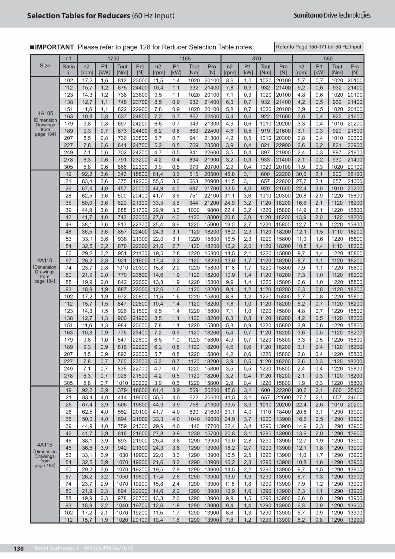
Bevel Buddybox 4 - 991361/EN-06/2018130
Selection Tables for Reducers (60 Hz Input)
Sizen1 1750 1165 870 580
Ratio i
n2 [rpm]
P1 [kW]
Tout [Nm]
Pro [N]
n2 [rpm]
P1 [kW]
Tout [Nm]
Pro [N]
n2 [rpm]
P1 [kW]
Tout [Nm]
Pro [N]
n2 [rpm]
P1 [kW]
Tout [Nm]
Pro [N]
102 17,2 1,6 812 23000 11,5 1,4 1020 20100 8,6 1,0 1020 20100 5,7 0,7 1020 20100 112 15,7 1,2 675 24400 10,4 1,1 932 21400 7,8 0,9 932 21400 5,2 0,6 932 21400 123 14,3 1,2 738 23800 9,5 1,1 1020 20100 7,1 0,9 1020 20100 4,8 0,6 1020 20100 138 12,7 1,1 748 23700 8,5 0,9 932 21400 6,3 0,7 932 21400 4,2 0,5 932 21400151 11,6 1,1 822 22900 7,8 0,9 1020 20100 5,8 0,7 1020 20100 3,9 0,5 1020 20100 163 10,8 0,8 637 24800 7,2 0,7 862 22400 5,4 0,6 922 21600 3,6 0,4 922 21600179 9,8 0,8 697 24200 6,6 0,7 943 21300 4,9 0,6 1010 20200 3,3 0,4 1010 20200 189 9,3 0,7 673 24400 6,2 0,6 860 22400 4,6 0,5 919 21600 3,1 0,3 920 21600207 8,5 0,8 736 23800 5,7 0,7 941 21300 4,2 0,5 1010 20300 2,8 0,4 1010 20300 227 7,8 0,6 641 24700 5,2 0,5 769 23500 3,9 0,4 821 22900 2,6 0,2 821 22900249 7,1 0,6 702 24200 4,7 0,5 841 22600 3,5 0,4 897 21900 2,4 0,3 897 21900 278 6,3 0,6 791 23200 4,2 0,4 894 21900 3,2 0,3 933 21400 2,1 0,2 930 21400305 5,8 0,6 866 22300 3,9 0,5 979 20700 2,9 0,4 1020 20100 1,9 0,3 1020 20100 19 92,2 3,6 343 18800 61,4 3,6 515 20500 45,8 3,1 600 22200 30,6 2,1 600 2510021 83,4 3,6 375 19200 55,5 3,6 563 20900 41,5 3,1 657 22600 27,7 2,1 657 24600 26 67,4 4,0 457 20000 44,9 4,0 687 21700 33,5 4,0 920 21600 22,4 3,0 1010 2020028 62,5 3,6 500 20400 41,7 3,6 751 22100 31,1 3,6 1010 20300 20,8 2,9 1220 15800 35 50,0 3,6 629 21300 33,3 3,6 944 21200 24,9 3,2 1120 18200 16,6 2,1 1120 18200 39 44,9 3,6 688 21700 29,9 3,6 1030 19800 22,4 3,2 1220 15800 14,9 2,1 1220 15800 42 41,7 4,0 743 22000 27,8 4,0 1120 18300 20,8 3,0 1120 18200 13,9 2,0 1120 1820046 38,1 3,6 813 22300 25,4 3,6 1220 15900 19,0 2,7 1220 15800 12,7 1,8 1220 15800 48 36,5 3,6 857 22400 24,3 3,1 1120 18200 18,2 2,3 1120 18200 12,1 1,5 1110 1820053 33,1 3,6 938 21300 22,0 3,1 1220 15800 16,5 2,3 1220 15800 11,0 1,6 1220 15800 54 32,5 3,2 870 22300 21,6 2,7 1120 18200 16,2 2,0 1120 18200 10,8 1,4 1110 1820060 29,2 3,2 951 21100 19,5 2,8 1220 15800 14,5 2,1 1220 15800 9,7 1,4 1220 15800 67 26,2 2,8 921 21600 17,4 2,2 1120 18200 13,0 1,7 1120 18200 8,7 1,1 1120 18200 74 23,7 2,8 1010 20300 15,8 2,2 1220 15800 11,8 1,7 1220 15800 7,9 1,1 1220 15800 80 21,9 2,0 770 23500 14,6 1,9 1120 18200 10,9 1,4 1120 18200 7,3 1,0 1120 18200 88 19,9 2,0 842 22600 13,3 1,9 1220 15800 9,9 1,4 1220 15800 6,6 1,0 1220 15800 93 18,9 1,9 887 22000 12,6 1,6 1120 18200 9,4 1,2 1120 18200 6,3 0,8 1120 18200
102 17,2 1,9 972 20800 11,5 1,6 1220 15800 8,6 1,2 1220 15800 5,7 0,8 1220 15800 112 15,7 1,5 847 22600 10,4 1,4 1120 18200 7,8 1,0 1120 18200 5,2 0,7 1120 18200 123 14,3 1,5 926 21500 9,5 1,4 1220 15800 7,1 1,0 1220 15800 4,8 0,7 1220 15800 138 12,7 1,3 900 21900 8,5 1,1 1120 18200 6,3 0,8 1120 18200 4,2 0,5 1120 18200151 11,6 1,3 984 20600 7,8 1,1 1220 15800 5,8 0,9 1220 15800 3,9 0,6 1220 15800 163 10,8 0,9 775 23400 7,2 0,9 1120 18200 5,4 0,7 1120 18200 3,6 0,5 1120 18200179 9,8 1,0 847 22600 6,6 1,0 1220 15800 4,9 0,7 1220 15800 3,3 0,5 1220 15800 189 9,3 0,9 816 22900 6,2 0,8 1120 18200 4,6 0,6 1120 18200 3,1 0,4 1120 18200207 8,5 0,9 893 22000 5,7 0,8 1220 15800 4,2 0,6 1220 15800 2,8 0,4 1220 15800 227 7,8 0,7 765 23500 5,2 0,7 1120 18200 3,9 0,5 1120 18200 2,6 0,3 1120 18200249 7,1 0,7 836 22700 4,7 0,7 1220 15800 3,5 0,5 1220 15800 2,4 0,4 1220 15800 278 6,3 0,7 926 21500 4,2 0,5 1120 18200 3,2 0,4 1120 18200 2,1 0,3 1120 18200305 5,8 0,7 1010 20200 3,9 0,6 1220 15800 2,9 0,4 1220 15800 1,9 0,3 1220 15800
4A115[Dimension Drawings
frompage 184]
19 92,2 3,9 379 18600 61,4 3,9 569 20200 45,8 3,1 600 22200 30,6 2,1 600 2510021 83,4 4,0 414 19000 55,5 4,0 622 20600 41,5 3,1 657 22600 27,7 2,1 657 24600 26 67,4 3,9 505 19800 44,9 3,9 758 21300 33,5 3,9 1010 20200 22,4 2,6 1010 2020028 62,5 4,0 552 20100 41,7 4,0 830 21600 31,1 4,0 1110 18400 20,8 3,1 1290 13900 35 50,0 4,0 694 21000 33,3 4,0 1040 19600 24,9 3,7 1290 13900 16,6 2,5 1290 13900 39 44,9 4,0 759 21300 29,9 4,0 1140 17700 22,4 3,4 1290 13900 14,9 2,3 1290 13900 42 41,7 3,9 816 21600 27,8 3,9 1230 15700 20,8 3,1 1290 13900 13,9 2,0 1290 1390046 38,1 3,9 893 21900 25,4 3,8 1290 13900 19,0 2,8 1290 13900 12,7 1,9 1290 13900 48 36,5 3,9 942 21300 24,3 3,6 1290 13900 18,2 2,7 1290 13900 12,1 1,8 1290 1390053 33,1 3,9 1030 19900 22,0 3,3 1290 13900 16,5 2,5 1290 13900 11,0 1,7 1290 13900 54 32,5 3,9 1070 19200 21,6 3,2 1290 13900 16,2 2,3 1290 13900 10,8 1,6 1290 1390060 29,2 3,6 1070 19200 19,5 2,9 1290 13900 14,5 2,2 1290 13900 9,7 1,5 1290 13900 67 26,2 3,2 1050 19500 17,4 2,6 1290 13900 13,0 1,9 1290 13900 8,7 1,3 1290 13900 74 23,7 2,9 1070 19200 15,8 2,4 1290 13900 11,8 1,8 1290 13900 7,9 1,2 1290 13900 80 21,9 2,3 894 22000 14,6 2,2 1290 13900 10,9 1,6 1290 13900 7,3 1,1 1290 13900 88 19,9 2,3 978 20700 13,3 2,0 1290 13900 9,9 1,5 1290 13900 6,6 1,0 1290 13900 93 18,9 2,2 1040 19700 12,6 1,8 1290 13900 9,4 1,4 1290 13900 6,3 0,9 1290 13900
102 17,2 2,1 1070 19200 11,5 1,7 1290 13900 8,6 1,3 1290 13900 5,7 0,9 1290 13900 112 15,7 1,9 1020 20100 10,4 1,6 1290 13900 7,8 1,2 1290 13900 5,2 0,8 1290 13900
4A105[Dimension Drawings
frompage 184]
4A110[Dimension Drawings
frompage 184]
IMPORTANT: Please refer to page 128 for Reducer Selection Table notes. Refer to Page 150-171 for 50 Hz Input
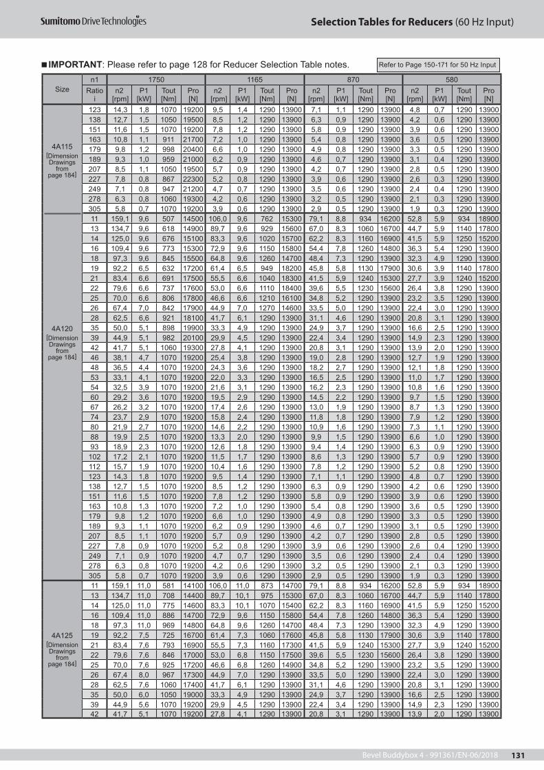
Bevel Buddybox 4 - 991361/EN-06/2018 131
Selection Tables for Reducers (60 Hz Input)
Sizen1 1750 1165 870 580
Ratio i
n2 [rpm]
P1 [kW]
Tout [Nm]
Pro [N]
n2 [rpm]
P1 [kW]
Tout [Nm]
Pro [N]
n2 [rpm]
P1 [kW]
Tout [Nm]
Pro [N]
n2 [rpm]
P1 [kW]
Tout [Nm]
Pro [N]
4A120[Dimension Drawings
frompage 184]
123 14,3 1,8 1070 19200 9,5 1,4 1290 13900 7,1 1,1 1290 13900 4,8 0,7 1290 13900 138 12,7 1,5 1050 19500 8,5 1,2 1290 13900 6,3 0,9 1290 13900 4,2 0,6 1290 13900151 11,6 1,5 1070 19200 7,8 1,2 1290 13900 5,8 0,9 1290 13900 3,9 0,6 1290 13900 163 10,8 1,1 911 21700 7,2 1,0 1290 13900 5,4 0,8 1290 13900 3,6 0,5 1290 13900179 9,8 1,2 998 20400 6,6 1,0 1290 13900 4,9 0,8 1290 13900 3,3 0,5 1290 13900 189 9,3 1,0 959 21000 6,2 0,9 1290 13900 4,6 0,7 1290 13900 3,1 0,4 1290 13900207 8,5 1,1 1050 19500 5,7 0,9 1290 13900 4,2 0,7 1290 13900 2,8 0,5 1290 13900 227 7,8 0,8 867 22300 5,2 0,8 1290 13900 3,9 0,6 1290 13900 2,6 0,3 1290 13900249 7,1 0,8 947 21200 4,7 0,7 1290 13900 3,5 0,6 1290 13900 2,4 0,4 1290 13900 278 6,3 0,8 1060 19300 4,2 0,6 1290 13900 3,2 0,5 1290 13900 2,1 0,3 1290 13900305 5,8 0,7 1070 19200 3,9 0,6 1290 13900 2,9 0,5 1290 13900 1,9 0,3 1290 13900 11 159,1 9,6 507 14500 106,0 9,6 762 15300 79,1 8,8 934 16200 52,8 5,9 934 1890013 134,7 9,6 618 14900 89,7 9,6 929 15600 67,0 8,3 1060 16700 44,7 5,9 1140 17800 14 125,0 9,6 676 15100 83,3 9,6 1020 15700 62,2 8,3 1160 16900 41,5 5,9 1250 1520016 109,4 9,6 773 15300 72,9 9,6 1150 15800 54,4 7,8 1260 14800 36,3 5,4 1290 13900 18 97,3 9,6 845 15500 64,8 9,6 1260 14700 48,4 7,3 1290 13900 32,3 4,9 1290 13900 19 92,2 6,5 632 17200 61,4 6,5 949 18200 45,8 5,8 1130 17900 30,6 3,9 1140 1780021 83,4 6,6 691 17500 55,5 6,6 1040 18300 41,5 5,9 1240 15300 27,7 3,9 1240 15200 22 79,6 6,6 737 17600 53,0 6,6 1110 18400 39,6 5,5 1230 15600 26,4 3,8 1290 13900 25 70,0 6,6 806 17800 46,6 6,6 1210 16100 34,8 5,2 1290 13900 23,2 3,5 1290 13900 26 67,4 7,0 842 17900 44,9 7,0 1270 14600 33,5 5,0 1290 13900 22,4 3,0 1290 1390028 62,5 6,6 921 18100 41,7 6,1 1290 13900 31,1 4,6 1290 13900 20,8 3,1 1290 13900 35 50,0 5,1 898 19900 33,3 4,9 1290 13900 24,9 3,7 1290 13900 16,6 2,5 1290 13900 39 44,9 5,1 982 20100 29,9 4,5 1290 13900 22,4 3,4 1290 13900 14,9 2,3 1290 13900 42 41,7 5,1 1060 19300 27,8 4,1 1290 13900 20,8 3,1 1290 13900 13,9 2,0 1290 1390046 38,1 4,7 1070 19200 25,4 3,8 1290 13900 19,0 2,8 1290 13900 12,7 1,9 1290 13900 48 36,5 4,4 1070 19200 24,3 3,6 1290 13900 18,2 2,7 1290 13900 12,1 1,8 1290 1390053 33,1 4,1 1070 19200 22,0 3,3 1290 13900 16,5 2,5 1290 13900 11,0 1,7 1290 13900 54 32,5 3,9 1070 19200 21,6 3,1 1290 13900 16,2 2,3 1290 13900 10,8 1,6 1290 1390060 29,2 3,6 1070 19200 19,5 2,9 1290 13900 14,5 2,2 1290 13900 9,7 1,5 1290 13900 67 26,2 3,2 1070 19200 17,4 2,6 1290 13900 13,0 1,9 1290 13900 8,7 1,3 1290 13900 74 23,7 2,9 1070 19200 15,8 2,4 1290 13900 11,8 1,8 1290 13900 7,9 1,2 1290 13900 80 21,9 2,7 1070 19200 14,6 2,2 1290 13900 10,9 1,6 1290 13900 7,3 1,1 1290 13900 88 19,9 2,5 1070 19200 13,3 2,0 1290 13900 9,9 1,5 1290 13900 6,6 1,0 1290 13900 93 18,9 2,3 1070 19200 12,6 1,8 1290 13900 9,4 1,4 1290 13900 6,3 0,9 1290 13900
102 17,2 2,1 1070 19200 11,5 1,7 1290 13900 8,6 1,3 1290 13900 5,7 0,9 1290 13900 112 15,7 1,9 1070 19200 10,4 1,6 1290 13900 7,8 1,2 1290 13900 5,2 0,8 1290 13900 123 14,3 1,8 1070 19200 9,5 1,4 1290 13900 7,1 1,1 1290 13900 4,8 0,7 1290 13900 138 12,7 1,5 1070 19200 8,5 1,2 1290 13900 6,3 0,9 1290 13900 4,2 0,6 1290 13900151 11,6 1,5 1070 19200 7,8 1,2 1290 13900 5,8 0,9 1290 13900 3,9 0,6 1290 13900 163 10,8 1,3 1070 19200 7,2 1,0 1290 13900 5,4 0,8 1290 13900 3,6 0,5 1290 13900179 9,8 1,2 1070 19200 6,6 1,0 1290 13900 4,9 0,8 1290 13900 3,3 0,5 1290 13900 189 9,3 1,1 1070 19200 6,2 0,9 1290 13900 4,6 0,7 1290 13900 3,1 0,5 1290 13900207 8,5 1,1 1070 19200 5,7 0,9 1290 13900 4,2 0,7 1290 13900 2,8 0,5 1290 13900 227 7,8 0,9 1070 19200 5,2 0,8 1290 13900 3,9 0,6 1290 13900 2,6 0,4 1290 13900249 7,1 0,9 1070 19200 4,7 0,7 1290 13900 3,5 0,6 1290 13900 2,4 0,4 1290 13900 278 6,3 0,8 1070 19200 4,2 0,6 1290 13900 3,2 0,5 1290 13900 2,1 0,3 1290 13900305 5,8 0,7 1070 19200 3,9 0,6 1290 13900 2,9 0,5 1290 13900 1,9 0,3 1290 13900
4A125[Dimension Drawings
frompage 184]
11 159,1 11,0 581 14100 106,0 11,0 873 14700 79,1 8,8 934 16200 52,8 5,9 934 1890013 134,7 11,0 708 14400 89,7 10,1 975 15300 67,0 8,3 1060 16700 44,7 5,9 1140 17800 14 125,0 11,0 775 14600 83,3 10,1 1070 15400 62,2 8,3 1160 16900 41,5 5,9 1250 1520016 109,4 11,0 886 14700 72,9 9,6 1150 15800 54,4 7,8 1260 14800 36,3 5,4 1290 13900 18 97,3 11,0 969 14800 64,8 9,6 1260 14700 48,4 7,3 1290 13900 32,3 4,9 1290 13900 19 92,2 7,5 725 16700 61,4 7,3 1060 17600 45,8 5,8 1130 17900 30,6 3,9 1140 1780021 83,4 7,6 793 16900 55,5 7,3 1160 17300 41,5 5,9 1240 15300 27,7 3,9 1240 15200 22 79,6 7,6 846 17000 53,0 6,8 1150 17500 39,6 5,5 1230 15600 26,4 3,8 1290 13900 25 70,0 7,6 925 17200 46,6 6,8 1260 14900 34,8 5,2 1290 13900 23,2 3,5 1290 13900 26 67,4 8,0 967 17300 44,9 7,0 1290 13900 33,5 5,0 1290 13900 22,4 3,0 1290 1390028 62,5 7,6 1060 17400 41,7 6,1 1290 13900 31,1 4,6 1290 13900 20,8 3,1 1290 13900 35 50,0 6,0 1050 19000 33,3 4,9 1290 13900 24,9 3,7 1290 13900 16,6 2,5 1290 13900 39 44,9 5,6 1070 19200 29,9 4,5 1290 13900 22,4 3,4 1290 13900 14,9 2,3 1290 13900 42 41,7 5,1 1070 19200 27,8 4,1 1290 13900 20,8 3,1 1290 13900 13,9 2,0 1290 13900
4A115[Dimension Drawings
frompage 184]
IMPORTANT: Please refer to page 128 for Reducer Selection Table notes. Refer to Page 150-171 for 50 Hz Input

Bevel Buddybox 4 - 991361/EN-06/2018132
Selection Tables for Reducers (60 Hz Input)
Sizen1 1750 1165 870 580
Ratio i
n2 [rpm]
P1 [kW]
Tout [Nm]
Pro [N]
n2 [rpm]
P1 [kW]
Tout [Nm]
Pro [N]
n2 [rpm]
P1 [kW]
Tout [Nm]
Pro [N]
n2 [rpm]
P1 [kW]
Tout [Nm]
Pro [N]
4A125[Dimension Drawings
frompage 184]
46 38,1 4,7 1070 19200 25,4 3,8 1290 13900 19,0 2,8 1290 13900 12,7 1,9 1290 13900 48 36,5 4,0 1070 19200 24,3 4,0 1290 13900 18,2 3,0 1290 13900 12,1 2,0 1290 1390053 33,1 4,1 1070 19200 22,0 3,3 1290 13900 16,5 2,5 1290 13900 11,0 1,7 1290 13900 54 32,5 3,9 1070 19200 21,6 3,4 1290 13900 16,2 2,3 1290 13900 10,8 1,6 1290 1390060 29,2 3,6 1070 19200 19,5 2,9 1290 13900 14,5 2,2 1290 13900 9,7 1,5 1290 13900 67 26,2 3,2 1070 19200 17,4 2,6 1290 13900 13,0 1,9 1290 13900 8,7 1,3 1290 13900 74 23,7 2,9 1070 19200 15,8 2,4 1290 13900 11,8 1,8 1290 13900 7,9 1,2 1290 13900 80 21,9 2,7 1070 19200 14,6 2,2 1290 13900 10,9 1,6 1290 13900 7,3 1,1 1290 13900 88 19,9 2,5 1070 19200 13,3 2,0 1290 13900 9,9 1,5 1290 13900 6,6 1,0 1290 13900 93 18,9 2,3 1070 19200 12,6 1,8 1290 13900 9,4 1,4 1290 13900 6,3 0,9 1290 13900
102 17,2 2,1 1070 19200 11,5 1,7 1290 13900 8,6 1,3 1290 13900 5,7 0,9 1290 13900 112 15,7 1,9 1070 19200 10,4 1,6 1290 13900 7,8 1,2 1290 13900 5,2 0,8 1290 13900 123 14,3 1,8 1070 19200 9,5 1,4 1290 13900 7,1 1,1 1290 13900 4,8 0,7 1290 13900 138 12,7 1,5 1070 19200 8,5 1,2 1290 13900 6,3 0,9 1290 13900 4,2 0,6 1290 13900151 11,6 1,5 1070 19200 7,8 1,2 1290 13900 5,8 0,9 1290 13900 3,9 0,6 1290 13900 163 10,8 1,3 1070 19200 7,2 1,1 1290 13900 5,4 0,8 1290 13900 3,6 0,5 1290 13900179 9,8 1,2 1070 19200 6,6 1,0 1290 13900 4,9 0,8 1290 13900 3,3 0,5 1290 13900 189 9,3 1,1 1070 19200 6,2 0,9 1290 13900 4,6 0,7 1290 13900 3,1 0,5 1290 13900207 8,5 1,1 1070 19200 5,7 0,9 1290 13900 4,2 0,7 1290 13900 2,8 0,5 1290 13900 227 7,8 0,9 1070 19200 5,2 0,8 1290 13900 3,9 0,6 1290 13900 2,6 0,4 1290 13900249 7,1 0,9 1070 19200 4,7 0,7 1290 13900 3,5 0,6 1290 13900 2,4 0,4 1290 13900 278 6,3 0,8 1070 19200 4,2 0,6 1290 13900 3,2 0,5 1290 13900 2,1 0,3 1290 13900305 5,8 0,7 1070 19200 3,9 0,6 1290 13900 2,9 0,5 1290 13900 1,9 0,3 1290 13900
4A140[Dimension Drawings
frompage 184]
11 159,1 19,0 1000 11800 106,0 15,7 1250 12700 79,1 12,1 1290 13900 52,8 8,1 1290 1390013 134,7 16,6 1070 12500 89,7 13,3 1290 13600 67,0 10,0 1290 13900 44,7 6,7 1290 13900 14 125,0 15,2 1070 13000 83,3 12,2 1290 13900 62,2 9,1 1290 13900 41,5 6,1 1290 1390016 109,4 13,3 1070 13700 72,9 10,7 1290 13900 54,4 8,0 1290 13900 36,3 5,4 1290 13900 18 97,3 12,1 1070 14300 64,8 9,8 1290 13900 48,4 7,3 1290 13900 32,3 4,9 1290 13900 19 92,2 11,1 1070 14900 61,4 8,9 1290 13900 45,8 6,7 1290 13900 30,6 4,4 1290 1390021 83,4 10,1 1070 15400 55,5 8,2 1290 13900 41,5 6,1 1290 13900 27,7 4,1 1290 13900 22 79,6 9,5 1070 15800 53,0 7,7 1290 13900 39,6 5,7 1290 13900 26,4 3,8 1290 13900 25 70,0 8,7 1070 16400 46,6 7,0 1290 13900 34,8 5,2 1290 13900 23,2 3,5 1290 13900 26 67,4 8,3 1070 16700 44,9 6,7 1290 13900 33,5 5,0 1290 13900 22,4 3,3 1290 1390028 62,5 7,6 1070 17300 41,7 6,1 1290 13900 31,1 4,6 1290 13900 20,8 3,1 1290 13900 35 50,0 6,1 1070 18900 33,3 4,9 1290 13900 24,9 3,7 1290 13900 16,6 2,5 1290 13900 39 44,9 5,6 1070 19200 29,9 4,5 1290 13900 22,4 3,4 1290 13900 14,9 2,3 1290 13900 42 41,7 5,1 1070 19200 27,8 4,1 1290 13900 20,8 3,1 1290 13900 13,9 2,0 1290 1390046 38,1 4,7 1070 19200 25,4 3,8 1290 13900 19,0 2,8 1290 13900 12,7 1,9 1290 13900 48 36,5 4,4 1070 19200 24,3 3,6 1290 13900 18,2 2,7 1290 13900 12,1 1,8 1290 1390053 33,1 4,1 1070 19200 22,0 3,3 1290 13900 16,5 2,5 1290 13900 11,0 1,7 1290 13900 54 32,5 3,9 1070 19200 21,6 3,1 1290 13900 16,2 2,3 1290 13900 10,8 1,6 1290 1390060 29,2 3,6 1070 19200 19,5 2,9 1290 13900 14,5 2,2 1290 13900 9,7 1,5 1290 13900 67 26,2 3,2 1070 19200 17,4 2,6 1290 13900 13,0 1,9 1290 13900 8,7 1,3 1290 13900 74 23,7 2,9 1070 19200 15,8 2,4 1290 13900 11,8 1,8 1290 13900 7,9 1,2 1290 13900 80 21,9 2,7 1070 19200 14,6 2,2 1290 13900 10,9 1,6 1290 13900 7,3 1,1 1290 13900 88 19,9 2,5 1070 19200 13,3 2,0 1290 13900 9,9 1,5 1290 13900 6,6 1,0 1290 13900 93 18,9 2,3 1070 19200 12,6 1,8 1290 13900 9,4 1,4 1290 13900 6,3 0,9 1290 13900
102 17,2 2,1 1070 19200 11,5 1,7 1290 13900 8,6 1,3 1290 13900 5,7 0,9 1290 13900 112 15,7 1,9 1070 19200 10,4 1,6 1290 13900 7,8 1,2 1290 13900 5,2 0,8 1290 13900 123 14,3 1,8 1070 19200 9,5 1,4 1290 13900 7,1 1,1 1290 13900 4,8 0,7 1290 13900 138 12,7 1,5 1070 19200 8,5 1,24 1290 13900 6,3 0,9 1290 13900 4,2 0,6 1290 13900151 11,6 1,5 1070 19200 7,8 1,2 1290 13900 5,8 0,9 1290 13900 3,9 0,6 1290 13900 163 10,8 1,3 1070 19200 7,2 1,1 1290 13900 5,4 0,8 1290 13900 3,6 0,5 1290 13900179 9,8 1,2 1070 19200 6,6 1,0 1290 13900 4,9 0,8 1290 13900 3,3 0,5 1290 13900 189 9,3 1,1 1070 19200 6,2 0,9 1290 13900 4,6 0,8 1290 13900 3,1 0,5 1290 13900207 8,5 1,1 1070 19200 5,7 0,9 1290 13900 4,2 0,7 1290 13900 2,8 0,5 1290 13900 227 7,8 0,9 1070 19200 5,2 0,8 1290 13900 3,9 0,6 1290 13900 2,6 0,4 1290 13900249 7,1 0,9 1070 19200 4,7 0,7 1290 13900 3,5 0,6 1290 13900 2,4 0,4 1290 13900 278 6,3 0,8 1070 19200 4,2 0,6 1290 13900 3,2 0,5 1290 13900 2,1 0,3 1290 13900305 5,8 0,7 1070 19200 3,9 0,6 1290 13900 2,9 0,5 1290 13900 1,9 0,3 1290 13900
4A145 11 159,1 20,2 1070 11400 106,0 15,7 1250 12700 79,1 12,1 1290 13900 52,8 8,1 1290 1390013 134,7 16,6 1070 12500 89,7 13,3 1290 13600 67,0 10,0 1290 13900 44,7 6,7 1290 13900
IMPORTANT: Please refer to page 128 for Reducer Selection Table notes. Refer to Page 150-171 for 50 Hz Input

Bevel Buddybox 4 - 991361/EN-06/2018 133
Selection Tables for Reducers (60 Hz Input)
Sizen1 1750 1165 870 580
Ratio i
n2 [rpm]
P1 [kW]
Tout [Nm]
Pro [N]
n2 [rpm]
P1 [kW]
Tout [Nm]
Pro [N]
n2 [rpm]
P1 [kW]
Tout [Nm]
Pro [N]
n2 [rpm]
P1 [kW]
Tout [Nm]
Pro [N]
4A145[Dimension Drawings
frompage 184]
14 125,0 15,2 1070 13000 83,3 12,2 1290 13900 62,2 9,1 1290 13900 41,5 6,1 1290 1390016 109,4 13,3 1070 13700 72,9 10,7 1290 13900 54,4 8,0 1290 13900 36,3 5,4 1290 13900 18 97,3 12,1 1070 14300 64,8 9,8 1290 13900 48,4 7,3 1290 13900 32,3 4,9 1290 13900 19 92,2 11,1 1070 14900 61,4 8,9 1290 13900 45,8 6,6 1290 13900 30,6 4,4 1290 1390021 83,4 10,1 1070 15400 55,5 8,2 1290 13900 41,5 6,1 1290 13900 27,7 4,1 1290 13900 22 79,6 9,5 1070 15800 53,0 7,7 1290 13900 39,6 5,7 1290 13900 26,4 3,8 1290 13900 25 70,0 8,7 1070 16400 46,6 7,0 1290 13900 34,8 5,2 1290 13900 23,2 3,5 1290 13900 26 67,4 8,3 1070 16700 44,9 6,7 1290 13900 33,5 5,0 1290 13900 22,4 3,3 1290 1390028 62,5 7,6 1070 17300 41,7 6,1 1290 13900 31,1 4,6 1290 13900 20,8 3,1 1290 13900 35 50,0 6,1 1070 18900 33,3 4,9 1290 13900 24,9 3,7 1290 13900 16,6 2,5 1290 13900 39 44,9 5,6 1070 19200 29,9 4,5 1290 13900 22,4 3,4 1290 13900 14,9 2,3 1290 13900 42 41,7 5,1 1070 19200 27,8 4,1 1290 13900 20,8 3,1 1290 13900 13,9 2,0 1290 1390046 38,1 4,7 1070 19200 25,4 3,8 1290 13900 19,0 2,8 1290 13900 12,7 1,9 1290 13900 48 36,5 4,4 1070 19200 24,3 3,6 1290 13900 18,2 2,7 1290 13900 12,1 1,8 1290 1390053 33,1 4,1 1070 19200 22,0 3,3 1290 13900 16,5 2,5 1290 13900 11,0 1,7 1290 13900 54 32,5 3,9 1070 19200 21,6 3,1 1290 13900 16,2 2,3 1290 13900 10,8 1,6 1290 1390060 29,2 3,6 1070 19200 19,5 2,9 1290 13900 14,5 2,2 1290 13900 9,7 1,5 1290 13900 67 26,2 3,2 1070 19200 17,4 2,6 1290 13900 13,0 1,9 1290 13900 8,7 1,3 1290 13900 74 23,7 2,9 1070 19200 15,8 2,3 1290 13900 11,8 1,7 1290 13900 7,9 1,2 1290 13900 80 21,9 2,7 1070 19200 14,6 2,2 1290 13900 10,9 1,6 1290 13900 7,3 1,1 1290 13900 88 19,9 2,5 1070 19200 13,3 2,0 1290 13900 9,9 1,5 1290 13900 6,6 1,0 1290 13900 93 18,9 2,3 1070 19200 12,6 1,8 1290 13900 9,4 1,4 1290 13900 6,3 0,9 1290 13900
102 17,2 2,1 1070 19200 11,5 1,7 1290 13900 8,6 1,3 1290 13900 5,7 0,9 1290 13900 112 15,7 1,9 1070 19200 10,4 1,6 1290 13900 7,8 1,2 1290 13900 5,2 0,8 1290 13900 123 14,3 1,8 1070 19200 9,5 1,4 1290 13900 7,1 1,1 1290 13900 4,8 0,7 1290 13900 138 12,7 1,5 1070 19200 8,5 1,2 1290 13900 6,3 0,9 1290 13900 4,2 0,6 1290 13900151 11,6 1,5 1070 19200 7,8 1,2 1290 13900 5,8 0,9 1290 13900 3,9 0,6 1290 13900 163 10,8 1,3 1070 19200 7,2 1,0 1290 13900 5,4 0,8 1290 13900 3,6 0,5 1290 13900179 9,8 1,2 1070 19200 6,6 1,0 1290 13900 4,9 0,8 1290 13900 3,3 0,5 1290 13900 189 9,3 1,1 1070 19200 6,2 0,9 1290 13900 4,6 0,7 1290 13900 3,1 0,5 1290 13900207 8,5 1,1 1070 19200 5,7 0,9 1290 13900 4,2 0,7 1290 13900 2,8 0,5 1290 13900 227 7,8 0,9 1070 19200 5,2 0,8 1290 13900 3,9 0,6 1290 13900 2,6 0,4 1290 13900249 7,1 0,9 1070 19200 4,7 0,7 1290 13900 3,5 0,6 1290 13900 2,4 0,4 1290 13900 278 6,3 0,8 1070 19200 4,2 0,6 1290 13900 3,2 0,5 1290 13900 2,1 0,3 1290 13900305 5,8 0,7 1070 19200 3,9 0,6 1290 13900 2,9 0,5 1290 13900 1,9 0,3 1290 13900
4B120[Dimension Drawings
frompage 184]
11 159,1 9,6 507 21100 106,0 9,6 762 23000 79,1 8,8 934 24700 52,8 5,9 934 2840013 134,7 9,6 618 22000 89,7 9,6 929 23900 67,0 8,3 1060 25800 44,7 5,9 1140 29400 14 125,0 9,6 676 22400 83,3 9,6 1020 24300 62,2 8,3 1160 26300 41,5 5,9 1250 3000016 109,4 9,6 773 23000 72,9 9,6 1150 24800 54,4 7,8 1260 27100 36,3 5,9 1420 30600 18 97,3 9,6 845 23500 64,8 9,6 1260 25200 48,4 7,8 1380 27500 32,3 5,9 1560 31100 19 92,2 6,5 632 25100 61,4 6,5 949 27400 45,8 5,8 1130 29500 30,6 3,9 1140 3390021 83,4 6,6 691 25700 55,5 6,6 1040 27900 41,5 5,9 1240 30000 27,7 3,9 1240 34500 22 79,6 6,6 737 26000 53,0 6,6 1110 28200 39,6 5,5 1230 30700 26,4 4,0 1360 34800 25 70,0 6,6 806 26500 46,6 6,6 1210 28700 34,8 5,5 1350 31200 23,2 4,0 1480 35400 26 67,4 6,5 842 26800 44,9 6,5 1270 28900 33,5 5,5 1410 31400 22,4 4,0 1550 3560028 62,5 6,6 921 27300 41,7 6,6 1380 29300 31,1 5,5 1550 31900 20,8 4,0 1700 36200 35 50,0 5,1 898 29500 33,3 5,1 1350 31900 24,9 4,6 1630 34200 16,6 3,1 1630 38100 39 44,9 5,1 982 30100 29,9 5,1 1480 32500 22,4 4,6 1780 34700 14,9 3,1 1780 36700 42 41,7 5,1 1060 30600 27,8 5,1 1590 32900 20,8 3,9 1630 36300 13,9 2,6 1630 3810046 38,1 5,1 1160 31100 25,4 5,1 1740 33300 19,0 3,9 1780 36700 12,7 2,6 1780 36700 48 36,5 5,1 1220 31400 24,3 4,5 1630 34500 18,2 3,4 1630 38100 12,1 2,2 1630 3810053 33,1 5,1 1340 31900 22,0 4,5 1780 34900 16,5 3,4 1780 36700 11,0 2,3 1780 36700 54 32,5 5,1 1390 32100 21,6 3,9 1620 36100 16,2 2,9 1610 38300 10,8 2,0 1620 3830060 29,2 5,1 1520 32600 19,5 4,0 1770 36600 14,5 3,0 1770 36900 9,7 2,0 1770 36900 67 26,2 4,0 1340 34800 17,4 3,2 1620 38200 13,0 2,4 1620 38200 8,7 1,6 1620 38200 74 23,7 4,0 1460 35400 15,8 3,2 1770 36800 11,8 2,4 1770 36800 7,9 1,6 1770 36800 80 21,9 3,1 1240 37400 14,6 2,7 1630 38100 10,9 2,1 1630 38100 7,3 1,4 1630 38100 88 19,9 3,1 1360 38100 13,3 2,7 1780 36700 9,9 2,1 1780 36700 6,6 1,4 1780 36700 93 18,9 3,0 1400 38700 12,6 2,3 1610 38300 9,4 1,7 1620 38300 6,3 1,2 1620 38300
102 17,2 3,0 1530 39000 11,5 2,3 1770 36900 8,6 1,8 1770 36900 5,7 1,2 1770 36900 112 15,7 2,5 1410 39900 10,4 2,0 1630 38100 7,8 1,5 1630 38100 5,2 1,0 1630 38100 123 14,3 2,5 1540 38900 9,5 2,0 1780 36700 7,1 1,5 1780 36700 4,8 1,0 1780 36700
IMPORTANT: Please refer to page 128 for Reducer Selection Table notes. Refer to Page 150-171 for 50 Hz Input
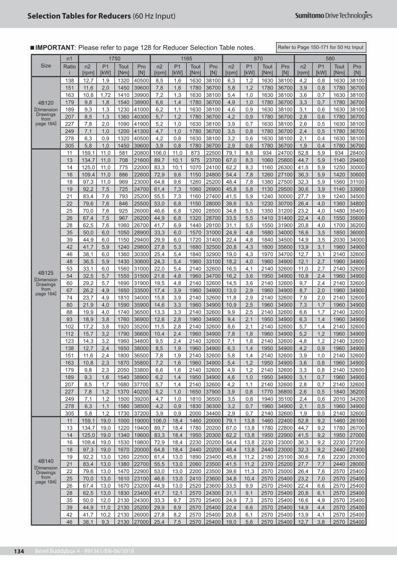
Bevel Buddybox 4 - 991361/EN-06/2018134
Selection Tables for Reducers (60 Hz Input)
Sizen1 1750 1165 870 580
Ratio i
n2 [rpm]
P1 [kW]
Tout [Nm]
Pro [N]
n2 [rpm]
P1 [kW]
Tout [Nm]
Pro [N]
n2 [rpm]
P1 [kW]
Tout [Nm]
Pro [N]
n2 [rpm]
P1 [kW]
Tout [Nm]
Pro [N]
4B120[Dimension Drawings
frompage 184]
138 12,7 1,9 1320 40500 8,5 1,6 1630 38100 6,3 1,2 1630 38100 4,2 0,8 1630 38100151 11,6 2,0 1450 39600 7,8 1,6 1780 36700 5,8 1,2 1780 36700 3,9 0,8 1780 36700 163 10,8 1,72 1410 39900 7,2 1,3 1630 38100 5,4 1,0 1630 38100 3,6 0,7 1630 38100179 9,8 1,8 1540 38900 6,6 1,4 1780 36700 4,9 1,0 1780 36700 3,3 0,7 1780 36700 189 9,3 1,3 1230 41000 6,2 1,1 1630 38100 4,6 0,9 1630 38100 3,1 0,6 1630 38100207 8,5 1,3 1360 40300 5,7 1,2 1780 36700 4,2 0,9 1780 36700 2,8 0,6 1780 36700 227 7,8 2,0 1090 41900 5,2 1,0 1630 38100 3,9 0,7 1630 38100 2,6 0,5 1630 38100249 7,1 1,0 1200 41300 4,7 1,0 1780 36700 3,5 0,8 1780 36700 2,4 0,5 1780 36700 278 6,3 0,9 1320 40500 4,2 0,8 1630 38100 3,2 0,6 1630 38100 2,1 0,4 1630 38100305 5,8 1,0 1450 39600 3,9 0,8 1780 36700 2,9 0,6 1780 36700 1,9 0,4 1780 36700
4B125[Dimension Drawings
frompage 184]
11 159,1 11,0 581 20800 106,0 11,0 873 22500 79,1 8,8 934 24700 52,8 5,9 934 2840013 134,7 11,0 708 21600 89,7 10,1 975 23700 67,0 8,3 1060 25800 44,7 5,9 1140 29400 14 125,0 11,0 775 22000 83,3 10,1 1070 24100 62,2 8,3 1160 26300 41,5 5,9 1250 3000016 109,4 11,0 886 22600 72,9 9,6 1150 24800 54,4 7,8 1260 27100 36,3 5,9 1420 30600 18 97,3 11,0 969 23000 64,8 9,6 1260 25200 48,4 7,8 1380 27500 32,3 5,9 1560 31100 19 92,2 7,5 725 24700 61,4 7,3 1060 26900 45,8 5,8 1130 29500 30,6 3,9 1140 3390021 83,4 7,6 793 25200 55,5 7,3 1160 27400 41,5 5,9 1240 30000 27,7 3,9 1240 34500 22 79,6 7,6 846 25500 53,0 6,8 1150 28000 39,6 5,5 1230 30700 26,4 4,0 1360 34800 25 70,0 7,6 925 26000 46,6 6,8 1260 28500 34,8 5,5 1350 31200 23,2 4,0 1480 35400 26 67,4 7,5 967 26200 44,9 6,8 1320 28700 33,5 5,5 1410 31400 22,4 4,0 1550 3560028 62,5 7,6 1060 26700 41,7 6,9 1440 29100 31,1 5,5 1550 31900 20,8 4,0 1700 36200 35 50,0 6,0 1050 28900 33,3 6,0 1570 31000 24,9 4,8 1680 34000 16,6 3,5 1850 36000 39 44,9 6,0 1150 29400 29,9 6,0 1720 31400 22,4 4,8 1840 34500 14,9 3,5 2030 34000 42 41,7 5,9 1240 29800 27,8 5,3 1680 32500 20,8 4,3 1800 35600 13,9 3,1 1960 3490046 38,1 6,0 1360 30300 25,4 5,4 1840 32900 19,0 4,3 1970 34700 12,7 3,1 2140 32600 48 36,5 5,9 1430 30600 24,3 5,4 1960 33100 18,2 4,0 1960 34900 12,1 2,7 1960 3490053 33,1 6,0 1560 31000 22,0 5,4 2140 32600 16,5 4,1 2140 32600 11,0 2,7 2140 32600 54 32,5 5,7 1550 31500 21,6 4,8 1960 34700 16,2 3,6 1950 34900 10,8 2,4 1960 3490060 29,2 5,7 1690 31900 19,5 4,8 2140 32600 14,5 3,6 2140 32600 9,7 2,4 2140 32600 67 26,2 4,9 1650 33500 17,4 3,9 1960 34900 13,0 2,9 1960 34900 8,7 2,0 1960 34900 74 23,7 4,9 1810 34000 15,8 3,9 2140 32600 11,8 2,9 2140 32600 7,9 2,0 2140 32600 80 21,9 4,0 1590 35900 14,6 3,3 1960 34900 10,9 2,5 1960 34900 7,3 1,7 1960 34900 88 19,9 4,0 1740 36500 13,3 3,3 2140 32600 9,9 2,5 2140 32600 6,6 1,7 2140 32600 93 18,9 3,8 1760 36900 12,6 2,8 1960 34900 9,4 2,1 1950 34900 6,3 1,4 1960 34900
102 17,2 3,8 1920 35200 11,5 2,8 2140 32600 8,6 2,1 2140 32600 5,7 1,4 2140 32600 112 15,7 3,2 1790 36600 10,4 2,4 1960 34900 7,8 1,8 1960 34900 5,2 1,2 1960 34900 123 14,3 3,2 1960 34800 9,5 2,4 2140 32600 7,1 1,8 2140 32600 4,8 1,2 2140 32600 138 12,7 2,4 1650 38000 8,5 1,9 1960 34900 6,3 1,4 1950 34900 4,2 0,9 1960 34900151 11,6 2,4 1800 36500 7,8 1,9 2140 32600 5,8 1,4 2140 32600 3,9 1,0 2140 32600 163 10,8 2,3 1870 35800 7,2 1,6 1960 34900 5,4 1,2 1950 34900 3,6 0,8 1960 34900179 9,8 2,3 2050 33800 6,6 1,6 2140 32600 4,9 1,2 2140 32600 3,3 0,8 2140 32600 189 9,3 1,6 1540 38900 6,2 1,4 1950 34900 4,6 1,0 1950 34900 3,1 0,7 1960 34900207 8,5 1,7 1680 37700 5,7 1,4 2140 32600 4,2 1,1 2140 32600 2,8 0,7 2140 32600 227 7,8 1,2 1370 40200 5,2 1,0 1650 37900 3,9 0,8 1770 36800 2,6 0,5 1840 36200249 7,1 1,2 1500 39200 4,7 1,0 1810 36500 3,5 0,8 1940 35100 2,4 0,6 2010 34200 278 6,3 1,1 1580 38500 4,2 0,9 1830 36300 3,2 0,7 1960 34900 2,1 0,5 1960 34900305 5,8 1,2 1730 37200 3,9 0,9 2000 34400 2,9 0,7 2140 32600 1,9 0,5 2140 32600
4B140[Dimension Drawings
frompage 184]
11 159,1 19,0 1000 19000 106,0 18,4 1460 20000 79,1 13,8 1460 22400 52,8 9,2 1460 2610013 134,7 19,0 1220 19400 89,7 18,4 1780 20200 67,0 13,8 1780 22800 44,7 9,2 1780 26700 14 125,0 19,0 1340 19600 83,3 18,4 1950 20300 62,2 13,8 1950 22900 41,5 9,2 1950 2700016 109,4 19,0 1530 19800 72,9 18,4 2230 20200 54,4 13,8 2230 23000 36,3 9,2 2230 27200 18 97,3 19,0 1670 20000 64,8 18,4 2440 20200 48,4 13,8 2440 23000 32,3 9,2 2440 27400 19 92,2 13,0 1260 22500 61,4 13,0 1890 23400 45,8 11,2 2180 25100 30,6 7,6 2230 2930021 83,4 13,0 1380 22700 55,5 13,0 2060 23500 41,5 11,2 2370 25200 27,7 7,7 2440 28000 22 79,6 13,0 1470 22900 53,0 13,0 2200 23500 39,6 11,3 2570 25000 26,4 7,6 2570 25400 25 70,0 13,0 1610 23100 46,6 13,0 2410 23600 34,8 10,4 2570 25400 23,2 7,0 2570 25400 26 67,4 13,0 1670 23200 44,9 13,0 2520 23600 33,5 9,9 2570 25400 22,4 6,6 2570 2540028 62,5 13,0 1830 23400 41,7 12,1 2570 24300 31,1 9,1 2570 25400 20,8 6,1 2570 25400 35 50,0 12,0 2130 24300 33,3 9,7 2570 25400 24,9 7,3 2570 25400 16,6 4,9 2570 25400 39 44,9 11,0 2130 25200 29,9 8,9 2570 25400 22,4 6,6 2570 25400 14,9 4,4 2570 25400 42 41,7 10,2 2130 26000 27,8 8,2 2570 25400 20,8 6,1 2570 25400 13,9 4,1 2570 2540046 38,1 9,3 2130 27000 25,4 7,5 2570 25400 19,0 5,6 2570 25400 12,7 3,8 2570 25400
IMPORTANT: Please refer to page 128 for Reducer Selection Table notes. Refer to Page 150-171 for 50 Hz Input

Bevel Buddybox 4 - 991361/EN-06/2018 135
Selection Tables for Reducers (60 Hz Input)
Sizen1 1750 1165 870 580
Ratio i
n2 [rpm]
P1 [kW]
Tout [Nm]
Pro [N]
n2 [rpm]
P1 [kW]
Tout [Nm]
Pro [N]
n2 [rpm]
P1 [kW]
Tout [Nm]
Pro [N]
n2 [rpm]
P1 [kW]
Tout [Nm]
Pro [N]
4B140[Dimension Drawings
frompage 184]
48 36,5 8,8 2130 27600 24,3 7,1 2570 25400 18,2 5,3 2570 25400 12,1 3,5 2570 2540053 33,1 8,1 2130 28600 22,0 6,5 2570 25400 16,5 4,9 2570 25400 11,0 3,3 2570 25400 54 32,5 7,8 2130 29000 21,6 6,3 2570 25400 16,2 4,7 2570 25400 10,8 3,1 2570 2540060 29,2 7,2 2130 30000 19,5 5,8 2570 25400 14,5 4,3 2570 25400 9,7 2,9 2570 25400 67 26,2 6,3 2130 31400 17,4 5,1 2570 25400 13,0 3,8 2570 25400 8,7 2,6 2570 25400 74 23,7 5,8 2130 32600 15,8 4,7 2570 25400 11,8 3,5 2570 25400 7,9 2,3 2570 25400 80 21,9 5,3 2130 32700 14,6 4,3 2570 25400 10,9 3,2 2570 25400 7,3 2,2 2570 25400 88 19,9 4,9 2130 32700 13,3 3,9 2570 25400 9,9 2,9 2570 25400 6,6 2,0 2570 25400 93 18,9 4,6 2130 32700 12,6 3,7 2570 25400 9,4 2,7 2570 25400 6,3 1,8 2570 25400
102 17,2 4,2 2130 32700 11,5 3,4 2570 25400 8,6 2,5 2570 25400 5,7 1,7 2570 25400 112 15,7 3,8 2130 32700 10,4 3,1 2570 25400 7,8 2,3 2570 25400 5,2 1,6 2570 25400 123 14,3 3,5 2130 32700 9,5 2,8 2570 25400 7,1 2,1 2570 25400 4,8 1,4 2570 25400 138 12,7 3,1 2130 32700 8,5 2,5 2570 25400 6,3 1,9 2570 25400 4,2 1,2 2570 25400151 11,6 2,9 2130 32700 7,8 2,3 2570 25400 5,8 1,7 2570 25400 3,9 1,2 2570 25400 163 10,8 2,6 2130 32700 7,2 2,1 2570 25400 5,4 1,6 2570 25400 3,6 1,0 2570 25400179 9,8 2,4 2130 32700 6,6 1,9 2570 25400 4,9 1,5 2570 25400 3,3 1,0 2570 25400 189 9,3 2,2 2130 32700 6,2 1,8 2570 25400 4,6 1,3 2570 25400 3,1 0,9 2570 25400207 8,5 2,1 2130 32700 5,7 1,7 2570 25400 4,2 1,3 2570 25400 2,8 0,9 2570 25400 227 7,8 1,9 2130 32700 5,2 1,5 2570 25400 3,9 1,1 2570 25400 2,6 0,8 2570 25400249 7,1 1,7 2130 32700 4,7 1,4 2570 25400 3,5 1,1 2570 25400 2,4 0,7 2570 25400 278 6,3 1,5 2130 32700 4,2 1,2 2570 25400 3,2 0,9 2570 25400 2,1 0,6 2570 25400305 5,8 1,4 2130 32700 3,9 1,2 2570 25400 2,9 0,9 2570 25400 1,9 0,6 2570 25400
4B145[Dimension Drawings
frompage 184]
11 159,1 22,0 1160 18300 106,0 18,4 1460 20000 79,1 13,8 1460 22400 52,8 9,2 1460 2610013 134,7 22,0 1420 18600 89,7 18,4 1780 20200 67,0 13,8 1780 22800 44,7 9,2 1780 26700 14 125,0 22,0 1550 18700 83,3 18,4 1950 20300 62,2 13,8 1950 22900 41,5 9,2 1950 2700016 109,4 22,0 1770 18800 72,9 18,4 2230 20200 54,4 13,8 2230 23000 36,3 9,2 2230 27200 18 97,3 22,0 1940 18800 64,8 18,4 2440 20200 48,4 13,8 2440 23000 32,3 9,2 2440 27400 19 92,2 15,1 1460 21600 61,4 13,9 2020 22800 45,8 11,2 2180 25100 30,6 7,6 2230 2930021 83,4 15,1 1600 21800 55,5 13,9 2210 22900 41,5 11,2 2370 25200 27,7 7,7 2440 28000 22 79,6 15,1 1710 21800 53,0 15,1 2560 22000 39,6 11,3 2570 25000 26,4 7,6 2570 25400 25 70,0 15,1 1870 22000 46,6 13,9 2570 22900 34,8 10,4 2570 25400 23,2 7,0 2570 25400 26 67,4 15,1 1940 22000 44,9 13,3 2570 23400 33,5 9,9 2570 25400 22,4 6,6 2570 2540028 62,5 15,1 2130 22100 41,7 12,1 2570 24300 31,1 9,1 2570 25400 20,8 6,1 2570 25400 35 50,0 12,0 2130 24300 33,3 9,7 2570 25400 24,9 7,3 2570 25400 16,6 4,9 2570 25400 39 44,9 11,0 2130 25200 29,9 8,9 2570 25400 22,4 6,6 2570 25400 14,9 4,4 2570 25400 42 41,7 10 2130 26000 27,8 8,0 2570 25400 20,8 6,0 2570 25400 13,9 4,0 2570 2540046 38,1 9,3 2130 27000 25,4 7,5 2570 25400 19,0 5,6 2570 25400 12,7 3,8 2570 25400 48 36,5 8,8 2130 27600 24,3 7,1 2570 25400 18,2 5,3 2570 25400 12,1 3,5 2570 2540053 33,1 8,1 2130 28600 22,0 6,5 2570 25400 16,5 4,9 2570 25400 11,0 3,3 2570 25400 54 32,5 7,8 2130 29000 21,6 6,3 2570 25400 16,2 4,7 2570 25400 10,8 3,1 2570 2540060 29,2 7,2 2130 30000 19,5 5,8 2570 25400 14,5 4,3 2570 25400 9,7 2,9 2570 25400 67 26,2 6,3 2130 31400 17,4 5,1 2570 25400 13,0 3,8 2570 25400 8,7 2,6 2570 25400 74 23,7 5,8 2130 32600 15,8 4,7 2570 25400 11,8 3,5 2570 25400 7,9 2,3 2570 25400 80 21,9 5,3 2130 32700 14,6 4,3 2570 25400 10,9 3,2 2570 25400 7,3 2,2 2570 25400 88 19,9 4,9 2130 32700 13,3 3,9 2570 25400 9,9 2,9 2570 25400 6,6 2,0 2570 25400 93 18,9 4,6 2130 32700 12,6 3,7 2570 25400 9,4 2,7 2570 25400 6,3 1,8 2570 25400
102 17,2 4,2 2130 32700 11,5 3,4 2570 25400 8,6 2,5 2570 25400 5,7 1,7 2570 25400 112 15,7 3,8 2130 32700 10,4 3,1 2570 25400 7,8 2,3 2570 25400 5,2 1,6 2570 25400 123 14,3 3,5 2130 32700 9,5 2,8 2570 25400 7,1 2,1 2570 25400 4,8 1,4 2570 25400 138 12,7 3,1 2130 32700 8,5 2,5 2570 25400 6,3 1,9 2570 25400 4,2 1,2 2570 25400151 11,6 2,9 2130 32700 7,8 2,3 2570 25400 5,8 1,7 2570 25400 3,9 1,2 2570 25400 163 10,8 2,6 2130 32700 7,2 2,1 2570 25400 5,4 1,6 2570 25400 3,6 1,0 2570 25400179 9,8 2,4 2130 32700 6,6 1,9 2570 25400 4,9 1,5 2570 25400 3,3 1,0 2570 25400 189 9,3 2,2 2130 32700 6,2 1,8 2570 25400 4,6 1,3 2570 25400 3,1 0,9 2570 25400207 8,5 2,1 2130 32700 5,7 1,7 2570 25400 4,2 1,3 2570 25400 2,8 0,9 2570 25400 227 7,8 1,9 2130 32700 5,2 1,5 2570 25400 3,9 1,1 2570 25400 2,6 0,8 2570 25400249 7,1 1,7 2130 32700 4,7 1,4 2570 25400 3,5 1,1 2570 25400 2,4 0,7 2570 25400 278 6,3 1,5 2130 32700 4,2 1,2 2570 25400 3,2 0,9 2570 25400 2,1 0,6 2570 25400305 5,8 1,4 2130 32700 3,9 1,2 2570 25400 2,9 0,9 2570 25400 1,9 0,6 2570 25400
4B16011 159,1 25,3 1340 17500 106,0 23,3 1850 18400 79,1 17,4 1850 20800 52,8 11,6 1850 2450013 134,7 25,3 1630 17700 89,7 23,3 2250 18200 67,0 17,4 2250 20700 44,7 11,6 2250 2470014 125,0 25,3 1780 17700 83,3 23,3 2470 18100 62,2 17,4 2470 20800 41,5 11,6 2470 24800
IMPORTANT: Please refer to page 128 for Reducer Selection Table notes. Refer to Page 150-171 for 50 Hz Input

Bevel Buddybox 4 - 991361/EN-06/2018136
Selection Tables for Reducers (60 Hz Input)
Sizen1 1750 1165 870 580
Ratio i
n2 [rpm]
P1 [kW]
Tout [Nm]
Pro [N]
n2 [rpm]
P1 [kW]
Tout [Nm]
Pro [N]
n2 [rpm]
P1 [kW]
Tout [Nm]
Pro [N]
n2 [rpm]
P1 [kW]
Tout [Nm]
Pro [N]
4B160[Dimension Drawings
frompage 184]
16 109,4 25,3 2040 17600 72,9 21,3 2570 18800 54,4 15,9 2570 21500 36,3 10,6 2570 2540018 97,3 24,2 2130 18000 64,8 19,4 2570 19700 48,4 14,5 2570 22500 32,3 9,7 2570 2540019 92,2 22,0 2130 18800 61,4 17,7 2570 20500 45,8 13,2 2570 23400 30,6 8,8 2570 2540021 83,4 20,2 2130 19500 55,5 16,2 2570 21400 41,5 12,1 2570 24300 27,7 8,1 2570 2540022 79,6 18,9 2130 20000 53,0 15,2 2570 21900 39,6 11,3 2570 25000 26,4 7,6 2570 2540025 70,0 17,3 2130 20900 46,6 13,9 2570 22900 34,8 10,4 2570 25400 23,2 7,0 2570 2540026 67,4 16,5 2130 21300 44,9 13,3 2570 23400 33,5 9,9 2570 25400 22,4 6,6 2570 2540028 62,5 15,1 2130 22100 41,7 12,1 2570 24300 31,1 9,1 2570 25400 20,8 6,1 2570 2540035 50,0 12,0 2130 24300 33,3 9,7 2570 25400 24,9 7,3 2570 25400 16,6 4,9 2570 2540039 44,9 11,0 2130 25200 29,9 8,9 2570 25400 22,4 6,6 2570 25400 14,9 4,4 2570 2540042 41,7 10,2 2130 26000 27,8 8,1 2570 25400 20,8 6,1 2570 25400 13,9 4,1 2570 2540046 38,1 9,3 2130 27000 25,4 7,5 2570 25400 19,0 5,6 2570 25400 12,7 3,8 2570 2540048 36,5 8,8 2130 27600 24,3 7,1 2570 25400 18,2 5,3 2570 25400 12,1 3,5 2570 2540053 33,1 8,1 2130 28600 22,0 6,5 2570 25400 16,5 4,9 2570 25400 11,0 3,3 2570 2540054 32,5 7,8 2130 29000 21,6 6,3 2570 25400 16,2 4,7 2570 25400 10,8 3,1 2570 2540060 29,2 7,2 2130 30000 19,5 5,8 2570 25400 14,5 4,3 2570 25400 9,7 2,9 2570 2540067 26,2 6,3 2130 31400 17,4 5,1 2570 25400 13,0 3,8 2570 25400 8,7 2,6 2570 2540074 23,7 5,8 2130 32600 15,8 4,7 2570 25400 11,8 3,5 2570 25400 7,9 2,3 2570 2540080 21,9 5,3 2130 32700 14,6 4,3 2570 25400 10,9 3,2 2570 25400 7,3 2,2 2570 2540088 19,9 4,9 2130 32700 13,3 3,9 2570 25400 9,9 2,9 2570 25400 6,6 2,0 2570 2540093 18,9 4,6 2130 32700 12,6 3,7 2570 25400 9,4 2,7 2570 25400 6,3 1,8 2570 25400102 17,2 4,2 2130 32700 11,5 3,4 2570 25400 8,6 2,5 2570 25400 5,7 1,7 2570 25400112 15,7 3,8 2130 32700 10,4 3,1 2570 25400 7,8 2,3 2570 25400 5,2 1,6 2570 25400123 14,3 3,5 2130 32700 9,5 2,8 2570 25400 7,1 2,1 2570 25400 4,8 1,4 2570 25400138 12,7 3,1 2130 32700 8,5 2,5 2570 25400 6,3 1,9 2570 25400 4,2 1,2 2570 25400151 11,6 2,9 2130 32700 7,8 2,3 2570 25400 5,8 1,7 2570 25400 3,9 1,2 2570 25400163 10,8 2,6 2130 32700 7,2 2,1 2570 25400 5,4 1,6 2570 25400 3,6 1,0 2570 25400179 9,8 2,4 2130 32700 6,6 1,9 2570 25400 4,9 1,5 2570 25400 3,3 1,0 2570 25400189 9,3 2,2 2130 32700 6,2 1,8 2570 25400 4,6 1,3 2570 25400 3,1 0,9 2570 25400207 8,5 2,1 2130 32700 5,7 1,7 2570 25400 4,2 1,3 2570 25400 2,8 0,9 2570 25400227 7,8 1,9 2130 32700 5,2 1,5 2570 25400 3,9 1,1 2570 25400 2,6 0,8 2570 25400249 7,1 1,7 2130 32700 4,7 1,4 2570 25400 3,5 1,1 2570 25400 2,4 0,7 2570 25400278 6,3 1,5 2130 32700 4,2 1,2 2570 25400 3,2 0,9 2570 25400 2,1 0,6 2570 25400305 5,8 1,4 2130 32700 3,9 1,2 2570 25400 2,9 0,9 2570 25400 1,9 0,6 2570 25400
4B165[Dimension Drawings
frompage 184]
11 159,1 29,0 1530 16700 106,0 23,3 1850 18400 79,1 17,4 1850 20800 52,8 11,6 1850 2450013 134,7 29,0 1870 16700 89,7 23,3 2250 18200 67,0 17,4 2250 20700 44,7 11,6 2250 2470014 125,0 29,0 2040 16600 83,3 23,3 2470 18100 62,2 17,4 2470 20800 41,5 11,6 2470 2480016 109,4 26,5 2130 17200 72,9 21,3 2570 18800 54,4 15,9 2570 21500 36,3 10,6 2570 2540018 97,3 24,2 2130 18000 64,8 19,4 2570 19700 48,4 14,5 2570 22500 32,3 9,7 2570 2540019 92,2 22 2130 18800 61,4 17,7 2570 20500 45,8 13,2 2570 23400 30,6 8,8 2570 2540021 83,4 20,2 2130 19500 55,5 16,2 2570 21400 41,5 12,1 2570 24300 27,7 8,1 2570 2540022 79,6 18,9 2130 20000 53,0 15,2 2570 21900 39,6 11,3 2570 25000 26,4 7,6 2570 2540025 70,0 17,3 2130 20900 46,6 13,9 2570 22900 34,8 10,4 2570 25400 23,2 7,0 2570 2540026 67,4 16,5 2130 21300 44,9 13,3 2570 23400 33,5 9,9 2570 25400 22,4 6,6 2570 2540028 62,5 15,1 2130 22100 41,7 12,1 2570 24300 31,1 9,1 2570 25400 20,8 6,1 2570 2540035 50,0 12,0 2130 24300 33,3 9,7 2570 25400 24,9 7,3 2570 25400 16,6 4,9 2570 2540039 44,9 11,0 2130 25200 29,9 8,9 2570 25400 22,4 6,6 2570 25400 14,9 4,4 2570 2540042 41,7 10,2 2130 26000 27,8 8,2 2570 25400 20,8 6,1 2570 25400 13,9 4,1 2570 2540046 38,1 9,3 2130 27600 25,4 7,5 2570 25400 19,0 5,6 2570 25400 12,7 3,8 2570 2540048 36,5 8,8 2130 26000 24,3 7,1 2570 25400 18,2 5,3 2570 25400 12,1 3,5 2570 2540053 33,1 8,1 2130 28600 22,0 6,5 2570 25400 16,5 4,9 2570 25400 11,0 3,3 2570 2540054 32,5 7,8 2130 29000 21,6 6,3 2570 25400 16,2 4,7 2570 25400 10,8 3,1 2570 2540060 29,2 7,2 2130 30000 19,5 5,8 2570 25400 14,5 4,3 2570 25400 9,7 2,9 2570 2540067 26,2 6,3 2130 31400 17,4 5,1 2570 25400 13,0 3,8 2570 25400 8,7 2,6 2570 2540074 23,7 5,8 2130 32600 15,8 4,7 2570 25400 11,8 3,5 2570 25400 7,9 2,3 2570 2540080 21,9 5,3 2130 32700 14,6 4,3 2570 25400 10,9 3,2 2570 25400 7,3 2,2 2570 2540088 19,9 4,9 2130 32700 13,3 3,9 2570 25400 9,9 2,9 2570 25400 6,6 2,0 2570 2540093 18,9 4,6 2130 32700 12,6 3,7 2570 25400 9,4 2,7 2570 25400 6,3 1,8 2570 25400
102 17,2 4,2 2130 32700 11,5 3,4 2570 25400 8,6 2,5 2570 25400 5,7 1,7 2570 25400112 15,7 3,8 2130 32700 10,4 3,1 2570 25400 7,8 2,3 2570 25400 5,2 1,6 2570 25400123 14,3 3,5 2130 32700 9,5 2,8 2570 25400 7,1 2,1 2570 25400 4,8 1,4 2570 25400138 12,7 3,1 2130 32700 8,5 2,5 2570 25400 6,3 1,9 2570 25400 4,2 1,2 2570 25400
IMPORTANT: Please refer to page 128 for Reducer Selection Table notes. Refer to Page 150-171 for 50 Hz Input

Bevel Buddybox 4 - 991361/EN-06/2018 137
Selection Tables for Reducers (60 Hz Input)
Sizen1 1750 1165 870 580
Ratio i
n2 [rpm]
P1 [kW]
Tout [Nm]
Pro [N]
n2 [rpm]
P1 [kW]
Tout [Nm]
Pro [N]
n2 [rpm]
P1 [kW]
Tout [Nm]
Pro [N]
n2 [rpm]
P1 [kW]
Tout [Nm]
Pro [N]
4B165[Dimension Drawings
frompage 184]
151 11,6 2,9 2130 32700 7,8 2,3 2570 25400 5,8 1,7 2570 25400 3,9 1,2 2570 25400163 10,8 2,6 2130 32700 7,2 2,1 2570 25400 5,4 1,6 2570 25400 3,6 1,0 2570 25400179 9,8 2,4 2130 32700 6,6 1,9 2570 25400 4,9 1,5 2570 25400 3,3 1,0 2570 25400189 9,3 2,2 2130 32700 6,2 1,8 2570 25400 4,6 1,3 2570 25400 3,1 0,9 2570 25400207 8,5 2,1 2130 32700 5,7 1,7 2570 25400 4,2 1,3 2570 25400 2,8 0,9 2570 25400227 7,8 1,9 2130 32700 5,2 1,5 2570 25400 3,9 1,1 2570 25400 2,6 0,8 2570 25400249 7,1 1,7 2130 32700 4,7 1,4 2570 25400 3,5 1,1 2570 25400 2,4 0,7 2570 25400278 6,3 1,5 2130 32700 4,2 1,2 2570 25400 3,2 0,9 2570 25400 2,1 0,6 2570 25400305 5,8 1,4 2130 32700 3,9 1,2 2570 25400 2,9 0,9 2570 25400 1,9 0,6 2570 25400
4C140[Dimension Drawings
frompage 184]
11 159,1 19,0 1000 28200 106,0 18,4 1460 30600 79,1 13,8 1460 33900 52,8 9,2 1460 3900013 134,7 19,0 1220 29300 89,7 18,4 1780 31600 67,0 13,8 1780 35100 44,7 9,2 1780 4050014 125,0 19,0 1340 29800 83,3 18,4 1950 32000 62,2 13,8 1950 35600 41,5 9,2 1950 4120016 109,4 19,0 1530 30500 72,9 18,4 2230 32500 54,4 13,8 2230 36300 36,3 9,2 2230 4210018 97,3 19,0 1670 31000 64,8 18,4 2440 32900 48,4 13,8 2440 36800 32,3 9,2 2440 4270019 92,2 13,0 1260 33600 61,4 13,0 1890 36200 45,8 11,2 2180 39100 30,6 7,6 2230 4500021 83,4 13,0 1380 34200 55,5 13,0 2060 36700 41,5 11,2 2370 39600 27,7 7,7 2440 4560022 79,6 13,0 1470 34500 53,0 13,0 2200 37000 39,6 12,3 2780 38900 26,4 9,0 3060 4430025 70,0 13,0 1610 35200 46,6 13,0 2410 37500 34,8 12,3 3040 39400 23,2 9,0 3350 4480026 67,4 13,0 1670 35400 44,9 13,0 2520 37700 33,5 10,6 2750 41100 22,4 7,8 3030 4680028 62,5 13,0 1830 36000 41,7 13,0 2750 38100 31,1 10,6 3010 41600 20,8 7,8 3320 4730035 50,0 13,0 2310 37200 33,3 13,0 3460 38800 24,9 10,7 3800 42300 16,6 7,2 3800 4960039 44,9 13,0 2520 37700 29,9 13,0 3780 39100 22,4 10,7 4160 42600 14,9 7,2 4160 5010042 41,7 13,0 2720 38100 27,8 12,1 3800 40300 20,8 9,04 3810 45300 13,9 6,0 3800 5300046 38,1 13,0 2980 38400 25,4 12,1 4160 40500 19,0 9,1 4160 45600 12,7 6,1 4160 5350048 36,5 12,0 2900 39500 24,3 10,5 3810 42700 18,2 7,8 3800 47900 12,1 5,2 3800 5590053 33,1 12,0 3170 39900 22,0 10,5 4160 42900 16,5 7,9 4160 48300 11,0 5,3 4160 5410054 32,5 10,1 2760 42000 21,6 9,3 3800 44900 16,2 6,9 3800 50300 10,8 4,6 3810 5740060 29,2 10,1 3010 42500 19,5 9,3 4160 45200 14,5 7,0 4160 50700 9,7 4,7 4160 5410067 26,2 8,7 2930 44700 17,4 7,5 3800 48600 13,0 5,6 3800 54400 8,7 3,8 3800 5740074 23,7 8,7 3200 45300 15,8 7,5 4160 49100 11,8 5,6 4160 54100 7,9 3,8 4160 5410080 21,9 6,9 2770 48300 14,6 6,3 3800 52000 10,9 4,7 3800 57400 7,3 3,2 3800 5740088 19,9 6,9 3030 49000 13,3 6,3 4160 52600 9,9 4,7 4160 54100 6,6 3,2 4160 5410093 18,9 6,0 2780 51000 12,6 5,4 3800 55100 9,4 4,1 3800 57400 6,3 2,7 3800 57400
102 17,2 6,0 3040 51700 11,5 5,5 4160 54100 8,6 4,1 4160 54100 5,7 2,7 4160 54100112 15,7 5,3 2930 53900 10,4 4,5 3800 57400 7,8 3,4 3800 57400 5,2 2,3 3800 57400123 14,3 5,3 3210 54700 9,5 4,5 4160 54100 7,1 3,4 4160 54100 4,8 2,3 4160 54100138 12,7 3,9 2730 58900 8,5 3,7 3810 57400 6,3 2,7 3800 57400 4,2 1,8 3800 57400151 11,6 4,0 2990 59800 7,8 3,7 4160 54100 5,8 2,8 4160 54100 3,9 1,9 4160 54100163 10,8 3,4 2820 62200 7,2 3,1 3800 57400 5,4 2,3 3800 57400 3,6 1,5 3820 57400179 9,8 3,5 3080 62700 6,6 3,1 4160 54100 4,9 2,3 4160 54100 3,3 1,6 4160 54100189 9,3 3,0 2810 64300 6,2 2,7 3810 57400 4,6 2,0 3800 57400 3,1 1,3 3810 57400207 8,5 3,0 3080 62800 5,7 2,7 4160 54100 4,2 2,0 4160 54100 2,8 1,4 4160 54100227 7,8 2,4 2780 64500 5,2 2,2 3810 57400 3,9 1,7 3790 57400 2,6 1,1 3790 57400249 7,1 2,5 3040 63000 4,7 2,3 4160 54100 3,5 1,7 4160 54100 2,4 1,1 4160 54100278 6,3 2,0 2770 64500 4,2 1,8 3810 57400 3,2 1,35 3800 57400 2,1 0,9 3800 57400305 5,8 2,0 3030 63000 3,9 1,9 4160 54100 2,9 1,4 4160 54100 1,9 0,9 4160 54100
4C145[Dimension Drawings
frompage 184]
11 159,1 22,0 1160 27600 106,0 18,4 1460 30600 79,1 13,8 1460 33900 52,8 9,2 1460 3900013 134,7 22,0 1420 28500 89,7 18,4 1780 31600 67,0 13,8 1780 35100 44,7 9,2 1780 4050014 125,0 22,0 1550 29000 83,3 18,4 1950 32000 62,2 13,8 1950 35600 41,5 9,2 1950 4120016 109,4 22,0 1770 29600 72,9 18,4 2230 32500 54,4 13,8 2230 36300 36,3 9,2 2230 4210018 97,3 22,0 1940 30000 64,8 18,4 2440 32900 48,4 13,8 2440 36800 32,3 9,2 2440 4270019 92,2 15,1 1460 32800 61,4 13,9 2020 35700 45,8 11,2 2180 39100 30,6 7,6 2230 4500021 83,4 15,1 1600 33300 55,5 13,9 2210 36100 41,5 11,2 2370 39600 27,7 7,7 2440 4560022 79,6 15,1 1710 33600 53,0 15,1 2560 35600 39,6 12,3 2780 38900 26,4 9,0 3060 4430025 70,0 15,1 1870 34200 46,6 15,1 2800 36000 34,8 12,3 3040 39400 23,2 9,0 3350 4480026 67,4 15,1 1940 34400 44,9 13,3 2570 37500 33,5 10,6 2750 41100 22,4 7,8 3030 4680028 62,5 15,1 2130 34900 41,7 13,3 2810 37900 31,1 10,6 3010 41600 20,8 7,8 3320 4730035 50,0 15,1 2680 35800 33,3 13,8 3660 38100 24,9 11,0 3920 41800 16,6 7,6 4010 4880039 44,9 15,1 2930 36200 29,9 13,8 4000 38300 22,4 11,0 4290 42100 14,9 7,6 4390 4930042 41,7 15,1 3160 36500 27,8 13,5 4240 38700 20,8 10,1 4250 43600 13,9 6,7 4260 5130046 38,1 15,1 3650 36700 25,4 13,5 4630 38700 19,0 10,1 4650 43800 12,7 6,8 4650 4870048 36,5 15,1 3560 36800 24,3 11,6 4210 41100 18,2 8,7 4220 46300 12,1 5,8 4220 5360053 33,1 14,6 3850 37400 22,0 11,6 4610 41200 16,5 8,7 4610 46600 11,0 5,8 4610 4920054 32,5 12,0 3280 40000 21,6 10,3 4230 43200 16,2 7,7 4260 48600 10,8 5,2 4250 5320060 29,2 12,0 3590 40300 19,5 10,3 4650 43300 14,5 7,8 4650 48700 9,7 5,2 4650 4870067 26,2 11,0 3700 41800 17,4 8,1 4080 47600 13,0 6,2 4160 53100 8,7 4,1 4160 5420074 23,7 11,0 4050 42100 15,8 8,1 4460 48000 11,8 6,2 4550 50000 7,9 4,1 4550 5000080 21,9 8,0 3180 46700 14,6 7,1 4250 50300 10,9 5,3 4250 53200 7,3 3,5 4250 5320088 19,9 8,0 3480 47300 13,3 7,1 4650 48700 9,9 5,3 4650 48700 6,6 3,5 4650 4870093 18,9 7,5 3520 48200 12,6 6,1 4260 53200 9,4 4,5 4250 53200 6,3 3,0 4250 53200
IMPORTANT: Please refer to page 128 for Reducer Selection Table notes. Refer to Page 150-171 for 50 Hz Input

Bevel Buddybox 4 - 991361/EN-06/2018138
Selection Tables for Reducers (60 Hz Input)
Sizen1 1750 1165 870 580
Ratio i
n2 [rpm]
P1 [kW]
Tout [Nm]
Pro [N]
n2 [rpm]
P1 [kW]
Tout [Nm]
Pro [N]
n2 [rpm]
P1 [kW]
Tout [Nm]
Pro [N]
n2 [rpm]
P1 [kW]
Tout [Nm]
Pro [N]
4C145[Dimension Drawings
frompage 184]
102 17,2 7,6 3850 48700 11,5 6,1 4650 48700 8,6 4,6 4650 48700 5,7 3,1 4650 48700112 15,7 7,6 4250 49000 10,4 5,1 4250 53200 7,8 3,8 4250 53200 5,2 2,5 4250 53200123 14,3 7,0 4260 50800 9,5 5,1 4650 48700 7,1 3,8 4650 48700 4,8 2,5 4650 48700138 12,7 5,4 3730 55100 8,5 4,0 4110 54600 6,3 3,1 4260 53200 4,2 2,0 4260 53200151 11,6 5,4 4080 54900 7,8 4,0 4490 50600 5,8 3,1 4650 48700 3,9 2,1 4650 48700163 10,8 4,2 3470 59700 7,2 3,1 3860 56900 5,4 2,5 4130 54400 3,6 1,7 4260 53200179 9,8 4,3 3790 57500 6,6 3,2 4220 53500 4,9 2,5 4520 50200 3,3 1,8 4650 48700189 9,3 3,7 3470 60100 6,2 2,7 3840 57100 4,6 2,2 4110 54600 3,1 1,5 4240 53200207 8,5 3,7 3800 57500 5,7 2,7 4200 53700 4,2 2,2 4500 50500 2,8 1,5 4650 48700227 7,8 3,0 3460 60100 5,2 2,2 3810 57400 3,9 1,8 4070 54900 2,6 1,2 4100 54600249 7,1 3,1 3790 57600 4,7 2,3 4170 54100 3,5 1,8 4460 50900 2,4 1,2 4500 50600278 6,3 2,5 3470 60000 4,2 1,8 3850 57100 3,2 1,4 3890 56800 2,1 0,9 3880 56800305 5,8 2,5 3800 57500 3,9 1,9 4200 53700 2,9 1,4 4240 53300 1,9 1,0 4240 53300
4C160[Dimension Drawings
frompage 184]
11 159,1 25,3 1340 26900 106,0 25,3 2010 28600 79,1 25,3 2690 29300 52,8 20,5 3260 3230013 134,7 25,3 1630 27700 89,7 25,3 2450 29100 67,0 25,3 3280 29500 44,7 20,5 3980 3220014 125,0 25,3 1780 28100 83,3 25,3 2680 29300 62,2 25,3 3580 29500 41,5 20,5 4350 3220016 109,4 25,3 2040 28600 72,9 25,3 3060 29400 54,4 25,3 4100 29300 36,3 20,5 4970 3180018 97,3 25,3 2230 28900 64,8 25,3 3350 29500 48,4 25,3 4480 29200 32,3 19,3 5140 3260019 92,2 25,3 2440 29100 61,4 25,3 3670 29500 45,8 21,2 4120 31800 30,6 14,1 4110 3790021 83,4 25,3 2670 29300 55,5 25,3 4020 29400 41,5 21,2 4500 31700 27,7 14,1 4500 3790022 79,6 20,3 2290 31500 53,0 20,3 3440 32400 39,6 20,3 4600 32100 26,4 14,4 4900 3740025 70,0 20,3 2500 31800 46,6 20,3 3760 32500 34,8 20,3 5030 32000 23,2 13,8 5140 3810026 67,4 19,7 2540 32200 44,9 19,7 3810 32900 33,5 19,7 5100 32400 22,4 13,2 5140 3890028 62,5 19,7 2770 32500 41,7 19,7 4170 32800 31,1 18,1 5140 33700 20,8 12,1 5140 4050035 50,0 19,7 3490 32800 33,3 19,3 5140 32500 24,9 14,4 5140 37300 16,6 9,7 5140 4190039 44,9 19,7 3820 32900 29,9 17,7 5140 34100 22,4 13,2 5140 38900 14,9 8,8 5140 4190042 41,7 19,7 4120 32800 27,8 16,3 5140 35300 20,8 12,2 5140 40300 13,9 8,1 5140 4190046 38,1 18,6 4260 33700 25,4 14,9 5140 36800 19,0 11,2 5140 41900 12,7 7,5 5140 4190048 36,5 17,6 4260 34400 24,3 14,2 5140 37700 18,2 10,6 5140 41900 12,1 7,1 5140 4190053 33,1 16,1 4260 35800 22,0 13,0 5140 39300 16,5 9,7 5140 41900 11,0 6,5 5140 4190054 32,5 13,1 3590 38900 21,6 12,5 5140 39900 16,2 9,3 5140 41900 10,8 6,2 5140 4190060 29,2 13,1 3910 39100 19,5 11,4 5140 41500 14,5 8,6 5140 41900 9,7 5,7 5140 4190067 26,2 12,6 4260 39700 17,4 10,1 5140 41900 13,0 7,6 5140 41900 8,7 5,1 5140 4190074 23,7 11,5 4260 41300 15,8 9,3 5140 41900 11,8 7,0 5140 41900 7,9 4,7 5140 4190080 21,9 9,9 3970 43800 14,6 8,5 5140 41900 10,9 6,4 5140 41900 7,3 4,3 5140 4190088 19,9 9,7 4260 44400 13,3 7,8 5140 41900 9,9 5,8 5140 41900 6,6 3,9 5140 4190093 18,9 9,1 4260 45500 12,6 7,3 5140 41900 9,4 5,5 5140 41900 6,3 3,7 5140 41900
102 17,2 8,4 4260 47100 11,5 6,7 5140 41900 8,6 5,0 5140 41900 5,7 3,4 5140 41900112 15,7 7,6 4260 48900 10,4 6,1 5140 41900 7,8 4,6 5140 41900 5,2 3,1 5140 41900123 14,3 7,0 4260 50800 9,5 5,6 5140 41900 7,1 4,2 5140 41900 4,8 2,8 5140 41900138 12,7 6,2 4260 53100 8,5 4,9 5140 41900 6,3 3,7 5140 41900 4,2 2,5 5140 41900151 11,6 5,7 4260 53100 7,8 4,6 5140 41900 5,8 3,4 5140 41900 3,9 2,3 5140 41900163 10,8 5,2 4260 53100 7,2 4,2 5140 41900 5,4 3,1 5140 41900 3,6 2,1 5140 41900179 9,8 4,8 4260 53100 6,6 3,9 5140 41900 4,9 2,9 5140 41900 3,3 1,9 5140 41900189 9,3 4,4 4200 53700 6,2 3,6 5140 41900 4,6 2,7 5140 41900 3,1 1,8 5140 41900207 8,5 4,1 4260 53100 5,7 3,3 5140 41900 4,2 2,5 5140 41900 2,8 1,7 5140 41900227 7,8 3,5 3970 56000 5,2 3,0 5140 41900 3,9 2,2 5140 41900 2,6 1,5 5140 41900249 7,1 3,5 4260 53100 4,7 2,8 5140 41900 3,5 2,1 5140 41900 2,4 1,4 5140 41900278 6,3 3,0 4260 53100 4,2 2,4 5140 41900 3,2 1,8 5140 41900 2,1 1,2 5140 41900305 5,8 2,8 4260 53100 3,9 2,3 5140 41900 2,9 1,7 5140 41900 1,9 1,2 5140 41900
4C165[Dimension Drawings
frompage 184]
11 159,1 30,0 1580 26000 106,0 30,0 2380 27200 79,1 30,0 3190 27500 52,8 20,5 3260 3230013 134,7 30,0 1930 26600 89,7 30,0 2900 27400 67,0 30,0 3890 27200 44,7 20,5 3980 3220014 125,0 30,0 2110 26900 83,3 30,0 3170 27500 62,2 30,0 4250 27100 41,5 20,5 4350 3220016 109,4 30,0 2420 27100 72,9 30,0 3630 27300 54,4 28,1 4550 27500 36,3 20,5 4970 3180018 97,3 30,0 2640 27300 64,8 30,0 3970 27200 48,4 28,1 4980 27300 32,3 19,3 5140 3260019 92,2 30,0 2900 27400 61,4 28,3 4110 27900 45,8 21,2 4120 31800 30,6 14,1 4100 3790021 83,4 30,0 3170 27500 55,5 28,3 4500 27600 41,5 21,2 4500 31700 27,7 14,1 4500 3790022 79,6 24,1 2710 29900 53,0 24,1 4080 30000 39,6 21,6 4900 31000 26,4 14,4 4900 3740025 70,0 24,1 2960 30100 46,6 24,1 4460 29900 34,8 20,7 5140 31600 23,2 13,8 5140 3810026 67,4 24,1 3100 30100 44,9 24,1 4660 29700 33,5 19,8 5140 32200 22,4 13,2 5140 3890028 62,5 24,1 3390 30200 41,7 24,1 5100 29400 31,1 18,1 5140 33700 20,8 12,1 5140 4050035 50,0 24,0 4260 29900 33,3 19,3 5140 32500 24,9 14,4 5140 37300 16,6 9,7 5140 4190039 44,9 22,0 4260 31200 29,9 17,7 5140 34100 22,4 13,2 5140 38900 14,9 8,8 5140 4190042 41,7 20,0 4260 32300 27,8 16,0 5140 35300 20,8 12,0 5140 40300 13,9 8,0 5140 4190046 38,1 18,6 4260 33700 25,4 14,9 5140 36800 19,0 11,2 5140 41900 12,7 7,5 5140 4190048 36,5 17,6 4260 34400 24,3 14,2 5140 37700 18,2 10,6 5140 41900 12,1 7,1 5140 4190053 33,1 16,1 4260 35800 22,0 13,0 5140 39300 16,5 9,7 5140 41900 11,0 6,5 5140 4190054 32,5 15,6 1260 36400 21,6 12,5 5140 39900 16,2 9,3 5140 41900 10,8 6,2 5140 4190060 29,2 14,2 4260 37800 19,5 11,4 5140 41500 14,5 8,6 5140 41900 9,7 5,7 5140 4190067 26,2 12,6 4260 39700 17,4 10,1 5140 41900 13,0 7,6 5140 41900 8,7 5,1 5140 4190074 23,7 11,5 4260 41300 15,8 9,3 5140 41900 11,8 7,0 5140 41900 7,9 4,7 5140 4190080 21,9 10,6 4260 42700 14,6 8,5 5140 41900 10,9 6,4 5140 41900 7,3 4,3 5140 4190088 19,9 9,7 4260 44400 13,3 7,8 5140 41900 9,9 5,8 5140 41900 6,6 3,9 5140 4190093 18,9 9,1 4260 45500 12,6 7,3 5140 41900 9,4 5,5 5140 41900 6,3 3,7 5140 41900
102 17,2 8,4 4260 47100 11,5 6,7 5140 41900 8,6 5,0 5140 41900 5,7 3,4 5140 41900112 15,7 7,6 4260 48900 10,4 6,1 5140 41900 7,8 4,6 5140 41900 5,2 3,1 5140 41900123 14,3 7,0 4260 50800 9,5 5,6 5140 41900 7,1 4,2 5140 41900 4,8 2,8 5140 41900138 12,7 6,2 4260 45500 8,5 4,9 5140 41900 6,3 3,7 5140 41900 4,2 2,5 5140 41900
IMPORTANT: Please refer to page 128 for Reducer Selection Table notes. Refer to Page 150-171 for 50 Hz Input

Bevel Buddybox 4 - 991361/EN-06/2018 139
Selection Tables for Reducers (60 Hz Input)
Sizen1 1750 1165 870 580
Ratio i
n2 [rpm]
P1 [kW]
Tout [Nm]
Pro [N]
n2 [rpm]
P1 [kW]
Tout [Nm]
Pro [N]
n2 [rpm]
P1 [kW]
Tout [Nm]
Pro [N]
n2 [rpm]
P1 [kW]
Tout [Nm]
Pro [N]
4C165[Dimension Drawings
frompage 184]
151 11,6 5,7 4260 53100 7,8 4,6 5140 41900 5,8 3,4 5140 41900 3,9 2,3 5140 41900163 10,8 5,2 4260 53100 7,2 4,2 5140 41900 5,4 3,1 5140 41900 3,6 2,1 5140 41900179 9,8 4,8 4260 53100 6,6 3,9 5140 41900 4,9 2,9 5140 41900 3,3 1,9 5140 41900189 9,3 4,5 4260 53100 6,2 3,6 5140 41900 4,6 2,7 5140 41900 3,1 1,8 5140 41900207 8,5 4,1 4260 53100 5,7 3,3 5140 41900 4,2 2,5 5140 41900 2,8 1,7 5140 41900227 7,8 3,7 4260 53100 5,2 3,0 5140 41900 3,9 2,2 5140 41900 2,6 1,5 5140 41900249 7,1 3,5 4260 53100 4,7 2,8 5140 41900 3,5 2,1 5140 41900 2,4 1,4 5140 41900278 6,3 3,0 4260 53100 4,2 2,4 5140 41900 3,2 1,8 5140 41900 2,1 1,2 5140 41900305 5,8 2,8 4260 53100 3,9 2,3 5140 41900 2,9 1,7 5140 41900 1,9 1,2 5140 41900
4C170[Dimension Drawings
frompage 184]
11 159,1 41,5 2190 23700 106,0 41,5 3290 23800 79,1 37,4 3970 24600 52,8 24,9 3970 2960013 134,7 41,5 2670 23900 89,7 41,5 4010 23300 67,0 35,8 4640 24400 44,7 24,9 4840 2910014 125,0 41,5 2920 23900 83,3 41,2 4360 23100 62,2 33,6 4760 25200 41,5 23,1 4900 3020016 109,4 41,5 3340 23700 72,9 37,9 4580 23800 54,4 30,9 5000 26000 36,3 21,2 5140 3120018 97,3 41,5 3650 23600 64,8 35,5 4700 24500 48,4 28,0 4960 27400 32,3 18,7 4960 3330019 92,2 33,9 3270 26000 61,4 33,5 4870 25000 45,8 26,5 5140 28000 30,6 17,6 5140 3410021 83,4 33,9 3580 25900 55,5 28,9 4590 27300 41,5 21,6 4590 31300 27,7 14,4 4590 3760022 79,6 33,9 3820 25700 53,0 28,9 4900 27000 39,6 21,6 4900 31100 26,4 14,4 4900 3750025 70,0 33,9 4180 25600 46,6 27,7 5130 27400 34,8 20,7 5140 31600 23,2 13,8 5140 3810026 67,4 33,1 4260 25800 44,9 26,6 5140 27900 33,5 19,8 5140 32200 22,4 13,2 5140 3890028 62,5 30,2 4260 26900 41,7 24,3 5140 29200 31,1 18,1 5140 33700 20,8 12,1 5140 4050035 50,0 24,0 4260 29900 33,3 19,3 5140 32500 24,9 14,4 5140 37300 16,6 9,7 5140 4190039 44,9 22,0 4260 31200 29,9 17,7 5140 34100 22,4 13,2 5140 38900 14,9 8,8 5140 4190042 41,7 20,3 4260 32300 27,8 16,3 5140 35300 20,8 12,2 5140 40300 13,9 8,1 5140 4190046 38,1 18,6 4260 33700 25,4 14,9 5140 36800 19,0 11,2 5140 41900 12,7 7,5 5140 4190048 36,5 17,6 4260 34400 24,3 14,2 5140 37700 18,2 10,6 5140 41900 12,1 7,1 5140 4190053 33,1 16,1 4260 35800 22,0 13,0 5140 39300 16,5 9,7 5140 41900 11,0 6,5 5140 4190054 32,5 15,6 4260 36400 21,6 12,5 5140 39900 16,2 9,3 5140 41900 10,8 6,2 5140 4190060 29,2 14,2 4260 37800 19,5 11,4 5140 41500 14,5 8,6 5140 41900 9,7 5,7 5140 4190067 26,2 12,6 4260 39700 17,4 10,1 5140 41900 13,0 7,6 5140 41900 8,7 5,1 5140 4190074 23,7 11,5 4260 41300 15,8 9,3 5140 41900 11,8 7,0 5140 41900 7,9 4,7 5140 4190080 21,9 10,6 4260 42700 14,6 8,5 5140 41900 10,9 6,4 5140 41900 7,3 4,3 5140 4190088 19,9 9,7 4260 44400 13,3 7,8 5140 41900 9,9 5,8 5140 41900 6,6 3,9 5140 4190093 18,9 9,1 4260 45500 12,6 7,3 5140 41900 9,4 5,5 5140 41900 6,3 3,7 5140 41900
102 17,2 8,4 4260 47100 11,5 6,7 5140 41900 8,6 5,0 5140 41900 5,7 3,4 5140 41900112 15,7 7,6 4260 48900 10,4 6,1 5140 41900 7,8 4,6 5140 41900 5,2 3,1 5140 41900123 14,3 7,0 4260 50800 9,5 5,6 5140 41900 7,1 4,2 5140 41900 4,8 2,8 5140 41900138 12,7 6,2 4260 53100 8,5 4,9 5140 41900 6,3 3,7 5140 41900 4,2 2,5 5140 41900151 11,6 5,7 4260 53100 7,8 4,6 5140 41900 5,8 3,4 5140 41900 3,9 2,3 5140 41900163 10,8 5,2 4260 53100 7,2 4,2 5140 41900 5,4 3,1 5140 41900 3,6 2,1 5140 41900179 9,8 4,8 4260 53100 6,6 3,9 5140 41900 4,9 2,9 5140 41900 3,3 1,9 5140 41900189 9,3 4,5 4260 53100 6,2 3,6 5140 41900 4,6 2,7 5140 41900 3,1 1,8 5140 41900207 8,5 4,1 4260 53100 5,7 3,3 5140 41900 4,2 2,5 5140 41900 2,8 1,7 5140 41900227 7,8 3,7 4260 53100 5,2 3,0 5140 41900 3,9 2,2 5140 41900 2,6 1,5 5140 41900249 7,1 3,5 4260 53100 4,7 2,8 5140 41900 3,5 2,1 5140 41900 2,4 1,4 5140 41900278 6,3 3,0 4260 53100 4,2 2,4 5140 41900 3,2 1,8 5140 41900 2,1 1,2 5140 41900305 5,8 2,8 4260 53100 3,9 2,3 5140 41900 2,9 1,7 5140 41900 1,9 1,2 5140 41900
4C175[Dimension Drawings
frompage 184]
11 159,1 45,0 2380 23000 106,0 45,0 3570 22700 79,1 37,4 3970 24600 52,8 24,9 3970 2960013 134,7 45,0 2900 23000 89,7 43,9 4250 22400 67,0 35,8 4640 24400 44,7 24,9 4840 2910014 125,0 45,0 3170 23000 83,3 41,2 4360 23100 62,2 33,6 4760 25200 41,5 23,1 4900 3020016 109,4 45,0 3620 22700 72,9 37,9 4580 23800 54,4 30,9 5000 26000 36,3 21,2 5140 3120018 97,3 45,0 3960 22400 64,8 35,5 4700 24500 48,4 28,0 4960 27400 32,3 18,7 4960 3330019 92,2 37,0 3570 24900 61,4 33,5 4870 25000 45,8 26,5 5140 28000 30,6 17,6 5140 3410021 83,4 36,0 3800 25100 55,5 28,9 4590 27300 41,5 21,6 4590 31300 27,7 14,4 4590 3760022 79,6 36,0 4060 24900 53,0 28,9 4900 27000 39,6 21,6 4900 31100 26,4 14,4 4900 3750025 70,0 34,5 4260 25300 46,6 27,7 5130 27400 34,8 20,7 5140 31600 23,2 13,8 5140 3810026 67,4 33,1 4260 25800 44,9 26,6 5140 27900 33,5 19,8 5140 32200 22,4 13,2 5140 3890028 62,5 30,2 4260 26900 41,7 24,3 5140 29200 31,1 18,1 5140 33700 20,8 12,1 5140 4050035 50,0 24,0 4260 29900 33,3 19,3 5140 32500 24,9 14,4 5140 37300 16,6 9,7 5140 4190039 44,9 22,0 4260 31200 29,9 17,7 5140 34100 22,4 13,2 5140 38900 14,9 8,8 5140 4190042 41,7 20,3 4260 32300 27,8 16,3 5140 35300 20,8 12,2 5140 40300 13,9 8,1 5140 4190046 38,1 18,6 4260 33700 25,4 14,9 5140 36800 19,0 11,2 5140 41900 12,7 7,5 5140 4190048 36,5 17,6 4260 34400 24,3 14,2 5140 37700 18,2 10,6 5140 41900 12,1 7,1 5140 4190053 33,1 16,1 4260 35800 22,0 13,0 5140 39300 16,5 9,7 5140 41900 11,0 6,5 5140 4190054 32,5 15,6 4260 36400 21,6 12,5 5140 39900 16,2 9,3 5140 41900 10,8 6,2 5140 4190060 29,2 14,2 4260 37800 19,5 11,4 5140 41500 14,5 8,6 5140 41900 9,7 5,7 5140 4190067 26,2 12,6 4260 39700 17,4 10,1 5140 41900 13,0 7,6 5140 41900 8,7 5,1 5140 4190074 23,7 11,5 4260 41300 15,8 9,3 5140 41900 11,8 7,0 5140 41900 7,9 4,7 5140 4190080 21,9 10,6 4260 42700 14,6 8,5 5140 41900 10,9 6,4 5140 41900 7,3 4,3 5140 4190088 19,9 9,7 4260 44400 13,3 7,8 5140 41900 9,9 5,8 5140 41900 6,6 3,9 5140 4190093 18,9 9,1 4260 45500 12,6 7,3 5140 41900 9,4 5,5 5140 41900 6,3 3,7 5140 41900
102 17,2 8,4 4260 47100 11,5 6,7 5140 41900 8,6 5,0 5140 41900 5,7 3,4 5140 41900112 15,7 7,6 4260 48900 10,4 6,1 5140 41900 7,8 4,6 5140 41900 5,2 3,1 5140 41900123 14,3 7,0 4260 50800 9,5 5,6 5140 41900 7,1 4,2 5140 41900 4,8 2,8 5140 41900138 12,7 6,2 4260 53100 8,5 4,9 5140 41900 6,3 3,7 5140 41900 4,2 2,5 5140 41900151 11,6 5,7 4260 53100 7,8 4,6 5140 41900 5,8 3,4 5140 41900 3,9 2,3 5140 41900
IMPORTANT: Please refer to page 128 for Reducer Selection Table notes. Refer to Page 150-171 for 50 Hz Input

Bevel Buddybox 4 - 991361/EN-06/2018140
Selection Tables for Reducers (60 Hz Input)
Sizen1 1750 1165 870 580
Ratio i
n2 [rpm]
P1 [kW]
Tout [Nm]
Pro [N]
n2 [rpm]
P1 [kW]
Tout [Nm]
Pro [N]
n2 [rpm]
P1 [kW]
Tout [Nm]
Pro [N]
n2 [rpm]
P1 [kW]
Tout [Nm]
Pro [N]
4C175[Dimension Drawings
frompage 184]
163 10,8 5,2 4260 53100 7,2 4,2 5140 41900 5,4 3,1 5140 41900 3,6 2,1 5140 41900179 9,8 4,8 4260 53100 6,6 3,9 5140 41900 4,9 2,9 5140 41900 3,3 1,9 5140 41900189 9,3 4,5 4260 53100 6,2 3,6 5140 41900 4,6 2,7 5140 41900 3,1 1,8 5140 41900207 8,5 4,1 4260 53100 5,7 3,3 5140 41900 4,2 2,5 5140 41900 2,8 1,7 5140 41900227 7,8 3,7 4260 53100 5,2 3,0 5140 41900 3,9 2,2 5140 41900 2,6 1,5 5140 41900249 7,1 3,5 4260 53100 4,7 2,8 5140 41900 3,5 2,1 5140 41900 2,4 1,4 5140 41900278 6,3 3,0 4260 53100 4,2 2,4 5140 41900 3,2 1,8 5140 41900 2,1 1,2 5140 41900305 5,8 2,8 4260 53100 3,9 2,3 5140 41900 2,9 1,7 5140 41900 1,9 1,2 5140 41900
4D160[Dimension Drawings
frompage 184]
19 92,2 25,3 2440 47500 61,4 25,3 3670 50700 45,8 21,2 4120 55100 30,6 14,1 4110 6390021 83,4 25,3 2670 48200 55,5 25,3 4020 51400 41,5 21,2 4500 55700 27,7 14,1 4500 6470022 79,6 20,3 2290 50500 53,0 20,3 3440 54400 39,6 20,3 4600 56600 26,4 16,0 5450 6320025 70,0 20,3 2500 51500 46,6 20,3 3760 55200 34,8 20,3 5030 57300 23,2 16,0 5960 6380026 67,4 19,7 2540 52100 44,9 19,7 3810 55900 33,5 19,7 5100 58100 22,4 14,0 5440 6650028 62,5 19,7 2770 53000 41,7 19,7 4170 56700 31,1 19,7 5580 58600 20,8 14,0 5960 6720035 50,0 19,7 3490 55100 33,3 19,7 5240 58100 24,9 15,3 5450 64300 16,6 10,2 5450 7480039 44,9 19,7 3820 55900 29,9 19,7 5730 58700 22,4 15,3 5960 65000 14,9 10,2 5960 7590042 41,7 19,7 4120 56600 27,8 17,3 5440 61400 20,8 12,9 5430 68600 13,9 8,6 5450 8310046 38,1 19,7 4510 57200 25,4 17,3 5960 61900 19,0 12,9 5960 69300 12,7 8,7 5960 7970048 36,5 18,7 4520 58300 24,3 15,0 5440 64800 18,2 11,2 5440 72400 12,1 7,5 5450 8310053 33,1 18,7 4950 59000 22,0 15,0 5960 65500 16,5 11,2 5960 73200 11,0 7,5 5960 7970054 32,5 13,1 3590 64100 21,6 13,1 5390 68200 16,2 9,9 5450 75800 10,8 6,6 5450 8310060 29,2 13,1 3910 65100 19,5 13,1 5890 69000 14,5 9,9 5960 76700 9,7 6,6 5960 7970067 26,2 12,9 4360 66500 17,4 10,7 5450 73500 13,0 8,1 5450 81800 8,7 5,4 5450 8310074 23,7 12,9 4770 67500 15,8 10,7 5960 74400 11,8 8,1 5960 79700 7,9 5,4 5960 7970080 21,9 9,9 3970 72100 14,6 9,1 5450 78300 10,9 6,8 5450 83100 7,3 4,5 5450 8310088 19,9 9,9 4340 73300 13,3 9,1 5960 79400 9,9 6,8 5960 79700 6,6 4,5 5960 7970093 18,9 10,5 4900 73000 12,6 7,8 5450 82800 9,4 5,8 5450 83100 6,3 3,9 5450 83100
102 17,2 10,5 5360 74000 11,5 7,8 5960 79700 8,6 5,8 5960 79700 5,7 3,9 5960 79700112 15,7 9,7 5450 76300 10,4 6,5 5450 83100 7,8 4,9 5450 83100 5,2 3,3 5450 83100123 14,3 9,7 5960 77400 9,5 6,5 5960 79700 7,1 4,9 5960 79700 4,8 3,3 5960 79700138 12,7 7,5 5160 83300 8,5 5,2 5390 83400 6,3 3,9 5390 83400 4,2 2,6 5390 83400151 11,6 7,5 5640 81900 7,8 5,2 5890 80200 5,8 3,9 5890 80200 3,9 2,6 5890 80200163 10,8 5,8 4720 87100 7,2 4,4 5450 83100 5,4 3,3 5450 83100 3,6 2,2 5450 83100179 9,8 5,8 5170 84700 6,6 4,5 5960 79700 4,9 3,3 5960 79700 3,3 2,2 5960 79700189 9,3 4,4 4200 89600 6,2 3,8 5450 83100 4,6 2,9 5450 83100 3,1 1,9 5450 83100207 8,5 4,5 4590 87800 5,7 3,9 5960 79700 4,2 2,9 5960 79700 2,8 1,9 5960 79700227 7,8 3,5 3970 90600 5,2 3,2 5440 83100 3,9 2,4 5450 83100 2,6 1,6 5450 83100249 7,1 3,5 4340 89000 4,7 3,2 5960 79700 3,5 2,4 5960 79700 2,4 1,6 5960 79700278 6,3 3,5 4860 86400 4,2 2,6 5450 83100 3,2 1,9 5440 83100 2,1 1,3 5450 83100305 5,8 3,5 5320 83900 3,9 2,6 5960 79700 2,9 2,0 5960 79700 1,9 1,3 5960 79700
4D165[Dimension Drawings
frompage 184]
19 92,2 30,0 2900 46000 61,4 28,3 4110 49300 45,8 21,2 4120 55100 30,6 14,1 4110 6390021 83,4 30,0 3170 46700 55,5 28,3 4500 49800 41,5 21,2 4500 55700 27,7 14,1 4500 6470022 79,6 24,1 2710 49200 53,0 24,1 4080 52300 39,6 22,7 5150 54900 26,4 16,5 5610 6260025 70,0 24,1 2960 50000 46,6 24,1 4460 53000 34,8 22,7 5640 55400 23,2 16,5 6140 6330026 67,4 24,1 3100 50400 44,9 24,1 4660 53200 33,5 20,6 5340 57300 22,4 14,9 5790 6540028 62,5 24,1 3390 51100 41,7 24,1 5100 53700 31,1 20,6 5830 57800 20,8 14,9 6340 6600035 50,0 24,1 4260 52600 33,3 24,1 6410 54400 24,9 18,3 6520 60900 16,6 12,2 6520 7140039 44,9 24,1 4660 53300 29,9 24,1 7010 54700 22,4 18,3 7130 61300 14,9 12,2 7130 7010042 41,7 22,6 4730 54600 27,8 20,7 6510 58000 20,8 15,5 6530 65200 13,9 10,3 6500 7550046 38,1 22,6 5170 55100 25,4 20,7 7130 58200 19,0 15,5 7130 65600 12,7 10,3 7130 7010048 36,5 22,6 5460 55400 24,3 18,0 6530 61400 18,2 13,4 6510 69000 12,1 9,0 6520 7550053 33,1 22,6 5970 55700 22,0 18,0 7130 61800 16,5 13,4 7130 69500 11,0 9,0 7130 7010054 32,5 18,8 5150 59100 21,6 15,9 6540 64600 16,2 11,8 6500 72400 10,8 7,9 6520 7550060 29,2 18,8 5640 59600 19,5 15,9 7130 65000 14,5 11,8 7130 70100 9,7 7,9 7130 7010067 26,2 16,1 5430 63100 17,4 12,8 6520 70000 13,0 9,6 6520 75500 8,7 6,4 6520 7550074 23,7 16,1 5940 63800 15,8 12,8 7130 70100 11,8 9,6 7130 70100 7,9 6,4 7130 7010080 21,9 15,1 6070 65400 14,6 10,8 6520 74900 10,9 8,1 6520 75500 7,3 5,4 6520 7550088 19,9 15,1 6630 66000 13,3 10,8 7130 70100 9,9 8,1 7130 70100 6,6 5,4 7130 7010093 18,9 11,4 5320 71700 12,6 9,3 6520 75500 9,4 6,9 6520 75500 6,3 4,6 6520 75500
102 17,2 11,4 5830 72500 11,5 9,3 7130 70100 8,6 7,0 7130 70100 5,7 4,7 7130 70100112 15,7 11,4 6430 73200 10,4 7,7 6520 75500 7,8 5,8 6520 75500 5,2 3,9 6520 75500123 14,3 11,4 7030 71000 9,5 7,7 7130 70100 7,1 5,8 7130 70100 4,8 3,9 7130 70100138 12,7 7,9 5480 82300 8,5 6,3 6520 75500 6,3 4,7 6520 75500 4,2 3,1 6520 75500151 11,6 8,0 5990 79500 7,8 6,3 7130 70100 5,8 4,7 7130 70100 3,9 3,2 7130 70100163 10,8 7,5 6180 78100 7,2 5,3 6530 75500 5,4 4,0 6520 75500 3,6 2,6 6520 75500179 9,8 7,6 6770 73400 6,6 5,3 7130 70100 4,9 4,0 7130 70100 3,3 2,7 7130 70100189 9,3 5,8 5460 83000 6,2 4,6 6520 75500 4,6 3,4 6520 75500 3,1 2,3 6530 75500207 8,5 5,8 5970 79600 5,7 4,6 7130 70100 4,2 3,5 7130 70100 2,8 2,3 7130 70100227 7,8 5,7 6460 76000 5,2 3,8 6530 75500 3,9 2,8 6530 75500 2,6 1,9 6520 75500
IMPORTANT: Please refer to page 128 for Reducer Selection Table notes. Refer to Page 150-171 for 50 Hz Input
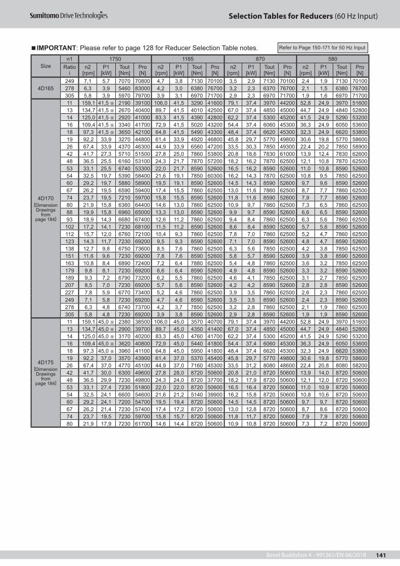
Bevel Buddybox 4 - 991361/EN-06/2018 141
Selection Tables for Reducers (60 Hz Input)
Sizen1 1750 1165 870 580
Ratio i
n2 [rpm]
P1 [kW]
Tout [Nm]
Pro [N]
n2 [rpm]
P1 [kW]
Tout [Nm]
Pro [N]
n2 [rpm]
P1 [kW]
Tout [Nm]
Pro [N]
n2 [rpm]
P1 [kW]
Tout [Nm]
Pro [N]
4D165249 7,1 5,7 7070 70800 4,7 3,8 7130 70100 3,5 2,9 7130 70100 2,4 1,9 7130 70100278 6,3 3,9 5460 83000 4,2 3,0 6380 76700 3,2 2,3 6370 76700 2,1 1,5 6380 76700305 5,8 3,9 5970 79700 3,9 3,1 6970 71700 2,9 2,3 6970 71700 1,9 1,6 6970 71700
4D170[Dimension Drawings
frompage 184]
11 159,1 41,5 2190 39100 106,0 41,5 3290 41600 79,1 37,4 3970 44200 52,8 24,9 3970 5160013 134,7 41,5 2670 40400 89,7 41,5 4010 42500 67,0 37,4 4850 45000 44,7 24,9 4840 5280014 125,0 41,5 2920 41000 83,3 41,5 4390 42800 62,2 37,4 5300 45200 41,5 24,9 5290 5320016 109,4 41,5 3340 41700 72,9 41,5 5020 43200 54,4 37,4 6060 45300 36,3 24,9 6050 5360018 97,3 41,5 3650 42100 64,8 41,5 5490 43300 48,4 37,4 6620 45300 32,3 24,9 6620 5380019 92,2 33,9 3270 44800 61,4 33,9 4920 46800 45,8 29,7 5770 49800 30,6 19,8 5770 5860026 67,4 33,9 4370 46300 44,9 33,9 6560 47200 33,5 30,3 7850 49300 22,4 20,2 7850 5890042 41,7 27,3 5710 51500 27,8 25,0 7860 53800 20,8 18,6 7830 61000 13,9 12,4 7830 6260048 36,5 25,5 6160 53100 24,3 21,7 7870 57200 18,2 16,2 7870 62500 12,1 10,8 7870 6250053 33,1 25,5 6740 53300 22,0 21,7 8590 52600 16,5 16,2 8590 52600 11,0 10,8 8590 5260054 32,5 19,7 5390 58400 21,6 19,1 7850 60300 16,2 14,3 7870 62500 10,8 9,5 7850 6250060 29,2 19,7 5880 58900 19,5 19,1 8590 52600 14,5 14,3 8590 52600 9,7 9,6 8590 5260067 26,2 19,5 6590 59400 17,4 15,5 7860 62500 13,0 11,6 7860 62500 8,7 7,7 7860 6250074 23,7 19,5 7210 59700 15,8 15,5 8590 52600 11,8 11,6 8590 52600 7,9 7,7 8590 5260080 21,9 15,8 6360 64400 14,6 13,0 7860 62500 10,9 9,7 7860 62500 7,3 6,5 7860 6250088 19,9 15,8 6960 65000 13,3 13,0 8590 52600 9,9 9,7 8590 52600 6,6 6,5 8590 5260093 18,9 14,3 6680 67400 12,6 11,2 7860 62500 9,4 8,4 7860 62500 6,3 5,6 7860 62500
102 17,2 14,1 7230 68100 11,5 11,2 8590 52600 8,6 8,4 8590 52600 5,7 5,6 8590 52600112 15,7 12,0 6760 72100 10,4 9,3 7860 62500 7,8 7,0 7860 62500 5,2 4,7 7860 62500123 14,3 11,7 7230 69200 9,5 9,3 8590 52600 7,1 7,0 8590 52600 4,8 4,7 8590 52600138 12,7 9,8 6750 73600 8,5 7,6 7860 62500 6,3 5,6 7850 62500 4,2 3,8 7850 62500151 11,6 9,6 7230 69200 7,8 7,6 8590 52600 5,8 5,7 8590 52600 3,9 3,8 8590 52600163 10,8 8,4 6890 72400 7,2 6,4 7880 62500 5,4 4,8 7860 62500 3,6 3,2 7850 62500179 9,8 8,1 7230 69200 6,6 6,4 8590 52600 4,9 4,8 8590 52600 3,3 3,2 8590 52600189 9,3 7,2 6790 73200 6,2 5,5 7860 62500 4,6 4,1 7850 62500 3,1 2,7 7850 62500207 8,5 7,0 7230 69200 5,7 5,6 8590 52600 4,2 4,2 8590 52600 2,8 2,8 8590 52600227 7,8 5,9 6770 73400 5,2 4,6 7860 62500 3,9 3,5 7860 62500 2,6 2,3 7860 62500249 7,1 5,8 7230 69200 4,7 4,6 8590 52600 3,5 3,5 8590 52600 2,4 2,3 8590 52600278 6,3 4,8 6740 73700 4,2 3,7 7850 62500 3,2 2,8 7860 62500 2,1 1,9 7860 62500305 5,8 4,8 7230 69200 3,9 3,8 8590 52600 2,9 2,8 8590 52600 1,9 1,9 8590 52600
4D175[Dimension Drawings
frompage 184]
11 159,1 45,0 2380 38500 106,0 45,0 3570 40700 79,1 37,4 3970 44200 52,8 24,9 3970 5160013 134,7 45,0 2900 39700 89,7 45,0 4350 41400 67,0 37,4 4850 45000 44,7 24,9 4840 5280014 125,0 45,0 3170 40200 83,3 45,0 4760 41700 62,2 37,4 5300 45200 41,5 24,9 5290 5320016 109,4 45,0 3620 40800 72,9 45,0 5440 41800 54,4 37,4 6060 45300 36,3 24,9 6050 5360018 97,3 45,0 3960 41100 64,8 45,0 5950 41800 48,4 37,4 6620 45300 32,3 24,9 6620 5380019 92,2 37,0 3570 43900 61,4 37,0 5370 45400 45,8 29,7 5770 49800 30,6 19,8 5770 5860026 67,4 37,0 4770 45100 44,9 37,0 7160 45300 33,5 31,2 8080 48600 22,4 20,8 8080 5820042 41,7 30,0 6300 49600 27,8 28,0 8720 50600 20,8 21,0 8720 50600 13,9 14,0 8720 5060048 36,5 29,9 7230 49800 24,3 24,0 8720 37700 18,2 17,9 8720 50600 12,1 12,0 8720 5060053 33,1 27,4 7230 51800 22,0 22,0 8720 50600 16,5 16,4 8720 50600 11,0 10,9 8720 5060054 32,5 24,1 6600 54600 21,6 21,2 5140 39900 16,2 15,8 8720 50600 10,8 10,6 8720 5060060 29,2 24,1 7200 54700 19,5 19,4 8720 50600 14,5 14,5 8720 50600 9,7 9,7 8720 5060067 26,2 21,4 7230 57400 17,4 17,2 8720 50600 13,0 12,8 8720 50600 8,7 8,6 8720 5060074 23,7 19,5 7230 59700 15,8 15,7 8720 50600 11,8 11,7 8720 50600 7,9 7,9 8720 5060080 21,9 17,9 7230 61700 14,6 14,4 8720 50600 10,9 10,8 8720 50600 7,3 7,2 8720 50600
IMPORTANT: Please refer to page 128 for Reducer Selection Table notes. Refer to Page 150-171 for 50 Hz Input

Bevel Buddybox 4 - 991361/EN-06/2018142
Selection Tables for Reducers (60 Hz Input)
Sizen1 1750 1165 870 580
Ratio i
n2 [rpm]
P1 [kW]
Tout [Nm]
Pro [N]
n2 [rpm]
P1 [kW]
Tout [Nm]
Pro [N]
n2 [rpm]
P1 [kW]
Tout [Nm]
Pro [N]
n2 [rpm]
P1 [kW]
Tout [Nm]
Pro [N]
4D175[Dimension Drawings
frompage 184]
88 19,9 16,4 7230 64100 13,3 13,2 8720 50600 9,9 9,9 8720 50600 6,6 6,6 8720 5060093 18,9 15,5 7230 65700 12,6 12,4 8720 50600 9,4 9,3 8720 50600 6,3 6,2 8720 50600
102 17,2 14,1 7230 68100 11,5 11,4 8720 50600 8,6 8,5 8720 50600 5,7 5,7 8720 50600112 15,7 12,8 7230 69200 10,4 10,3 8720 50600 7,8 7,7 8720 50600 5,2 5,2 8720 50600123 14,3 11,7 7230 69200 9,5 9,5 8720 50600 7,1 7,1 8720 50600 4,8 4,7 8720 50600138 12,7 10,4 7230 69200 8,5 8,4 8720 50600 6,3 6,3 8720 50600 4,2 4,2 8720 50600151 11,6 9,6 7230 69200 7,8 7,7 8720 50600 5,8 5,8 8720 50600 3,9 3,9 8720 50600163 10,8 8,8 7230 69200 7,2 7,1 8720 50600 5,4 5,3 8720 50600 3,6 3,5 8720 50600179 9,8 8,1 7230 69200 6,6 6,5 8720 50600 4,9 4,9 8720 50600 3,3 3,3 8720 50600189 9,3 7,6 7230 69200 6,2 6,1 8720 50600 4,6 4,6 8720 50600 3,1 3,0 8720 50600207 8,5 7,0 7230 69200 5,7 5,6 8720 50600 4,2 4,2 8720 50600 2,8 2,8 8720 50600227 7,8 6,3 7230 69200 5,2 5,1 8720 50600 3,9 3,8 8720 50600 2,6 2,5 8720 50600249 7,1 5,8 7230 69200 4,7 4,7 8720 50600 3,5 3,5 8720 50600 2,4 2,4 8720 50600278 6,3 5,2 7230 69200 4,2 4,1 8720 50600 3,2 3,1 8720 50600 2,1 2,1 8720 50600305 5,8 4,8 7230 69200 3,9 3,8 8720 50600 2,9 2,9 8720 50600 1,9 1,9 8720 50600
4D180[Dimension Drawings
frompage 184]
11 159,1 53,4 2820 37100 106,0 53,4 4240 38600 79,1 49,6 5270 40100 52,8 33,1 5280 4740013 134,7 53,4 3440 38000 89,7 53,4 5170 38900 67,0 49,6 6430 39900 44,7 33,1 6430 4770014 125,0 53,4 3760 38300 83,3 53,4 5650 38800 62,2 49,6 7030 39700 41,5 33,1 7030 4770016 109,4 53,4 4300 38600 72,9 53,4 6460 38600 54,4 49,6 8030 39000 36,3 33,1 8040 4730018 97,3 53,4 4700 38800 64,8 53,4 7060 38300 48,4 46,1 8170 40400 32,3 32,8 8720 4720019 92,2 41,5 4010 42500 61,4 41,5 6020 43300 45,8 37,4 7270 45100 30,6 24,9 7260 5390021 83,4 41,5 4380 42800 55,5 41,5 6590 43200 41,5 37,4 7950 44800 27,7 24,9 7940 5380022 79,6 41,5 4680 43000 53,0 41,5 7030 43100 39,6 33,2 7530 47400 26,4 22,1 7520 5670025 70,0 41,5 5120 43200 46,6 41,5 7680 42800 34,8 33,2 8230 47200 23,2 22,1 8220 5660026 67,4 41,5 5350 43200 44,9 39,5 7640 43800 33,5 29,5 7640 50000 22,4 19,7 7660 5960028 62,5 41,5 5850 43300 41,7 39,3 8320 43500 31,1 29,5 8360 49700 20,8 19,7 8370 5590035 50,0 41,5 7350 42900 33,3 32,8 8720 47200 24,9 24,5 8720 50600 16,6 16,3 8720 5060039 44,9 41,5 8040 42600 29,9 30,0 8720 49200 22,4 22,4 8720 50600 14,9 14,9 8720 5060042 41,7 40,4 8460 42800 27,8 27,7 8720 50600 20,8 20,7 8720 50600 13,9 13,8 8720 5060046 38,1 37,2 8520 44500 25,4 25,4 8720 50600 19,0 18,9 8720 50600 12,7 12,6 8720 5060048 36,5 32,4 7820 47900 24,3 24,0 8720 50600 18,2 17,9 8720 50600 12,1 12,0 8720 5060053 33,1 32,4 8560 47600 22,0 22,0 8720 50600 16,5 16,4 8720 50600 11,0 10,9 8720 5060054 32,5 30,6 8380 48900 21,6 21,2 8720 50600 16,2 15,8 8720 50600 10,8 10,6 8720 5060060 29,2 29,1 8720 49900 19,5 19,4 8720 50600 14,5 14,5 8720 50600 9,7 9,7 8720 5060067 26,2 25,8 8720 50600 17,4 17,2 8720 50600 13,0 12,8 8720 50600 8,7 8,6 8720 5060074 23,7 23,6 8720 50600 15,8 15,7 8720 50600 11,8 11,7 8720 50600 7,9 7,9 8720 5060080 21,9 21,7 8720 50600 14,6 14,4 8720 50600 10,9 10,8 8720 50600 7,3 7,2 8720 5060088 19,9 19,8 8720 50600 13,3 13,2 8720 50600 9,9 9,9 8720 50600 6,6 6,6 8720 5060093 18,9 18,7 8720 50600 12,6 12,4 8720 50600 9,4 9,3 8720 50600 6,3 6,2 8720 50600
102 17,2 17,1 8720 50600 11,5 11,4 8720 50600 8,6 8,5 8720 50600 5,7 5,7 8720 50600112 15,7 15,5 8720 50600 10,4 10,3 8720 50600 7,8 7,7 8720 50600 5,2 5,2 8720 50600123 14,3 14,1 8720 50600 9,5 9,5 8720 50600 7,1 7,1 8720 50600 4,8 4,7 8720 50600138 12,7 12,6 8720 50600 8,5 8,4 8720 50600 6,3 6,3 8720 50600 4,2 4,2 8720 50600151 11,6 11,5 8720 50600 7,8 7,7 8720 50600 5,8 5,8 8720 50600 3,9 3,9 8720 50600163 10,8 10,6 8720 50600 7,2 7,2 8720 50600 5,4 5,3 8720 50600 3,6 3,5 8720 50600179 9,8 9,8 8720 50600 6,6 6,5 8720 50600 4,9 4,9 8720 50600 3,3 3,3 8720 50600189 9,3 9,2 8720 50600 6,2 6,1 8720 50600 4,6 4,6 8720 50600 3,1 3,0 8720 50600207 8,5 8,4 8720 50600 5,7 5,6 8720 50600 4,2 4,2 8720 50600 2,8 2,8 8720 50600227 7,8 7,6 8720 50600 5,2 5,0 8720 50600 3,9 3,8 8720 50600 2,6 2,5 8720 50600249 7,1 7,0 8720 50600 4,7 4,7 8720 50600 3,5 3,5 8720 50600 2,4 2,4 8720 50600278 6,3 6,2 8720 50600 4,2 4,1 8720 50600 3,2 3,1 8720 50600 2,1 2,1 8720 50600305 5,8 5,7 8720 50600 3,9 3,8 8720 50600 2,9 2,9 8720 50600 1,9 1,9 8720 50600
4D185[Dimension Drawings
frompage 184]
11 159,1 60,0 3170 36000 106,0 60,0 4760 37000 79,1 49,6 5270 40100 52,8 33,1 5280 4740013 134,7 60,0 3860 36600 89,7 60,0 5800 36800 67,0 49,6 6430 39900 44,7 33,1 6430 4770014 125,0 60,0 4230 36800 83,3 60,0 6350 36600 62,2 49,6 7030 39700 41,5 33,1 7030 4770016 109,4 60,0 4830 37000 72,9 60,0 7260 36100 54,4 49,6 8030 39000 36,3 33,1 8040 4730018 97,3 60,0 5280 37000 64,8 56,6 7480 37000 48,4 46,1 8170 40400 32,3 32,8 8720 4720019 92,2 45,0 4350 41400 61,4 45,0 6530 41700 45,8 38,0 7380 44700 30,6 25,3 7370 5350021 83,4 45,0 4750 41600 55,5 45,0 7140 41400 41,5 38,0 8080 44400 27,7 25,3 8070 5340022 79,6 45,0 5070 41700 53,0 45,0 7620 41200 39,6 33,7 7640 47100 26,4 22,5 7650 5630025 70,0 45,0 5550 41800 46,6 43,2 7990 41800 34,8 33,7 8360 46800 23,2 22,5 8370 5600026 67,4 45,0 5800 41800 44,9 40,2 7780 43400 33,5 30,0 7770 49600 22,4 20,0 7770 5920028 62,5 45,0 6340 41700 41,7 39,3 8320 43500 31,1 30,0 8500 49300 20,8 20,0 8500 5410035 50,0 45,0 7970 40900 33,3 32,8 8720 47200 24,9 24,5 8720 50600 16,6 16,3 8720 5060039 44,9 41,8 8100 42400 29,9 30,0 8720 49200 22,4 22,4 8720 50600 14,9 14,9 8720 5060042 41,7 40,4 8460 42800 27,8 27,7 8720 50600 20,8 20,7 8720 50600 13,9 13,8 8720 5060046 38,1 37,2 8520 44500 25,4 25,4 8720 50600 19,0 18,9 8720 50600 12,7 12,6 8720 5060048 36,5 36,1 8720 45000 24,3 24,0 8720 50600 18,2 17,9 8720 50600 12,1 12,0 8720 5060053 33,1 33,0 8720 47000 22,0 22,0 8720 50600 16,5 16,4 8720 50600 11,0 10,9 8720 5060054 32,5 31,9 8720 47800 21,6 21,2 8720 50600 16,2 15,8 8720 50600 10,8 10,6 8720 50600
IMPORTANT: Please refer to page 128 for Reducer Selection Table notes. Refer to Page 150-171 for 50 Hz Input

Bevel Buddybox 4 - 991361/EN-06/2018 143
Selection Tables for Reducers (60 Hz Input)
Sizen1 1750 1165 870 580
Ratio i
n2 [rpm]
P1 [kW]
Tout [Nm]
Pro [N]
n2 [rpm]
P1 [kW]
Tout [Nm]
Pro [N]
n2 [rpm]
P1 [kW]
Tout [Nm]
Pro [N]
n2 [rpm]
P1 [kW]
Tout [Nm]
Pro [N]
4D185[Dimension Drawings
frompage 184]
60 29,2 29,1 8720 49900 19,5 19,4 8720 50600 14,5 14,5 8720 50600 9,7 9,7 8720 5060067 26,2 25,8 8720 50600 17,4 17,2 8720 50600 13,0 12,8 8720 50600 8,7 8,6 8720 5060074 23,7 23,6 8720 50600 15,8 15,7 8720 50600 11,8 11,7 8720 50600 7,9 7,9 8720 5060080 21,9 21,7 8720 50600 14,6 14,4 8720 50600 10,9 10,8 8720 50600 7,3 7,2 8720 5060088 19,9 19,8 8720 50600 13,3 13,2 8720 50600 9,9 9,9 8720 50600 6,6 6,6 8720 5060093 18,9 18,7 8720 50600 12,6 12,4 8720 50600 9,4 9,3 8720 50600 6,3 6,2 8720 50600
102 17,2 17,1 8720 50600 11,5 11,4 8720 50600 8,6 8,5 8720 50600 5,7 5,7 8720 50600112 15,7 15,5 8720 50600 10,4 10,3 8720 50600 7,8 7,7 8720 50600 5,2 5,2 8720 50600123 14,3 14,1 8720 50600 9,5 9,5 8720 50600 7,1 7,1 8720 50600 4,8 4,7 8720 50600138 12,7 12,6 8720 50600 8,5 8,4 8720 50600 6,3 6,3 8720 50600 4,2 4,2 8720 50600151 11,6 11,5 8720 50600 7,8 7,7 8720 50600 5,8 5,8 8720 50600 3,9 3,9 8720 50600163 10,8 10,6 8720 50600 7,2 7,1 8720 50600 5,4 5,3 8720 50600 3,6 3,5 8720 50600179 9,8 9,8 8720 50600 6,6 6,5 8720 50600 4,9 4,9 8720 50600 3,3 3,3 8720 50600189 9,3 9,2 8720 50600 6,2 6,1 8720 50600 4,6 4,6 8720 50600 3,1 3,0 8720 50600207 8,5 8,4 8720 50600 5,7 5,6 8720 50600 4,2 4,2 8720 50600 2,8 2,8 8720 50600227 7,8 7,6 8720 50600 5,2 5,1 8720 50600 3,9 3,8 8720 50600 2,6 2,5 8720 50600249 7,1 7,0 8720 50600 4,7 4,7 8720 50600 3,5 3,5 8720 50600 2,4 2,4 8720 50600278 6,3 6,2 8720 50600 4,2 4,14 8720 50600 3,2 3,1 8720 50600 2,1 2,2 8720 50600305 5,8 5,7 8720 50600 3,9 3,8 8720 50600 2,9 2,9 8720 50600 1,9 1,9 8720 50600
4E170[Dimension Drawings
frompage 184]
11 159,1 41,5 2190 52800 106,0 41,5 3290 57300 79,1 37,4 3970 61500 52,8 24,9 3970 70900 13 134,7 41,5 2670 55000 89,7 41,5 4010 59300 67,0 37,4 4850 63400 44,7 24,9 4840 73400 14 125,0 41,5 2920 56000 83,3 41,5 4390 60100 62,2 37,4 5300 64200 41,5 24,9 5290 74500 16 109,4 41,5 3340 57400 72,9 41,5 5020 61300 54,4 37,4 6060 65300 36,3 24,9 6050 76000 18 97,3 41,5 3650 58400 64,8 41,5 5490 62000 48,4 37,4 6620 65900 32,3 24,9 6620 76900 19 92,2 33,9 3270 61400 61,4 33,9 4920 65800 45,8 29,7 5770 70700 30,6 19,8 5770 8200026 67,4 33,9 4370 64600 44,9 33,9 6560 68300 33,5 30,3 7850 72600 22,4 20,2 7850 8490042 41,7 27,3 5710 72900 27,8 25,0 7860 78300 20,8 18,6 7830 87500 13,9 12,4 7830 9030048 36,5 25,5 6160 75500 24,3 21,7 7870 82700 18,2 16,2 7870 90200 12,1 10,8 7870 9020053 33,1 25,5 6740 76400 22,0 21,7 8590 83500 16,5 16,2 8590 88700 11,0 10,8 8590 8870054 32,5 19,7 5390 81300 21,6 19,1 7850 86700 16,2 14,3 7870 90200 10,8 9,5 7850 9020060 29,2 19,7 5880 82500 19,5 19,1 8590 87600 14,5 14,3 8590 88700 9,7 9,6 8590 8870067 26,2 19,5 6590 84000 17,4 15,5 7860 90200 13,0 11,6 7860 90200 8,7 7,7 7860 9020074 23,7 19,5 7210 85200 15,8 15,5 8590 88700 11,8 11,6 8590 88700 7,9 7,7 8590 8870080 21,9 15,8 6360 90200 14,6 13,0 7860 90200 10,9 9,7 7860 90200 7,3 6,5 7860 9020088 19,9 15,8 6960 91600 13,3 13,0 8590 88700 9,9 9,7 8590 88700 6,6 6,5 8590 8870093 18,9 14,3 6680 92600 12,6 11,2 7860 90200 9,4 8,4 7860 90200 6,3 5,6 7860 90200
102 17,2 14,3 7300 91300 11,5 11,2 8590 88700 8,6 8,4 8590 88700 5,7 5,6 8590 88700112 15,7 12,0 6760 92400 10,4 9,3 7860 90200 7,8 7,0 7860 90200 5,2 4,7 7860 90200123 14,3 12,0 7400 91100 9,5 9,3 8590 88700 7,1 7,0 8590 88700 4,8 4,7 8590 88700138 12,7 9,8 6750 92400 8,5 7,6 7860 90200 6,3 5,6 7850 90200 4,2 3,8 7850 90200151 11,6 9,8 7380 91200 7,8 7,6 8590 88700 5,8 5,7 8590 88700 3,9 3,8 8590 88700163 10,8 8,4 6890 92100 7,2 6,4 7860 90200 5,4 4,8 7860 90200 3,6 3,2 7850 90200179 9,8 8,4 7540 90900 6,6 6,4 8590 88700 4,9 4,8 8590 88700 3,3 3,2 8590 88700189 9,3 7,2 6790 92300 6,2 5,5 7860 90200 4,6 4,1 7850 90200 3,1 2,7 7850 90200207 8,5 7,2 7430 91100 5,7 5,6 8590 88700 4,2 4,2 8590 88700 2,8 2,8 8590 88700227 7,8 5,9 6770 92400 5,2 4,6 7860 90200 3,9 3,4 7860 90200 2,6 2,3 7860 90200249 7,1 6,0 7400 91100 4,7 4,6 8590 88700 3,5 3,5 8590 88700 2,4 2,3 8590 88700278 6,3 4,8 6740 92500 4,2 3,7 7850 90200 3,2 2,8 7860 90200 2,1 1,9 7860 90200305 5,8 4,9 7370 91200 3,9 3,8 8590 88700 2,9 2,8 8590 88700 1,9 1,9 8590 88700
IMPORTANT: Please refer to page 128 for Reducer Selection Table notes. Refer to Page 150-171 for 50 Hz Input

Bevel Buddybox 4 - 991361/EN-06/2018144
Selection Tables for Reducers (60 Hz Input)
IMPORTANT: Please refer to page 128 for Reducer Selection Table notes.
Sizen1 1750 1165 870 580
Ratio i
n2 [rpm]
P1 [kW]
Tout [Nm]
Pro [N]
n2 [rpm]
P1 [kW]
Tout [Nm]
Pro [N]
n2 [rpm]
P1 [kW]
Tout [Nm]
Pro [N]
n2 [rpm]
P1 [kW]
Tout [Nm]
Pro [N]
11 159,1 45,0 2380 52300 106,0 45,0 3570 56500 79,1 37,4 3970 61500 52,8 24,9 3970 70900 13 134,7 45,0 2900 54400 89,7 45,0 4350 58300 67,0 37,4 4850 63400 44,7 24,9 4840 73400 14 125,0 45,0 3170 55300 83,3 45,0 4760 59100 62,2 37,4 5300 64200 41,5 24,9 5290 74500 16 109,4 45,0 3620 56600 72,9 45,0 5440 60100 54,4 37,4 6060 65300 36,3 24,9 6050 76000 18 97,3 45,0 3960 57500 64,8 45,0 5950 60700 48,4 37,4 6620 65900 32,3 24,9 6620 76900 19 92,2 37,0 3570 60500 61,4 37,0 5370 64500 45,8 29,7 5770 70700 30,6 19,8 5770 8200026 67,4 37,0 4770 63500 44,9 37,0 7160 66600 33,5 31,2 8080 71900 22,4 20,8 8080 8420042 41,7 30,1 6300 71100 27,8 30,1 9460 73600 20,8 23,2 9770 81900 13,9 15,5 9790 8640048 36,5 30,1 7270 72200 24,3 25,4 9210 78700 18,2 20,1 9760 86400 12,1 13,4 9760 8640053 33,1 30,1 7960 72800 22,0 24,8 9830 79900 16,5 18,5 9830 86300 11,0 12,3 9830 8630054 32,5 24,1 6600 77800 21,6 23,8 9790 81200 16,2 17,8 9800 86300 10,8 11,8 9750 8640060 29,2 24,1 7200 78700 19,5 21,9 9830 84000 14,5 16,3 9830 86300 9,7 10,9 9830 8630067 26,2 24,1 8130 79600 17,4 19,3 9780 86400 13,0 14,4 9780 86400 8,7 9,6 9780 8640074 23,7 22,0 8140 82500 15,8 17,7 9830 86300 11,8 13,2 9830 86300 7,9 8,9 9830 8630080 21,9 19,5 7850 85900 14,6 16,2 9780 86400 10,9 12,1 9780 86400 7,3 8,1 9780 8640088 19,9 18,5 8140 88200 13,3 14,9 9830 86300 9,9 11,1 9830 86300 6,6 7,4 9830 8630093 18,9 17,4 8140 89600 12,6 13,9 9750 86400 9,4 10,4 9770 86400 6,3 6,9 9780 86400102 17,2 15,9 8140 89600 11,5 12,8 9830 86300 8,6 9,6 9830 86300 5,7 6,4 9830 86300112 15,7 15,1 8490 88900 10,4 11,6 9780 86400 7,8 8,7 9780 86400 5,2 5,8 9780 86400123 14,3 15,1 9290 87300 9,5 11,6 10700 84500 7,1 8,7 10700 84500 4,8 5,8 10700 84500138 12,7 11,3 7820 90300 8,5 9,4 9790 86400 6,3 7,0 9780 86400 4,2 4,7 9780 86400151 11,6 11,3 8560 88800 7,8 9,5 10700 84500 5,8 7,1 10700 84500 3,9 4,7 10700 84500163 10,8 11,3 9280 87400 7,2 7,9 9780 86400 5,4 5,9 9780 86400 3,6 4,0 9790 86400179 9,8 10,7 9610 86700 6,6 8,0 10700 84500 4,9 6,0 10700 84500 3,3 4,0 10700 84500189 9,3 8,3 7880 90200 6,2 6,9 9790 86400 4,6 5,1 9780 86400 3,1 3,4 9770 86400207 8,5 8,3 8610 88700 5,7 6,9 10700 84500 4,2 5,2 10700 84500 2,8 3,5 10700 84500227 7,8 7,2 8170 89600 5,2 5,7 9790 86400 3,9 4,3 9770 86400 2,6 2,8 9800 86300249 7,1 7,2 8940 88100 4,7 5,7 10700 84500 3,5 4,3 10700 84500 2,4 2,9 10700 84500278 6,3 5,6 7870 90200 4,2 4,7 9780 86400 3,2 3,5 9780 86400 2,1 2,3 9760 86400305 5,8 5,7 8610 88700 3,9 4,7 10700 84500 2,9 3,5 10700 84500 1,9 2,4 10700 84500
4E180[Dimension Drawings
frompage 184]
11 159,1 53,4 2820 51000 106,0 53,4 4240 54600 79,1 49,6 5270 57700 52,8 33,1 5280 67100 13 134,7 53,4 3440 52800 89,7 53,4 5170 56000 67,0 49,6 6430 58800 44,7 33,1 6430 68800 14 125,0 53,4 3760 53600 83,3 53,4 5650 56500 62,2 49,6 7030 59200 41,5 33,1 7030 69500 16 109,4 53,4 4300 54700 72,9 53,4 6460 57100 54,4 49,6 8030 59500 36,3 33,1 8040 70200 18 97,3 53,4 4700 55300 64,8 53,4 7060 57500 48,4 49,6 8780 59600 32,3 33,1 8790 70600 19 92,2 41,5 4010 59300 61,4 41,5 6020 62700 45,8 37,4 7270 66400 30,6 24,9 7260 7770021 83,4 41,5 4380 60100 55,5 41,5 6590 63200 41,5 37,4 7950 66800 27,7 24,9 7940 78400 22 79,6 41,5 4680 60700 53,0 41,5 7030 63500 39,6 33,2 7530 69800 26,4 22,1 7520 81600 25 70,0 41,5 5120 61500 46,6 41,5 7680 63900 34,8 33,2 8230 70200 23,2 22,1 8220 82400 26 67,4 41,5 5350 61800 44,9 39,5 7640 65200 33,5 29,5 7640 73200 22,4 19,7 7660 8550028 62,5 41,5 5850 62500 41,7 39,5 8360 65500 31,1 29,5 8360 73700 20,8 19,7 8370 86400 35 50,0 41,5 7350 63700 33,3 41,5 11000 64100 24,9 32,6 11600 71300 16,6 21,7 11600 82000 39 44,9 41,5 8040 64100 29,9 39,9 11600 65200 22,4 29,8 11600 74200 14,9 19,8 11600 82000 42 41,7 41,5 8690 64300 27,8 36,9 11600 67400 20,8 27,6 11600 76700 13,9 18,4 11600 8200046 38,1 41,5 9500 64400 25,4 33,7 11600 70200 19,0 25,2 11600 79700 12,7 16,8 11600 82000 48 36,5 32,4 7820 70700 24,3 32,0 11600 71900 18,2 23,9 11600 81500 12,1 15,9 11600 8200053 33,1 32,4 8560 71100 22,0 29,2 11600 74800 16,5 21,8 11600 82000 11,0 14,6 11600 82000 54 32,5 30,6 8380 72700 21,6 28,2 11600 75900 16,2 21,1 11600 82000 10,8 14,0 11600 8200060 29,2 30,6 9160 73100 19,5 25,8 11600 78900 14,5 19,3 11600 82000 9,7 12,8 11600 82000 67 26,2 30,0 10100 73900 17,4 22,8 11600 82000 13,0 17,1 11600 82000 8,7 11,4 11600 82000 74 23,7 30,0 11100 74000 15,8 20,9 11600 82000 11,8 15,6 11600 82000 7,9 10,4 11600 82000 80 21,9 24,1 9700 80800 14,6 19,2 11600 82000 10,9 14,3 11600 82000 7,3 9,6 11600 82000 88 19,9 24,1 10600 81100 13,3 17,5 11600 82000 9,9 13,1 11600 82000 6,6 8,8 11600 82000 93 18,9 19,5 9100 87400 12,6 16,5 11600 82000 9,4 12,4 11600 82000 6,3 8,2 11600 82000102 17,2 19,5 9960 86000 11,5 15,1 11600 82000 8,6 11,3 11600 82000 5,7 7,6 11600 82000 112 15,7 18,8 10600 84800 10,4 13,7 11600 82000 7,8 10,2 11600 82000 5,2 6,9 11600 82000 123 14,3 18,8 11600 82100 9,5 12,5 11600 82000 7,1 9,4 11600 82000 4,8 6,3 11600 82000 138 12,7 15,1 10500 85000 8,5 11,2 11600 82000 6,3 8,3 11600 82000 4,2 5,5 11600 82000151 11,6 15,1 11400 83100 7,8 10,2 11600 82000 5,8 7,7 11600 82000 3,9 5,1 11600 82000 163 10,8 12,0 9850 86200 7,2 9,4 11600 82000 5,4 7,0 11600 82000 3,6 4,7 11600 82000179 9,8 12,0 10800 84400 6,6 8,6 11600 82000 4,9 6,5 11600 82000 3,3 4,3 11600 82000
4E175[Dimension Drawings
frompage 184]
Refer to Page 150-171 for 50 Hz Input
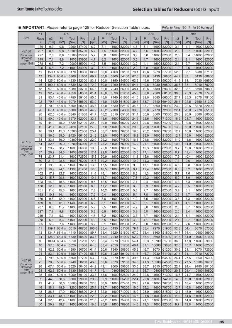
Bevel Buddybox 4 - 991361/EN-06/2018 145
Selection Tables for Reducers (60 Hz Input)
Sizen1 1750 1165 870 580
Ratio i
n2 [rpm]
P1 [kW]
Tout [Nm]
Pro [N]
n2 [rpm]
P1 [kW]
Tout [Nm]
Pro [N]
n2 [rpm]
P1 [kW]
Tout [Nm]
Pro [N]
n2 [rpm]
P1 [kW]
Tout [Nm]
Pro [N]
4E180[Dimension Drawings
frompage 184]
189 9,3 9,8 9260 87400 6,2 8,1 11600 82000 4,6 6,1 11600 82000 3,1 4,1 11600 82000207 8,5 9,8 10100 85700 5,7 7,5 11600 82000 4,2 5,6 11600 82000 2,8 3,7 11600 82000 227 7,8 8,8 10100 85800 5,2 6,8 11600 82000 3,9 5,0 11600 82000 2,6 3,4 11600 82000249 7,1 8,8 11000 83900 4,7 6,2 11600 82000 3,5 4,7 11600 82000 2,4 3,1 11600 82000 278 6,3 7,2 10000 85900 4,2 5,5 11600 82000 3,2 4,1 11600 82000 2,1 2,7 11600 82000305 5,8 7,2 11000 84000 3,9 5,1 11600 82000 2,9 3,8 11600 82000 1,9 2,6 11600 82000
4E185[Dimension Drawings
frompage 184]
11 159,1 60,0 3170 50000 106,0 60,0 4760 53100 79,1 49,6 5270 57700 52,8 33,1 5280 67100 13 134,7 60,0 3860 51600 89,7 60,0 5800 54100 67,0 49,6 6430 58800 44,7 33,1 6430 68800 14 125,0 60,0 4230 52300 83,3 60,0 6350 54500 62,2 49,6 7030 59200 41,5 33,1 7030 69500 16 109,4 60,0 4830 53100 72,9 60,0 7260 54800 54,4 49,6 8030 59500 36,3 33,1 8040 70200 18 97,3 60,0 5280 53700 64,8 60,0 7940 55000 48,4 49,6 8780 59600 32,3 33,1 8790 70600 19 92,2 45,0 4350 58300 61,4 45,0 6530 61200 45,8 38,0 7380 66100 30,6 25,3 7370 7740021 83,4 45,0 4750 59100 55,5 45,0 7140 61600 41,5 38,0 8080 66500 27,7 25,3 8070 78100 22 79,6 45,0 5070 59600 53,0 45,0 7620 61800 39,6 33,7 7640 69400 26,4 22,5 7650 81300 25 70,0 45,0 5550 60200 46,6 45,0 8330 62100 34,8 33,7 8360 69900 23,2 22,5 8370 82000 26 67,4 45,0 5800 60500 44,9 40,2 7780 64800 33,5 30,0 7770 72800 22,4 20,0 7770 8510028 62,5 45,0 6340 61000 41,7 40,2 8510 65100 31,1 30,0 8500 73300 20,8 20,0 8500 86000 35 50,0 45,0 7970 62000 33,3 43,6 11600 62500 24,9 32,6 11600 71300 16,6 21,7 11600 82000 39 44,9 45,0 8720 62100 29,9 39,9 11600 65200 22,4 29,8 11600 74200 14,9 19,8 11600 82000 42 41,7 45,0 9420 62100 27,8 37,0 11600 67400 20,8 28,0 11600 76700 13,9 18,0 11600 8200046 38,1 45,0 10300 62000 25,4 33,7 11600 70200 19,0 25,2 11600 79700 12,7 16,8 11600 82000 48 36,5 39,0 9420 66100 24,3 32,0 11600 71900 18,2 23,9 11600 81500 12,1 15,9 11600 8200053 33,1 39,0 10300 66100 22,0 29,2 11600 74800 16,5 21,8 11600 82000 11,0 14,6 11600 82000 54 32,5 39,0 10700 66000 21,6 28,2 11600 75900 16,2 21,1 11600 82000 10,8 14,0 11600 8200060 29,2 38,7 11600 66000 19,5 25,8 11600 78900 14,5 19,3 11600 82000 9,7 12,8 11600 82000 67 26,2 34,3 11600 69700 17,4 22,8 11600 82000 13,0 17,1 11600 82000 8,7 11,4 11600 82000 74 23,7 31,4 11600 72500 15,8 20,9 11600 82000 11,8 15,6 11600 82000 7,9 10,4 11600 82000 80 21,9 28,8 11600 75200 14,6 19,2 11600 82000 10,9 14,3 11600 82000 7,3 9,6 11600 82000 88 19,9 26,3 11600 78200 13,3 17,5 11600 82000 9,9 13,1 11600 82000 6,6 8,8 11600 82000 93 18,9 24,1 11300 81200 12,6 16,5 11600 82000 9,4 12,4 11600 82000 6,3 8,2 11600 82000
102 17,2 22,7 11600 82000 11,5 15,1 11600 82000 8,6 11,3 11600 82000 5,7 7,6 11600 82000 112 15,7 20,6 11600 82000 10,4 13,7 11600 82000 7,8 10,2 11600 82000 5,2 6,9 11600 82000 123 14,3 18,8 11600 82000 9,5 12,5 11600 82000 7,1 9,4 11600 82000 4,8 6,3 11600 82000 138 12,7 16,8 11600 82000 8,5 11,2 11600 82000 6,3 8,3 11600 82000 4,2 5,5 11600 82000151 11,6 15,3 11600 82000 7,8 10,2 11600 82000 5,8 7,7 11600 82000 3,9 5,1 11600 82000 163 10,8 14,1 11600 82000 7,2 9,4 11600 82000 5,4 7,0 11600 82000 3,6 4,7 11600 82000179 9,8 12,9 11600 82000 6,6 8,6 11600 82000 4,9 6,5 11600 82000 3,3 4,3 11600 82000 189 9,3 12,0 11400 83100 6,2 8,1 11600 82000 4,6 6,1 11600 82000 3,1 4,1 11600 82000207 8,5 11,2 11600 82000 5,7 7,5 11600 82000 4,2 5,6 11600 82000 2,8 3,7 11600 82000 227 7,8 9,8 11200 83600 5,2 6,8 11600 82000 3,9 5,0 11600 82000 2,6 3,4 11600 82000249 7,1 9,3 11600 82000 4,7 6,2 11600 82000 3,5 4,7 11600 82000 2,4 3,1 11600 82000 278 6,3 8,3 11600 82000 4,2 5,5 11600 82000 3,2 4,1 11600 82000 2,1 2,7 11600 82000305 5,8 7,6 11600 82000 3,9 5,1 11600 82000 2,9 3,8 11600 82000 1,9 2,6 11600 82000
4E190[Dimension Drawings
frompage 184]
11 159,1 68,4 3610 48700 106,0 68,4 5430 51100 79,1 68,4 7270 51900 52,8 54,4 8670 5730013 134,7 68,4 4410 50000 89,7 68,4 6620 51800 67,0 68,4 8860 51800 44,7 54,4 10600 5690014 125,0 68,4 4820 50500 83,3 68,4 7240 51900 62,2 68,4 9690 51500 41,5 51,9 11000 5790016 109,4 68,4 5510 51200 72,9 68,4 8270 51900 54,4 66,3 10700 51700 36,3 47,8 11600 5990018 97,3 68,4 6020 51500 64,8 68,4 9050 51700 48,4 61,1 10800 53800 32,3 43,7 11600 6250019 92,2 50,6 4890 56700 61,4 50,6 7340 58800 45,8 46,7 9070 61200 30,6 31,1 9070 7250021 83,4 50,6 5350 57400 55,5 50,6 8030 59100 41,5 46,7 9930 61100 27,7 31,1 9910 7270022 79,6 50,6 5700 57700 53,0 50,6 8570 59100 39,6 41,3 9360 64500 26,4 27,5 9350 7630025 70,0 50,6 6240 58200 46,6 50,6 9370 59100 34,8 41,3 10200 64500 23,2 27,5 10200 7670026 67,4 50,6 6520 58400 44,9 49,1 9500 59800 33,5 36,7 9510 67800 22,4 24,4 9480 8010028 62,5 50,6 7130 58800 41,7 49,1 10400 59700 31,1 36,7 10400 67900 20,8 24,4 10400 8050035 50,0 50,6 8960 59100 33,3 43,6 11600 62500 24,9 32,6 11600 71300 16,6 21,7 11600 8200039 44,9 50,6 9800 59000 29,9 39,9 11600 65200 22,4 29,8 11600 74200 14,9 19,8 11600 8200042 41,7 50,6 10600 58700 27,8 36,9 11600 67400 20,8 27,6 11600 76700 13,9 18,4 11600 8200046 38,1 48,9 11200 59500 25,4 33,7 11600 70200 19,0 25,2 11600 79700 12,7 16,8 11600 8200048 36,5 47,9 11600 59800 24,3 32,0 11600 71900 18,2 23,9 11600 81500 12,1 15,9 11600 8200053 33,1 43,9 11600 62300 22,0 29,2 11600 74800 16,5 21,8 11600 82000 11,0 14,6 11600 8200054 32,5 42,4 11600 63300 21,6 28,2 11600 75900 16,2 21,1 11600 82000 10,8 14,0 11600 8200060 29,2 38,7 11600 66000 19,5 25,8 11600 78900 14,5 19,3 11600 82000 9,7 12,8 11600 82000
IMPORTANT: Please refer to page 128 for Reducer Selection Table notes. Refer to Page 150-171 for 50 Hz Input

Bevel Buddybox 4 - 991361/EN-06/2018146
Selection Tables for Reducers (60 Hz Input)
Sizen1 1750 1165 870 580
Ratio i
n2 [rpm]
P1 [kW]
Tout [Nm]
Pro [N]
n2 [rpm]
P1 [kW]
Tout [Nm]
Pro [N]
n2 [rpm]
P1 [kW]
Tout [Nm]
Pro [N]
n2 [rpm]
P1 [kW]
Tout [Nm]
Pro [N]
4E190[Dimension Drawings
from page 184]
67 26,2 34,3 11600 69700 17,4 22,8 11600 82000 13,0 17,1 11600 82000 8,7 11,4 11600 8200074 23,7 31,4 11600 72500 15,8 20,9 11600 82000 11,8 15,6 11600 82000 7,9 10,4 11600 8200080 21,9 28,8 11600 75200 14,6 19,2 11600 82000 10,9 14,3 11600 82000 7,3 9,6 11600 8200088 19,9 26,3 11600 78200 13,3 17,5 11600 82000 9,9 13,1 11600 82000 6,6 8,8 11600 8200093 18,9 24,8 11600 80200 12,6 16,5 11600 82000 9,4 12,4 11600 82000 6,3 8,2 11600 82000
102 17,2 22,7 11600 82000 11,5 15,1 11600 82000 8,6 11,3 11600 82000 5,7 7,6 11600 82000112 15,7 20,6 11600 82000 10,4 13,7 11600 82000 7,8 10,2 11600 82000 5,2 6,9 11600 82000123 14,3 18,8 11600 82000 9,5 12,5 11600 82000 7,1 9,4 11600 82000 4,8 6,3 11600 82000138 12,7 16,8 11600 82000 8,5 11,2 11600 82000 6,3 8,3 11600 82000 4,2 5,6 11600 82000151 11,6 15,3 11600 82000 7,8 10,2 11600 82000 5,8 7,7 11600 82000 3,9 5,1 11600 82000163 10,8 14,1 11600 82000 7,2 9,4 11600 82000 5,4 7,0 11600 82000 3,6 4,7 11600 82000179 9,8 12,9 11600 82000 6,6 8,6 11600 82000 4,9 6,5 11600 82000 3,3 4,3 11600 82000189 9,3 12,2 11600 82000 6,2 8,1 11600 82000 4,6 6,1 11600 82000 3,1 4,1 11600 82000207 8,5 11,2 11600 82000 5,7 7,5 11600 82000 4,2 5,6 11600 82000 2,8 3,7 11600 82000227 7,8 10,1 11600 82000 5,2 6,8 11600 82000 3,9 5,0 11600 82000 2,6 3,4 11600 82000249 7,1 9,3 11600 82000 4,7 6,2 11600 82000 3,5 4,7 11600 82000 2,4 3,1 11600 82000278 6,3 8,3 11600 82000 4,2 5,5 11600 82000 3,2 4,1 11600 82000 2,1 2,7 11600 82000305 5,8 7,6 11600 82000 3,9 5,1 11600 82000 2,9 3,8 11600 82000 1,9 2,6 11600 82000
4E195[Dimension Drawings
from page 184]
11 159,1 75,0 3960 47700 106,0 75,0 5950 49600 79,1 74,5 7920 50000 52,8 54,4 8670 5730013 134,7 75,0 4830 48800 89,7 75,0 7260 49900 67,0 74,8 9690 49400 44,7 54,4 10600 5690014 125,0 75,0 5280 49200 83,3 75,0 7940 49900 62,2 68,9 9770 51300 41,5 51,9 11000 5790016 109,4 75,0 6040 49600 72,9 75,0 9070 49600 54,4 66,3 10700 51700 36,3 47,8 11600 5990018 97,3 75,0 6600 49900 64,8 74,9 9910 49200 48,4 61,1 10800 53800 32,3 43,7 11600 6250019 92,2 55,0 5310 55500 61,4 55,0 7980 57000 45,8 47,6 9250 60600 30,6 31,8 9270 7190021 83,4 55,0 5810 56000 55,5 55,0 8730 57000 41,5 47,6 10100 60500 27,7 31,8 10100 7220022 79,6 55,0 6200 56300 53,0 55,0 9310 56900 39,6 42,1 9540 64000 26,4 28,0 9520 7580025 70,0 55,0 6780 56700 46,6 55,0 10200 56700 34,8 42,1 10400 63900 23,2 28,0 10400 7610026 67,4 55,0 7080 56800 44,9 50,1 9690 59300 33,5 37,4 9690 67300 22,4 24,9 9680 7960028 62,5 55,0 7750 57000 41,7 50,1 10600 59100 31,1 37,4 10600 67300 20,8 24,9 10600 7990035 50,0 55,0 9740 56800 33,3 43,6 11600 62500 24,9 32,6 11600 71300 16,6 21,7 11600 8200039 44,9 54,9 10600 56600 29,9 39,9 11600 65200 22,4 29,8 11600 74200 14,9 19,8 11600 8200042 41,7 53,0 11100 57300 27,8 36,9 11600 67400 20,8 27,6 11600 76700 13,9 18,4 11600 8200046 38,1 48,9 11200 59500 25,4 33,7 11600 70200 19,0 25,2 11600 79700 12,7 16,8 11600 8200048 36,5 47,9 11600 59800 24,3 32,0 11600 71900 18,2 23,9 11600 81500 12,1 15,9 11600 8200053 33,1 43,9 11600 62300 22,0 29,2 11600 74800 16,5 21,8 11600 82000 11,0 14,6 11600 8200054 32,5 42,4 11600 63300 21,6 28,2 11600 75900 16,2 21,1 11600 82000 10,8 14,0 11600 8200060 29,2 38,7 11600 66000 19,5 25,8 11600 78900 14,5 19,3 11600 82000 9,7 12,8 11600 8200067 26,2 34,3 11600 69700 17,4 22,8 11600 82000 13,0 17,1 11600 82000 8,7 11,4 11600 8200074 23,7 31,4 11600 72500 15,8 20,9 11600 82000 11,8 15,6 11600 82000 7,9 10,4 11600 8200080 21,9 28,8 11600 75200 14,6 19,2 11600 82000 10,9 14,3 11600 82000 7,3 9,6 11600 8200088 19,9 26,3 11600 78200 13,3 17,5 11600 82000 9,9 13,1 11600 82000 6,6 8,8 11600 8200093 18,9 24,8 11600 80200 12,6 16,5 11600 82000 9,4 12,4 11600 82000 6,3 8,2 11600 82000
102 17,2 22,7 11600 82000 11,5 15,1 11600 82000 8,6 11,3 11600 82000 5,7 7,6 11600 82000112 15,7 20,6 11600 82000 10,4 13,7 11600 82000 7,8 10,2 11600 82000 5,2 6,9 11600 82000123 14,3 18,8 11600 82000 9,5 12,5 11600 82000 7,1 9,4 11600 82000 4,8 6,3 11600 82000138 12,7 16,8 11600 82000 8,5 11,2 11600 82000 6,3 8,3 11600 82000 4,2 5,6 11600 82000151 11,6 15,3 11600 82000 7,8 10,2 11600 82000 5,8 7,7 11600 82000 3,9 5,1 11600 82000163 10,8 14,1 11600 82000 7,2 9,4 11600 82000 5,4 7,0 11600 82000 3,6 4,7 11600 82000179 9,8 12,9 11600 82000 6,6 8,6 11600 82000 4,9 6,5 11600 82000 3,3 4,3 11600 82000189 9,3 12,2 11600 82000 6,2 8,1 11600 82000 4,6 6,1 11600 82000 3,1 4,1 11600 82000207 8,5 11,2 11600 82000 5,7 7,5 11600 82000 4,2 5,6 11600 82000 2,8 3,7 11600 82000227 7,8 10,1 11600 82000 5,2 6,8 11600 82000 3,9 5,0 11600 82000 2,6 3,4 11600 82000249 7,1 9,3 11600 82000 4,7 6,2 11600 82000 3,5 4,7 11600 82000 2,4 3,1 11600 82000278 6,3 8,3 11600 82000 4,2 5,5 11600 82000 3,2 4,1 11600 82000 2,1 2,7 11600 82000305 5,8 7,6 11600 82000 3,9 5,1 11600 82000 2,9 3,8 11600 82000 1,9 2,6 11600 82000
4F180[Dimension Drawings
from page 184]
11 159,1 53,4 2820 90500 106,0 53,4 4240 99500 79,1 49,6 5270 107000 52,8 33,1 5280 12300013 134,7 53,4 3440 94800 89,7 53,4 5170 104000 67,0 49,6 6430 111000 44,7 33,1 6430 12800014 125,0 53,4 3760 96900 83,3 53,4 5650 106000 62,2 49,6 7030 113000 41,5 33,1 7030 13000016 109,4 53,4 4300 99700 72,9 53,4 6460 109000 54,4 49,6 8030 116000 36,3 33,1 8040 12900018 97,3 53,4 4700 102000 64,8 53,4 7060 111000 48,4 49,6 8780 118000 32,3 33,1 8790 12800019 92,2 41,5 4010 107000 61,4 41,5 6020 117000 45,8 37,4 7270 126000 30,6 24,9 7260 13100021 83,4 41,5 4380 109000 55,5 41,5 6590 119000 41,5 37,4 7950 128000 27,7 24,9 7940 130000
IMPORTANT: Please refer to page 128 for Reducer Selection Table notes. Refer to Page 150-171 for 50 Hz Input

Bevel Buddybox 4 - 991361/EN-06/2018 147
Selection Tables for Reducers (60 Hz Input)
Sizen1 1750 1165 870 580
Ratio i
n2 [rpm]
P1 [kW]
Tout [Nm]
Pro [N]
n2 [rpm]
P1 [kW]
Tout [Nm]
Pro [N]
n2 [rpm]
P1 [kW]
Tout [Nm]
Pro [N]
n2 [rpm]
P1 [kW]
Tout [Nm]
Pro [N]
4F180[Dimension Drawings
from page 184]
22 79,6 41,5 4680 111000 53,0 41,5 7030 120000 39,6 33,2 7530 130000 26,4 22,1 7520 13000025 70,0 41,5 5120 113000 46,6 41,5 7680 123000 34,8 33,2 8230 129000 23,2 22,1 8220 12900026 67,4 41,5 5350 114000 44,9 39,5 7640 124000 33,5 29,5 7640 130000 22,4 19,7 7660 13000028 62,5 41,5 5850 116000 41,7 39,5 8360 127000 31,1 29,5 8360 129000 20,8 19,7 8370 12900035 50,0 41,5 7350 121000 33,3 41,5 11000 124000 24,9 35,4 12600 122000 16,6 23,6 12600 12200039 44,9 41,5 8040 124000 29,9 41,5 12100 123000 22,4 35,4 13800 120000 14,9 23,6 13800 12000042 41,7 41,5 8690 125000 27,8 40,1 12600 122000 20,8 29,9 12600 122000 13,9 20,0 12600 12200046 38,1 41,5 9500 127000 25,4 40,1 13800 120000 19,0 29,9 13800 120000 12,7 20,0 13800 12000048 36,5 32,4 7820 130000 24,3 32,4 11800 123000 18,2 26,0 12600 122000 12,1 17,3 12600 12200053 33,1 32,4 8560 129000 22,0 32,4 12900 121000 16,5 26,0 13800 120000 11,0 17,3 13800 12000054 32,5 30,6 8380 129000 21,6 30,6 12600 122000 16,2 22,9 12600 122000 10,8 15,3 12600 12200060 29,2 30,6 9160 128000 19,5 30,6 13800 120000 14,5 22,9 13800 120000 9,7 15,3 13800 12000067 26,2 30,0 10100 126000 17,4 24,8 12600 122000 13,0 18,5 12600 122000 8,7 12,3 12500 12200074 23,7 30,0 11100 124000 15,8 24,8 13800 120000 11,8 18,5 13800 120000 7,9 12,3 13700 12000080 21,9 24,1 9700 127000 14,6 20,8 12600 122000 10,9 15,5 12500 122000 7,3 10,4 12600 12200088 19,9 24,1 10600 125000 13,3 20,8 13800 120000 9,9 15,5 13700 120000 6,6 10,4 13800 12000093 18,9 19,5 9100 128000 12,6 17,9 12600 122000 9,4 13,4 12600 122000 6,3 8,9 12600 122000102 17,2 19,5 9960 126000 11,5 17,9 13700 120000 8,6 13,4 13800 120000 5,7 9,0 13800 120000112 15,7 18,8 10600 125000 10,4 14,9 12600 122000 7,8 11,1 12600 122000 5,2 7,4 12600 122000123 14,3 18,8 11600 123000 9,5 14,9 13800 120000 7,1 11,1 13800 120000 4,8 7,4 13800 120000138 12,7 15,1 10500 125000 8,5 12,1 12600 122000 6,3 9,1 12600 122000 4,2 6,0 12600 122000151 11,6 15,1 11400 124000 7,8 12,1 13800 120000 5,8 9,1 13800 120000 3,9 6,1 13800 120000163 10,8 12,0 9850 126000 7,2 10,2 12600 122000 5,4 7,6 12600 122000 3,6 5,1 12600 122000179 9,8 12,0 10800 125000 6,6 10,2 13800 120000 4,9 7,7 13800 120000 3,3 5,1 13800 120000189 9,3 9,8 9260 127000 6,2 8,8 12600 122000 4,6 6,6 12600 122000 3,1 4,4 12600 122000207 8,5 9,8 10100 126000 5,7 8,9 13800 120000 4,2 6,6 13800 120000 2,8 4,4 13800 120000227 7,8 8,8 10100 126000 5,2 7,3 12600 122000 3,9 5,5 12600 122000 2,6 3,7 12600 122000249 7,1 8,8 11000 124000 4,7 7,4 13800 120000 3,5 5,5 13800 120000 2,4 3,7 13800 120000278 6,3 7,2 10000 126000 4,2 6,0 12600 122000 3,2 4,5 12600 122000 2,1 3,0 12600 122000305 5,8 7,2 11000 124000 3,9 6,0 13800 120000 2,9 4,5 13800 120000 1,9 3,0 13800 120000
4F185[Dimension Drawings
from page 184]
11 159,1 60,0 3170 89600 106,0 60,0 4760 98200 79,1 49,6 5270 107000 52,8 33,1 5280 12300013 134,7 60,0 3860 93700 89,7 60,0 5800 102000 67,0 49,6 6430 111000 44,7 33,1 6430 12800014 125,0 60,0 4230 95700 83,3 60,0 6350 104000 62,2 49,6 7030 113000 41,5 33,1 7030 13000016 109,4 60,0 4830 98300 72,9 60,0 7260 106000 54,4 49,6 8030 116000 36,3 33,1 8040 12900018 97,3 60,0 5280 100000 64,8 60,0 7940 108000 48,4 49,6 8780 118000 32,3 33,1 8790 12800019 92,2 45,0 4350 106000 61,4 45,0 6530 115000 45,8 38,0 7380 125000 30,6 25,3 7370 13100021 83,4 45,0 4750 108000 55,5 45,0 7140 118000 41,5 38,0 8080 128000 27,7 25,3 8070 12900022 79,6 45,0 5070 109000 53,0 45,0 7620 119000 39,6 33,7 7640 130000 26,4 22,5 7650 13000025 70,0 45,0 5550 112000 46,6 45,0 8330 121000 34,8 33,7 8360 129000 23,2 22,5 8370 12900026 67,4 45,0 5800 113000 44,9 40,2 7780 124000 33,5 30,0 7770 130000 22,4 20,0 7770 13000028 62,5 45,0 6340 115000 41,7 40,2 8510 126000 31,1 30,0 8500 129000 20,8 20,0 8500 12900035 50,0 45,0 7970 120000 33,3 45,0 12000 123000 24,9 40,4 14400 119000 16,6 27,9 14900 11800039 44,9 45,0 8720 122000 29,9 45,0 13100 121000 22,4 40,4 15700 116000 14,9 27,9 16300 11500042 41,7 45,0 9420 123000 27,8 45,0 14100 119000 20,8 36,0 15200 117000 13,9 24,0 15200 11700046 38,1 45,0 10300 125000 25,4 45,0 15500 117000 19,0 36,2 16700 115000 12,7 24,1 16600 11500048 36,5 39,0 9420 127000 24,3 34,0 12300 122000 18,2 27,2 13200 121000 12,1 19,9 14500 11800053 33,1 39,0 10300 126000 22,0 34,0 13500 120000 16,5 27,2 14500 118000 11,0 19,9 15900 11600054 32,5 39,0 10700 125000 21,6 32,3 13300 120000 16,2 25,8 14200 119000 10,8 18,8 15500 11700060 29,2 39,0 11700 123000 19,5 32,3 14500 118000 14,5 25,8 15500 117000 9,7 18,8 17000 11400067 26,2 39,0 13200 121000 17,4 30,6 15500 117000 13,0 22,8 15500 117000 8,7 15,2 15500 11700074 23,7 39,0 14400 119000 15,8 30,6 17000 114000 11,8 22,8 17000 114000 7,9 15,2 17000 11400080 21,9 30,1 12100 122000 14,6 25,7 15500 117000 10,9 19,2 15500 117000 7,3 12,8 15500 11700088 19,9 30,1 13300 121000 13,3 25,7 17000 114000 9,9 19,2 17000 114000 6,6 12,8 17000 11400093 18,9 24,1 11300 124000 12,6 22,1 15500 117000 9,4 16,5 15500 117000 6,3 11,0 15500 117000102 17,2 24,1 12300 122000 11,5 22,1 17000 114000 8,6 16,5 16900 114000 5,7 11,0 16900 114000112 15,7 22,6 12700 121000 10,4 18,3 15500 117000 7,8 13,7 15500 117000 5,2 9,2 15500 117000123 14,3 22,6 13900 119000 9,5 18,3 16900 114000 7,1 13,7 17000 114000 4,8 9,2 17000 114000138 12,7 18,8 13000 121000 8,5 14,9 15500 117000 6,3 11,2 15600 117000 4,2 7,4 15500 117000151 11,6 18,8 14200 119000 7,8 14,9 16900 114000 5,8 11,2 17100 114000 3,9 7,5 17000 114000163 10,8 15,1 12400 122000 7,2 12,6 15500 117000 5,4 9,4 15500 117000 3,6 6,3 15500 117000179 9,8 15,1 13600 120000 6,6 12,6 17000 114000 4,9 9,4 17000 114000 3,3 6,3 17000 114000189 9,3 12,0 11400 124000 6,2 10,9 15600 117000 4,6 8,1 15500 117000 3,1 5,4 15500 117000
IMPORTANT: Please refer to page 128 for Reducer Selection Table notes. Refer to Page 150-171 for 50 Hz Input

Bevel Buddybox 4 - 991361/EN-06/2018148
Selection Tables for Reducers (60 Hz Input)
Sizen1 1750 1165 870 580
Ratio i
n2 [rpm]
P1 [kW]
Tout [Nm]
Pro [N]
n2 [rpm]
P1 [kW]
Tout [Nm]
Pro [N]
n2 [rpm]
P1 [kW]
Tout [Nm]
Pro [N]
n2 [rpm]
P1 [kW]
Tout [Nm]
Pro [N]
4F185[Dimension Drawings
from page 184]
207 8,5 12,0 12500 122000 5,7 10,9 17000 114000 4,2 8,2 17000 114000 2,8 5,5 17000 114000227 7,8 9,8 11200 124000 5,2 8,2 14000 119000 3,9 6,1 14000 119000 2,6 4,1 14000 119000249 7,1 9,8 12200 122000 4,7 8,2 15300 117000 3,5 6,1 15300 117000 2,4 4,1 15300 117000278 6,3 8,6 12000 123000 4,2 7,4 15500 117000 3,2 5,5 15500 117000 2,1 3,7 15500 117000305 5,8 8,6 13200 121000 3,9 7,4 17000 114000 2,9 5,6 17000 114000 1,9 3,7 17000 114000
4F190[Dimension Drawings
from page 184]
11 159,1 68,4 3610 88400 106,0 68,4 5430 96500 79,1 68,4 7270 102000 52,8 54,4 8670 11400013 134,7 68,4 4410 92300 89,7 68,4 6620 100000 67,0 68,4 8860 105000 44,7 54,4 10600 11700014 125,0 68,4 4820 94100 83,3 68,4 7240 102000 62,2 68,4 9690 106000 41,5 54,4 11600 11900016 109,4 68,4 5510 96600 72,9 68,4 8270 104000 54,4 68,4 11100 108000 36,3 53,4 13000 12100018 97,3 68,4 6020 98400 64,8 68,4 9050 105000 48,4 68,4 12100 109000 32,3 53,4 14200 11900019 92,2 50,6 4890 104000 61,4 50,6 7340 113000 45,8 46,7 9070 121000 30,6 31,1 9070 12800021 83,4 50,6 5350 107000 55,5 50,6 8030 115000 41,5 46,7 9930 123000 27,7 31,1 9910 12600022 79,6 50,6 5700 108000 53,0 50,6 8570 116000 39,6 41,3 9360 127000 26,4 27,5 9350 12700025 70,0 50,6 6240 110000 46,6 50,6 9370 118000 34,8 41,3 10200 126000 23,2 27,5 10200 12600026 67,4 50,6 6520 111000 44,9 49,1 9500 120000 33,5 36,7 9510 127000 22,4 24,4 9480 12700028 62,5 50,6 7130 113000 41,7 49,1 10400 121000 31,1 36,7 10400 125000 20,8 24,4 10400 12500035 50,0 50,6 8960 117000 33,3 50,6 13500 120000 24,9 50,5 18000 112000 16,6 33,7 18000 11200039 44,9 50,6 9800 119000 29,9 50,6 14700 118000 22,4 46,2 18000 112000 14,9 30,8 18000 11200042 41,7 50,6 10600 120000 27,8 50,6 15900 116000 20,8 42,8 18000 112000 13,9 28,5 18000 11200046 38,1 50,6 11600 122000 25,4 50,6 17400 113000 19,0 39,1 18000 112000 12,7 26,1 18000 11200048 36,5 50,6 12200 122000 24,3 49,6 18000 112000 18,2 37,1 18000 112000 12,1 24,7 18000 11200053 33,1 50,6 13400 120000 22,0 45,4 18000 112000 16,5 33,9 18000 112000 11,0 22,6 18000 11200054 32,5 50,6 13800 120000 21,6 43,8 18000 112000 16,2 32,7 18000 112000 10,8 21,8 18000 11200060 29,2 50,6 15100 117000 19,5 40,0 18000 112000 14,5 29,9 18000 112000 9,7 19,9 18000 11200067 26,2 41,0 13900 119000 17,4 35,4 18000 112000 13,0 26,5 18000 112000 8,7 17,6 18000 11200074 23,7 41,0 15200 117000 15,8 32,4 18000 112000 11,8 24,2 18000 112000 7,9 16,1 18000 11200080 21,9 35,2 14200 119000 14,6 29,8 18000 112000 10,9 22,2 18000 112000 7,3 14,8 18000 11200088 19,9 35,2 15500 117000 13,3 27,2 18000 112000 9,9 20,3 18000 112000 6,6 13,6 18000 11200093 18,9 30,7 14300 119000 12,6 25,7 18000 112000 9,4 19,2 18000 112000 6,3 12,8 18000 112000102 17,2 30,7 15700 116000 11,5 23,5 18000 112000 8,6 17,5 18000 112000 5,7 11,7 18000 112000112 15,7 24,3 13700 120000 10,4 21,3 18000 112000 7,8 15,9 18000 112000 5,2 10,6 18000 112000123 14,3 24,3 15000 118000 9,5 19,4 18000 112000 7,1 14,5 18000 112000 4,8 9,7 18000 112000138 12,7 20,9 14500 118000 8,5 17,3 18000 112000 6,3 12,9 18000 112000 4,2 8,6 18000 112000151 11,6 20,9 15800 116000 7,8 15,8 18000 112000 5,8 11,8 18000 112000 3,9 7,9 18000 112000163 10,8 18,2 14900 118000 7,2 14,6 18000 112000 5,4 10,9 18000 112000 3,6 7,3 18000 112000179 9,8 18,2 16300 115000 6,6 13,3 18000 112000 4,9 10,0 18000 112000 3,3 6,7 18000 112000189 9,3 15,3 14500 118000 6,2 12,6 18000 112000 4,6 9,4 18000 112000 3,1 6,3 18000 112000207 8,5 15,3 15900 116000 5,7 11,5 18000 112000 4,2 8,7 18000 112000 2,8 5,8 18000 112000227 7,8 13,5 15400 117000 5,2 10,5 18000 112000 3,9 7,8 18000 112000 2,6 5,2 18000 112000249 7,1 13,5 16900 114000 4,7 9,6 18000 112000 3,5 7,2 18000 112000 2,4 4,8 18000 112000278 6,3 11,8 16500 115000 4,2 8,6 18000 112000 3,2 6,4 18000 112000 2,1 4,3 18000 112000305 5,8 11,7 18000 112000 3,9 7,9 18000 112000 2,9 5,9 18000 112000 1,9 3,9 18000 112000
4F195[Dimension Drawings
from page 184]
11 159,1 75,0 3960 87500 106,0 75,0 5950 95100 79,1 74,5 7920 100000 52,8 54,4 8670 11400013 134,7 75,0 4830 91200 89,7 75,0 7260 98300 67,0 75,0 9720 103000 44,7 54,4 10600 11700014 125,0 75,0 5280 92900 83,3 75,0 7940 99900 62,2 75,0 10600 104000 41,5 54,4 11600 11900016 109,4 75,0 6046 95200 72,9 75,0 9070 10200 54,4 71,0 11500 107000 36,3 53,4 13000 12100018 97,3 75,0 6600 96900 64,8 75,0 9920 103000 48,4 71,0 12600 108000 32,3 53,4 14200 11900019 92,2 55,0 5310 103000 61,4 55,0 7980 112000 45,8 47,6 9250 120000 30,6 31,8 9270 12700021 83,4 55,0 5810 105000 55,5 55,0 8730 113000 41,5 47,6 10100 122000 27,7 31,8 10100 12600022 79,6 55,0 6200 107000 53,0 55,0 9310 114000 39,6 42,1 9540 126000 26,4 28,0 9520 12700025 70,0 55,0 6780 109000 46,6 55,0 10200 116000 34,8 42,1 10400 125000 23,2 28,0 10400 12500026 67,4 55,0 7080 109000 44,9 50,1 9690 119000 33,5 37,4 9690 127000 22,4 24,9 9680 12700028 62,5 55,0 7750 111000 41,7 50,1 10600 121000 31,1 37,4 10600 125000 20,8 24,9 10600 12500035 50,0 55,0 9740 115000 33,3 55,0 14600 118000 24,9 50,5 18000 112000 16,6 33,7 18000 11200039 44,9 55,0 10700 117000 29,9 55,0 16000 116000 22,4 46,2 18000 112000 14,9 30,8 18000 11200042 41,7 55,0 11500 118000 27,8 55,0 17300 114000 20,8 42,8 18000 112000 13,9 28,5 18000 11200046 38,1 55,0 12600 119000 25,4 52,3 18000 112000 19,0 39,1 18000 112000 12,7 26,1 18000 11200048 36,5 55,0 13300 120000 24,3 49,6 18000 112000 18,2 37,1 18000 112000 12,1 24,7 18000 11200053 33,1 55,0 14500 118000 22,0 45,4 18000 112000 16,5 33,9 18000 112000 11,0 22,6 18000 11200054 32,5 55,0 15100 117000 21,6 43,8 18000 112000 16,2 32,7 18000 112000 10,8 21,8 18000 11200060 29,2 55,0 16500 115000 19,5 40,0 18000 112000 14,5 29,9 18000 112000 9,7 19,9 18000 11200067 26,2 48,1 16300 115000 17,4 35,4 18000 112000 13,0 26,5 18000 112000 8,7 17,6 18000 112000
IMPORTANT: Please refer to page 128 for Reducer Selection Table notes. Refer to Page 150-171 for 50 Hz Input

Bevel Buddybox 4 - 991361/EN-06/2018 149
Selection Tables for Reducers (60 Hz Input)
Sizen1 1750 1165 870 580
Ratio i
n2 [rpm]
P1 [kW]
Tout [Nm]
Pro [N]
n2 [rpm]
P1 [kW]
Tout [Nm]
Pro [N]
n2 [rpm]
P1 [kW]
Tout [Nm]
Pro [N]
n2 [rpm]
P1 [kW]
Tout [Nm]
Pro [N]
4F195[Dimension Drawings
from page 184]
74 23,7 48,1 17800 113000 15,8 32,4 18000 112000 11,8 24,2 18000 112000 7,9 16,1 18000 11200080 21,9 40,5 16300 115000 14,6 29,8 18000 112000 10,9 22,2 18000 112000 7,3 14,8 18000 11200088 19,9 40,5 17800 113000 13,3 27,2 18000 112000 9,9 20,3 18000 112000 6,6 13,6 18000 11200093 18,9 37,8 17600 113000 12,6 25,7 18000 112000 9,4 19,2 18000 112000 6,3 12,8 18000 112000102 17,2 35,2 18000 112000 11,5 23,5 18000 112000 8,6 17,5 18000 112000 5,7 11,7 18000 112000112 15,7 30,1 17000 114000 10,4 21,3 18000 112000 7,8 15,9 18000 112000 5,2 10,6 18000 112000123 14,3 29,2 18000 112000 9,5 19,4 18000 112000 7,1 14,5 18000 112000 4,8 9,7 18000 112000138 12,7 26,0 18000 112000 8,5 17,3 18000 112000 6,3 12,9 18000 112000 4,2 8,6 18000 112000151 11,6 23,8 18000 112000 7,8 15,8 18000 112000 5,8 11,8 18000 112000 3,9 7,9 18000 112000163 10,8 20,9 17200 114000 7,2 14,6 18000 112000 5,4 10,9 18000 112000 3,6 7,3 18000 112000179 9,8 20,0 18000 112000 6,6 13,3 18000 112000 4,9 10,0 18000 112000 3,3 6,7 18000 112000189 9,3 18,8 17900 113000 6,2 12,6 18000 112000 4,6 9,4 18000 112000 3,1 6,3 18000 112000207 8,5 17,3 18000 112000 5,7 11,5 18000 112000 4,2 8,7 18000 112000 2,8 5,8 18000 112000227 7,8 15,6 17800 113000 5,2 10,5 18000 112000 3,9 7,8 18000 112000 2,6 5,2 18000 112000249 7,1 14,4 18000 112000 4,7 9,6 18000 112000 3,5 7,2 18000 112000 2,4 4,8 18000 112000278 6,3 12,9 18000 112000 4,2 8,6 18000 112000 3,2 6,4 18000 112000 2,1 4,3 18000 112000305 5,8 11,7 18000 112000 3,9 7,9 18000 112000 2,9 5,9 18000 112000 1,9 3,9 18000 112000
IMPORTANT: Please refer to page 128 for Reducer Selection Table notes. Refer to Page 150-171 for 50 Hz Input

Bevel Buddybox 4 - 991361/EN-06/2018150
Selection Tables for Reducers (50 Hz Input)
Sizen1 1450 980 720 50
Ratio i
n2 [rpm]
P1 [kW]
Tout [Nm]
Pro [N]
n2 [rpm]
P1 [kW]
Tout [Nm]
Pro [N]
n2 [rpm]
P1 [kW]
Tout [Nm]
Pro [N]
n2 [rpm]
Tout [Nm]
Pro [N]
4A100[Dimension Drawings
from page 184]
11 131,9 2,4 150 17400 89,1 2,4 222 19300 65,5 2,3 290 20900 4,6 290 2680013 111,6 2,4 182 18300 75,4 2,4 270 20300 55,4 2,3 353 21900 3,9 353 2660014 103,6 2,4 200 18800 70,0 2,4 296 20700 51,5 2,3 386 22400 3,6 386 2640016 90,7 2,4 228 19400 61,3 2,4 338 21400 45,0 2,3 442 23100 3,2 442 2610018 80,6 2,4 249 19900 54,5 2,4 369 21900 40,0 2,3 483 23600 2,8 483 2590019 76,4 2,0 274 20400 51,6 2,0 405 22400 37,9 2,0 531 24100 2,7 531 2560021 69,1 2,4 299 20800 46,7 2,4 443 22800 34,3 2,3 580 24500 2,4 580 25200 26 55,8 2,4 365 21800 37,7 2,4 541 23900 27,7 2,2 689 24300 2,0 775 2340028 51,8 2,4 399 22300 35,0 2,4 591 24300 25,8 2,2 753 23700 1,8 849 22500 35 41,5 2,4 502 23500 28,0 2,4 743 23800 20,6 1,8 776 23400 1,5 776 23400 39 37,2 2,4 549 23900 25,2 2,4 813 23000 18,5 1,8 849 22500 1,3 849 22500 42 34,6 2,4 594 24300 23,4 2,1 777 23400 17,2 1,5 778 23400 1,2 777 2340046 31,6 2,4 649 24700 21,3 2,1 849 22500 15,7 1,6 849 22500 1,1 849 22500 48 30,3 2,4 685 24300 20,5 1,8 776 23400 15,0 1,3 775 23400 1,1 778 2340053 27,4 2,4 748 23700 18,5 1,8 849 22500 13,6 1,4 849 22500 1,0 849 22500 54 26,9 2,0 657 24600 18,2 1,6 777 23400 13,4 1,2 778 23400 1,0 776 2340060 24,2 2,0 717 24000 16,4 1,6 849 22500 12,0 1,2 849 22500 0,9 849 22500 67 21,7 1,9 776 23400 14,7 1,3 776 23400 10,8 1,0 776 23400 0,8 776 23400 74 19,6 1,9 849 22500 13,3 1,3 849 22500 9,8 1,0 849 22500 0,7 849 22500 80 18,2 1,3 617 24900 12,3 1,1 776 23400 9,0 0,8 776 23400 0,7 776 23400 88 16,5 1,3 675 24400 11,2 1,1 849 22500 8,2 0,8 849 22500 0,6 849 22500 93 15,6 1,2 682 24400 10,6 0,9 776 23400 7,8 0,7 776 23400 0,6 784 23400102 14,3 1,3 746 23700 9,7 1,0 849 22500 7,1 0,7 849 22500 0,5 849 22500 112 13,0 1,0 663 24500 8,8 0,8 776 23400 6,5 0,6 776 23400 0,5 776 23400 123 11,8 1,0 725 23900 8,0 0,8 849 22500 5,9 0,6 849 22500 0,5 849 22500138 10,6 0,8 652 24600 7,1 0,6 776 23400 5,3 0,5 776 23400 0,4 775 23400151 9,6 0,8 713 24100 6,5 0,7 849 22500 4,8 0,5 849 22500 0,4 849 22500163 8,9 0,6 555 25400 6,1 0,5 777 23400 4,5 0,4 776 23400 0,4 776 23400179 8,1 0,6 607 25000 5,5 0,6 849 22500 4,1 0,4 849 22500 0,3 849 22500 189 7,7 0,5 592 25100 5,2 0,5 777 23400 3,9 0,3 776 23400 0,3 765 23400207 7,0 0,6 647 24700 4,8 0,5 849 22500 3,5 0,4 849 22500 0,3 849 22500227 6,4 0,4 602 25100 4,4 0,4 776 23400 3,2 0,3 775 23400 0,3 760 23400249 5,9 0,5 658 24600 4,0 0,4 849 22500 2,9 0,3 849 22500 0,2 849 22500278 5,3 0,4 732 23900 3,6 0,3 775 23400 2,6 0,2 776 23400 0,2 784 23400305 4,8 0,5 801 23100 3,3 0,4 849 22500 2,4 0,3 849 22500 0,2 849 22500
4A105[Dimension Drawings
from page 184]
11 131,9 3,2 203 17100 89,1 3,1 285 18900 65,5 2,3 290 20900 4,6 290 2680013 111,6 3,2 247 18000 75,4 3,1 348 19900 55,4 2,3 353 21900 3,9 353 2660014 103,6 3,2 270 18400 70,0 3,1 380 20300 51,5 2,3 386 22400 3,6 386 2640016 90,7 3,2 309 19000 61,3 3,1 435 20900 45,0 2,3 442 23100 3,2 442 2610018 80,6 3,2 338 19400 54,5 3,1 475 21300 40,0 2,3 483 23600 2,8 483 2590019 76,4 3,2 371 19800 51,6 3,0 521 21700 37,9 2,3 531 24100 2,7 531 2560021 69,1 3,2 405 20200 46,7 3,1 570 22100 34,3 2,3 580 24500 2,4 580 25200 26 55,8 3,2 494 21100 37,7 2,8 639 23300 27,7 2,2 689 24300 2,0 857 2240028 51,8 3,2 541 21500 35,0 2,8 701 23700 25,8 2,2 753 23700 1,8 938 21300 35 41,5 3,2 680 22500 28,0 2,9 904 21800 20,6 2,3 955 21100 1,5 955 21100 39 37,2 3,2 743 22900 25,2 2,9 989 20500 18,5 2,3 1050 19600 1,3 1050 19600 42 34,6 3,2 803 23100 23,4 2,5 931 21400 17,2 1,8 931 21400 1,2 930 2140046 31,6 3,2 879 22200 21,3 2,5 1020 20100 15,7 1,9 1020 20100 1,1 1020 20100 48 30,3 3,2 927 21500 20,5 2,2 932 21400 15,0 1,6 933 21400 1,1 930 2140053 27,4 3,2 1010 20100 18,5 2,2 1020 20100 13,6 1,6 1020 20100 1,0 1020 20100 54 26,9 2,5 813 23000 18,2 1,9 934 21400 13,4 1,4 931 21400 1,0 929 2140060 24,2 2,5 887 22000 16,4 2,0 1020 20100 12,0 1,4 1020 20100 0,9 1020 20100 67 21,7 2,3 932 21400 14,7 1,6 932 21400 10,8 1,2 932 21400 0,8 932 21400 74 19,6 2,3 1020 20100 13,3 1,6 1020 20100 9,8 1,2 1020 20100 0,7 1020 20100 80 18,2 1,7 813 23000 12,3 1,3 932 21400 9,0 1,0 932 21400 0,7 932 21400 88 16,5 1,7 889 22000 11,2 1,3 1020 20100 8,2 1,0 1020 20100 0,6 1020 20100 93 15,6 1,6 896 21900 10,6 1,1 934 21400 7,8 0,8 932 21400 0,6 932 21400
IMPORTANT: Please refer to page 128 for Reducer Selection Table notes.

Bevel Buddybox 4 - 991361/EN-06/2018 151
Selection Tables for Reducers (50 Hz Input)
Sizen1 1450 980 720 50
Ratio i
n2 [rpm]
P1 [kW]
Tout [Nm]
Pro [N]
n2 [rpm]
P1 [kW]
Tout [Nm]
Pro [N]
n2 [rpm]
P1 [kW]
Tout [Nm]
Pro [N]
n2 [rpm]
Tout [Nm]
Pro [N]
4A105[Dimension Drawings
from page 184]
102 14,3 1,6 980 20700 9,7 1,2 1020 20100 7,1 0,9 1020 20100 0,5 1020 20100 112 13,0 1,2 815 23000 8,8 1,0 932 21400 6,5 0,7 932 21400 0,5 932 21400 123 11,8 1,2 891 22000 8,0 1,0 1020 20100 5,9 0,7 1020 20100 0,5 1020 20100 138 10,6 1,1 902 21800 7,1 0,8 932 21400 5,3 0,6 932 21400 0,4 921 21400151 9,6 1,1 992 20500 6,5 0,8 1020 20100 4,8 0,6 1020 20100 0,4 1020 20100 163 8,9 0,8 769 23500 6,1 0,6 922 21600 4,5 0,5 922 21600 0,4 920 21600179 8,1 0,8 841 22600 5,5 0,7 1010 20200 4,1 0,5 1010 20200 0,3 1010 20200 189 7,7 0,7 781 23400 5,2 0,5 899 21900 3,9 0,4 919 21600 0,3 931 21600207 7,0 0,7 854 22500 4,8 0,6 984 20600 3,5 0,4 1010 20300 0,3 1010 20300 227 6,4 0,5 698 24200 4,4 0,4 821 22900 3,2 0,3 820 22900 0,3 840 22900249 5,9 0,6 763 23600 4,0 0,5 897 21900 2,9 0,3 897 21900 0,2 897 21900 278 5,3 0,5 850 22500 3,6 0,4 931 21400 2,6 0,3 933 21400 0,2 932 21400305 4,8 0,6 930 21500 3,3 0,4 1020 20100 2,4 0,3 1020 20100 0,2 1020 20100
4A110[Dimension Drawings
from page 184]
19 76,4 3,6 414 19600 51,6 3,5 600 21300 37,9 2,6 601 23700 2,7 602 2510021 69,1 3,6 453 20000 46,7 3,5 657 21700 34,3 2,6 657 24100 2,4 657 24600 26 55,8 4,0 552 20800 37,7 4,0 817 22400 27,7 3,0 1010 20200 2,0 1010 2020028 51,8 3,6 603 21200 35,0 3,6 893 22000 25,8 3,6 1220 16000 1,8 1220 15800 35 41,5 3,6 759 22100 28,0 3,6 1120 18200 20,6 2,6 1120 18200 1,5 1120 18200 39 37,2 3,6 830 22400 25,2 3,6 1220 15800 18,5 2,6 1220 15800 1,3 1220 15800 42 34,6 4,0 897 21900 23,4 3,0 1120 18200 17,2 2,0 1120 18200 1,2 1120 1820046 31,6 3,6 981 20700 21,3 3,0 1220 15800 15,7 2,2 1220 15800 1,1 1220 15800 48 30,3 3,6 1030 19800 20,5 2,6 1120 18200 15,0 1,9 1120 18200 1,1 1120 1820053 27,4 3,6 1130 17900 18,5 2,6 1220 15800 13,6 1,9 1220 15800 1,0 1220 15800 54 26,9 3,2 1050 19500 18,2 2,3 1120 18200 13,4 1,7 1120 18200 1,0 1120 1820060 24,2 3,2 1150 17600 16,4 2,3 1220 15800 12,0 1,7 1220 15800 0,9 1220 15800 67 21,7 2,8 1110 18300 14,7 1,9 1120 18200 10,8 1,4 1120 18200 0,8 1120 18200 74 19,6 2,8 1220 16000 13,3 1,9 1220 15800 9,8 1,4 1220 15800 0,7 1220 15800 80 18,2 2,0 930 21500 12,3 1,6 1120 18200 9,0 1,2 1120 18200 0,7 1120 18200 88 16,5 2,0 1020 20100 11,2 1,6 1220 15800 8,2 1,2 1220 15800 0,6 1220 15800 93 15,6 1,9 1070 19100 10,6 1,3 1120 18200 7,8 1,0 1120 18200 0,6 1110 18200
102 14,3 1,9 1170 17000 9,7 1,4 1220 15800 7,1 1,0 1220 15800 0,5 1220 15800 112 13,0 1,5 1020 20000 8,8 1,2 1120 18200 6,5 0,9 1120 18200 0,5 1120 18200 123 11,8 1,5 1120 18200 8,0 1,2 1220 15800 5,9 0,9 1220 15800 0,5 1220 15800 138 10,6 1,3 1090 18800 7,1 0,9 1120 18200 5,3 0,7 1120 18200 0,4 1110 18200151 9,6 1,3 1190 16700 6,5 1,0 1220 15800 4,8 0,7 1220 15800 0,4 1220 15800 163 8,9 0,9 936 21400 6,1 0,8 1120 18200 4,5 0,6 1120 18200 0,4 1120 18200179 8,1 1,0 1020 20000 5,5 0,8 1220 15800 4,1 0,6 1220 15800 0,3 1220 15800 189 7,7 0,9 985 20600 5,2 0,7 1120 18200 3,9 0,5 1120 18200 0,3 1130 18200207 7,0 0,9 1080 19000 4,8 0,7 1220 15800 3,5 0,5 1220 15800 0,3 1220 15800 227 6,4 0,7 923 21600 4,4 0,6 1120 18200 3,2 0,4 1120 18200 0,3 1120 18200249 5,9 0,7 1010 20200 4,0 0,6 1220 15800 2,9 0,5 1220 15800 0,2 1220 15800 278 5,3 0,7 1120 18200 3,6 0,5 1120 18200 2,6 0,3 1120 18200 0,2 1130 18200305 4,8 0,7 1220 15800 3,3 0,5 1220 15800 2,4 0,4 1220 15800 0,2 1220 15800
4A115[Dimension Drawings
from page 184]
19 76,4 3,9 457 19400 51,6 3,5 600 21300 37,9 2,6 601 23700 2,7 602 2510021 69,1 4,0 500 19700 46,7 3,5 657 21700 34,3 2,6 657 24100 2,4 657 24600 26 55,8 3,9 609 20500 37,7 3,9 902 21900 27,7 3,2 1010 20200 2,0 1010 2020028 51,8 4,0 666 20900 35,0 4,0 986 20600 25,8 3,8 1290 13900 1,8 1290 13900 35 41,5 4,0 838 21600 28,0 4,0 1240 15400 20,6 3,0 1290 13900 1,5 1290 13900 39 37,2 4,0 916 21600 25,2 3,8 1290 13900 18,5 2,8 1290 13900 1,3 1290 13900 42 34,6 3,9 985 20600 23,4 3,5 1290 13900 17,2 2,5 1290 13900 1,2 1290 1390046 31,6 3,9 1080 19000 21,3 3,2 1290 13900 15,7 2,4 1290 13900 1,1 1290 13900 48 30,3 3,9 1140 17800 20,5 3,0 1290 13900 15,0 2,2 1290 13900 1,1 1290 1390053 27,4 3,9 1240 15300 18,5 2,8 1290 13900 13,6 2,1 1290 13900 1,0 1290 13900 54 26,9 3,9 1290 14000 18,2 2,6 1290 13900 13,4 1,9 1290 13900 1,0 1290 1390060 24,2 3,6 1290 13900 16,4 2,5 1290 13900 12,0 1,8 1290 13900 0,9 1290 13900 67 21,7 3,2 1270 14500 14,7 2,2 1290 13900 10,8 1,6 1290 13900 0,8 1290 13900 74 19,6 2,9 1290 13900 13,3 2,0 1290 13900 9,8 1,5 1290 13900 0,7 1290 13900 80 18,2 2,3 1080 19000 12,3 1,8 1290 13900 9,0 1,4 1290 13900 0,7 1290 13900 88 16,5 2,3 1180 16800 11,2 1,7 1290 13900 8,2 1,3 1290 13900 0,6 1290 13900 93 15,6 2,2 1250 15000 10,6 1,6 1290 13900 7,8 1,1 1290 13900 0,6 1290 13900
102 14,3 2,1 1290 13900 9,7 1,5 1290 13900 7,1 1,1 1290 13900 0,5 1290 13900 112 13,0 1,9 1230 15600 8,8 1,3 1290 13900 6,5 1,0 1290 13900 0,5 1290 13900
IMPORTANT: Please refer to page 128 for Reducer Selection Table notes.

Bevel Buddybox 4 - 991361/EN-06/2018152
Selection Tables for Reducers (50 Hz Input)
Sizen1 1450 980 720 50
Ratio i
n2 [rpm]
P1 [kW]
Tout [Nm]
Pro [N]
n2 [rpm]
P1 [kW]
Tout [Nm]
Pro [N]
n2 [rpm]
P1 [kW]
Tout [Nm]
Pro [N]
n2 [rpm]
Tout [Nm]
Pro [N]
4A115[Dimension Drawings
from page 184]
123 11,8 1,8 1290 13900 8,0 1,2 1290 13900 5,9 0,9 1290 13900 0,5 1290 13900 138 10,6 1,5 1270 14600 7,1 1,0 1290 13900 5,3 0,8 1290 13900 0,4 1290 13900151 9,6 1,5 1290 13900 6,5 1,0 1290 13900 4,8 0,8 1290 13900 0,4 1290 13900 163 8,9 1,1 1100 18600 6,1 0,9 1290 13900 4,5 0,6 1290 13900 0,4 1290 13900179 8,1 1,2 1200 16300 5,5 0,9 1290 13900 4,1 0,6 1290 13900 0,3 1290 13900 189 7,7 1,0 1160 17400 5,2 0,8 1290 13900 3,9 0,6 1290 13900 0,3 1290 13900207 7,0 1,1 1270 14600 4,8 0,7 1290 13900 3,5 0,6 1290 13900 0,3 1290 13900 227 6,4 0,8 1050 19600 4,4 0,6 1290 13900 3,2 0,5 1290 13900 0,3 1290 13900249 5,9 0,8 1140 17700 4,0 0,6 1290 13900 2,9 0,5 1290 13900 0,2 1290 13900 278 5,3 0,8 1280 14200 3,6 0,5 1290 13900 2,6 0,4 1290 13900 0,2 1290 13900305 4,8 0,7 1290 13900 3,3 0,5 1290 13900 2,4 0,4 1290 13900 0,2 1290 13900
4A120[Dimension Drawings
from page 184]
11 131,9 9,6 612 14900 89,1 9,6 906 15600 65,5 7,3 934 17400 4,6 934 2140013 111,6 9,6 746 15300 75,4 9,0 1030 16200 55,4 7,2 1130 17700 3,9 1140 17800 14 103,6 9,6 816 15500 70,0 9,0 1120 16300 51,5 7,2 1230 15600 3,6 1250 1520016 90,7 9,6 933 15600 61,3 8,5 1220 16000 45,0 6,6 1290 13900 3,2 1290 13900 18 80,6 9,6 1020 15700 54,5 8,2 1290 13900 40,0 6,1 1290 13900 2,8 1290 13900 19 76,4 6,5 763 17700 51,6 6,4 1100 18500 37,9 4,9 1140 17800 2,7 1140 1780021 69,1 6,6 834 17900 46,7 6,4 1210 16200 34,3 4,9 1240 15200 2,4 1240 15200 22 66,0 6,6 890 18000 44,6 6,0 1200 16400 32,8 4,7 1290 14000 2,3 1290 13900 25 58,0 6,6 973 18200 39,2 5,9 1290 13900 28,8 4,4 1290 13900 2,0 1290 13900 26 55,8 7,0 1020 18300 37,7 6,0 1290 13900 27,7 4,0 1290 13900 2,0 1290 1390028 51,8 6,6 1110 18300 35,0 5,2 1290 13900 25,8 3,8 1290 13900 1,8 1290 13900 35 41,5 5,1 1080 18900 28,0 4,1 1290 13900 20,6 3,0 1290 13900 1,5 1290 13900 39 37,2 5,1 1190 16700 25,2 3,8 1290 13900 18,5 2,8 1290 13900 1,3 1290 13900 42 34,6 5,1 1280 14200 23,4 3,5 1290 13900 17,2 2,5 1290 13900 1,2 1290 1390046 31,6 4,7 1290 13900 21,3 3,2 1290 13900 15,7 2,4 1290 13900 1,1 1290 13900 48 30,3 4,4 1290 13900 20,5 3,0 1290 13900 15,0 2,2 1290 13900 1,1 1290 1390053 27,4 4,1 1290 13900 18,5 2,8 1290 13900 13,6 2,1 1290 13900 1,0 1290 13900 54 26,9 3,9 1290 13900 18,2 2,6 1290 13900 13,4 1,9 1290 13900 1,0 1290 1390060 24,2 3,6 1290 13900 16,4 2,5 1290 13900 12,0 1,8 1290 13900 0,9 1290 13900 67 21,7 3,2 1290 13900 14,7 2,2 1290 13900 10,8 1,6 1290 13900 0,8 1290 13900 74 19,6 2,9 1290 13900 13,3 2,0 1290 13900 9,8 1,5 1290 13900 0,7 1290 13900 80 18,2 2,7 1290 13900 12,3 1,8 1290 13900 9,0 1,4 1290 13900 0,7 1290 13900 88 16,5 2,5 1290 13900 11,2 1,7 1290 13900 8,2 1,3 1290 13900 0,6 1290 13900 93 15,6 2,3 1290 13900 10,6 1,6 1290 13900 7,8 1,1 1290 13900 0,6 1290 13900
102 14,3 2,1 1290 13900 9,7 1,5 1290 13900 7,1 1,1 1290 13900 0,5 1290 13900 112 13,0 1,9 1290 13900 8,8 1,3 1290 13900 6,5 1,0 1290 13900 0,5 1290 13900 123 11,8 1,8 1290 13900 8,0 1,2 1290 13900 5,9 0,9 1290 13900 0,5 1290 13900 138 10,6 1,5 1290 13900 7,1 1,0 1290 13900 5,3 0,8 1290 13900 0,4 1290 13900151 9,6 1,5 1290 13900 6,5 1,0 1290 13900 4,8 0,8 1290 13900 0,4 1290 13900 163 8,9 1,3 1290 13900 6,1 0,9 1290 13900 4,5 0,6 1290 13900 0,4 1290 13900179 8,1 1,2 1290 13900 5,5 0,9 1290 13900 4,1 0,6 1290 13900 0,3 1290 13900 189 7,7 1,1 1290 13900 5,2 0,8 1290 13900 3,9 0,6 1290 13900 0,3 1290 13900207 7,0 1,1 1290 13900 4,8 0,7 1290 13900 3,5 0,6 1290 13900 0,3 1290 13900 227 6,4 0,9 1290 13900 4,4 0,6 1290 13900 3,2 0,5 1290 13900 0,3 1290 13900249 5,9 0,9 1290 13900 4,0 0,6 1290 13900 2,9 0,5 1290 13900 0,2 1290 13900 278 5,3 0,8 1290 13900 3,6 0,5 1290 13900 2,6 0,4 1290 13900 0,2 1290 13900305 4,8 0,7 1290 13900 3,3 0,5 1290 13900 2,4 0,4 1290 13900 0,2 1290 13900
4A125[Dimension Drawings
from page 184]
11 131,9 11,0 701 14400 89,1 9,9 934 15400 65,5 7,3 934 17400 4,6 934 2140013 111,6 11,0 855 14700 75,4 9,0 1030 16200 55,4 7,2 1130 17700 3,9 1140 17800 14 103,6 11,0 935 14800 70,0 9,0 1120 16300 51,5 7,2 1230 15600 3,6 1250 1520016 90,7 11,0 1070 14900 61,3 8,5 1220 16000 45,0 6,6 1290 13900 3,2 1290 13900 18 80,6 11,0 1170 14900 54,5 8,2 1290 13900 40,0 6,1 1290 13900 2,8 1290 13900 19 76,4 7,5 876 17100 51,6 6,4 1100 18500 37,9 4,9 1140 17800 2,7 1140 1780021 69,1 7,6 957 17300 46,7 6,4 1210 16200 34,3 4,9 1240 15200 2,4 1240 15200 22 66,0 7,6 1020 17300 44,6 6,0 1200 16400 32,8 4,7 1290 14000 2,3 1290 13900 25 58,0 7,6 1120 17500 39,2 5,9 1290 13900 28,8 4,4 1290 13900 2,0 1290 13900 26 55,8 8,0 1170 17100 37,7 6,0 1290 13900 27,7 4,0 1290 13900 2,0 1290 1390028 51,8 7,6 1280 14300 35,0 5,2 1290 13900 25,8 3,8 1290 13900 1,8 1290 13900 35 41,5 6,0 1270 14600 28,0 4,1 1290 13900 20,6 3,0 1290 13900 1,5 1290 13900 39 37,2 5,6 1290 13900 25,2 3,8 1290 13900 18,5 2,8 1290 13900 1,3 1290 13900 42 34,6 5,1 1290 13900 23,4 3,5 1290 13900 17,2 2,5 1290 13900 1,2 1290 13900
IMPORTANT: Please refer to page 128 for Reducer Selection Table notes.

Bevel Buddybox 4 - 991361/EN-06/2018 153
Selection Tables for Reducers (50 Hz Input)
Sizen1 1450 980 720 50
Ratio i
n2 [rpm]
P1 [kW]
Tout [Nm]
Pro [N]
n2 [rpm]
P1 [kW]
Tout [Nm]
Pro [N]
n2 [rpm]
P1 [kW]
Tout [Nm]
Pro [N]
n2 [rpm]
Tout [Nm]
Pro [N]
4A125[Dimension Drawings
from page 184]
46 31,6 4,7 1290 13900 21,3 3,2 1290 13900 15,7 2,4 1290 13900 1,1 1290 13900 48 30,3 4,0 1290 13900 20,5 3,0 1290 13900 15,0 2,0 1290 13900 1,1 1290 1390053 27,4 4,1 1290 13900 18,5 2,8 1290 13900 13,6 2,1 1290 13900 1,0 1290 13900 54 26,9 3,9 1290 13900 18,2 2,6 1290 13900 13,4 1,9 1290 13900 1,0 1290 1390060 24,2 3,6 1290 13900 16,4 2,5 1290 13900 12,0 1,8 1290 13900 0,9 1290 13900 67 21,7 3,2 1290 13900 14,7 2,2 1290 13900 10,8 1,6 1290 13900 0,8 1290 13900 74 19,6 2,9 1290 13900 13,3 2,0 1290 13900 9,8 1,5 1290 13900 0,7 1290 13900 80 18,2 2,7 1290 13900 12,3 1,8 1290 13900 9,0 1,4 1290 13900 0,7 1290 13900 88 16,5 2,5 1290 13900 11,2 1,7 1290 13900 8,2 1,3 1290 13900 0,6 1290 13900 93 15,6 2,3 1290 13900 10,6 1,6 1290 13900 7,8 1,1 1290 13900 0,6 1290 13900
102 14,3 2,1 1290 13900 9,7 1,5 1290 13900 7,1 1,1 1290 13900 0,5 1290 13900 112 13,0 1,9 1290 13900 8,8 1,3 1290 13900 6,5 1,0 1290 13900 0,5 1290 13900 123 11,8 1,8 1290 13900 8,0 1,2 1290 13900 5,9 0,9 1290 13900 0,5 1290 13900 138 10,6 1,5 1290 13900 7,1 1,0 1290 13900 5,3 0,8 1290 13900 0,4 1290 13900151 9,6 1,5 1290 13900 6,5 1,0 1290 13900 4,8 0,8 1290 13900 0,4 1290 13900 163 8,9 1,3 1290 13900 6,1 0,9 1290 13900 4,5 0,6 1290 13900 0,4 1290 13900179 8,1 1,2 1290 13900 5,5 0,9 1290 13900 4,1 0,6 1290 13900 0,3 1290 13900 189 7,7 1,1 1290 13900 5,2 0,8 1290 13900 3,9 0,6 1290 13900 0,3 1290 13900207 7,0 1,1 1290 13900 4,8 0,7 1290 13900 3,5 0,6 1290 13900 0,3 1290 13900 227 6,4 0,9 1290 13900 4,4 0,6 1290 13900 3,2 0,5 1290 13900 0,3 1290 13900249 5,9 0,9 1290 13900 4,0 0,6 1290 13900 2,9 0,5 1290 13900 0,2 1290 13900 278 5,3 0,8 1290 13900 3,6 0,5 1290 13900 2,6 0,4 1290 13900 0,2 1290 13900305 4,8 0,7 1290 13900 3,3 0,5 1290 13900 2,4 0,4 1290 13900 0,2 1290 13900
4A140[Dimension Drawings
from page 184]
11 131,9 18,3 1170 11900 89,1 13,7 1290 13500 65,5 10,0 1290 13900 4,6 1290 1390013 111,6 16,5 1280 12400 75,4 11,2 1290 13900 55,4 8,3 1290 13900 3,9 1290 13900 14 103,6 15,2 1290 12900 70,0 10,3 1290 13900 51,5 7,6 1290 13900 3,6 1290 1390016 90,7 13,3 1290 13700 61,3 9,0 1290 13900 45,0 6,6 1290 13900 3,2 1290 13900 18 80,6 12,1 1290 13900 54,5 8,2 1290 13900 40,0 6,1 1290 13900 2,8 1290 13900 19 76,4 11,1 1290 13900 51,6 7,5 1290 13900 37,9 5,5 1290 13900 2,7 1290 1390021 69,1 10,1 1290 13900 46,7 6,9 1290 13900 34,3 5,1 1290 13900 2,4 1290 13900 22 66,0 9,5 1290 13900 44,6 6,5 1290 13900 32,8 4,8 1290 13900 2,3 1290 13900 25 58,0 8,7 1290 13900 39,2 5,9 1290 13900 28,8 4,4 1290 13900 2,0 1290 13900 26 55,8 8,3 1290 13900 37,7 5,6 1290 13900 27,7 4,1 1290 13900 2,0 1290 1390028 51,8 7,6 1290 13900 35,0 5,2 1290 13900 25,8 3,8 1290 13900 1,8 1290 13900 35 41,5 6,1 1290 13900 28,0 4,1 1290 13900 20,6 3,0 1290 13900 1,5 1290 13900 39 37,2 5,6 1290 13900 25,2 3,8 1290 13900 18,5 2,8 1290 13900 1,3 1290 13900 42 34,6 5,1 1290 13900 23,4 3,5 1290 13900 17,2 2,5 1290 13900 1,2 1290 1390046 31,6 4,7 1290 13900 21,3 3,2 1290 13900 15,7 2,4 1290 13900 1,1 1290 13900 48 30,3 4,4 1290 13900 20,5 3,0 1290 13900 15,0 2,2 1290 13900 1,1 1290 1390053 27,4 4,1 1290 13900 18,5 2,8 1290 13900 13,6 2,1 1290 13900 1,0 1290 13900 54 26,9 3,9 1290 13900 18,2 2,6 1290 13900 13,4 1,9 1290 13900 1,0 1290 1390060 24,2 3,6 1290 13900 16,4 2,5 1290 13900 12,0 1,8 1290 13900 0,9 1290 13900 67 21,7 3,2 1290 13900 14,7 2,2 1290 13900 10,8 1,6 1290 13900 0,8 1290 13900 74 19,6 2,9 1290 13900 13,3 2,0 1290 13900 9,8 1,5 1290 13900 0,7 1290 13900 80 18,2 2,7 1290 13900 12,3 1,8 1290 13900 9,0 1,4 1290 13900 0,7 1290 13900 88 16,5 2,5 1290 13900 11,2 1,7 1290 13900 8,2 1,3 1290 13900 0,6 1290 13900 93 15,6 2,3 1290 13900 10,6 1,6 1290 13900 7,8 1,1 1290 13900 0,6 1290 13900102 14,3 2,1 1290 13900 9,7 1,5 1290 13900 7,1 1,1 1290 13900 0,5 1290 13900 112 13,0 1,9 1290 13900 8,8 1,3 1290 13900 6,5 1,0 1290 13900 0,5 1290 13900 123 11,8 1,8 1290 13900 8,0 1,2 1290 13900 5,9 0,9 1290 13900 0,5 1290 13900 138 10,6 1,5 1290 13900 7,1 1,0 1290 13900 5,3 0,8 1290 13900 0,4 1290 13900151 9,6 1,5 1290 13900 6,5 1,0 1290 13900 4,8 0,8 1290 13900 0,4 1290 13900 163 8,9 1,3 1290 13900 6,1 0,9 1290 13900 4,5 0,7 1290 13900 0,4 1290 13900179 8,1 1,2 1290 13900 5,5 0,9 1290 13900 4,1 0,6 1290 13900 0,3 1290 13900 189 7,7 1,1 1290 13900 5,2 0,8 1290 13900 3,9 0,6 1290 13900 0,3 1290 13900207 7,0 1,1 1290 13900 4,8 0,7 1290 13900 3,5 0,6 1290 13900 0,3 1290 13900 227 6,4 0,9 1290 13900 4,4 0,6 1290 13900 3,2 0,5 1290 13900 0,3 1290 13900249 5,9 0,9 1290 13900 4,0 0,6 1290 13900 2,9 0,5 1290 13900 0,2 1290 13900 278 5,3 0,8 1290 13900 3,6 0,5 1290 13900 2,6 0,4 1290 13900 0,2 1290 13900305 4,8 0,7 1290 13900 3,3 0,5 1290 13900 2,4 0,4 1290 13900 0,2 1290 13900
IMPORTANT: Please refer to page 128 for Reducer Selection Table notes.

Bevel Buddybox 4 - 991361/EN-06/2018154
Selection Tables for Reducers (50 Hz Input)
4A145[Dimension Drawings
from page 184]
14 103,6 15,2 1290 12900 70,0 10,3 1290 13900 51,5 7,6 1290 13900 3,6 1290 1390016 90,7 13,3 1290 13700 61,3 9,0 1290 13900 45,0 6,6 1290 13900 3,2 1290 13900 18 80,6 12,1 1290 13900 54,5 8,2 1290 13900 40,0 6,1 1290 13900 2,8 1290 13900 19 76,4 11,1 1290 13900 51,6 7,5 1290 13900 37,9 5,5 1290 13900 2,7 1290 1390021 69,1 10,1 1290 13900 46,7 6,9 1290 13900 34,3 5,1 1290 13900 2,4 1290 13900 22 66,0 9,5 1290 13900 44,6 6,5 1290 13900 32,8 4,8 1290 13900 2,3 1290 13900 25 58,0 8,7 1290 13900 39,2 5,9 1290 13900 28,8 4,4 1290 13900 2,0 1290 13900 26 55,8 8,3 1290 13900 37,7 5,6 1290 13900 27,7 4,1 1290 13900 2,0 1290 1390028 51,8 7,6 1290 13900 35,0 5,2 1290 13900 25,8 3,8 1290 13900 1,8 1290 13900 35 41,5 6,1 1290 13900 28,0 4,1 1290 13900 20,6 3,0 1290 13900 1,5 1290 13900 39 37,2 5,6 1290 13900 25,2 3,8 1290 13900 18,5 2,8 1290 13900 1,3 1290 13900 42 34,6 5,1 1290 13900 23,4 3,5 1290 13900 17,2 2,5 1290 13900 1,2 1290 1390046 31,6 4,7 1290 13900 21,3 3,2 1290 13900 15,7 2,4 1290 13900 1,1 1290 13900 48 30,3 4,4 1290 13900 20,5 3,0 1290 13900 15,0 2,2 1290 13900 1,1 1290 1390053 27,4 4,1 1290 13900 18,5 2,8 1290 13900 13,6 2,1 1290 13900 1,0 1290 13900 54 26,9 3,9 1290 13900 18,2 2,6 1290 13900 13,4 1,9 1290 13900 1,0 1290 1390060 24,2 3,6 1290 13900 16,4 2,5 1290 13900 12,0 1,8 1290 13900 0,9 1290 13900 67 21,7 3,2 1290 13900 14,7 2,2 1290 13900 10,8 1,6 1290 13900 0,8 1290 13900 74 19,6 2,9 1290 13900 13,3 2,0 1290 13900 9,8 1,5 1290 13900 0,7 1290 13900 80 18,2 2,7 1290 13900 12,3 1,8 1290 13900 9,0 1,4 1290 13900 0,7 1290 13900 88 16,5 2,5 1290 13900 11,2 1,7 1290 13900 8,2 1,3 1290 13900 0,6 1290 13900 93 15,6 2,3 1290 13900 10,6 1,6 1290 13900 7,8 1,1 1290 13900 0,6 1290 13900
102 14,3 2,1 1290 13900 9,7 1,5 1290 13900 7,1 1,1 1290 13900 0,5 1290 13900 112 13,0 1,9 1290 13900 8,8 1,3 1290 13900 6,5 1,0 1290 13900 0,5 1290 13900 123 11,8 1,8 1290 13900 8,0 1,2 1290 13900 5,9 0,9 1290 13900 0,5 1290 13900 138 10,6 1,5 1290 13900 7,1 1,0 1290 13900 5,3 0,8 1290 13900 0,4 1290 13900151 9,6 1,5 1290 13900 6,5 1,0 1290 13900 4,8 0,8 1290 13900 0,4 1290 13900 163 8,9 1,3 1290 13900 6,1 0,9 1290 13900 4,5 0,7 1290 13900 0,4 1290 13900179 8,1 1,2 1290 13900 5,5 0,9 1290 13900 4,1 0,6 1290 13900 0,3 1290 13900 189 7,7 1,1 1290 13900 5,2 0,8 1290 13900 3,9 0,6 1290 13900 0,3 1290 13900207 7,0 1,1 1290 13900 4,8 0,7 1290 13900 3,5 0,6 1290 13900 0,3 1290 13900 227 6,4 0,9 1290 13900 4,4 0,6 1290 13900 3,2 0,5 1290 13900 0,3 1290 13900249 5,9 0,9 1290 13900 4,0 0,6 1290 13900 2,9 0,5 1290 13900 0,2 1290 13900 278 5,3 0,8 1290 13900 3,6 0,5 1290 13900 2,6 0,4 1290 13900 0,2 1290 13900305 4,8 0,7 1290 13900 3,3 0,5 1290 13900 2,4 0,4 1290 13900 0,2 1290 13900
4B120[Dimension Drawings
from page 184]
11 131,9 9,6 612 22000 89,1 9,6 906 23800 65,5 7,3 934 26300 4,6 934 4270013 111,6 9,6 746 22900 75,4 9,0 1030 24900 55,4 7,2 1130 27300 3,9 1140 41600 14 103,6 9,6 816 23300 70,0 9,0 1120 25400 51,5 7,2 1230 27800 3,6 1250 4100016 90,7 9,6 933 23900 61,3 8,5 1220 26200 45,0 6,9 1330 28700 3,2 1420 39800 18 80,6 9,6 1020 24300 54,5 8,5 1330 26600 40,0 6,9 1460 29100 2,8 1560 38800 19 76,4 6,5 763 26200 51,6 6,4 1100 28400 37,9 4,9 1140 31500 2,7 1140 4160021 69,1 6,6 834 26700 46,7 6,4 1210 28900 34,3 4,9 1240 32000 2,4 1240 41000 22 66,0 6,6 890 27000 44,6 6,0 1200 29600 32,8 4,7 1290 32500 2,3 1610 38300 25 58,0 6,6 973 27500 39,2 6,0 1310 30100 28,8 4,7 1410 33100 2,0 1760 36900 26 55,8 6,5 1020 27800 37,7 6,0 1370 30300 27,7 4,7 1480 33300 2,0 1630 3810028 51,8 6,6 1110 28200 35,0 6,0 1500 30700 25,8 4,8 1620 33800 1,8 1780 36700 35 41,5 5,1 1080 30700 28,0 5,1 1600 32900 20,6 3,8 1630 36600 1,5 1630 38100 39 37,2 5,1 1190 31200 25,2 5,1 1750 33400 18,5 3,8 1780 36700 1,3 1780 36700 42 34,6 5,1 1280 31700 23,4 4,4 1630 34800 17,2 3,2 1630 38100 1,2 1630 3810046 31,6 5,1 1400 32200 21,3 4,4 1780 35300 15,7 3,2 1780 36700 1,1 1780 36700 48 30,3 5,1 1480 32500 20,5 3,8 1630 36700 15,0 2,8 1630 38100 1,1 1630 3810053 27,4 5,1 1620 33000 18,5 3,8 1780 36700 13,6 2,8 1780 36700 1,0 1780 36700 54 26,9 4,9 1620 33400 18,2 3,3 1610 38300 13,4 2,4 1620 38300 1,0 1620 3830060 24,2 4,9 1770 33800 16,4 3,3 1770 36900 12,0 2,5 1770 36900 0,9 1770 36900 67 21,7 4,0 1610 36000 14,7 2,7 1620 38200 10,8 2,0 1620 38200 0,8 1620 38200 74 19,6 4,0 1770 36500 13,3 2,7 1770 36800 9,8 2,0 1770 36800 0,7 1770 36800 80 18,2 3,1 1500 38800 12,3 2,3 1630 38100 9,0 1,7 1630 38100 0,7 1630 38100 88 16,5 3,1 1640 38000 11,2 2,3 1780 36700 8,2 1,7 1780 36700 0,6 1780 36700 93 15,6 2,9 1620 38300 10,6 1,9 1620 38300 7,8 1,4 1610 38300 0,6 1620 38300
102 14,3 2,9 1770 36900 9,7 2,0 1770 36900 7,1 1,5 1770 36900 0,5 1770 36900 112 13,0 2,4 1610 38300 8,8 1,7 1630 38100 6,5 1,2 1630 38100 0,5 1630 38100 123 11,8 2,4 1770 36900 8,0 1,7 1780 36700 5,9 1,2 1780 36700 0,5 1780 36700
IMPORTANT: Please refer to page 128 for Reducer Selection Table notes.
Sizen1 1450 980 720 50
Ratio i
n2 [rpm]
P1 [kW]
Tout [Nm]
Pro [N]
n2 [rpm]
P1 [kW]
Tout [Nm]
Pro [N]
n2 [rpm]
P1 [kW]
Tout [Nm]
Pro [N]
n2 [rpm]
Tout [Nm]
Pro [N]
11 131,9 18,3 1170 11900 89,1 13,7 1290 13500 65,5 10,0 1290 13900 4,6 1290 1390013 111,6 16,5 1280 12400 75,4 11,2 1290 13900 55,4 8,3 1290 13900 3,9 1290 13900

Bevel Buddybox 4 - 991361/EN-06/2018 155
Selection Tables for Reducers (50 Hz Input)
Sizen1 1450 980 720 50
Ratio i
n2 [rpm]
P1 [kW]
Tout [Nm]
Pro [N]
n2 [rpm]
P1 [kW]
Tout [Nm]
Pro [N]
n2 [rpm]
P1 [kW]
Tout [Nm]
Pro [N]
n2 [rpm]
Tout [Nm]
Pro [N]
4B120[Dimension Drawings
from page 184]
138 10,6 1,9 1600 38400 7,1 1,32 1630 38100 5,3 1,0 1630 38100 0,4 1620 38100151 9,6 2,0 1750 37000 6,5 1,4 1780 36700 4,8 1,0 1780 36700 0,4 1780 36700 163 8,9 1,6 1620 38300 6,1 1,1 1630 38100 4,5 0,8 1630 38100 0,4 1640 38100179 8,1 1,7 1770 36900 5,5 1,2 1780 36700 4,1 0,9 1780 36700 0,3 1780 36700 189 7,7 1,3 1490 39200 5,2 1,0 1630 38100 3,9 0,7 1630 38100 0,3 1630 38100207 7,0 1,3 1640 38100 4,8 1,0 1780 36700 3,5 0,8 1780 36700 0,3 1780 36700 227 6,4 1,0 1320 40500 4,4 0,8 1630 38100 3,2 0,6 1630 38100 0,3 1640 38100249 5,9 1,0 1440 39600 4,0 0,8 1780 36700 2,9 0,6 1780 36700 0,2 1780 36700 278 5,3 0,9 1600 38400 3,6 0,7 1630 38100 2,6 0,5 1630 38100 0,2 1620 38100305 4,8 1,0 1750 37100 3,3 0,7 1780 36700 2,4 0,5 1780 36700 0,2 1780 36700
4B125[Dimension Drawings
from page 184]
11 131,9 11,0 701 21600 89,1 9,9 934 23700 65,5 7,3 934 26300 4,6 934 4270013 111,6 11,0 855 22400 75,4 9,0 1030 24900 55,4 7,2 1130 27300 3,9 1140 41600 14 103,6 11,0 935 22800 70,0 9,0 1120 25400 51,5 7,2 1230 27800 3,6 1250 4100016 90,7 11,0 1070 23300 61,3 8,5 1220 26200 45,0 6,9 1330 28700 3,2 1420 39800 18 80,6 11,0 1170 23700 54,5 8,5 1330 26600 40,0 6,9 1460 29100 2,8 1560 38800 19 76,4 7,5 876 25700 51,6 6,4 1100 28400 37,9 4,9 1140 31500 2,7 1140 4160021 69,1 7,6 957 26200 46,7 6,4 1210 28900 34,3 4,9 1240 32000 2,4 1240 41000 22 66,0 7,6 1020 26500 44,6 6,0 1200 29600 32,8 4,7 1290 32500 2,3 1610 38300 25 58,0 7,6 1120 26900 39,2 6,0 1310 30100 28,8 4,7 1410 33100 2,0 1760 36900 26 55,8 7,5 1170 27100 37,7 6,0 1370 30300 27,7 4,7 1480 33300 2,0 1780 3670028 51,8 7,6 1280 27500 35,0 6,0 1500 30700 25,8 4,8 1620 33800 1,8 1950 34900 35 41,5 6,0 1270 29900 28,0 5,2 1640 32700 20,6 4,1 1760 36000 1,5 1930 35100 39 37,2 6,0 1380 30400 25,2 5,2 1790 33200 18,5 4,1 1930 35200 1,3 2110 32900 42 34,6 5,9 1500 30800 23,4 4,7 1750 34300 17,2 3,7 1880 35700 1,2 1960 3490046 31,6 6,0 1640 31200 21,3 4,7 1910 34800 15,7 3,7 2060 33700 1,1 2140 32600 48 30,3 5,9 1730 31400 20,5 4,5 1960 34900 15,0 3,3 1950 34900 1,1 1950 3490053 27,4 6,0 1890 31800 18,5 4,6 2140 32600 13,6 3,4 2140 32600 1,0 2140 32600 54 26,9 5,7 1870 32300 18,2 4,0 1960 34900 13,4 2,9 1960 34900 1,0 1950 3490060 24,2 5,7 2040 32700 16,4 4,0 2140 32600 12,0 3,0 2140 32600 0,9 2140 32600 67 21,7 4,8 1960 34500 14,7 3,3 1960 34900 10,8 2,4 1960 34900 0,8 1960 34900 74 19,6 4,8 2140 32600 13,3 3,3 2140 32600 9,8 2,4 2140 32600 0,7 2140 32600 80 18,2 4,0 1920 35300 12,3 2,8 1960 34900 9,0 2,0 1960 34900 0,7 1960 34900 88 16,5 4,0 2100 33100 11,2 2,8 2140 32600 8,2 2,0 2140 32600 0,6 2140 32600 93 15,6 3,5 1960 34900 10,6 2,4 1960 34900 7,8 1,7 1950 34900 0,6 1960 34900
102 14,3 3,5 2140 32600 9,7 2,4 2140 32600 7,1 1,8 2140 32600 0,5 2140 32600 112 13,0 2,9 1960 34900 8,8 2,0 1960 34900 6,5 1,5 1960 34900 0,5 1960 34900 123 11,8 2,9 2140 32600 8,0 2,0 2140 32600 5,9 1,5 2140 32600 0,5 2140 32600 138 10,6 2,3 1960 34900 7,1 1,6 1950 34900 5,3 1,1 1950 34900 0,4 1960 34900151 9,6 2,4 2140 32600 6,5 1,6 2140 32600 4,8 1,2 2140 32600 0,4 2140 32600 163 8,9 2,0 1950 34900 6,1 1,3 1950 34900 4,5 1,0 1960 34900 0,4 1950 34900179 8,1 2,0 2140 32600 5,5 1,4 2140 32600 4,1 1,0 2140 32600 0,3 2140 32600 189 7,7 1,6 1860 36000 5,2 1,2 1950 34900 3,9 0,8 1960 34900 0,3 1960 34900207 7,0 1,7 2030 34000 4,8 1,2 2140 32600 3,5 0,9 2140 32600 0,3 2140 32600 227 6,4 1,1 1570 38600 4,4 0,8 1720 37300 3,2 0,7 1840 36200 0,3 1840 36200249 5,9 1,2 1720 37300 4,0 0,9 1880 35700 2,9 0,7 2010 34200 0,2 2010 34200 278 5,3 1,0 1740 37200 3,6 0,8 1900 35500 2,6 0,6 1960 34900 0,2 1960 34900305 4,8 1,1 1900 35500 3,3 0,8 2080 33400 2,4 0,6 2140 32600 0,2 2140 32600
4B140[Dimension Drawings
from page 184]
11 131,9 19,0 1210 19400 89,1 15,5 1460 21400 65,5 11,4 1460 24100 4,6 1460 3950013 111,6 19,0 1480 19800 75,4 15,5 1780 21700 55,4 11,4 1780 24500 3,9 1780 36700 14 103,6 19,0 1620 19900 70,0 15,5 1950 21800 51,5 11,4 1950 24800 3,6 1950 3490016 90,7 19,0 1850 20000 61,3 15,5 2230 21800 45,0 11,4 2230 24900 3,2 2230 31400 18 80,6 19,0 2020 20100 54,5 15,5 2440 21900 40,0 11,4 2440 25000 2,8 2440 28000 19 76,4 13,0 1520 23000 51,6 12,2 2100 24200 37,9 9,5 2230 26900 2,7 2230 3140021 69,1 13,0 1660 23200 46,7 12,2 2300 24200 34,3 9,5 2440 27000 2,4 2440 28000 22 66,0 13,0 1770 23300 44,6 12,8 2570 23700 32,8 9,4 2570 25400 2,3 2570 25400 25 58,0 13,0 1940 23400 39,2 11,7 2570 24700 28,8 8,6 2570 25400 2,0 2570 25400 26 55,8 13,0 2020 23500 37,7 11,2 2570 25200 27,7 8,2 2570 25400 2,0 2570 2540028 51,8 13,0 2210 23600 35,0 10,2 2570 25400 25,8 7,6 2570 25400 1,8 2570 25400 35 41,5 12,0 2570 24300 28,0 8,2 2570 25400 20,6 6,0 2570 25400 1,5 2570 25400 39 37,2 11,0 2570 25400 25,2 7,5 2570 25400 18,5 5,5 2570 25400 1,3 2570 25400 42 34,6 10,2 2570 25400 23,4 6,9 2570 25400 17,2 5,1 2570 25400 1,2 2570 2540046 31,6 9,3 2570 25400 21,3 6,3 2570 25400 15,7 4,7 2570 25400 1,1 2570 25400
IMPORTANT: Please refer to page 128 for Reducer Selection Table notes.

Bevel Buddybox 4 - 991361/EN-06/2018156
Selection Tables for Reducers (50 Hz Input)
Sizen1 1450 980 720 50
Ratio i
n2 [rpm]
P1 [kW]
Tout [Nm]
Pro [N]
n2 [rpm]
P1 [kW]
Tout [Nm]
Pro [N]
n2 [rpm]
P1 [kW]
Tout [Nm]
Pro [N]
n2 [rpm]
Tout [Nm]
Pro [N]
4B140[Dimension Drawings
from page 184]
48 30,3 8,8 2570 25400 20,5 6,0 2570 25400 15,0 4,4 2570 25400 1,1 2570 2540053 27,4 8,1 2570 25400 18,5 5,5 2570 25400 13,6 4,0 2570 25400 1,0 2570 25400 54 26,9 7,8 2570 25400 18,2 5,3 2570 25400 13,4 3,9 2570 25400 1,0 2570 2540060 24,2 7,2 2570 25400 16,4 4,9 2570 25400 12,0 3,6 2570 25400 0,9 2570 25400 67 21,7 6,3 2570 25400 14,7 4,3 2570 25400 10,8 3,2 2570 25400 0,8 2570 25400 74 19,6 5,8 2570 25400 13,3 3,9 2570 25400 9,8 2,9 2570 25400 0,7 2570 25400 80 18,2 5,3 2570 25400 12,3 3,6 2570 25400 9,0 2,7 2570 25400 0,7 2570 25400 88 16,5 4,9 2570 25400 11,2 3,3 2570 25400 8,2 2,4 2570 25400 0,6 2570 25400 93 15,6 4,6 2570 25400 10,6 3,1 2570 25400 7,8 2,3 2570 25400 0,6 2570 25400
102 14,3 4,2 2570 25400 9,7 2,9 2570 25400 7,1 2,1 2570 25400 0,5 2570 25400 112 13,0 3,8 2570 25400 8,8 2,6 2570 25400 6,5 1,9 2570 25400 0,5 2570 25400 123 11,8 3,5 2570 25400 8,0 2,4 2570 25400 5,9 1,8 2570 25400 0,5 2570 25400 138 10,6 3,1 2570 25400 7,1 2,1 2570 25400 5,3 1,5 2570 25400 0,4 2570 25400151 9,6 2,9 2570 25400 6,5 1,9 2570 25400 4,8 1,4 2570 25400 0,4 2570 25400 163 8,9 2,6 2570 25400 6,1 1,8 2570 25400 4,5 1,3 2570 25400 0,4 2570 25400179 8,1 2,4 2570 25400 5,5 1,6 2570 25400 4,1 1,2 2570 25400 0,3 2570 25400 189 7,7 2,2 2570 25400 5,2 1,5 2570 25400 3,9 1,1 2570 25400 0,3 2570 25400207 7,0 2,1 2570 25400 4,8 1,4 2570 25400 3,5 1,1 2570 25400 0,3 2570 25400 227 6,4 1,9 2570 25400 4,4 1,3 2570 25400 3,2 0,9 2570 25400 0,3 2570 25400249 5,9 1,7 2570 25400 4,0 1,2 2570 25400 2,9 0,9 2570 25400 0,2 2570 25400 278 5,3 1,5 2570 25400 3,6 1,0 2570 25400 2,6 0,8 2570 25400 0,2 2570 25400305 4,8 1,4 2570 25400 3,3 1,0 2570 25400 2,4 0,7 2570 25400 0,2 2570 25400
4B145[Dimension Drawings
from page 184]
11 131,9 22,0 1400 18600 89,1 15,5 1460 21400 65,5 11,4 1460 24100 4,6 1460 3950013 111,6 22,0 1710 18800 75,4 15,5 1780 21700 55,4 11,4 1780 24500 3,9 1780 36700 14 103,6 22,0 1870 18800 70,0 15,5 1950 21800 51,5 11,4 1950 24800 3,6 1950 3490016 90,7 22,0 2140 18700 61,3 15,5 2230 21800 45,0 11,4 2230 24900 3,2 2230 31400 18 80,6 22,0 2340 18700 54,5 15,5 2440 21900 40,0 11,4 2440 25000 2,8 2440 28000 19 76,4 15,1 1760 21900 51,6 12,2 2100 24200 37,9 9,5 2230 26900 2,7 2330 3140021 69,1 15,1 1930 22000 46,7 12,2 2300 24200 34,3 9,5 2440 27000 2,4 2440 28000 22 66,0 15,1 2060 22000 44,6 12,8 2570 23700 32,8 9,4 2570 25400 2,3 2570 25400 25 58,0 15,1 2250 22100 39,2 11,7 2570 24700 28,8 8,6 2570 25400 2,0 2570 25400 26 55,8 15,1 2350 22100 37,7 11,2 2570 25200 27,7 8,2 2570 25400 2,0 2570 2540028 51,8 15,1 2570 22100 35,0 10,2 2570 25400 25,8 7,6 2570 25400 1,8 2570 25400 35 41,5 12,0 2570 24300 28,0 8,2 2570 25400 20,6 6,0 2570 25400 1,5 2570 25400 39 37,2 11,0 2570 25400 25,2 7,5 2570 25400 18,5 5,5 2570 25400 1,3 2570 25400 42 34,6 10,0 2570 25400 23,4 7,0 2570 25400 17,2 5,0 2570 25400 1,2 2570 2540046 31,6 9,3 2570 25400 21,3 6,3 2570 25400 15,7 4,7 2570 25400 1,1 2570 25400 48 30,3 8,8 2570 25400 20,5 6,0 2570 25400 15,0 4,4 2570 25400 1,1 2570 2540053 27,4 8,1 2570 25400 18,5 5,5 2570 25400 13,6 4,0 2570 25400 1,0 2570 25400 54 26,9 7,8 2570 25400 18,2 5,3 2570 25400 13,4 3,9 2570 25400 1,0 2570 2540060 24,2 7,2 2570 25400 16,4 4,9 2570 25400 12,0 3,6 2570 25400 0,9 2570 25400 67 21,7 6,3 2570 25400 14,7 4,3 2570 25400 10,8 3,2 2570 25400 0,8 2570 25400 74 19,6 5,8 2570 25400 13,3 3,9 2570 25400 9,8 2,9 2570 25400 0,7 2570 25400 80 18,2 5,3 2570 25400 12,3 3,6 2570 25400 9,0 2,7 2570 25400 0,7 2570 25400 88 16,5 4,9 2570 25400 11,2 3,3 2570 25400 8,2 2,4 2570 25400 0,6 2570 25400 93 15,6 4,6 2570 25400 10,6 3,1 2570 25400 7,8 2,3 2570 25400 0,6 2570 25400
102 14,3 4,2 2570 25400 9,7 2,9 2570 25400 7,1 2,1 2570 25400 0,5 2570 25400 112 13,0 3,8 2570 25400 8,8 2,6 2570 25400 6,5 1,9 2570 25400 0,5 2570 25400 123 11,8 3,5 2570 25400 8,0 2,4 2570 25400 5,9 1,8 2570 25400 0,5 2570 25400 138 10,6 3,1 2570 25400 7,1 2,1 2570 25400 5,3 1,5 2570 25400 0,4 2570 25400151 9,6 2,9 2570 25400 6,5 1,9 2570 25400 4,8 1,4 2570 25400 0,4 2570 25400 163 8,9 2,6 2570 25400 6,1 1,8 2570 25400 4,5 1,3 2570 25400 0,4 2570 25400179 8,1 2,4 2570 25400 5,5 1,6 2570 25400 4,1 1,2 2570 25400 0,3 2570 25400 189 7,7 2,2 2570 25400 5,2 1,5 2570 25400 3,9 1,1 2570 25400 0,3 2570 25400207 7,0 2,1 2570 25400 4,8 1,4 2570 25400 3,5 1,1 2570 25400 0,3 2570 25400 227 6,4 1,9 2570 25400 4,4 1,3 2570 25400 3,2 0,9 2570 25400 0,3 2570 25400249 5,9 1,7 2570 25400 4,0 1,2 2570 25400 2,9 0,9 2570 25400 0,2 2570 25400 278 5,3 1,5 2570 25400 3,6 1,0 2570 25400 2,6 0,8 2570 25400 0,2 2570 25400305 4,8 1,4 2570 25400 3,3 1,0 2570 25400 2,4 0,7 2570 25400 0,2 2570 25400
IMPORTANT: Please refer to page 128 for Reducer Selection Table notes.

Bevel Buddybox 4 - 991361/EN-06/2018 157
Selection Tables for Reducers (50 Hz Input)
16 90,7 24,8 2410 17600 61,3 17,9 2570 20400 45,0 13,1 2570 23400 3,2 2570 2540018 80,6 23,6 2510 18000 54,5 16,3 2570 21300 40,0 12,0 2570 24400 2,8 2570 2540019 76,4 22,0 2570 18500 51,6 14,9 2570 22200 37,9 10,9 2570 25400 2,7 2570 2540021 69,1 20,2 2570 19300 46,7 13,6 2570 23100 34,3 10,0 2570 25400 2,4 2570 2540022 66,0 18,9 2570 19800 44,6 12,8 2570 23700 32,8 9,4 2570 25400 2,3 2570 2540025 58,0 17,3 2570 20800 39,2 11,7 2570 24700 28,8 8,6 2570 25400 2,0 2570 2540026 55,8 16,5 2570 21200 37,7 11,2 2570 25200 27,7 8,2 2570 25400 2,0 2570 2540028 51,8 15,1 2570 22100 35,0 10,2 2570 25400 25,8 7,6 2570 25400 1,8 2570 2540035 41,5 12,0 2570 24300 28,0 8,2 2570 25400 20,6 6,0 2570 25400 1,5 2570 2540039 37,2 11,0 2570 25400 25,2 7,5 2570 25400 18,5 5,5 2570 25400 1,3 2570 2540042 34,6 10,2 2570 25400 23,4 6,9 2570 25400 17,2 5,1 2570 25400 1,2 2570 2540046 31,6 9,3 2570 25400 21,3 6,3 2570 25400 15,7 4,7 2570 25400 1,1 2570 2540048 30,3 8,8 2570 25400 20,5 6,0 2570 25400 15,0 4,4 2570 25400 1,1 2570 2540053 27,4 8,1 2570 25400 18,5 5,5 2570 25400 13,6 4,0 2570 25400 1,0 2570 2540054 26,9 7,8 2570 25400 18,2 5,3 2570 25400 13,4 3,9 2570 25400 1,0 2570 2540060 24,2 7,2 2570 25400 16,4 4,9 2570 25400 12,0 3,6 2570 25400 0,9 2570 2540067 21,7 6,3 2570 25400 14,7 4,3 2570 25400 10,8 3,2 2570 25400 0,8 2570 2540074 19,6 5,8 2570 25400 13,3 3,9 2570 25400 9,8 2,9 2570 25400 0,7 2570 2540080 18,2 5,3 2570 25400 12,3 3,6 2570 25400 9,0 2,7 2570 25400 0,7 2570 2540088 16,5 4,9 2570 25400 11,2 3,3 2570 25400 8,2 2,4 2570 25400 0,6 2570 2540093 15,6 4,6 2570 25400 10,6 3,1 2570 25400 7,8 2,3 2570 25400 0,6 2570 25400
102 14,3 4,2 2570 25400 9,7 2,9 2570 25400 7,1 2,1 2570 25400 0,5 2570 25400112 13,0 3,8 2570 25400 8,8 2,6 2570 25400 6,5 1,9 2570 25400 0,5 2570 25400123 11,8 3,5 2570 25400 8,0 2,4 2570 25400 5,9 1,8 2570 25400 0,5 2570 25400138 10,6 3,1 2570 25400 7,1 2,1 2570 25400 5,3 1,5 2570 25400 0,4 2570 25400151 9,6 2,9 2570 25400 6,5 1,9 2570 25400 4,8 1,4 2570 25400 0,4 2570 25400163 8,9 2,6 2570 25400 6,1 1,8 2570 25400 4,5 1,3 2570 25400 0,4 2570 25400179 8,1 2,4 2570 25400 5,5 1,6 2570 25400 4,1 1,2 2570 25400 0,3 2570 25400189 7,7 2,2 2570 25400 5,2 1,5 2570 25400 3,9 1,1 2570 25400 0,3 2570 25400207 7,0 2,1 2570 25400 4,8 1,4 2570 25400 3,5 1,1 2570 25400 0,3 2570 25400227 6,4 1,9 2570 25400 4,4 1,3 2570 25400 3,2 0,9 2570 25400 0,3 2570 25400249 5,9 1,7 2570 25400 4,0 1,2 2570 25400 2,9 0,9 2570 25400 0,2 2570 25400278 5,3 1,5 2570 25400 3,6 1,0 2570 25400 2,6 0,8 2570 25400 0,2 2570 25400305 4,8 1,4 2570 25400 3,3 1,0 2570 25400 2,4 0,7 2570 25400 0,2 2570 25400
4B165[Dimension Drawings
from page 184]
11 131,9 29,0 1850 16700 89,1 19,6 1850 19800 65,5 14,4 1850 22500 4,6 1850 3600013 111,6 29,0 2250 16400 75,4 19,6 2250 19700 55,4 14,4 2250 22500 3,9 2250 3100014 103,6 27,9 2380 16700 70,0 19,6 2470 19700 51,5 14,4 2470 22600 3,6 2470 2750016 90,7 24,8 2410 17600 61,3 17,9 2570 20400 45,0 13,1 2570 23400 3,2 2570 2540018 80,6 23,6 2510 18000 54,5 16,3 2570 21300 40,0 12,0 2570 24400 2,8 2570 2540019 76,4 22,0 2570 18500 51,6 14,9 2570 22200 37,9 10,9 2570 25400 2,7 2570 2540021 69,1 20,2 2570 19300 46,7 13,6 2570 23100 34,3 10,0 2570 25400 2,4 2570 2540022 66,0 18,9 2570 19800 44,6 12,8 2570 23700 32,8 9,4 2570 25400 2,3 2570 2540025 58,0 17,3 2570 20800 39,2 11,7 2570 24700 28,8 8,6 2570 25400 2,0 2570 2540026 55,8 16,5 2570 21200 37,7 11,2 2570 25200 27,7 8,2 2570 25400 2,0 2570 2540028 51,8 15,1 2570 22100 35,0 10,2 2570 25400 25,8 7,6 2570 25400 1,8 2570 2540035 41,5 12,0 2570 24300 28,0 8,2 2570 25400 20,6 6,0 2570 25400 1,5 2570 2540039 37,2 11,0 2570 25400 25,2 7,5 2570 25400 18,5 5,5 2570 25400 1,3 2570 2540042 34,6 10,2 2570 25400 23,4 6,9 2570 25400 17,2 5,1 2570 25400 1,2 2570 2540046 31,6 9,3 2570 25400 21,3 6,3 2570 25400 15,7 4,7 2570 25400 1,1 2570 2540048 30,3 8,8 2570 25400 20,5 6,0 2570 25400 15,0 4,4 2570 25400 1,1 2570 2540053 27,4 8,1 2570 25400 18,5 5,5 2570 25400 13,6 4,0 2570 25400 1,0 2570 2540054 26,9 7,8 2570 25400 18,2 5,3 2570 25400 13,4 3,9 2570 25400 1,0 2570 2540060 24,2 7,2 2570 25400 16,4 4,9 2570 25400 12,0 3,6 2570 25400 0,9 2570 2540067 21,7 6,3 2570 25400 14,7 4,3 2570 25400 10,8 3,2 2570 25400 0,8 2570 2540074 19,6 5,8 2570 25400 13,3 3,9 2570 25400 9,8 2,9 2570 25400 0,7 2570 2540080 18,2 5,3 2570 25400 12,3 3,6 2570 25400 9,0 2,7 2570 25400 0,7 2570 2540088 16,5 4,9 2570 25400 11,2 3,3 2570 25400 8,2 2,4 2570 25400 0,6 2570 2540093 15,6 4,6 2570 25400 10,6 3,1 2570 25400 7,8 2,3 2570 25400 0,6 2570 25400
102 14,3 4,2 2570 25400 9,7 2,9 2570 25400 7,1 2,1 2570 25400 0,5 2570 25400112 13,0 3,8 2570 25400 8,8 2,6 2570 25400 6,5 1,9 2570 25400 0,5 2570 25400123 11,8 3,5 2570 25400 8,0 2,4 2570 25400 5,9 1,8 2570 25400 0,5 2570 25400138 10,6 3,1 2570 25400 7,1 2,1 2570 25400 5,3 1,5 2570 25400 0,4 2570 25400
IMPORTANT: Please refer to page 128 for Reducer Selection Table notes.
Sizen1 1450 980 720 50
Ratio i
n2 [rpm]
P1 [kW]
Tout [Nm]
Pro [N]
n2 [rpm]
P1 [kW]
Tout [Nm]
Pro [N]
n2 [rpm]
P1 [kW]
Tout [Nm]
Pro [N]
n2 [rpm]
Tout [Nm]
Pro [N]
11 131,9 25,3 1610 17700 89,1 19,6 1850 19800 65,5 14,4 1850 22500 4,6 1850 3600013 111,6 25,3 1970 17700 75,4 19,6 2250 19700 55,4 14,4 2250 22500 3,9 2250 3100014 103,6 25,3 2150 17600 70,0 19,6 2470 19700 51,5 14,4 2470 22600 3,6 2470 27500
4B160[Dimension Drawings
from page 184]

Bevel Buddybox 4 - 991361/EN-06/2018158
Selection Tables for Reducers (50 Hz Input)
Sizen1 1450 980 720 50
Ratio i
n2 [rpm]
P1 [kW]
Tout [Nm]
Pro [N]
n2 [rpm]
P1 [kW]
Tout [Nm]
Pro [N]
n2 [rpm]
P1 [kW]
Tout [Nm]
Pro [N]
n2 [rpm]
Tout [Nm]
Pro [N]
4B165[Dimension Drawings
from page 184]
151 9,6 2,9 2570 25400 6,5 1,9 2570 25400 4,8 1,4 2570 25400 0,4 2570 25400163 8,9 2,6 2570 25400 6,1 1,8 2570 25400 4,5 1,3 2570 25400 0,4 2570 25400179 8,1 2,4 2570 25400 5,5 1,6 2570 25400 4,1 1,2 2570 25400 0,3 2570 25400189 7,7 2,2 2570 25400 5,2 1,5 2570 25400 3,9 1,1 2570 25400 0,3 2570 25400207 7,0 2,1 2570 25400 4,8 1,4 2570 25400 3,5 1,1 2570 25400 0,3 2570 25400227 6,4 1,9 2570 25400 4,4 1,3 2570 25400 3,2 0,9 2570 25400 0,3 2570 25400249 5,9 1,7 2570 25400 4,0 1,2 2570 25400 2,9 0,9 2570 25400 0,2 2570 25400278 5,3 1,5 2570 25400 3,6 1,0 2570 25400 2,6 0,8 2570 25400 0,2 2570 25400305 4,8 1,4 2570 25400 3,3 1,0 2570 25400 2,4 0,7 2570 25400 0,2 2570 25400
4C140[Dimension Drawings
from page 184]
11 131,9 19,0 1210 29200 89,1 15,5 1460 32500 65,5 11,4 1460 36200 4,6 1460 6990013 111,6 19,0 1480 30300 75,4 15,5 1780 33600 55,4 11,4 1780 37500 3,9 1780 6890014 103,6 19,0 1620 30800 70,0 15,5 1950 34100 51,5 11,4 1950 38100 3,6 1950 6830016 90,7 19,0 1850 31400 61,3 15,5 2230 34700 45,0 11,4 2230 38900 3,2 2230 6720018 80,6 19,0 2020 31800 54,5 15,5 2440 35200 40,0 11,4 2440 39500 2,8 2440 6630019 76,4 13,0 1520 34800 51,6 12,2 2100 37600 37,9 9,5 2230 41600 2,7 2230 6720021 69,1 13,0 1660 35400 46,7 12,2 2300 38200 34,3 9,5 2440 42200 2,4 2440 6630022 66,0 13,0 1770 35700 44,6 13,0 2620 37800 32,8 10,6 2910 41400 2,3 3120 6250025 58,0 13,0 1940 36300 39,2 13,0 2860 38300 28,8 10,6 3180 41800 2,0 3410 6050026 55,8 13,0 2020 36600 37,7 11,6 2670 39600 27,7 9,2 2880 43700 2,0 3570 5930028 51,8 13,0 2210 37100 35,0 11,6 2930 40000 25,8 9,2 3150 44200 1,8 3900 5660035 41,5 13,0 2780 38100 28,0 12,0 3800 40300 20,6 8,9 3800 45600 1,5 3800 5740039 37,2 13,0 3040 38500 25,2 12,0 4160 40600 18,5 8,9 4160 46000 1,3 4160 5410042 34,6 13,0 3280 38800 23,4 10,2 3810 43200 17,2 7,5 3810 48800 1,2 3800 5740046 31,6 13,0 3600 39000 21,3 10,2 4160 43400 15,7 7,5 4160 49200 1,1 4160 5410048 30,3 12,0 3500 40200 20,5 8,8 3800 45700 15,0 6,5 3800 51500 1,1 3800 5740053 27,4 12,0 3830 40500 18,5 8,9 4160 46000 13,6 6,5 4160 52000 1,0 4160 5410054 26,9 10,1 3340 42900 18,2 7,8 3800 48000 13,4 5,7 3810 54000 1,0 3800 5740060 24,2 10,1 3640 43200 16,4 7,8 4160 48400 12,0 5,8 4160 54100 0,9 4160 5410067 21,7 8,7 3540 45600 14,7 6,3 3800 52000 10,8 4,7 3800 57400 0,8 3800 5740074 19,6 8,7 3870 46100 13,3 6,3 4160 52600 9,8 4,7 4160 54100 0,7 4160 5410080 18,2 6,9 3350 49500 12,3 5,3 3800 55500 9,0 3,9 3800 57400 0,7 3800 5740088 16,5 6,9 3660 50100 11,2 5,3 4160 54100 8,2 3,9 4160 54100 0,6 4160 5410093 15,6 6,0 3350 52400 10,6 4,6 3800 57400 7,8 3,4 3800 57400 0,6 3810 57400
102 14,3 6,0 3670 53000 9,7 4,6 4160 54100 7,1 3,4 4160 54100 0,5 4160 54100112 13,0 5,3 3540 55400 8,8 3,8 3800 57400 6,5 2,8 3800 57400 0,5 3800 57400123 11,8 5,3 3870 56100 8,0 3,8 4160 54100 5,9 2,8 4160 54100 0,5 4160 54100138 10,6 3,9 3290 60800 7,1 3,1 3810 57400 5,3 2,3 3800 57400 0,4 3800 57400151 9,6 4,0 3600 59000 6,5 3,1 4160 54100 4,8 2,3 4160 54100 0,4 4160 54100163 8,9 3,4 3400 60600 6,1 2,6 3800 57400 4,5 1,9 3810 57400 0,4 3790 57400179 8,1 3,5 3720 58100 5,5 2,6 4160 54100 4,1 2,0 4160 54100 0,3 4160 54100189 7,7 3,0 3390 60600 5,2 2,2 3800 57400 3,9 1,7 3810 57400 0,3 3790 57400207 7,0 3,0 3710 58200 4,8 2,3 4160 54100 3,5 1,7 4160 54100 0,3 4160 54100227 6,4 2,4 3350 60900 4,4 1,9 3800 57400 3,2 1,4 3810 57400 0,3 3800 57400249 5,9 2,5 3670 58500 4,0 1,9 4160 54100 2,9 1,4 4160 54100 0,2 4160 54100278 5,3 2,0 3350 61000 3,6 1,5 3800 57400 2,6 1,12 3810 57400 0,2 3820 57400305 4,8 2,0 3660 58600 3,3 1,6 4160 54100 2,4 1,2 4160 54100 0,2 4160 54100
4C145[Dimension Drawings
from page 184]
11 131,9 22,0 1400 28500 89,1 15,5 1460 32500 65,5 11,4 1460 36200 4,6 1460 6990013 111,6 22,0 1710 29400 75,4 15,5 1780 33600 55,4 11,4 1780 37500 3,9 1780 6890014 103,6 22,0 1870 29800 70,0 15,5 1950 34100 51,5 11,4 1950 38100 3,6 1950 6830016 90,7 22,0 2140 30300 61,3 15,5 2230 34700 45,0 11,4 2230 38900 3,2 2230 6720018 80,6 22,0 2340 30600 54,5 15,5 2440 35200 40,0 11,4 2440 39500 2,8 2440 6630019 76,4 15,1 1760 33900 51,6 12,2 2100 37600 37,9 9,5 2230 41600 2,7 2230 6720021 69,1 15,1 1930 34400 46,7 12,2 2300 38200 34,3 9,5 2440 42200 2,4 2440 6630022 66,0 15,1 2060 34600 44,6 13,4 2710 37500 32,8 10,6 2910 41400 2,3 3120 6250025 58,0 15,1 2250 35100 39,2 13,4 2960 37900 28,8 10,6 3180 41800 2,0 3410 6050026 55,8 15,1 2350 35300 37,7 11,6 2670 39600 27,7 9,2 2880 43700 2,0 3570 5930028 51,8 15,1 2580 35700 35,0 11,6 2930 40000 25,8 9,2 3150 44200 1,8 3900 5660035 41,5 15,1 3240 36400 28,0 12,1 3810 40300 20,6 9,4 4010 44800 1,5 4010 5550039 37,2 15,1 3540 36700 25,2 12,1 4170 40500 18,5 9,4 4390 45100 1,3 4390 5180042 34,6 15,1 3810 36800 23,4 11,4 4260 41500 17,2 8,4 4250 47100 1,2 4260 5320046 31,6 15,1 4160 36900 21,3 11,4 4650 41600 15,7 8,4 4650 47300 1,1 4650 4870048 30,3 14,5 4230 37500 20,5 9,8 4220 44200 15,0 7,2 4210 50000 1,1 4220 53600
IMPORTANT: Please refer to page 128 for Reducer Selection Table notes.

Bevel Buddybox 4 - 991361/EN-06/2018 159
Selection Tables for Reducers (50 Hz Input)
Sizen1 1450 980 720 50
Ratio i
n2 [rpm]
P1 [kW]
Tout [Nm]
Pro [N]
n2 [rpm]
P1 [kW]
Tout [Nm]
Pro [N]
n2 [rpm]
P1 [kW]
Tout [Nm]
Pro [N]
n2 [rpm]
Tout [Nm]
Pro [N]
4C145[Dimension Drawings
from page 184]
53 27,4 14,5 4610 37500 18,5 9,8 4610 44300 13,6 7,2 4610 49200 1,0 4610 4920054 26,9 12,0 3960 40500 18,2 8,7 4260 46300 13,4 6,4 4260 52300 1,0 4250 5320060 24,2 12,0 4340 40600 16,4 8,7 4650 46600 12,0 6,4 4650 48700 0,9 4650 4870067 21,7 9,5 3870 44400 14,7 6,9 4160 50700 10,8 5,1 4160 54200 0,8 4160 5420074 19,6 9,5 4230 44700 13,3 6,9 4550 50000 9,8 5,1 4550 50000 0,7 4550 5000080 18,2 8,0 3840 47700 12,3 6,0 4250 53200 9,0 4,4 4250 53200 0,7 4250 5320088 16,5 8,0 4200 48100 11,2 6,0 4650 48700 8,2 4,4 4650 48700 0,6 4650 4870093 15,6 7,5 4240 49100 10,6 5,1 4250 53200 7,8 3,8 4260 53200 0,6 4250 53200
102 14,3 7,6 4640 48800 9,7 5,1 4650 48700 7,1 3,8 4650 48700 0,5 4650 48700112 13,0 6,3 4250 52700 8,8 4,3 4250 53200 6,5 3,2 4250 53200 0,5 4250 53200123 11,8 6,3 4650 48700 8,0 4,3 4650 48700 5,9 3,2 4650 48700 0,5 4650 48700138 10,6 4,7 3900 56500 7,1 3,4 4250 53200 5,3 2,5 4260 53200 0,4 4260 53200151 9,6 4,7 4270 53000 6,5 3,5 4650 48700 4,8 2,6 4650 48700 0,4 4650 48700163 8,9 3,7 3670 58500 6,1 2,7 4020 55500 4,5 2,1 4250 53200 0,4 4250 53200179 8,1 3,7 4010 55600 5,5 2,8 4400 51700 4,1 2,2 4650 48700 0,3 4650 48700189 7,7 3,2 3650 58700 5,2 2,4 4000 55700 3,9 1,8 4250 53200 0,3 4260 53200207 7,0 3,2 3990 55800 4,8 2,4 4380 51900 3,5 1,9 4650 48700 0,3 4650 48700227 6,4 2,6 3610 58900 4,4 1,9 3960 56000 3,2 1,5 4110 54600 0,3 4120 54600249 5,9 2,7 3960 56100 4,0 2,0 4340 52300 2,9 1,5 4500 50600 0,2 4500 50600278 5,3 2,2 3650 58700 3,6 1,6 3880 56800 2,6 1,1 3880 56800 0,2 3870 56800305 4,8 2,2 3990 55800 3,3 1,6 4240 53300 2,4 1,2 4240 53300 0,2 4240 53300
4C160[Dimension Drawings
from page 184]
11 131,9 25,3 1610 27800 89,1 25,3 2390 29100 65,5 25,3 3250 29500 4,6 3260 6150013 111,6 25,3 1970 28400 75,4 25,3 2910 29400 55,4 25,3 3960 29300 3,9 3980 5590014 103,6 25,3 2150 28800 70,0 25,3 3180 29500 51,5 25,3 4330 29300 3,6 4350 5220016 90,7 25,3 2460 29100 61,3 25,3 3640 29400 45,0 24,6 4820 29200 3,2 4970 4450018 80,6 25,3 2690 29300 54,5 25,3 3980 29400 40,0 24,0 5140 29400 2,8 5140 4190019 76,4 25,3 2950 29500 51,6 23,8 4110 30200 37,9 17,5 4110 34600 2,7 4130 5460021 69,1 25,3 3230 29500 46,7 23,8 4500 30000 34,3 17,5 4500 34500 2,4 4500 5050022 66,0 20,3 2760 32000 44,6 20,3 4090 32300 32,8 17,9 4900 33900 2,3 4900 4550025 58,0 20,3 3020 32300 39,2 20,3 4470 32300 28,8 17,2 5140 34500 2,0 5140 4190026 55,8 19,7 3060 32700 37,7 19,7 4530 32700 27,7 16,4 5140 35200 2,0 5140 4190028 51,8 19,7 3350 32800 35,0 19,7 4960 32500 25,8 15,0 5140 36700 1,8 5140 4190035 41,5 19,7 4210 32700 28,0 16,3 5140 35300 20,6 11,9 5140 40600 1,5 5140 4190039 37,2 19,7 4600 32700 25,2 14,9 5140 36900 18,5 10,9 5140 41900 1,3 5140 4190042 34,6 19,7 4980 32500 23,4 13,8 5140 38200 17,2 10,1 5140 41900 1,2 5140 4190046 31,6 18,6 5140 33300 21,3 12,6 5140 39800 15,7 9,3 5140 41900 1,1 5140 4190048 30,3 17,6 5140 34100 20,5 11,9 5140 40700 15,0 8,8 5140 41900 1,1 5140 4190053 27,4 16,1 5140 35600 18,5 10,9 5140 41900 13,6 8,1 5140 41900 1,0 5140 4190054 26,9 13,1 4330 39200 18,2 10,5 5140 41900 13,4 7,7 5140 41900 1,0 5140 4190060 24,2 13,1 4720 39200 16,4 9,7 5140 41900 12,0 7,1 5140 41900 0,9 5140 4190067 21,7 12,6 5140 39600 14,7 8,6 5140 41900 10,8 6,3 5140 41900 0,8 5140 4190074 19,6 11,5 5140 41400 13,3 7,8 5140 41900 9,8 5,8 5140 41900 0,7 5140 4190080 18,2 9,9 4790 44100 12,3 7,2 5140 41900 9,0 5,3 5140 41900 0,7 5140 4190088 16,5 9,7 5140 41900 11,2 6,6 5140 41900 8,2 4,8 5140 41900 0,6 5140 4190093 15,6 9,1 5140 41900 10,6 6,2 5140 41900 7,8 4,5 5140 41900 0,6 5140 41900
102 14,3 8,4 5140 41900 9,7 5,7 5140 41900 7,1 4,2 5140 41900 0,5 5140 41900112 13,0 7,6 5140 41900 8,8 5,2 5140 41900 6,5 3,8 5140 41900 0,5 5140 41900123 11,8 7,0 5140 41900 8,0 4,7 5140 41900 5,9 3,5 5140 41900 0,5 5140 41900138 10,6 6,2 5140 41900 7,1 4,2 5140 41900 5,3 3,1 5140 41900 0,4 5140 41900151 9,6 5,7 5140 41900 6,5 3,8 5140 41900 4,8 2,8 5140 41900 0,4 5140 41900163 8,9 5,2 5140 41900 6,1 3,5 5140 41900 4,5 2,6 5140 41900 0,4 5140 41900179 8,1 4,8 5140 41900 5,5 3,2 5140 41900 4,1 2,4 5140 41900 0,3 5140 41900189 7,7 4,4 5070 43100 5,2 3,0 5140 41900 3,9 2,2 5140 41900 0,3 5140 41900207 7,0 4,1 5140 41900 4,8 2,8 5140 41900 3,5 2,1 5140 41900 0,3 5140 41900227 6,4 3,5 4790 47000 4,4 2,5 5140 41900 3,2 1,9 5140 41900 0,3 5140 41900249 5,9 3,5 5140 41900 4,0 2,3 5140 41900 2,9 1,7 5140 41900 0,2 5140 41900278 5,3 3,0 5140 41900 3,6 2,1 5140 41900 2,6 1,5 5140 41900 0,2 5140 41900305 4,8 2,8 5140 41900 3,3 1,9 5140 41900 2,4 1,4 5140 41900 0,2 5140 41900
4C165
11 131,9 30,0 1910 26600 89,1 30,0 2830 27400 65,5 25,4 3260 29500 4,6 3260 6150013 111,6 30,0 2330 27100 75,4 30,0 3450 27300 55,4 25,4 3980 29300 3,9 3980 5590014 103,6 30,0 2550 27300 70,0 30,0 3770 27300 51,5 25,4 4350 29200 3,6 4350 5220016 90,7 30,0 2910 27400 61,3 30,0 4310 26900 45,0 24,6 4820 29200 3,2 4970 44500
IMPORTANT: Please refer to page 128 for Reducer Selection Table notes.

Bevel Buddybox 4 - 991361/EN-06/2018160
Selection Tables for Reducers (50 Hz Input)
Sizen1 1450 980 720 50
Ratio i
n2 [rpm]
P1 [kW]
Tout [Nm]
Pro [N]
n2 [rpm]
P1 [kW]
Tout [Nm]
Pro [N]
n2 [rpm]
P1 [kW]
Tout [Nm]
Pro [N]
n2 [rpm]
Tout [Nm]
Pro [N]
4C165[Dimension Drawings
from page 184]
18 80,6 30,0 3190 27500 54,5 30,0 4720 26700 40,0 24,0 5140 29400 2,8 5140 4190019 76,4 30,0 3500 27400 51,6 23,8 4110 30200 37,9 17,5 4110 34600 2,7 4130 5460021 69,1 30,0 3830 27300 46,7 23,8 4500 30000 34,3 17,5 4500 34500 2,4 4500 5050022 66,0 24,1 3270 30100 44,6 24,1 4850 29500 32,8 17,9 4900 33900 2,3 4900 4550025 58,0 24,1 3580 30200 39,2 23,4 5140 29800 28,8 17,2 5140 34500 2,0 5140 4190026 55,8 24,1 3750 30200 37,7 22,3 5140 30400 27,7 16,4 5140 35200 2,0 5140 4190028 51,8 24,1 4090 30100 35,0 20,4 5140 31800 25,8 15,0 5140 36700 1,8 5140 4190035 41,5 24,0 5140 29200 28,0 16,3 5140 35300 20,6 11,9 5140 40600 1,5 5140 4190039 37,2 22,0 5140 30700 25,2 14,9 5140 36900 18,5 10,9 5140 41900 1,3 5140 4190042 34,6 20,0 5140 31800 23,4 14,0 5140 38200 17,2 10,0 5140 41900 1,2 5140 4190046 31,6 18,6 5140 33300 21,3 12,6 5140 39800 15,7 9,3 5140 41900 1,1 5140 4190048 30,3 17,6 5140 34100 20,5 11,9 5140 40700 15,0 8,8 5140 41900 1,1 5140 4190053 27,4 16,1 5140 35600 18,5 10,9 5140 41900 13,6 8,1 5140 41900 1,0 5140 4190054 26,9 15,6 5140 36100 18,2 10,5 5140 41900 13,4 7,7 5140 41900 1,0 5140 4190060 24,2 14,2 5140 37600 16,4 9,7 5140 41900 12,0 7,1 5140 41900 0,9 5140 4190067 21,7 12,6 5140 39600 14,7 8,6 5140 41900 10,8 6,3 5140 41900 0,8 5140 4190074 19,6 11,5 5140 41400 13,3 7,8 5140 41900 9,8 5,8 5140 41900 0,7 5140 4190080 18,2 10,6 5140 41900 12,3 7,2 5140 41900 9,0 5,3 5140 41900 0,7 5140 4190088 16,5 9,7 5140 41900 11,2 6,6 5140 41900 8,2 4,8 5140 41900 0,6 5140 4190093 15,6 9,1 5140 41900 10,6 6,2 5140 41900 7,8 4,5 5140 41900 0,6 5140 41900
102 14,3 8,4 5140 41900 9,7 5,7 5140 41900 7,1 4,2 5140 41900 0,5 5140 41900112 13,0 7,6 5140 41900 8,8 5,2 5140 41900 6,5 3,8 5140 41900 0,5 5140 41900123 11,8 7,0 5140 41900 8,0 4,7 5140 41900 5,9 3,5 5140 41900 0,5 5140 41900138 10,6 6,2 5140 41900 7,1 4,2 5140 41900 5,3 3,1 5140 41900 0,4 5140 41900151 9,6 5,7 5140 41900 6,5 3,8 5140 41900 4,8 2,8 5140 41900 0,4 5140 41900163 8,9 5,2 5140 41900 6,1 3,5 5140 41900 4,5 2,6 5140 41900 0,4 5140 41900179 8,1 4,8 5140 41900 5,5 3,2 5140 41900 4,1 2,4 5140 41900 0,3 5140 41900189 7,7 4,5 5140 41900 5,2 3,0 5140 41900 3,9 2,2 5140 41900 0,3 5140 41900207 7,0 4,1 5140 41900 4,8 2,8 5140 41900 3,5 2,1 5140 41900 0,3 5140 41900227 6,4 3,7 5140 41900 4,4 2,5 5140 41900 3,2 1,9 5140 41900 0,3 5140 41900249 5,9 3,5 5140 41900 4,0 2,3 5140 41900 2,9 1,7 5140 41900 0,2 5140 41900278 5,3 3,0 5140 41900 3,6 2,1 5140 41900 2,6 1,5 5140 41900 0,2 5140 41900305 4,8 2,8 5140 41900 3,3 1,9 5140 41900 2,4 1,4 5140 41900 0,2 5140 41900
4C170[Dimension Drawings
from page 184]
11 131,9 41,5 2650 23900 89,1 41,5 3920 23400 65,5 30,9 3970 26900 4,6 3980 5590013 111,6 41,5 3230 23800 75,4 38,9 4480 23600 55,4 30,9 4840 26100 3,9 4850 4630014 103,6 41,5 3530 23600 70,0 36,5 4590 24300 51,5 28,6 4900 27100 3,6 4900 4550016 90,7 41,5 4030 23300 61,3 33,6 4830 25100 45,0 26,3 5140 28100 3,2 5140 4190018 80,6 41,4 4400 22900 54,5 31,5 4950 25800 40,0 23,2 4960 30100 2,8 4960 4460019 76,4 33,9 3950 25700 51,6 29,7 5120 26400 37,9 21,9 5140 30700 2,7 5140 4190021 69,1 33,9 4320 25400 46,7 24,3 4590 29700 34,3 17,9 4590 34100 2,4 4590 4950022 66,0 33,9 4610 25100 44,6 24,3 4900 29400 32,8 17,9 4900 34000 2,3 4900 4560025 58,0 32,3 4810 25600 39,2 23,4 5140 29800 28,8 17,2 5140 34500 2,0 5140 4190026 55,8 31,9 4970 25600 37,7 22,3 5140 30400 27,7 16,4 5140 35200 2,0 5140 4190028 51,8 29,4 5000 26700 35,0 20,4 5140 31800 25,8 15,0 5140 36700 1,8 5140 4190035 41,5 24,0 5140 29200 28,0 16,3 5140 35300 20,6 11,9 5140 40600 1,5 5140 4190039 37,2 22,0 5140 30700 25,2 14,9 5140 36900 18,5 10,9 5140 41900 1,3 5140 4190042 34,6 20,3 5140 31800 23,4 13,8 5140 38200 17,2 10,1 5140 41900 1,2 5140 4190046 31,6 18,6 5140 33300 21,3 12,6 5140 39800 15,7 9,3 5140 41900 1,1 5140 4190048 30,3 17,6 5140 34100 20,5 11,9 5140 40700 15,0 8,8 5140 41900 1,1 5140 4190053 27,4 16,1 5140 35600 18,5 10,9 5140 41900 13,6 8,1 5140 41900 1,0 5140 4190054 26,9 15,6 5140 36100 18,2 10,5 5140 41900 13,4 7,7 5140 41900 1,0 5140 4190060 24,2 14,2 5140 37600 16,4 9,7 5140 41900 12,0 7,1 5140 41900 0,9 5140 4190067 21,7 12,6 5140 39600 14,7 8,6 5140 41900 10,8 6,3 5140 41900 0,8 5140 4190074 19,6 11,5 5140 41400 13,3 7,8 5140 41900 9,8 5,8 5140 41900 0,7 5140 4190080 18,2 10,6 5140 41900 12,3 7,2 5140 41900 9,0 5,3 5140 41900 0,7 5140 4190088 16,5 9,7 5140 41900 11,2 6,6 5140 41900 8,2 4,8 5140 41900 0,6 5140 4190093 15,6 9,1 5140 41900 10,6 6,2 5140 41900 7,8 4,5 5140 41900 0,6 5140 41900
102 14,3 8,4 5140 41900 9,7 5,7 5140 41900 7,1 4,2 5140 41900 0,5 5140 41900112 13,0 7,6 5140 41900 8,8 5,2 5140 41900 6,5 3,8 5140 41900 0,5 5140 41900123 11,8 7,0 5140 41900 8,0 4,7 5140 41900 5,9 3,5 5140 41900 0,5 5140 41900138 10,6 6,2 5140 41900 7,1 4,2 5140 41900 5,3 3,1 5140 41900 0,4 5140 41900151 9,6 5,7 5140 41900 6,5 3,8 5140 41900 4,8 2,8 5140 41900 0,4 5140 41900
IMPORTANT: Please refer to page 128 for Reducer Selection Table notes.

Bevel Buddybox 4 - 991361/EN-06/2018 161
Selection Tables for Reducers (50 Hz Input)
Sizen1 1450 980 720 50
Ratio i
n2 [rpm]
P1 [kW]
Tout [Nm]
Pro [N]
n2 [rpm]
P1 [kW]
Tout [Nm]
Pro [N]
n2 [rpm]
P1 [kW]
Tout [Nm]
Pro [N]
n2 [rpm]
Tout [Nm]
Pro [N]
4C170[Dimension Drawings
from page 184]
163 8,9 5,2 5140 41900 6,1 3,5 5140 41900 4,5 2,6 5140 41900 0,4 5140 41900179 8,1 4,8 5140 41900 5,5 3,2 5140 41900 4,1 2,4 5140 41900 0,3 5140 41900189 7,7 4,5 5140 41900 5,2 3,0 5140 41900 3,9 2,2 5140 41900 0,3 5140 41900207 7,0 4,1 5140 41900 4,8 2,8 5140 41900 3,5 2,1 5140 41900 0,3 5140 41900227 6,4 3,7 5140 41900 4,4 2,5 5140 41900 3,2 1,9 5140 41900 0,3 5140 41900249 5,9 3,5 5140 41900 4,0 2,3 5140 41900 2,9 1,7 5140 41900 0,2 5140 41900278 5,3 3,0 5140 41900 3,6 2,1 5140 41900 2,6 1,5 5140 41900 0,2 5140 41900305 4,8 2,8 5140 41900 3,3 1,9 5140 41900 2,4 1,4 5140 41900 0,2 5140 41900
4C175[Dimension Drawings
from page 184]
11 131,9 45,0 2870 23100 89,1 42,1 3970 23200 65,5 30,9 3970 26900 4,6 3980 5590013 111,6 45,0 3500 22800 75,4 38,9 4480 23600 55,4 30,9 4840 26100 3,9 4850 4630014 103,6 45,0 3830 22500 70,0 36,5 4590 24300 51,5 28,6 4900 27100 3,6 4900 4550016 90,7 44,2 4290 22300 61,3 33,6 4830 25100 45,0 26,3 5140 28100 3,2 5140 4190018 80,6 41,4 4400 22900 54,5 31,5 4950 25800 40,0 23,2 4960 30100 2,8 4960 4460019 76,4 37,0 4310 24400 51,6 29,7 5120 26400 37,9 21,9 5140 30700 2,7 5140 4190021 69,1 36,0 4590 24500 46,7 24,3 4590 29700 34,3 17,9 4590 34100 2,4 4590 4950022 66,0 34,9 4740 24600 44,6 24,3 4900 29400 32,8 17,9 4900 34000 2,3 4900 4560025 58,0 32,3 4810 25600 39,2 23,4 5140 29800 28,8 17,2 5140 34500 2,0 5140 4190026 55,8 31,9 4970 25600 37,7 22,3 5140 30400 27,7 16,4 5140 35200 2,0 5140 4190028 51,8 29,4 5000 26700 35,0 20,4 5140 31800 25,8 15,0 5140 36700 1,8 5140 4190035 41,5 24,0 5140 29200 28,0 16,3 5140 35300 20,6 11,9 5140 40600 1,5 5140 4190039 37,2 22,0 5140 30700 25,2 14,9 5140 36900 18,5 10,9 5140 41900 1,3 5140 4190042 34,6 20,3 5140 31800 23,4 13,8 5140 38200 17,2 10,1 5140 41900 1,2 5140 4190046 31,6 18,6 5140 33300 21,3 12,6 5140 39800 15,7 9,3 5140 41900 1,1 5140 4190048 30,3 17,6 5140 34100 20,5 11,9 5140 40700 15,0 8,8 5140 41900 1,1 5140 4190053 27,4 16,1 5140 35600 18,5 10,9 5140 41900 13,6 8,1 5140 41900 1,0 5140 4190054 26,9 15,6 5140 36100 18,2 10,5 5140 41900 13,4 7,7 5140 41900 1,0 5140 4190060 24,2 14,2 5140 37600 16,4 9,7 5140 41900 12,0 7,1 5140 41900 0,9 5140 4190067 21,7 12,6 5140 39600 14,7 8,6 5140 41900 10,8 6,3 5140 41900 0,8 5140 4190074 19,6 11,5 5140 41400 13,3 7,8 5140 41900 9,8 5,8 5140 41900 0,7 5140 4190080 18,2 10,6 5140 41900 12,3 7,2 5140 41900 9,0 5,3 5140 41900 0,7 5140 4190088 16,5 9,7 5140 41900 11,2 6,6 5140 41900 8,2 4,8 5140 41900 0,6 5140 4190093 15,6 9,1 5140 41900 10,6 6,2 5140 41900 7,8 4,5 5140 41900 0,6 5140 41900
102 14,3 8,4 5140 41900 9,7 5,7 5140 41900 7,1 4,2 5140 41900 0,5 5140 41900112 13,0 7,6 5140 41900 8,8 5,2 5140 41900 6,5 3,8 5140 41900 0,5 5140 41900123 11,8 7,0 5140 41900 8,0 4,7 5140 41900 5,9 3,5 5140 41900 0,5 5140 41900138 10,6 6,2 5140 41900 7,1 4,2 5140 41900 5,3 3,1 5140 41900 0,4 5140 41900151 9,6 5,7 5140 41900 6,5 3,8 5140 41900 4,8 2,8 5140 41900 0,4 5140 41900163 8,9 5,2 5140 41900 6,1 3,5 5140 41900 4,5 2,6 5140 41900 0,4 5140 41900179 8,1 4,8 5140 41900 5,5 3,2 5140 41900 4,1 2,4 5140 41900 0,3 5140 41900189 7,7 4,5 5140 41900 5,2 3,0 5140 41900 3,9 2,2 5140 41900 0,3 5140 41900207 7,0 4,1 5140 41900 4,8 2,8 5140 41900 3,5 2,1 5140 41900 0,3 5140 41900227 6,4 3,7 5140 41900 4,4 2,5 5140 41900 3,2 1,9 5140 41900 0,3 5140 41900249 5,9 3,5 5140 41900 4,0 2,3 5140 41900 2,9 1,7 5140 41900 0,2 5140 41900278 5,3 3,0 5140 41900 3,6 2,1 5140 41900 2,6 1,5 5140 41900 0,2 5140 41900305 4,8 2,8 5140 41900 3,3 1,9 5140 41900 2,4 1,4 5140 41900 0,2 5140 41900
4D160[Dimension Drawings
from page 184]
19 76,4 25,3 2950 49100 51,6 23,8 4110 52700 37,9 17,5 4110 59000 2,7 4130 9000021 69,1 25,3 3230 49800 46,7 23,8 4500 53200 34,3 17,5 4500 59800 2,4 4500 8820022 66,0 20,3 2760 52400 44,6 20,3 4090 55800 32,8 19,7 5390 58300 2,3 5450 8310025 58,0 20,3 3020 53300 39,2 20,3 4470 56500 28,8 19,7 5890 58900 2,0 5960 7970026 55,8 19,7 3060 54000 37,7 19,7 4530 57300 27,7 17,4 5450 61300 2,0 5450 8310028 51,8 19,7 3350 54800 35,0 19,7 4960 57900 25,8 17,4 5960 61800 1,8 5960 7970035 41,5 19,7 4210 56600 28,0 17,2 5450 61400 20,6 12,7 5450 69100 1,5 5450 8310039 37,2 19,7 4600 57400 25,2 17,2 5960 62100 18,5 12,7 5960 69900 1,3 5960 7970042 34,6 19,7 4980 57900 23,4 14,6 5460 65600 17,2 10,7 5440 73600 1,2 5450 8310046 31,6 19,7 5440 58400 21,3 14,6 5960 66200 15,7 10,7 5960 74500 1,1 5960 7970048 30,3 18,7 5450 59600 20,5 12,6 5430 69200 15,0 9,3 5450 77600 1,1 5450 8310053 27,4 18,7 5960 60100 18,5 12,6 5960 70000 13,6 9,3 5960 78600 1,0 5960 79700
IMPORTANT: Please refer to page 128 for Reducer Selection Table notes.

Bevel Buddybox 4 - 991361/EN-06/2018162
Selection Tables for Reducers (50 Hz Input)
Sizen1 1450 980 720 50
Ratio i
n2 [rpm]
P1 [kW]
Tout [Nm]
Pro [N]
n2 [rpm]
P1 [kW]
Tout [Nm]
Pro [N]
n2 [rpm]
P1 [kW]
Tout [Nm]
Pro [N]
n2 [rpm]
Tout [Nm]
Pro [N]
4D160[Dimension Drawings
from page 184]
54 26,9 13,1 4330 66200 18,2 11,2 5470 72500 13,4 8,2 5450 81200 1,0 5450 8310060 24,2 13,1 4720 67100 16,4 11,2 5960 73400 12,0 8,2 5960 79700 0,9 5960 7970067 21,7 12,9 5260 68300 14,7 9,1 5450 78300 10,8 6,7 5450 83100 0,8 5450 8310074 19,6 12,9 5760 69100 13,3 9,1 5960 79400 9,8 6,7 5960 79700 0,7 5960 7970080 18,2 9,9 4790 74300 12,3 7,6 5450 83100 9,0 5,6 5450 83100 0,7 5450 8310088 16,5 9,9 5240 75500 11,2 7,6 5960 79700 8,2 5,6 5960 79700 0,6 5960 7970093 15,6 9,6 5390 76600 10,6 6,5 5450 83100 7,8 4,8 5450 83100 0,6 5460 83100
102 14,3 9,6 5890 77600 9,7 6,6 5960 79700 7,1 4,8 5960 79700 0,5 5960 79700112 13,0 8,1 5450 81800 8,8 5,5 5450 83100 6,5 4,0 5450 83100 0,5 5450 83100123 11,8 8,1 5960 79700 8,0 5,5 5960 79700 5,9 4,0 5960 79700 0,5 5960 79700138 10,6 6,5 5390 83400 7,1 4,4 5390 83400 5,3 3,2 5380 83400 0,4 5380 83400151 9,6 6,5 5890 80200 6,5 4,4 5890 80200 4,8 3,2 5890 80200 0,4 5890 80200163 8,9 5,5 5450 83100 6,1 3,7 5450 83100 4,5 2,7 5450 83100 0,4 5460 83100179 8,1 5,5 5960 79700 5,5 3,8 5960 79700 4,1 2,8 5960 79700 0,3 5960 79700189 7,7 4,4 5070 85300 5,2 3,2 5450 83100 3,9 2,4 5450 83100 0,3 5450 83100207 7,0 4,5 5540 82500 4,8 3,3 5960 79700 3,5 2,4 5960 79700 0,3 5960 79700227 6,4 3,5 4790 86800 4,4 2,7 5450 83100 3,2 2,0 5450 83100 0,3 5440 83100249 5,9 3,5 5240 84300 4,0 2,7 5960 79700 2,9 2,0 5960 79700 0,2 5960 79700278 5,3 3,2 5440 83100 3,6 2,2 5450 83100 2,6 1,6 5450 83100 0,2 5440 83100305 4,8 3,3 5960 79700 3,3 2,2 5960 79700 2,4 1,6 5960 79700 0,2 5960 79700
4D165[Dimension Drawings
from page 184]
19 76,4 30,0 3500 47300 51,6 23,8 4110 52700 37,9 17,5 4110 59000 2,7 4130 9000021 69,1 30,0 3830 47900 46,7 23,8 4500 53200 34,3 17,5 4500 59800 2,4 4500 8820022 66,0 24,1 3270 50700 44,6 24,1 4850 53400 32,8 19,7 5390 58300 2,3 5610 8200025 58,0 24,1 3580 51500 39,2 24,1 5310 53900 28,8 19,7 5890 58900 2,0 6140 7840026 55,8 24,1 3750 51800 37,7 22,5 5180 55200 27,7 17,8 5570 60900 2,0 5820 8080028 51,8 24,1 4090 52500 35,0 22,5 5670 55600 25,8 17,8 6090 61400 1,8 6340 7690035 41,5 24,1 5140 53700 28,0 20,6 6520 58000 20,6 15,2 6520 65600 1,5 6520 7550039 37,2 24,1 5620 54200 25,2 20,6 7130 58400 18,5 15,2 7130 66200 1,3 7130 7010042 34,6 22,6 5710 55600 23,4 17,4 6500 62200 17,2 12,8 6510 70200 1,2 6520 7550046 31,6 22,6 6250 55900 21,3 17,4 7130 62500 15,7 12,8 7130 70100 1,1 7130 7010048 30,3 22,4 6530 56200 20,5 15,1 6510 65500 15,0 11,1 6520 74200 1,1 6530 7550053 27,4 22,4 7130 56400 18,5 15,1 7130 66200 13,6 11,1 7130 70100 1,0 7130 7010054 26,9 18,8 6210 60100 18,2 13,3 6500 69100 13,4 9,8 6520 75500 1,0 6520 7550060 24,2 18,8 6810 60500 16,4 13,3 7130 69600 12,0 9,8 7130 70100 0,9 7130 7010067 21,7 16,0 6520 64300 14,7 10,8 6520 74900 10,8 8,0 6520 75500 0,8 6520 7550074 19,6 16,0 7130 64800 13,3 10,8 7130 70100 9,8 8,0 7130 70100 0,7 7130 7010080 18,2 13,4 6520 68800 12,3 9,1 6520 75500 9,0 6,7 6520 75500 0,7 6520 7550088 16,5 13,4 7130 69500 11,2 9,1 7130 70100 8,2 6,7 7130 70100 0,6 7130 7010093 15,6 11,4 6420 73300 10,6 7,8 6520 75500 7,8 5,8 6530 75500 0,6 6520 75500
102 14,3 11,4 7030 71000 9,7 7,9 7130 70100 7,1 5,8 7130 70100 0,5 7130 70100112 13,0 9,6 6520 75500 8,8 6,5 6520 75500 6,5 4,8 6520 75500 0,5 6520 75500123 11,8 9,6 7130 70100 8,0 6,5 7130 70100 5,9 4,8 7130 70100 0,5 7130 70100138 10,6 7,8 6530 75500 7,1 5,3 6530 75500 5,3 3,9 6530 75500 0,4 6520 75500151 9,6 7,9 7130 70100 6,5 5,3 7130 70100 4,8 3,9 7130 70100 0,4 7130 70100163 8,9 6,6 6520 75500 6,1 4,5 6530 75500 4,5 3,3 6530 75500 0,4 6520 75500179 8,1 6,6 7130 70100 5,5 4,5 7130 70100 4,1 3,3 7130 70100 0,3 7130 70100189 7,7 5,7 6520 75500 5,2 3,8 6510 75500 3,9 2,8 6510 75500 0,3 6520 75500207 7,0 5,7 7130 70100 4,8 3,9 7130 70100 3,5 2,9 7130 70100 0,3 7130 70100227 6,4 4,7 6530 75500 4,4 3,2 6510 75500 3,2 2,4 6530 75500 0,3 6520 75500249 5,9 4,8 7130 70100 4,0 3,2 7130 70100 2,9 2,4 7130 70100 0,2 7130 70100278 5,3 3,8 6370 76700 3,6 2,6 6380 76700 2,6 1,9 6370 76700 0,2 6370 76700305 4,8 3,8 6970 71700 3,3 2,6 6970 71700 2,4 1,9 6970 71700 0,2 6970 71700
IMPORTANT: Please refer to page 128 for Reducer Selection Table notes.
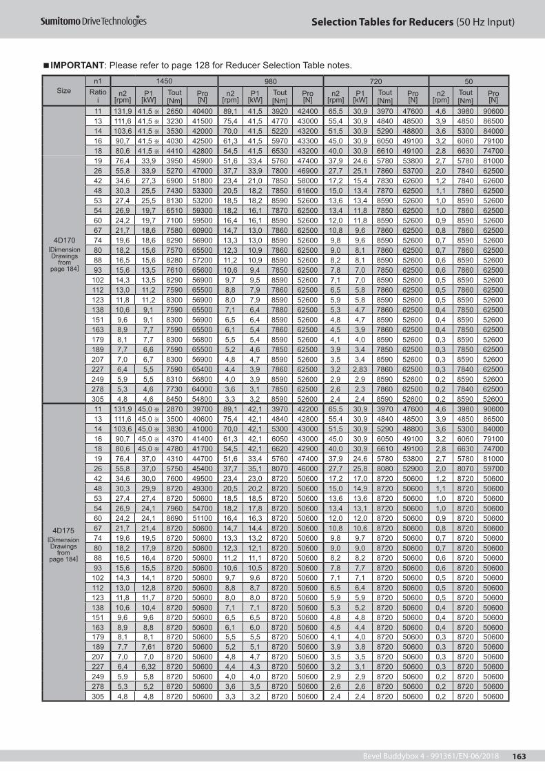
Bevel Buddybox 4 - 991361/EN-06/2018 163
Selection Tables for Reducers (50 Hz Input)
19 76,4 33,9 3950 45900 51,6 33,4 5760 47400 37,9 24,6 5780 53800 2,7 5780 8100026 55,8 33,9 5270 47000 37,7 33,9 7800 46900 27,7 25,1 7860 53700 2,0 7840 6250042 34,6 27,3 6900 51800 23,4 21,0 7850 58000 17,2 15,4 7830 62600 1,2 7840 6260048 30,3 25,5 7430 53300 20,5 18,2 7850 61600 15,0 13,4 7870 62500 1,1 7860 6250053 27,4 25,5 8130 53200 18,5 18,2 8590 52600 13,6 13,4 8590 52600 1,0 8590 5260054 26,9 19,7 6510 59300 18,2 16,1 7870 62500 13,4 11,8 7850 62500 1,0 7860 6250060 24,2 19,7 7100 59500 16,4 16,1 8590 52600 12,0 11,8 8590 52600 0,9 8590 5260067 21,7 18,6 7580 60900 14,7 13,0 7860 62500 10,8 9,6 7860 62500 0,8 7860 6250074 19,6 18,6 8290 56900 13,3 13,0 8590 52600 9,8 9,6 8590 52600 0,7 8590 5260080 18,2 15,6 7570 65500 12,3 10,9 7860 62500 9,0 8,1 7860 62500 0,7 7860 6250088 16,5 15,6 8280 57200 11,2 10,9 8590 52600 8,2 8,1 8590 52600 0,6 8590 5260093 15,6 13,5 7610 65600 10,6 9,4 7850 62500 7,8 7,0 7850 62500 0,6 7860 62500
102 14,3 13,5 8290 56900 9,7 9,5 8590 52600 7,1 7,0 8590 52600 0,5 8590 52600112 13,0 11,2 7590 65500 8,8 7,9 7860 62500 6,5 5,8 7860 62500 0,5 7860 62500123 11,8 11,2 8300 56900 8,0 7,9 8590 52600 5,9 5,8 8590 52600 0,5 8590 52600138 10,6 9,1 7590 65500 7,1 6,4 7880 62500 5,3 4,7 7860 62500 0,4 7850 62500151 9,6 9,1 8300 56900 6,5 6,4 8590 52600 4,8 4,7 8590 52600 0,4 8590 52600163 8,9 7,7 7590 65500 6,1 5,4 7860 62500 4,5 3,9 7860 62500 0,4 7850 62500179 8,1 7,7 8300 56800 5,5 5,4 8590 52600 4,1 4,0 8590 52600 0,3 8590 52600189 7,7 6,6 7590 65500 5,2 4,6 7850 62500 3,9 3,4 7850 62500 0,3 7850 62500207 7,0 6,7 8300 56900 4,8 4,7 8590 52600 3,5 3,4 8590 52600 0,3 8590 52600227 6,4 5,5 7590 65400 4,4 3,9 7860 62500 3,2 2,83 7860 62500 0,3 7840 62500249 5,9 5,5 8310 56800 4,0 3,9 8590 52600 2,9 2,9 8590 52600 0,2 8590 52600278 5,3 4,6 7730 64000 3,6 3,1 7850 62500 2,6 2,3 7860 62500 0,2 7840 62500305 4,8 4,6 8450 54800 3,3 3,2 8590 52600 2,4 2,4 8590 52600 0,2 8590 5260011 131,9 45,0 2870 39700 89,1 42,1 3970 42200 65,5 30,9 3970 47600 4,6 3980 9060013 111,6 45,0 3500 40600 75,4 42,1 4840 42800 55,4 30,9 4840 48500 3,9 4850 8650014 103,6 45,0 3830 41000 70,0 42,1 5300 43000 51,5 30,9 5290 48800 3,6 5300 8400016 90,7 45,0 4370 41400 61,3 42,1 6050 43000 45,0 30,9 6050 49100 3,2 6060 7910018 80,6 45,0 4780 41700 54,5 42,1 6620 42900 40,0 30,9 6610 49100 2,8 6630 7470019 76,4 37,0 4310 44700 51,6 33,4 5760 47400 37,9 24,6 5780 53800 2,7 5780 8100026 55,8 37,0 5750 45400 37,7 35,1 8070 46000 27,7 25,8 8080 52900 2,0 8070 5970042 34,6 30,0 7600 49500 23,4 23,0 8720 50600 17,2 17,0 8720 50600 1,2 8720 5060048 30,3 29,9 8720 49300 20,5 20,2 8720 50600 15,0 14,9 8720 50600 1,1 8720 5060053 27,4 27,4 8720 50600 18,5 18,5 8720 50600 13,6 13,6 8720 50600 1,0 8720 5060054 26,9 24,1 7960 54700 18,2 17,8 8720 50600 13,4 13,1 8720 50600 1,0 8720 5060060 24,2 24,1 8690 51100 16,4 16,3 8720 50600 12,0 12,0 8720 50600 0,9 8720 5060067 21,7 21,4 8720 50600 14,7 14,4 8720 50600 10,8 10,6 8720 50600 0,8 8720 5060074 19,6 19,5 8720 50600 13,3 13,2 8720 50600 9,8 9,7 8720 50600 0,7 8720 5060080 18,2 17,9 8720 50600 12,3 12,1 8720 50600 9,0 9,0 8720 50600 0,7 8720 5060088 16,5 16,4 8720 50600 11,2 11,1 8720 50600 8,2 8,2 8720 50600 0,6 8720 5060093 15,6 15,5 8720 50600 10,6 10,5 8720 50600 7,8 7,7 8720 50600 0,6 8720 50600
102 14,3 14,1 8720 50600 9,7 9,6 8720 50600 7,1 7,1 8720 50600 0,5 8720 50600112 13,0 12,8 8720 50600 8,8 8,7 8720 50600 6,5 6,4 8720 50600 0,5 8720 50600123 11,8 11,7 8720 50600 8,0 8,0 8720 50600 5,9 5,9 8720 50600 0,5 8720 50600138 10,6 10,4 8720 50600 7,1 7,1 8720 50600 5,3 5,2 8720 50600 0,4 8720 50600151 9,6 9,6 8720 50600 6,5 6,5 8720 50600 4,8 4,8 8720 50600 0,4 8720 50600163 8,9 8,8 8720 50600 6,1 6,0 8720 50600 4,5 4,4 8720 50600 0,4 8720 50600
IMPORTANT: Please refer to page 128 for Reducer Selection Table notes.
Sizen1 1450 980 720 50
Ratio i
n2 [rpm]
P1 [kW]
Tout [Nm]
Pro [N]
n2 [rpm]
P1 [kW]
Tout [Nm]
Pro [N]
n2 [rpm]
P1 [kW]
Tout [Nm]
Pro [N]
n2 [rpm]
Tout [Nm]
Pro [N]
11 131,9 41,5 2650 40400 89,1 41,5 3920 42400 65,5 30,9 3970 47600 4,6 3980 9060013 111,6 41,5 3230 41500 75,4 41,5 4770 43000 55,4 30,9 4840 48500 3,9 4850 8650014 103,6 41,5 3530 42000 70,0 41,5 5220 43200 51,5 30,9 5290 48800 3,6 5300 8400016 90,7 41,5 4030 42500 61,3 41,5 5970 43300 45,0 30,9 6050 49100 3,2 6060 7910018 80,6 41,5 4410 42800 54,5 41,5 6530 43200 40,0 30,9 6610 49100 2,8 6630 74700
179 8,1 8,1 8720 50600 5,5 5,5 8720 50600 4,1 4,0 8720 50600 0,3 8720 50600189 7,7 7,61 8720 50600 5,2 5,1 8720 50600 3,9 3,8 8720 50600 0,3 8720 50600207 7,0 7,0 8720 50600 4,8 4,7 8720 50600 3,5 3,5 8720 50600 0,3 8720 50600227 6,4 6,32 8720 50600 4,4 4,3 8720 50600 3,2 3,1 8720 50600 0,3 8720 50600249 5,9 5,8 8720 50600 4,0 4,0 8720 50600 2,9 2,9 8720 50600 0,2 8720 50600278 5,3 5,2 8720 50600 3,6 3,5 8720 50600 2,6 2,6 8720 50600 0,2 8720 50600305 4,8 4,8 8720 50600 3,3 3,2 8720 50600 2,4 2,4 8720 50600 0,2 8720 50600
4D175[Dimension Drawings
from page 184]
4D170[Dimension Drawings
from page 184]

Bevel Buddybox 4 - 991361/EN-06/2018164
Selection Tables for Reducers (50 Hz Input)
Sizen1 1450 980 720 50
Ratio i
n2 [rpm]
P1 [kW]
Tout [Nm]
Pro [N]
n2 [rpm]
P1 [kW]
Tout [Nm]
Pro [N]
n2 [rpm]
P1 [kW]
Tout [Nm]
Pro [N]
n2 [rpm]
Tout [Nm]
Pro [N]
4D180[Dimension Drawings
from page 184]
11 131,9 53,4 3400 38000 89,1 53,4 5040 38900 65,5 41,1 5280 43400 4,6 5270 8410013 111,6 53,4 4150 38600 75,4 53,4 6140 38700 55,4 41,1 6430 43400 3,9 6420 7620014 103,6 53,4 4540 38800 70,0 53,4 6720 38500 51,5 41,1 7040 43300 3,6 7030 7100016 90,7 53,4 5190 38900 61,3 53,4 7680 37900 45,0 41,1 8040 42700 3,2 8030 6020018 80,6 53,4 5670 38800 54,5 50,1 7880 38900 40,0 40,4 8640 42700 2,8 8720 5060019 76,4 41,5 4840 43100 51,6 41,5 7160 43000 37,9 30,9 7260 49000 2,7 7270 6880021 69,1 41,5 5290 43200 46,7 41,5 7830 42700 34,3 30,9 7940 48900 2,4 7950 6140022 66,0 41,5 5640 43300 44,6 37,4 7530 44900 32,8 27,5 7530 51600 2,3 7530 6610025 58,0 41,5 6170 43300 39,2 37,4 8230 44600 28,8 27,5 8240 51400 2,0 8240 5770026 55,8 41,5 6450 43200 37,7 33,3 7660 47400 27,7 24,4 7640 54300 2,0 7660 6480028 51,8 41,5 7060 43100 35,0 33,3 8380 47100 25,8 24,4 8360 54200 1,8 8380 5590035 41,5 39,8 8510 43100 28,0 27,6 8720 50600 20,6 20,3 8720 50600 1,5 8720 5060039 37,2 36,7 8570 44800 25,2 25,2 8720 50600 18,5 18,5 8720 50600 1,3 8720 5060042 34,6 34,5 8720 46000 23,4 23,3 8720 50600 17,2 17,1 8720 50600 1,2 8720 5060046 31,6 31,6 8720 48100 21,3 21,3 8720 50600 15,7 15,7 8720 50600 1,1 8720 5060048 30,3 29,9 8720 49300 20,5 20,2 8720 50600 15,0 14,9 8720 50600 1,1 8720 5060053 27,4 27,4 8720 50600 18,5 18,5 8720 50600 13,6 13,6 8720 50600 1,0 8720 5060054 26,9 26,4 8720 50600 18,2 17,8 8720 50600 13,4 13,1 8720 50600 1,0 8720 5060060 24,2 24,1 8720 50600 16,4 16,3 8720 50600 12,0 12,0 8720 50600 0,9 8720 5060067 21,7 21,4 8720 50600 14,7 14,4 8720 50600 10,8 10,6 8720 50600 0,8 8720 5060074 19,6 19,5 8720 50600 13,3 13,2 8720 50600 9,8 9,7 8720 50600 0,7 8720 5060080 18,2 17,9 8720 50600 12,3 12,1 8720 50600 9,0 9,0 8720 50600 0,7 8720 5060088 16,5 16,4 8720 50600 11,2 11,1 8720 50600 8,2 8,2 8720 50600 0,6 8720 5060093 15,6 15,5 8720 50600 10,6 10,5 8720 50600 7,8 7,7 8720 50600 0,6 8720 50600
102 14,3 14,1 8720 50600 9,7 9,6 8720 50600 7,1 7,1 8720 50600 0,5 8720 50600112 13,0 12,8 8720 50600 8,8 8,7 8720 50600 6,5 6,4 8720 50600 0,5 8720 50600123 11,8 11,7 8720 50600 8,0 8,0 8720 50600 5,9 5,9 8720 50600 0,5 8720 50600138 10,6 10,4 8720 50600 7,1 7,1 8720 50600 5,3 5,2 8720 50600 0,4 8720 50600151 9,6 9,6 8720 50600 6,5 6,5 8720 50600 4,8 4,8 8720 50600 0,4 8720 50600163 8,9 8,8 8720 50600 6,1 6,0 8720 50600 4,5 4,4 8720 50600 0,4 8720 50600179 8,1 8,1 8720 50600 5,5 5,5 8720 50600 4,1 4,0 8720 50600 0,3 8720 50600189 7,7 7,6 8720 50600 5,2 5,1 8720 50600 3,9 3,8 8720 50600 0,3 8720 50600207 7,0 7,0 8720 50600 4,8 4,7 8720 50600 3,5 3,5 8720 50600 0,3 8720 50600227 6,4 6,3 8720 50600 4,4 4,3 8720 50600 3,2 3,1 8720 50600 0,3 8720 50600249 5,9 5,8 8720 50600 4,0 4,0 8720 50600 2,9 2,9 8720 50600 0,2 8720 50600278 5,3 5,16 8720 50600 3,6 3,5 8720 50600 2,6 2,6 8720 50600 0,2 8720 50600305 4,8 4,8 8720 50600 3,3 3,2 8720 50600 2,4 2,4 8720 50600 0,2 8720 50600
4D185[Dimension Drawings
from page 184]
11 131,9 60,0 3830 36600 89,1 55,9 5270 38100 65,5 41,1 5280 43400 4,6 5270 8410013 111,6 60,0 4660 36900 75,4 55,9 6430 37800 55,4 41,1 6430 43400 3,9 6420 7620014 103,6 60,0 5100 37000 70,0 55,9 7030 37500 51,5 41,1 7040 43300 3,6 7030 7100016 90,7 60,0 5830 36800 61,3 54,5 7840 37400 45,0 41,1 8040 42700 3,2 8030 6020018 80,6 60,0 6380 36600 54,5 50,1 7880 38900 40,0 40,4 8640 42700 2,8 8720 5060019 76,4 45,0 5250 41800 51,6 42,8 7380 42300 37,9 31,4 7370 48700 2,7 7370 6770021 69,1 45,0 5740 41800 46,7 42,6 8040 42000 34,3 31,4 8060 48500 2,4 8060 5990022 66,0 45,0 6120 41800 44,6 38,0 7650 44600 32,8 27,9 7640 51200 2,3 7650 6480025 58,0 45,0 6690 41600 39,2 38,0 8360 44200 28,8 27,9 8360 51000 2,0 8370 5600026 55,8 45,0 7000 41500 37,7 33,8 7770 47000 27,7 24,8 7760 53900 2,0 7750 6350028 51,8 45,0 7650 41200 35,0 33,8 8500 46700 25,8 24,8 8490 53800 1,8 8480 5410035 41,5 39,8 8510 43100 28,0 27,6 8720 50600 20,6 20,3 8720 50600 1,5 8720 5060039 37,2 36,7 8570 44800 25,2 25,2 8720 50600 18,5 18,5 8720 50600 1,3 8720 5060042 34,6 34,5 8720 46000 23,4 23,3 8720 50600 17,2 17,1 8720 50600 1,2 8720 5060046 31,6 31,6 8720 48100 21,3 21,3 8720 50600 15,7 15,7 8720 50600 1,1 8720 5060048 30,3 29,9 8720 49300 20,5 20,2 8720 50600 15,0 14,9 8720 50600 1,1 8720 5060053 27,4 27,4 8720 50600 18,5 18,5 8720 50600 13,6 13,6 8720 50600 1,0 8720 5060054 26,9 26,4 8720 50600 18,2 17,8 8720 50600 13,4 13,1 8720 50600 1,0 8720 50600
IMPORTANT: Please refer to page 128 for Reducer Selection Table notes.

Bevel Buddybox 4 - 991361/EN-06/2018 165
Selection Tables for Reducers (50 Hz Input)
Sizen1 1450 980 720 50
Ratio i
n2 [rpm]
P1 [kW]
Tout [Nm]
Pro [N]
n2 [rpm]
P1 [kW]
Tout [Nm]
Pro [N]
n2 [rpm]
P1 [kW]
Tout [Nm]
Pro [N]
n2 [rpm]
Tout [Nm]
Pro [N]
4D185[Dimension Drawings
from page 184]
60 24,2 24,1 8720 50600 16,4 16,3 8720 50600 12,0 12,0 8720 50600 0,9 8720 5060067 21,7 21,4 8720 50600 14,7 14,4 8720 50600 10,8 10,6 8720 50600 0,8 8720 5060074 19,6 19,5 8720 50600 13,3 13,2 8720 50600 9,8 9,7 8720 50600 0,7 8720 5060080 18,2 17,9 8720 50600 12,3 12,1 8720 50600 9,0 9,0 8720 50600 0,7 8720 5060088 16,5 16,4 8720 50600 11,2 11,1 8720 50600 8,2 8,2 8720 50600 0,6 8720 5060093 15,6 15,5 8720 50600 10,6 10,5 8720 50600 7,8 7,7 8720 50600 0,6 8720 50600
102 14,3 14,1 8720 50600 9,7 9,6 8720 50600 7,1 7,1 8720 50600 0,5 8720 50600112 13,0 12,8 8720 50600 8,8 8,7 8720 50600 6,5 6,4 8720 50600 0,5 8720 50600123 11,8 11,7 8720 50600 8,0 8,0 8720 50600 5,9 5,9 8720 50600 0,5 8720 50600138 10,6 10,4 8720 50600 7,1 7,1 8720 50600 5,3 5,2 8720 50600 0,4 8720 50600151 9,6 9,6 8720 50600 6,5 6,5 8720 50600 4,8 4,8 8720 50600 0,4 8720 50600163 8,9 8,8 8720 50600 6,1 6,0 8720 50600 4,5 4,4 8720 50600 0,4 8720 50600179 8,1 8,1 8720 50600 5,5 5,5 8720 50600 4,1 4,0 8720 50600 0,3 8720 50600189 7,7 7,6 8720 50600 5,2 5,1 8720 50600 3,9 3,8 8720 50600 0,3 8720 50600207 7,0 7,0 8720 50600 4,8 4,7 8720 50600 3,5 3,5 8720 50600 0,3 8720 50600227 6,4 6,3 8720 50600 4,4 4,3 8720 50600 3,2 3,1 8720 50600 0,3 8720 50600249 5,9 5,8 8720 50600 4,0 4,0 8720 50600 2,9 2,9 8720 50600 0,2 8720 50600278 5,3 5,2 8720 50600 3,6 3,5 8720 50600 2,6 2,6 8720 50600 0,2 8720 50600305 4,8 4,8 8720 50600 3,3 3,2 8720 50600 2,4 2,4 8720 50600 0,2 8720 50600
4E170[Dimension Drawings
from page 184]
11 131,9 41,5 2650 54900 89,1 41,5 3920 59100 65,5 30,9 3970 65700 4,6 3980 98000 13 111,6 41,5 3230 57100 75,4 41,5 4770 60900 55,4 30,9 4840 67900 3,9 4850 96200 14 103,6 41,5 3530 58000 70,0 41,5 5220 61600 51,5 30,9 5290 68900 3,6 5300 95300 16 90,7 41,5 4030 59300 61,3 41,5 5970 62600 45,0 30,9 6050 70100 3,2 6060 93800 18 80,6 41,5 4410 60200 54,5 41,5 6530 63200 40,0 30,9 6610 70900 2,8 6630 92700 19 76,4 33,9 3950 63600 51,6 33,4 5760 67700 37,9 24,6 5780 75800 2,7 5780 9440026 55,8 33,9 5270 66500 37,7 33,9 7800 69400 27,7 25,1 7860 78100 2,0 7840 9020042 34,6 27,3 6900 74600 23,4 21,0 7850 83700 17,2 15,4 7830 90300 1,2 7840 9030048 30,3 25,5 7430 77200 20,5 18,2 7850 88300 15,0 13,4 7850 90200 1,1 7860 9020053 27,4 25,5 8130 77900 18,5 18,2 8590 88700 13,6 13,4 8590 88700 1,0 8590 8870054 26,9 19,7 6510 83700 18,2 16,1 7870 90200 13,4 11,8 7850 90200 1,0 7860 9020060 24,2 19,7 7100 84800 16,4 16,1 8590 88700 12,0 11,8 8590 88700 0,9 8590 8870067 21,7 18,6 7580 87100 14,7 13,0 7860 90200 10,8 9,6 7860 90200 0,8 7860 9020074 19,6 18,6 8290 88200 13,3 13,0 8590 88700 9,8 9,6 8590 88700 0,7 8590 8870080 18,2 15,6 7570 90800 12,3 10,9 7860 90200 9,0 8,1 7860 90200 0,7 7860 9020088 16,5 15,6 8280 89400 11,2 10,9 8590 88700 8,2 8,1 8590 88700 0,6 8590 8870093 15,6 13,5 7610 90700 10,6 9,4 7850 90200 7,8 6,9 7850 90200 0,6 7860 90200
102 14,3 13,5 8290 89300 9,7 9,5 8590 88700 7,1 7,0 8590 88700 0,5 8590 88700112 13,0 11,2 7590 90800 8,8 7,9 7860 90200 6,5 5,8 7860 90200 0,5 7860 90200123 11,8 11,2 8300 89300 8,0 7,9 8590 88700 5,9 5,8 8590 88700 0,5 8590 88700138 10,6 9,1 7590 90800 7,1 6,4 7860 90200 5,3 4,7 7860 90200 0,4 7850 90200151 9,6 9,1 8300 89300 6,5 6,4 8590 88700 4,8 4,7 8590 88700 0,4 8590 88700163 8,9 7,7 7590 90700 6,1 5,4 7860 90200 4,5 3,9 7860 90200 0,4 7850 90200179 8,1 7,7 8300 89300 5,5 5,4 8590 88700 4,1 4,0 8590 88700 0,3 8590 88700189 7,7 6,6 7590 90700 5,2 4,6 7850 90200 3,9 3,4 7850 90200 0,3 7850 90200207 7,0 6,7 8300 89300 4,8 4,7 8590 88700 3,5 3,4 8590 88700 0,3 8590 88700227 6,4 5,5 7590 90800 4,4 3,9 7860 90200 3,2 2,8 7860 90200 0,3 7840 90200249 5,9 5,5 8310 89300 4,0 3,9 8590 88700 2,9 2,9 8590 88700 0,2 8590 88700278 5,3 4,6 7730 90500 3,6 3,1 7850 90200 2,6 2,3 7860 90200 0,2 7840 90200305 4,8 4,6 8450 89000 3,3 3,2 8590 88700 2,4 2,4 8590 88700 0,2 8590 88700
IMPORTANT: Please refer to page 128 for Reducer Selection Table notes.

Bevel Buddybox 4 - 991361/EN-06/2018166
Selection Tables for Reducers (50 Hz Input)
26 55,8 37,0 5750 65100 37,7 35,1 8070 68600 27,7 25,8 8080 77500 2,0 8070 8980042 34,6 30,1 7600 72500 23,4 26,2 9790 78100 17,2 19,2 9770 86400 1,2 9820 8630048 30,3 30,1 8770 73400 20,5 22,3 9620 83200 15,0 16,7 9800 86300 1,1 9810 8630053 27,4 30,1 9590 73700 18,5 20,8 9830 85600 13,6 15,3 9830 86300 1,0 9830 8630054 26,9 24,1 7960 79500 18,2 20,0 9780 86400 13,4 14,7 9780 86400 1,0 9770 8640060 24,2 24,1 8690 80200 16,4 18,4 9830 86300 12,0 13,5 9830 86300 0,9 9830 8630067 21,7 23,6 9620 81200 14,7 16,2 9780 86400 10,8 11,9 9780 86400 0,8 9780 8640074 19,6 22,0 9830 83800 13,3 14,9 9830 86300 9,8 10,9 9830 86300 0,7 9830 8630080 18,2 19,5 9470 87000 12,3 13,6 9780 86400 9,0 10,0 9780 86400 0,7 9780 8640088 16,5 18,5 9830 86300 11,2 12,5 9830 86300 8,2 9,2 9830 86300 0,6 9830 8630093 15,6 17,4 9810 86300 10,6 11,7 9760 86400 7,8 8,6 9780 86400 0,6 9790 86400
102 14,3 15,9 9830 86300 9,7 10,8 9830 86300 7,1 8,0 9830 86300 0,5 9830 86300112 13,0 14,4 9780 86400 8,8 9,8 9780 86400 6,5 7,2 9780 86400 0,5 9780 86400123 11,8 14,4 10700 84500 8,0 9,8 10700 84500 5,9 7,2 10700 84500 0,5 10700 84500138 10,6 11,3 9440 87100 7,1 7,9 9780 86400 5,3 5,8 9780 86400 0,4 9790 86400151 9,6 11,3 10300 85300 6,5 8,0 10700 84500 4,8 5,9 10700 84500 0,4 10700 84500163 8,9 9,9 9780 86400 6,1 6,7 9780 86400 4,5 4,9 9780 86400 0,4 9770 86400179 8,1 9,9 10700 84500 5,5 6,7 10700 84500 4,1 4,9 10700 84500 0,3 10700 84500189 7,7 8,3 9500 86900 5,2 5,8 9790 86400 3,9 4,2 9790 86400 0,3 9770 86400207 7,0 8,3 10400 85200 4,8 5,8 10700 84500 3,5 4,3 10700 84500 0,3 10700 84500227 6,4 7,0 9630 86700 4,4 4,8 9780 86400 3,2 3,5 9780 86400 0,3 9800 86300249 5,9 7,0 10500 84900 4,0 4,8 10700 84500 2,9 3,6 10700 84500 0,2 10700 84500278 5,3 5,6 9500 86900 3,6 3,9 9780 86400 2,6 2,9 9770 86400 0,2 9810 86300305 4,8 5,7 10400 85200 3,3 4,0 10700 84500 2,4 2,9 10700 84500 0,2 10700 84500
4E180[Dimension Drawings
from page 184]
11 131,9 53,4 3400 52700 89,1 53,4 5040 55800 65,5 41,1 5280 61900 4,6 5270 95400 13 111,6 53,4 4150 54400 75,4 53,4 6140 56900 55,4 41,1 6430 63300 3,9 6420 93100 14 103,6 53,4 4540 55100 70,0 53,4 6720 57300 51,5 41,1 7040 63800 3,6 7030 91900 16 90,7 53,4 5190 56000 61,3 53,4 7680 57700 45,0 41,1 8040 64300 3,2 8030 89900 18 80,6 53,4 5670 56500 54,5 53,4 8400 57800 40,0 41,1 8800 64600 2,8 8780 88400 19 76,4 41,5 4840 61000 51,6 41,5 7160 63600 37,9 30,9 7260 71500 2,7 7270 9140021 69,1 41,5 5290 61700 46,7 41,5 7830 64000 34,3 30,9 7940 72100 2,4 7950 90000 22 66,0 41,5 5640 62200 44,6 37,4 7530 66500 32,8 27,5 7530 75100 2,3 7530 90900 25 58,0 41,5 6170 62800 39,2 37,4 8230 66900 28,8 27,5 8240 75700 2,0 8240 89500 26 55,8 41,5 6450 63100 37,7 33,3 7660 69800 27,7 24,4 7640 78700 2,0 7660 9060028 51,8 41,5 7060 63600 35,0 33,3 8380 70300 25,8 24,4 8360 79400 1,8 8380 89200 35 41,5 41,5 8870 64300 28,0 36,7 11600 67600 20,6 26,9 11600 77400 1,5 11600 82000 39 37,2 41,5 9700 64400 25,2 33,5 11600 70400 18,5 24,6 11600 80500 1,3 11600 82000 42 34,6 41,5 10500 64300 23,4 31,0 11600 72800 17,2 22,8 11600 82000 1,2 11600 8200046 31,6 41,5 11500 64000 21,3 28,4 11600 75700 15,7 20,8 11600 82000 1,1 11600 82000 48 30,3 32,4 9440 71400 20,5 26,9 11600 77500 15,0 19,8 11600 82000 1,1 11600 8200053 27,4 32,4 10300 71600 18,5 24,6 11600 80500 13,6 18,1 11600 82000 1,0 11600 82000 54 26,9 30,6 10100 73300 18,2 23,7 11600 81700 13,4 17,4 11600 82000 1,0 11600 8200060 24,2 30,6 11100 73400 16,4 21,7 11600 82000 12,0 15,9 11600 82000 0,9 11600 82000 67 21,7 28,4 11600 75700 14,7 19,2 11600 82000 10,8 14,1 11600 82000 0,8 11600 82000 74 19,6 26,0 11600 78700 13,3 17,6 11600 82000 9,8 12,9 11600 82000 0,7 11600 82000 80 18,2 23,9 11600 81500 12,3 16,1 11600 82000 9,0 11,9 11600 82000 0,7 11600 82000 88 16,5 21,8 11600 82000 11,2 14,8 11600 82000 8,2 10,8 11600 82000 0,6 11600 82000 93 15,6 19,5 11000 84000 10,6 13,9 11600 82000 7,8 10,2 11600 82000 0,6 11600 82000
102 14,3 18,8 11600 82000 9,7 12,7 11600 82000 7,1 9,4 11600 82000 0,5 11600 82000 112 13,0 17,1 11600 82000 8,8 11,5 11600 82000 6,5 8,5 11600 82000 0,5 11600 82000 123 11,8 15,6 11600 82000 8,0 10,5 11600 82000 5,9 7,8 11600 82000 0,5 11600 82000 138 10,6 13,9 11600 82000 7,1 9,4 11600 82000 5,3 6,9 11600 82000 0,4 11600 82000151 9,6 12,7 11600 82000 6,5 8,6 11600 82000 4,8 6,3 11600 82000 0,4 11600 82000 163 8,9 11,7 11600 82000 6,1 7,9 11600 82000 4,5 5,8 11600 82000 0,4 11600 82000179 8,1 10,7 11600 82000 5,5 7,3 11600 82000 4,1 5,4 11600 82000 0,3 11600 82000
IMPORTANT: Please refer to page 128 for Reducer Selection Table notes.
Sizen1 1450 980 720 50
Ratio i
n2 [rpm]
P1 [kW]
Tout [Nm]
Pro [N]
n2 [rpm]
P1 [kW]
Tout [Nm]
Pro [N]
n2 [rpm]
P1 [kW]
Tout [Nm]
Pro [N]
n2 [rpm]
Tout [Nm]
Pro [N]
11 131,9 45,0 2870 96200 89,1 42,1 3970 58900 65,5 30,9 3970 65700 4,6 3980 98000 13 111,6 45,0 3500 56300 75,4 42,1 4840 60700 55,4 30,9 4840 67900 3,9 4850 95300 14 103,6 45,0 3830 57100 70,0 42,1 5300 61400 51,5 30,9 5290 68900 3,6 5300 93800 16 90,7 45,0 4370 58300 61,3 42,1 6050 62400 45,0 30,9 6050 70100 3,2 6060 92700 18 80,6 45,0 4780 59100 54,5 42,1 6620 62900 40,0 30,9 6610 70900 2,8 6630 92700 19 76,4 37,0 4310 62500 51,6 33,4 5760 67700 37,9 24,6 5780 75800 2,7 5780 94400
4E175[Dimension Drawings
from page 184]

Bevel Buddybox 4 - 991361/EN-06/2018 167
Selection Tables for Reducers (50 Hz Input)
Sizen1 1450 980 720 50
Ratio i
n2 [rpm]
P1 [kW]
Tout [Nm]
Pro [N]
n2 [rpm]
P1 [kW]
Tout [Nm]
Pro [N]
n2 [rpm]
P1 [kW]
Tout [Nm]
Pro [N]
n2 [rpm]
Tout [Nm]
Pro [N]
4E180[Dimension Drawings
from page 184]
189 7,7 9,8 11200 83600 5,2 6,8 11600 82000 3,9 5,0 11600 82000 0,3 11600 82000207 7,0 9,3 11600 82000 4,8 6,3 11600 82000 3,5 4,6 11600 82000 0,3 11600 82000 227 6,4 8,49 11600 82000 4,4 5,7 11600 82000 3,2 4,2 11600 82000 0,3 11600 82000249 5,9 7,7 11600 82000 4,0 5,2 11600 82000 2,9 3,9 11600 82000 0,2 11600 82000 278 5,3 6,9 11600 82000 3,6 4,6 11600 82000 2,6 3,4 11600 82000 0,2 11600 82000305 4,8 6,3 11600 82000 3,3 4,3 11600 82000 2,4 3,2 11600 82000 0,2 11600 82000
4E185[Dimension Drawings
from page 184]
11 131,9 60,0 3830 51500 89,1 55,9 5270 55100 65,5 41,1 5280 61900 4,6 5270 95400 13 111,6 60,0 4660 52900 75,4 55,9 6430 56100 55,4 41,1 6430 63300 3,9 6420 93100 14 103,6 60,0 5100 53500 70,0 55,9 7030 56400 51,5 41,1 7040 63800 3,6 7030 91900 16 90,7 60,0 5830 54100 61,3 55,9 8040 56600 45,0 41,1 8040 64300 3,2 8030 89900 18 80,6 60,0 6380 54500 54,5 55,9 8790 56600 40,0 41,1 8800 64600 2,8 8780 88400 19 76,4 45,0 5250 59800 51,6 42,8 7380 63000 37,9 31,4 7370 71200 2,7 7370 9120021 69,1 45,0 5740 60400 46,7 42,8 8080 63300 34,3 31,4 8060 71700 2,4 8060 89800 22 66,0 45,0 6120 60800 44,6 38,0 7650 66200 32,8 27,9 7640 74800 2,3 7650 90600 25 58,0 45,0 6690 61300 39,2 38,0 8360 66600 28,8 27,9 8360 75400 2,0 8370 89200 26 55,8 45,0 7000 61500 37,7 33,8 7770 69500 27,7 24,8 7760 78400 2,0 7750 9040028 51,8 45,0 7650 61900 35,0 33,8 8500 69900 25,8 24,8 8490 79000 1,8 8480 89000 35 41,5 45,0 9620 62100 28,0 36,7 11600 67600 20,6 26,9 11600 77400 1,5 11600 82000 39 37,2 45,0 10500 62000 25,2 33,5 11600 70400 18,5 24,6 11600 80500 1,3 11600 82000 42 34,6 45,0 11400 61700 23,4 31,0 11600 72800 17,2 23,0 11600 82000 1,2 11600 8200046 31,6 41,8 11500 63800 21,3 28,4 11600 75700 15,7 20,8 11600 82000 1,1 11600 82000 48 30,3 39,0 11400 65800 20,5 26,9 11600 77500 15,0 19,8 11600 82000 1,1 11600 8200053 27,4 36,4 11600 67900 18,5 24,6 11600 80500 13,6 18,1 11600 82000 1,0 11600 82000 54 26,9 35,1 11600 69000 18,2 23,7 11600 81700 13,4 17,4 11600 82000 1,0 11600 8200060 24,2 32,1 11600 71800 16,4 21,7 11600 82000 12,0 15,9 11600 82000 0,9 11600 82000 67 21,7 28,4 11600 75700 14,7 19,2 11600 82000 10,8 14,1 11600 82000 0,8 11600 82000 74 19,6 26,0 11600 78700 13,3 17,6 11600 82000 9,8 12,9 11600 82000 0,7 11600 82000 80 18,2 23,9 11600 81500 12,3 16,1 11600 82000 9,0 11,9 11600 82000 0,7 11600 82000 88 16,5 21,8 11600 82000 11,2 14,8 11600 82000 8,2 10,8 11600 82000 0,6 11600 82000 93 15,6 20,6 11600 82000 10,6 13,9 11600 82000 7,8 10,2 11600 82000 0,6 11600 82000
102 14,3 18,8 11600 82000 9,7 12,7 11600 82000 7,1 9,4 11600 82000 0,5 11600 82000 112 13,0 17,1 11600 82000 8,8 11,5 11600 82000 6,5 8,5 11600 82000 0,5 11600 82000 123 11,8 15,6 11600 82000 8,0 10,5 11600 82000 5,9 7,8 11600 82000 0,5 11600 82000 138 10,6 13,9 11600 82000 7,1 9,4 11600 82000 5,3 6,9 11600 82000 0,4 11600 82000151 9,6 12,7 11600 82000 6,5 8,6 11600 82000 4,8 6,3 11600 82000 0,4 11600 82000 163 8,9 11,7 11600 82000 6,1 7,9 11600 82000 4,5 5,8 11600 82000 0,4 11600 82000179 8,1 10,7 11600 82000 5,5 7,3 11600 82000 4,1 5,4 11600 82000 0,3 11600 82000 189 7,7 10,1 11600 82000 5,2 6,8 11600 82000 3,9 5,0 11600 82000 0,3 11600 82000207 7,0 9,3 11600 82000 4,8 6,3 11600 82000 3,5 4,6 11600 82000 0,3 11600 82000 227 6,4 8,4 11600 82000 4,4 5,7 11600 82000 3,2 4,2 11600 82000 0,3 11600 82000249 5,9 7,7 11600 82000 4,0 5,2 11600 82000 2,9 3,9 11600 82000 0,2 11600 82000 278 5,3 6,9 11600 82000 3,6 4,6 11600 82000 2,6 3,4 11600 82000 0,2 11600 82000305 4,8 6,3 11600 82000 3,3 4,3 11600 82000 2,4 3,2 11600 82000 0,2 11600 82000
4E190[Dimension Drawings
from page 184]
11 131,9 68,4 4360 50000 89,1 68,4 6450 51700 65,5 66,1 8490 52700 4,6 8670 8860013 111,6 68,4 5320 51000 75,4 68,4 7870 51900 55,4 65,6 10300 52300 3,9 10600 8480014 103,6 68,4 5820 51400 70,0 68,4 8600 51900 51,5 60,4 10300 54300 3,6 11600 8240016 90,7 68,4 6650 51800 61,3 68,4 9830 51400 45,0 58,1 11400 54700 3,2 11600 8200018 80,6 68,4 7270 51900 54,5 66,4 10400 51900 40,0 53,5 11500 56900 2,8 11600 8200019 76,4 50,6 5900 57900 51,6 50,6 8730 59100 37,9 38,7 9090 66300 2,7 9100 8770021 69,1 50,6 6450 58400 46,7 50,6 9550 59100 34,3 38,7 9940 66300 2,4 9950 8600022 66,0 50,6 6880 58600 44,6 46,5 9360 61300 32,8 34,1 9340 69800 2,3 9350 8720025 58,0 50,6 7530 58900 39,2 46,5 10200 61200 28,8 34,1 10200 70000 2,0 10200 8550026 55,8 50,6 7870 59000 37,7 41,3 9500 64500 27,7 30,3 9490 73400 2,0 9510 8690028 51,8 50,6 8600 59100 35,0 41,3 10400 64400 25,8 30,3 10400 73600 1,8 10400 8510035 41,5 50,6 10800 58700 28,0 36,7 11600 67600 20,6 26,9 11600 77400 1,5 11600 8200039 37,2 48,2 11300 59900 25,2 33,5 11600 70400 18,5 24,6 11600 80500 1,3 11600 8200042 34,6 45,9 11600 61000 23,4 31,0 11600 72800 17,2 22,8 11600 82000 1,2 11600 8200046 31,6 42,0 11600 63600 21,3 28,4 11600 75700 15,7 20,8 11600 82000 1,1 11600 8200048 30,3 39,8 11600 65200 20,5 26,9 11600 77500 15,0 19,8 11600 82000 1,1 11600 8200053 27,4 36,4 11600 67900 18,5 24,6 11600 80500 13,6 18,1 11600 82000 1,0 11600 8200054 26,9 35,1 11600 69000 18,2 23,7 11600 81700 13,4 17,4 11600 82000 1,0 11600 8200060 24,2 32,1 11600 71800 16,4 21,7 11600 82000 12,0 15,9 11600 82000 0,9 11600 82000
IMPORTANT: Please refer to page 128 for Reducer Selection Table notes.

Bevel Buddybox 4 - 991361/EN-06/2018168
Selection Tables for Reducers (50 Hz Input)
Sizen1 1450 980 720 50
Ratio i
n2 [rpm]
P1 [kW]
Tout [Nm]
Pro [N]
n2 [rpm]
P1 [kW]
Tout [Nm]
Pro [N]
n2 [rpm]
P1 [kW]
Tout [Nm]
Pro [N]
n2 [rpm]
Tout [Nm]
Pro [N]
4E190[Dimension Drawings
from page 184]
67 21,7 28,4 11600 75700 14,7 19,2 11600 82000 10,8 14,1 11600 82000 0,8 11600 8200074 19,6 26,0 11600 78700 13,3 17,6 11600 82000 9,8 12,9 11600 82000 0,7 11600 8200080 18,2 23,9 11600 81500 12,3 16,1 11600 82000 9,0 11,9 11600 82000 0,7 11600 8200088 16,5 21,8 11600 82000 11,2 14,8 11600 82000 8,2 10,8 11600 82000 0,6 11600 8200093 15,6 20,6 11600 82000 10,6 13,9 11600 82000 7,8 10,2 11600 82000 0,6 11600 82000
102 14,3 18,8 11600 82000 9,7 12,7 11600 82000 7,1 9,4 11600 82000 0,5 11600 82000112 13,0 17,1 11600 82000 8,8 11,5 11600 82000 6,5 8,5 11600 82000 0,5 11600 82000123 11,8 15,6 11600 82000 8,0 10,5 11600 82000 5,9 7,8 11600 82000 0,5 11600 82000138 10,6 13,9 11600 82000 7,1 9,4 11600 82000 5,3 6,9 11600 82000 0,4 11600 82000151 9,6 12,7 11600 82000 6,5 8,6 11600 82000 4,8 6,3 11600 82000 0,4 11600 82000163 8,9 11,7 11600 82000 6,1 7,9 11600 82000 4,5 5,8 11600 82000 0,4 11600 82000179 8,1 10,7 11600 82000 5,5 7,3 11600 82000 4,1 5,4 11600 82000 0,3 11600 82000189 7,7 10,1 11600 82000 5,2 6,8 11600 82000 3,9 5,0 11600 82000 0,3 11600 82000207 7,0 9,3 11600 82000 4,8 6,3 11600 82000 3,5 4,6 11600 82000 0,3 11600 82000227 6,4 8,4 11600 82000 4,4 5,7 11600 82000 3,2 4,2 11600 82000 0,3 11600 82000249 5,9 7,7 11600 82000 4,0 5,2 11600 82000 2,9 3,9 11600 82000 0,2 11600 82000278 5,3 6,9 11600 82000 3,6 4,6 11600 82000 2,6 3,41 11600 82000 0,2 11600 82000305 4,8 6,3 11600 82000 3,3 4,3 11600 82000 2,4 3,2 11600 82000 0,2 11600 82000
4E195[Dimension Drawings
from page 184]
11 131,9 75,0 4780 48700 89,1 75,0 7080 49900 65,5 66,1 8490 52700 4,6 8670 8860013 111,6 75,0 5830 49500 75,4 75,0 8630 49700 55,4 65,6 10300 52300 3,9 10600 8480014 103,6 75,0 6380 49800 70,0 74,9 9430 49500 51,5 60,4 10300 54300 3,6 11600 8240016 90,7 75,0 7290 49900 61,3 72,1 10400 49900 45,0 58,1 11400 54700 3,2 11600 8200018 80,6 75,0 7970 49900 54,5 66,4 10400 51900 40,0 53,5 11500 56900 2,8 11600 8200019 76,4 55,0 6410 56400 51,6 53,7 9260 57600 37,9 39,4 9250 65700 2,7 9260 8740021 69,1 55,0 7010 56800 46,7 53,7 10100 57400 34,3 39,4 10100 65800 2,4 10100 8570022 66,0 55,0 7480 56900 44,6 47,4 9540 60800 32,8 34,8 9530 69300 2,3 9550 8680025 58,0 55,0 8180 57000 39,2 47,4 10400 60600 28,8 34,8 10400 69400 2,0 10400 8510026 55,8 55,0 8550 57000 37,7 42,1 9680 63900 27,7 30,9 9670 72800 2,0 9690 8660028 51,8 55,0 9350 56900 35,0 42,1 10600 63900 25,8 30,9 10600 73000 1,8 10600 8470035 41,5 52,2 11200 57700 28,0 36,7 11600 67600 20,6 26,9 11600 77400 1,5 11600 8200039 37,2 48,2 11300 59900 25,2 33,5 11600 70400 18,5 24,6 11600 80500 1,3 11600 8200042 34,6 45,9 11600 61000 23,4 31,0 11600 72800 17,2 22,8 11600 82000 1,2 11600 8200046 31,6 42,0 11600 63600 21,3 28,4 11600 75700 15,7 20,8 11600 82000 1,1 11600 8200048 30,3 39,8 11600 65200 20,5 26,9 11600 77500 15,0 19,8 11600 82000 1,1 11600 8200053 27,4 36,4 11600 67900 18,5 24,6 11600 80500 13,6 18,1 11600 82000 1,0 11600 8200054 26,9 35,1 11600 69000 18,2 23,7 11600 81700 13,4 17,4 11600 82000 1,0 11600 8200060 24,2 32,1 11600 71800 16,4 21,7 11600 82000 12,0 15,9 11600 82000 0,9 11600 8200067 21,7 28,4 11600 75700 14,7 19,2 11600 82000 10,8 14,1 11600 82000 0,8 11600 8200074 19,6 26,0 11600 78700 13,3 17,6 11600 82000 9,8 12,9 11600 82000 0,7 11600 8200080 18,2 23,9 11600 81500 12,3 16,1 11600 82000 9,0 11,9 11600 82000 0,7 11600 8200088 16,5 21,8 11600 82000 11,2 14,8 11600 82000 8,2 10,8 11600 82000 0,6 11600 8200093 15,6 20,6 11600 82000 10,6 13,9 11600 82000 7,8 10,2 11600 82000 0,6 11600 82000
102 14,3 18,8 11600 82000 9,7 12,7 11600 82000 7,1 9,4 11600 82000 0,5 11600 82000112 13,0 17,1 11600 82000 8,8 11,5 11600 82000 6,5 8,5 11600 82000 0,5 11600 82000123 11,8 15,6 11600 82000 8,0 10,5 11600 82000 5,9 7,8 11600 82000 0,5 11600 82000138 10,6 13,9 11600 82000 7,1 9,4 11600 82000 5,3 6,9 11600 82000 0,4 11600 82000151 9,6 12,7 11600 82000 6,5 8,6 11600 82000 4,8 6,3 11600 82000 0,4 11600 82000163 8,9 11,7 11600 82000 6,1 7,9 11600 82000 4,5 5,8 11600 82000 0,4 11600 82000179 8,1 10,7 11600 82000 5,5 7,3 11600 82000 4,1 5,4 11600 82000 0,3 11600 82000189 7,7 10,1 11600 82000 5,2 6,8 11600 82000 3,9 5,0 11600 82000 0,3 11600 82000207 7,0 9,3 11600 82000 4,8 6,3 11600 82000 3,5 4,6 11600 82000 0,3 11600 82000227 6,4 8,4 11600 82000 4,4 5,7 11600 82000 3,2 4,2 11600 82000 0,3 11600 82000249 5,9 7,7 11600 82000 4,0 5,2 11600 82000 2,9 3,9 11600 82000 0,2 11600 82000278 5,3 6,9 11600 82000 3,6 4,6 11600 82000 2,6 3,4 11600 82000 0,2 11600 82000305 4,8 6,3 11600 82000 3,3 4,3 11600 82000 2,4 3,2 11600 82000 0,2 11600 82000
4F180[Dimension Drawings
from page 184]
11 131,9 53,4 3400 94700 89,1 53,4 5040 103000 65,5 41,1 5280 114000 4,6 5270 13400013 111,6 53,4 4150 99000 75,4 53,4 6140 107000 55,4 41,1 6430 119000 3,9 6420 13200014 103,6 53,4 4540 101000 70,0 53,4 6720 110000 51,5 41,1 7040 121000 3,6 7030 13100016 90,7 53,4 5190 104000 61,3 53,4 7680 112000 45,0 41,1 8040 124000 3,2 8030 12900018 80,6 53,4 5670 106000 54,5 53,4 8400 114000 40,0 41,1 8800 126000 2,8 8780 12800019 76,4 41,5 4840 111000 51,6 41,5 7160 121000 37,9 30,9 7260 131000 2,7 7270 13100021 69,1 41,5 5290 114000 46,7 41,5 7830 123000 34,3 30,9 7940 130000 2,4 7950 130000
IMPORTANT: Please refer to page 128 for Reducer Selection Table notes.

Bevel Buddybox 4 - 991361/EN-06/2018 169
Selection Tables for Reducers (50 Hz Input)
Sizen1 1450 980 720 50
Ratio i
n2 [rpm]
P1 [kW]
Tout [Nm]
Pro [N]
n2 [rpm]
P1 [kW]
Tout [Nm]
Pro [N]
n2 [rpm]
P1 [kW]
Tout [Nm]
Pro [N]
n2 [rpm]
Tout [Nm]
Pro [N]
4F180[Dimension Drawings
from page 184]
22 66,0 41,5 5640 115000 44,6 37,4 7530 126000 32,8 27,5 7530 130000 2,3 7530 13000025 58,0 41,5 6170 117000 39,2 37,4 8230 129000 28,8 27,5 8240 129000 2,0 8240 12900026 55,8 41,5 6450 118000 37,7 33,3 7660 130000 27,7 24,4 7640 130000 2,0 7660 13000028 51,8 41,5 7060 121000 35,0 33,3 8380 129000 25,8 24,4 8360 129000 1,8 8380 12900035 41,5 41,5 8870 126000 28,0 39,9 12600 122000 20,6 29,3 12600 122000 1,5 12600 12200039 37,2 41,5 9700 127000 25,2 39,9 13800 120000 18,5 29,3 13800 120000 1,3 13800 12000042 34,6 41,5 10500 125000 23,4 33,7 12600 122000 17,2 24,8 12600 122000 1,2 12600 12200046 31,6 41,5 11500 124000 21,3 33,7 13800 120000 15,7 24,8 13800 120000 1,1 13800 12000048 30,3 32,4 9440 127000 20,5 29,2 12600 122000 15,0 21,5 12600 122000 1,1 12600 12200053 27,4 32,4 10300 126000 18,5 29,2 13800 120000 13,6 21,5 13800 120000 1,0 13800 12000054 26,9 30,6 10100 126000 18,2 25,8 12600 122000 13,4 19,0 12600 122000 1,0 12600 12200060 24,2 30,6 11100 124000 16,4 25,8 13800 120000 12,0 19,0 13800 120000 0,9 13800 12000067 21,7 30,0 12200 122000 14,7 20,8 12600 122000 10,8 15,3 12600 122000 0,8 12500 12200074 19,6 30,0 13400 120000 13,3 20,8 13700 120000 9,8 15,3 13800 120000 0,7 13700 12000080 18,2 24,1 11700 123000 12,3 17,5 12600 122000 9,0 12,9 12600 122000 0,7 12600 12200088 16,5 24,1 12800 121000 11,2 17,5 13800 120000 8,2 12,9 13800 120000 0,6 13800 12000093 15,6 19,5 11000 124000 10,6 15,1 12600 122000 7,8 11,1 12600 122000 0,6 12600 122000
102 14,3 19,5 12000 123000 9,7 15,1 13800 120000 7,1 11,1 13800 120000 0,5 13800 120000112 13,0 18,5 12600 122000 8,8 12,5 12600 122000 6,5 9,2 12600 122000 0,5 12600 122000123 11,8 18,5 13800 120000 8,0 12,5 13800 120000 5,9 9,2 13800 120000 0,5 13800 120000138 10,6 15,1 12600 122000 7,1 10,2 12600 122000 5,3 7,5 12600 122000 0,4 12600 122000151 9,6 15,1 13800 120000 6,5 10,2 13800 120000 4,8 7,5 13800 120000 0,4 13800 122000163 8,9 12,0 11900 123000 6,1 8,6 12600 122000 4,5 6,3 12600 122000 0,4 12600 122000179 8,1 12,0 13000 121000 5,5 8,6 13800 120000 4,1 6,3 13800 120000 0,3 13800 120000189 7,7 9,8 11200 124000 5,2 7,4 12600 122000 3,9 5,5 12600 122000 0,3 12600 122000207 7,0 9,8 12200 122000 4,8 7,5 13800 120000 3,5 5,5 13800 120000 0,3 13700 120000227 6,4 8,8 12100 122000 4,4 6,2 12600 122000 3,2 4,5 12600 122000 0,3 12600 122000249 5,9 8,8 13300 120000 4,0 6,2 13800 120000 2,9 4,6 13800 120000 0,2 13700 120000278 5,3 7,2 12100 123000 3,6 5,0 12600 122000 2,6 3,7 12600 122000 0,2 12600 122000305 4,8 7,2 13200 121000 3,3 5,1 13800 120000 2,4 3,7 13800 120000 0,2 13800 120000
4F185[Dimension Drawings
from page 184]
11 131,9 60,0 3830 93600 89,1 55,9 5270 103000 65,5 41,1 5280 114000 4,6 5270 13400013 111,6 60,0 4660 97600 75,4 55,9 6430 107000 55,4 41,1 6430 119000 3,9 6420 13200014 103,6 60,0 5100 99600 70,0 55,9 7030 109000 51,5 41,1 7040 121000 3,6 7030 13100016 90,7 60,0 5830 102000 61,3 55,9 8040 111000 45,0 41,1 8040 124000 3,2 8030 12900018 80,6 60,0 6380 104000 54,5 55,9 8790 113000 40,0 41,1 8800 126000 2,8 8780 12800019 76,4 45,0 5250 110000 51,6 42,8 7380 120000 37,9 31,4 7370 131000 2,7 7370 13100021 69,1 45,0 5740 113000 46,7 42,8 8080 122000 34,3 31,4 8060 129000 2,4 8060 12900022 66,0 45,0 6120 114000 44,6 38,0 7650 126000 32,8 27,9 7640 130000 2,3 7650 13000025 58,0 45,0 6690 116000 39,2 38,0 8360 128000 28,8 27,9 8360 129000 2,0 8370 12900026 55,8 45,0 7000 117000 37,7 33,8 7770 130000 27,7 24,8 7760 130000 2,0 7750 13000028 51,8 45,0 7650 119000 35,0 33,8 8500 129000 25,8 24,8 8490 129000 1,8 8480 12900035 41,5 45,0 9620 124000 28,0 44,3 14000 119000 20,6 34,7 14900 118000 1,5 14900 11800039 37,2 45,0 10500 125000 25,2 44,3 15300 117000 18,5 34,7 16300 115000 1,3 16300 11500042 34,6 45,0 11400 124000 23,4 40,0 14800 118000 17,2 30,0 15200 117000 1,2 15200 11700046 31,6 45,0 12400 122000 21,3 39,7 16200 115000 15,7 29,9 16600 115000 1,1 16700 11500048 30,3 39,0 11400 124000 20,5 29,8 12900 121000 15,0 23,5 13800 120000 1,1 15300 11700053 27,4 39,0 12400 122000 18,5 29,8 14100 119000 13,6 23,5 15100 117000 1,0 16700 11500054 26,9 38,2 12600 122000 18,2 28,3 13800 120000 13,4 22,4 14900 118000 1,0 15500 11700060 24,2 38,2 13800 120000 16,4 28,3 15100 117000 12,0 22,4 16300 115000 0,9 17000 11400067 21,7 38,1 15500 117000 14,7 25,7 15500 117000 10,8 18,9 15500 117000 0,8 15500 11700074 19,6 38,1 17000 114000 13,3 25,7 17000 114000 9,8 18,9 17000 114000 0,7 17000 11400080 18,2 30,1 14600 118000 12,3 21,6 15500 117000 9,0 15,9 15600 117000 0,7 15500 11700088 16,5 30,1 16000 116000 11,2 21,6 17000 114000 8,2 15,9 17000 114000 0,6 16900 11400093 15,6 24,1 13600 120000 10,6 18,6 15500 117000 7,8 13,7 15500 117000 0,6 15500 117000
102 14,3 24,1 14900 118000 9,7 18,6 17000 114000 7,1 13,7 17000 114000 0,5 17000 114000112 13,0 22,6 15400 117000 8,8 15,4 15500 117000 6,5 11,3 15500 117000 0,5 15500 117000123 11,8 22,6 16800 114000 8,0 15,4 16900 114000 5,9 11,3 16900 114000 0,5 17000 114000138 10,6 18,6 15500 117000 7,1 12,6 15600 117000 5,3 9,2 15500 117000 0,4 15500 117000151 9,6 18,6 17000 114000 6,5 12,6 17000 114000 4,8 9,3 17000 114000 0,4 17000 114000163 8,9 15,1 15000 118000 6,1 10,6 15500 117000 4,5 7,8 15500 117000 0,4 15500 117000179 8,1 15,1 16400 115000 5,5 10,6 17000 114000 4,1 7,8 17000 114000 0,3 17000 114000189 7,7 12,0 13800 120000 5,2 9,2 15500 117000 3,9 6,7 15500 117000 0,3 15500 117000
IMPORTANT: Please refer to page 128 for Reducer Selection Table notes.

Bevel Buddybox 4 - 991361/EN-06/2018170
Selection Tables for Reducers (50 Hz Input)
Sizen1 1450 980 720 50
Ratio i
n2 [rpm]
P1 [kW]
Tout [Nm]
Pro [N]
n2 [rpm]
P1 [kW]
Tout [Nm]
Pro [N]
n2 [rpm]
P1 [kW]
Tout [Nm]
Pro [N]
n2 [rpm]
Tout [Nm]
Pro [N]
4F185[Dimension Drawings
from page 184]
207 7,0 12,0 15000 117000 4,8 9,2 17000 114000 3,5 6,8 17000 114000 0,3 17000 114000227 6,4 9,8 13500 120000 4,4 6,9 14000 119000 3,2 5,1 14000 119000 0,3 14000 119000249 5,9 9,8 14800 118000 4,0 6,9 15300 117000 2,9 5,1 15300 117000 0,2 15300 117000278 5,3 8,6 14500 118000 3,6 6,2 15500 117000 2,6 4,6 15500 117000 0,2 15500 117000305 4,8 8,6 15900 116000 3,3 6,3 17000 114000 2,4 4,6 17000 114000 0,2 17000 114000
4F190[Dimension Drawings
from page 184]
11 131,9 68,4 4360 92200 89,1 68,4 6450 99700 65,5 66,1 8490 106000 4,6 8670 12800013 111,6 68,4 5320 95900 75,4 68,4 7870 103000 55,4 67,5 10600 108000 3,9 10600 12500014 103,6 68,4 5820 97800 70,0 68,4 8600 105000 51,5 67,5 11600 109000 3,6 11600 12300016 90,7 68,4 6650 100000 61,3 68,4 9830 106000 45,0 62,1 12200 113000 3,2 13200 12100018 80,6 68,4 7270 102000 54,5 68,4 10800 108000 40,0 62,1 13300 114000 2,8 14500 11800019 76,4 50,6 5900 109000 51,6 50,6 8730 117000 37,9 38,7 9090 128000 2,7 9100 12800021 69,1 50,6 6450 111000 46,7 50,6 9550 119000 34,3 38,7 9940 126000 2,4 9950 12600022 66,0 50,6 6880 112000 44,6 46,5 9360 122000 32,8 34,1 9340 127000 2,3 9350 12700025 58,0 50,6 7530 114000 39,2 46,5 10200 124000 28,8 34,1 10200 126000 2,0 10200 12600026 55,8 50,6 7870 115000 37,7 41,3 9500 127000 27,7 30,3 9490 127000 2,0 9510 12700028 51,8 50,6 8600 117000 35,0 41,3 10400 125000 25,8 30,3 10400 125000 1,8 10400 12500035 41,5 50,6 10800 121000 28,0 50,6 16000 116000 20,6 41,8 18000 112000 1,5 18000 11200039 37,2 50,6 11800 122000 25,2 50,6 17500 113000 18,5 38,2 18000 112000 1,3 18000 11200042 34,6 50,6 12800 121000 23,4 48,2 18000 112000 17,2 35,4 18000 112000 1,2 18000 11200046 31,6 50,6 14000 119000 21,3 44,0 18000 112000 15,7 32,3 18000 112000 1,1 18000 11200048 30,3 50,6 14700 118000 20,5 41,7 18000 112000 15,0 30,7 18000 112000 1,1 18000 11200053 27,4 50,6 16100 116000 18,5 38,2 18000 112000 13,6 28,0 18000 112000 1,0 18000 11200054 26,9 50,6 16700 115000 18,2 36,8 18000 112000 13,4 27,1 18000 112000 1,0 18000 11200060 24,2 49,8 18000 112000 16,4 33,7 18000 112000 12,0 24,7 18000 112000 0,9 18000 11200067 21,7 41,0 16700 115000 14,7 29,8 18000 112000 10,8 21,9 18000 112000 0,8 18000 11200074 19,6 40,3 18000 112000 13,3 27,3 18000 112000 9,8 20,0 18000 112000 0,7 18000 11200080 18,2 35,2 17100 114000 12,3 25,0 18000 112000 9,0 18,4 18000 112000 0,7 18000 11200088 16,5 33,9 18000 112000 11,2 22,9 18000 112000 8,2 16,8 18000 112000 0,6 18000 11200093 15,6 30,7 17300 114000 10,6 21,6 18000 112000 7,8 15,9 18000 112000 0,6 18000 112000
102 14,3 29,2 18000 112000 9,7 19,7 18000 112000 7,1 14,5 18000 112000 0,5 18000 112000112 13,0 24,3 16500 115000 8,8 17,9 18000 112000 6,5 13,1 18000 112000 0,5 18000 112000123 11,8 24,2 18000 112000 8,0 16,4 18000 112000 5,9 12,0 18000 112000 0,5 18000 112000138 10,6 20,9 17500 113000 7,1 14,6 18000 112000 5,3 10,7 18000 112000 0,4 18000 112000151 9,6 19,7 18000 112000 6,5 13,3 18000 112000 4,8 9,8 18000 112000 0,4 18000 112000163 8,9 18,2 18000 112000 6,1 12,3 18000 112000 4,5 9,0 18000 112000 0,4 18000 112000179 8,1 16,6 18000 112000 5,5 11,2 18000 112000 4,1 8,3 18000 112000 0,3 18000 112000189 7,7 15,3 17500 113000 5,2 10,6 18000 112000 3,9 7,8 18000 112000 0,3 18000 112000207 7,0 14,4 18000 112000 4,8 9,7 18000 112000 3,5 7,2 18000 112000 0,3 18000 112000227 6,4 13,0 18000 112000 4,4 8,8 18000 112000 3,2 6,5 18000 112000 0,3 18000 112000249 5,9 11,9 18000 112000 4,0 8,1 18000 112000 2,9 6,0 18000 112000 0,2 18000 112000278 5,3 10,6 18000 112000 3,6 7,2 18000 112000 2,6 5,3 18000 112000 0,2 18000 112000305 4,8 9,8 18000 112000 3,3 6,6 18000 112000 2,4 4,9 18000 112000 0,2 18000 112000
4F195[Dimension Drawings
from page 184]
11 131,9 75,0 4780 91100 89,1 75,0 7080 98100 65,5 66,1 8490 106000 4,6 8670 12800013 111,6 75,0 5830 94600 75,4 75,0 8630 101000 55,4 67,5 10600 108000 3,9 10600 12500014 103,6 75,0 6380 96300 70,0 75,0 9430 102000 51,5 67,5 11600 109000 3,6 11600 12300016 90,7 75,0 7290 98400 61,3 75,0 10800 104000 45,0 62,1 12200 113000 3,2 13200 12100018 80,6 75,0 7970 100000 54,5 75,0 11800 105000 40,0 62,1 13300 114000 2,8 14500 11800019 76,4 55,0 6410 107000 51,6 53,7 9260 115000 37,9 39,4 9250 127000 2,7 9260 12700021 69,1 55,0 7010 109000 46,7 53,7 10100 117000 34,3 39,4 10100 126000 2,4 10100 12600022 66,0 55,0 7480 110000 44,6 47,4 9540 121000 32,8 34,8 9530 127000 2,3 9550 12700025 58,0 55,0 8180 112000 39,2 47,4 10400 123000 28,8 34,8 10400 125000 2,0 10400 12500026 55,8 55,0 8550 113000 37,7 42,1 9680 127000 27,7 30,9 9670 127000 2,0 9690 12700028 51,8 55,0 9350 115000 35,0 42,1 10600 125000 25,8 30,9 10600 125000 1,8 10600 12500035 41,5 55,0 11800 118000 28,0 55,0 17400 113000 20,6 41,8 18000 112000 1,5 18000 11200039 37,2 55,0 12900 120000 25,2 52,0 18000 112000 18,5 38,2 18000 112000 1,3 18000 11200042 34,6 55,0 13900 119000 23,4 48,2 18000 112000 17,2 35,4 18000 112000 1,2 18000 11200046 31,6 55,0 15200 117000 21,3 44,0 18000 112000 15,7 32,3 18000 112000 1,1 18000 11200048 30,3 55,0 16000 116000 20,5 41,7 18000 112000 15,0 30,7 18000 112000 1,1 18000 11200053 27,4 55,0 17500 113000 18,5 38,2 18000 112000 13,6 28,0 18000 112000 1,0 18000 11200054 26,9 54,5 18000 112000 18,2 36,8 18000 112000 13,4 27,1 18000 112000 1,0 18000 11200060 24,2 49,8 18000 112000 16,4 33,7 18000 112000 12,0 24,7 18000 112000 0,9 18000 11200067 21,7 44,1 18000 112000 14,7 29,8 18000 112000 10,8 21,9 18000 112000 0,8 18000 112000
IMPORTANT: Please refer to page 128 for Reducer Selection Table notes.
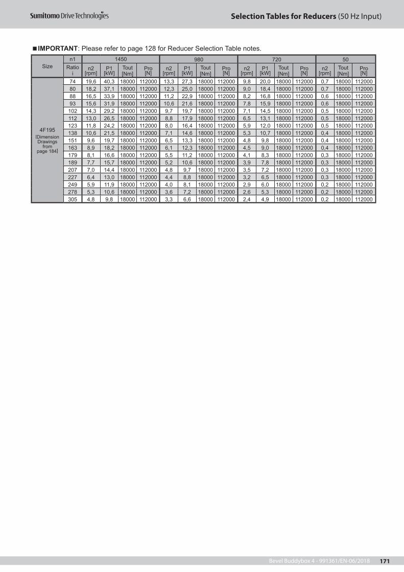
Bevel Buddybox 4 - 991361/EN-06/2018 171
Selection Tables for Reducers (50 Hz Input)
Sizen1 1450 980 720 50
Ratio i
n2 [rpm]
P1 [kW]
Tout [Nm]
Pro [N]
n2 [rpm]
P1 [kW]
Tout [Nm]
Pro [N]
n2 [rpm]
P1 [kW]
Tout [Nm]
Pro [N]
n2 [rpm]
Tout [Nm]
Pro [N]
4F195[Dimension Drawings
from page 184]
74 19,6 40,3 18000 112000 13,3 27,3 18000 112000 9,8 20,0 18000 112000 0,7 18000 11200080 18,2 37,1 18000 112000 12,3 25,0 18000 112000 9,0 18,4 18000 112000 0,7 18000 11200088 16,5 33,9 18000 112000 11,2 22,9 18000 112000 8,2 16,8 18000 112000 0,6 18000 11200093 15,6 31,9 18000 112000 10,6 21,6 18000 112000 7,8 15,9 18000 112000 0,6 18000 112000
102 14,3 29,2 18000 112000 9,7 19,7 18000 112000 7,1 14,5 18000 112000 0,5 18000 112000112 13,0 26,5 18000 112000 8,8 17,9 18000 112000 6,5 13,1 18000 112000 0,5 18000 112000123 11,8 24,2 18000 112000 8,0 16,4 18000 112000 5,9 12,0 18000 112000 0,5 18000 112000138 10,6 21,5 18000 112000 7,1 14,6 18000 112000 5,3 10,7 18000 112000 0,4 18000 112000151 9,6 19,7 18000 112000 6,5 13,3 18000 112000 4,8 9,8 18000 112000 0,4 18000 112000163 8,9 18,2 18000 112000 6,1 12,3 18000 112000 4,5 9,0 18000 112000 0,4 18000 112000179 8,1 16,6 18000 112000 5,5 11,2 18000 112000 4,1 8,3 18000 112000 0,3 18000 112000189 7,7 15,7 18000 112000 5,2 10,6 18000 112000 3,9 7,8 18000 112000 0,3 18000 112000207 7,0 14,4 18000 112000 4,8 9,7 18000 112000 3,5 7,2 18000 112000 0,3 18000 112000227 6,4 13,0 18000 112000 4,4 8,8 18000 112000 3,2 6,5 18000 112000 0,3 18000 112000249 5,9 11,9 18000 112000 4,0 8,1 18000 112000 2,9 6,0 18000 112000 0,2 18000 112000278 5,3 10,6 18000 112000 3,6 7,2 18000 112000 2,6 5,3 18000 112000 0,2 18000 112000305 4,8 9,8 18000 112000 3,3 6,6 18000 112000 2,4 4,9 18000 112000 0,2 18000 112000
IMPORTANT: Please refer to page 128 for Reducer Selection Table notes.
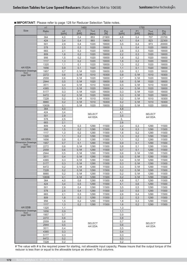
Bevel Buddybox 4 - 991361/EN-06/2018172
Selection Tables for Low Speed Reducers (Ratio from 364 to 10658)
Sizen1 1450 1750
Ratioi
n2 [rpm]
P1[kW]
Tout [Nm]
Pro [N]
n2 [rpm]
P1[kW]
Tout [Nm]
Pro [N]
4A10DA[Dimension Drawings
from page 184]
364 4,0 0,4 853 21900 4,8 0,4 707 23700424 3,4 0,4 993 19600 4,1 0,4 823 22300501 2,9 0,4 1020 19000 3,5 0,4 973 20000578 2,5 0,3 1020 19000 3, 0,4 1020 19000683 2,1 0,3 1020 19000 2,6 0,3 1020 19000809 1,8 0,2 1020 19000 2,2 0,3 1020 19000 956 1,5 0,2 1020 19000 1,8 0,2 1020 19000 1117 1,3 0,2 1020 19000 1,6 0,2 1020 19000 1320 1,1 0,1 1020 19000 1,3 0,2 1020 19000 1656 0,9 0,1 1020 19000 1,1 0,1 1020 19000 1957 0,7 0,1# 1020 19000 0,9 0,1 1020 19000 2272 0,6 0,1# 1010 19300 0,8 0,1# 1010 19300 2559 0,6 0,1# 1020 19000 0,7 0,1# 1020 19000 2944 0,5 0,1# 1020 19000 0,6 0,1# 1020 19000 3511 0,4 0,1# 1010 19300 0,5 0,1# 1010 19300 4365 0,3 0,1# 1020 19000 0,4 0,1# 1020 19000 5177 0,3 0,1# 1020 19000 0,3 0,1# 1020 19000 6472 0,2 0,1# 1020 19000 0,3 0,1# 1020 19000 7228 0,2 0,1# 1010 19300 0,2 0,1# 1010 19300 8880 0,2 0,1# 1010 19300 0,2 0,1# 1010 19300 10658 0,1 0,1# 1020 19000 0,2 0,1# 1020 19000
4A12DA[Dimension Drawings
from page 184]
364 4,0
SELECT4A10DA
4,8
SELECT4A10DA
424 3,4 4,1501 2,9 3,5578 2,5 3,683 2,1 2,6809 1,8 0,3 1290 11500 2,2 0,3 1290 11500 956 1,5 0,2 1290 11500 1,8 0,3 1290 11500 1117 1,3 0,2 1290 11500 1,6 0,2 1290 11500 1320 1,1 0,2 1290 11500 1,3 0,2 1290 11500 1656 0,9 0,1 1290 11500 1,1 0,2 1290 11500 1957 0,7 0,1 1290 11500 0,9 0,1 1290 11500 2272 0,6 0,1# 1290 11500 0,8 0,1 1290 11500 2559 0,6 0,1# 1290 11500 0,7 0,1 1290 11500 2944 0,5 0,1# 1290 11500 0,6 0,1# 1290 11500 3511 0,4 0,1# 1290 11500 0,5 0,1# 1290 11500 4365 0,3 0,1# 1290 11500 0,4 0,1# 1290 11500 5177 0,3 0,1# 1290 11500 0,3 0,1# 1290 11500 6472 0,2 0,1# 1290 11500 0,3 0,1# 1290 11500 7228 0,2 0,1# 1290 11500 0,2 0,1# 1290 11500 8880 0,2 0,1# 1290 11500 0,2 0,1# 1290 11500 10658 0,1 0,1# 1290 11500 0,2 0,1# 1290 11500
4A12DB[Dimension Drawings
from page 184]
364 4,0 0,6 1290 11500 4,8 0,7 1290 11500424 3,4 0,5 1290 11500 4,1 0,6 1290 11500 501 2,9 0,4 1290 11500 3,5 0,5 1290 11500578 2,5 0,4 1290 11500 3,0 0,5 1290 11500683 2,1 0,3 1290 11500 2,6 0,4 1290 11500809 1,8 0,3 1290 11500 2,2 0,3 1290 11500 956 1,5 0,2 1290 11500 1,8 0,3 1290 11500 1117 1,3 0,2 1290 11500 1,6 0,2 1290 11500 1320 1,1
SELECT4A12DA
1,3
SELECT4A12DA
1656 0,9 1,11957 0,7 0,92272 0,6 0,8 2559 0,6 0,72944 0,5 0,63511 0,4 0,54365 0,3 0,45177 0,3 0,3 6472 0,2 0,3 7228 0,2 0,2
# The value with # is the required power for starting, not allowable input capacity, Please insure that the output torque of the reducer is less than or equal to the allowable torque as shown in Tout columns.
IMPORTANT: Please refer to page 128 for Reducer Selection Table notes.

Bevel Buddybox 4 - 991361/EN-06/2018 173
Selection Tables for Low Speed Reducers (Ratio from 364 to 10658)
Sizen1 1450 1750
Ratioi
n2 [rpm]
P1[kW]
Tout [Nm]
Pro [N]
n2 [rpm]
P1[kW]
Tout [Nm]
Pro [N]
4A12DB 8880 0,2 SELECT4A12DA
0,2 SELECT4A12DA10658 0,1 0,2
4B12DA[Dimension Drawings
from page 184]
364 4,0
SELECT4A12DB
4,8
SELECT4A12DB
424 3,4 4,1501 2,9 3,5578 2,5 3,0683 2,1 2,6809 1,8 0,4 1900 34400 2,2 0,4 1570 37900 956 1,5 0,4 2140 30900 1,8 0,4 1860 34900 1117 1,3 0,3 2140 30900 1,6 0,4 2140 30900 1320 1,1 0,3 2140 30900 1,3 0,3 2140 30900 1656 0,9 0,2 2140 30900 1,1 0,3 2140 30900 1957 0,7 0,2 2140 30900 0,9 0,2 2140 30900 2272 0,6 0,1 2140 30900 0,8 0,2 2140 30900 2559 0,6 0,1 2140 30900 0,7 0,2 2140 30900 2944 0,5 0,1 2140 30900 0,6 0,2 2140 30900 3511 0,4 0,1 2140 30900 0,5 0,1 2140 30900 4365 0,3 0,1# 2140 30900 0,4 0,1 2140 30900 5177 0,3 0,1# 2140 30900 0,3 0,1# 2140 30900 6472 0,2 0,1# 2140 30900 0,3 0,1# 2140 30900 7228 0,2 0,1# 2140 30900 0,2 0,1# 2140 30900 8880 0,2 0,1# 2140 30900 0,2 0,1# 2140 30900 10658 0,1 0,1# 2140 30900 0,2 0,1# 2140 30900
4B12DB[Dimension Drawings
from page 184]
364 4,0 1,02 2140 30900 4,8 1,2 2140 30900 424 3,4 0,9 2120 31300 4,1 1,1 2120 31300 501 2,9 0,7 2140 30900 3,5 0,9 2140 30900 578 2,5 0,6 2140 30900 3,0 0,8 2140 30900 683 2,1 0,5 2140 30900 2,6 0,7 2140 30900 809 1,8 0,5 2140 30900 2,2 0,6 2140 30900 956 1,5 0,4 2140 30900 1,8 0,5 2140 30900 1117 1,3 0,3 2140 30900 1,6 0,4 2140 30900 1320 1,1
SELECT4B12DA
1,3
SELECT4B12DA
1656 0,9 1,11957 0,7 0,92272 0,6 0,82559 0,6 0,72944 0,5 0,63511 0,4 0,54365 0,3 0,45177 0,3 0,3 6472 0,2 0,3 7228 0,2 0,28880 0,2 0,210658 0,1 0,2
4B14DA[Dimension Drawings
from page 184]
364 4,0
SELECT4B12DB
4,8
SELECT4B12DB
424 3,4 4,1501 2,9 3,5578 2,5 3,0683 2,1 2,6809 1,8 2,2956 1,5 1,81117 1,3 1,6 1320 1,1 1,31656 0,9 1,11957 0,7 0,2 2570 22300 0,9 0,3 2570 22300 2272 0,6 0,2# 2570 22300 0,8 0,2 2570 22300 2559 0,6 0,2# 2570 22300 0,7 0,2 2570 22300 2944 0,5 0,2# 2570 22300 0,6 0,2# 2570 22300 3511 0,4 0,2# 2570 22300 0,5 0,2# 2570 22300 4365 0,3 0,2# 2570 22300 0,4 0,2# 2570 22300 5177 0,3 0,2# 2570 22300 0,3 0,2# 2570 22300
IMPORTANT: Please refer to page 128 for Reducer Selection Table notes.
# The value with # is the required power for starting, not allowable input capacity, Please insure that the output torque of the reducer is less than or equal to the allowable torque as shown in Tout columns.

Bevel Buddybox 4 - 991361/EN-06/2018174
Selection Tables for Low Speed Reducers (Ratio from 364 to 10658)
Sizen1 1450 1750
Ratioi
n2 [rpm]
P1[kW]
Tout [Nm]
Pro [N]
n2 [rpm]
P1[kW]
Tout [Nm]
Pro [N]
4B14DA
6472 0,2 0,2# 2570 22300 0,3 0,2# 2570 22300 7228 0,2 0,2# 2570 22300 0,2 0,2# 2570 22300 8880 0,2 0,2# 2570 22300 0,2 0,2# 2570 22300 10658 0,1 0,2# 2570 22300 0,2 0,2# 2570 22300
4B14DB[Dimension Drawings
from page 184]
364 4,0 SELECT4B14DA
4,8 SELECT4B14DA424 3,4 4,1
501 2,9 0,9 2570 22300 3,5 1,1 2570 22300 578 2,5 0,8 2570 22300 3, 0,9 2570 22300 683 2,1 0,7 2570 22300 2,6 0,8 2570 22300 809 1,8 0,6 2570 22300 2,2 0,7 2570 22300 956 1,5 0,5 2570 22300 1,8 0,6 2570 22300 1117 1,3 0,4 2570 22300 1,6 0,5 2570 22300 1320 1,1 0,3 2570 22300 1,3 0,4 2570 22300 1656 0,9 0,3 2570 22300 1,1 0,3 2570 22300 1957 0,7 0,2 2570 22300 0,9 0,3 2570 22300 2272 0,6 0,2# 2570 22300 0,8 0,2 2570 22300 2559 0,6 - - - 0,7 - - -2944 0,5 0,2# 2570 22300 0,6 0,2# 2570 22300 3511 0,4
SELECT4B14DA
0,5
SELECT4B14DA
4365 0,3 0,45177 0,3 0,36472 0,2 0,3 7228 0,2 0,28880 0,2 0,210658 0,1 0,2
4C14DA[Dimension Drawings
from page 184]
364 4,0
SELECT4B14DB
4,8
SELECT4B14DB
424 3,4 4,1501 2,9 3,5578 2,5 3,0683 2,1 2,6809 1,8 2,2956 1,5 1,81117 1,3 1,6 1320 1,1 1,31656 0,9 1,11957 0,7 0,4 4590 46400 0,9 0,4 3800 556002272 0,6 0,4 4660 45300 0,8 0,4 4410 487002559 0,6 0,3 4660 45300 0,7 0,4 4660 453002944 0,5 0,3 4660 45300 0,6 0,3 4020 533003511 0,4 0,2 4660 45300 0,5 0,3 4660 453004365 0,3 0,2# 4660 45300 0,4 0,2 4660 453005177 0,3 0,2# 4250 50800 0,3 0,2# 4250 508006472 0,2 0,2# 4660 45300 0,3 0,2# 4660 453007228 0,2 0,2# 4660 45300 0,2 0,2# 4660 453008880 0,2 0,2# 4660 45300 0,2 0,2# 4660 4530010658 0,1 0,2# 4250 50800 0,2 0,2# 4250 50800
4C14DB[Dimension Drawings
from page 184]
364 4,0 SELECT4C14DA
4,8 SELECT4C14DA424 3,4 4,1
501 2,9 1,5 4370 49300 3,5 1,5 3620 57300578 2,5 1,4 4620 45900 3,0 1,5 4180 51600683 2,1 1,2 4620 45900 2,6 1,4 4620 45900809 1,8 1,0 4550 46900 2,2 1,2 4550 46900956 1,5 0,8 4550 46900 1,8 1,0 4550 469001117 1,3 0,7 4660 45300 1,6 0,9 4660 453001320 1,1 0,6 4660 45300 1,3 0,7 4660 453001656 0,9 0,5 4660 45300 1,1 0,6 4660 453001957 0,7 0,4 4660 45300 0,9 0,5 4660 453002272 0,6 0,4 4660 45300 0,8 0,4 4660 453002559 0,6 - - - 0,7 - - -2944 0,5 0,3 4660 45300 0,6 0,3 4660 453003511 0,4 - - - 0,5 - - -
IMPORTANT: Please refer to page 128 for Reducer Selection Table notes.
# The value with # is the required power for starting, not allowable input capacity, Please insure that the output torque of the reducer is less than or equal to the allowable torque as shown in Tout columns.

Bevel Buddybox 4 - 991361/EN-06/2018 175
Selection Tables for Low Speed Reducers (Ratio from 364 to 10658)
Sizen1 1450 1750
Ratioi
n2 [rpm]
P1[kW]
Tout [Nm]
Pro [N]
n2 [rpm]
P1[kW]
Tout [Nm]
Pro [N]
4C14DB[Dimension Drawings
from page 184]
4365 0,3
SELECT4C14DA
0,4
SELECT4C14DA
5177 0,3 0,3 6472 0,2 0,3 7228 0,2 0,28880 0,2 0,210658 0,1 0,2
4C14DC[Dimension Drawings
from page 184]
364 4,0 2,2 4660 45300 4,8 2,7 4660 45300424 3,4 1,8 4400 49000 4,1 2,1 4400 49000501 2,9 1,6 4660 45300 3,5 2,0 4660 45300578 2,5 1,4 4620 45900 3,0 1,7 4620 45900683 2,1
SELECT4C14DB
2,6
SELECT4C14DB
809 1,8 2,2956 1,5 1,81117 1,3 1,6 1320 1,1 1,31656 0,9 1,11957 0,7 0,92272 0,6 0,8 2559 0,6 0,72944 0,5 0,63511 0,4 0,54365 0,3 0,45177 0,3 0,3 6472 0,2 0,3 7228 0,2 0,28880 0,2 0,210658 0,1 0,2
4C16DA[Dimension Drawings
from page 184]
364 4,0SELECT4C14DC
4,8SELECT4C14DC
424 3,4 4,1501 2,9 3,5578 2,5 3,0683 2,1 1,3 5140 37200 2,6 1,5 4940 40900809 1,8 1,1 5140 37200 2,2 1,3 5140 37200956 1,5 0,9 5140 37200 1,8 1,1 5140 372001117 1,3 0,8 5140 37200 1,6 1,0 5140 372001320 1,1 0,7 5140 37200 1,3 0,8 5140 372001656 0,9 0,5 5140 37200 1,1 0,7 5140 372001957 0,7 0,5 5140 37200 0,9 0,6 5140 372002272 0,6 0,4# 5140 37200 0,8 0,4 5140 372002559 0,6 0,4# 5140 37200 0,7 0,4 5140 372002944 0,5 0,4# 5140 37200 0,6 0,4# 5140 372003511 0,4 0,4# 5140 37200 0,5 0,4# 5140 372004365 0,3 0,4# 5140 37200 0,4 0,4# 5140 372005177 0,3 0,4# 5140 37200 0,3 0,4# 5140 372006472 0,2 0,2# 5140 37200 0,3 0,4# 5140 372007228 0,2 0,2# 5140 37200 0,2 0,4# 5140 372008880 0,2 0,2# 5140 37200 0,2 0,2# 5140 3720010658 0,1 0,2# 5140 37200 0,2 0,2# 5140 37200
4D16DA[Dimension Drawings
from page 184]
364 4,0SELECT4C16DA
4,8SELECT4C16DA
424 3,4 4,1501 2,9 3,5578 2,5 3,0683 2,1 1,5 5960 77400 2,6 1,5 4940 84500809 1,8 1,5 7060 67100 2,2 1,5 5850 78300956 1,5 1,3 7150 66100 1,8 1,5 6910 687001117 1,3 1,1 7150 66100 1,6 1,3 7150 661001320 1,1 0,9 7150 66100 1,3 1,1 7150 661001656 0,9 0,7 7150 66100 1,1 0,9 7150 661001957 0,7 0,6 7150 66100 0,9 0,8 7150 661002272 0,6 0,5 7150 66100 0,8 0,7 7150 661002559 0,6 0,5 7150 66100 0,7 0,6 7150 66100
# The value with # is the required power for starting, not allowable input capacity, Please insure that the output torque of the reducer is less than or equal to the allowable torque as shown in Tout columns.
IMPORTANT: Please refer to page 128 for Reducer Selection Table notes.

Bevel Buddybox 4 - 991361/EN-06/2018176
Selection Tables for Low Speed Reducers (Ratio from 364 to 10658)
Sizen1 1450 1750
Ratioi
n2 [rpm]
P1[kW]
Tout [Nm]
Pro [N]
n2 [rpm]
P1[kW]
Tout [Nm]
Pro [N]
4D16DA[Dimension Drawings
from page 184]
2944 0,5 0,4 7150 66100 0,6 0,5 7150 661003511 0,4 0,4# 7150 66100 0,5 0,4 7150 661004365 0,3 0,4# 7150 66100 0,4 0,4# 7150 661005177 0,3 0,4# 6980 67900 0,3 0,4# 6980 679006472 0,2 0,2# 7150 66100 0,3 0,4# 7150 661007228 0,2 0,2# 7150 66100 0,2 0,4# 7150 661008880 0,2 0,2# 7150 66100 0,2 0,2# 7150 6610010658 0,1 0,2# 6980 67900 0,2 0,2# 6980 67900
4D16DB[Dimension Drawings
from page 184]
364 4,0 3,2 6670 71100 4,8 3,2 5530 80600424 3,4 2,9 7150 66100 4,1 3,2 6430 73400501 2,9 2,5 7150 66100 3,5 3,0 7150 66100578 2,5 2,2 7150 66100 3,0 2,6 7150 66100683 2,1 1,8 7150 66100 2,6 2,2 7150 66100809 1,8 1,5 7150 66100 2,2 1,9 7150 66100956 1,5 1,3 7150 66100 1,8 1,6 7150 661001117 1,3
SELECT4D16DA
1,6
SELECT4D16DA
1320 1,1 1,31656 0,9 1,11957 0,7 0,92272 0,6 0,82559 0,6 0,72944 0,5 0,63511 0,4 0,54365 0,3 0,45177 0,3 0,3 6472 0,2 0,3 7228 0,2 0,28880 0,1 0,210658 0,1 0,2
4D17DA[Dimension Drawings
from page 184]
364 4,0
SELECT4D16DB
4,8
SELECT4D16DB
424 3,4 4,1501 2,9 3,5578 2,5 3,0683 2,1 2,6809 1,8 2,2956 1,5 1,5 8340 49500 1,8 1,5 6910 687001117 1,3 1,4 8720 42200 1,6 1,5 8100 539001320 1,1 1,2 8720 42200 1,3 1,4 8720 422001656 0,9 0,9 8720 42200 1,1 1,1 8720 422001957 0,7 0,8 8720 42200 0,9 0,9 8720 422002272 0,6 0,7 8720 42200 0,8 0,8 8720 422002559 0,6 0,6 8720 42200 0,7 0,7 8720 422002944 0,5 0,5 8720 42200 0,6 0,6 8720 422003511 0,4 0,4 8720 42200 0,5 0,5 8720 422004365 0,3 0,4# 8720 42200 0,4 0,4 8720 422005177 0,3 0,4# 8720 42200 0,3 0,4# 8720 422006472 0,2 0,4# 8720 42200 0,3 0,4# 8720 422007228 0,2 0,4# 8720 42200 0,2 0,4# 8720 422008880 0,2 0,4# 8720 42200 0,2 0,4# 8720 4220010658 0,1 0,2# 8720 42200 0,2 0,4# 8720 42200
4D17DB[Dimension Drawings
from page 184]
364 4,0 - - - 4,8 - - -424 3,4 - - - 4,1 - - -501 2,9 3,0 8720 42200 3,5 3,2 7600 60700578 2,5 2,6 8720 42200 3,0 3,2 8720 42200683 2,1 2,2 8720 42200 2,6 2,7 8720 42200809 1,8 1,9 8720 42200 2,2 2,3 8720 42200956 1,5 1,6 8720 42200 1,8 1,9 8720 42200 1117 1,3 1,4 8720 42200 1,6 1,6 8720 422001320 1,1 1,2 8720 42200 1,3 1,4 8720 422001656 0,9 - - - 1,1 - - -1957 0,7 - - - 0,9 - - -
# The value with # is the required power for starting, not allowable input capacity, Please insure that the output torque of the reducer is less than or equal to the allowable torque as shown in Tout columns.
IMPORTANT: Please refer to page 128 for Reducer Selection Table notes.

Bevel Buddybox 4 - 991361/EN-06/2018 177
Selection Tables for Low Speed Reducers (Ratio from 364 to 10658)
Sizen1 1450 1750
Ratioi
n2 [rpm]
P1[kW]
Tout [Nm]
Pro [N]
n2 [rpm]
P1[kW]
Tout [Nm]
Pro [N]
4D17DB[Dimension Drawings
from page 184]
2272 0,6
SELECT4D17DA
0,8
SELECT4D17DA
2559 0,6 0,72944 0,5 0,63511 0,4 0,54365 0,3 0,45177 0,3 0,3 6472 0,2 0,3 7228 0,2 0,28880 0,2 0,210658 0,1 0,2
4D17DC[Dimension Drawings
from page 184]
364 4,0 4,2 8720 42200 4,8 5,0 8720 42200424 3,4 3,6 8720 42200 4,1 4,3 8720 42200501 2,9 3,0 8720 42200 3,5 3,7 8720 42200578 2,5 2,6 8720 42200 3,0 3,2 8720 42200683 2,1 2,2 8720 42200 2,6 2,7 8720 42200809 1,8 1,9 8720 42200 2,2 2,3 8720 42200956 1,5 1,6 8720 42200 1,8 1,91 8720 422001117 1,3
SELECT4D17DB
1,6
SELECT4D17DB
1320 1,1 1,31656 0,9 1,11957 0,7 0,92272 0,6 0,8 2559 0,6 0,72944 0,5 0,63511 0,4 0,54365 0,3 0,45177 0,3 0,3 6472 0,2 0,3 7228 0,2 0,28880 0,2 0,210658 0,1 0,2
4D18DA[Dimension Drawings
from page 184]
364 4,0
SELECT4D17DC
4,8
SELECT4D17DC
424 3,4 4,1501 2,9 3,5578 2,5 3,0683 2,1 2,6809 1,8 1,9 8720 42200 2,2 2,3 8720 42200 956 1,5 1,6 8720 42200 1,8 1,9 8720 42200 1117 1,3 1,4 8720 42200 1,6 1,6 8720 42200 1320 1,1 1,2 8720 42200 1,3 1,4 8720 42200 1656 0,9 0,9 8720 42200 1,1 1,1 8720 42200 1957 0,7 0,8 8720 42200 0,9 0,9 8720 42200 2272 0,6 0,8# 8720 42200 0,8 0,8 8720 42200 2559 0,6 0,8# 8720 42200 0,7 0,8# 8720 42200 2944 0,5 0,8# 8720 42200 0,6 0,8# 8720 42200 3511 0,4 0,8# 8720 42200 0,5 0,8# 8720 42200 4365 0,3 0,8# 8720 42200 0,4 0,8# 8720 42200 5177 0,3 0,8# 8720 42200 0,3 0,8# 8720 42200 6472 0,2 0,8# 8720 42200 0,3 0,8# 8720 42200 7228 0,2 0,4# 8720 42200 0,2 0,8# 8720 42200 8880 0,2 0,4# 8720 42200 0,2 0,4# 8720 42200 10658 0,1 0,4# 8720 42200 0,2 0,4# 8720 42200
4D18DB[Dimension Drawings
from page 184]
364 4,0 4,2 8720 42200 4,8 5,0 8720 42200424 3,4 3,6 8720 42200 4,1 4,3 8720 42200501 2,9 3,0 8720 42200 3,5 3,7 8720 42200578 2,5 2,6 8720 42200 3,0 3,2 8720 42200683 2,1 2,2 8720 42200 2,6 2,7 8720 42200809 1,8 1,9 8720 42200 2,2 2,3 8720 42200 956 1,5 1,6 8720 42200 1,8 1,9 8720 42200 1117 1,3 1,4 8720 42200 1,6 1,6 8720 42200 1320 1,1 1,2 8720 42200 1,3 1,4 8720 42200
IMPORTANT: Please refer to page 128 for Reducer Selection Table notes.
# The value with # is the required power for starting, not allowable input capacity, Please insure that the output torque of the reducer is less than or equal to the allowable torque as shown in Tout columns.

Bevel Buddybox 4 - 991361/EN-06/2018178
Selection Tables for Low Speed Reducers (Ratio from 364 to 10658)
Sizen1 1450 1750
Ratioi
n2 [rpm]
P1[kW]
Tout [Nm]
Pro [N]
n2 [rpm]
P1[kW]
Tout [Nm]
Pro [N]
4D18DB[Dimension Drawings
from page 184]
1656 0,9
SELECT4D18DA
1,0
SELECT4D18DA
1957 0,7 0,92272 0,6 0,82559 0,6 0,72944 0,5 0,63511 0,4 0,54365 0,3 0,45177 0,3 0,36472 0,2 0,3 7228 0,2 0,28880 0,2 0,210658 0,1 0,2
4E17DA[Dimension Drawings
from page 184]
364 4,0
SELECT4D18DB
4,8
SELECT4D18DB
424 3,4 4,1501 2,9 3,5578 2,5 3,0683 2,1 2,6809 1,8 2,2956 1,5 1,5 8340 89200 1,8 1,5 6910 921001117 1,3 1,5 9780 86400 1,6 1,5 8100 897001320 1,1 1,4 10700 84500 1,3 1,5 9580 868001656 0,9 1,1 10700 84500 1,1 1,4 10700 845001957 0,7 0,9 10700 84500 0,9 1,2 10700 845002272 0,6 0,8 10700 84500 0,8 1,0 10700 845002559 0,6 0,7 10700 84500 0,7 0,9 10700 845002944 0,5 0,6 10700 84500 0,6 0,8 10700 845003511 0,4 0,5 10700 84500 0,5 0,6 10700 845004365 0,3 0,4 10700 84500 0,4 0,5 10700 845005177 0,3 0,4# 10700 84500 0,3 0,4 10700 845006472 0,2 0,4# 10700 84500 0,3 0,4# 10700 845007228 0,2 0,4# 10700 84500 0,2 0,4# 10700 845008880 0,2 0,4# 10700 84500 0,2 0,4# 10700 8450010658 0,1 0,2# 10700 84500 0,2 0,4# 10700 84500
4E17DB[Dimension Drawings
from page 184]
364 4,0 - - - 4,8 - - -424 3,4 - - - 4,1 - - -501 2,9 3,2 9170 87600 3,5 3,2 7600 90700578 2,5 3,2 10600 84800 3,0 3,2 8770 88400683 2,1 2,7 10700 84500 2,6 3,2 10400 85200809 1,8 2,3 10700 84500 2,2 2,8 10700 84500956 1,5 1,9 10700 84500 1,8 2,4 10700 845001117 1,3 1,7 10700 84500 1,6 2,0 10700 845001320 1,1 1,4 10700 84500 1,3 1,7 10700 845001656 0,9
SELECT4E17DA
1,1
SELECT4E17DA
1957 0,7 0,92272 0,6 0,8 2559 0,6 0,72944 0,5 0,63511 0,4 0,54365 0,3 0,45177 0,3 0,36472 0,2 0,3 7228 0,2 0,28880 0,2 0,210658 0,1 0,2
4E17DC[Dimension Drawings
from page 184]
364 4,0 5,1 10700 84500 4,8 6,2 10700 84500424 3,4 4,4 10700 84500 4,1 5,3 10700 84500501 2,9 3,7 10700 84500 3,5 4,5 10700 84500578 2,5 3,2 10700 84500 3,0 3,9 10700 84500683 2,1 2,7 10700 84500 2,6 3,3 10700 84500809 1,8 2,3 10700 84500 2,2 2,8 10700 84500956 1,5 1,9 10700 84500 1,8 2,4 10700 84500
# The value with # is the required power for starting, not allowable input capacity, Please insure that the output torque of the reducer is less than or equal to the allowable torque as shown in Tout columns.
IMPORTANT: Please refer to page 128 for Reducer Selection Table notes.

Bevel Buddybox 4 - 991361/EN-06/2018 179
Selection Tables for Low Speed Reducers (Ratio from 364 to 10658)
Sizen1 1450 1750
Ratioi
n2 [rpm]
P1[kW]
Tout [Nm]
Pro [N]
n2 [rpm]
P1[kW]
Tout [Nm]
Pro [N]
4E17DC[Dimension Drawings
from page 184]
1117 1,3
SELECT4E17DB
1,6
SELECT4E17DB
1320 1,1 1,31656 0,9 1,01957 0,7 0,92272 0,6 0,8 2559 0,6 0,72944 0,5 0,63511 0,4 0,54365 0,3 0,45177 0,3 0,36472 0,2 0,3 7228 0,2 0,28880 0,2 0,210658 0,1 0,2
4E18DA[Dimension Drawings
from page 184]
364 4,0
SELECT4E17DC
4,8
SELECT4E17DC
424 3,4 4,1501 2,9 3,5578 2,5 3,0683 2,1 2,6809 1,8 2,5 11600 75600 2,2 3,0 11600 75600 956 1,5 2,1 11600 75600 1,8 2,5 11600 75600 1117 1,3 1,8 11600 75600 1,6 2,2 11600 75600 1320 1,1 1,5 11600 75600 1,3 1,8 11600 75600 1656 0,9 1,2 11600 75600 1,1 1,5 11600 75600 1957 0,7 1,0 11600 75600 0,9 1,2 11600 75600 2272 0,6 0,9 11600 75600 0,8 1,1 11600 75600 2559 0,6 0,8 11600 75600 0,7 1,0 11600 75600 2944 0,5 0,8# 11600 75600 0,6 0,8 11600 75600 3511 0,4 0,8# 11600 75600 0,5 0,8# 11600 75600 4365 0,3 0,8# 11600 75600 0,4 0,8# 11600 75600 5177 0,3 0,8# 11600 75600 0,3 0,8# 11600 75600 6472 0,2 0,8# 11600 75600 0,3 0,8# 11600 75600 7228 0,2 0,4# 11600 75600 0,2 0,8# 11600 75600 8880 0,2 0,4# 11600 75600 0,2 0,4# 11600 75600 10658 0,1 0,4# 11600 75600 0,2 0,4# 11600 75600
4E18DB[Dimension Drawings
from page 184]
364 4,0 5,5 11600 75600 4,8 6,7 11600 75600424 3,4 4,8 11600 75600 4,1 5,7 11600 75600501 2,9 4,0 11600 75600 3,5 4,9 11600 75600578 2,5 3,5 11600 75600 3,0 4,2 11600 75600 683 2,1 3,0 11600 75600 2,6 3,6 11600 75600809 1,8 2,5 11600 75600 2,2 3,0 11600 75600 956 1,5 2,1 11600 75600 1,8 2,5 11600 75600 1117 1,3 1,8 11600 75600 1,6 2,2 11600 75600 1320 1,1 1,5 11600 75600 1,3 1,84 11600 75600 1656 0,9
SELECT4E18DA
1,1
SELECT4E18DA
1957 0,7 0,92272 0,6 0,82559 0,6 0,72944 0,5 0,63511 0,4 0,54365 0,3 0,45177 0,3 0,3 6472 0,2 0,3 7228 0,2 0,28880 0,2 0,210658 0,1 0,2
4E19DA[Dimension Drawings
from page 184]
364 4,0SELECT4E18DB
4,8SELECT4E18DB424 3,4 4,1
501 2,9 3,5578 2,5 3,0683 2,1 3,0 11600 75600 2,6 3,6 11600 75600
# The value with # is the required power for starting, not allowable input capacity, Please insure that the output torque of the reducer is less than or equal to the allowable torque as shown in Tout columns.
IMPORTANT: Please refer to page 128 for Reducer Selection Table notes.

Bevel Buddybox 4 - 991361/EN-06/2018180
Selection Tables for Low Speed Reducers (Ratio from 364 to 10658)
Sizen1 1450 1750
Ratioi
n2 [rpm]
P1[kW]
Tout [Nm]
Pro [N]
n2 [rpm]
P1[kW]
Tout [Nm]
Pro [N]
4E19DA[Dimension Drawings
from page 184]
809 1,8 2,5 11600 75600 2,2 3,0 11600 75600 956 1,5 2,1 11600 75600 1,8 2,5 11600 75600 1117 1,3 1,8 11600 75600 1,6 2,2 11600 75600 1320 1,1 1,5 11600 75600 1,3 1,8 11600 75600 1656 0,9 1,2 11600 75600 1,1 1,5 11600 75600 1957 0,7 1,0 11600 75600 0,9 1,2 11600 75600 2272 0,6 0,9 11600 75600 0,8 1,1 11600 75600 2559 0,6 0,8 11600 75600 0,7 1,0 11600 75600 2944 0,5 0,8# 11600 75600 0,6 0,8 11600 75600 3511 0,4 0,8# 11600 75600 0,5 0,8# 11600 75600 4365 0,3 0,8# 11600 75600 0,4 0,8# 11600 75600 5177 0,3 0,8# 11600 75600 0,3 0,8# 11600 75600 6472 0,2 0,8# 11600 75600 0,3 0,8# 11600 75600 7228 0,2 0,8# 11600 75600 0,2 0,8# 11600 75600 8880 0,2 0,8# 11600 75600 0,2 0,8# 11600 75600 10658 0,1 0,8# 11600 75600 0,2 0,8# 11600 75600
4E19DB[Dimension Drawings
from page 184]
364 4,0 5,5 11600 75600 4,8 6,7 11600 75600424 3,4 4,8 11600 75600 4,1 5,7 11600 75600501 2,9 4,0 11600 75600 3,5 4,9 11600 75600578 2,5 3,5 11600 75600 3,0 4,2 11600 75600683 2,1 3,0 11600 75600 2,6 3,6 11600 75600809 1,8 2,5 11600 75600 2,2 3,0 11600 75600 956 1,5 2,1 11600 75600 1,8 2,5 11600 75600 1117 1,3
SELECT4E19DA
1,6 2,2 11600 75600 1320 1,1 1,3
SELECT4E19DA
1656 0,9 1,11957 0,7 0,92272 0,6 0,8 2559 0,6 0,72944 0,5 0,63511 0,4 0,54365 0,3 0,45177 0,3 0,3 6472 0,2 0,3 7228 0,2 0,28880 0,2 0,210658 0,1 0,2
4F18DA[Dimension Drawings
from page 184]
364 4,0
SELECT4E19DB
4,8
SELECT4E19DB
424 3,4 4,1501 2,9 3,5578 2,5 3,0683 2,1 2,6809 1,8 3,2 14800 143000 2,2 3,2 12300 143000 956 1,5 3,1 17000 136000 1,8 3,2 14500 143000 1117 1,3 2,6 17000 136000 1,6 3,2 17000 136000 1320 1,1 2,2 17000 136000 1,3 2,7 17000 136000 1656 0,9 1,8 17000 136000 1,1 2,2 17000 136000 1957 0,7 1,5 17000 136000 0,9 1,8 17000 136000 2272 0,6 1,3 17000 136000 0,8 1,6 17000 136000 2559 0,6 1,2 17000 136000 0,7 1,4 17000 136000 2944 0,5 1,0 17000 136000 0,6 1,2 17000 136000 3511 0,4 0,8 17000 136000 0,5 1,0 17000 136000 4365 0,3 0,8# 17000 136000 0,4 0,8 17000 136000 5177 0,3 0,8# 17000 136000 0,3 0,8# 17000 136000 6472 0,2 0,8# 17000 136000 0,3 0,8# 17000 136000 7228 0,2 0,4 17000 136000 0,2 0,8# 17000 136000 8880 0,2 0,4# 17000 136000 0,2 0,4 17000 136000 10658 0,1 0,4# 17000 136000 0,2 0,4# 17000 136000
4F18DB364 4,0 8,0 16700 139000 4,8 9,6 16700 139000 424 3,4 6,7 16400 141000 4,1 8,1 16400 141000 501 2,9 5,8 16700 139000 3,5 7,0 16700 139000
# The value with # is the required power for starting, not allowable input capacity, Please insure that the output torque of the reducer is less than or equal to the allowable torque as shown in Tout columns.
IMPORTANT: Please refer to page 128 for Reducer Selection Table notes.

Bevel Buddybox 4 - 991361/EN-06/2018 181
Selection Tables for Low Speed Reducers (Ratio from 364 to 10658)
Sizen1 1450 1750
Ratioi
n2 [rpm]
P1[kW]
Tout [Nm]
Pro [N]
n2 [rpm]
P1[kW]
Tout [Nm]
Pro [N]
4F18DB[Dimension Drawings
from page 184]
578 2,5 5,0 16700 138000 3,0 6,1 16700 138000 683 2,1 4,3 16700 138000 2,6 5,1 16700 138000 809 1,8 3,7 17000 136000 2,2 4,4 17000 136000 956 1,5 3,1 17000 136000 1,8 3,7 17000 136000 1117 1,3 2,6 17000 136000 1,6 3,2 17000 136000 1320 1,1 2,2 17000 136000 1,3 2,7 17000 136000 1656 0,9
SELECT4F18DA
1,1
SELECT4F18DA
1957 0,7 0,92272 0,6 0,8 2559 0,6 0,72944 0,5 0,63511 0,4 0,54365 0,3 0,45177 0,3 0,3 6472 0,2 0,3 7228 0,2 0,28880 0,2 0,210658 0,1 0,2
4F19DA[Dimension Drawings
from page 184]
364 4,0SELECT4F18DB
4,8SELECT4F18DB
424 3,4 4,1501 2,9 3,5578 2,5 3,0683 2,1 4,4 17400 132000 2,6 5,3 17400 132000 809 1,8 3,7 17400 132000 2,2 4,5 17400 132000 956 1,5 3,2 17400 132000 1,8 3,8 17400 132000 1117 1,3 2,7 17400 132000 1,6 3,3 17400 132000 1320 1,1 2,3 17400 132000 1,3 2,8 17400 132000 1656 0,9 1,8 17400 132000 1,1 2,2 17400 132000 1957 0,7 1,5 17400 132000 0,9 1,9 17400 132000 2272 0,6 1,3 17400 132000 0,8 1,6 17400 132000 2559 0,6 1,2 17400 132000 0,7 1,4 17400 132000 2944 0,5 1,0 17400 132000 0,6 1,2 17400 132000 3511 0,4 0,9 17400 132000 0,5 1,0 17400 132000 4365 0,3 0,8# 17400 132000 0,4 0,8 17400 132000 5177 0,3 0,8# 17400 132000 0,3 0,8# 17400 132000 6472 0,2 0,8# 17400 132000 0,3 0,8# 17400 132000 7228 0,2 0,8# 17400 132000 0,2 0,8# 17400 132000 8880 0,2 0,8# 17400 132000 0,2 0,8# 17400 132000 10658 0,1 0,8# 17400 132000 0,2 0,8# 17400 132000
4F19DB[Dimension Drawings
from page 184]
364 4,0 8,3 17400 132000 4,8 10,0 17400 132000 424 3,4 7,1 17400 132000 4,1 8,6 17400 132000 501 2,9 6,0 17400 132000 3,5 7,3 17400 132000 578 2,5 5,2 17400 132000 3,0 6,3 17400 132000 683 2,1 4,4 17400 132000 2,6 5,3 17400 132000 809 1,8 3,7 17400 132000 2,2 4,5 17400 132000 956 1,5 3,2 17400 132000 1,8 3,8 17400 132000 1117 1,3
SELECT4F19DA
1,6 3,3 17400 132000 1320 1,1 1,3
SELECT4F19DA
1656 0,9 1,11957 0,7 0,92272 0,6 0,8 2559 0,6 0,72944 0,5 0,63511 0,4 0,54365 0,3 0,45177 0,3 0,3 6472 0,2 0,37228 0,2 0,28880 0,2 0,210658 0,1 0,2
# The value with # is the required power for starting, not allowable input capacity, Please insure that the output torque of the reducer is less than or equal to the allowable torque as shown in Tout columns.
IMPORTANT: Please refer to page 128 for Reducer Selection Table notes.

Bevel Buddybox 4 - 991361/EN-06/2018182

Bevel Buddybox 4 - 991361/EN-06/2018 183
Dimensional Drawings for Reducers
Dimensional Drawings:
Supplementary Drawings:
184
188
192
196
197
201
203
Page
Page
Important Notes :
1. All the dimension values (except for shaft diameter and main mounting sections) on the dimensional drawings in this catalog are the maximum values determined considering the concavo-convex portions on each section. Thus, they may somewhat differ from those of the actual products.2. Consult us for the dimensions of any portions not specified on the dimensional drawings.3. The dimensional drawings on this catalog are subject to change without prior notice.4. Perform the final confirmation on the dimension of product with our manufacturing specification.
Shaft Mount / Case Mount Type :
Flange Mount Type :
Foot Mount Type :
X-Adaptor for Single Stage :
X-Adaptor for Double Stage :
J-Adaptor for Single Stage :
J-Adaptor for Double Stage :

Bevel Buddybox 4 - 991361/EN-06/2018184
Dimensional Drawings
Shaft Mount for Hollow Shafts and Case Mount for Solid Shafts / Bevel + Cyclo Single Stage Type
L Y - Reducer’s frame size - Reduction ratio
Mounting Position Y1
Note: Consult us for dimensions if mounting position is other than Y1 and Y2.
K
H
CC
22.5°22.5°
K
ØLA
E1Q
2
ØD1
Q2
ØD3
4-S1x 1 A
A
H1
2x2-Ød
ØDC
Q2 E1
Q1
F1Q
1G
1G
2
ZZ
4-S1x 1
b
ØD H8
mn
M1 M2(M)
tØD2 R2.5
A-A
ØD4
H7
h
1
* Details of *1 part
Hollow shaft
Solid Shaft Solid Shaft
Q F1 QN
A
A
Ss
V
ms
L2
G
U2 T2
A-A
bs
ØDs h6
ts hs
ØDCØDC
F
2x8-SDEPTH
GL
GH
GJ
B
B
E1Q
2Q
2Ø
D3
4-S1x 1
mn
ØDC
LCFKE
CL1P
Q1MF1
Q1P
GK
Ød1
b1
t1 h1
B-B
4A10□ 4E19□
T3 U3
G
ØD3
Q2
E1Q
2
F1 QQN
Ss
VT2U2
L24-S1x 1
ØDC
G
ms
A
A
r
J
U3T3
G
4F18□ 4F19□
Mounting Position Y2
For Supplementary drawings on X-Adaptor and J-Adaptor, refer to pages 196 to 205

Bevel Buddybox 4 - 991361/EN-06/2018 185
Dimensional Drawings
Frame Size L CF DC d1 L1 b1 h1 t1 Weight
[kg] GJ GL GH GK
4A10 399 237 150 15 25 5 5 3 48 98 152 220 3394A11 406 248 162 15 25 5 5 3 54 102 174 228 3474A12 426 244 204 18 35 6 6 3,5 56 162 203 226 3644A14 456 265 230 22 40 6 6 3,5 63 164 231 244 4014B12 483 280 204 18 35 6 6 3,5 85 162 203 263 4014B14 508 298 230 22 40 6 6 3,5 93 164 231 276 4334B16 561 326 300 30 45 8 7 4 117 180 261 293 4504C14 597 356 230 22 40 6 6 3,5 140 164 231 334 4914C16 642 377 317 30 45 8 7 4 163 180 261 344 5014C17 678 393 362 35 55 10 8 5 186 202 289 358 5654D16 744 450 317 30 45 8 7 4 230 180 261 416 5734D17 758 443 362 35 55 10 8 5 249 202 289 408 6154D18 774 446 390 40 65 12 8 5 261 230 314 411 6874E17 808 468 362 35 55 10 8 5 323 202 289 433 6404E18 824 471 390 40 65 12 8 5 344 230 314 436 7034E19 860 490 451 45 70 14 9 5,5 377 260 355 450 7174F18 913 535 390 40 65 12 8 5 541 230 314 499 7664F19 947 552 451 45 70 14 9 5,5 571 260 355 512 779
Frame Size
C F Q1 Q2 P Q G1 H D4 D D1 M1 m S S1 L2 U3 V Ds Ss bsE G2 b D2 LA U2 J hsK d M E1 Z N F1 H1 h t D3 M2 n 1 T2 T3 G r ms ts
4A10 110 184 23 35 5 23 96 276 130 55 85 85 2,2 M10 M12 301 95,5 90 50 M10 144A11
114 111 16 58 155 110,5 94A12 4A14 18 18 216 150 35 206 160 141 4 59,3 175 85 30 17 20 190,5 206 118 3 20 5,54B12 130 214 27 35 5 27 122 308 150 65 100 100 2,7 M12 M16 369 122 115 65 M12 184B14 142 127 18 68 175 127 114B16 23 22 259 190 40 249 195 161 4 69,4 199 100 30 20 26 242 247 147 3 24 74C14 160 264 31 50 5 31 124 364 180 75 120 120 2,7 M16 M20 425 124 145 80 M12 224C16 172 151 20 78 212 151 144C17 28 26 285 220 45 275 213 193 5 79,9 244 120 37 26 33 274 301 181 5 24 94D16 190 310 36 65 7 36 148 424 210 85 140 145 3,2 M20 M24 503 148 170 95 M20 254D17 193 178 22 88,5 255 178 144D18 35 33 340 250 55 326 254 223 5 90,4 295 145 37 33 40 325 355 213 5 40 94E17 215 360 38 65 7 38 156 498 240 100 160 165 3,2 M20 M24 566 156 200 110 M20 284E18 230 203 28 104 280 203 164E19 35 33 373 300 55 359 283 248 5 106,4 320 165 37 35 40 363 410 246,5 5 40 10
4F18 4F19
240 400 50,5 70 7 50,5 183 590 260 120 180 194 4,2 M24 M30 638 183 210 130 M20 32252 238 32 124 320 238 39 1845 39 435 340 70 421 320 273 5 127,4 370 189 49 40 50 400 455 267,5 5 45 11
Notes: 1. Mark in model numbers represents output shaft direction symbol H, V, or W. For details, refer to page 18. 2. Each mark in the “Frame Size” column in the dimensions table represents 0 or 5. 3. The dimension tolerance of the output shaft end of the solid shaft is in accordance with DIN EN ISO 286-2. 4. The dimension tolerance of the output shaft end of the hollow shaft is in accordance with DIN EN ISO 286-2. 5. Dimensions of keyway: According to the parallel key (standard class) to DIN 6885-1. 6. For details of the output shaft of the solid shaft section, refer to page 208. 7. For details of the input shaft, refer to page 207. 8. The weights on the dimensional drawings are for the hollow shaft units. For the solid shaft units, add the value in the table below. 9. The dimensions and weights on the dimensional drawings are subject to change without prior notice.
Additional weight values for solid shaft units [kg]
Frame Size
Output Shaf t One S ide(L, R)
Output Shaf t Both S ide(T)
4A 4 74B 8 154C 12 224D 19 334E 30 534F 50 82
For Supplementary drawing on X-Adaptor and J-Adaptor, refer to pages 196 to 205

Bevel Buddybox 4 - 991361/EN-06/2018186
Dimensional Drawings
Shaft Mount for Hollow Shafts and Case Mount for Solid Shafts / Bevel + Cyclo Double Stage Type
L Y - Reducer’s frame size - Reduction ratio
Mounting Position Y1
Note: Consult us for dimensions if mounting position is other than Y1 and Y2.
LCF
KKEC
H
CC
22.5°22.5°
K
PQ1M
F1Q1P
ØLA
E1Q
2
ØD1
Q2
ØD3
4-S1x 1 A
A
H1
2x2-Ød
ØDC
Q2 E1
Q1
F1Q
1G
1G
2
ZZ
4-S1x 1
b
ØD H8
mn
M1 M2(M)
tØD2
R2.5
ØD4
H7
h
1
Ss
V
ms
L2
G
U2 T2
r
ØDCØDC
F
2x8-SDEPTH
L1
E1Q
2Q
2Ø
D3
4-S1x 1
mn
B
B
B-B
b1
Ød1
h1t1
GH
GK
GL
T3 U3
G
ØD3
Q2
E1Q
2
F1 QQN
Ss
VT2U2
L24-S1x 1
ØDC
G
ms
r
J
U3T3
G
Hollow shaft
Solid ShaftSolid Shaft
A-A
* Details of *1 part
A
A
A-A
bs
ØDs h6
ts hs
4A10DA 4E18DB
A
A
4F18DA 4F19DB
Q E QN
Mounting Position Y2
For Supplementary drawings on X-Adaptor and J-Adaptor, refer to pages 196 to 205

Bevel Buddybox 4 - 991361/EN-06/2018 187
Dimensional Drawings
Frame Size L CF DC d1 L1 b1 h1 t1 Weight
[kg] GL GH GK
4A10DA 448 285 150 12 25 4 4 2,5 50 152 278 3974A12DA 460 297 204 12 25 4 4 2,5 58 203 290 4284A12DB 479 309 204 15 25 5 5 3 61 203 299 4374B12DA 517 334 204 12 25 4 4 2,5 87 203 327 4654B12DB 536 346 204 15 25 5 5 3 90 203 336 4744B14DA 534 351 230 12 25 4 4 2,5 90 231 349 5064B14DB 550 360 230 15 25 5 5 3 94 231 353 5104C14DA 623 410 230 12 25 4 4 2,5 137 231 407 5644C14DB 639 419 230 15 25 5 5 3 141 231 411 5684C14DC 645 433 230 15 25 5 5 3 142 231 418 5754C16DA 662 442 300 15 25 5 5 3 164 261 433 5904D16DA 765 515 300 15 25 5 5 3 231 261 505 6624D16DB 771 529 300 15 25 5 5 3 233 261 512 6694D17DA 759 509 340 15 25 5 5 3 245 289 496 7034D17DB 765 523 340 15 25 5 5 3 247 289 503 7104D17DC 790 527 340 18 35 6 6 3,5 252 289 508 7154D18DA 773 531 370 15 25 5 5 3 288 314 511 7874D18DB 823 553 370 22 40 6 6 3,5 299 314 527 7944E17DA 809 534 340 15 25 5 5 3 319 289 521 7284E17DB 815 548 340 15 25 5 5 3 321 289 528 7354E17DC 840 552 340 18 35 6 6 3,5 326 289 533 7404E18DA 823 556 370 15 25 5 5 3 363 314 536 8034E18DB 874 578 370 22 40 6 6 3,5 374 314 522 8194F18DA 911 619 370 15 25 5 5 3 539 314 599 8664F18DB 962 641 370 22 40 6 6 3,5 550 314 615 8824F19DA 956 643 430 18 35 6 6 3,5 586 355 624 8914F19DB 980 659 430 22 40 6 6 3,5 588 355 633 900
Frame Size
C F Q1 Q2 P Q G1 H D4 D D1 M1 m S S1 L2 U3 V Ds Ss bsE G2 b D2 LA U2 J hsK d M E1 Z N F1 H1 h t D3 M2 n 1 T2 T3 G r ms ts
4A10DA 110 184 23 35 5 23 96 276 130 55 85 85 2,2155
M10 M12 301 95,5 90 50 M10 144A12DA 114 111 16 58 110,5 94A12DB 18 18 216 150 35 206 160 141 4 59,3 175 85 30 17 20 190,5 206 118 3 20 5,54B12DA 130 214 27 35 5 27 122 308 150 65 100 100 2,7
175
M12 M16 369 122 115 65 M12 184B12DB 142 127 18 68 127 114B14DA4B14DB 23 22 259 190 40 249 195 161 4 69,4 199 100 30 20 26 242 247 147 3 24 74C14DA 160 264 31 50 5 31 124 364 180 75 120 120 2,7
212
M16 M20 425 124 145 80 M12 224C14DB 172 151 20 78 151 144C14DC4C16DA 28 26 285 220 45 275 213 193 5 79,9 244 120 37 26 33 274 301 181 5 24 94D16DA 190 310 36 65 7 36 148 424 210 85 140 145 3,2
255
M20 M24 503 148 170 95 M20 254D16DB
178 144D17DA4D17DB 193 178 22 88,54D17DC4D18DA4D18DB 35 33 340 250 55 326 254 223 5 90,4 295 145 37 33 40 325 355 213 5 40 94E17DA 215 360 38 65 7 38 156 498 240 100 160 165 3,2
280
M20 M24 566 156 200 110 M20 284E17DB
203 164E17DC 230 203 28 1044E18DA4E18DB 35 33 373 300 55 359 283 248 5 106,4 320 165 37 35 40 363 410 246,5 5 40 104F18DA 240 400 50,5 70 7 50,5 183 590 260 120 180 194 4,2
320
M24 M30 638 183 210 130 M20 324F18DB 252 238 32 124 238 39 184F19DA4F19DB 45 39 435 340 70 421 320 273 5 127,4 370 189 49 40 50 400 455 267,5 5 45 11
Notes: 1. Mark in model numbers represents output shaft direction symbol H, V, or W. For details, refer to page 18. 2. The dimension tolerance of the output shaft end of the solid shaft is in accordance with DIN EN ISO 286-2. 3. The dimension tolerance of the output shaft bore diameter of the hollow shaft is in accordance with DIN EN ISO 286-2. 4. Dimensions of keyway: According to the parallel key (standard class) in DIN 6885-1. 5. For details of the output shaft section of each solid shaft, refer to page 208. 6. For details of the input shaft, refer to page 207. 7. The weight values in the table are for the hollow shaft units. For the solid shaft units, add the value in the table below. 8. The dimensions and weights on the dimensional drawings are subject to change without prior notice.
Additional weight values for solid shaft units [kg]
Frame Size
Output Shaf t One S ide(L, R)
Output Shaf t Both S ide(T)
4A 4 74B 8 154C 12 224D 19 334E 30 534F 50 82
For Supplementary drawings on X-Adaptor and J-Adaptor, refer to pages 196 to 205

Bevel Buddybox 4 - 991361/EN-06/2018188
Dimensional Drawings
A-A
bs
ØDs h6
ts hs
A
A
4A10□ 4E19□
Ød1
b1
t1 h1
A-A
4F18□ 4F19□
ØD2
ØD1
h6
ØD3
PF
TR
UL2
M Q
ØDC
AE AE
ØLA
LE
H
CCH1
A
AK
CF
N-Ød
ØDC
C
TR
U2L3
Ss
Q1ms
T3
ØD2
ØD1
h6
ØD3
P
M
r
F
ØDC
B-B
L1
B
B
ØDC
b
ØD H8
mn
M1 M2(M)
tØD2 R2.5
mn
GL
GH
GK
T4
Q1
T3
L3U2 T
PRF
ØD2
T3
ms
Q1
r
Ss
ØD3
ØD1
h6
M
ØDC
J
T4T3
ØDj
A
A
Hollow shaft
Solid ShaftSolid Shaft
Flange Mount for Hollow Shafts and for Solid Shafts / Bevel + Cyclo Single Stage Type
L F - Reducer’s frame size - Reduction ratio
Mounting Position F1 G1
Mounting Position F2 G2
Note: Consult us for dimensions if mounting position is other than F1, F2, G1 and G2..
For Supplementary drawings on X-Adaptor and J-Adaptor, refer to pages 196 to 205

Bevel Buddybox 4 - 991361/EN-06/2018 189
Dimensional Drawings
Frame Size L CF DC d1 L1 b1 h1 t1 Weight
[kg] GJ GL GH GK
4A10 414 237 150 15 25 5 5 3 55 98 152 220 3394A11 421 248 162 15 25 5 5 3 61 102 174 228 3474A12 441 244 204 18 35 6 6 3,5 63 162 203 226 3644A14 471 265 230 22 40 6 6 3,5 70 164 231 244 4014B12 503 280 204 18 35 6 6 3,5 94 162 203 263 4014B14 528 298 230 22 40 6 6 3,5 102 164 231 276 4334B16 581 326 317 30 45 8 7 4 126 180 261 293 4504C14 612 356 230 22 40 6 6 3,5 155 164 231 334 4914C16 657 377 317 30 45 8 7 4 178 180 261 344 5014C17 693 393 362 35 55 10 8 5 201 202 289 358 5654D16 779 450 317 30 45 8 7 4 255 180 261 416 5734D17 793 443 362 35 55 10 8 5 274 202 289 408 6154D18 809 446 390 40 65 12 8 5 286 230 314 411 6874E17 818 468 362 35 55 10 8 5 350 202 289 433 6404E18 834 471 390 40 65 12 8 5 371 230 314 436 7034E19 870 490 451 45 70 14 9 5,5 403 260 355 450 7174F18 1003 535 390 40 65 12 8 5 614 230 314 499 7664F19 1037 552 451 45 70 14 9 5,5 643 260 355 512 779
Frame Size
E H L2 M F D D1 M1 m N AE L3 U2 Ds Ss bsC U P b D2 T3 J hsK H1 T Q R t D3 M2 n d LA Q1 T4 r ms ts
4A10 125 276 280 216 50 55 180 85 2,2 4 45 306 115,5 50 M10 144A11
110 115,5 4 16 250 30 94A12 4A14 132 141 160,5 60 15 59,3 120 85 30 14 215 90 176 3 20 5,54B12 150 308 324 245 50 65 230 100 2,7 4 45 369 127 65 M12 184B14 130 132 4 18 300 54 114B16 165 161 188 61 16 69,4 140 100 30 14 265 115 193 3 24 74C14 175 364 363 280 60 75 250 120 2,7 4 45 425 151 80 M12 224C16 160 156 5 20 350 72 144C17 200 193 202 73 18 79,9 165 120 37 18 300 145 229 5 24 94D16 225 424 425 333 65 85 350 145 3,2 8 22,5 503 178 95 M20 254D17 190 185 5 22 450 90 144D18 228 223 235 80 22 90,4 195 145 37 18 400 170 265 5 40 94E17 225 498 458 373 65 100 350 165 3,2 8 22,5 566 203 110 M20 284E18 215 210 5 28 450 120 164E19 265 248 243 80 22 106,4 220 165 37 18 400 200 290 5 40 10
4F18 4F19
330 590 505 435 48 120 550 194 4,2 8 22,5 638 238 130 M20 32240 245 5 32 660 145 39 18297 273 255 65 24 127,4 240 189 49 24 600 210 310 5 45 11
Notes: 1. Mark in model numbers represents output shaft direction symbol H, V, or W. For details, refer to page 18. 2. Each mark in the “Frame Size” column in the dimensions table represents 0 or 5. 3. The dimension tolerance of the output shaft end of the solid shaft is in accordance with DIN EN ISO 286-2. 4. The dimension tolerance of the output shaft bore diameter of the hollow shaft is in accordance with DIN EN ISO 286-2. 5. Dimensions of keyway: According to the parallel key (standard class) in DIN 6885-1. 6. For details of the output shaft section of each solid shaft, refer to page 208. 7. For details of the input shaft, refer to page 207. 8. The weight values in the table are for the hollow shaft units. For the solid shaft units, add the value in the table below. 9. The dimensions and weights on the dimensional drawings are subject to change without prior notice.
Additional weight values for solid shaft units [kg]
Frame Size
Output Shaf t One S ide(L, R)
4A 44B 84C 124D 194E 304F 50
For Supplementary drawings on X-Adaptor and J-Adaptor, refer to pages 196 to 205

Bevel Buddybox 4 - 991361/EN-06/2018190
Dimensional Drawings
Flange Mount for Hollow Shafts and for Solid Shafts / Bevel + Cyclo Double Stage Type
L F - Reducer’s frame size - Reduction ratio
Mounting Position F1 G1
Note: Consult us for dimensions if mounting position is other than F1, F2, G1 and G2..
A-A
bs
ØDs h6
ts hs
A
A
A-A
4A10DA 4E18DB4F18DA 4F19DB
ØD2
ØD1
h6
ØD3
PF
TR
UL2
M Q
ØDC
AE AE
ØLA
H
CCH1
A
N-Ød
ØDC
TR
U2L3
Ss
Q1ms
T3
ØD2
ØD1
h6
ØD3
P
M
r
F
ØDC b
ØD H8
mn
M1 M2(M)
tØD2 R2.5
mn
GL
GH
GK
B
B
B-B
b1
Ød1
h1t1
LE
AK
CFC
L1
T4
Q1
T3
L3U2 T
PRF
ØD2
T3
ms
Q1
r
Ss
ØD3
ØD1
h6
M
ØDC
J
T4T3
ØDj
A
A
Hollow shaft
Solid ShaftSolid Shaft
Mounting Position F2 G2
For Supplementary drawings on X-Adaptor and J-Adaptor, refer to pages 196 to 205

Bevel Buddybox 4 - 991361/EN-06/2018 191
Dimensional Drawings
Frame Size L CF DC d1 L1 b1 h1 t1 Weight
[kg] GL GH GK
4A10DA 463 285 150 12 25 4 4 2,5 57 152 278 3974A12DA 475 297 204 12 25 4 4 2,5 65 203 290 4284A12DB 494 309 204 15 25 5 5 3 68 203 299 4374B12DA 537 334 204 12 25 4 4 2,5 96 203 327 4654B12DB 556 346 204 15 25 5 5 3 99 203 336 4744B14DA 554 351 230 12 25 4 4 2,5 99 231 349 5064B14DB 570 360 230 15 25 5 5 3 103 231 353 5104C14DA 638 410 230 12 25 4 4 2,5 152 231 407 5644C14DB 654 419 230 15 25 5 5 3 156 231 411 5684C14DC 660 433 230 15 25 5 5 3 157 231 418 5754C16DA 667 442 300 15 25 5 5 3 179 261 433 5904D16DA 800 515 300 15 25 5 5 3 256 261 505 6624D16DB 806 529 300 15 25 5 5 3 258 261 512 6694D17DA 794 509 340 15 25 5 5 3 270 289 496 7034D17DB 800 523 340 15 25 5 5 3 272 289 503 7104D17DC 825 527 340 18 35 6 6 3,5 277 289 508 7154D18DA 808 531 370 15 25 5 5 3 313 314 511 7874D18DB 858 553 370 22 40 6 6 3,5 324 314 527 7944E17DA 819 534 340 15 25 5 5 3 346 289 521 7284E17DB 825 548 340 15 25 5 5 3 348 289 528 7354E17DC 850 552 340 18 35 6 6 3,5 353 289 533 7404E18DA 833 556 370 15 25 5 5 3 390 314 536 8034E18DB 883 578 370 22 40 6 6 3,5 401 314 522 8194F18DA 1001 619 370 15 25 5 5 3 612 314 599 8664F18DB 1051 641 370 22 40 6 6 3,5 623 314 615 8824F19DA 1046 643 430 18 35 6 6 3,5 659 355 624 8914F19DB 1069 659 430 22 40 6 6 3,5 661 355 633 900
Frame Size
E H L2 M F D D1 M1 m N AE L3 U2 Ds Ss bsC U P b D2 T3 J hsK H1 T Q R t D3 M2 n d LA Q1 T4 r ms ts
4A10DA 125 276 280 216 50 55 180 85 2,2 4 45 306 115,5 50 M10 144A12DA 110 115,5 4 16 250 30 94A12DB 132 141 160,5 60 15 59,3 120 85 30 14 215 90 176 3 20 5,54B12DA 150 308 324 245 50 65 230 100 2,7 4 45 369 127 65 M12 184B12DB 130 132 4 18 330 54 114B14DA4B14DB 165 161 188 61 16 69,4 140 100 30 14 265 115 193 3 24 74C14DA 175 364 363 280 60 75 250 120 2,7 4 45 425 151 80 M12 224C14DB 160 156 5 20 350 72 144C14DC 4C16DA 200 193 202 73 18 79,9 165 120 37 18 300 145 229 5 24 94D16DA 225 424 425 333 65 85 350 145 3,2 8 22,5 503 178 95 M20 254D16DB 4D17DA 4D17DB 190 185 5 22 450 90 144D17DC 4D18DA 4D18DB 228 223 235 80 22 90,4 195 145 37 18 400 170 265 5 40 94E17DA 225 498 458 373 65 100 350 165 3,2 8 22,5 566 203 110 M20 284E17DB 4E17DC 215 210 5 28 450 120 164E18DA 4E18DB 265 248 243 80 22 106,4 220 165 37 18 400 200 290 5 40 104F18DA 330 590 505 435 48 120 550 194 4,2 8 22,5 638 238 130 M20 324F18DB 240 245 5 32 660 145 39 184F19DA4F19DB 297 273 255 65 24 127,4 240 189 49 24 600 210 310 5 45 11
Notes: 1. Mark in model numbers represents output shaft direction symbol H, V, or W. For details, refer to page 18. 2. The dimension tolerance of the output shaft end of the solid shaft is in accordance with DIN EN ISO 286-2. 3. The dimension tolerance of the output shaft bore diameter of the hollow shaft is in accordance with DIN EN ISO 286-2. 4. Dimensions of keyway: According to the parallel key (standard class) in DIN 6885-1. 5. For details of the output shaft of each solid shaft, refer to page 208. 6. For details of the input shaft, refer to page 207. 7. The weight values in the table are for the hollow shaft units. For those for the solid shaft units, add the value in the table below. 8. The dimensions and weights on the dimensional drawings are subject to change without prior notice.
Additional weight values for solid shaft units [kg]
Frame Size
Output Shaf t One S ide(L, R)
4A 44B 84C 124D 194E 304F 50
For Supplementary drawings on X-Adaptor and J-Adaptor, refer to pages 196 to 205

Bevel Buddybox 4 - 991361/EN-06/2018192
Dimensional Drawings
Foot Mount for Solid Shafts / Bevel + Cyclo Single Stage Type
L H - Reducer’s frame size - Reduction ratio
Mounting Position K1
Note: Consult us for dimensions if mounting position is other than K1 and V2..
A
A
4A10� 4E19�
A-A
Ød1
b1t1 h1
B-B
bs
ØDs h6
ts hs
A
A
4F18� 4F19�
Q E QN
B1P B P
F
Ss
V
ms
L1
G
U2 T1
r
ØDC
LCFK
H
CKH1
4-ØdØDC
R
B
B
L1
GL
GH
GK
T2 U3
ØDj
E QQN
Ss
VT1U2
L1
ØDC
G
ms
r
T2
J
U3
Mounting Position V2
For Supplementary drawings on X-Adaptor and J-Adaptor, refer to pages 196 to 205

Bevel Buddybox 4 - 991361/EN-06/2018 193
Dimensional Drawings
Frame Size L CF DC d1 L1 b1 h1 t1 Weight
[kg] GJ GL GH GK
4A10 399 237 150 15 25 5 5 3 60 98 152 220 3394A11 406 248 162 15 25 5 5 3 66 102 174 228 3474A12 426 244 204 18 35 6 6 3,5 68 162 203 226 3644A14 456 265 230 22 40 6 6 3,5 75 164 231 244 4014B12 483 280 204 18 35 6 6 3,5 109 162 203 263 4014B14 508 298 230 22 40 6 6 3,5 117 164 231 276 4334B16 561 326 317 30 45 8 7 4 141 180 261 293 4504C14 597 356 230 22 40 6 6 3,5 181 164 231 334 4914C16 642 377 317 30 45 8 7 4 204 180 261 344 5014C17 678 393 362 35 55 10 8 5 227 202 289 358 5654D16 744 449 317 30 45 8 7 4 292 180 261 416 5734D17 758 443 362 35 55 10 8 5 331 202 289 408 6154D18 774 446 390 40 65 12 8 5 304 230 314 411 6874E17 808 468 362 35 55 10 8 5 412 202 289 433 6404E18 824 471 390 40 65 12 8 5 403 230 314 436 7034E19 860 490 451 45 70 14 9 5,5 436 260 355 450 7174F18 913 535 390 40 65 12 8 5 644 230 314 499 7664F19 947 552 451 45 70 14 9 5,5 674 260 355 512 779
Frame Size
C H F E P L1 U3 V Ds Ss bsB N Q U2 J hs
K H1 B1 R d T1 T2 G r ms ts4A10 140 306 320 160 20 301 95,5 90 50 M10 144A11
280 202 21 110,5 94A12 4A14 110 141 135 25 14 190,5 206 118 3 20 5,54B12 170 346 385 195 20 369 122 115 65 M12 184B14 345 245 25 127 114B16 130 161 160 35 18 242 247 147 3 24 74C14 210 414 505 210 30 425 124 145 80 M12 224C16 445 270 30 151 144C17 160 193 195 40 22 274 301 182,5 5 24 94D16 245 479 560 260 30 503 148 170 95 M20 254D17 500 320 30 178 144D18 190 223 235 45 26 325 355 210 5 40 94E17 275 558 650 280 35 566 156 200 110 M20 284E18 580 355 37,5 203 164E19 215 248 270 45 33 363 410 245 5 40 10
4F18 4F19
320 670 740 320 35 638 183 210 130 M20 32670 400 40 238 39 18
240 273 300 65 33 400 455 268 5 45 11Notes: 1. Mark in model numbers represents output shaft direction symbol H, V, or W. For details, refer to page 18. 2. Each mark in the “Frame Size” column in the dimensions table represents 0 or 5. 3. The dimension tolerance of the output shaft end of the solid shaft is in accordance with DIN EN ISO 286-2. 4. Dimensions of keyway: According to the parallel key (standard class) in DIN 6885-1. 5. For details of the output shaft of each solid shaft, refer to page 208. 6. For details of the input shaft, refer to page 207. 7. The weight values in the table are for the hollow shaft units. For the solid shaft units, add the value in the table below. 8. The dimensions and weights on the dimensional drawings are subject to change without prior notice.
Additional weight values for both side output shaft units [kg]
Frame Size
Both-S ide Output Shaf t(T)
4A 74B 154C 224D 334E 534F 82
For Supplementary drawings on X-Adaptor and J-Adaptor, refer to pages 196 to 205
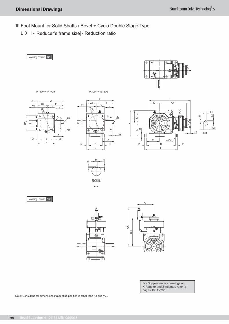
Bevel Buddybox 4 - 991361/EN-06/2018194
Dimensional Drawings
Foot Mount for Solid Shafts / Bevel + Cyclo Double Stage Type
L H - Reducer’s frame size - Reduction ratio
Mounting Position K1
Note: Consult us for dimensions if mounting position is other than K1 and V2..
A
A
4A10DA 4E18DB
A-A
Ød1
b1
t1 h1
B-B
bs
ØDs h6
ts hs
A
A
4F18DA 4F19DB
Q E QN
P B PF
B1
Ss
V
ms
L1
G
U2 T1r
ØDC
LCFK
H
CKH1
4-ØdØDC
R
L1
B
BG
K
GL
GH
T2 U3
ØDj
E QQN
Ss
VT1U2
L1
ØDC
G
ms
r
T2
J
U3
Mounting Position V2
For Supplementary drawings on X-Adaptor and J-Adaptor, refer to pages 196 to 205

Bevel Buddybox 4 - 991361/EN-06/2018 195
Dimensional Drawings
Frame Size L CF DC d1 L1 b1 h1 t1 Weight
[kg] GL GH GK
4A10DA 448 285 150 12 25 4 4 2,5 62 152 278 3974A12DA 460 297 204 12 25 4 4 2,5 70 203 290 4284A12DB 479 309 204 15 25 5 5 3 73 203 299 4374B12DA 517 334 204 12 25 4 4 2,5 111 203 327 4654B12DB 536 346 204 15 25 5 5 3 114 203 336 4744B14DA 534 351 230 12 25 4 4 2,5 114 231 349 5064B14DB 550 360 230 15 25 5 5 3 118 231 353 5104C14DA 623 410 230 12 25 4 4 2,5 178 231 407 5644C14DB 639 419 230 15 25 5 5 3 182 231 411 5684C14DC 645 433 230 15 25 5 5 3 183 231 418 5754C16DA 662 442 300 15 25 5 5 3 205 261 433 5904D16DA 765 515 300 15 25 5 5 3 293 261 505 6624D16DB 771 529 300 15 25 5 5 3 295 261 512 6694D17DA 759 509 340 15 25 5 5 3 307 289 496 7034D17DB 765 523 340 15 25 5 5 3 309 289 503 7104D17DC 790 527 340 18 35 6 6 3,5 314 289 508 7154D18DA 773 531 370 15 25 5 5 3 331 314 511 7874D18DB 823 553 370 22 40 6 6 3,5 342 314 527 7944E17DA 809 534 340 15 25 5 5 3 408 289 521 7284E17DB 815 548 340 15 25 5 5 3 410 289 528 7354E17DC 840 552 340 18 35 6 6 3,5 415 289 533 7404E18DA 823 556 370 15 25 5 5 3 422 314 536 8034E18DB 873 578 370 22 40 6 6 3,5 433 314 522 8194F18DA 911 619 370 15 25 5 5 3 642 314 599 8664F18DB 961 641 370 22 40 6 6 3,5 653 314 615 8824F19DA 956 643 430 18 35 6 6 3,5 689 355 624 8914F19DB 979 659 430 22 40 6 6 3,5 691 355 633 900
Frame Size
C H F E P L1 U3 V Ds Ss bsB N Q U2 J hs
K H1 B1 R d T1 T2 G r ms ts4A10DA 140 306 320 160 20 301 95,5 90 50 M10 144A12DA 280 202 21 110,5 94A12DB 110 141 135 25 14 190,5 206 118 3 20 5,54B12DA 170 346 385 195 20 369 122 115 65 M12 184B12DB 345 245 25 127 114B14DA4B14DB 130 161 160 35 18 242 247 147 3 24 74C14DA 210 414 505 210 30 425 124 145 80 M12 224C14DB 445 270 30 151 144C14DC4C16DA 160 193 195 40 22 274 301 182,5 5 24 94D16DA 245 479 560 260 30 503 148 170 95 M20 254D16DB4D17DA4D17DB 500 320 30 178 144D17DC4D18DA4D18DB 190 223 235 45 26 325 355 210 5 40 94E17DA 275 558 650 280 35 566 156 200 110 M20 284E17DB4E17DC 580 355 37,5 203 164E18DA4E18DB 215 248 270 45 33 363 410 245 5 40 104F18DA 320 670 740 320 35 638 183 210 130 M20 324F18DB 670 400 40 238 39 184F19DA4F19DB 240 273 300 65 33 400 455 268 5 45 11
Notes: 1. Mark in model numbers represents output shaft direction symbol H, V, or W. For details, refer to page 18. 2. The dimension tolerance of the output shaft end of the solid shaft is in accordance with DIN EN ISO 286-2. 3. Dimensions of keyway: According to the parallel key (standard class) in DIN 6885-1. 4. For details of the output shaft of each solid shaft, refer to page 208. 5. For details of the input shaft, refer to page 207. 6. The weight values in the table are for the hollow shaft units. For the solid shaft units, add the value in the table below. 7. The dimensions and weights on the dimensional drawings are subject to change without prior notice.
Additional weight values for both side output shaft units [kg]
Frame Size
Both-S ide Output Shaf t(T)
4A 74B 154C 224D 334E 534F 82
For Supplementary drawings on X-Adaptor and J-Adaptor, refer to pages 196 to 205
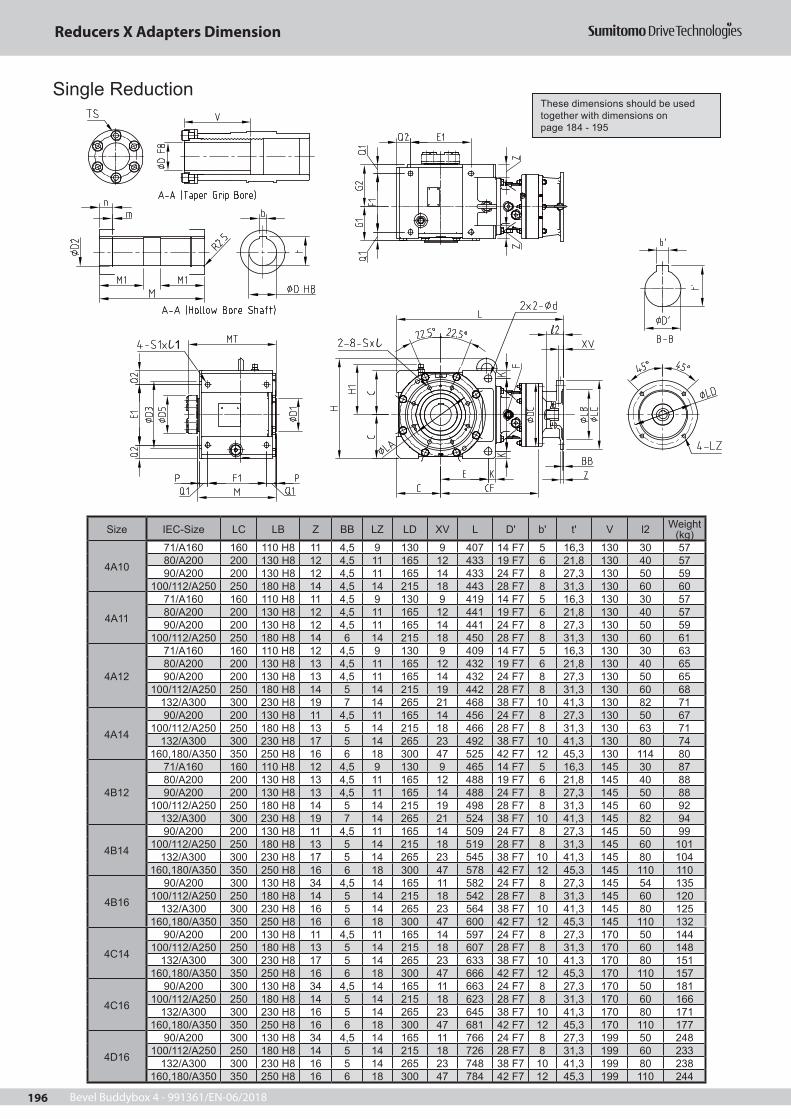
Bevel Buddybox 4 - 991361/EN-06/2018196
Size IEC-Size LC LB Z BB LZ LD XV L D' b' t' V l2 Weight (kg)
4A10
71/A160 160 110 H8 11 4,5 9 130 9 407 14 F7 5 16,3 130 30 5780/A200 200 130 H8 12 4,5 11 165 12 433 19 F7 6 21,8 130 40 5790/A200 200 130 H8 12 4,5 11 165 14 433 24 F7 8 27,3 130 50 59
100/112/A250 250 180 H8 14 4,5 14 215 18 443 28 F7 8 31,3 130 60 60
4A11
71/A160 160 110 H8 11 4,5 9 130 9 419 14 F7 5 16,3 130 30 5780/A200 200 130 H8 12 4,5 11 165 12 441 19 F7 6 21,8 130 40 5790/A200 200 130 H8 12 4,5 11 165 14 441 24 F7 8 27,3 130 50 59
100/112/A250 250 180 H8 14 6 14 215 18 450 28 F7 8 31,3 130 60 61
4A12
71/A160 160 110 H8 12 4,5 9 130 9 409 14 F7 5 16,3 130 30 6380/A200 200 130 H8 13 4,5 11 165 12 432 19 F7 6 21,8 130 40 6590/A200 200 130 H8 13 4,5 11 165 14 432 24 F7 8 27,3 130 50 65
100/112/A250 250 180 H8 14 5 14 215 19 442 28 F7 8 31,3 130 60 68132/A300 300 230 H8 19 7 14 265 21 468 38 F7 10 41,3 130 82 71
4A14
90/A200 200 130 H8 11 4,5 11 165 14 456 24 F7 8 27,3 130 50 67100/112/A250 250 180 H8 13 5 14 215 18 466 28 F7 8 31,3 130 63 71
132/A300 300 230 H8 17 5 14 265 23 492 38 F7 10 41,3 130 80 74160,180/A350 350 250 H8 16 6 18 300 47 525 42 F7 12 45,3 130 114 80
4B12
71/A160 160 110 H8 12 4,5 9 130 9 465 14 F7 5 16,3 145 30 8780/A200 200 130 H8 13 4,5 11 165 12 488 19 F7 6 21,8 145 40 8890/A200 200 130 H8 13 4,5 11 165 14 488 24 F7 8 27,3 145 50 88
100/112/A250 250 180 H8 14 5 14 215 19 498 28 F7 8 31,3 145 60 92132/A300 300 230 H8 19 7 14 265 21 524 38 F7 10 41,3 145 82 94
4B14
90/A200 200 130 H8 11 4,5 11 165 14 509 24 F7 8 27,3 145 50 99100/112/A250 250 180 H8 13 5 14 215 18 519 28 F7 8 31,3 145 60 101
132/A300 300 230 H8 17 5 14 265 23 545 38 F7 10 41,3 145 80 104160,180/A350 350 250 H8 16 6 18 300 47 578 42 F7 12 45,3 145 110 110
4B16
90/A200 300 130 H8 34 4,5 14 165 11 582 24 F7 8 27,3 145 54 135100/112/A250 250 180 H8 14 5 14 215 18 542 28 F7 8 31,3 145 60 120
132/A300 300 230 H8 16 5 14 265 23 564 38 F7 10 41,3 145 80 125160,180/A350 350 250 H8 16 6 18 300 47 600 42 F7 12 45,3 145 110 132
4C14
90/A200 200 130 H8 11 4,5 11 165 14 597 24 F7 8 27,3 170 50 144100/112/A250 250 180 H8 13 5 14 215 18 607 28 F7 8 31,3 170 60 148
132/A300 300 230 H8 17 5 14 265 23 633 38 F7 10 41,3 170 80 151160,180/A350 350 250 H8 16 6 18 300 47 666 42 F7 12 45,3 170 110 157
4C16
90/A200 300 130 H8 34 4,5 14 165 11 663 24 F7 8 27,3 170 50 181100/112/A250 250 180 H8 14 5 14 215 18 623 28 F7 8 31,3 170 60 166
132/A300 300 230 H8 16 5 14 265 23 645 38 F7 10 41,3 170 80 171160,180/A350 350 250 H8 16 6 18 300 47 681 42 F7 12 45,3 170 110 177
4D16
90/A200 300 130 H8 34 4,5 14 165 11 766 24 F7 8 27,3 199 50 248100/112/A250 250 180 H8 14 5 14 215 18 726 28 F7 8 31,3 199 60 233
132/A300 300 230 H8 16 5 14 265 23 748 38 F7 10 41,3 199 80 238160,180/A350 350 250 H8 16 6 18 300 47 784 42 F7 12 45,3 199 110 244
ll1
Single Reduction These dimensions should be used together with dimensions on page 184 - 195
These dimensions should be used together with dimensions on page 184 - 195
Reducers X Adapters Dimension
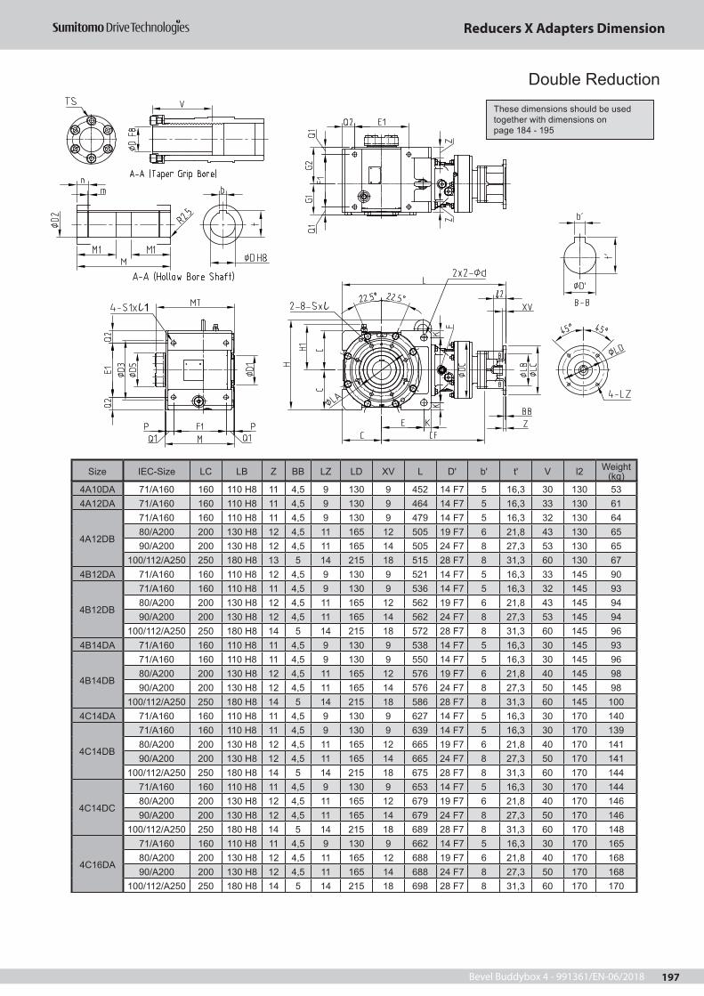
Bevel Buddybox 4 - 991361/EN-06/2018 197
Size IEC-Size LC LB Z BB LZ LD XV L D' b' t' V l2 Weight (kg)
4A10DA 71/A160 160 110 H8 11 4,5 9 130 9 452 14 F7 5 16,3 30 130 534A12DA 71/A160 160 110 H8 11 4,5 9 130 9 464 14 F7 5 16,3 33 130 61
4A12DB
71/A160 160 110 H8 11 4,5 9 130 9 479 14 F7 5 16,3 32 130 6480/A200 200 130 H8 12 4,5 11 165 12 505 19 F7 6 21,8 43 130 6590/A200 200 130 H8 12 4,5 11 165 14 505 24 F7 8 27,3 53 130 65
100/112/A250 250 180 H8 13 5 14 215 18 515 28 F7 8 31,3 60 130 674B12DA 71/A160 160 110 H8 12 4,5 9 130 9 521 14 F7 5 16,3 33 145 90
4B12DB
71/A160 160 110 H8 11 4,5 9 130 9 536 14 F7 5 16,3 32 145 9380/A200 200 130 H8 12 4,5 11 165 12 562 19 F7 6 21,8 43 145 9490/A200 200 130 H8 12 4,5 11 165 14 562 24 F7 8 27,3 53 145 94
100/112/A250 250 180 H8 14 5 14 215 18 572 28 F7 8 31,3 60 145 964B14DA 71/A160 160 110 H8 11 4,5 9 130 9 538 14 F7 5 16,3 30 145 93
4B14DB
71/A160 160 110 H8 11 4,5 9 130 9 550 14 F7 5 16,3 30 145 9680/A200 200 130 H8 12 4,5 11 165 12 576 19 F7 6 21,8 40 145 9890/A200 200 130 H8 12 4,5 11 165 14 576 24 F7 8 27,3 50 145 98
100/112/A250 250 180 H8 14 5 14 215 18 586 28 F7 8 31,3 60 145 1004C14DA 71/A160 160 110 H8 11 4,5 9 130 9 627 14 F7 5 16,3 30 170 140
4C14DB
71/A160 160 110 H8 11 4,5 9 130 9 639 14 F7 5 16,3 30 170 13980/A200 200 130 H8 12 4,5 11 165 12 665 19 F7 6 21,8 40 170 14190/A200 200 130 H8 12 4,5 11 165 14 665 24 F7 8 27,3 50 170 141
100/112/A250 250 180 H8 14 5 14 215 18 675 28 F7 8 31,3 60 170 144
4C14DC
71/A160 160 110 H8 11 4,5 9 130 9 653 14 F7 5 16,3 30 170 14480/A200 200 130 H8 12 4,5 11 165 12 679 19 F7 6 21,8 40 170 14690/A200 200 130 H8 12 4,5 11 165 14 679 24 F7 8 27,3 50 170 146
100/112/A250 250 180 H8 14 5 14 215 18 689 28 F7 8 31,3 60 170 148
4C16DA
71/A160 160 110 H8 11 4,5 9 130 9 662 14 F7 5 16,3 30 170 16580/A200 200 130 H8 12 4,5 11 165 12 688 19 F7 6 21,8 40 170 16890/A200 200 130 H8 12 4,5 11 165 14 688 24 F7 8 27,3 50 170 168
100/112/A250 250 180 H8 14 5 14 215 18 698 28 F7 8 31,3 60 170 170
ll1
Double Reduction These dimensions should be used together with dimensions on page 184 - 195
Reducers X Adapters Dimension

Bevel Buddybox 4 - 991361/EN-06/2018198
Size IEC-Size LC LB Z BB LZ LD XV L D' b' t' V l2 Weight (kg)
4D16DA
71/A160 160 110 H8 11 4,5 9 130 9 764 14 F7 5 16,3 30 199 23380/A200 200 130 H8 12 4,5 11 165 12 790 19 F7 6 21,8 40 199 23590/A200 200 130 H8 12 4,5 11 165 14 790 24 F7 8 27,3 53 199 235
100/112/A250 250 180 H8 14 5 14 215 18 800 28 F7 8 31,3 60 199 237
4D16DB
71/A160 160 110 H8 11 4,5 9 130 9 778 14 F7 5 16,3 30 199 23580/A200 200 130 H8 12 4,5 11 165 12 804 19 F7 6 21,8 40 199 23790/A200 200 130 H8 12 4,5 11 165 14 804 24 F7 8 27,3 50 199 237
100/112/A250 250 180 H8 14 5 14 215 18 814 28 F7 8 31,3 60 199 239
4D17DA
71/A160 160 110 H8 11 4,5 9 130 9 759 14 F7 5 16,3 30 199 24680/A200 200 130 H8 12 4,5 11 165 12 785 19 F7 6 21,8 40 199 24990/A200 200 130 H8 12 4,5 11 165 14 785 24 F7 8 27,3 50 199 249
100/112/A250 250 180 H8 14 5 14 215 18 795 28 F7 8 31,3 60 199 251
4D17DB
71/A160 160 110 H8 11 4,5 9 130 9 773 14 F7 5 16,3 30 199 24980/A200 200 130 H8 12 4,5 11 165 12 799 19 F7 6 21,8 40 199 25190/A200 200 130 H8 12 4,5 11 165 14 799 24 F7 8 27,3 50 199 251
100/112/A250 250 180 H8 14 5 14 215 18 809 28 F7 8 31,3 60 199 253
4D17DC
71/A160 160 110 H8 12 4,5 9 130 9 772 14 F7 5 16,3 30 199 25380/A200 200 130 H8 12 4,5 11 165 12 795 19 F7 6 21,8 40 199 25590/A200 200 130 H8 12 4,5 11 165 14 795 24 F7 8 27,3 50 199 255
100/112/A250 250 180 H8 14 5 14 215 18 805 28 F7 8 31,3 60 199 259132/A300 300 230 H8 19 7 14 265 21 831 38 F7 10 41,3 82 199 261
4D18DA
71/A160 160 110 H8 12 4,5 9 130 9 846 14 F7 5 16,3 30 199 29080/A200 200 130 H8 12 4,5 11 165 12 872 19 F7 6 21,8 40 199 29290/A200 200 130 H8 12 4,5 11 165 14 872 24 F7 8 27,3 50 199 292
100/112/A250 250 180 H8 14 4,5 14 215 18 882 28 F7 8 31,3 60 199 294
4D18DB
80/A200 200 130 H8 11 4,5 11 165 12 889 19 F7 6 21,8 52 199 30390/A200 200 130 H8 11 4,5 11 165 14 889 24 F7 8 27,3 50 199 303
100/112/A250 250 180 H8 13 4,5 14 215 18 899 28 F7 8 31,3 60 199 305132/A300 300 230 H8 17 5 14 265 23 925 38 F7 10 41,3 80 199 309
ll1
Double Reduction These dimensions should be used together with dimensions on page 184 - 195
Reducers X Adapters Dimension

Bevel Buddybox 4 - 991361/EN-06/2018 199
Size IEC-Size LC LB Z BB LZ LD XV L D' b' t' V l2 Weight (kg)
4E17DA
71/A160 160 110 H8 12 4,5 9 130 9 804 14 F7 5 16,3 30 200 320
80/A200 200 130 H8 12 4,5 11 165 12 835 19 F7 6 21,8 40 200 323
90/A200 200 130 H8 12 4,5 11 165 14 835 24 F7 8 27,3 53 200 323
100/112/A250 250 180 H8 14 4,5 14 215 18 845 28 F7 8 31,3 60 200 325
4E17DB
71/A160 160 110 H8 12 4,5 9 130 9 823 14 F7 5 16,3 30 200 323
80/A200 200 130 H8 12 4,5 11 165 12 849 19 F7 6 21,8 40 200 325
90/A200 200 130 H8 12 4,5 11 165 14 849 24 F7 8 27,3 50 200 325
100/112/A250 250 180 H8 14 4,5 14 215 18 859 28 F7 8 31,3 60 200 327
4E17DC
80/A200 200 130 H8 13 4,5 11 165 12 845 19 F7 6 21,8 40 200 329
90/A200 200 130 H8 12 4,5 11 165 14 845 24 F7 8 27,3 50 200 329
100/112/A250 250 180 H8 14 4,5 14 215 18 855 28 F7 8 31,3 60 200 333
132/A300 300 230 H8 19 5 14 265 21 881 38 F7 10 41,3 82 200 335
4E18DA
71/A160 160 110 H8 11 4,5 9 130 9 896 14 F7 5 16,3 30 200 365
80/A200 200 130 H8 12 4,5 11 165 12 922 19 F7 6 21,8 40 200 367
90/A200 200 130 H8 12 4,5 11 165 14 922 24 F7 8 27,3 50 200 367
100/112/A250 250 180 H8 14 4,5 14 215 18 932 28 F7 8 31,3 60 200 369
4E18DB
80/A200 200 130 H8 11 4,5 11 165 12 939 19 F7 6 21,8 40 200 395
90/A200 200 130 H8 11 4,5 11 165 14 939 24 F7 8 27,3 50 200 395
100/112/A250 250 180 H8 13 4,5 14 215 18 949 28 F7 8 31,3 60 200 397
132/A300 300 230 H8 17 5 14 265 23 975 38 F7 10 41,3 80 200 402
ll1
Double ReductionThese dimensions should be used together with dimensions on page 184 - 195
Reducers X Adapters Dimension

Bevel Buddybox 4 - 991361/EN-06/2018200
Size IEC-Size LC LB Z BB LZ LD XV L D' b' t' V l2 Weight (kg)
4F18DA
71/A160 160 110 H8 11 4,5 9 130 9 984 14 F7 5 16,3 30 248 541
80/A200 200 130 H8 12 4,5 11 165 12 1010 19 F7 6 21,8 40 248 543
90/A200 200 130 H8 12 4,5 11 165 14 1010 24 F7 8 27,3 50 248 543
100/112/A250 250 180 H8 14 4,5 14 215 18 1020 28 F7 8 31,3 60 248 545
4F18DB
80/A200 200 130 H8 11 4,5 11 165 12 1027 19 F7 6 21,8 40 248 553
90/A200 200 130 H8 11 4,5 11 165 14 1027 24 F7 8 27,3 50 248 553
100/112/A250 250 180 H8 14 4,5 14 215 18 1037 28 F7 8 31,3 60 248 555
132/A300 300 230 H8 17 5 14 265 23 1063 38 F7 10 41,3 80 248 560
4F19DA
71/A160 160 110 H8 12 4,5 9 130 9 1013 14 F7 5 16,3 30 248 587
80/A200 200 130 H8 13 4,5 11 165 12 1036 19 F7 6 21,8 40 248 589
90/A200 200 130 H8 13 4,5 11 165 14 1036 24 F7 8 27,3 50 248 589
100/112/A250 250 180 H8 14 4,5 14 215 18 1046 28 F7 8 31,3 60 248 593
132/A300 300 230 H8 17 5 14 265 23 1078 38 F7 10 41,3 80 248 595
4F19DB
80/A200 200 130 H8 11 4,5 11 165 12 1055 19 F7 6 21,8 40 248 591
90/A200 200 130 H8 11 4,5 11 165 14 1055 24 F7 8 27,3 50 248 591
100/112/A250 250 180 H8 13 4,5 14 215 18 1065 28 F7 8 31,3 60 248 594
132/A300 300 230 H8 17 5 14 265 23 1091 38 F7 10 41,3 80 248 598
Double Reduction
ll1
These dimensions should be used together with dimensions on page 184 - 195
Reducers X Adapters Dimension

Bevel Buddybox 4 - 991361/EN-06/2018 201
ll1
Size IEC-Size LC LB Z BB LZ LD XV L D' b' h' t' l2 V Weight (kg)
4A10
71/A160 160 110 H8 10 4 9 130 33 432 14 k6 5 5 3 25 130 50,480/A200 200 130 H8 10 10 11 165 43 442 14 k6 5 5 3 25 130 5290/A200 200 130 H8 10 5 11 165 53 452 14 k6 5 5 3 25 130 52
100/112/A250 250 180 H8 16 6 14 215 63 462 14 k6 5 5 3 25 130 54,6
4A11
71/A160 160 110 H8 10 5 9 130 33 439 14 k6 5 5 3 25 130 56,780/A200 200 130 H8 12 5 11 165 53 459 14 k6 5 5 3 25 130 57,990/A200 200 130 H8 12 5 11 165 53 459 14 k6 5 5 3 25 130 57,9
100/112/A250 250 180 H8 16 6 14 215 63 469 14 k6 5 5 3 25 130 60,1
4A12
71/A160 160 110 H8 10 - M8 130 33 460 19 k6 6 6 3,5 35 130 60,880/A200 200 130 H8 12 5 11 165 53 480 19 k6 6 6 3,5 35 130 60,990/A200 200 130 H8 12 5 11 165 53 480 19 k6 6 6 3,5 35 130 60,9
100/112/A250 250 180 H8 15 6 14 215 63 490 19 k6 6 6 3,5 35 130 63,8132/A300 300 230 H8 20 6 14 265 83 510 19 k6 6 6 3,5 35 130 68
4A14
80/A200 200 130 H8 12 - 12 165 53 509 22 h6 6 6 3,5 40 130 70,590/A200 200 130 H8 12 - 12 165 53 509 22 h6 6 6 3,5 40 130 70,5
100/112/A250 250 180 H8 15 6 14 215 63 519 22 h6 6 6 3,5 40 130 71,4132/A300 300 230 H8 15 6 14 265 83 539 22 h6 6 6 3,5 40 130 73,7
160,180/A350 350 250 H8 20 7 18 300 113 569 22 h6 6 6 3,5 40 130 81,9
4B12
71/A160 160 110 H8 10 - M8 130 33 516 19 k6 6 6 3,5 35 145 89,880/A200 200 130 H8 12 5 11 165 53 536 19 k6 6 6 3,5 35 145 89,990/A200 200 130 H8 12 5 11 165 53 536 19 k6 6 6 3,5 35 145 89,9
100/112/A250 250 180 H8 15 6 14 215 63 546 19 k6 6 6 3,5 35 145 92,8132/A300 300 230 H8 20 6 14 265 83 566 19 k6 6 6 3,5 35 145 97
4B14
80/A200 200 130 H8 12 - 12 165 53 562 22 h6 6 6 3,5 40 145 100,590/A200 200 130 H8 12 - 12 165 53 562 22 h6 6 6 3,5 40 145 100,5
100/112/A250 250 180 H8 15 6 14 215 63 572 22 h6 6 6 3,5 40 145 101,4132/A300 300 230 H8 15 6 14 265 83 592 22 h6 6 6 3,5 40 145 103,7
160,180/A350 350 250 H8 20 7 18 300 113 622 22 h6 6 6 3,5 40 145 111,9
4B16
90/A200 200 130 H8 12 - M10 165 68 629 30 h6 8 7 4 45 145 135,1100/112/A250 250 180 H8 15 6 14 215 63 624 30 h6 8 7 4 45 145 131,4
132/A300 300 230 H8 15 6 14 265 83 644 30 h6 8 7 4 45 145 132,6160,180/A350 350 250 H8 20 7 18 300 113 674 30 h6 8 7 4 45 145 141,5
200/A400 400 300 H8 20 7 18 350 114 675 30 h6 8 7 4 45 145 145,9
4C14
80/A200 200 130 H8 12 - 12 165 53 650 22 h6 6 6 3,5 40 170 147,590/A200 200 130 H8 12 - 12 165 53 650 22 h6 6 6 3,5 40 170 147,5
100/112/A250 250 180 H8 15 6 14 215 63 660 22 h6 6 6 3,5 40 170 148,4132/A300 300 230 H8 15 6 14 265 83 680 22 h6 6 6 3,5 40 170 150,7
160,180/A350 350 250 H8 20 7 18 300 113 710 22 h6 6 6 3,5 40 170 158,9
4C16
90/A200 200 130 H8 12 - M10 165 68 710 30 h6 8 7 4 45 170 181,1100/112/A250 250 180 H8 15 6 14 215 63 705 30 h6 8 7 4 45 170 177,4
132/A300 300 230 H8 15 6 14 265 83 725 30 h6 8 7 4 45 170 178,6160,180/A350 350 250 H8 20 7 18 300 113 755 30 h6 8 7 4 45 170 187,5
200/A400 400 300 H8 20 7 18 350 114 756 30 h6 8 7 4 45 170 191,9
4C17
100/112/A250 250 180 H8 15 6 14 215 63 741 35 h6 10 8 5 55 170 206,3132/A300 300 230 H8 15 6 14 265 83 761 35 h6 10 8 5 55 170 208
160,180/A350 350 250 H8 20 7 18 300 113 791 35 h6 10 8 5 55 170 215,8200/A400 400 300 H8 16 7 18 350 114 792 35 h6 10 8 5 55 170 218,2
Single Reduction These dimensions should be used together with dimensions on page 184 - 195
Reducers J Adapters Dimension

202Bevel Buddybox 4 - 991361/EN-06/2018202
Size IEC-Size LC LB Z BB LZ LD XV L D’ b’ h’ t’ l2 V Weight (kg)
4D16
90/A200 200 130 H8 12 - M10 165 68 813 30 h6 8 7 4 45 199 248,1100/112/A250 250 180 H8 15 6 14 215 63 808 30 h6 8 7 4 45 199 244,4
132/A300 300 230 H8 15 6 14 265 83 828 30 h6 8 7 4 45 199 245,6160,180/A350 350 250 H8 20 7 18 300 113 858 30 h6 8 7 4 45 199 254,5
200/A400 400 300 H8 20 7 18 350 114 859 30 h6 8 7 4 45 199 258,9
4D17
100/112/A250 250 180 H8 15 6 14 215 63 821 35 h6 10 8 5 55 199 269,3132/A300 300 230 H8 15 6 14 265 83 841 35 h6 10 8 5 55 199 271
160,180/A350 350 250 H8 20 7 18 300 113 871 35 h6 10 8 5 55 199 278,8200/A400 400 300 H8 16 7 18 350 114 872 35 h6 10 8 5 55 199 281,2
4D18
100/112/A250 250 180 H8 15 6 15 215 63 837 40 h6 12 8 5 65 199 284,5132/A300 300 230 H8 20 7 15 265 83 857 40 h6 12 8 5 65 199 288,1
160,180/A350 350 250 H8 20 7 18 300 113 887 40 h6 12 8 5 65 199 291,9200/A400 400 300 H8 19 7 18 350 114 888 40 h6 12 8 5 65 199 297,9225/A450 450 350 H8 20 7 18*1 400 144 918 40 h6 12 8 5 65 199 306,2
4E17
100/112/A250 250 180 H8 15 6 14 215 63 871 35 h6 10 8 5 55 200 343,3132/A300 300 230 H8 15 6 14 265 83 891 35 h6 10 8 5 55 200 345
160,180/A350 350 250 H8 20 7 18 300 113 921 35 h6 10 8 5 55 200 352,8200/A400 400 300 H8 16 7 18 350 114 922 35 h6 10 8 5 55 200 355,2
4E18
100/112/A250 250 180 H8 15 6 15 215 63 887 40 h6 12 8 5 65 199 367,5132/A300 300 230 H8 20 7 15 265 83 907 40 h6 12 8 5 65 199 371,1
160,180/A350 350 250 H8 20 7 18 300 113 937 40 h6 12 8 5 65 199 374,4200/A400 400 300 H8 19 7 18 350 114 938 40 h6 12 8 5 65 199 380,4225/A450 450 350 H8 20 7 18*1 400 144 968 40 h6 12 8 5 65 199 388,7
4E19
100/112/A250 250 180 H8 16 6 M12 215 63 923 45 h6 14 9 5,5 70 199 407,9132/A300 300 230 H8 16 6 M12 265 83 943 45 h6 14 9 5,5 70 199 410,5
160,180/A350 350 250 H8 20 7 18 300 113 973 45 h6 14 9 5,5 70 199 416,6200/A400 400 300 H8 20 7 18 350 114 974 45 h6 14 9 5,5 70 199 418,8225/A450 450 350 H8 20 7 18*1 400 144 1004 45 h6 14 9 5,5 70 199 421,6250/A550 500 400 H8 22 7 18*1 450 144 1004 45 h6 14 9 5,5 70 199 444,8280/A550 500 400 H8 22 7 18*1 450 144 1004 45 h6 14 9 5,5 70 199 444,8
4F18
100/112/A250 250 180 H8 15 6 15 215 63 976 40 h6 12 8 5 65 248 564,5132/A300 300 230 H8 20 7 15 265 83 996 40 h6 12 8 5 65 248 568,1
160,180/A350 350 250 H8 20 7 18 300 113 1026 40 h6 12 8 5 65 248 571,4200/A400 400 300 H8 19 7 18 350 114 1027 40 h6 12 8 5 65 248 577,4225/A450 450 350 H8 20 7 18*1 400 144 1057 40 h6 12 8 5 65 248 585,7
4F19
100/112/A250 250 180 H8 16 6 M12 215 63 1010 45 h6 14 9 5,5 70 248 601,9132/A300 300 230 H8 16 6 M12 265 83 1030 45 h6 14 9 5,5 70 248 604,5
160,180/A350 350 250 H8 20 7 18 300 113 1060 45 h6 14 9 5,5 70 248 610,6200/A400 400 300 H8 20 7 18 350 114 1061 45 h6 14 9 5,5 70 248 612,8225/A450 450 350 H8 20 7 18*1 400 144 1091 45 h6 14 9 5,5 70 248 615,6250/A550 500 400 H8 22 7 18*1 450 144 1091 45 h6 14 9 5,5 70 248 638,8280/A550 500 400 H8 22 7 18*1 450 144 1091 45 h6 14 9 5,5 70 248 638,8
ll1
Single ReductionThese dimensions should be used together with dimensions on page 184 - 195
Reducers J Adapters Dimension

Bevel Buddybox 4 - 991361/EN-06/2018 203
4A10DA 71/A160 160 110 H8 10 5 9 130 44 492 12 k6 4 4 2,5 25 130 52,24A12DA 71/A160 160 110 H8 10 5 9 130 44 504 12 k6 4 4 2,5 25 130 60,2
4A12DB71/A160 160 110 H8 10 5 9 130 46 525 14 k6 5 5 3 25 130 63,780/A200 200 130 H8 10 5 11 165 43 522 14 k6 5 5 3 25 130 65,990/A200 200 130 H8 12 5 12 165 53 532 14 k6 5 5 3 25 130 65,4
4B12DA 71/A160 160 110 H8 10 5 9 130 44 561 12 k6 4 4 2,5 25 145 89,2
4B12DB71/A160 160 110 H8 10 5 9 130 46 582 14 k6 5 5 3 25 145 92,780/A200 200 130 H8 10 5 11 165 43 579 14 k6 5 5 3 25 145 94,990/A200 200 130 H8 12 5 12 165 53 589 14 k6 5 5 3 25 145 94,4
4B14DA 71/A160 160 110 H8 11 4,5 9 130 44 578 12 k6 4 4 2,5 25 145 92,2
4B14DB71/A160 160 110 H8 12 4,5 9 130 46 596 14 k6 5 5 3 25 145 96,780/A200 200 130 H8 12 4,5 11 165 43 593 14 k6 5 5 3 25 145 98,990/A200 200 130 H8 12 4,5 11 165 53 603 14 k6 5 5 3 25 145 98,4
4C14DA 71/A160 160 110 H8 11 4,5 9 130 44 667 12 k6 4 4 2,5 25 170 139,2
4C14DB71/A160 160 110 H8 12 4,5 9 130 46 685 14 k6 5 5 3 25 170 143,780/A200 200 130 H8 12 4,5 11 165 43 682 14 k6 5 5 3 25 170 145,990/A200 200 130 H8 12 4,5 11 165 53 692 14 k6 5 5 3 25 170 145,4
4C14DC
71/A160 160 110 H8 10 4 M8 130 33 678 14 k6 5 5 3 25 170 144,480/A200 160 110 H8 10 5 11 130 57 702 14 k6 5 5 3 25 170 145,590/A200 200 130 H8 10 4 11 165 53 698 14 k6 5 5 3 25 170 146
100/112/A250 200 130 H8 16 6 14 165 63 708 14 k6 5 5 3 25 170 148,6
4C16DA71/A160 160 110 H8 10 5 9 130 46 708 14 k6 5 5 3 25 145 166,780/A200 200 130 H8 10 5 11 165 43 705 14 k6 5 5 3 25 145 168,990/A200 200 130 H8 12 5 12 165 53 715 14 k6 5 5 3 25 145 168,4
Size IEC-Size LC LB Z BB LZ LD XV L D’ b’ h’ t’ l2 V Weight (kg)
ll1
Double ReductionThese dimensions should be used together with dimensions on page 184 - 195
Reducers J Adapters Dimension
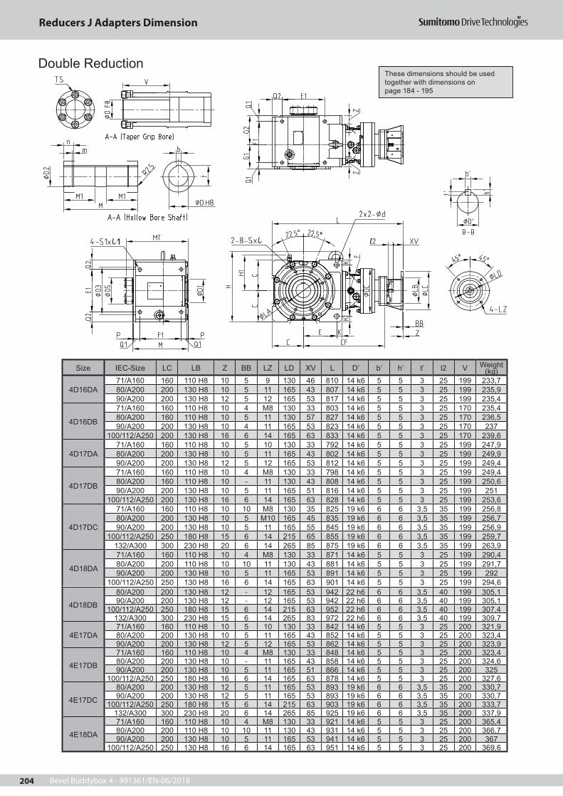
Bevel Buddybox 4 - 991361/EN-06/2018204
ll1
Size IEC-Size LC LB Z BB LZ LD XV L D’ b’ h’ t’ l2 V Weight (kg)
4D16DA71/A160 160 110 H8 10 5 9 130 46 810 14 k6 5 5 3 25 199 233,780/A200 200 130 H8 10 5 11 165 43 807 14 k6 5 5 3 25 199 235,990/A200 200 130 H8 12 5 12 165 53 817 14 k6 5 5 3 25 199 235,4
4D16DB
71/A160 160 110 H8 10 4 M8 130 33 803 14 k6 5 5 3 25 170 235,480/A200 160 110 H8 10 5 11 130 57 827 14 k6 5 5 3 25 170 236,590/A200 200 130 H8 10 4 11 165 53 823 14 k6 5 5 3 25 170 237
100/112/A250 200 130 H8 16 6 14 165 63 833 14 k6 5 5 3 25 170 239,6
4D17DA71/A160 160 110 H8 10 5 10 130 33 792 14 k6 5 5 3 25 199 247,980/A200 200 130 H8 10 5 11 165 43 802 14 k6 5 5 3 25 199 249,990/A200 200 130 H8 12 5 12 165 53 812 14 k6 5 5 3 25 199 249,4
4D17DB
71/A160 160 110 H8 10 4 M8 130 33 798 14 k6 5 5 3 25 199 249,480/A200 160 110 H8 10 - 11 130 43 808 14 k6 5 5 3 25 199 250,690/A200 200 130 H8 10 5 11 165 51 816 14 k6 5 5 3 25 199 251
100/112/A250 200 130 H8 16 6 14 165 63 828 14 k6 5 5 3 25 199 253,6
4D17DC
71/A160 160 110 H8 10 10 M8 130 35 825 19 k6 6 6 3,5 35 199 256,880/A200 200 130 H8 10 5 M10 165 45 835 19 k6 6 6 3,5 35 199 256,790/A200 200 130 H8 10 5 11 165 55 845 19 k6 6 6 3,5 35 199 256,9
100/112/A250 250 180 H8 15 6 14 215 65 855 19 k6 6 6 3,5 35 199 259,7132/A300 300 230 H8 20 6 14 265 85 875 19 k6 6 6 3,5 35 199 263,9
4D18DA
71/A160 160 110 H8 10 4 M8 130 33 871 14 k6 5 5 3 25 199 290,480/A200 200 110 H8 10 10 11 130 43 881 14 k6 5 5 3 25 199 291,790/A200 200 130 H8 10 5 11 165 53 891 14 k6 5 5 3 25 199 292
100/112/A250 250 130 H8 16 6 14 165 63 901 14 k6 5 5 3 25 199 294,6
4D18DB
80/A200 200 130 H8 12 - 12 165 53 942 22 h6 6 6 3,5 40 199 305,190/A200 200 130 H8 12 - 12 165 53 942 22 h6 6 6 3,5 40 199 305,1
100/112/A250 250 180 H8 15 6 14 215 63 952 22 h6 6 6 3,5 40 199 307,4132/A300 300 230 H8 15 6 14 265 83 972 22 h6 6 6 3,5 40 199 309,7
4E17DA71/A160 160 110 H8 10 5 10 130 33 842 14 k6 5 5 3 25 200 321,980/A200 200 130 H8 10 5 11 165 43 852 14 k6 5 5 3 25 200 323,490/A200 200 130 H8 12 5 12 165 53 862 14 k6 5 5 3 25 200 323,9
4E17DB
71/A160 160 110 H8 10 4 M8 130 33 848 14 k6 5 5 3 25 200 323,480/A200 200 130 H8 10 - 11 165 43 858 14 k6 5 5 3 25 200 324,690/A200 200 130 H8 10 5 11 165 51 866 14 k6 5 5 3 25 200 325
100/112/A250 250 180 H8 16 6 14 165 63 878 14 k6 5 5 3 25 200 327,6
4E17DC
80/A200 200 130 H8 12 5 11 165 53 893 19 k6 6 6 3,5 35 200 330,790/A200 200 130 H8 12 5 11 165 53 893 19 k6 6 6 3,5 35 200 330,7
100/112/A250 250 180 H8 15 6 14 215 63 903 19 k6 6 6 3,5 35 200 333,7132/A300 300 230 H8 20 6 14 265 85 925 19 k6 6 6 3,5 35 200 337,9
4E18DA
71/A160 160 110 H8 10 4 M8 130 33 921 14 k6 5 5 3 25 200 365,480/A200 200 110 H8 10 10 11 130 43 931 14 k6 5 5 3 25 200 366,790/A200 200 130 H8 10 5 11 165 53 941 14 k6 5 5 3 25 200 367
100/112/A250 250 130 H8 16 6 14 165 63 951 14 k6 5 5 3 25 200 369,6
Double ReductionThese dimensions should be used together with dimensions on page 184 - 195
Reducers J Adapters Dimension
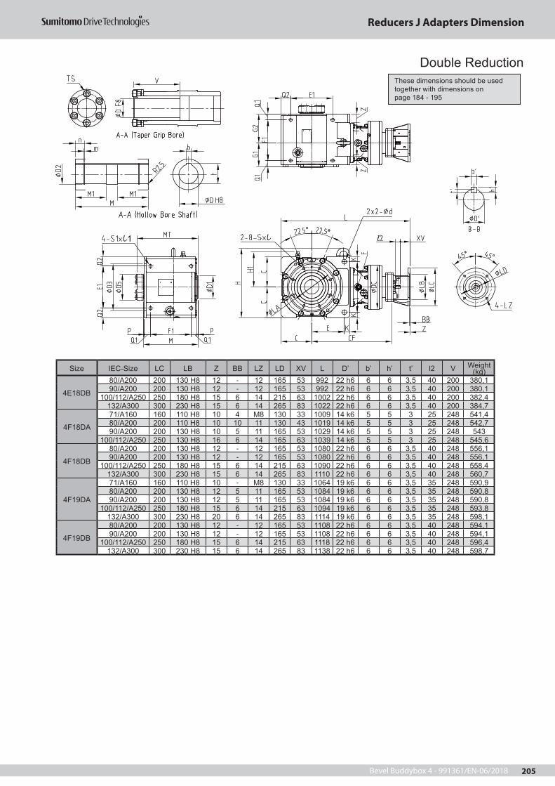
Bevel Buddybox 4 - 991361/EN-06/2018 205
Size IEC-Size LC LB Z BB LZ LD XV L D’ b’ h’ t’ l2 V Weight (kg)
4E18DB
80/A200 200 130 H8 12 - 12 165 53 992 22 h6 6 6 3,5 40 200 380,190/A200 200 130 H8 12 - 12 165 53 992 22 h6 6 6 3,5 40 200 380,1
100/112/A250 250 180 H8 15 6 14 215 63 1002 22 h6 6 6 3,5 40 200 382,4132/A300 300 230 H8 15 6 14 265 83 1022 22 h6 6 6 3,5 40 200 384,7
4F18DA
71/A160 160 110 H8 10 4 M8 130 33 1009 14 k6 5 5 3 25 248 541,480/A200 200 110 H8 10 10 11 130 43 1019 14 k6 5 5 3 25 248 542,790/A200 200 130 H8 10 5 11 165 53 1029 14 k6 5 5 3 25 248 543
100/112/A250 250 130 H8 16 6 14 165 63 1039 14 k6 5 5 3 25 248 545,6
4F18DB
80/A200 200 130 H8 12 - 12 165 53 1080 22 h6 6 6 3,5 40 248 556,190/A200 200 130 H8 12 - 12 165 53 1080 22 h6 6 6 3,5 40 248 556,1
100/112/A250 250 180 H8 15 6 14 215 63 1090 22 h6 6 6 3,5 40 248 558,4132/A300 300 230 H8 15 6 14 265 83 1110 22 h6 6 6 3,5 40 248 560,7
4F19DA
71/A160 160 110 H8 10 - M8 130 33 1064 19 k6 6 6 3,5 35 248 590,980/A200 200 130 H8 12 5 11 165 53 1084 19 k6 6 6 3,5 35 248 590,890/A200 200 130 H8 12 5 11 165 53 1084 19 k6 6 6 3,5 35 248 590,8
100/112/A250 250 180 H8 15 6 14 215 63 1094 19 k6 6 6 3,5 35 248 593,8132/A300 300 230 H8 20 6 14 265 83 1114 19 k6 6 6 3,5 35 248 598,1
4F19DB
80/A200 200 130 H8 12 - 12 165 53 1108 22 h6 6 6 3,5 40 248 594,190/A200 200 130 H8 12 - 12 165 53 1108 22 h6 6 6 3,5 40 248 594,1
100/112/A250 250 180 H8 15 6 14 215 63 1118 22 h6 6 6 3,5 40 248 596,4132/A300 300 230 H8 15 6 14 265 83 1138 22 h6 6 6 3,5 40 248 598,7
ll1
Double ReductionThese dimensions should be used together with dimensions on page 184 - 195
Reducers J Adapters Dimension
Bevel Buddybox 4 - 991361/EN-06/2018206
Technical Data and Options Detailed Dimensions of Input Shaft End 207Detailed Dimensions of Output Shaft End 208Lubrication 209Handling Precautions: Solid Shaft Units 213Handling Precautions: Hollow Shaft Units 214Shrink Disc (Option) 217Taper Grip Bush (Option) 219Torque Arm 221Construction Drawings 224Motor Information 225
Page
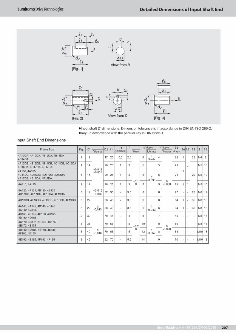
Bevel Buddybox 4 - 991361/EN-06/2018 207
Detailed Dimensions of Input Shaft End
Input shaft D’ dimensions: Dimension tolerance is in accordance in DIN EN ISO 286-2.Key: In accordance with the parallel key in DIN 6885-1.
Input Shaft End Dimensions
Frame Size Fig. D' D2 1 K1(Roundness)
t' b' (key) h' (key) 5(key) 6 7 8 S1 9
Tolerance Tolerance Tolerance Tolerance4A10DA, 4A12DA, 4B12DA, 4B14DA4C14DA 1 12
+0,012+0,001
17 25 0,5 2,5
+0,10
4 0-0,030 4
0-0,030
22 1
1
23 M4 8
4A12DB, 4B12DB, 4B14DB, 4C14DB, 4C16DA4D16DA, 4D17DA, 4E17DA 1 14 20 25 1 3 5
0-0,036
5 21
122
M5 10
4A100, 4A1054C14DC, 4D16DB, 4D17DB, 4D18DA, 4E17DB, 4E18DA, 4F18DA
1 14 20 25 1 3 5 5 21 M5 10
4A110, 4A115 1 14 20 25 1 3 5 5 21 1 1 M5 10
4A120, 4A125, 4B120, 4B1254D17DC, 4E17DC, 4E19DA, 4F19DA 3 19 +0,015
+0,002 32 35 - 3,5 6 6 27 - - 28 M6 12
4D18DB, 4E18DB, 4E19DB, 4F18DB, 4F19DB 3 22
0-0,013
38 40 - 3,5 6
0-0,043
6 34 1 - 35 M8 16
4A140, 4A145, 4B140, 4B1454C140, 4C145, 3 22 38 40 - 3,5 6 6 34 1 - 35 M8 16
4B160, 4B165, 4C160, 4C1654D160, 4D165 2 30 70 45 - 4
+0,20
8 7
0-0,090
45 - - - M8 16
4C170, 4C175, 4D170, 4D1754E170, 4E175 3 35
0-0,016
70 55 - 5 10
0-0,052
8 50 - - - M8 16
4D180, 4D185, 4E180, 4E1854F180, 4F185 3 40 70 65 - 5 12 8 63 - - - M10 18
4E190, 4E195, 4F190, 4F195 3 45 82 70 - 5,5 14 9 70 - - - M10 18
8
1
5
K1
B
B
b'
D'
t'
h'
b'
D't'
h'
View from B
View from C
[Fig. 1]
[Fig. 3]
D2
1
8
D2
K1
5
7
6
C
5
1
9
D2
S1
K1
[Fig. 2]

Bevel Buddybox 4 - 991361/EN-06/2018208
Output Shaft Details
Output Shaft End Dimensions
Frame Size
D(h6) D1 K
(Roundness) s 2t b (key) h (key) 3
(key) 4Tolerance Tolerance (h9) Tolerance Tolerance
4A10 4A11 4A12 4A14
50 0-0,016 85 90 R3 M10 20 5,5
+0,20
140
-0,043
9 0-0,090 70 77
4B12 4B14 4B16
650
-0,019
100 115 R3 M12 24 7 18 11
0-0,110
80 89
4C14 4C16 4C17
80 120 145 R5 M12 24 9 22
0-0,052
14 120 131
4D16 4D17 4D18
95
0-0,022
140 170 R5 M20 40 9 25 14 140 152,5
4E17 4E18 4E19
110 160 200 R5 M20 40 10 28 16 160 174
4F18 4F19 130 180 210 R5 M20 45 11 32 0
-0,062 18 170 186
Notes: 1. The mark of each frame size contains 0, 5, DA, DB, or DC. 2. The above values are subject to change without notice.
b
Dt h
View from A
4
3
2
D1A S
K
Detailed Dimensions of Output Shaft End

Bevel Buddybox 4 - 991361/EN-06/2018 209
1. Standard Lubrication Method
Standard Lubrication Method The of a frame size mark represents 0 or 5.Standard Lubrication Method Table
Frame Size
Cyclo or Planetary Single Stage Reduction
4A10 4A11 4A12 4B12
4A14 4B14 4C14
4B16 4C16 4D16
4C17 4D17 4E17
4D18 4E18 4F18
4E19 4F19
Cyclo Two-Stage Reduction 4A10DA -
4A12DA4A12DB4B12DA4B12DB
4B14DA4B14DB4C14DA4C14DB4C14DC
4C16DA4C16DB4D16DA4D16DB
4D17DB4D17DC4E17DA4E17DB4E17DC
4D18DA4D18DB4E18DA4E18DB4F18DA4F18DB
4F19DA4F19DB
Output Side (Bevel) Oil bath
Input Side (Cyclo or
Planetary)
Motor Horizontal Oil bath
Motor Vertical
Output end at bottom
Oil bath
Output end at top
Grease lubrication
Notes: 1. The above lubrication method is used when Bevel Buddybox reducers are driven at a standard input speed. 2. Grease lubrication may be available also for reducer models where oil lubrication is the standard method. When it is available, the
performance and other characteristics may differ from the standard. Consult us for details. 3. The mark of each frame size represents 0 or 5, depending on the combination with the reduction ratio.
Lubrication

Bevel Buddybox 4 - 991361/EN-06/2018210
2. LubricantsA. Oil Lubrication Models
The oil lubrication models are shipped without oil. Be sure to ll lubrication oil up to the center of the oil gauge before starting operation.
Recommended OilsTable 1: Recommended Oils, lists the oils that may be used to lubricate the Bevel Gear portion of the unit. These oils may also be used in the Cyclo portion if it is oil lubricated.
Table 1: Recommended OilsManufacturer Type of oil Manufacturer Type of oil
AVIA Gear RSX MOBIL Mobilgear 600XPCASTROL Alpha EP SHELL Omala
DEA Falcon CLP TOTAL Carter EP / XEPKLÜBER Klüberoil GEM1
• Use lubricants with low viscosity for operation during winter or at relatively low temperatures.• Use a lubricant with a viscosity within the range listed in Table 2, Recommended Oil Viscosity.
Table 2: Recommended Oil Viscositylubricant as per DIN 57517 part 3
possible operating temperatures °Cambient temperature °C
-20°C 0° +20° +40° +60° +80° +100°
CLP 68CLP 100CLP 150CLP 220CLP 320
• Consult local distributor, nearest authorized agent or Sumitomo directly when the unit will be operated in ambient temperatures other than -10° – 40 °C. Special unit modi cations may be necessary.
B. Grease Lubrication Models (Mounting Position: Y4, F4, G4, K4, and W4)The grease lubrication model is shipped after the appropriate portions have been lled with the grease in Table 2. You only need to ll with oil lubrication in the oil lubrication portions before starting operations.
Cyclo Portion Approved GreasesTable 3: Cyclo Portion Approved Greases, lists the greases that may be used to lubricate the Cyclo portion if grease is the speci ed lubrication method (refer to the Lubrication Method section for details).
Table 3: Cyclo Portion Approved GreasesAmbient Temp.
°C
Overall
Reduction RatioAll Unit Sizes
-10º – 50 ºC11:1 through 18:1 Shell Gadus S2 V220 0019:1 and higher Esso Unirex N2
Cyclo portions have unique operating characteristics that require speci c lubricant properties. Please consult Sumitomo if alternate lubricants are required.
* Consult us if the unit is stored for a long period beyond three years because grease maintenance may be necessary.
Lubrication

Bevel Buddybox 4 - 991361/EN-06/2018 211
3. Oil Fill QuantitiesThe approximate oil fill quantities are listed in table below.Be sure to check the oil level with the oil gauge.
Approximate oil fill quantities for Bevel Buddybox (liters)[Single Stage Type] Output side: Bevel; input side: Cyclo or planetary;G: Grease lubrication (For the amount of grease, refer to the operation and maintenance manual.)
Frame SizeMounting Position
Y1, F1, G1, K1, V1 Y2, F2, G2, K2, V2, W2
Y3, F3, G3, K3, V3, W3
Y4, F4, G4, K4, W4 Y5, F5, G5, K5, V5 Y6, F6, G6, K6, V6Output Side Input Side4A10 1,6 3,2 1,6
1,1 G
1,4 1,8 4A11 1,7 3,3 1,7 1,4 1,9 4A12 1,7 3,4 1,7 1,5 1,9 4A14 1,9 3,8 1,9 1,7 2,1 4B12 3,3 6,5 3,3
1,7 G3,3 3,2
4B14 3,5 7,0 3,5 3,5 3,4 4B16 3,9 7,6 3,9 4,0 3,9 4C14 5,5 11,1 5,5
2,7 G5,3 5,9
4C16 6,0 11,8 6,0 5,7 6,3 4C17 6,3 12,5 6,3 6,1 6,7 4D16 10,1 19,9 10,1
4,6 G9,7 10,4
4D17 10,4 20,5 10,4 10,0 10,8 4D18 10,7 21,0 10,7 10,3 11,1 4E17 14,6 28,8 14,6
6,3 G13,1 16,1
4E18 14,7 29,1 14,7 13,2 16,24E19 15,7 30,4 15,7 14,2 17,24F18 20,0 39,4 20,0 7,3 G 18,5 21,4 4F19 20,8 40,6 20,8 19,3 22,2
The mark of each frame size represents 0 or 5.
[Double Stage Type] Output side: Bevel; input side: CycloG: Grease lubrication (For the amount of grease, refer to the operation and maintenance manual.)
Frame SizeMounting Position
Y1, F1, G1, K1, V1 Y2, F2, G2, K2, V2, W2 Y3, F3, G3, K3, V3, W3 Y4, F4, G4, K4, W4 Y5, F5, G5, K5, V5 Y6, F6, G6, K6, V6Output Side Input Side4A10DA 1,7 3,2 1,7
1,1 G1,4 1,9
4A12DA 1,7 3,4 1,7 1,5 2,0 4A12DB 1,8 3,4 1,8 1,5 2,0 4B12DA 3,3 6,5 3,3
1,7 G
3,4 3,3 4B12DB 3,4 6,6 3,4 3,4 3,3 4B14DA 3,5 7,0 3,5 3,6 3,5 4B14DB 3,6 7,0 3,6 3,6 3,5 4C14DA 5,6 11,2 5,6
2,7 G
5,3 5,9 4C14DB 5,6 11,2 5,6 5,4 5,9 4C14DC 5,6 11,3 5,6 5,4 6,0 4C16DA 6,0 11,8 6,0 5,8 6,4 4C16DB 6,1 11,9 6,1 5,9 6,4 4D16DA 10,1 20,0 10,1
4,6 G
9,8 10,54D16DB 10,1 20,0 10,1 9,8 10,5 4C17DA 10,2 20,0 10,2 9,8 10,6 4D17DB 10,5 20,6 10,5 10,2 10,9 4D17DC 10,7 20,7 10,7 10,3 11,0 4D18DA 10,8 21,1 10,8 10,5 11,24D18DB 11,7 21,4 11,7 11,4 12,14E17DA 14,6 28,8 14,6
6,3 G
13,1 16,1 4E17DB 14,7 28,9 14,7 13,2 16,2 4E17DC 14,8 29,0 14,8 13,3 16,3 4E18DA 14,8 29,3 14,8 13,3 16,3 4E18DB 15,7 29,6 15,7 14,2 17,2 4E19DA 17,5 31,0 17,5 16,0 19,0 4E19DB 17,7 31,0 17,7 16,2 19,2 4F18DA 20,1 39,6 20,1
7,3 G
18,6 21,54F18DB 21,0 39,9 21,0 19,5 22,44F19DA 22,6 41,2 22,6 21,1 24,04F19DB 22,8 41,2 22,8 21,3 24,2
4. Precautions on Oil SealOil seals have their lifetime. While it is used for many hours, the sealing effect may degrade due to natural degradation or abrasion. The seal lifetime varies significantly with the operation conditions and ambient conditions of the reducer. If it is used in a usual operation manner (uniform load, operated for 10 hours a day, at a normal temperature), it is recommended to replace oil seals every 1 to 3 years or so. If rust is found on the shaft (or collar), replace it as well.
Lubrication

Bevel Buddybox 4 - 991361/EN-06/2018212
The oil gauge is equipped, as standard, on the side of the case. You may designate its mounting position and type of oil gauge optionally.
For the specification where oil gauge is in
standard position
L-shaped oil gaugebody made of brass and
inside made of glass
For the specification where oil gauge is in reverse position or
equipped on both sides
Dip stick type is also available. Consult us for details.
5. Oil Gauge Options
Lubrication

Bevel Buddybox 4 - 991361/EN-06/2018 213
Seal Cap
For solid shaft type units,(1) A seal cap is put on the opposite side of shaft projection direction for frame size A ~ E.
(2) A cover is put on the opposite side of shaft projection direction for frame size F.
Seal Cap
Cover
Handling Precautions: Solid Shaft Type

Bevel Buddybox 4 - 991361/EN-06/2018214
Hollow Shaft Type Mounting1. Mounting to Driven Shaft
Apply molybdenum disulfide to the surface of the shaft and the inside of the hollow shaft. Then, insert Buddybox onto the driven shaft.If engagement is too tight, lightly strike on the end of the hollow output shaft with a mallet. Never strike on the casing. It is recommended to make and use jigs to as shown on the right for smooth insertion.The hollow shaft dimension tolerance is in accordance with DIN EN ISO 286-2 "H8". The recommended tolerance for the driven shaft is as follows:For uniform load without shock load: h6 or js6For shock load or large radial load: js6 or k6Snap ring size is in accordance with DIN 472.If the driven shaft is stepped, check the shaft stress of driven shaft.
e
cba
d
Retaining ring Spacer Thrust bearing Nut Flush cut bolt
2. Removal from Driven ShaftHandle with care so that excessive force will not be applied between the casing and hollow shaft. It is recommended to make jigs to as shown on the right for easy removal.Note: For use in mounting, securing, and removal, prepare the
parts of the recommended dimensions below.g
h A
i
f A~
Spacer Hex head bolt Disc Retaining ringRecommended Dimensions of Mounting and Removal Jigs and Driven Shaft
e
db
c
h
f g
A2
A3A8
A6
A4
A5
A7k i
i jL2
LLH
LGLF
L1L3
A1
DD1
a
Fig. 1: Securing
Fig. 3: Securing
Fig. 2: Mounting
Fig. 4: Removal
L4 x L5
Handling Precautions: Hollow Shaft Type

Bevel Buddybox 4 - 991361/EN-06/2018 215
Recommended Dimensions of Driven Shaft and Jigs
Frame Size
Hollow Shaft(Bevel Buddybox)
Recommended Dimensions ofDriven Shaft
Recommended Dimensions of Jigs
ØD L LH LG LF L1 L2L3
(Minimum)(MIN)
L4 L5 ØD1 C type Retaining
Ring in boreA2
Thrust bearing
NutDouble-end stud
A3 A4 A5 A6 A7Hex head bolt (Full
thread type)A8 A1
Hex head bolt
Outside Dia. x Width
4A10 4A11 4A12 4A14
Ø55 216 186 131 85 157 10 76 M16 32 Ø65 Ø55 25 51104 M16 M16x250 19 45 55-0,1 -0,3 16 M24 M24x250 5 13 M16x80 Ø55x29
4B12 4B14 4B16
Ø65 259 229 159 100 204 12 115 M20 34 Ø75 Ø65 25 51105 M20 M20x300 19 58 65-0,1 -0,3 18 M24 M24x300 5 13 M20x80 Ø65x25
4C14 4C16 4C17
Ø75 285 248 165 120 223 12 170 M20 39 Ø85 Ø75 25 51105 M20 M20x300 19 67,5 75-0,1 -0,3 20 M24 M24x300 5 13 M20x80 Ø75x25
4D16 4D17 4D18
Ø85 340 303 195 145 272 15 215 M24 44 Ø95 Ø85 35 51107 M24 M24x400 24 77 85-0,1 -0,3 25 M30 M30x400 6 15 M24x100 Ø85x31
4E17 4E18 4E19
Ø100 373 336 208 165 310 16 220 M24 48 Ø110 Ø100 35 51107 M24 M24x400 19 90 100-0,1 -0,3 28 M30 M30x400 6 15 M24x100 Ø100x26
4F18 4F19
Ø120 435 386 241 189 345 16 260 M30 60 Ø140 Ø120 46 51109 M30 M30x450 30 109 120-0,1 -0,3 32 M36 M36x450 7 15 M30x110 Ø120x41
* The mark of each frame size represents 0, 5, DA, DB, or DC.
3. Securing to Driven Shaft For whirl stop by a torque arm, be sure to secure the reducer to the driven shaft.
a. Example of securing the reducer not to move to the machine side
Mac
hine
Sid
e
SpacerBearing unit Stopper ring Set screw
Secured by a stepped shaft Secured by a spacer
(non stepped driven shaft)
Secured by a set screw and stopper
(non stepped driven shaft)
b. Example of securing the reducer not to move off from the machine side
Mac
hine
Sid
e
SpacerRetaining ring
End plate
Secured by a spacer and stopper ring Secured by an end plate Secured by set screw and stopper ring
Set screw Stopper ring
Handling Precautions: Hollow Shaft Type

Bevel Buddybox 4 - 991361/EN-06/2018216
Take care at the time of attachment so that the reducer casing is not twisted by the driven shaft or its hollow shaft during operation. This may cause extra force that may result in damage.
Safety Cover
* Can be mounted on both the left and right sides.
Dimensions of Safety CoverFrame Size L D
4A10 4A11 4A12 4A14 43 1154B12 4B14 4B16 47 1304C14 4C16 4C17 57 1804D16 4D17 4D18 62 2004E17 4E18 4E19 69 210
4F18 4F19 102,5 260
The mark of each frame size represents 0, 5, DA, DB, or DC.The above values are subject to change without notice.One safety cover is included with every hollow shaft type model.
Bearing unit
Hollow shaftBevel BUDDYBOX
Poor Concentricity for Driven Shaft andAttachment Pilot Alignment
Poor Perpendicularity for Driven ShaftCenter and Attachment Flange Surface
These situations may cause damage to internal parts by exerting extra force on the reducer and bearing unit.
Good Installation Bad Installation
4. Mounting Flange
Handling Precautions: Hollow Shaft Type

Bevel Buddybox 4 - 991361/EN-06/2018 217
Examples of Recommended Design1. Design of Driven Shaft
When ordering a product, be sure to designate the orientation in which to install the shrink disk (refer to Table1 on page 218). Once the product is delivered to you, the mounting direction of the shrink disk can not be changed.When designing the driven shaft, refer to the dimensions table (Table 1 on page 218).
2. Installing the Shrink DiskWith grease applied to the squeezing surface (before tightening of the boss), the shrink disk is shipped with
the reducer, once you receive it, you can assemble it immediately.The inserts padded between plates can be removed by loosening all the bolts.If you want to remove and reuse the shrink disk, rst disassemble and clean it, and apply molybdenum disul de grease to the sliding cone, the tightening bolt, and the surface coming in contact with the bolt head.
(1) Completely degrease the boss holes and all the shafts coming in contact with them.(2) Slide the shrink disk onto the hollow shaft. Do not tighten any tightening bolt until the driven shaft is inserted into the hollow shaft.(3) Slide the driven shaft or reducer to insert the driven shaft into the hollow shaft.(4) When tightening the bolts, take care to place the surfaces of both plates in parallel. In this case, a wrench with a short grip is suitable for work. (5) Make sure that the shrink disk has been placed properly. Then, use a wrench with proper length to start tightening the tightening bolt. Tighten each bolt clockwise (not diagonally) one by one while keeping the two plates in
parallel evenly. It is recommended that in this case, each bolt be tightened by 30 degrees at each tightening step.(6) After the shrink disk has been tightened, be sure to check the torque by using torque wrench. The speci ed torque is described on the shrink disk nameplate.(7) Last of all, examine whether the two plates are in parallel.
d1D U
DSddw
L1L2
L3
LZJ
LSLVH
ZS Driven shaft(driven machine axis)
Tightening bolt10.9 (equivalent to 10T)
Plate
Sliding cone
Hollow shaft(reducer output shaft)
Completely degrease the hollowshaft inside surface and thedriven shaft outside surface.
Figure 1. Hollow Shaft Dimensions for Shrink Disk mounting
Figure 2. Shrink Disk Construction
Note: Operate the shrink disk after correctly installing it by the process shown above. Do not apply oil between hollow shaft and driven shaft. If an improperly installed Shrink Disc is rotated, scratching or galling to shaft may occur.
Shrink Disc (Option)

Bevel Buddybox 4 - 991361/EN-06/2018218
Table 1. Shrink Disk Dimensions, Recommended dimensions of driven shafts
Frame Size
Shrink Disk Hollow ShaftMounting Bolt Safety Cover
Mounting Position Model d DS H ZS Strength
ClassTANm J LZ LV LS U
4A10 4A11 4A12 4A14
R S-55X68 68 115 30 M6 10.9 11,8 100,5 258,5 5 7 130
L S-55X68 68 115 30 M6 10.9 11,8 115,5 258,5 5 7 130
4B12 4B14 4B16
R S-65X80 80 145 32 M8 12.9 34,3 127 303,5 5 7 153
L S-65X80 80 145 32 M8 12.9 34,3 132 303,5 5 7 1534C14 4C16 4C17
R S-75X100 100 170 44 M8 12.9 34,3 156 336,5 0 12,3 184
L S-75X100 100 170 44 M8 12.9 34,3 129 336,5 0 12,3 1844D16 4D17 4D18
R H-85X110 110 185 60 M10 12.9 67,6 155 407,5 0 13,4 202
L H-85X110 110 185 60 M10 12.9 67,6 185 407,5 0 13,4 2024E17 4E18 4E19
R S-100X140 140 230 60 M12 12.9 118 163 440,5 0 14,5 242
L S-100X140 140 230 60 M12 12.9 118 210 440,5 0 14,5 242
4F18 4F19
R S-120X165 165 290 71 M16 10.9 245 190 513 0 17 310L S-120X165 165 290 71 M16 10.9 245 244,5 513 0 17 310
Frame SizeDriven Shaft (Recommended Design Dimensions)
dw d1 D L1 L2 L3
4A10 4A11 4A12 4A14
55 h6 55,5 56 h7 258,5 201 50
55 h6 55,5 56 h7 258,5 201 50
4B12 4B14 4B16
65 h6 65,5 66 h7 303,5 244 50
65 h6 65,5 66 h7 303,5 244 504C14 4C16 4C17
75 h6 75,5 76 h7 336,5 270 50
75 h6 75,5 76 h7 336,5 270 504D16 4D17 4D18
85 h6 85,5 86 h7 407,5 325 65
85 h6 85,5 86 h7 407,5 325 654E17 4E18 4E19
100 h6 100,5 101 h7 440,5 358 65
100 h6 100,5 101 h7 440,5 358 65
4F18 4F19
120 h6 120,5 121 h7 513 415 98120 h6 120,5 121 h7 513 415 98
Table 2. Speci ed Tightening Torques of Tightening Bolt
BoltType ISO 10.9Size M5 M6 M8 M10 M12 M16 M20 M24 M27
Tightening Torque (Nm) 6,9 11,8 29,4 57,8 98 245 480 823 1225
BoltType ISO 12.9Size M5 M6 M8 M10 M12 M16 M20 M24 M27
Tightening Torque (Nm) 7,8 13,7 34,3 67,6 118 284 559 960 1421
Shrink Disk Mounting Position Speci cation Code
In the view from motor fan cover or input shaft
Right R61
Left R62
* Instead of a code, you may use the following description for designation: "Right (or left), viewing from motor fan cover (or input shaft)."
3. Removing the Shrink DiskTo remove the shrink disk, perform the steps of the installation procedure in the reverse order.Loosen the bolts little by little in order so that both plates will not slant on the sliding cone.Never remove any bolt unless the two plates are in parallel, failing which, both plates may pop out suddenly from the sliding cone, resulting in a personal injury. For this reason, loosen all the bolts slightly, and insert a wedge between the plates so that they become parallel.
* The mark of each frame size represents 0, 5, DA, DB, or DC.
Shrink Disc (Option)

Bevel Buddybox 4 - 991361/EN-06/2018 219
Examples of Recommended DesignTaper Grip Bush option o ers follwing advantages:
Standard bores require no key or keywayEasy installation and removal of gear unitResistant to fretting corrosion and shaft damage
MS2
Ø D
6Ø
D
L1
TT
Minimum length of engagement
Table 1. Taper Grip Dimensions
Frame Size 1 D6 TT
Tightening Bolt
Standard Diameter
Option Diameter Size
Tightening Torque
Nm4A10 4A11 4A12 4A14 55 45,50 130 104 245 198 M12 754B12 4B14 4B16 65 55,60 145 114 291 237 M12 1404C14 4C16 4C17 75 50,70 170 138 320 258 M16 2504D16 4D17 4D18 85 70,80 199 152 380 300 M16 3004E17 4E18 4E19 100 80,90 200 170 415 354 M16 300The mark represents 0, 5, DA, DB, or DC.Consult us for frame size F.The recommended tolerance of driven shaft that is inserted into the taper grip bushing is h8.
Selection of Taper GripSelect your taper grip through the following procedure for frequent startup or large impact.This information is for selecting only the taper grip. Refer to the gearmotor selection procedure for reducer selection.
1. Selecting the Taper GripFormula of selection:
Ts: Taper grip slip torque NmTlmax: Maximum load torque NmS: Safety factorWhen load is constant in continuous operation: No impact and low inertia 2,0~3,0When start/stop is frequent and impact occurs: Medium impact and medium inertia 3,0~4,0Large impact and large inertia 4,0~5,0For example, for hoist or traverse applications:Ts TImax × S
2. Maximum Load Torque TImax1) For operation with constant load
Use actual load torque for selection.2) Use the key type for operation with frequency startup and stop or with shock or vibration.
Consult us when using the taper grip. It requires special treatments, such as locking screws.
4. Other Notes1) The taper grip section cannot acept any bending moment or thrust load.2) The taper grip section cannot be used together with any ange type.
Use the key type in the above case.
Operating Procedure of Handling the Taper Grip and Notes on Using ItNotes:1. Never use any oil or grease including antifriction compositions, failing which, the predetermined transmission torque will be unable to be obtained.2. When tightening a bolt, be sure to use a torque wrench. With the predetermined torque, be sure to use the procedure as described in this maintenance manual, else the predetermined transmission may be unable to be obtained or the bolt may be loosened.3. In addition, do not tighten any bolt with a tightening torque beyond the predetermined value, as the bolt or taper grip may break.4. For safety purposes, additionally tighten the bolts periodically.
Table 2. Taper Grip Slip TorqueFrame Size
4A10 4A11 4A12 4A14
4B12 4B14 4B16
4C14 4C16 4C17
4D16 4D17 4D18
4E17 4E18 4E19
Ts Nm 3450 7870 12000 19000 21800Symbol in each frame size represents 0, 5, DA, DB, or DC.
Taper Grip Bush (Option)

Bevel Buddybox 4 - 991361/EN-06/2018220
Taper Grip Assembly Procedure1. Prepare the Shaft of the Machine on Which to Install the Reducer1-1) Make sure that the shaft has none of rusty and convex/concave portions, speci cally protrusions.1-2) The recommended tolerance of the shaft is h8.1-3) Using a cloth or alcohol solvent , wipe o garbage, dust, oil, or the like adhering to the shaft. In particular, wipe oil, grease, and similar material completely.
2. Load the Taper Grip onto the Reducer2-1) Apply oil in a thin layer on the taper grip’s threaded portion.2-2) Place the thrust collar on the taper grip’s threaded portion. Insert the taper grip into the reducer shaft while turning it clockwise. The taper grip must be inserted by turning it until the ange touches the thrust collar (Figure 1).2-3) Turn the taper grip counterclockwise. The gap between the thrust collar (or taper grip) and ange should be 1 mm or so (Figure 2). In turn, tighten all the set bolts into the taper grip. The tightening force should be used to an extent that each of the bolt touches the spot facing gently
(i.e., with a force generated when the screw is directly turned with ngers).
3. Load the Reducer onto the Machine Shaft3-1) With the reducer (taper grip’s hollow bore) on the machine shaft, insert it until it reaches the
predetermined position (TT dimensions). If it is impractical to place it inward, loosen the tightening bolt a little. Do not apply a strong force to it,
for example, by hammering.3-2) Tighten the taper grip’s screw according to the following procedure: Note that a torque wrench must always be used in tightening the bolts. For the predetermined tightening torques for the bolts, refer to Table 1 on page 219.
[1] With one-third or so of the predetermined torque, tighten all the bolts in the order shown in Figure 4 (1 2 3 4 5 6).[2] With two-thirds or so of the predetermined torque, tighten all the bolts in the same manner.[3] With the predetermined torque, tighten all the bolts in the same manner.[4] With the predetermined torque, tighten all the bolts repeatedly several times in the same manner. Now the installation is complete.
4. Additionally tighten the Bolts after OperationCheck the tightening torques 20 to 30 hours after operation. If a bolt seems to be loose, retighten it to the predetermined tightening torque.In addition, check the tightening torque periodically once half year or so.
Removing the Taper Grip1. Loosen the tightening screws slowly in order until they are separated from the thrust collar’s spot facing.2. Using a wooden hammer, tap the taper grip’s ange until the reducer comes to be free from the
machine shaft.3. Tighten two tightening screws a little with ngers.
This is to prevent the taper grip from being locked when the reducer is to be disengaged from the shaft.In this condition, remove the reducer from the machine shaft.If you feel hard to achieve the removal, remove the reducer by taking advantage of taper grip’s ange with a puller.
Figure 1
Figure 2
Figure 3
Figure 4
Taper Grip Bush(Option)

Bevel Buddybox 4 - 991361/EN-06/2018 221
Three types of torque arms are available: Attachment, Banjo and T-Type.Torque arm mounting bolts, rubber bushes, and disk springs are also available to be procured separately.At the whirl stop of the torque arm, make the reducer and driven shaft free to an extent that no extra force can be applied to them. Never x the torque arm using a whirl stop or the like.The torque arm may be used only for continuous operation in a constant direction, or for a very low startup frequency. If the startup or stop frequency is high or repetition of forward and backward operation is performed, take measures to mitigate the
shock by installing a rubber bush and disk spring (as a shock absorber) between the torque arm and each mounting bolt (or spacer).
1. Attachment Type
Installation with Rubber Bush
Installation with Disk Spring
Material of rubber bush: Black natural rubber
Hardness: IRHD 75
Note that the rubber may degrade, depending on the ambient conditions.(Use a disk spring in ambient conditions where the rubber may degrade easily (e.g., at a high temperature of 50°C, where the product may be exposed to direct sunlight, or if the product may be splashed with oil)).
Table 3. Installation Dimensions for Use of Disk SpringFrame Size A M
(Nut) PR(MAX) TS
(Disk spring, nominal)
Quantity (Disk
spring)Bolt length
L4A10 4A11 4A12 4A14
16.1 M16 40 20 A50 2x3 80+PR
4B12 4B14 4B16
22.4 M20 50 26 A63 2x4 115+PR
4C14 4C16 4C17
26.7 M24 60 30 A80 2x3 135+PR
4D16 4D17 4D18
32.2 M30 85 36 A90 2x4 165+PR
4E17 4E18 4E19
32.2 M30 85 36 A100 2x3 165+PR
Table 1. Torque Arm Dimensions (Attachment Type)Frame Size L1 L2 W1 W2 T d1 d2 Mounting
Bolt4A10 4A11 4A12 4A14
161 191 36 66 20 18 53 M16
4B12 4B14 4B16
195 231 48 84 26 22 66 M20
4C14 4C16 4C17
232 277 61 106 30 26 83 M24
4D16 4D17 4D18
279 334 74 129 36 33 103 M30
4E17 4E18 4E19
306 361 73,5 128,5 36 33 103 M30
Example of Using the Torque Arm
Table 2. Installation Dimensions for Use of Rubber BushFrame Size A M
(Nut) PR(MAX) TS
(Bush thickness)
(Washer thickness)
Bolt length L
4A10 4A11 4A12 4A14
25 M16 40 20 10 15 105+PR
4B12 4B14 4B16
25 M20 50 26 10 15 120+PR
4C14 4C16 4C17
27 M24 60 30 10 17 135+PR
4D16 4D17 4D18
30 M30 85 36 10 20 160+PR
4E17 4E18 4E19
32 M30 85 36 10 22 165+PR
φd1
L2
L1
φd2Note.1 W2W
1T
T LA
TA
PR
Hex head bolt
Disk spring (S)
M
Rubber bush (S)Washer (t)
L
AT A
PRM
•
Torque Arm

Bevel Buddybox 4 - 991361/EN-06/2018222
2. Banjo Type
Note: The oil fill/drain position on the reducer may interfere the torque arm or mechanical device, depending on the mounting direction of the banjo type torque arm or the layout of the mechanical device.The oil fill/drain position can be changed. Check whether some interference occurs. Then, consult us, if you found some problem.
L
L1
R1
R2 D
Z x AE
S
d1 d2
a
b
LA
Torque Arm
Size a b Ød1 Ød2 ØLA L L1 ØD Z AE R1 R2 s4A 12 36 24 38 155 345 225 132 8 45° 88 32 114B 12 50 40 55 175 403 260 150 8 45° 101 42 13,54C 15 50 40 55 212 515 343 180 8 45° 122 50 17,54D 15 64 55 82,5 255 628 430 210 8 45° 150 48 224E 15 64 55 82,5 280 689 475 240 8 45° 165 49 22

Bevel Buddybox 4 - 991361/EN-06/2018 223
Torque Arm, Left Position Torque Arm, Right Position
A
C B
F
ØH THRU
D
E
D
T- Type Torque Arm Dimensions Frame Size A B C D Left [2] D Right [2] E F ØH
4A 18188 161 108 41 50 30 20
4B 22228 195 127 53 62 36 29
4C 26274 232 156 66 75 45 32
4D 33327 279 188 81 91 55 38
4E 361 306 210 81 91 55 36 33
Note: [1] The BBB4 is shown in Y1 mounting position [2] D dimension is from flange-mount casing surface to hole ØH. [3] Dimensions shown are for reference only and are subject to change without notice, unless certified. Certified prints are available after receipt of an order; consult factory.
3. T-Type
Torque Arm

Bevel Buddybox 4 - 991361/EN-06/2018224
1. Construction Drawings of Bevel Buddybox Gear Section
Fig. 2 Reducer
Main Parts of Bevel Buddybox Gear SectionNo. Part Name No. Part Name No. Part Name No. Part Name
1 Casing 16 Hex socket plug 51 Slow speed shaft pin 66 Input shaft2 Gear 17 Hex socket bolt 52 Ring gear housing 67 Collar3 Key 18 Spring washer 53 Ring gear pin 68 Spacer4 Hollow shaft 19 End plate 54 Space ring 69 Spacer5 Output shaft cover 20 Collar 55 Eccentric cam6 Bush 21 Hex socket plug 56 Slow speed shaft roller7 Air vent 22 Oil seal 57 Cycloid disc8 Pinion shaft 23 Hex head bolt 58 Spacer9 Pinion shaft A bearing 24 O ring 59 Retaining ring10 O ring 25 Shim 60 Pin carrier11 Shim 26 NILOS ring 61 Retaining ring12 Hex head bolt 27 Output shaft bearing 62 Input shaft A bearing13 Spring washer 63 Retaining ring14 Pinion shaft B bearing 64 Input shaft B bearing15 Flanged casing 65 Oil seal
Fig. 1 Gearmotor
Gear Section Construction Drawings
Construction Drawings

Bevel Buddybox 4 - 991361/EN-06/2018 225
Energy saving motors
Sumitomo's 4-pole AC motors from 0,75 kW to 55 kW ful l the requirements of the e ciency class IE3. Brake motors have e ciency class IE1. IE3 brake motors are available on request.
Standards and RegulationsThe CYCLO gearmotor comply with the following standards and regulations.
EN60034- 1, IEC 34-1General requirements for rotating electrical machines
EN60034- 6, IEC 34-6Methods of cooling rotating electrical machines
EN60034- 7, IEC 34-7Types of construction of rotating electrical machines
EN60034- 14, IEC 34-14Mechanical vibrations of rotating electrical machines
EN 60 034-5; IEC 60 034-5Degrees of protection by enclosures for rotating electrical machinery
IEC60034- 8Terminal designations and direction of rotation of electrical machines
Other Standards and RegulationsUpon request we can supply gearmotor which comply with any other national or international standard.For further details please contact Sumitomo Drive Technologies.
Motor Information
1. General Information

Bevel Buddybox 4 - 991361/EN-06/2018226
PM = motor power [kW] nM = motor speed [min-1] IN = rated current [A]cos = power factor = e ciency [%]
MA / MN = starting torque/rated torque [%] MK/MN = breakdown torque/rated torque [%]IA / IN = starting current/rated current [%]
0,12 kW - 4 kW 5,5 kW - 55 kW
starting possible
Motor Information

Bevel Buddybox 4 - 991361/EN-06/2018 227
Standard Motors
PM Motor nM TM In [A] In [A] Class MA N MK N IA N JM
kW 4p size Größe [rpm] [Nm] -4 kgm2]
0,12 V63S 1390 0,82 0,67 0,39 0,71 63,3 61,4 55 214 209 333 3,250,18 V63M 1420 1,21 1,02 0,59 0,66 66,7 64 57,1 262 261 390 50,25 V63M 1380 1,73 1,22 0,7 0,74 69,5 69,4 65,2 225 205 371 50,37 V71M 1430 2,47 2,05 1,18 0,66 68,6 66,9 61 246 249 373 6,50,55 V80S 1410 3,73 2,45 1,41 0,77 73,8 74,5 71,5 225 219 390 10,10,75 N80M 1440 4,97 3,54 2,05 0,63 IE3 84,6 83,8 80,7 423 446 643 23,51,1 N90S 1440 7,30 4,5 2,6 0,71 IE3 85,6 85,8 84,1 336 387 672 33,71,5 N90L 1430 10,0 6,17 3,56 0,72 IE3 85,8 86,1 84,5 338 375 631 39,12,2 N100L 1450 14,5 8,56 4,95 0,74 IE3 88,7 88,5 86,9 382 465 839 883 N112S 1440 19,9 11,2 6,45 0,77 IE3 87,9 88,5 87,6 352 419 766 1004 N112M 1460 26,2 14,4 8,3 0,79 IE3 89,1 89,4 88,3 273 388 768 194
5,5 N132S 1460 36,0 11,6 0,76 IE3 90,6 90,4 88,9 351 524 985 2917,5 N132M 1460 49,1 16 0,76 IE3 91,2 91,1 89,9 206 350 738 40911 N160M 1460 72,0 22,2 0,78 IE3 91,6 92 91,4 229 322 621 56115 N160L 1480 96,8 30,6 0,76 IE3 92,5 92,6 91,6 256 338 680 995
18,5 N180MS 1480 119 35,4 0,8 IE3 93,9 93,8 92,7 272 375 816 256022 N180M 1480 142 40,9 0,83 IE3 93,8 93,9 93,3 227 314 707 256030 N180L 1480 194 59,1 0,78 IE3 94 93,8 92,8 265 382 767 326037 N200L 1480 239 69,5 0,81 IE3 94,1 94,3 93,6 266 361 791 390045 N200LL 1480 290 82,5 0,84 IE3 94,6 94,6 93,8 317 411 886 731055 N225S 1480 355 97 0,86 IE3 95,1 95,2 94,6 358 409 963 8640
Brake Motors
PM Motor nM TM In [A] In [A] Class MA N MK N IA N JM
kW 4p size Größe [rpm] [Nm] -4 kgm2]
0,12 V63S 1390 0,82 0,67 0,39 0,71 63,3 61,4 214 209 333 3,500,18 V63M 1420 1,21 1,02 0,59 0,66 66,7 64 262 261 390 5,500,25 V63M 1380 1,73 1,22 0,7 0,74 69,5 69,4 225 205 371 5,500,37 V71M 1430 2,47 2,05 1,18 0,66 68,6 66,9 246 249 373 6,750,55 V80S 1410 3,72 2,45 1,41 0,77 73,8 74,5 225 219 390 11,10,75 V80M 1420 5,04 3,38 1,94 0,76 IE1 73,7 73,8 215 234 412 13,01,1 V90S 1420 7,40 4,64 2,67 0,77 IE1 77,6 77,7 226 246 498 20,81,5 V90L 1420 10,1 6,06 3,49 0,78 IE1 79,6 80,3 224 233 490 23,52,2 V100L 1430 14,7 8,44 4,87 0,79 IE1 82,3 83,2 255 268 534 37,33 V112S 1420 20,2 11,2 6,45 0,82 IE1 82,6 82,8 237 242 577 814 V112M 1420 26,9 14,2 8,19 0,84 IE1 84,2 85,3 219 242 573 96
5,5 V132S 1420 37,0 11,2 0,84 IE1 85,7 86,2 256 285 652 1257,5 V132M 1450 49,0 14,8 0,83 IE1 88,1 88,1 260 317 669 30311 V160M 1450 72,0 21 0,85 IE1 89,2 89,3 282 326 697 41015 G160L 1470 97,0 26,6 0,88 IE1 92,4 92,7 265 271 677 1070
18,5 F180MG 1450 122 33,1 0,88 IE1 91,7 91,8 312 293 789 243022 F180MG 1440 146 39,3 0,89 IE1 90,5 91,3 262 246 659 243030 F180L 1450 197 54 0,87 IE1 91,8 92,4 265 244 635 2620
Motor Information
2. Technical Data

Bevel Buddybox 4 - 991361/EN-06/2018228
Name plates (examples)
Tolerances to electrical values:According to DIN EN 60 034 the following tolerances are permitted:
Voltage (area A) 5%Frequency (area A) 2%E ciency - 0,15 (1- )Power factor (cos ) - (1-cos ) / 6
Slip Pn 1 kW 30% Pn 1 kW 20%
Starting current + 20%Starting torque - 15% - + 20%Brake down torque - 10%Inertia 10%
Range of application:
Voltage and frequency:The CYCLO gearmotor is suitable for the connection to the following IEC standard voltages.According to DIN EN 60034-1.
0,12 kW - 4,0 kW50 Hz : 220 - 240 V / 380 - 420 V Y +/- 5 %
Usage with 60 Hz allowable for 440 to 480 V
5,5 kW - 55 kW50 Hz : 380 - 420 V +/- 5 %
Motor Information
3. Application

Bevel Buddybox 4 - 991361/EN-06/2018 229
1. Brake Voltage of Sumitomo Standard Motors
Motor voltage 400 V 50 Hz, connection YStandard brake control voltage is 230 V
The motor will be run at 400 V.The recti er is pre connected to the terminal block.The connection bars at the terminal block have to be xed by the customer acc. to the supply voltage.
Here 400 V Y-connection. The voltage between L1 / U1 and the so called "star-point" is 230 V.The recti er for the brake is automatically supplied with 230 V.400 V brake is not necessary.
400 V brake is available as option.The brake will be supplied separately with 400 V AC.The 24 V DC brake is also supplied separately.
Motor voltage 230 V 50Hz, connection Standard brake control voltage is 230 V
The connection of the recti er is the same as above.The connection bars must be xed for 230 V.The recti er for the brake is automatically supplied with 230 V
Wk 0,4 - 21,0
Y 380 400 420 Br
ake
Brem
se U1 V1 W1
W2 U2 V2
400V 400V L1 L2 L3
230V
Gleichrichter Rectifier
1 2 3 4
Wk 0,4 - 21,0
Y 380 400 4 Br
ake
Brem
se U1 V1 W1
W2 U2 V2
400V 400V L1 L2 L3
230V
Gleichrichter Rectifier
1 2 3 4 Gleichrichter
Rectifier 1 2 3 4
Wk 0,4 - 21,0
Y 380 400 420
U1 V1 W1
W2 U2 V2
400V 400V L1 L2 L3
Brak
e Br
emse
Gleichrichter Rectifier
1 2 3 4
400V / 24V
Wk 0,4 - 21,0
Y 380 400 4
U1 V1 W1
W2 U2 V2
400V 400V L1 L2 L3
Brak
e Br
emse
Gleichrichter Rectifier
1 2 3 4 Gleichrichter
Rectifier 1 2 3 4
400V / 24V
0,12 - 4,0 kW
Brak
eBr
emse
U1 V1 W1
W2 U2 V2 Gleichrichter
Rectifier1 2 3 4
220230240
L1 L2 L3230V 230V
230V
0,12 - 4,0 kW
Brak
eBr
emse
U1 V1 W1
W2 U2 V2 Gleichrichter
Rectifier1 2 3 4
GleichrichterRectifier
1 2 3 4220230240
L1 L2 L3230V 230V
230V
Motor Information
4. Brake Voltage

Bevel Buddybox 4 - 991361/EN-06/2018230
2. Brake Voltage of Sumitomo Standard Motors
Motor voltage 400 V 50 Hz, connection YStandard brake supply voltage is 400 V
The recti er for the brake is automatically supplied with 400 V.
Example: Wiring for quick brake with varistor
Example: Wiring for quick brake with varistorThe brake is supplied separately with 400 V
- 5,5
Brak
e Br
emse
U1 V1 W1
W2 U2 V2
380 400 420
L1 L2 L3 400V 400V
400V
Gleichrichter Rectifier
1 2 3 4
03 - 5,5
Brak
e Br
emse
U1 V1 W1
W2 U2 V2
380 400 4
L1 L2 L3 400V 400V
400V
Gleichrichter Rectifier
1 2 3 4 Gleichrichter
Rectifier 1 2 3 4
kW
Wk 0,4 - 21,0
Y 380 400 4
Brak
e Br
emse
400V 400V L1 L2 L3
U1 V1 W1
W2 U2 V2 Gleichrichter Rectifier
1 2 3 4
Schaltschrank Cabinet
Wk 0,4 - 21,0
Y 380 400 420
Brak
e Br
emse
400V 400V L1 L2 L3
U1 V1 W1
W2 U2 V2 Gleichrichter Rectifier
1 2 3 4
Schaltschrank Cabinet
Motor Information

Bevel Buddybox 4 - 991361/EN-06/2018 231
The standard protection level of the brake is IP 44.IP55 is available on request.
Standard brake input voltages: Recti er Coil voltaje
180 - 250 V (+/- 0%) , 50/60 Hz (0,12 - 4,0 kW) Half wave 90 V DC380 - 460 V (+/- 0%) , 50/60 Hz (5,5 kW and bigger / ab 5,5 kW) Half wave 180 V DC
PM [kW x P] Motor Brake
Brake torque [Nm]
Option max.
torque [Nm
Brake delay time Brake motorinertia
-4 kg m2]
Totalbrakingenergy
6 J]
Brake current Option
Standard [sec]
Fast [sec]
0,12 x 4 V63S FB-01A 1,0 1,3 0,15 - 0,2 0,015 - 0,02 3,50 120 0,12 0,040,18 x 4 V63M FB-02A 2,0 2,7 0,15 - 0,2 0,015 - 0,02 5,50 120 0,2 0,070,25 x 4 V63M FB-02A 2,0 2,7 0,15 - 0,2 0,015 - 0,02 5,50 120 0,2 0,070,37 x 4 V71M FB-05A 4,0 5,4 0,1 - 0,15 0,01 - 0,015 6,75 120 0,2 0,070,55 x 4 V80S FB-1D 7,5 10 0,2 - 0,3 0,01 - 0,02 11,1 330 0,2 0,10,75 x 4 V80M FB-1D 7,5 10 0,2 - 0,3 0,01 - 0,02 13,0 330 0,2 0,11,1 x 4 V90S FB-2D 15 20 0,2 - 0,3 0,01 - 0,02 20,8 380 0,5 0,21,5 x 4 V90L FB-2D 15 20 0,2 - 0,3 0,01 - 0,02 23,5 380 0,5 0,22,2 x 4 V100L FB-3D 22 30 0,3 - 0,4 0,01 - 0,02 37,3 450 0,5 0,23,0 x 4 V112S FB-5B 37 50 0,4 - 0,5 0,01 - 0,02 81 2350 0,9 0,44,0 x 4 V112M FB-5B 37 50 0,4 - 0,5 0,01 - 0,02 96 2350 0,9 0,45,5 x 4 V132S FB-8B 55 74 0,3 - 0,4 0,01 - 0,02 125 2350 0,37,5 x 4 V132M FB-10B 75 100 0,7 - 0,8 0,03 - 0,04 303 3430 0,411 x 4 V160M FB-15B 110 110 0,5 - 0,6 0,03 - 0,04 410 3430 0,415 x 4 G160L FB-20 150 220 1,7 - 1,8 0,03 - 0,06 1070 10100 0,2
18,5 x 4 F180MG FB-30 190 220 1,4 - 1,5 0,03 - 0,06 2430 10100 0,222 x 4 F180MG FB-30 220 220 1,4 - 1,5 0,03 - 0,06 2430 10100 0,230 x 4 F180L FB-30 220 220 1,4 - 1,5 0,03 - 0,06 2620 10100 0,2
Brake torque:The brake motor will be supplied with the standard brake torque. The brake motors can be supplied with the increased torque on request.
If you require larger or smaller brake torque than those listed, please advise the factory when ordering.
Characteristics of the FB brakes• Low inertia• Long life• Low maintenance• Enclosure IP 44 (IP 54, 55 upon request)• One touch brake release lever for upon request, for size: FB-01A - FB-15B
The standard brakemotor used for outdoor installation must be IP55.For vertical mounting a canopy must be used.
Motor Information
5. Brake Motor Data
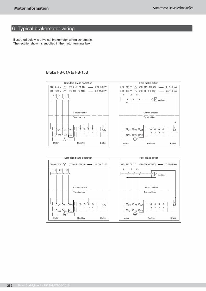
Bevel Buddybox 4 - 991361/EN-06/2018232
Illustrated below is a typical brakemotor wiring schematic.The recti er shown is supplied in the motor terminal box.
Brake FB-01A to FB-15B
Motor Information
6. Typical brakemotor wiring
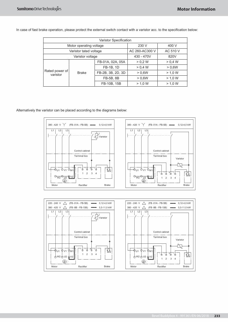
Bevel Buddybox 4 - 991361/EN-06/2018 233
In case of fast brake operation, please protect the external switch contact with a varistor acc. to the speci cation below:
Alternatively the varistor can be placed according to the diagrams below:
Varistor Speci cationMotor operating voltage 230 V 400 V
Varistor tated voltage AC 260-AC300 V AC 510 VVaristor voltage 430 - 470V 820V
Rated power of varistor Brake
FB-01A, 02A, 05A > 0,2 W > 0,4 WFB-1B, 1D > 0,4 W > 0,6W
FB-2B, 3B, 2D, 3D > 0,6W > 1,0 WFB-5B, 8B > 0,6W > 1,0 W
FB-10B, 15B > 1,0 W > 1,0 W
Motor Information

Bevel Buddybox 4 - 991361/EN-06/2018234
Alternatively a 6-pole recti er can be used:
Alternatively a 6-pole recti er can be used:
Motor Information

Bevel Buddybox 4 - 991361/EN-06/2018 235
InstallationVentilation openings must be kept clear.For proper cooling the distance FB is the minimum required between the cover and the wall. FA is the minimum clearance required for disassembling the fan cover.
Cable gland socketsStandard EN 50262.This new standard recommend to use ISO metric ne screw threads (symbol M) for the cable sockets.
Frame Conduit threat
63 -7180 -132S
132 M - 160180
200 - 225250
1x M16 x 1,5 / 1x M25 x 1,52x M 25 x 1,52x M 32 x 1,52x M 40 x 1,52x M 50 x 1,52x M 63 x 1,5
Standard-MotorMotor frame: 63 - 71 80 90 100 112-132S 160L 180M 180L 200FB (mm): 20 20 20 20 20 25 30 30 30 30FA (mm): 48 49 52 56 60 75 130 155 170 230
Brake motorMotor frame: 63 - 71 80 90 100 112-132S 160L 180M 180L 200FB (mm): 20 20 20 20 25 25 30 30 30 30FA (mm): 61 93 115 121 132 170 220 367 370 445
Motor Information
7. Range of application

Bevel Buddybox 4 - 991361/EN-06/2018236
Speed and direction of rotationThe values of rated speed are referred to operation under rated conditions.
The synchronous speed varies in direct proportion to the frequency of the power supply system.
The motors are suitable for operating in either direction of rotation.
PowerThe rated power of the gearmotor listed in the selection sheets applies to continuous duty "S1" according to VDE0530 part 1 at an ambient temperature of +40 °C and at an altitude of up to 1000 m above sea level.For other working conditions the allowable motor power has to be determined according to the following tables.If a di erent ambient temperature occurs simultaneously with a di erent altitude, the factors have to be multiplied together. For further information, please consult Sumitomo Drive Technologies.
ambient temperature allowable power in % of rated power
altitude above sea level NN [m]
altitude power in % of rated power
[° C]101520253035404550
%1001001001001001001009590
[m]100015002000250030003500
%1009794918885
* For higher temperatures, please consult Sumitomo Drive Technologies.
Motor Information
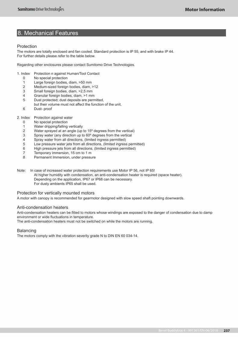
Bevel Buddybox 4 - 991361/EN-06/2018 237
ProtectionThe motors are totally enclosed and fan cooled. Standard protection is IP 55, and with brake IP 44.For further details please refer to the table below.
Regarding other enclosures please contact Sumitomo Drive Technologies.
1. Index Protection n against Human/Tool Contact 0 No special protection 1 Large foreign bodies, diam, >50 mm 2 Medium-sized foreign bodies, diam, >12 3 Small foreign bodies, diam, >2,5 mm 4 Granular foreign bodies, diam, >1 mm 5 Dust protected; dust deposits are permitted, but their volume must not a ect the function of the unit, 6 Dust- proof
2. Index Protection against water 0 No special protection 1 Water dripping/falling vertically 2 Water sprayed at an angle (up to 15º degrees from the vertical) 3 Spray water (any direction up to 60º degrees from the vertical 4 Spray water from all directions, (limited ingress permitted) 5 Low pressure water jets from all directions, (limited ingress permitted) 6 High pressure jets from all directions, (limited ingress permitted) 7 Temporary immersion, 15 cm to 1 m 8 Permanent Immersion, under pressure
Note: In case of increased water protection requirements use Motor IP 56, not IP 65! At higher humidity with condensation, an anti-condensation heater is required (space heater). Depending on the application, IP67 or IP68 can be necessary. For dusty ambients IP65 shall be used.
Protection for vertically mounted motorsA motor with canopy is recommended for gearmotor designed with slow speed shaft pointing downwards.
Anti-condensation heatersAnti-condensation heaters can be tted to motors whose windings are exposed to the danger of condensation due to damp environment or wide uctuations in temperature.The anti-condensation heaters must not be switched on while the motors are running.
BalancingThe motors comply with the vibration severity grade N to DIN EN 60 034-14.
Motor Information
8. Mechanical Features

Bevel Buddybox 4 - 991361/EN-06/2018238
Part No Description
1 Bearing cover2 Bearing3 Bolt4 Fan5 Fan cover6 End braket7 Bolt8 Bolt9101112
Complete rotor
1315 Stationary Core and Coil
14 Stator Frame16 Bolt17 Eye Bolt *18 CYCLO Flange Bracket19 Bearing20 Slinger or oil seal21 Motor Shaft22 Terminal Box23 Bearing Cover
*) Do not remove the eye bolt when the motor is used outside. If it is removed, close the tapped hole by a substitute bolt to avoid ingress of water.
Motor Information
9. Brake motor assembly

Bevel Buddybox 4 - 991361/EN-06/2018 239
Part. No. Description
1 Stationary Core2 Spacer3 Brake lining4 Bolt5 Bushing6 Retaining Ring7 Brake Cover8 Fan9 Leaf Spring10 Plate11 Armature Plate12 Pressure Spring13 Solenoid Coil14 Bearing15 Motor Shaft
Part. No. Description
1 Stationary Core2 Spacer3 Shim4 Bolt5 Brake lining6 Leaf Spring7 Bushing8 Retaining ring9 Brake cover10 Bolt11 Fan12 Plate13 Armature Plate14 Pressure Spring15 Solenoid Coil16 Bearing17 Motor Shaft
Part. No. Description
1 Stationary Core2 Stud Bolt3 Spacer4 Spring washer5 Gab adjusting nut6 Brake lining7 Bushing8 Retaining ring9 Brake cover
10 Spring pin11 Fan12 Leaf Spring13 Plate14 Armature Plate15 Pressure Spring16 Solenoid Coil17 Bearing18 Motor Shaft
G
1234567
8 1211109 13 14 15
G
21 31 14 15 16 17 18 19 20
1234678 511 10 9
G
12346 57811 10 9
21 31 14 15 16 17 18 19 20 21
Motor Information

Bevel Buddybox 4 - 991361/EN-06/2018240
Part No Description
1 Roller2 Brake release bolt3 Auxiliary spring4 Plug5 Stationary Core6 Electromagnetic coil7 Stud Bolt8 Brake lining9 Adjusting washer10 Spring washer11 Gap adjusting nut12 Bushing13 Retaining ring14 Fan15 Cover16 Fan setting bolt17 Leaf Spring18 Plate19 Armature Plate20 Pressure Spring21 Nut22 Stud bolt23 Ball bearing24 Shifting plate25 Bearing cover26 Motor shaft
123456791011 8121314
15 16 17 18 19 20 21 22 2324 2526
27123456791011 8121314
15 16 17 18 19 20 21 22 23 24 25 26
Motor Information
Bevel Buddybox 4 - 991361/EN-06/2018 241
Motor Options:In addition to brake the following options are available:
Motor standard options:- Hand release lever for brake- 6-pole recti er- Thermistor PTC- TOC (bimetal, break contact)- Canopy- External fan- Incremental encoder- Space heater- Harting connector (Han Drive, 10-pin)
Further available options:- Pole changing motors- High inertia fan- UL or CSA-design- NEMA electrical- Insulation class H- 2nd shaft (IEC)- IP 56 / IP 65 (no heavy sea)- Special winding with free voltage/Frequency relation IP 55 brake
Motor Information
10. Motor Options

Bevel Buddybox 4 - 991361/EN-06/2018242

Bevel Buddybox 4 - 991361/EN-06/2018 243

Bevel Buddybox 4 - 991361/EN-06/2018244


Worldwide locations
World Headquarters JAPANSumitomo Heavy Industries Ltd.PTC GroupThink Park Tower, 1-1Osaki 2-chomeShinagawa-ku, Tokyo 141-6025, Japanwww.cyclo.shi.co.jpwww.sumitomodrive.com
Headquarters & Manufacturing CHINASumitomo (SHI) Cyclo Drive China, Ltd. Shanghai Branch10F, SMEG Plaza, No.1386Hongqiao RoadShanghai, China (P.C.200336)
Headquarters & Manufacturing EUROPEGermany
Sumitomo (SHI) Cyclo Drive Germany GmbHEuropean HeadquartersCyclostraße 9285229 Markt IndersdorfGermanyTel. +49 8136 66-0www.sumitomodrive.com
Our Subsidiaries & Sales Offices in EUROPE, MIDDLE EAST, AFRICA & INDIAAustria
Sumitomo (SHI) Cyclo Drive Germany GmbHSales Office AustriaGruentalerstraße 30 A4020 Linz, AustriaTel. +43 732 330958
Belgium, Netherlands, Luxemburg
Hansen Industrial Transmissions NVLeonardo da Vincilaan 1-32650 Edegem, BelgiumTel. +32 3 450 12 11
France
SM-Cyclo France S.A.S.8 Avenue Christian Doppler77700 Serris, FranceTel. +33 1 64171717
India
Sumi-Cyclo Drive India Pvt. Ltd.Gat No. 186, Global Raisoni Industrial ParkAlandi Markal Road, FulgaonPune 411 033, IndiaTel. +91 20 6674 2900
Italy
SM-Cyclo Italy S.R.L.Via dell’Artigianato 2320010 Cornaredo (MI), ItalyTel. +39 2 93481101
Middle East
Hansen Industrial Transmissions NVLeonardo da Vincilaan 1-32650 Edegem, BelgiumTel. +32 3 450 12 11
Headquarters & Manufacturing AMERICASSumitomo Drive TechnologiesSumitomo Machinery Corp. of America4200 Holland BoulevardChesapeake, VA 23323, USAwww.sumitomodrive.com
Headquarters ASIA PACIFICSumitomo (SHI) Cyclo Drive Asia Pacific Pte. Ltd.15 Kwong Min RoadSingapore, 628718 Singapore
Belgium
Hansen Industrial Transmissions NVLeonardo da Vincilaan 1-32650 EdegemBelgiumTel. +32 3 450 12 11www.sumitomodrive.com
Sweden, Denmark, Norway, Finland, Estonia,
Latvia – NORDIC
SM-Cyclo UK, Ltd.Unit 29, Bergen Way,Sutton Fields Industrial EstateKingston upon HullHU7 0YQ, East Yorkshire, United KingdomTel. +44 1482 790340
Spain
SM-Cyclo Iberia, S.L.U.C/Gran Vía nº 63 bisPlanta primera, oficina 1B48011 Bilbao – Vizcaya, SpainTel. +34 944 805389
South Africa, Sub-Saharan Africa – Sales Partner
BMG BEARING MAN GROUP (PTY) LTDPO Box 33431; Jeppestown Johannesburg 2043; South AfricaTel. +27 11 620 1615
Turkey
Sumitomo Cyclo Güç Aktarım Sis. Tic. Ltd.Sti.Barbaros Mh. Çiğdem Sk. Ağaoğlu My Office İş Mrk.No:1 Kat:4 D.18 34746 Ataşehir / Istanbul – TurkeyTel . +90 216 250 6069
United Kingdom
SM-Cyclo UK, Ltd.Unit 29, Bergen Way,Sutton Fields Industrial EstateKingston upon HullHU7 0YQ, East Yorkshire, United KingdomTel. +44 1482 790340
Sumitomo (SHI) Cyclo Drive Germany GmbH


![1-Phenyl-3-{4-[4-(4-undecyloxybenzoyloxy)phenyloxycarbonyl]phenyl}triazene 1-oxide](https://img.pdfslide.net/doc/110x75/6347f12809e11fdd740a83cc/1-phenyl-3-4-4-4-undecyloxybenzoyloxyphenyloxycarbonylphenyltriazene-1-oxide.jpg)


