Embed Size (px)
Citation preview
© 2020 - 2020 Cisco and/or its affiliates. All rights reserved. Cisco Public Page 1 of 17 www.netacad.com
BGP Lab 4 - Implement BGP Communities: Present screenshots and paste on the boxes provided. Likewise, provide answers to the questions that are in bold, italicized and underlined. Write your answers to the questions using red color font.
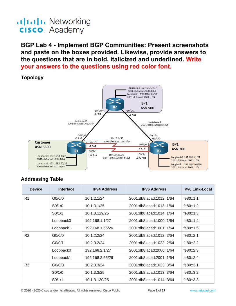
Topology
Addressing Table
Device Interface IPv4 Address IPv6 Address IPv6 Link-Local
R1 G0/0/0 10.1.2.1/24 2001:db8:acad:1012::1/64 fe80::1:1
R1
S0/1/0 10.1.3.1/25 2001:db8:acad:1013::1/64 fe80::1:2
R1
S0/1/1 10.1.3.129/25 2001:db8:acad:1014::1/64 fe80::1:3
R1
Loopback0 192.168.1.1/27 2001:db8:acad:1000::1/64 fe80::1:4
R1
Loopback1 192.168.1.65/26 2001:db8:acad:1001::1/64 fe80::1:5
R2 G0/0/0 10.1.2.2/24 2001:db8:acad:1012::2/64 fe80::2:1
R2
G0/0/1 10.2.3.2/24 2001:db8:acad:1023::2/64 fe80::2:2
R2
Loopback0 192.168.2.1/27 2001:db8:acad:2000::1/64 fe80::2:3
R2
Loopback1 192.168.2.65/26 2001:db8:acad:2001::1/64 fe80::2:4
R3 G0/0/0 10.2.3.3/24 2001:db8:acad:1023::3/64 fe80::3:1
R3
S0/1/0 10.1.3.3/25 2001:db8:acad:1013::3/64 fe80::3:2
R3
S0/1/1 10.1.3.130/25 2001:db8:acad:1014::3/64 fe80::3:3
BGP Lab 4 - Implement BGP Communities
© 2020 - 2020 Cisco and/or its affiliates. All rights reserved. Cisco Public Page 2 of 17 www.netacad.com
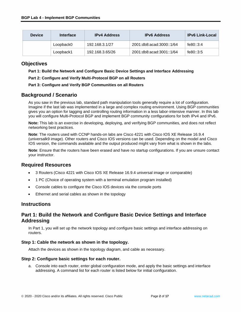
Device Interface IPv4 Address IPv6 Address IPv6 Link-Local
R3
Loopback0 192.168.3.1/27 2001:db8:acad:3000::1/64 fe80::3:4
R3
Loopback1 192.168.3.65/26 2001:db8:acad:3001::1/64 fe80::3:5
Objectives
Part 1: Build the Network and Configure Basic Device Settings and Interface Addressing
Part 2: Configure and Verify Multi-Protocol BGP on all Routers
Part 3: Configure and Verify BGP Communities on all Routers
Background / Scenario
As you saw in the previous lab, standard path manipulation tools generally require a lot of configuration. Imagine if the last lab was implemented in a large and complex routing environment. Using BGP communities gives you an option for tagging and controlling routing information in a less labor-intensive manner. In this lab you will configure Multi-Protocol BGP and implement BGP community configurations for both IPv4 and IPv6.
Note: This lab is an exercise in developing, deploying, and verifying BGP communities, and does not reflect networking best practices.
Note: The routers used with CCNP hands-on labs are Cisco 4221 with Cisco IOS XE Release 16.9.4 (universalk9 image). Other routers and Cisco IOS versions can be used. Depending on the model and Cisco IOS version, the commands available and the output produced might vary from what is shown in the labs.
Note: Ensure that the routers have been erased and have no startup configurations. If you are unsure contact your instructor.
Required Resources
• 3 Routers (Cisco 4221 with Cisco IOS XE Release 16.9.4 universal image or comparable)
• 1 PC (Choice of operating system with a terminal emulation program installed)
• Console cables to configure the Cisco IOS devices via the console ports
• Ethernet and serial cables as shown in the topology
Instructions
Part 1: Build the Network and Configure Basic Device Settings and Interface Addressing
In Part 1, you will set up the network topology and configure basic settings and interface addressing on routers.
Step 1: Cable the network as shown in the topology.
Attach the devices as shown in the topology diagram, and cable as necessary.
Step 2: Configure basic settings for each router.
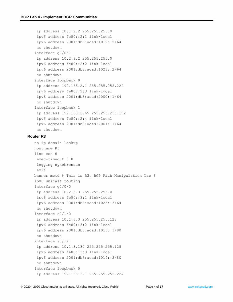
a. Console into each router, enter global configuration mode, and apply the basic settings and interface addressing. A command list for each router is listed below for initial configuration.
Open configure
ation window
BGP Lab 4 - Implement BGP Communities
© 2020 - 2020 Cisco and/or its affiliates. All rights reserved. Cisco Public Page 3 of 17 www.netacad.com
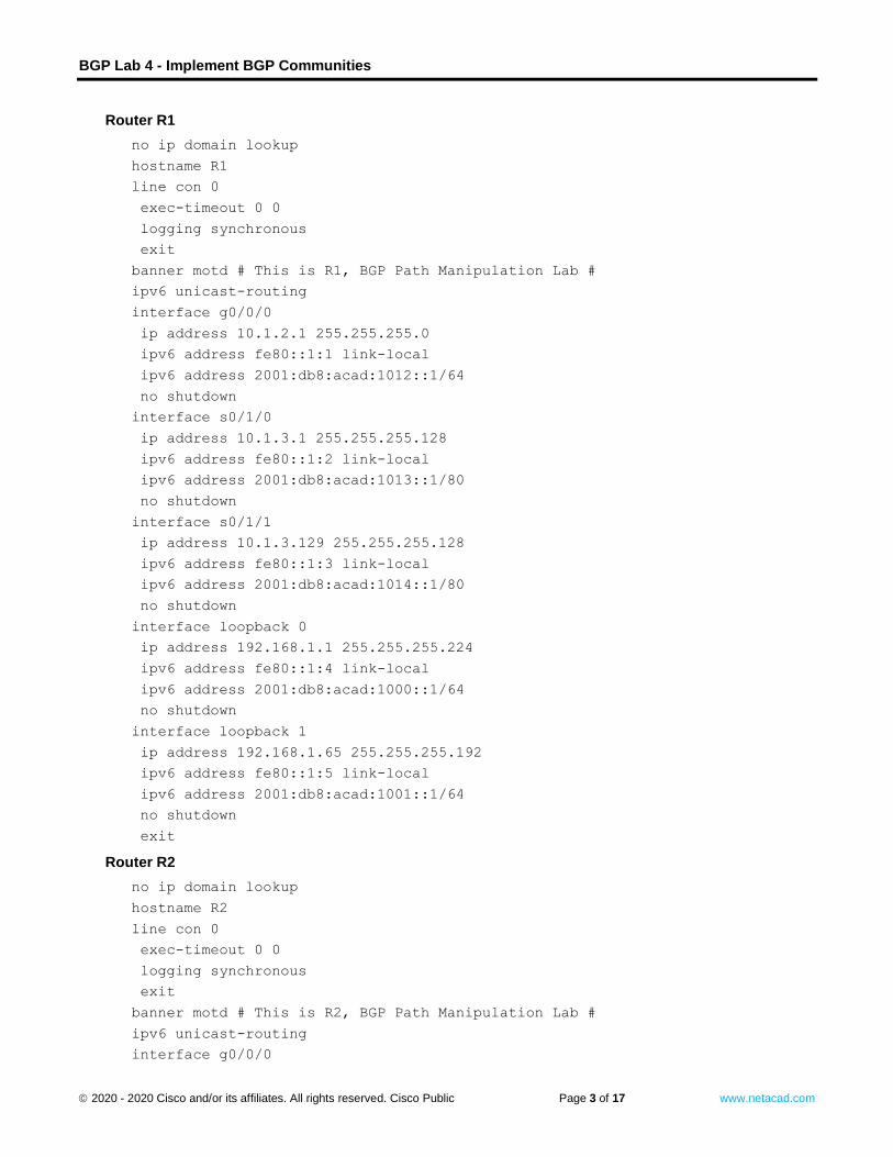
Router R1
no ip domain lookup
hostname R1
line con 0
exec-timeout 0 0
logging synchronous
exit
banner motd # This is R1, BGP Path Manipulation Lab #
ipv6 unicast-routing
interface g0/0/0
ip address 10.1.2.1 255.255.255.0
ipv6 address fe80::1:1 link-local
ipv6 address 2001:db8:acad:1012::1/64
no shutdown
interface s0/1/0
ip address 10.1.3.1 255.255.255.128
ipv6 address fe80::1:2 link-local
ipv6 address 2001:db8:acad:1013::1/80
no shutdown
interface s0/1/1
ip address 10.1.3.129 255.255.255.128
ipv6 address fe80::1:3 link-local
ipv6 address 2001:db8:acad:1014::1/80
no shutdown
interface loopback 0
ip address 192.168.1.1 255.255.255.224
ipv6 address fe80::1:4 link-local
ipv6 address 2001:db8:acad:1000::1/64
no shutdown
interface loopback 1
ip address 192.168.1.65 255.255.255.192
ipv6 address fe80::1:5 link-local
ipv6 address 2001:db8:acad:1001::1/64
no shutdown
exit
Router R2
no ip domain lookup
hostname R2
line con 0
exec-timeout 0 0
logging synchronous
exit
banner motd # This is R2, BGP Path Manipulation Lab #
ipv6 unicast-routing
interface g0/0/0
BGP Lab 4 - Implement BGP Communities
© 2020 - 2020 Cisco and/or its affiliates. All rights reserved. Cisco Public Page 4 of 17 www.netacad.com
ip address 10.1.2.2 255.255.255.0
ipv6 address fe80::2:1 link-local
ipv6 address 2001:db8:acad:1012::2/64
no shutdown
interface g0/0/1
ip address 10.2.3.2 255.255.255.0
ipv6 address fe80::2:2 link-local
ipv6 address 2001:db8:acad:1023::2/64
no shutdown
interface loopback 0
ip address 192.168.2.1 255.255.255.224
ipv6 address fe80::2:3 link-local
ipv6 address 2001:db8:acad:2000::1/64
no shutdown
interface loopback 1
ip address 192.168.2.65 255.255.255.192
ipv6 address fe80::2:4 link-local
ipv6 address 2001:db8:acad:2001::1/64
no shutdown
Router R3
no ip domain lookup
hostname R3
line con 0
exec-timeout 0 0
logging synchronous
exit
banner motd # This is R3, BGP Path Manipulation Lab #
ipv6 unicast-routing
interface g0/0/0
ip address 10.2.3.3 255.255.255.0
ipv6 address fe80::3:1 link-local
ipv6 address 2001:db8:acad:1023::3/64
no shutdown
interface s0/1/0
ip address 10.1.3.3 255.255.255.128
ipv6 address fe80::3:2 link-local
ipv6 address 2001:db8:acad:1013::3/80
no shutdown
interface s0/1/1
ip address 10.1.3.130 255.255.255.128
ipv6 address fe80::3:3 link-local
ipv6 address 2001:db8:acad:1014::3/80
no shutdown
interface loopback 0
ip address 192.168.3.1 255.255.255.224
BGP Lab 4 - Implement BGP Communities
© 2020 - 2020 Cisco and/or its affiliates. All rights reserved. Cisco Public Page 5 of 17 www.netacad.com
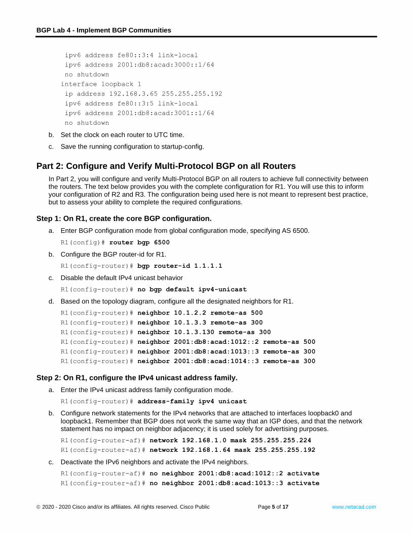
ipv6 address fe80::3:4 link-local
ipv6 address 2001:db8:acad:3000::1/64
no shutdown
interface loopback 1
ip address 192.168.3.65 255.255.255.192
ipv6 address fe80::3:5 link-local
ipv6 address 2001:db8:acad:3001::1/64
no shutdown
b. Set the clock on each router to UTC time.
c. Save the running configuration to startup-config. Close configuration window
Part 2: Configure and Verify Multi-Protocol BGP on all Routers
In Part 2, you will configure and verify Multi-Protocol BGP on all routers to achieve full connectivity between the routers. The text below provides you with the complete configuration for R1. You will use this to inform your configuration of R2 and R3. The configuration being used here is not meant to represent best practice, but to assess your ability to complete the required configurations.
Step 1: On R1, create the core BGP configuration.
a. Enter BGP configuration mode from global configuration mode, specifying AS 6500. Open configuration window
R1(config)# router bgp 6500
b. Configure the BGP router-id for R1.
R1(config-router)# bgp router-id 1.1.1.1
c. Disable the default IPv4 unicast behavior
R1(config-router)# no bgp default ipv4-unicast
d. Based on the topology diagram, configure all the designated neighbors for R1.
R1(config-router)# neighbor 10.1.2.2 remote-as 500
R1(config-router)# neighbor 10.1.3.3 remote-as 300
R1(config-router)# neighbor 10.1.3.130 remote-as 300
R1(config-router)# neighbor 2001:db8:acad:1012::2 remote-as 500
R1(config-router)# neighbor 2001:db8:acad:1013::3 remote-as 300
R1(config-router)# neighbor 2001:db8:acad:1014::3 remote-as 300
Step 2: On R1, configure the IPv4 unicast address family.
a. Enter the IPv4 unicast address family configuration mode.
R1(config-router)# address-family ipv4 unicast
b. Configure network statements for the IPv4 networks that are attached to interfaces loopback0 and
loopback1. Remember that BGP does not work the same way that an IGP does, and that the network statement has no impact on neighbor adjacency; it is used solely for advertising purposes.
R1(config-router-af)# network 192.168.1.0 mask 255.255.255.224
R1(config-router-af)# network 192.168.1.64 mask 255.255.255.192
c. Deactivate the IPv6 neighbors and activate the IPv4 neighbors.
R1(config-router-af)# no neighbor 2001:db8:acad:1012::2 activate
R1(config-router-af)# no neighbor 2001:db8:acad:1013::3 activate
BGP Lab 4 - Implement BGP Communities
© 2020 - 2020 Cisco and/or its affiliates. All rights reserved. Cisco Public Page 6 of 17 www.netacad.com
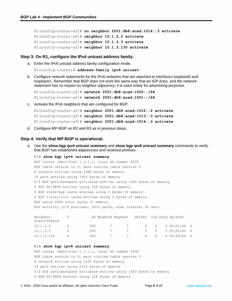
R1(config-router-af)# no neighbor 2001:db8:acad:1014::3 activate
R1(config-router-af)# neighbor 10.1.2.2 activate
R1(config-router-af)# neighbor 10.1.3.3 activate
R1(config-router-af)# neighbor 10.1.3.130 activate
Step 3: On R1, configure the IPv4 unicast address family.
a. Enter the IPv6 unicast address family configuration mode.
R1(config-router)# address-family ipv6 unicast
b. Configure network statements for the IPv6 networks that are attached to interfaces loopback0 and
loopback1. Remember that BGP does not work the same way that an IGP does, and the network statement has no impact on neighbor adjacency; it is used solely for advertising purposes.
R1(config-router-af)# network 2001:db8:acad:1000::/64
R1(config-router-af)# network 2001:db8:acad:1001::/64
c. Activate the IPv6 neighbors that are configured for BGP.
R1(config-router-af)# neighbor 2001:db8:acad:1012::2 activate
R1(config-router-af)# neighbor 2001:db8:acad:1013::3 activate
R1(config-router-af)# neighbor 2001:db8:acad:1014::3 activate
d. Configure MP-BGP on R2 and R3 as in previous steps. Close configuration window
Step 4: Verify that MP-BGP is operational.
a. Use the show bgp ipv4 unicast summary and show bgp ipv6 unicast summary commands to verify that BGP has established adjacencies and received prefixes.
Open configuration window
R1# show bgp ipv4 unicast summary
BGP router identifier 1.1.1.1, local AS number 6500
BGP table version is 9, main routing table version 9
6 network entries using 1488 bytes of memory
14 path entries using 1904 bytes of memory
5/3 BGP path/bestpath attribute entries using 1400 bytes of memory
4 BGP AS-PATH entries using 128 bytes of memory
0 BGP route-map cache entries using 0 bytes of memory
0 BGP filter-list cache entries using 0 bytes of memory
BGP using 4920 total bytes of memory
BGP activity 12/0 prefixes, 28/0 paths, scan interval 60 secs
Neighbor V AS MsgRcvd MsgSent TblVer InQ OutQ Up/Down
State/PfxRcd
10.1.2.2 4 500 7 7 9 0 0 00:01:46 4
10.1.3.3 4 300 7 7 9 0 0 00:00:45 4
10.1.3.130 4 300 7 7 9 0 0 00:00:44 4
R1# show bgp ipv6 unicast summary
BGP router identifier 1.1.1.1, local AS number 6500
BGP table version is 9, main routing table version 9
6 network entries using 1632 bytes of memory
14 path entries using 2128 bytes of memory
5/3 BGP path/bestpath attribute entries using 1400 bytes of memory
4 BGP AS-PATH entries using 128 bytes of memory
BGP Lab 4 - Implement BGP Communities
© 2020 - 2020 Cisco and/or its affiliates. All rights reserved. Cisco Public Page 7 of 17 www.netacad.com
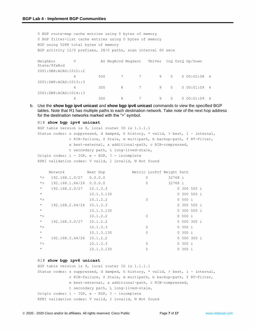
0 BGP route-map cache entries using 0 bytes of memory
0 BGP filter-list cache entries using 0 bytes of memory
BGP using 5288 total bytes of memory
BGP activity 12/0 prefixes, 28/0 paths, scan interval 60 secs
Neighbor V AS MsgRcvd MsgSent TblVer InQ OutQ Up/Down
State/PfxRcd
2001:DB8:ACAD:1012::2
4 500 7 7 9 0 0 00:02:08 4
2001:DB8:ACAD:1013::3
4 300 8 7 9 0 0 00:01:09 4
2001:DB8:ACAD:1014::3
4 300 8 7 9 0 0 00:01:09 4
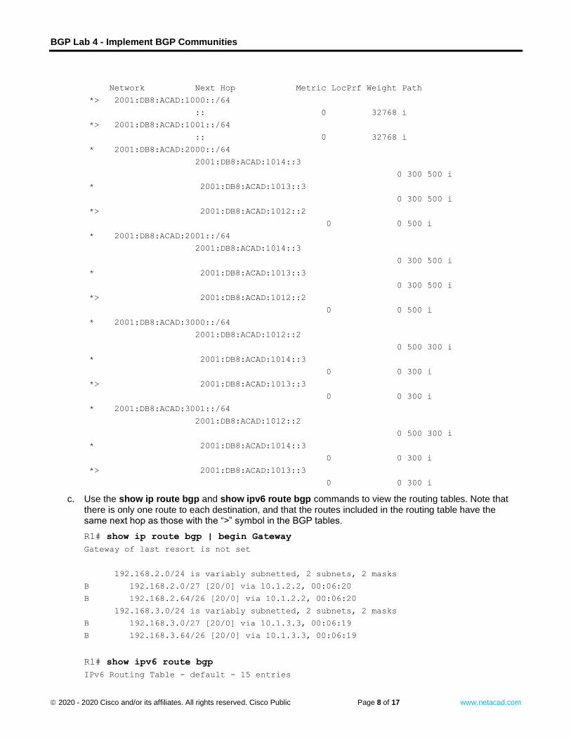
b. Use the show bgp ipv4 unicast and show bgp ipv6 unicast commands to view the specified BGP
tables. Note that R1 has multiple paths to each destination network. Take note of the next hop address for the destination networks marked with the “>” symbol.
R1# show bgp ipv4 unicast
BGP table version is 9, local router ID is 1.1.1.1
Status codes: s suppressed, d damped, h history, * valid, > best, i - internal,
r RIB-failure, S Stale, m multipath, b backup-path, f RT-Filter,
x best-external, a additional-path, c RIB-compressed,
t secondary path, L long-lived-stale,
Origin codes: i - IGP, e - EGP, ? - incomplete
RPKI validation codes: V valid, I invalid, N Not found
Network Next Hop Metric LocPrf Weight Path
*> 192.168.1.0/27 0.0.0.0 0 32768 i
*> 192.168.1.64/26 0.0.0.0 0 32768 i
* 192.168.2.0/27 10.1.3.3 0 300 500 i
* 10.1.3.130 0 300 500 i
*> 10.1.2.2 0 0 500 i
* 192.168.2.64/26 10.1.3.3 0 300 500 i
* 10.1.3.130 0 300 500 i
*> 10.1.2.2 0 0 500 i
* 192.168.3.0/27 10.1.2.2 0 500 300 i
*> 10.1.3.3 0 0 300 i
* 10.1.3.130 0 0 300 i
* 192.168.3.64/26 10.1.2.2 0 500 300 i
*> 10.1.3.3 0 0 300 i
* 10.1.3.130 0 0 300 i
R1# show bgp ipv6 unicast
BGP table version is 9, local router ID is 1.1.1.1
Status codes: s suppressed, d damped, h history, * valid, > best, i - internal,
r RIB-failure, S Stale, m multipath, b backup-path, f RT-Filter,
x best-external, a additional-path, c RIB-compressed,
t secondary path, L long-lived-stale,
Origin codes: i - IGP, e - EGP, ? - incomplete
RPKI validation codes: V valid, I invalid, N Not found
BGP Lab 4 - Implement BGP Communities
© 2020 - 2020 Cisco and/or its affiliates. All rights reserved. Cisco Public Page 8 of 17 www.netacad.com
Network Next Hop Metric LocPrf Weight Path
*> 2001:DB8:ACAD:1000::/64
:: 0 32768 i
*> 2001:DB8:ACAD:1001::/64
:: 0 32768 i
* 2001:DB8:ACAD:2000::/64
2001:DB8:ACAD:1014::3
0 300 500 i
* 2001:DB8:ACAD:1013::3
0 300 500 i
*> 2001:DB8:ACAD:1012::2
0 0 500 i
* 2001:DB8:ACAD:2001::/64
2001:DB8:ACAD:1014::3
0 300 500 i
* 2001:DB8:ACAD:1013::3
0 300 500 i
*> 2001:DB8:ACAD:1012::2
0 0 500 i
* 2001:DB8:ACAD:3000::/64
2001:DB8:ACAD:1012::2
0 500 300 i
* 2001:DB8:ACAD:1014::3
0 0 300 i
*> 2001:DB8:ACAD:1013::3
0 0 300 i
* 2001:DB8:ACAD:3001::/64
2001:DB8:ACAD:1012::2
0 500 300 i
* 2001:DB8:ACAD:1014::3
0 0 300 i
*> 2001:DB8:ACAD:1013::3
0 0 300 i
c. Use the show ip route bgp and show ipv6 route bgp commands to view the routing tables. Note that there is only one route to each destination, and that the routes included in the routing table have the same next hop as those with the “>” symbol in the BGP tables.
R1# show ip route bgp | begin Gateway
Gateway of last resort is not set
192.168.2.0/24 is variably subnetted, 2 subnets, 2 masks
B 192.168.2.0/27 [20/0] via 10.1.2.2, 00:06:20
B 192.168.2.64/26 [20/0] via 10.1.2.2, 00:06:20
192.168.3.0/24 is variably subnetted, 2 subnets, 2 masks
B 192.168.3.0/27 [20/0] via 10.1.3.3, 00:06:19
B 192.168.3.64/26 [20/0] via 10.1.3.3, 00:06:19
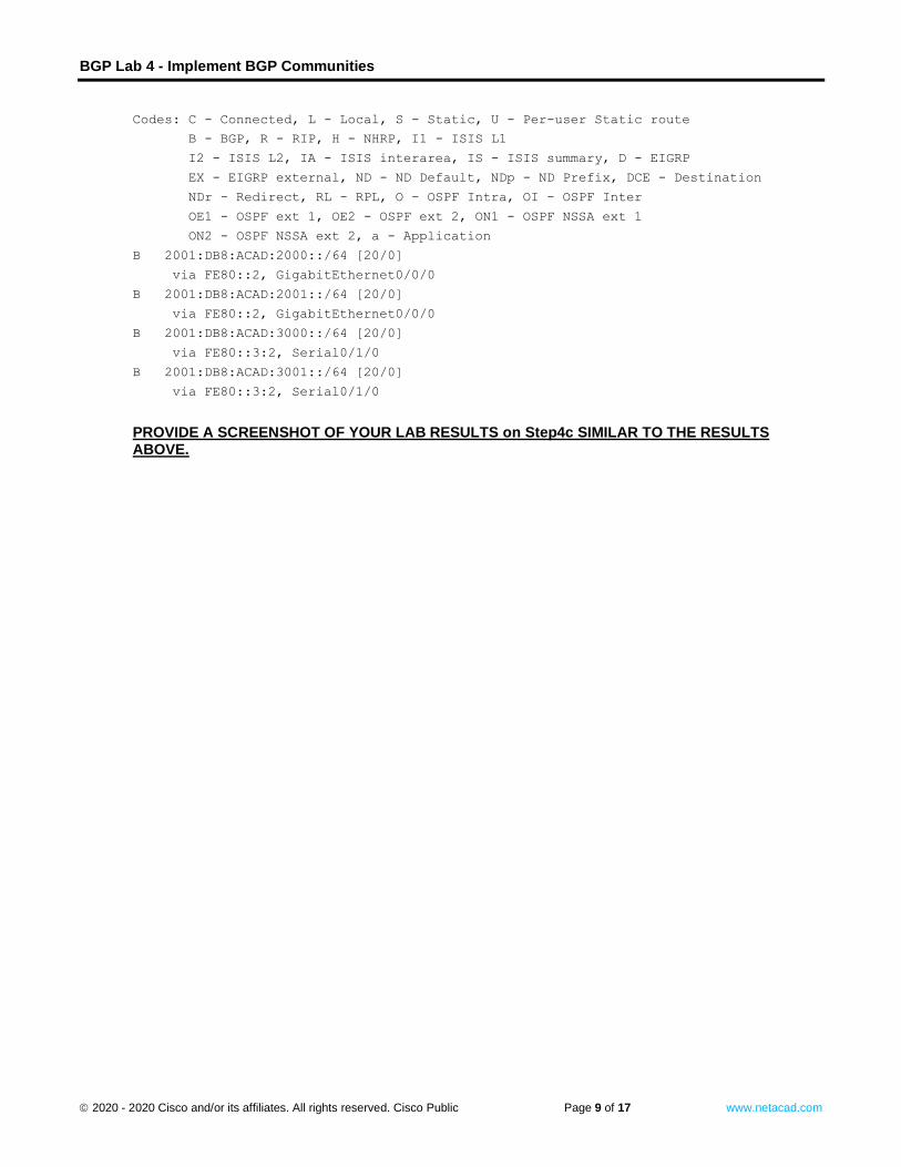
R1# show ipv6 route bgp
IPv6 Routing Table - default - 15 entries
BGP Lab 4 - Implement BGP Communities
© 2020 - 2020 Cisco and/or its affiliates. All rights reserved. Cisco Public Page 9 of 17 www.netacad.com
Codes: C - Connected, L - Local, S - Static, U - Per-user Static route
B - BGP, R - RIP, H - NHRP, I1 - ISIS L1
I2 - ISIS L2, IA - ISIS interarea, IS - ISIS summary, D - EIGRP
EX - EIGRP external, ND - ND Default, NDp - ND Prefix, DCE - Destination
NDr - Redirect, RL - RPL, O - OSPF Intra, OI - OSPF Inter
OE1 - OSPF ext 1, OE2 - OSPF ext 2, ON1 - OSPF NSSA ext 1
ON2 - OSPF NSSA ext 2, a - Application
B 2001:DB8:ACAD:2000::/64 [20/0]
via FE80::2, GigabitEthernet0/0/0
B 2001:DB8:ACAD:2001::/64 [20/0]
via FE80::2, GigabitEthernet0/0/0
B 2001:DB8:ACAD:3000::/64 [20/0]
via FE80::3:2, Serial0/1/0
B 2001:DB8:ACAD:3001::/64 [20/0]
via FE80::3:2, Serial0/1/0
PROVIDE A SCREENSHOT OF YOUR LAB RESULTS on Step4c SIMILAR TO THE RESULTS ABOVE.
Close configuration window
BGP Lab 4 - Implement BGP Communities
© 2020 - 2020 Cisco and/or its affiliates. All rights reserved. Cisco Public Page 10 of 17 www.netacad.com
Part 3: Configure and Verify BGP Communities on all Routers
In Part 3, you will configure BGP communities and various community attributes to see their effect on routing decisions. The way these tools are being used is not meant to represent best practice, but to assess your ability to complete the required configurations.
Step 1: Configure all routers to send community information.
In this step, you will configure all of the routers to support the new-format for exchanging community information and enable sending community information to all neighbors on all routers. A BGP community is a 32-bit number that can be included as a flag or tag in a route. The BGP community can be configured and displayed as two 16 bit numbers AA:NN commonly referred to as new-format. To configure and display using the AA:NN, issue the ip bgp-community new-format command. The first part of the AA:NN represents the AS number and the second part represents a 2-byte number.
The configuration for R1 is shown below. Use this as an example and complete the configuration on R2 and R3 on your own.
a. Issue the global configuration command that enables configuration and display of community information using the AA:NN format.
Open configuration window
R1(config)# ip bgp-community new-format
b. Add a neighbor statement for each neighbor with the send community parameter.
R1(config)# router bgp 6500
R1(config-router)# address-family ipv4 unicast
R1(config-router-af)# neighbor 10.1.2.2 send-community
R1(config-router-af)# neighbor 10.1.3.3 send-community
R1(config-router-af)# neighbor 10.1.3.130 send-community
R1(config-router-af)# address-family ipv6 unicast
R1(config-router-af)# neighbor 2001:db8:acad:1012::2 send-community
R1(config-router-af)# neighbor 2001:db8:acad:1013::3 send-community
R1(config-router-af)# neighbor 2001:db8:acad:1014::3 send-community
R1(config-router-af)# exit
c. At this point, the routers are ready to send community information, but there is no community information
available. On R2, issue the command show bgp ipv4 unicast 192.168.2.0/27, and you will see there is no community information listed.
Close configuration window
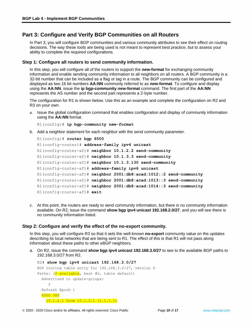
Step 2: Configure and verify the effect of the no-export community.
In this step, you will configure R3 so that it sets the well-known no-export community value on the updates describing its local networks that are being sent to R1. The effect of this is that R1 will not pass along information about these paths to other eBGP neighbors.
a. On R2, issue the command show bgp ipv4 unicast 192.168.3.0/27 to see to the available BGP paths to 192.168.3.0/27 from R2.
Open configuration window
R2# show bgp ipv4 unicast 192.168.3.0/27
BGP routing table entry for 192.168.3.0/27, version 6
Paths: (2 available, best #2, table default)
Advertised to update-groups:
2
Refresh Epoch 1
6500 300
10.1.2.1 from 10.1.2.1 (1.1.1.1)
BGP Lab 4 - Implement BGP Communities
© 2020 - 2020 Cisco and/or its affiliates. All rights reserved. Cisco Public Page 11 of 17 www.netacad.com
Origin IGP, localpref 100, valid, external
rx pathid: 0, tx pathid: 0
Refresh Epoch 1
300
10.2.3.3 from 10.2.3.3 (3.3.3.3)
Origin IGP, metric 0, localpref 100, valid, external, best
rx pathid: 0, tx pathid: 0x0 Close configuration window
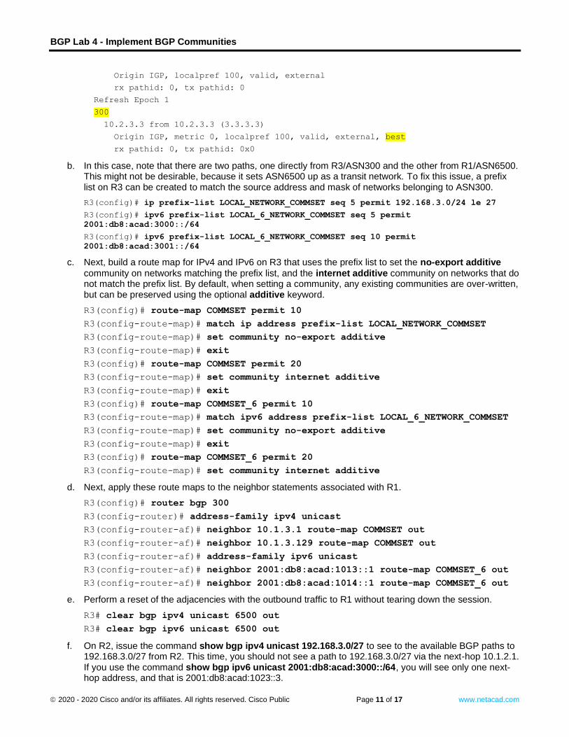
b. In this case, note that there are two paths, one directly from R3/ASN300 and the other from R1/ASN6500. This might not be desirable, because it sets ASN6500 up as a transit network. To fix this issue, a prefix list on R3 can be created to match the source address and mask of networks belonging to ASN300.
Open configuration window
R3(config)# ip prefix-list LOCAL_NETWORK_COMMSET seq 5 permit 192.168.3.0/24 le 27
R3(config)# ipv6 prefix-list LOCAL_6_NETWORK_COMMSET seq 5 permit
2001:db8:acad:3000::/64
R3(config)# ipv6 prefix-list LOCAL_6_NETWORK_COMMSET seq 10 permit
2001:db8:acad:3001::/64
c. Next, build a route map for IPv4 and IPv6 on R3 that uses the prefix list to set the no-export additive
community on networks matching the prefix list, and the internet additive community on networks that do not match the prefix list. By default, when setting a community, any existing communities are over-written, but can be preserved using the optional additive keyword.
R3(config)# route-map COMMSET permit 10
R3(config-route-map)# match ip address prefix-list LOCAL_NETWORK_COMMSET
R3(config-route-map)# set community no-export additive
R3(config-route-map)# exit
R3(config)# route-map COMMSET permit 20
R3(config-route-map)# set community internet additive
R3(config-route-map)# exit
R3(config)# route-map COMMSET_6 permit 10
R3(config-route-map)# match ipv6 address prefix-list LOCAL_6_NETWORK_COMMSET
R3(config-route-map)# set community no-export additive
R3(config-route-map)# exit
R3(config)# route-map COMMSET_6 permit 20
R3(config-route-map)# set community internet additive
d. Next, apply these route maps to the neighbor statements associated with R1.
R3(config)# router bgp 300
R3(config-router)# address-family ipv4 unicast
R3(config-router-af)# neighbor 10.1.3.1 route-map COMMSET out
R3(config-router-af)# neighbor 10.1.3.129 route-map COMMSET out
R3(config-router-af)# address-family ipv6 unicast
R3(config-router-af)# neighbor 2001:db8:acad:1013::1 route-map COMMSET_6 out
R3(config-router-af)# neighbor 2001:db8:acad:1014::1 route-map COMMSET_6 out
e. Perform a reset of the adjacencies with the outbound traffic to R1 without tearing down the session.
R3# clear bgp ipv4 unicast 6500 out
R3# clear bgp ipv6 unicast 6500 out Close configuration window
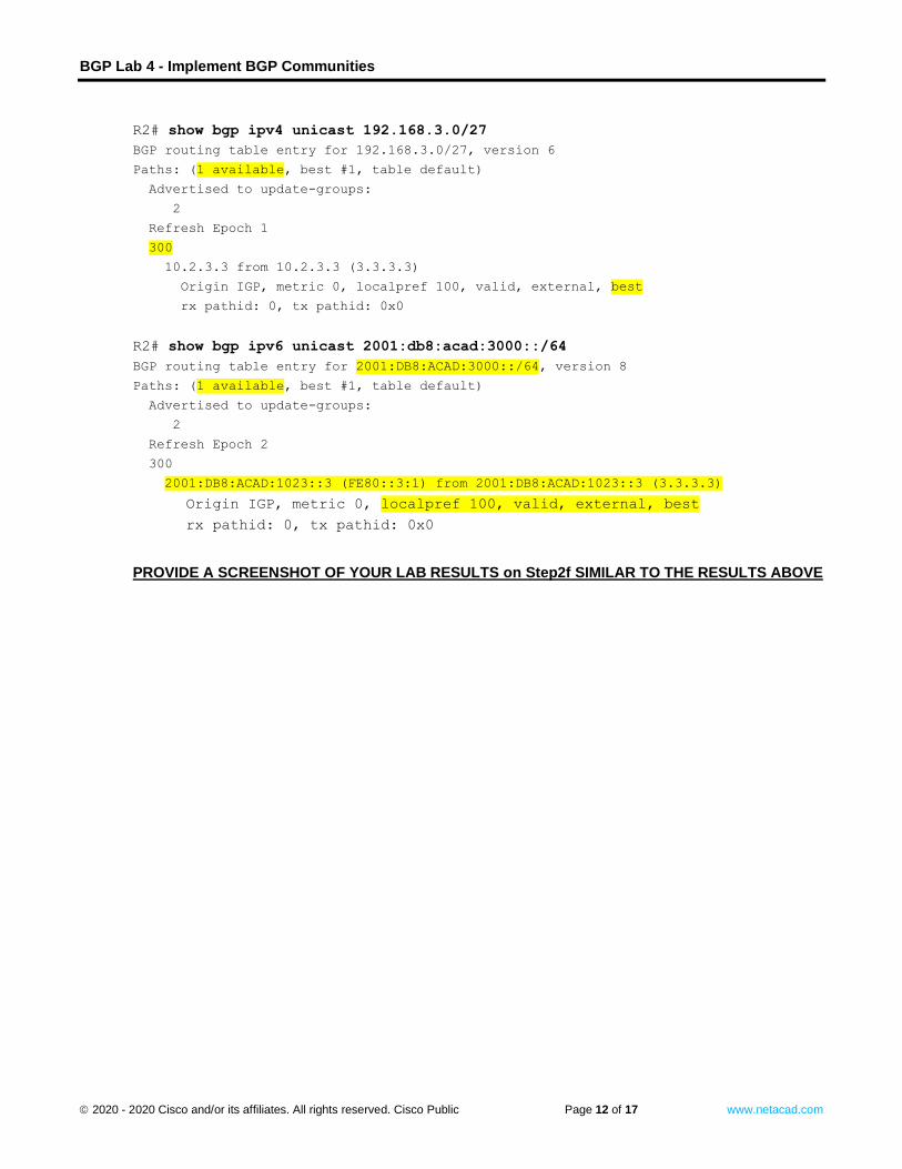
f. On R2, issue the command show bgp ipv4 unicast 192.168.3.0/27 to see to the available BGP paths to 192.168.3.0/27 from R2. This time, you should not see a path to 192.168.3.0/27 via the next-hop 10.1.2.1. If you use the command show bgp ipv6 unicast 2001:db8:acad:3000::/64, you will see only one next-hop address, and that is 2001:db8:acad:1023::3.
BGP Lab 4 - Implement BGP Communities
© 2020 - 2020 Cisco and/or its affiliates. All rights reserved. Cisco Public Page 12 of 17 www.netacad.com
Open configuration window
R2# show bgp ipv4 unicast 192.168.3.0/27
BGP routing table entry for 192.168.3.0/27, version 6
Paths: (1 available, best #1, table default)
Advertised to update-groups:
2
Refresh Epoch 1
300
10.2.3.3 from 10.2.3.3 (3.3.3.3)
Origin IGP, metric 0, localpref 100, valid, external, best
rx pathid: 0, tx pathid: 0x0
R2# show bgp ipv6 unicast 2001:db8:acad:3000::/64
BGP routing table entry for 2001:DB8:ACAD:3000::/64, version 8
Paths: (1 available, best #1, table default)
Advertised to update-groups:
2
Refresh Epoch 2
300
2001:DB8:ACAD:1023::3 (FE80::3:1) from 2001:DB8:ACAD:1023::3 (3.3.3.3)
Origin IGP, metric 0, localpref 100, valid, external, best
rx pathid: 0, tx pathid: 0x0
PROVIDE A SCREENSHOT OF YOUR LAB RESULTS on Step2f SIMILAR TO THE RESULTS ABOVE
Close configuration window
BGP Lab 4 - Implement BGP Communities
© 2020 - 2020 Cisco and/or its affiliates. All rights reserved. Cisco Public Page 13 of 17 www.netacad.com
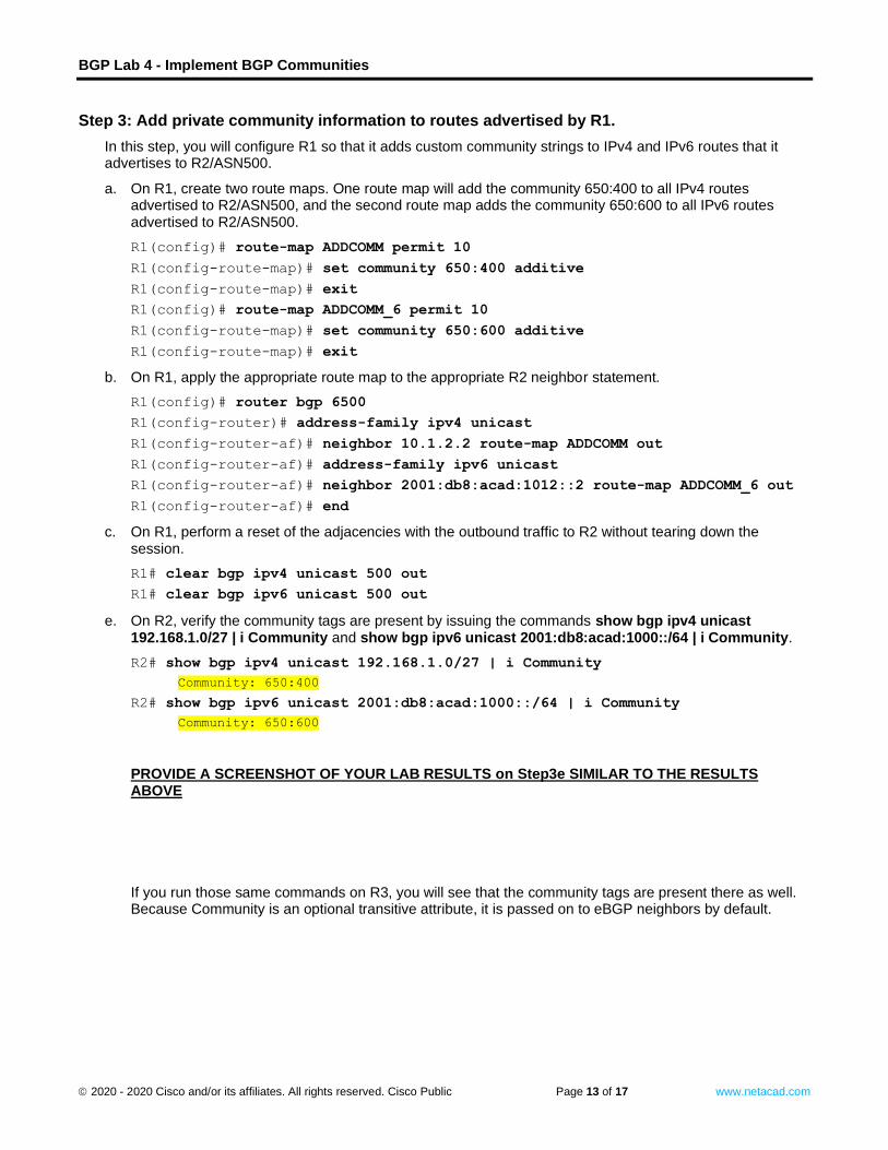
Step 3: Add private community information to routes advertised by R1.
In this step, you will configure R1 so that it adds custom community strings to IPv4 and IPv6 routes that it advertises to R2/ASN500.
a. On R1, create two route maps. One route map will add the community 650:400 to all IPv4 routes advertised to R2/ASN500, and the second route map adds the community 650:600 to all IPv6 routes advertised to R2/ASN500.
Open configuration window
R1(config)# route-map ADDCOMM permit 10
R1(config-route-map)# set community 650:400 additive
R1(config-route-map)# exit
R1(config)# route-map ADDCOMM_6 permit 10
R1(config-route-map)# set community 650:600 additive
R1(config-route-map)# exit
b. On R1, apply the appropriate route map to the appropriate R2 neighbor statement.
R1(config)# router bgp 6500
R1(config-router)# address-family ipv4 unicast
R1(config-router-af)# neighbor 10.1.2.2 route-map ADDCOMM out
R1(config-router-af)# address-family ipv6 unicast
R1(config-router-af)# neighbor 2001:db8:acad:1012::2 route-map ADDCOMM_6 out
R1(config-router-af)# end
c. On R1, perform a reset of the adjacencies with the outbound traffic to R2 without tearing down the session.
R1# clear bgp ipv4 unicast 500 out
R1# clear bgp ipv6 unicast 500 out Close configuration window
e. On R2, verify the community tags are present by issuing the commands show bgp ipv4 unicast 192.168.1.0/27 | i Community and show bgp ipv6 unicast 2001:db8:acad:1000::/64 | i Community.
Open configuration window
R2# show bgp ipv4 unicast 192.168.1.0/27 | i Community
Community: 650:400
R2# show bgp ipv6 unicast 2001:db8:acad:1000::/64 | i Community
Community: 650:600 Close configuration window
PROVIDE A SCREENSHOT OF YOUR LAB RESULTS on Step3e SIMILAR TO THE RESULTS ABOVE
If you run those same commands on R3, you will see that the community tags are present there as well. Because Community is an optional transitive attribute, it is passed on to eBGP neighbors by default.
BGP Lab 4 - Implement BGP Communities
© 2020 - 2020 Cisco and/or its affiliates. All rights reserved. Cisco Public Page 14 of 17 www.netacad.com
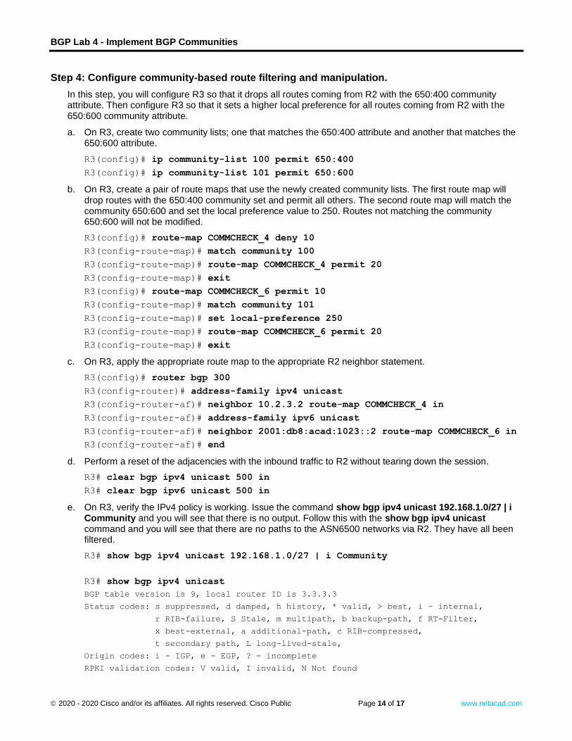
Step 4: Configure community-based route filtering and manipulation.
In this step, you will configure R3 so that it drops all routes coming from R2 with the 650:400 community attribute. Then configure R3 so that it sets a higher local preference for all routes coming from R2 with the 650:600 community attribute.
a. On R3, create two community lists; one that matches the 650:400 attribute and another that matches the 650:600 attribute.
Open configuration window
R3(config)# ip community-list 100 permit 650:400
R3(config)# ip community-list 101 permit 650:600
b. On R3, create a pair of route maps that use the newly created community lists. The first route map will drop routes with the 650:400 community set and permit all others. The second route map will match the community 650:600 and set the local preference value to 250. Routes not matching the community 650:600 will not be modified.
R3(config)# route-map COMMCHECK_4 deny 10
R3(config-route-map)# match community 100
R3(config-route-map)# route-map COMMCHECK_4 permit 20
R3(config-route-map)# exit
R3(config)# route-map COMMCHECK_6 permit 10
R3(config-route-map)# match community 101
R3(config-route-map)# set local-preference 250
R3(config-route-map)# route-map COMMCHECK_6 permit 20
R3(config-route-map)# exit
c. On R3, apply the appropriate route map to the appropriate R2 neighbor statement.
R3(config)# router bgp 300
R3(config-router)# address-family ipv4 unicast
R3(config-router-af)# neighbor 10.2.3.2 route-map COMMCHECK_4 in
R3(config-router-af)# address-family ipv6 unicast
R3(config-router-af)# neighbor 2001:db8:acad:1023::2 route-map COMMCHECK_6 in
R3(config-router-af)# end
d. Perform a reset of the adjacencies with the inbound traffic to R2 without tearing down the session.
R3# clear bgp ipv4 unicast 500 in
R3# clear bgp ipv6 unicast 500 in
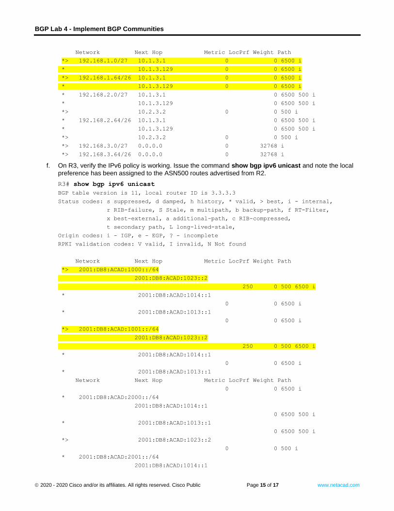
e. On R3, verify the IPv4 policy is working. Issue the command show bgp ipv4 unicast 192.168.1.0/27 | i Community and you will see that there is no output. Follow this with the show bgp ipv4 unicast command and you will see that there are no paths to the ASN6500 networks via R2. They have all been filtered.
R3# show bgp ipv4 unicast 192.168.1.0/27 | i Community
R3# show bgp ipv4 unicast
BGP table version is 9, local router ID is 3.3.3.3
Status codes: s suppressed, d damped, h history, * valid, > best, i - internal,
r RIB-failure, S Stale, m multipath, b backup-path, f RT-Filter,
x best-external, a additional-path, c RIB-compressed,
t secondary path, L long-lived-stale,
Origin codes: i - IGP, e - EGP, ? - incomplete
RPKI validation codes: V valid, I invalid, N Not found
BGP Lab 4 - Implement BGP Communities
© 2020 - 2020 Cisco and/or its affiliates. All rights reserved. Cisco Public Page 15 of 17 www.netacad.com
Network Next Hop Metric LocPrf Weight Path
*> 192.168.1.0/27 10.1.3.1 0 0 6500 i
* 10.1.3.129 0 0 6500 i
*> 192.168.1.64/26 10.1.3.1 0 0 6500 i
* 10.1.3.129 0 0 6500 i
* 192.168.2.0/27 10.1.3.1 0 6500 500 i
* 10.1.3.129 0 6500 500 i
*> 10.2.3.2 0 0 500 i
* 192.168.2.64/26 10.1.3.1 0 6500 500 i
* 10.1.3.129 0 6500 500 i
*> 10.2.3.2 0 0 500 i
*> 192.168.3.0/27 0.0.0.0 0 32768 i
*> 192.168.3.64/26 0.0.0.0 0 32768 i
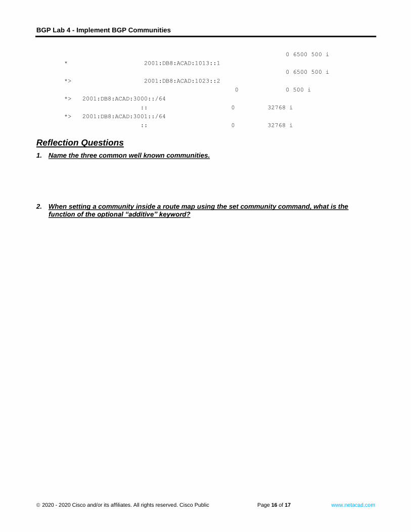
f. On R3, verify the IPv6 policy is working. Issue the command show bgp ipv6 unicast and note the local
preference has been assigned to the ASN500 routes advertised from R2.
R3# show bgp ipv6 unicast
BGP table version is 11, local router ID is 3.3.3.3
Status codes: s suppressed, d damped, h history, * valid, > best, i - internal,
r RIB-failure, S Stale, m multipath, b backup-path, f RT-Filter,
x best-external, a additional-path, c RIB-compressed,
t secondary path, L long-lived-stale,
Origin codes: i - IGP, e - EGP, ? - incomplete
RPKI validation codes: V valid, I invalid, N Not found
Network Next Hop Metric LocPrf Weight Path
*> 2001:DB8:ACAD:1000::/64
2001:DB8:ACAD:1023::2
250 0 500 6500 i
* 2001:DB8:ACAD:1014::1
0 0 6500 i
* 2001:DB8:ACAD:1013::1
0 0 6500 i
*> 2001:DB8:ACAD:1001::/64
2001:DB8:ACAD:1023::2
250 0 500 6500 i
* 2001:DB8:ACAD:1014::1
0 0 6500 i
* 2001:DB8:ACAD:1013::1
Network Next Hop Metric LocPrf Weight Path
0 0 6500 i
* 2001:DB8:ACAD:2000::/64
2001:DB8:ACAD:1014::1
0 6500 500 i
* 2001:DB8:ACAD:1013::1
0 6500 500 i
*> 2001:DB8:ACAD:1023::2
0 0 500 i
* 2001:DB8:ACAD:2001::/64
2001:DB8:ACAD:1014::1
BGP Lab 4 - Implement BGP Communities
© 2020 - 2020 Cisco and/or its affiliates. All rights reserved. Cisco Public Page 16 of 17 www.netacad.com
0 6500 500 i
* 2001:DB8:ACAD:1013::1
0 6500 500 i
*> 2001:DB8:ACAD:1023::2
0 0 500 i
*> 2001:DB8:ACAD:3000::/64
:: 0 32768 i
*> 2001:DB8:ACAD:3001::/64
:: 0 32768 i Close configuration window
Reflection Questions
1. Name the three common well known communities.
Type your answers here.
2. When setting a community inside a route map using the set community command, what is the function of the optional “additive” keyword?
Type your answ
ers here.
BGP Lab 4 - Implement BGP Communities
© 2020 - 2020 Cisco and/or its affiliates. All rights reserved. Cisco Public Page 17 of 17 www.netacad.com
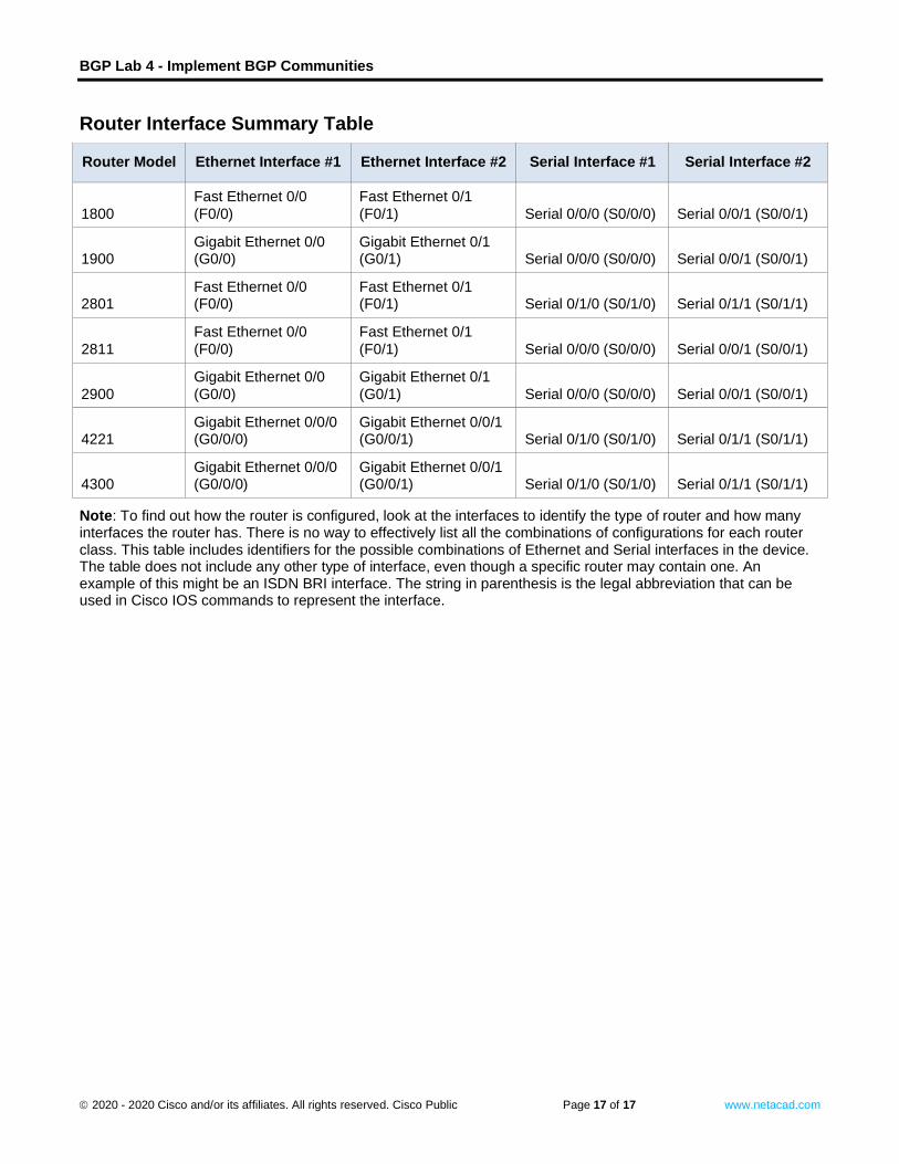
Router Interface Summary Table
Router Model Ethernet Interface #1 Ethernet Interface #2 Serial Interface #1 Serial Interface #2
1800
Fast Ethernet 0/0
(F0/0)
Fast Ethernet 0/1
(F0/1) Serial 0/0/0 (S0/0/0) Serial 0/0/1 (S0/0/1)
1900 Gigabit Ethernet 0/0 (G0/0)
Gigabit Ethernet 0/1 (G0/1) Serial 0/0/0 (S0/0/0) Serial 0/0/1 (S0/0/1)
2801 Fast Ethernet 0/0 (F0/0)
Fast Ethernet 0/1 (F0/1) Serial 0/1/0 (S0/1/0) Serial 0/1/1 (S0/1/1)
2811
Fast Ethernet 0/0
(F0/0)
Fast Ethernet 0/1
(F0/1) Serial 0/0/0 (S0/0/0) Serial 0/0/1 (S0/0/1)
2900
Gigabit Ethernet 0/0
(G0/0)
Gigabit Ethernet 0/1
(G0/1) Serial 0/0/0 (S0/0/0) Serial 0/0/1 (S0/0/1)
4221 Gigabit Ethernet 0/0/0 (G0/0/0)
Gigabit Ethernet 0/0/1 (G0/0/1) Serial 0/1/0 (S0/1/0) Serial 0/1/1 (S0/1/1)
4300 Gigabit Ethernet 0/0/0 (G0/0/0)
Gigabit Ethernet 0/0/1 (G0/0/1) Serial 0/1/0 (S0/1/0) Serial 0/1/1 (S0/1/1)
Note: To find out how the router is configured, look at the interfaces to identify the type of router and how many interfaces the router has. There is no way to effectively list all the combinations of configurations for each router class. This table includes identifiers for the possible combinations of Ethernet and Serial interfaces in the device. The table does not include any other type of interface, even though a specific router may contain one. An example of this might be an ISDN BRI interface. The string in parenthesis is the legal abbreviation that can be used in Cisco IOS commands to represent the interface. End of document