Embed Size (px)
Citation preview

APCBEE Procedia 7 ( 2013 ) 42 – 47
2212-6708 © 2013 The Authors. Published by Elsevier B.V.Selection and peer-review under responsibility of Asia-Pacific Chemical, Biological & Environmental Engineering Society.doi: 10.1016/j.apcbee.2013.08.010
ICBET 2013: May 19-20, 2013, Copenhagen, Denmark
Bio-Impedance Excitation System: A Comparison of Voltage Source and Current Source Designs T R Qureshia,b,*, Chris Chatwina , Wei Wanga
aUniversity of Sussex, School of Engineering and Informatics, Brighton BN1 9QJ, United Kingdom bCOMSATS Instiute of Information Technology, Park Road Chak Shahzad, Islamabad, Pakistan
Abstract
The key component in any bio-impedance measurement system is the excitation subsystem. Bio-impedance measurement can be performed by applying either current or voltage through the electrodes and then by measuring the resulting voltages or current respectively. A current source based excitation system can be useful for lower frequencies (i.e. up to 1MHz). For a mammography system, many useful characteristics of the breast tissues lie above 1MHz. The performance will degrade if a current source is used as an excitation system due to the higher output impedance and high precision requirement for an EIM system. Therefore a wideband excitation source covering higher frequencies, above 1MHz, with an acceptable level of output impedance is required. This paper reports on a performance comparison of a traditional Enhanced Howland based current source with a proposed voltage controlled voltage source (VCVS). Results are compared to establish their relationship to performance parameters: bandwidth, output impedance, SNR, and phase difference over a wide bandwidth (i.e. up to 10MHz). The objective of this research is to show which design is the most appropriate for constructing a wideband excitation source specifically for EIM or for any other EIT related biomedical application which requires a wideband system. © 2013 Published by Elsevier B.V. Selection and/or peer review under responsibility of Asia-Pacific Chemical, Biological & Environmental Engineering Society Keywords: Excitation system, Voltage and Current source, Bio-impedance hardware, EIT/EIM
1. Introduction
A high quality excitation source is required in any bio-impedance measurement system. There are two
* Corresponding author. Tel.: +44 750 6187973. E-mail address: [email protected]; [email protected]
© 2013 The Authors. Published by Elsevier B.V.Selection and peer-review under responsibility of Asia-Pacific Chemical, Biological & Environmental Engineering Society.
Available online at www.sciencedirect.com
ScienceDirect

43 T.R. Qureshi et al. / APCBEE Procedia 7 ( 2013 ) 42 – 47
possible methods: either by injecting current into the body and measuring the resulting voltage across it, or by applying voltages across the body and measuring the current though it. Both methods have advantages and disadvantages. The determination of internal impedance distribution is mathematically ill-posed. Hence, a large change in the unknown impedance distribution may result in only a small change in the measured data; therefore impedance measuring systems require high precision [1]. In order to get a good impedance measurement system the source must be specified according to the required precision level and operating frequency range.
High output impedance and steady current is required for the current source in an EIT or EIM system throughout the high frequency [1][2][3]. High output impedance is required to reduce the effect of the changing contact impedances produced by various electrodes within the system. Ideally the output impedance of the current should be infinitely large but practically this is not possible due to the presence of output capacitance and stray capacitance. The output capacitance and stray capacitance can be reduced by using additional circuitry after the current source, which can be a negative impedance convertor (NIC), Generalized Impedance convertor (GIC) [1] etc. As a result, a current source based excitation system becomes more complex and the performance will be degraded and limited to operate at less than 1MHz.
On the other hand, a high precision voltage source implemented using a broadband operational amplifier is generally less costly and easier to implement, for such a source it is required to know the applied voltage and its resulting current [4][5][6]. In order to get a constant voltage across the body, a low output impedance source is required. An ideal voltage source should have zero output impedance but practically this is not possible, nevertheless, it should be as low as possible. Previous studies have shown that breast tissue characteristics are best explored above 1MHz [7]. Therefore an EIM system should at least cover the frequency range between 1MHz -15MHz to effectively characterise the breast.
This paper gives a performance comparison of the voltage controlled current source (VCCS) with a proposed voltage controlled voltage source (VCVS). In this paper we study two excitation sources: The Enhanced-Howland-GIC model and a proposed VCVS model with controllable gain and feedback. Both circuits are tested and analysed to check which design will be more suitable for an EIT based EIM measurement system. The tests have been designed to explore circuit performance related to the source bandwidth, output impedance, SNR and phase difference.
2. Source Architecture
2.1. Current Source Model The current source, which is mostly used in bio-impedance measuring systems is the Enhanced Howland
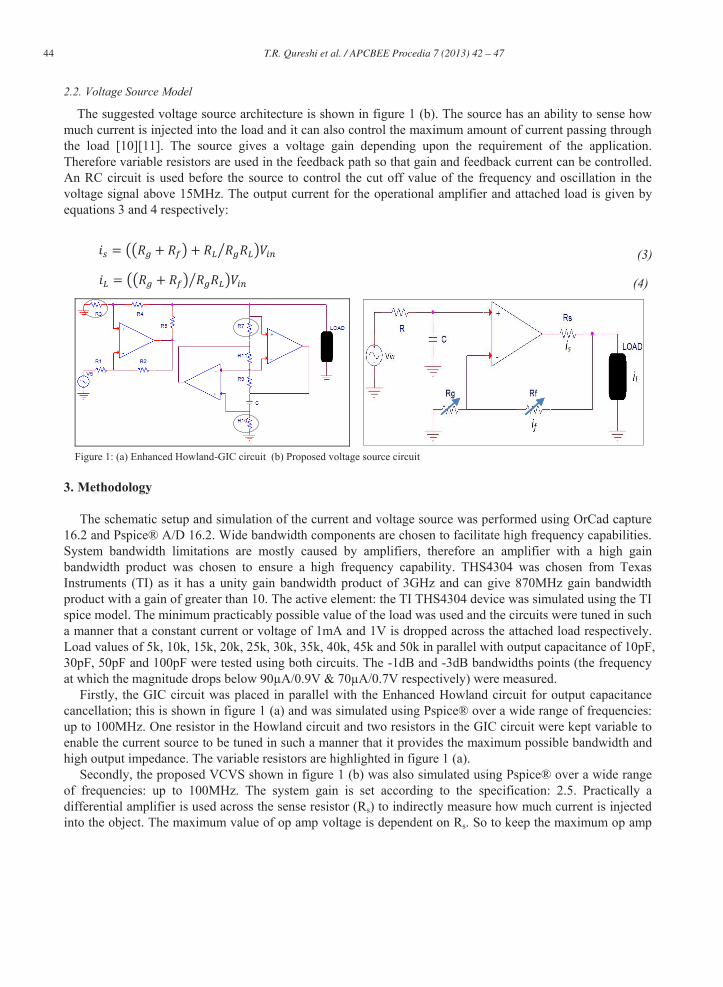
circuit due to its simple structure and good performance [8][9]. At higher frequencies, the output impedance degrades due to the presence of output capacitance, by cancelling this output capacitance higher output impedance can be achieved. The placement of a GIC in parallel with an Enhanced Howland circuit is known to improve the output impedance of the circuit [2][3][9] as shown in figure 1 (a).
To effectively produce inductance the GIC should have specific components as shown in figure 1 (a). The Output current of the Enhanced Howland circuit for an ideal op amp and the inductance produced is given by equation 1 and 2 respectively,
(1)
(2)
44 T.R. Qureshi et al. / APCBEE Procedia 7 ( 2013 ) 42 – 47
2.2. Voltage Source Model
The suggested voltage source architecture is shown in figure 1 (b). The source has an ability to sense how much current is injected into the load and it can also control the maximum amount of current passing through the load [10][11]. The source gives a voltage gain depending upon the requirement of the application. Therefore variable resistors are used in the feedback path so that gain and feedback current can be controlled. An RC circuit is used before the source to control the cut off value of the frequency and oscillation in the voltage signal above 15MHz. The output current for the operational amplifier and attached load is given by equations 3 and 4 respectively:
(3)
(4)
Figure 1: (a) Enhanced Howland-GIC circuit (b) Proposed voltage source circuit
3. Methodology
The schematic setup and simulation of the current and voltage source was performed using OrCad capture 16.2 and Pspice® A/D 16.2. Wide bandwidth components are chosen to facilitate high frequency capabilities. System bandwidth limitations are mostly caused by amplifiers, therefore an amplifier with a high gain bandwidth product was chosen to ensure a high frequency capability. THS4304 was chosen from Texas Instruments (TI) as it has a unity gain bandwidth product of 3GHz and can give 870MHz gain bandwidth product with a gain of greater than 10. The active element: the TI THS4304 device was simulated using the TI spice model. The minimum practicably possible value of the load was used and the circuits were tuned in such a manner that a constant current or voltage of 1mA and 1V is dropped across the attached load respectively. Load values of 5k, 10k, 15k, 20k, 25k, 30k, 35k, 40k, 45k and 50k in parallel with output capacitance of 10pF, 30pF, 50pF and 100pF were tested using both circuits. The -1dB and -3dB bandwidths points (the frequency at which the magnitude drops below 90μA/0.9V & 70μA/0.7V respectively) were measured.
Firstly, the GIC circuit was placed in parallel with the Enhanced Howland circuit for output capacitance cancellation; this is shown in figure 1 (a) and was simulated using Pspice® over a wide range of frequencies: up to 100MHz. One resistor in the Howland circuit and two resistors in the GIC circuit were kept variable to enable the current source to be tuned in such a manner that it provides the maximum possible bandwidth and high output impedance. The variable resistors are highlighted in figure 1 (a).
Secondly, the proposed VCVS shown in figure 1 (b) was also simulated using Pspice® over a wide range of frequencies: up to 100MHz. The system gain is set according to the specification: 2.5. Practically a differential amplifier is used across the sense resistor (Rs) to indirectly measure how much current is injected into the object. The maximum value of op amp voltage is dependent on Rs. So to keep the maximum op amp

45 T.R. Qureshi et al. / APCBEE Procedia 7 ( 2013 ) 42 – 47
voltage in line with its data sheet range we have to find the optimum value of Rs , which can be expressed as:
(5)
4. Results and Discussion
The circuit was tested using an ideal operational amplifier present in Pspice® libraries. This paper gives simulation results to show which source is useful for a mammography system over a wide range of frequency. First the current source was tested without load capacitance. The results show that a wide bandwidth can be achieved by careful tuning of the circuit and can achieve high output impedance at low frequencies. At high frequencies: above 100 kHz, the output impedance of the source starts decreasing due to the capacitance effect. The current source is then tested in the presence of a load capacitance in parallel with the load. The circuit is set for a 10pF load capacitance to give the maximum achievable performance and using the same circuit parameter it is tested for different load capacitances. The results show that at 10pF load capacitance the source gives a bandwidth of 1.50 MHz with a 50k resistance. A maximum output impedance of
a phase difference of approximately -1800 to -2680 for load current as compared to the input signal. The SNR is calculated for the voltage signal dropped across the load and it is approximately between 82dB 54dB for the frequency range of 1 kHz 30 MHz. The detailed results using a current source are reported in table 1.The current source load currents at different loads in parallel with the load capacitance are shown in figure 2 (a).
The proposed voltage source shown in figure 1 (b) was also tested with and without the load capacitance t a
voltage source can easily achieve a wide bandwidth of approximately 18 MHz across the whole range of the tested load. It can also achieve a low output impedance of approx. 7.18SNR is calculated for a 2.5V signal. The SNR achieved using the proposed voltage varies between 100dB 87dB for the frequency range of 1 kHz 30 MHz. The signal phase lag is also very low and is about -280 at 10 MHz. The detailed results for the voltage source are reported in the table 2. The voltage source load voltages for different loads in parallel with the load capacitance are shown in figure 2 (b).
Figure 2: (a) Load current for 5k using current source. (b) Load voltage for 5kwith 10pF load capacitance using proposed voltage source.
5. Conclusion
In this paper, an enhanced Howland-GIC circuit and wide band voltage source design has been simulated

46 T.R. Qureshi et al. / APCBEE Procedia 7 ( 2013 ) 42 – 47
using ideal and non-ideal operational amplifiers in the presence of a load capacitance. The source architecture has been presented. The results show that the current source gives a high bandwidth (greater than 10MHz) for smaller loads but gives a bandwidth of less than 2MHz for a heavier load; whilst the proposed voltage source gives a stable bandwidth throughout the tested values of load. The current source gives an acceptable level of output impedance but is limited to lower frequency operation: b/w 100 kHz 500 kHz. The voltage source gives low output impedance as desired and a better SNR when compared to the current source. As mentioned earlier, this paper gives a comparison between two sources that can be used to construct an EIM/EIT excitation source. According to our findings, the proposed voltage source will be useful for constructing a wide band EIM excitation source or any other EIT application that requires a wideband excitation source. When building the voltage source it is very important to manufacture the printed circuit board to high quality standards so as to minimize on board parasitic impedances. The proposed wideband voltage source will then achieve low output impedance with an acceptable level of SNR as compared to the current source.
Table 1: Enhanced Howland-GIC output with 10pF load capacitance
Load ( Bandwidth (MHz) Output Impedance at different frequency ( )
Ideal -1dB -3dB 100 Hz 10k Hz 100k Hz 1M Hz 10M Hz
5k > 25 8.85 17.23 4.99M 4.99M 4.54M 1.85M 32.27k
10k > 25 4.06 7.96 8.32M 8.32M 7.68M 1.11M 16.50k
15k > 25 2.64 5.18 11.52M 11.52M 9.99M 76.02k 12.75k
20k > 25 1.96 3.84 13.31M 13.31M 11.09M 57.52k 11.15k
5k > 25 1.55 3.05 15.60M 15.60M 11.88M 46.38k 10.27k
30k > 25 1.29 2.53 17.62M 17.62M 11.97M 38.99k 9.73k
35k > 25 1.10 2.16 18.39M 18.39M 12.03M 33.77k 9.36k
40k > 25 0.96 1.88 19.96M 19.96M 11.73M 29.18k 9.08k
45k > 25 0.85 1.67 20.41M 20.41M 11.49M 26.96k 8.88k
50k > 25 0.76 1.50 21.69M 21.69M 11.06M 24.63k 8.72k
Table 2: Voltage Source output with 10pF load capacitance
Load ( Bandwidth (MHz) Output Impedance at different frequency ( )
Ideal -1dB -3dB 100 Hz 10k Hz 100k Hz 1M Hz 10M Hz
5k > 25 9.19 18.18 6.81 6.81 6.81 14.44 722.13
10k > 25 9.20 18.19 13.22 13.22 13.22 28.48 1.44k
15k > 25 9.21 18.20 19.83 19.83 19.83 42.72 2.16k
20k > 25 9.21 18.20 26.44 26.44 26.44 56.96 2.88k
5k > 25 9.21 18.20 32.04 32.04 33.04 71.20 3.59k
30k > 25 9.21 18.20 38.45 38.45 39.65 85.44 4.31k
35k > 25 9.21 18.20 44.86 44.86 46.26 99.68 5.03k
40k > 25 9.22 18.20 51.27 51.27 52.87 113.92 5.75k
45k > 25 9.22 18.21 57.67 57.67 59.48 128.16 6.47k
50k > 25 9.22 18.21 64.08 64.08 66.09 140.39 7.18k

47 T.R. Qureshi et al. / APCBEE Procedia 7 ( 2013 ) 42 – 47
References
[1] Alexander S R et al., Current source design for electrical impedance tomography, 2003 Physiol. Meas. 24 509-516. [2] Oh T I et al., Calibration methods for a multi-channed multi-frequency EIT system, 2007 Physiol. Meas.28 1175-88. [3] Wang W et al., A comprehensive study on current source circuits, 2007 ICEBI, IFMBE Proceedings 17 213-216. [4] Hartov A et al., A Multichannel continously selectable EIS measurement system, 2000, IEEE Trans. Biomed. Eng. 47 49-58. [5] Ryan Halter et al., A Broadband high frequency EIT system for breast Imaging, 2008, IEEE Trans. Biomed. Eng. Vol 55, No. 2. [6] Gary J S et al., A high-precision voltage source for EIT, 2006, Physiol. Meas. 27 S221-S236. [7] Jossinet J, The impedivity of freshly excised human breast tissue, 1998, Physiol. Meas.19 61-75. [8] Franco S, Design with operational analog integrated circuits, 2002 (New York: McGraw-Hill). [9] T R Qureshi et al., Comparison of Howland-GIC circuit based current sources, 2010, Journal of Physics 224 012167. [10] T R Qureshi et al., Investigation of voltage sourc designs for EIM systems, 2012, IEEE EMBS San Diego USA. [11] T R Qureshi et al., Design of wideband voltage having low output impedance, flexible gain & controllable feedback current for
EIT systems, 2012, ICBET IPCBEE Vol. 34.