Embed Size (px)
Citation preview

Computational Materials Science 82 (2014) 134–139
Contents lists available at ScienceDirect
Computational Materials Science
journal homepage: www.elsevier .com/locate /commatsci
Bio-inspired composite structures subjected to underwater impulsiveloading
0927-0256/$ - see front matter Crown Copyright � 2013 Published by Elsevier B.V. All rights reserved.http://dx.doi.org/10.1016/j.commatsci.2013.09.033
⇑ Corresponding author. Tel.: +61 468316863.E-mail address: [email protected] (P. Tran).
Phuong Tran ⇑, Tuan Duc Ngo, Priyan MendisDepartment of Infrastructure Engineering, The University of Melbourne, Victoria 3010, Australia
a r t i c l e i n f o
Article history:Received 23 August 2013Accepted 14 September 2013Available online 19 October 2013
Keywords:Bio-inspired compositeBiomimeticComposite failureFluid–structure interactionUnderwater impact
a b s t r a c t
Designing lightweight high-performance materials that can sustain high impulsive loadings is of greatinterest to marine and civil applications. When designing tough, strong new materials from relativelyweak components, mimicking structures from nature can be a highly promising strategy, as illustratedby nacre from red abalone shells. One of nacre’s most impressive features is its ability to laterally spreaddamage and dissipate energy over millimetre length scales at crack tips and other defects. In this work, acomposite panel is redesigned to mimic nacre’s microstructure. The bio-inspired composite panel and theoriginal composite structure, which have identical areal mass, are subjected to an underwater impulsiveloading scenario. Their performances are compared numerically in terms of damage and deflection. Afinite element fluid–structure interaction model is developed to capture the water impact on E-glass/vinylester composite facets and to provide insights into the deformation modes and failure mechanisms.Damage and degradation in individual unidirectional composite laminas are simulated using Hashin’scomposite damage model. The delamination between laminas is modelled by a bilinear cohesive model.Results interpreted from this numerical study will be used as guidance for the future manufacturing andexperimental characterisation of bio-inspired composite structures.
Crown Copyright � 2013 Published by Elsevier B.V. All rights reserved.
1. Introduction
Designing and manufacturing lightweight yet high-perfor-mance materials has attracted a lot of attention recently due tofast-growing military and civil applications. In modern warfare,marine’s structures could be exposed to extreme impact inducedby underwater and in-air blasts that can impose significant dam-ages on their structures. Designing a reliable structures or warshipsagainst such extreme threats requires continuous improvements ofmaterial systems for better energy absorption, mitigation and frag-ment penetration resistance. Comprehensive understanding the ef-fects of various factors such as dynamic responses, failuremechanisms and operating environments on the vulnerabilityand survivability of structures impacted by such threats becomesextremely critical. Development in this area has been discussedin the extensive review-paper by Mouritz et al. [1], Porfiri and Gup-ta [2] and Hall [3]. In recent years, glass fibre reinforced plastic(GFRP) composite materials are of current interest in naval hullconstruction [1,4] because they exhibit low weight and low mag-netic signature. These advantages are of particular interest to navalengineers, who are interested in designing fast and stealth marinestructures. Two different architectures are generally used to buildcomposite hulls: single-skin design and sandwich construction,
where a crushable core is encased between fibre-reinforced faceskins. Both architectures involve the use of frames, stiffeners andbulkheads that provide the overall structural stiffness and supportthe GFRP composite hull. The use of sandwich structures in blastmitigation became a favourable choice for designers realizing thatthe encased crushable core could attenuate the impulse transmit-ted to the back-side composite face-sheet by which protecting theinterior structures or occupants. The two monolithic compositefaces (front and back), on the other hand, provide overall structuralintegrity and penetration proof capability. Extensive designs ofsandwich architectures have been studied and showing superiorperformances compared with single structures of equal areal mass([5–9]).
Numerous experimental studies of marine composites sub-jected to impulsive loadings are reported in Porfiri and Gupta [2].These studies present the performance of different compositepanels and the most significant damage modes involved in blastor ballistic resistance of sandwich structures. In these experiments,it has been shown that local degradations can significantly affectthe overall structural performance [10]. Localised damage is notrepresentative structural failures observed in larger scale blaststudies, where clamping tearing is not the most critical mechanismresponsible for structural failure, and deformation and damage are,instead, spread over a large section of the hull. In recent study byLatourte et al. [11] has reported experiments on monolithic andsandwich composite panels subjected to a wide range of impulsive
P. Tran et al. / Computational Materials Science 82 (2014) 134–139 135
loading using a scaled-down FSI apparatus. Post-mortem analysisof composite damages has revealed various damage mechanismsof composite panels such as inter-laminar delamination, fibreand matrix damage in the composite plies over large area. The cen-tre of the front face-sheet composite laminates, which is subjectedto water impact, is severely damaged due to the initial impact thefollowing cavitation collapse. These composite failures lead tofoam cracking and therefore significantly affects the crushingperformance of the polymeric core. As a result, designing a newgeneration of composite facet which could provide a combinationof stiffness and smart energy absorption capability protecting inte-rior structure becomes a promising venture.
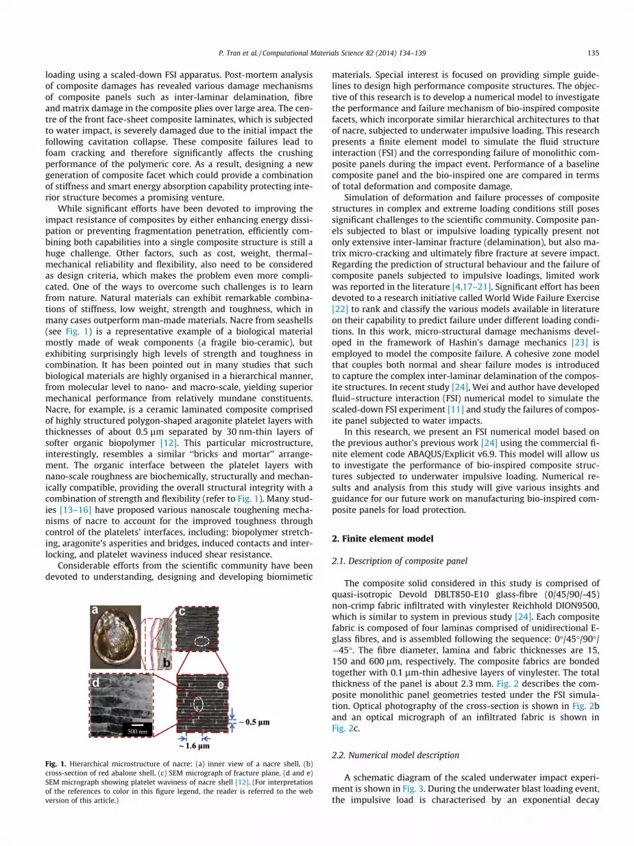
While significant efforts have been devoted to improving theimpact resistance of composites by either enhancing energy dissi-pation or preventing fragmentation penetration, efficiently com-bining both capabilities into a single composite structure is still ahuge challenge. Other factors, such as cost, weight, thermal–mechanical reliability and flexibility, also need to be consideredas design criteria, which makes the problem even more compli-cated. One of the ways to overcome such challenges is to learnfrom nature. Natural materials can exhibit remarkable combina-tions of stiffness, low weight, strength and toughness, which inmany cases outperform man-made materials. Nacre from seashells(see Fig. 1) is a representative example of a biological materialmostly made of weak components (a fragile bio-ceramic), butexhibiting surprisingly high levels of strength and toughness incombination. It has been pointed out in many studies that suchbiological materials are highly organised in a hierarchical manner,from molecular level to nano- and macro-scale, yielding superiormechanical performance from relatively mundane constituents.Nacre, for example, is a ceramic laminated composite comprisedof highly structured polygon-shaped aragonite platelet layers withthicknesses of about 0.5 lm separated by 30 nm-thin layers ofsofter organic biopolymer [12]. This particular microstructure,interestingly, resembles a similar ‘‘bricks and mortar’’ arrange-ment. The organic interface between the platelet layers withnano-scale roughness are biochemically, structurally and mechan-ically compatible, providing the overall structural integrity with acombination of strength and flexibility (refer to Fig. 1). Many stud-ies [13–16] have proposed various nanoscale toughening mecha-nisms of nacre to account for the improved toughness throughcontrol of the platelets’ interfaces, including: biopolymer stretch-ing, aragonite’s asperities and bridges, induced contacts and inter-locking, and platelet waviness induced shear resistance.
Considerable efforts from the scientific community have beendevoted to understanding, designing and developing biomimetic
Fig. 1. Hierarchical microstructure of nacre: (a) inner view of a nacre shell, (b)cross-section of red abalone shell, (c) SEM micrograph of fracture plane, (d and e)SEM micrograph showing platelet waviness of nacre shell [12]. (For interpretationof the references to color in this figure legend, the reader is referred to the webversion of this article.)
materials. Special interest is focused on providing simple guide-lines to design high performance composite structures. The objec-tive of this research is to develop a numerical model to investigatethe performance and failure mechanism of bio-inspired compositefacets, which incorporate similar hierarchical architectures to thatof nacre, subjected to underwater impulsive loading. This researchpresents a finite element model to simulate the fluid structureinteraction (FSI) and the corresponding failure of monolithic com-posite panels during the impact event. Performance of a baselinecomposite panel and the bio-inspired one are compared in termsof total deformation and composite damage.
Simulation of deformation and failure processes of compositestructures in complex and extreme loading conditions still posessignificant challenges to the scientific community. Composite pan-els subjected to blast or impulsive loading typically present notonly extensive inter-laminar fracture (delamination), but also ma-trix micro-cracking and ultimately fibre fracture at severe impact.Regarding the prediction of structural behaviour and the failure ofcomposite panels subjected to impulsive loadings, limited workwas reported in the literature [4,17–21]. Significant effort has beendevoted to a research initiative called World Wide Failure Exercise[22] to rank and classify the various models available in literatureon their capability to predict failure under different loading condi-tions. In this work, micro-structural damage mechanisms devel-oped in the framework of Hashin’s damage mechanics [23] isemployed to model the composite failure. A cohesive zone modelthat couples both normal and shear failure modes is introducedto capture the complex inter-laminar delamination of the compos-ite structures. In recent study [24], Wei and author have developedfluid–structure interaction (FSI) numerical model to simulate thescaled-down FSI experiment [11] and study the failures of compos-ite panel subjected to water impacts.
In this research, we present an FSI numerical model based onthe previous author’s previous work [24] using the commercial fi-nite element code ABAQUS/Explicit v6.9. This model will allow usto investigate the performance of bio-inspired composite struc-tures subjected to underwater impulsive loading. Numerical re-sults and analysis from this study will give various insights andguidance for our future work on manufacturing bio-inspired com-posite panels for load protection.
2. Finite element model
2.1. Description of composite panel
The composite solid considered in this study is comprised ofquasi-isotropic Devold DBLT850-E10 glass-fibre (0/45/90/-45)non-crimp fabric infiltrated with vinylester Reichhold DION9500,which is similar to system in previous study [24]. Each compositefabric is composed of four laminas comprised of unidirectional E-glass fibres, and is assembled following the sequence: 0�/45�/90�/�45�. The fibre diameter, lamina and fabric thicknesses are 15,150 and 600 lm, respectively. The composite fabrics are bondedtogether with 0.1 lm-thin adhesive layers of vinylester. The totalthickness of the panel is about 2.3 mm. Fig. 2 describes the com-posite monolithic panel geometries tested under the FSI simula-tion. Optical photography of the cross-section is shown in Fig. 2band an optical micrograph of an infiltrated fabric is shown inFig. 2c.
2.2. Numerical model description
A schematic diagram of the scaled underwater impact experi-ment is shown in Fig. 3. During the underwater blast loading event,the impulsive load is characterised by an exponential decay

Fig. 2. Schematic diagram of the composite panel: (a) panel is bonded to a fixedsteel ring, (b) optical photograph of the solid panel cross-section highlightingdifferent fabrics and (c) optical microscopy image of the E-glass/vinylester fabricused in the composite panel.
Fig. 4. Schematic cross-section of (a) baseline composite panel and (b) bio-inspiredcomposite panel with waviness. (c) Representative elements of a bio-inspiredcomposite panel with dovetail shape. Blue solid lines indicate the adhesive layersand dotted lines illustrate the original shape of the composite element. (Forinterpretation of the references to colour in this figure legend, the reader is referredto the web version of this article.)
136 P. Tran et al. / Computational Materials Science 82 (2014) 134–139
pressure history, which is defined by two parameters: the peakpressure po and the decay time to (Fig. 3b). Fig. 3c illustrates thesetup for the FSI experiment, where the water is contained in asteel tube that is sealed at one end by a steel water piston and atthe other end by the composite sample. In this FSI setup, the steelring is used to clamp the composite panel. The exponentiallydecaying pressure history is produced by impacting the water pis-ton with the steel flyer plate at an impact velocity of 300 m/s. Afterthe impact, the pressure waves propagate through the water col-umn and reach the composite panel. The circular portion of thecomposite panel that was in contact with the water (which has adiameter of 44 mm) is subjected to impulsive loading.
2.3. Bio-inspired composite model
Fig. 4a presents the cross-section of the composite panel, whichhas four layers of fabric bonded together by three adhesive layers.As mentioned in the Introduction section, the excellent perfor-mance of nacre is partly related to its platelet waviness and inter-locking. In this work, to mimic the dovetail microstructure of nacretablets, we present a modification to the composite laminategeometry, which accounts for a change in the waviness of the con-tact surfaces. This unique arrangement of the nacre’s tablets hasbeen argued to have substantial influence on dissipating impactenergy by enhancing the kinematics for tile interlocking, especiallywhen subjected to compression. In contrast to the actual biologicalstructures, the tablet geometry in this work is limited to squaretiles. The thickness of each baseline laminate is about 0.6 mm.The thickness of the biomimic composite laminate is varied by
Fig. 3. (a) Schematic diagram of the underwater explosion, (b) pressure profilehistory and (c) schematic diagram of the underwater blast impact simulation.
shifting the nodal coordinates in the through-thickness directionabout 0.1 mm, as shown in Fig. 4c. Here, the platelet thickness is0.5 mm in the middle and increases linearly towards the edge (atabout 0.7 mm). This bio-inspired architecture is designed ensuringthe preservation of mass between the baseline and modifiedcomposites.
2.4. Fluid–structure interaction model
Three approaches have been widely used to simulate the fluid–structure interaction in air/water blast problems. The first ap-proach is to simulate both the fluid media and solid structure withLagrangian mesh (L–L model). The fluid behaviour can be describedwith the Mie-Grüneisen equation of state (EOS) with a linearHugoniot relation. An adaptive remeshing technique is requiredto prevent the large distortion of fluid mesh during wave propaga-tion and interactions with solid structures. Recently, a coupledEulerian and Lagrangian technique (CEL or E–L model) has beenintroduced to simulate the problems involving complex interac-tions between fluid and solid structures. The fluid behaviour is de-scribed with the same equation of state as in the L–L model;however, using Eulerian mesh in the fluid domain helps preventthe element distortion problems in an FSI test. However, capturingthe migration of the fluid requires extending the Eulerian mesh be-yond the original fluid domain, which usually results in difficultiesin achieving a fine Eulerian mesh density. On the other hand, thecontact between the Eulerian surface and the Lagrangian surfaceartificially becomes too stiff when the coarse Eulerian mesh isused. Thus, in this study, a third approach called the acoustic andLagrangian technique (A–L model), is employed.
The governing equation for the acoustic medium is obtainedfrom ABAQUS’s user manual as:
@p@xþ c _uf þ qf
€uf ¼ 0; ð1Þ
where p is the excess pressure in the fluid (referring to the staticpressure), _uf and €uf are the fluid particle velocity and acceleration,qf is the fluid density, and c is the volumetric drag coefficient (forceper unit volume per velocity). With an assumption of inviscid, linearand compressible fluid, the constitutive law for acoustic medium isgiven as:
p ¼ �Kf@uf
@x; ð2Þ
where Kf is the bulk modulus of the fluid. The density and bulkmodulus of water are qf = 985.27 kg/m3 and Kf = 2.19 GPa, respec-tively. The momentum loss in the acoustic medium is characterisedby introducing the volumetric drag coefficient c, which is approxi-mated by:
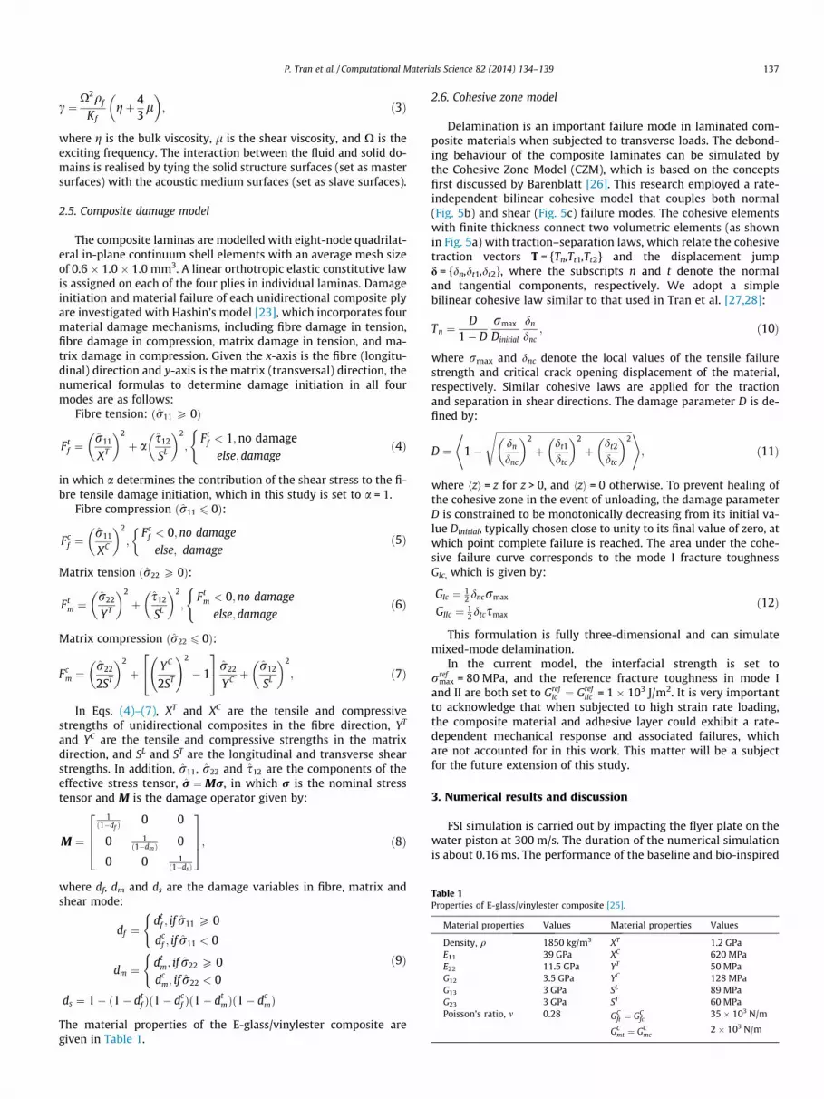
Table 1Properties of E-glass/vinylester composite [25].
Material properties Values Material properties Values
Density, q 1850 kg/m3 XT 1.2 GPaE11 39 GPa XC 620 MPaE22 11.5 GPa YT 50 MPaG12 3.5 GPa YC 128 MPaG13 3 GPa SL 89 MPaG23 3 GPa ST 60 MPaPoisson’s ratio, m 0.28 GC
ft ¼ GCfc
35 � 103 N/m
GCmt ¼ GC
mc2 � 103 N/m
P. Tran et al. / Computational Materials Science 82 (2014) 134–139 137
c ¼X2qf
Kfgþ 4
3l
� �; ð3Þ
where g is the bulk viscosity, l is the shear viscosity, and X is theexciting frequency. The interaction between the fluid and solid do-mains is realised by tying the solid structure surfaces (set as mastersurfaces) with the acoustic medium surfaces (set as slave surfaces).
2.5. Composite damage model
The composite laminas are modelled with eight-node quadrilat-eral in-plane continuum shell elements with an average mesh sizeof 0.6 � 1.0 � 1.0 mm3. A linear orthotropic elastic constitutive lawis assigned on each of the four plies in individual laminas. Damageinitiation and material failure of each unidirectional composite plyare investigated with Hashin’s model [23], which incorporates fourmaterial damage mechanisms, including fibre damage in tension,fibre damage in compression, matrix damage in tension, and ma-trix damage in compression. Given the x-axis is the fibre (longitu-dinal) direction and y-axis is the matrix (transversal) direction, thenumerical formulas to determine damage initiation in all fourmodes are as follows:
Fibre tension: ðr11 P 0Þ
Ftf ¼
r11
XT
� �2
þ as12
SL
� �2
;Ft
f < 1;no damageelse;damage
(ð4Þ
in which a determines the contribution of the shear stress to the fi-bre tensile damage initiation, which in this study is set to a = 1.
Fibre compression ðr11 6 0Þ:
Fcf ¼
r11
XC
� �2
;Fc
f < 0;no damage
else; damage
�ð5Þ
Matrix tension ðr22 P 0Þ:
Ftm ¼
r22
YT
� �2
þ s12
SL
� �2
;Ft
m < 0;no damage
else;damage
(ð6Þ
Matrix compression ðr22 6 0Þ:
Fcm ¼
r22
2ST
� �2
þ YC
2ST
!2
� 1
24
35 r22
YC þr12
SL
� �2
; ð7Þ
In Eqs. (4)–(7), XT and XC are the tensile and compressivestrengths of unidirectional composites in the fibre direction, YT
and YC are the tensile and compressive strengths in the matrixdirection, and SL and ST are the longitudinal and transverse shearstrengths. In addition, r11, r22 and s12 are the components of theeffective stress tensor, r ¼Mr, in which r is the nominal stresstensor and M is the damage operator given by:
M ¼
1ð1�df Þ
0 0
0 1ð1�dmÞ 0
0 0 1ð1�dsÞ
2664
3775; ð8Þ
where df, dm and ds are the damage variables in fibre, matrix andshear mode:
df ¼dt
f ; if r11 P 0
dcf ; if r11 < 0
(
dm ¼dt
m; if r22 P 0dc
m; if r22 < 0
(
ds ¼ 1� ð1� dtf Þð1� dc
f Þð1� dtmÞð1� dc
mÞ
ð9Þ
The material properties of the E-glass/vinylester composite aregiven in Table 1.
2.6. Cohesive zone model
Delamination is an important failure mode in laminated com-posite materials when subjected to transverse loads. The debond-ing behaviour of the composite laminates can be simulated bythe Cohesive Zone Model (CZM), which is based on the conceptsfirst discussed by Barenblatt [26]. This research employed a rate-independent bilinear cohesive model that couples both normal(Fig. 5b) and shear (Fig. 5c) failure modes. The cohesive elementswith finite thickness connect two volumetric elements (as shownin Fig. 5a) with traction–separation laws, which relate the cohesivetraction vectors T = {Tn,Tt1,Tt2} and the displacement jumpd = {dn,dt1,dt2}, where the subscripts n and t denote the normaland tangential components, respectively. We adopt a simplebilinear cohesive law similar to that used in Tran et al. [27,28]:
Tn ¼D
1� Drmax
Dinitial
dn
dnc; ð10Þ
where rmax and dnc denote the local values of the tensile failurestrength and critical crack opening displacement of the material,respectively. Similar cohesive laws are applied for the tractionand separation in shear directions. The damage parameter D is de-fined by:
D ¼ 1�
ffiffiffiffiffiffiffiffiffiffiffiffiffiffiffiffiffiffiffiffiffiffiffiffiffiffiffiffiffiffiffiffiffiffiffiffiffiffiffiffiffiffiffiffiffiffiffiffiffiffiffiffiffiffiffiffiffidn
dnc
� �2
þ dt1
dtc
� �2
þ dt2
dtc
� �2s* +
; ð11Þ
where hzi = z for z > 0, and hzi = 0 otherwise. To prevent healing ofthe cohesive zone in the event of unloading, the damage parameterD is constrained to be monotonically decreasing from its initial va-lue Dinitial, typically chosen close to unity to its final value of zero, atwhich point complete failure is reached. The area under the cohe-sive failure curve corresponds to the mode I fracture toughnessGIc, which is given by:
GIc ¼ 12 dncrmax
GIIc ¼ 12 dtcsmax
ð12Þ
This formulation is fully three-dimensional and can simulatemixed-mode delamination.
In the current model, the interfacial strength is set torref
max = 80 MPa, and the reference fracture toughness in mode Iand II are both set to Gref
Ic ¼ GrefIIc = 1 � 103 J/m2. It is very important
to acknowledge that when subjected to high strain rate loading,the composite material and adhesive layer could exhibit a rate-dependent mechanical response and associated failures, whichare not accounted for in this work. This matter will be a subjectfor the future extension of this study.
3. Numerical results and discussion
FSI simulation is carried out by impacting the flyer plate on thewater piston at 300 m/s. The duration of the numerical simulationis about 0.16 ms. The performance of the baseline and bio-inspired

Fig. 5. (a) 3D eight-node cohesive element, (b) normal and (c) shear mode of a rate-independent bilinear cohesive model.
Fig. 7. Deformations of composite panels (side view), and evolution history ofwater side central point deflection and velocity.
138 P. Tran et al. / Computational Materials Science 82 (2014) 134–139
composite panels are compared in terms of deformation historyand total damage. One of the objectives of this work is to investi-gate the ability of the designed bio-inspired composite model todistribute the impact energy over the contact area. Fig. 6 has illus-trated the distribution of stress on the air side and water side ofboth composite panels at the end of the simulation.
As clearly shown in Fig. 6, due to the waviness of the compositelaminates, stress is spread all over the bio-inspired compositepanel compared to localised stress concentration at the edge ofthe baseline composite panel. The stress distribution pattern isevidently aligned with the wavy pattern of the designedcomposite, indicating sliding-induced contact of the laminates.Furthermore, the severe stress concentration that developed inthe water side of the baseline composite panel is not seen in thebio-inspired composite panel.
Fig. 7 shows the side view deformation of the composite panels,revealing extensive edge delamination of the composite laminates.Displacements and velocity histories of the central points on theair sides of the composite panels are also presented in Fig. 7. It isinteresting to note that there are no significant differencesbetween the baseline and bio-inspired composite models in termsof central deflection. This could be explained by the fact that thewaviness of the modified composite laminate is effective in pre-venting the laminate from sliding, while mass is a dominant factorin the out-of-plane deformation.
Total composite damage is effectively illustrated by the sheardamage parameters as described in Eq. (9). Shear damage patternsfor the composite panels are presented in Fig. 8, illustrating againthe distribution of damages in the bio-inspired composite panel
Fig. 6. Stress distributions on the air side and water side of regular and bio-inspiredcomposite panels.
to avoid severe edge failures. One of the important failure mecha-nisms of composites is inter-laminate delamination. This failuremode occurs as the composite laminates debond from each otherduring the impact event, affecting the overall structural integrityof the composite panels. The adhesive layers in composite materi-als play a similar role to the organic biopolymer layers in nacre. Inthis work, we employ a rate-independent bilinear cohesive modelto simulate the interface of the composite. Fig. 9 shows thecross-sections of three adhesive layers of both composite models.
Fig. 8. Shear damage on the air side and water side of regular and bio-inspiredcomposite panels.

Fig. 9. Interfacial delamination evolution of: (a) baseline and (b) bio-inspiredcomposite panels.
P. Tran et al. / Computational Materials Science 82 (2014) 134–139 139
Snapshots of these adhesive layers are taken at three differenttimes: 0.05, 0.07 and 0.09 ms. The continuous segments of theinterface represent the intact adhesive layers.
As failure occurs, the damaged segments are removed from thepicture, leaving blank segments. At 0.05 ms, the interfaces of bothcomposite models remain intact as no failure occurs. At 0.07 ms,interface delamination occurs in both cases and develops furtherat 0.09 ms. As clearly shown in Fig. 9, the interface debonding ismuch more severe in the baseline case compared to the bio-in-spired case. The second and third layers in the baseline compositeare almost removed due to failure, while the second layer in thebio-inspired composite remains undamaged.
4. Conclusions
In this study, we have developed a fluid–structure interactionnumerical model using a coupled acoustic-solid technique that iscapable of describing the interaction between water and compositepanels. The numerical mode is employed to study the performanceof composite panels subjected to underwater impulsive loading.Bio-inspired design of composite panels is proposed to improvethe energy mitigation capability of composite structures. The com-parison between performances of the two composite materials interms of deformation, composite damage and interfacial delamina-tion are conducted, highlighting the advantages of bio-inspiredcomposite structures. Compared with the baseline compositepanel, the bio-inspired composite structure helps to relieve the
stress concentration by spreading out the induced damages overa larger area. Furthermore, the inter-laminar debonding of com-posite laminates is reduced noticeably for bio-inspired structuresdue to the interlocking mechanism associated with the dog-boneshape design of composite laminates.
Acknowledgements
This research was sponsored by the Commonwealth Scientificand Industrial Research Organisation (CSIRO) and was accom-plished through the Future Manufacturing Flagship program (Dr.Swee Mak, Program Director).
References
[1] A.P. Mouritz, C. Townsend, M.Z. Shah Khan, Compos. Sci. Technol. 60 (1) (2000)23–32.
[2] M. Porfiri, N. Gupta, A Rev. Res. Impulsive Loading Marine Compos. (2009)169–194.
[3] D.J. Hall, Compos. Struct. 11 (2) (1989) 101–120.[4] I. Chirica, D. Boazu, E.-F. Beznea, Comput. Mater. Sci. 52 (1) (2012) 197–203.[5] Z.Y. Xue, J.W. Hutchinson, Int. J. Mech. Sci. 45 (4) (2003) 687–705.[6] S. Heimbs, Comput. Mater. Sci. 45 (2) (2009) 205–216.[7] N.A. Fleck, V.S. Deshpande, ASME J. Appl. Mech. Trans. 72 (6) (2005). 980–980.[8] X. Qiu, V.S. Deshpande, N.A. Fleck, ASME J. Appl. Mech. Trans. 71 (5) (2004)
637–645.[9] L.F. Mori et al., J. Mech. Mater. Struct. 2 (10) (2007) 1981–2006.
[10] D. Zenkert et al., Compos. Sci. Technol. 65 (15–16) (2005) 2597–2611.[11] F. Latourte et al., J. Mech. Phys. Solids 59 (8) (2011) 1623–1646.[12] F. Barthelat, H.D. Espinosa, Exp. Mech. 47 (3) (2007) 311–324.[13] S. Bargmann et al., Comput. Mater. Sci. 79 (2013) 390–401.[14] S. Dashkovskiy et al., Comput. Mater. Sci. 41 (1) (2007) 96–106.[15] K.S. Katti, D.R. Katti, Mater. Sci. Eng. C-Biomimetic Supramol. Syst. 26 (8)
(2006) 1317–1324.[16] B.-W. Li et al., Comput. Mater. Sci. 57 (2012) 14–22.[17] L. Aktay, A.F. Johnson, M. Holzapfel, Comput. Mater. Sci. 32 (3–4) (2005) 252–
260.[18] W. Barnat et al., Comput. Mater. Sci. 50 (4) (2011) 1233–1237.[19] V.N. Burlayenko, T. Sadowski, Comput. Mater. Sci. 52 (1) (2012) 212–216.[20] M.S.H. Fatt, L. Palla, J. Sandwich Struct. Mater. 11 (4) (2009) 357–380.[21] M.T. Tilbrook, V.S. Deshpande, N.A. Fleck, Int. J. Solids Struct. 46 (17) (2009)
3209–3221.[22] P.D. Soden, M.J. Hinton, A.S. Kaddour, Compos. Sci. Technol. 58 (7) (1998)
1225–1254.[23] Z. Hashin, Eng. Fract. Mech. 25 (5–6) (1986) 771–778.[24] X.D. Wei et al., J. Mech. Phys. Solids 61 (6) (2013) 1319–1336.[25] I.M. Daniel, O. Ishai, Eng. Mechan. Compos. Mater., vol. 22, Oxford University
Press, New York, 1994.[26] G.I. Barenblatt, Curr. Contents Eng. Technol. Appl. Sci. 42 (1983). 20–20.[27] P. Tran et al., Int. J. Fract. 162 (1–2) (2010) 77–90.[28] P. Tran et al., Eng. Fract. Mech. 75 (14) (2008) 4217–4233.