Embed Size (px)
Citation preview
BLOOD DONOR INFORMATION
SYSTEM
M.N. Azeem Mohamed
FM 29022
KIT 26-13-01
Supervisor
03rd.02.2015
Mr. Munshif
PDIE/ MP
BLOOD DONOR INFORMATION SYSTEM DOCUMENTATION 1
Declaration
I hereby declare that the project work entitled by under the guidance and Supervision of,
Mr. Munshif Cassim Bsc, Member of the Research center of the Bcas Kandy
Campus.
Mr. Mohamed Nuzrath Bsc, Senior Lecture of the Bcas Kandy Campus.
.
The Started time of the project,
20th September 2014, this project is submitted to Bcas Kandy Campus.
The Ending time of the project,
10th January 2015,
And these project are my own creativity and thinking, I have collected information from the
internet and some other books. I think this could be a good project according to my future
career.
This project work is submitted in the partial fulfillment of the requirements for the award of
the Advanced Diploma of Technology in Computer System. The results embodied in this
thesis have not been submitted to any other University or Institute for the award of any
degree or diploma.
MOHAMED NAZAR AZEEM MOHAMED

PDIE/ MP
BLOOD DONOR INFORMATION SYSTEM DOCUMENTATION 2
Acknowledgment
First of all I would like to express our heartful thanks to ”God” for this opportunity, which he
rendered to us and gives the physical strength and pleasant mind to complete this project
work as success.
Then of all I’ll thanks to Mr. Mohamed Niwas Director of the BCAS Kandy Campus. To give
this great opportunity to complete my HND Programme without any confusion. Then my
sincere gratitude to whole Administrative and IT Department of Bcas Kandy Campus for
their constant encouragements.
I also thanks to Mr. Mohamed Nuzrath, Senior Lecture of the Bcas Kandy Campus. He is
the only person give the idea and the fact about the system. And Sincere thanks to the
individuals that participated in my research Mr. Munshif Cassim. And he was helped to
develop my system as possible.
Who all encourage and satisfy my needs to finish this project work. I am very happy to thank
our Coordinator of the Bcas Kandy Campus, and other lectures giving a well-equipped for
developing this project work. I extent my thanks and gratitude my parents, Friends those
who helped me directly and indirectly for the successful completion of this project work.

PDIE/ MP
BLOOD DONOR INFORMATION SYSTEM DOCUMENTATION 3
Table of Contents
1. Abstract ………………………………………………………………………………… 16
1.1. Content Summery ………………………………………………………….. 16
1.1.1. Scope ……………………………………………………………….. 16
1.1.2. Schedule …………………………………………………………….. 16
1.1.3. Costs ………………………………………………………………… 16
2. Introduction …………………………………………………………………………… 17 - 21
2.1. Project Background ……………………………………………………….. 17
2.1.1. Project Documentation ……………………………………………. 17
2.1.2. Software Engineering Principles …………………………………. 17
2.2. Motivation and Objective of the Project …………………………………. 18
2.3. Scope of the Project ………………………………………………………. 19
2.4. Chapter Summery …………………………………………………………. 20
2.5. Software Tools and Overview ……………………………………………. 21
2.5.1. Overview ………………………………………………………….... 21
2.5.2. Attributes for Comparing Process Model ……………………….. 21
2.5.3. Software Engineering Umbrella Activities ………………………. 21
2.5.4. Software Tools …………………………………………………….. 21
3. Literature Review ……………………………………………………………………. 22 - 29
3.1.1. Abstract …………………………………………………………….. 22
3.1.2. Rationale of the Research ……………………………………….. 22
3.1.3. Systematic Literature Review Process …………………………. 23 - 24
3.1.3.1. Formal Definition ……………………………………… 23
3.1.3.2. Motivation & Benefits ……………………………….... 23
3.1.3.3. The Process …………………………………………… 23 - 24
3.2. Project Development Principle ………………………………………….. 25 - 27
3.2.1. The Reason it All Exists ………………………………………….. 25
3.2.2. Keep It Simple, Stupid (KISS) …………………………………… 25
3.2.3. Maintain the Vision ……………………………………………….. 25
3.2.4. What We Produce, Others Will Consume ……………………… 26
PDIE/ MP
BLOOD DONOR INFORMATION SYSTEM DOCUMENTATION 4
3.2.5. Be Open to the Future ……………………………………………. 26
3.2.6. Plan Ahead for Reuse ……………………………………………. 26
3.2.7. Think ……………………………………………………………….. 27
3.3. Principle of Software Engineering ………………………………………. 27 - 29
3.3.1. Separating of Concerns ………………………………………….. 27
3.3.2. Modularity ………………………………………………………….. 28
3.3.3. Abstraction …………………………………………………………. 28
3.3.4. Anticipation of Change ……………………………………………. 28
3.3.5. Generality …………………………………………………………… 29
3.3.6. Incremental Development ………………………………………… 29
3.3.7. Consistency ………………………………………………………… 29
4. Analysis ……………………………………………………………………………….. 30 - 46
4.1.1. Meaning of Analysis ………………………………………………. 30
4.1.2. Importance of Analysis ……………………………………………. 30
4.2. Similar System Studies …………………………………………………… 31 - 36
4.2.1. Similar System 1 – ElDorado Donor System …………………... 31 - 32
4.2.1.1. Functional and Non-Functional Requirements …….. 31
4.2.1.2. Help Ensure Donor and Patient Safety ……………... 31
4.2.1.3. Gain Fast Access to information …………………….. 32
4.2.2. User Interface of the ElDorado …………………………………... 32 - 33
4.2.2.1. Description (Figure 4.1.1) …………………………….. 32
4.2.2.2. Description (Figure 4.1.2) …………………………….. 33
4.2.3. Similar System 2 – Integrated Blood Donor System …………… 35
4.2.3.1. Summary ……………………………………………….. 35
4.2.3.2. Objective ………………………………………………... 35
4.2.3.3. Project Fact File ………………………………………… 35
4.2.4. Similar System 3 – Web Based Application ……………………. 36
4.2.4.1. Institution ……………………………………………….. 36
4.2.4.2. Theme …………………………………………………... 36
4.2.4.3. Summary ……………………………………………….. 36
4.2.4.4. Impact …………………………………………………… 36
4.2.4.5. Source …………………………………………………... 36
4.2.4.6. Project Home URL …………………………………….. 36
4.3. Feasibility Studies …………………………………………………………. 37 - 40
4.3.1. Operational Feasibility ……………………………………………. 39
4.3.2. Cultural or Political Feasibility ……………………………………. 39
4.3.3. Technical Feasibility ………………………………………………. 39

PDIE/ MP
BLOOD DONOR INFORMATION SYSTEM DOCUMENTATION 5
4.3.4. Schedule Feasibility ………………………………………………. 40
4.3.5. Economic Feasibility ………………………………………………. 40
4.3.6. Legal Feasibility ……………………………………………………. 40
4.4. Criteria for Project Success and Failure ………………………………… 41 - 42
4.4.1. Project Success Factors ………………………………………….. 41
4.4.1.1. User Involvement ……………………………………… 41
4.4.1.2. Executive Management Support …………………….. 41
4.4.1.3. Clear Statement of Requirements …………………… 41
4.4.1.4. Proper Planning ……………………………………….. 41
4.4.1.5. Clear Responsibility and Accountability …………….. 41
Of them members ……………………………………... 41
4.4.2. Causes of Project Failure ………………………………………… 42
4.4.2.1. Planning and Estimate Factor ……………………….. 42
4.4.2.2. Implementation Factor ………………………………… 42
4.4.2.3. Human Factor …………………………………………. 42
4.5. Resource Allocation Matrix ………..……………………………………... 43 - 44
4.5.1. Resources Need to Run the System ……………………………. 43
4.5.1.1. Computer ………………………………………………. 43
4.5.1.2. Dongle …………………………………………………. 43
4.5.2. Hardware Requirements …………………………………………. 44
4.5.3. Operating System …………………………………………………. 44
4.5.4. PC Specifications …………………………………………………. 44
4.5.5. Server Specification for Enterprise Vision ……………………… 44
4.6. Specification ……………………………………………………………….. 45 - 46
4.6.1. Functional Requirements ………………………………………… 45
4.6.1.1. Main Function of the System ………………………… 45
4.6.1.2. Some Other Requirements …………………………... 45
4.6.2. Non – Functional Requirements …………………………………. 46
5. Design …………………………………………………………………………………. 47 - 62
5.1. Work Breakdown Structure and Task Allocation ………………………. 47 - 49
5.1.1. Purpose …………………………………………………………….. 47
5.1.2. Process ……………………………………………………………... 47
5.1.3. WBS Task Allocation ……………………………………………… 49
5.2. User Interface ……………………………………………………………… 50 - 55
5.2.1. What is Interface Design? ………………………………………... 50
5.2.2. Principle of User Interface ………………………………………... 50

PDIE/ MP
BLOOD DONOR INFORMATION SYSTEM DOCUMENTATION 6
5.2.3. User Interface of Blood Donor Information System ……………. 51 - 55
5.2.3.1. Splash Screen and Login Window …………………… 51
5.2.3.2. Main Window of the System ………………………….. 52
5.2.3.3. Some Main Windows and Functions ………….……... 53 - 55
5.3. Context Diagram & Use Case Diagram …………………………………. 56
5.4. Data Flow Diagram ………………………………………………………… 57 - 61
5.5. ER – Diagram ………………………………………………………………. 61
5.6. Other Diagram ……………………………………………………………… 62
6. Method and Methodology …………………………………………………………… 63 - 76
6.1. Model and Methodology Evaluation ……………………………………… 63 - 69
6.2. Software Process Models ………………………………………………… 63 - 69
6.2.1. Waterfall Model …………………………………………………….. 64 - 65
6.2.1.1. System Requirements …………………………………. 64
6.2.1.2. Software Requirements ……………………………….. 64
6.2.1.3. Architectural Design …………………………………… 65
6.2.1.4. Detailed Design ………………………………………… 65
6.2.1.5. Coding …………………………………………………... 65
6.2.1.6. Testing …………………………………………………... 65
6.2.1.7. Maintenance ……………………………………………. 65
6.2.1.8. Advantages of the Waterfall Model …………………... 65
6.2.1.9. Disadvantages of the Waterfall Model ………………. 65
6.2.2. Iteration Model ……………………………………………………… 66
6.2.3. V – Shaped Model …………………………………………………. 67
6.2.3.1. Advantages of the V – Shaped Model ……………..... 67
6.2.3.2. Disadvantages of the V – Shaped Model ……………. 67
6.2.4. Spiral Model ………………………………………………………… 68
6.2.4.1. Advantages of the Spiral Model ……………………… 68
6.2.4.2. Disadvantages of the Spiral Model ………………...... 68
6.2.5. Extreme Model …………………………………………………….. 69
6.2.5.1. XP and Agile Principle ………………………………… 69
6.2.5.2. Advantage of the XP ………………………………….. 69

PDIE/ MP
BLOOD DONOR INFORMATION SYSTEM DOCUMENTATION 7
6.2.5.3. Disadvantages of the XP ……………………………… 69
6.3. Selected Methodology …………………………………………………… 70
6.3.1. Waterfall Model …………………………………………………… 70
6.4. Procedures …………………….………………………………………….. 71
6.4.1. Requirements …………………………………………………….. 71
6.4.2. Analysis …..………………………………………………………... 71
6.4.3. Design ……….…………………………………………………….. 71
6.4.4. Coding …………………………………………………………….. 71
6.4.5. Testing ………………..…………………………………………… 71
6.4.6. Maintenance …………………..………………………………….. 71
6.5. Implementation ……………………….…………………………………... 72 - 76
6.5.1. Requirements ……….……………………………………………. 72
6.5.2. Analysis ………….………………………………………………… 72
6.5.3. Design ………………………….…………………………………. 73
6.5.4. Coding …………………….……………………………………….. 73
6.5.4.1. Example 1 – Database Connection ………………… 74
6.5.4.2. Example 2 – Clear the Text Fields …………………. 74
6.5.5. Testing …………………..………………………………………… 75
6.5.5.1. Program Test ………………………………………… 75
6.5.5.2. System Test ………………………………………….. 75
6.5.6. Implementation ………….……………………………………….. 75
6.5.7. Maintenance ……………….…………………………………….. 76
7. Result and Discussion …………………………………………………………….. 77 - 78
8. Testing and Evaluation ……………………………………………………………... 79 - 105
8.1. Testing ……………………………………………………………………… 79 - 98
8.1.1. Method of Testing …………………………………………………. 79 - 81
8.1.1.1. Black Box Testing ……………………………………… 79
8.1.1.2. White Box Testing …………………………………….. 80
8.1.1.3. Gray Box testing ………………………………………. 80 - 81

PDIE/ MP
BLOOD DONOR INFORMATION SYSTEM DOCUMENTATION 8
8.1.2. Test Cases ………………………………………………………… 82 - 90
8.1.2.1. Test Case 1.1 …………………………………………. 82
8.1.2.2. Test Case 1.2 …………………………………………. 83
8.1.2.3. Test Case 1.3 …………………………………………. 84
8.1.2.4. Test Case 1.4 …………………………………………. 85
8.1.2.5. Test Case 1.5…………………………………………. 86
8.1.2.6. Test Case 1.6…………………………………………. 87
8.1.2.7. Test Case 1.7…………………………………………. 88
8.1.2.8. Test Case 1.8 …………………………………………. 89
8.1.2.9. Test Case 1.9 …………………………………………. 90
8.1.3. Evaluation of Actual and Expected Results ……………………. 91 - 98
8.1.3.1. Test the Actual Result of the Login
Of the users ……………………………………………. 91
8.1.3.2. Test the Actual Result of the Login
Of the Donor Registration ……………………………. 92
8.1.3.3. Error Correction (Table 8.1.3.2
Test No 3) ……………………………………………… 92
8.1.3.4. Test the Actual Result of the Donor
Maintaining ……………………………………………. 93
8.1.3.5. Error Correction (Table 8.1.3.3
Test No 1, 4) …………………………………………... 93
8.1.3.6. Test the Actual Result of the Sending SMS ……….. 94
8.1.3.7. Error Correction (Table 8.1.3.4 and
Test No 1, 2) ………………………………………….. 94
8.1.3.8. Test the Actual Result of the Report View ……….... 95
8.1.3.9. Error Correction ………………………………………. 95
8.1.3.10. Test the Actual Result of Create Admin
And User ………………………………………………. 96
8.1.3.11. Error Correction (Table 8.1.3.6
Test No 2, 4, 5) ……………………………………….. 96
8.1.3.12. Test the Actual Result of Creating New
Events ………………………………………………..... 97
8.1.3.13. Error Correction (Table 8.1.3.7 and
Test No 1, 5) ………………………………………….. 97
8.1.3.14. Test the Actual Result of Search
Blood Donors …………………………………………. 98

PDIE/ MP
BLOOD DONOR INFORMATION SYSTEM DOCUMENTATION 9
8.2. Project Performance Analysis ………………………………………….. 99 - 100
8.2.1. Budgeted Cost for Work Schedule (BCWS) ………………….. 99
8.2.2. Budgeted Cost for Work Performed (BCWP) ………………… 100
8.2.3. Actual Cost for Work Performed (ACWP) …………………….. 100
8.3. Change Control of Project ……………………………………………… 101 - 102
8.3.1. Change of Schedule …………………………………………….. 101
8.3.2. Change of Resource ……………………………………………. 102
8.3.2.1. Skills Sets Need from the Resource improved …… 102
8.4. Suggestion, Recommendation and areas need to be improved …… 103 - 105
8.4.1. Software Process Improvement ……………………………….. 103
8.4.2. Why Need of Software Process Improvement ………………. 103
8.4.3. Principal Product Quality Factors ……………………………... 103
8.4.4. The Module Testing Activity …………………………………… 104
8.4.5. Suggestion for Improvement of Blood Donor System ………. 105
8.4.6. Object Oriented Programming Language ……………………. 105
8.4.7. Creating Nice Interface GUI …………………………………… 105
8.4.8. Separate the Classes into Packages ………………………… 105
8.4.9. Centralization Database ………………………………………. 105
8.4.10. Use of New Tools ……………………………………… 105
9. Support and Maintenance ……………………………………………………… 106 - 129
9.1. Reason for Termination of Project …………………………………… 106
9.1.1. Reason for Project Termination ……………………………… 106
9.1.2. Person Responsible for Termination Decision ……………... 106
9.2. Client Certification ……………………………………………………... 107 -108
9.3. Close – Out – Report ………………………………………………….. 109 - 116
9.3.1. General Information …………………………………………… 109
9.3.2. Project Deliverables …………………………………………... 109
9.3.3. Performance Baseline ……………………………………….. 109
9.3.4. Cost (Budget) Baseline ………………………………………. 110
9.3.5. Schedule Baseline …………………………………………….. 111
9.3.6. Scope …………………………………………………………… 112
9.3.7. Operation and Maintenance …………………………………. 112 - 113
9.3.8. Project Resources ………………………………………….…. 114
9.3.9. Project Documentation ……………………………………….. 115
9.3.10. Lesson Learned ………………………………………. 115
9.3.11. Dates for Post Implementation ……………………… 116
9.3.12. Approvals ……………………………………………… 116

PDIE/ MP
BLOOD DONOR INFORMATION SYSTEM DOCUMENTATION 10
9.4. User Manual ……………………………………………………………. 117 - 129
9.4.1. How to Run the Application …………………………………... 117
9.4.2. How to Logging to the System ………………………….……. 118
9.4.3. How to Register the Blood Donors ….……………………….. 119
9.4.4. How to Delete the Blood Donors …………………………….. 120
9.4.5. How to Update the Details of a Blood Donor ……………….. 121
9.4.6. How to Create New Event ……………………………………. 122
9.4.7. How to Maintain the Event …………………………………… 123
9.4.8. How to Send SMS to Blood Donors …….…………………… 124
9.4.9. How to Search Blood Donors …………….………………….. 125
9.4.10. How to Create Admin and User ……………………… 126
9.4.11. How to Maintain Admin and User …………………… 127
9.4.12. How to View the Reports …………………………….. 128
9.4.13. How to Print the Reports …………………………….. 129
10. Summary and Conclusion …………………………………………………….. 130
11. Reference …………………………………………………………………………. 131 - 134
11.1. System Development Principle ……………………………………… 131
11.2. Similar System Studies ………………………………………………. 132
11.3. Some Project Success Factors and Failure ……………………….. 132
11.4. Software Life Cycle …………………………………………………… 133
11.5. Testing Methods ………………………………………………………. 133
11.6. Others …………….……………………………………………………. 134
12. Index ………………………………………………………………………………. 135 - 136

PDIE/ MP
BLOOD DONOR INFORMATION SYSTEM DOCUMENTATION 11
List of Figures
1. Figure 1.1 Systematic Literature Review Process Flowchart ………………… 24
2. Figure 4.1.1 ElDorado Management System – Registration …………………. 32
3. Figure 4.1.2 ElDorado Management System – Blood Ordering ……………… 33
4. Figure 4.1.3 ElDorado Management System – ER Diagram …………………. 34
5. Figure 4.2.1 Feasibility Studies – 1 ……………………………………………… 37
6. Figure 4.2.2 Feasibility Studies – 2 ……………………………………………… 37
7. Figure 4.2.3 Feasibility Studies – 3 ……………………………………………… 38
8. Figure 4.4.1 GSM Network ……………………………………………………….. 43
9. Figure 5.2.1 Splash Screen of System ………………………………………….. 51
10. Figure 5.2.2 Login for Administrator …………………………………………….. 51
11. Figure 5.2.3 Main Window of System …………………………………………… 52
12. Figure 5.2.4 Menu Strip Tool of the Main Window …………………………….. 52
13. Figure 5.2.5 Button with Icon …………………………………………………….. 52
14. Figure 5.2.6 Blood Donor Registration Form …………………………………… 53
15. Figure 5.2.7 Maintaining Blood Donors …………………………………………. 53
16. Figure 5.2.8 Sending SMS to Donors …………………………………………… 54
17. Figure 5.2.9 Create New Admin and User ……………………………………… 54
18. Figure 5.2.10 Create New Events ……………………………………………….. 55
19. Figure 5.2.11 Search Donors …………………………………………………….. 55
20. Figure 6.1.1 Waterfall Model ……………………………………………………... 64
21. Figure 6.1.2 Iteration Model ………………………………………………………. 66
22. Figure 6.1.3 V-Shaped Model ……………………………………………………. 67
23. Figure 6.1.4 Spiral Model …………………………………………………………. 68
24. Figure 6.1.5 Extreme XP Release Cycle ………………………………………... 69
25. Figure 6.4.1 Sample User Manual ………………………………………………. 76
26. Figure 8.4.1 Principle of Software Project Quality Factors …………………… 103
27. Figure 8.4.2 Module Testing Activity ……………………………………………. 104
28. Figure 9.4.1 Run the Blood Donor Information System ……………………….. 117
29. Figure 9.4.2 Incorrect Username and Password ………………………………. 118
30. Figure 9.4.3 Correct Username and Password ………………………………… 118
31. Figure 9.4.4 Donor Registration Window ……………………………………….. 119
32. Figure 9.4.5 Message Box of Donor Registration ……………………………… 119
33. Figure 9.4.6 Selecting the Donor ID …………………………………………….. 120
34. Figure 9.4.7 Delete the Current Blood Donor ………………………………….. 120
35. Figure 9.4.8 Confirmation Message for Deleted ………………………………. 120
36. Figure 9.4.9 Edit or Update Blood Donor Details ……………………………… 121
37. Figure 9.4.10 Edit the Blood Donor Details ……………………………………. 121
38. Figure 9.4.11 Create New Events ………………………………………………. 122

PDIE/ MP
BLOOD DONOR INFORMATION SYSTEM DOCUMENTATION 12
39. Figure 9.4.12 Table View of the Events ………………………………………... 122
40. Figure 9.4.13 Edit the Event …………………………………………………….. 123
41. Figure 9.4.14 Delete the Event …………………………………………………. 123
42. Figure 9.4.15 SMS to the Donors ……………………………………………….. 124
43. Figure 9.4.16 Confirmation of Sending SMS …………………………………... 124
44. Figure 9.4.17 Search Donors by Name ………………………………………… 125
45. Figure 9.4.18 Searching Options ……………………………………………….. 125
46. Figure 9.4.19 Search by City ……………………………………………………. 125
47. Figure 9.4.20 Create New Administrator ……………………………………….. 126
48. Figure 9.4.21 Create New User …………………………………………………. 126
49. Figure 9.4.22 Delete the Current User …………………………………………. 127
50. Figure 9.4.23 Delete Confirmation of the Users ………………………………. 127
51. Figure 9.4.24 Window of Reports ……………………………………………….. 128
52. Figure 9.4.25 Detailed Report View of the Blood Donors …………………….. 128
53. Figure 9.4.26 Click the Print in the Report ……………………………………… 129
54. Figure 9.4.27 Print Properties Window …………………………………………. 129

PDIE/ MP
BLOOD DONOR INFORMATION SYSTEM DOCUMENTATION 13
List of Tables
1. Table 4.3.1 Issues for Project Management Success ………………………… 42
2. Table 4.4.1 PC Specification …………………………………………………….. 44
3. Table 4.4.2 Server Specification ………………………………………………… 44
4. Table 5.5.1 WBS Task Matrix ……………………………………………………. 49
5. Table 8.1 SDLC Compliance Matrix ……………………………………………. 77
6. Table 8.2 SDLC Compliance Matrix …………………………………………….. 78
7. Table 8.1.1.1 Advantages & Disadvantages of Black Box Testing ………….. 79
8. Table 8.1.1.2 Advantages & Disadvantages of White Box Testing ………….. 80
9. Table 8.1.1.3 Advantages & Disadvantages of Grey Box Testing …………… 81
10. Table 8.1.1.4 Deferent Between Testing Methods ……………………………. 81
11. Table 8.1.2.1 Test Case for Login Validation ………………………………….. 82
12. Table 8.1.2.2 Test Case for Donor Registration ………………………………. 83
13. Table 8.1.2.3 Test Case for Update Donor Details …………………….……… 84
14. Table 8.1.2.4 Test Case for Delete Donor Details …………………………….. 85
15. Table 8.1.2.5 Test Case for Sending SMS …………………………………….. 86
16. Table 8.1.2.6 Test Case for Report View ………………………………………. 87
17. Table 8.1.2.7 Test Case for Create Admin & User ……………………………. 88
18. Table 8.1.2.8 Test Case for Creating New Event ………………….……….…. 89
19. Table 8.1.2.9 Test Case for Search Blood Donors ………………………….... 90
20. Table 8.1.3.1 Test Case for Login …………………………………….………… 91
21. Table 8.1.3.2 Test Case for Donor Registration ………………………….…… 92
22. Table 8.1.3.2.1 Test Case for Donor Registration – Error Correction ………. 92
23. Table 8.1.3.3 Test Case for Donor Maintaining ………………………………. 93
24. Table 8.1.3.3.1 Test Case for Donor Maintaining – Error Correction ………. 93
25. Table 8.1.3.4 Test Case for Sending SMS ……………………………………. 94
26. Table 8.1.3.4.1 Test Case for Sending SMS – Error Correction ……………. 94
27. Table 8.1.3.5 Test Case for Report View ……………………………………… 95
28. Table 8.1.3.6 Test Case for Create Admin & User …………………………… 96
29. Table 8.1.3.6.1 Test Case Create Admin & User – Error Correction ………. 96
30. Table 8.1.3.7 Test Case for Creating New Events …………………………… 97
31. Table 8.1.3.7.1 Test Case for Creating New Events – Error Correction …… 97
32. Table 8.1.3.8 Test Case for Search Blood Donors …………………………… 98
33. Table 8.2.1.1 Budgeted Cost for Work Schedule ……………….................... 99
34. Table 8.2.2.1 Budgeted Cost for Work Performed………………................... 100
35. Table 8.3.1.1 Change of Schedule …………………………………………….. 101

PDIE/ MP
BLOOD DONOR INFORMATION SYSTEM DOCUMENTATION 14
List of Acronyms
AC Actual Cost
ACWP Actual Cost of Work Performed
AD Activity Description
ADM Arrow Diagramming Method
ACML AMD Core Math Library
AMD Advanced Micro Devices
API Application Programming Interface
APPML AMD Accelerated Processing Math Libraries
APU Accelerated Processing Unit
BAC Budget at Completion
BCWP Budgeted Cost of Work Performed
BCWS Budgeted Cost of Work Scheduled
CentOS Community Enterprise Operating System
CVS Concurrent Versioning System / Concurrent Versions System
CVSQL Concurrent Versioning System Structured Query Language
COTS Commercial off the Shelf
CPU Central Processing Unit
COQ Cost of Quality
CPF Cost-Plus-Fee
CPFF Cost-Plus-Fixed-Fee
CPI Cost Performance Index
CPIF Cost-Plus-Incentive-Fee
CPM Critical Path Method
CPPC Cost-Plus-Percentage of Cost
CV Cost Variance

PDIE/ MP
BLOOD DONOR INFORMATION SYSTEM DOCUMENTATION 15
CWBS Contract Work Breakdown Structure
DU Duration
DUR Duration
DMA Direct Memory Access
DSP Digital Signal Processing
EAC Estimate at Completion
EF Early Finish Date
EMV Expected Monetary Value
ES Early Start Date
ETC Estimate to Complete
EV Earned Value
FF Free Float
FFP Firm-Fixed-Price
JDBC Java Data Base Connectivity
LF Late Finish date
LOE Level of Effort
LS Late Start date
OS Operating System
PM Project Management
PMO Project Management Office
PMP Project Management Professional
RAM Random Access Memory
RAM Responsibility Assignment Matrix
RBS Resource Breakdown Structure
RBS Risk Breakdown Structure
SQL Structured Query Language (database query language)
SPM Software Process Model
SS Scheduled Start date
TAU Tuning and Analysis Utilities
WCNS Wroclaw Centre for Networking and Supercomputing

PDIE/ MP
BLOOD DONOR INFORMATION SYSTEM DOCUMENTATION 16
WP Work Package
XML eXtensible Markup Language
Abstract
Blood Donor Information System is to create a Computerized Information about the donor
and Hospitals that are related to donating the blood. Through this System any person who is
interested in donating the blood can register himself in the same way, if any hospitals wants
to register itself with this System that can also register. And the purpose of my System is
registering blood donors, and maintain their details. Not only had those things, using my
system easily contact the donors in a critical or emergency situation. Because this system
giving more features to the clients or the hospitals or the blood camp groups.
And I have gathered some information in the internet and some ideas given by the project
supervisors. And this Project Document will cover each Stages of the System Development
Life Cycle (SDLF), and some other important objectives, scope, and motivation of the
project.
Computerized systems as compared to Paper record Systems are time consuming,
laborious, and costly. This paper introduces the review of the main features, merits and
demerits provided by the existing Computer-Based Information System for Blood Banks.
This study shows the comparison of various existing system and providing some more idea
about the computerized system.
1.1 Content Summary
Scope
This system is not only for business purpose. This can take for social services, because if
we are using this system for a hospital, it will be make easy to register the donors and
contact the donors in a emergency situation.
This system is standalone application, this system using local Database to store donor’s
details using GUI (Graphical user Interface). This system interface will have many function to
control easily
Schedule
The started date of the project was 20th September 2014 and continue for among 4 – 5
months to complete the project and project report successfully.
Costs
Hardware costs include the Leptop to create interfaces and programming. The USB Modem
used for contact blood donors sending SMS via GSM.
All additional costs have been development, Software and Programming time.

PDIE/ MP
BLOOD DONOR INFORMATION SYSTEM DOCUMENTATION 17
Introduction
Blood is universally recognized as the most precious element that sustains life. It saves
innumerable lives across the world in a variety of conditions. A blood bank is a place
designed especially for the storage of blood and blood products. The term "blood bank"
typically refers to a division of a hospital laboratory where the storage of blood product
occurs and where proper testing is performed to reduce the risk of transfusion related
events. Large coolers hold these products at a constant temperature and they are available
at a moment's notice. The blood donor information system offers functionalities to quick
access to register the donor, and collected donor details from various parts of the Provinces.
It enables monitoring of the results and performance of the blood donation activity such that
relevant and measurable objectives of the organization can be checked. In my system I’m
providing the efficient search who needs the blood in their own city, name, and blood groups
as fast as possible.
Blood Bank or the Hospital accept the donated blood, only if donor satisfy all of the following
conditions.
If the donors are between age group of 18-60 years.
If the donor’s weight is 45 kg’s or more.
If the donor’s hemoglobin is 12.5 gm% minimum.
If the donor’s last blood donation was 6 or more months earlier. And etc.
2.1 Project Background
The Blood Donor information system is fully computerized system it makes easy to manage
the system by the administrator. And the beginning of this project is research. I mean
researching new things and identify the fact and knowledge about that, focus on the
following areas of study,
Project Documentation
Project Documentation or the Report will give the brief idea about the system which has
been developed by the developers. In the project documentation contain many facts, such
as software development life cycle and each stages, I mean explanation of each stages or
phase and etc.
Software Engineering Principles
Separation of Concerns
Modularity
Abstraction
Anticipation of Change
Generality
Incremental Development

PDIE/ MP
BLOOD DONOR INFORMATION SYSTEM DOCUMENTATION 18
Consistency
Information Metrics
For get more details of software engineering principles, please visit to this site.
http://www.d.umn.edu/~gshute/softeng/principles.html
2.2 Motivation and Objectives of the Project
Goals and objectives are statements that describe what the project will accomplish.
Objectives are lower level statements that describe the specific, tangible products and
deliverables that the project will deliver. Objectives are concrete statements describing what
the project is trying to achieve. The objective should be written at a lower level, so that it can
be evaluated at the conclusion of a project to see whether it was achieved or not. Goal
statements are designed to be vague. Objectives should not be vague. A well-worded
objective will be Specific, Measurable, Attainable/Achievable, Realistic and Time-bound.
The Purpose of this system is if any critical or emergency situation it will be more useful to
save the lives. Because in this system there is a one method called sending SMS to the
registered donors. Using that function the system users or admin can send a SMS just
clicking one button.
And have some other purpose for using this system. Nowadays hackers and intruders are
very disturbance for any kind of system, such as Standalone or Web based Systems. So this
system is very secures rather than other systems. And the earlier day’s hospitals and blood
camps were used paper base recording system. Even though today also they all using
Paper recording system. What I’m trying to say is paper records are not secures, because
any one can see the donors personal details without authorized permission, if any natural
disaster happened I mean flood or something happened then we can’t sure papers are safe
in that place. And there are more and more disadvantages using paper records.
If we are using Computerized or Database record will be more secured. Anyone cannot see
or update the records without authorized permission. It will be more useful, and the blood
camp authorized people can handle these problems just simply. Because they all are the
people really going to be use this system. Some main objectives of this project,
To computerize all details regarding blood donor details & events details.
To automate the process of sending SMS selecting via district.
To maintain records effectively.
To manage current blood group of the donors and maintaining new events.
The project has information regarding the fresh blood donors, already registered
blood donor details, events, creating new events details and sending SMS to already
registered blood donors in the system.
Creating New Admin and Users for the System, only from admin privilege.
The valuable data can be keep as secure.
Creating new events to display about when next blood camp? , and where?

PDIE/ MP
BLOOD DONOR INFORMATION SYSTEM DOCUMENTATION 19
2.3 Scope of the Project
Anyone who has ever done a project will have tales of how scope changes caused grief.
Scope is bound to change, and this is to be expected. As the detail becomes clearer, more
complications creep in. These are not foreseeable at the start and hopefully I build in a
contingency for what we cannot see. The scope changes that usually cause problems are
those where the perception of what was in and out of scope was different between various
parties.
The Scope of the project mean normally expecting the result of something. Scope is same
like the motivation and objectives. But there some more special in this case. Scope is really
expecting, as we take our system, we have to think why we are using computerized system
rather other paper base, and we have to think what purpose of that system.
Why we need computerized system, actually today’s world we can’t maintain or manage the
things without proper system or computer. Now computers are merge with our life. So the
computer based systems are very popular, and that’s very secure rather than paper base
system. If we tell one example there were happened a flood disaster, and all the paper
based records can be Drench to the water. Then we cannot recover the important
information. These kind of situation we can recover the information by using computerized
system. Just remove the hard disk and recover the file easily
And security is high, because using computerized system is not allow to use any peoples
without their accounts or authorized permission. So the paper base is not like that, anyone
can see the information and they can do for that information whatever they want.
As my project also a computerized system called Blood Donor Information System. This
system can be used in the hospitals, blood donor camps, or any other important public
places, and etc.
Blood Donor Information System will be more use full for the important medical places,
because if someone need blood immediately, the system will help to identify the blood
donor, and it will be send a SMS to that donor. So it will be make a quick communication
with donors. As I told earlier the purpose of this system is send SMS to the donors in the
critical situation.
My initial thought is that this scope statement completely lacks any of the SMART goal
features. SMART stands for,
Specific
Measurable
Agreed Upon
Realistic
Time Bound

PDIE/ MP
BLOOD DONOR INFORMATION SYSTEM DOCUMENTATION 20
2.4 Chapter Summery
1. Abstract
The abstract is a summary of the entire project or experiment.
2. Table of Contents
The table of contents lists the various sections of the report in logical order.
3. Introduction
The introduction presents the problem at hand. That is the purpose of analysis or
experiment.
Many times the introduction presents what others have done in the area of concern, what
has and has not worked well; references to previous work is appropriate in this section.
4. Theory/Literature Review
This section identifies the methodology upon which the analysis or experiment is based.
5. Discussion of Procedures or Methods Used
This section should briefly describe the approach taken.
6. Results Obtained and Analysis Performed
This section identifies the actual results obtained or analyses performed.
7. Summary /Conclusions /Recommendations
This section may be just the summary or just the conclusions or just the recommendations or
combinations thereof.
8. References
The references should be complete and follow Harvard formats.

PDIE/ MP
BLOOD DONOR INFORMATION SYSTEM DOCUMENTATION 21
9. Appendices
The appendices may contain large sets of tabular data, detailed computer output results,
detailed procedures utilized, etc.
2.5 Software Tools and Overview
Overview
Develop high quality Software project.
A Software process provides a framework for managing activities that can very easily
get out of control.
Different types of function require different software processes.
The best indicators of how well a software process has worked are the quality,
timeliness, and long-term viability of the resulting software project.
Attributes for Comparing Process Model
Overall flow and level of interdependencies among tasks
Degree to which work tasks are defined within each framework activity
Degree to which work products are identified and required
Manner in which quality assurance activities are applied
Manner in which project tracking and control activities are applied.
Software Engineering Umbrella Activities
Software project tracking and control (allows team to assess progress and take
corrective action to maintain schedule)
Risk management (assess risks that may affect project outcomes or quality)
Software quality assurance (activities required to maintain software quality)
Formal technical reviews (assess engineering work products to uncover and remove
errors before they propagate to next activity)
Measurement (define and collect process, project, and product measures to assist
the software in delivering software meeting customer needs)
Software configuration management (manage effects of change)
Software Tools
Visual Studio 2010
- Introduced by Microsoft Corporation.
- Help to Develop Software and Systems according to the requirements.
Microsoft Word 2013
- Introduced by Microsoft Corporation.
- Help to create reports and documents
Edraw Max 6
- Introduced by Edraw Soft Pvt.Ltd.
- Help to draw the software related diagrams.
Microsoft SQL Server 2008
- Introduced by Microsoft Corporation.
- Used to manage the data called database management system (DBMS).
Adobe Photoshop

PDIE/ MP
BLOOD DONOR INFORMATION SYSTEM DOCUMENTATION 22
- Introduced by Adobe.
- Help to create nice artistic, and editing works.
Web Browser (Google Chrome, Opera Mini)
- I have used Google Chrome and Opera Mini to browse the facts in the internet.
Literature Review
Abstract
It is observed that in recent years small and medium Software companies have emerged
very rapidly and thousands of such companies are in existence all over the globe. To cater
the needs of such companies, a new field of research was created – Software Engineering,
given than Web engineering differs from traditional software engineering in numerous ways,
which include the need of agile process models, extended modelling techniques (WebML),
Navigational development techniques, different architectures and rapid application process
along with different testing techniques.
It has been observed that Software process improvement emerges as one of the biggest
challenges for such companies. A systematic literature review (SLR) has been conducted to
identify and discuss the existing models and techniques used by small and medium
companies. Important phases of our SLR included identification of the research questions to
be investigated, primary and secondary database searches to identify relevant literature,
data extraction from selected studies, data synthesis to formulate answers, and formal
discussion to identify trends and research gaps.
Rationale of the Research
Software processes play an important role in helping project teams in software development
organizations and them use similar and software practices. Ideally, these processes should
combine the need for rigor and discipline with the need for flexibility and creativity, but that
balance is hard to achieve. Formal processes emphasize the explicit command-and-control
side of the organization due to their concrete nature, while informal team practices
emphasize the mutual adjustment and explorations needed to accomplish tasks
successfully.
Many researchers are focusing their attention to define the process and its relation to the
quality of the project. While this remains important, many researchers are exploring the
success factors and people issues that inherently play major roles in the adoption of new
processes by software organizations.
I have also focused some important facts, to finish my project successfully. Projects need a
quality to make success, so I have completed my project in a quality way.
The fact that the engineering of Stand-alone applications differs from the engineering of web
applications motivated this work. As previously illustrated, many development methodologies
and techniques were proposed specifically to tackle issues associated with Stand-alone
applications development and project management. Therefore SPI for small and medium
Stand-alone enterprises also seemed a relevant research topic to be investigated, which is
the objective of this systematic literature review and automatically also the objective of this
research. I focus explicitly on Software companies, which are characterized by companies
that only provide Software solution services such as Software application development.

PDIE/ MP
BLOOD DONOR INFORMATION SYSTEM DOCUMENTATION 23
The above mentioned studies and facts laid the foundation of our investigation. I observed
different approaches for the various artefacts of engineering Software.
Therefore, the purpose of this systematic review (SR) is to gather evidence about process
improvement initiatives observed for Software companies
Systematic Literature Review Process
Formal Definition
“A systematic literature review (often referred to as a systematic review) is a means of
identifying, evaluating and interpreting all available research relevant to a particular research
question, or topic area, or phenomenon of interest”.
Motivation & Benefits
Systematic reviews are used to gain effective insight into a problem and understand existing
approaches. The main benefits that can be obtained by performing a Systematic reviews are
as follows,
Identification of the particular research questions to be investigated by some Doctors
to make successful application.
Identification of the desired population, intervention, context and outcomes.
Helps in summarizing the existing research evidence.
Lays a foundation for a disciplined search mechanism.
Provides a case to assess the quality of studies.
Helps in producing unbiased empirically validated results.
Provides a mechanism to synthesize the research evidence.
Make easy to register the blood donors.
And easily maintain by the admin.
The Process
SR is a detailed process divided into different tasks and activities that are listed as follows:
Systematic Literature Review Study and Understanding – This Phase helps in
developing and understanding of review concepts and to develop an understanding of the
overall methodology.
Formulation of Research Questions – This is an iterative phase where the important
research questions to be investigated during the SR are identified.
Development of a Study Protocol – This phase is very rigorous and also iterative. It covers
the overall plan for the systematic literature review
Identification of Relevant Literature – This phase encompasses the identification of
primary and secondary studies and is a search phase.
Determining Inclusion & Exclusion Criteria – During this phase a criteria is applied to
select the studies for to be part of the SR. If a study fulfils the inclusion criteria it is selected
otherwise it is discarded.
PDIE/ MP
BLOOD DONOR INFORMATION SYSTEM DOCUMENTATION 24
Selection of Studies – This phase includes both primary and secondary studies. The
studies are selected after the application of the inclusion criteria and are further filtered.
Study Quality Assessment – Both qualitative and quantitative studies are assessed for
quality in this phase based on the developed checklists and appropriate scores are assigned
to each study.
Data Extraction – Data are extracted from each study and based on the research
questions.
Data Synthesis – After extraction the data is aggregated, integrated and summarized for the
further clarity and to answer the research questions.
Report Write Up – A very important concluding phase that details and summarizes the
results and findings of the overall systematic literature review process comes at last. All
previous phases contributed to it.

PDIE/ MP
BLOOD DONOR INFORMATION SYSTEM DOCUMENTATION 25
Figure 1.1 is showing the SR phases in depth using flowchart,
Figure 1.1 Systematic Literature Review Process Flowchart
Figure Source - http://effectivehealthcare.ahrq.gov/index.cfm/search-for-guides-reviews-and-
reports/?productid=1669&pageaction=displayproduct
3.1 Project Development Principles
What does it take to ensure a successful software development project? If we follow one or
two basic will that be enough to guarantee a responsive, reliable product developed within
schedule and budget? Or do you need dozens of checklists with dozens of items in each?
We have seven basic principles of Software Development. Such as,
1. The Reason It All Exists
PDIE/ MP
BLOOD DONOR INFORMATION SYSTEM DOCUMENTATION 26
2. Keep It Simple, Stupid (KISS)
3. Maintain the Vision
4. What We Produce, Others Will Consume
5. Be Open to the Future
6. Plan Ahead for Reuse
7. Think
The Reason It All Exists
A software system exists for one reason: to provide value to its users. All decisions should
be made with this in mind. Before specifying a system requirement, before noting a piece of
system functionality, before determining the hardware platforms or development processes,
ask yourself questions such as: "Does this add real VALUE to the system?" If the answer is
"no", don't do it. All other principles support this one.
Keep It Simple, Stupid (KISS)
Software design is not a haphazard process. There are many factors to consider in any
design effort. All design should be as simple as possible, but no simpler. This facilitates
having a more easily understood, and easily maintained system. This is not to say that
features, even internal features, should be discarded in the name of simplicity. Indeed, the
more elegant designs are usually the more simple ones. Simple also does not mean "quick
and dirty." In fact, it often takes a lot of thought and work over multiple iterations to simplify.
The payoff is software that is more maintainable and less error-prone.
Maintain the Vision
A clear vision is essential to the success of a software project. Without one, a project almost
unfailingly ends up being "of two or more minds" about itself. Without conceptual integrity, a
system threatens to become a patchwork of incompatible designs, held together by the
wrong kind of screws. As Brooks’ states,
Having a clean internal structure is essential to constructing a system that is understandable,
can be extended and reorganized, and is maintainable and testable.
It is only through having a clear sense of a system s architecture that it becomes possible to
discover common abstractions and mechanisms. Exploiting this commonality ultimately
leads to systems that are simpler, and therefore smaller and more reliable.
Compromising the architectural vision of a software system weakens and will eventually
break even the most well designed systems. Having an empowered Architect who can hold
the vision and enforce compliance helps ensure a very successful software project.
What We Produce, Others Will Consume
In some way or other, someone else will use, maintain, document, or otherwise depend on
being able to understand your system. So, always specify, design, and implement knowing
someone else will have to understand what we are doing. The audience for any product of
software development is potentially large. Specify with an eye to the users. Design, keeping
the implementers in mind. Code with concern for those that must maintain and extend the

PDIE/ MP
BLOOD DONOR INFORMATION SYSTEM DOCUMENTATION 27
system. Someone may have to debug the code we write, and that makes them a user of our
code. Making their job easier adds value to the system.
Be Open to the Future
A system with a long lifetime has more value. In today's computing environments, where
specifications change on a moment's notice and hardware platforms are obsolete when just
a few months old, software lifetimes are typically measured in months instead of years.
However, true "industrial-strength" software systems must endure far longer. To do this
successfully, these systems must be ready to adapt to these and other changes. Systems
that do this successfully are those that have been designed this way from the start. Never
design ourselves into a corner. Always ask "what if ", and prepare for all possible answers by
creating systems that solve the general problem, not just the specific one. This could very
possibly lead to the reuse of an entire system.
Abusing this principle is where I see many developers go wrong. One of the benefits of
having both years of experience and many of them on a single project is that we learn As
developers, we often guess wrong on how a system is going to change unless we are also
domain experts. Further, systems do change but often converge so the generalized solution
becomes baggage.
Plan Ahead for Reuse
Reuse saves time and effort. Achieving a high level of reuse is arguably the hardest goal to
accomplish in developing a software system. The reuse of code and designs has been
proclaimed as a major benefit of using object-oriented technologies. However, the return on
this investment is not automatic. To leverage the reuse possibilities that OO programming
provides requires forethought and planning. There are many techniques to realize reuse at
every level of the system development process. Those at the detailed design and code level
are well known and documented. New literature is addressing the reuse of design in the form
of software patterns. However, this is just part of the battle. Communicating opportunities for
reuse to others in the organization is paramount. How can you reuse something that we
don't know exists? Planning ahead for reuse reduces the cost and increases the value of
both the reusable components and the systems into which they are incorporated.
Think
This last Principle is probably the most overlooked. Placing clear, complete thought before
action almost always produces better results. When we think about something, we are more
likely to do it right. We also gain knowledge about how to do it right again. If we do think
about something and still do it wrong, it becomes valuable experience. A side effect of
thinking is learning to recognize when we don t know something, at which point we can

PDIE/ MP
BLOOD DONOR INFORMATION SYSTEM DOCUMENTATION 28
research the answer. When clear thought has gone into a system, value comes out.
Applying the first six Principles requires intense thought, for which the potential rewards are
enormous.
3.2 Principles of Software Engineering
Number of basic principles which provide the keys to a successful software effort. Through
this experience, I have found that one or two such principles are insufficient to guarantee
such a successful outcome. It now appears that at least seven basic principles are involved.
These are,
1. Separation of Concerns
2. Modularity
3. Abstraction
4. Anticipation of Change
5. Generality
6. Incremental Development
7. Consistency
Separation of Concerns
Separation of concerns is a recognition of the need for human beings to work within a limited
context. Although human capacity for forming abstractions appears to be unlimited, it takes
time and repetitive use for an abstraction to become a useful tool. When specifying the
behavior of a data structure component, there are often two concerns that need to be dealt
with basic functionality and support for data integrity. A data structure component is often
easier to use if these two concerns are divided as much as possible into separate sets of
client functions. It is certainly helpful to clients if the client documentation treats the two
concerns separately. Further, implementation documentation and algorithm descriptions can
profit from separate treatment of basic algorithms and modifications for data integrity and
exception handling.
There is another reason for the importance of separation of concerns. Software engineers
must deal with complex values in attempting to optimize the quality of a project. From the
study of algorithmic complexity, we can learn an important lesson. There are often efficient
algorithms for optimizing a single measurable quantity, but problems requiring optimization
of a combination of quantities are almost always complete. Although it is not a proven fact,
most experts in complexity theory believe that complete problems cannot be solved by
algorithms that run in polynomial time.
Modularity
The principle of modularity is a specialization of the principle of separation of concerns.
Following the principle of modularity implies separating software into components according
to functionality and responsibility.

PDIE/ MP
BLOOD DONOR INFORMATION SYSTEM DOCUMENTATION 29
Abstraction
The principle of abstraction is another specialization of the principle of separation of
concerns. Following the principle of abstraction implies separating the behavior of software
components from their implementation. It requires learning to look at software and software
components from two points of view, what it does, and how it does it.
Failure to separate behavior from implementation is a common cause of unnecessary
coupling. For example, it is common in recursive algorithms to introduce extra parameters to
make the recursion work. When this is done, the recursion should be called through a non-
recursive shell that provides the proper initial values for the extra parameters. Otherwise, the
caller must deal with a more complex behavior that requires specifying the extra parameters.
If the implementation is later converted to a non-recursive algorithm then the client code will
also need to be changed.
Anticipation of Change
Computer software is an automated solution to a problem. The problem arises in some
context, or domain that is familiar to the users of the software. The domain defines the types
of data that the users need to work with and relationships between the types of data.
Software developers, on the other hand, are familiar with a technology that deals with data in
an abstract way. They deal with structures and algorithms without regard for the meaning or
importance of the data that is involved. A software developer can think in terms of graphs
and graph algorithms without attaching concrete meaning to vertices and edges. Working
out an automated solution to a problem is thus a learning experience for both software
developers and their clients. Software developers are learning the domain that the clients
work in. They are also learning the values of the client. What form of data presentation is
most useful to the client, what kinds of data are crucial and require special protective
measures? The clients are learning to see the range of possible solutions that software
technology can provide. They are also learning to evaluate the possible solutions with regard
to their effectiveness in meeting the client’s needs.
If the problem to be solved is complex then it is not reasonable to assume that the best
solution will be worked out in a short period of time. The clients do, however, want a timely
solution. In most cases, they are not willing to wait until the perfect solution is worked out.
They want a reasonable solution soon; perfection can come later. To develop a timely
solution, software developers need to know the requirements: how the software should
behave. The principle of anticipation of change recognizes the complexity of the learning
process for both software developers and their clients. Preliminary requirements need to be
worked out early, but it should be possible to make changes in the requirements as learning
progresses.
Generality
The principle of generality is closely related to the principle of anticipation of change. It is
important in designing software that is free from unnatural restrictions and limitations. One
excellent example of an unnatural restriction or limitation is the use of two digit year
numbers, which has led to the "year 2000" problem, software that will garble record keeping
at the turn of the century. Although the two-digit limitation appeared reasonable at the time,
good software frequently survives beyond its expected lifetime.

PDIE/ MP
BLOOD DONOR INFORMATION SYSTEM DOCUMENTATION 30
For another example where the principle of generality applies, consider a customer who is
converting business practices into automated software. They are often trying to satisfy
general needs, but they understand and present their needs in terms of their current
practices. As they become more familiar with the possibilities of automated solutions, they
begin seeing what they need, rather than what they are currently doing to satisfy those
needs. This distinction is similar to the distinction in the principle of abstraction, but its effects
are felt earlier in the software development process.
Incremental Development
Description of an incremental software development process. In this process, we build the
software in small increments, for example, adding one use case at a time.
An incremental software development process simplifies verification. If we develop software
by adding small increments of functionality then, for verification, we only need to deal with
the added portion. If there are any errors detected then they are already partly isolated so
they are much easier to correct.
A carefully planned incremental development process can also ease the handling of
changes in requirements. To do this, the planning must identify use cases that are most
likely to be changed and put them towards the end of the development process.
Consistency
The principle of consistency is a recognition of the fact that it is easier to do things in a
familiar context. For example, coding style is a consistent manner of laying out code text.
This serves two purposes. First, it makes reading the code easier. Second, it allows
programmers to automate part of the skills required in code entry, freeing the programmer's
mind to deal with more important issues
Consistency serves two purposes in designing graphical user interfaces. First, a consistent
look and feel makes it easier for users to learn to use software. Once the basic elements of
dealing with an interface are learned, they do not have to be relearned for a different
software application. Second, a consistent user interface promotes reuse of the interface
components. Graphical user interface systems have a collection of frames, panes, and other
view components that support the common look. They also have a collection of controllers
for responding to user input, supporting the common feel. Often, both look and feel are
combined, as in pop-up menus and buttons. These components can be used by any
program.
Analysis
One of important phase of Software development life cycle is Analysis. So it’s really
important for any kind of software project. Even I’m also spend many days to analysis for my
project called blood donor information system.
Analysis part is beginning of any software project, so this is summarizing all the feasibly
studies, functional and non-function requirements.

PDIE/ MP
BLOOD DONOR INFORMATION SYSTEM DOCUMENTATION 31
So will see what analysis is and why it’s important for software project or any other project.
Meaning of Analysis
“In a broad sense, a general methodology (not a fixed set of techniques) that applies a
'systems' or 'holistic' perspective by taking all aspects of the situation into account, and by
concentrating on the interactions between its different elements. It provides a framework in
which judgments of the experts in different fields can be combined to determine what must
be done, and what is the best way to accomplish it in light of current and future needs.
Although closely associated with data or information processing, the practice of SA has been
in existence since long before computers were invented.”
“In a narrow sense, analysis of the current and future roles of proposed computer system in
an organization, the system analyst (usually a software engineer or programmer) examines
the flow of documents, information, and material to design a system that best meets the
cost, performance, and scheduling objectives.”
Important of Analysis
Problem identification, definition and capture – The requirement analyst should
identify the problem along with the system define it accurately. The requirement
definition should be able to provide information on -
o The problems the solution is aimed to solve
o The benefits expected from the solution
The feasibility of the requirements
High Level Description of solution – The solution planned to be developed should be
described at a high level along with the system needs it caters to.
Address the needs of all the clients and the users – This is a very important part of
the requirement analysis and a step which needs to be meticulously followed before
freezing the requirements. This would help in the deployment phase of the project
too, by getting the users adaptable to the new process or application.
Feature definition – The application’s planned features need to be captured at length.
The functional and non-functional requirements need to be captured in detail along
with the details on how the project is going to be executed etc.
4.1 Similar System Studies
Before designing a system, we have to refer some existing similar systems and familiarize
with their plus and minus. We have to arrange some time studying the similar systems and it
is effectively used in this design.
We have to think there manual system in the hospitals or any other blood camps. Some
methods related to marks calculation were also studied and gained knowledge by
interviewing relevant officers in the division and administrative department. These methods
PDIE/ MP
BLOOD DONOR INFORMATION SYSTEM DOCUMENTATION 32
were very useful while designing this system. All the necessary reports generated by the
division and administrative department were also referred and used them in report
generating activities of the project.
To design application client, some similar systems with login facility which were installed in
the internet cafes and communication stores, were studied to get some idea about designing
information system with a login. Some ideas of designing user interface were also gained
from these systems.
Similar System 1 - ElDorado Donor® Blood Management System
I have studied the ElDorado Donor® Blood Management System based on standalone
application. So I have gathered some more information about that. And this is java based
application, I mean the programming language is java.
ElDorado Donor® is them blood management software system designed by blood bankers
to help blood centers manage their blood collection safely, maintain compliance, and
improve efficiency. This system was developed to support the integrated data processing
requirements of both small and large centers and complex organizations. The ElDorado
Donor system’s modular configuration provides maximum flexibility to meet them system-
specific requirements.
So this system is mainly use for record the blood donor’s details, and maintain those details
in a manner. There are some requirements and benefits are there about this blood bank
system.
Functional and Non-Functional Requirements
Three users can access to the system with proper username and password.
Login function to access to the system.
Order the Bloods using the system easily.
Blood Donors Details can be printed by the system in full details.
Registration of the blood donors.
Help Ensure Donor and Patient Safety
Calculate and track blood loss based on site-defined eligibility criteria
Post deferrals for tests, medication, and travel automatically
Perform system safety checks prior to labeling and release
Create customizable warning and error messages to help prevent errors
Gain Fast Access to Information
Improve traceability by tracking component license status from collection to release
Streamline navigation and workflow with an easy-to-use interface
View donor and component data using the *Patient-at-a-Glance Bar®
User Interface of the ElDorado Donor® Blood Management System

PDIE/ MP
BLOOD DONOR INFORMATION SYSTEM DOCUMENTATION 33
Figure 4.1.1 ElDorado Donor Blood Management System – Donor Registration
Figure Source -
http://www.haemonetics.com/Products/Software/Blood%20Center/ElDorado%20Donor.aspx
Description (Figure 4.1.1)
Figure showing the registration form of the ElDorado blood management system. There are
many text fields and more space to fill by the user or the administrator of this system. And
there is advanced function, upload photograph. Mean take picture of the donor while filling
the registration form, and upload in to the database.
Most of the text fields are validated, without completing or without proper reference can’t
save or store any data in to the database.

PDIE/ MP
BLOOD DONOR INFORMATION SYSTEM DOCUMENTATION 34
Figure 4.1.2 ElDorado Donor Blood Management System – Blood Ordering
Figure Source -
http://www.haemonetics.com/Products/Software/Blood%20Center/ElDorado%20Donor.aspx
Description (Figure 4.1.2)
This figure of window is showing the ordering bloods by selecting the donor id and donor
name. Here the administrator or user can order the bloods for other patient. This make easy
way to connect other hospitals or other blood camps by using local area network connection.
And here the administrator or user can print the order details. Mean how long the system is
running, and what type blood ordered, who are ordering, where, when those details are
easily retrieve from the database.

PDIE/ MP
BLOOD DONOR INFORMATION SYSTEM DOCUMENTATION 35
Database is one of important for any kind of computer base system. So we need to design a
database for a system. Likewise here ElDorado blood management system have database
fields. So first they must need design of it.
Figure 4.1.3 ElDorado Donor Blood Management System – ER Diagram
Figure Source - http://lbsitbytes2010.files.wordpress.com/2013/09/finalerd.jpg
Also called an entity-relationship (ER) diagram, a graphical representation of entities and
their relationships to each other, typically used in computing in regard to the organization of
data within databases or information systems. An entity is a piece of data-an object or
concept about which data is stored.
ER Diagram will give a brief and stating idea about the database. Before start to create a
database we must know to design an ER Diagram to make easy. Entity Relation Diagram -
giving you image of how the tables should connect, what fields are going to be on each
table, the tables connection, if many-to-many, one-to-many.
PDIE/ MP
BLOOD DONOR INFORMATION SYSTEM DOCUMENTATION 36
Similar System 2 - Integrated Blood Donor Data Base Management
System
Summary
This project started in July 2008 and will develop and implement a computer based Blood
Donor Tracking System. This system is developed for the staff of the Zambian Blood
Transfusion Services (ZBTS) and will reduce the risks of incorrectly identifying donors and
blood units. Repeat donors can effectively be tracked and a reliable pool of regular repeat
blood donors is established. It ensures blood safety through accurate labelling and
identification of blood units at every stage. The database will be developed with open source
software (software without license costs). More than 17,000 blood donators and patients in
need of a blood transfusion benefit from the Blood Donor Tracking System.
Objectives
To develop and maintain an appropriate integrated blood donor tracing database
system for the efficient and effective recording and management of blood donor data
and blood donor retention
To improve the quality of recording and management of information about blood
donors. This facilitates the effective tracking of repeat blood donors and the
establishment of a reliable pool of regular repeat blood donors
To improve the accuracy, efficiency and effectiveness of tracking information on
blood donations, from “Vein to Vein” and ensure blood safety through accurate
labelling and identification of blood units at every stage
To ensure sustainability through capacity building, staff skills training and the
integration of the project into the plan and operations of Zambian Blood Transfusion
Services (ZBTS)
Project fact file
Country: Zambia
Sector: Health
Type: on the ground project
Status: implementation
Start date: June 2008
Project owner: Zambia National Blood Transfusion Service (ZNBTS)
Beneficiary: Staff of ZBTS and blood donors
ICT tools: Database, Open Source
Contact: [email protected]
More Details of this System please visit: - http://www.iicd.org/projects/zambia-znbts

PDIE/ MP
BLOOD DONOR INFORMATION SYSTEM DOCUMENTATION 37
Similar System 3 - Web-based Blood Bank Management System
Institution
Department of Health and Family Welfare, Government of Delhi
Theme
Knowledge Management in Government, Internet Governance
Implementation Date: Oct 08, 2005
Summary
The Web-based Blood Bank Management System of the Department of Health and
Family Welfare provides the stock of blood for different groups in the various blood
banks as well as online registration to people who are willing to donate blood. The
details of blood donation camps are also available in the system.
The Blood Bank Management System software features, among other things, donor
registration and blood collection; red cell serology; an infectious marker system;
stock maintenance (whole blood/component); transfer of stock of whole blood
(unscreened location to screened location); rejection accounting; discard accounting;
record of the staff; details on blood donation camps; inventory record; and user
access control.
Impact
Through the Web-based Blood Bank Management System, the entire process of
submitting the online registration form is simple and citizens can register online from
home.
The Department of Health and Family Welfare can collect information regarding
various blood groups. Citizens receive information about the next blood donation
camp via post or e-mail after registration as a result of the listings with respect to
various blood groups.
Source
Government of Delhi
Project Home URL
http://www.bloodbanksdelhi.com/

PDIE/ MP
BLOOD DONOR INFORMATION SYSTEM DOCUMENTATION 38
4.2 Feasibility Studies
Normally feasibility study mean, evaluation and analysis of the potential of a proposed
project which is based on extensive investigation and research to support the process of
decision making. First we have to make plane about our project, such we have to allocate a
budget and fix that, who are worker or employees we need to complete our project to make
success. There are many reason to do a feasibility study for a project.
Gives focus to the project and outline alternatives.
Narrows business alternatives
Identifies new opportunities through the investigative process.
Identifies reasons not to proceed.
Enhances the probability of success by addressing and mitigating factors early on
that could affect the project.
Provides quality information for decision making.
Provides documentation that the business venture was thoroughly investigated.
Helps in securing funding from lending institutions and other monetary sources.
Helps to attract equity investment.
So these are some reason to understand how feasibility is important for any kind of projects.
As well as for my project even got some feasibility method, I mean I have plan the budget
and the time period of the project, and schedule the tasks.
A typical feasibility study will take the form of the following diagram,
Figure 4.2.1 Feasibility Studies 1
Figure Source - http://www.prince2primer.com/feasibility-study-and-tailoring-prince2
Because of the range of options and the uncertainty of which would be recommended, then
embedding a feasibility study within the delivery project would give rise to many problems.
For example, each option would require a different project plan for my blood donor
information system, and it would be difficult to create the project initiation documentation
without knowing which option would be chosen.
For this reason, current wisdom suggests that a feasibility study being conducted as a
standalone project, with the project implement as the final report itself. This would then be
used by corporate or programme management to act as a mandate to implement the project
that would implement the feasibility recommendations,
Figure 4.2.2 Feasibility Studies 2
Figure Source - http://www.prince2primer.com/feasibility-study-and-tailoring-prince2

PDIE/ MP
BLOOD DONOR INFORMATION SYSTEM DOCUMENTATION 39
The implementing a project, like any project that would be based on a System. Blood donor
information system as would the feasibility study itself. By definition, every project that uses
the important methodology must be used in some way.
If we take any project can range from short, small, simple and low risk, to long, large,
complex and high risk. As my project event got those issues, however due to the nature of a
feasibility study, it is possible to suggest various approaches when developing the system.
More formal and complex feasibility studies, it may be best to run the project in four
management stages,
Figure 4.2.3 Feasibility Studies 3
Figure Source - http://www.prince2primer.com/feasibility-study-and-tailoring-prince2
Feasibility can be viewed from multiple perspectives. Below present six categories of
feasibility tests.
Operational Feasibility is measure of how well a solution meets the identified the
system requirements to solve the problems and take advantage of the opportunities
envisioned for the system.
Cultural or Political Feasibility is a measure of how people fell about a solution and
how well it will be accepted in a given organizational climate.
Technical Feasibility is a measure of the practicality of a specific technical solution
and the availability of technical resources and expertise to implement and maintain it.
Schedule Feasibility is a measure of how reasonable the project timetable is.
Economic Feasibility is a measure of the cost effectiveness of a project or solution.
Legal Feasibility is a measure of how well a solution can be implemented within
existing legal and contractual obligations.

PDIE/ MP
BLOOD DONOR INFORMATION SYSTEM DOCUMENTATION 40
Operational Feasibility
Operational feasibility is the measure of how well a proposed system solves the problems
and the task of the project advantage of the opportunities identified during the scope
definition and problem analysis phases and how well it satisfies the system requirements
identified in the requirements analysis phase. Operational feasibility also asks if, given what
is now known about the problem and the cost of the solution, the problem is still worth
solving.
Cultural or Political Feasibility
This is related to operational feasibility. But where operational feasibility deals more with how
well the solution will meet system requirements, cultural or political feasibility deals with how
the end users feel about the proposed system. You could say the operational feasibility
evaluates whether a system can work, and cultural or political feasibility asks whether a
system will work in a given organizational climate.
In an information age knowledge is power. It is common for an information system to change
the structure of how information is routed and controlled, changing to some extent the power
structure of the organization.
Technical Feasibility
Today very little is technically impossible. Consequently, technical feasibility looks at what is
practical and reasonable. Technical feasibility addresses three major issues,
1. Is the proposed technology or solution practical?
2. Do we currently possess the necessary technology?
3. Do we possess the necessary technical expertise?
Is the proposed technology or solution practical?
The technology for any defined solution is normally available. The question is whether that
technology is mature enough to be easily applied to our problems. A mature technology has
a larger customer base for obtaining advice concerning problems and improvements.
Do we currently possess the necessary technology?
Assuming the solution’s required technology is practical, we must next ask ourselves, is the
technology available in our blood donor information system? If the technology is available,
we must ask if we have the capacity. If we can’t afford the technology, then the alternative
that requires the technology is not practical and is technically infeasible.
Do we possess the necessary technical expertise?
This consideration of technical feasibility is often forgotten during feasibility analysis. For
instance, a system should need database management system (DBMS). However, the
analysts and programmers available for the project may not know that DBMS well enough to
properly need to apply.
PDIE/ MP
BLOOD DONOR INFORMATION SYSTEM DOCUMENTATION 41
Schedule Feasibility
Given the available technical expertise, are the project deadlines reasonable that is, what is
the schedule feasibility of the project? Some projects are initiated with specific deadlines. It
is necessary to determine whether the deadlines are mandatory or desirable. For instance, a
project to develop a system to meet the customer requirements.
If the deadlines are desirable rather than mandatory, the analyst can propose alternative
schedules. It is preferable to deliver a properly functioning information system late deliver
unless information system on time.
Economic Feasibility
The bottom line in many projects is economic feasibility. During the early phases of the
project, economic feasibility analysis amount too little more than judging whether the
possible benefits of solving the problem are worthwhile. Costs are practically impossible to
estimate at that stage because the end user’s requirements and alternative technical
solutions have not been identified. However, as soon as specific requirements and solutions
have been identified, the analyst can weigh the costs and benefits of each alternative. This is
called a cost benefit analysis.
Legal Feasibility
Information system have a legal impact. First of all, there are copyright restrictions. For any
system that includes purchased components, one has to make sure that the license
agreements are not violated. For one things this means installing only licensed copies. But
license agreements and copy protection can also restrict how you integrate the data and
processes with other parts of the system. If you are working with contract programmers, the
ownership of the program source code and nondisclosure agreements have to be worked
out in advance.
Union contracts can add constrains to the information system on how workers are paid and
how their work is monitored. Legal requirements for financial reporting must be met. System
requirements for sharing data with partners could even run up against antitrust laws. Finally,
many information systems today are international in scope. Some countries mandate where
data on local employees and local transactions must be stored and processed. Countries
differ on the number of hours that make up a workweek or how long employees break for
lunch.

PDIE/ MP
BLOOD DONOR INFORMATION SYSTEM DOCUMENTATION 42
4.3 Criteria for Project Success and Failure
Often, software managers have to monitor and manage many projects concurrently.
Unfortunately, some projects were completed successfully but somewhere not completed on
time, over budget or being cancelled. Some of the reasons of this project failure are, lack of
user involvement, lack of planning, incomplete requirements, lack of resources, incorrect
cost estimation, just to name a few. There are many project planning and scheduling
techniques to manage and help to ensure project success. Some of these techniques,
however, may not be suitable for specific types of projects and thus, cause projects to fail.
A project is a complex, no routine, one-time effort limited by time, budget, resources, and
performance specifications design to meet customer needs. Project management is a set of
tools, techniques, and knowledge that, when applied, helps to achieve the three main
constraints of scope, cost and time.
Project Success Factor
User involvement
The absence of user involvement is the major cause of project failure. Even when delivered
on time and on budget, a project can fail if it does not meet users’ needs.
Executive management support
This influences the process and progress of a project and lack of executive input can put a
project at a severe disadvantage.
Clear statement of requirements
This refers to the base level requirements. By creating a minimal, obtainable base level of
requirements and then developing those features, the effect of change will be reduced. As a
result, an added benefit is that project managers are better prepared to articulate the needs
and priorities of the next phase of the project.
Proper planning
This is one of the keys to a successful project. Creating a project plan is the first thing to do
when undertaking any kind of project. We should need to create a proper plan to develop the
system with the customer requirements.
Clear Responsibility and Accountability of Team Members
This requires that all team members have a clear understanding of their roles and duties in
the project. They must understand how expectations vs. achievements will be measured
and graded. It is left to the project manager to properly implement the communication of
these responsibilities, to provide feedback, and to assure all understand that for which they
will be held accountable.

PDIE/ MP
BLOOD DONOR INFORMATION SYSTEM DOCUMENTATION 43
Table 4.3.1 Issues of project management success
Causes of project failure
Projects fail mainly because of unable to plan and estimate correctly, or fail to implement the
tasks according to plan or failure causes by human factor.
Planning and Estimation factor
This factor refers to initial cost and schedule estimates are not revised when more
information becomes available as a project progresses. Also plans are not used correctly or
used to guide the project forward, thus causing the project to fail.
Implementation factor
This is caused by project scope changes, incorrect use of project methodology, major
changes in the requirements and testing, and/or inspections are poorly done.
Human factor
Project managers are not trained to acquire the necessary management skills. Also, some
managers are not able to apply and put the theory of project management into practice. Poor
communications are also one of the human factors that cause a project to fail.
Among these three factors, the major cause of project failure is inappropriate use of project
planning and scheduling methodology.
Issues Description Activities
Project Focus Time, budget and quality. Focused on achieving these broad goals.
Planning Engage in planning – detailed and systematic.
Planning and preplanning.
Sense of Urgency Limited time, money, and other resources.
Regular status checks, meetings, and reminders are essential.
Use a time-tested, proven project life Cycle
Use standard models to build into project plans.
Identify the best project life cycle.
Evolve gradually to succeed Involvement of users in cost and time estimation and risk management.
Maintain a controlled evolution.
Clear approvals and sign-off by Sponsors
Clear approval points. Examine and approve.

PDIE/ MP
BLOOD DONOR INFORMATION SYSTEM DOCUMENTATION 44
4.4 Resource Allocation Matrix
Basically blood donor information system is a standalone application. The resource
allocation process is designed to enable executives to make informed decision about the
resources need to run the system, and hardware requirement of the pc.
Resource need to run the system
These two are the important resource to run the blood donor information system without any
hardness.
Computer
A computer is an electronic device that manipulates information, or data. It has the ability to
store, retrieve, and process data. We probably already know that you can use a computer to
type documents, send email, play games, and browse the Web.
As well as computer is the main part to run the system. All the data can store in the
computer database, so it’s make easy to store the data, and retrieve the data in any time
Dongle
Dongle is help to connect the GSM with the computer. GSM is the legacy network of the
evolution to the third generation (3G) technologies Universal Mobile Telecommunication
System (UMTS), also known as WCDMA, and High Speed Packet Access (HSPA).
Commonly referred to as the GSM family of technologies
Figure 4.4.1 GSM Network

PDIE/ MP
BLOOD DONOR INFORMATION SYSTEM DOCUMENTATION 45
Hardware Requirements
The selection of hardware requirements for Blood camp or hospital is critical because the
Blood donor information system software is expected to become the backbone of the
hospital or blood camp.
Operating System
Blood donor information system runs on Windows XP, Vista or Windows 7& 8 (also Windows
Server 2000, 2003 and 2008). It also has full support for both 32-bit and 64-bit architectures.
If we are thinking of purchasing a new computer, then we thoroughly recommend the
excellent Windows 8. My second choice would be Windows 7.
PC Specifications
This table 4.4.1 shows the recommended and minimum computer specifications for running
the blood donor information system.
Table 4.4.1 PC Specification
Server Specifications for Enterprise version
This table 4.4.2 shows the recommended and minimum server computer specifications for
running the blood donor information system.
Table 4.4.2 Server Specification

PDIE/ MP
BLOOD DONOR INFORMATION SYSTEM DOCUMENTATION 46
4.5 Specification
A standalone application is able to function independently of other hardware. Standalone
application not like web application, only run inside the computer RAM not in the server.
4.5.1 Functional Requirements
Main Function of the System
User and Administrator need login to the system using their own username and
password from each database fields.
Username and password field are need to be validate.
4 seconds progress need after login success message.
After the registration of a donor the program will authenticate the accuracy of the
donor’s mobile number through counting the number of characters in the entered
mobile number
System uses the donor registration number & the identity card number to identify
each donor separately.
Inside the system the administrator has more advance functions than the user.
The hospital doctor is not a user of the system.
In donor registration, submission of providing donation details to the system the
doctor will connect directly with the system administrator.
Sending SMS to the registered blood donors in the system.
Type the mobile number and send SMS to anyone.
Administrator can update and delete of any account of blood donor.
Administrator only can create new user and admin for the system, and admin can
delete and update the admin or one user in the system.
The administrator only can create new event and manage events by using system.
The user can only view the events.
Search the donors by donor id, name, address, and the blood group.
Admin and user can view the report of the donor’s details, and their details of contact.
Logout process need for admin and user accounts.
Some Other Requirements
Every donor has a mobile phone.
The system doesn’t keep the details of the gathering stock of blood.
The system database will be accessible in real time.
The donor doesn’t submit any fake reports to the system.
Donors who want to contribute to a donation will definitely reply to the request of
system.
The system asking for the user name & the password.
Admin provides the username & the password.
System does authentication.
Main application relevant to admin is displayed.
The donor has contributed to a donation within last 5 months.

PDIE/ MP
BLOOD DONOR INFORMATION SYSTEM DOCUMENTATION 47
4.5.2 Non – Functional Requirements
In addition to the obvious features and functions that we will provide in our system, there are
other requirements that don't actually DO anything, but are important characteristics
nevertheless. These are called non-functional requirements.
Non-functional requirements define the overall qualities or attributes of the resulting system.
Non-functional requirements place restrictions on the project being developed, the
development process, and specify external constraints that the project must meet.
Examples of Blood donor information system include safety, security, usability, reliability and
performance requirements. Project management issues (costs, time, and schedule) are
often considered as non-functional requirements as well
These define system properties and constraints.
Process requirements may also be specified mandating a particular CASE system,
programming language or development method.
Non-functional requirements may be more critical than functional requirements. If
these are not met, the system is useless.
Requirements which specify that the delivered project must behave in a particular
way e.g. execution speed, reliability, etc.
Requirements which are a consequence of organizational policies and procedures
e.g. process standards used, implementation requirements, etc.
Requirements which arise from factors which are external to the system and its
development process e.g. interoperability requirements, legislative requirements, etc.
The user interface for Blood donor information system shall be implemented as
simple C# and .NET Framework.
Most systems must operate with other systems and the operating interfaces must be
specified as part of the requirements.
Certain constraints are related to the design solution that is unknown
at the requirements stage
Certain constraints, are highly subjective and can only be determined through
complex empirical evaluations
Non-functional requirements tend to be related to one or more functional
requirements

PDIE/ MP
BLOOD DONOR INFORMATION SYSTEM DOCUMENTATION 48
Design
5.1 Work Breakdown Structure and Task Allocation
The Work Breakdown Structure (WBS) is defined by A Guide to the Project Management
Body of Knowledge.
"A deliverable-oriented hierarchical decomposition of the work to be executed by the project
team to accomplish the project objectives and create the required deliverables."
Purpose
Why do we need to create a WBS for our projects? What purpose does it serve? Why should
I waste my time writing on post-it notes and drawing charts when I could be getting my team
started on the actual work of the project? Now, I know everyone reading this is a great
project manager or team member, so I am sure none of we have ever said comments such
as these, but I am sure we have heard them from those "other" project managers who will
remain nameless.
So to answer these questions, let's take a look at what purpose the WBS serves to our
project. There are three reasons to use a WBS in my project. The first is that is helps more
accurately and specifically define and organize the scope of the total project. The most
common way this is done is by using a hierarchical tree structure. Each level of this structure
breaks the project deliverables or objectives down to more specific and measurable chunks.
The second reason for using a WBS in my project is to help with assigning responsibilities,
resource allocation, monitoring the project, and controlling the project. The WBS makes the
deliverables more precise and concrete so that the project team knows exactly what has to
be accomplished within each deliverable. This also allows for better estimating of cost, risk,
and time because you can work from the smaller tasks back up to the level of the entire
project. Finally, it allows you double check all the deliverables' specifics with the
stakeholders and make sure there is nothing missing or overlapping.
Process
Now that we have agreed that creating a WBS will be help to our project's efficiency and
effectiveness, how do we go about it? First, let's look at what all we need to get started.
There are several inputs,
The Project Scope Statement
The Project Scope Management Plan
Organizational Process Assets
Approved Change Requests

PDIE/ MP
BLOOD DONOR INFORMATION SYSTEM DOCUMENTATION 49

PDIE/ MP
BLOOD DONOR INFORMATION SYSTEM DOCUMENTATION 50
A complex project is made manageable by first breaking it down into individual components
in a hierarchical structure, known as the work breakdown structure, or WBS. Such a
structure defines tasks that can be completed independently of other tasks, facilitating
resource allocation, assignment of responsibilities, and measurement and control of the
project
WBS Task Allocation
The Work breakdown structure can converted to the task matrix.
Task or Project Sub Task Work Package
1. Blood Donor Information System
1.1 Planning 1.1.1 Conceptual Planning
1.2 System Analysis 1.2.1 Functional Requirements
1.2.2 Technical Requirements
1.2.3 Requirements Specification Review
1.3 System Design 1.3.1 Internal / External
1.3.2 Design Review
1.3.3 Detailed Project Development
1.4 Coding 1.4.1 Codes Review
1.5 Testing 1.5.1 Programme Test
1.5.2 System Test
1.5.3 Bug Reports
1.5.4 Test Summery
1.6 Implementation 1.6.1 User Documentation
1.6.2 System Documentation
1.7 Maintenance 1.7.1 Review the System
1.7.2 Maintaining the System
1.7.3 Bug Fixing
1.7.4 Upgrade the System
1.8 Final Documentation
Table 5.1.1 WBS Task Matrix

PDIE/ MP
BLOOD DONOR INFORMATION SYSTEM DOCUMENTATION 51
5.2 User Interface
GUI is one of most important for any kind of computer based or software based application,
because this is help to manage or control the system easily by using some icons and some
other buttons.
As well as I have used Microsoft Visual Studio and .NET Framework to create the user
interfaces for my system.
What is Interface Design?
Interface design is the art of making the interaction between the human and the computer
seamless and as effortless as possible. Everything (at some level) on our computer is an
interface, created and designed to allow we access to the data our want.
Principle of User Interface
The structure principle – Design should organize the user interface purposefully, in
meaningful and useful ways based on clear, consistent models that are apparent and
recognizable to users, putting related things together and separating unrelated
things, differentiating dissimilar things and making similar things resemble one
another. The structure principle is concerned with overall user interface architecture.
The simplicity principle – The design should make simple, common tasks easy,
communicating clearly and simply in the user’s own language, and providing good
shortcuts that are meaningfully related to longer procedures.
The visibility principle – The design should make all needed options and materials
for a given task visible without distracting the user with extraneous or redundant
information. Good designs don’t overwhelm users with alternatives or confuse with
unneeded information.
The feedback principle – The design should keep users informed of actions or
interpretations, changes of state or condition, and errors or exceptions that are
relevant and of interest to the user through clear, concise, and unambiguous
language familiar to users.
The tolerance principle – The design should be flexible and tolerant, reducing the
cost of mistakes and misuse by allowing undoing and redoing, while also preventing
errors wherever possible by tolerating varied inputs and sequences and by
interpreting all reasonable actions.
The reuse principle – The design should reuse internal and external components
and behaviors, maintaining consistency with purpose rather than merely arbitrary
consistency, thus reducing the need for users to rethink and remember.

PDIE/ MP
BLOOD DONOR INFORMATION SYSTEM DOCUMENTATION 52
User Interface of Blood Donor Information System
User interface is ever need for any computer based system. As well as I have created nice
graphical user interfaces for my system to meet the client requirements.
Splash Screen and Login Window
There are many great interface designs in my system called Blood Donor Information
System. If we start the system, there is splash screen beginning of my system.
Figure 5.2.1 Splash Screen of System
After five second the system will display a new window called login window, I mean in my
system there two privileges can access to the system. Those are administrator and users.
Administrators are the people manage whole the system, and users are just registering
donors and maintaining the donors.
Figure 5.2.2 Login for Administrator
Figure 5.2.2 is showing administrator login, without proper username, and password anyone
cannot access to the system. Likewise the interface for the user, they also ever need proper
username and password to access to the system.

PDIE/ MP
BLOOD DONOR INFORMATION SYSTEM DOCUMENTATION 53
Main Window of the Blood Donor Information System
The main window is the really important window in the system, this window is secured by
using login privileges, after type correct username, and password, and then only the main
window will be display.
Figure 5.2.3 Main window of System
In here figure 5.2.3 there are some icons I have use some icons to get more clear idea about
those functions. And I have used menu strip tools to rive some more function in the separate
way.
Figure 5.2.4 Menu Strip tool of the Main window in the system
Menu strip help to quick access to the function in the system. And I have used some button
tools and picture tools to make visible to the users.
Figure 5.2.5 Button with Icon
Figure 5.2.5 is showing the button with one icon. I have created this icon used Adobe
Photoshop tool. This button will give more easiness to fine the solution to the users.

PDIE/ MP
BLOOD DONOR INFORMATION SYSTEM DOCUMENTATION 54
Some Main Windows and Function of the System
Here I have used different kind of tools to create this interface for get more visible to the
users.
Figure 5.2.6 Blood Donor Registration Form
Figure 5.2.7 is showing the window of maintain the donors by the administrator.
Administrator only can visible or display this window to make any changes in the system.
Figure 5.2.7 Maintaining Blood Donors

PDIE/ MP
BLOOD DONOR INFORMATION SYSTEM DOCUMENTATION 55
This is interface called sending SMS to the blood donors. So this user interface also got
some more tools and graphical designs.
Figure 5.2.8 Sending SMS to the Donors
As well as there is other interface called create new administrators and users to the system.
This figure 5.2.9 also displaying some kind of .NET framework tools.
Figure 5.2.9 Create new admin, and user

PDIE/ MP
BLOOD DONOR INFORMATION SYSTEM DOCUMENTATION 56
And I have created separate interface for event management, the event management will
give details about the next blood donation camp, and where it is.
Figure 5.2.10 Create new events
And figure 5.2.11 is showing the search window. I mean using this window the admin and
users can easily search the donors and find out easily from the donors list.
Figure 5.2.11 Search donors

PDIE/ MP
BLOOD DONOR INFORMATION SYSTEM DOCUMENTATION 57
5.3 Context Diagram and Use Case Diagram
Diagram 5.3.1 Use Case Diagram

PDIE/ MP
BLOOD DONOR INFORMATION SYSTEM DOCUMENTATION 58
5.4 Data Flow Diagram
Diagram 5.3.2 Data Flow Diagram

PDIE/ MP
BLOOD DONOR INFORMATION SYSTEM DOCUMENTATION 59
Diagram 5.3.3 Data Flow Diagram – Level 0
Diagram 5.3.4 Data Flow Diagram – Level 1

PDIE/ MP
BLOOD DONOR INFORMATION SYSTEM DOCUMENTATION 60
Diagram 5.3.5 Data Flow Diagram – Level 1
Diagram 5.3.6 Data Flow Diagram – Level 1

PDIE/ MP
BLOOD DONOR INFORMATION SYSTEM DOCUMENTATION 61
Diagram 5.3.7 Data Flow Diagram – Level 1
Diagram 5.3.8 Data Flow Diagram – Level 1

PDIE/ MP
BLOOD DONOR INFORMATION SYSTEM DOCUMENTATION 62
Diagram 5.3.9 Data Flow Diagram – Level 1
5.5 ER – Diagram
Diagram 5.3.10 ER- Diagram

PDIE/ MP
BLOOD DONOR INFORMATION SYSTEM DOCUMENTATION 63
5.6 Other Diagrams

PDIE/ MP
BLOOD DONOR INFORMATION SYSTEM DOCUMENTATION 64
Method and Methodology
6.1 Model and Methodology Evaluation
The development models are the various processes or methodologies that are being
selected for the development of the project depending on the project’s aims and goals.
There are many development life cycle models that have been developed in order to achieve
different required objectives. The models specify the various stages of the process and the
order in which they are carried out.
In addition to using computer for work, people use it for fun and entertainment. Noticeably,
the number of companies that produce software programs for the purpose of facilitating
works of offices, administrations, banks, etc., has increased recently which results in the
difficulty of enumerating such companies. During the previous four decades, software has
been developed from a tool used for analyzing information or solving a problem to a product
in itself. However, the early programming stages have created a number of problems turning
software an obstacle to software development particularly those relying on computers.
Software consists of documents and programs that contain a collection that has been
established to be a part of software engineering procedures. Moreover, the aim of software
engineering is to create a suitable work that construct programs of high quality.
Software Process Models
A software process model is an abstract representation of a process. It presents a
description of a process from some particular perspective as:
Specification
Design
Validation
Evolution
The selection of model has very high impact on the testing that is carried out. It will define
the what, where and when of our planned testing, influence regression testing and largely
determines which test techniques to use.
There are various Software development models or methodologies,
Waterfall Model
Iteration Model
V – Shaped Model
Spiral Model
Extreme Model

PDIE/ MP
BLOOD DONOR INFORMATION SYSTEM DOCUMENTATION 65
Waterfall Model
The waterfall model is the classical model of software engineering. This model is one of the
oldest models and is widely used in government projects and in many major companies. As
this model emphasizes planning in early stages, it ensures design flaws before they develop.
In addition, its intensive document and planning make it work well for projects in which
quality control is a major concern.
The pure waterfall lifecycle consists of several no overlapping stages, as shown in the
following figure 6.1.1. The model begins with establishing system requirements and software
requirements and continues with architectural design, detailed design, coding, and testing.
The waterfall model serves as a baseline for many other lifecycle models.
Figure 6.1.1 Waterfall Model
Figure Source - http://www.scrum-compact.com/fundamentals-of-project-management/waterfall-
model/
The following list details the steps for using the waterfall model,
System requirements
Establishes the components for building the system, including the hardware requirements,
software tools, and other necessary components. Examples include decisions on hardware,
such as plug-in boards (number of channels, acquisition speed, and so on), and decisions
on external pieces of software, such as databases or libraries.
Software requirements
Establishes the expectations for software functionality and identifies which system
requirements the software affects. Requirements analysis includes determining interaction
needed with other applications and databases, performance requirements, user interface
requirements, and so on.

PDIE/ MP
BLOOD DONOR INFORMATION SYSTEM DOCUMENTATION 66
Architectural design
Determines the software framework of a system to meet the specific requirements. This
design defines the major components and the interaction of those components, but it does
not define the structure of each component. The external interfaces and tools used in the
project can be determined by the designer.
Detailed design
Examines the software components defined in the architectural design stage and produces a
specification for how each component is implemented.
Coding
Implements the detailed design specification.
Testing
Determines whether the software meets the specified requirements and finds any errors
present in the code.
Maintenance
Addresses problems and enhancement requests after the software releases.
Although the waterfall model has its weaknesses, it is instructive because it emphasizes
important stages of project development. Even if one does not apply this model, we must
consider each of these stages and its relationship to our own project.
Advantages of the Waterfall Model
Easy to understand and implement.
Widely used and known.
Reinforces good habits: define-before- design, design-before-code.
Identifies deliverables and milestones.
Document driven, URD, SRD, etc. Published documentation standards, e.g. PSS-05.
Works well on mature products and weak teams.
Disadvantages of the Waterfall Model
Idealized, doesn’t match reality well.
Doesn’t reflect iterative nature of exploratory development.
Unrealistic to expect accurate requirements so early in project.
Software is delivered late in project, delays discovery of serious errors.
Difficult to integrate risk management.
Difficult and expensive to make changes to documents, “swimming upstream”.
Significant administrative overhead, costly for small teams and projects.

PDIE/ MP
BLOOD DONOR INFORMATION SYSTEM DOCUMENTATION 67
Iteration Model
The problems with the Waterfall Model created a demand for a new method of developing
systems which could provide faster results, require less up-front information, and offer
greater flexibility. With Iterative Development, the project is divided into small parts. This
allows the development team to demonstrate results earlier on in the process and obtain
valuable feedback from system users.
Often, each iteration is actually a mini-Waterfall process with the feedback from one phase
providing vital information for the design of the next phase. In a variation of this model, the
software products, which are produced at the end of each step (or series of steps), can go
into production immediately as incremental releases.
Figure 6.1.2 Iteration Model
Figure Source - http://www.scrum-compact.com/fundamentals-of-project-management/iteration-
model/

PDIE/ MP
BLOOD DONOR INFORMATION SYSTEM DOCUMENTATION 68
V – Shaped Model
Just like the waterfall model, the V-Shaped life cycle is a sequential path of execution of
processes. Each phase must be completed before the next phase begins. Testing is
emphasized in this model more than the waterfall model. The testing procedures are
developed early in the life cycle before any coding is done, during each of the phases
preceding implementation. Requirements begin the life cycle model just like the waterfall
model. Before development is started, a system test plan is created. The test plan focuses
on meeting the functionality specified in requirements gathering.
Advantages of the V –Shaped Model
Simple and easy to use.
Each phase has specific deliverables.
Higher chance of success over the waterfall model due to the early development of
test plans during the life cycle.
Works well for small projects where requirements are easily understood.
Disadvantages of the V –Shaped Model
Very rigid like the waterfall model.
Little flexibility and adjusting scope is difficult and expensive.
Software is developed during the implementation phase, so no early prototypes of
the software are produced.
This Model does not provide a clear path for problems found during testing phases.
Figure 6.1.3 V-Shaped Model
Figure Source - http://www.scrum-compact.com/fundamentals-of-project-management/v-
shaped-model/

PDIE/ MP
BLOOD DONOR INFORMATION SYSTEM DOCUMENTATION 69
Spiral Model
The spiral model is similar to the incremental model, with more emphases placed on risk
analysis. The spiral model has four phases: Planning, Risk Analysis, Engineering and
Evaluation. A software project repeatedly passes through these phases in iterations (called
Spirals in this model). The baseline spiral, starting in the planning phase, requirements are
gathered and risk is assessed. Each subsequent spiral builds on the baseline spiral.
Requirements are gathered during the planning phase. In the risk analysis phase, a process
is undertaken to identify risk and alternate solutions. A prototype is produced at the end of
the risk analysis phase. Software is produced in the engineering phase, along with testing at
the end of the phase. The evaluation phase allows the customer to evaluate the output of the
project to date before the project continues to the next spiral.
In the spiral model, the angular component represents progress, and the radius of the spiral
represents cost.
Advantages of the Spiral Model
High amount of risk analysis.
Good for large and mission-critical projects.
Software is produced early in the software life cycle.
Disadvantages of the Spiral Model
Can be a costly model to use.
Risk analysis requires highly specific expertise.
Project’s success is highly dependent on the risk analysis phase.
Doesn’t work well for smaller project.
Figure 6.1.4 Spiral Model
Figure Source - http://www.nada.kth.se/~karlm/prutt05/lectures/prutt05_lec6.pdf

PDIE/ MP
BLOOD DONOR INFORMATION SYSTEM DOCUMENTATION 70
Extreme Model
An approach to development, based on the development and delivery of very small
increments of functionality. It relies on constant code improvement, user involvement in the
development team and pair wise programming. It can be difficult to keep the interest of
customers who are involved in process. Team members may be unsuited to the intense
involvement that characterizes agile methods.
Figure 6.1.5 Extreme XP Release Cycle
XP and Agile Principles
Incremental development is supported through small, frequent system releases.
Customer involvement means full-time customer engagement with the team.
People not process through pair programming, collective ownership and a process
that avoids long working hours.
Change supported through regular system releases.
Maintaining simplicity through constant refactoring of code.
Advantages of the XP
Lightweight methods suit small-medium size projects.
Produces good team cohesion.
Emphasizes final product.
Iterative.
Test based approach to requirements and quality assurance.
Disadvantages of the XP
Difficult to scale up to large projects where documentation is essential.
Needs experience and skill if not to degenerate into code – and – fix.
Programming pairs costly.
Select user
stories for this
release
Break down
stories to tasks Plan release
Evaluate system Release
software
Develop/
integrate/ test
software

PDIE/ MP
BLOOD DONOR INFORMATION SYSTEM DOCUMENTATION 71
6.2 Selected Methodology
When choosing a development life cycle, we don't just trust our feelings. Decide based on
factors that really matter.
Which life cycle will work best for our project? This is an important strategic question
because making the wrong choice could lead to disastrous results of catastrophic
proportions. Think about delayed deliveries, unhappy clients, project overruns, and cancelled
projects.
During the 80s and early 90s, the waterfall model was the de-facto in project delivery. With
the rapid pace in software development and popular use of the Internet, many companies
started shifting to more flexible life cycles such as the iterative, incremental, spiral, and agile.
These new life cycle methods provide more flexibility and support fast-paced development,
giving companies the edge in delivering "the first" in the industry. To date, there are dozens
of life cycle methods available to choose from, each having its own advantages and
disadvantages.
I have selected the Waterfall Method to develop my system called blood donor information
system. Because the water fall method is best to full fill each stages within the time frame.
Waterfall Model
The waterfall model is a sequential design process, often used in software development
processes, in which progress is seen as flowing steadily downwards (like a waterfall) through
the phases of planning, analyzing, designing, coding, testing, implementing, and
maintaining.
The waterfall development model originates in the manufacturing and construction
industries. Highly structured physical environments in which after-the-fact changes are
prohibitively costly, if not impossible. Since no formal software development methodologies
existed at the time, this hardware-oriented model was simply adapted for software
development.
When done well the waterfall method is excellent for large projects and there are no
surprises when the application is finally delivered as all features and even the appearance of
the application has been fully specified and understood by future users of the system.
If the requirements phase is done badly the waterfall method delivers failure as the end
result will only ever be as good as the specifications.
My first step is to create the functional specification. This often begins life as a very
abstract requirements specification provided by the client.
When the application is complete a beta release is published and provided to the
business for testing. Any bugs found are rapidly repaired.

PDIE/ MP
BLOOD DONOR INFORMATION SYSTEM DOCUMENTATION 72
6.3 Procedures
The waterfall model proceeds from one phase to the next in a sequential manner. For
example, one first completes requirements specification, which after sign-off are considered
set in stone. When requirements are completed, one proceeds to design. The software in
question is designed and a blueprint is drawn for implementers (coders) to follow this design
should be a plan for implementing the requirements given. When the design is complete, an
implementation of that design is made by coders. Towards the later stages of this
implementation phase, separate software components produced are combined to introduce
new functionality and reduced risk through the removal of errors.
Thus the waterfall model maintains that one should move to a phase only when it’s
preceding phase is completed and perfected. However, there are various modified waterfall
models that may include slight or major variations upon this process.
Phases of the waterfall life cycle model.
Requirements - The first phase involves understanding what we need to design and
what is its function, purpose etc. Unless we know what we are going to design, we
cannot approach the problem. Here, the specifications of the input and output or the
final product is studied and marked.
Analysis - As per the requirements, the software and hardware needed for the
proper completion of the project is analyzed in this phase. Right from deciding which
computer language should be used for designing the software, to the database
system that can be used for the smooth functioning of the software, such features are
decided at this stage.
Design - The algorithm (pseudo-code) of the program or the software code to be
written in the next stage, is created now. This algorithm forms the backbone for the
actual coding process. Proper planning relating to the design of user interface,
flowcharts is done here.
Coding - Based on the algorithm or flowchart designed, the actual coding of the
software is carried out at this stage. The flowcharts / algorithms are converted into
instructions written in a programming language.
Testing - The software designed, needs to go through constant software testing and
error correction processes to find out if there are any flaw or errors. Testing is done
so that the client does not face any problem during the installation of the software.
Maintenance - There are some issues which come up in the client environment. To
fix those issues patches are released. Also to enhance the product some better
versions are released. Maintenance is done to deliver these changes in the customer
environment.

PDIE/ MP
BLOOD DONOR INFORMATION SYSTEM DOCUMENTATION 73
6.4 Implementation
Normally I have did work of each phases of the software development life cycle. Now here I’ll
show the implementation or the works in each phases during the development of the blood
donor information system. These are the stages or phases of software development life
cycle.
Requirements
For the requirements, I have categorized in to two ways, such as functional and non-
function requirements. These are the important thing during the project development period
because we need requirements to collect how system it should be. These are some notes
which I have gathered from the clients and other resources.
Software development team need a plan develop their projects.
There two types of requirements, such as functional and non-functional
requirements.
Functional requirements mean clients preference, the client have plan they must
need some function in the system so those are functional requirements.
Non-functional mean the not the clients preference but the system may be need
some extra function to give quality to use.
Here I have gathered those requirements in two categories.
Requirements is decide the system how it should be.
Analysis
After collected requirements have to analyze the function or we need to study some similar
systems and develop the systems with use of requirements. And I have studied some similar
systems same as blood donor information systems. Some facts,
I have collected factual data similar to system.
I understand the process involved.
Identifying problems and recommending feasible suggestions for improving the
system functioning.
Gathering operational data.
Understand the information flow.
Finding out bottlenecks and evolving solutions for overcoming the weaknesses of the
system so as to achieve the organizational goals.
System Analysis also includes subdividing of complex process involving the entire
system.
Identification of data store and manual processes.

PDIE/ MP
BLOOD DONOR INFORMATION SYSTEM DOCUMENTATION 74
Design
Based on the user requirements and the detailed analysis of a new system, the new system
must be designed. This is the phase of system designing. It is the most crucial phase in the
development of a system. The logical system design arrived at as a result of system analysis
and is converted into physical system design.
The logical design produced during the analysis is turned into a physical design - a detailed
description of what is needed to solve original problem. Input, output, databases, forms,
codification schemes and processing specifications are drawn up in detail. In the design
stage, the programming language and the hardware and software platform in which the new
system will run are also decided. Data structure, control process, equipment source,
workload and limitation of the system, Interface, documentation, training, procedures of
using the system, taking backups and staffing requirement are decided at this stage.
There are several tools and techniques used for describing the system design of the system.
These tools and techniques are: Flowchart, Data flow diagram (DFD), Data dictionary.
Design is make impact to the systems. Because before develop the system, the diagrams
other resources will give brief idea how this system it should be.
Coding
The system design needs to be implemented to make it a workable system. Its demands the
coding of design into computer language, i.e., programming language. This is also called the
programming phase in which the programmer converts the program specifications into
computer instructions, which we refer to as programs. It is an important stage where the
defined procedures are transformed into control specifications by the help of a computer
language. The programs coordinate the data movements and control the entire process in a
system. A well written code reduces the testing and maintenance effort. It is generally felt
that the programs must be modular in nature. This helps in fast development, maintenance
and future changes, if required. Programming tools like compilers, interpreters and language
like c#, c++, and java etc., are used for coding .with respect to the type of application. The
right programming language should be chosen.
And I have choose C# programming language to develop the system by using codes. And
coding is important to make the functions and the programmes. I have used Microsoft Visual
Studio 2010 GUI to develop this system without any affection.

PDIE/ MP
BLOOD DONOR INFORMATION SYSTEM DOCUMENTATION 75
Here is some codes sample of the blood donor information system. This is most need to
connect whole the data in the database.
Example 1 – Database Connection
namespace Blood_Donor_Information_system { class db_connection { public SqlConnection conn; public void Connect_Database() { conn = new SqlConnection("Data Source=Azeem-PC;Initial Catalog=Blood_Donor_System;Integrated Security=True"); conn.Open(); } }
These set of codes are help to connect with database. So this one method or function,
because we can use this method in anywhere, that’s why we are called as object oriented
programming language.
Example 2 – Clear the text fields
private void button1_Click(object sender, EventArgs e) { Action<Control.ControlCollection> func = null; func = (controls) => { foreach (Control control in controls) if (control is TextBox) (control as TextBox).Clear(); else func(control.Controls); }; func(Controls); }
These set of codes are used to clear the text fields which they have called this function.
Example 1 and 2 is showing the sample codes which I have used in my system.

PDIE/ MP
BLOOD DONOR INFORMATION SYSTEM DOCUMENTATION 76
Testing
Before actually implementing the new system into operations, a test run of the system is
done removing all the bugs, if any. It is an important phase of a successful system. After
codifying the whole programs of the system, a test plan should be developed and run on a
given set of test data. The output of the test run should match the expected results.
Sometimes, system testing is considered as a part of implementation process.
Program Test: When the programs have been coded and compiled and brought to working
conditions, they must be individually tested with the prepared test data. All verification and
validation be checked and any undesirable happening must be noted and debugged (error
corrected).
System Test: After carrying out the program test for each of the programs of the system and
errors removed, then system test is done. At this stage the test is done on actual data. The
complete system is executed on the actual data. At each stage of the execution, the results
or output of the system is analyzed. During the result analysis, it may be found that the
outputs are not matching the expected output of the system. In such case, the errors in the
particular programs are identified and are fixed and further tested for the expected output. All
independent modules be brought together and all the interfaces to be tested between
multiple modules, the whole set of software is tested to establish that all modules work
together correctly as an application or system or package.
Below pages there are some testing case and actual test result which I have developed for
the blood donor information system.
Implementation
After having the user acceptance of the new system developed, the implementation phase
begins. Implementation is the stage of a project during which theory is turned into practice.
The major steps involved in this phase are,
Installation of Software and Hardware.
Documentation
The hardware and the relevant software required for running the system must be made fully
operational before implementation. The conversion is also one of the most critical and
expensive activities in the system development life cycle. The data from the old system
needs to be converted to operate in the new format of the new system. The database needs
to be setup with security and recovery procedures fully defined.
I have already recommended computer configuration to install and run this system in the
computer and server.

PDIE/ MP
BLOOD DONOR INFORMATION SYSTEM DOCUMENTATION 77
Maintenance
Maintenance is necessary to eliminate errors in the system during its working life and to tune
the system to any variations in its working environments. It must meet the scope of any
future enhancement, future functionality and any other added functional features to cope up
with the latest future needs. It has been seen that there are always some errors found in the
systems that must be noted and corrected. It also means the review of the system from time
to time. The review of the system is done for,
Knowing the full capabilities of the system
Knowing the required changes or the additional requirements
Studying the performance.
If a major change to a system is needed, a new project may have to be set up to carry out
the change. The new project will then proceed through all the above life cycle phases.
And the main documentation for the maintenance is user manual, it all give the operating
and control the system for the users.
Figure 6.4.1 Sample User Manual
Figure Resource - http://sis.agr.gc.ca/cansis/references/1984mk_a.jpg
Systems Development Life Cycle (SDLC) puts emphasis on decision making processes that
affect system cost and usefulness. These decisions must be based on full consideration of
functional requirements, and economic and technical feasibility. The primary objectives of
any SDLC is to deliver quality system which meets or exceed customer expectations and
within cost estimates, work effectively and efficiently within the current and planned
infrastructure, and is an inexpensive to maintain. SDLC establishes a logical order of events
for conducting system development that is controlled, measured, documented, and
ultimately improved. Any software is not all complete and there are enough rooms to add
new features to existing software.

PDIE/ MP
BLOOD DONOR INFORMATION SYSTEM DOCUMENTATION 78
Results and Discussion
Here I would like to tell the blood donor information system which I have developed. It was a
good experience on the developing area. I have used Microsoft Visual Studio 2010 to create
my application, and I have used Microsoft Word 2013 to create final documentation. Before
start to develop the system I was created Work break down structure to make sure how
many weeks or days I need to compete the system. And below table 8.1 is showing the
result of the stages of work break down structure.
Table 8.1 SDLC Compliance Matrix
Task No WBS Stages Completed Completed Date
1.1 Planning Yes 23rd September 2014
1.1.1 Conceptual Planning Yes 26th September 2014
1.2 System Analysis Yes 07th October 2014
1.2.1 Functional Requirements Yes 30th September 2014
1.2.2 Technical Requirements Yes 02nd October 2014
1.2.3 Requirements Specification Review Yes 06th October 2014
1.3 System Design Yes 21st October 2014
1.3.1 Internal / External Yes 08th October 2014
1.3.2 Design Review Yes 10th October 2014
1.3.3 Detailed Project Development Yes 21st October 2014
1.4 Coding Yes 01st November 2014
1.4.1 Codes Review Yes 01st November 2014
1.5 Testing Yes 24th November 2014
1.5.1 Programme Test Yes 31st October 2014
1.5.2 System Test Yes 07th November 2014
1.5.3 Bug Reports Yes 13th November 2014
1.5.4 Test Summery Yes 18th November 2014
1.6 Implementation Yes 09th December 2014
1.6.1 User Documentation Yes 20th November 2014
1.6.2 System Documentation Yes 25th November 2014
1.7 Maintenance Yes 22nd December 2014
1.7.1 Review the System Yes 27th November 2014
1.7.2 Maintaining the System Yes 01st December 2014
1.7.3 Bug Fixing Yes 04th December 2014
1.7.4 Upgrade the System Yes 08th December 2014
1.8 Final Documentation Yes 10th January 2015

PDIE/ MP
BLOOD DONOR INFORMATION SYSTEM DOCUMENTATION 79
Table 8.1 is showing the completed date of each phases of the software development life
cycle. And after complete each phases and test those phases according to the requirements.
Total number of Phases and Sub Phases 26
Number of Phases implemented 26
Phases partially fulfilled 0
Phases not fulfilled 0
Phases dropped 0
Table 8.2 SDLC Compliance Summary
And summary show how many phases implemented for this project work, and about phases
of the software development life cycle table 8.2.
I was created test cases to identify the each step of the system, and test for to identify the
working condition of the whole system. Below I have created the test cases for each and
each methods of the system, which is clearly testing the each methods and function witch
are run inside the system.
Most of actual testing is giving good comment, and I have got some errors and warning
messages during testing period, I have corrected those errors and warning with the system,
and I have fixed those problems.
This system could be more useful for any kind of patients in the hospitals. Whoever
immediately need blood, using this this they contact the already registered donors by using
this system.
The scope and objective of this system is giving a more secure to data and the information
of the donors, in the critical or emergency situation the admin or user can easily contact the
blood donors, and administrator can create new events to get know when next blood
donation camp will start and the time of it.
So I make one decision the computerized system is better than other paper base or other
systems. So it’s more secured purpose. I really experienced on developing computer based
and standalone application.

PDIE/ MP
BLOOD DONOR INFORMATION SYSTEM DOCUMENTATION 80
Testing and Evaluation
8.1 Testing
8.1.1 Method of Testing
There are different methods which can be used for Software testing. This chapter briefly
describes those methods. Test cases are developed using various test techniques to
achieve more effective testing. By this, software completeness is provided and conditions of
testing which get the greatest probability of finding errors are chosen. So, testers do not
guess which test cases to choose, and test techniques enable them to design testing
conditions in a systematic way. Also, if one combines all sorts of existing test techniques,
one will obtain better results rather if one uses just one test technique.
Black Box Testing
Black Box Testing is a software testing method in which the internal structure/ design/
implementation of the item being tested is not known to the tester. These tests can be
functional or non-functional, though usually functional. Test design techniques include,
Equivalence partitioning
Boundary Value Analysis
Cause Effect Graphing
The technique of testing without having any knowledge of the interior workings of the
application is Black Box testing. The tester is oblivious to the system architecture and does
not have access to the source code. Typically, when performing a black box test, a tester will
interact with the system's user interface by providing inputs and examining outputs without
knowing how and where the inputs are worked upon.
Advantages Disadvantages
Well suited and efficient for large code segments.
Code Access not required.
Clearly separates user's perspective from the developer's perspective through visibly defined roles.
Large numbers of moderately skilled testers can test the application with no knowledge of implementation, programming language or operating systems.
Limited Coverage since only a selected number of test scenarios are actually performed.
Inefficient testing, due to the fact
that the tester only has limited knowledge about an application.
Blind Coverage, since the tester
cannot target specific code segments or error prone areas.
The test cases are difficult to design.
Table 8.1.1.1 Advantages and Disadvantages of Black box testing

PDIE/ MP
BLOOD DONOR INFORMATION SYSTEM DOCUMENTATION 81
White Box Testing
White Box Testing is a software testing method in which the internal structure/ design/
implementation of the item being tested is known to the tester. Test design techniques
include,
Control flow testing
Data flow testing
Branch testing
Path testing
White box testing is the detailed investigation of internal logic and structure of the code.
White box testing is also called glass testing or open box testing. In order to perform white
box testing on an application, the tester needs to possess knowledge of the internal working
of the code.
The tester needs to have a look inside the source code and find out which unit/ chunk of the
code is behaving inappropriately.
Advantages Disadvantages
As the tester has knowledge of the source code, it becomes very easy to find out which type of data can help in testing the application effectively.
It helps in optimizing the code.
Extra lines of code can be removed which can bring in hidden defects.
Due to the tester's knowledge about the code, maximum coverage is attained during test scenario writing.
Due to the fact that a skilled tester is needed to perform white box testing, the costs are increased.
Sometimes it is impossible to look into every nook and corner to find out hidden errors that may create problems as many paths will go untested.
It is difficult to maintain white box testing as the use of specialized tools like code analyzers and debugging tools are required.
Table 8.1.1.2 Advantages and Disadvantages of White box testing
Grey Box Testing
Grey Box testing is a technique to test the application with limited knowledge of the internal
workings of an application. In software testing, the term the more you know the better carries
a lot of weight when testing an application.
Mastering the domain of a system always gives the tester an edge over someone with
limited domain knowledge. Unlike black box testing, where the tester only tests the
application's user interface, in grey box testing, the tester has access to design documents
and the database. Having this knowledge, the tester is able to better prepare test data and
test scenarios when making the test plan.

PDIE/ MP
BLOOD DONOR INFORMATION SYSTEM DOCUMENTATION 82
Advantages Disadvantages
Offers combined benefits of black box and white box testing wherever possible.
Grey box testers don't rely on the source code; instead they rely on interface definition and functional specifications.
Based on the limited information available, a grey box tester can design excellent test scenarios especially around communication protocols and data type handling.
The test is done from the point of view of the user and not the designer.
Since the access to source code is not available, the ability to go over the code and test coverage is limited.
The tests can be redundant if the software designer has already run a test case.
Testing every possible input stream is unrealistic because it would take an unreasonable amount of time; therefore, many program paths will go untested.
Table 8.1.1.3 Advantages and Disadvantages of Grey box testing
Table 8.1.1.4 display the different and compere of those testing methods.
S.N. Black Box Testing Grey Box Testing White Box Testing
1 The Internal Workings of an application are not required to be known
Somewhat knowledge of the internal workings are known
Tester has full knowledge of the Internal workings of the application
2 Also known as closed box testing, data driven testing and functional testing
Another term for grey box testing is translucent testing as the tester has limited knowledge of the insides of the application
Also known as clear box testing, structural testing or code based testing
3 Performed by end users and also by testers and developers
Performed by end users and also by testers and developers
Normally done by testers and developers
4 Testing is based on external expectations - Internal behavior of the application is unknown
Testing is done on the basis of high level database diagrams and data flow diagrams
Internal workings are fully known and the tester can design test data accordingly
5 This is the least time consuming and exhaustive
Partly time consuming and exhaustive
The most exhaustive and time consuming type of testing
6 Not suited to algorithm testing
Not suited to algorithm testing Suited for algorithm testing
7 This can only be done by trial and error method
Data domains and Internal boundaries can be tested, if known
Data domains and Internal boundaries can be better tested
Table 8.1.1.4 Different between testing methods

PDIE/ MP
BLOOD DONOR INFORMATION SYSTEM DOCUMENTATION 83
8.1.2 Test Cases
Pre- Conditions
System have 2 kind privileges to access, those are admin and the user. They must access to
the system with proper username and password. If the admin or user type their correct
username and password, then the programme will be check the valid username and
password to access to the system.
Step Action Expected System Response Pass/ Fail
Comment
1 Click the user type button Change the user type to admin or user in the system
Pass Good
2 Without Filling the text box and click login button
Display error message with information to login
Pass Good
3 Type incorrect username and password and click login button
Display error message with information to login
Pass Too Slow to popup the message
4 Type correct username and password and click login button
Access to main menu after completed the progress
Pass Good Visible
5 Click the cancel button To exit the system Pass Fast
Table 8.1.2.1 Test Case for Login Validation
Post- Conditions
There are two User type, Administrator and User.
If the Username and Password is correct, access to the main function in the system.
If the Username and Password is incorrect, then error massage will be display.
Check the valid username and password from the database.
Make Sure the username and password of those two users in the system.
Test Case: 1.1 Test Case Name: Login Validation
System: Blood Donor Information System Design Date: 20th December 2014
Short Description: Test the Login Validation

PDIE/ MP
BLOOD DONOR INFORMATION SYSTEM DOCUMENTATION 84
Pre- Conditions
After given correct username and password, then the user can view this page by using main
window of the system. All the text fields can be fill by administrator or user.
Step Action Expected System Response Pass/ Fail
Comment
1 Click the donor id text field and fill
Filling with using any kind numbers or text
Pass Too Slow to select
2 Without filling the donor id field and click save button
Display error message with information
Pass Good
3 Selecting Blood Group and click save button
Any kind of blood group can be added to database
Pass Good
4 Complete all the text fields and click save button
All the details save in the database Pass Very Fast
5 Without completing some text fields and click save button
Display current error with information
Fail Not satisfied
6 Click donor maintaining button
Access to donor maintaining window
Pass Very Fast
7 Without completing any fields click save button
Sometime can save in the database, or can be display an error message
Pass Not Fix
8 Click clear button All the text filed can be clean using just a click
Pass Fix
9 Click close button To exit the window Pass Fix
Table 8.1.2.2 Test Case for Donor Registration
Post- Conditions
All the Donor details can be store in the database.
Donor id is the primary key, can’t duplicate the value.
Admin and users can view this window to register new donors to the system.
Test Case: 1.2 Test Case Name: Donor Registration
System: Blood Donor Information System Design Date: 20th December 2014
Short Description: Test the Donor Registration Fields

PDIE/ MP
BLOOD DONOR INFORMATION SYSTEM DOCUMENTATION 85
Pre- Conditions
After completing the registration of donor, then if they have any wrong details the admin can
only update or edit their details with correct details. Using donor id and they can select to
update their details.
Step Action Expected System Response Pass/ Fail
Comment
1 Using donor id and select the donor
Changing with details Pass Very Quick
2 Type the donor id in the combo box field
Changing with details Fail Not Fix
3 Without Changing any details of the donors and click update button
Not display any error message and save in the database
Pass Good
4 Edit the details and click to save
Display updated successfully message
Pass Fix
5 Changing donor id and click save button
Display error message Pass Fix
Table 8.1.2.3 Test Case for Update Donor Details
Post- Conditions
Only Administrator can update or edit the donor details.
Using Donor id and select the donors to make changes.
Donor Details can be make complete changes.
After change all the details and clicking save button will change all the details of the
current donor.
Test Case: 1.3 Test Case Name: Update Donor Details
System: Blood Donor Information System Design Date: 21th December 2014
Short Description: Test Update the Donor Details

PDIE/ MP
BLOOD DONOR INFORMATION SYSTEM DOCUMENTATION 86
Pre- Conditions
If the blood camp, no need one donor they can just delete the donor by clicking one button.
In the donor maintaining window there is combo box to change the donor list, I mean using
that combo box and select the donor current donor and delete.
Step Action Expected System Response Pass/ Fail
Comment
1 Changing the donor id using combo box
All the details must change with the donor id
Pass Fix
2 Click delete button Delete the donor details Pass Quick
3 After delete the donor then get refresh
Delete the donors and get refresh to make the list of the donor id
Pass Fix
4 Click the refresh button To get current details about the donor
Pass Fix
5 Without Selecting Donor id and delete
Give error message with information
Pass Fix
Table 8.1.2.4 Test Case for Delete Donor Details
Post- Conditions
Only Administrator can delete the donor details.
Selecting donor id and delete the donors.
Easily can delete the donors from the list.
Test Case: 1.4 Test Case Name: Delete Donor Details
System: Blood Donor Information System Design Date: 21th December 2014
Short Description: Test Delete the Donor Details
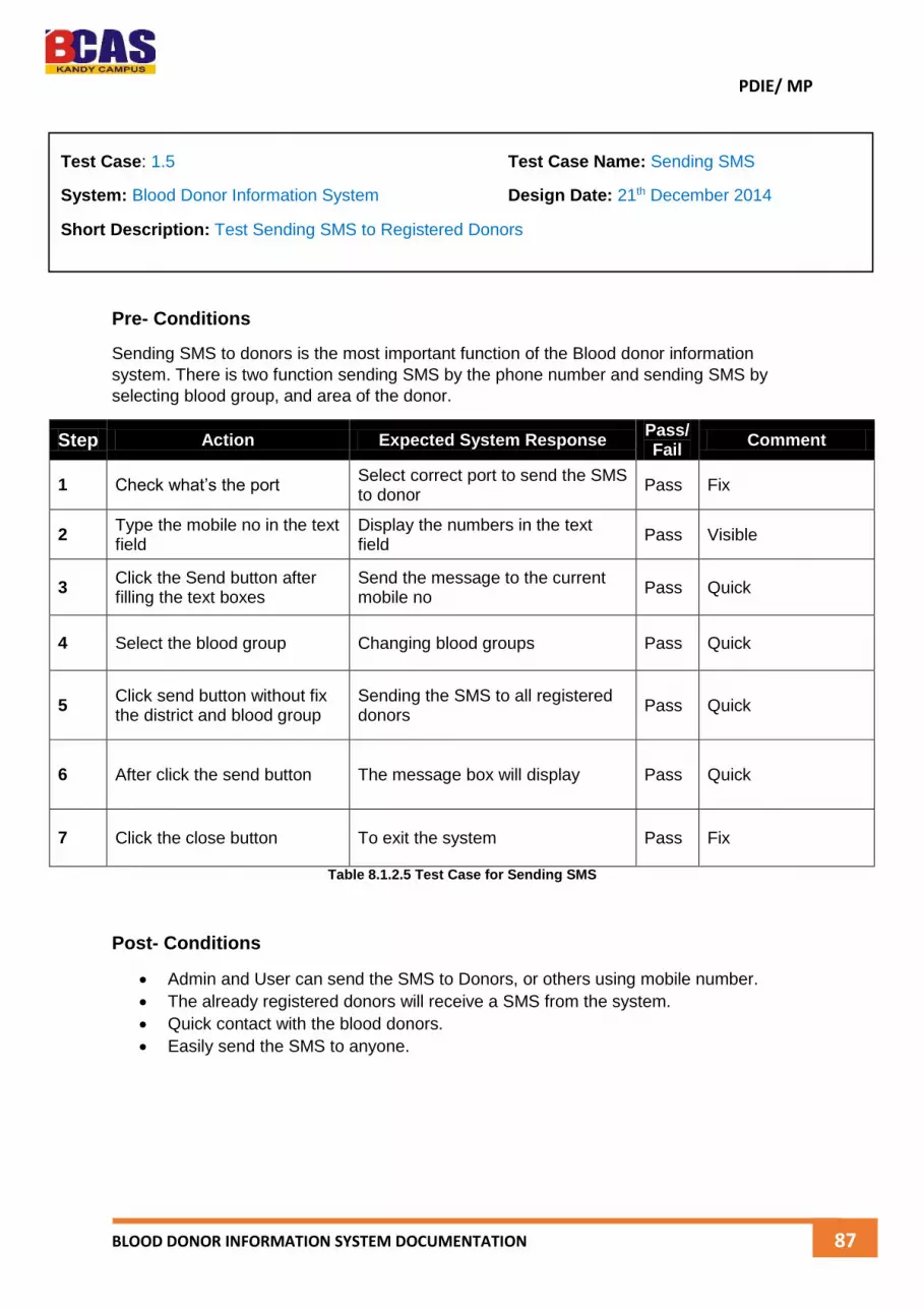
PDIE/ MP
BLOOD DONOR INFORMATION SYSTEM DOCUMENTATION 87
Pre- Conditions
Sending SMS to donors is the most important function of the Blood donor information
system. There is two function sending SMS by the phone number and sending SMS by
selecting blood group, and area of the donor.
Step Action Expected System Response Pass/ Fail
Comment
1 Check what’s the port Select correct port to send the SMS to donor
Pass Fix
2 Type the mobile no in the text field
Display the numbers in the text field
Pass Visible
3 Click the Send button after filling the text boxes
Send the message to the current mobile no
Pass Quick
4 Select the blood group Changing blood groups Pass Quick
5 Click send button without fix the district and blood group
Sending the SMS to all registered donors
Pass Quick
6 After click the send button The message box will display Pass Quick
7 Click the close button To exit the system Pass Fix
Table 8.1.2.5 Test Case for Sending SMS
Post- Conditions
Admin and User can send the SMS to Donors, or others using mobile number.
The already registered donors will receive a SMS from the system.
Quick contact with the blood donors.
Easily send the SMS to anyone.
Test Case: 1.5 Test Case Name: Sending SMS
System: Blood Donor Information System Design Date: 21th December 2014
Short Description: Test Sending SMS to Registered Donors

PDIE/ MP
BLOOD DONOR INFORMATION SYSTEM DOCUMENTATION 88
Pre- Conditions
Report view is one of important for any kind of system. So report will give the brief idea
about all the blood donors’ details at one time. Not only that admin or user can print the
donors list with details.
Step Action Expected System Response Pass/ Fail
Comment
1 Click the donor registered list report
Preview the donor registered list report with details
Pass Too Slow
2 Click the donor contact details report
Preview the donor contact details report with the details
Pass Tool Slow
3 Click the event details report Preview the event details report Pass Too Slow
4 Print those reports selecting the donors list
Printing with the details Pass Good
5 View with suitable arrangement
All the details are in order Pass Good
6 Click the close button To exit the reports Pass Fast
Table 8.1.2.6 Test Case for Report view
Post- Conditions
Reports can view by administrator and users.
Using report they can easily print those details.
Report is given brief idea and clear for the users.
Test Case: 1.6 Test Case Name: Reports View
System: Blood Donor Information System Design Date: 21th December 2014
Short Description: Test All the Reports in the System

PDIE/ MP
BLOOD DONOR INFORMATION SYSTEM DOCUMENTATION 89
Pre- Conditions
Administrator only can create the new administrator and user for the system. To create new
admin or user they must log into one of admin account. Admin can create new account,
update the account, and delete the account.
Step Action Expected System Response Pass/ Fail
Comment
1 Change the admin id Changing user name and password of the current administrator
Pass Good
2 Change the user id Changing user and password of the current user
Pass Good
3 Fill the username and password with proper name and click save
Display successful message in the message box
Pass Very Quick
4 Without filling username and password and click save
Display error message with information
Pass Very Quick
5 Change the username and password of current user and click update
Display updated successfully message with detailed
Pass Good
6 Select the current user and click delete button
Display deleted successfully message with detailed
Pass Good
Table 8.1.2.7 Test Case for Create Admin and User
Post- Conditions
Admin only can use this system.
Easily create new administrator and users to the system.
Update the username and password of current users, or administrators.
Delete unwanted users from the database.
Clear the text field just clicking a button.
Test Case: 1.7 Test Case Name: Create Admin and User
System: Blood Donor Information System Design Date: 22nd December 2014
Short Description: Test Creating Administrator to the System
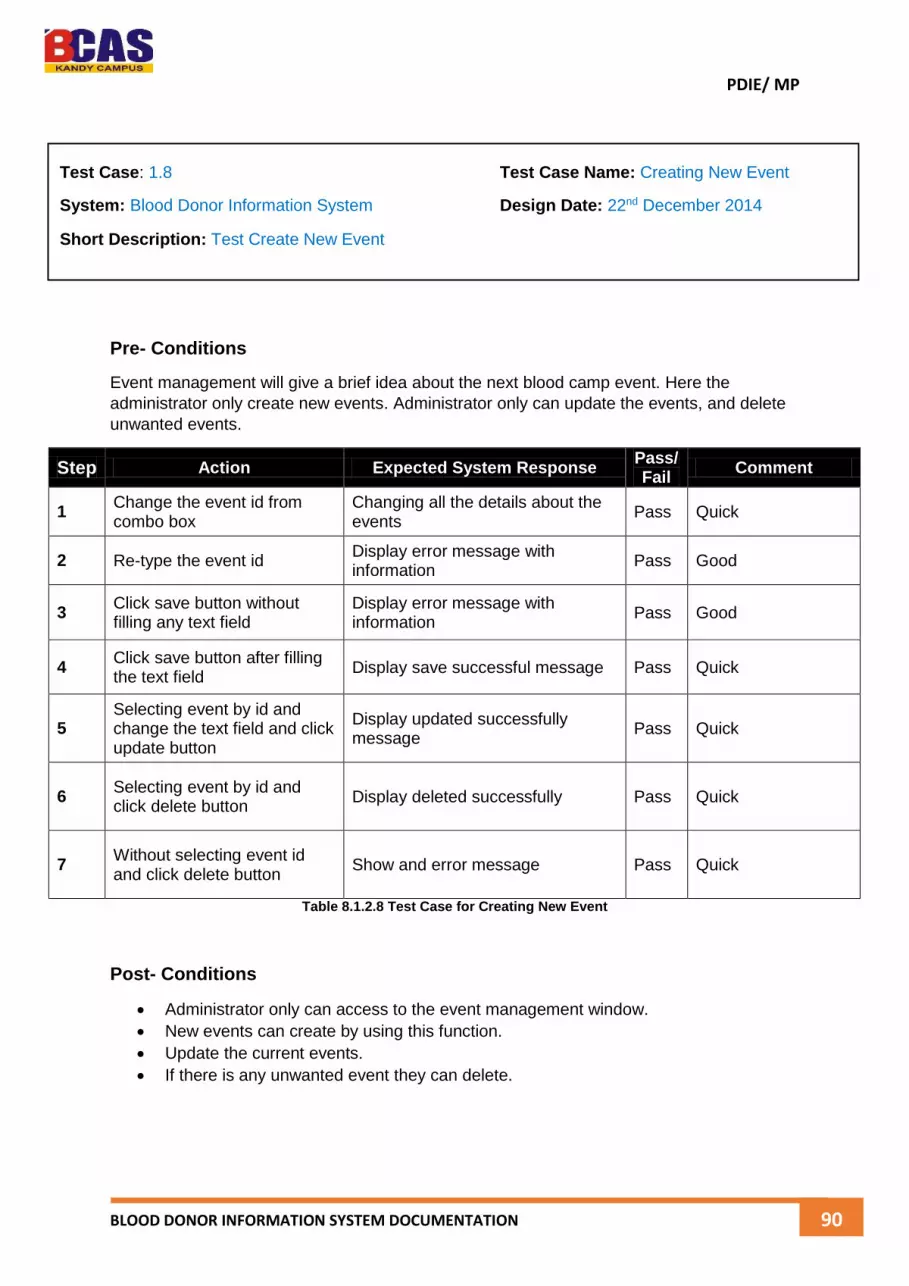
PDIE/ MP
BLOOD DONOR INFORMATION SYSTEM DOCUMENTATION 90
Pre- Conditions
Event management will give a brief idea about the next blood camp event. Here the
administrator only create new events. Administrator only can update the events, and delete
unwanted events.
Step Action Expected System Response Pass/ Fail
Comment
1 Change the event id from combo box
Changing all the details about the events
Pass Quick
2 Re-type the event id Display error message with information
Pass Good
3 Click save button without filling any text field
Display error message with information
Pass Good
4 Click save button after filling the text field
Display save successful message Pass Quick
5 Selecting event by id and change the text field and click update button
Display updated successfully message
Pass Quick
6 Selecting event by id and click delete button
Display deleted successfully Pass Quick
7 Without selecting event id and click delete button
Show and error message Pass Quick
Table 8.1.2.8 Test Case for Creating New Event
Post- Conditions
Administrator only can access to the event management window.
New events can create by using this function.
Update the current events.
If there is any unwanted event they can delete.
Test Case: 1.8 Test Case Name: Creating New Event
System: Blood Donor Information System Design Date: 22nd December 2014
Short Description: Test Create New Event

PDIE/ MP
BLOOD DONOR INFORMATION SYSTEM DOCUMENTATION 91
Pre- Conditions
Search event is most important for any kind of system, because it will be make easy to
identify the details by using id. Here search donors is needed to identify donors immediately.
Step Action Expected System Response Pass/ Fail
Comment
1 Changing the search by combo box and click to next
Display search window Pass Good
2 Select the Search by Display the some search by option in the combo box
Pass Quick
3 Click to Search by id and click next
Display search by id window Pass Quick
4 Click to Search by name and click next
Display search by name window Pass Too Slow
5 Click to Search by address and click next
Display search by address window Pass Quick
6 Click to Search by blood group and click next
Display search by blood group window
Pass Quick
7 Enter value in the search text field
Display search result in the grid view
Pass Quick
Table 8.1.2.9 Test Case for Search Blood Donors
Post- Conditions
Administrator and user can search the blood donors.
There 4 type to search the donors
o Search by Donor ID
o Search by Donor Name
o Search by Donor Address
o Search by Donor Blood Group
Quickly view the search result to grid view.
Test Case: 1.9 Test Case Name: Search Blood Donors
System: Blood Donor Information System Design Date: 23rd December 2014
Short Description: Test Search Blood Donors

PDIE/ MP
BLOOD DONOR INFORMATION SYSTEM DOCUMENTATION 92
8.1.3 Evaluation of Actual and Expected Results
Expected is how the System has to behave after testing the functionality of an application.
Actual is what the System behaved after testing the functionality of an application.
Functionality/result that is expected for the correct functioning of the application. It is usually
mentioned in the requirement specification documents.
Test the Actual Result of the Login of the Users
Test No Test Data Purpose Expected
Result Actual Result
01
Username and password for Admin
User name = admin Password=admin
Check whether the log in the form will allow the program
to run or not
Login will be granted to
Admin Main Form
Login will be granted Admin Main Form
02
Username and password for Admin
User name = admin Password=ADMIN
Check whether the log in the form will allow the program
to run or not
There will be an error message
called “username and
password incorrect”
There will be an error message called “username and
password incorrect”
03
Username and password for User
User name = user Password=user
Check whether the log in the form will allow the program
to run or not
Login will be granted to User
Main Form
Login will be granted User Main Form
04
Username and password for User
User name = user12333
Password=sdkfnd
Check whether the log in the form will allow the program
to run or not
There will be an error message
called “username and
password incorrect”
There will be an error message called “username and
password incorrect”
05
Username and password for Admin
User name = Password =
Check whether the log in the form will allow to run or not
There will be an error message called “fill the
username and password”
There will be an error message called “fill the
username and password”
06
Username and password for User
User name = Password =
Check whether the log in the form will allow to run or not
There will be an error message called “fill the
username and password”
There will be an error message called “fill the
username and password”
Table 8.1.3.1 Test Case for Login

PDIE/ MP
BLOOD DONOR INFORMATION SYSTEM DOCUMENTATION 93
Test the Actual Result of the Donor Registration
I have already created the test case for the donor registration table 8.1.2.2 is showing the
test case with detailed. Here I have evaluate the actual test result of blood donor information
system.
Test No Test Data Purpose Expected
Result Actual Result
01
Click the Save button to Record the details in the
database without filling any fields
Store the details in the database
Popup an error message
Not Saved in the database, there is an
error message
02 Click the Save button to Record the details in the
database with filling fields
Store the details in the database
Need to be store all the details in the
database fields
Successfully Saved in the database
03 Type already registered id
of the donor Avoid the
registration Show an error
message
Successfully save the donor details to the
registered donor details
04 Check the Valid blood
groups in the combo box Easily can select the blood group
Changing with using mouse
scroll Successfully changing
Table 8.1.3.2 Test Case for Donor Registration
Error Correction (Table 8.1.3.2 and Test No 3)
The reason for this error is the primary key, I mean during my database design I forget to fix
the primary key for the donor registration table. After the correction and test result of the
donor registration in the table 8.1.3.2.1
03 Type already registered id
of the donor Avoid the
registration Show an error
message Not Saved, Popup an
error message
Table 8.1.3.2.1 Test Case for Donor Registration – Error Correction

PDIE/ MP
BLOOD DONOR INFORMATION SYSTEM DOCUMENTATION 94
Test the Actual Result of the Donor Maintaining
I have already created the test case for the donor maintaining table 8.1.2.3, and table 8.1.2.4
are showing the test case with detailed. Here I have evaluate the actual test result of blood
donor information system.
Test No Test Data Purpose Expected
Result Actual Result
01 Click update button without
selecting the donor id Update the details of current donor
Give a warning message called “Please select
an id of the donor”
Update successfully
02 Click the update button with selecting the current donor
Update the details of current donor
Give message called “Updated
successfully” Updated successfully
03 Delete the donor by
selecting the donor id Delete the donors
Delete from the database
Deleted successfully
04 Logout process Logout the system
Hide the main window and
display the login window
Without hiding the main window and display login
window
Table 8.1.3.3 Test Case for Donor Maintaining
Error Correction (Table 8.1.3.3 and Test No 1, 4)
These errors are called run time errors, because during the run time only display these kind
of errors. Reasons for these errors while developing the system there are some misuse
codes were written by me. So now I have correct the codes and test the system and the
result of that testing is showing in the table 8.1.3.3.1
01 Click update button without
selecting the donor id Update the details of current donor
Give a warning message called “Please select
an id of the donor”
Update successfully
04 Logout process Logout the system
Hide the main window and
display the login window
Hide the main window and display login
window
Table 8.1.3.3.1 Test Case for Donor Maintaining – Error Correction

PDIE/ MP
BLOOD DONOR INFORMATION SYSTEM DOCUMENTATION 95
Test the Actual Result of Sending SMS
I have already created the test case for the sending SMS to registered donors table 8.1.2.5
is showing the test case with detailed. Here I have evaluate the actual test result of blood
donor information system.
Test No Test Data Purpose Expected
Result Actual Result
01 Change the COM Port Connect with GSM Successfully
connected with the GSM
Show an error message
02 Without selecting any field
and click send button Popup an error
message Display error
message Display send message
successfully
03 Selecting the field and click
send button Sending the SMS
Display Successfully
Send message
Popup the message called “Successfully send the message”
04 Selecting donor by using
city, and blood group
Send to current city or blood group
donor
Send the SMS to donor
Successfully sent
Table 8.1.3.4 Test Case for Sending SMS
Error Correction (Table 8.1.3.4 and Test No 1, 2)
These errors also called runtime errors, because during running the system then only these
kind of errors can be seen in the display. After plugged the dongle we have check the which
port is connected to dongle. Then only we can make select one port number from the system
and send the SMS to registered blood donors.
01 Change the COM Port Connect with GSM Successfully
connected with the GSM
Successfully connected with GSM
network
02 Without selecting any field
and click send button Popup an error
message Display error
message Display error message
Table 8.1.3.4.1 Test Case for Sending SMS – Error Correction
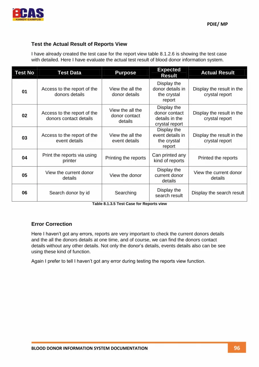
PDIE/ MP
BLOOD DONOR INFORMATION SYSTEM DOCUMENTATION 96
Test the Actual Result of Reports View
I have already created the test case for the report view table 8.1.2.6 is showing the test case
with detailed. Here I have evaluate the actual test result of blood donor information system.
Test No Test Data Purpose Expected
Result Actual Result
01 Access to the report of the
donors details View the all the donor details
Display the donor details in
the crystal report
Display the result in the crystal report
02 Access to the report of the
donors contact details
View the all the donor contact
details
Display the donor contact details in the crystal report
Display the result in the crystal report
03 Access to the report of the
event details View the all the
event details
Display the event details in
the crystal report
Display the result in the crystal report
04 Print the reports via using
printer Printing the reports
Can printed any kind of reports
Printed the reports
05 View the current donor
details View the donor
Display the current donor
details
View the current donor details
06 Search donor by id Searching Display the
search result Display the search result
Table 8.1.3.5 Test Case for Reports view
Error Correction
Here I haven’t got any errors, reports are very important to check the current donors details
and the all the donors details at one time, and of course, we can find the donors contact
details without any other details. Not only the donor’s details, events details also can be see
using these kind of function.
Again I prefer to tell I haven’t got any error during testing the reports view function.

PDIE/ MP
BLOOD DONOR INFORMATION SYSTEM DOCUMENTATION 97
Test the Actual Result of Create Admin & User
I have already created the test case for create new admin & user, table 8.1.2.7 is showing
the test case with detailed. Here I have evaluate the actual test result of blood donor
information system.
Test No Test Data Purpose Expected
Result Actual Result
01 Change the user id and
click update button
Update the username and
password
Update successfully
Display updated successfully
02 Click clear button Clean the text fields Clean the text
fields Nothing happened
03 Click the text box and type
new username and password and click create
Creating new user or admin account
Created successfully
Created successfully
04 Click delete button to delete
current user or admin Delete current user
or admin
Delete the current user or admin from the
database
Nothing happened any changes
05 Change user or admin id and view the user name and password of each
View the username and password of
each user & admin
View each user and admin
Not changing any username and password
Table 8.1.3.6 Test Case for Create Admin & User
Error Correction (Table 8.1.3.6 and Test No 2, 4, 5)
Here test no 2 error is function is missing to called to clear button, test no 4 is runtime error,
during test period only I have analyze that error and fix, and test no 05 these one also make
error during the runtime.
02 Click clear button Clean the text fields Clean the text
fields Cleared the text in the
text field
04 Click delete button to delete
current user or admin Delete current user
or admin
Delete the current user or admin from the
database
Deleted successfully
05 Change user or admin id and view the user name and password of each
View the username and password of
each user & admin
View each user and admin
Changing with user or admin id
Table 8.1.3.6.1 Test Case for Create Admin and User – Error Correction

PDIE/ MP
BLOOD DONOR INFORMATION SYSTEM DOCUMENTATION 98
Test the Actual Result of Creating New Events
I have already created the test case of creating new events table 8.1.2.8 is showing the test
case with detailed. Here I have evaluate the actual test result of blood donor information
system.
Test No Test Data Purpose Expected
Result Actual Result
01 Click the create button
without filling any details Popup error
message Display an error
message Save successfully in the
database
02 Click the create button after
filling details Save the event
details
Display message save successfully
Save in the database with successful message
03 Update the event details
buy using event id Update event
details
Display message updated
successfully
Update event details in the database
04 Click delete button to delete
current event Delete event by using event id
Display message deleted
successfully
Delete the event detail from the database
05 Changing the event id View the event
details by changing event id
View the event details by
changing the event id
Not change according to the event id
Table 8.1.3.7 Test Case for Creating New Events
Error Correction (Table 8.1.3.7 and Test No 1, 5)
These errors also called runtime errors, because during running the system then only these
kind of errors can be seen in the display. Reasons for these errors are the SQL commands.
01 Click the create button
without filling any details Popup error
message Display an error
message Show an error
message
05 Changing the event id View the event
details by changing event id
View the event details by
changing the event id
Can view the event details successfully
Table 8.1.3.7.1 Test Case for Create New Events – Error Correction

PDIE/ MP
BLOOD DONOR INFORMATION SYSTEM DOCUMENTATION 99
Test the Actual Result of Search Blood Donors
I have already created the test case of search blood donors table 8.1.2.9 is showing the test
case with detailed. Here I have evaluate the actual test result of blood donor information
system.
Test No Test Data Purpose Expected
Result Actual Result
01 Select the Search by list Select a one
searching method Select a method
Selected a method
02 Select search by donor id
and click next Select donor id and
search
Display the donor id window
Display the donor id window
03 Select search by donor address and click next
Select donor address and search
Display the donor address
window
Display the donor address window
04 Select search by donor
blood group and click next Select donor blood group and search
Display the donor blood
group window
Display the donor blood group window
05 Select search by donor
name and click next Select donor name
and search
Display the donor name
window
Display the donor name window
06 Type id of the current blood
donor and search Searching current
blood donor Display the
search result Displayed the search
result
07 Click close button Close the window Close the window
Closed the window
Table 8.1.3.8 Test Case for Search Blood Donors

PDIE/ MP
BLOOD DONOR INFORMATION SYSTEM DOCUMENTATION 100
8.2 Project Performance Analysis
8.2.1 Budgeted Cost for Work Schedule (BCWS)
Make deliver the project successfully we have to work with allocated time budget, and the
cost for working on that project. As well as I have developed a standalone application which
is run inside the computer, or any other windows platform. And I have already created a
budget cost for this project.
The budgeted cost of individual tasks as I’m scheduled in the project plan, based on the
costs of the resources that are assigned to those tasks, plus any fixed costs that are
associated with the tasks. This is the budgeted cost of work scheduled (BCWS).
Reason for Cost Description of Cost Cost of Description Total Cost
Travel Cost Cost for the travelling to known about the project and the documentation
Rs. 2, 000 Rs. 2, 000
Internet Data Cost Searching the Details of the System, and Documentation
1 GB = Rs. 200 , 4 GB Rs. 800
Paper Costs Papers for Making the Function of the System, and for other works
1 A4 = Rs. 2 , 100 A4 Rs. 200
Documentation To create the Project Book 1 Book = Rs. 2, 000 , 3 Book Rs. 6, 000
Dongle Dongle for Connect with GSM Network to Send the SMS to Blood Donors
1 Dongle = Rs. 3, 000 Rs. 3, 000
SIM Card To Send the SMS to the Donors SIM Card = Rs. 200 Rs. 200
Activate SMS Activate the SMS Package to Send the SMS to the Donors
1 Month = Rs. 150 Rs. 150
Total Cost for the Project Rs. 12, 350
Table 8.2.1.1 Budgeted Cost for Work Schedule
Project duration: 5 months
Project Cost (Rs.): Rs. 12, 350
Percent complete: 100% (as per the schedule)
Table 8.2.1.1 is showing the cost for work schedule of the blood donor information system.
The total cost is 12, 200 rupees to develop this system successfully. The more cost to print
the documentation, I mean to bind the Project report. And low cost for to buy a SIM Card and
A4 Papers. This my estimation of the cost schedule.

PDIE/ MP
BLOOD DONOR INFORMATION SYSTEM DOCUMENTATION 101
8.2.2 Budgeted Cost for Work Performed (BCWP)
This is cost for so far, I mean I have to complete the project within 5 months. So far 4
months has finished. Now table 8.2.1.2 is showing the cost in the 4 months.
Table 8.2.2.1 Budgeted Cost of Work Performed
8.2.3 Actual Cost of Work Performed (ACWP)
The Actual Cost is the total cost incurred for the actual work completed to date; or simply
put, it is the amount of money you have spent to date. And for this project actual cost of
details,
Reason for Cost
Description of Cost Cost of Description BCWS Total Cost with
4 Months
Travel Cost Cost for the travelling to known about the project and the documentation
Rs. 2, 000 Rs. 2, 000 Rs. 1, 500
Internet Data Cost
Searching the Details of the System, and Documentation
1 GB = Rs. 200 , 4 GB Rs. 800 Rs. 600
Paper Costs Papers for Making the Function of the System, and for other works
1 A4 = Rs. 2 , 100 A4 Rs. 200 Rs. 120
Documentation To create the Project Book 1 Book = Rs. 2, 000 , 3 Book
Rs. 6, 000 Rs. 00.00
Dongle Dongle for Connect with GSM Network to Send the SMS to Blood Donors
1 Dongle = Rs. 3, 000 Rs. 3, 000 Rs. 3, 000
SIM Card To Send the SMS to the Donors SIM Card = Rs. 200 Rs. 200 Rs. 200
Activate SMS Activate the SMS Package to Send the SMS to the Donors
1 Month = Rs. 150 Rs. 150 Rs. 120
Total Cost for the Project Rs. 12, 350 Rs. 5, 540
Actual Project duration: 5 months
Actual Cost (Rs.): Rs. 12, 350
Time elapsed: 4 months
Percent complete: 80% (as per the schedule)
Actual Cost: Rs. 5, 540
Time elapsed: 4 months
Percent complete: 80% (as per the schedule)
Percent complete: 80% (as per the schedule)

PDIE/ MP
BLOOD DONOR INFORMATION SYSTEM DOCUMENTATION 102
8.3 Change Control of Project
To manage a schedule, the project manager must know how the work is progressing
compared to the master schedule and, if necessary, make changes to keep the project on
time. As well as my project also got some changes during the working period.
8.3.1 Change of Schedule
Milestones provide the opportunity for project management to focus on completing activities
that will have the greatest impact on the schedule. On complex projects, focusing on the
milestones is useful for communicating important dates to the entire project team. Project
team members can then adjust their efforts to complete the activities connected to the
milestone events.
Many project leaders believe that time lost on early activities can be made up toward the end
of the project. Hard decisions about paying overtime and working weekends are often
delayed until the end of the project when the pressure to complete the project on time
becomes much stronger. Project managers who focus on milestone events create a sense of
urgency to meet the milestone deadlines and spread the urgency to complete the project
over the life of the project. Projects that meet milestone dates are more likely to meet project
completion dates.
Here I have change and add some extra days to complete my project.
Task Name Duration Changed Duration
1. Planning 6 Days 7 Days
1.1. Conceptual Planning 4 Days 5 Days
2. System Design 13 Days 16 Days
2.1. Design Review 2 Days 5 Days
3. Coding 11 Days 15 Days
4. Testing 17 Days 19 Days
4.1. Programme Test 6 Days 7 Days
4.2. System Test 5 Days 6 Days
5. Maintenance 9 Days 11 Days
5.1. Bug Fixing 3 Days 5 Days
6. Final Documentation 16 Days 18 days
Table 8.3.1.1 Change of Schedule
As I told, I have changed some schedule of the project and add some more extra days. Then
within these days I have finalized my project as much possible.

PDIE/ MP
BLOOD DONOR INFORMATION SYSTEM DOCUMENTATION 103
8.3.2 Change of Resource
The schedule of activities is constrained by the availability of resources. If we apply those
thing to our software project development, then it will be given a better process.
Skill Sets Needed From the Resources
Use different skill sets for human resources required for software development projects,
such as,
Programmers – to develop the software programs needed for the project – experts in
the chosen programming language.
Graphic Designers – to design the graphics and the web pages / front-end required
for the project.
Database Administrator – to design the database and assist the programmers in
optimizing data retrieval queries so that the response time is shorter.
System Architects – to develop the software architecture for the project.
System Integrators – to integrate various components of the project and ensure that
the end product is built conforming to the specifications.
Functional Experts – who are experts in the application domain of the project?
These are some important resources in the software development,
Time
Human Resources – the most crucial of all the resources
Computer Resources
Money
If we take the time period of the software development is not enough to complete
successfully, because of that I have adjusted the date in the work break down structure. Now
I feel very exiting with this project.
And the computer resources even change according to the situation as well as early I
haven’t plan to fix a function called sending SMS, after few days I got to know that function
and change the time period of this software project and some resources.
As we know to send SMS mean, definitely we need to connect with the GSM Network then
only we can connect with others. To connect that I bought a one dongle with spent 3,000
rupees, so know my budget even change in that category. So really know any kind project
can be make any kind changes.

PDIE/ MP
BLOOD DONOR INFORMATION SYSTEM DOCUMENTATION 104
8.4 Suggestion, Recommendation and Areas need to be improved
In future we need advanced technology systems, so we must need some changes in the
system development life cycle and other process.
A process can be as big and broad as the entire software development process, or as small
and as focused as a process for design inspections. Regardless of its size, every process is
an opportunity for improvement. Software process improvement can be any action taken to
make a software process better than that which exists.
Software Process Improvement
Understanding existing processes.
Introducing process changes to achieve organizational objectives which are usually
focused on quality improvement, cost reduction and schedule acceleration.
Most process improvement work so far has focused on defect reduction. This reflects
the increasing attention paid by industry to quality.
However, other process attributes can be the focus of improvement.
Why Need of Software Process Improvements
We want to build better software projects (cheaper, more dependable, quicker, …)
We really don’t know how to measure the software projects characteristics.
There, measure the process under the assumption – a better process will produce a
better software projects.
Principal Product Quality Factors
Figure 8.4.1 Principal of Software Projects Quality Factors
Figure Source - http://nas.uhcl.edu/helm/swen5231/Process/sld008.htm

PDIE/ MP
BLOOD DONOR INFORMATION SYSTEM DOCUMENTATION 105
For large software projects with ‘average’ capabilities, the development process
determines project quality.
For small software projects, the capabilities of the developers is the main
determinant.
The development technology is particularly significant for small software projects.
In all cases, if an unrealistic schedule is imposed then software quality will suffer.
The Module Testing Activity
Figure 8.4.2 Module Testing Activity
Figure Source - http://www.slideshare.net/waruimaina/9process-improvement-chapter-9
Module testing is the testing of complete code objects as produced by the compiler when
built from source.
A library may be composed of a single compiled object or several compiled objects. There is
only a slight difference between unit testing and module testing. Modules are fully formed
chunks of coherent source code that can typically be tested by driving a few function
signatures with various stimuli. On the other hand, unit testing (which is considered as part
of the implementation phase for this software development process) may involve testing one
small part of a function that will never formally implement any function interface.

PDIE/ MP
BLOOD DONOR INFORMATION SYSTEM DOCUMENTATION 106
Suggestion for Improvement of Blood Donor Information System
Object Oriented Programming Language
Need to reuse more than just code, need to reuse all kinds of experience. Because all the
time we cannot crate functions for the list of classes. So it’s very easy to call that method in
the suitable place. I have used few object oriented methods in the blood donor information
system.
In future I have plan to separate those methods into one and make it simple and object
oriented way.
Creating Nice Interface GUI
Here already I have created nice interface, even in future I can give more attraction interface
to the blood donor information. Because interface is give the easy way to manage or control
the system for the users. If it’s attractive interface the user can get more benefits.
Any we need to maintain the professional standard on the interface, because some interface
look like a kinder garden. So we to make it the interface in the professional way.
Separate the Classes in to Packages
Separate the classes in to packages mean normally that is the object oriented, because it is
give more use for set of codes, I mean easily use the methods and easily find the classes in
the packages.
In future I can create the classes in the different packages of it.
Centralization Database
Make the database into centralization by using a database server. Because if all the data of
the donors are in a one database mean that’s very useful to contact or communicate the
donors easily and quickly.
So we can make the database of blood donor information system into the centralization
database server. So it’s safe because in a one place of all the data. Easily can make security
purpose for the database server.
Use of New Tools
Use of .NET framework easily use much tools in the GUI. Then system will look more useful
getting the tools. Using menu strip option for access to the windows in the system. As well
as their many tools we use as well.

PDIE/ MP
BLOOD DONOR INFORMATION SYSTEM DOCUMENTATION 107
Support and Maintenance
9.1 Reason for Termination of Project
It is a fact that most project management professionals are not aware that project
termination procedures are critically important for successful as well as failed or prematurely
abandoned projects.
But my project not got termination, but here some fact why the projects are getting
termination before closing date.
Every project has to officially end sometime. Project termination need not necessarily mean
project failure or premature abandonment. A project may be terminated for a variety of
reasons, including successful completion of the endeavor. We'll take a closer look at what
some of these reasons are and how to know when to terminate a project.
Reasons for Project Termination
Here are a few reasons why a project gets terminated before the natural closing date.
Project is completed ahead of schedule and handed over to the sponsors/users.
Premature abandonment due to technical grounds that impede achievement of core
goals.
It is suddenly found that another group publishes results in same core area of
interest.
The principal investigator or an equitant person suddenly quits and the project cannot
continue as planned and the project has to terminated, as putting on hold will be
counter-productive.
Unanticipated loss of human, funding and other valuable resources.
A variety of insurmountable problems may force termination of the project.
An interim review suggests the project will not help achieve the desired objectives.
Person Responsible for Termination Decision
It is the principal investigator (PI) who is entrusted with the task of conducting periodic
reviews of the project and is responsible for closely monitoring the project progress
throughout the project life cycle. Thus, the exact closing date for a project has to be decided
by the principal investigator after consulting the co-principal investigators and subprogram
leader.
The principal investigator will be aware that for all projects, final technical and financial
reports will have to be prepared and presented. It is therefore only to be expected that the
principal investigator will work closely with the subprogram leader to handle necessary
project termination work. It is believed that under certain extraordinary circumstances, the
subprogram leader may seek a time extension for completing the project, provided no
additional funds are demanded.

PDIE/ MP
BLOOD DONOR INFORMATION SYSTEM DOCUMENTATION 108
9.2 Client Certification
Research and Development Centre BCAS Kandy Campus
CLIENT ACCEPTANCE CERTIFICATE Purpose: This form is completed at the end of the Project where the client is handing
over a deliverable to the Company. The form verifies what deliverables are being turned
over to the Company and that the client has accepted / approved those deliverables.
Project Name Blood Donor Information System
Project Number << >>
Project Sponsor Individual
Leaner Details M.N. Azeem Mohamed [email protected]
+96 75 200 4415
(name) (email) (phone number)
Project Description This project is about Blood Donor Information System. Purpose
of this system registering the blood donors, and critical situation
easily can communicate with registered blood donors via SMS.
SDLC Stage Chapter 1: Introduction Chapter 2: Literature review Chapter 3: Analysis Chapter 4: Design Chapter 5: Method and methodology Chapter 6: Results and Discussion Chapter 7: Testing and evaluation Chapter 8: Support and maintenance Chapter 9: Summary and conclusion
Important Notes for Completing this Document
Each section of the Client Acceptance Certificate must be completed in full. If a particular
section is not applicable to this project, then you must write Not Applicable and provide a
reason.
Important Note: No sections are to be deleted from this document. Text contained within
<< >> provides information on how to complete that section and can be deleted once the
section has been completed.
This template is owned and maintained by the BCAS Kandy campus.

PDIE/ MP
BLOOD DONOR INFORMATION SYSTEM DOCUMENTATION 109
LIST OF CLIENT DELIVERABLES COMPLETED
Deliverables A working and completed system is for the hospitals or the
blood camps.
Acceptance Response Accepted
Not Accepted until below issues are addressed
Accepted provided below issues are addressed
Issues Normally I haven’t got any issues. But I have spent lots time to
develop this system.
Additional Comments I have completed as my knowledge. In future this system is very
useful for the hospitals to contact the blood donors immediately.
PREPARED BY
Project Manager(Client)
(name) (signature) (date)
APPROVALS
Sponsor
(name) (signature) (date)
Project
Supervisor(Academic)
(name) (signature) (date)

PDIE/ MP
BLOOD DONOR INFORMATION SYSTEM DOCUMENTATION 110
9.3 Close-Out Report
A. General Information
Project Title:
Blood Donor Information System
Project category :
Softwares & Databases
Leaner:
M.N. Azeem Mohamed
Supervisor:
Mr. Munshif Cassim
Prepared by:
M.N. Azeem Mohamed
Date/ Project Number:
B. Project Deliverables
List all Project Deliverables and the date each was accepted by the user. Identify any contingencies
or conditions related to the acceptance.
Deliverable Date Accepted Contingencies or Conditions
A Useful System Called Blood Donor Information System (Donor Registration and Maintaining)
Null
Project documentation and user manual
Null
C. Performance Baseline
The above stated project business objectives and servicers alongside the performance goal and their respective results were all achieved. A look on the below cost base line would allow to see how the project had been successful and hence cost effective as well.
PROJECT BUSINESS
OBJECTIVE Performance Goal Results
Contact the Donors Contact the Donor via SMS Objective achieved
Fast execution Programs runs at expected
time
Objective achieved
Pubic Servicers Saving Lives by using
System Objective achieved
Cost effective A worthy product with best
use Objectives achieved

PDIE/ MP
BLOOD DONOR INFORMATION SYSTEM DOCUMENTATION 111
D. Cost (Budget) Baseline
State the Planned Cost and Funding for the project, as approved in the Initial Cost Baseline and the
Project Charter. State the Actual Cost and Funding at completion. Document and explain all cost
and funding variances, including approved changes to the cost baseline.
Expenditures (Rs.000)
Planned Actual Variance Explanation
Internal Staff Labor - - - No internal staff
Services Rs. 3000 Rs. 3250 +250 Electricity + transportation
Software Tools - - - Not Specify
Hardware Rs. 3000 Rs. 3000 0 Dongle
Materials and
Supplies - - - No special materials
Facilities Rs. 6500 Rs. 7000 +500 Internet and printing
Telecommunications Rs. 150 Rs. 250 +100 Phone calls
Training - - - No special training observed
Contingency (Risk) - - - No special risks incurred
Total Rs. 12, 650/- Rs. 13, 500/- Rs. 850/-
Funding Source (Rs.000)
Planned Actual Variance Explanation
General Fund Rs. 5000 Rs. 4000 -1000 Cash at bank
Non-General Fund - - - -
Federal - - - -
Other Rs. 5000 Rs. 5000 Rs. 000 Cash from parents
Total Rs. 10, 000 Rs. 9, 000 0 -

PDIE/ MP
BLOOD DONOR INFORMATION SYSTEM DOCUMENTATION 112
E. Schedule Baseline
Compare the initial approved schedule baseline against the actual completion dates. Enter the
planned start and finish dates from the initial schedule baseline. Document all actual start, finish
dates, and explain any schedule variances, including approved changes to the schedule baseline
WBS Elements Activity or Task
Planned Start Date
Actual Start Date
Planned Finish Date
Actual Finish Date
1.1 Planning 20 / 09 / 2014 22 / 09 / 2014 23 / 09 / 2014 24 / 09 / 2014
1.1.1 Conceptual Planning 23 / 09 / 2014 23 / 09 / 2014 26 / 09 / 2014 27 / 09 / 2014
1.2 System Analysis 27 / 09 / 2014 27 / 09 / 2014 07 / 10 / 2014 07 / 10 / 2014
1.2.1 Functional Requirements 29 / 09 / 2014 29 / 09 / 2014 30 / 09 / 2014 30 / 09 / 2014
1.2.2 Technical Requirements 01 / 10 / 2014 02 / 10 / 2014 02 / 10 / 2014 05 / 10 / 2014
1.2.3 Requirements Specification Review 03 / 10 / 2014 03 / 10 / 2014 06 / 10 / 2014 06 / 10 / 2014
1.3 System Design 04 / 10 / 2014 05 / 10 / 2014 21 / 10 /2014 22 / 10 /2014
1.3.1 Internal / External 07 / 10 / 2014 07 / 10 / 2014 08 / 10 2014 09 / 10 2014
1.3.2 Design Review 09 / 10 / 2014 09 / 10 / 2014 10 / 10 / 2014 10 / 10 / 2014
1.3.3 Detailed Project Development 13 / 10 / 2014 14 / 10 / 2014 21 / 10 / 2014 23 / 10 / 2014
1.4 Coding 20 / 10 / 2014 20 / 10 / 2014 01 / 11 / 2014 06 / 11 / 2014
1.4.1 Codes Review 22 / 10 / 2014 22 / 10 / 2014 01 / 11 / 2014 05 / 11 / 2014
1.5 Testing 02 / 11 / 2014 03 / 11 / 2014 24 / 11 / 2014 24 / 11 / 2014
1.5.1 Programme Test 24 / 10 / 2014 24 / 10 / 2014 31 / 10 / 2014 31 / 10 / 2014
1.5.2 System Test 03 / 11 / 2014 03 / 11 / 2014 07 / 11 / 2014 08 / 11 / 2014
1.5.3 Bug Reports 10 / 11 / 2014 12 / 11 / 2014 13 / 11 / 2014 14 / 11 / 2014
1.5.4 Test Summery 14 / 11 / 2014 14 / 11 / 2014 18 / 11 / 2014 18 / 11 / 2014
1.6 Implementation 25 / 11 / 2014 27 / 11 / 2014 09 / 12 / 2014 09 / 12 / 2014
1.6.1 User Documentation 19 / 11 / 2014 19 / 11 / 2014 20 / 11 / 2014 20 / 11 / 2014
1.6.2 System Documentation 21 / 11 / 2014 22 / 11 / 2014 25 / 11 / 2014 26 / 11 / 2014
1.7 Maintenance 10 / 12 / 2014 10 / 12 / 2014 22 / 12 / 2014 22 / 12 / 2014
1.7.1 Review the System 26 / 11 / 2014 27 / 11 / 2014 27 / 11 / 2014 27 / 11 / 2014
1.7.2 Maintaining the System 28 / 11 / 2014 28 / 11 / 2014 01 / 12 / 2014 02 / 12 / 2014
1.7.3 Bug Fixing 02 / 12 / 2014 02 / 12 / 2014 04 / 12 / 2014 04 / 12 / 2014
1.7.4 Upgrade the System 05 / 12 / 2014 06 / 12 / 2014 08 / 12 / 2014 09 / 12 / 2014
1.8 Final Documentation 09 / 12 / 2014 02 / 01 / 2015 10 / 01 / 2015 05/ 02 / 2015

PDIE/ MP
BLOOD DONOR INFORMATION SYSTEM DOCUMENTATION 113
F. Scope
Document any changes to the Project Scope and their impact on Performance, Cost, or Schedule
Baselines.
Scope Change Impact of Scope Change
G. Operations and Maintenance
Describe the plan for operation and maintenance of the product, well, or service delivered by the
project. State the projected annual cost to operate and maintain the product, good, or service.
Identify where and why this projection of cost differs (if it differs) from the Project Proposal. If the
operation and maintenance plan is not in place, what is the target date for the plan and what is the
impact of not having operations and maintenance for the product, well, or services in place.
1. Operations and Maintenance Plan
This project has to be handled with proper care. The system codes very longer than others,
and the user have computer based knowledge to operate the system.
Failing to that, the following problem is likely to occur:
**The entire program may not execute successfully
**And hence the expected output may not be seen
Therefore it’s very important that this program is maintained by a learned person. If for e.g. the
client wills to increase the capturing frame number or even wishes to change the saving directory a
backup of the original program must be taken first before any changes shall be considered to take
effect.
Need to back up the data twice a month.
However a review on the entire program must be made in every two weeks basis.
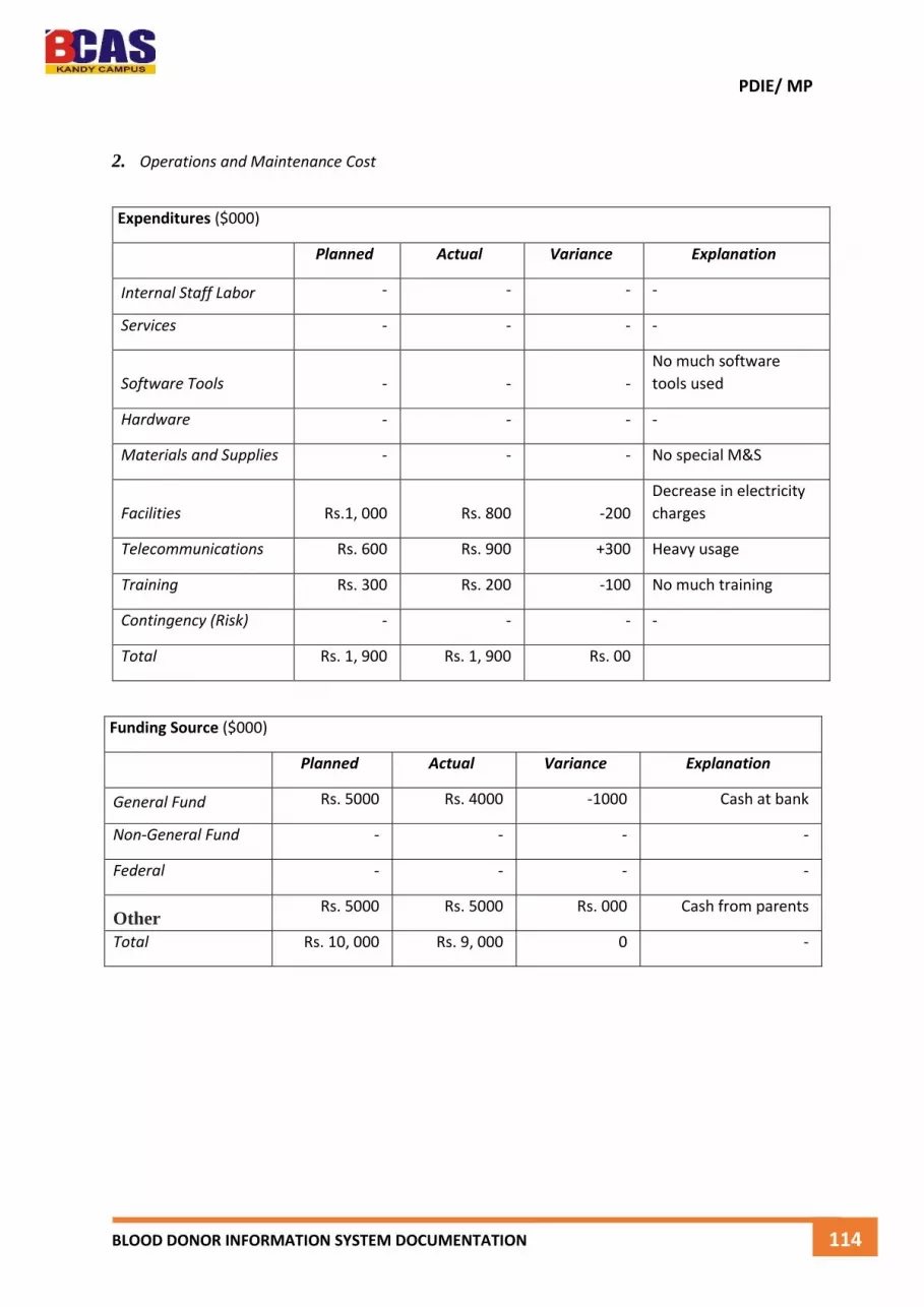
PDIE/ MP
BLOOD DONOR INFORMATION SYSTEM DOCUMENTATION 114
2. Operations and Maintenance Cost
Expenditures ($000)
Planned Actual Variance Explanation
Internal Staff Labor - - - -
Services - - - -
Software Tools - - -
No much software
tools used
Hardware - - - -
Materials and Supplies - - - No special M&S
Facilities Rs.1, 000 Rs. 800 -200
Decrease in electricity
charges
Telecommunications Rs. 600 Rs. 900 +300 Heavy usage
Training Rs. 300 Rs. 200 -100 No much training
Contingency (Risk) - - - -
Total Rs. 1, 900 Rs. 1, 900 Rs. 00
Funding Source ($000)
Planned Actual Variance Explanation
General Fund Rs. 5000 Rs. 4000 -1000 Cash at bank
Non-General Fund - - - -
Federal - - - -
Other Rs. 5000 Rs. 5000 Rs. 000 Cash from parents
Total Rs. 10, 000 Rs. 9, 000 0 -

PDIE/ MP
BLOOD DONOR INFORMATION SYSTEM DOCUMENTATION 115
H. Project Resources
List the Resources specified in the Resource Plan and used by the project. Identify to whom each resource was transferred and when it was transferred. Account for all project resources utilized by the project.
Resource (Describe or name the resource used)
Person or Organization Who Received Resource
Turnover Date
Project Team
Mr. Munshif Help to develop 11th November 2014
Mr. Nuzrath Giving a plan 15th August 2014
Customer Support
Facilities
Equipment
Dongle (Modem) Parents 12th June 2014
Software Tools
Visual Studio 2010 BCAS Kandy Campus 14th July 2014
Crystal Report BCAS Kandy Campus 14th July 2014
SQL Server 2008 BCAS Kandy Campus 14th July 2014
Other

PDIE/ MP
BLOOD DONOR INFORMATION SYSTEM DOCUMENTATION 116
I. Project Documentation
Identify all project documentation materials stored in the project library or other repository. Identify the
type of media used and the disposition of the project documentation (see Communications Plan).
J. Lessons Learned
Identify Lessons Learned for feedback to the Commonwealth Project Management process. Lessons Learned should be stated in terms of Problems (or issues) and Corrective Actions taken. Provide a brief discussion of the problem that identifies its nature, source, and impact. Site any references that provide additional detail. References may include project reports, plans, issue logs, change management documents, and general literature or guidance used that comes from another source.
Statement of Problem Discussion References Corrective Actions
Report(s) and Document(s) Media Used
Storage
Location Disposition
Feasibility Studies Report Doc, PDF DVD Feasibility Study of System
Specification Report Doc, PDF DVD Functional and Non-Functional
User Interfaces Report Doc, PDF, MP4 DVD Images of Interfaces
System Diagram Report Doc, PDF DVD Sample Diagrams
SDLC Report Doc, PDF DVD Introduction to SDLC
System Testing Report Doc, PDF DVD Testing Methods, Actual Test
User Manual Documentation Doc, PDF DVD User Manual

PDIE/ MP
BLOOD DONOR INFORMATION SYSTEM DOCUMENTATION 117
K. Dates for Post Implementation Review and Report
Identify the date for completing the post implementation report and the person responsible for this
action.
Action Date Responsible Person
Post - Implementation Review
Post - Implementation Report
L. Approvals
Position/Title Signature/Printed Name/Title Date
Project Supervisor
Project Sponsor
Project coordinator

PDIE/ MP
BLOOD DONOR INFORMATION SYSTEM DOCUMENTATION 118
9.4 User Manual
Blood Donor Information system is a standalone application which is allowed to register the
blood donors, maintain the donors, and contact the donors quickly via sending SMS. Here I
will describe how we can use those function with screen capture of the system.
How to run the application
Make sure first of all we have to install this application on the computer or the Leptop. Then
figure 9.4.1 is showing how to run the application, just double click the icon in the desktop
and run the application.
Figure 9.4.1 Run the Blood Donor Information System
After double click the icon, then there is one splash screen will pop up in the display, and
after 3 to 6 second the progress will be load, then the logging window will display in the
computer or leptop monitor.
Double click and open the
Blood Donor Information
System after the installation.

PDIE/ MP
BLOOD DONOR INFORMATION SYSTEM DOCUMENTATION 119
How to logging to the system
After the progress the login window will be display in the monitor. Login function is give
security for any kind system. As well as blood donor information system also have these kind
function. If the user name and password is wrong error message will pop up on the display
figure 9.4.2 is showing.
Figure 9.4.2 Incorrect Username or Password
If the password is not matching with the username, then this kind of error message will be
display. If the administrator given correct username and password in the correct text fields in
the login window figure 9.4.3 is showing,
Figure 9.4.3 Correct Username or Password
After fill all the text fields with the correct username and password, then the user need to
click the login button to access or display the main admin window.

PDIE/ MP
BLOOD DONOR INFORMATION SYSTEM DOCUMENTATION 120
How to register the blood donors
Blood donor registration is the main function of the blood donor information system because
without registering any of person, we cannot continue the system to make changes. To
make the register of each donors, we must know how fill the text fields as below shown
figure 9.4.4.
Figure 9.4.4 Donor Registration Window
If we miss some important text fields then it won’t save in the database. So we should know
what thing need to be complete are.
Donor ID – Donor id must be type in that field, it is a unique, can’t be repeated same
numbers.
Name – Name also need to be fill then only system allow to record the data.
Blood Group – We cannot leave this stage, because this is one of important for the
system.
After complete those fields then the data or blood donor details recorded in the database.
And display a message box figure 9.4.5 is shown.
Figure 9.4.5 Message Box of Donor Registration

PDIE/ MP
BLOOD DONOR INFORMATION SYSTEM DOCUMENTATION 121
How to delete a blood donor
Delete function is come under the maintaining donor details in the blood donor information
system. To delete a one donor make sure we have to select that particular donor by using
donor id figure 9.4.6 showing,
Figure 9.4.6 Selecting the Donor ID
Select a current donor by using donor id, and if that donor is not important or no need for the
future works then just click the delete button to delete that donor with details completely.
Figure 9.4.7 Delete the Current Blood Donor
After delete the current donor form the list then there is one confirmation message will be
display in the screen figure 9.4.8 is showing.
Figure 9.4.8 Confirmation Message for Deleted

PDIE/ MP
BLOOD DONOR INFORMATION SYSTEM DOCUMENTATION 122
How to update the details of a blood donor
Update or edit is normally making some changes to the details. As well blood donor
information system have these kind function to edit the blood donor details. Just click the edit
button figure 9.4.9 is showing without selecting any donor by using donor id.
Figure 9.4.9 Edit or Update Blood Donor Details
After clicking the edit button there is window called edit the donors will be display figure
9.4.10 showing.
Figure 9.4.10 Edit the Blood Donor Details
Just select the donors via using donor id. So then we can make any kind of changes about
the selected donors in the list box. Sometimes the donor might be change their mobile
numbers and other email addresses according to their situation. So we should need
connection with the donors to contact them in a critical or emergency situation.
The Administrator can select one donor and make the changes according to that donors
prefer.

PDIE/ MP
BLOOD DONOR INFORMATION SYSTEM DOCUMENTATION 123
How to create new event
Event management is giving an idea about the blood camps, I mean when the next blood
donation will be, and where it is. So those we can add to the system, this function is only
allow to the administrator to create new events.
Figure 9.4.11 Create New Events
First of all we should fill those empty text boxes like figure 9.4.11. Then press the save to
create new events. After few second new event has been created in the database figure
9.4.12 is showing that function in clearly.
Figure 9.4.12 Table view of the events
Here it’s showing the events details in clearly. Even we can search the events by using
events id. So you can just type the wanted event by using event id in the search field.

PDIE/ MP
BLOOD DONOR INFORMATION SYSTEM DOCUMENTATION 124
How to maintain the event
Maintain mean normally managed by the system administrator. Blood donor information
system even got the save privileges. The administrator can edit or delete the events
according to their preference. Here figure 9.4.13 showing how to edit an event. I.e. already
the place got “BMICH” after selecting that particular event and change that place into
“Sugarathasa Stadium”.
Figure 9.4.13 Edit the Event
To delete the old or unwanted event just click the delete button with selected events id. Then
there is one message will display in the window about to confirm the delete via using two
button “Yes”, and “No”. If we want delete that event press “Yes”, to keep that even as well it
is press “No”.
Figure 9.4.14 Delete the Event
There is one button called clear, this is for to clean the text fields, and make it empty. In the
figure 9.4.13 showing that button clearly.

PDIE/ MP
BLOOD DONOR INFORMATION SYSTEM DOCUMENTATION 125
How to send SMS to blood donors
SMS is main function of this system, because this is the fastest way to communicate with
blood donors in the critical situation. To run this function, make sure we need a GSM Modem
or Dongle to connect with the GSM Network. Then only we can use that system.
Figure 9.4.15 is showing that interface of the Sending SMS to the Donors. Here there three
different details can be manually fix and we can send a SMS to the Donors. Such as we
select the donors via district, blood group, and the duration of period.
Example,
- Only selected a district and send the SMS, it won’t look any blood group, and
duration. All registered donors can receive a SMS who are in the particular
district.
- Selecting the one of district, blood group, and duration. Then the system check all
the details in the database. And process that particular command and send the
SMS to the registered donors.
Figure 9.4.15 SMS to the Donors
There is a one default message in that particular message field, so if we want right
something new just click the clear button to clean that message box and whatever we want
we can type the message and clicking the send to send to the donors. Make sure the
confirmation message.
Figure 9.4.16 Confirmation of Sending SMS

PDIE/ MP
BLOOD DONOR INFORMATION SYSTEM DOCUMENTATION 126
How to search blood donor
The administrator and user can search the particular registered donors from the list. Its easy
way to search that particular donor with their details. There are five different search option
have with this system such as using,
- Donor ID
- Donor Name
- Donor Address
- Donor City Selecting the Search Option
- Donor Blood Group
Figure 9.4.17 Search Donors by Name
Using the selecting search option and easily do a search with different search option and
figure 9.4.18 is showing that window.
Figure 9.4.18 Searching Options
Selecting the Search Option
Select one search option and click next button then particular search window will be display
in the monitor as figure 9.4.19 showing.
Figure 9.4.19 Search by City
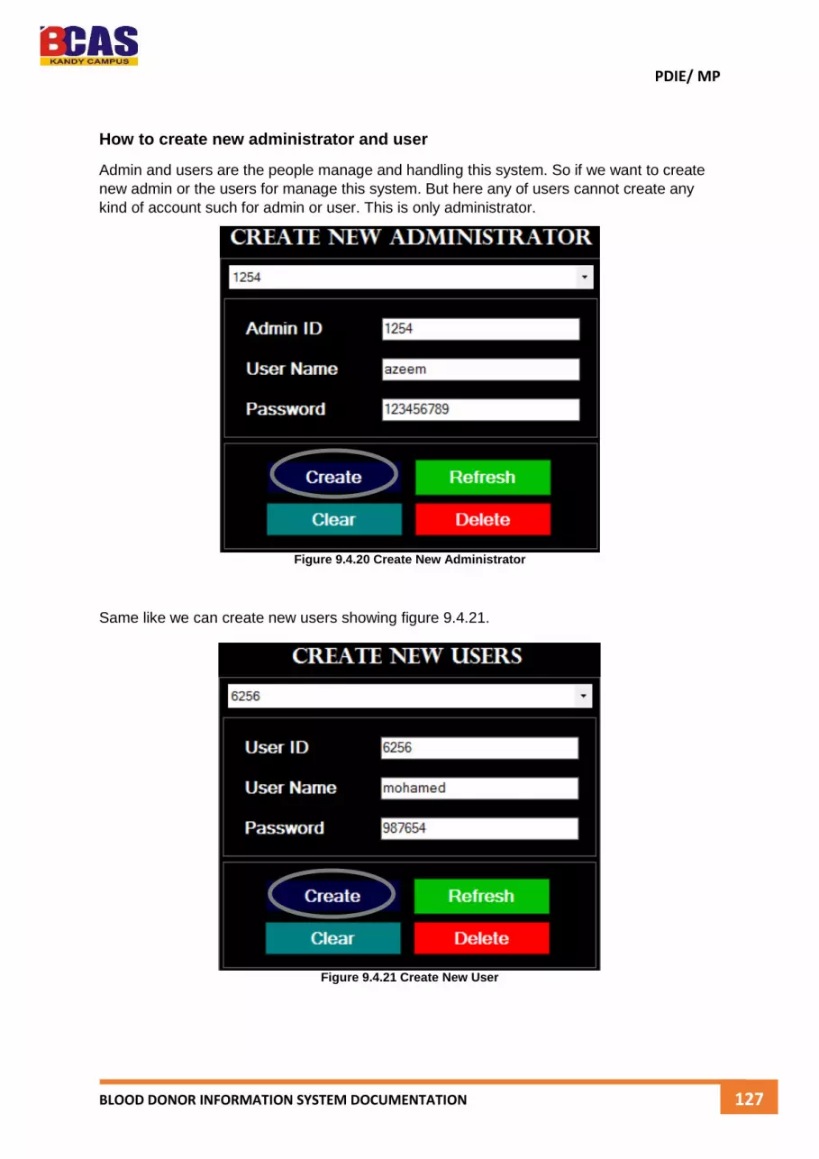
PDIE/ MP
BLOOD DONOR INFORMATION SYSTEM DOCUMENTATION 127
How to create new administrator and user
Admin and users are the people manage and handling this system. So if we want to create
new admin or the users for manage this system. But here any of users cannot create any
kind of account such for admin or user. This is only administrator.
Figure 9.4.20 Create New Administrator
Same like we can create new users showing figure 9.4.21.
Figure 9.4.21 Create New User

PDIE/ MP
BLOOD DONOR INFORMATION SYSTEM DOCUMENTATION 128
How to maintain the administrator and user
Maintaining the admin and user mean making some changes in their particular account I
mean remove that account from the system storage. Now we will see how delete the details
of current account.
Figure 9.4.22 Delete the Current User
Make sure first of all we should select the particular user by using the ID. Then just click the
delete button to delete that particular account from the list figure 9.4.22. Confirmation of the
deleted will be display figure 9.4.23.
Figure 9.4.23 Delete Confirmation of the Users
Likewise we can delete the administrator account and user account clicking just one button,
but this function is only allow for administrator to make changes. Any other account cannot
access to this maintain function without authorized permission.

PDIE/ MP
BLOOD DONOR INFORMATION SYSTEM DOCUMENTATION 129
How to view the reports
Report is normally view the details of the particular details. The blood donor information
system have got some important reports, such figure 9.4.24 showing.
Figure 9.4.24 Window of Reports
There are three types of reports can view with details. If we Donor registered list. After few
second it will be display figure 9.4.25 is showing that particular report.
Figure 9.4.25 Detailed Report View of Blood Donors
And easily view the report and make good understanding of the details of each and each
donors.

PDIE/ MP
BLOOD DONOR INFORMATION SYSTEM DOCUMENTATION 130
How to print the reports
Printing can done by using printer. The admin or the user can view the report and print each
details of donor in hard paper.
Figure 9.4.26 Click the Print in the Report
After click the print button the print properties window will be display figure 9.4.27 is showing
that properties of printing.
Figure 9.4.27 Print Properties Window
Here just select the printer and setup the pages then click the print button to print the details
of the current details of donors.

PDIE/ MP
BLOOD DONOR INFORMATION SYSTEM DOCUMENTATION 131
Summary and Conclusion
In this project I have learned how to manage the software projects and developing software
projects. Normally any management system have a value for that. So in my project even
there is a value to save the lives. Because using this system any authorized person can
easily contact the blood donors those who were already registered.
Here there some more advanced functions with this blood donor information system.
1. Blood donor registration is normally happening in the system. But here cannot
duplicate the id of blood donor.
2. Administrators only can maintain the blood donor’s details.
3. Search the donors easily.
4. Sending SMS to the registered donors in the critical or emergency situation.
5. Creating new events and maintain the events.
And this project documentation cover,
1. User Manual Documentation
2. System Testing Report
3. Software Development Life Cycle Stages
4. System Design
All together this report delivering the quality of software projects and how we can main the
software projects. Use of user manual guidance any one easily can understand how this
system is working and how can use this system to get the benefit.
And this system can expect more demand and the commercial selling prizes for any
hospitals or any other blood donation camps. It give more benefits for hospitals and blood
donor camps.
And this report delivering some important titles of the system development life cycle. Such
as stages of software development life cycle.

PDIE/ MP
BLOOD DONOR INFORMATION SYSTEM DOCUMENTATION 132
References
System Development Principle
James, 1996. tifr. [Online]
Available at: http://www.smartdraw.com/resources/tutorials/jackson-system-
development-diagrams/#/resources/tutorials/Introduction-to-Yourdon-and-Coad
[Accessed 09 11 2014]
South Carolina Department of Education. Program for Assisting, Developing and Evaluating
Principal Performance (PADEPP). n.d. Retrieved December 1, 2010,from
http://www.scteachers.org/leadership/principalperformance.cfm
W. W. Royce, Managing the Development of Large Software Systems: Concepts and
Techniques, Proceedings of WESCON, August 1970; also in TRW Software Series, SS-70-01,
and August 1970.
E. R. Mangold, Software Visibility and Management: Technology, Proceedings of the TRW
Symposium on Reliable, Cost-Effective, Secure Software, TRW-SS- 74-14, March 1974.
J. A. Ward, Twenty Commandments for Managing the Development of Tactical Computer
Programs, Proceedings, I974 National Computer Conference, pp. 803– 806.
P. W. Metzger, Managing a Programming Project, Prentice-Hall, Englewood Cliffs, NJ, 1973
(2nd ed. 1981).
B. N. Abramson, and R. D. Kennedy, Managing Small Projects, TRW-SS-69-02, 1969.
R. W. Wolverton, the Cost of Developing Large-Scale Software, IEEE Transactions on
Computers, 1974.
G. F. Hice, W. S. Turner, and L. F. Cashwell, System Development Methodology, North-
Holland, New York, 1974

PDIE/ MP
BLOOD DONOR INFORMATION SYSTEM DOCUMENTATION 133
Similar System Studies
Berry, M. W., Dumais, S. T., and O’Brian, G. W.1995. “Using Linear Algebra for Intelligent
Information Retrieval”. SIAM Review, 37(4), pp. 573-595.
Billsus, D., and Pazzani, M. J. 1998. “Learning Collaborative Information Filters”. In
Proceedings of Recommender Systems Workshop. Tech. Report WS-98-08, AAAI Press.
Bhattacharyya, S. 1998. “Direct Marketing Response Models using Genetic Algorithms.” In
Proceedings of the Fourth International Conference on Knowledge Discovery and Data
Mining, pp. 144-148.
Some Project Success Factors and Failure
James, 1998. tifr. [Online]
Available at: http://www.martinbauer.com/Articles/How-to-Plan-a-CMS-Project/Project-
Success-Factors [Accessed 15 11 2014]
Pinto, 2000. tifr. [Online]
Available at: http://www.projecttimes.com/articles/10-key-success-factors-for-
application-implementation-projects.html [Accessed 15 11 2014]
Kerly, 2003. tifr. [Online]
Available at: http://hrishikeshkarekar.com/2012/05/top-10-critical-success-factors-for-
project-success [Accessed 15 11 2014]
Maakr, 2007. tifr. [Online]
Available at: http://www.cio.com/article/2417296/project-management/it-project-
management--10-less-considered-keys-to-success.html
[Accessed 16 11 2014]
Kerzner, H. (2001), Project Management: A Systems Approach to Planning, Scheduling and
Controlling. 7th Ed. New York: J. Wiley & Sons.
Lim, C.S., and Mohamed, M.Z. (1999), “Criteria of project success”, International Journal of
Project Management, v.17 (4), pp.243-8.
Pinto, J. K., and Slevin, D. P. (1988), “Critical success factors across the project life cycle”,
Project Management Journal, v.19 (3), pp.67-75.
Prabhakar, G. P. (2008), “What is project success: A literature review”, International
Journal of Business and Management, v.39, pp.3-10.
Schultz, R. L., Slevin, D. P., and Pinto, J. K., (1987), “Strategy and tactics in a process model
of project implementation”, Interfaces, v.17, May-June, pp.34-46.

PDIE/ MP
BLOOD DONOR INFORMATION SYSTEM DOCUMENTATION 134
Software Life Cycle
Mohana, 2000. tifr. [Online]
Available at: http://www.tutorialspoint.com/sdlc/sdlc_overview.htm [Accessed 01 12
2014]
Kitty, 2001. tifr. [Online]
Available at: https://airbrake.io/blog/insight/what-is-the-software-development-life-cycle
[Accessed 01 12 2014]
Mekka, 2010. tifr. [Online]
Available at: http://www.techopedia.com/definition/22193/software-development-life-
cycle-sdlc [Accessed 02 12 2014]
Uido, 1999. tifr. [Online]
Available at: http://www.veracode.com/security/software-development-lifecycle
[Accessed 03 12 2014]
[Becker et al.(1988)Becker, Chambers, and Wilks] R. A. Becker, J. M. Chambers, and A. R.
Wilks. The New S Language. Chapman & Hall, London, 1988. ISBN 0-534-09193-8.
[Chambers(1998)] J. M. Chambers. Programming with Data. Springer, New York, 1998. URL
http://cm.bell-labs.com/cm/ms/departments/sia/Sbook/. ISBN 0-387-98503-4.
[Chambers and Hastie(1992)] J. M. Chambers and T. J. Hastie. Statistical Models in S.
Chapman & Hall, London, 1992. ISBN 0-534-16764-0.
Testing Methods
Guide to the Software Engineering Body of Knowledge, Swebok – A project of the IEEE
Computer Society Professional Practices Committee, 2004.
“Software Engineering: A Practitioner’s Approach, 6/e; Chapter 14: Software Testing
Techniques”, R.S. Pressman & Associates, Inc., 2005.
Myers, Glenford J., IBM Systems Research Institute, Lecturer in Computer Science,
Polytechnic Institute of New York, “The Art of Software Guide to the Software Engineering
Body of Knowledge, Swebok – A project of the IEEE Computer Society Professional Practices
Committee, 2004.
“Software Engineering: A Practitioner’s Approach, 6/e; Chapter 14: Software Testing
Techniques”, R.S. Pressman & Associates, Inc., 2005.
Myers, Glenford J., IBM Systems Research Institute, Lecturer in Computer Science,
Polytechnic Institute of New York, “The Art of Software” 2004.

PDIE/ MP
BLOOD DONOR INFORMATION SYSTEM DOCUMENTATION 135
Others
James, 2013. tifr. [Online]
Available at: http://www.cs.vu.nl/~hans/SEbook.html
[Accessed 09 11 2014].
Vilkomir, A, Kapoor, K & Bowen, JP, “Tolerance ofControl-flow testing Criteria”, Proceedings
27th Annual International Computer Software and applications Conference, 3-6 November
2003, 182-187, or http://ro.uow.edu.au/infopapers/88
http://www2.hawaii.edu/~roever/wbt.htm , February 08,2009.
http://www.businessdictionary.com/definition/real-timetesting.html, February, 2009.
Mikucionis, Marius, Larsen, Kim, Nielsen, Brian, “Online On-the-Fly Testing of Real-time
systems”, http://www.brics.dk/RS/03/49/BRICS-RS-03-49.pdf, February, 2009.
Tretmans, Jan, “An Overview of OSI Conformance Testing”,
http://www.cs.aau.dk/~kgl/TOV03/iso9646.pdf
http://www.ifp.uiuc.edu/~hning2/protocol.htm , February2009.
F. S. Ingrassia, Combating the 90% Syndrome, Datamation 171–76 (1978).
P. F. Drucker, The Practice of Management, Harper and Row, New York, 1954.
H. Koontz, C. F. O’Donnell, Principles of Management: An Analysis of Managerial Functions,
McGraw-Hill, New York, 1972.
G. M. Weinberg, The Psychology of Computer Programming, Van Nostrand Reinhold, New
York, 1971.
H. Sackman, Man-Computer Problem Solving, Auerbath, 1970.
J. R. Brown, et al., Quantitative Software Safety Study, TRW report SDP-1776, 1973.
F. P. Brooks, Jr., The Mythical Man-Month, Addison- Wesley, New York, 1975.
J. D. Aron, The Program Development Process: The Individual Programmer, Addison-
Wesley, New York, 1974.
D. J. Riefer, and S. Trattner, A Glossary of Software Tools and Techniques, Computer 52–60
(1977).
R. C. Houghton, Jr., Software Development Tools, NBS Special Publication 500- 88, NBS,
Washington, DC, 1982.

PDIE/ MP
BLOOD DONOR INFORMATION SYSTEM DOCUMENTATION 136
Index
Acronyms – 14
Abstract – 16, 20, 22, and 27
Admin – 18, 40, 51, 62, 70, 71, and 72
Application – 22, and 117
Analysis – 30, and 104
Business – 16, and 23
Blood Donor – 16, 17, 33, 36, 51, 52, 53, 54, 66, 77, 99, and 107 – 120
Computerized – 16, 43
Coding – 17, 20, 25, and 73
Documentation – 17, 18, 20, 40, 70, 92, and 108
Developers – 17, 68, and 69
Diagram – 56- 62
Database – 33, 66, 34, 74, and 105
Data – 23, 24, and 48
Development – 25, and 29
Design – 25, and 73
Engineering – 21, 27, and 46
Functional – 31, 45, 46, 49, and 64
Feasibility – 37, 38, 39, and 40
Factor – 42, 50, and 77
Gathered – 16, 41, and 42
Generality – 29, 42, and 50
Goal – 17, and 26
Graphical – 34, and 75
Hospital – 16, 17, and 33
Information – 32, 45, 78, 112, and 115
Implement – 25, and 35
Interface – 50, and 70
Modularity – 17, 27, and 28

PDIE/ MP
BLOOD DONOR INFORMATION SYSTEM DOCUMENTATION 137
Motivation – 23, and 118
Maintain – 25, 49, 73, and115
Matrix – 43, and 44
Model – 63
Overview – 21, and 45
Project – 16, 14, 17, 19, 22, 40, 41, and 106
Process – 23, 47, 63, and 103
Principle – 27, 50, 103, and 104
Planning – 41, 50, and 77
Purpose – 18, 40, and 47
Produces 69, 70, 78, and 80
Quality – 23, and 47
Register – 16, 25, and 26
Report – 15, and 35
Result – 20
Research – 22, and 37
Requirement – 18, 22, 29, 35, 49, 57, 69, 71, 78, 79, 84, 86, 89, and 115
Stages – 17, 21, 40, and 92
Scope – 19, and 112
Software Tools – 21, and 46
Separation – 27, 32, and 51
Similar – 31, 32, and 33
Server – 44, and 105
System 16, 17, 18, 19, 23, 25, and 50 – 59
Software – 16, 17, 22, 25, 27, 41, 63, 67, and 105
Testing – 75, 77, 79 – 98, and 104
Universally – 17, 20, 40, 45, 70, and 110
User – 50, 60, 77, 78, 82, 84, 86
Waterfall – 63
Work Breakdown – 47, and 49


