Embed Size (px)
Citation preview

BMX-III
Operations&
TechnicalManual
PR&E Document #75-10
Broadcast Console
2070 Las Palmas Drive • Carlsbad, CA 92009 USA • Tel: 760.438.3911 FAX: 760.438.9277 • E-Mail: [email protected] • Internet: http://www.pre.comP A C I F I C R E S E A R C H & E N G I N E E R I N G C O R P O R A T I O N
BMX-18 Mainframe: PR&E # 99-260-3CUBMX-22 Mainframe: PR&E # 99-260-4CUBMX-26 Mainframe: PR&E # 99-260-5CUBMX-30 Mainframe: PR&E # 99-260-610UBMX-34 Mainframe: PR&E # 99-260-7CU

REVISION C
BMX SERIES III CONSOLE
PACIFIC RESEARCH & ENGINEERING
PR&E DOCUMENT #75-10STATUS PAGE
(Revision C - June 1999)
This listing provides a reference of current pages of this document, and their revision numbers (i.e., A.1, A.2, etc.).When a revision to this document is received from PR&E, simply replace the old pages with the new ones, discardthe old pages, and post the new status page in the front of this manual (NOTE: It may be desirable to retainreplaced status pages in order to have a record of document changes). If deemed necessary by PR&E’sEngineering Department, comment information relating to any change may also be included on this page.
Page No. Revision Comments
ALL B Corporate Name Change
4,5,78,89 C Standard output level is now90,100,101 +4 dBu instead of +8 dBu.
References in text updated.
ALL C Files changed to PC format.Text & graphics updated.
i

REVISION C
BMX SERIES III CONSOLE
PACIFIC RESEARCH & ENGINEERING
TABLE OF CONTENTS
1.0 GENERAL INFORMATION 11.1 Introduction 11.2 Description 11.3 Specifications 31.4 Warranty Information 6
2.0 INSTALLATION 72.1 General Guidelines 72.2 Cable Preparation 82.3 Mainframe Configuration 10
2.3.1 Control Panel 102.3.2 Meter Panel 112.3.3 Connector Panel 12
2.4 Grounding And Shielding 142.5 Power Connection 142.6 Patch Point Connection 152.7 Audio And Logic Connection 16
2.7.1 Microphone Input Module Connection 182.7.2 Stereo Line Input Module Connection 192.7.3 Stereo Line Output Amplifier Connection 202.7.4 Monitor Module Input Connection 212.7.5 Control Room Monitor Module Connection 222.7.6 Two-Studio Monitor Module Connection 232.7.7 Monaural Line Output Amplifier Connection 242.7.8 Telco Mix Module Connection 252.7.9 Send And Return Module Connection 262.7.10 Slate/Talkback/Test Osc. Module Connection 272.7.11 Meter Switcher Module Connection 282.7.12 Remote Line Selector Module Connection 292.7.13 Timer Control Connection 30
2.8 Module Remote Control Capabilities 312.8.1 Microphone Input Module Remote Control 312.8.2 Stereo Line Input Module Remote Control 322.8.3 Control Room Monitor Module Remote Control 332.8.4 Two-Studio Monitor Module Remote Control 352.8.5 Send And Return Module Remote Control 372.8.6 Slate/Talkback/Test Oscillator Remote Control 38
2.9 Module Internal Option Switches 402.9.1 Microphone Input Module Option Switches 402.9.2 Stereo Line Input Module Option Switches 422.9.3 Control Room Monitor Module Option Switch 442.9.4 Two-Studio Monitor Module Option Switch 46
ii

REVISION C
BMX SERIES III CONSOLE
PACIFIC RESEARCH & ENGINEERING
2.9.5 Telco Mix Option Switch 472.9.6 Send And Return Module Option Switches 482.9.7 Slate/Talkback/Test Osc. Module Option Switch 492.9.8 Meter Switcher Module Option Switch 50
3.0 OPERATION 513.1 Microphone Input Module 513.2 Microphone Input Module With Sends 523.3 Stereo Line Input Module 533.4 Stereo Line Input Module With Sends 543.5 Stereo Line Output Amplifier 553.6 Control Room Monitor Module 563.7 Two-Studio Monitor Module 573.8 Monaural Line Output Amplifier 583.9 Monaural Output/Telco Mix Module 593.10 Send And Return Module 603.11 Monaural Output/Telco Mix/Send And Return Module 613.12 Slate/Talkback/Test Oscillator Module 623.13 Meter Switcher Module 633.14 Remote Line Selector Module 643.15 Timer Control Panel 65
4.0 EQUIPMENT DESCRIPTION 664.1 Mainframe 66
4.1.1 Function 664.1.2 Circuitry 66
4.2 Microphone Input Modules 674.2.1 Function 674.2.2 Circuitry 67
4.3 Stereo Line Input Modules 704.3.1 Function 704.3.2 Circuitry 70
4.4 Stereo Line Output Amplifier 724.4.1 Function 724.4.2 Circuitry 72
4.5 Control Room Monitor Module 734.5.1 Function 734.5.2 Circuitry 73
4.6 Two-Studio Monitor Module 754.6.1 Function 754.6.2 Circuitry 75
4.7 Monaural Line Output Amplifier 764.7.1 Function 764.7.2 Circuitry 77
4.8 Monaural Output/Telco Mix Module 77
iii

REVISION C
BMX SERIES III CONSOLE
PACIFIC RESEARCH & ENGINEERING
4.8.1 Function 774.8.2 Circuitry 77
4.9 Send And Return Module 784.9.1 Function 784.9.2 Circuitry 78
4.10 Monaural Output/Telco Mix/Send And Return Module 804.11 Slate/Talkback/Test Oscillator Module 80
4.11.1 Function 804.11.2 Circuitry 80
4.12 Meter Switcher Module 854.12.1 Function 854.12.2 Circuitry 85
4.13 Remote Line Selector Module 864.13.1 Function 864.13.2 Circuitry 86
4.14 VU Meter Power Regulator 864.14.1 Function 864.14.2 Circuitry 87
4.15 VU Meter Buffer Amplifier 874.15.1 Function 874.15.2 Circuitry 87
4.16 Power Supply Assembly 874.16.1 Function 874.16.2 Circuitry 87
5.0 OPTIONS AND MODIFICATIONS 895.1 Phantom Microphone Powering 895.2 Output Level Conversion (+4 dBu to +8 dBu) 895.3 Stereo Send Operation 905.4 Input Module Steady Cue Indication 915.5 Using Send Circuits For Telco Operations 915.6 Talkback/Intercom Module 94
6.0 MAINTENANCE AND ALIGNMENT 986.1 Routine Maintenance 98
6.1.1 Checking Power Supply Voltages 986.1.2 Lamp Replacement 986.1.3 Button Replacement 996.1.4 Collet Knob Removal 99
6.2 Troubleshooting (Module Removal) 996.3 Level Alignment 1006.4 Tool Kit 1026.5 Spare Parts Kit 1026.6 Replacement Parts 104
iv

REVISION C
BMX SERIES III CONSOLE
PACIFIC RESEARCH & ENGINEERING
7.0 DRAWINGS AND SCHEMATICS 1107.1 Functional Block Diagrams (Console Block Diagram) 112
7.1.1 Microphone Input Module Block Diagram 1137.1.2 Stereo Line Input Module Block Diagram 1147.1.3 Stereo Line Output Amplifier Block Diagram 1157.1.4 Control Room Monitor Module Block Diagram 1167.1.5 Two-Studio Monitor Module Block Diagram 1177.1.6 Monaural Line Output Amplifier Block Diagram 1187.1.7 Telco Mix Module Block Diagram 1197.1.8 Send And Return Module Block Diagram 1207.1.9 Slate/Talkback/Test Oscillator Block Diagram 1217.1.10 Meter Switcher Module Block Diagram 1227.1.11 Remote Line Selector Module Block Diagram 123
7.2 Microphone Input Module Schematic 1247.3 Microphone Input Module With Sends Schematic 1297.4 Stereo Line Input Module Schematic 1347.5 Stereo Line Input Module With Sends Schematic 1397.6 Stereo Line Output Amplifier Schematic 1447.7 Control Room Monitor Module Schematic 1467.8 Two-Studio Monitor Module Schematic 1497.9 Monitor Module Switching Schematic 1537.10 Monaural Line Output Amplifier Schematic 1547.11 Monaural Output/Telco Mix Module Schematic 1557.12 Send And Return Module Schematic 1577.13 Mono/Telco/Send And Return Module Schematic 1607.14 Slate/Talkback/Test Oscillator Module Schematic 1657.15 Talkback/Intercom Module 1687.16 Meter Switcher Module Schematic 1707.17 Remote Line Selector Module Schematic 1717.18 VU Meter Buffer Amplifier Schematic 1727.19 Meter Power Regulator Schematic 1737.20 Power Supply Assembly Schematic 1747.21 Output Amplifier Function Module Schematic 1757.22 Instrumentation Amplifier Function Module Schematic 1767.23 990 Function Module Schematic 1777.24 Console Main Mother Board Schematic 1787.25 Monitor Selector Mother Board Schematic 1797.26 Remote Line Selector Mother Board Schematic 1807.27 Console Wiring (Edge Connector Layout) 181
7.27.1 Microphone Input Module Audio 1827.27.2 Stereo Line Input Module Audio 1837.27.3 Input Module Logic 1847.27.4 Program Amplifier Output 1857.27.5 Audition Amplifier Output 1867.27.6 Utility Amplifier Output 187
v

REVISION C
BMX SERIES III CONSOLE
PACIFIC RESEARCH & ENGINEERING
7.27.7 Monitor Module Input 1887.27.8 Control Room Monitor Module 1897.27.9 Two-Studio Monitor Module 1907.27.10 Monaural Amplifier Output 1917.27.11 Telco Mix 1927.27.12 Send And Return 1937.27.13 Slate/Talkback/Test Oscillator Audio 1947.27.14 Slate/Talkback/Test Oscillator Logic 1957.27.15 Meter Switcher Module 1967.27.16 Remote Line Selector Inputs 1977.27.17 Remote Line Selector Outputs 1987.27.18 Meter Power 1997.27.19 Timer Control 2007.27.20 Remote Control Panel Cable Assembly 201
8.0 ACCESSORIES 2028.1 Tape Machine Remote Control Panels 202
8.1.1 Cart Recorder Remote Control Panel 2028.1.2 Tape Recorder Remote Control Panel 202
8.2 Clocks And Timers 2038.2.1 TD-2 Digital Clock 2038.2.2 TD-171 Digital Slave Clock 2048.2.3 DT-4 Digital Timer 205
8.3 PPM Meter 2068.4 Redundant Power Supply Coupler Unit 2068.5 Logic Interfaces 207
8.5.1 TCI-2A Cartridge Interface 2098.5.2 CI-2 Cartridge Interface (+12 to +28 Volt Logic) 2108.5.3 CI-2 Cartridge Interface (+5 Volt Logic) 2108.5.4 TI-2 Tape Interface 2108.5.5 TT-3 Turntable Interface 2118.5.6 WL-2 Warning Light Interface 2128.5.7 Dual Relay Interface 2128.5.8 Cassette Skimmer Interface 212
8.6 Accessory Schematics 2148.6.1 Cart Recorder Remote Control Panel 2158.6.2 Tape Recorder Remote Control Panel 2168.6.3 TD-2 Digital Clock 2178.6.4 TD-171 Digital Slave Clock 2188.6.5 DT-4 Digital Timer 2198.6.6 Timer Control Panel 2208.6.7 PPM Buffer Amplifier 2218.6.8 Power Supply Coupler Unit 2228.6.9 TCI-2A Cartridge Interface 2238.6.10 CI-2 Cartridge Interface 224
vi

REVISION C
BMX SERIES III CONSOLE
PACIFIC RESEARCH & ENGINEERING
8.6.11 TI-2 Tape Interface 2258.6.12 TT-3 Turntable Interface 2268.6.13 WL-2 Warning Light Interface 2278.6.14 Dual Relay Interface 2288.6.15 Cassette Skimmer Interface 2298.6.16 #99-38 Console To Interface Cable 2308.6.17 #99-464 Console To TI-2 Interface Cable 2318.6.18 #99-465 Console To CI-2 Interface Cable 2328.6.19 #99-453 Control Cable, 9-Pin Male To Male 2338.6.20 #99-454 Control Cable, 12-Pin Male To Male 2348.6.21 #99-455 Control Cable, 24-Pin Male To Male 235
vii

REVISION C
BMX SERIES III CONSOLE
1PACIFIC RESEARCH & ENGINEERING
1.0 GENERAL INFORMATION
This chapter contains an introduction to the BMX Series III Broadcast Console Technical Manual, anoverview of the BMX III’s features, its specifications and warranty information.
1.1 INTRODUCTION
Congratulations on your decision to join the growing ranks of Pacific Research & EngineeringCorporation (PR&E) broadcasters. PR&E is in the business of supplying the finest audio systems tothe world’s leading broadcast facilities. Your decision to go with PR&E means that you expect morethan simple working hardware. Please be assured that it is our strong desire to provide each of ourcustomers with the kind of products, systems, documentation and support that we would specify if wewere in your position.
We invite your comments and suggestions for improvement of this document, and of all our services.By constant attention to our customer’s needs, we will continue to earn our reputation for excellence,and to refine our understanding of the requirements of the marketplace.
This manual is designed to provide the information required to understand, install, operate and maintainthe BMX III Broadcast Console. It is assumed that the reader has a working knowledge of audio controlconsoles, systems and installation practices. The BMX III is a very sophisticated device with anextensive range of features and capabilities. To obtain the maximum benefit of the console’scapabilities, it is strongly recommended that the Installation, Operation, and Equipment Descriptionchapters of this manual be read thoroughly prior to installing the console.
Each BMX III is specifically configured to the customer’s requirements, thoroughly tested, and“burned-in” prior to packing for shipment. Should you encounter any difficulty during installation orinitial operation, we recommend that you contact PR&E for assistance.
1.2 DESCRIPTION
The BMX III is designed with the capacity to accomplish almost any type of stereo on-air audio controltask in a radio broadcast facility. In addition, patch points are supplied for all the input and the line outputamplifiers for the insertion of processing equipment. This gives the BMX III the capability for creativeproduction as well as on-air applications.
The BMX III was developed in parallel with our AMX Broadcast Operations Console, and many of thefunction modules were derived from the AMX concepts. For example, the BMX III Microphone and
BMX SERIES III BROADCAST CONSOLETECHNICAL MANUAL

REVISION C
BMX SERIES III CONSOLE
2PACIFIC RESEARCH & ENGINEERING
Stereo Line Input Modules are almost identical to the AMX modules, with the exception of the two Sendcircuits, while the Control Room Monitor, Two-Studio Monitor, Stereo Line Output, and Slate/Talkback/Test Oscillator Modules are identical. The BMX III will also accommodate the AMX inputmodules with Sends, along with the optional Send And Return Module. The Monaural Output, TelcoMix and Send And Return Modules for the AMX have been combined into a single module for the BMXIII, but all are still available as individual modules, depending upon customer requirements.
NOTE: The BMX III was not derived from the BMX Series II, but was designed to be part of the ABXand AMX family of broadcast consoles. Therefore, the BMX Series II and Series III consoles do notshare any common modules or subassemblies.
The BMX III is currently being produced in seven mainframe sizes which will accommodate 10, 14,18, 22, 26, 30 and 34 input modules. The term “input modules” refers to microphone and line inputmodules. The seven mainframes are virtually identical with the only difference being the availablespace for the meter panel.
In order to realize the full potential of the BMX III, it is important that the user become fully acquaintedwith the extensive audio and logic control functions available. The console and module block diagrams,located in Chapter 7 of this document, show the audio signal flow and the extensive logic control inputsand outputs which are available to the user. These block diagrams present a concise picture of themodules’ operating functions and features as well as the overall console system, and can be very usefulin determining how to best utilize your BMX III.
The BMX III has been designed functionally, mechanically and electronically to provide the maximumvalue in performance and features of any currently available broadcast console. Highest qualitycomponents and circuit designs are used throughout the console. The gain structure of the console hasbeen designed so that normal operation is easily achieved without danger of internal clipping (whenoperating the amplifiers at optimum signal to noise conditions).
The input modules accommodate the range of input levels normally found in broadcast operationswithout the use of external pads or amplifiers. A patch point is provided for each input position afterthe input amplifier and before the fader. This is the optimum point at which to insert external processingdevices such as limiters and equalizers. Patch points are also provided in each main output channel (afterthe mixing amplifier and before the line output amplifiers).
All console inputs and program outputs are balanced, for best noise rejection and simplified systemgrounding. When properly installed using the information in this manual, the BMX III console is freeof internal pops, clicks, and radio-frequency interference (RFI).
The separately packaged power supply is fully regulated, and is protected with magnetic circuitbreakers, as well as electronic safeguards against excessive current and line voltage fluctuations. Thepower supply provides four separate voltage outputs. Two of these outputs (± 22 volts) are used to powerthe audio circuitry. The third output (+12 volts) is used to power the logic control circuitry, lamps andrelays. The fourth output (+ 48 volts) is for the phantom powering of condenser microphones connectedto the Microphone Input Modules.

REVISION C
BMX SERIES III CONSOLE
3PACIFIC RESEARCH & ENGINEERING
1.3 SPECIFICATIONS
Following is a list of specifications for the BMX III Broadcast Operations Console:
MICROPHONE INPUTS
Source Impedance 150 ohms.Input Impedance 1000 ohms minimum, balanced.Input Level Range Adjustable from -60 dBu to -35 dBu.Input Headroom Greater than 30 dB above nominal input.
HIGH LEVEL INPUTS
Source Impedance 600 ohms.Input Impedance Greater than 40K ohms, balanced.Input Level Range:
Line Input Module Adjustable from -12 dBu to +4 dBu.Return Module Adjustable from -15 dBu to +4 dBu.Monitor Module Inputs Nominal +4 dBu/+4 dBu.
Input Headroom Greater than 30 dB above nominal input.
MAIN OUTPUTS
Load Impedance 600 ohms and greater.Source Impedance 30 ohms, balanced.Output Level Range Adjustable from +4 dBu to +4 dBu.Maximum Output Levels:
Line Output Amplifiers +28 dBm, 600 ohm load.Send Module +26 dBm, 600 ohm load.
MONITOR OUTPUTS
Main Outputs:Load Impedance 600 ohms or greater.Source Impedance 30 ohms, unbalanced.Output Level 0 dBu nominal, +20 dBu maximum.
Headphone Outputs:Load Impedance 45 ohms or greater.Source Impedance Less than 4 ohms.Output Level 0 dBu nominal, +20 dBu maximum.

REVISION C
BMX SERIES III CONSOLE
4PACIFIC RESEARCH & ENGINEERING
PATCH SENDS AND RETURNS
Patch Send Outputs Nominal -10 dBu; unbalanced.Patch Return Inputs Nominal -10 dBu; 40k ohm balanced and bridging.
FREQUENCY RESPONSE
Microphone Input to Program Output +0 dB, -0.9 dB, 20 Hz to 20 kHz.Line Input to Program Output +0 dB, -0.8 dB, 20 Hz to 20 kHz.
NOISE
Microphone Input Amplifier -127 dBu equivalent input noise, 150 ohm source, 20 kHzbandwidth.
Line Input Amplifier -88 dBu equivalent input noise, 600 ohm source, 20 kHzbandwidth.
Output Noise with one microphone 76 dB below output, reference +4 dBu, 150 ohmchannel ON, fader at -15 dB, source, 20 kHz bandwidth.Input sensitivity at -50 dBu
Output Noise with one line 80 dB below output, reference +4 dBu, 600 ohmchannel ON, fader at -15 dB, source, 20 kHz bandwidth.Input sensitivity at +4 dBu
Output Noise with no input 82 dB below output, reference +4 dBu, 20 kHzchannels ON bandwidth.
DISTORTION, T.H.D.
Mic Input to Program Output Less than 0.02%, 20 Hz to 20 kHz, -50 dBu input, +4 dBuoutput into 600 ohm load, 80 kHz meter bandwidth; lessthan 0.01 at 1 kHz, +28 dBu output.
Line Input to Program Output Less than 0.008%, 20 Hz to 20 kHz, +4 dBu input, +4 dBuoutput into 600 ohm load, 80 kHz meter bandwidth; lessthan 0.01 at 1 kHz, +28 dBu output.
REVISION C
BMX SERIES III CONSOLE
5PACIFIC RESEARCH & ENGINEERING
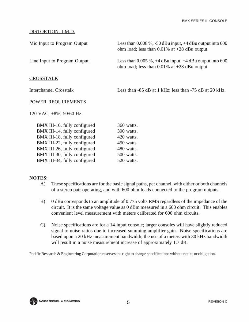
DISTORTION, I.M.D.
Mic Input to Program Output Less than 0.008 %, -50 dBu input, +4 dBu output into 600ohm load; less than 0.01% at +28 dBu output.
Line Input to Program Output Less than 0.005 %, +4 dBu input, +4 dBu output into 600ohm load; less than 0.01% at +28 dBu output.
CROSSTALK
Interchannel Crosstalk Less than -85 dB at 1 kHz; less than -75 dB at 20 kHz.
POWER REQUIREMENTS
120 VAC, ±8%, 50/60 Hz
BMX III-10, fully configured 360 watts.BMX III-14, fully configured 390 watts.BMX III-18, fully configured 420 watts.BMX III-22, fully configured 450 watts.BMX III-26, fully configured 480 watts.BMX III-30, fully configured 500 watts.BMX III-34, fully configured 520 watts.
NOTES:A) These specifications are for the basic signal paths, per channel, with either or both channels
of a stereo pair operating, and with 600 ohm loads connected to the program outputs.
B) 0 dBu corresponds to an amplitude of 0.775 volts RMS regardless of the impedance of thecircuit. It is the same voltage value as 0 dBm measured in a 600 ohm circuit. This enablesconvenient level measurement with meters calibrated for 600 ohm circuits.
C) Noise specifications are for a 14-input console; larger consoles will have slightly reducedsignal to noise ratios due to increased summing amplifier gain. Noise specifications arebased upon a 20 kHz measurement bandwidth; the use of a meters with 30 kHz bandwidthwill result in a noise measurement increase of approximately 1.7 dB.
Pacific Research & Engineering Corporation reserves the right to change specifications without notice or obligation.

REVISION C
BMX SERIES III CONSOLE
6PACIFIC RESEARCH & ENGINEERING
1.4 WARRANTY INFORMATION
This product carries a manufacturer’s warranty which is subject to the following guidelines andlimitations:
A) Except as expressly excluded hereinafter, Pacific Research & Engineering Corporation(“Seller”) warrants equipment of its own manufacture against faulty workmanship or the useof defective materials for a period of one (1) year from date of shipment to Buyer. Theliability of the Seller under this Warranty is limited to replacing, repairing or issuing credit(at the Seller’s discretion) for any equipment, provided that Seller is promptly notified inwriting within five (5) days upon discovery of such defects by Buyer, and Seller’sexamination of such equipment shall disclose to its satisfaction that such defects existed atthe time shipment was originally made by seller, and Buyer returns the defective equipmentto Seller’s place of business in Carlsbad, California, packaging and transportage prepaid,with return packaging and transportage guaranteed.
B) Equipment furnished by Seller but manufactured by another shall be warranted only to theextent provided by the other manufacturer.
C) Thermal filament devices such as lamps and fuses are expressly excluded from this warranty.
D) The warranty period on equipment or parts repaired or replaced under warranty shall expireupon the expiration date of the original warranty.
E) This Warranty is void for equipment which has been subject to abuse, improper installation,improper operation, improper or omitted maintenance, alteration, accident, negligence (inuse, storage, transportation or handling), operation not in accordance with Seller’s operationand service instructions, or operation outside of the environmental conditions specified bySeller.
F) This Warranty is the only warranty made by Seller, and is in lieu of all other warranties,including merchantability and fitness for a particular purpose, whether expressed or implied,except as to title and to the expressed specifications contained in this manual. Seller’s soleliability for any equipment failure or any breach of this Warranty is as set forth insubparagraph A) above; and Seller shall not be liable or responsible for any business loss orinterruption, or other consequential damages of any nature whatsoever, resulting from anyequipment failure or breach of this warranty.

REVISION C
BMX SERIES III CONSOLE
7PACIFIC RESEARCH & ENGINEERING
2.0 INSTALLATION
This chapter provides instruction in the proper installation of the BMX III Broadcast OperationsConsole. Included are sections describing general installation guidelines, cable preparation, mainframeconfiguration, grounding and shielding, power connection, patch point connection, audio and logicconnection, remote control connection, and module internal option switches.
2.1 GENERAL GUIDELINES
The BMX III should be carefully unpacked and inspected for any shipping damage. If the inspectionreveals any damage, immediately file a claim with the delivering carrier. The packing material shouldbe kept as evidence of mishandling, as well as to allow return of the equipment to the factory, ifnecessary.
Included with the console are the tool and spare parts kits (as described in Chapter 6), and the appropriateconnector kit, which contains all of the Molex connector housings and pins necessary to prepare theaudio input/output and logic cables (as described in Section 2.2).
The console is physically installed by setting it into a cutout in the work surface of the studio cabinetry(console and cutout dimensions are provided in Figure 2.1). Prior to installing the mainframe, a finalcheck should be made to confirm that the cutout dimensions are correct. Also, be sure that the cabinetryis in its proper position and leveled, as it is unlikely that the cabinetry can be moved, squared or leveledonce the weight of the BMX III has been added.
NOTE: The cabinetry in which the BMX III is to be mounted must be of sufficiently sturdy constructionto support the console.
FIGURE 2.1 CONSOLE DIMENSIONS
A
B
TOP VIEW
5-3/4"
6-13/16"
12-9/16"
26-9/16"
5"
CUTOUT
24-7/8"
C
SIDE VIEW
24-7/16"
10-1/4"
DIMENSION TABLE
CONSOLE A B C
BMX III-14
BMX III-18
BMX III-22
BMX III-26
38"
44"
50"
56"
36-1/2"
42-1/2"
48-1/2"
54-1/2"
36-3/4"
42-3/4"
48-3/4"
54-3/4"
BMX III-30
BMX III-34
62
68
60-1/2"
66-1/2"
60-3/4"
66-3/4"
BMX III-10 32" 30-1/2" 30-3/4"

REVISION C
BMX SERIES III CONSOLE
8PACIFIC RESEARCH & ENGINEERING
The console mainframe is supported by the hardwood oak end panels, and is actually suspended betweenthe two end panels, with the front oak piece serving only as trim molding.
NOTE: Care should be taken to avoid locating the console within six feet of any intense electromag-netic hum fields such as are produced by large power transformers and motors. Likewise, cables to andfrom the console should be routed to achieve maximum practical distance from AC mains power wiring.Particular attention should be paid to some of the low-cost, supposedly “professional”, power amplifierswhich have appeared in the marketplace. In many cases the low cost has been partially achieved throughthe use of small core power transformers operating on the edge of saturation. While these units mayoperate to their own specifications, the electromagnetic fields they radiate may impair the performanceof the console, neighboring turntables, tape recorders and cartridge machines.
Signal, logic and power connections are made to the connector panel located at the rear of the console.This panel is recessed to provide the installer flexibility of wire routing in console installation.
The power supply is usually installed in the console support cabinetry using EIA standard rack rails.Adequate ventilation must be provided for the proper dissipation of heat. The power supply is designedfor convection cooling by the two massive rectifier/regulator heat sinks located on opposite sides of thechassis. Large heat sinks were chosen over the use of fans to eliminate the problems of dust circulation,noise, and potential mechanical failure associated with fan cooling.
Install legend strips by sliding them into the tops of the legend panels. Monitor legend strips are 0.6inch wide by 5.15 inches high (15 mm by 131 mm); Remote Line Selector legend strips are 0.6 inchwide by 5.7 inches high (15 mm by 145 mm); Meter Switcher legend strips are 0.6 inch wide by 2.8inches high (15 mm by 71 mm). Vertical switch spacing is 0.6 inch (15 mm).
2.2 CABLE PREPARATION
Before beginning the installation, a plan should be drawn up showing how the system will beinterconnected (use the module pin-out information contained in Section 2.7 as a guide). All cables andconnectors should be tagged with numbers and/or legends, and logged.
Only unspliced (preferably new) cables should be used in connecting the mainframe. Audioconnections should be made with 2-conductor stranded insulated foil shielded cable with drain wire.The cable used should be equivalent to Belden types 8451, 9451, or 8761.
Strip the cable insulation jacket and foil shield back about 1-1/2 inches, and sleeve the shield drain wirewith heat-shrink tubing, leaving about 3/16 inch of the wire exposed. Then, strip the insulation of eachsignal wire back about 3/16 inch, and sleeve the shield (at cable ends) with heat-shrink tubing.
NOTE: It is very important to sleeve the shield drain wire and the shield (at cable ends) with heat-shrinktubing. This is the only means of assuring an installation according to recommended groundingprocedures.

REVISION C
BMX SERIES III CONSOLE
9PACIFIC RESEARCH & ENGINEERING
The Molex pins are designed so that the short tab “ears” are crimped onto the stripped wire to make theelectrical connection, while the long “ears” are crimped over the insulated section of the wire to helpsupport the connection.
In order to crimp, insert the short ears of the Molex crimp pin into notch “B” of the crimping tool (PR&E#70-3), with the ears pointing toward the letter “B”. Insert the wire into the terminal so that the strippedportion is between the short crimp ears, and the insulation is between the long crimp ears. Crimp theshort ears.
Now place the long ears of the pin into tool notch “A”, with the ears pointing toward the letter “A”.Crimp the long ears over the insulated section of wire. See Figure 2.2 for an example of a properlycrimped Molex pin.
NOTE: When using the ratchet type Molex Crimping Tool #HTR-1719-C (PR&E #70-5), place a pininto slot “B” with the long ears on the “B” of the tool and pointing toward the letter “B”. Place the wireinto the tool from the “B”, and then crimp the pin.
Logic control cables should be fabricated in a similar manner using 22 gauge multiple conductor, non-shielded, jacketed cable. The number of conductors required will be determined by application.
Once the pins are crimped, they may be inserted and locked into the nylon connector housing inaccordance with the pin-out diagrams contained in Section 2.7. A click can be felt indicating that thelocking ears on the pin have set. If a pin is inserted in the wrong connector position, or it is desired tomake a circuit change, use the connector pin extractor tool (PR&E #70-4) to release the pin and pressit out of the connector housing.
FIGURE 2.2 MOLEX CRIMP PIN
WIRE VISIBLE IN WINDOW
INSULATION CRIMP(STRAIN RELIEF)
FLARE
WIRE
PIN LOCATING TAB(DO NOT CRIMP OR BEND)
CONDUCTOR (WIRE) CRIMP
TERMINAL "WINDOW"

REVISION C
BMX SERIES III CONSOLE
10PACIFIC RESEARCH & ENGINEERING
2.3 MAINFRAME CONFIGURATION
Each BMX III mainframe is factory configured to the customer’s order by the installation of microphoneinput, line input and other modules in their specified and/or dedicated locations. This section containsdescriptions of the BMX III mainframe’s control panel, meter panel and connector panel.
2.3.1 Control Panel
Figure 2.3 illustrates the control panel layout of an BMX III-14 console. The positions identified bymodule names are dedicated to those modules only, and will not accept any other type of plug-inmodule.
The positions indicated by shading are “optional”, and blank panels will be installed in these positionswhen no modules are present. Any unused “optional” module positions may be used for the installationof customer designed special purpose panels. OPTION cutouts have been provided in the Molexconnector panel for the routing of wiring from these positions to the rear of the console (reference Figure2.5).
NOTE: The “optional” module positions labeled A through E are pre-wired with 24-pin logic cables.These cables are routed to corresponding rear panel OPTION cutouts, as defined in Figure 2.5.
FIGURE 2.3 CONTROL PANEL LAYOUT
INPUT MODULES 1 - 14
PR
OG
RA
M A
MP
LIF
IER
AU
DIT
ION
AM
PLI
FIE
R
UT
ILIT
Y A
MP
LIF
IER
MO
NO
OU
TP
UT
/TE
LCO
MIX
/SE
ND
AN
D R
ET
UR
N
SLA
TE
/TA
LKB
AC
K/T
ES
T O
SC
ILLA
TOR
CO
NT
RO
L R
OO
M M
ON
ITO
R
TW
O-S
TU
DIO
MO
NIT
OR
TIM
ER
CO
NT
RO
L PA
NE
L
A B C D E
ME
TE
R S
WIT
CH
ER
RE
MO
TE
LIN
E S
ELE
CTO
R
RE
MO
TE
LIN
E S
ELE
CTO
R

REVISION C
BMX SERIES III CONSOLE
11PACIFIC RESEARCH & ENGINEERING
2.3.2 Meter Panel
Figure 2.4 illustrates the layout of the meter panels for the entire range of BMX III consoles. TheAUXILIARY meters are utilized for metering the AUDITION and UTILITY outputs of the BMX III-10 and BMX III-14 mainframe sizes, and for metering the UTILITY output of the BMX III-18 andBMX III-22 mainframe sizes. This is accomplished by means of the Meter Switcher Module, whichcan also be used to display the Monaural, Send-1, Send-2 or other desired source levels. TheAUXILIARY meters are also used to meter CUE and SOLO signals.
The built-in electret condenser microphone is used as the Control Room source for Slate and Talkbackoperations.
NOTE: Blank filler panels are supplied for any unused clock or timer position.
FIGURE 2.4 METER PANEL LAYOUT
CLOCK TIMER
AUXILIARY PROGRAM
PROGRAMAUXILIARY AUDITION
TIMERCLOCK
LEFT RIGHT LEFT RIGHT
LEFT RIGHT LEFT RIGHTLEFT RIGHT
Talkback Microphone
Talkback Microphone
BMX III-10BMX III-14
BMX III-18BMX III-22
PACIFIC RESEARCH & ENGINEERINGBMX III
PACIFIC RESEARCH & ENGINEERINGBMX III
PACIFIC RESEARCH & ENGINEERINGBMX III
PROGRAMAUXILIARY AUDITION UTILITY
TIMERCLOCK
LEFT RIGHT LEFT RIGHT LEFT RIGHT LEFT RIGHT
Talkback Microphone
BMX III-26BMX III-30BMX III-34

REVISION C
BMX SERIES III CONSOLE
12PACIFIC RESEARCH & ENGINEERING
2.3.3 Connector Panel
Figure 2.5 (on the following page) illustrates the Molex connector panel for an BMX III-14 console,and is intended to provide the installer with a map to the location of the various groups of connectorson the panel. As a general rule, the connectors for any given module are located on the panel behindthat module’s position in the mainframe.
Cutouts are provided for a 24-pin Molex connector for each input position in the mainframe. These arelabeled “OPTION” and are available for the installation of remote control connectors, special purposepanels, etc. The OPTION connectors labeled A through E on Figure 2.5 are pre-wired with 24-pin logiccables, which are routed to corresponding positions in the mainframe, as defined in Figure 2.3.
Nylon tie anchors are provided along the length of the Molex connector panel for tying down patchcables between the various module positions and the meter and monitor connectors. Factory configuredconsoles will have the appropriate patch wiring in place.
NOTE: Audio and logic pin assignment information is provided in Figure 2.6 as a quick reference only.It is highly recommended that the complete information contained in Section 2.7 be used whenconnecting the console.

REVISION C
BMX SERIES III CONSOLE
13PACIFIC RESEARCH & ENGINEERING
YEL
GRN
RED
BLK
WHT
VIO
ORN
BLU
OPTION+
OPTION-
MIC+
MICCOM
AUDIO+
AUDIOCOM
AUDIOCOM
AUDIO-
LOGIC+
LOGICCOM
POWER
FAILINDICATOR
SERIAL NO.
1
2
3
4
5
6
7
8
9
TIMER CONTROL
INPUTS 1+2
INPUTS 5+6
INPUTS 3+4
INPUTS 7+8
UTILITY
MAIN OUT
AUX OUT-1
AUX OUT-3
PATCH
UTILITY
AUDITION
MAIN OUT
AUX OUT-1
AUX OUT-3
PATCH
AUDITION
PROGRAM
MAIN OUT
AUX OUT-1
AUX OUT-3
PATCH
PROGRAM
METERSWITCHER
STUDIO-2
LOGIC
FIXED+TALK
H/P+SELECT
MAIN
STUDIO-1
LOGIC
FIXED+TALK
H/P+SELECT
MAIN
CONTROL RM
MAIN
H/P+SELECT
CUE+TALK
LOGIC
A B C
TALK/SLATE
PRODUCERINPUT
LOGIC
EXT TALK
INPUT
OUTPUT
LOGIC
SEND/RETURN
SEND/RETURN
LOGIC
SEND-1OUTPUT
SEND-2OUTPUT
SEND-1MONITOR
SEND-2MONITOR
RETURNDIRECT OUT
A
B
PATCH
LOGIC - A
LOGIC - B
INPUT - 13
INPUT - 13
OPTION
DIRECT OUT
A
B
PATCH
LOGIC - A
LOGIC - B
INPUT - 12
INPUT - 12
OPTION
DIRECT OUT
A
B
PATCH
LOGIC - A
LOGIC - B
INPUT - 11
INPUT - 11
OPTION
DIRECT OUT
A
B
PATCH
LOGIC - A
LOGIC - B
INPUT - 10
INPUT - 10
OPTION
DIRECT OUT
A
B
PATCH
LOGIC - A
LOGIC - B
INPUT - 9
INPUT - 9
OPTION
DIRECT OUT
A
B
PATCH
LOGIC - A
LOGIC - B
INPUT - 8
INPUT - 8
OPTION
DIRECT OUT
A
B
PATCH
LOGIC - A
LOGIC - B
INPUT - 7
INPUT - 7
OPTION
DIRECT OUT
A
B
PATCH
LOGIC - A
LOGIC - B
INPUT - 6
INPUT - 6
OPTION
DIRECT OUT
A
B
PATCH
LOGIC - A
LOGIC - B
INPUT - 5
INPUT - 5
OPTION
DIRECT OUT
A
B
PATCH
LOGIC - A
LOGIC - B
INPUT - 1
INPUT - 1
OPTION
ADIRECT OUT
A
B
PATCH
LOGIC - A
LOGIC - B
INPUT - 2
INPUT - 2
OPTION
BDIRECT OUT
A
B
PATCH
LOGIC - A
LOGIC - B
INPUT - 3
INPUT - 3
OPTION
CDIRECT OUT
A
B
PATCH
LOGIC - A
LOGIC - B
INPUT - 4
INPUT - 4
OPTION
DDIRECT OUT
A
B
PATCH
LOGIC - A
LOGIC - B
INPUT - 14
INPUT - 14
OPTION
ETELCO
SEND/RETURN
MONO/SENDMETERS
MAIN
AUX
MONITOR
AUX OUT-2AUX OUT-2AUX OUT-2
INPUT-1
INPUT-2
INPUT-3MONO
OUTPUTS
INPUTS
OPTIONOPTION OPTION OPTION OPTIONMONITORREMOTE
INPUTS 9+10
OUTPUTS 1+2
BMX III-14PACIFIC RESEARCH& ENGINEERING
MONITOR INPUT AUDIO PIN ASSIGNMENT
Signal Connector Shield Low High
Input 1/Left
Input 1/Right
Input 2/LeftInput 2/Right
Input 3/Left
Input 3/Right
Input 4/Left
Input 4/Right
INPUT 1
INPUT 2
"
"
INPUT 3
"
INPUT 4
"
1 2 3
4 5 6
1 2 34 5 61 2 3
4 5 6
1 2 3
4 5 6
Pin Number
Input 5/Left
Input 5/Right
Input 6/Left
Input 6/Right
INPUT 5
"
INPUT 6
"
1
4
1
4
2
5
25
3
6
3
6
Input 7/Left
Input 7/Right
Input 8/Left
Input 8/Right
INPUT 7
"
INPUT 8
"
1
4
1
4
2
5
2
5
3
6
3
6
Input 9/Left
Input 9/Right
INPUT 9
"
1
4
2
5
3
6
REMOTE LINE SELECTOR AUDIO PIN ASSIGNMENT
Signal Connector Shield Low High
Input 1/Left
Input 1/Right
Input 2/LeftInput 2/Right
Input 3/Left
Input 3/Right
Input 4/Left
Input 4/Right
INPUTS 1+2
"
"
"
INPUTS 3+4
"
"
"
1 2 3
4 5 6
7 8 910 11 121 2 3
4 5 6
7 8 9
10 11 12
Pin Number
Input 5/Left
Input 5/Right
Input 6/Left
Input 6/Right
INPUTS 5+6
"
"
"
1
4
7
10
2
5
8
11
3
6
9
12
Input 7/Left
Input 7/Right
Input 8/Left
Input 8/Right
INPUTS 7+8
"
"
"
1
4
7
10
2
5
8
11
3
6
9
12
Input 9/Left
Input 9/Right
Input 10/Left
Input 10/Right
INPUTS 9+10
"
"
"
1
4
7
10
2
5
8
11
3
6
9
12
Output 1/Left
Output 1/Right
Output 2/Left
Output 2/Right
OUTPUTS 1+2
"
"
"
1
4
7
10
2
5
8
11
3
6
9
12
TWO-STUDIO MONITOR AUDIO PIN ASSIGNMENT
Signal Connector Shield Low High
Monitor Output/Left
Monitor Output/Right
H/P Output/LeftH/P Output/Right
Selector Output/Left
Selector Output/Right
Fixed Level Output/Left
Fixed Level Output/Right
MAIN
H/P+SELECT
"
"
"
"
FIXED+TALK
"
1 2 3
4 5 6
1 2 34 5 67 8 9
10 11 12
1 2 3
4 5 6
Pin Number
-No Connection-Talkback Output, Direct
"
"
7
10
8
11
9
12
TWO-STUDIO MONITOR LOGIC PIN ASSIGNMENT
Function Pin Number
1
2
3
4
5
6
7
8
9
Logic Common
Logic +12 VDC
TALKBACK
MUTE
DIM
WARNING TALLY
Logic Common
DIM Studio Monitors
MUTE Studio Monitors
CONTROL ROOM MONITOR AUDIO PIN ASSIGNMENT
Signal Connector Shield Low High
Monitor Output/Left
Monitor Output/Right
Headphone Output/LeftHeadphone Output/Right
Selector Output/Left
Selector Output/Right
Cue Output/Left
Cue Output/Right
MAIN
H/P+SELECT
"
"
"
"
CUE+TALK
"
1 2 3
4 5 6
1 2 34 5 67 8 9
10 11 12
1 2 3
4 5 6
Pin Number
Talkback Output, Var. w/muteTalkback Output, Direct
"
"
7
10
8
11
9
12
CONTROL ROOM MONITOR LOGIC PIN ASSIGNMENT
Function Pin Number
1
2
3
4
5
6
7
8
9
Logic Common
Logic +12 VDC
TALKBACK
MUTE
DIM
WARNING TALLY
Logic Common
DIM Control Room Monitors
MUTE Control Room Monitors
TALK/SLATE AUDIO PIN ASSIGNMENT
Signal Connector Shield Low High
Producer's Mic Input
External Mic/Line Input
Talk to External Output
PRODUCER INPUT
EXTERNAL OUTPUT
EXTERNAL INPUT
1 2 3
1 2 3
1 2 3
Pin Number
PRODUCER TALKBACK LOGIC PIN ASSIGNMENT
Function Pin Number
1
2
3
4
5
6
7
8
9
Logic Common
Logic +12 VDC
TALK to Studio-1
TALK to Studio-2
TALK to External
-No Connection-
-No Connection-
SLATE
-No Connection-
EXTERNAL TALKBACK LOGIC PIN ASSIGNMENT
Function Pin Number
1
2
3
4
5
6
7
8
9
Logic Common
Logic +12 VDC
TALK to Studio-1
TALK to Studio-2
TALK to Control Room
-No Connection-
-No Connection-
TALK
-No Connection-
TIMER CONTROL LOGIC PIN ASSIGNMENT
Function Pin Number
1
2
3
4
5
HOLD
Logic Common
RESET
START
STOP
MIC INPUT MODULE AUDIO PIN ASSIGNMENT
Signal Connector Shield Low High
Direct Output/Left
Direct Output/Right
Microphone A-No Connection-
Microphone B
-No Connection-
Patch Send
-No Connection-
DIRECT OUT
A
"
"
B
"
PATCH
"
1 2 3
4 5 6
1 2 34 5 61 2 3
4 5 6
1 2 3
4 5 6
Pin Number
Patch Return-No Connection-
"
"
7
10
8
11
9
12
METER SWITCHER AUDIO PIN ASSIGNMENT
Signal Connector Shield Low High
Input 1/Left
Input 1/Right
Input 2/LeftInput 2/Right
Input 3/Left
Input 3/Right
Input 4/Left
Input 4/Right
INPUT-1
INPUT-2
"
"
INPUT-3
"
INPUT-4
"
1 2 3
4 5 6
1 2 34 5 61 2 3
4 5 6
1 2 3
4 5 6
Pin Number
Input 5/Left
Input 5/Right
INPUT-5
"
1 2 3
4 5 6
STEREO OUTPUT AMPLIFIER AUDIO PIN ASSIGNMENT
Signal Connector Shield Low High
Main Output/Left
Main Output/Right
Auxiliary Output-1/LeftAuxiliary Output-1/Right
Auxiliary Output-2/Left
Auxiliary Output-2/Right
Patch Send/Left
Patch Send/Right
MAIN OUT
AUX OUT-1
"
"
AUX OUT-2
"
PATCH
"
1 2 3
4 5 6
1 2 34 5 61 2 3
4 5 6
1 2 3
4 5 6
Pin Number
Patch Return/Left
Patch Return/Right
"
"
7
10
8
11
9
12
Auxiliary Output-3/Left
Auxiliary Output-3/Right
AUX OUT-3
"
1 2 3
4 5 6
SEND & RETURN AUDIO PIN ASSIGNMENT
Signal Connector Shield Low High
Return/Left
Return/Right
Send-1 OutputSend-2 Output
Send-1 Monitor Output
Send-2 Monitor Output
RETURN
SEND-1 OUTPUT
SEND-2 OUTPUT
"
SEND-1 MONITOR
SEND-2 MONITOR
1 2 3
4 5 6
1 2 31 2 31 2 3
1 2 3
Pin Number
SEND & RETURN LOGIC PIN ASSIGNMENT
Function Pin Number
1
2
3
4
5
6
7
8
9
10
11
12
13
14
15
Logic Common
Logic +12 VDC
Send-1 ON/OFF
Send-2 ON/OFF
Send-1 ON TALLY
Send-2 ON TALLY
Return ON
Return OFF
Return ON TALLY
Return OFF TALLY
-No Connection-
-No Connection-
-No Connection-
-No Connection-
-No Connection-
TELCO MIX AUDIO PIN ASSIGNMENT
Signal Connector Shield Low High
Monitor Output, Variable
Monitor Output, Fixed
Output 1Output 2
Input 1
Input 2
MONITOR
OUTPUTS
"
"
INPUTS
"
1 2 3
4 5 6
1 2 34 5 6
1 2 3
4 5 6
Pin Number
MONO OUTPUT AMPLIFIER AUDIO PIN ASSIGNMENT
Signal Connector Shield Low High
Main Output
Auxiliary Output
Monaural Meter Source-No Connection-
MAIN OUT
MONO/SEND METERS
"
AUX OUT
1 2 3
1 2 3
1 2 34 5 6
Pin Number
Send-1 Meter SourceSend-2 Meter Source
"
"
7 8 910 11 12
MIC INPUT MODULE LOGIC PIN ASSIGNMENT
Function Pin Number
1
2
3
4
5
6
7
8
9
10
11
12
13
14
15
Logic Common
Logic +12 VDC
ON
OFF
ON TALLY
OFF TALLY
COUGH
TALK to Control Room
TALK to Studio-1
TALK to Studio-2
TALK to External
-No Connection-
INHIBIT Cue & Solo (Privacy Mode)
-No Connection-
-No Connection-
LINE INPUT MODULE AUDIO PIN ASSIGNMENT
Signal Connector Shield Low High
Direct Output/Left
Direct Output/Right
Input A/LeftInput A/Right
Input B/Left
Input B/Right
Patch Send/Left
Patch Send/Right
DIRECT OUT
A
"
"
B
"
PATCH
"
1 2 3
4 5 6
1 2 34 5 61 2 3
4 5 6
1 2 3
4 5 6
Pin Number
Patch Return/Left
Patch Return/Right
"
"
7
10
8
11
9
12
LINE INPUT MODULE LOGIC PIN ASSIGNMENT
Function Pin Number
1
2
3
4
5
6
7
8
9
10
11
12
13
14
15
Logic Common
Logic +12 VDC
ON
OFF
ON TALLY
OFF TALLY
READY
AUDIO RESET TO OFF
CUE
START PULSE
STOP PULSE
CUE TALLY
SOLO
SOLO TALLY
-No Connection-
NOTE: The audio and logic pinassignment information providedhere is for quick reference only.Refer to Section 2.7 Audio &Logic Connection (pages 16-30)while connecting the console.
FIGURE 2.4 CONNECTOR PANEL LAYOUT

REVISION C
BMX SERIES III CONSOLE
14PACIFIC RESEARCH & ENGINEERING
2.4 GROUNDING AND SHIELDING
Grounding in modern broadcast consoles is more critical than with older devices of more limited band-pass capabilities. Achieving low system ground impedance with a small piece of equipment is relativelyeasy. However, the problem becomes progressively more difficult as the system becomes larger. Indesigning the BMX III, much thought was given to system grounding requirements and the eliminationof DC path ground loops.
The shield pins on each console connector are connected directly to the console mainframe ground, andthe only location where the console mainframe ground meets the console’s “audio common” point isthe power terminal strip on the console mainframe. Therefore, the station’s “technical ground” shouldbe connected to either of the two screw terminals labeled “AUDIO COMMON” on the console powerterminal strip.
NOTE: Do not connect the station’s “technical ground” to any terminals on the power supply terminalstrip.
A preferred method of connecting the line shields in a system is to connect both ends of every shieldto all affiliated equipment. However, this method is only satisfactory if every component shares acommon earth ground. This can be accomplished using isolated ground receptacles tied to the station’s“technical ground”.
If isolated ground receptacles are not available when grounding the BMX III, observe the followingguidelines:
A) Shields of cables connecting the console to auxiliary equipment should be connected at theconsole end only, and should not be terminated to the ground of the auxiliary equipment.
B) Ensure that the auxiliary equipment is connected to a “clean” ground by its power cordassembly, or by the addition of a separate ground wire connected between the chassis of theauxiliary equipment and the station’s “technical ground”.
NOTE: Buzz pickup is generally electrostatic, due to capacitive pickup between an audio line and apower line. When shielded lines are used this should be no problem, unless the audio lines are run inthe same wireways or area as a power line. Radio-frequency interference can also manifest itself as abuzz in the program audio. RFI is minimized by the extensive RF bypassing and ground-planetechniques used in the BMX III, and the shielded lines external to the unit.
2.5 POWER CONNECTION
A separate power outlet should be assigned exclusively to the BMX III power supply. Confirm that theoutlet supplies 120 VAC, ± 8%, 50/60 Hz, and that the voltage does not sag under a load of up to 5amperes. The third pin “U-ground” on the power connector must be left intact and connected to aproperly installed three way AC outlet. For safety, the “U-ground” wire is connected to the chassis ofthe power supply and the cores of the power transformers.

REVISION C
BMX SERIES III CONSOLE
15PACIFIC RESEARCH & ENGINEERING
WARNING : Do not defeat the safety ground in any way. To do so may provide a potentially dangerouscondition to the operator.
NOTE: The DC outputs of the power supply are not referenced to the power supply chassis and,therefore, are completely floating from the AC safety ground.
The AC mains cord should be kept away from low level audio wiring to avoid the possibility of inducinghum into that wiring. Also, even though the power transformers were designed for very low radiatedmagnetic fields, the power supply should not be placed unnecessarily close to tape playback units orother sensitive equipment.
Console connection to the power supply is made with the supplied six foot multiconductor cable. Thiscable carries only regulated DC power, and will not radiate hum into adjacent audio wiring. The cableis color-coded, and the corresponding color names are printed adjacent to the terminals on the consoleand the power supply.
Should it be necessary to install the power supply at a distance further than permitted by the suppliedcable, it is recommended that a new cable be made rather than splicing a longer length to the existingcable. Cable lengths up to twenty feet may be fabricated using 14 gauge wire. Cables longer than 20feet are not recommended.
It is very important to check and double-check the power supply connections prior to turn-on. An errorin wiring could result in damage to the power supply and/or console circuitry. Once the power supplyis turned on, the meter lamps will illuminate. Use an accurate DC volt meter to verify the operatingvoltages at the test terminals on the front panel of the power supply.
NOTE: For information on the Redundant Power Supply Coupler Unit (PR&E #99-76), see Chapter 8.
2.6 PATCH POINT CONNECTION
Each BMX III input and output module features an audio PATCH connector. These connectors providethe ideal point to connect external processing equipment such as equalizers, limiters, filters, etc. Apatch bay system may also be connected to provide a very flexible processing/patching facility.
The output at each patch point is unbalanced, and designed to operate into low-impedance (600 ohmor higher) loads. The patch return is balanced, 40k ohm impedance.
The level at all patch points is -10 dBu nominal. This level was determined to provide optimumheadroom within the console as well as a good compatibility match with currently available processingequipment. See Section 2.7 for PATCH connector pin assignment.
REVISION C
BMX SERIES III CONSOLE
16PACIFIC RESEARCH & ENGINEERING
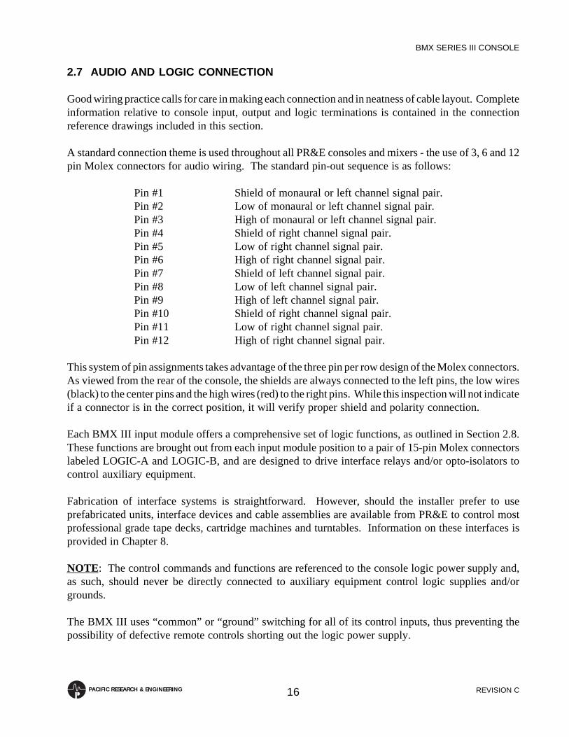
2.7 AUDIO AND LOGIC CONNECTION
Good wiring practice calls for care in making each connection and in neatness of cable layout. Completeinformation relative to console input, output and logic terminations is contained in the connectionreference drawings included in this section.
A standard connection theme is used throughout all PR&E consoles and mixers - the use of 3, 6 and 12pin Molex connectors for audio wiring. The standard pin-out sequence is as follows:
Pin #1 Shield of monaural or left channel signal pair.Pin #2 Low of monaural or left channel signal pair.Pin #3 High of monaural or left channel signal pair.Pin #4 Shield of right channel signal pair.Pin #5 Low of right channel signal pair.Pin #6 High of right channel signal pair.Pin #7 Shield of left channel signal pair.Pin #8 Low of left channel signal pair.Pin #9 High of left channel signal pair.Pin #10 Shield of right channel signal pair.Pin #11 Low of right channel signal pair.Pin #12 High of right channel signal pair.
This system of pin assignments takes advantage of the three pin per row design of the Molex connectors.As viewed from the rear of the console, the shields are always connected to the left pins, the low wires(black) to the center pins and the high wires (red) to the right pins. While this inspection will not indicateif a connector is in the correct position, it will verify proper shield and polarity connection.
Each BMX III input module offers a comprehensive set of logic functions, as outlined in Section 2.8.These functions are brought out from each input module position to a pair of 15-pin Molex connectorslabeled LOGIC-A and LOGIC-B, and are designed to drive interface relays and/or opto-isolators tocontrol auxiliary equipment.
Fabrication of interface systems is straightforward. However, should the installer prefer to useprefabricated units, interface devices and cable assemblies are available from PR&E to control mostprofessional grade tape decks, cartridge machines and turntables. Information on these interfaces isprovided in Chapter 8.
NOTE: The control commands and functions are referenced to the console logic power supply and,as such, should never be directly connected to auxiliary equipment control logic supplies and/orgrounds.
The BMX III uses “common” or “ground” switching for all of its control inputs, thus preventing thepossibility of defective remote controls shorting out the logic power supply.

REVISION C
BMX SERIES III CONSOLE
17PACIFIC RESEARCH & ENGINEERING
Connection to the control circuitry requires an understanding of the logic nomenclature and symbols.These are outlined below.
Control Outputs:
Tally (light) Provides a +12 VDC continuous source when activated.Pulse Provides a +12 VDC pulse source when activated.Sink An open collector that provides a connection to Logic Common
when activated.
Control Inputs:
Control A line above the word indicates that the function is activatedwhen a connection to Logic Common is made.
ON

REVISION C
BMX SERIES III CONSOLE
18PACIFIC RESEARCH & ENGINEERING
2.7.1 Microphone Input Module Connection
INPUT - #
DIRECT OUT
A
B
PATCH
LOGIC-A
LOGIC-B
INPUT - #
1
654
32
1
654
32
1
654
32
1
10 11 12
987
654
32
13 14 15
1
10 11 12
987
654
32
13 14 15
1
10 11 12
987
654
32
AUDIO PIN ASSIGNMENT
Signal Connector Shield Low High
Direct Output/Left
Direct Output/Right
Microphone A-No Connection-
Microphone B
-No Connection-
Patch Send
-No Connection-
DIRECT OUT
A
"
"
B
"
PATCH
"
1 2 3
4 5 6
1 2 34 5 61 2 3
4 5 6
1 2 3
4 5 6
Pin Number
Patch Return-No Connection-
"
"
7
10
8
11
9
12
NOTES:A) The Patch Send is unbalanced; the Patch Return is balanced.B) The PATCH connector must be wired so that the Patch Send is
connected through to the Patch Return. If no external processing orpatch bay equipment is connected, a mating connector with jumpersfrom pins #2 to #8 and #3 to #9 must be installed.
LOGIC PIN ASSIGNMENT
Function Pin Number
1
2
3
4
5
6
7
8
9
10
11
12
13
14
15
Logic Common
Logic +12 VDC
ON
OFF
ON TALLY
OFF TALLY
COUGH
TALK to Control Room
TALK to Studio-1
TALK to Studio-2
TALK to External
-No Connection-
INHIBIT Cue & Solo (Privacy Mode)
-No Connection-
-No Connection-
NOTES:A) A input logic is connected to LOGIC-A; B input logic is connected to
LOGIC-B.B) Consult Section 2.8.1 when connecting Microphone Input Module
remote controls.

REVISION C
BMX SERIES III CONSOLE
19PACIFIC RESEARCH & ENGINEERING
2.7.2 Stereo Line Input Module Connection
INPUT - #
DIRECT OUT
A
B
PATCH
LOGIC-A
LOGIC-B
INPUT - #
1
654
32
1
654
32
1
654
32
1
10 11 12
987
654
32
13 14 15
1
10 11 12
987
654
32
13 14 15
1
10 11 12
987
654
32
AUDIO PIN ASSIGNMENT
Signal Connector Shield Low High
Direct Output/Left
Direct Output/Right
Input A/LeftInput A/Right
Input B/Left
Input B/Right
Patch Send/Left
Patch Send/Right
DIRECT OUT
A
"
"
B
"
PATCH
"
1 2 3
4 5 6
1 2 34 5 61 2 3
4 5 6
1 2 3
4 5 6
Pin Number
Patch Return/Left
Patch Return/Right
"
"
7
10
8
11
9
12
NOTES:A) When connecting a monaural line level source (such as a Telco
hybrid) to a Stereo Line Input Module, connect the signal to the leftinput channel, and insert jumpers between pins #1 and #4, #2 and #5,and #3 and #6.
B) The Patch Sends are unbalanced; the Patch Returns are balanced.C) The PATCH connector must be wired so that the Patch Sends are
connected through to the Patch Returns. If no external processing orpatch bay equipment is connected, a mating connector with jumpersfrom pins #2 to #8, #3 to #9, #5 to #11 and #6 to #12 must be installed.
LOGIC PIN ASSIGNMENT
Function Pin Number
1
2
3
4
5
6
7
8
9
10
11
12
13
14
15
Logic Common
Logic +12 VDC
ON
OFF
ON TALLY
OFF TALLY
READY
AUDIO RESET TO OFF
CUE
START PULSE
STOP PULSE
CUE TALLY
SOLO
SOLO TALLY
-No Connection-
NOTES:A) A input logic is connected to LOGIC-A; B input logic is connected to
LOGIC-B.B) Consult Section 2.8.2 when connecting Stereo Line Input Module
remote controls.
REVISION C
BMX SERIES III CONSOLE
20PACIFIC RESEARCH & ENGINEERING
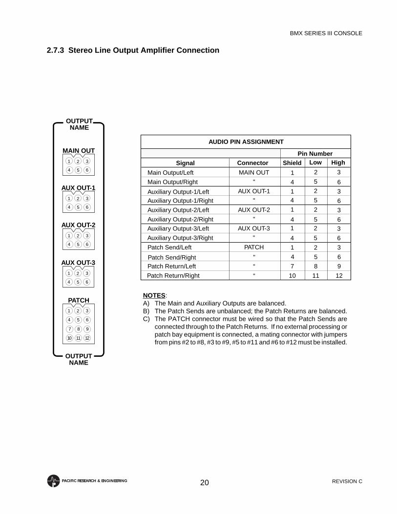
2.7.3 Stereo Line Output Amplifier Connection
OUTPUTNAME
AUX OUT-1
AUX OUT-2
PATCH
OUTPUTNAME
1
654
32
1
654
32
1
654
32
1
10 11 12
987
654
32
MAIN OUT
AUX OUT-3
1
654
32
NOTES:A) The Main and Auxiliary Outputs are balanced.B) The Patch Sends are unbalanced; the Patch Returns are balanced.C) The PATCH connector must be wired so that the Patch Sends are
connected through to the Patch Returns. If no external processing orpatch bay equipment is connected, a mating connector with jumpersfrom pins #2 to #8, #3 to #9, #5 to #11 and #6 to #12 must be installed.
AUDIO PIN ASSIGNMENT
Signal Connector Shield Low High
Main Output/Left
Main Output/Right
Auxiliary Output-1/LeftAuxiliary Output-1/Right
Auxiliary Output-2/Left
Auxiliary Output-2/Right
Patch Send/Left
Patch Send/Right
MAIN OUT
AUX OUT-1
"
"
AUX OUT-2
"
PATCH
"
1 2 3
4 5 6
1 2 34 5 61 2 3
4 5 6
1 2 3
4 5 6
Pin Number
Patch Return/Left
Patch Return/Right
"
"
7
10
8
11
9
12
Auxiliary Output-3/Left
Auxiliary Output-3/Right
AUX OUT-3
"
1 2 3
4 5 6

REVISION C
BMX SERIES III CONSOLE
21PACIFIC RESEARCH & ENGINEERING
2.7.4 Monitor Module Input Connection
MONITOR
INPUT 2
INPUT 3
1
654
32
1
654
32
1
654
32
INPUT 1
INPUT 5
INPUT 6
1
654
32
1
654
32
1
654
32
INPUT 4
INPUT 8
INPUT 9
1
654
32
1
654
32
1
654
32
INPUT 7
AUDIO PIN ASSIGNMENT
Signal Connector Shield Low High
Input 1/Left
Input 1/Right
Input 2/LeftInput 2/Right
Input 3/Left
Input 3/Right
Input 4/Left
Input 4/Right
INPUT 1
INPUT 2
"
"
INPUT 3
"
INPUT 4
"
1 2 3
4 5 6
1 2 34 5 61 2 3
4 5 6
1 2 3
4 5 6
Pin Number
Input 5/Left
Input 5/Right
Input 6/Left
Input 6/Right
INPUT 5
"
INPUT 6
"
1
4
1
4
2
5
25
3
6
3
6
Input 7/Left
Input 7/Right
Input 8/Left
Input 8/Right
INPUT 7
"
INPUT 8
"
1
4
1
4
2
5
2
5
3
6
3
6
Input 9/Left
Input 9/Right
INPUT 9
"
1
4
2
5
3
6

REVISION C
BMX SERIES III CONSOLE
22PACIFIC RESEARCH & ENGINEERING
2.7.5 Control Room Monitor Module Connection
CONTROL RM
H/P+SELECT
1
654
32
MAIN
1
10 11 12
987
654
32
1
10 11 12
987
654
32
1
987
654
32
CUE+TALK
LOGIC
LOGIC PIN ASSIGNMENT
Function Pin Number
1
2
3
4
5
6
7
8
9
Logic Common
Logic +12 VDC
TALKBACK
MUTE
DIM
WARNING TALLY
Logic Common
DIM Control Room Monitors
MUTE Control Room Monitors
NOTE: Consult Section 2.8.3 when connecting Control Room MonitorModule remote controls.
NOTES:A) The Selector Output is the direct output of the Control Room Monitor
Module, and consists only of the source selected on the 12-stationMonitor Input switch. However, Talkback signals may be assigned tothis output (reference Section 2.9.3).
B) The Talkback outputs consist of any Talk To Control Room signals,and are provided for connection to self-contained headphone and/ormonitor systems, if desired.
C) The Variable Talkback Output is only active when the Control Roomis muted.
AUDIO PIN ASSIGNMENT
Signal Connector Shield Low High
Monitor Output/Left
Monitor Output/Right
Headphone Output/LeftHeadphone Output/Right
Selector Output/Left
Selector Output/Right
Cue Output/Left
Cue Output/Right
MAIN
H/P+SELECT
"
"
"
"
CUE+TALK
"
1 2 3
4 5 6
1 2 34 5 67 8 9
10 11 12
1 2 3
4 5 6
Pin Number
Talkback Output, Var. w/muteTalkback Output, Direct
"
"
7
10
8
11
9
12

REVISION C
BMX SERIES III CONSOLE
23PACIFIC RESEARCH & ENGINEERING
2.7.6 Two-Studio Monitor Module Connection
AUDIO PIN ASSIGNMENT
Signal Connector Shield Low High
Monitor Output/Left
Monitor Output/Right
H/P Output/LeftH/P Output/Right
Selector Output/Left
Selector Output/Right
Fixed Level Output/Left
Fixed Level Output/Right
MAIN
H/P+SELECT
"
"
"
"
FIXED+TALK
"
1 2 3
4 5 6
1 2 34 5 67 8 9
10 11 12
1 2 3
4 5 6
Pin Number
-No Connection-Talkback Output, Direct
"
"
7
10
8
11
9
12NOTES:A) The Selector Output is the direct output of the Two-Studio Monitor
Module, and consists only of the source selected on the 12-stationMonitor Input switch.
B) The Talkback Output consists of the respective Talk To Studiosignals, and is provided for connection to self-contained headphoneand/or monitor systems, if desired.
LOGIC PIN ASSIGNMENT
Function Pin Number
1
2
3
4
5
6
7
8
9
Logic Common
Logic +12 VDC
TALKBACK
MUTE
DIM
WARNING TALLY
Logic Common
DIM Studio Monitors
MUTE Studio Monitors
NOTE: Consult Section 2.8.4 when connecting Two-Studio MonitorModule remote controls.
STUDIO-#
H/P+SELECT
1
654
32
MAIN
1
10 11 12
987
654
32
1
10 11 12
987
654
32
1
987
654
32
FIXED+TALK
LOGIC

REVISION C
BMX SERIES III CONSOLE
24PACIFIC RESEARCH & ENGINEERING
2.7.7 Monaural Line Output Amplifier Connection
AUX
MONO/SENDMETERS
MAIN1 32
1 32
MONO
1
10 11 12
987
654
32
AUDIO PIN ASSIGNMENT
Signal Connector Shield Low High
Main Output
Auxiliary Output
Monaural Meter Source-No Connection-
MAIN OUT
MONO/SEND METERS
"
AUX OUT
1 2 3
1 2 3
1 2 34 5 6
Pin Number
Send-1 Meter SourceSend-2 Meter Source
"
"
7 8 910 11 12
NOTES:A) The Main and Auxiliary Outputs are balanced.B) Monaural and Send Meter Source signals are provided for connection
to a Meter Switcher Module input, if desired.

REVISION C
BMX SERIES III CONSOLE
25PACIFIC RESEARCH & ENGINEERING
2.7.8 Telco Mix Module Connection
TELCO
OUTPUTS
MONITOR
1
654
32
INPUTS
1
654
32
1
654
32
AUDIO PIN ASSIGNMENT
Signal Connector Shield Low High
Monitor Output, Variable
Monitor Output, Fixed
Output 1Output 2
Input 1
Input 2
MONITOR
OUTPUTS
"
"
INPUTS
"
1 2 3
4 5 6
1 2 34 5 6
1 2 3
4 5 6
Pin Number
NOTES:A) Telco Outputs are routed to the telephone hybrid(s).B) The Fixed and Variable Monitor Outputs consist of only those callers
assigned to the Telco Mix System.C) The Telco Mix Module receives its inputs from the Direct Output/Left
signals of those Stereo Line Input Modules designated as Telcoinputs.
NOTE: When "off-air" Telco monitoring facilities are desired, theseDirect Outputs should be continuous (reference Section 2.9.2). Thisallows the Telco system to be fed caller audio regardless of the ON/OFF status of the caller's Stereo Line Input Module.

REVISION C
BMX SERIES III CONSOLE
26PACIFIC RESEARCH & ENGINEERING
2.7.9 Send And Return Module Connection
SEND/RETURN
RETURN
LOGIC
SEND/RETURN
1
654
32
13 14 15
1
10 11 12
987
654
32
1 32
SEND-1OUTPUT
1 32
SEND-2OUTPUT
1 32
SEND-1MONITOR
1 32
SEND-2MONITOR
LOGIC PIN ASSIGNMENT
Function Pin Number
1
2
3
4
5
6
7
8
9
10
11
12
13
14
15
Logic Common
Logic +12 VDC
Send-1 ON/OFF
Send-2 ON/OFF
Send-1 ON TALLY
Send-2 ON TALLY
Return ON
Return OFF
Return ON TALLY
Return OFF TALLY
-No Connection-
-No Connection-
-No Connection-
-No Connection-
-No Connection-
NOTE: Consult Section 2.8.5 when connecting Send And Return Moduleremote controls.
AUDIO PIN ASSIGNMENT
Signal Connector Shield Low High
Return/Left
Return/Right
Send-1 OutputSend-2 Output
Send-1 Monitor Output
Send-2 Monitor Output
RETURN
SEND-1 OUTPUT
SEND-2 OUTPUT
"
SEND-1 MONITOR
SEND-2 MONITOR
1 2 3
4 5 6
1 2 31 2 31 2 3
1 2 3
Pin Number
NOTES:A) The Sends and the Return are balanced.B) The Send Monitor Outputs are provided for connection to monitor
module inputs, if desired.

REVISION C
BMX SERIES III CONSOLE
27PACIFIC RESEARCH & ENGINEERING
2.7.10 Slate/Talkback/Test Oscillator Module Connection
PRODUCER LOGIC PIN ASSIGNMENT
Function Pin Number
1
2
3
4
5
6
7
8
9
Logic Common
Logic +12 VDC
TALK to Studio-1
TALK to Studio-2
TALK to External
-No Connection-
-No Connection-
SLATE
-No Connection-
EXTERNAL LOGIC PIN ASSIGNMENT
Function Pin Number
1
2
3
4
5
6
7
8
9
Logic Common
Logic +12 VDC
TALK to Studio-1
TALK to Studio-2
TALK to Control Room
-No Connection-
-No Connection-
TALK
-No Connection-
NOTE: Consult Section 2.8.6 when connecting Slate/Talkback/TestOscillator Module remote controls.
AUDIO PIN ASSIGNMENT
Signal Connector Shield Low High
Producer's Mic Input
External Mic/Line Input
Talk to External Output
PRODUCER INPUT
EXTERNAL OUTPUT
EXTERNAL INPUT
1 2 3
1 2 3
1 2 3
Pin Number
NOTE: The External Input is switchable between microphone and lineinput levels (reference Section 2.9.7).1 32
1 32
1 32
1
987
654
32
1
987
654
32
PRODUCERINPUT
LOGIC
EXT TALK
INPUT
OUTPUT
LOGIC
TALK/SLATE

REVISION C
BMX SERIES III CONSOLE
28PACIFIC RESEARCH & ENGINEERING
2.7.11 Meter Switcher Module Connection
METERSWITCHER
INPUT-1
1
654
32
INPUT-3
1
654
32
INPUT-2
1
654
32
INPUT-4
1
654
32
INPUT-5
1
654
32
AUDIO PIN ASSIGNMENT
Signal Connector Shield Low High
Input 1/Left
Input 1/Right
Input 2/LeftInput 2/Right
Input 3/Left
Input 3/Right
Input 4/Left
Input 4/Right
INPUT-1
INPUT-2
"
"
INPUT-3
"
INPUT-4
"
1 2 3
4 5 6
1 2 34 5 61 2 3
4 5 6
1 2 3
4 5 6
Pin Number
Input 5/Left
Input 5/Right
INPUT-5
"
1 2 3
4 5 6
NOTES:A) On BMX III-18 and 22 mainframes, Input 5 will be pre-wired for
UTILITY metering, and the INPUT-5 connector will not be present.B) On BMX III-10 and 14 mainframes, Input 4 will be pre-wired for
AUDITION metering and Input 5 will be pre-wired for UTILITYmetering. The INPUT-4 and INPUT-5 connectors will not be present.

REVISION C
BMX SERIES III CONSOLE
29PACIFIC RESEARCH & ENGINEERING
2.7.12 Remote Line Selector Module Connection
1
10 11 12
987
654
32
1
10 11 12
987
654
32
1
10 11 12
987
654
32
1
10 11 12
987
654
32
REMOTEINPUTS 1+2
INPUTS 3+4
INPUTS 5+6
INPUTS 7+8
1
10 11 12
987
654
32
1
10 11 12
987
654
32
INPUTS 9+10
OUTPUTS 1+2
AUDIO PIN ASSIGNMENT
Signal Connector Shield Low High
Input 1/Left
Input 1/Right
Input 2/LeftInput 2/Right
Input 3/Left
Input 3/Right
Input 4/Left
Input 4/Right
INPUTS 1+2
"
"
"
INPUTS 3+4
"
"
"
1 2 3
4 5 6
7 8 910 11 121 2 3
4 5 6
7 8 9
10 11 12
Pin Number
Input 5/Left
Input 5/Right
Input 6/Left
Input 6/Right
INPUTS 5+6
"
"
"
1
4
7
10
2
5
8
11
3
6
9
12
Input 7/Left
Input 7/Right
Input 8/Left
Input 8/Right
INPUTS 7+8
"
"
"
1
4
7
10
2
5
8
11
3
6
9
12
Input 9/Left
Input 9/Right
Input 10/Left
Input 10/Right
INPUTS 9+10
"
"
"
1
4
7
10
2
5
8
11
3
6
9
12
Output 1/Left
Output 1/Right
Output 2/Left
Output 2/Right
OUTPUTS 1+2
"
"
"
1
4
7
10
2
5
8
11
3
6
9
12

REVISION C
BMX SERIES III CONSOLE
30PACIFIC RESEARCH & ENGINEERING
2.7.13 Timer Control Connection
LOGIC PIN ASSIGNMENT
Function Pin Number
1
2
3
4
5
HOLD
Logic Common
RESET
START
STOP
TIMER CONTROL
1 32 541 32 54
A B
1 32 54
C
NOTE: These output commands are provided for the control of external"slave" timers.

REVISION C
BMX SERIES III CONSOLE
31PACIFIC RESEARCH & ENGINEERING
2.8 MODULE REMOTE CONTROL CAPABILITIES
This section outlines BMX III module remote control capabilities. Included are descriptions ofMicrophone Input, Stereo Line Input, Control Room Monitor, Two-Studio Monitor, Send And Return,and Slate/Talkback/Test Oscillator Module remote control capabilities.
2.8.1 Microphone Input Module Remote Control
The schematic below illustrates the full remote control capability of the Microphone Input Module'sA and B inputs. Since it is not desirable for a microphone to “talk” to its own location, or to locationswhich may not exist in a particular installation, delete any inappropriate talk buttons. The INHIBITcommand disables module CUE and SOLO functions for as long as the PRIVACY button is engaged.This facility ensures at private "off-mic" conversations cannot be overheard in the Control Room.
ON OFF COUGH
TALK TOCONTROL
ROOMTALK TO
STUDIO-1TALK TO
STUDIO-2TALK TO
EXTERNALPRIVACY
(See Notes)
ON 3
ON TALLY 5
OFF 4
OFF TALLY 6
COUGH 7
TALK TO CR 8
TALK TO STUDIO-1 9
TALK TO STUDIO-2 10
TALK TO EXT 11
INHIBIT (Privacy) 13
LOGIC +12 VDC 2
LOGIC COMMON 1
NOTES:A) All button switches except PRIVACY are momentary-action (the PRIVACY button switch is
maintained-action.B) Lamps are 12-14 volt, 80 mA.C) When COUGH, TALK TO and PRIVACY tallies are connected as shown above, switch
lamps will be illuminated at all times.
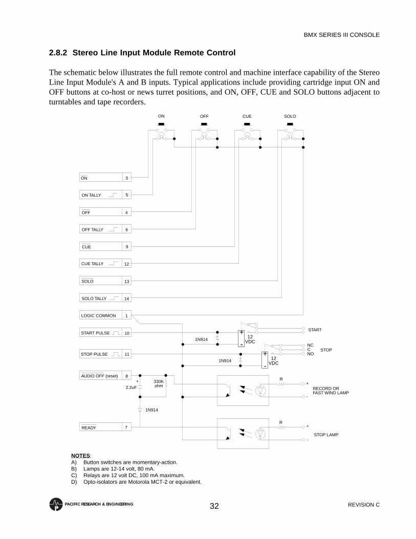
REVISION C
BMX SERIES III CONSOLE
32PACIFIC RESEARCH & ENGINEERING
2.8.2 Stereo Line Input Module Remote Control
The schematic below illustrates the full remote control and machine interface capability of the StereoLine Input Module's A and B inputs. Typical applications include providing cartridge input ON andOFF buttons at co-host or news turret positions, and ON, OFF, CUE and SOLO buttons adjacent toturntables and tape recorders.
R+
-STOP LAMP
R+
-
RECORD OR FAST WIND LAMP
1N914
READY 7
AUDIO OFF (reset) 8
STOP PULSE 11
START PULSE 10
LOGIC COMMON 1
14SOLO TALLY
SOLO 13
12CUE TALLY
CUE 9
OFF TALLY 6
OFF 4
5ON TALLY
ON 3
ON OFF CUE SOLO
STOP
1N914
1N914
START
NCCNO
2.2uF+ 330K
ohm
+
-12
VDC
+
-12
VDC
NOTES:A) Button switches are momentary-action.B) Lamps are 12-14 volt, 80 mA.C) Relays are 12 volt DC, 100 mA maximum.D) Opto-isolators are Motorola MCT-2 or equivalent.

REVISION C
BMX SERIES III CONSOLE
33PACIFIC RESEARCH & ENGINEERING
2.8.3 Control Room Monitor Module Remote Control
The schematic below illustrates the full remote control capability of the Control Room MonitorModule.
While it is unlikely that a “typical” installation will utilize all of these facilities, it is important tounderstand what is available, along with the potential applications.
The DIM control input may be used to remote control the dim function of the Control Room MonitorModule. Typical applications include equipping the Control Room door with a “door open” switch,or a telephone set with an “off-hook” switch to automatically dim the Control Room speakers wheneverthe door opens or the telephone is picked up.
DIM 5
4MUTE
TALKBACK 3
2LOGIC + 12 VDC
1LOGIC COMMON
6C/R WARNING
7LOGIC COMMON
9MUTE C/R
8DIM C/R
DIM
MUTE
TALKBACK
+ 12 VDC
NCCNO
WARNING
MUTEDIM
1N4001+
-12
VDC
NOTES:A) Button switches are momentary-action.B) Lamps are 12-14 volt, 80 mA.C) Relay is 12 volt DC, 100 mA maximum.D) When DIM and MUTE tallies are connected as shown above,
switch lamps will be illuminated at all times.

REVISION C
BMX SERIES III CONSOLE
34PACIFIC RESEARCH & ENGINEERING
The MUTE control input may be used to remote control the mute function of the Control Room MonitorModule. Typical applications include operations where two on-air consoles are used in the same room,such as a second console for news and sports programming.
The TALKBACK control output is a current-sinking open collector, which is active (low) wheneverthe Control Room is receiving Talkback from another location. This command is intended forconnection to active, self-contained, headphone and monitor systems, and is used to switch the Talk ToControl Room signals into the headphone and monitor circuits. Such headphone and/or monitorsystems are usually provided to co-host and news positions in a Control Room.
The MUTE control output is a current-sinking open collector, which is active (low) whenever a ControlRoom microphone is ON. This command is provided for interface to intercoms, telephones and/or otherexternal equipment which may need to be muted whenever a Control Room microphone is “live”.
The DIM control output is a current-sinking open collector, which is active (low) whenever Talkbackis occurring from the Control Room to another location. This command is provided for similarapplications as the MUTE command.
The C/R WARNING tally is a 12 volt DC, 150 mA maximum, source output for connection to amagnetic or solid-state relay unit for driving the Control Room entry warning light(s).

REVISION C
BMX SERIES III CONSOLE
35PACIFIC RESEARCH & ENGINEERING
2.8.4 Two-Studio Monitor Module Remote Control
The Two-Studio Monitor Module is equipped with many of the same audio and logic features providedin the Control Room Monitor Module. The schematic below illustrates the full remote controlcapability of each of the two Studio logic connectors.
DIM 5
4MUTE
TALKBACK 3
2LOGIC + 12 VDC
1LOGIC COMMON
6STU. WARNING
7LOGIC COMMON
9MUTE STUDIO
8DIM STUDIO
DIM
MUTE
TALKBACK
+ 12 VDC
NCCNO
WARNING
MUTEDIM
1N4001+
-12
VDC
NOTES:A) Button switches are momentary-action.B) Lamps are 12-14 volt, 80 mA.C) Relay is 12 volt DC, 100 mA maximum.D) When DIM and MUTE tallies are connected as shown above,
switch lamps will be illuminated at all times.
While it is unlikely that a “typical” studio installation will use all of these features, it is important tounderstand what is available, along with the potential applications.
The DIM control input may be used to remotely control the dim function of the Studio Monitor Module.Typical applications include equipping the Studio door with a “door open” switch, or a telephone setwith an “off-hook” switch to automatically dim the Studio speakers whenever the door opens or thetelephone is picked up.

REVISION C
BMX SERIES III CONSOLE
36PACIFIC RESEARCH & ENGINEERING
The MUTE control input may be used to remotely control the mute function of the Studio MonitorModule. A typical application would be to provide a host with a Monitor Mute button in thoseinstallations where a monitor volume control is not provided in the Studio itself.
The TALKBACK control output is a current-sinking open collector, which is active (low) wheneverthe Studio is receiving Talkback from another location. This command is intended for connection toactive, self-contained, headphone and monitor systems, and is used to switch the Talkback signal intothe headphone and monitor circuits. Such headphone and/or monitor systems are usually provided tothe host and co-host positions.
The MUTE control output is a current-sinking open collector, which is active (low) whenever a Studiomicrophone is ON. This command is provided for interface to intercoms, telephones and/or otherexternal equipment which may need to be muted whenever a Studio microphone is “live”.
The DIM control output is a current-sinking open collector, which is active (low) whenever Talkbackis occurring from the Studio to another location. This command is provided for similar applicationsas the MUTE Command.
The STUDIO WARNING tally is a 12 volt DC, 150 mA maximum, source output for connection toa magnetic or solid-state relay unit for driving the Studio entry warning light(s).

REVISION C
BMX SERIES III CONSOLE
37PACIFIC RESEARCH & ENGINEERING
2.8.5 Send And Return Module Remote Control
The Send And Return Module contains three independent sets of circuitry: two Send circuits and onestereo Return input channel. The schematic below illustrates the full remote control capability of thismodule, which consists of controlling and tallying the ON/OFF status of both Send circuits and theReturn circuitry.
LOGIC COMMON 1
10RETURN OFF TALLY
RETURN OFF 8
9RETURN ON TALLY
RETURN ON 7
SEND-2 ON TALLY 6
SEND-2 ON/OFF 4
5SEND-1 ON TALLY
SEND-1 ON/OFF 3
SEND-1 SEND-2 RETURNON
RETURNOFF
NOTES:A) Button switches are momentary-action.B) Lamps are 12-14 volt, 80 mA.C) SEND-1 and SEND-2 remote ON/OFF control inputs can be momentary- or maintained-action,
as determined by module internal option switches (reference Section 2.9.5).

REVISION C
BMX SERIES III CONSOLE
38PACIFIC RESEARCH & ENGINEERING
2.8.6 Slate/Talkback/Test Oscillator Remote Control
The Slate/Talkback/Test Oscillator module has remote control circuitry available for both “Producer”and “External” locations.
PRODUCER INPUT
The “Producer” is usually located somewhere in the Control Room. TALK control inputs route theProducer’s Microphone Input signal to the selected location. The schematic below illustrates the fullremote control capability of this input.
NOTES:A) Button switches are momentary-action.B) Lamps are 12-14 volt, 80 mA.C) When tallies are connected as shown above, switch lamps will be illuminated at all times.
LOGIC COMMON 1
2LOGIC +12 VDC
SLATE 8
TALK TO EXTERNAL 5
TALK TO STUDIO-2 4
TALK TO STUDIO-1 3
TALK TOSTUDIO-1
TALK TOSTUDIO-2
TALK TOEXTERNAL SLATE

REVISION C
BMX SERIES III CONSOLE
39PACIFIC RESEARCH & ENGINEERING
EXTERNAL INPUT
The “External” circuitry is intended for a variety of possible applications, including a telephone callscreener booth, announce booth, newsroom, or even connection to a two-way transmitter/receiver forcommunicating with the rush-hour traffic reporter. The schematic below illustrates the full remotecontrol capability of this input.
The TALKBACK control output is a current-sinking open collector, which is active (low) wheneverthe external location is receiving Talkback from another location. Typical applications include keyinga two–way transmitter or dimming an external monitor.
NOTES:A) Button switches are momentary-action.B) Lamps are 12-14 volt, 80 mA.C) When tallies are connected as shown above, switch lamps will be illuminated at all times.
LOGIC COMMON 1
2LOGIC +12 VDC
TALK TO CONTROL 5
TALK TO STUDIO-2 4
TALK TO STUDIO-1 3
TALK TOSTUDIO-1
TALK TOSTUDIO-2
TALK TOCONTROL
ROOM
TALKBACK 8 TALKBACK

REVISION C
BMX SERIES III CONSOLE
40PACIFIC RESEARCH & ENGINEERING
1 2 3 4 5 6 7 8
OPEN
1 2ON
ON
ON
C1
C2
12
S7, Logic Assignment SelectorFunction
S206, Logic Assignment Selector
OFF (OPEN): Sends follow module ON/OFF.
ON (CLOSED): Sends always active with PRE-fader selection.
Function
C1 (Down): Direct Output follows module ON/OFF.C2 (Up): Direct Output continuous.
S204, Logic Assignment Selector
OFF (OPEN): No SOLO reset function.ON (CLOSED): SOLO resets with module ON.
Function#
1
OFF (OPEN): No CUE reset function.ON (CLOSED): CUE resets with module ON.2
S205, Logic Assignment Selector
OFF (OPEN): No local cough function.
ON (CLOSED): Local cough function with module ON button depressed.
Function
S207, Logic Assignment SelectorFunction
ON (CLOSED): Assign to Studio-1.ON (CLOSED): Assign to Studio-2.ON (CLOSED): Assign to External.ON (CLOSED): Assign to Control Room.ON (CLOSED): Assign to Studio-1.ON (CLOSED): Assign to Studio-2.ON (CLOSED): Assign to External.ON (CLOSED): Assign to Control Room.
#12345678
InputAAAABBBB
2.9 MODULE INTERNAL OPTION SWITCHES
Some BMX III console modules are equipped with PCA-mounted option switches to enable or disableselected module functions. This section shows the locations of these switches on each PCA as well astheir functions. Included are descriptions of the Microphone Input, Stereo Line Input, Control RoomMonitor, Two-Studio Monitor, Send And Return, Telco Mix, Slate/Talkback/Test Oscillator, MeterSwitcher, and Monaural and Stereo Equalizer Module option switches.
2.9.1 Microphone Input Module Option Switches
The illustration below shows the locations of the Microphone Input Module internal option switches,and defines their functions.
NOTE: Switch S206 is only present on modules equippedwith Sends.
NOTE: Each input may be assigned to a single locationonly. Assigning an input to more than one location willdisable the module ON circuitry.
Switch S7 sets whether the module’s Direct Output follows the ON/OFF status of the module or hascontinuous audio output.

REVISION C
BMX SERIES III CONSOLE
41PACIFIC RESEARCH & ENGINEERING
Switch S204 sets the Cue and Solo reset functions. S204-1 determines if SOLO resets when the moduleis turned ON. S204-2 determines if CUE resets when the module is turned ON.
Switch S205 enables the local cough function, allowing the module ON button to function as a coughbutton. The cough function mutes the module audio from all buses for as long as the module ON buttonis pressed.
Switch S206 is only found on modules with the Sends option. The Sends normally follow the ON/OFFstatus of the module. For applications that require continuous Sends, such as on or off-air telephonecontest recording, the PRE-fader Send audio can to be set “on” and available at all times by closing S206.This setting engages the Send relay whenever the PRE button is engaged, regardless of the ON/OFFstatus of the module.
Switch 207 is an eight-station switch that assigns the microphone to its own location (Control Room,Studio-1, Studio-2, External) to enable the correct monitor mute function for that location. This alsoenables Talkback from that location to all other locations.

REVISION C
BMX SERIES III CONSOLE
42PACIFIC RESEARCH & ENGINEERING
2.9.2 Stereo Line Input Module Option Switches
The illustration below provides the locations of the Stereo Line Input Module internal option switches,and defines their functions.
Switch S7 sets whether the module’s Direct Output follows the ON/OFF status of the module or hascontinuous audio output.
Switch S200 is an eight-station switch that can enable muting of the Control Room, Studio-1 andStudio-2 on the A and/or B inputs (typically only used when a preamplified microphone is connectedto the module). S200-4 and S200-8 separately enable the timer reset function for each input. Whenclosed the console timer resets at module ON.
1 2 3 4 5 6 7 8
OPEN
1 2ON
ON
C1
C2
12
12 ON
S7, Logic Assignment SelectorFunction
C1 (Down): Direct Output follows module ON/OFF.C2 (Up): Direct Output continuous.
S206, Logic Assignment Selector
OFF (OPEN): Sends follow ON/OFF.
ON (CLOSED): Sends always active with PRE-faderselection.
Function
S205, Logic Assignment Selector
OFF (OPEN): No CUE reset function.ON (CLOSED): CUE resets with module ON.
Function#
1
OFF (OPEN): No SOLO reset function.ON (CLOSED): SOLO resets with module ON.2
S200, Logic Assignment SelectorFunction#
ON (CLOSED): Control Room mute enable.ON (CLOSED): Studio-1 mute enable.ON (CLOSED): Studio-2 mute enable.ON (CLOSED): Timer reset enable.ON (CLOSED): Control Room mute enable.ON (CLOSED): Studio-1 mute enable.ON (CLOSED): Studio-2 mute enable.ON (CLOSED): Timer reset enable.
12345678
InputAAAABBBB
S207, Logic Assignment Selector
OFF (OPEN): Ready lamp function enabled.ON (CLOSED): No Ready lamp function.
Function#
1
OFF (OPEN): Ready lamp function enabled.ON (CLOSED): No Ready lamp function.2
Input
A
B
NOTE: Switch S206 is only present on modules equipped withSends.

REVISION C
BMX SERIES III CONSOLE
43PACIFIC RESEARCH & ENGINEERING
Switch S205 sets the Cue and Solo reset functions. S205-1 determines if CUE resets when the moduleis turned ON. S204-2 determines if SOLO resets when the module is turned ON.
Switch S206 is only found on modules with the Sends option. The Sends normally follow the ON/OFFstatus of the module. For applications that require continuous Sends, such as on or off-air telephonecontest recording, the PRE-fader Send audio can to be set “on” and available at all times by closing S206.This setting engages the Send relay whenever the PRE button is engaged, regardless of the ON/OFFstatus of the module.
Switch S207 is a two-station switch that enables the ready lamp function for each input. When setclosed, the OFF lamp follows the module’s ON/OFF status. When set open, the OFF lamp is controlledby the Ready Logic coming from a peripheral device. This allows the OFF lamp to function as a “readyindicator,” to easily alert the operator to the status of the cart machine, tape player, etc. connected tothe module.

REVISION C
BMX SERIES III CONSOLE
44PACIFIC RESEARCH & ENGINEERING
2.9.3 Control Room Monitor Module Option Switches
The Control Room Monitor Module has a four-station internal option switch and an Auto-Cue option.The illustration below provides the location of this switch, and defines its functions. See the followingpage for a description of the Auto-Cue option.
Switch S200-1 allows Talkback to be assigned to the console CUE system. The CUE output is dimmedby 10 dB while Talkback is inserted at unity level.
Switch S200-2 allows the Control Room speakers to be dimmed while the Control Room is receivingincoming Talkback communication. Note that the Control Room speakers already dim when theControl Room is talking to another location.
Switch S200-3 allows the Talkback circuitry to be assigned to the Selector Output. The monitor feedto this direct output will be dimmed by 10 dB while Talkback is inserted at unity level.
1 2ON
3 4
S200, Logic Assignment Selector
OFF (OPEN): No Talkback to CUE assignment.ON (CLOSED): Talkback assigned to CUE.
Function#
1
OFF (OPEN): No dim function.ON (CLOSED): Receiving Talkback dims C/R.2
OFF (OPEN): Talkback not assigned to Selector Output.ON (CLOSED): Talkback assigned to Selector Output.3
OFF (OPEN): C/R dim does not disable receiving Talkback.ON (CLOSED): C/R dim disables receiving Talkback.4

REVISION C
BMX SERIES III CONSOLE
45PACIFIC RESEARCH & ENGINEERING
Switch S200-4 can be set to block incoming Talkback to the Control Room whenever the Control Roomis talking to another location. This option prevents other locations from talking to the Control Roomwhile it is talking, and is desirable where the console operator and/or producer want the absolute priorityof communication.
AUTO-CUE
The Auto-Cue headphone monitoring system is activated while the Control Room Module AUTObutton is engaged. While Auto-Cue is active, putting any module into CUE switches the consoleoperator’s headphones from the normal stereo source monitor selection to one of two user-assignedAuto-Cue modes—Mode 1: stereo Cue audio is fed to both headphone channels, or Mode 2: the sourcemonitor audio is summed into the left headphone and the stereo Cue audio is summed into the rightheadphone. The Auto-Cue Mode is selected by the orientation of header/jumper U7 in its 16-pin socketas shown below. Note that this socket is located below the Monitor Source Selector PCA.
U7
MODE 1: Stereo Cue is fed to left and rightheadphones, while source monitor is cut off.
U7
MODE 2: Cue is summed to the right headphone, source monitor is summed to left headphone.
U7
AUTO-CUE
AUTO-CUE
AUTO-CUE

REVISION C
BMX SERIES III CONSOLE
46PACIFIC RESEARCH & ENGINEERING
2.9.4 Two-Studio Monitor Module Option Switch
The illustration shows the location of the Two-Studio Monitor Module internal option switch andoutlines its functions.
Two-station switch S202 determines how the Studio-1 and Studio-2 dim functions affect Talkbackcommunication. Closing S202-1 causes the Studio-1 dim function to block incoming Talkback signalsto Studio-1. Closing S202-2 causes the Studio-2 dim function to block incoming Talkback signals toStudio-2. Since the dim function is the result of the studio talking to another location, this functionprevents other locations from talking to the studio while it is talking.
1 2ON
S202, Logic Assignment Selector
OFF (OPEN): Dim does not disable receiving Talkback.ON (CLOSED): Dim disables receiving Talkback.
Function#
1
OFF (OPEN): Dim does not disable receiving Talkback.ON (CLOSED): Dim disables receiving Talkback.2
Studio
Studio-1
Studio-2

REVISION C
BMX SERIES III CONSOLE
47PACIFIC RESEARCH & ENGINEERING
2.9.5 Telco Mix Option Switch
The Monaural Output/Telco Mix Module is equipped with two bandpass filters for the Telco-1 andTelco-2 outputs used with telephone hybrids. The filters are three-pole, 18 dB/octave designs with abandpass of 300 Hz to 3 kHz. The filters limit the frequency response to the range typically within thenull capabilities of professional-grade hybrid systems. The filters may not be required, nor desirable,for non-hybrid mix-minus applications, thus each filter is equipped with its own bypass switch.
NOTE: This option switch is also present on the Monaural Output/Telco Mix/Send And Return Module(PR&E #99-266).
C1
C2
12
S601, Audio Assignment Selector
DOWN: Filter bypassed.UP: Filter inserted.
Function#
1
DOWN: Filter bypassed.UP: Filter inserted.2
Output
Telco-1
Telco-2

REVISION C
BMX SERIES III CONSOLE
48PACIFIC RESEARCH & ENGINEERING
2.9.6 Send And Return Module Option Switches
The illustration shows the location of the Send And Return Module internal option switches and definestheir functions.
NOTE: These option switches are also present on the Monaural Output/Telco Mix/Send And ReturnModule (PR&E #99-266).
Two-station switch S1 sets whether the Send-1 local and/or remote ON/OFF buttons are momentaryor maintained-action. When momentary-action is selected for the local and/or remote ON/OFF buttons,Send-1 is active only as long as the button is held depressed.
Two-station switch S2 sets whether the Send-2 local and/or remote ON/OFF buttons are momentaryor maintained-action. When momentary-action is selected for the local and/or remote ON/OFF buttons,Send-1 is active only as long as the button is held depressed.
The momentary-action function may be desired when using Sends for special effects applications.
C1
C2
1 2C1
C2
1 2
S1, Logic Assignment Selector
DOWN: Send-1 ON/OFF button is momentary-action.UP: Send-1 ON/OFF button is maintained-action.
Function#
1
DOWN: Send-1 ON/OFF button is maintained-action.UP: Send-1 ON/OFF button is momentary-action.2
Control
Remote
Local
S2, Logic Assignment Selector
DOWN: Send-2 ON/OFF button is momentary-aciton.UP: Send-2 ON/OFF button is maintained-action.
Function#
1
DOWN: Send-2 ON/OFF button is maintained-action.UP: Send-2 ON/OFF button is momentary-action.2
Control
Remote
Local

REVISION C
BMX SERIES III CONSOLE
49PACIFIC RESEARCH & ENGINEERING
2.9.7 Slate/Talkback/Test Oscillator Module Option Switch
The Slate/Talkback/Test Oscillator Module has one internal option switch, which sets the External Talkaudio input to be either microphone or line level. The illustration below provides the location of thisswitch, and defines its function.
C1
C2
1 2
S1, Audio Assignment SelectorFunction
C1 (Up): Line level External input.C2 (Down): Microphone level External input.

REVISION C
BMX SERIES III CONSOLE
50PACIFIC RESEARCH & ENGINEERING
2.9.8 Meter Switcher Module Option Switch
The Meter Switcher Module has one internal option switch, which sets the priority of the AUXILIARYmeter display between CUE and SOLO. The illustration provides the location of this switch, and definesits function.
ON
¥ S6, AUX Meter Display Priority
OFF (OPEN): CUE has meter priority.ON (CLOSED): SOLO has meter priority.
Function
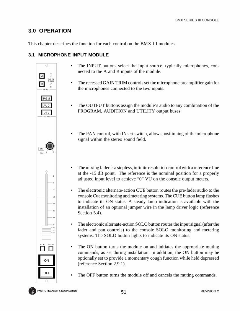
REVISION C
BMX SERIES III CONSOLE
51PACIFIC RESEARCH & ENGINEERING
3.0 OPERATION
This chapter describes the function for each control on the BMX III modules.
3.1 MICROPHONE INPUT MODULE
CUE SOLO
ON
OFF
L R
1 5
2 0
3 0
4 0
5 0
6 0
7 0
1 0
5
0
PAN
I N
OUTPUT
I N P U T
A
B
A
G A I NT R I M
B
UTL
AUD
PGM
• The INPUT buttons select the Input source, typically microphones, con-nected to the A and B inputs of the module.
• The recessed GAIN TRIM controls set the microphone preamplifier gain forthe microphones connected to the two inputs.
• The OUTPUT buttons assign the module’s audio to any combination of thePROGRAM, AUDITION and UTILITY output buses.
• The PAN control, with INsert switch, allows positioning of the microphonesignal within the stereo sound field.
• The mixing fader is a stepless, infinite resolution control with a reference lineat the -15 dB point. The reference is the nominal position for a properlyadjusted input level to achieve “0” VU on the console output meters.
• The electronic alternate-action CUE button routes the pre-fader audio to theconsole Cue monitoring and metering systems. The CUE button lamp flashesto indicate its ON status. A steady lamp indication is available with theinstallation of an optional jumper wire in the lamp driver logic (referenceSection 5.4).
• The electronic alternate-action SOLO button routes the input signal (after thefader and pan controls) to the console SOLO monitoring and meteringsystems. The SOLO button lights to indicate its ON status.
• The ON button turns the module on and initiates the appropriate mutingcommands, as set during installation. In addition, the ON button may beoptionally set to provide a momentary cough function while held depressed(reference Section 2.9.1).
• The OFF button turns the module off and cancels the muting commands.
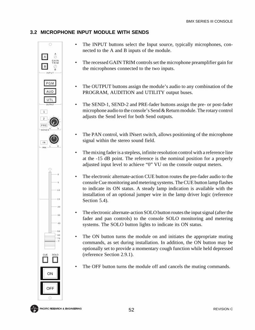
REVISION C
BMX SERIES III CONSOLE
52PACIFIC RESEARCH & ENGINEERING
3.2 MICROPHONE INPUT MODULE WITH SENDS
CUE SOLO
ON
OFF
L R
1 5
2 0
3 0
4 0
5 0
6 0
7 0
1 0
5
0
PAN
I N
S E N D S
OUTPUT
I N P U T
1
P R E
2
A
B
A
G A I NT R I M
B
UTL
AUD
PGM
0
• The INPUT buttons select the Input source, typically microphones, con-nected to the A and B inputs of the module.
• The recessed GAIN TRIM controls set the microphone preamplifier gain forthe microphones connected to the two inputs.
• The OUTPUT buttons assign the module’s audio to any combination of thePROGRAM, AUDITION and UTILITY output buses.
• The SEND-1, SEND-2 and PRE-fader buttons assign the pre- or post-fadermicrophone audio to the console’s Send & Return module. The rotary controladjusts the Send level for both Send outputs.
• The PAN control, with INsert switch, allows positioning of the microphonesignal within the stereo sound field.
• The mixing fader is a stepless, infinite resolution control with a reference lineat the -15 dB point. The reference is the nominal position for a properlyadjusted input level to achieve “0” VU on the console output meters.
• The electronic alternate-action CUE button routes the pre-fader audio to theconsole Cue monitoring and metering systems. The CUE button lamp flashesto indicate its ON status. A steady lamp indication is available with theinstallation of an optional jumper wire in the lamp driver logic (referenceSection 5.4).
• The electronic alternate-action SOLO button routes the input signal (after thefader and pan controls) to the console SOLO monitoring and meteringsystems. The SOLO button lights to indicate its ON status.
• The ON button turns the module on and initiates the appropriate mutingcommands, as set during installation. In addition, the ON button may beoptionally set to provide a momentary cough function while held depressed(reference Section 2.9.1).
• The OFF button turns the module off and cancels the muting commands.

REVISION C
BMX SERIES III CONSOLE
53PACIFIC RESEARCH & ENGINEERING
3.3 STEREO LINE INPUT MODULE
S U M
R I G H T
L E F T
S T E R E OI N P U TM O D E
CUE SOLO
ON
OFF
L R
1 5
2 0
3 0
4 0
5 0
6 0
7 0
1 0
5
0
PAN
I N
OUTPUT
I N P U T
A
B
L E F T
G A I NT R I M
R I G H T
UTL
AUD
PGM
• The INPUT buttons select between stereo sources connected to the A and Binputs of the module.
• The recessed GAIN TRIM controls adjust the gain of the LEFT and RIGHTinput buffers. These affect both inputs equally.
• The OUTPUT buttons assign the module to any combination of thePROGRAM, AUDITION and UTILITY output buses.
• The PAN control with INsert button may be used to adjust the left-rightbalance of a stereo signal, or to position a monaural or sum mode signalwithin the stereo sound field.
• The INPUT MODE selector determines the module mode as follows:STEREO Discrete stereo channels.
LEFT Left input is routed to both output channels.RIGHT Right input is routed to both output channels.
SUM Left and right inputs are summed to both output channels.
• The mixing fader is a stepless, infinite resolution control with a reference lineat the -15 dB point. The reference is the nominal position for a properlyadjusted input level to achieve “0” VU on the console output meters.
• The alternate-action CUE button routes pre-fader audio to the console Cuemonitoring and metering systems. The button lamp flashes to indicate its ONstatus. For a steady lamp indication, available with the installation of anoptional jumper wire, see Section 5.4.
• The alternate-action SOLO button routes the input signal (after the fader andpan controls) to the console SOLO monitoring and metering systems. TheSOLO button lights to indicate its ON status.
• The ON button turns the module on and initiates machine start control, timerreset or muting commands, as set during installation.
• The OFF button turns the module off and initiates machine stop controlcommands as set during installation. The OFF lamp may be set to act as amachine ready status indicator, see Section 2.9.2.

REVISION C
BMX SERIES III CONSOLE
54PACIFIC RESEARCH & ENGINEERING
3.4 STEREO LINE INPUT MODULE WITH SENDS
S U M
R I G H T
L E F T
S T E R E OI N P U TM O D E
CUE SOLO
ON
OFF
L R
1 5
2 0
3 0
4 0
5 0
6 0
7 0
1 0
5
0
PAN
I N
S E N D S
OUTPUT
I N P U T
1
P R E
2
A
B
L E F T
G A I NT R I M
R I G H T
UTL
AUD
PGM
0
• The INPUT buttons select between stereo sources connected to the A and Binputs of the module.
• The recessed GAIN TRIM controls adjust the gain of the LEFT and RIGHTinput buffers. These affect both inputs equally.
• The OUTPUT buttons assign the module to any combination of thePROGRAM, AUDITION and UTILITY output buses.
• The SEND-1, SEND-2 and PRE-fader buttons assign the pre- or post-faderaudio to the console’s Send & Return module. The rotary control adjusts theSend level for both Send outputs. Optional stereo Send functions andoperation are available, see Section 5.3.
• The PAN control with INsert button may be used to adjust the left-rightbalance of a stereo signal, or to position a monaural or sum mode signalwithin the stereo sound field.
• The INPUT MODE selector determines the module mode as follows:STEREO Discrete stereo channels.
LEFT Left input is routed to both output channels.RIGHT Right input is routed to both output channels.
SUM Left and right inputs are summed to both output channels.
• The mixing fader is a stepless, infinite resolution control with a reference lineat the -15 dB point. The reference is the nominal position for a properlyadjusted input level to achieve “0” VU on the console output meters.
• The alternate-action CUE button routes pre-fader audio to the console Cuemonitoring and metering systems. The button lamp flashes to indicate its ONstatus. For a steady lamp indication, available with the installation of anoptional jumper wire, see Section 5.4.
• The alternate-action SOLO button routes the input signal (after the fader andpan controls) to the console SOLO monitoring and metering systems. TheSOLO button lights to indicate its ON status.
• The ON button turns the module on and initiates machine start control, timerreset or muting commands, as set during installation.
• The OFF button turns the module off and initiates machine stop controlcommands as set during installation. The OFF lamp may be set to act as amachine ready status indicator, see Section 2.9.2.

REVISION C
BMX SERIES III CONSOLE
55PACIFIC RESEARCH & ENGINEERING
3.5 STEREO LINE OUTPUT AMPLIFIER
LEFT
GAINTRIM
RIGHT
• The recessed LEFT and RIGHT GAIN TRIM controls set the gain of the lineoutput distribution amplifiers. These controls are for engineering personnelonly.

REVISION C
BMX SERIES III CONSOLE
56PACIFIC RESEARCH & ENGINEERING
PGM
AUD
UTL
TALKBACK0
0
CUE
S U M
R I G H T
L E F T
S T E R E OI N P U TM O D E
0
MONITOR0
AUTO
HEADPHONE
CONTROL ROOM
• The 12-station Monitor Input switch selects the monitor source from thePROGRAM, AUDITION or UTILITY buses, or any one of nine externalsources.
NOTE: Legend strip dimensions are provided in Section 2.1.
• TALKBACK controls the level of Talkback communication received in theControl Room via the adjustable Talkback output or the Cue output (whenTalkback is assigned to Cue per Section 2.9.3).
NOTE: The TALKBACK control functions only when the Control Roomis muted.
• CUE controls the level of the Control Room Cue output.
• INPUT MODE sets the module’s monitor and headphone outputs as follows:STEREO Discrete stereo is output.
LEFT The Left input is routed to both output channels.RIGHT The Right input is routed to both output channels.
SUM Left and Right inputs are summed to both output channels.
• HEADPHONE controls the output level for the console operator’s head-phone system.
• When the AUTO button is up, Cue is not routed to the operator’s headphones.With the AUTO button down, and Cue active on any module, the operator’sheadphones automatically switch to Cue using the selected Auto-Cue Mode.Refer to Section 2.9.3 for information on the two Auto-Cue Modes.
• MONITOR controls the volume of the Control Room monitors.
3.6 CONTROL ROOM MONITOR MODULE

REVISION C
BMX SERIES III CONSOLE
57PACIFIC RESEARCH & ENGINEERING
3.7 TWO-STUDIO MONITOR MODULE
STUDIO-1
TALKOVERMUTE
TALKBACK
TALKOVERMUTE
STUDIO-2
0
TALKBACK0
PGM
AUD
UTL
MONITOR0
MONITOR0
This optional module includes the monitoring and talkback controls for twoseparate rooms, refered to as Studio-1 and Studio-2.
• The 12-station Monitor Input switch selects the monitor source, for bothStudio-1 and Studio-2, from the Program (PGM), Audition (AUD) or Utility(UTL) buses, or from one of the nine external Monitor Inputs.
NOTE: Legend strip dimensions are provided in Section 2.1.
STUDIO-1 CONTROLS
• TALKBACK controls the level of Talkback communications received inStudio-1.
• TALK OVER MUTE is an alternate-action switch which, when engaged(down), allows communication to Studio-1 even when there is a livemicrophone in the studio and the studio speakers are muted. This function isusually limited to off-air recording and production, although some “person-ality” formats do allow the console operator to talk to the hosts on-air.
• MONITOR controls the volume of the Studio-1 monitors.
STUDIO-2 CONTROLS
• TALKBACK controls the level of Talkback communications received inStudio-2.
• TALK OVER MUTE is an alternate-action switch which, when engaged(down), allows communication to Studio-2 even when there is a livemicrophone in the studio and the studio speakers are muted.
• MONITOR controls the volume of the Studio-2 monitors.

REVISION C
BMX SERIES III CONSOLE
58PACIFIC RESEARCH & ENGINEERING
3.8 MONAURAL LINE OUTPUT AMPLIFIER
MONOSOURCE
GAINTRIM
PGM
UTL
AUD
This optional module includes the Source Selection for the Mono Main and AuxOutputs and the gain trim for these outputs.
• The recessed GAIN TRIM control sets the gain of the monaural line outputdistribution amplifier. This control is for engineering personnel only.
• The MONO SOURCE buttons select the monaural output source. Anycombination of the summed PROGRAM, AUDITION and UTILITY outputbuses can be selected.

REVISION C
BMX SERIES III CONSOLE
59PACIFIC RESEARCH & ENGINEERING
3.9 MONAURAL OUTPUT/TELCO MIX MODULE
This optional module includes the independent functions for the Mono Main and Aux Outputs and theTelco Inputs, Outputs and Monitor. The Telco Mix half of the module produces the two outputs fed backto the callers. Each of the caller Feeds is a mix-minus output consisting of the selected SEND TOTELCO bus (normally the UTL bus, as described below) plus any selected callers minus the callerhimself. This mix-minus matrix is best illustrated through the module’s block diagram in Section 7.1.7.
NOTE: To assign a caller to an output bus (such as the PGM bus for “on-air” Telco operations), selectthe desired bus on the caller’s Input module and turn the module ON. Do not assign the caller's Inputmodule to the SEND TO TELCO bus (normally UTL), as the callers are added to the base mix-minususing the TELCO INPUT assignment buttons, as described below.
UTILITY BASE MIX
The Utility (UTL) bus is normally assigned as the base mix bus for Telco operations by configuring theconsole as follows:
1. Assign all Input modules to be included in the base mix to the UTL bus. Do Not assign anyInput Module with the Telco input to the UTL bus.
2. Select only UTL on the SEND TO TELCO switches.
3. Select which callers to add to the base mix using the TELCO-1 and TELCO-2 INPUTassignment buttons.
MONOSOURCE
GAINTRIM
PGM
UTL
AUD
PGM
AUD
UTL
SEND TOTELCO
INPUT
MONITOR
TELCO 2
TELCO 1
0
00TELCO MIX
NOTE: The Monaural Output and Telco Mix sections of this module functionindependently. The Monaural Output operations are covered in Section 3.8.
• The three SEND TO TELCO assignment switches selects the console busesthat are fed to all telephone callers (normally the Utility bus, as describedbelow).
• The TELCO-1 and TELCO-2 INPUT buttons select the input feeds from theInput Modules assigned as telephone hybrid inputs and assign them to themix matrix, where the two Telco outputs and the monitor mix are created.
• MONITOR controls the level of the variable Telco Monitor Output.
NOTE: Both Telco Monitor Outputs (fixed and variable) are non-mutedcaller-only outputs.

REVISION C
BMX SERIES III CONSOLE
60PACIFIC RESEARCH & ENGINEERING
3.10 SEND AND RETURN MODULE
S U M
R I G H T
L E F T
S T E R E OI N P U TM O D E
L RPAN
I N
OUTPUT
UTL
AUD
PGM
SEND OUTPUTS
S
ON
S
ON
0
0
0MIX
SOLOON
RETURN
1
2
∞
∞
∞
This optional module includes the independent functions for the two SendOutputs and Monitors and the stereo Return Input.
• ON controls the individual Send outputs. These buttons may be maintained-or momentary-action, as set by the setting of internal option switches (seeSection 2.9.5).
• S (SOLO) routes the individual pre-fader Send mix bus audio to the SOLOmonitoring and metering systems. The two rotary controls independentlyadjust the two Send levels.
• The OUTPUT buttons assign the stereo Return audio to any combination ofthe PROGRAM, AUDITION and UTILITY output buses.
• PAN controls, when the INsert switch is down, the left-right balance of astereo Return signal, or the position of a monaural or sum mode signal withinthe stereo sound field.
• The INPUT MODE switch routes the Return audio as follows:STEREO Discrete stereo channel throughput.
LEFT Left input is routed to both outputs.RIGHT Right input is routed to both outputs.
SUM Left and right inputs are summed to both outputs.
• MIX is a stepless, infinite resolution control for the Return audio.
• The alternate-action SOLO button routes the stereo Return audio to theconsole SOLO monitoring and metering systems. The SOLO button illumi-nates to tally its ON status.
• The alternate-action ON button turns the Return audio ON and OFF.
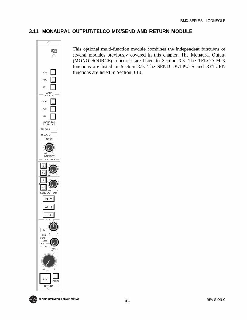
REVISION C
BMX SERIES III CONSOLE
61PACIFIC RESEARCH & ENGINEERING
3.11 MONAURAL OUTPUT/TELCO MIX/SEND AND RETURN MODULE
S U M
R I G H T
L E F T
S T E R E OI N P U TM O D E
L RPAN
I N
OUTPUT
UTL
AUD
PGM
SEND OUTPUTS
S
ON
S
ON
0
00
0
00
000
MIX
SOLOON
RETURN
1
2
MONOSOURCE
GAINTRIM
PGM
UTL
AUD
PGM
AUD
UTL
SEND TOTELCO
INPUT
MONITOR
TELCO 2
TELCO 1
0
00
TELCO MIX
This optional multi-function module combines the independent functions ofseveral modules previously covered in this chapter. The Monaural Output(MONO SOURCE) functions are listed in Section 3.8. The TELCO MIXfunctions are listed in Section 3.9. The SEND OUTPUTS and RETURNfunctions are listed in Section 3.10.

REVISION C
BMX SERIES III CONSOLE
62PACIFIC RESEARCH & ENGINEERING
3.12 SLATE/TALKBACK/TEST OSCILLATOR MODULE
OUTPUT
UTL
AUD
PGM
EXTERNALOUTPUT
EXTERNALINPUT
PRODUCERMIC
CONSOLEMIC
SLATELEVEL
G A I NT R I M
EXT
STUDIO2
STUDIO1
SLATE
OSCILLATOR
OSC
100
10
1
MULTIPLIER
FREQUENCY
0
00
LEVEL
30
50100
150
200
This optional module includes the independent functions for Control RoomTalkback to several locations, the Producer and External Talk interfacing, a 30Hz slate tone generator and a test tone oscillator.
• The OUTPUT buttons assign the test tone and the slate tone generators to anycombination of the Program (PGM), Audition (AUD) and Utility (UTL)output buses.
• The recessed GAIN TRIM controls independetly set these levels:
EXTERNAL OUTPUT sets the level of the External Talkback Output.EXTERNAL INPUT sets the level of the External Talkback Input.PRODUCER MIC sets the gain of the Producer Input preamplifier.CONSOLE MIC sets the gain of the meter panel electret microphone.SLATE LEVEL sets the output level of the slate tone. This control is factory-set for a -6 VU meter reading.
• The FREQUENCY selector and MULTIPLIER buttons set the outputfrequency of the built-in test tone oscillator.
• LEVEL adjusts the output level of the test tone oscillator.
• OSC, when engaged (down), switches the test tone oscillator output to thebuses selected by the OUTPUT assignment buttons. OSC, when not engaged(up) switches the Slate tone output to the buses adn turns off the toneoscillator.
• Pressing SLATE sends a mix of the 30 Hz Slate tone and the consoleTalkback microphone to the buses selected by the OUTPUT assignmentbuttons.
• The three Talkback buttons (STUDIO 1, STUDIO 2, EXT) provide commu-nications to two Studios and an External location. Multiple buttons can bepressed for simultaneous communications.

REVISION C
BMX SERIES III CONSOLE
63PACIFIC RESEARCH & ENGINEERING
3.13 METER SWITCHER MODULE
S O L O
C U E
M E T E RS W I T C H E R
• The five-station Meter Source switch selects the Auxiliary meter source. On26, 30 and 34 input mainframes, all five sources come from the MeterSwitcher Inputs. This allows metering of the monaural and Send buses,remote modulation readouts, etc. On the smaller mainframes, one or two ofthe Meter inputs are used to meter the Utility (UTL) and Audition (AUD)buses. On the 18 and 22 input mainframes, Input 5 (the bottom input) selectsUTL metering. On the smaller 10 and 14 input mainframes, the two bottominputs (Input 4 and 5) are used to meter AUD (Input 4) and UTL (Input 5).
NOTE: Legend strip dimensions are provided in Section 2.1.
• The SOLO and CUE tallies indicate when either function is engagedsomewhere in the console. While the SOLO or CUE tallies are lit, the Soloor Cue level is displayed on the Auxiliary meters.
NOTE: SOLO or CUE metering priority is set by an internal option switch(see Section 2.9.8).

REVISION C
BMX SERIES III CONSOLE
64PACIFIC RESEARCH & ENGINEERING
3.14 REMOTE LINE SELECTOR MODULE
Up to two optional Remote Line Selectors may be installed in the BMX III mainframe. The ten RemoteInputs are common between the two RLS modules.
• A ten-station switchbank selects one input source from among the tenRemote Inputs. The stereo output from each RLS module is then routed toan Input module, tape recorder, station playback system, etc.
NOTE: Legend strip dimensions are provided in Section 2.1.
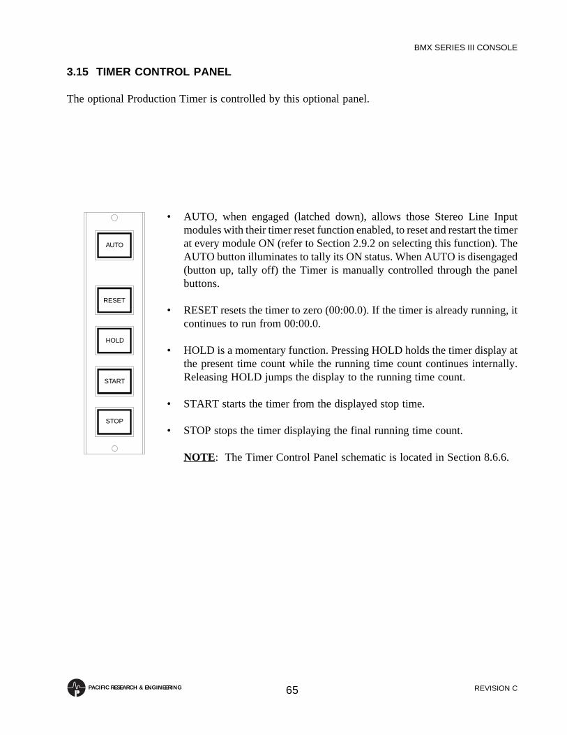
REVISION C
BMX SERIES III CONSOLE
65PACIFIC RESEARCH & ENGINEERING
AUTO
RESET
HOLD
START
STOP
3.15 TIMER CONTROL PANEL
The optional Production Timer is controlled by this optional panel.
• AUTO, when engaged (latched down), allows those Stereo Line Inputmodules with their timer reset function enabled, to reset and restart the timerat every module ON (refer to Section 2.9.2 on selecting this function). TheAUTO button illuminates to tally its ON status. When AUTO is disengaged(button up, tally off) the Timer is manually controlled through the panelbuttons.
• RESET resets the timer to zero (00:00.0). If the timer is already running, itcontinues to run from 00:00.0.
• HOLD is a momentary function. Pressing HOLD holds the timer display atthe present time count while the running time count continues internally.Releasing HOLD jumps the display to the running time count.
• START starts the timer from the displayed stop time.
• STOP stops the timer displaying the final running time count.
NOTE: The Timer Control Panel schematic is located in Section 8.6.6.

REVISION C
BMX SERIES III CONSOLE
66PACIFIC RESEARCH & ENGINEERING
4.0 EQUIPMENT DESCRIPTION
This chapter describes the functions and circuitry of the various components incorporated in the BMXIII console and its associated modules. Included are sections describing the mainframe, MicrophoneInput Module, Stereo Line Input Module, Stereo Line Output Amplifier, Control Room MonitorModule, Two-Studio Monitor Module, Monaural Line Output Amplifier, Monaural Output/Telco MixModule, Send and Return Module, Monaural Output/Telco Mix/Send And Return Module, Slate/Talkback/Test Oscillator Module, Meter Switcher Module, Remote Line Selector Module, VU MeterPower Regulator, VU Meter Buffer Amplifier, and Power Supply Assembly.
Corresponding diagrams and schematics are located in Chapter 7.
4.1 MAINFRAME
4.1.1 Function
The console mainframe contains all the interconnection wiring required to accommodate a fullcomplement of modules. Each input position is wired in a universal fashion and, therefore, will accepteither a Microphone Input or Stereo Line Input Module.
NOTE: Section 7.27 has the complete mainframe wiring diagrams.
4.1.2 Circuitry
The only active electronic components in the mainframe are the VU meter power regulator assemblyand the meter buffer amplifiers. These are described in detail in Sections 4.14 and 4.15, respectively.The meter buffer amplifiers are mounted on their respective meters, and the power regulator assemblyis mounted on the bottom of the console mainframe, beneath the Remote Line Selectors. The VU meterdistribution board is mounted inside the mainframe, immediately below the meters.
NOTE: The BMX III power supply assembly provides ±22 volt DC power to the console mainframe.This is regulated to ±16 volts DC by the VU meter regulator assembly and by regulator assemblies onall BMX III modules except output amplifiers, which regulate the ±22 volt DC power to ±18 volts DC(reference the module schematics located in Chapter 7).
The meter panel assemblies on the BMX III-10 and BMX III-14 are equipped with two sets of stereoVU meters (PROGRAM and AUXILIARY). The Audition and Utility buses are metered on theAuxiliary meters, as selected by the Meter Switcher module.
The BMX III-18 and BMX III-22 are equipped with three sets of stereo meters (PROGRAM,AUDITION and AUXILIARY). The Utility bus is metered on the Auxiliary meters, as selected by theMeter Switcher module.
The BMX III-26, BMX III-30 and BMX III-34 are equipped with four sets of stereo meters(PROGRAM, AUDITION, UTILITY and AUXILIARY).

REVISION C
BMX SERIES III CONSOLE
67PACIFIC RESEARCH & ENGINEERING
4.2 MICROPHONE INPUT MODULES
This section describes the function and circuitry of the Microphone Input Module (PR&E #99-262) andthe Microphone Input Module With Sends (PR&E #99-252). See Chapter 7 for the module schematics.
4.2.1 Function
Both versions of the Microphone Input Module accommodate a wide range of input levels, permittingthe use of all contemporary microphones. Phantom powering for condenser microphones on both A andB inputs is built into each Mic module (see Section 5.1 for details). Individual A and B input preampgain trimpots allow the module to handle nominal input levels from -60 dBu to -35 dBu.
The A/B input selector provides two microphone inputs per module, each with programmable monitormute selection for Control Room, Studio-1 or Studio-2. The mute circuitry incorporates an automatic40 millisecond delay before the microphone is turned on, permitting “room reverb” to decay off-mic.
The PAN control allows for positioning of the microphone signal within the stereo sound field, and thealternate action PGM, AUD and UTL buttons allow the module to be assigned to any or all of the consolestereo output buses.
4.2.2 Circuitry
NOTE: Except for the presence or absence of the Send circuitry, the two Microphone Input Modulesfunction identically. The additional Send circuitry is described at the end of the audio and logic circuitdescriptions.
AUDIO
Transformer-coupled microphone input preamplifier U1 utilizes variable feedback control to providean overall voltage gain range of 24 dB to 50 dB. Gain trim controls R9 and R10 adjust the preamplifiergain for the A and B inputs respectively. The gain is adjusted to provide a nominal -10 dBu level to thePatch Output. The Patch Input is buffered by balanced differential amplifier U2 operating at unity gain.This amplifier provides input common mode noise isolation and signal drive to the mix fader, Cue relayK3, and Talkback relays K4 and K5.
The mix fader “in-hand” attenuation is 15 dB, which is recovered by fader buffer amplifier U3 to the–10 dBu internal system level. The output of U3 is routed to the pan pot and the pan INsert switch. Theleft and right outputs of the pan circuit are buffered and amplified 3 dB by dual amplifier U4, and routedto channel on/off relay K1, and Solo relay K6. The channel on/off relay routes the signal to the outputbus assignment button switches.
With Sends
PRE/post fader Send switch S5 gets its pre-fader input from balanced differential amplifier U2, and itspost-fader input from dual amplifier U4. The outputs of the Send PRE/post switch are controlled by dual

REVISION C
BMX SERIES III CONSOLE
68PACIFIC RESEARCH & ENGINEERING
channel Send potentiometers R43 and R44, and routed through Send relay K2 to the two Send circuitON/off switches. This module may be modified for post-pan stereo Send operation by following theprocedure outlined in Section 5.3.
LOGIC
The selection of the A or B input to the module results in the selection of the corresponding control logic.One contact on input selector switch S2 is connected to pin 9 of U200, U201, U202 and U212. The setof logic controls for input A are chosen when this line is low and the logic controls for input B are chosenwhen this line is high. U200 and U201 select the A and B remote control inputs, U202 selects the statusof A and B programming switch S207, and U212 selects A and B tally output drivers.
Pressing the module’s ON button, or the On button on a remote control panel, causes the output ofU207A to go high and toggle flip-flop circuit U208 to the “on” state. The low output from pin 4 of theflip-flop is connected to U206 pin 9, and U211 pins 12 and 8. If the logic programming switch has beenset for a microphone located in the Control Room, the output of U206 will turn on transistor Q200 topull down the Control Room mute bus. In the same manner U211D/Q201 and U211C/Q202 provideStudio-1 and Studio-2 monitor muting for inputs set to those locations.
The high output from pin 3 of the flip-flop is connected to the inputs of U215B and U211B. The otherinputs of U215B are normally high; therefore, the high provided by the flip-flop will give a high outputto the tally lamp and audio relay drive circuits U213A/Q229 and U216B/Q228. The input to U216Bis delayed with a 40 millisecond network consisting of R273 and C237. Circuit U211B, used as aninverter, along with U213B and Q230, removes the tally voltage from the OFF light. The outputs ofU213A and U213B also connect to U212, for routing to the appropriate remote tally lamp driver. Eachof the four tally outputs has its own lamp driver, shown schematically as Lamp Driver B, and each ofthe two 12 volt output sources has its own driver, shown schematically as Lamp Driver A.
The lamp is driven by a low applied to R280, which pulls down the base of Q211 via conducting FETQ210. Q210 normally operates at zero bias.
NOTE: If a short should occur in the load, Q210 will be pinched off to remove the base current fromQ211. This protection circuit is reset by switching off the drive and removing the short.
Pressing the OFF button on the module, or on the selected input’s remote control panel, will cause theoutput of U214 to go high and toggle flip-flop circuit U208 to the “off” state. Time delay network R273,C237, R274 is bypassed by CR209 to eliminate any delay in turning the audio relay off.
Operation of either the A or B input selector button places a momentary low pulse into the input of U214,which will key the channel logic to the “off” state to prevent any input switching transient from beingrouted into the console mix buses.
The CONSOLE COUGH ENABLE switch is intended for use with a microphone located at the console.This switch connects the ON button directly to U215B to provide momentary channel muting wheneverthe ON button is held depressed.

REVISION C
BMX SERIES III CONSOLE
69PACIFIC RESEARCH & ENGINEERING
The remote control cough muting function is achieved by pulling low the appropriate A or B cough line,which is selected by U201, and routed through U215B to U215A. Whenever any of the inputs to U215Aare low, the “on” tally lights are extinguished and the channel outputs are muted. When the cough lineis released, the outputs are unmuted and the “on” lamps illuminated.
Pressing the CUE button gives a high output from U207B to CUE bistable U210A. When the CUEfunction is engaged, U210A output pin 1 goes high to turn on CUE relay K3, and pull the CUE commandbus low via Q203. Output pin 2 goes low and is routed to Control Room monitor mute selector U206B.A Control Room microphone selection causes a high at the output of U206, saturating Q200, and pullingdown the Control Room mute bus to prevent feedback. This change of state is also routed to networkC222 and R223, through U209A, to reset SOLO bistable U210B if this function was engaged. The CUEbistable output is also coupled to a lamp flashing circuit for the CUE lamp. The lamp flashing circuitmay be defeated by strapping together points E200 and E201 on the printed circuit board. The modulewill be taken out of the CUE mode when the channel ON button is pressed, if CUE RESET ENABLEswitch S204B pins 2 and 3 are closed.
Pressing the SOLO button gives a high output from U207C to SOLO bistable U210B. When the SOLOfunction is engaged, U210B output pin 13 goes high to turn on SOLO relay K6, and pull the SOLOcommand bus low via Q204. Output pin 12 goes low and is routed to Control Room monitor muteselector U206B. A Control Room microphone selection will causes a high at the output of U206B,saturating Q200, and pulling down the Control Room mute bus to prevent feedback. The change of stateis also routed to network C219 and R220, through U209B, to reset CUE bistable U210A, if the CUEfunction was engaged. The low at pin 12 also drives Q206 to turn on the lamp in the SOLO button. Themodule will be taken out of the SOLO mode when the channel ON button is pressed, if SOLO RESETENABLE switch S204A pins 1 and 4 are closed.
A remote control “privacy” mode is available which prevents the module from being able to enter theCUE or SOLO functions. This INHIBIT function is routed from logic input selector U201 throughU208 to both U209A and U209B. The inhibit function puts a high into the reset inputs of both the CUEand SOLO bistables to lock them in the “off” mode.
Circuit U200 selects the input A and B Talkback selection functions. Pin 14 is low for Talkback to theControl Room, pin 4 for Studio-1, pin 5 for Studio-2, and pin 13 for the External location. Circuit U202is used as the input microphone location status selector, as determined by module programming switchS207. Pin 13 will be low for a Control Room microphone, pin 14 for Studio-1, pin 4 for Studio-2, andpin 5 for the External location. The outputs of U200 and U202 are routed to gates U203, U204, U205,and U206B. These gates provide the logic controls for a location to Talk to any other location, dim themonitor levels at the originating location, and command the Talkback function at the destinationlocation.
For an input module to Talk to the Control Room, one of the Talk to Control Room lines is pulled lowby a “Talk to Control Room” push-button switch. This will cause a low at U200 pin 14, which is routedto U203 pin 1, which will generate a low output at U203 pin 7. The low at U203 pin 7 is routed to U215Apin 3, giving a low at the output of U215A, which is routed to U215B. The “on” tally circuit will bede-energized. The low at U203 pin 7, via inverter U213F, saturates Q221, pulling down the Talk to

REVISION C
BMX SERIES III CONSOLE
70PACIFIC RESEARCH & ENGINEERING
Control Room bus, and also drives U216C via time delay network R253, R254, C229 and CR203. Theoutput of inverter U216C drives Talkback relay K5 at pin 6.
The other Talkback functions operate in a similar fashion. One of the input control lines is pulled lowby a push-button switch, the appropriate output from A/B selector U200 will then be low, and the logicin U203, U204, U205 and U206 will pull down the appropriate control bus, dim the monitor, engagethe Talk circuit, and mute the signal from being on program lines at the same time. This logic designalso prevents a microphone from Talking to its own location.
With Sends
Send relay K2 is energized through Q228. When internal option switch S206 is ON, Sends are alwaysactive with PRE-fader selection, regardless of the ON/OFF status of the module.
4.3 STEREO LINE INPUT MODULES
This section describes the function and circuitry of both the Stereo Line Input Module (PR&E #99-263)and the Stereo Line Input Module With Sends (PR&E #99-253). Schematics for both modules arelocated in Chapter 7.
4.3.1 Function
Both Stereo Line Input Modules will accommodate nominal input levels from -12 dBu to +8 dBu. TheA/B input selector allows for the selection of either of two stereo inputs. Separate logic controls areavailable for each input for the remote control of tape machines and/or other sources, and the INPUTMODE switch allows for the selection of a STEREO, MONO, LEFT or RIGHT source to be sent tothe output assignment switches.
4.3.2 Circuitry
NOTE: Except for the presence or absence of the Send circuitry, the two Stereo Line Input Modulesfunction identically. The additional Send circuitry is described at the end of the audio and logic circuitdescriptions.
AUDIO
NOTE: The stereo audio path consists of two identical sets of circuitry. For clarity and simplicity, onlythe left channel is described below.
The input to the module is a balanced, symmetrical input, instrumentation amplifier. This amplifieris configured with three operational amplifiers, contained on plug-in function amplifier A1, operatingwith a cross-coupled input stage feedback gain trim control. The voltage gain range from module inputto the output of the amplifier is -18 dB to +2 dB. The gain trim control is adjusted to provide a levelof -10 dB to the Patch Output line.

REVISION C
BMX SERIES III CONSOLE
71PACIFIC RESEARCH & ENGINEERING
The Patch Input signal is buffered by balanced differential amplifier U1A operating at unity gain, andthen routed to the INPUT MODE switch. The output of the mode switch is connected to the mix fader,and CUE bus relay K2.
The mix fader “in-hand” attenuation of 15 dB is recovered by fader buffer amplifier U2A to the -10 dBuinternal system level, and routed to the PAN pot and the pan insert switch. The pan switch selectsbetween the attenuated output of the fader buffer and the output of the pan pot, and then routes the signalto amplifier U3A, which operates at a gain of 3 dB. The output of U3A is connected to channel on/offrelay K3 and SOLO relay K4. The channel on/off relay then routes the signal to the output busassignment switches and the direct output lines.
With Sends
PRE/post fader Send switch S3 gets its PRE-fader input from INPUT MODE switch, and its post-faderinput from amplifiers U3A and U3B. The outputs of the two-section Send fader are routed through Sendrelay K1 to the two Send ON/off switches. The two Send signals are a monaural mix of the left andright channels. However, this module may be modified for stereo Send operation by following theprocedure outlined in Section 5.3.
LOGIC
The module is provided with two sets of control logic, one for each of the A and B inputs. This logicincludes the capacity to provide independent machine and remote controls for the ON, OFF, CUE, andSOLO functions for each input. A contact on the A/B input selector switch is routed to integrated circuitswitches U206, U200, U212 and U201. U206 selects the A/B logic status of the module, as determinedby programming switches S200, U200 (the A and B remote control input lines), and U212, U201 (theA and B output tally lamp and control pulse lines).
When the module or the selected input’s remote control ON button is pressed, the output of U202A willgo high. This output is routed to channel on/off flip-flop U209, and CUE and SOLO reset enableswitches S205-1 and S205-2, respectively. The low “on” output from U209 pin 3 is routed to themonitor mute gates in U207, to delay circuit R239, C213, R240 and U208D, to channel ON/OFF relaydrive transistor Q204, and also to ON relay K3. This low is also connected to output switch U212, andto “on” lamp drive transistor Q205. The high “on” output from U209 pin 11 is routed to “off” lamp gateU205A, through “start” pulse generator circuit U211A to output switch U212, and through timer “reset”pulse generator U211B to transistor Q207.
When the module or the selected input’s remote control OFF button is pressed, the output of U203 willgo high. This output is connected to channel on/off flip-flop U209, and resets it to the “off” state. Theoutput of U209 pin 3 goes high, and bypasses the turn-on delay network via diode CR202 to turn offthe channel relays. The channel audio is also switched off when either the A or B input selector switchis operated by generating a short pulse into “off” gate U203 pins 11 and 12, respectively.
Output driver short-circuit protection is provided to prevent damage caused by shorts in the output lines.As an example of this protection, consider the case when the A INPUT ON TALLY lamp is powered;

REVISION C
BMX SERIES III CONSOLE
72PACIFIC RESEARCH & ENGINEERING
a short circuit will drop the gate of Q208 to ground, which turns the FET off and removes the drivecurrent from the base of output transistor Q209.
The module’s OFF lamp may be remotely controlled by applying a low to the selected remote READYinput. This is routed through U200 pin 4 to U205A pin 2, which will result in a low output at pin 9,keying “on” OFF lamp driver Q206. This provides the facility of using the module’s OFF lamp to tallythe ready state of remote controlled equipment.
Pressing the module or the selected input’s remote control CUE button causes a high to appear at theoutput of U202B, which is connected to U210A. Circuit U210A is connected in a bistableconfiguration, with each positive-going transition causing the output of U210 to change state. Theoutput of this CUE bistable is routed to CUE relay K2, CUE logic bus drive transistor Q224, SOLOreset circuit U205C, and to the CUE lamp flasher circuit of U202 and U208. The circuitry around U202and U208 is a free-running multivibrator. The lamp flasher may be defeated by installing a jumperbetween E212 and E213 on the printed circuit board. The output of the lamp flasher circuit is connectedto CUE lamp drive transistor Q225, and to remote CUE tally output switch U201.
Pressing the module or the selected input’s remote control SOLO button causes a high to appear at theoutput of U202C, which is connected to U210B. Circuit U210B is connected in a bistable configuration,with each positive-going transition causing the output of U210 to change state. The output of this SOLObistable is routed to SOLO relay K4, SOLO logic bus drive transistor Q226, CUE reset circuit U205B,and SOLO lamp drive transistors Q227 and Q228. The low output from transistor Q227 is also routedto remote SOLO tally output switch U201.
With Sends
Send relay K1 is energized by channel ON/OFF relay drive transistor Q204. When internal optionswitch S206 is ON, Send-1 and Send-2 are always active with PRE-fader selection, regardless of theON/OFF status of the module.
4.4 STEREO LINE OUTPUT AMPLIFIER
4.4.1 Function
The Stereo Line Output Amplifier contains the mixing and distribution amplifiers for a console lineoutput. The console mainframe is supplied with three of these modules; one each for the PROGRAM,AUDITION and UTILITY buses. Each module supplies four distribution outputs, with each outputcapable of supplying up to +28 dBm. The main output is an active balanced design. Patch send andreturn points are available for the connection of external processing equipment and/or a patch field.
4.4.2 Circuitry
NOTE: The stereo audio path consists of two identical sets of circuitry. For clarity and simplicity, onlythe left channel is described below.

REVISION C
BMX SERIES III CONSOLE
73PACIFIC RESEARCH & ENGINEERING
Bus summing amplifier A3 is a discrete JE-990 type operational amplifier constructed on a plug-inmodule. The output of the summer is connected to inverting amplifier U1 to provide an inphase outputto the bus patch point. Both of these amplifiers operate at unity gain and, therefore, provide a nominallevel of -10 dBu to the Bus Patch Output.
The Patch Return input signal is buffered by balanced differential amplifier U4 operating at unity gain.The output of U4 is routed to variable gain amplifier U5, and also to monaural mixing amplifier U6.Voltage gain amplifier U5 is adjusted by front panel Gain Trim control R26, and has sufficient rangeto adjust the output level from +4 dBu to +8 dBu. The output of U5 is connected to line output amplifiersA1 and A2 operating as a push-pull pair to provide balanced drive to the console distribution outputlines.
NOTE: The early version of the Stereo Line Output Amplifier was designed to accommodate theoptional installation of a Jensen type JE-123A transformer in the main output, meter and monitor lines.This option was discontinued in 1986 due to lack of interest.
4.5 CONTROL ROOM MONITOR MODULE
4.5.1 Function
The Control Room Monitor Module allows for the monitoring of PROGRAM, AUDITION, UTILITY,or any of nine stereo line inputs by means of an interlocking monitor selector. The module consists offive sections: monitor, SOLO, CUE, Talkback and headphone. Each section has a relationship withthe others that can be best appreciated by reviewing the module block diagram located in Chapter 7.
4.5.2 Circuitry
AUDIO
NOTE: The stereo audio paths for the monitor, solo, cue and headphone sections consist of twoidentical sets of circuitry. For clarity and simplicity, only the left channel of each section is describedbelow.
The input to the monitor is selected by the front panel 12-station push button switch assembly. The inputto the module is a balanced, symmetrical input, instrumentation amplifier. This amplifier is configuredwith three operational amplifiers, contained on the plug-in function amplifier A1, operating with cross-coupled input stage feedback. The voltage gain from module input to the output of the instrumentationamplifier is -8 dB for consoles operating at a +8 dBm reference level, and -4 dB for consoles operatingat a +4 dBm reference level. The output of this stage is routed through the SOLO relay, INPUT MODEswitch, dim relay, MONITOR level control, mute relay, and output buffer amplifier U4A. This bufferoperates at unity gain, as supplied by the factory. The gain of this stage may be increased to 6 dB withthe installation of R28 and C19 as shown in the schematic in Chapter 7 of this document.
The output of the monitor input stage is also routed through Talk to selector output relay K1 to selectbuffer amplifier U1A. The 6 dB loss of the Talk to direct relay circuit is made up by the 6 dB gain of

REVISION C
BMX SERIES III CONSOLE
74PACIFIC RESEARCH & ENGINEERING
amplifier U1A. The output of the INPUT MODE switch is also routed to the AUTO-CUE FUNCTIONheader, and relays K5 and K6.
The SOLO bus input is summed by amplifier U2A and inverted by U3A. The output is connected tothe SOLO METER output terminal, and to SOLO relay K2 in the monitor section.
The CUE bus input is summed by amplifier U5A and inverted by U6A. The output is connected to theCUE METER output terminal and AUTO-CUE FUNCTION header U7. The output of U6A is alsorouted through the front panel CUE level control, mute relay K9, and output buffer amplifier U10A.The 6 dB loss of the Talkback insert circuit is made up by the 6 dB gain of the buffer amplifier.
The headphone signal from AUTO-CUE relays K5 and K6 is routed through Talkback insert relay K7and the HEADPHONE level control, to plug-in amplifier assembly A2. The line amplifier operatesat a fixed gain of 12 dB.
The Talkback to Control Room bus signal is summed by U8A and inverted by U8B. The output of U8Bis connected to the TALKBACK OUTPUT terminal, to Talkback insert relays K1 and K7, and to theTALKBACK level control. The output of the TALKBACK control is routed to Talk to CUE relay K8A,Talkback mute relay K8B, and output buffer amplifier U9. This buffer operates at unity gain, as suppliedby the factory. The gain of this stage may be increased to 6 dB with the installation of R61 and C44as shown in the schematic.
LOGIC
The Control Room monitor system may be muted by a low applied to the MUTE CR logic bus or bya low applied to the REMOTE MUTE CR input line. In either case, the low command causes a highoutput on gate U200A. This high signal is routed to monitor mute relay K4, MUTE OUTPUT transistorQ200, and through inverter U201F to warning lamp driver circuit Q201 and Q202.
The Control Room monitor system may be dimmed by a low applied to the DIM CR logic bus or bya low applied to the REMOTE DIM CR input line. In either case, the low command causes a high outputon gate U200D. This high is routed through gate U202D to dim relay K3, and to DIM OUTPUTtransistor Q203.
The TALK CR bus is driven low whenever a Microphone Input Module, or the External input to theSlate/Talkback/Test Oscillator Module, initiates communication to the Control Room. This low isrouted through gate U202B and inverter U201B to Talk to headphone relay K7. This low may also beapplied to Talk to CUE relay K8A by closing internal option switch S200-1, and to Talk to direct relayK1 by closing switch S200-3.
The Talk to Control Room command may also be set to dim the Control Room monitor system byclosing switch S200-2, which directs the high output of U201B to monitor dim relay K3.
The Control Room monitors are automatically dimmed whenever the console initiates Talkback toanother location. This low dim command comes into the monitor module on the DIM CR bus. This

REVISION C
BMX SERIES III CONSOLE
75PACIFIC RESEARCH & ENGINEERING
low command may be routed by option switch S200-4 through inverter U201E and gate U202B to holdthe input of U201B high. This high locks out the Talk to Control Room logic, and establishes a priorityof communication in the Control Room’s favor.
The CUE system is activated whenever a low is applied to the CUE logic bus. This results in a highoutput from inverter U201D, which is routed to auto-CUE relays K5 and K6 and the CUE TO METERSW output.
The SOLO system is activated whenever a low is applied to the SOLO logic bus. This results in a highoutput from inverter U201C, which is routed to SOLO relay K2 and the SOLO TO METER SW output.
4.6 TWO-STUDIO MONITOR MODULE
4.6.1 Function
The Two-Studio Monitor Module is expressly designed for applications where separate voice/announcebooths or conference Studios are required. This module provides the monitor, headphone and Talkbackfacilities for up to two Studios. Monitoring of PROGRAM, AUDITION, UTILITY, or any of nineexternal sources is provided by means of an interlocking monitor selector.
The module consists of a common monitor source selector and two identical sets of “guest” and “talent”headphone outputs, fixed and variable level monitor outputs, and Talkback to Studio circuits. Eachsection of each Studio’s monitor circuitry has a relationship with the others which can best beappreciated by reviewing the module block diagram located in Chapter 7 of this document.
4.6.2 Circuitry
AUDIO
NOTE: The stereo audio paths for the monitor and headphone sections consist of two identical setsof circuitry. For clarity and simplicity, only the left channel of the Studio-1 section is described below.
The input to the Studio monitors is selected by the front panel 12-station push button switch assembly,and routed to the balanced, symmetrical input, instrumentation amplifier. This amplifier is configuredwith three operational amplifiers contained on plug-in function amplifier A1, operating with cross-coupled input stage feedback. The voltage gain from module input to the output of the instrumentationamplifier is -8 dB. The output of this stage is connected to the module MONITOR SELECT OUTterminals, to Talk to talent headphone relay K3, and to the input of mute Studio relay K1.
The output of Talk to talent headphone relay K3 is buffered by amplifier U3A, which operates with 6dB of gain to recover the 6 dB loss of the Talkback insert circuit. The output of U3A is connected tothe module TALENT HEADPHONE OUT terminal.
The output of the mute Studio relay is routed through dim relay K2 and feeds both the fixed and variablelevel monitor circuits. The “fixed level” signal is routed through Talk to Studio relay K4 and buffer

REVISION C
BMX SERIES III CONSOLE
76PACIFIC RESEARCH & ENGINEERING
amplifier U4A. Dim relay K2, when energized, inserts a fixed 12 dB attenuator into the signal path. Thegain of U4A is 6 dB to recover the 6 dB loss of the Talkback insert circuitry. The output of U4A isconnected to the module FIXED OUTPUT LEFT terminal.
The “variable level” signal path includes the front panel MONITOR level control, Talk to Studio relayK5, and buffer amplifier U5A. The gain of U5A is also 6 dB to recover the loss of the Talkback insertcircuitry. The output of U5A is connected to the module VARIABLE OUTPUT LEFT terminal.
The TALK TO STUDIO BUS-1 signal is summed and inverted by dual amplifier U1, and routed to Talkto talent relay K3 and Talk to Studio relays K4 and K5. An additional output from U1 is connected tothe TALK TO STUDIO-1 OUT terminal. The resistor network around each of the Talkback relayscauses the monitor signal to be dimmed by 10 dB whenever the relay is energized to insert the Talkbacksignal, and allows the Talkback signal to be inserted at unity gain over the attenuated monitor signal.
LOGIC
The Studio-1 monitor system may be muted by a low applied to the MUTE STUDIO-1 logic bus, orby a low applied to the REMOTE MUTE input line. In either case, a low input will cause a high outputfrom gate U200D. This high is routed through Q201 to monitor mute relay K1, REMOTE MUTECOMMAND transistor Q200, through inverter U203E to warning lamp driver circuit Q202 and Q203,and to front panel TALK OVER MUTE switch S200.
The Studio-1 monitor system may be dimmed by a low applied to the DIM STUDIO-1 logic bus, orby a low applied to the REMOTE DIM input line. In either case, a low input will cause a high outputfrom gate U200A. This high is routed through Q205 to drive dim relay K2, and to REMOTE DIMDRIVE COMMAND transistor Q204. The logic bus dim command is also connected to internal optionswitch S202 (“dim disables Talk”). This switch provides the ability to establish a one-way priority ofcommunication from the Studio by switching the DIM STUDIO command to inhibit the receipt ofTALK TO STUDIO commands. This is accomplished by closing switch S202, which then routes thedim command through inverter U202C to Talk to Studio gate U201.
The TALK STUDIO-1 bus is driven low whenever a Microphone Input Module assigned to Studio-1initiates communication to another location. This low is routed to Talk to Studio gate U201, and toinverter U203D. Gate U201B provides the control logic for the TALK OVER MUTE feature. Theoutput of U201B is routed through inverter U202E to Talk to Studio relays K4 and K5. The output ofinverter U203D drives Talk to talent headphone relay K3 and REMOTE TALK COMMAND transistorQ206.
4.7 MONAURAL LINE OUTPUT AMPLIFIER
4.7.1 Function
The Monaural Line Output Amplifier may select or mix any combination of the PROGRAM,AUDITION and UTILITY stereo signals to produce balanced MAIN and AUXILIARY monauraloutputs.

REVISION C
BMX SERIES III CONSOLE
77PACIFIC RESEARCH & ENGINEERING
4.7.2 Circuitry
The input signals are supplied by the three Stereo Line Output Amplifiers, and are selected by the frontpanel MONO SOURCE switch and connected to variable gain amplifier U1. The voltage gain of U1is adjusted by the front panel GAIN TRIM control, and has sufficient range to adjust the output levelfrom +4 dBu to +8 dBu. The output of U1 is connected to line output plug-in amplifiers A1 and A2,operating as a push-pull pair to provide balanced drive to the output lines.
4.8 MONAURAL OUTPUT/TELCO MIX MODULE
The Monaural Output and Telco Mix sections of this module function independently. The MonauralOutput section is described in Section 4.7.
4.8.1 Function
The Telco Mix section produces up to three unique output mixes from the two telephone caller inputsand a selection of the PROGRAM, AUDITION or UTILITY bus. The module receives its inputs fromthose Stereo Line Input Modules designated as Telco inputs, and creates a unique output for each callerwhich includes the selected bus plus any other caller except the caller’s own voice (i.e., “mix-minus”).Each mix-minus output may be bandpass limited with internally switchable filters for improved hybridoperation (reference Section 2.9.5).
NOTE: In order to assign a caller to the PROGRAM, AUDITION and/or UTILITY output buses (suchas the PROGRAM bus for “on-air” Telco operations), the desired bus must be selected on the StereoLine Input Module being used as the caller’s Telco input.
The Telco Mix Module also creates a “monitor mix”, which is the summed inputs of all callers. Thismix may also be used for applications where it is desired to create one or more custom mix-minusfoldback mixes or CUE feeds.
4.8.2 Circuitry
The inputs for the two telephone input module signals are routed to the front panel TELCO 1 andTELCO 2 INPUT selectors. A monaural mix of each of the three main console outputs is connectedto the SEND TO TELCO switch. The output of this selector is buffered by input amplifier U601Boperating at unity gain to provide a level of -10 dBu to the mix-minus matrix.
The Telco monitor mix matrix consists of resistors R603 and R703 and mixing amplifier U601A.Amplifier U601A operates with a voltage gain of 10 dB resulting in a nominal output level of 0 dBu,which is connected to the front panel MONITOR control and the MONITOR OUTPUT terminals.
NOTE: The two Telco mix-minus circuits are identical, thus only the Telco 1 path is described.
The Telco 1 mix matrix consists of resistors R614 and R615 and summing amplifier U602B operatingat unity gain.

REVISION C
BMX SERIES III CONSOLE
78PACIFIC RESEARCH & ENGINEERING
The -10 dBu output of U602B is routed to the bandpass filter circuit and to filter in/out switch S601A.The highpass filter is a three-pole, 18 dB/octave design, using U603B and its related components. Theoutput of the highpass filter is applied to a lowpass filter, also a three-pole design, using U603A andassociated parts. The 3 dB points of the resulting bandpass filter are slightly below 300 Hz and slightlyabove 3400 Hz. The output of the filter is connected to filter in/out switch S601A.
The signal, as chosen by the filter in/out switch, is connected to output amplifiers U604A and U604B.The first stage operates at a gain of 4 dB and the second, inverting stage, at unity. The input to outputgain of the push-pull pair is 10 dB, resulting in an output level of 0 dBu.
4.9 SEND AND RETURN MODULE
4.9.1 Function
The Send and Return Module contains both the two Send amplifiers and the stereo Return circuits. TheSend portion of the module contains the mixing and output amplifiers for the effects/foldback channels.The Return signal may be assigned to the PROGRAM, AUDITION or UTILITY output buses.
4.9.2 Circuitry
SEND AUDIO
NOTE: The two Send output circuits are identical, thus only Send-1 is described.
The Send-1 bus signal is summed and inverted by amplifiers U101A and U101B, which are operatingat unity gain. The output of U101B is routed through Send on/off relay K100 and the front panel SEND–1 master fader to balanced line output amplifiers U102A and U102B. Amplifier U102A operates witha gain of 22 dB while inverting amplifier U102B operates at unity. Therefore, the total voltage gainfrom input to balanced output of the line amplifiers is 28 dB. This gain provides a master fader “in-hand” attenuation of 10 dB for an output level of +4 dBu.
The output of U101B is also connected to solo relay K1A. When energized, this relay routes the pre-fader signal to both of the stereo SOLO buses via resistors R321 and R421.
SEND LOGIC
NOTE: The logic circuitry for the two Send circuits are essentially identical. For clarity and simplicity,only the circuitry for Send-1 is described below.
Pressing the Send ON button will pull down the input to inverter U3B, which will deliver a high outputto S1A and the input of U8C. If S1A is as shown, pin 2 closed to pin 4, the high output from U3B willbe applied to the input of U6D. Each time the ON button is pressed, bistable U5A will be toggled bythe positive-going signal applied to its input, and its output will change state. The output of bistableU5A is connected to one input of gate U4A. A high at any input to this device will cause a high at itsoutput. This high is applied through inverter U7B to ON lamp drive transistor Q3, and to transistor Q2

REVISION C
BMX SERIES III CONSOLE
79PACIFIC RESEARCH & ENGINEERING
to drive Send on/off relay K100. The output of U4A also drives inverter U7C, which activates Send-1 ON Tally transistors Q4 and Q5.
Note that the circuit, as described, is an alternate-action system in which the Send is switched on whenthe ON button is pressed, and is switched off when the ON button is pressed again. If switch S1A isset to connect pin 2 to pin 3, the bistable is removed from the circuit. Under this condition the Sendwill be switched on only while the ON button is held down. The remote ON function operates in asimilar manner, using U3D as an input buffer and S1B to determine the choice between alternate actionand momentary control.
The SOLO function operates in a similar manner except that the switching is always alternate-action.The input buffering is done by U3F and the toggling by U9A. The output of U9A at pin 2 is appliedto SOLO lamp driver Q1. The output of U9A pin 1 operates SOLO relay K1. The output of U9A pin1 also drives OR gate U4C. Any logic high at the input to this gate results in a high output, which pullsdown the SOLO BUS via transistor Q6. Operating the SOLO button again will toggle bistable U9Ato turn off the SOLO mode. If a local or remote Send ON button is pressed, a high will be deliveredto one of the inputs of U8C. Either of these highs will cause a high on the output of U8C, which willreset the SOLO bistable to the “off” condition.
RETURN AUDIO
NOTE: The stereo return circuits consist of two identical sets of circuitry. For clarity and simplicity,only the left channel is described below.
The input signal is buffered by balanced differential amplifier U300B, operating with a gain of -8 dB.The output of U300B is routed through the front panel INPUT MODE switch, MIX level control, andbuffer to the PAN control and pan insert switch. The output of the pan circuitry is buffered by U302B,and then connected to channel on/off relay K300 and SOLO relay K301. The output of channel relayK300 is connected to the stereo mix bus assignment buttons, while the output of SOLO relay K301 isrouted through resistor R320 to the SOLO LEFT BUS terminal.
RETURN LOGIC
Pressing the local RETURN ON button causes the output of U10F to go high. This high is connectedthrough gate U6A to the input of bistable U12A, which causes the bistable to toggle. The output ofU12A pin 1 will go high. This high is inverted by U7F to operate the remote “on” lamp via Q14 andQ15, inverted by U10E to energize ON relay K300 and the ON tally via Q13, and routed through gateU11B to turn off remote “off” tally drive circuit Q16 and Q17. Pressing the ON button again togglesU12A, causing pin 1 to go low and drive remote “off” lamp drive circuit U11B, Q16 and Q17. Theadditional circuitry around remote tally drive circuits is for short-circuit protection on the external lines.
Unlike the module’s controls, the remote controls are not alternate action, but are independent “on” and“off” controls. Pressing a remote ON button causes a high output from U10B, which is routed to U11C.If U12A is in the off state (pin 2 high), then U11C will deliver a high at its output. This will toggleU12A via U6A. Pressing the remote ON button again causes no further action because U11C pin 10

REVISION C
BMX SERIES III CONSOLE
80PACIFIC RESEARCH & ENGINEERING
will then be low. Pressing a remote OFF button causes a high output from U10D, which is routed toU6B, causing a high output. This high is routed to U12A to reset the bistable to the off state. Furtheroperation of the remote OFF button has no effect.
Pressing the SOLO button causes a high output at U7A, which toggles SOLO bistable U12B with outputpin 13 high and pin 12 low. The high output from U12B pin 13 is routed through U4C to SOLO busdrive transistor Q6. The high output of U12B also energizes SOLO relay K301. The low output fromU12B pin 12 saturates transistor Q12 to drive the SOLO button lamp. Pressing the SOLO button againtoggles U12B, de-energizing the SOLO relay and extinguishing the SOLO button lamp. Pressing eitherthe local or remote ON buttons will produce a high output from U8B, which will reset solo bistableU12B.
4.10 MONAURAL OUTPUT/TELCO MIX/SEND AND RETURN MODULE
The Monaural Output, Telco Mix, and Send And Return sections of this module function independently.The Monaural Output section is described in Section 4.7; the Telco Mix section is described in Section4.8; and the Send And Return section is described in Section 4.9.
4.11 SLATE/TALKBACK/TEST OSCILLATOR MODULE
4.11.1 Function
The Slate/Talkback/Test Oscillator Module provides a slate tone oscillator, Talkback facilities, and atest oscillator for the BMX III console.
Slate commentary may be added to a tape recording via the console-mounted electret microphone and/or from a Producer’s microphone. A low-distortion spotter tone (nominal 30 Hz, adjustable), withcarefully controlled envelope rise and fall times, may be recorded with the commentary for ease of fast-wind identification of the cuts on a track.
The console and Producer microphones can Talk to any two Studios plus a remote or External location.The External location can also Talk back to the Studios, as well as to the Control Room.
The test oscillator generates low-distortion, stable amplitude tones to allow system test and lineup withany 15 frequencies. The tones may be assigned to any combination of the PROGRAM, AUDITIONand UTILITY mix buses.
4.11.2 Circuitry
The Slate/Talkback/Test Oscillator module contains these five major circuit sections:• Slate Tone Oscillator• Console Talkback Microphone/Amplifier• Producer Microphone Input• Test Oscillator• Talkback

REVISION C
BMX SERIES III CONSOLE
81PACIFIC RESEARCH & ENGINEERING
The interrelationship of these five sections is best understood by referring to the module block diagramlocated in Section 7.1.9 of this manual.
SLATE TONE OSCILLATOR
Pressing the SLATE button causes a high output from U15A, which is connected to one input of U20A.When a Producer’s remote SLATE button is pressed, the output of U15B, which is connected to the otherinput of U20A, goes high. Either input will cause a high output from U20A to the base of Q1, whichdrives opto-isolator U12, and applies +15 volts to the slate oscillator supply line. The output of U20Ais also connected to the base of Q2, which pulls the Control Room monitor mute bus low.
The low frequency slate tone is produced by function generator U13, which generates a 30 Hz signalwhenever the supply line is energized. The frequency of the signal is determined by timing capacitorC78 and resistor network R115, R117 and R116 (the frequency trimmer). The output of U13 is takenfrom pin 2 (the distortion at this point is about 2% and there is a modest keying transient). This signalis applied to bandpass filter U14B to eliminate the keying transient and reduce the harmonic distortion.This filtering also shapes the envelope rise and fall time. The frequency of this filter is determined byC82, C83, R122, R120 and R121, the tuning control. Additional filtering is provided by R118, C81and R119. The output of the filter is routed to the front panel SLATE TONE level control, and then toslate relay K7.
As soon as the slate oscillator supply line is keyed on, a positive voltage is applied to comparator U14Avia diode CR11. The output of the comparator switches slate relay K7 on. Therefore, when the slate toneis requested, K7 immediately switches on and 200 milliseconds later the output of the bandpass filterbuilds up and provides tone into the slate relay. The output of the relay is routed to the out position ofthe front panel OSC button switch via R123. When the OSC switch is in the out position, the slate toneis connected to buffer amplifier U11, whose output may be routed to Program, Audition, and Utility.
When the slate oscillator supply line is keyed off, function generator U13 immediately stops oscillating,and the ringing output of the bandpass filter decays over a 200 millisecond interval. Shortly thereafterthe C76 discharges through R109, and the comparator output goes negative to de-energize slate relayK7. The overall sequence is: whenever the slate tone is keyed on, relay K7 is immediately energizedand the slate tone builds up in amplitude; when the slate tone is keyed off, the tone is allowed to decayand then relay K7 is switched off.
Pressing the console SLATE button also keys on the console’s electret microphone. While the buttonis pressed, U15A presents a high to the time-delay network using R143 and C106. The network outputis applied to U18A about 40 milliseconds after the SLATE button is pressed. The output of U18A goeshigh, energizing relay K1A, and routing console microphone to the “out” position of the OSC switch.
When the Producer’s SLATE button is pressed, the slate tone and the Producer microphone are keyedon. Pressing the button causes a high output from U15B, which is routed through delay network R145and C107 to U18B. As with the console slate system, about 40 milliseconds after the Producer’s SLATEbutton is pressed, the output of U18B goes high. This operates the Producer microphone, keying relayK1B, and the signal is routed to the “out” position of the OSC switch.

REVISION C
BMX SERIES III CONSOLE
82PACIFIC RESEARCH & ENGINEERING
CONSOLE MICROPHONE/AMPLIFIER
The console microphone is an electret type, and is powered by a filtered +11 volt DC supply derivedby CR1, R1, R2 and C1. The signal from the microphone is connected to preamplifier U1A, whichoperates with a midband voltage gain of 40 dB. The output of the preamplifier is routed through frontpanel CONSOLE MIC level control R148, and then to amplifier U1B, which operates with 31 dB ofmidband gain. The reactive components around the microphone preamplifier stages have been chosenfor a response characteristic favoring speech frequencies.
PRODUCER MICROPHONE INPUT
The Producer microphone input is a conventional design intended to be driven by a 150 ohmmicrophone, which is coupled to the preamplifier using input transformer T1. The first stage of theamplifier uses U2A operating with a midband gain of 32 dB. The output of this stage is routed throughthe front panel PRODUCER MIC level control to amplifier U2B, which operates with 21 dB of midbandgain. As with the console microphone preamplifier, the reactive components around these circuits havebeen chosen to favor speech frequencies. The output of U2B is connected to Producer mic relay K1B.
TEST OSCILLATOR
The built-in multifrequency test oscillator is of the Wein-bridge configuration, with an AGC loop tokeep the operating level precisely defined. U10 and the associated circuitry form the basic oscillator.Positive feedback around this amplifier is via the frequency-determining network. The output of U10is applied to the top end of the network, and the midpoint of the network is fed back to the non-invertinginput of U10. The resistor/capacitor network has maximum transmission and minimum phase shift atonly one frequency, which is the frequency of oscillation.
The frequency-determining network uses a pair of fixed value capacitors and a set of 5 pairs of resistors,which are selected by the front panel FREQUENCY switch assembly. Additional pairs of fixed valuecapacitors are switched into the network to provide three ranges of frequencies.
Negative feedback for U10 is provided with R86 in parallel with opto-coupler U9, R85, R84, andfeedback adjustment control R83. The oscillator’s AGC circuit operates by adjusting the amount ofnegative feedback around the circuit. The output of U10 is connected to full-wave, absolute value,rectifier system U7A and U7B. The output signal of U7B is a precise full wave rectified version of theoscillator output signal. It is connected to the non-inverting input of comparator U8A, and the referencevoltage connected to the inverting input. The reference voltage is +5.9 volts, as set by voltage dividerR79 and R81.
Should the oscillator output peak amplitude rise above +5.9 volts, the comparator will deliver a morepositive output. This is applied to the input of voltage-to-current converter U8B, to drive the LED inopto-coupler U9 harder. This lowers the resistance of the output side of the coupler to increase thenegative feedback around U10, and thus reduces the output amplitude of the oscillator to its designvalue.

REVISION C
BMX SERIES III CONSOLE
83PACIFIC RESEARCH & ENGINEERING
If the oscillator output amplitude should drop, the output from comparator U8A will be less, whichcauses the opto-coupler LED to be driven less. This reduces the negative feedback around the oscillator,and the amplitude of the oscillation will be increased to its design value.
Comparator U8A continuously delivers a DC control signal, which may be measured at the AGC testpoint. It is set to a nominal value of +6 volts by adjusting oscillator feedback control R83. This voltageshould remain within the limits of +5.5 to +6.5 volts.
The wide-band distortion of the oscillator is quite low. However, distortion in the low frequency regionis trimmed by DIST ADJ control R78. This is not a “nulling” type of control; it provides a trade-offbetween distortion and AGC-loop dynamics. It is normally set for an oscillator total harmonicdistortion figure of 0.1% at 20 Hz. It is characteristic of the circuit that the distortion will roll off at6 dB per octave above 30 Hz, until it falls to the midband value of about 0.015%. The distortion at 30Hz may be lowered to about 0.05%, however, amplitude transients during frequency changing (pressingvarious frequency selecting buttons) will be more noticeable. Changing the setting of R78 will notsignificantly affect the distortion of frequencies above 200 Hz. It is normal for the oscillator distortionto rise slightly at frequencies above 5 kHz, until it reaches a value of about 0.05% at 20 kHz.
When the test oscillator is not selected, it is muted by injecting a voltage into the AGC loop at R71 tocancel oscillation.
The output of the oscillator is connected through the front panel OSCILLATOR LEVEL control to the“in” position of the front panel OSC button switch.
TALKBACK
Intercommunication facilities are contained in this module to allow various locations in the broadcastoperation to Talk to each other. Rather than use separate speaker/microphone assemblies, use is madeof the existing broadcast microphones, input modules, associated preamplifiers, and existing monitors.
A built-in electret microphone is located in the center of the meter panel. A Producer may also be locatedin the Control Room; however, the Producer’s position is usually far enough from the console that itwould be difficult to operate the console Talkback facilities directly. Therefore, remote controls havebeen provided for that position, along with an input for the Producer’s microphone.
When a person with a broadcast microphone wants to Talk to a particular location, use is made of thatmicrophone and the preamplifier in its input module.
The EXTERNAL location is usually a telephone-call screening booth, announce booth, or even a two-way link to a traffic reporter. Circuitry is provided for microphone or line level input along withbalanced line level output, for use with the EXTERNAL location facility. Remote control is providedfor Talking to the console and the two Studios.
When the console operator presses the Talk to STUDIO-1 button, the output of U15C goes high, whichis routed through U21A which then goes high, driving Q3 to pull down the Talk to STUDIO-1 logic

REVISION C
BMX SERIES III CONSOLE
84PACIFIC RESEARCH & ENGINEERING
control bus. The high output of U15C is also routed through delay circuit R125, C100 and U19A toTalk to Studio-1 relay K2A, which routes the Talkback signal to the TALK TO STUDIO-1 audio bus.The high output of U15C is also routed through U22A to U20B, and causes a high to appear at the outputof U20B. This saturates Q7, pulling down the DIM C/R BUS.
Operating the console STUDIO-2 button causes a chain of events schematically similar to operatingthe STUDIO-1 button. When the STUDIO-2 button is pressed the output of U15D goes high, whichis routed to U21B which then goes high, driving Q4 to pull down the Talk to Studio-2 control bus. Thehigh output of U15D is also routed through delay circuit R127, C101 and U19B, to Talk to Studio relayK2B, which connects the audio signal to the TALK TO STUDIO-2 mix bus. The high output of U15Dis also routed to U22A, U20B to DIM C/R BUS transistor Q7.
Pressing the EXT Talkback button on the console causes a high output from U15E, which is routedthrough delay circuit R129, C102 and U19C, to Talk to External relay K3A. The high output from U15Eis also routed through U22A and U20B to DIM C/R BUS drive transistor Q7, and through U21C toTALK TO EXT CMD transistor Q6.
The Producer’s Talkback functions are a duplicate of the console’s facilities, so that the Producer mayalso Talk to the same locations.
Pressing the Producer’s STUDIO-1 button causes a high output from U15F, which is routed throughU21A which then goes high, driving Q3 to pull down the Talk to STUDIO-1 logic control bus. Thehigh output of U15F is also routed through delay circuit R131, C103 and U19D, to Talk to Studio-1relay K3B, which routes the Talkback signal to the TALK TO STUDIO-1 audio bus. The high outputof U15F is also routed through U22B to U20B, which saturates Q7, pulling down the DIM C/R BUS.
Operating the Producer’s STUDIO-2 button causes a chain of events schematically similar to operatingthe STUDIO-1 button. When the STUDIO-2 button is pressed, the output of U16A goes high, and isrouted to U21B which then goes high, driving Q4 to pull down the Talk to Studio-2 control bus. Thehigh output of U16A is routed through delay circuit R133, C104 and U19E, to Talk to Studio relay K6Awhich connects the audio signal to the TALK TO STUDIO-2 mix bus. The high output of U16A is alsorouted to U22B, U20B and Q7 to the DIM C/R BUS.
Operating the Producer’s EXT Talkback button causes a high output from U16B, which is routedthrough delay circuit R135, C105 and U19F, to Talk to External relay K6B. The high output from U16Bis also routed through U22B and U20B to the DIM C/R BUS drive transistor Q7. The high output ofU16B is also routed to gate U21C to drive TALK EXT CMD logic bus transistor Q6.
The microphone preamplifier for the External location is very similar to that for the Producer’smicrophone. It makes use of both halves of dual amplifier U3, with the front panel EXTERNAL INPUTadjusting the level. The External preamplifier has a switchable pad, located before the input transformerin order that line-level input signals can be accommodated. The EXTERNAL remote controls operatesimilarly to the Producer controls, with the addition of the ability to Talk to the Control Room.
REVISION C
BMX SERIES III CONSOLE
85PACIFIC RESEARCH & ENGINEERING
Pressing the External STUDIO-1 button will cause a high output from U16C to U21A, which will drivetransistor Q3 to pull down the Talk to Studio-1 control bus. The high output of U16C is also routedto relay K4A, which connects the External audio signal to the TALK TO STUDIO-1 mix bus.
Pressing the External STUDIO-2 button will cause a high output from U16D to U21B, which will drivetransistor Q4 to pull down the Talk to Studio-2 control bus. The high output of U16D is also routedto relay K4B, which connects the External audio signal to the TALK TO STUDIO-2 mix bus.
Pressing the External CONTROL ROOM button will cause a high output from U16E to relay K5, whichwill route the External audio signal to the TALK TO CONTROL ROOM mix bus. The high outputof U16E also is connected to transistor Q5, which pulls the TALK C/R BUS low.
Any of the Microphone Input Modules can Talk to the External location. This is accomplished by thatmodule pulling down the TALK EXT CONTROL BUS, causing the output of U16F, which is routedto U21C, to go high. The high output of U21C drives transistor Q6, which pulls down the remote TALKEXT CMD line. The Microphone Input Module which pulled down the Talk to External control busalso applies audio to the Talk to External audio bus. Any signals on that bus are summed and invertedby amplifiers U6B and U6A. These amplifiers provide a balanced push-pull output to the TALK TOEXTERNAL terminals. The gain of this output stage is set by the front panel EXTERNAL OUTPUTgain trim control.
4.12 METER SWITCHER MODULE
4.12.1 Function
The Meter Switcher Module drives the AUXILIARY meters in the BMX III meter panel. This modulealso provides switchable metering facilities for the AUDITION and UTILITY outputs in the smallermainframe sizes. The unassigned inputs may be used to meter user determined external sources.
The module automatically defaults from the selected status whenever a CUE or SOLO button is engagedon any module. The AUXILIARY meters will then display the nominal operating level at the CUE orSOLO point selected. This enables quick input level check when displaying CUE, and very convenientlevel lineup when displaying SOLO. The SOLO metering function eliminates the need to use one ofthe main output buses for preview and level setting.
NOTE: SOLO or CUE metering priority may be set by means of an internal option switch (referenceSection 2.9.8).
4.12.2 Circuitry
The signal path for the manual selector to the AUXILIARY meters is through the normally closedcontacts of meter relay K1.
When a console module is placed in the CUE or SOLO mode, the Control Room Monitor Module routesthe appropriate CUE or SOLO stereo signal and logic command to the Meter Switcher Module. The

REVISION C
BMX SERIES III CONSOLE
86PACIFIC RESEARCH & ENGINEERING
CUE command is connected to U5A and the SOLO command to U5C. A meter display priority isrequired, since it is possible for the Meter Switcher to receive CUE and SOLO commands simulta-neously from different console modules. This priority is selected by internal option switch S6. CUEwill have priority when this switch is open, and SOLO will have priority when it is closed.
The output of CUE logic circuit U5A is routed to CUE tally drive transistor Q1, CUE select relay K3drive transistor Q2, and through diode CR3 to the base of meter relay drive transistor Q3. The outputof SOLO logic circuit U5B is routed through U5D to SOLO tally drive transistor Q4, and through diodeCR2 to the base of meter relay drive transistor Q3.
Whenever the CUE or SOLO function is engaged, transistor Q3 will drive meter relay K1 to select theoutput of amplifiers U1 and U2. These amplifiers are required to bring the -10 dBu nominal level ofthe stereo CUE or SOLO signal up to either the +4 dBu or +8 dBu level required by the AUXILIARYmeters. The gain of left channel amplifier U1A is adjusted by trim potentiometer R5, and the gain ofright channel amplifier U2A is adjusted by R19. These amplifiers, along with their unity gain inverters,U1B and U2B, provide balanced outputs through the meter relay to the AUXILIARY meters.
4.13 REMOTE LINE SELECTOR
4.13.1 Function
The Remote Line Selector provides a selection of ten stereo input signals switched to one output. Upto two parallel-input selector modules may be installed in the BMX III. The inputs and outputs for themodules are all brought out to the connector panel for ease of assignment. Typical applications includeuse as a line pre-selector ahead of input modules and tape recorders.
4.13.2 Circuitry
This module consists of one ten-station stereo selector switch fed from ten common remote inputs. Theswitch used is equipped with a mechanical lockout mechanism to prevent actuation of two or morebuttons simultaneously.
4.14 VU METER POWER REGULATOR
4.14.1 Function
The VU meter power regulator assembly is mounted on the bottom of the console mainframe below theRemote Line Selector positions. This location was selected to allow for ease of maintenance. Itprovides regulated ±16 volt DC power to the VU meter buffer amplifiers via the distribution board,which is mounted inside the mainframe immediately below the meters.
4.14.2 Circuitry
The +22 volt console power is regulated down to +16 volts by series regulator U1. The -22 volt consolepower is regulated down to -16 volts by series regulator U2. The various small components around the

REVISION C
BMX SERIES III CONSOLE
87PACIFIC RESEARCH & ENGINEERING
regulators are used to set the output voltage and improve the noise and transient response of theregulators.
4.15 VU METER BUFFER AMPLIFIER
4.15.1 Function
The console VU meters are driven by balanced isolation buffer amplifiers, which are mounted on theirrespective meters. The assemblies fully conform to American National Standard C16.5-1954.
4.15.2 Circuitry
The VU meter buffer amplifier consists of dual integrated circuit amplifier U1 configured for a balancedsymmetrical input, and operating with cross-connected feedback. The gain of the amplifiers is adjustedby trim potentiometer R8. The output of the two amplifiers is coupled to the VU meter through therecommended source resistance of 3600 ohms. Light emitting diodes DS1 and DS2 provide overdriveprotection to the meter movement.
4.16 POWER SUPPLY ASSEMBLY
4.16.1 Function
The fully regulated power supply provides four separate voltage outputs, and is protected with magneticcircuit breakers, as well as electronic safeguards against excessive current.
4.16.2 Circuitry
The power supply has three discrete power modules: a bipolar 22 volt audio supply, a 12 volt logicsupply and a 48 volt “phantom” supply. Each module has its own magnetic circuit breaker, powertransformer and regulator circuitry. Color-coded voltage test points are located on the front panel forease of routine measurement.
The bipolar 22 volt, 5 amp, audio supply is configured by two identical +22 volt monopolar supplieswhich are powered from two separate secondary windings of power transformer T1. The first secondaryof T1, terminals 6 and 7, is rectified by diode bridge CR1, filtered by capacitor C1, and regulated byseries regulator U1. The various small components around the regulator are used to set the outputvoltage and improve the noise and transient response of the regulator. When the supply is initiallyturned ON, Q2 is turned ON by Q1 to provide start-up current through R7. After a short time, Q1 andQ2 turn OFF, leaving regulator U1 to provide all of the console current.
The second secondary of T1, terminals 8 and 9, is rectified by diode bridge CR2, filtered by capacitorC2, and regulated by series regulator U2. The high current, low noise regulators are a plug-in integratedcircuit design and are mounted on the large heat sink located on the right side of the power supply (asviewed from the front). The outputs of these two supplies are coupled in series for the required bipolar

REVISION C
BMX SERIES III CONSOLE
88PACIFIC RESEARCH & ENGINEERING
configuration with the common point referred to as “Audio Common”. Inside the console mainframethis coupling only occurs at the two power terminals labeled “Audio Common”.
The monopolar 12 volt, 10 amp, logic supply uses the same type of high voltage integrated circuitregulator as used in the audio supply. The secondary of T2, terminals 6 and 7, is rectified by diode bridgeCR3, filtered by capacitor C3, and regulated by series regulator U3. The various small componentsaround the regulator are used to set the output voltage and improve the noise and transient response ofthe regulator. This regulator is mounted on the large heat sink located on the left side of the power supply(as viewed from the front).
NOTE: The regulator/heat sink assemblies used for the audio and logic supplies are each capable ofdelivering up to 10 amps of current to the BMX III console. This capacity requires proper thermalinstallation of the regulators on the heat sinks to provide efficient heat dissipation. Even though theregulators are of a plug-in design, replacement of any of the power regulators should be performed bypersonnel experienced in working with high power devices.
The 48 volt supply consists of printed circuit assembly #90-148, and is powered by transformer T1,rectified by diodes CR1 and CR2, and filtered by capacitor C1. The regulator is a discrete design, usinga highly filtered zener diode reference and a series-pass Darlington transistor. The output noise isextremely low, in keeping with the requirements for the phantom powering of microphones.

REVISION C
BMX SERIES III CONSOLE
89PACIFIC RESEARCH & ENGINEERING
5.0 OPTIONS AND MODIFICATIONS
This chapter describes available BMX III options and modifications. Included are sections describingphantom microphone powering, +4 dBu to +8 dBu conversion, stereo Sends, input module steady CUEindication, using Send circuits for Telco operations, and the Talkback/Intercom Module.
5.1 PHANTOM MICROPHONE POWERING
The BMX III is equipped with a +48 volt “phantom” power supply for the powering of condensermicrophones connected to the Microphone Input Modules. This “phantom” power is availablewhenever the MICROPHONE toggle switch on the BMX III power supply is placed in the ON position.All necessary modifications to the Microphone Input Modules have been accomplished at the factory(see note below), so condenser microphones may be connected just like any other microphone.
NOTE: To power microphones connected to the A input, jumper wires have been installed betweenpoints E1 and E3 on the Microphone Input Module PC assembly. To power microphones connected tothe B input, jumper wires have been installed between points E2 and E4 (reference the schematic locatedin Chapter 7 for more information).
5.2 OUTPUT LEVEL CONVERSION (+4 dBu to +8 dBu)
All consoles are set for a +4 dBu output level at the time of factory test, unless a +8 dBu level is specifiedat the time of order. In order to convert a +4 dBu console operating level to +8 dBu, it will first benecessary to change resistors on the Control Room Monitor Module and Telco Mix Module PCassemblies as follows:
1. Change 4.32K ohm, 1% resistors R5 and R105 on the Control Room Monitor Module PCassembly to 10K ohm, 1% (PR&E #1-1002). This change provides a gain match betweenthe Monitor Selector and the SOLO bus levels.
2. Change 5.1K ohm, 5% resistor R51 on the Telco Mix Module PC assembly to 3.0K ohm,5% (PR&E #2-302). This change rectifies the Telco Meter Output for +8 dBu operation.
Once these resistors have been changed, align the console to the +8 dBu operating level in accordancewith the following procedures:
STEREO LINE INPUT MODULES
Apply a 1 kHz test signal at +8 dBu (600 ohm source) to both the left and right module inputs. Adjustthe module GAIN TRIM controls for a -10 dBu output at the module Patch Sends.
STEREO LINE OUTPUT AMPLIFIER
Apply a 1 kHz test signal at -10 dBu (600 ohm source) to both the left and right Patch Returns. Adjustthe module GAIN TRIM controls for a +8 dBu output into a balanced bridging load.

REVISION C
BMX SERIES III CONSOLE
90PACIFIC RESEARCH & ENGINEERING
MONAURAL LINE OUTPUT AMPLIFIER
Apply a 1 kHz test signal at -10 dBu (600 ohm source) to the module Patch Return. Adjust the moduleGAIN TRIM control for a +8 dBu output into a balanced bridging load.
VU METER BUFFER AMPLIFIER CALIBRATION
The gain trim control for each VU meter buffer amplifier is located on the buffer amplifier PC assembly.
PROGRAM, AUDITION and UTILITY meters: Apply a 1 kHz test signal at -10 dBu (600 ohm source)to both the left and right Patch Returns of the appropriate Stereo Line Output Amplifier. Adjust bothmeter gain trim controls for 0 VU.
AUXILIARY meters: Apply a 1 kHz test signal at +8 dBu to Meter Switcher Module external INPUT1. Adjust both meter gain trim controls for 0 VU.
METER SWITCHER MODULE
NOTE: The Meter Switcher Module amplifiers should be adjusted after the VU meter amplifiers havebeen calibrated.
The Meter Switcher Module has a pair of amplifiers which boost the level of the CUE and SOLO VUmeter signals from -10 dBu to +4 dBu. The gain trim controls for these amplifiers are located on themodule PC assembly (R5 and R19) and are accessible by removing the adjacent modules, or by usingan extender board.
Apply a 1 kHz test signal at -10 dBu to the left and right Patch Returns of a Stereo Line Input Module.Place the module in CUE and adjust the Meter Switcher Module gain trim controls for a 0 VU levelon the AUXILIARY meters.
5.3 STEREO SEND OPERATION
Normally, the input module Send 1 and Send 2 signals are a monaural sum of the left and right inputsignals. However, the Stereo Line Input Modules may be modified for stereo Send operation by cuttingthe two jumpers between points E1 and E2 and points E3 and E4 on the module PC assembly. Removingboth of these jumpers provides a monaural mix to either Send-1 or Send-2. However, when both Sendassignment buttons are depressed the left module channel is routed to Send-1 and the right to Send-2.
Microphone Input Modules may also be modified in this manner by cutting the jumpers between pointsE5 and E6 and points E7 and E8 on the module PC assembly. This modification allows the post-fadermicrophone signal to be manipulated in the stereo image by means of the module PAN control.
NOTE: PRE-fader Microphone Input Module operation will be the same as before this modification.

REVISION C
BMX SERIES III CONSOLE
91PACIFIC RESEARCH & ENGINEERING
5.4 INPUT MODULE STEADY CUE INDICATION
Under normal circumstances, the Microphone and Stereo Line Input Module CUE button lamp flashesto tally its ON status. This function can be modified to provide a steady indication on both local andremote CUE tallies by adding a jumper wire between two “E” points on the module PC assemblies. OnMicrophone Input Modules, insert the jumper wire between points E200 and E201. On Stereo LineInput Modules, insert the jumper wire between points E212 and E213.
5.5 USING SEND CIRCUITS FOR TELCO OPERATIONS
The BMX III Telco Mix-Minus System provides the console operator with the ability to communicatewith up to two individual callers at one time (as described in Section 3.8). However, in some cases,it may be desirable to have the additional capability to take calls both “on-air” and “off-air” withoutchanging the configuration of this system.
This can be accomplished by utilizing the two console Send outputs as a second, “off-air”, mix-minussystem. Once configured per the instructions contained in this section, these Send outputs are routed,in addition to the Telco Mix-Minus System outputs, to the telephone hybrid, and connected via a relay.This relay is energized by the ON tally of the Stereo Line Input Module being used as a Telco input.When the input module is turned ON, the caller is placed “on-air”, and is fed the Telco output. Whenthe module is turned OFF, the caller is “off-air”, and is fed the Send output (reference Figure 5.1).
In order to configure the Send outputs as mix-minus outputs, console input module internal optionswitches must be set as follows:
1. On Stereo Line Input Modules assigned as Telco inputs, set internal option switch S7 toenable the module Direct Output to be continuous. This will cause the audio signal to besent to the Telco Mix Module regardless of the ON/OFF status of the input module, therebyallowing the connection of the intercom speaker via the caller-only Telco Mix ModuleMonitor Output, as shown in Figure 5.3.
2. On all Microphone and Stereo Line Input Modules, set internal option switch S206 so thatthe Sends are always active with PRE-fader selection.
Once these internal option switches have been set, the steps for connecting the Telco and Send outputsto the telephone hybrid(s), and for assigning signal sources to the Send outputs, vary, depending onwhether one or two Send outputs are being used. Both procedures are provided below.
NOTE: Each telephone hybrid requires an individual Send output.
SINGLE SEND OPERATION (Using One Hybrid)
In systems where a single Send output is being used, connect Telco Output 1 and the Send-1 Outputto the telephone hybrid as shown in Figure 5.1 (on the following page).

REVISION C
BMX SERIES III CONSOLE
92PACIFIC RESEARCH & ENGINEERING
Once this has been accomplished, assign signal sources to the Send-1 output as follows:
1. Depress the PRE-fader and SEND-1 buttons on all input modules to be added to the Send–1 output, including the console operator’s Microphone Input Module.
NOTE: When assigning input signals to the Send-1 bus, do not assign Caller-1 audio to theSend-1 bus, since it is undesirable for the caller to hear his/her own voice.
2. Turn Send-1 ON via the Send And Return Module.
3. Adjust input and Send And Return Module rotary faders as required.
NOTE: The Send-1 output can be metered on the AUXILIARY meters by selecting Send1+2 on the Meter Switcher module. Send-1 is on the left meter, Send-2 on the right meter.
DUAL SEND OPERATION (Using Two Hybrids)
In systems where both Send outputs are being used, connect Telco Outputs 1 and 2 and the Send-1 andSend-2 outputs to the two telephone hybrids as shown in Figure 5.2 (on the following page).
Once this has been accomplished, assign signal sources to the Send-1 and Send-2 outputs as follows:
1. Depress the PRE-fader and SEND-1 buttons on all input modules to be added to the Send–1 output. This includes Caller-1 audio, since Send-1 will be fed to Caller-2 and Send-2 willbe fed to Caller-1, as shown in Figure 5.2.
2. Depress the PRE-fader and SEND-2 buttons on all input modules to be added to the Send–2 output, including Caller-2 audio.
3. Turn Send-1 and Send-2 ON via the Send And Return Module.
+
-12
VDC
Send-1 Output
Telco Output 1
TELEPHONEHYBRID
IN (ToCaller)
OUT 2
OUT 1
Left Channel Feed To Tape(Option 1 - Send Output Only)
Left Channel Feed To Tape(Option 2 - Both Outputs)
To Line Input ModuleAudio Connector
(FromCaller)
Right ChannelFeed To Tape
To Line Input ModuleLogic ON TALLY
To Line Input ModuleLogic Common
NC
NO
W
FIGURE 5.1 SEND MIX-MINUS CONNECTION USING ASINGLE TELEPHONE HYBRID

REVISION C
BMX SERIES III CONSOLE
93PACIFIC RESEARCH & ENGINEERING
4. Adjust input and Send And Return Module rotary faders as required.
NOTE: Both Send outputs can be metered on the AUXILIARY meters by selectingSend 1+2 on the Meter Switcher Module. Send-1 will be on the left meter and Send-2 onthe right.
Connect tape equipment to the hybrid and console outputs as shown in Figure 5.1.
“OFF-AIR” TELCO MONITORING
Callers can be monitored during “off-air” Telco operations by means of the console CUE system, or anexternal speaker connected to the Telco Mix Module’s variable Telco Monitor Output. When using theconsole CUE system, depress the CUE button(s) on the module(s) being used as the Telco input(s) toroute caller audio to the console operator’s headphones (the CUE buttons will reset when the moduleis turned ON). When connecting an external speaker, use a relay driven by the Control Room WarningTally, so that the speaker will mute whenever the Control Room is muted, as shown in Figure 5.3.
FIGURE 5.3 "OFF-AIR" TELCO SPEAKER CONNECTION
+
-12
VDC
Variable TelcoMonitor Output
To C/R Monitor ModuleC/R WARNING TALLY
To C/R Monitor ModuleLogic Common
NC
NO
W
AMPLIFIER"OFF-AIR"
TELCO SPEAKER
FIGURE 5.2 SEND MIX-MINUS CONNECTION USINGTWO TELEPHONE HYBRIDS
+
-12
VDC
Send-2 Output
Telco Output 1
TELEPHONEHYBRID 1
IN (ToCaller)
OUT(FromCaller)
To Line Input Module 1Logic ON TALLY
To Line Input Module 1Logic Common
NC
NO
W To Line Input Module 1Audio Connector
+
-12
VDC
Send-1 Output
Telco Output 2
TELEPHONEHYBRID 2
IN (ToCaller)
OUT(FromCaller)
To Line Input Module 2Logic ON TALLY
To Line Input Module 2Logic Common
NC
NO
W To Line Input Module 2Audio Connector

REVISION C
BMX SERIES III CONSOLE
94PACIFIC RESEARCH & ENGINEERING
AUDIO PIN ASSIGNMENT
Signal Connector Shield Low High
- No Connection -
- No Connection -
- No Connection -- No Connection -
- No Connection -
- No Connection -
Talk From Studio-1 Input
- No Connection -
MAIN
H/P+SELECT
"
"
"
"
FIXED+TALK
"
1 2 3
4 5 6
1 2 34 5 67 8 9
10 11 12
1 2 3
4 5 6
Pin Number
- No Connection -Talk From Studio-1 Output
"
"
7
10
8
11
9
12
NOTE: The Talk From Studio Input and Talk To Studio Outputare calibrated for a 0 dBu operating level.
STUDIO-1
H/P+SELECT
1
654
32
MAIN
1
10 11 12
987
654
32
1
10 11 12
987
654
32
1
987
654
32
FIXED+TALK
LOGIC
5.6 TALKBACK/INTERCOM MODULE
The optional Talkback/Intercom module (PR&E #99-371, #99-371-1 with TALK OVER MUTE)enables Talkback communication between the Control Room and up to two external locations withouta Two-Studio Monitor module. This module, while lacking the full monitor control facilities of theTwo-Studio Monitor module, provides two-way Talkback audio and logic functions.
Section 7.15 has the Talkback/Intercom module schematic. Installation, audio connection, remotecontrol connection, internal options and its circuitry are described below.
INSTALLATION
The Talkback/Intercom module is installed in the mainframe position reserved for the Two-StudioMonitor module (see Figure 2.3, page 10) and uses the STUDIO-1 and STUDIO-2 rear panel Molexconnectors for audio and logic connection.
AUDIO CONNECTION
When a Slate/Talkback/Test Oscillator module is installed in the console mainframe, the consoleelectret microphone will be the Talk To Studio Output source. When there is no Slate/Talkback/TestOscillator module present, a Microphone Input module assigned to the Control Room (see Section2.9.1) is the Talk To Studio Output source. A customer-supplied remote control panel must be installedto control the microphone Talkback logic (refer to Section 2.8.1, page 31).
A Studio-assigned microphone connected to a Microphone Input module (Section 2.9.1, page 40) willbe the Studio Talkback source. In the event that there is no Studio-assigned Microphone Input module,a Talk From Studio Input is provided at the Studio connector for the connection of a high levelmicrophone source. However, when this input is used, the signal is assigned to the Control Room busonly, and no Talkback communication between the two Studios is possible. Pin assignment for eachStudio is identical. Audio pin assignment for the STUDIO-1 connector is defined below.
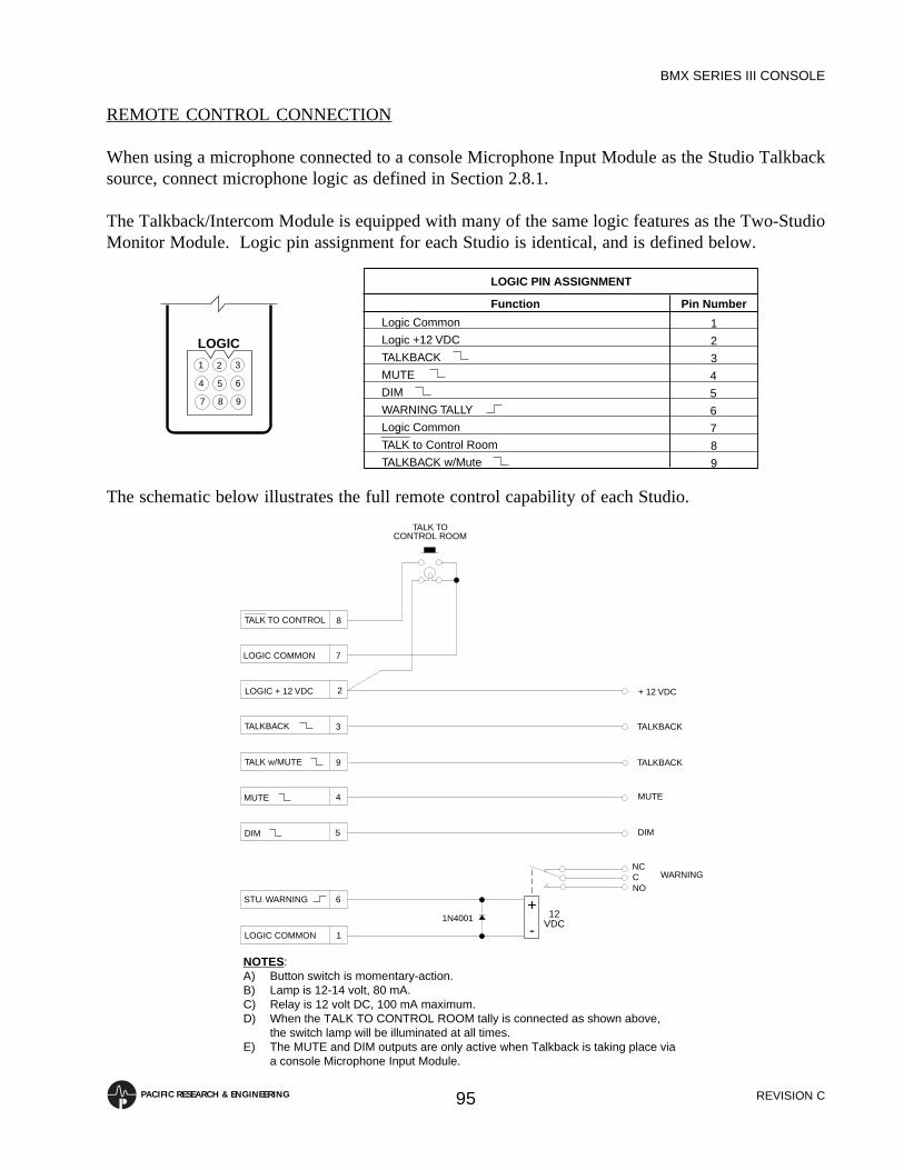
REVISION C
BMX SERIES III CONSOLE
95PACIFIC RESEARCH & ENGINEERING
REMOTE CONTROL CONNECTION
When using a microphone connected to a console Microphone Input Module as the Studio Talkbacksource, connect microphone logic as defined in Section 2.8.1.
The Talkback/Intercom Module is equipped with many of the same logic features as the Two-StudioMonitor Module. Logic pin assignment for each Studio is identical, and is defined below.
LOGIC PIN ASSIGNMENT
Function Pin Number
1
2
3
4
5
6
7
8
9
Logic Common
Logic +12 VDC
TALKBACK
MUTE
DIM
WARNING TALLY
Logic Common
TALK to Control Room
TALKBACK w/Mute
1
987
654
32
LOGIC
The schematic below illustrates the full remote control capability of each Studio.
DIM 5
4MUTE
TALKBACK 3
2LOGIC + 12 VDC
1LOGIC COMMON
6STU. WARNING
7LOGIC COMMON
8TALK TO CONTROL
DIM
MUTE
TALKBACK
+ 12 VDC
NCCNO
WARNING
TALK TOCONTROL ROOM
1N4001+
-12
VDC
TALK w/MUTE 9 TALKBACK
NOTES:A) Button switch is momentary-action.B) Lamp is 12-14 volt, 80 mA.C) Relay is 12 volt DC, 100 mA maximum.D) When the TALK TO CONTROL ROOM tally is connected as shown above,
the switch lamp will be illuminated at all times.E) The MUTE and DIM outputs are only active when Talkback is taking place via
a console Microphone Input Module.

REVISION C
BMX SERIES III CONSOLE
96PACIFIC RESEARCH & ENGINEERING
While it is unlikely that a “typical” installation will utilize all of the Talkback/Intercom module logicfacilities, it is important to understand what is available, along with the potential applications.
The TALK TO CONTROL ROOM control input dims the Control Room monitors and enablesTalkback from the Studio to the Control Room when using a line level source connected to the TalkFrom Studio Input as the Studio Talkback source. This input will not be used when Talkback is takingplace via a console Microphone Input module, as each microphone input has its own Talkback controlinputs (reference Section 2.8.1).
The TALKBACK control output is a current-sinking open collector, which is active (low) wheneverthe Studio is receiving Talkback from the Control Room. This command is intended for connectionto active, self-contained, headphone and monitor systems, and is used to switch the Talkback signal intothe headphone and monitor circuits. Such headphone and/or monitor systems are usually provided tothe host and co-host positions.
The TALKBACK WITH MUTE control output is a current-sinking open collector, which is active(low) whenever the Studio is receiving Talkback from the Control Room. This output differs from theTALKBACK output (pin 3) in that it is disabled whenever the Studio is muted.
NOTE: The TALKBACK WITH MUTE output will function identically to the TALKBACK outputby cutting the jumpers between points E1 and E2 (for Studio-1) and E3 and E4 (for Studio-2) on theTalkback/Intercom Module PC assembly. Also, PR&E #99-371-1 is equipped with a front panel TALKOVER MUTE button which, when depressed, performs the same function.
The MUTE control output is a current-sinking open collector, which is active (low) whenever aMicrophone Input Module assigned to the Studio is turned ON. This command is provided for interfaceto intercoms, telephones and/or other external equipment which may need to be muted whenever aStudio microphone is “live”.
The DIM control output is a current-sinking open collector, which is active (low) whenever Talkbackis occurring from the Studio to another location via a console Microphone Input Module. Thiscommand is provided for similar applications as the MUTE Command.
The STUDIO WARNING tally is a 12 volt DC, 150 mA maximum, source output for connection toa magnetic or solid-state relay unit for driving the Studio entry warning light(s).
INTERNAL OPTIONS
The Talkback/Intercom module is equipped with a two-station internal option DIP switch (S3) whichdetermines how the Studio-1 and Studio-2 dim functions affect Talkback communication.
NOTE: Since the Studio only dims when Talkback is occurring via a console Microphone Inputmodule, this switch will have no effect when the Talk From Studio Input is being used.
Closing S3-1 causes the Studio-1 dim function to block incoming Talkback signals to Studio-1. Closing

REVISION C
BMX SERIES III CONSOLE
97PACIFIC RESEARCH & ENGINEERING
S3-2 causes the Studio-2 dim function to block incoming Talkback signals to Studio-2. This switch isidentical to the Two-Studio Monitor Module option switch (see Section 2.9.4, page 46 for switchlocation).
CIRCUITRY
NOTE: The Studio-1 and Studio-2 audio and logic paths consist of identical sets of circuitry. For clarityand simplicity, only the Studio-1 audio and logic paths are described below.
Audio
The TALK TO STUDIO-1 bus signal is summed by U2A, amplified by U2B, and routed to the TALKSTUDIO-1 output terminal.
The TALK FROM STUDIO-1 signal is fed to balanced differential input amplifier U1A. This signalfeeds Talk to Control Room relay K1. When closed, Talkback audio is directed to summing resistorR11, and to the TALK TO CONTROL ROOM audio bus.
Logic
The TALK TO CONTROL ROOM input command forces the output of gate U10D high. TransistorQ13 conducts, causing Studio-1 Talk relay K1 to close. The output of U10D also feeds the input of gateU10B. The output of this NOR gate is inverted to drive TALK TO CONTROL ROOM bus switch Q14.These logic functions allow received Studio-1 Talk to connect to the console TALK TO CONTROLROOM bus.
The five external commands are activated by three internal control buses. The MUTE STUDIO 1 busis inverted by gates U6F. This gate output drives MUTE OUTPUT switch Q1 and the WARNINGCOMMAND driver, consisting of inverter U7E, Q2 and Q3. The MUTE STUDIO 1 commandconnects to gate U8B through the E1 to E2 jumper or the TALK OVER MUTE switch (when it is inthe disengaged position). The output of U8B is inverted by U9E to turn on TALKBACK WITH MUTEswitch Q5. Note that OR gate U8B is used as an inverted NAND gate.
The DIM STUDIO 1 bus command connects to gate U6A, is inverted, and drives DIM OUTPUT switchQ4. This bus signal also feeds DIM DISABLES TALK switch S3, which disables gates U8C and U8Bfrom operating Talkback output switches Q5 and Q6.
The TALK STUDIO 1 bus will force gate U8C low if switch S3-1 is open. This gate output will beinverted by U7D to drive TALKBACK OUTPUT switch Q6 low. The output of U8C connects to U8B,which will allow the TALKBACK WITH MUTE switch to go low if the E1 to E2 is installed or theTALK OVER MUTE switch is disengaged.

REVISION C
BMX SERIES III CONSOLE
98PACIFIC RESEARCH & ENGINEERING
6.0 MAINTENANCE AND ALIGNMENT
This chapter contains sections describing routine maintenance, troubleshooting, the installation andservicing tool kit, the spare parts kit, and replacement parts for the BMX III console.
6.1 ROUTINE MAINTENANCE
Routine maintenance is usually limited to checking button switches for proper operation and keepingpanel surfaces clean. The panel surfaces are finished with a baked polyurethane paint and may becleaned with a weak solution of dishwashing detergent. The procedures for checking power supplyvoltages, lamp replacement, button replacement, and collet knob removal are described below.
NOTE: The Penny & Giles faders used in BMX III input modules (PR&E #24-115 for Stereo Line InputModules and PR&E #24-116 for Microphone Input Modules) are not field serviceable.
6.1.1 Checking Power Supply Voltages
The BMX III power supply is designed to provide very low noise power to the console. Banana jacksare provided on the front panel of the power supply for checking power supply voltages. Each outputshould be within 0.5 volts of its specified DC voltage. The outputs should also be checked periodicallyfor ripple and noise using a sensitive AC voltmeter. The reading should be less than 350 microvoltsRMS.
6.1.2 Lamp Replacement
NOTE: When replacing a lamp, replace it with an identical type. Do not substitute lamps of differentvoltage or current ratings.
Meter lamp replacement is accomplished by squeezing the mounting ears on the lamp socket to removethe socket from the rear of the lamp bracket assembly. Replace the wedge based lamp with PR&E #12–22, and reinstall the socket into the lamp bracket assembly.
Module ON and OFF lenses are removed by hand by lifting them straight up out of the switch housing,and are unique in that they unseat and withdraw the lamp with them. Install the wedge basedreplacement lamp (PR&E #12-20) into the socket in the switch housing, and reinstall the lens.
Talkback, Return ON, and timer and machine remote control panel switches are EAO series 31, andthe procedure for lamp replacement is as follows:
1. Remove the lens by using the tong-shaped EAO Lens Removal Tool (PR&E #70-40) tograsp the top and bottom of the lens and pull it straight out of the button housing.
NOTE: Failure to use this tool will probably result in damage to the lens’ molded retainingnotches.
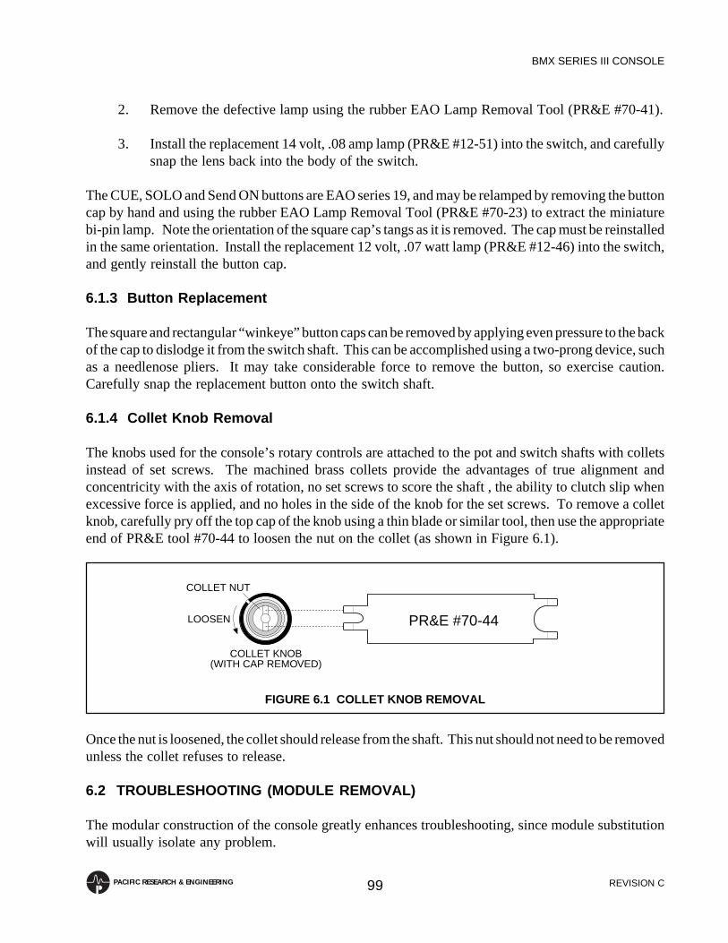
REVISION C
BMX SERIES III CONSOLE
99PACIFIC RESEARCH & ENGINEERING
2. Remove the defective lamp using the rubber EAO Lamp Removal Tool (PR&E #70-41).
3. Install the replacement 14 volt, .08 amp lamp (PR&E #12-51) into the switch, and carefullysnap the lens back into the body of the switch.
The CUE, SOLO and Send ON buttons are EAO series 19, and may be relamped by removing the buttoncap by hand and using the rubber EAO Lamp Removal Tool (PR&E #70-23) to extract the miniaturebi-pin lamp. Note the orientation of the square cap’s tangs as it is removed. The cap must be reinstalledin the same orientation. Install the replacement 12 volt, .07 watt lamp (PR&E #12-46) into the switch,and gently reinstall the button cap.
6.1.3 Button Replacement
The square and rectangular “winkeye” button caps can be removed by applying even pressure to the backof the cap to dislodge it from the switch shaft. This can be accomplished using a two-prong device, suchas a needlenose pliers. It may take considerable force to remove the button, so exercise caution.Carefully snap the replacement button onto the switch shaft.
6.1.4 Collet Knob Removal
The knobs used for the console’s rotary controls are attached to the pot and switch shafts with colletsinstead of set screws. The machined brass collets provide the advantages of true alignment andconcentricity with the axis of rotation, no set screws to score the shaft , the ability to clutch slip whenexcessive force is applied, and no holes in the side of the knob for the set screws. To remove a colletknob, carefully pry off the top cap of the knob using a thin blade or similar tool, then use the appropriateend of PR&E tool #70-44 to loosen the nut on the collet (as shown in Figure 6.1).
Once the nut is loosened, the collet should release from the shaft. This nut should not need to be removedunless the collet refuses to release.
6.2 TROUBLESHOOTING (MODULE REMOVAL)
The modular construction of the console greatly enhances troubleshooting, since module substitutionwill usually isolate any problem.
FIGURE 6.1 COLLET KNOB REMOVAL
PR&E #70-44
COLLET KNOB(WITH CAP REMOVED)
COLLET NUT
LOOSEN
REVISION C
BMX SERIES III CONSOLE
100PACIFIC RESEARCH & ENGINEERING
NOTE: An important feature when troubleshooting the BMX III is that modules may be removed orinserted with power supplied to the console.
To remove a module from the mainframe, remove the black button head retaining screws from the topand bottom of the module, and the silver button head screws from the module face. Screw the ModulePull/Extractor Tools (PR&E #70-43) into the holes vacated by the silver button head screws, and thenuse both hands to extract the module from the mainframe.
Once the module at fault has been identified, it is recommended that the Equipment Description sectionfor the module in question be read thoroughly prior to troubleshooting that module. Use the appropriatemodule extender board (PR&E #99-272 for input, Slate/Talkback/Test Oscillator and Send And ReturnModules; PR&E #99-274 for Control room and Studio Monitor Modules; PR&E #99-231 for MonauralOutput, Telco Mix and Meter Switcher Modules; PR&E #99-230 for Processing Modules; and PR&E#99-273 for Stereo Line Output Amplifiers) or standard bench service techniques to isolate the problem.
NOTE: Most of the analog and logic components are socketed for ease of replacement.
WARNING : The CMOS logic devices are susceptible to destruction from static discharge while beinghandled. It is recommended that considerable caution be exercised when working with these parts.
6.3 LEVEL ALIGNMENT
All consoles are set for a +4 dBu output level unless +8 dBu is specifically requested at the time of order.It is very important that the test levels are maintained exactly as specified to avoid a buildup of toleranceerrors. The GAIN TRIM controls on the output amplifiers should not require trimming unlesscomponents which affect amplifier gain have been replaced.
Input module GAIN TRIM controls should always be adjusted so that the input accommodates thesignal level of the source equipment.
BMX III modules were aligned at the time of factory test in accordance with the following procedures(NOTE: Instructions for aligning the console for an output level of +8 dBu are contained in Section5.2):
MICROPHONE INPUT MODULES
Apply a 1 kHz test signal at -50 dBu (150 ohm source) to the module input. Adjust the module GAINTRIM controls for a -10 dBu output at the module Patch Send.
STEREO LINE INPUT MODULES
Apply a 1 kHz test signal at +4 dBu (600 ohm source) to both the left and right module inputs. Adjustthe module GAIN TRIM controls for a -10 dBu output at the module Patch Sends.
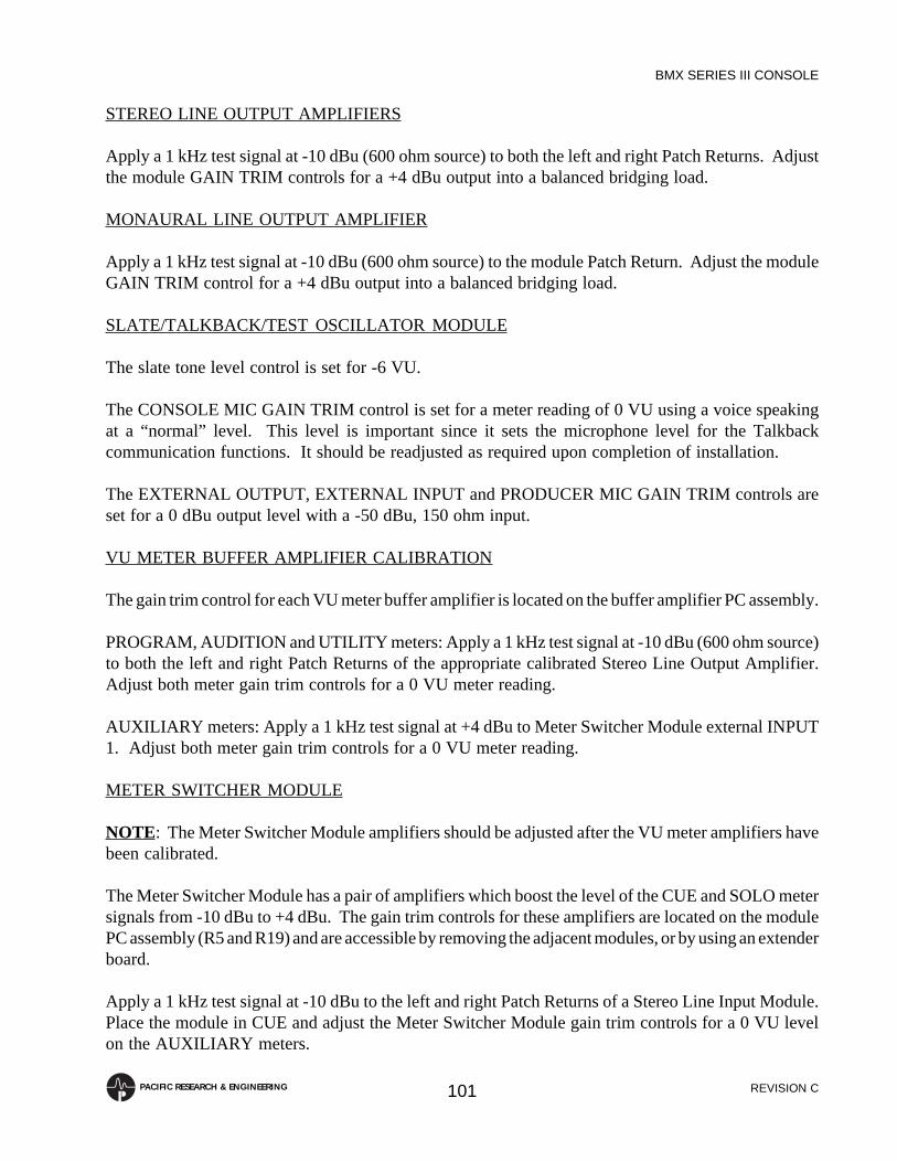
REVISION C
BMX SERIES III CONSOLE
101PACIFIC RESEARCH & ENGINEERING
STEREO LINE OUTPUT AMPLIFIERS
Apply a 1 kHz test signal at -10 dBu (600 ohm source) to both the left and right Patch Returns. Adjustthe module GAIN TRIM controls for a +4 dBu output into a balanced bridging load.
MONAURAL LINE OUTPUT AMPLIFIER
Apply a 1 kHz test signal at -10 dBu (600 ohm source) to the module Patch Return. Adjust the moduleGAIN TRIM control for a +4 dBu output into a balanced bridging load.
SLATE/TALKBACK/TEST OSCILLATOR MODULE
The slate tone level control is set for -6 VU.
The CONSOLE MIC GAIN TRIM control is set for a meter reading of 0 VU using a voice speakingat a “normal” level. This level is important since it sets the microphone level for the Talkbackcommunication functions. It should be readjusted as required upon completion of installation.
The EXTERNAL OUTPUT, EXTERNAL INPUT and PRODUCER MIC GAIN TRIM controls areset for a 0 dBu output level with a -50 dBu, 150 ohm input.
VU METER BUFFER AMPLIFIER CALIBRATION
The gain trim control for each VU meter buffer amplifier is located on the buffer amplifier PC assembly.
PROGRAM, AUDITION and UTILITY meters: Apply a 1 kHz test signal at -10 dBu (600 ohm source)to both the left and right Patch Returns of the appropriate calibrated Stereo Line Output Amplifier.Adjust both meter gain trim controls for a 0 VU meter reading.
AUXILIARY meters: Apply a 1 kHz test signal at +4 dBu to Meter Switcher Module external INPUT1. Adjust both meter gain trim controls for a 0 VU meter reading.
METER SWITCHER MODULE
NOTE: The Meter Switcher Module amplifiers should be adjusted after the VU meter amplifiers havebeen calibrated.
The Meter Switcher Module has a pair of amplifiers which boost the level of the CUE and SOLO metersignals from -10 dBu to +4 dBu. The gain trim controls for these amplifiers are located on the modulePC assembly (R5 and R19) and are accessible by removing the adjacent modules, or by using an extenderboard.
Apply a 1 kHz test signal at -10 dBu to the left and right Patch Returns of a Stereo Line Input Module.Place the module in CUE and adjust the Meter Switcher Module gain trim controls for a 0 VU levelon the AUXILIARY meters.

REVISION C
BMX SERIES III CONSOLE
102PACIFIC RESEARCH & ENGINEERING
6.4 TOOL KIT
The following installation and servicing Tool Kit (PR&E #76-22) is provided with each console:
DESCRIPTION PR&E#MOLEX Connector Pin Crimp Tool 70-3MOLEX Connector Pin Insertion Tool 70-8MOLEX Connector Pin Extractor Tool 70-4EAO Lens Removal Tool (series 31 button switch) 70-40EAO Lamp Removal Tool (series 19 button switch) 70-23EAO Lamp Removal Tool (series 31 button switch) 70-41EAO Nut Wrench (series 19 button switch) 70-38EAO Nut Wrench (series 31 button switch) 70-39PR&E Module Pull/Extractor Tools (2) 70-43SIFAM Double-Ended Spanner Wrench (for collet knobs) 70-44
6.5 SPARE PARTS KIT
The following Spare Parts Kit (PR&E #76-21) is supplied with each console. This kit is excluded fromthe limited warranty, and is provided to support initial installation only.
DESCRIPTION QTY PR&E#Diodes
1N4001 2 11-71N4004 1 11-171N914B 2 11-13
Integrated CircuitsDual D flip-flop, 4013 2 21-43Dual Monostable, 4538 2 21-76Dual Voltage Comparator, LM393 1 20-60Dual 5-input Majority Gate, 4530 2 21-89Dual 4-input AND, 4082 2 21-91Dual 4-input NAND, 4012 2 21-70Dual 4-input OR, 4072 2 21-92Dual SPDT Analog Switch, HI-307 2 21-93Hex, Schmidt Inverter, 4584 2 21-46Op Amp, DIP, 5534 2 20-28Op Amp, Dual, LF353N 2 20-32Op Amp, Dual, 8-Pin, DIP, 5532 2 20-53Quad 2-input AND, 4081 2 21-68Quad 2-input NAND, 4093 2 21-4Quad 2-input OR, 4071 2 21-57Quad 2-input NOR, 4001 2 21-61Quad 2-input Multiplexer, 4551 2 21-90Triple 3-input OR 2 21-67

REVISION C
BMX SERIES III CONSOLE
103PACIFIC RESEARCH & ENGINEERING
DESCRIPTION QTY PR&E#Triple 2-input Analog Switch, 4053 2 21-718-input NAND, 4068 2 21-568-input NOR, 4078 2 21-77
Lamps12V, 0.7W Bi-Pin, 1099BPE 2 12-4614V, .08A, 658 4 12-2014V, .08A, 73 4 12-2214V, .08A, 386 2 12-51
Operational Amplifier, NE5534 2 20-28Relay, DPDT, 12 volt, Polarized, Gold Contact 2 28-5Transistors
FET, PN4303 2 9-1FET, 2N5638 2 9-2NPN, MJE181 2 7-1NPN, MPSA13 1 7-4NPN, MPS6560 2 7-11NPN, 100V, 2A, TIP112 1 7-23NPN, 80V, 0.5A, MPSA06 1 7-24PNP, MJE171 2 8-1PNP, MPSA63 2 8-4PNP, MPSU95 2 8-6PNP, 2N3638A 2 8-8PNP, MPS2907 2 8-16
Voltage RegulatorsVariable, 1.5A, Pos., LM317T 1 20-49Variable, 1.5A, Neg., LM337T 1 20-59Variable, 5A, LM338K 1 20-57Variable, 10A, LM396 1 20-58
This kit should provide sufficient support spares for the initial operating period; however, it isrecommended that this kit be replenished and kept on hand for service use.
In applications where any system “downtime” is unacceptable, it is recommended that the followingmodules be kept on hand as spares:
DESCRIPTION PR&E#Power Supply Assembly 99-238AMicrophone Input Module 99-252Stereo Line Input Module 99-253Stereo Line Output Amplifier 99-258-1Control Room Monitor Module 99-257

REVISION C
BMX SERIES III CONSOLE
104PACIFIC RESEARCH & ENGINEERING
6.6 REPLACEMENT PARTS
The components used are, wherever possible, standard items of general availability. However, shoulddifficulty be encountered locating any of the items, PR&E maintains a stock of replacement parts.
The power supply transformers and circuit breakers, Penny & Giles faders, potentiometers, VU meters,“winkeye” button switches, and all engraved button caps are manufactured to custom designspecifications and are, therefore, available only from PR&E.
Following is a partial list of parts and assemblies used in the BMX III console, and the PR&E partnumber for easy reference:
DESCRIPTION PR&E#Blank Panels
6-inch 99-20910-inch 99-27116-inch 99-259
ButtonsRectangular, White 25-771Rectangular, White, “PRE” 25-771-1Rectangular, White, “OSC” 25-771-5Rectangular, White, “100” 25-771-6Rectangular, White, “10” 25-771-7Rectangular, White, “1” 25-771-8Rectangular, Gray 25-772Rectangular, Gray, “IN” 25-772-3Rectangular, Gray, “1” 25-772-4Rectangular, Gray, “2” 25-772-5
Buttons, IlluminatingRed, “ON” (Input Module) 25-2-1Yellow, “OFF” (Input Module) 25-5-1Rectangular, Orange, “SLATE” 25-121-1Rectangular, White, “STUDIO 1” 25-125-1Rectangular, White, “STUDIO 2” 25-125-2Rectangular, White, “EXT” 25-125-5Square, Red, “ON” (Return) 25-127-1Square, Red, “ON” (Sends) 25-115-1Square, White (Solo) 25-118Square, White, “S” 25-118-1Square, Yellow (Cue) 25-116
Buttons, Self-Indicating (“Winkeye”)Rectangular, Blk/Org, “PGM” 25-768-1Rectangular, Blk/Org, “AUD” 25-768-2Rectangular, Blk/Org, “UTL” 25-768-3Square, Blk/Org 25-769

REVISION C
BMX SERIES III CONSOLE
105PACIFIC RESEARCH & ENGINEERING
DESCRIPTION PR&E#Square, Blk/Org, “A” 25-769-1Square, Blk/Org, “B” 25-769-2
CapacitorsElectrolytic, 1µF, 50V, Low Leakage 60-45Electrolytic, 2.2µF, 50V, Low Leakage 60-50Electrolytic, 4.7µF, 40V, Axial 60-21Electrolytic, 10µF, 25V, Low Leakage 60-67Electrolytic, 10µF, 25V, NP 60-84Electrolytic, 10µF, 100V 60-41Electrolytic, 22µF, 16V 60-55Electrolytic, 22µF, 16V, Low Leakage 60-47Electrolytic, 22µF, 25V 60-76Electrolytic, 22µF, 25V, Axial 60-11Electrolytic, 22µF, 25V, NP 60-85Electrolytic, 47µF, 16V, NP 60-81Electrolytic, 100µF, 16V, NP 60-82Electrolytic, 100µF, 25V, NP 60-87Electrolytic, 100µF, 63V 60-53Electrolytic, 220µF, 16V 60-44Electrolytic, 220µF, 16V, NP 60-83Electrolytic, 220µF, 25V 60-78Electrolytic, 470µF, 80V 60-40Electrolytic, 16,000µF at 50WVDC 60-93Electrolytic, 51,000µF at 40WVDC 60-92Metalized Polyester, .01µF, 400V 63-4Metalized Polyester, .015µF, 100V 63-1Metalized Polyester, .022µF, 250V 63-9Metalized Polyester, .047µF, 250V 63-6Metalized Polyester, .1µF, 100V 63-7Metalized Polyester, .22µF, 100V 63-8Metalized Polyester, .47µF, 100V 63-10Monolythic, .1 µF, 50V 62-5Monolythic, 1µF, 50V 62-6Polypropylene, 4700pF, 160V, Axial 64-23Tantalum, 2.2µF, 35V 65-14Tantalum, 10µF, 20V 65-6Tantalum, 10µF, 35V 65-5Tantalum, 10µF, 50V 65-8
Circuit BreakersFor Audio Power Supply 30-32For Logic Power Supply 30-28For Phantom Power Supply 30-9
Cue Header Assembly 90-326
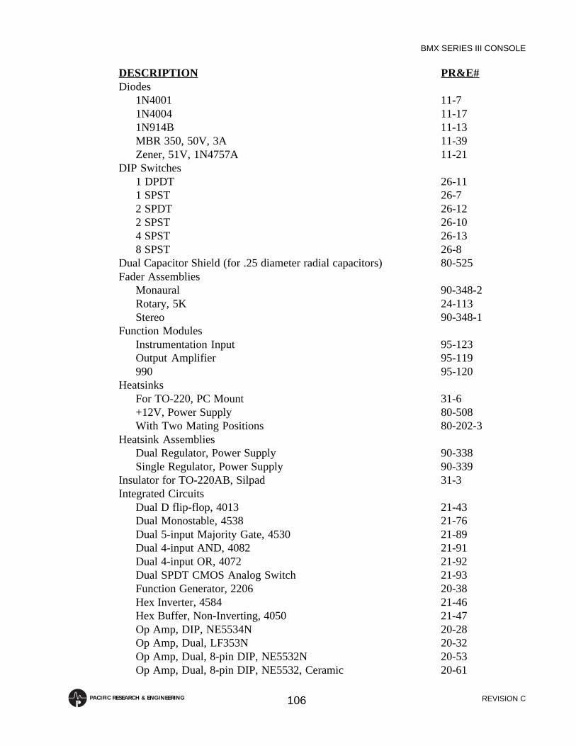
REVISION C
BMX SERIES III CONSOLE
106PACIFIC RESEARCH & ENGINEERING
DESCRIPTION PR&E#Diodes
1N4001 11-71N4004 11-171N914B 11-13MBR 350, 50V, 3A 11-39Zener, 51V, 1N4757A 11-21
DIP Switches1 DPDT 26-111 SPST 26-72 SPDT 26-122 SPST 26-104 SPST 26-138 SPST 26-8
Dual Capacitor Shield (for .25 diameter radial capacitors) 80-525Fader Assemblies
Monaural 90-348-2Rotary, 5K 24-113Stereo 90-348-1
Function ModulesInstrumentation Input 95-123Output Amplifier 95-119990 95-120
HeatsinksFor TO-220, PC Mount 31-6+12V, Power Supply 80-508With Two Mating Positions 80-202-3
Heatsink AssembliesDual Regulator, Power Supply 90-338Single Regulator, Power Supply 90-339
Insulator for TO-220AB, Silpad 31-3Integrated Circuits
Dual D flip-flop, 4013 21-43Dual Monostable, 4538 21-76Dual 5-input Majority Gate, 4530 21-89Dual 4-input AND, 4082 21-91Dual 4-input OR, 4072 21-92Dual SPDT CMOS Analog Switch 21-93Function Generator, 2206 20-38Hex Inverter, 4584 21-46Hex Buffer, Non-Inverting, 4050 21-47Op Amp, DIP, NE5534N 20-28Op Amp, Dual, LF353N 20-32Op Amp, Dual, 8-pin DIP, NE5532N 20-53Op Amp, Dual, 8-pin DIP, NE5532, Ceramic 20-61

REVISION C
BMX SERIES III CONSOLE
107PACIFIC RESEARCH & ENGINEERING
DESCRIPTION PR&E#Opto-Isolator 29-4Quad 2-input NAND, 4093 21-4Quad 2-input OR, 4071 21-57Quad 2-input NOR, 4001 21-61Quad 2-input AND, 4081 21-68Quad 2-input Analog Multiplexer, 4551 21-90Triple 2-input Analog Switch, 4053 21-71Triple 3-input OR, 4075 21-678-input NAND, 4068 21-56
IC Sockets6-pin 16-1078-pin 16-10814-pin 16-11416-pin 16-116
Knobs21 mm, Grey 32-13811 mm, Grey, With Black Base Indicator 90-327-1
Knob CapsBlack (for 11 mm knob) 32-121Blue (for 11 mm knob) 32-123Gray (for 11 mm knob) 32-124Green (for 11 mm knob) 32-122Orange (for 11 mm knob) 32-127Orange (for 21 mm knob) 32-140Red (for 21 mm knob) 32-139
Lamps12V, 0.7W, bi-pin, 1099BPE (for CUE and SOLO) 12-4614V, .08A, 658 (for module ON/OFF) 12-2014V, .08A, 73 (for VU meters) 12-2214V, .08A, 386 (for Talkback and remote controls) 12-51
Microphone Power Supply PCA, 120 VAC 90-148-1Modules
Control Room Monitor 99-257Switching Board 95-146
Meter Switcher 99-268Microphone Input With Sends 99-252
Output Assignment Switcher Assembly 95-143-1Microphone Input Without Sends 99-262Monaural Output Amplifier 99-264Monaural Output/Telco Mix 99-265Remote Line Selector 99-267Send and Return 99-255
Output Assignment Switcher Assembly 95-143-2Send and Return/Mono Output/Telco Mix 99-266

REVISION C
BMX SERIES III CONSOLE
108PACIFIC RESEARCH & ENGINEERING
DESCRIPTION PR&E#Slate/Talkback/Test Oscillator 99-254
Output Assignment Switcher Assembly 95-143-3Stereo Line Input With Sends 99-253
Output Assignment Switcher Assembly 95-143-1Stereo Line Input Without Sends 99-263Stereo Line Output Amplifier 99-258-1Two-Studio Monitor 99-256
Switching Board 95-146Module Extender Boards
Control Room and Studio Monitor 99-274Input, Slate/Talkback/Test Osc., Send and Return 99-272Stereo Line Output Amplifiers 99-273
PotentiometersDual, 10K, CW Log 24-100Dual, 10K, CW Log (2-Studio) 24-101Dual, 25K, Linear 24-99Single, 10K, 1/2W, CCW, Audio Taper 24-20Single, 10K, 1/2W, CW, Audio Taper 24-108Single, 10K, CW Log 24-98
Power Supply Assembly, 120 Volts 99-238APPM Meter, 3.5", with Buffer Amplifier 99-224-1Regulator Board PCAs
+12V Power Supply 95-89+/-22V Power Supply 95-91
RelaysDPDT, 12 volt, Polarized, Gold Contact 28-5Opto-Isolator, 40mA, 1.65-2.0V 28-602
Resistor/Inductor Assembly, 40µH 90-91Spare Parts Kit 76-21Switches
SPDT, Momentary, Rectangular (Slate/Talkback) 25-119SPDT, Momentary, Square 25-126SPST, Momentary, Pushbutton Input Module ON/OFF) 25-102SPST, Momentary, Square 25-114Toggle, DPST, 15A, 125V 26-1001-Station, 2PDT, Push-Push 25-7571-Station, 4PDT, Push-Push 25-7752-Station, 6PDT, Interlock/Lockout 25-7553-Station, 2PDT, Push-Push 25-7643-Station, 2PDT, Interlock (Telco Mix, Mono Output) 25-7653-Station, 2PDT, Interlock/Lockout (Slate/Talkback/Test) 25-7745-Station, 4PDT, Interlock/Lockout 25-76310-Station, 4PDT, Interlock 25-79312-Station, 4PDT, Interlock/Lockout 25-761

REVISION C
BMX SERIES III CONSOLE
109PACIFIC RESEARCH & ENGINEERING
DESCRIPTION PR&E#Transformers
Audio, Input (Slate/Talkback/Test) 49-9Audio, Mic Input 49-5Power for Phantom Supply 48-7Power for Audio Supply 48-12Power for Logic Supply 48-13
TransistorsFET, PN4303 9-1FET, 2N5638 9-2NPN, MPSA13 7-4NPN, MPS6560 7-11NPN, PN2484 7-21NPN, 80V, 0.5A, MPSA06 7-24NPN, 100V, 2A, TIP112 7-23NPN, LM394H 10-2PNP, MPSA63 8-4PNP, MPSU95 8-6PNP, PN3638A 8-8PNP, PN4250A 8-12PNP, MPS-2907 8-16
Transistor/Diode AssembliesMJE171/1N914B 90-119-1MJE181/1N914B 90-119-2
Trim-potsSingle-Turn, 72PR1K 24-51Single-Turn, 72PR10K 24-54Single-Turn, 100K 24-58
Voltage RegulatorsVariable, 1.5A, Pos., LM317T 20-49Variable, 1.5A, Neg., LM337T 20-59Variable, 5A, LM338K 20-57Variable, 10A, LM396 20-58
VU Meters3.5" 46-123.5", with Buffer Amplifier 99-222-1
VU Meter Buffer Amplifier 95-72

REVISION C
BMX SERIES III CONSOLE
110PACIFIC RESEARCH & ENGINEERING
7.0 DRAWINGS AND SCHEMATICS
This chapter is made up of the following drawings and schematics:
7.1 Functional Block Diagrams (Console Block Diagram)7.1.1 Microphone Input Module Block Diagram7.1.2 Stereo Line Input Module Block Diagram7.1.3 Stereo Line Output Amplifier Block Diagram7.1.4 Control Room Monitor Module Block Diagram7.1.5 Two-Studio Monitor Module Block Diagram7.1.6 Monaural Line Output Amplifier Block Diagram7.1.7 Telco Mix Block Diagram7.1.8 Send And Return Module Block Diagram7.1.9 Slate/Talkback/Test Oscillator Module Block Diagram7.1.10 Meter Switcher Module Block Diagram7.1.11 Remote Line Selector Block Diagram
7.2 Microphone Input Module Schematic7.3 Microphone Input Module With Sends Schematic7.4 Stereo Line Input Module Schematic7.5 Stereo Line Input Module With Sends Schematic7.6 Stereo Line Output Amplifier Schematic7.7 Control Room Monitor Module Schematic7.8 Two-Studio Monitor Module Schematic7.9 Monitor Module Switching Schematic7.10 Monaural Line Output Amplifier Schematic7.11 Monaural Output/Telco Mix Module Schematic7.12 Send And Return Module Schematic7.13 Monaural Output/Telco Mix/Send And Return Module Schematic7.14 Slate/Talkback/Test Oscillator Module Schematic7.15 Talkback/Intercom Module Schematic7.16 Meter Switcher Module Schematic7.17 Remote Line Selector Schematic7.18 VU Meter Buffer Amplifier Schematic7.19 Meter Power Regulator And Distribution Board Schematic7.20 Power Supply Assembly Schematic7.21 Output Amplifier Function Module Schematic7.22 Instrumentation Amplifier Function Module Schematic7.23 990 Function Module Schematic7.24 Console Main Mother Board Schematic7.25 Monitor Selector Mother Board Schematic7.26 Remote Line Selector Mother Board Schematic

REVISION C
BMX SERIES III CONSOLE
111PACIFIC RESEARCH & ENGINEERING
7.27 Console Wiring (Edge Connector Layout)7.27.1 Microphone Input Module Audio7.27.2 Stereo Line Input Module Audio7.27.3 Input Module Logic7.27.4 Program Amplifier Output7.27.5 Audition Amplifier Output7.27.6 Utility Amplifier Output7.27.7 Monitor Module Input7.27.8 Control Room Monitor Module7.27.9 Two-Studio Monitor Module7.27.10 Monaural Amplifier Output7.27.11 Telco Mix7.27.12 Send And Return7.27.13 Slate/Talkback/Test Oscillator Audio7.27.14 Slate/Talkback/Test Oscillator Logic7.27.15 Meter Switcher Module7.27.16 Remote Line Selector Inputs7.27.17 Remote Line Selector Outputs7.27.18 Meter Power7.27.19 Timer Control7.27.20 Remote Control Panel Cable Assembly
NOTE: On PR&E schematics, capacitor values are in microfarads (µF), unless otherwise specified,and resistors are 1/4 watt, 5%, unless otherwise specified.

BMX SERIES III CONSOLE
REVISION B202PACIFIC RESEARCH & ENGINEERING
8.0 ACCESSORIES
This chapter contains descriptions of the various BMX III console accessories. Included are sectionsdescribing tape machine remote control panels, clocks and timers, the PPM Meter, the Redundant PowerSupply Coupler Unit, and logic interfaces. Section 8.6 contains schematics for the accessories describedin this chapter. Contact PR&E for further details and price information.
8.1 TAPE MACHINE REMOTE CONTROL PANELS
There are two tape machine remote control panels available for use in the BMX III mainframe—one forcart recorders (PR&E #99-240) and one for cassette and reel-to-reel tape recorders (PR&E #99-221). Bothconsist of five momentary-action switches, and both are mounted in the lower module area of the mainframein the positions labeled A through E, as shown in Figure 2.3. These positions are pre-wired with 24-pinlogic cables, which are routed to OPTION A - E positions on the rear of the mainframe, as shown in Figure2.5.
Tape machine remote control panels operate in conjunction with input module remote controls, andconnection to cart and tape recorders is accomplished by means of a "Y" cable located at the recorder, asshown in Figure 8.5. Prefabricated remote control "Y" cables for most commercial cart and tape machinesare available from PR&E.
8.1.1 Cart Recorder Remote Control Panel
The cart recorder remote control panel (PR&E #99-240) can control the record, tertiary cue tone, secondarycue tone, play and stop functions of a connected cart recorder. For a schematic showing rear panel Molexconnector pin assignment, and an illustration of the panel controls, see Section 8.6.
Presently, there are four different versions of this panel available from PR&E: #99-240-0, for use with cartmachines with no lamp tallies; #99-240-1, for use with cart machines with 5 volt lamp tallies; #99-240-2,for use with cart machines with 14 volt lamp tallies; and #99-240-3 for use with cart machines with 28 voltlamp tallies.
8.1.2 Cassette And Tape Recorder Remote Control Panel
The cassette and reel-to-reel tape recorder remote control panel (PR&E #99-221) can control the record,forward, rewind, play and stop functions of a connected cassette or tape recorder. For a schematic showingrear panel Molex connector pin assignment, and an illustration of panel controls, see Section 8.6.
Presently, there are five different versions of this panel available from PR&E: #99-221-0, for use with tapemachines with no lamp tallies; #99-221-1, for use with tape machines with 5 volt lamp tallies; #99-221-2, for use with tape machines with 14 volt lamp tallies; #99-221-3, for use with tape machines with 28 voltlamp tallies; and 99-221-4, for use with tape machines with a 5 volt record tally only.

BMX SERIES III CONSOLE
REVISION B203PACIFIC RESEARCH & ENGINEERING
8.2 CLOCKS AND TIMERS
BMX III meter panel clock and timer positions are defined in Figure 2.4 (Section 2.3.2). These positionsaccommodate the TD-2 Digital Clock (PR&E #99-179-1) or the TD-171 Digital Slave Clock (PR&E #99-312-1), and the DT-4 Digital Timer (PR&E #99-180-1).
8.2.1 TD-2 Digital Clock
The TD-2 is a six-digit (hours, minutes, seconds) general purpose digital clock. The only connectionrequired at the rear of the clock is the external power source (PR&E #50-17, supplied with the clock).
Setting the clock requires the use of the supplied magnet tool (PR&E #90-151) to operate the Hall-effectswitches located immediately behind the front panel lens. These switches are centered beneath the threepairs of digits about 1/4 inch above the bottom of the bezel, as shown in Figure 8.1.
To adjust the clock, place the end of the adjusting magnet against the panel in the appropriate area. Use theFAST SET switch to advance the hours, and the SLOW SET switch to advance the minutes. The HOLDswitch will cause the hours, minutes and seconds to stop and hold at their current setting.
CIRCUITRY
The TD-2 is designed around MM5314 digital clock integrated circuit U3. The time base is supplied bycrystal oscillator/divider circuit Y1 and U1. The voltage doubler circuit of Q1, Q2, C4, CR1, CR2, andC5 provides the high positive voltage required to pin 15 of U3. The display multiplex frequency isdetermined by C3 and R2.
The segments of displays DS1 through DS6 are driven by transistors Q4 through Q10, and the digits areselected by inverters Q11 through Q16 and drivers Q17 through Q22. Hall-effect switches U4 through U6are magnetically activated to set the clock’s FAST, SLOW and HOLD functions.
FIGURE 8.1 TD-2 DIGITAL CLOCK
FASTSET
SLOWSET
HOLD
PACIFIC RESEARCH & ENGINEERING CORP.
DIGICLOCK TD-2
PR&E #90-151

BMX SERIES III CONSOLE
REVISION B204PACIFIC RESEARCH & ENGINEERING
8.2.2 TD-171 Digital Slave Clock
The TD-171 Digital Slave Clock is a six-digit (hours, minutes, seconds) digital display specificallydesigned to operate with an ESE or compatible master clock time code generator. It is constructed in analuminum case for shielding, uses an external power supply (PR&E #50-17, supplied with the clock), andis designed specifically for use in PR&E consoles. Power and master clock connection are made to the rearof the unit.
FIGURE 8.2 TD-171 DIGITAL SLAVE CLOCK
PACIFIC RESEARCH & ENGINEERING CORP.
TD-171
CIRCUITRY
The TD-171 circuit is virtually the same as the ESE model ES-171 unit (the TD-171 is manufactured withthe express consent of ESE). The time code consists of 24 bits of pulse width modulated data. A wide pulse(260 microseconds) represents a binary one (1), and a narrow pulse (65 microseconds) represents a binaryzero. The data rate is 60 Hz.
Demodulation is accomplished using shift registers U3, U4 and U5. The incoming data is buffered bytransistor Q2 and gate U1 before it is fed to shift register U3. One of the one-shots of dual monostable U2is used to clock the shift registers. The pulse width of this one-shot is set to be 2.5 times the pulse widthof the narrow data pulse. As a result a “one” or “zero” will be clocked into U3 depending on the width ofthe data pulse.
The second one-shot of U2 is retriggered by each data pulse until the completion of all 24 bits of data. U2then times out and triggers another one-shot, formed by two gates of U1. This transfers the data from theshift register outputs to the latches contained in decoder/drivers U6 through U11, prior to the nexttransmission of data. This completes the serial-to-parallel conversion. The decoder/drivers and displaysthen translate the parallel BCD information into the visual time display.

BMX SERIES III CONSOLE
REVISION B205PACIFIC RESEARCH & ENGINEERING
8.2.3 DT-4 Digital Timer
The DT-4 is a five-digit (minutes, seconds, tenths-of-a-second) digital timer which is controlled by eitherthe Timer Control Panel (PR&E #99-220) or the console timer reset bus. The Timer Control Panel is locatedin the lower far right console position. See Section 3.15 for instruction in operating the timer.
FIGURE 8.3 DT-4 DIGITAL TIMER
PACIFIC RESEARCH & ENGINEERING CORP.
DIGITIMER DT-4
NOTE: Three five-pin timer reset Molex connectors are provided at the rear of the mainframe forconnection to external timers, if desired.
CIRCUITRY
The DT-4 is designed around MK50397 timer integrated circuit U4. The time base and display multiplexfrequency is provided by crystal oscillator/divider circuit Y1 and U1. The segments of displays DS1through DS5 are driven by transistors Q1 through Q7, while the digits are selected by transistors Q8 throughQ12.
Power-up circuit R13, CR1 and C9 resets U4 to zero, and sets start/stop flip-flop U2A and U2C so thatthe NOT RUN line is high. An external START command causes the flip-flop to change state to the RUNcondition. An external STOP command via U2C will set the flip-flop back to the STOP condition. Anexternal RESET command via U2B will reset U4 to zero. An external HOLD command via U3D willmomentarily hold the display at the present time count, while the real time count continues internally.
A READ or RUN command is routed via U3C, U3B and U3A to enable the tenth of second display, and,via Q13, to turn on the decimal point. Strapping J1 pin E to J1 pin F continuously enables both the tenthof second display and decimal point. A BLANK command to U4 allows the entire display to be blanked.
NOTE: In some cases it may be desirable to disable the tenth of second and decimal point indicators. Thiscan be accomplished by cutting the strap between pins E and F (.1 SEC LOCK) on the timer connector.

BMX SERIES III CONSOLE
REVISION B206PACIFIC RESEARCH & ENGINEERING
8.3 PPM METER
The optional Peak Program Meter is a peak level indicating meter which can be supplied to replace oraugment the standard VU meters. The PPM fully conforms to British Standard 4297:1968, which specifiesthe characteristics for the meter movement and the overall performance when connected to the requireddrive circuitry.
The PPM has a faster rise than standard VU meters, and its dynamic characteristics are radically different.The rise time is measured with isolated variable length tone bursts of 5 kHz sinusoidal voltage, whosesteady-state value will result in a "0" reference reading. The burst times and scale indications are as follows:100 ms = 0 dB, 10 ms = -2.5 dB, 5 ms = -4 dB, and 1.5 ms = -9 dB. The fall-back time is defined as between2.5 and 3.2 seconds for the pointer to fall from +4 to -20 after the removal of a steady-state 1 kHz sinusoidalvoltage.
8.4 REDUNDANT POWER SUPPLY COUPLER UNIT
The Redundant Power Supply Coupler Unit (PR&E #99-76) is used whenever redundant power is desired.When two power supplies are connected to the unit, the power supply voltages are diode-coupled, withthe highest of the two voltages being supplied to the console. If there is a voltage failure, redundant poweris instantaneously supplied to the console, and the Remote Power Fail Indicator on the coupler unit isilluminated.
The unit should be installed adjacent to the two console power supplies, and connected with the twoprefabricated cables supplied. The connections to the supplies and to the console are made to the heavy–duty barrier strips on the rear of the coupler. The cables are color-coded, and the corresponding color namesare printed adjacent to the terminal strips.
NOTE: The high-current diodes used in the coupler have very low forward voltage drop and, therefore,do not add significantly to the heat dissipation of the power supply system. However, the second powersupply in a redundant system does add approximately 50 watts of heat, due to the excitation currentconsumed by the power transformers.
-22 -16 -12 -8 -4 0+4
FIGURE 8.4 PEAK PROGRAM METER

BMX SERIES III CONSOLE
REVISION B207PACIFIC RESEARCH & ENGINEERING
8.5 LOGIC INTERFACES
PR&E recommends the use of logic interface electronics between the console and any piece of auxiliaryequipment to protect the console from hazardous voltages, and to prevent ground loops, such as thosewhich occur when control circuitry is referenced to a different ground or power supply.
A variety of different interfaces is manufactured by PR&E to accommodate most types of cart, tape andcassette machines, turntables, and compact disc players. Cable assemblies connecting the console to theinterface, and the interface to the auxiliary equipment are also produced by PR&E. For complete interfaceinformation, including all standard machine cable assemblies and machine “Y” cables, contact PR&E.
The table below provides a listing of the various interfaces described in this section, as well as their partnumbers and a general description of their use.
Interface PR&E P/N For Use With
TCI-2A
CI-2
CI-2 (5V)
TI-2
TT-3
WL-2
Dual Relay
CassetteSkimmer
99-165
99-125-0
99-125-1
99-111
99-110
99-143
99-419
99-410 Cassette recorders
General purpose switching, mute contacts
Studio and Control Room warning lights
Turntables
Reel to reel tape machines w/12-28 V lamp tallies
Cart machines, CD players and cassette machines w/5 V lamp tallies
Cart machines, CD players and cassette machines w/12-28 V lamp tallies
PR&E TOMCAT, Micromax cart machines
Section 8.6 contains schematics of these interfaces, and diagrams of the three console to interface cables:PR&E #99-464 (for use with the TI-2 Tape Interface); PR&E #99-465 (for use with the CI-2 Cart Interfacewhen interfacing Studer A725, A727 and A730 compact disc players); and PR&E #99-38 (for use withall other interfaces). It also contains diagrams of the 9-, 12- and 24-pin control cables (PR&E #99-453, #99-454 and #99-455, respectively), which are used when connecting to a cart, tape or cassette recorder "Y"cable.
While there are three console to interface cables, there is a variety of interface to machine cables, each witha configuration dependent upon the individual machine being connected. When a machine "Y" cable isused in an installation, only the "Y" cable (not the control cables) is machine dependent. Figure 8.5 (on thefollowing page) provides an overview of the logic interface and cable system.

BMX SERIES III CONSOLE
REVISION B208PACIFIC RESEARCH & ENGINEERING
FIGURE 8.5LOGIC INTERFACE AND CABLE SYSTEM OVERVIEW
TurntableMachine Cable (attachedto the turntable using amodification kit suppliedwith the interface)
TT399-38Console
99-38I/F
Machine Cable
Cart,Cass,or CD
Console
Console99-38
(or 99-464for TI-2)
I/F99-453 (9 pin)
or 99-454(12 pin; for TI-2)
Machine "Y"Cable
Cart,Tape or
CassetteRecorder
99-455
Optional RemoteControl Panel
(or 99-465 forStuder A725,
A727 and A730CD Players)
NOTES:A) The addition of the optional cart or tape recorder remote control panel
is made possible by the installation of the machine "Y" cable.B) Pin assignment for the PR&E #99-38, #99-464 and #99-465 console to
interface cables, and the #99-453, #99-454 and #99-455 control cables,is defined in Section 8.6.

BMX SERIES III CONSOLE
REVISION B209PACIFIC RESEARCH & ENGINEERING
8.5.1 TCI-2A Cartridge Interface
The TCI-2A Cartridge Interface (PR&E #99-165) was specifically designed for use with PR&ETOMCAT and Micromax cart machines. Each TCI-2A can accommodate up to three reproducers orrecorder/reproducers. For a schematic of this interface, as well as a diagram of the console to interface cable(PR&E #99-38), see Section 8.6.
NOTE: If you already have TCI-2 interfaces for TOMCAT, they may be modified slightly to work withboth TOMCAT and Micromax cart machines, as follows:
1. Replace resistors R1, R3, R5, R7 and R9 with 750 ohm, 1/2 watt resistors (PR&E #3-751).
2. On the component side of the PC board, cut the trace going to J4 pin 4.
3. Add an insulated jumper wire between J4 pin 1 and the trace that previously went to J4 pin 4(which was cut in step 2).
4. Verify that resistor R14 is a 10M ohm, 1/4 watt resistor (PR&E #2-106).
CIRCUITRY
The TCI-2A uses opto-isolators to eliminate potential audio/logic ground loops. The LED inputs of opto-isolators U1 thru U5 are connected to the cart machine tally outputs through current limiting resistors R1,R3, R5, R7 and R9. The collector of opto-isolator U1 is connected to the AUDIO RESET line on consoleconnector J1. When the FWD LIGHT tally is present at cart connector J4, current flows through U1’s LED,turning on its output transistor, and pulling the AUDIO RESET line to console LOGIC COMMON. Whenthe STOP LIGHT tally is present at cart connector J4, U2 will operate in the same manner, pulling theREADY line to console LOGIC COMMON. Capacitor C2 will pulse the AUDIO RESET line low at the“rising edge” of the STOP LIGHT tally, thus providing a console AUDIO RESET when the cart machinestops.
Opto-isolators U3, U4 and U5 provide open collector outputs referenced to an isolated COMMON onconnector J3. These opto-isolators function in the manner described above, in conjunction with theremaining cart tallies: PLAY LIGHT, SEC LIGHT and TER LIGHT.
NOTE: These outputs can be used to provide automatic “cart sequencing” by connecting the appropriatecart cue line on connector J3 to the console ON input on J2 of the “next” cart machine interface. The isolatedCOM on connector J3 needs to connect to LOGIC COMMON as well. If needed, a switch can be installedin series with the connection to disable the cart sequence. The J3 outputs from several cart machines mayalso be paralleled together to form an “end of message” warning bus. This bus can then be buffered, asneeded, to drive external warning lights. Contact PR&E for more information.
Opto-isolators U6 and U7 are connected through current limiting resistors R11 and R13 to the consoleSTART and STOP pulses on J1, respectively. The open collector outputs of U6 and U7 are connected to

BMX SERIES III CONSOLE
REVISION B210PACIFIC RESEARCH & ENGINEERING
the cart START and STOP inputs of connector J4, respectively. The resistor and capacitor on each opto-isolator (i.e., C1/R2 on U1, etc.) slows down the switching time on the opto-isolator’s output transistor.
8.5.2 CI-2 Cartridge Interface (+12 to +28 Volt Logic)
The CI-2 Cartridge Interface (PR&E #99-125-0) was designed for use with those commercial cartmachines which use +12 to +28 volt logic. The CI-2 uses dry relay contacts for start and stop functions,and also serves as a capable logic interface for CD players and cassette machines. The CI-2 also routesmachine status indicator feedback to the console module “OFF” lamp, mimicking machine READY,PAUSE or STOP indicators.
Each CI-2 can accommodate up to three machines. For a schematic of this interface, as well as a diagramof the console to interface cable (PR&E #99-38), see Section 8.6.
CIRCUITRY
When a cartridge is inserted, current is fed to isolator circuit CR9-12, R2, R4, C2 and U2, forcing the NOTREADY line low and momentarily pulsing NOT AUDIO reset low (ensuring module turnoff). A STARTpulse input via CR1 will turn on relay K1, starting the cartridge machine. Current fed to isolator circuit CR5-8, R1, R3, C1 and U1 will force the NOT AUDIO RESET line low. A STOP pulse input via CR2 willturn on relay K2, stopping the cartridge machine.
8.5.3 CI-2 Cartridge Interface (+5 Volt Logic)
The CI-2 Cartridge Interface (PR&E #99-125-1) was designed for use with those commercial cartmachines which use +5 volt logic feedback. Its function is identical to the CI-2 Interface for +12 to +28volt logic. For a schematic of this interface, as well as a diagram of the console to interface cable (PR&E#99-38), see Section 8.6.
CIRCUITRY
The circuitry for the +5 volt version of the CI-2 Cartridge Interface functions identically to that of the +12to +28 volt version (reference Section 8.4.2), except that resistors R3 and R4 are 100 ohm, 1/4 watt, insteadof 1K ohm, 1/2 watt.
8.5.4 TI-2 Tape Interface
The TI-2 Tape Interface (PR&E #99-111) was designed for use with those commercial reel to reel tapemachines which use +12 to +28 volt logic. Each TI-2 accommodates one machine. For a schematic of thisinterface, as well as a diagram of the console to TI-2 interface cable (PR&E #99-464), see Section 8.6.
NOTE: This interface may also be used with cartridge machines. In this event, use console to interfacecable #99-38 if the replay lockout function is desired.

BMX SERIES III CONSOLE
REVISION B211PACIFIC RESEARCH & ENGINEERING
CIRCUITRY
When the tape machine is stopped, current is fed to STOP LAMP isolator circuit R1, R2, R3, CR1, C1and U1, forcing the NOT STOP LAMP line low, which, via U4C and pulse driver circuit R4, R20, CR8,C10 and Q1, momentarily holds the NOT AUDIO RESET low (ensuring module turnoff).
When the tape machine is in the record mode, current is fed to RECORD LAMP isolator circuit R9, R10,C3, CR3 and U3, holding the NOT AUDIO RESET low.
The NOT REPLAY line, strapped low by jumpering pins 14, 15 or J1 (i.e., reel to reel mode) via R11, R12,C4, U5B and U5C, holds resistor U6B such that the START ENABLE line is always high. When theSTOP LAMP and START ENABLE lines are both high, via U5D, R14 and Q2, the NOT READY outputwill go low. With the NOT START ENABLE line low, a START pulse input via R16, R17, C6, U4Eand U4D will trigger monostable circuit R18, C7, CR4 and U6A, which momentarily turns on driver circuitR19 and Q3 and TAPE START relay K1 (starting the tape machine). A STOP pulse input via CR6 turnson TAPE STOP relay K2 (stopping the tape machine).
Either the NOT STOP LAMP line’s low state or current fed to PLAY LAMP isolator circuit R6, R7, R8,CR2, C2 and U2 forces the NOT RUN line low, which, via U5A and U4A, asserts the CART line high(i.e., there is a cartridge in place).
When used for cartridge machine operation, the NOT REPLAY line is left unstrapped to the high state.Without a cartridge loaded, the CART line is low, which, via U5B and U5C, presets U6B such that theNOT START ENABLE line is low. After insertion of a cartridge (CART line is high), a start pulse inputwill, as in reel to reel operation, start the cartridge machine. The NOT RUN line will then go low, which,via U4B, will clock the low state on the data input of register U6B, asserting the NOT START ENABLEline high. When the cartridge machine recues and stops, the RUN line will go low and the NOT STARTENABLE line remains high, which inhibits further start pulses from triggering monostable U6A, andprevents restarting the cartridge machine. Either the CART line going low (by removing the cartridge) viaU5B, or a STOP pulse input, via R13, C5 and U4F via U5C, will again preset register U6B, asserting theNOT START ENABLE line low.
8.5.5 TT-3 Turntable Interface
The TT-3 Turntable Interface (PR&E #99-110) was designed for use with most commercial turntables.Each TT-3 can accommodate up to two turntables. For a schematic of this interface, as well as a diagramof the console to interface cable (PR&E #99-38), see Section 8.6.
CIRCUITRY
When the turntable is stopped, no current will be fed to isolator circuit R1, R2, C1, C2 and U1, allowingthe NOT RUN line to go high, which, via driver R3, R12, and Q1, holds the NOT READY output low(i.e., turntable is ready) and momentarily pulses, via C8, the NOT AUDIO RESET line low (ensuringmodule turnoff). With the NOT RUN line’s high state fed to U2D, a START pulse, via R4, R5, C3, U2Dand U2B, will cause a CONTROL pulse output via isolator circuit R8, R9, Q2, U3, R10, R11 and C5,

BMX SERIES III CONSOLE
REVISION B212PACIFIC RESEARCH & ENGINEERING
starting the turntable. With the RUN line’s high state fed to U2C (i.e., the turntable is running), a STOPpulse, via R6, R7, C4 U2C and U2B will similarly cause a CONTROL pulse output, stopping the turntable.
8.5.6 WL-2 Warning Light Interface
The WL-2 Warning Light Interface (PR&E #99-143) is an opto-isolated switched AC relay designed toilluminate external studio and/or control room warning lights. This interface has two inputs (STUDIO andCONTROL ROOM), which are activated by 12 volt DC commands. Each input has a corresponding ACoutput. For a schematic of this interface, see Section 8.6.
NOTE: The WL-2 inputs are polarity sensitive, and will not work unless connected correctly.
CIRCUITRY
NOTE: The WL-2 contains two independent relays. For clarity and simplicity, only relay K1 is describedbelow.
A voltage between 3 VDC and 32 VDC applied to input connector J1 energizes solid state relay K1. RelayK1 then switches the “hot” lead (black) of the 115 VAC input to output connector J2. Switching transitionsoccur during the zero crossing point of the AC source to minimize noise transients.
8.5.7 Dual Relay Interface
The Dual Relay Interface (PR&E #99-419) consists of two separately controlled relays, which can be usedfor audio or control circuitry. For a schematic of this interface, see Section 8.6.
CIRCUITRY
NOTE: The Dual Relay Interface contains two independent 4PDT relays. For clarity and simplicity, onlyrelay A is described below.
With no control voltage applied, relay A will have continuity between each WIPER terminal and itsrespective N.C. terminal. With 12 VDC applied to terminals COM and +12 V, each WIPER will havecontinuity to its respective N.O. terminal.
NOTE: Relays A and B each draw .036 amps when energized with contacts rated at 2 amps at 30 VDC.
8.5.8 Cassette Skimmer Interface
The Cassette Skimmer Interface (PR&E #99-410) is used to create cassette recordings of selected consolemicrophone inputs. One to four Microphone Input Modules may be connected to the skimmer, which willtoggle up to two cassette tape machines from the pause mode into the record mode the instant a connectedmic module is turned ON. When the mic module is turned OFF, the cassette tape machines toggle from therecord mode into the pause mode. In this way, a recording of a personality or personalities may be createdfor later review.
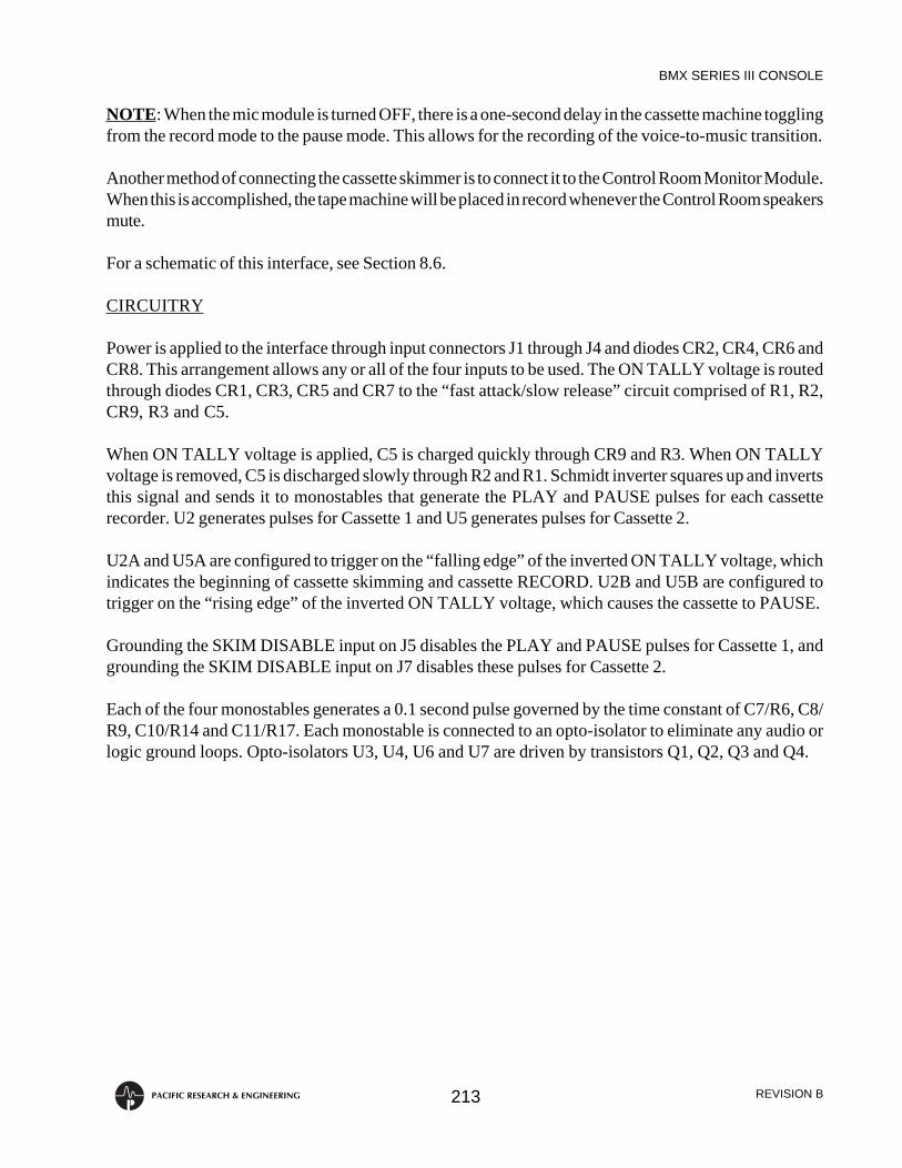
BMX SERIES III CONSOLE
REVISION B213PACIFIC RESEARCH & ENGINEERING
NOTE: When the mic module is turned OFF, there is a one-second delay in the cassette machine togglingfrom the record mode to the pause mode. This allows for the recording of the voice-to-music transition.
Another method of connecting the cassette skimmer is to connect it to the Control Room Monitor Module.When this is accomplished, the tape machine will be placed in record whenever the Control Room speakersmute.
For a schematic of this interface, see Section 8.6.
CIRCUITRY
Power is applied to the interface through input connectors J1 through J4 and diodes CR2, CR4, CR6 andCR8. This arrangement allows any or all of the four inputs to be used. The ON TALLY voltage is routedthrough diodes CR1, CR3, CR5 and CR7 to the “fast attack/slow release” circuit comprised of R1, R2,CR9, R3 and C5.
When ON TALLY voltage is applied, C5 is charged quickly through CR9 and R3. When ON TALLYvoltage is removed, C5 is discharged slowly through R2 and R1. Schmidt inverter squares up and invertsthis signal and sends it to monostables that generate the PLAY and PAUSE pulses for each cassetterecorder. U2 generates pulses for Cassette 1 and U5 generates pulses for Cassette 2.
U2A and U5A are configured to trigger on the “falling edge” of the inverted ON TALLY voltage, whichindicates the beginning of cassette skimming and cassette RECORD. U2B and U5B are configured totrigger on the “rising edge” of the inverted ON TALLY voltage, which causes the cassette to PAUSE.
Grounding the SKIM DISABLE input on J5 disables the PLAY and PAUSE pulses for Cassette 1, andgrounding the SKIM DISABLE input on J7 disables these pulses for Cassette 2.
Each of the four monostables generates a 0.1 second pulse governed by the time constant of C7/R6, C8/R9, C10/R14 and C11/R17. Each monostable is connected to an opto-isolator to eliminate any audio orlogic ground loops. Opto-isolators U3, U4, U6 and U7 are driven by transistors Q1, Q2, Q3 and Q4.

BMX SERIES III CONSOLE
REVISION B214PACIFIC RESEARCH & ENGINEERING
8.6 ACCESSORY SCHEMATICS
This section contains schematics for the various accessories described in this chapter, as follows:
8.6.1 Cart Recorder Remote Control Panel8.6.2 Cassette and Tape Recorder Remote Control Panel8.6.3 TD-2 Digital Clock8.6.4 TD-171 Digital Slave Clock8.6.5 DT-4 Digital Timer8.6.6 Timer Control Panel8.6.7 PPM Meter Buffer Amplifier8.6.8 Power Supply Coupler Unit8.6.9 TCI-2A Cartridge Interface8.6.10 CI-2 Cartridge Interface8.6.11 TI-2 Tape Interface8.6.12 TT-3 Turntable Interface8.6.13 WL-2 Warning Light Interface8.6.14 Dual Relay Interface8.6.15 Cassette Skimmer Interface8.6.16 #99-38 Console To Interface Cable8.6.17 #99-464 Console To TI-2 Interface Cable8.6.18 #99-465 Console to CI-2 Interface Cable (for Studer A725, A727
and A730 CD Players)8.6.19 #99-453 Control Cable, 9-pin Male To Male8.6.20 #99-454 Control Cable, 12-pin Male To Male8.6.21 #99-455 Control Cable, 24-pin Male To Male
NOTE: On PR&E schematics, capacitor values are in microfarads (µF), unless otherwise specified, andresistors are 1/4 watt, 5%, unless otherwise specified.


