Embed Size (px)
Citation preview
BOM Template Guide
v 1.0

Table of ContentsPanel Type Tab .........................................1
Panels Tab ................................................3 Trimless Ends ........................................5 Transverse Bends..................................6 Double Transverse Bends .....................7 Longitudinal Bends ................................8 Double Longitudinal Bends....................9 Ribbed Ends ..........................................10 Curved Panels .......................................11
Modified Edges ......................................12 Modified Ends ........................................13 Beveled Ends ........................................14 Hidden Columns - Kingspan Use Only ..15
Flashing Tab .............................................16
Accessories Tab ......................................17
Extrusions Tab .........................................18

Panel Type Tab
Most cells will have a drop-down menu with different option to choose from when filling out the Panel Types.
Below is a list of all cells with drop-down menus along with all of the options within that menu list.
Panel Type - DW2000, DW2000R, DW2000S, DW4000, and DW1000.
Reveal - Tight, 1/2”, and Other.
Thick - 1 1/8”, 2”, 2 1/2”, 3”, 3” Deep Joint, 4”, and 4” Deep Joint.
Orientation - Horizontal and Vertical.
Profile - Flat, Striated, and Ribbed.
Foam/Core - ISO (polyisosanurate).
Exposed Backer - Yes or No.
Gauge (Face/Backer) - 24, 22, 20, .040 gauge.
Texture (Face/Backer) - Smooth or Embossed texture.
Color (Face) - Maunally enter in the Panel color.
Color (Backer) - USDA Imperial White
1
Panel Type Tab (cont.)
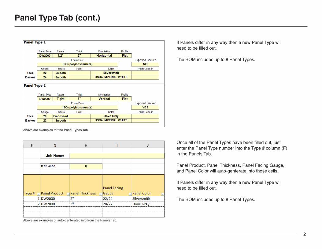
If Panels differ in any way then a new Panel Type will need to be filled out.
The BOM includes up to 8 Panel Types.
Once all of the Panel Types have been filled out, just enter the Panel Type number into the Type # column (F)in the Panels Tab.
Panel Product, Panel Thickness, Panel Facing Gauge, and Panel Color will auto-genterate into those cells.
If Panels differ in any way then a new Panel Type will need to be filled out.
The BOM includes up to 8 Panel Types.
Above are examples for the Panel Types Tab.
Above are examples of auto-genterated info from the Panels Tab.
2

Panels Tab
1
1 4
2 5
3
2 3 4 5
Once the Panel Types have been filled out in the Panel Type Tab, that information will auto-generate and appear here.
More information will be manually entered here. Please see page X for more details.
Trimless End information will be entered here. Please see page X for more details.
Information for Transverse Bends and Double Transverse Bends will go here. Please see page X for more details.
Linear Footage and Square Footage will appear here. Information will auto-genterate as you enter your cutlist items.
NOTE: Some columns may be hidden.
To unhide just click and hold Shift on the columns to the left and right, right-click and select Unihide.
3

Panels Tab
Enter Module Width into column K without the inch marks, they will auto-genterate.
Enter Elevation / Location Tags into column L.Tags have a limit of 6 characters.
Enter Quantity into column M.
Measurments for Panels are separated into two columns, feet (N) and inches (O).
Please convert any measurement in other forms into feet and inches.
Our system does not accept measurments in 16ths. Please round up or down to the nearest 8th.
NOTE: Due to manufacturing capablities there are maximum and minimum limitations for Panel lengths. Please make sure lengths meet the requirements below.
Min Length: 4” Max Length: 24’ 0”
4

DESIGNWALL 2000H, 2" THICK
TYPE 'X' PANEL
JOB # XXXXXXXXXXXXXX
DESIGNWALL 2000H, 2" THICK
TYPE 'X' PANEL
JOB # XXXXXXXXXXXXXX
Trimless Ends
TEA - Trimless End A (Left)TEB - Trimless End B (Right)
Entering in the Trimless End (TE) angle indicates two things, that the Panel End will have a TE, and what the angle of the TE will be.
Enter TEA angle into column P.Enter TEB angle into column Q.
Angle capablility can range between 30º to 150º.
Angles smaller than 90º (89º to 30º) will bend inward, see examples 1 and 3.
Angles larger than 90º (91º to 150º) will bend outward, see example 2.
Standard Trimless Ends are 90º.
If no TE is needed then leave blank.
1
123
2
2
1
3
Examples
45° TEA 90° TEB
90° TEA 135° TEB
DESIGNWALL 2000H, 2" THICK
TYPE 'X' PANEL
JOB # XXXXXXXXXXXXXX
45° TEA 45° TEB
3
5
Transverse Bend
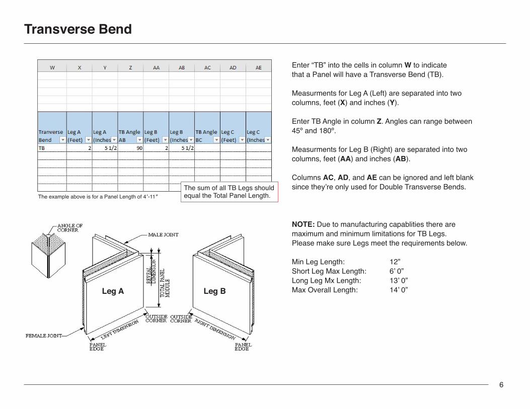
Enter “TB” into the cells in column W to indicate that a Panel will have a Transverse Bend (TB).
Measurments for Leg A (Left) are separated into two columns, feet (X) and inches (Y).
Enter TB Angle in column Z. Angles can range between 45º and 180º.
Measurments for Leg B (Right) are separated into two columns, feet (AA) and inches (AB).
Columns AC, AD, and AE can be ignored and left blank since they’re only used for Double Transverse Bends.
NOTE: Due to manufacturing capablities there are maximum and minimum limitations for TB Legs. Please make sure Legs meet the requirements below.
Min Leg Length: 12” Short Leg Max Length: 6’ 0” Long Leg Mx Length: 13’ 0” Max Overall Length: 14’ 0”Leg A Leg B
The sum of all TB Legs should equal the Total Panel Length.The example above is for a Panel Length of 4′-11″
6

Double Transverse Bend
Enter “DTB” into the cells in column W to indicate that a Panel will have a Double Transverse Bend (DTB).
Measurments for Leg A (Left) are separated into two columns, feet (X) and inches (Y).
Enter TB Angle AB in column Z. This will be the angle between Leg A and B. Angles can range between 45º and 180º.
Measurments for Leg B (Right) are separated into two columns, feet (AA) and inches (AB).
Enter TB Angle BC in column AC. This will be the angle between Leg B and C. Angles can range between 45º and 180º.
Measurments for Leg B (Right) are separated into two columns, feet (AD) and inches (AE).
NOTE: Due to manufacturing capablities there are maximum and minimum limitations for DTB Legs. Please make sure Legs meet the requirements below.
Min Leg Length: 12” Center Leg Min Length: 16”Center Leg Max Length: 6’ 0”Side Leg Max Length: 13’ 0” Max Overall Length: 15’ 0”
The sum of all DTB Legs should equal the Total Panel Length.
Leg A Leg C
Leg B
The example above is for a Panel Length of 4′-11″
7

Longitudinal Bend
Enter “LB” into the cells in column AF to indicate that a Panel will have a Longitudinal Bend (LB).
Lengths for the Male Leg (Male joint) are separated into two columns, feet (AG) and inches (AH).
Enter LB Angle AB in column AI. Angles can range between 45º and 180º.
Lengths for the Female Leg (Female joint) are separated into two columns, feet (AJ) and inches (AK).
Columns AL, AM, and AN can be ignored and left blank since they’re only used for Double Longitudinal Bends.
NOTE: Due to manufacturing capablities there are maximum and minimum limitations for LB Legs. Please make sure Legs meet the requirements below.
Min Width for Small Leg: Panel Thickness + 3”Max Overal Length: 18’ 0”
The sum of all LB Legs should equal the Panel Module Width.The example above is for a 36” Module.
DESIGNWALL 2000H, 2" THICK, 1/2" REVEAL
TYPE 'X' PANEL
FACEGIRTH
LINERGIRTH
FOAMWIDTH
PANELMODULE
30" 36 1/2" 34" 32 1/4"
JOB # XXXXXXXXXXXXXX
This column may be hidden.
8

Double Longitudinal Bend
Enter “DLB” into the cells in column AF to indicate that a Panel will have a Longitudinal Bend (LB).
Lengths for the Male Leg (Male joint) are separated into two columns, feet (AG) and inches (AH).
Enter LB Angle AB in column AI. Angles can range between 45º and 180º.
Lengths for the Center Leg are separated into two columns, feet (AJ) and inches (AK).
Enter LB Angle BC in column AL. Angles can range between 45º and 180º.
Lengths for the Female Leg (Female joint) are separated into two columns, feet (AM) and inches (AN).
NOTE: Due to manufacturing capablities there are maximum and minimum limitations for DLB Legs. Please make sure Legs meet the requirements below.
Middle Leg Min Length: Panel Thickness x 2 + 12”Max Overal Length: 18’ 0”
The example above is for a 36” Module.
The sum of all DLB Legs should equal the Panel Module Width.
FACEGIRTH
LINERGIRTH
FOAMWIDTH
PANELMODULE
30" 36 1/2" 34" 32 1/4"
TYPE 'X' PANEL
DESIGNWALL 2000H, 2" THICK, 1/2" REVEAL
JOB # XXXXXXXXXXXXXX
This column may be hidden.
9

Ribbed Endcaps
L - Left / End AR - Right / End BB - Both End A and B
Enter L, R, or B into column R.
Endcaps are only use for Ribbed Panels.
If Ribbed Endcaps are not needed then leave cells blank.
Examples
Male Edge
Female Edge
End
B
End
A Face of Panel
1
2
Ribbed Panel Sketch
Ribbed Endcap Sketch
This column may be hidden.
10

Curved Panels This column may be hidden.
11
Modified Edges
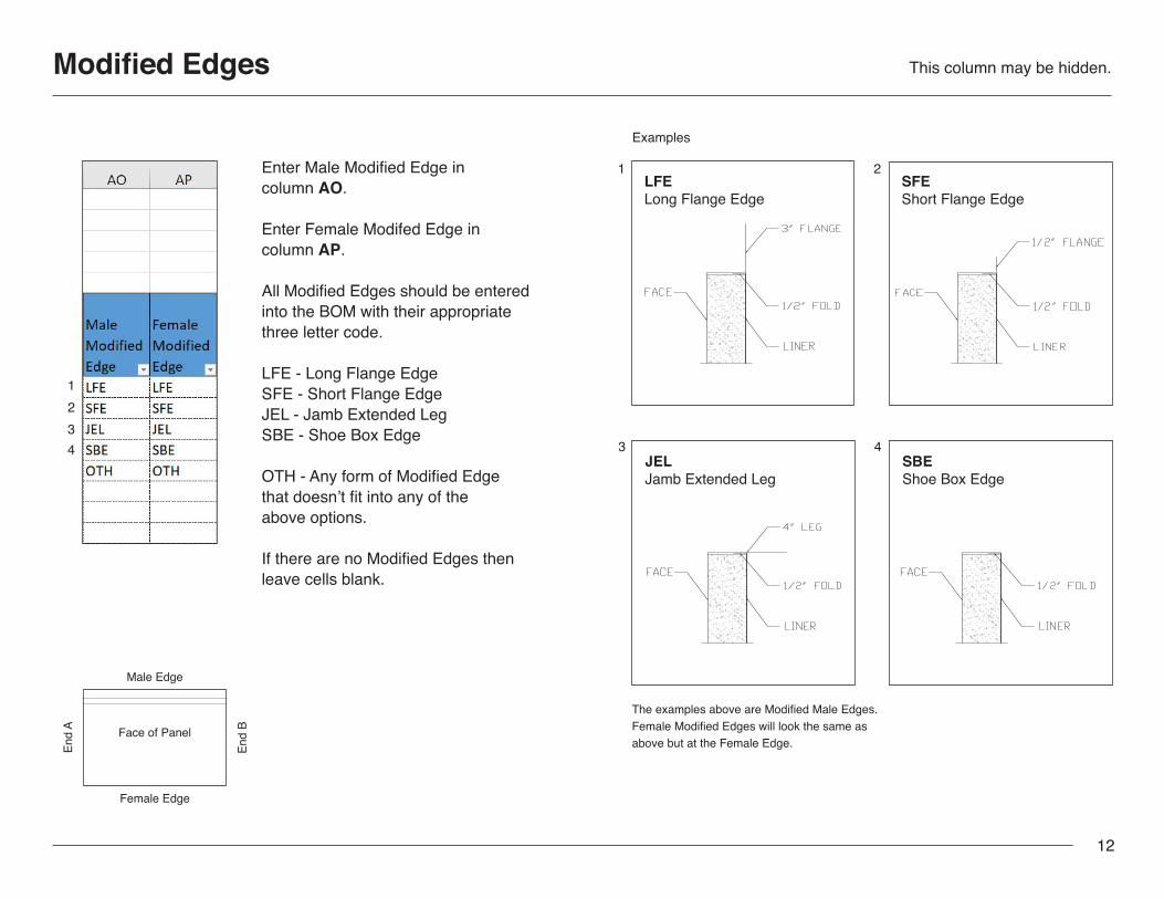
Enter Male Modified Edge in column AO.
Enter Female Modifed Edge in column AP.
All Modified Edges should be entered into the BOM with their appropriate three letter code.
LFE - Long Flange EdgeSFE - Short Flange EdgeJEL - Jamb Extended LegSBE - Shoe Box Edge
OTH - Any form of Modified Edge that doesn’t fit into any of the above options.
If there are no Modified Edges then leave cells blank.
LFELong Flange Edge
JELJamb Extended Leg
SBEShoe Box Edge
SFEShort Flange Edge
Examples
1
3
2
4
1234
The examples above are Modified Male Edges. Female Modified Edges will look the same as above but at the Female Edge.
Male Edge
Female Edge
End
B
End
A Face of Panel
This column may be hidden.
12

Modified Ends
Modified End A (Left)Modified End B (Right)
Enter Modified End A in column AQ.Enter Modified End B in column AR.
All Modified Ends should be entered into the BOM with their appropriate three letter code.
BSE - Block Spline EndFWE - Full Wrap End
OMN - Any form of Modified End that doesn’t fit into any of the above options.
If there are no Modified Ends then leave cells blank.
BSEBlock Spline End
FWEFull Wrap End
Examples
1
2
12
Male Edge
Female Edge
End
B
End
A Face of Panel
This column may be hidden.
13

Beveled Ends This column may be hidden.
Enter A, B, or BOTH into column AS.
A - Left / End AB - Right / End BBOTH - End A and B
The BOM does not allow any indication for what the Beveled Angles may be. Please proved Shop Drawings or Sketches.
1
2
3
Beveled End A
Beveled End B
Beveled End BOTH
Examples
123
14
Male Edge
Female Edge
End
B
End
A Face of Panel

Hidden Columns - Kingspan Use Only
SAP Job # (B), Tag (D), and Bundle (E) columns will be filled out by Kingspan.
Please do not fill out these columns.
15

Flashing Tab
Fill out the Flashing Tab for any Flashing or Mending Plates needed.
Enter Flashing Mark into column D.
Enter Trim Color into column E.
Mending Plates are typically made from Premium Overstock (PRESTK) material.
Enter Quantity into column F.
Enter the Flashing or Mending Plate Girth into column G.
Both Flashing and Mending Plate come in 10′ lengths, columns H and I.
16
BF-1 Flashing Sketch CT-1 Flashing Sketch MP-1 Mending Plate Sketch
Examples
1 2 3
123

Accessories Tab
Fill out the Flashing Tab for any Flashing or Mending Plates needed.
Enter Flashing Mark into column D.
Enter Trim Color into column E.
Mending Plates are typically made from Premium Overstock (PRESTK) material.
Enter Quantity into column F.
Enter the Flashing or Mending Plate Girth into column G.
Both Flashing and Mending Plate come in 10′ lengths, columns H and I.
17

Extrusions Tab
18


![[ PowerPoint Template ]](https://img.pdfslide.net/doc/110x75/631afe995d5809cabd0fa04b/-powerpoint-template-.jpg)


