Embed Size (px)
Citation preview
BPS 307iBar Code Positioning System
O r i g i n a l o p e r a t i n g i n s t r u c t i o n s
EN 2
016/
12 -
5012
7000
We
rese
rve
the
right
to
mak
e te
chni
cal c
hang
es

Leuze electronic BPS 307i 2
© 2016Leuze electronic GmbH + Co. KGIn der Braike 1D-73277 Owen / GermanyPhone: +49 7021 573-0Fax: +49 7021 573-199http://[email protected]
Leuze electronic BPS 307i 3
1 About this document . . . . . . . . . . . . . . . . . . . . . . . . . . . . . . . . . . . . . . . . . . . . . . 61.1 Used symbols and signal words . . . . . . . . . . . . . . . . . . . . . . . . . . . . . . . . . . . . . . . . . . . . . 6
2 Safety . . . . . . . . . . . . . . . . . . . . . . . . . . . . . . . . . . . . . . . . . . . . . . . . . . . . . . . . . . 82.1 Intended use . . . . . . . . . . . . . . . . . . . . . . . . . . . . . . . . . . . . . . . . . . . . . . . . . . . . . . . . . . . . 82.2 Foreseeable misuse . . . . . . . . . . . . . . . . . . . . . . . . . . . . . . . . . . . . . . . . . . . . . . . . . . . . . . 82.3 Competent persons . . . . . . . . . . . . . . . . . . . . . . . . . . . . . . . . . . . . . . . . . . . . . . . . . . . . . . . 92.4 Exemption of liability . . . . . . . . . . . . . . . . . . . . . . . . . . . . . . . . . . . . . . . . . . . . . . . . . . . . . . 92.5 Laser warning notices . . . . . . . . . . . . . . . . . . . . . . . . . . . . . . . . . . . . . . . . . . . . . . . . . . . . . 9
3 Device description . . . . . . . . . . . . . . . . . . . . . . . . . . . . . . . . . . . . . . . . . . . . . . . 123.1 Device overview . . . . . . . . . . . . . . . . . . . . . . . . . . . . . . . . . . . . . . . . . . . . . . . . . . . . . . . . 123.1.1 General information . . . . . . . . . . . . . . . . . . . . . . . . . . . . . . . . . . . . . . . . . . . . . . . . . . . . . . 123.1.2 Performance characteristics . . . . . . . . . . . . . . . . . . . . . . . . . . . . . . . . . . . . . . . . . . . . . . . 133.1.3 Accessories . . . . . . . . . . . . . . . . . . . . . . . . . . . . . . . . . . . . . . . . . . . . . . . . . . . . . . . . . . . . 133.1.4 Device model with heating. . . . . . . . . . . . . . . . . . . . . . . . . . . . . . . . . . . . . . . . . . . . . . . . . 133.2 Connection technology . . . . . . . . . . . . . . . . . . . . . . . . . . . . . . . . . . . . . . . . . . . . . . . . . . . 143.2.1 MS 307 connection hood with M12 connectors. . . . . . . . . . . . . . . . . . . . . . . . . . . . . . . . . 143.2.2 MK 307 connection hood with spring-cage terminals . . . . . . . . . . . . . . . . . . . . . . . . . . . . 143.2.3 Connection hood KB 307 with cable . . . . . . . . . . . . . . . . . . . . . . . . . . . . . . . . . . . . . . . . . 153.2.4 Connection hood KB 301 with cable . . . . . . . . . . . . . . . . . . . . . . . . . . . . . . . . . . . . . . . . . 163.3 Display elements . . . . . . . . . . . . . . . . . . . . . . . . . . . . . . . . . . . . . . . . . . . . . . . . . . . . . . . . 163.3.1 LED indicators . . . . . . . . . . . . . . . . . . . . . . . . . . . . . . . . . . . . . . . . . . . . . . . . . . . . . . . . . . 163.3.2 Display indicators . . . . . . . . . . . . . . . . . . . . . . . . . . . . . . . . . . . . . . . . . . . . . . . . . . . . . . . 173.4 Bar code tape . . . . . . . . . . . . . . . . . . . . . . . . . . . . . . . . . . . . . . . . . . . . . . . . . . . . . . . . . . 193.4.1 General information . . . . . . . . . . . . . . . . . . . . . . . . . . . . . . . . . . . . . . . . . . . . . . . . . . . . . . 193.4.2 Control bar codes . . . . . . . . . . . . . . . . . . . . . . . . . . . . . . . . . . . . . . . . . . . . . . . . . . . . . . . 213.4.3 Marker labels . . . . . . . . . . . . . . . . . . . . . . . . . . . . . . . . . . . . . . . . . . . . . . . . . . . . . . . . . . . 243.4.4 Twin tapes . . . . . . . . . . . . . . . . . . . . . . . . . . . . . . . . . . . . . . . . . . . . . . . . . . . . . . . . . . . . . 25
4 Functions . . . . . . . . . . . . . . . . . . . . . . . . . . . . . . . . . . . . . . . . . . . . . . . . . . . . . . 264.1 Position measurement. . . . . . . . . . . . . . . . . . . . . . . . . . . . . . . . . . . . . . . . . . . . . . . . . . . . 264.2 Speed measurement . . . . . . . . . . . . . . . . . . . . . . . . . . . . . . . . . . . . . . . . . . . . . . . . . . . . . 264.3 Timing . . . . . . . . . . . . . . . . . . . . . . . . . . . . . . . . . . . . . . . . . . . . . . . . . . . . . . . . . . . . . . . . 274.4 Leuze webConfig tool . . . . . . . . . . . . . . . . . . . . . . . . . . . . . . . . . . . . . . . . . . . . . . . . . . . . 274.5 Evaluation of the reading quality . . . . . . . . . . . . . . . . . . . . . . . . . . . . . . . . . . . . . . . . . . . . 274.6 Distance measurement to the bar code tape. . . . . . . . . . . . . . . . . . . . . . . . . . . . . . . . . . . 28
5 Applications . . . . . . . . . . . . . . . . . . . . . . . . . . . . . . . . . . . . . . . . . . . . . . . . . . . . 295.1 High-bay storage device . . . . . . . . . . . . . . . . . . . . . . . . . . . . . . . . . . . . . . . . . . . . . . . . . . 305.2 Telpher line . . . . . . . . . . . . . . . . . . . . . . . . . . . . . . . . . . . . . . . . . . . . . . . . . . . . . . . . . . . . 315.3 Gantry cranes . . . . . . . . . . . . . . . . . . . . . . . . . . . . . . . . . . . . . . . . . . . . . . . . . . . . . . . . . . 32
6 Mounting and installation . . . . . . . . . . . . . . . . . . . . . . . . . . . . . . . . . . . . . . . . . . 336.1 Mounting bar code tape. . . . . . . . . . . . . . . . . . . . . . . . . . . . . . . . . . . . . . . . . . . . . . . . . . . 336.1.1 Installation and application remarks . . . . . . . . . . . . . . . . . . . . . . . . . . . . . . . . . . . . . . . . . 336.1.2 Cutting bar code tapes . . . . . . . . . . . . . . . . . . . . . . . . . . . . . . . . . . . . . . . . . . . . . . . . . . . 346.1.3 Mounting the BCB . . . . . . . . . . . . . . . . . . . . . . . . . . . . . . . . . . . . . . . . . . . . . . . . . . . . . . . 356.2 Bar code Positioning System. . . . . . . . . . . . . . . . . . . . . . . . . . . . . . . . . . . . . . . . . . . . . . . 386.2.1 Mounting instructions. . . . . . . . . . . . . . . . . . . . . . . . . . . . . . . . . . . . . . . . . . . . . . . . . . . . . 396.2.2 Orientation of the BPS to the bar code tape . . . . . . . . . . . . . . . . . . . . . . . . . . . . . . . . . . . 406.2.3 Mounting with the BTU 0300M-W mounting device . . . . . . . . . . . . . . . . . . . . . . . . . . . . . 406.2.4 Mounting with the BT 300 W mounting bracket. . . . . . . . . . . . . . . . . . . . . . . . . . . . . . . . . 416.2.5 Mounting with BT 56 mounting device. . . . . . . . . . . . . . . . . . . . . . . . . . . . . . . . . . . . . . . . 41
Leuze electronic BPS 307i 4
6.2.6 Mounting with BT 300-1 mounting device . . . . . . . . . . . . . . . . . . . . . . . . . . . . . . . . . . . . . 426.2.7 Mounting with M4 fastening screws. . . . . . . . . . . . . . . . . . . . . . . . . . . . . . . . . . . . . . . . . . 42
7 Electrical connection . . . . . . . . . . . . . . . . . . . . . . . . . . . . . . . . . . . . . . . . . . . . . 437.1 External parameter memory in the connection hood. . . . . . . . . . . . . . . . . . . . . . . . . . . . . 437.2 MS 307 connection hood with connectors. . . . . . . . . . . . . . . . . . . . . . . . . . . . . . . . . . . . . 447.3 MK 307 connection hood with spring-cage terminals . . . . . . . . . . . . . . . . . . . . . . . . . . . . 447.4 Connection hood KB 307 with cable . . . . . . . . . . . . . . . . . . . . . . . . . . . . . . . . . . . . . . . . . 447.5 Pin assignment . . . . . . . . . . . . . . . . . . . . . . . . . . . . . . . . . . . . . . . . . . . . . . . . . . . . . . . . . 447.5.1 PWR / SW IN/OUT (Power and switching input/output) . . . . . . . . . . . . . . . . . . . . . . . . . . 447.5.2 SSI (HOST / BUS IN) . . . . . . . . . . . . . . . . . . . . . . . . . . . . . . . . . . . . . . . . . . . . . . . . . . . . 467.5.3 SSI connection cable KB 307 . . . . . . . . . . . . . . . . . . . . . . . . . . . . . . . . . . . . . . . . . . . . . . 477.5.4 Service USB . . . . . . . . . . . . . . . . . . . . . . . . . . . . . . . . . . . . . . . . . . . . . . . . . . . . . . . . . . . 477.6 Cable lengths and shielding . . . . . . . . . . . . . . . . . . . . . . . . . . . . . . . . . . . . . . . . . . . . . . . 48
8 Basic configuration. . . . . . . . . . . . . . . . . . . . . . . . . . . . . . . . . . . . . . . . . . . . . . . 508.1 Configuring the SSI interface. . . . . . . . . . . . . . . . . . . . . . . . . . . . . . . . . . . . . . . . . . . . . . . 508.1.1 Principal functionality of the SSI interface . . . . . . . . . . . . . . . . . . . . . . . . . . . . . . . . . . . . . 508.1.2 Setting the configuration of the SSI interface . . . . . . . . . . . . . . . . . . . . . . . . . . . . . . . . . . 528.2 Configuring the switching inputs/outputs . . . . . . . . . . . . . . . . . . . . . . . . . . . . . . . . . . . . . . 528.3 Configuring the resolution for the position value . . . . . . . . . . . . . . . . . . . . . . . . . . . . . . . . 528.4 Configuring speed monitoring with switching output . . . . . . . . . . . . . . . . . . . . . . . . . . . . . 528.5 Setting tape selection via the webConfig tool . . . . . . . . . . . . . . . . . . . . . . . . . . . . . . . . . . 538.6 Configuration via the switches of the connection hood . . . . . . . . . . . . . . . . . . . . . . . . . . . 538.7 Setting configuration parameters to factory settings . . . . . . . . . . . . . . . . . . . . . . . . . . . . . 558.8 Key factory settings of the BPS. . . . . . . . . . . . . . . . . . . . . . . . . . . . . . . . . . . . . . . . . . . . . 55
9 Leuze electronic webConfig tool – Extended configuration . . . . . . . . . . . . . . . . 579.1 Installing software . . . . . . . . . . . . . . . . . . . . . . . . . . . . . . . . . . . . . . . . . . . . . . . . . . . . . . . 579.1.1 System requirements. . . . . . . . . . . . . . . . . . . . . . . . . . . . . . . . . . . . . . . . . . . . . . . . . . . . . 579.1.2 Install USB driver. . . . . . . . . . . . . . . . . . . . . . . . . . . . . . . . . . . . . . . . . . . . . . . . . . . . . . . . 579.2 Start webConfig tool . . . . . . . . . . . . . . . . . . . . . . . . . . . . . . . . . . . . . . . . . . . . . . . . . . . . . 589.3 Short description of the webConfig tool. . . . . . . . . . . . . . . . . . . . . . . . . . . . . . . . . . . . . . . 599.3.1 Overview . . . . . . . . . . . . . . . . . . . . . . . . . . . . . . . . . . . . . . . . . . . . . . . . . . . . . . . . . . . . . . 599.3.2 CONFIGURATION function. . . . . . . . . . . . . . . . . . . . . . . . . . . . . . . . . . . . . . . . . . . . . . . . 609.3.3 ALIGNMENT function . . . . . . . . . . . . . . . . . . . . . . . . . . . . . . . . . . . . . . . . . . . . . . . . . . . . 669.3.4 PROCESS function . . . . . . . . . . . . . . . . . . . . . . . . . . . . . . . . . . . . . . . . . . . . . . . . . . . . . . 679.3.5 DIAGNOSIS function . . . . . . . . . . . . . . . . . . . . . . . . . . . . . . . . . . . . . . . . . . . . . . . . . . . . . 689.3.6 MAINTENANCE function. . . . . . . . . . . . . . . . . . . . . . . . . . . . . . . . . . . . . . . . . . . . . . . . . . 69
10 Diagnostics and troubleshooting . . . . . . . . . . . . . . . . . . . . . . . . . . . . . . . . . . . . 7010.1 What to do in case of failure? . . . . . . . . . . . . . . . . . . . . . . . . . . . . . . . . . . . . . . . . . . . . . . 7010.1.1Diagnostics with webConfig tool . . . . . . . . . . . . . . . . . . . . . . . . . . . . . . . . . . . . . . . . . . . . 7010.2 Operating indicators of the LEDs. . . . . . . . . . . . . . . . . . . . . . . . . . . . . . . . . . . . . . . . . . . . 7010.3 Error messages on the display . . . . . . . . . . . . . . . . . . . . . . . . . . . . . . . . . . . . . . . . . . . . . 7110.4 Checklist for causes of errors . . . . . . . . . . . . . . . . . . . . . . . . . . . . . . . . . . . . . . . . . . . . . . 71
11 Care, maintenance and disposal . . . . . . . . . . . . . . . . . . . . . . . . . . . . . . . . . . . . 7311.1 Cleaning . . . . . . . . . . . . . . . . . . . . . . . . . . . . . . . . . . . . . . . . . . . . . . . . . . . . . . . . . . . . . . 7311.2 Servicing . . . . . . . . . . . . . . . . . . . . . . . . . . . . . . . . . . . . . . . . . . . . . . . . . . . . . . . . . . . . . . 7311.2.1Firmware update . . . . . . . . . . . . . . . . . . . . . . . . . . . . . . . . . . . . . . . . . . . . . . . . . . . . . . . . 7311.2.2BCB repair with repair kit. . . . . . . . . . . . . . . . . . . . . . . . . . . . . . . . . . . . . . . . . . . . . . . . . . 7311.3 Disposing. . . . . . . . . . . . . . . . . . . . . . . . . . . . . . . . . . . . . . . . . . . . . . . . . . . . . . . . . . . . . . 74

Leuze electronic BPS 307i 5
12 Service and support . . . . . . . . . . . . . . . . . . . . . . . . . . . . . . . . . . . . . . . . . . . . . . 7512.1 What to do should servicing be required? . . . . . . . . . . . . . . . . . . . . . . . . . . . . . . . . . . . . . 75
13 Technical data . . . . . . . . . . . . . . . . . . . . . . . . . . . . . . . . . . . . . . . . . . . . . . . . . . 7613.1 General specifications . . . . . . . . . . . . . . . . . . . . . . . . . . . . . . . . . . . . . . . . . . . . . . . . . . . . 7613.1.1BPS without heating . . . . . . . . . . . . . . . . . . . . . . . . . . . . . . . . . . . . . . . . . . . . . . . . . . . . . 7813.1.2BPS with heating . . . . . . . . . . . . . . . . . . . . . . . . . . . . . . . . . . . . . . . . . . . . . . . . . . . . . . . . 7813.2 Bar code tape . . . . . . . . . . . . . . . . . . . . . . . . . . . . . . . . . . . . . . . . . . . . . . . . . . . . . . . . . . 7913.3 Dimensioned drawings . . . . . . . . . . . . . . . . . . . . . . . . . . . . . . . . . . . . . . . . . . . . . . . . . . . 8113.4 Dimensioned drawings: Accessories. . . . . . . . . . . . . . . . . . . . . . . . . . . . . . . . . . . . . . . . . 8313.5 Dimensioned drawing bar code tape . . . . . . . . . . . . . . . . . . . . . . . . . . . . . . . . . . . . . . . . . 87
14 Ordering information and accessories . . . . . . . . . . . . . . . . . . . . . . . . . . . . . . . . 8814.1 BPS 307i type overview. . . . . . . . . . . . . . . . . . . . . . . . . . . . . . . . . . . . . . . . . . . . . . . . . . . 8814.2 Connection hoods . . . . . . . . . . . . . . . . . . . . . . . . . . . . . . . . . . . . . . . . . . . . . . . . . . . . . . . 8814.3 Cables accessories . . . . . . . . . . . . . . . . . . . . . . . . . . . . . . . . . . . . . . . . . . . . . . . . . . . . . . 8814.4 Other accessories . . . . . . . . . . . . . . . . . . . . . . . . . . . . . . . . . . . . . . . . . . . . . . . . . . . . . . . 8914.5 Bar code tapes . . . . . . . . . . . . . . . . . . . . . . . . . . . . . . . . . . . . . . . . . . . . . . . . . . . . . . . . . 89
15 EC Declaration of Conformity. . . . . . . . . . . . . . . . . . . . . . . . . . . . . . . . . . . . . . . 92
16 Appendix . . . . . . . . . . . . . . . . . . . . . . . . . . . . . . . . . . . . . . . . . . . . . . . . . . . . . . 9316.1 Revision History. . . . . . . . . . . . . . . . . . . . . . . . . . . . . . . . . . . . . . . . . . . . . . . . . . . . . . . . . 9316.1.1Firmware . . . . . . . . . . . . . . . . . . . . . . . . . . . . . . . . . . . . . . . . . . . . . . . . . . . . . . . . . . . . . . 9316.2 Bar code sample . . . . . . . . . . . . . . . . . . . . . . . . . . . . . . . . . . . . . . . . . . . . . . . . . . . . . . . . 9316.2.1BCB bar code tape with 40 mm grid . . . . . . . . . . . . . . . . . . . . . . . . . . . . . . . . . . . . . . . . . 9316.2.2Bar code tape BCB8 with 30 mm grid . . . . . . . . . . . . . . . . . . . . . . . . . . . . . . . . . . . . . . . . 94

About this document
Leuze electronic BPS 307i 6
1 About this document
1.1 Used symbols and signal words
Table 1.1: Warning symbols and signal words
Table 1.2: Other symbols
Table 1.3: Terms and abbreviations
Symbol indicating dangers to persons
Symbol indicating dangers from harmful laser radiation
NOTE Signal word for property damageIndicates dangers that may result in property damage if the measures for danger avoidance are not followed.
Symbol for tipsText passages with this symbol provide you with further information.
Symbol for action stepsText passages with this symbol instruct you to perform actions.
BCB Bar code tape (general or specific BCB type with 40 mm grid)
BCB8 Bar code tape (BCB type with 30 mm grid)
BPS Bar code Positioning System
CFR Code of Federal Regulations
DAP Device Access Point
DCP Discovery and Configuration Protocol
EMC Electromagnetic compatibility
EN European standard
FE Functional earth
GSD General Station Description
GSDML Generic Station Description Markup Language
GUI Graphical User Interface
IO or I/O Input/Output
I&M Information & Maintenance
IP Internet Protocol
LED Light Emitting Diode
MAC Media Access Control
MVS Type of control bar code
MV0 Type of control bar code

About this document
Leuze electronic BPS 307i 7
NEC National Electric Code
OSI Open Systems Interconnection model
PELV Protective Extra-Low Voltage
RT Real Time
SNMP Simple Network Management Protocol
PLC Programmable Logic Control
SSI Synchronous Serial Interface(Digital Synchronous Serial Interface)
TCP Transmission Control Protocol
UDP User Datagram Protocol
USB Universal Serial Bus
UL Underwriters Laboratories
UV Ultraviolet
XML Extensible Markup Language
Safety
Leuze electronic BPS 307i 8
2 SafetyThis sensor was developed, manufactured and tested in line with the applicable safety standards. It corre-sponds to the state of the art.
2.1 Intended useThe device is an optical measuring system which uses visible red laser light to determine its position rela-tive to a permanently mounted bar code tape.All accuracy details for the BPS 300 measurement system refer to the position relative to the permanently mounted bar code tape.
Areas of application
The BPS is designed for positioning in the following areas of application:• Telpher line• Travel and lifting axes of high-bay storage devices• Repositioning units• Gantry crane bridges and their trolleys• Elevators
2.2 Foreseeable misuseAny use other than that defined under “Intended use” or which goes beyond that use is considered improper use.
In particular, use of the device is not permitted in the following cases:• in rooms with explosive atmospheres• for medical purposes• as own safety component in accordance with the machinery directive
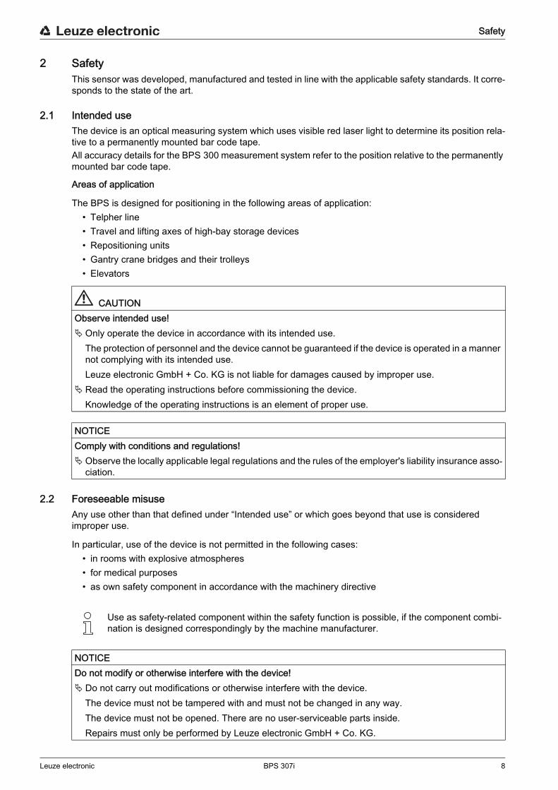
CAUTIONObserve intended use! Only operate the device in accordance with its intended use.
The protection of personnel and the device cannot be guaranteed if the device is operated in a manner not complying with its intended use.Leuze electronic GmbH + Co. KG is not liable for damages caused by improper use.
Read the operating instructions before commissioning the device.Knowledge of the operating instructions is an element of proper use.
NOTICEComply with conditions and regulations! Observe the locally applicable legal regulations and the rules of the employer's liability insurance asso-
ciation.
Use as safety-related component within the safety function is possible, if the component combi- nation is designed correspondingly by the machine manufacturer.
NOTICEDo not modify or otherwise interfere with the device! Do not carry out modifications or otherwise interfere with the device.
The device must not be tampered with and must not be changed in any way.The device must not be opened. There are no user-serviceable parts inside. Repairs must only be performed by Leuze electronic GmbH + Co. KG.

Safety
Leuze electronic BPS 307i 9
2.3 Competent personsConnection, mounting, commissioning and adjustment of the device must only be carried out by competent persons.
Prerequisites for competent persons:• They have a suitable technical education.• They are familiar with the rules and regulations for occupational safety and safety at work.• They are familiar with the original operating instructions of the device.• They have been instructed by the responsible person on the mounting and operation of the device.
Certified electriciansElectrical work must be carried out by a certified electrician.Due to their technical training, knowledge and experience as well as their familiarity with relevant stan-dards and regulations, certified electricians are able to perform work on electrical systems and indepen-dently detect possible dangers.In Germany, certified electricians must fulfill the requirements of accident-prevention regulations BGV A3 (e.g. electrician foreman). In other countries, there are respective regulations that must be observed.
2.4 Exemption of liabilityLeuze electronic GmbH + Co. KG is not liable in the following cases:
• The device is not being used properly.• Reasonably foreseeable misuse is not taken into account.• Mounting and electrical connection are not properly performed.• Changes (e.g., constructional) are made to the device.
2.5 Laser warning notices
ATTENTION, LASER RADIATION – LASERCLASS2Never look directly into the beam!The device satisfies the requirements of IEC 60825-1:2007 (EN 60825-1:2007) safety regulations for a product of laser class 2 as well as the U.S. 21 CFR 1040.10 regulations with deviations corresponding to “Laser Notice No. 50” from June 24, 2007. Never look directly into the laser beam or in the direction of reflected laser beams!
If you look into the beam path over a longer time period, there is a risk of injury to the retina. Do not point the laser beam of the device at persons! Interrupt the laser beam using a non-transparent, non-reflective object if the laser beam is accidentally
directed towards a person.When mounting and aligning the device, avoid reflections of the laser beam off reflective surfaces! CAUTION! The use of operating or adjusting devices other than those specified here or carrying out
of differing procedures may lead to dangerous exposure to radiation. Observe the applicable statutory and local laser protection regulations. The device must not be tampered with and must not be changed in any way.
There are no user-serviceable parts inside the device.Repairs must only be performed by Leuze electronic GmbH + Co. KG.
Safety
Leuze electronic BPS 307i 10
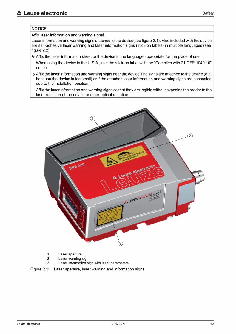
1 Laser aperture2 Laser warning sign3 Laser information sign with laser parameters
Figure 2.1: Laser aperture, laser warning and information signs
NOTICEAffix laser information and warning signs!Laser information and warning signs attached to the device(see figure 2.1). Also included with the device are self-adhesive laser warning and laser information signs (stick-on labels) in multiple languages (see figure 2.2). Affix the laser information sheet to the device in the language appropriate for the place of use.
When using the device in the U.S.A., use the stick-on label with the “Complies with 21 CFR 1040.10” notice.
Affix the laser information and warning signs near the device if no signs are attached to the device (e.g. because the device is too small) or if the attached laser information and warning signs are concealed due to the installation position.Affix the laser information and warning signs so that they are legible without exposing the reader to the laser radiation of the device or other optical radiation.
2
1
3
Safety
Leuze electronic BPS 307i 11
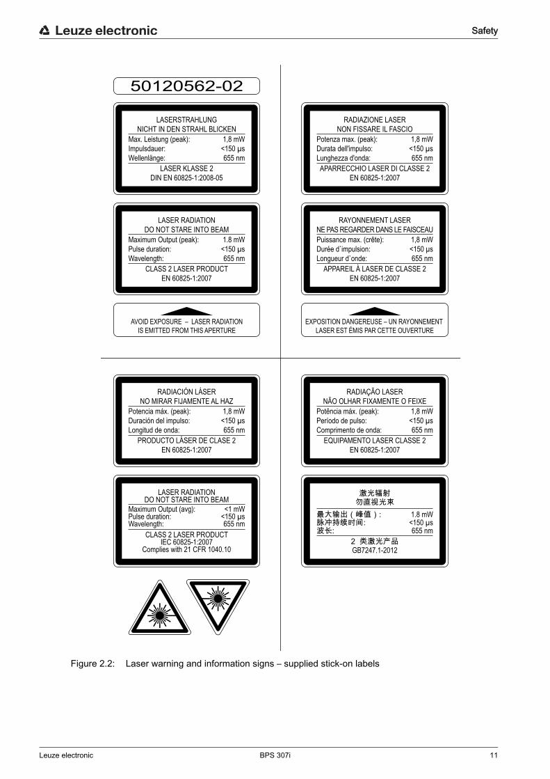
Figure 2.2: Laser warning and information signs – supplied stick-on labels
AVOID EXPOSURE – LASER RADIATIONIS EMITTED FROM THIS APERTURE
EXPOSITION DANGEREUSE – UN RAYONNEMENT LASER EST ÉMIS PAR CETTE OUVERTURE
LASERSTRAHLUNGNICHT IN DEN STRAHL BLICKEN
LASER KLASSE 2DIN EN 60825-1:2008-05
Max. Leistung (peak):Impulsdauer:Wellenlänge:
RADIAZIONE LASERNON FISSARE IL FASCIO
APARRECCHIO LASER DI CLASSE 2EN 60825-1:2007
Potenza max. (peak):Durata dell'impulso:Lunghezza d'onda:
LASER RADIATIONDO NOT STARE INTO BEAM
CLASS 2 LASER PRODUCTEN 60825-1:2007
Maximum Output (peak):Pulse duration:Wavelength:
RAYONNEMENT LASERNE PAS REGARDER DANS LE FAISCEAU
APPAREIL À LASER DE CLASSE 2EN 60825-1:2007
Puissance max. (crête):Durée d`impulsion:Longueur d`onde:
RADIACIÓN LÁSERNO MIRAR FIJAMENTE AL HAZ
PRODUCTO LÁSER DE CLASE 2EN 60825-1:2007
Potencia máx. (peak):Duración del impulso:Longitud de onda:
RADIAÇÃO LASERNÃO OLHAR FIXAMENTE O FEIXE
EQUIPAMENTO LASER CLASSE 2EN 60825-1:2007
Potência máx. (peak):Período de pulso:Comprimento de onda:
LASER RADIATIONDO NOT STARE INTO BEAM
CLASS 2 LASER PRODUCTIEC 60825-1:2007
Complies with 21 CFR 1040.10
Maximum Output (avg):Pulse duration:Wavelength:
GB7247.1-2012
1,8 mW<150 µs655 nm
1,8 mW<150 µs655 nm
1.8 mW<150 µs655 nm
1,8 mW<150 µs655 nm
1,8 mW<150 µs655 nm
1,8 mW<150 µs655 nm
<1 mW<150 µs655 nm
1.8 mW<150 µs655 nm
50120562-02
Device description
Leuze electronic BPS 307i 12
3 Device description
3.1 Device overview
3.1.1 General information
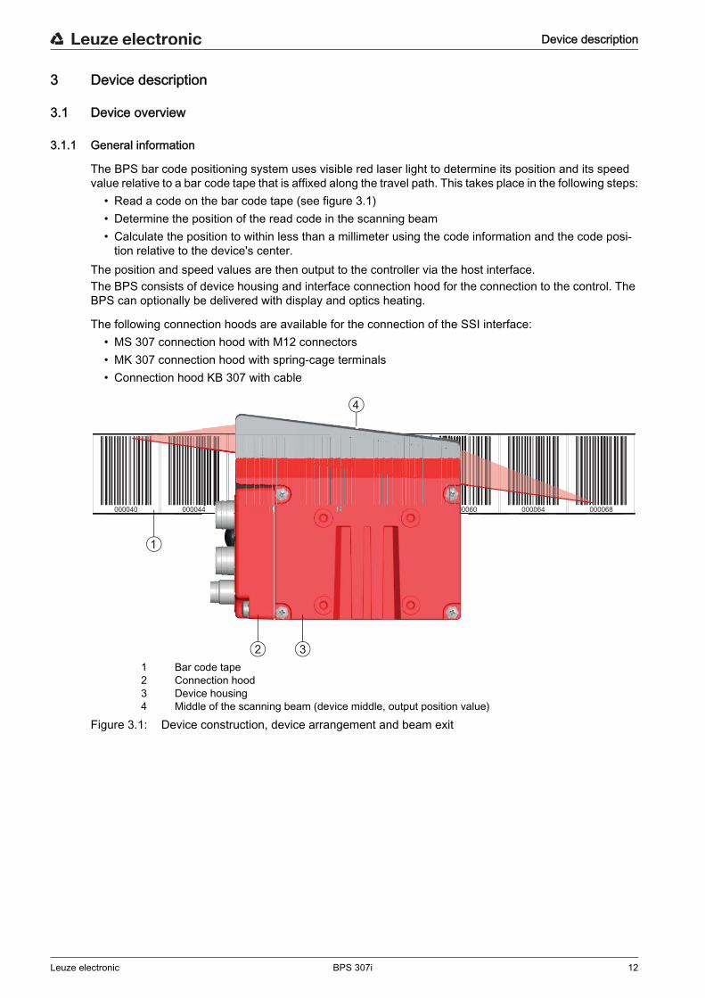
The BPS bar code positioning system uses visible red laser light to determine its position and its speed value relative to a bar code tape that is affixed along the travel path. This takes place in the following steps:
• Read a code on the bar code tape (see figure 3.1)• Determine the position of the read code in the scanning beam• Calculate the position to within less than a millimeter using the code information and the code posi-
tion relative to the device's center.The position and speed values are then output to the controller via the host interface.The BPS consists of device housing and interface connection hood for the connection to the control. The BPS can optionally be delivered with display and optics heating.
The following connection hoods are available for the connection of the SSI interface:• MS 307 connection hood with M12 connectors• MK 307 connection hood with spring-cage terminals• Connection hood KB 307 with cable
1 Bar code tape2 Connection hood3 Device housing4 Middle of the scanning beam (device middle, output position value)
Figure 3.1: Device construction, device arrangement and beam exit
000040 000044 000048 000052 000056 000060 000064 0000684 0000488 00000000000000000000000000000000000000000 0 52 000056565656565656656656565 000000000
1
2
4
3

Device description
Leuze electronic BPS 307i 13
3.1.2 Performance characteristics
The most important performance characteristics of the bar code positioning system:• Positioning with submillimeter accuracy from 0 to 10,000 m• For the control at high traverse rates of up to 10 m/s• Simultaneous position and speed measurement• Working range: 50 to 170 mm; enables flexible mounting positions• Interfaces: PROFINET fieldbus, PROFIBUS fieldbus, SSI, RS 232/RS 422, RS 485• Binary inputs and outputs for control and process monitoring • Configuration via webConfig tool or fieldbus• Diagnostics via webConfig tool or optional display• Optional model with display• Optional model with heating for use to -35 °C
3.1.3 Accessories
Special accessories are available for the bar code positioning system. The accessories are optimally matched to the BPS:
• Highly flexible, scratch-, smudge- and UV-resistant bar code tape• Mounting devices for precise mounting with one screw (easy-mount)• Modular connection technology via connection hoods with M12 connectors, spring-cage terminals or
with cable.
3.1.4 Device model with heatingThe bar code positioning system is optionally available as a model with integrated heating. In this case, heating is permanently installed ex works.
The heating consists of two parts:• Front cover heater• Housing heater
Features of the integrated heating:• Extends the application range of the BPS to -35 °C• Supply voltage 18 … 30 VDC • BPS enabling through an internal temperature switch (start-up delay of about 30 min for 24 V DC
and minimum ambient temperature of -35 °C)• Required conductor cross-section for the power supply: At least 0.75 mm2
FunctionWhen the supply voltage is applied to the BPS, a temperature switch initially only supplies the heating with current (front cover heater and housing heater). During the heating phase (around 30 min), when the inside temperature rises above 15 °C, the temperature switch connects the BPS to the supply voltage. This is followed by the self test and the changeover to read operation. The PWR LED lights up, showing overall readiness for operation.
NOTICENo self-installation of the heating! Self-installation of the heating on-site by the user is not possible.
NOTICEDo not use ready-made cables! It is not possible to use ready-made cables.
The current consumption of the BPS is too high for the ready-made cables.

Device description
Leuze electronic BPS 307i 14
When the inside temperature reaches approx. 18 °C, another temperature switch turns the housing heater off and, if necessary, back on again (if the inside temperature drops below 15 °C). This does not interrupt the read operation. The front cover heater remains activated until an inside temperature of 25 °C is reached. At temperatures above this, the front cover heater switches off and, with a switching hysteresis of 3 °C, back on again at an inside temperature below 22 °C.
3.2 Connection technology
For the electrical connection of the BPS, the following connection variants are available:• MS 307 connection hood with M12 connectors• MK 307 connection hood with spring-cage terminals• Connection hood KB 307 with cable
The voltage supply (18 … 30 VDC) is connected acc. to the connection type selected.Two freely programmable switching inputs/switching outputs for individual adaptation to the respective application are also available here.
3.2.1 MS 307 connection hood with M12 connectorsThe MS 307 connection hood features two M12 connector plugs and a Mini-B type USB socket as a service interface for configuration and diagnostics of the BPS.
1 PWR / SW IN/OUT: M12 plug (A-coded)2 SERVICE: Mini-B USB socket (behind protective cap)3 HOST / BUS IN: M12 plug (B-coded), SSI4 BUS OUT: not equipped
Figure 3.2: MS 307 connection hood, connections
3.2.2 MK 307 connection hood with spring-cage terminalsThe MK 307 connection hood makes it possible to connect the BPS directly and without additional connec-tors. The MK 307 features cable bushings in which the shielding connection for the interface cable is also located. A Mini-B type USB socket is used for service purposes and for configuration and diagnostic of the BPS.
The configuration switches and the integrated parameter memory for the simple replacement of the BPS are located in the MS 307.
NOTICEShielding connection The shielding connection is done via the M12 connector housing.
1
3 4
2
Device description
Leuze electronic BPS 307i 15
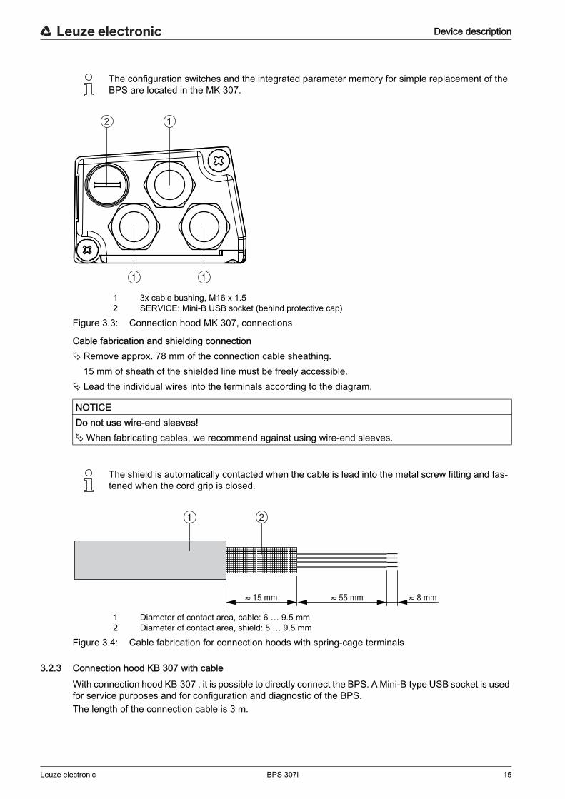
1 3x cable bushing, M16 x 1.52 SERVICE: Mini-B USB socket (behind protective cap)
Figure 3.3: Connection hood MK 307, connections
Cable fabrication and shielding connection Remove approx. 78 mm of the connection cable sheathing.
15 mm of sheath of the shielded line must be freely accessible. Lead the individual wires into the terminals according to the diagram.
1 Diameter of contact area, cable: 6 … 9.5 mm2 Diameter of contact area, shield: 5 … 9.5 mm
Figure 3.4: Cable fabrication for connection hoods with spring-cage terminals
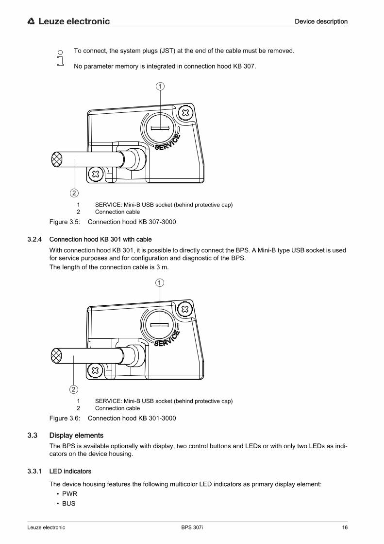
3.2.3 Connection hood KB 307 with cableWith connection hood KB 307 , it is possible to directly connect the BPS. A Mini-B type USB socket is used for service purposes and for configuration and diagnostic of the BPS.The length of the connection cable is 3 m.
The configuration switches and the integrated parameter memory for simple replacement of the BPS are located in the MK 307.
NOTICEDo not use wire-end sleeves!When fabricating cables, we recommend against using wire-end sleeves.
The shield is automatically contacted when the cable is lead into the metal screw fitting and fas- tened when the cord grip is closed.
12
1 1
≈ 55 mm ≈ 8 mm ≈ 15 mm
1 2
Device description
Leuze electronic BPS 307i 16
1 SERVICE: Mini-B USB socket (behind protective cap)2 Connection cable
Figure 3.5: Connection hood KB 307-3000
3.2.4 Connection hood KB 301 with cableWith connection hood KB 301, it is possible to directly connect the BPS. A Mini-B type USB socket is used for service purposes and for configuration and diagnostic of the BPS.The length of the connection cable is 3 m.
1 SERVICE: Mini-B USB socket (behind protective cap)2 Connection cable
Figure 3.6: Connection hood KB 301-3000
3.3 Display elementsThe BPS is available optionally with display, two control buttons and LEDs or with only two LEDs as indi-cators on the device housing.
3.3.1 LED indicators
The device housing features the following multicolor LED indicators as primary display element:• PWR• BUS
To connect, the system plugs (JST) at the end of the cable must be removed.
No parameter memory is integrated in connection hood KB 307.
1
2
1
2
Device description
Leuze electronic BPS 307i 17
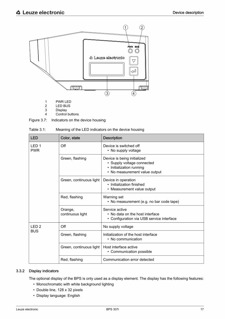
1 PWR LED2 LED BUS3 Display4 Control buttons
Figure 3.7: Indicators on the device housing
Table 3.1: Meaning of the LED indicators on the device housing
3.3.2 Display indicators
The optional display of the BPS is only used as a display element. The display has the following features:• Monochromatic with white background lighting• Double line, 128 x 32 pixels• Display language: English
1
3 4
2
LED Color, state Description
LED 1PWR
Off Device is switched off• No supply voltage
Green, flashing Device is being initialized• Supply voltage connected• Initialization running• No measurement value output
Green, continuous light Device in operation• Initialization finished• Measurement value output
Red, flashing Warning set• No measurement (e.g. no bar code tape)
Orange, continuous light
Service active• No data on the host interface• Configuration via USB service interface
LED 2BUS
Off No supply voltage
Green, flashing Initialization of the host interface• No communication
Green, continuous light Host interface active• Communication possible
Red, flashing Communication error detected
Device description
Leuze electronic BPS 307i 18
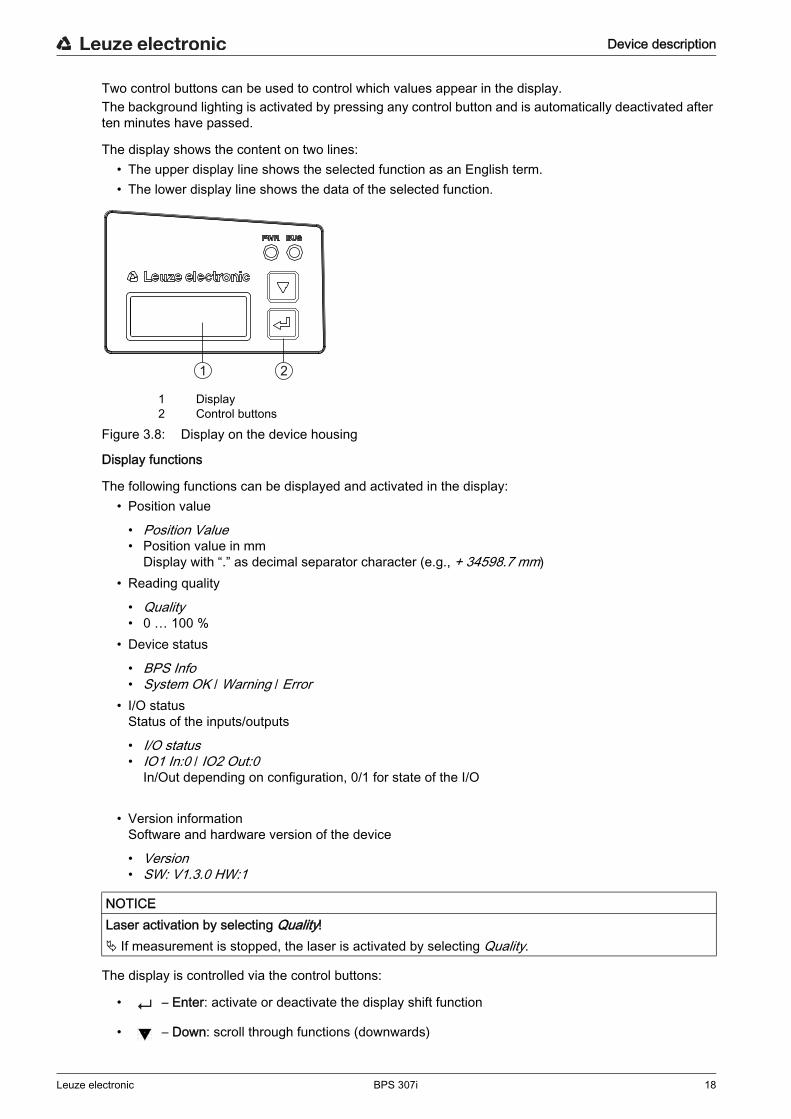
Two control buttons can be used to control which values appear in the display.The background lighting is activated by pressing any control button and is automatically deactivated after ten minutes have passed.
The display shows the content on two lines:• The upper display line shows the selected function as an English term.• The lower display line shows the data of the selected function.
1 Display2 Control buttons
Figure 3.8: Display on the device housing
Display functions
The following functions can be displayed and activated in the display:• Position value
• Position Value• Position value in mm
Display with “.” as decimal separator character (e.g., + 34598.7 mm)• Reading quality
• Quality• 0 … 100 %
• Device status
• BPS Info• System OK / Warning / Error
• I/O statusStatus of the inputs/outputs
• I/O status• IO1 In:0 / IO2 Out:0
In/Out depending on configuration, 0/1 for state of the I/O
• Version informationSoftware and hardware version of the device
• Version• SW: V1.3.0 HW:1
The display is controlled via the control buttons:
• – Enter: activate or deactivate the display shift function
• – Down: scroll through functions (downwards)
NOTICELaser activation by selecting Quality! If measurement is stopped, the laser is activated by selecting Quality.
1 2

Device description
Leuze electronic BPS 307i 19
Example: Representation of the I/O status on the display1. Press button : Display flashes
2. Press button : Display changes from position value (Position Value) to reading quality (Quality)
3. Press button : Display changes from reading quality (Quality) to device status (BPS Info)
4. Press button : Display changes from device status (BPS Info) to I/O status
5. Press button : I/O status displayed, display stops flashing
Display during device start-upDuring device start-up, a start-up display first appears which is briefly followed by the display with the version information.The standard display after starting up the BPS is Position Value.
3.4 Bar code tape
3.4.1 General informationThe bar code tape is available in different variants:
• BCB bar code tape with 40 mm gridCode128 with character set C, increasing in increments of 4 (e.g., 000004, 000008, … )
• Bar code tape BCB8 with 30 mm gridCode128 with character set C, increasing in increments of 3 (e.g. 000003, 000006, … )
A bar code tape consists of a sequence of individual position labels in one of the two grids. Defined cut marks are provided for cutting the BCB.The bar code tape is delivered on a roll. A roll contains up to 200 m of BCB, with the wrapping direction from the outside to the inside (smallest number on the outside). If more than 200 m of BCB is ordered, the total length is divided into rolls of 200 m.Bar code tapes with special requirements with respect to height, length and value range can be ordered from Leuze electronic (see chapter 14.5 "Bar code tapes").
NOTICEValue range for BCB with special requirements!When ordering bar code tapes with special requirements, make certain that the value range contains
only values that are divisible by three (BCB8 with 30 mm grid) or four (BCB with 40 mm grid).It may otherwise not be possible to purchase and use repair tapes.
NOTICEOnly one BCB type per system! In a given system, use either only BCB8 with 30 mm grid or only BCB with 40 mm grid.
If different BCB types are used in one system, the BPS cannot ensure an exact position determination.
NOTICEConfigure the BPS for the used BCB type! The used BCB type must be set in the webConfig tool with the Tape selection parameter; see
chapter 9.3.2 "CONFIGURATION function". On delivery, the BPS is set for BCB with a 40 mm grid.
If the BCB8 with a 30 mm grid is used, the Tape selection must be adjusted in the BPS configuration. If the used BCB type does not correspond to the Tape selection configured in the BPS, exact position
determination cannot be performed by the BPS.
Device description
Leuze electronic BPS 307i 20
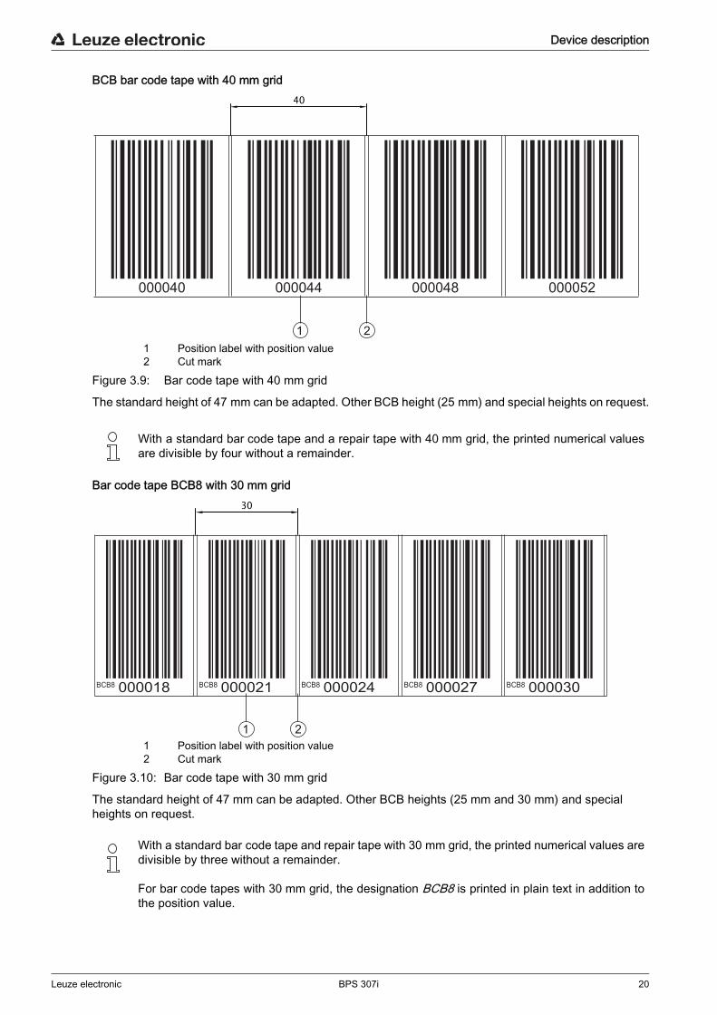
BCB bar code tape with 40 mm grid
1 Position label with position value2 Cut mark
Figure 3.9: Bar code tape with 40 mm grid
The standard height of 47 mm can be adapted. Other BCB height (25 mm) and special heights on request.
Bar code tape BCB8 with 30 mm grid
1 Position label with position value2 Cut mark
Figure 3.10: Bar code tape with 30 mm grid
The standard height of 47 mm can be adapted. Other BCB heights (25 mm and 30 mm) and special heights on request.
With a standard bar code tape and a repair tape with 40 mm grid, the printed numerical values are divisible by four without a remainder.
With a standard bar code tape and repair tape with 30 mm grid, the printed numerical values are divisible by three without a remainder.
For bar code tapes with 30 mm grid, the designation BCB8 is printed in plain text in addition to the position value.
1 2
000040 000044 000048 000052
40
BCB8 BCB8 BCB8 BCB8 BCB8000018 000021 000024 000027 000030
1 2
30
Device description
Leuze electronic BPS 307i 21
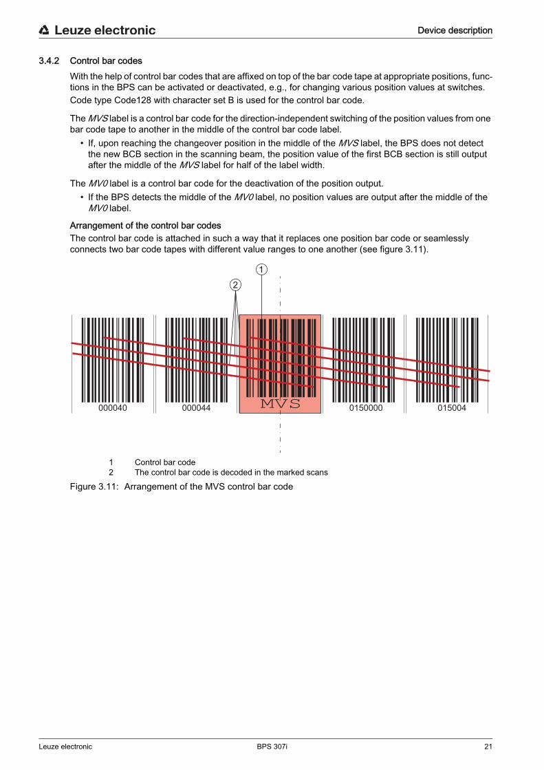
3.4.2 Control bar codesWith the help of control bar codes that are affixed on top of the bar code tape at appropriate positions, func-tions in the BPS can be activated or deactivated, e.g., for changing various position values at switches. Code type Code128 with character set B is used for the control bar code.
The MVS label is a control bar code for the direction-independent switching of the position values from one bar code tape to another in the middle of the control bar code label.
• If, upon reaching the changeover position in the middle of the MVS label, the BPS does not detect the new BCB section in the scanning beam, the position value of the first BCB section is still output after the middle of the MVS label for half of the label width.
The MV0 label is a control bar code for the deactivation of the position output.• If the BPS detects the middle of the MV0 label, no position values are output after the middle of the
MV0 label.
Arrangement of the control bar codesThe control bar code is attached in such a way that it replaces one position bar code or seamlessly connects two bar code tapes with different value ranges to one another (see figure 3.11).
1 Control bar code2 The control bar code is decoded in the marked scans
Figure 3.11: Arrangement of the MVS control bar code
2
000040 000044 000048 0150000 015004
1
Device description
Leuze electronic BPS 307i 22
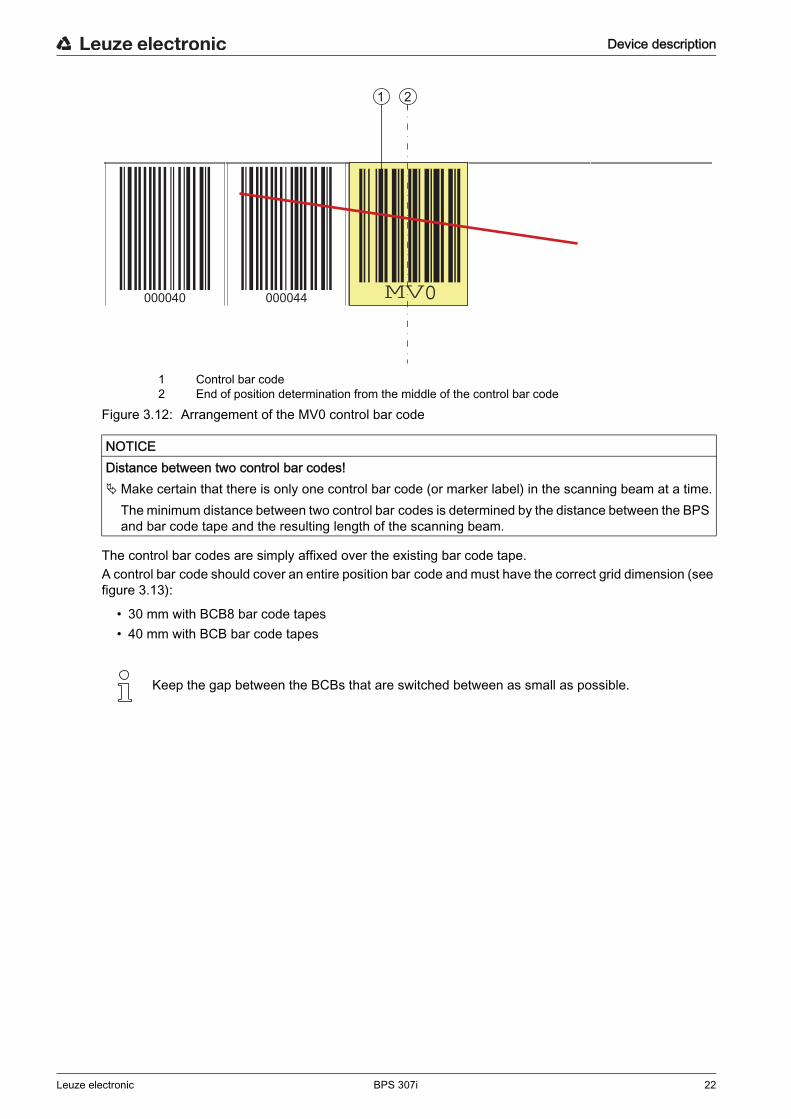
1 Control bar code2 End of position determination from the middle of the control bar code
Figure 3.12: Arrangement of the MV0 control bar code
The control bar codes are simply affixed over the existing bar code tape.A control bar code should cover an entire position bar code and must have the correct grid dimension (see figure 3.13):
• 30 mm with BCB8 bar code tapes• 40 mm with BCB bar code tapes
NOTICEDistance between two control bar codes!Make certain that there is only one control bar code (or marker label) in the scanning beam at a time.
The minimum distance between two control bar codes is determined by the distance between the BPS and bar code tape and the resulting length of the scanning beam.
Keep the gap between the BCBs that are switched between as small as possible.
000040 000044 0
1 2
Device description
Leuze electronic BPS 307i 23
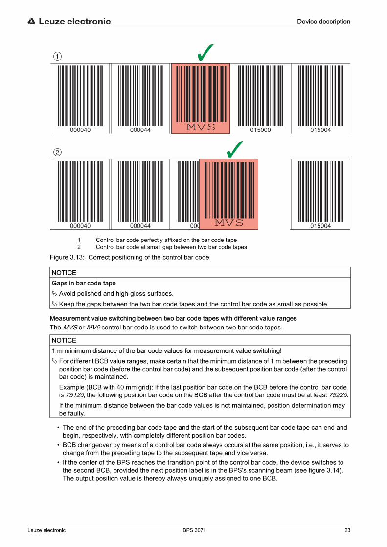
1 Control bar code perfectly affixed on the bar code tape2 Control bar code at small gap between two bar code tapes
Figure 3.13: Correct positioning of the control bar code
Measurement value switching between two bar code tapes with different value rangesThe MVS or MV0 control bar code is used to switch between two bar code tapes.
• The end of the preceding bar code tape and the start of the subsequent bar code tape can end and begin, respectively, with completely different position bar codes.
• BCB changeover by means of a control bar code always occurs at the same position, i.e., it serves to change from the preceding tape to the subsequent tape and vice versa.
• If the center of the BPS reaches the transition point of the control bar code, the device switches to the second BCB, provided the next position label is in the BPS's scanning beam (see figure 3.14).The output position value is thereby always uniquely assigned to one BCB.
NOTICEGaps in bar code tape Avoid polished and high-gloss surfaces. Keep the gaps between the two bar code tapes and the control bar code as small as possible.
NOTICE1 m minimum distance of the bar code values for measurement value switching! For different BCB value ranges, make certain that the minimum distance of 1 m between the preceding
position bar code (before the control bar code) and the subsequent position bar code (after the control bar code) is maintained. Example (BCB with 40 mm grid): If the last position bar code on the BCB before the control bar code is 75120, the following position bar code on the BCB after the control bar code must be at least 75220.If the minimum distance between the bar code values is not maintained, position determination may be faulty.
1
2
000040 000044 000048 015000 015004
000040 000044 000048 015004
Device description
Leuze electronic BPS 307i 24
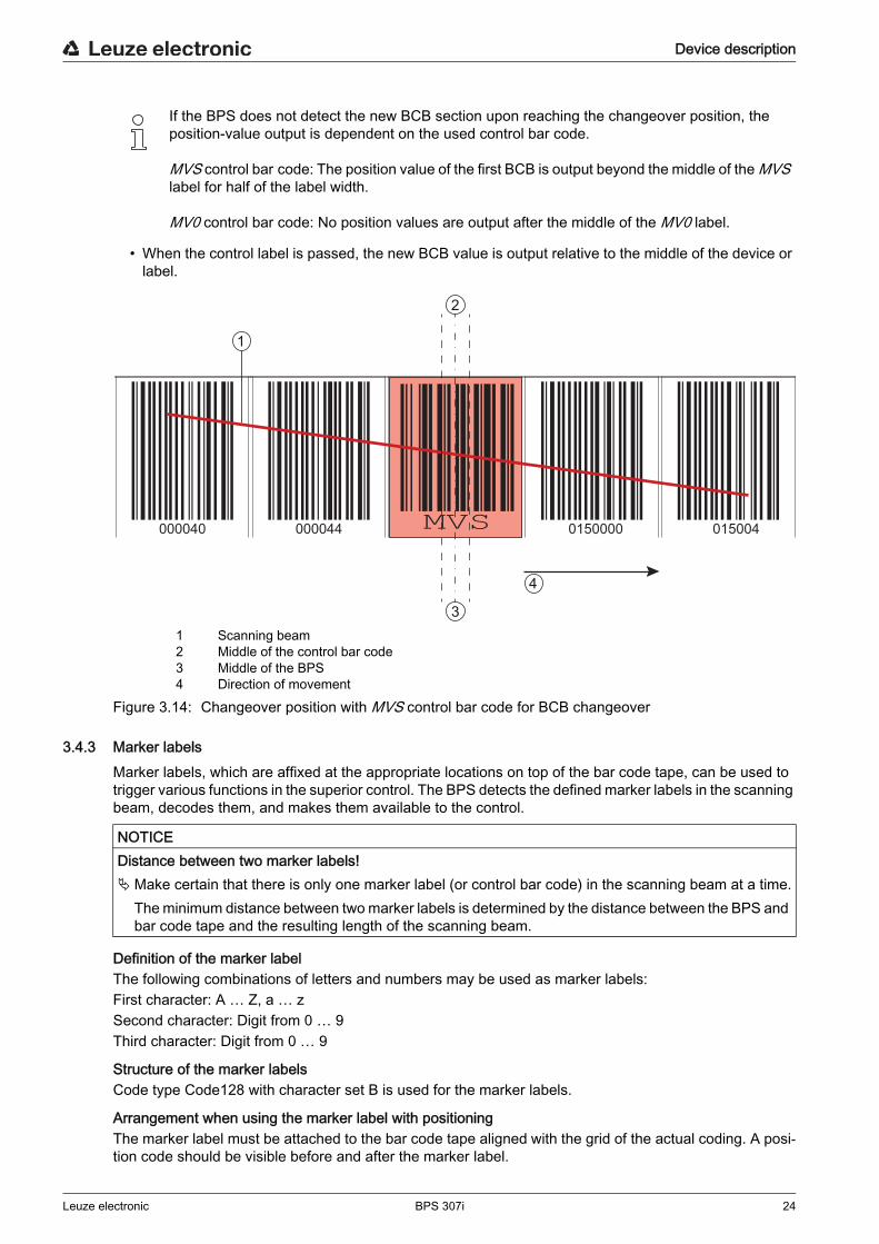
• When the control label is passed, the new BCB value is output relative to the middle of the device or label.
1 Scanning beam2 Middle of the control bar code3 Middle of the BPS4 Direction of movement
Figure 3.14: Changeover position with MVS control bar code for BCB changeover
3.4.3 Marker labelsMarker labels, which are affixed at the appropriate locations on top of the bar code tape, can be used to trigger various functions in the superior control. The BPS detects the defined marker labels in the scanning beam, decodes them, and makes them available to the control.
Definition of the marker labelThe following combinations of letters and numbers may be used as marker labels:First character: A … Z, a … zSecond character: Digit from 0 … 9Third character: Digit from 0 … 9
Structure of the marker labelsCode type Code128 with character set B is used for the marker labels.
Arrangement when using the marker label with positioningThe marker label must be attached to the bar code tape aligned with the grid of the actual coding. A posi-tion code should be visible before and after the marker label.
If the BPS does not detect the new BCB section upon reaching the changeover position, the position-value output is dependent on the used control bar code.
MVS control bar code: The position value of the first BCB is output beyond the middle of the MVS label for half of the label width.
MV0 control bar code: No position values are output after the middle of the MV0 label.
000040 000044 000048 0150000 015004
1
2
3
4
NOTICEDistance between two marker labels!Make certain that there is only one marker label (or control bar code) in the scanning beam at a time.
The minimum distance between two marker labels is determined by the distance between the BPS and bar code tape and the resulting length of the scanning beam.
Device description
Leuze electronic BPS 307i 25
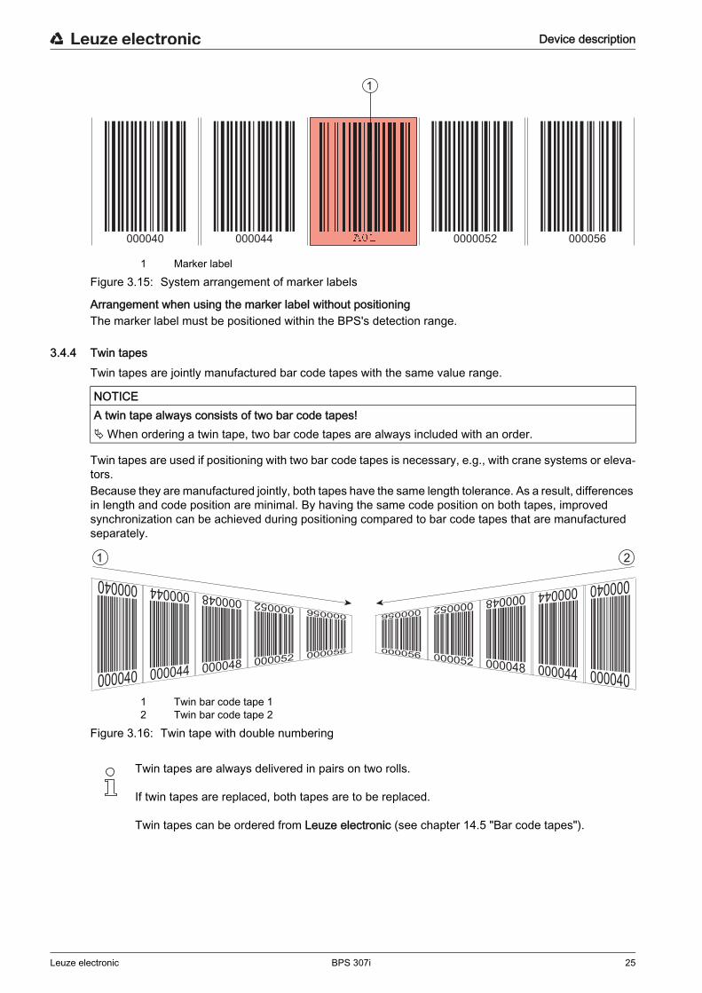
1 Marker labelFigure 3.15: System arrangement of marker labels
Arrangement when using the marker label without positioningThe marker label must be positioned within the BPS's detection range.
3.4.4 Twin tapesTwin tapes are jointly manufactured bar code tapes with the same value range.
Twin tapes are used if positioning with two bar code tapes is necessary, e.g., with crane systems or eleva-tors.Because they are manufactured jointly, both tapes have the same length tolerance. As a result, differences in length and code position are minimal. By having the same code position on both tapes, improved synchronization can be achieved during positioning compared to bar code tapes that are manufactured separately.
1 Twin bar code tape 12 Twin bar code tape 2
Figure 3.16: Twin tape with double numbering
000040 000044 000048 0000052 000056
1
NOTICEA twin tape always consists of two bar code tapes!When ordering a twin tape, two bar code tapes are always included with an order.
Twin tapes are always delivered in pairs on two rolls.
If twin tapes are replaced, both tapes are to be replaced.
Twin tapes can be ordered from Leuze electronic (see chapter 14.5 "Bar code tapes").
1 2

Functions
Leuze electronic BPS 307i 26
4 FunctionsThis chapter describes the functions of the BPS and the parameters for adaptation to the respective appli-cation conditions and requirements.The parameters are set via the webConfig tool; see chapter 9 "Leuze electronic webConfig tool – Extended configuration".
Main functions:• Position measurement• Speed measurement
The following parameters are relevant for the timing of the position and speed measurement:• Measurement value preparation
Configurable response time• Measurement error tolerance
Configurable time-based error suppression
4.1 Position measurementThe output value of the position measurement is calculated from the measurement and the settings for resolution, preset, offset, etc.The most important individual parameters for the position measurement are:
4.2 Speed measurementThe current speed is ascertained and output on the basis of the respective position values.The most important individual parameters for the speed measurement are:
Parameter Description Range/Values
Position resolution The parameter specifies the resolution of the position value. It acts only on the host interface. The resolution has no effect on the set parameter values such as offset or preset.
0.001 mm 0.01 mm 0.1 mm 1 mm 10 mm orfree resolution
Unit The parameter specifies the measurement unit of the mea-sured position and speed. The selection of the measurement unit affects all parame-ters with measurement units.
Metric (mm)orinch (1/100 in)
Offset The offset is used to correct the position value by a fixed amount.If the offset is activated, the offset is added to the position value. This yields a new output value:Output value = position value + offset
1 mmorinch/100
Preset Like the offset, the preset is used to correct the position value. With preset, a preset value is specified. The value is accepted during a corresponding event (switching input or fieldbus).If the preset is activated, this has priority over the offset.
1 mmorinch/100
Functions
Leuze electronic BPS 307i 27
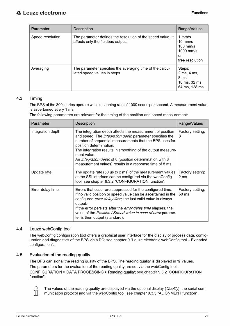
4.3 TimingThe BPS of the 300i series operate with a scanning rate of 1000 scans per second. A measurement value is ascertained every 1 ms.The following parameters are relevant for the timing of the position and speed measurement:
4.4 Leuze webConfig toolThe webConfig configuration tool offers a graphical user interface for the display of process data, config-uration and diagnostics of the BPS via a PC; see chapter 9 "Leuze electronic webConfig tool – Extended configuration".
4.5 Evaluation of the reading qualityThe BPS can signal the reading quality of the BPS. The reading quality is displayed in % values.The parameters for the evaluation of the reading quality are set via the webConfig tool:CONFIGURATION > DATA PROCESSING > Reading quality; see chapter 9.3.2 "CONFIGURATION function".
Parameter Description Range/Values
Speed resolution The parameter defines the resolution of the speed value. It affects only the fieldbus output.
1 mm/s 10 mm/s100 mm/s 1000 mm/s orfree resolution
Averaging The parameter specifies the averaging time of the calcu-lated speed values in steps.
Steps:2 ms, 4 ms, 8 ms,16 ms, 32 ms,64 ms, 128 ms
Parameter Description Range/Values
Integration depth The integration depth affects the measurement of position and speed. The integration depth parameter specifies the number of sequential measurements that the BPS uses for position determination. The integration results in smoothing of the output measure-ment value.An integration depth of 8 (position determination with 8 measurement values) results in a response time of 8 ms.
Factory setting: 8
Update rate The update rate (50 µs to 2 ms) of the measurement values at the SSI interface can be configured via the webConfig tool; see chapter 9.3.2 "CONFIGURATION function".
Factory setting: 2 ms
Error delay time Errors that occur are suppressed for the configured time.If no valid position or speed value can be ascertained in the configured error delay time, the last valid value is always output. If the error persists after the error delay time elapses, the value of the Position / Speed value in case of error parame-ter is then output (standard).
Factory setting: 50 ms
The values of the reading quality are displayed via the optional display (Quality), the serial com- munication protocol and via the webConfig tool; see chapter 9.3.3 "ALIGNMENT function".

Functions
Leuze electronic BPS 307i 28
The evaluation of the reading quality provides the following information, e.g.:• The reading quality is constantly bad: Soiling of the BPS optics• The reading quality is always bad at certain position values: Soiling of the BCB
4.6 Distance measurement to the bar code tapeWithin the reading field, the BPS can output the current distance from the read head to the BCB. The distance from the position label closest to the reference point is output.
The distance measurement value is output via:• The ALIGNMENT function (Quality menu) in the webConfig tool (see chapter 9.3.3); this function is
only available in the Service operating mode.

Applications
Leuze electronic BPS 307i 29
5 ApplicationsWherever systems are moved automatically, it is necessary to uniquely determine their respective posi-tions. In addition to mechanical measuring sensors, optical methods are particularly well suited for position determination as they can be used to determine position without mechanical wear and slippage.Compared to common optical measurement techniques, the Leuze electronic Bar code Positioning System (BPS) is able to measure a position with absolute sub-millimeter accuracy, i.e. independent of reference points. As a result, it is able to provide a unique position value at any time. With the highly flexible and hard-wearing Bar Code Tape (BCB), the system can even be used without problem in systems with curves or guide tolerances. And this at lengths of up to 10,000 meters.
The product family of Leuze electronic bar code positioning systems convinces with a variety of advan-tages:
• The laser simultaneously scans three bar codes and, as a result, is able to determine the position with sub-millimeter accuracy. The wide reading field makes accurate position determination possible even in the event of minor damage to the tape.
• With the systems' flexible depth of field, it is also possible to bridge over mechanical deviations.• Due to the large reading distance combined with the great depth of field, a large opening angle and a
very compact construction, the device is ideally suited for the conveyor and storage technology market.
• The BPS devices are capable of simultaneously measuring position and speed and are thus also suitable for control tasks in your automation applications.
• Using a mounting device, the BPS can be mounted with millimeter accuracy with just one screw. If mounted using a mounting device, a new device is automatically aligned correctly should it be nec-essary to exchange a device (easy-mount).
• The unique labeling of the bar code tape allows the system to be put back into operation without problem even after a brief voltage drop without, e.g., needing to utilize a reference point.
• The Leuze electronic bar code tape is very robust, highly flexible and, thanks to the self-adhesive back, can be easily integrated into your overall mechanical system. It can be fit optimally to both ver-tical as well as horizontal curved paths and thereby reliably facilitates trouble-free and reproducible measurement at any point in your system with sub-millimeter accuracy.
Typical applications for the BPS include:• High-bay storage device (see chapter 5.1)• Telpher line (see chapter 5.2)• Gantry cranes (see chapter 5.3)
Applications
Leuze electronic BPS 307i 30
5.1 High-bay storage device
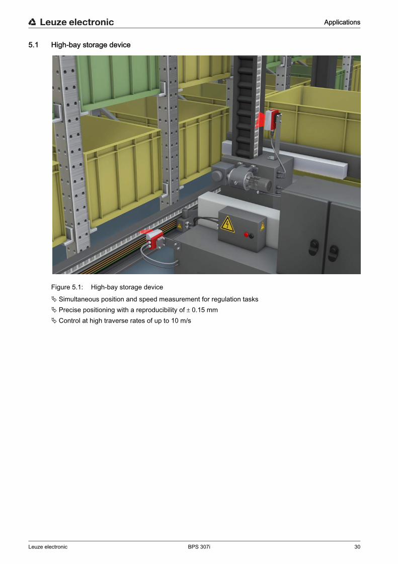
Figure 5.1: High-bay storage device
Simultaneous position and speed measurement for regulation tasks Precise positioning with a reproducibility of 0.15 mm Control at high traverse rates of up to 10 m/s
Applications
Leuze electronic BPS 307i 31
5.2 Telpher line
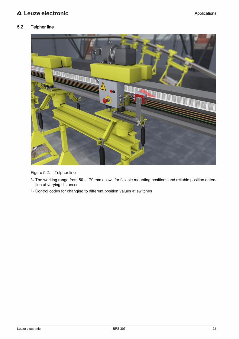
Figure 5.2: Telpher line
The working range from 50 - 170 mm allows for flexible mounting positions and reliable position detec-tion at varying distances
Control codes for changing to different position values at switches
Applications
Leuze electronic BPS 307i 32
5.3 Gantry cranes
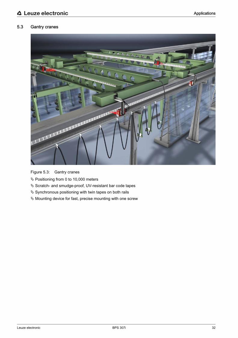
Figure 5.3: Gantry cranes
Positioning from 0 to 10,000 meters Scratch- and smudge-proof, UV-resistant bar code tapes Synchronous positioning with twin tapes on both rails Mounting device for fast, precise mounting with one screw

Mounting and installation
Leuze electronic BPS 307i 33
6 Mounting and installation
6.1 Mounting bar code tape
6.1.1 Installation and application remarks
NOTICEBCB mountingWhen processing BCBs, observe the specified processing temperatures.
When processing BCBs in cold storage facilities, the BCB must be affixed before cooling the storage facility.However, if it should be necessary to affix the BCB at temperatures outside of the specified processing temperature, assure that the bonding surface as well as the BCB are at the processing temperature.
Avoid dirt deposits on the BCB.If possible, affix the BCB vertically.If possible, affix the BCB below an overhead covering.The BCB must never be continuously cleaned by on-board cleaning devices such as brushes or sponges. Permanent on-board cleaning devices polish the BCB and give it a glossy finish. The reading quality deteriorates as a result.
After affixing the BCBs, make certain that there are no polished, high-gloss surfaces in the scanning beam (e.g., glossy metal at gaps between the individual BCBs), as the measurement quality of the BPS may be impaired.Affix the BCBs to a diffusely reflective support, e.g., a painted surface.
Avoid sources of extraneous light and reflections on the BCB.Ensure that neither strong sources of extraneous light nor reflections of the support on which the BCB is affixed occur in the vicinity of the BPS scanning beam.
Affix the BCB over expansion joints up to a width of several millimeters.The BCB must not be interrupted at this location.
Cover protruding screw heads with the BCB. Ensure that the BCB is affixed without tension.
The BCB is a plastic tape that can be stretched by strong mechanical tension. Excessive mechanical stretching results in lengthening of the tape and distortion of the position values.
NOTICEBCB applicationMake certain that the BCB is located in the scanning beam of the BPS over the entire traversing path.
The BPS can determine the position on BCBs with arbitrary orientation. Bar code tapes with different value ranges may not directly follow one another.
In the case of different value ranges, a gap of at least 1 m must be maintained between the last position bar code of the preceding BCB and the first position bar code of the subsequent BCB (see chapter 3.4.2).
For MVS/MV0 control bar codes (see chapter 3.4.2), the minimum distance of 1 m between the last position bar code before the control bar code and the first position bar code after the control bar code must be maintained.
For bar code tapes with different value ranges, both BCBs must correspond to the BCB type config-ured in the BPS (see chapter 3.4.1).
Avoid position bar code labels with the value 00000.Measurements to the left of the center of a 00000 label produce negative position values that may not be displayed correctly.
Mounting and installation
Leuze electronic BPS 307i 34
6.1.2 Cutting bar code tapes
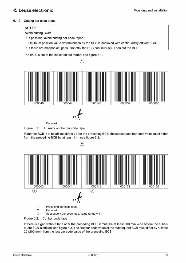
The BCB is cut at the indicated cut marks; see figure 6.1.
1 Cut markFigure 6.1: Cut mark on the bar code tape
If another BCB is to be affixed directly after the preceding BCB, the subsequent bar code value must differ from the preceding BCB by at least 1 m; see figure 6.2.
1 Preceding bar code tape2 Cut mark3 Subsequent bar code tape, value range + 1 m
Figure 6.2: Cut bar code tape
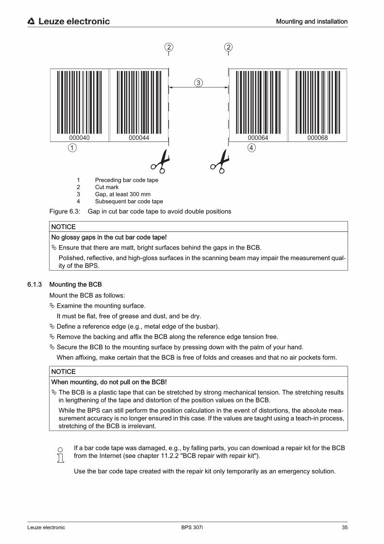
If there is a gap without tape after the preceding BCB, it must be at least 300 mm wide before the subse-quent BCB is affixed; see figure 6.3. The first bar code value of the subsequent BCB must differ by at least 20 (200 mm) from the last bar code value of the preceding BCB.
NOTICEAvoid cutting BCB! If possible, avoid cutting bar code tapes.
Optimum position value determination by the BPS is achieved with continuously affixed BCB. If there are mechanical gaps, first affix the BCB continuously. Then cut the BCB.
1
000040 000044 000048 000052 000056
1000040 000044 000148 000152 000156
2
3
Mounting and installation
Leuze electronic BPS 307i 35
1 Preceding bar code tape2 Cut mark3 Gap, at least 300 mm4 Subsequent bar code tape
Figure 6.3: Gap in cut bar code tape to avoid double positions
6.1.3 Mounting the BCBMount the BCB as follows: Examine the mounting surface.
It must be flat, free of grease and dust, and be dry. Define a reference edge (e.g., metal edge of the busbar). Remove the backing and affix the BCB along the reference edge tension free. Secure the BCB to the mounting surface by pressing down with the palm of your hand.
When affixing, make certain that the BCB is free of folds and creases and that no air pockets form.
NOTICENo glossy gaps in the cut bar code tape! Ensure that there are matt, bright surfaces behind the gaps in the BCB.
Polished, reflective, and high-gloss surfaces in the scanning beam may impair the measurement qual-ity of the BPS.
000040 000044 000064 000068
2 2
1
3
4
NOTICEWhen mounting, do not pull on the BCB! The BCB is a plastic tape that can be stretched by strong mechanical tension. The stretching results
in lengthening of the tape and distortion of the position values on the BCB.While the BPS can still perform the position calculation in the event of distortions, the absolute mea-surement accuracy is no longer ensured in this case. If the values are taught using a teach-in process, stretching of the BCB is irrelevant.
If a bar code tape was damaged, e.g., by falling parts, you can download a repair kit for the BCB from the Internet (see chapter 11.2.2 "BCB repair with repair kit").
Use the bar code tape created with the repair kit only temporarily as an emergency solution.
Mounting and installation
Leuze electronic BPS 307i 36
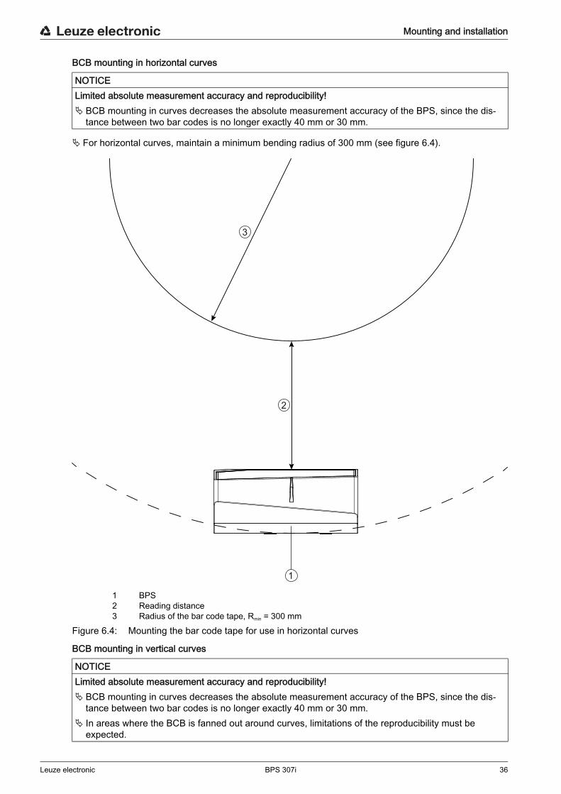
BCB mounting in horizontal curves
For horizontal curves, maintain a minimum bending radius of 300 mm (see figure 6.4).
1 BPS2 Reading distance3 Radius of the bar code tape, Rmin = 300 mm
Figure 6.4: Mounting the bar code tape for use in horizontal curves
BCB mounting in vertical curves
NOTICELimited absolute measurement accuracy and reproducibility! BCB mounting in curves decreases the absolute measurement accuracy of the BPS, since the dis-
tance between two bar codes is no longer exactly 40 mm or 30 mm.
NOTICELimited absolute measurement accuracy and reproducibility! BCB mounting in curves decreases the absolute measurement accuracy of the BPS, since the dis-
tance between two bar codes is no longer exactly 40 mm or 30 mm. In areas where the BCB is fanned out around curves, limitations of the reproducibility must be
expected.
1
2
3
Mounting and installation
Leuze electronic BPS 307i 37
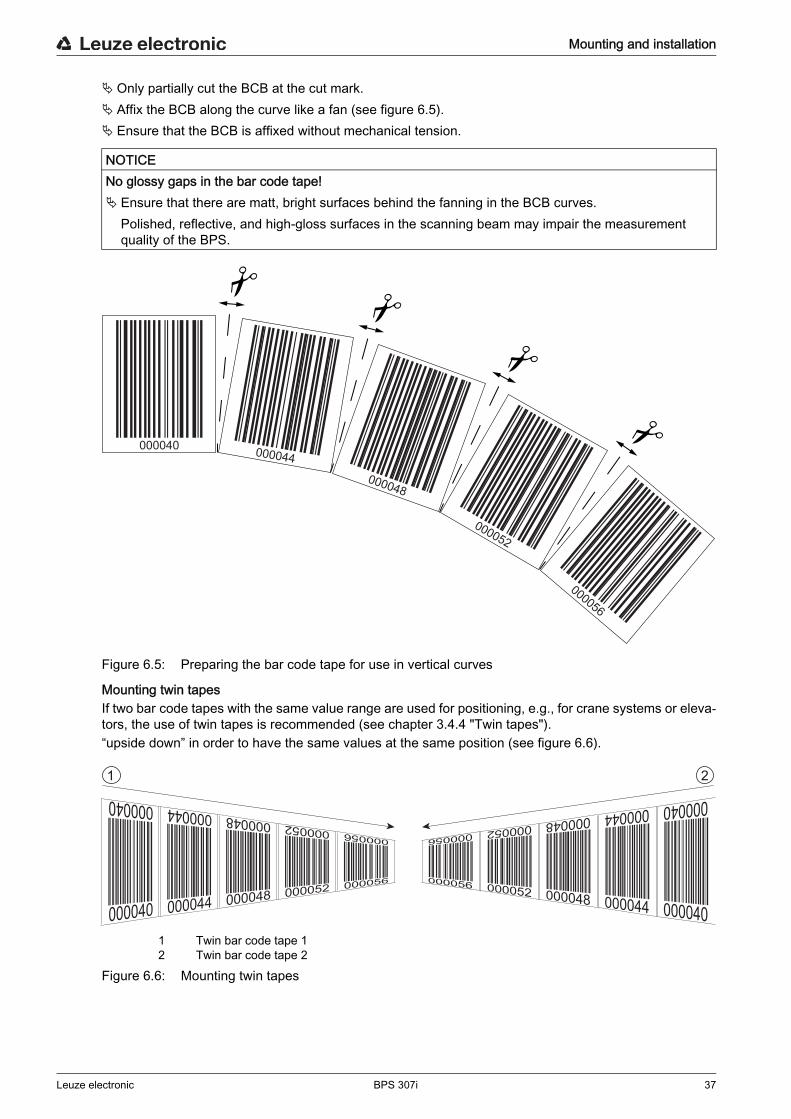
Only partially cut the BCB at the cut mark. Affix the BCB along the curve like a fan (see figure 6.5). Ensure that the BCB is affixed without mechanical tension.
Figure 6.5: Preparing the bar code tape for use in vertical curves
Mounting twin tapesIf two bar code tapes with the same value range are used for positioning, e.g., for crane systems or eleva-tors, the use of twin tapes is recommended (see chapter 3.4.4 "Twin tapes").“upside down” in order to have the same values at the same position (see figure 6.6).
1 Twin bar code tape 12 Twin bar code tape 2
Figure 6.6: Mounting twin tapes
NOTICENo glossy gaps in the bar code tape! Ensure that there are matt, bright surfaces behind the fanning in the BCB curves.
Polished, reflective, and high-gloss surfaces in the scanning beam may impair the measurement quality of the BPS.
000040 000044
000048
000052
000056
1 2
Mounting and installation
Leuze electronic BPS 307i 38
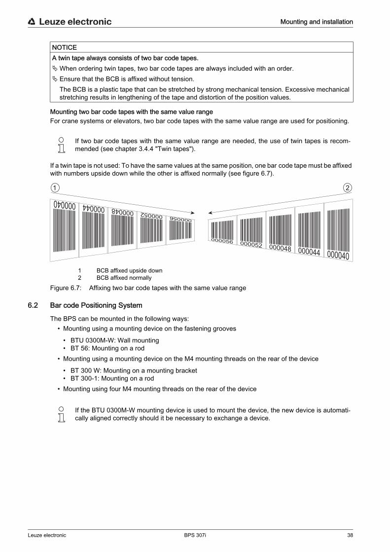
Mounting two bar code tapes with the same value rangeFor crane systems or elevators, two bar code tapes with the same value range are used for positioning.
If a twin tape is not used: To have the same values at the same position, one bar code tape must be affixed with numbers upside down while the other is affixed normally (see figure 6.7).
1 BCB affixed upside down2 BCB affixed normally
Figure 6.7: Affixing two bar code tapes with the same value range
6.2 Bar code Positioning System
The BPS can be mounted in the following ways:• Mounting using a mounting device on the fastening grooves
• BTU 0300M-W: Wall mounting• BT 56: Mounting on a rod
• Mounting using a mounting device on the M4 mounting threads on the rear of the device
• BT 300 W: Mounting on a mounting bracket• BT 300-1: Mounting on a rod
• Mounting using four M4 mounting threads on the rear of the device
NOTICEA twin tape always consists of two bar code tapes.When ordering twin tapes, two bar code tapes are always included with an order. Ensure that the BCB is affixed without tension.
The BCB is a plastic tape that can be stretched by strong mechanical tension. Excessive mechanical stretching results in lengthening of the tape and distortion of the position values.
If two bar code tapes with the same value range are needed, the use of twin tapes is recom- mended (see chapter 3.4.4 "Twin tapes").
1 2
If the BTU 0300M-W mounting device is used to mount the device, the new device is automati- cally aligned correctly should it be necessary to exchange a device.
Mounting and installation
Leuze electronic BPS 307i 39
6.2.1 Mounting instructions
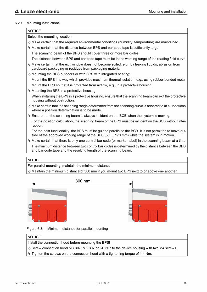
Figure 6.8: Minimum distance for parallel mounting
NOTICESelect the mounting location.Make certain that the required environmental conditions (humidity, temperature) are maintained.Make certain that the distance between BPS and bar code tape is sufficiently large.
The scanning beam of the BPS should cover three or more bar codes.The distance between BPS and bar code tape must be in the working range of the reading field curve.
Make certain that the exit window does not become soiled, e.g., by leaking liquids, abrasion from cardboard packaging or residues from packaging material.
Mounting the BPS outdoors or with BPS with integrated heating:Mount the BPS in a way which provides maximum thermal isolation, e.g., using rubber-bonded metal.Mount the BPS so that it is protected from airflow, e.g., in a protective housing.
Mounting the BPS in a protective housing:When installing the BPS in a protective housing, ensure that the scanning beam can exit the protective housing without obstruction.
Make certain that the scanning range determined from the scanning curve is adhered to at all locations where a position determination is to be made.
Ensure that the scanning beam is always incident on the BCB when the system is moving.For the position calculation, the scanning beam of the BPS must be incident on the BCB without inter-ruption.For the best functionality, the BPS must be guided parallel to the BCB. It is not permitted to move out-side of the approved working range of the BPS (50 … 170 mm) while the system is in motion.
Make certain that there is only one control bar code (or marker label) in the scanning beam at a time.The minimum distance between two control bar codes is determined by the distance between the BPS and bar code tape and the resulting length of the scanning beam.
NOTICEFor parallel mounting, maintain the minimum distance!Maintain the minimum distance of 300 mm if you mount two BPS next to or above one another.
NOTICEInstall the connection hood before mounting the BPS! Screw connection hood MS 307, MK 307 or KB 307 to the device housing with two M4 screws. Tighten the screws on the connection hood with a tightening torque of 1.4 Nm.
300 mm
Mounting and installation
Leuze electronic BPS 307i 40
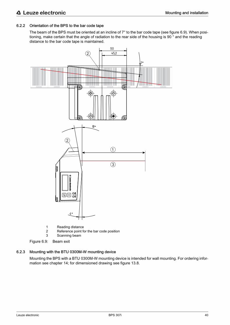
6.2.2 Orientation of the BPS to the bar code tapeThe beam of the BPS must be oriented at an incline of 7° to the bar code tape (see figure 6.9). When posi-tioning, make certain that the angle of radiation to the rear side of the housing is 90 ° and the reading distance to the bar code tape is maintained.
1 Reading distance2 Reference point for the bar code position3 Scanning beam
Figure 6.9: Beam exit
6.2.3 Mounting with the BTU 0300M-W mounting deviceMounting the BPS with a BTU 0300M-W mounting device is intended for wall mounting. For ordering infor-mation see chapter 14; for dimensioned drawing see figure 13.8.
000040 000044 000048 000052 000056 000060 000064 000068
1
3
2
2
50
Mounting and installation
Leuze electronic BPS 307i 41
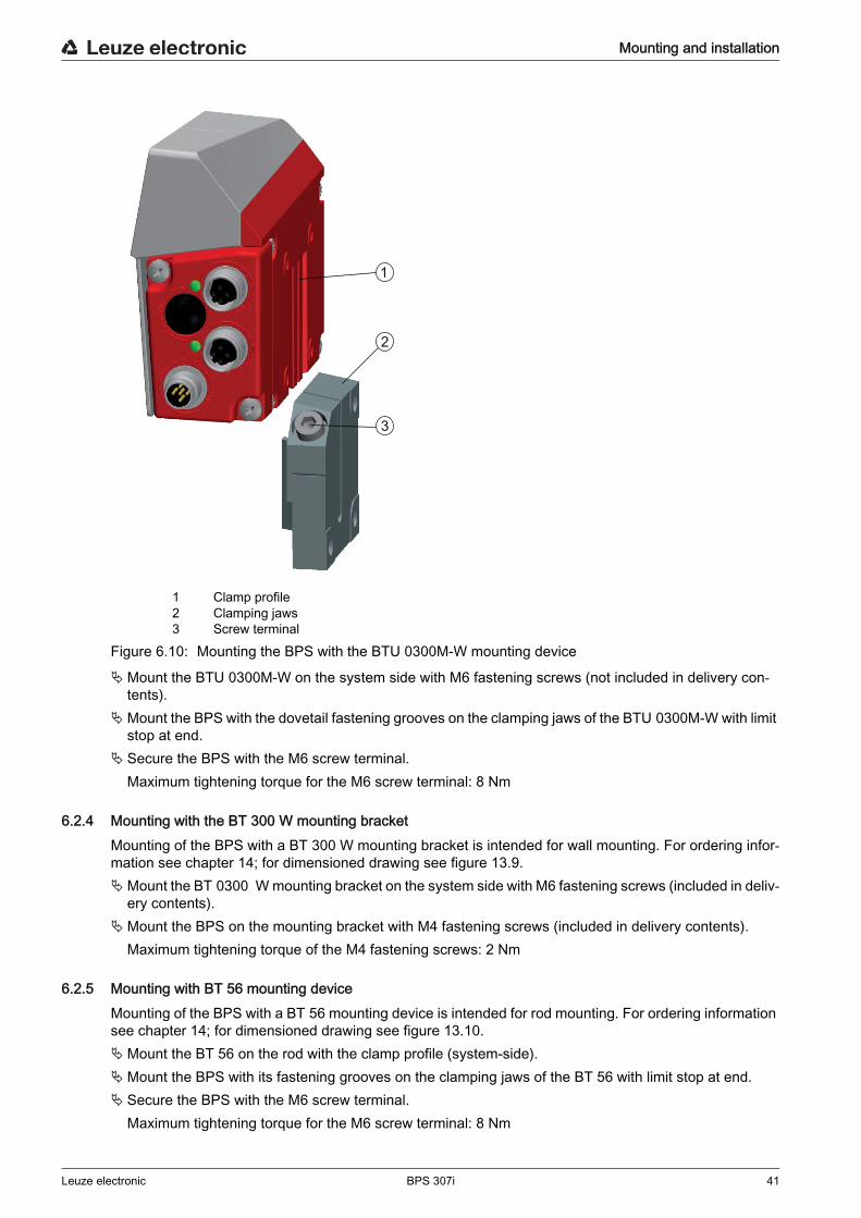
1 Clamp profile2 Clamping jaws3 Screw terminal
Figure 6.10: Mounting the BPS with the BTU 0300M-W mounting device
Mount the BTU 0300M-W on the system side with M6 fastening screws (not included in delivery con-tents).
Mount the BPS with the dovetail fastening grooves on the clamping jaws of the BTU 0300M-W with limit stop at end.
Secure the BPS with the M6 screw terminal.Maximum tightening torque for the M6 screw terminal: 8 Nm
6.2.4 Mounting with the BT 300 W mounting bracketMounting of the BPS with a BT 300 W mounting bracket is intended for wall mounting. For ordering infor-mation see chapter 14; for dimensioned drawing see figure 13.9.Mount the BT 0300 W mounting bracket on the system side with M6 fastening screws (included in deliv-
ery contents).Mount the BPS on the mounting bracket with M4 fastening screws (included in delivery contents).
Maximum tightening torque of the M4 fastening screws: 2 Nm
6.2.5 Mounting with BT 56 mounting deviceMounting of the BPS with a BT 56 mounting device is intended for rod mounting. For ordering information see chapter 14; for dimensioned drawing see figure 13.10.Mount the BT 56 on the rod with the clamp profile (system-side).Mount the BPS with its fastening grooves on the clamping jaws of the BT 56 with limit stop at end. Secure the BPS with the M6 screw terminal.
Maximum tightening torque for the M6 screw terminal: 8 Nm
1
2
3
Mounting and installation
Leuze electronic BPS 307i 42
6.2.6 Mounting with BT 300-1 mounting deviceMounting of the BPS with a BT 300-1 mounting device is intended for rod mounting. For ordering informa-tion see chapter 14; for dimensioned drawing see figure 13.11.Mount the BT 300-1 mounting device with the clamp profile on the rod (system-side).Mount the BPS on the mounting bracket of the BT 300-1 with M4 fastening screws (included in delivery
contents).Maximum tightening torque of the M4 fastening screws: 2 Nm
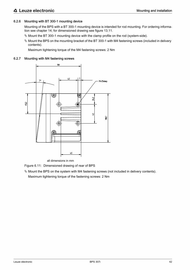
6.2.7 Mounting with M4 fastening screws
all dimensions in mmFigure 6.11: Dimensioned drawing of rear of BPS
Mount the BPS on the system with M4 fastening screws (not included in delivery contents).Maximum tightening torque of the fastening screws: 2 Nm

Electrical connection
Leuze electronic BPS 307i 43
7 Electrical connection
7.1 External parameter memory in the connection hoodTo enable simple exchange of the BPS, the integrated parameter memory of the MS 307 and MK 307 connection hoods store a copy of the current parameter set.
Also located in the MS 307 and MK 307 are switches S1 and S2.• Slide switch S1 is used to toggle the encoding of the output measurement value between Gray and
binary. • Rotary switch S2 is used to set the resolution of the position value (in mm) or a speed monitoring
function.
CAUTIONSafety notices! Before connecting the device, be sure that the supply voltage agrees with the value printed on the
name plate. Only allow competent persons to perform the electrical connection. Ensure that the functional earth (FE) is connected correctly.
Fault-free operation is only guaranteed if the functional earth is connected properly. If faults cannot be rectified, take the device out of operation. Protect the device from accidentally being
started.
NOTICEUL applications For UL applications, use is only permitted in Class 2 circuits in accordance with the NEC (National
Electric Code).
NOTICEProtective Extra Low Voltage (PELV) The BPS is designed in accordance with protection class III for supply with PELV (protective extra-low
voltage).
NOTICEConnection hood and degree of protection IP 65 Before connecting, mount the connection hood on the BPS device housing. To ensure degree of protection IP 65 is fulfilled, the screws of the connection hood are tightened with
a tightening torque of 1.4 Nm for connecting to the BPS. Degree of protection IP 65 is not fulfilled until connectors or cable bushings are screwed on and caps
are installed.
For all connections (connection cable, interconnection cable, etc.), use only the cables listed in the accessories (see chapter 14).
NOTICENo parameter memory and no configuration switches in connection hood KB 307! No parameter memory is integrated in connection hood KB 307. Connection hood KB 307 does not include any switches for configuring the BPS.

Electrical connection
Leuze electronic BPS 307i 44
7.2 MS 307 connection hood with connectorsThe MS 307 connection hood features two M12 connector plugs and a Mini-B type USB socket as a service interface.The integrated parameter memory for the simple replacement of the BPS is located in the MS 307.
Connect connection PWR / SW IN/OUT to the supply voltage or the switching inputs/outputs. Connect connection SSI (HOST / BUS IN) to your SSI interface.
7.3 MK 307 connection hood with spring-cage terminalsWith the MK 307 connection hood, the BPS is connected directly and with no additional plug.
• The MK 307 features cable bushings in which the shielding connection for the interface cable is also located.
• The integrated parameter memory for the simple replacement of the BPS is located in the MK 307.• A Mini-B type USB socket is used for service purposes.
Connect connection PWR / SW IN/OUT to the supply voltage or the switching inputs/outputs. Connect connection SSI (HOST / BUS IN) to your SSI interface.
7.4 Connection hood KB 307 with cableConnection hood KB 307 features an SSI connection cable and a Mini-B type USB socket as service inter-face.
Remove the system plug (JST) at the end of the cable. Connect the connection cable to your SSI interface.
7.5 Pin assignment
7.5.1 PWR / SW IN/OUT (Power and switching input/output)5-pin, M12 plug (A-coded) or terminal block for connecting to PWR / SW IN/OUT.
NOTICEShielding connection and functional earth connection! The shielding connection is done via the M12 connector housing. Ensure that the functional earth (FE) is connected correctly. Unimpaired operation is only guaranteed
when the functional earth is connected properly. All electrical disturbances (EMC couplings) are dis-charged via the functional earth connection.
NOTICECable fabrication!We recommend against using wire-end sleeves.
NOTICEFunctional earth connection! Ensure that the functional earth (FE) is connected correctly. Unimpaired operation is only guaranteed
when the functional earth is connected properly. All electrical disturbances (EMC couplings) are dis-charged via the functional earth connection.
NOTICENo integrated parameter memory! No parameter memory is integrated in connection hood KB 307.

Electrical connection
Leuze electronic BPS 307i 45
Figure 7.1: PWR / SW IN/OUT connection
Table 7.1: PWR / SW IN/OUT pin assignment
Connection cables: see table 14.3
Switching input/outputThe BPS is equipped with two, freely programmable, optically decoupled switching inputs/outputs, SWIO1 and SWIO2.
• The switching inputs can be used to activate various internal functions of the BPS (e.g., Measure-ment Stop/Start, Teach Preset, Reset Preset).
• The switching outputs can be used to signal the state of the BPS and to implement external functions independent of the superior control (e.g. position value/speed value invalid, position and speed limit value exceeded, device error).
• The control can use switching inputs/outputs as digital I/Os.If no internal BPS function is connected to the switching inputs/outputs, the ports can be addressed as two inputs, two outputs or as one input and one output of a digital I/O component.
3
21
4
5
2
3
1
4
5
FE
Pin/terminal Designation Assignment
1 VIN +18 … +30 VDC supply voltage
2 SWIO1 Sw. input/output 1 (configurable)
3 GNDIN Negative supply voltage (0 VDC)
4 SWIO2 Sw. input/output 2 (configurable)
5 FE Functional earth
Thread (M12 plug)Cable gland
Functional earth Connection cable shield.The shield of the connection cable is on the thread of the M12 plug or on the screw fitting of the cable bush-ing.The thread or the screw fitting is part of the metallic housing. The housing is at the potential of the func-tional earth via pin 5.
NOTICEAttention! For UL applications, use is only permitted in Class 2 circuits in accordance with the NEC (National
Electric Code).
The function as input or output is set via the webConfig configuration tool (CONFIGURATION > DEVICE > Switching inputs/outputs, see chapter 9.3.2).
NOTICEMaximum input current The input current of the respective switching input is maximum 8 mA.
Electrical connection
Leuze electronic BPS 307i 46
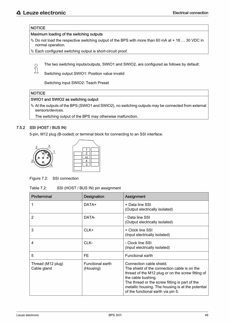
7.5.2 SSI (HOST / BUS IN)5-pin, M12 plug (B-coded) or terminal block for connecting to an SSI interface.
Figure 7.2: SSI connection
Table 7.2: SSI (HOST / BUS IN) pin assignment
NOTICEMaximum loading of the switching outputs Do not load the respective switching output of the BPS with more than 60 mA at + 18 … 30 VDC in
normal operation. Each configured switching output is short-circuit proof.
The two switching inputs/outputs, SWIO1 and SWIO2, are configured as follows by default:
Switching output SWIO1: Position value invalid
Switching input SWIO2: Teach Preset
NOTICESWIO1 and SWIO2 as switching output At the outputs of the BPS (SWIO1 and SWIO2), no switching outputs may be connected from external
sensors/devices.The switching output of the BPS may otherwise malfunction.
2nc
1
43
3
12
4
5
Pin/terminal Designation Assignment
1 DATA+ + Data line SSI(Output electrically isolated)
2 DATA- - Data line SSI(Output electrically isolated)
3 CLK+ + Clock line SSI(Input electrically isolated)
4 CLK- - Clock line SSI(Input electrically isolated)
5 FE Functional earth
Thread (M12 plug)Cable gland
Functional earth(Housing)
Connection cable shield.The shield of the connection cable is on the thread of the M12 plug or on the screw fitting of the cable bushing.The thread or the screw fitting is part of the metallic housing. The housing is at the potential of the functional earth via pin 5.
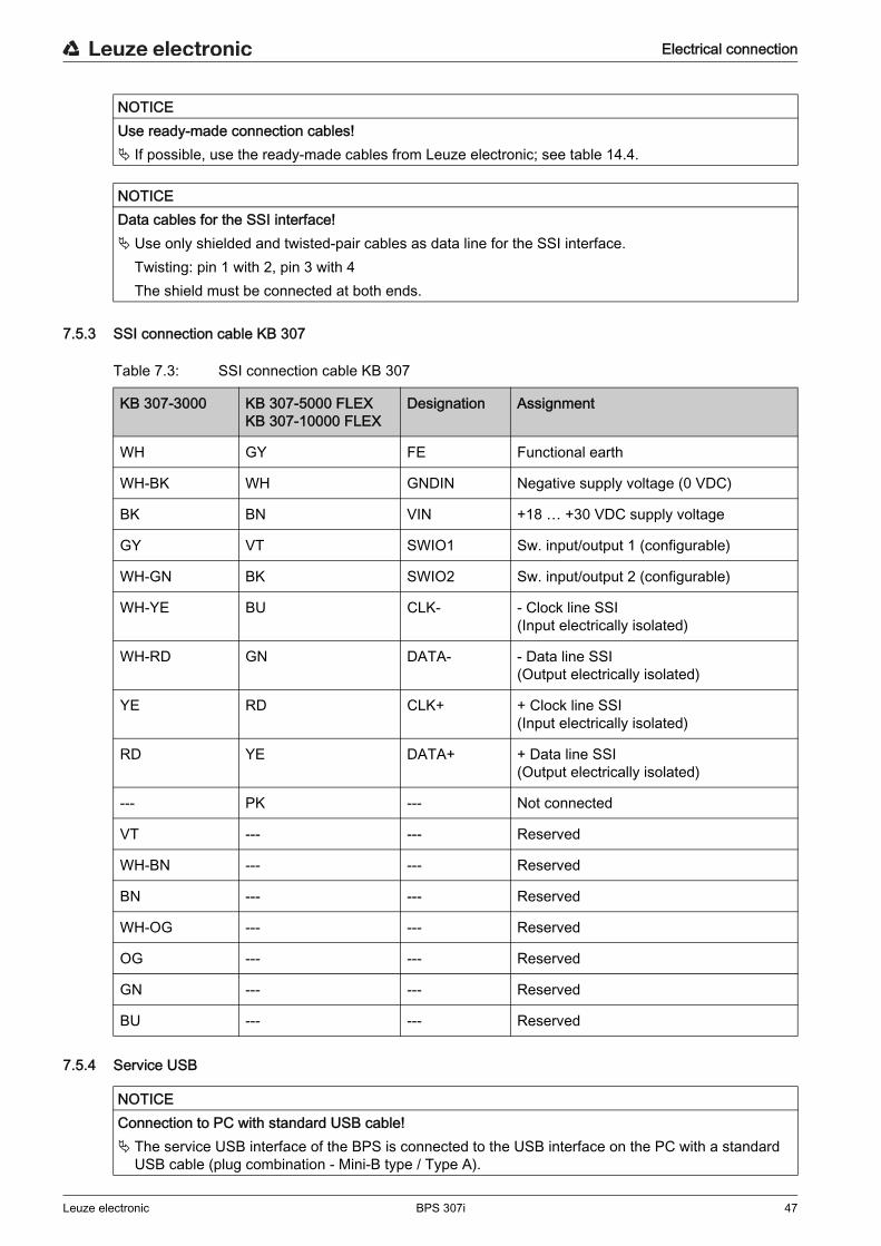
Electrical connection
Leuze electronic BPS 307i 47
7.5.3 SSI connection cable KB 307
Table 7.3: SSI connection cable KB 307
7.5.4 Service USB
NOTICEUse ready-made connection cables! If possible, use the ready-made cables from Leuze electronic; see table 14.4.
NOTICEData cables for the SSI interface! Use only shielded and twisted-pair cables as data line for the SSI interface.
Twisting: pin 1 with 2, pin 3 with 4The shield must be connected at both ends.
KB 307-3000 KB 307-5000 FLEXKB 307-10000 FLEX
Designation Assignment
WH GY FE Functional earth
WH-BK WH GNDIN Negative supply voltage (0 VDC)
BK BN VIN +18 … +30 VDC supply voltage
GY VT SWIO1 Sw. input/output 1 (configurable)
WH-GN BK SWIO2 Sw. input/output 2 (configurable)
WH-YE BU CLK- - Clock line SSI(Input electrically isolated)
WH-RD GN DATA- - Data line SSI(Output electrically isolated)
YE RD CLK+ + Clock line SSI(Input electrically isolated)
RD YE DATA+ + Data line SSI(Output electrically isolated)
--- PK --- Not connected
VT --- --- Reserved
WH-BN --- --- Reserved
BN --- --- Reserved
WH-OG --- --- Reserved
OG --- --- Reserved
GN --- --- Reserved
BU --- --- Reserved
NOTICEConnection to PC with standard USB cable! The service USB interface of the BPS is connected to the USB interface on the PC with a standard
USB cable (plug combination - Mini-B type / Type A).

Electrical connection
Leuze electronic BPS 307i 48
5-pin, Mini-B plug for connecting to the service USB.
Figure 7.3: Service USB connection
Table 7.4: Service USB pin assignment
7.6 Cable lengths and shieldingObserve the maximum cable lengths and the shielding types:
Cable length according to the data rate
The maximum possible cable length of the SSI connection is dependent on the used cable and the data rate.
12
543
Pin Designation Assignment
1 VB Sense input
2 D- Data -
3 D+ Data +
4 ID Not connected
5 GND Ground
NOTICEUse ready-made connection cables! If possible, use the ready-made cables from Leuze electronic; see table 14.6.
NOTICESelf-configured cables! Ensure adequate shielding.
The maximum cable length of 3 m must not be exceeded.
Connection Interface Max. cable length Shielding
BPS service USB 3 m Shielding absolutely nec-essary acc. to USB speci-fications
BPS power supply unit 30 m Not necessary
NOTICEData cables for the SSI interface! Use only shielded and twisted-pair cables as data line for the SSI interface.
Twisting: pin 1 with 2, pin 3 with 4The shield must be connected at both ends.
Do not lay the data line parallel to power cables.
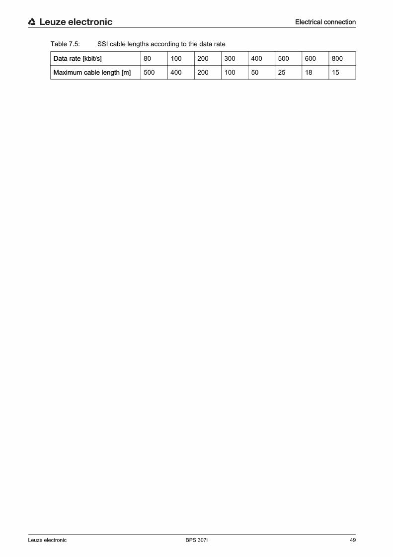
Electrical connection
Leuze electronic BPS 307i 49
Table 7.5: SSI cable lengths according to the data rate
Data rate [kbit/s] 80 100 200 300 400 500 600 800
Maximum cable length [m] 500 400 200 100 50 25 18 15

Basic configuration
Leuze electronic BPS 307i 50
8 Basic configurationThe parameters of the SSI interface as well as the switching inputs/outputs can be configured via the webConfig tool (see chapter 9) or via connection hood MS 307 or MK 307.Devices with connection hood KB 307 can only be configured via the webConfig tool.
8.1 Configuring the SSI interface
8.1.1 Principal functionality of the SSI interfaceData communication of the SSI interface is based on differential transmission as is used for RS 422 inter-faces. The position value is transmitted in sync with a cycle (CLOCK) specified by the control, starting with the most significant bit (MSB); see figure 8.1.
• In the quiescent state, both the clock line as well as the data line are at HIGH level.On the first HIGH-LOW edge (1), the data of the internal register are stored. This ensures that the data are not changed during serial transfer of the value.
• With the subsequent change of the clock signal from LOW to HIGH level (2), transfer of the position value begins with the most significant bit (MSB).
• With each subsequent change of the clock signal from LOW to HIGH level, the next least-signifi-cant bit is transmitted on the data line.
• After the least significant bit (LSB) has been output, the clock signal switches from LOW to HIGH for one last time and the data line switches to LOW level (end of transmission).
• A monoflop retriggered by the clock signal determines how long before the SSI interface can be called for the next transmission. This yields the minimum pause time between two successive clock cycles (tm)If time tm has elapsed, the data line is reset to bias level (HIGH) (3). This signals the fully completed data exchange and renewed transmission-ready state.
• tm = 20 µs with master clock frequency 80 kHz - 800 kHz• tm = 30 µs with master clock frequency 50 kHz - 79 kHz
• The update rate (50 µs to 2 ms) of the measurement values at the SSI interface can be configured via the webConfig tool. Factory setting: 2 ms.The update rate describes how quickly the data are replaced on the SSI interface by current data. The measurement value is updated independent of the clock frequency.
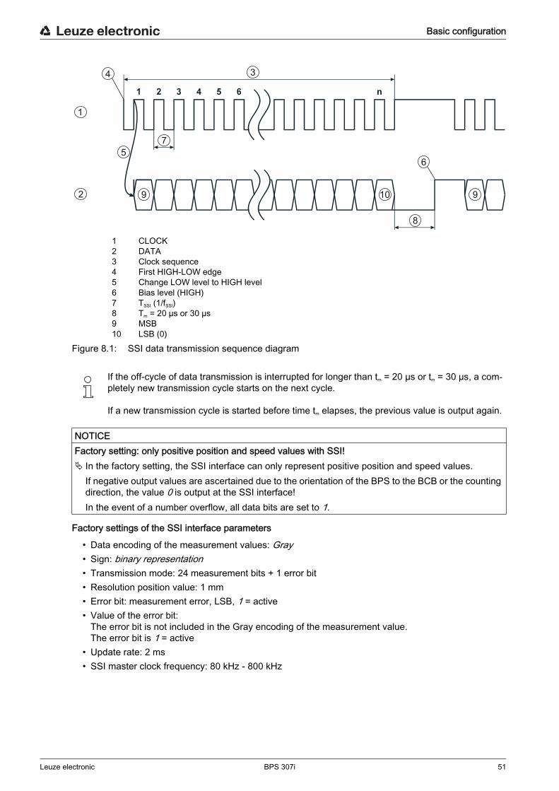
Basic configuration
Leuze electronic BPS 307i 51
1 CLOCK2 DATA3 Clock sequence4 First HIGH-LOW edge5 Change LOW level to HIGH level6 Bias level (HIGH)7 TSSI (1/fSSI)8 Tm = 20 µs or 30 µs9 MSB10 LSB (0)
Figure 8.1: SSI data transmission sequence diagram
Factory settings of the SSI interface parameters
• Data encoding of the measurement values: Gray• Sign: binary representation• Transmission mode: 24 measurement bits + 1 error bit• Resolution position value: 1 mm• Error bit: measurement error, LSB, 1 = active• Value of the error bit:
The error bit is not included in the Gray encoding of the measurement value.The error bit is 1 = active
• Update rate: 2 ms• SSI master clock frequency: 80 kHz - 800 kHz
If the off-cycle of data transmission is interrupted for longer than tm = 20 µs or tm = 30 µs, a com- pletely new transmission cycle starts on the next cycle.
If a new transmission cycle is started before time tm elapses, the previous value is output again.
NOTICEFactory setting: only positive position and speed values with SSI! In the factory setting, the SSI interface can only represent positive position and speed values.
If negative output values are ascertained due to the orientation of the BPS to the BCB or the counting direction, the value 0 is output at the SSI interface! In the event of a number overflow, all data bits are set to 1.
3
1
2
57
9 910
8
4
6
Basic configuration
Leuze electronic BPS 307i 52
8.1.2 Setting the configuration of the SSI interface Set the parameters of the SSI interface via the webConfig tool or via connection hood MS 307 or
MK 307.
• Setting via the webConfig tool: CONFIGURATION > OUTPUT; see chapter 9.3.2 "CONFIGURATION function"
• Setting via connection hood MS 307/MK 307: see chapter 8.6 "Configuration via the switches of the connection hood"
8.2 Configuring the switching inputs/outputs Set the configuration of the switching inputs/outputs via the webConfig tool or via connection hood
MS 307 or MK 307.
• Setting via the webConfig tool: CONFIGURATION > DEVICE; see chapter 9.3.2 "CONFIGURATION function"
• Setting via connection hood MS 307/MK 307: see chapter 8.6 "Configuration via the switches of the connection hood"
8.3 Configuring the resolution for the position value Set the parameters for the resolution during position measurement via the webConfig tool or via con-
nection hood MS 307 or MK 307.
• Setting via the webConfig tool: CONFIGURATION > OUTPUT; see chapter 9.3.2 "CONFIGURATION function"
• Setting via connection hood MS 307/MK 307: see chapter 8.6 "Configuration via the switches of the connection hood"
8.4 Configuring speed monitoring with switching output Set the parameters for speed monitoring via the webConfig tool or via connection hood MS 307 or
MK 307.
• Setting via the webConfig tool:
• Switching output function: CONFIGURATION > DEVICE > Switching inputs/outputs; see chapter 9.3.2 "CONFIGURATION function"
• Speed limit values: CONFIGURATION > DATA PROCESSING > Speed > Monitoring; see chapter 9.3.2 "CONFIGURATION function"
• Setting via connection hood MS 307/MK 307: see chapter 8.6 "Configuration via the switches of the connection hood"
Devices with connection hood KB 307 can only be configured via the webConfig tool.
Devices with connection hood KB 307 can only be configured via the webConfig tool.
Devices with connection hood KB 307 can only be configured via the webConfig tool.
Devices with connection hood KB 307 can only be configured via the webConfig tool.
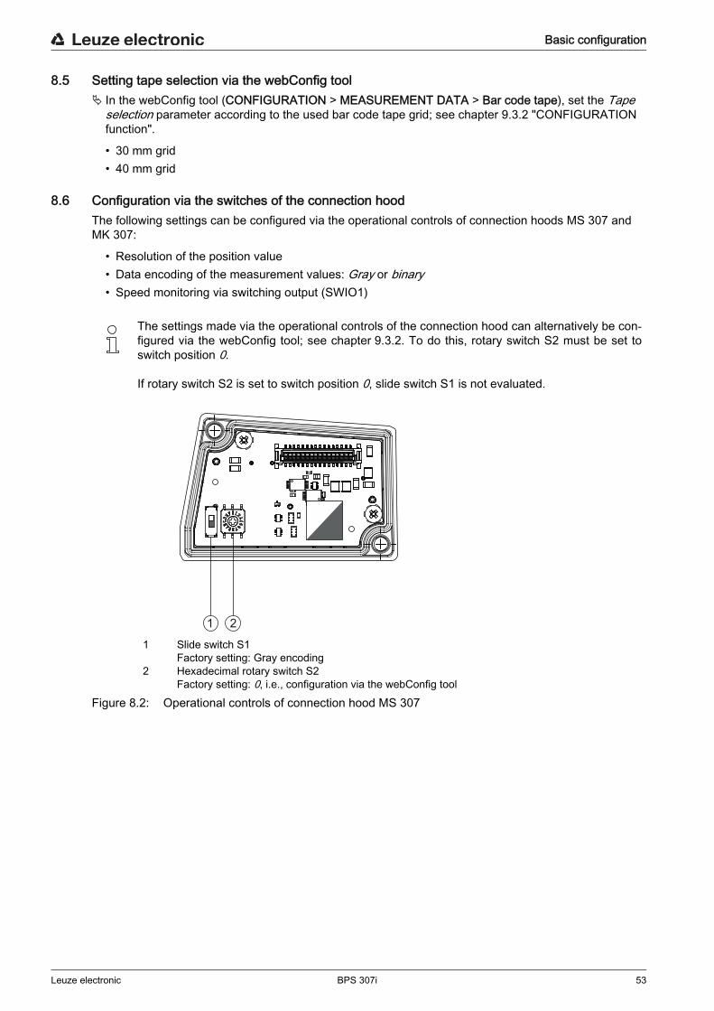
Basic configuration
Leuze electronic BPS 307i 53
8.5 Setting tape selection via the webConfig tool In the webConfig tool (CONFIGURATION > MEASUREMENT DATA > Bar code tape), set the Tape
selection parameter according to the used bar code tape grid; see chapter 9.3.2 "CONFIGURATION function".
• 30 mm grid• 40 mm grid
8.6 Configuration via the switches of the connection hoodThe following settings can be configured via the operational controls of connection hoods MS 307 and MK 307:
• Resolution of the position value• Data encoding of the measurement values: Gray or binary• Speed monitoring via switching output (SWIO1)
1 Slide switch S1Factory setting: Gray encoding
2 Hexadecimal rotary switch S2Factory setting: 0, i.e., configuration via the webConfig tool
Figure 8.2: Operational controls of connection hood MS 307
The settings made via the operational controls of the connection hood can alternatively be con- figured via the webConfig tool; see chapter 9.3.2. To do this, rotary switch S2 must be set to switch position 0.
If rotary switch S2 is set to switch position 0, slide switch S1 is not evaluated.
1 2
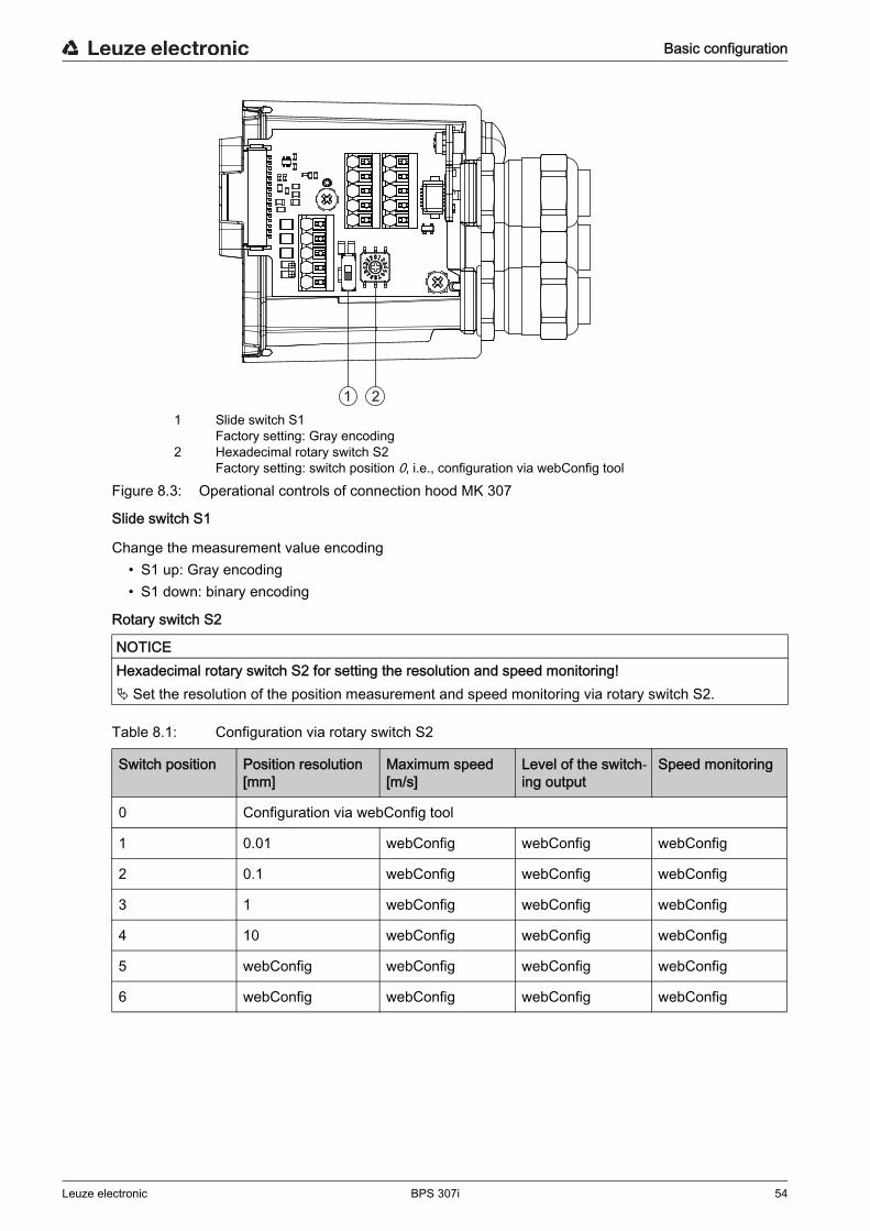
Basic configuration
Leuze electronic BPS 307i 54
1 Slide switch S1 Factory setting: Gray encoding
2 Hexadecimal rotary switch S2Factory setting: switch position 0, i.e., configuration via webConfig tool
Figure 8.3: Operational controls of connection hood MK 307
Slide switch S1
Change the measurement value encoding• S1 up: Gray encoding• S1 down: binary encoding
Rotary switch S2
Table 8.1: Configuration via rotary switch S2
NOTICEHexadecimal rotary switch S2 for setting the resolution and speed monitoring! Set the resolution of the position measurement and speed monitoring via rotary switch S2.
1 2
Switch position Position resolution [mm]
Maximum speed [m/s]
Level of the switch-ing output
Speed monitoring
0 Configuration via webConfig tool
1 0.01 webConfig webConfig webConfig
2 0.1 webConfig webConfig webConfig
3 1 webConfig webConfig webConfig
4 10 webConfig webConfig webConfig
5 webConfig webConfig webConfig webConfig
6 webConfig webConfig webConfig webConfig
Basic configuration
Leuze electronic BPS 307i 55
8.7 Setting configuration parameters to factory settingsProceed as follows: Set slide switch S1 to switch position Gray encoding. Set rotary switch S2 to switch position F. Restart the BPS.The current parameter set of the BPS is overwritten with the parameter set containing the factory settings.
8.8 Key factory settings of the BPS
Table 8.2: Factory settings on delivery of the BPS
7 webConfig 0.7 • HIGHCurrent speedBelow maxi-mum speed
• LOW Current speedAbove maxi-mum speed
Activated
8 webConfig 2 Activated
9 webConfig 3 Activated
A webConfig 4 Activated
F Factory setting of the configuration parametersNotice: Switch S1 must be set to switch position Gray encoding.
webConfig: The parameter value set via the webConfig tool is used.
Switch position Position resolution [mm]
Maximum speed [m/s]
Level of the switch-ing output
Speed monitoring
All parameters that are not influenced by the position of the switch are configured via the webConfig tool; see chapter 9.
In rotary switch positions 7, 8, 9 or A, the webConfig tool can be used, e.g., to change the reso- lution of the position measurement or invert the mode of the switching inputs/outputs.
NOTICERotary switch S2 on 0 if configuring with the webConfig tool! To configure the BPS with the webConfig tool, rotary switch S2 on connection hood MK 307 or MS 307
must be set to switch position 0.
Parameter Factory setting Explanation
Measurement value encoding
Gray Data encoding of the measurement values
Tape selection BCB with 40 mm grid Changeover between BCB with 30 mm grid and BCB with 40 mm grid
Position measurement Integration depth: 8 Number of successive measurements that the BPS uses for position determi-nation.
Resolution: 1 mm Resolution of the position value in mm
Master clock frequency 80 kHz - 800 kHz Request frequency of the control (master)
Update rate 2 ms Update rate of the measurement val-ues on the SSI interface
Basic configuration
Leuze electronic BPS 307i 56
SSI interface
Transmission mode 24 measurement bits + 1 error bit
Position resolution 1 mm Resolution of the position value in mm
Error bit Measurement errorLSB1 = active
Value of the error bit:• The error bit is not included in the
Gray encoding of the measure-ment value.
• The error bit is 1 = active
Sw. inputs/outputs
IO1 HIGHFunction: Position value invalid
Switching output - level controlledIf a valid position value cannot be ascertained, the output is set
IO2 HIGHFunction: Preset teach
Switching input - edge-triggeredTransition 0 → 1: Read in preset value
Parameter Factory setting Explanation

Leuze electronic webConfig tool – Extended configuration
Leuze electronic BPS 307i 57
9 Leuze electronic webConfig tool – Extended configurationWith the Leuze electronic webConfig tool, an operating-system independent, web-technology based, graphical user interface is available for configuring the BPS.The webConfig tool can be run on any Internet-ready PC. The webConfig tool uses HTTP as communica-tion protocol and the client-side restriction to standard technologies (HTML, JavaScript and AJAX) that are supported by modern browsers.
9.1 Installing softwareIn order for the BPS to be automatically detected by the connected PC, the USB driver must be installed once on your PC. Administrator rights are required for driver installation.
9.1.1 System requirements
Table 9.1: webConfig system requirements
9.1.2 Install USB driver Start your PC with administrator privileges and log on. Download the setup program from the Internet:
www.leuze.com > Products > Measuring Sensors > Sensors for Positioning > BPS 300i > (Name of the BPS) > Tab Downloads > Software/driver.
Start the setup program and follow the instructions.
The webConfig tool is offered in the following languages:
German, English, French, Italian, Spanish
If a USB driver for the webConfig tool is already installed on your computer, the USB driver does not need to be installed again.
Regularly update the operating system and the Internet browser.
Install the current Windows Service Packs.
Operating system Windows XP (Home Edition, Professional)Windows VistaWindows 7Windows 8
Computer PC with USB interface version 1.1 or higher
Graphics card Min. 1024 x 768 pixels or higher resolution
Required disk space for USB driver
10 MB
Internet browser Internet Explorer version 8.0 or higherFirefox version 4.0 or higher
Alternatively, you can manually install the LEO_RNDIS.inf USB driver.
Contact your network administrator if the installation fails.
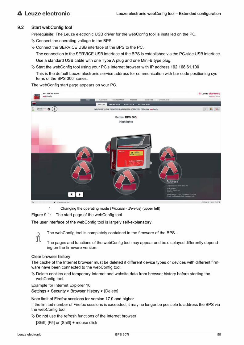
Leuze electronic webConfig tool – Extended configuration
Leuze electronic BPS 307i 58
9.2 Start webConfig toolPrerequisite: The Leuze electronic USB driver for the webConfig tool is installed on the PC. Connect the operating voltage to the BPS. Connect the SERVICE USB interface of the BPS to the PC.
The connection to the SERVICE USB interface of the BPS is established via the PC-side USB interface.Use a standard USB cable with one Type A plug and one Mini-B type plug.
Start the webConfig tool using your PC's Internet browser with IP address 192.168.61.100This is the default Leuze electronic service address for communication with bar code positioning sys-tems of the BPS 300i series.
The webConfig start page appears on your PC.
1 Changing the operating mode (Process - Service) (upper left)Figure 9.1: The start page of the webConfig tool
The user interface of the webConfig tool is largely self-explanatory.
Clear browser historyThe cache of the Internet browser must be deleted if different device types or devices with different firm-ware have been connected to the webConfig tool. Delete cookies and temporary Internet and website data from browser history before starting the
webConfig tool.Example for Internet Explorer 10:Settings > Security > Browser History > [Delete]
Note limit of Firefox sessions for version 17.0 and higherIf the limited number of Firefox sessions is exceeded, it may no longer be possible to address the BPS via the webConfig tool. Do not use the refresh functions of the Internet browser:
[Shift] [F5] or [Shift] + mouse click
The webConfig tool is completely contained in the firmware of the BPS.
The pages and functions of the webConfig tool may appear and be displayed differently depend- ing on the firmware version.
1

Leuze electronic webConfig tool – Extended configuration
Leuze electronic BPS 307i 59
9.3 Short description of the webConfig tool
9.3.1 Overview
Operating modes
For configurations with the webConfig tool, you can switch between the following operating modes:• Process
The BPS is connected to the control.
• The process communication to the control is activated.• The switching inputs/outputs are activated.• The configuration cannot be changed.• PROCESS function available.• ALIGNMENT function not available.
• Service• The process communication to the control is interrupted.• The switching inputs/outputs are deactivated.• The configuration can be changed.• PROCESS function not available.• ALIGNMENT function available.
Functions
In the Process operating mode, the webConfig tool has the following main menus and functions:• HOME
Information on the connected BPS as well as on installation.This information corresponds to the information in the current technical description.
• CONFIGURATION (see chapter 9.3.2)Information on the current BPS configuration – no change to the configuration:• Display of the interface parameters• Display of the output modules (value formatting)• Selection of the used bar code tape (30 mm grid or 40 mm grid)• Display of the tape value correction (deviation of the BCB from scaling)• Display of the device components (switching inputs/outputs, display)• Data processing (position / speed detection or monitoring, data preparation)• Display of the warning threshold and the error threshold for the reading quality
• PROCESSCheck and save the current read data in process mode (see chapter 9.3.4).
• Tabular display of the following values:Scan number, position, speed, reading quality, distance from BCB, info on the control label
In the Service operating mode, the webConfig tool also has the following main menus and functions:• CONFIGURATION (see chapter 9.3.2)
• Configuration of the interface parameters• Configuration of the output modules (value formatting)• Configuration of device components (switching inputs/outputs, display)• Selection of the used bar code tape• Configuration of the data processing (position / speed detection or monitoring, data preparation)• Configuration of the warning threshold and the error threshold for the reading quality
• ALIGNMENT (see chapter 9.3.3)
• Display of the following values:Scan number, position, speed, quality, distance, number of labels in the scanning beam
• Graphical displays of the following values:Position, speed, quality
• DIAGNOSIS (see chapter 9.3.5)
• Event logging of warnings and errors.• MAINTENANCE (see chapter 9.3.6)
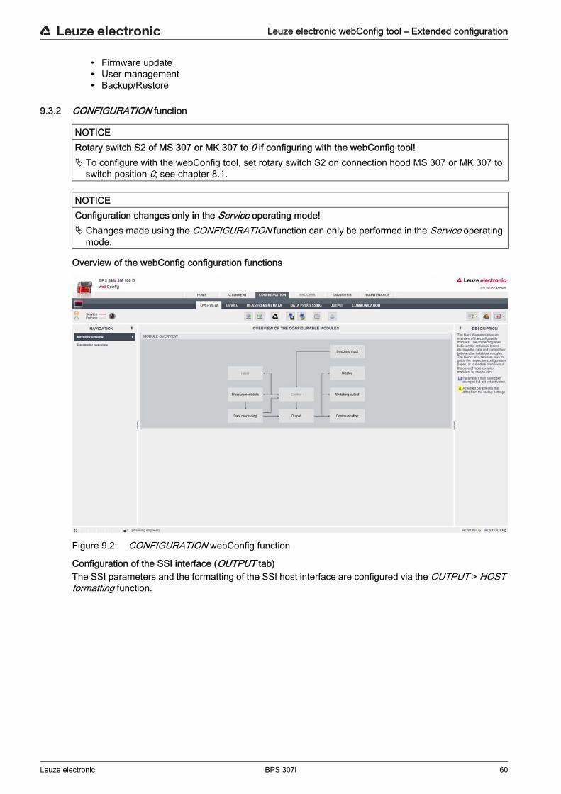
Leuze electronic webConfig tool – Extended configuration
Leuze electronic BPS 307i 60
• Firmware update• User management• Backup/Restore
9.3.2 CONFIGURATION function
Overview of the webConfig configuration functions
Figure 9.2: CONFIGURATION webConfig function
Configuration of the SSI interface (OUTPUT tab)The SSI parameters and the formatting of the SSI host interface are configured via the OUTPUT > HOST formatting function.
NOTICERotary switch S2 of MS 307 or MK 307 to 0 if configuring with the webConfig tool! To configure with the webConfig tool, set rotary switch S2 on connection hood MS 307 or MK 307 to
switch position 0; see chapter 8.1.
NOTICEConfiguration changes only in the Service operating mode! Changes made using the CONFIGURATION function can only be performed in the Service operating
mode.
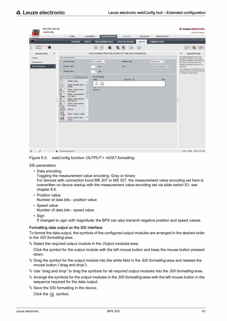
Leuze electronic webConfig tool – Extended configuration
Leuze electronic BPS 307i 61
Figure 9.3: webConfig function OUTPUT > HOST formatting
SSI parameters• Data encoding
Toggling the measurement value encoding: Gray or binaryFor devices with connection hood MK 307 or MS 307, the measurement value encoding set here is overwritten on device startup with the measurement value encoding set via slide switch S1; see chapter 8.6.
• Position valueNumber of data bits - position value
• Speed valueNumber of data bits - speed value
• SignIf changed to sign with magnitude, the BPS can also transmit negative position and speed values.
Formatting data output on the SSI interfaceTo format the data output, the symbols of the configured output modules are arranged in the desired order in the SSI formatting area. Select the required output module in the Output modules area.
Click the symbol for the output module with the left mouse button and keep the mouse button pressed down.
Drag the symbol for the output module into the white field in the SSI formatting area and release the mouse button (“drag and drop”).
Use “drag and drop” to drag the symbols for all required output modules into the SSI formatting area. Arrange the symbols for the output modules in the SSI formatting area with the left mouse button in the
sequence required for the data output. Save the SSI formatting in the device.
Click the symbol.
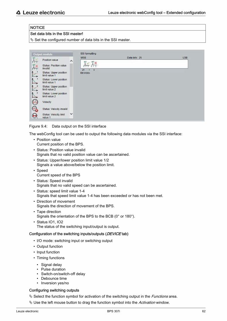
Leuze electronic webConfig tool – Extended configuration
Leuze electronic BPS 307i 62
Figure 9.4: Data output on the SSI interface
The webConfig tool can be used to output the following data modules via the SSI interface:• Position value
Current position of the BPS.• Status: Position value invalid
Signals that no valid position value can be ascertained.• Status: Upper/lower position limit value 1/2
Signals a value above/below the position limit.• Speed
Current speed of the BPS• Status: Speed invalid
Signals that no valid speed can be ascertained.• Status: speed limit value 1-4
Signals that speed limit value 1-4 has been exceeded or has not been met.• Direction of movement
Signals the direction of movement of the BPS.• Tape direction
Signals the orientation of the BPS to the BCB (0° or 180°).• Status IO1, IO2
The status of the switching input/output is output.
Configuration of the switching inputs/outputs (DEVICE tab)
• I/O mode: switching input or switching output• Output function• Input function• Timing functions
• Signal delay• Pulse duration• Switch-on/switch-off delay• Debounce time• Inversion yes/no
Configuring switching outputs Select the function symbol for activation of the switching output in the Functions area. Use the left mouse button to drag the function symbol into the Activation window.
NOTICESet data bits in the SSI master! Set the configured number of data bits in the SSI master.
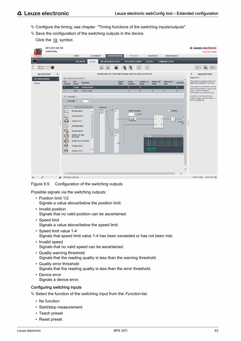
Leuze electronic webConfig tool – Extended configuration
Leuze electronic BPS 307i 63
Configure the timing; see chapter "Timing functions of the switching inputs/outputs". Save the configuration of the switching outputs in the device.
Click the symbol.
Figure 9.5: Configuration of the switching outputs
Possible signals via the switching outputs:• Position limit 1/2
Signals a value above/below the position limit.• Invalid position
Signals that no valid position can be ascertained.• Speed limit
Signals a value above/below the speed limit.• Speed limit value 1-4
Signals that speed limit value 1-4 has been exceeded or has not been met.• Invalid speed
Signals that no valid speed can be ascertained.• Quality warning threshold
Signals that the reading quality is less than the warning threshold.• Quality error threshold
Signals that the reading quality is less than the error threshold.• Device error
Signals a device error.
Configuring switching inputs Select the function of the switching input from the Function list:
• No function• Start/stop measurement• Teach preset• Reset preset
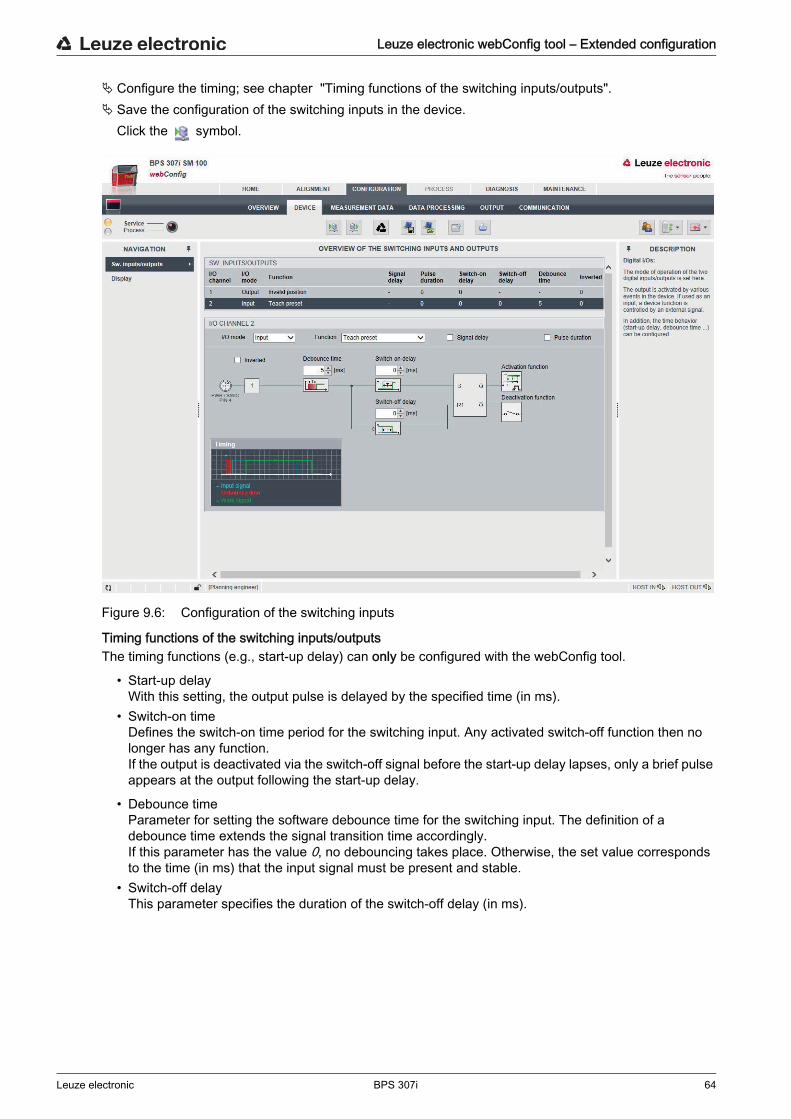
Leuze electronic webConfig tool – Extended configuration
Leuze electronic BPS 307i 64
Configure the timing; see chapter "Timing functions of the switching inputs/outputs". Save the configuration of the switching inputs in the device.
Click the symbol.
Figure 9.6: Configuration of the switching inputs
Timing functions of the switching inputs/outputsThe timing functions (e.g., start-up delay) can only be configured with the webConfig tool.
• Start-up delayWith this setting, the output pulse is delayed by the specified time (in ms).
• Switch-on timeDefines the switch-on time period for the switching input. Any activated switch-off function then no longer has any function.If the output is deactivated via the switch-off signal before the start-up delay lapses, only a brief pulse appears at the output following the start-up delay.
• Debounce timeParameter for setting the software debounce time for the switching input. The definition of a debounce time extends the signal transition time accordingly.If this parameter has the value 0, no debouncing takes place. Otherwise, the set value corresponds to the time (in ms) that the input signal must be present and stable.
• Switch-off delayThis parameter specifies the duration of the switch-off delay (in ms).
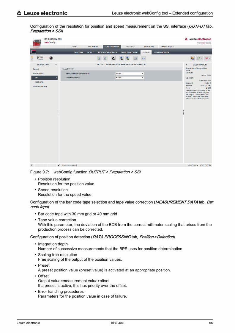
Leuze electronic webConfig tool – Extended configuration
Leuze electronic BPS 307i 65
Configuration of the resolution for position and speed measurement on the SSI interface (OUTPUT tab, Preparation > SSI)
Figure 9.7: webConfig function OUTPUT > Preparation > SSI• Position resolution
Resolution for the position value• Speed resolution
Resolution for the speed value
Configuration of the bar code tape selection and tape value correction (MEASUREMENT DATA tab, Bar code tape)
• Bar code tape with 30 mm grid or 40 mm grid• Tape value correction
With this parameter, the deviation of the BCB from the correct millimeter scaling that arises from the production process can be corrected.
Configuration of position detection (DATA PROCESSING tab, Position >Detection)
• Integration depthNumber of successive measurements that the BPS uses for position determination.
• Scaling free resolutionFree scaling of the output of the position values.
• PresetA preset position value (preset value) is activated at an appropriate position.
• OffsetOutput value=measurement value+offsetIf a preset is active, this has priority over the offset.
• Error handling proceduresParameters for the position value in case of failure.

Leuze electronic webConfig tool – Extended configuration
Leuze electronic BPS 307i 66
Configuration of position monitoring (DATA PROCESSINGtab, Position >Monitoring)
• Position limit value 1/2Signals that the position value is outside of the configured limit value range.
Configuration of speed detection (DATA PROCESSING tab, Speed > Detection)
• Speed measurement averagingMeasurement value preparation averages all speed values calculated during the selected period (averaging) to yield a speed output value.
• Scaling free resolutionFree scaling of the output of the speed values.
• Error handling proceduresParameters for the speed value in case of failure.
Configuration of speed monitoring (DATA PROCESSING tab, Measurement data > Speed > Monitoring)
• Speed limit value 1-4Signals that the speed is outside of the configured limit value range.
Configuration of the measurement value display (DATA PROCESSING tab, General preparation)
Unit of measurement: metric or inch
• Counting directionCount direction for position calculation or sign for speed calculation.
• Output mode signOutput mode of the sign. Affects position value and speed output.
Configuration of monitoring of the reading quality (DATA PROCESSING tab, Reading quality)
• Warning threshold for reading quality in %• Error threshold for reading quality in %
Configuration of the communication data (COMMUNICATION tab)
• Configuration of the SERVICE USB interface• Selection of the master clock frequency according to the request frequency of the control (master):
• 80 kHz - 800 kHz• 50 kHz - 79 kHz
• Update rate of the measurement values on the SSI interface. The measurement value is updated independent of the clock frequency.
• 2 ms• 1 ms• 200 µs• 50 µs
9.3.3 ALIGNMENT function
The ALIGNMENT function serves to simplify mounting and alignment of the BPS. The laser is to be acti-vated via the Start icon so that the function can monitor and directly display the measurement values for position and speed and determine the optimum installation location. In addition, reading quality (in %), working distance and the number of labels in the scanning beam can be displayed. Using this information, it is possible to assess how well the BPS is aligned with the BCB.
NOTICEALIGNMENT function only in the Service operating mode! The BPS can only be aligned using the ALIGNMENT function in the Service operating mode.
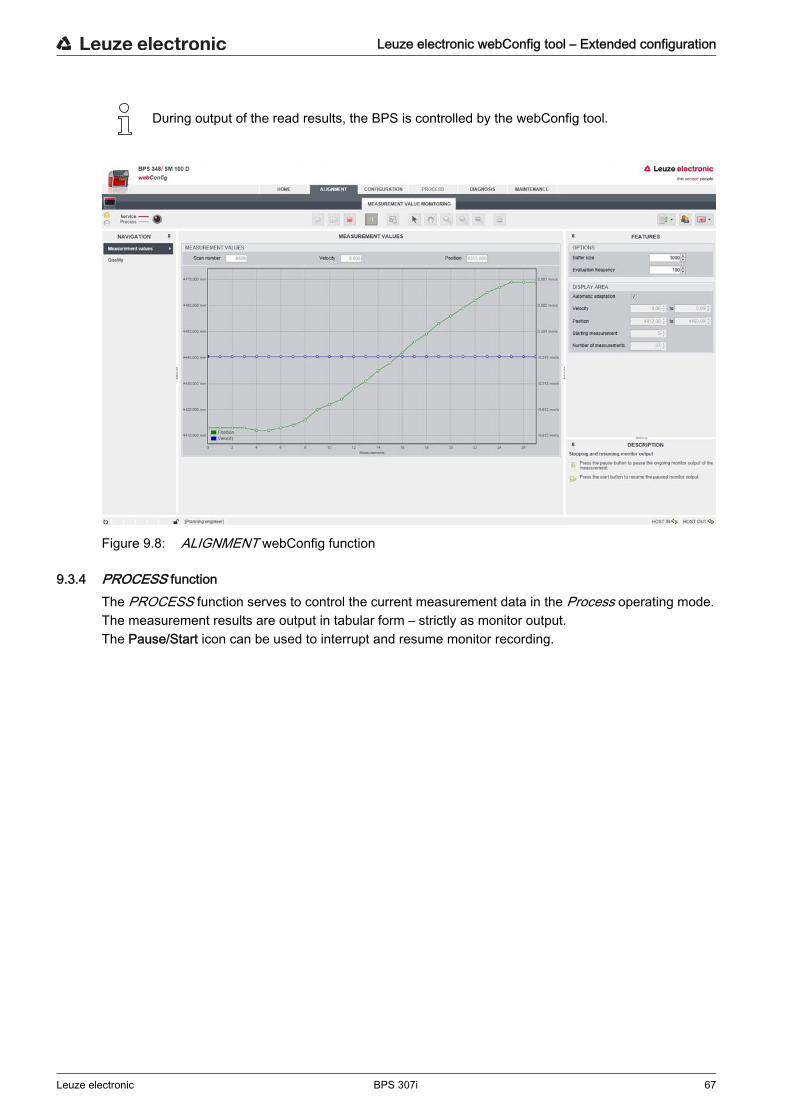
Leuze electronic webConfig tool – Extended configuration
Leuze electronic BPS 307i 67
Figure 9.8: ALIGNMENT webConfig function
9.3.4 PROCESS functionThe PROCESS function serves to control the current measurement data in the Process operating mode.The measurement results are output in tabular form – strictly as monitor output.The Pause/Start icon can be used to interrupt and resume monitor recording.
During output of the read results, the BPS is controlled by the webConfig tool.
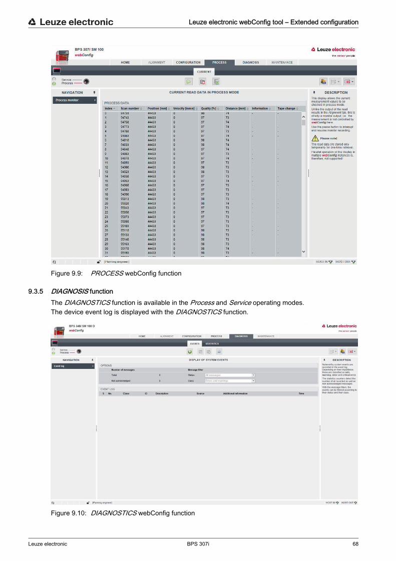
Leuze electronic webConfig tool – Extended configuration
Leuze electronic BPS 307i 68
Figure 9.9: PROCESS webConfig function
9.3.5 DIAGNOSIS functionThe DIAGNOSTICS function is available in the Process and Service operating modes. The device event log is displayed with the DIAGNOSTICS function.
Figure 9.10: DIAGNOSTICS webConfig function
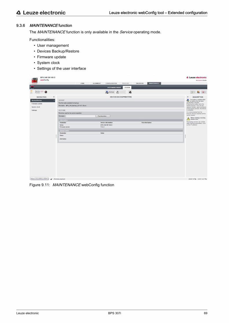
Leuze electronic webConfig tool – Extended configuration
Leuze electronic BPS 307i 69
9.3.6 MAINTENANCE functionThe MAINTENANCE function is only available in the Service operating mode.
Functionalities:• User management• Devices Backup/Restore• Firmware update• System clock• Settings of the user interface
Figure 9.11: MAINTENANCE webConfig function

Diagnostics and troubleshooting
Leuze electronic BPS 307i 70
10 Diagnostics and troubleshooting
10.1 What to do in case of failure?After switching on the BPS, display elements (see chapter 3.3) assist in checking the proper function and troubleshooting.In case of error, you can determine the error from the LED displays. With the error message you can deter-mine the cause of the error and initiate measures to rectify it. Switch off the system and leave it switched off. Analyze the cause of the error using the operation indicators, the error messages and the diagnostic
tools (also with the help of the webConfig tool, DIAGNOSTICS tab) and rectify the error.
10.1.1 Diagnostics with webConfig toolSystem events are displayed in the webConfig tool via the DIAGNOSTICS tab. Noteworthy system events are recorded in the event log. Depending on their importance, the events are classified as info, warning, error and critical error. The statistics counters detect the number of all recorded as well as non-acknowledged messages. With the message filters, the events can be filtered according to their status and their class.
Figure 10.1: DIAGNOSTICS webConfig function
10.2 Operating indicators of the LEDsYou can ascertain general causes of errors via the PWR and BUS status LEDs (see table 10.4).
NOTICEContact Leuze electronic subsidiary/customer service. If you are unable to rectify a fault, contact the Leuze electronic branch responsible for you or call the
Leuze electronic customer service (see chapter 12 "Service and support").
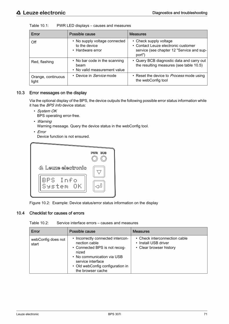
Diagnostics and troubleshooting
Leuze electronic BPS 307i 71
Table 10.1: PWR LED displays – causes and measures
10.3 Error messages on the display
Via the optional display of the BPS, the device outputs the following possible error status information while it has the BPS Info device status:
• System OKBPS operating error-free.
• WarningWarning message. Query the device status in the webConfig tool.
• ErrorDevice function is not ensured.
Figure 10.2: Example: Device status/error status information on the display
10.4 Checklist for causes of errors
Table 10.2: Service interface errors – causes and measures
Error Possible cause Measures
Off • No supply voltage connected to the device
• Hardware error
• Check supply voltage• Contact Leuze electronic customer
service (see chapter 12 "Service and sup-port")
Red, flashing • No bar code in the scanning beam
• No valid measurement value
• Query BCB diagnostic data and carry out the resulting measures (see table 10.5)
Orange, continuous light
• Device in Service mode • Reset the device to Process mode using the webConfig tool
BPS InfoSystem OK
Error Possible cause Measures
webConfig does not start
• Incorrectly connected intercon-nection cable
• Connected BPS is not recog-nized
• No communication via USB service interface
• Old webConfig configuration in the browser cache
• Check interconnection cable• Install USB driver• Clear browser history
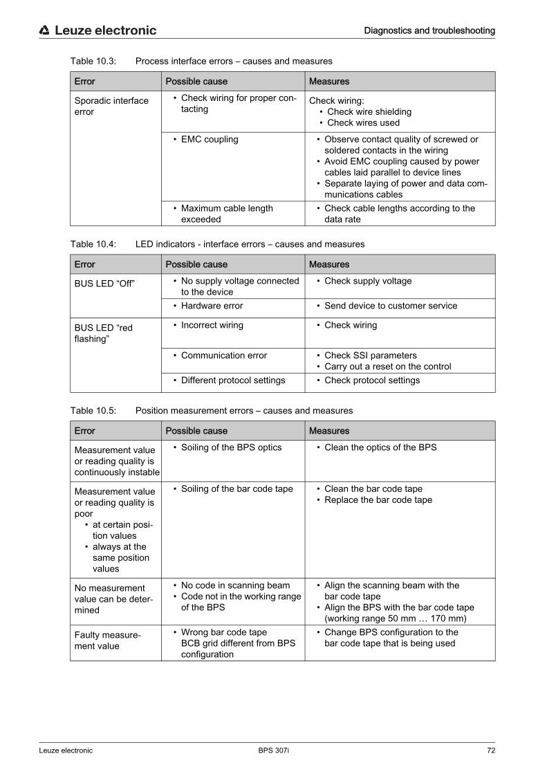
Diagnostics and troubleshooting
Leuze electronic BPS 307i 72
Table 10.3: Process interface errors – causes and measures
Table 10.4: LED indicators - interface errors – causes and measures
Table 10.5: Position measurement errors – causes and measures
Error Possible cause Measures
Sporadic interface error
• Check wiring for proper con-tacting
Check wiring:• Check wire shielding• Check wires used
• EMC coupling • Observe contact quality of screwed or soldered contacts in the wiring
• Avoid EMC coupling caused by power cables laid parallel to device lines
• Separate laying of power and data com-munications cables
• Maximum cable length exceeded
• Check cable lengths according to the data rate
Error Possible cause Measures
BUS LED “Off” • No supply voltage connected to the device
• Check supply voltage
• Hardware error • Send device to customer service
BUS LED “red flashing”
• Incorrect wiring • Check wiring
• Communication error • Check SSI parameters• Carry out a reset on the control
• Different protocol settings • Check protocol settings
Error Possible cause Measures
Measurement value or reading quality is continuously instable
• Soiling of the BPS optics • Clean the optics of the BPS
Measurement value or reading quality is poor
• at certain posi-tion values
• always at the same position values
• Soiling of the bar code tape • Clean the bar code tape• Replace the bar code tape
No measurement value can be deter-mined
• No code in scanning beam• Code not in the working range
of the BPS
• Align the scanning beam with the bar code tape
• Align the BPS with the bar code tape (working range 50 mm … 170 mm)
Faulty measure-ment value
• Wrong bar code tape BCB grid different from BPS configuration
• Change BPS configuration to the bar code tape that is being used

Care, maintenance and disposal
Leuze electronic BPS 307i 73
11 Care, maintenance and disposal
11.1 CleaningIf there is dust on the BPS device: Clean the BPS device with a soft cloth; use a cleaning agent (commercially available glass cleaner) if
necessary.
11.2 ServicingThe BPS does not normally require any maintenance by the operator.Repairs to the device must only be carried out by the manufacturer. For repairs, contact your responsible Leuze electronic subsidiary or Leuze electronic customer service
(see chapter 12 "Service and support").
11.2.1 Firmware updateA firmware update can only be performed by Leuze electronic Service on-site or at the company head-quarters. For firmware updates, contact your responsible Leuze electronic subsidiary or Leuze electronic cus-
tomer service (see chapter 12).
11.2.2 BCB repair with repair kit
If a bar code tape was damaged, e.g., by falling parts, you can download a repair kit for the BCB from the Internet.www.leuze.com > Products > Measuring Sensors > Sensors for Positioning > BPS 300i > (Name of the BPS) > Tab Downloads > Repair kit.
Layout:• BCB8: 0.9 m of bar code tape is provided on each A4 sheet.
Five lines of 18 cm with six code-information segments of 30 mm eachTape lengths: 0 … 500 m, 500 … 1000 m, 1000 … 1500 m … 2500 … 3000 m
• BCB: 1 m of bar code tape is provided on each A4 sheet.Five lines of 20 cm with five code-information sections of 40 mm eachTape lengths: 0 … 500 m, 500 … 1000 m, 1000 … 1500 m and 1500 … 2000 m
Replacing a section of defective bar code tape Determine the coding of the defective area. Print out the coding for the given area.
NOTICEDo not use aggressive cleaning agents! Do not use aggressive cleaning agents such as thinner or acetone for cleaning the BPS device.
Use of improper cleaning agents can damage the lens cover.
NOTICEDo not use the BCB repair kit on a permanent basis! Use the bar code tape created with the repair kit only temporarily as an emergency solution.
The optical and mechanical properties of the self-printed bar code tape do not correspond to those of the original bar code tape. Self-printed bar code tape should not remain in the system on a permanent basis.
Repair bar code tapes in lengths of 1 m can be ordered from Leuze electronic on request.
In the repair kit files, you will find all position values with 30 mm grid and 40 mm grid.
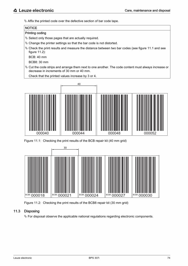
Care, maintenance and disposal
Leuze electronic BPS 307i 74
Affix the printed code over the defective section of bar code tape.
Figure 11.1: Checking the print results of the BCB repair kit (40 mm grid)
Figure 11.2: Checking the print results of the BCB8 repair kit (30 mm grid)
11.3 Disposing For disposal observe the applicable national regulations regarding electronic components.
NOTICEPrinting coding Select only those pages that are actually required. Change the printer settings so that the bar code is not distorted. Check the print results and measure the distance between two bar codes (see figure 11.1 and see
figure 11.2):BCB: 40 mmBCB8: 30 mm
Cut the code strips and arrange them next to one another. The code content must always increase or decrease in increments of 30 mm or 40 mm. Check that the printed values increase by 3 or 4.
000040 000044 000048 000052
40
BCB8 BCB8 BCB8 BCB8 BCB8000018 000021 000024 000027 000030
30

Service and support
Leuze electronic BPS 307i 75
12 Service and support
24-hour on-call service at:+49 (0) 7021 573 - 0
Service hotline: +49 (0) 7021 573 - 123Monday to Friday 8.00 a.m. to 5.00 p.m. (UTC+1)
E-mail:[email protected]
Repair service and returns:Procedure and Internet form can be found atwww.leuze.com/repairReturn address for repairs:Service centerLeuze electronic GmbH + Co. KGIn der Braike 1D-73277 Owen / Germany
12.1 What to do should servicing be required?
Customer data (please complete)
Leuze Service fax number:+49 7021 573 - 199
NOTICEPlease use this chapter as a master copy if service is required! Enter the contact information and fax the form together with your service order to the fax number given
below.
Device type:
Serial number:
Firmware:
Display messages:
Status of LEDs:
Error description:
Company:
Contact person/department:
Phone (direct dial):
Fax:
Street/No:
ZIP code/City:
Country:
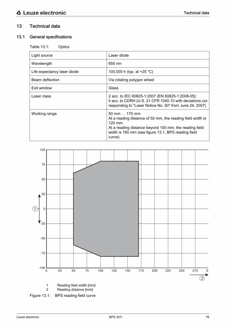
Technical data
Leuze electronic BPS 307i 76
13 Technical data
13.1 General specifications
Table 13.1: Optics
1 Reading field width [mm]2 Reading distance [mm]
Figure 13.1: BPS reading field curve
Light source Laser diode
Wavelength 655 nm
Life expectancy laser diode 100,000 h (typ. at +25 °C)
Beam deflection Via rotating polygon wheel
Exit window Glass
Laser class 2 acc. to IEC 60825-1:2007 (EN 60825-1:2008-05);II acc. to CDRH (U.S. 21 CFR 1040.10 with deviations cor-responding to "Laser Notice No. 50" from June 24, 2007)
Working range 50 mm … 170 mm At a reading distance of 50 mm, the reading field width is 120 mm. At a reading distance beyond 100 mm, the reading field width is 160 mm (see figure 13.1, BPS reading field curve).
250 7550 100 150 200 250 30125 175 225 275
25
50
75
100
-25
-50
-75
-100
1
2
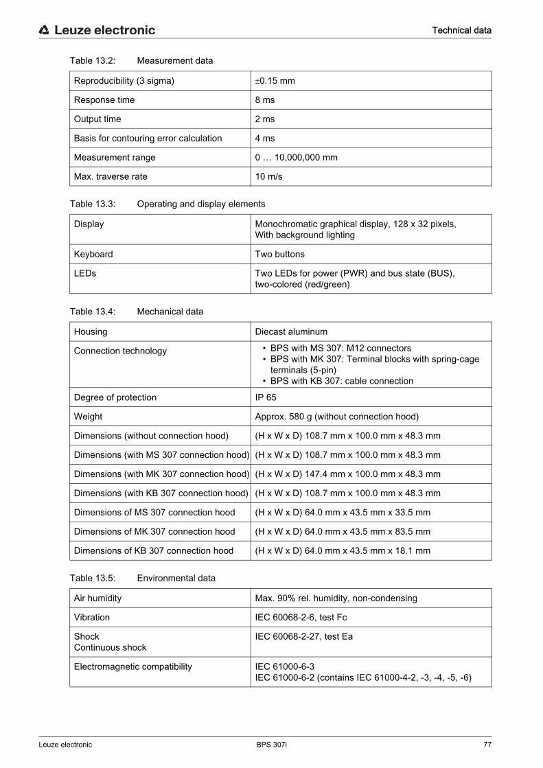
Technical data
Leuze electronic BPS 307i 77
Table 13.2: Measurement data
Table 13.3: Operating and display elements
Table 13.4: Mechanical data
Table 13.5: Environmental data
Reproducibility (3 sigma) 0.15 mm
Response time 8 ms
Output time 2 ms
Basis for contouring error calculation 4 ms
Measurement range 0 … 10,000,000 mm
Max. traverse rate 10 m/s
Display Monochromatic graphical display, 128 x 32 pixels,With background lighting
Keyboard Two buttons
LEDs Two LEDs for power (PWR) and bus state (BUS), two-colored (red/green)
Housing Diecast aluminum
Connection technology • BPS with MS 307: M12 connectors • BPS with MK 307: Terminal blocks with spring-cage
terminals (5-pin)• BPS with KB 307: cable connection
Degree of protection IP 65
Weight Approx. 580 g (without connection hood)
Dimensions (without connection hood) (H x W x D) 108.7 mm x 100.0 mm x 48.3 mm
Dimensions (with MS 307 connection hood) (H x W x D) 108.7 mm x 100.0 mm x 48.3 mm
Dimensions (with MK 307 connection hood) (H x W x D) 147.4 mm x 100.0 mm x 48.3 mm
Dimensions (with KB 307 connection hood) (H x W x D) 108.7 mm x 100.0 mm x 48.3 mm
Dimensions of MS 307 connection hood (H x W x D) 64.0 mm x 43.5 mm x 33.5 mm
Dimensions of MK 307 connection hood (H x W x D) 64.0 mm x 43.5 mm x 83.5 mm
Dimensions of KB 307 connection hood (H x W x D) 64.0 mm x 43.5 mm x 18.1 mm
Air humidity Max. 90% rel. humidity, non-condensing
Vibration IEC 60068-2-6, test Fc
Shock Continuous shock
IEC 60068-2-27, test Ea
Electromagnetic compatibility IEC 61000-6-3IEC 61000-6-2 (contains IEC 61000-4-2, -3, -4, -5, -6)
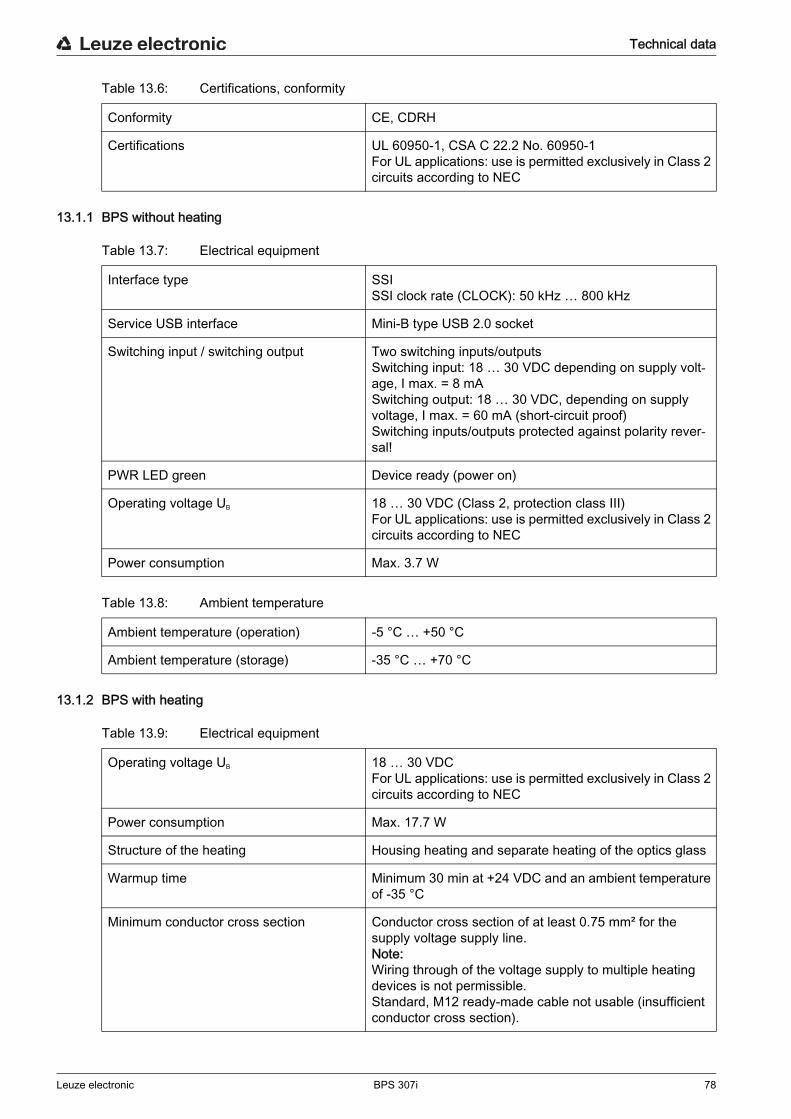
Technical data
Leuze electronic BPS 307i 78
Table 13.6: Certifications, conformity
13.1.1 BPS without heating
Table 13.7: Electrical equipment
Table 13.8: Ambient temperature
13.1.2 BPS with heating
Table 13.9: Electrical equipment
Conformity CE, CDRH
Certifications UL 60950-1, CSA C 22.2 No. 60950-1For UL applications: use is permitted exclusively in Class 2 circuits according to NEC
Interface type SSISSI clock rate (CLOCK): 50 kHz … 800 kHz
Service USB interface Mini-B type USB 2.0 socket
Switching input / switching output Two switching inputs/outputsSwitching input: 18 … 30 VDC depending on supply volt-age, I max. = 8 mASwitching output: 18 … 30 VDC, depending on supply voltage, I max. = 60 mA (short-circuit proof)Switching inputs/outputs protected against polarity rever-sal!
PWR LED green Device ready (power on)
Operating voltage UB 18 … 30 VDC (Class 2, protection class III)For UL applications: use is permitted exclusively in Class 2 circuits according to NEC
Power consumption Max. 3.7 W
Ambient temperature (operation) -5 °C … +50 °C
Ambient temperature (storage) -35 °C … +70 °C
Operating voltage UB 18 … 30 VDCFor UL applications: use is permitted exclusively in Class 2 circuits according to NEC
Power consumption Max. 17.7 W
Structure of the heating Housing heating and separate heating of the optics glass
Warmup time Minimum 30 min at +24 VDC and an ambient temperature of -35 °C
Minimum conductor cross section Conductor cross section of at least 0.75 mm² for the supply voltage supply line.Note:Wiring through of the voltage supply to multiple heating devices is not permissible.Standard, M12 ready-made cable not usable (insufficient conductor cross section).

Technical data
Leuze electronic BPS 307i 79
Table 13.10: Ambient temperature
13.2 Bar code tape
Table 13.11: BCB dimensions
Table 13.12: BCB structure
Table 13.13: BCB environmental data
Ambient temperature (operation) -35 °C … +50 °C
Ambient temperature (storage) -35 °C … +70 °C
BCB BCB8
Grid 40 mm 30 mm
Standard height 47 mm 47 mm
Preferred heights 25 mm,Special heights for lengths greater than 150 m
25 mm, 30 mm, special heights for lengths greater than 150 m
Length 0 … 5 m, 0 … 10 m, 0 … 20 m, …,0 … 150 m, 0 … 200 m;Special lengths and special codings for lengths greater than 150 m (see chapter 14)
0 … 5 m, 0 … 10 m, 0 … 20 m, …,0 … 150 m;Special lengths and special codings for lengths greater than 150 m (see chapter 14)
Tape tolerance 1 mm per meter 1 mm per meter
NOTICETwin tapes on request Twin tapes can be ordered on request (see chapter 14).
Manufacturing process Filmsetting
Surface protection Polyester, matt
Base material Polyester film, affixed without silicone
Adhesive Acrylate adhesive
Strength of adhesive 0.1 mm
Adhesive strength (average values) On aluminum: 25 N/25 mmOn steel: 25 N/25 mmOn polycarbonate: 22 N/25 mmOn polypropylene: 20 N/25 mm
Recommended processing temperature 0 °C … +45 °C
Ambient temperature -40 °C … +120 °C
Dimensional stability No shrinkage, tested according to DIN 30646
Curing Final curing after 72 h;the BPS can detect the position immediately after the BCB is affixed.
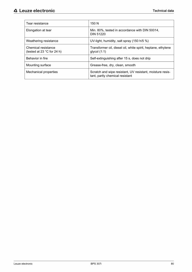
Technical data
Leuze electronic BPS 307i 80
Tear resistance 150 N
Elongation at tear Min. 80%, tested in accordance with DIN 50014, DIN 51220
Weathering resistance UV-light, humidity, salt spray (150 h/5 %)
Chemical resistance(tested at 23 °C for 24 h)
Transformer oil, diesel oil, white spirit, heptane, ethylene glycol (1:1)
Behavior in fire Self-extinguishing after 15 s, does not drip
Mounting surface Grease-free, dry, clean, smooth
Mechanical properties Scratch and wipe resistant, UV resistant, moisture resis-tant, partly chemical resistant
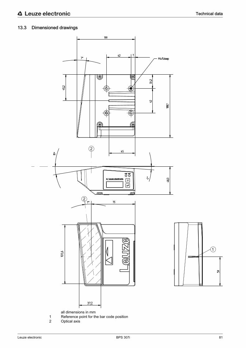
Technical data
Leuze electronic BPS 307i 81
13.3 Dimensioned drawings
all dimensions in mm1 Reference point for the bar code position2 Optical axis
1
2
2
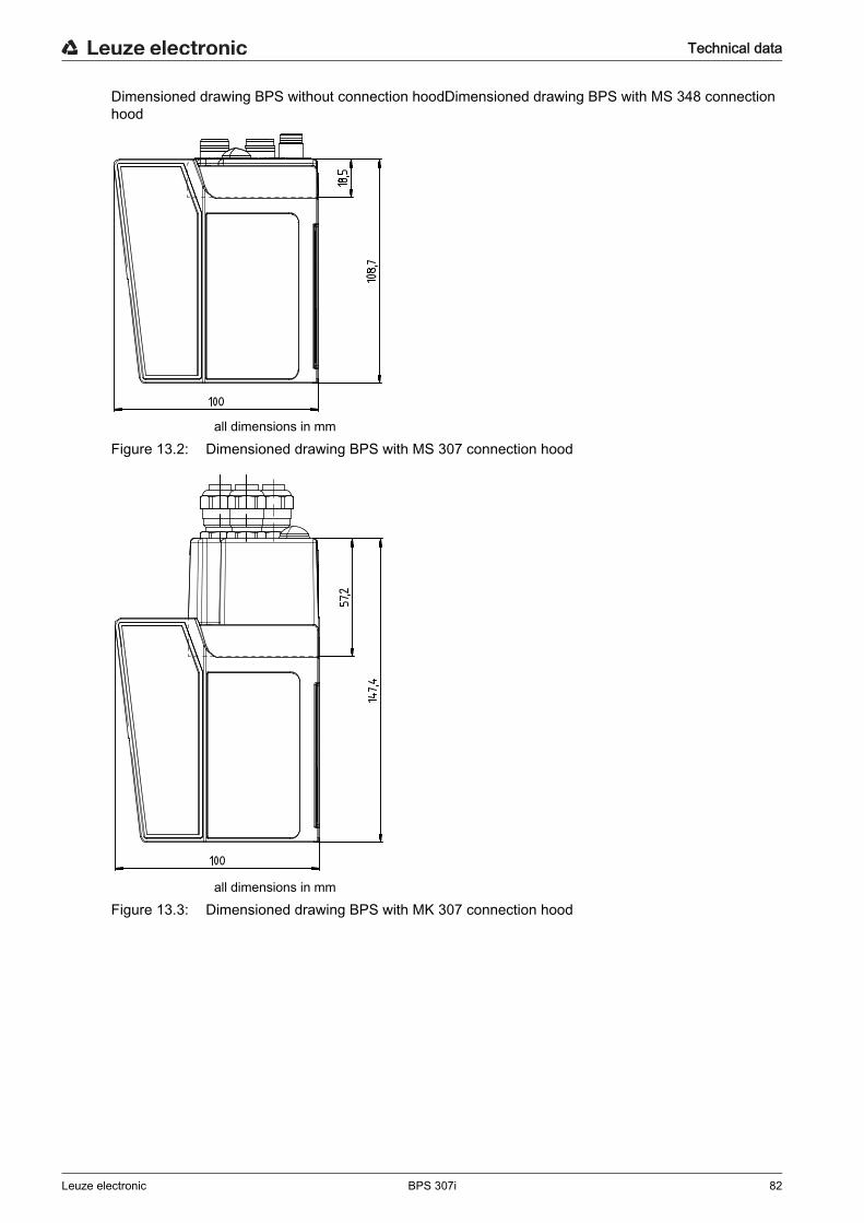
Technical data
Leuze electronic BPS 307i 82
Dimensioned drawing BPS without connection hoodDimensioned drawing BPS with MS 348 connection hood
all dimensions in mm
Figure 13.2: Dimensioned drawing BPS with MS 307 connection hood
all dimensions in mmFigure 13.3: Dimensioned drawing BPS with MK 307 connection hood
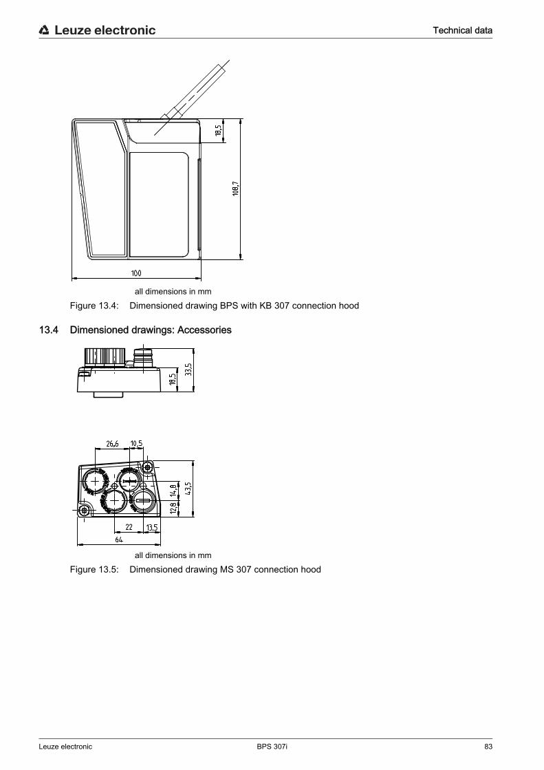
Technical data
Leuze electronic BPS 307i 83
all dimensions in mmFigure 13.4: Dimensioned drawing BPS with KB 307 connection hood
13.4 Dimensioned drawings: Accessories
all dimensions in mmFigure 13.5: Dimensioned drawing MS 307 connection hood
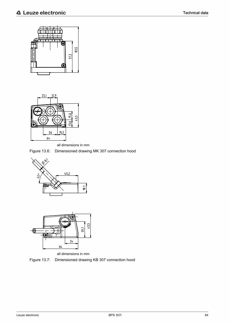
Technical data
Leuze electronic BPS 307i 84
all dimensions in mmFigure 13.6: Dimensioned drawing MK 307 connection hood
all dimensions in mmFigure 13.7: Dimensioned drawing KB 307 connection hood
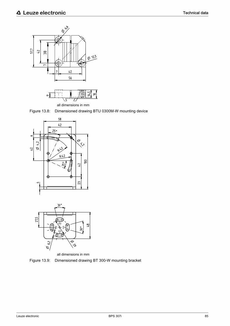
Technical data
Leuze electronic BPS 307i 85
all dimensions in mmFigure 13.8: Dimensioned drawing BTU 0300M-W mounting device
all dimensions in mm
Figure 13.9: Dimensioned drawing BT 300-W mounting bracket
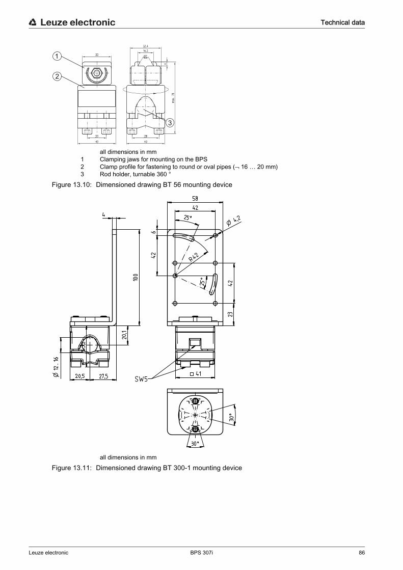
Technical data
Leuze electronic BPS 307i 86
all dimensions in mm1 Clamping jaws for mounting on the BPS2 Clamp profile for fastening to round or oval pipes ( 16 … 20 mm)3 Rod holder, turnable 360 °
Figure 13.10: Dimensioned drawing BT 56 mounting device
all dimensions in mmFigure 13.11: Dimensioned drawing BT 300-1 mounting device
1
2
3
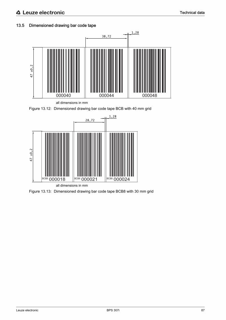
Technical data
Leuze electronic BPS 307i 87
13.5 Dimensioned drawing bar code tape
all dimensions in mmFigure 13.12: Dimensioned drawing bar code tape BCB with 40 mm grid
all dimensions in mmFigure 13.13: Dimensioned drawing bar code tape BCB8 with 30 mm grid
000040 000044 000048
38,72
47 ±0,2
1,28
BCB8 BCB8 BCB8000018 000021 000024
28,72
47 ±0,2
1,28
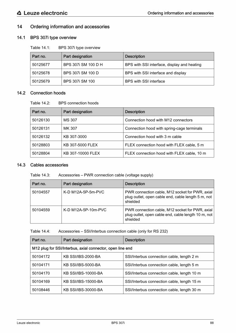
Ordering information and accessories
Leuze electronic BPS 307i 88
14 Ordering information and accessories
14.1 BPS 307i type overview
Table 14.1: BPS 307i type overview
14.2 Connection hoods
Table 14.2: BPS connection hoods
14.3 Cables accessories
Table 14.3: Accessories – PWR connection cable (voltage supply)
Table 14.4: Accessories – SSI/Interbus connection cable (only for RS 232)
Part no. Part designation Description
50125677 BPS 307i SM 100 D H BPS with SSI interface, display and heating
50125678 BPS 307i SM 100 D BPS with SSI interface and display
50125679 BPS 307i SM 100 BPS with SSI interface
Part no. Part designation Description
50126130 MS 307 Connection hood with M12 connectors
50126131 MK 307 Connection hood with spring-cage terminals
50126132 KB 307-3000 Connection hood with 3 m cable
50128803 KB 307-5000 FLEX FLEX connection hood with FLEX cable, 5 m
50128804 KB 307-10000 FLEX FLEX connection hood with FLEX cable, 10 m
Part no. Part designation Description
50104557 K-D M12A-5P-5m-PVC PWR connection cable, M12 socket for PWR, axial plug outlet, open cable end, cable length 5 m, not shielded
50104559 K-D M12A-5P-10m-PVC PWR connection cable, M12 socket for PWR, axial plug outlet, open cable end, cable length 10 m, not shielded
Part no. Part designation Description
M12 plug for SSI/Interbus, axial connector, open line end
50104172 KB SSI/IBS-2000-BA SSI/Interbus connection cable, length 2 m
50104171 KB SSI/IBS-5000-BA SSI/Interbus connection cable, length 5 m
50104170 KB SSI/IBS-10000-BA SSI/Interbus connection cable, length 10 m
50104169 KB SSI/IBS-15000-BA SSI/Interbus connection cable, length 15 m
50108446 KB SSI/IBS-30000-BA SSI/Interbus connection cable, length 30 m
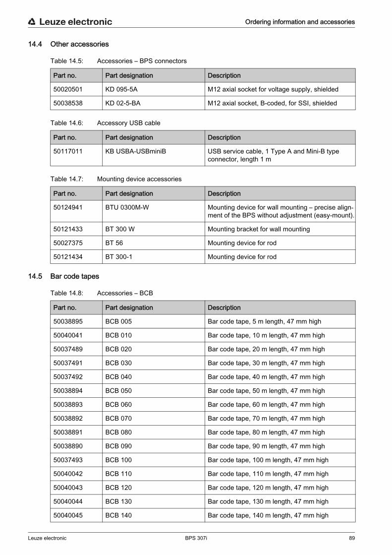
Ordering information and accessories
Leuze electronic BPS 307i 89
14.4 Other accessories
Table 14.5: Accessories – BPS connectors
Table 14.6: Accessory USB cable
Table 14.7: Mounting device accessories
14.5 Bar code tapes
Table 14.8: Accessories – BCB
Part no. Part designation Description
50020501 KD 095-5A M12 axial socket for voltage supply, shielded
50038538 KD 02-5-BA M12 axial socket, B-coded, for SSI, shielded
Part no. Part designation Description
50117011 KB USBA-USBminiB USB service cable, 1 Type A and Mini-B type connector, length 1 m
Part no. Part designation Description
50124941 BTU 0300M-W Mounting device for wall mounting – precise align-ment of the BPS without adjustment (easy-mount).
50121433 BT 300 W Mounting bracket for wall mounting
50027375 BT 56 Mounting device for rod
50121434 BT 300-1 Mounting device for rod
Part no. Part designation Description
50038895 BCB 005 Bar code tape, 5 m length, 47 mm high
50040041 BCB 010 Bar code tape, 10 m length, 47 mm high
50037489 BCB 020 Bar code tape, 20 m length, 47 mm high
50037491 BCB 030 Bar code tape, 30 m length, 47 mm high
50037492 BCB 040 Bar code tape, 40 m length, 47 mm high
50038894 BCB 050 Bar code tape, 50 m length, 47 mm high
50038893 BCB 060 Bar code tape, 60 m length, 47 mm high
50038892 BCB 070 Bar code tape, 70 m length, 47 mm high
50038891 BCB 080 Bar code tape, 80 m length, 47 mm high
50038890 BCB 090 Bar code tape, 90 m length, 47 mm high
50037493 BCB 100 Bar code tape, 100 m length, 47 mm high
50040042 BCB 110 Bar code tape, 110 m length, 47 mm high
50040043 BCB 120 Bar code tape, 120 m length, 47 mm high
50040044 BCB 130 Bar code tape, 130 m length, 47 mm high
50040045 BCB 140 Bar code tape, 140 m length, 47 mm high
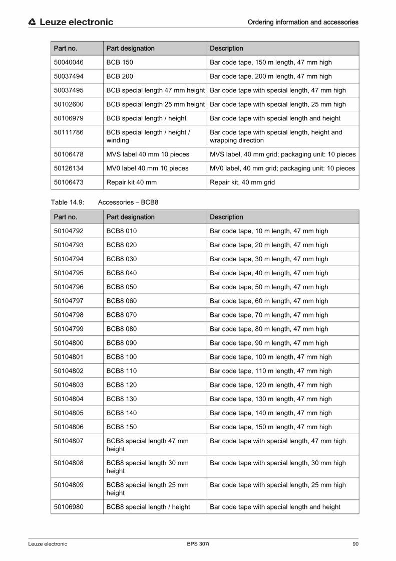
Ordering information and accessories
Leuze electronic BPS 307i 90
Table 14.9: Accessories – BCB8
50040046 BCB 150 Bar code tape, 150 m length, 47 mm high
50037494 BCB 200 Bar code tape, 200 m length, 47 mm high
50037495 BCB special length 47 mm height Bar code tape with special length, 47 mm high
50102600 BCB special length 25 mm height Bar code tape with special length, 25 mm high
50106979 BCB special length / height Bar code tape with special length and height
50111786 BCB special length / height / winding
Bar code tape with special length, height and wrapping direction
50106478 MVS label 40 mm 10 pieces MVS label, 40 mm grid; packaging unit: 10 pieces
50126134 MV0 label 40 mm 10 pieces MV0 label, 40 mm grid; packaging unit: 10 pieces
50106473 Repair kit 40 mm Repair kit, 40 mm grid
Part no. Part designation Description
Part no. Part designation Description
50104792 BCB8 010 Bar code tape, 10 m length, 47 mm high
50104793 BCB8 020 Bar code tape, 20 m length, 47 mm high
50104794 BCB8 030 Bar code tape, 30 m length, 47 mm high
50104795 BCB8 040 Bar code tape, 40 m length, 47 mm high
50104796 BCB8 050 Bar code tape, 50 m length, 47 mm high
50104797 BCB8 060 Bar code tape, 60 m length, 47 mm high
50104798 BCB8 070 Bar code tape, 70 m length, 47 mm high
50104799 BCB8 080 Bar code tape, 80 m length, 47 mm high
50104800 BCB8 090 Bar code tape, 90 m length, 47 mm high
50104801 BCB8 100 Bar code tape, 100 m length, 47 mm high
50104802 BCB8 110 Bar code tape, 110 m length, 47 mm high
50104803 BCB8 120 Bar code tape, 120 m length, 47 mm high
50104804 BCB8 130 Bar code tape, 130 m length, 47 mm high
50104805 BCB8 140 Bar code tape, 140 m length, 47 mm high
50104806 BCB8 150 Bar code tape, 150 m length, 47 mm high
50104807 BCB8 special length 47 mm height
Bar code tape with special length, 47 mm high
50104808 BCB8 special length 30 mm height
Bar code tape with special length, 30 mm high
50104809 BCB8 special length 25 mm height
Bar code tape with special length, 25 mm high
50106980 BCB8 special length / height Bar code tape with special length and height
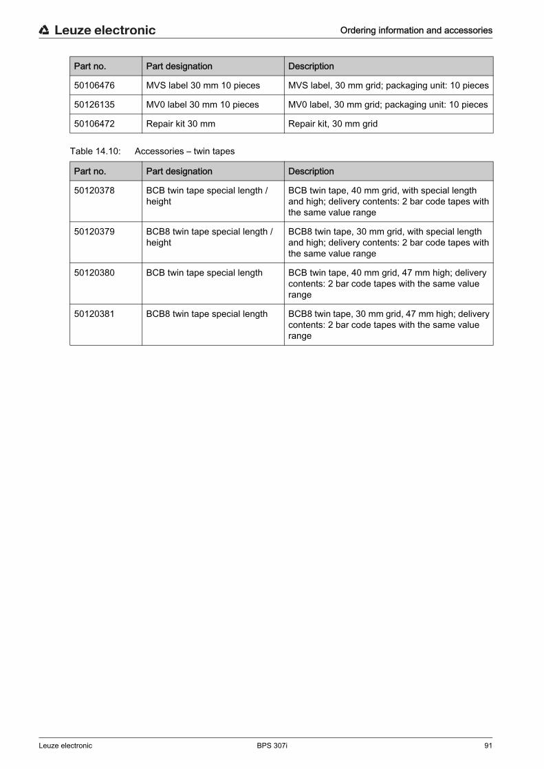
Ordering information and accessories
Leuze electronic BPS 307i 91
Table 14.10: Accessories – twin tapes
50106476 MVS label 30 mm 10 pieces MVS label, 30 mm grid; packaging unit: 10 pieces
50126135 MV0 label 30 mm 10 pieces MV0 label, 30 mm grid; packaging unit: 10 pieces
50106472 Repair kit 30 mm Repair kit, 30 mm grid
Part no. Part designation Description
Part no. Part designation Description
50120378 BCB twin tape special length / height
BCB twin tape, 40 mm grid, with special length and high; delivery contents: 2 bar code tapes with the same value range
50120379 BCB8 twin tape special length / height
BCB8 twin tape, 30 mm grid, with special length and high; delivery contents: 2 bar code tapes with the same value range
50120380 BCB twin tape special length BCB twin tape, 40 mm grid, 47 mm high; delivery contents: 2 bar code tapes with the same value range
50120381 BCB8 twin tape special length BCB8 twin tape, 30 mm grid, 47 mm high; delivery contents: 2 bar code tapes with the same value range

EC Declaration of Conformity
Leuze electronic BPS 307i 92
15 EC Declaration of ConformityThe bar code positioning systems of the BPS 300 series have been developed and manufactured in accor-dance with the applicable European standards and directives.The manufacturer of the product, Leuze electronic GmbH + Co. KG in D-73277 Owen, possesses a certi-fied quality assurance system in accordance with ISO 9001.
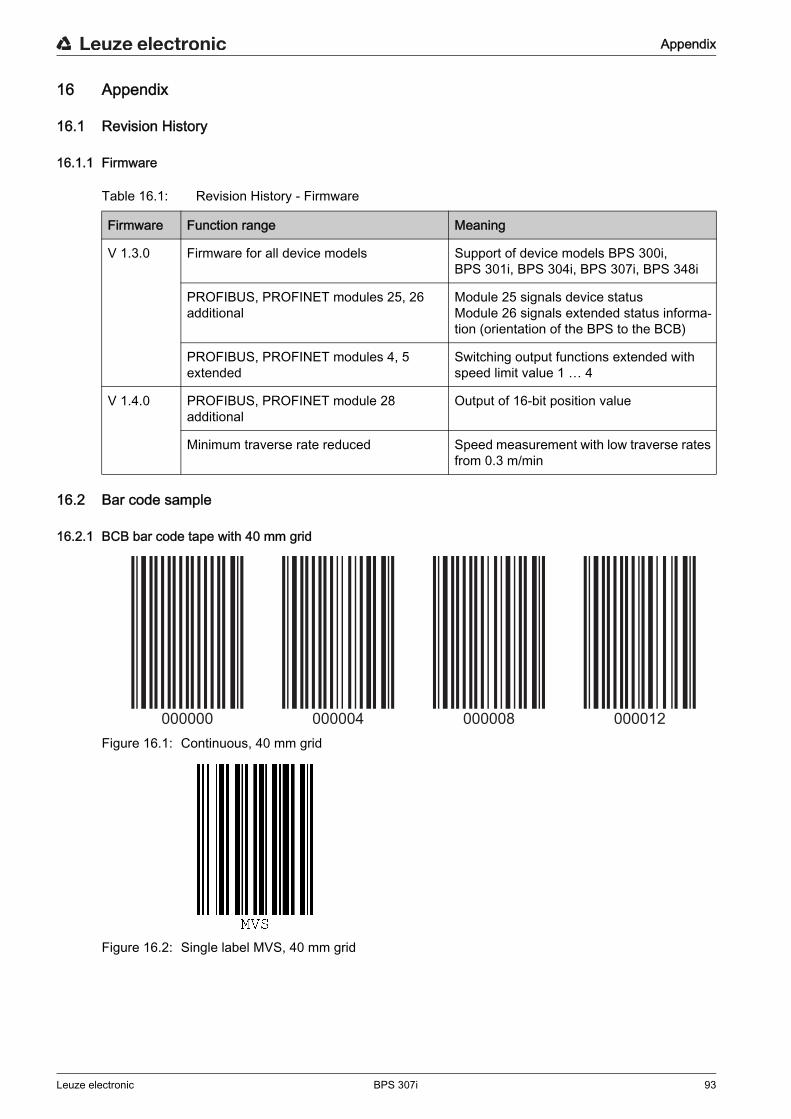
Appendix
Leuze electronic BPS 307i 93
16 Appendix
16.1 Revision History
16.1.1 Firmware
Table 16.1: Revision History - Firmware
16.2 Bar code sample
16.2.1 BCB bar code tape with 40 mm grid
Figure 16.1: Continuous, 40 mm grid
Figure 16.2: Single label MVS, 40 mm grid
Firmware Function range Meaning
V 1.3.0 Firmware for all device models Support of device models BPS 300i, BPS 301i, BPS 304i, BPS 307i, BPS 348i
PROFIBUS, PROFINET modules 25, 26 additional
Module 25 signals device statusModule 26 signals extended status informa-tion (orientation of the BPS to the BCB)
PROFIBUS, PROFINET modules 4, 5 extended
Switching output functions extended with speed limit value 1 … 4
V 1.4.0 PROFIBUS, PROFINET module 28 additional
Output of 16-bit position value
Minimum traverse rate reduced Speed measurement with low traverse rates from 0.3 m/min
000000 000004 000008 000012
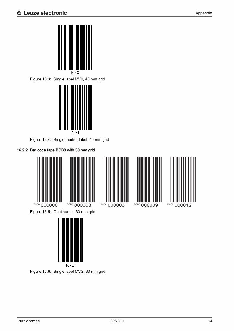
Appendix
Leuze electronic BPS 307i 94
Figure 16.3: Single label MV0, 40 mm grid
Figure 16.4: Single marker label, 40 mm grid
16.2.2 Bar code tape BCB8 with 30 mm grid
Figure 16.5: Continuous, 30 mm grid
Figure 16.6: Single label MVS, 30 mm grid
BCB8 BCB8 BCB8 BCB8 BCB8000000 000003 000006 000009 000012
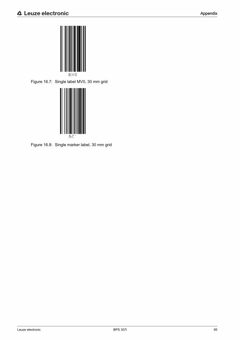
Appendix
Leuze electronic BPS 307i 95
Figure 16.7: Single label MV0, 30 mm grid
Figure 16.8: Single marker label, 30 mm grid


