Embed Size (px)
Citation preview
BPW OPERATOR’S MANUAL
• ECO Plus 3 Axles• ECO Plus Axles• ECO Axles• Conventional Axles• TS2, TSB and SB Style Disc Brakes• Airbag Suspensions• Turntables• BPW Multivolt Trailer EBS• BPW Weight Watcher• BPW Landing Legs• BPW Special Tools• BPW Alloy Hubs
Valid for operational use in
AUSTRALIA WARRANTY DOCUMENTS / SERVICE AND MAINTENANCE INSTRUCTIONS
BPW Operator’s Manual 8/20192
BPW Operator’s Manual
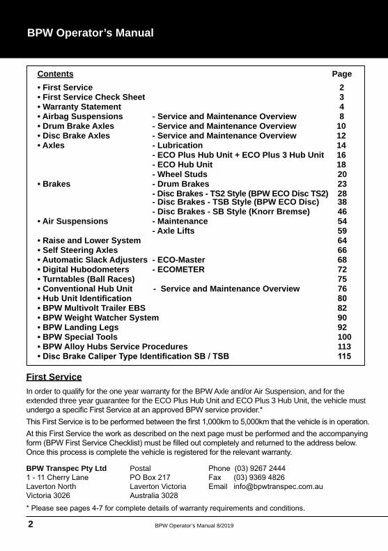
Contents Page• First Service 2• First Service Check Sheet 3• Warranty Statement 4• Airbag Suspensions - Service and Maintenance Overview 8• Drum Brake Axles - Service and Maintenance Overview 10• Disc Brake Axles - Service and Maintenance Overview 12• Axles - Lubrication 14 - ECO Plus Hub Unit + ECO Plus 3 Hub Unit 16 - ECO Hub Unit 18 - Wheel Studs 20• Brakes - Drum Brakes 23 - Disc Brakes - TS2 Style (BPW ECO Disc TS2) 28 - Disc Brakes - TSB Style (BPW ECO Disc) 38 - Disc Brakes - SB Style (Knorr Bremse) 46• Air Suspensions - Maintenance 54 - Axle Lifts 59• Raise and Lower System 64• Self Steering Axles 66• Automatic Slack Adjusters - ECO-Master 68• Digital Hubodometers - ECOMETER 72• Turntables (Ball Races) 75• Conventional Hub Unit - Service and Maintenance Overview 76
• BPW Multivolt Trailer EBS 82• BPW Weight Watcher System 90• BPW Landing Legs 92• BPW Special Tools 100• BPW Alloy Hubs Service Procedures 113
First ServiceIn order to qualify for the one year warranty for the BPW Axle and/or Air Suspension, and for the extended three year guarantee for the ECO Plus Hub Unit and ECO Plus 3 Hub Unit, the vehicle must
BPW Transpec Pty Ltd
Laverton North
Postal
Laverton Victoria
BPW Operator’s Manual 8/2019 3
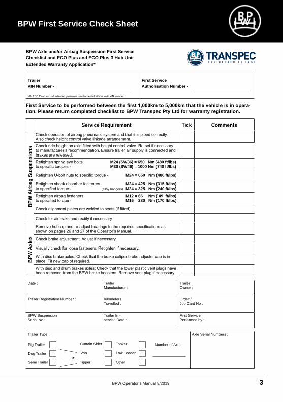
BPW First Service Check Sheet
Service Requirement Tick Comments
BPW
Airb
ag S
uspe
nsio
ns
Check operation of airbag pneumatic system and that it is piped correctly. Also check height control valve linkage arrangement.
to manufacturer’s recommendation. Ensure trailer air supply is connected and brakes are released.
M24 (SW36) = 650 Nm (480 ft/lbs) M30 (SW46) = 1000 Nm (740 ft/lbs)
M24 = 650 Nm (480 ft/lbs)
M24 = 425 Nm (315 ft/lbs) (alloy hangers) M24 = 325 Nm (240 ft/lbs)
M12 = 66 Nm ( 49 ft/lbs) M16 = 230 Nm (170 ft/lbs)
Check for air leaks and rectify if necessary
BPW
Axl
es
Trailer VIN Number -
First Service Authorisation Number -
-tion. Please return completed checklist to BPW Transpec Pty Ltd for warranty registration.
Date : Trailer Trailer
Kilometers Travelled :
Job Card No :
BPW Suspension Serial No :
service Date :
First Service Performed by :
Trailer Type : Axle Serial Numbers :
Pig Trailer
Dog Trailer
Semi Trailer
Curtain Sider
Van
Tipper
Tanker Number of Axles
BPW Axle and/or Airbag Suspension First Service Checklist and ECO Plus and ECO Plus 3 Hub Unit Extended Warranty Application*
BPW Operator’s Manual 8/20194
BPW Operator’s Manual
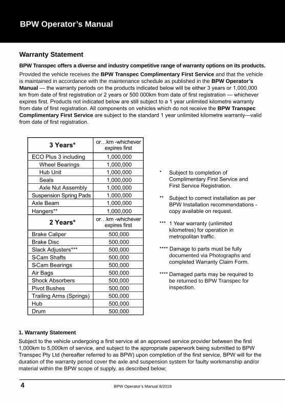
1. Warranty Statement
duration of the warranty period cover the axle and suspension system for faulty workmanship and/or material within the BPW scope of supply, as described below;
documented via Photographs and
be returned to BPW Transpec for
Warranty StatementBPW Transpec offers a diverse and industry competitive range of warranty options on its products. Provided the vehicle receives the BPW Transpec Complimentary First Service and that the vehicle is maintained in accordance with the maintenance schedule as published in the BPW Operator’s Manual
BPW Transpec Complimentary First Service
3 Years*
ECO Plus 3 including 1,000,000Wheel Bearings 1,000,000Hub Unit 1,000,000Seals 1,000,000Axle Nut Assembly 1,000,000
Suspension Spring Pads 1,000,000Axle Beam 1,000,000Hangers** 1,000,000
2 Years* or…km -whichever expires first
or…km -whichever expires first
Brake Caliper 500,000Brake Disc 500,000Slack Adjusters*** 500,000S-Cam Shafts 500,000S-Cam Bearings 500,000Air Bags 500,000Shock Absorbers 500,000Pivot Bushes 500,000Trailing Arms (Springs) 500,000Hub 500,000Drum 500,000
BPW Operator’s Manual 8/2019 5
• In the case of air suspension systems, only for trailers equipped with a transverse throttle between
• Only for trailers registered for and used on public roads at or below legally permitted axle loads and
2. Scope of Warranty
be agreed in advance with BPW or the relevant BPW representative and performed by an authorized
3. Exclusion from the Warranty
This warranty does not cover normal wear and tear, the relevant wearing parts (in particular brake
4. Registration
5. Conditions for obtaining and maintaining the ECO Plus Hub Unit warranty
Obtaining and maintaining the ECO Plus Hub Unit warranty, is subject to compliance with all measures
Warranty Statement
BPW Operator’s Manual 8/20196
BPW Operator’s Manual
6. Repairs during the warranty period
When repairs are carried out during the warranty period the warranty covering the replaced component
travelling on such roads, and will travel on unmade roads incidentally for small distances and predominantly at low speeds, then for the purpose of this warranty statement the vehicle is considered to be
8. Further development of BPW products, alterations to maintenance requirements
Because BPW is continuously developing and improving its products, the prescribed maintenance
ranty and, where applicable, the extended warranty for the ECO Plus Hub Unit and ECO Plus 3 Hub
9. BPW Transpec Pty Ltd General Warranty Conditions
Claims hereunder can only be accepted if lodged by the customer at an authorised service centre of
the expense of the customer and, where applicable, repaired or replacement goods will be shipped to
def ect that its recommendation for installation and maintenance has been followed and the Goods
terms of this Warranty where Goods have been repaired, altered or overhauled without the Company’
any deduction on account thereof from remittances or current accounts while claims are in process of
BPW Operator’s Manual 8/2019 7
Warranty Statement
The Company shall in no circumstances be liable under this Warranty in contract or tort
If you have acquired our goods as a consumer within the meaning of the Australian Consumer Law, the following also applies: Our goods come with guarantees that cannot be
for a major failure and for compensation for any other reasonably foreseeable loss or
does not purport to, and does not have the effect of, excluding, restricting or modifying the exercise of any right or remedy in respect of the Goods which the Customer has under the Austral ian Consumer Law or other relevant legislation which cannot be lawfully excluded,
It is essential that all maintenance work is carried out in accordance with the prescribed in
operation and service regulations of the vehicle manufacturer and of the manufacturers of
parts. Parts authorised by BPW for trailer axles and axle units are regularly subjected to special inspections. BPW accepts product liability for them.
BPW is unable to determine whether all third party products can be used with BPW trailer axles and axle units without any safety risk; this also applies even if an autho-rised testing organisation has accepted the product.
Our warranty will cease to apply if spare parts other than genuine BPW spare parts are employed in warranty covered work and repairs.
The warranty shall also be rendered null and void if the BPW axle systems are not installed in
Brake linings
Brake lining qualities authorised by BPW are matched to each other and their performance
These brake linings are subject to continual monitoring by the Quality Assurance Depart
BPW Operator’s Manual 8/20198
BPW Operator’s Manual
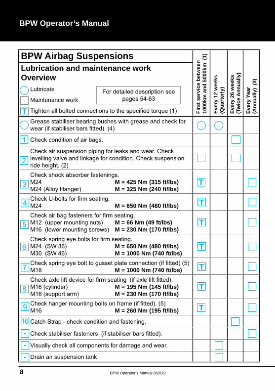
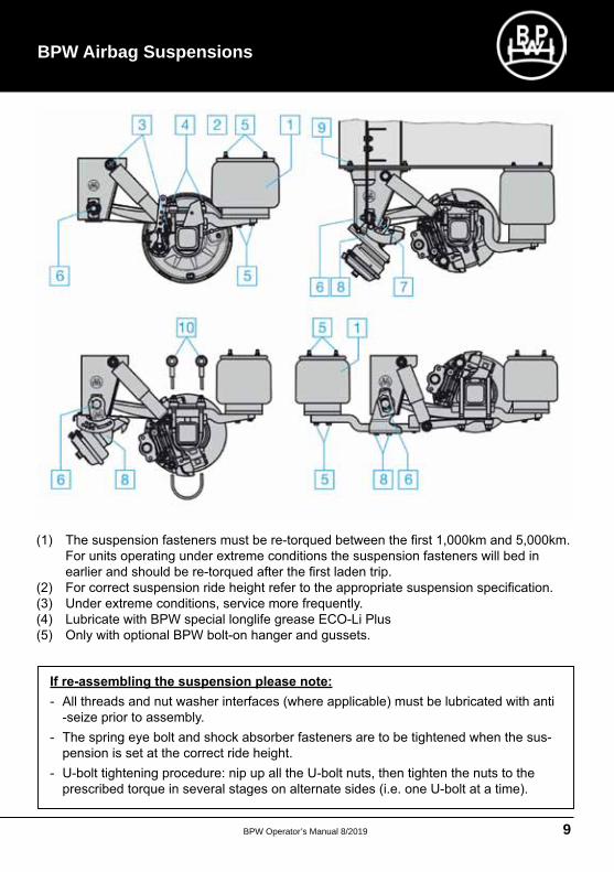
BPW Airbag Suspensions
Firs
t ser
vice
bet
wee
n 10
00km
and
500
0km
(1)
Ever
y 12
wee
ks(Q
uart
erly
)
Ever
y 26
wee
ks
(Tw
ice
Ann
ually
)
Ever
y Ye
ar(A
nnua
lly)
(3)
Lubrication and maintenance work Overview
Lubricate
Maintenance work
Grease stabiliser bearing bushes with grease and check for
M = 425 Nm (315 ft/lbs)M = 325 Nm (240 ft/lbs)
M = 650 Nm (480 ft/lbs)
M = 66 Nm (49 ft/lbs)M = 230 Nm (170 ft/lbs)
M = 650 Nm (480 ft/lbs) M = 1000 Nm (740 ft/lbs)
M = 1000 Nm (740 ft/lbs)
M = 195 Nm (145 ft/lbs)M = 230 Nm (170 ft/lbs)
M = 260 Nm (195 ft/lbs)
Drain air suspension tank
2
3 T
T
T
T
T
T
T
---
T
BPW Operator’s Manual 8/2019 9
BPW Airbag Suspensions
BPW Operator’s Manual 8/201910
BPW Operator’s Manual
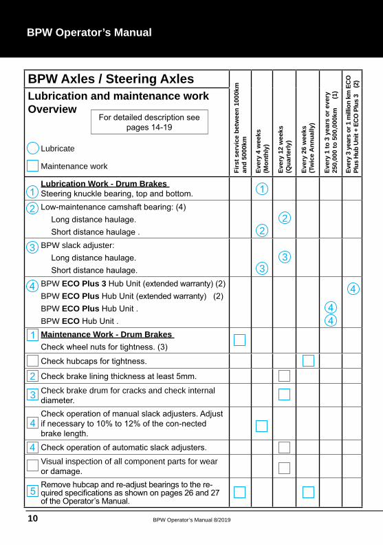
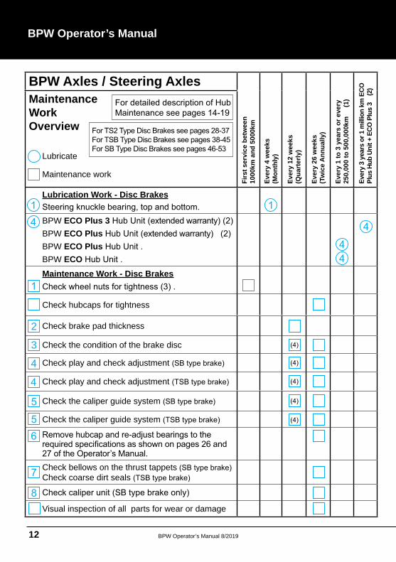
BPW Axles / Steering Axles
Firs
t ser
vice
bet
wee
n 10
00km
an
d 50
00km
Ever
y 4
wee
ks(M
onth
ly)
Ever
y 12
wee
ks
(Qua
rter
ly)
Ever
y 26
wee
ks
(Tw
ice
Ann
ually
)
Ever
y 1
to 3
yea
rs o
r eve
ry
250,
000
to 5
00,0
00km
(
1)
Ever
y 3
year
s or
1 m
illio
n km
ECO
Pl
us H
ub U
nit +
ECO
Plu
s 3
(2
)
Lubrication and maintenance work Overview
Lubricate
Maintenance work
Lubrication Work - Drum Brakes
BPW slack adjuster:
BPW ECO Plus 3BPW ECO PlusBPW ECO Plus BPW ECOMaintenance Work - Drum Brakes
Check brake drum for cracks and check internal
Visual inspection of all component parts for wear
2
22
3
33
2
3
BPW Operator’s Manual 8/2019 11
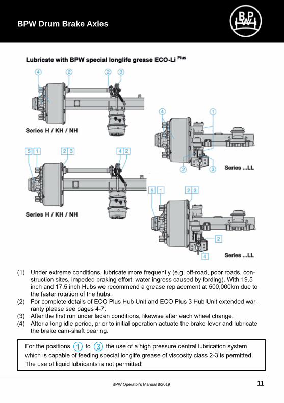
BPW Drum Brake Axles
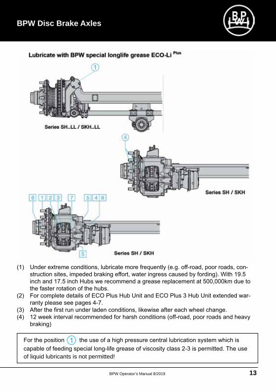
which The use of liquid lubricants is not permitted!
3
BPW Operator’s Manual 8/201912
BPW Operator’s Manual
BPW Axles / Steering Axles
Firs
t ser
vice
bet
wee
n
1000
km a
nd 5
000k
m
Ever
y 4
wee
ks(M
onth
ly)
Ever
y 12
wee
ks
(Qua
rter
ly)
Ever
y 26
wee
ks
(Tw
ice
Ann
ually
)
Ever
y 1
to 3
yea
rs o
r eve
ry
250,
000
to 5
00,0
00km
(
1)
Ever
y 3
year
s or
1 m
illio
n km
ECO
Pl
us H
ub U
nit +
ECO
Plu
s 3
(2
)
Maintenance Work Overview
Lubricate
Maintenance work
Lubrication Work - Disc Brakes
BPW ECO Plus 3BPW ECO PlusBPW ECO Plus BPW ECOMaintenance Work - Disc Brakes
Check hubcaps for tightness
Check brake pad thickness
Check the condition of the brake disc
Check play and check adjustment
Check play and check adjustment
Check the caliper guide system
Check the caliper guide system
Check bellows on the thrust tappets Check coarse dirt seals
Visual inspection of all parts for wear or damage
2
3
BPW Operator’s Manual 8/2019 13
BPW Disc Brake Axles
of liquid lubricants is not permitted!
BPW Operator’s Manual 8/201914
BPW Operator’s Manual
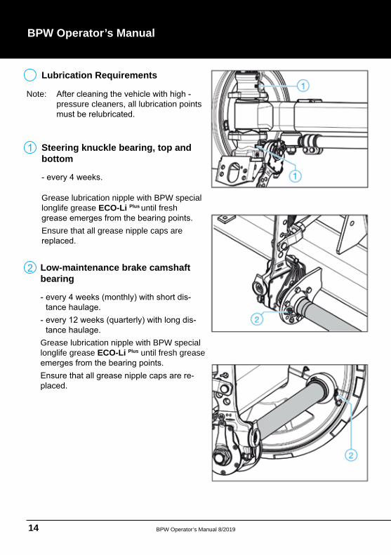
Lubrication Requirements
pressure cleaners, all lubrication points Note:
Steering knuckle bearing, top and bottom
Grease lubrication nipple with BPW special longlife grease ECO-Li Plus until fresh
Ensure that all grease nipple caps are
Low-maintenance brake camshaft bearing
Grease lubrication nipple with BPW special longlife grease ECO-Li Plus until fresh grease
2
BPW Operator’s Manual 8/2019 15
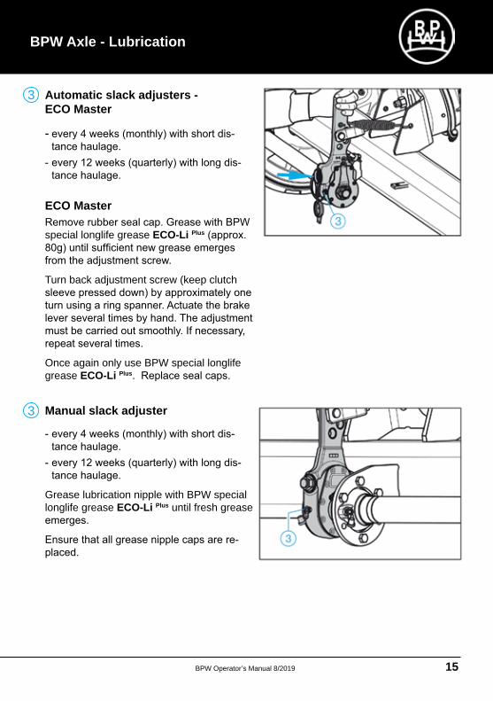
Automatic slack adjusters - ECO Master
ECO Master
special longlife grease ECO-Li Plus
Turn back adjustment screw (keep clutch
Once again only use BPW special longlife grease ECO-Li Plus
BPW Axle - Lubrication
Manual slack adjuster
Grease lubrication nipple with BPW special longlife grease ECO-Li Plus until fresh grease
3
3
BPW Operator’s Manual 8/201916
BPW Operator’s Manual
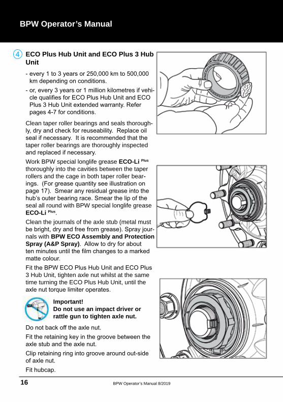
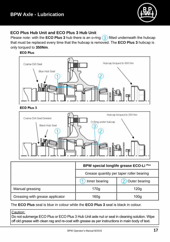
ECO Plus Hub Unit and ECO Plus 3 Hub Unit
Clean taper roller bearings and seals thorough
taper roller bearings are thoroughly inspected
Work BPW special longlife grease ECO-Li Plus thoroughly into the cavities between the taper rollers and the cage in both taper roller bear
seal all round with BPW special longlife grease ECO-Li Plus
Clean the journals of the axle stub (metal must
nals with BPW ECO Assembly and Protection Spray (A&P Spray)
3 Hub Unit, tighten axle nut whilst at the same time turning the ECO Plus Hub Unit, until the
Important!Do not use an impact driver or rattle gun to tighten axle nut.
BPW Operator’s Manual 8/2019 17
BPW Axle - Lubrication
ECO Plus Hub Unit and ECO Plus 3 Hub Unit
BPW special longlife grease ECO-Li Plus
Grease quantity per taper roller bearing
Inner bearing Outer bearing
Manual greasing
Greasing with grease applicator
Caution:
Please note: with the ECO Plus 3ECO Plus 3 hubcap is
only torqued to 350Nm
The ECO Plus seal is blue in colour while the ECO Plus 3
32
2
3
2
BPW Operator’s Manual 8/201918
BPW Operator’s Manual
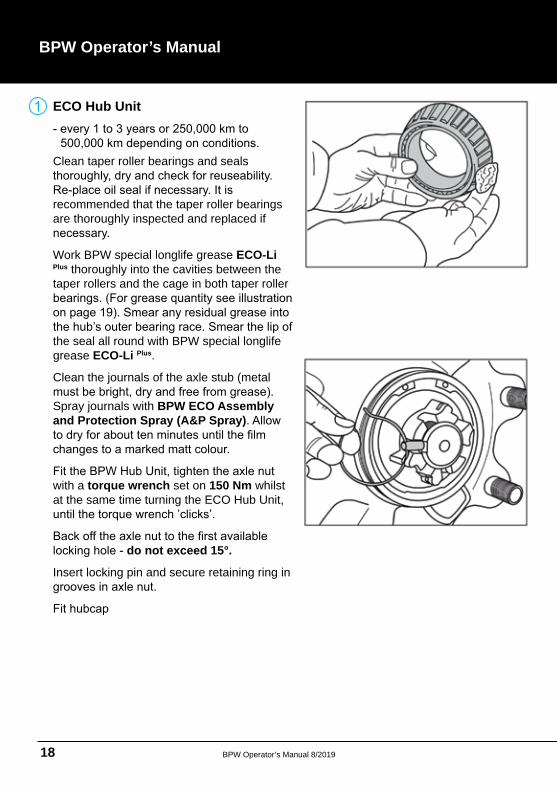
ECO Hub Unit
Clean taper roller bearings and seals
recommended that the taper roller bearings are thoroughly inspected and replaced if
Work BPW special longlife grease ECO-Li Plus thoroughly into the cavities between the taper rollers and the cage in both taper roller
the seal all round with BPW special longlife grease ECO-Li Plus
Clean the journals of the axle stub (metal
Spray journals with BPW ECO Assembly and Protection Spray (A&P Spray)
with a torque wrench set on 150 Nm whilst at the same time turning the ECO Hub Unit,
do not exceed 15°.
Insert locking pin and secure retaining ring in
BPW Operator’s Manual 8/2019 19
BPW Axle - Lubrication
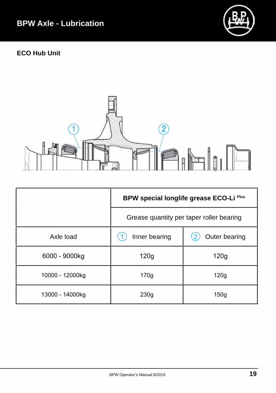
ECO Hub Unit
BPW special longlife grease ECO-Li Plus
Grease quantity per taper roller bearing
Axle load Inner bearing Outer bearing2
BPW Operator’s Manual 8/201920
BPW Operator’s Manual
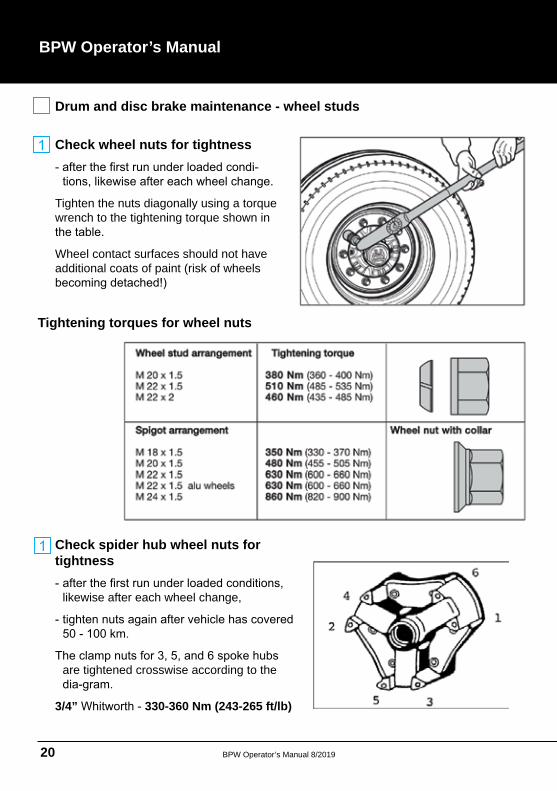
Drum and disc brake maintenance - wheel studs
Tightening torques for wheel nuts
Check spider hub wheel nuts for tightness
likewise after each wheel change,
are tightened crosswise according to the
3/4” 330-360 Nm (243-265 ft/lb)
Check wheel nuts for tightness
Tighten the nuts diagonally using a torque wrench to the tightening torque shown in
Wheel contact surfaces should not have additional coats of paint (risk of wheels
BPW Operator’s Manual 8/2019 21
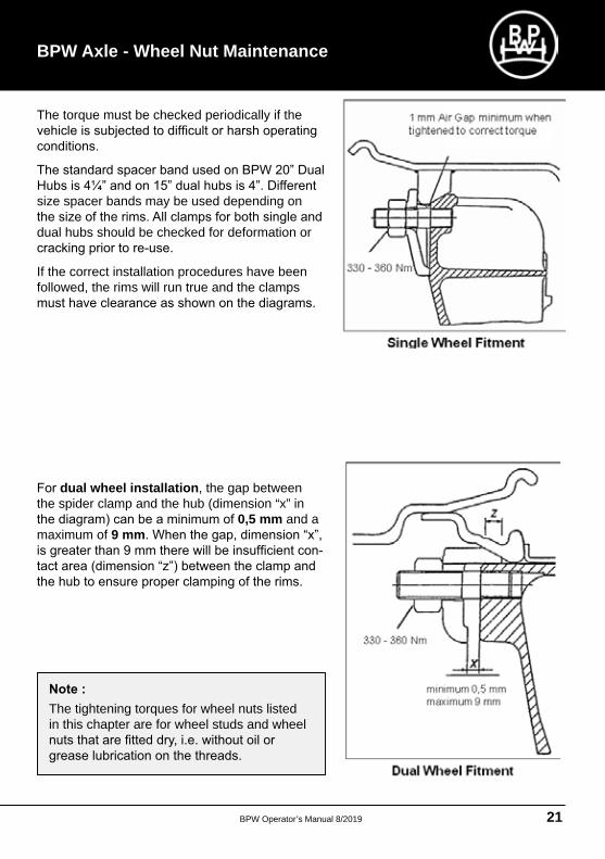
The torque must be checked periodically if the
size spacer bands may be used depending on
dual hubs should be checked for deformation or
If the correct installation procedures have been followed, the rims will run true and the clamps
dual wheel installation, the gap between the spider clamp and the hub (dimension “x” in
0,5 mm and a maximum of 9 mm
The tightening torques for wheel nuts listed in this chapter are for wheel studs and wheel
BPW Axle - Wheel Nut Maintenance
BPW Operator’s Manual 8/201922
BPW Operator’s Manual
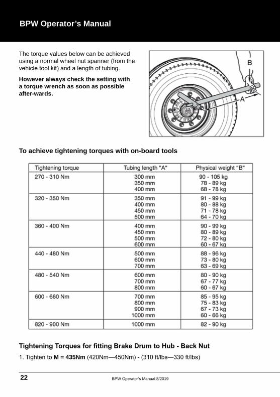
The torque values below can be achieved using a normal wheel nut spanner (from the
However always check the setting with a torque wrench as soon as possible after-wards.
To achieve tightening torques with on-board tools
M = 435Nm
BPW Operator’s Manual 8/2019 23
BPW Axle - Drum Brake Maintenance
Drum brake maintenance and visual inspection
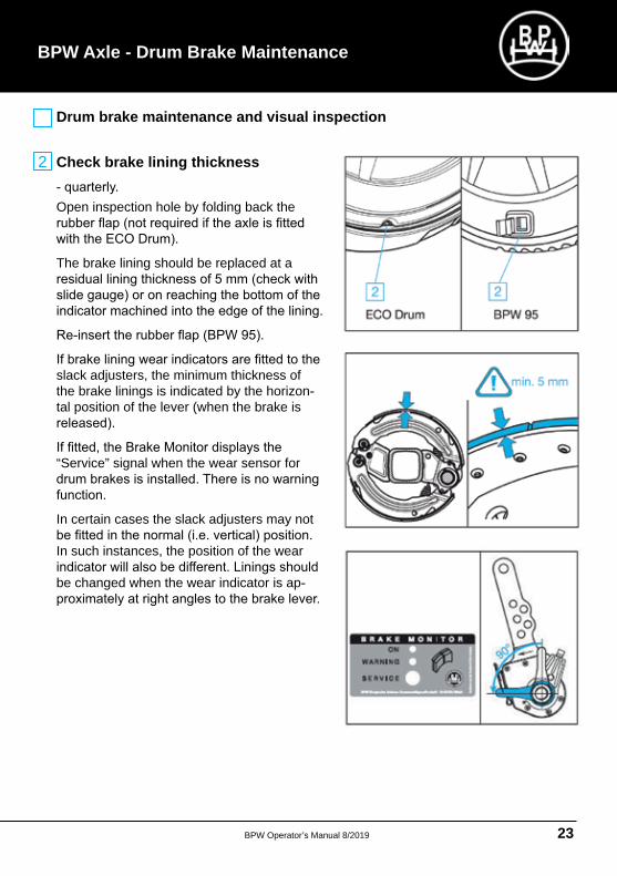
Check brake lining thickness
Open inspection hole by folding back the
The brake lining should be replaced at a
slack adjusters, the minimum thickness of the brake linings is indicated by the horizontal position of the lever (when the brake is
“Service” signal when the wear sensor for
In certain cases the slack adjusters may not
In such instances, the position of the wear
be changed when the wear indicator is ap
2
BPW Operator’s Manual 8/201924
BPW Operator’s Manual
Drum brake maintenance and visual inspection
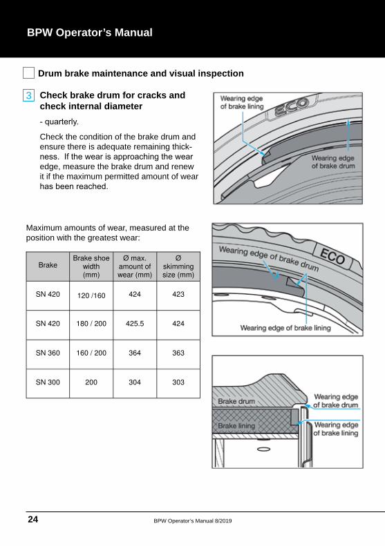
Check brake drum for cracks and check internal diameter
Check the condition of the brake drum and ensure there is adequate remaining thick
edge, measure the brake drum and renew it if the maximum permitted amount of wear
Brake
Brake shoe width (mm)
Ø max. amount of wear (mm)
Ø skimming size (mm)
SN 420
120 /160
424
423
SN 420
180 / 200
425.5
424
SN 360
160 / 200
364
363
SN 300
200
304
303
Maximum amounts of wear, measured at the position with the greatest wear:
3
BPW Operator’s Manual 8/2019 25
BPW Axle - Drum Brake Maintenance
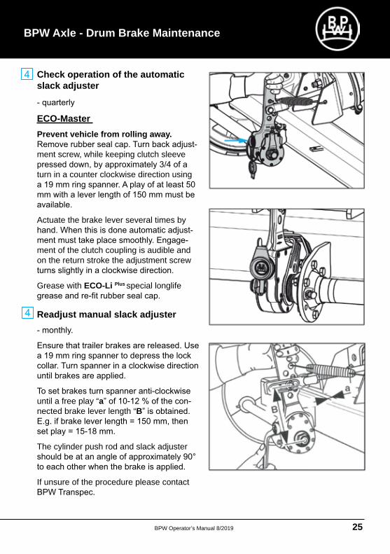
Check operation of the automatic slack adjuster
ECO-Master Prevent vehicle from rolling away.
ment screw, while keeping clutch sleeve
turn in a counter clockwise direction using
Actuate the brake lever several times by
ment of the clutch coupling is audible and on the return stroke the adjustment screw
Grease with ECO-Li Plus special longlife
Readjust manual slack adjuster
until a free play “anected brake lever length “B
The cylinder push rod and slack adjuster
If unsure of the procedure please contact
BPW Operator’s Manual 8/201926
BPW Operator’s Manual
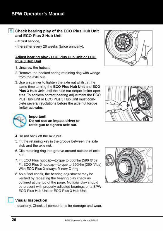
Check bearing play of the ECO Plus Hub Unit and ECO Plus 3 Hub Unit
Adjust bearing play - ECO Plus Hub Unit or ECO Plus 3 Hub Unit
same time turning the ECO Plus Hub Unit and ECO Plus 3 Hub Unit until the axle nut torque limiter oper
Plus Hub Unit or ECO Plus 3 Hub Unit must complete several revolutions before the axle nut torque
Important!Do not use an impact driver or rattle gun to tighten axle nut.
be present with properly adjusted bearings on a BPW
Visual Inspection
BPW Operator’s Manual 8/2019 27
Visual Inspection
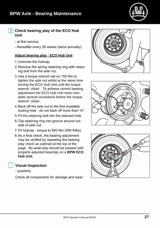
Check bearing play of the ECO Hub Unit
Adjust bearing play - ECO Hub Unit
tighten the axle nut whilst at the same time turning the ECO Hub Unit until the torque
adjustment the ECO Hub Unit must complete several revolutions before the torque
play check as outlined at the top of the
properly adjusted bearings on a BPW ECO Hub Unit
BPW Axle - Bearing Maintenance
BPW Operator’s Manual 8/201928
BPW Operator’s Manual - TS2 Style Disc Brake
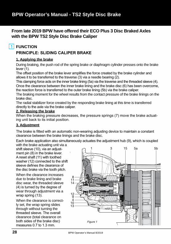
FUNCTION
1. Applying the brakeDuring braking, the push rod of the spring brake or diaphragm cylinder presses onto the brake
The braking moment for the wheel results from the contact pressure of the brake linings on the
The radial stabilizer force created by the responding brake lining at this time is transferred
2. Releasing the brake
3. Adjustment
with the brake actuating unit via a
When the clearance increases due to brake lining and brake disc wear, the threaded sleeve
wear through adjustment via a
When the clearance is correctly set, the wrap spring slides through without turning the
clearance (total clearance on
g
8
4
1310
9
11
12
14
31 15 5a 5b
Figure 1
From late 2019 BPW have offered their ECO Plus 3 Disc Braked Axles with the BPW TS2 Style Disc Brake Caliper
BPW Operator’s Manual 8/2019 29
4. Reset mechanism
The disc brake features a reset mechanism at the back for replacing the brake linings and
To reset the threaded sleeve to its initial position, the reset shaft equipped with a hexagon
5. Brake cylinder
When compressed air is applied to the brake cylinder, an air cushion forms behind the
the secondary chamber of the brake cylinder, as otherwise the clamping mechanism will
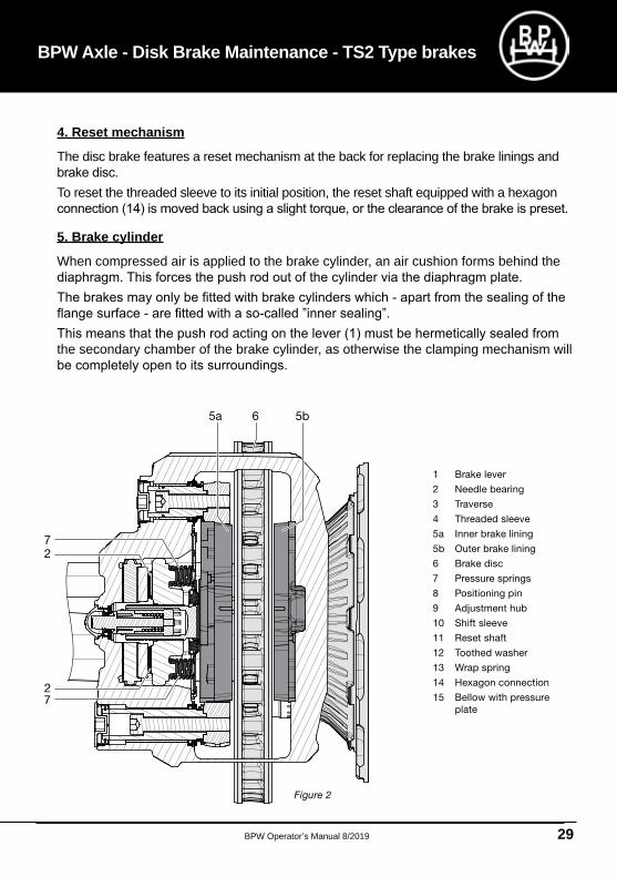
BPW Axle - Disk Brake Maintenance - TS2 Type brakes
Figure 2
1 Brake lever
2 Needle bearing
3 Traverse
4 Threaded sleeve
5a Inner brake lining
5b Outer brake lining
6 Brake disc
7 Pressure springs
8 Positioning pin
9 Adjustment hub
10 Shift sleeve
11 Reset shaft
12 Toothed washer
13 Wrap spring
14 Hexagon connection
15 Bellow with pressure
plate
5a 5b6
7
7
2
2
BPW Operator’s Manual 8/201930
BPW Operator’s Manual
2
X X
New condition Check required
29 mm40 mm
Brake lining active Brake lining passive
Friction
lining
Lining carrier plate
Total brake
lining thickness
21 mm
2 m
m r
em
ain
ing
b
rake lin
ing
thic
kness
2 m
m
rem
ain
ing
bra
ke
linin
g t
hic
kness
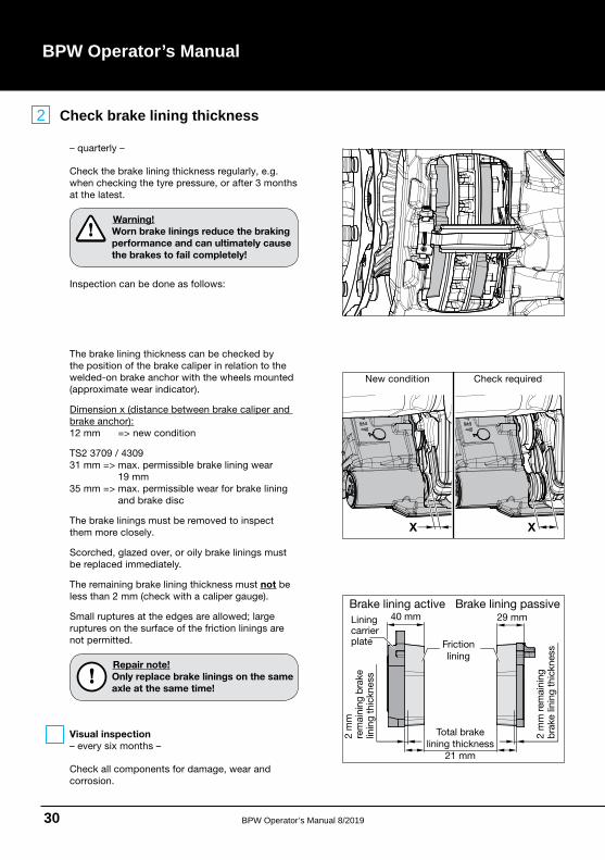
– quarterly –
Check the brake lining thickness regularly, e.g.
when checking the tyre pressure, or after 3 months
at the latest.
Warning!
Worn brake linings reduce the braking
performance and can ultimately cause
the brakes to fail completely!
Inspection can be done as follows:
The brake lining thickness can be checked by
the position of the brake caliper in relation to the
welded-on brake anchor with the wheels mounted
(approximate wear indicator).
Dimension x (distance between brake caliper and
brake anchor):
12 mm => new condition
TS2 3709 / 4309
31 mm => max. permissible brake lining wear
19 mm
35 mm => max. permissible wear for brake lining
and brake disc
The brake linings must be removed to inspect
them more closely.
Scorched, glazed over, or oily brake linings must
be replaced immediately.
The remaining brake lining thickness must not be
less than 2 mm (check with a caliper gauge).
Small ruptures at the edges are allowed; large
ruptures on the surface of the friction linings are
not permitted.
Repair note!
Only replace brake linings on the same
axle at the same time!
- Visual inspection
– every six months –
Check all components for damage, wear and
corrosion.
Check brake lining thickness
BPW Operator’s Manual 8/2019 31
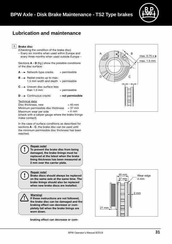
BPW Axle - Disk Brake Maintenance - TS2 Type brakes
3 Brake disc
(Checking the condition of the brake disc)
– Every six months when used within Europe and
every three months when used outside Europe –
Sections A - D (fig.) show the possible conditions
of the disc surface:
A Network-type cracks = permissible
B Radial cracks up to max.
1.5 mm width and depth = permissible
C Uneven disc surface less
than 1.5 mm = permissible
D Continuous cracks = not permissible
Technical data:
Disc thickness, new = 45 mm
= 37 mm
= 4 mm
(check with a caliper gauge where the brake linings Maximum wear per side
Minimum permissible disc thickness
make contact).
In the case of surface conditions as described for
sections A - C, the brake disc can be used until
the minimum permissible disc thickness has been
reached.
Repair note!
To prevent the brake disc from being
damaged, the brake linings must be
replaced at the latest when the brake
lining thickness has been measured at
2 mm over the carrier plate.
Repair note!
Brake discs should always be replaced
on the same axle at the same time. The
brake linings should also be replaced
when new brake discs are installed.
Warning!
If these instructions are not followed,
the brake disc can be damaged and the
braking effect can decrease or com-
braking effect can decrease or com-
pletely fail when the brake linings are
worn down.
a
21 mm
2 mm
45 mm
37 mmWear edge
4 mm
max. 0.75 x a
max. 1.5 mm
Lubrication and maintenance
BPW Operator’s Manual 8/201932
BPW Operator’s Manual
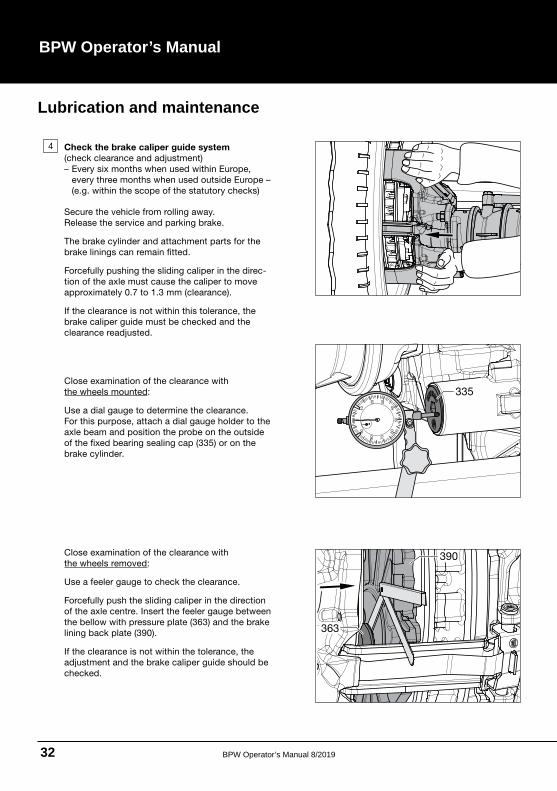
Close examination of the clearance with
the wheels mounted:
Use a dial gauge to determine the clearance.
For this purpose, attach a dial gauge holder to the
axle beam and position the probe on the outside
of the fixed bearing sealing cap (335) or on the
brake cylinder.
4 Check the brake caliper guide system
(check clearance and adjustment)
– Every six months when used within Europe,
every three months when used outside Europe –
(e.g. within the scope of the statutory checks)
Secure the vehicle from rolling away.
Release the service and parking brake.
The brake cylinder and attachment parts for the
brake linings can remain fitted.
Forcefully pushing the sliding caliper in the direc-
tion of the axle must cause the caliper to move
approximately 0.7 to 1.3 mm (clearance).
If the clearance is not within this tolerance, the
brake caliper guide must be checked and the
clearance readjusted.
Close examination of the clearance with
the wheels removed:
Use a feeler gauge to check the clearance.
Forcefully push the sliding caliper in the direction
of the axle centre. Insert the feeler gauge between
the bellow with pressure plate (363) and the brake
lining back plate (390).
If the clearance is not within the tolerance, the
adjustment and the brake caliper guide should be
checked.
335
010
20
30
40
50
60
70
80
90
363
390
Lubrication and maintenance
BPW Operator’s Manual 8/2019 33
BPW Axle - Disk Brake Maintenance - TS2 Type brakes
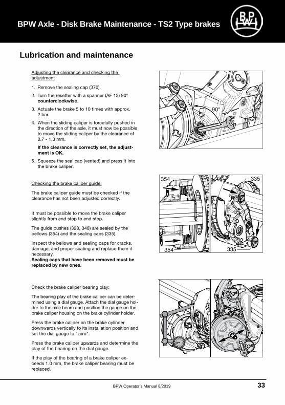
Adjusting the clearance and checking the
adjustment
1. Remove the sealing cap (370).
2. Turn the resetter with a spanner (AF 13) 90°
counterclockwise.
3. Actuate the brake 5 to 10 times with approx.
2 bar.
4. When the sliding caliper is forcefully pushed in
the direction of the axle, it must now be possible
to move the sliding caliper by the clearance of
0.7 - 1.3 mm.
If the clearance is correctly set, the adjust-
ment is OK.
5. Squeeze the seal cap (vented) and press it into
the brake caliper.
Checking the brake caliper guide:
The brake caliper guide must be checked if the
clearance has not been adjusted correctly.
It must be possible to move the brake caliper
slightly from end stop to end stop.
The guide bushes (328, 348) are sealed by the
bellows (354) and the sealing caps (335).
Inspect the bellows and sealing caps for cracks,
damage, and proper seating and replace them if
necessary.
Sealing caps that have been removed must be
replaced by new ones.
Check the brake caliper bearing play:
The bearing play of the brake caliper can be deter-
mined using a dial gauge. Attach the dial gauge hol-
der to the axle beam and position the gauge on the
brake caliper housing on the brake cylinder holder.
Press the brake caliper on the brake cylinder
downwards vertically to its installation position and
set the dial gauge to "zero".
Press the brake caliper upwards and determine the
play of the bearing on the dial gauge.
If the play of the bearing of a brake caliper ex-
ceeds 1.0 mm, the brake caliper bearing must be
replaced.
90°
Lubrication and maintenance
BPW Operator’s Manual 8/201934
BPW Operator’s Manual
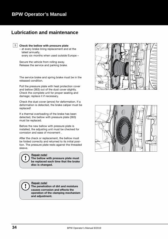
5 Check the bellow with pressure plate
– at every brake lining replacement and at the
latest annually,
every six months when used outside Europe –
Secure the vehicle from rolling away.
Release the service and parking brake.
The service brake and spring brake must be in the
released condition.
Pull the pressure plate with heat protection cover
and bellow (363) out of the dust cover slightly.
Check the complete unit for proper seating and
damage; replace it if necessary.
Check the dust cover (arrow) for deformation. If a
deformation is detected, the brake caliper must be
replaced!
If a thermal overloading of the brake has been
detected, the bellow with pressure plate (363)
must be replaced.
Before the new bellow with pressure plate is
installed, the adjusting unit must be checked for
corrosion and ease of movement .
After the check or replacement, the bellow must
be folded correctly and returned to its initial posi-
tion. The pressure plate rests against the threaded
sleeve.
Repair note!
The bellow with pressure plate must
be replaced each time that the brake
disc is changed.
Repair note!
The penetration of dirt and moisture
causes corrosion and effects theoperation of the clamping mechanism
and adjustment.
363
Lubrication and maintenance
BPW Operator’s Manual 8/2019 35
BPW Axle - Disk Brake Maintenance - TS2 Type brakes
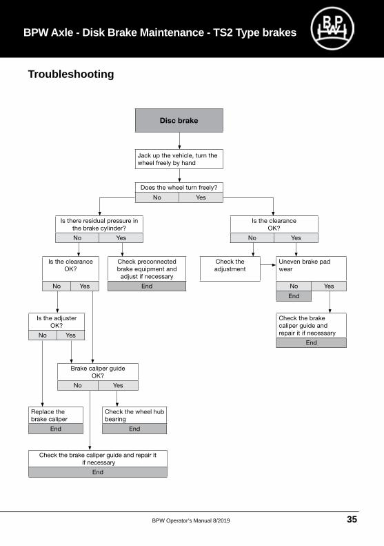
Disc brake
Jack up the vehicle, turn the
wheel freely by hand
Does the wheel turn freely?
No Yes
Is the clearance
OK?
No Yes
Is there residual pressure in
the brake cylinder?
No Yes
Check the
adjustment
Uneven brake pad
wear
No Yes
End
Check the brake
caliper guide and
repair it if necessary
End
Check preconnected
brake equipment and
adjust if necessary
End
Is the clearance
OK?
No Yes
Is the adjuster
OK?
No Yes
Brake caliper guide
OK?
No Yes
Replace the
brake caliper
End
Check the wheel hub
bearing
End
Check the brake caliper guide and repair it
if necessary
End
Troubleshooting
BPW Operator’s Manual 8/201936
BPW Operator’s Manual
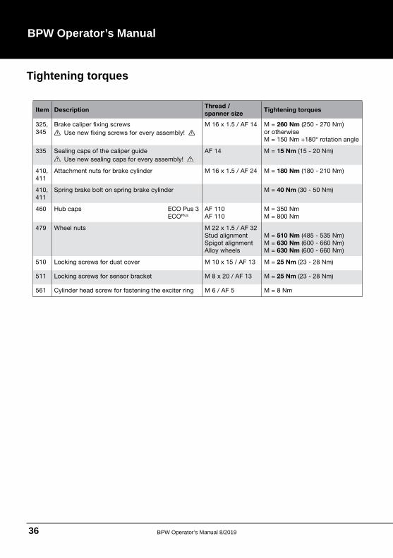
Item DescriptionThread /
spanner sizeTightening torques
325,
345
Brake caliper fixing screws
Use new fixing screws for every assembly!
M 16 x 1.5 / AF 14 M = 260 Nm (250 - 270 Nm)
or otherwise
M = 150 Nm +180° rotation angle
335 Sealing caps of the caliper guide
Use new sealing caps for every assembly!
AF 14 M = 15 Nm (15 - 20 Nm)
410,
411
Attachment nuts for brake cylinder M 16 x 1.5 / AF 24 M = 180 Nm (180 - 210 Nm)
410,
411
Spring brake bolt on spring brake cylinder M = 40 Nm (30 - 50 Nm)
460 Hub caps ECO Pus 3
ECOPlus
AF 110
AF 110
M = 350 Nm
M = 800 Nm
479 Wheel nuts M 22 x 1.5 / AF 32
Stud alignment
Spigot alignment
Alloy wheels
M = 510 Nm (485 - 535 Nm)
M = 630 Nm (600 - 660 Nm)
M = 630 Nm (600 - 660 Nm)
510 Locking screws for dust cover M 10 x 15 / AF 13 M = 25 Nm (23 - 28 Nm)
511 Locking screws for sensor bracket M 8 x 20 / AF 13 M = 25 Nm (23 - 28 Nm)
561 Cylinder head screw for fastening the exciter ring M 6 / AF 5 M = 8 Nm
Tightening torques
BPW Operator’s Manual 8/2019 37
BPW Axle - Disk Brake Maintenance - TS2 Type brakes
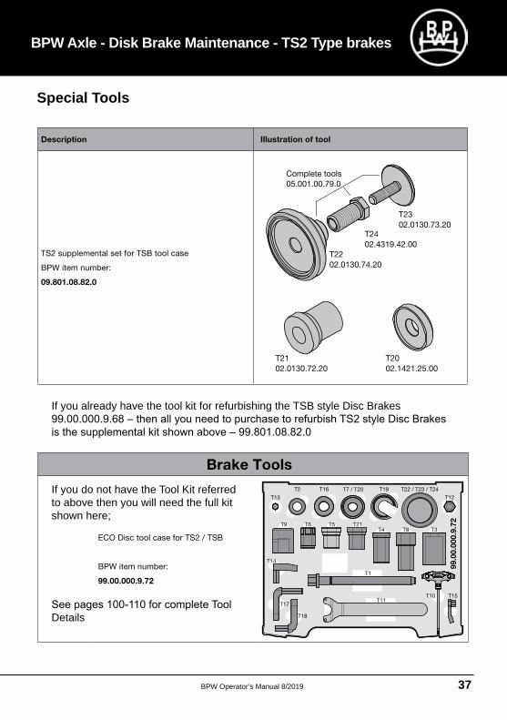
Description Illustration of tool
TS2 supplemental set for TSB tool case
BPW item number:
09.801.08.82.0
T21
02.0130.72.20
T20
02.1421.25.00
T23
02.0130.73.20
05.001.00.79.0
T24
02.4319.42.00
T22
02.0130.74.20
Complete tools
If you already have the tool kit for refurbishing the TSB style Disc Brakes
ECO Disc tool case for TS2 / TSB
BPW item number:
99.00.000.9.72
T19
T13
T2 T16 T7 / T20
T12
T21T6 T5T4
T22 / T23 / T24
T8 T3
T14
T1
T10 T15T11
T17
T18
T9
99.0
0.0
00.9
.72
Brake Tools
If you do not have the Tool Kit referred to above then you will need the full kit shown here;
Details
Special Tools
BPW Operator’s Manual 8/201938
BPW Operator’s Manual
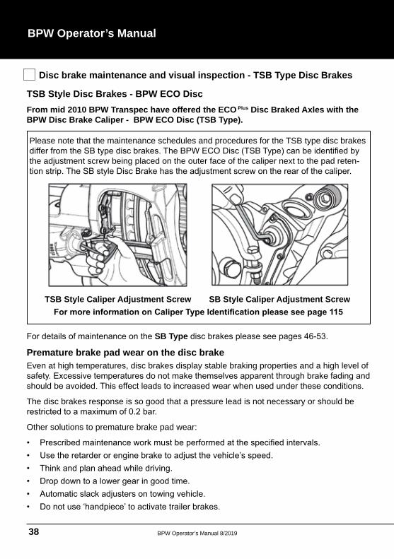
Disc brake maintenance and visual inspection - TSB Type Disc Brakes
TSB Style Disc Brakes - BPW ECO Disc From mid 2010 BPW Transpec have offered the ECO Plus Disc Braked Axles with the BPW Disc Brake Caliper - BPW ECO Disc (TSB Type).
Please note that the maintenance schedules and procedures for the TSB type disc brakes
the adjustment screw being placed on the outer face of the caliper next to the pad reten
TSB Style Caliper Adjustment Screw SB Style Caliper Adjustment Screw
SB Type
Premature brake pad wear on the disc brake Even at high temperatures, disc brakes display stable braking properties and a high level of
The disc brakes response is so good that a pressure lead is not necessary or should be
Other solutions to premature brake pad wear:
BPW Operator’s Manual 8/2019 39
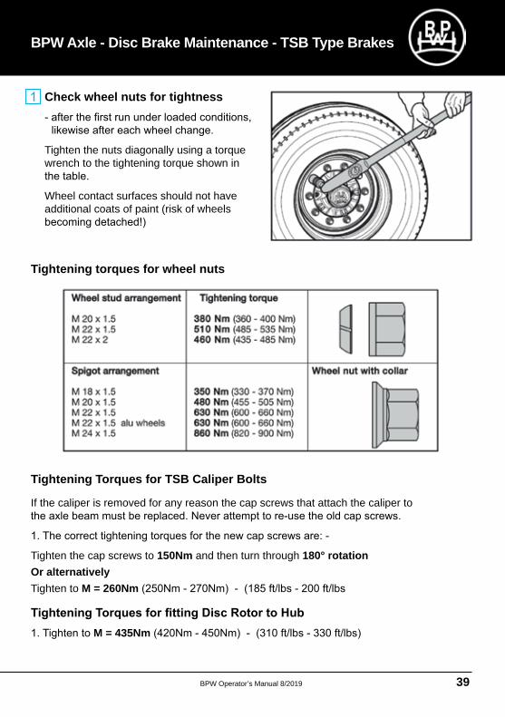
Check wheel nuts for tightness
Tighten the nuts diagonally using a torque wrench to the tightening torque shown in
Wheel contact surfaces should not have additional coats of paint (risk of wheels
BPW Axle - Disc Brake Maintenance - TSB Type Brakes
Tightening torques for wheel nuts
Tightening Torques for TSB Caliper Bolts
If the caliper is removed for any reason the cap screws that attach the caliper to
Tighten the cap screws to 150Nm and then turn through 180° rotation Or alternativelyTighten to M = 260Nm
M = 435Nm
BPW Operator’s Manual 8/201940
BPW Operator’s Manual
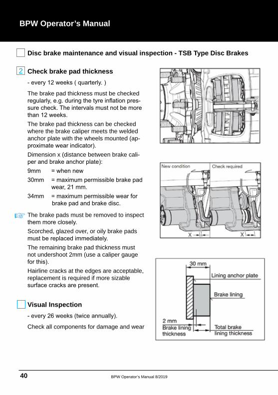
Disc brake maintenance and visual inspection - TSB Type Disc Brakes
Check brake pad thickness
The brake pad thickness must be checked
The brake pad thickness can be checked where the brake caliper meets the welded anchor plate with the wheels mounted (ap
Dimension x (distance between brake cali
The brake pads must be removed to inspect
Scorched, glazed over, or oily brake pads
The remaining brake pad thickness must not undershoot 2mm (use a caliper gauge
Hairline cracks at the edges are acceptable, replacement is required if more sizable
Visual Inspection
Check all components for damage and wear
2
BPW Operator’s Manual 8/2019 41
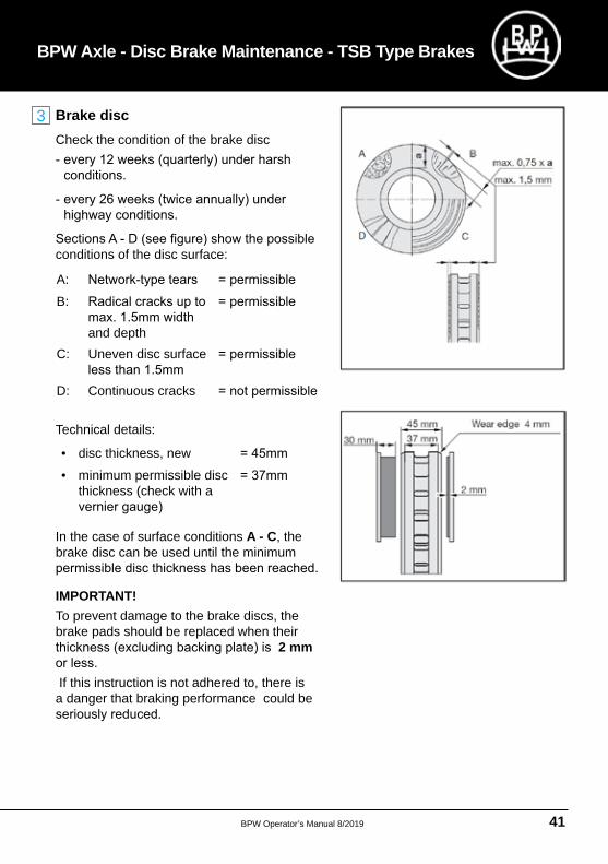
Brake disc Check the condition of the brake disc
conditions of the disc surface:
Technical details:
BPW Axle - Disc Brake Maintenance - TSB Type Brakes
A:
B:
and depthC: Uneven disc surface
D: Continuous cracks
• disc thickness, new
• minimum permissible disc thickness (check with a
In the case of surface conditions A - C, the brake disc can be used until the minimum
IMPORTANT! To prevent damage to the brake discs, the brake pads should be replaced when their
2 mm
If this instruction is not adhered to, there is a danger that braking performance could be
3
BPW Operator’s Manual 8/201942
BPW Operator’s Manual
Disc brake maintenance and visual inspection - TSB Type Disc Brakes
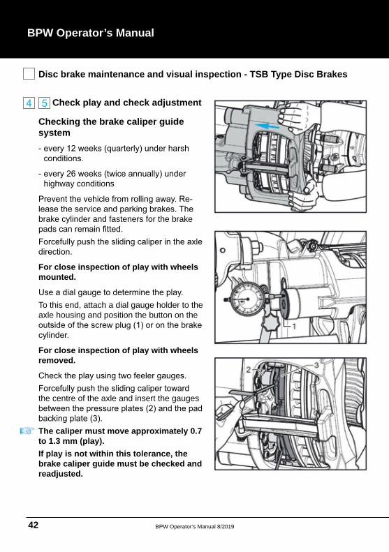
Check play and check adjustment
Checking the brake caliper guide system
highway conditions
brake cylinder and fasteners for the brake
For close inspection of play with wheels mounted.
To this end, attach a dial gauge holder to the axle housing and position the button on the
For close inspection of play with wheels removed.
the centre of the axle and insert the gauges
The caliper must move approximately 0.7 to 1.3 mm (play). If play is not within this tolerance, the brake caliper guide must be checked and readjusted.
BPW Operator’s Manual 8/2019 43
BPW Axle - Disc Brake Maintenance - TSB Type Brakes
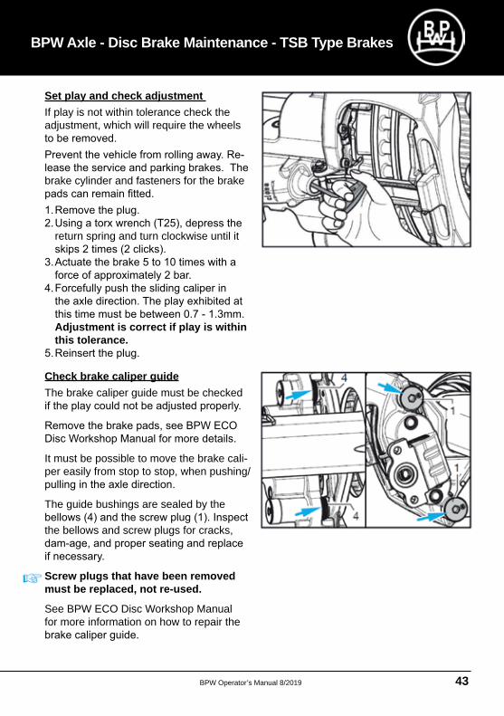
Set play and check adjustment If play is not within tolerance check the adjustment, which will require the wheels
brake cylinder and fasteners for the brake
return spring and turn clockwise until it
Adjustment is correct if play is within this tolerance.
Check brake caliper guideThe brake caliper guide must be checked
It must be possible to move the brake caliper easily from stop to stop, when pushing/
The guide bushings are sealed by the
the bellows and screw plugs for cracks,
Screw plugs that have been removed must be replaced, not re-used.
See BPW ECO Disc Workshop Manual for more information on how to repair the
BPW Operator’s Manual 8/201944
BPW Operator’s Manual
Disc brake maintenance and visual inspection - TSB Type Brakes
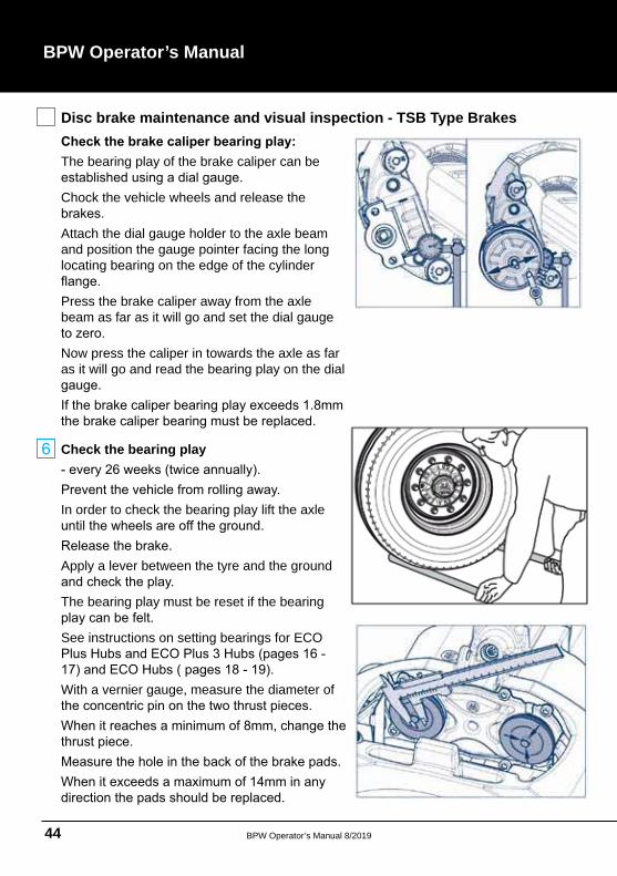
The bearing play of the brake caliper can be
Chock the vehicle wheels and release the
Attach the dial gauge holder to the axle beam and position the gauge pointer facing the long locating bearing on the edge of the cylinder
Press the brake caliper away from the axle beam as far as it will go and set the dial gauge
Now press the caliper in towards the axle as far as it will go and read the bearing play on the dial
Check the bearing play
In order to check the bearing play lift the axle
Apply a lever between the tyre and the ground
The bearing play must be reset if the bearing
See instructions on setting bearings for ECO
With a vernier gauge, measure the diameter of
BPW Operator’s Manual 8/2019 45
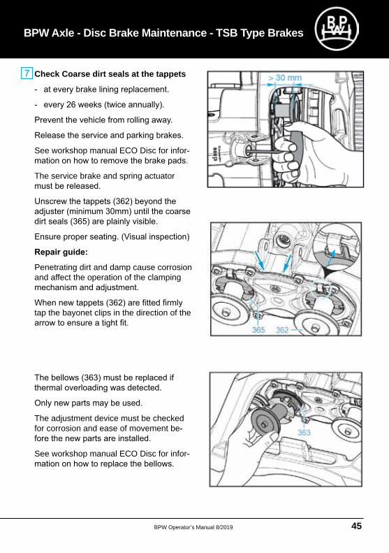
Check Coarse dirt seals at the tappets
See workshop manual ECO Disc for infor
The service brake and spring actuator
Penetrating dirt and damp cause corrosion and affect the operation of the clamping
tap the bayonet clips in the direction of the
The adjustment device must be checked for corrosion and ease of movement be
See workshop manual ECO Disc for infor
BPW Axle - Disc Brake Maintenance - TSB Type Brakes
BPW Operator’s Manual 8/201946
BPW Operator’s Manual
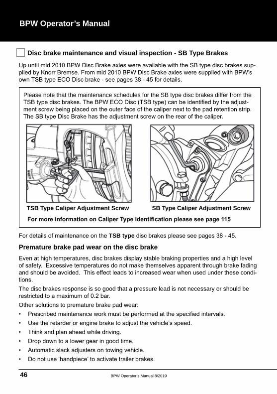
Disc brake maintenance and visual inspection - SB Type Brakes
Please note that the maintenance schedules for the SB type disc brakes differ from the
TSB Type Caliper Adjustment Screw SB Type Caliper Adjustment Screw
TSB type
Premature brake pad wear on the disc brake
Even at high temperatures, disc brakes display stable braking properties and a high level
The disc brakes response is so good that a pressure lead is not necessary or should be
Other solutions to premature brake pad wear:
BPW Operator’s Manual 8/2019 47
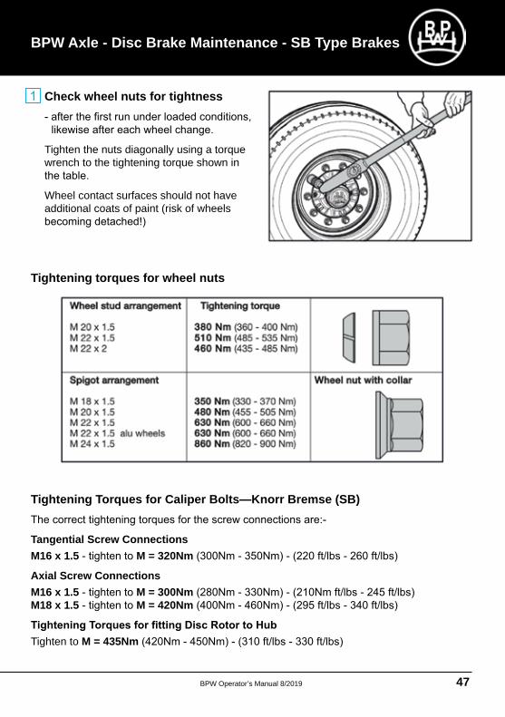
Check wheel nuts for tightness
Tighten the nuts diagonally using a torque wrench to the tightening torque shown in
Wheel contact surfaces should not have additional coats of paint (risk of wheels
Tightening torques for wheel nuts
Tightening Torques for Caliper Bolts—Knorr Bremse (SB)
Tangential Screw Connections M16 x 1.5 M = 320Nm
Axial Screw Connections M16 x 1.5 M = 300NmM18 x 1.5 M = 420Nm
Tighten to M = 435Nm
BPW Axle - Disc Brake Maintenance - SB Type Brakes
BPW Operator’s Manual 8/201948
BPW Operator’s Manual
Disc brake maintenance and visual inspection - SB Type Disc Brakes
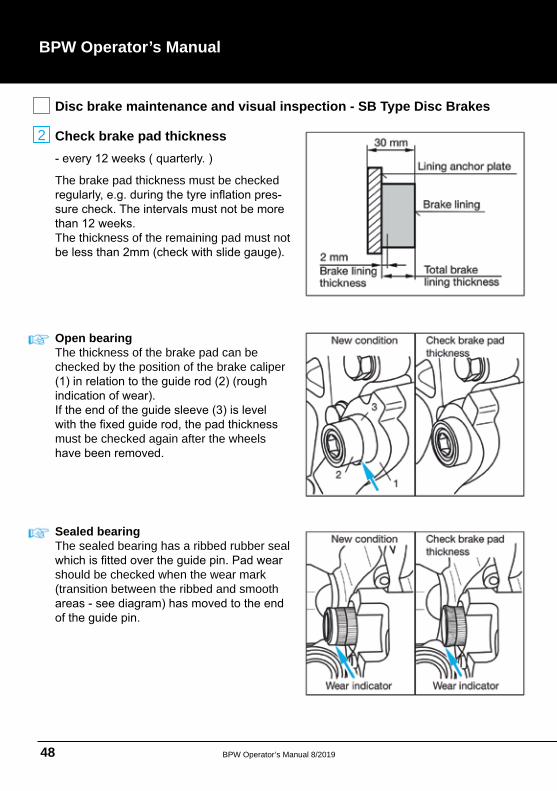
Check brake pad thickness
The brake pad thickness must be checked
The thickness of the remaining pad must not
Open bearing The thickness of the brake pad can be checked by the position of the brake caliper
must be checked again after the wheels
Sealed bearing The sealed bearing has a ribbed rubber seal
should be checked when the wear mark (transition between the ribbed and smooth
2
BPW Operator’s Manual 8/2019 49
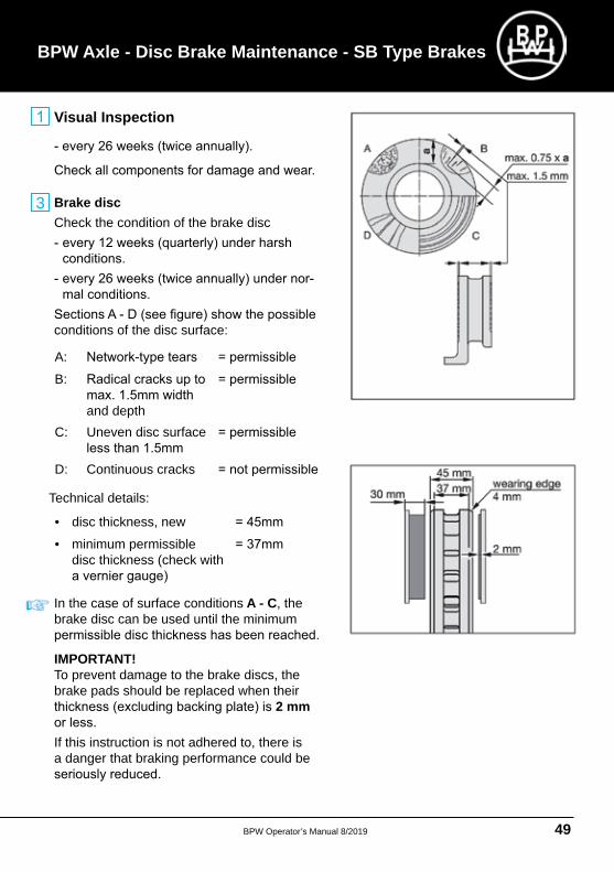
Visual Inspection
Brake disc Check the condition of the brake disc
conditions of the disc surface:
A:
B:
and depthC: Uneven disc surface
D: Continuous cracks
Technical details:
• disc thickness, new
• minimum permissible disc thickness (check with
In the case of surface conditions A - C, the brake disc can be used until the minimum
IMPORTANT! To prevent damage to the brake discs, the brake pads should be replaced when their
2 mm
If this instruction is not adhered to, there is a danger that braking performance could be
BPW Axle - Disc Brake Maintenance - SB Type Brakes
3
BPW Operator’s Manual 8/201950
BPW Operator’s Manual
Disc brake maintenance and visual inspection - SB Type Disc Brakes
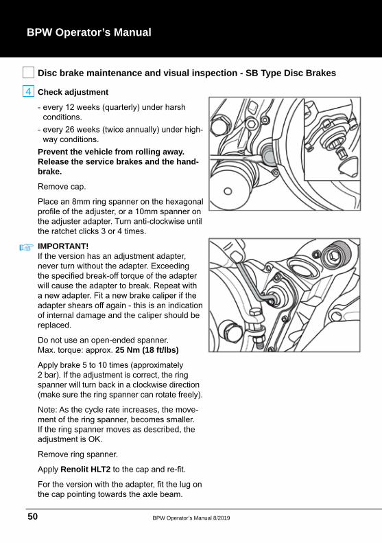
Check adjustment
Prevent the vehicle from rolling away. Release the service brakes and the hand-brake.
IMPORTANT! If the version has an adjustment adapter,
of internal damage and the caliper should be
25 Nm (18 ft/lbs)
spanner will turn back in a clockwise direction
Note: As the cycle rate increases, the move
If the ring spanner moves as described, the
Apply Renolit HLT2
BPW Operator’s Manual 8/2019 51
The adjuster or the ring spanner:
application,the adjustment is not correct and the brake
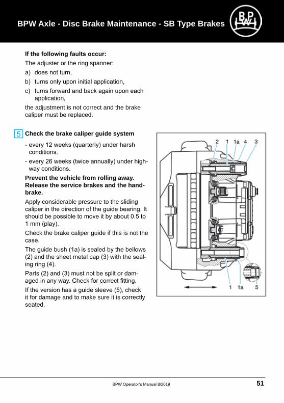
Check the brake caliper guide system
Prevent the vehicle from rolling away. Release the service brakes and the hand-brake.Apply considerable pressure to the sliding
Check the brake caliper guide if this is not the
it for damage and to make sure it is correctly
BPW Axle - Disc Brake Maintenance - SB Type Brakes
BPW Operator’s Manual 8/201952
BPW Operator’s Manual
Disc brake maintenance and visual inspection - SB Type Disc Brakes
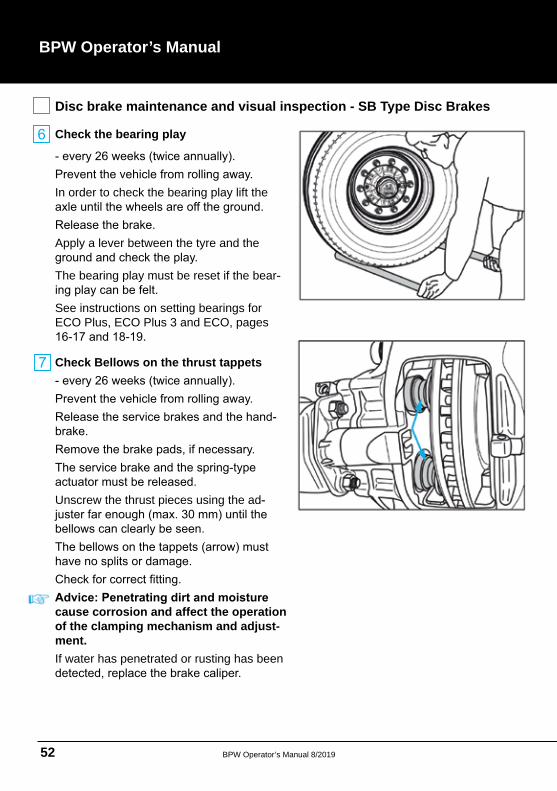
Check the bearing play
In order to check the bearing play lift the
Apply a lever between the tyre and the
The bearing play must be reset if the bear
See instructions on setting bearings for ECO Plus, ECO Plus 3 and ECO, pages
Check Bellows on the thrust tappets
Unscrew the thrust pieces using the ad
cause corrosion and affect the operation of the clamping mechanism and adjust-ment. If water has penetrated or rusting has been
BPW Operator’s Manual 8/2019 53
BPW Axle - Notes
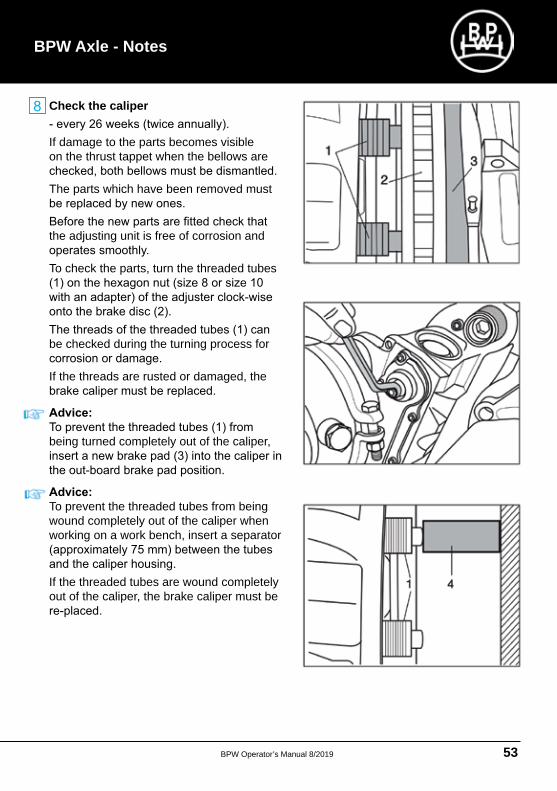
Check the caliper
If damage to the parts becomes visible on the thrust tappet when the bellows are
The parts which have been removed must
the adjusting unit is free of corrosion and
To check the parts, turn the threaded tubes
be checked during the turning process for
If the threads are rusted or damaged, the
being turned completely out of the caliper,
To prevent the threaded tubes from being wound completely out of the caliper when working on a work bench, insert a separator
If the threaded tubes are wound completely out of the caliper, the brake caliper must be
BPW Operator’s Manual 8/201954
BPW Operator’s Manual
Airbag suspension maintenance and visual inspection
Visual inspection
Check all airbag suspension component
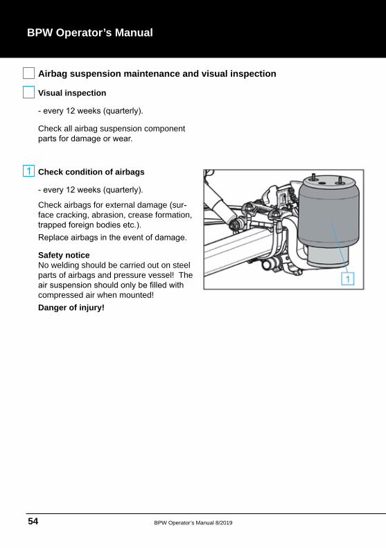
Check condition of airbags
Check airbags for external damage (surface cracking, abrasion, crease formation,
Safety notice No welding should be carried out on steel parts of airbags and pressure vessel! The
compressed air when mounted! Danger of injury!
BPW Operator’s Manual 8/2019 55
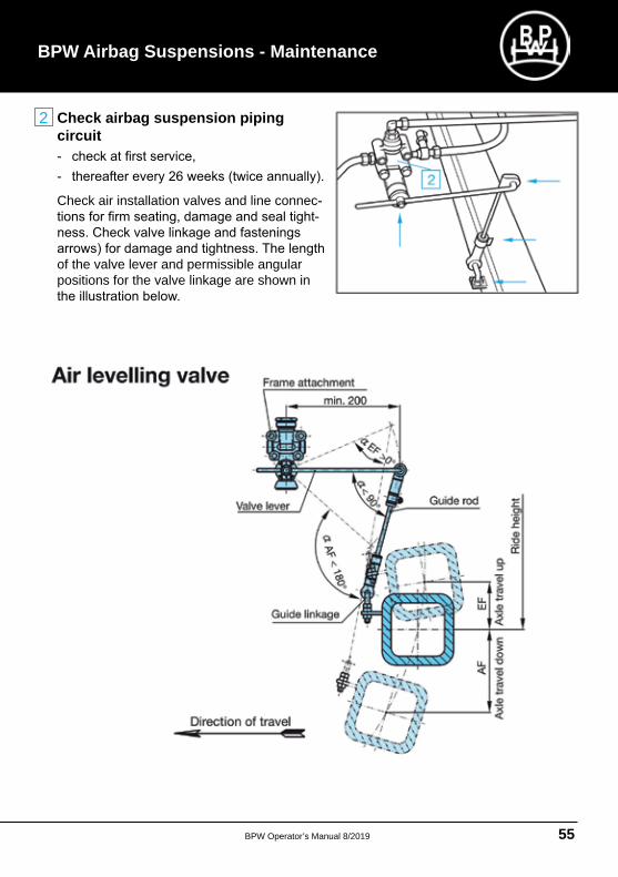
Check airbag suspension piping circuit
Check air installation valves and line connec
of the valve lever and permissible angular positions for the valve linkage are shown in
BPW Airbag Suspensions - Maintenance
2
BPW Operator’s Manual 8/201956
BPW Operator’s Manual
Airbag suspension maintenance and visual inspection
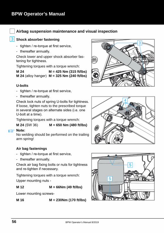
Shock absorber fastening
Check lower and upper shock absorber fas
Tightening torques with a torque wrench: M 24 M = 425 Nm (315 ft/lbs) M 24 M = 325 Nm (240 ft/lbs)
U-bolts
If loose, tighten nuts to the prescribed torque
Tightening torques with a torque wrench:M 24 M = 650 Nm (480 ft/lbs)
No welding should be performed on the trailing arm spring!
Air bag fastenings
Tightening torques with a torque wrench:
M 12 M = 66Nm (49 ft/lbs)
M 16 M = 230Nm (170 ft/lbs)
3
BPW Operator’s Manual 8/2019 57
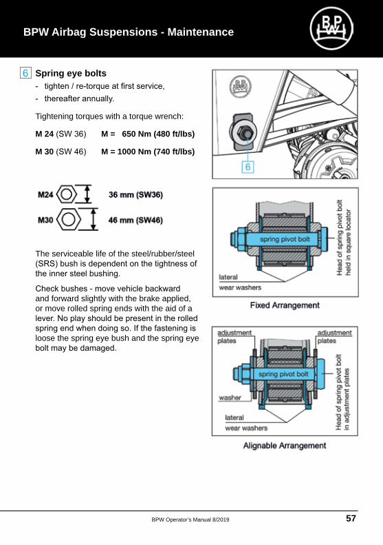
Spring eye bolts
Tightening torques with a torque wrench:
M 24 M = 650 Nm (480 ft/lbs)
M 30 M = 1000 Nm (740 ft/lbs)
The serviceable life of the steel/rubber/steel
and forward slightly with the brake applied, or move rolled spring ends with the aid of a
loose the spring eye bush and the spring eye
BPW Airbag Suspensions - Maintenance
BPW Operator’s Manual 8/201958
BPW Operator’s Manual
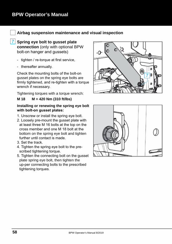
Airbag suspension maintenance and visual inspection
Spring eye bolt to gusset plate connection (only with optional BPW
gusset plates on the spring eye bolts are
Tightening torques with a torque wrench: M 18 M = 420 Nm (310 ft/lbs)
Installing or renewing the spring eye bolt
bottom on the spring eye bolt and tighten
plate spring eye bolt, then tighten the
BPW Operator’s Manual 8/2019 59
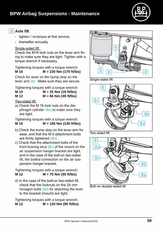
Axle lift
Tightening torques with a torque wrench:M 16 M = 230 Nm (170 ft/lbs)Check for wear on the bump stop on the lever arm
Tightening torques with a torque wrench: M 10 M = 25 Nm (18 ft/lbs) M 12 M = 66 Nm (49 ft/lbs)
phragm cylinder to make sure they
Tightening torques with a torque wrench:M 16 M = 195 Nm (145 ft/lbs)
front bracing strut of the mount on the air suspension hanger bracket are tight,
lift, the bolted connection on the air sus
Tightening torques with a torque wrench:M 12 M = 75 Nm (55 ft/lbs)
hexagon bolts for attaching the lever
Tightening torques with a torque wrench: M 12 M = 120 Nm (90 ft/lbs)
BPW Airbag Suspensions - Maintenance
BPW Operator’s Manual 8/201960
BPW Operator’s Manual
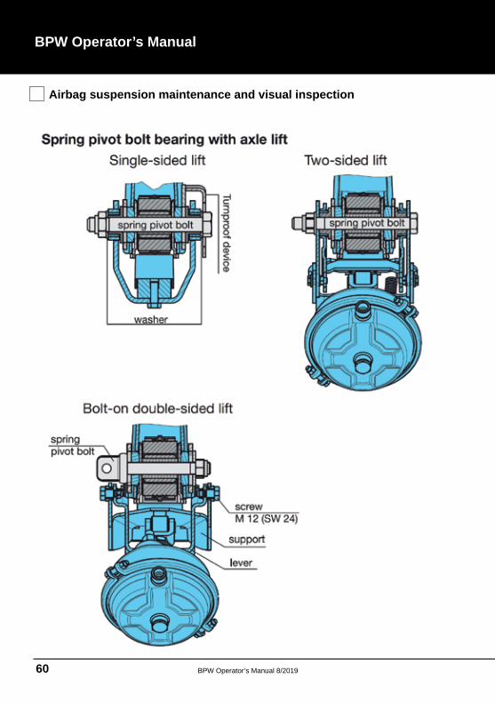
Airbag suspension maintenance and visual inspection
BPW Operator’s Manual 8/2019 61
BPW Airbag Suspensions - Maintenance
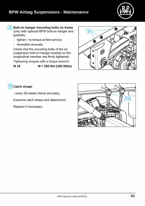
Bolt-on hanger mounting bolts on frame
Check that the mounting bolts of the air
Tightening torques with a torque wrench: M 16 M = 260 Nm (195 ft/lbs)
Catch straps
BPW Operator’s Manual 8/201962
BPW Operator’s Manual
BPW Axle Lift Systems
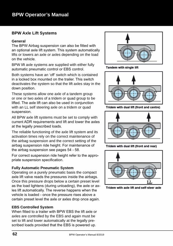
General
lifts or lowers an axle or axles depending on the load
BPW lift axle systems are supplied with either fully
Both systems have an ‘off’ switch which is contained
deactivates the system so that the lift axles stay in the
These systems allow one axle of a tandem group or one or two axles of a tridem or quad group to be
with an LL self steering axle on a tridem or quad
All BPW axle lift systems must be set to comply with
The reliable functioning of the axle lift system and its activation times rely on the correct maintenance of the airbag suspension and the correct setting of the
Fully Automatic Pneumatic System Operating on a purely pneumatic basis the compact
Once this pressure drops below a certain preset level
EBS Controlled System
axles are controlled by the EBS and again must be set to lift and lower automatically at the legally pre
BPW Operator’s Manual 8/2019 63
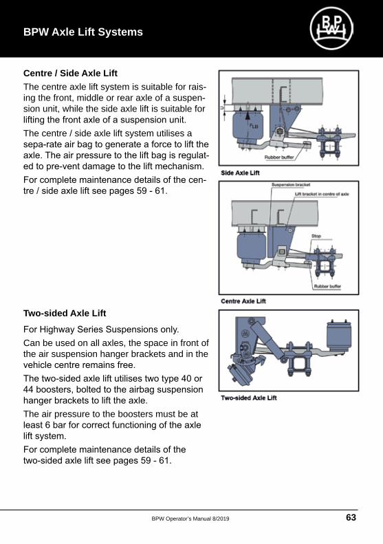
Centre / Side Axle Lift The centre axle lift system is suitable for raising the front, middle or rear axle of a suspension unit, while the side axle lift is suitable for
The centre / side axle lift system utilises a
Two-sided Axle Lift
Can be used on all axles, the space in front of the air suspension hanger brackets and in the
The air pressure to the boosters must be at
BPW Axle Lift Systems
BPW Operator’s Manual 8/201964
BPW Operator’s Manual
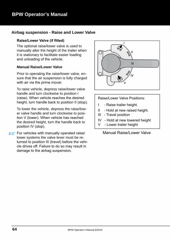
The optional raise/lower valve is used to manually alter the height of the trailer when it is stationary to facilitate easier loading
Manual Raise/Lower Valve
Prior to operating the raise/lower valve, ensure that the air suspension is fully charged
To raise vehicle, depress raise/lower valve handle and turn clockwise to position I
To lower the vehicle, depress the raise/lower valve handle and turn clockwise to posi
the desired height, turn the handle back to
lower systems the valve lever must be re
Airbag suspension - Raise and Lower Valve
BPW Operator’s Manual 8/2019 65
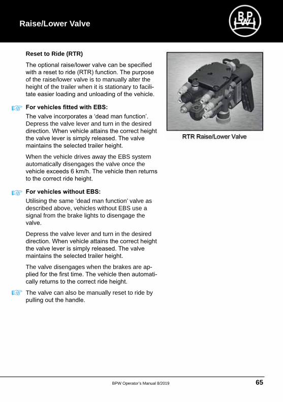
Reset to Ride (RTR)
of the raise/lower valve is to manually alter the height of the trailer when it is stationary to facili
Depress the valve lever and turn in the desired
When the vehicle drives away the EBS system automatically disengages the valve once the
Utilising the same ’dead man function’ valve as described above, vehicles without EBS use a signal from the brake lights to disengage the
Depress the valve lever and turn in the desired
The valve disengages when the brakes are ap
The valve can also be manually reset to ride by
Raise/Lower Valve
BPW Operator’s Manual 8/201966
BPW Operator’s Manual
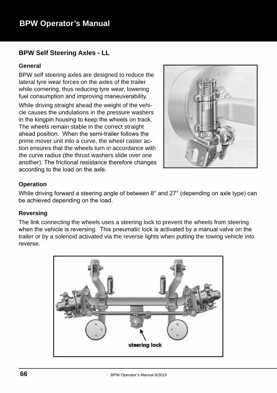
BPW Self Steering Axles - LL
General BPW self steering axles are designed to reduce the lateral tyre wear forces on the axles of the trailer while cornering, thus reducing tyre wear, lowering
While driving straight ahead the weight of the vehicle causes the undulations in the pressure washers
The wheels remain stable in the correct straight
prime mover unit into a curve, the wheel caster action ensures that the wheels turn in accordance with the curve radius (the thrust washers slide over one
Operation
Reversing The link connecting the wheels uses a steering lock to prevent the wheels from steering
trailer or by a solenoid activated via the reverse lights when putting the towing vehicle into
BPW Operator’s Manual 8/2019 67
Service and Inspection• The BPW LL self steering axle utilises
standard BPW hub units, braking systems
tions of this book for the relevant maintenance instructions for hub units, braking
• Ensure that the kingpins are properly
use of a high pressure central lubrication system which is capable of feeding special
not permitted!
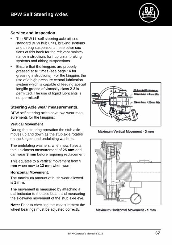
Steering Axle wear measurements. BPW self steering axles have two wear measurements for the kingpins:
Vertical Movement During the steering operation the stub axle moves up and down as the stub axle rotates
The undulating washers, when new, have a total thickness measurement of 25 mm and can wear 3 mm
This equates to a vertical movement from 9 mm when new to 12 mm
Horizontal Movement. The maximum amount of bush wear allowed is 1 mm.
The movement is measured by attaching a dial indicator to the axle beam and measuring
Prior to checking this measurement the
BPW Self Steering Axles
BPW Operator’s Manual 8/201968
BPW Operator’s Manual
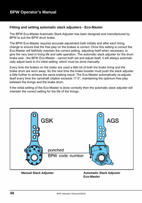
Fitting and setting automatic slack adjusters - Eco-Master
Every time the brakes on the trailer are used a little bit of both the brake lining and the
Manual Slack Adjuster Automatic Slack Adjuster Eco-Master
BPW Operator’s Manual 8/2019 69
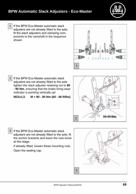
ponents to the camshaft in the sequence
tighten the slack adjuster retaining nut to 80 - 90 Nm, ensuring that the brake lining wear indicator is pointing vertically up! M22x1,5 M = 80 - 90 Nm (60 - 66 ft/lbs)
the anchor brackets and leave the nuts loose
BPW Automatic Slack Adjusters - Eco-Master
2
3
BPW Operator’s Manual 8/201970
BPW Operator’s Manual
Fitting and setting automatic slack adjusters - ECO-Master
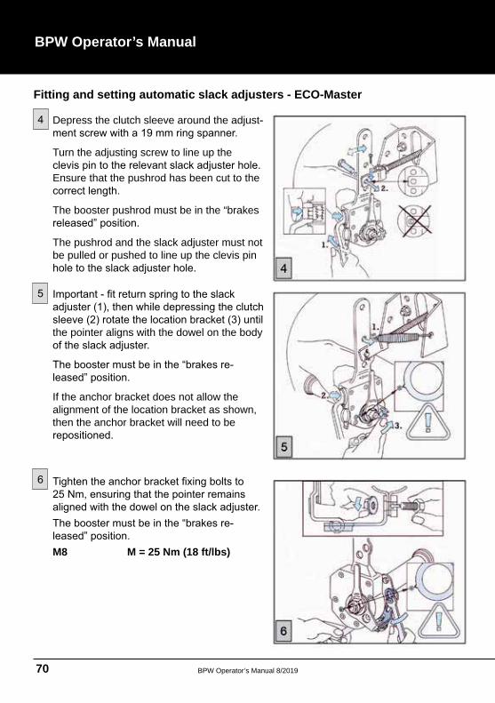
Depress the clutch sleeve around the adjust
Turn the adjusting screw to line up the
Ensure that the pushrod has been cut to the
The booster pushrod must be in the “brakes
The pushrod and the slack adjuster must not be pulled or pushed to line up the clevis pin
the pointer aligns with the dowel on the body
If the anchor bracket does not allow the alignment of the location bracket as shown, then the anchor bracket will need to be
M8 M = 25 Nm (18 ft/lbs)
BPW Operator’s Manual 8/2019 71
BPW Automatic Slack Adjusters - Eco-Master
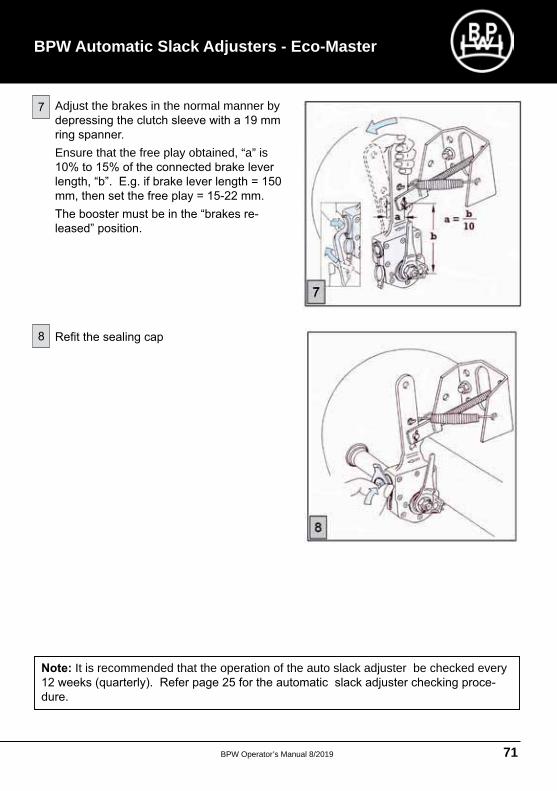
Adjust the brakes in the normal manner by
Ensure that the free play obtained, “a” is
It is recommended that the operation of the auto slack adjuster be checked every
BPW Operator’s Manual 8/201972
BPW Operator’s Manual
Fitting and Setting Digital Hubodometers A minicomputer that is protected from water and dirt counts the wheel revolutions using a magnet
the special clasp locking ring and integrated mag
The tyre rolling circumference is set initially and
Start-up / Setting the tyre rolling circumference
counting mode until the tyre rolling circumference
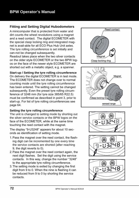
Setting the tyre rolling circumference The unit is changed to setting mode by shorting out the silver service contacts or the BPW logos on the
ing digit can be incremented by one every time the service contacts are shorted (after reaching
BPW Operator’s Manual 8/2019 73
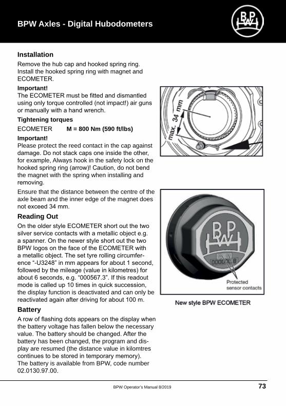
Installation
Install the hooked spring ring with magnet and
Important!
Tightening torques M = 800 Nm (590 ft/lbs)
Important!Please protect the reed contact in the cap against
for example, Always hook in the safety lock on the
the magnet with the spring when installing and
Ensure that the distance between the centre of the axle beam and the inner edge of the magnet does
Reading Out
the display function is deactivated and can only be
Battery
the battery voltage has fallen below the necessary
battery has been changed, the program and display are resumed (the distance value in kilomtres
The battery is available from BPW, code number
BPW Axles - Digital Hubodometers
BPW Operator’s Manual 8/201974
BPW Operator’s Manual
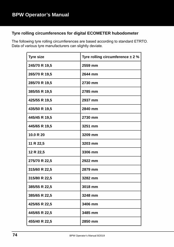
Tyre rolling circumferences for digital ECOMETER hubodometer
Tyre size Tyre rolling circumference ± 2 %
245/70 R 19,5 2559 mm
265/70 R 19,5 2644 mm
285/70 R 19,5 2730 mm
385/55 R 19,5 2785 mm
425/55 R 19,5 2937 mm
435/50 R 19,5 2840 mm
445/45 R 19,5 2730 mm
445/65 R 19,5 3251 mm
10.0 R 20 3209 mm
11 R 22,5 3203 mm
12 R 22,5 3306 mm
275/70 R 22,5 2922 mm
315/60 R 22,5 2879 mm
315/80 R 22,5 3282 mm
385/55 R 22,5 3018 mm
385/65 R 22,5 3248 mm
425/65 R 22,5 3406 mm
445/65 R 22,5 3485 mm
455/40 R 22,5 2850 mm
BPW Operator’s Manual 8/2019 75
BPW Turntables (Ball Races)
Service and maintenance
BPW special long life grease ECO-Li Plus
• The turntable bearing is to be lubricated via the grease nipples with BPW special long life grease ECO-Li Plus
• All bolted fastenings must be checked at regular intervals for tightness and tightened if
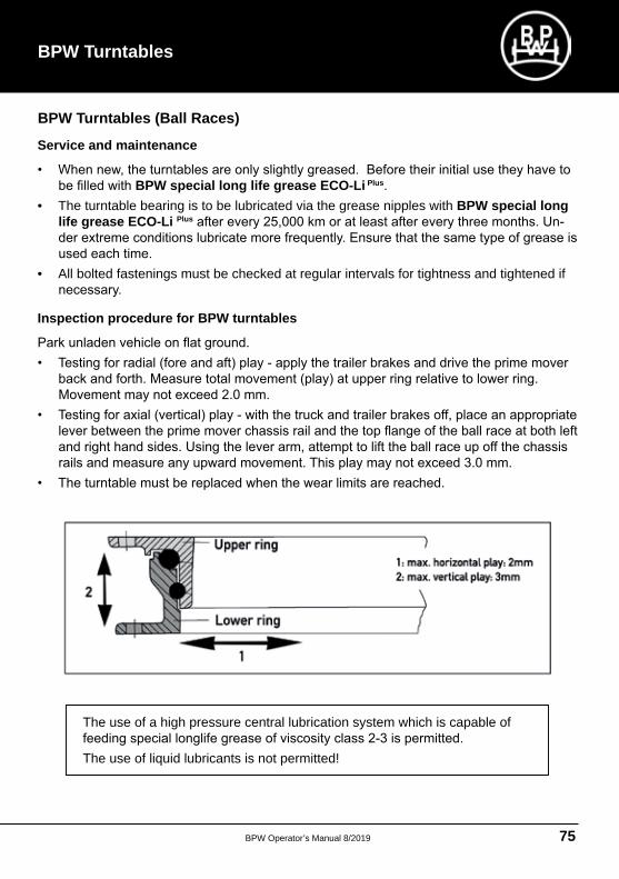
Inspection procedure for BPW turntables
The use of a high pressure central lubrication system which is capable of
The use of liquid lubricants is not permitted!
BPW Turntables
BPW Operator’s Manual 8/201976
BPW Operator’s Manual
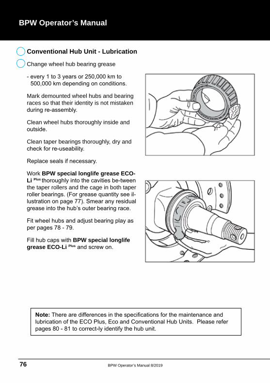
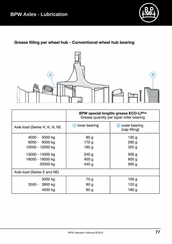
Change wheel hub bearing grease
Mark demounted wheel hubs and bearing races so that their identity is not mistaken
Clean wheel hubs thoroughly inside and
Clean taper bearings thoroughly, dry and
Work BPW special longlife grease ECO-Li Plus
the taper rollers and the cage in both taper
BPW special longlife grease ECO-Li Plus
Conventional Hub Unit - Lubrication
BPW Operator’s Manual 8/2019 77
BPW Axles - Lubrication
BPW Operator’s Manual 8/201978
BPW Operator’s Manual
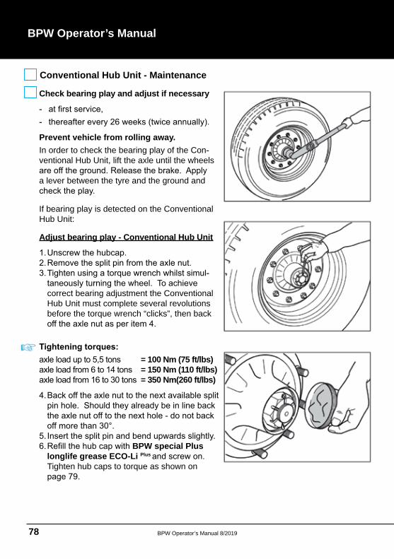
Conventional Hub Unit - Maintenance
Check bearing play and adjust if necessary
Prevent vehicle from rolling away. In order to check the bearing play of the Conventional Hub Unit, lift the axle until the wheels
a lever between the tyre and the ground and
If bearing play is detected on the Conventional Hub Unit:
Adjust bearing play - Conventional Hub Unit
correct bearing adjustment the Conventional Hub Unit must complete several revolutions before the torque wrench “clicks”, then back
= 100 Nm (75 ft/lbs)= 150 Nm (110 ft/lbs)= 350 Nm(260 ft/lbs)
BPW special Plus longlife grease ECO-Li Plus
Tighten hub caps to torque as shown on
BPW Operator’s Manual 8/2019 79
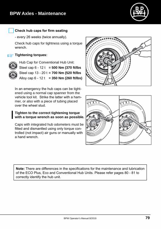
Check hub caps for tightness using a torque
Hub Cap for Conventional Hub Unit: = 500 Nm (370 ft/lbs = 700 Nm (520 ft/lbs
= 350 Nm (260 ft/lbs)
ened using a normal cap spanner from the
mer, or also with a piece of tubing placed
Tighten to the correct tightening torque with a torque wrench as soon as possible.
Caps with integrated hub odometers must be
BPW Axles - Maintenance
BPW Operator’s Manual 8/201980
BPW Operator’s Manual
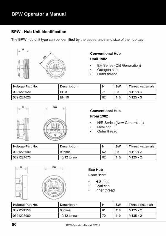
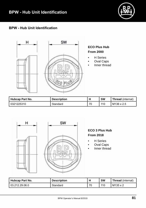
Hubcap Part No. Description H SW Thread
Hubcap Part No. Description H SW Thread
Hubcap Part No. Description H SW Thread
Conventional Hub Until 1982
• Octagon cap• Outer thread
Conventional Hub From 1982
• Oval cap• Outer thread
Eco HubFrom 1992
• H Series• Oval cap• Inner thread
BPW Operator’s Manual 8/2019 81
Hubcap Part No. Description H SW Thread Standard
Hubcap Part No. Description H SW Thread Standard
ECO Plus HubFrom 2000
• H Series• Oval Caps• Inner thread
ECO 3 Plus HubFrom 2018
• H Series• Oval Caps• Inner thread
BPW Operator’s Manual 8/201982
BPW Operator’s Manual
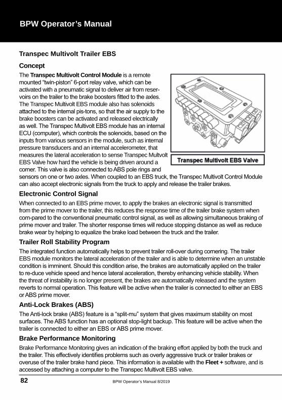
Transpec Multivolt Trailer EBS
Concept The Transpec Multivolt Control Module is a remote
activated with a pneumatic signal to deliver air from reser
The Transpec Multivolt EBS module also has solenoids
brake boosters can be activated and released electrically
inputs from various sensors in the module, such as internal pressure transducers and an internal accelerometer, that measures the lateral acceleration to sense Transpec Multvolt EBS Valve how hard the vehicle is being driven around a
Electronic Control SignalWhen connected to an EBS prime mover, to apply the brakes an electronic signal is transmitted from the prime mover to the trailer, this reduces the response time of the trailer brake system when
Trailer Roll Stability Program
EBS module monitors the lateral acceleration of the trailer and is able to determine when an unstable
the threat of instability is no longer present, the brakes are automatically released and the system
Anti-Lock Brakes (ABS)
Brake Performance Monitoring Brake Performance Monitoring gives an indication of the braking effort applied by both the truck and
Fleet + software, and is
BPW Operator’s Manual 8/2019 83
Electronic Load-Sensing
brakes when the vehicles are laden, however they are normally not very well balanced when empty
Properly adjusted Load Sensing on the trailer will not only deliver good brake feel, but also provide
Fleet + Software (Optional)The Transpec Multivolt EBS valve stores various operational parameters regarding braking and trip performance within an internal memory which can then be accessed via a laptop running the optional Fleet +Fleet + programmed laptop into the valve via the optional hardware kit and download the data for
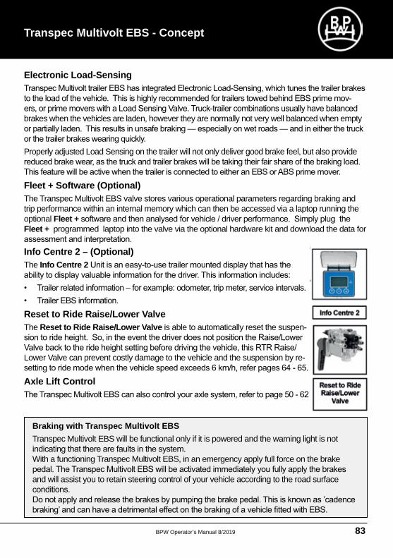
Info Centre 2 – (Optional)The Info Centre 2
Reset to Ride Raise/Lower ValveThe Reset to Ride Raise/Lower Valve is able to automatically reset the suspen
Lower Valve can prevent costly damage to the vehicle and the suspension by re
Axle Lift Control
Braking with Transpec Multivolt EBS Transpec Multivolt EBS will be functional only if it is powered and the warning light is not
With a functioning Transpec Multivolt EBS, in an emergency apply full force on the brake
and will assist you to retain steering control of your vehicle according to the road surface
Transpec Multivolt EBS - Concept
BPW Operator’s Manual 8/201984
BPW Operator’s Manual
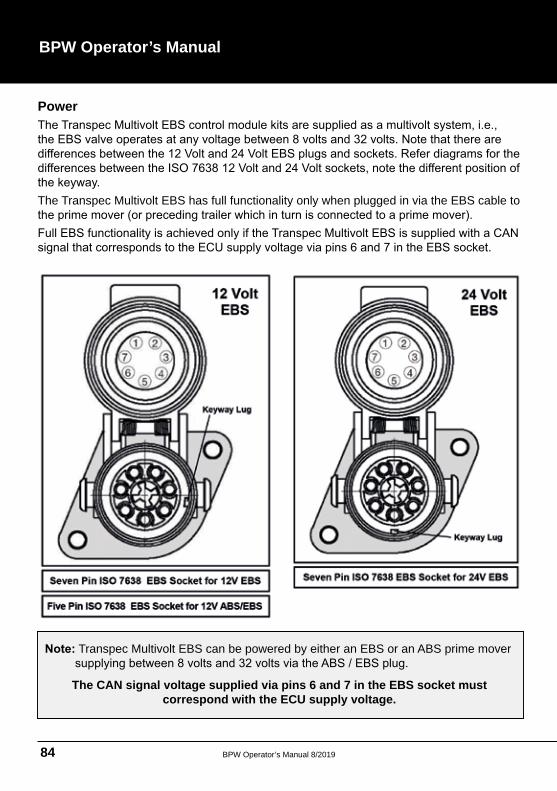
Power
The Transpec Multivolt EBS has full functionality only when plugged in via the EBS cable to
Transpec Multivolt EBS can be powered by either an EBS or an ABS prime mover
The CAN signal voltage supplied via pins 6 and 7 in the EBS socket must correspond with the ECU supply voltage.
BPW Operator’s Manual 8/2019 85
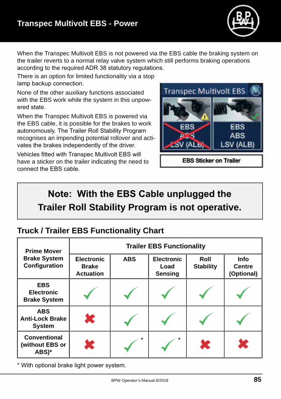
When the Transpec Multivolt EBS is not powered via the EBS cable the braking system on the trailer reverts to a normal relay valve system which still performs braking operations
There is an option for limited functionality via a stop
None of the other auxiliary functions associated with the EBS work while the system in this unpow
When the Transpec Multivolt EBS is powered via the EBS cable, it is possible for the brakes to work
recognises an impending potential rollover and acti
have a sticker on the trailer indicating the need to
Trailer Roll Stability Program is not operative.
Truck / Trailer EBS Functionality Chart
Prime Mover Brake System
Trailer EBS Functionality
Electronic Brake
Actuation
ABS Electronic Load
Sensing
Roll Stability
Info Centre
(Optional)
EBS Electronic
Brake System
ABS Anti-Lock Brake
System
Conventional (without EBS or
ABS)*
Transpec Multivolt EBS - Power
BPW Operator’s Manual 8/201986
BPW Operator’s Manual
System Diagnostics
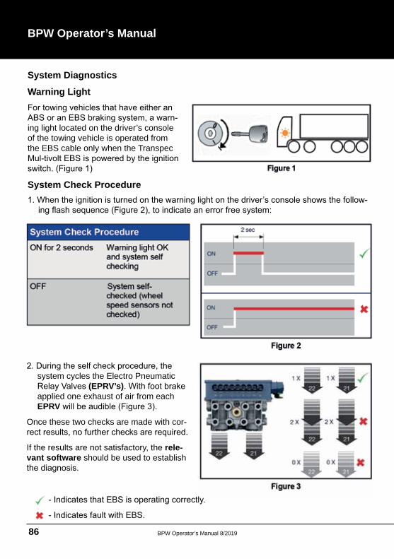
Warning Light
ing light located on the driver’s console of the towing vehicle is operated from the EBS cable only when the Transpec
System Check Procedure
system cycles the Electro Pneumatic (EPRV’s)
applied one exhaust of air from each EPRV
Once these two checks are made with cor
If the results are not satisfactory, the rele-vant software should be used to establish
BPW Operator’s Manual 8/2019 87
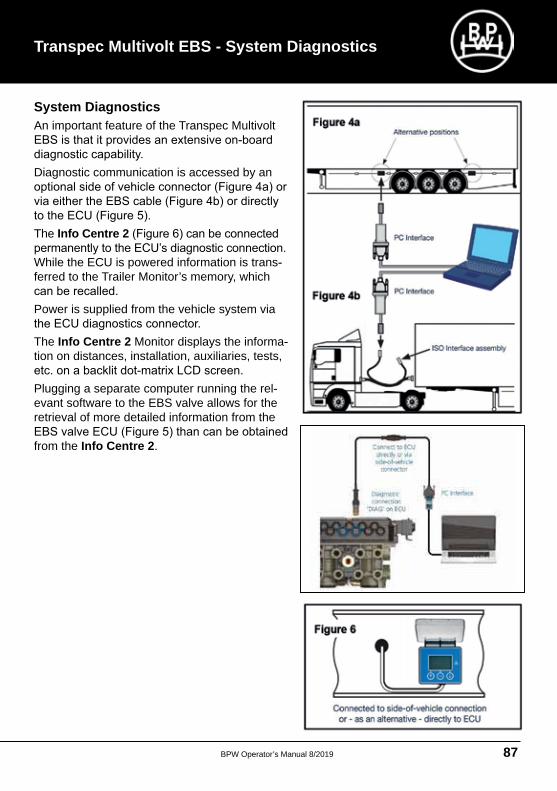
System DiagnosticsAn important feature of the Transpec Multivolt
Diagnostic communication is accessed by an
The Info Centre 2
While the ECU is powered information is transferred to the Trailer Monitor’s memory, which
Power is supplied from the vehicle system via
The Info Centre 2 Monitor displays the information on distances, installation, auxiliaries, tests,
Plugging a separate computer running the relevant software to the EBS valve allows for the retrieval of more detailed information from the
from the Info Centre 2
Transpec Multivolt EBS - System Diagnostics
BPW Operator’s Manual 8/201988
BPW Operator’s Manual
Power Up Modes
the following occurs:
With no blue line pneumatic pressure (i.e. Brakes OFF)
sensing mode is limited to 2 minutes for any single brake application, after which it returns
With blue line pneumatic pressure (i.e. Brakes ON)
Other errors shown by the warning light.The Transpec
Multivolt EBS
Service due
Non EBS Faultdirectly effecting the EBS, for example: Reset-to-Ride Valve
CautionNo welding work may be performed on the vehicle without
Installation and/or BPW Operator’s Manuals.
BPW Operator’s Manual 8/2019 89
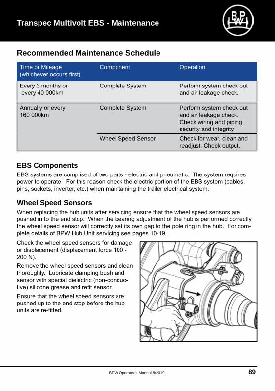
Recommended Maintenance ScheduleTime or Mileage Component Operation
Every 3 months or Complete System Perform system check out
Annually or every Complete System Perform system check out
Check wiring and piping security and integrity
Wheel Speed Sensor Check for wear, clean and
EBS Components
Wheel Speed SensorsWhen replacing the hub units after servicing ensure that the wheel speed sensors are
Check the wheel speed sensors for damage
Ensure that the wheel speed sensors are pushed up to the end stop before the hub
Transpec Multivolt EBS - Maintenance
BPW Operator’s Manual 8/201990
BPW Operator’s Manual
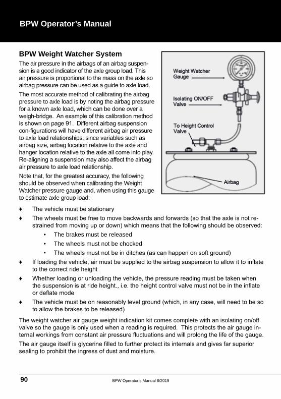
BPW Weight Watcher System The air pressure in the airbags of an airbag suspen
air pressure is proportional to the mass on the axle so
The most accurate method of calibrating the airbag pressure to axle load is by noting the airbag pressure for a known axle load, which can be done over a
to axle load relationships, since variables such as airbag size, airbag location relative to the axle and
Note that, for the greatest accuracy, the following should be observed when calibrating the Weight Watcher pressure gauge and, when using this gauge to estimate axle group load:
• The brakes must be released• The wheels must not be chocked
to the correct ride height
The weight watcher air gauge weight indication kit comes complete with an isolating on/off
BPW Operator’s Manual 8/2019 91
BPW Weight Watcher System
BPW Operator’s Manual 8/201992
BPW Operator’s Manual
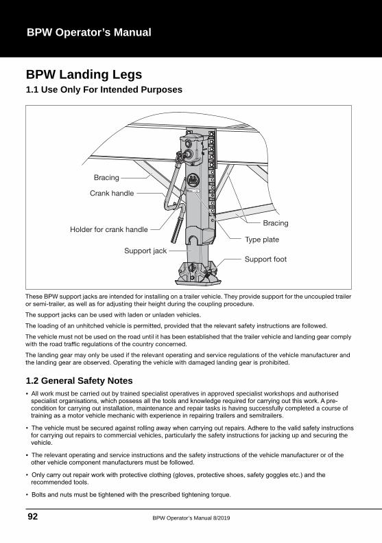
These BPW support jacks are intended for installing on a trailer vehicle. They provide support for the uncoupled trailer
or semi-trailer, as well as for adjusting their height during the coupling procedure.
The support jacks can be used with laden or unladen vehicles.
The loading of an unhitched vehicle is permitted, provided that the relevant safety instructions are followed.
The vehicle must not be used on the road until it has been established that the trailer vehicle and landing gear comply
c regulations of the country concerned.
The landing gear may only be used if the relevant operating and service regulations of the vehicle manufacturer and
the landing gear are observed. Operating the vehicle with damaged landing gear is prohibited.
BPW Landing Legs1.1 Use Only For Intended Purposes
1.2 General Safety Notes• All work must be carried out by trained specialist operatives in approved specialist workshops and authorised
condition for carrying out installation, maintenance and repair tasks is having successfully completed a course of
for carrying out repairs to commercial vehicles, particularly the safety instructions for jacking up and securing the
• The relevant operating and service instructions and the safety instructions of the vehicle manufacturer or of the
BPW Operator’s Manual 8/2019 93
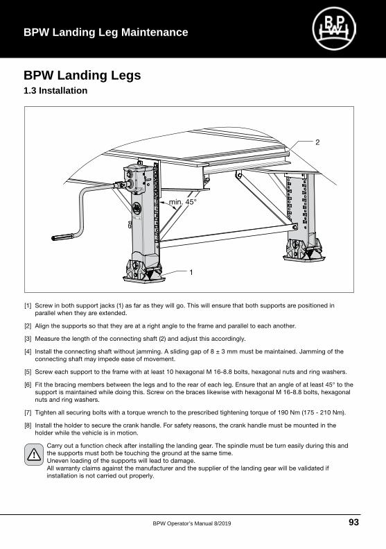
[1] Screw in both support jacks (1) as far as they will go. This will ensure that both supports are positioned in
parallel when they are extended.
[2] Align the supports so that they are at a right angle to the frame and parallel to each another.
[3] Measure the length of the connecting shaft (2) and adjust this accordingly.
[4] Install the connecting shaft without jamming. A sliding gap of 8 ± 3 mm must be maintained. Jamming of the
connecting shaft may impede ease of movement.
[5] Screw each support to the frame with at least 10 hexagonal M 16-8.8 bolts, hexagonal nuts and ring washers.
[6] Fit the bracing members between the legs and to the rear of each leg. Ensure that an angle of at least 45° to the
support is maintained while doing this. Screw on the braces likewise with hexagonal M 16-8.8 bolts, hexagonal
nuts and ring washers.
[7] Tighten all securing bolts with a torque wrench to the prescribed tightening torque of 190 Nm (175 - 210 Nm).
[8] Install the holder to secure the crank handle. For safety reasons, the crank handle must be mounted in the
holder while the vehicle is in motion.
Carry out a function check after installing the landing gear. The spindle must be turn easily during this and
the supports must both be touching the ground at the same time.
Uneven loading of the supports will lead to damage.
All warranty claims against the manufacturer and the supplier of the landing gear will be validated if
installation is not carried out properly.
BPW Landing Legs1.3 Installation
BPW Landing Leg Maintenance
BPW Operator’s Manual 8/201994
BPW Operator’s Manual
Operating safety notes
• The landing gear must only be operated by authorised personnel.
• Before operating the landing gear, the vehicle must always be secured against rolling away.
• No persons must be present beneath the vehicle during hitching and unhitching and when a vehicle is being
supported.
• No persons must be present beneath the vehicle during the coupling procedure.
• Fast or slow gear must always be engaged.
• Care must be taken to avoid handle kick-back by completing the turning
movement slowly.
• While the vehicle is in motion:
- The crank handle must be installed and mounted in the holder
- The landing gear must be completely retrected
- The landing gear must be in a proper condition, with any defective support equipment having been repaired or replaced.
• When the vehicle is being supported, care must be taken that:
rm, with a suitable base being provided if necessary.
- The ground must be even - The ground underneath is sufficiently fi
- The support foot must be freely movable
- The upper and lower hoist limiters are not overwound.
BPW Landing Legs1.4 Operation
BPW Operator’s Manual 8/2019 95
BPW Landing Leg Maintenance
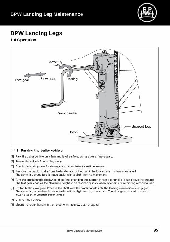
1.4.1 Parking the trailer vehicle
[1] Park the trailer vehicle on a fi rm and level surface, using a base if necessary.
[2] Secure the vehicle from rolling away.
[3] Check the landing gear for damage and repair before use if necessary.
[4] Remove the crank handle from the holder and pull out until the locking mechanism is engaged.
The switching procedure is made easier with a slight turning movement.
[5] Turn the crank handle clockwise, therefore extending the support in fast gear until it is just above the ground.
The fast gear enables the clearance height to be reached quickly when extending or retracting without a load.
[6] Switch to the slow gear. Press in the shaft with the crank handle until the locking mechanism is engaged.
The switching procedure is made easier with a slight turning movement. The slow gear is used to raise or
lower a laden or unladen trailer vehicle.
[7] Unhitch the vehicle.
[8] Mount the crank handle in the holder with the slow gear engaged.
BPW Landing Legs1.4 Operation
BPW Operator’s Manual 8/201996
BPW Operator’s Manual
1.4.2 Coupling the trailer
[1] Take the crank handle from the holder.
[2] Check whether the low gear is engaged and engage if required (see [6] page 95).
Take pressure off the crank handle slowly when the desired coupling height has been reached.
There is a danger that the handle may kick back.
[3] Turn the crank handle in slow gear:
- Clockwise: to raise
- Counter-clockwise: to lower.
[4] Raise the trailer to the desired coupling height. Leave the spindle in slow gear.
[5] Couple the trailer vehicle.
[6] After coupling, fully retract the landing gear.
[7] Mount the crank handle in the holder with slow gear engaged.
1.4.3 Loading the supported trailer vehicle
The supported trailer vehicle may only be loaded with a crane or driven onto with a fork-lift truck if the
relevant safety instructions have been complied with.
Do not exceed the centre of gravity of the vehicle during the loading procedure, otherwise the drawbar trailer
vehicle could tip over.
BPW Landing Legs1.4 Operation
BPW Operator’s Manual 8/2019 97
BPW Landing Leg Maintenance
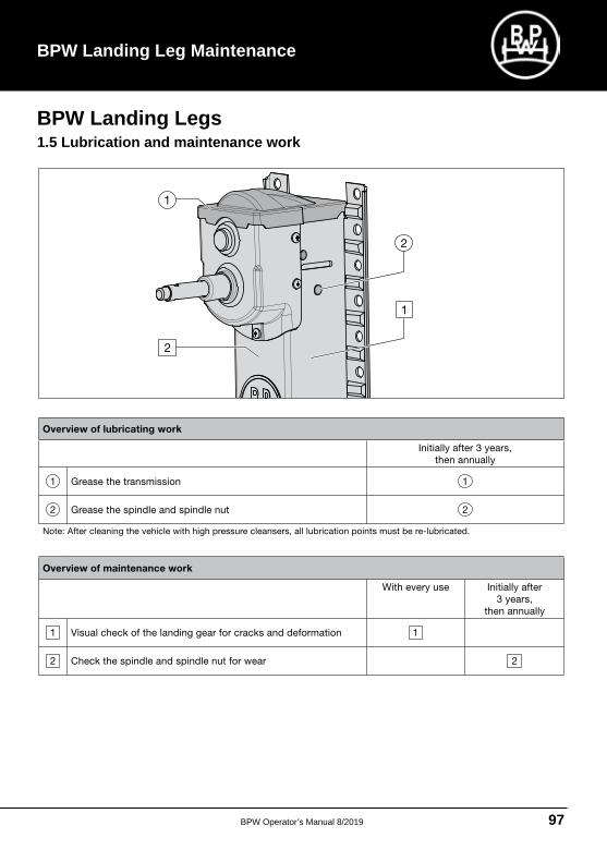
Overview of lubricating work
Initially after 3 years,
then annually
1 Grease the transmission 1
2 Grease the spindle and spindle nut 2
Note: After cleaning the vehicle with high pressure cleansers, all lubrication points must be re-lubricated.
Overview of maintenance work
With every use Initially after
3 years,
then annually
1 Visual check of the landing gear for cracks and deformation 1
2 2raew rof tun eldnips dna eldnips eht kcehC
BPW Landing Legs1.5 Lubrication and maintenance work
BPW Operator’s Manual 8/201998
BPW Operator’s Manual
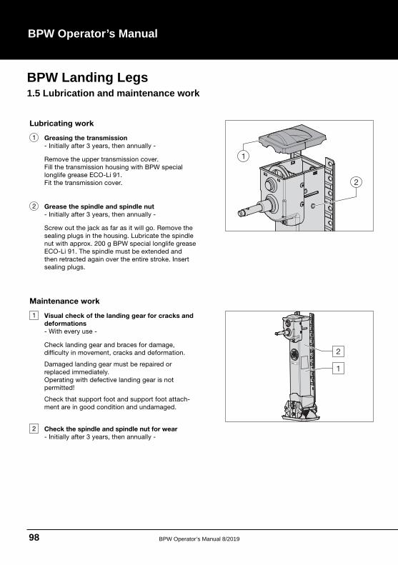
Lubricating work
1 Greasing the transmission
- Initially after 3 years, then annually -
Remove the upper transmission cover.
Fill the transmission housing with BPW special
longlife grease ECO-Li 91.
Fit the transmission cover.
2 Grease the spindle and spindle nut
- Initially after 3 years, then annually -
Screw out the jack as far as it will go. Remove the
sealing plugs in the housing. Lubricate the spindle
nut with approx. 200 g BPW special longlife grease
ECO-Li 91. The spindle must be extended and
then retracted again over the entire stroke. Insert
sealing plugs.
Maintenance work
1 Visual check of the landing gear for cracks and
deformations
- With every use -
Check landing gear and braces for damage,
difficulty in movement, cracks and deformation.
Damaged landing gear must be repaired or
replaced immediately.
Operating with defective landing gear is not
permitted!
Check that support foot and support foot attach-
ment are in good condition and undamaged.
2 Check the spindle and spindle nut for wear
- Initially after 3 years, then annually -
BPW Landing Legs1.5 Lubrication and maintenance work
BPW Operator’s Manual 8/2019 99
BPW Landing Leg Maintenance
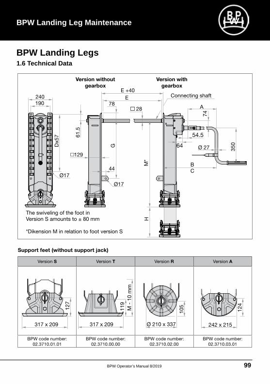
Support feet (without support jack)
Version S Version T Version R Version A
BPW code number:
02.3710.01.01
BPW code number:
02.3710.00.00
BPW code number:
02.3710.02.00
BPW code number:
02.3710.03.01
BPW Landing Legs1.6 Technical Data
BPW Operator’s Manual 8/2019100
BPW Operator’s Manual
BPW Special Tools In order to simplify the maintenance procedures on BPW axles and airbag suspensions a comprehensive range of special tools are available.
Tried and tested design
Use of high-quality materials
Favourable price/performance ratio
Long service life, low wear BPW tools are designed to be particularly resistant to wear and tear, and guar
Simple to handle
complete details please contact your local BPW Transpec BPW agent.
BPW Operator’s Manual 8/2019 101
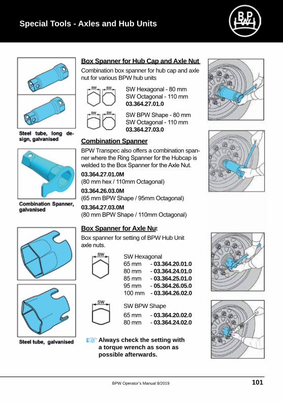
Box Spanner for Hub Cap and Axle Nut Combination box spanner for hub cap and axle nut for various BPW hub units
03.364.27.01.0
03.364.27.03.0
Combination SpannerBPW Transpec also offers a combination span
03.364.27.01.0M
03.364.26.03.0M
03.364.27.03.0M
Box Spanner for Axle Nut Box spanner for setting of BPW Hub Unit
SW Hexagonal03.364.20.01.0 03.364.24.01.0 03.364.25.01.0 05.364.26.05.0 03.364.26.02.0
SW BPW Shape03.364.20.02.0 03.364.24.02.0
Always check the setting with a torque wrench as soon as possible afterwards.
Special Tools - Axles and Hub Units
BPW Operator’s Manual 8/2019102
BPW Operator’s Manual
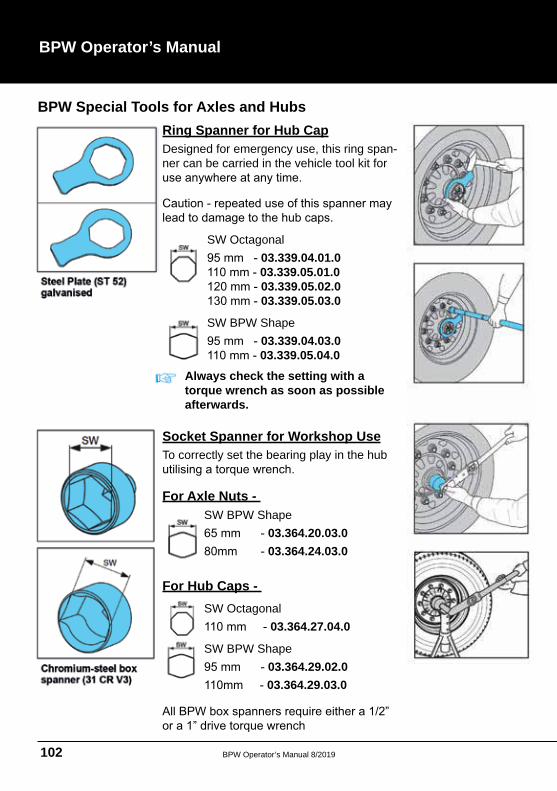
Ring Spanner for Hub Cap Designed for emergency use, this ring spanner can be carried in the vehicle tool kit for
Socket Spanner for Workshop Use To correctly set the bearing play in the hub
For Axle Nuts -
BPW Special Tools for Axles and Hubs
SW Octagonal 03.339.04.01.0 03.339.05.01.0 03.339.05.02.0 03.339.05.03.0
SW BPW Shape 03.339.04.03.0 03.339.05.04.0
Always check the setting with a torque wrench as soon as possible afterwards.
SW BPW Shape 03.364.20.03.003.364.24.03.0
SW BPW Shape 03.364.29.02.003.364.29.03.0
SW Octagonal03.364.27.04.0
For Hub Caps -
BPW Operator’s Manual 8/2019 103
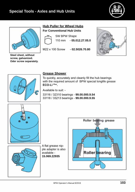
Hub Puller for Wheel HubsFor Conventional Hub Units
SW BPW Shape 05.012.27.05.0
02.5026.70.80
Grease Shower
with the required amount of BPW special longlife grease ECO-Li Plus.
99.00.000.9.54 99.00.000.9.55
Steel sheet, without screw, galvanized. Oder screw separately.
ple adapter is also
15.069.22935
Special Tools - Axles and Hub Units
BPW Operator’s Manual 8/2019104
BPW Operator’s Manual
BPW Special Tools for Drum Brakes
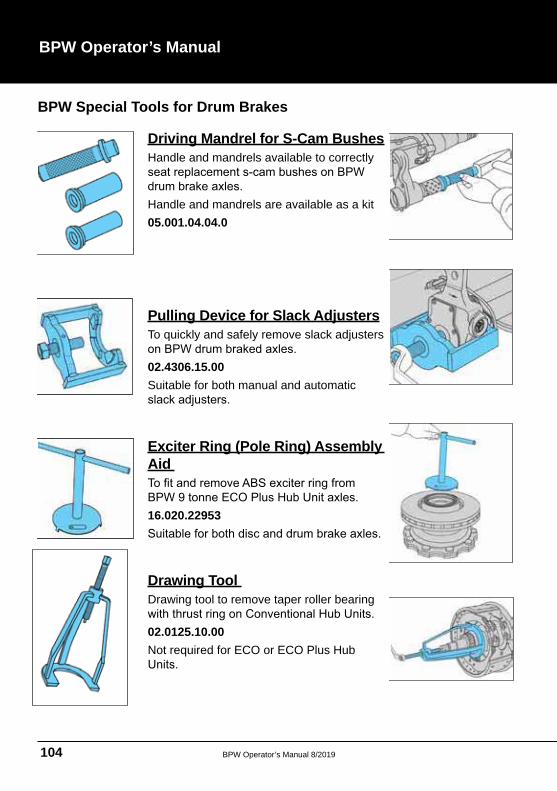
Driving Mandrel for S-Cam BushesHandle and mandrels available to correctly
Handle and mandrels are available as a kit05.001.04.04.0
Pulling Device for Slack AdjustersTo quickly and safely remove slack adjusters
02.4306.15.00 Suitable for both manual and automatic
Exciter Ring (Pole Ring) Assembly Aid
16.020.22953
Drawing Tool Drawing tool to remove taper roller bearing
02.0125.10.00 Not required for ECO or ECO Plus Hub
BPW Operator’s Manual 8/2019 105
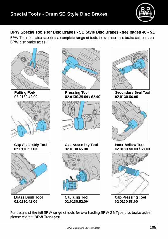
Special Tools - Drum SB Style Disc Brakes
BPW Special Tools for Disc Brakes - SB Style Disc Brakes - see pages 46 - 53.
please contact BPW Transpec.
Pulling Fork 02.0130.42.00
Cap Assembly Tool 02.0130.57.00
Brass Bush Tool 02.0130.41.00
Pressing Tool 02.0130.39.00 / 62.00
Cap Assembly Tool 02.0130.65.00
Caulking Tool 02.0130.52.00
Secondary Seal Tool 02.0130.66.00
Inner Bellow Tool 02.0130.40.00 / 63.00
Cap Pressing Tool 02.0130.58.00
BPW Operator’s Manual 8/2019106
BPW Operator’s Manual
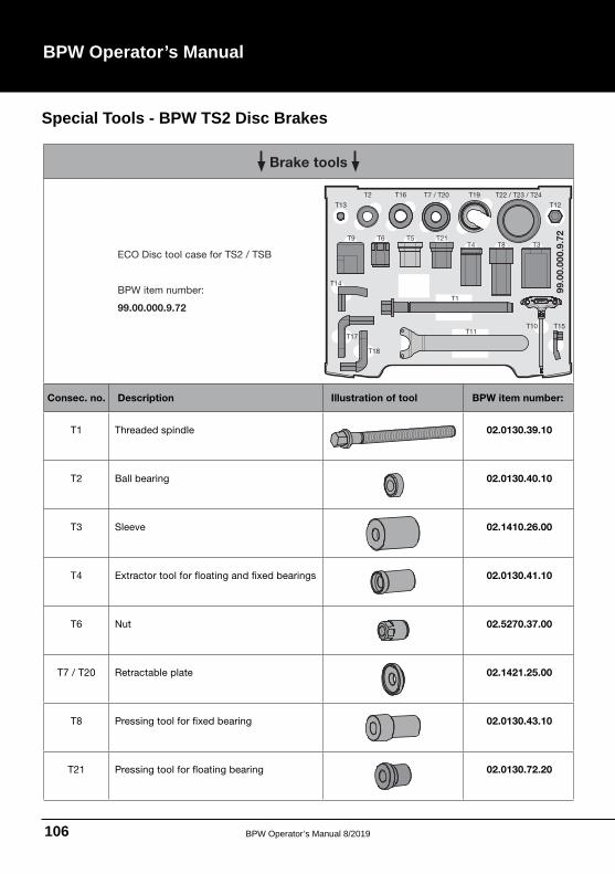
Brake tools
ECO Disc tool case for TS2 / TSB
BPW item number:
99.00.000.9.72
T19
T13
T2 T16 T7 / T20
T12
T21T6 T5T4
T22 / T23 / T24
T8 T3
T14
T1
T10 T15T11
T17
T18
T9
99.0
0.0
00.9
.72
Consec. no. Description Illustration of tool BPW item number:
T1 Threaded spindle 02.0130.39.10
T2 Ball bearing 02.0130.40.10
T3 Sleeve 02.1410.26.00
T4 Extractor tool for floating and fixed bearings 02.0130.41.10
T6 Nut 02.5270.37.00
T7 / T20 Retractable plate 02.1421.25.00
T8 Pressing tool for fixed bearing 02.0130.43.10
T21 Pressing tool for floating bearing 02.0130.72.20
Special Tools - BPW TS2 Disc Brakes
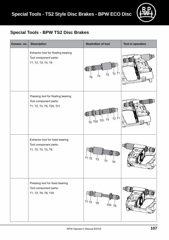
BPW Operator’s Manual 8/2019 107
Consec. no. Description Illustration of tool Tool in operation
Extractor tool for floating bearing
Tool component parts:
T1, T2, T3, T4, T6
T1T2
T6
Pressing tool for floating bearing
Tool component parts:
T1, T2, T4, T6, T20, T21
T1T2
T6T21T20
Extractor tool for fixed bearing
Tool component parts:
T1, T2, T3, T4, T6
T1 T2
T6
Pressing tool for fixed bearing
Tool component parts:
T1, T2, T6, T8, T20
T1 T2 T8T6T20
Special Tools - BPW TS2 Disc Brakes
Special Tools - TS2 Style Disc Brakes - BPW ECO Disc
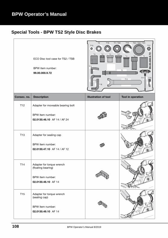
BPW Operator’s Manual 8/2019108
BPW Operator’s Manual
ECO Disc tool case for TS2 / TSB
BPW item number:
99.00.000.9.72
T19
T13
T2 T16 T7 / T20
T12
T21T6 T5T4
T22 / T23 / T24
T8 T3
T14
T1
T10 T15T11
T17
T18
T9
99.0
0.0
00.9
.72
Consec. no. Description Illustration of tool Tool in operation
T12 Adapter for moveable bearing bolt
BPW item number:
02.0130.46.10 AF 14 / AF 24
T13 Adapter for sealing cap
BPW item number:
02.0130.47.10 AF 14 / AF 12
T14 Adapter for torque wrench
(floating bearing)
BPW item number:
02.0130.48.10 AF 14
T15 Adapter for torque wrench
(sealing cap)
BPW item number:
02.0130.49.10 AF 14
Special Tools - BPW TS2 Style Disc Brakes
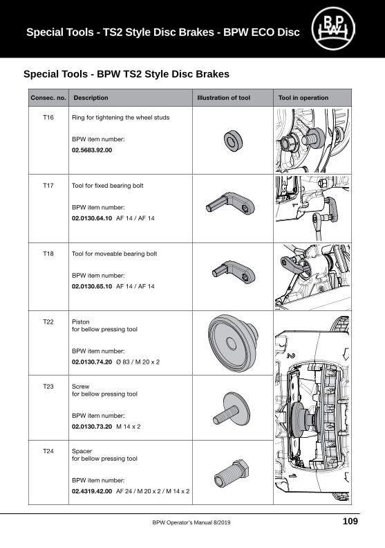
BPW Operator’s Manual 8/2019 109
Consec. no. Description Illustration of tool Tool in operation
T16 Ring for tightening the wheel studs
BPW item number:
02.5683.92.00
T17 Tool for fixed bearing bolt
BPW item number:
02.0130.64.10 AF 14 / AF 14
T18 Tool for moveable bearing bolt
BPW item number:
02.0130.65.10 AF 14 / AF 14
T22 Piston
for bellow pressing tool
BPW item number:
02.0130.74.20 Ø 83 / M 20 x 2
T23 Screw
for bellow pressing tool
BPW item number:
02.0130.73.20 M 14 x 2
T24 Spacer
for bellow pressing tool
BPW item number:
02.4319.42.00 AF 24 / M 20 x 2 / M 14 x 2
Special Tools - BPW TS2 Style Disc Brakes
Special Tools - TS2 Style Disc Brakes - BPW ECO Disc
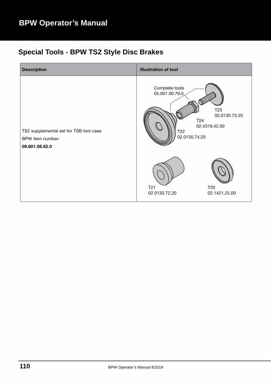
BPW Operator’s Manual 8/2019110
BPW Operator’s Manual
Description Illustration of tool
TS2 supplemental set for TSB tool case
BPW item number:
09.801.08.82.0
T21
02.0130.72.20
T20
02.1421.25.00
T23
02.0130.73.20
05.001.00.79.0
T24
02.4319.42.00
T22
02.0130.74.20
Complete tools
Special Tools - BPW TS2 Style Disc Brakes
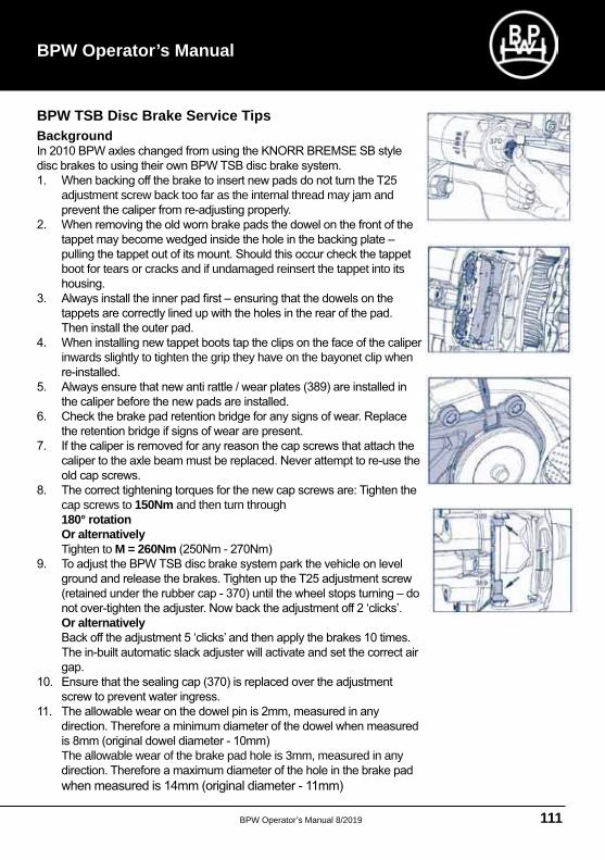
BPW Operator’s Manual 8/2019 111
BPW TSB Disc Brake Service Tips Background
adjustment screw back too far as the internal thread may jam and
boot for tears or cracks and if undamaged reinsert the tappet into its
inwards slightly to tighten the grip they have on the bayonet clip when
cap screws to 150Nm and then turn through 180° rotation
Or alternatively Tighten to M = 260Nm
Or alternatively
The allowable wear of the brake pad hole is 3mm, measured in any
BPW Operator’s Manual
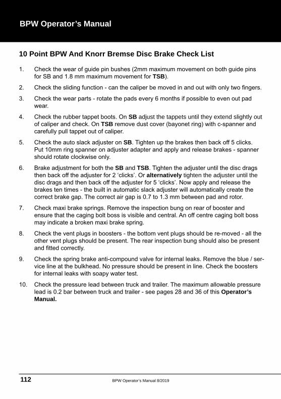
BPW Operator’s Manual 8/2019112
BPW Operator’s Manual
10 Point BPW And Knorr Bremse Disc Brake Check List
TSB
SB adjust the tappets until they extend slightly out TSB
SB
SB and TSBalternatively tighten the adjuster until the
Operator’s Manual.
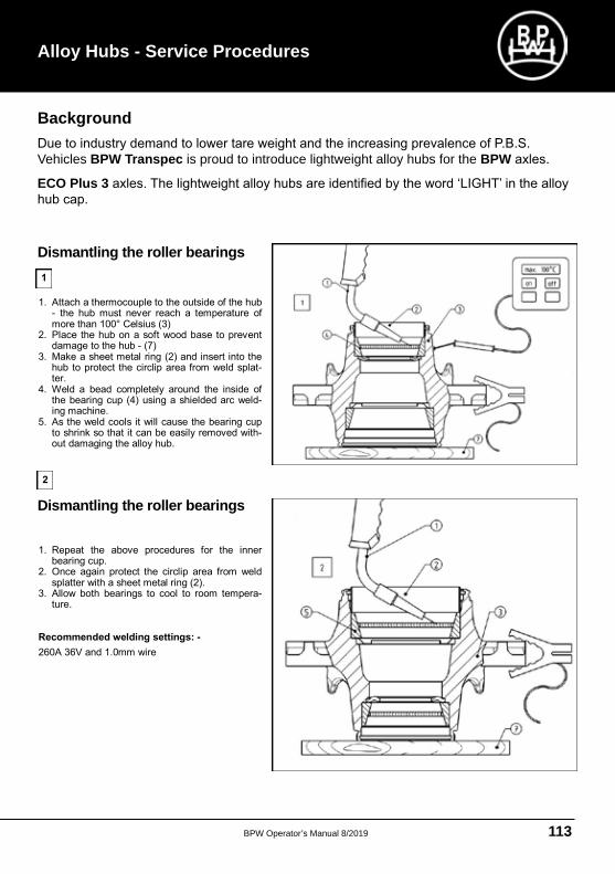
BPW Operator’s Manual 8/2019 113
Alloy Hubs - Service Procedures
Dismantling the roller bearings. 1. Repeat the above procedures for the inner
bearing cup. 2. Once again protect the circlip area from weld
splatter with a sheet metal ring (2). 3. Allow both bearings to cool to room tempera-
ture. Recommended welding settings: -
260A 36V and 1.0mm wire
Dismantling the roller bearings.
1. Attach a thermocouple to the outside of the hub - the hub must never reach a temperature of more than 100° Celsius (3)
2. Place the hub on a soft wood base to prevent damage to the hub - (7)
3. Make a sheet metal ring (2) and insert into the hub to protect the circlip area from weld splat-ter.
4. Weld a bead completely around the inside of the bearing cup (4) using a shielded arc weld-ing machine.
5. As the weld cools it will cause the bearing cup to shrink so that it can be easily removed with-out damaging the alloy hub.
1
2
Background
Vehicles BPW Transpec is proud to introduce lightweight alloy hubs for the BPW
ECO Plus 3
Dismantling the roller bearings
Dismantling the roller bearings
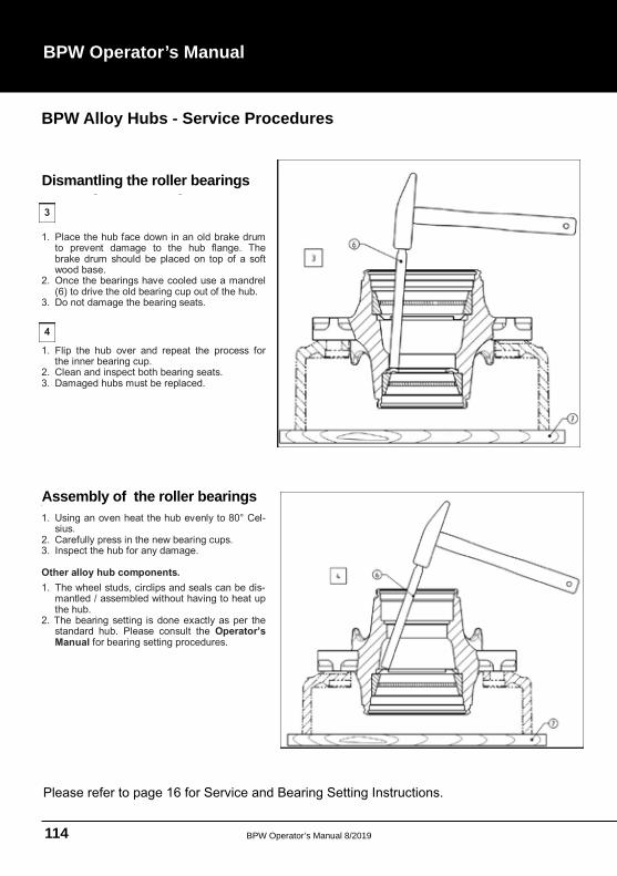
BPW Operator’s Manual 8/2019114
BPW Operator’s Manual
Dismantling the roller bearings.
1. Place the hub face down in an old brake drum to prevent damage to the hub flange. The brake drum should be placed on top of a soft wood base.
2. Once the bearings have cooled use a mandrel (6) to drive the old bearing cup out of the hub.
3. Do not damage the bearing seats.
1. Flip the hub over and repeat the process for the inner bearing cup.
2. Clean and inspect both bearing seats. 3. Damaged hubs must be replaced.
3
4
Assembly of the roller bearings.
1. Using an oven heat the hub evenly to 80° Cel-sius.
2. Carefully press in the new bearing cups. 3. Inspect the hub for any damage. Other alloy hub components.
1. The wheel studs, circlips and seals can be dis-mantled / assembled without having to heat up the hub.
2. The bearing setting is done exactly as per the standard hub. Please consult the Operator’s Manual for bearing setting procedures.
Dismantling the roller bearings
Assembly of the roller bearings
BPW Alloy Hubs - Service Procedures
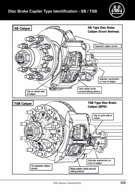
BPW Operator’s Manual 8/2019 115

NEW SOUTH WALES
QUEENSLAND
WESTERN AUSTRALIA
1300 651 652
The information and advice contained in this brochure including prices
1st June 2019 but BPW Transpec shall not be liable for any
your BPW Transpec branch or representative to ensure that all information and advice is up to date before placing an order


