Embed Size (px)
Citation preview
Aalborg Universitet
Breaking the Transmitter-Receiver Isolation Barrier in Mobile Handsets with SpatialDuplexing
Alrabadi, Osama; Tatomirescu, Alexandru; Knudsen, Mikael; Pelosi, Mauro; Pedersen, GertFrølundPublished in:I E E E Transactions on Antennas and Propagation
DOI (link to publication from Publisher):10.1109/TAP.2012.2232897
Publication date:2013
Document VersionEarly version, also known as pre-print
Link to publication from Aalborg University
Citation for published version (APA):Alrabadi, O., Tatomirescu, A., Knudsen, M., Pelosi, M., & Pedersen, G. F. (2013). Breaking the Transmitter-Receiver Isolation Barrier in Mobile Handsets with Spatial Duplexing. I E E E Transactions on Antennas andPropagation, 61(4), 2241 - 2251. https://doi.org/10.1109/TAP.2012.2232897
General rightsCopyright and moral rights for the publications made accessible in the public portal are retained by the authors and/or other copyright ownersand it is a condition of accessing publications that users recognise and abide by the legal requirements associated with these rights.
- Users may download and print one copy of any publication from the public portal for the purpose of private study or research. - You may not further distribute the material or use it for any profit-making activity or commercial gain - You may freely distribute the URL identifying the publication in the public portal -
Take down policyIf you believe that this document breaches copyright please contact us at [email protected] providing details, and we will remove access tothe work immediately and investigate your claim.
1
Breaking the Transmitter-Receiver Isolation Barrierin Mobile Handsets with Spatial Duplexing
Osama N. Alrabadi1, Alexandru D. Tatomirescu1, Mikael B. Knudsen2, Mauro Pelosi1 and Gert F. Pedersen1
Abstract—In full-duplex radio communication systems like e-UTRAN, CDMA-2000, the radio transmitter (Tx) is active at thesame time as the radio receiver (Rx). The Tx and the Rx will beusing separate dedicated frequency bands and the Tx-Rx isolationis ensured by duplex filters. However, agile duplexers requiredfor multiband operation are almost non-existent while dedicatinga bank of narrowband filters is bulky and incurs considerableswitching losses. In this article we propose an approach thatdramatically reduces the complexity of the RF frontend, firstby replacing the duplex filter with a spatial filter and second,by co-designing the filtering antennas and the RF frontend. Thespatial filter is synthesized by equipping the Tx with redundantantennas. By properly weighting the Tx antennas, the Tx signalis selectively attenuated in the Rx direction. The spatial filter canbe tuned to different frequency bands as long as the antennas aremade tunable. Moreover, the spatial filter may directly benefitfrom the balanced architecture of the power amplifiers (PAs) thusreducing the total system complexity and insertion loss. Finally,simulation and initial measurement results are provided in achallenging low-frequency band, serving as a proof-of-concept.
Index Terms—Duplexing, Decoupling, Null-steering, Spatialfilter, Transmitter-receiver isolation, Zero-forcing.
I. I NTRODUCTION
CURRENT and future mobile handsets need to accom-modate an increasing number of frequency bands and
to cope with sophisticated wireless standards like the Ad-vanced Long Term Evolution (LTE-A) for supporting higherdata rates. At the same time, handheld terminals have tostay efficient, performance reliable and cost affordable. Theminiaturization trend in the handset form factor together withthe large frequency spectrum to be covered by the antennasystem (700 to 2600 MHz and later up to 3600 MHz) results inmany design challenges in the antenna system design besidescomplicating the transceiver Radio Frequency (RF) frontendarchitecture. Moreover, ignoring the time-varying disturbanceincurred by the user head and hand on the wireless antennasystem leads to a significant number of call drops [1], limitingthe overall system performance. The co-design of the RFfrontend and the antenna system is a promising approach thatcan solve some the aforementioned design challenges. In suchan approach, the antenna needs to provide some functionalitiesdifferent from the conventional functionality of acting asamere electromagnetic radiator, e.g. RF filtering [2]. Moreover,some RF components can be modified to provide dual or
1 Antennas, Propagation and Radio Networking (APNet) Section, Depart-ment of Electronic Systems, Faculty of Engineering and Science, Aalborg Uni-versity, DK-9220 Aalborg, Denmark (e-mails:{ona,ata,mp,gfp}@es.aau.dk).
2 Intel Mobile Communication Denmark Aps, Aalborg East, Denmark (e-mail: [email protected]).
multiple functionalities while redundant RF components canbe removed, thus reducing cost, size and losses. An exampleof such joint optimization is the co-design of the antenna andthe power amplifier (PA) circuit. For example, [3] suggests todirectly connect the differential feed of a balanced antenna tothe output of a balanced PA, thus the antenna is employed asan out-of-phase spatial combiner. Such architecture dispenseswith using baluns or hybrid couplers for converting the bal-anced PA output into single ended. The architecture resultsin almost zero insertion loss and higher PA efficiency whilethe use of balanced antennas immunizes (to some level) themobile handset against the user proximity effect [4]. BesidesPA efficiency and immunity to user proximity effects, Tx-Rxisolation is still a major design challenge existing in currentmobile phones due to the magnificent difference between thelevel of the transmit power (say0 dBm) and the sensitivityof a receiver (say−100dBm). A small leakage from theTx to the Rx may burn the Rx circuit or least saturate it,thus degrading the Rx sensitivity. The Tx noise in the Rxspectrum also degrades the quality of the received signal andis often considered the dominant source of noise. The problembecomes more challenging when considering the followingsystem scenarios:
• Frequency Division Duplex (FDD) systems like mostcellular systems, including the UMTS/WCDMA, CDMA-2000 system and the IEEE 802.16 WiMax system. In suchsystems, the Tx and the Rx are simultaneously active overtwo neighboring subbands.
• Tx and Rx modules belonging to different wireless stan-dards and collocated in the same handset, e.g. a GSM Txcollocated with a D-TV Rx.
To mitigate the Tx noise in the Rx spectrum, duplex filtersshould be sharp and able to provide a high level of isolationso as to perfectly isolate the neighboring subbands. Unfortu-nately, duplex filters are quite bulky whereas the proposed Sur-face Acoustic Wave (SAW) filters, though occupying smallerarea, provide limited performance [5]. Moreover, duplex filtersare generally narrowband thus, covering multiple wirelessbands requires a bank of switched narrowband filters. Thisin turn increases size, cost as well as switching losses.
This paper exploits the balanced PA - antenna architecturefor synthesizing a spatial filter that replaces the duplex filter orat least relaxes its requirement. The spatial filter is synthesizedby equipping the Tx with at least one more antenna than theRx. The Tx antennas are properly weighted such that the near-field is zero-forced in the direction(s) of the Rx antenna(s). Theproposed approach combines the concept of leakage cancel-
2
lation and antennas decoupling. Unlike conventional leakagecancellation that takes place right after the Rx antenna, theproposed approach selectively cancels the Tx power in the Rxdirection (Tx spatial combining). Moreover, like conventionalantennas decoupling techniques, the proposed approach dimin-ishes the trans-impedance between the Tx and the Rx i.e. theTx-Rx isolation is owed to the mutual coupling loss betweenthe Tx and the Rx antenna(s). The spatial duplexing filter isshown to achieve a remarkable level of adaptive and agileisolation, without trading such isolation with other antennadesign parameters like bandwidth or efficiency. Moreover, byco-designing the Tx antennas and the balanced Tx architectureexisting in current and future mobile handsets, cost, size,complexity and insertion loss are all minimized.
Notation: In the following, boldface lower-case and upper-case characters denote vectors and matrices, respectively. Theoperators(·)∗, (·)T designate complex conjugate and matrixtranspose operators, respectively. The notation0N indicatesan N × N matrix of all zero entries whereas the notion(·)ij
returns the{i, j} entry of the enclosed matrix.‖·‖ denotes theEuclidean norm of the enclosed vector,| · | returns the absolutevalue whereas∠ returns the angle. Finally,C denotes the setof complex numbers of the specified dimensions.
The rest of the paper is divided as follows: Section IIdescribes conventional duplexing whereas Section III proposesthe concept of spatial duplexing using baseband null-steeringas well as analogue orthogonal weighting networks. SectionIV discusses the degrees of freedom of such approach whereasSection V investigates the sensitivity of the phase and am-plitude control on the isolation level. Section VI providessimulation results together with a fully operational measuredprototype whereas Section VII concludes the paper.
II. CONVENTIONAL DUPLEXING
The traditional approach of attenuating the Tx leakagesignal and the Tx noise that lies in the Rx band, is to employa duplex filter comprised of two filters combined before theantenna. The filter-branch in the Tx path stops the Tx noisecomponent that lies in the Rx band and the filter-branch inthe Rx path stops the Tx signal overloading the Rx (Rxdesensitization).
A duplexer can be built in many ways using classicalresonant circuits (e.g. ceramic or cavity resonators). Recently,duplexers are being built using multilayer technology withtheuse of slotline or microstrip line coupling structures to improvethe level of integration. Other popular techniques includeSAW filters and Film Bulk Acoustic Wave Resonator (FBAR)devices. The following summarizes the classical duplexerdesigns
• Lumped element filters. [9]–[15]• Cavity duplexing filters [16]–[20]• Ceramic duplexing filters [21]–[26]• SAW duplexing filters [27]–[31]• MicroElectroMechanical Systems (MEMS) devices [32]–
[34]• MEMS resonators [35]–[49]• Stripline or microstrip line duplexing filters [50]–[55]
a)
b)
c)
PA
LNA
Mixer
Antenna
Filter
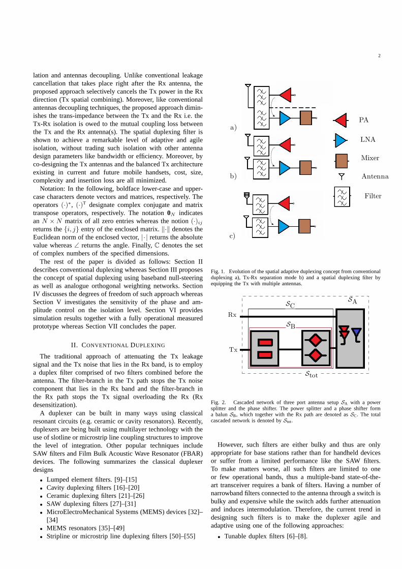
Fig. 1. Evolution of the spatial adaptive duplexing conceptfrom conventionalduplexing a), Tx-Rx separation mode b) and a spatial duplexing filter byequipping the Tx with multiple antennas.
Rx
Tx
SC
SB
SA
Stot
Fig. 2. Cascaded network of three port antenna setupSA with a powersplitter and the phase shifter. The power splitter and a phase shifter forma balunSB, which together with the Rx path are denoted asSC. The totalcascaded network is denoted byStot.
However, such filters are either bulky and thus are onlyappropriate for base stations rather than for handheld devicesor suffer from a limited performance like the SAW filters.To make matters worse, all such filters are limited to oneor few operational bands, thus a multiple-band state-of-the-art transceiver requires a bank of filters. Having a number ofnarrowband filters connected to the antenna through a switchisbulky and expensive while the switch adds further attenuationand induces intermodulation. Therefore, the current trendindesigning such filters is to make the duplexer agile andadaptive using one of the following approaches:
• Tunable duplex filters [6]–[8].
3
TxBalun
SA SC
Rx
Stot
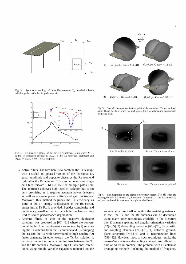
Fig. 3. Symmetric topology of three IFA antennasSA , attached a balunwhich together with the Rx path formSC.
0.5 1 1.5 2 2.5 3−140
−120
−100
−80
−60
−40
−20
0
20
f (GHz)
dB
1.4 1.45 1.5 1.55 1.6−20
−15
−10
−5
0Tx
Rx
Isolation
Fig. 4. Frequency response of the three IFA antennas setup where STxTxis the Tx reflection coefficient,SRxRx is the Rx reflection coefficient andSTxRx = SRxTx is the Tx-Rx coupling.
• Active filters: The idea here is to combine the Tx leakagewith a scaled anti-phased version of the Tx signal i.e.equal amplitude and opposite phase, at the Rx frontendright after the Rx antenna. This can be done using singlepath feed-forward [56] [57] [58] or multiple paths [59].The approach achieves high level of isolation but is notvery promising as it requires accurate power detectorsas well as accurate phase shifters and gain controllers.Moreover, this method degrades the Tx efficiency assome of the Tx energy is dissipated in the Rx circuit,unless initial Tx-Rx is provided. Besides complexity andinefficiency, small errors in the whole mechanism maylead to severe performance degradation.
• Antenna filters: A shift in the adaptive duplexingparadigm was proposed in [60] [61] where the conven-tional duplex filter requirements are relaxed by i) separat-ing the Tx antenna from the Rx antenna and ii) equippingthe Tx and the Rx with narrowband or high Quality (Q)factor antennas. In other words, the Tx-Rx isolation ispartially due to the mutual coupling loss between the Txand the Rx antennas. Moreover, high Q antennas can betuned using simple variable capacitors mounted on the
Gϑ(ϑ,ϕ), Gain=1.8 dB2)
Gϕ(ϑ,ϕ), Gain=-4.13 dBGϑ(ϑ,ϕ), Gain=2.23 dB1)
ϕ
ϑ
Gϕ(ϑ,ϕ), Gain=2.37 dB
Fig. 5. Far-field beampattern (active gain) of the combined Tx and an idealbalun 1) and the Rx 2) whereGϑ andGϕ are theϑ ϕ polarization componentsof the far-field.
Rx
Tx
First Tx antenna alone Second Tx antenna alone
Both Tx antennas outphasedRx alone
Fig. 6. The magnitude of the spatial power flow vector| ~E × ~H| when theexciting the first Tx antenna 1), the second Tx antenna 2), theRx antenna 3)and the combined Tx antennas through an ideal balun.
antenna structure itself or within the matching network.In fact, the Tx and the Rx antennas can be decoupledusing many other techniques available in the literaturelike 1) antenna spacing and angular orientation variation[62]–[65], 2) decoupling networks [66]–[70], 3) parasiticand coupling elements [71]–[73], 4) defected ground-plane structures [74]–[78] and 5) neutralization lines[79]–[82]. However, most of such techniques, unlike thenarrowbandantenna decoupling concept, are difficult totune or adjust in practice. The problem with all antennasdecoupling methods (including the method of frequency
4
Balanced PA
Balanced PA
Balanced PA
Tx Module
Tx Module
Tx Modulea)
b)
c)
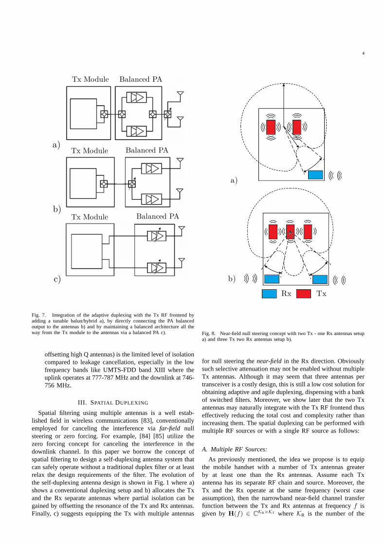
Fig. 7. Integration of the adaptive duplexing with the Tx RF frontend byadding a tunable balun/hybrid a), by directly connecting the PA balancedoutput to the antennas b) and by maintaining a balanced architecture all theway from the Tx module to the antennas via a balanced PA c).
offsetting high Q antennas) is the limited level of isolationcompared to leakage cancellation, especially in the lowfrequency bands like UMTS-FDD band XIII where theuplink operates at 777-787 MHz and the downlink at 746-756 MHz.
III. SPATIAL DUPLEXING
Spatial filtering using multiple antennas is a well estab-lished field in wireless communications [83], conventionallyemployed for canceling the interference viafar-field nullsteering or zero forcing. For example, [84] [85] utilize thezero forcing concept for canceling the interference in thedownlink channel. In this paper we borrow the concept ofspatial filtering to design a self-duplexing antenna systemthatcan safely operate without a traditional duplex filter or at leastrelax the design requirements of the filter. The evolution ofthe self-duplexing antenna design is shown in Fig. 1 where a)shows a conventional duplexing setup and b) allocates the Txand the Rx separate antennas where partial isolation can begained by offsetting the resonance of the Tx and Rx antennas.Finally, c) suggests equipping the Tx with multiple antennas
Rx Tx
b)
a)
Fig. 8. Near-field null steering concept with two Tx - one Rx antennas setupa) and three Tx two Rx antennas setup b).
for null steering thenear-field in the Rx direction. Obviouslysuch selective attenuation may not be enabled without multipleTx antennas. Although it may seem that three antennas pertransceiver is a costly design, this is still a low cost solution forobtaining adaptive and agile duplexing, dispensing with a bankof switched filters. Moreover, we show later that the two Txantennas may naturally integrate with the Tx RF frontend thuseffectively reducing the total cost and complexity rather thanincreasing them. The spatial duplexing can be performed withmultiple RF sources or with a single RF source as follows:
A. Multiple RF Sources:
As previously mentioned, the idea we propose is to equipthe mobile handset with a number of Tx antennas greaterby at least one than the Rx antennas. Assume each Txantenna has its separate RF chain and source. Moreover, theTx and the Rx operate at the same frequency (worst caseassumption), then the narrowband near-field channel transferfunction between the Tx and Rx antennas at frequencyf isgiven by H(f) ∈ C
KR×KT whereKR is the number of the
5
Txchain
DSP
Rxchain
Local channelestimation unit
Null steeringelement
Trainingunit
Sensor(s)
Adaptiveoperating
unit
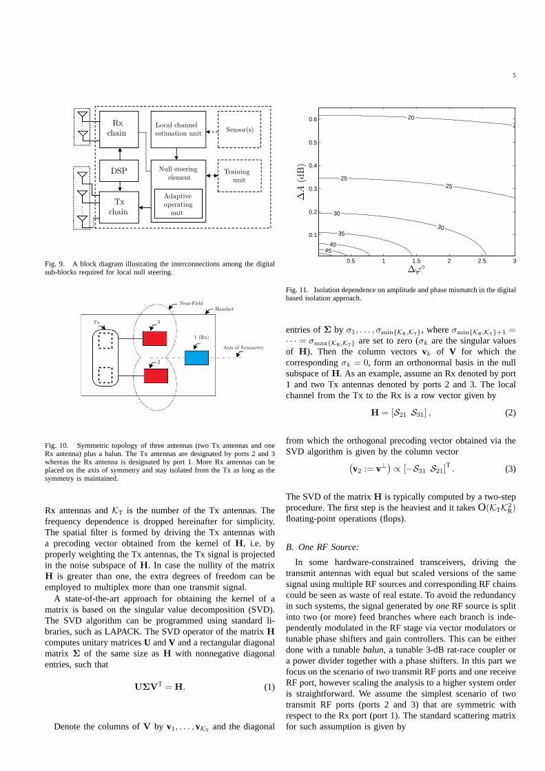
Fig. 9. A block diagram illustrating the interconnections among the digitalsub-blocks required for local null steering.
Tx 3
2
Handset
1 (Rx)
Axis of Symmetry
Near-Field
Fig. 10. Symmetric topology of three antennas (two Tx antennasand oneRx antenna) plus a balun. The Tx antennas are designated by ports 2 and 3whereas the Rx antenna is designated by port 1. More Rx antennas can beplaced on the axis of symmetry and stay isolated from the Tx as long as thesymmetry is maintained.
Rx antennas andKT is the number of the Tx antennas. Thefrequency dependence is dropped hereinafter for simplicity.The spatial filter is formed by driving the Tx antennas witha precoding vector obtained from the kernel ofH, i.e. byproperly weighting the Tx antennas, the Tx signal is projectedin the noise subspace ofH. In case the nullity of the matrixH is greater than one, the extra degrees of freedom can beemployed to multiplex more than one transmit signal.
A state-of-the-art approach for obtaining the kernel of amatrix is based on the singular value decomposition (SVD).The SVD algorithm can be programmed using standard li-braries, such as LAPACK. The SVD operator of the matrixH
computes unitary matricesU andV and a rectangular diagonalmatrix Σ of the same size asH with nonnegative diagonalentries, such that
UΣVT = H. (1)
Denote the columns ofV by v1, . . . , vKT and the diagonal
2020
2525
30
30
35
4045
∆ϕ◦
∆A
(dB
)
0.5 1 1.5 2 2.5 3
0.1
0.2
0.3
0.4
0.5
0.6
Fig. 11. Isolation dependence on amplitude and phase mismatch in the digitalbased isolation approach.
entries ofΣ by σ1, . . . , σmin{KR,KT}, whereσmin{KR,KT}+1 =· · · = σmax{KR,KT} are set to zero (σk are the singular valuesof H). Then the column vectorsvk of V for which thecorrespondingσk = 0, form an orthonormal basis in the nullsubspace ofH. As an example, assume an Rx denoted by port1 and two Tx antennas denoted by ports 2 and 3. The localchannel from the Tx to the Rx is a row vector given by
H = [S21 S31] , (2)
from which the orthogonal precoding vector obtained via theSVD algorithm is given by the column vector
(
v2 := v⊥)
∝ [−S31 S21]T. (3)
The SVD of the matrixH is typically computed by a two-stepprocedure. The first step is the heaviest and it takesO(KTK
2R)
floating-point operations (flops).
B. One RF Source:
In some hardware-constrained transceivers, driving thetransmit antennas with equal but scaled versions of the samesignal using multiple RF sources and corresponding RF chainscould be seen as waste of real estate. To avoid the redundancyin such systems, the signal generated byoneRF source is splitinto two (or more) feed branches where each branch is inde-pendently modulated in the RF stage via vector modulators ortunable phase shifters and gain controllers. This can be eitherdone with a tunablebalun, a tunable 3-dB rat-race coupler ora power divider together with a phase shifters. In this part wefocus on the scenario of two transmit RF ports and one receiveRF port, however scaling the analysis to a higher system orderis straightforward. We assume the simplest scenario of twotransmit RF ports (ports 2 and 3) that are symmetric withrespect to the Rx port (port 1). The standard scattering matrixfor such assumption is given by
6
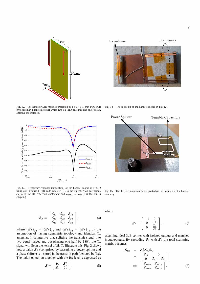
Fig. 12. The handset CAD model represented by a55×110 mm PEC PCB(typical smart phone size) over which two Tx PIFA antennas andone Rx ILAantenna are installed.
750 800 850 900−50
−45
−40
−35
−30
−25
−20
−15
−10
−5
0
f(MHz)
Sim
ula
ted
scatt
erin
gpara
met
ers
(dB
)
SRxRx
STxTx
STxRx
Fig. 13. Frequency response (simulation) of the handset modelin Fig. 12using our in-house FDTD code whereSTxTx is the Tx reflection coefficient,SRxRx is the Rx reflection coefficient andSTxRx = SRxTx is the Tx-Rxcoupling.
SA =
S11 S12 S12
S12 S22 S23
S12 S23 S22
, (4)
where {SA}22= {SA}33
and {SA}12= {SA}13
by theassumption of having symmetric topology and identical Txantennas. It is intuitive that splitting the transmit signal intotwo equal halves and out-phasing one half by180◦, the Txsignal will lie in the kernel ofH. To illustrate this, Fig. 2 showshow a balunSB (comprised by cascading a power splitter anda phase shifter) is inserted in the transmit path (denoted byTx).The balun operation together with the Rx feed is expressed as
S =
[
02 STC
SC 03
]
, (5)
Tx antennasRx antenna
Fig. 14. The mock-up of the handset model in Fig. 12.
Tunable CapacitorsPower Splitter
Fig. 15. The Tx-Rx isolation network printed on the backsideof the handsetmock-up.
where
SC =
+1 00 +1√
2
0 −1√2
, (6)
assuming ideal 3dB splitter with isolated outputs and matchedinputs/outputs. By cascadingSC with SA the total scatteringmatrix becomes
S tot = STCSASC
=
[
S11 00 S22 − S23
]
:=
[
SRxRx SRxTx
STxRx STxTx
]
. (7)
7
750 800 850 900−70
−60
−50
−40
−30
−20
−10
0
f (MHz)
Mea
sure
dsc
att
erin
gpara
met
ers
(dB
)
SRxRx
STxTx
STxRx
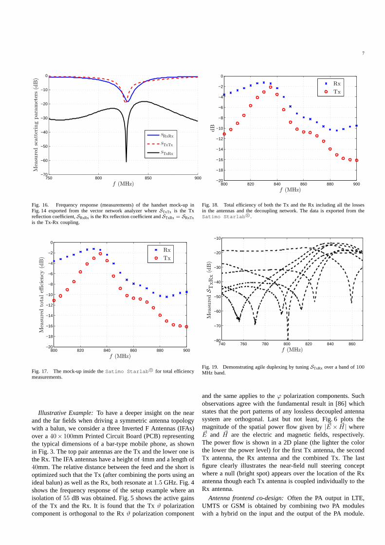
Fig. 16. Frequency response (measurements) of the handset mock-up inFig. 14 exported from the vector network analyzer whereSTxTx is the Txreflection coefficient,SRxRx is the Rx reflection coefficient andSTxRx = SRxTxis the Tx-Rx coupling.
800 820 840 860 880 900−20
−18
−16
−14
−12
−10
−8
−6
−4
−2
0
f (MHz)
Mea
sure
dto
taleffi
cien
cy(d
B)
Rx
Tx
Fig. 17. The mock-up inside theSatimo Starlab R© for total efficiencymeasurements.
Illustrative Example:To have a deeper insight on the nearand the far fields when driving a symmetric antenna topologywith a balun, we consider a three Inverted F Antennas (IFAs)over a40× 100mm Printed Circuit Board (PCB) representingthe typical dimensions of a bar-type mobile phone, as shownin Fig. 3. The top pair antennas are the Tx and the lower one isthe Rx. The IFA antennas have a height of4mm and a length of40mm. The relative distance between the feed and the short isoptimized such that the Tx (after combining the ports using anideal balun) as well as the Rx, both resonate at1.5 GHz. Fig. 4shows the frequency response of the setup example where anisolation of55 dB was obtained. Fig. 5 shows the active gainsof the Tx and the Rx. It is found that the Txϑ polarizationcomponent is orthogonal to the Rxϑ polarization component
800 820 840 860 880 900−20
−18
−16
−14
−12
−10
−8
−6
−4
−2
0
f (MHz)
dB
Rx
Tx
Fig. 18. Total efficiency of both the Tx and the Rx including all the lossesin the antennas and the decoupling network. The data is exported from theSatimo Starlab R©.
740 760 780 800 820 840 860−80
−70
−60
−50
−40
−30
−20
−10
Mea
sure
dST
xR
x(d
B)
f (MHz)
Fig. 19. Demonstrating agile duplexing by tuningSTxRx over a band of100MHz band.
and the same applies to theϕ polarization components. Suchobservations agree with the fundamental result in [86] whichstates that the port patterns of any lossless decoupled antennasystem are orthogonal. Last but not least, Fig. 6 plots themagnitude of the spatial power flow given by| ~E × ~H| where~E and ~H are the electric and magnetic fields, respectively.The power flow is shown in a 2D plane (the lighter the colorthe lower the power level) for the first Tx antenna, the secondTx antenna, the Rx antenna and the combined Tx. The lastfigure clearly illustrates the near-field null steering conceptwhere a null (bright spot) appears over the location of the Rxantenna though each Tx antenna is coupled individually to theRx antenna.
Antenna frontend co-design:Often the PA output in LTE,UMTS or GSM is obtained by combining two PA moduleswith a hybrid on the input and the output of the PA module.
8
On the Tx side, all the signals are balanced and there is ahybrid at the output of the Tx module to convert it into singleended. With this implementation, a tunable balun/hybrid isneeded at the PA output to implement the near-field zeroforcing concept as shown in Fig. 7a. Alternatively, as Fig. 7apresents the standard perception of the implementation withno modifications to the frontend, Fig. 7b shows a possibleintermediate setup where the balanced antenna is directlyattached to the balanced PA output as in [3].
On the other hand, the zero forcing concept can be imple-mented digitally by removing all the hybrids throughout theTx chain, see Fig. 7c. With this lineup, no hybrid couplerswill be required on the input or the output of the PA module.The hybrid at the Tx output is removed and the zero forcing isdone digitally without the need for a tunable balun/hybrid,all-in-all resulting in a significant reduction in the total insertionloss. In an all-digital Tx modulator, a phase shift of one branchrelative to the other can be done relatively simple by a registershift operation. A variable phase shift can be applied digitallyto one of the branches in the PA module, which can be usedto phase shift the signal at one antenna output relative to theother. By adjusting the relative phase shift of the transmittedsignal from one antenna relative to the other it is possibleto adjust the relative phase of the two versions of the Txsignal. Moreover, it is possible to adjust the power level ofeach transmitted signal by using independent power controlof the two Tx signals. By adjusting both phase and amplitudeit is possible to implement the zero forcing concept digitallyand using one RF source.
IV. D EGREES OFFREEDOM
A. Time-varying channel
In case the entries of the matrixH are time-varying bythe near-field coupling with nearby objects e.g. the proximityeffect of the user head and hand, the nullity ofH is given byKT − KR. To illustrate this, Fig. 8a shows a setup of two Txantennas and one Rx antenna, thus the system has a nullityof one, i.e. the Tx can transmit one signal subject to stayingorthogonal to the Rx direction. Fig. 8b shows a system withthree Tx antennas and two Rx antennas, again the nullity is onethus one Tx signal can be transmitted while two signals canbe received without suffering from any harmful Tx leakage.In Fig. 8b, if the Rx has one antenna, then the nullity ofH istwo and two independent Tx signals can thus be multiplexedwhile staying orthogonal to the Rx antenna.
On the other hand, learning the local time-varying channelrequires lowering the Tx power during the training phase to alevel that does not harm the Rx sensitivity. Another trainingstrategy is to use a pseudo-random pilot signal where the signalpower is lowered by spreading it over a wide spectrum band.Fig. 9 shows the relation among the system subblocks requiredfor learning the channels and for weighting the Tx antennas.Alternatively, the zero-forcing approach can be performedblindly without learning the channel; by iterating Rx powerand the Tx weights until converging into an acceptable levelof isolation.
The rate over which the weights should be updated dependson the rate over which isolation (i.e. the Tx-Rx leakage in
dBm) is degraded. This rate is expected to be much slowerthan the rate over which the far-field channel gains varyin a scattering environment. The isolation could be eitherenhanced or degraded by the proximity effect of the userhead and hand depending on the exact setup and the typeof the antennas. For example, the impedance mismatch whenusing narrowband antennas is quite insignificant compared tothe absorption losses by the user hand. Such losses enhancethe Tx-Rx isolation. Moreover, the fact that the closed loopmechanism for sensing the leakage and updating the weights islocal in the same handset, the time-delay required for maintainthe isolation becomes negligible [61]. Last but not least, thefact that the closed loop mechanism for sensing the leakageand updating the weights is local in the same handset, the time-delay required for maintain the isolation becomes negligible.
B. Time-invariant channel
In case the elements of the matrixH are constant (staticchannel), multiple Rx antennas can be isolated from the Tx an-tennas by properly exploiting the antenna location. To illustratethis, Fig. 10 illustrates two Tx antennas that are symmetricwith respect to the Rx antenna, thusH = [S21 S21] =S21 [1 1]. It is obvious that by driving the two Tx antennaswith equal but out of phase excitations (180◦ difference inphase), full Tx-Rx isolation is obtained. Moreover, an infinitenumber of Rx antennas can be placed on the axis of symmetryshown in the figure and enjoy a high level of isolation. This isbecause any Rx antenna placed on this axis will have a localchannel vectorH′ proportional toH (equal toall onesup toa scalar), and thus any weighting vector orthogonal toH willbe orthogonal toH′.
V. SENSITIVITY ANALYSIS
We theoretically investigate the error in the weighting vectorapplied to the Tx antennas on the Tx-Rx isolation. To do so,we consider the system example in Fig. 10 where the two Txantennas are weighted with the vectorv = [v1 v2] such that‖v‖2
= 1. The relationship between the voltage signal squaredat the Rx to the transmit Tx voltage signal squared whendriving the Tx antennas with an arbitrary excitation vectorv = [v1 v2] becomes after some manipulations as follows
|VRx|2
= |VTx|2
(
1 −2 (∆A)
1 + (∆A)2
cos(∆φ)
)
(8)
where∆ A and ∆φ are the amplitude imbalance and phasedeviation from180◦, respectively. Fig. 11 shows the isolationlevel in dB, i.e.10 log10
(
|VRx||VTx|
)
versus∆A and∆φ. The mini-mum amplitude mismatch was set to0.01 dB and the minimumphase mismatch (from180◦) was set to0.01 degrees. Thefigure shows that around35 − 40 dB of isolation is obtainedwith a maximum amplitude mismatch of0.1 dB jointly with amaximum phase mismatch of of1.5◦. Although the matchingof the amplitude and phase seems to be strict, such matchingis obtained digitally within a remarkable resolution whereasobtaining such accuracy in practice is done by tuning the twofeeds rather than one. Later we show that with two tunable
9
capacitors per feed, the null iscontinuouslysteered over afrequency band of 100 MHz though no attempt was attainedto optimize the isolation level over such band.
VI. A NTENNA DESIGN AND MEASUREMENTS
The numerical simulations were conducted using our in-house Finite Difference Time Domain (FDTD) code, choosinga space step size of 1mm and an energy based terminationcriterion. The FDTD code is parallel and it uses the supercom-puter facilities at Aalborg University (Fyrkat) [87], allowingdemanding simulations to be run in a limited time. Thehandset ground-plane has been modeled as a Perfect ElectricConductor (PEC) plate representing the typical dimensionsofa smart phone (55mm× 110mm). A practical implementationhas been considered and intended for the extreme scenarioof i) zero duplex separation together with ii) operation inthe low frequency band. The computer aided design (CAD)model is shown in Fig. 12 where three simple structures havebeen used as radiators, two of them are Planar Inverted FAntennas (PIFAs) whereas the third is an Inverted L Antenna(ILA). Slots in the antenna structures are introduced to reducethe antenna dimensions at the expense of bandwidth. Theheight of the antennas is7 mm occupying an area of6 × 55mm2. The model is reused to construct a feeding networkon the backside which is required for the Tx-Rx isolation.The network was co-simulated usingAgilent ADS R© andused to feed PIFAs on the other side of the PCB. Thenetworks is comprised of a power splitter, two T networksand transmission lines. The lengths of the transmission lineswere optimized so that a null appears in the Rx (the ILA)direction at the resonance frequency. This phase differencecan be smoothly tuned using some tunable capacitors withinthe T network. The T network has two tunable capacitorswith a shunt inductor connected to the ground. The Q of thecomponents used in the manufacturing are90 and80 for theinductors and the capacitors, respectively. The network hasa small tuning range of20◦ over which the insertion lossis maintained low (the insertion loss of the feeding networkranges from1−2.5 dB depending on the capacitors’ settings.)while the difference in the length of the transmission linesprovides the desired phase shift value. The slight tuning inthe T network is meant to have some agility around the majortarget band. The frequency response of the simulated model isshown in Fig. 13 where a deep null is obtained at the desiredband by slightly tuning the capacitors.
With these specification, a prototype has been manufacturedas shown in Fig. 14. The antenna elements are stabilized usingpolystyrene and Teflon tapes whereas the PCB is a two sidedFR4. The isolation network is synthesized over the backsideof the PCB as shown in in Fig. 15. Thin coaxial cableshave been used for feeding and measuring the mock-up. Thecables are led away from the PCB in a direction orthogonalto the main current oscillation path thus limiting the cableeffects. Fig. 16 shows the frequency response of the measuredprototype where a good agreement between simulation andmeasurements is obtained, except for a20 MHz difference dueto the numerical dispersion in the FDTD domain besides some
possible manufacturing imperfections. The level of isolation isimpressive considering an initial coupling of−4 dB betweenthe PIFAs and around−5 dB between the PIFAs and the ILA.
The total efficiency of the system has been measuredusing theSatimo Starlab R© shown in Fig. 17. The totalefficiency curve is shown in Fig. 18, includes the losses inthe antennas as well as the losses in the feeding network andcables. The curve is generally calculated by integrating the 3Dfar-field (power) radiation patterns. From the total efficiencycurve, the bandwidth of the Tx antenna configuration is foundsmaller than the Rx bandwidth mainly due to limiting thecurrent distribution over some parts of the PCB (the area wherethe Rx resides). Finally Fig. 19 shows how the null is tunedover a band of100 MHz (though no attempts were made tooptimize the performance of the isolation network over suchband) paving the way for agile duplexing.
VII. C ONCLUSION AND FUTURE WORK
The paper proposed the concept of spatial duplexing forisolating the Tx from the Rx in a local handset, utilizing thebalanced Tx architecture in mobile phones. The immenselyattained Tx-Rx isolation is not traded for other antenna pa-rameters like bandwidth and efficiency while the co-design ofthe proposed concept with the RF frontend gets rid of balunsor hybrid couplers that incur unnecessary losses and occupyalarge space.
In the future we aim at performing a complete modelingof the impedance parameters (local coupling channel coef-ficients), and evaluate their rate of change within a normaluser coupling environment utilizing the APNet unique opticalunits [88]. We will also investigate the proximity effect bythe user on the spatial filter performance and study the roleof the antenna type on such isolation. Finally we are aimingat validating the spatial duplexing concept through a real-timedemonstration.
VIII. A CKNOWLEDGMENT
The work is supported by the Smart Antenna FrontEnd(SAFE) project within the Danish National Advanced Tech-nology Foundation - High Technology Platform.
REFERENCES
[1] V. Savov, “IPhone 4 antenna problems were predicted on June 10 byDanish professor,” Online Available (Yellow Paper), Jun.,2010.
[2] E. Tsakalaki, O. N. Alrabadi, C. B. .Papadias and R. Prasad, “SpatialSpectrum Sensing for Wireless Handheld Terminals: Design Challengesand Novel Solutions Based on Tunable Parasitic Antennas,”IEEE Wire-less Communications Magazine, vol.17, no. 4, pp. 33-40, August 2010.
[3] W. R. Deal, V. Radisic, Q. Yongxi, T. Itoh, “Integrated-antenna pushpullpower amplifiers,”IEEE Trans. on Microwave Theory and Techniques,pp. 1418 - 1425, vol. 47, no. 8, Aug 1999.
[4] S. Kingsley, “Advances in Handset Antenna Design,” Online Available:www.rfdesign.com, pp. 16-22, May 2005.
[5] J. Machui, J. Bauregger, G. Riha and I. Schropp, “SAW devices in cellularand cordless phones,”IEEE Ultrasonics Symposium, pp. 121-130, vol. 1,1995.
[6] A. Abbaspour-Tamijani, L. Dussopt, and G. M. Rebeiz, “A high per-formance MEMS miniature tunable bandpass filter,”IEEE MTT-S Int.Microwave Symp. Dig., Jun. 813, 2003, pp. 17851788.
[7] B. Lakshminarayanan and T. Weller, “Tunable bandpass filter usingdistributed MEMS transmission lines,”IEEE MTT-S Int. MicrowaveSymp.Dig., vol. 3, Jun. 813, 2003, pp. 17891792.
10
[8] K. Saitou and K. Kegeyama, “Tunable duplexer having multilayer struc-ture using LTCC,”IEEE MTT-S Int. Microwave Symp. Dig., vol. 3, Jun.813, 2003, pp. 17631766.
[9] J.-S. Hong and M. J. Lancaster,Microstrip Filters for RF/MicrowaveApplications, John Wiley & Sons, Inc., 2001.
[10] Temex, RF Filters, Duplexers & Subassemblies.[11] R. Levy, R. V. Snyder, and G. Matthaei, “Design of Microwave Filters,”
IEEE Transactions on Microwave Theory and Techniques, vol. 50, no. 3,pp. 783-793, March 2002.
[12] A. Coon, “SAW Filters and Competitive Technologies: A ComparativeReview,” IEEE Proceedings of Ultrasonics Symposium, vol.1, 8-11, pp.155160, Dec. 1991.
[13] A. N. Mohieldin, E. Sanchez-Sinencio, and J. Silva-Martinez, “A 2.7-V1.8-GHz Fourth-Order Tunable LC Bandpass Filter Based on Emulationof Magnetically Coupled Resonators,”IEEE Journal of Solid-State Cir-cuits, vol. 38, no. 7, pp. 1172-1181, July 2003.
[14] F Dulger, E. Sanchez-Sinencio, and J. Silva-Martinez,“A 1.3-V 5-mWFully Integrated Tunable Bandpass Filter at 2.1 GHz in 0.35-/spl mu/mCMOS,” IEEE Journal of Solid-State Circuits, vol. 38, no. 6, pp. 918-928,June 2003.
[15] A. Simine, et al., “Design of Quasi-Lumped-Element LTCC Filtersand Duplexers for Wireless Communications,”33rd European MicrowaveConference, vol. 3, pp. 911914, Oct. 2003.
[16] K. Shoemaker, Cavities and Duplexer, www.dalek.org/srg/cavity.html[17] RFI, Cavity Filters, www.rfi.com.au[18] Chapter 17 - Repeater Antenna Systems[19] F. L. William, EMR Corporation, Understanding, Maintaining & Re-
Tuning Antenna Duplexers, www.emrcorp.com[20] Radio Frequency Systems (RFS),Duplexers-GSM 1800,
http://www.rfsworld.com/[21] I. C. Hunter, L. Billonet, B. Jarry, and P. Guillon, “Microwave Filters-
Applications and Technology,”IEEE Transactions on Microwave Theoryand Techniques, vol. 50, no. 3, pp. 794805, March 2002.
[22] J. Yohannan, A. V. P. Kumar, V. Hamsakkutty, V. Thomas, and K. T.Mathew, “Synthesis of Dielectric Resonator for Microwave Filter De-signing,” Progress In Electromagnetics Research Symposium, Hangzhou,China, Aug. 2005.
[23] C. Kudsia, R. Cameron, and W.C. Tang, “Innovations in Microwave Fil-ters and Multiplexing Networks for Communications SatelliteSystems,”IEEE Transactions on Microwave Theory and Techniques, vol. 40, no. 6,pp. 11331149, June 1992.
[24] High Frequency Electronics, “Basic Data on High-Q Ceramic CoaxialResonators,”High Frequency Electronics, Summit Technical Media, LLC,p. 50, November 2002.
[25] TOKO, Toko’s TDP is a Chip Ceramic Dielectric, http://www.toko.com/.[26] Murata Manufacturing Co., Ltd.,Murata Products for Mobile Commu-
nications, http://www.murata.com/[27] J. Phillips, “Piezoelectric Technology Primer”, Microwave Journal, Aug.
2001.[28] T. Senbo, “Advanced SAW Filters Facilitate Design of Smaller Mobile
Terminals,” Technology Focus, Dempa Publications, pp. 45-53, Dec.2003.
[29] D. Hao, T. X. Wu, K. S. Cheema, B. P. Abbott, C. A. Finch, andH. Foo,“Design of Miniaturized RF SAW Duplexer Package,”IEEE Transactionson Ultrasonics, Ferroelectrics and Frequency Control, vol. 51, no. 7, pp.849858, July 2004.
[30] G. Kovacs, W. Ruile, M. Jakob, U. Rosler, E. Maier, U. Knauer, and H.Zoul, “A SAW Duplexer with Superior Temperature Characteristics forUS-PCS,”IEEE Ultrasonics Symposium, vol. 2, pp. 974977, Aug. 2004.
[31] M. Kadota, T. Nakao, N. Taniguchi, E. Takata, M. Mimura, K.Nishiyama, T. Hada, and T. Komura, “SAW duplexer for PCS in USwith Excellent Temperature Stability,”IEEE Symposium on Ultrasonics,vol. 2, pp. 2105-2109, Oct. 2003.
[32] E. R. Brown, “RF-MEMS Switches for Reconfigurable Integrated Cir-cuits,” IEEE Transactions on Microwave Theory and Techniques, vol. 46,no. 11, Part 2, pp. 18681880, Nov. 1998.
[33] J. Bryzek, K. Petersen and W. McCulley, “Micromachines on theMarch,” IEEE Spectrum Magazine, vol. 31, no. 5, pp. 2031, May 1994.
[34] Mumor, Design Methodology and Technologies for Multi-Mode RadioFront-Ends [On-line].
[35] S. Mishin, Y. Oshmyansky, J. D. Larson, and R. Ruby,Sputtering Processes for Bulk Acoustic Wave Filters.
[36] W. Mueller, “A Brief Overview of FBAR Technology”,White Paper,Agilent Technologies.
[37] W. W. Lau, Y. Song, and E. S. Kim, “Lateral-Field-Excitation AcousticResonators For Monolithic Oscillators and Filters,”Proceedings of the
50th IEEE International Frequency Control Symposium, pp. 558562, June1996.
[38] K. M. Lakin, G. R. Kline, and K. T. McCarron, “High Q MicrowaveAcoustic Resonators and Filters,”IEEE Transactions on MicrowaveTheory and Techniques, vol. 41, no. 12, pp. 21392146, Dec. 1993.
[39] K. M. Lakin, “Thin Film Resonator Technology,”Proceedings of the2003 IEEE International Frequency Control Symposium and PDA Exhi-bition Jointly with the 17th European Frequency and Time Forum, pp.765778, May 2003.
[40] K. M. Lakin, G. R. Kline and K. T. McCarron, “Development of Minia-ture Filters for Wireless Applications,”IEEE Transactions on MicrowaveTheory and Techniques, vol. 43, no. 12, Part 2, pp. 29332939, Dec. 1995.
[41] R. J. Richards and H. J. De Los Santos, “MEMS for RF/MicrowaveWireless Applications: The Next Wave,”Microwave Journal, March 2001.
[42] C. H. Tai, T. K. Shing, Y. D. Lee, and C. C. Tien, “A Novel Thin FilmBulk Acoustic Resonator (FBAR) Duplexer for Wireless Applications,”Tamkang Journal of Science and Engineering, vol. 7, no. 2, pp. 67-71,2004.
[43] R. Ruby, et al., “High Rejection Rx Filters for GSM Handsets withWafer Level Packaging,”IEEE Proceedings of Ultrasonics Symposium,vol. 1, pp. 925929, Oct. 2002.
[44] P. D. Bradley, et al., “Duplexer Incorporating Thin-Film Bulk AcousticResonators (FBARs),” U. S. Patent 6 262 637, July 17 2001.
[45] P. Bradley, R. Ruby, J. D. Larson, Y. Oshmyansky, and D. Figueredo,“A Film Bulk Acoustic Resonator (FBAR) Duplexer for USPCS HandsetApplications,” IEEE MTT-S Internationa Microwave Symposium Digest,vol. 1, pp. 367-370, 2001.
[46] R. Ruby, P. Bradley, J. D. Larson, and Y. Oshmyansky, “PCS1900MHz Duplexer Using Thin Film Bulk Acoustic Resonators (FBARs),”Electronics Letters, vol. 35, no. 10, pp. 794795, May 1999.
[47] S. Kim, J. Lee, H. Choi, and Y. Lee, “The Fabrication of Thin-Film BulkAcoustic Wave Resonators Employing a ZnO/Si Composite DiaphragmStructure Using Porous Silicon Layer Etching,IEEE Electron DeviceLetters, vol. 20, no. 3, pp. 113115, March 1999.
[48] C. T. C. Nguyen, “Frequency-Selective MEMS for Miniaturized Low-Power Communication Devices,”IEEE Transactions on Microwave The-ory and Techniques, vol. 47, no. 8, pp. 14861503, Aug. 1999.
[49] L. E. Larson, “Microwave MEMS Technology for Next-GenerationWireless Communications,”IEEE MTT-S International Microwave Sym-posium Digest, vol. 3, pp. 1073-1076, June 1999.
[50] G. Gonzalez,Microwave Transistor Amplifiers Analysis and Design,Second Edition, Prentice Hall, Upper Saddle River, New Jersey, 1997.
[51] H. Jia-Sheng and M. J. Lancaster, “Theory and Experimentof NovelMicrostrip Slow-wave Open-Loop Resonator Filters,”IEEE Transactionson Microwave Theory and Techniques, vol. 45, no. 12 Part 2, pp. 2358-2365, Dec. 1997.
[52] Y. Toutain, J. P. Coupez, and C. Person, “Microstrip MiniaturizedLoop-Filters with High Out-Of-Band Rejection for Future 3GMobileTerminals,” IEEE MTT-S International Microwave Symposium Digest,vol. 3, pp. 15891592, May 2001.
[53] H. K. Yang, H. M. Cho, and J. C. Park, “The Effects of Stripline Geome-tries for Phase Shifting on SAW Antenna Duplexer, IEEE Proceedings ofUltrasonics Symposium, vol.1, pp. 115118, Oct. 1998.
[54] O. Ikata, et al., “Development of Small Antenna Duplexer using SAWFilters for Handheld Phones,”IEEE Proceedings of Ultrasonics Sympo-sium, vol. 1, pp. 111114, 31 Oct.-3 Nov. 1993.
[55] N. Hirasawa, H. Fukushima, O. Kawachi, T. Nishihara, O. Ikata, andY. Satoh, “A Study of Miniaturization Technique of SAW AntennaDuplexer for Mobile Application,”IEEE Ultrasonics Symposium, vol. 1,pp. 413416, Oct. 2000.
[56] T. OSullivan, R. York, B. Noren, and P. Asbeck, “Adaptive duplexerimplemented using feedforward technique with BST phase shifter,” IEEEMTT-S Int. Microwave Symp., 2004.
[57] S. Kannangara and M. Faulkner, “Adaptive duplexer for multibandtransceiver,” IEEE Radio and Wireless Conf., Aug. 1013, 2003, pp.381384.
[58] S. Chen, M. A. Beach, and J. P. McGeehan, “Division-freeduplex forwireless application,”Electron. Lett., vol. 34, no. 2, pp. 147148, Jan.1998.
[59] T. OSullivan, R. York, B. Noren, and P. Asbeck, “Adaptive duplexerimplemented using single-path and multipath feedforward techniques withBST phase shifters,”IEEE Trans. on Mic. Theory and Tech., vol. 53, no.1, Jan. 2005.
[60] M. Pelosi, G. F. Pedersen and K. M. Bergholz, “A novel paradigm forhigh isolation in multiple antenna systems with user’s influence,” 4thEuropean Conference on Antennas and Propagation (EuCAP), pp. 1-5,Jul. 2010.
11
[61] M. Pelosi, M. B. Knudsen, G. F. Pedersen, “Multiple antenna systemswith inherently decoupled radiators,”IEEE Trans. on ant. and propag.,pp. 503-515, vol. 60, no. Feb. 2012.
[62] P. Vainikainen, J. Holopainen, C. Icheln, O. Kiveks, M.Kyr, M. Musto-nen, S. Ranvier, R. Valkonen, and J. Villanen, “More than 20 antenna ele-ments in future mobile phones, threat or opportunity,” Proceedings of the3rd European Conference on Antennas and Propagation (EuCAP’2009),pp. 2940-2943, Mar. 2009.
[63] K. L. Wong, J. H. Chou, S. W. Su, and C. M. Su, “Isolation betweenGSM/DCS and WLAN antennas in a PDA phone,”Microwave Opt.Technol. Lett., vol. 45, p. 347, 2005.
[64] H. Carrasco, H. D. Hristov, R. Feick, and D. Cofr, “Mutual couplingbetween planar inverted-F antennas,”Microwave Opt. Technol. Lett., vol.42, no. 3, pp. 224-227, Aug. 2004.
[65] A. Diallo , C. Luxey , P. L. Thuc , R. Staraj and G. Kossiavas, “Enhancedtwo-antenna structures for universal mobile telecommunications systemdiversity terminals”,IET Microw., Antennas Propag., vol. 2, no. 1, pp.93-101, 2008.
[66] C. Volmer, J. Weber, R. Stephan, K. Blau, and M. A. Hein, “An eigen-analysis of compact antenna arrays and its application to port decoupling,”IEEE Transactions on Antennas and Propagation, vol. 56, no. 2, pp. 360-370, Feb. 2008.
[67] B. K. Lau, J. B. Andersen, G. Kristensson, and A. F. Molisch, “Impactof matching network on bandwidth of compact antenna arrays,”IEEETransactions on Antennas and Propagation, vol. 54, no. 11, pp. 3225-3238, Nov. 2006.
[68] J. B. Andersen and H. Rasmussen, “Decoupling and descattering net-works for antennas,”IEEE Transactions on Antennas and Propagation,vol. 24, no. 6, pp. 841-846, Nov. 1976.
[69] S. C. Chen, Y. S. Wang and S. J. Chung, “A decoupling technique forincreasing the port isolation between two strongly coupledantennas,”IEEE Transactions on Antennas and Propagation, vol. 56, no. 12, pp.3650-3658, Dec. 2008.
[70] R. A. Bhatti, S. Yi, and S. Park, “Compact antenna array with portdecoupling for LTE-standardized mobile phones,”IEEE Antennas andWireless Propagation Letters, vol. 8, pp. 1430-1433, 2009.
[71] A. C. K. Mak, C. R. Rowell, and R. D. Murch, “Isolation enhancementbetween two closely packed antennas,”IEEE Transactions on Antennasand Propagation, vol.56, no.11, pp. 3411-3419, Nov. 2008.
[72] P. Ferrer, J. Arbesu, and J. Romeu, “Decorrelation of twoclosely spacedantennas with a metamaterial AMC surface,”Microwave and Optic. Tech.Lett., vol. 50, no. 5, May 2008.
[73] A. Abe, N. Michishita, Y. Yamada, J. Muramatsu, T. Watanabe,and K. Sato, “Mutual coupling reduction between two dipole antennaswith parasitic elements composed of composite right-/left-handed trans-mission lines,” IEEE International Workshop on Antenna Technology(iWAT’2009), pp.1-4, Mar. 2009.
[74] C. Chi-Yuk, C. Chi-Ho, R. D. Murch, and C. R. Rowell, “Reductionof mutual coupling between closely-packed antenna elements,” IEEETransactions on Antennas and Propagation, vol. 55, no. 6, pp. 1732-1738, Jun. 2007.
[75] G. Yue, C. Xiaodong, Y. Zhinong, and C. Parini, “Design and perfor-mance investigation of a dual-element PIFA array at 2.5 GHz forMIMOterminal,” IEEE Transactions on Antennas and Propagation, vol. 55, no.12, pp. 3433-3441, Dec. 2007.
[76] C. Younkyu, J. Seong-Sik, D. Ahn, C. Jae-Ick, and T. Itoh, “Highisolation dual-polarized patch antenna using integrated defected groundstructure,” IEEE Microwave and Wireless Components Letters, vol. 14,no. 1, pp. 4-6, Jan. 2004.
[77] H. Li, J. Xiong and S. He, “A compact planar MIMO antenna systemof four elements with similar radiation characteristics and isolationstructure,”IEEE Antennsa wireless propag. Lett., vol. 8, pp. 1107-1110,2009.
[78] F. G. Zhu, J. D. Xu, and Q. Xu, “Reduction of mutual coupling be-tween closely-packed antenna elements using defected ground structure,”Electronics Letters, vol. 45, no. 12, pp. 601-602, Jun. 2009.
[79] A. Diallo, C. Luxey P. Le Thuc, R. Staraj, and G. Kossiavas, “Enhancedtwo-antenna structures for universal mobile telecommunications systemdiversity terminals,”IET Microwaves, Antennas & Propagation, vol. 2,no. 1, pp. 93-101, Feb. 2008.
[80] A. Chebihi, C. Luxey, A. Diallo, P. Le Thuc, and R. Staraj, “A novelisolation technique for closely spaced PIFAs for UMTS mobilephones,”IEEE Antennas and Wireless Propagation Letters, vol. 7, pp. 665-668,2008.
[81] H. Minseok and C. Jaehoon, “Small-size printed strip MIMO antennafor next generation mobile handset application,”Microw. Opt. Technol.Lett., vol. 53, no. 2, pp. 48-352, 2011.
[82] I. Dioum, A. Diallo, C. Luxey, and S. M. Farsi, “Compact dual-band monopole antenna for LTE mobile phones,” in Proceedings of theLoughborough Antennas and Propagation Conference (LAPC), pp. 593-596, Nov. 2010.
[83] B. D. V. Veen and K. M. Buckley, “Beamforming: A versatile approachto spatial filtering,”IEEE ASSP Magazine, vol. 5, no. 2, pp. 4-24, Apr.1988.
[84] B. C. B. Peel, B. M. Hochwald and A. L. Swindlehurst, “A vector-perturbation technique for near-capacity multiantenna multiuser commu-nication - Part I: channel inversion and regularization,”IEEE Trans.Commun.vol. 53, no. 1, pp. 195-202, Jan. 2005.
[85] N. Jindal, “MIMO broadcast channels with finite rate feedback,” IEEETrans. Information Theory.vol. 52 no. 11, pp. 5045-5059, Nov. 2006.
[86] S. Stein, “On cross coupling in multiple -beam antennas,” IEEE Trans.Antennas Propag., vol. AP-10, no. 5, pp. 548557, Sep. 1962.
[87] http://www.dcsc.aau.dk/.[88] B. Yanakiev, M. Christensen, and G. F. Pedersen, “MIMO OTA optical
measurement device,”5th European Conf. Antennas and Propag. (Eu-CAP), pp. 58-61, 2011.


