Embed Size (px)
Citation preview

WARNING: If incorrectly used this machine can cause severeinjury. Those who use and maintain this machine should betrained in its proper use, warned of its dangers and shouldread the entire manual before attempting to set up, operate,adjust or service the machine.
BUNKER RAKE OPERATOR’SMANUAL
SUPER STARModel 42-000-D, E and 42-001-D
SUPER RAKEGas Model 13-550-D and 13-551-DDiesel Model 17-001-D, E
SAND STAR E 36V and 48VModel 7327/7328 and 8327/8328
G - STARModel 9328
Part #50-01-GB111204


3
CONTENTS
Introduction ...........................................................................................................4Symbols ...............................................................................................................5Safe Practices ......................................................................................................7Specifications G Star And Super Star ....................................................................8Specifications Sand Star E 36v And 48v ...............................................................9Specification Gas And Diesel Super Rake ...........................................................10Setup................................................................................................................... 11Sand Star E 36v And 48v .....................................................................................12Battery On Sand Star E 36v And 48v ....................................................................13Controls And Instruments Gas Super Rake...........................................................14Controls And Instruments Diesel Super Rake .......................................................16Controls & Instruments Sand Star E 36v ...............................................................18Controls & Instruments Sand Star E 48v ...............................................................19Control & Instruments Super Star .........................................................................20Controls & Instruments G Star ..............................................................................22Operation And Daily Check List ...........................................................................23How To Rake A Sand Trap ...................................................................................25Battery .................................................................................................................26Ec Declaration Of Conformity...............................................................................27Limited Warranty..................................................................................................28

4
INTRODUCTIONThank you for purchasing a product.
Read this manual and all other manuals pertaining to the Bunker Rake carefully as they have safety,operating, assembly and maintenance instructions. Failure to do so could result in personal injury orequipment damage.
Keep manuals in a safe place after operator and maintenance personnel have read them. Right andleft sides are from the operator’s seat, facing forward.
All machines have a Serial Number and Model Number. Both numbers are needed when orderingparts. Refer to engine manual for placement of engine serial number.
For easy access record your Serial and Model numbers here.
Information needed when ordering replacement parts:
1. Model Number of machine
2. Serial Number of machine
3. Name and Part Number of part

5
SYMBOLS

6
SYMBOLS

7
SAFE PRACTICES1. It is your responsibility to read this manual and all publications associated with this machine
(engine, accessories and attachments).2. Never allow anyone to operate or service the machine or its attachments without proper training
and instructions. Never allow minors to operate any equipment.3. Learn the proper use of the machine, the location and purpose of all the controls and gauges
before you operate the equipment. Working with unfamiliar equipment can lead to accidents.4. Wear all the necessary protective clothing and personal safety devises to protect your head,
eyes, ears, hands and feet. Operate the machine only in daylight or in good artificial light.5. Inspect the area where the equipment will be used. Pick up all debris you can find before
operating. Beware of overhead obstructions and underground obstacles. Stay alert for hiddenhazards.
6. Never operate equipment that is not in perfect working order or without decals, guards, shields,or other protective devices in place.
7. Never disconnect or bypass any switch.8. Carbon monoxide in the exhaust fumes can be fatal when inhaled, never operate a machine
without proper ventilation.9. Fuel is highly flammable, handle with care.10. Keep engine clean. Allow the engine to cool before storing and always remove the ignition key.11. After engine has started machine must not move. If movement is evident, the neutral
mechanism is not adjusted correctly. Shut engine off and readjust so the machine does notmove when in neutral position.
13. Never use your hands to search for oil leaks. Hydraulic fluid under pressure can penetrate theskin and cause serious injury.
14. This machine demands your attention. To prevent loss of control or tipping of the vehicle:A. Use extra caution in backing up the vehicle. Ensure area is clear.B. Do not stop or start suddenly on any slope.C. Reduce speed on slopes and in sharp turns. Use caution when changing directions
on slopes.D. Stay alert for holes in the terrain and other hidden hazards.
15. Before leaving operator’s position for any reason:A. Disengage all drives.B. Lower all attachments to the ground.C. Set park brake.D. Shut engine off and remove the ignition key.
16. Keep hands, feet and clothing away from moving parts. Wait for all movement to stop before youclean, adjust or service the machine.
17. Keep the area of operation clear of all bystanders.18. Never carry passengers.19. Stop engine before making repairs/adjustments or checking/adding oil to the crankcase.20. Use parts and materials supplied by SMITHCO only. Do not modify any function or part.21. Sand Star E: Use insulated wrenches and be careful not to allow wrenches to contact metal
areas of the vehicle.
These machines are intended for professional maintenance on golf courses and baseball fields. Otheruse is forbidden.

8
SPECIFICATIONS G STAR AND SUPER STAR
WEIGHTS AND DIMENSIONS G STAR SUPER STARLength 69" (183cm) 64" (163 cm)Width 54" (140cm) 57" (145 cm) with rakeHeight 45" (112cm) 47" (119 cm)Weight 695 lbs. (313kg) 950 lbs. (431kg)
SOUND LEVEL (DBA) AT 3200 RPMAt ear level 84 dba 84 dbaAt 3 ft (0.914 m) 89 dba 86 dbaAt 30 ft (9.14 m) 74 dba 70 dba
ENGINEMake Briggs and Stratton Vanguard Kohler
Horsepower 11 Hp (8.2 kW) 16 Hp (12 kW) 2 WD
SPEEDTransport Speed 0 to 12 mph (0-19 kph) 0 to 11 mph (0-18 kph)Reverse Speed 0 to 5 mph (0-8 kph) 0 to 5 mph (0-8 kph)
BATTERY (Not Included) Automotive type 45-12 volt Automotive type 45-12 voltBCI Group Size 45 Size 45Cold Cranking Amps 480 480Ground Terminal Polarity Negative (-) Negative (-)Maximum Length 9" (23cm) 9" (23cm)Maximum Width 5.38" (14cm) 5.38" (14cm)Maximum Height 9" (23cm) 9" (23cm)
FLUID CAPACITYCrankcase Oil See Engine Manual See Engine ManualFuel 20 quart (18.93 liters) 20 quart (18.93 liters)Hydraulic Fluid 20 quart (18.93 liters) 20 quart (18.93 liters)
WHEELS & TIRE Three: 23 x 10.5 x 12; 4 ply multitrack 5 psi (.35 bar)Front tire fluid filled to weigh a total of 80 lbs.Approximately 41 pints (19.4l) of windshield washer fluid or equivalent.

9
SPECIFICATIONS Sand star E 36v and 48v
WEIGHTS AND DIMENSIONS SAND STAR E 36V SAND STAR E 48VLength 72”” (165cm) 72”” (165cm)Width 55" (117cm) 55" (117cm)Height 44" (116cm) 44" (116cm)Weight 454 lbs. (206kg) without batteries Same
840 lbs. (381 kg) with batteries Same
BATTERIESSix 6-volt Trojan T125 batteries Six 8-volt Trojan T125 batteries
Weight per Battery 64 lbs. (29 kg) 64 lbs. (29 kg)Maximum Length 10.375” (26.46 cm) 10.375” (26.46 cm)Maximum Width 7.125” (18.17 cm) 7.125” (18.17 cm)Maximum Height 11.1875” (28.53 cm) 11.1875” (28.53 cm)
SPEEDForward Speed 0 to 10 mph (0-16 kph) 0 to 10 mph (0-16 kph)Reverse Speed 0 to 5 mph (0-8 kph) 0 to 5 mph (0-8 kph)
FLUID CAPACITYGearbox Oil 20 oz (591.4 milliliters); Gear Box Oil SAE 30
WHEELS & TIRE Three: 21 x 11 x 8; 8 x LP Tubeless: 7 psi (.48 bar)

10
Specification Gas and Diesel Super Rake
WEIGHTS AND DIMENSIONS GAS SUPER RAKE DIESEL SUPER RAKE
Length 85" (216cm) 85" (216cm)Width 73.5" (187cm) 73.5" (187cm)Height 45" (114cm) 45" (114cm)Wheel Base 47" (120cm) 47" (120cm)Weight 990 lbs. (449kg) 1010 lbs. (458kg)
SOUND LEVEL (DBA)At ear level 84 dba 96 dbaAt 3 ft (0.914 m) 89 dba 90 dbaAt 30 ft (9.14 m) 74 dba 78 dba
ENGINEMake Briggs and Stratton Vanguard KubotaHorsepower 16 hp (12kW) 12.5hp (9.5 kW)
SPEEDForward Speed 0 to10 mph (0-16kph) 0 to10 mph (0-16kph)Reverse Speed 0 to 4 mph (0-6kph) 0 to 4 mph (0-6kph)
BATTERY (Not included) Automotive Type 45-12 Volt Automotive Type 45-12 VoltBCI Group Size 45 Size 45Cold Cranking Amps 480 480Ground Terminal Polarity Negative (-) Negative (-)Maximum Length 9" (23cm) 9" (23cm)Maximum Width 5.38" (14cm) 5.38" (14cm)Maximum Height 9" (23cm) 9" (23cm)
FLUID CAPACITYCrankcase Oil See Engine Manual See Engine ManualFuel 15.6 quarts (14.8liters) 15.6 quarts (14.8liters)Hydraulic Fluid 12.9 quarts (12.2liters) 12.9 quarts (12.2liters)
11
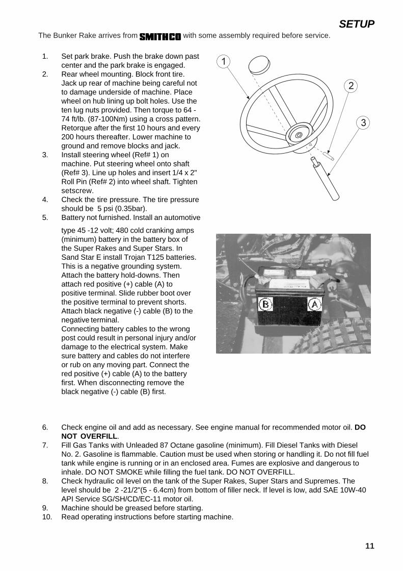
SETUPThe Bunker Rake arrives from with some assembly required before service.
1. Set park brake. Push the brake down pastcenter and the park brake is engaged.
2. Rear wheel mounting. Block front tire.Jack up rear of machine being careful notto damage underside of machine. Placewheel on hub lining up bolt holes. Use theten lug nuts provided. Then torque to 64 -74 ft/lb. (87-100Nm) using a cross pattern.Retorque after the first 10 hours and every200 hours thereafter. Lower machine toground and remove blocks and jack.
3. Install steering wheel (Ref# 1) onmachine. Put steering wheel onto shaft(Ref# 3). Line up holes and insert 1/4 x 2"Roll Pin (Ref# 2) into wheel shaft. Tightensetscrew.
4. Check the tire pressure. The tire pressureshould be 5 psi (0.35bar).
5. Battery not furnished. Install an automotive
type 45 -12 volt; 480 cold cranking amps(minimum) battery in the battery box ofthe Super Rakes and Super Stars. InSand Star E install Trojan T125 batteries.This is a negative grounding system.Attach the battery hold-downs. Thenattach red positive (+) cable (A) topositive terminal. Slide rubber boot overthe positive terminal to prevent shorts.Attach black negative (-) cable (B) to thenegative terminal.Connecting battery cables to the wrongpost could result in personal injury and/ordamage to the electrical system. Makesure battery and cables do not interfereor rub on any moving part. Connect thered positive (+) cable (A) to the batteryfirst. When disconnecting remove theblack negative (-) cable (B) first.
6. Check engine oil and add as necessary. See engine manual for recommended motor oil. DONOT OVERFILL.
7. Fill Gas Tanks with Unleaded 87 Octane gasoline (minimum). Fill Diesel Tanks with DieselNo. 2. Gasoline is flammable. Caution must be used when storing or handling it. Do not fill fueltank while engine is running or in an enclosed area. Fumes are explosive and dangerous toinhale. DO NOT SMOKE while filling the fuel tank. DO NOT OVERFILL.
8. Check hydraulic oil level on the tank of the Super Rakes, Super Stars and Supremes. Thelevel should be 2 -21/2"(5 - 6.4cm) from bottom of filler neck. If level is low, add SAE 10W-40API Service SG/SH/CD/EC-11 motor oil.
9. Machine should be greased before starting.10. Read operating instructions before starting machine.

12
Sand Star E 36V and 48VWHEN SERVICING
!!! WARNING !!!
SET THE PARKING BRAKE.
DO NOT WORK ON THE MOTOR WHILE CONNECTED TO BATTERIES.
KEEP SMOKING MATERIALS, FLAME OR SPARKS AWAY FROM THE BATTERIES.
NEVER CONNECT OR DISCONNECT EITHER THE BATTERIES OR ANY ELECTRICALCOMPONENT WHILE THE KEY IS IN THE SWITCH.
WHEN CONNECTING THE BATTERY CABLES, PAY PARTICULAR ATTENTION TO THEIRPOLARITIES. NEVER CONFUSE THE POSITIVE POSTS WITH THE NEGATIVE POSTS.
!!! WARNING !!!
USE INSULATED WRENCHES AND BE CAREFUL NOT TO ALLOW WRENCHES TO CONTACTMETAL AREAS OF VEHICLE WHILE WORKING ON BATTERY TERMINALS, OBSERVEBATTERY POLARITY WHEN REINSTALLING CABLES.
Using an insulated wrench, remove all wires from the vehicle batteries. Wrapping a wrench withelectrical tape will work, making sure no bare metal is showing. (Figure 1)
FIGURE 1 INSULATED WRAP
Remove the batteries using a battery carrying tool.
!!! WARNING !!!
BATTERIES ARE HEAVY AND CARE SHOULD BE TAKEN WHEN REMOVING THEM. BE CAREFULTO LIFT BATTERIES WITHOUT TIPPING THEM; ELECTROLYTE MAY BE SPILLED WHICH COULDCAUSE BURNS OR DAMAGE TO VEHICLE AND CLOTHING. SHOULD ANY ELECTROLYTE BESPILLED FLUSH THOROUGHLY WITH WATER. BE SURE TO WEAR EYE PROTECTION.

13
Battery on Sand Star E 36V and 48V
BATTERY
Batteries normally produce explosive gases, which can cause personal injury. Do not allow flames,sparks or any ignited object to come near the battery. When charging or working near battery, alwayswear proper eye protection and provide proper ventilation.
Electric vehicle batteries require CAREFUL maintenance to maximize their full service life.
PREVENTIVE MAINTENANCE
• Batteries must be recharged after each day’s use.• Check the electrolyte level at LEAST once a week.• Inspect all wiring for breaks or deterioration of the insulation.• Before charging batteries, inspect all terminals for frayed, loose, or damaged connectors.• Before charging batteries, inspect all terminals to assure that they are both clean (corrosion
free) and securely fastened to battery posts.• Batteries should be checked frequently to be sure that they are in a good state of charge. Full
charge for a new battery should yield a hydrometer reading of 1.260-1.280 specific gravity, whilean older battery may give a reading of 1.250 specific gravity and still be fully charged.
• When adding water, do not overfill. Overfilling will cause a loss of acid from the electrolyte. Usedistilled water when adding water to batteries. We recommend that other water sources NOT beused since impurities can reduce the full life of the batteries.
• To prevent unnecessary drag on the vehicle, which will result in poor performance and a higheramperage draw, inspect for improperly adjusted wheel bearings, dragging brakes and under-inflated tires.
• In the “off season,” the batteries should be FULLY CHARGED and stored in an unheated,covered area. Check the batteries during the “off season” at thirty-day intervals and recharge if ahydrometer shows a reading of less than 1.220 specific gravity.
BATTERY CHARGING
It is most important to follow the following steps when charging batteries:• Always use SMITHCO automatic chargers.• Check that electrolyte covers the plates in ALL cells.• Charging must be performed in a well-ventilated area.• Inspect the charger DC plug for loose, bent, arced or dirty contacts.• Inspect the vehicle receptacle for loose wires or damage.• Insert plug fully into receptacle and check that the connection is tight.• Be careful not to pull on the DC cord or place it in a position where it can be driven over or
present a hazard to personnel working in the area.

14
CONTROLS AND INSTRUMENTS GAS SUPER RAKE
IInstrument PanelLocated on right fender.
A. Ignition Switch: Three Positions. Stop-Run-Start.
B. Two Or Three Wheel Drive: Front wheeldrive valve is located on front right fender.Push to engage front wheel drive and pullto disengage front wheel drive.
Disengage front wheel drive for transportand plow operation only. Three to two wheeldrives can be shifted on the fly. Two wheeldrive increases ground speed.
C. Ammeter: The ammeter indicates the rateof charging or discharging of battery.
D. Fuse Holder and Fuse: Located incenter right side of instrument panel. A 30Amp fuse is used.
E. Oil Light: The oil light should come onwhen ignition is on, without engineoperating. The oil light will light when theoil pressure is low. If oil light should comeon, shut off engine immediately and findcause.
F. Hour Meter: The hour meter indicateshours of machine operation. The hourmeter operates when ignition switch is on.
G. Choke: Choke is located in center ofinstrument panel. Pull choke to rear toclose choke plate when starting a coldengine. A warm engine may not require“choking” to start.
H. Hand Throttle: Hand throttle is located onleft side of instrument panel. Use it toregulate engine speed.

15
Right Floorboard
Foot PedalThe Foot Pedal controls forward andreverse motion. Pushing down on the frontof pedal (I) will give you a forward motionand pushing down on rear pedal will giveyou a reverse motion. When pedal isreleased, the hydrostatic transmissioncenters and stops the vehicle. Groundspeed is proportional to how far the footpedal is depressed. (J) is the Hand Lift forthe Sand Plow.Quick removal of foot from forward orreverse pedal will result in an abrupt stop ofmachine.
SteeringThe automotive steering wheel isconnected to the front wheel assembly by achain driven sprocket. This allows for quickturns and short turning radius.
Seat AdjustmentSeat Adjustment Lever is located underfront of seat on left side. It allows seatadjustment forward or backward foroperator’s comfort. There are four differentbolt patterns so that you can manuallyadjust seat to fit operator’s comfort.
Park BrakePark brake is located on left fender. Pushlever (K) forward to release brake and pulllever rearward to set brake. Park brakemust be applied to start trap rake.
Valve PanelThe Lift Levers are located on left fender.To raise push down and to lower pull backforward. Release the lever whenattachment is in proper position and leverwill return too neutral. The Rake Lift lever(L) is on the inside of the machine. The LiftAssembly lever (M) is on the outsideclosest to the seat unless equipped with ahydraulic plow then the plow lever is closestto the seat.
Rear
Front

16
CONTROLS AND INSTRUMENTS Diesel SUPER RAKE
Instrument PanelLocated on right fender.A. Ignition Switch: Four Positions. Preheat-
Stop-Run-Start.
B. Hour Meter: The hour meter indicates thehours of machine operation. It operatesonly when the ignition switch is on.
C. Glow Plug: When ignition is turned topreheat, glow plug lights when ready tostart.
D. Temperature Light: The temperaturelight will come on if machine starts to overheat.
E. Oil Light: The oil light should come onwhen ignition is on, without engineoperating. The oil light will light when theoil pressure is low. If oil light should comeon, shut off engine immediately and findcause.
F. Fuse Holder and Fuse: Located incenter of instrument panel. A 30 Amp fuseis used.
G. Hand Throttle: Hand throttle is located onright fender. Use it to regulate enginespeed.
H. Two or Three Wheel Drive: Front wheeldrive valve is located on front right fender.Push to engage front wheel drive and pullto disengage front wheel drive.
Two Or Three Wheel Drive:Front wheel drive valve is located on frontright fender. Push to engage frontwheel drive and pull to disengage frontwheel drive.

17
Right Floorboard
Foot PedalThe Foot Pedal controls forward andreverse motion. Pushing down on the frontof pedal (I) will give you a forward motionand pushing down on rear pedal will giveyou a reverse motion. When pedal isreleased, the hydrostatic transmissioncenters and stops the vehicle. Groundspeed is proportional to how far the footpedal is depressed. (J) Is the Hand Lift forthe Sand Plow.Quick removal of foot from forward orreverse pedal will result in an abrupt stopof machine.
SteeringThe automotive steering wheel isconnected to the front wheel assembly bya chain driven sprocket. This allows forquick turns and short turning radius.
Seat AdjustmentSeat Adjustment Lever is located underfront of seat on left side. It allows seatadjustment forward or backward foroperator’s comfort. There are four differentbolt patterns so that you can manuallyadjust seat to fit operator’s comfort.
Park BrakePark brake is located on left fender. Pushlever (K) forward to release brake and pulllever rearward to set brake. Park brakemust be applied to start trap rake.
Valve PanelThe Lift Levers are located on left fender.To raise push down and to lower pull backforward. Release the lever whenattachment is in proper position and leverwill return too neutral. The Rake Lift lever(L) is on the inside of the machine. The LiftAssembly lever (M) is on the outsideclosest to the seat unless equipped with ahydraulic plow then the plow lever isclosest to the seat.
Rear
Front

18
Controls & Instruments Sand Star E 36VControls and Instruments on Sand Star E 36V (Models) 7327 / 7328
Key Switch:Located on the upper left corner of dash.Key must be turned to “on” position to runmachine.
Hour and Charge Meter: Located below key switch. Hours ofoperation are indicated at the bottom ofmeter; amount of charge in batteriesindicated on top. Note: As chargedecreases, light changes from green tored in stages.
Actuator switch for rear lift: Located on upper right corner of dash.Push top of switch to raise attachment;push bottom of switch to lower attachment.
Charging Receptacle:Located on right side of front cover. Plugbattery charger into receptacle.
Rear cover:Forward/Neutral/Reverse Lever: Located infront of seat on back cover. Use lever todetermine direction of movement.
Steering:Acquaint yourself with steering beforeoperating machine. The automotivesteering wheel is connected to the frontwheel by a chain-driven sprocket. Thisallows for quick turns and short turningradius.
Seat Adjustment:Seat adjustment lever is located under frontof seat on left side. It allows seatadjustment forward or backward foroperator’s comfort.
Left Running Board:The brake pedal is located on the leftrunning board. To lock the park brake, pushthe top of the two-piece brake pedal downuntil pedal locks. To release park brake,push down on the bottom part of the brakepedal until top of pedal springs back intoplace. Then take foot off of pedal.
Right Running Board:Accelerator pedal is located on right runningboard. When pedal is depressed, unit willmove in direction chosen on Forward/Neutral/Reverse (F-N-R) Lever. Under rightrunning board, the speed boss is fastenedto the accelerator pedal, and then connectsto the lift bracket at back of unit. When liftbracket is in “down” position, this pulls onthe speed boss cable, causing the unit toslow down. When lift bracket is in the “up”position, the unit will speed up.
Reverse Sounder:A beeper sounds when unit is in “reverse”setting. CINSTRUMENTS
Regenerative Braking System:The regenerative braking is activated two ways:1. If the unit is sitting on the side of a hill
unattended, the park brake is not engagedand the unit starts rolling down the hill, thebraking system will engage and the unit willroll at 2 mph (3 kph). It will not matter if keyswitch is “on” or “off” or whether in“forward” or “reverse”.
2. If the operator is driving the unit on flatterrain, starts down a hill, and the unitreaches 10 mph (16 kph), the brakingsystem will automatically engage and slowthe unit to 8 mph (12 kph). The unit willthen, speed up to 10 mph (16 kph) again.

19
Controls & Instruments Sand Star E 48VControls and Instruments on Sand Star E 48V (Models) 8327/ 8328 Dashboard/Front Cover
Key Switch: Located on the upper left corner of dash.Key must be turned to the “on” position torun machine.
Charge Meter: Located in the lower rightcorner of dash. It indicates the level ofcharge on batteries.
Note: As charge decreases, light changesfrom green to red in stages.
Actuator Switch for Cultivator/ScarifierAttachment:
Located on lower left corner of dash.Push top of switch to rise and bottom ofswitch to lower.
Actuator Switch for Rear Lift:Located on upper right corner of dash.Push top of switch to raise attachment;push bottom of switch to lowerattachment.
Charging Receptacle:Located on right side of front cover. Plugbattery charger into receptacle.
Forward/Reverse Switch:Located on center of dash under steeringshaft. Press top of switch to go forward;press bottom of switch to move backward.
Steering:Acquaint yourself with steering beforeoperating machine. Set steering wheel tiltto comfort of operator. The automotivesteering wheel is connected to the frontwheel by a chain driven sprocket. Thisallows for quick turns and short turningradius.
Seat Adjustment:Seat adjustment lever is located underfront of seat on left side. It allows seatadjustment forward or backward foroperator’s comfort.
Left Running Board:The brake pedal is located on the leftrunning board. To lock the park brake,push the top of the two-piece brake pedaldown until pedal locks. To release parkbrake, push down on the bottom part ofthe brake pedal until top of pedal springs
back into place. Then take foot off ofpedal.
Right Running Board:Accelerator pedal is located on right running
board. When pedal is depressed, unit willmove in direction chosen on Forward/Reverse (F/R) switch. Under right runningboard, the speed boss is fastened to theaccelerator pedal, and then connects tothe lift bracket at the back of the unit.When lift bracket is in “down” position, thispulls on the speed boss cable, which inturn, pulls back on the accelerator pedal,causing the unit to slow down. When liftbracket is in the “up” position, the unit willspeed up.
Reverse Sounder:A beeper sounds when unit is in “reverse”setting. CINSTRUMENTS
Regenerative Braking System:The regenerative braking is activated two ways:
1. If the unit is sitting on the side of a hillunattended, the park brake is not engagedand the unit starts rolling down the hill, thebraking system will engage and the unitwill roll at 2 mph (3 kph). It will not matter ifkey switch is “on” or “off” or whether in“forward” or “reverse”.
2. If the operator is driving the unit on flatterrain, starts down a hill, and the unitreaches 10 mph (16 kph), the brakingsystem will automatically engage and slowthe unit to 8 mph (12 kph). The unit willthen, speed up to 10 mph (16 kph) again.
NOTE: This will happen repeatedly until unitreaches flat terrain again.
REMEMBER: The operator does not need tostop unit before going down a hill. The brakingsystem works either from a stopped position ora rolling position.
Run-Tow/Maintenance Switch:Located in front of the batteries, this
switch activates the Regenerative Brakingsystem. Switch must be in “Run/On” positionbefore unit will operate.
Remember: Always turn switch to “Tow/Off”position when towing or working on unit.

20
Control & Instruments Super Star
IInstruments Loacted on the Control Panel
A. Electric On/Off Valve Switch:Toggle switch that turns 2 Wheel to 3Wheel Drive. For 42-117 Optional ElectricValve Kit.
B. Oil Light:The oil light should come on when ignitionis on without engine running. The oil lightwill light when the oil pressure is low. If oillight should come on shut off engineimmediately and find the cause.
C. Ignition Switch:The ignition switch has three positions:Off-Run-Start.
D. Choke:Pull choke control knob up to close chokeplate when starting a cold engine. A warmengine may not require “choking” to start.
E. Hand Throttle:The hand throttle is used to regulateengine speed.
F. Circuit Breaker:The circuit breaker is a resetable fuse. Toreset push down on it.
G. Light:This is an optional switch that comes withthe Light Kit.
SteeringAcquaint yourself with the steering beforeoperating the machine. This machine isequipped with a tilt steering mechanism.The lever to tilt the steering wheel islocated at bottom of rubber boot onsteering column. Hold the lever down andadjust the steering wheel to a comfortableposition.

21
Rake Lift LeverThis lever (H) raises and lowers all rearattachments. To raise, push forward tolower, pull back. Release the lever whenattachment is in proper position and leverwill return to neutral.
Lift Assembly LeverThis lever (J) raises and lowers allattachments under the center of themachine. To raise, push forward to lower,pull back. Release the lever whenattachment is in proper position and leverwill return to neutral.
Seat AdjsutmentSeat adjustment lever is located underfront of seat on left side. It allows seatadjustment forward or backward foroperator’s comfort. The seat also has thestart safety switch in it. To start the SuperStar the operator must be sitting on theseat.
Right FloorboardTwo Pedal Foot Control: Foot pedalcontrols forward and reverse motion andalso acts as a brake. Pushing down on thefront pedal (K) will give you a forwardmotion and pushing down on rear pedal(L) will give you a reverse motion. Whenpedal is released the hydrostatictransmission centers and stops thevehicle with a braking action. Groundspeed is proportional to how far the footpedal is depressed.
Hour Meter/ Volt MeterLocated on the right front fiberglasscowling (M). The hour meter indicateshours of machine operation. The hourmeter operates when ignition switch is on.The voltmeter indicates battery voltage.When starting the battery, voltage shouldnot drop below 9 volts, with the key on;engine not running the voltage should be a12 volts. With engine running at 3600 rpmthe voltage should read around 14 volts.

22
Controls & Instruments G Star
GEAR SHIFT LEVERTo shift, you must come to a completestop. Shift the shift lever into desired gear,which is marked at the base of the shiftlever. No clutching is necessary to changegears.
IGNITION SWITCH Located on right side of console. This is athree-position ignition switch; Stop – Run– Start.
Choke:Choke is located on the right side of theconsole. Pull choke control knob upwardsto close choke plate when starting a coldengine. A warm engine may not require“choking” to start.
Hand Throttle:Hand throttle is located on right side of theconsole. Use hand throttle when moreengine speed than ground speed isneeded.
Fuse & Fuse Holder:30 AMP fuse is used.
STEERINGAcquaint yourself with steering beforeoperating machine. The automotivesteering wheel is connected to the frontwheel assembly by a chain drivensprocket. This allows for quick turns andshort turning radius.
SEAT ADJUSTMENTSeat adjustment lever is located underfront of seat on left side. It provides seatadjustment forward or backward foroperator’s comfort.
RIGHT RUNNING BOARDAccelerator pedal is located on rightrunning board. When pedal is depressed,unit will move in direction chosen onForward/Neutral/Reverse (F-N-R) lever.Under the right running board, the SPEEDBOSS is fastened to the acceleratorpedal, and connects to the rake assemblylift bracket at the rear of the unit. When liftbracket is in “down” position, this pulls onthe SPEED BOSS cable, causing the unitto slow down to the adjustable desiredraking speed. When lift bracket is in the“up” position, the unit will speed up totransport speed.
LEFT RUNNING BOARD The brake pedal is located on the leftrunning board. To lock the park brake,push the top of the two-piece brake pedaldown until pedal locks. To release parkbrake, push down on the bottom part ofthe brake pedal until top of pedal springsback into place, and then take foot off ofpedal.

23
Operation and Daily Check List
STARTING ENGINEBefore operating this machine, become familiarwith all controls and functions of these units.Also complete all maintenance requirementsand read all safety warnings. By knowing themachine thoroughly, how it operates and bydoing the prescribed maintenance steps, youcan expect relatively trouble-free operation foryears to come.
1. Make sure the fuel flow valve, located onthe fuel tank, and is “ON.”
2. Set park brake. Start safety switch is onthe park brake.
3. The ignition switch is a three position ongas and four positions on diesel. For Gasengines: Insert key (A) and turn clockwiseuntil engine starts (C). Release key and itwill return to run position (B). Use chokeand hand throttle as necessary. For DieselEngines: Insert key (A) and turn counter-clockwise (D) until glow plug is glowing.Turn key clockwise until engine starts (C).Release key and it will return to runposition (B).
4. Allow engine to idle and warm up a fewminutes before selecting a direction oftravel.
5. To shut off engine on all gas machinesturn key to the stop position. On DieselSuper Rake move throttle to stop position.

24
DAILY CHECKLISTUse all procedures and parts prescribed by themanufacturers. Read the engine manual beforeoperation.
The suggested maintenance checklist is notoffered as a replacement for the manufacturersbut as a supplement. You must adhere toguidelines established by manufacturer forwarranty coverage. In adverse conditions such asdirt, mud or extreme temperatures, maintenanceshould be more frequent.
1. Check park brake adjustment. Adjust asrequired.
2. Check engine oil level. Add as needed. DONOT OVERFILL.
3. Tire pressure should be 5 psi (0.35bar)maximum.
4. Inspect electrical system for looseconnections or frayed wiring, includingbattery cables. Replace any faultyequipment or tighten if loose.
5. Check hardware for loose or missing nuts,bolts, screws, etc., and tighten or replaceas needed.
6. Inspect hydraulic lines for damage or leaks.Never use hands to inspect leaks.
7. Check hydraulic oil level.
8. Change hydraulic oil filter after first 20hours then at 100 hours, then every 250hours thereafter.
9. Inspect steering, throttle and shift linkagesfor good hookups and clear travel.
10. Check rear axle oil. If low, replenish; use10W-40 Motor Oil API Service SG/SH/CD/EC-
11. Check anti-vibration mounts on engineframe.
12. Check controls for smooth, proper workingoperation. Lubricate as needed.

25
How to Rake a Sand Trap
How to rake a sand trap
View bunker to determine the most efficientpattern to follow so that rake pattern andconfiguration of bunker will flow in same generaldirection and look attractive.
Enter bunker at its lowest point. Perhaps drainarea or another point where “lip” of the trap isminimal.
Operate at 2-4 mph (3-6.5 kph) for best rakingresults. Control speed with hydraulic pedal.
Once fully inside bunker, lower rear rake andproceed forward as described above.
First pass should be directly down center oftrap. This helps avoid extremely sharp turns thatwill spoil sands’ appearance. Once at far end,turn machine and drive down one side of trapand come back up other side.
Grass or other material may build up on raketines as machine passes “enter/exit” point inFigure 1. Lift rake briefly while still movingforward.
Do not rake closer than 6" (15cm) to edge oftrap.
Do not rake slopes in trap. The weight ofmachine will pull sand down.
Use cultivator or other center mountedaccessories only as necessary for compacted
sand. Frequent use will leave sand too soft andobjectionable to some golfers.
Use front mounted plow to push sand to desiredlocations within trap.
After exiting trap, secure machines in accordancewith practices described in this manual. Raketrap edges, slopes and “enter /exit” area with ahand rake.
After returning to maintenance area, thoroughlyclean machine, check fluids, and lubricate.

26
BATTERY
BatteryBatteries normally produce explosive gases,which can cause personal injury. Do not allowflames, sparks or any ignited object to comenear the battery. When charging or working nearbattery, always shield your eyes and alwaysprovide proper ventilation.
Battery cable should be disconnected beforeusing “Fast Charge”.
Charge battery at 15 amps for 10 minutes or 7amps for 30 minutes. Do not exceed therecommended charging rate. If electrolyte startsboiling over, decrease charging.
Always remove grounded (-) battery clamp firstand replace it last. Avoid hazards by:
1. Filling batteries in well-ventilated areas.2. Wear eye protection and rubber gloves.3. Avoid breathing fumes when electrolyte is
added.4. Avoid spilling or dripping electrolyte.Battery Electrolyte is an acidic solution andshould be handled with care. If electrolyte issplashed on any part of your body, flush allcontact areas immediately with liberal amountsof water. Get medical attention immediately.
Jump StartingParticular care should be used when connectinga booster battery. Use proper polarity in order toprevent sparks.
To jump start (negative grounded battery):
1. Shield eyes.2. Connect ends of one cable too positive (+)
terminals of each battery, first (A) then (B).3. Connect one end of other cable to
negative (-) terminal of “good” battery (C).4. Connect other end of cable (D) to engine
block on unit being started (NOT tonegative (-) terminal of battery)
To prevent damage to other electricalcomponents on unit being started, make certainthat engine is at idle speed before disconnectingjumper cables.

27
EC Declaration of Conformity according to Directive 89/392/EEC
We
SMITHCO INC. (Name of supplier)
34 West Ave. Wayne, PA 19087 USA
(Full address of the manufacture - authorized representative established in the Community must also give the
business name and address of the manufacture)
declare under our sole responsibility, that the product
42-000-D, E / 42-001-D Super Star 3 Wheel Drive / 2 Wheel Drive
13-550-D / 13-551-D Super Rake 3 Wheel Drive / 2 Wheel Drive
17-001-D, E Diesel Super Rake 3 Wheel Drive
43-000-A Super Star X-treme
43-001-A Diesel Super Star
9328 / 9430 G-Star
(Make, Model)
to which this declaration relates corresponds to the relevant basic safety and health requirements of the Directive
89/392/EEC,
(if applicable)
and to the requirements of the other Directives:
EN292-1
EN292-2
EN294
EN349
92/59
89/392 (Title and/or number and date of issue of the other Directives)
(if applicable)
For the relevant implementation of the safety and health requirements mentioned in the Directives, the following
standard(s) and/or technical specification(s) has (have) been respected:
ISO 37-1983
PREN 836
ISO 1219-1976
SAE HS-2800
SAE J1362 (Title and/or number and date of issue of standard(s) and/or technical specification(s))
Cameron, Wisconsin USA
(Place and date of issue) (Name, function and signature of the authorized person)

28
Limited Warranty
SMITHCO warrants this product to be free from defects in material and workmanship undernormal use for one year from the date of purchase by the original user. (60 days if product isused for rental purposes.) All warranty claims must be handles through a SMITHCOauthorized dealer or by SMITHCO, INC. The purchaser must pay all transportation charges.There is no further express warranty. All implied warranties, including those ofmerchantability and fitness for a particular purpose, are limited to one year, (60 days if productis used for rental purposes) from the date of purchase by the original user, and to the extentpermitted by law any and all implied warranties are excluded and disclaimed after theexpiration of such period.All incidental and consequential damages, including pickup and delivery of the unit,communication, mileage charges and/or rental of a replacement unit during repair, are notcovered under this warranty, nor is any loss of income and/or other loss resulting from thefailure of the product to function due to a warranty defect.The following items are not covered under the SMITHCO warranty, and are warranted by theirrespective manufacturer.
(a) Engine and engine parts, including starters, generators,alternators and filters.
(b) Transaxle, differentials, gearboxes and mechanical pumps.(c) Hydrostatic transmissions, hydraulic pump and motor.(d) Batteries.(e) Wheels and tires.
A copy of the warranty for the above items is furnished if necessary with each SMITHCOproduct.Some states do not allow limitations on how long an implied warranty lasts, or the exclusion orlimitations of incidental or consequential damages, so the above limitations or exclusions maynot apply to you. This warranty gives you specific legal rights and you may also have otherrights, which may vary from state to state.
Federal law now requires disclosure of the warranty, which applies to this product prior to thesale to a customer. Please leave this statement attached to the product and allow the buyer toremove it after purchase.


BOB-CAT BUNTON CUSHMAN JACOBSEN RANSOMES RYAN E-Z-GORansomes Jacobsen LimitedCentral Avenue, Ransomes Europark, Ipswich, England, IP3 9QGEnglish Company Registration No. 1070731www.ransomesjacobsen.com
Equipment from Ransomes Jacobsen Limited is built toexacting standards ensured by ISO 9001 registration at
all our manufacturing locations. A worldwide dealernetwork and factory-trained technicians backed by
Ransomes Jacobsen Parts Xpress provide reliable,high-quality product support.
World Class Quality, Performance and Support


