Embed Size (px)
Citation preview

WALLENSTEIN by EMB Mfg.
Rev # 1304171023T100 BX72R RevB Parts Manual.091214
EMB Manufacturing Inc.4144 Boomer Line · St. Clements, On · N0B 2M0 · Canada
Ph: (519) 699-9283 · Fax: (519) 699-4146 www.wallensteinequipment.com
Refer to the operators manual for safe opera-tion and maintenance
BX72 Series 3 Point HitchChipper Parts Manual
Starting with S/N 172R00002 to 172R240MODELS BX72R, BX72RI, BX72REU.
BX72RI
WALLENSTEIN by EMB Mfg.1023T100 BX72R RevB Parts Manual.091214
130417Page 2 of 24 For threaded parts installation, refer to the torque charts in this manual.
ForewordEMB Mfg. has prepared this parts manual to assist customers in ordering quality OEM replacement parts.Proper and regular service and replacing old, worn or broken parts with the correct Wallenstein parts are essen-tial to prolonging the life of your Wallenstein product. Please refer to this manual before ordering any replace-ment parts.All information contained in this parts manual is based on the latest product specification available at the time of printing this manual. If your product differs from the specifications contained within this manual contact EMB Mfg. for information.EMB reserves the right to alter specifications on their products at any time.Reproduction of this parts manual of any kind is prohibited without prior written permission from EMB Mfg.
For parts and information please contact your dealer. If your dealer is no longer availalble please go to our website: http://www.embmfg.com and click on ”FIND A DEALER NEAR YOU” for information on a local dealer.
Table of ContentsContents
BX72 VARIATION CHART .................................................................................. 3BOLT TORQUE ................................................................................................... 4HYDRAULIC FITTING TORQUE......................................................................... 5ROTOR ASS’Y..................................................................................................... 6BASE ASS’Y ...................................................................................................... 7CHUTE & GUARD ASS’Y ................................................................................... 8UPPER ROLLER ASS’Y .................................................................................... 9LOWER ROLLER ASS’Y ................................................................................. 10HOPPER ASS’Y (TOP VIEW) ............................................................................11BYPASS VALVE DETAIL ...................................................................................11HOPPER ASS’Y (BOTTOM VIEW) .................................................................. 12FEED TABLE ASS’Y ......................................................................................... 13MANUAL FEED ROLLER CONTROL DETAIL ................................................ 14FEED ROLLER CONTROL DETAIL ................................................................ 14INTELLIFEED ROLLER CONTROL DETAIL .................................................... 15INTELLIFEED COMPONENTS ......................................................................... 15PTO SHAFT #Z44504 ....................................................................................... 16INTELLIFEED SETTINGS ................................................................................. 17INTELLIFEED WIRING DIAGRAM #Z62109 .................................................... 18HYDRAULIC HOSE PARTS LIST .................................................................... 19HYDRAULIC SCHEMATIC BX72R ................................................................... 20HYDRAULIC SCHEMATIC BX72RI .................................................................. 21LABELS - LEFT SIDE VIEW ............................................................................. 22LABELS - RIGHT SIDE VIEW .......................................................................... 23
WALLENSTEIN by EMB Mfg. 1023T100 BX72R RevB Parts Manual.091214
Page 3 of 24130417 For threaded parts installation, refer to the torque charts in this manual.
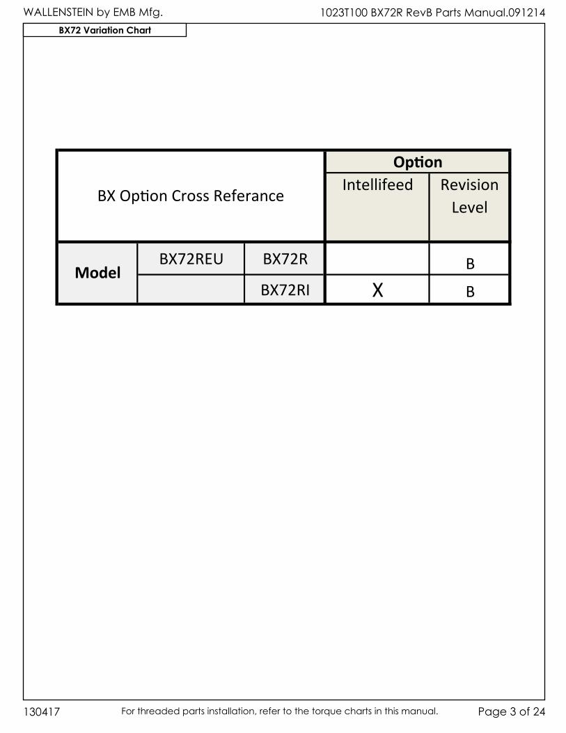
BX72 Variation Chart
Intellifeed RevisionLevel
BX72REU BX72R BBX72RI X B
BX Option Cross Referance
Option
Model
WALLENSTEIN by EMB Mfg.1023T100 BX72R RevB Parts Manual.091214
130417Page 4 of 24 For threaded parts installation, refer to the torque charts in this manual.
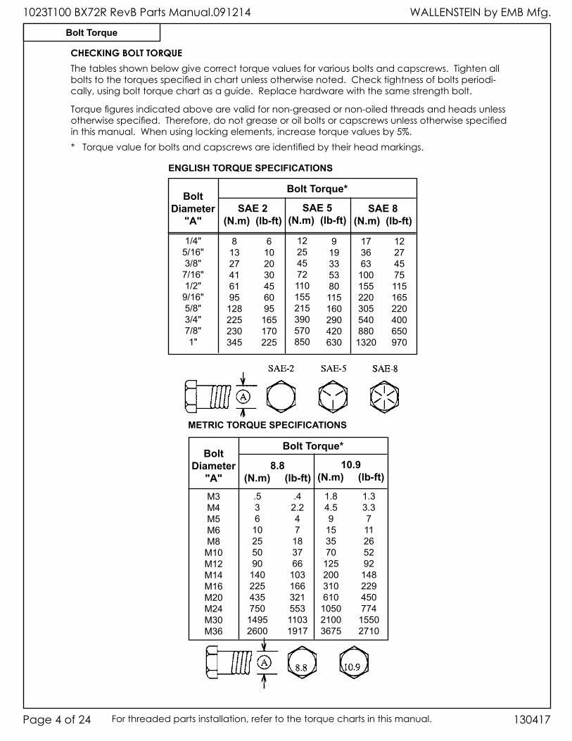
CHECKING BOLT TORQUEThe tables shown below give correct torque values for various bolts and capscrews. Tighten all bolts to the torques specified in chart unless otherwise noted. Check tightness of bolts periodi-cally, using bolt torque chart as a guide. Replace hardware with the same strength bolt.
ENGLISH TORQUE SPECIFICATIONS
SAE 2(N.m) (lb-ft)
Bolt Torque*Bolt
Diameter"A"
SAE 5(N.m) (lb-ft)
SAE 8(N.m) (lb-ft)
1/4"5/16"3/8"
7/16"1/2"
9/16"5/8"3/4"7/8"1"
81327416195
128225230345
6102030456095
165170225
12254572110155215390570850
919335380115160290420630
173663
100155220305540880
1320
12274575115165220400650970
METRIC TORQUE SPECIFICATIONS
8.8(N.m) (lb-ft)
Bolt Torque*Bolt
Diameter"A"
10.9(N.m) (lb-ft)
M3M4M5M6M8
M10M12M14M16M20M24M30M36
.536
10255090
140225435750
14952600
.42.247
183766
10316632155311031917
1.84.59
153570
125200310610
105021003675
1.33.3711265292
148229450774
15502710
Torque figures indicated above are valid for non-greased or non-oiled threads and heads unless otherwise specified. Therefore, do not grease or oil bolts or capscrews unless otherwise specified in this manual. When using locking elements, increase torque values by 5%.* Torque value for bolts and capscrews are identified by their head markings.
Bolt Torque
WALLENSTEIN by EMB Mfg. 1023T100 BX72R RevB Parts Manual.091214
Page 5 of 24130417 For threaded parts installation, refer to the torque charts in this manual.
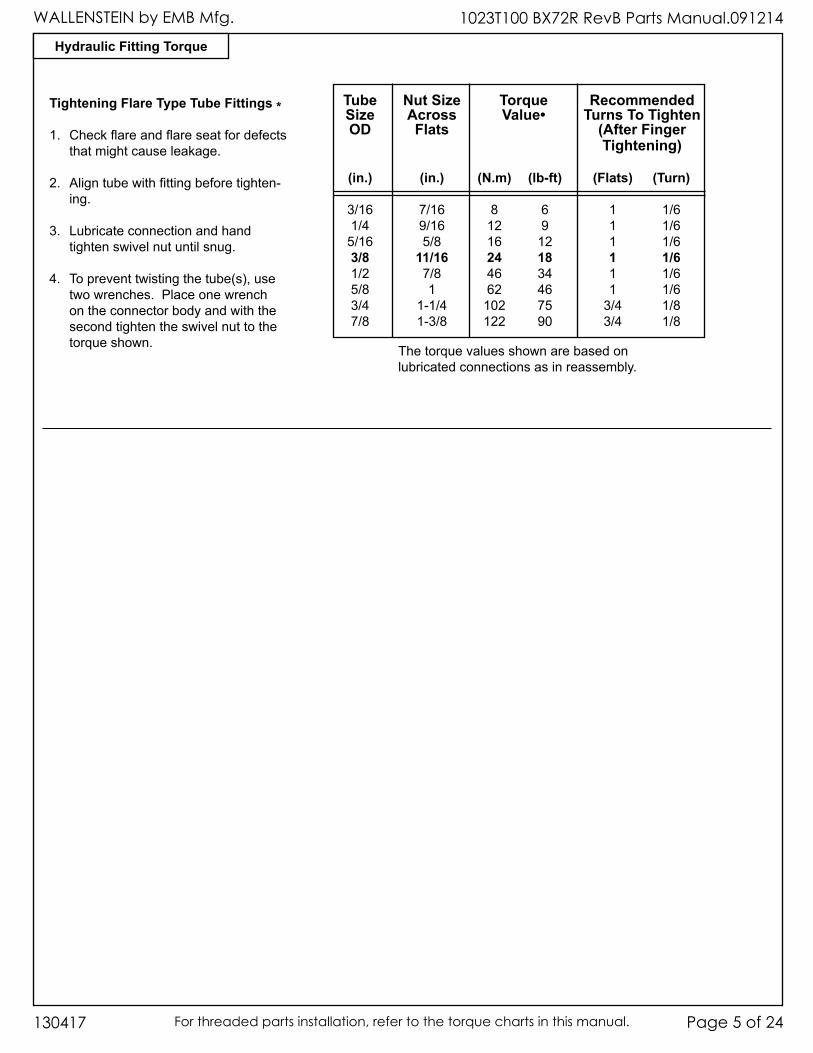
Tightening Flare Type Tube Fittings *
1. Checkflareandflareseatfordefectsthatmightcauseleakage.
2. Aligntubewithfittingbeforetighten-ing.
3. Lubricateconnectionandhandtightenswivelnutuntilsnug.
4. Topreventtwistingthetube(s),usetwowrenches.Placeonewrenchontheconnectorbodyandwiththesecondtightentheswivelnuttothetorqueshown.
Tube Nut Size Torque Recommended Size Across Value• Turns To Tighten OD Flats (After Finger Tightening)
(in.) (in.) (N.m) (lb-ft) (Flats) (Turn)
3/16 7/16 8 6 1 1/6 1/4 9/16 12 9 1 1/6 5/16 5/8 16 12 1 1/6 3/8 11/16 24 18 1 1/6 1/2 7/8 46 34 1 1/6 5/8 1 62 46 1 1/6 3/4 1-1/4 102 75 3/4 1/8 7/8 1-3/8 122 90 3/4 1/8
Thetorquevaluesshownarebasedonlubricatedconnectionsasinreassembly.
Hydraulic Fitting Torque
WALLENSTEIN by EMB Mfg.1023T100 BX72R RevB Parts Manual.091214
130417Page 6 of 24 For threaded parts installation, refer to the torque charts in this manual.
Roto
r Ass
’y
12
9
61010
6
4
8
17
12
10
3
510
211
12
9
61010
6
4
8
17
12
10
3
510
211
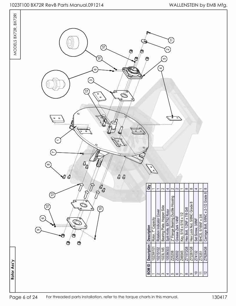
BOM
IDDe
scrip
tion
Desc
riptio
nQt
y1
1023
W10
1Ro
tor, 7
" Cap
acity
12
1021
S102
Rotat
ion In
dicato
r Cov
er1
310
23L1
45Be
aring
Plat
e, Ho
pper
Side
24
1053
M303
Split
Knife
, BXT
62 R
otor
45
Z252
082"
Flan
ge B
earin
g Duc
tile H
ousin
g2
6Z2
9202
Grea
se Z
erk 1
/4NF
27
Z465
45Ke
y, 5/1
6 x 5/
16 x
1/21
8Z7
1572
G8He
x Bolt
, 1/2N
F x 7
/8 Gr
88
9Z7
2261
G8He
x Loc
k Nut,
5/8N
C Gr
ade 8
810
Z741
32Se
t Scre
w, 3/
8NF
411
Z753
51BH
CS, 5
/16NF
x 3/4
112
Z762
64G8
Carri
age B
olt, 5
/8NC
x 2-1
/2 Gr
ade 8
8
MO
DEL
S BX
72R,
BX7
2RI
WALLENSTEIN by EMB Mfg. 1023T100 BX72R RevB Parts Manual.091214
Page 7 of 24130417 For threaded parts installation, refer to the torque charts in this manual.
Base
Ass
’y
202123
1939
22
3035
16
33
15
34
24
38
See L
edge
r Blad
e Deta
il
18
27
36
37
32
14
2813
25
31
29
26
17
202123
1939
22
3035
16
33
15
34
24
38
See L
edge
r Blad
e Deta
il
18
27
36
37
32
14
2813
25
31
29
26
17
4041
4645
44
4243
4041
4645
44
4243
BOM
IDDe
scrip
tion
Desc
riptio
nQt
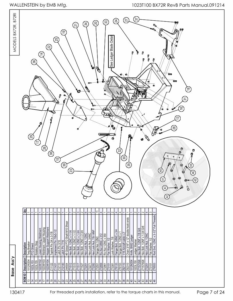
y13
1012
W20
4Tw
ig Br
eake
r1
1410
23L1
53PT
O Sh
ield
115
1023
L155
Rotat
ion S
top1
1610
23W
102
Lowe
r Hou
sing W
eldme
nt1
1710
23W
103
Weld
ment,
Upp
er H
ousin
g1
1810
23W
104
Hopp
er S
uppo
rt W
eldme
nt1
19Z1
1122
Topli
nk P
in 3/4
x 3-
7/81
20Z1
1431
Imple
ment
Pin 7
/8x5-
1/22
21Z1
2110
Latch
Pin
3/16
222
Z121
40La
tch P
in 7/1
61
23Z4
4504
#5 G
lobal
PTO
Shaft
M10
She
ar1
24Z7
1512
Hex B
olt, 1
/2NC
x 1-1
/47
25Z7
1515
Hex B
olt, 1
/2NC
x 1-1
/22
26Z7
1517
Hex B
olt, 1
/2NC
x 1-3
/43
27Z7
1527
Hex B
olt, 1
/2NC
x 2-3
/42
28Z7
2251
Hex L
ock N
ut, 1/
2NC
629
Z722
71He
x Loc
k Nut,
3/4N
C2
30Z7
2282
Hex L
ock N
ut, 7/
8-14
NF2
31Z7
2551
Flang
e Nut
1/2NC
1132
Z729
59Ri
v-Nut
3/8NC
x 31
24
33Z7
2961
Riv-N
ut 1/2
NC x
350
134
Z731
51Fla
t Was
her,
1/23
35Z7
3381
Lock
Was
her,
7/82
36Z7
6133
Flang
e Bolt
, 3/8N
C x 3
/44
37Z7
6153
Flang
e Bolt
, 1/2N
C x 1
438
Z921
101/1
6 Airc
raft c
able
x 2'
139
Z923
10Ch
ain 3/
16" x
12" d
ouble
hook
ends
140
1012
M204
Knife
, BX6
2 Led
ger
141
1023
L150
Ledg
er W
ashe
r2
42Z7
1572
G8He
x Bolt
, 1/2N
F x 7
/8 Gr
81
43Z7
1579
G8He
x Bolt
, 1/2N
F x 1
-3/4
Gr8
244
Z722
51He
x Loc
k Nut,
1/2N
C4
45Z7
3151
Flat W
ashe
r, 1/2
346
Z765
53Ro
d End
, 1/2N
C x 3
-1/2"
Full
Thr
eads
2
MO
DEL
S BX
72R,
B72
RI
WALLENSTEIN by EMB Mfg.1023T100 BX72R RevB Parts Manual.091214
130417Page 8 of 24 For threaded parts installation, refer to the torque charts in this manual.
Chu
te &
Gua
rd A
ss’y
55
49
59 50
58
56
52
53
51
47
61
60
5748
55
54
55
49
59 50
58
56
52
53
51
47
61
60
5748
55
54
BOM
IDDe
scrip
tion
Desc
riptio
nQt
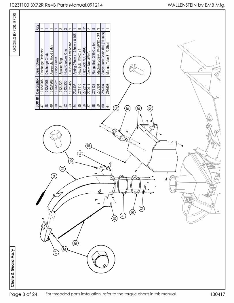
y47
1012
W20
5Di
scha
rge D
eflec
tor1
4810
12W
206
Disc
harg
e Chu
te1
4910
12W
208
Asse
mbly,
Hoo
d Latc
h1
5010
23W
221
Bridg
e Gua
rd1
5110
12L2
29Sp
acer
Ring
252
1012
L230
Hood
Cap
ture R
ing2
5310
82L4
22BX
62 ro
tation
limitin
g tab
154
Z314
03Sp
ring 2
7mm
x 178
mm x
0.105
155
Z711
10He
x Bolt
, 1/4N
C x 1
856
Z722
11He
x Loc
k Nut,
1/4N
C11
57Z7
2911
Acor
n Nut,
3/8N
C2
58Z7
6133
Flang
e Bolt
, 3/8N
C x 3
/48
59Z7
8301
Mach
ine S
crew,
1/4-
20NC
x 3/4
360
Z923
04Si
ngle-
Jack
Cha
in #1
0 [35
links
]1
61Z9
6503
Manu
al Tu
be 3-
1/2 S
hort
1
MO
DEL
S BX
72R,
B72
RI
WALLENSTEIN by EMB Mfg. 1023T100 BX72R RevB Parts Manual.091214
Page 9 of 24130417 For threaded parts installation, refer to the torque charts in this manual.
118
87
105
88
9799
9682
112
117
95
107
101
100
113
93 116
83
92
110
80
115
88
89 114
84
96
102
81
111
108
85 109
97
90
94
103
106
104
118
87
105
88
9799
9682
112
117
95
107
101
100
113
93 116
83
92
110
80
115
88
89 114
84
96
102
81
111
108
85 109
97
90
94
103
106
104
BOM
IDDe
scrip
tion
Desc
riptio
nQt
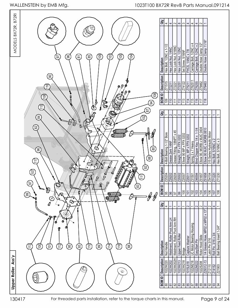
y80
1022
W22
0Nu
t Han
dle4
8110
23W
202
Weld
ment,
Roll
er P
ivot A
rm LH
182
1023
W20
2HW
eldme
nt, R
oller
Pivo
t Arm
RH
183
1023
W21
3Up
per F
eed R
oller
184
1023
W21
8Br
idge
185
1015
L618
Captu
re W
ashe
r2
8710
22M2
18UC
Moto
r Bea
ring H
ousin
g1
8810
22M2
22Ea
sySt
art P
in2
8910
22S2
08Ro
tor H
ood S
lide
290
Z293
12-1
31/4
Gre
ase H
ose,
MP02
x MP
02 x
13"
292
Z121
10La
tch P
in 3/1
62
93Z1
4152
Roll P
in, 3/
16 x
3/44
94Z2
1903
Ball B
earin
g Ins
ert 1
-3/4"
1
BOM
IDDe
scrip
tion
Desc
riptio
nQt
y95
Z252
044-
Bolt B
earin
g 1-1
/2" B
ore
196
Z292
02Gr
ease
Zer
k 1/4N
F2
97Z2
9204
Grea
se F
itting
, 1/8N
PT x
452
99Z2
9302
Stra
ight, F
P x F
PX 02
022
100
Z293
07El
bow
90 M
P x F
PX 02
022
101
Z293
11St
raigh
t, MP
x FPX
0202
110
2Z3
1501
Sprin
g 2 x
7 Hea
vy4
103
Z465
94Bl
ind C
hippe
r Key
1/4 x
1-1
/41
104
Z516
57El
bow
90, M
ORB
x MJIC
0404
110
5Z5
1658
Elbo
w 90
MJIC
x MO
RB 08
102
106
Z541
0431
5 Ser
ies H
ydra
ulic M
otor
110
7Z7
1220
Hex B
olt, 5
/16NC
x 2
110
8Z7
1230
Hex B
olt, 5
/16NC
x 3
1
BOM
IDDe
scrip
tion
Desc
riptio
nQt
y10
9Z7
1515
Hex B
olt, 1
/2NC
x 1-1
/24
110
Z722
11He
x Loc
k Nut,
1/4N
C4
111
Z722
21He
x Loc
k Nut,
5/16
NC2
112
Z722
51He
x Loc
k Nut,
1/2N
C8
113
Z741
22Se
t Scre
w, 5/
16NF
311
4Z7
5211
FHCS
, 1/4N
C x 7
/84
115
Z762
511
Carri
age B
olt, 1
/2NC
x 44
116
Z762
55Ca
rriag
e Bolt
, 1/2N
C x 2
411
7Z7
9462
Doub
le Ho
se C
lamp 1
/2"2
118
Z794
63Do
uble
Hose
Clam
p 11/1
6"1
Uppe
r Rol
ler
Ass
’yM
OD
ELS
BX72
R, B
72RI
WALLENSTEIN by EMB Mfg.1023T100 BX72R RevB Parts Manual.091214
130417Page 10 of 24 For threaded parts installation, refer to the torque charts in this manual.
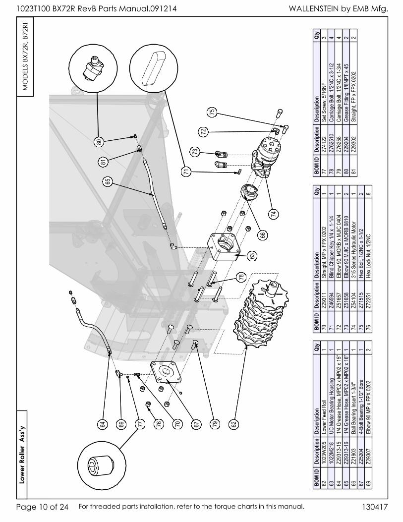
76 6764 707769 6279
78
8081
65
6366
71
74
7372
75
76 6764 707769 6279
78
8081
65
6366
71
74
7372
75
BOM
IDDe
scrip
tion
Desc
riptio
nQt
y62
1023
W20
5Lo
wer F
eed R
oll1
6310
22M2
18UC
Moto
r Bea
ring H
ousin
g1
64Z2
9313
-15
1/4 G
reas
e Hos
e, MP
02 x
MP02
x 15
"1
65Z2
9313
-16
1/4 G
reas
e Hos
e, MP
02 x
MP02
x 16
"1
66Z2
1903
Ball B
earin
g Ins
ert 1
-3/4"
167
Z252
044-
Bolt B
earin
g 1-1
/2" B
ore
169
Z293
07El
bow
90 M
P x F
PX 02
022
BOM
IDDe
scrip
tion
Desc
riptio
nQt
y70
Z293
11St
raigh
t, MP
x FPX
0202
171
Z465
94Bl
ind C
hippe
r Key
1/4 x
1-1
/41
72Z5
1657
Elbo
w 90
, MOR
B x M
JIC 04
041
73Z5
1658
Elbo
w 90
MJIC
x MO
RB 08
102
74Z5
4104
315 S
eries
Hyd
rauli
c Moto
r1
75Z7
1515
Hex B
olt, 1
/2NC
x 1-1
/22
76Z7
2251
Hex L
ock N
ut, 1/
2NC
8
BOM
IDDe
scrip
tion
Desc
riptio
nQt
y77
Z741
22Se
t Scre
w, 5/
16NF
378
Z762
510
Carri
age B
olt, 1
/2NC
x 3-1
/24
79Z7
6258
Carri
age B
olt, 1
/2NC
x 1-3
/44
80Z2
9204
Grea
se F
itting
, 1/8N
PT x
452
81Z2
9302
Stra
ight, F
P x F
PX 02
022
Low
er R
olle
r A
ss’y
MO
DEL
S BX
72R,
B72
RI
WALLENSTEIN by EMB Mfg. 1023T100 BX72R RevB Parts Manual.091214
Page 11 of 24130417 For threaded parts installation, refer to the torque charts in this manual.
Hopp
er A
ss’y
(top
vie
w)
125
135
131
128
138
139
Used
on B
X72R
Only
122
137
132
121
136
129
120
126
134
133
123
119
127
130
See B
ypas
sDe
tail
124
125
135
131
128
138
139
Used
on B
X72R
Only
122
137
132
121
136
129
120
126
134
133
123
119
127
130
See B
ypas
sDe
tail
124
BOM
IDDe
scrip
tion
Desc
riptio
nQt
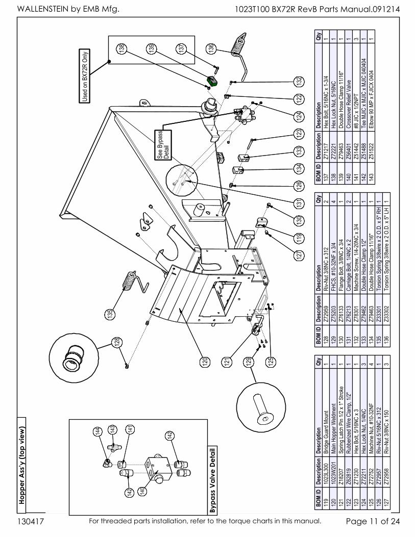
y11
910
23L3
00Br
idge G
uard
Mou
nt1
120
1023
W20
1Ma
in Ho
pper
Weld
ment
112
1Z1
8207
Sprin
g Latc
h Pin
1/2 x
1" S
troke
112
2Z6
2819
Rubb
erize
d Wire
Clam
p, 1/2
"1
123
Z712
30He
x Bolt
, 5/16
NC x
31
124
Z722
11He
x Loc
k Nut,
1/4N
C3
125
Z727
52Ma
chine
Nut,
#10-
32NF
412
6Z7
2957
Riv-N
ut 5/1
6NC
x 312
112
7Z7
2958
Riv-N
ut 3/8
NC x
150
3
BOM
IDDe
scrip
tion
Desc
riptio
nQt
y12
8Z7
2959
Riv-N
ut 3/8
NC x
312
212
9Z7
5203
FHCS
, #10
-32N
F x 3
/44
130
Z761
33Fla
nge B
olt, 3
/8NC
x 3/4
113
1Z7
6213
Carri
age B
olt, 1
/4NC
x 22
132
Z783
01Ma
chine
Scre
w, 1/
4-20
NC x
3/41
133
Z794
62Do
uble
Hose
Clam
p 1/2"
113
4Z7
9463
Doub
le Ho
se C
lamp 1
1/16"
113
5Z3
3301
Torsi
on S
pring
3/8w
ire x
2 O.D
. x 5"
RH
113
6Z3
3302
Torsi
on S
pring
3/8w
ire x
2 O.D
. x 5"
LH1
BOM
IDDe
scrip
tion
Desc
riptio
nQt
y13
7Z7
1217
Hex B
olt, 5
/16NC
x 1-
3/41
138
Z722
21He
x Loc
k Nut,
5/16
NC1
139
Z794
63Do
uble
Hose
Clam
p 11/1
6"1
140
Z564
01Cr
osso
ver R
elief
Valve
114
1Z5
1442
#8 JI
C x 1
/2NPT
314
2Z5
1488
Tee M
JIC x
MJIC
x MJ
IC 04
0404
114
3Z5
1522
Elbo
w 90
MP
x FJIC
X 04
041
142
140
141
142
144 143
142
140
141
142
144 143
Bypa
ss V
alve
Det
ail
WALLENSTEIN by EMB Mfg.1023T100 BX72R RevB Parts Manual.091214
130417Page 12 of 24 For threaded parts installation, refer to the torque charts in this manual.
Hopp
er A
ss’y
(bot
tom
vie
w)
149
137
138
142
144
147
150
143
152
141
140
151
146
139
149
137
138
142
144
147
150
143
152
141
140
151
146
139
BOM
IDDe
scrip
tion
Desc
riptio
nQt
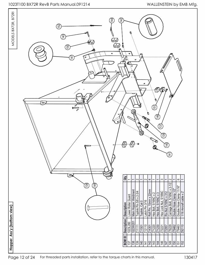
y13
710
23L2
80Lo
wer R
oller
Gua
rd1
138
1023
W20
1Ma
in Ho
pper
Weld
ment
113
9Z1
1111
Topli
nk P
in 5/8
x 2-
3/42
140
Z115
01To
plink
, Cat
01
141
Z121
10La
tch P
in 3/1
62
142
Z143
01Ro
ll Pin,
10mm
x 22
mm4
143
Z712
20He
x Bolt
, 5/16
NC x
21
144
Z712
30He
x Bolt
, 5/16
NC x
31
146
Z722
21He
x Loc
k Nut,
5/16
NC3
147
Z729
57Ri
v-Nut
5/16N
C x 3
121
149
Z762
29Ca
rriag
e Bolt
, 5/16
NC x
3-1/2
215
0Z7
9462
Doub
le Ho
se C
lamp 1
/2"1
151
Z794
63Do
uble
Hose
Clam
p 11/1
6"6
152
Z921
101/1
6 Airc
raft c
able
x 2'
1
MO
DEL
S BX
72R,
B72
RI
WALLENSTEIN by EMB Mfg. 1023T100 BX72R RevB Parts Manual.091214
Page 13 of 24130417 For threaded parts installation, refer to the torque charts in this manual.
Feed
Tabl
e A
ss’y
165
156
164
168
158
157
173
170
153
160
166
15517
2
171
167
See F
eed R
oller
Contr
ol De
tail
See F
eed C
ontro
l Deta
il:- I
ntellif
eed
- Man
ual F
eed
175
176
174
161
162
163
169
159
154
165
156
164
168
158
157
173
170
153
160
166
15517
2
171
167
See F
eed R
oller
Contr
ol De
tail
See F
eed C
ontro
l Deta
il:- I
ntellif
eed
- Man
ual F
eed
175
176
174
161
162
163
169
159
154
BOM
IDDe
scrip
tion
Desc
riptio
nQt
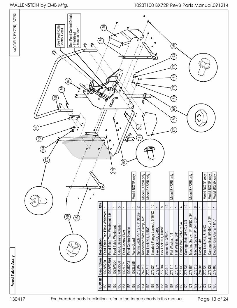
y15
310
22W
230
Feed
Tab
le Tr
ap P
late W
eldme
nt1
154
1022
W23
0HFe
ed T
able
Trap
Weld
ment,
LH1
155
1023
W20
4Fe
ed T
able
Weld
ment
115
610
15S5
38U-
bolt,
Bear
ing A
dapte
r5
157
1022
L271
Feed
Con
trol P
ivot
115
810
23S2
03Fe
ed C
ontro
l Han
dle1
159
1022
L256
Valve
Gua
rd1
160
Z182
07Sp
ring L
atch P
in 1/2
x 1"
Stro
ke2
161
Z628
19Ru
bber
ized W
ire C
lamp,
1/2"
116
2Z7
2211
Hex L
ock N
ut, 1/
4NC
116
3Z7
2521
Serra
ted F
lange
Lock
nut, 5
/16NC
1016
4Z7
2271
Hex L
ock N
ut, 3/
4NC
116
5Z7
2204
Hex L
ock N
ut, #1
0NF
816
6Z7
2911
Acor
n Nut,
3/8N
C12
167
Z731
11Fla
t Was
her,
1/41
168
Z731
71Fla
t Was
her,
3/4"
116
9Z7
6133
Flang
e Bolt
, 3/8N
C x 3
/44
170
Z762
33Ca
rriag
e Bolt
, 3/8N
C x 3
/412
171
Z783
01Ma
chine
Scre
w, 1/
4-20
NC x
3/41
172
Z783
16Ma
chine
Scre
w, #1
0NF
x 3/4
817
3Z9
4601
Deca
l, SMV
117
4Z7
2221
Hex L
ock N
ut, 5/
16NC
117
5Z7
6227
Carri
age B
olt, 5
/16NC
x 1-
3/41
176
Z794
63Do
uble
Hose
Clam
p 11/1
6"1
MO
DEL
S BX
72R,
B72
RI
Mode
l BX7
2R on
ly
Mode
l BX7
2R on
lyMo
del B
X72R
only
Mode
l BX7
2RI o
nlyMo
del B
X72R
I only
Mode
l BX7
2RI o
nly
Mode
l BX7
2RI o
nly
Mode
l BX7
2R on
ly
WALLENSTEIN by EMB Mfg.1023T100 BX72R RevB Parts Manual.091214
130417Page 14 of 24 For threaded parts installation, refer to the torque charts in this manual.
176
170171
Feed Table
178
179
172
168
166
175
177
165
173
167
164
169
174
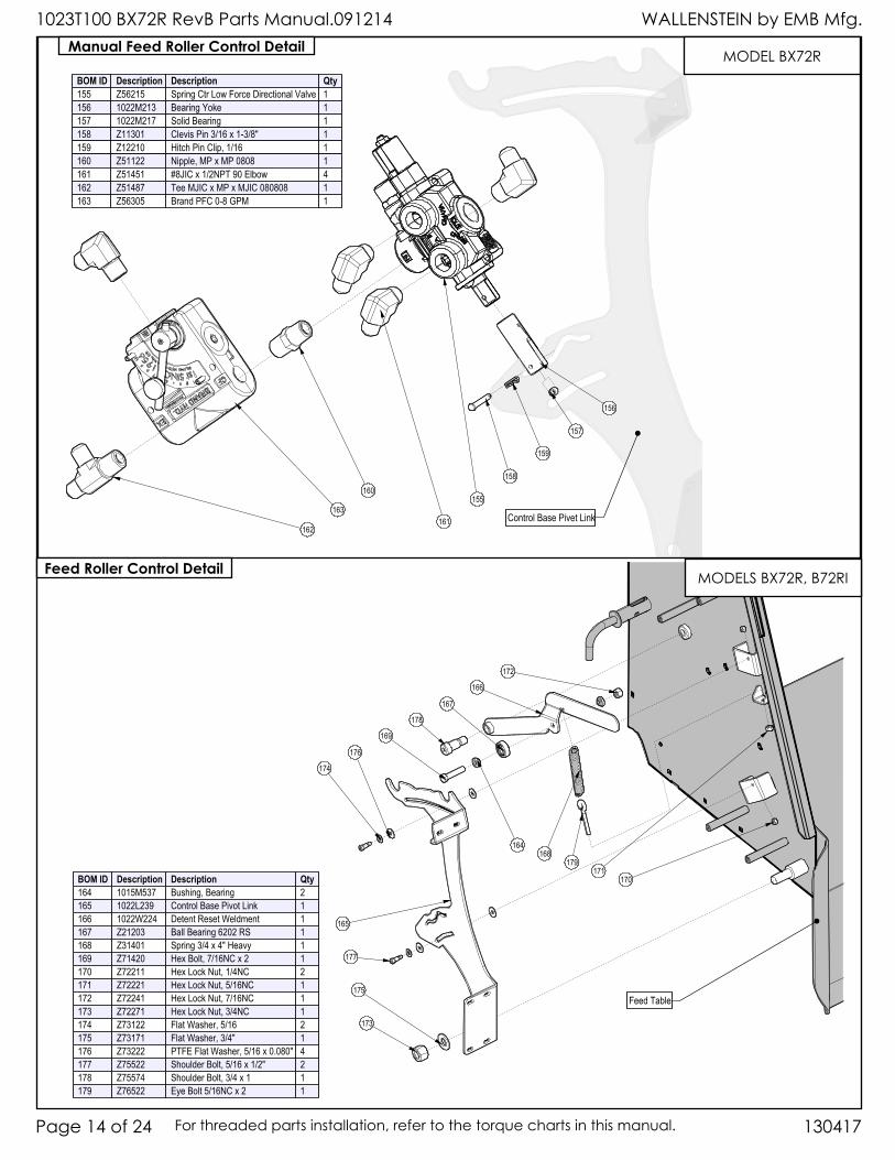
BOM ID Description Description Qty164 1015M537 Bushing, Bearing 2165 1022L239 Control Base Pivot Link 1166 1022W224 Detent Reset Weldment 1167 Z21203 Ball Bearing 6202 RS 1168 Z31401 Spring 3/4 x 4" Heavy 1169 Z71420 Hex Bolt, 7/16NC x 2 1170 Z72211 Hex Lock Nut, 1/4NC 2171 Z72221 Hex Lock Nut, 5/16NC 1172 Z72241 Hex Lock Nut, 7/16NC 1173 Z72271 Hex Lock Nut, 3/4NC 1174 Z73122 Flat Washer, 5/16 2175 Z73171 Flat Washer, 3/4" 1176 Z73222 PTFE Flat Washer, 5/16 x 0.080" 4177 Z75522 Shoulder Bolt, 5/16 x 1/2" 2178 Z75574 Shoulder Bolt, 3/4 x 1 1179 Z76522 Eye Bolt 5/16NC x 2 1
162
163
160
157
156
155
Control Base Pivet Link
158
159
161
BOM ID Description Description Qty155 Z56215 Spring Ctr Low Force Directional Valve 1156 1022M213 Bearing Yoke 1157 1022M217 Solid Bearing 1158 Z11301 Clevis Pin 3/16 x 1-3/8" 1159 Z12210 Hitch Pin Clip, 1/16 1160 Z51122 Nipple, MP x MP 0808 1161 Z51451 #8JIC x 1/2NPT 90 Elbow 4162 Z51487 Tee MJIC x MP x MJIC 080808 1163 Z56305 Brand PFC 0-8 GPM 1
Manual Feed Roller Control Detail
Feed Roller Control Detail
MODEL BX72R
MODELS BX72R, B72RI
WALLENSTEIN by EMB Mfg. 1023T100 BX72R RevB Parts Manual.091214
Page 15 of 24130417 For threaded parts installation, refer to the torque charts in this manual.
Feed Table
319 313
311306
299
302
296
322
Control Base Pivot Link
321
304 303310
307297 323
298318
Feed Table
319 313
311306
299
302
296
322
Control Base Pivot Link
321
304 303310
307297 323
298318
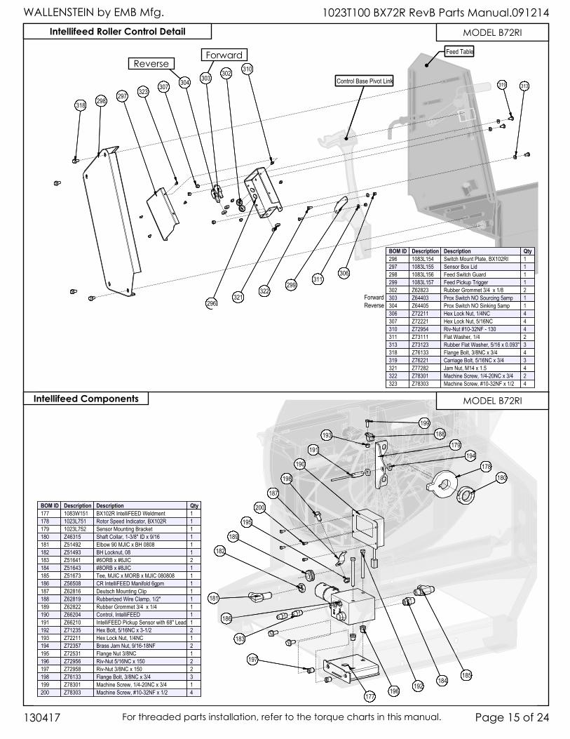
BOM ID Description Description Qty296 1083L154 Switch Mount Plate, BX102RI 1297 1083L155 Sensor Box Lid 1298 1083L156 Feed Switch Guard 1299 1083L157 Feed Pickup Trigger 1302 Z62823 Rubber Grommet 3/4 x 1/8 2303 Z64403 Prox Switch NO Sourcing 5amp 1304 Z64405 Prox Switch NO Sinking 5amp 1306 Z72211 Hex Lock Nut, 1/4NC 4307 Z72221 Hex Lock Nut, 5/16NC 4310 Z72954 Riv-Nut #10-32NF - 130 4311 Z73111 Flat Washer, 1/4 2313 Z73123 Rubber Flat Washer, 5/16 x 0.093" 3318 Z76133 Flange Bolt, 3/8NC x 3/4 4319 Z76221 Carriage Bolt, 5/16NC x 3/4 3321 Z77282 Jam Nut, M14 x 1.5 4322 Z78301 Machine Screw, 1/4-20NC x 3/4 2323 Z78303 Machine Screw, #10-32NF x 1/2 4
Intellifeed Roller Control Detail
182
185
181
184
177196
197
186
194179
193 188
198
199
191
192
190
195
187
178
183
189
180
200
182
185
181
184
177196
197
186
194179
193 188
198
199
191
192
190
195
187
178
183
189
180
200BOM ID Description Description Qty177 1083W151 BX102R IntelliFEED Weldment 1178 1023L751 Rotor Speed Indicator, BX102R 1179 1023L752 Sensor Mounting Bracket 1180 Z46315 Shaft Collar, 1-3/8" ID x 9/16 1181 Z51492 Elbow 90 MJIC x BH 0808 1182 Z51493 BH Locknut, 08 1183 Z51641 #6ORB x #6JIC 2184 Z51643 #8ORB x #8JIC 1185 Z51673 Tee, MJIC x MORB x MJIC 080808 1186 Z56508 CR IntelliFEED Manifold 6gpm 1187 Z62816 Deutsch Mounting Clip 1188 Z62819 Rubberized Wire Clamp, 1/2" 1189 Z62822 Rubber Grommet 3/4 x 1/4 1190 Z66204 Control, IntelliFEED 1191 Z66210 IntelliFEED Pickup Sensor with 68" Lead 1192 Z71235 Hex Bolt, 5/16NC x 3-1/2 2193 Z72211 Hex Lock Nut, 1/4NC 1194 Z72357 Brass Jam Nut, 9/16-18NF 2195 Z72531 Flange Nut 3/8NC 1196 Z72956 Riv-Nut 5/16NC x 150 2197 Z72958 Riv-Nut 3/8NC x 150 2198 Z76133 Flange Bolt, 3/8NC x 3/4 3199 Z78301 Machine Screw, 1/4-20NC x 3/4 1200 Z78303 Machine Screw, #10-32NF x 1/2 4
Intellifeed Components
MODEL B72RI
MODEL B72RI
ForwardReverse
ForwardReverse
WALLENSTEIN by EMB Mfg.1023T100 BX72R RevB Parts Manual.091214
130417Page 16 of 24 For threaded parts installation, refer to the torque charts in this manual.
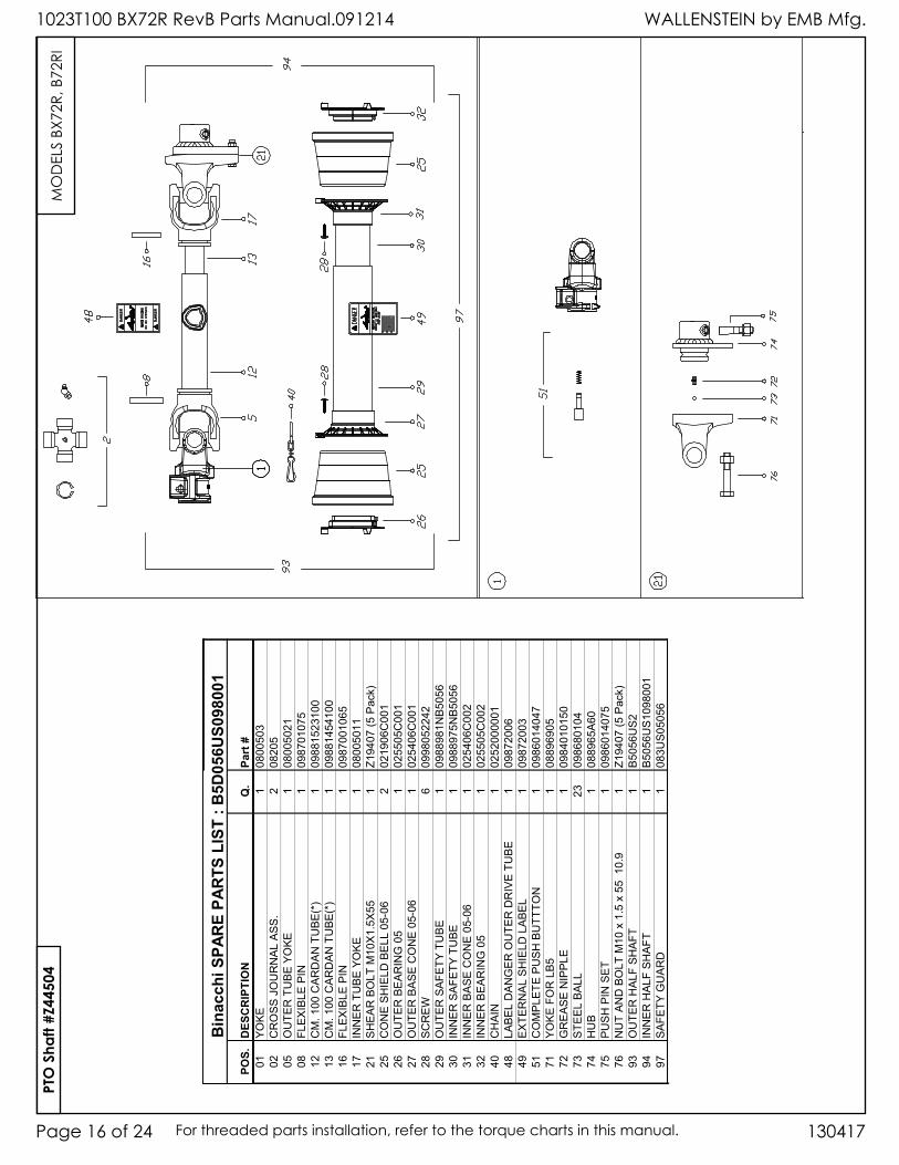
Bin
acch
i SPA
RE
PAR
TS L
IST
: B5D
056U
S098
001
POS.
DES
CR
IPTI
ON
Q.
Part
#01
YOKE
108
0050
302
CR
OSS
JO
UR
NA
L AS
S.2
0820
505
OU
TER
TU
BE Y
OKE
108
0050
2108
FLEX
IBLE
PIN
109
8701
075
12CM.100CAR
DANTUBE
(*)
109
8815
2310
013
CM.100CAR
DANTUBE
(*)
109
8814
5410
016
FLEX
IBLE
PIN
109
8700
1065
17IN
NER
TU
BE Y
OKE
108
0050
1121
SH
EA
R B
OLT
M10
X1.
5X55
1Z1
9407
(5 P
ack)
25C
ON
E SH
IELD
BEL
L 05
-06
202
1906
C00
126
OU
TER
BEA
RIN
G 0
51
0255
05C
001
27O
UTE
R B
ASE
CO
NE
05-0
6 1
0254
06C
001
28SC
RE
W6
0998
0522
4229
OU
TER
SAF
ETY
TUBE
109
8898
1NB5
056
30IN
NER
SAF
ETY
TUBE
109
8897
5NB5
056
31IN
NER
BAS
E C
ON
E 05
-06
102
5406
C00
232
INN
ER B
EAR
ING
05
102
5505
C00
240
CH
AIN
102
5200
0001
48LA
BEL
DAN
GER
OU
TER
DR
IVE
TUBE
109
8720
0649
EXTE
RN
AL
SHIE
LD L
ABEL
109
8720
0351
COMPL
ETEPU
SHBUTT
TON
109
8601
4047
71YO
KE F
OR
LB5
108
8969
0572
GREA
SENIPPL
E1
0984
0101
5073
STEE
L BA
LL23
0986
8010
474
HU
B1
0889
65A6
075
PUSH
PINSET
1
0986
0140
7576
NU
T AN
D B
OLT
M10
x 1
.5 x
55
10.
91
Z19407(5Pack)
93O
UTE
R H
ALF
SHAF
T1
B505
6US2
94IN
NER
HAL
F SH
AFT
1B5
056U
S109
8001
97SA
FETY
GU
ARD
108
3US0
5056
PTO
Sha
ft #Z
4450
4M
OD
ELS
BX72
R, B
72RI
WALLENSTEIN by EMB Mfg. 1023T100 BX72R RevB Parts Manual.091214
Page 17 of 24130417 For threaded parts installation, refer to the torque charts in this manual.
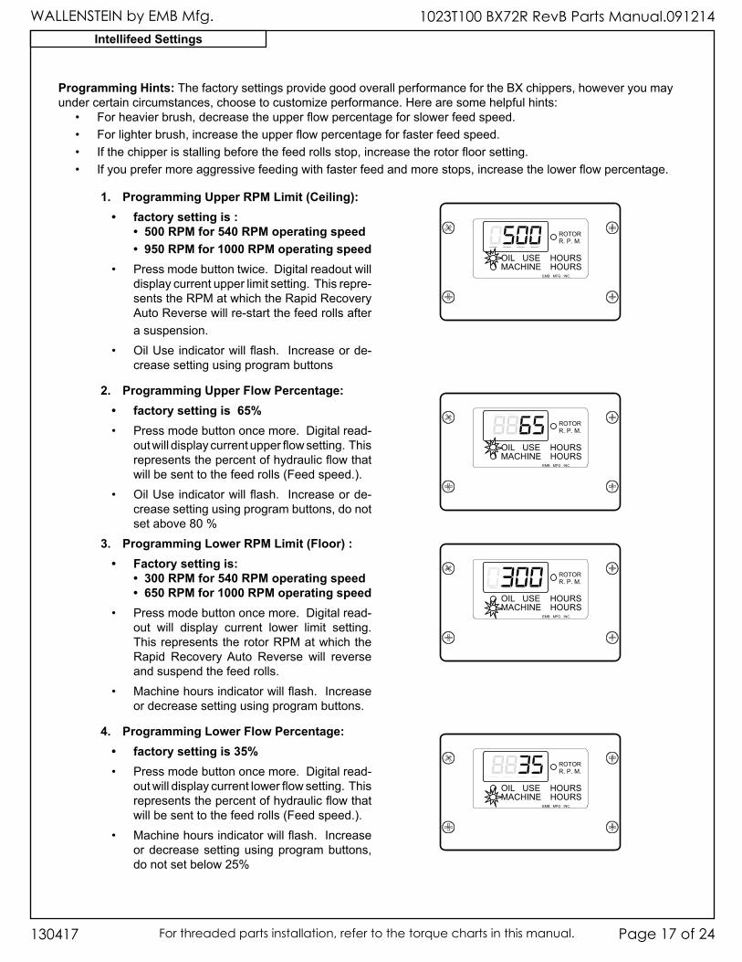
1. Programming Upper RPM Limit (Ceiling): • factory setting is :
• 500 RPM for 540 RPM operating speed• 950 RPM for 1000 RPM operating speed
• Pressmodebuttontwice.Digitalreadoutwilldisplaycurrentupperlimitsetting.Thisrepre-sentstheRPMatwhichtheRapidRecoveryAutoReversewillre-startthefeedrollsafterasuspension.
• OilUseindicatorwillflash.Increaseorde-creasesettingusingprogrambuttons
2. Programming Upper Flow Percentage:• factory setting is 65%• Pressmodebuttononcemore.Digitalread-
outwilldisplaycurrentupperflowsetting.Thisrepresentsthepercentofhydraulicflowthatwillbesenttothefeedrolls(Feedspeed.).
• OilUseindicatorwillflash.Increaseorde-creasesettingusingprogrambuttons,donotsetabove80%
3. Programming Lower RPM Limit (Floor) :• Factory setting is:
• 300 RPM for 540 RPM operating speed• 650 RPM for 1000 RPM operating speed
• Pressmodebuttononcemore.Digitalread-out will display current lower limit setting.ThisrepresentstherotorRPMatwhichtheRapid RecoveryAuto Reverse will reverseandsuspendthefeedrolls.
• Machinehoursindicatorwillflash.Increaseordecreasesettingusingprogrambuttons.
4. Programming Lower Flow Percentage: • factory setting is 35% • Pressmodebuttononcemore.Digitalread-
outwilldisplaycurrentlowerflowsetting.Thisrepresentsthepercentofhydraulicflowthatwillbesenttothefeedrolls(Feedspeed.).
• Machinehoursindicatorwillflash.Increaseordecreasesettingusingprogrambuttons,donotsetbelow25%
8888 ROTORR. P. M.
OIL USE HOURSMACHINE HOURS
EMB MFG INC.
0500
8888 ROTORR. P. M.
OIL USE HOURSMACHINE HOURS
EMB MFG INC.
8865
8888 ROTORR. P. M.
OIL USE HOURSMACHINE HOURS
EMB MFG INC.
0300
8888 ROTORR. P. M.
OIL USE HOURSMACHINE HOURS
EMB MFG INC.
8835
Programming Hints: ThefactorysettingsprovidegoodoverallperformancefortheBXchippers,howeveryoumayundercertaincircumstances,choosetocustomizeperformance.Herearesomehelpfulhints:
• Forheavierbrush,decreasetheupperflowpercentageforslowerfeedspeed.• Forlighterbrush,increasetheupperflowpercentageforfasterfeedspeed.• Ifthechipperisstallingbeforethefeedrollsstop,increasetherotorfloorsetting.• Ifyouprefermoreaggressivefeedingwithfasterfeedandmorestops,increasethelowerflowpercentage.
Intellifeed Settings
WALLENSTEIN by EMB Mfg.1023T100 BX72R RevB Parts Manual.091214
130417Page 18 of 24 For threaded parts installation, refer to the torque charts in this manual.
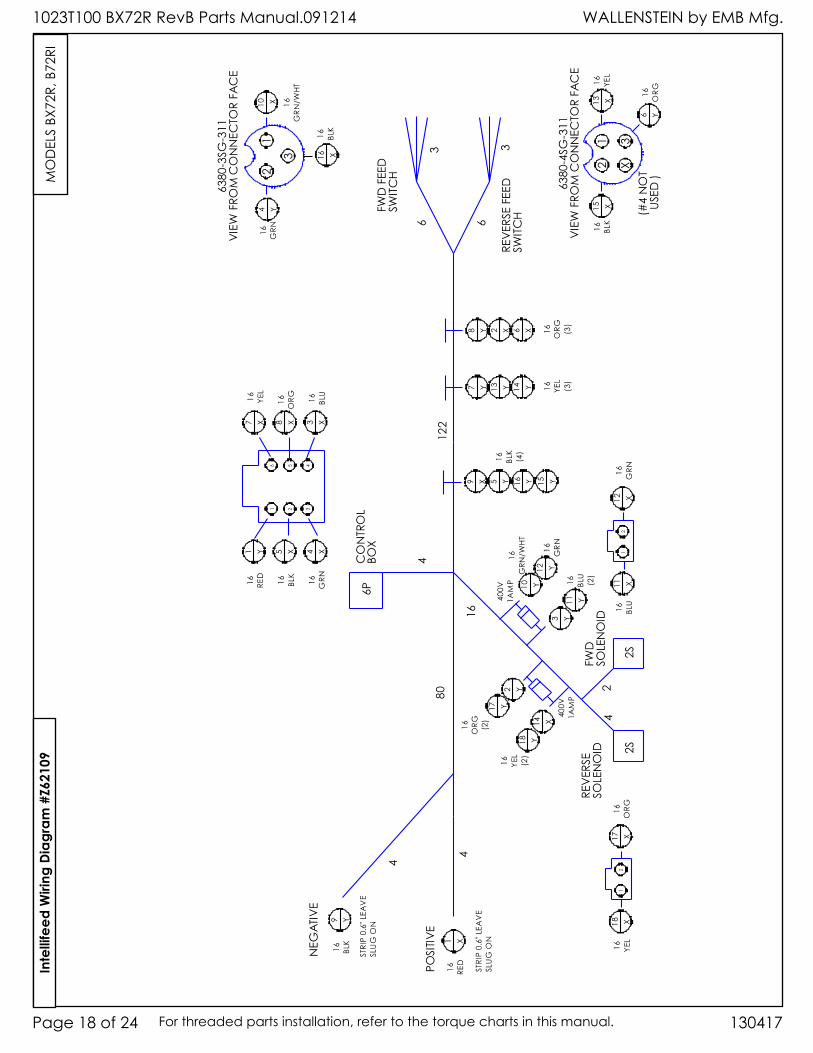
Inte
llife
ed W
iring
Dia
gram
#Z6
2109
MO
DEL
S BX
72R,
B72
RI
WALLENSTEIN by EMB Mfg. 1023T100 BX72R RevB Parts Manual.091214
Page 19 of 24130417 For threaded parts installation, refer to the torque charts in this manual.
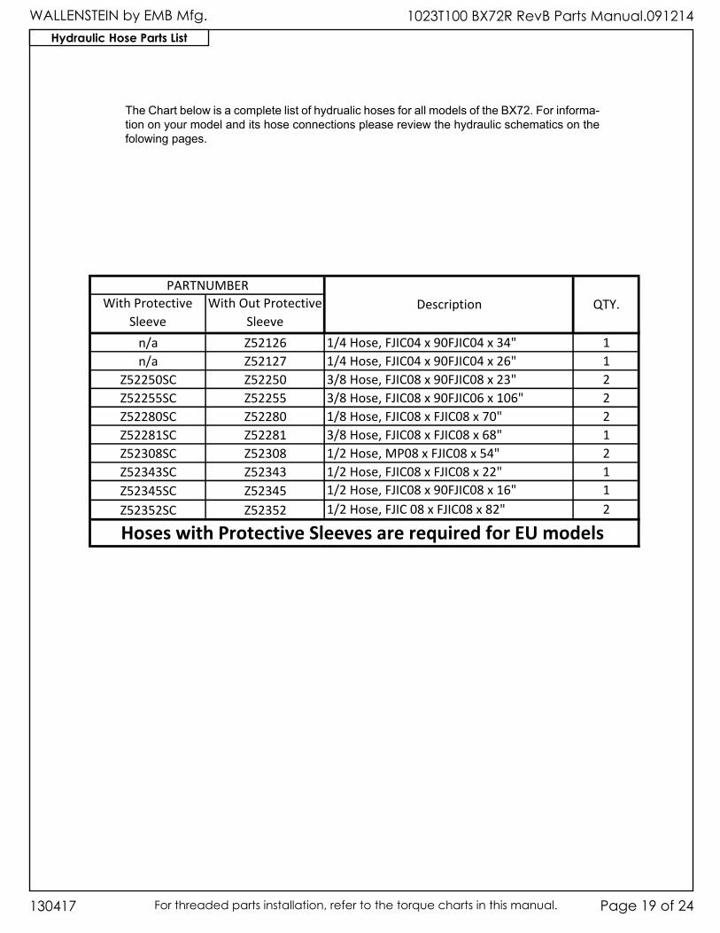
Hydraulic Hose Parts List
TheChartbelowisacompletelistofhydrualichosesforallmodelsoftheBX72.Forinforma-tiononyourmodelanditshoseconnectionspleasereviewthehydraulicschematicsonthefolowingpages.
With Protective Sleeve
With Out Protective Sleeve
n/a Z52126 1/4 Hose, FJIC04 x 90FJIC04 x 34" 1n/a Z52127 1/4 Hose, FJIC04 x 90FJIC04 x 26" 1
Z52250SC Z52250 3/8 Hose, FJIC08 x 90FJIC08 x 23" 2Z52255SC Z52255 3/8 Hose, FJIC08 x 90FJIC06 x 106" 2Z52280SC Z52280 1/8 Hose, FJIC08 x FJIC08 x 70" 2Z52281SC Z52281 3/8 Hose, FJIC08 x FJIC08 x 68" 1Z52308SC Z52308 1/2 Hose, MP08 x FJIC08 x 54" 2Z52343SC Z52343 1/2 Hose, FJIC08 x FJIC08 x 22" 1Z52345SC Z52345 1/2 Hose, FJIC08 x 90FJIC08 x 16" 1Z52352SC Z52352 1/2 Hose, FJIC 08 x FJIC08 x 82" 2
PARTNUMBERDescription QTY.
Hoses with Protective Sleeves are required for EU models
WALLENSTEIN by EMB Mfg.1023T100 BX72R RevB Parts Manual.091214
130417Page 20 of 24 For threaded parts installation, refer to the torque charts in this manual.
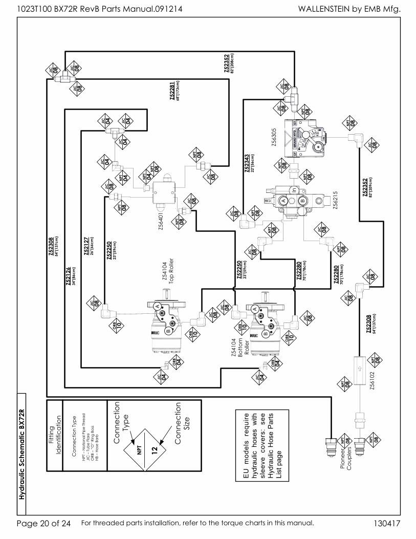
Hydr
aulic
Sch
emat
ic B
X72R
NPT 12
Con
nect
ion
Type
Con
nect
ion
Size
Con
nect
ion
Type
NPT
– N
atio
nal P
ipe
Thre
adJI
C –
Tub
e Fl
are
ORB
– “
O”
Ring
Bos
sHB
– H
ose
Barb
Fitti
ng
Iden
tific
atio
nZ52126
34"(86cm
)
Z52127
26"(66cm
)
Z52280
70"(178c
m)Z5
2250
23"(59cm
)
Z52352
82"(209c
m)
Z541
04Bo
ttom
Ro
ller
Z541
04To
p Ro
ller
Z564
01
Z562
15
Z563
05
Z561
02NPT 08
NPT 08
NPT 08
NPT 08
NPT 08
NPT 08
ORB 10
JIC 08
ORB 10
JIC 08
ORB 10
JIC 08
ORB 10
JIC 08
NPT 08
JIC 08
NPT 08
NPT 04
JIC 08
NPT 04
NPT 08
JIC 08
JIC 08 JIC 08
JIC 08
JIC 08
NPT 08
ORB 04
JIC 04JIC 04
ORB 04
NPT 08
Z52352
82"(208c
m)
Z52343
22"(56cm
)
Z52281
68"(173c
m)
Z52308
54"(137c
m)
Z52250
23"(59cm
)
JIC 04
JIC 04 JIC 04
JIC 08
NPT 08
JIC 08
Z52308
54"(137c
m)
JIC 08
JIC 08
NPT 08JIC 08
JIC 04
A B
Pion
eer
Cou
pler
s
JIC 08
NPT 08 JIC 08
NPT 08
A
B
A
B
In
Z52280
70"(178c
m)
EUm
odelsrequ
ire
hydraulichosesw
ith
slee
vecovers:see
HydraulicHoseParts
Listpage
WALLENSTEIN by EMB Mfg. 1023T100 BX72R RevB Parts Manual.091214
Page 21 of 24130417 For threaded parts installation, refer to the torque charts in this manual.
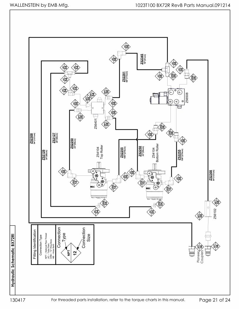
Hydr
aulic
Sch
emat
ic B
X72R
I
NPT 12
Conne
ction
Type
Conne
ction
Siz
e
Conne
ction
Type
NP
T–
NationalP
ipe
Thread
JIC
–Tube
Flar
eO
RB
–“O
” Rin
g B
oss
HB
–Hos
eBarb
Fitting
Identification
Z521
2634
"(86
cm)
Z521
2726
"(66
cm)
Z522
5510
6"(2
70cm
)Z522
5023
"(59
cm)
Z523
0854
"(13
7cm
)
Z541
04Bottom
Roller
Z541
04Top
Roller
Z564
01
Z565
08
Z561
02
NPT 08
NPT 08
JIC 08
JIC 08
JIC 08
OR
B10
JIC 08
NPT 08
JIC 08
NPT 08
NPT 04
JIC 04
NPT 08
NPT 08
OR
B04
JIC 04JIC 04
OR
B04
Z522
8168
"(17
3cm
)
Z523
0854
"(13
7cm
)
JIC 06
OR
B06
Z522
5510
6"(2
70cm
)
Z522
5023
"(59
cm)
JIC 04
JIC 04 JIC 04
JIC 08
JIC 08
Z523
4516
"(41
cm)
OR
B10O
RB
10
OR
B10
OR
B06
JIC 06
JIC 04
JIC 08
JIC 08
OR
B08
JIC 08
JIC 08
OR
B08
JIC 08
NPT 08NPT 08
Pion
eer
Cou
pler
s
ABT P
A
B
A
B
WALLENSTEIN by EMB Mfg.1023T100 BX72R RevB Parts Manual.091214
130417Page 22 of 24 For threaded parts installation, refer to the torque charts in this manual.
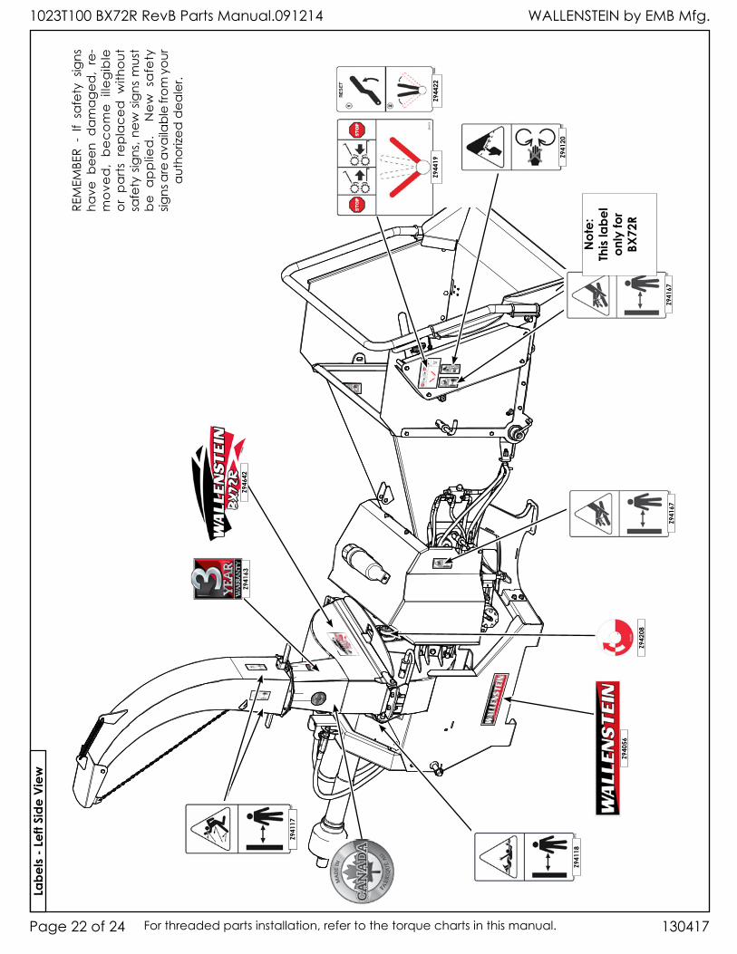
Z942
08
Z941
67Z9
4167
Z941
20
Z944
22
Z941
63
Z940
56
Z941
18
Z941
17
Z946
42
Not
e:Th
is la
bel
only
for
BX72
R
Labe
ls - L
eft S
ide
View
REM
EMBE
R -
If sa
fety
sig
ns
have
bee
n d
am
age
d,
re-
mo
ved
, b
eco
me
illeg
ible
or
pa
rts r
epla
ced
with
out
safe
ty s
igns
, new
sig
ns m
ust
be
ap
plie
d.
New
sa
fety
sig
ns a
re a
vaila
ble
from
you
r au
thor
ized
dea
ler.
Z944
19
WALLENSTEIN by EMB Mfg. 1023T100 BX72R RevB Parts Manual.091214
Page 23 of 24130417 For threaded parts installation, refer to the torque charts in this manual.
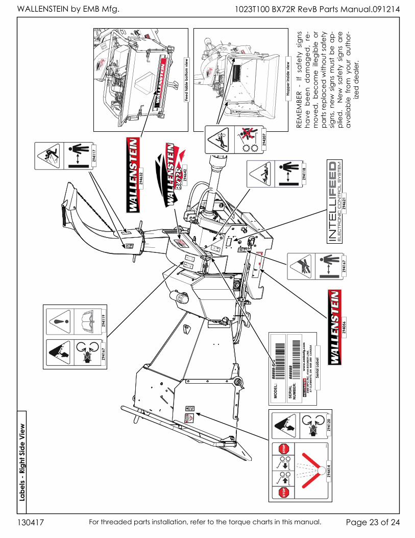
Feed
tabl
e bo
ttom
vie
w
Hopp
er in
side
view
Z946
21
####
#-##
#
####
##
Seria
l Lab
el
Z942
07
Z941
18
Z940
56
Z946
32
Z941
20Z9
4414
Z941
67
Z941
17
Z941
67Z9
4119
Z946
42
Labe
ls - R
ight
Sid
e Vi
ew
REM
EMBE
R -
If sa
fety
sig
ns
have
be
en
da
ma
ge
d,
re-
mov
ed,
beco
me
illegi
ble
or
parts
repl
aced
with
out s
afet
y sig
ns,
new
sig
ns m
ust
be a
p-pl
ied
. N
ew s
afet
y sig
ns a
re
ava
ilab
le f
rom
you
r a
utho
r-ize
d d
eale
r.
WALLENSTEIN by EMB Mfg.1023T100 BX72R RevB Parts Manual.091214
130417Page 24 of 24 For threaded parts installation, refer to the torque charts in this manual.
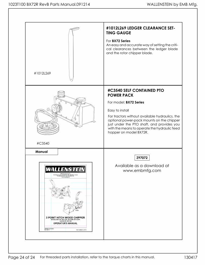
Manual
Available as a download atwww.embmfg.com
Z97072
For BX72 SeriesAn easy and accurate way of setting the criti-cal clearances between the ledger blade and the rotor chipper blade.
#1012L269 LEDGER CLEARANCE SET-TING GAUGE
#1012L269
For model: BX72 Series
Easy to install
#C3540 SELF CONTAINED PTO POWER PACK
For tractors without available hydraulics, the optional power-pack mounts on the chipper just under the PTO shaft, and provides you with the means to operate the hydraulic feed hopper on model BX72R.
#C3540


