Embed Size (px)
Citation preview
C A R B U R E T O R / M E F I 4E N G I N E O W N E R ’ S M A N U A L
Includes:Rountine Maintenance • Troubleshooting Guidelines • Electronic Fuel Injection • Dealer Directory
VERSION 1
i www.MarinePowerUSA.com
Table of ContentsSection 1: ownerS operation Manual
General emissions Warranty CoveraGe ..................... 1-3 Carbon monoxide exposure ...........................................4 introduCtion.................................................................4 enGine identifiCation .....................................................5 emissions Control information ......................................6Warranty reGistration/sea trial information ........... 7-8efi introduCtion and desCription ............................. 9-10marine poWer domestiC distributors .................... 11-12enGine speCifiCations ............................................. 13-15 3.0l / 181 Cid......................................................13 4.3l / 262 Cid......................................................13 5.7l / 350 Cid......................................................13 6.0l / 364 Cid......................................................14 7.4l / 454 Cid......................................................14 8.2l / 502 Cid......................................................14a Word to the “do-it-yourselfer” ..............................16
Section 2: General inforMation
enGine Compartment ...................................................18enGine mountinG ........................................................18 enGine bed .................................................................18sea Water pipinG .......................................................18fuel lines ...................................................................19eleCtriCal ConneCtions ...............................................19exhaust pipinG ............................................................19hydro-loCk .......................................................... 19-20Water inversion .........................................................20detonation and/or pre-iGnition ...................................20pre-start CheCklist ....................................................21Gasoline reCommendation ...........................................21startinG enGine - Carbureted ................................ 21-22startinG enGine - efi ..................................................22
proper enGines break-in .............................................2310 hour serviCe .........................................................23enGine rotation ..........................................................24propeller information .................................................24
Section 3: routine Maintenance
hoW to use this seCtion ............................................25 please be Careful .......................................................25 troubleshootinG .........................................................25 CrankCase oil ChanGe .......................................... 25-26 oil filters ............................................................ 26-27starter (top mount only) ..........................................27 flame arrestor ..........................................................27Carburetor fuel filter ................................................27Water separatinG fuel filter .......................................28 G-forCe fuel system ..................................................28 battery Cables ...........................................................28multiple enGine battery preCautions - efi ...................28 alternator belt tension ..............................................29CheCkinG belt tension .................................................29delCo est iGnition - usinG timinG tool: Carbureted enGines ................................................................ 29-30enGine tune-ups.........................................................30raW Water Cooled enGines ........................................30 Closed CoolinG system ......................................... 30-31fillinG Closed CoolinG system .....................................31extended storaGe and storaGe in beloW freezinG temperatures .................................................32foGGinG proCedures ....................................................32returninG enGine to serviCe after extended storaGe ....33sCheduled maintenanCe by oWner ...............................34sCheduled maintenanCe by Qualified teChniCian ...........35
Section 4: enGine DiaGraMS
Coolant floW diaGram: raW Water CoolinG................36Coolant floW diaGram: Closed CoolinG system ..... 37-38primary enGine WirinG harness: Carb/eleCtriC fuel pump ..................................................................39shift assist WirinG diaGram: Carbureted merC & early omC ................................................................39 tbi shift interrupt WirinG diaGram ............................39initial timinG Jumper WirinG diaGram .........................40shift interrupt - omC ................................................40efi primary enGine harness ........................................40efi seCondary WirinG harness ...................................41enGine instrument panel WirinG .................................42
Section 5: troubleShootinG GuiDe
enGine Will not turn over ........................................43 enGine starts and stops .............................................43enGine Cranks but Will not start .............................44enGine runs poorly .............................................. 44-45 fuel system - riCh/lean .............................................45 hiGh speed miss .........................................................46 poor fuel eConomy .....................................................47 oil pressure - loW/hiGh ....................................... 47-48 exCessive oil Consumption ..........................................48 enGine overheatinG .....................................................49 Water in enGine Cylinder or base ...............................50
exceSSive oil conSuMption troubleShootinG chart ....51
warranty reGiStration tranSfer forM .......................52
1www.MarinePowerUSA.com
1. General Emissions Warranty CoverageCalifornia Emissions Control Warranty Statement
Your Warranty Rights and ObligationsThe California Air Resources board and Marine Power Holding LLC is pleased to explain the emission control system warranty on your 2003 inboard engine. In California, new inboard engines must be designed, built, and equipped to meet the State’s stringent anti- smog standards. Marine Power Holding LLC must warrant the emission control system on your inboard engine for the periods of time listed below, provided there has been no abuse, neglect or improper mainte-nance of your inboard engine.
Your emission control system may include parts such as carburetor or fuel injection system, the ignition system, and catalytic converter. Also included may be hoses, belts, connectors, and other emission-related assemblies.
Where a warrantable condition exists, Marine Power Holding LLC will repair your inboard engine at no cost to you, including diagnosis, parts and labor.
Manufacturer’s Warranty Coverage:For 2003-08 spark-ignition inboard engines, select emission control parts from model year 2003-08 inboard engines are warranted for two (2) years.
For 2009 and later spark-ignition inboard marine engines, select emission control parts from model year 2009 and later inboard engines are warranted for three (3) years.
Owner’s Warranty Responsibilities:As the inboard engine owner, you are responsible for the performance of the required maintenance listed in your owner’s manual. Marine Power Holding LLC recom-mends that you retain all receipts covering maintence on your inboard engine, but Marine Power Holding LLC cannot deny warranty solely for the lack of receipts or your failure to ensure the performance of all schedule maintence.
As the inboard engine owner, you should however be aware that Marine Power Holding LLC may deny you warranty coverage if your inboard engine or part has failed due to abuse, neglect or improper maintence or unapproved modifications.
You are responsible for presenting your inboard engine to a Marine Power Holding LLC distribution center as soon as a problem exists. The warranty repairs will be complete within a reasonable amount of time, not to exceed 30 days.
1. Marine Ppwer (“the Company”) warranties each new Marine Power propulsion engine and factory installed accessories designed, built and equipped with all applicable regulations adopted by the
Air Resources Board pursuant to its authority in Chapters 1 and 2, Part 5, Division 26 of the Health and Safety Code; and to be free from defects in materials and workmanship that cause the failure of a warranted part to be identified in all material respects to that part as described in the engine manufacturer application for certification.
2. The warranty shall commence, on the date of the first retail purchase and extends to original and subsequent purchasers. However, in no event shall the duration of this warranty exceed two (2) years measured from the original retail sale date.
3. Any warranted part that is not scheduled for replacement as required maintenance in the written instructions in the owners manual will be warranted for the two (2) year warranty period. If the part fails during the period of warranty cover-age, the part will be repaired or replaced by Marine Power at a warranty station. Any such part repaired or replaced under warranty will be warranted for the remainder of the period.
4. Any warranted part that is scheduled only for regular inspection in the written instructions in the owners manual will be warranted for the two (2) year warranty period. A statement in such written instructions to the effect of “repair and replace as necessary” does not reduce the period of warran-ty coverage. Any such part repaired or replaced
2 www.MarinePowerUSA.com
1. General Emissions Warranty Coverageunder warranty will be warranted for the remaining warranty period.
5. Any warranted part that is scheduled for replace-ment as required maintenance in the written instructions in the owners manual will be warrant-ed for the period of time before the first scheduled replacement date for the part. If the part fails before the first scheduled replacement, the part will be repaired or replaced by Marine Power at a warranty station. Any such part repaired or replaced under warranty will be warranted for the remainder of the period to the first scheduled replacement point for the part.
6. Repair or replacement of any warranted part under the warranty provisions of the article will be performed at a warranty station at no charge to the owner. Warranty services and repairs will be pro-vided at all Marine Power distribution centers and trained marine dealers.
7. The engine owner will not be charged for diagnos-tic labor that is directly associated with diagnosis of a defective, emission related warranted part, provided that such diagnostic work is performed at a warranty station.
8. Marine Power is liable for damages to other engine components proximately caused by a failure under warranty of any warranted part.
9. Throughout the two (2) year warranty period Marine Power will maintain a supply of warranted parts sufficient to meet the expected demands for such parts.
10. Any replacement part may be used in the perfor-mance of any warranty maintenance or repairs and will be provided without charge to the owner. Such usage will not reduce Marine Power’s warranty obligations.
11. Marine Power, distributor or dealer must be advised of any warranty related problem prior to the expira-tion of the warranty.
12. This warranty will not apply to:
A) Use of an accessories or parts not manufactured or sold by Marine Power.
B) Neglect, failure to follow maintenance sched-ules, accident, abnormal operations, misuse, negligence, improperly maintained, improperly operated or installed, racing, or engine mod-ification. Problems arising from installation, application, exhaust to engine, fuel lines to the engine, propping, cooling to the engine or engine damage due to defective electrical hookups.
C) Rust, corrosion or effects of weather.
D) Water inversion through exhaust.
E) Detonation or operation with fuels, oils or lubri-
cants which are not suitable for use with this product. Detonation causes: Poor fuel quality, overloading of engine, improper gear or propel-ler selection, engine overheating, excessive back pressure, incorrect ignition timing, excessive total timing.
F) Reimbursement for: Haulout, launch, towing, storage charges, rental charges of any type, inconvenience of any type, loss of time or income, expense of returning a Marine Power product to a service facility, towing, lodging, loss or damage to personal property.
13. Add-on or modified parts, as defined in CCR, section 1900 (b) (1) and (b) (10), Title 13, that are not exempted by the Air Resources Board will not be used. The use of any non-exempted add-on or modi-fied parts by the ultimate purchaser will be grounds for disallowing a warranty claim made in accordance with this article statement. Marine Power will not be liable under this statement to warranted failures of warranted parts caused by the use of non- exempted add-on or modified part
14. The following parts are covered by this general emissions warranty statement.
A) Fuel Metering System.
1) Carburetor and Internal Parts (and/or pressure regulator or fuel injection system).
3www.MarinePowerUSA.com
1. General Emissions Warranty Coverage 2) Cold Start Enrichment System.
3) Intake Valve(s).
B) Air Induction System.
1) Intake Manifold.
2) Air Filter.
C) Ignition System.
1) Spark Plugs.
2) Electronic Ignition System.
3) Spark Advance/Retard System.
4) Ignition Coil and/or Control Module.
5) Ignition Wires.
D) Lubrication System.
1) Oil Pump and Internal Parts.
E) Positive Crankcase Ventilation (PCV) System.
1) PCV Valve.
2) Oil Filler Cap.
F) Exhaust System.
1) Exhaust Manifold.
2) Exhaust Valves.
G) Miscellaneous items used in above systems.
1) Hoses, Clamps, Fittings, Tubing, Sealing Gaskets
or Devices and Mounting Hardware.
2) Pulleys, Belts and Idlers.
3) Vacuum, Temperature, Check and Timer Sensi-tive Valves and Switches.
4) Electronic Controls.
15. Reasonable access must be provided to the product for warranty service. Removal and/or replacement of boat partitions or material because of boat design for necessary access to the product is not covered.
16. Warranty service must be requested by delivering the product for inspection to the retailer from whom the product was purchased or any convenient marine service center.
17. Proof of warranty must be provided at time of request for warranty service. A properly complet-ed Warranty Registration/Sea Trial form should be on file with Marine Power. Otherwise a valid bill of sale will be required for proof of purchase date.
18. All incidental and/or consequential damages are excluded from this warranty. Implied warranties are limited to the life of this warranty. All implied warranties including merchantability, fitness for a particular purpose or otherwise are disclaimed in their entirety after expiration of the appropriate two (2) year warranty period. This warranty gives you
specific rights, and you may also have other rights, which may vary from state to state. Some jurisdic-tions do not allow the exclusion or limitation of incidental or consequential damages, so the above limitation or exclusion may not apply to you.
19. Marine Power reserves the right to change or improve design of any product previously assem-bled without notice and without obligation.
20. In the event that a warranty claim is required outside of the continental United States, with the exception of Alaska and Hawaii, there may be additional charges to the engine owner. Any/all litigations must be filed within the State of Louisiana, Parish of Tangipahoa. Marine Power will not warranty any engine sold outside the continen-tal United States, with the exception of Alaska and Hawaii, unless competent and trained personnel and available to provide service to the engine.
4 www.MarinePowerUSA.com
1. Carbon Monoxide Exposure
Carbon Monoxide is a hazardous gas that is produced when items containing carbon are burned. Items such as, but not limited to; wood, coal, gasoline, natural gas, propane or oil. Carbon Monoxide (CO) is found in many areas such as any type of internal combustion en-gines, heaters, charcoal grills, cooking ranges and any other open flame appliances. There are many possible
variables for the accumulation of carbon monoxide. Wind direction, boat speed, vessel proximity to other vessels or structures are just a few of the possible variables that would permit exposure to carbon monoxide gases. It is important that regular inspections of the exhaust system are conducted and maintenance is properly performed by a qualified technician.
Adequate air circulation in all areas of your boat are necessary in order to prevent build-up of carbon monoxide. Please contact your boat manufacturer if you have questions regarding these hazards.
For more information regarding safe boating practic-es, and/or carbon monoxide poisoning on recreational boats, contact the following:
National Marine Manufacturers Association (NMMA) 200 East Randolph Drive, Suite 5100 Chicago, IL 60601 312-946-6200 • www.nmma.org
United States Coast Guard Office of Boating Safety CG Headquarters G-OPB-3 2100 Second Street, SW Washington, DC 20593 202-267-0984 • www.uscgboating.org
American Boat & Yacht Council, Inc. (ABYC) 3069 Solomons Island Road Edgewater, MD 21037-1416 410-956-1050 • www.abyc.com
DANGER
WARNING
CAUTIONCarbon Monoxide ExposureCarbon Monoxide is a odorless, colorless and tasteless gas that cannot be smelled, seen or tasted. Sustained exposure to carbon monoxide gas may lead to brain damage, unconsciousness or death.
1. IntroductionThe pleasure and peace of mind derived from your new engine is in direct proportion to the amount of care that it is given. We have tried to include as much as possible in our updated Engine Owners Manual to help you. READ THIS MANUAL THOROUGHLY AND COMPLETELY before attempting to operate your Marine Power Engine. Become familiar with the components and the maintenance schedules. If there is anything you do not completely understand contact your nearest Marine Power dealer or distributor.
This Manual contains five (5) Sections:
Section 1: Owner’s Operation Manual ................Page 1
Section 2: General Information .........................Page 16
Section 3: Routine Maintenance.......................Page 23
Section 4: Engine Diagrams ..............................Page 34
Section 5: Troubleshooting Guide .....................Page 41
5www.MarinePowerUSA.com
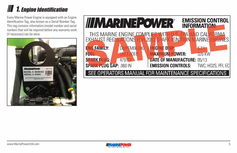
1. Engine IdentificationEvery Marine Power Engine is equipped with an Engine Identification Tag, also known as a Serial Number Tag. This tag contains information (model number and serial number) that will be required before any warranty work (if necessary) can be done.
6 www.MarinePowerUSA.com
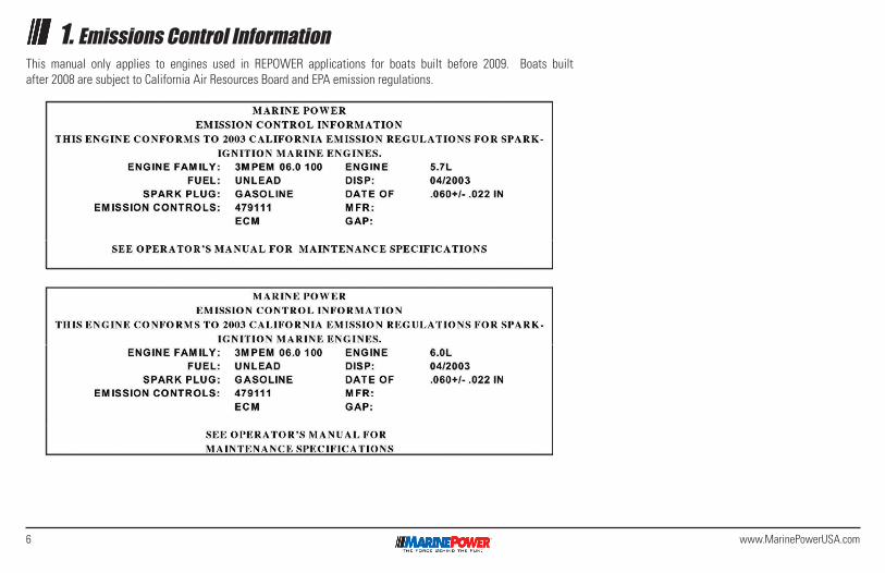
1. Emissions Control InformationThis manual only applies to engines used in REPOWER applications for boats built before 2009. Boats built after 2008 are subject to California Air Resources Board and EPA emission regulations.
7www.MarinePowerUSA.com
1. Warranty Registration/Sea Trial InformationYour Warranty Rights and ObligationsWhere a warrantable condition exists, Marine Power Holding LLC will repair your inboard engine at no cost to you, including diagnosis, parts and labor.
Manufacturer’s Warranty CoverageNew engines purchased for Repower Applications are warranted for two (2) years.
Engines covered by this manual are not suitable for New OEM Installations.
Owner’s Warranty ResponsibilitiesAs the inboard engine owner, you are responsible for the performance of the required maintenance list-ed in your owner’s manual. Marine Power Holding LLC recommends that you retain all receipts covering maintenance on your inboard engine.
As the Inboard engine owner, you should however be aware that Marine Power Holding LLC may deny you warranty coverage if your inboard engine or part has failed due to abuse, neglect or improper maintenance or unapproved modifications.
You are responsible for presenting your inboard engine to a Marine Power Holding LLC distribution center as soon as a problem exists.
NO WARRANTY SERVICES CAN BE PROVIDED WITH-OUT PRIOR AUTHORIZATION FROM MARINE POWER.
1. Marine Power (“The Company”) warranties each new Marine Power propulsion engine and factory installed accessories designed and built to be free from defects in materials and workmanship.
2. The warranty shall commence, on the date of first retail purchase and extends to original and subsequent purchasers. However, in no event shall the duration of this warranty exceed two (2) years measured from the original retail sale date.
3. Any warranted part that is not scheduled for replacement as required maintenance in the written instructions in the Owner’s Manual will be warranted for the two (2) year warranty period. If the part fails during the period of warranty cover-age, the part will be repaired or replaced by Marine Power at a warranty station. Any such part repaired or replaced under warranty will be warranted for the remainder of the period.
4. Any warranted part that is scheduled only for regular inspection in the written instructions in the owner’s manual will be warranted for the two (2) year warranty period. A statement in such written instructions to the effect of “repair and replace as necessary” does not reduce the period of warranty coverage. Any such part repaired or replaced under warranty will be warranted for the remaining warranty period.
5. Any warranted part that is scheduled for replace-
ment as required maintenance in the written instructions in the owner’s manual will be warrant-ed for the period of time before the first scheduled replacement date for the part. If the part fails before the first scheduled replacement, the part will be repaired or replaced by Marine Power at a warranty station. Any such part repaired or replaced under warranty will be warranted for the remainder of the period to the first scheduled replacement point for the part.
6. Repair or replacement of any warranted part under the warranty provisions of the article will be performed at a warranty station at no charge to the owner. Warranty services and repairs will be provided at all Marine Power distribution centers and trained marine dealers.
7. The engine owner will not be charged for diagnostic labor that is directly associated with diagnosis of a defective related warranted part, provided that such diagnostic work is performed at a warranty station.
8. Marine Power is liable for damages to other engine components proximately caused by a failure under warranty of any warranted part.
9. Throughout the two (2) year warranty period Marine Power will maintain a supply of warranted parts sufficient to meet the expected demands for such parts.
8 www.MarinePowerUSA.com
1. Warranty Registration/Sea Trial Information10. Any replacement part may be used in the perfor-
mance of any warranty maintenance or repairs and will be provided without charge to the owner. Such usage will not reduce Marine Power’s warranty obligations.
11. Marine Power, distributor, or dealer must be advised of any warranty related problem prior to the expiration of the warranty.
12. The warranty will not apply to:
A) Use of an accessories or parts not manufactured or sold by Marine Power.
B) Neglect, failure to follow maintenance sched-ules, accident, abnormal operations, misuse, negligence, improperly maintained, improp-erly operated or installed, racing, or engine modification. Problems arising from installation, application, exhaust to engine, fuel lines to the engine, propping, cooling to the engine or engine damage due to defective electrical hookups.
C) Rust, corrosion or effects of weather.
D) Water inversion through exhaust.
E) Detonation or operation with fuels, oils or lubricants which are not suitable for use with this product. Detonation causes: Poor fuel quality, overloading of engine, improper gear or propeller selection, engine overheating,
excessive back pressure, incorrect ignition timing, excessive total timing.
F) Reimbursement for: haulout, launch, towing, storage charges, rental charges of any type, inconvenience of any type, loss of time or income, expense of returning a Marine Power product to a service facility, towing, lodging, loss or damage to personal property.
13. Add-on or modified parts may not be used. The use of any non-exempted add-on or modified parts by the ultimate purchaser will be grounds for disallowing a warranty claim made in accordance with this article statement. Marine Power will not be liable under this statement to warranted failures of warranted parts caused by the use of non- exempted add-on or modified part
14. Reasonable access must be provided to the product for warranty service. Removal and/or replacement of boat partitions or material because of boat design for necessary access to the product is not covered.
15. Warranty service must be requested by delivering the product for inspection to the retailer from whom the product was purchased or any convenient marine service center.
16. Proof of warranty must be provided at time of request for warranty service. A properly complet-
ed Warranty Registration/Sea Trial form should be on file with Marine Power. Otherwise a valid bill of sale will be required for proof of purchase date.
17. All incidental and/or consequential damages are excluded from this warranty. Implied warranties are limited to the life of this warranty. All implied warranties including merchantability, fitness for a particular purpose, or otherwise are disclaimed in their entirety after expiration of the appropriate two (2) year warranty period. This warranty gives you specific rights, and you may also have other rights, which may vary from state to state. Some jurisdictions do not allow the exclusion or limita-tion of incidental or consequential damages, so the above limitation or exclusion may not apply to you.
18. Marine Power reserves the right to change or improve design of any product previously assem-bled without notice and without obligation.
19. In the event that a warranty claim is required outside of the continental United States, with the exception of Alaska and Hawaii, there may be additional charges to the engine owner. Any/All litigations must be filed within the State of Louisiana, Parish of Tangipahoa. Marine Power will not warranty any engine sold outside the continen-tal United States, with the exception of Alaska and Hawaii, unless competent and trained personnel and available to provide service to the engine.
9www.MarinePowerUSA.com
1. EFI Introduction and DescriptionWhat It IsElectronic Fuel Injection (EFI) has become the indus-try standard for marine engines. EFI is the basic term which applies to any fuel delivery system which uses a computer to determine how much fuel to add at a specific moment in time.
Two Basic TypesThere are two basic types of EFI used in the marine industry, Throttle Body Injection (TBI) and Multiport Fuel Injection (MPFI, MFI, PFI) etc. The TBI system is a wet flow design which flows a mixture fuel and air through the intake manifold. The PFI system flows air through the intake manifold, then injects fuel towards the cylinder head to complete the mixture, thus allow-ing the intake to be designed to flow air only. PFI systems are slightly more efficient than the TBI systems. Combustion requires a finely atomized mixture to ignite. In the wet flow TBI system some of the fuel will condense or collect on the intake walls and then pass into the combustion chamber. When solid fuel passes into the combustion chamber it is not burned and subse-quently it is passed out the exhaust. This is why the PFI systems are more efficient than the TBI systems.
How It WorksThe Engine Control Module (ECM) refers to the comput-er which makes the necessary calculations to deliver fuel and spark to the engine. The ECM relies on input
from sensors and switches to perform its calculations. The ECM then sends out its data along it’s output wires to the various items which it controls.
Typical inputs which the ECM uses are RPM, throttle position, manifold absolute pressure, coolant tempera-ture and a knock sensor. With the data being collected form these sensors at a very high rate, the ECM then calculates the proper fuel to be delivered and the proper spark timing to ignite the mixture.
The ECM delivers the fuel through injectors, which are electronic solenoids. The fuel is injected at high pressures of 60 PSI which creates a much finer mixture of fuel and air. The injector is pulsed for a length of time, called the Base Pulse Width (BPW). The BPW can be modified for enrichment when cold, a lean condition when hot, enrichment when knock is detected and so on.
Benefits and FeaturesThe primary benefit of fuel injection is the repeatability or accuracy of the amount of fuel delivered (BPW). The fuel injectors are very precise in their ability to deliv-er fuel and maintain their accuracy over the entire life span of the engine.
Another feature of EFI is the ability to develop “cal-ibrations” for the ECM which are specific to each application. For example EFI installed in a inboard ski boat application will have little in common with EFI
installed in a jet boat. The calibration is tailored to develop maximum power and efficiency for each application.
Another benefit of fuel injection is the high level of reliability in the components used. Generally speaking, a carbureted engine begins to deteriorate as soon as it is purchased. Fuel which sits for extended time attacks the carburetor and begins to hamper performance. The older style points ignition system also breaks down with age due to friction which wears out the components being used to control spark timing. Within 2 or 3 years the fuel and spark delivery has deteriorated and the engine must be tuned up in order to restore the original power. Also, a side effect of this deterioration is that the engine may actually be damaged by being over or under fueled.
EFI also offers the owner a level of protection which older engines did not have as standard features. The ECM monitors the temperature, RPM’s and other inputs and then makes decisions whether or not to allow the engine to continue to run in the current conditions. For example, the engine may be running above the ideal RPM, if the ECM detects that the RPM is over the calibrated rev limiter, then the ECM will reduce the RPM’s to a level which the engine can handle. The rev limiter can protect the engine from a prop which is not correctly matched or is to loose for the application.
10 www.MarinePowerUSA.com
1. EFI Introduction and Description
Note: Under no circumstances should your EFI unit be repaired or serviced except by an authorized Marine Power EFI trained techni-cian for warranty service. Prior authorization from area distributor is required.
To reduce the chance of personal injury and/or prop-erty damage, the following instructions must be carefully observed:
• Proper service and repair are important to the safety of the service technician and the safe, reliable operation of all Electronic Fuel Injection (EFI) Marine Power Engines. If part replacement is necessary, the part must be replaced with one of
the same part number or with an equivalent part. Do not use a replacement part of lesser quality.
• The service procedures recommended and described in this manual are effective methods of performing service and repair. Some of these procedures require the use of tools specially designed for the purpose.
• Accordingly, anyone who intends to use a replace-ment part, service procedure or tool which is not recommended by the system manufacturer, must first determine that neither his safety nor the safe operation of the engine will be jeopardized by the replacement part, service procedure or tool selected.
DANGER
WARNING
CAUTION
11www.MarinePowerUSA.com
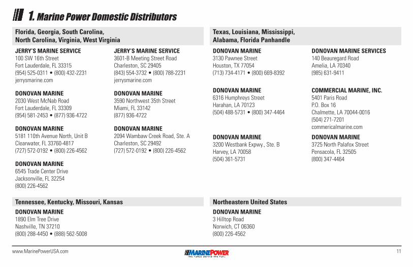
1. Marine Power Domestic DistributorsFlorida, Georgia, South Carolina, North Carolina, Virginia, West Virginia
Texas, Louisiana, Mississippi, Alabama, Florida Panhandle
JERRY’S MARINE SERVICE100 SW 16th StreetFort Lauderdale, FL 33315(954) 525-0311 • (800) 432-2231jerrysmarine.com
DONOVAN MARINE2030 West McNab RoadFort Lauderdale, FL 33309(954) 581-2453 • (877) 936-4722
DONOVAN MARINE5181 110th Avenue North, Unit BClearwater, FL 33760-4817(727) 572-0192 • (800) 226-4562
DONOVAN MARINE6545 Trade Center DriveJacksonville, FL 32254(800) 226-4562
JERRY’S MARINE SERVICE3601-B Meeting Street RoadCharleston, SC 29405(843) 554-3732 • (800) 788-2231jerrysmarine.com
DONOVAN MARINE3590 Northwest 35th StreetMiami, FL 33142(877) 936-4722
DONOVAN MARINE2094 Wambaw Creek Road, Ste. ACharleston, SC 29492(727) 572-0192 • (800) 226-4562
DONOVAN MARINE3130 Pawnee StreetHouston, TX 77054(713) 734-4171 • (800) 669-8392
DONOVAN MARINE6316 Humphreys StreetHarahan, LA 70123(504) 488-5731 • (800) 347-4464
DONOVAN MARINE3200 Westbank Expwy., Ste. BHarvey, LA 70058(504) 361-5731
DONOVAN MARINE SERVICES140 Beauregard RoadAmelia, LA 70340(985) 631-9411
COMMERCIAL MARINE, INC.5401 Paris RoadP.O. Box 16Chalmette, LA 70044-0016(504) 271-7201commericalmarine.com
DONOVAN MARINE3725 North Palafox StreetPensacola, FL 32505(800) 347-4464
Northeastern United StatesTennessee, Kentucky, Missouri, KansasDONOVAN MARINE3 Hilltop RoadNorwich, CT 06360(800) 226-4562
DONOVAN MARINE1890 Elm Tree DriveNashville, TN 37210(800) 288-4450 • (888) 562-5008

12 www.MarinePowerUSA.com
1. Engine Specifications
Engine TypeCrankshaft Horsepower*DisplacementBore & StrokeCompression RatioMaximum RPM @ WOTIdle RPM in Forward GearFuel Pump PressureOil Pressure @ 2000 RPMMinimum Oil Pressure @ IdleOperating Temp RW CooledOperating Temp FW CooledSparkplug Type
Sparkplug GapTiming @ Idle RPMMax Timing @ 4000 RPMFiring Order
Electrical SystemAlternator RatingRecommended Battery RatingCrankcase Oil**Transmission Oil*** Closed Cooling FluidClosed Cooling CapacityCrankcase Oil (Add 2/3 qt. oil for each oil filter used on engine)
3.0L / 181 CID (Carb)Inline 4140 HP / 104 kw3.0L / 181 CID4” x 3.6”9.25 : 14300 - 4600650 - 8004-7 PSI20-60 PSI10 PSI143° F (62° C)160° F (71° C)MR 43 LTS
.035”-1° ATDC23° Total1-3-4-2
12 volt Negative Ground70 ampsMin 350 amps15W40Dextron III 50% Water/50% Antifreeze10 Quarts4 Quarts
4.3L / 262 CID (Carb)V6225 HP / 167 kw4.3L / 262 CID4” x 3.48”9.4 : 14300 - 4600650 - 8004-7 PSI20-60 PSI10 PSI143° F (62° C)160° F (71° C)262 STD - MR 43 T4.3L Vortec - MR 43 LTS.035”2°26° Total1-6-5-4-3-2
12 volt Negative Ground70 ampsMin 350 amps15W40Dextron III 50% Water/50% Antifreeze16 Quarts4.5 Quarts
5.7L / 350 CID (Carb)V8315 HP / 235 kw5.7L / 350 CID4” x 3.48”9.4 : 14300 - 4600650 - 8004-7 PSI20-60 PSI10 PSI143° F (62° C)160° F (71° C)Pre-Vortec - MR 43 TVortec - MR 43 LTS.035”8°26° TotalLH 1-8-4-3-6-5-7-2RH 1-2-7-5-6-3-4-812 volt Negative Ground70 ampsMin 350 amps15W40Dextron III 50% Water/50% Antifreeze18 QuartsAlum. Pan 7 Quarts, Sheet Metal Pan 5 Quarts, JetPac Pan (Single Filter) 8 Quarts, JetPac Pan (Dual Filters) 9 Quarts.
4.3L / 262 CID (MPI)V6230 HP / 171 kw4.3L / 262 CID4” x 3.48”9.4 : 14200 - 4600650 - 8004-7 PSI20-60 PSI10 PSI143° F (62° C)160° F (71° C)4.3L Vortec - AC 41-932
.035”Set at Factory26° Total1-6-5-4-3-2
12 volt Negative Ground70 ampsMin 350 amps15W40Dextron III 50% Water/50% Antifreeze16 Quarts4.5 Quarts
5.7L / 350 CID (MPI)V8325-335 HP / 242 kw5.7L / 350 CID4” x 3.48”9.4 : 14200 - 5000650 - 80039 PSI20-60 PSI10 PSI143° F (62° C)160° F (71° C)5.7 Vortec - AC 41-932
.060” (Platinium)10°
LH 1-8-4-3-6-5-7-2RH 1-2-7-5-6-3-4-812 volt Negative Ground70 ampsMin 350 amps15W40Dextron III 50% Water/50% Antifreeze18 QuartsAlum. Pan 7 Quarts, Sheet Metal Pan 5 Quarts, JetPac Pan (Single Filter) 8 Quarts, JetPac Pan (Dual Filters) 9 Quarts.
13www.MarinePowerUSA.com
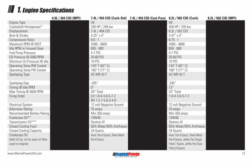
1. Engine Specifications
Engine TypeCrankshaft Horsepower*DisplacementBore & StrokeCompression RatioMaximum RPM @ WOTIdle RPM in Forward GearFuel Pump PressureOil Pressure @ 2000 RPMMinimum Oil Pressure @ IdleOperating Temp RW CooledOperating Temp FW CooledSparkplug Type
Sparkplug GapTiming @ Idle RPMMax Timing @ 4000 RPMFiring Order
Electrical SystemAlternator RatingRecommended Battery RatingCrankcase Oil**Transmission Oil*** Closed Cooling FluidClosed Cooling CapacityCrankcase Oil (Add 2/3 qt. oil for each oil filter used on engine)
7.4L / 454 CID (Carb-Std)V8330 HP / 246 kw7.4L / 454 CID4.25” x 4”8.0 : 14300 - 4600650 - 8004-7 PSI20-60 PSI10 PSI143° F (62° C)160° F (71° C)AC MR 43 T
.035”0°20° TotalLH 1-8-4-3-6-5-7-2RH 1-2-7-5-6-3-4-812 volt Negative Ground70 ampsMin 350 amps15W40Dextron III 50% Water/50% Antifreeze24 QuartsAlum. Pan 8 Quarts, Sheet Metal Pan 8 Quarts.
6.0L / 364 CID (MPI)V8360 HP @ 5200 RPM6.0L / 364 CID4.00” x 3.62”9.4 : 15200650 - 80050 PSI / 55 PSI @ WOT60 PSI10 PSI
160° F (71° C)Platinum - AC 12567759
.059”Computer ControlledComputer Controlled1-8-7-2-6-5-4-3
12 volt Negative Ground70 ampsMin 350 amps15W40Dextron III 50% Water/50% Antifreeze24 Quarts6 Quarts, Jetpac Pan with Single Filter 6.5 Quarts.
7.4L / 454 CID (Carb-Prem)V8380 HP / 282 kw7.4L / 454 CID4.25” x 4”8.6 : 14600 - 5000650 - 8004-7 PSI20-60 PSI10 PSI143° F (62° C)160° F (71° C)AC MR 43 T
.035”12°32° TotalLH 1-8-4-3-6-5-7-2RH 1-2-7-5-6-3-4-812 volt Negative Ground70 ampsMin 350 amps15W40Dextron III 50% Water/50% Antifreeze24 QuartsAlum. Pan 8 Quarts, Sheet Metal Pan 8 Quarts.
8.2L / 502 CID (Carb)V8450 HP / 335 kw8.2L / 502 CID4.47” x 4”8.75 : 14300 - 4800650 - 8004-7 PSI20-60 PSI10 PSI143° F (62° C)160° F (71° C)AC MR 43 T
.035”12°32° Total1-8-4-3-6-5-7-2
12 volt Negative Ground70 ampsMin 350 amps15W40Dextron III 50% Water/50% Antifreeze24 QuartsAlum. Pan 8 Quarts, Sheet Metal Pan 8 Quarts, JetPac Pan (Single Filter) 7 Quarts, JetPac Pan (Dual Filters) 8 Quarts.
8.2L / 502 CID (MPI)V8450 HP / 335 kw8.2L / 502 CID4.47” x 4”8.75 : 14600 - 5000650 - 80039 PSI20-60 PSI10 PSI143° F (62° C)160° F (71° C)AC MR 43 T
.035”12°Computer Controlled1-8-4-3-6-5-7-2
12 volt Negative Ground70 ampsMin 350 amps15W40Dextron III 50% Water/50% Antifreeze24 QuartsAlum. Pan 8 Quarts, Sheet Metal Pan 8 Quarts, JetPac Pan (Single Filter) 7 Quarts, JetPac Pan (Dual Filters) 8 Quarts.
14 www.MarinePowerUSA.com
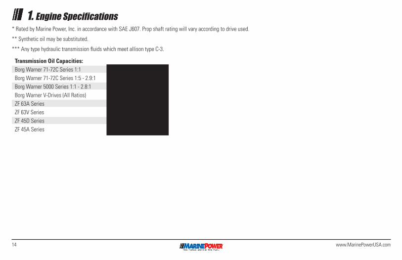
1. Engine Specifications* Rated by Marine Power, Inc. in accordance with SAE J607. Prop shaft rating will vary according to drive used.
** Synthetic oil may be substituted.
*** Any type hydraulic transmission fluids which meet allison type C-3.
Transmission Oil Capacities:Borg Warner 71-72C Series 1:1Borg Warner 71-72C Series 1:5 - 2.9:1Borg Warner 5000 Series 1:1 - 2.8:1Borg Warner V-Drives (All Ratios)ZF 63A SeriesZF 63V SeriesZF 45D SeriesZF 45A Series
2 Quarts3 Quarts2 Quarts4 Quarts3.2 Quarts4.2 Quarts2.1 Quarts3.2 Quarts
15www.MarinePowerUSA.com
1. A Word to the “Do-It-Yourselfer”The past twenty years has seen a revolution in the way both automotive and marine engines are built. The most revolutionary is the advent of Electronic Fuel Injection or EFI.
Before EFI, the carburetor was the most popular and easiest way of supplying fuel to the engine. The carbu-retor injected fuel into the engine by using a mechanical means of linkage, throttle plates, jets, etc. While it did an excellent job for many years, it was not efficient and it was adjustable only to a certain point with a screw-driver.
Today it is much different. EFI engines are operated by a computer and sophisticated engine calibrations. These calibrations are critical to how much fuel the engine receives and are peculiar to a specific engine type. The sensors that feed information back to the computer are not adjustable nor can they be repaired. The senors must be replaced.
Marine engine technicians receive specialized train-ing in the diagnosing and correcting of EFI equipped engines. A factory trained technician is required to properly diagnose and repair your Marine Power EFI engine to avoid irreparable or permanent engine damage.
Engine ProblemsEngine problems are very difficult to attempt to solve over the telephone. In most cases the trained eye of a
good marine technician is the easiest and fastest way of determining and solving a problem. Contacting the dealer, distributor or the factory and trying to resolve the problem over the telephone only tends to lengthen the time of repair.
Engine CareMost engine problems can be avoided with a good engine maintenance schedule. Marine engines are operating at much higher rpm’s than automobile vehicles. The work that a marine engine does at cruis-ing speed is comparable to an automobile engine going uphill in a strong headwind all the time. The engine parts must work harder and thus require more attention. Oil, filters, spark plug wires, spark plugs, distributor rotors and distributor caps can make all the difference in the world in performance versus being towed back in.
GasolineGasoline can be a major contributor to engine damage. Old, last season fuel loses its octane rating and does not create the correct amount of cylinder burn. This can cause DETONATION or “fuel knock” were the fuel will explode violently in the cylinder. The explosion, in turn, causes overheating or damage to the spark plugs, pistons and valves. Any engine stored for thirty (30) days or longer needs a fuel stablizer. We recommend that STA-BIL be added to the fuel per the manufacturer’s directions. This will prevent the formation of harmful
varnish in the fuel system.
Crankcase OilSome engines are installed on an angle. This causes the oil to flow to the back of the oil pan. Consequently, the oil level on the dipstick may change. It is the responsi-bility of the installer and the owner to determine the correct oil dipstick reading. To little as well as to much oil will cause engine damage.
Cold Weather or Extended StorageIf you put your boat away for the winter or you will not be using it for an extended length of time, it is recommended that a competent marine service facility be contacted to perform the winterization or storage.
16 www.MarinePowerUSA.com
2. General Information
Engine CompartmentThe engine compartment should be well-planed giving consideration to accessibility and ventilation. Engines must have air as well as fuel to operate efficiently. The battery should be located as close as possible to the starter motor so that the battery leads can be kept short.
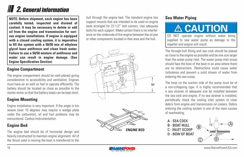
Engine MountingEngine installation is very important. If the angle is too severe (over 10 degrees may require a wedge plate under the carburetor), oil and fuel problems may be encountered. Canbus Instrumentation.
Engine BedThe engine bed should be of horizontal design and heavily constructed to maintain engine alignment. All of the thrust used in moving the boat is transferred to the
NOTE: Before shipment, each engine has been carefully tested, inspected and drained of coolant. It may be necessary to delete or add oil from the engine and transmission for vari-ous engine installations. If engine is equipped with a closed cooling system, it is imperative to fill the system with a 50/50 mix of ethylene glycol base antifreeze and clean fresh water. Failure to use a 50/50 mixture of antifreeze and water can result in engine damage. (See Engine Specification Section)
hull through the engine bed. The standard engine has support mounts that are intended to be used on engine beds arranged for 22-1/2” bolt centers. Use adequate bolts for each support. Make certain there is no interfer-ence on the underside of the engine between the oil pan or other components located in that area and the hull.
DANGER
WARNING
CAUTIONDO NOT operate engine without water being supplied to raw water pump as damage to the impeller and engine will result.
Sea Water Piping
The through-hull fitting and sea cock should be placed as close to the engine as possible and be one size larger than the water pump inlet. The water pump inlet scoop should face the bow of the boat in an area where there are no obstructions. Obstructions could cause water turbulence and prevent a solid stream of water from entering the sea scoop.
The hose on the suction side of the pump must be of a non-collapsing type. It is highly recommended that a sea strainer of adequate size be installed between the sea cock and engine. If no sea strainer is installed, periodically check the cooling inlet system to clear debris from engine and transmission oil coolers. Debris entering the cooling system is one of the main causes of overheating.
ENGINE BED
17www.MarinePowerUSA.com
2. General InformationFuel Lines
A 3/8” minimum (inner-dimension) “Type A1” USCG Approved tubing is recommended for the fuel line from the tank to the engine for all 181/3.0L, 262/4.3L and 350/5.7L Engines. All 364/6.0L and larger engines must be 1/2” minimum (inner-dimension). It should be adequately secured and provided with a flexible section near the engine to reduce vibration to the line. Fittings for the tubing should conform to current U.S. Coast Guard or American Boating & Yacht Council standards. It is also recommended that older copper fuel lines be replaced with an approved fuel line.
All Marine Power EFI engines require the fuel return line be connected only to the fuel tank.
Fuel tanks should be of a size adequate with the hull requirements and should be anchored securely and vented in such a manner to conform to Coast Guard regulations. The fuel tank filling arrangements should conform to all safety regulations, and must be outboard. The installation of an approved fuel shut off valve at the tank is mandatory.
Electrical ConnectionsAll electrical connections should conform to U.S. Coast Guard or American Boating & Yacht Council standards.
Exhaust Piping
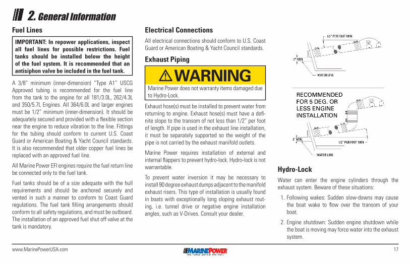
Exhaust hose(s) must be installed to prevent water from returning to engine. Exhaust hose(s) must have a defi-nite slope to the transom of not less than 1/2” per foot of length. If pipe is used in the exhaust line installation, it must be separately supported so the weight of the pipe is not carried by the exhaust manifold outlets.
Marine Power requires installation of external and internal flappers to prevent hydro-lock. Hydro-lock is not warrantable.
To prevent water inversion it may be necessary to install 90 degree exhaust dumps adjacent to the manifold exhaust risers. This type of installation is usually found in boats with exceptionally long sloping exhaust rout-ing, i.e. tunnel drive or negative engine installation angles, such as V-Drives. Consult your dealer.
Hydro-LockWater can enter the engine cylinders through the exhaust system. Beware of these situations:
1. Following wakes: Sudden slow-downs may cause the boat wake to flow over the transom of your boat.
2. Engine shutdown: Sudden engine shutdown while the boat is moving may force water into the exhaust system.
IMPORTANT: In repower applications, inspect all fuel lines for possible restrictions. Fuel tanks should be installed below the height of the fuel system. It is recommended that an antisiphon valve be included in the fuel tank.
DANGER
WARNING
CAUTION
Marine Power does not warranty items damaged due to Hydro-Lock.
18 www.MarinePowerUSA.com
2. General Information3. Improper installation: Refer to Exhaust Piping
Section. An exhaust system without flappers and the specified incline increases the likelihood of water entering the engine.
4. Improper hoisting: Operators are sometimes tempt-ed to reduce hoisting time for propeller changes by hoisting only the boat stern. Such hoisting can cause residual water in the exhaust system to enter engine cylinders.
Water entering engine cylinders will cause the engine to lock because water does not compress. To remedy this situation, take the following steps:
1. Change engine oil and filters.
2. Remove all spark plugs.
3. Remove coil wire.
4. Crank engine for 15 seconds.
5. Replace spark plugs and reattach coil wire.
6. Start engine - if there are any abnormal sounds STOP ENGINE immediately and contact your Marine Power dealer.
Water InversionWater inversion is water that is pulled back into the exhaust and usually ends up in the piston cylinder. Most of the time this happens under the following conditions:
• Shutting off engine at high RPM’s.
• Water comes up the exhaust after a quick slowdown.
• Long periods of idling.
• Exhaust drop not sufficient.
Usually the water is not found until the next time the boat is used. In some cases this may not be for weeks. In the case of a salt water environment this is cata-strophic due to the rusting.
To minimize this problem Marine Power requires the installation of flappers at the transom and in the exhaust hose just after the exhaust riser or elbow.
Detonation and/or Pre-IgnitionDetonation is most commonly known as “pinging”, “spark knock” or “fuel knock”. It is the abnormal combustion of the fuel which causes the fuel to explode severely within the combustion chamber.
In a four-cycle engine, normal combustion or burning starts at the spark plug and a wave of flames move across the combustion chamber. This results in an even pressure rise in the combustion chamber which pushes the piston downward.
Detonation begins as normal combustion with the spark-ignited flame progressing across the combustion chamber while applying the heat and pressure to the unburned portion of fuel. Instead of continuing to burn evenly, the last portion of the fuel explodes violently which in turn causes overheating of the pistons, valves
and spark plugs.
This may occur at any speed and is not often detected, serious and tragic engine damage may occur.
There are many causes of detonation, with the most common being the use of a low-octane gasoline. Detonation may also occur when using the proper octane gasoline if engine maintenance has been neglected.
• Poor or improper fuel quality/octaine.
• Improper initial ignition timing setting.
• Improper propeller selection.
• Engine overload, such as operating twin-engine boat with only one engine.
• Improper cooling operation resulting in engine over-heating.
• Fuel starvation or vapor lock resulting from poor fuel quality/lean out.
• Malfunctioning carburetor causing lean mixture.
• Operating engine that is out of proper tune, dead cylinder, defective distributor cap.
• Excessive exhaust backpressure caused by restrict-ed exhaust mufflers or outlets.
19www.MarinePowerUSA.com
DANGER
WARNING
CAUTIONDO NOT operate engine without water being supplied to raw water pump as pump impeller and engine will be damaged.
2. General InformationPre-Start Checklist
1. Check engine and transmission oil level.
2. Check that all engine drain plugs are installed and tightened.
3. Check for proper coolant level if engine is equipped with optional closed cooling system. Ensure than the coolant tank cap is tight. The cooling system must be filled with a 50/50 mix of ethylene glycol base antifreeze and clean fresh water. (See Routine Maintenance Section for “Filling” instructions.)
4. Check throttle linkage to make sure it operates freely and that it returns to the idle position.
5. Check transmission shift lever. Refer to your trans-mission operator manual.
1. Operate bilge blower for five (5) minutes. If not equipped with bilge blower, open engine hatch and leave open while starting engine to remove any explosive fumes from engine compartment.
2. Place shift lever in the neutral position.
3. Pump throttle lever two (2) times to prime intake manifold.
4. Place throttle 1/4 open.
5. Turn ignition switch to start position. The engine should start within twenty (20) seconds.
6. Run engine at 1000 RPM until it reaches normal operating temperature:
Raw Water Cooling: Operating temperature should be 140° - 165°.
Closed Cooling: Operating temperature should range 160° - 190°.
DANGER
WARNING
CAUTIONDO NOT operate engine without water being supplied to raw water pump as pump impeller and engine will be damaged.
IMPORTANT: Marine Power requires that your servicing dealer perform a sea trial for proper completion of your warranty/sea trial form. Failure to properly registered your engine will result in delay receiving warranty repairs, if required. Registration is required by the Federal Boat Safety Act.
WARNING! Gasoline vapors are highly explo-sive under certain conditions.
6. Inspect fuel and water system for leakage.
7. Check that all engine mounts are tight.
8. Check that battery is secure and all electrical connections are tight.
Gasoline RecommendationMarine Power recommends the use of unleaded gasoline of at least 87 octane to insure adequate engine performance.
ALCOHOL ADDED GASOLINE:Use of ethanol or methanol type gasolines are not recommended for use in your Marine Power engine. Adverse effects such as, but not limited to, corrosion, excessive wear to internal parts, or damage to flexible fuel lines are possible. If this type of gasoline is used, a complete fuel system inspection is required prior to engine operation. Repair or replace worn or damaged parts immediately.
Starting Engine - CarburetedA fully charged battery (12-14V) is necessary to crank a cold engine. At lower temperatures a richer fuel mixture is desired at startup. For carbureted engines, you may have to pump the throttle control more than usual while cranking the engine to start.
20 www.MarinePowerUSA.com
2. General InformationThe closed cooling system is designed to provide extended life to your new Marine Power engine. Your engine will operate at a different temperature range from a raw water cooled engine. Please refer to the appropriate Engine Specification page for proper cooling ranges.
The cooling system does require certain preventative maintenance to keep it in optimum operating conditions.
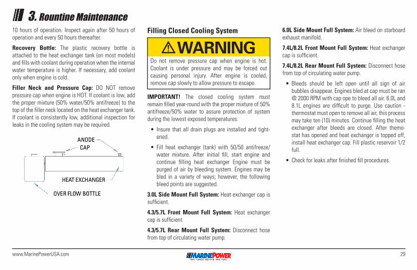
Zinc Anode: Your cooling system is equipped with a zinc anode that is approximately 2” long. This anode should be inspected for deterioration after the first 10 hours of operation. Inspect again after 50 hours of operation and every 50 hours thereafter.
Recovery Bottle: The plastic recovery bottle is attached to the heat exchanger tank (on most models) and fills with coolant during operation when the internal water temperature is higher. If necessary, add coolant only when engine is cold.
Filler Neck and Pressure Cap: DO NOT remove pressure cap when engine is HOT. If coolant is low, add the proper mixture (50% water/50% antifreeze) to the top of the filler neck located on the heat exchanger tank. If coolant is consistently low, additional inspection for leaks in the cooling system may be required.
7. Check water outlets (exhausts) for waterflow.
8. If oil pressure or waterflow is not normal, shut off engine and locate problem. (See Troubleshooting
Section).
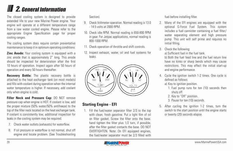
9. Check Voltmeter operation. Normal reading is 13.0 - 14.5 volts at 2000 RPM.
10. Check idle RPM. Normal reading is 650-800 RPM in gear. For Jetpac applications, normal reading is 800-1000 RPM.
11. Check operation of throttle and shift controls.
12. Inspect exhaust, water, oil and fuel systems for leaks.
Starting Engine - EFI1. Fill the fuel/water separator filter 2/3 to the top
with clean, fresh gasoline. Put a light film of oil on filter gasket. Screw the filter onto the base. hand tighten the filter plus 1/2 turn, if possible, after the filter gasket contacts the base. DO NOT OVERTIGHTEN. Note: On EFI equipped engines, the fuel/water separator must be 2/3 filled with
fuel before installing filter.
2. Many of the EFI engines are equipped with the optional G-Force Fuel System. This system includes a fuel cannister containing a fuel filter/water separating element and high pressure pump. This unit will self prime and requires no initial filling.
3. Check the following: a) Sufficient fuel in the fuel tank. b) Both the fuel feed line and the fuel return line
have no kinks or sharp bends which may cause restrictions. This may effect the initial start-up and engine performance.
4. Cycle the ignition switch 1-2 times. One cycle is defined as follows:
a) Key to ignition position. 1. Fuel pump runs for ten (10) seconds then
shuts off. 2. Key to “Off” position. 3. Pause for ten (10) seconds.
5. After cycling the ignition 1-2 times, turn the switch to the start position until the engine starts or twenty (20) seconds elapse.
21www.MarinePowerUSA.com
DANGER
WARNING
CAUTIONFirst twenty-five (25) hours vary the RPM. Avoid sustained periods of wide open throttle. Some EFI engines will not reach WOT until engine is up to normal operating temperatures.
2. General InformationProper Engine Break-In
To insure maximum life of your Marine Power engine, the following engine break-in schedule is recommend-ed:
First hour - Perform Sea Trial.
2. VOLTMETER: Normal reading is 13.0 - 14.5 volts at 2000 RPM.
3. OIL PRESSURE: Not less than 10 PSI at idle.
4. NORMAL OPERATING TEMP: Raw water cooling: Less than 165°. Closed cooling: Between 160° and 190°.
5. IDLE RPM: Normal reading is 650 - 800 RPM in gear. Note: For Jetpac applications, normal read-ing is 800-1000 RPM.
6. THROTTLE AND SHIFT CONTROLS: Check that movement is not constrictive. Verify that linkage is adjusted so that engine may reach Wide Open Throttle (WOT).
7. EXHAUST, OIL, WATER AND FUEL SYSTEM: Inspect for leaks. Be sure to check riser bolt tightness after ten (10) hours and every 50 hours of operation. Refer to Scheduled Maintenance.
10 Hour ServiceIt is very important to re-tighten exhaust manifold riser bolts after ten (10) hours of operation. Failure to do so can cause non-warrantable engine damage.
DANGER
WARNING
CAUTION
DANGER
WARNING
CAUTION
DANGER
WARNING
CAUTION
Engine dipstick level may change due to the angle of installation. Ensure that “high” oil level is properly marked accordingly.
When adding crankcase oil, DO NOT OVERFILL. If crankcase is overfilled, it will cause foaming or aera-tion of oil in the oil pan. This will effect oil pressure which may result in severe internal engine damage.
If the engine is to be operated (after the initial break-in period) near or at maximum rpms in rough water conditions wherein the craft may become temporarily airborne, a RPM Rev Limiter Device must be installed on the engine to prevent a runaway condition which could seriously damage the engine or its component parts. Rev limiters are included on all EFI systems.
At no time should the engine be operated beyond the specified maximum RPM rating. Failure to adhere to there recommendations will void the terms of warranty.
IMPORTANT: The space between the “FULL” and “ADD” marks on the dipstick represent one quart. It is not necessary to add oil unless the level is at or below the “ADD” mark.
IMPORTANT! During the break-in period, pay close attention to the following steps.
1. OIL LEVEL: Check the oil level before each engine start up and every eight (8) hours of continuous operation. It should be understood that internal combustion engines will use a certain amount of oil during operation as a cooling and lubricat-ing agent (especially during break-in period). Oil consumption should decrease after approximately 100 hours of operation.
22 www.MarinePowerUSA.com
2. General InformationEngine RotationDirectional references used in this section are given as if standing behind the boat, looking forward:
• front of boat is bow
• rear of boat is stern
• right side is starboard
• left side is port
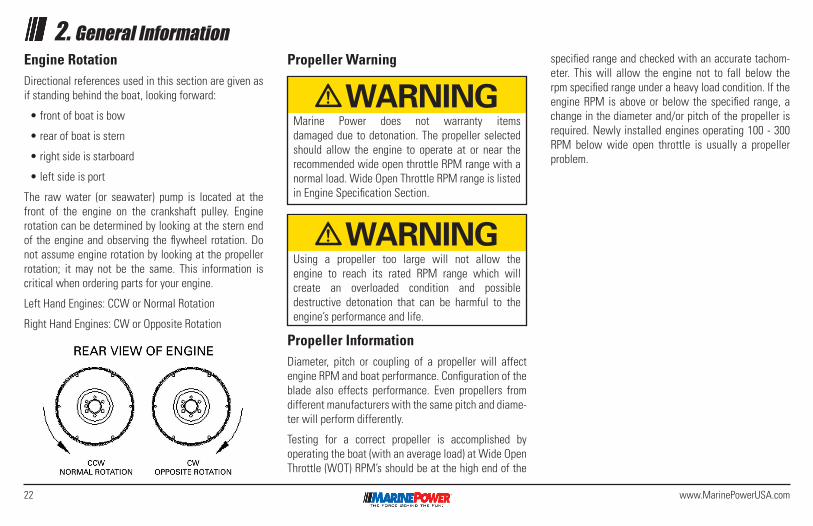
The raw water (or seawater) pump is located at the front of the engine on the crankshaft pulley. Engine rotation can be determined by looking at the stern end of the engine and observing the flywheel rotation. Do not assume engine rotation by looking at the propeller rotation; it may not be the same. This information is critical when ordering parts for your engine.
Left Hand Engines: CCW or Normal Rotation
Right Hand Engines: CW or Opposite Rotation
Propeller Warning specified range and checked with an accurate tachom-eter. This will allow the engine not to fall below the rpm specified range under a heavy load condition. If the engine RPM is above or below the specified range, a change in the diameter and/or pitch of the propeller is required. Newly installed engines operating 100 - 300 RPM below wide open throttle is usually a propeller problem.
DANGER
WARNING
CAUTIONDANGER
WARNING
CAUTION
Marine Power does not warranty items damaged due to detonation. The propeller selected should allow the engine to operate at or near the recommended wide open throttle RPM range with a normal load. Wide Open Throttle RPM range is listed in Engine Specification Section.
Using a propeller too large will not allow the engine to reach its rated RPM range which will create an overloaded condition and possible destructive detonation that can be harmful to the engine’s performance and life.
Propeller InformationDiameter, pitch or coupling of a propeller will affect engine RPM and boat performance. Configuration of the blade also effects performance. Even propellers from different manufacturers with the same pitch and diame-ter will perform differently.
Testing for a correct propeller is accomplished by operating the boat (with an average load) at Wide Open Throttle (WOT) RPM’s should be at the high end of the
23www.MarinePowerUSA.com
3. Rountine MaintenanceHow to Use This SectionThis manual provides basic information on routine main-tenance of Marine Power engines. Whether the reader is an experienced marine mechanic or a first time boat owner, we strongly suggest you thoroughly read these procedures BEFORE you attempt any procedure. Make sure you are familiar with the tools suggested and the methods recommended. Safety is our first concern. If repair required is beyond your expertise, please contact your dealer or other qualified technician.
This manual contains guidelines to convey a particular level of risk:
• DANGER: HAZARDS THAT WILL RESULT IN SEVERE INJURY OR DEATH.
• WARNING: HAZARDS THAT COULD RESULT IN SEVERE INJURY OR DEATH.
• CAUTION: HAZARDS WHICH COULD RESULT IN MINOR INJURY OR PROPERTY DAMAGE.
Please Be CarefulElectrical, ignition and fuel system components on Marine Power engines comply with U.S. Coast Guard (USCG) Rules and Regulations to minimize risks of fire and explosion. Use of replacement electrical, ignition and fuel components which do not comply with these rules and regulations could result in a fire or explo-sion and must be avoided. The electrical and ignition
system is capable of violent electrical shock. Always disconnect the battery cables when performing any work where the cables could touch.
Take care to properly install and tighten all components when servicing the electrical, ignition and fuel systems. If the installation is not correct, sparks could ignite fuel vapors from the fuel system.
If you are doing repair work around the intake or ex-haust openings, always protect those openings against foreign matter entering the cylinders.
Care must be taken to use exact replacement parts. Damage could result if mismatched. If a grade 5, hex head bolt is removed, the same grade 5, hex head bolt must be replaced. If you cannot re-use the same bolt, do not improvise.
Performance could be sacrificed without original Marine Power parts or parts recommended by Marine Power. A marine environment is a tough one. Parts subjected to salt water can rapidly corrode and engine failure could result. Warranty on Marine Power engines could also be affected if other than recommended replacement parts are used.
TroubleshootingIf a problem is detected, contact your Marine Power selling/installing dealer first. He is trained to diagnosis your problem and handle warranty repair.
Please refer to the Troubleshooting Guide section. Remember that a problem is not normally caused only by one part, but by the relation of one part with other parts. This list cannot give all possible problems and corrections. The serviceman must find the problem and its source, then make the necessary repairs. A normal maintenance schedule has been prepared to help the operator care for his or her new engine.
Following this schedule will help the owner get the most trouble-free operation of his new engine.
Crankcase Oil ChangeIMPORTANT! Start engine and operate until normal temperature is reached. Warm oil flows more freely carrying away more impurities. Remove the oil into a suitable container. Some oil will remain in the pan and engine. It is a small quantity and will make the new oil appear used.
NOTE: Some of the remedies described should be attempted by qualified personnel.
24 www.MarinePowerUSA.com
3. Rountine MaintenanceStart engine and run for 5 minutes to circulate oil throughout. Inspect entire engine for leakage. Shut off engine and wait 5 minutes for oil to drain back into pan. Check level with dipstick. Add oil to proper level if needed.
Marine Power does not recommend the use of multi- viscosity, non-detergent type oils. Oils that contain solid additives or low quality oils (other than 20W-40 or 20W-50) are also not recommended.
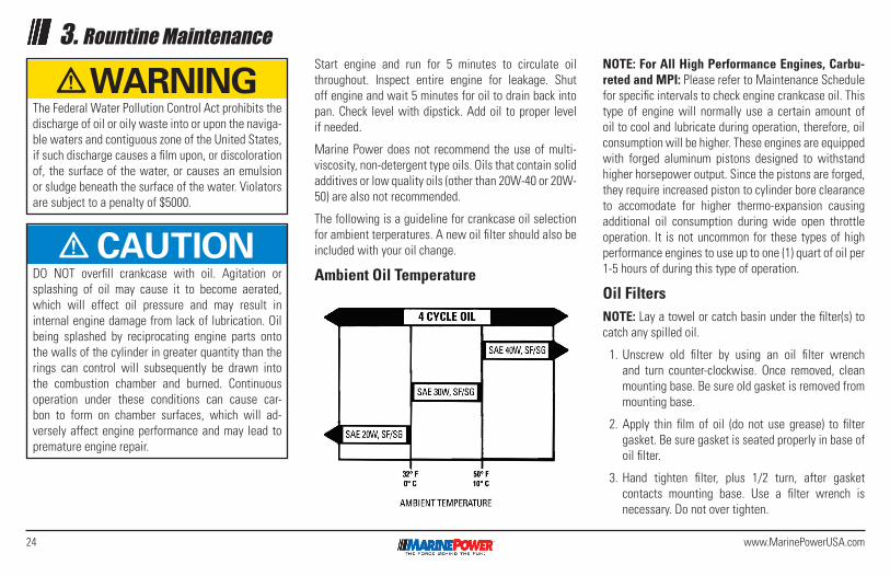
The following is a guideline for crankcase oil selection for ambient terperatures. A new oil filter should also be included with your oil change.
Ambient Oil Temperature
NOTE: For All High Performance Engines, Carbu-reted and MPI: Please refer to Maintenance Schedule for specific intervals to check engine crankcase oil. This type of engine will normally use a certain amount of oil to cool and lubricate during operation, therefore, oil consumption will be higher. These engines are equipped with forged aluminum pistons designed to withstand higher horsepower output. Since the pistons are forged, they require increased piston to cylinder bore clearance to accomodate for higher thermo-expansion causing additional oil consumption during wide open throttle operation. It is not uncommon for these types of high performance engines to use up to one (1) quart of oil per 1-5 hours of during this type of operation.
Oil FiltersNOTE: Lay a towel or catch basin under the filter(s) to catch any spilled oil.
1. Unscrew old filter by using an oil filter wrench and turn counter-clockwise. Once removed, clean mounting base. Be sure old gasket is removed from mounting base.
2. Apply thin film of oil (do not use grease) to filter gasket. Be sure gasket is seated properly in base of oil filter.
3. Hand tighten filter, plus 1/2 turn, after gasket contacts mounting base. Use a filter wrench is necessary. Do not over tighten.
DANGER
WARNING
CAUTIONDO NOT overfill crankcase with oil. Agitation or splashing of oil may cause it to become aerated, which will effect oil pressure and may result in internal engine damage from lack of lubrication. Oil being splashed by reciprocating engine parts onto the walls of the cylinder in greater quantity than the rings can control will subsequently be drawn into the combustion chamber and burned. Continuous operation under these conditions can cause car-bon to form on chamber surfaces, which will ad-versely affect engine performance and may lead to premature engine repair.
DANGER
WARNING
CAUTION
The Federal Water Pollution Control Act prohibits the discharge of oil or oily waste into or upon the naviga-ble waters and contiguous zone of the United States, if such discharge causes a film upon, or discoloration of, the surface of the water, or causes an emulsion or sludge beneath the surface of the water. Violators are subject to a penalty of $5000.
25www.MarinePowerUSA.com
3. Rountine Maintenance4. Check to see that oil shows “FULL” on dipstick.
Start engine. Turn on water. Run for approximately 5 minutes and inspect for leaks.
5. Turn off water. Shut off engine and wait 5 minutes for oil to drain back into pan. Check level with dipstick. Add oil to proper level if needed.
Always contact your nearest Marine Power Sericing Dealer if you have a problem.
Starter (Top Mount Only)Starters are notorious for problems due to moisture and corrosion.
However, Marine Power uses a top-mounted rear entry starter on most Sportpac and Jetpac models, that reduces starter problems and is more accessible.
Spray lubricating oil on the starter pinion and shaft.
1. Remove rubber plug “A” in flywheel housing.
2. Spray lubrication oil through hole and replace rubber plug.
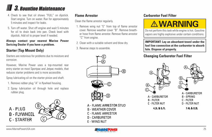
Flame ArrestorClean the flame arrestor regularly.
1. Remove wing nut “E” from top of flame arrestor cover. Remove weather cover “B”. Remove breath-er hose from flame arrestor. Remove flame arrestor “C” from engine.
2. Clean with a suitable solvent and blow dry.
3. Reverse steps to assemble.
Carburetor Fuel Filter
Changing Carburetor Fuel Filter
DANGER
WARNING
CAUTION
Do not perform this task while engine is hot. Gasoline vapors are highly explosive under certain conditions.
IMPORTANT: Lay an absorbent towel under the fuel line connection at the carburetor to absorb fule. Dispose of properly.
26 www.MarinePowerUSA.com
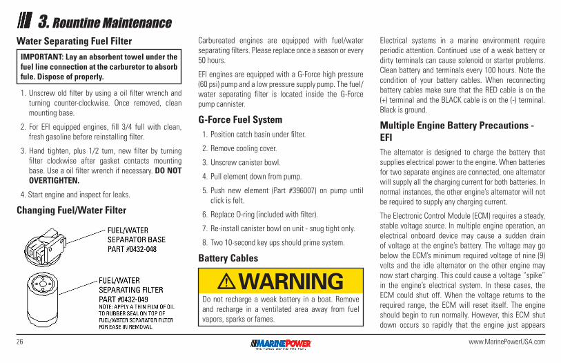
3. Rountine MaintenanceWater Separating Fuel Filter
1. Unscrew old filter by using a oil filter wrench and turning counter-clockwise. Once removed, clean mounting base.
2. For EFI equipped engines, fill 3/4 full with clean, fresh gasoline before reinstalling filter.
3. Hand tighten, plus 1/2 turn, new filter by turning filter clockwise after gasket contacts mounting base. Use a oil filter wrench if necessary. DO NOT OVERTIGHTEN.
4. Start engine and inspect for leaks.
Changing Fuel/Water Filter
Carbureated engines are equipped with fuel/water separating filters. Please replace once a season or every 50 hours.
EFI engines are equipped with a G-Force high pressure (60 psi) pump and a low pressure supply pump. The fuel/water separating filter is located inside the G-Force pump cannister.
G-Force Fuel System1. Position catch basin under filter.
2. Remove cooling cover.
3. Unscrew canister bowl.
4. Pull element down from pump.
5. Push new element (Part #396007) on pump until click is felt.
6. Replace O-ring (included with filter).
7. Re-install canister bowl on unit - snug tight only.
8. Two 10-second key ups should prime system.
Battery Cables
Electrical systems in a marine environment require periodic attention. Continued use of a weak battery or dirty terminals can cause solenoid or starter problems. Clean battery and terminals every 100 hours. Note the condition of your battery cables. When reconnecting battery cables make sure that the RED cable is on the (+) terminal and the BLACK cable is on the (-) terminal. Black is ground.
Multiple Engine Battery Precautions - EFIThe alternator is designed to charge the battery that supplies electrical power to the engine. When batteries for two separate engines are connected, one alternator will supply all the charging current for both batteries. In normal instances, the other engine’s alternator will not be required to supply any charging current.
The Electronic Control Module (ECM) requires a steady, stable voltage source. In multiple engine operation, an electrical onboard device may cause a sudden drain of voltage at the engine’s battery. The voltage may go below the ECM’s minimum required voltage of nine (9) volts and the idle alternator on the other engine may now start charging. This could cause a voltage “spike” in the engine’s electrical system. In these cases, the ECM could shut off. When the voltage returns to the required range, the ECM will reset itself. The engine should begin to run normally. However, this ECM shut down occurs so rapidly that the engine just appears
IMPORTANT: Lay an absorbent towel under the fuel line connection at the carburetor to absorb fule. Dispose of properly.
DANGER
WARNING
CAUTION
Do not recharge a weak battery in a boat. Remove and recharge in a ventilated area away from fuel vapors, sparks or fames.
27www.MarinePowerUSA.com
to have an ignition miss. In multi-EFI power packages, each engine must be connected to its own battery. This provides the required voltage source for the ECM.
In these applications where battery switches are used, it is important that each switch be positioned to allow each engine to run off its own individual battery. DO NOT run engines with the battery switches in “BOTH” or “ALL” positions. This will allow the other engine’s battery to be used in case of emergency to start the engine with the dead battery.
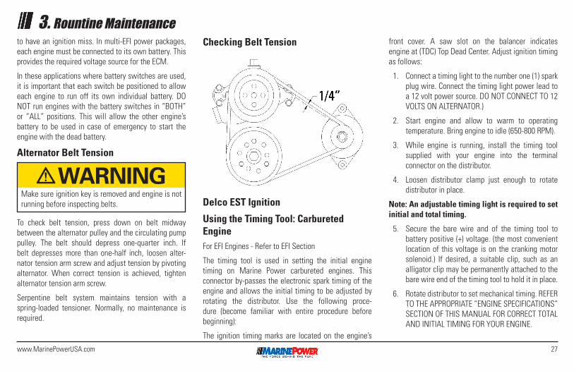
Alternator Belt Tension
To check belt tension, press down on belt midway between the alternator pulley and the circulating pump pulley. The belt should depress one-quarter inch. If belt depresses more than one-half inch, loosen alter-nator tension arm screw and adjust tension by pivoting alternator. When correct tension is achieved, tighten alternator tension arm screw.
Serpentine belt system maintains tension with a spring-loaded tensioner. Normally, no maintenance is required.
Checking Belt Tension
Delco EST Ignition
Using the Timing Tool: Carbureted EngineFor EFI Engines - Refer to EFI Section
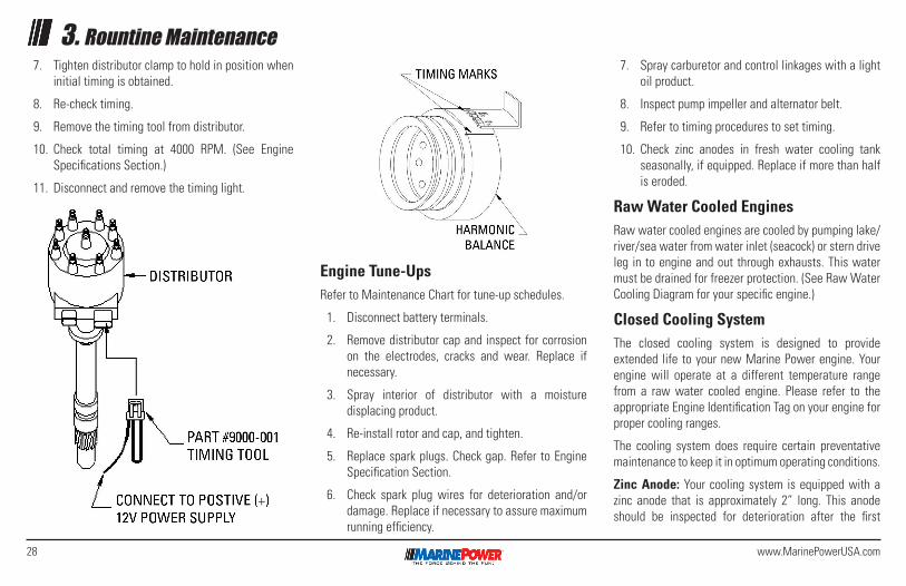
The timing tool is used in setting the initial engine timing on Marine Power carbureted engines. This connector by-passes the electronic spark timing of the engine and allows the initial timing to be adjusted by rotating the distributor. Use the following proce-dure (become familiar with entire procedure before beginning):
The ignition timing marks are located on the engine’s
front cover. A saw slot on the balancer indicates engine at (TDC) Top Dead Center. Adjust ignition timing as follows:
1. Connect a timing light to the number one (1) spark plug wire. Connect the timing light power lead to a 12 volt power source. DO NOT CONNECT TO 12 VOLTS ON ALTERNATOR.)
2. Start engine and allow to warm to operating temperature. Bring engine to idle (650-800 RPM).
3. While engine is running, install the timing tool supplied with your engine into the terminal connector on the distributor.
4. Loosen distributor clamp just enough to rotate distributor in place.
Note: An adjustable timing light is required to set initial and total timing.
5. Secure the bare wire and of the timing tool to battery positive (+) voltage. (the most convenient location of this voltage is on the cranking motor solenoid.) If desired, a suitable clip, such as an alligator clip may be permanently attached to the bare wire end of the timing tool to hold it in place.
6. Rotate distributor to set mechanical timing. REFER TO THE APPROPRIATE “ENGINE SPECIFICATIONS” SECTION OF THIS MANUAL FOR CORRECT TOTAL AND INITIAL TIMING FOR YOUR ENGINE.
3. Rountine Maintenance
DANGER
WARNING
CAUTION
Make sure ignition key is removed and engine is not running before inspecting belts.
28 www.MarinePowerUSA.com
3. Rountine Maintenance
Engine Tune-UpsRefer to Maintenance Chart for tune-up schedules.
1. Disconnect battery terminals.
2. Remove distributor cap and inspect for corrosion on the electrodes, cracks and wear. Replace if necessary.
3. Spray interior of distributor with a moisture displacing product.
4. Re-install rotor and cap, and tighten.
5. Replace spark plugs. Check gap. Refer to Engine Specification Section.
6. Check spark plug wires for deterioration and/or damage. Replace if necessary to assure maximum running efficiency.
7. Spray carburetor and control linkages with a light oil product.
8. Inspect pump impeller and alternator belt.
9. Refer to timing procedures to set timing.
10. Check zinc anodes in fresh water cooling tank seasonally, if equipped. Replace if more than half is eroded.
Raw Water Cooled EnginesRaw water cooled engines are cooled by pumping lake/river/sea water from water inlet (seacock) or stern drive leg in to engine and out through exhausts. This water must be drained for freezer protection. (See Raw Water Cooling Diagram for your specific engine.)
Closed Cooling SystemThe closed cooling system is designed to provide extended life to your new Marine Power engine. Your engine will operate at a different temperature range from a raw water cooled engine. Please refer to the appropriate Engine Identification Tag on your engine for proper cooling ranges.
The cooling system does require certain preventative maintenance to keep it in optimum operating conditions.
Zinc Anode: Your cooling system is equipped with a zinc anode that is approximately 2” long. This anode should be inspected for deterioration after the first
7. Tighten distributor clamp to hold in position when initial timing is obtained.
8. Re-check timing.
9. Remove the timing tool from distributor.
10. Check total timing at 4000 RPM. (See Engine Specifications Section.)
11. Disconnect and remove the timing light.
29www.MarinePowerUSA.com
3. Rountine Maintenance10 hours of operation. Inspect again after 50 hours of operation and every 50 hours thereafter.
Recovery Bottle: The plastic recovery bottle is attached to the heat exchanger tank (on most models) and fills with coolant during operation when the internal water temperature is higher. If necessary, add coolant only when engine is cold.
Filler Neck and Pressure Cap: DO NOT remove pressure cap when engine is HOT. If coolant is low, add the proper mixture (50% water/50% antifreeze) to the top of the filler neck located on the heat exchanger tank. If coolant is consistently low, additional inspection for leaks in the cooling system may be required.
Filling Closed Cooling System
IMPORTANT! The closed cooling system must remain filled year-round with the proper mixture of 50% antifreeze/50% water to assure protection of system during the lowest exposed temperatures.
• Insure that all drain plugs are installed and tight-ened.
• Fill heat exchanger (tank) with 50/50 antifreeze/ water mixture. After initial fill, start engine and continue filling heat exchanger Engine must be purged of air by bleeding system. Engines may be bled in a variety of ways; however, the following bleed points are suggested.
3.0L Side Mount Full System: Heat exchanger cap is sufficient.
4.3/5.7L Front Mount Full System: Heat exchanger cap is sufficient.
4.3/5.7L Rear Mount Full System: Disconnect hose from top of circulating water pump.
6.0L Side Mount Full System: Air bleed on starboard exhaust manifold.
7.4L/8.2L Front Mount Full System: Heat exchanger cap is sufficient.
7.4L/8.2L Rear Mount Full System: Disconnect hose from top of circulating water pump.
• Bleeds should be left open until all sign of air bubbles disappear. Engines bled at cap must be ran @ 2000 RPM with cap ope to bleed all air. 6.0L and 8.1L engines are difficult to purge. Use caution - thermostat must open to remove all air, this process may take ten (10) minutes. Continue filling the heat exchanger after bleeds are closed. After themo-stat has opened and heat exchanger is topped off, install heat exchanger cap. Fill plastic reservoir 1/2 full.
• Check for leaks after finished fill procedures.
DANGER
WARNING
CAUTION
Do not remove pressure cap when engine is hot. Coolant is under pressure and may be forced out causing personal injury. After engine is cooled, remove cap slowly to allow pressure to escape.
30 www.MarinePowerUSA.com
3. Rountine MaintenanceExtended Storage and Storage in Below Freezing Temperatures
Raw Water Cooled Engines
Note: Raw water cooling requires no filling.
1. Shut down engine and change engine oil and filters. (Refer to Oil Filter in Rountine Maintenance)
2. V6/V8 blocks must be drained on both sides. Drain plug locations are as follows:
• 3.0L/181: Single plug on port side of lower block.
• 4.3L/5.0L/5.7L/7.4L/8.2L Carbureted: Plug on lower center portion of block on each side.
• 4.3L/5.7L EFI: Knock sensor is located in port block drain. Sensor must be removed for drain-
ing and retorqued to 22 ft.lb. When reinstalled.
3. Re-install hose on circulating pump after system has drained completely. Coat all plug threads with sealant and re-install into proper locations.
4. Remove engine oil and transmission cooler drain plugs.
5. Remove hoses from sea water pump, if applicable.
6. Remove circulating pump hose from lower inlet to circulating pump. Remove all exhaust manifold drain plugs. Drain engine completely.
7. Any engine stored for thirty (30) days or longer needs a fuel stabilizer. We recommend that Sta-Bil be added to the fuel per the manufacturer’s directions. This will prevent the formation of harmful varnish in the fuel system.
8. Fog engine. (Refer to Fogging Procedures.)
9. Reconnect suction hose to sea water inlet. (See Raw Water Cooling Diagram for your engine.)
Closed Cooling Engines1. Follow raw water drawing procedure except for the
following:
• Draining manifolds are not necessary unless closed system is half system type as on 5.0/5.7V EL models.
• Engine block does not need draining.
• Circulating water pump hose does not need to be removed.
2. Remove end caps on heat exchanger. Inspect for debris and trapped water.
3. Refill closed cooling system according to instruc-tions in Filling Closed Cooling System section.
Fogging ProceduresThis procedure necessary for carbureted models only:
1. Remove flame arrestor cover and flame arrestor.
2. Start engine and run at 1500 to 2000 RPM.
3. Pour approximately one (1) cup of rust preventive oil (or if not available, SAE 20W motor oil) into carbu-retor.
DANGER
WARNING
CAUTION
DANGER
WARNING
CAUTION DANGER
WARNING
CAUTION
These operations should be performed only by qualified marine service personnel.
Do not operate engine without water being supplied to the sea water pump as pump impeller and engine will be damaged.
Do not use 100% water or antifreeze as engine coolant. Overheating and engine damage will result.
DANGER
WARNING
CAUTIONDo not pour an excessive amount of oil into the carburetor at one time. This can cause engine to stall and/or create a hydraulic lock condition in a cylinder resulting in engine damage.
31www.MarinePowerUSA.com
3. Rountine Maintenance4. Turn ignition switch off.
5. Clean flame arrestor and re-install on engine with cover.
6. Cover complete carburetor assembly with plastic bag to prevent moisture from entering carburetor during storage.
Returning Engine to Service After Extended StorageIf you followed the storage procedure the new season start-up time should be minimal. Please do the follow-ing before attempting to start your engine.
1. Check that all engine drain plugs are installed and seacock on water inlet is open. Check coolant levels.
2. Check all hoses to make sure they are properly connected and clamps are tightened.
3. Inspect bilge area and around engine for nesting creatures, signs of leakage or physical damage.
4. Clean battery cables and install a fully charged battery. Attach red wire to positive (+) termi-nal and black wire to negative (-) terminal. It is recommended that a anti-corrosion battery terminal spray be use to coat terminal connections.
5. After engine is started, monitor gauges to insure en-gine is operating in normal operating temperatures.
6. After engine has reached normal operating temperature, inspect engine for leaks such as fuel, exhaust, water and oil.
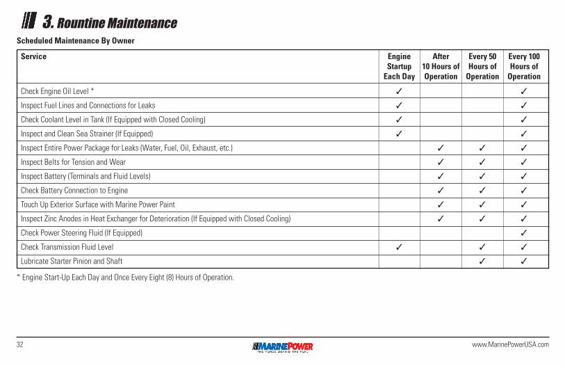
32 www.MarinePowerUSA.com
3. Rountine MaintenanceScheduled Maintenance By Owner
* Engine Start-Up Each Day and Once Every Eight (8) Hours of Operation.
Service Engine After Every 50 Every 100 Startup 10 Hours of Hours of Hours of Each Day Operation Operation Operation
Check Engine Oil Level * 3 3
Inspect Fuel Lines and Connections for Leaks 3 3
Check Coolant Level in Tank (If Equipped with Closed Cooling) 3 3
Inspect and Clean Sea Strainer (If Equipped) 3 3
Inspect Entire Power Package for Leaks (Water, Fuel, Oil, Exhaust, etc.) 3 3 3
Inspect Belts for Tension and Wear 3 3 3
Inspect Battery (Terminals and Fluid Levels) 3 3 3
Check Battery Connection to Engine 3 3 3
Touch Up Exterior Surface with Marine Power Paint 3 3 3
Inspect Zinc Anodes in Heat Exchanger for Deterioration (If Equipped with Closed Cooling) 3 3 3
Check Power Steering Fluid (If Equipped) 3
Check Transmission Fluid Level 3 3 3
Lubricate Starter Pinion and Shaft 3 3
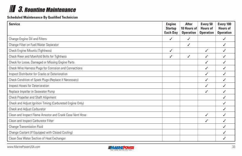
33www.MarinePowerUSA.com
3. Rountine MaintenanceScheduled Maintenance By Qualified Technician
Service Engine After Every 50 Every 100 Startup 10 Hours of Hours of Hours of Each Day Operation Operation Operation
Change Engine Oil and Filters 3 3 3
Change Filter on Fuel/Water Separator 3 3
Check Engine Mounts (Tightness) 3 3 3
Check Riser and Manifold Bolts for Tightness 3 3 3 3
Check for Loose, Damaged or Missing Engine Parts 3 3
Check Wire Harness Plugs for Corrosion and Connections 3 3
Inspect Distributor for Cracks or Deterioration 3 3
Check Condition of Spark Plugs (Replace if Necessary) 3 3
Inspect Hoses for Deterioration 3 3
Replace Impeller in Seawater Pump 3 3
Check Propeller and Shaft Alignment 3
Check and Adjust Ignition Timing (Carbureted Engine Only) 3
Check and Adjust Carburetor 3
Clean and Inspect Flame Arrestor and Crank Case Vent Hose 3 3
Clean and Inspect Carburetor Filter 3 3
Change Transmission Fluid 3
Change Coolant (If Equipped with Closed Cooling) 3
Clean Sea Water Section of Heat Exchanger 3
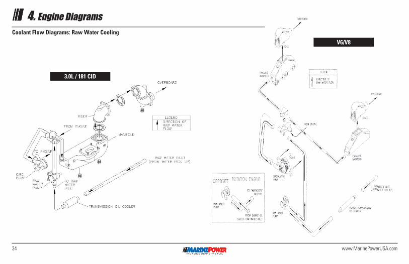
34 www.MarinePowerUSA.com
4. Engine DiagramsCoolant Flow Diagrams: Raw Water Cooling
3.0L / 181 CID
V6/V8
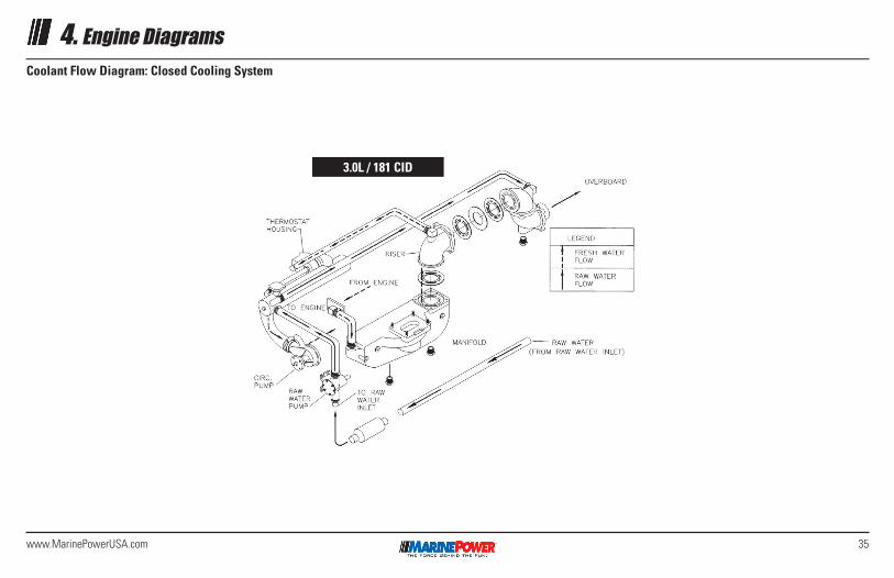
35www.MarinePowerUSA.com
4. Engine DiagramsCoolant Flow Diagram: Closed Cooling System
3.0L / 181 CID
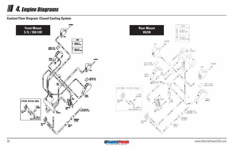
36 www.MarinePowerUSA.com
4. Engine DiagramsCoolant Flow Diagram: Closed Cooling System
Front Mount 5.7L / 350 CID
Rear Mount V6/V8
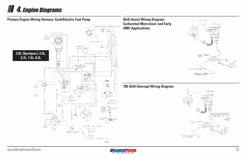
37www.MarinePowerUSA.com
4. Engine DiagramsPrimary Engine Wiring Harness: Carb/Electric Fuel Pump Shift Assist Wiring Diagram:
Carbureted Mercruiser and Early OMC Applications
TBI Shift Interrupt Wiring Diagram
3.0L (Sportpac), 4.3L, 5.7L, 7.4L, 8.2L
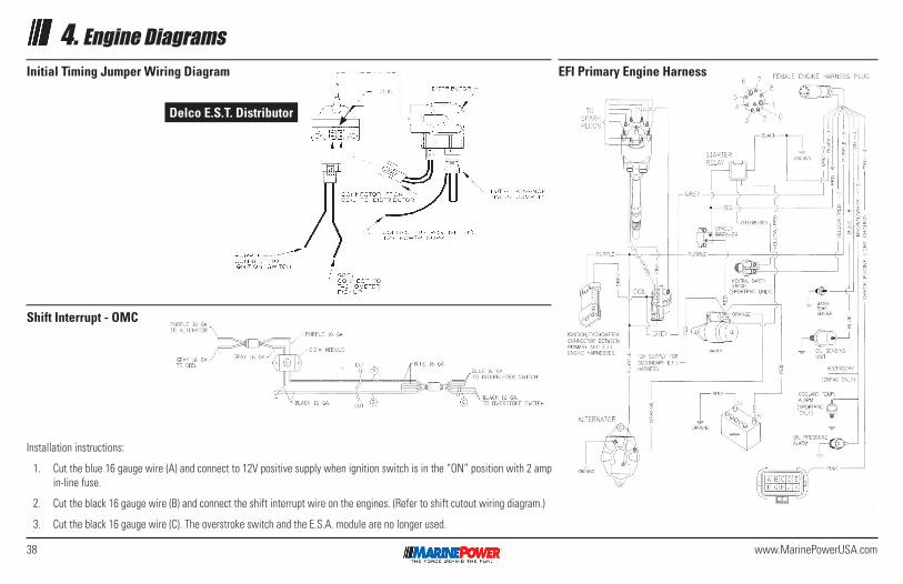
38 www.MarinePowerUSA.com
4. Engine DiagramsInitial Timing Jumper Wiring Diagram EFI Primary Engine Harness
Shift Interrupt - OMC
Installation instructions:
1. Cut the blue 16 gauge wire (A) and connect to 12V positive supply when ignition switch is in the “ON” position with 2 amp in-line fuse.
2. Cut the black 16 gauge wire (B) and connect the shift interrupt wire on the engines. (Refer to shift cutout wiring diagram.)
3. Cut the black 16 gauge wire (C). The overstroke switch and the E.S.A. module are no longer used.
Delco E.S.T. Distributor
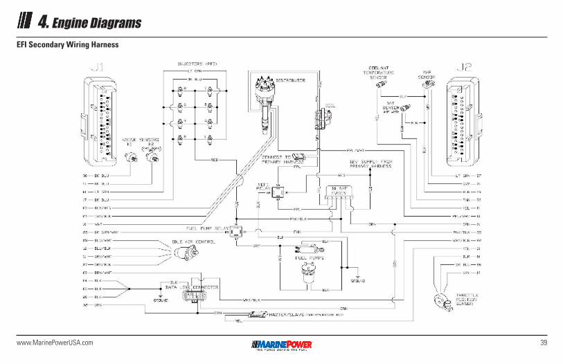
39www.MarinePowerUSA.com
4. Engine DiagramsEFI Secondary Wiring Harness
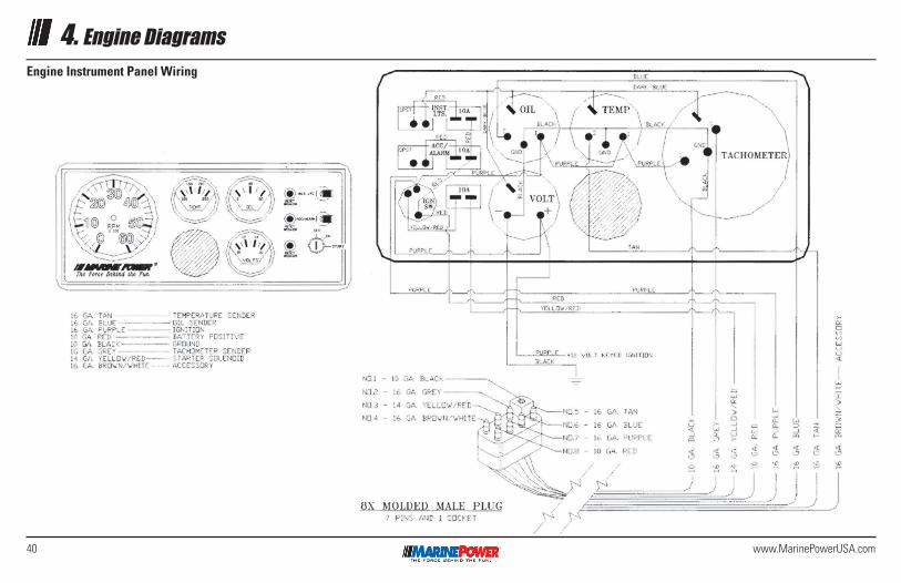
40 www.MarinePowerUSA.com
4. Engine DiagramsEngine Instrument Panel Wiring
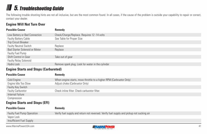
41www.MarinePowerUSA.com
5. Troubleshooting GuideThe following trouble shooting hints are not all inclusive, but are the most common found. In all cases, if the cause of the problem is outside your capability to repair or correct, contact your dealer.
Engine Will Not Turn OverPossible Cause Remedy
Low Battery or Bad Connection Check/Charge/Replace. Requires 12 -14 voltsFaulty Battery Cable See Table for Proper SizeTrip Circuit Breaker Faulty Neutral Switch ReplaceBad Starter Solenoid or Motor ReplaceFaulty Fuel PumpShift Control in Gear Take out of gearFaulty Relay Solenoid Hydro Lock Remove spark plug. Look for water in the cylinder
Engine Starts and Stops (Carbureted)Possible Cause Remedy
Cold Engine When engine starts, move throttle to a higher RPM (Carbruetor Only)Engine Idle Too Slow Adjust choke (Carbruetor Only)Faulty Key SwitchFaulty Carburetor Check inline filter. Check carburetor filter.Internal FailureCompression
Engine Starts and Stops (EFI)Possible Cause Remedy
Faulty Fuel Pump Operation Verify fuel supply and return not reversed. Verify fuel supply and pickup not sucking airVapor LockInsufficient Fuel Supply
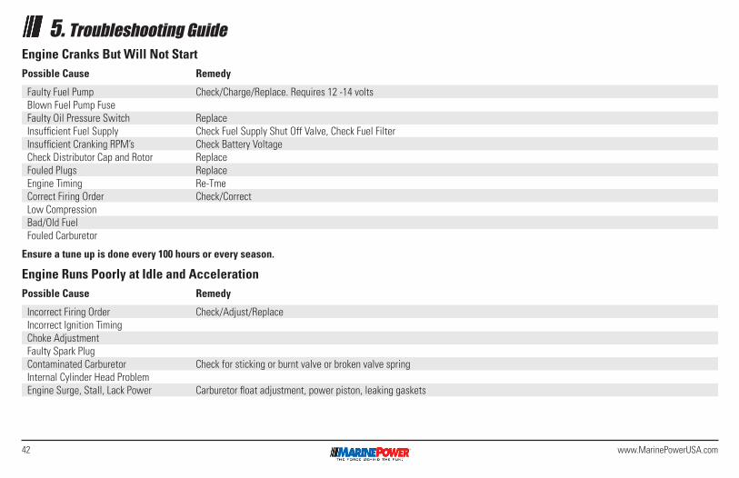
42 www.MarinePowerUSA.com
5. Troubleshooting GuideEngine Cranks But Will Not StartPossible Cause Remedy
Faulty Fuel Pump Check/Charge/Replace. Requires 12 -14 voltsBlown Fuel Pump FuseFaulty Oil Pressure Switch ReplaceInsufficient Fuel Supply Check Fuel Supply Shut Off Valve, Check Fuel FilterInsufficient Cranking RPM’s Check Battery VoltageCheck Distributor Cap and Rotor ReplaceFouled Plugs ReplaceEngine Timing Re-TmeCorrect Firing Order Check/CorrectLow Compression Bad/Old FuelFouled Carburetor
Ensure a tune up is done every 100 hours or every season.
Engine Runs Poorly at Idle and AccelerationPossible Cause Remedy
Incorrect Firing Order Check/Adjust/ReplaceIncorrect Ignition TimingChoke Adjustment Faulty Spark Plug Contaminated Carburetor Check for sticking or burnt valve or broken valve springInternal Cylinder Head ProblemEngine Surge, Stall, Lack Power Carburetor float adjustment, power piston, leaking gaskets
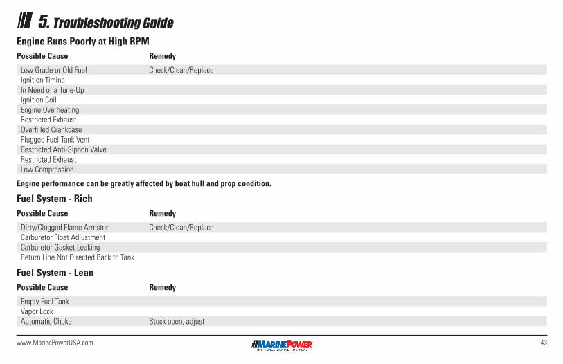
43www.MarinePowerUSA.com
5. Troubleshooting GuideEngine Runs Poorly at High RPMPossible Cause Remedy
Low Grade or Old Fuel Check/Clean/ReplaceIgnition TimingIn Need of a Tune-UpIgnition CoilEngine OverheatingRestricted ExhaustOverfilled CrankcasePlugged Fuel Tank VentRestricted Anti-Siphon ValveRestricted ExhaustLow Compression
Engine performance can be greatly affected by boat hull and prop condition.
Fuel System - RichPossible Cause Remedy
Dirty/Clogged Flame Arrester Check/Clean/ReplaceCarburetor Float AdjustmentCarburetor Gasket LeakingReturn Line Not Directed Back to Tank
Fuel System - LeanPossible Cause Remedy
Empty Fuel TankVapor LockAutomatic Choke Stuck open, adjust
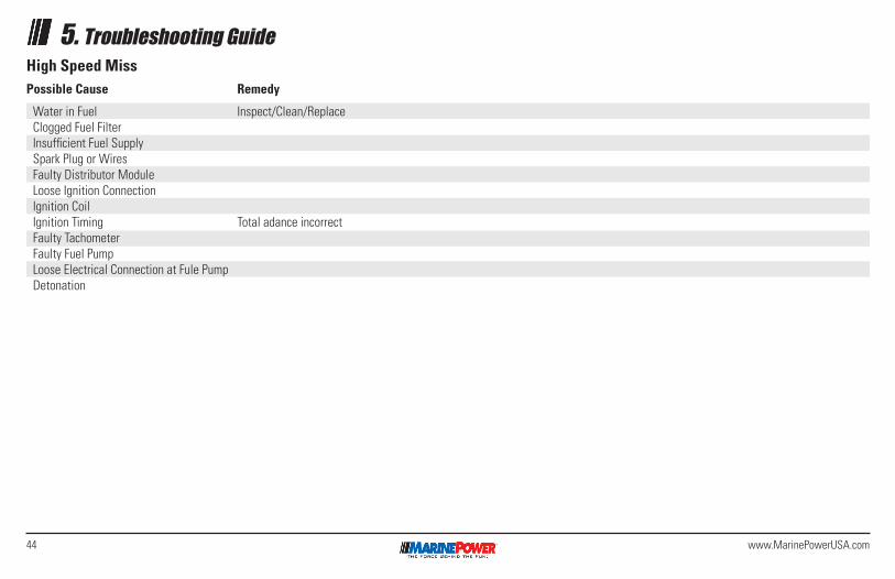
44 www.MarinePowerUSA.com
5. Troubleshooting GuideHigh Speed MissPossible Cause Remedy
Water in Fuel Inspect/Clean/ReplaceClogged Fuel FilterInsufficient Fuel SupplySpark Plug or WiresFaulty Distributor ModuleLoose Ignition ConnectionIgnition CoilIgnition Timing Total adance incorrectFaulty TachometerFaulty Fuel PumpLoose Electrical Connection at Fule PumpDetonation
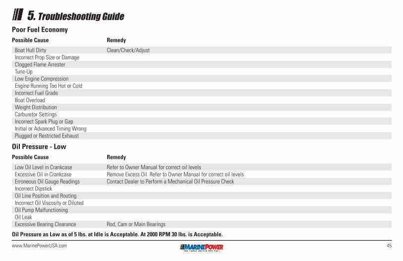
45www.MarinePowerUSA.com
5. Troubleshooting Guide
Oil Pressure - LowPossible Cause Remedy
Low Oil Level in Crankcase Refer to Owner Manual for correct oil levelsExcessive Oil in Crankcase Remove Excess Oil. Refer to Owner Manual for correct oil levelsErroneous Oil Gauge Readings Contact Dealer to Perform a Mechanical Oil Pressure CheckIncorrect DipstickOil Line Position and RoutingIncorrect Oil Viscosity or Diluted Oil Pump Malfunctioning Oil LeakExcessive Bearing Clearance Rod, Cam or Main Bearings
Oil Pressure as Low as of 5 lbs. at Idle is Acceptable. At 2000 RPM 30 lbs. is Acceptable.
Poor Fuel EconomyPossible Cause Remedy
Boat Hull Dirty Clean/Check/AdjustIncorrect Prop Size or DamageClogged Flame ArresterTune-UpLow Engine CompressionEngine Running Too Hot or ColdIncorrect Fuel GradeBoat OverloadWeight DistributionCarburetor SettingsIncorrect Spark Plug or GapInitial or Advanced Timing WrongPlugged or Restricted Exhaust
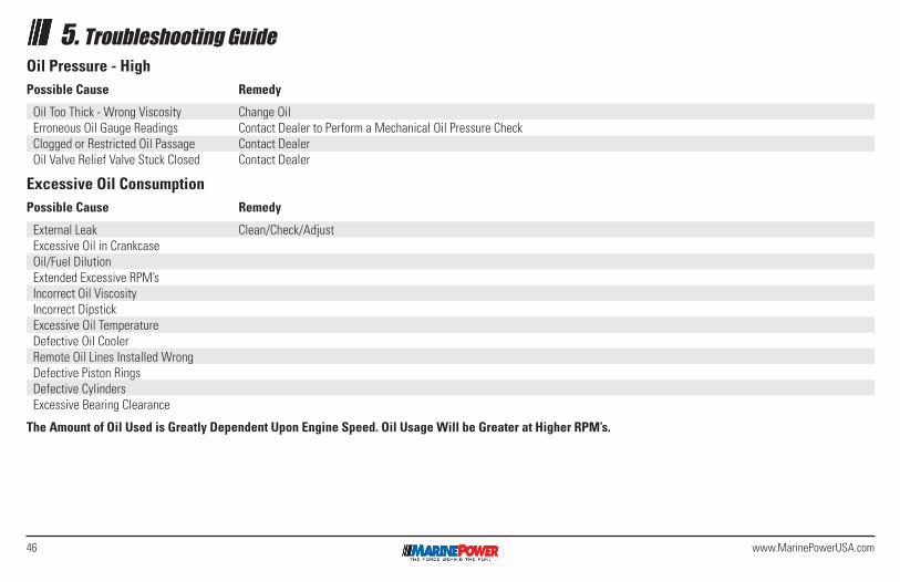
46 www.MarinePowerUSA.com
5. Troubleshooting GuideOil Pressure - HighPossible Cause Remedy
Oil Too Thick - Wrong Viscosity Change OilErroneous Oil Gauge Readings Contact Dealer to Perform a Mechanical Oil Pressure CheckClogged or Restricted Oil Passage Contact DealerOil Valve Relief Valve Stuck Closed Contact Dealer
Excessive Oil ConsumptionPossible Cause Remedy
External Leak Clean/Check/AdjustExcessive Oil in CrankcaseOil/Fuel DilutionExtended Excessive RPM’sIncorrect Oil ViscosityIncorrect DipstickExcessive Oil TemperatureDefective Oil CoolerRemote Oil Lines Installed WrongDefective Piston RingsDefective CylindersExcessive Bearing Clearance
The Amount of Oil Used is Greatly Dependent Upon Engine Speed. Oil Usage Will be Greater at Higher RPM’s.
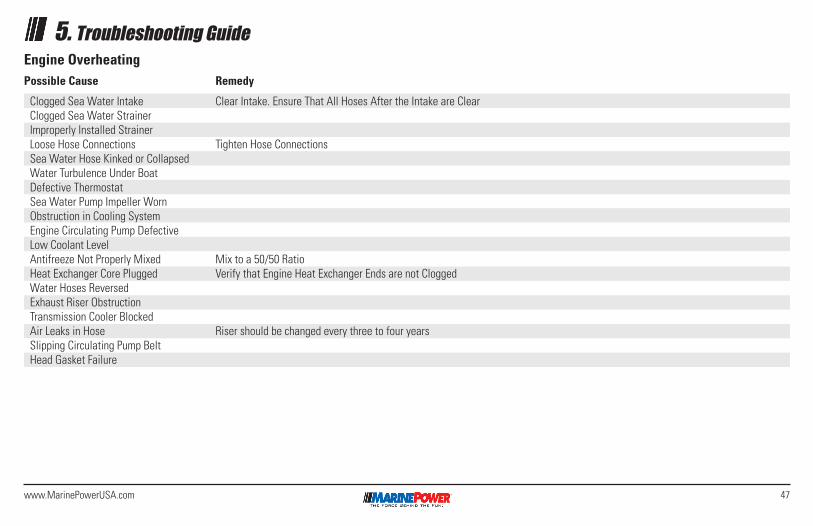
47www.MarinePowerUSA.com
5. Troubleshooting GuideEngine OverheatingPossible Cause Remedy
Clogged Sea Water Intake Clear Intake. Ensure That All Hoses After the Intake are ClearClogged Sea Water StrainerImproperly Installed StrainerLoose Hose Connections Tighten Hose ConnectionsSea Water Hose Kinked or CollapsedWater Turbulence Under BoatDefective ThermostatSea Water Pump Impeller WornObstruction in Cooling SystemEngine Circulating Pump DefectiveLow Coolant LevelAntifreeze Not Properly Mixed Mix to a 50/50 RatioHeat Exchanger Core Plugged Verify that Engine Heat Exchanger Ends are not CloggedWater Hoses ReversedExhaust Riser ObstructionTransmission Cooler BlockedAir Leaks in Hose Riser should be changed every three to four yearsSlipping Circulating Pump BeltHead Gasket Failure
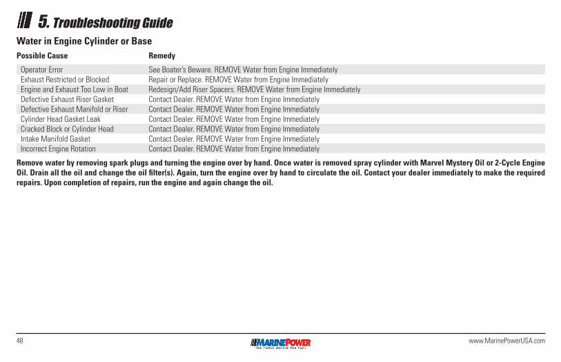
48 www.MarinePowerUSA.com
5. Troubleshooting GuideWater in Engine Cylinder or BasePossible Cause Remedy
Operator Error See Boater’s Beware. REMOVE Water from Engine ImmediatelyExhaust Restricted or Blocked Repair or Replace. REMOVE Water from Engine ImmediatelyEngine and Exhaust Too Low in Boat Redesign/Add Riser Spacers. REMOVE Water from Engine ImmediatelyDefective Exhaust Riser Gasket Contact Dealer. REMOVE Water from Engine ImmediatelyDefective Exhaust Manifold or Riser Contact Dealer. REMOVE Water from Engine ImmediatelyCylinder Head Gasket Leak Contact Dealer. REMOVE Water from Engine ImmediatelyCracked Block or Cylinder Head Contact Dealer. REMOVE Water from Engine ImmediatelyIntake Manifold Gasket Contact Dealer. REMOVE Water from Engine ImmediatelyIncorrect Engine Rotation Contact Dealer. REMOVE Water from Engine Immediately
Remove water by removing spark plugs and turning the engine over by hand. Once water is removed spray cylinder with Marvel Mystery Oil or 2-Cycle Engine Oil. Drain all the oil and change the oil filter(s). Again, turn the engine over by hand to circulate the oil. Contact your dealer immediately to make the required repairs. Upon completion of repairs, run the engine and again change the oil.

49www.MarinePowerUSA.com
Excessive Oil Consumption Troubleshooting Chart Cause Information
Normal Oil Consumption One quart of oil consumed within 5-15 hours of wide-open throttle operation is normal.
Oil Level Too High
Oil Leak Clean bilge, put clean white towel on bilge floor and run engine to locate oil leak(s).
Oil Too Thin Oil diluted or wrong viscosity.
Cylinder Head Drain Holes Plugged Oil will flood valve guides.
Defective Valve Seals
Leaking Intake Manifold Gasket
Worn Valve Guides or Valve Stems
Defective Piston Rings Worn, stuck, glazed, scuffed, improperly installed ring grooves worn, improper break-in. Wrong end gap.
Defective Cylinders Scored, tapered, glazed, out of round. Excessive piston to cylinder clearance. Cracked piston.
Excessive Bearing Clearance
Defective Oil Cooler (if equipped) Crack in cooler tubes.
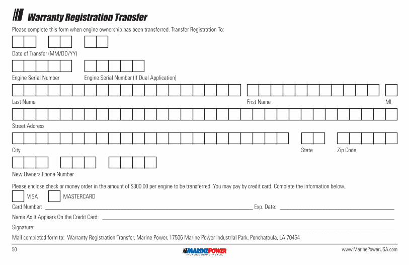
50 www.MarinePowerUSA.com
Warranty Registration TransferPlease complete this form when engine ownership has been transferred. Transfer Registration To:
Please enclose check or money order in the amount of $300.00 per engine to be transferred. You may pay by credit card. Complete the information below.
VISA MASTERCARD
Card Number: _____________________________________________________________________ Exp. Date: ______________________________________
Name As It Appears On the Credit Card: _________________________________________________________________________________________________
Signature: _______________________________________________________________________________________________________________________
Mail completed form to: Warranty Registration Transfer, Marine Power, 17506 Marine Power Industrial Park, Ponchatoula, LA 70454
Date of Transfer (MM/DD/YY)
Engine Serial Number
Last Name
City
Street Address
New Owners Phone Number
First Name
State
MI
Zip Code
Engine Serial Number (If Dual Application)
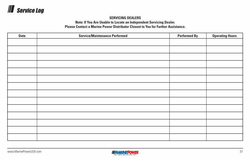
51www.MarinePowerUSA.com
Service LogSERVICING DEALERS
Note: If You Are Unable to Locate an Independent Servicing Dealer.Please Contact a Marine Power Distributor Closest to You for Further Assistance.
Date Service/Maintenance Performed Performed By Operating Hours
Copyright 2019 Marine Power
All rights reserved. No part of this book may be reproduced or utilized in any form or by any means, electronic or mechanical, including photocopying, recording or any information storage and retrieval system, without permission in writing from MARINE POWER HOLDING, LLC.
Marine Power 17506 Marine Power Industrial Park, Ponchatoula, LA 70454 USA www.MarinePowerUSA.com


