Embed Size (px)
Citation preview

www.AIMCO-GLOBAL.com
A chie v ing As s e m b ly ex c e l l e n c e
CATA L OG • 2 016

AIMCO
For over 40 years AIMCO has been working with manufacturers around the world, we are the complete global
source for all assembly, fastening, and critical bolting needs. AIMCO can effectively and swiftly meet your needs
whether you’re in Thailand fastening a 3 mm nut at 3 Nm, or in Tennessee, USA torquing the last lug nut. AIMCO
provides the tools and solutions, on a global scale, that guarantee the success of your project. It is with great
pride that AIMCO can say the products that we manufacture are MADE IN THE USA.
Visit our NEW website www.aimco-global.com

ACRADYNE®
GEN IV CONTROLLER 10-12CONTROLLER SOFTWARE 131000 SERIES NUTRUNNERS 14-151000, 2000 & 5000 SERIES PISTOL GRIP NUTRUNNERS 16-172000, 3000 & 5000 SERIES ANGLE / INLINE NUTRUNNERS 18-215000 SERIES FIXTURED NUTRUNNERS 22TUBENUT NUTRUNNERS AND SPECIALTY GEARHEADS 23HOLD & DRIVE NUTRUNNERS 24MID-EXIT CABLE NUTRUNNERS 25RIV-NUT NUTRUNNERS 26HT SERIES D/C TOOLS 27HT SERIES D/C ANGLE TOOLS 28HT SERIES DUAL LEVER AND GEARHEAD TOOLS 29HT SERIES NOSE EXTENSIONS AND ACCESSORIES 30TOOL / SPINDLE SELECTION GUIDE 32-33ACCESSORIES 34-36HT SERIES PNEUMATIC TOOLS 37HT SERIES PNEUMATIC TOOL ACCESSORIES 38ACRADYNE® SYSTEMS 39
URYUFIXTURED F-SERIES NUTRUNNERS 40-43CONTROLLERS 44-48CONTROLLED PULSE TOOLS AND CONTROLLER 49-54CONTROLLER ACCESSORIES 55-56
AUDITORTM
TORQUE MEASUREMENT: OVERVIEW 57-59TORQUE MEASUREMENT SYSTEMS 60TORQUE MEASUREMENT TESTERS 61-63TORQUE MEASUREMENT ANALYZERS 64-69TOOL MANAGER / AUDIT MANAGER 70HIGH-CAPACITY TEST STANDS 71-73AUDITOR TORQUE WRENCHES 74-77SCS TORQUE WRENCHES 78-81TORQUE CARTS 82-83DATAPRO + SQNET SOFTWARE 84TRANSDUCERS 85-86RUNDOWN FIXTURES / JOINT SIMULATORS 87-89TORQUE MEASUREMENT CABLES 90APPENDICES 92-95
POWER TOOLSAIMCO PULSE TOOLS: OVERVIEW 96-97UAT SERIES 98-99OMEGA PULSE TOOLS: UL SERIES 100ACRA-PULSE® SERIES 101-103UDBP PULSE SERIES CORDLESS TOOLS 104-105UDP-TA SERIES 106NUTRUNNERS: OVERVIEW 107NUTRUNNERS 108-109DYNATORQUE MANUAL TORQUE MULTIPLIERS 110-111SCREWDRIVERS: OVERVIEW 112PNEUMATIC SCREWDRIVERS 113-115SIGNATURE SERIES CORDLESS TOOLS 116-118ELECTRIC SCREWDRIVERS 119-121IMPACT TOOLS 122GRINDERS AND SANDERS 123DRILLS & PERCUSSION TOOLS 124
ASSEMBLY SYSTEMSSCREW PRESENTERS: OVERVIEW 125A-50 SCREW PRESENTERS 126ACRA-FEED AUTOMATIC SCREW FEED SYSTEMS 127
TOOL SUPPORT SYSTEMSBALANCERS / RETRACTORS 128-129ERGO-ARM® TOOL SUPPORT SYSTEMS 130ERGO-ARM® ACCESSORIES / LINEAR ARM 131CUSTOM REACTION DEVICES 131CARBON TORQUE ARMS / TUBES 132-133WORKSTATION COMPONENTS AND ASSEMBLIES 134-135AIR PREPARATION UNITS 136AIR LINE 137-138
FASTENER TOOLSSTANDARD FASTENER TOOLS 139-141ERGO-DRIVE® SERIES * 142-143CUSTOM / SPECIAL PARTS 144-147CONVERSION CHARTS 148
AIMCO
TABLE OF CONTENTS
* logo indicates where ERGO-DRIVE sockets/extensions benefit tool operation.
AIMCO
ERGO-DRIVE sockets are uniquely designed to seat deeper on the tool anvil while an O-ring inside the socket fits tight onto the anvil to reduce vibration. By reducing run-out and vibration, ERGO-DRIVE sockets allow the most repeatable, accurate rundowns, ensuring excellent product quality, longer tool life, and better ergonomics for the tool user.
Look for the ERGO-DRIVE logo in this catalog to see where ERGO-DRIVE sockets/extensions benefit tool operation, operator, and rundown. See page 142 for ERGO-DRIVE details.
3Visit our NEW website www.aimco-global.com

PRODUCTIVITY The speed and efficiency of the assembly processEvery manufacturer wants to produce finished goods in the most cost-effective manner possible. Whether the customer is a large automotive manufacturer, building several hundred vehicles daily, or an electronics company producing individual, custom made components, AIMCO provides products and services that allow each company to work at their ideal pace in order to keep its processes running efficiently.
ERGONOMICS The relationship between assembler and the assembly processEmployees are the most important assets of any company. Protecting these individuals from job related health issues is critical. To help its customers face the challenges surrounding ergonomics, AIMCO focuses on providing products that combine a lack of torque reaction, low vibration, light weight, as well as quiet and simple operation. These features allow assemblers to do their job in the safest possible manner and help manufacturers avoid the often hidden costs of workplace injuries.
RELIABILITY The total cost of tool maintenance and repairTo keep production lines running, tools must perform reliably. AIMCO helps manufacturers face the challenges of maintenance, repair and lost labor time by offering products with superior workmanship and durability. By combining high quality products with a detailed and flexible service-training program, AIMCO ensures its tools will meet the customer’s expectations of reliability.
QUALITY The ability of the tool to adhere to process requirementsThe most important challenge faced by many companies is to meet the customer’s demands for quality. AIMCO provides assembly tools that have been tested and proven to meet the most stringent engineering specifications. AIMCO backs those tools up with its innovative AuditorTM torque measurement products. This allows manufacturers to focus on their most important goal—creating a quality product.
4 Visit our NEW website www.aimco-global.com

PERQ® is the industry-standard formula that matches the needs of manufacturers with the assembly tools they use in their processes.
AIMCO and its distributors evaluate each manufacturer based on the PERQ® formula to determine that company’s unique blend of the PERQ® elements – productivity, ergonomics,
reliability and quality – we then provide tooling options that will enhance that mix. The end result is a manufacturing process that runs efficiently, produces high quality products and does so at the lowest possible cost.
Combining PERQ® with AIMCO’s vast experience and unequalled service will enable any manufacturer to succeed in the global marketplace.
Each of the PERQ® elements acts as a gear – each interacts with the others to affect the overall profitability of the manufacturing process. AIMCO looks at each step in the manufacturing process to determine the best type of tool, or equipment, for that application. Only AIMCO, with its extensive product lineup, can offer the manufacturer the ideal tool for the job, whether it be continuous drive or pulse tool, electric, pneumatic or battery powered.
Power Source
Drive Type
Orientation & Fixturing
Correct Tool Choice
• Pneumatic tools will generally provide the fastest operation possible.• Pneumatic tools offer the best power-to-weight ratio when compared to similar tools with
electric or battery powered motors.• Pneumatic tools will often have a longer overall service life when compared to similar tools with
electric or battery powered motors.• Electric tools will generally be the cleanest and most quiet to operate. Electric tools can provide
excellent torque repeatability due to their slower speeds.• Cordless tools, due to their mobility, allow the most flexibility in line-design.• Cordless tools prevent air-hoses and cords from interfering with operators movements.• Electric tools allow more flexibility at low torque ranges (< 3 Nm) while pneumatic tools allow
more coverage at higher torque ranges ( > 200 NM).
• Discontinuous drive tools will provide the fastest operation. Discontinuous tools often allow operators to do more by freeing up one hand for other, simultaneous tasks.
• Discontinuous tools offer virtually no torque reaction, making cumbersome and expensive reaction-systems unnecessary.
• Continuous drive tools can be used effectively on a wider range of joint types, from very hard to extremely soft.
• Continuous drive tools generally require less frequent maintenance than discontinuous drive tools.• Continuous drive tools can provide excellent Torque repeatability due to their slower speeds.• Discontinuous drive tools offer equal or superior Clamp Load repeatability when compared to
continuous drive tools with similar torque capacity
• Pistol style tools generally offer the quickest operation due to their “point-and-tighten” familiarity.
• Inline continuous drive tools will normally require a reaction device when used on applications requiring greater than approximately 2.5 Nm (20 InLb).
• For continuous drive tools, the right-angle configuration allows the highest possible torque ranges before reaction devices are required.
• Right-angle tools often allow the ability to reach into some low clearance applications.
• Hand held tools are normally the fastest to use on individual applications.
• Multi-spindle systems provide high productivity rates, but their speed and cost may not be justified.
• Fixtured systems can be fully automated, allowing the operator to conduct other tasks as the system operates.
Power Tool or Controlled Tool specified for application
Correct Tool Choice
Power tool specified for application
Power Source
Pneumatic tools will generally provide the fastest operation possible Pneumatic tools offer the best power-to-weight ratio when compared to similar
tools with electric or battery powered motors Pneumatic tools will often have a longer overall service life when compared to
similar tools with electric or battery powered motors Electric tools will generally be the cleanest and most quiet to operate Electric tools can provide excellent torque repeatability due to their slower
speeds Cordless tools, due to their mobility, allow the most flexibility in line-design Cordless tools prevent air-hoses and cords from interfering with operators
movements Electric tools allow more flexibility at low torque ranges (< 3 Nm) while pneu-
matic tools allow more coverage at higher torque ranges ( > 200 NM)
Pistol-style tools generally offer the quickest operation due to their “point-and-tighten” familiarity
Inline continuous drive tools will normally require a reaction device when used on applications requiring greater than approximately 2.5 Nm (20 InLb)
For continuous drive tools, the right-angle configuration allows the highest possible torque ranges before reaction devices are required
Right-angle tools often allow the ability to reach into some low-clearance ap-plications
Hand-held tools are normally the fastest to use on individual applications Multi-spindle systems provide high productivity rates, but their speed and cost
may not be justified Fixtured systems can be fully automated, allowing the operator to conduct
other tasks as the system operates
Discontinuous drive tools will provide the fastest operation Discontinuous tools often allow operators to do more by freeing up one hand
for other, simultaneous tasks Discontinuous tools offer virtually no torque reaction, making cumbersome and
expensive reaction-systems unnecessary Continuous drive tools can be used effectively on a wider range of joint types,
from very hard to extremely soft Continuous drive tools generally require less frequent maintenance than dis-
continuous drive tools Continuous drive tools can provide excellent Torque repeatability due to their
slower speeds Discontinuous drive tools offer equal or superior Clamp Load repeatability
when compared to continuous drive tools with similar torque capacity
Drive Type
Orientation & Fixturing
5Visit our NEW website www.aimco-global.com

6 Visit our NEW website www.aimco-global.com
AIMCO’s commitment to you doesn’t end with the purchase of our tools. Our goal is to educate you and your team on the most effective and efficient ways to utilize our tools; therefore, consistently producing a quality product.
One of the many benefits of purchasing AIMCO tools is the opportunity to attend our Tool-U training. AIMCO believes this is one of the greatest assets we can offer you. AIMCO has spent valuable time
and dollars in setting up a training program at our corporate headquarters in Portland, Oregon, that will enable your team to receive effective technical and practical training. Our training program is not performed in just one corner of our facility; virtually our entire facility is accessed for training individuals tailored to their specific needs and applications. This is essential for the continued success of our training.
OVERVIEW The speed and efficiency of the assembly process

7Visit our NEW website www.aimco-global.com
The objective of the Tool-U program is to train your team from a technical aspect, learning how to effectively trouble shoot in order to reduce down time, as well as testing and proper use of the tool for maximum performance.
We do not depend on just one individual to train our customers; AIMCO utilizes a team of experts to share their knowledge with you. Our training programs have been designed to cover all elements influencing the fastening process. The first key to success is
understanding the mechanics of the fastened joint; AIMCO then explores the synergy between the joint, power tool, torque measurement and operator handling. The knowledge you gain from participating in the Tool University program can be applied to almost any assembly process regardless of the tool brand.
AIMCO is so committed to ensuring you receive proper training that this program is offered to our customers at no charge.

8 Visit our NEW website www.aimco-global.com
OVERVIEW The speed and efficiency of the assembly process
AIMCO’s Technical and Repair Service departments are one of the biggest value adds in the industry. We don’t just work for you, we work with you. AIMCO’s Repair and Technical Field Services provide support unmatched by our competitors. Our skilled technicians work closely with our Technical Services group, as well as our expert team of engineers, to share knowledge, keep up with new technologies, and improve processes.
GUARANTEED The relationship between assembler and the assembly process
When AIMCO receives tools and equipment for servicing, they are pre-tested and inspected to identify issues and provide pertinent feedback to the user on getting the most out of their tool investment. We provide precise repair estimates giving the best value for your money. Repairs are completed using factory standards, parts, and processes. Once a repair is complete, it is tested, and/or calibrated, using N.I.S.T. certified measuring equipment, and guaranteed to perform to factory specifications.

9Visit our NEW website www.aimco-global.com
CUSTOMER SERVICE The total cost of tool maintenance and repair
To keep production lines running, tools must perform reliably. AIMCO helps manufacturers face the challenges of maintenance, repair, and lost labor time by offering products with superior workmanship and durability. By combining high quality products with a detailed and flexible service-training program, AIMCO ensures its tools will meet the expectations of reliability.
FOLLOW THROUGH The ability of the tool to adhere to process requirements
The most important challenge faced by most companies is to meet its customer’s demands for quality. AIMCO provides assembly tools that have been tested and proven to meet the most stringent engineering specifications. AIMCO backs those tools with its innovative AuditorTM torque measurement products. This allows manufacturers to focus on their most important goal — satisfied customers.

10
GEN IV CONTROLLER
The AcraDyne Gen IV controller is the culmination of more than 40 years of serving our industrial fastening customers with 15 years of designing and manufacturing DC tools that are Made in the USA. It is filled with countless advanced capabilities and features. The Gen IV Controller is the core of the modular AcraDyne DC system. One controller will command any tool in the AcraDyne line from 0.5 Nm to 8100 Nm, all with one cable.
FEATURES AND BENEFITS
• Backward compatible – Works with any Gen III tool from 0.5 Nm – 8100 Nm.
• Bright LED screen – View Torque, Angle, Bolt Count, Parameter Set, Job/Sequence easily from a distance.
• Graphical Screen with on-board software that is the same on all devices
• Web browser based programing – Receive data on your PC, Tablet, SmartPhone, or any other web-capable device. You can use more than one device at a time: Be in program mode on one device while reviewing real-time curves on another while watching tool diagnostics on a third.
• Multiple Fastening Strategies – Program up to 256 Parameters with as many as 20 Steps.
• Jobs Capability – 99
• Backup & Restore through USB or Ethernet.
• Removable Flash Memory
• Assignable I/O (8 X 8)
• Rundown storage – 1,000,000
• Curve storage – 10,000
• Event log – 5,000
• Real-time curve viewing
• Programmable Calibration and Service alerts.
• Top exit tool cable option available.
NETWORKING CAPABILITIES
• Ethernet Protocols including Open Protocol, Ethernet/IP & PFCS
• Modular field bus connectivity: PROFIBUS, DeviceNET, Modbus TCP, or any Fieldbus offered by
• Data collection
• Serial protocols and string output
• Bar Code Scanning & printing
• Multi-spindle synchronization
10 Visit our NEW website www.aimco-global.com
ACRADYNE® GEN IV CONTROLLER

11
Four Digit Torque Display
Secondary DisplayAllows user to easily set and toggle through information:
• Angle• Engineering Units• Bolt Count• Job/Job Sequence
Optional 7” Graphical Display• Runs the same software on
PC for ease of use.• Real Time Graphing for
Application Review.• Selectable Run Screens.• Touch-screen
Parameter Set DisplayDisplays current parameter set and enables user to quickly change by scrolling up or down.
LED Display Large numbers can be seen from a distance.
11Visit our NEW website www.aimco-global.com
ACRADYNE® GEN IV CONTROLLER
MODEL
SYSTEM PORT & REMOVABLE
MEMORY
LIGHTS (L) LED DISPLAY (D)
GRAPH (G)
24V I/O ASSIGNABLE
8 X 8"
SERIAL PORT WITH
PROTOCOLS
BACKUP & RESTORE
(USB) ETHERNET* DEVICENET PROFIBUS
iEC4E X L/D X X X
iEC4EV(T) X L/D X X X X
iEC4EG(T) X L/D/G X X X
iEC4EGV(T) X L/D/G X X X X
iEC4ED X L/D X X X X
iEC4EP X L/D X X X X
iEC4EVD X L/D X X X X X
iEC4EVP(T) X L/D X X X X X
iEC4EGD X L/D/G X X X X
iEC4EGP X L/D/G X X X X
iEC4EGVD X L/D/G X X X X X
iEC4EGVP X L/D/G X X X X X
* Ethernet channel supports The Open Protocol, Toolsnet, EtherNet/IP, Modbus/TCP, and other protocols.Add (-T) to model number for top exit tool cable option

12
ACRADYNE® GEN IV CONTROLLER
NETWORK CONNECTIVITY
CONNECTIVITY� USB� Ethernet
To Plant Network
PROTOCOLS� Open Protocol� Ethernet/IP� Modbus TCP� Toolsnet
LINE CONTROL PLC� 24V I/O� PROFIBUS� DeviceNET� Profinet
DIMENSIONS
WIDTH HEIGHT DEPTH WEIGHT
5.83 in / 148 mm 15.75 in / 400 mm 12.44 in / 316 mm 15.65 lbs / 7.1 kg
12 Visit our NEW website www.aimco-global.com

13
SOFTWARE
AcraDyne’s software package is on-board every AcraDyne controller and is provided FREE of charge. This comprehensive, user-friendly program allows programming, analysis, and diagnostics.
The software is based on a standard web browser. This allows you to connect the AcraDyne controller with any computer, tablet, or smart device. Connect through Ethernet, USB, or wirelessly via a network to which both devices are connected.
ACRADYNE® SOFTWARE
Adding and editing Parameter Sets (256) and Jobs (99) Is easy and intuitive in the parameter set up function
View curve results in real time or one of the up to 10000 stored in memory to program the application for optimal performance
Several run screens to choose from. The large screen indicators are helpful in viewing real time results of the rundown from a distance
Tool programming and diagnostics for repair, calibration and advanced troubleshooting
13Visit our NEW website www.aimco-global.com
14
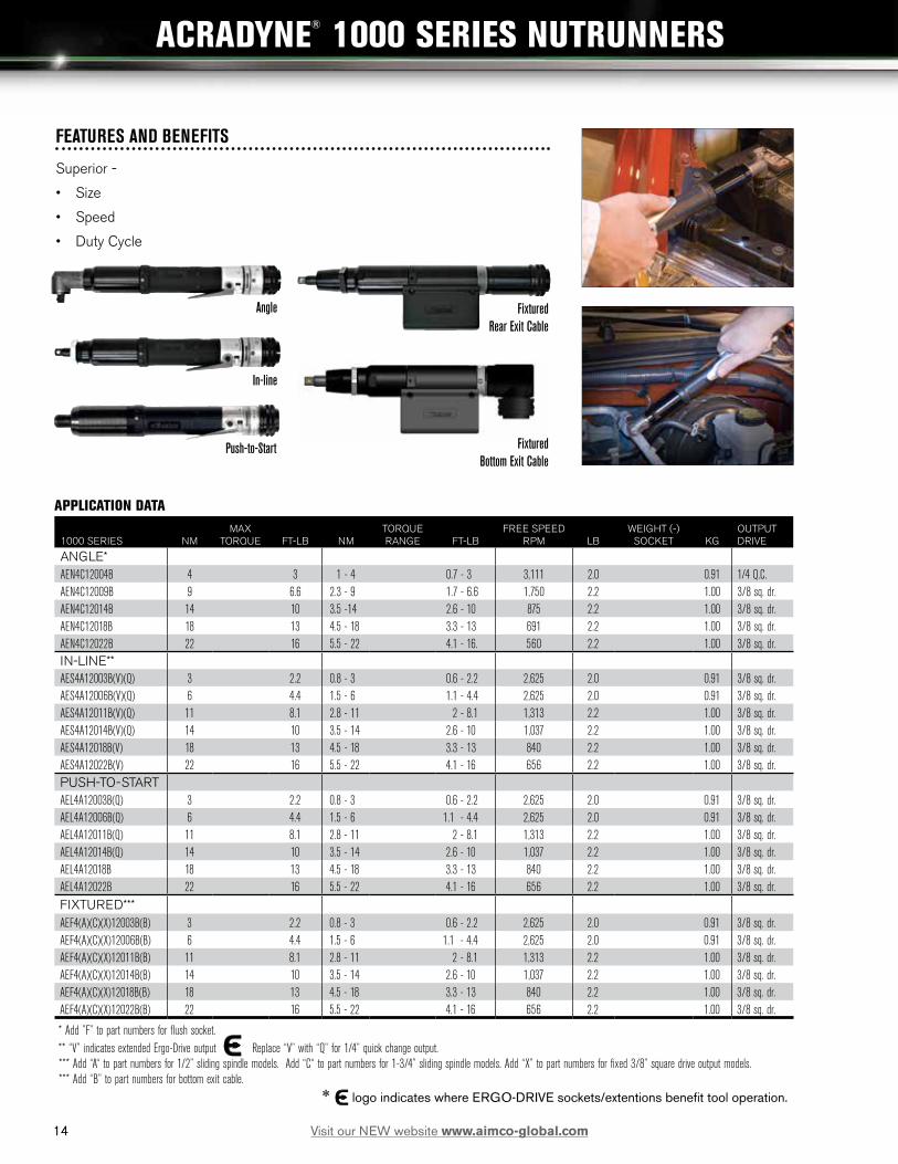
ACRADYNE® 1000 SERIES NUTRUNNERS
FEATURES AND BENEFITS
Superior -
• Size
• Speed
• Duty Cycle
In-line
Push-to-Start
Angle Fixtured Rear Exit Cable
Fixtured Bottom Exit Cable
APPLICATION DATA
1000 SERIES NMMAX
TORQUE FT-LB NMTORQUE RANGE FT-LB
FREE SPEED RPM LB
WEIGHT (-) SOCKET KG
OUTPUT DRIVE
ANGLE*AEN4C12004B 4 3 1 - 4 0.7 - 3 3,111 2.0 0.91 1/4 Q.C. AEN4C12009B 9 6.6 2.3 - 9 1.7 - 6.6 1,750 2.2 1.00 3/8 sq. dr. AEN4C12014B 14 10 3.5 -14 2.6 - 10 875 2.2 1.00 3/8 sq. dr.AEN4C12018B 18 13 4.5 - 18 3.3 - 13 691 2.2 1.00 3/8 sq. dr.AEN4C12022B 22 16 5.5 - 22 4.1 - 16. 560 2.2 1.00 3/8 sq. dr.IN-LINE**AES4A12003B(V)(Q) 3 2.2 0.8 - 3 0.6 - 2.2 2,625 2.0 0.91 3/8 sq. dr.AES4A12006B(V)(Q) 6 4.4 1.5 - 6 1.1 - 4.4 2,625 2.0 0.91 3/8 sq. dr.AES4A12011B(V)(Q) 11 8.1 2.8 - 11 2 - 8.1 1,313 2.2 1.00 3/8 sq. dr.AES4A12014B(V)(Q) 14 10 3.5 - 14 2.6 - 10 1,037 2.2 1.00 3/8 sq. dr.AES4A12018B(V) 18 13 4.5 - 18 3.3 - 13 840 2.2 1.00 3/8 sq. dr.AES4A12022B(V) 22 16 5.5 - 22 4.1 - 16 656 2.2 1.00 3/8 sq. dr.PUSH-TO-STARTAEL4A12003B(Q) 3 2.2 0.8 - 3 0.6 - 2.2 2,625 2.0 0.91 3/8 sq. dr.AEL4A12006B(Q) 6 4.4 1.5 - 6 1.1 - 4.4 2,625 2.0 0.91 3/8 sq. dr.AEL4A12011B(Q) 11 8.1 2.8 - 11 2 - 8.1 1,313 2.2 1.00 3/8 sq. dr.AEL4A12014B(Q) 14 10 3.5 - 14 2.6 - 10 1,037 2.2 1.00 3/8 sq. dr.AEL4A12018B 18 13 4.5 - 18 3.3 - 13 840 2.2 1.00 3/8 sq. dr.AEL4A12022B 22 16 5.5 - 22 4.1 - 16 656 2.2 1.00 3/8 sq. dr.FIXTURED***AEF4(A)(C)(X)12003B(B) 3 2.2 0.8 - 3 0.6 - 2.2 2,625 2.0 0.91 3/8 sq. dr.AEF4(A)(C)(X)12006B(B) 6 4.4 1.5 - 6 1.1 - 4.4 2,625 2.0 0.91 3/8 sq. dr.AEF4(A)(C)(X)12011B(B) 11 8.1 2.8 - 11 2 - 8.1 1,313 2.2 1.00 3/8 sq. dr.AEF4(A)(C)(X)12014B(B) 14 10 3.5 - 14 2.6 - 10 1,037 2.2 1.00 3/8 sq. dr.AEF4(A)(C)(X)12018B(B) 18 13 4.5 - 18 3.3 - 13 840 2.2 1.00 3/8 sq. dr.AEF4(A)(C)(X)12022B(B) 22 16 5.5 - 22 4.1 - 16 656 2.2 1.00 3/8 sq. dr.
* Add ”F” to part numbers for flush socket. ** “V” indicates extended Ergo-Drive output Replace “V” with “Q” for 1/4” quick change output. *** Add “A“ to part numbers for 1/2” sliding spindle models. Add “C“ to part numbers for 1-3/4” sliding spindle models. Add “X” to part numbers for fixed 3/8” square drive output models. *** Add “B” to part numbers for bottom exit cable.
* logo indicates where ERGO-DRIVE sockets/extentions benefit tool operation.
14 Visit our NEW website www.aimco-global.com

15
C
E
D
G B
A
F
ACRADYNE® 1000 SERIES NUTRUNNERS
AB
C D
E
A
B C
E D
DIMENSIONSFIXTURED IN (A) MM IN (B) MM IN (C) MM IN (D) MM IN (E) MM IN (F) MM IN (G) MM
AEF4A12003B 11.53 292.9 9.10 231.04 1.47 37.3 1.13 28.57 2.06 52.2 1.59 40.4 2.18 55.5AEF4A12006B 11.53 292.9 9.10 231.04 1.47 37.3 1.13 28.57 2.06 52.2 1.59 40.4 2.18 55.5AEF4A12011B 12.20 309.8 9.10 231.04 1.47 37.3 1.13 28.57 2.72 69.1 1.59 40.4 2.18 55.5AEF4A12014B 12.20 309.8 9.10 231.04 1.47 37.3 1.13 28.57 2.72 69.1 1.59 40.4 2.18 55.5AEF4A12018B 12.20 309.8 9.10 231.04 1.47 37.3 1.13 28.57 2.72 69.1 1.59 40.4 2.18 55.5AEF4A12022B 12.20 309.8 9.10 231.04 1.47 37.3 1.13 28.57 2.72 69.1 1.59 40.4 2.18 55.5AEF4C12003B 15.32 389.2 9.10 231.04 1.47 37.3 1.13 28.57 2.06 52.2 1.59 40.4 5.98 151.8AEF4C12006B 15.32 389.2 9.10 231.04 1.47 37.3 1.13 28.57 2.06 52.2 1.59 40.4 5.98 151.8AEF4C12011B 15.99 406.1 9.10 231.04 1.47 37.3 1.13 28.57 2.72 69.1 1.59 40.4 5.98 151.8AEF4C12014B 15.99 406.1 9.10 231.04 1.47 37.3 1.13 28.57 2.72 69.1 1.59 40.4 5.98 151.8AEF4C12018B 15.99 406.1 9.10 231.04 1.47 37.3 1.13 28.57 2.72 69.1 1.59 40.4 5.98 151.8AEF4C12022B 15.99 406.1 9.10 231.04 1.47 37.3 1.13 28.57 2.72 69.1 1.59 40.4 5.98 151.8AEF4X12003B 9.35 237.5 9.10 231.04 1.47 37.3 1.13 28.57 2.06 52.2 1.59 40.4 .80 20.4AEF4X12006B 9.35 237.5 9.10 231.04 1.47 37.3 1.13 28.57 2.06 52.2 1.59 40.4 .80 20.4AEF4X12011B 10.00 254.4 9.10 231.04 1.47 37.3 1.13 28.57 2.72 69.1 1.59 40.4 .80 20.4AEF4X12014B 10.00 254.4 9.10 231.04 1.47 37.3 1.13 28.57 2.72 69.1 1.59 40.4 .80 20.4AEF4X12018B 10.00 254.4 9.10 231.04 1.47 37.3 1.13 28.57 2.72 69.1 1.59 40.4 .80 20.4AEF4X12022B 10.00 254.4 9.10 231.04 1.47 37.3 1.13 28.57 2.72 69.1 1.59 40.4 .80 20.4
DIMENSIONSANGLE IN (A) MM IN (B) MM IN (C) MM IN (D) MM IN (E) MM
AEN4C12004B 11.65 295.9 1.47 37.3 .98 24.8 .62 15.8 .40 10.2 AEN4C12009B 11.00 279.5 1.47 37.3 1.29 32.8 .82 20.9 .52 13.1AEN4C12014B 11.66 296.4 1.47 37.3 1.29 32.8 .82 20.9 .52 13.1AEN4C12018B 11.66 296.4 1.47 37.3 1.29 32.8 .82 20.9 .52 13.1AEN4C12022B 11.66 296.4 1.47 37.3 1.29 32.8 .82 20.9 .52 13.1
DIMENSIONSINLINE IN (A) MM IN (B) MM IN (C) MM IN (D) MM IN (E) MM
AES4A12003B 11.12 282.7 1.47 37.3 7.38 187.5 1.59 40.4 1.25 31.8 AES4A12006B 11.12 282.7 1.47 37.3 7.38 187.5 1.59 40.4 1.25 31.8AES4A12011B 11.44 290.5 1.47 37.3 7.38 187.5 1.59 40.4 1.25 31.8 AES4A12014B 11.44 290.5 1.56 39.6 7.38 187.5 1.59 40.4 1.25 31.8AES4A12018B 11.44 290.5 1.47 37.3 7.38 187.5 1.59 40.4 1.25 31.8 AES4A12022B 11.44 290.5 1.47 37.3 7.38 187.5 1.59 40.4 1.25 31.8 PUSH-TO-START IN (A) MM IN (B) MM IN (C) MM IN (D) MM IN (E) MM
AEL4A12003B 11.31 287.3 1.56 39.6 7.38 187.5 1.59 40.4 1.25 31.8 AEL4A12006B 11.32 287.4 1.56 39.6 7.38 187.5 1.59 40.4 1.25 31.8 AEL4A12011B 11.62 295.4 1.56 39.6 7.38 187.5 1.59 40.4 1.25 31.8 AEL4A12014B 11.62 295.4 1.56 39.6 7.38 187.5 1.59 40.4 1.25 31.8 AEL4A12018B 11.62 295.4 1.56 39.6 7.38 187.5 1.59 40.4 1.25 31.8 AEL4A12022B 11.62 295.4 1.56 39.6 7.38 187.5 1.59 40.4 1.25 31.8
15Visit our NEW website www.aimco-global.com

16
APPLICATION DATA
1000 SERIES* NMMAX
TORQUE FT-LB NMTORQUE RANGE FT-LB
FREE SPEED RPM LB
WEIGHT (-) SOCKET KG
OUTPUT DRIVE
AEP4(A)(R)(T)12003B(V)(Q) 3 2.2 0.8 - 3 0.6 - 2.2 2,625 2.2 1.00 3/8 SQ. DR.*AEP4(A)(R)(T)12006B(V)(Q) 6 4.4 1.5 - 6 1.1 - 4.4 2,625 2.2 1.00 3/8 SQ. DR.*AEP4(A)(R)(T)12011B(V)(Q) 11 8.1 2.8 - 11 2 - 8.1 1,313 2.3 1.04 3/8 SQ. DR.AEP4(A)(R)(T)12014B(V)(Q) 14 10 3.5 - 14 2.6 - 10 1,037 2.3 1.04 3/8 SQ. DR.AEP4(A)(R)(T)12018B(V) 18 13 4.5 - 18 3.3 - 13 840 2.3 1.04 3/8 SQ. DR.AEP4(A)(R)(T)12022B(V) 22 16 5.5 - 22 4.1 - 16 656 2.3 1.04 3/8 SQ. DR.
2000 SERIES* NMMAX
TORQUE FT-LB NMTORQUE RANGE FT-LB
FREE SPEED RPM LB
WEIGHT (-) SOCKET KG OUTPUT DRIVE
AEP4(A)(R)(T)22020B(V) 20 14 5 - 20 3.7 - 14 1,313 2.4 1.09 3/8 SQ. DR.AEP4(A)(R)(T)22025B(V) 25 18 6.3 - 25 4.6 - 18 1,037 2.4 1.09 3/8 SQ. DR.AEP4(A)(R)(T)22030B(V) 30 22 7.5 - 30 5.5 - 22 840 2.4 1.09 3/8 SQ. DR.AEP4(A)(R)(T)22035B(V) 35 25 8.8- 35 6.5 - 25 747 2.4 1.09 3/8 SQ. DR.AEP4(A)(R)(T)22040B(V) 40 29 10 - 40 7.4 - 29 656 2.4 1.09 3/8 SQ. DR.
* Add “Q” to part numbers for 1/4” quick change output standard Add “A” to part numbers for bottom exit cable models, Add “R” to part numbers for rear exit cable models, Add “T” to part numbers for top exit cable models,
“V” indicates extended Ergo-Drive output Replace “V” with “Q” for 1/4” quick change output. Push To Start models available by special order.
FEATURES AND BENEFITS
• Cable configurations available in rear exit, bottom exit, or right angle exit.
• Configured with AcraDyne’s multi-function button (MFB) enabling flexibility in operation.
• On-board lights and audible signal for operator feedback.
• Push-To-Start models also available.
ACRADYNE® PISTOL GRIP NUTRUNNERS
37.3mm1.47in
38.1mm1.50in
304.8mm12.00in
15.9mm.63in
TOOL HEADLIGHTS
6.4mm.25in
37.3mm1.47in
12.7mm.50in
TOOL RUNDOWNSTATUS LIGHT LOCATION2 PLACES 180° APART
D
C
B
AA
B
C
D
12345678
8 7 6 5 4 3 2 1
E
F
E
F
DOCUMENT CONTROLPRINTED COPIES OF THIS DOCUMENT ARE CONSIDERED TO BE
UNCONTROLLED DOCUMENTS. HOLDERS ARE RESPONSIBLE FORVERIFYING THE CURRENT REVISION LEVEL WITH PURCHASING OR ENGINEERING PRIOR TO USE OR FABRICATION. THE CONTROLLED
VERSION OF THIS DOCUMENT IS ELECTRONICALLY MAINTAINED.
PROPRIETARY AND CONFIDENTIALTHIS DRAWING CONTAINS INFORMATION STRICTLY
CONFIDENTIAL TO ACRADYNE/AIMCO. IN THE ABSENCE OF EXPRESSED WRITTEN PERMISSION, ACRADYNE/AIMCO
HAS LOANED THIS COPY WITH THE MUTUAL UNDERSTANDINGTHAT (A) IT WILL NOT BE USED FOR ANY PURPOSE OTHER
THAN FOR THAT IN WHICH IT WAS PROVIDED, (B) THE DATACONTAINED HEREIN WILL NOT BE DISCLOSED TO OTHERS,
(C) IT WILL NOT BE REPRODUCED, AND (D) IT WILL BE RETURNEDTO ACRADYNE/AIMCO IMMEDIATELY UPON DEMAND.
REVISIONLEVEL
A 03/09/11REVISION
RELEASE DATE
REVISION BLOCKDESCRIPTION OF CHANGES MADE TO PART
PRODUCTION RELEASE MDJAUTHOR/
APPROVAL
UNLESS OTHERWISE SPECIFIED,DIMENSIONS ARE IN INCHES
DIMENSIONS AND TOLERANCING PER ANSI Y14.5SURFACE ROUGHNESS PER ANSI Y14.36
BLOCK TOLERANCING PER DECIMAL:.X = .030 .XX = .010 .XXX = .005 .XXXX = .0005
ANGLE = 0 30'
REMOVE BURRS AND SHARP EDGES: R.015 MAX MACHINE SURFACE FINISH: 125 RMS OR BETTER
DRAWINGS AND TECHNICAL DOCUMENTS CONTROLLED BY:ACRADYNE MECHANICAL ENGINEERING
SIZE
DSCALE 1 : 1 DO NOT SCALE DRAWING
PART / DRAWING NUMBER
AEP4A12011AV
AEP4A12011AVOUTLINE DRAWING
1000 SERIES
REVISION
CSHEET 2 OF 3
10000 SE PINE STREETPORTLAND, OREGON 97216
503.254.6600
ECN #
230
JJN277UPDATED WITH PRODUCTION REDLINES4/21/11B
294C 5/17/11 MDJ25871 SWITCH WAS 24874
A
B
C
DDIMENSIONS1000 SERIES IN (A) MM IN (B) MM IN (C) MM IN (D) MM
AEP412003BV 7.34 186.3 0.54 13.7 6.01 152.6 1.96 49.7AEP412006BV 7.34 186.3 0.54 13.7 6.01 152.6 1.96 49.7AEP412011BV 8.00 203.3 0.54 13.7 6.01 152.6 1.96 49.7AEP412014BV 8.00 203.3 0.54 13.7 6.01 152.6 1.96 49.7AEP412018BV 8.00 203.3 0.54 13.7 6.01 152.6 1.96 49.7AEP412022BV 8.00 203.3 0.54 13.7 6.01 152.6 1.96 49.72000 SERIES IN (A) MM IN (B) MM IN (C) MM IN (D) MM
AEP422020BV 8.66 219.9 0.56 14.2 6.87 174.4 1.96 49.7AEP422025BV 8.66 219.9 0.56 14.2 6.87 174.4 1.96 49.7AEP422030BV 8.66 219.9 0.56 14.2 6.87 174.4 1.96 49.7AEP422035BV 8.66 219.9 0.56 14.2 6.87 174.4 1.96 49.7AEP422040BV 8.66 219.9 0.56 14.2 6.87 174.4 1.96 49.7
Top Exit Cable Bottom Exit CableRear Exit Cable
* logo indicates where ERGO-DRIVE sockets/extentions benefit tool operation.
16 Visit our NEW website www.aimco-global.com

17
ACRADYNE® PISTOL GRIP NUTRUNNERS
25.4mm1.00in
377.8mm14.88in
47mm1.85in
58.7mm2.31in
12.7mm.50in
28mm1.10in
17.4mm.68in
15.9mm.63in
40.7mm1.60in
31.8mm1.25inHEX
R17.5mm.69in
SHOWN WITHOUT REACTION BARAND WITHOUT LOCKNUT
CATALOG NO.
MODEL NO.AEP35075AVAEP35090AVAEP35110AVAEP35135AVAEP35170AV
D
C
B
AA
B
C
D
12345678
8 7 6 5 4 3 2 1
E
F
E
F
DOCUMENT CONTROLPRINTED COPIES OF THIS DOCUMENT ARE CONSIDERED TO BE
UNCONTROLLED DOCUMENTS. HOLDERS ARE RESPONSIBLE FORVERIFYING THE CURRENT REVISION LEVEL WITH PURCHASING OR ENGINEERING PRIOR TO USE OR FABRICATION. THE CONTROLLED
VERSION OF THIS DOCUMENT IS ELECTRONICALLY MAINTAINED.
PROPRIETARY AND CONFIDENTIALTHIS DRAWING CONTAINS INFORMATION STRICTLY
CONFIDENTIAL TO ACRADYNE/AIMCO. IN THE ABSENCE OF EXPRESSED WRITTEN PERMISSION, ACRADYNE/AIMCO
HAS LOANED THIS COPY WITH THE MUTUAL UNDERSTANDINGTHAT (A) IT WILL NOT BE USED FOR ANY PURPOSE OTHER
THAN FOR THAT IN WHICH IT WAS PROVIDED, (B) THE DATACONTAINED HEREIN WILL NOT BE DISCLOSED TO OTHERS,
(C) IT WILL NOT BE REPRODUCED, AND (D) IT WILL BE RETURNEDTO ACRADYNE/AIMCO IMMEDIATELY UPON DEMAND.
REVISIONLEVEL
A 01/09/12REVISION
RELEASE DATE
REVISION BLOCK
DESCRIPTION OF CHANGES MADE TO PART
PRODUCTION RELEASE LHELLERAUTHOR/
APPROVAL
UNLESS OTHERWISE SPECIFIED,DIMENSIONS ARE IN INCHES
DIMENSIONS AND TOLERANCING PER ANSI Y14.5SURFACE ROUGHNESS PER ANSI Y14.36
BLOCK TOLERANCING PER DECIMAL:.X = .030 .XX = .010 .XXX = .005 .XXXX = .0005
ANGLE = 0 30'
REMOVE BURRS AND SHARP EDGES: R.015 MAX MACHINE SURFACE FINISH: 125 RMS OR BETTER
DRAWINGS AND TECHNICAL DOCUMENTS CONTROLLED BY:ACRADYNE MECHANICAL ENGINEERING
SIZE
DSCALE 3:4 DO NOT SCALE DRAWING
PART / DRAWING NUMBER
AEP35_ _ _AV
AEP35_ _ _AVTOOL OUTLINE
5000 SERIES, GEN III
REVISION
ASHEET 3 OF 6
10000 SE PINE STREETPORTLAND, OREGON 97216
503.254.6600
ECN #
542
A
B
C
D
AEP35280AAEP35350AAEP35420AAEP35515AAEP35635A
AEP35075AVAEP35090AVAEP35110AVAEP35135AVAEP35170AV
APPLICATION DATA
5000 SERIES NMMAX
TORQUE FT-LB NMTORQUE RANGE FT-LB
FREE SPEED RPM LB
WEIGHT (-) SOCKET KG
OUTPUT DRIVE
AEP35075AV(T) 75 55 19 - 75 14 - 55 944 9.2 4.17 1/2 SQ. DR.AEP35090AV(T) 90 66 23 - 90 17 - 66 767 9.2 4.17 1/2 SQ. DR.AEP35110AV(T) 110 81 28 - 110 21 - 81 634 9.2 4.17 1/2 SQ. DR.AEP35135AV(T) 135 99 34 - 135 25 - 99 515 9.2 4.17 1/2 SQ. DR.AEP35170AV(T) 170 125 43 - 170 32 - 125 418 9.2 4.17 1/2 SQ. DR.AEP35280A(T) 280 206 70 - 280 52 - 207 236 13.6 6.17 3/4 SQ. DR.AEP35350A(T) 350 258 88 - 350 65 - 258 192 13.6 6.17 3/4 SQ. DR.AEP35420A(T) 420 310 105 - 420 78 - 310 159 13.6 6.17 3/4 SQ. DR.AEP35515A(T) 515 380 128 - 515 95 - 380 129 13.6 6.17 3/4 SQ. DR.AEP35635A(T) 635 468 159 - 635 117 - 469 104 13.6 6.17 3/4 SQ. DR.
“V” indicates extended Ergo-Drive output.
Add “T” to part numbers for top exit cable models,
DIMENSIONS5000 SERIES IN (A) MM IN (B) MM IN (C) MM IN (D) MM
AEP35075AV 15.95 405.2 .68 17.4 7.37 187.1 1.96 49.7AEP35090AV 15.95 405.2 .68 17.4 7.37 187.1 1.96 49.7AEP35110AV 15.95 405.2 .68 17.4 7.37 187.1 1.96 49.7AEP35135AV 15.95 405.2 .68 17.4 7.37 187.1 1.96 49.7AEP35170AV 15.95 405.2 .68 17.4 7.37 187.1 1.96 49.7AEP35280A 18.43 468.2 1.11 28.1 7.37 187.1 1.96 49.7AEP35350A 18.43 468.2 1.11 28.1 7.37 187.1 1.96 49.7AEP35420A 18.43 468.2 1.11 28.1 7.37 187.1 1.96 49.7AEP35515A 18.43 468.2 1.11 28.1 7.37 187.1 1.96 49.7AEP35635A 18.43 468.2 1.11 28.1 7.37 187.1 1.96 49.7
* logo indicates where ERGO-DRIVE sockets/extentions benefit tool operation.
17Visit our NEW website www.aimco-global.com

18
FEATURES AND BENEFITS
AcraDyne® angle nutrunners provide are the perfect solution to space-limited fastening applications that are not practical with inline or pistol model tools. A compact, durable head houses a precision right angle gear set which fits into the tightest of spaces and delivers a highly accurate fastening cycle. Lightweight materials and a uniform body diameter provide a comfortable grip and an ergonomically placed start lever allows for simple control.
A
D
E
C
B
ACRADYNE® ANGLE NUTRUNNERS
AEN 2000 Series Models
AEN 3000 Series Models APPLICATION DATA
2000 SERIES* NMMAX
TORQUE FT-LB NMTORQUE RANGE FT-LB
FREE SPEED RPM LB
WEIGHT (-) SOCKET KG
OUTPUT DRIVE
AEN32015C(F)(DL) 15 11 3 - 15 2.2 - 11 1,481 2.7 1.22 3/8 SQ. DR.AEN32025C(F)(DL) 25 18 5 - 20 3.7 - 15 833 2.7 1.22 3/8 SQ. DRAEN32030C(F)(DL) 30 22 6 - 30 4.4 - 22 803 2.8 1.27 3/8 SQ. DR.AEN32040C(F)(DL) 40 30 8 - 40 5.9 - 29 574 2.8 1.27 3/8 SQ. DR.
3000 SERIES* NMMAX
TORQUE FT-LB NMTORQUE RANGE FT-LB
FREE SPEED RPM LB
WEIGHT (-) SOCKET KG
OUTPUT DRIVE
AEN33042C(F) 42 31 9.5 - 42 7 - 31 1,095 4.4 2.00 3/8 SQ. DR.AEN33053C(F) 53 39 12 - 53 8 - 39 865 4.4 2.00 3/8 SQ. DR.AEN33060C(F)(DL) 60 44 12 - 60 9 - 44 845 6.6 2.99 1/2 SQ. DR.AEN33090C(F)(DL) 90 66 18 - 90 13 - 66 568 6.6 2.99 1/2 SQ. DR.AEN33120C(F)(DL) 120 89 24 - 120 18 - 88 442 9.3 4.22 1/2 SQ. DR.AEN33200C(F)(DL) 200 148 40 - 200 29 - 147 245 9.4 4.26 3/4 SQ. DR.AEN33210C(F)(DL) 210 95 50 - 210 37 - 155 234 10.0 4.54 3/4 SQ. DR.AEN33300C(F)(DL) 300 221 60 - 300 42 - 221 151 10.0 4.54 3/4 SQ. DR.AEN33375C(F)(DL) 375 277 75 - 375 55 - 276 151 10.0 4.54 3/4 SQ. DR.
* Add “F” to part numbers for flush socket.
Add “DL” to part numbers for dual levers.
DIMENSIONS2000 SERIES IN (A) MM IN (B) MM IN (C) MM IN (D) MM IN (E) MM
AEN32015C 14.61 371 1.85 47 1.37 34.8 .90 22.9 .52 13.1AEN32025C 14.61 371 1.85 47 1.37 34.8 .90 22.9 .52 13.1AEN32030C 14.42 366.2 1.85 47 1.65 41.8 1.16 29.4 .70 17.8AEN32040C 14.42 366.2 1.85 47 1.65 41.8 1.16 29.4 .70 17.83000 SERIES IN (A) MM IN (B) MM IN (C) MM IN (D) MM IN (E) MM
AEN33042C 16.63 422.33 1.85 47 1.66 42.11 1.17 29.67 .7 17.78AEN33053C 16.63 422.33 1.85 47 1.66 42.11 1.17 29.67 .7 17.78 AEN33060C 18.92 480.53 1.85 47 1.90 48.36 1.37 34.90 .83 20.96 AEN33090C 18.92 480.53 1.85 47 1.90 48.36 1.37 34.90 .83 20.96 AEN33120C 21.00 533.46 1.85 47 2.78 70.59 2.08 52.81 1.05 26.67 AEN33200C 23.21 589.64 1.85 47 2.59 65.75 1.89 47.98 1.05 26.67AEN33210C 23.58 598.88 1.85 47 2.90 73.53 1.97 50.04 1.25 31.75AEN33300C 23.58 598.88 1.85 47 2.90 73.53 1.97 50.04 1.25 31.75AEN33375C 23.58 598.88 1.85 47 2.90 73.53 1.97 50.04 1.25 31.75
18 Visit our NEW website www.aimco-global.com

19
A
A
D
D
E
E
C
C
B
B
ACRADYNE® ANGLE NUTRUNNERS
AEN 5000 Series Models
APPLICATION DATA
5000 SERIES* NMMAX
TORQUE FT-LB NMTORQUE RANGE FT-LB
FREE SPEED RPM LB
WEIGHT (-) SOCKET KG
OUTPUT DRIVE
AEN35090B(F) 90 66 23 - 90 17 - 66 607 6.9 3.13 1/2 SQ. DR.AEN35140B(F) 140 103 35 - 140 26 - 103 472 10.4 4.72 3/4 SQ. DR.AEN35175B(F) 175 129 44 - 175 33 - 129 384 10.5 4.76 3/4 SQ. DR.AEN35225B(F) 225 166 56 - 225 41 - 166 291 12.3 5.58 3/4 SQ. DR.AEN35285B(F) 285 210 71 - 285 52 - 210 236 12.3 5.58 3/4 SQ. DR.AEN35350B(F) 350 258 88 - 350 65 - 258 191 12.3 5.58 3/4 SQ. DR
* Add “F” to part numbers for flush socket.
DIMENSIONS5000 SERIES IN (A) MM IN (B) MM IN (C) MM IN (D) MM IN (E) MM
AEN35090B 22.59 573.7 2.31 58.7 1.90 48.4 1.37 34.9 .81 20.6AEN35140B 22.52 571.9 2.31 58.7 2.59 65.8 1.89 48 1.05 26.7AEN35175B 22.52 571.9 2.31 58.7 2.59 65.8 1.89 48 1.05 26.7AEN35225B 22.88 581.1 2.31 58.7 2.90 73.5 1.97 50 1.25 31.8AEN35285B 22.88 581.1 2.31 58.7 2.90 73.5 1.97 50 1.25 31.8AEN35350B 22.88 581.1 2.31 58.7 2.90 73.5 1.97 50 1.25 31.8
19Visit our NEW website www.aimco-global.com

20
A
BD
E
C
FEATURES AND BENEFITS
AcraDyne® inline nutrunners are the perfect choice for fixtured fastening applications because of their compact size and durability. A uniform body diameter and a hex shaped mounting point allow for simple installation into fixture plates. Simply machine a female hex into a steel plate, insert the nutrunner, secure with the factory supplied nut and your fastening machine is assembled. A reaction bar for use in handheld applications is also included with all AcraDyne® inline nutrunners.
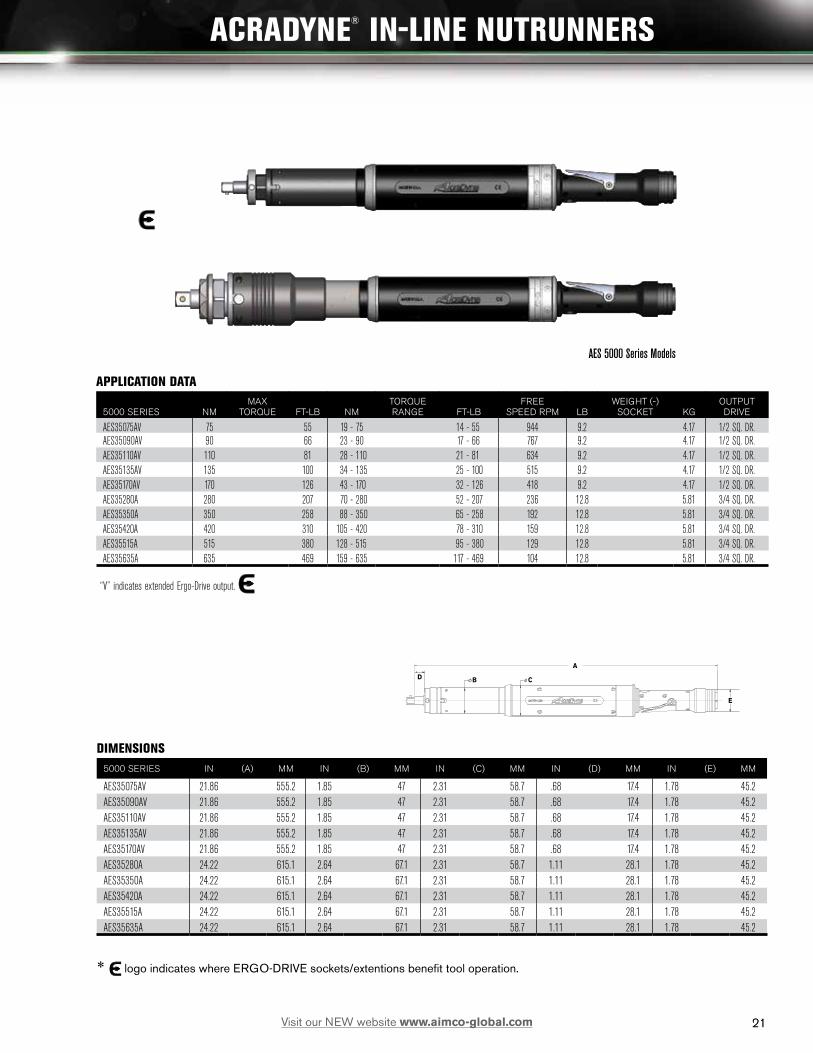
ACRADYNE® IN-LINE NUTRUNNERS
AES 2000 Series Models
AES 3000 Series Models APPLICATION DATA
2000 SERIES* NMMAX
TORQUE FT-LB NMTORQUE RANGE FT-LB
FREE SPEED RPM LB
WEIGHT (-) SOCKET KG
OUTPUT DRIVE
AES32010C(V)(Q) 10 7.4 2 - 10 1.5 - 7.4 2,222 2.5 1.13 3/8 SQ. DR.*AES32020C(V)(Q) 20 15 4 - 20 3.0 - 15 1,250 2.5 1.13 3/8 SQ. DR.*AES32025C(V)(Q) 25 18 5 - 25 3.7 - 18 893 3.2 1.45 3/8 SQ. DR.*AES32038C(V) 38 28 7.5 - 38 5.5 - 28 595 4.2 1.91 3/8 SQ. DR.
3000 SERIES* NMMAX
TORQUE FT-LB NMTORQUE RANGE FT-LB
FREE SPEED RPM LB
WEIGHT (-) SOCKET KG
OUTPUT DRIVE
AES33040C(V)(-2) 40 30 8 - 40 5.9 - 30 1,314 6.4 2.90 1/2 SQ. DR.AES33060C(V)(-2) 60 44 12 - 60 8.9 - 44 883 6.4 2.90 1/2 SQ. DR.AES33100C(V)(-2) 100 74 20 - 100 15 - 74 489 8.1 3.67 1/2 SQ. DR.AES33150C(V)(-2) 150 111 30 - 150 22 - 111 329 8.1 3.67 1/2 SQ. DR.AES33230C(V)(-2) 230 170 46 - 230 34 - 184 221 8.1 3.67 1/2 SQ. DR.AES33400C 400 295 80 - 400 59 - 295 122 13.0** 5.90** 3/4 SQ. DR.AES33600C 600 440 120 - 600 89 - 440 82 13.0** 5.90** 3/4 SQ. DR.
* Add “Q” to part numbers for 1/4” quick change output standard. Add “V“ to part numbers for standard spindle models. Add “-2” to part numbers for 2” sliding spindle models, and add 2.3 lb to the weight listed.**Includes reaction bar and fixture nut
DIMENSIONS2000 SERIES IN (A) MM IN (B) MM IN (C) MM IN (D) MM IN (E) MM
AES32010CV 13.85 351.7 1.59 40.4 1.85 47 .56 14.3 1.50 38.1 AES32020CV 13.85 351.7 1.59 40.4 1.85 47 .56 14.3 1.50 38.1 AES32025CV 13.85 351.7 1.59 40.4 1.85 47 .56 14.3 1.50 38.1 AES32038CV 16.69 424 1.50 38.1 1.85 47 .51 12.9 1.50 38.1 3000 SERIES IN (A) MM IN (B) MM IN (C) MM IN (D) MM IN (E) MM
AES33040CV 18.24 463.38 1.94 49.28 1.85 47 .68 17.17 1.85 47 AES33060CV 18.24 463.38 1.94 49.28 1.85 47 .68 17.17 1.85 47 AES33100CV 22.56 572.99 1.94 49.28 1.85 47 .68 17.17 1.85 47 AES33150CV 22.56 572.99 1.94 49.28 1.85 47 .68 17.17 1.85 47 AES33230CV 22.56 572.99 1.94 49.28 1.85 47 .68 17.17 1.85 47 AES33400C 24.90 532.36 1.94 49.28 1.85 47 1.11 28.08 2.64 67.1AES33600C 24.90 532.36 1.94 49.28 1.85 47 1.11 28.08 2.64 67.1
* logo indicates where ERGO-DRIVE sockets/extentions benefit tool operation.
20 Visit our NEW website www.aimco-global.com
21
E
B C
A
D
ACRADYNE® IN-LINE NUTRUNNERS
AES 5000 Series Models
APPLICATION DATA
5000 SERIES NMMAX
TORQUE FT-LB NMTORQUE RANGE FT-LB
FREE SPEED RPM LB
WEIGHT (-) SOCKET KG
OUTPUT DRIVE
AES35075AV 75 55 19 - 75 14 - 55 944 9.2 4.17 1/2 SQ. DR.AES35090AV 90 66 23 - 90 17 - 66 767 9.2 4.17 1/2 SQ. DR.AES35110AV 110 81 28 - 110 21 - 81 634 9.2 4.17 1/2 SQ. DR.AES35135AV 135 100 34 - 135 25 - 100 515 9.2 4.17 1/2 SQ. DR.AES35170AV 170 126 43 - 170 32 - 126 418 9.2 4.17 1/2 SQ. DR.AES35280A 280 207 70 - 280 52 - 207 236 12.8 5.81 3/4 SQ. DR.AES35350A 350 258 88 - 350 65 - 258 192 12.8 5.81 3/4 SQ. DR.AES35420A 420 310 105 - 420 78 - 310 159 12.8 5.81 3/4 SQ. DR.AES35515A 515 380 128 - 515 95 - 380 129 12.8 5.81 3/4 SQ. DR.AES35635A 635 469 159 - 635 117 - 469 104 12.8 5.81 3/4 SQ. DR.
“V” indicates extended Ergo-Drive output.
DIMENSIONS5000 SERIES IN (A) MM IN (B) MM IN (C) MM IN (D) MM IN (E) MM
AES35075AV 21.86 555.2 1.85 47 2.31 58.7 .68 17.4 1.78 45.2AES35090AV 21.86 555.2 1.85 47 2.31 58.7 .68 17.4 1.78 45.2AES35110AV 21.86 555.2 1.85 47 2.31 58.7 .68 17.4 1.78 45.2AES35135AV 21.86 555.2 1.85 47 2.31 58.7 .68 17.4 1.78 45.2AES35170AV 21.86 555.2 1.85 47 2.31 58.7 .68 17.4 1.78 45.2AES35280A 24.22 615.1 2.64 67.1 2.31 58.7 1.11 28.1 1.78 45.2AES35350A 24.22 615.1 2.64 67.1 2.31 58.7 1.11 28.1 1.78 45.2AES35420A 24.22 615.1 2.64 67.1 2.31 58.7 1.11 28.1 1.78 45.2AES35515A 24.22 615.1 2.64 67.1 2.31 58.7 1.11 28.1 1.78 45.2AES35635A 24.22 615.1 2.64 67.1 2.31 58.7 1.11 28.1 1.78 45.2
* logo indicates where ERGO-DRIVE sockets/extentions benefit tool operation.
21Visit our NEW website www.aimco-global.com

22
ACRADYNE® FIXTURED NUTRUNNERS
E
B
A
C
D
Standard Spindle, Bottom Exit Cable
2" Sliding Spindle, Bottom Exit Cable
Standard Spindle, Rear Exit Cable
2" Sliding Spindle, Rear Exit Cable
APPLICATION DATA
5000 SERIES* NMMAX
TORQUE FT-LB NMTORQUE RANGE FT-LB
FREE SPEED RPM LB
WEIGHT (-) SOCKET KG
OUTPUT DRIVE
AEF35075A(V)(VB)(-2)(B-2) 75 55 19 - 75 14 - 55 944 9.6 4.35 1/2 SQ. DR. AEF35090A(V)(VB)(-2)(B-2) 90 66 23 - 90 17 - 66 767 9.6 4.35 1/2 SQ. DRAEF35110A(V)(VB)(-2)(B-2) 110 81 28 - 110 21 - 81 634 9.6 4.35 1/2 SQ. DRAEF35135A(V)(VB)(-2)(B-2) 135 100 34 - 135 25 - 100 515 9.6 4.35 1/2 SQ. DRAEF35170A(V)(VB)(-2)(B-2) 170 125 43 - 170 32 - 125 418 9.6 4.35 1/2 SQ. DRAEF35280A(V)(VB)(-2)(B-2) 280 207 70 - 280 52 - 207 236 13.6 6.17 3/4 SQ. DR.AEF35350A(V)(VB)(-2)(B-2) 350 258 88 - 350 65 - 258 192 13.6 6.17 3/4 SQ. DRAEF35420A(V)(VB)(-2)(B-2) 420 310 105 - 420 77 - 310 159 13.6 6.17 3/4 SQ. DRAEF35515A(V)(VB)(-2)(B-2) 515 380 128 - 515 95 - 380 129 13.6 6.17 3/4 SQ. DRAEF35635A(V)(VB)(-2)(B-2) 635 469 159 - 635 117 - 469 104 13.6 6.17 3/4 SQ. DR
* Add “V“ to part numbers for standard spindle with rear exit cable models. Add “VB“ to part numbers for standard spindle with bottom exit cable models.
* Add “-2” to part numbers for 2” sliding spindle with rear exit cable models. Add “B-2“ to part numbers for 2” sliding spindle with bottom exit cable models.
* Item 28843 is a panel mount 2” sliding spindle for 280 – 635 Nm models.
DIMENSIONS5000 SERIES IN (A) MM IN (B) MM IN (C) MM IN (D) MM IN (E) MM
AEF35075AV 17.67 448.8 1.85 47 2.31 58.7 .72 18.4 1.59 40.4AEF35090AV 17.67 448.8 1.85 47 2.31 58.7 .72 18.4 1.59 40.4AEF35110AV 17.67 448.8 1.85 47 2.31 58.7 .72 18.4 1.59 40.4AEF35135AV 17.67 448.8 1.85 47 2.31 58.7 .72 18.4 1.59 40.4AEF35170AV 17.67 448.8 1.85 47 2.31 58.7 .72 18.4 1.59 40.4AEF35075A-2 23.43 595.1 1.85 47 2.31 58.7 2.22 56.4 1.59 40.4AEF35090A-2 23.43 595.1 1.85 47 2.31 58.7 2.22 56.4 1.59 40.4AEF35110A-2 23.43 595.1 1.85 47 2.31 58.7 2.22 56.4 1.59 40.4AEF35135A-2 23.43 595.1 1.85 47 2.31 58.7 2.22 56.4 1.59 40.4AEF35170A-2 23.43 595.1 1.85 47 2.31 58.7 2.22 56.4 1.59 40.4AEF35280A 18.43 468.2 1.11 28.1 7.37 187.1 1.96 49.7 20.4 518AEF35350A 18.43 468.2 1.11 28.1 7.37 187.1 1.96 49.7 20.4 518AEF35420A 18.43 468.2 1.11 28.1 7.37 187.1 1.96 49.7 20.4 518AEF35515A 18.43 468.2 1.11 28.1 7.37 187.1 1.96 49.7 20.4 518AEF35635A 18.43 468.2 1.11 28.1 7.37 187.1 1.96 49.7 20.4 518
* logo indicates where ERGO-DRIVE sockets/extentions benefit tool operation.
22 Visit our NEW website www.aimco-global.com
23
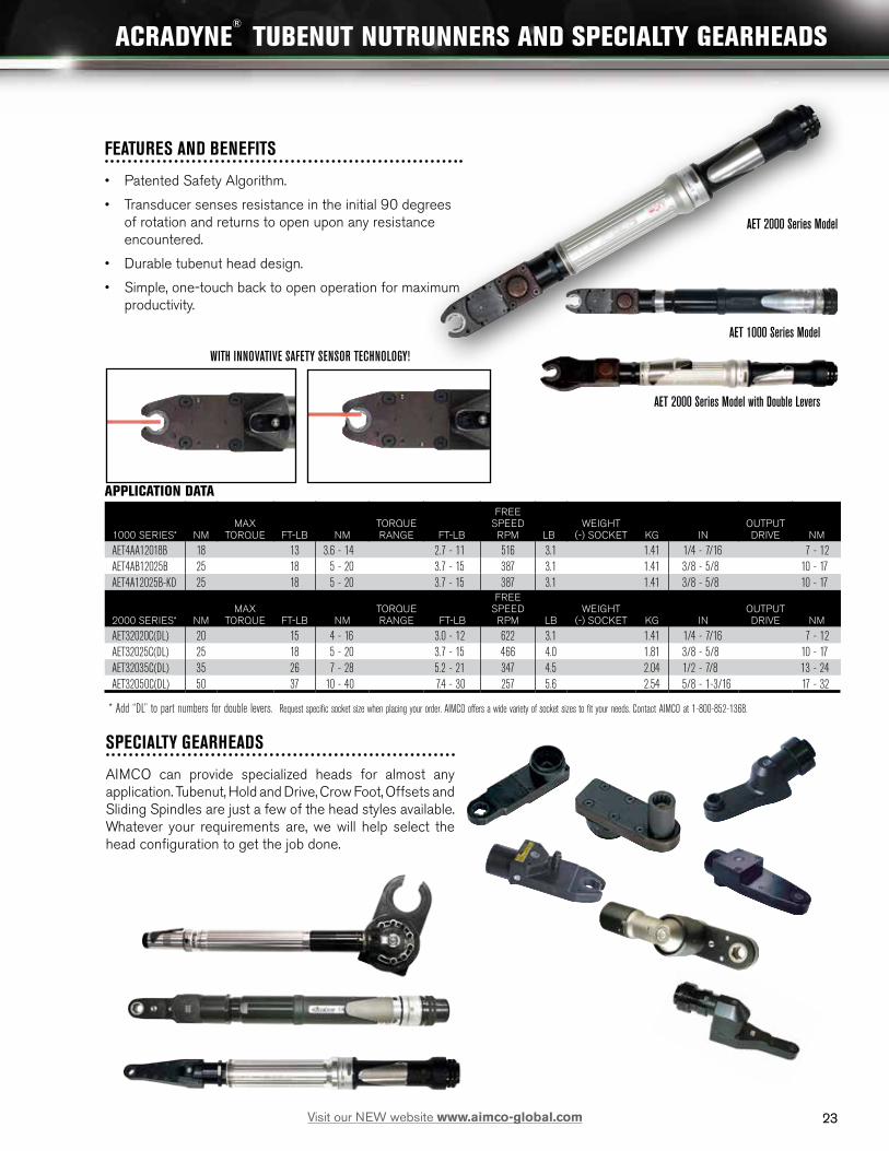
SPECIALTY GEARHEADS
AIMCO can provide specialized heads for almost any application. Tubenut, Hold and Drive, Crow Foot, Offsets and Sliding Spindles are just a few of the head styles available. Whatever your requirements are, we will help select the head configuration to get the job done.
FEATURES AND BENEFITS
• Patented Safety Algorithm.
• Transducer senses resistance in the initial 90 degrees of rotation and returns to open upon any resistance encountered.
• Durable tubenut head design.
• Simple, one-touch back to open operation for maximum productivity.
WITH INNOVATIVE SAFETY SENSOR TECHNOLOGY!
ACRADYNE® TUBENUT NUTRUNNERS AND SPECIALTY GEARHEADS
AET 2000 Series Model
AET 1000 Series Model
AET 2000 Series Model with Double Levers
APPLICATION DATA
1000 SERIES* NMMAX
TORQUE FT-LB NMTORQUE RANGE FT-LB
FREE SPEED
RPM LBWEIGHT
(-) SOCKET KG INOUTPUT DRIVE NM
AET4AA12018B 18 13 3.6 - 14 2.7 - 11 516 3.1 1.41 1/4 - 7/16 7 - 12AET4AB12025B 25 18 5 - 20 3.7 - 15 387 3.1 1.41 3/8 - 5/8 10 - 17AET4A12025B-KD 25 18 5 - 20 3.7 - 15 387 3.1 1.41 3/8 - 5/8 10 - 17
2000 SERIES* NMMAX
TORQUE FT-LB NMTORQUE RANGE FT-LB
FREE SPEED
RPM LBWEIGHT
(-) SOCKET KG INOUTPUT DRIVE NM
AET32020C(DL) 20 15 4 - 16 3.0 - 12 622 3.1 1.41 1/4 - 7/16 7 - 12AET32025C(DL) 25 18 5 - 20 3.7 - 15 466 4.0 1.81 3/8 - 5/8 10 - 17AET32035C(DL) 35 26 7 - 28 5.2 - 21 347 4.5 2.04 1/2 - 7/8 13 - 24AET32050C(DL) 50 37 10 - 40 7.4 - 30 257 5.6 2.54 5/8 - 1-3/16 17 - 32
* Add “DL” to part numbers for double levers. Request specific socket size when placing your order. AIMCO offers a wide variety of socket sizes to fit your needs. Contact AIMCO at 1-800-852-1368.
23Visit our NEW website www.aimco-global.com

24
FEATURES AND BENEFITS
• Torques Ranging from 20 Nm – 200 Nm.
• Very Robust modern design.
• 1" and 2" travels are standard.
• Sockets and holders are custom to order.
ACRADYNE® HOLD & DRIVE NUTRUNNERS
38.50mm1.516in
35.56mm1.400in
36.51mm1.438in
37.34mm1.470in
40.39mm1.590in
174.32mm6.863in
46.99mm1.850in
42.07mm1.656in
44.45mm1.750in
26.92mm1.060in
44.5MM (1-3/4") FLATS
D
C
B
AA
B
C
D
12345678
8 7 6 5 4 3 2 1
E
F
E
F
DOCUMENT CONTROLPRINTED COPIES OF THIS DOCUMENT ARE CONSIDERED TO BE
UNCONTROLLED DOCUMENTS. HOLDERS ARE RESPONSIBLE FORVERIFYING THE CURRENT REVISION LEVEL WITH PURCHASING OR ENGINEERING PRIOR TO USE OR FABRICATION. THE CONTROLLED
VERSION OF THIS DOCUMENT IS ELECTRONICALLY MAINTAINED.
PROPRIETARY AND CONFIDENTIALTHIS DRAWING CONTAINS INFORMATION STRICTLY
CONFIDENTIAL TO ACRADYNE/AIMCO. IN THE ABSENCE OF EXPRESSED WRITTEN PERMISSION, ACRADYNE/AIMCO
HAS LOANED THIS COPY WITH THE MUTUAL UNDERSTANDINGTHAT (A) IT WILL NOT BE USED FOR ANY PURPOSE OTHER
THAN FOR THAT IN WHICH IT WAS PROVIDED, (B) THE DATACONTAINED HEREIN WILL NOT BE DISCLOSED TO OTHERS,
(C) IT WILL NOT BE REPRODUCED, AND (D) IT WILL BE RETURNEDTO ACRADYNE/AIMCO IMMEDIATELY UPON DEMAND.
REVISIONLEVEL
A 09/21/12REVISION
RELEASE DATE
REVISION BLOCK
DESCRIPTION OF CHANGES MADE TO PART
PRODUCTION RELEASE M. JULIANO
AUTHOR/APPROVAL
UNLESS OTHERWISE SPECIFIED,DIMENSIONS ARE IN INCHES
DIMENSIONS AND TOLERANCING PER ANSI Y14.5SURFACE ROUGHNESS PER ANSI Y14.36
BLOCK TOLERANCING PER DECIMAL:.X = .030 .XX = .010 .XXX = .005 .XXXX = .0005
ANGLE = 0 30'
REMOVE BURRS AND SHARP EDGES: R.015 MAX MACHINE SURFACE FINISH: 125 RMS OR BETTER
DRAWINGS AND TECHNICAL DOCUMENTS CONTROLLED BY:ACRADYNE MECHANICAL ENGINEERING
SIZE
DSCALE 1 : 1 DO NOT SCALE DRAWING
PART / DRAWING NUMBER REVISION
ASHEET 2 OF 2
10000 SE PINE STREETPORTLAND, OREGON 97216
503.254.6600
ECN #
725
AEH33053A-1
AEH33053A-1 H & D NUTRUNNER, 1" TVL.TOOL OUTLINE
GEN 3, 3000 SERIES
A
BC D
E
DIMENSIONSMODEL IN (A) MM IN (B) MM IN (C) MM IN (D)* MM IN (E) MM
AEH4F12020C-1 14.59 370.7 1.59 40.4 3.72 94.4 3.17 80.6 .76 19.3AEH4F12026C-1 14.59 370.7 1.59 40.4 3.72 94.4 3.17 80.6 .76 9.3AEH32025C-1 14.59 370.7 1.85 47 3.72 94.4 3.17 80.6 .76 19.3AEH32030C-1 14.59 370.7 1.85 47 3.72 94.4 3.17 80.6 .76 19.3AEH32040C-1 14.59 370.7 1.85 47 3.72 94.4 3.17 80.6 .76 19.3AEH33053C-1 16.79 426.5 1.85 47 3.72 94.4 3.17 80.6 .76 19.3AEH33060C-1 18.92 480.53 1.96 49.8 4.04 102.5 3.37 85.66 .94 23.9AEH33090C-1 18.92 480.53 1.96 49.8 4.04 102.5 3.37 85.66 .94 23.9AEH33120C-1 21.00 533.49 1.96 49.8 4.87 123.66 4.09 103.82 1.13 28.6AEH33200C-1 23.21 589.5 1.96 49.8 4.87 123.66 4.09 103.82 1.13 28.6AEH35140C-1 22.52 572.0 2.31 58.7 4.87 123.66 4.09 103.82 1.13 28.6AEH35170C-1 22.52 572.0 2.31 58.7 4.87 123.66 4.09 103.82 1.13 28.6
APPLICATION DATA
MODEL* NMMAX
TORQUE FT-LB NMTORQUE RANGE FT-LB
FREE SPEED RPM WEIGHT LB
MIN/MAX SOCKET
AEH4F12020B-(1,2) 20 15 4 - 20 3 - 15 533 -1=2.8, -2=3.0 9/16 (14 MM) / 13/16, (21 MM)AEH4F12026B-(1,2) 26 19 5 - 26 4 - 19 432 -1=2.8, -2=3.1 9/16 (14 MM) / 13/16, (21 MM)AEH32025C-(1,2) 25 18 5 - 25 4 - 18 833 -1 = 3.5, -2=3.5 9/16 (14 MM) / 13/16, (21 MM)AEH32030C-(1,2) 30 22 6 - 30 4 - 22 803 -1 = 3.5, -2=3.6 9/16 (14 MM) / 13/16, (21 MM)AEH32040C-(1,2) 40 30 8 - 40 6 - 30 574 -1 = 3.5, -2=3.7 9/16 (14 MM) / 13/16, (21 MM)AEH33042C-(1,2) 42 31 10 - 42 7 - 31 1,095 -1=5.6, -2=5.8 9/16 (14 MM) / 13/16, (21 MM)AEH33053C-(1,2) 53 39. 12 - 53 8 - 39 865 -1=5.6, -2=5.8 9/16 (14 MM) / 13/16, (21 MM)AEH33060C-(1,2) 60 44 12 - 60 9 - 44 845 -1=7.3, -2=7.5 5/8 (16 MM) / 1-1/4, (32 MM)AEH33090C-(1,2) 90 66 18 - 90 13 - 66 568 -1=7.3, -2=7.6 5/8 (16 MM) / 1-1/4, (32 MM)AEH33120C-(1,2) 120 89 24 - 120 18 - 89 442 -1=10.0, -2=10.3 5/8 (16 MM) / 1-1/4, (32 MM)AEH33200C-(1,2) 200 148 40 - 200 29 - 148 245 -1=10.0, -2=10.4 5/8 (16 MM) / 1-1/4, (32 MM)AEH35140B-(1,2) 140 103 35 - 140 26 - 103 472 -1=10.6, -2=11.0 5/8 (16 MM) / 1-1/4, (32 MMAEH35175B-(1,2) 175 129 44 - 175 33 - 129 384 -1=10.6, -2=11.1 5/8 (16 MM) / 1-1/4, (32 MM)
* Add “1” to part numbers for 1" travel. Add “2“ to part numbers for 2" travel.
24 Visit our NEW website www.aimco-global.com

25
ACRADYNE® MID-EXIT CABLE NUTRUNNERS
FEATURES AND BENEFITS
• Length - The tool’s length is reduced by the cable exiting in front of the grip surface.
• Ergonomics - Torque reaction is reduced relative to pistol style tools. - The hand is positioned farther away from the application for more leverage. This is maximized by the cable being in front of the hand. The handle is inline putting less stress on the wrist.
• Cable management - If used with a spring balancer, the tool hangs naturally near its center of gravity, the cable is controlled by the balancer. - The front position of the cable provides easy cable management. This is especially beneficial where one plane has length constraints and at 90° is free from obstruction (vertical for Doors-On).
43.64mm1.72in
15.88mm.63in
381mm15.00in
40.39mm1.59in
MUTI FUNCTIONBUTTON
40.51mm1.60in
37.34mm1.47in
21.08mm.83in
6.35mm.25in
14.15mm.56in
108.80mm4.28in
11.94mm.47in
TOOL MODEL
AES4A22020BVMAES4A22025BVMAES4A22030BVMAES4A22035BVMAES4A22040BVM
D
C
B
AA
B
C
D
12345678
8 7 6 5 4 3 2 1
E
F
E
F
DOCUMENT CONTROLPRINTED COPIES OF THIS DOCUMENT ARE CONSIDERED TO BE
UNCONTROLLED DOCUMENTS. HOLDERS ARE RESPONSIBLE FORVERIFYING THE CURRENT REVISION LEVEL WITH PURCHASING OR ENGINEERING PRIOR TO USE OR FABRICATION. THE CONTROLLED
VERSION OF THIS DOCUMENT IS ELECTRONICALLY MAINTAINED.
PROPRIETARY AND CONFIDENTIALTHIS DRAWING CONTAINS INFORMATION STRICTLY
CONFIDENTIAL TO ACRADYNE/AIMCO. IN THE ABSENCE OF EXPRESSED WRITTEN PERMISSION, ACRADYNE/AIMCO
HAS LOANED THIS COPY WITH THE MUTUAL UNDERSTANDINGTHAT (A) IT WILL NOT BE USED FOR ANY PURPOSE OTHER
THAN FOR THAT IN WHICH IT WAS PROVIDED, (B) THE DATACONTAINED HEREIN WILL NOT BE DISCLOSED TO OTHERS,
(C) IT WILL NOT BE REPRODUCED, AND (D) IT WILL BE RETURNEDTO ACRADYNE/AIMCO IMMEDIATELY UPON DEMAND.
REVISIONLEVEL
REVISIONRELEASE DATE
REVISION BLOCK
DESCRIPTION OF CHANGES MADE TO PART AUTHOR/APPROVAL
UNLESS OTHERWISE SPECIFIED,DIMENSIONS ARE IN INCHES
DIMENSIONS AND TOLERANCING PER ANSI Y14.5SURFACE ROUGHNESS PER ANSI Y14.36
BLOCK TOLERANCING PER DECIMAL:.X = .030 .XX = .010 .XXX = .005 .XXXX = .0005
ANGLE = 0 30'
REMOVE BURRS AND SHARP EDGES: R.015 MAX MACHINE SURFACE FINISH: 125 RMS OR BETTER
DRAWINGS AND TECHNICAL DOCUMENTS CONTROLLED BY:ACRADYNE MECHANICAL ENGINEERING
SIZE
DSCALE 1:1 DO NOT SCALE DRAWING
PART / DRAWING NUMBER
AES4A220_ _BVM
AES4A220_ _BVM INLINE NUTRUNNERGEN 4, 2000 SERIES
REVISION
ASHEET 2 OF 2
10000 SE PINE STREETPORTLAND, OREGON 97216
503.254.6600
ECN #
LHELLER699PRODUCTION RELEASE08/28/12A
A
B
C
43.64mm1.72in
40.39mm1.59in
3/8" SQ. DR.
MUTI FUNCTIONBUTTON
40.51mm1.60in
33.35mm1.31in
165.89mm6.53in
TOOL MODELAEN4F22030BMAEN4F22037BMAEN4F22044BM
D
C
B
AA
B
C
D
12345678
8 7 6 5 4 3 2 1
E
F
E
F
DOCUMENT CONTROLPRINTED COPIES OF THIS DOCUMENT ARE CONSIDERED TO BE
UNCONTROLLED DOCUMENTS. HOLDERS ARE RESPONSIBLE FORVERIFYING THE CURRENT REVISION LEVEL WITH PURCHASING OR ENGINEERING PRIOR TO USE OR FABRICATION. THE CONTROLLED
VERSION OF THIS DOCUMENT IS ELECTRONICALLY MAINTAINED.
PROPRIETARY AND CONFIDENTIALTHIS DRAWING CONTAINS INFORMATION STRICTLY
CONFIDENTIAL TO ACRADYNE/AIMCO. IN THE ABSENCE OF EXPRESSED WRITTEN PERMISSION, ACRADYNE/AIMCO
HAS LOANED THIS COPY WITH THE MUTUAL UNDERSTANDINGTHAT (A) IT WILL NOT BE USED FOR ANY PURPOSE OTHER
THAN FOR THAT IN WHICH IT WAS PROVIDED, (B) THE DATACONTAINED HEREIN WILL NOT BE DISCLOSED TO OTHERS,
(C) IT WILL NOT BE REPRODUCED, AND (D) IT WILL BE RETURNEDTO ACRADYNE/AIMCO IMMEDIATELY UPON DEMAND.
REVISIONLEVEL
REVISIONRELEASE DATE
REVISION BLOCK
DESCRIPTION OF CHANGES MADE TO PART AUTHOR/APPROVAL
UNLESS OTHERWISE SPECIFIED,DIMENSIONS ARE IN INCHES
DIMENSIONS AND TOLERANCING PER ANSI Y14.5SURFACE ROUGHNESS PER ANSI Y14.36
BLOCK TOLERANCING PER DECIMAL:.X = .030 .XX = .010 .XXX = .005 .XXXX = .0005
ANGLE = 0 30'
REMOVE BURRS AND SHARP EDGES: R.015 MAX MACHINE SURFACE FINISH: 125 RMS OR BETTER
DRAWINGS AND TECHNICAL DOCUMENTS CONTROLLED BY:ACRADYNE MECHANICAL ENGINEERING
SIZE
DSCALE 1:1 DO NOT SCALE DRAWING
PART / DRAWING NUMBER
AEN4F220_ _BM
AEN4F220_ _BM ANGLE NUTRUNNERGEN 4, 2000 SERIES
REVISION
ASHEET 2 OF 2
10000 SE PINE STREETPORTLAND, OREGON 97216
503.254.6600
ECN #
M. JULIANO676PRODUCTION RELEASE08/03/12A
A
B
C D
E
F
Specialized heads and blades available by request. Contact AIMCO at 1-800-852-1368.
Straight
Offset
Angle:Flush Socket
Angle:Square Drive
Inline
Patent Pending
APPLICATION DATA
MODEL* NMMAX
TORQUE FT-LB NMTORQUE RANGE FT-LB
FREE SPEED RPM LB
WEIGHT (-) SOCKET KG
OUTPUT DRIVE
AEN4C22015BM(F) 15 11 3.75 - 15 2.77 - 11 700 2.6 1.18 3/8 SQ. DR.AEN4F22030BM(F) 30 22 7.5 - 30 5.53 - 22 675 3.3 1.50 3/8 SQ. DR.AEN4F22037BM(F) 37 29 9.25 - 37 6.82 - 29 533 3.3 1.50 3/8 SQ. DR.AEN4F22044BM(F) 44 32 11 - 40 8.11 - 29 432 3.3 1.50 3/8 SQ. DR.AES4A22020BVM 20 15 5 - 20 3.7 - 15 1050 2.4 1.09 3/8 SQ. DR.AES4A22025BVM 25 18 6.3 - 25 4.6 - 18 830 2.4 1.09 3/8 SQ. DR.AES4A22030BVM 30 22 7.5 - 30 5.5 - 22 672 2.4 1.09 3/8 SQ. DR.AES4A22040BVM 40 30 10 - 40 7.4 - 30 525 2.4 1.09 3/8 SQ. DR.
* Add “F” to part numbers for flush socket.
DIMENSIONSMODEL IN (A) MM IN (B) MM IN (C) MM IN (D) MM IN (E) MM IN (F) MM
AEN4C22015BM 9.02 229.1 1.47 37.3 1.29 32.8 .82 20.9 .52 13.1 5.53 140.4AEN4D22023BM 11.1 280.3 1.47 37.3 1.42 36.1 .92 23.4 .56 14.1 5.67 144.1AEN4D22029BM 11.1 280.3 1.47 37.3 1.42 36.1 .92 23.4 .56 14.1 5.67 144.1AEN4D22035BM 11.1 280.3 1.47 37.3 1.42 36.1 .92 23.4 .56 14.1 5.67 144.1AEN4F22030BM 11.24 285.6 1.47 37.3 1.66 42.1 1.17 29.7 .70 17.8 5.73 145.6AEN4F22037BM 11.24 285.6 1.47 37.3 1.66 42.1 1.17 29.7 .70 17.8 5.73 145.6AEN4F22044BM 11.24 285.6 1.47 37.3 1.66 42.1 1.17 29.7 .70 17.8 5.73 145.6AES4A22020BM 9.0 228.1 1.47 37.3 3.49 88.6AES4A22025BM 9.0 228.1 1.47 37.3 3.49 88.6AES4A22030BM 9.0 228.1 1.47 37.3 3.49 88.6AES4A22040BM 9.0 228.1 1.47 37.3 3.49 88.6
25Visit our NEW website www.aimco-global.com

26
ACRADYNE® RIV-NUT NUTRUNNERS
FEATURES AND BENEFITS
• Top and Rear exit cable are standard.
• Straight, Fixtured and Push to Start models are available by request. Contact AIMCO at 1-800-852-1368.
41mm1.61in
38.1mm1.50in
TOOL HEADLIGHTS
34.9mm1.38in
37.3mm1.47in TOOL RUNDOWN
STATUS LIGHT LOCATION2 PLACES 180° APART
GEARING STEPS MODEL NO.
SINGLE STEP AEP4A12006BR
DOUBLE STEP AEP4A12014BRAEP4A12022BR
D
C
B
AA
B
C
D
12345678
8 7 6 5 4 3 2 1
E
F
E
F
DOCUMENT CONTROLPRINTED COPIES OF THIS DOCUMENT ARE CONSIDERED TO BE
UNCONTROLLED DOCUMENTS. HOLDERS ARE RESPONSIBLE FORVERIFYING THE CURRENT REVISION LEVEL WITH PURCHASING OR ENGINEERING PRIOR TO USE OR FABRICATION. THE CONTROLLED
VERSION OF THIS DOCUMENT IS ELECTRONICALLY MAINTAINED.
PROPRIETARY AND CONFIDENTIALTHIS DRAWING CONTAINS INFORMATION STRICTLY
CONFIDENTIAL TO ACRADYNE/AIMCO. IN THE ABSENCE OF EXPRESSED WRITTEN PERMISSION, ACRADYNE/AIMCO
HAS LOANED THIS COPY WITH THE MUTUAL UNDERSTANDINGTHAT (A) IT WILL NOT BE USED FOR ANY PURPOSE OTHER
THAN FOR THAT IN WHICH IT WAS PROVIDED, (B) THE DATACONTAINED HEREIN WILL NOT BE DISCLOSED TO OTHERS,
(C) IT WILL NOT BE REPRODUCED, AND (D) IT WILL BE RETURNEDTO ACRADYNE/AIMCO IMMEDIATELY UPON DEMAND.
REVISIONLEVEL
A 02/26/13REVISION
RELEASE DATE
REVISION BLOCKDESCRIPTION OF CHANGES MADE TO PART
PRODUCTION RELEASE M. JULIANO
AUTHOR/APPROVAL
UNLESS OTHERWISE SPECIFIED,DIMENSIONS ARE IN INCHES
DIMENSIONS AND TOLERANCING PER ANSI Y14.5SURFACE ROUGHNESS PER ANSI Y14.36
BLOCK TOLERANCING PER DECIMAL:.X = .030 .XX = .010 .XXX = .005 .XXXX = .0005
ANGLE = 0 30'
REMOVE BURRS AND SHARP EDGES: R.015 MAX MACHINE SURFACE FINISH: 125 RMS OR BETTER
DRAWINGS AND TECHNICAL DOCUMENTS CONTROLLED BY:ACRADYNE MECHANICAL ENGINEERING
SIZE
DSCALE 1 : 1 DO NOT SCALE DRAWING
PART / DRAWING NUMBER
AEP4A120_ _BR
AEP4A120_ _BROUTLINE DRAWING
GEN 4, 1000 SERIES
REVISION
ASHEET 2 OF 2
10000 SE PINE STREETPORTLAND, OREGON 97216
503.254.6600
ECN #
853
AB
C
D
Top Exit Cable Rear Exit Cable Bottom Exit Cable
APPLICATION DATA
MODEL* NMMAX
TORQUE FT-LB NMTORQUE RANGE FT-LB
FREE SPEED RPM LB
WEIGHT (-) SOCKET KG
OUTPUT DRIVE
AEP4(A,R,T)12011BR 11 8.1 2.8 - 11 2 - 8.1 1,313 2.3 1.04 3/8 SQ. DR.AEP4(A,R,T)12014BR 14 10 3.5 - 14 2.6 - 10 1,037 2.3 1.04 3/8 SQ. DR.AEP4(A,R,T)12018BR 18 13 4.5 - 18 3.3 - 13 840 2.3 1.04 3/8 SQ. DR.AEP4(A,R,T)12022BR 22 16 5.5 - 22 4.1 - 16 656 2.3 1.04 3/8 SQ. DR.AEP4(A,R,T)22020BR 20 15 5 - 20 3.7 - 15 1,313 2.4 1.09 3/8 SQ. DR.AEP4(A,R,T)22025BR 25 18 6.3 - 25 4.6 - 18 1,037 2.4 1.09 3/8 SQ. DR.AEP4(A,R,T)22030BR 30 22 7.5 - 30 5.5 - 22 840 2.4 1.09 3/8 SQ. DR.AEP4(A,R,T)22040BR 40 30 10 - 40 7.4 - 30 656 2.4 1.09 3/8 SQ. DR.
* Add “A” to part numbers for bottom exit cable models, Add “R” to part numbers for rear exit cable models, Add “T” to part numbers for top exit cable models,
DIMENSIONSMODEL IN (A) MM IN (B) MM IN (C) MM IN (D)* MM
AEP412011BR 9.68 245.9 1.05 26.7 6.87 174.5 1.96 49.8AEP412014BR 9.68 245.9 1.05 26.7 6.87 174.5 1.96 49.8AEP412018BR 9.68 245.9 1.05 26.7 6.87 174.5 1.96 49.8AEP412022BR 9.68 245.9 1.05 26.7 6.87 174.5 1.96 49.8AEP422020BR 10.18 258.6 1.05 26.7 6.87 174.5 1.96 49.8AEP422025BR 10.18 258.6 1.05 26.7 6.87 174.5 1.96 49.8AEP422030BR 10.18 258.6 1.05 26.7 6.87 174.5 1.96 49.8AEP422040BR 10.18 258.6 1.05 26.7 6.87 174.5 1.96 49.8
26 Visit our NEW website www.aimco-global.com

2727Visit our NEW website www.aimco-global.com
PISTOL TYPE(AEP)
REAR MOUNTED PISTOL(AED)
FIXTURED TYPE (AEF)
AXIAL TYPE(AEJ)
STRAIGHT LEVER TYPE(AES)
FEATURES AND BENEFITS
Critical high torque assembly and bolting applications demand tools that will deliver torque with superior performance and durability. The precision design of AcraDyne’s HT Series combines these features in an electric tool that beats the competition on productivity and ergonomics. AcraDyne’s transducer torque control system provides consistent, reliable torque values as well as the ability to monitor rotational angle during the tightening process. When combined with AcraDyne’s Controllers, customers have a high torque critical bolting system that can handle the toughest and most important bolting jobs. The faster speed, coupled with its extreme accuracy, makes this bolting system an outstanding cost effective investment.
• Transducerized closed-loop control, NOT current control like most High Torque products available.
• One of the only high torque tools in the world with the transducer at the output.
• Torque is measured at the output, not before the gearing like competing products.
• No effect on results caused by gear wear like all other tools available.
• The torque reported is the torque delivered to the fastener.
• Most accurate high torque tools in the world.
• Up to three times faster than the competition.
• Interchangeable Tools, Cables, and Controllers – Calibrations are specific to the tool not the system as a whole.
• Universal Controller for all AcraDyne® tools.
• On-tool LEDs for Accept / Reject signals.
• Designed and MADE IN THE USA.
MODEL* APPROX. TORQUEAPPROX. SPEED WEIGHT LENGTH DIA. DRIVE
SOUND LEVEL
(HANDLE TYPE) SERIES Nm ft-lb rpm kg lb mm in mm in in dB(A)
( )4(A)(B)66250B 6000 250 185 315 5.3 12 305 12 66 2.6 0.75 66( )4(A)(B)66425B 6000 425 315 165 5.3 12 305 12 66 2.6 0.75 66( )4(A)(B)66625B 6000 625 460 106 5.5 12 305 12 66 2.6 0.75 66( )4(A)(B)66925B 6000 925 682 72 5.5 12 305 12 66 2.6 0.75 66( )4(A)(B)771200B 7000 1200 885 65 7.3 16 310 12.2 76 3.0 1 66( )4(A)(B)773000B 7000 3000 2,213 25 8.2 18 345 13.6 76 3.0 1 66( )4(A)(B)884200B1 8000 4,200 3,100 12 11.8 26 391 15.4 86 3.6 1 66( )4(A)(B)884200B 8000 4,200 3,100 12 11.8 26 391 15.4 86 3.6 1.5 66( )4(A)(B)885000B 8000 5,000 3,700 9 11.8 26 391 15.4 86 3.6 1.5 66( )4(A)(B)896500B 8000/9000 6,500 4,800 7 16.4 36 429 16.9 101 4.0 1.5 66( )4(A)(B)898100B 8000/9000 8,100 6,000 5 16.4 36 429 16.9 101 4.0 1.5 66* The fifth digit of the model number is “A” for fixed gearcase models and “B” for clutched gearcase models. Add “B” to the end of the model number for bottom exit cable (fixtured type). Above data is for clutched gearcase models. For no-clutched models, reduce weight by 1.5 lb (0.7 kg) and length by 2 in (51 mm).
ACRADYNE® HIGH TORQUE D/C TOOLS
28
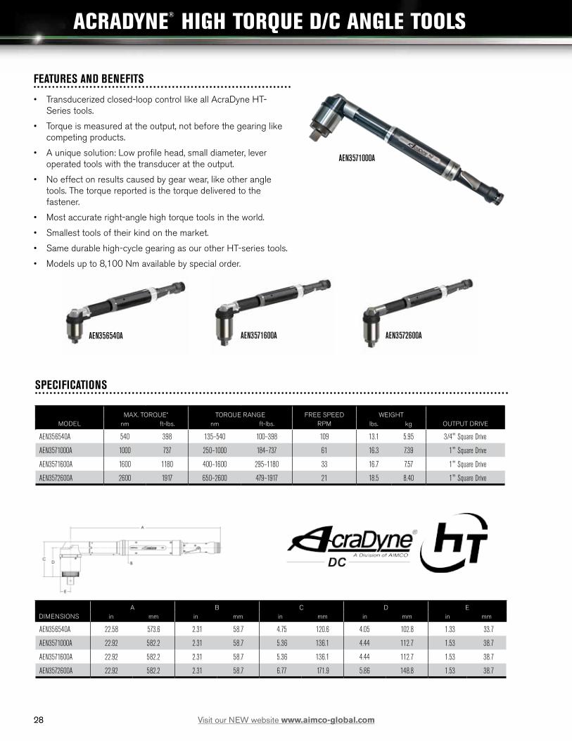
ACRADYNE® HIGH TORQUE D/C ANGLE TOOLS
28 Visit our NEW website www.aimco-global.com
AEN3571600AAEN356540A
FEATURES AND BENEFITS
• Transducerized closed-loop control like all AcraDyne HT-Series tools.
• Torque is measured at the output, not before the gearing like competing products.
• A unique solution: Low profile head, small diameter, lever operated tools with the transducer at the output.
• No effect on results caused by gear wear, like other angle tools. The torque reported is the torque delivered to the fastener.
• Most accurate right-angle high torque tools in the world.
• Smallest tools of their kind on the market.
• Same durable high-cycle gearing as our other HT-series tools.
• Models up to 8,100 Nm available by special order.
AEN3572600A
SPECIFICATIONS
MAX. TORQUE* TORQUE RANGE FREE SPEED WEIGHTMODEL nm ft-lbs. nm ft-lbs. RPM lbs. kg OUTPUT DRIVE
AEN356540A 540 398 135–540 100–398 109 13.1 5.95 3/4" Square Drive
AEN3571000A 1000 737 250–1000 184–737 61 16.3 7.39 1" Square Drive
AEN3571600A 1600 1180 400–1600 295–1180 33 16.7 7.57 1" Square Drive
AEN3572600A 2600 1917 650–2600 479–1917 21 18.5 8.40 1" Square Drive
A B C D EDIMENSIONS in mm in mm in mm in mm in mm
AEN356540A 22.58 573.6 2.31 58.7 4.75 120.6 4.05 102.8 1.33 33.7
AEN3571000A 22.92 582.2 2.31 58.7 5.36 136.1 4.44 112.7 1.53 38.7
AEN3571600A 22.92 582.2 2.31 58.7 5.36 136.1 4.44 112.7 1.53 38.7
AEN3572600A 22.92 582.2 2.31 58.7 6.77 171.9 5.86 148.8 1.53 38.7
AEN3571000A

29
ACRADYNE® HIGH TORQUE DUAL LEVER AND GEARHEAD TOOLS
FEATURES AND BENEFITS
• Custom made to fit virtually any application.
• Same high durability gearing as on AcraDyne’s standard HT Series tools.
• Model types available: o HT Offset Gearhead tools
• o HT Right Angle with Offset Gearhead Tools o HT Right Angle Air Tools with Offset Gearhead
• Torque ranges from 250 Nm to 8100 Nm.
FEATURES AND BENEFITS
• Additional safety when using a tool with a reaction bar or nose extension.
• Requires the operator to use both hands when starting the tool, which keeps hands clear of the application.
• Helps to avoid accidental starting of the tool.
• Available in two handle types: “Handle Bar” style (F) and Straight (S) tool with side handle.
DUAL LEVER TOOLS
HT GEARHEAD TOOLS
MODEL* APPROX. TORQUE
APPROX. SPEED WEIGHT LENGTH DIA. DRIVE
SOUND LEVEL
(HANDLE TYPE) SERIES Nm ft-lb rpm kg lb mm in mm in in dB(A)
AE(S)(F)4(A)(B)66250BDL 6000 250 185 315 4.6 10.5 254 10 66 2.6 0.75 66AE(S)(F)4(A)(B)66425BDL 6000 425 315 165 4.6 10.5 254 10 66 2.6 0.75 66AE(S)(F)4(A)(B)66625BDL 6000 625 460 106 4.8 10.5 254 10 66 2.6 0.75 66AE(S)(F)4(A)(B)66925BDL 6000 925 682 72 4.8 10.5 254 10 66 2.6 0.75 66AE(S)(F)4(A)(B)771200BDL 7000 1,200 885 65 6.6 14.5 259 10.2 76 3.0 1 66AE(S)(F)4(A)(B)773000BDL 7000 3,000 2,213 25 7.5 16.5 294 11.6 76 3.0 1 66AE(S)(F)4(A)(B)884200B1DL 8000 4,200 3,100 12 11.1 24.5 340 13.4 86 3.6 1 66AE(S)(F)4(A)(B)884200BDL 8000 4,200 3,100 12 11.1 24.5 340 13.4 86 3.6 1.5 66AE(S)(F)4(A)(B)885000BDL 8000 5,000 3,700 9 11.1 24.5 340 13.4 86 3.6 1.5 66AE(S)(F)4(A)(B)896500BDL 8000/9000 6,500 4,800 7 15.7 34.5 378 14.9 101 4.0 1.5 66AE(S)(F)4(A)(B)898100BDL 8000/9000 8,100 6,000 5 15.7 34.5 378 14.9 101 4.0 1.5 66* The fifth digit of the model number is “A” for fixed gearcase models and “B” for clutched gearcase models. - Above data is for clutched gearcase models. For no-clutched models, reduce weight by 1.5 lb (0.7 kg) and length by 2 in (51 mm).- For Straight Type Tools Choose the Position of the Handle by Adding (L) for Left Side and (R) for Right Side
29Visit our NEW website www.aimco-global.com
AEF TYPE
AES TYPE

30
NOSE EXTENSIONS
30 Visit our NEW website www.aimco-global.com
REACTION BARS
Each tool includes a standard spline-attachment reaction device. Custom reaction devices are also available; contact your AIMCO sales representative for more details, 1-800-852-1368.
ACCESSORIES
Custom accessories are also available for your application; contact your AIMCO Sales Representative for more details, 1-800-852-1368.
SWIVEL HANDLE SWIVEL BAIL HOIST RING
FIXED HANDLEWITH HOIST RING
FIXED HANDLE
ACRADYNE® HIGH TORQUE NOSE EXTENSIONS
MODEL DESCRIPTION
26810 Single Ended, Flat, 6000 Series26815 Single Ended, 2.375” Offset, 6000 Series26830 Double Ended, Flat, 6000 Series26885 Single Ended, 4.00” Offset, 6000 Series26800 Single Ended, Flat, 7000 Series27200 Single Ended, 3.10” Offset, 7000 Series26820 Double Ended, Flat, 7000 Series26890 Single Ended, 4.00” Offset, 7000 Series25277 Single Ended, flat, 8000 Series25274 Single Ended, 3.35” offset, 8000 Series25275 Single Ended, 4.00” offset, 8000 Series25278 Double Ended, flat, 8000 Series25276 Double Ended, 3.35” offset, 8000 Series27255 Single Ended, flat, 9000 Series26840 Single Ended, 3.35” offset, 9000 Series
MODEL DESCRIPTION
26477 Swivel Bail Assembly, 6000 Series26478 Swivel “D” Handle Assembly, 6000 Series26479 Stationary Bail Assembly, 6000 Series26337 Rear Fixed Hoist Ring Sub-Assembly, 7000/8000 Series26327 Swivel Bail Assembly, 7000 Series26328 Swivel “D” Handle Assembly, 7000 Series26336 Fixed Handle Sub-Assembly, 7000 Series25291 Swivel Handle, 8000 Series25287 Swivel Bail Hoist, 8000 Series25497 Rear fixed hoist ring, 8000 Series25289 Fixed hoist (handle not included), 8000 Series25280 Auxiliary Handle, 8000 Series27045 Sliding Spindle, 7000 Series28549 Sliding Spindle, 6000 Series
REACTION BARS
FEATURES AND BENEFITS
• Ideal for hard-to-reach applications when a torque tube, or arm, is not desirable.
• Used as a cost-effective, more flexible option to a multiple spindle system.
• Common Applications:
- Wheel install and repair stations.
- Large flange assembly

3131Visit our NEW website www.aimco-global.com
NOTES

3232 Visit our NEW website www.aimco-global.com
DC TOOLS: TOOL/SPINDLE SELECTION GUIDE
MODEL RPM LENGTH WEIGHT in mm lb kg
ANGLE AEN4C12004B 3,111 11.65 295.9 2.0 0.91 AEN4C12009B 1,750 11.00 279.5 2.2 0.91 AEN4C12014B 875 11.66 296.4 2.2 1.00 AEN4C12018B 691 11.66 296.4 2.2 1.00 AEN4C12022B 560 11.66 296.4 2.2 1.00 AEN32015C 1481 14.8 376.7 2.7 1.22 AEN32025C 833 14.8 376.7 2.7 1.22 AEN32030C 803 14.6 371.9 2.8 1.27 AEN32040C 574 14.6 371.9 2.8 1.27 AEN33042C 1,095 16.6 422.3 4.4 2.00 AEN33053C 1,095 16.6 422.3 4.4 2.00 AEN33060C 845 19.1 485.7 6.6 2.99 AEN33090C 568 19.1 485.7 6.6 2.99 AEN33120C 442 21.2 539.0 9.3 4.22 AEN33200C 245 23.4 594.4 9.4 4.26 AEN33210C 234 23.6 599.9 10.0 4.54 AEN33300C 151 23.8 603.8 10.0 4.54 AEN35090B 607 22.6 573.7 6.9 3.13 AEN35140B 472 22.5 571.9 10.4 4.72 AEN35175B 384 22.5 571.9 10.5 4.76 AEN35225B 291 22.9 581.1 12.3 5.58 AEN35285B 236 22.9 581.1 12.3 5.58 AEN35350B 191 22.9 581.1 12.3 5.58
INLINE
AES4A12003BQ 2,625 11.12 282.7 2.0 0.91 AES4A12006BQ 2,625 11.12 282.7 2.0 0.91 AES4A12011BV 1,313 11.44 290.5 2.2 1.00 AES4A12014BV 1,037 11.44 290.5 2.2 1.00 AES4A12018BV 840 11.44 290.5 2.2 1.00 AES4A12022BV 656 11.44 290.5 2.2 1.00 AES32010CV 2222 14.3 363.7 2.5 1.13 AES32020CV 1250 14.3 363.7 2.5 1.13 AES32025CV 893 14.3 363.7 3.2 1.45 AES32038CV 595 17.2 435.9 4.2 1.91 AES33040CV 1314 18.7 475.7 6.4 2.90 AES33060CV 883 18.7 475.7 6.4 2.90 AES33100CV 489 23.1 585.7 8.1 3.67 AES33150CV 329 23.1 585.7 8.1 3.67 AES33230CV 221 23.1 585.7 8.1 3.67 AES33400CV 122 25.5 647.7 13.0* 5.90* AES33600CV** 82 25.5 647.7 13.0* 5.90* AES35075AV 944 21.9 555.2 9.2 4.17 AES35090AV 767 21.9 555.2 9.2 4.17 AES35110AV 634 21.9 555.2 9.2 4.17 AES35135AV 515 21.9 555.2 9.2 4.17 AES35170AV 418 21.9 555.2 9.2 4.17 AES35280A 236 24.2 615.1 12.8 5.81 AES35350A 192 24.2 615.1 12.8 5.81 AES35420A 159 24.2 615.1 12.8 5.81 AES35515A*** 129 24.2 615.1 12.8 5.81 AES35635A**** 104 24.2 615.1 12.8 5.81
*Includes reaction bar and fixture nut. **Torque Range: 120-480 Nm Max Torque: 600 Nm*** Torque Range: 128-515 Nm ****Torque Range: 159-635 Nm
TORQUE, Nm 5 10 15 20 25 50 75 100 125 150 175 200 225 250 275 300 325 350 375 400 425 450
Recommended Torque Range Max Torque

3333Visit our NEW website www.aimco-global.com
DC TOOLS: TOOL/SPINDLE SELECTION GUIDE
HIGH TORQUE SERIES –
DC TOOLS: TOOL/SPINDLE SELECTION GUIDE
TORQUE, Nm50 100 200 300 400 500 600 850 1100 1200 1300 1500 2000 2500 3000 4000 5000 6500 8100
Max Torque
MODEL RPM** LENGTH WEIGHT in mm lb kg
( )4(A)(B)66200B 315 12 305 12 5.3
( )4(A)(B)66425B 165 12 305 12 5.3
( )4(A)(B)66625B 106 11.8 299 12.5 5.7
( )4(A)(B)66925B 72 11.8 299 12.5 5.7
( )4(A)(B)771200B 65 11.5 292 12.5 5.7
( )4(A)(B)773000B 25 12.9 328 18 8.1
( )4(A)(B)884200B1 12 14.8 376 27 12.3
( )4(A)(B)884200B 12 14.8 376 27 12.3
( )4(A)(B)885000B 9 14.8 376 27 12.3
( )4(A)(B)896500B 7 18.0 457 34 15.0
( )4(A)(B)898100B 5 18.0 457 34 15.0
Recommended Torque Range
MODEL RPM LENGTH WEIGHT in mm lb kg
PISTOL AEP4_12003B_ 2,625 7.6 194.2 2.2 1.00 AEP4_12006B_ 2,625 7.6 194.2 2.2 1.00 AEP4_12011BV 1,313 7.5 191.2 2.3 1.04 AEP4_12014BV 1,037 7.5 191.2 2.3 1.04 AEP4_12018BV 840 7.5 191.2 2.3 1.04 AEP4_12022BV 656 7.5 191.2 2.3 1.04 AEP4_2020BV 1,313 14.3 363.7 2.4 1.09 AEP4_2025BV 1,037 14.3 363.7 2.4 1.09 AEP4_2030BV 840 17.2 435.9 2.4 1.09 AEP4_2035BV 747 17.2 435.9 2.4 1.09 AEP4_2040BV 656 17.2 435.9 2.4 1.09 AEP35075AV 944 16.0 405.2 9.2 4.17 AEP35090AV 767 16.0 405.2 9.2 4.17 AEP35110AV 634 16.0 405.2 9.2 4.17 AEP35135AV 515 16.0 405.2 9.2 4.17 AEP35170AV 418 16.0 405.2 9.2 4.17 AEP35280A 236 18.4 468.2 13.6 6.17 AEP35350A 192 18.4 468.2 13.6 6.17 AEP35420A 159 18.4 468.2 13.6 6.17 AEP35515A* 129 18.4 468.2 13.6 6.17 AEP35635A** 104 18.4 468.2 13.6 6.17
TUBENUT AET4A12018B 516 11.3 288.1 3.1 1.41 AET4A12025B 387 11.3 288.1 3.1 1.41 AET4A12025B-KD 387 15.9 402.6 3.1 1.41 AET32020C 622 14.8 375.9 3.1 1.41 AET32025C 466 15.5 393.7 4.0 1.81 AET32035C 347 16.0 406.4 4.5 2.04 AET32050C 257 16.4 416.6 5.6 2.54
* Torque Range: 128 - 515 Nm **Torque Range: 159 - 635 Nm
TORQUE, Nm 5 10 15 20 25 50 75 100 125 150 175 200 225 250 275 300 325 350 375 400 425 450

3434 Visit our NEW website www.aimco-global.com
ACRADYNE® ACCESSORIES
CABLE ASSEMBLIES
The AcraDyne® DC electric nutrunner tool system uses a single cable to carry all necessary conductors for superior ergonomics and durability.
• Flexible polyurethane cover for maximum durability, abrasion and transmission fluid resistant.
• Quick disconnects at both ends facilitate tool changeover and troubleshooting.
• The CAN data/signal is via RJ45 for products such as the KDM, socket tray or computer.
LENGTH
MODEL DESCRIPTION m ft
TOOL CABLES
24330 Cable G3 Tool Cable 3M 3 9.8
25350 Cable G3 Tool Cable 5M 5 16.4
24320 Cable G3 Tool Cable 10M 10 32.8
27110 Cable G3 Tool Cable 3M Lightweight* 3 9.8
27115 Cable G3 Tool Cable 5M Lightweight* 5 16.4
27122 Cable G3 Tool Cable 10M Lightweight* 10 32.8
25646 G1 iEC to G3 Cable Adapter
26934 G3 iEC to G1 Cable Adapter
27210 G3 Tool to G1 Cable Adapter
26364 Right Angle Cable Adapter
26709 G3 Tool to G1 Cable (Cable Tester only)
26700 Cable Tester Unit, G3
26594 Conversion Kit G1 iEC to G3 iEC
27370 Conversion Kit G3 iEC to G1 iEC
25491 Breakaway Cable Connector – Ensures disconnect of cable should stress in excess of 40 lbs occur
*Lightweight cables are for use only with 1000 & 2000 Series tools.
EXTENSION
24320 Extension cable 10M 10 32.8
25518 Extension cable 20M 20 65.6
DATA
20403 Data/signal connection cable – Accessories to controller 2.0 7
23490 I/O Wiring Connector – Simple Module to facilitate connections to I/O on iEC Controllers
AEC-CIM Interface module which allows communication between a computer and an AcraDyne® controller through USB or CAN connections. All necessary cables included.
23490Cable Adapter25491
Lightweight Tool Cable
Standard Tool Cable
AEC-CIM

3535Visit our NEW website www.aimco-global.com
ACRADYNE® ACCESSORIES ACRADYNE® ACCESSORIES
UNIVERSAL TOOL BASKET
Universal Tool Basket 21226SLIDING SPINDLES
MODEL DESCRIPTION
AMPST-2-I 2 Position Socket Tray for iEC ControllersAMPST-4-I 4 Position Socket Tray for iEC ControllersAMPST-6S-I 6 Position Socket Tray for iEC Controllers, Straight LineAMPST-6-I 6 Position Socket Tray for iEC ControllersAMPST-8-I 8 Position Socket Tray for iEC Controllers
TOOL BAILS
• AcraDyne’s spring bails are designed for use with any of the AcraDyne® 1000, 2000 or 3000 Series tools.
• The spring bails snap on quickly and firmly at any place on the body of the tool for perfect balance and secure suspension.
SOCKET TRAY
• Simply remove the assigned socket to select the application to be run.
• Quick and easy set up. Parameters assigned to socket position automatically.
• Optional self illuminating socket receptacles.
• Delrin® blanks may be easily machined by the customer to accommodate custom socket profiling.
• Nothing to break, wear out or maintain.
• Proximity sensors detect presence of socket.
• Can also be used with UEC style controllers.21208
Tool Bail23575
23662
Socket Tray AMPST-6S-I
MODEL DESCRIPTION
20712 Sliding Spindle 2” Stroke 2000 Series Tools20848 Sliding Spindle 2” Stroke 3000 Series Tools
MODEL DESCRIPTION
25501 Wire Bail for 1000 Series Tools 27594 Stationary Bail for 1000 Series Tools27791 Rotating Bail Assembly for 1000 Series Tools26327 Swivel Bail Assembly for 7000 Series Tools26332 Stationary Bail Assembly for 7000 Series Tools26629 Stationary Bail Assembly for 9000 Series Tools26630 Hoist Swivel Bail Assembly for 9000 Series Tools26632 Stationary Bail Assembly for 9000 Series Tools26568 Cable Bail to Hang Tool Vertically for Gen III Cables 21159 2000/3000 Vertical Tool Hanger for Gen 1 Tools21208 Spring Bail for 2000 Series Tools23662 Rotating Bail for 2000 Series Tools 23575 Rotating Bail for 3000 Series Tools

36
BARCODE READER
36 Visit our NEW website www.aimco-global.com
ACRADYNE® ACCESSORIES
CONTROLLER BRACKETS
MODEL DESCRIPTION
20322 Wall Plate Bolts to wall allows controller bracket (23362) to hang without hard fastening
20853 Table Stand Free standing platform enables controller Bracket (23362) to simply hang from.
27816 Mounting Bracket for Gen IV Controller
MOUNTING BRACKETS
TOOL BODY JACKETS
Keep your tools protected and avoid accidental damage to the application with AIMCO’s tool body jackets.
LIGHT TOWER
23730
20853 27816
Light Tower Bracket for Gen IV Controller
28489
MODEL DESCRIPTION
BJ10051 For 1000 series angle toolsBJ10052 For 2015, 2025 series angle toolsBJ10053 For 2030, 2040, 2055 series angle tools BJ10054 For 3060, 3090 series angle toolsBJ10055 For 3120, 3200 series angle tools
MODEL DESCRIPTION
LS4208 RS232 Barcode Reader KitLS4278 RS232 Wireless Barcode Reader Kit
MODEL DESCRIPTION
25717 Mounting Bracket for 1000 Series Angle Tools 25843 Mounting Bracket for 1000 Series Push-To-Start Tools 26443 Mounting Bracket for Straight and Pistol 1000/2000 Series 24924 Mounting Flange for Straight and Pistol 1000/2000 Series 25718 Mounting Bracket for 3000/5000 Series Angle Tools 26570 Mounting Bracket for 3000/5000 Series Straight Tools25265 Angle head Mounting Bracket (Cradle type) for 3000/5000 Angle Tools over 225 Nm
20322

3737Visit our NEW website www.aimco-global.com
ACRADYNE® HIGH TORQUE PNEUMATIC TOOLS
TORQUE TORQUE SPEED WEIGHT SQUARE DR. AIR CONSUMPTIONMODEL (Nm) (Ft-lb) (rpm) (lb) (in) (CFM)
AAP1B66400A 400 300 70 9.75 3/4 22.9
AAP1B66600A 600 450 50 9.75 3/4 22.9
AAP1B66850A 850 625 36 9.75 1 22.9
AAP1B76950A 950 700 37 10.4 1 26.3
AAP1B771350A 1350 1000 22 10.4 1 26.3
AAP1B771800A 1800 1325 15 14.9 1 26.3
AAP1B772950A 2950 2175 9 14.9 1 26.3
AAP1B885100A1 5100 3775 7.5 23 1 31.5
AAP1B885100A 5100 3775 7.5 23 1-1/2 31.5
FEATURES AND BENEFITS
AcraDyne’s High Torque Pneumatic Bolting Tools offer a reliable and dependable solution for the installation and removal of heavy-duty fasteners in a variety of industries that require high torque capability, accuracy, power, and safety. • Modular design allows for
ease of maintenance.
• Motors and gearing are interchangeable.
• Durable and reliable gearbox• Proven air motor• Faster Free Speed• One-Hand ReverseAAP1B76950A
AAP1B771800A AAP1B885100A1
AAP1B66600A
See page 136 for Air Preparation Units

3838 Visit our NEW website www.aimco-global.com
• Assemblies include reusable swivel fitting.
• Burst pressure 428 PSI @ 68° F.
• Working temperature: -104° F to 175° F.
• Straight hose is available by the foot with, or without, hose fittings.
• Ask about full reel pricing. Call 1-800-852-1368.
SINGLE AIR HOSE (COILED) CUSTOM LENGTHS
STRAIGHT AIR HOSE (SOLD PER FOOT)
Custom length coil assemblies and special colors are available in minimum order quantities.
AIMCO AIR HOSE SINGLE AIR HOSE ASSEMBLIES (COILED) MODEL WORKINGPRESSURE 100 PSI
DESCRIPTION(OD x ID x LENGTH)
RETRACTEDLENGTH
NPTFITTINGS
ASH-500C-15MSZ 3/4’’ x 1/2’’ x 15’ 13’’ 1/2’’ASH-500C-25MSZ 3/4’’ x 1/2’’ x 25’ 23’’ 1/2’’
MODEL DESCRIPTION
ASH-500Z 1/2’’ I.D.
MODEL CAPACITY
500-RZ 1/2’’ NPT Rigid Fitting500-SZ 1/2’’ NPT Swivel Fitting
AIR LINE
“RL”(Retracted Length)
16" TAIL
ID
8" TAIL
• Durable Polyurethane or Rubber hose.
• Excellent recoil memory.
• Maximum flexibility and lightweight.
• Polyurethane available in transparent hose color (opaque available).
• Custom colors available.
• High chemical resistance.
AIR HOSE FITTINGS
PLUGSMODEL DESCRIPTION
28161 1/2” x 1/4” MPT28162 1/2” x 3/8” MPT28163 1/2” x 1/2” MPT28164 1/2” x 1/2” FPT
QUICK-CHANGE COUPLERS
MODEL DESCRIPTION
27768 1/2” FPT27769 1/2” MPT
PROTECTIVE COUPLER
MODEL DESCRIPTION
27771 Vinyl
BRASS FITTINGS
ACRADYNE® HT PNEUMATIC TOOL ACCESSORIES
REACTION BARS
Each tool includes a standard spline-attachment reaction device. See 30 for part numbers. Custom reaction devices are also available; contact your AIMCO Sales Representative for more details, 1-800-852-1368.
REACTION BARS
PROTECTIVE COVERS
Durable protective covers prevent marring and damage.
MODEL DESCRIPTION
BJ10078 Protective Cover, 6000 SeriesBJ10077 Protective Cover, 7000 SeriesBJ10076 Protective Cover, 8000 Series

3939Visit our NEW website www.aimco-global.com
FEATURES AND BENEFITS
• Nutrunner sequencing - Allows nutrunners to be sequenced at each phase of the tightening process providing even distribution of torque and load to each fastener.
• Even torque distribution - Where there is uneven torque distribution, part damage or distortion could occur with possible fastener failure or loss of residual clamp load.
• Snug, threshold, final torque in one pass - No need for multiple torque stage sequencing. Fixtured nutrunners save time and effort.
• No missed fasteners - With multiple nutrunners there is a spindle dedicated to each location, ensuring quality on every rundown on every bolt.
• Better residual torques - Synchronized controlled fastening allows residual torque levels to be consistent with the dynamic torque specification.
• Saving in cycle time - Compared to using a single nutrunner tool with many rundowns, running all fasteners simultaneously reduces in-station cycle time.
• Cost saving benefits - Saving installation cycle time frees operators to handle additional tasks and potentially reduce labor costs.
• Collect data — Most common methods of collecting data for quality control and statistical analysis can be implemented from a serial data string using RS232 to formatted data from a network database.
ENGINE MANUFACTURER
• Gasoline generator assembly.
• Six spindle 30 Nm
• Replaced hand assembly with rotation pattern to simultaneous rundown.
AUTOMOTIVE MANUFACTURER
• Wheel lug nut assembly.
• Four spindle 105 Nm
• Rotating spindle trunnion.
• Replaced competitive system.
• Built-in PC for data storage.
• Custom display panel showing application.
• Cpk range of 3.2–6.9 far exceed quality requirements.
SMALL ENGINE MANUFACTURER
• Air cooled small vehicle engine assembly.
• Ten spindle 2.4–2.8 kgf-m.
• Integrated PLC control of system functions.
• Supplied overhead rail follows line and returns powerhead to home position.
• Powerhead features single lever control and visual confirmation of accepted torque.
ACRADYNE® SYSTEMS
MULTIPLE NUTRUNNING SYSTEMS
AIMCO has the capability to integrate the AcraDyne® tool spindle into a customized Multiple Nutrunning System. From simple systems vertically suspended above the part to assembly stations that integrate with your line, AIMCO can effectively accommodate your project.
LET US KNOW YOUR REQUIREMENTS AND WE WILL PROPOSE A SOLUTION TAILORED TO YOUR NEEDS.

4040 Visit our NEW website www.aimco-global.com
FEATURES AND BENEFITS
• Reduced Cable Numbers — Integral type tube containing torque sensor cable and resolver cable.
• Enhanced Memory Capacity — Designed with increased memory capacity for improved efficiency of assembly line and tightening data control.
• Open Network Communication — We have prepared various types of communication boards for your specifications (M-NET, Device net, Inter-bas, CC-link).
• Automatic Setting (Automatic recommended value input) — Advance value preparation per application will help you simplify your parameter setting.
• Space Saving — One piece structure contained spindle controller and driver unit reduces space occupancy by 40% to 60% .
VOLUME & WIDTH VOLUME & WIDTH WITH F-SERIESBEFORE UEC-F024 UEC-F120
NO. OF SPINDLES CM MM CM MM CM MM
1-Spindle 16,800 200 6,360 150 8,268 1952-Spindle 24,360 290 8,904 210 12,084 2855-Spindle 47,040 560 16,536 390 24,804 58510-Spindle 84,840 1,010 29,256 690 48,336 1,140
F-SERIES NETWORK CONNECTIVITY
FIXTURED F-SERIES NUTRUNNERS

4141Visit our NEW website www.aimco-global.com
FIXTURED F-SERIES NUTRUNNERS
Power Socket AC100~220V single phase
External Input/Output Connector PLC1: input signal connector for control signal input (fixed allocation)PLC2: output signal connector for judgement result and status output (free allocation)
Serial Port (Data Input Connector)RS232C DATA-IN accepts serial numbers, etc. provided by external equipment such as a barcode reader then outputs tightening data together with serial numbers.
Serial Port (Data Output Connector)RS232C PRINTER outputs tightening result data to your printer (free format)
Serial Port (Data Output Connector)RS232C PLC outputs tightening result data to PLC (free format)
Serial Port (Data Output Connector)RS485 outputs tightening result data to an external exclusive display unit
PC ConnectorRS232C for communication with a PC
Spindle-to-Spindle Communication ConnectorRS485 for internal spindle unit to spindle unit communications
Manual SwitchesRESET, START, REVERSE and CAL
LED DisplayPOWER, M RUN, ACCEPT, REJECT and ALARM
Status Change Switch RUN/BYPASS change switchRUN: Operation possible statusBYPASS: Non-operation status
External Communication Device RS485 connector
Resolver ConnectorTool and resolver connection
MON Connector (Monitor Output)Analog torque electric pressure and angle pulse output
T/D ConnectorTools torque sensor connection
I/O ConnectorExternal input and output control connection
MOTOR ConnectorConnection with tools magnet motor
AC IN ConnectorAC200V~220V 3-phase power socket
Manual Operation SwitchesSTART: manual start switch REVERSE: Manual reverse switch CAL: Manual calibration switchRESET: Manual reset switch
Data Display Operation SwitchMODE switchSET switchDATA UP switchDATA DOWN switch
NOTE: Display unit (UEC-MKB) is an option.
1 1 1
22
3
4
5
6
7
8
2
3
4
5
6
7
8
9
10
1
5
4
10
8
9
6
7
2
3
1
2
4
5
6
3
7
8
1
2
The “F” Series Nutrunner System will satisfy multiple tightening patterns.
• Torque Tightening
• Spline Press Ft Tightening
• Torque
• Pin Hole Alignment Tightening
• Angle Tightening
• Pre-Load Detection
• Angle
• Idle Operation Check
• Plastic Range Monitor
Main unit UEC-F300M Spindle unit UEC-F024 UEC-MKB

4242 Visit our NEW website www.aimco-global.com
APPLICATION DATAEXTERNAL DIMENSIONS (MM) TORQUE MOTOR FLANGE
TYPE L1 L2 L3 D1 D2 P A B SENSOR TYPE DESIGN
UNR-F015-45NT 371 41 12 40.5 38 51 M6 9.5 TM-035 F015 (a)UNR-F015-65NT 371 41 12 40.5 38 51 M6 9.5 TM-035 F015 (a)UNR-F015-200NT 400 41 12 40.5 38 51 M6 9.5 TM-035 F015 (a)UNR-F015-280NT 400 41 12 40.5 38 51 M6 9.5 TM-035 F015 (a)UNR-F015-350NT 400 41 12 40.5 38 51 M6 9.5 TM-035 F015 (a)UNR-F050-270NT 453.5 41 12 50 38 51 M6 9.5 TM-035 F050 (a)UNR-F050-630NT 500.5 41 16.5 50 38 62 M8 12.7 TM-085 F050 (a)UNR-F050-730NT 500.5 41 16.5 50 38 62 M8 12.7 TM-085 F050 (a)UNR-F050-880NT 512.5 45 20 50 48 62 M8 15.88 TM-150 F050 (a)UNR-F050-1400NT 512.5 45 20 50 48 62 M8 15.88 TM-150 F050 (a)UNR-F100-1300NT 519.5 45 20 62 48 62 M8 15.88 TM-150 F100 (a)UNR-F100-1900NT 515.5 45 20 62 48 76 M8 15.88 TM-250 F100 (b)UNR-F100-2500NT 515.5 45 20 62 48 76 M8 15.88 TM-250 F100 (b)UNR-F100-3700NT 589 57 30 62 58 76 M10 19 TM-400 F100 (b)UNR-F100-5400NT 704.5 80 40 62 70 90 M10 25.4 TM-700 F100 (b)
Torque Sensor Specifications
TYPE CAPACITY (NM)TM-035 34.3TM-085 83.3TM-150 147TM-250 245TM-400 392TM-700 686TM-1000 980
Rated Strain 2000X10–6Output Voltage 1.0 mV/VNon-Lineality ±0.5% R.O.Influence on Zero Point Due to Temperature ±0.1% R.O./°C
Temperature Rating –10~+65°CInput Output Resistance 480ΩMaximum Input Voltage 16VInsulation Resistance Greater than 300ΩOverload Capacity 150%
INLINE NUTRUNNERS
FIXTURED F-SERIES NUTRUNNERS
INLINE MOTOR SPECIFICATIONSTIGHTENING FREE SPEED WEIGHT SPINDLE
TYPE TORQUE (NM) RPM KG UNIT
UNR-F015-45NT 4.5 3,200 2.48 UEC-F024UNR-F015-65NT 6.5 2,200 2.48 UEC-F024UNR-F015-200NT 20 730 2.73 UEC-F024UNR-F015-280NT 28 500 2.73 UEC-F024UNR-F015-350NT 35 410 2.73 UEC-F024UNR-F050-270NT 27 1,750 4.86 UEC-F060UNR-F050-630NT 63 750 5.08 UEC-F060UNR-F050-730NT 73 650 5.08 UEC-F060
TIGHTENING FREE SPEED WEIGHT SPINDLE
TYPE TORQUE (NM) RPM KG UNIT
UNR-F050-880NT 88 540 5.47 UEC-F060UNR-F050-1400NT 140 340 5.47 UEC-F060UNR-F100-1300NT 130 730 7.42 UEC-F120UNR-F100-1900NT 190 500 7.94 UEC-F120UNR-F100-2500NT 250 370 7.94 UEC-F120UNR-F100-3700NT 370 260 9.55 UEC-F120UNR-F100-5400NT 540 175 17.0 UEC-F120

4343Visit our NEW website www.aimco-global.com
FIXTURED F-SERIES NUTRUNNERS
RIGHT ANGLE MOTOR SPECIFICATIONS
EXTERNAL DIMENSIONS (MM) STRAIGHT MOTORSTYPE L1 L2 H1 H2 D1 D2 P A B TYPE SENSOR MOTOR
UNR-F015-25NTC 507 120 49 10.6 70 28 85 M6 9.5 UNR-F015-200NT TM-035 F015UNR-F015-55NTC 521 130 58 18 70 36 85 M6 12.7 UNR-F015-350NT TM-035 F015UNR-F050-95NTC 643 150 73.5 20 85 45 102 M6 15.88 UNR-F050-630NT TM-085 F050UNR-F050-130NTC 649 150 73.5 20 85 45 102 M6 15.88 UNR-F050-880NT TM-150 F050UNR-F100-200NTC 681.5 170 85.5 20 85 56 102 M6 15.88 UNR-F100-1300NT TM-150 F100UNR-F100-250NTC 677.5 170 85.5 20 100 56 120 M8 15.88 UNR-F100-1900NT TTM-150 F100UNR-F100-380NTC 716.5 200 109.5 25 110 74 134 M10 19 UNR-F100-2500NT TM-250 F100UNR-F100-550NTC 784 200 114.5 29 110 74 134 M10 25.4 UNR-F100-3700NT TM-400 F100
TIGHTENING FREE SPEED WEIGHT SPINDLETYPE TORQUE (Nm) (rpm) (kg) UNIT
UNR-F015-25NTC 25 460 4.18 UEC-F024UNR-F015-55NTC 55 260 4.37 UEC-F024UNR-F050-95NTC 95 480 8.08 UEC-F060UNR-F050-130NTC 130 340 8.3 UEC-F060
DIMENSIONS (mm)TYPE A B C D E F G
UNR-F015-45NT 43 52 64 46 74 92 122UNR-F015-65NT 43 52 64 46 74 92 122UNR-F015-200NT 43 52 64 46 74 92 122UNR-F015-280NT 43 52 64 46 74 92 122UNR-F015-350NT 43 52 64 46 74 92 122UNR-F050-270NT 59 72 90 64 108 122 160UNR-F050-630NT 59 72 90 64 108 122 160UNR-F050-730NT 59 72 90 64 108 122 160UNR-F050-880NT 59 72 90 64 108 122 160UNR-F050-1400NT 59 72 90 64 108 122 160UNR-F100-1300NT 66 75 92 65 116 130 170UNR-F100-1900NT 70 100 110 78 115 132 174UNR-F100-2500NT 70 100 110 78 115 132 174UNR-F100-3700NT 76 100 110 78 120 140 184UNR-F100-5400NT 94 125 143 102 166 188 257UNR-F100-7000NT 94 125 143 102 166 188 257UNR-F100-10000NT 94 125 143 102 166 188 257
TIGHTENING FREE SPEED WEIGHT SPINDLETYPE TORQUE (Nm) (rpm) (kg) UNIT
UNR-F100-200NTC 200 460 11.92 UEC-F120UNR-F100-250NTC 250 340 12.3 UEC-F120UNR-F100-380NTC 380 235 15.92 UEC-F120UNR-F100-550NTC 550 165 17.43 UEC-F120
“F” NUTRUNNER MOTORS’ MINIMUM PITCH CIRCLE
Refer to minimum pitch circles for designing your machine.
RIGHT ANGLE NUTRUNNERS

44
STATE-OF -THE-ART CONTROLLER FOR PULSE TOOLS
FEATURES AND BENEFITS: UEC-4800 • Programmable from front panel or PC – no separate touchpad
module or cable required.• 12,000 data point memory.• On-screen statistical readout.• Eight parameter sets available. • Increased programmable I/O options.• Built-in Ethernet connectivity.• PC Windows based software included.• For use with pneumatic or electric transducerized tools.• Compatible with: UA-MC, UEP-MC (with driver box),
UA-SMC, UA-AMC (with optional Angle Encoder Board), ALPHA-MC, and UXR-MC series tools.
FEATURES AND BENEFITS: UEC-4800TP • Provides all features of the UEC-4800.• Enhanced user interface via Touch-Screen programming and information access.
UEC-4800TP Controller with Touch-Screen option.
UEC-4800-EX Controller with network connectivity
UEC-4800
UEC-4800 CONTROLLER
44 Visit our NEW website www.aimco-global.com
MODEL 24V I/OURYU DATA, BARCODE,
& PRINTER LIGHT TOWER & BYPASS
SWITCH CAPABLEETHERNET
PROTOCOLSSERIAL PROTOCOLS
& BAR CODEANYBUS
DEVICENETANYBUS
PROFIBUSTOUCH PANEL
DISPLAYANGLE
MONITORINGUEC-4800 X XUEC-4800A-ANGLE X X XUEC-4800TP X X XUEC-4800TPA X X X XUEC-4800-EX X X XUEC-4800-EXL X X X XUEC-4800-EDA X X XUEC-4800-EDAL X X X XUEC-4800-EPA X X XUEC-4800-EPAL X X X XUEC-4800A-EX X X X XUEC-4800A-EXL X X X X XUEC-4800A-EDA X X X XUEC-4800A-EDAL X X X X XUEC-4800A-EPA X X X XUEC-4800A-EPAL X X X X XUEC-4800TP-EX X X X XUEC-4800TP-EXL X X X X XUEC-4800TP-EDA X X X XUEC-4800TP-EDAL X X X X XUEC-4800TP-EPA X X X XUEC-4800TP-EPAL X X X X XUEC-4800TPA-EX X X X X XUEC-4800TPA-EXL X X X X X XUEC-4800TPA-EDA X X X X XUEC-4800TPA-EDAL X X X X X XUEC-4800TPA-EPA X X X X XUEC-4800TPA-EPAL X X X X X XUEC-5500 X X

45
FEATURES AND BENEFITS: UEC-4800A/E(SD)
• Economical LCD front panel.
• Easy programming or upload of your program from a PC.
• Torque Wave data visible on your PC.
• UEC-4800(SD) memorizes maximum 12,000 fastening data. When connected to a PC, standard deviations, Cp value, and Cpk values can be analyzed instantly from the stored data within the controller.
• Graph statistical data.
Hub
PC / Printer etc.
Serial Printer PLC
PLC
Rear side of UEC
Receptacle
Power Cable
Torque Sensor Cable
LAN Cable
LAN
TOOLPC
UEC-4800(SD) SERIES BLOCK DIAGRAM
Power Supply AC100~240V ±10%
Display
Torque Resolution ±2048 (12-Bit A/D)LCD: 20 characters x 4 linesContents: Work No., Fastening Count, Down No., Fastening Time, Pulse No. 1-digit digital display (DPM): WORK NO.4-digit digital display (DPM): TORQUE
Power Frequency 50/60 Hz
Noise Protection 1000V 1µS (according to noise simulator)
Insulation Protection DC500V over 10MΩ
Ambient Temperature 0~50°C (non-freezing)
Ambient Humidity Under 90%RH (no dew)LED
COUNT Lamp: OK (Green), NOK (Red)TORQUE Lamp: LOW (Yellow), OK (Green), HIGH (Red)Power Consumption Approx. 30VA
Weight Approx. 3.6 kgInput Terminal Signal
Operation Voltage/Current: DC24V/approx. 10mA6 terminals (free format), VALVEDimensions 265(d) x 222(w) x 120(h)
Main Functions Torque Monitoring/Control + Fastening Counter
Output Terminal SignalContact Capacity: AC:125V, 0.3A, DC:30V, 1A6 terminals (free format), VALVEParameter Setup
Manual Input on Front LCD PanelPersonal Computer (with setup software)
UEC-4800A/E(SD) SPECIFICATIONS
45Visit our NEW website www.aimco-global.com
UEC-4800A/E(SD) CONTROLLER

46
FEATURES AND BENEFITS: UEC-4800TPA/E(SD)
• Programming is easy on the front touch panel or upload your program from a PC. • UEC-4800(SD) can be used with various transducerized tools:
- Oil-Pulse Tools fitted with a Magnetostrictive Transducer UA-MC series, ALPHA-MC Series, UEP-MC Series (UEPD driver is required separately). - Oil-Pulse Tools fitted with a Strain-Gauged Transducer U-EC Series, UX-EC Series. - Pneumatic Tools fitted with a Strain-Gauged Transducer UAN-M Series, UOW-M Series, UNR-NT Series.
• Highly reliable Torque Control and Monitor.• Ethernet (TCP/IP) capable.
FUNCTIONS: UEC-4800TPA/E(SD)
• Choose between Torque Control and Monitor. Detect various errors and control the job with the fastening counter.
• Torque Wave data visible on both front touch panel and PC.• UEC-4800(SD) can be used for eight different fastening applications.• Front panel, PC display, or buzzer indicates Input/Output (terminal blocks and tool
wiring), checks, and errors.• UEC-4800(SD) memorizes cumulative fastening numbers and pulse numbers
from the start of operation.• UEC-4800(SD) memorizes maximum 12,000 fastening data. Analyze standard
deviations, Cp value, and Cpk value instantly from stored data within the controller. When connected to a PC, statistical data can be graphed.
• Using Input/Output terminals, UEC-4800(SD) can be interlocked with production line.
UEC-4800TPA/E(SD) CONTROLLER
Torque Monitor Display
Power Supply AC100~240V ±10%Power Frequency 50/60 HzNoise Protection 1000V 1µS (according to noise simulator)Insulation Protection DC500V over 10MΩAmbient Temperature 0~50°C (non-freezing)Ambient Humidity Under 90%RH (no dew)Power Consumption Aprox. 30VAWeight Approx 3.6 kgDimensions 265(d) x 222(w) x 120(h)Main Functions Torque Monitoring/Control + Fastening Counter
Parameter SetupManual Input on Front Touch PanelPersonal Computer (with setup software)
DisplayTorque Resolution ±2048 (12-Bit A/D)320 x 240 dot 25 characters X 15 lines
LEDCOUNT Lamp: OK (Green), NOK (Red)TORQUE Lamp: LOW (Yellow), OK (Green), HIGH (Red)
Input Terminal SignalOperation Voltage/Current: DC24V/approx. 10mA6 terminals (free format), VALVE
Output Terminal SignalContact Capacity: AC:125V, 0.3A, DC:30V, 1A6 terminals (free format), VALVE
UEC-4800TPA/E(SD) SPECIFICATIONSThe conventional UEC-4800 Series has been superceded by UEC-4800(SD), which has the following new functions:
1) miniSD card slot on back panel- Fastening data and wave can be saved to mniniSD card.- Option to save and read setting values in miniSD card.
2) Terminal on the rear side. The following terminals are added:1 x Input terminal1 x Output terminal2 x Input COM terminals2 x Output COM terminals
3) Valve CheckValve wiring check function checks the valve connection to the terminal. If using ALPHA-MC fitted with the valve inside the tool, it checks the tool valve connection.
4) Other Features- Increased PC communication speed from 38,400 bps to
115,200 bps.- Faster data input and memory deletion.
Signal AllocationsCOM: Common Terminal for the input termianls. (-)IN 1~6: Input TerminalsIN COM: Common Terminal for the input terminals. (-)OUT COM: Common Terminal for the output terminals.
Signal AllocationsCOM: Common Terminal for the output terminals.OUT 1~5: Output TerminalsVALVE: Valve Output (0V)VALVE COM: +24VOut 6: Output TerminalOUT COM: Common Terminal for the output terminals
(Input Terminal Block) (Output Terminal Block)
Torque Wave Monitor Display
46 Visit our NEW website www.aimco-global.com

47
FEATURES AND BENEFITS
• Integrates Tool Driver and UEC-4800 Controller – No Separate Box.
• Windows Based PC Software included.
• Programmable Tool Speeds.
• 4 Models to suit UEP Series Tools.
UECD-4800 FOR UEP TOOLS
UECD-4800 FUNCTIONS AND SPECIFICATIONS
Power Supply AC100~240V ±10%
Power Frequency 50/60 Hz
Noise Protection 1000V 1µS (according to noise simulator)
Insulation Protection DC500V over 10MΩ
Ambient Temperature 0~50°C (non-freezing)
Ambient Humidity 90%RH or less (no dew)
Weight Approx. 11.30 kg
Dimensions 265(d) x 222(w) x 200(h)
Main Functions Torque control, Torque monitoring, Fastener number count
Parameter SetupManual Input on Front LCD PanelPC (with exclusive setup software)
Display
Torque Resolution ±2048 (12-Bit A/D use)LCD type, 20 characters x 4 linesContents: Work No., Bolt Count No., Tightening Time, Pulse Blow Number1-digit digital display (DPM): Work No. displayed4-digit digital display (DPM): Torque reading displayed
LEDTotal Lamp (for count judgment): OK (Green), NOK (Red)Torque Lamp (for torque judgment): LOW (Yellow), OK (Green), HIGH (Red)
Input Terminal SignalOperation Voltage/Current: DC24V, approx. 10mA6 terminals available (programmable). Note: Contact input necessary
Output Terminal SignalContact Capacity: DC 30V, 1A6 terminals available (programmable), VALVE
• Motor Setting - Motor current can be set in four steps. - Motor rotational speed can be set in 100 rpm increments.
• Fastening error detection and fastener number countdown functions ensure seamless operation.
• Allows setup or changeover of fastening torque and fastening number count.
• Tool’s maintenance is possible by counting both total cycle numbers (how many fasteners) and/or total pulse numbers.
• Input/Output check and error messages can be checked from your PC or the front panel of UECD-4800, which will notify you with a buzzer.
• Can set up and monitor various control values. Values can be set either on the front panel or on the PC.
• Ethernet (TCP/IP) capable. Upload and receive setting values. Upload fastening result/waveform data through PC software.
• Power Supply: UEP tool is driven by commercial electricity, providing flexible assembly line changes.
47Visit our NEW website www.aimco-global.com
UECD-4800 CONTROLLER

48
MODEL 24V I/O URYU DATA, BARCODE & PRINTER
LIGHT TOWER & BYPASS SWITCH CAPABLE
ETHERNET PROTOCOLS
SERIAL PROTOCOLS & BAR CODE
ANYBUS DEVICENET
ANYBUS PROFIBUS
TOUCH PANEL DISPLAY
UECD-4800A-50 X XUECD-4800A-60 X XUECD-4800A-70 X XUECD-4800A-100 X XUECD-4800TPA-50 X X XUECD-4800TPA-60 X X XUECD-4800TPA-70 X X XUECD-4800TPA-100 X X XUECD-4800A-EX-50 X X XUECD-4800A-EXL-50 X X X XUECD-4800A-EDA-50 X X XUECD-4800A-EDAL-50 X X X XUECD-4800A-EPA-50 X X XUECD-4800A-EPAL-50 X X X XUECD-4800A-EX-60 X X XUECD-4800A-EXL-60 X X X XUECD-4800A-EDA-60 X X XUECD-4800A-EDAL-60 X X X XUECD-4800A-EPA-60 X X XUECD-4800A-EPAL-60 X X X XUECD-4800A-EX-70 X X XUECD-4800A-EXL-70 X X X XUECD-4800A-EDA-70 X X XUECD-4800A-EDAL-70 X X X XUECD-4800A-EPA-70 X X XUECD-4800A-EPAL-70 X X X XUECD-4800A-EX-100 X X XUECD-4800A-EXL-100 X X X XUECD-4800A-EDA-100 X X XUECD-4800A-EDAL-100 X X X XUECD-4800A-EPA-100 X X XUECD-4800A-EPAL-100 X X X XUECD-4800TPA-EX-50 X X X XUECD-4800TPA-EXL-50 X X X X XUEDC-4800TPA-EDA-50 X X X XUECD-4800TPA-EDAL-50 X X X X XUECD-4800TPA-EPA-50 X X X XUECD-4800TPA-EPAL-50 X X X X XUECD-4800TPA-EX-60 X X X XUECD-4800TPA-EXL-60 X X X X XUECD-4800TPA-EDA-60 X X X XUECD-4800TPA-EDAL-60 X X X X XUEDC-4800TPA-EPA-60 X X X XUECD-4800TPA-EPAL-60 X X X X XUECD-4800TPA-EX-70 X X X XUECD-4800TPA-EXL-70 X X X X XUECD-4800TPA-EDA-70 X X X XUECD-4800TPA-EDAL-70 X X X X XUECD-4800TPA-EPA-70 X X X XUECD-4800TPA-EPAL-70 X X X X XUECD-4800TPA-EX-100 X X X XUECD-4800TPA-EXL-100 X X X X XUECD-4800TPA-EDA-100 X X X XUECD-4800TPA-EDAL-100 X X X X XUECD-4800TPA-EPA-100 X X X XUECD-4800TPA-EPAL-100 X X X X X
48 Visit our NEW website www.aimco-global.com
UECD-4800 CONTROLLER

49
UA-MC SERIES
TORQUE RANGE FREE SPEED LENGTH WEIGHT DRIVE SIZE AIR USAGE
MODEL NM FT-LB RPM MM IN LB KG IN CFM
PISTOL TYPEUA-40MC 6.8 - 12.0 5.0 - 8.8 3,600 170 6.7 2.4 1.1 3/8 7.0UA-40DMC 6.9 - 12.0 5.0 - 8.8 3,600 170 6.7 2.4 1.1 1/4 QC 7.0UA-50MC 16.6 - 29.0 12.2 - 21.4 4,250 170 6.7 2.4 1.1 3/8 8.8UA-50DMC 16.6 - 29.0 12.2 - 21.4 4,250 170 6.7 2.4 1.1 1/4 8.8UA-60MC 25.1 - 44.0 18.5 - 32.5 5,000 175 6.9 2.5 1.1 3/8 14.0UA-70MC 28.5 - 50.0 21.0 - 37.0 5,700 187 7.4 2.7 1.2 3/8 15.8UA-80MC 40.0 - 60.0 29.6 - 44.4 6,000 195 7.7 3.4 1.6 3/8 16.8UA-90MC 45.7 - 80.0 33.8 - 59.2 5,500 203 8.0 3.7 1.7 1/2 18.6UA-100MC 51.4 - 90.0 38.0 - 66.6 5,200 215 8.5 4.5 2.1 1/2 19.3UA-130MC 74.2 - 130.0 54.9 - 96.2 4,500 233 9.2 6.2 2.8 1/2 25.6STRAIGHT TYPEUA-40SMC 7.0 - 13.0 5.2 - 9.6 3,600 246 9.7 2.7 1.2 3/8 7.0UA-40SDMC 5.0 - 12.0 3.7 - 8.9 3,600 246 9.7 2.7 1.2 1/4 7.0UA-50SMC 11.0 - 25.0 8.1 - 18.5 4,250 246 9.7 2.7 1.2 3/8 8.8UA-50SDMC 9.0 - 23.0 6.7 - 17.0 4,250 246 9.7 2.7 1.2 1/4 8.8UA-60SMC 18.0 - 38.0 13.3 - 28.1 5,000 252 10.0 2.9 1.3 3/8 14.0UA-60SDMC 16.0 - 34.0 11.8 - 25.2 5,000 252 10.0 2.9 1.3 1/8 14.0UA-70SMC 30.0 - 50.0 22.2 - 37.0 5,700 265 10.4 3.1 1.4 3/8 15.8
UA-MC SERIESFEATURES AND BENEFITS
• The UA-MC features patented Auto Relief Technology providing additional control to the application of torque during the pulsing events.
• The external solenoid valve increases power-to-weight ratios by 20%.
• Magnetostrictive Transducer provides increased durability with low size and weight.
• Pulse Tool requirements with Controlled Tool advantages.
• All models work with any UEC Series controller and can connect to a wide range of network protocols.
• With torque reaction virtually non-existent, allowing for a one-handed operation, the UA-MC provides significantly increased productivity.
RECOMMENDED AIR PRESSURE: 85 PSI
UA-50MC
SENSING & EXCITING COIL
SENSOR SHAFT
OIL-PULSE UNIT
MAGNETOSTRICTIVETRANSDUCER
MAGNETOSTRICTIVE TRANSDUCER SYSTEM LAYOUT
Uryu’s brushless Magnetostrictive Torque Transducer consists of an Anvil and a pair of sensor coils. Without contacting the Anvil, the sensor coil detects load to the Anvil (non-contact). The grooves in the Anvil are provided at a 45 degree angle in one region. When torque is applied to the Anvil, tensile stress appears on the region and magnet permeability increases. These permeability changes are detected, respectively transformed to the voltage change (proportional to applied torque) and converted to torque signals to control the tool.
* logo indicates where ERGO-DRIVE sockets/extentions benefit tool operation. 49Visit our NEW website www.aimco-global.com

50
UA-AMC SERIESFEATURES AND BENEFITS
• The UA-AMC features angle measurement for improved process control.
• No torque reaction.
• The UA-AMC Series detects cross threading, double hits on the same fastener, stripped and damaged fastener threads and incorrect fasteners for an application.
• Two Angle Resolver types: External Resolver and Transducer Integrated Resolver.
• The UA-AMC features patented Auto Relief Technology providing smooth delivery of torque during pulsing events.
• Triple chamber air motors for high power output in UA-400AMC, UA-500AMC and UA-600AMC models.
• UEC-4800 controllers can easily be upgraded to angle capable models. Contact your AIMCO representative for details, 1-800-852-1368.
RECOMMENDED AIR PRESSURE: 85 PSI
UA-500AMC
UA-AMC SERIES
SYSTEM LAYOUT
UAAMC
FRL
Sensor Cable
Angle Encoding Cable
To Booster Tank
Solenoid Valve UEC-4800TP(With Angle Board)
Note: Use a guided socket which can fit in the anvil size.
Note: The air hose between the tool and the solenoid valve should be within 5m.
Recommended Air Motor Oil: AM-OIL
TORQUE RANGE FREE SPEED LENGTH WEIGHT DRIVE SIZE AIR USAGE
MODEL NM FT-LB RPM MM IN LB KG IN CFM
UA-400AMC 7 - 13 5.2 - 9.6 3,600 193.0 7.6 3.0 1.4 3/8 7.0UA-500AMC 11 - 25 8.1 - 18.4 4,250 193.0 7.6 3.0 1.4 3/8 8.8UA-600AMC 18 - 38 13.3 - 28.0 5,000 198.5 7.8 3.1 1.4 3/8 14.0UA-700AMC 30 - 50 22.1 - 36.9 5,700 207.5 8.2 3.3 1.5 3/8 15.8UA-800AMC 40 - 60 29.5 - 44.3 6,000 215.5 8.5 3.7 1.7 3/8 16.8UA-900AMC 40 - 80 29.5 - 59.0 5,500 227.5 9.0 4.7 2.2 1/2 18.6UA-1000AMC 50 - 90 36.9 - 66.4 5,200 235.0 9.3 5.4 2.5 1/2 19.3UA-1300AMC 85 - 130 62.7 - 95.9 4,500 256.5 10.1 7.2 3.3 1/2 25.6
* logo indicates where ERGO-DRIVE sockets/extentions benefit tool operation.
50 Visit our NEW website www.aimco-global.com

51
UEP-MC SERIES
TORQUE RANGE FREE SPEED WEIGHT LENGTH DRIVE SOUND LEVEL REQUIRED
MODEL TYPE NM FT-LB RPM LB IN IN DB(A) DRIVER BOX
UEP-50MC(-STDA)* Transducerized 5 - 10 3.7 - 7.4 2,000 4.0 7.9 3/8 SQ. 70 UEPD-51A-ULUEP-50DMC(-STDA)* Transducerized 5 - 10 3.7 - 7.4 2,000 4.0 7.9 1/4 HEX 70 UEPD-51A-ULUEP-60MC(-STDA)* Transducerized 10 - 25 7.4 - 18.5 2,000 4.7 8.7 3/8 SQ. 70 UEPD-61A-ULUEP-60DMC(-STDA)* Transducerized 10 - 25 7.4 - 18.5 2,000 4.7 8.7 1/4 HEX 70 UEPD-61A-ULUEP-70MC(-STDA)* Transducerized 25 - 40 18.5 - 29.6 2,000 5.2 9.3 3/8 SQ. 72 UEPD-71A-ULUEP-80MC(-STDA)* Transducerized 30 - 60 22.2 - 44.4 2,000 6.6 9.3 1/2 SQ. 75 UEPD-71A-ULUEP-100MC(-STDA)* Transducerized 60 - 120 44.4 - 88.8 2,000 9.2 10.9 1/2 SQ. 75 UEPD-101A-UL
* Add ”-STDA” to part numbers to include tool, driver box, and driver cable (components can be purchased individually).
FEATURES AND BENEFITS
• Operates on standard 110V or 220V power.
• Extremely durable, brushless motor.
• Programmable tool RPM for increased accuracy and adjustability to joint conditions.
• Two stage trigger for separate, slower RPM for soft start applications.
• Quiet operation.
• I/O capability for programmable line control.
• Pulse tool advantages on applications that require controlled electric tools.
UEP-60MC
UEP-MC SERIES
SYSTEM LAYOUT
Uryu’s unique feature, a non-contact and Magnetostrictive Transducer, provides tightening and fastening counter monitoring controlled by a highly accurate torque control mechanism connected to the multi-functional UECD-4800 Series controller (This is a combination unit of UEC-4800 and UEPD driver box).
* logo indicates where ERGO-DRIVE sockets/extentions benefit tool operation.
51Visit our NEW website www.aimco-global.com

52
UECP-4800 CONTROLLER
FEATURES AND BENEFITS
• Integrates Tool Driver and UEC-4800 Controller – No Separate Box.• Windows Based PC Software included.• Programmable Tool Speeds.
UECP-4800 - UDP TOOLS
UECP-4800 FUNCTIONS AND SPECIFICATIONS
Power Supply AC100~240V ±10%Power Frequency 50/60 HzNoise Protection 1000V 1µS (according to noise simulator)
Insulation Protection DC500V over 10MΩAmbient Temperature 0~50°C (non-freezing)Ambient Humidity 90%RH or less (no dew)Weight Approx. 11.30 kgDimensions 265(d) x 222(w) x 200(h)Main Functions Torque control, Torque monitoring, Fastener number count
Parameter SetupManual Input on Front LCD PanelPC (with exclusive setup software)
Display
Torque Resolution ±2048 (12-Bit A/D use)LCD type, 20 characters x 4 linesContents: Work No., Bolt Count No., Tightening Time, Pulse Blow Number1-digit digital display (DPM): Work No. displayed4-digit digital display (DPM): Torque reading displayed
LEDTotal Lamp (for count judgment): OK (Green), NOK (Red)Torque Lamp (for torque judgment): LOW (Yellow), OK (Green), HIGH (Red)
Input Terminal SignalOperation Voltage/Current: DC24V, approx. 10mA6 terminals available (programmable). Note: Contact input necessary
Output Terminal SignalContact Capacity: DC 30V, 1A6 terminals available (programmable), VALVE
The UECP-4800 is an exclusive controller for UDP-MC Series, so it cannot be connected to other MC/EC tools.
• Motor Setting- Motor current can be set in four steps.- Motor rotational speed can be set in 100 rpm
increments. • Fastening error detection and fastener number
countdown functions ensure seamless operation.• Allows setup or changeover of fastening torque
and fastening number count.• Tool’s maintenance is possible by counting both
total cycle numbers (how many fasteners) and/or total pulse numbers.
• Input/Output check and error messages can be checked from your PC or the front panel of UECP-4800, which will notify you with a buzzer.
• Can set up and monitor various control values. Values can be set either on the front panel or on the PC.
• Ethernet (TCP/IP) capable. Upload and receive setting values. Upload fastening result/waveform data through PC software.
• Power Supply: UDP tool is driven by commercial electricity, providing flexible assembly line changes.
MODEL 24V I/O URYU DATA, BARCODE, & PRINTER
LIGHT TOWER & BYPASS SWITCH CAPABLE
ETHERNET PROTOCOLS
SERIAL PROTOCOLS & BAR CODE
ANYBUS DEVICENET
ANYBUS PROFIBUS
TOUCH PANEL DISPLAY
UECP-4800A X X
UECP-4800A-EX X X X
UECP-4800A-EXL X X X X
UECP-4800A-EDA X X X
UECP-4800A-EDAL X X X X
UECP-4800A-EPA X X X
UECP-4800A-EPAL X X X X
52 Visit our NEW website www.aimco-global.com

53
TORQUE RANGE FREE SPEED WEIGHT LENGTH DRIVE SOUND LEVEL REQUIREDMODEL TYPE NM FT-LB RPM LB IN IN DB(A) DRIVER BOX
UDP-A60LMC Transducerized 4 - 20 3.0 - 14.8 1000 - 4,800 3.4 8.4 3/8 SQ. 74
UDP-A60MC Transducerized 5 - 25 3.7 - 18.5 1,000 - 4,800 3.4 8.4 3/8 SQ. 74 N/A
UDP-A80MC Transducerized 25 - 55 18.5 - 40.5 1,000 - 4,800 3.9 9.5 3/8 SQ. 76 N/A
UDP-A100MC UNDER DEVELOPMENT
FEATURES AND BENEFITS
• High speed for increased productivity.
• No torque reaction.
• Magnetostrictive Transducer provides increased durability with low size and weight.
• Auto relief pulse mechanism for measured application of tightening energy.
• Durable 11 mm cable.
• Use with UECP-4800A Controller with integrated driver box.
• Automatic Ventilation System: Cooling fan is activated automatically when pulling the throttle trigger, which reduces heat and increases duty cycle.
• Safety: To protect the operator, the UDP-MC tool stops operation immediately when failure is detected, including overloaded operation, short circuit, and broken wire.
UDP-A80MC
UDP-MC SERIES
UDP-MC SERIES
TOOL HOLDERS FOR MC TOOLS
Tool Holder Kits provide excellent tool management and protect the torque sensor on the tool from damage when not in use. Kits are supplied with rubber holder, metal bracket, and fasteners to facilitate easy installation.
MODEL DESCRIPTION
852-669-1 RUBBER TOOL HOLDER, 40 - 90 SERIES
852-669-1 KIT TOOL HOLDER KIT, 40 - 90 SERIES
852-645-1 RUBBER TOOL HOLDER, 100 SERIES
852-645-1 KIT TOOL HOLDER KIT, 100 SERIES
852-669-1
852-645-1 852-669-1 KIT852-645-1 KIT
* logo indicates where ERGO-DRIVE sockets/extentions benefit tool operation.
53Visit our NEW website www.aimco-global.com

54
U-50EC
UXR-1820MC
ACRA-PULSE® MC & EC SERIES
ACRA-PULSE® MC SERIES RECOMMENDED AIR PRESSURE: 85 PSI
TORQUE RANGE FREE SPEED LENGTH WEIGHT DRIVE NOISE LEVEL AIR USAGE
MODEL NM FT-LB RPM MM IN LB KG IN DB(A) CFM
ALPHA-60SMC* 10 - 17 7.2 - 14.4 6,300 280 11.0 2.6 1.4 3/8 SQ. 75 8.8ALPHA-101MC 38 - 70 27.4 - 51.3 6,200 243 9.6 4.6 2.1 1/2 SQ. 80 17.6ALPHA-110MC 55 - 100 40.5 - 72.3 5,000 250 9.8 5.5 2.5 1/2 SQ. 80 22.9ALPHA-130MC 90 - 150 65.8 - 109.9 3,400 276 10.9 7.7 3.5 1/2 SQ. 82 22.9ALPHA-140MC 150 - 220 110.7 - 162.0 3,500 295 11.6 10.2 4.6 3/4 SQ. 85 28.3UXR-1820MC 160 - 250 117.8 - 183.7 4,600 322 12.7 12.3 5.5 3/4 SQ. 84 24.7UXR-2000MC 250 - 400 184.4 - 295.1 4,800 355 14.0 17.6 8.0 3/4 SQ. 85 33.6UXR-2400SMC 350 - 600 258.2 - 442.7 3,300 457 18.0 27.6 12.5 1.0 SQ. 85 35.3
Air Hose Size: 3/8" I.D. 1/2” I.D. for 2000MC Air Inlet: N.P.T. 1/4" N.P.T. 3/8" for UXR-1820MC N.P.T. 1/2" for UXR-2400SMC* External Solenoid Valve (909-749-0) Required
ACRA-PULSE® EC SERIES RECOMMENDED AIR PRESSURE: 85 PSI
TORQUE RANGE FREE SPEED LENGTH WEIGHT CENTER TO OUTSIDE DRIVE NOISE LEVEL AIR USAGE
MODEL NM FT-LB RPM MM IN LB KG MM IN IN DB(A) CFM
U-50EC 5 - 11 3.7 - 8.1 2,100 195 7.7 3.3 1.5 24.0 1.0 3/8 SQ. 72 8.8U-60SEC* 15 - 25 11.1 - 18.4 1,900 305 8.1 4.4 2.0 27.0 1.1 3/8 SQ. 75 12.3
Air Hose Size: 3/8” I.D. Air Inlet: N.P.T. 1/4” NOTE: Torque ranges reflect residual B joint torque values* External Solenoid Valve (909-749-0) required
* logo indicates where ERGO-DRIVE sockets/extentions benefit tool operation.
54 Visit our NEW website www.aimco-global.com

55
UEC-4800 CONTROLLER BRACKETS
• Provides a stable platform for the UEC 4800 Controller.
• Flexible mounting configurations for ease of access and operator viewing.
• Optional accessory bracket provides compact storage of light tower and accessories with Controller.
• Durable, Powder Coat finish.
UEC-4800TRAY Complete Assembly for Standard Controllers and Light Towers/Accessories
MODEL DESCRIPTION
24582 Advanced Communication Enabled Controller Hold Down Bracket24588 Controller Tray Mount24587 Wall Mount24583 Standard Controller Hold Down Bracket24586 Bypass Bracket
PROGRAMMABLE PNEUMATIC REGULATOR
• Provides enhanced control for pneumatic assembly tools.
• Enables downshifts with controlled air tools.
• Automatically changes air pressure when programmed Start Torque (threshold) value is reached.
• Can be programmed to switch from high pressure to low pressure or from low pressure to high pressure.
• Excellent for use on extremely hard or extremely soft joints.
• Can be programmed to fully disable tool via PLC input.
• Link to other devices such as a four-position socket tray.
Bypass Bracket24586
Advanced Communicator Controller Bracket24582
Tray Mount24588
Multi-Positions Controller Tray with wall mount
Hold Down Bracket24583
Wall Mount24587
55Visit our NEW website www.aimco-global.com
UEC-4800 CONTROLLER ACCESSORIES
Air line to tool
Signal cable from tool controller
Programmable Pressure Regulator
ITV3050-40N4BL4

56
CONTROLLED PULSE TOOL CABLES
56 Visit our NEW website www.aimco-global.com
LENGTH TOOL SERIES CONTROLLER PLATFORM
PART NUMBER
DESCRIPTION
FUNCTION M FT
UA- MC
UA-AMC
UEP-MC
UDP-MC
ALPHA-MC
UXR-MC
U/UX-EC
UEC-4800
UECD-4800
UECP-4800
909-921-0 Sensor Cable Assembly
Tool Cable to Controller 5 18 X X X X X X
910-974-0 Joint Cable Assembly
Tool Cable to Controller 5 18 X X
910-975-0 Joint Cable Assembly
Tool Cable to Controller 10 35 X X
910-546-0 Joint Cable Assembly
Tool Cable to Controller 3 10 X X
910-547-0 Joint Cable Assembly
Tool Cable to Controller 5 18 X X
910-548-0 Joint Cable Assembly
Tool Cable to Controller 10 35 X X
EC/MCCBL-3 Sensor Cable Assembly
Tool Cable to Controller 1 3 X X X X X X
EC/MCCBL-10 Sensor Cable Assembly
Tool Cable to Controller 3 10 X X X X X X
EC/MCCBL-25 Sensor Cable Assembly
Tool Cable to Controller 7 25 X X X X X X
EC/MCCBL-30 Sensor Cable Assembly
Tool Cable to Controller 9 30 X X X X X X
EC/MCCBL-35 Sensor Cable Assembly
Tool Cable to Controller 10 35 X X X X X X
EC/MCCBL-40 Sensor Cable Assembly
Tool Cable to Controller 12 40 X X X X X X
EC/MCCBL-45 Sensor Cable Assembly
Tool Cable to Controller 13 45 X X X X X X
EC/MCCBL-50 Sensor Cable Assembly
Tool Cable to Controller 15 50 X X X X X X
EC/MCCBL-60 Sensor Cable Assembly
Tool Cable to Controller 18 60 X X X X X X
EC/MCCBL-75 Sensor Cable Assembly
Tool Cable to Controller 22 75 X X X X X X
911-023-0 Encoder "Y" Cable
Enables Angle Sensor-Splits Tool Cable to Controller
0.3 1 X X*
910-623-0 Sensor Cable Assembly
External Driver Box to Controller
0.3 1 X X
* Requires Controller with Angle Encoder Board installed
CONTROLLED PULSE TOOL CABLES

5757Visit our NEW website www.aimco-global.com
TORQUE MEASUREMENT: OVERVIEW
TORQUE MEASUREMENT AND THE VERIFICATION OF TORQUE TOOLS AND APPLIED TORQUE ARE AN INTEGRAL PART OF TODAY’S THREADED ASSEMBLY PROCESS. The method used to measure torque can affect the judgments made regarding tool performance, assembly processes and overall product quality.
Values as examples only
A hard joint, one requiring a low degree of rotation during tightening, will normally show very little relaxation after tightening. Due to the high amount of remaining clamp load and friction within the joint members, additional movement of the fastener requires additional torque energy to be applied. Therefore, Residual Torque values will be higher than Dynamic Torque values.
Values as examples only
A soft joint, one requiring a high degree of rotation during tightening, will normally show significant amounts of relaxation after tightening. Relaxation leads to a loss of clamp load and friction within the joint members. Due to this relaxation, additional movement of the fastener requires relatively small amounts of additional torque energy and Residual Torque values will be lower than Dynamic Torque values.
DYNAMIC TORQUE
The torque produced during the actual tightening process, normally measured using rotary transducers and a torque analyzer. Advantages:
• Reduces operator influence.
• Measures applied torque.
• Can also include angle of rotation as error proofing parameter.
RESIDUAL TORQUE
The torque measured by producing an incremental amount of movement of the fastener after the actual tightening process, normally measured using a dial or digital torque wrench. Advantages:
• Easy access to fastener.
• Error proofing.
• Can detect missed fasteners or joints with significant relaxation.
Dynamic Torque: 15 Nm Residual Torque: 12 NmDynamic Torque: 15 Nm Residual Torque: 18 Nm
HARD JOINT SOFT JOINT
OR OR
Metal Metal
Metal Metal Metal
Gasket
Less than 30° degreesof rotation
720° degrees or more of rotation
Metal
Metal
Gasket
Metal
AUDIT METHOD AUDIT METHOD

5858 Visit our NEW website www.aimco-global.com
BEFORE ASSEMBLY — TOOL CAPABILITY
Is the tool working correctly?
Testing and verifying tools under controlled conditions. Identify the accuracy & repeatability of the tool before using it in production.Equipment used:
• Desktop testers with internal transducers.
• AuditorTM analyzers with either stationary or rotary transducers.
• UFT hydraulic joint simulators and rotary transducers.
DURING ASSEMBLY — PROCESS CAPABILITY
How does the tool work with the product being assembled?
Testing the tools during the actual process helps ensure that the process is working correctly. This is where variables in the parts and influences from the operator can be accounted for. Equipment used:
• Torque Data Collectors/Analyzers
• AuditorTM Rotary Transducers
AFTER ASSEMBLY — PRODUCT CAPABILITY
Does the finished product meet the user’s expectations?
Checking the product after assembly is the final opportunity to check the product prior to user delivery. This is the way to verify that product quality is satisfactory.Equipment used:
• Click/Dial wrenches
• Electronic wrenches with AuditorTM analyzers.
• Rotary transducers and AuditorTM analyzers with hand driver to move fastener.
TORQUE MEASUREMENT: OVERVIEW
CHECKING TORQUE MEASUREMENT BEFORE, DURING, AND AFTER ASSEMBLY ENSURES QUALITY MANUFACTURING. Proper torque measurement is critical in many assembly operations. AIMCO utilizes years of experience to design a process around your specific auditing requirements. From simple dial wrenches to electronic data collectors and joint analyzers for R&D, AIMCO is with you every step of the way.
PRODUCTS TO USE...

5959Visit our NEW website www.aimco-global.com
43
MEASURING QUALITY — CLAMP LOAD
THE PURPOSE OF THREADED FASTENING IS TO PRODUCE THE CORRECT AMOUNT OF CLAMP LOAD WITHIN THE JOINT.
Due to the cost and difficulty of measuring clamp load during the actual assembly process, torque is used as the control parameter during tightening.
Many manufacturers use torque values as the primary indicator of threaded assembly quality. However, achieving repeatable clamp load is a better indicator of joint quality.
Studies have shown that discontinuous drive tools can produce equal or better clamp load results when compared to continuous drive tools.
TARGET
MEASURING QUALITY — PROCESS CAPABILITYSTATISTICAL ANALYSIS IS AN IMPORTANT STEP IN ANY QUALITY CONTROL PROCESS.One of the most widely accepted statistical indicators of process quality, and therefore product quality, is Cpk, or the process capability for a centered process. This value indicates how capable a process is and whether the results of that process are properly centered near a specific target. A capable process is one that approaches, as a limit, 100% conformance to specifications.
Cpk is a statistical value that indicates how tightly grouped a series of samples is around the target value. Cpk is a function of the Upper Specification Limit (USL), the Lower Specification Limit (LSL), the mean of the samples and the standard deviation (σ) of the samples.
Cpk = either (USL - Mean) or (Mean - LSL), whichever is smaller.
An acceptable, or capable, process will normally have a Cpk value of at least 1.33.
(3 x σ ) (3 x σ )
TORQUE MEASUREMENT: OVERVIEW
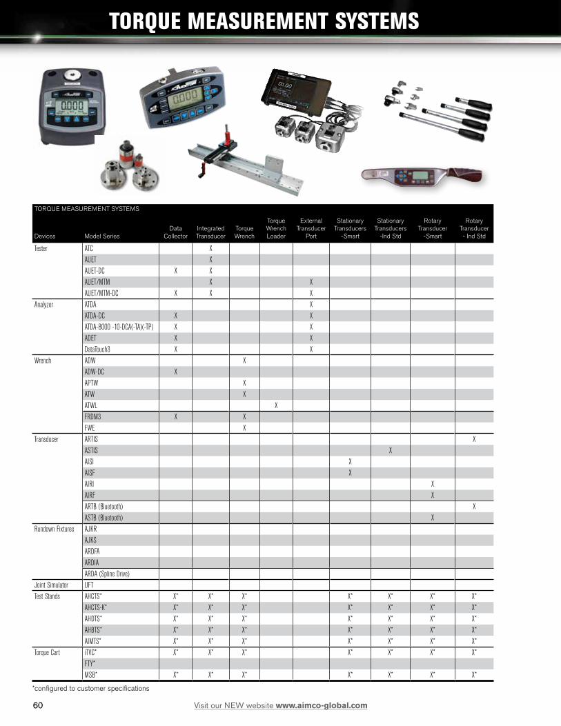
60
TORQUE MEASUREMENT SYSTEMS
Devices Model SeriesData
CollectorIntegrated Transducer
Torque Wrench
Torque Wrench Loader
External Transducer
Port
Stationary Transducers
-Smart
Stationary Transducers
-Ind Std
Rotary Transducer
-Smart
Rotary Transducer - Ind Std
Tester ATC XAUET XAUET-DC X XAUET/MTM X XAUET/MTM-DC X X X
Analyzer ATDA XATDA-DC X XATDA-8000 -10-DCA(-TA)(-TP) X XADET X XDataTouch3 X X
Wrench ADW XADW-DC XAPTW XATW XATWL XFRDM3 X XFWE X
Transducer ARTIS XASTIS XAISI XAISF XAIRI X AIRF XARTB (Bluetooth) XASTB (Bluetooth) X
Rundown Fixtures AJKRAJKSARDFAARDIAARDA (Spline Drive)
Joint Simulator UFTTest Stands AHCTS* X* X* X* X* X* X* X*
AHCTS-K* X* X* X* X* X* X* X*AHDTS* X* X* X* X* X* X* X*AHBTS* X* X* X* X* X* X* X*AIMTS* X* X* X* X* X* X* X*
Torque Cart iTVC* X* X* X* X* X* X* X*FTY*MSB* X* X* X* X* X* X* X*
*configured to customer specifications
TORQUE MEASUREMENT SYSTEMS
60 Visit our NEW website www.aimco-global.com

61
TORQUE MEASUREMENT: TESTERS
Features and Benefits
• Heavy Industrial Design
• All Software included
• Auditor Torque Testers are designed for intuitive and functional usability. AUET/MTM models are available with our unique dual integrated torque transducer package.
Testers are designed to audit torque wrenches and power tools, including pulse tools
ATC AUET AUET/MTM AUET-DC AUET/MTM-DCAuditor Torque Cube Auditor Universal
Electronic TesterAuditor Universal Electronic Tester - Multiple Transducer Module
Auditor Universal Electronic Tester - Data Collector
Auditor Universal Electronic Tester - Multiple transducer Module - Data Collector
Compact vertical or horizontal bench-mount tester.
Bench mount or line side tester utilizing integrated transducer.
Bench mount or line side tester with dual integrated transducer and external transducer capacity.
Bench mount or line side tester utilizing integrated transducer. Provides data collection capability with included software to interface with PC.
Bench mount or line side tester with dual integrated transducer and external transducer capacity. Provides data collection capability with included software to interface with PC.
Integrated Transducer Range (values are in full scale)
100 in/oz - 1,000 ft/lbs
1 - 1,350 Nm
100 in/oz - 750 ft/lbs
1 - 1,000 Nm
100 in/oz - 750 ft/lbs
1 - 1,000 Nm
100 in/Oz - 750 ft/lbs
1 - 1,000 Nm
100 in/oz - 750 ft/lbs
1 - 1,000 NmExternal Transducer Capacity (transducer sizes exceeding this range may be special ordered)
up to 5,000 ft-lbs up to 5,000 ft-lbs
Vertical / Horizontal Mount XBi-directional accuracy of +/- X of indicated reading within the top 90% of the Tester’s capacity
1% 0.50% 0.50% 0.50% 0.50%
Data Output to PC X X X X XIntegrated Torque Transducer 1 1 2 1 2External Transducer Port X XNumber of stored readings 999 999 999 999 999Adjustable rundown fixture included * 1 1 2 1 2Rechargeable NiMH Battery X X X X XMeasurement Modes Peak X X X X X First Peak (Click) X X X X X Pulse X X X X X Track X X X X XUnits of Measure Options 8 8 8 8 8Tool Manager Software Included X X
* Included with all testers and analyzers with a range up to 1000 in/lbs.
TORQUE MEASUREMENT TESTERS USED IN CONJUNCTION WITH
External Transducers ASTIS - Stationary X X ARTIS - Rotary X XSwitch box for External Transducer AISWT-4L > 4 Way Intellect box X X AISWT-6L > 6 Way Intellect box X XCables ICBL-USB - USB Serial > PC X X X X X ATDBLIS - IS Transducer w/angle (10 Pin) X X ATDBRIS - IS Transducer (4 Pin) X X ICBL-10P - Intellect transducer cable Identification chip in cable - 10 pin connector
X X
ICBL-4P - Intellect transducer cable. Identification chip in cable - 4 pin connector
X X
TORQUE MEASUREMENT TESTERS
61Visit our NEW website www.aimco-global.com

6262 Visit our NEW website www.aimco-global.com
AUDITORTM TORQUE CUBETM
MODEL MAX TORQUE WEIGHT W X H X D SQUARE DRIVENm in-lb kg lb mm in in
ATC-10 1.13 10 1.13 2.5 79 x 95 x 83 3.13 x 3.75 x 3.25 1/4
ATC-25 2.8 25 1.13 2.5 79 x 95 x 83 3.13 x 3.75 x 3.25 1/4
ATC-100 11.3 100 1.13 2.5 79 x 95 x 83 3.13 x 3.75 x 3.25 1/4
ATC-250 28.25 250 1.13 2.5 79 x 95 x 83 3.13 x 3.75 x 3.25 3/8
ATC-500 56.5 500 1.13 2.5 79 x 95 x 83 3.13 x 3.75 x 3.25 3/8
ATC-250F 339 250 ft-lb 2.25 5 79 x 95 x 83 3.13 x 3.75 x 3.25 1/2
ATC-750F 1017 750 ft-lb 2.25 5 79 x 95 x 83 3.13 x 3.75 x 3.25 3/4
AUDITOR™ TORQUE CUBE™
The Auditor Torque Cube (ATC) is a compact, versatile desktop tester and provides a multitude of capabilities. The ATC is designed to test hand or power tools with the following:
• Peak, first peak and track modes.• Multiple engineering units.• Manual and auto clear function.• Multiple frequency response settings.• Bi-directional use and accuracy.• Accuracy is better than 1% of indicated reading
top 90% of range. • Serial data output.• Memory 999 data samples.• Battery and/or mains powered.
Because precision and quality are critical, you can depend on our testers to calibrate and certify your tools. Whether you are assembling large complicated systems or small precise time pieces, AIMCO provides the best system for your application. Our instruments have been judged “best in class” by independent National Standards laboratories. The Auditor Torque Cube is rugged enough to test and verify tools at “point of use” while still being accurate enough to calibrate hand and power tools.
Each tester is shipped with a mains/battery charger power cord, a joint rundown fixture, a hex to allen drive bit and a bolting template. The ATC can be positioned vertically or horizontally for the ergonomic testing of inline or pistol grip tools.
ATC-250FATC-750F
ATC-10ATC-25ATC-100ATC-250ATC-500

63
AUDITOR™ UNIVERSAL ELECTRONIC TESTERS
The Auditor Universal Electronic Testers (AUET) have a broad range of features to accommodate most requirements. These instruments are designed to be bench top mounted and are available in several configurations and various single or multiple torque ranges. They are also available with file capability (DC) models. The DC models require PC software Auditor Tool Manager (ATM).
Instruments up to 1,000 in-lb are supplied with rundown adapters/joint kits. Rundown kits for larger instruments can be ordered separately. AUET/MTM units are supplied with an external transducer port and selector switch for connecting additional transducers.
These AUET instruments utilize the same transducers that are featured in the ATC instruments, providing the same high quality accuracy and durability. The common interface makes the Auditor tester extremely user friendly.
63Visit our NEW website www.aimco-global.com
AUDITORTM BENCH MOUNT TESTERS
RECOMMENDED TORQUE RANGE
MODEL** Transducer 1 Transducer 2 Transducer 1 Transducer 2
AUET/MTM-10-100(-DC) 1.0 - 10 in-lb 10 - 100 in-lb 0.11 - 1.12 Nm 1.3 - 11.3 Nm
AUET/MTM-50-250(-DC) 5.0 - 50 in-lb 25 - 250 in-lb 0.56 - 5.65 Nm 2.8 - 28.3 Nm
AUET/MTM-50-500(-DC) 5.0 - 50 in-lb 50 - 500 in-lb 0.56 - 5.65 Nm 5.65 - 56.49 Nm
AUET/MTM-100-500(-DC) 10 - 100 in-lb 50 - 500 in-lb 1.13 - 11.3 Nm 5.65 - 56.49 Nm
AUET/MTM-100-1000(-DC) 10 - 100 in-lb 100 - 1,000 in-lb 1.13 - 11.3 Nm 11.3 - 113 Nm
*Custom sizes are also available, please inquire. **Add “-DC” to part numbers for data collecting models.Data collecting models allow multiple files/tools/applications to be associated with torque data. Requires Tool Manager software.
DUAL TRANSDUCER MODELS
MODEL** RECOMMENDED TORQUE RANGE
AUET-0100(-DC) 10 - 100 in-oz 0.7 - 7.2 kgf-cm
AUET-10(-DC) 1 - 10 in-lb 1.1 - 11.5 kgf-cm
AUET-50(-DC) 5 - 50 in-lb 0.5 - 5.6 Nm
AUET-100(-DC) 10 - 100 in-lb 1.1 - 11.3 Nm
AUET-250(-DC) 25 - 250 in-lb 2.8 - 28.3 Nm
AUET-1000(-DC) 100 - 1,000 in-lb 11.3 - 113 Nm
AUET-1200(-DC) 120 - 1,200 in-lb 13.6 - 135.6 Nm
SINGLE TRANSDUCER MODELS
AUET/MTM-DC
AUET/MTM
AUET

6464 Visit our NEW website www.aimco-global.com
AUDITORTM TORQUE MEASUREMENT ANALYZERS
TORQUE MEASUREMENT: ANALYZERS
Features and Benefits
• Auditor Torque Analyzers share similar features across all products and are designed for intuitive and functional usability.
• Connects to AIMCO’s line of rotary and stationary transducers
ATDA ATDA-DC ATDA-8000 ATDA-8000-10-DCA(-TA)(-TP) ADET DataTouch3Auditor Torque Data Analyzer Auditor Torque Data Analyzer with Data Collection Auditor Torque Data Analyzer with 7” screen Auditor Torque Data Analyzer -10” display with Data Col-
lection. TA = Torque & Angle, TP = Torque & PressureAuditor Torque Data Analyzer with Data Collection Torque and Angle Data Collector designed to oper-
ate with SQnet softwarePortable analyzer to be connected to various transducers Portable analyzer to be connected to various transducers. Provides
data collection capability with included software to interface with PC7” screen with high resolution display and intui-tive user interface
10” touch screen with high resolution display and intuitive user interface with multiplexer
Portable with 2.8” touchscreen that displays graphical data with zoom/plot features and 1 GB memory
Portable with 2.8” touchscreen that displays graphical data with zoom/plot features and 1 GB memory
Bi-directional X X X X X XData Output to PC X X X X X XExternal Transducer Port 1 1 4 4 1 1Number of stored readings 999 999 999 999 20,000 20,000Rechargeable NiMH Battery X X X X X XDigital I/O for external devices X X X X X XMeasurement Modes X X X X X X Peak X X X X X X First Peak (Click)’ X X X X X X Pulse X X X X X X Track X X X X X XMeasurement Units 8 8 8 8 8 8Software Included X X X X X FirmwareLAB - Line Side Auditing X XSPC - Quality Control XBarcode Reader X X X XBluetooth Wireless Option X X
USED IN CONJUNCTION WITH
Transducers AISI / AISF - Digital X X ASTIS - Stationary X X ASTB - Stationary Wireless X X ARTIS - Rotary X X ARTB - Rotary Wireless X XWrenches ATW X X FWE X XSwitch boxes for External Transducers AISWT-4L > 4 Way Intellect box X X AISWT-6L > 6 Way Intellect box X XCables ICBL-USB - USB Serial > PC X X ATDBLIS - IS Transducer w/ angle (10 Pin) X X ATDBRIS - IS Transducer (4 Pin) X X ICBL-10P - Intellect transducer cable. Identification chip in cable - 10 pin connector X X ICBL-4P - Intellect transducer cable. Identification chip in cable - 4 pin connector X X ICBL-8000DIG - Connect from ATDA-8000 series analyzer to AISI / AIFI transducer X X RMC Cable DT.ET X X FWE Cable DT.ET X X

6565Visit our NEW website www.aimco-global.com
TORQUE MEASUREMENT: ANALYZERS
Features and Benefits
• Auditor Torque Analyzers share similar features across all products and are designed for intuitive and functional usability.
• Connects to AIMCO’s line of rotary and stationary transducers
ATDA ATDA-DC ATDA-8000 ATDA-8000-10-DCA(-TA)(-TP) ADET DataTouch3Auditor Torque Data Analyzer Auditor Torque Data Analyzer with Data Collection Auditor Torque Data Analyzer with 7” screen Auditor Torque Data Analyzer -10” display with Data Col-
lection. TA = Torque & Angle, TP = Torque & PressureAuditor Torque Data Analyzer with Data Collection Torque and Angle Data Collector designed to oper-
ate with SQnet softwarePortable analyzer to be connected to various transducers Portable analyzer to be connected to various transducers. Provides
data collection capability with included software to interface with PC7” screen with high resolution display and intui-tive user interface
10” touch screen with high resolution display and intuitive user interface with multiplexer
Portable with 2.8” touchscreen that displays graphical data with zoom/plot features and 1 GB memory
Portable with 2.8” touchscreen that displays graphical data with zoom/plot features and 1 GB memory
Bi-directional X X X X X XData Output to PC X X X X X XExternal Transducer Port 1 1 4 4 1 1Number of stored readings 999 999 999 999 20,000 20,000Rechargeable NiMH Battery X X X X X XDigital I/O for external devices X X X X X XMeasurement Modes X X X X X X Peak X X X X X X First Peak (Click)’ X X X X X X Pulse X X X X X X Track X X X X X XMeasurement Units 8 8 8 8 8 8Software Included X X X X X FirmwareLAB - Line Side Auditing X XSPC - Quality Control XBarcode Reader X X X XBluetooth Wireless Option X X
USED IN CONJUNCTION WITH
Transducers AISI / AISF - Digital X X ASTIS - Stationary X X ASTB - Stationary Wireless X X ARTIS - Rotary X X ARTB - Rotary Wireless X XWrenches ATW X X FWE X XSwitch boxes for External Transducers AISWT-4L > 4 Way Intellect box X X AISWT-6L > 6 Way Intellect box X XCables ICBL-USB - USB Serial > PC X X ATDBLIS - IS Transducer w/ angle (10 Pin) X X ATDBRIS - IS Transducer (4 Pin) X X ICBL-10P - Intellect transducer cable. Identification chip in cable - 10 pin connector X X ICBL-4P - Intellect transducer cable. Identification chip in cable - 4 pin connector X X ICBL-8000DIG - Connect from ATDA-8000 series analyzer to AISI / AIFI transducer X X RMC Cable DT.ET X X FWE Cable DT.ET X X
AUDITORTM TORQUE MEASUREMENT ANALYZERS

6666 Visit our NEW website www.aimco-global.com
AUDITORTM TORQUE DATA ANALYZERS
AUDITOR™ TORQUE DATA ANALYZERS
The Auditor Torque Data Analyzer (ATDA) DC is designed to be portable or conveniently placed on a bench. Depending on requirements, the tester can be connected to various transducers. In addition, it can be connected to transducerized wrenches, rotary or stationary transducers. The user interface is common between the ATC (Cube), AUET, AUET-DC, AUET/MTM, AUET/MTM-DC, ATDA, and ATDA-DC. All of these instruments have similar menus. Additionally, all data collector testers utilize Auditor Tool Manager for tool testing and data management.
The Auditor Torque Data Analyzer is available in two configurations:
• ATDA: A simple torque analyzer with sequential memory, 999 data samples, engineering limits, limited statistical processing average, range, Cp and CpK with serial output.
• ATDA-DC: Contains all of the features of the ATDA and has additional file capability. It can associate data with file names and manage data collection with a computer and Auditor Tool Manager software.
This is a great “starter” tool management system. It provides testing, archiving, and analysis of tools at single or multiple torque targets. The tool and torque data is stored in a SQL database and can be exported to Excel or any .csv spreadsheet.
MODEL DESCRIPTION
ATDA Auditor Torque Data Analyzer
ATDA-DC Auditor Torque Data Collector
ATDA-DC

6767Visit our NEW website www.aimco-global.com
Auditor offers the ATDA-8000 and the ATDA-8000-10-DCA(-TA)(-TP). The ATDA-8000 is a touch screen instrument with a high resolution display and user interface that facilitates “point of use” tool validation. The user interface is intuitive and the display provides clear easy to read data. Features and parameter settings are password protected to ensure parameters cannot be inadvertently changed. After initial setup, the instrument provides semi-automatic tool validation and judgment.
ATDA-8000
ATDA-8000-10-DCA(-TA)(-TP)
MODEL DESCRIPTION
ATDA-8000 Auditor Torque Analyzer Single channel 7” touch screen point of use validation system
ATDA-8000-10-DCA(-TA)(-TP) Auditor Torque Analyzer Multiple transducer 10” touch screen point of use validation system
AUDITORTM TORQUE DATA ANALYZERS
TOUCH SCREEN AUDITOR™ TORQUE DATA ANALYZERS
The ATDA-8000 is a single channel instrument – the ATDA-8000-10-DCA(-TA)(-TP) is a larger instrument that includes a multiplexor for connection to multiple transducers allowing a wide range of tools to be tested with one instrument. Both systems work with AIMCO’s line of digital transducers.

6868 Visit our NEW website www.aimco-global.com
AUDITORTM TORQUE DATA ANALYZER
Features and Benefits• Full-color touchscreen• Graphical display with zoom/plot features• Transducer auto-recognition• Bluetooth wireless (standard) • Advanced tightening strategies with easy input steps• Embedded firmware (Lab)• 1 GB memory• Li-Ion battery with 8 hour life• Available in two versions
- Basic - ADET - Advanced - ADETBAdvanced version connects with wireless transducers and printers, and exports data using system software.
Auditor Data Analyzer provides a simple way to control nutrunners and torque wrenches on the assembly line. This quick and simple data collector provides an economical alternative to the DataTouch Data Analyzer.
Specifications
Internal Memory: 1 GB
20,000 results, 20,000 curves, 1,000 programs
High-resolution 2.3” touchscreen, 320 x 240 pixels, 65,535 colors
ADET

6969Visit our NEW website www.aimco-global.com
DATATOUCH DATA ANALYZER
Features and Benefits• Full-color touchscreen• Graphical display with zoom/plot features• Transducer auto-recognition• Wireless and Bluetooth options • Keyboard for navigation and switching on/off• Advanced tightening strategies with easy input steps• Embedded firmware (LAB and SPC) targets all
operational functions• 1 GB memory• Li-Ion battery with 8 hour life• Optional bar code reader
DataTouch3 is a torque/angle data collector designed to operate with SQnet software. Test tightening tools by connecting stationary or rotary transducers. Test joints by connecting the FWE Wrench.
Specifications
Internal Memory: 1 GB
20,000 results, 20,000 curves, 1,000 settable programs
High-resolution 2.8” touch-screen, 320 x 240 pixels, 65,535 colors
DimensionsLength 215 mmWidth 144 mm (with battery cap)Depth 63 mmWeight 750 g + 90 g (belt)
Power Supply• Li-Ion changeable battery
3.6 V, 2700 mA• 9 hours battery life• 6 hours to recharge
battery by PC USB port• 4 hours to recharge
battery using external battery charger (optional)
Battery
SQnet software provides protection protocols and allows user to define routes linked to location and tool ID. User downloads events to wrench, performs tasks and sends results back that can be graphed or charted so that statistics can be analyzed.
DataTouch 3
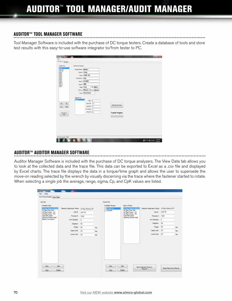
7070 Visit our NEW website www.aimco-global.com
AUDITORTM TOOL MANAGER/AUDIT MANAGER
AUDITOR™ TOOL MANAGER SOFTWARE
Tool Manager Software is included with the purchase of DC torque testers. Create a database of tools and store test results with this easy-to-use software integrator to/from tester to PC.
AUDITOR™ AUDITOR MANAGER SOFTWARE
Auditor Manager Software is included with the purchase of DC torque analyzers. The View Data tab allows you to look at the collected data and the trace file. This data can be exported to Excel as a .csv file and displayed by Excel charts. The trace file displays the data in a torque/time graph and allows the user to supersede the move-on reading selected by the wrench by visually discerning via the trace where the fastener started to rotate. When selecting a single job the average, range, sigma, Cp, and CpK values are listed.

71
TORQUE MEASUREMENT: HIGH CAPACITY TEST STANDS
Features and Benefits
• Advanced test stations for larger tools and higher torque output
• Configured to meet application requirements• Durable industrial grade devices
AHCTS AHCTS-K AHDTS AHBTS AIMTSAuditor High Capacity Test Stand
Auditor High Capacity Test Stand - Hydraulic
Auditor High Capacity Test Stand Dual Trans-ducer
Auditor High Capacity Stand w/variable joint simulation
Auditor High Capacity Impact Test Stand
Designed for testing tools with continuous rotating output spindles and pulse tools.
Specifically designed for hydraulic wrenches testing.
Two transducers, one for rotary tools and one for hydraulic tools. Includes rundown & reaction fixtures with a single display.
Designed for testing rotating tools without the use of rundown fixtures. Adjustable airbrake joint simulation eliminates CCW rotation after rundown.
Ideal for testing impact wrenches and is recommended to utilize rundown fixtures when testing impacts.
Capacity 6,750 Nm 33,750 Nm 33,750 Nm 6,750 Nm 2,700 Nm
ACCESSORIESRundown fixtures AHCTS-3/4RDF X X AHCTS-1RDF X X AHCTS-1.5RDF X XInsert Square Drive Adapters CA1510 1-1/2" Male to 1" Female X X X CA1550 1-1/2" Male to 1/2" Female X X X CA1575 1-1/2" Male to 3/4" Female X X X CA2510I 2-1/2" Male to 1" Female X X X CA2515I 2-1/2" Male to 1-1/2" Female X X X CA2575I 2-1/2" Male to 3/4" Female X X X CA150100DHD 1-1/2" Male to 1" Male Hex Dr X CA250108DHD 2-1/2" Male to 1-1/2" Male Hex Dr X
Please refer to the Test Stand Configurator in Appendix C on 94 for required ordering options.
71Visit our NEW website www.aimco-global.com
AUDITORTM HIGH CAPACITY TEST STANDS

7272 Visit our NEW website www.aimco-global.com
AUDITORTM HIGH-CAPACITY TEST STANDS
AHCTS TEST STANDS FOR ROTATING TOOLS
Designed for testing tools with continuous rotating output spindles. The test stand includes a rundown fixture, bushing for side load support, reaction post or reaction paddles, transducer and torque analyzer display.
AHCTS-K STANDS
The AHCTS-K stands are specifically designed for hydraulic wrench testing. Hydraulic wrenches have very low profiles but very high torque output, therefore, working height must be minimized to prevent side loading which could lead to errors in data or damage to tool or reaction devices.
Either stand can be ordered with options such as extension legs, casters, embedded or attached torque analyzers with various rundown fixtures and reaction devices. Contact an AIMCO Customer Service Associate for additional information, 1-800-852-1368.
MODEL DESCRIPTION
AHCTS-0500 ¾” Square Drive w/rundown fixture
AHCTS-1000 1” Square Drive w/rundown fixture
AHCTS-2500 1.5” Square Drive w/rundown fixture
AHCTS-5000 1.5” Square Drive w/rundown fixture
AHCTS-7500 1.5” Square Drive w/rundown fixture
AHDTS-5025* 1.5” Sq Dr dual station w/rundown fixture and reaction devices
*This stand has two transducers embedded into the base, one for rotary tools and one for hydraulic tools, and comes with rundown and reaction fixtures and one display.**Please refer to 94 for required ordering options.
MODEL DESCRIPTION
AHCTS-0.5K ¾” Square Drive w/reaction device
AHCTS-001K 1” Square Drive w/reaction device
AHCTS-2.5K 1.5” Square Drive w/reaction device
AHCTS-005K 1.5” Square Drive w/reaction device
AHCTS-010K 1.5” Square Drive w/reaction device
AHCTS-025K 2” Square Drive w/reaction device
Optional Pelican Case shown (ordered separately)
AHCTS-5000
AHCTS-001K
25503

7373Visit our NEW website www.aimco-global.com
AUDITORTM HIGH-CAPACITY TEST STANDS
AIMTS-0500Test stand for small impact tools
AIMTS-2000Test stand for large impact tools
AHBTS-2500Auto Release test stand for quickly testing large rotating tools
AHBTS STANDS
These test stands are for testing rotating tools without requiring the use of rundown fixtures. We utilize an airbrake for testing tools that cannot or should not be used in reverse. These test stands are compatible with any Auditor Torque Analyzer.
MODEL DESCRIPTION
AIMTS-0500 ¾” square drive impact test stand
AIMTS-2000 1.5” square drive impact test stand
MODEL DESCRIPTION
AHBTS-25001.5” square drive brake system w/reaction device, rotary transducer and display
AHBTS-50001.5” square drive brake system w/reaction device, rotary transducer and display
AIMTS STANDS
These test stands are designed to test impact wrenches, it is necessary to bolt them to a bench. We also recommend that a rundown fixture is always used for testing impacts. These test stands are compatible with any Auditor Torque Analyzer.
Please refer to the Test Stand Configurator in Appendix C on page 94 for required ordering options.

7474 Visit our NEW website www.aimco-global.com
AUDITOR™ TORQUE WRENCHES
TORQUE MEASUREMENT: TORQUE WRENCH
Features and Benefits• Multiple Options from
Simple to Sophisticated• Similar Interface with other
Auditor Products• Durable
ADW ADW-DC APTW ATW Freedom3 Digital Wrench
FWE
* Auditor Digital Wrench * Auditor Digital Wrench with Data Collection
Auditor Preset Torque Wrench
Auditor Torque Wrench Freedom3 Torque/Angle Wrench
Electric Torque Wrench
Torque Range 7 - 370 ft/lbs 10 - 500 Nm
7 - 370 ft/lbs 10 - 500 Nm
4 - 250 ft/lbs 5 - 340 Nm
4 - 148 ft/lbs 5 - 200 Nm
1.1 - 885 ft/lbs 1.5 - 1,200 Nm
1.1 - 885 ft/lbs 1.5 - 1,200 Nm
Digital wrench with multiple head options for line side testing/auditing
Digital wrench with multiple head options for line side testing/audit-ing. Data Collector
Interchangeable heads. Preset uses proprietary adjustment tool to guard against unauthorized setting changes
Transducer on a stick. Communicates with Data Collector Testers and Analyzers
Freedom3 offers a uniquely complete tightening solution with large color touchscreen and 1 GB of memory
Transducerized wrench communicates with DataTouch and ADEC Analyzers (required)
Bi-Directional accuracy of +/- X of indicated reading within the top 90% of the Tester’s capacity
1% 1% 3% 0.50% 1% 1%
Software Included X X X
USED IN CONJUNCTION WITH
ATDA(DC) Data Analyzer X
AUET(DC) Tester X
AUET/MTM(DC) Tester X
ADEC X
DataTouch3 Data Analyzer X
TORQUE WRENCH LOADERS
For Calibration of all types of torque wrenches eliminating human variable for more accurate measurement - digital transducer used with ATDA-8000-10-DCA
ATWL-250 Torque range up to 250 ft/lbs
ATWL-750 Torque range up to 750 ft/lbs
ATWL-1000 Torque range up to 1000 ft/bs
See Appendix B on page 94 to configure wrench with options.

7575Visit our NEW website www.aimco-global.com
AUDITORTM DIGITAL WRENCH SERIES
DATA COLLECTING MODELS
• Large memory capacity.
• Every torque value has associated trace file.
• “Pick a Point” and “Move On” feature.
• Barcode scanner.
• Alpha Numeric screen for entering text.
• Field replaceable batteries.
• Docking station connection.
• Serial connection.
• Battery charger connection.
• Ergonomic handle.
• Switch between measure and data collection modes at any time.
• Multiple files and route capability.
• Data memory and simple statistics “On Board”.
• Complete statistical analysis, data archiving and exporting in Audit Manager software.
• Five models standard ranges 10 - 500 Nm full scale.
• Torsion transducer — not length dependent.
• Transducer is replaceable.
• 1400 Nm model uses different handle design.
TORQUE RANGE WEIGHT OVERALL LENGTH SQ. DRIVE
MODEL NM FT-LB LB KG IN MM IN
ADW-0010K 1 - 10 0.7 - 7.4 2.2 1 18 457.2 1/4
ADW-0075K 7.5 - 75 5.5-55 3.1 1.4 23.5 596.9 3/8
ADW-0180K 18 - 180 13-130 3.6 1.6 30.1 765.2 1/2
ADW-0270K 27 - 270 20-198 3.6 1.6 30.1 765.2 3/4
ADW-0500K 50 - 500 37-369 4 1.8 36 914 1
ADW-1400F 140 - 1,400 103-1,033 4.8 2.2 60 1524 1 Unit accuracy is ± 1.0% FSD of indicated reading for the top 95% of full scale as indicated above.
Each model includes a case, a battery charger, and a standard square-drive head. Other heads are available at additional cost.*Part numbers with K, D or F followed by a 1 designate models with file and route capability. K followed by 2 indicate sequential memory no file capability. Part numbers with K, D or F followed by a 1,1 indicate file and route with bar code and docking station capability. K, D or F followed by a 1,2 indicate file and route capability with serial port only.
Please refer to the Wrench Configurator in Appendix B on page 92 for required ordering options.
ADW-0010K111312222
DOCKING STATION
• Nest for accepting all wrench sizes.
• Charger and serial communication accomplished through docking station.
• Bench mountable.ADW-DS

7676 Visit our NEW website www.aimco-global.com
AUDITORTM
ELECTRONIC TORQUE WRENCHES
“TRANSDUCERS ON A STICK”
• Non-Length Dependent – Where the operator’s hand is positioned during use has no effect on torque readings.
• Available in Industry Standard (IS) or Intelligent (Intellect) Configurations – Transducer is compatible with a wide variety IS style instruments or Auditor™ Intellect instruments that self recognize the transducer.
• Durable – Steel, Aluminum and Carbon Fiber construction providing optimal strength and weight characteristics. Transducer supplied with overload capacity of 150% of full scale.
• Accurate – Torque readings are accurate to 1% of indicated reading in top 95% of full scale.
TORQUE RANGE SQUARE DRIVE
MODEL Nm ft-lb in
ATW-0100F 14-136 10-100 3/8
ATW-0200F 27-272 20-200 1/2
ATW-0500F 68-680 50-500 3/4
ATW-1000F 136-1360 100-1000 1
Unit accuracy is ± 0.5% of indicated reading for the top 90% of full scale as indicated above. Required Accessory: ATDBRIS IS cable to connect AuditorTM ATDA instrument.
ALLOW PRECISE TIGHTENING AND AUDITING OF YOUR ASSEMBLY APPLICATIONS

7777Visit our NEW website www.aimco-global.com
AUDITORTM PRESET TORQUE WRENCHES
FEATURES AND BENEFITS
• Easy-to-use preset wrenches for fastener torque auditing.
• Torque ranges from 5-340 Nm.
• User friendly, sleek, ergonomic design.
• Tactile feedback on achievement of preset torque.
• Proprietary adjustment tool guards against unauthorized setting changes.
• Wide range of interchangeable heads provide flexibility and convenience.
• +/- 3% accuracy when used in clockwise or counterclockwise directions.
Preset Wrenches Description
APTW-25 Auditor Preset Torque Wrench, 5 - 25 Nm, Accepts 12 mm Inserts
APTW-50 Auditor Preset Torque Wrench, 10 - 50 Nm, Accepts 12 mm Inserts
APTW-100 Auditor Preset Torque Wrench, 20 - 100 Nm, Accepts 12 mm Inserts
APTW-150 Auditor Preset Torque Wrench, 30 - 150 Nm, Accepts 12 mm Inserts
APTW-200 Auditor Preset Torque Wrench, 40 - 200 Nm, Accepts 14 mm Inserts
APTW-340 Auditor Preset Torque Wrench, 60 - 340Nm, Accepts 14 mm Inserts
Ratchet and Square Drive Heads Description
APTH-12RT25 Auditor Preset Torque Wrench Ratchet Insert, 1/4 SQ DR, 12 mm
APTH-12RT38 Auditor Preset Torque Wrench Ratchet Insert, 3/8 SQ DR, 12 mm
APTH-12RT50 Auditor Preset Torque Wrench Ratchet Insert, 1/2 SQ DR, 12 mm
APTH-14RT50 Auditor Preset Torque Wrench Ratchet Insert, 1/2 SQ DR, 14 mm
APTH-14RT34 Auditor Preset Torque Wrench Ratchet Insert, 3/4 SQ DR, 14 mm
APTH-12SD25 Auditor Preset Torque Wrench SQ DR Insert, 1/4 SQ DR, 12 mm
APTH-12SD38 Auditor Preset Torque Wrench SD DR Insert, 3/8 SQ DR, 12 mm
APTH-12SD50 Auditor Preset Torque Wrench SQ DR Insert, 1/2 SQ DR, 12 mm
APTH-14SD50 Auditor Preset Torque Wrench SQ DR Insert, 1/2 SQ DR, 14 mm
Open End Heads Description
APTH-12OE7 Auditor Preset Torque Wrench Insert 7 mm OE, 12 mm
APTH-12OE8 Auditor Preset Torque Wrench Insert 8 mm OE, 12 mm
APTH-12OE9 Auditor Preset Torque Wrench Insert 9 mm OE, 12 mm
APTH-12OE10 Auditor Preset Torque Wrench Insert 10 mm OE, 12 mm
APTH-12OE11 Auditor Preset Torque Wrench Insert 11 mm OE, 12 mm
APTH-12OE12 Auditor Preset Torque Wrench Insert 12 mm OE, 12 mm
APTH-12OE13 Auditor Preset Torque Wrench Insert 13 mm OE, 12 mm
APTH-12OE14 Auditor Preset Torque Wrench Insert 14 mm OE, 12 mm
APTH-12OE15 Auditor Preset Torque Wrench Insert 15 mm OE, 12 mm
APTH-12OE16 Auditor Preset Torque Wrench Insert 16 mm OE, 12 mm
APTH-12OE17 Auditor Preset Torque Wrench Insert 17 mm OE, 12 mm
APTH-12OE18 Auditor Preset Torque Wrench Insert 18 mm OE, 12 mm
APTH-12OE19 Auditor Preset Torque Wrench Insert 19 mm OE, 12 mm
APTH-14OE13 Auditor Preset Torque Wrench Insert 13 mm OE, 14 mm
APTH-14OE14 Auditor Preset Torque Wrench Insert 14 mm OE, 14 mm
APTH-14OE15 Auditor Preset Torque Wrench Insert 15 mm OE, 14 mm
APTH-14OE16 Auditor Preset Torque Wrench Insert 16 mm OE, 14 mm
APTH-14OE17 Auditor Preset Torque Wrench Insert 17 mm OE, 14 mm
APTH-14OE18 Auditor Preset Torque Wrench Insert 18 mm OE, 14 mm
APTH-14OE19 Auditor Preset Torque Wrench Insert 19 mm OE, 14 mm
APTH-14OE21 Auditor Preset Torque Wrench Insert 21 mm OE, 14 mm
APTH-14OE22 Auditor Preset Torque Wrench Insert 22 mm OE, 14 mm
APTH-14OE24 Auditor Preset Torque Wrench Insert 24 mm OE, 14 mm
APTH-14OE27 Auditor Preset Torque Wrench Insert 27 mm OE, 14 mm
APTH-14OE30 Auditor Preset Torque Wrench Insert 30 mm OE, 14 mm
APTH-14OE32 Auditor Preset Torque Wrench Insert 32 mm OE, 14 mm
APTH-14OE34 Auditor Preset Torque Wrench Insert 34 mm OE, 14 mm
APTH-14OE36 Auditor Preset Torque Wrench Insert 36 mm OE, 14 mm
APTH-14OE38 Auditor Preset Torque Wrench Insert 38 mm OE, 14 mm
APTH-14OE41 Auditor Preset Torque Wrench Insert 41 mm OE, 14 mm

7878 Visit our NEW website www.aimco-global.com
SCS WRENCHES
TORQUE MEASUREMENT: SCS WRENCHES
Features and Benefits• Torque and Angle Measurement• Wireless Communication (optional)• Use as a production wrench or for quality control with
high-resolution touch screen display storing data points and curves for quick viewing or transfer to PC
Freedom3 DIGITAL WRENCH FWE TA FWE
Torque Range 11 - 740 ft/Lbs 15 - 1000 Nm 11 - 740 ft/Lbs 15 - 1000 Nm 11 - 740 ft/LbS 15 - 1000 Nm
Performance/Display 1GB Memory stores 20,000 values / 20,000 curves / 1,000 parameter sets, 80 Mips CPU, 32-Bit processor
HiRes 2.3” Touch-screen display, 320 x 240 pixel resolution
Li-lo rechargeable battery 3.6V 2700mAh, 9 hrs charge
— —
Bi-directional Measurement accuracy of + / - .5% in top 80% of range1.0% in top 90% of range0.1% display deviation of angle
— —
Firmware
LAB: Use when storing results including curves on wrench. These results can be downloaded to PC via F3 Explorer
X X X
SPC: Jobs and routes are developed for QC and Production via SQnet and downloaded/uploaded to/from wrench
X X
PRW: Used as production tool - communicating on-line via radio, BT or Wi-Fi where results are published in real time using VPG software
X
Software
F3 Explorer: Collects data results/curves > edit/export to Excel X X
SQnet: Transfers jobs and routes data to/from device to PC X X
VPG: Real time data transfer via wireless communication X
Options (must include with tool purchase)
Barcode Reader Integrated (optional) X
Bluetooth Module Integrated Beneficial in PRW mode to communicate with VPG Software
X
WiFi Module Integrated Beneficial in PRW mode to communicate with VPG Software
X
ACCESSORIES
Battery Cradle X
USB Cable X
External Battery Charger X
Body Jacket X
WRENCH USED IN CONJUNCTION WITH
DataTouch X X
EasyTouch X
FREEDOM RATCHETS AND SOCKETS
Reversible ratchet X X X
Open end ratchet X X X
Ring end ratchet X X X
Ring open X X X
Recognition chip option X X X

7979Visit our NEW website www.aimco-global.com
SCS FREEDOM3 WRENCH
Features and Benefits• Full-color 2.8” touchscreen provides a graphical
display with zoom/plot features.• Vibration and LED visual queues• Create a tightening strategy on the wrench.• Capable of communicating with PLC and system network• Auto-recognition of insert head (optional)• Docking station• Bar Code Reader (optional)• Wireless technology (optional)• Advanced tightening strategies with
easy input steps• Embedded firmware targeting all operational functions Lab analysis (LAB), Quality (SPC), Production (PRW)• Highly functional software options• Simple flexibility with end effectors• Programmable or self recognizing length/torsion adjustments
ensure accurate measurements with any custom attachment.• Large internal memory• Long battery life
Capacity Drive L1* L2* Weight*Model Nm Ft-Lb mm mm mm lb kg
FRDM3-15 15 11 9 x 12 female 375 393 1.8 0.8
FRDM3-30 30 22 9 x 12 female 375 393 1.8 0.86
FRDM3-70 70 52 9 x 12 female 480 498 2.1 0.93
FRDM3-100 100 74 9 x 12 female 480 498 2.1 0.93
FRDM3-200 200 148 14 x 18 female 604 629 3.3 1.5
FRDM3-300 300 222 14 x 18 female 754 779 4.1 1.86
FRDM3-400 400 296 14 x 18 female 754 779 4.1 1.86
FRDM3-600 600 444 14 x 18 female 1,032 1,057 8.0 3.65
FRDM3-800 800 592 Ø20 male 1,250 1,330 11.2 5.1
FRDM3-1000 1000 740 Ø20 male 1,520 1,610 13.8 6.25
FRDM3-1200 1200 885 Ø28 SA female 1,732 1,578 15.4 7.0
* without ratchet Call for quote on devices with larger capacitiesFRDM3 models include predisposition for battery cradle and auto recognition of inserted socket on wrench
L1
L213 mm
66 m
m
The Freedom3 Wrench offers a uniquely complete tightening solution. Its patented angle measuring system, large color touchscreen, and internal 1 GB memory, make it the best performing and flexible torque/angle wrench on the market.
Specifications
Capacity 1.5–1,200 Nm (90% of full scale)Output 1GB memory stores 20,000 Values
with Curves over 1,000 Parameter sets
Repeatability Torque +/- 1% accuracy when used in top
90% of wrench range.Angle +/- 0.1% display deviation of angle

8080 Visit our NEW website www.aimco-global.com
SCS FREEDOM3 WRENCH
With the SCS Freedom3 Wrench, tightening strategies can be monitored using techniques designed to minimize joint elongation of typical breakaway testing. New breakaway methods employ an algorithm to protect real breakaway point and produce similar results regardless of operator influence.
Tightening StrategiesSPC Quality Inspection• Breakaway Angle
Preset angle 1–4° and wrench will return torque value reached at the specified angle of rotation
• Smart Breakaway Angle Preset angle but returns either First Peak or Residual Torque values. See graphs of typical hard and soft joint curves
• Breakaway Open/Close Rotate joint CCW a specific degree of angle then retighten CW the same rotation value to move bolt back to original position. Wrench returns torque value at the preset rotation parameter
• Minimum Torque Validate that the joint meets established torque parameter by setting angle rotation value Wrench returns pass/fail value
LAB Quality Inspection• Joint Analysis
Wrench will sense yield point and produce joint curves and save as yield torque, yield angle, max torque and angle at max torque
Smart Breakaway Graph
Typical Hard Joint
Joint Analysis Graph
Choose testing method ➠ Test joint ➠ View torque/time, torque angle graphs on wrench
Transfer data where applicable.
➠
Smart Breakaway Graph
Typical Soft Joint

8181Visit our NEW website www.aimco-global.com
SCS FWE/FWETA ELECTRONIC WRENCH
Features and Benefits• Advanced tightening strategies with easy input steps• Measure torque and torque/angle.• Utilize SQNet and F3 Explorer software.• Extended range covering 1.5 to 1,000 Nm. Other capacities
on request.• Available with internal memory for automatic recognition
when connected to the DataTouch3.• Standard end-fittings 9 x 12 or 14 x 18 allow the use of
standard bits.
The FWE Wrench is an economic alternative to the Freedom3 Wrench. FWE utilizes the same high-quality firmware/software programs and can be cabled to several analyzer options.
Specifications
Capacity 1.5–1,000 Nm (wrenches capable of function within top 90% of full scale)
Model FunctionFWE TA Torque/AngleFWE Torque only
Capacity Drive
Model Nm ft-lb in
Freedom FWE(TA) 15 15 11 9 x 12
Freedom FWE(TA) 30 30 22 9 x 12
Freedom FWE(TA) 70 70 52 9 x 12
Freedom FWE(TA) 100 100 74 9 x 12
Freedom FWE(TA) 200 200 148 14 x 18
Freedom FWE(TA) 300 300 222 14 x 18
Freedom FWE(TA) 400 400 296 14 x 18
Freedom FWE(TA) 600 600 444 14 x 18
Freedom FWE(TA) 800 800 592 ø20
Freedom FWE(TA) 1000 1,000 740 ø20
Call for quote on devices with larger capacities
Use in conjunction with
DataTouch3 Analyzer FWE TA or FWE
Auditor Torque Data Analyzer FWE
✚

8282 Visit our NEW website www.aimco-global.com
TORQUE MEASUREMENT: TORQUE CARTS
Features and Benefits
• Test on repeatable joint simulators or production joints
• Simple to sophisticated options
• Manual or self-propelled
• Mobile test carts can be configured for testing continuous and discontinuous drive tools that include DC electric, clutch, battery, impulse, and torque wrenches
• Each cart is customizable to meet testing needs from 1 - 1,356 Nm
Contact your AIMCO representative for a quote or more information iTVC FTY MSB
Hydraulic Braking Technology• Dry braking with multiple hydraulic cylinders where thrust is generated
equally to allow better linear control of the braking ramp• Programmable joint characteristics for use with continuous drive tools - no
unwinding required after testing
X
UFT Repeatable Joint Simulator• Mechanically adjustable hydraulic pressure circuits allow the bolt tightening
body to be configured to simulate various joint characteristics• Ideal for repeatable, linear joint rate simulation while testing all tools
including impulse tools
X X* X*
DataPro Software X X X
Torque Wrench Loader Option X X X
* Optional equipment - extension added to cart
TORQUE CARTS
AUDITOR TORQUE CARTAIMCO offers torque carts for “lineside” or “point of use“ tool validation and calibration. Our torque carts allow testing of tools on repeatable joint simulators and “in process” use on production joints, allowing users to identify process capability. There are multiple torque cart options:
• Manual push carts equipped with simple torque testers.
• Manual push carts equipped with data collectors and database application software.
• Self propelled cart with computer and relational database application.
• Driven cart with computer and relational database application.
Each cart can be equipped to specific customer requirements. Maximum torque range on board torque cart is 1000 ft-lb or 1,356 Nm. Ancillary test stands up to 50,000 ft-lb available.
iTVC Torque Cart

8383Visit our NEW website www.aimco-global.com
SCS TORQUE CART
Features and Benefits• ISO 5393, VDI 2862, ISO 6789, VDE 2647• Sophisticated DataPro software• Time saving testing of tools with the same tightening
strategy as used on production line• Comparative test analysis• Lightweight
High-precision torque carts able to simulate a fastener in all conditions
Specifications
• USB interface• Sampling frequency of up to 30 kHz with settable filter
up to 3 kHz• Accuracy of 0.5% within top 90% of full scale• Tests power tools up to 1,356 Nm
FTY Torque Cart
MSB Torque Cart
The FTY Torque Cart includes all of the features and benefits of the MSB Torque Cart, plus hydraulic braking technology for better linear control of the braking ramp.

8484 Visit our NEW website www.aimco-global.com
TORQUE CART DATAPRO + SQNET SOFTWARE
As the data management system for the AIMCO Torque Cart line, DataPro and SQnet software provides tool management, verification and calibration applications. Users can manage their complete tool inventory, create jobs / routes and store collected data. Calibration sequencing can be scheduled by time or number of rundowns.
TORQUE VERIFICATION DataPro displays sample values of torque, angle and pulse count. It calculates statistics: average, Cp, Cpk, Six Sigma and Mean variation. As values are measured they are graphically plotted on a X-bar range chart scaled to specification limits.
DATABASE INFORMATIONThese screens show Operation lists and associated tools along with the historic test or quality data recorded. From the historic data screen you can launch statistical graphs to view and analyze archived data. The graphs include X-bar range, histogram, Six Sigma, Cp & Cpk graphs.
TRACESThe axis of the traces can be torque/time, torque/angle, angle/time,. You can save a trace, retrieve it and overlay a new trace for comparison. The trace details are displayed at the bottom of the graph. Maximum values, plot time (ms), number of data points, filter frequency and sample rate.

8585Visit our NEW website www.aimco-global.com
TRANSDUCERS
Stationary Transducers with joint rundown fixtures and, where applicable, bench stands.
STATIONARYTRANSDUCER
MAX TORQUE WEIGHT W X H X D DRIVE
Nm in-lb/ft-lb kg lb mm in in
AISI-200025 2.8 25 1.13 2.5 79 x 95 x 83 3.13 x 3.75 x 3.25 1/4
AISI-200100 11.3 100 1.13 2.5 79 x 95 x 83 3.13 x 3.75 x 3.25 1/4
AISI-200500 56.5 500 1.13 2.5 79 x 95 x 83 3.13 x 3.75 x 3.25 3/8
AISF-200100 135.6 1,200/100 2.25 5 100 x 65 4 x 3 1/2
AISF-200250 339 3,000/250 2.25 5 100 x 65 4 x 3 1/2
AISF-201000 1350 12,000/1,000 2.8 6 100 x 65 4 x 3 1
TORQUE MEASUREMENT: TRANSDUCERS
Features and BenefitsSuperior: • Accuracy• Compatibility• DurabilityAuditor offers multiple styles of transducers in various configurations. Industry standard transducers (2mv/v) and intellect transducers for Auditor instruments that reduce configuration set up time.
Please contact our Customer Service Associates for additional information, 1-800-852-1368.
Stationary Rotary
ASTIS AISI - AISF ASTB ARTIS ARTB
Auditor Stationary Trans-ducer Industry Standard
Auditor Industry Standard Stationary
Auditor Stationary Transducer Industry Standard Bluetooth
Auditor Rotary Transducer Industry Standard
Auditor Rotary Trans-ducer Industry Standard Bluetooth
Used in Conjunction with Analyzers
ATC X X
AUET X X
AUET/MTM X X
ATDA X X
ATDA-8000 X
ADET X X X
DataTouch3 X X X
See Appendix A on page 92 to configure complete part.
STATIONARY MAX TORQUE DRIVETRANSDUCER Nm in-lb/ft-lb in
ASTIS-25D-11 11 100 in-lb 1/4
ASTIS-25D-28 28 250 in-lb 1/4
ASTIS-38D-135 135 100 ft-lb 3/8
ASTIS-50D-270 270 200 ft-lb 1/2
ASTIS-75D-1000 1017 750 ft-lb 3/4
ASTIS-100D-1700 1695 Nm 750 ft-lb 1
AUDITOR™ STATIONARY TRANSDUCERS
AISI
ASTIS
ASTB
STATIONARY MAX TORQUE DRIVETRANSDUCER Nm in-lb/ft-lb in
ASTB-75R-10P 10 7.4 3/4
ASTB-75S-10C 10 7.4 3/4
ASTB-75R-50P 50 36.8 3/4
ASTB-75S-50C 50 36.8 3/4
ASTB-75R-100P 100 73.6 3/4
ASTB-75R-250P 250 184 3/4
ASTB-75R-500P 500 369 3/4
ASTB-75R-1000P 1000 737 3/4
ASTB-75R-2500P 2500 1844 3/4
R= spline drive for pulse tool, S= square drive for con-tinuous drive tools, Bluetooth

8686 Visit our NEW website www.aimco-global.com
AUDITORTM TRANSDUCERS
MAX TORQUE LENGTH THICKNESS WIDTH WEIGHT
MODEL DRIVE Nm in-lb/ft-lb (A) (B) (C) lb
ARTIS-25H-2T(A) 1/4 Hex 2 18 in-lb 4.6 1.1 2.2 1.0
ARTIS-25H-5T(A) 1/4 Hex 5 44 in-lb 4.6 1.1 2.2 1.0
ARTIS-25H-20T(A) 1/4 Hex 20 180 in-lb 4.6 1.1 2.2 1.0
ARTIS-25S-10T(A) 1/4 Sq. 10 88 in-lb 2.9 1.1 2.2 1.0
ARTIS-38S-75T(A) 3/8 Sq. 75 50 ft-lb 3.0 1.6 2.7 1.2
ARTIS-50S-180T(A) 1/2 Sq. 180 130 ft-lb 3.4 1.6 2.7 1.5
ARTIS-75S-500T(A) 3/4 Sq. 500 370 ft-lb 4.1 2.0 3.1 2.2
ARTIS-100S-1400T(A) 1 Sq. 1400 1025 ft-lb 4.9 2.4 3.6 4.0
*Add “A” to the end of the part number to indicate torque/angle transducer.
AUDITOR™ ROTARY TRANSDUCERS
STATIONARY DRIVE MAX TORQUETRANSDUCER in Nm in-lb/ft-lb
ARTB-25H-2TA 1/4 Hex 2 1.4
ARTB-25H-5TA 1/4 Hex 5 3.7
ARTB-25S-10TA 1/4 Sq. 10 7.4
ARTB-25S-20TA 1/4 Sq. 20 14.7
ARTB-38S-25TA 3/8 Sq. 25 18.4
ARTB-38S-75TA 3/8 Sq. 75 55.3
ARTB-50S-180TA 1/2 Sq. 180 133
ARTB-75S-250TA 3/4 Sq. 250 184
ARTB-75S-500TA 3/4 Sq. 500 369
ARTB-100S-1400TB 1” Sq. 1400 1032
ARTB-150S-3000TB 1-1/2 Sq. 3000 2213
ARTB-150S-5000TA 1-1/2 Sq. 5000 3688
Bluetooth, Torque / Anlge

8787Visit our NEW website www.aimco-global.com
TORQUE MEASUREMENT RUNDOWN FIXTURES / JOINT SIMULATORS
RUNDOWN FIXTURE
MODEL SERIESWEAR RESISTANT
HEAVY DUTY
HEAVY DUTY FULLY
ENCAPSULATED
HEAVY DUTY ENCAPSULATED
WASHERS
STANDARD (INCLUDED W/
ANALYZER) SPLINE DRIVE
ARDIA-XXXHD X
ARDFA-XXXXHD X
ARDFA-XXXHDS X
ARDIA-XXXHDS X
ARDFA-XXXHDE X
ARDIA-XXXHDE X
ARDFA-XXX X
ARDIA-XXX X
ARDA-XXX X X X*
Fixtures can be ordered to simulate hard, med, or soft jointsMechanical Belleville system of bolt, nut or nut body, Belleville washers and main housing, 1/4” - 3/4” drive sizes, 10 in/lbs - 1,200 ft/lbs*Spline drive feature provides rundown control when testing pulse tools
Rundown Fixtures used in conjunction with these external transducers: ASTIS AISI-AISF ARTIS ASTB ARTB
ARDIA/ARDFA X X X X
ARDA X X
AJKS X X
AJKR X X
UFT X X
JOINT SIMULATOR
AJKR- Joint Kit for Rotary Transducer
AJKS- Joint Kit for Stationary Transducer
Provide linear response and are repeatable 1/4” - 1” drive sizes 28 - 1,695 Nm
HYDRAULIC MECHANICAL JOINT SIMULATOR
UFT SERIES
Accurate, repeatable, linear, and durable. Tests 3 - 690 Nm, M5 - M24 fastener sizes
See page 89.
Design Type: Power Tools Impulse Tools
Square drive X
Spline Drive X

8888 Visit our NEW website www.aimco-global.com
TORQUE MEASUREMENT RUNDOWN FIXTURES / JOINT KITS
AUDITOR™ RUNDOWN FIXTURES
To test power tools, pneumatic or electric, consistent rotational speed must be achieved. The joint rundown fixture/simulator provides the means by which the tool motor and spindle rotates freely at the start of the test cycle and then develops torque as resistance to rotation increases as load on the fastener and joint increases. The linearity and consistency of the joint rundown fixtures/simulators vary greatly and the tool test data is a product of the variations in these rundown fixtures. Higher quality joint rundown fixtures produce torque data with less scatter.
HDS Series
RECOMMENDED TORQUE RANGEMODEL* DESCRIPTION IN-LB Nm SQUARE DRIVE
ARDIA-10(HD)(HDE)(HDS) Rundown Fixture 1.0 - 10 .13 - 1.13 1/4
ARDIA-25(HD)(HDE)(HDS) Rundown Fixture 2.5 - 25 .28 - 2.8 1/4
ARDIA-100(HD)(HDE)(HDS) Rundown Fixture 10.0 -100 1.3 - 11.3 1/4
ARDIA-250(HD)(HDE)(HDS) Rundown Fixture 25.0 - 250 2.8 - 28.25 3/8
ARDIA-500(HD)(HDE)(HDS) Rundown Fixture 50.0 - 500 5.6 - 56.5 3/8
* Add “HD” to part numbers for wear resistant models. Add “HDS” to part numbers for fully encapsulated wear resistant models.* Add “HDE” to part numbers for partial encapsulated wear resistant models.
RECOMMENDED TORQUE RANGEMODEL* DESCRIPTION IN-LB Nm SQUARE DRIVE
ARDFA-100(HD)(HDE)(HDS) Rundown Fixture 10 - 100 13.6 - 136 1/2
ARDFA-150(HD)(HDE)(HDS) Rundown Fixture 15 - 150 20.4 - 204 1/2
ARDFA-250(HD)(HDE)(HDS) Rundown Fixture 25 - 250 34.0 - 340 1/2
ARDFA-600(HD)(HDE)(HDS) Rundown Fixture 60 - 600 81.6 - 816 3/4
* Add “HD” to part numbers for wear resistant models. Add “HDS” to part numbers for encapsulated wear resistant models.* Add “HDE” to part numbers for partial encapsulated wear resistant models.
Rundown fixtures for heavy duty use.
DRIVE SIZE - IN ROTARY KIT PART NUMBER STATIONARY KIT PART NUMBER
1/4 AJKR-28 AJKS-25D
3/8 AJKR-135 AJKS-38D
1/2 AJKR-271 AJKS-50D
3/4 AJKR-1017 AJKS-75D
1 AJKR-1695 AJKS-100D
JOINT KITS
HD SeriesHDE Series

8989Visit our NEW website www.aimco-global.com
UFT SERIES JOINT SIMULATORS
UFT SERIES JOINT SIMULATORS
• AIMCO’s UFT Joint Simulators offer the most repeatable and linear joint rate simulation of any product on the market.
• Pulse tool and continuous drive tool certification and testing.
• Consists of a bolt tightening body and a hydraulic pressure loading mechanism. A hydraulic pressure circuit connects these two bodies. Ideal for ISO 5393 test procedures.
• Three joint rates can be easily and quickly simulated by opening or closing two external valves.
• Specially coated testing bolt produces over 100,000 cycles without variation or deformation.
BOLT
TORQUE RANGE
SNUG TORQUE
A-JOINT RATE
B-JOINT RATE
C-JOINT RATE
D-JOINT RATE
CENTER TO OUTSIDE X HEIGHT WEIGHT
MODEL SIZE FT-LB NM NM NM/DEG NM/DEG NM/DEG NM/DEG MM LB KG
UFT-S10 M6 5 - 11 6.7 - 14.7 2.7 0.36 0.10 0.04 0.02 76 x 203 43 19.5
M8 11 - 23 14.7 - 31.4 7.5 0.79 0.26 0.06 0.03
M10 23 - 40 31.4 - 53.9 14.9 1.22 0.35 0.09 0.06
UFT-S16 M12 40 - 65 53.9 - 88.2 27.5 1.80 0.51 0.22 0.09 97 x 256 88 40
M14 65 - 110 88.2 - 149 44.0 2.70 0.79 0.22 0.14
M16 110 - 140 149 - 190 73.5 4.70 1.22 0.35 0.21
UFT-24* M18 140 - 217 190 - 294 138 x 171 108 49.1
M20 217 - 325 294 - 441
M24 325 - 506 441 - 686
* UFT-24 medium hard/soft joints onlyReaction fixture for continuous drive tools not included. Sockets included.
UFT-24
UFT-S10 UFT-S16

9090 Visit our NEW website www.aimco-global.com
TORQUE MEASUREMENT: CABLES
MODEL
SERIAL CABLE TRANSDUCER CABLE ROTARY ROTARY W/ANGLE STATIONARY IND STD INTELLECT
1 ICBL-USB X
2 ATDBLIS X X X
3 ATDBRIS X X X X
4 ICBL-10P X X X
5 ICBL-4P X X X X
6 ICBL-8000DIG X
7 RMC Cable DT.ET X X X X
8 FWE Cable DT.ET X
Cables 1-5 are compatible with ATDA, AUET, ADW products1. Connects between comport of display to PC2. Connect to IS transducer w/ angle - 10 pin3. Connect to IS transducer - 4 pin4. Intellect transducer cable. Identification chip in cable - 10 pin connector5. Intellect transducer cable. Identification chip in cable - 4 pin connector6. Connect from ATDA-8000 series analyzer to AISI / AIFI transducer7. Connect from DataTouch3 / ADET analyzer to ARTB/ARTS transducers8. Connect from DataTouch3 / ADET analyzer to FWE Wrenches
ATDBLISICBL-USB
CABLES
TORQUE MEASUREMENT CABLES
CABLE COMPATIBILITY
ATC AUET AUET/ MTM
AUET- DC
AUET/ MTM-DC
ATDA ATDA- DC
ATDA- 8000
ATDA-8000-10- DCA(-TA)(-TP)
ADW ADW- DC
FWE AEDT DataTouch
ICBL-USB X X X X X X X X X
ATDBLIS X X X X X X
ATDBRIS X X X X X X
ICBL-10P X X X X X X
ICBL-4P X X X X X X
ICBL-8000DIG X X
RMC Cable DT.ET X X
FWE Cable DT.ET X

9191Visit our NEW website www.aimco-global.com
NOTES

9292 Visit our NEW website www.aimco-global.com
APPENDICES
APPENDIX A: TRANSDUCER CONFIGURATOR
Base Model Number (1-9) Future Options (15-18)
Model Number Columns 1 2 3 4 5 6 7 8 9 10 11 12 13 14 15 16 17 18
Examples of part numbersA D W - 0 0 7 5 K 1 1 3 3 1 2 2 2 2
A D W - 0 0 1 0 K 1 1 1 3 2 2 2 2 2
A T W - 0 2 0 0 F 2 2 3 1 2 2 2 2 2
Wrench Options and Configuration Auditor Type Wrench Capacity Style Data
CollectorBar Code
Docking Station Sq Dr Configuration Engineering Unit Angle Accelerometer Graphics Tone
Generator
D = Digital
T = Transducer
K = Katana D = Katana w/dovetail transducer F = “Stick” straight handle
1 = Yes
2 = No
1 = Yes
2 = No
1 = 1/4”
2 = 3/8”
3 = 1/2”
4 = 3/4”
5 = 1”
6 = NA
1 = Intellect (intelligent td)
2 = IS (industry standard)
3 = NA (digital wrench)
1 = NM
2 = ft lb
3 = in lb
1 = Yes
2 = No
1 = Yes
2 = No
1 = Yes
2 = No
1 = Yes
2 = No
Not yet available so always enter 2 (No) for these options.
Base model number (first 9 characters) describes Auditor, Type; Digital or Transducer, Capacity, Style; Katana, Katana w/Dovetail transducer or Stick.
To complete configuration of a 18 character part number select options and configuration sequentially from column 1 through 18. Columns 5-8 specify torque capacity.
The base model number is not a complete part number, - Data Collector, Bar Code & Docking Station, Sq Dr, Configuration, Engineering Unit and Future Options must be specified by completing 18 character part number.
Base Model Number (1-11)
Model Number 1 2 3 4 5 6 7 8 9 10 11 12 13 14 15
Examples of part numbers
A I S I - 2 0 0 0 5 0 1 2 1 2
A I S F - 2 0 0 7 5 0 1 2 1 5A X R N - 1 0 0 1 8 0 2 2 2 4
Transducer Options and Configuration Auditor Configuration Type Units Angle Capacity Fixture Expanded Range Digital Transducer Drive Size
I = Intellect
X = Industry Standard
R= Rotary
S = Stationary
W = Wireless
I = in lb
F = ft lb
N = NM
1 = Yes
2 = No
1 = Bench Stand
2 = Inline
3 = Loader
1 = Yes
2 = No
1 = Yes
2 = No
1 = 1/4” Hex
2 = 1/4” Sq
3 = 3/8” Sq
4 = 1/2” Sq
5 = 3/4” Sq 6 = 1” Sq
7 = 1-1/2” Sq
Base model number (first 11 characters) describes Auditor, Configuration Intellect or Industry Standard, Type Rotary, Stationary or Wireless, Engineering Units In Lb, Ft Lb or NM, Angle Yes or No and Capacity.
To complete configuration of a 15 character part number select options and configuration sequentially from column 1 through 15. Columns 7-11 specify torque capacity.
The base model number is not a complete part number, - Fixture, Expanded Range, Digital Transducer and Drive Size must be specified by building complete part number.
APPENDIX B: WRENCH CONFIGURATOR

9393Visit our NEW website www.aimco-global.com
Base Model Number (1-9) Future Options (15-18)
Model Number Columns 1 2 3 4 5 6 7 8 9 10 11 12 13 14 15 16 17 18
Examples of part numbersA D W - 0 0 7 5 K 1 1 3 3 1 2 2 2 2
A D W - 0 0 1 0 K 1 1 1 3 2 2 2 2 2
A T W - 0 2 0 0 F 2 2 3 1 2 2 2 2 2
Wrench Options and Configuration Auditor Type Wrench Capacity Style Data
CollectorBar Code
Docking Station Sq Dr Configuration Engineering Unit Angle Accelerometer Graphics Tone
Generator
D = Digital
T = Transducer
K = Katana D = Katana w/dovetail transducer F = “Stick” straight handle
1 = Yes
2 = No
1 = Yes
2 = No
1 = 1/4”
2 = 3/8”
3 = 1/2”
4 = 3/4”
5 = 1”
6 = NA
1 = Intellect (intelligent td)
2 = IS (industry standard)
3 = NA (digital wrench)
1 = NM
2 = ft lb
3 = in lb
1 = Yes
2 = No
1 = Yes
2 = No
1 = Yes
2 = No
1 = Yes
2 = No
Not yet available so always enter 2 (No) for these options.
Base model number (first 9 characters) describes Auditor, Type; Digital or Transducer, Capacity, Style; Katana, Katana w/Dovetail transducer or Stick.
To complete configuration of a 18 character part number select options and configuration sequentially from column 1 through 18. Columns 5-8 specify torque capacity.
The base model number is not a complete part number, - Data Collector, Bar Code & Docking Station, Sq Dr, Configuration, Engineering Unit and Future Options must be specified by completing 18 character part number.
Base Model Number (1-11)
Model Number 1 2 3 4 5 6 7 8 9 10 11 12 13 14 15
Examples of part numbers
A I S I - 2 0 0 0 5 0 1 2 1 2
A I S F - 2 0 0 7 5 0 1 2 1 5A X R N - 1 0 0 1 8 0 2 2 2 4
Transducer Options and Configuration Auditor Configuration Type Units Angle Capacity Fixture Expanded Range Digital Transducer Drive Size
I = Intellect
X = Industry Standard
R= Rotary
S = Stationary
W = Wireless
I = in lb
F = ft lb
N = NM
1 = Yes
2 = No
1 = Bench Stand
2 = Inline
3 = Loader
1 = Yes
2 = No
1 = Yes
2 = No
1 = 1/4” Hex
2 = 1/4” Sq
3 = 3/8” Sq
4 = 1/2” Sq
5 = 3/4” Sq 6 = 1” Sq
7 = 1-1/2” Sq
Base model number (first 11 characters) describes Auditor, Configuration Intellect or Industry Standard, Type Rotary, Stationary or Wireless, Engineering Units In Lb, Ft Lb or NM, Angle Yes or No and Capacity.
To complete configuration of a 15 character part number select options and configuration sequentially from column 1 through 15. Columns 7-11 specify torque capacity.
The base model number is not a complete part number, - Fixture, Expanded Range, Digital Transducer and Drive Size must be specified by building complete part number.
APPENDICES

94 Visit our NEW website www.aimco-global.com
APPENDIX C: TEST STAND CONFIGURATOR
APPENDICES
Base Model Number (1-10)
Model Number Columns 1 2 3 4 5 6 7 8 9 10 11 12 13 14 15 16 17 18
Example of part numbersA H C T S - 5 0 0 0 1 3 3 5 7 1 1 2
A H C T S - 5 0 0 0 6 2 3 5 1 1 2 2
A H C T S - 0 0 5 K 1
A H B T S - 2 0 0 0 4
Test Stand Configuration and options Auditor High Cap Test Stand Configuration & Capacity
K= Hydraulic Display Options Legs Base Dimension Rundown Fixture Options
Reaction Post Options Casters Arm for
DisplayDigital Module
1 = ATDA
2 = No Embedded display
3 = ATDA-DC
4 = ATDA-8000 (7)
5 = ATDA-8000-10 (10)
6 = Embedded Display
7 = ATRC Module
1 = 6” Legs
2 = No Legs
3 = 18” Legs
4 = Custom Legs in 6” increments
0 = 8” x 8”
1 = 12’ x 12”
3 = 14” x 19”
4 = 18” x 24”
5 = 18” x 36”
6 = NA no base plate
1 = 500 ft lb capacity
2 = No rundown fixture
3 = 1000 ft lb capacity
4 = 2500 ft lb capacity
5 = 5000 ft lb capacity
6 = 7500 ft lb capacity
7 = 1.5” rundown kit for “K” stands.
8 = 2.5” rundown kit for “K” stands.
1 = 6” Post
2 = No Post
3 = 6” Posts
4 = Paddles
5 = Custom
6 = 9” Post
7 = 9” Posts
1 = Yes
2 = No
1 = Yes
2 = No
1 = Yes
2 = No
Base model number (first 10 characters) describes Auditor, High, Capacity or Brake, Test Stand, Torque Capacity and Configuration; Rotary or Hydraulic (K).
To complete configuration of a 18 character part number select options and configuration sequentially from column 1 through 18. Columns 7-10 specify torque capacity.
The base model number is not a complete part number, - Display Options, Legs, Base Dimension, Rundown Fixture, Reaction Post, Casters, Arm and Digital Module must be specified by building complete part number.

95Visit our NEW website www.aimco-global.com
APPENDICES
Base Model Number (1-10)
Model Number Columns 1 2 3 4 5 6 7 8 9 10 11 12 13 14 15 16 17 18
Example of part numbersA H C T S - 5 0 0 0 1 3 3 5 7 1 1 2
A H C T S - 5 0 0 0 6 2 3 5 1 1 2 2
A H C T S - 0 0 5 K 1
A H B T S - 2 0 0 0 4
Test Stand Configuration and options Auditor High Cap Test Stand Configuration & Capacity
K= Hydraulic Display Options Legs Base Dimension Rundown Fixture Options
Reaction Post Options Casters Arm for
DisplayDigital Module
1 = ATDA
2 = No Embedded display
3 = ATDA-DC
4 = ATDA-8000 (7)
5 = ATDA-8000-10 (10)
6 = Embedded Display
7 = ATRC Module
1 = 6” Legs
2 = No Legs
3 = 18” Legs
4 = Custom Legs in 6” increments
0 = 8” x 8”
1 = 12’ x 12”
3 = 14” x 19”
4 = 18” x 24”
5 = 18” x 36”
6 = NA no base plate
1 = 500 ft lb capacity
2 = No rundown fixture
3 = 1000 ft lb capacity
4 = 2500 ft lb capacity
5 = 5000 ft lb capacity
6 = 7500 ft lb capacity
7 = 1.5” rundown kit for “K” stands.
8 = 2.5” rundown kit for “K” stands.
1 = 6” Post
2 = No Post
3 = 6” Posts
4 = Paddles
5 = Custom
6 = 9” Post
7 = 9” Posts
1 = Yes
2 = No
1 = Yes
2 = No
1 = Yes
2 = No
Base model number (first 10 characters) describes Auditor, High, Capacity or Brake, Test Stand, Torque Capacity and Configuration; Rotary or Hydraulic (K).
To complete configuration of a 18 character part number select options and configuration sequentially from column 1 through 18. Columns 7-10 specify torque capacity.
The base model number is not a complete part number, - Display Options, Legs, Base Dimension, Rundown Fixture, Reaction Post, Casters, Arm and Digital Module must be specified by building complete part number.

96 Visit our NEW website www.aimco-global.com
AIMCO PULSE TOOLS: OVERVIEW
NEW TECHNOLOGYThe first pulse tool prototype was designed in an attempt to provide a tool that would provide torque control without the high maintenance costs of impact wrenches.
1965U SERIESUryu produces the U-series, the first pulse tools to be available commercially for assembly. The U-Series evolves over the next several years to cover torque ranges from 4 – 850 Newton meters and finally, the development of full-shut-off tools. The lack of torque reaction and accurate, repeatable torque makes these tools a manufacturer standard.
1980EC SERIESThe EC Series (and later the MC Series) combines the advantages of pulse tools with the technology of controlled tools. By incorporating a transducer into the design of the U-Series pulse tool, customers gain the Productivity and Ergonomics of pulse tools and the traceability and control of other transducerized assembly tools. Manufacturers with safety critical applications now have many more options for assembly tools.
1988
HOW DOES A PULSE TOOL WORK?The unique design of a pulse tool, combining motor power and hydraulics, leads to an assembly tool that produces smooth, controlled torque in a series of very fast (2 – 4 ms) events and virtually no torque reaction.
• At free-speed, the entire pulse unit, a sealed cylinder containing hydraulic fluid and an output shaft, rotates at the same speed as the tool motor.
• As resistance to rotation increases, the rotation of the output shaft slows, while the rotation of the cylinder
and the hydraulic fluid continues until they approach a seal point within the cylinder.
• This seal point produces an increase in fluid pressure and transmits the energy from the rotational mass of the cylinder and fluid to the output shaft, producing torque on the fastener.
• After a series of these cycles (pulses), fluid pressure builds to a point that overcomes the limit of a relief valve, allowing pressure to drop and torque to be controlled
OMEGA PULSE TOOLS: OVERVIEW
UEP-MC SERIESUryu does what no other manufacturer can by developing the UEP series, the first and only electric powered pulse tool. The lower speeds, quiet operation, and extremely repeatable torque make the UEP the perfect choice for applications where accuracy and clean operation are critical. By combining programmable tool speed with the MC-style transducer, extremely accurate and repeatable torque is achieved on a variety of applications.
2006UDP-MC CONTROLLED SERIESUryu introduced the UDP-MC controlled series — smaller, lighter electric pulse tools that have an integrated fan unit. The state-of-the-art UECD controller with a built-in driver box eliminates the need for a secondary driver box in the system configuration.
2012
TIMELINE

97Visit our NEW website www.aimco-global.com
ALPHA SERIESThe Alpha-series continued Uryu’s advancements in pulse-tool design. In order to achieve the best possible power-to-weight ratio, the Alpha 9-blade, twin chamber air motor is developed. Still unique today, this new motor provides significantly more power, thereby, reducing cycle times and improving torque repeatability. The new Alpha air motor and design changes make the tools smaller and lighter, keeping Uryu at the forefront of pulse tool technology.
1995ULT / UL SERIES Continuous innovations and developments include a new O-ring design that improves durability, roller bearings in the pulse unit to increase hydraulic fluid life and redesigned porting helps maintain fluid temperature and torque repeatability. UL tools, with their non-shut off operation, are ideal for applications where the lightest, fastest tool is necessary. Each model features the powerful Alpha air motor and latest in pulse unit design.
2001
OMEGA PULSE TOOLS: OVERVIEW
UA-AMC CONTROLLED PULSE SERIESThe UA-AMC Series features angle measurement for improved process control. It detects cross threading, double hits on the same fastener, stripped and damaged fastener threads and incorrect fasteners. It also features patented Auto Relief Technology, which modulates the beginning of the torque event, increases pulse frequency, and reduces resistance during the non-pulsing portion of the cycle. This shortens cycle time and increases fluid life.
2013UAT SERIESIn 2013, Uryu developed and patented the latest innovation in Pulse Tool technology. Auto Relief (PAT) enables efficient delivery of torque energy to the application. Auto Relief responds to ever-changing pressures in the pulse unit, applying its energy in a smooth manner to the joint as the torque is developed. The Auto Relief valve is fully open during free run and automatically closes when torque resistance is sensed. No adjustment required. Benefits include elimination of initial torque spike on hard joints, reduction in oil flow resistance, and maximized performance of the tool.
By partnering with AIMCO, manufacturers can apply the advantages of pulse tools in many ways to reduce production costs and increase profits.
• Productivity – Combining high operating speeds with one-handed operation, AIMCO pulse tools help manufacturers produce at the highest possible rates.
• Ergonomics – Light weight, low vibration and no torque reaction make AIMCO pulse tools the safest assembly
tools available for threaded assembly.
• Reliability – Advances in design and AIMCO’s extensive maintenance and training programs add up to years of low cost service from any AIMCO pulse tool.
• Quality – AIMCO pulse tools offer the most repeatable torque and clamp load results of any assembly tool, guaranteeing high product quality for manufacturers.
BENEFITS OF AIMCO PULSE TOOLS:Pulse tools offer advantages in all of the PERQ® elements – productivity, ergonomics, reliability and quality.
TIMELINE

98 Visit our NEW website www.aimco-global.com
OMEGA PULSE TOOLS: UAT SERIES
PATENTED AUTO RELIEF TECHNOLOGY:UAT features patented Auto Relief Technology providing additional control to the application of torque during the pulsing events.
• Auto Relief eliminates initial spike of torque during a cycle. Highly effective on hard joint applications.
• Auto Relief ramps up pressure within the pulse unit resulting in more pulses in less time providing a more efficient and even torque event.
A NEW LEAP FORWARD IN PRODUCTIVITY AND QUALITY:• Fastening accuracy and time can be improved
by as much as 30% depending on application.
■Fastening efficiency comparison (UAT vs ULT)
Mechanism(Patented)

* logo indicates where ERGO-DRIVE sockets/extentions benefit tool operation.
99Visit our NEW website www.aimco-global.com
MODEL FREE SPEED TORQUE RANGE WEIGHT OVERALL LENGTH DRIVE SOUND LEVEL AIR USAGErpm Nm ft-lb lb kg in mm in dB(A) cfm
UAT-30D 4,200 2.5 - 5.5 1.9 - 4.1 1.9 0.9 6.5 165 1/4 76 10.5UAT-40 3,800 4.5 - 8.0 3.3 - 5.9 2.0 0.9 6.4 162 3/8 75 8.8UAT-40D 3,800 4.5 - 8.0 3.3 - 5.9 2.0 0.9 6.5 165 1/4 75 8.8UAT-50 4,600 7.0 - 15.5 5.2 - 11.5 2.0 0.9 6.4 162 3/8 78 8.8UAT-50D 4,600 7.0 - 15.5 5.2 - 11.5 2.0 0.9 6.5 165 1/4 78 8.8UAT-50L 4,000 7.0 - 15.5 5.2 - 11.5 2.0 0.9 6.4 162 3/8 75 8.8UAT-50DL 4,000 7.0 - 15.5 5.2 - 11.5 2.0 0.9 6.5 165 1/4 75 8.8UAT-60 6,700 15.0 - 32.0 11.1 - 23.7 2.1 1.0 6.8 174 3/8 80 12.3UAT-60D 6,700 15.0 - 32.0 11.1 - 23.7 2.1 1.0 7.0 177 1/4 80 12.3UAT-60L 6,000 13.0 - 28.0 9.6 - 20.7 2.1 1.0 6.8 174 3/8 77 8.8UAT-70 6,000 30.0 - 55.0 22.2 - 40.7 2.3 1.1 7.1 180 3/8 80 14.0UAT-70L 5,300 25.0 - 48.0 18.5 - 35.5 2.3 1.1 7.1 180 3/8 78 10.5UAT-80 5,600 45.0 - 63.0 33.3 - 46.6 2.8 1.3 7.3 186 3/8 80 16.8UAT-80L 5,300 35.0 - 55.0 25.9 - 40.7 2.8 1.3 7.3 186 3/8 78 14.0UAT-90 5,700 50.0 - 85.0 37.0 - 62.9 3.2 1.5 7.6 192 1/2 82 18.6UAT-90L 5,100 45.0 - 75.0 33.3 - 55.5 3.2 1.5 7.6 192 1/2 79 15.8UAT-100 5,200 70.0 - 130.0 51.8 - 96.2 3.7 1.7 7.8 199 1/2 82 19.3UAT-100L 5.200 60.0 - 110.0 44.4 - 81.4 3.7 1.7 7.8 199 1/2 79 16.8UAT-130 4,500 110.0 - 150.0 81.4 - 111 5.1 2.3 8.5 217 1/2 82 24.6UAT-200 2,400 200.0 - 400.0 148.0 - 296.0 12.8 5.8 11.0 279 3/4 85 35.2
Air Hose Size: 1/4” ID for UAT-30 to UAT-50, 3/8” ID for UAT-60 to UAT-100, 1/2” ID for UAT-130 to UAT-200 Air Inlet Thread: 1/4” NPT for UAT-30 to UAT-100 3/8” NPT for UAT-130 to UAT-200 Note Torque Ranges reflect residual B joint torque values UAT Models containing “D” indicate 1/4” quick change bit holder UAT Models containing “L” indicate models designed to run at 57 PSI air pressure. Most models can be equipped with TM (Tightening Monitor) feature for use with qualifier systems. Order TM tools by adding “TM“ to model number (for example, UAT-60 becomes UAT-60TM).
PISTOL SHUT-OFF Recommended Air Pressure: 85 psi
INLINE SHUT-OFF Recommended Air Pressure: 85 psi
INLINE SHUT-OFFPISTOL SHUT-OFF
MODEL FREE SPEED TORQUE RANGE WEIGHT OVERALL LENGTH DRIVE SOUND LEVEL AIR USAGErpm Nm ft-lb lb kg in mm in dB(A) cfm
UAT-30SD 3,400 2.5 - 5.5 1.9 - 4.1 1.9 0.8 8.7 222 1/4 68 12.3UAT-40S 3,300 4.5 - 8.0 3.3 - 5.9 1.9 0.9 8.8 224 3/8 70 7.0UAT-40SD 3,300 4.5 - 8.0 3.3 - 5.9 1.9 0.9 8.9 227 1/4 70 7.0UAT-50S 3,900 7.0 - 15.5 5.2 - 11.5 1.9 0.9 8.8 224 3/8 78 8.8UAT-50SD 3,900 7.0 - 15.5 5.2 - 11.5 1.9 0.9 8.9 227 1/4 78 8.8UAT-50SL 3,800 7.0 - 15.5 5.2 - 11.5 1.9 0.9 8.8 224 3/8 75 7.0UAT-50SDL 3,800 7.0 - 15.5 5.2 - 11.5 1.9 0.9 8.9 227 1/4 75 7.0UAT-60S 5,700 15.0 - 32.0 11.1 - 23.7 1.9 0.9 9.0 229 3/8 80 10.5UAT-60SD 5,700 15.0 - 32.0 11.1 - 23.7 1.9 0.9 9.1 232 1/4 80 10.5UAT-60SL 5,300 13.0 - 28.0 9.6 - 20.7 1.9 0.9 9.0 229 3/8 77 8.8UAT-60SDL 5,300 13.0 - 28.0 9.6 - 20.7 1.9 0.9 9.1 232 1/4 77 8.8UAT-70S 4,700 30.0 - 50.0 22.2 - 37.0 2.1 1.0 9.4 239 3/8 80 12.3UAT-70SL 4,400 25.0 - 45.0 18.5 - 33.3 2.1 1.0 9.4 239 3/8 78 9.5
Air Hose Size: 1/4” ID for UAT-30 to UAT-50, 3/8” ID for UAT-60 to UAT-70 Air Inlet Thread: 1/4” NPT for UAT-30 to UAT-70 Note Torque Ranges reflect residual B joint torque values UAT Models containing “D” indicate 1/4” quick change bit holder UAT Models containing “L” indicate models designed to run at 57 PSI air pressure.Most models can be equipped with TM (Tightening Monitor) feature for use with qualifier systems. Order TM tools by adding “TM“ to model number (for example, UAT-60 becomes UAT-60TM).
OMEGA PULSE TOOLS: UAT SERIES

100 Visit our NEW website www.aimco-global.com
FEATURES AND BENEFITS
• Models available from 6 – 260 Nm (4.4 – 170 FtLb) • Models with air, electric, or battery power. • Available in Standard, Tightening Monitor, and Transducerized versions. • High power-to-weight ratio • Simple operation • Reduced Maintenance • Extended service life • Environmentally friendly design. • Accurate and repeatable
FREE SPEED TORQUE RANGE WEIGHT OVERALL LENGTH DRIVE SOUND LEVEL AIR USAGEMODEL rpm Nm ft-lb lb kg in mm in dB(A) cfm
UL-30SD 5,000 6 - 12 4.4 - 8.9 1.4 0.6 8.2 209 1/4 hex 75 8.1
UL-30S 5,000 6 - 12 4.4 - 8.9 1.4 0.6 8.1 205 3/8 sq. 72 8.1
UL-40SD 5,000 9 - 20 6.7 - 14.8 1.4 0.6 8.2 209 1/4 hex 75 8.1
UL-40S 5,000 11 - 22 8.1 - 16.3 1.4 0.6 8.1 205 3/8 sq. 72 8.1
UL-50SD 6,400 18 - 28 13.3 - 20.7 1.6 0.7 8.4 214 1/4 hex 78 12.3
UL-50S 6,400 22 - 35 16.3 - 25.9 1.6 0.7 8.2 208 3/8 sq. 78 12.3
UL-60SD 6,700 22 - 35 16.3 - 25.9 1.7 0.8 8.3 212 1/4 hex 80 15.8
UL-60S 6,700 32 - 50 23.7 - 37.0 1.7 0.8 8.2 209 3/8 sq. 80 15.8
UL-70S 5,400 36 - 60 26.6 - 44.4 1.9 0.9 8.8 223 3/8 sq. 84 14.0 Air Hose Size: 1/4 I.D. for UL-30 (D/SD) - UL-50 (D/SD) – 3/8” I.D. for UL-60 (D/SD) - UL-150 (D/SD) Air Inlet: N.P.T. 1/4 NOTE: Torque ranges reflect residual B joint torque valuesAll pulse tools ending in “D” include a 1/4” Hex quick-change bit holder.
Roller bearings – reduced friction. Accumulator – stable fluid temperature. Reduced size – lightweight tools. New O-ring design – better durability
FREE SPEED TORQUE RANGE WEIGHT OVERALL LENGTH DRIVE SOUND LEVEL AIR USAGEMODEL rpm Nm ft-lb lb kg in mm in dB(A) cfm
UL-30D 5,700 6 - 12 4.4 - 8.9 1.5 0.7 5.4 137 1/4 hex 75 7.0
UL-30 5,700 6 - 12 4.4 - 8.9 1.5 0.7 5.2 133 3/8 sq. 75 7.0
UL-40D 6,100 11 - 20 8.1 - 14.8 1.5 0.7 5.4 137 1/4 hex 75 7.0
UL-40 6,100 13 - 22 9.6 - 16.3 1.5 0.7 5.2 133 3/8 sq. 75 7.0
UL-50D 6,400 18 - 28 13.3 - 20.7 1.7 0.8 5.8 146 1/4 hex 78 10.5
UL-50 6,400 22 - 35 16.3 - 25.9 1.7 0.8 5.5 140 3/8 sq. 78 10.5
UL-60D 7,000 22 - 35 16.3 - 25.9 1.8 0.8 5.6 143 1/4 sq.. 80 14.0
UL-60 7,000 32 - 50 23.7 - 37.0 1.8 0.8 5.5 140 3/8 sq. 80 14.0
UL-70 5,700 40 - 65 29.6 - 48.1 2.1 1.0 6.0 153 3/8 sq. 80 15.8
UL-80 5,900 45 - 70 33.3 - 50.0 2.5 1.1 6.4 162 3/8 sq. 80 16.8
UL-90 6,000 60 - 100 44.4 - 74.0 2.9 1.3 6.7 170 1/2 sq. 82 18.6
UL-100 5,400 80 - 130 59.2 - 96.2 3.7 1.7 7.0 177 1/2 sq. 80 20.3
UL-130 4,400 100 - 160 74.0 - 118.4 5.1 2.3 7.8 197 1/2 sq. 83 22.7
UL-150 3,800 150 - 230 109.9 - 169.6 6.6 3.0 8.4 213 3/4 sq.. 84 24.7
Recommended Air Pressure: 85 psiUL SERIES PISTOL NON SHUT-OFF
4
3
2
1
1
2
3
4
Recommended Air Pressure: 85 psiUL SERIES INLINE NON SHUT-OFF
Omega Series Pulse Unit
UL-50S
UL-50
OMEGA PULSE TOOLS: UL SERIES
OMEGA UL SERIESWhether the goal is improving productivity, ergonomics, reliability, or quality, the UL Series contains the technology to achieve success.
* logo indicates where ERGO-DRIVE sockets/extentions benefit tool operation.

101Visit our NEW website www.aimco-global.com
PISTOL SHUT-OFF 3/8” – 1/2” DRIVE Recommended Air Pressure: 85 psi
FREE SPEED TORQUE RANGE OVERALL LENGTH WEIGHT FROM CENTER TO OUTSIDE SQ. DRIVE NOISE LEVEL AIR USAGEMODEL RPM NM FT-LB MM IN LB KG MM IN IN DB(A) CFM
UX-T700L* 7,500 13 - 26 10 - 19 187 7.4 3.2 1.5 25.5 1.0 3/8 72 10.5UX-T700* 7,500 20 - 38 15 - 28 187 7.4 3.2 1.5 25.5 1.0 3/8 72 10.5UX-T800 8,300 30 - 45 22 - 33 196 7.7 4.0 1.8 28.0 1.1 3/8 75 12.3UX-T900 7,000 35 - 70 25 - 50 202 7.9 4.4 2.0 30.0 1.2 1/2 75 16.0UX-T1000 6,800 50 - 90 36 - 65 207 8.2 5.2 2.4 33.0 1.3 1/2 75 17.6UX-T1300 6,200 70 - 130 50 - 94 225 8.9 6.2 2.8 36.0 1.4 1/2 77 19.4UX-T1400 5,300 100 - 160 75 - 115 245 9.6 7.5 3.4 40.0 1.6 1/2 79 21.1
Air Hose Size: 3/8 I.D. Air Inlet: N.P.T. 1/4 NOTE: Torque ranges reflect residual B joint torque values* UX-T700 and UX-T700L models can be equipped with TM (Tightening Monitor) feature for use with qualifier systems. Order TM tools by adding “TM“ to model number (for example, UX-T700 becomes UX-T700TM).
ACRA-PULSE® SERIES
UXR-T3000S
UX-T1400
UXR-T1820
SHUT-OFF 3/4” – 1” DRIVE Recommended Air Pressure: 85 psi
FREE SPEED TORQUE RANGE OVERALL LENGTH WEIGHT FROM CENTER TO OUTSIDE SQ. DRIVE NOISE LEVEL AIR USAGEMODEL RPM NM FT-LB MM IN LB KG MM IN IN DB(A) CFM
UX-T1620 5,000 120 - 210 87 - 150 260 10.2 8.1 3.7 40.0 1.6 3/4 82 22.9UXR-T1820 4,400 150 - 250 110 - 180 270 10.6 9.9 4.5 42.0 1.7 3/4 84 24.7UXR-T2000 4,000 200 - 400 150 - 290 303 11.9 15.0 6.8 47.0 1.8 3/4 85 34.0UXR-T2400S* 3,600 360 - 650 260 - 470 444 17.5 26.5 12.0 61.5 2.4 1 85 35.3UXR-T3000S 4,400 450 - 850 330 - 620 477 18.8 32.0 14.5 62.0 2.4 1 85 37.1
Air Hose Size: 3/8” I.D. for UX-T1620 – 1/2” I.D. for UXR-T1820 - UXR-T3000S Air Inlet: N.P.T. 3/8” for UXR-T1820 - UXR-T2000 – N.P.T. 1/2” for UXR-T2400S - UXR-T3000S – N.P.T. 1/4” for UX-T1620NOTE: Torque ranges reflect residual B joint torque values Inside Trigger Standard (UXR-T2400S – UXR-T3000S)* UXR-T2400S model can be equipped with TM (Tightening Monitor) feature for use with qualifier systems. Order TM tools by adding “TM“ to model number (UXR-T2400STM).
* logo indicates where ERGO-DRIVE sockets/extentions benefit tool operation.

102 Visit our NEW website www.aimco-global.com
ACRA-PULSE® SERIES
PISTOL NON SHUT-OFF 1/4” HEX DRIVE Recommended Air Pressure: 85 psi
FREE SPEED TORQUE RANGE OVERALL LENGTH WEIGHT FROM CENTER TO OUTSIDE NOISE LEVEL AIR USAGEMODEL RPM NM FT-LB MM IN LB KG MM IN DB(A) CFM
U-350D 10,500 3.5 - 5.8 2.5 - 4.2 154 6.1 1.7 0.8 22.0 0.9 74 5.3UX-450D 9,500 8 - 14 5.8 - 10 152 6.0 1.9 0.9 22.0 0.9 <70 7.0UX-500D 9,300 13 - 20 10 - 15 152 6.0 1.9 0.9 22.0 0.9 70 8.8UX-612D 9,300 16 - 28 12 - 20 165 6.5 2.1 1.0 22.5 0.9 75 11.2
Air Hose Size: 1/4 I.D. for U-350D - UX-500D – 3/8” I.D. for UX-612D - UX-700D Air Inlet Thread: N.P.T. 1/4 NOTE: Torque ranges reflect residual B joint torque valuesAll Tools Standard with 1/4” Quick Change Chuck
PISTOL NON SHUT-OFF 3/8” – 1/2” DRIVE Recommended Air Pressure: 85 psi
FREE SPEED TORQUE RANGE OVERALL LENGTH WEIGHT FROM CENTER TO OUTSIDE SQ. DRIVE NOISE LEVEL AIR USAGEMODEL RPM NM FT-LB MM IN LB KG MM IN IN DB(A) CFM
UX-450 9,500 9 - 15 6.5 - 11 147 5.8 1.9 0.9 22.0 0.9 3/8 65 7.0UX-500 9,300 15 - 25 11 - 19 147 5.8 1.9 0.9 22.0 0.9 3/8 70 8.8UX-612 9,300 20 - 35 15 - 25 160 6.3 2.1 1.0 22.5 0.9 3/8 75 11.2UX-700 9,000 25 - 45 20 - 35 169 6.7 3.0 1.4 25.5 1.0 3/8 73 12.3UX-800 9,000 35 - 60 25 - 45 175 6.9 3.7 1.7 28.0 1.1 3/8 73 14.1UX-900 7,600 45 - 75 35 - 55 181 7.1 4.1 1.9 30.0 1.2 1/2 75 14.7UX-1000 6,800 50 - 95 40 - 70 187 7.4 4.8 2.2 33.0 1.3 1/2 75 17.9UX-1300 6,200 80 - 130 60 - 95 205 8.1 5.9 2.7 36.0 1.4 1/2 76 19.4UX-1400 5,300 100 - 160 75 - 120 224 8.8 7.0 3.2 40.0 1.6 1/2 78 21.1
Air Hose Size: 1/4” I.D. for U-410 - UX-500 – 3/8” I.D. for UX-612 - UX-1400 Air Inlet: N.P.T. 1/4” NOTE: Torque ranges reflect residual B joint torque values
PISTOL NON SHUT-OFF 3/4” – 1” DRIVE Recommended Air Pressure: 85 psi
FREE SPEED TORQUE RANGE OVERALL LENGTH WEIGHT FROM CENTER TO OUTSIDE SQ. DRIVE NOISE LEVEL AIR USAGEMODEL RPM NM FT-LB MM IN LB KG MM IN IN DB(A) CFM
UX-1620 5,000 120 - 190 90.0 - 140.0 241 9.5 7.9 3.6 40.0 1.6 3/4 82 22.9UXR-1820 4,600 160 - 250 120.0 - 185.0 242 9.5 9.0 4.1 42.0 1.7 3/4 84 26.3UXR-2000 4,200 300 - 450 220.0 - 330.0 282 11.1 14.3 6.5 47.0 1.8 3/4 85 31.5
Air Hose Size: 3/8” I.D. for UX-1620 1/2” I.D. for UXR-1820 Air Inlet: N.P.T. 1/4” for UX-1620 N.P.T. 3/8” for UXR-1820, UXR-2000NOTE: Torque ranges reflect residual B joint torque values Torque Control in Left-Hand Rotation Available for UXR-2000
Auto Reversing UX-ST800
UX-1400
AUTO REVERSING Recommended Air Pressure: 85 psi
FREE SPEED TORQUE RANGE OVERALL LENGTH WEIGHT FROM CENTER TO OUTSIDE NOISE LEVEL AIR USAGEMODEL RPM NM FT-LB MM IN LB KG MM IN DB(A) CFM
UX-ST800 7,300 35 - 55 25 - 40 195 7.7 3.8 1.8 28.0 1.1 75 10.5
Air Hose Size: 3/8” I.D. Air Inlet: N.P.T. 1/4” NOTE: Torque ranges reflect residual B joint torque values * logo indicates where ERGO-DRIVE sockets/extentions benefit tool operation.

103Visit our NEW website www.aimco-global.com
ACRA-PULSE® SERIES
INLINE NON SHUT-OFF 1/4” HEX DRIVE Recommended Air Pressure: 85 psi
FREE SPEED TORQUE RANGE OVERALL LENGTH WEIGHT FROM CENTER TO OUTSIDE NOISE LEVEL AIR USAGEMODEL RPM NM FT-LB MM IN LB KG MM IN DB(A) CFM
U-310SD 11,000 2.5 - 3.1 1.8 - 2.2 222 8.7 1.5 0.6 18.0 0.7 74 5.3U-350SD 10,500 3.5 - 5.8 2.5 - 4.2 238 9.4 1.5 0.7 22.0 0.7 74 5.3U-410SD 10,500 7 - 10 5.0 - 7.2 240 9.5 1.8 0.8 22.0 0.9 70 5.3UX-450SD 9,500 8 - 14 5.8 - 10 239 9.4 1.8 0.8 22.0 0.9 <70 7.0UX-500SD 9,300 13 - 20 10 - 15 244 9.5 2.0 0.9 22.0 0.9 70 8.8UX-612SD 9,300 16 - 28 12 - 20 253 10.0 2.2 1.0 23.3 0.9 75 11.1UX-700SD 9,000 20 - 36 16 - 28 249 9.8 2.8 1.3 26.5 1.0 78 12.3
Air Hose Size:1/4 I.D. for U-310SD - UX-500SD – 3/8” I.D. for UX-612D - UX-700SD Air Inlet: N.P.T. 1/4” NOTE: Torque ranges reflect residual B joint torque valuesAll Tools Standard with 1/4 Quick Change Chuck
INLINE NON SHUT-OFF 3/8” – 1/2” DRIVE Recommended Air Pressure: 85 psi
FREE SPEED TORQUE RANGE OVERALL LENGTH WEIGHT FROM CENTER TO OUTSIDE SQ. DRIVE NOISE LEVEL AIR USAGEMODEL RPM NM FT-LB MM IN LB KG MM IN IN DB(A) CFM
U-410S 10,500 7 - 10 5.0 - 7.2 239 9.4 1.8 0.8 22.0 0.9 3/8 70 5.3UX-450S 9,500 9 - 15 6.5 - 11 234 9.2 1.8 0.8 22.0 0.9 3/8 <70 7.0UX-500S 9,300 15 - 25 11 - 19 239 9.4 2.0 0.9 22.0 0.9 3/8 70 8.8UX-612S 9,300 20 - 35 15 - 25 248 9.8 2.2 1.0 23.3 0.9 3/8 75 11.1UX-700S 9,000 25 - 45 20 - 35 244 9.5 2.8 1.3 26.5 1.0 3/8 78 12.3UX-800S 9,000 35 - 60 25 - 45 250 9.8 3.2 1.5 35.5 1.0 3/8 75 14.2UX-900S 7,600 45 - 75 35 - 55 310 12.2 3.9 1.8 37.5 1.1 1/2 75 14.9UX-1000S 6,800 50 - 95 40 - 70 320 12.6 4.6 2.1 39.0 1.1 1/2 75 17.9UX-1300S 6,200 80 - 130 60 - 95 336 13.2 6.6 2.6 42.0 1.3 1/2 77 19.4
Air Hose Size: 1/4” I.D. for U-410S - UX-500S – 3/8” I.D. for UX-612S - UX-1300S Air Inlet: N.P.T. 1/4” NOTE: Torque ranges reflect residual B joint torque values
ANGLE 3/8” – 1/2” DRIVE Recommended Air Pressure: 85 psi
FREE SPEED TORQUE RANGE WEIGHT OVERALL LENGTH SQ. DRIVE NOISE LEVEL AIR USAGEMODEL RPM NM FT-LB LB KG MM IN IN DB(A) CFM
ALPHA-70C 6,300 28 - 45 20.2 - 32.5 3.9 1.8 266 10.5 3/8 82 15.8ALPHA-70CH 3,600 50 - 76 36.1 - 56.0 4.4 2.0 282 11.1 1/2 82 15.8UX-500C 9,300 13 - 20 10.0 - 15.0 2.8 1.3 270 10.6 3/8 82 8.8UX-612C 9,800 16 - 28 12.0 - 20.0 3.0 1.4 283 11.1 3/8 85 11.2UX-700C 9,500 20 - 36 16.0 - 28.0 3.7 1.7 273 10.8 3/8 85 12.3UX-800C 9,000 29 - 43 20.0 - 31.0 4.3 1.9 285 11.2 3/8 85 14.1UX-1000C 6,800 50 - 80 40.0 - 58.0 6.8 3.1 365 14.4 1/2 90 17.9
Air Hose Size: 1/4” I.D. for UX-500C – 3/8” I.D. for ALPHA-70C, ALPHA-70CH, UX-612C - UX-1000C Air Inlet: N.P.T. 1/4 NOTE: Torque ranges reflect residual B joint torque values
INLINE NON SHUT-OFF 3/4” - 1” DRIVE Recommended Air Pressure: 85 psi
FREE SPEED TORQUE RANGE OVERALL LENGTH WEIGHT FROM CENTER TO OUTSIDE SQ. DRIVE NOISE LEVEL AIR USAGEMODEL RPM NM FT-LB MM IN LB KG MM IN IN DB(A) CFM
UXR-2000S 4,200 300 - 450 220 - 330 340 13.4 15.4 7.0 47.0 1.8 3/4 85 31.6UXR-2400S 4,000 400 - 650 290 - 470 385 15.2 23.7 11.0 55.0 2.1 1 85 35.2UXR-3000S 4,400 500 - 850 360 - 630 455 17.9 29.3 13.3 62.0 2.1 1 85 37.1UXR-3000S(OUT) 4,400 500 - 850 360 - 630 455 17.9 29.3 13.3 62.0 2.1 1 85 37.1
UXR-2000 S - UXR-3000S have an inside trigger. UXR-3000S(OUT) has an outside trigger NOTE: Torque ranges reflect residual B joint torque valuesAir Hose Size: 1/2” I.D. Air Inlet (NPT): 3/8” for UXR-2000S 1/2” for UXR-2400S, UXR-3000S, and UXR-3000S(OUT) Torque control in left-hand rotation available
UX-700S UX-700CU-410S
* logo indicates where ERGO-DRIVE sockets/extentions benefit tool operation.

Battery: UB111Li, UB222Li, UB333Li
FEATURES AND BENEFITS
• Uryu Direct Battery Pulse (UDBP) – This new design connects the pulse unit directly to the motor — no reduction gearing — resulting in a tool with less noise and vibration.
• The new brushless Internal Permanent Magnet (IPM) motor provides longer motor life and more efficiency allowing more fastening cycles per battery charge.
• UDBP features patented Auto Relief Technology providing additional control to the application of torque during the pulsing events.
• On board LEDs for application illumination.
• Li-Ion battery provides more power and ends the “battery-memory” issues of NiCd batteries.
• Tool/battery combination is 27% lighter than earlier UBP tools.
• RF Types transmit “good” signal to receiver (sold separately) over 426Mhz.
• “Good” signal can be used for Poka-Yoke or Bolt Counting.
The next-generation cordless pulse tool combines industry-leading pulse technology with Lithium-Ion battery power.
UDBP PULSE SERIES CORDLESS TOOLS
104 Visit our NEW website www.aimco-global.com
UDBP PULSE SERIES CORDLESS TOOLS
BODY JACKETS FOR UDBP SERIES
MODEL DESCRIPTION
863-964-1 UDBP TOOL, 40/50 SERIES
863-965-1 UDBP TOOL, 60 SERIES
863-966-1 UDBP TOOL, 70 SERIES
MODEL DESCRIPTION
TWF-600R Receiver for UDBP (RF) type tools 426Mhz (also sold separately)
RECEIVER
MODEL DESCRIPTION
863-976-1 UDBP BATTERY COVER, 40/50 SERIES
863-977-1 UDBP BATTERY COVER, 60 SERIES
863-978-1 UDBP BATTERY COVER, 70 SERIES
BATTERY COVERS
* logo indicates where ERGO-DRIVE sockets/extentions benefit tool operation.
FREE SPEED TORQUE RANGE WEIGHT W/BATTERY LENGTH DRIVE SOUND LEVEL VOLTAGEMODEL TYPE RPM Nm ft-lb lb in in dB(A) V BATTERY CHARGER
UDBP-TA40 Shut-off 4,800 4.5 - 8 3.3 - 5.9 3.1 8.2 1/4 hex 75 11.1 UB111Li UBC
UDBP-TA40(P)(RF) Shut-off 4,800 4.5 - 8 3.3 - 5.9 3.1 8.2 1/4 hex 75 11.1 UB111Li UBC
UDBP-TA50 Shut-off 4,800 6.5 -13 4.8 - 9.6 3.1 8.2 1/4 hex 76 11.1 UB111Li UBC
UDBP-TA50(RF) Shut-off 4,800 6.5 -13 4.8 - 9.6 3.1 8.2 1/4 hex 76 11.1 UB111Li UBC
UDBP-TA60 Shut-off 4,800 13 - 26 9.6 - 19.2 3.7 8.8 1/4 hex 77 22.2 UB222Li UBC
UDBP-TA60(RF) Shut-off 4,800 13 - 26 9.6 - 19.2 3.7 8.8 1/4 hex 77 22.2 UB222Li UBC
UDBP-TA50(P) Shut-off 4,800 7 - 15 5.1 - 11.1 3.1 8.1 3/8 sq. 76 11.1 UB111Li UBC
UDBP-TA50(P)(RF) Shut-off 4,800 7 - 15 5.1 - 11.1 3.1 8.1 3/8 sq. 76 11.1 UB111Li UBC
UDBP-TA60(P) Shut-off 4,800 15 - 28 11.1 - 20.7 3.7 8.7 3/8 sq. 76 22.2 UB222Li UBC
UDBP-TA60(P)(RF) Shut-off 4,800 15 - 28 11.1 - 20.7 3.7 8.7 3/8 sq. 76 22.2 UB222Li UBC
UDBP-TA70(P)(RF) Shut-off 4,800 26 - 47 19.2 - 34.7 4.4 9.2 3/8 sq. 76 33.3 UB333Li UBCAdding “KIT” to the tool model number will include two (2) batteries and the battery charger with the specified tool. Example: UDBP-T50KIT NOTE: Torque ranges reflect residual B joint torque values. Battery: UB111Li, UB222Li, UB333Li (also sold separately) Charger: UBC (also sold separately)Charge Time: 80% battery capacity - 40 minutes, 100% battery capacity - 64 minutes.
The lithium-ion battery provides better power-to-weight ratio. It will not be affected by the memory effect caused by repeated recharging after being only partially discharged.
The battery power indicator provides you with a visual indication to charge the lithium-ion battery.l = good charge l = low charge (recharging needed) l = very low charge (immediate recharging needed)
The slide design battery provides the high-energy efficiency in power and no damage to contact.
(P) represents the 3/8” square drive anvil with socket retainer pin. (RF) represents the tool with wireless transmission feature.
Charger: UBC

Standard Shut Off Type
TOOL TOOL BATTERY (SUPPLIED SEPARATELY) CHARGER TOOL PLUS 1 BATTERY TOOL PLUS 2 BATTERIES AND 1 CHARGER
UDBP-TA40 UB111LI UBC UDBP-TA40-B UDBP-TA40-KIT
UDBP-TA50 UB111LI UBC UDBP-TA50-B UDBP-TA50-KIT
UDBP-TA50(P) UB111LI UBC UDBP-TA50(P)-B UDBP-TA50(P)-KIT
UDBP-TA60 UB-222LI UBC UDBP-TA60-B UDBP-TA60-KIT
UDBP-TA60(P) UB-222LI UBC UDBP-TA60(P)-B UDBP-TA60(P)-KIT
UDBP-TA70(P) UB-333LI UBC UDBP-TA70(P)-B UDBP-TA70(P)-KIT
Shut Off Type With Rf Communication (Poka Yoke)
TOOL 2 CHANNEL RF RECEIVER TOOL BATTERY (SUPPLIED SEPARATELY) CHARGER TOOL PLUS 1 BATTERY TOOL PLUS 2 BATTERIES AND 1 CHARGER
UDBP-TA40RF TWF-600R UB111LI UBC UDBP-TA40RF-B UDBP-TA40RF-KIT
UDBP-TA50RF TWF-600R UB111LI UBC UDBP-TA50RF-B UDBP-TA50RF-KIT
UDBP-TA50(P)RF TWF-600R UB111LI UBC UDBP-TA50(P)-RF-B UDBP-TA50(P)-RF-KIT
UDBP-TA60RF TWF-600R UB-222LI UBC UDBP-TA60RF-B UDBP-TA60RF-KIT
UDBP-TA60(P)RF TWF-600R UB-222LI UBC UDBP-TA60(P)-RF-B UDBP-TA60(P)-RF-KIT
UDBP-TA70(P)RF TWF-600R UB-333LI UBC UDBP-TA70(P)-RF-B UDBP-TA70(P)-RF-KIT
105Visit our NEW website www.aimco-global.com
UDBP PULSE TOOL BATTERIES
UDBP SERIES KITS AND COMPONENTS
www.aimco-global.com 800-852-1368

FEATURES AND BENEFITS
• Direct Wall Plug in – Tool plugs directly to 100-115VAC wall power with circuit protection breaker box or integrated power cable balancer.
• Brushless (IPM) Motor provides long motor life with integrated trigger activated fan for increased duty cycle.
• Patented Auto Relief Pulse Unit Technology.• Lightweight, high impact, rugged plastic housing for
superior ergonomics.• Optional power cable integrated balancer available.
DIRECT PLUG IN, SHUT OFF PULSE TOOLS
106 Visit our NEW website www.aimco-global.com
UDP-TA SERIES
MODEL TORQUE RANGE RPM OVERALL LENGTH WEIGHTNM FT LBS FREE SPEED IN MM LB KG DRIVE
Bottom Cable Exit Models (denoted by -B)
UDP-TA40-B 4.5 - 8.0 3.3 - 5.9 3,300 7.1 179.5 3.0 1.4 3/8” Sq.
UDP-TA40D-B 4.5 - 8.0 3.3 - 5.9 3,300 7.2 182.5 3.0 1.4 1/4” Hex
UDP-TA50-B 7.0 - 15.5 5.2 - 11.5 3,900 7.1 179.5 3.0 1.4 3/8 Sq.
UDP-TA50D-B 7.0 - 15.5 5.2 - 11.5 3,900 7.2 182.5 3.0 1.4 1/4” Hex
UDP-TA55-B 12.5 - 25.0 9.3 - 18.5 4,800 7.3 184.5 3.0 1.4 3/8” Sq.
Top Cable Exit Models (denoted by (B-TL) )
UDP-TA40 (B-TL) 4.5 - 8.0 3.3 - 5.9 3,300 7.1 179.5 3.0 1.4 3/8” Sq.
UDP-TA40D (B-TL) 4.5 - 8.0 3.3 - 5.9 3,300 7.2 182.5 3.0 1.4 1/4” Hex
UDP-TA50 (B-TL) 7.0 - 15.5 5.2 - 11.5 3,900 7.1 179.5 3.0 1.4 3/8” Sq.
UDP-TA50D (B-TL) 7.0 - 15.5 5.2 - 11.5 3,900 7.2 182.5 3.0 1.4 1/4” Hex
UDP-TA55 (B-TL) 12.5 - 25.0 9.2 - 18.5 4,800 7.3 184.5 3.0 1.4 3/8” Sq.
OPTIONAL ACCESSORIES
MODEL DESCRIPTION
UCB-25 Power Cable Balancer
910-629-0 Breaker Unit
910-618-0 5M UDP Tool to Breaker Cable
910-619-0 10M UDP Tool to Breaker Cable
910-627-0 5M UDP Extension Cable*
* Extension Cables connect between Tool and Breaker Cables
UDP-TA SERIES
UCB-25 910-629-0

107Visit our NEW website www.aimco-global.com
UOW SERIES OPEN-END NUTRUNNERS
Designed for tubenut fastening, the UOW Series can transfer torque through a variety of options.
• Stall Type — Depending on the application requirements, the standard UOW Series will stall when torque resistance matches power output.
• Mechanical Shut-off Type — For greater torque accuracy and less reaction impulse to the operator, the UOW-T Series incorporates a mechanical clutch to shut off the tool at the preset torque.
• Electronically Monitored Type — For critical torque applications requiring monitoring or controlling of the fastening torque, the UOW-M Series utilizes a transducer to signal the clutch shut-off.
• UOW series incorporates a one-hand, two-step throttle, which automatically reverses the socket to a preset open position.
URW SERIES IN-LINE RATCHET WRENCHES
Designed to set flush over the fastener head, the URW Series is ideal for narrow fastening spaces. Motor torque is transferred from a gear driven, dual lobed cam that pushes a spring loaded push rod, rotating the socket one tooth at a time. A wide variety of socket sizes, head thicknesses, and tool lengths allow the URW Series access to many difficult applications.
UAN SERIES ANGLE NUTRUNNERS
• Torque Control
• Electronically Monitored or Controlled Type
Designed for fastening in tight quarters or applications not served well by a pulse tool. The UAN Series transfers torque through beveled angle gears, continuously driving the fastener. When the resistance to rotation overcomes the spring resistance on the clutch, the tool will disengage at the adjusted torque value. Low reaction force characteristics on hard joints make it comfortable for the operator to use. Ideal for applications ranging from 6-60 Nm (4 – 44 ft-lbs).
NUTRUNNERS: OVERVIEW

108 Visit our NEW website www.aimco-global.com
NUTRUNNERS
ANGLE TORQUE CONTROL UAN SERIES Recommended Air Pressure: 85 psi
TORQUE RANGEFREE
SPEEDOVERALL LENGTH
ANGLE HEAD HEIGHT
FROM CENTER TO OUTSIDE
WEIGHT LESS SOCKET
SQUARE DRIVE
NOISE LEVEL
AIR USAGE
MODEL NM FT-LB RPM MM IN MM IN MM IN KG LB IN DB(A) CFM
UAN-611R-60C 6.5 - 12.0 4.3 - 8.6 620 383 15.1 47 1.9 14.0 0.5 1.6 3.5 3/8 80 21.2
UAN-611R-50C 8.5 - 15.0 5.7 - 10.8 470 373 14.7 47 1.9 14.0 0.5 1.6 3.5 3/8 80 21.2
UAN-611R-40C 10.0 - 18.0 7.2 - 12.9 400 373 14.7 47 1.9 14.0 0.5 1.6 3.5 3/8 80 21.2
UAN-611R-30C 13.0 - 25.0 9.3 - 18.0 270 373 14.7 47 1.9 14.0 0.5 1.6 3.5 3/8 80 21.2
UAN-701R-60C 20.0 - 31.0 14.5 - 23.1 600 445 17.5 47 1.9 14.0 0.5 2.4 5.3 3/8 85 31.8
UAN-701R-40C 28.0 - 45.0 21.0 - 33.3 400 455 17.9 51 2.0 18.0 0.7 2.4 5.3 3/8 85 31.8
UAN-701R-30C 37.0 - 60.0 27.5 - 44.1 300 455 17.9 58 2.3 18.0 0.7 2.4 5.3 1/2 85 31.8
Air Hose Size: 3/8 I.D. Air Inlet: N.P.T. 1/4
UOW/UOW-T SERIES TUBENUT WRENCHES Recommended Air Pressure: 85 psi
MAX TORQUE/RANGE FREE SPEED OVERALL LENGTH WEIGHT MIN/MAX HEX SOCKET SIZE NOISE LEVEL AIR USAGEMODEL NM FT-LB RPM MM IN LB KG MM IN DB(A) CFM
STALLUOW-11-10 13 9.6 390 295 11.7 3.3 1.5 7 - 12 1/4 - 7/16 76 10.5
UOW-11-14 16 11.8 290 311 12.3 3.5 1.6 10 - 17 7/16 - 5/8 76 10.5
UOW-11-22 24 17.8 220 326 12.8 3.9 1.8 11 - 24 7/16 - 5/8 76 10.5UOW-11-30 32 23.7 160 347 13.7 4.4 2.0 14 - 36 5/8 - 1-3/16 76 10.5SHUT-OFF CLUTCHUOW-T60-10 4 - 14 3.0 - 10.4 300 370 14.6 4.6 2.1 7 - 12 1/4 - 7/16 76 10.5UOW-T60-14 5 - 17 3.7 - 12.6 240 385 15.1 4.9 2.2 10 - 17 7/16 - 5/8 76 10.5UOW-T60-22 7 - 24 5.2 - 17.8 170 400 15.8 5.2 2.4 11 - 24 7/16 - 5/8 76 10.5UOW-T60-30 10 - 32 7.4 - 23.7 130 420 16.6 5.7 2.6 14 - 36 5/8 - 1-3/16 76 10.5GEARED WRENCHESUGW-6N 18 13.3 530 310 12.2 3.1 1.4 9 - 12 3/8 - 7/16 76 10.5UGW-8N 23 17.0 410 322 12.7 3.2 1.5 10 - 17 7/16 - 5/8 76 10.5
Air Hose Size: 3/8 I.D. Air Inlet: N.P.T. 1/4
* logo indicates where ERGO-DRIVE sockets/extentions benefit tool operation.
UAN-611R-30C
UOW-11-14

109Visit our NEW website www.aimco-global.com
URW SERIES RATCHET WRENCHES Recommended Air Pressure: 85 psi
MAX TORQUE FREE SPEED OVERALL LENGTH WEIGHT MIN/MAX HEX SOCKET SIZE AIR USAGE
MODEL Nm ft-lb rpm mm in lb kg mm in cfm
STRAIGHT HEAD
URW-6 11 8.1 210 292 11.5 2.5 1.2 6 - 12 1/4 - 7/16 9.9
URW-8N 16 11.8 260 300 11.8 4.2 1.9 7 - 15 7/16 - 9/16 19.5
URW-8 16 11.8 240 360 14.2 5.0 2.3 7 - 15 7/16 - 9/16 19.8
URW-9N 31 22.9 140 380 15.0 5.2 2.4 7 - 15 7/16 - 9/16 23.7
URW-10N 57 42.2 155 394 15.5 5.8 2.7 10 - 19 9/16 - 3/4 25.0
URW-12N 59 43.7 145 397 15.6 5.9 2.7 12 - 23 3/8 - 13/16 25.0
URW-12NA 78 57.7 105 408 16.1 6.2 2.8 17 - 27 11/16 - 15/16 25.0
URW-12NB 93 68.8 90 416 16.3 6.4 2.9 24 - 32 5/8 - 1-1/8 25.0
BENT HEAD
URW-60R* 11 8.1 210 288 11.3 2.5 1.2 6 - 12 1/4 - 7/16 9.9
URW-60* 11 8.1 210 288 11.3 2.5 1.2 6 - 12 1/4 - 7/16 9.9
URW-80R* 16 11.8 240 300 11.8 5.0 2.3 7 - 15 7/16 - 9/16 19.5
URW-80* 16 11.8 240 300 11.8 5.0 2.3 7 - 15 7/16 - 9/16 19.5
URW-81** 16 11.8 240 300 11.8 5.0 2.3 7 - 15 7/16 - 9/16 19.5
URW-81R** 16 11.8 240 300 11.8 5.0 2.3 7 - 15 7/16 - 9/16 19.5
Air Hose Size: 3/8 I.D. Air Inlet: N.P.T. 1/4* 160° Bent Head ** 150° Bent Head
NUTRUNNERS
URW-8

110 Visit our NEW website www.aimco-global.com
DYNATORQUE MANUAL TORQUE MULTIPLIERS
FEATURES AND BENEFITSManual Torque Multipliers offer the perfect, economical solution to high torque bolting applications.• Superior power to weight ratio.• Delivered torque accuracy +/- 4%.• Anti-Wind Up feature (2,800 NM models and up).• True Torque Multiplication Ratios.• Standard Reaction Arms supplied. Custom reaction
arms/nose extensions available to suit specific applications.
• Replaces long lever arms and/or slugging wrenches.• Manually powered — no external power source
required.• Value priced.• No preventative maintenance required.• Overload protected by Shear Drive design.
ANTI-WIND UP FEATURE
Standard on models delivering 2,800 NM and up.• Eliminates the backward force on the torque input
device.• Insures safe operation by the operator by not allowing
the input device to spring backward when released.• Eliminates the need to continually rotate the input
device in 360 degree movements to apply torque. In many applications this is simply not possible.
• Facilitates removal of the multiplier from the application upon completion of the job.
SHEAR-OFF SYSTEM
In order to protect the gear system against overload, DynaTorque Multipliers are fitted with a controlled shear-off system (spare torsion shaft included). Sheared off pins can easily be replaced at the work site.
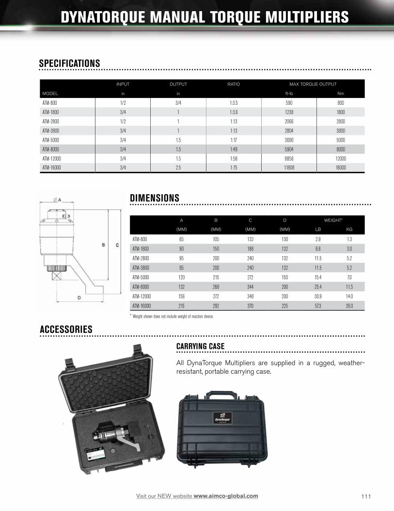
111Visit our NEW website www.aimco-global.com
DYNATORQUE MANUAL TORQUE MULTIPLIERS
INPUT OUTPUT RATIO MAX TORQUE OUTPUT
MODEL in in ft-lb Nm
ATM-800 1/2 3/4 1:3.5 590 800
ATM-1800 3/4 1 1:3.6 1238 1800
ATM-2800 1/2 1 1:13 2066 2800
ATM-3800 3/4 1 1:13 2804 3800
ATM-5000 3/4 1.5 1:17 3690 5000
ATM-8000 3/4 1.5 1:49 5904 8000
ATM-12000 3/4 1.5 1:58 8856 12000
ATM-16000 3/4 2.5 1:75 11808 16000
A B C D WEIGHT*
(MM) (MM) (MM) (MM) LB KG
ATM-800 65 105 132 130 2.9 1.3
ATM-1800 90 150 188 132 6.6 3.0
ATM-2800 95 200 240 132 11.5 5.2
ATM-3800 95 200 240 132 11.5 5.2
ATM-5000 120 215 272 150 15.4 7.0
ATM-8000 132 268 344 200 25.4 11.5
ATM-12000 156 272 348 200 30.9 14.0
ATM-16000 215 292 370 225 57.3 26.0
* Weight shown does not include weight of reaction device.
SPECIFICATIONS
ACCESSORIES
CARRYING CASE
All DynaTorque Multipliers are supplied in a rugged, weather-resistant, portable carrying case.
DIMENSIONS

112 Visit our NEW website www.aimco-global.com
DIRECT DRIVE
• Air motor driven gears.
• Stall torque dependent on air pressure.
• Simple maintenance.
• Lightest and smallest air screwdriver.
• Ideal for soft draw applications such as wood screws, self tapping screws, or trim screws.
TORQUE CONTROL AUTOMATIC SHUT-OFF TYPE
• Precise repeatability improves quality.
• Minimal wear on internal parts for longer life.
• Quick shut off for minimum torque reaction.
• Speed choice for flexibility.
• Easy external torque adjustment.
• Midrange air motor provides high speed during entire cycle.
• Ideal for industrial torque control applications.
POSITIVE CLUTCH TYPE
• Good for varying torque applications.
• Clutch ratchets at preset torque.
• Operator can force clutch engagement for higher torque.
• Good for prevailing torque applications.
IMPACT TYPE
• High power-to-weight ratio.
• Fast cycle times with free speeds up to 16,000 rpm.
• Ideal for non-critical applications.
HAMMER
ANVIL
HAMMERCAM
Hammer
Hammer Cage
Anvil Hammer Cam
CUSHION CLUTCH TYPE
• Good general duty screwdriver.
• High speed rundown.
• Clutch ratchets at preset torque.
• Internal torque adjustment.
• General assembly, wood, and sheet metal screws.
SCREWDRIVERS: OVERVIEW
HAMMER CAGE
PNEUMATIC SCREWDRIVERS
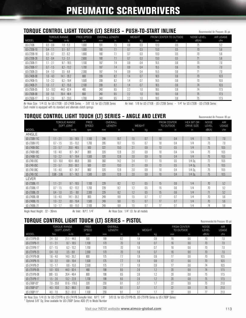
113Visit our NEW website www.aimco-global.com
TORQUE CONTROL LIGHT TOUCH (LT) SERIES – PUSH-TO-START INLINE Recommended Air Pressure: 85 psi
TORQUE RANGE FREE SPEED OVERALL LENGTH WEIGHT FROM CENTER TO OUTSIDE NOISE LEVEL AIR USAGEMODEL Nm in-lb rpm mm in lb kg mm in dB(A) cfm
US-LT10B 0.2 - 0.6 1.8 - 5.3 1,000 191 7.5 0.6 0.3 12.0 0.5 75 5.2US-LT20B-10 0.4 - 1.1 3.1 - 9.7 1,000 180 7.1 0.7 0.3 13.0 0.5 70 5.6US-LT20B-18 0.3 - 0.7 2.2 - 6.2 1,800 180 7.1 0.7 0.3 13.0 0.5 70 5.6US-LT20B-26 0.2 - 0.4 1.3 - 3.1 2,600 180 7.1 0.7 0.3 13.0 0.5 71 5.6US-LT30B-11 1.1 - 2.1 9.7 - 18.5 1,100 187 7.4 0.9 0.4 15.5 0.6 70 7.0US-LT30B-17 0.7 - 1.5 6.2 - 13.2 1,700 187 7.4 0.9 0.4 15.5 0.6 70 7.0US-LT30B-23 0.4 - 1.0 3.5 - 8.8 2,300 187 7.4 0.9 0.4 15.5 0.6 71 7.0US-LT40B-08 1.6 - 4.0 14.1 - 35.2 800 209 8.2 1.4 0.7 16.5 0.6 70 10.5US-LT40B-15 1.0 - 2.2 6.2 - 19.4 1,500 209 8.2 1.4 0.7 16.5 0.6 70 10.5US-LT40B-21 1.0 - 1.7 6.2 - 15.0 2,100 209 8.2 1.4 0.7 16.5 0.6 74 10.5US-LT50B-05 5.0 - 10.2 44.0 - 92.4 480 240 9.5 2.2 1.0 19.5 0.8 74 17.5US-LT50B-08 3.0 - 5.5 26.4 - 48.4 800 240 9.5 2.2 1.0 19.5 0.8 75 17.5US-LT50B-17 1.5 - 2.6 9.7 - 23.0 1,700 240 9.5 2.2 1.0 19.5 0.8 75 17.5
Air Hose Size: 1/4 I.D. for US-LT10B - US-LT40B Series – 3/8” I.D. for US-LT50B Series Air Inlet: 1/8 for US-LT10B - US-LT20B Series – 1/4” for US-LT30B - US-LT50B SeriesEach model is equipped with its standard and alternate clutch springs
PNEUMATIC SCREWDRIVERS
TORQUE CONTROL LIGHT TOUCH (LT) SERIES – ANGLE AND LEVER Recommended Air Pressure: 85 psi
TORQUE RANGE FREE OVERALL FROM CENTER HEX BIT OR NOISE AIRSOFT JOINT SPEED LENGTH WEIGHT TO OUTSIDE DRIVE SIZE LEVEL USAGE
MODEL Nm in-lb rpm mm in lb kg mm in in dB(A) cfm
ANGLEUS-LT30B-11C 1.1 - 2.1 3.5 - 18.5 1,100 298 10.7 1.5 0.7 10 0.4 1/4 73 7.0US-LT30B-17C 0.7 - 1.5 3.5 - 13.2 1,700 295 10.7 1.5 0.7 10 0.4 1/4 73 7.0US-LT40B-05C 2.3 - 5.7 20.0 - 49.5 500 322 13.0 2.1 0.9 13 0.5 1/4 75 10.5US-LT40B-08C 1.6 - 4.0 8.7 - 34.7 800 320 12.8 2.0 0.9 10 0.4 1/4 75 10.5US-LT40B-15C 1.0 - 2.2 8.7 - 19.4 1,500 320 12.8 2.0 0.9 10 0.4 1/4 75 10.5US-LT40-03C 5.0 - 10.0 43.4 - 86.8 300 360 14.2 2.4 1.1 13 0.5 1/4 Sq. 72 10.5US-LT40-05C 2.3 - 5.7 20.0 - 50.2 500 322 13.0 2.1 0.9 13 0.5 1/4 Sq. 75 10.5US-LT40-08C 1.6 - 4.0 8.7 - 34.7 800 320 12.8 2.0 0.9 10 0.4 1/4 Sq. 75 10.5US-LT40-15C 0.98 - 2.06 8.7 - 18.2 1,500 320 12.8 2.0 0.9 10 0.4 1/4 Sq. 75 10.5LEVERUS-LT30BL-11 1.1 - 2.1 9.7 - 18.5 1,100 229 8.2 1.2 0.5 15 0.6 1/4 70 5.2US-LT30BL-17 0.7 - 1.5 6.2 - 13.2 1,700 229 8.2 1.2 0.5 15 0.6 1/4 70 5.2US-LT30BL-23 0.4 - 1.0 3.5 - 8.8 2,300 229 8.2 1.2 0.5 15 0.6 1/4 71 5.2US-LT40BL-08 1.6 - 4.0 14.1 - 35.2 800 249 9.8 1.5 0.7 17 0.7 1/4 70 5.6US-LT40BL-15 1.0 - 2.2 8.8 - 19.4 1,500 249 9.8 1.5 0.7 17 0.7 1/4 70 5.6US-LT40BL-21 1.0 - 1.7 8.8 - 15.0 2,100 249 9.8 1.5 0.7 17 0.7 1/4 74 5.6
Angle Head Height: 32 - 36mm Air Inlet: N.P.T. 1/4” Air Hose Size: 1/4” I.D. for all models
TORQUE CONTROL LIGHT TOUCH (LT) SERIES – PISTOL Recommended Air Pressure: 85 psi
TORQUE RANGE FREE OVERALL FROM CENTER NOISE AIR(SOFT JOINT) SPEED LENGTH WEIGHT TO OUTSIDE LEVEL USAGE
MODEL Nm in-lb rpm mm in lb kg mm in dB(A) cfm
US-LT31PB-05 2.4 - 5.0 21.1 - 44.0 500 189 8.2 1.9 0.9 16 0.6 70 7.0US-LT31PB-11 1.1 - 2.1 9.7 - 18.5 1,100 170 7.0 1.6 0.7 16 0.6 70 7.0US-LT31PB-17 0.7 - 1.5 6.2 - 13.2 1,700 170 7.0 1.6 0.7 16 0.6 70 7.0US-LT31PB-23 0.4 - 1.0 3.5 - 8.8 2,300 170 7.0 1.6 0.7 16 0.6 70 7.0US-LT41PB-08 1.6 - 4.0 14.0 - 35.2 800 175 7.7 1.9 0.9 17 0.6 70 10.5US-LT41PB-15 1.0 - 2.2 8.8 - 19.4 1,500 175 7.7 1.9 0.9 17 0.6 70 10.5US-LT41PB-21 1.0 - 1.7 8.8 - 15.0 2,500 175 7.7 1.9 0.9 17 0.6 74 10.5US-LT51PB-05 5.0 - 10.5 44.0 - 92.4 480 198 8.5 2.6 1.2 20 0.8 74 17.5US-LT51PB-08 300 - 5.5 26.4 - 48.4 800 198 8.5 2.6 1.2 20 0.8 75 17.5US-LT51PB-17 1.5 - 2.6 13.2 - 22.9 1,700 198 8.5 2.6 1.2 20 0.8 75 17.5US-LT60P-03* 7.0 - 20.0 61.6 - 176.0 320 230 9.1 3.7 1.7 22 0.9 75 21.0US-LT60P-07* 4.0 - 10.0 35.2 - 88.0 650 230 9.1 3.7 1.7 22 0.9 76 21.0US-LT60P-11* 4.0 - 7.0 35.2 - 61.6 1,100 230 9.1 3.7 1.7 22 0.9 77 21.0
Air Hose Size: 1/4 I.D. for US-LT31PB & US-LT41PB Series Air Inlet: N.P.T. 1/4” 3/8 I.D. for US-LT31PB-05, US-LT51PB Series & US-LT60P Series* Optional 3/8” Sq. Drive available for US-LT60P Series ADD (P) to Model Number

114 Visit our NEW website www.aimco-global.com
OPTIONAL CLUTCH SPRINGSCLUTCH SPRINGS RECOMMENDED TORQUE RANGE
PROVIDED HARD JOINT CLUTCH SPRINGMODEL Standard Option Nm in-lb CODE NUMBER
US-LT10/10B Black 0.20 - 0.60 1.7 - 5.2 976-379-0US-LT20B-10 Black 0.34 - 1.10 3.0 - 9.5 976-432-0
Red 0.20 - 0.70 1.7 - 6.1 976-431-0Yellow 0.15 - 0.34 1.3 - 3.0 976-430-0
US-LT20B-18 Red 0.24 - 0.67 2.2 - 6.1 976-431-0Yellow 0.15 - 0.34 1.3 - 3.0 976-430-0
US-LT20B-26 Yellow 0.15 - 0.34 1.3 - 3.0 976-430-0US-LT31PB-05 Red 2.35 - 5.00 20.9 - 44.0 976-493-0
Pink 0.98 - 2.74 8.7 - 24.3 976-471-0US-LT30 Series, 1100 rpm Blue 0.98 - 2.1 8.7 - 18.5 976-472-0
Red 0.67 - 1.76 6.1 - 15.6 976-493-0Pink 0.39 - 0.98 3.5 - 8.7 976-471-0
Black (not included) 1.22 - 2.74 10.8 - 24.3 976-504-0US-LT30 Series, 1700 rpm Red 0.67 - 1.47 6.1 - 13.0 976-493-0
Pink 0.39 - 0.98 3.5 - 8.7 976-471-0US-LT30 Series, 2300 rpm Pink 0.39 - 0.98 3.5 - 8.7 976-471-0US-LT40-03C Red 4.90 - 9.80 43.4 - 86.8 976-516-0US-LT40 Series, 800 rpm Black 1.57 - 3.92 13.9 - 34.7 976-515-0
Red 0.98 - 2.17 8.7 - 19.1 976-516-0Yellow 0.98 - 1.67 8.7 - 14.8 976-517-0
US-LT40 Series, 1500 rpm Red 0.98 - 2.17 8.7 - 19.1 976-516-0Yellow 0.98 - 1.67 8.7 - 14.8 976-517-0
US-LT40 Series, 2100 rpm Yellow 0.98 - 1.67 8.7 - 14.8 976-517-0US-LT50 Series, 500 rpm Black 4.9 - 10.3 43.4 - 91.1 976-620-0
Red 2.9 - 5.4 26.1 - 47.7 976-614-0Yellow 1.4 - 2.5 13.0 - 22.6 976-588-0
US-LT50 Series, 800 rpm Red 2.7 - 5.4 24.3 - 47.7 976-614-0Yellow 1.4 - 2.5 13.0 - 22.6 976-588-0
US-LT50 Series, 1700 rpm Yellow 1.4 - 2.6 13.0 - 23.0 976-588-0
SILENCER ASSEMBLIES DIRECT TYPE LEADER HOSE EXHAUST HOSE
MODEL SILENCER ASSEMBLY ASSEMBLY
US-LT10 Series N/A 934-201-0 459-885-1US-LT20 Series 455-088-2 934-201-0 455-885-1US-LT30 Series 408-088-2 934-150-0 408-885-0US-LT40 Series 496-088-1 934-150-0 496-885-1
EXTERNAL TORQUE ADJUSTMENT (AIR SHUT-OFF)Set the hand driver into the key hole on the Adjusting Gear, turn clockwise to increase torque. Turn counter clockwise to decrease torque.
PNEUMATIC SCREWDRIVERS
US-LT Series Model

115Visit our NEW website www.aimco-global.com
PNEUMATIC SCREWDRIVERS
DIRECT DRIVE SERIES MAX TORQUE
SOFT JOINT HARD JOINT FREE SPEED OVERALL LENGTH WEIGHT FROM CENTER TO OUTSIDE NOISE LEVEL AIR USAGE
MODEL Nm ft-lb Nm ft-lb rpm mm in lb kg mm in db(A) cfm
PISTOLUS-LD40P-08 4.8 3.6 5.7 4.2 940 130 5.1 1.5 0.7 17 0.7 70 14.0US-LD40P-15 3.0 2.2 3.2 2.4 1,700 130 5.1 1.5 0.7 17 0.7 70 14.0US-LD40P-21 2.0 1.5 2.8 2.1 2,500 130 5.1 1.5 0.7 17 0.7 74 14.0US-LD50P-05 10.0 7.4 11.2 8.3 500 153 6.0 2.0 0.9 20 0.8 74 17.5US-LD50P-08 6.5 4.8 7.8 5.8 900 153 6.0 2.0 0.9 20 0.8 75 17.5US-LD50P-17 3.5 2.6 5.9 4.4 1,900 150 5.9 2.0 0.9 20 0.8 75 17.5
CAPACITY (SCREW SIZE) FREE SPEED OVERALL LENGTH WEIGHT FROM CENTER TO OUTSIDE NOISE LEVEL AIR USAGE
ANGLE mm in rpm mm in lb kg mm in db(A) cfm
US-3.5ACB 4 No. 8 2,000 200 7.9 1.4 0.7 10.0 0.4 85 7.0Air Hose Size: 1/4 I.D. Air Inlet: N.P.T. 1/4
Recommended Air Pressure: 85 psi
Recommended Air Pressure: 85 psi
Recommended Air Pressure: 85 psi
US-LD40P-15
US-3.5PB
US-350PW
CUSHION CLUTCH SERIESCAPACITY (SCREW SIZE) FREE SPEED OVERALL LENGTH WEIGHT LESS BIT FROM CENTER TO OUTSIDE NOISE LEVEL AIR USAGE
MODEL mm in rpm mm in lb kg mm in db(A) cfm
US-3.5PB* 4 No. 8 2,000 200 7.9 1.7 0.8 17 0.7 75 7.0US-3.5B 4 No. 8 2,000 214 8.5 1.4 0.6 17 0.7 75 7.0US-5 5 No. 10 1,400 236 7.1 2.4 1.1 21 0.8 75 7.0
* Push-To-Start Air Hose Size: 1/4” I.D. for all models Air Inlet: N.P.T. 1/4”
IMPACT SERIESCAPACITY (SCREW SIZE) FREE SPEED OVERALL LENGTH WEIGHT LESS BIT FROM CENTER TO OUTSIDE NOISE LEVEL AIR USAGE
MODEL mm in rpm mm in lb kg mm in db(A) cfm
PISTOLUS-350PW* 4 No. 8 15,000 121 4.8 1.2 0.5 17 0.7 81 7.0US-450PW* 5 No. 10 14,000 151 5.9 1.7 0.8 17 0.7 79 7.0US-652PW* 6 1/4 9,000 155 6.1 1.9 0.9 23 0.9 79 12.4STRAIGHTUS-450WB* 5 No. 10 11,000 161 6.3 1.2 0.6 18.5 0.7 80 7.0
Air Hose Size: 1/4” I.D. for US-350PW, US-450WB & US-652PW – Air Inlet: N.P.T. 1/4” NOTE: Additional models available. Please contact AIMCO, 1-800-852-1368.(R) Denotes Directional Muffled Rear Exhaust option *Recommended air pressure: 57 psi 3/8” I.D. for UW-6 Series

116 Visit our NEW website www.aimco-global.com
SIGNATURE SERIES PRECISION TOOLS
Simple to use, yet sophisticated in performance, the AIMCO Signature Series pistol tools provide the operator the performance required to meet the needs of today’s cordless tool applications.
The ergonomic handle design provides the operator ideal balance and weight. These tools allow for fastening in hard-to-reach locations at torques up to 9 ft-lb (12 NM) in the pistol configuration and 52 ft-lb (70 NM) in the angle nutrunner configuration. The Signature Series Precision Clutch range features a wide range of torque outputs and the ability to program the tool speed for the demands of the application. Bright LED indicator lights provide clear feedback to the operator on OK/NOK tightening result, Tool Direction setting, and Battery Status. Signature Series Precision tools all operate with a single 18V Li-Ion Battery and common chargers to maximize flexibility while minimizing cost associated with differing battery chemistries.
SIGNATURE SERIES PRECISE QUICK RELEASE CLUTCH
The Signature Series tool features a quick releasing clutch that delivers accuracy across multiple joint types. Each clutch assembly is constructed of precisely machined parts to guarantee accuracy and durability over the life of the tool. In addition to tight tolerances, the driving anvil is well supported to ensure that torque is precisely sensed by the clutch and not influenced by side loads or runout of the tool’s rotating components.
Whether the application is made up of soft materials, such as plastics or gaskets, or harder materials, such as direct metal to metal joints, the Signature Series Precision Clutch tool delivers the accuracy the job requires.
Typical Torque Graph of the Signature Series Precision Cordless Tools
Extremely Fast, Smooth Clutch Mechanism
SIGNATURE SERIES PRECISION CLUTCH CORDLESS TOOLS
Features that raise the bar of expectations!

117Visit our NEW website www.aimco-global.com
TORQUE RANGE FREE SPEED RPM RANGE TOOL WEIGHT (W/O BATTERY) ANVIL
MODEL ft-lb Nm (Programmable with Programmer Accessory) BATTERY VOLTAGE lb kg SIZE
Pistol GripSPC-P2325Q .6 – 2.2 .8 – 3 500 – 1550 18V 2.1 .95 1/4” hexSPC-P2625Q .7 – 4.4 1 – 6 300 – 1000 18V 2.1 .95 1/4” hexSPC-P2925Q 1.1 – 6.6 1.5 – 9 300 – 800 18V 2.1 .95 1/4” hexSPC-P21225Q 1.5 – 8.8 2 – 12 250 – 600 18V 2.1 .95 1/4” hexAngle NutrunnerSPC-A21025Q 2.2 – 8.8 3 – 12 400 – 1000 18V 3.5 1.6 1/4” hexSPC-A21025 2.2 – 8.8 3 – 12 400 – 1000 18V 3.5 1.6 1/4” SqSPC-A21038 2.2 – 8.8 3 – 12 400 – 1000 18V 3.5 1.6 3/8” SqSPC-A21625Q 3.7 – 13.3 5 – 18 300 – 600 18V 3.5 1.6 1/4” hexSPC-A21625 3.7 – 13.3 5 – 18 300 – 600 18V 3.5 1.6 1/4” SqSPC-A21638 3.7 – 13.3 5 – 18 300 – 600 18V 3.5 1.6 3/8” SqSPC-A23038 5.9 – 22 8 – 30 250 – 480 18V 3.5 1.6 3/8” SqSPC-A23538 7.4 – 25.8 10 – 35 220 – 330 18V 3.5 1.6 3/8” SqSPC-A25038 7.4 - 37 10 - 50 200 Non-Programmable Fixed Speed* 18V 5.3 2.4 3/8” SqSPC-A27038 14.8 - 51.7 20 - 70 170 Non-Programmable Fixed Speed* 18V 6.3 2.9 3/8” Sq
• Pistol Grip Tools include: Torque Adjustment Tool and one (1) 18V Li-Ion Battery• Angle Nutrunners include: Torque Adjustment Tool, Head Indexing Spanner Wrench, and one (1) 18V Li-Ion Battery* High torque tools feature fixed RPM.
SIGNATURE SERIES PRECISION CLUTCH CORDLESS TOOLS
LED indicator provides simple process information to the operator. The signal is visible from any angle.
Li-Ion battery pack delivers longer run-time.
Ergonomic handle design provides good balance.
Trigger repeat protection avoids double hits on already seated screw.
Press button for easy F/R operation.
LED light for working in dark areas.Angle head allows multiple head positions
User can distinguish the torque at a glance of color.
Torque adjustment.
Torque adjustment. LED indicator provides simple process information to the operator. The signal is visible from any angle.
Press button for easy F/R operation.
Ergonomic handle design provides good balance.
Li-Ion battery pack delivers longer run-time.
Easily attached sliding battery system.
Trigger repeat protection avoids double hits on already seated screw.
LED light for working in dark areas.
Signature Series tools can be adapted to a wide range of application-specific configurations. Contact your AIMCO Representative for assistance, 1-800-852-1368.

118 Visit our NEW website www.aimco-global.com
TOOL SPEED PROGRAMMER
The Signature Series Precision Cordless tool line is capable of specifically programming the running RPM into the tool within its range of operation. Each tool in the range has an integrated Mini USB connector that couples to the Signature Series Programmer module. Simply connect the tool to the Programmer Module and flash the tool to the desired RPM. Once flashed, the tool will hold the RPM setting until a change is desired and it is re-flashed. New tools, that have not been specifically set by the programmer module, will run at their maximum rated RPM as shown in the catalog table and on the tool label.
BATTERIES AND CHARGERS
The AIMCO Signature Series battery and charging system could not be more simple. One universal battery and one universal charger interface with any of the Signature Series Precision Clutch tools. Pistol type, angle type, low amount of torque output, or the highest torque tool in the range, each tool utilizes the same 18V Lithium Ion battery for superior charge life and weight. The charger accepts input AC power of 100–240AC, making use simple anywhere in the world.
The Signature Series battery features a slim profile design and a slide mount connection to the tool, which ensures durability and makes changing out batteries simple.
SIGNATURE SERIES CORDLESS TOOL BATTERY, CHARGER & ACCESSORIES
QUICK CLIP
Carry your Signature Series Pistol tool on any work belt with the Quick Clip. The two piece Quick Clip comes with a belt clip and a stretch cord attachment for the tool. The patented ball feature allows for quick and easy release on the belt. The Quick Clip keeps the tool well balanced and frees the operator’s hands for other tasks.
BATTERY AND CHARGER SPECIFICATIONS
TOOL BASKETS
Tool Baskets are a great way to keep the Signature Series tool in place when not being used. AIMCO tool baskets can be affixed to a bench or rack and can be used for either a pistol or right angle tool.
SPC-2-PGMSPC-QC
HOLSTERS
For ease in carrying your Signature Series pistol and right angle tools, AIMCO offers several holster designs.
SPC-P-HL
BODY JACKETS
MODEL DESCRIPTION
BJ10082 For Signature Series G2 Pistol Tools
BJ10083 For Signature Series G2 Angle Nutrunners
BATTERY MODEL NUMBER VOLTAGE TYPE CAPACITY WEIGHT
SPC-B218LI 18V Li-Ion 2.0Ah .8 Lb/.4 kg
SPC-B218LI-HC 18V Li-Ion 4.0Ah 1.4 Lb/.64 kg
CHARGER MODEL NUMBER OUTPUT INPUT DIMENSIONS WEIGHT
SPC-C218-19 18V-19.2V, 3.0A 100-240VAC, 50-60Hz 6.25” deep X 5” wide X 3.5” tall (w/o Battery)158.75 mm X 127 mm X 89 mm
1.2 Lb/.54 kg
21226
SPC-B218LISPC-C218-19

119Visit our NEW website www.aimco-global.com
ELECTRIC SCREWDRIVERS
• Available in push-to-start and lever start styles.
• Ergonomic design — Lightweight, compact housings ensure operator comfort during operation.
• Accurate torque control — Precise controlled fastening with automatic shut-off clutches.
• External brush replacement — Virtually no down time for brush replacement.
• External torque adjustment — Torque level can be easily adjusted by simply turning the external adjustment ring.
• Grounded bit — Grounded chuck assembly routes any existing charge to ground.
• Carbonized housing — Handle material and buttons are constructed of carbonized plastic throughout, enabling any charge received by the handle to be routed to ground.
• Long-Lasting ESD resistant handle — Material will maintain its integrity for the life of the handle, unlike coatings or paints.
AE-5681ESD
AE-5681
ELECTRA SERIESTORQUE RANGE FREE SPEED WEIGHT LENGTH HEX DRIVE POWER
MODEL IN-LB KGF-CM RPM LB KG IN MM IN MM SOURCE
PUSH-TO-START DIRECT PLUG-IN SERIESAE-5681 3 3.5 - 15.6 4 - 18.0 1,000 1.2 0.5 9.3 237 1/4 6.4 115V AC 1
AE-8681 4 15 - 45 23.0 - 51.8 600 1.6 0.7 10.6 269 1/4 6.4 115V AC 1
LOW VOLTAGE LEVER START SERIES2 POWER SUPPLY:
AE-2020 .35 - 1.3 .40 - 1.5 720 0.7 0.3 8.0 203 1/4 6.4 See page 121 forAE-4020 .9 - 5 1.0 - 6.0 720 0.7 0.3 8.0 203 1/4 6.4 required powerAE-4520 1.3 - 8.7 1.5 - 10.0 720 0.7 0.3 8.0 203 1/4 6.4 supplies2
AE-7010 6.1 - 17.4 7.0 - 20.0 750 1.4 0.6 9.3 236 1/4 6.4AE-8010 10.4 - 26.0 12.0 - 29.9 550 1.4 0.6 9.3 236 1/4 6.4LOW VOLTAGE PUSH-TO-START SERIES2 POWER SUPPLY:
AE-7010PS 6.1 - 17.4 7.0 - 20.0 750 1.4 0.6 9.3 236 1/4 6.4 See page 121 forAE-8010PS 10.4 - 26.0 12.0 - 29.9 550 1.4 0.6 9.3 236 1/4 6.4 power supplies2
• 1 220V AC is available upon request. Contact AIMCO at 1-800-852-1368. • 3 AE-5681 includes a torque cover.• 2 Low voltage units require an external power supply. • 4 AE-8681 includes a pistol grip handle adapter
ELECTRA LOW ESD SERIESTORQUE RANGE FREE SPEED WEIGHT LENGTH HEX DRIVE POWER
MODEL IN-LB KGF-CM RPM LB KG IN MM IN MM SOURCE
AE-2020ESD .35 - 1.3 .40 - 1.5 720 0.7 0.3 8.0 203 1/4 6.4 See page 121AE-4520ESD 2 1.3 - 8.7 1.5 - 10.0 720 0.9 0.4 8.0 204 1/4 6.4 35V DCAE-5681ESD 3.5 - 15.6 4 - 18.0 1,000 1.2 0.5 9.3 237 1/4 6.4 115V AC 1
• 1 220V AC is available upon request. Contact AIMCO at 1-800-852-1368.• 2 Low voltage units require an external power supply.
• UL Listed and CE Certified — Drivers meet electrical safety standards in both the U.S. and Europe.
• Direct plug-in style — Offers easy and convenient start-up (certain models) simply plug it in.
• State-of-the-art motor design — Ensures comfortable grip temperature for operator and extended motor life.
SERIES
ELECTRA LOW ESD SERIES

120 Visit our NEW website www.aimco-global.com
For low torque applications
• Featuring ergonomic design in shape and materials.
• Comes with options such as long-life brushless motors and adjustable speed power supplies.
STANDARD MODELS• Optional speed control power supply — Enables infinite
control from 20% to 100% of maximum tool speed and adjustable soft start to minimize cross threading.
• Ergonomic housing — Oval shape conforms to hand.
• Duralite — New casing material provides a secure grip.
• Integrated Lever — Feather touch integrated lever reduces travel and stress. Requires only 2 mm of travel to activate.
• External torque control — Twist and go.
• High-speed performance — For quick and consistent assembly and disassembly
• Maximum ergonomics and convenience — Offers a combination of a slip clutch with a high speed motor to provide low torque reaction; one of the best power-to-weight ratios in the industry.
• Added maintenance feature — A LED light indicates when to change brushes. Brush cap contains a switch that shuts off the power during brush replacement.
• Direct 110V plug-in — Eliminates the need for an external power supply.
ELECTRIC SCREWDRIVERS
ELECTRA SLIP CLUTCH SERIESRECOMMENDED TORQUE RANGE FREE SPEED WEIGHT LENGTH HEX DRIVE POWER
MODEL IN-LB KGF-CM RPM LB KG IN MM IN MM SOURCE
AE-2015 4.3 - 21.7 5.0 - 25.0 1000 1.2 .55 9.2 234 1/4 6.4 110 V / 120V AC1
• 1 220V AC is available upon request. Contact AIMCO at 1-800-852-1368.
PRECISION SERIESTORQUE RANGE FREE SPEED WEIGHT LENGTH HEX DRIVE
MODEL IN-LB KGF-CM RPM LB KG IN MM IN
STANDARDAE-6300 .85 - 5.0 1.0 - 5.8 725 0.9 0.4 8.5 216 1/4AE-6450 1.3 - 8.7 1.5 - 10.0 770 0.9 0.4 8.5 216 1/4HIGH SPEEDAE-6300S 1.2 - 5.5 1.4 - 6.3 920 0.9 0.4 8.5 216 1/4AE-6450S 1.3 - 8.7 1.5 - 10.0 920 0.9 0.4 8.5 216 1/4EXTENDED LIFEAE-6300M 1.0 - 5.5 1.1 - 6.3 550 0.9 0.4 8.5 216 1/4
AE-6300
PRECISION SERIES
EXTENDED LIFE MODELS• Sealed Swiss motor — For higher duty cycles, longer
life, and less maintenance. Sealed casing means no brush changes are necessary.
• Extended warranty on tool motor — Three year standard motor warranty.
• Compact power supply — Makes setup a breeze.
AE-2015
ELECTRA SLIP CLUTCH SERIES
• 1/4" hex quick change chuck — For easy bit changes
• External torque collar — For easy torque adjustment.

121Visit our NEW website www.aimco-global.com
OPTIONAL ACCESSORIESITEM MODEL COMPATIBLE SCREWDRIVERS
Angle Head Attachments AE-2045A For AE-2020, AE-4020, AE-4520 AE-7080A For AE-7010, AE-8010
Pistol Grip Handle AE-PG7080 For AE-7010, AE-1070PS, and AE-8010Torque Cover AE-TC2045 For AE-2020, AE-4020, AE-4520
AE-TC7080 For AE-7010, AE-7010PS, AE-80104H2055 For AE-8681
Fastener Counter TM-45 For AE-2020, AE-4020, AE-4520 Standard and ESD typesTM-65 For AE-7010, AE-8010 and AE-8010PS
AE-224PS and AE-278PSAPS-35W
ELECTRA SERIES ACCESSORIES – POWER SUPPLIES
PISTOL GRIP HANDLE
Converts to a pistol style driver for horizontal fastening. Available for Trigger Start only (included with AE-8681).
TORQUE COVER
Prevents accidental torque adjustment by the operator (included with AE-5681).
ANGLE HEAD ATTACHMENTS
Available for lever start series.
Part # AE-2045A or AE-7080A.
Not available on Low ESD Series.
FASTENER COUNTER
Verifies and error-proofs assembly process.
ELECTRIC SCREWDRIVERS
MODEL COMPATIBLE
SCREWDRIVERS
TOOL
RPM
VOLTAGE
CONVERSION
DIMENSIONS
(LB)
WEIGHT
(KG)
AE-224PS AE-2020 AE-2020ESDAE-4020AE-4520 AE-4520ESD
AE-6300AE-6300SAE-6450AE-6450S
720 110V AC / 35V DC2.6 x 1.6 x 5.0
66 x 41 x 127 mm 1.0 .45
APS-35W AE-2020 AE-2020ESDAE-4020AE-4520 AE-4520ESD
AE-6300AE-6300SAE-6450AE-6450S
VARIABLE SPEED / SOFT START 110V AC / 35V DC2.6 x 1.6 x 5.0
66 x 41 x 127 mm1.0 0.5
AE-278PS AE-7010 AE-7010PS
AE-8010AE-7010
STANDARD 110V AC - 220V AC / 30V DC1.6 x 5.0 x 2.6
41 x 127 x 66 mm1.0 .45
APM-30 AE-6300M550 110V AC - 220V AC / 30V DC
2.1 x 3.4 x 1.953 x 87 x 48mm
0.4 0.2
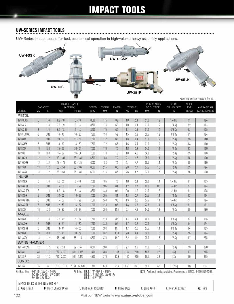
122 Visit our NEW website www.aimco-global.com
IMPACT TOOLS MODEL NUMBER KEY C: Angle Head D: Quick Change Driver E: Built-in Air Regulator H: Heavy Duty L: Long Anvil R: Rear Air Exhaust SS: Inline
IMPACT TOOLS
Recommended Air Pressure: 85 psi
CAPACITY
TORQUE RANGE (APPROX)
SPEED
OVERALL LENGTH
WEIGHT
FROM CENTER TO OUTSIDE
SQ. DR. OR HEX SIZE
NOISE LEVEL
AVERAGE AIR
MODEL MM IN NM FT-LB RPM MM IN KG LB MM IN IN DB(A) CONSUMPTION
PISTOLUW-6SLRDK 6 1/4 6.9 - 18 5 - 13 8,500 175 6.9 1.0 2.1 31.0 1.2 1/4 Hex 91 12.4UW-6SLK 6 1/4 7.8 - 19 6 - 14 8,500 175 6.9 1.0 2.1 31.0 1.2 1/4 Sq. 92 12.4UW-6SLRK 6 1/4 6.9 - 18 5 - 13 8,500 175 6.9 1.1 2.1 31.0 1.2 3/8 Sq. 92 10.5UW-61ER(D)K 8 5/16 14 - 40 10 - 30 7,300 150 5.9 1.5 3.3 29.5 1.2 3/8 Sq. 91 12.4UW-8SHK 8 5/16 29 - 69 21 - 51 7,500 172 6.8 1.6 3.4 31.0 1.2 1/2 Sq. 93 14.0UW-8SHRK 8 5/16 18 - 40 13 - 30 7,300 172 6.8 1.6 3.4 31.0 1.2 1/2 Sq. 93 14.0UW-9SRK 10 3/8 35 - 87 26 - 64 7,000 178 7.0 1.8 3.9 34.0 1.3 1/2 Sq. 93 16.0UW-9SK 10 3/8 35 - 87 26 - 64 7,000 178 7.0 1.8 4.0 34.0 1.3 1/2 Sq. 95 17.6UW-10SHK 12 1/2 49 - 180 36 - 133 6,500 183 7.2 2.1 4.7 35.0 1.4 1/2 Sq. 95 16.0UW-10SHRK 12 1/2 47 - 170 35 - 125 6,000 183 7.2 2.1 4.7 30.5 1.4 1/2 Sq. 95 16.0UW-13SK 13 1/2 88 - 250 65 - 184 6,500 215 8.5 2.6 5.7 37.5 1.5 1/2 Sq. 95 19.4UW-13SRK 13 1/2 88 - 250 65 - 184 6,000 215 8.5 2.6 5.7 37.5 1.5 1/2 Sq. 95 16.0INLINEUW-6SSDK 6 1/4 7.8 - 22 6 - 16 7,500 185 7.3 1.0 2.1 28.0 1.1 1/4 Hex 91 10.5UW-6SSHDK 8 5/16 15 - 30 11 - 22 7,500 205 8.1 1.2 2.7 22.0 0.8 1/4 Hex 91 12.4UW-6SSLRDK 6 1/4 6.9 - 18 5 - 13 8,500 239 9.4 0.9 1.9 31.0 1.3 1/4 Hex 91 10.5UW-6SSHK 8 5/16 22 - 50 16 - 37 7,500 205 8.1 1.3 2.7 27.5 1.1 1/4 Sq. 92 12.4UW-6SSHRDK 8 5/16 15 - 30 11 - 22 7,300 249 9.8 1.3 2.8 27.5 1.1 1/4 Hex 91 12.4UW-6SSHRK 8 5/16 22 - 50 16 - 37 7,300 249 9.8 1.3 2.8 27.5 1.1 3/8 Sq. 91 12.4UW-9SSK 10 3/8 35 - 87 26 - 64 7,000 290 11.4 2.1 4.6 34.0 1.3 1/2 Sq. 95 16.0ANGLEUW-6CSK 6 1/4 7.8 - 22 6 - 16 7,500 218 8.6 1.4 3.1 28.0 1.1 3/8 Sq. 94 10.5UW-6CSHK 8 5/16 19 - 41 14 - 30 7,500 238 9.4 1.7 3.8 27.5 1.1 3/8 Sq. 94 12.4UW-6CSHRK 8 5/16 19 - 41 14 - 30 7,300 282 11.1 1.7 3.8 27.5 1.1 3/8 Sq. 94 10.5UW-9CSK 10 3/8 27 - 71 20 - 52 7,000 337 13.3 2.8 6.1 34.0 1.3 1/2 Sq. 95 12.4UW-13CSK 13 1/2 75 - 200 55 - 148 6,500 374 14.7 5.2 11.4 39.0 1.5 1/2 Sq. 97 26.5SWING HAMMERUW-140P(WR) 12 1/2 70 - 210 52 - 155 6,500 200 7.9 2.7 5.9 33.0 1.3 1/2 Sq. 93 25.0UW-381 38 1-1/2 760 - 2,000 561 - 1,475 4,700 395 115.6 9.5 20.9 58.5 2.3 1 Sq. 100 31.5UW-381P 38 1-1/2 760 - 2,000 561 - 1,475 4,700 276 10.9 10.0 20.9 58.5 2.3 1 Sq. 99 31.5JUMBOUW-75S 76 3 7,800 - 17,000 5,753 - 12, 539 1,400 670 26.4 56.0 123.0 96.0 3.8 1-1/2 Sq. 112 114.0
Air Hose Size: 3/8” I.D. (UW-6 – 140P) Air Inlet: N.P.T. 1/4” (UW-6 – 140P) NOTE: Additional models available. Please contact AIMCO, 1-800-852-1368. 1/2 I.D. (UW-381, UW-381P) N.P.T. 1/2 (UW-381, UW-381P) 3/4 I.D. (UW-75S) N.P.T. 1 (UW-75S)
UW-9SSKUW-13CSK
UW-6SLK
UW-381P
UW-SERIES IMPACT TOOLS
UW-Series impact tools offer fast, economical operation in high-volume heavy assembly applications.
UW-75S

123Visit our NEW website www.aimco-global.com
GRINDERS AND SANDERS
UG-25NAUG-45H
UAG-40SB-136UAG-40SBL-136UAG-50SBL-120
UG-50S-200
GRINDERS Recommended Air Pressure: 85 psiCAPACITY
(WHEEL SIZE)
SPEEDRATED
HORSEPOWER
OVERALL LENGTH
OVERALL HEIGHT
WEIGHTNOISE LEVEL
AVERAGE AIR CONSUMPTION
MODEL IN RPM HP MM IN MM IN KG LB DB(A) CFM
UAG-40SBL-136 4 13,600 1.0 246 9.7 76 3.0 1.3 2.9 84 34.0UAG-50SBL-109 5 10,900 1.0 246 9.7 76 3.0 1.4 3.1 82 34.0UAG-50SBL-120 5 12,000 1.0 246 9.7 76 3.0 1.4 3.1 82 34.0UAG-70SBL-76 7 7,600 2.0 300 11.8 98 3.9 2.9 6.4 83 57.0UAG-90SBL-59 9 5,900 2.5 308 12.1 98 3.9 3.3 7.3 88 67.0
Air Hose Size: 3/8” I.D. – Air Inlet: N.P.T. 1/4” - N.P.T. 3/8” (UAG-90SBL-59) NOTE: Additional models available. Please contact AIMCO, 1-800-852-1368.
GRINDERS / SANDERS Recommended Air Pressure: 85 psiCAPACITY
(WHEEL SIZE)COLLET
CHUCK SIZE
SPEEDRATED
HORSEPOWER
OVERALL LENGTH
WEIGHTNOISE LEVEL
AVERAGE AIR CONSUMPTION
MODEL IN IN RPM HP MM IN KG LB DB(A) CFM
UG-25NA — 1/4 23,500 0.3 153 6.0 0.5 1.2 82 10.7UG-38N — 1/4 25,000 0.4 164 6.5 0.6 1.3 85 10.7UG-38NA — 1/4 22,000 0.4 165 6.5 0.7 1.4 75 14.0UG-38NL — 1/4 21,000 0.4 317 12.5 0.9 2.0 85 10.7UG-38NS — 1/4 25,000 0.4 174 6.8 0.6 1.3 85 10.7UG-50S-200 — 1/4 23,000 0.3 198 7.8 0.6 1.3 73 14.0UG-45H — 1/4 18,000 0.5 196 7.7 0.8 1.8 76 22.0UG-20A-200 — 1/4 20,000 0.2 131 5.2 0.5 1.1 75 10.7UG-20A-120 — 1/4 12,000 0.2 131 5.2 0.5 1.1 76 10.7UG-50S-200A — 1/4 20,000 0.3 195 7.7 0.9 2.0 75 14.0UG-65EB 2.5 — 14,600 0.6 242 9.8 1.3 2.8 95 22.0UG-65EL 2.5 — 14,600 0.6 272 10.7 1.4 3.1 85 22.0UG-65ER 2.5 — 14,600 0.6 271 10.7 1.5 3.3 85 22.0UG-65EBL 2.5 — 14,600 0.6 272 10.7 1.4 3.1 95 22.0UG-650EL 2.5 — 14,600 0.6 420 16.5 1.6 3.4 85 22.0UG-1250L-72 5 — 7,200 1.0 436 17.2 2.8 6.2 88 32.7UP-25DB 5 — 10,000 0.3 212 8.3 1.7 3.7 73 7.0
Air Hose Size: 3/8” I.D. – 1/2” I.D. (UG-1250L-72) Air Inlet: N.P.T. 1/4” N.P.T. 3/8” (UG-1250L-72) NOTE: Additional models available. Please contact AIMCO, 1-800-852-1368.

124 Visit our NEW website www.aimco-global.com
DRILLS & PERCUSSION TOOLS
UD-60S-29
DRILLS Recommended Air Pressure: 85 psi
CAPACITY
SPEED
OVERALL LENGTH
WEIGHT WITH CHUCK
FROM CENTER TO OUTSIDE
NOMINAL CHUCK SIZE
TYPE OF SPINDLE
NOISE LEVEL
AVERAGE AIR CONSUMPTION
MODEL MM IN RPM MM IN KG LB MM IN IN IN-THR’D DB(A) CFM
UD-50-200 3 1/8 23,000 135 5.3 0.7 1.5 21.0 0.8 5/16 3/8-24UNF 73 14UD-50-45 6 1/4 5,000 145 5.7 0.9 1.9 21.0 0.8 5/16 3/8-24UNF 72 14UD-50-22 8 5/16 2,200 140 5.5 0.9 2.0 21.0 0.8 5/16 3/8-24UNF 72 14UD-60-29 8 5/16 2,900 167 6.6 1.1 2.4 22.5 0.9 5/16 3/8-24UNF 77 18UD-60-20 8 5/16 2,000 180 7.1 1.2 2.6 22.5 0.9 5/16 3/8-24UNF 77 18UD-60-15 8 5/16 1,600 180 7.1 1.2 2.6 22.5 0.9 5/16 3/8-24UNF 76 18UD-60-07 13 1/2 700 219 8.6 1.4 3.1 22.5 0.9 1/2 1/2-20UNF 75 18UD-60-04 13 1/2 500 220 8.6 1.4 3.1 22.5 0.9 1/2 1/2-20UNF 75 18UD-80-12 13 1/2 1,200 216 8.5 1.8 4.0 26.0 1.0 1/2 1/2-20UNF 79 23UD-80-07 13 1/2 700 239 9.4 2.3 5.1 26.0 1.0 1/2 1/2-20UNF 79 23UD-80-04 16 5/8 400 247 9.7 2.9 6.4 26.0 1.0 5/8 5/8-16UNF 79 23UD-50S-45 6 1/4 5,000 210 8.3 0.9 1.9 21.0 0.8 5/16 3/8-24UNF 77 14UD-50S-22 8 5/16 2,200 205 8.1 0.8 1.8 21.0 0.8 5/16 3/8-24UNF 77 14UD-60S-29 8 5/16 2,900 227 8.9 1.1 2.3 22.5 0.9 5/16 3/8-24UNF 77 18UD-60S-15 8 5/16 1,600 238 9.4 1.2 2.5 22.5 0.9 5/16 3/8-24UNF 77 18UD-60S-29C 8 5/16 2,900 276 10.9 1.5 3.3 22.5 0.9 5/16 3/8-24UNF 79 18UD-60S-15C 8 5/16 1,600 283 11.1 1.6 3.5 22.5 0.9 5/16 3/8-24UNF 79 18
Air Hose Size: 3/8” I.D. Air Inlet: N.P.T. 1/4” NOTE: Other models are available. Please contact AIMCO, 1-800-852-1368.
RIVETING HAMMERS Recommended Air Pressure: 85 psiCAPACITY BLOW PISTON PISTON NOISE AVERAGE AIR
DURALUMIN STEEL PER MIN. OVERALL LENGTH WEIGHT DIAMETER STROKE LEVEL CONSUMPTIONMODEL IN IN BPM MM IN KG LB MM IN MM IN DB(A) CFM
SBH-0 3/32 — 6,500 123 4.8 0.3 0.7 10.0 0.4 23 0.9 90 3.5SBH-1A(R,H)* 7/64 — 4,000 209 8.2 0.9 1.9 11.1 0.4 56 2.2 92 5.0BRH-1U(R,H)* 1/8 3/32 2,800 122 4.9 1.1 2.4 14.3 0.6 38 1.5 95 12.0BRH-1US(R,H)* 1/8 3/32 2,800 180 7.1 1.0 2.2 14.3 0.6 38 1.5 95 12.0BRH-1UG(R,H)* 1/8 3/32 2,800 187 7.4 1.8 3.9 14.3 0.6 38 1.5 95 12.0BRH-5U(R,H)* 1/4 3/16 1,800 189 7.4 1.4 3.1 12.7 0.5 100 4.0 95 13.0BRH-5US(R,H)* 1/4 3/16 1,800 246 9.7 1.5 3.2 12.7 0.5 100 4.0 95 13.0BRH-5UG(R,H)* 1/4 3/16 1,800 258 10.2 2.1 4.7 12.7 0.5 100 4.0 95 13.0BRH-1UV(R,H)* 1/8 3/32 2,800 143 5.6 1.4 3.0 14.3 0.6 38 1.5 91 12.0BRH-5UV(R,H)* 1/4 3/16 1,800 210 8.3 1.7 3.7 12.7 0.5 100 4.0 91 13.0BRH-1USV(R,H)* 1/8 3/32 2,800 271 10.7 1.6 3.5 14.3 0.6 38 1.5 91 12.0BRH-5USV(R,H)* 1/4 3/16 1,800 338 13.3 1.9 4.1 12.7 0.5 100 4.0 91 12.0BRH-7(R,H)* - - 3,400 168 6.6 1.6 3.6 19.1 0.8 50 2.0 100 17.0
Air Hose Size: 3/8” I.D. Air Inlet: N.P.T. 1/4” * R - Round Bushing H - Hex Bushing
ONE SHOT HAMMERS Recommended Air Pressure: 85 psi
BLOW POWERRIVET SET
DIA X LENGTH
SHANK DIAMETER
STROKE
LENGTH
WEIGHTMODEL LB IN MM IN MM IN MM IN LB KG
CB-13P 1.7 4.04 x 9.86 — — 3.0 0.12 185 7.3 0.7 0.3RH-25 20.4 — 10.2 0.401 29.8 1.2 213 8.4 2.0 0.9RH-80 27.6 — 10.2 0.401 29.8 1.2 254 10.0 2.9 0.3RH-90 103 — 10.2 0.401 29.8 1.2 328 12.9 3.5 1.6RH-100Z 78.1 — 10.2 0.401 29.8 1.2 328 12.9 3.9 1.8RH-200 139 — 10.2 0.401 39.8 1.2 341 13.4 4.6 2.1
Air Hose Size: 3/8” I.D. Air Inlet: N.P.T. 1/4” NOTE: Additional models available. Please contact AIMCO, 1-800-852-1368.

125Visit our NEW website www.aimco-global.com
For semi-automated assembly, look no further — AIMCO AcraFeed® screw presenters provide:
PRODUCTIVITY
• One hand operation eliminates manual handling of screws.
• Screw is presented to operator for easy magnetic or vacuum pickup.
• Keeps workspace clear of dropped fasteners.
• Quick feed rate from oscillating hopper design — up to two (2) screws per second.
• Large hopper holds approximately 1000 — 1500 fasteners.
• Solid design — no tie downs or straps required.
FLEXIBILITY
• Perfect for contract or dedicated assembly.
• Switch rails in minutes for different screw sizes.
ERGONOMICS
• Allows for fewer arm and hand movements.
RELIABILITY
• Heavy duty industrial design.
• Modular design for easy repairs.
QUALITY
• Uses existing or our new torque control drivers.
• Keeps stray fasteners from getting into assemblies.
Load screws into the hopper. There is no side to load unit and no gates to limit capacity.
FASTENING IN 3 EASY STEPS
Acra-Feed® Screw Presenter
1 Address screw with magnetized bit.2 Bring screw to workpiece
and fasten parts.3
SCREW PRESENTERS: OVERVIEW

126 Visit our NEW website www.aimco-global.com
WHICH TO USE…?
Standard Screw Presenters For manual assembly stations where the operator must otherwise pick up and hold fasteners by hand.
Robotic Screw Presenters For automated fastening systems or manual systems using vacuum assist to pick up non-ferrous fasteners.
Compact Robotic Screw Presenters For automated systems, or manual systems, using vacuum-assist to pick up nonferrous fasteners when work space is limited,
ROBOTIC COMPACT ROBOTIC
A-50 SCREW PRESENTERS
STANDARD
OPTIONAL ACCESSORIESMODEL PART NO.
Mag-O-Net Bit Magnetizer AM1/42, AM52, AM3/162
A-50B Series Bit Guide Protector NJ08004TIN8#23
A-50C Series Bit Guide Protector NJ08004TIN8#45
COMPACT ROBOTIC SCREW PRESENTERSADDITIONAL RAIL NOMINAL SCREW SIZE MAX SCREW LENGTH
MODEL PART NO. IN MM IN MM
A-50ARBTC-0 AR-RBTC-0 #0 1.4 .390 10A-50ARBTC-1.7 AR-RBTC-1.7 — 1.7 .390 10A-50BRBTC-1 BR-RBTC-1 #1 2.0 .700 18A-50BRBTC-2 BR-RBTC-2 #2 2.3 .700 18A-50BRBTC-3 BR-RBTC-3 #3 2.6 .700 18A-50BRBTC-4 BR-RBTC-4 #4 3.0 .700 18A-50CRBTC-6 CR-RBTC-6 #6 3.5 .700 18A-50CRBTC-8 CR-RBTC-8 #6-8 4.0 .700 18A-50CRBTC-10 CR-RBTC-10 #10 5.0 .700 18
Dimensions: 7.2 (L) x 4.9 (W) x 5.7 (H) Weight: 6.7 lbs.
STANDARD SCREW PRESENTERSADDITIONAL RAIL SCREW SIZE MAX SCREW LENGTH
MODEL PART NO. IN MM IN MM
A-50A-0 AR-0 #0 1.4 .39 10A-50A-1.7 AR-1.7 — 1.7 .39 10A-50B-1 BR-1 #1 2.0 .75 18A-50B-2 BR-2 #2 2.3 .75 18A-50B-3 BR-3 #3 2.6 .75 18A-50B-4 BR-4 #4 3.0 .75 18A-50C-6 CR-6 #6 3.5 .75 18A-50C-8 CR-8 #6-8 4.0 .75 18A-50C-10 CR-10 #10 5.0 .75 18
Dimensions: 5.1 (W) x 8.5 (L) x 5.3 (H) Weight: 7.0 lbs.
ROBOTIC SCREW PRESENTERSADDITIONAL RAIL SCREW SIZE MAX SCREW LENGTH
MODEL PART NO. IN MM IN MM
A-50ARBT-0 AR-RBT-0 #0 1.4 .39 10A-50ARBT-1.7 AR-RBT-1.7 - 1.7 .39 10A-50BRBT-1 BR-RBT-1 #1 2.0 .70 18A-50BRBT-2 BR-RBT-2 #2 2.3 .70 18A-50BRBT-3 BR-RBT-3 #3 2.6 .70 18A-50BRBT-4 BR-RBT-4 #4 3.0 .70 18A-50CRBT-6 CR-RBT-6 #6 3.5 .70 18A-50CRBT-8 CR-RBT-8 #6-8 4.0 .70 18A-50CRBT-10 CR-RBT-10 #10 5.0 .70 18
Dimensions: 5.1” (W) x 10.8” (L) x 5.3” (H) Weight: 9.2 lbs.

127Visit our NEW website www.aimco-global.com
ACRA-FEED AUTOMATIC SCREW FEED SYSTEMS
HOW TO ORDER: Acra-Feed systems are application-specific and configured to the unique workpiece and requirements of the user. Quotations are provided from a review of sample workpieces, 25 fasteners, and required torque specifications.
FEATURES AND BENEFITS
• Delivers fastener directly to the driver.
• For #2 - #10 fasteners, up to 1 inch long.
• Available for captive washer type screws (A-315V).
• Feed speed of up to 1 screw per second.
• System includes feeder, hose assembly, air screwdriver, and FRL.
PRODUCTIVE
• Eliminates reaching for fasteners.
• Most jams are easily cleared on the line.
• Frees operator’s hand for productive use.
• Large hopper holds between 1000-5000 fasteners.
ERGONOMIC
• Eliminates manual handling of fasteners and shavings.
• Reduces workspace clutter.
• Keeps workspace clean of dropped fasteners.
• Torque reaction of standard driver is minimal and can be eliminated with optional Ergo-Arm®.
RELIABLE
• Longest warranty in the industry — 3 years.
• Rocking Bar design only operates as needed.
• “Photo eyes” maximize motor life.
• Design eliminates burrs and shavings by minimal handling of the fastener.
• Durable head assembly lasts for years.
• There are more Acra-Feed® systems in use than any other system.
Reduces Cycle Time By Approximately Two Seconds Per Fastener
A-2100
A-315V
APPLICABLE SCREW LENGTH DIMENSIONSMODEL SCREWS IN MM HOPPER CAPACITY MAX FASTENING SPEED WEIGHT (LB) L X W X H (IN)
A-2100 Series M2-M5 (#2 - #10) 1/4-1 6-25 1,500cc (1,000-5,000 pcs)* 60 screws/min* 68 7 x 17 x 16A-315V Series M2-M5 (#2 - #10) 1/4-1 6-25 450cc (500-2,500 pcs)* 60 screws/min* 74 10 x 21 x 16
* Dependent on screw size Delivery Hose: 10 ft Air Pressure: 85 psi Power: AC 110V, 20W, AC 220V by request. Contact AIMCO at 1-800-852-1368.

128 Visit our NEW website www.aimco-global.com
ASB-OCGravity Defying and Hand Adjustable Balancer
ASB-SERIES BALANCERS
• Built-in Safety Features: The cable, drum, and enclosed spring are fully visible without opening the unit for easy and convenient safety checks. The sturdy spiral spring is enclosed for greater control and safety.
• Ergonomic Spring Release: The automatic safety lock provides extra control.
• Extended Cable Length: Stainless steel cables allow for extended reach on applications.
• Enhanced Gear Mechanism: Allows for more exact adjustment of tension.
• No Recoil and Low Resistance: Tapered drum style provides gravity defying tool positioning and low travel.
MODEL CAPACITYANTI-GRAVITY
CAPACITY (LBS)
TW-00 1.1 - 3.3 lb 0.5 - 1.5 kg 2.5 - 3.0TW-0 1.1 - 3.3 lb 0.5 - 1.5 kg 2.5 - 3.0TW-3 2.2 - 6.6 lb 1.0 - 3.0 kg 4.5 - 6.0TW-5 5.5 - 11.0 lb 2.5 - 5.0 kg 8.0 - 10.5TW-9 9.9 - 19.8 lb 4.5 - 9.0 kg 15.0 - 19.0TW-15 19.8 - 33.0 lb 9.0 - 15.0 kg 26.0 - 32.5TW-22 33.0 - 48.4 lb 15 - 22 kg 41.0 - 48.0TW-30 48.4 - 66.0 lb 22 - 30 kg 58.0 - 65.5TW-40 66.0 - 88.0 lb 30 - 40 kg 77.5 - 87.5TW-50 88.0 - 110.0 lb 40 - 50 kg 100.0 - 109.5TW-60 110.0 - 132.0 lb 50 - 60 kg 122.0 - 131.0TW-70 132.0 - 154.0 lb 60 - 70 kg 144.0 - 153.0
TW-0 and TW-00
• Gravity defying / “true balance”.
• No tension buildup to cause worker fatigue.
• Easy external direct drive tensioning.
• 360 degree upper swivel.
• 3.3 ft stranded steel cable 1/8" diameter (TW-00 cable length 18").
• Safety cable provision.
• Tool clip included.
TW-3 through TW-15
• Four (4) models supporting weights from 2.2 to 33 lb.
• Tapered drum allows “true balance” throughout cable travel.
• Easy external direct drive tensioning.
• Cast aluminum casing for durability.
• Permanent lubrication.
• 360 degree top swivel.
• 4.3 ft of 5/32" diameter stranded steel cable.
• Safety chain provision.
• Enclosed spiral spring for added safety.
TW-22 through TW-70
• Six (6) models supporting weights from 33 to 154 lb.
• Tapered drum allows for “true balance”.
• Cast aluminum housing.
• Easy external tensioning.
• Manual drum lock.
• 360 degree upper swivel.
• Permanent lubrication.
• 5 ft of stranded steel 3/16".
• Automatic Safety Lock.
• Enclosed spiral spring for added safety.
TW-3 to TW-70 Series
TW-0 & TW-00 Series
ASB-3C & ASB-5C
GRAVITY-DEFYING BALANCERS
MODEL CAPACITY STROKE WEIGHT
ASB-0C 1.1 - 3.3 lb 0.5 - 1.5 kg 51.1 in 130 cm 1.5 lb 0.7 kgASB-3C 3.3 - 6.6 lb 1.5 - 3 kg 86.4 in 220 cm 3.0 lb 1.4 kgASB-5C 5.5 - 11 lb 2.5 - 5 kg 86.4 in 220 cm 3.4 lb 1.5 kg
TW-SERIES BALANCERS

129Visit our NEW website www.aimco-global.com
RMA-L Series
RPA Series
RETRACTORS
RPA Series
• No tools needed to set tension.
• 5 ft nylon coated steel cable.
• Reinforced hanging bracket includes safety cable provision.
• Adjustable cable stop.
• Three (3) models support weight 0.5-5 lb.
• Tool clip included.
RMA-L Series
• Steel housing with polyester finish.
• Reinforced hanging bracket includes safety cable provision.
• 8 ft of 3/32" diameter coated steel cable.
• Permanently lubricated.
• Tool clip included.
• External tension adjustment.
• Ratchet cable lock.
LINE REEL BALANCERS
LR-Series
• Designed for light duty applications with small pneumatic tools.
• Integrating air hose and support cable keep work areas clean.
• Adjustable ball stop for optional positioning.
• 1/4" I.D. polyvinyl hose with 1/4" NPT inlet.
• 360 degree upper swivel.
• Maximum 142 PSI
LR-09B-90/200
MODEL HOSE LENGTH CAPACITY
LR-09B-90 35.5 in 90 cm 3 lb 1.5 kg
LR-09B-200 78.3 in 199 cm 3 lb 1.5 kg
LINE REEL BALANCERS / RETRACTORS
MODEL CAPACITY
RPA-1 0.5 - 1.5 lb 0.2 - 0.7 kg
RPA-2 1.5 - 3.0 lb 0.7 - 1.4 kg
RPA-3 3.0 - 5.0 lb 1.4 - 2.3 kg
RMA-7L 5 - 10 lb* 2.3 - 4.8 kg*
RMA-15L 10 - 15 lb* 4.5 - 6.8 kg*
RMA-20L 15 - 23 lb* 6.8 - 10.4 kg*
* With ratchet lock

130 Visit our NEW website www.aimco-global.com
FEATURES AND BENEFITS
• Ergonomic support for electric and pneumatic tools.
• Reduces operator fatigue.
• Increases productivity, consistency, and accuracy.
Dual ball bearing joint construction for smoother movement and long life
Air regulator offers precision adjustment of resistance for perfect balance
Unique upper rail adjustment allows true vertical approach to any fastener – no cross-threading
AD-D1098-PAC
SPECIAL FEATURES OF CLASSIC STYLE ERGO-ARM®
REACH CAPACITY MAXIMUM TORQUE*MODEL ARM STYLE TOOL MOUNT IN MM LB KG IN-LB MM
AIR CYLINDER SERIESAD-D1098-SAC Single Air manifold 4 - 33 102 - 838 0 - 15 0 - 7 110 12AD-D1098-PAC Parallel Air manifold 4 - 33 102 - 838 0 - 15 0 - 7 110 12AD-D1098-PACE Parallel Electric 4 - 33 102 - 838 0 - 15 0 - 7 110 12OIL CYLINDER SERIESAD-D1098-S Single Air manifold** 4 - 33 102 - 838 0 - 15 0 - 7 110 12AD-D1098-P Parallel Air manifold 4 - 33 102 - 838 0 - 15 0 - 7 110 12
* Max torque allowed may be dependent on tool clutch type and joint rate** For single arm electric tool mount, order EAP-202ED-KIT
AD-D1098-SAC
SINGLE ARM SERIESAD-D1098-S, AD-D1098-SAC
• Full tool rotation.
• Operator control.
• Adjustable reach.
• Compatible with automatic screw feeder.
• Available in air or oil cylinder models.
PARALLEL ARM SERIESAD-D1098-p, AD-D1098-pac, AD-D1098-pAce
• Minimizes operator control.
• Vertical adjustment eliminates cross-threading.
• Fixtured tool increases repeatability.
• Adjustable reach.
• Available in air or oil cylinder models.
• Electric tool mount standard on PACE model.
ERGO-ARM® TOOL SUPPORT SYSTEMS

131Visit our NEW website www.aimco-global.com
ERGO-ARM® ACCESSORIES
• End-of-Arm Tooling options for the Ergo-Arm® allow you to choose the style right for your application.
• The tool holders permit the tool to swivel, rotate, swing, or twist. The heavy duty construction can lock out any single, or combination of rotating, actions allowing only the motions required by your application.
• End-of-Arm Tooling Brackets are simple to use, one Ergo-Arm® can be used for more than one application.
FOR USE WITH MODELS AD-D1098-S/SAC
EAA-04 - Provides easy conversion of the standard Ergo-Arms® to the parallel style.
EAP-202ASSY - Driver Tool Mount
FOR USE WITH MODELS AD-D1098-P/PAC
PARALLEL ARM KIT
EAP-203-ASSY - Air Manifold Tool Mount Kit (Standard on parallel units)
LQ-0002 Linear Arm shipped with two ASB-0C balancers
LQ-0004 Linear Arm shipped with two TW-3 balancers
LQ-0024H Heavy Duty Arm shipped with two TW-3 balancers
LINEAR ARM
• Smooth movement and perfect balance while limiting operator control.
• Machined stainless steel and ball bearing construction.
• Two high quality tool balancers are included with each arm to provide a wide range of adjustment.
EAP-202ED-KIT - Electric Driver Tool Mount Kit
ERGO-ARM® ACCESSORIES AND LINEAR ARM
CUSTOM REACTION DEVICES
• Torque Tubes
• Articulating Torque Arms
• Ergo Arm 3 Zero Gravity Arms
• Smart Arms
Contact your AIMCO sales representative, 1-800-852-1368, in order to determine the exact torque reaction system needed to improve the productivity and ergonomics of your assembly station!
LINEAR ARM KIT
Articulating Smart Carbon Arm
Articulating Torque Arm Carbon Fiber Arm Ergo-Arm 3 Torque Tube
Ergo-Arm 3
MAX. REACH WEIGHT CAPACITY MAX TORQUE HEIGHT STANDARD TOOL MOUNT DIAMETERMODEL DESCRIPTION IN CM LB KG FT-LB NM IN CM IN CM
LQ-0002 Linear Arm 14 37 1- 5 0.5 - 2.3 20 27 24 61 1.6 4.1
LQ-0004 Linear Arm 24 58 3 - 10 1.4 - 4.5 25 34 36 91.4 1.6 4.1
LQ-0024H Heavy Duty Arm 24 58 3 - 10 1.4 - 4.5 75 102 36 91.4 1.6 4.1

132 Visit our NEW website www.aimco-global.com
Carbon Arms and Carbon Torque tubes are simple, lightweight yet strong devices designed to absorb torque reactive forces. These innovative devices adapt to a wide range of tools and
eliminate hazards to operators created during fastening processes with power tools. AIMCO’s range of Carbon Arm products are highly flexible and modular in nature.
FEATURES AND BENEFITS
• Absorb torque reactions created by continuous drive tools
• Counter balance tool weight when configured with AIMCO’s wide array of tool balancers (page 128) or with integrated balancer kits
• Orient tool correctly to the workpiece to improve efficiency and reduce operator effort in alignment to the fastener
CARBON TORQUE ARMS / TUBES
ACA Series
MODEL
MIN. LENGTH
MM
MAX. LENGTH
MM
MAX TORQUE
NM
ACA10-1000 495 1105 10
ACA10-1500 665 1605 10
ACA15-1000 486 1066 15
ACA15-1500 646 1556 15
ACA15-2000 806 2046 15
ACA40-1000 486 1066 40
ACA40-1500 646 1556 40
ACA40-2000 806 2046 40
ACA40-2500 986 2576 40
ACA80-1500 658 1586 80
ACA80-2000 828 2078 80
ACA80-2500 998 2588 80
ACA150-1500 668 1578 150
ACA150-2000 838 1918 150
ACA150-2500 1003 2248 150
ACA220-1500 668 1578 220
ACA220-2000 838 2088 220
ACA220-2500 1003 2588 220
ACA-V Series
MODEL
MIN. LENGTH
MM
MAX. LENGTH
MM
MAX LENGTH
MM
ACA-V15-1000 777 1345 15
ACA-V15-1500 937 1835 15
ACA-V15-2000 1097 2325 15
ACA-V40-1000 777 1345 40
ACA-V40-1500 937 1835 40
ACA-V40-2000 1097 2325 40
ACA-V40-2500 1277 2855 40
ACA-V80-1500 949 1865 80
ACA-V80-2000 1119 2357 80
ACA-V80-2500 1289 2867 80
ACA-V150-1500 960 1957.5 150
ACA-V150-2000 1129 2357 150
ACA-V150-2500 1294 2862 150
ACA-V220-1500 960 1957.5 220
ACA-V220-2000 1129 2357 220
ACA-V220-2500 1294 2867 220
TELESCOPIC TORQUE ARMS
ACA-P2 Series X,Y Axis Encoders(Requires ACA-POSIX System)
MODEL
MIN. LENGTH
MM
MAX. LENGTH
MM
MAX LENGTH
MM
ACA-P215-1000 647 1227 15
ACA-P215-1500 803 1713 15
ACA-P215-2000 977 2227 15
ACA-P240-1000 647 1227 40
ACA-P240-1500 803 1713 40
ACA-P240-2000 977 2227 40
ACA-P240-2500 1157 2737 40
ACA-P280-1500 830 1757 80
ACA-P280-2000 1000 2249 80
ACA-P280-2500 1169 2760 80
ACA-P2150-1500 839 1749 150
ACA-P2150-2000 1009 2087 150
ACA-P2150-2500 1174 2419 150
ACA-P2220-1500 839 1749 220
ACA-P2220-2000 1009 2259 220ACA-P2220-2500 1174 2760 220
POSITIONING SYSTEMAIMCO’s compact, self-contained ACA-Posix process visualization system guides operators through their assigned tasks. It connects to ACA-P2 series arms with integrated balancer kits
FEATURES AND BENEFITS
• HMI with an embedded 7” Color LCD Touch Screen Display
• Storage for up to 500 unique assembly sequences
• Communicates directly with Power Tool controllers over digital I/O
• Intuitive and simple programming
• Store and display product images or CAD drawings. Images/drawings are displayed with targeting sequences to direct operators easily through their task.
• Output for synchronizing with line controls

133Visit our NEW website www.aimco-global.com
CARBON TORQUE ARMS / TUBES
ACTT SERIES TORQUE TUBESMODEL MIN. LENGTH MM MAX. LENGTH MM MAX TORQUE NM
ACTT-V15-600 150 150 600 15
ACTT-V15-800 300 300 800 15
ACTT-V40-600 150 150 600 40
ACTT-V40-850 300 300 850 40
ACTT-V40-1500 600 600 1500 40
ACTT-V80-900 300 300 900 80
ACTT-V80-1500 600 600 1500 80ACTT-V80-2100 900 900 2100 80
ACPTT SERIES TORQUE TUBES FOR ACSA ARTICULATING SUPPORT ARMS
MODEL MIN. LENGTH MM MAX. LENGTH MM MAX LENGTH MM
ACPTT-V15-510 150 150 600 15
ACPTT-V15-710 300 300 800 15
ACPTT-V40-510 150 150 600 40
ACPTT-V40-760 300 300 850 40
ACPTT-V40-1410 600 600 1500 40
ACPTT-V80-810 300 300 900 80ACPTT-V80-1410 600 600 1500 80
ACIT-V40-850 300ACPIT-V40-SA-510 150
TOOL HOLDERSMODEL DESCRIPTION MIN. TOOL
GRIP (MM)MAX. TOOL GRIP (MM)
FOR TELESCOPIC ARMS
ACAH-15 Base tool holder 4 screws 27 45
ACAH-40-80 Base tool holder 4 screws 30 60
ACAH-150-220 Base tool holder 4 screws 40 70
Multi-Position
ACAH-15-MPE2745 Multi-pos tool holder interface 27 45
ACAH-150220-MPE4070 Multi position tool holder 40 70
ACAH-4080-MPE2745 Multi-pos tool holder 27 45
Swivel
ACAH-S154080 Swivel tool holder 20 to 35 mm 20 35
ACAH-SL15150 Swivel tool holder 40 to 55 mm 40 55
FOR ANTI-ROTATION ARMS
ACAHTT-15A-3060 Angle Tool Holder - 15 Nm Arm 30 60
ACAHTT-15S-2745 Straight Tool Holder - 15 Nm Arm 27 45
ACAHTT-4080A-3165 Angle Tool Holder - 40/80 Nm Arms 31 65
ACAHTT-4080S-2745 Straight Tool Holder - 40/80 Nm Arms
27 45
MODELMAX REACH
MMMAX HEIGHT
MMMAX TORQUE
NM
ACSA-600-1500 600 1500 80
ACSA-800-1500 800 1500 80
ACSA-1000-1500 1000 1500 80
ACSA-600-1500
BALANCER KITS FOR ACA-P2 SERIES
MODEL
MIN. CAPACITY
(KG)
MAX. CAPACITY
(KG)
ACA-P2BK-4 2 4
ACA-P2BK-6 4 6
ACA-P2BK-8 6 8
ACA-P2BK-10 8 10
ACA-P2BK-14 10 14 ACA-P2BK-10
ANTI-ROTATION TORQUE ARMS
ACCESSORIES
ACSA ARTICULATING SUPPORT ARMS
Angle
Straight

134 Visit our NEW website www.aimco-global.com
3 FT. SWINGING JIB (AW3S)3 FT FIXED JIB (AW3F)3 FT. SWINGING JIB FOR CHANNEL MOUNT (AJS3**)Jibs are mounted to wall or beams to create free standing workstations. End stop, end cap, and balancer trolley included. Maximum weight: 30 lb.
6 FT. SWINGING JIB (AW6S)6 FT FIXED JIB (AW6F)Jibs can be wall mounted or attached to vertical column (AVC-5) to create a freestanding workstation. End stop, end caps, and balancer trolley are included. Maximum weight: 50 lbs.
All complete assemblies are beige polyester finish and include balancer trolley, end caps, and end stops. Floor mounted assemblies are not able to ship via UPS.
** Additional freight may apply ** AJS3 Does not include balancer trolley
90° CONNECTOR FOR 3/8" HOSE (WSCH)3/8" I.D. Brass. Use to provide stable transfer point from air line to tool. 90 degree connector attaches to ABT-5.
BALANCER TROLLEY (ABT-3/5) Black polyester finish. Use as moving support for tool balancers, hose, and cable. Quality ball bearing wheels for long life and smooth tracking.• ABT-3 for 30 lb track (1.00 dia)• ABT-5 for 50 lb track (1.25 dia)
HANGER BRACKET (AHB-3/5) Black polyester finish. Use to suspend track at right angle.• AHB-3 for 30 lb. track• AHB-5 for 50 lb. track
VERTICAL COLUMN (AVC-5*) Beige polyester finish, 3" diameter x 9 ft upright steel column with welded base. Use as floor mount for extra stability with jibs or workstation components.
INTERMEDIATE CARRIERBlack polyester finish. Use for moving cable or hose festoon. Supports hose cable OD .60-.94.• AIC3-2 for 30 lb. track• AIC5-2 for 50 lb. track
U-BOLTS (AUB-5)Zinc plated steel. Use to secure boom bracket, or any flat metal plate, to AVC-5 (sold individually).
END CLAMP (AEC5-2) Black polyester finish. Use as end stop with hose carrier for festoon. Cable/hose OD .60-.94.
SUPPORT CLAMPS (ASC-3/5) Black polyester finish. Use as additional support for track.• ASC-3 for 30 lb. track• ASC-5 for 50 lb. track
TOOL CLIP (SH-5) Steel clip with safety latch. Use for tool attachment and as replacement clip for lightweight tool balancers. Measures 2.37" long.
ROLLING HANGER (ABT5-R)Black polyester finish. Use as support for rolling track. Allows X/Y axis movement, includes ball bearing wheels.
0.562 DIA.
6.005.00
4.003.50
1.26
1.18
0.47
6.00(152)
6.00(152)
3.00
2.50
0.41 DIA TYP
4.5
AW6F
AW6S
AJS3**
AW3S
AW3F
14 GA
1.575
1.575
0.55
11 GA
0.41 DIA. TYP 3.00
5.00AJH-5 Shown
4.00
1.50
0.531 DIA. TYP
5.51.0
COMPONENTS
WALL AND FLOOR MOUNTED JIBS
PART NUMBER 30# TRACK
AT3-3 3 ft trackAT3-4 4 ft trackAT3-6 6 ft trackAT3-9* 9 ft track
PART NUMBER 50# TRACK
AT5-3 3 ft trackAT5-4 4 ft trackAT5-6 6 ft trackAT5-9* 9 ft trackAT5-12* 12 ft track
TRACKSteel with beige polyester finish. Use for vertical and horizontal workstation support.
13.0"
When choosing a workstation system, remember...
Total weight capacities should include tool balancer, hose/cable, and tool/fixture. Units need to be supported vertically and horizontally every 6 ft.
WORKSTATION COMPONENTS AND ASSEMBLIES
TRACK NUT (ATN-3/5)Zinc plated steel. Use to attach accessories to track, as end stops, or to isolate rolling accessories. Fits both 50 lb. and 30 lb. track.
END STOP (AES-3/5)Zinc oxide finish. Use to prevent balancer trolley from “overtraveling” the horizontal track.
MOUNTING PLATE(AMP-5)Black polyester finish. Use as a base to mount vertical uprights.
END CAP (AEP-3/5)Black molded vinyl. Use to cap track ends for a professional finish. • AEP-3 for 30 lb. track• AEP-5 for 50 lb. track
ANGLE BRACKET (AB-3/5)Black polyester finish.Use to mount horizontal track to vertical track. Fits both 50 lb. and 30 lb. track.
JOINT HANGER BRACKET (AJH-3/5) Black polyester finish.Use to couple and hang end-to-end track.• AJH - 3 for 30 lb. track• AJH - 5 for 50 lb. track

135Visit our NEW website www.aimco-global.com
BENCH MOUNTED SWINGING JIB (JJ30-S)BENCH MOUNTED FIXED JIB (JJ30)
• 30 lb maximum weight
• 48" column height including mounting plate
• 3 ft. swinging jib includes balancer trolley, end stop and cap
BENCH MOUNTED WORKSTATIONWITH TORQUE ARM (JJ30-TA**)
• 5 lb. maximum weight (RPA-3 included)
• 5’ column height including mounting plate
• 38" jib length (swinging)
• 15 ft-lb torque rating
• 3/8" NPT inlet
• 1/4" NPT outlet
• Beige polyester finish
• 1/4" braided air hose
• 21" maximum vertical arm travel
**Additional freight may apply**For use with pneumatic tools only
AIMCO TOOL SUPPORT ARMS
• Organize work areas to create a safe, productive working environment.
• Reduce risk of injury to assembler by providing support for heavy tools.
• Protect valuable tools, fixtures, and monitoring devices from damage by suspending them out of the way.
AIMCO BASIC WORKSTATION KIT (ATW-50)
• 50 lb maximum weight capacity
• 48" uprights
• 36" extensions
• Table mounts included
• 6’ tool rail with rolling trolley included
• All necessary hardware included
TROLLEY MOUNTED TORQUE ARM WITH 3-LB RETRACTOR AND HOSE (FA-50-2*)Ergonomic arm absorbs torque reaction. Moves front to back along overhead jib.
(TA-50-2)Moves side to side on overhead track.
20 inches
TOOL BASKET (21226)Mounts easily to any work areato hold pistol and angle style tools.
AW6FMS*
AW6FMF*
AW3FMF
AW3FMS
WORKSTATION COMPONENTS AND ASSEMBLIES
AIMCO can customize a workstation for you.Contact your AIMCO sales representative, 1-800-852-1368.
FLOOR MOUNTED 3 FT. SWINGING JIB (AW3FMS)
FLOOR MOUNTED 3 FT. FIXED JIB (AW3FMF)Maximum weight: 30 lbColumn height: 6 ft
FLOOR MOUNTED 6 FT. SWINGING JIB (AW6FMS*)
FLOOR MOUNTED 6 FT. FIXED JIB (AW6FMF*)Maximum weight: 50 lbColumn height: 9 ft
Units include end stop, balancer trolley and intermediate carrier.
CREATE A CUSTOM SUPPORT SYSTEM USING AIMCO’S QUALITY PRODUCTS

136 Visit our NEW website www.aimco-global.com
FEATURES AND BENEFITS
• All models include L-mount bracket, gauge, and metal bowl shields.
• Polycarbonate filter and lubricator bowls (metal bowls standard on AFRL-8).
• 25-micron filter included on all models.
• Regulating range: 7 – 125 PSI
• Custom order upgrade items include metal bowl, 5 micron filter, semi-automatic filter drain, and reduced PSI range regulator. Contact an AIMCO sales representative for more information, 1-800-852-1368.
To determine unit size for application, you need to know:
• Total air flow (CFM) required for application.
• Size of incoming air line.
• Size of air line required by tool.
• Air supply pressure (PSI).
• Allowable pressure drop.
• Does the application requires lubrication?
• Does the overall system have the required capacity?
The supply of clean, dry air is essential to the operation of pneumatic powered tools. Use only clean filtered air for longer tool life. Provide proper airflow (CFM) and regulate air pressure (PSI) for optimum performance.
AIR PREPARATION UNITS
HB
L
LS
HS
H
TG TB
TR
HB
H
HS
LS
L
TG TB
TR
AFRL-2-CAFRL-3-C
AFRL-2AFRL-3AFRL-4AFRL-8
MODEL PORT GAUGE PORT FLOW RATE BOWL SHIELD
CFM L/MIN
AFRL-2 1/4 1/8 70 2,000 yesAFRL-2-C 1/4" 1/8" 60 1,700 yesAFRL-3 3/8" 1/4" 140 4,000 yesAFRL-3-C 3/8" 1/4" 105 3,000 yesAFRL-4 1/2" 1/4" 140 4,000 yesAFRL-8 1" 1/4" 180 5,000 yes
DIM. AFRL-2 AFRL-2-C AFRL-3 AFRL-3-C AFRL-4 AFRL-8
H 6.16 (156.5) 8.31 (211.1) 7.54 (191.5) 10.31 (261.9) 7.54 (191.5) 10.69 (271.5)HB 1.39 (35.3) 1.38 (35.1) 1.57 (40.0) 1.57 (39.9) 1.57 (40.0) 1.97 (50.0)HS 1.50 (38.1) 3.64 (92.5) 1.61 (40.9) 4.41 (112.0) 1.61 (40.9) 1.89 (48.0)L 7.13 (181.1) 4.61 (117.1) 9.37 (238.0) 6.06 (153.9) 9.37 (238.0) 11.81 (300.0)LS 2.52 (64.0) 2.30 (58.4) 3.31 (84.1) 3.03 (77.0) 3.31 (84.1) 4.13 (104.9)TB 1.61 (41.0) 1.61 (40.9) 1.97 (50.0) 1.97 (50.0) 1.97 (50.0) 2.75 (69.9)TG 2.39 (60.7) 2.39 (60.7) 2.58 (65.5) 2.58 (65.5) 2.58 (65.5) 2.97 (75.4)TR 2.09 (53.1) 2.09 (53.1) 2.76 (70.1) 2.76 (70.1) 2.76 (70.1) 3.54 (89.9)
AIR PREPARATION UNITS: BASIC FUNCTIONS
AFRL-3AFRL-4AFRL-8
AFRL-3-C
AFRL-4HTAStandalone Unit
Stored compressed air, oil-water emulsion from
condensate and lubricating oil
Clean, regulated, and lubricated
compressed air for AIMCO tools
PRESSURE VESSEL
Clean, dry compressed air,
regulated at desired pressure
Contaminated compressed air
- oil water, solids (scale, etc.)
Clean compressed air with
pressure fluctuations
FILTERREGULATORLUBRICATOR

137Visit our NEW website www.aimco-global.com
“RL”(Retracted Length)
16" TAIL
ID
8" TAIL
• Assemblies include reusable swivel fitting.
• Burst pressure 428 PSI @ 68° F
• Working temperature: -104° F to 175° F
• Straight hose is available by the foot with, or without, hose fittings.
• Ask about full reel pricing.
• Durable Polyurethane Hose
• Excellent recoil memory
• Maximum flexibility and lightweight
• Transparent hose color (opaque available)
• Custom colors available
• High chemical resistance
SINGLE AIR HOSE (COILED) CUSTOM LENGTHS
STRAIGHT AIR HOSE (SOLD PER FOOT)
Custom length coil assemblies and special colors are available in minimum order quantities.
HELPFUL HINTS FOR AIR HOSE USE:
• Use recommended ID air hose and fittings.
• Replace air hose regularly to help maintain clean air.
• A clear hose allows you to see water or dirt accumulation in hose.
• Use correct length of hose to reduce air loss and pressure drop.
• Use locking quick disconnect couplers for additional safety.
AIMCO AIR HOSE
• Two rotation points prevent kinking of air hose.
• Design ensures full air pressure flow.
• Rotating joint comes with polyurethane dust cover.
• Heavy duty construction for maximum life.
O RingShaft
NippleRing Bush
X Ring
Adapter
Tube BandDust Cover
Bush
ERGONOMIC TWIST PLUGS
These unique, ergonomically designed hose fittings provide 360° rotation and 35° angled rotation in any direction.
QUICK COUPLERS
Manual ball couplers designed for use with ergonomic twist plugs. Brass with nitrile seals, rated to 300 PSI, from -40° to +250° F.
AIR LINE
SINGLE AIR HOSE ASSEMBLIES (COILED)MODEL (WORKING PRESSURE 100 PSI)
DESCRIPTION(OD X ID X LENGTH)
RETRACTEDLENGTH
NPT FITTINGS
ASH-250C-10MSZ 3/8" x 1/4" x 10’ 7" 1/4" ASH-250C-15MSZ 3/8" x 1/4" x 15’ 9 1/2" 1/4"ASH-250C-25MSZ 3/8" x 1/4" x 25’ 15 1/2" 1/4"ASH-375C-15MSZ 9/16" x 3/8" x 15’ 10" 3/8"ASH-375C-25MSZ 9/16" x 3/8" x 25’ 14" 3/8"ASH-500C-15MSZ 3/4" x 1/2" x 15’ 13" 1/2"ASH-500C-25MSZ 3/4" x 1/2" x 25’ 23" 1/2"
MODEL DESCRIPTION
ASH-250Z 1/4" I.D.ASH-375Z 3/8" I.D.ASH-500Z 1/2" I.D.
AIR HOSE FITTINGSMODEL CAPACITY
250-RZ 1/4" NPT Rigid Fitting250-SZ 1/4" NPT Swivel Fitting375-RZ 3/8" NPT Rigid Fitting375-SZ 3/8" NPT Swivel Fitting500-RZ 1/2" NPT Rigid Fitting500-SZ 1/2" NPT Swivel Fitting
MODEL DESCRIPTION
B23 1/4" NPT F x 1/4" QC Brass Coupler B23E 1/4" NPT F x 3/8" QC Brass CouplerB25 3/8" NPT F x 3/8" QC Brass Coupler
MODEL DESCRIPTION
TS-20NP-3NPT 1/4" NPT Female x 3/8" NPT MaleTS-30NP-2NPT 3/8" NPT Female x 1/4" NPT MaleTS-20NP-2NPT 1/4" NPT Female x 1/4" NPT MaleTS-20US-2NPT 1/4" US Plug x 1/4" NPT MaleTS-20US-3NPT 1/4" US Plug x 3/8" NPT MaleTS-30US-2NPT 3/8" US Plug x 1/4" NPT Male TS-30US-3NPT 3/8" US Plug x 3/8" NPT Male

138 Visit our NEW website www.aimco-global.com
SWIVEL AIR FITTINGS GAUGES
For use with most portable air tools, including screwdrivers, drills, grinders, sanders, buffers, staple guns, and more. Rotates 360º for awkward angles.
IN-LINE MINI LUBRICATORS
These mist type inline lubricators keep air operated tools performing with greater efficiency. The patented “on the tool” mist lubricator system is more cost effective.
IN-LINE MINI REGULATORS
Easily adjust airflow with the turn of a dial.
FITTINGS AND ADAPTERS
Brass pipe fittings for use as medium and low pressure connectors. Meets functional requirements of SAE J530, SAE J531, ASME and ASA. Rated 1,000 PSI from -65° to +250° F.
AIR LINE ACCESSORIES
MINI AIR GAUGE SWIVEL JOINT KITS
• Bi-directional 360º rotation.
• Keeps air hose straight and untwisted.
• Decreases operator fatigue.
MODEL DESCRIPTION
222P-6-4 3/8 NPT F x 1/4 NPT M Adapter 222P-8-6 1/2 NPT F x 3/8 NPT M Adapter222P-12-8 3/4 NPT F x 1/2 NPT M Adapter209P-6-4 1/4 NPT F x 3/8 NPT M Bushing209P-8-6 3/8 NPT F x 1/2 NPT M Bushing
MODEL DESCRIPTION
7021AG 1/4 PT/NPT7041AG 3/8 PT/NPT
MODEL CAPACITY
932-100-0 1/8" NPT932-110-0A 1/4" NPT
MODEL INLET WEIGHT MAX PSI TOOL CFM
7021 1/4" NPT 3 oz Up to 125 257021AG 1/4" NPT 3 oz Up to 125 257041A 3/8" NPT 11 oz Up to 125 507041AG 3/8" NPT 3 oz Up to 125 507051 1/2" NPT 7 oz Up to 125 60
MODEL DESCRIPTION WEIGHT LENGTH NPT TOOL CFM
7006 Mini Lube 2 1/2 oz 2 1/4 1/4 3 - 77007 Midget Lube 3 1/2 oz 2 1/2 1/4 7 - 157008 Master Lube 5 oz 3 1/4 3/8 15 - 30

STANDARD FASTENER TOOLS
Connect your tool to the application with Bits, Sockets and Nutsetters from AIMCO.
AIMCO has assembled the most complete package of commonly used screwdriver bits and nutsetters in the industry. Our goal is to supply you with the highest quality bits and nutsetters for your fastener needs. Whether you’re in electronics, aerospace, automotive, or general industry, AIMCO has the bits and nutsetters to fit your needs.
H(6PT)
Sq.
L
ØD1 ØD2
TYPE A
TYPE B
TYPE C
L
ØD2
ØD2
L
ØD1
H(6PT)
Sq.
L
ØD1 ØD2
TYPE A
TYPE B
TYPE C
L
ØD2
ØD2
L
ØD1
H(6PT)
Sq.
L
ØD1 ØD2
TYPE A
TYPE B
TYPE C
L
ØD2
ØD2
L
ØD1
D1 D1 D2 D2 L L
PART NO HEX MM IN MM IN MM IN
3/8” Square Drive
SAE A31/4 1/4” 10 0.39 19 0.75 34 1.34
A35/16 5/16” 12 0.47 19 0.75 34 1.34A33/8 3/8” 15 0.59 19 0.75 34 1.34
METR
IC A306 6 mm 10 0.39 19 0.75 34 1.34A307 7 mm 13 0.49 20 0.79 32 1.26A308 8 mm 14 0.55 20 0.79 32 1.26
3/8” Square Drive, DeepA307-2 7 mm 13 0.49 20 0.79 50 1.97A307-2.75 7 mm 13 0.49 20 0.79 70 2.76A308-2 8 mm 14 0.55 20 0.79 50 1.97
3/8” Square Drive, Magnetic
SAE A31/4MP 1/4” 10 0.39 19 0.75 34 1.34
A35/16MP 5/16” 12 0.47 19 0.75 34 1.34A33/8MP 3/8” 15 0.59 19 0.75 34 1.34
METR
IC A308MP 8 mm 14 0.55 20 0.79 32 1.26A310MP 10 mm 17 0.65 20 0.79 32 1.26A311MP 11 mm 17 0.65 19 0.75 34 1.34
1/2” Square Drive
SAE A43/8 3/8” 16 0.63 25 0.98 38 1.50
A47/16 7/16” 18 0.69 25 0.98 38 1.50A41/2 1/2” 19 0.75 25 0.98 50 1.97
METR
IC A408 8 mm 16 0.61 25 0.98 40 1.58A409 9 mm 16 0.63 25 0.98 40 1.58A410 10 mm 18 0.69 25 0.98 40 1.58
1/2” Square Drive, Deep
SAE A43/8-3.25 3/8” 17 0.67 25 0.98 82 3.23
A47/16-3.25 7/16” 19 0.73 25 0.98 82 3.23A41/2-3.25 1/2” 22 0.85 25 0.98 82 3.23
METR
IC
A410-2 10 mm 18 0.69 25 0.98 50 1.97A410-3 10 mm 18 0.69 25 0.98 75 2.95A410-3.25 10 mm 17 0.67 25 0.98 82 3.23A411-3.25 11 mm 19 0.73 25 0.98 82 3.23
H Sq.
SQ D1 D1 L L
PART NO DRIVE HEX MM IN MM IN
ADC-2S 1/4” 1/4” 19 0.75 38 1.50ADC-3S 3/8” 1/4” 20 0.79 42 1.65ADC-4S 1/2” 1/4” 19 0.75 46 1.81ADC-3SH7/16 3/8” 7/16” 25 0.98 46 1.81ADC-4SH7/16 1/2” 7/16” 33 1.30 55 2.17
H Sq.
L
L1
Additional types and sizes of fastener tools are available upon request. Contact AIMCO at 1-800-852-1368.
IMPACT SOCKETS
QUICK CHANGE CHUCKS
ALLEN SOCKETS
D1 D1 D2 D2 L L
PART NO HEX MM IN MM IN MM IN
1/2” Square Drive, MagneticA408MP 8 mm 16 0.61 25 0.98 40 1.58A410MP 10 mm 18 0.69 25 0.98 40 1.58A412MP 12 mm 21 0.81 25 0.98 40 1.58
3/4” Square Drive
SAE A611/16 11/16” 30 1.18 44 1.73 50 1.97
A63/4 3/4” 32 1.26 44 1.73 50 1.97A613/16 13/16” 35 1.38 44 1.73 50 1.97
METR
IC A614 14 mm 24 0.95 38 1.50 55 2.17A616 16 mm 27 1.06 44 1.73 50 1.97A617 17 mm 30 1.18 38 1.50 55 2.17
3/4” Square Drive, Deep
SAE A611/16-4 11/16” 31 1.22 44 1.73 100 3.94
A63/4-4 3/4” 33 1.30 44 1.73 100 3.94A613/16-4 13/16” 36 1.42 44 1.73 100 3.94
METR
IC A617-4 17 mm 31 1.22 44 1.73 100 3.94A618-4 18 mm 32 1.26 44 1.73 100 3.94A619-4 19 mm 33 1.30 38 1.50 100 3.94
1” Square DriveSA
E A87/8 7/8” 37 1.46 54 2.13 59 2.32A815/16 15/16” 38 1.50 54 2.13 59 2.32A81 1” 41 1.61 54 2.13 59 2.32
METR
IC A817 17 mm 31 1.22 50 1.97 63 2.48A819 19 mm 33 1.30 50 1.97 63 2.48A821 21 mm 37 1.46 50 1.97 63 2.48
L1 L1 L L
PART NO HEX MM IN MM IN
3/8” Square DriveA31/4C 1/4” 10 0.39 42 1.65A304C 4 mm 10 0.39 42 1.65
1/2” Square DriveA41/4C 1/4” 25 0.98 50 1.97A405C 5 mm 25 0.98 50 1.97
139Visit our NEW website www.aimco-global.com
STANDARD FASTENER TOOLS

Additional types and sizes of fastener tools are available upon request. Contact AIMCO at 1-800-852-1368.
Sq.
L
H
Sq.
L
H Sq.
L
H
EXTENSIONS
L
1/4
H
BIT HOLDERS
SOCKET ADAPTERS
D
LM
H Sq.
L
D1
D2
UNIVERSAL SOCKETS
Description of Bits and Nutsetters Part Number Nomenclature
BITS A3S = Phillips® Power DriveA3W = Double Ended Phillips®
A38S = Phillips® InsertA39S = Phillips® Insert Reduced NoseA3M = Slotted Power DriveA38M = Slotted InsertA3MT = Slotted Power Drive Reduced NoseA3C = Allen Socket Head Power DriveA38C = Allen Socket Head InsertA3R = Square Recess Power DriveA3RT = Square Recess Turned Down (Power)A38R = Square Recess InsertA3T = Torx® Power DriveA38T = Torx® InsertA3TS = Torq-Set® Power DriveA38TS = Torq-Set® InsertA3TA = Triangle Power DriveA3TW = Tri-Wing® Power DriveA38TW = Tri-Wing® InsertA7 = 7/16 Power DriveAS = Electric Type Phillips®
Precedes Part Number
BITS (Cont.)
AM = Electric Type SlottedATW = ElectricType Tri-Wing®
AT = Electric Hios Type Torx®
A26S = Electric Driver Phillips®
A26M = Electric Driver SlottedA26C = Electric Driver Allen Socket HeadA3BHM = Insert Bit Holder (Magnetic Type)A3BHD = Insert Bit Holder (Non Magnetic)
NUTSETTERS A3B = NutsetterA3BMP = Magnetic (MP) Pressed TypeA3BMS = Magnetic (MS) Spring LoadedA3BMT = Magnetic (MT) Tube TypeA3BU = Universal Nutsetter
MAG-O-NETS
AM = AIMCO Mag-O-Net®
BITS
PZ = Pozidriv®
PZACR = Pozidriv® ACR®
SDV = Supadriv®
TR = Torx® Tamper ResistantACRI = ACR® InstallationACR = ACR® RemoveACRB = ACR® 4x4 Both Install and RemoveE4 = Electric 4mm diameterE5 = Electric 5mm diameterRS = Reduced Shank
Contained Within Part Number
SQ L L D DPART NO DRIVE HEX MM IN MM IN
A375E 3/8” 3/8” 75 2.95 20 0.79A405E 1/2” 1/2” 51 2.01 30 1.18A610E 3/4” 3/4” 100 3.94 44 1.73A810E 1” 1” 102 4.02 54 2.13A1220E 1-1/4” 1-1/4” 200 7.87 60 2.36A1418E 1-1/2” 1-1/2” 178 7.01 84 3.31A2426E 2-1/2” 2-1/2” 264 10.39 137 5.39
L L
PART NO MM IN
1/4” Hex, MagneticA3BHM-3 75 2.94A3BHM-4 100 3.94A3BHM-6 150 5.91A3BHM-8 200 7.87A3BHM-10 250 9.84
FEMALE MALE D D L L
PART NO SQ. DRIVE SQ. DRIVE MM IN MM IN
A302A 3/8” 1/4” 22 0.87 35 1.38A403A 1/2” 3/8” 25 0.98 37 1.46A504A 5/8” 1/2” 35 1.38 47 1.46A604A 3/4” 1/2” 38 1.50 53 2.09A806A 1” 3/4” 50 1.97 70 2.76A128A 1-1/4” 1” 60 2.36 76 2.99A#508A Spline #5 1” 60 2.36 90 3.54
D1 D1 D2 D2 L L
PART NO HEX MM IN MM IN MM IN
3/8” Square DriveA310U 10 mm 16 0.63 20 0.79 55 2.17A311U 11 mm 16 0.63 20 0.79 60 2.36
1/2” Square DriveA412U 12 mm 20.5 0.81 25 0.98 70 2.76A413U 13 mm 19 0.75 24 0.95 70 2.76
140 Visit our NEW website www.aimco-global.com
STANDARD FASTENER TOOLS

L
L
12
Double-Ended
TORX POWER BITS
MAG-O-NETS®*
H
L
For custom parts, please contact us for more information, 1-800-852-1368.
ODID
L
*U.S. Patent 5861789
Additional types and sizes of fastener tools are available upon request. Contact AIMCO at 1-800-852-1368.
POINT L L
PART NO SIZE MM IN
A3S0-2 0 50 1.97A3S1-2 1 50 1.97A3S1-2.75 1 70 2.76A3S1-3 1 75 2.95A3S1-3.5 1 90 3.54A3S1-4 1 100 3.94A3S1-6 1 150 5.91A3S2-1.2 2 30 1.18A3S2-1.6 2 40 1.57A3S3-2 3 50 1.97A3S3-2.75 3 70 2.76
A3W1-3 1 75 2.94A3W1-4 1 100 3.94A3W2-2 2 50 1.97A3W2-3 2 75 2.94A3W2-4 2 100 3.94A3W2-6 2 150 5.91A3W2-8 2 200 7.87A3W2-10 2 250 9.84A3W2-12 2 300 11.81A3W3-2 3 50 1.97A3W3-3 3 75 2.94A3W3-4 3 100 3.94A3W3-6 3 150 5.91A3W3-8 3 200 7.87
TORX L L
PART NO SIZE MM IN
A3T6-2 T6 50 1.97A3T7-2 T7 50 1.97A3T7-2.75 T7 70 2.76A3T7-3.5 T7 90 3.54A3T7-6 T7 150 5.91A3T8-2 T8 50 1.97A3T9-2.75 T9 70 2.76
L LPART NO HEX MM IN
A3B1/4-2 1/4” 50 1.97A3B1/4-2.5 1/4” 63 2.50A3B5/16-2 5/16” 50 1.97A3B5/16-2.5 5/16” 63 2.50A3B3/8-2 3/8” 50 1.97A3B3/8-2.5 3/8” 63 2.50A3B05-2.75 5 mm 70 2.76A3B55-1.2 5.5 mm 30 1.18A3B55-2.75 5.5 mm 70 2.76A3B55-4 5.5 mm 100 3.94A3B06-2.75 6 mm 70 2.76A3B07-1.2 7 mm 30 1.18A3B07-2 7 mm 50 1.97A3B07-2.75 7 mm 70 2.76A3B07-4 7 mm 100 3.94A3B08-1.2 8 mm 30 1.18A3B08-2 8 mm 50 1.97A3B08-2.75 8 mm 70 2.76A3B08-4 8 mm 100 3.94A3B08-6 8 mm 150 5.91A3B08-8 8 mm 200 7.87A3B09-2.75 9 mm 70 2.76A3B09-4 9 mm 100 3.94A3B10-1.2 10 mm 30 1.18A3B10-2 10 mm 50 1.97A3B10-2.75 10 mm 70 2.76A3B11-2.75 11 mm 70 2.76A3B12-1.2 12 mm 30 1.18A3B13-2.75 13 mm 70 2.76A3B14-2.75 14 mm 70 2.76A3B16-2.75 16 mm 70 2.76A3B17-2.75 17 mm 70 2.76
TORX L L
PART NO SIZE MM IN
AM1/4Z 7 mm 19 mm 10 mmAM5Z 6 mm 17.5 mm 10 mmAM3/16Z 3/16 17.5 mm 10 mm
PHILLIPS POWER BITS NUTSETTERS
141Visit our NEW website www.aimco-global.com
STANDARD FASTENER TOOLS

ERGO-DRIVE®
SLEEVERECESSED
SQUARE DRIVEEXTENSION
ERGO-DRIVE®
STANDARD
ERGO-DRIVE® VS. STANDARD
STANDARD EXTENSION
...YOUR INVESTMENT!
Pulse tools are an investment and the anvil is the most expensive single part of any pulse tool. ERGO-DRIVE® sockets decrease vibration and wear on this critical component.
...YOUR ASSEMBLERS!
ERGO-DRIVE® sockets cause significantly less vibration during fastening than conventional sockets. This allows your assemblers to do their jobs without the worry of vibration related injuries.
107113
101
109113
120
X Y
AXIS DIRECTION
Z859095
100105110115120125
VIBRATION LEVEL
db(VL)
CONVENTIONAL SOCKET ERGO-DRIVE SOCKET
...YOUR PRODUCTS!
By reducing run-out and vibration, ERGO-DRIVE® sockets allow the most repeatable, accurate rundowns to take place, ensuring excellent product quality.
% TORQUE LOSS USING ULT-70 (SET AT 45Nm)
7%
29%
3.5%
18%
2%
12%
150 MM ERGO DRIVE
STANDARD
100 MM ERGO DRIVE
STANDARD
75 MM ERGO DRIVE
STANDARD
EXTENSION LENGTHS
O-RING retaining insert maximizes secure fit to your pulse tool.
UDBP-TA50
Cross Section
Cross Section
ERGO-DRIVE® SOCKETS PROTECT...
142 Visit our NEW website www.aimco-global.com
ERGO-DRIVE® SERIES
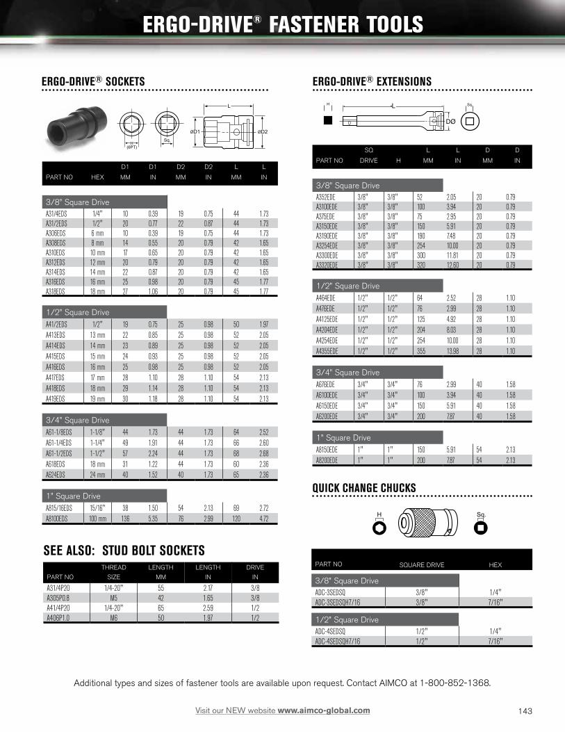
H(6PT)
Sq.
L
ØD1 ØD2
TYPE A
TYPE B
TYPE C
L
ØD2
ØD2
L
ØD1
H(6PT)
Sq.
L
ØD1 ØD2
TYPE A
TYPE B
TYPE C
L
ØD2
ØD2
L
ØD1
ERGO-DRIVE® SOCKETS
H(6PT)
Sq.
L
ØD1 ØD2
TYPE A
TYPE B
TYPE C
L
ØD2
ØD2
L
ØD1
H Sq.
ERGO-DRIVE® EXTENSIONS
QUICK CHANGE CHUCKS
L
ØD
Sq.H
L
ØD
Sq.H
L
ØD
Sq.H
H(6PT)
Sq.
L
ØD1 ØD2
TYPE A
TYPE B
TYPE C
L
ØD2
ØD2
L
ØD1
DØ
SEE ALSO: STUD BOLT SOCKETS
Additional types and sizes of fastener tools are available upon request. Contact AIMCO at 1-800-852-1368.
D1 D1 D2 D2 L L
PART NO HEX MM IN MM IN MM IN
3/8” Square DriveA31/4EDS 1/4" 10 0.39 19 0.75 44 1.73A31/2EDS 1/2" 20 0.77 22 0.87 44 1.73A306EDS 6 mm 10 0.39 19 0.75 44 1.73A308EDS 8 mm 14 0.55 20 0.79 42 1.65A310EDS 10 mm 17 0.65 20 0.79 42 1.65A312EDS 12 mm 20 0.79 20 0.79 42 1.65A314EDS 14 mm 22 0.87 20 0.79 42 1.65A316EDS 16 mm 25 0.98 20 0.79 45 1.77A318EDS 18 mm 27 1.06 20 0.79 45 1.77
1/2” Square DriveA41/2EDS 1/2" 19 0.75 25 0.98 50 1.97A413EDS 13 mm 22 0.85 25 0.98 52 2.05A414EDS 14 mm 23 0.89 25 0.98 52 2.05A415EDS 15 mm 24 0.93 25 0.98 52 2.05A416EDS 16 mm 25 0.98 25 0.98 52 2.05A417EDS 17 mm 28 1.10 28 1.10 54 2.13A418EDS 18 mm 29 1.14 28 1.10 54 2.13A419EDS 19 mm 30 1.18 28 1.10 54 2.13
3/4” Square DriveA61-1/8EDS 1-1/8" 44 1.73 44 1.73 64 2.52A61-1/4EDS 1-1/4" 49 1.91 44 1.73 66 2.60A61-1/2EDS 1-1/2" 57 2.24 44 1.73 68 2.68A618EDS 18 mm 31 1.22 44 1.73 60 2.36A624EDS 24 mm 40 1.52 40 1.73 65 2.36
1” Square DriveA815/16EDS 15/16" 38 1.50 54 2.13 69 2.72A8100EDS 100 mm 136 5.35 76 2.99 120 4.72
THREAD LENGTH LENGTH DRIVE
PART NO SIZE MM IN IN
A31/4P20 1/4-20" 55 2.17 3/8A305P0.8 M5 42 1.65 3/8A41/4P20 1/4-20" 65 2.59 1/2A406P1.0 M6 50 1.97 1/2
SQ L L D D
PART NO DRIVE H MM IN MM IN
3/8” Square DriveA352EDE 3/8" 3/8" 52 2.05 20 0.79A3100EDE 3/8" 3/8" 100 3.94 20 0.79A375EDE 3/8" 3/8" 75 2.95 20 0.79 A3150EDE 3/8" 3/8" 150 5.91 20 0.79A3190EDE 3/8" 3/8" 190 7.48 20 0.79A3254EDE 3/8" 3/8" 254 10.00 20 0.79A3300EDE 3/8" 3/8" 300 11.81 20 0.79A3320EDE 3/8" 3/8" 320 12.60 20 0.79
1/2” Square DriveA464EDE 1/2" 1/2" 64 2.52 28 1.10A476EDE 1/2" 1/2" 76 2.99 28 1.10A4125EDE 1/2" 1/2" 125 4.92 28 1.10A4204EDE 1/2" 1/2" 204 8.03 28 1.10A4254EDE 1/2" 1/2" 254 10.00 28 1.10A4355EDE 1/2" 1/2" 355 13.98 28 1.10
3/4” Square DriveA676EDE 3/4" 3/4" 76 2.99 40 1.58A6100EDE 3/4" 3/4" 100 3.94 40 1.58A6150EDE 3/4" 3/4" 150 5.91 40 1.58A6200EDE 3/4" 3/4" 200 7.87 40 1.58
1” Square DriveA8150EDE 1" 1" 150 5.91 54 2.13A8200EDE 1" 1" 200 7.87 54 2.13
PART NO SQUARE DRIVE HEX
3/8” Square DriveADC-3SEDSQ 3/8" 1/4"ADC-3SEDSQH7/16 3/8" 7/16"
1/2” Square DriveADC-4SEDSQ 1/2" 1/4"ADC-4SEDSQH7/16 1/2" 7/16"
143Visit our NEW website www.aimco-global.com
ERGO-DRIVE® FASTENER TOOLS

CUSTOM BITS, SOCKETS, AND EXTENSIONS FOR THE POWER TOOL USER
AIMCO can provide specials for virtually any application. From design to delivery, AIMCO’s quick response ensures high quality, tight tolerance specials.
Specials are available in every style including:
• Deep Socket
• Extended Socket
• Universal
• Allen Head
• Torx Head
• Socket Adapter
• Nut Runner Socket
• Nut Runner Joint
• Nutsetter
• Magnetic Nutsetter
• Universal Nutsetter
• Screwdriver Bits
Sample request forms are shown. Your detailed requirements will allow AIMCO to quickly respond with custom solutions for your fastening requirements.
H L L1 L2 A ØC ØD1 ØD2 Sq.
L
ØD2ØD1
HSq.
A
ØC
L1 L2
Magnet MP / MT / MS SIZE
TYPE
SOCKET
144 Visit our NEW website www.aimco-global.com
CUSTOM BITS, SOCKETS, AND EXTENSIONS
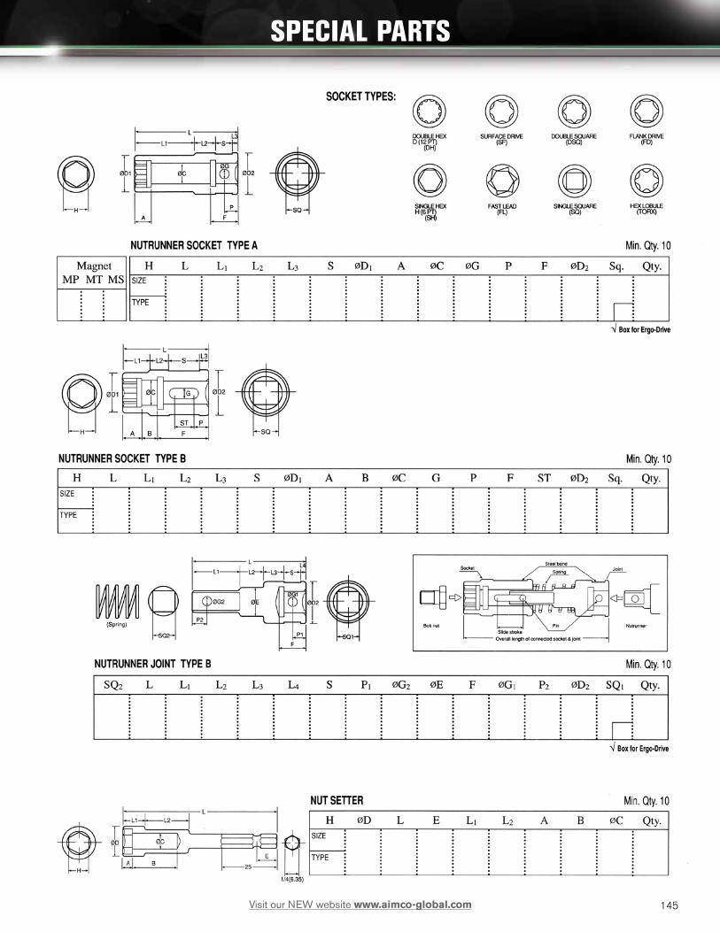
145Visit our NEW website www.aimco-global.com
SPECIAL PARTS

146 Visit our NEW website www.aimco-global.com
SPECIAL PARTS

147Visit our NEW website www.aimco-global.com
SPECIAL PARTS

Torque Conversion FactorsUnits to be SAE METRIC INTERNATIONAL SYSTEM - S.I.Converted ozf-in lbf-in lbf-ft gf-cm kgf-cm kgf-m mNm cNm Nm
1 ozf-in = 1 0.0625 0.005 72 0.072 0.0007 7.062 0.706 0.0071 lbf-in = 16 1 0.083 1152.1 1.152 0.0115 113 11.3 0.1131 lbf-ft = 192 12 1 13826 13.83 0.138 1356 135.6 1.3561 gf-cm = 0.014 0.0009 0.00007 1 0.001 0.00001 0.098 0.01 0.00011 kgf-cm = 13.89 0.868 0.072 1000 1 0.01 98.07 9.807 0.0981 kgf-m = 1389 86.8 7.233 100000 100 1 9807 980.7 9.8071 mN-m = 0.142 0.009 0.0007 10.2 0.01 0.0001 1 0.1 0.0011 cN-m = 1.42 0.088 0.007 102 0.102 0.001 10 1 0.011 N-m = 141.6 8.851 0.738 10197 10.20 0.102 1000 100 1
Fraction n Decimal n Metric Conversions (to .32)Decimal mm Decimal mm Decimal mm Decimal mm
1/32 .03125 .7938 9/32 .28125 7.1438 17/32 .53125 13.4938 25/32 .78125 19.8438
1/16 .0625 1.5875 5/16 .3125 7.9375 9/16 .5625 14.2875 13/16 .8125 20.6375
3/32 .09375 2.3812 11/32 .34375 8.7312 19/32 .59375 15.0812 27/32 .84375 21.4312
1/8 .125 3.175 3/8 .375 9.525 5/8 .625 15.875 7/8 .875 22.225
5/32 .15625 3.9688 13/32 .40625 10.3188 21/32 .65625 16.6688 29/32 .90625 23.0188
3/16 .1875 4.7625 7/16 .4375 11.1125 11/16 .6875 17.4625 15/16 .9375 23.8125
7/32 .21875 5.5562 15/32 .46875 11.9062 23/32 .71875 18.2562 31/32 .96875 24.6062
1/4 .25 6.35 1/2 .5 12.7 3/4 .75 19.05 1 1.0 25.4
Thread Size to Hex Size
MM MM UNC INCHES SAE INCHESM 2 4 M 27 41 1/4 7/16 1/4 7/16M 2.3 4.5 M 30 46 5/16 1/2 5/16 1/2M 2.6 5 M 33 50 3/8 9/16 3/8 9/16M 3 5.5 M 36 55 7/16 11/16 7/16 5/8M 3.5 6 M 39 60 1/2 3/4 1/2 3/4M 4 7 M 42 65 9/16 7/8 9/16 7/8M 5 8 M 45 70 5/8 15/16 5/8 15/16(M 5-6) 9 M 48 75 3/4 1-1/8 3/4 1-1/16M 6 10 M 52 80 7/8 1-5/16 7/8 1-1/4M 7 11 M 56 85 1 1-1/2 1-1/8 1-7/16M 8 13 M 60 90 1-1/8 1-11/16 1-1/4 1-13/16(M 8) 14 M 64 95 1-1/4 1-7/8 1-3/8 2M 10 16 M 68 100 1-3/8 2-1/16 1-1/2 2-3/16(M 10) 17 M 72 105 1-1/2 2-1/4M 12 18 M 76 110 1-3/4 2-5/8(M 12) 19 M 80 115 2 3M 14 21 M 85 120 2-1/4 3-3/8(M 14) 22 M 90 130 2-1/2 3-3/4M 16 24 M 95 135M 18 27 M 100 145M 20 30 M 105 150(M 22) 32 M 110 155M 22 34 M 115 165M 24 36 M 120 170
148 Visit our NEW website www.aimco-global.com
CONVERSION CHARTS

149Visit our NEW website www.aimco-global.com
NOTES

150150 Visit our NEW website www.aimco-global.com
NOTES


AIMCO CORPORATE HEADQUARTERS 10000 SE Pine Street Portland, Oregon 97216 Phone: (503) 254–6600 Toll Free: 1-800-852-1368
AIMCO CORPORATION DE MEXICO SA DE CVAve. Cristobal Colon 14529Chihuahua, Chihuahua. 31125MexicoPhone: (01-614) 380-1010 Fax: (01-614) 380-1019
AIMCO EUROPEC/ Río Gallo, 431 urb. Montelar19174 Galápagos / GuadalajaraSpainPhone: +34 673 34 99 25
AIMCO CHINARoom 607, No. 3998 Hongxin RdMinhang District, ShanghaiChinaPhone: 0086-21-34319246Fax: 0086-21-34319245
AIMCO SOUTH AMERICACarrera 29A, #7B-91. Origami Building. Int604. Medellin; Colombia 050021
www.AIMCO-GLOBAL.com
PRINTED IN THE U.S.A.
LIT-AT100, REV 05/09/16, ©2016
AIMCO
Visit our NEW website


