Embed Size (px)
Citation preview

Pergamon Prog. Energy Combust. Sci. Vol. 23, pp. 1-39, 1997
© 1997 Elsevier Science Ltd. All fights reserved Printed in Great Britain
0360-1285/97 $29.00
PH: S0360-1285(97)00003-8
C A T A L Y T I C A U T O M O T I V E E X H A U S T A F T E R T R E A T M E N T
Grigorios C. Koltsakis and Anastasios M. Stamatelos* Laboratory of Applied Thermodynamics, Aristotle University Thessaloniki, 540 06 Thessaloniki, Greece
Abstract--Catalytic exhaust aftertreatment of vehicle engines is increasingly employed to the benefit of the atmosphere quality, especially in the large urban area of the world. Both spark-ignition and compression- ignition engines benefit from the application of catalytic converters for the elimination of their main pollutants. Catalysts are further employed in various forms as regeneration aids in particulate filters of diesel engines. The especially demanding exhaust gas conditions prevailing in each engine application pose challenging problems to the emissions control engineer. The attainment of strict emissions regulations requires highly active and durable catalysts, as well as optimized exhaust system design and engine controls. This paper reviews the potential of catalytic systems in automobile emission control. The review covers the catalyst technology applicable in each case, the operating principles and performance characteristics, durability aspects and considerations regarding the interactions between catalyst performance and engine management. The concise presentation of related mathematical model equations provides insight into the catalytic mechanisms and the physical phenomena involved. Further reductions of catalytically controlled automobile emissions may be attained by developing improved and more durable catalysts, by applying a systems approach in designing optimized engine-exhaust aftertreatment configurations, as well as by efficient control of in-use catalytic systems through inspection, maintenance and on-board diagnostics. © 1997 Elsevier Science Ltd.
Keywords: catalysis, chemical reactors, automobile, emission control.
C O N T E N T S
Nomenclature 2 1. Introduction 3
1.1. Catalyst Operating Conditions in Engine Exhaust 3 1.2. Fuel Effects 4
2. Emissions Legislation in Europe and the U.S. 5 3. Catalytic Converters for Stoichiometric Spark Ignition Engines 7
3.1. Catalyst Types 7 3.2. Phenomena Involved in 3WCC Operation 8
3.2.1. Heat and mass transfer 8 3.2.2. Inlet flow distribution 8 3.2.3. Reactions 8 3.2.4. Chemical kinetics 9 3.2.5. Oxygen storage 10
3.3. Catalyst Activity Assessment 11 3.3.1. Light-off tests with mini scale catalysts 11 3.3.2. Light-off test on engine bench 12 3.3.3. Redox scan 12 3.3.4. Oxygen storage assessment tests 13
3.4. Catalyst Deactivation--Ageing 14 3.4.1. Catalyst ageing mechanisms 14 3.4.2. Accelerated catalyst ageing 15
3.5. Catalyst Fast Light-off Techniques (FLTs) 16 3.5.1. General 16 3.5.2. Close-coupled main catalyst 16 3.5.3. Pre-catalyst 16 3.5.4. Hydrocarbon adsorber systems 17 3.5.5. Electrically heated catalyst (EHC) 18 3.5.6. Fuel burner 20 3.5.7. Exhaust gas ignition (EGI) 20 3.5.8. Secondary air-rich fuel mixture 20
3.6. Catalysts for Alternative Fuelled Engines 21 3.7. On-board Diagnosis for Catalytic Converters 21
3.7.1. OBD system requirements 21 3.7.2. Catalyst monitoring techniques 22
3.8. Mathematical Modelling of 3WCC 23 3.8,1. Historical review 23
* Corresponding author.

2 G.C. Koltsakis and A. M. Stamatelos
3.8.2. Governing equations for the reactor model 4. Catalytic Exhaust Aftertreatment for Diesel Engines
4.1. Oxidation Catalysts for Diesel Engines 4.2. NOx Reduction Catalysts for Diesel Engines
5. Catalysts for Diesel Particulate Filters 5.1. The Particulate Filter 5.2. Catalytically Coated Filters 5.3. Catalytic Fuel Additives
5.3.1. Catalyst types 5.3.2. Mechanisms of additive action 5.3.3. Soot combustion and CO selectivity
5.4. Control Issues Related with the Use of Catalysts in Particulate Filters 5.5. Modeling Catalytic Regeneration
6. Catalytic Converters for Lean Burn SI Engines 7. Concluding Remarks References
24 25 25 26 27 27 28 28 28 29 30 30 32 33 34 35
3WCC A Af A/F AH
A/-/(i ) AH(ii) C
Cp2 Cps D DPF E
Eox
~ d
G h Hcond Hreact k k K kl
kox
kp
k ~
k S m M Mc
N NEDC
NOMENCLATURE OSC
three way catalytic converter p reaction rate constant R filtration area of paniculate filter S air to fuel mass ratio 'combined' reaction enthalpy of soot oxi- SOF dation (DPF), reaction enthalpy (3WCC) Sp specific heat of CO 2 formation (DPF) t specific heat of CO formation (DPF) T species concentration v specific heat capacity of soot deposit Vca t
specific heat capacity of ceramic wall w specific heat capacity of exhaust gas hydraulic diameter of channel (DPF) diesel paniculate filter w s apparent activation energy of soot oxi- y dation activation energy for metal additive oxi- z dation activation energy for metal additive reduc- tion inhibition factor convective heat transfer coefficient conductive heat flux (DPF) reaction heat release (DPF) collisions frequency factor (DPF) mass transfer coefficient adsorption equilibrium constant rate coefficient for the soot combustion reaction rate coefficient for fuel additive (DPF) or oxygen storage component (3WCC) oxida- tion permeability of ceramic substrate rate coefficient for fuel additive (DPF) or oxygen storage component (3WCC) reduc- tion g permeability of soot deposit layer i = 1,2 accumulated soot mass j molecular weight ox atomic weight of deposit p molecular weight of exhaust gas red exhaust gas molar flow rate s new European driving cycle w
oxygen storage capacity per unit reactor volume exhaust gas pressure reaction rate or gas constant specific surface area per unit reactor volume soluble organic fraction specific area of deposit layer time temperature exhaust gas velocity (DPF) catalyst volume mass flux of exhaust gas per unit area (3WCC), thickness of the deposit layer (DPF) channel wall thickness oxygen concentration of the exhaust gas (DPF) axial distance
Greek symbols a index for the completeness of soot oxidation e void fraction a l constant in channel pressure drop correla-
tion A P filter backpressure A thermal conductivity # exhaust gas viscosity
concentration of catalyst in the soot layer (DPF), Eq. (23)
p density ~b oxygen storage component oxidation
fraction (3WCC), oxidation state of fuel additive in the deposit layer (DPF), Eq. (24)
Subscripts exhaust gas inlet, outlet channel index for exhaust species oxidation paniculate layer reduction substrate wall

Catalytic automotive exhaust after-treatment 3
Table 1. Operating conditions of catalytic converters (exhaust composition and exhaust gas temperatures) of different engine types
CO (%) HC (ppmC) NOx (ppm) Particulate 02 (%) Redox Temperature (g/kWh) (°C)
Diesel 0.01-0.2 Otto lean-burn 0.05-0.5 Otto 0.3-1 Otto CNG fuelled 0.1-0.5
100-2000 200-1000 0.15-0.5 3-15 <1 80-700 1000-5000 100-1000 - - 0.5-5 <1 100-900 1000-5000 50-2500 - - 0.1-0.5 1 150-1000 1000- 3 0 0 0 50-2000 - - 0.1-0.5 1 100-900
1. INTRODUCTION
1.1. Catalyst Operating Conditions in Engine Exhaust
Spark-ignition and diesel engines are a major source of urban air pollution. The spark-ignition engine exhaust gases contain oxides of nitrogen (NO and small amounts of NOE--collectively referred to as NOx), carbon monoxide (CO) and organic compounds, which are unburnt or partially burnt hydrocarbons (HC). Compression-ignition (diesel) engine exhaust contains smaller amounts of CO and HC, their main problem being the particulate emissions. The relative amounts depend on engine technology and operating conditions. Table 1 gives indicative values of the operating conditions for exhaust aftertreatment catalysts met in different technology engine types.
As shown in Table l, in diesel engine exhausts, the concentrations of NOx are comparable to those from SI engines. Diesel hydrocarbon emissions are, how- ever, significantly lower than those from SI engines. The hydrocarbons in the exhaust may also condense to form white smoke during engine startup and warm- up. Specific hydrocarbon compounds in diesel engines exhaust are the source of characteristic diesel colour.
Diesel engines are also a source of particulate emissions. About 0.1-0.5% of the fuel is emitted as small particulates (0.1 #m mean size), which consist primarily of soot with some additional adsorbed hydrocarbon material. Carbon monoxide emissions of diesel engines are insignificant because of the abundancy of oxygen in diesel combustion.
Use of alcohol fuels in either of these engines substantially increases aldehyde emissions. Aldehydes would be another significant pollutant if these fuels were to be used in quantities comparable to gasoline and diesel.
Currently used fuels, gasoline and diesel, contain sulfur: gasoline in small amounts (<600 ppm weight S), diesel fuel in larger amounts (0.01-0.3% w.). In diesel engines the sulfur is oxidized to produce sulfur dioxide, SO2, a fraction of which can be oxidized to sulfur trioxide, SO3, which combines with water to form a sulfuric acid aerosol. In gasoline engines H2S is produced in small amounts as a by-product of the reactions occurring in a 3WCC during oxygen deficiency conditions.
Improvements in engine design and fuel manage- ment have led to substantial lowering of raw emission
figures during the last decades. Further reductions in exhaust emissions can be obtained by removing pollutants from the exhaust gases in the engine- exhaust system. Devices developed to achieve this result are usually assisted by catalysts, and include catalytic converters (oxidizing catalysts for HC, CO and SOF of HC, three-way catalysts for the simultaneous reduction of all three pollutants) and catalytically assisted traps or filters for the diesel particulate.
The temperature of exhaust gas in a warmed-up spark-ignition engine can vary from 300 to 400°C during idle, to about 1000°C in full load operation. Modern spark ignition engines usually operate at oscillating A/F, close to stoichiometric, as a result of the feedback lambda control system. The exhaust gas may therefore contain modest amounts of oxygen (when lean), or more substantial amounts of CO (when rich of stoichiometric). Lean burn engines, operating in the range 14.5 < A/F < 22, are also produced in limited numbers, mainly in Japan. Diesel engines, on the other hand, operate significantly leaner, and load is controlled by the amount of fuel injected in a fairly constant (at constant speed) quantity of air. The diesel exhaust gas, therefore, contains substantial oxygen and is at lower tempera- tures (100-700°C). Removal of gaseous pollutants from exhaust after it leaves the engine cylinder can be either thermal or catalytic. However, thermal oxida- tion requires temperatures of the order of 600-700°C and high residence times of the order of 50ms, and thus has limited applicability.I
Table 2 summarizes the application of various catalyst categories in different engine types to convert the regulated automobile pollutants, which will be reviewed in this paper. Catalytic oxidation of CO and hydrocarbons in the exhaust can be achieved at temperatures as low as 220°C. On the other hand, the only efficient methods known for the removal of NO from exhaust gas either at stoichiometric or lean A/F conditions, involve catalytic processes. 2 Consump- tion of NO by the reducing species present in the exhaust such as CO, hydrocarbons or H 2 is the preferred catalytic process. This is the case in 3WCCs for SI engines. NOx reduction in oxygen rich conditions is currently achieved by catalysts which promote NO-hydrocarbons reactions in lean burn or diesel exhaust gas. In the latter case, additional amounts of hydrocarbons are usually injected in the exhaust gas to ensure high NO conversion efficiency.

4 G.C. Koltsakis and A. M. Stamatelos
Table 2. Application of catalysts in different technology engines
Otto stoichiometric Otto, lean-bum Diesel
CO 3WCC* Oxi-catt Oxi-cat HC 3WCC Oxi-cat Oxi-cat NOx 3WCC Lean NOx$ Lean NOx Particulate - - - - Oxi-cat,
Filter regeneration aids§
* Precious metal loaded three-way catalytic converters. t Precious metal loaded oxidation catalysts. :~ Zeolite based or precious metals catalysts for NO reduction. § Catalytically coated filters, fuel additives to lower filter regeneration temperature.
Particulates in the diesel exhaust gas stream may be removed by a particulate filter (trap). Due to the small particle size involved (order of 0.2/zm), mechanical filtration is the most effective trapping method. The accumulation of mass within the filter and the increase in exhaust manifold pressure during filter operation are major development problems. Diesel particulates, once trapped, can be burned up either by initiating oxidation within the filter with an external heat source, or by using a catalytically coated filter or, better, a fuel doped with some type of catalytic fuel additive. Reliable regeneration of diesel particulate filters remains a major challenge for diesel engine emission control.
1.2. Fuel Effects
The role of fuel composition and properties as an additional factor in reducing air pollutant emissions is widely recognized and discussed. In this discussion, two main streams are evident: improvement of the traditional fuels (reformulated fuels) and the intro- duction of alternative fuels. Improving traditional fuels has two different performance aspects:
1. To maintain engine and emissions control equipment in the best possible order during a vehicle's useful life. For example, sulfur in fuel can clearly affect the efficiency of catalyst conversion systems.
2. To further lower the engine out and, subse- quently, catalyst out exhaust emissions.
The following parameters have been, and are being, studied extensively for their relationship with exhaust and evaporative emissions: aromatics content (clearly related to benzene emissions), olefins content (strong effect on butadiene emissions), benzene content, boiling range (T50, T90--signifi- cant effect on HC emissions), vapour pressure (high RVP leads to breakthrough of canister control systems) and content of oxygenated compounds (mainly lower CO emissions, MTBE may increase formaldehyde emissions).
Fuel improvements could enable the legislator to drastically reduce atmospheric concentrations of HC and (to a lesser extent) NOx emissions. However, such issues should seriously consider the dual role of NOx in ozone formation. In areas with low atmospheric HC-NOx ratios, reducing NOx can increase ozone
formation, whereas for high atmospheric HC-NOx ratio areas, reducing NOx decreases ozone: In a recent U.S. study it was stated that in 2005 the light duty vehicles will contribute 5-9% of peak ground level 03 values in three US cities. This contribution could be lowered by 25% by switching to reformu- lated gasoline. Afterwards the effect becomes appre- ciably smaller; also the effect strongly depends on the local pollutant mix.
Compressed natural gas (CNG) as a fuel for internal combustion engines is mainly composed of methane (from 60 to 99% by volume, depending on different sources). Although methane is a greenhouse gas, it does not contribute to the formation of photochemical smog and this is the reason that the U.S. legislation excludes methane from the regulated emissions. Thus, ULEV standards may be more easily attained by the use of CNG. However, if total hydrocarbon emissions are controlled, as in the EC legislation, special catalysts must be developed able to convert methane at relatively low temperatures. 4
Liquified petroleum gas (LPG) has some advan- tages over gasoline regarding engine-out emissions which, however, essentially disappear with the introduction of the closed loop control three-way catalyst system:
Methanol is used as a component of fuels for S.I. engines (M85 or M100). The main thrust behind California/U.S. interest in methanol is future trans- port energy supply and the potential for lowering photooxidants. Its use results in a clear reduction of HC emissions (of the order of 30-40%), less or no benzene emissions and acceptable methanol and formaldehyde concentrations in the air. Depending on the source material for methanol production, greenhouse gases can range from favorable or equal to, to very much worse than petrol. However, methanol fuelled vehicle exhaust also contains significant amounts of photochemically reactive alde- hydes (primarily formaldehyde). Previous studies 6'7 have shown that maximum air quality benefit from methanol fuel can be obtained, provided that exhaust emissions of formaldehyde are kept to very low levels. The California Air Resources Board has enacted a 15mg/mile formaldehyde emission standard for methanol-fuelled vehicles and the requirement that this standard be met for at least 5 years or 50,000 miles of vehicle use.

Catalytic automotive exhaust after-treatment 5
E "~ 4
E 2
o z
0
60
50
o 2o.
~ lO
7
6
E 5 -~- 4
3 E 2
"1" 1
I
I
I
i
I
I
1970
Federal
California
, ! !
- - - | I
i I = I i I i I 1975 1980 1985 1990
= I
1995
- - B
I '
/ I I = I i I t I = I i I
1970 1975 1980 1985 1990 1995
L - |
1970 1975 1980 1985 1990 1995 Year
Fig. 1. Historical evolution of emission standards in the U.S. for light-duty vehicles.
Oxygenates, as a component of gasoline (MTBE or alcohol 10-17% or 3-4% O2 equivalent), leads to lower CO emissions and somewhat lower HC including benzene. NOx and acetaldehyde emissions can go up somewhat depending on the type of oxygenate, whereas evaporative emissions can go up strongly due to blocking of active carbon canister sites by alcohols.
Regarding the effect of diesel fuel on emissions, the following composition parameters have been, and are being, studied extensively for their relationship with exhaust emissions: density, cetane number and index, aromatics content, sulfur content, boiling range (T50-T90). In some studies an attempt has been made to differentiate between mono- and polyaromatics. Of all the fuel parameters, cetane number appears to be the only consistent parameter; it clearly affects the quantity and quality of particulate emissions in IDI and high speed DI engines. Rapeseed oil is discussed as a new agricultural product, that could replace other overproduced crops in Europe and elsewhere. In terms of regulated and unregulated emissions there appear to be major disadvantages for the straight oil. In esterified form (rapeseed oil methylester), small advantages in regulated emissions against increase of smell result. Like all vegetable oils, it offers an overall advantage in terms of CO2 emissions. However, if the overall greenhouse gas
emissions from the full production cycle of esterified rapeseed oil are considered, advantages over the diesel fuel cycle essentially disappear.
2. EMISSIONS LEGISLATION IN EUROPE AND THE U.S.
Figure 1 shows the evolution of U.S. emissions standards over the last 25 years. In the past, the exhaust emissions standards for passenger cars and other road vehicles were strengthened stepwise every few years. This concept was based on the experience that the manufacturers of passenger cars construct the vehicles in such a way that the emissions are lower than the limit values by a safety margin. The thus attainable emissions levels could then be considered as a new basis of common available technology, for the negotiations of the next step. This approach has an advantage for the manufacturer, since only small changes are required every 2 or 3 years. On the other hand, frequent modifications in the produc- tion had to be done and expenses for new certifica- tions incurred. In the more recent EPA legislation, as well as in the European directive 94/12/EEC, it is required that the proposal for emission standards for passenger cars for the year 2000 should aim at a substantial pollutant reduction. For the following steps, the potential of the existing engine and exhaust

6 G . C . Koltsakis and A. M. Stamatelos
Table 3. Current and future emission standards for light-duty vehicles in the U.S. Implementation plan of the Clean Air Act Amendments
Emissions Durability MY 91 -0 MY 94 ~ Proposal (miles) (Tier 0) (Tier I) MY 2003
(U.S. 87) (U.S. 94) (Tier II)
HC 50,000 0.41 0.41 NMHC 50,000 0.25
100,000 0.31 0.125 CO 50,000 3.4 3.4
100,000 4.2 1.7 CO (-7°C) 50,000 1.0 3.4 NOx* 50,000 !.0 0.4
100,000 0.6 0.2 NOxt 50,000 1.0 1.0
100,000 1.25 Particulates 50,000 0.2 0.08
100,000 0.10 0.08
* Gasoline vehicles. tDiesel vehicles. Emissions figures in grams/mile.
Model year
Phase-in (%) 93 94 95 96 97 98 99 2000 2001 2002 2003
Exhaust emisshms Tier I Phase-in Cold CO standard Tier II proposal
In-use testing OBD II Cert. short test (CST) Enh. I/M (I/M 240)
Testing procedures Revised FTP Rev. durability
Others Clean fuel veh. fleets
r 40 80 100 I 40 80 100 t . - . . . . . . . . . . . . . . . .
r . . . . . . . 7 6 - 0 . . . . . . . . . . . . . . . . . . . . . . . . . . .
i 100 I
1 3 o _ _ j 0 o . . . . . . . . . . . . . . . . . . . . . . . . . . .
Eold old + alternative r-Phase.in
new + alternative
aftertreatment technologies must be reassessed from time to time.
Also, the effects of traffic induced CO2 emissions must be taken into account in the evolution of emissions reduction technologies. In order to meet the aim of decreasing anthropogenic CO2 emissions by 25% by the year 2005 compared to 1990, which was required by the German government during the 1st World Climate Conference in Berlin, a significant drop in traffic CO2 emissions needs to be effected.
The properly working standard closed-loop TWC reduces emissions of HC, CO and NOx of a spark- ignition engine by 80-90%. The main potential to further reduce emissions is to reduce the time needed for the catalyst to reach light-off temperature. Currently, about 60-80% of total HC emissions over the New European Driving Cycle (NEDC) and the FTP 75 cycle are emitted within the first 200 see of the cold start phase. As a large part of inner-urban driving is done over small distances (less than 3 km), the reduction of cold start emissions can significantly reduce the overall traffic induced immission burden.
Legislation in the U.S., especially California,
already requires much lower emission standards than can be achieved with the conventional TWC technology. Yet for Europe more stringent emission regulations are also scheduled, including a more realistic test procedure (e.g. omitting the 40 sec idle period at the beginning of the driving cycle), and new requirements regarding evaporative emissions and on-board diagnostics.
The basis for the new U.S. regulations are the 1990 Clean Air Act Amendments (CAAA), with the objective to improve air quality, particularly in large cities where in summer high ozone levels and in winter high CO levels are encountered. Besides tighter tail-pipe emission standards, the CAAA require the establishment of improved inspection-maintenance programmes, a reformulated gasoline program, legislation covering standards for vehicle fleet operators and for 'clean fuels-clean vehicles', which could lead to the introduction of alternative fuels.
Exhaust emissions standards defined in the CAAA are listed in Table 3. The current standard is Tier I which was phased in between 1994 and 1996, when certification up to 100,000 miles will also be required,

Catalytic automotive exhaust after-treatment 7
~~ " - - - - washcoat ii;i Fig. 2. Structure of the monolithic catalytic converter.
enforced by the possibility of an 'emission-recall'. Tier II standards will only come into effect if EPA decides that they are necessary, technically feasible and cost-effective.
More stringent emission standards are being intro- duced in California with the aim of progressively reducing vehicular emissions, to achieve the national air quality standards. In Table 3, the classes of low- emissions vehicles are also defined. Only the intro- duction of ZEV is mandatory, whereas for TLEV, LEV and ULEV implementation is up to the manufacturer, as long as his average NMOG fleet emissions are below the mandatory limits. Non- methane organic gases (NMOG) are the sum of NMHC (up to 12C atoms) plus oxygenated com- pounds (up to 5 C atoms) such as aldehydes/ketones and alcohols (for alcohol-fuelled vehicles). The inten- tion is to evaluate the tropospheric ozone formation potential, therefore methane is excluded, and the measured NMOG emissions are corrected using reactivity adjustment factors (RAF) which are basic characteristics for a given vehicle/fuel combination. For gasoline and alcohol vehicles additional tests are required at 10°C, with the same CO and NO~ standards, but less stringent NMOG and HCHO limits.
3. CATALYTIC CONVERTERS FOR S T O I C H I O M E T R I C
S P A R K I G N I T I O N E N G I N E S
3.1. Catalyst Types
The catalytic converters used in spark-ignition engines consist of an active catalytic material in a specially designed metal casing, which directs the exhaust gas flow through the catalyst bed. The active material employed for CO and HC oxidation or NO reduction (normally noble metals), must be distrib- uted over a large surface area, so that the mass transfer characteristics between the gas phase and the active catalyst surface are sufficient to allow close to 100% conversion with high catalytic activity. 8 The most widespread type today employs a ceramic (or
metallic) honeycomb structure or monolith held in a metal can in the exhaust stream. The noble metals are impregnated into a highly porous alumina washcoat about 20-40 #m thick that is applied to the passage- way walls (Fig. 2). A typical monolith has square cross section passageways with inside dimensions of the order of 1 mm separated by thin (0.1-0.15 mm) porous walls. The number of channels per square inch varies between 400 and 600, 9 although even higher cell densities of the order of 1200cpsi have been demonstrated for metallic substrates.l° The washcoat, 5-15% of the monolith weight is mainly composed of A1203 and has a surface area of 100-200m2/g.
The majority of the present day monolithic three way emission control catalysts for gasoline engines use a combination of platinum and rhodium as precious metal components. There has been a keen interest lately in replacing a part or all of the platinum content of an automotive catalyst by palladium, mainly as a means to reduce the precious metal cost of the catalyst. 11 Most of the oxidation catalysts used in the U.S.A. on model years 1975- 1980 vehicles, contained Pt and Pd in the ratio 5 Pt-2 Pd at a typical loading of 50-70 g/ft 3. Also, a lot of the bead type three way catalysts used by General Motors on model year 1981-1992 vehicles, used Pt together with Pd and Rh. In the literature, precious metal loading ranges are reported for Pt 30-100g/ ft 3; Pd 0-120 g/ft 3; and Rh 5-10 g/fla. The ratio of Pt to Pd was in most cases higher than one. During the development of these catalysts it was recognized that each of the three precious metals Pt, Pd and Rh need a particular position in the catalyst to function properly. To this end, advanced impreg- nation techniques were developed. A number of disadvantages have been reported when Pd is incorporated in P t -Rh catalysts. For example it has been demonstrated that Pd can form alloys with Rh in which Pd is enriched at the alloy surface, thereby suppressing the full deployment of the excellent catalytic activity of Rh) 2 To avoid this, advanced, costly impregnation technologies are necessary.
In addition, several fundamental studies have shown that the resistance of Pd against poisoning by for example lead and sulfur is substantially inferior to that of both Pt and Rh. It was shown that sulfur decreases, in particular, the ability of Pd to convert CO and HC in net reducing exhaust gas conditions, thereby narrowing the A/F window, in which a high conversion of CO, HC and NOx is simultaneously reached. It The same studies, however, stressed that this negative influence does not occur in net oxidizing exhaust gas compo- sition. Other studies showed that with net oxidizing conditions, Pd favours the CO-O2 reaction more than the C O - N O reaction--as opposed to Rh- - so that the A/F window is narrowed by the poorer NOx conversion at the lean side, when using Pd. 13
Finally, Pd only catalysts have been used in specific applications (e.g. as pre catalysts etc.). However, it is recognized that only Rh provides selective reduction

8 G.C. Koltsakis and A. M. Stamatelos
of the nitric oxide to nitrogen with low ammonia formation. Muraki et al. 14 demonstrated that under reducing conditions with Pd catalysts, poor NOx reduction results. The reduction of nitric oxides on Pd catalysts was found to be significantly inhibited by hydrocarbons, is The light-off performance and NOx reduction efficiency have been improved by both periodic operation and addition of lanthanium to the catalyst. 16,17
The net result of these technical facts is that the successful use of Pd in three way emission control catalysts was limited to applications where the engineering targets for the conversion of CO, HC and NOx are lower than 90% and/or where the content of the catalyst poisoning elements in the fuel is low--such as the gasoline available on the Japanese market. 18 In 1992 only about 9% of the Pd supplied to the market found use in automotive catalysts, compared to 45% for the platinum and 85% of the rhodium. Recent trends in improvement of the catalyst relevant properties of the fuels available in the U.S. and Europe, along with the wide application of advanced engine management systems with a capability for much tighter A/F control close to stoichiometry, relieve the above-mentioned con- straints to the use of Tri-metal catalysts, tl'19 In addition, the significant advantage of Pd in pro- ducing faster catalyst light off under net oxidizing conditions is exploited by means of introducing Pd- based light-off catalysts, which lead to significant further reduction of cold start emissions. Also, the development of advanced washcoats for Pd com- pensated to some extent, some of the disadvantages mentioned above.
Apart from the precious metals, the 3WCC alumina washcoat also contains other components, which function as catalytic promoters or stabilizers against ageing. Cerium is normally present in high quantities in the washcoat (order of 30% w. or 1000g/ft 3) and has multiple functions: stabilization of the washcoat layer and improvement of thermal resistance, enhancement of precious metal catalytic activity, promotion of the water-gas shift reaction and function as an oxygen storage component. 2°-22 Iridium has remarkable activity for NO reduction under net oxidising conditions. 23 However, the availability of Ir is lower than Rh and it tends to form volatile oxides in the exhaust environment, so it is not used in automotive catalysts. Ruthenium and nickel have catalytic properties for NO reduction. Nickel is also capable of suppressing H2S formation. They are not currently used as stand-alone catalysts, but are potential additives for catalytic washcoats.
3.2. Phenomena Involved in 3 WCC Operation
3.2.1. Heat and mass transfer
Although the flow in the exhaust piping of an engine is normally turbulent, the Reynolds (Re)
numbers in the converter monofith channels are in the laminar region (20 < Re < 300). The transition of the flow to laminar occurs in the first few millimeters after the monolith entrance, where the transport phenomena are generally enhanced.
The main heat transfer mode in the converter is the convective heat exchange between the exhaust gas and the substrate. Heat is additionally generated from the exothermic reactions of some exhaust components (CO, hydrocarbons) on the catalytic washcoat. In the case of electrically heat catalysts, electrical energy is supplied to the substrate in order to quicken its temperature rise during warm-ups. At high operation temperatures, heat radiation from the substrate to the surrounding walls become appreciable. Related studies 24 have shown that the latter effect is generally of secondary importance. The converter heat losses to the ambient occur via convection (free and forced) and radiation from the converter shell.
The concentration gradients between the flowing gas and the reactive washcoat induce the convective mass transfer in the monolith channels. Since the species of interest are present in low concentrations in the exhaust gas of a gasoline engine, the mass transfer is governed by the laws of diffusion in dilute mixtures and the analogies between heat and mass transfer are fully applicable. 25
3.2.2. Inlet flow distribution
Non-uniformities in the velocity field at the inlet of the converter may cause both poor converter performance, due to localized high space velocities, and increased ageing, due to poison accumulation in high mass flow rate areas of the monolith. 26'27 Consequently, a large amount of computation and experimental work has been conducted so far, aiming at the minimization of the flow maldistribution. 28'29 An outcome of these studies is related to the quantification of maldistribution by means of semi- empirical indices, which correlate well with the flow Re numbers and the geometrical parameters of the diffuser and monolith.
3.2.3. Reactions
The main reactions contributing to the conversion of the main SI engine pollutants, that take place in a three way catalytic converter are:
oxidation reactions
CO -~- 102 ~ CO 2
H2 + / O 2 ~ H 2 0
y
steam reforming
CxHy + xH20---~ xCO+ (x +Y)H2;

Catalytic automotive exhaust after-treatment 9
I00
-_NO, 8O
- H c " ' . / ~ ! \ ~ 60- c o . /
° 80~ e~io .~ i i \ _~ 40 -air~e, ratio~ i#'-- \
i ,i \ ',: :1 Stoichiometric i:: i ~ air/fue ratio
0 t : :::.: .: I 14.3 14.4 14.5 14.6 14.7 14.8 14.9
Rich l.can Air/fuel ratio
Fig. 3. Conversion efficiency of NO, CO and HC as function of the air-fuel ratio in a three way catalytic converter. 8
NO x reduction
2CO + 2NO --~ 2CO 2 + N 2
C~Hv+(2x+2)NO--~xCO2+Y. . 2 H 2 0
H 2 + NO -----* H20 + IN2;
water-gas shift
CO + H20 ----+ C O 2 + H 2.
If an engine is operated at all times with an air-fuel ratio at or close to stoichiometry, NO reduction, CO and HC oxidation can be attained in a single catalyst bed. Enough reducing gases will be present to reduce NO, and enough 02 to oxidize the CO and hydro- carbons. Such a catalyst is called a three way catalyst, since it removes all three pollutants simultaneously. Figure 3 shows the conversion efficiency of NO, CO and HC as function of the air-fuel ratio. There is a narrow range of air-fuel ratios near stoichiometry in which high conversion efficiencies for all three pollutants are achieved. The width of this window is narrow, about 0.1 air-fuel ratios for catalyst with high mileage use, and depends on catalyst formulation and engine operating conditions, s
This window is sufficiently narrow to require the application of closed loop fuel injection control. An oxygen sensor in the exhaust is used to indicate whether the engine is operating on the rich or lean side of stoichiometry, and provide a signal for adjusting the fuel system to achieve the desired air-fuel mixture. Holding the equivalence ratio precisely on the chosen near-stoichiometric value is not a practical expectation of the state-of-the-art feedback systems, and the equivalence ratio oscillates around the set point in an approximately periodic manner as the fuel flow is varied. Experimental data show that there is a considerable widening of the air-fuel ratio window, where all three pollutants are effectively removed,
with cyclic variation of the fuel flow. 3° The maximum conversion efficiency in the middle of the window is reduced, however, from its value when there are fluctuations. A number of researchers addressed the problem of optimum electronic control of A/F fluctuation characteristics (setpoint, frequency, ampli- tude) for A/F window maximization. 3z On the other hand, significant research activities are aimed at exploiting the capabilities of model based A/F control in eliminating deviations from stoichiometry, especially during transient operation. 32'33
Because of the cyclic variations in exhaust gas composition about a set point close to stoichiometry, it is desirable that the catalyst is able to reduce NO even when there is a slight excess of oxygen (on the lean side) and remove CO and HC when a slight deficiency of oxygen is present (on the rich side). Rhodium is the principal ingredient used in com- mercial catalysts to convert NO. It is very active for NO reduction, is much less inhibited by CO and sulfur compounds, and produces less NH 3 than Pt. To remove NO under slightly lean conditions, the catalyst must react the CO, H 2 or HC with NO rather than with O2, as the exhaust gas passes through the catalyst bed. Rhodium shows some NO reduction activity slightly lean of stoichiometric. On the rich side, the three-way catalyst window is determined by hydrocarbon and CO removal. Platinum is most commonly used for HC and CO oxidation; it has good activity under stoichiometric and lean condi- tions. When sufficient rhodium is present, the participation of Pt in NO removal is minimal. In the rich regime, the three-way catalyst consumes all the oxygen that is present in the exhaust, and as a consequence removes an equivalent amount of CO, H 2 and hydrocarbons; H2 is the most reactive among the three species by itself; in the presence of CO it tends to light-off at the same time as the other species.
The water-gas shift reaction and the steam reforming reaction can additionally consume CO and HC, respectively. 3a The exhaust contains an H2/CO ratio of about 1/3, where the equilibrium ratio at 500°C is about 4. Considerable CO removal can be expected if the water-gas shift equilibrium is approached. Platinum is active in promoting this reaction, but is strongly poisoned by sulfur. 35 For large molecular weight paraffin hydrocarbons and for olefins and aromatic hydrocarbons, the equilibrium for the steam-reforming reactions lies to the right. This reaction can therefore lead to considerable hydrocarbon removal. Rhodium is particularly active in the steam-reforming reaction.
3.2.4. Chemical kinetics The multitude of the heterogeneous reactions
taking place on the catalytic washcoat poses a challenge for the engineer involved in the design, modeling and manufacturing of three-way catalytic converters. Converter models require reliable kinetic
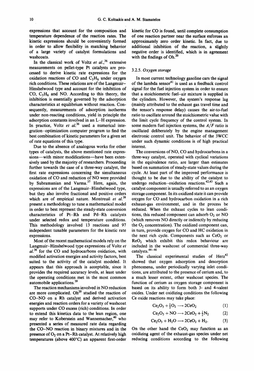
10 G.C. Koltsakis and A. M. Stamatelos
expressions that account for the composition and temperature dependence of the reaction rates. The kinetic expressions should be conveniently formed in order to allow flexibility in matching behavior of a large variety of catalyst formulations and washcoats.
In the classical work of Voltz et al., 36 extensive measurements on pellet-type Pt catalysts are pro- cessed to derive kinetic rate expressions for the oxidation reactions of CO and C3H6 under oxygen rich conditions. These relations are of the Langmuir- Hinshelwood type and account for the inhibition of CO, C3H6 and NO. According to this theory, the inhibition is essentially governed by the adsorption characteristics at equilibrium without reaction. Con- sequently, measurements of adsorption isotherms under non-reacting conditions, yield in principle the adsorption constants involved in an L - H expression. In practice, Voltz et al. 36 used a numerical inte- gration-optimization computer program to find the best combination of kinetic parameters for a given set of rate equations of this type.
Due to the absence of analogous works for other types of catalysts, the above mentioned rate expres- s ions-wi th minor modifications--have been exten- sively used by the majority of researchers. Proceeding further towards the case of a three-way catalyst, the first rate expressions concerning the simultaneous oxidation of CO and reduction of NO were provided by Subramanian and Varma. 37 Here, again, the expressions are of the Langmuir-Hinshelwood type, but they also involve fractional and positive orders which are of empirical nature. Montreuil et al. 38
present a methodology to tune a mathematical model in order to best represent the steady-state conversion characteristics of P t -Rh and Pd -Rh catalysts under selected redox and temperature conditions. This methodology involved 13 reactions and 97 independent tunable parameters for the kinetic rate expressions.
Most of the recent mathematical models rely on the Langrnuir-Hinshelwood type expressions of Voltz et al. 36 for the CO and hydrocarbons oxidation, with modified activation energies and activity factors, best suited to the activity of the catalyst modeled. It appears that this approach is acceptable, since it provides the required accuracy levels, at least under the operating conditions met in the most common automobile applications. 39
The reaction mechanisms involved in NO reduction are more complicated. Oh 2° studied the reaction of C O - N O on a Rh catalyst and derived activation energies and reaction orders for a variety of washcoat supports under CO excess (rich) conditions. In order to extend this kinetics data to the lean region, one may refer to Koberstein and Wannemacber, 4° who presented a series of measured rate data regarding the C O - N O reaction in binary mixtures and in the presence of OE on a P t -Rh catalyst. At relatively high temperatures (above 400°C) an apparent first-order
kinetic for CO is found, until complete consumption of one reaction partner near the surface enforces an approximately zero order kinetic. In fact, due to additional inhibition of the reaction, a slightly negative order is identified, which is in agreement with the findings of Oh. 2°
3.2.5. Oxygen storage
In most current technology gasoline cars the signal of the lambda sensor 41 is used as a feedback control signal for the fuel injection system in order to ensure that a stoichiometric fuel-air mixture is supplied in the cylinders. However, the system's response lag (mainly attributed to the exhaust gas travel time and the sensor's response delay) causes the air-to-fuel ratio to oscillate around the stoichiometric value with the limit cycle frequency of the control system. In some modern fuel injection systems, the A / F ratio is oscillated deliberately by the engine management electronic control unit. The behavior of the 3WCC under such dynamic conditions is of high practical interest.
The conversions of NO, CO and hydrocarbons in a three-way catalyst, operated with cyclical variations in the equivalence ratio, are larger than estimates based on summation of steady-state values during the cycle. At least part of the improved performance is thought to be due to the ability of the catalyst to undergo reduction-oxidation reactions. 42'43 Such a catalyst component is usually referred to as an oxygen storage component. In its oxidized state it can provide oxygen for CO and hydrocarbon oxidation in a rich exhaust-gas environment, and in the process be reduced. When the exhaust cycles to lean condi- tions, this reduced component can adsorb O2 or NO (which removes NO directly or indirectly by reducing the 02 concentration). The oxidized component can, in turn, provide oxygen for CO and HC oxidation in the next rich cycle. Components such as CeO2 or ReOE which exhibit this redox behaviour are included in the washcoat of commercial three-way catalysts. 44-46
The classical experimental studies of Herz 42 showed that oxygen adsorption and desorption phenomena, under periodically varying inlet condi- tions, are attributed to the presence of cerium and, to a much lesser extent, other washcoat species. The function of cerium as oxygen storage component is based on its ability to form both 3- and 4-valent oxides. Under net oxidizing conditions the following Ce oxide reactions may take place:
Ce203 + 1 0 2 ~ 2CeO 2 (1)
Ce20 3 + NO ~ 2CeOE + 1N 2 (2)
Ce203 q- H20 ~ 2CeO2 + H2. (3)
On the other hand the CeO2 may function as an oxidizing agent of the exhaust-gas species under net reducing conditions according to the following

Catalytic automotive exhaust after-treatment 11
-2
-4 2)
-6
-8
-10
.d
O E
.o
-12 , i , I , i 0.80 1.20 1.60 2.00
1/T ( l /K)
Fig. 4. Reaction rate measurements (Arrhenius plot) of CO-O2 reaction in a Pt-Rh catalyst. 4°
reactions:
2CEO2 + CO ~ Ce203 + CO 2 (4)
2CeO2 + H2 ~ Ce203 + H20. (5)
The interaction of Ce oxides with the hydrocarbons has been reported to be of minor importance. 42 The oxygen storage availability is apparently a function of the washcoat Ce content and dispersion. Moreover, the stored oxygen available to react under operating conditions is a function of the local temperature and redox environment. 47
3.3. Catalyst Activity Assessment
3.3.1. Light-off tests with mini scale catalysts
The activity of the catalyst as a function of its temperature is a critical feature of its performance and is affected by a number of exothermic reactions. Arrhenius plots, derived from dedicated measure- ments, yield information regarding the reaction kinetics of single reactions. Figure 4 presents, as an example, a typical Arrhenius plot obtained for the CO-O2 reaction on a P t - R h catalyst. 4° Four temperature regions characterized by their own activation energy may be recognized in this plot. In the first the overall reaction is controlled by the reaction kinetics, whereas in the second the conver- sion is limited by the pore diffusion in the alumina washcoat. The third region corresponds to mass- transfer controlled conditions and in the fourth, high temperature region the homogeneous reaction becomes the controlling phenomenon.
An easier way to assess the catalytic activity in the laboratory is to measure the efficiency with which hydrocarbons, carbon monoxide and nitrogen oxides, contained in synthetic exhaust gas, are converted as functions of catalyst temperature. Such tests are per- formed on a monolithic catalyst core or representative
400
360
o o o 320 to I--
0 0 0 tO I -
280
f Cat A ........... Cat B Cat C
i
AT/At = 1 K/s
240 , i , i , I , 0 20000 40000 60000 80000
GHSV ( l /h ) (a)
Cat A
4 5 0 . . . . . . . . . . Cat B ,
Cat C G H S V = 50000 ( l / h
400
350
300
250
. . . . - -
200 , i , ~ , ~ , 0 1 2 3 4
Temperature increase rate (K/s) (b)
Fig. 5. The dependence of the observed light-off temperature for 50% CO conversion on (a) the GHSV; and (b) the
temperature increase rate in a light-off test. s°
pellet sample aged in a predetermined way. The sample is subjected to a representative flow of synthetic gases to simulate car operating conditions. The temperature of the mixture is controlled to increase at a specified rate. The conversion efficiency is measured by the composition upstream and downstream of the converter as a function of inlet gas temperature. The composition of the synthetic gas mixture can optionally be lean, rich or modulated around a mean concentration at a specified amplitude and frequency. The latter option is used to better reproduce the catalyst operation under real world conditions on an engine operating with closed loop lambda control.
The main light-off test parameters (feed-gas space velocity, temperature increase rate) should be

12 G.C. Koltsakis and A. M. Stamatelos
400
300
v
200
E
100
GHSV=28000 1/h
i / = I = 50 100
time (s)
(a)
150
100 • , • ~ • ~ , f
/ / =
80 L CO / / "
- - - HC / ,/
60 J /
"~ / fl I ~_
4 0 >o
i I I//111 o
2O
0 '¢' 100 200 300 400 500 Exhaust gas inlet temperature (C)
(b)
Fig. 6. (a) Exhaust gas temperature and (b) converter efficiency observed in a full-scale light-off test conducted on an engine test bench. GHSV = 28,000/hr, A/F= 14.85,
2.11 catalyst--Pt-Rh 5:1--50 g/ft 3.39
carefully selected, in order to best exploit the measurement results. 48 More specifically, a well designed light-off test should be able to provide a clear differentiation in the light-off temperature among activity catalysts. Mathematical models have been used to optimize the design of a light-off test in this sense. 49'5°
Figure 5 (a) shows the dependence of the 'observed' light-off temperature for four different activity catalysts when the test is performed with variable space velocities. The temperature increase rate for these simulations is 1 K/see. For all catalysts, a remarkable increase in the light-off temperature is recognized for GHSV values below 20,000/hr, where a local minimum is observed. For GHSV greater than 20,000/hr the light-off temperature increase is more profound for the lower activity catalyst. Similar investigations may be performed regarding the effect
of the temperature increase rate selected for such a test procedure. Figure 5 (b) presents, in the same manner, the differences in the light-off temperature measured for different test conditions. Clearly, the temperature corresponding to 50% conversion is strongly dependent on the temperature increase rate. 5°
The tendencies observed in these results are explained by the effects of catalyst substrate warm- up behavior during the light-off test. In general, the temperature of the catalyst sample is axially non- uniform during the test; on the other hand the exhaust gas inlet temperature is not necessarily a sufficient representation of the catalyst temperature. The use of the mean value of exhaust-gas inlet and outlet temperatures to correlate the catalyst performance has been shown to be more representative for a wide range of test conditions. More details on the analysis of light-off tests may be found in Kolstakis et aL so
3.3.2. Light-off test on engine bench
The light-off testing on an engine bench is better suited for the facilities of typical automotive laboratories. For this test the catalytic converter is mounted on the given exhaust system and the engine is braked to operate at a constant point. The converter is thus subjected to an exhaust flow of nearly constant flow rate and composition, whereas its temperature increases with time from ambient to a constant value. The conversion efficiency of the catalyst can be calculated based on inlet-outlet species concentrations as a function of inlet gas temperature. As before, the engine should be controlled to produce lean, rich and modulated A / F exhaust gas mixture.
A particularity of this test compared to the corresponding laboratory light-off test on a mini- scale sample is the temperature evolution at the catalyst inlet, which is principally dictated by the engine and exhaust piping transient characteristics (thermal response). Figure 6 presents the temperature evolution at the converter inlet and the conversion efficiency for CO and HC as functions of the inlet temperature measured in a full-scale light-off test. 39 The temperature increase rate is relatively steep and not sufficient to achieve uniform temperature distribution in the converter during the test. In the full-scale light-off activity test the catalyst is subjected to a generally non-uniform flow at its entrance. This, together with the heat transfer effects from the monolith to ambient, results in non-uniform flow and temperature conditions inside the converter, which adds to the complexity of catalyst assessment.
3.3.3. Redox scan
This type of test is necessary to distinguish catalyst efficiency for engine operation at various air-to-fuel ratios. Useful information can be derived regarding the efficient A / F operating region of the catalyst

Catalytic automotive exhaust after-treatment 13
_g
0 0 "1"
o~ c
g
>=
( 3
0
100
80
i •
60
40
20
0 14 .0
100
8 0
6 0
4 0
2 0
, i • J • i • i •
s s I
Fresh
. . . . Aged
I I I I , I i I ,
14 .2 14 .4 14 .6 14 .8 15 .0
A i r /Fue l ratio
(a)
• i • i I I i
/
i s
/ i
i i
i i
i i
I i
i J
i
J
F resh
. . . . Aged
, I i I i I i I i
14 .0 14 .2 14 .4 14 .6 14 .8 15 .0
A i r /Fue l r a t i o
(b)
Fig. 7. Effect of 850°C fuel-cut ageing (5 h) on (a) HC and (b) CO performance of noble metal catalysts as function of
A/F. 51
(A /F window). This test can be performed either on a catalyst sample or on a full converter installed on a vehicle which can be externally controlled to operate at various A / F ratios. The redox scanning experiment can be performed for different exhaust-gas tempera- tures, which are safely above the light-off region, that is greater than 400°C.
As an example, we could invoke the experiment presented in Fig. 7. 51 This figure shows the HC and CO performances of fresh and aged (cycle A in Table 4) proprietary noble metal formulation three-way catalysts as a function of A / F ratio (A /F is varied between 14 and 15). High levels of conversion, rich of stoichiometric, are observed over the fresh catalyst. However, the aged catalyst shows a significant reduction of activity, which grows higher in the rich region. According to Summers and Silver, 51 mainly attributed to the loss of catalyst selectivity to the steam-reforming reaction.
For a more detailed analysis of the behavior of the catalyst as function of redox, it must be taken into account that certain differences occur depending on the direction of redox change. Specifically, the conversion efficiency observed during a lean to rich transition may differ from that observed during a rich to lean transition. An example of this behavior is described in Subramanian et al. 52 for methane conversion on Pd containing catalysts.
3.3.4. Oxygen storage assessment tests
In our previous discussion, it has been supported that the oxygen storage activity of the catalytic converter is mainly attributed to the oxidizing and reducing functions of Ce oxides present in the washcoat. According to this assumption, the maxi- mum expected oxygen storage capacity expected for a catalytic converter may be calculated as half the amount of Ce atoms per unit of catalyst volume. However, this calculation usually yields results that are much higher compared to the experimentally observed storage capacities under operating condi- tions. 47 This is explained by the fact that only the active fraction of the oxygen storage component (CeO2) participates in the transient processes occur- ring in real-world conditions. The values of model parameters, used to describe the oxygen storage- release functions of the converter (oxygen storage capacity, storage-release rates), can be estimated in laboratory conditions by producing a step change of inlet gas composition.
This test is based on the measurement of exhaust- gas composition downstream of the converter after a step change in its composition at the catalyst inlet. The step change can be realized by rapidly turning the
Table 4. Mechanisms of three-way catalytic converter ageing 53
Chemical Thermal Fouling Mechanical
Poisoning: irreversible adsorption or reaction on/with the surface
Inhibition: competitive reversible adsorption of poison percusor(s)
Poison induced reconstructing of catalytic surfaces
Physical/chemical blockage of support pore structure
Sintering (redispersion) Alloying Support changes Noble metal-base metal
interactions Metal/metal oxide-support
interactions Oxidation (alloy segregation) Noble metal surface orientation Metal volatilization
Carbonaceous Thermal shock deposits (coking) Attrition
Mechanical breakage

14 G.C. Koltsakis and A. M. Starnatelos
1.0 " '0.025
0.9"
0.8 ' ' 0.020
0.7"
~ 0.6. 0.015
~ 0.5.
o.4. .o.o,o 0.3
0.2 -0.005
0.1 ~ HC
I '1 I I I I I I 4 - 0 20 40 60 S0 100 120 140 160
Time/residence time
Fig. 8. Experimental results of a step change oxygen storage measurement. Step responses of HC, CO and 02 equivalents after a step of 1% CO to the catalyst, which was operating at A = 1.01 prior to the step. The
space velocity was 30,000/hr and the temperature was 773 K. 47
~ 1 5 0 ~_, " 0
o 50
0
o
~me[mi~
Fig. 9. Driving pattern of a typical European road ageing module representing highway driving conditions. 61
mixture from lean to rich, by injecting a quantity of a reducing agent (e.g. CO). With the help of simple mass balance calculations the oxygen storage capacity and the associated rate parameters can be estimated. However, employment of this technique requires fast- response exhaust gas analyzers (diode-laser for the measurement of CO and flame ionization detectors for hydrocarbons).
Figure 8 presents experimental results regarding the CO and HC responses after a step change in inlet gas composition. By conducting such an experiment, we can calculate the oxygen storage capacity by using the following transient mass balance relationship:
[" [½(co).-co(t) OSC = Vat .'o
+ }[(CsH~). - CsH6(t)]] dt, (6) assuming that the hydrocarbons of the exhaust gas are represented by propylene.
The assessment of the oxygen storage activity, by producing a step change in exhaust-gas inlet concen- tration and measuring the response of the exhaust gas exiting the converter, may also be employed in full- scale converters. In this case the step change may be produced by externally controlling the engine fuel control. The assessment methodology is identical to the one described in the previous section for laboratory environments.
An alternative method to test the oxygen storage activity of the converter is based on engine operation at modulated A/F ratio. The engine is externally caused to operate at a continually varying A/F ratio which is modulated between two values (lean-rich) with a relatively low frequency (e.g. 0.1 Hz). The load and speed of the engine are kept nearly constant, so as to ensure stable exhaust gas flow rate and temperature. The time averaged exhaust gas composition is measured before and after the catalytic converter. This test can be performed using conventional exhaust gas analyzers with no special response characteristics, provided the modulation frequency is sufficiently low.
3.4. Catalyst Deactivation--Ageing
3.4.1. Catalyst ageing mechanisms
Deactivation of automotive catalysts can result from various processes summarized in Table 4. s3 For current catalytic converter systems, deactivation during normal vehicle operation typically results from chemical and thermal mechanisms, rather than fouling and mechanical factors.
Prolonged catalyst exposure to high temperatures (above 850°C) is known to enhance reduction of the

Catalytic automotive exhaust after-treatment
Table 5. Typical fast ageing procedures used by various catalyst manufacturers (lean spike type)
15
Cycle Mode Mode Inlet Bed A GHSV Total Reference duration temp. temp. [/hr] duration
[sec] [°C] [°C] [hr]
A 1 60 850 905 1 68,000 100 Summers e t al. 6° 2 5 800 912 1.65 59,000
B 1 60 760 825 1 72,000 100 Summers e t al. 6° 2 5 704 850 1.65 59,000
C 1 100 880 925 1 92,000 100 Summers e t al. 60 2 10 850 925 1.18 109,000
D 1 180 900 N/A 0.98 75,000 60 Barley et al. 59 2 10 820 N/A >4.5 5000
E 1 50 805 860 1 N/A 100 Harkonen et al. 1° 2 10 925 1000 N/A N/A
F 1 50 800 875 1 N/A 100 Harkonen e t al. I° 2 I 0 890 930 N/A N/A
alumina surface area and sintering of the noble metals, resulting in losses of effective catalytic area. The dispersion of some important promoters/ stabilizers, such as Ce, is also affected, which results in decrease of activity and oxygen storage capa- city. 47 Surface loss of cerium in high temperature, oxygen-rich atmospheres can be retarded by the use of stabilizers such as La, Nd or Y. After high temperature oxidations, the use of stabilized cerias results in poor three-way activity, due to significant enrichment of the stabilized ceria surface with lanthana or neoydmia. The resulting activity loss can be partially reversed by reduction in H2 .54 The most damaging scenario for the catalyst is its exposure to temperatures higher than 850°C in an oxidizing atmosphere (e.g. sudden braking after full load running of the vehicle). 55 Sustained engine misfiring caused by defects on the ignition module may also lead to severe thermal damage of the catalytic converter. 56
The major chemical damages (poisoning) are caused by lead and sulfur contained in the fuel, as well as by oil additives such as zinc and phosphorous. Detailed studies about poisoning and thermal ageing mechanisms are available in the related literature. 2'57
3.4.2. A c c e l e r a t e d c a t a l y s t a g e i n g
A large number of ageing cycles have been developed by the catalyst and the vehicle manu- facturers for accelerated testing of catalyst dur- ability. 58-6° They fall into three broad categories, which are briefly presented below: • vehicle ageing cycles; • engine bench ageing; • laboratory oven ageing.
A vehicle ageing cycle is supposed to represent, in the best possible way, the most severe real world driving conditions to which a given vehicle could be subjected during a typical catalyst lifetime (80,000- 100,000km). As an example Fig. 9 presents a road
testing module that is used by certain European automotive manufacturers as a part of a converter durability test procedure in prototype models. Analogous cycles are used by U.S. manufacturers (i.e. A M A durability driving cycle etc.). The use of such vehicle ageing procedures is normally limited to prototype testing due to the high associated cost.
A successful engine bench ageing cycle should comprise subjection of the catalyst to thermal loading, high temperature oxidation and presence of catalyst poisons. This tendency is also revealed by a study of existing accelerated ageing cycles of the lean spike type (Table 5).
As mentioned above, the major damage for the catalyst results from exposure to oxidizing atmos- phere under high temperature. Such conditions are normally encountered during vehicle braking with fuel cut after running at moderate or high power. During this phase the temperature of the gas exiting the cylinders drops rapidly, since no fuel is burnt. The temperature of the gas entering the converter drops more slowly, due to the thermal inertia of the exhaust system. The fuel-cut is, however, accompanied with an instantaneous increase of hydrocarbons and CO emissions, resulting from incomplete combustion phenomena in the cylinders during the transient operating mode. Figure 10 shows the evolution of temperature, CO and HC concentrations of the exhaust gas entering the converter during a braking scenario with fuel cut, as measured on a 2000 cc car in the extra-urban part of the legislated ECE-EU cycle. The effect of the fuel-cut on catalyst temperature is investigated below, with the aid of a computer model for the prediction of transient catalyst behavior. 6~
Figure 10 (upper diagram) compares the catalyst temperature 50ram from inlet for the cases of braking with and without fuel-cut. According to the simulation results, it is expected that, for the specific scenario, the catalyst temperature is about 50°C higher in the case of fuel-cut for a duration of 5-10sec. This is due to the larger amount of

16 G.C. Koltsakis and A. M. Stamatelos
8 0 0 . . f u a l . c u t 800
760 750
720
700 ~ e d I 150 ooo ,oo!
inlet tempera!ure ~ t~ E 500 0
6000 . . . . . ,'- 2.0
~" CO E
4000 1.0
1 , E E
2000 I 0.0 1160 1180 1200 time (s)
Fig. 10. Evolution of temperature, CO, HC concentrations of the exhaust gas entering the converter during a braking scenario with fuel cut, as measured on a 2000 cc car in the extra-urban part of the legislated European cycle. Com- parison of computed catalyst bed temperatures with and
without fuel cut. 6]
combustible species entering the converter during the fuel-cut deceleration. The increased thermal loading under oxidizing atmosphere, produced in this case, dramatically increase the severeness of the ageing conditions for the catalyst.
Table 6 presents some typical laboratory ageing procedures, which simulate high temperature oxida- tion and sintering of the washcoat and noble metals in an artificial atmosphere. In order to simulate severe ageing conditions in minimum time, the oven ageing is usually performed at very high tempera- tures, that are very rarely met in usual real driving conditions. Also, there are laboratory ageing pro- cedures involving cycled feedstreams or using a pulse flame combustor. 62
3.5. Catalyst Fast Light-off Techniques (FLTs)
Table 6. Typical oven ageing procedures
Gas f e e d Temperature Duration
1 1.5% CO, 0.15% HC, 900°C 4hr 0.1% NO, 20ppm SO2, 1.19% 02
2 N2 + 10% H20 1200°C 3hr
3 Air 980°C 95 hr
4 0.20% 02 q- N 2 1000°C 5 hr
as fast light-off techniques (FLTs). A review of existing FLTs shows that they may be categorized as follows:
(i) passive systems, employing exhaust system design changes (positioning of the catalytic converter closer to the engine, use of pre- catalysts or HC traps) in order to reduce cold start emissions;
(ii) active systems, which rely on the controlled supply of additional energy to raise exhaust gas temperature during cold start (electrically heated catalyst, burner, exhaust gas ignition with secondary air injection).
The main FLTs appearing in the literature are schematically presented in Fig. 12. A brief descrip- tion of these systems is given in the following subsections.
3.5.2. Close-coupled main catalyst
Positioning of the catalytic converter closer to the exhaust manifold is an efficient way of increasing the catalyst inlet temperature levels during engine cold start. On the other hand, the resulting higher thermal loading under high-load engine operation may substantially accelerate catalyst ageing.
Recent developments in catalytic washcoating technology have led to the production of highly stable Pd-containing catalysts, even at temperatures as high as 1000°C.63 Since Pd is also effective regarding the HC light-off behavior hydrocarbons, it has proven appropriate for use in close coupled catalysts.
It seems that converter close coupling is an effective means for reducing cold start emissions, as long as the converter remains reasonably active. In order to comply with the legislation regulations regarding converter useful life, great care should be placed on the selection and design of a close coupled catalyst.
3.5.1. General
Cold start HC and CO emissions contribute the majority of the total emissions in the legislated driving cycles. Figure 11 presents the cumulative CO, HC and NOx emissions recorded in the European driving cycle for a gasoline vehicle. In order to minimize cold start emissions, special techniques have been developed and presented in the literature, referred to
3.5.3. Pre-catalyst
In this technique the main catalyst remains at i t s
initial position, whereas the pre-catalyst is usually placed in the vicinity of the exhaust manifold. Pre- catalysts should be carefully designed regarding their formulation and volume. The pre-catalyst volume is usually small (10-30% of the main converter

Catalytic automotive exhaust a•r-treatment 17
14
/ 12 CO
10
o
4
200 400 600 800 1000 1200 time (s)
Fig. l 1. Cumulative CO, HC, NOx emissions of a 21 gasoline car in the new European driving centre.
volume), in order to allow installation close to the exhaust manifold without any required modification to the car underfloor. Larger pre-catalysts exhibit a higher thermal inertia, resulting in slower warming-up of the main converter. Usually, an optimum pre- catalyst volume in terms of overall efficiency and cost can be determined with computer aided engineering. 64
The common formulation for precatalysts is either Pd-Rh or Pd-only with high precious metal loading (usually three times the loading of the main converter, i.e. in the range of 150 g/f t3), thus favoring exothermic oxidation reactions and consequently producing heat utilized to heat-up the main catalyst brick.
3.5.4. Hydrocarbon adsorber systems
Another approach to cold-start hydrocarbon emissions control is related to the use of hydro- carbon adsorber systems (also referred to as hydro- carbon traps). The material employed to adsorb hydrocarbons at temperatures below 200°C is constantly being improved, from the initial activated carbon to special zeolite adsorbers.
Figure 13 (a) shows a hydrocarbon adsorber system combining a start catalyst with a heat exchanger composed of two 3WCC beds and a hydrocarbon trap. 65 During the cold start, the exhaust gas flows unconverted through the start catalyst and the first pass of the catalysed heat exchanger and on into the hydrocarbon adsorber, where HC is removed via physisorption. The first 3WCC bed is, thus, cooled by thermal contact with the second bed, which is located far downstream. On the other hand, during the critical phase of HC desorption from trap, the second bed has been already warmed up by the first bed, thus reaching light-off in time to oxidize the
desorbed hydrocarbons. Naturally, a high HC conversion efficiency during the desorption phase requires additional air injection.
A more recent development in HC adsorber systems, avoiding the complexities of a heat exchan- ger between 3WCC beds, is shown in Fig. 13(b). 66 The vacuum actuated main diversion valve (V1) is readily closed completely, to pass the exhaust gas over the adsorbers, or opened to allow the exhaust gas to pass directly through the main exhaust pipe line. In order to regenerate the adsorbers with the hot exhaust gas it is necessary to heat the adsorbers while not allowing the second catalyst to drop below its light-off temperature. Should the second catalyst temperature drop too much it would allow the desorbed HCs to be emitted through the tail-pipe. The fractional opening of the vacuum actuated valve is varied and controlled by bleeding air into the vacuum line through a needle valve.
To avoid the complexities of by-passing the HC adsorber, in-line HC adsorber systems are studied and tested in various versions. 67'68 An advanced system employing a fluidics diverter valve is shown in Fig. 13 (c). The system consists of a first catalyst followed by an adsorber unit with a central hole and a downstream second catalyst. During cold start, the exhaust gas passes through the adsorber substrate channels and the central hole. The hydrocarbons are adsorbed from the exhaust gas passing through the channels and a portion of the exhaust gas passing through the hole impinges directly on and heats the second catalyst. A fluidics diverter is used to divert the exhaust gas through the adsorber unit and away from the central hole during cold start. After the fluidics diverter is turned off most of the exhaust gas flows directly through the hole to the second catalyst, thus

18 G.C. Koltsakis and A. M. Stamatelos
Single or double-walt piping
Close-coupled catalyst
D Pre-catalyst
m
m
q __ 1~ f,1 l J
Base configuration
Electr. heated catalyst
Electr. heated cascade (heated metalic +
non-heated ceramic core)
Fuel line
m Fig. 12. Schematic of the main fast light-off techniques.
Case 1
Case 2
Case 3
Case 4
Case 5
Case 6
heating it faster than the adsorber unit. As the adsorber is heated the HCs are slowly desorbed and oxidized over the second catalyst.
Based on the most recent developments, HC trap technology could present a viable alternative to fast light-off techniques regarding HC emissions reduc- tion capability (reported total HC emissions 45-75% relative to standard 3WCC system). Further work is needed to develop simple (passive), durable HC trap systems with HC desorption temperature higher than typical catalyst light-off temperatures.
3.5.5. Electrically heated catalyst (EHC)
The demands posed by the on-coming ULEV standard can be successfully met with the use of an electrically heated (pre)catalyst (abbr.: EHC) 69'70 as an addition to the main catalytic converter. The low mass EHC quickly reaches high temperature levels,
sufficient for a limited CO and HC conversion. The heat generated by the exothermic oxidations is carried down by the exhaust gas to the main converter, which consequently attains faster light-off.
It has been reported 69'7° that this technique could be optimized if the following measures are taken: • positioning of the heated precatalyst close to the
main catalyst brick; • positioning of the heated pre-catalyst and the main
catalyst close to the engine (i.e. exhaust manifold); • reduction of the heated pre-catalyst mass; • beginning of heat supply (8-10sec) before the
engine start. Moreover, it is claimed that the most effective scenario consists of a combination of pre- and post- crank heating. 7~ This is due to the fact that when the heating begins a few seconds before engine crank, the total amount of the provided power is consumed for increasing the temperature of the metallic catalyst

Catalytic automotive exhaust after-treatment 19
Tail pipe
Heat exchanger
TWC bed 2 i
Engine ----[ TWC ~ ITWC bed 1
~ t l ~ H C trap
Pl P2 P3 P4
Adsorber
Air P5 P6
P4 P1 P2 P3
catalyst "-i~dii?ber:
483 cm A 1 1 ' Air diverter Secondary air
port injector port
Fig. 13. Schematic of hydrocarbon trap systems.
substrate. When the engine is started through, the substrate must have already reached a high tem- perature (more than 250°C), so that reaction exotherm compensates for the cooling effect caused by the exhaust gas flow. A short pre-crank heating has been suggested, although this is not a practical solution.
However, a full-featured EHC system can be rather complex, as well as expensive. The EHC is electrically connected with the vehicle electrical system, including an electronic power switch, the purpose of which is to actuate the heating current, to monitor the whole system and allow for the exchange of necessary data with the engine management system. Also provided are additional diagnostic lines, which measure the
EHC voltage. The heating current can be alternatively supplied by either the vehicle battery, an additional battery, the alternator or a high-power capacitor. The heating scenario is provided by the engine manage- ment system, which also controls the whole pro- cedure. A current of secondary air, supplied during the heat-up phase can improve the efficiency of the system. The air supply is also controlled by the engine management system.
Significant improvements in the cold start HC emissions may be attained by the employment of an additional mini catalyst between the EHC and the main converter. This is referred to as 'cascade system' in the literature. 7°'72 Figure 14 presents the significant improvements attainable with such systems, which

20 G.C. Koltsakis and A. M. Stamatelos
H C emissions without cascade system: 2 . 1 g
2 . 4 0
2 . 0 0
c= • . ._o • P= .~ 1 . 6 0 ...., " ,
,- ///,, e 1 . 2 0 """ P = 1 . 5 k W ' •
0 . 8 0 P = 2 k W " " ~ , ,
" ' . .
0 . 4 0 ~ / ~ I 2 0 4 0 6 0 8 0
Heating time ( s )
Fig. 14. Reductions in HC emissions achieved with a cascade EHC system for different heating powers.
implies that the mini converter assists in a better exploitation of the external energy supply.
The effectiveness of the electrical heating concept is sensitive to the engine operation during the first minute from start. A rational optimization should additionally comprise feedback control of the power supply timing based on signals from temperature or HC sensors. 73
On-board diagnostics requirements of such systems are also demanding and add to the system complexity. Detected system errors must be stored by the engine management system and be able to be extracted by a diagnostic tester.
3.5.6. Fuel burner
The use of a burner system is a straightforward way to heat up the catalyst. Figure 12(f) is a simplified schematic of a burner catalyst system. The combus- tion chamber is located just in front of the converter to ensure rapid and efficient heat transfer. When the engine is started a temperature sensor, located on the converter shell, checks whether the catalytic converter is above or below its light-off temperature. 74 If it detects a lower temperature, the burner is turned on for a certain period of time defined by the temperature level. With the start of the burner the secondary air pump and ignition are switched on and shut-off valves for both fuel and secondary air are opened. By means of a sparking voltage the primary side of the ignition module detects whether the ignition function is working properly. Only when this condition is met, the fuel is added by controlling the fuel supply system, metered in the fuel regulator to a constant flow rate and supplied to the burner nozzle virtually at atmospheric pressure. As soon as a sufficiently high catalyst bed temperature is sensed, both secondary air and fuel supply shut-off values are reset to their normally closed positions.
Burner systems are presented as alternatives to EHC, claiming that the energy consumption asso- ciated with their application is significantly lower. This is true because of the poor efficiency of the system 'engine plus alternator' in producing electrical energy to be dissipated in the EHC resistance. On the other hand, real world burner systems are of high complexity, equipped with a number of control valves and sensors, which are micro-processor controlled. A significant part of the complexity and relatively high cost associated with such systems is due to the need to comply with safety regulations.
3.5.7. Exhaust gas ignition (EGI)
Exhaust gas ignition systems have been employed in order to avoid added cost and complexities, as well as safety concerns, associated with the gasoline supply of the burner systems. For the employment of EGI the engine operates initially with very rich fuel conditions, allowing a combustible exhaust gas mixture to reach the catalyst inlet where it is ignited with the help of a spark plug, located at the converter inlet. 75 An electric pump provides the additional air required for the combustion of the exhaust gas mixture. Only part of the fuel is burned in the combustion chamber, whereas the remaining part (main active species is H2) is ignited at the catalyst inlet face. The conditions necessary for a cold non- reacting mixture of combustible exhaust gases to be ignitable in the afterburner at ambient temperature are examined in Collins and Hands. 75
3.5.8. Secondary air-rich fuel mixture
During the cold start phase, most engines must be run with richer than stoichiometric fuel mixtures, in order to ensure smooth operation without stalling. 76 The consequent lack of oxygen in the catalytic converter allows for only partial oxidation of CO and HC, thus resulting to higher exhaust gas emissions. This problem is handled by injecting a secondary current of air after the exhaust valves of the engine.
Secondary air injection requires a separate piping system, as well as an electrically driven air pump, which blows the additional air into the exhaust manifold, just after the exhaust valves.
The injected air can react with the hot exhaust gas, thus allowing for an initial oxidation of CO and HC to take place in the exhaust piping. The heat produced by the oxidation reactions increase the exhaust gas temperatures, resulting in a fast catalyst light-off. The light-off time achieved with this system in FTP-75 test cycle is less than 40see (compared to 100sec of the conventional catalytic system). 76 The respective reduction of cumulative HC emissions in the FTP- 75 test can reach even 50% (depending on the engine and exhaust piping characteristics).

Catalytic automotive exhaust after-treatment 21
550
500
450
~-- 400
35o
300
; 25o "I"
200
150
100
~ X ~ Alkanes
i ~ : , JL Oleflns
', ,"~~~ :I?ynz¢ s
1 2 3 4 5 6 7 8 9 10 HC carbon number
Fig. 15. The effect of hydrocarbon structure on its light-off temperature. 77
Table 7. Malfunctioning criteria for catalytic converters for different emission technology vehicles
Failure limit (g/km)
Legislation HC CO NO~ EPA 0.12" 1.06" 0.31" CARB (TLEV) CARB (LEV) 1.5 times the respective CARB (ULEV) emission limits E.OBD 0.4 3.2 0.6
* Increase above emission limits.
3.6. Catalysts for Alternative Fuelled Engines
Methane is much more effective than carbon dioxide at absorbing infrared radiation: it has been estimated that each molecule of methane in the atmosphere has a greenhouse effect equivalent to 25 molecules of carbon dioxide. This fact has led to significant concern, especially in Europe, on the development of dedicated catalysts for exhaust aftertreatment of spark-ignition CNG engines.
Methane is a very stable molecule 77 and, thus, requires very high temperatures to be catalytically oxidized (Fig. 15). In order to reduce methane emissions during the first few minutes of operation after the start of the engine, the light-off temperature for methane has to be lowered. To reach this goal several precious metals were tested for their methane oxidation activity. 7s-s° The results clearly indicated that Pd containing catalysts are the most active for the oxidation of methane, especially under slightly lean conditions. Furthermore, under real CNG engine exhaust conditions, i.e. high water vapor and low CO concentrations, Pd containing catalysts showed a significant higher stability as compared to standard P t - R h catalysts, sl
Furthermore, the eitieiency of the methane selective catalyst is highly sensitive on the A/F ratio of the exhaust gas. To overcome this problem, tighter and improved fuelling control is necessary in CNG fuelled engines.
Catalytic control of exhaust emissions for methanol or variable fuelled vehicles may present problems, because many catalysts have been shown to exhibit tendencies to partially oxidize unburned methanol to formaldehyde at temperatures typically encountered during the convener warm-up period, s2's3 Thus, the ideal exhaust catalyst for a methanol fuelled exhaust should possess additionally both high activity and high selectivity for the complete oxida- tion of methanol. The computational study presented in Oh and Bissett ~ indicates that the total amount of aldehyde emissions may be reduced by reducing the time needed for catalyst light-off.
3.7. On-board Diagnosis for Catalytic Converters
3.7.1. OBD system requirements
Modern studies on the vehicle related air pollution suggest that improved air quality stan- dards could be achieved by monitoring and control- ling the current technology vehicle emissions, instead of imposing new ultra-low compliance standards for new cars. s5 In this respect, improved inspection and maintenance programs, remote sensing and on-board diagnosis are expected to play an ever increasing role.
Since 1988 the State of California required all cars sold in California to be equipped with a first generation on-board diagnostics system (OBD I). Thus, after a 3-year phase-in, by 1990, all cars sold in California were equipped with some minimum OBD capability. 86 First generation OBDs did not monitor many important emission control subsystems, such as the evaporative emissions system, the secondary air injection and the catalytic converter.
Second generation (OBD II) systems, introduced since 1994, must cover the catalytic converter, the lambda sensor, engine misfiring and alert the operator of any possible malfunction or need for repair to emission control parts. Analogous regula- tions are projected for Europe by 2000. Table 7 summarizes the malfunctioning criteria for catalytic converters in North America (EPA), the state of California (CARB) and Europe (E.OBD). 87
A diagnostic system for the catalytic converter installed on vehicles is expected to detect failure to achieve the required purification efficiency and, in this case, warn the car owner for the necessary system service. As it is both impractical and expensive to directly measure the conversion efficiency of a catalytic converter on-vehicle using exhaust gas analysis, integrated methodologies are necessary to indirectly assess catalyst performance by processing
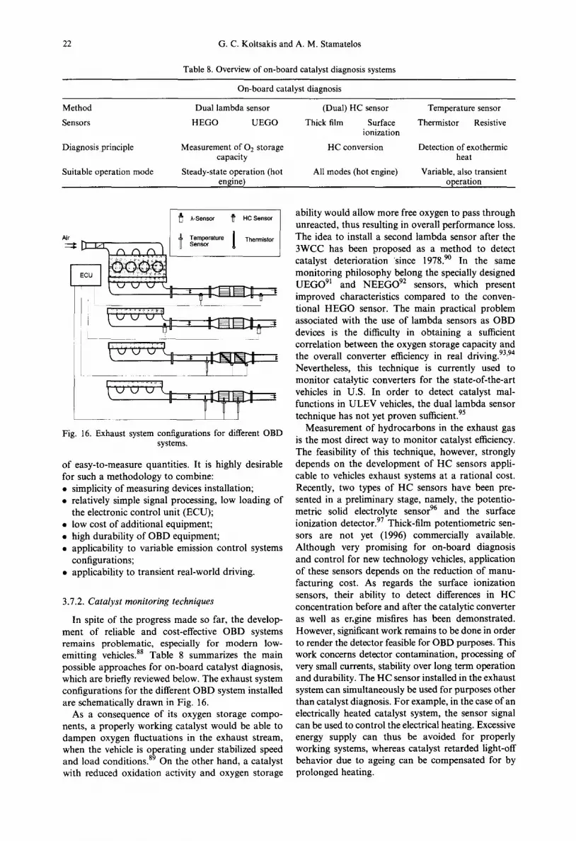
22 G. C. Koltsakis and A. M. Stamatelos
Table 8. Overview of on-board catalyst diagnosis systems
On-board catalyst diagnosis
Method Dual lambda sensor
Sensors HEGO UEGO
Diagnosis principle Measurement of 0 2 storage capacity
Suitable operation mode Steady-state operation (hot engine)
(Dual) HC sensor Temperature sensor
Thick film Surface Thermistor Resistive ionization
HC conversion Detection of exothermic heat
All modes (hot engine) Variable, also transient operation
Air
~' h-Sensor ~' HC Sensor
l Temperature 1 Thermist°r Sensor
I ~ 2 2 22 : 12 ~ ~ ..... I
Fig. 16. Exhaust system configurations for different OBD systems.
of easy-to-measure quantities. It is highly desirable for such a methodology to combine: • simplicity of measuring devices installation; • relatively simple signal processing, low loading of
the electronic control unit (ECU); • low cost of additional equipment; • high durability of OBD equipment; • applicability to variable emission control systems
configurations; • applicability to transient real-world driving.
3.7.2. Catalyst monitoring techniques
In spite of the progress made so far, the develop- ment of reliable and cost-effective OBD systems remains problematic, especially for modern low- emitting vehicles. 88 Table 8 summarizes the main possible approaches for on-board catalyst diagnosis, which are briefly reviewed below. The exhaust system configurations for the different OBD system installed are schematically drawn in Fig. 16.
As a consequence of its oxygen storage compo- nents, a properly working catalyst would be able to dampen oxygen fluctuations in the exhaust stream, when the vehicle is operating under stabilized speed and load conditions. 89 On the other hand, a catalyst with reduced oxidation activity and oxygen storage
ability would allow more free oxygen to pass through unreacted, thus resulting in overall performance loss. The idea to install a second lambda sensor after the 3WCC has been proposed as a method to detect catalyst deterioration 'since 1978. 90 In the same monitoring philosophy belong the specially designed UEGO 91 and NEEGO 92 sensors, which present improved characteristics compared to the conven- tional HEGO sensor. The main practical problem associated with the use of lambda sensors as OBD devices is the difficulty in obtaining a sufficient correlation between the oxygen storage capacity and the overall converter efficiency in real driving. 93'94 Nevertheless, this technique is currently used to monitor catalytic converters for the state-of-the-art vehicles in U.S. In order to detect catalyst mal- functions in ULEV vehicles, the dual lambda sensor technique has not yet proven sufficient. 95
Measurement of hydrocarbons in the exhaust gas is the most direct way to monitor catalyst efficiency. The feasibility of this technique, however, strongly depends on the development of HC sensors appli- cable to vehicles exhaust systems at a rational cost. Recently, two types of HC sensors have been pre- sented in a preliminary stage, namely, the potentio- metric solid electrolyte sensor 96 and the surface ionization detector. 97 Thick-film potentiometric sen- sors are not yet (1996) commercially available. Although very promising for on-board diagnosis and control for new technology vehicles, application of these sensors depends on the reduction of manu- facturing cost. As regards the surface ionization sensors, their ability to detect differences in HC concentration before and after the catalytic converter as well as er.gine misfires has been demonstrated. However, significant work remains to be done in order to render the detector feasible for OBD purposes. This work concerns detector contamination, processing of very small currents, stability over long term operation and durability. The HC sensor installed in the exhaust system can simultaneously be used for purposes other than catalyst diagnosis. For example, in the case of an electrically heated catalyst system, the sensor signal can be used to control the electrical heating. Excessive energy supply can thus be avoided for properly working systems, whereas catalyst retarded light-off behavior due to ageing can be compensated for by prolonged heating.

Catalytic automotive exhaust after-treatment 23
100 I I I I I
ic
8O
60
-.~
2o :, Pt:Pd 211
) - I Y 2" oPt:ahl0/I
0 / , a - - - -
20O 400 500 800 Temperature. °C
Fig. 17. SO2 conversion to SO3 as a function of temperature with 5% 02 concentration and no reducing species present. Space velocity 10/sec. Results for Pt-Rh, Pt-Pd and Pd
catalysts.
Exhaust gas temperature monitoring inside the catalytic converter can provide useful information about heat release caused by exothermal reactions, which is an indication of catalyst light-off. 9s Deacti- vation of the front catalyst part causes a shift of the main reaction zone in the direction of the flow, so that different temperature profiles along the substrate are expected during the course of ageing. Thus, a single temperature measurement in a fixed position would probably not be sufficient to monitor exothermal heat release over a long operating period.
A number of studies related to thermal methods for catalyst diagnosis have been recently presented. Collins et al. 99 proposed that a linear temperature sensor be installed diagonally in the catalyst bed. A linear sensor (made by high temperature thermistor material) can detect local over-temperature condi- tions anywhere along its length, by indicating a temperature that is much more dependent on the maximum temperatures encountered over its length than on the lower ones. The sensor signal may then be processed to indicate whether exothermal reactions, mainly CO and HC oxidation, take place in the cata- lytic converter or not. The computational studies of the above authors have shown that for practical engine/ catalyst combinations the 'hot region' of the monolith lies in the order of 10-30 mm. The same studies have shown that using a sensor, which is about up to five times longer than the hot region, the indicated temperature approximates the real maximum tem- perature with sufficient accuracy. Linear temperature sensors become more attractive if they are used simultaneously for monitoring other emission con- trol functions (exhaust gas ignition, catalyst tempera- ture management) or detection of engine misfire.
The main problem with the temperature measure- ment techniques remains the definition of a univer- sally valid monitoring method, principally applicable during each driving scenario. One such method applicable to metallic substrate converters is pro- posed in Pelters et al.l°° During the deceleration fuel cut-off phase the temperature difference between the metal catalyst substrate and the exhaust gas entering the converter is obtained. The substrate temperature measurement involves resistance sensors specially integrated between the layers of the metallic foils. Due to the very small temperature differences during a fuel cut-off phase, it is necessary to intensify the signals, so as to enable a clearer distinction between the fresh and the aged converter. To this end, a pre- defined quantity of fuel can be injected with the help of the fuel injection system with turned off ignition. The temperature signals obtained can be electronically processed by differentiation, to distin- guish between a working and a defective catalyst. Research in this field is currently carried out in order to assess applicability of such techniques for large scale utilization.
Methods based on energy balance calculations to assess the exothermic heat generated during random engine operation have shown initially promising results) °1'1°2 Suitably developed algorithms are used to calculate the energy released per unit mass of exhaust gas flowing through the converter. This value correlates sufficiently with overall catalyst efficiency. To employ this method for a pre-catalyst, two temperature sensors are sufficient. For larger volume main catalysts, a third sensor may be necessary. These techniques could probably support OBD for ultra low emitting cars, equipped with 'fast light-off' systems, including pre-catalysts or electrically heated catalysts.
3.8. Mathematical Modeling o f 3 WCC
3.8.1. Historical review
Mathematical modelling of monolithic catalytic converters has been employed over the last 25 years to assist the design and development of automotive exhaust aftertreatment systems. Kuo et al.l°3 devel- oped a lumped parameter model for the monolithic converter, which has been used by a number of automobile and oil companies. Vortruba et al. 104 have also presented a similar model. Young and Finlayson, 1°5 in a pioneering work, have developed and solved a two-dimensional channel model for a monolith using orthogonal collocation. They dis- cussed in detail the applicability of the quasistatic assumption for the gas phase for transient cases. Heck et al.l°6 showed that a simpler one-dimensional model is adequate for predicting monolith behavior. They also presented analytical solutions for the adiabatic temperature under steady state operation. Lee and Aris 24 reported a two-dimensional model that also included heat radiation effects. Otto and LeGray 1°7

24 G.C. Koltsakis and A. M. Stamatelos
validated their model with experimental results and presented model predictions regarding converter efficiency for different exhaust system designs. Their model also included radial conduction effects in the monolith. Oh et al. l°s presented a model for the pellet type catalyst. Extensive verification of this model by engine bench experiments is given in Oh and Cavendish. 1°9 This model was employed for the prediction and parametric analysis of vehicle exhaust emissions during warm-up. 110
Most of the above mentioned modeling studies were focused on the behavior of adiabatic monoliths exposed to a uniform flow distribution at the front face. In this case, temperature and concentration profiles in all channels of the monolith are the same, so that consideration of only one channel would be sufficient. However, actual automobile converters operate in a nonadiabatic mode, under conditions where the gas flow is distributed non-uniformly at the monolith inlet. Flytzani-Stephanopoulos et al. i l l
dealt with the two-dimensional (axisymmetric) heat transfer process in a non-reactive monolith. Becker and Zygourakis H2 presented two-dimensional solu- tions for an adiabatic reacting monolith, using a simplistic reaction scheme considering only CO oxidation and neglecting the effects of heat transfer through the surrounding materials. Chcn et al. H3
developed a comprehensive three-dimensional model for the analysis of transient thermal and conversion characteristics of monolithic catalytic converters.
All of the above mentioned models relied on the historical data provided by Voltz et al. 36 which refer to CO and HC oxidation in a lean environment on a platinum catalyst. The rate expressions are of the Langmuir-Hinshelwood type and account for the inhibition due to CO, HC and NO. This approach was sufficient for modeling oxidizing catalytic converters. However, three-way catalytic converter modeling should account for the reaction mechanisms in operating conditions very close to stoichiometry, which pose additional challenges.
Gottberg et al. H4 presented a detailed channel model, which took into account independent adsorp- tion from gas phase to surface site, surface reactions ('electron transfer') and desorption from surface to gas phase for the following five chemical species: CO, CO2, 02, NO and C3Hs. The authors conducted extensive trial simulation work aiming at achieving a satisfactory model validation against real emission data under different dynamic conditions, using minor (empirical) adjustments of adsorption, desorption and reaction rate constants. Montreuil et al. 3s
presented a concerted effort aiming at the com- pilation of an experimental database of steady-state catalyst conversion efficiency for two catalyst for- mulations, for the purpose of updating the kinetic rate constants in the Ford 3WCC model. 1°7 They employed an extended reaction scheme comprising 13 reactions and derived redox dependent kinetic expressions, which are valid above 371°C.
Pattas et al. 39 presented a transient 1-D modeling approach for the 3WCC embodying an oxygen storage and release submodel. The model relied on a simplified five reaction scheme comprising CO, H 2 and HC oxidation and NO reduction by CO. A similar approach for the reaction scheme, lacking oxygen storage, was presented in Siemund et al. 115 A two-dimensional model with an extended reaction scheme and a more comprehensive oxygen storage submodel is presented in Kolstakis et al., 49 along with an investigation of the model application extents in common automotive applications. This category of models are routinely used by auto-manufacturers for design optimization of exhaust aftertreatment systems based on 3WCCs.
The main problem in the evolution of this category of transient 3WCC models is the lack of adequate kinetics data covering a significant number of reactions, for the multitude of catalyst for- mulations and washcoats employed in automotive applications. Moreover, the situation is further complicated by the effect of various modes and degrees of catalyst ageing during vehicle operation. For this reason, it has become common practice to rely on tunable kinetics expressions, which should supply a satisfactory number of degrees of freedom for the model.
3.8.2. Governing equations f o r the reactor model
As mentioned above, two main directions in the modeling of the transport processes in the monolithic channels have appeared in the related literature: simultaneous 3-D solution of the energy and mass balance equations of the boundary layer has been presented in Young and Finlayson 1°5 and Spicher and Lcpperhoff.lt6 The simplified approach of employing the well-known Nu and Sh functions for the flow in closed ducts has been followed in the great majority of the 3WCC models presented. The latter approach offers simplified, less time-demanding 1-D handling and practically equivalent accuracy levels. In the following, the main assumptions and the governing differential equations used in mathematical models of monolithic catalytic converters will be briefly presented.
Most of the recent advanced three way converter models feature:
1. Computation of the convective heat and mass transfer from the exhaust gas to the catalytic surface. A 'film approach' is adopted, employ- ing mean bulk values for the gas phase and solid-gas interface values for the solid phase species concentrations. The corresponding transfer c~fficients are computed using spa- tial dependent relations for Nusselt and Sherwood numbers, applicable to laminar flows in ducts.
2. Computation of the heterogeneous chemical reactions taking place on the catalytic surface based on Langmuir-Hinshelwood based rate

Catalytic automotive exhaust after-treatment 25
expressions. 'Lumping' of surface adsorpt ion- desorption and pore diffusion phenomena in the kinetic rate expressions. Neglection of the contribution of homogeneous reactions, since their reaction rates are important only at unusually high temperatures.
3. The 3-D transient temperature field in the converter is computed, taking into account the heat conduction in the substrate and the surrounding insulation, and the heat losses to the surroundings via convection and radiation. The contributions of the convective heat transfer in the channels and the exothermal heat release are taken into account by respective source terms.
4. The oxygen storage and release phenomena in the washcoat are described by the dynamic redox activity of the cerium oxides present in the catalytic layer. Tunable kinetic rate expressions are employed to represent catalyst performance in a wide range of temperature and redox environments.
The transient behavior of the catalytic converter is computed as a series of quasi steady-states. The differential equations describing the conservation of mass and energy in the catalytic converter are given below:
mass balance in the gas phase
Ocg, i w 0--7 = -pg ki S(cg, i - Cs, i); (7)
energy balance in the gas phase:
org wCp, g ~ - = hS(rs - Tg); (8)
mass balance in the gas-solid intermediate phase
(~g )R i=k iS (cg , i-Cs, i); (9)
energy balance in the solid phase
,9( Q T~) (1 - ¢ ) P s at
{~ 02Ts 02rs 02Ts~ = ( 1 - e ) ~ x~-x2 +Ay--~-y2 +Az~-z2 J
+ h S ( T g - Ts) -t- E ( - A H ) j R j . (10)
Based on the theoretical ground of the Langmuir- Hinsheiwood theory, the reaction rates are usually expressed in the following fo rm: 36
A e -E'/RTcco CO= (11) R = G
The variable G represents an inhibition factor of the form
Gl = T(1 + K1Cco + K2 Cc'3H6 )2
2 2 1 0.7 × (1 +K3ccocc3tq6)(+K4cNo). (12)
Similar expressions are used for the other reactions.
Details on kinetic rate expressions and constants used in 3WCC modeling can be found in the related re ferences . 36-40,49,56
According to Koltsakis et al. 49 and Herz, n7 the oxygen storage mechanism may be described by the oxidation and reduction of the Ce oxides present in the washcoat according to the following reaction:
2CeO 2 ~ Ce203 + ½02. (13)
The reaction to the right denotes the release of an oxygen atom, which is made available to react with a reducing species of the exhaust gas (e.g. CO). The left direction of the reaction represents the storage of an oxygen atom by increasing the oxidation state of Ce203. In order to express the fractional extent of oxidation of the oxygen storage component, the auxiliary number 4~ may be defined as:
2 × moles CeO2 = (14) 2 × moles CeO2 + moles Ce203 "
Oxidation rate is considered proportional to the oxygen storage capacity (OSC), to the local oxygen concentration as well as to the difference 1 - ~; analogously, the reduction rate should be propor- tional to ~p and dependent on the local CO concentration:
Rox = kox[02]OSC(l - ~b)mol/m3/sec, (15)
Rre d = kred[CO]OSC~bmol/m3/sec, (16)
where kox and kre d are characteristic rate factors, which exhibit an Arrhenius type dependence on temperature.
4. CATALYTIC EXHAUST AFTERTREATMENT FOR DIESEL ENGINES
4.1. Oxidation Catalysts for Diesel Engines
Oxidation catalysts in diesel passenger cars were put on the market in 1988. They are presently the preferred emission control system for passenger cars and light duty trucks in Europe as well as for heavy duty diesel engines in the U.S. A diesel oxidation catalyst converts a large part of the hydrocarbon constituents of the SOF, as well as gaseous HC, CO, odor creating compounds and mutagenic emissions. The particulate conversion efficiency is, obviously, much less than the filtration efficiency of a wall-flow filter. However, a particulate control efficiency of even 25-35% is sometimes enough to bring many current development engines within the target range for existing emission standards, n8 The relatively low particulate conversion efficiency is attributed to its limited operating conditions, which are met during engine operation at medium loads. At low loads the exhaust gas temperature is not sufficient to activate the catalyst, whereas at high loads, the SOF part of the particulate, which may be oxidized in the converter, is relatively low.

26 G.C. Koltsakis and A. M. Stamatelos
%NOxConvcrsion 70
60
50
40
30
20
10
200 ~ 300 325 350 375 400 425 450 475 500 525 550 Temperature ((2)
[~Cu//_.SM-5 ,e-Catalyst A -*-Catalyst B]
Fig. 18. Activity of zeolite based catalysts as function of temperature. SV=50,000/hr, NO= 1000ppm, C3H6 =
4000ppmC, 02 = 10%, H20 = 10%, SO2 = 50ppm. 127
The catalyst is also very efficient in reducing emissions of gaseous and particle bound toxic air contaminants, such as aldehydes, PNA and nitro- PNA. While a precious metal catalysed filter would have the same advantages, the catalytic converter has little impact on fuel economy or safety and it will probably not require replacement. Furthermore, in contrast to particulate filters, the catalytic converter is today a relatively mature technology.
A disadvantage of the diesel catalytic converter is potential sulfate emissions. Sulfates can be formed in two ways. For steady-state sulfate formation, the precious metals catalyze the reaction of SO2 to SO3, which can further react with water to form sulfates and sulfuric acidJ 19 Alternatively, sulfur can be stored as SO2 or as sulfate on the alumina wash- coat i 2° At a certain temperature, the stored sulfur can be released from the washcoat and converted to sulfate (Fig. 17). Efforts have been made to avoid these disadvantages. In order to minimize sulfate produc- tion, a silica washcoat is preferred over alumina and Pd is preferred over Pt as the noble metal. TM On the other hand, as a spinoff from work on selective NOx reducing zeolite catalysts, some research has been focused on zeolite based diesel catalysts, which decrease the amount of particulate matter by reducing the SOF, and exhibit no significant SO2 to SO3 conversion at elevated catalyst temperaturesJ 22 If the car is driven at elevated exhaust gas tem- peratures, the catalyst might further oxidize NO to NO2 )2a Also, at low exhaust gas temperatures, N20 formation might occur at certain local reducing conditions during engine and catalyst heating.
The tendency of the precious metal catalyst to convert SO2 to particulate sulfates requires the use of low sulfur fuel: otherwise, the increase in sulfate emissions would more than counterbalance the decrease in SOF. Especially for the application to heavy duty engines, the oxidation catalyst has been formulated to avoid deactivation by poisoning, for example by sulfur oxides in order to match the long service life of these engines. Europe, the U.S. and Japan have already decided to reduce the sulfur content of diesel fuel.
Recent research and development w o r k 124 has led to substantial improvement in the emission perfor- mance and durability by use of high precious metal dispersion and narrow particle size distribution on stabilised support systems, which are less prone to thermal sintering and poison uptake. Catalytic activity is further enhanced by use of combined metal oxide promoters, which selectively promote precious metal activity for desired reactions, while still inhibiting SO2 oxidation and sulfate storage.
4.2. NO~ Reduction Catalysts for Diesel Engines
Much attention has been devoted recently to the reduction of NOx emissions from diesel engines, that could be made possible by special catalytic exhaust aftertreatment techniques. However, NOx reduction catalysts and systems suggested for the diesel engines are currently relatively few. The commercial selective catalytic reduction (SCR) catalysts which are cur- rently in use on stationary engines, using reductants such as ammonia or urea, pose great difficulties in their translation to on-road vehicles. The main problems are the additional tank needed for the reductant, its safe transport, its distribution and the potential for the reductant slip, which are not allowed due to safety and health considerationsJ 25
A lean NOx catalyst for diesel engines is required to operate under a wide range of exhaust conditions, depending on the driving mode. The exhaust gas temperatures may vary from 100°C for low load cycles to 600-700°C for high load operation. A catalyst, which could be able to promote the NOx decomposition to nitrogen and oxygen would be ideal, since it would not require any reducing agents. However, even the most promising catalyst reported to date, Cu exchanged ZSM-5126 is strongly inhibited by 02 and SO2 and slightly inhibited by H20, all of which are always present in diesel exhaust.
An alternative approach for catalytic conversion of NOx is the selective reduction using hydrocarbons. The reaction, using propylene as model reactant in this case , is: 127
2NOx + C3H6 + 702 ~ N2 + 3CO2 + 3H20. (17)
A desired feature ofa de-NOx catalyst is to promote the oxidation of certain hydrocarbons with NOx instead of oxygen (that is, a high hydrocarbon selectivity).
The current state-of-the-art high temperature catalyst for the selective reduction of NO~ with hydrocarbons in lean environments is Cu/ZSM- 5J 2s:29 The activity of this catalyst is promoted by the presence of small amounts of 02, whereas SO2 and H20 only slightly inhibit its performance. Unlike precious metals catalysts, which become active at lower temperatures, the zeolite-based Cu/ZSM-5 is active for NO reduction at temperatures above 350°C (Fig. 18). A major problem associated with Cu/ZSM-5 is its hydrothermal stability, since it deactivates significantly after steaming for short

Catalytic automotive exhaust after-treatment 27
Z v~, T~, Pt, P~ ~ l n ~ l ~ a n n ~
Iv.,T.. l We,, Depos~ Substrate
v2, Tz, p=, P2 / Outlet channel
Fig. 19. Schematic diagram of the monolith inlet and outlet channels with the substrate wall and the soot deposit layer.
periods of time at temperatures greater than 700°C. This deactivation is known to be related to zeolite dealumination and subsequent loss in the number of active exchanged Cu cations.13° The low hydrocarbon selectivity of this catalyst can be compensated by injecting additional hydrocarbon reductants in the exhaust upstream of the catalyst. Due to the very low HC emissions of diesel engines, secondary fuel addition strategy is expected to play a large role in practical application.
Also, it is very important to adapt the catalyst to exhaust gas temperature because whole or only a part of the catalyst contributes to NOx conversion, depending on the temperature. It has been found that the precious metal catalysts, which have relatively low sulfate suppression ability, can reduce NOx at low temperatures, but particulate greatly increases by the sulfate formation because of the exhaust gas temperature increase, caused by the addition of secondary fuel. On the other hand, the surplus secondary fuel must be readily oxidized by the catalyst, in order to avoid significant HC and CO emission increases (as is the case with high light-off catalysts). Simultaneous 12% NOx and 25% particu- late reduction have been reported with base metal catalyst by minor optimization of the amount and pattern of secondary fuel addition, with 3% fuel penalty. 129 Higher amounts of secondary fuel are not favorable because they result in an increase of particulate emissions and fuel economy penalty. Furthermore, it is important to note that diesel fuel, which is readily available on diesel powered vehicles, is not the best means of producing the necessary HC for reduction of NOx. Current research is aimed at the optimization of secondary fuel addition strategies (e.g. by exploitation of the post injection capabilities of modern common rail diesel injection systems), combined with the development of improved catalyst formulations) 31
5. CATALYSTS FOR DIESEL PARTICULATE FILTERS
5.1. The Particulate Filter
The wall-flow particulate filter (Fig. 19) is today the most efficient device for reducing diesel soot emis- sions, attaining filtration efficiencies of the order of
90% at nominal operation conditions) 32-135 Soot filtering is especially important in the case of worn-out diesel engines with poorly controlled fuel combustion. Specific application problems, basically related to filter durability, have limited the use of particulate filters, mainly on city buses, some delivery trucks and fork lift trucks. Intensive research is aimed at developing diesel filter systems suitable for a wider application to commercial vehicles or passenger cars.
The particulate filter concept has focused research and development activities around the world, and a variety of systems is offered by various manufac- turers. 136'137 A trap oxidizer system is based on a durable temperature resistant filter, which removes particulate matter from the exhaust before it is emitted to the atmosphere. The accumulated particu- late raises filter backpressure, i.e. the pressure difference across the filter which is necessary to force the exhaust through it. The typical back- pressure level depends on the filter type, and increases as the filter becomes loaded with particu- late. High backpressure is undesirable, since it increases fuel consumption and reduces available power. It is necessary to clean the filter periodically by burning off (oxidizing) the collected particulate; this process is known as regeneration. 138
Under the conditions met in diesel exhaust systems regarding exhaust flow rate and oxygen content, the required reaction rates for complete filter regenera- tion are attained at temperatures above 550°C. Exhaust temperatures of that order are observed only at high load operation of the diesel engine, which are scarcely attained in the driving cycles of the official tests (e.g. ECE-EUDC, FTP-75 etc.). Thus, special regeneration techniques are employed, that fall into three broad categories: • thermal regeneration by use of engine measures or
by the supply of external energy; • catalytic regeneration (catalytically coated filter or
fuel doping); • aerodynamic cleaning (using compressed air to
remove the soot). In the first category, a significant fuel consumption
penalty must be foreseen to supply the additional energy required for regular thermal regeneration during city driving. Catalytic regeneration, on the other hand, is based on the use of catalysts to achieve the onset of regeneration at significantly lower temperatures. The catalyst may impregnate the porous ceramic wall or be used as a fuel additive, which is emitted and accumulated in the filter together with the particulate. The use of catalysts is critical to the design of a successful diesel filter system, because it overcomes both problems mentioned above: namely that of minimizing backpressure levels and that of sustaining regeneration at low temperatures. 139-145
The use of some catalytic fuel additives results in regeneration temperatures as low as 350°C, although stochastic regenerations may be observed even down to 200°C for high filter loadings.143 Figure 20 presents
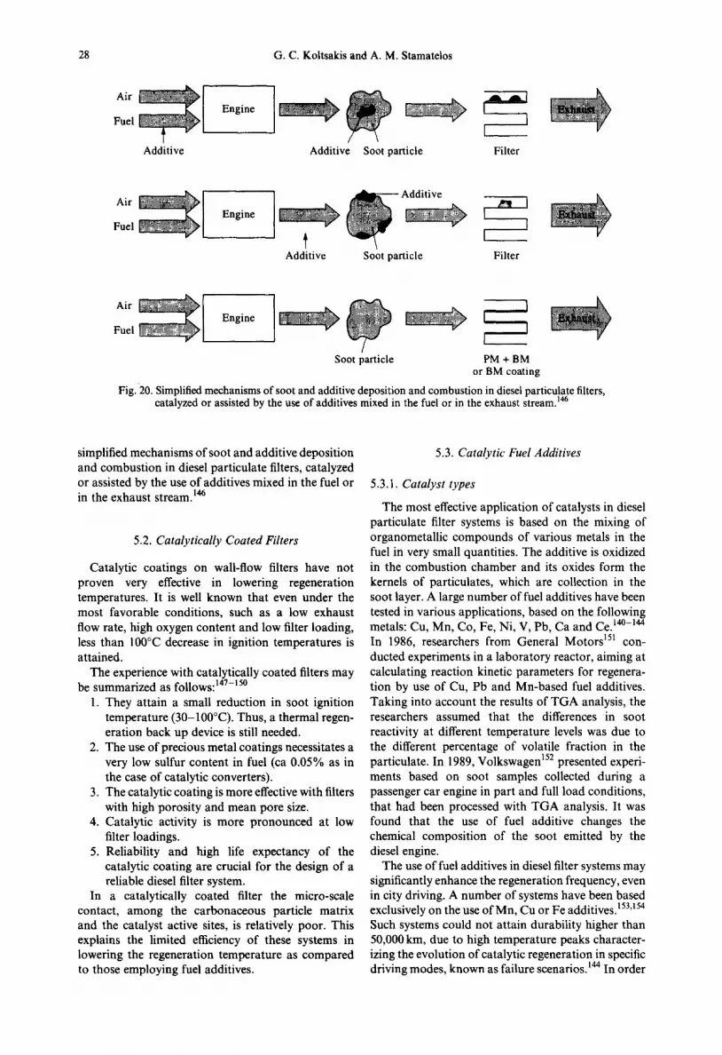
28 G.C. Koltsakis and A. M. Stamatelos
Additive Additive Soot particle Filter
Fuel Engine
Additive Soot particle Filter
Air ~ I Engine Fuel
Soot particle PM + BM or BM coating
Fig. 20. Simplified mechanisms of soot and additive deposition and combustion in diesel particulate filters, catalyzed or assisted by the use of additives mixed in the fuel or in the exhaust stream. 146
simplified mechanisms of soot and additive deposition and combustion in diesel particulate filters, catalyzed or assisted by the use of additives mixed in the fuel or in the exhaust stream. 146
5.2. Catalytically Coated Filters
Catalytic coatings on wall-flow filters have not proven very effective in lowering regeneration temperatures. It is well known that even under the most favorable conditions, such as a low exhaust flow rate, high oxygen content and low filter loading, less than 100°C decrease in ignition temperatures is attained.
The experience with catalytically coated filters may be summarized as follows: 147-15°
1. They attain a small reduction in soot ignition temperature (30-100°C). Thus, a thermal regen- eration back up device is still needed.
2. The use of precious metal coatings necessitates a very low sulfur content in fuel (ca 0.05% as in the case of catalytic converters).
3. The catalytic coating is more effective with filters with high porosity and mean pore size.
4. Catalytic activity is more pronounced at low filter loadings.
5. Reliability and high life expectancy of the catalytic coating are crucial for the design of a reliable diesel filter system.
In a catalytically coated filter the micro-scale contact, among the carbonaceous particle matrix and the catalyst active sites, is relatively poor. This explains the limited efficiency of these systems in lowering the regeneration temperature as compared to those employing fuel additives.
5.3. Catalytic Fuel Additives
5.3.1. Catalyst types
The most effective application of catalysts in diesel particulate filter systems is based on the mixing of organometallic compounds of various metals in the fuel in very small quantities. The additive is oxidized in the combustion chamber and its oxides form the kernels of particulates, which are collection in the soot layer. A large number of fuel additives have been tested in various applications, based on the following metals: Cu, Mn, Co, Fe, Ni, V, Pb, Ca and CeJ 4°-144 In 1986, researchers from General Motors TM con- ducted experiments in a laboratory reactor, aiming at calculating reaction kinetic parameters for regenera- tion by use of Cu, Pb and Mn-based fuel additives. Taking into account the results of TGA analysis, the researchers assumed that the differences in soot reactivity at different temperature levels was due to the different percentage of volatile fraction in the particulate. In 1989, Volkswagen 152 presented experi- ments based on soot samples collected during a passenger car engine in part and full load conditions, that had been processed with TGA analysis. It was found that the use of fuel additive changes the chemical composition of the soot emitted by the diesel engine.
The use of fuel additives in diesel filter systems may significantly enhance the regeneration frequency, even in city driving. A number of systems have been based
153 154 exclusively on the use of Mn, Cu or Fe additives. ' Such systems could not attain durability higher than 50,000 km, due to high temperature peaks character- izing the evolution of catalytic regeneration in specific driving modes, known as failure scenarios. 144 In order

Catalytic automotive exhaust after-treatment 29
300,
250
'~ ~ 200
"N 100
~ 5o z
o
300 -
250 -
150
• -~ 100 -
50- z
0
.o
i - ,oo[- 5° F z 0
R e g e n e r a t i o n b e h a v i o u r with c e r i u m 5 0 p p m Ce
S t o c h a s t i c r e g e n e r a t i o n s
~ Equilibrium r e g e n e r a t i o n s
, , . / t I t t ~
Regeneration bebaviour with ferrocene 20 ppm Fe
~ Stochastic \ regenerations
k ~ Equilibrium i ' ~ ~ regenerations
Regeneration behaviour with copper additive 20 ppm Cu
1 1 \ Stochastic k ~ r e g enerations
' ~ ' ~ Equilibrium ~ - regenerations
I I I I t 100 200 300 400 500 600
Temperature [°C]
Fig. 21. Regeneration maps for different fuel additives and concentrations: the equilibrium temperature (reaction rate = accumulation rate) is plotted as a function of the normalized
backpressure.143
to ensure satisfactory durability, the system should be equipped with additional devices to keep filter loading under a specific safety threshold) 45
5.3.2. Mechanisms of additive action
The process of catalytic regeneration has been extensively studied and a number of models have been developed to understand and predict it. A number of researchers suggested the application of single or multiple stage reaction kinetics for catalytic soot oxidation. 155-158 The results were strongly dependent on the reaction environment.
As mentioned above, in the absence of catalytic assistance, complete filter regeneration occurs at temperatures above 550°C, depending on the exhaust flow rate and prevailing oxygen concentration. Soot ignition at lower temperatures often results in partial combustion of the deposited soot in the filter, leaving behind a less reactive carbonaceous residue. Soot can differ considerably in its reactivity according to the degree of graphitization after partial oxidation and the amount of hydrogen retained. The use of catalytic fuel additives, based on transition metals such as Mn, Cu, Fe, Ce and Pb and finely dispersed ]41:59'16°
during the fuel c o m b u s t i o n p r o c e s s throughout the soot particles, results in regeneration temperatures as low as 350°C. 132'14°J'~'161 Although stochastic (erratic) regenerations may be observed even down to 200°C under favorable engine and filter operating conditions (Fig. 21)) 43 Minor secondary effects that may arise by the use of catalytic fuel additives include incomplete filter cleaning and filter backpressure increase, due to the retaining of fuel additive ash after regeneration.
Erratic regeneration behavior observed at low temperatures ]4°'143 has its roots, in part, in the presence of the volatile hydrocarbon. The volatile fraction originates from unburned fuel and lubri- cating oil and is found adsorbed/condensed on-the soot particles at temperatures below 190°C (this part is completely gasified and desorbed at higher temperatures). 132't61 In this case, the regeneration initiates in specific channels of the monolith, where the local soot loading and temperatures are favorable. The associated heat release, apart from the soot, gasifies and ignites the volatile hydrocarbons, thus enhancing the propagation of the reaction. These, unpredictable, low-temperature regenerations may also be 'ignited' by hot particles originating from engine deposits formed by the additive.143
Several mechanisms have been suggested to explain the catalytic activity of metal compounds on carbon/ soot oxidation/combustion. 162:63 Due to the strong oxygen concentration dependence of the action of transition metal oxides, a redox mechanism 164-16s is usually invoked to explain their catalytic activity: the additive stores and exchanges oxygen atoms with the surrounding carbonaceous matrix and gas. However, additional mechanisms involving catalyzed thermal decomposition of water vapor and soot oxidation by hydroxyl radicals, 164 or electron exchange among additive and carbon atoms resulting in a weakening of the carbon bonds in the boundaries of the carbon matrix facilitating this reaction with oxygen, ~62 have also been proposed.
The commonly used transition metal additives for promoting filter regeneration, form more than one type of oxide, corresponding to the possible valence states they can assume. We can, therefore, distinguish between the metal being in 'higher' or 'lower' oxidation state. The approach presented here refers to regeneration catalyzed by transition metal fuel additives, existing as well dispersed oxides with varying valence states inside the porous soot deposit in the filter. Soot oxidation by the catalyst oxides, triggers the ignition of the remaining soot. The fuel additive participates in the combustion process, leaves the combustion chamber and accumulates in the filter together with the emitted soot. Typical filtration efficiencies for additives are usually over 95%. 139'143'161 We can assume that during this process each metal additive molecule is bonded with a number of soot constituents, such as carbon and hydrocarbon molecules. By reaching the filter the metal additive is

30 G.C. Koltsakis and A. M. Stamatelos
800
O.~ 600
400
200
I I i • I •
100 ppm
20.0
,00ppm ?0pp 0ppm I:: ~ /
8 10.0 D .
" 0
0.0 = I ,
0 1 O0 200 300 400 500 time (S)
Fig. 22. Comparison of typical filter regenerations with different fuel additive concentrations. Exhaust gas flow rate:
38g/see, [02] = 9.3%.
actually in its higher oxidation state. Provided that the filter temperature reaches a sufficiently high value, the metal oxide in the deposit layer releases an oxygen atom to react with soot and assumes its 'lower' oxidation state. The reduced oxides produced in this way may react at the same time with the oxygen contained in the flowing exhaust gas. This continuing oxidation-reduction process, which takes place at significantly lower temperatures than unaided soot oxidation, results in reaction of soot with oxygen from the exhaust gas via the fuel additive, which acts as a catalyst itself.
5.3.3. Soot combustion and CO selectivity
Typical diesel particulate consists mainly of a carbonaceous core (soot formed during combus- tion), adsorbed components such as unburnt and partially oxygenated hydrocarbons, sulfates (due to the oxidation of the sulphur contained in the fuel) and metal oxides. 132 Laboratory research 169 has shown that CO selectivity of soot oxidation reaction is finite and weakly affected by temperature, to the extent that it can be assumed constant up to 700°C. However, the presence of water vapor introduces a strong depend- ence on temperature paralleling the temperature
dependence of water-CO gas shift reaction. The incomplete carbon oxidation, is assumed to be described by the following reaction:
C + c~O2 ~ 2(a - 0.5)CO 2 + 2(1 - c~)CO + AH,
(18) a, is an index of the completeness of the reaction taking values from 0.5 to 1. Measured values for soot reported in the literature range between 0.55 and 0.9,17° while laboratory studies give a value of 0.9 in the absence of water vapor and 0.9-0.975 in the presence of 7% water vapor at 450-300°C, respectively.169
Figures 22 and 23 present the computed evolution of filter exit temperature and particulate loading during typical catalytic regenerations with variable catalyst concentrations in the soot layer. The catalytic regenerations are clearly initiated at significantly lower temperatures compared to the thermal (unca- talysed) regeneration. The concentration of additive in the fuel also affects the onset of regeneration. On the other hand, little influence of the catalyst presence in the maximum developed filter temperature is observed. Dimensional analysis of the catalytic regeneration process reveals that the maximum temperature encountered during a catalytic regenera- tion depends mainly on the soot loading of the filter and to a much lesser extent to other operating parameters.tS°
5.4. Control Issues Related with the Use of Catalysts in Particulate Filters
The durability of regenerable filter systems prob- ably presents the major obstacle in their wider application in vehicle applications. Filter failure may either result from overheating above the melting point or from local high temperature gradients that cause severe thermal and mechanical stresses. This occurs under several failure scenarios, a typical one comprising engine operation at high load and subsequent braking, leading to idle operation with low exhaust flow rates.
Considering the behavior of the regeneration process, we can state four major directions for limiting the undesired high regeneration rates:
1. Maintaining low mean filter loading. According to the results of computation, filter loading substantially affects attainable temperatures during a failure scenario.
2. Cooling of the filter. This would lead to a significant reduction in reaction rates.
3. Reduction of the exhaust gas oxygen content. Again, this would limit reaction rate.
4. Decreasing the exhaust gas residence time in the soot layer.
The above theoretical possibilities could be realized in practice by a number of techniques (limiting filter loading by controlling regeneration frequency, limiting oxygen availability in the

Catalytic automotive exhaust after-treatment 31
.2.
.= e t
E I - -
1000
800
600
400
200
0
I
30 g--
20 g.
10g~
30.0
20.0 oO
E
0
"o 10.0 /
0.0 0
30 g
---..
1 0 g
1 oo 200 300 time (s)
i I ,
400 500
Fig. 23. Effect of initial filter loading on the evolution of filter temperature during regeneration.
exhaust gas by controlling A/F, filter cooling and decreased residence time by keeping a high exhaust flow rate).
As an example, we may consider the principle of filter protection by limiting the oxygen content of the feed exhaust gas, which has recently been shown to be effective in a number of filter failure scenarios) 71 Figure 24 shows the measured filter inlet and outlet temperatures developed during a failure scenario comprising a sudden vehicle braking following engine operation at high load and speed. This scenario causes the onset of a very fast regenera- t i o n - d u e to the combination of relatively high temperatures, low exhaust flow rates and high oxygen content. In this specific case, exhaust gas recirculation is activated at t = 155sec in order to control the regeneration. Lack of regeneration rate control in this case, would have led to much higher temperature levels, that could possibly damage the filter. The experience gained by a significant number of experiments of this kind, indicates that the design of a control system for this technique is a complex task. This is mainly due to the fact that the levels of exhaust gas recirculation necessary for filter protec- tion in each specific failure scenario are variable. Additionally, one must take into account variation in fuel additive concentration in soot for different filter loading modes. Control system design in this case is substantially aided by process modeling.
Filter bypassing by the exhaust gas is an alter- native, quite effective protection technique: its
9. o
Q) (3. E Q)
I--
900
Full Idle load
BOO ] ~ Oxygen
7oo t 600 Inlet
500 !.-
400
300
200
Idle EGR Idle
' t 0.20
" • '~ " v r I I ! v ' | ' I ~ ' I ' - -
Filter 0,15
¢ -
o
e -
O.lO e "
8 o
X
0 0.05
100
I o.oo 1 O0 200 300
t ime (s)
Fig. 24. Filter protection by limiting oxygen content of the exhaust gas during a filter failure scenario) 71

32 G.C. Koltsakis and A. M. Stamatelos
application has led to high durability of filter systems. 172 Details on different filter protection techniques are given in Stamateios 173 and Pattas et al)74,175
5.5. Modeling Catalytic Regeneration
The design of a diesel particulate filter system to fit a specific vehicular application requires significant expenditure, due to the high degree of interaction between the vehicle operation and filter behavior. The assistance of modeling in the design process is already well established. 176
Zero-dimensional regeneration models for par- ticulate filters assume identical flow conditions of the exhaust gas flowing through the wall along the channel) 77 These models have been quite effective in simulating filter regeneration characteristics under relatively high exhaust flow rates) 7s For operation under low flow rates, variations along the filter channel become significant; so one-dimensional models have been developed for filter thermal (non-catalytic) regeneration. 179
Existing theories 154,ts6:Ss address catalytic regen- eration through phenomenological modifications of the apparent activation energy of soot combustion and frequency factor, employing otherwise unchanged thermal regeneration models. Recently, a zero- dimensional model employing a redox mechanism for fuel additive action in the soot layer has been presented) s° The model, extended to cover 1-D effects along the filter channel is presented in Koltsakis and Stamatelos) sl The basic features and balance equations of these types of models are briefly presented below. More details about the model assumptions, the formulation and the solution of the balance equations may be found elsewhere. 179,180
Figure 19 presents a schematic diagram of the monolith inlet and outlet channels with the substrate wall and the soot deposit layer. The exhaust gas temperatures, densities, velocities and pressures are expressed as radially averaged values. Previous work 177 has shown that conduction in the thin x- direction in the ceramic filter phase is so dominant, that the wall temperature may be taken independent of x, even though the heat from reaction is only produced in the deposit layer. The interphase heat transfer within the wall is so large that the gas and solid temperatures may be taken equal except in a very thin boundary layer at the interface with the inlet channel.
The governing balance equations, along with the correlations used for the pressure drop through the porous monolith wall follow:
conservation of mass of channel gas
f-~(p,v,) = (-1) ' (4/D)pwvw; (19)
conservation of z-component of momentum of
channel gas
~ + 0 2 (p : , ) = - ~ v ; / D 2. (20)
The r.h.s, term of Eq. (20) represents the pressure losses in the axial flow direction z, caused by the viscous drag forces. Since the mass flow passing through the wall is only a small fraction of the axial flow, the velocity profile should be close to that observed in flows in closed channels. Thus, the relation used to compute the pressure loss is the one used for laminar flows in square ducts.
Conservation of energy of channel gas:
Cp, g[D2 pi vi Ti [z+Z~z - D2 pi vi Ti lz
- (-1)i4oZXZpw vw Ti t z]
= hi4DAz(Tw - Ti). (21)
The overall rate of soot combustion without catalytic aids is assumed to follow a simple Arrhenius type expression:
kl = k T e -E/Rr. (22)
For the apparent activation energy E appearing in Eq. (22) several values have been proposed ranging from 80,000 to 160,000J/mol. 14°'155,156,ls2,ts3 Experi- mental evidence with a Pb additive Is4 supports the independence of the apparent activation energy from additive presence, while engine experiments 185 indi- cate that a value of 150,000J/mol satisfactory represents regeneration reaction behavior. The con- centration of catalyst in the soot layer may be expressed by: 18°
moles of metal oxides present in soot = carbon moles present in soot (23)
The fraction ~ is a function of the metal additive concentration in the fuel as well as the engine soot emissions produced during the filter loading opera- tion. Metal additive oxides can in principle be present in the deposit layer in both the lower and the higher oxidation state. One could define:
'higher oxidation state' metal oxides present in soot (24)
~b = total metal oxides present in soot
During catalytic regeneration the oxidation state of the metal oxides may be changed, by reacting either with oxygen of the exhaust gas or with the carbon atoms of the deposit layer. Thus, if we assume that the metal additive Me forms oxides with say, its 3- and 4-valent states, the following redox reactions take place:
2MeO2 + C ----, Me20 3 + CO (25)
Me203 + 1 0 2 ~ 2MeO 2. (26)
These reactions combine with reaction (18) to complete the reaction scheme for catalytic soot oxidation. They represent a continuous oxidation- reduction process of the metal oxides present in the

Catalytic automotive exhaust after-treatment 33
0
t . . , j
t~
o
~5
~ bc
HC
I I - - 1.0 1.6 1.8
k
Fig. 25. Lean burn engine raw emissions as a function of lambda [187].
deposit soot layer. The rate of the reduction reaction (25) is assumed to follow an Arrhenius-type tempera- ture dependence according to the following equation:
Rred = kred" ~b. e -E~a/RT. (27)
From the equation for the consumption rate of the deposit (30), we can compute the heat released by the overall reaction expressed per unit time and area:
exp( o )pwVwya [ Vw /j
Po 2M c W A H ~ R r e d. (32)
The contribution of heat conduction is:
o (wO W o2Tw Hcond = --Ap ~zz \ - ~ z J -- As ws OZ 2 " (33)
Darcy's law for the porous ceramic wall as well as for the soot deposit viewed as two porous media in series, is experimentally validated and quantitatively defended for typical filter applications in Sorenson et a l ) s6 and exploited below to express the pressure 'jump' across the thin cell wall as:
Pl --P2 = ,~-~Vw w + # (34) ks Vw Ws. Kp
The rate of the heterogeneous oxidation reaction (26) is expected to be proportional to the oxygen content of the exhaust gas, as well as to the availability of 'lower oxidation state' metal oxides, which is expressed by 1 - ~b. An Arrhenius-type temperature dependence is also assumed here. The reaction rate for Eq. (27) is then:
Rox = kox" [02]. (1 - ¢) . e -e°dRr. (28)
The total rate of change of ~b may then be written as:
de d--7 = Rox - Rred. (29)
Considering the stoichiometry of the reduction reaction the mass balance equation for the deposit layer, assuming that the deposit is consumed in a shrinking mode, gives:
dw Pp ~ f = - Pw Vw y
oxp( Vw / /
mb ERred 2Af (30)
The energy balance equation for the wall should take into account the contributions of convective heat transfer from the channel flow and from the flow through the wall, the heat released by the exothermal soot combustion as well as the conductive heat transfer along the channel wall:
~ ( p p C p , pTw + psCp, srw)
= hi(T1 - Tw) + h2(T2 - rw)
+PwVwCp, g(Tl - Tw) + Hreact + Heond. (31)
6. CATALYTIC CONVERTERS FOR LEAN BURN SI ENGINES
The lean burn concept has received significant interest by the automobile industry. This is due to the clear advantages concerning brake specific fuel consumption at low engine loads and the relatively lower engine out emissions (Fig. 25).187 The lean burn engine operates at air-excess conditions at medium loads; when maximum engine torque is desirable, the engine operates at stoichiometric conditions. These engines have intrinsically very low emissions of CO and relatively low HC emissions, that are further reduced by the three way catalyst under oxidizing conditions. In order to meet stringent NOx emissions standards, in catalyst equipped lean-burn engines, the engine operation is shifted from lean (A = 1.5) to stoichiometric (A = 1) under high load conditions, e.g. during acceleration and high speed cruising. Thus, although during high load operation, the amount of NOx is significantly increased, the conventional three way catalysts fed with stoichio- metric composition exhaust is capable of keeping low NOx emissions.
The catalytic reduction of NO in lean exhaust environment presents considerable difficulties, since the reducing CO is present in low concentrations and NO should further compete with oxygen to react with hydrocarbons. Consequently, current lean burn engined vehicles must be run stoichiometrically over a significant part of the legislated driving cycle. New types of catalysts are under development capable of reducing NOx under lean (oxidizing) conditions. This is achieved by selective reduction of NOx by HC existing in the exhaust, by use of new

34 G.C. Koltsakis and A. M. Stamatelos
I In lean A/F ]
NO + 02 / No;-7
~ - ~ NO2 A N i t r a t e
Stored as nitrate )
In stoichiometric A/F ]
HC, CO CO2 + HO2 H2 NO 2
component
( Reduced to nitrogen )
Fig. 26. NOx storage-reduction mechanism in lean burn NOx catalysts. 18s
families of catalysts that have been studied recently by a number of researchers, 188-191 with regard to various chemical compound families, including zeolite, alumina and complex oxides. These cata- lysts, however, posed a number of problems such as low conversion efficiency, narrow temperature window (temperature range where the catalyst has high conversion efficiency) and low heat resistance. In their present status, these types of catalysts are difficult to commercialize and require further development.
The principle of storing NO in the catalyst during lean engine operation and converting it during short duration, carefully controlled, rich excursions was presented and realized in Myoshi et al. 188 In a P t - B a - A120 3 catalyst, NO was found to be oxidized with oxygen and then react with Ba (storage component) to form a resulting nitrate. The amount of NO storage capacity in such catalysts is strongly affected by the basicity of the elements used as storage components. This is attributed to the fact that the stronger metal basicity results in more stable nitrates. The catalyst was able to reduce NO with CO, H2 or hydrocarbons, in a similar way as a three-way converter, under stoichiometric or reducing conditions. The NO storage-reduction mechanism is presented schemati- cally in Fig. 26. A lean-bum system with this catalyst and a specially designed fuel control system, that periodically (every 50sec) caused short (300msec) enrichments successfully met the Japanese emission standards.
Other researchers used advanced catalysts to expand the lean NOx reduction capacity of the zeolite catalysts. Takami et al. 192 reported a signifi- cant increase in NOx conversion over the legislated U.S. and Japanese driving cycles, by use of P t - I r - R h / MFI zeolite catalysts. These catalysts demonstrated relatively high NOx reduction performance in a wide operation range from stoichiometric to lean along with a high durability. Their efficiency improved even further by the addition of CeO2 and AI203 additives. This catalyst has been mass produced for the Japanese domestic market. However, there is significant work to be done with these catalysts, to increase their efficiency in attaining future, more stringent emissions standards.
7. CONCLUDING REMARKS
This paper reviewed the most common existing catalytic exhaust aftertreatment technologies for gasoline and diesel powered vehicles.
The catalytic technologies were classified according to engine type, which determines the catalyst operating conditions. The stoichiometric Otto engine, which is the most popular today, must be supported by advanced catalyst fast light-off techni- ques to meet stringent HC emissions standards during cold start. The measures applied to this end should, at the same time, maintain a high durability of the converter.
The diesel engine, which is the second most popular, is under increasing legislative pressure to meet extremely stringent NOx emissions while keeping very low particulate emissions. A combina- tion of advanced lean NOx catalysts with diesel particulate filters could be a solution for ultra low emission standards. The well established at present diesel oxidation catalytic converters, although relieved from previous problems with sulfate produc- tion, are not capable of sufficiently high particulate emissions reduction.
The lean-burn Otto engine needs further develop- ment to meet stringent NOx emissions levels, without compromising its fuel consumption advantages over the stoichiometric Otto engine.
An outcome of this unified presentation of catalytic exhaust aftertreatment is the fact that the future evolution of vehicle engines is substantially affected by their potential to conform to increasingly stringent pollutant emissions standards. The role of catalyst technologies in this process is essential and causes significant feedback to engine design and control.
Regarding the potential of current catalytic technologies to further improve vehicle tailpipe emissions, it is claimed that substantial gains can be achieved by means of applying system's engineering in the design optimization of exhaust aftertreatment systems. The role of computational models in this field is illustrated by specific application examples and test cases.
It is concluded that the important role of catalyst technologies in meeting the increasingly stringent

Catalytic automotive exhaust after-treatment 35
vehicle emissions standards will continue for the next decade, strongly affecting the design of engine exhaust aftertreatment systems and the engines themselves.
REFERENCES
1. Heywood, J. B., Internal Combustion Engine Funda- mentals. McGraw-Hill (1988).
2. Taylor, K. C., in Catalysis, J. Anderson and M. Boudart, eds. Springer, Berlin (1981).
3. Gallopoulos, N. E., Bridging the Present to the Future in Personal Transportation--the Role of Internal Combustion Engines. SAE paper 920721 (1992).
4. Conti, L., Ferrera, M., Garlaseo, R., Volpi, E., Cornetti, G. M., Rationale of Dedicated Low Emit- ting CNG Cars. SAE 932763 (1993).
5. Rijkeboer, R. C., Hendrikson, P., Hollernans, B., van der Weide, J., Potential Impact of Four Different Car Fuels on the Dutch Environments. SAE paper 941914 (1994).
6. Harris, J. N., Russell, A. G., Milford, J. B., Air Quality Implications of Methanol Fuel Utilization. SAE paper 881198 (1988).
7. Moses, D., Saricks, C., A Review of Methanol Vehicles and Air Quality Impacts. SAE paper 872053 (1987).
8. Kummer, J. T., Catalysts for automobile emission control. Prog. Energy Combust. Sci. 6, 177-199 (1980).
9. Day, J. P., The Design of a new Ceramic Catalyst Support. SAE paper 902167 (1990).
10. Harkonen, M., Kivioja, M., Maunula, T., Slotte, T., Vakkilainen, A., Performance and Durability of Palladium Only Metallic Three-Way Catalyst. SAE paper 940935 (1994).
11. Ichihara, S., Onoda, H., Garr, G. T., Psaras, D., Engler, B. H., Lox, E. S., Ostgathe, K., Ohata, T., Tsuchitani, K., Recent Trends in the Application of Tri-Metal Emission Control Catalysts. SAE paper 940928 (1994).
12. Nunan, J. G., Williamson, W. B., Robota, H. J. and Henk, M. G., Impact ofPt Rh and Pd Rh Interactions on Performance of Bimetal Catalysts. SAE paper 950258 (1995).
13. Golunski, S. E., Hatcher, H. A., Rajaram, R. R., Bennett, C. J. and Truex, T. J., Low Light Off Catalyst Technology and its Low Emission Vehicle Application. SAE paper 950408 (1995).
14. Muraki, H., Shinjoh, H. and Fujitani, Y., Appl. Cat. 27, 325-335 (1986).
15. Brisley, R. J., Chandler, G. R., Jones, H. R., Anderson, P. J. and Shady, P. J., The Use of Palladium in Advanced Catalysts. SAE paper 950259 (1995).
16. Muraki, H., Kimura, M. and Fujitani, Y., Nitric oxide reduction performance of automotive palladium catalysts. Appl. Cat. 48, 95-105 (1989).
17. Muraki, H., Sobukausa, M., Kimura, M. and Isogai, A., The Effect of Palladium on the Performance of Three Way Catalysts. SAE technical paper series, 900610 (1990).
18. Matsuura, S., Hirai, A., Arimura, K. and Shinjoh, H., Development of Three Way Catalyst Using only Pd as Activator SAE paper 950257 (1995).
19. Punke, A., Dahle, U., Tauster, S. J., Rabinowitz, H. N. and Yamada, T., Trimetallic Three Way Catalysts. SAE paper 950255 (1995).
20. Oh, S. H., Effects of cerium addition on the CO-NO reaction kinetics over alumina-supported rhodium catalysts. J. Catal. 17.4, 477-487 (1990).
21. Diwell, A. F., Rajaram, R. R., Shaw, H. A. and Truex, T. J., The role of ceria in three-way catalysts, in Catalysis and Automotive Pollution Control 11, Elsevier Science, Amsterdam (1991).
22. Nunan, J. G., Robota, H. J., Cohn, M. J. and Bradley, S. A., Physico-chemical properties of Ce-containing three-way-catalysts and the effect of Ce on catalyst activity, in Catalysis and Automotive Pollution Control II, Elsevier Science, Amsterdam (1991).
23. Taylor, K. C. and Schlatter, J. C., J. Catal. 63, 53 (1980).
24. Lee, S. T. and Aris, R., On the effects of radiative heat transfer in monoliths. Chem. Engng Sci. 32, 827-837 (1977).
25. Mondt, J. R., Adapting the heat and mass transfer analogy to model performance of automotive catalytic converters. Trans. ASME J. Engng Gas Turbines Power, 109, 200-206 (1987).
26. Bella, G., Rocco, V. and Maggiore, M., A study of inlet flow distortion effects on automotive catalytic con- verters. Trans. ASME J. Engng Gas Turbines Power, 113, 419-426 (1991).
27. Wendland, D. W. and Matthes, W. R., Visualization of Automotive Catalytic Converter Internal Flows. SAE paper 861554 (1986).
28. Lai, M. C., Lee, T., Kim, J. Y., Cheng, C. Y., Li, P. and Chui, G., Numerical and experimental characteriza- tions of automotive catalytic converter internal flows. J. Fluid. Struct. 6, 451-470 (1992).
29. Weltens, H., Bressler, H., Terres, F., Neumeier, H. and Rammoser, D., Optimization of Catalytic Converter Gas Flow Distribution by CFD Prediction. SAE paper 930780 (1993).
30. Katashiba, H., Nishida, M., Washino, S., Takahashi, A., Hashimoto, T. and Miyake, M., Fuel Injection Control Systems that Improve Three Way Catalyst Conversion Efficiency. SAE paper 910390 (1991).
31. Silveston, P. L., Automotive exhaust catalysis: is periodic operation beneficial? Chem. Engng Sci. 51 (10), 2419-2426 (1996).
32. Hendricks, E., Chevalier, A., Jensen, M., Sorenson, S. C., Trumpy, D. and Asik, J., Modelling of the intake manifold filling dynamics. SAE paper 960037 (1996).
33. Onder, C. H. and Geering, H. P., Model-Based Multivariable Speed and Air-to-Fuel Ratio Control of an SI-Engine. SAE paper 930859 (1993).
34. Barbier, J. Jr and Duprez, D., Reactivity of steam in exhaust gas catalysts. Appl. Catal. !13, 61-83 (1993).
35. Schlatter, J. C. and Mitchell, P. J., Three-way catalyst response to transients. Ind. Engng Chem. Prod. Res. Dev. 19, 288 (1980).
36. Voltz, S. E., Morgan, C. R., Liederman, D. and Jacob, S. M., Kinetic study of carbon monoxide and propylene oxidation on platinum catalysts. Ind. Engng Chem. Prod. Res. Dev. 12, 294 (1973).
37. Subramanian, B. and Varma, A., Reaction kinetics on a commercial three-way catalyst: the CO-NO-O2- H20 system. Ind. Engng Chem. Prod. Res. Dev. 24, 512-516 (1985).
38. Montreuil, C., Williams, S. and Adamszyk, A., Modeling Current Generation Catalytic Converters: Laboratory Experiments and Kinetic Parameter Optimization--Steady State Kinetics. SAE paper 920096 (1992).
39. Pattas, K. N., Stamatelos, A. M., Pistikopoulos, P. K., Koltsakis, G. C., Konstantinidis, P. A., Volpi, E. and Leveroni, E., Transient Modeling of 3-Way Catalytic Converters. SAE paper 940934 (1994).
40. Koberstein, E. and Wannernacher, G., The A/F window with three-way catalysts. Kinetic and surface investigations, in Catalysis and Automotive Pollution Control, Elsevier Science, Amsterdam (1987).
41. Bozek, J. W., Evans, R., Tyree, C. D. and Zerafa, K. I., Operating Characteristics of Zirconia Galvanic Cells (Lambda Sensors) in Automotive Closed-Loop Emission Control Systems. SAE paper 920289 (1992).
42. Herz, R. K., Dynamic behavior of automotive

36 G.C. Koltsakis and A. M. Stamatelos
catalysts. 1. Catalyst oxidation and reduction. Ind. Engng Chem. Prod. Res. Dev. 20, 451-457 (1981).
43. Matsunaga Schin-ichi, Yokota, K., Muraki, H., Fujitani, Y., Improvement of Engine Emissions Over Three-Way catalyst by the Periodic Operations. SAE paper 872098 (1987).
44. Herz, R. K., Klela, J. B., Sell, J. A., Dynamic behavior of automotive catalysts. 2. Carbon monoxide conver- sion under transient air/fuel ratio conditions. Ind. Engng Chem. Prod. Res. Dev. 22, 387-396 (1983).
45. Taylor, K. C. and Sinkevitch, R. M., Behavior of automobile exhaust catalysts with cycled feedstreams. Ind. Eng. Chem. Prod. Res. Dev. 22, 45-51 (1983).
46. Sehlatter, J. C., Sinkevitch, R. M. and Mitchell, P. J., Laboratory reactor system for three-way automotive catalyst evaluation. Ind. Engng Chem. Prod. Res. Dev. 22, 51-56 (1983).
47. Smedler, G., Eriksson, S., Lindblad, M., Bernler, H., Lundgren, S. and Jobson, E., Deterioration of Three- Way Automotive Catalysts, Part II--Oxygen Storage Capacity at Exhaust Conditions. SAE paper 930944 (1993).
48. Sehweich, D., Laboratory data for three-way catalytic converter modeling, in Catalysis and Automotive Pollution Control 111, Elsevier Science, Amsterdam (1993).
49. Koltsakis, G. C., Konstantinidis, P. A. and Stamatelos, A. M., Development and application range of mathematical models for automotive 3-way catalytic converters. Appl. Cat., B Environ. (in press).
50. Koltsakis, G. C., Konstantinidis, P. A. and Stamatelos, A. M., Exploitation of laboratory data for 3-way catalytic convener Assessment and Modeling. Chem. Engng Comm. (submitted).
51. Summers, J. C. and Silver, R. G., Catalytic control issues associated with tbe use of reformulated gasolines, in SAE Transactions 1990, Vol. 99, Section 4, pp. 556-567, SAE paper 902072 (1990).
52. Subramanian, S., Kudla, R. J. and Chattha, M. S., Removal of methane from compressed natural gas fueled vehicle exhaust. Ind. Engng Chem. Res. 31, 2460-2465 (1992).
53. Carol, L. A., Newman, N. E. and Mann, G. S., High Temperature Deactivation of Three-Way Catalyst. SAE paper 892040 (1989).
54. Kubsh, J. E., Rieck, J. S. and Spencer, N. D., Cerium oxide stabilization: physical property and three-way activity considerations, in Catalysis and Automotive Pollution Control II, A. Crucq, Ed., Elsevier Science, Amsterdam (1991).
55. Hock, R. M., Hochmuth, J. K. and Dettling, J. C., Effect of Oxygen Concentration on Aging of TWC Catalysts. SAE paper 920098 (1992).
56. Oh, S. H., Thermal Response of Monolithic Catalytic Converters During Sustained Engine Misfiring: a Computational Study, SAE paper 881591 (1988).
57. Jobson, E., Laurell, M., Hoegberg, E., Bernler, H., Lundgren, S., Wirmark, G. and Smedler, G., Deterio- ration of Three-Way Automotive Catalysts, Part I - - Steady State and Transient Emission of Aged Catalyst. SAE paper 930937 (1993).
58. Siebler et al., Gemeinsames Katalysatorpruef- verfahren von Audi, BMW, Mercedes-Benz, Porsche und VW. Motortechnische Zeitschrift 55, 4 (1994).
59. Bartley, G. J. J., Shady, P. J., D'Aniello, M. J., Chandler, G. R., Brisley, R. J. and Webster, D. E., Advanced Three-Way Catalyst Formulations for High Temperature Applications. SAE paper 930076 (1993).
60. Summers, J. C., Williamson, W. B. and Scaparo, J. A., The Role of Durability and Evaluation Conditions on the Performance of Pt/Rh and Pd/Rh Automotive Catalysts. SAE paper 900495 (1990).
61. Pattas, K. N., Stamatelos, A. M., Pistikopoulos, P. K., Koltsakis, G. C., Konstantinidis, P. A., Volpi, E. and Leveroni, E., Computer Aided Assessment of Catalyst Ageing Cycles. SAE paper 950934 (1995).
62. Otto, K., Daila Botta, R. A. and Yao, H. C., J. Air Pollution Control Assoc. 24, 596 (1994).
63. Hu, Z. and Heck, R. M., High Temperature Ultra Stable Close-Coupled Catalysts. SAE paper 950254 (1995).
64. Konstantinidis, P. A., Koltsakis, G. C. and Stamatelos, A. M., Computer aided assessment and optimization of fast light-off techniques. Prec. IMechE, D: J. Automobile Engng 211, 21-37.
65. Burk, P. L., Hochmuth, J. K., Anderson, D. R., Sung, S., Tauster, S. J., Tolentino, C. O., Regale, J., Miles, G., Niejako, M., Punke, A. and Dahle, U., Cold Start Hydrocarbon Emissions Control. SAE paper 950410 (1995).
66. Williams, J. L., Patil, M. D. and Hertl, W., By-Pass Hydrocarbon Adsorber System for ULEV. SAE paper 960343 (1996).
67. Hertl, W., Patil, M. D. and Williams, J. L., Hydro- carbon Adsorber System for Cold Start Emissions. SAE paper 960347 (1996).
68. Patil, M. D., Hetl, W., Williams, J. L. and Nagel, J. N., In-Line Hydrocarbon Adsorber System for ULEV. SAE paper 960348 (1996).
69. Socha, L. S. Jr. and Thompson, D. F., Electrically Heated Extruded Metal Converters for Low Emission Vehicles. SAE paper 920093 (1992).
70. Socha, L. S. Jr., Thompson, D. F. and Weber, P. A., Optimization of Extruded Electrically Heated Catalysts. SAE 940468 (1994).
71. Pfalzgraf, B., Otto, E., Wirth, A., Kueper, P. F., Held, W. and Donnerstag, A., The System Development of Electrically Heated Catalyst (EHC) for the LEV and EU-III legislation. SAE 951072 (1995).
72. Socha, L. S. Jr., Thompson, D. F., Smith, D. K. and Weber, P. A., Emissions Performance of Extruded Heated Catalysts in Several Vehicle Applications. SAE paper 950405 (1995).
73. Haefele, E., Schoenauer, U. and Seeger, W., Sensorsysteme fuer Low-Emission-Fahrzeuge mit Katalysator-Ueberwachung. Automobil Technische Zeitschrift 95, 5 (1993).
74. Oeser, P., Mueller, E., Haertel, G. R. and Schuerfeld, A. O., Novel Emission Technologies with Emphasis on Catalyst Cold Start Improvements Status Report on VW-Pierburg Burner/Catalyst Systems. SAE paper 940474 (1994).
75. Ma, T., Collins, N. and Hands, T., Exhaust Gas Ignition (EGI)--a New Concept for Rapid Light-Off of Automotive Exhaust Catalyst. SAE paper 920400 (1992).
76. Kollmann, K., Abthoff, J., Zahn, W., Bischof, H. and G6hre, J., Secondary Air Injection with a New Developed Electrical Blower for Reduced Exhaust Emissions. SAE 940472 (1994).
77. Amon-Meziere, I., Castagna, F., Prigent, M. and Pentenero, A., Speciated Hydrocarbon Conversion on a Fresh Pd/Rh Three-Way Catalyst. SAE paper 950932 (1995).
78. G16ck, K. H., Lox, E., Schofer-Sindlinger, A., Kreuzer, T. and Muniz, R. S., Catalyst Development for Stoichiometric and Lean Burn Natural Gas Engines. SAE-Brasil paper 942419 (1994).
79. Oh, S. H., Mitchell, P. J. and Siewert, R. M., Methane oxidation over alumina supported noble metal cata- lysts with and without ceriam additives. J. Catal. 132, 287 (1991).
80. Cullis, C. F. and Willat, B. M., J. CataL 83, 17 (1983). 81. Conti, L., Saroglia, G. P., van Yperen, R., Stamatelos,
A. M. and Koltsakis, G. C., Development of

Catalytic automotive exhaust after-treatment 37
dedicated CNG-fuelled ultra low emitting cars, in A TA Conference on Alternative and Bio Fuels: Production and Use, Leece, Italy (1996).
82. Thomas, C. L., Catalytic Processes and Proven Catalysts. Academic Press, New York (1970).
83. McCabe, R. and Mitchell, P., Exhaust-catalyst devel- opment for methanol-fuelled vehicles: 1. A com- parative study of methanol oxidation over alumina supported catalysts containing group 9, 10 and 11 metals. Appl. Catal. 27, 83 (1986).
84. Oh, S. H. and Bissett, E. J., Mathematical Modeling of Monolith Warmup Behavior in Variable-Fuel Vehicle Exhaust. SAE paper 932721 (1993).
85. Calvert, J. G., Heywood, J. B., Sawyer, R. F., Seinfeld, J. H., Achieving acceptable air quality: some reflections on controlling vehicle emissions. Science, 261 (1993).
86. Clemmens, W. B., Sabourin, M. A. and Rao, T., Detection of Catalyst Performance Loss Using On- Board Diagnostics. SAE paper 900062 (1990).
87. Hansen, J., OBD in a European context, in Proc. 1st lnt. Conf. on Control and Diagnostics in Automotive Applications, Genova, Italy (1996).
88. Koltsakis, G. C. and Stamatelos, A. M., Detection of automotive catalyst failure by use of on-board diagnostics. Proc. IMechE, D: J. Automotive Engng, 209, 171-182 (1995).
89. Clernmens, W. B., Sabourin, M. A. and Rao, T., Detection of Catalyst Performance Loss Using On- Board Diagnostics. SAE paper 900062 (1990).
90. Koberstein, E. and Voelker, H., Wirkungsweise und Charakterisierung multifunktioneller Autoabgas- Katalysatoren. Chem. lng. Tech. (1978).
91. Yamada, T., Hayakawa, N., Kami, Y. and Kawa, T., Universal Air-Fuel Ratio Heated Exhaust Gas Oxygen Sensor and Further Applications. SAE paper 920234 (1992).
92. Eastwood, P., Fischer, S., Konzept zur Ueberpruefung der Funktionstauglichkeit des Abgaskatalysators. Automobil Technische Zeitschrift 96, Vol. 1, pp. 18- 24 (1994).
93. Fisher, G. B., Theis, J. R., Casarella, M. V. and Mahan, S. T., The Role of Ceria in Automotive Exhaust Catalysis and OBD-II Catalyst Monitoring. SAE paper 931034 (1993).
94. Shimashaki, Y., Kato, H., Muramatsu, H., Teshirogi, T., Aoki, T., Saito, A. and Rodrigues, G., Study of Conformity Technology with ULEV Using EHC System, SAE paper 960342 (1996).
95. Shimashaki, Y., Kato, H., Muramatsu, H., Teshirogi, T., Aoki, T., Salto, A. and Rodrigues, G., Study of Conformity Technology with ULEV Using EHC System. SAE paper 960342 (1996).
96. Haefele, E., Schoenauer, U. and Seeger, W., Sensorsysteme fuer Low-Emission-Fahrzeuge mit Katalysator-Ueberwachung. Automobil Technische Zeitschrift 95, Vol. 5 (1993).
97. Cai, W. and Collins, N., Unburnt Hydrocarbon Measurement by Means of a Surface Ionisation Detector. SAE paper 910254 (1991).
98. Theis, J. R., Catalytic Converter Diagnosis Using the Catalyst Exotherm. SAE paper 942058 (1994).
99. Collins, N., Cai, W., Ma, T. and Ball, D., A Linear Temperature Sensor for Exhaust Gas Ignition (EGI) and On Board Diagnosis of Misfire and Catalyst Efficiency. SAE paper 930938 (1993).
100. Pelters, S., Schwarzenthal, D., Maus, W., Swars, H. and Br6ek, R., Alternative Technologies for Studying Catalyst Bchaviour to Meet OBD II Requirements. SAE paper 932854 (1993).
101. Nobuhido Kato, Nobukazu Ikoma and Satshi Nishi- kawa, Exhaust Gas Temperature Sensor for OBD-II Catalyst Monitoring. SAE paper 960333 (1996).
102. Koltsakis, G. C., Stamatelos, A. M., Konzept zur
Katalysatorueberpruepung durch Reaktionswaermeer- mittlung. Motorteehnische Zeitschrift (MTZ) (1997).
103. Kuo, J. C. W., Lassen, H. G. and Morgan, C. R., Mathematical Modeling of CO and HC Catalytic Converter Systems. SAE paper 710289 (1971).
104. Vortruba, J., Sinkole, J., Hlavacek, V. and Skrivanek, J., Heat and mass transfer in monolithic honeycomb catalysts--I. Chem. Engng Sei. 30, 117 (1975).
105. Young, L. C. and Finlayson, B. A., Mathematical models of the monolith catalytic converter: part I. Development of model and application of orthogonal collocation. AIChE J. 22 (2), 331-343 (1976).
106. Heck, R. H., Wei, J. and Katzer, J. R., Mathematical modeling of monolithic catalysts. AIChE J. 22 (3), 477-484 (1976).
107. Otto, N. O. and LeGray, W. J., Mathematical Models for Catalytic Converter Performance. SAE paper 800841 (1980).
108. Oh, S. H., Cavendish, J. C. and Hegedus, L. L., Mathematical modeling of catalytic converter lightoff: single-pellet studies. AIChE J. 26, 935 (1980).
109. Oh, S. H. and Cavendish, J. C., Mathematical modeling of catalytic converter lightoff--Part II: model verifi- cation by engine-dynamometer experiments'. AICkE J. 31 (6) (1985).
110. Oh, S. H. and Cavendish, J. C., Mathematical modeling of catalytic converter lightoff--Part III: prediction of vehicle exhaust emissions and para- metric analysis. AICkE J. 31 (6) (1985).
111. Flytzani-Stephanopoulos, M., Voecks, G. E. and Charng, T., Modeling of heat transfer in non- adiabatic monolithic reactors and experimental com- parisons of metal monoliths with packed beds. Chem. Engng Sci. 41, 1203-1212 (1986).
112. Zygourakis, K., Transient operation of monolith converters: a two dimensional reactor model and the effects of radially nonuniform flow distributions. Chem. Engng Sci. 44, 2075-2086 (1989).
113. Cben, D. K. S., Bissett, E. J., Oh, S. H. and Van Ostrom, D. L., A Three Dimensional Model for The Analysis of Transient Thermal and Conversion Characteristics of Monolithic Catalytic Converters. SAE paper 880282 (1988).
114. Gottherg, I., Rydqulst, J. E., Backlund, O., Waltman, S., Maus, W., Brueck, R. and Swars, H., New Potential Exhaust Gas Aftertreatment Technologies for 'Clean Car' Legislation. SAE paper 910840 (1991).
115. Siemund, S., Schweich, D., Lecierc, J. P. and Villermaux, J., Modelling three-way monolithic converter: comparison between simulation and experi- mental data, in Catalysis and Automotive PollutDn Control III, Elsevier Science, Amsterdam (1993).
116. Spicher, U. and Lepperhoff, G., Instationaerverhalten des Abgaskatalysators. Motortechnische Zeitschrift 56, 6 (1995).
117. Herz, R. K. Dynamic behavior of automotive three-way emission control systems, in Catalysis and Automotive Pollution Control, p. 427, Elsevier Science, Amsterdam (1987).
118. Walsh, M., Global Trends in Diesel Particulate Control--A 1995 Update. SAE paper 950149 (1995).
119. Trayser, D. A., Blosser, E. R. and Pierson, W. R., Sulfuric Acid and Nitrate Emissions from Oxidation Catalysts. SAE paper 750091 (1975).
120. Hunter, J. E., Studies of Catalyst Degradation in Automotive Emission Control Systems. SAE paper 720122 (1972).
121. Henk, M. G., Williamson, W. B. and Silver, R. G., Diesel Catalysts for Low Particulate and Low Sulfur Emissions. SAE paper 920368 (1992).
122. Zelenka, P., Ostgathe, K. and Lox, E., Reduction of diesel exhaust emissions by using oxidation catalysts. SAE paper 902111 (1990).

38 G.C. Koltsalds and A. M. Stamatelos
123. Standt, U. D. and Konig, A., Performance of Zeolite Based Diesel Catalysts. SAE paper 950749 (1995).
124. Smedler, G., Ahlstroem, G., Fredholm, S., Frost, J., Loof, R., Marsh, P., Walker, A. and Winterboru, D., High Performance Diesel Catalysts for Europe Beyond 1996. SAE paper 950750 (1995).
125. Huethwohl, G., Backes, B., Ketcher, D. A., Horrocks, R. W., Hurley, R. G. and Hammerle, R. H., An Urea Lean NOx Catalyst System for Diesel Vehicles. SAE paper 952493 (1995).
126. Li Yuejin and Hall, W. K., Catalytic decomposition of nitric oxide over Cu-zeolites. J. Catal. 129, 202-215 (1991).
127. Feeley, J. S., Deebe, M. and Farrauto, R. J., Abatement of NOx from Diesel Engines: Status and Technical Challenges. SAE paper 950747 (1995).
128. Sate, S., Yu-u Y., Yahiro, H., Mizuno, N. and Iwamoto, M., Cu-ZSM-5 zeolite as highly active cata- lyst for removal of nitrogen monoxide from emission of diesel engines. Appl. Catal. 70, L1-L5 (1991).
129. Kawanami, M., Horiuchi, M., Leyrer, J., Lox, E. and Psaras, D., Advanced Catalyst Studies of Diesel NOx Reduction for On-Highway Trucks. SAE 950154 (1995).
130. Grindsted, R. A., Jen, H. W., Montreull, C. N., Rokosz, M. J. and Shelef, M., The Relation between deactivation of CuZSM-5 in the selective reduction of NO and dealumination of the zeolite. Zeolites 13(8), 602-606 (1993).
131. Zelenka, P., Cartellieri, W. and Herzog, P., Worldwide diesel emission standards, current experiences and future needs. Appl. Catal. B Environ. 10, 3-28 (1996).
132. Moser, F., Haas, E. and Schloegi, H., Zur Partik- elemission von Nutzfahrzeug-Dieselmotoren. Motor- technische Zeitschrift (MTZ) 51 (1990).
133. Howitt, J. S. and Montierth, M. R., Cellular Ceramic Diesel Particulate Filter. SAE paper 8 I0114 (1981).
134. Abthoff, J., Schuster, H. D., Langer, H. J. and Loose, G., The Regenerable Trap Oxidizer--an Emission Control Technique for Diesel Engines. SAE paper 850015 (1985).
135. Johnson, J. H., Bagley, S. T., Gratz, L. D. and Leddy, D. G., A Review of Diesel Particulate Control Technology and Emission Effects. SAE paper 940233 (1994).
136. Hoepke, E., Partikelfilter fuer Omnibusse und Kommunal-fahrzenge. Automobile Technische Zeits- thrift 91 s.680, 12 (1989).
137. Rue, V. D. N. and Cicanek, H. A., Diesel Particulate Control System for Ford 1.8L Sierra Turbo-Diesel to Meet 1997-2003 Particulate Standards. SAE paper 940458 (1994).
138. Weaver, C. S., Particulate Control Technology and Particulate Standards for Heavy Duty Diesel Engines. SAE paper 840174 (1984).
139. Montierth, M., Fuel Additive Effect upon Diesel Particulate Filters. SAE paper 840072 0984).
140. Wiedemann, B., Doerges, U., Engeler, W. and Poettner, B. Regeneration of Particulate Filters at Low Temperatures. SAE paper 830086 (1983).
141. Wiedemann, B. and Neumann, K., Vehicular Experience with Additives for Regeneration of Ceramic Diesel Filters. SAE paper 850017 (1985).
142. Wiedemann, B., Doerges, U., Engeler, W. and Poettner, B., Application of Particulate Traps and Fuel Additives for Reduction of Exhaust Emissions. SAE paper 840078 (1984).
143. Lepperhoff, G., Lueders, H., Barthe, P. and Lemaire, J., Quasi-Continuous Particle Trap Regeneration by Cerium-Additives. SAE paper 950369 (1995).
144. Pattas, K. N. and Michalopoulou, C. C., Catalytic Activity in the Regeneration of the Ceramic Diesel Particulate Trap. SAE paper 920362 (1992).
145. Pattas, K. N., Samaras, Z., Patsatzis, N., Michalo- poulou, C., Zogou, O., Stamatclos, A. and Barkis, M., On-Road Experience with Trap Oxidizer Sys- tems Installed on Urban Buses. SAE paper 900109 (1990).
146. Lox, E. S., Engler, B. H. and Koberstein, E., Diesel emission control, in Catalysis and Automotive Pollution Controlll, A. Crucq, Ed., Elsevier Science, Amsterdam (1991).
147. Enga, B., Buchmann, M. and Liehtstein, I., Catalytic Control of Diesel Particulate. SAE paper 820184 (1982).
148. Koberstein, E., Pletka, H. and Voelker, H., Cata- lytically Activated Diesel Exhaust Filters: Engine Test Methods and Results. SAE paper 830081 (1983).
149. Rue, V., White, J., Wade, W., Aimaone, M. and Cikanek, H., Advanced Techniques for Thermal and Catalytic Diesel Particulate Trap Regeneration. SAE paper 850014 (1985).
150. Wade, W., White, J., Florek, J. and Cikanek, H., Thermal and Catalytic Regeneration of Diesel Particulate Traps. SAE paper 830083 (1983).
151. McCabe, R. W. and Sinkevitch, R. M., A Laboratory Combustion Study of Diesel Particulate Containing Metal Additives. SAE paper 860011 (1986).
152. Wiedemann, B., Mueller, E., Preuss, A. and Schaedlich, H., Diesel-Partikelfiltersystem mit Addi- tivgestuetzter Regeneration. Automobil Technische Zeitschrift 91, vol. 12 (1989).
153. Wiedemann, B. and Neumann, K., Vehicular Experi- ence with Additives for Regeneration of Ceramic Diesel Filters. SAE paper 850017 (1985).
154. Wade, W., White, J., Florek, J. and Cikanek, H., Thermal and Catalytic Regeneration of Diesel Particulate Traps. SAE paper 830083 (1983).
155. Hoffman, U. and Ma, J., Study on regeneration of diesel particulate filter using a laboratory reactor. Chem. Engng Technol. 13, 251-258 (1990).
156. Hoffmann, U., Rieckmann, T. and Ma, J., Kinetic study and modeling of diesel particulate filter regeneration. Chem. Engng Sci. 44 (1991).
157. Simon, G., Stark, T., Diesel Particulate Trap Regen- eration Using Ceramic Wall-Flow Traps, Fuel Additives and Supplemental Electrical Ingitors. SAE paper 850016 (1985).
158. Frohne, J., Reisig, H. and Schaedlich, K., Thermo- analytische Methoden zur Characterisierung von Dieselruss. Wissenschaft Technik, 4, 42 (1989).
159. Peterson, R. C. SAE paper 870628 (1987). 160. Ritrievi, K. E., Longwell, J. P. and Sarofim, A. F.,
Combust. Flame 70, 17-31 (1987). 161. Konstandopoulos, A. G., Gratz, L. D., Johnson, J. H.,
Bagley, S. T. and Leddy, D. G., Ceramic particulate traps for diesel emissions control. Effect of a manganese-copper fuel additive. SAE Trans. J. Eng. 97, 37-53 (1988).
162. McKee, D. W., Metal oxides as catalysts for the oxidation of graphite. Carbon 8, 623-635.
163. McKee, D. W., The catalyzed gasification reactions of carbon. In Chemistry and Physics of Carbon, Vol. 16, P. L. Walker Jr and P. A. Thrower, Eds, Marcel Dekker, New York.
164. Cotton, D. H., Friswell, N. J. and Jenkins, D. R., The suppression of soot emission from flames by metal additives. Combust. Flame, 17, 87-98 (1971).
165. Ahlstroem, A. F. and Odenbrand, C. U. I., Appl. Catal. 60, 143-156 (1990).
166. Ahlstroem, A. F. and Odenbrand, C. U. I., Appl. Catal. 60, 157-172 (1990).
167. Loewe, A. and Mendoza-Frohn, C., Appl. Catal. 66, L1 l-L16 (1990).
168. Yuan, S., Meriaudeau, P. and Perrichon, V., Catalytic combustion of soot particles on copper catalysts

Catalytic automotive exhaust after-treatment 39
supported on TiO2. AppL Catal. B: Environ. 3, 319-333 (1994).
169. Ahlstroem, A. F. and Odenbrand, C. U. I., Carbon, 27, 475-483 (1989).
170. Aoki, H., Asano, A., Kurazono, K., Kobashi, K. and Sami, H., Numerical Simulation Model for the Regeneration Process of a Wall-Flow Monolith Diesel Particulate Filter. SAE paper 930364 (1993).
171. Pattas, K. N., Stamatelos, A. M., Kougianos, K. N., Koltsakis, G. C. and Pistikopoulos, P. K., Trap Protection by Limiting A/F during Regeneration. SAE paper 950366 (1995).
172. Higuchi, N., Mochida, S. and Kojima, M., Optimized Regeneration Conditions of Ceramic Honeycomb Diesel Filter. SAE paper 830078 (1983).
173. Stamatelos, A. M., On-line regeneration control for a diesel particulate trap system. Automatica, 30 (3), 513-520 (1994).
174. Pattas, K., Patsatzis, N., Michalopoulou, C., Stamatelos, A., Kikidis, P., Samaras, Z. and Sowul, H. SAE paper 880004 (1988).
175. Pattas, K., Samaras, Z., Kyriakis, N., Mihailidis, A. and Manikas, Th., Diesel Particulate Trap Protection Against Uncontrolled Regeneration via Selective Flow Modulation. SAE paper 960128 (1996).
176. Pattas, K. N., Stamatelos, A. M., Koltsakis, G. C., Kandylas, I. P. and Mustel, W., Computer aided engineering in the design of catalytically assisted trap systems, SAE Int. Congress, Detroit. SAE paper 970472 (1997).
177. Bissett, E. J. and Shadman, F., Thermal regeneration of diesel-particulate monolithic filters. AIChE J. 31 (5), 753 (1985).
178. Koltsakis, G. C. and Stamatelos, A. M., Modeling thermal regeneration of wall-flow diesel particulate traps. AIChE J. 42 (6), (1996).
179. Bissett, E. J., Mathematical modeling of the thermal regeneration of a wall-flow monolith diesel particulate filter. Chem. Engng Sci. 39 (7/8), 1233-1244 (1984).
180. Koltsakis, G. C. and Stamatelos, A. M., Modeling catalytic regeneration in wall flow particulate filters. Ind, Engng Chem. Res. 35, 2-13 (1996).
181. Koltsakis, G. C. and Stamatelos, A. M., Modes of
catalytic regeneration in diesel particulate filters. Ind. Engng Chem. Res. (submitted).
182. Pauli, E., Lepperhoff, E. and Pischinger, F., The Calculation of Regeneration Limits of Diesel Particulate Traps for Different Regeneration Methods. SAE paper 840075 (1984).
183. Sachdev, R., Wong, V. and Shahed, S., Analysis of Regeneration Data for a Cellular Ceramic Particulate Trap. SAE paper 840076 (1984).
184. Peterson, R. C., The oxidation rate of diesel particulate which contains lead. SAE paper 870628 (1987).
185. Lepperhoff, G. and Kroon, G., Abgasnachbehandlung I--Verminderung der Partikelemission yon Diesel- motoren fuer PKW durch Abgasnachbehandlung. Abschlussbericht, Vorhaben Nr. 259, Heft 352, F W (1984).
186. Sorenson, S. C., Hoj, J. W. and Stobbe, P., Flow Characteristics of SiC Diesel Particulate Filter Materials. SAE paper 940236 (1994).
187. Heck, E., MaUog, J., Mueller, A. and Thoma, J., Motorkonzept mit Oxidationskatalysator. Motor- technische Zeitserift 50, 3 (1989).
188. Miyoshi, N., Matsumoto, S., Katoh, K., Takahashi, N., Yokota, K., Sugiura, M. and Kasahara, K., Development of New Concept Three Way Catalyst for Automotive Lean Burn Engines. SAE papers 950809 (1995).
189. Held, W., Koenig, A., Richter, T. and Puppe, L., Catalytic NOv Reduction in Net Oxidizing Atmos- phere. SAE paper 920496 (1992).
190. Kintaichi, Y., Hamada, H., Tabata, M., Masato, M. and Ito, T., Selective reduction of nitrogen oxide with hydrocarbons over solid acid catalysts in oxygen rich atmosphere. Catal. Lett. 6, 239 (1990).
191. Inoui, T., Kojo, S., Shibata, M., Yoshida, T. and Iwamoto, S., NO decomposition on Cu incorporated A zeolites under the reaction of excess oxygen with a small amount of hydrocarbons, in Studies in Surface Science and Catalysis 69, pp. 355-364, Elsevier, Amsterdam (1991).
192. Takami, A., Takemoto, T., Iwakuni, H., Saito, F. and Komatsu, K., Development of Lean Burn Catalyst. SAE paper 950746 (1995).


