Embed Size (px)
Citation preview
Publication Since 2012 | ISSN: 2321-9939 | ©IJEDR 2021 Year 2021, Volume 9, Issue 2
IJEDR2102041 International Journal of Engineering Development and Research (www.ijedr.org) 255
Catia customization for Design and Modeling ofTwo stage spur Gearbox
1Mayuresh V.Patwardhan, 2Uddhavrao Nimbalkar1P.G.Student, 2Assistant Professor
Rajarambapu Institute of Technology, Sakharale, Maharashtra, 415414, INDIA
_____________________________________________________________________________________________________
Abstract - In this paper, we describe how the customization of design task, in solid modeling with CATIA V5 for twostage spur gearbox can be approached, by means of macros (piece of code) and with GUI form. The user has to supplysome basic requirements of the gearbox and rest of the different parameters for design of gearbox is calculated byformulas. And then with the help of these parameters, part model of gearbox is created.
keywords - CAD, Catia, GUI, Macros, Design, Parametric modeling, two stage spur gearbox
__________________________________________________________________________________________________
INTRODUCTIONCurrent scenario of the market is competitive. To sustain in the market for company product time to the market have to beminimum. Companies existing product demands from the customer are to be provided quickly as soon as possible. Existingproduct requirement has same parametric features of components for different specification. Design and modeling time of theproduct is generally 60-70% of overall time of the product development. Design phase has lot of potential where time can besaved. Parametric modeling can be used for saving the modeling time. Knowledge based approach can be useful for savingthe design time. Lot of repetitive calculations can be saving for avoiding tedious work. CATIA software is selected havingstrong parameterization. Mechanical product selected is gearbox. Nowadays best of the best innovations are coming intopicture, in these, researchers have made one way to reduce maximum design time by doing design automation concept whichmeans integration of GUI developed with the help of computer programming language and market available CAD packages.Graphical User Interface (GUI) is the only way for users to communicate with the system.But no specific software is available for the design of a specific product. So by this dissertation approach it is very importantto make one tailor-made software which will be useful for complete design of a specific component and output of the softwareshould easily be integrated with other modeling software. In this with use of Macro which means program written for specifictask. For developing advanced macros for special needs Catia V5 is an open system. Macros may be useful for creating,analyzing, measuring, modifying. Translating, optimizing surfaces, solids, wireframes and more. Macros are useful for partoperation, assembly operation and all multidisciplinary applications.
LITERATURE REVIEWMany research attempts have been made in the area of parametric modeling.
Ruchik D. Trivedi et al [1] discussed about integrating the commercially available package Pro/E with Microsoft Excelspreadsheet for 3D parametric modeling. Various product variants of the inner ring of spherical roller bearing have beenexecuted by parametric designing concept in Pro/Engineer Wildfire.
Umesh Bedse et al [2] discussed about developed GUI is made for the case study of design of CI engine parts like cylinderhead, cylinder block, piston and crankshaft. CI engine is having many numbers of mechanical components, but parts namedabove are the most important parts of any CI engine. So design of these parts is useful to take into account to develop a GUI.And creo software is used for modeling.
Indrajitsinh J. Jadeja et al [3] discussed about the work reviews the procedural steps involved in the design of couplings andthe development of the software package using visual basic as a tool for the design. This system is carried out on the casestudy of flange coupling and standard design equation being carried out together with the use of programming software anduse CREO as modeling software.
Dhaval b. shah et al [4] discussed about the 3D models for flange type coupling and related dimension database in MicrosoftExcel have been prepared. This Excel sheet has been linked with Autodesk Inventor to transfer data and relate to respectivefeatures of the part. User can update the model just by modifying the sheet. This takes comparatively very less time togenerate complex part models with respect to generating them individually. This automation can further be proceeded byexporting models to the analysis or CAM package.
Publication Since 2012 | ISSN: 2321-9939 | ©IJEDR 2021 Year 2021, Volume 9, Issue 2
IJEDR2102041 International Journal of Engineering Development and Research (www.ijedr.org) 256
L.Karikalan et al [5] discussed about the the main purpose of this assignment is to provide a gear box with Low reductionratio, low weight and efficient for engine up to 500cc. It should also be used in “All Terrain” vehicles.
CATIA V5CATIA (Computer Aided Three Dimensional Interactive Application) is a multi-platform CAD/CAM/CAE commercialsoftware suite developed by French company Dassault Systems and it is marketed world-wide by IBM. Catia is the world’sleading CAD/CAM/CAE software. For developing advanced macros for special needs Catia V5 is open system. A macro is aseries of functions, written in a scripting language, that you group in a single command to perform the requested taskautomatically. These macros may be useful for creating, analyzing, measuring, modifying. Translating, optimizing surfaces,solids, wireframes and more. Macros are used to save time, reduce the possibility of human error by automating repetitiveprocesses, standardization, improving efficiency, expanding Catia’s capabilities, and for streamlining tasks. For creating basicstructure and basic flow of program we require inputs, outputs, and supporting data from the user. Catia providescustomization capability. In Catia the part Objects, which are used for developing part model i.e. three dimensional object arestructured under a automation tree.
CATIA V5 MACROSA macro is a series of functions, written in a scripting language, that you group in a single command to perform the requestedtask automatically. In simple it is a piece of code written in certain programming language which groups a set of operationthat defines a certain task. For each task separate code is written and assembled together by using forms.
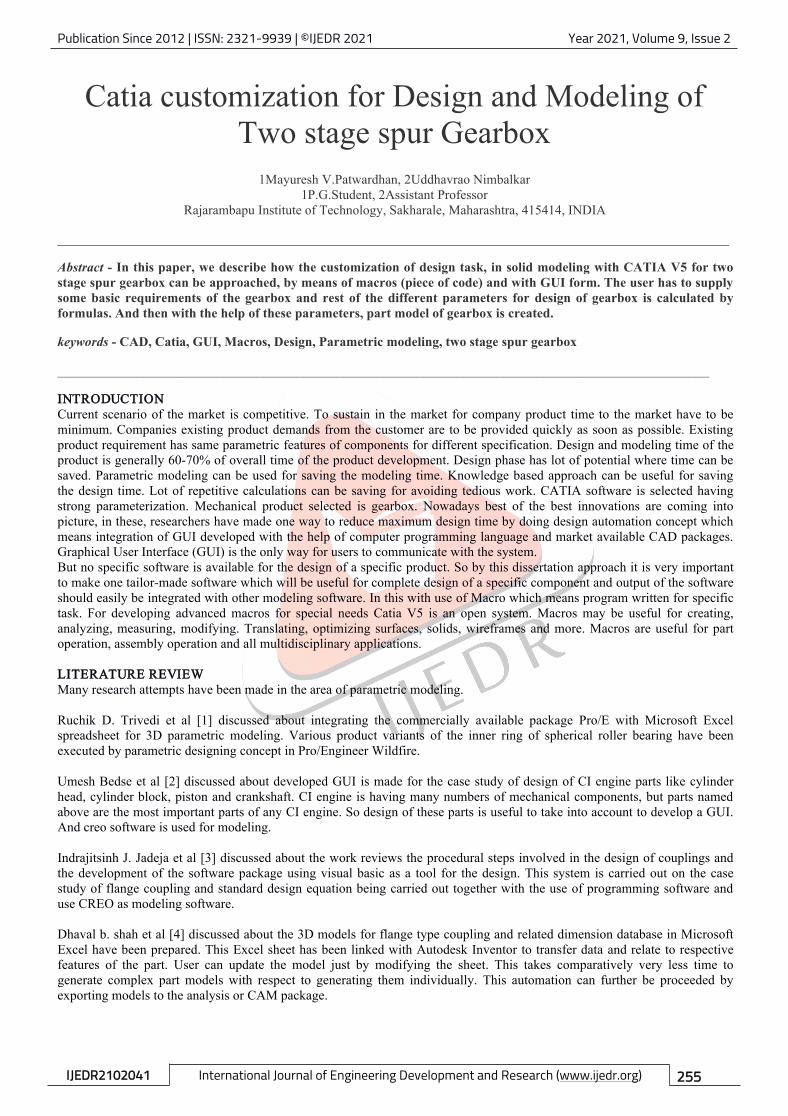
CATIA Customization/Automation ObjectsIn CATIA the part objects, which are used for developing part model i.e. three dimensional object are structured under a treeas shown in the following figure. As and when needed the part object can be extracted with the macro programming forcustomization or automation of CATIA V5 The Part Document object aggregates, or includes, the part tree structure startingwith the Part object located at the top of the part specification tree. These Part Document objects are: Origin Element,Geometric Elements, Bodies and Part objects are: Constraints, Relations, Parameters, and Factory3D, Shape Factory(Sketches, Geometric Elements, and Shapes)
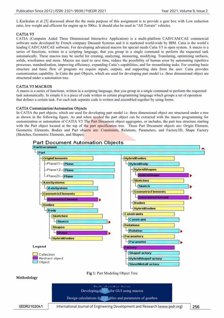
Fig 1: Part Modeling Object TreeMethodology
Study of gearbox designDeveloping Forms for GUI using macros
Design calculations for variables and parameters of gearbox
Publication Since 2012 | ISSN: 2321-9939 | ©IJEDR 2021 Year 2021, Volume 9, Issue 2
IJEDR2102041 International Journal of Engineering Development and Research (www.ijedr.org) 257
Fig 2: Methodology
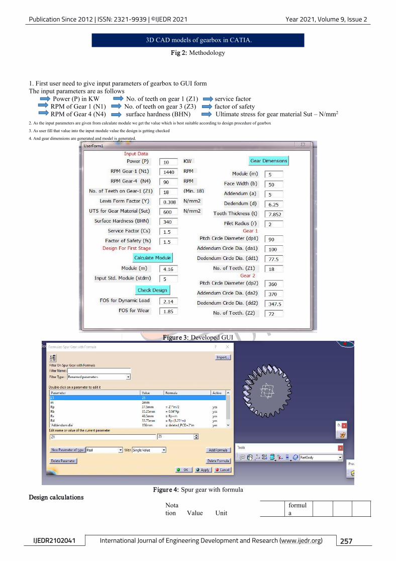
1. First user need to give input parameters of gearbox to GUI formThe input parameters are as follows
Power (P) in KW No. of teeth on gear 1 (Z1) service factorRPM of Gear 1 (N1) No. of teeth on gear 3 (Z3) factor of safetyRPM of Gear 4 (N4) surface hardness (BHN) Ultimate stress for gear material Sut – N/mm2
2. As the input parameters are given from calculate module we get the value which is best suitable according to design procedure of gearbox
3. As user fill that value into the input module value the design is getting checked
4. And gear dimensions are generated and model is generated.
Figure 3: Developed GUI
Figure 4: Spur gear with formulaDesign calculations
Notation Value Unit
formula
3D CAD models of gearbox in CATIA.
Publication Since 2012 | ISSN: 2321-9939 | ©IJEDR 2021 Year 2021, Volume 9, Issue 2
IJEDR2102041 International Journal of Engineering Development and Research (www.ijedr.org) 258
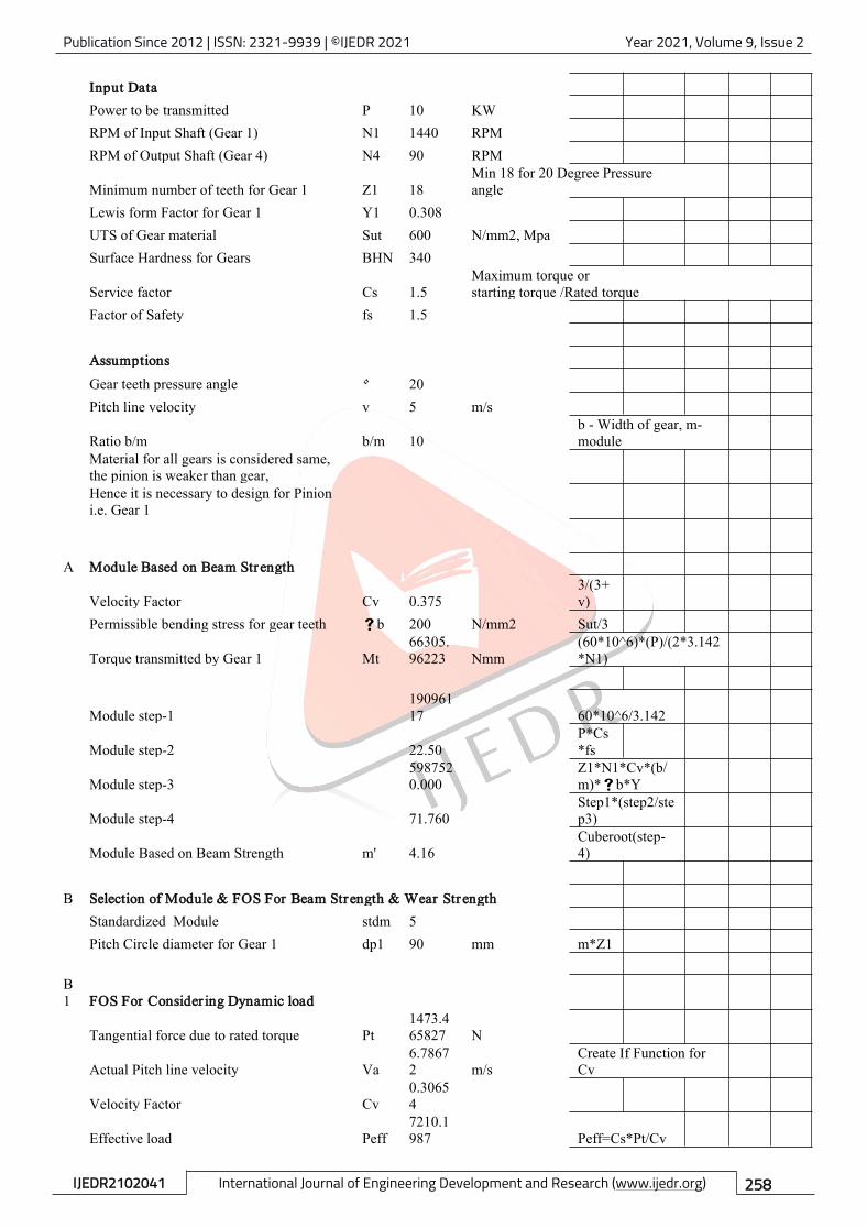
Input DataPower to be transmitted P 10 KWRPM of Input Shaft (Gear 1) N1 1440 RPMRPM of Output Shaft (Gear 4) N4 90 RPM
Minimum number of teeth for Gear 1 Z1 18Min 18 for 20 Degree Pressureangle
Lewis form Factor for Gear 1 Y1 0.308UTS of Gear material Sut 600 N/mm2, MpaSurface Hardness for Gears BHN 340
Service factor Cs 1.5Maximum torque orstarting torque /Rated torque
Factor of Safety fs 1.5
AssumptionsGear teeth pressure angle 20Pitch line velocity v 5 m/s
Ratio b/m b/m 10b - Width of gear, m-module
Material for all gears is considered same,the pinion is weaker than gear,Hence it is necessary to design for Pinioni.e. Gear 1
A Module Based on Beam Strength
Velocity Factor Cv 0.3753/(3+v)
Permissible bending stress for gear teeth b 200 N/mm2 Sut/3
Torque transmitted by Gear 1 Mt66305.96223 Nmm
(60*10^6)*(P)/(2*3.142*N1)
Module step-119096117 60*10^6/3.142
Module step-2 22.50P*Cs*fs
Module step-35987520.000
Z1*N1*Cv*(b/m)*b*Y
Module step-4 71.760Step1*(step2/step3)
Module Based on Beam Strength m' 4.16Cuberoot(step-4)
B Selection of Module & FOS For Beam Strength & Wear StrengthStandardized Module stdm 5Pitch Circle diameter for Gear 1 dp1 90 mm m*Z1
B1 FOS For Consider ing Dynamic load
Tangential force due to rated torque Pt1473.465827 N
Actual Pitch line velocity Va6.78672 m/s
Create If Function forCv
Velocity Factor Cv0.30654
Effective load Peff7210.1987 Peff=Cs*Pt/Cv
Publication Since 2012 | ISSN: 2321-9939 | ©IJEDR 2021 Year 2021, Volume 9, Issue 2
IJEDR2102041 International Journal of Engineering Development and Research (www.ijedr.org) 259
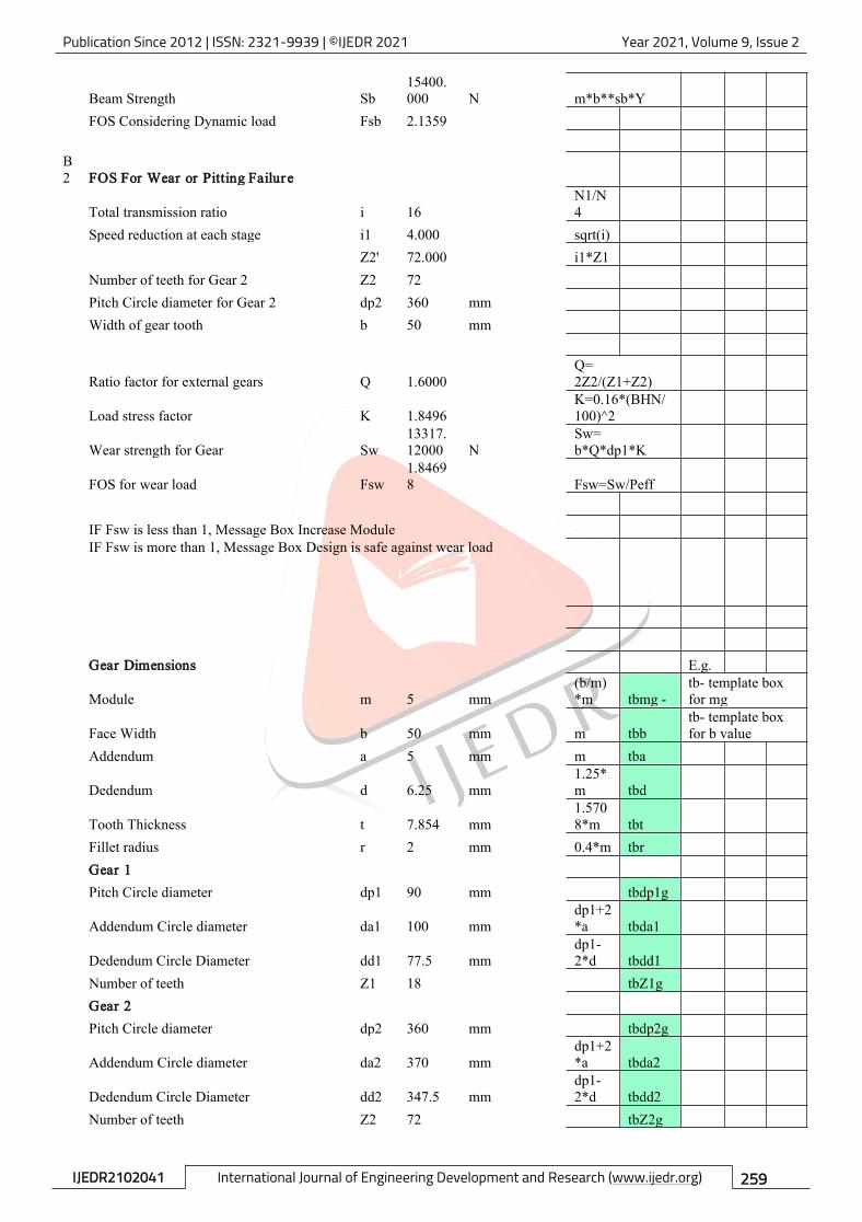
Beam Strength Sb15400.000 N m*b**sb*Y
FOS Considering Dynamic load Fsb 2.1359
B2 FOS For Wear or Pitting Failure
Total transmission ratio i 16N1/N4
Speed reduction at each stage i1 4.000 sqrt(i)Z2' 72.000 i1*Z1
Number of teeth for Gear 2 Z2 72Pitch Circle diameter for Gear 2 dp2 360 mmWidth of gear tooth b 50 mm
Ratio factor for external gears Q 1.6000Q=2Z2/(Z1+Z2)
Load stress factor K 1.8496K=0.16*(BHN/100)^2
Wear strength for Gear Sw13317.12000 N
Sw=b*Q*dp1*K
FOS for wear load Fsw1.84698 Fsw=Sw/Peff
IF Fsw is less than 1, Message Box Increase ModuleIF Fsw is more than 1, Message Box Design is safe against wear load
Gear Dimensions E.g.
Module m 5 mm(b/m)*m tbmg -
tb- template boxfor mg
Face Width b 50 mm m tbbtb- template boxfor b value
Addendum a 5 mm m tba
Dedendum d 6.25 mm1.25*m tbd
Tooth Thickness t 7.854 mm1.5708*m tbt
Fillet radius r 2 mm 0.4*m tbrGear 1Pitch Circle diameter dp1 90 mm tbdp1g
Addendum Circle diameter da1 100 mmdp1+2*a tbda1
Dedendum Circle Diameter dd1 77.5 mmdp1-2*d tbdd1
Number of teeth Z1 18 tbZ1gGear 2Pitch Circle diameter dp2 360 mm tbdp2g
Addendum Circle diameter da2 370 mmdp1+2*a tbda2
Dedendum Circle Diameter dd2 347.5 mmdp1-2*d tbdd2
Number of teeth Z2 72 tbZ2g
Publication Since 2012 | ISSN: 2321-9939 | ©IJEDR 2021 Year 2021, Volume 9, Issue 2
IJEDR2102041 International Journal of Engineering Development and Research (www.ijedr.org) 260
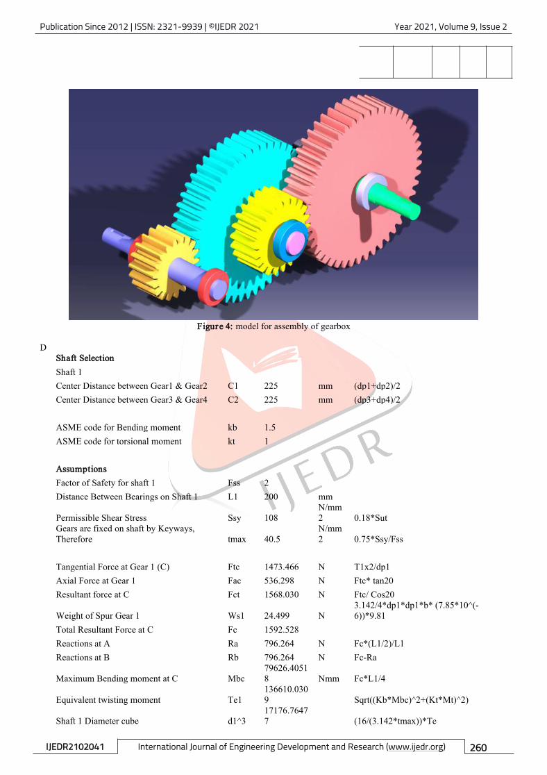
Figure 4: model for assembly of gearbox
DShaft SelectionShaft 1Center Distance between Gear1 & Gear2 C1 225 mm (dp1+dp2)/2Center Distance between Gear3 & Gear4 C2 225 mm (dp3+dp4)/2
ASME code for Bending moment kb 1.5ASME code for torsional moment kt 1
AssumptionsFactor of Safety for shaft 1 Fss 2Distance Between Bearings on Shaft 1 L1 200 mm
Permissible Shear Stress Ssy 108N/mm2 0.18*Sut
Gears are fixed on shaft by Keyways,Therefore tmax 40.5
N/mm2 0.75*Ssy/Fss
Tangential Force at Gear 1 (C) Ftc 1473.466 N T1x2/dp1Axial Force at Gear 1 Fac 536.298 N Ftc* tan20Resultant force at C Fct 1568.030 N Ftc/ Cos20
Weight of Spur Gear 1 Ws1 24.499 N3.142/4*dp1*dp1*b* (7.85*10^(-6))*9.81
Total Resultant Force at C Fc 1592.528Reactions at A Ra 796.264 N Fc*(L1/2)/L1Reactions at B Rb 796.264 N Fc-Ra
Maximum Bending moment at C Mbc79626.40518 Nmm Fc*L1/4
Equivalent twisting moment Te1136610.0309 Sqrt((Kb*Mbc)^2+(Kt*Mt)^2)
Shaft 1 Diameter cube d1^317176.76477 (16/(3.142*tmax))*Te
Publication Since 2012 | ISSN: 2321-9939 | ©IJEDR 2021 Year 2021, Volume 9, Issue 2
IJEDR2102041 International Journal of Engineering Development and Research (www.ijedr.org) 261
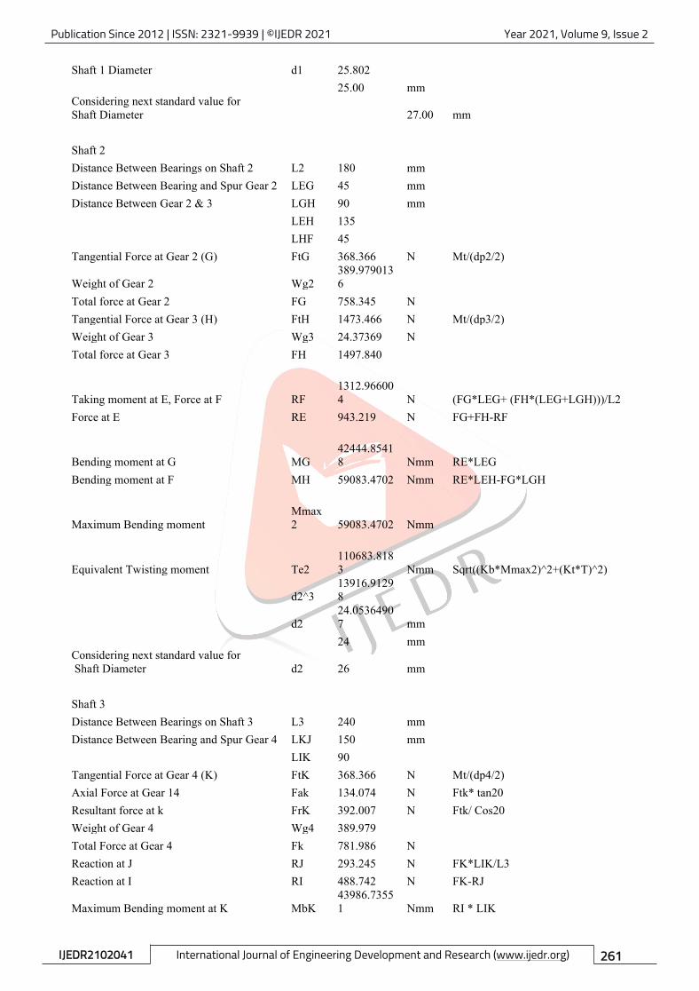
Shaft 1 Diameter d1 25.80225.00 mm
Considering next standard value forShaft Diameter 27.00 mm
Shaft 2Distance Between Bearings on Shaft 2 L2 180 mmDistance Between Bearing and Spur Gear 2 LEG 45 mmDistance Between Gear 2 & 3 LGH 90 mm
LEH 135LHF 45
Tangential Force at Gear 2 (G) FtG 368.366 N Mt/(dp2/2)
Weight of Gear 2 Wg2389.9790136
Total force at Gear 2 FG 758.345 NTangential Force at Gear 3 (H) FtH 1473.466 N Mt/(dp3/2)Weight of Gear 3 Wg3 24.37369 NTotal force at Gear 3 FH 1497.840
Taking moment at E, Force at F RF1312.966004 N (FG*LEG+ (FH*(LEG+LGH)))/L2
Force at E RE 943.219 N FG+FH-RF
Bending moment at G MG42444.85418 Nmm RE*LEG
Bending moment at F MH 59083.4702 Nmm RE*LEH-FG*LGH
Maximum Bending momentMmax2 59083.4702 Nmm
Equivalent Twisting moment Te2110683.8183 Nmm Sqrt((Kb*Mmax2)^2+(Kt*T)^2)
d2^313916.91298
d224.05364907 mm24 mm
Considering next standard value forShaft Diameter d2 26 mm
Shaft 3Distance Between Bearings on Shaft 3 L3 240 mmDistance Between Bearing and Spur Gear 4 LKJ 150 mm
LIK 90Tangential Force at Gear 4 (K) FtK 368.366 N Mt/(dp4/2)Axial Force at Gear 14 Fak 134.074 N Ftk* tan20Resultant force at k FrK 392.007 N Ftk/ Cos20Weight of Gear 4 Wg4 389.979Total Force at Gear 4 Fk 781.986 NReaction at J RJ 293.245 N FK*LIK/L3Reaction at I RI 488.742 N FK-RJ
Maximum Bending moment at K MbK43986.73551 Nmm RI * LIK
Publication Since 2012 | ISSN: 2321-9939 | ©IJEDR 2021 Year 2021, Volume 9, Issue 2
IJEDR2102041 International Journal of Engineering Development and Research (www.ijedr.org) 262
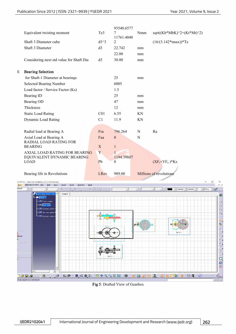
Equivalent twisting moment Te393540.65777 Nmm sqrt((Kb*MbK)^2+(Kt*Mt)^2)
Shaft 3 Diameter cube d3^311761.40482 (16/(3.142*tmax))*Te
Shaft 3 Diameter d3 22.742 mm22.00 mm
Considering next std value for Shaft Dia d3 30.00 mm
E Bear ing Selectionfor Shaft-1 Diameter at bearings 25 mmSelected Bearing Number 6005Load factor / Service Factor (Ks) 1.5Bearing ID 25 mmBearing OD 47 mmThickness 12 mmStatic Load Rating C01 6.55 KNDynamic Load Rating C1 11.9 KN
Radial load at Bearing A Fra 796.264 N RaAxial Load at Bearing A Faa 0 NRADIAL LOAD RATING FORBEARING X 1AXIAL LOAD RATING FOR BEARING Y 1EQUIVALENT DYNAMIC BEARINGLOAD Pb
1194.396078 (XFr+YFa )*Ks
Bearing life in Revolutions LRev 989.00 Millions of revolutions
Fig 5: Drafted View of Gearbox
Publication Since 2012 | ISSN: 2321-9939 | ©IJEDR 2021 Year 2021, Volume 9, Issue 2
IJEDR2102041 International Journal of Engineering Development and Research (www.ijedr.org) 263
ConclusionThe objective was to customize CATIAV5 for design two stage spur gearbox with minimum user requirements (inputs). Withthe help of this customization gearbox is generated. Also the time required for generating part model (three dimensionalmodel) of gearbox is reduced to few minutes. This part model can be used to draft different views of the gearbox which candirectly be used for manufacturing processes. Thus, customization will increase productivity of the designer with increase inquality of design which in turn reduces lead time for design of gearbox.
References[1] Ruchik D. Trivedi (2013). 3D Parametric Modeling for Product Variants Using Case Study on Inner Ring of SphericalRoller Bearing. Mechanical Engineering Tracks of the 3rd Nirma University International Conference on Engineering.Procardia Engineering 51(2013)709 –714[2] Umesh Bedse (2016).Developing a GUI based Design Software in VB Environment to Integrate with CREO for Designand Modeling of CI Engine. International Journal of Latest Trends in Engineering and Technology (IJLTET), Vol. 6 Issue 4March 2016, ISSN: 2278-621X[3] Indrajitsinh J. Jadeja (2014).Developing a GUI based Design Software in VB Environment to Integrate with CREO forDesign and Modeling using Case Study of Coupling. International Journal of Engineering Sciences & Research TechnologyApril, 2014 [4089-4095] ISSN: 2277 9655[4] DHAVAL B. SHAH (2013).Parametric Modeling and Drawing Automation for Flange Coupling Using Excel Spreadsheet.International Journal of Research in Engineering & Technology (IJRET) Vol. 1, Issue 2, July 2013, 187-192 © ImpactJournals[5] L.Karikalan (2018). Design and Analysis of Two Stage Reduction Gearbox for All Terrain Vehicles. International Journalof Advance Engineering and Research Development Volume 5, Issue 03, March -2018 e-ISSN (O): 2348-4470 p-ISSN (P):2348-6406[6] Saša ĆUKOVIĆ (2010). Automatic Determination of Grinding Tool Profile for Helical Surfaces Machining UsingCATIA/VB Interface. UPB Scientific Bulletin, Series D: Mechanical Engineering · January 2010Vol. 72, Issue. 2, 2010 ISSN1454-2358(7) Thakkar A. and Patel Y., 2012. Integration of PRO/E with Excel and C language for design automation, India: IJERT, pp.1-4(8) V.B.Bhandari “A text book of design of machine elements”, McGraw-Hill education India Pvt.Ltd(9) R.S.Khurmi and J.K.Gupta “A text book of Machine Design”, Euraisa Publication House, 2005 pp1021-1065


