Embed Size (px)
Citation preview
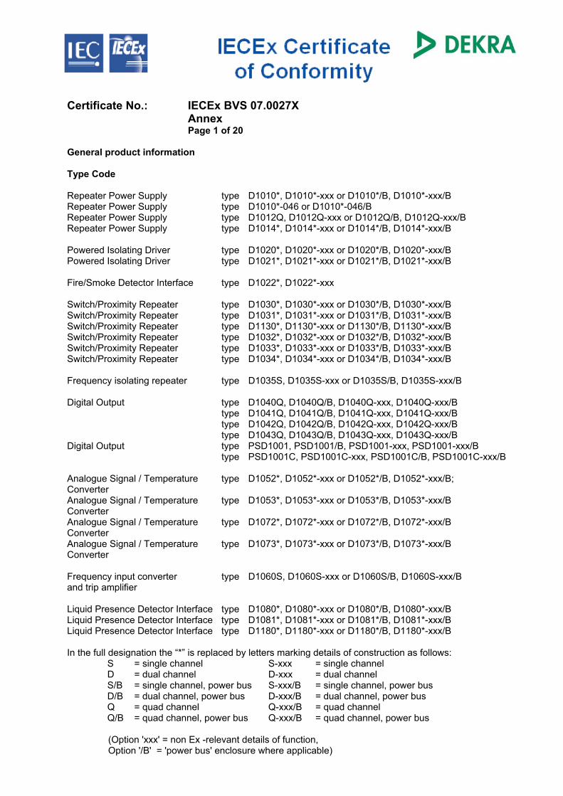
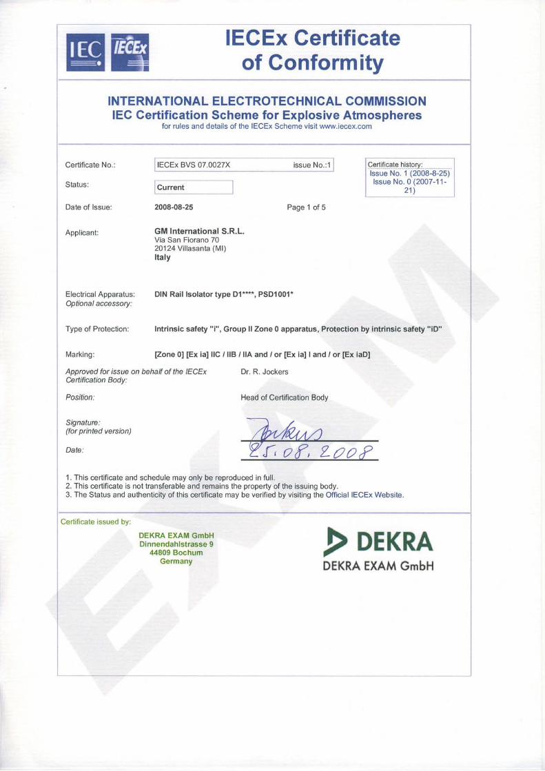
Certificate No.: IECEx BVS 07.0027X Annex Page 1 of 20 General product information Type Code
Repeater Power Supply type D1010*, D1010*-xxx or D1010*/B, D1010*-xxx/B Repeater Power Supply type D1010*-046 or D1010*-046/B Repeater Power Supply type D1012Q, D1012Q-xxx or D1012Q/B, D1012Q-xxx/B Repeater Power Supply type D1014*, D1014*-xxx or D1014*/B, D1014*-xxx/B Powered Isolating Driver type D1020*, D1020*-xxx or D1020*/B, D1020*-xxx/B Powered Isolating Driver type D1021*, D1021*-xxx or D1021*/B, D1021*-xxx/B Fire/Smoke Detector Interface type D1022*, D1022*-xxx Switch/Proximity Repeater type D1030*, D1030*-xxx or D1030*/B, D1030*-xxx/B Switch/Proximity Repeater type D1031*, D1031*-xxx or D1031*/B, D1031*-xxx/B Switch/Proximity Repeater type D1130*, D1130*-xxx or D1130*/B, D1130*-xxx/B Switch/Proximity Repeater type D1032*, D1032*-xxx or D1032*/B, D1032*-xxx/B Switch/Proximity Repeater type D1033*, D1033*-xxx or D1033*/B, D1033*-xxx/B Switch/Proximity Repeater type D1034*, D1034*-xxx or D1034*/B, D1034*-xxx/B Frequency isolating repeater type D1035S, D1035S-xxx or D1035S/B, D1035S-xxx/B Digital Output type D1040Q, D1040Q/B, D1040Q-xxx, D1040Q-xxx/B type D1041Q, D1041Q/B, D1041Q-xxx, D1041Q-xxx/B type D1042Q, D1042Q/B, D1042Q-xxx, D1042Q-xxx/B type D1043Q, D1043Q/B, D1043Q-xxx, D1043Q-xxx/B Digital Output type PSD1001, PSD1001/B, PSD1001-xxx, PSD1001-xxx/B type PSD1001C, PSD1001C-xxx, PSD1001C/B, PSD1001C-xxx/B Analogue Signal / Temperature type D1052*, D1052*-xxx or D1052*/B, D1052*-xxx/B; Converter Analogue Signal / Temperature type D1053*, D1053*-xxx or D1053*/B, D1053*-xxx/B Converter Analogue Signal / Temperature type D1072*, D1072*-xxx or D1072*/B, D1072*-xxx/B Converter Analogue Signal / Temperature type D1073*, D1073*-xxx or D1073*/B, D1073*-xxx/B Converter Frequency input converter type D1060S, D1060S-xxx or D1060S/B, D1060S-xxx/B and trip amplifier Liquid Presence Detector Interface type D1080*, D1080*-xxx or D1080*/B, D1080*-xxx/B Liquid Presence Detector Interface type D1081*, D1081*-xxx or D1081*/B, D1081*-xxx/B Liquid Presence Detector Interface type D1180*, D1180*-xxx or D1180*/B, D1180*-xxx/B In the full designation the “*” is replaced by letters marking details of construction as follows: S = single channel S-xxx = single channel D = dual channel D-xxx = dual channel S/B = single channel, power bus S-xxx/B = single channel, power bus D/B = dual channel, power bus D-xxx/B = dual channel, power bus Q = quad channel Q-xxx/B = quad channel Q/B = quad channel, power bus Q-xxx/B = quad channel, power bus (Option 'xxx' = non Ex -relevant details of function, Option '/B' = 'power bus' enclosure where applicable)
Certificate No.: IECEx BVS 07.0027X Annex Page 2 of 20 Description General Electronic components of DIN Rail Isolators are arranged on printed-circuit-boards (PCB) packaged in plastic enclosures suitable for installation on T35 DIN Rails. DIN Rail Isolators of D1**** / PSD1001* series provide safe galvanic separation between intrinsically safe circuits and non intrinsically safe signal circuits and power supply on the PCB up to a sum of peak values of rated voltages of 375 V. DIN Rail Isolators of D1**** / PSD1001* series are designated for installation in the safe area. Repeater Power Supply type D1010*, D1010*-xxx or D1010*/B, D1010*-xxx/B Repeater Power Supply Type D1010 provide single or dual channel intrinsically safe power supply for IS apparatus and repeat a 4 - 20 mA analogue signal in non intrinsically safe circuits. Repeater Power Supply type D1010*-046 or D1010*-046/B Repeater Power Supply Type D1010*-046 provide single or dual channel intrinsically safe power supply for measuring transmitters and repeat a 4 - 20 mA analogue signal in non intrinsically safe circuits. Version of the Repeater Power Supply: single channel: Type D1010S-046, D1010S-046/B; dual channel: Type D1010D-046, D1010D-046/B. Repeater Power Supply type D1012Q, D1012Q-xxx or D1012Q/B, D1012Q-xxx/B Repeater Power Supply type D1012Q, D1012Q-xxx, D1012Q/B, D1012Q-xxx/B provide quad channel intrinsically safe power supply for measuring transmitters and repeat a 4 - 20 mA analogue signal in non intrinsically safe circuits. Repeater Power Supply type D1014*, D1014*-xxx or D1014*/B, D1014*-xxx/B Repeater Power Supply type D1014* provide single or dual channel intrinsically safe power supply for measuring transmitters and repeat a 4 - 20 mA analogue signal in non intrinsically safe circuits. Available versions: single channel: type D1014S, D1014S/B; dual channel: type D1014D, D1014D/B. Powered Isolating Driver type D1020*, D1020*-xxx or D1020*/B, D1020*-xxx/B Isolating Driver Type D1020* provide single or dual channel intrinsically safe power supply for valve positioners or I/P-converters and repeat a non intrinsically safe 4 - 20 mA analogue signal in intrinsically safe circuits. (Type D1020S, D1020S/B: single channel; Type D1020D, D1020D/B: dual channel) Powered Isolating Driver type D1021*, D1021*-xxx or D1021*/B, D1021*-xxx/B Isolating Driver Type D1021* provide single channel intrinsically safe power supply for valve positioners or I/P-converters and repeat a non intrinsically safe 4 - 20 mA analogue signal in the intrinsically safe circuit. Available versions: single channel only: type D1021S, D1021S/B. Fire/Smoke Detector Interface type D1022*, D1022*-xxx Fire/Smoke Detector Interface type D1022*, D1022*-xxx provide single or dual channel intrinsically safe power supply for fire/smoke detectors "switched resistor mode" and repeat the analogue signal in non intrinsically safe circuits. Switch/Proximity Repeater type D1030*, D1030*-xxx or D1030*/B, D1030*-xxx/B type D1031*, D1031*-xxx or D1031*/B, D1031*-xxx/B type D1130*, D1130*-xxx or D1130*/B, D1130*-xxx/B Switch/Proximity Repeater Detector types D1030*, D1031*, D1130* provide single, dual or quad channel intrinsically safe power supply for switch / proximity switch circuits and repeat the status of voltage free contacts or proximity switches in non intrinsically safe circuits. Switch/Proximity Repeater Detectors are identical except for non intrinsically safe output configuration: relay-contact (types D1030*, D1130*), opto-isolator (type D1031*). Available version of the Switch/Proximity Repeater Detector: single channel: type D1*3*S, D1*3*S/B; dual channel: type D1*3*D, D1*3*D/B; quad channel: type D1*3*Q, D1*3*Q/B.
Certificate No.: IECEx BVS 07.0027X Annex Page 3 of 20 Switch/Proximity Repeater type D1032*, D1032*-xxx or D1032*/B, D1032*-xxx/B
type D1033*, D1033*-xxx or D1033*/B, D1033*-xxx/B Switch/Proximity Repeater Detector types D1032*, D1033* provide dual / quad channel intrinsically safe power supply for switch / proximity switch circuits and repeat the status of voltage free contacts or proximity switches in non intrinsically safe circuits. Switch/Proximity Repeater Detectors are identical except for non intrinsically safe output configuration relay-contact (type D1032*), opto-isolator (type D1033*). Available version of the Switch/Proximity Repeater Detector: dual channel: type D103*D, D103*D/B; quad channel: type D103*Q, D103*Q/B. Switch/Proximity Repeater type D1034*, D1034*-xxx or D1034*/B, D1034*-xxx/B Switch/Proximity Repeater Detector types D1034* provide single or dual channel intrinsically safe power supply for switch / proximity switch circuits and repeat the status of voltage free contacts or proximity switches in non intrinsically safe circuits. Available versions of the Switch/Proximity Repeater Detector: single channel: type D1034S, D1034S/B.dual channel: type D1034D, D1034D/B. Frequency isolating repeater type D1035S, D1035S-xxx or D1035S/B, D1035S-xxx/B Frequency isolating repeater type D1035S, D1035S-xxx, D1035S/B, D1035S-xxx/B,provide single channel intrinsically safe power supply for digital sensors (i.e. contacts, proximity switches, optical couplers) and convert the obtained frequency signal into non intrinsically safe 4 - 20 mA circuits. Alternatively the input circuit can accept pulses from non powered magnetic pick up. Digital Output type D1040Q, D1040Q/B, D1040Q-xxx, D1040Q-xxx/B
type D1041Q, D1041Q/B, D1041Q-xxx, D1041Q-xxx/B type D1042Q, D1042Q/B, D1042Q-xxx, D1042Q-xxx/B type D1043Q, D1043Q/B, D1043Q-xxx, D1043Q-xxx/B
Digital Output Type D104*Q provide up to four intrinsically safe remote outputs to operate solenoid valves, LEDs or audible alarms driven by non intrinsically safe digital remote signals. The four remote outputs - configuration with common "+" - may be used as single outputs or interconnected in parallel. The versions type D1040Q, D1041Q. D1042Q, D1043Q provide different electrical parameters. Digital Output type PSD1001, PSD1001/B, PSD1001-xxx, PSD1001-xxx/B
type PSD1001C, PSD1001C-xxx, PSD1001C/B, PSD1001C-xxx/B Digital Output Type PSD1001 provides four intrinsically safe power outputs to drive intrinsically safe apparatus. The four power outputs - configuration with common "+" - may be used as single outputs or interconnected in parallel. Digital Output Type PSD1001C provides one intrinsically safe power output to drive intrinsically safe apparatus. Digital Output Type PSD1001C complies with Digital Output Type PSD1001 with the exception, that the four power outputs - configuration with common "+" - are already interconnected in parallel and form one single output. Analogue Signal / Temperature Converter type D1052*, D1052*-xxx or D1052*/B, D1052*-xxx/B;
type D1053*, D1053*-xxx or D1053*/B, D1053*-xxx/B Analogue Signal Converter types D1052*, D1053* provide single or dual channel conversion of analogue intrinsically safe "mA" - or "V"-signals from separately powered transducers into non intrinsically safe 0/4 - 20 mA or 0/1 - 5V analogue- or alarm-signal circuits. Analogue Signal Converters are identical except for non intrinsically safe output configuration and function: type D1052*: analogue-output; type D1053*: relay-contacts "alarm A/B" and analogue-output; type D105*S: single channel; type D105*D: dual channel; type D105*X; single channel / two analogue-outputs; Type D105*Y: dual channel / double analogue-output. Available versions of the Analogue Signal Converters: single channel: type D105*S, D105*S/B. dual channel: type D105*D, D105*D/B.
Certificate No.: IECEx BVS 07.0027X Annex Page 4 of 20 Frequency input converter and trip amplifier type D1060S, D1060S-xxx or D1060S/B, D1060S-xxx/B Frequency input converter and trip amplifier type D1060S, D1060S-xxx, D1060S/B, D1060S-xxx/B respectively, provide single channel intrinsically safe power supply for digital sensors (i.e. contacts, proximity switches, optical couplers) and convert the obtained frequency signal into non intrinsically safe 4 - 20 mA circuits. Alternatively the input circuit can accept pulses from non powered magnetic pick up. Analogue Signal / Temperature Converter type D1072*, D1072*-xxx or D1072*/B, D1072*-xxx/B
type D1073*, D1073*-xxx or D1073*/B, D1073*-xxx/B Temperature Converter types D1072*, D1073* provide single or dual channel conversion of intrinsically safe low level DC-signals of thermocouples, resistance thermometers or transmitting potentiometers with 2-, 3-, 4-wire configuration and generate non intrinsically safe 0/4 - 20 mA or 0/1 - 5V analogue- or alarm-signal circuits. Temperature Converters are identical except for non intrinsically safe output configuration and function: type D1072*: analogue-output; type D1073*: relay-contacts "alarm A/B" and analogue-output; type D107*S: single channel; type D107*D: dual channel; type D107*X; single channel / two analogue-outputs; type D107*Y: dual channel / double analogue-output. Available versions of the Analogue Signal / Temperature Converter: single channel: type D107*S, D107*S/B. dual channel: type D107*D, D107*D/B. Liquid Presence Detector Interface type D1080*, D1080*-xxx or D1080*/B, D1080*-xxx/B
type D1081*, D1081*-xxx or D1081*/B, D1081*-xxx/B type D1180*, D1180*-xxx or D1180*/B, D1180*-xxx/B
Liquid Presence Detector Interfaces Types D1080*, D1081*, D1180* provide dual channel intrinsically safe 3-wire sensor circuits and repeat the sensor signal in a non-intrinsically safe output relay contact (types D1080*, D1180*) or opto-isolated transistor output (D1081*). Available versions of the Liquid Presence Detector Interfaces: dual channel: type D108*D, D108*D/B.
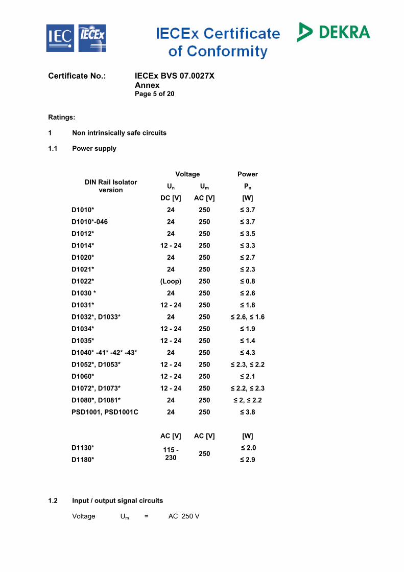
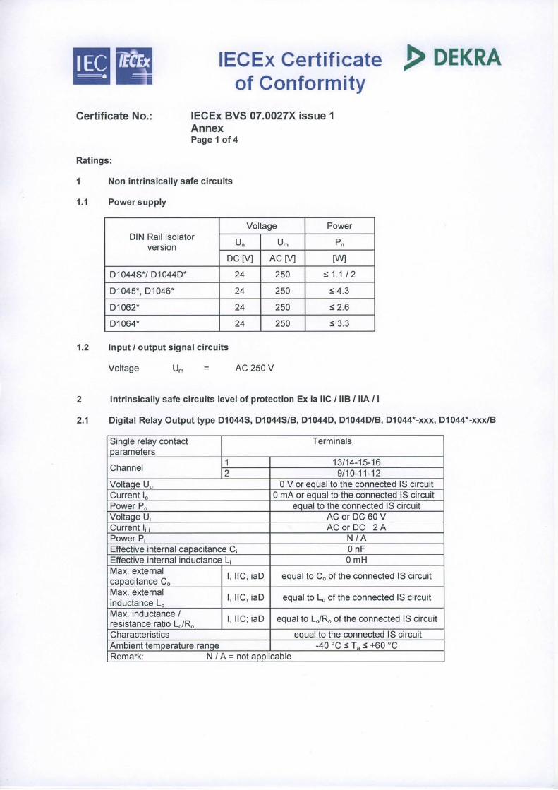
Certificate No.: IECEx BVS 07.0027X Annex Page 5 of 20 Ratings: 1 Non intrinsically safe circuits 1.1 Power supply
Voltage Power
Un Um Pn DIN Rail Isolator version
DC [V] AC [V] [W]
D1010* 24 250 ≤ 3.7
D1010*-046 24 250 ≤ 3.7
D1012* 24 250 ≤ 3.5
D1014* 12 - 24 250 ≤ 3.3
D1020* 24 250 ≤ 2.7
D1021* 24 250 ≤ 2.3
D1022* (Loop) 250 ≤ 0.8
D1030 * 24 250 ≤ 2.6
D1031* 12 - 24 250 ≤ 1.8
D1032*, D1033* 24 250 ≤ 2.6, ≤ 1.6
D1034* 12 - 24 250 ≤ 1.9
D1035* 12 - 24 250 ≤ 1.4
D1040* -41* -42* -43* 24 250 ≤ 4.3
D1052*, D1053* 12 - 24 250 ≤ 2.3, ≤ 2.2
D1060* 12 - 24 250 ≤ 2.1
D1072*, D1073* 12 - 24 250 ≤ 2.2, ≤ 2.3
D1080*, D1081* 24 250 ≤ 2, ≤ 2.2
PSD1001, PSD1001C 24 250 ≤ 3.8
AC [V] AC [V] [W]
D1130* ≤ 2.0
D1180* 115 -230 250
≤ 2.9 1.2 Input / output signal circuits Voltage Um = AC 250 V
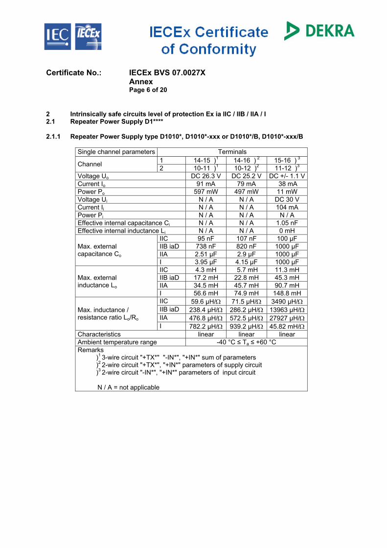
Certificate No.: IECEx BVS 07.0027X Annex Page 6 of 20 2 Intrinsically safe circuits level of protection Ex ia IIC / IIB / IIA / I 2.1 Repeater Power Supply D1**** 2.1.1 Repeater Power Supply type D1010*, D1010*-xxx or D1010*/B, D1010*-xxx/B
Single channel parameters Terminals
1 14-15 )1 14-16 ) 2 15-16 ) 3 Channel 2 10-11 )1 10-12 )2 11-12 )3 Voltage Uo DC 26.3 V DC 25.2 V DC +/- 1.1 V Current Io 91 mA 79 mA 38 mA Power Po 597 mW 497 mW 11 mW Voltage Ui N / A N / A DC 30 V Current Ii N / A N / A 104 mA Power Pi N / A N / A N / A Effective internal capacitance Ci N / A N / A 1.05 nF Effective internal inductance Li N / A N / A 0 mH
IIC 95 nF 107 nF 100 µF IIB iaD 738 nF 820 nF 1000 µF IIA 2.51 µF 2.9 µF 1000 µF
Max. external capacitance Co
I 3.95 µF 4.15 µF 1000 µF IIC 4.3 mH 5.7 mH 11.3 mH IIB iaD 17.2 mH 22.8 mH 45.3 mH IIA 34.5 mH 45.7 mH 90.7 mH
Max. external inductance Lo
I 56.6 mH 74.9 mH 148.8 mH IIC 59.6 µH/Ω 71.5 µH/Ω 3490 µH/Ω IIB iaD 238.4 µH/Ω 286.2 µH/Ω 13963 µH/Ω IIA 476.8 µH/Ω 572.5 µH/Ω 27927 µH/Ω
Max. inductance / resistance ratio Lo/Ro
I 782.2 µH/Ω 939.2 µH/Ω 45.82 mH/Ω Characteristics linear linear linear Ambient temperature range -40 °C ≤ Ta ≤ +60 °C Remarks
)1 3-wire circuit "+TX*" "-IN*", "+IN*" sum of parameters )2 2-wire circuit "+TX*", "+IN*" parameters of supply circuit )3 2-wire circuit "-IN*", "+IN*" parameters of input circuit
N / A = not applicable
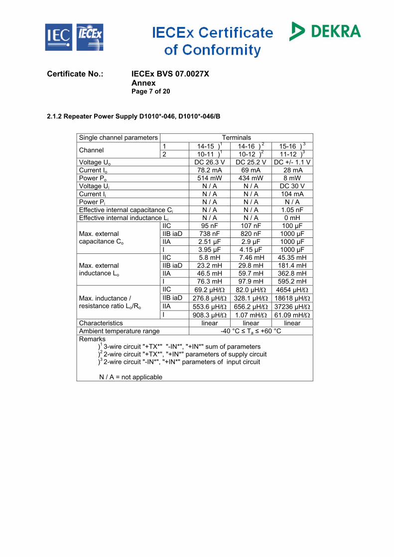
Certificate No.: IECEx BVS 07.0027X Annex Page 7 of 20 2.1.2 Repeater Power Supply D1010*-046, D1010*-046/B
Single channel parameters Terminals
1 14-15 )1 14-16 ) 2 15-16 ) 3 Channel 2 10-11 )1 10-12 )2 11-12 )3 Voltage Uo DC 26.3 V DC 25.2 V DC +/- 1.1 V Current Io 78.2 mA 69 mA 28 mA Power Po 514 mW 434 mW 8 mW Voltage Ui N / A N / A DC 30 V Current Ii N / A N / A 104 mA Power Pi N / A N / A N / A Effective internal capacitance Ci N / A N / A 1.05 nF Effective internal inductance Li N / A N / A 0 mH
IIC 95 nF 107 nF 100 µF IIB iaD 738 nF 820 nF 1000 µF IIA 2.51 µF 2.9 µF 1000 µF
Max. external capacitance Co
I 3.95 µF 4.15 µF 1000 µF IIC 5.8 mH 7.46 mH 45.35 mH IIB iaD 23.2 mH 29.8 mH 181.4 mH IIA 46.5 mH 59.7 mH 362.8 mH
Max. external inductance Lo
I 76.3 mH 97.9 mH 595.2 mH IIC 69.2 µH/Ω 82.0 µH/Ω 4654 µH/Ω IIB iaD 276.8 µH/Ω 328.1 µH/Ω 18618 µH/Ω IIA 553.6 µH/Ω 656.2 µH/Ω 37236 µH/Ω
Max. inductance / resistance ratio Lo/Ro
I 908.3 µH/Ω 1.07 mH/Ω 61.09 mH/Ω Characteristics linear linear linear Ambient temperature range -40 °C ≤ Ta ≤ +60 °C Remarks
)1 3-wire circuit "+TX*" "-IN*", "+IN*" sum of parameters )2 2-wire circuit "+TX*", "+IN*" parameters of supply circuit )3 2-wire circuit "-IN*", "+IN*" parameters of input circuit
N / A = not applicable
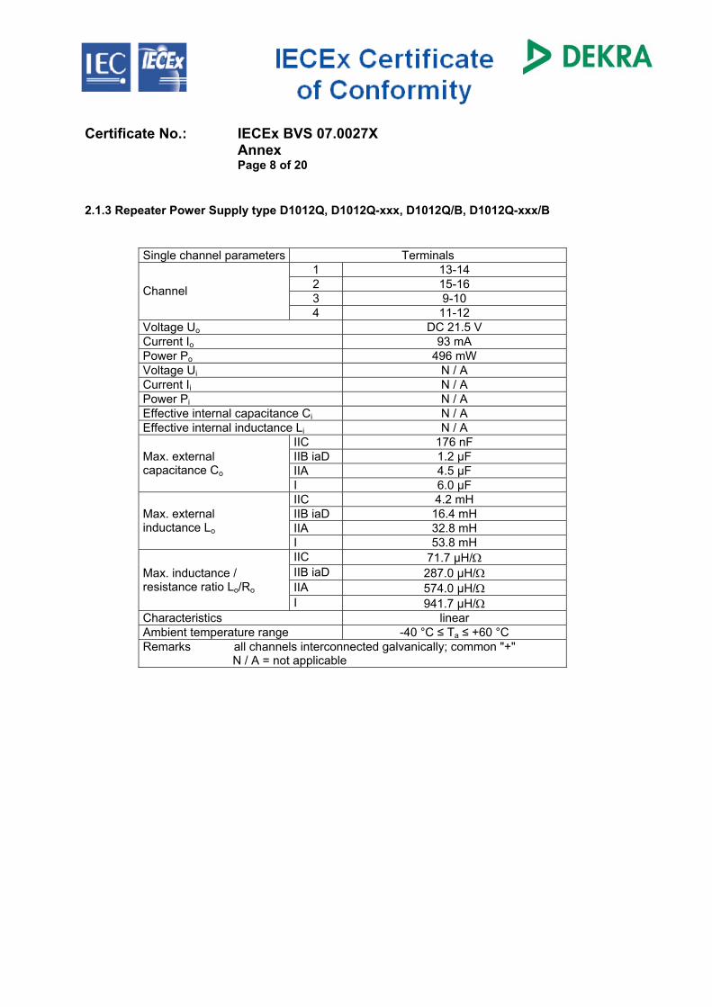
Certificate No.: IECEx BVS 07.0027X Annex Page 8 of 20 2.1.3 Repeater Power Supply type D1012Q, D1012Q-xxx, D1012Q/B, D1012Q-xxx/B
Single channel parameters Terminals 1 13-14 2 15-16 3 9-10 Channel
4 11-12 Voltage Uo DC 21.5 V Current Io 93 mA Power Po 496 mW Voltage Ui N / A Current Ii N / A Power Pi N / A Effective internal capacitance Ci N / A Effective internal inductance Li N / A
IIC 176 nF IIB iaD 1.2 µF IIA 4.5 µF
Max. external capacitance Co
I 6.0 µF IIC 4.2 mH IIB iaD 16.4 mH IIA 32.8 mH
Max. external inductance Lo
I 53.8 mH IIC 71.7 µH/Ω IIB iaD 287.0 µH/Ω IIA 574.0 µH/Ω
Max. inductance / resistance ratio Lo/Ro
I 941.7 µH/Ω Characteristics linear Ambient temperature range -40 °C ≤ Ta ≤ +60 °C Remarks all channels interconnected galvanically; common "+" N / A = not applicable
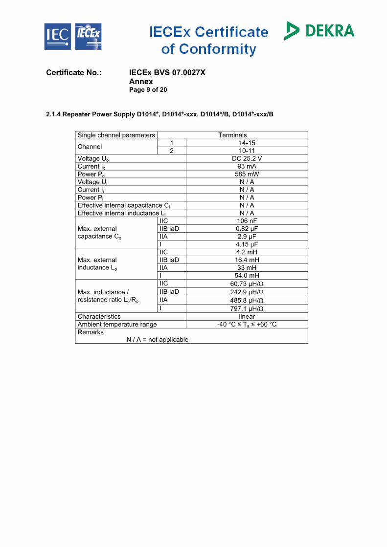
Certificate No.: IECEx BVS 07.0027X Annex Page 9 of 20 2.1.4 Repeater Power Supply D1014*, D1014*-xxx, D1014*/B, D1014*-xxx/B
Single channel parameters Terminals
1 14-15 Channel 2 10-11 Voltage Uo DC 25.2 V Current Io 93 mA Power Po 585 mW Voltage Ui N / A Current Ii N / A Power Pi N / A Effective internal capacitance Ci N / A Effective internal inductance Li N / A
IIC 106 nF IIB iaD 0.82 µF IIA 2.9 µF
Max. external capacitance Co
I 4.15 µF IIC 4.2 mH IIB iaD 16.4 mH IIA 33 mH
Max. external inductance Lo
I 54.0 mH IIC 60.73 µH/Ω IIB iaD 242.9 µH/Ω IIA 485.8 µH/Ω
Max. inductance / resistance ratio Lo/Ro
I 797.1 µH/Ω Characteristics linear Ambient temperature range -40 °C ≤ Ta ≤ +60 °C Remarks N / A = not applicable
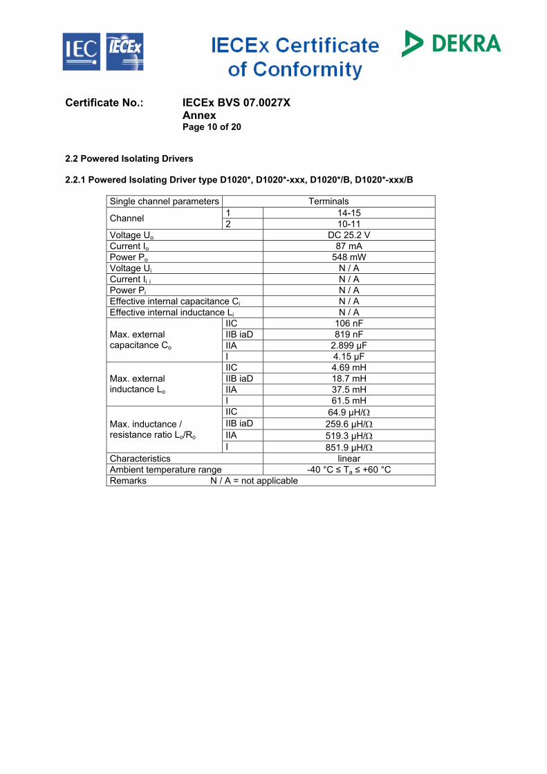
Certificate No.: IECEx BVS 07.0027X Annex Page 10 of 20 2.2 Powered Isolating Drivers 2.2.1 Powered Isolating Driver type D1020*, D1020*-xxx, D1020*/B, D1020*-xxx/B
Single channel parameters Terminals
1 14-15 Channel 2 10-11 Voltage Uo DC 25.2 V Current Io 87 mA Power Po 548 mW Voltage Ui N / A Current Ii i N / A Power Pi N / A Effective internal capacitance Ci N / A Effective internal inductance Li N / A
IIC 106 nF IIB iaD 819 nF IIA 2.899 µF
Max. external capacitance Co
I 4.15 µF IIC 4.69 mH IIB iaD 18.7 mH IIA 37.5 mH
Max. external inductance Lo
I 61.5 mH IIC 64.9 µH/Ω IIB iaD 259.6 µH/Ω IIA 519.3 µH/Ω
Max. inductance / resistance ratio Lo/Ro
I 851.9 µH/Ω Characteristics linear Ambient temperature range -40 °C ≤ Ta ≤ +60 °C Remarks N / A = not applicable
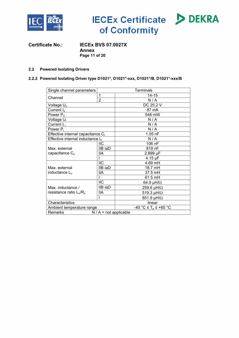
Certificate No.: IECEx BVS 07.0027X Annex Page 11 of 20 2.2 Powered Isolating Drivers 2.2.2 Powered Isolating Driver type D1021*, D1021*-xxx, D1021*/B, D1021*-xxx/B
Single channel parameters Terminals 1 14-15 Channel 2 N / A
Voltage Uo DC 25.2 V Current Io 87 mA Power Po 548 mW Voltage Ui N / A Current Ii i N / A Power Pi N / A Effective internal capacitance Ci 1.05 nF Effective internal inductance Li N / A
IIC 106 nF IIB iaD 819 nF IIA 2.899 µF
Max. external capacitance Co
I 4.15 µF IIC 4.69 mH IIB iaD 18.7 mH IIA 37.5 mH
Max. external inductance Lo
I 61.5 mH IIC 64.9 µH/Ω IIB iaD 259.6 µH/Ω IIA 519.3 µH/Ω
Max. inductance / resistance ratio Lo/Ro
I 851.9 µH/Ω Characteristics linear Ambient temperature range -40 °C ≤ Ta ≤ +60 °C Remarks N / A = not applicable
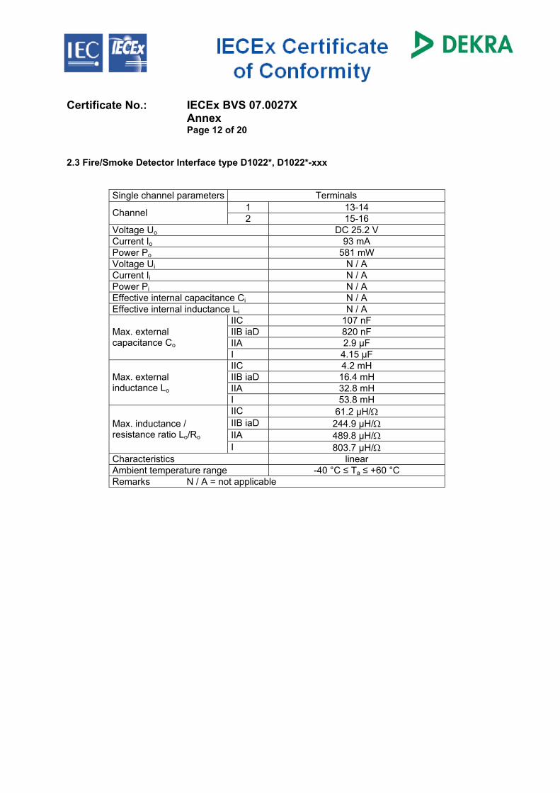
Certificate No.: IECEx BVS 07.0027X Annex Page 12 of 20 2.3 Fire/Smoke Detector Interface type D1022*, D1022*-xxx
Single channel parameters Terminals 1 13-14 Channel 2 15-16
Voltage Uo DC 25.2 V Current Io 93 mA Power Po 581 mW Voltage Ui N / A Current Ii N / A Power Pi N / A Effective internal capacitance Ci N / A Effective internal inductance Li N / A
IIC 107 nF IIB iaD 820 nF IIA 2.9 µF
Max. external capacitance Co
I 4.15 µF IIC 4.2 mH IIB iaD 16.4 mH IIA 32.8 mH
Max. external inductance Lo
I 53.8 mH IIC 61.2 µH/Ω IIB iaD 244.9 µH/Ω IIA 489.8 µH/Ω
Max. inductance / resistance ratio Lo/Ro
I 803.7 µH/Ω Characteristics linear Ambient temperature range -40 °C ≤ Ta ≤ +60 °C Remarks N / A = not applicable
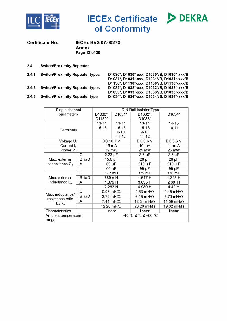
Certificate No.: IECEx BVS 07.0027X Annex Page 13 of 20 2.4 Switch/Proximity Repeater 2.4.1 Switch/Proximity Repeater types D1030*, D1030*-xxx, D1030*/B, D1030*-xxx/B D1031*, D1031*-xxx, D1031*/B, D1031*-xxx/B D1130*, D1130*-xxx, D1130*/B, D1130*-xxx/B 2.4.2 Switch/Proximity Repeater types D1032*, D1032*-xxx, D1032*/B, D1032*-xxx/B D1033*, D1033*-xxx, D1033*/B, D1033*-xxx/B 2.4.3 Switch/Proximity Repeater type D1034*, D1034*-xxx, D1034*/B, D1034*-xxx/B
DIN Rail Isolator Type Single channel parameters D1030*,
D1130* D1031* D1032*,
D1033* D1034*
Terminals
13-14 15-16
13-14 15-16 9-10 11-12
13-14 15-16 9-10 11-12
14-15 10-11
Voltage Uo DC 10.7 V DC 9.6 V DC 9.6 V Current Io 15 mA 10 mA 11 m A Power Po 39 mW 24 mW 25 mW
IIC 2.23 µF 3.6 µF 3.6 µF IIB iaD 15.6 µF 26 µF 26 µF IIA 69 µF 210 µ F 210 µ F
Max. external capacitance Co
I 60 µF 99 µF 99 µF IIC 172 mH 379 mH 336 mH IIB iaD 689 mH 1.517 H 1.345 H IIA 1.379 H 3.035 H 2.69 H
Max. external inductance Lo
I 2.263 H 4.980 H 4.42 H IIC 0.93 mH/Ω 1.53 mH/Ω 1.45 mH/Ω IIB iaD 3.72 mH/Ω 6.15 mH/Ω 5.79 mH/Ω IIA 7.44 mH/Ω 12.31 mH/Ω 11.59 mH/Ω
Max. inductance/ resistance ratio
Lo/Ro I 12.20 mH/Ω 20.20 mH/Ω 19.02 mH/Ω Characteristics linear linear linear Ambient temperature range
-40 °C ≤ Ta ≤ +60 °C
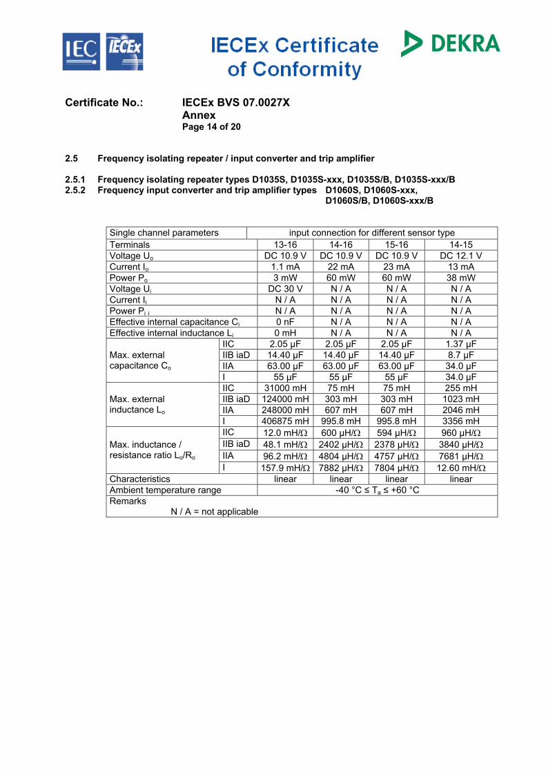
Certificate No.: IECEx BVS 07.0027X Annex Page 14 of 20 2.5 Frequency isolating repeater / input converter and trip amplifier 2.5.1 Frequency isolating repeater types D1035S, D1035S-xxx, D1035S/B, D1035S-xxx/B 2.5.2 Frequency input converter and trip amplifier types D1060S, D1060S-xxx,
D1060S/B, D1060S-xxx/B
Single channel parameters input connection for different sensor type Terminals 13-16 14-16 15-16 14-15 Voltage Uo DC 10.9 V DC 10.9 V DC 10.9 V DC 12.1 V Current Io 1.1 mA 22 mA 23 mA 13 mA Power Po 3 mW 60 mW 60 mW 38 mW Voltage Ui DC 30 V N / A N / A N / A Current Ii N / A N / A N / A N / A Power Pi i N / A N / A N / A N / A Effective internal capacitance Ci 0 nF N / A N / A N / A Effective internal inductance Li 0 mH N / A N / A N / A
IIC 2.05 µF 2.05 µF 2.05 µF 1.37 µF IIB iaD 14.40 µF 14.40 µF 14.40 µF 8.7 µF IIA 63.00 µF 63.00 µF 63.00 µF 34.0 µF
Max. external capacitance Co
I 55 µF 55 µF 55 µF 34.0 µF IIC 31000 mH 75 mH 75 mH 255 mH IIB iaD 124000 mH 303 mH 303 mH 1023 mH IIA 248000 mH 607 mH 607 mH 2046 mH
Max. external inductance Lo
I 406875 mH 995.8 mH 995.8 mH 3356 mH IIC 12.0 mH/Ω 600 µH/Ω 594 µH/Ω 960 µH/Ω IIB iaD 48.1 mH/Ω 2402 µH/Ω 2378 µH/Ω 3840 µH/Ω IIA 96.2 mH/Ω 4804 µH/Ω 4757 µH/Ω 7681 µH/Ω
Max. inductance / resistance ratio Lo/Ro
I 157.9 mH/Ω 7882 µH/Ω 7804 µH/Ω 12.60 mH/Ω Characteristics linear linear linear linear Ambient temperature range -40 °C ≤ Ta ≤ +60 °C Remarks N / A = not applicable
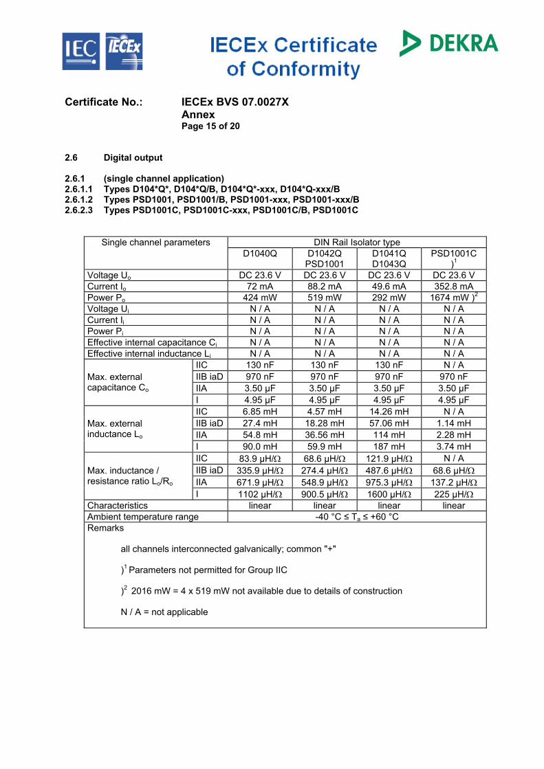
Certificate No.: IECEx BVS 07.0027X Annex Page 15 of 20 2.6 Digital output 2.6.1 (single channel application) 2.6.1.1 Types D104*Q*, D104*Q/B, D104*Q*-xxx, D104*Q-xxx/B 2.6.1.2 Types PSD1001, PSD1001/B, PSD1001-xxx, PSD1001-xxx/B 2.6.2.3 Types PSD1001C, PSD1001C-xxx, PSD1001C/B, PSD1001C
DIN Rail Isolator type Single channel parameters D1040Q
D1042Q PSD1001
D1041Q D1043Q
PSD1001C )1
Voltage Uo DC 23.6 V DC 23.6 V DC 23.6 V DC 23.6 V Current Io 72 mA 88.2 mA 49.6 mA 352.8 mA Power Po 424 mW 519 mW 292 mW 1674 mW )2 Voltage Ui N / A N / A N / A N / A Current Ii N / A N / A N / A N / A Power Pi N / A N / A N / A N / A Effective internal capacitance Ci N / A N / A N / A N / A Effective internal inductance Li N / A N / A N / A N / A
IIC 130 nF 130 nF 130 nF N / A IIB iaD 970 nF 970 nF 970 nF 970 nF IIA 3.50 µF 3.50 µF 3.50 µF 3.50 µF
Max. external capacitance Co
I 4.95 µF 4.95 µF 4.95 µF 4.95 µF IIC 6.85 mH 4.57 mH 14.26 mH N / A IIB iaD 27.4 mH 18.28 mH 57.06 mH 1.14 mH IIA 54.8 mH 36.56 mH 114 mH 2.28 mH
Max. external inductance Lo
I 90.0 mH 59.9 mH 187 mH 3.74 mH IIC 83.9 µH/Ω 68.6 µH/Ω 121.9 µH/Ω N / A IIB iaD 335.9 µH/Ω 274.4 µH/Ω 487.6 µH/Ω 68.6 µH/Ω IIA 671.9 µH/Ω 548.9 µH/Ω 975.3 µH/Ω 137.2 µH/Ω
Max. inductance / resistance ratio Lo/Ro
I 1102 µH/Ω 900.5 µH/Ω 1600 µH/Ω 225 µH/Ω Characteristics linear linear linear linear Ambient temperature range -40 °C ≤ Ta ≤ +60 °C Remarks
all channels interconnected galvanically; common "+" )1 Parameters not permitted for Group IIC )2 2016 mW = 4 x 519 mW not available due to details of construction N / A = not applicable
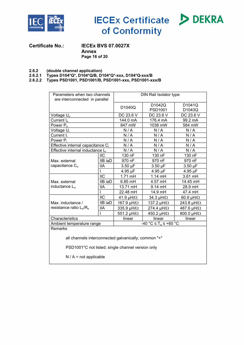
Certificate No.: IECEx BVS 07.0027X Annex Page 16 of 20 2.6.2 (double channel application) 2.6.2.1 Types D104*Q*, D104*Q/B, D104*Q*-xxx, D104*Q-xxx/B 2.6.2.2 Types PSD1001, PSD1001/B, PSD1001-xxx, PSD1001-xxx/B
DIN Rail Isolator type Parameters when two channels are interconnected in parallel
D1040Q D1042Q
PSD1001 D1041Q D1043Q
Voltage Uo DC 23.6 V DC 23.6 V DC 23.6 V Current Io 144.0 mA 176.4 mA 99.2 mA Power Po 847 mW 1038 mW 584 mW Voltage Ui N / A N / A N / A Current Ii N / A N / A N / A Power Pi N / A N / A N / A Effective internal capacitance Ci N / A N / A N / A Effective internal inductance Li N / A N / A N / A
IIC 130 nF 130 nF 130 nF IIB iaD 970 nF 970 nF 970 nF IIA 3.50 µF 3.50 µF 3.50 µF
Max. external capacitance Co
I 4.95 µF 4.95 µF 4.95 µF IIC 1.71 mH 1.14 mH 3.61 mH IIB iaD 6.85 mH 4.57 mH 14.45 mH IIA 13.71 mH 9.14 mH 28.9 mH
Max. external inductance Lo
I 22.48 mH 14.9 mH 47.4 mH IIC 41.9 µH/Ω 34.3 µH/Ω 60.9 µH/Ω IIB iaD 167.9 µH/Ω 137.2 µH/Ω 243.8 µH/Ω IIA 335.9 µH/Ω 274.4 µH/Ω 487.6 µH/Ω
Max. inductance / resistance ratio Lo/Ro
I 551.2 µH/Ω 450.2 µH/Ω 800.0 µH/Ω Characteristics linear linear linear Ambient temperature range -40 °C ≤ Ta ≤ +60 °C Remarks
all channels interconnected galvanically; common "+" PSD1001*C not listed; single channel version only N / A = not applicable
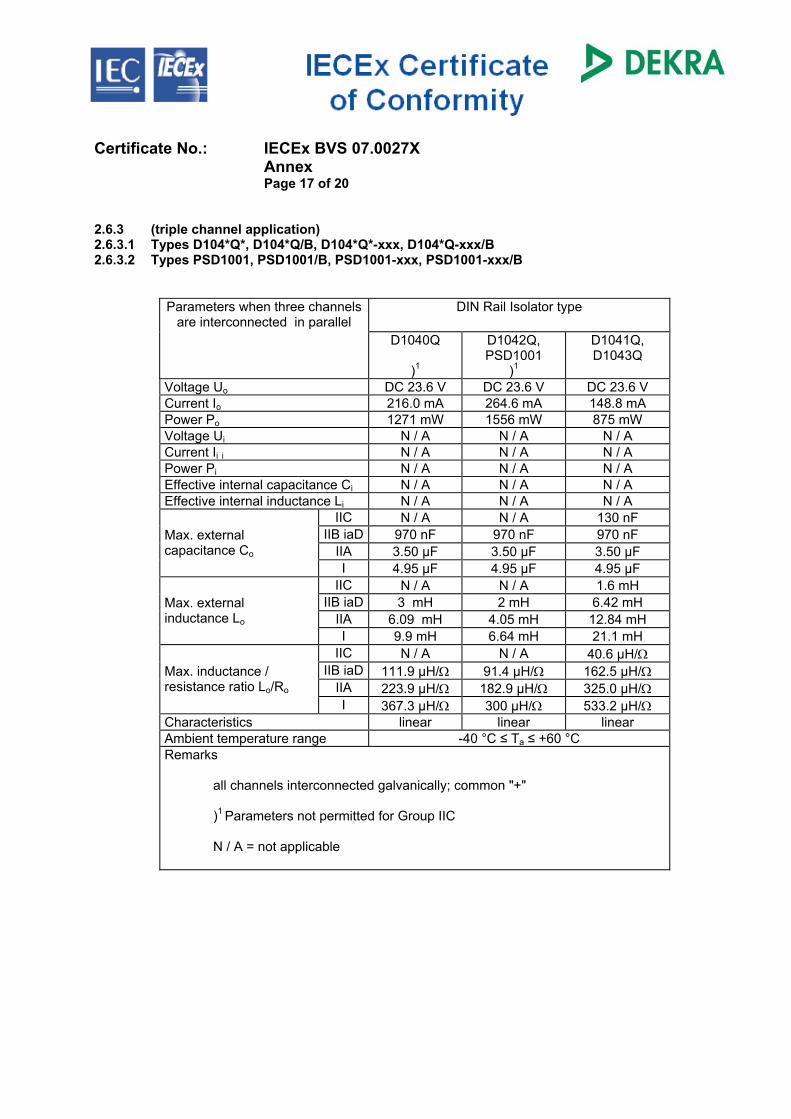
Certificate No.: IECEx BVS 07.0027X Annex Page 17 of 20 2.6.3 (triple channel application) 2.6.3.1 Types D104*Q*, D104*Q/B, D104*Q*-xxx, D104*Q-xxx/B 2.6.3.2 Types PSD1001, PSD1001/B, PSD1001-xxx, PSD1001-xxx/B
DIN Rail Isolator type Parameters when three channels are interconnected in parallel
D1040Q
)1
D1042Q, PSD1001
)1
D1041Q, D1043Q
Voltage Uo DC 23.6 V DC 23.6 V DC 23.6 V Current Io 216.0 mA 264.6 mA 148.8 mA Power Po 1271 mW 1556 mW 875 mW Voltage Ui N / A N / A N / A Current Ii i N / A N / A N / A Power Pi N / A N / A N / A Effective internal capacitance Ci N / A N / A N / A Effective internal inductance Li N / A N / A N / A
IIC N / A N / A 130 nF IIB iaD 970 nF 970 nF 970 nF
IIA 3.50 µF 3.50 µF 3.50 µF Max. external capacitance Co
I 4.95 µF 4.95 µF 4.95 µF IIC N / A N / A 1.6 mH
IIB iaD 3 mH 2 mH 6.42 mH IIA 6.09 mH 4.05 mH 12.84 mH
Max. external inductance Lo
I 9.9 mH 6.64 mH 21.1 mH IIC N / A N / A 40.6 µH/Ω
IIB iaD 111.9 µH/Ω 91.4 µH/Ω 162.5 µH/Ω IIA 223.9 µH/Ω 182.9 µH/Ω 325.0 µH/Ω
Max. inductance / resistance ratio Lo/Ro
I 367.3 µH/Ω 300 µH/Ω 533.2 µH/Ω Characteristics linear linear linear Ambient temperature range -40 °C ≤ Ta ≤ +60 °C Remarks
all channels interconnected galvanically; common "+" )1 Parameters not permitted for Group IIC N / A = not applicable
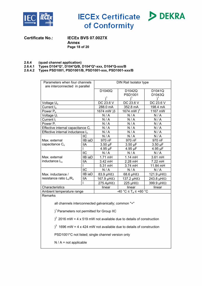
Certificate No.: IECEx BVS 07.0027X Annex Page 18 of 20 2.6.4 (quad channel application) 2.6.4.1 Types D104*Q*, D104*Q/B, D104*Q*-xxx, D104*Q-xxx/B 2.6.4.2 Types PSD1001, PSD1001/B, PSD1001-xxx, PSD1001-xxx/B
DIN Rail Isolator type Parameters when four channels are interconnected in parallel
D1040Q
)1
D1042Q PSD1001
)1
D1041Q D1043Q
)1 Voltage Uo DC 23.6 V DC 23.6 V DC 23.6 V Current Io 288.0 mA 352.8 mA 198.4 mA Power Po 1674 mW )3 1674 mW )2 1167 mW Voltage Ui N / A N / A N / A Current Ii N / A N / A N / A Power Pi N / A N / A N / A Effective internal capacitance Ci N / A N / A N / A Effective internal inductance Li N / A N / A N / A
IIC N / A N / A N / A IIB iaD 970 nF 970 nF 970 nF IIA 3.50 µF 3.50 µF 3.50 µF
Max. external capacitance Co
I 4.95 µF 4.95 µF 4.95 µF IIC N / A N / A N / A IIB iaD 1.71 mH 1.14 mH 3.61 mH IIA 3.42 mH 2.28 mH 7.22 mH
Max. external inductance Lo
I 5.31 mH 3.74 mH 11.84 mH IIC N / A N / A N / A IIB iaD 83.9 µH/Ω 68.6 µH/Ω 121.9 µH/Ω IIA 167.9 µH/Ω 137.2 µH/Ω 243.8 µH/Ω
Max. inductance / resistance ratio Lo/Ro
I 275.4µH/Ω 225 µH/Ω 399.9 µH/Ω Characteristics linear linear linear Ambient temperature range -40 °C ≤ Ta ≤ +60 °C Remarks
all channels interconnected galvanically; common "+" )1 Parameters not permitted for Group IIC )2 2016 mW = 4 x 519 mW not available due to details of construction )3 1696 mW = 4 x 424 mW not available due to details of construction PSD1001*C not listed; single channel version only
N / A = not applicable
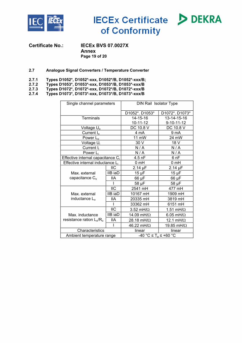
Certificate No.: IECEx BVS 07.0027X Annex Page 19 of 20 2.7 Analogue Signal Converters / Temperature Converter 2.7.1 Types D1052*, D1052*-xxx, D1052*/B, D1052*-xxx/B; 2.7.2 Types D1053*, D1053*-xxx, D1053*/B, D1053*-xxx/B 2.7.3 Types D1072*, D1072*-xxx, D1072*/B, D1072*-xxx/B 2.7.4 Types D1073*, D1073*-xxx, D1073*/B, D1073*-xxx/B
DIN Rail Isolator Type
Single channel parameters
D1052*. D1053* D1072*. D1073* Terminals 14-15-16
10-11-12 13-14-15-16 9-10-11-12
Voltage Uo DC 10.8 V DC 10.8 V Current Io 4 mA 9 mA Power Lo 11 mW 24 mW Voltage Ui 30 V 18 V Current Ii N / A N / A Power Li N / A N / A
Effective internal capacitance Ci 4.5 nF 6 nF Effective internal inductance Li 0 mH 0 mH
IIC 2.14 µF 2.14 µF IIB iaD 15 µF 15 µF
IIA 66 µF 66 µF Max. external
capacitance Co I 58 µF 58 µF
IIC 2541 mH 477 mH IIB iaD 10167 mH 1909 mH
IIA 20335 mH 3819 mH Max. external inductance Lo
I 33362 mH 6151 mH IIC 3.52 mH/Ω 1.51 mH/Ω
IIB iaD 14.09 mH/Ω 6.05 mH/Ω IIA 28.18 mH/Ω 12.1 mH/Ω
Max. inductance resistance ration Lo/Ro
I 46.22 mH/Ω 19.85 mH/Ω Characteristics linear linear
Ambient temperature range -40 °C ≤ Ta ≤ +60 °C
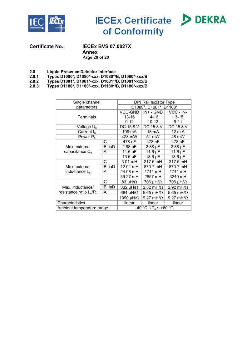
Certificate No.: IECEx BVS 07.0027X Annex Page 20 of 20 2.8 Liquid Presence Detector Interface 2.8.1 Types D1080*, D1080*-xxx, D1080*/B, D1080*-xxx/B 2.8.2 Types D1081*, D1081*-xxx, D1081*/B, D1081*-xxx/B 2.8.3 Types D1180*, D1180*-xxx, D1180*/B, D1180*-xxx/B
DIN Rail Isolator Type Single channel parameters D1080*, D1081*, D1180*
Terminals VCC-GND
13-16 9-12
IN+ - GND 14-16 10-12
VCC - IN- 13-15 9-11
Voltage Uo DC 15.8 V DC 15.8 V DC 15.8 V Current Io 109 mA 13 mA 12 m A Power Po 428 mW 51 mW 48 mW
IIC 478 nF 478 nF 478 nF IIB iaD 2.88 µF 2.88 µF 2.88 µF IIA 11.6 µF 11.6 µF 11.6 µF
Max. external capacitance Co
I 13.6 µF 13.6 µF 13.6 µF IIC 3.01 mH 217.6 mH 217.6 mH IIB iaD 12.04 mH 870.7 mH 870.7 mH IIA 24.08 mH 1741 mH 1741 mH
Max. external inductance Lo
I 39.27.mH 2857 mH 3240 mH IIC 83 µH/Ω 706 µH/Ω 706 µH/Ω IIB iaD 332 µH/Ω 2.82 mH/Ω 2.92 mH/Ω IIA 664 µH/Ω 5.65 mH/Ω 5.65 mH/Ω
Max. inductance/ resistance ratio Lo/Ro
I 1090 µH/Ω 9.27 mH/Ω 9.27 mH/Ω Characteristics linear linear linear Ambient temperature range -40 °C ≤ Ta ≤ +60 °C
IECEx BVS 07.0027X issue No.:2
INTERNATIONAL ELECTROTECHNICAL COMMISSIONIEC Certification Scheme for Explosive Atmospheres
for rules and details of the IECEx Scheme visit www.iecex.com
Certificate No.: Status: Current Date of Issue: 2010-10-20 Page 1 of 5
Applicant:
Electrical Apparatus: DIN Rail Isolator type D1****, PSD1001*Optional accessory:
Type of Protection:Intrinsic safety "i", Construction, test and Marking of Type of Protection "n" electricalapparatus, Equipment with equipment protection level (EPL) Ga, Protection by intrinsicsafety "iD"
Marking: (previous devices updated to:)[Ex ia Ga] IIC, [Ex ia Da] IIIC, [Ex ia Ma] I(new devices:)Ex nA [ia Ga] IIC T4 Gc, [Ex ia Da] IIIC, [Ex ia Ma] I
Approved for issue on behalf of the IECExCertification Body:
H.-Ch. Simanski
Position: Head of Certification Body
Signature:(for printed version) Date: 1. This certificate and schedule may only be reproduced in full.2. This certificate is not transferable and remains the property of the issuing body.3. The Status and authenticity of this certificate may be verified by visiting the Official IECEx Website.
Certificate issued by:
DEKRA EXAM GmbHDinnendahlstrasse 9
44809 BochumGermany
Certificate history:Issue No. 2 (2010-10-20)Issue No. 1 (2008-8-25)Issue No. 0 (2007-11-21)
GM International S.R.L.Via San Fiorano 7020058 Villasanta (MI)Italy
Certificate No.: IECEx BVS 07.0027X Date of Issue: 2010-10-20 Issue No.: 2
Page 2 of 5 Manufacturer:
Manufacturing location(s): This certificate is issued as verification that a sample(s), representative of production, was assessed and tested andfound to comply with the IEC Standard list below and that the manufacturer's quality system, relating to the Ex productscovered by this certificate, was assessed and found to comply with the IECEx Quality system requirements. Thiscertificate is granted subject to the conditions as set out in IECEx Scheme Rules, IECEx 02 and Operational Documentsas amended.
STANDARDS:The electrical apparatus and any acceptable variations to it specified in the schedule of this certificate and the identifieddocuments, was found to comply with the following standards: IEC 60079-0 : 2007-10Edition: 5
Explosive atmospheres - Part 0:Equipment - General requirements
IEC 60079-11 : 2006Edition: 5
Explosive atmospheres - Part 11: Equipment protection by intrinsic safety "i"
IEC 60079-15 :2005-03Edition: 3
Electrical apparatus for explosive gas atmospheres Part 15: Construction, test andMarking of Type of Protection "n" electrical apparatus
IEC 60079-26 : 2006Edition: 2
Explosive atmospheres - Part 26: Equipment with equipment protection level (EPL) Ga
IEC 61241-11 : 2005Edition: 1
Electrical apparatus for use in the presence of combustible dusts - Part 11: Protection byintrinsic safety 'iD'
This Certificate does not indicate compliance with electrical safety and performance requirements other than those
expressly included in the Standards listed above.
TEST & ASSESSMENT REPORTS:A sample(s) of the equipment listed has successfully met the examination and test requirements as recorded in Test Report:DE/BVS/ExTR07.0033/02
Quality Assessment Report:
NO/DNV/QAR07.0005/03
GM International S.R.L.Via San Fiorano 7020058 Villasanta (MI)Italy
Certificate No.: IECEx BVS 07.0027X Date of Issue: 2010-10-20 Issue No.: 2
Page 3 of 5
Schedule
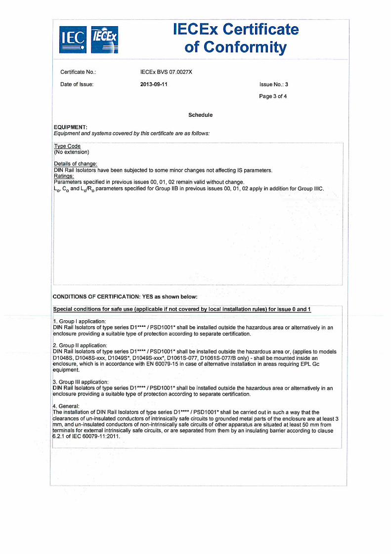
EQUIPMENT:Equipment and systems covered by this certificate are as follows: The Type Code, Description and Ratings of issue 0 are still valid but are supplemented as followed: Type Code DIN Rail Isolators of type series D10** / D11** / PSD1001* are extended optionally by the following new versions: Digital Output Driver type D1048S, D1048S-xxx,Digital Output Driver type D1049S, D1049S-xxx, D1049S/B, D1049S-xxx/BRS422 / RS485 Fieldbus type D1061S-077, D1061S-077/BIsolating Repeater S = single channel S-xxx = single channel (Option 'xxx' = non Ex -relevant details of function, Option '/B' = 'power bus' enclosure where applicable)
CONDITIONS OF CERTIFICATION: YES as shown below: Special conditions for safe use (applicable if not covered by local installation rules) for issue 0 and 1 1. Group I application:DIN Rail Isolators of type series D1**** / PSD1001* shall be installed outside the hazardous area or alternatively in anenclosure providing a suitable type of protection according to separate certification. 2. Group II application:DIN Rail Isolators of type series D1**** / PSD1001* shall be installed outside the hazardous area or, (applies to modelsD1048S, D1048S-xxx, D1049S*, D1049S-xxx*, D1061S-077, D1061S-077/B only) - shall be mounted inside anenclosure, which is in accordance with EN 60079-15 in case of alternative installation in areas requiring EPL Gcequipment. 3. Group III application:DIN Rail Isolators of type series D1**** / PSD1001* shall be installed outside the hazardous area. 4. General:The installation of DIN Rail Isolators of type series D1**** / PSD1001* shall be carried out in such a way that theclearances of un-insulated conductors of intrinsically safe circuits to grounded metal parts of the enclosure are at least 3mm, and un-insulated conductors of non-intrinsically safe circuits of other apparatus are situated at least 50 mm fromterminals for external intrinsically safe circuits, or are separated from them by an insulating barrier according to clause6.2.1 of IEC 60079-11:2006.
Certificate No.: IECEx BVS 07.0027X Date of Issue: 2010-10-20 Issue No.: 2
Page 4 of 5
EQUIPMENT(continued): Description Digital Output type D1048S, D1048S-xxx, type D1049S, D1049S-xxx, D1049S/B, D1049S-xxx/BDigital Output Type D104*S*, D104*S-xxx* provides single channel intrinsically safe remote outputs to operate solenoidvalves, LEDs or audible alarms driven by non intrinsically safe digital remote signals. The versions type D1048S,D1048S-xxx, type D1049S*, D1049S-xxx* provide different electrical parameters and/or configuration on the non-IS side. RS422 / RS485 Isolating Repeater type D1061S-077, D1061S-077/BThe DIN-Rail RS422 / RS485 Fieldbus Isolating Repeater type D1061S-077, D1061S-077/B provides single channelseparation of intrinsically safe RS422 (4-wire)) / RS485 (2-wire) equipment located in a hazardous area from a RS232 /RS422 / RS485 controller located in a safe area. The new models of DIN Rail Isolators are designed as associated apparatus and designated for installation in the safearea or alternatively in areas requiring EPL Gc equipment.Electronic components of DIN Rail Isolators are arranged on printed-circuit-boards (PCB) packaged in plastic enclosuressuitable for installation on T35 DIN Rails.The new models of DIN Rail Isolators provide safe galvanic separation between intrinsically safe circuits and nonintrinsically safe signal circuits / non intrinsically safe power supply on the PCB up to a sum of peak values of ratedvoltages of 375 V. ParametersSee Annex
Certificate No.: IECEx BVS 07.0027X Date of Issue: 2010-10-20 Issue No.: 2
Page 5 of 5
DETAILS OF CERTIFICATE CHANGES (for issues 1 and above): DIN Rail Isolator type D1**** / PSD1001* were extended optionally with new models subjected to assessment accordingto IECEx-Scheme: Digital Output Driver type D1048S, D1048S-xxx,Digital Output Driver type D1049S, D1049S-xxx, D1049S/B, D1049S-xxx/BRS422 / RS485 Fieldbus type D1061S-077, D1061S-077/BIsolating Repeater
Annexe: BVS_07_0027X_GM_Annex_issue2.pdf
trB IECEx Certificateof Conformity
) oxnn
CeÉificate No.r IECEX BVS 07.0027XAnnexPage 1 of 2
Ratings:
1 Non intrinsically safe circuits
1.1 Powersupply
1.2 lnput/ output signal circuits
Voltage U, = AC 250 V
2 lntrinsically safe circuits level of proteclion Ex ia llc / llB / llA / I
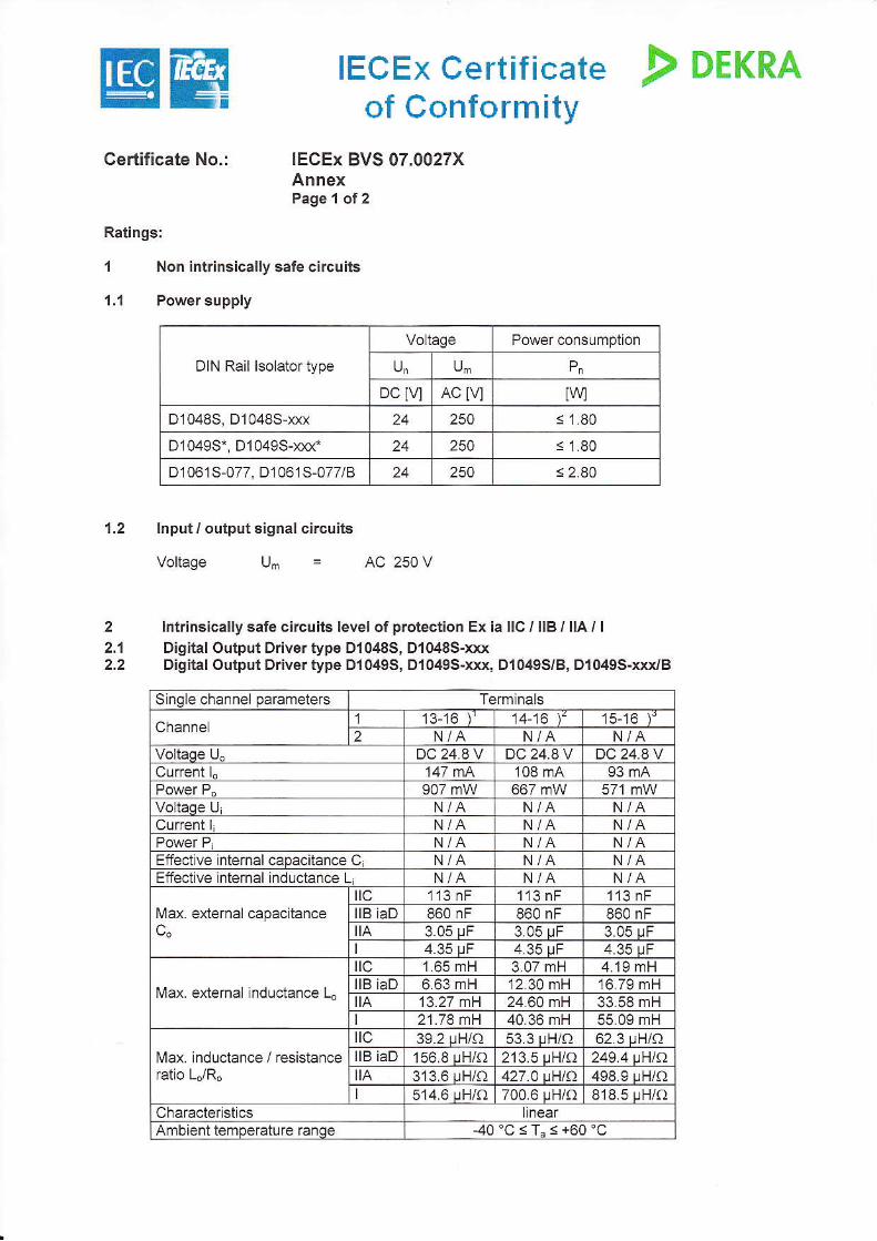
2.'l Digital Output Drivertype D1048S, D1048s-xxx2.2 Digital Output Drivertype D'|049S, D{049s-xxx, Dl049S/8, Dl049s-xxx./B
DIN Rail lsolator type
Voltage Power consumption
U, U-
DC lvl AC t\l IWD10485, D10485-oc{ 24 250 s 1.80
D10495., D1049s-rcod 24 250 < 1.80
D1061S-077, D1061S-077/B 250 < 2.80
Sinqle channel parameters Terminals
Channel 1 13-16 I 14-16 15-16 I
2 N/A N/A N/AVoltadè lJ^ DC248V DC248V DC 24 AVCurrent ì" 147 fiA 108 mA 93 mA
907 mW 667 mWVoltaqe lJ N/A N/ACunent L N/A N/A
N/A N/A N/AEffeclive nternal caDecitencé C N/A N/AEffective nternal inductance L N/A N/A N/A
l\rax external caùacitenceC 113 nF 113 nF 1'13 nF
llB iaD 860 nF 860 nF 860 nFc" A 3.05 uF 3.05 uF 3.05 uF
4.35 uF 4.35 uF 4.35 uF
l\,4ax. external lnductance Lo
C '1.65 mH 3.07 mH 4.'19 mHllB iaD 6.63 rnH 12.30 mH 16.79 mHA 13.27 tt)H 24.60 mH 33.58 mH
21.78 mH 40.36 mH 55.09 mH
Max. inductance / resistanceratio LJR"
IC 39 2 uH/eJ 53 3 uH/O 62 3 uH/e)llB iaD 156.8 uH/o 213.5 uqlo 249.4 uqloA 313.6 uH/O 427.4 rHlA 498.9 uH/O
I 514.6 uH/o 700.6 uH/o 818.5 uH/oCharacterisucs linearAmbient temoerature ranoe 40'C<T,<+60"C
EB IECEx Certificateof Conformity
! orrna
CeÉificate No.: IECEX BVS 07.0027XAnnexPage 2 ol2
Remarks:
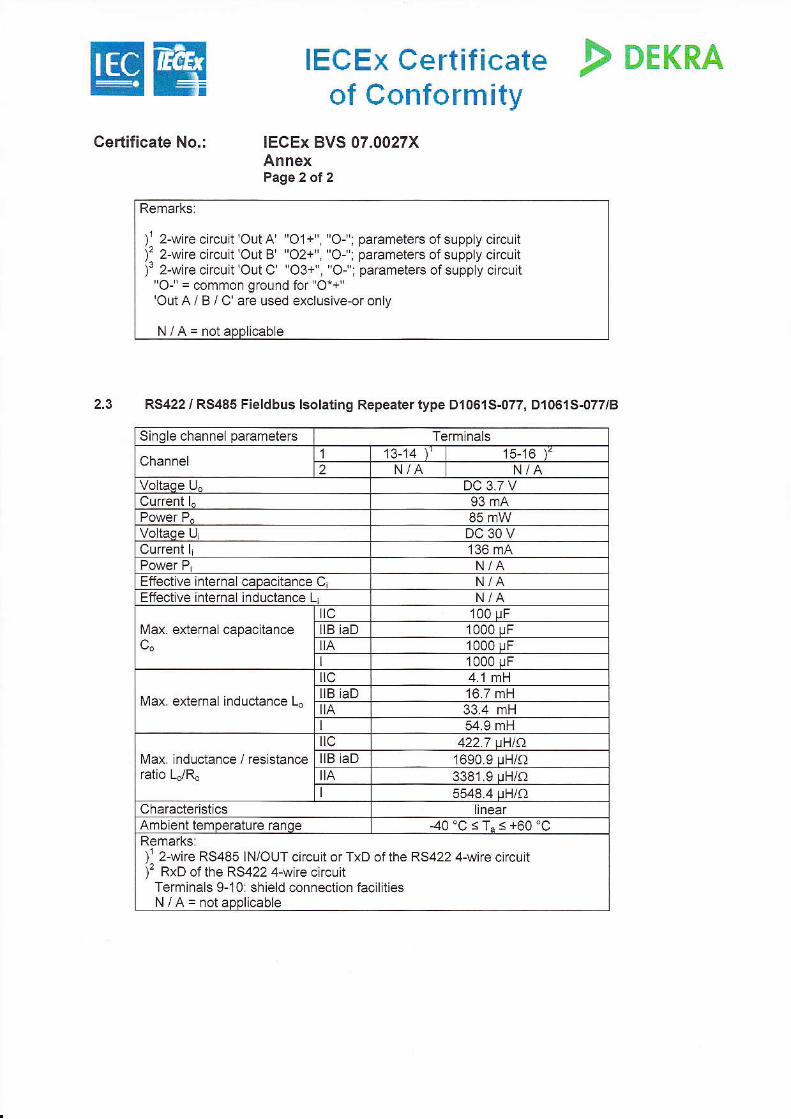
,' 2-wi'e ci'cuÌ OutA "O'+" "O- : pa'ameters of supply circutì' 2-wire circuir'Out B' "O2+" "O-: parameters of supply circu tl 2-wire circuit'Out C' 'O3-'.'Or': parameters ofsuppy ci'c-[
"Or'= common ground for O*+"'Out A / B / C' are used exclusivè-or only
N/A=noiaoDlicabe
2.3 RS422 / RS485 Fieldbus lsolating Repeater type Dr061S-077, Dl0615-077/8
Single channel parametérc Terminals
Channel1 13-14 l', 15-15 )
2 NiA N/AVoltaqe ll DC37VCurrent I 93 mA
85 mWVoltedè lJ DC30VCurrent I 136 mA
N/AEffective nterneLcaDacitance C, N/AEffective nternaL inductance Li N/A
Max. external capacitanceC 100 uF
IIB iaD 1000 uFC" ìtA 1000 uF
1000 uF
Max. extémal inductance L.
C 41 mHllB iaD 16.7 mHt!A 33.4 mH
54.9 mH
Max. inductance / resistanceratio LJR"
tìc 422 7 u{lf)llB iaD 1690.9 uH/oA 3381.9 uH/o
5548 4 uH/e)Characteristics linearAmbient temoerature ranoe -40 'C < T" s +60 'CRemarks:
). 2-wire RS485 INiOUT circuit o. TxD of rhe RS a22 A-wi'e cicu tl' RYD of th.a RS422 4-wiré cir.r,it
Terminals 9-10: shield connection facllitiesN/A=notapplicable