Embed Size (px)
Citation preview
DQD 507 Rev. 2016-02-18 Page 1
Certificate of Compliance Certificate: 2541184 Master Contract: 160686
Project: 70110551 Date Issued: January 25, 2017
Issued to: Endress + Hauser Flowtec AG Kaegenstrasse 7 CH-4153 Reinach SWITZERLAND Attention: Frank Bonshab
The products listed below are eligible to bear the CSA Mark shown
Issued by: E.Giusti Eric Giusti
PRODUCTS CLASS 2258 02 - PROCESS CONTROL EQUIPMENT - For Hazardous Locations CLASS 2258 82 - PROCESS CONTROL EQUIPMENT - For Hazardous Locations - Certified to US Standards Class I, Division 1, Groups A, B, C and D Prosonic Flow B 200 Types 9B2B**-C3*********+#**#, O9B2B**-C3**********+#**#, explosionproof with non intrinsically safe I/Os, integral intrinsically safe sensor and remote display when connected per installation drawing FES0191, which also specifies the maximum temperature code T6-T1 function of maximum ambient temperature -50°C to 60°C and maximum process temperature up to 80°C. Class I, Division 2, Groups A, B, C and D Prosonic Flow B 200 Types 9B2B**-C4*********+#**#, O9B2B**-C4**********+#**# FES0192, which also specifies the maximum temperature code T6-T1 function of maximum ambient temperature -60°C to 60°C and maximum process temperature up to 80°C.
Certificate: 2541184 Project: 70110551
Master Contract: 160686 Date Issued: January 25, 2017
DQD 507 Rev. 2016-02-18 Page 2
Class I, Division 1, Groups A, B, C and D Class II, Division 1, Groups E, F and G; Class III Ex d[ia] IIC and AEx d[ia] IIC, Class I, Zone 1 Proline Promass E/F Types 8E2B**-C3*********+#**#, 8E2B**-C6*********+#**#, O8E2B**-C3**********+#**#, O8E2B**-C6**********+#**#, 8F2B**-C3**********+#**#, 8F2B**-C6**********+#**#, O8F2B**-C3***********+#**#, O8F2B**-C6***********+#**#, 8E2C**-C3*********+#**#, O8E2C**-C6*********+#**#, explosionproof with non intrinsically safe I/Os, integral intrinsically safe sensor and remote display when connected per installation drawing FES0169, which also specifies the maximum temperature code T6-T1 function of maximum ambient temperature -50°C to 60°C and maximum process temperature -50°C to 205°C; Enclosure Type 4X; Dual Seal. Promag E/H/P/W 200 Types 5H2B**-C3*********+#**#, 5H2B**-C6*********+#**#, 5P2B**-C3*********+#**#, 5P2B**-C6*********+#**#, 5W2B**-C3*********+#**#, 5W2B**-C6*********+#**#, O5H2B**-C3**********+#**#, O5H2B**-C6**********+#**#, O5P2B**-C3**********+#**#, O5P2B**-C6**********+#**#, O5W2B**-C3**********+#**#, O5W2B**-C6**********+#**#, 5E2B**-C3*********+#**#, O5E2B**-C6*********+#**#, explosionproof with non intrinsically safe I/Os, integral intrinsically safe sensor and remote display when connected per installation drawing FES0206, which also specifies the maximum temperature code T6-T1 function of maximum ambient temperature -40°C to 60°C and maximum process temperature -40°C to 150°C; Enclosure Type 4X. Prowirl C/D/F/R/O 200 Types 7*2B**-C3*********+#**#, 7*2B**-C6*********+#**#, O7*2B**-C3**********+#**#, O7*2B**-C6**********+#**#, explosionproof with non intrinsically safe I/Os, integral intrinsically safe sensor and remote display when connected per installation drawing FES0228, which also specifies the maximum temperature code T6-T1 function of maximum ambient temperature -50°C to 85°C and maximum process temperature up to 450°C. Enclosure Type 4X; Dual Seal. Class I, Division 2, Groups A, B, C and D Class II, Division 1, Groups E, F and G; Class III Ex nA IIC and AEx nA IIC, Class I, Zone 2 Proline Promass E 200 Types 8E2B**-C4*********+#**#, 8E2B**-C7*********+#**#, O8E2B**-C4**********+#**#, O8E2B**-C7**********+#**#, 8F2B**-C4**********+#**#, 8F2B**-C7**********+#**#, O8F2B**-C4***********+#**#, O8F2B**-C7***********+#**#, 8E2C**-C4*********+#**#, O8E2C**-C7*********+#**#, non incendive sensor and remote display when connected per installation drawing FES0170, which also specifies the maximum temperature code T6-T1 function of maximum ambient temperature -60°C to 60°C and maximum process temperature -50°C to 205°C; Enclosure Type 4X; Dual Seal. Promag H/P/W 200 Types 5H2B**-C4**********+#**#, 5H2B**-C7**********+#**#, 5P2B**-C4**********+#**#, 5P2B**-C7**********+#**#, 5W2B**-C4**********+#**#, 5W2B**-C7**********+#**#, O5H2B**-C4*********+#**#, O5H2B**-C7*********+#**#, O5P2B**-C4*********+#**#, O5P2B**-C7*********+#**#, O5W2B**-C4*********+#**#, O5W2B**-C7*********+#**#, 5E2B**-C4**********+#**#, O5E2B**-C7**********+#**#, non incendive sensor and remote display when connected per installation drawing FES0207, which also specifies the maximum temperature
Certificate: 2541184 Project: 70110551
Master Contract: 160686 Date Issued: January 25, 2017
DQD 507 Rev. 2016-02-18 Page 3
code T6-T1 function of maximum ambient temperature -40°C to 60°C and maximum process temperature -40°C to 150°C; Enclosure Type 4X. Prowirl C/D/F/R/O 200 Types 7*2B**-C4*********+#**#, 7*2B**-C7*********+#**#, O7*2B**-C4**********+#**#, O7*2B**-C7**********+#**# non incendive sensor and remote display when connected per installation drawing FES0229, which also specifies the maximum temperature code T6-T1 function of maximum ambient temperature -60°C to 85°C and maximum process temperature up to 450°C. Enclosure Type 4X; Dual Seal CLASS 2258 03 - PROCESS CONTROL EQUIPMENT - Intrinsically Safe and Non-Incendive Systems - For Hazardous Locations CLASS 2258 83 - PROCESS CONTROL EQUIPMENT - Intrinsically Safe and Non-Incendive Systems - For Hazardous Locations - Certified to US Standards Class I, Division 2, Groups A, B, C and D Class II, Division 1, Groups E, F and G; Class III Ex nL IIC and AEx nC IIC T6-T1, Class I, Zone 2 Proline Promass E/F 200 Types 8E2B**-C4*********+#**#, 8E2B**-C7*********+#**#, O8E2B**-C4**********+#**#, O8E2B**-C7**********+#**#, 8FE2B**-C4**********+#**#, 8F2B**-C7**********+#**#, O8F2B**-C4***********+#**#, O8F2B**-C7***********+#**#, 8E2C**-C4*********+#**#, O8E2C**-C7*********+#**#, non-incendive when connected per installation drawing FES0170, which also specifies the entity parameters and the maximum temperature code T6-T1 function of maximum ambient temperature -60°C to 60°C and maximum process temperature -50°C to 205°C; Enclosure Type 4X; Dual Seal. Promag H/P/W 200 Types 5H2B**-C4*********+#**#, 5H2B**-C7*********+#**#, 5P2B**-C4*********+#**#, 5P2B**-C7*********+#**#, 5W2B**-C4*********+#**#, 5W2B**-C7*********+#**#, O5H2B**-C4**********+#**#, O5H2B**-C7**********+#**#, O5P2B**-C4**********+#**#, O5P2B**-C7**********+#**#, O5W2B**-C4**********+#**#, O5W2B**-C7**********+#**#, 5E2B**-C4*********+#**#, O5E2B**-C7*********+#**#, non-incendive when connected per installation drawing FES0207, which also specifies the entity parameters and the maximum temperature code T6-T1 function of maximum ambient temperature -40°C to 60°C and maximum process temperature -40°C to 150°C; Enclosure Type 4X; Dual Seal. Prowirl C/D/F/R/O 200 Types 7*2B**-C4*********+#**#, 7*2B**-C7*********+#**#, O7*2B**-C4**********+#**#, O7*2B**-C7**********+#**# non incendive when connected per installation drawing FES0229, which also specifies the maximum temperature code T6-T1 function of maximum ambient temperature -60°C to 85°C and maximum process temperature up to 450°C. Enclosure Type 4X; Dual Seal.
Certificate: 2541184 Project: 70110551
Master Contract: 160686 Date Issued: January 25, 2017
DQD 507 Rev. 2016-02-18 Page 4
CLASS 2258 04 - PROCESS CONTROL EQUIPMENT - Intrinsically Safe Entity - For Hazardous Locations CLASS 2258 84 - PROCESS CONTROL EQUIPMENT - Intrinsically Safe Entity - For Hazardous Locations - Certified to US Standards Class I, Division 1, Groups A, B, C and D Prosonic Flow B 200 Types 9B2B**-C2*********+#**#, O9B2B**-C2**********+#**#, intrinsically safe with entity parameters Ui, Umax =30V, Ii, Imax = 300mA, Pi, Pmax = 1W, Ci = 5nF and 30nF depending on the models, Li = 0 when connected per installation drawing FES0190, which also specifies the maximum temperature code T6-T1 function of maximum ambient temperature -50°C to 60°C and maximum process temperature 0°C to 80°C. Class I, Division 1, Groups A, B, C and D Class II, Division 1, Groups E, F and G; Class III Ex ia IIC and AEx ia IIC, Class I, Zone 1 Proline Promass E/F 200 Types 8E2B**-C2*********+#**#, 8E2B**-C5*********+#**#, O8E2B**-C2**********+#**# and O8E2B**-C5**********+#**#, 8F2B**-C2**********+#**#, 8F2B**-C5**********+#**#, O8F2B**-C2***********+#**# and O8F2B**-C5***********+#**#, 8E2C**-C2*********+#**#, O8E2C**-C5*********+#**#, intrinsically safe when connected per installation drawing FES0166, which also specifies the entity parameters the maximum temperature code T6-T1 function of maximum ambient temperature -50°C to 60°C and maximum process temperature -50°C to 205°C; Enclosure Type 4X; Dual Seal. Promag H/P/W 200 Types 5H2B**-C2*********+#**#, 5H2B**-C5*********+#**#, 5P2B**-C2*********+#**#, 5P2B**-C5*********+#**#, 5W2B**-C2*********+#**#, 5W2B**-C5*********+#**#, O5H2B**-C2*********+#**#, O5H2B**-C5*********+#**#, O5P2B**-C2*********+#**#, O5P2B**-C5*********+#**#, O5W2B**-C2*********+#**#, O5W2B**-C5*********+#**#, 5E2B**-C2*********+#**#, O5E2B**-C5*********+#**#, intrinsically safe when connected per installation drawing FES0205, which also specifies the maximum temperature code T6-T1 function of maximum ambient temperature -40°C to 60°C and maximum process temperature -40°C to 150°C; Enclosure Type 4X, Dual Seal. Class I, Division 1, Groups A, B, C and D Class II, Division 1, Groups E, F and G; Class III Ex ia IIC and AEx ia IIC, Class I, Zone 0 Prowirl C/D/F/R/O 200 Types 7*2B**-C2*********+#**#, 7*2B**-C5*********+#**#, O7*2B**-C2*********+#**#, O7*2B**-C5*********+#**#, intrinsically safe when connected per installation drawing FES0227, which also specifies the entity parameters the maximum temperature code T6-T1 function of maximum ambient temperature -50°C to 85°C and maximum process temperature from -50°C to 450°C; Enclosure Type 4X, dual seal.
Certificate: 2541184 Project: 70110551
Master Contract: 160686 Date Issued: January 25, 2017
DQD 507 Rev. 2016-02-18 Page 5
APPLICABLE REQUIREMENTS CSA C22.2 No. 0-10 General Requirements - Canadian Electrical Code, Part II CAN/CSA C22.2 No. 61010-1-12 Safety Requirements for Electrical Equipment for
Measurement, Control, and Laboratory Use - Part 1: General Requirements - Second Edition
CSA C22.2 No. 25-1966 Enclosures for Use in Class II, Groups E, F & G Hazardous Locations
CAN/CSA C22.2 No. 94-M91 Special Purpose Enclosures CSA C22.2 No. 213-2016 Nonincendive electrical equipment for use in Class I and II,
Division 2 and Class III, Divisions 1 and 2 hazardous (classified) locations
CSA C22.2 No 60079-0: 15 Explosive atmospheres - Part 0: Equipment - General requirements
CSA C22.2 No 60079-11:14 Explosive atmospheres - Part 11: Equipment protection by intrinsic safety “i”
CSA C22.2 No 60079-15:16 Explosive atmospheres - Part 15: Equipment protection by type of protection “n”
CSA C22.2 No 60079-1:16 Explosive atmospheres - Part 1: Equipment protection by flameproof enclosures “d”
CSA C22.2 No 60079-26:16 Explosive atmospheres - Part 26: Equipment with Equipment Protection Level (EPL) Ga
FM 3810: 2005 Approval Standard for Electrical Equipment for Measurement, Control, and Laboratory Use
ANSI/ ISA-61010-1 (82.02.01): 2012
Safety Requirements for Electrical Equipment for Measurement, Control, and Laboratory Use - Part 1 General Requirements
FM 3600:2011 Approval Standard for Electrical Equipment for use in Hazardous (Classified) Locations General Requirements
FM 3610:2015 Approval Standard for Intrinsically Safe Apparatus and Associated Apparatus for Use in Class I, II, III, Division 1, Hazardous (Classified) Locations
FM 3611:2004 Approval Standard for Nonincendive Electrical Equipment for Use in Class I and II, Division 2, and Class III Divisions 1 and 2, Hazardous (Classified) Locations
FM 3615: 2006 Approval Standard for Explosionproof Electrical Equipment General Requirements
FM 3616:2011 Approval Standard for Dust Ignitionproof Electrical Equipment for Use in Hazardous (Classified) Locations General Requirements
NEMA 250:2014 Enclosures for Electrical Equipment (1,000 Volts Maximum) ANSI/IEC 60529:2004 Degrees of Protection Provided by Enclosures (IP Code)
(identical national adoption) ISA 60079-0 (12.00.01): 2013 Explosive atmospheres – Part 0: Equipment – General
Requirements ISA 60079-11 (12.02.01): 2014 Explosive atmospheres - Part 11: Equipment protection by

Certificate: 2541184 Project: 70110551
Master Contract: 160686 Date Issued: January 25, 2017
DQD 507 Rev. 2016-02-18 Page 6
intrinsic safety “i” ISA 60079-15 (12.12.02): 2013 Explosive atmospheres – Part 15: Equipment protection by
type of protection "n" ISA-60079-26 (12.00.03)-2011 Explosive atmospheres - Part 26: Equipment for Use in Class
I, Zone 0 Hazardous (Classified) Locations ISA 12.27.01-2011 Requirements for Process Sealing Between Electrical
Systems and Flammable or Combustible Process Fluids MARKINGS The manufacturer is required to apply the following markings:
• Products shall be marked with the markings specified by the particular product standard. • Products certified for Canada shall have all Caution and Warning markings in both English and French.
Additional bilingual markings not covered by the product standard(s) may be required by the Authorities Having Jurisdiction. It is the responsibility of the manufacturer to provide and apply these additional markings, where applicable, in accordance with the requirements of those authorities. The products listed are eligible to bear the CSA Mark shown with adjacent indicators 'C' and 'US' for Canada and US (indicating that products have been manufactured to the requirements of both Canadian and U.S. Standards) or with adjacent indicator 'US' for US only or without either indicator for Canada only. Product markings shall be in accordance with the related standards. In addition, it shall be the responsibility of the manufacturer to provide additional markings on the product to comply with the requirements of the local regulatory authorities. Compliance of nameplates are covered under Letter of Attestation (CSA File 2095429) where a marking may be used such as one of the following plates
- Wölco Type 3105 2008 or - Eltex Type LAZRetch PM-200 (Top-Script 101 720) or - 3M Type 7847 or - stainless steel
Surface material: - powder coated aluminum IGP Type Durapol 6403A or - stainless steel
Nameplates are as per drawing FEK2508-0001, FEK2509-0001, FEK3066-0001, FEK3067-0000, FEK3321-0001 and FEK3117-0001. Applicable installation drawings FES0166, FES0169, FES0170, FES 190, FES191, FES192, FES204 are shipped with each product. Note - Jurisdictions in Canada may require these markings to also be provided in French language. It is the responsibility of the manufacturer to provide bilingual marking, where applicable, in accordance with the requirements of the Provincial Regulatory Authorities. It is the responsibility of the manufacturer to determine this requirement and have bilingual wording added to the "Markings".
DQD 507 Rev. 2016-02-18 Page 1
Supplement to Certificate of Compliance
Certificate: 2541184 Master Contract: 160686
The products listed, including the latest revision described below, are eligible to be marked in accordance with the referenced Certificate.
Product Certification History Project Date Description
70110551 2017/01/25 Update to report 2541184 to cover following points: 1. Changes to Prowirl 200 amplifier board V308 for connection of
sensor with pressure tapping 2. Additional connection boards L361 and L362 for remote versions as
with pressure sensor as alternative to L327 and L328 for versions without pressure sensor
3. Addition of connection board S-DAT 4. Increase maximum medium temperature for Prowirl 200 to 450°C 5. Changes to order code for Promass E type 8E2C and O8E2C 6. Drawing revisions to reflect the updates covered 7. Update of applicable standards editions
70006986 2014/06/19 Update to report 2541184 to cover following points: 1. Increased maximum medium temperature for Promass F 200 to
205°C. 2. Additional sensor Promag E for Promag 200 3. Additional version of Prowirl 200 4. Additional version of Promass E 5. Changes of approval code
70002075 2013/08/15 The purpose of this edition 2 is to cover the following points: - New flometer model Prowirl C/D/F/R/O 200 - Ta = -50°C for specific models - Ta = -60°C for versions with approval code “C4” for Prowirl 200 and
Promass 200 - New IO Option D for all flowmeters (IO module TRC[42] type IO218
and TRC[43] (IO219)) - New remote display FHX 50 for all flowmeters - Drawing revision from original certification
2567315 2012/11/1 Update to report 2541184 to cover minor revision on Control Drawing.
2541184 2012-07-02 Original Certification.
Descriptive Report and Test Results
This report shall not be reproduced, except in full, without the approval of CSA Group.
Unit 6 Hawarden Industrial Park, Hawarden, CH5 3US Telephone: +44(0)1244 670 900 www.csagroup.org
DQD 507.10 Rev 2016-01-18
MASTER CONTRACT: 160686 REPORT: 2541184
PROJECT: 70110551 Edition 1: June 29, 2012; Project 2541184 – Toronto
Issued by E.Giusti
Edition 2: November 1, 2012; Project 2567315 – Toronto Issued by Aisha Sreenath; Reviewed by Ron Wildish
Edition 3: August 15, 2013; Project 70002075 – Toronto Issued by E. Giusti
Edition 4: June 19, 2014; Project 70006986 – Toronto Issued by E. Giusti
Edition 5: January 25, 2017; Project 70110551 – CSA Europe Issued by E. Giusti
Report pages reissued Contents: Certificate of Compliance - Page 1 to 6
Supplement to Certificate of Compliance – Page 1 Description and Tests - Pages 1 to 60 Att1 Illustrations – 1 to 80 (illustrations 10 to 12, 48 to 50, 62, 68 to 70 were modified, illustrations added 71 to 80).
MASTER CONTRACT: 160686 REPORT: 2541184 PROJECT: 70110551
Page No: 2
Date Issued: January 25, 2017
DQD 507.10 Rev 2016-01-18
PRODUCTS CLASS 2258 02 - PROCESS CONTROL EQUIPMENT - For Hazardous Locations CLASS 2258 82 - PROCESS CONTROL EQUIPMENT - For Hazardous Locations - Certified to US Standards Class I, Division 1, Groups A, B, C and D Prosonic Flow B 200 Types 9B2B**-C3*********+#**#, O9B2B**-C3**********+#**#, explosionproof with non intrinsically safe I/Os, integral intrinsically safe sensor and remote display when connected per installation drawing FES0191, which also specifies the maximum temperature code T6-T1 function of maximum ambient temperature -50°C to 60°C and maximum process temperature up to 80°C. Class I, Division 2, Groups A, B, C and D Prosonic Flow B 200 Types 9B2B**-C4*********+#**#, O9B2B**-C4**********+#**# FES0192, which also specifies the maximum temperature code T6-T1 function of maximum ambient temperature -60°C to 60°C and maximum process temperature up to 80°C. Class I, Division 1, Groups A, B, C and D Class II, Division 1, Groups E, F and G; Class III Ex d[ia] IIC and AEx d[ia] IIC, Class I, Zone 1 Proline Promass E/F Types 8E2B**-C3*********+#**#, 8E2B**-C6*********+#**#, O8E2B**-C3**********+#**#, O8E2B**-C6**********+#**#, 8F2B**-C3**********+#**#, 8F2B**-C6**********+#**#, O8F2B**-C3***********+#**#, O8F2B**-C6***********+#**#, 8E2C**-C3*********+#**#, O8E2C**-C6*********+#**#, explosionproof with non intrinsically safe I/Os, integral intrinsically safe sensor and remote display when connected per installation drawing FES0169, which also specifies the maximum temperature code T6-T1 function of maximum ambient temperature -50°C to 60°C and maximum process temperature -50°C to 205°C; Enclosure Type 4X; Dual Seal. Promag E/H/P/W 200 Types 5H2B**-C3*********+#**#, 5H2B**-C6*********+#**#, 5P2B**-C3*********+#**#, 5P2B**-C6*********+#**#, 5W2B**-C3*********+#**#, 5W2B**-C6*********+#**#, O5H2B**-C3**********+#**#, O5H2B**-C6**********+#**#, O5P2B**-C3**********+#**#, O5P2B**-C6**********+#**#, O5W2B**-C3**********+#**#, O5W2B**-C6**********+#**#, 5E2B**-C3*********+#**#, O5E2B**-C6*********+#**#, explosionproof with non intrinsically safe I/Os, integral intrinsically safe sensor and remote display when connected per installation drawing FES0206, which also specifies the maximum temperature code T6-T1 function of maximum ambient temperature -40°C to 60°C and maximum process temperature -40°C to 150°C; Enclosure Type 4X. Prowirl C/D/F/R/O 200 Types 7*2B**-C3*********+#**#, 7*2B**-C6*********+#**#, O7*2B**-C3**********+#**#, O7*2B**-C6**********+#**#, explosionproof with non intrinsically safe I/Os, integral intrinsically safe sensor and remote display when connected per installation drawing FES0228, which also specifies the maximum temperature code T6-T1 function of maximum ambient temperature -50°C to 85°C and maximum process temperature up to 450°C. Enclosure Type 4X; Dual Seal. Class I, Division 2, Groups A, B, C and D Class II, Division 1, Groups E, F and G; Class III Ex nA IIC and AEx nA IIC, Class I, Zone 2 Proline Promass E 200 Types 8E2B**-C4*********+#**#, 8E2B**-C7*********+#**#, O8E2B**-C4**********+#**#, O8E2B**-C7**********+#**#, 8F2B**-C4**********+#**#, 8F2B**-C7**********+#**#, O8F2B**-C4***********+#**#, O8F2B**-C7***********+#**#, 8E2C**-
MASTER CONTRACT: 160686 REPORT: 2541184 PROJECT: 70110551
Page No: 3
Date Issued: January 25, 2017
DQD 507.10 Rev 2016-01-18
C4*********+#**#, O8E2C**-C7*********+#**#, non incendive sensor and remote display when connected per installation drawing FES0170, which also specifies the maximum temperature code T6-T1 function of maximum ambient temperature -60°C to 60°C and maximum process temperature -50°C to 205°C; Enclosure Type 4X; Dual Seal. Promag H/P/W 200 Types 5H2B**-C4**********+#**#, 5H2B**-C7**********+#**#, 5P2B**-C4**********+#**#, 5P2B**-C7**********+#**#, 5W2B**-C4**********+#**#, 5W2B**-C7**********+#**#, O5H2B**-C4*********+#**#, O5H2B**-C7*********+#**#, O5P2B**-C4*********+#**#, O5P2B**-C7*********+#**#, O5W2B**-C4*********+#**#, O5W2B**-C7*********+#**#, 5E2B**-C4**********+#**#, O5E2B**-C7**********+#**#, non incendive sensor and remote display when connected per installation drawing FES0207, which also specifies the maximum temperature code T6-T1 function of maximum ambient temperature -40°C to 60°C and maximum process temperature -40°C to 150°C; Enclosure Type 4X. Prowirl C/D/F/R/O 200 Types 7*2B**-C4*********+#**#, 7*2B**-C7*********+#**#, O7*2B**-C4**********+#**#, O7*2B**-C7**********+#**# non incendive sensor and remote display when connected per installation drawing FES0229, which also specifies the maximum temperature code T6-T1 function of maximum ambient temperature -60°C to 85°C and maximum process temperature up to 450°C. Enclosure Type 4X; Dual Seal CLASS 2258 03 - PROCESS CONTROL EQUIPMENT - Intrinsically Safe and Non-Incendive Systems - For Hazardous Locations CLASS 2258 83 - PROCESS CONTROL EQUIPMENT - Intrinsically Safe and Non-Incendive Systems - For Hazardous Locations - Certified to US Standards Class I, Division 2, Groups A, B, C and D Class II, Division 1, Groups E, F and G; Class III Ex nL IIC and AEx nC IIC T6-T1, Class I, Zone 2 Proline Promass E/F 200 Types 8E2B**-C4*********+#**#, 8E2B**-C7*********+#**#, O8E2B**-C4**********+#**#, O8E2B**-C7**********+#**#, 8FE2B**-C4**********+#**#, 8F2B**-C7**********+#**#, O8F2B**-C4***********+#**#, O8F2B**-C7***********+#**#, 8E2C**-C4*********+#**#, O8E2C**-C7*********+#**#, non-incendive when connected per installation drawing FES0170, which also specifies the entity parameters and the maximum temperature code T6-T1 function of maximum ambient temperature -60°C to 60°C and maximum process temperature -50°C to 205°C; Enclosure Type 4X; Dual Seal. Promag H/P/W 200 Types 5H2B**-C4*********+#**#, 5H2B**-C7*********+#**#, 5P2B**-C4*********+#**#, 5P2B**-C7*********+#**#, 5W2B**-C4*********+#**#, 5W2B**-C7*********+#**#, O5H2B**-C4**********+#**#, O5H2B**-C7**********+#**#, O5P2B**-C4**********+#**#, O5P2B**-C7**********+#**#, O5W2B**-C4**********+#**#, O5W2B**-C7**********+#**#, 5E2B**-C4*********+#**#, O5E2B**-C7*********+#**#, non-incendive when connected per installation drawing FES0207, which also specifies the entity parameters and the maximum temperature code T6-T1 function of maximum ambient temperature -40°C to 60°C and maximum process temperature -40°C to 150°C; Enclosure Type 4X; Dual Seal. Prowirl C/D/F/R/O 200 Types 7*2B**-C4*********+#**#, 7*2B**-C7*********+#**#, O7*2B**-C4**********+#**#, O7*2B**-C7**********+#**# non incendive when connected per installation drawing FES0229, which also specifies the maximum temperature code T6-T1 function of maximum ambient temperature -60°C to 85°C and maximum process temperature up to 450°C. Enclosure Type 4X; Dual Seal.
MASTER CONTRACT: 160686 REPORT: 2541184 PROJECT: 70110551
Page No: 4
Date Issued: January 25, 2017
DQD 507.10 Rev 2016-01-18
CLASS 2258 04 - PROCESS CONTROL EQUIPMENT - Intrinsically Safe Entity - For Hazardous Locations CLASS 2258 84 - PROCESS CONTROL EQUIPMENT - Intrinsically Safe Entity - For Hazardous Locations - Certified to US Standards Class I, Division 1, Groups A, B, C and D Prosonic Flow B 200 Types 9B2B**-C2*********+#**#, O9B2B**-C2**********+#**#, intrinsically safe with entity parameters Ui, Umax =30V, Ii, Imax = 300mA, Pi, Pmax = 1W, Ci = 5nF and 30nF depending on the models, Li = 0 when connected per installation drawing FES0190, which also specifies the maximum temperature code T6-T1 function of maximum ambient temperature -50°C to 60°C and maximum process temperature 0°C to 80°C. Class I, Division 1, Groups A, B, C and D Class II, Division 1, Groups E, F and G; Class III Ex ia IIC and AEx ia IIC, Class I, Zone 1 Proline Promass E/F 200 Types 8E2B**-C2*********+#**#, 8E2B**-C5*********+#**#, O8E2B**-C2**********+#**# and O8E2B**-C5**********+#**#, 8F2B**-C2**********+#**#, 8F2B**-C5**********+#**#, O8F2B**-C2***********+#**# and O8F2B**-C5***********+#**#, 8E2C**-C2*********+#**#, O8E2C**-C5*********+#**#, intrinsically safe when connected per installation drawing FES0166, which also specifies the entity parameters the maximum temperature code T6-T1 function of maximum ambient temperature -50°C to 60°C and maximum process temperature -50°C to 205°C; Enclosure Type 4X; Dual Seal. Promag H/P/W 200 Types 5H2B**-C2*********+#**#, 5H2B**-C5*********+#**#, 5P2B**-C2*********+#**#, 5P2B**-C5*********+#**#, 5W2B**-C2*********+#**#, 5W2B**-C5*********+#**#, O5H2B**-C2*********+#**#, O5H2B**-C5*********+#**#, O5P2B**-C2*********+#**#, O5P2B**-C5*********+#**#, O5W2B**-C2*********+#**#, O5W2B**-C5*********+#**#, 5E2B**-C2*********+#**#, O5E2B**-C5*********+#**#, intrinsically safe when connected per installation drawing FES0205, which also specifies the maximum temperature code T6-T1 function of maximum ambient temperature -40°C to 60°C and maximum process temperature -40°C to 150°C; Enclosure Type 4X, Dual Seal. Class I, Division 1, Groups A, B, C and D Class II, Division 1, Groups E, F and G; Class III Ex ia IIC and AEx ia IIC, Class I, Zone 0 Prowirl C/D/F/R/O 200 Types 7*2B**-C2*********+#**#, 7*2B**-C5*********+#**#, O7*2B**-C2*********+#**#, O7*2B**-C5*********+#**#, intrinsically safe when connected per installation drawing FES0227, which also specifies the entity parameters the maximum temperature code T6-T1 function of maximum ambient temperature -50°C to 85°C and maximum process temperature from -50°C to 450°C; Enclosure Type 4X, dual seal.
MASTER CONTRACT: 160686 REPORT: 2541184 PROJECT: 70110551
Page No: 5
Date Issued: January 25, 2017
DQD 507.10 Rev 2016-01-18
APPLICABLE REQUIREMENTS CSA C22.2 No. 0-10 -General Requirements - Canadian Electrical Code, Part II CAN/CSA C22.2 No. 61010-1-12 - Safety Requirements for Electrical Equipment for Measurement, Control, and Laboratory Use - Part 1: General Requirements - Second Edition CSA C22.2 No. 25-1966 - Enclosures for Use in Class II, Groups E, F & G Hazardous Locations CAN/CSA C22.2 No. 94-M91 – Special Purpose Enclosures CSA C22.2 No. 213-2016 - Nonincendive electrical equipment for use in Class I and II, Division 2 and Class III, Divisions 1 and 2 hazardous (classified) locations CSA C22.2 No 60079-0: 15 - Explosive atmospheres - Part 0: Equipment - General requirements
CSA C22.2 No 60079-11:14 - Explosive atmospheres - Part 11: Equipment protection by intrinsic safety “i”
CSA C22.2 No 60079-15:16- Explosive atmospheres - Part 15: Equipment protection by type of protection “n” CSA C22.2 No 60079-1:16 - Explosive atmospheres - Part 1: Equipment protection by flameproof enclosures “d” CSA C22.2 No 60079-26:16 - Explosive atmospheres - Part 26: Equipment with Equipment Protection Level (EPL) Ga FM 3810: 2005 - Approval Standard for Electrical Equipment for Measurement, Control, and Laboratory Use ANSI/ ISA-61010-1 (82.02.01): 2012 - Safety Requirements for Electrical Equipment for Measurement, Control, and Laboratory Use - Part 1 General Requirements FM 3600:2011 - Approval Standard for Electrical Equipment for use in Hazardous (Classified) Locations General Requirements FM 3610:2015 - Approval Standard for Intrinsically Safe Apparatus and Associated Apparatus for Use in Class I, II, III, Division 1, Hazardous (Classified) Locations FM 3611:2004 - Approval Standard for Nonincendive Electrical Equipment for Use in Class I and II, Division 2, and Class III Divisions 1 and 2, Hazardous (Classified) Locations FM 3615: 2006 - Approval Standard for Explosionproof Electrical Equipment General Requirements FM 3616:2011 - Approval Standard for Dust Ignitionproof Electrical Equipment for Use in Hazardous (Classified) Locations General Requirements NEMA 250:2014 - Enclosures for Electrical Equipment (1,000 Volts Maximum) ANSI/IEC 60529:2004 - Degrees of Protection Provided by Enclosures (IP Code) (identical national adoption) ISA 60079-0 (12.00.01): 2013 - Explosive atmospheres – Part 0: Equipment – General Requirements ISA 60079-11 (12.02.01): 2014 - Explosive atmospheres - Part 11: Equipment protection by intrinsic safety “i” ISA 60079-15 (12.12.02): 2013 - Explosive atmospheres – Part 15: Equipment protection by type of protection "n" ISA-60079-26 (12.00.03)-2011 Explosive atmospheres - Part 26: Equipment for Use in Class I, Zone 0 Hazardous (Classified) Locations ISA 12.27.01-2011 - Requirements for Process Sealing Between Electrical Systems and Flammable or Combustible Process Fluids

MASTER CONTRACT: 160686 REPORT: 2541184 PROJECT: 70110551
Page No: 6
Date Issued: January 25, 2017
DQD 507.10 Rev 2016-01-18
MARKINGS The manufacturer is required to apply the following markings:
• Products shall be marked with the markings specified by the particular product standard. • Products certified for Canada shall have all Caution and Warning markings in both English and French.
Additional bilingual markings not covered by the product standard(s) may be required by the Authorities Having Jurisdiction. It is the responsibility of the manufacturer to provide and apply these additional markings, where applicable, in accordance with the requirements of those authorities. The products listed are eligible to bear the CSA Mark shown with adjacent indicators 'C' and 'US' for Canada and US (indicating that products have been manufactured to the requirements of both Canadian and U.S. Standards) or with adjacent indicator 'US' for US only or without either indicator for Canada only. Product markings shall be in accordance with the related standards. In addition, it shall be the responsibility of the manufacturer to provide additional markings on the product to comply with the requirements of the local regulatory authorities. Compliance of nameplates are covered under Letter of Attestation (CSA File 2095429) where a marking may be used such as one of the following plates
- Wölco Type 3105 2008 or - Eltex Type LAZRetch PM-200 (Top-Script 101 720) or - 3M Type 7847 or - stainless steel
Surface material: - powder coated aluminum IGP Type Durapol 6403A or - stainless steel
Nameplates are as per drawing FEK2508-0001, FEK2509-0001, FEK3066-0001, FEK3067-0000, FEK3321-0001 and FEK3117-0001. Applicable installation drawings FES0166, FES0169, FES0170, FES 190, FES191, FES192, FES204 are shipped with each product. Note - Jurisdictions in Canada may require these markings to also be provided in French language. It is the responsibility of the manufacturer to provide bilingual marking, where applicable, in accordance with the requirements of the Provincial Regulatory Authorities. It is the responsibility of the manufacturer to determine this requirement and have bilingual wording added to the "Markings". Nameplate adhesive label material approval information: N/A. DOCUMENTATION for UL and CAN/CSA-C22.2 No. 1010.1 Documentation Includes the Following: - Electrical supply - Temperature rating ALTERATIONS Markings as above.
MASTER CONTRACT: 160686 REPORT: 2541184 PROJECT: 70110551
Page No: 7
Date Issued: January 25, 2017
DQD 507.10 Rev 2016-01-18
FACTORY TESTS Dielectric test is not applicable since the products are supplied by maximum voltage of 35Vdc. SPECIAL INSTRUCTIONS FOR FIELD SERVICES
1. Component descriptions marked with either the "(INT)" or "(INT*)" identifiers may be substituted with other components providing the requirements specified under the notes in the "Description" are complied with.
COMPONENT SPECIAL PICKUP
1. Component descriptions marked with the identifier "(CT)" are subject to annual pickup and Conformity Testing.
MASTER CONTRACT: 160686 REPORT: 2541184 PROJECT: 70110551
Page No: 8
Date Issued: January 25, 2017
DQD 507.10 Rev 2016-01-18
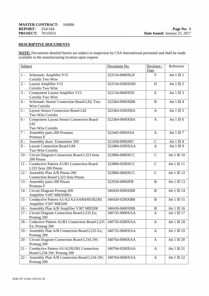
DESCRIPTIVE DOCUMENTS NOTE: Documents detailed herein are subject to inspection by CSA International personnel and shall be made available in the manufacturing location upon request.
Subject Document No. Revision / Date
Reference
1 - Schematic Amplifier V15 Coriolis Two Wire
322154-0000XGF F Att 1 Ill 1
2 - Layout Amplifier V15 Coriolis Two Wire
322154-0200XDD D Att 1 Ill 2
3 - Component Layout Amplifier V15 Coriolis Two Wire
322154-0600XFE E Att 1 Ill 3
4 - Schematic Sensor Connection Board L82; Two Wire Coriolis
322364-0000XBB B Att 1 Ill 4
5 - Layout Sensor Connection Board L82 Two Wire Coriolis
322364-0200XBA A Att 1 Ill 5
6 - Component Layout Sensor Connection Board L82 Two Wire Coriolis
322364-0600XBA A Att 1 Ill 6
7 - Assembly parts 200 Promass Promass E
322445-0000JAA A Att 1 Ill 7
8 - Assembly draw. Transmitter 200 322458-0000JHC C Att 1 Ill 8 9 - Layout Connection Board L84
Two Wire Coriolis 322484-0200XAA A Att 1 Ill 9
10 - Circuit Daigram Connection Board L323 Sens 200 Pmass
322806-0000XCC C Att 1 Ill 10
11 - Conductive Pattern A1/B1 Connection Board L323 Sens 200 Pmass
322806-0200XCC C Att 1 Ill 11
12 - Assembly Plan A/B Pmass 200 Connection Board L323 Sens Pmass
322806-0600XCC C Att 1 Ill 12
13 - Assembly parts 200 Pmass Promass F
322930-0000JFB B Att 1 Ill 13
14 - Circuit Diagram Promag 200 Amplifier V307 MID200Ex
340430-0000XBB B Att 1 Ill 14
15 - Conductive Pattern A1/A2/A3/A4/B4/B3/B2/B1 Amplifier V307 MID200
340430-0200XBB B Att 1 Ill 15
16 - Assembly Plan A/B Amplifier V307 MID200 340430-0600XBB B Att 1 Ill 16 17 - Circuit Diagram Connection Board L235 Ex;
Promag 200 340735-0000XAA A Att 1 Ill 17
18 - Coductive Pattern A1/B1 Connection Board L235 Ex; Promag 200
340735-0200XAA A Att 1 Ill 18
19 - Assembly Plan A/B Connection Board L235 Ex; Promag 200
340735-0600XAA A Att 1 Ill 19
20 - Circuit Diagram Connection Board L234 2W; Promag 200
340764-0000XAA A Att 1 Ill 20
21 - Conductive Pattern A1/A2/B2/B1 Connection Board L234 2W; Promag 200
340764-0200XAA A Att 1 Ill 21
22 - Assembly Plan A/B Connection Board L234 2W; Promag 200
340764-0600XAA A Att 1 Ill 22
MASTER CONTRACT: 160686 REPORT: 2541184 PROJECT: 70110551
Page No: 9
Date Issued: January 25, 2017
DQD 507.10 Rev 2016-01-18
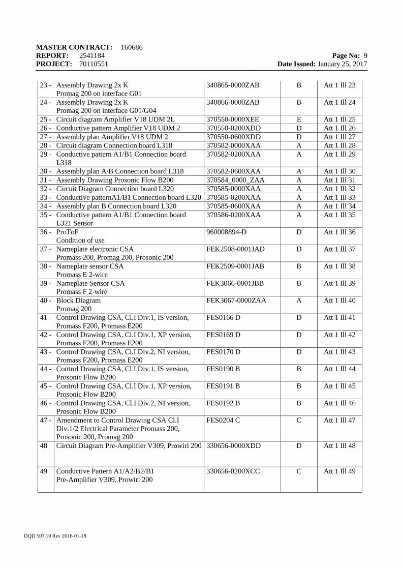
23 - Assembly Drawing 2x K Promag 200 on interface G01
340865-0000ZAB B Att 1 Ill 23
24 - Assembly Drawing 2x K Promag 200 on interface G01/G04
340866-0000ZAB B Att 1 Ill 24
25 - Circuit diagram Amplifier V18 UDM 2L 370550-0000XEE E Att 1 Ill 25 26 - Conductive pattern Amplifier V18 UDM 2 370550-0200XDD D Att 1 Ill 26 27 - Assembly plan Amplifier V18 UDM 2 370550-0600XDD D Att 1 Ill 27 28 - Circuit diagram Connection board L318 370582-0000XAA A Att 1 Ill 28 29 - Conductive pattern A1/B1 Connection board
L318 370582-0200XAA A Att 1 Ill 29
30 - Assembly plan A/B Connection board L318 370582-0600XAA A Att 1 Ill 30 31 - Assembly Drawing Prosonic Flow B200 370584_0000_ZAA A Att 1 Ill 31 32 - Circuit Diagram Connection board L320 370585-0000XAA A Att 1 Ill 32 33 - Conductive patternA1/B1 Connection board L320 370585-0200XAA A Att 1 Ill 33 34 - Assembly plan B Connection board L320 370585-0600XAA A Att 1 Ill 34 35 - Conductive pattern A1/B1 Connection board
L321 Sensor 370586-0200XAA A Att 1 Ill 35
36 - ProToF Condition of use
960008894-D D Att 1 Ill 36
37 - Nameplate electronic CSA Promass 200, Promag 200, Prosonic 200
FEK2508-0001JAD D Att 1 Ill 37
38 - Nameplate sensor CSA Promass E 2-wire
FEK2509-0001JAB B Att 1 Ill 38
39 - Nameplate Sensor CSA Promass F 2-wire
FEK3066-0001JBB B Att 1 Ill 39
40 - Block Diagram Promag 200
FEK3067-0000ZAA A Att 1 Ill 40
41 - Control Drawing CSA, Cl.I Div.1, IS version, Promass F200, Promass E200
FES0166 D D Att 1 Ill 41
42 - Control Drawing CSA, Cl.I Div.1, XP version, Promass F200, Promass E200
FES0169 D D Att 1 Ill 42
43 - Control Drawing CSA, Cl.I Div.2, NI version, Promass F200, Promass E200
FES0170 D D Att 1 Ill 43
44 - Control Drawing CSA, Cl.I Div.1, IS version, Prosonic Flow B200
FES0190 B B Att 1 Ill 44
45 - Control Drawing CSA, Cl.I Div.1, XP version, Prosonic Flow B200
FES0191 B B Att 1 Ill 45
46 - Control Drawing CSA, Cl.I Div.2, NI version, Prosonic Flow B200
FES0192 B B Att 1 Ill 46
47 - Amendment to Control Drawing CSA Cl.I Div.1/2 Electrical Parameter Promass 200, Prosonic 200, Promag 200
FES0204 C C Att 1 Ill 47
48 Circuit Diagram Pre-Amplifier V309, Prowirl 200 330656-0000XDD D Att 1 Ill 48
49 Conductive Pattern A1/A2/B2/B1 Pre-Amplifier V309, Prowirl 200
330656-0200XCC C Att 1 Ill 49
MASTER CONTRACT: 160686 REPORT: 2541184 PROJECT: 70110551
Page No: 10
Date Issued: January 25, 2017
DQD 507.10 Rev 2016-01-18
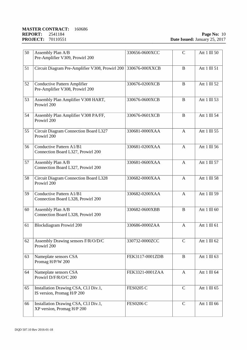
50 Assembly Plan A/B Pre-Amplifier V309, Prowirl 200
330656-0600XCC C Att 1 Ill 50
51 Circuit Diagram Pre-Amplifier V308, Prowirl 200 330676-000XXCB B Att 1 Ill 51
52 Conductive Pattern Amplifier Pre-Amplifier V308, Prowirl 200
330676-0200XCB B Att 1 Ill 52
53 Assembly Plan Amplifier V308 HART, Prowirl 200
330676-0600XCB B Att 1 Ill 53
54 Assembly Plan Amplifier V308 PA/FF, Prowirl 200
330676-0601XCB B Att 1 Ill 54
55 Circuit Diagram Connection Board L327 Prowirl 200
330681-0000XAA A Att 1 Ill 55
56 Conductive Pattern A1/B1 Connection Board L327, Prowirl 200
330681-0200XAA A Att 1 Ill 56
57 Assembly Plan A/B Connection Board L327, Prowirl 200
330681-0600XAA A Att 1 Ill 57
58 Circuit Diagram Connection Board L328 Prowirl 200
330682-0000XAA A Att 1 Ill 58
59 Conductive Pattern A1/B1 Connection Board L328, Prowirl 200
330682-0200XAA A Att 1 Ill 59
60 Assembly Plan A/B Connection Board L328, Prowirl 200
330682-0600XBB B Att 1 Ill 60
61 Blockdiagram Prowirl 200 330686-0000ZAA A Att 1 Ill 61
62 Assembly Drawing sensors F/R/O/D/C Prowirl 200
330732-0000ZCC C Att 1 Ill 62
63 Nameplate sensors CSA Promag H/P/W 200
FEK3117-0001ZDB B Att 1 Ill 63
64 Nameplate sensors CSA Prowirl D/F/R/O/C 200
FEK3321-0001ZAA A Att 1 Ill 64
65 Installation Drawing CSA, Cl.I Div.1, IS version, Promag H/P 200
FES0205 C C Att 1 Ill 65
66 Installation Drawing CSA, Cl.I Div.1, XP version, Promag H/P 200
FES0206 C C Att 1 Ill 66
MASTER CONTRACT: 160686 REPORT: 2541184 PROJECT: 70110551
Page No: 11
Date Issued: January 25, 2017
DQD 507.10 Rev 2016-01-18
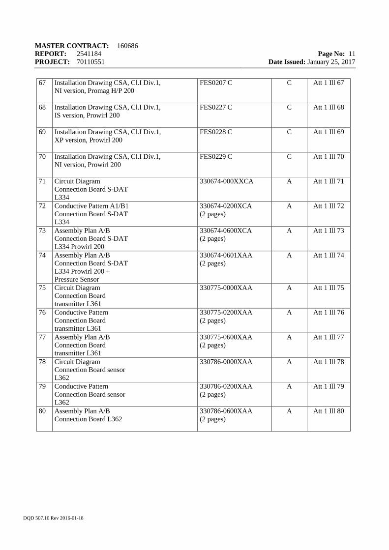
67 Installation Drawing CSA, Cl.I Div.1, NI version, Promag H/P 200
FES0207 C C Att 1 Ill 67
68 Installation Drawing CSA, Cl.I Div.1, IS version, Prowirl 200
FES0227 C C Att 1 Ill 68
69 Installation Drawing CSA, Cl.I Div.1, XP version, Prowirl 200
FES0228 C C Att 1 Ill 69
70 Installation Drawing CSA, Cl.I Div.1, NI version, Prowirl 200
FES0229 C C Att 1 Ill 70
71 Circuit Diagram Connection Board S-DAT L334
330674-000XXCA A Att 1 Ill 71
72 Conductive Pattern A1/B1 Connection Board S-DAT L334
330674-0200XCA (2 pages)
A Att 1 Ill 72
73 Assembly Plan A/B Connection Board S-DAT L334 Prowirl 200
330674-0600XCA (2 pages)
A Att 1 Ill 73
74 Assembly Plan A/B Connection Board S-DAT L334 Prowirl 200 + Pressure Sensor
330674-0601XAA (2 pages)
A Att 1 Ill 74
75 Circuit Diagram Connection Board transmitter L361
330775-0000XAA A Att 1 Ill 75
76 Conductive Pattern Connection Board transmitter L361
330775-0200XAA (2 pages)
A Att 1 Ill 76
77 Assembly Plan A/B Connection Board transmitter L361
330775-0600XAA (2 pages)
A Att 1 Ill 77
78 Circuit Diagram Connection Board sensor L362
330786-0000XAA A Att 1 Ill 78
79 Conductive Pattern Connection Board sensor L362
330786-0200XAA (2 pages)
A Att 1 Ill 79
80 Assembly Plan A/B Connection Board L362
330786-0600XAA (2 pages)
A Att 1 Ill 80
MASTER CONTRACT: 160686 REPORT: 2541184 PROJECT: 70110551
Page No: 12
Date Issued: January 25, 2017
DQD 507.10 Rev 2016-01-18
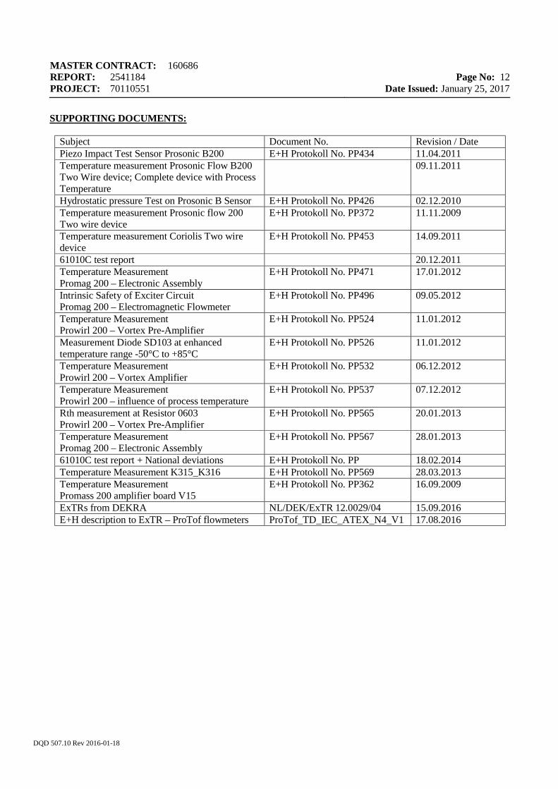
SUPPORTING DOCUMENTS:
Subject Document No. Revision / Date Piezo Impact Test Sensor Prosonic B200 E+H Protokoll No. PP434 11.04.2011 Temperature measurement Prosonic Flow B200 Two Wire device; Complete device with Process Temperature
09.11.2011
Hydrostatic pressure Test on Prosonic B Sensor E+H Protokoll No. PP426 02.12.2010 Temperature measurement Prosonic flow 200 Two wire device
E+H Protokoll No. PP372 11.11.2009
Temperature measurement Coriolis Two wire device
E+H Protokoll No. PP453 14.09.2011
61010C test report 20.12.2011 Temperature Measurement Promag 200 – Electronic Assembly
E+H Protokoll No. PP471 17.01.2012
Intrinsic Safety of Exciter Circuit Promag 200 – Electromagnetic Flowmeter
E+H Protokoll No. PP496 09.05.2012
Temperature Measurement Prowirl 200 – Vortex Pre-Amplifier
E+H Protokoll No. PP524 11.01.2012
Measurement Diode SD103 at enhanced temperature range -50°C to +85°C
E+H Protokoll No. PP526 11.01.2012
Temperature Measurement Prowirl 200 – Vortex Amplifier
E+H Protokoll No. PP532 06.12.2012
Temperature Measurement Prowirl 200 – influence of process temperature
E+H Protokoll No. PP537 07.12.2012
Rth measurement at Resistor 0603 Prowirl 200 – Vortex Pre-Amplifier
E+H Protokoll No. PP565 20.01.2013
Temperature Measurement Promag 200 – Electronic Assembly
E+H Protokoll No. PP567 28.01.2013
61010C test report + National deviations E+H Protokoll No. PP 18.02.2014 Temperature Measurement K315_K316 E+H Protokoll No. PP569 28.03.2013 Temperature Measurement Promass 200 amplifier board V15
E+H Protokoll No. PP362 16.09.2009
ExTRs from DEKRA NL/DEK/ExTR 12.0029/04 15.09.2016 E+H description to ExTR – ProTof flowmeters ProTof_TD_IEC_ATEX_N4_V1 17.08.2016
MASTER CONTRACT: 160686 REPORT: 2541184 PROJECT: 70110551
Page No: 13
Date Issued: January 25, 2017
DQD 507.10 Rev 2016-01-18
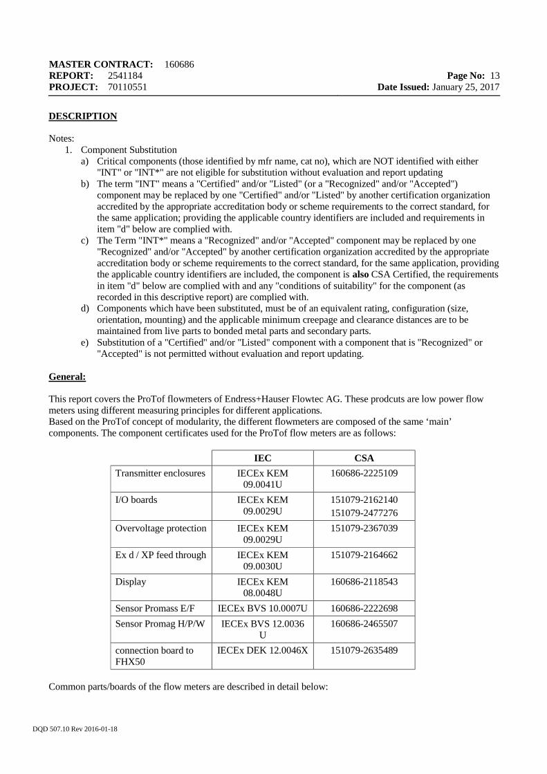
DESCRIPTION Notes:
1. Component Substitution a) Critical components (those identified by mfr name, cat no), which are NOT identified with either
"INT" or "INT*" are not eligible for substitution without evaluation and report updating b) The term "INT" means a "Certified" and/or "Listed" (or a "Recognized" and/or "Accepted")
component may be replaced by one "Certified" and/or "Listed" by another certification organization accredited by the appropriate accreditation body or scheme requirements to the correct standard, for the same application; providing the applicable country identifiers are included and requirements in item "d" below are complied with.
c) The Term "INT*" means a "Recognized" and/or "Accepted" component may be replaced by one "Recognized" and/or "Accepted" by another certification organization accredited by the appropriate accreditation body or scheme requirements to the correct standard, for the same application, providing the applicable country identifiers are included, the component is also CSA Certified, the requirements in item "d" below are complied with and any "conditions of suitability" for the component (as recorded in this descriptive report) are complied with.
d) Components which have been substituted, must be of an equivalent rating, configuration (size, orientation, mounting) and the applicable minimum creepage and clearance distances are to be maintained from live parts to bonded metal parts and secondary parts.
e) Substitution of a "Certified" and/or "Listed" component with a component that is "Recognized" or "Accepted" is not permitted without evaluation and report updating.
General: This report covers the ProTof flowmeters of Endress+Hauser Flowtec AG. These prodcuts are low power flow meters using different measuring principles for different applications. Based on the ProTof concept of modularity, the different flowmeters are composed of the same ‘main’ components. The component certificates used for the ProTof flow meters are as follows:
IEC CSA Transmitter enclosures IECEx KEM
09.0041U 160686-2225109
I/O boards IECEx KEM 09.0029U
151079-2162140 151079-2477276
Overvoltage protection IECEx KEM 09.0029U
151079-2367039
Ex d / XP feed through IECEx KEM 09.0030U
151079-2164662
Display IECEx KEM 08.0048U
160686-2118543
Sensor Promass E/F IECEx BVS 10.0007U 160686-2222698 Sensor Promag H/P/W IECEx BVS 12.0036
U 160686-2465507
connection board to FHX50
IECEx DEK 12.0046X 151079-2635489
Common parts/boards of the flow meters are described in detail below:
MASTER CONTRACT: 160686 REPORT: 2541184 PROJECT: 70110551
Page No: 14
Date Issued: January 25, 2017
DQD 507.10 Rev 2016-01-18
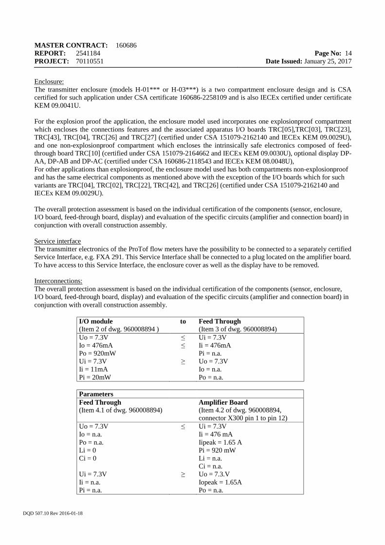
Enclosure: The transmitter enclosure (models H-01*** or H-03***) is a two compartment enclosure design and is CSA certified for such application under CSA certificate 160686-2258109 and is also IECEx certified under certificate KEM 09.0041U. For the explosion proof the application, the enclosure model used incorporates one explosionproof compartment which encloses the connections features and the associated apparatus I/O boards TRC[05],TRC[03], TRC[23], TRC[43], TRC[04], TRC[26] and TRC[27] (certified under CSA 151079-2162140 and IECEx KEM 09.0029U), and one non-explosionproof compartment which encloses the intrinsically safe electronics composed of feed-through board TRC[10] (certified under CSA 151079-2164662 and IECEx KEM 09.0030U), optional display DP-AA, DP-AB and DP-AC (certified under CSA 160686-2118543 and IECEx KEM 08.0048U), For other applications than explosionproof, the enclosure model used has both compartments non-explosionproof and has the same electrical components as mentioned above with the exception of the I/O boards which for such variants are TRC[04], TRC[02], TRC[22], TRC[42], and TRC[26] (certified under CSA 151079-2162140 and IECEx KEM 09.0029U). The overall protection assessment is based on the individual certification of the components (sensor, enclosure, I/O board, feed-through board, display) and evaluation of the specific circuits (amplifier and connection board) in conjunction with overall construction assembly. Service interface The transmitter electronics of the ProTof flow meters have the possibility to be connected to a separately certified Service Interface, e.g. FXA 291. This Service Interface shall be connected to a plug located on the amplifier board. To have access to this Service Interface, the enclosure cover as well as the display have to be removed. Interconnections: The overall protection assessment is based on the individual certification of the components (sensor, enclosure, I/O board, feed-through board, display) and evaluation of the specific circuits (amplifier and connection board) in conjunction with overall construction assembly.
I/O module (Item 2 of dwg. 960008894 )
to Feed Through (Item 3 of dwg. 960008894)
Uo = 7.3V Io = 476mA Po = 920mW Ui = 7.3V Ii = 11mA Pi = 20mW
≤ ≤ ≥
Ui = 7.3V Ii = 476mA Pi = n.a. Uo = 7.3V Io = n.a. Po = n.a.
Parameters Feed Through (Item 4.1 of dwg. 960008894)
Amplifier Board (Item 4.2 of dwg. 960008894, connector X300 pin 1 to pin 12)
Uo = 7.3V Io = n.a. Po = n.a. Li = 0 Ci = 0 Ui = 7.3V Ii = n.a. Pi = n.a.
≤ ≥
Ui = 7.3V Ii = 476 mA Iipeak = 1.65 A Pi = 920 mW Li = n.a. Ci = n.a. Uo = 7.3.V Iopeak = 1.65A Po = n.a.
MASTER CONTRACT: 160686 REPORT: 2541184 PROJECT: 70110551
Page No: 15
Date Issued: January 25, 2017
DQD 507.10 Rev 2016-01-18
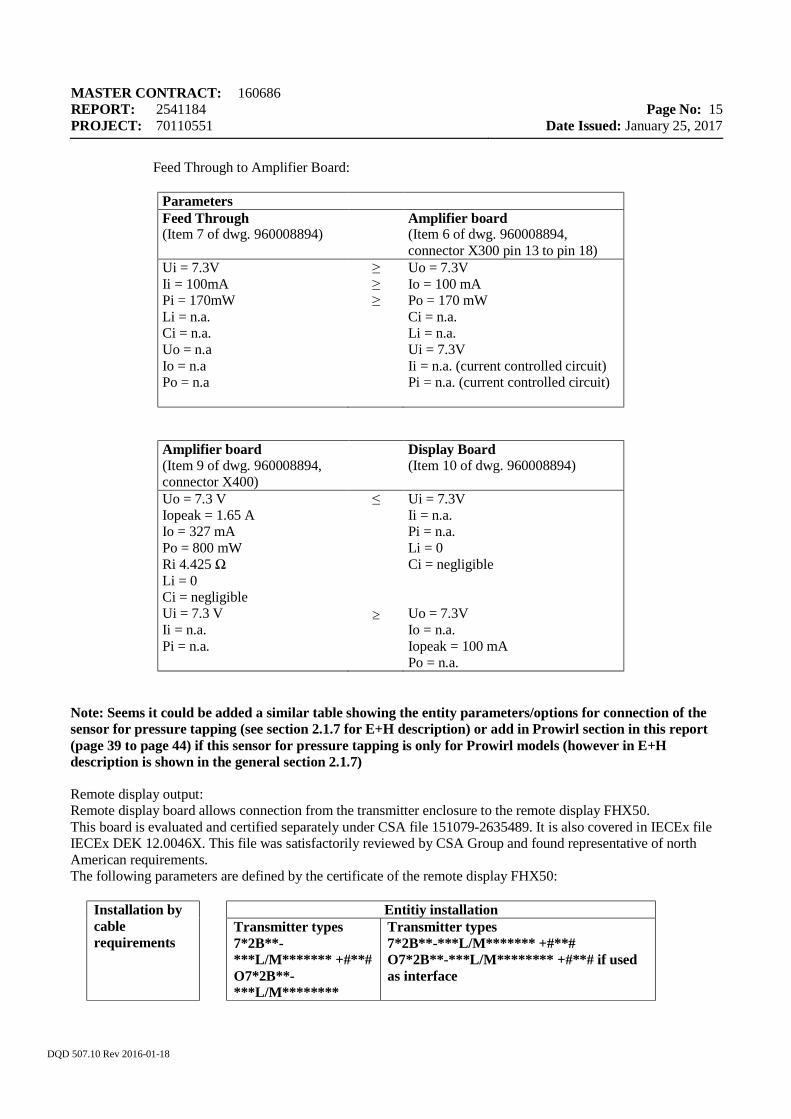
Feed Through to Amplifier Board:
Parameters Feed Through (Item 7 of dwg. 960008894)
Amplifier board (Item 6 of dwg. 960008894, connector X300 pin 13 to pin 18)
Ui = 7.3V Ii = 100mA Pi = 170mW Li = n.a. Ci = n.a. Uo = n.a Io = n.a Po = n.a
≥ ≥ ≥
Uo = 7.3V Io = 100 mA Po = 170 mW Ci = n.a. Li = n.a. Ui = 7.3V Ii = n.a. (current controlled circuit) Pi = n.a. (current controlled circuit)
Amplifier board (Item 9 of dwg. 960008894, connector X400)
Display Board (Item 10 of dwg. 960008894)
Uo = 7.3 V Iopeak = 1.65 A Io = 327 mA Po = 800 mW Ri 4.425 Ω Li = 0 Ci = negligible Ui = 7.3 V Ii = n.a. Pi = n.a.
≤
≥
Ui = 7.3V Ii = n.a. Pi = n.a. Li = 0 Ci = negligible Uo = 7.3V Io = n.a. Iopeak = 100 mA Po = n.a.
Note: Seems it could be added a similar table showing the entity parameters/options for connection of the sensor for pressure tapping (see section 2.1.7 for E+H description) or add in Prowirl section in this report (page 39 to page 44) if this sensor for pressure tapping is only for Prowirl models (however in E+H description is shown in the general section 2.1.7) Remote display output: Remote display board allows connection from the transmitter enclosure to the remote display FHX50. This board is evaluated and certified separately under CSA file 151079-2635489. It is also covered in IECEx file IECEx DEK 12.0046X. This file was satisfactorily reviewed by CSA Group and found representative of north American requirements. The following parameters are defined by the certificate of the remote display FHX50:
Installation by cable requirements
Entitiy installation Transmitter types
7*2B**-***L/M******* +#**# O7*2B**-***L/M********
Transmitter types 7*2B**-***L/M******* +#**# O7*2B**-***L/M******** +#**# if used as interface
MASTER CONTRACT: 160686 REPORT: 2541184 PROJECT: 70110551
Page No: 16
Date Issued: January 25, 2017
DQD 507.10 Rev 2016-01-18
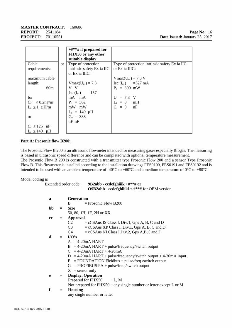
+#**# if prepared for FHX50 or any other suitable display
Cable requirements: maximum cable length: 60m for Cc ≤ 0.2nF/m Lc ≤ 1 µH/m or Cc ≤ 125 nF Lc ≤ 149 µH
or Type of protection intrinsic safety Ex ia IIC or Ex ia IIIC: Vmax(Uo ) = 7.3 V V Isc (Io ) =157 mA mA Po = 362 mW mW Lo = 149 µH Co = 388 nF nF
Type of protection intrinsic safety Ex ia IIC or Ex ia IIIC: Vmax(Uo ) = 7.3 V Isc (Io ) =327 mA Po = 800 mW Ui = 7.3 V Li = 0 mH Ci = 0 nF
Part A: Prosonic flow B200: The Prosonic Flow B 200 is an ultrasonic flowmeter intended for measuring gases especially Biogas. The measuring is based in ultrasonic speed difference and can be completed with optional temperature measurement. The Prosonic Flow B 200 is constructed with a transmitter type Prosonic Flow 200 and a sensor Type Prosonic Flow B. This flowmeter is installed according to the installation drawings FES0190, FES0191 and FES0192 and is intended to be used with an ambient temperature of -40°C to +60°C and a medium temperature of 0°C to +80°C. Model coding is
Extended order code: 9B2abb - ccdefghiiik +#**# or O9B2abb - ccdefghiiikl + #**# for OEM version
a Generation B = Prosonic Flow B200
bb = Size 50, 80, 1H, 1F, 2H or XX
cc = Approval C2 = cCSAus IS Class I, Div.1, Gps A, B, C and D C3 = cCSAus XP Class I, Div.1, Gps A, B, C and D C4 = cCSAus NI Class I,Div.2, Gps A,B,C and D
d = I/O’s A = 4-20mA HART B = 4-20mA HART + pulse/frequency/switch output C = 4-20mA HART + 4-20mA D = 4-20mA HART + pulse/frequency/switch output + 4-20mA input E = FOUNDATION Fieldbus + pulse/freq./switch output G = PROFIBUS PA + pulse/freq./switch output X = sensor only
e = Display, Operation Prepared for FHX50 : L, M Not prepared for FHX50 : any single number or letter except L or M
f = Housing any single number or letter
MASTER CONTRACT: 160686 REPORT: 2541184 PROJECT: 70110551
Page No: 17
Date Issued: January 25, 2017
DQD 507.10 Rev 2016-01-18
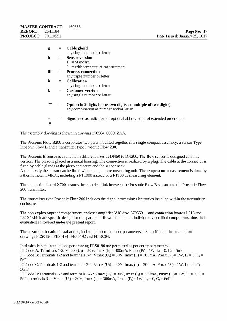
g = Cable gland any single number or letter
h = Sensor version 1 = Standard 2 = with temperature measurement
iii = Process connection any triple number or letter
k = Calibration any single number or letter
k = Customer version any single number or letter
** = Option in 2 digits (none, two digits or multiple of two digits)
any combination of number and/or letter + #
= Signs used as indicator for optional abbreviation of extended order code
The assembly drawing is shown in drawing 370584_0000_ZAA. The Prosonic Flow B200 incorporates two parts mounted together in a single compact assembly: a sensor Type Prosonic Flow B and a transmitter type Prosonic Flow 200. The Prosonic B sensor is available in different sizes as DN50 to DN200, The flow sensor is designed as inline version. The piezo is placed in a metal housing. The connection is realized by a plug. The cable at the connector is fixed by cable glands at the piezo enclosure and the sensor neck. Alternatively the sensor can be fitted with a temperature measuring unit. The temperature measurement is done by a thermometer TMR31, including a PT1000 instead of a PT100 as measuring element. The connection board X700 assures the electrical link between the Prosonic Flow B sensor and the Prosonic Flow 200 transmitter. The transmitter type Prosonic Flow 200 includes the signal processing electronics installed within the transmitter enclosure. The non-explosionproof compartment encloses amplifier V18 drw. 370550-... and connection boards L318 and L320 (which are specific design for this particular flowmeter and not individually certified components, thus their evaluation is covered under the present report. The hazardous location installations, including electrical input parameters are specified in the installation drawings FES0190, FES0191, FES0192 and FES0204: Intrinsically safe installations per drawing FES0190 are permitted as per entity parameters: IO Code A: Terminals 1-2: Vmax (Ui) = 30V, Imax (Ii) = 300mA, Pmax (Pi)= 1W, Li = 0, Ci = 5nF IO Code B:Terminals 1-2 and terminals 3-4: Vmax (U i) = 30V, Imax (Ii) = 300mA, Pmax (Pi)= 1W, Li = 0, Ci = 5nF IO Code C:Terminals 1-2 and terminals 3-4: Vmax (U i) = 30V, Imax (Ii) = 300mA, Pmax (Pi)= 1W, Li = 0, Ci = 30nF IO Code D:Terminals 1-2 and terminals 5-6 : Vmax (Ui) = 30V, Imax (Ii) = 300mA, Pmax (Pi)= 1W, Li = 0, Ci = 5nF ; terminals 3-4: Vmax (Ui) = 30V, Imax (Ii) = 300mA, Pmax (Pi)= 1W, Li = 0, Ci = 6nF ;
MASTER CONTRACT: 160686 REPORT: 2541184 PROJECT: 70110551
Page No: 18
Date Issued: January 25, 2017
DQD 507.10 Rev 2016-01-18
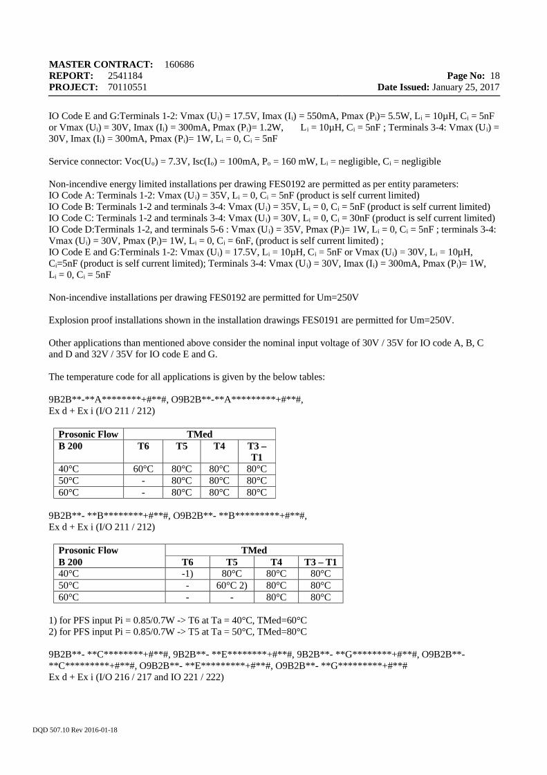
IO Code E and G:Terminals 1-2: Vmax (Ui) = 17.5V, Imax (Ii) = 550mA, Pmax (Pi)= 5.5W, Li = 10µH, Ci = 5nF or Vmax (Ui) = 30V, Imax (Ii) = 300mA, Pmax (Pi)= 1.2W, Li = 10µH, Ci = 5nF ; Terminals 3-4: Vmax (Ui) = 30V, Imax (Ii) = 300mA, Pmax (Pi)= 1W, Li = 0, Ci = 5nF Service connector: Voc(Uo) = 7.3V, Isc(Io) = 100mA, Po = 160 mW, Li = negligible, Ci = negligible Non-incendive energy limited installations per drawing FES0192 are permitted as per entity parameters: IO Code A: Terminals 1-2: Vmax (Ui) = 35V, Li = 0, Ci = 5nF (product is self current limited) IO Code B: Terminals 1-2 and terminals 3-4: Vmax (U i) = 35V, Li = 0, Ci = 5nF (product is self current limited) IO Code C: Terminals 1-2 and terminals 3-4: Vmax (U i) = 30V, Li = 0, Ci = 30nF (product is self current limited) IO Code D:Terminals 1-2, and terminals 5-6 : Vmax (U i) = 35V, Pmax (Pi)= 1W, Li = 0, Ci = 5nF ; terminals 3-4: Vmax (Ui) = 30V, Pmax (Pi)= 1W, Li = 0, Ci = 6nF, (product is self current limited) ; IO Code E and G:Terminals 1-2: Vmax (Ui) = 17.5V, Li = 10µH, Ci = 5nF or Vmax (Ui) = 30V, Li = 10µH, Ci=5nF (product is self current limited); Terminals 3-4: Vmax (U i) = 30V, Imax (Ii) = 300mA, Pmax (Pi)= 1W, Li = 0, Ci = 5nF Non-incendive installations per drawing FES0192 are permitted for Um=250V Explosion proof installations shown in the installation drawings FES0191 are permitted for Um=250V. Other applications than mentioned above consider the nominal input voltage of 30V / 35V for IO code A, B, C and D and 32V / 35V for IO code E and G. The temperature code for all applications is given by the below tables: 9B2B**-**A********+#**#, O9B2B**-**A*********+#**#, Ex d + Ex i (I/O 211 / 212)
Prosonic Flow TMed B 200 T6 T5 T4 T3 –
T1 40°C 60°C 80°C 80°C 80°C 50°C - 80°C 80°C 80°C 60°C - 80°C 80°C 80°C
9B2B**- **B********+#**#, O9B2B**- **B*********+#**#, Ex d + Ex i (I/O 211 / 212)
Prosonic Flow TMed B 200 T6 T5 T4 T3 – T1 40°C -1) 80°C 80°C 80°C 50°C - 60°C 2) 80°C 80°C 60°C - - 80°C 80°C
1) for PFS input Pi = 0.85/0.7W -> T6 at Ta = 40°C, TMed=60°C 2) for PFS input Pi = 0.85/0.7W -> T5 at Ta = 50°C, TMed=80°C 9B2B**- **C********+#**#, 9B2B**- **E********+#**#, 9B2B**- **G********+#**#, O9B2B**- **C*********+#**#, O9B2B**- **E*********+#**#, O9B2B**- **G*********+#**# Ex d + Ex i (I/O 216 / 217 and IO 221 / 222)
MASTER CONTRACT: 160686 REPORT: 2541184 PROJECT: 70110551
Page No: 19
Date Issued: January 25, 2017
DQD 507.10 Rev 2016-01-18
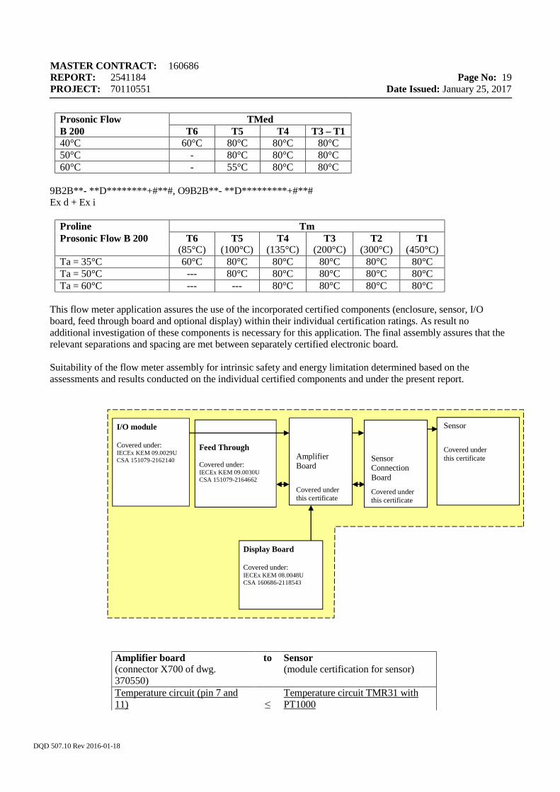
Prosonic Flow TMed B 200 T6 T5 T4 T3 – T1 40°C 60°C 80°C 80°C 80°C 50°C - 80°C 80°C 80°C 60°C - 55°C 80°C 80°C
9B2B**- **D********+#**#, O9B2B**- **D*********+#**# Ex d + Ex i
Proline Tm Prosonic Flow B 200 T6 T5 T4 T3 T2 T1 (85°C) (100°C) (135°C) (200°C) (300°C) (450°C) Ta = 35°C 60°C 80°C 80°C 80°C 80°C 80°C Ta = 50°C --- 80°C 80°C 80°C 80°C 80°C Ta = 60°C --- --- 80°C 80°C 80°C 80°C
This flow meter application assures the use of the incorporated certified components (enclosure, sensor, I/O board, feed through board and optional display) within their individual certification ratings. As result no additional investigation of these components is necessary for this application. The final assembly assures that the relevant separations and spacing are met between separately certified electronic board. Suitability of the flow meter assembly for intrinsic safety and energy limitation determined based on the assessments and results conducted on the individual certified components and under the present report.
Amplifier board (connector X700 of dwg. 370550)
to Sensor (module certification for sensor)
Temperature circuit (pin 7 and 11)
≤
Temperature circuit TMR31 with PT1000
Feed Through Covered under: IECEx KEM 09.0030U CSA 151079-2164662
I/O module Covered under: IECEx KEM 09.0029U CSA 151079-2162140
Sensor
Covered under this certificate
Amplifier Board
Covered under this certificate
Display Board Covered under: IECEx KEM 08.0048U CSA 160686-2118543
Sensor Connection Board
Covered under this certificate
MASTER CONTRACT: 160686 REPORT: 2541184 PROJECT: 70110551
Page No: 20
Date Issued: January 25, 2017
DQD 507.10 Rev 2016-01-18
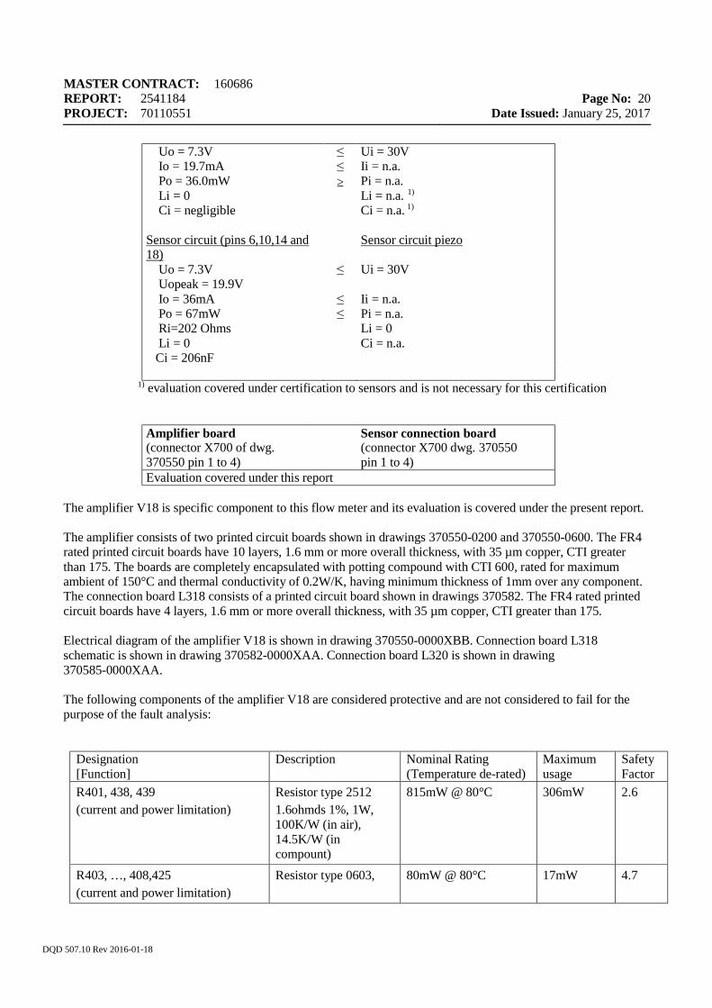
Uo = 7.3V Io = 19.7mA Po = 36.0mW Li = 0 Ci = negligible
≤ ≤ ≥
Ui = 30V Ii = n.a. Pi = n.a. Li = n.a. 1) Ci = n.a. 1)
Sensor circuit (pins 6,10,14 and 18)
Uo = 7.3V Uopeak = 19.9V Io = 36mA Po = 67mW Ri=202 Ohms Li = 0
Ci = 206nF
≤ ≤ ≤
Sensor circuit piezo Ui = 30V Ii = n.a. Pi = n.a. Li = 0 Ci = n.a.
1) evaluation covered under certification to sensors and is not necessary for this certification
Amplifier board (connector X700 of dwg. 370550 pin 1 to 4)
Sensor connection board (connector X700 dwg. 370550 pin 1 to 4)
Evaluation covered under this report
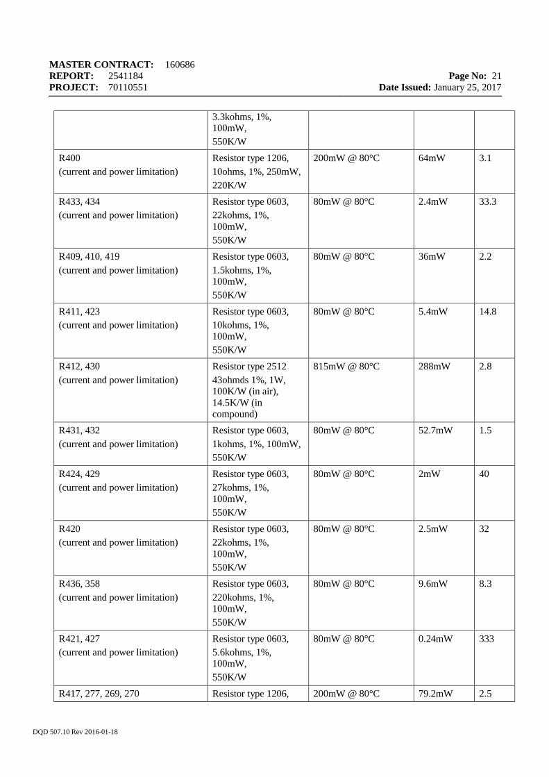
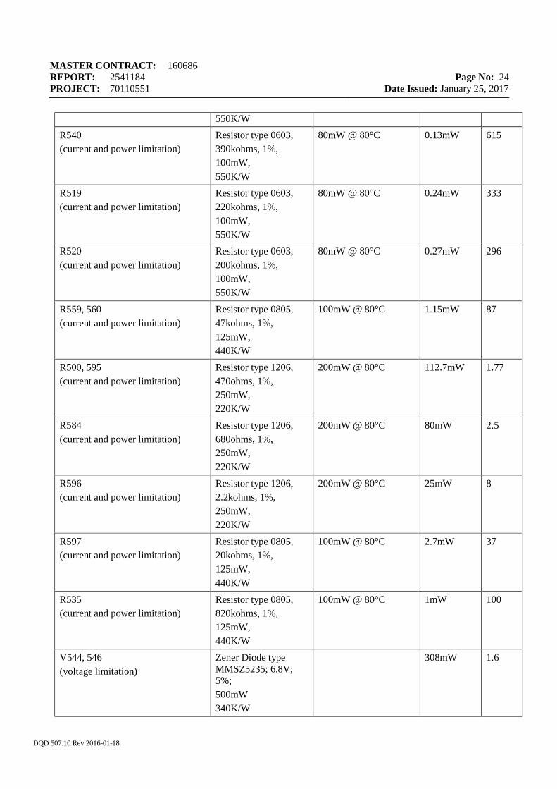
The amplifier V18 is specific component to this flow meter and its evaluation is covered under the present report. The amplifier consists of two printed circuit boards shown in drawings 370550-0200 and 370550-0600. The FR4 rated printed circuit boards have 10 layers, 1.6 mm or more overall thickness, with 35 µm copper, CTI greater than 175. The boards are completely encapsulated with potting compound with CTI 600, rated for maximum ambient of 150°C and thermal conductivity of 0.2W/K, having minimum thickness of 1mm over any component. The connection board L318 consists of a printed circuit board shown in drawings 370582. The FR4 rated printed circuit boards have 4 layers, 1.6 mm or more overall thickness, with 35 µm copper, CTI greater than 175. Electrical diagram of the amplifier V18 is shown in drawing 370550-0000XBB. Connection board L318 schematic is shown in drawing 370582-0000XAA. Connection board L320 is shown in drawing 370585-0000XAA. The following components of the amplifier V18 are considered protective and are not considered to fail for the purpose of the fault analysis:
Designation [Function]
Description Nominal Rating (Temperature de-rated)
Maximum usage
Safety Factor
R401, 438, 439 (current and power limitation)
Resistor type 2512 1.6ohmds 1%, 1W, 100K/W (in air), 14.5K/W (in compount)
815mW @ 80°C 306mW 2.6
R403, …, 408,425 (current and power limitation)
Resistor type 0603, 80mW @ 80°C 17mW 4.7
MASTER CONTRACT: 160686 REPORT: 2541184 PROJECT: 70110551
Page No: 21
Date Issued: January 25, 2017
DQD 507.10 Rev 2016-01-18
3.3kohms, 1%, 100mW, 550K/W
R400 (current and power limitation)
Resistor type 1206, 10ohms, 1%, 250mW, 220K/W
200mW @ 80°C 64mW 3.1
R433, 434 (current and power limitation)
Resistor type 0603, 22kohms, 1%, 100mW, 550K/W
80mW @ 80°C 2.4mW 33.3
R409, 410, 419 (current and power limitation)
Resistor type 0603, 1.5kohms, 1%, 100mW, 550K/W
80mW @ 80°C 36mW 2.2
R411, 423 (current and power limitation)
Resistor type 0603, 10kohms, 1%, 100mW, 550K/W
80mW @ 80°C 5.4mW 14.8
R412, 430 (current and power limitation)
Resistor type 2512 43ohmds 1%, 1W, 100K/W (in air), 14.5K/W (in compound)
815mW @ 80°C 288mW 2.8
R431, 432 (current and power limitation)
Resistor type 0603, 1kohms, 1%, 100mW, 550K/W
80mW @ 80°C 52.7mW 1.5
R424, 429 (current and power limitation)
Resistor type 0603, 27kohms, 1%, 100mW, 550K/W
80mW @ 80°C 2mW 40
R420 (current and power limitation)
Resistor type 0603, 22kohms, 1%, 100mW, 550K/W
80mW @ 80°C 2.5mW 32
R436, 358 (current and power limitation)
Resistor type 0603, 220kohms, 1%, 100mW, 550K/W
80mW @ 80°C 9.6mW 8.3
R421, 427 (current and power limitation)
Resistor type 0603, 5.6kohms, 1%, 100mW, 550K/W
80mW @ 80°C 0.24mW 333
R417, 277, 269, 270 Resistor type 1206, 200mW @ 80°C 79.2mW 2.5
MASTER CONTRACT: 160686 REPORT: 2541184 PROJECT: 70110551
Page No: 22
Date Issued: January 25, 2017
DQD 507.10 Rev 2016-01-18
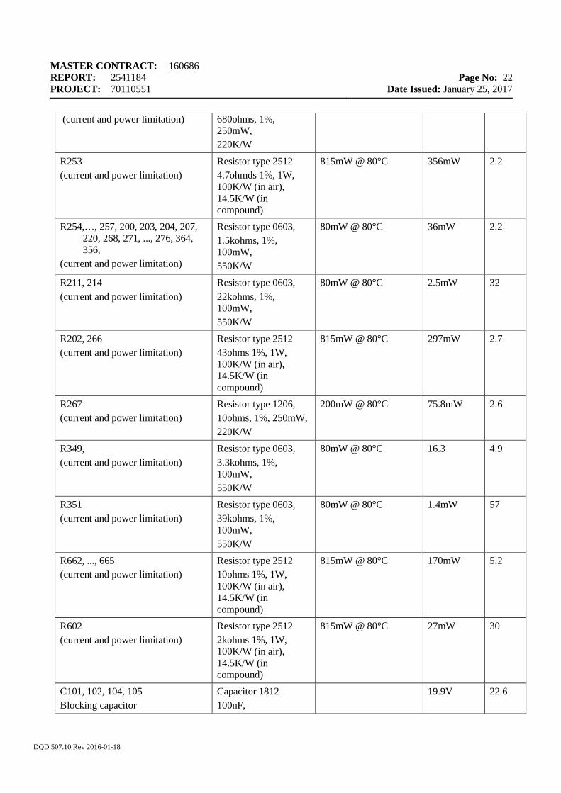
(current and power limitation) 680ohms, 1%, 250mW, 220K/W
R253 (current and power limitation)
Resistor type 2512 4.7ohmds 1%, 1W, 100K/W (in air), 14.5K/W (in compound)
815mW @ 80°C 356mW 2.2
R254,…, 257, 200, 203, 204, 207, 220, 268, 271, ..., 276, 364, 356,
(current and power limitation)
Resistor type 0603, 1.5kohms, 1%, 100mW, 550K/W
80mW @ 80°C 36mW 2.2
R211, 214 (current and power limitation)
Resistor type 0603, 22kohms, 1%, 100mW, 550K/W
80mW @ 80°C 2.5mW 32
R202, 266 (current and power limitation)
Resistor type 2512 43ohms 1%, 1W, 100K/W (in air), 14.5K/W (in compound)
815mW @ 80°C 297mW 2.7
R267 (current and power limitation)
Resistor type 1206, 10ohms, 1%, 250mW, 220K/W
200mW @ 80°C 75.8mW 2.6
R349, (current and power limitation)
Resistor type 0603, 3.3kohms, 1%, 100mW, 550K/W
80mW @ 80°C 16.3 4.9
R351 (current and power limitation)
Resistor type 0603, 39kohms, 1%, 100mW, 550K/W
80mW @ 80°C 1.4mW 57
R662, ..., 665 (current and power limitation)
Resistor type 2512 10ohms 1%, 1W, 100K/W (in air), 14.5K/W (in compound)
815mW @ 80°C 170mW 5.2
R602 (current and power limitation)
Resistor type 2512 2kohms 1%, 1W, 100K/W (in air), 14.5K/W (in compound)
815mW @ 80°C 27mW 30
C101, 102, 104, 105 Blocking capacitor
Capacitor 1812 100nF,
19.9V 22.6
MASTER CONTRACT: 160686 REPORT: 2541184 PROJECT: 70110551
Page No: 23
Date Issued: January 25, 2017
DQD 507.10 Rev 2016-01-18
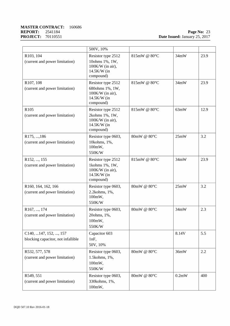
500V, 10% R103, 104 (current and power limitation)
Resistor type 2512 10ohms 1%, 1W, 100K/W (in air), 14.5K/W (in compound)
815mW @ 80°C 34mW 23.9
R107, 108 (current and power limitation)
Resistor type 2512 680ohms 1%, 1W, 100K/W (in air), 14.5K/W (in compound)
815mW @ 80°C 34mW 23.9
R105 (current and power limitation)
Resistor type 2512 2kohms 1%, 1W, 100K/W (in air), 14.5K/W (in compound)
815mW @ 80°C 63mW 12.9
R175, ...,186 (current and power limitation)
Resistor type 0603, 10kohms, 1%, 100mW, 550K/W
80mW @ 80°C 25mW 3.2
R152, ..., 155 (current and power limitation)
Resistor type 2512 1kohms 1%, 1W, 100K/W (in air), 14.5K/W (in compound)
815mW @ 80°C 34mW 23.9
R160, 164, 162, 166 (current and power limitation)
Resistor type 0603, 2.2kohms, 1%, 100mW, 550K/W
80mW @ 80°C 25mW 3.2
R167, ..., 174 (current and power limitation)
Resistor type 0603, 20ohms, 1%, 100mW, 550K/W
80mW @ 80°C 34mW 2.3
C140, ...147, 152, ..., 157 blocking capacitor, not infallible
Capacitor 603 1nF, 50V, 10%
8.14V 5.5
R532, 577, 578 (current and power limitation)
Resistor type 0603, 1.5kohms, 1%, 100mW, 550K/W
80mW @ 80°C 36mW 2.2
R549, 551 (current and power limitation)
Resistor type 0603, 330kohms, 1%, 100mW,
80mW @ 80°C 0.2mW 400
MASTER CONTRACT: 160686 REPORT: 2541184 PROJECT: 70110551
Page No: 24
Date Issued: January 25, 2017
DQD 507.10 Rev 2016-01-18
550K/W R540 (current and power limitation)
Resistor type 0603, 390kohms, 1%, 100mW, 550K/W
80mW @ 80°C 0.13mW 615
R519 (current and power limitation)
Resistor type 0603, 220kohms, 1%, 100mW, 550K/W
80mW @ 80°C 0.24mW 333
R520 (current and power limitation)
Resistor type 0603, 200kohms, 1%, 100mW, 550K/W
80mW @ 80°C 0.27mW 296
R559, 560 (current and power limitation)
Resistor type 0805, 47kohms, 1%, 125mW, 440K/W
100mW @ 80°C 1.15mW 87
R500, 595 (current and power limitation)
Resistor type 1206, 470ohms, 1%, 250mW, 220K/W
200mW @ 80°C 112.7mW 1.77
R584 (current and power limitation)
Resistor type 1206, 680ohms, 1%, 250mW, 220K/W
200mW @ 80°C 80mW 2.5
R596 (current and power limitation)
Resistor type 1206, 2.2kohms, 1%, 250mW, 220K/W
200mW @ 80°C 25mW 8
R597 (current and power limitation)
Resistor type 0805, 20kohms, 1%, 125mW, 440K/W
100mW @ 80°C 2.7mW 37
R535 (current and power limitation)
Resistor type 0805, 820kohms, 1%, 125mW, 440K/W
100mW @ 80°C 1mW 100
V544, 546 (voltage limitation)
Zener Diode type MMSZ5235; 6.8V; 5%; 500mW 340K/W
308mW 1.6
MASTER CONTRACT: 160686 REPORT: 2541184 PROJECT: 70110551
Page No: 25
Date Issued: January 25, 2017
DQD 507.10 Rev 2016-01-18
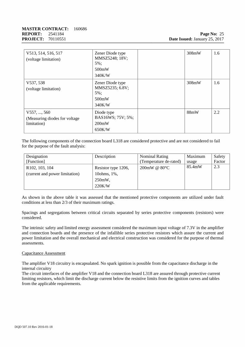
V513, 514, 516, 517 (voltage limitation)
Zener Diode type MMSZ5248; 18V; 5%; 500mW 340K/W
308mW 1.6
V537, 538 (voltage limitation)
Zener Diode type MMSZ5235; 6.8V; 5%; 500mW 340K/W
308mW 1.6
V557, ..., 560 (Measuring diodes for voltage limitation)
Diode type BAS16WS; 75V; 5%; 200mW 650K/W
88mW 2.2
The following components of the connection board L318 are considered protective and are not considered to fail for the purpose of the fault analysis:
Designation [Function]
Description Nominal Rating (Temperature de-rated)
Maximum usage
Safety Factor
R102, 103, 104 (current and power limitation)
Resistor type 1206, 10ohms, 1%, 250mW, 220K/W
200mW @ 80°C 85.4mW 2.3
As shown in the above table it was assessed that the mentioned protective components are utilized under fault conditions at less than 2/3 of their maximum ratings. Spacings and segregations between critical circuits separated by series protective components (resistors) were considered. The intrinsic safety and limited energy assessment considered the maximum input voltage of 7.3V in the amplifier and connection boards and the presence of the infallible series protective resistors which assure the current and power limitation and the overall mechanical and electrical construction was considered for the purpose of thermal assessments. Capacitance Assessment The amplifier V18 circuitry is encapsulated. No spark ignition is possible from the capacitance discharge in the internal circuitry The circuit interfaces of the amplifier V18 and the connection board L318 are assured through protective current limiting resistors, which limit the discharge current below the resistive limits from the ignition curves and tables from the applicable requirements.
MASTER CONTRACT: 160686 REPORT: 2541184 PROJECT: 70110551
Page No: 26
Date Issued: January 25, 2017
DQD 507.10 Rev 2016-01-18
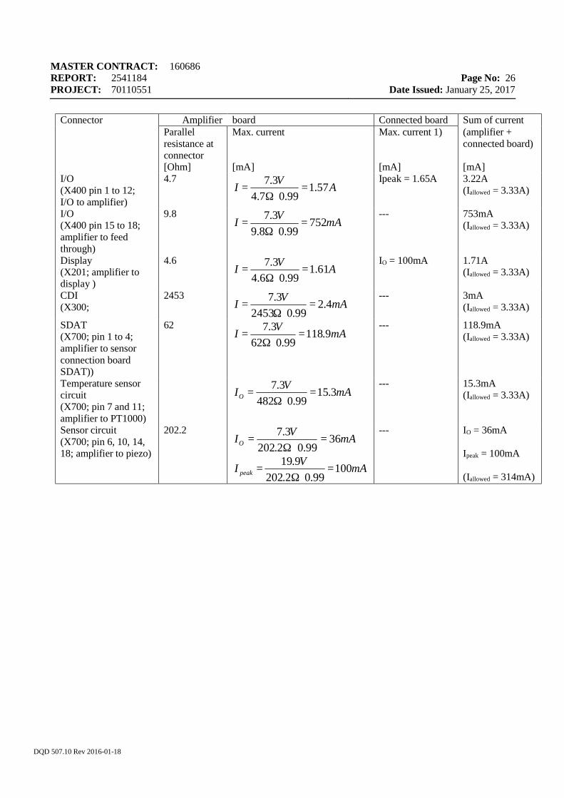
Connector Amplifier board Connected board Sum of current Parallel
resistance at connector
Max. current Max. current 1) (amplifier + connected board)
[Ohm] [mA] [mA] [mA] I/O (X400 pin 1 to 12; I/O to amplifier)
4.7
Ipeak = 1.65A 3.22A (Iallowed = 3.33A)
I/O (X400 pin 15 to 18; amplifier to feed through)
9.8
--- 753mA (Iallowed = 3.33A)
Display (X201; amplifier to display )
4.6
IO = 100mA 1.71A (Iallowed = 3.33A)
CDI (X300;
2453
--- 3mA (Iallowed = 3.33A)
SDAT (X700; pin 1 to 4; amplifier to sensor connection board SDAT))
62
--- 118.9mA (Iallowed = 3.33A)
Temperature sensor circuit (X700; pin 7 and 11; amplifier to PT1000)
--- 15.3mA (Iallowed = 3.33A)
Sensor circuit (X700; pin 6, 10, 14, 18; amplifier to piezo)
202.2
--- IO = 36mA Ipeak = 100mA (Iallowed = 314mA)
AVI 57.199.07.4
3.7=
⋅Ω=
mAVI 75299.08.9
3.7=
⋅Ω=
AVI 61.199.06.4
3.7=
⋅Ω=
mAVI 4.299.02453
3.7=
⋅Ω=
mAVI 9.11899.062
3.7=
⋅Ω=
mAVIO 3.1599.0482
3.7=
⋅Ω=
mAVIO 3699.02.202
3.7=
⋅Ω=
mAVI peak 10099.02.202
9.19=
⋅Ω=
MASTER CONTRACT: 160686 REPORT: 2541184 PROJECT: 70110551
Page No: 27
Date Issued: January 25, 2017
DQD 507.10 Rev 2016-01-18
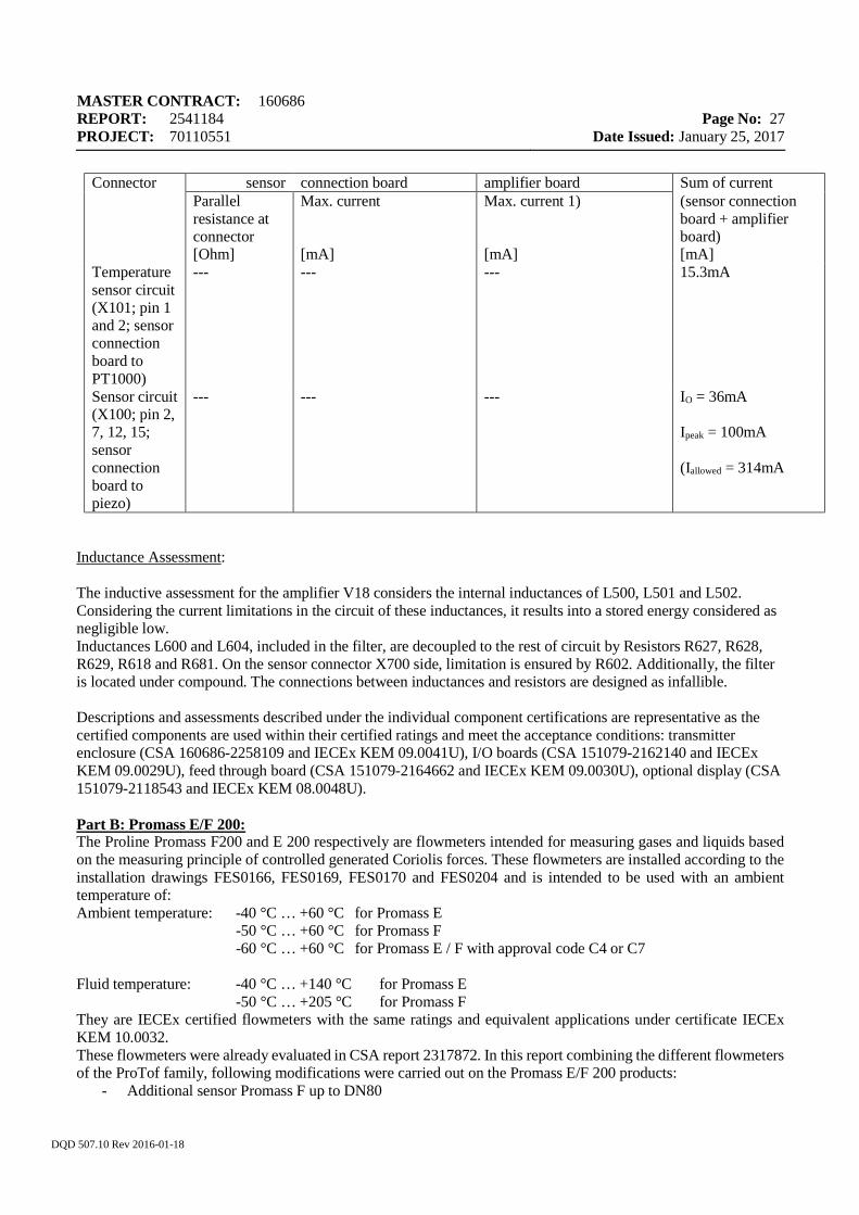
Connector sensor connection board amplifier board Sum of current Parallel
resistance at connector
Max. current Max. current 1) (sensor connection board + amplifier board)
[Ohm] [mA] [mA] [mA] Temperature sensor circuit (X101; pin 1 and 2; sensor connection board to PT1000)
--- --- --- 15.3mA
Sensor circuit (X100; pin 2, 7, 12, 15; sensor connection board to piezo)
--- --- ---
IO = 36mA Ipeak = 100mA (Iallowed = 314mA
Inductance Assessment: The inductive assessment for the amplifier V18 considers the internal inductances of L500, L501 and L502. Considering the current limitations in the circuit of these inductances, it results into a stored energy considered as negligible low. Inductances L600 and L604, included in the filter, are decoupled to the rest of circuit by Resistors R627, R628, R629, R618 and R681. On the sensor connector X700 side, limitation is ensured by R602. Additionally, the filter is located under compound. The connections between inductances and resistors are designed as infallible. Descriptions and assessments described under the individual component certifications are representative as the certified components are used within their certified ratings and meet the acceptance conditions: transmitter enclosure (CSA 160686-2258109 and IECEx KEM 09.0041U), I/O boards (CSA 151079-2162140 and IECEx KEM 09.0029U), feed through board (CSA 151079-2164662 and IECEx KEM 09.0030U), optional display (CSA 151079-2118543 and IECEx KEM 08.0048U). Part B: Promass E/F 200: The Proline Promass F200 and E 200 respectively are flowmeters intended for measuring gases and liquids based on the measuring principle of controlled generated Coriolis forces. These flowmeters are installed according to the installation drawings FES0166, FES0169, FES0170 and FES0204 and is intended to be used with an ambient temperature of: Ambient temperature: -40 °C … +60 °C for Promass E -50 °C … +60 °C for Promass F -60 °C … +60 °C for Promass E / F with approval code C4 or C7 Fluid temperature: -40 °C … +140 °C for Promass E -50 °C … +205 °C for Promass F They are IECEx certified flowmeters with the same ratings and equivalent applications under certificate IECEx KEM 10.0032. These flowmeters were already evaluated in CSA report 2317872. In this report combining the different flowmeters of the ProTof family, following modifications were carried out on the Promass E/F 200 products:
- Additional sensor Promass F up to DN80
MASTER CONTRACT: 160686 REPORT: 2541184 PROJECT: 70110551
Page No: 28
Date Issued: January 25, 2017
DQD 507.10 Rev 2016-01-18
- New display model DP-AB** and DP-AC** - New IO boards IO211 TRC[02] and IO212 TRC[03] - New IO boards IO220 TRC[26] and IO221 TRC[27] - For Promass E 200 with output option C, reduced ambient temperature from 55°C to 50°C for T5
application
Model coding is as follows: Extended order code Promass E (Tm = 140°C): 8E2abb - ccdefghiiik + #**# or O8Eabb - ccdefghiiikl + #**# for OEM version Extended order code Promass F: 8F2abb - ccdefghhiiik + #**# or O8Fabb - ccdefghhiiikl + #**# for OEM version
a = Generation B = Promass F Promass E (Tm = 140°C)
bb = Size 08, 15, 25, 40, 50, 80 or XX
cc = Approval
C2, C5 = cCSAus IS Class I,II,III, Div.1, Gps A, B, C, D, E, F and G C3, C6 = cCSAus XP Class I,II,III, Div.1, Gps A, B, C, D, E, F and G C4, C7 = cCSAus NI Class I,Div.2, Gps A,B,C,D; Cl. II,III, Div.1 Gps E,F,G
d = I/O’s A = 4-20mA HART B = 4-20mA HART + pulse/frequency/switch output C = 4-20mA HART + 4-20mA D = 4-20mA HART + pulse/frequency/switch output + 4-20mA input E = FOUNDATION Fieldbus + pulse/freq./switch output G = PROFIBUS PA + pulse/freq./switch output X = sensor only
e = Display, Operation Prepared for FHX50 : L, M Not prepared for FHX50 : any single number or letter except L or M
f = Housing any single number or letter
g = Cable gland any single number or letter
h, hh = Tube material h: Promass E (Tm = 140°C): any single number or letter hh: Promass E (Tm = 205°C), Promass F Tm ≤ 150°C: with any combination of double number and/or letter Tm ≤ 205°C: SD, SE, SF, TH
iii = Process connection any tripple number or letter
k = Calibration any single number or letter
l = Customer version any single number or letter
MASTER CONTRACT: 160686 REPORT: 2541184 PROJECT: 70110551
Page No: 29
Date Issued: January 25, 2017
DQD 507.10 Rev 2016-01-18
** = Option in 2 digits (none, one or more) any combination of number and/or letter
# = Indicates additional options which are not relevant for safety
Extended order code Promass E (Tm = 205°C): 8E2abb - ccdefghhiiikll + #**# or O8Eabb - ccdefghhiiikll+ #**# for OEM version
a = Generation C = Promass E (Tm = 205°C)
bb = Size 08, 15, 25, 40, 50, 80 or XX
cc = Approval C2, C5 = cCSAus IS Class I,II,III, Div.1, Gps A, B, C, D, E, F and G C3, C6 = cCSAus XP Class I,II,III, Div.1, Gps A, B, C, D, E, F and G C4, C7 = cCSAus NI Class I,Div.2, Gps A,B,C,D; Cl. II,III, Div.1 Gps E,F,G
d = I/O’s A = 4-20mA HART B = 4-20mA HART + pulse/frequency/switch output C = 4-20mA HART + 4-20mA D = 4-20mA HART + pulse/frequency/switch output + 4-20mA input E = FOUNDATION Fieldbus + pulse/freq./switch output G = PROFIBUS PA + pulse/freq./switch output X = sensor only
e = Display, Operation Prepared for FHX50 : L, M Not prepared for FHX50 : any single number or letter except L or M
f = Housing any single number or letter
g = Cable gland any single number or letter
hh = Tube material hh: Promass E (Tm = 205°C), Promass F Tm ≤ 150°C: with any combination of double number and/or letter Tm ≤ 205°C: SD, SE, SF, TH
iii = Process connection any tripple number or letter
k = Calibration any single number or letter
ll = Device model A1 – product version 1
** = Option in 2 digits (none, one or more)
any combination of number and/or letter # = Indicates additional options which are not relevant for safety
The assembly drawing is shown in drawing 322458.
MASTER CONTRACT: 160686 REPORT: 2541184 PROJECT: 70110551
Page No: 30
Date Issued: January 25, 2017
DQD 507.10 Rev 2016-01-18
The Proline Promass E200 and F200 incorporate two parts mounted together in a single compact assembly: a sensor Type Promass E or F and a transmitter type Promass 200. The Promass E sensor, model DN8-50, is CSA certified for such application under CSA certificate 160686-2222698. The Promass F sensor, model DN8-80, is CSA certified for such application under CSA certificate 160686-2222698. The connection boards L82 and L84 assure the electrical link between the Promas E sensor and the Promas 200 transmitter. The connection boards L82 and L323 assure the electrical link between the Promas F sensor and the Promas 200 transmitter. The transmitter type Promass 200 includes the signal processing electronics installed within the transmitter enclosure. The non explosion proof enclosure encloses the amplifier 322154 and connection boards L82, L84 and L323 (which are specific design for this particular flowmeters and not individually certified components, thus their evaluation is covered under the present report. The hazardous location installations, including electrical input parameters are specified in the installation drawings FES0166, EFS169, FES0170 and FES0204:
Intrinsically safe installations per drawing FES0166 are permitted as per entity parameters: IO Code A: Terminals 1-2: Vmax (Ui) = 30V, Imax (Ii) = 300mA, Pmax (Pi)= 1W, Li = 0, Ci = 5nF IO Code B:Terminals 1-2 and terminals 3-4: Vmax (U i) = 30V, Imax (Ii) = 300mA, Pmax (Pi)= 1W, Li = 0, Ci = 5nF IO Code C:Terminals 1-2 and terminals 3-4: Vmax (U i) = 30V, Imax (Ii) = 300mA, Pmax (Pi)= 1W, Li = 0, Ci = 30nF IO Code D:Terminals 1-2 and terminals 5-6 : Vmax (Ui) = 30V, Imax (Ii) = 300mA, Pmax (Pi)= 1W, Li = 0, Ci = 5nF ; terminals 3-4: Vmax (Ui) = 30V, Imax (Ii) = 300mA, Pmax (Pi)= 1W, Li = 0, Ci = 6nF ; IO Code E and G:Terminals 1-2: Vmax (Ui) = 17.5V, Imax (Ii) = 550mA, Pmax (Pi)= 5.5W, Li = 10µH, Ci = 5nF or Vmax (Ui) = 30V, Imax (Ii) = 300mA, Pmax (Pi)= 1.2W, Li = 10µH, Ci = 5nF ; Terminals 3-4: Vmax (Ui) = 30V, Imax (Ii) = 300mA, Pmax (Pi)= 1W, Li = 0, Ci = 5nF Service connector: Voc(Uo) = 7.3V, Isc(Io) = 100mA, Po = 160 mW, Li = negligible, Ci = negligible Non-incendive energy limited installations per drawing FES0170 are permitted as per entity parameters: IO Code A: Terminals 1-2: Vmax (Ui) = 35V, Li = 0, Ci = 5nF (product is self current limited) IO Code B: Terminals 1-2 and terminals 3-4: Vmax (U i) = 35V, Li = 0, Ci = 5nF (product is self current limited) IO Code C: Terminals 1-2 and terminals 3-4: Vmax (U i) = 30V, Li = 0, Ci = 30nF (product is self current limited) IO Code D:Terminals 1-2, and terminals 5-6 : Vmax (U i) = 35V, Pmax (Pi)= 1W, Li = 0, Ci = 5nF ; terminals 3-4: Vmax (Ui) = 30V, Pmax (Pi)= 1W, Li = 0, Ci = 6nF, (product is self current limited) ; IO Code E and G:Terminals 1-2: Vmax (Ui) = 17.5V, Li = 10µH, Ci = 5nF or Vmax (Ui) = 30V, Li = 10µH, Ci = 5nF (product is self current limited); Terminals 3-4: Vmax (U i) = 30V, Imax (Ii) = 300mA, Pmax (Pi)= 1W, Li = 0, Ci = 5nF Non-incendive installations per drawing FES0192 are permitted for Um=250V Explosion proof installations shown in the installation drawings FES0169 are permitted for Um=250V. Other applications than mentioned above consider the nominal input voltage of 30V / 35V for IO code A, B, C and D and 32V / 35V for IO code E and G.
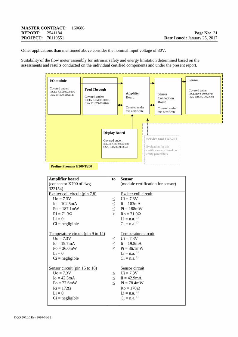
MASTER CONTRACT: 160686 REPORT: 2541184 PROJECT: 70110551
Page No: 31
Date Issued: January 25, 2017
DQD 507.10 Rev 2016-01-18
Other applications than mentioned above consider the nominal input voltage of 30V. Suitability of the flow meter assembly for intrinsic safety and energy limitation determined based on the assessments and results conducted on the individual certified components and under the present report.
Amplifier board (connector X700 of dwg. 322154)
to Sensor (module certification for sensor)
Exciter coil circuit (pin 7,8) Uo = 7.3V Io = 102.5mA Po = 187.1mW Ri = 71.3Ω Li = 0 Ci = negligible
≤ ≤ ≤ ≥
Exciter coil circuit Ui = 7.3V Ii = 103mA Pi = 188mW Ro = 71.0Ω Li = n.a. 1) Ci = n.a. 1)
Temperature circuit (pin 9 to 14) Uo = 7.3V Io = 19.7mA Po = 36.0mW Li = 0 Ci = negligible
≤ ≤ ≤
Temperature circuit Ui = 7.3V Ii = 19.8mA Pi = 36.1mW Li = n.a. 1) Ci = n.a. 1)
Sensor circuit (pin 15 to 18) Uo = 7.3V Io = 42.5mA Po = 77.6mW Ri = 172Ω Li = 0 Ci = negligible
≤ ≤ ≤
Sensor circuit Ui = 7.3V Ii = 42.9mA Pi = 78.4mW Ro = 170Ω Li = n.a. 1) Ci = n.a. 1)
Feed Through Covered under: IECEx KEM 09.0030U CSA 151079-2164662
I/O module Covered under: IECEx KEM 09.0029U CSA 151079-2162140
Sensor
Covered under IECExBVS 10.0007U CSA 160686- 2222698
Amplifier Board
Covered under this certificate
Display Board Covered under: IECEx KEM 08.0048U CSA 160686-2118543
Service tool FXA291 Evaluation for this certificate only based on entity parameters
Proline Promass E200/F200
Sensor Connection Board
Covered under this certificate
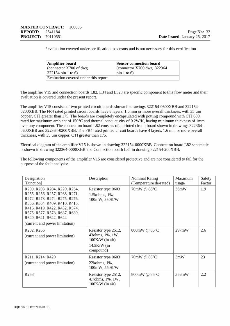
MASTER CONTRACT: 160686 REPORT: 2541184 PROJECT: 70110551
Page No: 32
Date Issued: January 25, 2017
DQD 507.10 Rev 2016-01-18
1) evaluation covered under certification to sensors and is not necessary for this certification
Amplifier board (connector X700 of dwg. 322154 pin 1 to 6)
Sensor connection board (connector X700 dwg. 322364 pin 1 to 6)
Evaluation covered under this report
The amplifier V15 and connection boards L82, L84 and L323 are specific component to this flow meter and their evaluation is covered under the present report. The amplifier V15 consists of two printed circuit boards shown in drawings 322154-0600XBB and 322154-0200XBB. The FR4 rated printed circuit boards have 8 layers, 1.6 mm or more overall thickness, with 35 µm copper, CTI greater than 175. The boards are completely encapsulated with potting compound with CTI 600, rated for maximum ambient of 150°C and thermal conductivity of 0.2W/K, having minimum thickness of 1mm over any component. The connection board L82 consists of a printed circuit board shown in drawings 322364- 0600XBB and 322364-0200XBB. The FR4 rated printed circuit boards have 4 layers, 1.6 mm or more overall thickness, with 35 µm copper, CTI greater than 175. Electrical diagram of the amplifier V15 is shown in drawing 322154-0000XBB. Connection board L82 schematic is shown in drawing 322364-0000XBB and Connection boarb L84 in drawing 322154-200XBB. The following components of the amplifier V15 are considered protective and are not considered to fail for the purpose of the fault analysis:
Designation [Function]
Description Nominal Rating (Temperature de-rated)
Maximum usage
Safety Factor
R200, R203, R204, R220, R254, R255, R256, R257, R268, R271, R272, R273, R274, R275, R276, R356, R364, R409, R410, R415, R416, R419, R422, R432, R574, R575, R577, R578, R637, R639, R640, R641, R642, R644 (current and power limitation)
Resistor type 0603 1.5kohms, 1%, 100mW, 550K/W
70mW @ 85°C 36mW 1.9
R202, R266 (current and power limitation)
Resistor type 2512, 43ohms, 1%, 1W, 100K/W (in air) 14.5K/W (in compound)
800mW @ 85°C 297mW 2.6
R211, R214, R420 (current and power limitation)
Resistor type 0603 22kohms, 1%, 100mW, 550K/W
70mW @ 85°C 3mW 23
R253
Resistor type 2512, 4.7ohms, 1%, 1W, 100K/W (in air)
800mW @ 85°C 356mW 2.2
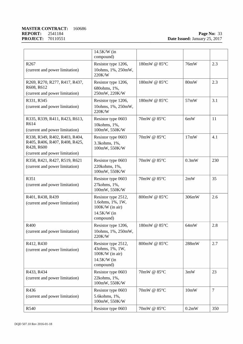
MASTER CONTRACT: 160686 REPORT: 2541184 PROJECT: 70110551
Page No: 33
Date Issued: January 25, 2017
DQD 507.10 Rev 2016-01-18
14.5K/W (in compound)
R267 (current and power limitation)
Resistor type 1206, 10ohms, 1%, 250mW, 220K/W
180mW @ 85°C 76mW 2.3
R269, R270, R277, R417, R437, R608, R612 (current and power limitation)
Resistor type 1206, 680ohms, 1%, 250mW, 220K/W
180mW @ 85°C 80mW 2.3
R331, R345 (current and power limitation)
Resistor type 1206, 10ohms, 1%, 250mW, 220K/W
180mW @ 85°C 57mW 3.1
R335, R339, R411, R423, R613, R614 (current and power limitation)
Resistor type 0603 10kohms, 1%, 100mW, 550K/W
70mW @ 85°C 6mW 11
R338, R349, R402, R403, R404, R405, R406, R407, R408, R425, R428, R600 (current and power limitation)
Resistor type 0603 3.3kohms, 1%, 100mW, 550K/W
70mW @ 85°C 17mW 4.1
R358, R421, R427, R519, R621 (current and power limitation)
Resistor type 0603 220kohms, 1%, 100mW, 550K/W
70mW @ 85°C 0.3mW 230
R351 (current and power limitation)
Resistor type 0603 27kohms, 1%, 100mW, 550K/W
70mW @ 85°C 2mW 35
R401, R438, R439 (current and power limitation)
Resistor type 2512, 1.6ohms, 1%, 1W, 100K/W (in air) 14.5K/W (in compound)
800mW @ 85°C 306mW 2.6
R400 (current and power limitation)
Resistor type 1206, 10ohms, 1%, 250mW, 220K/W
180mW @ 85°C 64mW 2.8
R412, R430 (current and power limitation)
Resistor type 2512, 43ohms, 1%, 1W, 100K/W (in air) 14.5K/W (in compound)
800mW @ 85°C 288mW 2.7
R433, R434 (current and power limitation)
Resistor type 0603 22kohms, 1%, 100mW, 550K/W
70mW @ 85°C 3mW 23
R436 (current and power limitation)
Resistor type 0603 5.6kohms, 1%, 100mW, 550K/W
70mW @ 85°C 10mW 7
R540 Resistor type 0603 70mW @ 85°C 0.2mW 350
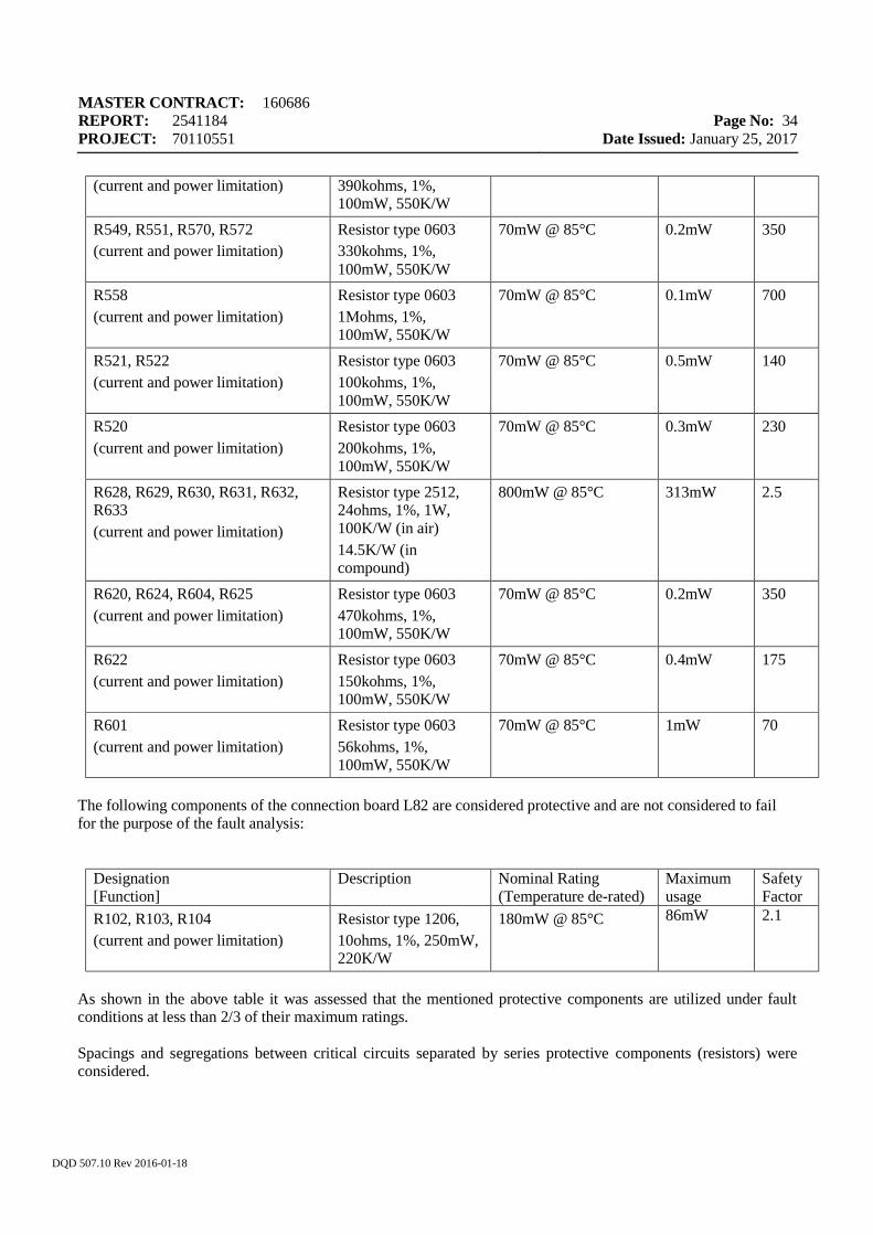
MASTER CONTRACT: 160686 REPORT: 2541184 PROJECT: 70110551
Page No: 34
Date Issued: January 25, 2017
DQD 507.10 Rev 2016-01-18
(current and power limitation) 390kohms, 1%, 100mW, 550K/W
R549, R551, R570, R572 (current and power limitation)
Resistor type 0603 330kohms, 1%, 100mW, 550K/W
70mW @ 85°C 0.2mW 350
R558 (current and power limitation)
Resistor type 0603 1Mohms, 1%, 100mW, 550K/W
70mW @ 85°C 0.1mW 700
R521, R522 (current and power limitation)
Resistor type 0603 100kohms, 1%, 100mW, 550K/W
70mW @ 85°C 0.5mW 140
R520 (current and power limitation)
Resistor type 0603 200kohms, 1%, 100mW, 550K/W
70mW @ 85°C 0.3mW 230
R628, R629, R630, R631, R632, R633 (current and power limitation)
Resistor type 2512, 24ohms, 1%, 1W, 100K/W (in air) 14.5K/W (in compound)
800mW @ 85°C 313mW 2.5
R620, R624, R604, R625 (current and power limitation)
Resistor type 0603 470kohms, 1%, 100mW, 550K/W
70mW @ 85°C 0.2mW 350
R622 (current and power limitation)
Resistor type 0603 150kohms, 1%, 100mW, 550K/W
70mW @ 85°C 0.4mW 175
R601 (current and power limitation)
Resistor type 0603 56kohms, 1%, 100mW, 550K/W
70mW @ 85°C 1mW 70
The following components of the connection board L82 are considered protective and are not considered to fail for the purpose of the fault analysis:
Designation [Function]
Description Nominal Rating (Temperature de-rated)
Maximum usage
Safety Factor
R102, R103, R104 (current and power limitation)
Resistor type 1206, 10ohms, 1%, 250mW, 220K/W
180mW @ 85°C 86mW 2.1
As shown in the above table it was assessed that the mentioned protective components are utilized under fault conditions at less than 2/3 of their maximum ratings. Spacings and segregations between critical circuits separated by series protective components (resistors) were considered.
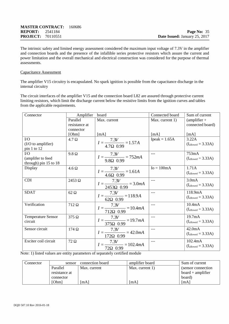
MASTER CONTRACT: 160686 REPORT: 2541184 PROJECT: 70110551
Page No: 35
Date Issued: January 25, 2017
DQD 507.10 Rev 2016-01-18
The intrinsic safety and limited energy assessment considered the maximum input voltage of 7.3V in the amplifier and connection boards and the presence of the infallible series protective resistors which assure the current and power limitation and the overall mechanical and electrical construction was considered for the purpose of thermal assessments. Capacitance Assessment The amplifier V15 circuitry is encapsulated. No spark ignition is possible from the capacitance discharge in the internal circuitry The circuit interfaces of the amplifier V15 and the connection board L82 are assured through protective current limiting resistors, which limit the discharge current below the resistive limits from the ignition curves and tables from the applicable requirements.
Connector Amplifier board Connected board Sum of current Parallel
resistance at connector
Max. current Max. current 1) (amplifier + connected board)
[Ohm] [mA] [mA] [mA] I/O (I/O to amplifier) pin 1 to 12
4.7 Ω
Ipeak = 1.65A 3.22A (Iallowed = 3.33A)
I/O (amplifer to feed through) pin 15 to 18
9.8 Ω
--- 753mA (Iallowed = 3.33A)
Display 4.6 Ω
Io = 100mA 1.71A (Iallowed = 3.33A)
CDI 2453 Ω
--- 3.0mA (Iallowed = 3.33A)
SDAT 62 Ω
--- 118.9mA (Iallowed = 3.33A)
Verification 712 Ω
--- 10.4mA (Iallowed = 3.33A)
Temperature Sensor circuit
375 Ω
--- 19.7mA (Iallowed = 3.33A)
Sensor circuit 174 Ω
--- 42.0mA (Iallowed = 3.33A)
Exciter coil circuit 72 Ω
--- 102.4mA (Iallowed = 3.33A)
Note: 1) listed values are entity parameters of separately certified module
Connector sensor connection board amplifier board Sum of current Parallel
resistance at connector
Max. current Max. current 1) (sensor connection board + amplifier board)
[Ohm] [mA] [mA] [mA]
AVI 57.199.07.4
3.7=
⋅Ω=
mAVI 75299.08.9
3.7=
⋅Ω=
AVI 61.199.06.4
3.7=
⋅Ω=
mAVI 0.399.02453
3.7=
⋅Ω=
AVI 9.11899.062
3.7=
⋅Ω=
mAVI 4.1099.0712
3.7=
⋅Ω=
mAVI 7.1999.0375
3.7=
⋅Ω=
mAVI 0.4299.0172
3.7=
⋅Ω=
mAVI 4.10299.072
3.7=
⋅Ω=
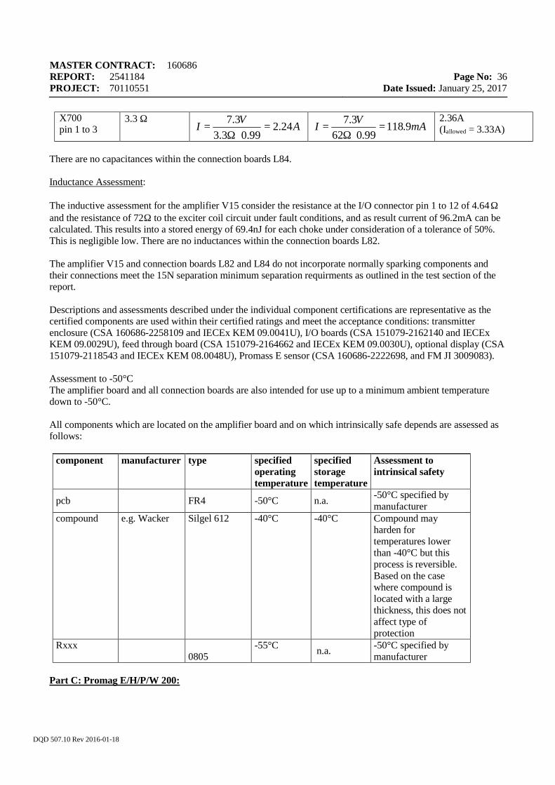
MASTER CONTRACT: 160686 REPORT: 2541184 PROJECT: 70110551
Page No: 36
Date Issued: January 25, 2017
DQD 507.10 Rev 2016-01-18
X700 pin 1 to 3
3.3 Ω
2.36A (Iallowed = 3.33A)
There are no capacitances within the connection boards L84. Inductance Assessment: The inductive assessment for the amplifier V15 consider the resistance at the I/O connector pin 1 to 12 of 4.64Ω and the resistance of 72Ω to the exciter coil circuit under fault conditions, and as result current of 96.2mA can be calculated. This results into a stored energy of 69.4nJ for each choke under consideration of a tolerance of 50%. This is negligible low. There are no inductances within the connection boards L82. The amplifier V15 and connection boards L82 and L84 do not incorporate normally sparking components and their connections meet the 15N separation minimum separation requirments as outlined in the test section of the report. Descriptions and assessments described under the individual component certifications are representative as the certified components are used within their certified ratings and meet the acceptance conditions: transmitter enclosure (CSA 160686-2258109 and IECEx KEM 09.0041U), I/O boards (CSA 151079-2162140 and IECEx KEM 09.0029U), feed through board (CSA 151079-2164662 and IECEx KEM 09.0030U), optional display (CSA 151079-2118543 and IECEx KEM 08.0048U), Promass E sensor (CSA 160686-2222698, and FM JI 3009083). Assessment to -50°C The amplifier board and all connection boards are also intended for use up to a minimum ambient temperature down to -50°C. All components which are located on the amplifier board and on which intrinsically safe depends are assessed as follows:
component manufacturer type specified
operating temperature
specified storage temperature
Assessment to intrinsical safety
pcb FR4 -50°C n.a. -50°C specified by manufacturer
compound e.g. Wacker Silgel 612 -40°C -40°C Compound may harden for temperatures lower than -40°C but this process is reversible. Based on the case where compound is located with a large thickness, this does not affect type of protection
Rxxx
0805
-55°C n.a. -50°C specified by manufacturer
Part C: Promag E/H/P/W 200:
AVI 24.299.03.3
3.7=
⋅Ω= mAVI 9.118
99.0623.7
=⋅Ω
=
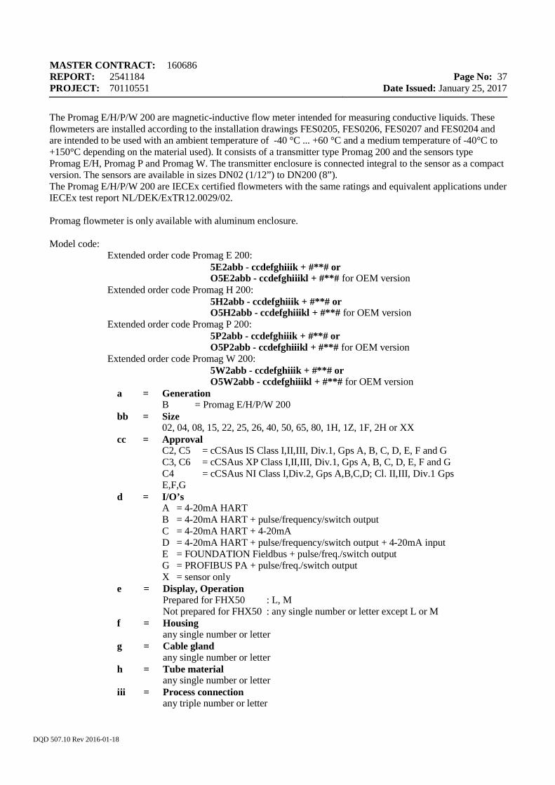
MASTER CONTRACT: 160686 REPORT: 2541184 PROJECT: 70110551
Page No: 37
Date Issued: January 25, 2017
DQD 507.10 Rev 2016-01-18
The Promag E/H/P/W 200 are magnetic-inductive flow meter intended for measuring conductive liquids. These flowmeters are installed according to the installation drawings FES0205, FES0206, FES0207 and FES0204 and are intended to be used with an ambient temperature of -40 °C ... +60 °C and a medium temperature of -40°C to +150°C depending on the material used). It consists of a transmitter type Promag 200 and the sensors type Promag E/H, Promag P and Promag W. The transmitter enclosure is connected integral to the sensor as a compact version. The sensors are available in sizes DN02 (1/12”) to DN200 (8”). The Promag E/H/P/W 200 are IECEx certified flowmeters with the same ratings and equivalent applications under IECEx test report NL/DEK/ExTR12.0029/02. Promag flowmeter is only available with aluminum enclosure. Model code:
Extended order code Promag E 200: 5E2abb - ccdefghiiik + #**# or O5E2abb - ccdefghiiikl + #**# for OEM version Extended order code Promag H 200: 5H2abb - ccdefghiiik + #**# or O5H2abb - ccdefghiiikl + #**# for OEM version Extended order code Promag P 200: 5P2abb - ccdefghiiik + #**# or O5P2abb - ccdefghiiikl + #**# for OEM version Extended order code Promag W 200: 5W2abb - ccdefghiiik + #**# or O5W2abb - ccdefghiiikl + #**# for OEM version
a = Generation B = Promag E/H/P/W 200
bb = Size 02, 04, 08, 15, 22, 25, 26, 40, 50, 65, 80, 1H, 1Z, 1F, 2H or XX
cc = Approval C2, C5 = cCSAus IS Class I,II,III, Div.1, Gps A, B, C, D, E, F and G C3, C6 = cCSAus XP Class I,II,III, Div.1, Gps A, B, C, D, E, F and G C4 = cCSAus NI Class I,Div.2, Gps A,B,C,D; Cl. II,III, Div.1 Gps E,F,G
d = I/O’s A = 4-20mA HART B = 4-20mA HART + pulse/frequency/switch output C = 4-20mA HART + 4-20mA D = 4-20mA HART + pulse/frequency/switch output + 4-20mA input E = FOUNDATION Fieldbus + pulse/freq./switch output G = PROFIBUS PA + pulse/freq./switch output X = sensor only
e = Display, Operation Prepared for FHX50 : L, M Not prepared for FHX50 : any single number or letter except L or M
f = Housing any single number or letter
g = Cable gland any single number or letter
h = Tube material any single number or letter
iii = Process connection any triple number or letter
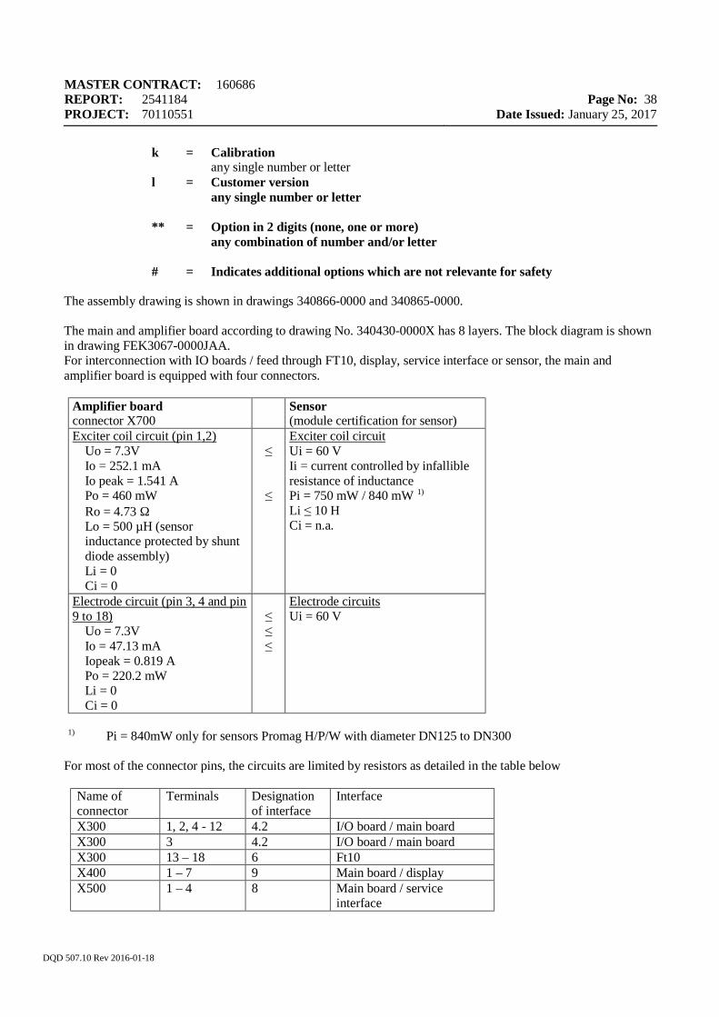
MASTER CONTRACT: 160686 REPORT: 2541184 PROJECT: 70110551
Page No: 38
Date Issued: January 25, 2017
DQD 507.10 Rev 2016-01-18
k = Calibration any single number or letter
l = Customer version any single number or letter
** = Option in 2 digits (none, one or more)
any combination of number and/or letter # = Indicates additional options which are not relevante for safety
The assembly drawing is shown in drawings 340866-0000 and 340865-0000. The main and amplifier board according to drawing No. 340430-0000X has 8 layers. The block diagram is shown in drawing FEK3067-0000JAA. For interconnection with IO boards / feed through FT10, display, service interface or sensor, the main and amplifier board is equipped with four connectors.
Amplifier board connector X700
Sensor (module certification for sensor)
Exciter coil circuit (pin 1,2) Uo = 7.3V Io = 252.1 mA Io peak = 1.541 A Po = 460 mW Ro = 4.73 Ω Lo = 500 µH (sensor inductance protected by shunt diode assembly) Li = 0 Ci = 0
≤ ≤
Exciter coil circuit Ui = 60 V Ii = current controlled by infallible resistance of inductance Pi = 750 mW / 840 mW 1) Li ≤ 10 H Ci = n.a.
Electrode circuit (pin 3, 4 and pin 9 to 18)
Uo = 7.3V Io = 47.13 mA Iopeak = 0.819 A Po = 220.2 mW Li = 0 Ci = 0
≤ ≤ ≤
Electrode circuits Ui = 60 V
1) Pi = 840mW only for sensors Promag H/P/W with diameter DN125 to DN300
For most of the connector pins, the circuits are limited by resistors as detailed in the table below
Name of connector
Terminals Designation of interface
Interface
X300 1, 2, 4 - 12 4.2 I/O board / main board X300 3 4.2 I/O board / main board X300 13 – 18 6 Ft10 X400 1 – 7 9 Main board / display X500 1 – 4 8 Main board / service
interface
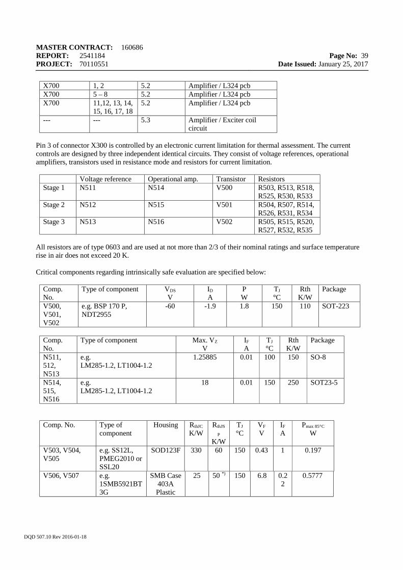
MASTER CONTRACT: 160686 REPORT: 2541184 PROJECT: 70110551
Page No: 39
Date Issued: January 25, 2017
DQD 507.10 Rev 2016-01-18
X700 1, 2 5.2 Amplifier / L324 pcb X700 5 – 8 5.2 Amplifier / L324 pcb X700 11,12, 13, 14,
15, 16, 17, 18 5.2 Amplifier / L324 pcb
--- --- 5.3 Amplifier / Exciter coil circuit
Pin 3 of connector X300 is controlled by an electronic current limitation for thermal assessment. The current controls are designed by three independent identical circuits. They consist of voltage references, operational amplifiers, transistors used in resistance mode and resistors for current limitation.
Voltage reference Operational amp. Transistor Resistors Stage 1 N511 N514 V500 R503, R513, R518,
R525, R530, R533 Stage 2 N512 N515 V501 R504, R507, R514,
R526, R531, R534 Stage 3 N513 N516 V502 R505, R515, R520,
R527, R532, R535 All resistors are of type 0603 and are used at not more than 2/3 of their nominal ratings and surface temperature rise in air does not exceed 20 K. Critical components regarding intrinsically safe evaluation are specified below:
Comp. No.
Type of component VDS V
ID
A P W
TJ °C
Rth K/W
Package
V500, V501, V502
e.g. BSP 170 P, NDT2955
-60 -1.9 1.8 150 110 SOT-223
Comp. No.
Type of component Max. VZ V
IF
A TJ °C
Rth K/W
Package
N511, 512, N513
e.g. LM285-1.2, LT1004-1.2
1.25885 0.01 100 150 SO-8
N514, 515, N516
e.g. LM285-1.2, LT1004-1.2
18 0.01 150 250 SOT23-5
Comp. No. Type of component
Housing RthJC
K/W RthJS
P
K/W
TJ
°C VF
V IF
A Pmax 85°C
W
V503, V504, V505
e.g. SS12L, PMEG2010 or SSL20
SOD123F 330 60 150 0.43 1 0.197
V506, V507 e.g. 1SMB5921BT3G
SMB Case 403A Plastic
25 50 *) 150 6.8 0.22
0.5777
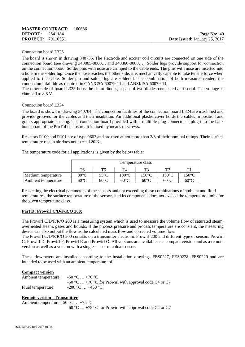
MASTER CONTRACT: 160686 REPORT: 2541184 PROJECT: 70110551
Page No: 40
Date Issued: January 25, 2017
DQD 507.10 Rev 2016-01-18
Connection board L325 The board is shown in drawing 340735. The electrode and exciter coil circuits are connected on one side of the connection board (see drawing 340865-0000… and 340866-0000…). Solder lugs provide support for connection on the connection board. Solder pins with nose are crimped to the cable ends. The pins with nose are inserted into a hole in the solder lug. Once the nose reaches the other side, it is mechanically capable to take tensile force when applied to the cable. Solder pin and solder lug are soldered. The combination of both measures renders the connection infallible as required in CAN/CSA 60079-11 and ANSI/ISA 60079-11. The other side of board L325 hosts the shunt diodes, a pair of two diodes connected anti-serial. The voltage is clamped to 8.8 V. Connection board L324 The board is shown in drawing 340764. The connection facilities of the connection board L324 are machined and provide grooves for the cables and their insulation. An additional plastic cover holds the cables in position and grants appropriate spacing. The connection board provided with a multiple plug connector is plug into the back bone board of the ProTof enclosure. It is fixed by means of screws. Resistors R100 and R101 are of type 0603 and are used at not more than 2/3 of their nominal ratings. Their surface temperature rise in air does not exceed 20 K. The temperature code for all applications is given by the below table:
Temperature class
T6 T5 T4 T3 T2 T1 Medium temperature 80°C 95°C 130°C 150°C 150°C 150°C Ambient temperature 60°C 60°C 60°C 60°C 60°C 60°C
Respecting the electrical parameters of the sensors and not exceeding these combinations of ambient and fluid temperatures, the surface temperature of the sensors and its components does not exceed the temperature limits for the given temperature class. Part D: Prowirl C/D/F/R/O 200: The Prowirl C/D/F/R/O 200 is a measuring system which is used to measure the volume flow of saturated steam, overheated steam, gases and liquids. If the process pressure and process temperature are constant, the measuring device can also output the flow as the calculated mass flow and corrected volume flow. The Prowirl C/D/F/R/O 200 consists on a transmitter electronic Prowirl 200 and different type of sensors Prowirl C, Prowirl D, Prowirl F, Prowirl R and Prowirl O. All versions are available as a compact version and as a remote version as well as a version with a single sensor or a dual sensor.
These flowmeters are installed according to the installation drawings FES0227, FES0228, FES0229 and are intended to be used with an ambient temperature of Compact version Ambient temperature: -50 °C … +70 °C -60 °C … +70 °C for Prowirl with approval code C4 or C7 Fluid temperature: -200 °C … +450 °C Remote version - Transmitter Ambient temperature: -50 °C … +75 °C -60 °C … +75 °C for Prowirl with approval code C4 or C7
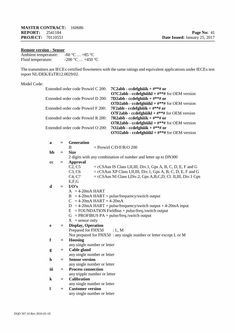
MASTER CONTRACT: 160686 REPORT: 2541184 PROJECT: 70110551
Page No: 41
Date Issued: January 25, 2017
DQD 507.10 Rev 2016-01-18
Remote version - Sensor Ambient temperature: -60 °C … +85 °C Fluid temperature: -200 °C … +450 °C The transmitters are IECEx certified flowmeters with the same ratings and equivalent applications under IECEx test report NL/DEK/ExTR12.0029/02. Model Code:
Extended order code Prowirl C 200: 7C2abb - ccdefghiiik + #**# or O7C2abb - ccdefghiiikl + #**# for OEM version Extended order code Prowirl D 200: 7D2abb - ccdefghiiik + #**# or O7D2abb - ccdefghiiikl + #**# for OEM version Extended order code Prowirl F 200: 7F2abb - ccdefghiiik + #**# or O7F2abb - ccdefghiiikl + #**# for OEM version Extended order code Prowirl R 200: 7R2abb - ccdefghiiik + #**# or O7R2abb - ccdefghiiikl + #**# for OEM version Extended order code Prowirl O 200: 7O2abb - ccdefghiiik + #**# or O7O2abb - ccdefghiiikl + #**# for OEM version
a = Generation B = Prowirl C/D/F/R/O 200
bb = Size 2 digits with any combination of number and letter up to DN300
cc = Approval C2, C5 = cCSAus IS Class I,II,III, Div.1, Gps A, B, C, D, E, F and G C3, C6 = cCSAus XP Class I,II,III, Div.1, Gps A, B, C, D, E, F and G C4, C7 = cCSAus NI Class I,Div.2, Gps A,B,C,D; Cl. II,III, Div.1 Gps E,F,G
d = I/O’s A = 4-20mA HART B = 4-20mA HART + pulse/frequency/switch output C = 4-20mA HART + 4-20mA D = 4-20mA HART + pulse/frequency/switch output + 4-20mA input E = FOUNDATION Fieldbus + pulse/freq./switch output G = PROFIBUS PA + pulse/freq./switch output X = sensor only
e = Display, Operation Prepared for FHX50 : L, M Not prepared for FHX50 : any single number or letter except L or M
f = Housing any single number or letter
g = Cable gland any single number or letter
h = Sensor version any single number or letter
iii = Process connection any tripple number or letter
k = Calibration any single number or letter
l = Customer version any single number or letter
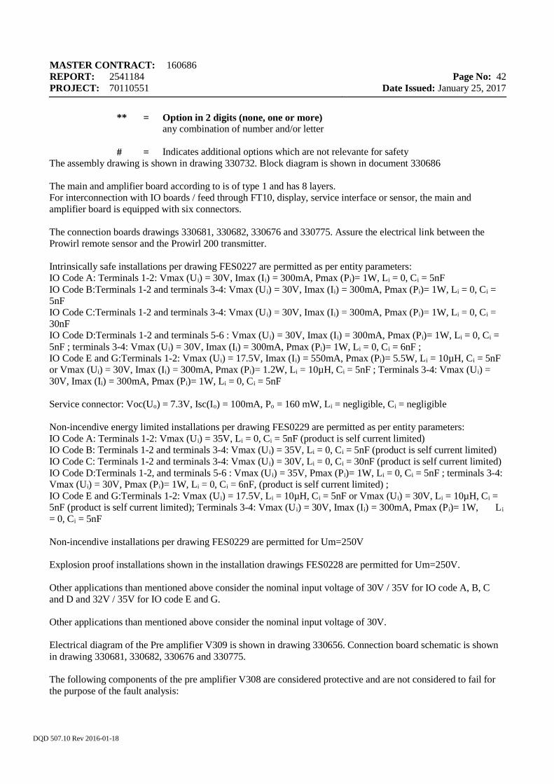
MASTER CONTRACT: 160686 REPORT: 2541184 PROJECT: 70110551
Page No: 42
Date Issued: January 25, 2017
DQD 507.10 Rev 2016-01-18
** = Option in 2 digits (none, one or more) any combination of number and/or letter
# = Indicates additional options which are not relevante for safety
The assembly drawing is shown in drawing 330732. Block diagram is shown in document 330686 The main and amplifier board according to is of type 1 and has 8 layers. For interconnection with IO boards / feed through FT10, display, service interface or sensor, the main and amplifier board is equipped with six connectors. The connection boards drawings 330681, 330682, 330676 and 330775. Assure the electrical link between the Prowirl remote sensor and the Prowirl 200 transmitter. Intrinsically safe installations per drawing FES0227 are permitted as per entity parameters: IO Code A: Terminals 1-2: Vmax (Ui) = 30V, Imax (Ii) = 300mA, Pmax (Pi)= 1W, Li = 0, Ci = 5nF IO Code B:Terminals 1-2 and terminals 3-4: Vmax (U i) = 30V, Imax (Ii) = 300mA, Pmax (Pi)= 1W, Li = 0, Ci = 5nF IO Code C:Terminals 1-2 and terminals 3-4: Vmax (U i) = 30V, Imax (Ii) = 300mA, Pmax (Pi)= 1W, Li = 0, Ci = 30nF IO Code D:Terminals 1-2 and terminals 5-6 : Vmax (Ui) = 30V, Imax (Ii) = 300mA, Pmax (Pi)= 1W, Li = 0, Ci = 5nF ; terminals 3-4: Vmax (Ui) = 30V, Imax (Ii) = 300mA, Pmax (Pi)= 1W, Li = 0, Ci = 6nF ; IO Code E and G:Terminals 1-2: Vmax (Ui) = 17.5V, Imax (Ii) = 550mA, Pmax (Pi)= 5.5W, Li = 10µH, Ci = 5nF or Vmax (Ui) = 30V, Imax (Ii) = 300mA, Pmax (Pi)= 1.2W, Li = 10µH, Ci = 5nF ; Terminals 3-4: Vmax (Ui) = 30V, Imax (Ii) = 300mA, Pmax (Pi)= 1W, Li = 0, Ci = 5nF Service connector: Voc(Uo) = 7.3V, Isc(Io) = 100mA, Po = 160 mW, Li = negligible, Ci = negligible Non-incendive energy limited installations per drawing FES0229 are permitted as per entity parameters: IO Code A: Terminals 1-2: Vmax (Ui) = 35V, Li = 0, Ci = 5nF (product is self current limited) IO Code B: Terminals 1-2 and terminals 3-4: Vmax (U i) = 35V, Li = 0, Ci = 5nF (product is self current limited) IO Code C: Terminals 1-2 and terminals 3-4: Vmax (U i) = 30V, Li = 0, Ci = 30nF (product is self current limited) IO Code D:Terminals 1-2, and terminals 5-6 : Vmax (U i) = 35V, Pmax (Pi)= 1W, Li = 0, Ci = 5nF ; terminals 3-4: Vmax (Ui) = 30V, Pmax (Pi)= 1W, Li = 0, Ci = 6nF, (product is self current limited) ; IO Code E and G:Terminals 1-2: Vmax (Ui) = 17.5V, Li = 10µH, Ci = 5nF or Vmax (Ui) = 30V, Li = 10µH, Ci = 5nF (product is self current limited); Terminals 3-4: Vmax (U i) = 30V, Imax (Ii) = 300mA, Pmax (Pi)= 1W, Li = 0, Ci = 5nF Non-incendive installations per drawing FES0229 are permitted for Um=250V Explosion proof installations shown in the installation drawings FES0228 are permitted for Um=250V. Other applications than mentioned above consider the nominal input voltage of 30V / 35V for IO code A, B, C and D and 32V / 35V for IO code E and G. Other applications than mentioned above consider the nominal input voltage of 30V. Electrical diagram of the Pre amplifier V309 is shown in drawing 330656. Connection board schematic is shown in drawing 330681, 330682, 330676 and 330775. The following components of the pre amplifier V308 are considered protective and are not considered to fail for the purpose of the fault analysis:

MASTER CONTRACT: 160686 REPORT: 2541184 PROJECT: 70110551
Page No: 43
Date Issued: January 25, 2017
DQD 507.10 Rev 2016-01-18
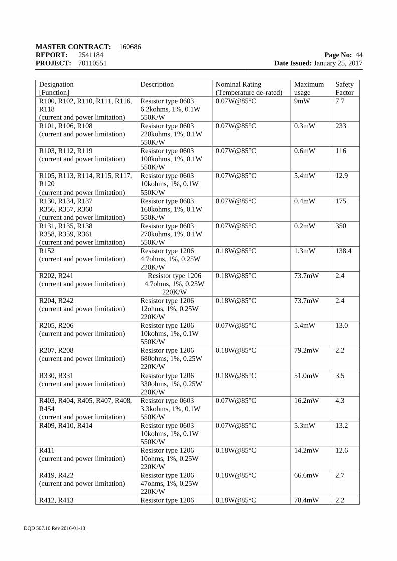
MASTER CONTRACT: 160686 REPORT: 2541184 PROJECT: 70110551
Page No: 44
Date Issued: January 25, 2017
DQD 507.10 Rev 2016-01-18
Designation [Function]
Description Nominal Rating (Temperature de-rated)
Maximum usage
Safety Factor
R100, R102, R110, R111, R116, R118 (current and power limitation)
Resistor type 0603 6.2kohms, 1%, 0.1W 550K/W
0.07W@85°C 9mW 7.7
R101, R106, R108 (current and power limitation)
Resistor type 0603 220kohms, 1%, 0.1W 550K/W
0.07W@85°C 0.3mW 233
R103, R112, R119 (current and power limitation)
Resistor type 0603 100kohms, 1%, 0.1W 550K/W
0.07W@85°C 0.6mW 116
R105, R113, R114, R115, R117, R120 (current and power limitation)
Resistor type 0603 10kohms, 1%, 0.1W 550K/W
0.07W@85°C 5.4mW 12.9
R130, R134, R137 R356, R357, R360 (current and power limitation)
Resistor type 0603 160kohms, 1%, 0.1W 550K/W
0.07W@85°C 0.4mW 175
R131, R135, R138 R358, R359, R361 (current and power limitation)
Resistor type 0603 270kohms, 1%, 0.1W 550K/W
0.07W@85°C 0.2mW 350
R152 (current and power limitation)
Resistor type 1206 4.7ohms, 1%, 0.25W 220K/W
0.18W@85°C 1.3mW 138.4
R202, R241 (current and power limitation)
Resistor type 1206 4.7ohms, 1%, 0.25W
220K/W
0.18W@85°C 73.7mW 2.4
R204, R242 (current and power limitation)
Resistor type 1206 12ohms, 1%, 0.25W 220K/W
0.18W@85°C 73.7mW 2.4
R205, R206 (current and power limitation)
Resistor type 1206 10kohms, 1%, 0.1W 550K/W
0.07W@85°C 5.4mW 13.0
R207, R208 (current and power limitation)
Resistor type 1206 680ohms, 1%, 0.25W 220K/W
0.18W@85°C 79.2mW 2.2
R330, R331 (current and power limitation)
Resistor type 1206 330ohms, 1%, 0.25W 220K/W
0.18W@85°C 51.0mW 3.5
R403, R404, R405, R407, R408, R454 (current and power limitation)
Resistor type 0603 3.3kohms, 1%, 0.1W 550K/W
0.07W@85°C 16.2mW 4.3
R409, R410, R414 Resistor type 0603 10kohms, 1%, 0.1W 550K/W
0.07W@85°C 5.3mW 13.2
R411 (current and power limitation)
Resistor type 1206 10ohms, 1%, 0.25W 220K/W
0.18W@85°C 14.2mW 12.6
R419, R422 (current and power limitation)
Resistor type 1206 47ohms, 1%, 0.25W 220K/W
0.18W@85°C 66.6mW 2.7
R412, R413 Resistor type 1206 0.18W@85°C 78.4mW 2.2
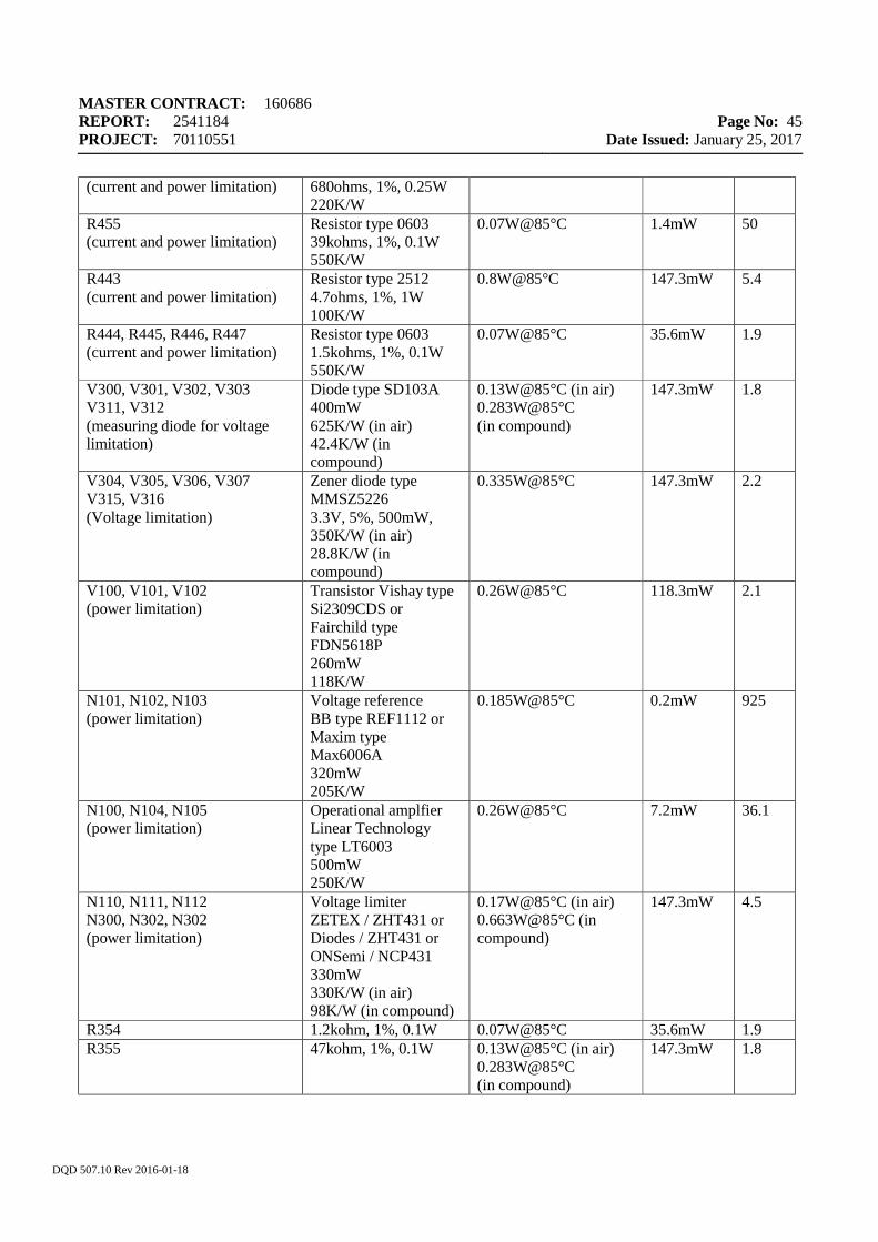
MASTER CONTRACT: 160686 REPORT: 2541184 PROJECT: 70110551
Page No: 45
Date Issued: January 25, 2017
DQD 507.10 Rev 2016-01-18
(current and power limitation) 680ohms, 1%, 0.25W 220K/W
R455 (current and power limitation)
Resistor type 0603 39kohms, 1%, 0.1W 550K/W
0.07W@85°C 1.4mW 50
R443 (current and power limitation)
Resistor type 2512 4.7ohms, 1%, 1W 100K/W
0.8W@85°C 147.3mW 5.4
R444, R445, R446, R447 (current and power limitation)
Resistor type 0603 1.5kohms, 1%, 0.1W 550K/W
0.07W@85°C 35.6mW 1.9
V300, V301, V302, V303 V311, V312 (measuring diode for voltage limitation)
Diode type SD103A 400mW 625K/W (in air) 42.4K/W (in compound)
0.13W@85°C (in air) 0.283W@85°C (in compound)
147.3mW 1.8
V304, V305, V306, V307 V315, V316 (Voltage limitation)
Zener diode type MMSZ5226 3.3V, 5%, 500mW, 350K/W (in air) 28.8K/W (in compound)
0.335W@85°C 147.3mW 2.2
V100, V101, V102 (power limitation)
Transistor Vishay type Si2309CDS or Fairchild type FDN5618P 260mW 118K/W
0.26W@85°C 118.3mW 2.1
N101, N102, N103 (power limitation)
Voltage reference BB type REF1112 or Maxim type Max6006A 320mW 205K/W
0.185W@85°C 0.2mW 925
N100, N104, N105 (power limitation)
Operational amplfier Linear Technology type LT6003 500mW 250K/W
0.26W@85°C 7.2mW 36.1
N110, N111, N112 N300, N302, N302 (power limitation)
Voltage limiter ZETEX / ZHT431 or Diodes / ZHT431 or ONSemi / NCP431 330mW 330K/W (in air) 98K/W (in compound)
0.17W@85°C (in air) 0.663W@85°C (in compound)
147.3mW 4.5
R354 1.2kohm, 1%, 0.1W 0.07W@85°C 35.6mW 1.9 R355 47kohm, 1%, 0.1W 0.13W@85°C (in air)
0.283W@85°C (in compound)
147.3mW 1.8
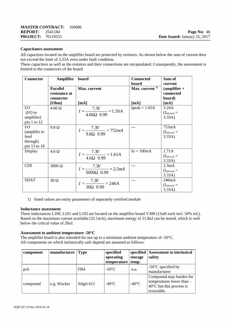
MASTER CONTRACT: 160686 REPORT: 2541184 PROJECT: 70110551
Page No: 46
Date Issued: January 25, 2017
DQD 507.10 Rev 2016-01-18
Capacitance assessment All capacitors located on the amplifier board are protected by resistors. As shown below the sum of current does not exceed the limit of 3.33A even under fault condition. These capacitors as well as the resistors and their connections are encapsulated. Consequently, the assessment is limited to the connectors of the board:
Connector Amplifier board Connected
board Sum of current
Parallel resistance at connector
Max. current Max. current 1) (amplifier + connected board)
[Ohm] [mA] [mA] [mA] I/O (I/O to amplifier) pin 1 to 12
4.66 Ω
Ipeak = 1.65A 3.24A (Iallowed = 3.33A)
I/O (amplifer to feed through) pin 13 to 18
9.8 Ω
--- 753mA (Iallowed = 3.33A)
Display 4.6 Ω
Io = 100mA 1.71A (Iallowed = 3.33A)
CDI 3000 Ω
--- 2.5mA (Iallowed = 3.33A)
SDAT 30 Ω
--- 246mA (Iallowed = 3.33A)
1) listed values are entity parameters of separately certified module
Inductance assessment Three inductances L100, L101 and L102 are located on the amplifier board V308 (15uH each incl. 50% tol.). Based on the maximum current available (32.1mA), maximum energy of 21.8nJ can be stored, which is well below the critical value of 20uJ. Assessment to ambient temperature -50°C The amplifier board is also intended for use up to a minimum ambient temperature of -50°C. All components on which intrinsically safe depend are assessed as follows:
component manufacturer Type specified operating temperature
specified storage temp.
Assessment to intrinsical safety
pcb FR4 -50°C n.a. -50°C specified by manufacturer
compound e.g. Wacker Silgel 612 -40°C -40°C
Compound may harden for temperatures lower than -40°C but this process is reversible.
AVI 59.199.066.4
3.7=
⋅Ω=
mAVI 75299.08.9
3.7=
⋅Ω=
AVI 61.199.06.4
3.7=
⋅Ω=
mAVI 5.299.03000
3.7=
⋅Ω=
AVI 24699.030
3.7=
⋅Ω=
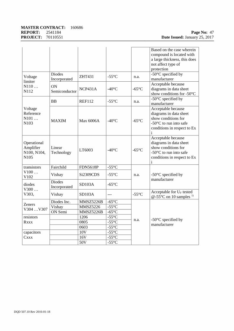
MASTER CONTRACT: 160686 REPORT: 2541184 PROJECT: 70110551
Page No: 47
Date Issued: January 25, 2017
DQD 507.10 Rev 2016-01-18
Based on the case wherein compound is located with a large thickness, this does not affect type of protection
Voltage limiter N110 … N112
Diodes Incorporated ZHT431 -55°C n.a. -50°C specified by
manufacturer
ON Semiconductor NCP431A -40°C -65°C
Acceptable because diagrams in data sheet show conditions for -50°C
Voltage Reference N101 … N103
BB REF112 -55°C n.a. -50°C specified by manufacturer
MAXIM Max 6006A -40°C -65°C
Acceptable because diagrams in data sheet show conditions for -50°C to run into safe conditions in respect to Ex i
Operational Amplifier N100, N104, N105
Linear Technology LT6003 -40°C -65°C
Acceptable because diagrams in data sheet show conditions for -50°C to run into safe conditions in respect to Ex i
transistors V100 … V102
Fairchild FDN5618P -55°C
n.a.
-50°C specified by manufacturer
Vishay Si2309CDS -55°C
diodes V300 … V303,
Diodes Incorporated SD103A -65°C
Vishay SD103A --- -55°C Acceptable for UF tested @-55°C on 10 samples 1)
Zeners V304 …V307
Diodes Inc. MMSZ5226B -65°C
n.a.
-50°C specified by manufacturer
Vishay MMSZ5226 -55°C ON Semi MMSZ5226B -65°C
resistors 1206 -55°C Rxxx 0805 -55°C 0603 -55°C capacitors 10V -55°C Cxxx 16V -55°C 50V -55°C
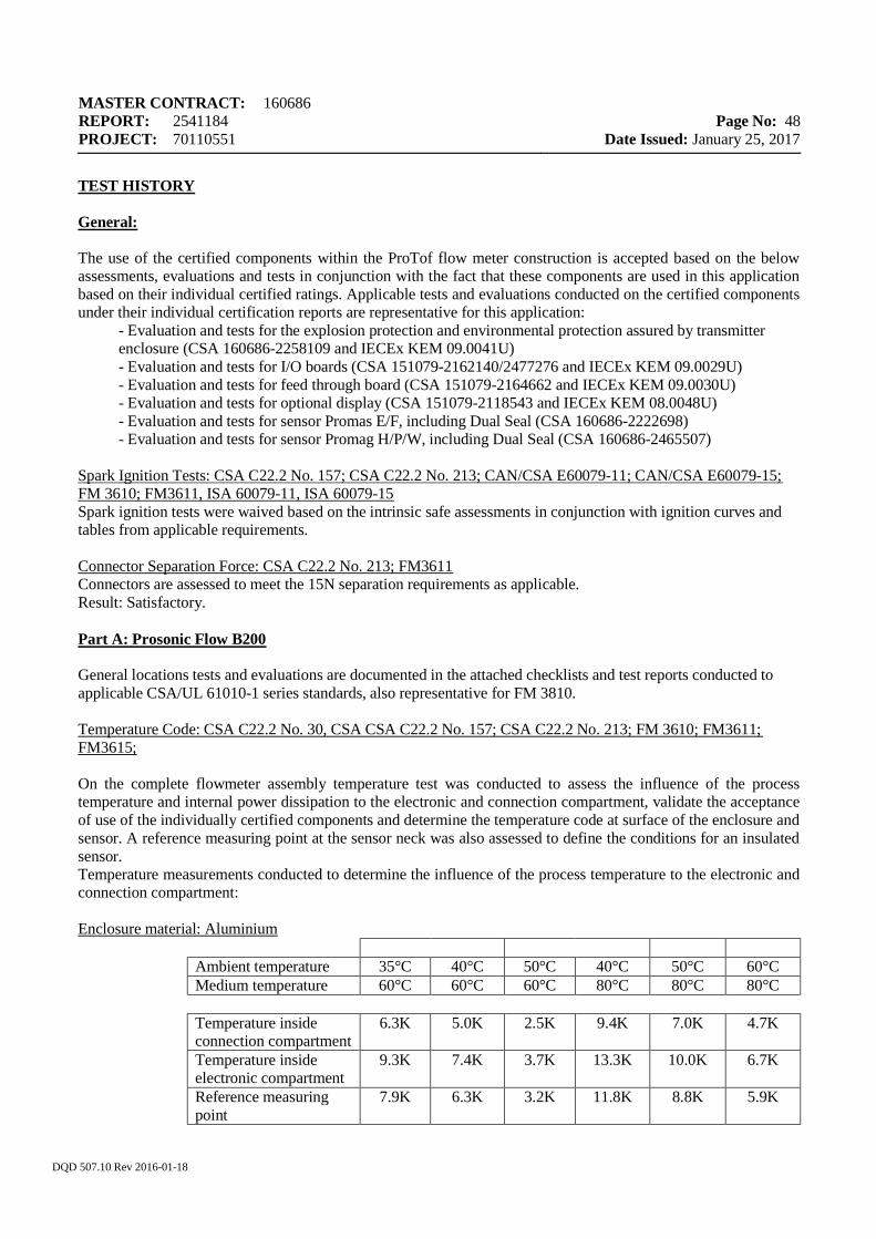
MASTER CONTRACT: 160686 REPORT: 2541184 PROJECT: 70110551
Page No: 48
Date Issued: January 25, 2017
DQD 507.10 Rev 2016-01-18
TEST HISTORY General: The use of the certified components within the ProTof flow meter construction is accepted based on the below assessments, evaluations and tests in conjunction with the fact that these components are used in this application based on their individual certified ratings. Applicable tests and evaluations conducted on the certified components under their individual certification reports are representative for this application:
- Evaluation and tests for the explosion protection and environmental protection assured by transmitter enclosure (CSA 160686-2258109 and IECEx KEM 09.0041U) - Evaluation and tests for I/O boards (CSA 151079-2162140/2477276 and IECEx KEM 09.0029U) - Evaluation and tests for feed through board (CSA 151079-2164662 and IECEx KEM 09.0030U) - Evaluation and tests for optional display (CSA 151079-2118543 and IECEx KEM 08.0048U) - Evaluation and tests for sensor Promas E/F, including Dual Seal (CSA 160686-2222698) - Evaluation and tests for sensor Promag H/P/W, including Dual Seal (CSA 160686-2465507)
Spark Ignition Tests: CSA C22.2 No. 157; CSA C22.2 No. 213; CAN/CSA E60079-11; CAN/CSA E60079-15; FM 3610; FM3611, ISA 60079-11, ISA 60079-15 Spark ignition tests were waived based on the intrinsic safe assessments in conjunction with ignition curves and tables from applicable requirements. Connector Separation Force: CSA C22.2 No. 213; FM3611 Connectors are assessed to meet the 15N separation requirements as applicable. Result: Satisfactory. Part A: Prosonic Flow B200 General locations tests and evaluations are documented in the attached checklists and test reports conducted to applicable CSA/UL 61010-1 series standards, also representative for FM 3810. Temperature Code: CSA C22.2 No. 30, CSA CSA C22.2 No. 157; CSA C22.2 No. 213; FM 3610; FM3611; FM3615; On the complete flowmeter assembly temperature test was conducted to assess the influence of the process temperature and internal power dissipation to the electronic and connection compartment, validate the acceptance of use of the individually certified components and determine the temperature code at surface of the enclosure and sensor. A reference measuring point at the sensor neck was also assessed to define the conditions for an insulated sensor. Temperature measurements conducted to determine the influence of the process temperature to the electronic and connection compartment:
Enclosure material: Aluminium
Ambient temperature 35°C 40°C 50°C 40°C 50°C 60°C Medium temperature 60°C 60°C 60°C 80°C 80°C 80°C Temperature inside connection compartment
6.3K 5.0K 2.5K 9.4K 7.0K 4.7K
Temperature inside electronic compartment
9.3K 7.4K 3.7K 13.3K 10.0K 6.7K
Reference measuring point
7.9K 6.3K 3.2K 11.8K 8.8K 5.9K
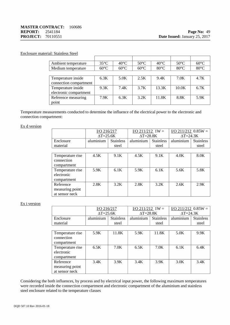
MASTER CONTRACT: 160686 REPORT: 2541184 PROJECT: 70110551
Page No: 49
Date Issued: January 25, 2017
DQD 507.10 Rev 2016-01-18
Enclosure material: Stainless Steel
Ambient temperature 35°C 40°C 50°C 40°C 50°C 60°C Medium temperature 60°C 60°C 60°C 80°C 80°C 80°C Temperature inside connection compartment
6.3K 5.0K 2.5K 9.4K 7.0K 4.7K
Temperature inside electronic compartment
9.3K 7.4K 3.7K 13.3K 10.0K 6.7K
Reference measuring point
7.9K 6.3K 3.2K 11.8K 8.8K 5.9K
Temperature measurements conducted to determine the influence of the electrical power to the electronic and connection compartment: Ex d version
I/O 216/217 ∆T=25.6K
I/O 211/212 1W = ∆T=28.8K
I/O 211/212 0.85W = ∆T=24.3K
Enclosure material
aluminium Stainless steel
aluminium Stainless steel
aluminium Stainless steel
Temperature rise connection compartment
4.5K 9.1K 4.5K 9.1K 4.0K 8.0K
Temperature rise electronic compartment
5.9K 6.1K 5.9K 6.1K 5.6K 5.8K
Reference measuring point at sensor neck
2.8K 3.2K 2.8K 3.2K 2.6K 2.9K
Ex i version
I/O 216/217 ∆T=25.6K
I/O 211/212 1W = ∆T=28.8K
I/O 211/212 0.85W = ∆T=24.3K
Enclosure material
aluminium Stainless steel
aluminium Stainless steel
aluminium Stainless steel
Temperature rise connection compartment
5.9K 11.8K 5.9K 11.8K 5.0K 9.9K
Temperature rise electronic compartment
6.5K 7.0K 6.5K 7.0K 6.1K 6.4K
Reference measuring point at sensor neck
3.4K 3.9K 3.4K 3.9K 3.0K 3.4K
Considering the both influences, by process and by electrical input power, the following maximum temperatures were recorded inside the connection compartment and electronic compartment of the aluminium and stainless steel enclosure related to the temperature classes
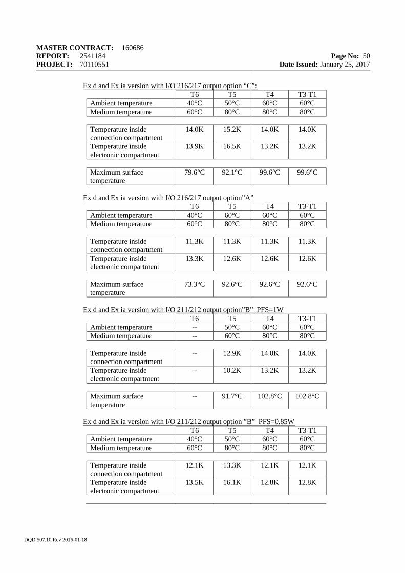
MASTER CONTRACT: 160686 REPORT: 2541184 PROJECT: 70110551
Page No: 50
Date Issued: January 25, 2017
DQD 507.10 Rev 2016-01-18
Ex d and Ex ia version with I/O 216/217 output option “C”: T6 T5 T4 T3-T1
Ambient temperature 40°C 50°C 60°C 60°C Medium temperature 60°C 80°C 80°C 80°C Temperature inside connection compartment
14.0K 15.2K 14.0K 14.0K
Temperature inside electronic compartment
13.9K 16.5K 13.2K 13.2K
Maximum surface temperature
79.6°C 92.1°C 99.6°C 99.6°C
Ex d and Ex ia version with I/O 216/217 output option”A”
T6 T5 T4 T3-T1 Ambient temperature 40°C 60°C 60°C 60°C Medium temperature 60°C 80°C 80°C 80°C Temperature inside connection compartment
11.3K 11.3K 11.3K 11.3K
Temperature inside electronic compartment
13.3K 12.6K 12.6K 12.6K
Maximum surface temperature
73.3°C 92.6°C 92.6°C 92.6°C
Ex d and Ex ia version with I/O 211/212 output option”B” PFS=1W
T6 T5 T4 T3-T1 Ambient temperature -- 50°C 60°C 60°C Medium temperature -- 60°C 80°C 80°C Temperature inside connection compartment
-- 12.9K 14.0K 14.0K
Temperature inside electronic compartment
-- 10.2K 13.2K 13.2K
Maximum surface temperature
-- 91.7°C 102.8°C 102.8°C
Ex d and Ex ia version with I/O 211/212 output option ”B” PFS=0.85W
T6 T5 T4 T3-T1 Ambient temperature 40°C 50°C 60°C 60°C Medium temperature 60°C 80°C 80°C 80°C Temperature inside connection compartment
12.1K 13.3K 12.1K 12.1K
Temperature inside electronic compartment
13.5K 16.1K 12.8K 12.8K
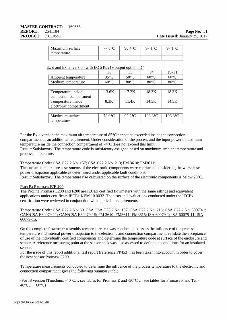
MASTER CONTRACT: 160686 REPORT: 2541184 PROJECT: 70110551
Page No: 51
Date Issued: January 25, 2017
DQD 507.10 Rev 2016-01-18
Maximum surface temperature
77.8°C 90.4°C 97.1°C 97.1°C
Ex d and Ex ia version with I/O 218/219 output option ”D” T6 T5 T4 T3-T1
Ambient temperature 35°C 50°C 60°C 60°C Medium temperature 60°C 80°C 80°C 80°C Temperature inside connection compartment
13.6K 17.2K 18.3K 18.3K
Temperature inside electronic compartment
8.3K 11.4K 14.5K 14.5K
Maximum surface temperature
78.9°C 92.2°C 103.3°C 103.3°C
For the Ex d version the maximum air temperature of 85°C cannot be exceeded inside the connection compartment as an additional requirement. Under consideration of the process and the input power a maximum temperature inside the connection compartment of 74°C does not exceed this limit. Result: Satisfactory. The temperature code is satisfactory assigned based on maximum ambient temperature and process temperature. Temperature Code: CSA C22.2 No. 157; CSA C22.2 No. 213; FM 3610; FM3611; The surface temperature assessments of the electronic components were conducted considering the worst case power dissipation applicable as determined under applicable fault conditions. Result: Satisfactory. The temperature rise calculated on the surface of the electronic components is below 20°C. Part B: Promass E/F 200 The Proline Promass E200 and F200 are IECEx certified flowmeters with the same ratings and equivalent applications under certificate IECEx KEM 10.0032. The tests and evaluations conducted under the IECEx certification were reviewed in conjunction with applicable requirements. Temperature Code: CSA C22.2 No. 30, CSA CSA C22.2 No. 157; CSA C22.2 No. 213; CSA C22.2 No. 60079-1; CAN/CSA E60079-11; CAN/CSA E60079-15; FM 3610; FM3611; FM3615; ISA 60079-1; ISA 60079-11; ISA 60079-15; On the complete flowmeter assembly temperature test was conducted to assess the influence of the process temperature and internal power dissipation to the electronic and connection compartment, validate the acceptance of use of the individually certified components and determine the temperature code at surface of the enclosure and sensor. A reference measuring point at the sensor neck was also assessed to define the conditions for an insulated sensor. For the issue of this report additional test report (reference PP453) has been taken into account in order to cover the new sensor Promass F200. Temperature measurements conducted to determine the influence of the process temperature to the electronic and connection compartment gives the following summary table: -For IS version (Tmedium: -40°C… see tables for Promass E and -50°C … see tables for Promass F and Ta: -40°C… +60°C)
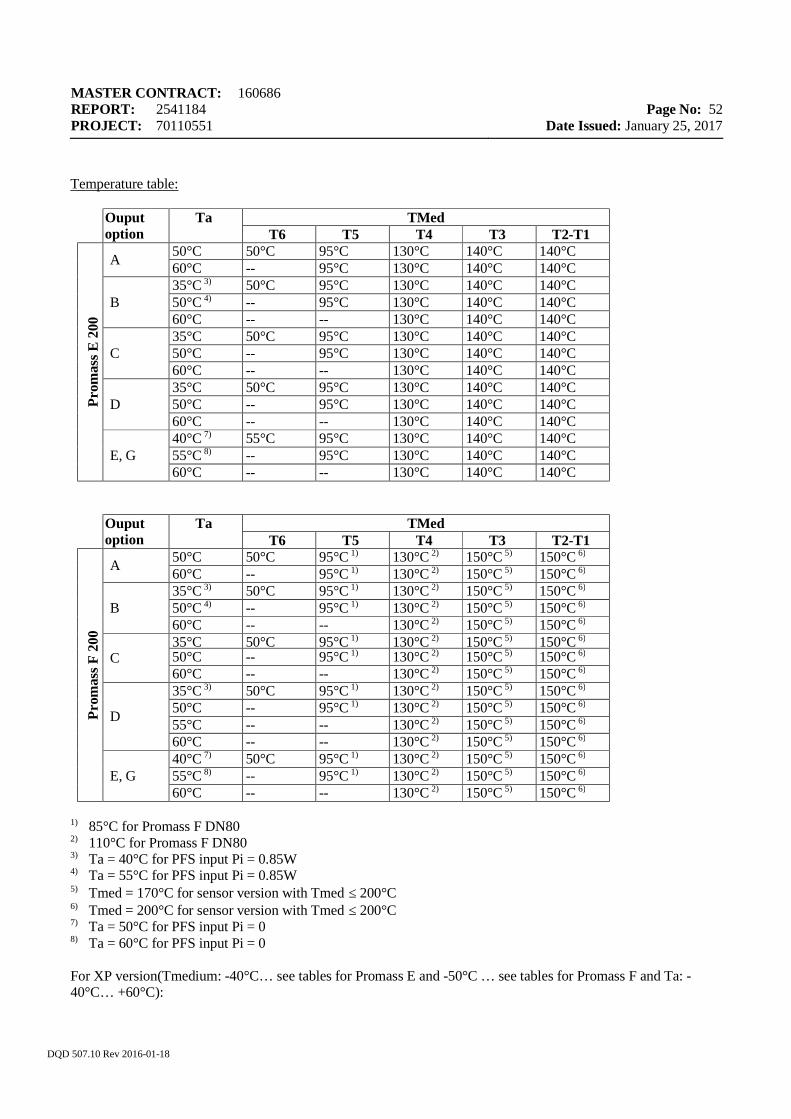
MASTER CONTRACT: 160686 REPORT: 2541184 PROJECT: 70110551
Page No: 52
Date Issued: January 25, 2017
DQD 507.10 Rev 2016-01-18
Temperature table:
Ouput option
Ta TMed T6 T5 T4 T3 T2-T1
Prom
ass E
200
A 50°C 50°C 95°C 130°C 140°C 140°C 60°C -- 95°C 130°C 140°C 140°C
B 35°C 3) 50°C 95°C 130°C 140°C 140°C 50°C 4) -- 95°C 130°C 140°C 140°C 60°C -- -- 130°C 140°C 140°C
C 35°C 50°C 95°C 130°C 140°C 140°C 50°C -- 95°C 130°C 140°C 140°C 60°C -- -- 130°C 140°C 140°C
D 35°C 50°C 95°C 130°C 140°C 140°C 50°C -- 95°C 130°C 140°C 140°C 60°C -- -- 130°C 140°C 140°C
E, G 40°C 7) 55°C 95°C 130°C 140°C 140°C 55°C 8) -- 95°C 130°C 140°C 140°C 60°C -- -- 130°C 140°C 140°C
Ouput option
Ta TMed T6 T5 T4 T3 T2-T1
Prom
ass F
200
A 50°C 50°C 95°C 1) 130°C 2) 150°C 5) 150°C 6) 60°C -- 95°C 1) 130°C 2) 150°C 5) 150°C 6)
B 35°C 3) 50°C 95°C 1) 130°C 2) 150°C 5) 150°C 6) 50°C 4) -- 95°C 1) 130°C 2) 150°C 5) 150°C 6) 60°C -- -- 130°C 2) 150°C 5) 150°C 6)
C 35°C 50°C 95°C 1) 130°C 2) 150°C 5) 150°C 6) 50°C -- 95°C 1) 130°C 2) 150°C 5) 150°C 6) 60°C -- -- 130°C 2) 150°C 5) 150°C 6)
D
35°C 3) 50°C 95°C 1) 130°C 2) 150°C 5) 150°C 6) 50°C -- 95°C 1) 130°C 2) 150°C 5) 150°C 6) 55°C -- -- 130°C 2) 150°C 5) 150°C 6) 60°C -- -- 130°C 2) 150°C 5) 150°C 6)
E, G 40°C 7) 50°C 95°C 1) 130°C 2) 150°C 5) 150°C 6) 55°C 8) -- 95°C 1) 130°C 2) 150°C 5) 150°C 6) 60°C -- -- 130°C 2) 150°C 5) 150°C 6)
1) 85°C for Promass F DN80
2) 110°C for Promass F DN80 3) Ta = 40°C for PFS input Pi = 0.85W 4) Ta = 55°C for PFS input Pi = 0.85W 5) Tmed = 170°C for sensor version with Tmed ≤ 200°C 6) Tmed = 200°C for sensor version with Tmed ≤ 200°C 7) Ta = 50°C for PFS input Pi = 0 8) Ta = 60°C for PFS input Pi = 0 For XP version(Tmedium: -40°C… see tables for Promass E and -50°C … see tables for Promass F and Ta: -40°C… +60°C):
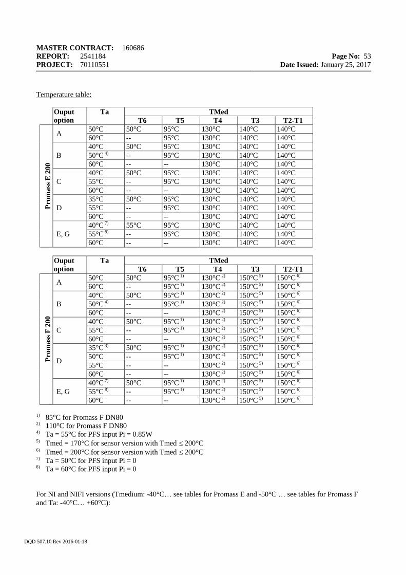
MASTER CONTRACT: 160686 REPORT: 2541184 PROJECT: 70110551
Page No: 53
Date Issued: January 25, 2017
DQD 507.10 Rev 2016-01-18
Temperature table:
Ouput option
Ta TMed T6 T5 T4 T3 T2-T1
Prom
ass E
200
A 50°C 50°C 95°C 130°C 140°C 140°C 60°C -- 95°C 130°C 140°C 140°C
B 40°C 50°C 95°C 130°C 140°C 140°C 50°C 4) -- 95°C 130°C 140°C 140°C 60°C -- -- 130°C 140°C 140°C
C 40°C 50°C 95°C 130°C 140°C 140°C 55°C -- 95°C 130°C 140°C 140°C 60°C -- -- 130°C 140°C 140°C
D 35°C 50°C 95°C 130°C 140°C 140°C 55°C -- 95°C 130°C 140°C 140°C 60°C -- -- 130°C 140°C 140°C
E, G 40°C 7) 55°C 95°C 130°C 140°C 140°C 55°C 8) -- 95°C 130°C 140°C 140°C 60°C -- -- 130°C 140°C 140°C
Ouput
option Ta TMed
T6 T5 T4 T3 T2-T1
Prom
ass F
200
A 50°C 50°C 95°C 1) 130°C 2) 150°C 5) 150°C 6) 60°C -- 95°C 1) 130°C 2) 150°C 5) 150°C 6)
B 40°C 50°C 95°C 1) 130°C 2) 150°C 5) 150°C 6) 50°C 4) -- 95°C 1) 130°C 2) 150°C 5) 150°C 6) 60°C -- -- 130°C 2) 150°C 5) 150°C 6)
C 40°C 50°C 95°C 1) 130°C 2) 150°C 5) 150°C 6) 55°C -- 95°C 1) 130°C 2) 150°C 5) 150°C 6) 60°C -- -- 130°C 2) 150°C 5) 150°C 6)
D
35°C 3) 50°C 95°C 1) 130°C 2) 150°C 5) 150°C 6) 50°C -- 95°C 1) 130°C 2) 150°C 5) 150°C 6) 55°C -- -- 130°C 2) 150°C 5) 150°C 6) 60°C -- -- 130°C 2) 150°C 5) 150°C 6)
E, G 40°C 7) 50°C 95°C 1) 130°C 2) 150°C 5) 150°C 6) 55°C 8) -- 95°C 1) 130°C 2) 150°C 5) 150°C 6) 60°C -- -- 130°C 2) 150°C 5) 150°C 6)
1) 85°C for Promass F DN80
2) 110°C for Promass F DN80 4) Ta = 55°C for PFS input Pi = 0.85W 5) Tmed = 170°C for sensor version with Tmed ≤ 200°C 6) Tmed = 200°C for sensor version with Tmed ≤ 200°C 7) Ta = 50°C for PFS input Pi = 0 8) Ta = 60°C for PFS input Pi = 0 For NI and NIFI versions (Tmedium: -40°C… see tables for Promass E and -50°C … see tables for Promass F and Ta: -40°C… +60°C):

MASTER CONTRACT: 160686 REPORT: 2541184 PROJECT: 70110551
Page No: 54
Date Issued: January 25, 2017
DQD 507.10 Rev 2016-01-18
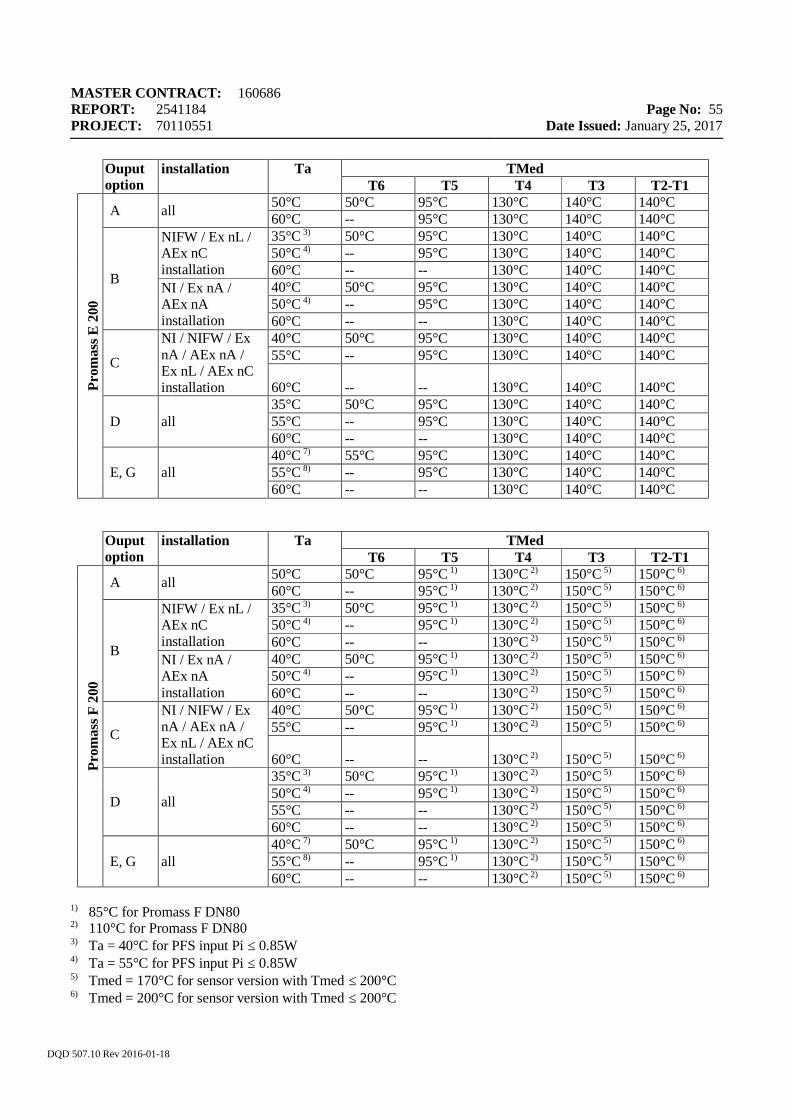
MASTER CONTRACT: 160686 REPORT: 2541184 PROJECT: 70110551
Page No: 55
Date Issued: January 25, 2017
DQD 507.10 Rev 2016-01-18
Ouput option
installation Ta TMed T6 T5 T4 T3 T2-T1
Prom
ass E
200
A all 50°C 50°C 95°C 130°C 140°C 140°C 60°C -- 95°C 130°C 140°C 140°C
B
NIFW / Ex nL / AEx nC installation
35°C 3) 50°C 95°C 130°C 140°C 140°C 50°C 4) -- 95°C 130°C 140°C 140°C 60°C -- -- 130°C 140°C 140°C
NI / Ex nA / AEx nA installation
40°C 50°C 95°C 130°C 140°C 140°C 50°C 4) -- 95°C 130°C 140°C 140°C 60°C -- -- 130°C 140°C 140°C
C
NI / NIFW / Ex nA / AEx nA / Ex nL / AEx nC installation
40°C 50°C 95°C 130°C 140°C 140°C 55°C -- 95°C 130°C 140°C 140°C
60°C -- -- 130°C 140°C 140°C
D all 35°C 50°C 95°C 130°C 140°C 140°C 55°C -- 95°C 130°C 140°C 140°C 60°C -- -- 130°C 140°C 140°C
E, G all 40°C 7) 55°C 95°C 130°C 140°C 140°C 55°C 8) -- 95°C 130°C 140°C 140°C 60°C -- -- 130°C 140°C 140°C
Ouput option
installation Ta TMed T6 T5 T4 T3 T2-T1
Prom
ass F
200
A all 50°C 50°C 95°C 1) 130°C 2) 150°C 5) 150°C 6) 60°C -- 95°C 1) 130°C 2) 150°C 5) 150°C 6)
B
NIFW / Ex nL / AEx nC installation
35°C 3) 50°C 95°C 1) 130°C 2) 150°C 5) 150°C 6) 50°C 4) -- 95°C 1) 130°C 2) 150°C 5) 150°C 6) 60°C -- -- 130°C 2) 150°C 5) 150°C 6)
NI / Ex nA / AEx nA installation
40°C 50°C 95°C 1) 130°C 2) 150°C 5) 150°C 6) 50°C 4) -- 95°C 1) 130°C 2) 150°C 5) 150°C 6) 60°C -- -- 130°C 2) 150°C 5) 150°C 6)
C
NI / NIFW / Ex nA / AEx nA / Ex nL / AEx nC installation
40°C 50°C 95°C 1) 130°C 2) 150°C 5) 150°C 6) 55°C -- 95°C 1) 130°C 2) 150°C 5) 150°C 6)
60°C -- -- 130°C 2) 150°C 5) 150°C 6)
D all
35°C 3) 50°C 95°C 1) 130°C 2) 150°C 5) 150°C 6) 50°C 4) -- 95°C 1) 130°C 2) 150°C 5) 150°C 6) 55°C -- -- 130°C 2) 150°C 5) 150°C 6) 60°C -- -- 130°C 2) 150°C 5) 150°C 6)
E, G all 40°C 7) 50°C 95°C 1) 130°C 2) 150°C 5) 150°C 6) 55°C 8) -- 95°C 1) 130°C 2) 150°C 5) 150°C 6) 60°C -- -- 130°C 2) 150°C 5) 150°C 6)
1) 85°C for Promass F DN80
2) 110°C for Promass F DN80 3) Ta = 40°C for PFS input Pi ≤ 0.85W 4) Ta = 55°C for PFS input Pi ≤ 0.85W 5) Tmed = 170°C for sensor version with Tmed ≤ 200°C 6) Tmed = 200°C for sensor version with Tmed ≤ 200°C
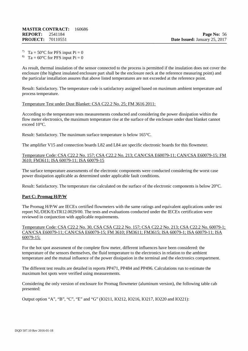
MASTER CONTRACT: 160686 REPORT: 2541184 PROJECT: 70110551
Page No: 56
Date Issued: January 25, 2017
DQD 507.10 Rev 2016-01-18
7) Ta = 50°C for PFS input Pi = 0 8) Ta = 60°C for PFS input Pi = 0 As result, thermal insulation of the sensor connected to the process is permitted if the insulation does not cover the enclosure (the highest insulated enclosure part shall be the enclosure neck at the reference measuring point) and the particular installation assures that above listed temperatures are not exceeded at the reference point. Result: Satisfactory. The temperature code is satisfactory assigned based on maximum ambient temperature and process temperature. Temperature Test under Dust Blanket: CSA C22.2 No. 25; FM 3616 2011: According to the temperature tests measurements conducted and considering the power dissipation within the flow meter electronics, the maximum temperature rise at the surface of the enclosure under dust blanket cannot exceed 10°C. Result: Satisfactory. The maximum surface temperature is below 165°C. The amplifier V15 and connection boards L82 and L84 are specific electronic boards for this flowmeter. Temperature Code: CSA C22.2 No. 157; CSA C22.2 No. 213; CAN/CSA E60079-11; CAN/CSA E60079-15; FM 3610; FM3611; ISA 60079-11; ISA 60079-15 The surface temperature assessments of the electronic components were conducted considering the worst case power dissipation applicable as determined under applicable fault conditions. Result: Satisfactory. The temperature rise calculated on the surface of the electronic components is below 20°C. Part C: Promag H/P/W The Promag H/P/W are IECEx certified flowmeters with the same ratings and equivalent applications under test report NL/DEK/ExTR12.0029/00. The tests and evaluations conducted under the IECEx certification were reviewed in conjunction with applicable requirements. Temperature Code: CSA C22.2 No. 30, CSA CSA C22.2 No. 157; CSA C22.2 No. 213; CSA C22.2 No. 60079-1; CAN/CSA E60079-11; CAN/CSA E60079-15; FM 3610; FM3611; FM3615; ISA 60079-1; ISA 60079-11; ISA 60079-15; For the hot spot assessment of the complete flow meter, different influences have been considered: the temperature of the sensors themselves, the fluid temperature to the electronics in relation to the ambient temperature and the mutual influence of the power dissipation in the terminal and the electronics compartment. The different test results are detailed in reports PP471, PP484 and PP496. Calculations run to estimate the maximum hot spots were verified using measurements. Considering the only version of enclosure for Promag flowmeter (aluminum version), the following table cab presented: Output option “A”, “B”, “C”, “E” and “G” (IO211, IO212, IO216, IO217, IO220 and IO221):
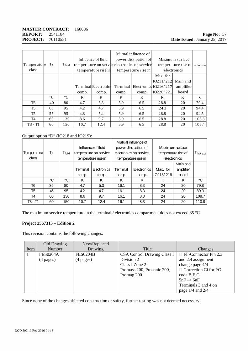
MASTER CONTRACT: 160686 REPORT: 2541184 PROJECT: 70110551
Page No: 57
Date Issued: January 25, 2017
DQD 507.10 Rev 2016-01-18
Output option “D” (IO218 and IO219):
The maximum service temperature in the terminal / electronics compartment does not exceed 85 °C. Project 2567315 – Edition 2 This revision contains the following changes:
Item Old Drawing
Number New/Replaced
Drawing Title Changes 1 FES0204A
(4 pages) FES0204B (4 pages)
CSA Control Drawing Class I Division 2 Class I Zone 2 Promass 200, Prosonic 200, Promag 200
FF-Connector Pin 2.3 and 2.4 assignment change page 4/4 Correction Ci for I/O code B,E,G 5nF → 6nF Terminals 3 and 4 on page 1/4 and 2/4
Since none of the changes affected construction or safety, further testing was not deemed necessary.
Temperature class
TA Tfluid T hot spot
Terminal comp.
Electronics comp.
Terminal comp.
Electronics comp.
Max. forIO218/ 219
Main and amplifier board
°C °C K K K K K K °CT6 35 80 4.7 5.3 16.1 8.3 24 20 79.8T5 45 95 4.2 4.7 16.1 8.3 24 20 89.3T4 60 130 8.6 9.7 16.1 8.3 24 20 108.7
T3 - T1 60 150 10.7 12.4 16.1 8.3 24 20 110.8
Maximum surface temperature rise of
electronics
Mutual influence of power dissipation of
electronics on service temperature rise in
Influence of fluid temperature on service
temperature rise in
Temperature class TA T fluid T hot spot
Terminal comp. Electronics comp. Terminal comp. Electronics comp. Max. forIO211/212 IO216/217 IO220/221
Main and amplifier board °C °C K K K K K K °CT6 40 80 4.7 5.3 5.9 6.5 28.8 20 79.4 T5 60 95 4.2 4.7 5.9 6.5 24.3 20 94.4 T5 55 95 4.8 5.4 5.9 6.5 28.8 20 94.5 T4 60 130 8.6 9.7 5.9 6.5 28.8 20 103.3 T3 - T1 60 150 10.7 12.4 5.9 6.5 28.8 20 105.4
Maximum surface temperature rise of electronicsMutual influence of power dissipation of electronics on service temperature rise in
Influence of fluid temperature on service temperature rise in
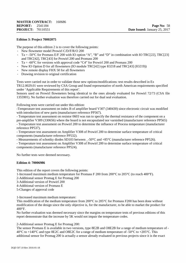
MASTER CONTRACT: 160686 REPORT: 2541184 PROJECT: 70110551
Page No: 58
Date Issued: January 25, 2017
DQD 507.10 Rev 2016-01-18
Edition 3: Project 70002075 The purpose of this edition 2 is to cover the following points: - New flowmeter model Prowirl C/D/F/R/O 200 - Ta = -50°C for Promass E/F 200 with IO option “A”, “B” and “D” in combination with IO TRC[22], TRC[23]
and TRC[42], TRC[43] for Prowirl 200 and Promass 200 - Ta = -60°C for versions with approval code “C4” for Prowirl 200 and Promass 200 - New IO Option D for all flowmeters (IO module TRC[42] type IO218 and TRC[43] (IO219)) - New remote display FHX 50 for all flowmeters - Drawing revision to original certification Tests were carried out in order to validate those new options/modifications: test results described in Ex TR12.0029.01 were reviewed by CSA Group and found representative of north American requirements specified under ‘Applicable Requirements of this report’. Sensors used on Prowirl flowmeters being identical to the ones already evaluated for Prowirl 72/73 (CSA file 1355901). No further evaluation was therefore carried out for dual seal evaluation. Following tests were carried out under this edition: -Temperature test assessment on index B of amplifier board V307 (340430) since electronic circuit was modified with introduction of new parts (manufacturer reference PP567). - Temperature test assessment on resistor 0603 was run to specify the thermal resistance of the component on a pre-amplifier V309 (330656) where the board is not encapsulated nor varnished (manufacturer reference PP565) - Temperature test assessment on Prowirl 200 to determine the influence of Process temperature (manufacturer reference PP537). - Temperature test assessment on Amplifier V308 of Prowirl 200 to determine surface temperature of critical components (manufacturer reference PP532). - Measurements of schottky diodes SD103 between _-50°C and +85°C (manufacturer reference PP526). - Temperature test assessment on Amplifier V308 of Prowirl 200 to determine surface temperature of critical components (manufacturer reference PP524). No further tests were deemed necessary. Edition 4: 70006986 This edition of the report covers the following points: 1-Increased maximum medium temperature for Promass F 200 from 200°C to 205°C (to reach 400°F). 2-Additional sensor Promag E for Promag 200 3-Additional version of Prowirl 200 4-Additional version of Promass E 5-Changes of approval code 1-Increased maximum medium temperature: This modification of the medium temperature from 200°C to 205°C for Promass F200 has been done without modification of the design since the only objective is, for the manufacturer, to be able to market the product for 400°F. No further evaluation was deemed necessary since the margins on temperature tests of previous editions of this report demonstrate that the increase by 5K would not impair the temperature codes. 2-Additional sensor Promag E for Promag 200: The sensor Promass E is available in two versions, type 8E2B and O8E2B for a range of medium temperature of -40°C to +140°C and type 8E2C and O8E2C for a range of medium temperature of -50°C to +205°C. This additional sensor for Promag 200 is actually a sensor already evaluated in previous projects since it is the exact
MASTER CONTRACT: 160686 REPORT: 2541184 PROJECT: 70110551
Page No: 59
Date Issued: January 25, 2017
DQD 507.10 Rev 2016-01-18
same design as the Promag P sensor already covered by CSA certification (160686-2465507): same electrical and mechanical parameters are therefore used for Promag 200 equipped with Promag E sensor. No further evaluation was done. 3-Additional version of Prowirl 200 The modification of Prowirl 200 is based on a modified sensor (including Prowirl C, Prowirl D, Prowirl F, Prowirl R, and Prowirl O). The modification covered is mechanical: additional pressure tapping with a connection facility for additional pressure sensor is now available (see clause 1.2.4 of IECEx description from E&H Flowtec). The connection facility for the pressure tap is located at the sensor tube. To this connection facility any pressure sensor which is separately certified depending on the installation requirements may be used and may be connected to the communication board of the electronic considering the rated entity parameters. The pressure sensor used for this installation is not part of this certification. Since this modification does not impair the safety of the sensor, no additional tests were carried out. 4-Additional version of Promass E: The sensor Promass E is available in two versions, types 8E2B and O8E2B for a range of medium temperature of -40°C to +140°C and type 8E2C and O8E2C for a range of medium temperature of -50°C to +205°C. No modification s 5-Changes of approval code The approval code has been modified in order to cover: - an additional variable to reflect the ’generation’ Edition 5: Project 70110551 This report revision updates the construction of the product and aligns it with most current edition of IECEx certificate (IECEx KEM 10.0032 issue 6), ExTR KEM 12.0029/04 and 4 th revision of E+H description of the products as per document ProTof_TD_IEC_ATEX_N4_V1 2016-08-17. As result this report revision covers following updates and modifications: 1. - Changes to Prowirl 200 amplifier board V308 for connection of sensor with pressure tapping 2. - Additional connection boards L361 and L362 for remote versions as with pressure sensor as alternative to L327 and L328 for versions without pressure sensor 3. – Addition of connection board S-DAT 3. - Increase maximum medium temperature for Prowirl 200 to 450°C 4. - Changes to order code for Promass E type 8E2C and O8E2C 5. - Drawing revisions to reflect the updates covered 6. – Update of applicable standards editions
1. Alternative connection for Pressure Tapping option is added for Prowirl 200. This allows connection to board V308 of an individual intrinsically safe certified pressure sensor that satisfy the entity parameters to either I/O terminals (entity parameters as previously established for the I/O terminals) or on the amplifier board V308, connector X300, with following entity parameters at pins 5, 7, 10 or 6, 8, 10, the two sets of pins are not separated circuits from intrinsic safety point of view: Uo = 4.1V (assured by infallible voltage limiters V304 to V307 located with the amplifier board) Io = 0.45A (as limited by infallible resistor network R151, R330, R331, R354, R355 located within the amplifier board) Po = 148mW (as maximum calculated @ terminal X300) Co=99.3 micro Farads (which is the margin allowed after subtracting 0.7microF, total unprotected capacitance, including tolerances, from the connection board
MASTER CONTRACT: 160686 REPORT: 2541184 PROJECT: 70110551
Page No: 60
Date Issued: January 25, 2017
DQD 507.10 Rev 2016-01-18
Lo=0.2mH (which is the margin allowed after subtracting 0.044mH already within the internal inductors L100 and L101 located within the connection boards L361/L362). The changes in amplifier V308 included addition of circuitry in and protective components. In the main section of this report the table of infallible components for amplifier V308 has been updated to include the new protective components. Several minor modifications within construction of board V308 included increasing of inductors L100, L101, and L102 from 4.7uH each to 10uH. The 50% tolerance for these inductors has been considered when updating the inductive assessment in the main descriptive section of this report.
2. The alternate connection boards L361/L362 have a similar design concept with L327/L328 and accepted
as part of the product using identical approach as for L327/L328.
3. Addition of connection board S-DAT which is a memory board that may be optionally plugged to the amplifier board directly. The only component which is located on this board is a memory chip.
4. Maximum temperature of the fluid for Prowirl 200 was increased from 440C to 450C. The temperatures
of the critical points on the enclosure and parts as relevant to flameproof and intrinsic safety protections do not exceed the thermal limits for which these protection features have been originally evaluated for. As well as the control of fluid (process) temperature is not covered by this application, it is identified as a requirement that the external sources of heat shall be closely monitored when exceeding 440C, thus that the temperature code T1 is not exceeded.
5. Updates of the order codes have been covered under this report revision and the changes in the order code have been implemented in the main body of the report.
6. The list of descriptive and supporting documents has been revised to include the new and revised drawings, test and reports that cover the current, updated, construction.
7. The editions of standards listed in applicable requirements of this report have been updated to their latest editions. Justification for this update is that the technical core of this report is based on its acceptance of the IECEx certification and ExTR’s done to the most current IEC edition, also the updated Canadian and US editions of 60079 series listed now under applicable requirements are currently based on the most current IEC editions. The provisions of the current listed editions of Canadian and US standards (including their deviations from the IEC versions) have been verified in conjunction with the protection concepts used in the design of this product and compared with provisions of the previous listed editions. It is concluded that Canadian and US deviations (including markings) are met to the most recent editions of the standards, as stated in applicable requirements.
--- End of Report ---
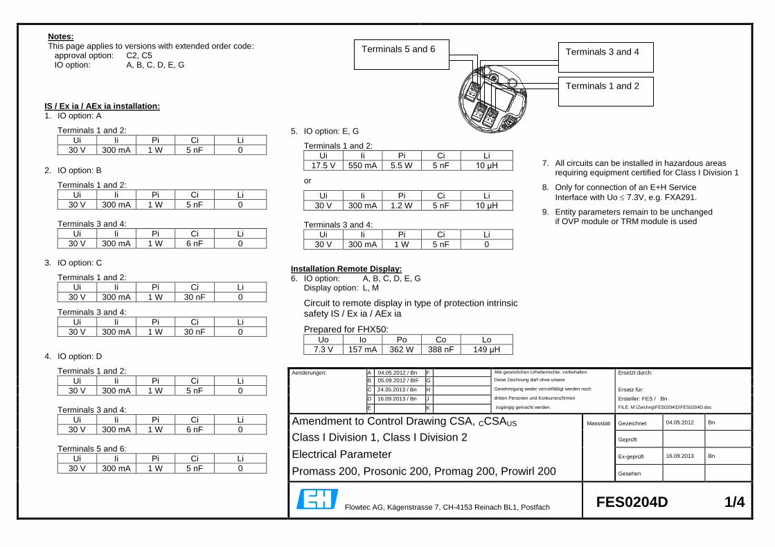
Aenderungen: A 04.05.2012 / Bn F Alle gesetzlichen Urheberrechte. vorbehalten. Ersetzt durch:
B 05.09.2012 / BIF G Diese Zeichnung darf ohne unsere
C 24.05.2013 / Bn H Genehmigung weder vervielfältigt werden noch Ersatz für:
D 16.09.2013 / Bn J dritten Personen und Konkurrenzfirmen Ersteller: FES / Bn
E K zugängig gemacht werden. FILE: M:\Zeichng\FES0204\D\FES0204D.doc
Amendment to Control Drawing CSA, CCSAUS Massstab Gezeichnet 04.05.2012 Bn
Class I Division 1, Class I Division 2 Geprüft
Electrical Parameter Ex-geprüft 16.09.2013 Bn
Promass 200, Prosonic 200, Promag 200, Prowirl 200 Gesehen
Flowtec AG, Kägenstrasse 7, CH-4153 Reinach BL1, Postfach FES0204D 1/4
IS / Ex ia / AEx ia installation: 1. IO option: A
Terminals 1 and 2:
Ui Ii Pi Ci Li
30 V 300 mA 1 W 5 nF 0
2. IO option: B
Terminals 1 and 2:
Ui Ii Pi Ci Li
30 V 300 mA 1 W 5 nF 0
Terminals 3 and 4:
Ui Ii Pi Ci Li
30 V 300 mA 1 W 6 nF 0
3. IO option: C
Terminals 1 and 2:
Ui Ii Pi Ci Li
30 V 300 mA 1 W 30 nF 0
Terminals 3 and 4:
Ui Ii Pi Ci Li
30 V 300 mA 1 W 30 nF 0
4. IO option: D
Terminals 1 and 2:
Ui Ii Pi Ci Li
30 V 300 mA 1 W 5 nF 0
Terminals 3 and 4:
Ui Ii Pi Ci Li
30 V 300 mA 1 W 6 nF 0
Terminals 5 and 6:
Ui Ii Pi Ci Li
30 V 300 mA 1 W 5 nF 0
Notes: This page applies to versions with extended order code: approval option: C2, C5 IO option: A, B, C, D, E, G
7. All circuits can be installed in hazardous areas
requiring equipment certified for Class I Division 1
8. Only for connection of an E+H Service
Interface with Uo 7.3V, e.g. FXA291.
9. Entity parameters remain to be unchanged if OVP module or TRM module is used
Terminals 3 and 4
Terminals 1 and 2
Terminals 5 and 6
5. IO option: E, G
Terminals 1 and 2:
Ui Ii Pi Ci Li
17.5 V 550 mA 5.5 W 5 nF 10 μH
or
Ui Ii Pi Ci Li
30 V 300 mA 1.2 W 5 nF 10 μH
Terminals 3 and 4:
Ui Ii Pi Ci Li
30 V 300 mA 1 W 5 nF 0
Installation Remote Display: 6. IO option: A, B, C, D, E, G Display option: L, M
Circuit to remote display in type of protection intrinsic safety IS / Ex ia / AEx ia
Prepared for FHX50: Uo Io Po Co Lo
7.3 V 157 mA 362 W 388 nF 149 μH
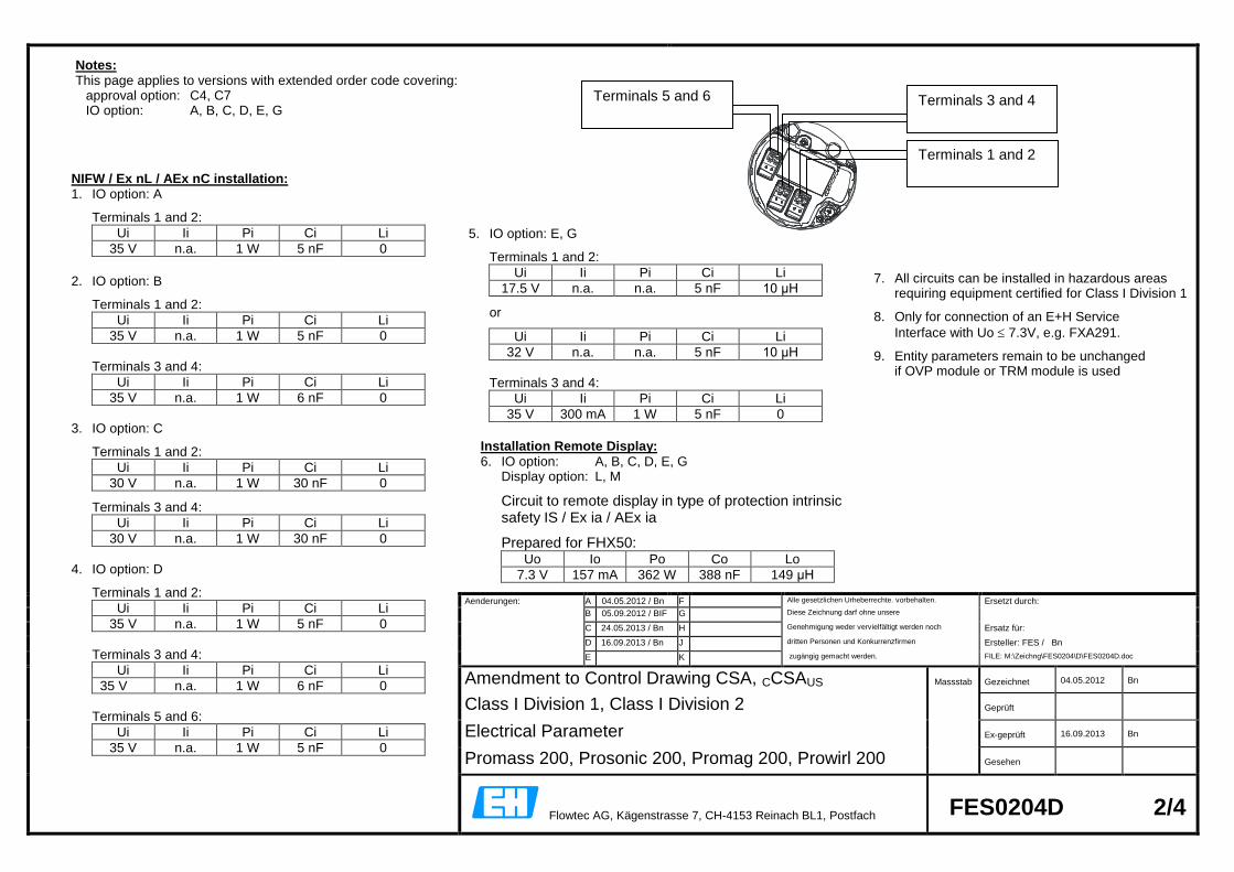
Aenderungen: A 04.05.2012 / Bn F Alle gesetzlichen Urheberrechte. vorbehalten. Ersetzt durch:
B 05.09.2012 / BIF G Diese Zeichnung darf ohne unsere
C 24.05.2013 / Bn H Genehmigung weder vervielfältigt werden noch Ersatz für:
D 16.09.2013 / Bn J dritten Personen und Konkurrenzfirmen Ersteller: FES / Bn
E K zugängig gemacht werden. FILE: M:\Zeichng\FES0204\D\FES0204D.doc
Amendment to Control Drawing CSA, CCSAUS Massstab Gezeichnet 04.05.2012 Bn
Class I Division 1, Class I Division 2 Geprüft
Electrical Parameter Ex-geprüft 16.09.2013 Bn
Promass 200, Prosonic 200, Promag 200, Prowirl 200 Gesehen
Flowtec AG, Kägenstrasse 7, CH-4153 Reinach BL1, Postfach FES0204D 2/4
NIFW / Ex nL / AEx nC installation: 1. IO option: A
Terminals 1 and 2:
Ui Ii Pi Ci Li
35 V n.a. 1 W 5 nF 0
2. IO option: B
Terminals 1 and 2:
Ui Ii Pi Ci Li
35 V n.a. 1 W 5 nF 0
Terminals 3 and 4:
Ui Ii Pi Ci Li
35 V n.a. 1 W 6 nF 0
3. IO option: C
Terminals 1 and 2:
Ui Ii Pi Ci Li
30 V n.a. 1 W 30 nF 0
Terminals 3 and 4:
Ui Ii Pi Ci Li
30 V n.a. 1 W 30 nF 0
4. IO option: D
Terminals 1 and 2:
Ui Ii Pi Ci Li
35 V n.a. 1 W 5 nF 0
Terminals 3 and 4:
Ui Ii Pi Ci Li
35 V n.a. 1 W 6 nF 0
Terminals 5 and 6:
Ui Ii Pi Ci Li
35 V n.a. 1 W 5 nF 0
Notes: This page applies to versions with extended order code covering: approval option: C4, C7 IO option: A, B, C, D, E, G
Terminals 3 and 4
Terminals 1 and 2
Terminals 5 and 6
5. IO option: E, G
Terminals 1 and 2:
Ui Ii Pi Ci Li
17.5 V n.a. n.a. 5 nF 10 μH
or
Ui Ii Pi Ci Li
32 V n.a. n.a. 5 nF 10 μH
Terminals 3 and 4:
Ui Ii Pi Ci Li
35 V 300 mA 1 W 5 nF 0
7. All circuits can be installed in hazardous areas
requiring equipment certified for Class I Division 1
8. Only for connection of an E+H Service
Interface with Uo 7.3V, e.g. FXA291.
9. Entity parameters remain to be unchanged if OVP module or TRM module is used
Installation Remote Display: 6. IO option: A, B, C, D, E, G Display option: L, M
Circuit to remote display in type of protection intrinsic safety IS / Ex ia / AEx ia
Prepared for FHX50: Uo Io Po Co Lo
7.3 V 157 mA 362 W 388 nF 149 μH
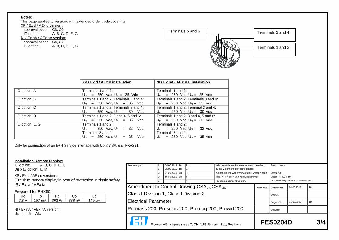
Aenderungen: A 04.05.2012 / Bn F Alle gesetzlichen Urheberrechte vorbehalten. Ersetzt durch:
B 05.09.2012 / BIF G Diese Zeichnung darf ohne unsere
C 24.05.2013 / Bn H Genehmigung weder vervielfältigt werden noch Ersatz für:
D 16.09.2013 / Bn J dritten Personen und Konkurrenzfirmen Ersteller: FES / Bn
E K zugängig gemacht werden. FILE: M:\Zeichng\FES0204\D\FES0204D.doc
Amendment to Control Drawing CSA, CCSAUS Massstab Gezeichnet 04.05.2012 Bn
Class I Division 1, Class I Division 2 Geprüft
Electrical Parameter Ex-geprüft 16.09.2013 Bn
Promass 200, Prosonic 200, Promag 200, Prowirl 200 Gesehen
Flowtec AG, Kägenstrasse 7, CH-4153 Reinach BL1, Postfach FES0204D 3/4
Notes: This page applies to versions with extended order code covering: XP / Ex d / AEx d version :
approval option: C3, C6 IO option: A, B, C, D, E, G
NI / Ex nA / AEx nA version: approval option: C4, C7 IO option: A, B, C, D, E, G
XP / Ex d / AEx d installation
NI / Ex nA / AEX nA installation
IO option: A Terminals 1 and 2: Um = 250 Vac, UN = 35 Vdc
Terminals 1 and 2: Um = 250 Vac, UN = 35 Vdc
IO option: B Terminals 1 and 2, Terminals 3 and 4: Um = 250 Vac, UN = 35 Vdc
Terminals 1 and 2, Terminals 3 and 4: Um = 250 Vac, UN = 35 Vdc
IO option: C Terminals 1 and 2, Terminals 3 and 4: Um = 250 Vac, UN = 30 Vdc
Terminals 1 and 2, Terminal 3 and 4: Um = 250 Vac, UN = 30 Vdc
IO option: D Terminals 1 and 2, 3 and 4, 5 and 6: Um = 250 Vac, UN = 35 Vdc
Terminals 1 and 2, 3 and 4, 5 and 6: Um = 250 Vac, UN = 35 Vdc
IO option: E, G Terminals 1 and 2: Um = 250 Vac, UN = 32 Vdc Terminals 3 and 4: Um = 250 Vac, UN = 35 Vdc
Terminals 1 and 2: Um = 250 Vac, UN = 32 Vdc Terminals 3 and 4: Um = 250 Vac, UN = 35 Vdc
Only for connection of an E+H Service Interface with Uo 7.3V, e.g. FXA291.
Terminals 3 and 4
Terminals 1 and 2
Terminals 5 and 6
Installation Remote Display: IO option: A, B, C, D, E, G Display option: L, M
XP / Ex d / AEx d version :
Circuit to remote display in type of protection intrinsic safety IS / Ex ia / AEx ia
Prepared for FHX50: Uo Io Po Co Lo
7.3 V 157 mA 362 W 388 nF 149 μH
NI / Ex nA / AEx nA version: UN = 5 Vdc
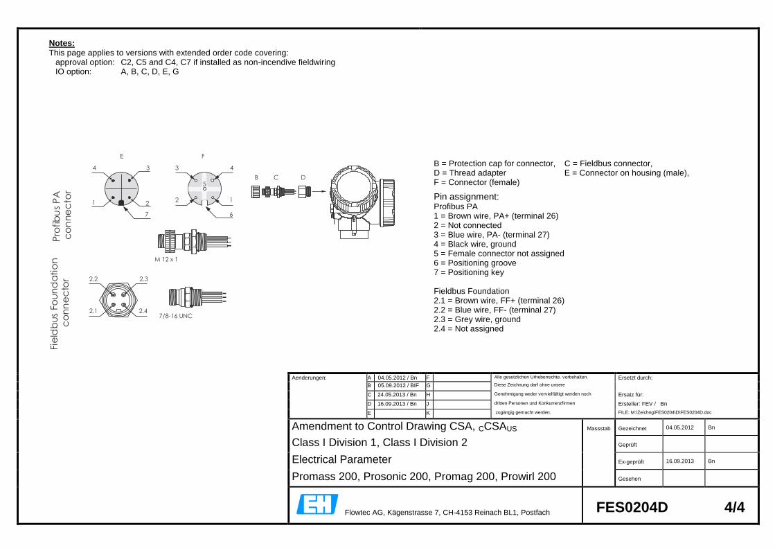
Aenderungen: A 04.05.2012 / Bn F Alle gesetzlichen Urheberrechte. vorbehalten. Ersetzt durch:
B 05.09.2012 / BIF G Diese Zeichnung darf ohne unsere
C 24.05.2013 / Bn H Genehmigung weder vervielfältigt werden noch Ersatz für:
D 16.09.2013 / Bn J dritten Personen und Konkurrenzfirmen Ersteller: FEV / Bn
E K zugängig gemacht werden. FILE: M:\Zeichng\FES0204\D\FES0204D.doc
Amendment to Control Drawing CSA, CCSAUS Massstab Gezeichnet 04.05.2012 Bn
Class I Division 1, Class I Division 2 Geprüft
Electrical Parameter Ex-geprüft 16.09.2013 Bn
Promass 200, Prosonic 200, Promag 200, Prowirl 200 Gesehen
Flowtec AG, Kägenstrasse 7, CH-4153 Reinach BL1, Postfach FES0204D 4/4
Notes: This page applies to versions with extended order code covering: approval option: C2, C5 and C4, C7 if installed as non-incendive fieldwiring IO option: A, B, C, D, E, G
B = Protection cap for connector, C = Fieldbus connector, D = Thread adapter E = Connector on housing (male), F = Connector (female)
Pin assignment: Profibus PA 1 = Brown wire, PA+ (terminal 26) 2 = Not connected 3 = Blue wire, PA- (terminal 27) 4 = Black wire, ground 5 = Female connector not assigned 6 = Positioning groove 7 = Positioning key Fieldbus Foundation 2.1 = Brown wire, FF+ (terminal 26) 2.2 = Blue wire, FF- (terminal 27) 2.3 = Grey wire, ground 2.4 = Not assigned
B C D
M 12 x 1
E F
4
1 2
3
7
3 4
2 1
5
6
Pro
fib
us
PA
co
nn
ec
tor
7/8-16 UNC
2.2 2.3
2.1 2.4
Fie
ldb
us
Fou
nd
ati
on
co
nn
ec
tor
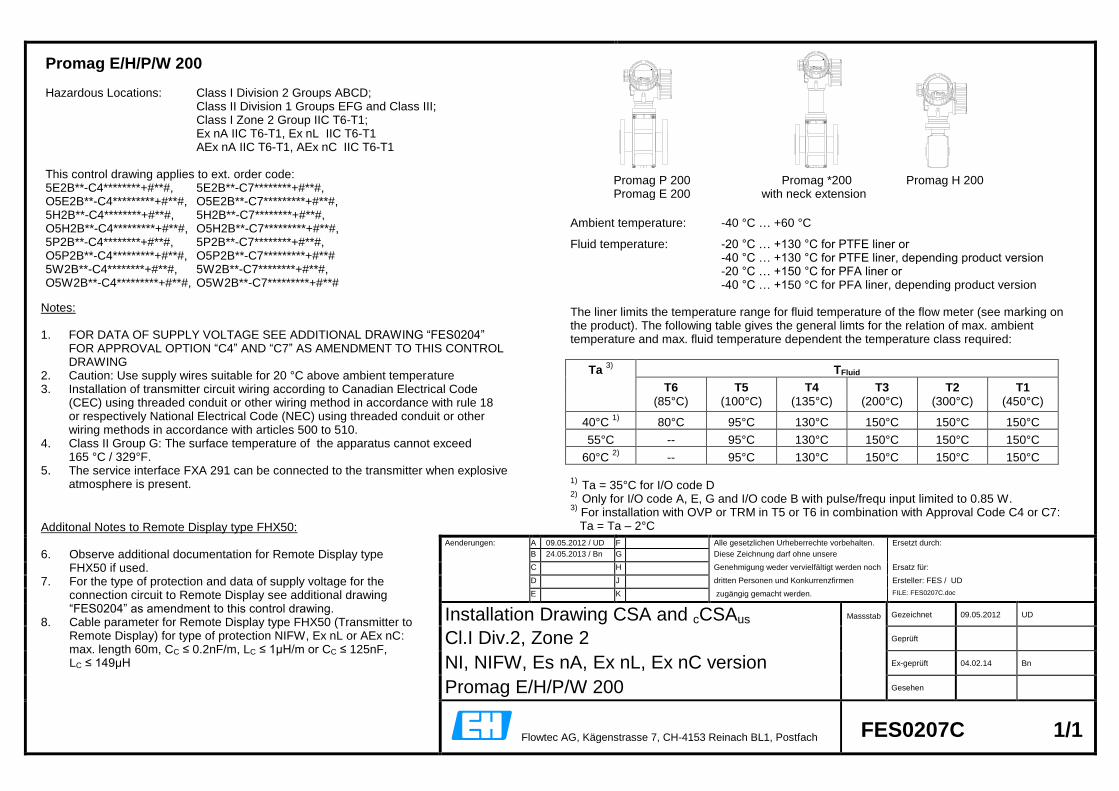
E
E
E
Aenderungen: A 09.05.2012 / UD F Alle gesetzlichen Urheberrechte vorbehalten. Ersetzt durch:
B 24.05.2013 / Bn G Diese Zeichnung darf ohne unsere
C H Genehmigung weder vervielfältigt werden noch Ersatz für:
D J dritten Personen und Konkurrenzfirmen Ersteller: FES / UD
E K zugängig gemacht werden. FILE: FES0207C.doc
Installation Drawing CSA and cCSAus Massstab Gezeichnet 09.05.2012 UD
Cl.I Div.2, Zone 2
Geprüft
NI, NIFW, Es nA, Ex nL, Ex nC version
Ex-geprüft 04.02.14 Bn
Promag E/H/P/W 200
Gesehen
Flowtec AG, Kägenstrasse 7, CH-4153 Reinach BL1, Postfach FES0207C 1/1
Notes: 1. FOR DATA OF SUPPLY VOLTAGE SEE ADDITIONAL DRAWING “FES0204”
FOR APPROVAL OPTION “C4” AND “C7” AS AMENDMENT TO THIS CONTROL DRAWING
2. Caution: Use supply wires suitable for 20 °C above ambient temperature 3. Installation of transmitter circuit wiring according to Canadian Electrical Code
(CEC) using threaded conduit or other wiring method in accordance with rule 18 or respectively National Electrical Code (NEC) using threaded conduit or other wiring methods in accordance with articles 500 to 510.
4. Class II Group G: The surface temperature of the apparatus cannot exceed 165 °C / 329°F.
5. The service interface FXA 291 can be connected to the transmitter when explosive atmosphere is present.
Promag E/H/P/W 200 Hazardous Locations: Class I Division 2 Groups ABCD; Class II Division 1 Groups EFG and Class III; Class I Zone 2 Group IIC T6-T1; Ex nA IIC T6-T1, Ex nL IIC T6-T1 AEx nA IIC T6-T1, AEx nC IIC T6-T1 This control drawing applies to ext. order code: 5E2B**-C4********+#**#, 5E2B**-C7********+#**#, O5E2B**-C4*********+#**#, O5E2B**-C7*********+#**#, 5H2B**-C4********+#**#, 5H2B**-C7********+#**#, O5H2B**-C4*********+#**#, O5H2B**-C7*********+#**#, 5P2B**-C4********+#**#, 5P2B**-C7********+#**#, O5P2B**-C4*********+#**#, O5P2B**-C7*********+#**# 5W2B**-C4********+#**#, 5W2B**-C7********+#**#, O5W2B**-C4*********+#**#, O5W2B**-C7*********+#**#
Ambient temperature: -40 °C … +60 °C
Fluid temperature: -20 °C … +130 °C for PTFE liner or -40 °C … +130 °C for PTFE liner, depending product version -20 °C … +150 °C for PFA liner or -40 °C … +150 °C for PFA liner, depending product version The liner limits the temperature range for fluid temperature of the flow meter (see marking on the product). The following table gives the general limts for the relation of max. ambient temperature and max. fluid temperature dependent the temperature class required:
Ta 3)
TFluid
T6 T5 T4 T3 T2 T1
(85°C) (100°C) (135°C) (200°C) (300°C) (450°C)
40°C 1)
80°C 95°C 130°C 150°C 150°C 150°C
55°C -- 95°C 130°C 150°C 150°C 150°C
60°C 2)
-- 95°C 130°C 150°C 150°C 150°C
1)
Ta = 35°C for I/O code D 2)
Only for I/O code A, E, G and I/O code B with pulse/frequ input limited to 0.85 W. 3)
For installation with OVP or TRM in T5 or T6 in combination with Approval Code C4 or C7: Ta = Ta – 2°C
Promag P 200 Promag *200 Promag H 200 Promag E 200 with neck extension
Additonal Notes to Remote Display type FHX50: 6. Observe additional documentation for Remote Display type
FHX50 if used. 7. For the type of protection and data of supply voltage for the
connection circuit to Remote Display see additional drawing “FES0204” as amendment to this control drawing.
8. Cable parameter for Remote Display type FHX50 (Transmitter to Remote Display) for type of protection NIFW, Ex nL or AEx nC: max. length 60m, CC ≤ 0.2nF/m, LC ≤ 1µH/m or CC ≤ 125nF, LC ≤ 149µH