Embed Size (px)
Citation preview

Hydraulics Manual M 23-03.07 Page 7-1 March 2022
7-1 Introduction This chapter covers the design requirements for water crossings on state highways over fish-bearing waters, in addition to HEC-18, HEC-20, and HEC-23 Volume 1 and Volume 2. See Chapter 3 for the design of non-fish-bearing culverts, and HEC-18, HEC-20, and HEC-23 Volume 1 and Volume 2 for the design of bridges over non-fish-bearing waters, unless local requirements dictate otherwise. Most rivers and creeks in Washington State contain one or more species of fish during all or part of the year. This chapter has been updated to reflect the requirements for fish passage crossings on WSDOT highways from current WAC Hydraulic Code Rules; the 2017 USACE, Seattle District, Nationwide Permit Regional Conditions; and the 2013 Federal Court Injunction for Fish Passage (Injunction). This chapter is specific to WSDOT projects. For non-WSDOT projects, it is up to the project owner to determine whether the guidance in this chapter is followed or other guidance is followed to obtain project permits and follow state law. WSDOT is actively monitoring completed fish passage projects and will update this chapter as new information becomes available. See Section 7-8 for more information.
All fish-bearing water crossings within Washington State must meet the requirements of WAC’s Hydraulic Code Rules and the requirements of the Hydraulics Manual, unless a deviation is approved by the HQ Hydraulics Section. In Water Resource Inventory Areas (WRIAs) 1 through 23, the design must also meet the requirements of the Injunction. This chapter uses WDFW’s 2013 Water Crossing Design Guidelines (WCDG) as reference. Other published manuals and guidelines may be used with the approval of the HQ Hydraulics Section and permitting agencies.
New bridges and fish-bearing culverts must be designed to meet current fish passage standards and WAC to ensure that they do not hinder fish use or migration. WAC requires a person to design water-crossing structures in fish-bearing streams to allow fish to move freely through them at all flows at which fish are expected to move.
WSDOT and WDFW have cooperated in a Fish Passage Barrier Removal Program since 1991. PEOs can check the WSDOT fish barrier database or contact the HQ Environmental Services Office biology branch to determine whether the project has any fish barriers within its limits and whether the crossing will need to be included as part of the project. WDFW also maintains a database of fish barriers statewide. All water crossings over fish-bearing waters shall be designed by the HQ Hydraulics Section or by an individual approved by the HQ Hydraulics Section (see Chapter 1).
Section 7-2 discusses requirements for assessing and documenting existing conditions to design a successful and fish-passable water crossing. Section 7-3 provides a discussion of hydraulic analyses required for the design, and Sections 7-4 and 7-5 discuss the design process, considerations, and criteria. Section 7-6 discusses the structure-free zone (SFZ). Section 7-7 provides guidance on temporary diversions, Section 7-8 describes the WSDOT monitoring process, and Section 7-9 presents a discussion of additional resources. Section 7-10 provides the appendices.
This chapter uses the term “stream designer(s)” to denote work that either the HQ Hydraulics Section or the individual approved by the HQ Hydraulics Section performs and to separate that work from the work that the PEO would do in the rest of the Hydraulics Manual. This chapter assumes that the stream designer has knowledge of WAC, WDFW’s 2013 WCDG, and hydrology and river hydraulics, and, as a result, does not cover every topic in thorough

Chapter 7 Water Crossings
Hydraulics Manual M 23-03.07 Page 7-2 March 2022
detail. This chapter outlines the process that the HQ Hydraulics Section follows in designing a stream crossing, and what is expected on WSDOT projects. These designs require a specialty report. Additional requirements about specialty reports are provided in Chapter 1. The template used by WSDOT can be found on WSDOT’s Hydraulics website along with training required to write a specialty report for a water crossing over fish-bearing waters.
A Fish Passage and Stream Restoration Design (FPSRD) Training certificate number is required for all authors of any portion of a specialty report. An FPSRD certificate number is given to those who have viewed all of the training modules and successfully passed the comprehensive exam. Additional information, training resources, and the point of contact for this training can be found on the WSDOT Training website.
7-2 Existing Conditions The first step to designing a water crossing is understanding the behavior of the existing system and identifying a reference reach. There is no comprehensive set of biological and physical predictive equations for stream restoration design. Therefore, a reference reach approach is needed. This approach in channel design uses a reference reach, which exhibits channel and habitat properties that are not highly altered from natural, background conditions. By mimicking the reference reach, the design channel will approach (though not duplicate) natural, pre-crossing stream behavior and habitat. A thorough investigation of the site and adjacent stream reach, its history, and any known problems should be performed prior to the field visit and confirmed during the field visit. Prior to the first field visit, the stream designer(s) should complete the following:
• Determine whether the project is within a FEMA-mapped floodplain • Evaluate the watershed conditions/land cover (past, current, and future) • Investigate the type of soils that are in the watershed • Look at historical aerial photographs for evidence of channel migration, avulsion, debris
flows, sediment pulses, LWM interactions, significant erosion, etc. • Discuss site history with WSDOT area maintenance, specifically noting quantities of
dredging, if available, scour repairs, and flooding • Review any available survey data and available historical as-builts • Confirm pre-field visit investigations and conclusions or document differences • Review any available watershed studies, watershed analyses, hydrology/drainage
studies, reach assessments, sediment budget, transport investigations, etc. • Review aerial photographs, topographic and survey maps, and previous watershed
analyses for potential reference reach locations
Through site visits, the stream designer will perform the following: • Determine the reference reach • Measure bankfull width (BFW) • Determine sediment size using either a Wolman pebble count or a grab sample
(as appropriate) • Investigate channel geometry • Note any channel-forming features • Note the presence and function of LWM • Note the presence and function of large cobbles or boulders

Chapter 7 Water Crossings
Hydraulics Manual M 23-03.07 Page 7-3 March 2022
Multiple site visits may be required, both before and after the survey has taken place, to ensure that all the necessary features are surveyed. The stream designer will benefit by reviewing the survey request in the field with the survey crew. The information listed above shall be photographed or otherwise recorded for report documentation and design discussions. The stream designer shall coordinate with the PEO for the attendance of the resource agencies and interested tribes during the reference reach selection and BFW determination.
Reference Reach The following process outlines several steps for locating the best reference reach possible while recognizing that many streams near roadway crossings are modified by human processes and thus are not perfect natural analogs. If a system is highly modified, contact the HQ Hydraulics Section for additional guidance. Figure 7-1 depicts a flow chart that describes the steps below that shall be completed by a multi-disciplinary team consisting of a hydraulics engineer, geomorphologist, and a biologist.
Examine the reaches with project stakeholders immediately upstream and downstream from the project reach and evaluate the following:
1. Does the average stream gradient change significantly between upstream and downstream?
2. Are there signs of significant erosion or deposition?
3. Are there any constructed features within the active channel? Within the floodplain?
4. Are there any sudden changes in sediment size distribution?
In evaluating the project reach for the above points, the stream designer is trying to determine whether the morphological attributes (gradient, confinement, planform, shape, bed materials, etc.) of the reach reflect what would be expected in the vicinity of the site, and how/to what extent these attributes are modified by artificial features, constraints, or conditions.
Significant changes in gradient are an indication that sediment supply may be a concern, or that the crossing is in a transition zone, etc. Large amounts of deposition or erosion have an impact on the overall channel slope and shape that may not be sustainable in the long term. Constructed features within the channel and/or floodplain such as riprap, piers, foundations, levees, or mechanically altered channels could cause the reach to not reflect what the channel would look like under natural conditions. However, if the channel is mechanically altered, the channel shape shall be mimicked; in these instances, contact the HQ Hydraulics Section for additional guidance.
If the answer to any of the above questions is yes, proceed to Section 7-2.1.2. If the answers to all of the above questions are no, proceed to Section 7-2.1.3.

Chapter 7 Water Crossings
Hydraulics Manual M 23-03.07 Page 7-4 March 2022
If the adjacent reach is not representative, an appropriate watershed reference reach will need to be located. Locate the watershed reference reach using the following steps:
1. Examine a topographic map at the 1:24,000 scale (or finer) for reaches farther upstream and downstream of the culvert reach with similar slope, watershed characteristics, and channel confinement.
2. When a new reach with similar slope, watershed characteristics, and channel confinement is identified, determine the size of the contributing watershed area. Is it similar (+/-20 percent) to the contributing area above the project reach?
If the reach meets criteria in item 2 above, go to Section 7-2.1.3. If it does not, look to adjacent watersheds with similar aspect, elevation, levels of development, and geology and follow the procedures in Step A for the location identified.
After locating an appropriate reference reach, collect data for the specialty report. At a minimum, collect the following information:
• Stage of channel evolution at the project reach • Water surface slope during non-flood event • Channel sinuosity and radius of curvature • Presence and residual depth of pools • BFW in at least three representative locations; compare to those measured at project
reach • Pebble counts or grab samples in at least three locations on riffles or pool tailouts
(Wolman 1954) • Note riparian zone vegetation, canopy density • Note presence and function (or absence) of LWM, especially key pieces (see Chapter
10) • Record geographic coordinates of reference reach • Note anthropogenic impacts to the reach

Chapter 7 Water Crossings
Hydraulics Manual M 23-03.07 Page 7-5 March 2022
If it is determined that a constraint is present requiring a design reference reach, contact the HQ Hydraulics Section for concurrence requirements for the use of a design reference reach.
Figure 7-1 Reference Reach Determination
Bankfull Width BFW is the most effective channel-forming flood with a recurrence interval seldom greater than the 2-year flood in undisturbed channels. The bankfull discharge may be greater than the 2-year flood for incised channels. Bankfull discharge occurs at the maximum product of flow frequency and sediment transport. Bankfull discharge may be exceeded multiple times within a given year. This may occur in a single event, or it might occur in different isolated events (Anderson et al. 2016).
An accurate BFW is critical. Appendix C of WDFW’s 2013 WCDG is a useful reference in determining an appropriate BFW. A minimum of three measurements shall be used when computing the average BFW. Measure widths that describe prevailing conditions at straight channel sections and outside the influence of any culvert, bridge, or other artificial or unique channel constriction (WAC 220-660-190).

Chapter 7 Water Crossings
Hydraulics Manual M 23-03.07 Page 7-6 March 2022
If there are significant differences between measured and modeled BFW, further evaluation or justification will be required. The designer shall verify that the channel hydrology is correct to the best of their knowledge, verify that the Manning’s n values are appropriate for the crossing, and use engineering judgment as appropriate to ensure that the hydraulic model is accurate, and any differences are explained. Sites that are not typical should be discussed with the tribe(s) and WDFW to come to an early understanding of the channel behavior.
In cases where BFW cannot be measured, the 2-year top width may serve as an estimate for BFW to be used for structure sizing in confined systems where the 2-year top width does not spill onto a floodplain. Proposed channel width in these cases should follow the process described in Section 7-4.3.
WDFW has created a regression equation used for estimating BFW that is provided in Appendix C of the 2013 WCDG and shall be used only as a check to determine what a reasonable measurement is on streams within the limitations of that equation. Additional guidance will be provided in future revisions to the Hydraulics Manual.
It is not always evident where the influence of an undersized structure ends. On a low-gradient system that has a high headwater at the crossing, the backwater during high flow events can extend upstream for hundreds of feet and result in an artificially wide BFW measurement. Once the existing-conditions model is created the bankfull measurement locations should be checked to confirm that they are outside the influence of the existing structure. If the BFW measurements are determined to be within the influence of the structure, additional site visits are required for reevaluating BFW measurements.
Watershed and Land Cover Understanding the past, current, and potential future conditions of a watershed is important for the long-term success of a project.
Historical and current aerial photographs should be examined to determine what type of land cover the watershed has now and how that has changed over time. Verifying whether the system is in an urban setting, within an urban growth area, or in an active forest will also help determine what the land cover could look like in the future and may increase the design flows expected during the design life and create the need for a larger structure. Understanding how the watershed has changed over time will help the stream designer create a successful crossing.
If a watershed has a high potential for future forest fires or has been recently affected by a forest fire, this shall be documented and taken into consideration when determining the final structure size.
Geology and Soils The soil types in the drainage basin not only assist the stream designer in understanding what is happening at the crossing, but also can impact the calculated hydrology at the site location if a continuous-simulation method, such as MGSFlood, is used to determine flow rates.
The surrounding geology will have an impact on channel migration and may influence where a new crossing is placed. It may also influence sediment load and size distribution in the channel. Generalized soil types may be found in soil surveys produced by NRCS. Surficial geology maps are also useful in determining soil information.

Chapter 7 Water Crossings
Hydraulics Manual M 23-03.07 Page 7-7 March 2022
Fluvial Geomorphology Fluvial geomorphology is an integral part of determining where the crossing should be placed, how the stream or river should be aligned, and where the stream or river may end up in the future and is a primary determinant of the appropriate design of the channel. The channel should be examined to determine if there are signs of lateral and vertical stability or instability and how the stream may be impacted in the future. Delineation of channel migration zones should be investigated (and may be required by local jurisdictions). The potential for channel avulsion should also be assessed.
Streams have often been straightened or moved, resulting in shorter crossings that are perpendicular to the roadway. Roadway as-builts and old ROW plans are good sources for determining what the crossing looked like prior to roadway construction. Old aerial photographs may give a good indication of the channel alignment over time, depending on tree cover. LiDAR, if available, is also a good resource to provide insight into general down-valley slopes and helps identify grade breaks beyond the limits of the survey. LiDAR can also identify relic channel features, such as side channels, scroll bars, avulsions, and alluvial fans.
Many WSDOT roads were built at the edge of stream and river valleys. As a result, it is not uncommon for the reach through the roadway prism to be within a transition zone between an upstream reach and a downstream reach. This often leads to a historical slope that is steeper than the adjacent reaches. Culvert crossings at roadways can serve as grade controls, which have been in place in some instances for many years and may have had an effect on the channel upstream and downstream of the crossing. Having a good understanding of sediment supply and general transport regime with and without the existing crossing within the system is important in determining the long-term potential for channel slope change over time.
The channel slope and changes in the channel slope should be documented, both in the reference reach and near the culvert. These slopes shall be measured in the field or determined by survey data.
The channel shape, changes in vegetation, cross-section break lines, and other well-defined features should be noted, as well as any low flow paths. It is important to verify that the survey matches what is in the field and represents the natural conditions in the hydraulic modeling.
When assessing a stream reach ahead of a construction activity (such as fish passage barrier correction or channel realignment), it is important to understand the history and processes affecting the stream’s longitudinal profile. Events such as forest clearing, loss of instream wood, dams, beaver removal, urbanization, changes in peak flows, and uplift, along with other factors can have and have had a major impact on the overall stability of streams in the Pacific Northwest. Processes taking place at different time scales (geologic versus human) and spatial scales (watershed versus reach versus site) could affect the project’s success. Identifying and understanding causal factors and related stream adjustments are necessary when designing robust and resilient instream projects, and should be part of any engineering design analysis (Skidmore et al. 2011).

Chapter 7 Water Crossings
Hydraulics Manual M 23-03.07 Page 7-8 March 2022
The “goal” of a river is to move sediment, debris, and water at a minimal expense of energy. To this end, the stream will smooth the longitudinal (or simply “long”) profile as much as possible. The long profile shape (usually concave downward) reflects the adjustment of the river to (1) the climate of the watershed (current and past), which controls the amount of runoff; (2) the tectonic setting of the watershed, which controls its overall relief as well as changes in base level; and (3) the geology of the watershed, which controls sediment supply and the bedrock’s resistance to erosion.
Tectonic activity and climate are not static phenomena, and bedrock is spatially variable. In addition, it takes time for a river to complete the job of adjusting its profile to these independent variables. Because of this, longitudinal profiles are in constant readjustment or dynamic equilibrium, never quite catching up to the changes that affect them (Mount 1995). Under natural, background conditions, the longitudinal profile of a river is in slow, constant adjustment to watershed conditions. Profiles are convex downward in shape with a steep gradient at the head and a low gradient at the mouth. Variations in the shape of profiles reflect the response of the river to the overall tectonic, climatic, geologic, and base level conditions. Changes in these conditions can produce regional shifts in profiles involving widespread river aggradation or incision to reestablish the ideal shape.
Rivers are constantly adjusting to local perturbations in their profile. These disruptions, known as knickpoints or headcuts, usually consist of a long, low-gradient reach that abruptly gives way to a relatively short, steep-gradient reach, with the “knick” occurring at the change in gradient. The asymmetric shape of most knickpoints reflects a river’s attempt to smooth its profile (

Chapter 7 Water Crossings
Hydraulics Manual M 23-03.07 Page 7-9 March 2022
Figure 7-2). The high-gradient portion immediately downstream of the headcut has a correspondingly high competence or stream power. Thus the face of the knickpoint is likely to undergo headward erosion. In contrast, the low-gradient reach immediately upstream of the headcut has low competence, leading to sediment accumulation. In the ideal case, the ponding of sediment upstream and erosion of sediment downstream leads to an upstream migration and eventual removal of the knickpoint.
Culverts that are replaced to provide fish passage often have served as grade control for 50 to 100 years. Removal and/or replacement of these grade control structures can set off a cascade of effects that negatively impact the habitat and passage that a project seeks to improve if the design does not account for the stability of the system. This instability can cause floodplain disconnection, loss of backwater and side channel habitat, increased levels of turbidity, and channel (and thus habitat) simplification. Evaluation of both the stage of stream evolution and a longitudinal profile analysis can help determine if morphologic grade control (Castro and Beavers 2016) is warranted, and if so, what type of structure is most geomorphically appropriate. Potential structures include placement of large wood and roughness elements, constructed riffles, step-pools, and cascades.

Chapter 7 Water Crossings
Hydraulics Manual M 23-03.07 Page 7-10 March 2022
Figure 7-2 Idealized Knickpoint Evolution (Mount 1995)
Vertical stream stability shall be evaluated and documented in the specialty report for all WSDOT road/stream crossings to determine if morphologic grade control is necessary, if additional freeboard due to aggradation risk is required, and to estimate the long-term degradation component of scour. Additional guidance on procedure and considerations for vertical stability will be provided in later iterations of this Hydraulics Manual. The stream designer shall contact the HQ Hydraulics Section at the beginning of a project to determine if supplemental guidance is available for vertical stability.

Chapter 7 Water Crossings
Hydraulics Manual M 23-03.07 Page 7-11 March 2022
Understanding how a stream interacts with its floodplain is important in understanding geomorphic processes as well as what potential impacts a change to the system can have on adjacent land and/or infrastructure. In cases where the crossing is within a FEMA special flood hazard area (SFHA), the understanding is also a regulatory one. All stream projects, regardless whether they are in a FEMA SFHA, shall assess the impacts of the project on adjacent lands and communicate those changes to the region. Projects within a FEMA SFHA have additional requirements. The changes to adjacent floodplains shall be documented in the specialty report. This process can be lengthy and add significant time to a project, so early coordination is critical.
WSDOT Fish Passage Projects For all WSDOT fish passage projects, the process for flood risk assessment is described in the WSDOT Environmental Manual. If the stream designer has questions about the process, contact the HQ Hydraulics Section.
All Other Projects This section describes flood risk assessment for all other projects.
For projects that are not in FEMA SFHA, a comparison of the water surface depths between existing and proposed conditions under a 100-year event shall be shown in the specialty report and any impacts shall be discussed. Enough detail shall be provided in the specialty report to ensure that the PEO has the information necessary to discuss any changes with the local floodplain regulator and/or adjacent property owners. This information shall be provided in the preliminary version of the specialty report.
When a project is within a FEMA SFHA, the crossing shall be evaluated to determine whether there are impacts to the base flood elevation (BFE) and the FEMA effective hydraulic model will need to be requested. Impacts on the BFEs are only a concern if there is any encroachment within the FEMA floodway. If the floodway can be avoided, impacts to the BFEs from floodplain encroachment are not a problem (w.r.t. FEMA regulations). Contact the HQ Hydraulics Section for the necessary steps for assessing the floodplain and to assist in the FEMA model request unless a contract gives other specific requirements.
A description of any past channel migration and potential future channel migration shall be documented in the specialty report. LiDAR and past aerial photographs should be used to determine where the channel has been in the past, if available. If a channel is expected to migrate, a meander amplitude assessment may be necessary. See Section 7-4.4.4 for more detail.
LWM within the reference reach and near the crossing shall be documented, as well as the potential for future LWM recruitment. The channel type (Montgomery and Buffington 1993) and any key features such as LWM, boulders, and bedrock outcrops that are creating channel complexity or influencing channel alignment shall be noted as well as the capability of the system to move wood if future conditions provide a stream buffer that could recruit LWM.

Chapter 7 Water Crossings
Hydraulics Manual M 23-03.07 Page 7-12 March 2022
Sediment size in the reference reach is determined through Wolman pebble counts or grab samples, depending on the size of the streambed material. If a grab sample is used, the sample size needs to be large enough to produce accurate results. Guidance on sample size is provided in scientific literature.
The sediment sampled should be within the reference reach and a minimum of three samples is required. Note any large, naturally occurring material that is on site and include the notation within the design documentation. In some cases, large, unnatural material or large deposits not transported by the current flow regime may be shaping the current stream conditions including elements from previous or upstream streambank stabilization and scour protection efforts. While it may not be accurate to include this angular rock or other streambank-stabilizing material in the pebble counts, making note of it may be useful for understanding the reach conditions and what the stream is capable of mobilizing.
Understanding the sediment supply in the system is critical to being able to determine the correct size material to be placed back into the stream. If a system is sediment starved, it may be necessary to provide material that is coarser than the adjacent reaches to avoid channel incision. If a system has a healthy sediment supply, it may make sense to place material that is mobile and matches the sediment in the adjacent reach.
Where there is a natural streambed armor layer on the surface of the streambed, in addition to pebble counts, a sub-layer sample shall be used to capture the sediment size below the armored layer (see Section 7-4.7.3). For WSDOT projects, sampling below the ordinary high water level (OHWL) is allowed under General Hydraulic Project Approval. Work within the wetted perimeter may occur only during the periods authorized in the APP ID 21036 titled “Allowable Freshwater Work Times, May 2018.” Work outside of the wetted perimeter may occur year round. For more information see the APPS website.
Samples collected below the OHWL must be documented in the current Hydraulics Field Report.
Hydrology If the hydrology at a site is estimated incorrectly, this can lead to underestimating or overestimating the required size for the structure’s span, incorrect scour elevations and depth estimates, incorrect channel shape, and incorrect LWM sizing and anchoring requirements.
Additional information about hydrology is provided in Chapter 2. Justification for the chosen methodology being the most appropriate is required for all projects, including if the USGS regression equation is used. In many instances, the USGS regression equation may be the best available information, but this shall be confirmed through modeling, site conditions, maintenance history, and engineering judgment. The standard error for the USGS regression equation is quite high in some areas and it may be necessary to adjust the flows based on these standard errors. Other methodologies, such as the basin transfer method or HSPF, may be more appropriate. In urban areas, hydrology models that include future buildout conditions may be available for use.
Chapter 7 Water Crossings
Hydraulics Manual M 23-03.07 Page 7-13 March 2022
7-3 Hydraulic Analysis Model outputs are required as part of the specialty report and must be used to verify that the minimum proposed structure size meets the appropriate WACs, WDFW’s 2013 WCDG, and this chapter. WSDOT requires the use of SRH-2D unless otherwise approved by the HQ Hydraulics Section. For a FEMA No-Rise assessment, Conditional Letter of Map Revision (CLOMR), or Letter of Map Revision (LOMR), the model required by the local floodplain manager is acceptable for the analysis; however, an SRH 2-D model is still required for the crossing design. FHWA has developed a reference document for two-dimensional hydraulic models called 2D Hydraulic Modeling for Highways in the River Environment.
7-4 Design All WSDOT crossings for fish-bearing waters must meet WAC 220-660, at a minimum. In WRIAs 1 through 23, the design must also meet the requirements of the Injunction.
The process that is required for WSDOT design projects is described in the sections that follow and summarized in Appendix 7B. These sections only cover the Bridge Design and Stream Simulation Design methods; other methods may be appropriate but must be approved by the HQ Hydraulics Section prior to use.
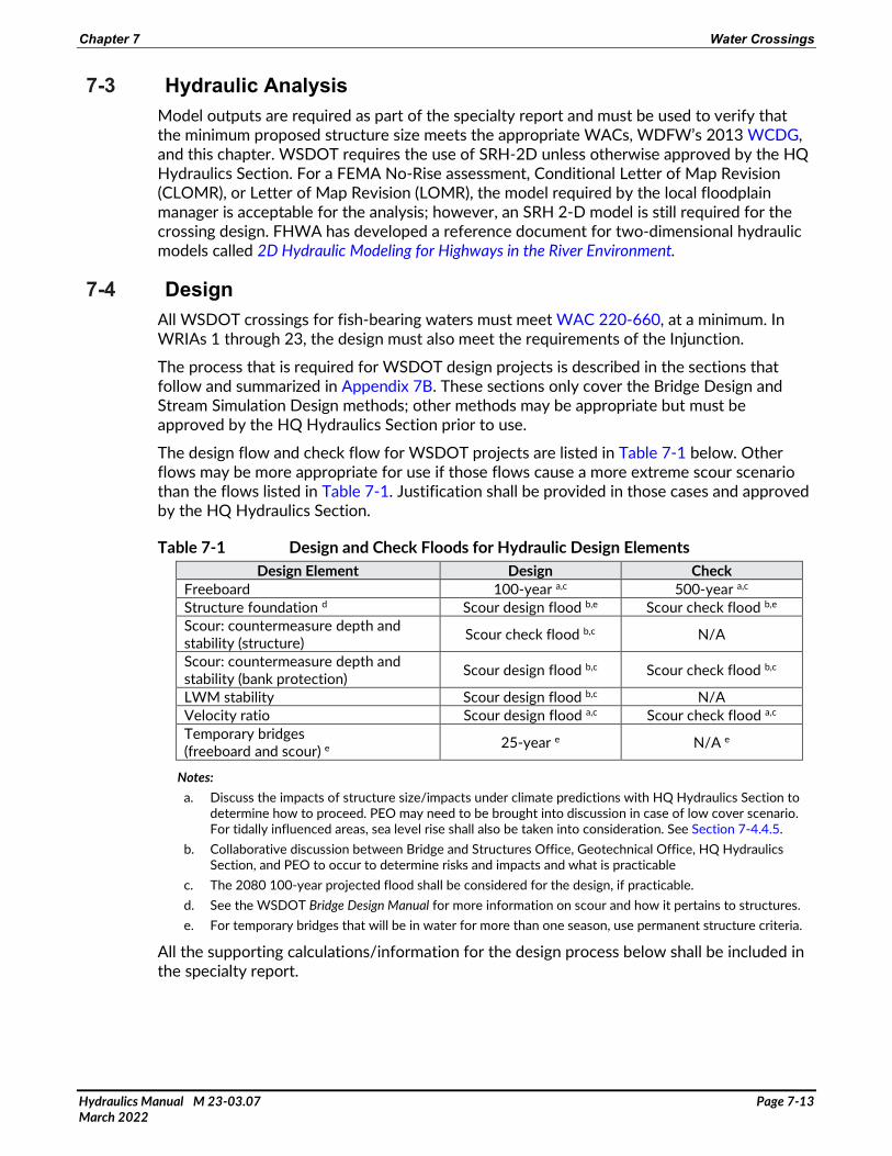
The design flow and check flow for WSDOT projects are listed in Table 7-1 below. Other flows may be more appropriate for use if those flows cause a more extreme scour scenario than the flows listed in Table 7-1. Justification shall be provided in those cases and approved by the HQ Hydraulics Section.
Table 7-1 Design and Check Floods for Hydraulic Design Elements Design Element Design Check
Freeboard 100-year a,c 500-year a,c Structure foundation d Scour design flood b,e Scour check flood b,e Scour: countermeasure depth and stability (structure) Scour check flood b,c N/A
Scour: countermeasure depth and stability (bank protection) Scour design flood b,c Scour check flood b,c
LWM stability Scour design flood b,c N/A Velocity ratio Scour design flood a,c Scour check flood a,c Temporary bridges (freeboard and scour) e 25-year e N/A e
Notes: a. Discuss the impacts of structure size/impacts under climate predictions with HQ Hydraulics Section to
determine how to proceed. PEO may need to be brought into discussion in case of low cover scenario. For tidally influenced areas, sea level rise shall also be taken into consideration. See Section 7-4.4.5.
b. Collaborative discussion between Bridge and Structures Office, Geotechnical Office, HQ Hydraulics Section, and PEO to occur to determine risks and impacts and what is practicable
c. The 2080 100-year projected flood shall be considered for the design, if practicable. d. See the WSDOT Bridge Design Manual for more information on scour and how it pertains to structures. e. For temporary bridges that will be in water for more than one season, use permanent structure criteria.
All the supporting calculations/information for the design process below shall be included in the specialty report.

Chapter 7 Water Crossings
Hydraulics Manual M 23-03.07 Page 7-14 March 2022
Constraints Constraints are infrastructure or land ownership issues that interfere with natural stream processes and need to be identified as soon as possible. Constraints can be both constructed and natural and, when encountered, should be discussed with resource agencies, tribes, and stakeholders early in the design process to prevent project delays in the future if not all parties agree on whether a constraint exists or may be resolvable within the scope of a project. There may be design constraints other than those covered in this section.
Infrastructure can include adjacent culverts/bridges, pipelines, buildings, water intakes/diversions, groundwater wells, and roadways as well as other infrastructure types not listed here. Infrastructure that is a design constraint can be owned by WSDOT or by other parties.
Environmental impacts should be considered when completing a stream design. If meeting the design methodology causes a large environmental footprint (i.e., if a roadway that needs to be raised next to a wetland or stream grading would need to be extended for a great distance), discussions with WDFW and the tribes should occur to determine the best design to move forward and whether mitigation (formal or informal) may be used in lieu of meeting requirements/recommendations.
Many culverts have been in place for a long time and the stream has adapted around them. Culverts may have been historically placed at a grade break in the channel that is dissimilar to the upstream and downstream reaches. If there is a large grade separation between the upstream reach and the downstream reach, it may be necessary to allow for a natural channel regrade, or to produce a steeper reach with an overcoarsened channel. As much information as possible should be obtained about historical conditions and the cause of the grade break and discussions with WDFW and the tribes should occur to determine the best solution for the project.
Impacts to cultural resources should be considered when completing a stream design. If meeting the requirements and recommendations for the project would have an impact on cultural resources, WDFW and the tribes should be consulted to determine the way to proceed.
Channel Alignment It is not always possible to cross a roadway at an ideal angle or avoid sharp bends leading into or out of a structure. The total length of a covered stream should be considered and the maximum angle of a bridge structure to the centerline of a roadway per the Bridge Design Manual, if a bridge structure is used. While the HQ Hydraulics Section does not recommend a structure type or layout, it is important for the stream designer to know what this constraint is and keep it in mind while designing the layout to make an efficient crossing. As a result of the crossing angle, if armoring is determined to be necessary, see Section 7-4.11.
Channel sinuosity and curve radii must match what would be expected in the reference reach, and a channel must not be artificially lengthened by increasing sinuosity beyond what would be expected to decrease slope. Meanders extended unnaturally to obtain length will
Chapter 7 Water Crossings
Hydraulics Manual M 23-03.07 Page 7-15 March 2022
not be stable. Conversely, channel sinuosity must not be unreasonably reduced or eliminated in the interest of shortening the structure span.
If a channel needs to be realigned, it must be done so in a way that does not increase the slope significantly or create an erosion risk. In the case of slope, WSDOT uses the stream simulation recommendation from WDFW’s 2013 WCDG of a slope no steeper than 125 percent of the upstream reach (or downstream if it is determined that the downstream reach is more appropriate). In systems where the slope is low gradient (i.e., less than 1 percent), exceeding the slope limit while still meeting this criterion may be permissible but must be approved by the HQ Hydraulics Section. If it is not practicable to meet the slope constraint, approval by the HQ Hydraulics Section is required.
If allowing for natural regrade is determined to be desirable, the stream designer must evaluate the long-term degradation, scour, potential equilibrium slopes, and whether a larger structure will be required as a result of the channel regrade. Channel migration during the process of the regrade should be considered and appropriate countermeasures must be implemented to protect banks from destabilization as a result of construction. Refer to Chapter 4 for additional guidance.
If regrade is determined not to be desirable, the reach must be designed to be stable. This may cause the project to be permitted as a fish passage improvement structure (see Section 7-5.2) and require long-term maintenance and monitoring. Additionally, extra consideration should be given to bank integrity for these systems to help the water body dissipate energy. The streambed material decision tree found in Appendix 7A may help the stream designer determine whether to allow for channel regrade.
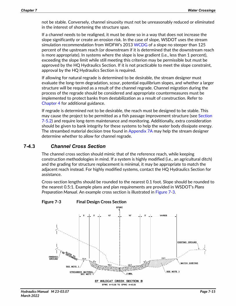
Channel Cross Section The channel cross section should mimic that of the reference reach, while keeping construction methodologies in mind. If a system is highly modified (i.e., an agricultural ditch) and the grading for structure replacement is minimal, it may be appropriate to match the adjacent reach instead. For highly modified systems, contact the HQ Hydraulics Section for assistance.
Cross-section lengths should be rounded to the nearest 0.1 foot. Slope should be rounded to the nearest 0.5:1. Example plans and plan requirements are provided in WSDOT’s Plans Preparation Manual. An example cross section is illustrated in Figure 7-3.
Figure 7-3 Final Design Cross Section

Chapter 7 Water Crossings
Hydraulics Manual M 23-03.07 Page 7-16 March 2022
Flows within the channel cross section must mimic those in the reference reach. For example, if the active channel is overtopped at less than a 2-year event, the channel should behave the same through the design reach.
Hydraulic Width For the purposes of this chapter, the minimum structure width required by the specialty report and the total height defined by minimum low chord elevation and scour elevation is defined as the minimum hydraulic opening. This section covers the width portion of the definition. Freeboard is covered in Section 7-4.5 and scour is covered in Section 7-4.8. The final SFZ determination made by region in conjunction with the Bridge and Structures Office shall be, at minimum, the established minimum hydraulic opening, but may be larger to include contextual needs. Any required scour countermeasure shall not encroach within the hydraulic opening and shall be set back horizontally far enough to establish planting (see Section 7-4.11).
For preliminary plans, prior to the structure type being known, 2:1 cut slopes with a note that “grading limits to be based on final structure size, type and location” shall be shown unless it is known that the structure will be buried. This lets the reviewers know that the structure type is undetermined while showing the potential impact areas. Cross sections should clearly depict where the minimum opening is, as shown in Figure 7-4.
Figure 7-4 Minimum Hydraulic Opening
There are three methods for determining the minimum hydraulic width: (1) stream simulation, (2) confined bridge, and (3) unconfined bridge. However, the process used for confined bridge is the same as that used for stream simulation. All methods are dependent on the floodplain utilization ration (FUR), which determines how confined a stream is. The minimum hydraulic width shall not be less than the greater of Equation 7-1 (2013 WCDG, Equation 3.2) or Equation 7-2, unless otherwise approved by the HQ Hydraulics Section.
WHYO = 1.2*Wbf + 2 feet (7-1)
WHYO = 1.3*Wbf (7-2)
Where WHYO= width of hydraulic opening Wbf= BFW

Chapter 7 Water Crossings
Hydraulics Manual M 23-03.07 Page 7-17 March 2022
The minimum hydraulic width is to be taken vertically through the entire structure. If a round or arch structure is used, additional width/height may be necessary to maintain the opening through the anticipated scour/required freeboard, as depicted in the SFZ Plans (see Standard Plans [WSDOT 2021d]).
The FUR needs to be calculated using existing conditions. The FUR is the width of the floodplain relative to the main channel. To determine the FUR for WSDOT designs, compare the 100-year water surface width from the model output to either the available BFW information or, if BFW is not available, the 2-year top width. To determine what the FUR is through the upstream reach, the existing structure shall be removed from the model.
A FUR larger than 3.0 is considered an unconfined system, while a FUR less than 3.0 is considered confined. If the system is unconfined, the unconfined bridge design method applies. If the system is confined, either the confined bridge design method or the stream simulation design method applies. More explanation of the FUR is provided in the 2013 WCDG. For areas that are tidally influenced, see Section 7-4.4.5.
An unconfined system has a FUR of greater than 3.0. In these situations, the velocity ratio, which is defined as the average main channel velocity through the structure divided by the average main channel velocity immediately upstream of the structure if the roadway fill were to be removed entirely, is used to determine minimum hydraulic width. In cases where a crossing has a FUR very close to 3.0 the velocity ratio shall be verified to meet the design criteria. The main channel is the section of the channel where sediment is expected to be mobilized during the design flow event and does not include the overbank areas. The velocity ratio shall be close to 1, which means that the ratio when rounded to the nearest tenth shall be 1.1 or less at the 100-year event. In some low velocity cases, a ratio of more than 1.1 may be allowable if the increase in velocity ratio does not result in bed coarsening, increased scour, significantly increased backwater, or negative biological/geomorphological effects. The HQ Hydraulics Section must approve in these instances.
If an existing structure is being replaced by a new structure, a velocity ratio of more than 1.1 may be acceptable. In this case, the existing structure should not have evidence of significant erosion, scour, or other performance issues. The HQ Hydraulics Section must approve in these instances.
For preliminary design, the stream designer is to assume vertical walls for the edge of structure while determining the minimum hydraulic opening in the hydraulic model. Once the final structure size has been determined by others, the model shall be updated to reflect the updated structure. Additional width may be required in instances where channel migration is a concern or to accommodate meander amplitude; see Section 7-4.9.
For confined systems, the BFW plus a factor of safety (FOS) shall be used. In the case of WSDOT crossings, minimum structure width shall not be less than the greater of Equation 7-1 or Equation 7-2 unless otherwise approved by the HQ Hydraulics Section. In many cases, this width is appropriate. In some cases, a wider structure may be more appropriate. The effects of long-term degradation and aggradation should be considered with regard to structure width.

Chapter 7 Water Crossings
Hydraulics Manual M 23-03.07 Page 7-18 March 2022
Additional width is required if the following apply:
• The structure is creating an excessive backwater. • The velocities through the structure differ greatly from the adjacent undisturbed
reach.1 • Channel migration is expected throughout the system. • The stream has a natural sinuosity that can be replicated and justified
(see Section 7-4.4.4). • The structure is considered a long crossing (see Section 7-4.4.4). • The stream designer has reason to believe that additional width is needed. This shall be
justified in the specialty report.
WSDOT water crossings are designed using a reach-based approach to allow for continuity of channel processes such as the natural movement of water, sediment, wood, and aquatic organisms. This requires investigating the system as a whole, rather than focusing only on the channel corridor near the roadway. As part of the system evaluation, defining an appropriately sized channel corridor within a water crossing is essential for sustaining natural river function. A variety of techniques and tools are used to assess the continuity of natural channel processes. The stream designer should make sure to consider if the selected methodology fits or is appropriate and to make sure to include the surrounding constraints of the site. The stream designer shall determine and document if a meander belt assessment, channel migration zone, or other process is appropriate to include in the assessment. The combination of methods used for the final determination will be unique to each water crossing to account for site-specific variations and the data available. These assessments balance economic, social, and environmental values while also assisting WSDOT to understand future potential hazards posed by changes in a system due to natural channel processes, construction, or removal of infrastructure in the watershed and climate. Allowing continuity of channel processes also assists WSDOT with continuing to design sustainable, resilient, and reliable transportation networks for the traveling public.
The following information is provided to assist project teams in considering continuity of channel processes in the design of water crossings. Future updates of this Hydraulics Manual will cover these topics in greater depth. Please check with the HQ Hydraulics Section for additional guidance.
1. The stream team should include an interdisciplinary team of hydrologists: hydraulic engineers, geomorphologists, biologists, and coordination with geotechnical engineers. A desktop exercise should be completed prior to a site reconnaissance (step 2) to determine availability data, including but not limited to existing reports, current and historical aerial imagery, existing topographic data, existing geologic information, and existing geotechnical investigations.
2. The interdisciplinary team conducts a site reconnaissance to investigate the project reach, including documenting site-specific controls, constraints, and other information required in the specialty report.
1 In the case of a difference in velocities, if the structure size is not the cause of the velocity discrepancy, the cause shall be documented and efforts shall be made to reduce the difference if possible. An increase in structure size is not necessary if the difference in velocities is not tied to structure width unless other elements of the channel design leads to a change in structure width.

Chapter 7 Water Crossings
Hydraulics Manual M 23-03.07 Page 7-19 March 2022
3. The interdisciplinary team selects the most appropriate methodologies to evaluate the continuity of natural channel processes of the stream system. Results of analyses/evaluation are documented in detail including assumptions and recommendations.
4. Meet with the HQ Hydraulics Section to discuss how various channel corridor widths based on the results of the analysis/evaluation may affect water crossing SFZ and general potential project impacts, and determine how to proceed. WSDOT applies professional judgment at step 4 with the information provided by the interdisciplinary team in step 3.
5. Document the decisions that were made in step 4 in the specialty report.
For tidally influenced systems follow at a minimum Appendix D from the 2013 WCDG and the guidance of this section. A system is defined as being tidally influenced when the crossing is located at or below the head of tide. The head of tide is the inland or upstream limit of water affected by the tide. For practical application in the tabulation for computation of tidal datums, head of tide is the inland or upstream point where the mean range becomes less than 0.2 foot. Tidal datums (except mean water level) are not computed beyond the head of tide (NOS CO-OPS 1 2000). The distance that the head of tide is located in a watercourse upstream from the coastline is dependent on the slope of the channel and the flow. Although the definition of the head of tide describes a point, it is really the zone of transition where the morphology of a watercourse changes from a fluvial to a tidal flow regime.
To design a fish passage structure on a watercourse that is tributary to Puget Sound or the Pacific Ocean it is necessary to establish where the project is located with respect to sea level and the geomorphic processes that define the site. The structure must be appropriately sized and the channel through or under the structure must be appropriately shaped to facilitate passage. Because the “head of tide” may be miles upstream of the coastline, indicators can be used to locate the project on the continuum between the fluvial and tidal flow regimes.
Elevation Determine mean higher high water (MHHW) using local tidal datums or using the National Oceanic and Atmospheric Administration (NOAA) VDatum tool. If the invert or any portion of any structure involved in the project is at a lower elevation than MHHW, then the project is located in the tidal zone. Washington Sea Grant, a collaborative organization of NOAA and the University of Washington, has developed extreme tide frequencies for Puget Sound and coastal Washington (unpublished data).

Chapter 7 Water Crossings
Hydraulics Manual M 23-03.07 Page 7-20 March 2022
Indicators The following field indicators that can be observed can then be used to help describe the project site:
• Mud line: A mud line demarks the elevation of transition between the frequently flooded zone and the uplands. In a tidal system the demarcation is normally bare soil or mud because of the twice daily inundation. This is different from an incised channel in a fluvial system, where the ordinary high water mark is characterized by reduced leaf litter and lack of woody vegetation. If a mud line is present, the location is likely in the zone below the “head of tide” and estuarine processes should be considered in the crossing design.
• Gravel bars: Clean gravel bars are usually an indicator of fluvial processes. Gravels coated in fine sediments may be found in estuaries, especially in Puget Sound, where gravel beaches are common. Clean gravel bars would be found at the upstream limits of the “head of tide” zone. Projects in this area may be suitable for a stream simulation design.
• Salt-intolerant vegetation: Salt-intolerant vegetation would be found at the upstream limits of the “head of tide” zone. Hutchinson provides a comprehensive listing of the salt tolerance of vegetation associated with estuarine wetlands (Hutchinson 1988). Western hemlock, tall Oregon grape, yellow skunk cabbage, or pale yellow iris are common riparian species that are very sensitive to salt. If these species are observed at the project site, the site is probably fluvial. Projects in this area may be suitable for a stream simulation design.
• Reverse flow: Flow upstream through the existing culvert would indicate that the site is located below the “head of tide.” If possible, plan to visit the site during the flood tide during the daily higher high tide when the stream is at base flow. High stream flows following storm events may mask tidal flow. If reverse flow is observed, an estuarine solution should be considered for the crossing design.
• Salinity: The salinity of the water can be measured with an electronic meter. The salinity of water in the ocean averages about 35 parts per thousand (ppt). The mixture of seawater and fresh water in estuaries is called brackish water and its salinity can range from 0.5 to 35 ppt. Fresh water has salinity of less than 0.5 ppt. The salinity of estuarine water can change from one day to the next depending on the tides, weather, or freshwater inflow. If the salinity is greater than 0.5 ppt, an estuarine solution should be considered for the crossing design.
WSDOT uses climate science and tools to evaluate the influence that climate change has on projects throughout the state of Washington. This is done through the use of the best available science and working with the Climate Impacts Group and stakeholders’ groups. Contact the HQ Hydraulics Section for guidance on incorporating climate resilience on projects.
The procedure as of the publication of this Hydraulics Manual is as follows:
1. Using the Climate-Adapted Culvert Design tool from WDFW, delineate or import the crossing drainage basin and create the output report. This tool can be accessed on WDFW’s Designing climate-change-resilient culverts and bridges website.

Chapter 7 Water Crossings
Hydraulics Manual M 23-03.07 Page 7-21 March 2022
2. The stream designer uses the current 100-year design flow established from the hydrology evaluation process and applies the projected increase in 2080 to get the 2080 projected 100-year flow.
3. The stream designer models the 2080 projected 100-year flow and evaluates whether the proposed hydraulic opening will see significant velocity increases through the crossing as compared to the adjacent reach. If the velocities are much higher, the stream designer evaluates what size minimum hydraulic opening is necessary to achieve similar velocities and discusses the results with the State Hydraulic Engineer to determine whether it is practicable to increase the structure size.
4. The stream designer evaluates the 2080 projected 100-year water surface elevation and discusses the results with the State Hydraulic Engineer to determine whether increasing the 100-year design freeboard to the 2080 projected water surface elevation is practicable. In situations where the system is tidally influenced, 2 additional feet should be analyzed to account for sea level rise.
5. The stream designer evaluates the 2080 projected 100-year scour elevation and discusses the results with the State Hydraulic Engineer to determine whether increasing the scour depth to the 2080 projected scour depth is practicable.
In steps 3, 4, and 5, the State Hydraulic Engineer may need to coordinate with the WSDOT Bridges and Structures Office, WSDOT Geotechnical Office, and PEO to determine what the effects of including climate change may be on the project, to ensure that all project impacts are quantified. See Table 7-1 above for more information.
Changes to this guidance will be provided in future revisions to the Hydraulics Manual. The stream designer should check with the HQ Hydraulics Section before beginning a WSDOT project to determine whether the process has changed. The process used for the project should be included as an appendix in the specialty report.
Climate resilience should also include the future risk of forest fire. If the watershed is located in an area that has a high potential for future forest fires, additional structure width and height may be warranted to accommodate this risk.
Vertical Clearance The vertical clearance under a structure is made up of two components: the 100-year design freeboard and the maintenance clearance. Vertical clearance is one component to the height aspect of the minimum hydraulic opening.
The 100-year design freeboard is the minimum dimension from the 100-year water surface elevation to the minimum low chord that is necessary to pass all expected debris, water, and sediment expected over the life of a structure. The figures in the Standard Plans further illustrate the terms used here (WSDOT 2021d).
A minimum of 3 feet of freeboard above the 100-year water surface elevation is required on all structures greater than 20 feet long and on all bridge structures unless otherwise approved by the HQ Hydraulics Section. The stream designer shall also confirm that local ordinance requirements are met and any necessary permit conditions are satisfied.
The 100-year design Freeboard required on all buried structures unless otherwise approved by the HQ Hydraulics Section are listed in Table 7-2.

Chapter 7 Water Crossings
Hydraulics Manual M 23-03.07 Page 7-22 March 2022
Table 7-2 100-Year Design Freeboard Requirements on Buried Structures Structure Bankfull Width Required Freeboard
Less than 8-foot BFW 1 foot above 100-year flow event 8- to 15-foot BFW 2 feet above 100-year flow event
Greater than 15-foot BFW 3 feet above 100-year flow event (bridge)
In areas that are tidally influenced, the impacts of 2 feet of sea level rise shall be considered for the project. For all projects, the stream designer shall consider providing the clearances in Table 7-2 above the 100-year projected 2080 water surface elevation.
The required minimum 100-year design freeboard shall be maintained across the entire minimum hydraulic opening, as shown in the SFZ figures in the Standard Plans (WSDOT 2021d). If aggradation is expected to occur, additional freeboard shall be given above the 100-year design freeboard equal to the anticipated aggradation.
If the 100-year design freeboard requirements listed above cannot be met, a deviation will be required in the specialty report and approval from the HQ Hydraulics Section is required. At a minimum, the stream designer shall demonstrate the following:
• The proposed freeboard will pass all expected debris, water, and sediment
• There is no history of repetitive maintenance at the crossing location
• Providing the required freeboard would cause adverse environmental impacts, roadway geometric impacts, or other unacceptable impacts
• Efforts have been made to maximize the freeboard to the extent practicable
Approval from the HQ Hydraulics Section does not guarantee that permitting agencies will approve the proposed 100-year design freeboard.
Maintenance clearance is the vertical dimension added to the height to allow for monitoring, maintenance, or wildlife. The HQ Hydraulics Section determines the maintenance clearance required if there is a height required to maintain habitat elements. If no habitat elements need to be maintained, the PEO determines the maintenance clearance required. The initial maintenance clearance target is 6 feet; however, if it is expected that machinery will need to access and operate under the structure, 10 feet may be necessary. More guidance on maintenance clearance can be found as design instructions on the WSDOT Design website and Chapter 720 of the WSDOT Design Manual (WSDOT 2020).
Buried Structures Buried structures for WSDOT projects can follow either the bridge design or stream simulation design criteria. When a buried structure is used as the crossing structure, wing walls shall be used to minimize the overall length of the buried structure. Wing walls can also increase the efficiency of the crossing structure. Wing walls shall be a minimum of 10 feet in length and shall be increased based on the potential impacts of lateral migration as assessed by the hydraulics engineer of record. If a buried structure is used, a few additional criteria apply.
If a structure length is more than 10 times its width, then a meander amplitude assessment shall be conducted per Section 7-4.4.4. A meander amplitude assessment may also be warranted in crossings that are greater than 200 feet in length, multiple crossings in a short length (interchange, divided highway, etc.), or in other situations as described in Section 7-4.4.4.

Chapter 7 Water Crossings
Hydraulics Manual M 23-03.07 Page 7-23 March 2022
The WCDG and WAC require that all stream simulation culverts be countersunk a minimum of 30 percent and a maximum of 50 percent, but not less than 2 feet overall. Alternative depths of culvert fill may be acceptable with engineering justification that considers channel degradation, aggradation, and total scour. Scour analyses are considered acceptable engineering justification.
Four-sided buried structures shall be countersunk a minimum of 2 feet below total scour at the design flood, regardless of span width. If this requirement cannot be met, approval from the HQ Hydraulics Section is required. It is understood that four-sided structures are created in whole-foot increments because of construction practices, so if the countersink is slightly below 2 feet, contact the HQ Hydraulics Section to verify if additional depth is required.
The footings of three-sided buried structures shall be countersunk as described in the WSDOT Bridge Design Manual.
In some cases, constructibility is easier if the structure is placed flat or the stream designer may recommend that the structure be placed at a different slope from that of the streambed. Buried structures may be placed at a different slope from the prevailing stream gradient so long as the minimum freeboard is met throughout the structure, the minimum required countersink is met throughout the structure, and justification is provided and approved by the HQ Hydraulics Section. In some cases, this may require a slightly taller structure. The reasoning for placing the culvert at a different slope shall be described in the specialty report.
Sediment WAC dictates allowable sediment sizes in a fish-bearing stream. Stream simulation design aims to mimic natural conditions to the extent possible, but sometimes stream conditions have been altered, reaches have been sediment starved, or adjacent infrastructure (constraints) do not allow for bed mobility into adjacent reaches.
Apply the stream simulation requirement of a D50 that is within 20 percent of the reference reach unless constraints prevent this. A Streambed Material Decision Tree to further assist stream designers in determining which methodology to use for streambed sediment sizing in these special cases is shown in Appendix 7A.
For sediment sizing, WSDOT uses the Modified Critical Shear Stress Approach, as described in Appendix E from the 2008 United States Forest Service (USFS) Guidelines for all systems under 4 percent and the Unit-Discharge Bed Design as described by the 2013 WCDG for systems greater than 4 percent. A system is considered stable if the D84 is stable at the design flow event.
As previously described, apply the stream simulation requirement of a D50 that is within 20 percent of the reference reach unless prevented by constraints. Most systems fall into this scenario. The design process for sediment sizing under these conditions is to match the reference reach material to the extent possible using the materials available from WSDOT’s Standard Specifications (WSDOT 2021c).
Stability of the bed mix shall still be evaluated and documented in the specialty report.

Chapter 7 Water Crossings
Hydraulics Manual M 23-03.07 Page 7-24 March 2022
If constraints in the systems, as described in Section 7-4.1, could have an impact on the stream design, the risk of the stream not being stable will need to be evaluated.
In some cases, a bed design based on the pebble count from the existing reference reach will meet the requirements for stability. The existing pebble count will first need to be evaluated for stability, using the appropriate methodology from Section 7-4.7. If the D84 is not stable at the design flood, then a risk assessment will need to be conducted to determine the next steps. The HQ Hydraulics Section and RHE shall be a part of the risk assessment process.
Risk Assessment To complete a risk assessment for the site, the constraints must be identified and what the potential impact to those constraints would be if natural processes were to occur. If the constraints are private or public infrastructure not owned by WSDOT, the owners of the infrastructure should be consulted. The Streambed Material Decision Tree in Appendix 7A can be helpful in determining the level of risk; however, the ultimate decision on constraints and risks to constraints is made by the project team.
If it is determined that the project is high risk and cannot be allowed to regrade, a roughened channel must be constructed. A roughened channel is designed to be completely non-deformable up to the design discharge. If a roughened channel is built, any habitat features must be installed at the time of construction, as they are unlikely to form themselves. A roughened channel will likely have additional permit requirements (and possibly long-term commitments) associated with it.
If a project is considered medium risk, an alternatives analysis needs to be conducted. The stream designer needs to describe the constraint, describe the impact of meeting the requirements for sediment size, identify and evaluate any alternatives, and describe the preferred alternative. When describing the preferred alternative, the stream designer must also describe how the preferred alternative reduces the risk to an acceptable level and what potential impact to fish life this alternative may have. In cases where coarser sediment is necessary on a medium-risk project, an overcoarsened channel with habitat complexity features may be constructed. This channel is subject to agreements between WSDOT and permitting agencies. An overcoarsened channel has a D84, which is stable at the Design Flood.
If a project is determined to be low risk, then the bed material should match the pebble count in the reference reach and the process described in Section 7-4.7.1 applies.
Streambed material that is designed and placed in a WSDOT channel follows a well-graded specification that results in a highly homogeneous mixture of streambed sediment and streambed cobbles lining the newly constructed and/or restored channel. This homogenous mix attempts to mimic the site-specific gradation of stream particles (sediment), normally prescribed via pebble count data, but also contains a large volume of fine-grained and highly mobile material with a desired outcome of bed sealing and relative bed stability. Streambed sediment can have as much as 16 percent by weight passing the No. 40 sieve, which is medium sand. In a gravel bed stream much of this finer material may be transported away from the active sediment layer during bed-forming discharges. This will be variable depending on sediment transported from upstream reaches. The bed will ultimately end at a state of dynamic equilibrium—a natural bed armor layer. The natural armor layer protects the integrity of the bed, adds stability, and renders the finer particles below it relatively immobile. However, a large volume of fine, highly mobile sediment must be “worked” by the stream to

Chapter 7 Water Crossings
Hydraulics Manual M 23-03.07 Page 7-25 March 2022
achieve this more stable state. The result is material transported downstream and likely lost within the reach. Figure 7-5 depicts formation of an armor layer.
Figure 7-5 Formation of an Armor Layer (a) Well-Mixed Original Bed Material (b) Armor Layer with Underlying Bed Material
Source: Borah 1989.
To prevent this loss, an active layer that matches the reference reach pebble count, but with no fines below a calculated surface layer particle size, could be designed. If the stream designer is in a system in which this may be appropriate and wants to pursue this design, approval from the HQ Hydraulics Section is required.
Construction Requirements The final streambed material shall be placed in lifts no thicker than 12 inches. Placement of streambed material shall be constructed to ensure that stream low flow rate is conveyed above each channel layer. The contractor shall apply water and 0.5 to 1.0 inch of streambed sand to each layer to facilitate filling the interstitial voids of the streambed materials. The voids are satisfactorily filled when water equivalent to the low flow rate of the stream does not go subsurface and there is no perceivable difference in the low flow rate from upstream of the project limits to the downstream of the project limits.
Step-pool systems occur naturally, between 3 and 8 percent slopes, and occur through natural material sorting or are forced through LWM. Many Washington streams are above this gradient and special consideration is required for their design.
If the system’s reference reach is step-pool in nature or the stream designer has other reason to believe that a step-pool system is most appropriate for the site, the stream designer shall contact the HQ Hydraulics Section for any additional guidance that has been developed. The design of a step-pool system may require stability features that are larger than typical habitat structures or sediment size, channel-spanning wood, higher than normally recommended drop heights, etc. Closely working with the HQ Hydraulics Section will also help expedite any deviations from this Hydraulics Manual that are necessary to ensure a successful step-pool design.

Chapter 7 Water Crossings
Hydraulics Manual M 23-03.07 Page 7-26 March 2022
Total Scour All structures shall be designed for total scour, as defined by HEC-18, regardless of structure span. Figure 7-6 illustrates the various total scour components—specifically, long-term degradation, contraction scour, and local scour for a water crossing that has likelihood of channel migration over the life of the structure. If no channel migration were expected to occur over the life of the structure, long-term degradation and contraction scour would be a uniform offset from the existing channel section. Methodology used for determining total scour shall follow the methods described in HEC-18. All four-sided buried structures shall be countersunk a minimum of 2 feet below the total scour depth at the scour design flood and shall be countersunk deep enough for the bottom to not become exposed during the scour check flood. Foundation depth for three-sided buried structures/traditional bridge structures with abutments and piers shall be determined by the bridge and geotechnical office.
Channel Migration for Structural Design All structures shall be designed to account for the channel migration expected over the life of the structure. If there is an opportunity for channel migration to occur over the design life of the structure, the stream designer shall document in the specialty report the risk of channel migration at each pier and/or abutment and whether any scour countermeasures or increase in structure size are recommended. See HEC-20 and Sections 7-2.5.4 and 7-4.4.4 for additional guidance on assessing channel migration and maintaining continuity of channel processes, respectively. Figure 7-6 provides an example for a water crossing with deep foundations, channel migration, and abutments. On the left side of Figure 7-6 a scour countermeasure designed meeting HEC-23 Volume 1 and Volume 2 requirements, specifically the use of an apron below long-term degradation and contraction scour at the scour check flood, is used to mitigate abutment scour. On the right side of Figure 7-6, no scour countermeasure was used, resulting in a greater depth of scour because of the requirement to account for abutment scour at the foundation. See HEC-23 Volume 1 and Volume 2 and the FHWA TechBrief Hydraulic Considerations for Shallow Abutment Foundations for additional guidance for the proper design of scour countermeasures.
Figure 7-6 Total Scour Components with Channel Migration and Abutments

Chapter 7 Water Crossings
Hydraulics Manual M 23-03.07 Page 7-27 March 2022
Channel Complexity Chapter 10 covers the requirements for channel complexity when LWM is used.
Channel complexities are obstructions within the stream channel that manipulate the flow to promote channel shape and stability and diversify flow velocities, which contributes to sediment sorting and supports diverse habitat for fish. Channel complexities are used to mimic natural characteristics in a stream. They are more important through water-crossing structures where vegetation and bank stability are absent or reduced. Mimicking bank strength and structure inside of a structure is difficult without soil cohesion and root strength, which is found outside of structures. Instability of the material being placed can create a situation where the channel shape deteriorates over time. Aggradation inside of the structure can also cause the channel to lose its shape over time. It is critical to consider the longevity of the channel complexity design: how it may change over time, its sustainability, and fish passability throughout the life of the crossing.
Channel complexities can be made up of coarser aggregate (cobbles and boulders) that is sized to be stable at the design flow events. Woody material can be used in conjunction with coarse aggregate but should not be used by itself inside of a crossing structure as its life span will not exceed the life of the crossing. Subsurface flow through channel complexities has been a concern in recent projects as voids in the coarser mixes allow low flows to penetrate below the stream profile. Streambed fine sediment bands have been installed upstream of complexity features that can help seal the streambed mix. In addition, layering and watering in streambed fine sediment in layers has also shown to help seal the complexity features.
WSDOT has used channel complexity features such as coarse bands, bars, barbs, and clusters. Additional guidance will be provided in future revisions to the Hydraulics Manual.
Coarse bands are bands of material that are coarser than the overall bed design material. They are meant to keep the stream centered in the culvert, should be partially deformable, and are not intended to be used for grade control. As a result of project monitoring and repair, it was determined that the use of a streambed fine sediment band of material upstream of a coarse band can help seal the streambed mix. Coarse bands shall be constructed to ensure that stream low-flow rate is conveyed above each channel layer. Streambed fine sediment shall consist of a natural material unless otherwise approved by HQ Hydraulics Section. The typical profile shape used for coarse and fine bands can be seen in Figure 7-7. More information on coarse bands, including spacing, can be found in the 2013 WCDG.
Figure 7-7 Coarse Band Profile Shape
Coarse bands can be used within all structures that are four-sided and that have a stream slope of 2 percent or less. Coarse bands shall not be used within structures that have a

Chapter 7 Water Crossings
Hydraulics Manual M 23-03.07 Page 7-28 March 2022
stream slope greater than 4 percent. Coarse bands are sized for the D84 to be stable at the 100-year flow event and shall not have material that is larger than twice the D100 of the design bed mix.
It may be necessary to have bars, barbs, or clusters of coarser material beneath/inside of structures to support channel complexity. In these cases, the stream designer must use engineering judgment to determine what this will look like and how it will tie into the upstream and downstream planform.
If used in the system, bars should be sized and spaced to mimic the expected sinuosity and consist of well-graded streambed cobbles.
If used in the system, clusters and barbs should be sized large enough to remain stable, be placed in a way that they promote localized scour/pool development, do not create a low-flow barrier risk, and engage in the active channel. In addition to being stable during flow events, consideration should be given for the stream’s location and whether vandalism could be an issue. If the location is in an area where there may be human activity, larger, heavier boulders may help keep the structures in place.
It may be necessary to install barbs to direct flows where site constraints exist. Barbs are considered a channel complexity feature but with a hydraulic intention to direct flows away from a bank or structure where bank stability is critical.
A channel takes a few large flows to have habitat elements form. In cases where a fish barrier is replaced, if these habitat elements are not formed during construction, the first migration of fish may be left with a long, straight channel that makes passage difficult. Leaving scour pools at the LWM and other complexity elements at locations where a pool would naturally form is recommended. A low-flow pilot channel is also required to be installed that connects the habitat complexity elements immediately after construction, unless otherwise approved by HQ Hydraulics Section.
Scour Countermeasures Scour countermeasures are not always avoidable, whether it is to protect the structure itself or to protect other elements of the roadway adjacent to a water body. When a scour countermeasure is necessary, the specialty report shall document the risk to the infrastructure asset and rationale for the protection, any current evidence of erosion, and the countermeasure design standard. HEC-23 Volume 1 and Volume 2, and Chapter 10 provide additional guidance on the implementation of scour countermeasures. The ISPG can be used for bank stabilization protection and in combination with HEC-23 Volume 1 and Volume 2 but cannot be considered a scour countermeasure alone for structural protection.
For new structures, scour countermeasures shall not encroach within the minimum hydraulic opening. The design of scour countermeasures first relies on an understanding and agreement of the element they intend to protect and the required design standard for the asset. Elements of a water crossing that may need a scour countermeasure include but are not limited to the bridge substructure, walls, and the roadway embankment. Each of these elements can have varying levels of acceptable risk and thus different design standards. Figure 7-8 and Figure 7-9 provide conceptual sketches for where a scour countermeasure can be placed in relation to the minimum hydraulic opening and depth of scour for a water crossing in a fish-bearing stream with and without abutment scour, respectively. In these

Chapter 7 Water Crossings
Hydraulics Manual M 23-03.07 Page 7-29 March 2022
examples, the bridge is founded on deep foundations, which are designed to meet HEC-18 requirements and do not rely on the integrity of the scour countermeasure. Also depicted in Figure 7-8 is a very important but often overlooked scour countermeasure feature for water crossings with abutment scour, the apron. Guidance for design of the apron can be found in HEC 23, Volume 1 and Volume 2 and the FHWA TechBrief Hydraulic Considerations for Shallow Abutment Foundations. The example figures also contain curtain walls, which assist to retain the roadway embankment fill and were decided by the PEO, for this specific crossing, to rely on the integrity of the scour countermeasure for their design. Because of the site-specific nature of water crossings, the HQ Hydraulics Section shall be contacted to assist in coordinating with the appropriate subject matter experts to determine the design standards for the scour countermeasure and the level of protection they can assume to provide for a given asset.
Figure 7-8 Scour Countermeasure Design for Water Crossing Structures with Deep Foundation and Calculated Abutment Scour
Figure 7-9 Scour Countermeasure Design for Water Crossing Structures with Deep Foundation and No Calculated Abutment Scour

Chapter 7 Water Crossings
Hydraulics Manual M 23-03.07 Page 7-30 March 2022
Landscaping/Planting The landscape architect will follow guidance for planting near streams located in WSDOT’s Roadside Manual Chapter 830 for all projects located near streams. It is also beneficial for the stream designer to review this chapter. The stream designer shall collaborate with the landscape architect and provide input on the need for bank stabilization countermeasures, habitat complexity, riparian restoration, and any planting that needs to be done prior to the first storm event of the year. The planting windows for WSDOT projects that do not install irrigation are October 1 to March 1 west of the Cascade Crest and October 1 to November 15 east of the Cascade Crest, per the WSDOT Standard Specifications (WSDOT 2021c). If planting needs to occur before the end of these windows for stability reasons, the contract will need to be updated to reflect the timeline.
Determining Crossing Design Methodology for Documentation The three most used design methodologies by WSDOT from WDFW’s 2013 WCDG are the Unconfined Bridge, Confined Bridge, and Stream Simulation methodologies. For all unconfined systems, the design methodology shall be described as Unconfined Bridge. For all confined systems over 20 feet, those expecting 1 foot or more of channel regrade, or slopes that are outside of the slope ratio, the methodology shall be described as Confined Bridge unless otherwise approved by the HQ Hydraulics Section. For all structures under 20 feet that do not fall into the categories described for Unconfined Bridge or Confined Bridge, the design methodology shall be Stream Simulation unless otherwise approved. If a different methodology was approved by the HQ Hydraulics Section, the design process shall be documented as the process that was approved. See Section 7-5 for some other available methods.
7-5 Other Design Methods It is recognized that not all stream crossings will be able to meet stream simulation or either bridge design methodologies. As described in Section 7-4, other available design methodologies can be accepted on a case-by-case basis with the approval of the HQ Hydraulics Section. This section briefly describes some of the other methodologies available.
Some of these design methodologies may need to include project objectives with performance measures, inspection schedules, maintenance triggers, and a contingency plan should the project fail to meet performance measures with permitting applications.
No-Slope Design No-slope design recommendations can be found in the 2013 WCDG and WAC. The no-slope designs are performed on BFWs of less than 10 feet, low gradients (less than 3 percent), and short culvert lengths (less than 75 feet). This design methodology is not preferred because it has a higher risk of becoming a barrier in the future, does not give the stream much room for natural processes, and has a lower capacity than stream simulation culverts and bridges.
Fish Passage Improvement Structures Fish passage improvement structures are any structures that facilitate the passage of fish either through or around the fish barrier that do not necessarily mimic natural channel processes. Structures such as roughened channels, roughened rock ramps, structure retrofit designs, and hydraulic culvert designs are examples of fish passage improvement structures. Fish passage improvement structures are allowed only by prior approval from the HQ Hydraulics Section. Additional information about roughened channels, roughened rock

Chapter 7 Water Crossings
Hydraulics Manual M 23-03.07 Page 7-31 March 2022
ramps, and structural retrofits is included below. Other fish passage improvement structures exist but are not covered here.
A fish passage improvement structure may be necessary to facilitate fish passage through an existing structure, allow for a transition between a newly constructed fish-passable structure and an upstream fishway, or as a means of grade control when deemed necessary. All fish passage improvement structures must meet WAC 220-660-200.
A roughened channel is a constructed channel with a streambed material and configuration designed to be non-deformable up to the design discharge. A roughened channel can help dissipate energy from an adjacent fishway into a newly constructed channel or may be necessary to prevent a channel from degrading over time.
Roughened rock ramps are similar to roughened channels except a roughened rock ramp uses large boulders to dissipate energy.
An existing structure that currently does not provide fish passage can be authorized to remain in place until the end of its useful life by retrofitting the culvert to make it fish passable. It must be demonstrated that the culvert will comply with WAC 220-660-200(11). It is unlikely that a structure retrofit will be allowed within WRIAs 1 through 23 because of the Injunction.
7-6 Structure-Free Zone The SFZ is an imaginary prism of infinite length both upstream and downstream that is horizontally centered on the stream and represents the minimum boundary within which no part of the fish passage structure, including footings, shall be allowed.
The components of the SFZ that determine the boundaries are width, height, and length. The specialty report documents the minimums for stream processes for hydraulic opening (width and height including freeboard, scour, and bed thickness), and length of the structure. However, there may be other reasons to increase the width and height of a structure that are not hydraulic related, such as constructibility, maintenance access, wildlife connectivity, or cost, and the specialty report does not document justification for additional width or height outside of what is necessary to allow for stream processes.
7-7 Temporary Stream Diversions Temporary stream diversions shall be designed following the methodology described in Chapter 3 using the flow rates determined by this section. All other temporary culvert designs should follow the requirements of Chapter 3. Under most circumstances, determination of the design and configuration of temporary culverts for streams is left to the contractor. This allows the contractor to create the most efficient work plan for its construction method. If the PEO wishes to design the temporary culverts, the reason shall be discussed with the HQ Hydraulics Section, and approval will be required.
For design-build projects, the design and flow rate are determined by the design-builder based on the requirements of project permits.
For design-bid-build projects on fish-bearing streams, the HQ Hydraulics Section calculates the flow rates necessary for temporary culverts and that value is part of the special

Chapter 7 Water Crossings
Hydraulics Manual M 23-03.07 Page 7-32 March 2022
provisions. A conceptual-level plan is required for permits, but no plans for the temporary culvert system should be put into the final plan set and should not be documented in the specialty report, unless otherwise approved.
Temporary culverts for streams shall be designed for the following storm events:
• Single season: For a temporary culvert expected to be in place for a single fish window, the design flow rate shall be, at a minimum, equal to the expected 50 percent exceedance flow rate during the window when the temporary culvert is in place with a contingency plan that shall be in place within 2 hours or less to bring the system to meet the expected 10 percent exceedance flow rate during the window when the temporary culvert is in place. The expected flow rates during the window when the temporary culvert is in place can be determined through stream gage data (if available) or through an MGSFlood seasonal flow analysis (western Washington only). The flows can also be measured in the previous fish window years to get a base flow followed by an analysis for a 2-year storm based on rainfall for that fish window. If there are no data to calculate the flows during the construction window, then the expected 2-year flow rate shall be used for the design flow (contingency not necessary in this case) unless the PEO can justify a different flow if approved by the HQ Hydraulics Section.
• Multiple season: The flow rate used for a temporary stream bypass expected to remain in place through a winter is to be the 10-year flow event as determined by the same hydrologic methodologies as those for the 2-year event.
The design flood for temporary structures over water bodies shall be determined on a case-by-case basis by the HQ Hydraulics Section.
7-8 Monitoring In September 2015, as part of the Injunction, state agencies and tribal nations agreed upon and finalized a set of Monitoring Implementation Guidelines. Those guidelines are the basis of WSDOT’s current fish passage monitoring plan. Some elements of the monitoring plan apply to all statewide fish passage projects, not just those within the case area. Some projects have monitoring requirements as part of a state or federal permit. The monitoring plan, based on the agreed-upon guidelines, provides protocols that can be applied to those special monitoring requirements and will ensure a consistent and efficient process.
There are three basic types of monitoring inspections:
• Post-construction compliance inspection: WSDOT evaluates all fish passage projects to ensure that they are constructed as designed and permitted. Sites are also evaluated for their ability to pass fish using WDFW barrier assessment methods.
• Overwinter inspection: WSDOT inspects sites corrected under the Injunction after the first full winter to evaluate the impact of high seasonal flows on fish passage at the new structure.
• Long-term evaluations: Sites corrected under the Injunction are evaluated 5 and 10 years after construction to determine if they still provide fish passage and to determine if the structures still conform to the fish passage standards under which they were constructed.
The results of the monitoring effort are summarized each year in the Fish Passage Annual Report, which can be found on the WSDOT Fish Passage Program website. WSDOT uses the information from the monitoring efforts to work with WDFW and the tribes to improve upon the design and construction processes and will update this chapter as needed to reflect current practices and best available science.

Chapter 7 Water Crossings
Hydraulics Manual M 23-03.07 Page 7-33 March 2022
7-9 Additional Resources The stream designer may find the following manuals helpful for additional information:
• HEC-17: Highways in the River Environment - Floodplains, Extreme Events, Risk, and Resilience
• HEC-18: Evaluating Scour at Bridges
• HEC-20: Stream Stability at Highway Structures Fourth Edition
• HEC-23: Bridge Scour and Stream Instability Countermeasures Experience, Selection, and Design Guidance Third Edition, Volume 1 and Volume 2
• HEC-25: Highways in the Coastal Environment
• 2013 WDFW WCDG
• 2008 USFS Manual: Stream Simulation: An Ecological Approach to Providing Passage for Aquatic Organisms at Road-Stream Crossings
• WDFW ISPG
7-10 Appendices Appendix 7A Streambed Material Decision Tree
Appendix 7B Design Methodology Requirements for Bridges and Stream Simulation Culverts

Chapter 7 Water Crossings
Hydraulics Manual M 23-03.07 Page 7-34 March 2022
Appendix 7A Streambed Material Decision Tree

Chapter 7 Water Crossings
Hydraulics Manual M 23-03.07 Page 7-35 March 2022

Chapter 7 Water Crossings
Hydraulics Manual M 23-03.07 Page 7-36 March 2022
This page intentionally left blank.

Chapter 7 Water Crossings
Hydraulics Manual M 23-03.07 Page 7-37 March 2022
Appendix 7B Design Methodology Requirements for Bridges and Stream Simulation Culverts

Chapter 7 Water Crossings
Hydraulics Manual M 23-03.07 Page 7-38 March 2022


