Embed Size (px)
Citation preview

Citation: Li, P.; Guo, P. Characteristic
Analysis of the Outer Sheath
Circulating Current in a Single-Core
AC Submarine Cable System.
Symmetry 2022, 14, 1088. https://
doi.org/10.3390/sym14061088
Academic Editor: Christos Volos
Received: 14 April 2022
Accepted: 23 May 2022
Published: 25 May 2022
Publisher’s Note: MDPI stays neutral
with regard to jurisdictional claims in
published maps and institutional affil-
iations.
Copyright: © 2022 by the authors.
Licensee MDPI, Basel, Switzerland.
This article is an open access article
distributed under the terms and
conditions of the Creative Commons
Attribution (CC BY) license (https://
creativecommons.org/licenses/by/
4.0/).
symmetryS S
Article
Characteristic Analysis of the Outer Sheath Circulating Currentin a Single-Core AC Submarine Cable SystemPeng Li and Pengcheng Guo *
School of Water Resources and Hydroelectric Engineering, Xi’an University of Technology, Xi’an 710048, China;[email protected] or [email protected]* Correspondence: [email protected]
Abstract: The single-core alternating current (AC) submarine cable can be provided with an outersheath that is firmly grounded on both ends of the cable. The circulating currents of the outersheath are generated to be almost as large as the conductor current. The outer sheaths, which havedifferent structures and properties, generate unwanted losses, asymmetric distribution of circulatingcurrent, and extra heat in the single-core AC submarine cables. The formation mechanism of thecirculating currents in the submarine cable sheath and armoring is analyzed from the perspective ofelectromagnetic shielding using electromagnetic transient theoretical analysis, simulation calculation,and field experiments. Equations for calculating the circulating currents of the sheath and armoringare proposed, and influences of these relationships that include the different material characteristicsof the sheath and armoring are analyzed. The influence factors, which include different levels ofmagnetic armoring permeability, resistivity, and ground resistance of the outer sheath, can affect thesymmetrical distribution of the circulating current in the outer sheaths. We propose using the phasedifferences to determine the material properties of each metallic section in the submarine cable.
Keywords: submarine cable; circulating current; magnetic field analysis; electromagnetic shielding
1. Introduction
As a means of power transmission, cables have an important application value in theurban power supply, offshore wind power transmission, and high-speed railway powersupply. With the rapid development of the marine economy and offshore wind powergeneration, submarine cables have been widely adopted in marine power transmissionsystems [1]. Single-core submarine cables are used as an option for power transmissionbetween islands and the mainland, and the ability of submarine cables to transfer bulkpower over long distances can satisfy the future needs of ever-expanding marine powertransmission systems [2].
Many papers have analyzed the structure of the single-core AC submarine cable andthe circulating current mechanism of its outer sheath. Worzyk [3] described the outersheaths that include the water-blocking sheath and the armoring; the water-blocking sheathis made of lead, copper, aluminum, etc., and the armoring is made of stainless mild steel,copper, etc. Bianchi [4] and an American national standard [5] indicated that the metallicsheath and armoring of the single-core submarine cable should be grounded by both endsin order to suppress the influence of the induced voltage. The alternating magnetic fieldaround the conductor generates a circulating current in the metallic sheath and armoring.
Some papers have described circulating current calculations that are based on thecalculation of cable loss in the outer sheath. The IEC 60,287 standard [6–8] proposed amathematical method for the circulating current of submarine cables that contains someerrors in the calculation and is not accurate enough to solve specific problems. Barrettand Anders [9] indicated that the skin effect should be considered when calculating theinductance and circulating current of conductors, but the formation mechanism of the
Symmetry 2022, 14, 1088. https://doi.org/10.3390/sym14061088 https://www.mdpi.com/journal/symmetry

Symmetry 2022, 14, 1088 2 of 16
circulating current has not been clearly studied. FAN Youbing et al. [10] concluded thatwhen the section area of the return conductor is increased, the cable ampacity is corre-spondingly improved. Wagenaars et al. [11–13] found that a characteristic impedance ofthe transmission line should be used to analyze the state of insulation, and there were noconclusions relating the circulating current to impedance characteristics.
More detailed and excellent calculation methods [14,15] have been proposed to calcu-late the induced voltage of the outer sheath in the submarine cable, but there are still fewstudies on the circulating current calculation and characteristics analysis of the outer sheath.The two sheaths, which include the metallic sheath and armoring, cannot accommodatethe cross-bonding technology in the submarine cable. Grounding both ends of the sheathand armoring is intensively employed in the grounding method for the submarine cable.Wang [15], Liu [16], and Candela [17] determined that the cross-bonding of the metallicsheath can influence the circulating current of the metallic sheath in the single-core cable,and the resistive losses due to the induced circulating currents in cable sheaths or armorsincrease the cable temperature, which therefore reduces its ampacity. These papers lack ananalysis of the mechanism of the circulating current and do not provide a clear value andevaluation index for the distribution of the circulating current in each layer of armor andsheath. The laying environments of single-core AC submarine cables include the beach, seamud, J-tube, etc., which have different thermal resistances [18–20]. The different thermalresistances can seriously affect the carrying capacity of the submarine cable. The differentstructures of the outer sheath, which can result in the asymmetric distribution of circulatingcurrent on the sheath and armoring, can be used to maintain the carrying capacity of theentire single-core AC submarine cable [3]. Asymmetric distribution of circulating currenton the sheath and armoring will lead to increased cable power loss and local overheating ofthe sheath and armoring in the AC submarine cable. The relationship of the transmissionlines [21–23], which is an excellent method to evaluate the equipment characteristics of anelectrical power system, has been widely used in the delivery of electrical power energy,but there is no effective method to evaluate the material properties between multiple con-ductors. Hence, it is necessary to research the formation mechanism, influence factor, anddiagnostic method of the circulating current in the submarine cable.
This article is structured in the following order: The first part, the Introduction,outlines the topics. In Section 2, the structure of the submarine cable is introduced, andthe electromagnetic field distribution of the different structures of the submarine cableis analyzed from two aspects: single-end grounding and two-ends grounding of theouter sheath. In Section 3, single-phase and three-phase impedance matrix equationsare respectively used to calculate the circulating currents of the sheath and armoring. InSection 4, the relationship between circulating currents and material parameters is verifiedby Alternative Transients Program (ATP) software. In Section 5, we describe the case of aChinese offshore wind power plant where the circulating currents of the submarine cablesheath and armoring are asymmetric between the offshore booster station and terrestrialsubstation grounding, and the causes of the asymmetry of the circulating current in thesheath and armoring are analyzed to verify the calculation and simulation. The last sectionsinclude the Conclusion and References.
2. Magnetic Field Analysis of Single-Core AC Submarine Cable2.1. Structure of Single-Core AC Submarine Cable
For more than a century, various shapes and styles of submarine power cables havebeen invented, developed, manufactured, tested, and installed. Accordingly, many differentrequirements have been set for the design and manufacture of submarine cables. Thestructure of a single-core submarine cable is shown in Figure 1. The specific structure of asingle-core submarine cable has been applied in offshore wind power plants in China, asillustrated in Table 1. These data are from reference [24].

Symmetry 2022, 14, 1088 3 of 16
Symmetry 2022, 14, x FOR PEER REVIEW 3 of 18
single-core submarine cable has been applied in offshore wind power plants in China, as illustrated in Table 1. These data are from reference [24].
(a) (b)
Figure 1. Structure diagram of a single-core submarine cable. (a) The armoring made of 66 galva-nized steel wire; and (b) the armoring made of 60 galvanized steel wire and 6 copper wire.
Table 1. Parameters of a Single-Core Submarine Cable.
No Structure Thickness Nominal Out-side Diameter
Material Property Volume Resis-tivity
1 Conductor 17.1 mm Copper 1.7241 × 10⁻⁸ Ω·m 2 Conductive package 2 × 0.25 mm 17.6 mm Semiconducting polyethylene (PE) <1000 Ω·m 3 Conductor shielding 1.5 mm 19.1 mm Semiconducting PE <1000 Ω·m 4 Insulation 25 mm 44.1 mm Cross-Linked Polyethylene 5 Insulative shielding 1.2 mm 45.3 mm Semiconducting PE <500 Ω·m 6 Aquiclude layer 2 × 0.5 mm 46.3 mm Semiconducting PE <500 Ω·m 7 Sheath 3.9 mm 50.2 mm Lead alloy 2.14 × 10⁻⁷ Ω·m 8 Sheath outer layer 3.4 mm 53.6 mm Semiconducting PE <1000 Ω·m 9 Packing layer 5.0 ± 0.5 mm 58.6 mm - -
10 Optical fiber unit - - - -
11 Armoring cushion layer 1.5 ± 0.2 mm 60.1 Poly propylene -
12 Armoring (66 ± 2) × Φ6.0
mm 66.1 mm Galvanized steel wire 1.38 × 10⁻⁷ Ω·m
13 PP outer serving 4.0 ± 0.5 mm 70.1 mm Poly propylene - 14 Armoring 6 × Φ6.0 mm - Copper 1.7241 × 10⁻⁸ Ω·m
2.2. Magnetic Field Analysis of Single-Core AC Submarine Cable under Different Outer Sheath Grounding Methods
There are two main outer sheath grounding methods for single-core AC submarine cable:
2.2.1. Single-End Grounding of the Outer Sheath One end of the metallic sheath and armoring is grounded through the direct ground-
ing box, and the other end of the metallic sheath and armoring is grounded through the grounding protection box. This grounding method is shown in Figure 2a.
Figure 1. Structure diagram of a single-core submarine cable. (a) The armoring made of 66 galvanizedsteel wire; and (b) the armoring made of 60 galvanized steel wire and 6 copper wire.
Table 1. Parameters of a Single-Core Submarine Cable.
No Structure Thickness Nominal OutsideDiameter Material Property Volume
Resistivity
1 Conductor 17.1 mm Copper 1.7241 × 10⁻⁸ Ω·m
2 Conductive package 2 × 0.25 mm 17.6 mm Semiconductingpolyethylene (PE) <1000 Ω·m
3 Conductor shielding 1.5 mm 19.1 mm Semiconducting PE <1000 Ω·m
4 Insulation 25 mm 44.1 mm Cross-LinkedPolyethylene
5 Insulative shielding 1.2 mm 45.3 mm Semiconducting PE <500 Ω·m6 Aquiclude layer 2 × 0.5 mm 46.3 mm Semiconducting PE <500 Ω·m7 Sheath 3.9 mm 50.2 mm Lead alloy 2.14 × 10⁻⁷ Ω·m8 Sheath outer layer 3.4 mm 53.6 mm Semiconducting PE <1000 Ω·m9 Packing layer 5.0 ± 0.5 mm 58.6 mm - -
10 Optical fiber unit - - - -11 Armoring cushion layer 1.5 ± 0.2 mm 60.1 Poly propylene -12 Armoring (66 ± 2) × Φ6.0 mm 66.1 mm Galvanized steel wire 1.38 × 10⁻⁷ Ω·m13 PP outer serving 4.0 ± 0.5 mm 70.1 mm Poly propylene -14 Armoring 6 × Φ6.0 mm - Copper 1.7241 × 10⁻⁸ Ω·m
2.2. Magnetic Field Analysis of Single-Core AC Submarine Cable under Different Outer SheathGrounding Methods
There are two main outer sheath grounding methods for single-core AC submarinecable:
2.2.1. Single-End Grounding of the Outer Sheath
One end of the metallic sheath and armoring is grounded through the direct groundingbox, and the other end of the metallic sheath and armoring is grounded through thegrounding protection box. This grounding method is shown in Figure 2a.
This grounding method can greatly reduce the circulating current on the outer sheathof the single-core AC submarine cable and improve its service life and safe operationreliability, but the induced voltage of the metallic sheath and armoring is increased. Theouter sheath of this grounding method is similar to the lifting pedestal of the transformer.The relationship between the magnetic field intensity B and the section radius of thedifferent cable media r is shown in Equation (1), and the magnetic induction intensity ofthe single-core AC submarine cable is shown in Figure 2c.

Symmetry 2022, 14, 1088 4 of 16Symmetry 2022, 14, x FOR PEER REVIEW 4 of 18
(a) (b)
(c) (d)
Figure 2. Cable grounding mode and magnetic induction intensity diagram. (a) The grounding di-agram for single-end grounding of the outer sheath; (b) the grounding diagram for both-end grounding of the outer sheath; (c) the magnetic induction intensity for single-end grounding of the outer sheath; and (d) the magnetic induction intensity for both-end grounding of the outer sheath. Curve ① indicates the magnetic field intensity of the conductor, and curve ② indicates the mag-netic field intensity of the sheath, and curve ③ indicates the magnetic field intensity of the armor-ing.
This grounding method can greatly reduce the circulating current on the outer sheath of the single-core AC submarine cable and improve its service life and safe operation re-liability, but the induced voltage of the metallic sheath and armoring is increased. The outer sheath of this grounding method is similar to the lifting pedestal of the transformer. The relationship between the magnetic field intensity B and the section radius of the dif-ferent cable media r is shown in Equation (1), and the magnetic induction intensity of the single-core AC submarine cable is shown in Figure 2c.
Figure 2. Cable grounding mode and magnetic induction intensity diagram. (a) The groundingdiagram for single-end grounding of the outer sheath; (b) the grounding diagram for both-endgrounding of the outer sheath; (c) the magnetic induction intensity for single-end grounding of theouter sheath; and (d) the magnetic induction intensity for both-end grounding of the outer sheath.Curve 1© indicates the magnetic field intensity of the conductor, and curve 2© indicates the magneticfield intensity of the sheath, and curve 3© indicates the magnetic field intensity of the armoring.
Bc =µ0 Ic2πa2 r, r<a
Bi =µ0 Ic2πr , a < r ≤ b
Bs =µsrµ0 Ic
2πr , b < r ≤ cBp = µ0 Ic
2πr , c < r ≤ dBr =
µrrµ0 Ic2πr , d < r ≤ e
Bz =µ0 Ic2πr , r > e
(1)
where Bc is the magnetic induction intensity of the conductor, Bi is the magnetic inductionintensity of the insulation, Bs is the magnetic induction intensity of the sheath, Bp is themagnetic induction intensity of the packing layer, Br is the magnetic induction intensityof the armoring, Bz is the magnetic induction intensity of the air, a is the radius of theconductor, b is the outer radius of the insulation, c is the outer radius of the sheath, d is theouter radius of the packing layer, e is the outer radius of the armor, µ0 is the permeabilityof the vacuum, µsr is the relative permeability of the sheath, µrr is the relative permeabilityof the armoring, and Ic is the current of the conductor.

Symmetry 2022, 14, 1088 5 of 16
2.2.2. Both-End Grounding of the Outer Sheath
Both ends of the metallic sheath and armoring are grounded through the directgrounding box. This grounding method is shown in Figure 2b.
The metallic sheath and armoring of the single-core submarine cable are grounded byboth ends in order to suppress the influence of the induced voltage, and the alternatingmagnetic field around the conductor generates a circulating current in the metallic sheathand armoring. The circulating current of a single-core AC submarine cable can reach themaximum conductor current, which will cause cable loss and overheating and affect thetransmission capacity and service life of the cable line. The outer sheath of this groundingmethod is similar to the enclosed busbar of the generator-transformer unit. The relationshipbetween the magnetic field intensity B and the section radius of the different cable mediar is shown in Equation (2), and the magnetic induction intensity of the single-core ACsubmarine cable is shown in Figure 2d.
Bc =µ0 Icr2πa2 , r < a
Bi =µ0 Ic2πr2 , a ≤ r < b
Bs =µsrµ02πr · [Ic − (r2−b2)
(c2−b2)· Is], b ≤ r < c
Bp = µ0(Ic−Is)2πr , c ≤ r < d
Br =µrrµ02πr · [Ic − Is − (r2−d2)
(e2−d2)· Ir], d ≤ r < e
Bz = 0, e > 0
(2)
where Is is the current of the cable sheath, and Ir is the current of the cable armoring.
3. Characteristic Analysis of Outer Sheath Circulating Current in Single-Core ACSubmarine Cable System3.1. Shielding Transmission Impedance of Single-Core Submarine Cable
The equivalent circuit diagram of the single-core AC submarine cable is shown inFigure 3. Shielding transmission impedance links the conductor current, the sheath currentand the armoring current.
Zij =∆Uij
Ij(3)
Symmetry 2022, 14, x FOR PEER REVIEW 6 of 18
3. Characteristic Analysis of Outer Sheath Circulating Current in Single-Core AC Submarine Cable System 3.1. Shielding Transmission Impedance of Single-Core Submarine Cable
The equivalent circuit diagram of the single-core AC submarine cable is shown in Figure 3. Shielding transmission impedance links the conductor current, the sheath cur-rent and the armoring current.
Z ijij
j
UI
Δ= (3)
Rcc
Rss
Rrr
Lcc
Lss
Lrr
Rdd Ldd
Ccs ΔUcs
CrcCcr
Power System
Earthing system
Ic
Is
Ir'1R1R '
2R 2R
Conductor
Sheath
ArmoringΔUcr
Csc
ΔUrd
Uc
Us
Ur
I1
I2
I3
Loop 1
Loop 2
Loop 3
Figure 3. Equivalent circuit diagram of the single-core AC submarine cable.
We determined that both ends of the metallic sheath and armoring should be grounded through the direct grounding box in the remote distance submarine cable trans-mission system. However, the circulating current of the sheath and armoring has an im-pact on cable operation. The alternating conductor current Ic induces reverse currents on the sheath and armoring. The magnetic field generated by Ic counteracts that generated by the circulating currents on the sheath and armoring.
In Figure 3, Rcc represents the self-impedance of the conductor, Rss represents the self-impedance of the sheath, Rrr represents the self-impedance of the armoring, Rdd represents the self-impedance of the earthing system, Lcc represents the self-inductor of the conduc-tor, Lss represents the self-inductor of the sheath, Lrr represents the self-inductor of the armoring, Ldd represents the self-inductor of the earthing system, Ccs represents the capac-itance between the conductor layer and the sheath layer, Csr represents the capacitance between the sheath layer and the armoring layer, Crd represents the capacitance between the armoring layer and the earthing system layer, Ri represents ground resistance under different conditions, ΔUcs represents the voltage from the conductor to the sheath, ΔUsr represents the sheath to the armoring, ΔUrd represents the armoring to the ground, Uc represents the voltage from the conductor to the ground, Us represents the voltage from the sheath to the ground, Ur represents the voltage from the armoring to the ground, I1 represents the current of Loop 1, I2 represents the current of Loop 2, and I3 represents the current of Loop 3.
The induced voltage between the conductor and the sheath ΔUcs pulls ahead of the conductor current Ic by 90° using the formula for the induced voltage, which is ΔUcs = jwMc-sIc. The circulating current Is is lagged by ΔUcs through sheath resistance Rs and in-ductance Ls. As a result, the mode of Ic + Is is smaller than that of Ic. If the geometric center of the sheath circulating current Is coincides with the conductor current Ic, Is + Ic is the
Figure 3. Equivalent circuit diagram of the single-core AC submarine cable.
We determined that both ends of the metallic sheath and armoring should be groundedthrough the direct grounding box in the remote distance submarine cable transmission

Symmetry 2022, 14, 1088 6 of 16
system. However, the circulating current of the sheath and armoring has an impact on cableoperation. The alternating conductor current Ic induces reverse currents on the sheath andarmoring. The magnetic field generated by Ic counteracts that generated by the circulatingcurrents on the sheath and armoring.
In Figure 3, Rcc represents the self-impedance of the conductor, Rss represents theself-impedance of the sheath, Rrr represents the self-impedance of the armoring, Rdd rep-resents the self-impedance of the earthing system, Lcc represents the self-inductor of theconductor, Lss represents the self-inductor of the sheath, Lrr represents the self-inductor ofthe armoring, Ldd represents the self-inductor of the earthing system, Ccs represents thecapacitance between the conductor layer and the sheath layer, Csr represents the capacitancebetween the sheath layer and the armoring layer, Crd represents the capacitance betweenthe armoring layer and the earthing system layer, Ri represents ground resistance underdifferent conditions, ∆Ucs represents the voltage from the conductor to the sheath, ∆Usrrepresents the sheath to the armoring, ∆Urd represents the armoring to the ground, Ucrepresents the voltage from the conductor to the ground, Us represents the voltage fromthe sheath to the ground, Ur represents the voltage from the armoring to the ground, I1represents the current of Loop 1, I2 represents the current of Loop 2, and I3 represents thecurrent of Loop 3.
The induced voltage between the conductor and the sheath ∆Ucs pulls ahead of the con-ductor current Ic by 90 using the formula for the induced voltage, which is ∆Ucs = jwMc-sIc.The circulating current Is is lagged by ∆Ucs through sheath resistance Rs and inductanceLs. As a result, the mode of Ic + Is is smaller than that of Ic. If the geometric center of thesheath circulating current Is coincides with the conductor current Ic, Is + Ic is the currentacting on the armoring. The induced voltage between the sheath and the armoring ∆Usrpulls ahead of the current Is + Ic by 90 using the formula for the induced voltage, namely∆Usr = jwMs,c-r(Is + Ic). The circulating current Ir is lagged by ∆Usr through the armoringresistance Rr and inductance Lr. A phasor diagram of the conductor current and sheathcirculating current is shown in Figure 4.
Symmetry 2022, 14, x FOR PEER REVIEW 7 of 18
current acting on the armoring. The induced voltage between the sheath and the armoring ΔUsr pulls ahead of the current Is + Ic by 90° using the formula for the induced voltage, namely ΔUsr = jwMs,c-r(Is + Ic). The circulating current Ir is lagged by ΔUsr through the ar-moring resistance Rr and inductance Lr. A phasor diagram of the conductor current and sheath circulating current is shown in Figure 4.
Figure 4. Phasor diagram of conductor current and outer sheath circulating current.
3.2. Shielding Transmission Impedance Characteristic of Single-Core Submarine Cable The cable parameters of the coaxial arrangement were derived in the form of equa-
tions for coaxial loops [12,13]. Loop 1 is formed by the conductor C and the metallic sheath S as return, and Loop 2 by the metallic sheath S and metallic armoring R as return, and finally, Loop 3 by the armoring R and either earth or seawater as return. It should be noted that mutual impedances exist among all three conductors. The sheath and armoring are normally bonded to the ground in a certain manner.
14ln( ) 1 ,
2e LRL r
ρπ
= − Ω (4)
where ρe represents the average sea mud resistivity, and L and r represent the length and radius of the rod, respectively, in meters.
2
22ln 1 ,
2c LRL wh
ρπ
= − Ω
(5)
where L is the length of the strip or wire, h is the depth, w is the width of the strip or the diameter of the round wire, and ρc is the average soil resistivity.
The series impedances of the three loops are described using three coupled equations. The three coupled equations are given in Equation (6).
11 12 1
21 22 23 2
332 33
, ,0, ,
0, ,
cs
sr
rd
U Z Z IU Z Z Z I
IU Z Z
Δ Δ = Δ
(6)
The relationship between the voltages of the three loops and the voltages from the conductor to the ground is expressed in Equation (7).
cs c s
sr s r
cr r
U U UU U UU U
Δ = −Δ = −Δ =
(7)
The relationship between the currents of the three loops and the current from the conductor to the ground is given by Equation (8).
Figure 4. Phasor diagram of conductor current and outer sheath circulating current.
3.2. Shielding Transmission Impedance Characteristic of Single-Core Submarine Cable
The cable parameters of the coaxial arrangement were derived in the form of equationsfor coaxial loops [12,13]. Loop 1 is formed by the conductor C and the metallic sheathS as return, and Loop 2 by the metallic sheath S and metallic armoring R as return, andfinally, Loop 3 by the armoring R and either earth or seawater as return. It should be notedthat mutual impedances exist among all three conductors. The sheath and armoring arenormally bonded to the ground in a certain manner.
R1 =ρe
2πL
[ln(
4Lr)− 1
], Ω (4)
where ρe represents the average sea mud resistivity, and L and r represent the length andradius of the rod, respectively, in meters.
R2 =ρc
2πL
[ln(
2L2
wh
)− 1]
, Ω (5)

Symmetry 2022, 14, 1088 7 of 16
where L is the length of the strip or wire, h is the depth, w is the width of the strip or thediameter of the round wire, and ρc is the average soil resistivity.
The series impedances of the three loops are described using three coupled equations.The three coupled equations are given in Equation (6). ∆Ucs
∆Usr∆Urd
=
Z11, Z12, 0Z21, Z22, Z230, Z32, Z33
I1I2I3
(6)
The relationship between the voltages of the three loops and the voltages from theconductor to the ground is expressed in Equation (7).
∆Ucs = Uc − Us∆Usr = Us − Ur∆Ucr = Ur
(7)
The relationship between the currents of the three loops and the current from theconductor to the ground is given by Equation (8).
I1 = IcI2 = Is + IcI3 = Ir + Is + Ic
(8)
According to Equations (6)–(8), the mathematical equations representing the voltagesand currents along the submarine cable are expressed in Equation (9).
∆·
Ucs
∆·
Usr
∆·
Urd
=
Zcc, Zcs, ZcrZsc, Zss, ZsrZrc, Zsc, Zrr
·Ic·Is·Ir
(9)
The impedance matrix is given by Equation (10).Zcc = Z11 + 2Z12 + Z22 + 2Z23 + Z33Zcs = Zsc = Z12 + Z22 + 2Z23 + Z33Zsr = Zrs = Z23 + Z33Zss = Z22 + 2Z23 + Z33Zrr = Z33
(10)
The parameter relationship for the circulating current of the sheath and armoring isgiven by Equation (11).
ϕij =IiIj= f (Zij, Z1, Z2, µr) (11)
where i, j represent the conductor c, sheath s, armoring r.The calculation results of ϕij are identical to the simulation results in Section 4.
4. Circulating Current Analysis of Sheath and Armoring under the Different MaterialCharacteristic Conditions by Simulation
The stationary time model is obtained with the sections of the power transmissionsystem that include the current source, three-phase single-core AC submarine cable, andelectricity load. The external characteristics of the power transmission system are shown asthe voltage class 220 kV, a maximum transmission capacity of 300 MW. The parameters andstructures of the submarine cable in Table 1 and Figure 1 are considered in the stationarytime model. More influence factors for the conductor current of single-core AC submarinecables are considered in the stationary time model and simulation. The results, which arecombined with the analysis of transmission impedance in Section 3, indicated that the

Symmetry 2022, 14, 1088 8 of 16
different levels of magnetic conductivity, resistivity, and ground resistance have a relativelygreat influence on the distribution of the outer sheath circulating current. The overallanalysis was performed using ATP-EMTP software. The simulation model and partialresults are shown in Figure 5.
Symmetry 2022, 14, x FOR PEER REVIEW 9 of 18
(a)
(b)
Figure 5. The simulation model and partial results of the submarine cable. (a) Simulation model of a three-phase single-core AC submarine cable; and (b) simulation partial result of a single-core AC submarine cable, where the red curve represents the conductor current, the green curve represents the sheath current, and the blue curve represents the armoring current.
4.1. Circulating Current of the Sheath and Armoring under the Different Magnetic Conductivity Conditions
Under different magnetic armoring permeability conditions, Ic remains unchanged. Is increases as the magnetic permeability of armoring increases. Ir decreases as the mag-netic permeability of armoring increases. The relationship between the currents of armor-ing and the magnetic permeability of armoring is shown in Figure 6a.
Figure 5. The simulation model and partial results of the submarine cable. (a) Simulation model of athree-phase single-core AC submarine cable; and (b) simulation partial result of a single-core ACsubmarine cable, where the red curve represents the conductor current, the green curve representsthe sheath current, and the blue curve represents the armoring current.
4.1. Circulating Current of the Sheath and Armoring under the Different MagneticConductivity Conditions
Under different magnetic armoring permeability conditions, Ic remains unchanged. Isincreases as the magnetic permeability of armoring increases. Ir decreases as the magneticpermeability of armoring increases. The relationship between the currents of armoring andthe magnetic permeability of armoring is shown in Figure 6a.

Symmetry 2022, 14, 1088 9 of 16Symmetry 2022, 14, x FOR PEER REVIEW 10 of 18
(a) (b)
(c) (d)
Figure 6. Diagrams of the circulating current and phase difference of sheath and armoring under different magnetic permeability conditions. (a) Diagram of the circulating current of the sheath and armoring under different levels of magnetic permeability of the armoring; (b) diagram of the phase difference of the sheath and armoring under different levels of magnetic permeability of the armor-ing; (c) diagram of the circulating current of the sheath and armoring under different levels of mag-netic permeability of the sheath; and (d) diagram of the phase difference of the sheath and armoring under different levels of magnetic permeability of the sheath.
The phase difference between the conductor current and sheath current φcs increases with increasing permeability, and φcs changes from 154.04° to 177.65°. The phase differ-ence between the conductor current and armoring current φcr decreases as the magnetic permeability of the armoring increases, and φcr changes from 190.36° to 187.22°. The phase difference between the sheath current and armoring current φsr decreases as the magnetic permeability of the armoring increases, and φsr changes from 36.32° to 9.57°. Obviously, the material properties of the armoring change from nonmagnetic to magnetic. The rela-tionship between the phase difference and the magnetic permeability of armoring is shown in Figure 6b.
Under different magnetic sheath permeability conditions, Ic remains unchanged. Is increases as the magnetic permeability of the sheath increases. Ir decreases as the magnetic permeability of the sheath increases. The relationship between the currents and the mag-netic permeability of the sheath is shown in Figure 6c.
The phase difference between the conductor current and sheath current φcs increases with increasing permeability, and φcs changes from 154.04° to 177.93°. The phase differ-ence between the conductor current and armoring current φcr decreases as the magnetic permeability of the armoring increases, and φcr changes from 190.36° to 318.15°. The phase difference between the sheath current and armoring current φsr remains the same, and then φsr increases as the magnetic permeability of the armoring increases, and φsr changes from 36.32° to 140.22°. There are obvious changes in phase difference, namely, the material of the armoring changes from nonmagnetic to magnetic. The relationship between the phase difference and the magnetic permeability of the sheath is shown in Figure 6d.
Figure 6. Diagrams of the circulating current and phase difference of sheath and armoring underdifferent magnetic permeability conditions. (a) Diagram of the circulating current of the sheath andarmoring under different levels of magnetic permeability of the armoring; (b) diagram of the phasedifference of the sheath and armoring under different levels of magnetic permeability of the armoring;(c) diagram of the circulating current of the sheath and armoring under different levels of magneticpermeability of the sheath; and (d) diagram of the phase difference of the sheath and armoring underdifferent levels of magnetic permeability of the sheath.
The phase difference between the conductor current and sheath current ϕcs increaseswith increasing permeability, and ϕcs changes from 154.04 to 177.65. The phase differ-ence between the conductor current and armoring current ϕcr decreases as the magneticpermeability of the armoring increases, and ϕcr changes from 190.36 to 187.22. Thephase difference between the sheath current and armoring current ϕsr decreases as themagnetic permeability of the armoring increases, and ϕsr changes from 36.32 to 9.57.Obviously, the material properties of the armoring change from nonmagnetic to magnetic.The relationship between the phase difference and the magnetic permeability of armoringis shown in Figure 6b.
Under different magnetic sheath permeability conditions, Ic remains unchanged. Isincreases as the magnetic permeability of the sheath increases. Ir decreases as the mag-netic permeability of the sheath increases. The relationship between the currents and themagnetic permeability of the sheath is shown in Figure 6c.
The phase difference between the conductor current and sheath current ϕcs increaseswith increasing permeability, and ϕcs changes from 154.04 to 177.93. The phase differ-ence between the conductor current and armoring current ϕcr decreases as the magneticpermeability of the armoring increases, and ϕcr changes from 190.36 to 318.15. The phasedifference between the sheath current and armoring current ϕsr remains the same, and thenϕsr increases as the magnetic permeability of the armoring increases, and ϕsr changes from36.32 to 140.22. There are obvious changes in phase difference, namely, the material ofthe armoring changes from nonmagnetic to magnetic. The relationship between the phasedifference and the magnetic permeability of the sheath is shown in Figure 6d.
Symmetry 2022, 14, 1088 10 of 16
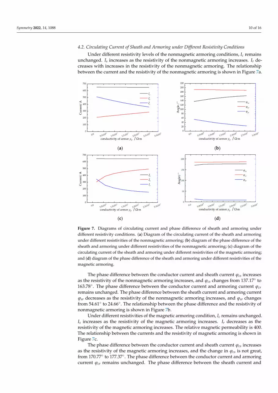
4.2. Circulating Current of Sheath and Armoring under Different Resistivity Conditions
Under different resistivity levels of the nonmagnetic armoring conditions, Ic remainsunchanged. Is increases as the resistivity of the nonmagnetic armoring increases. Ir de-creases with increases in the resistivity of the nonmagnetic armoring. The relationshipbetween the current and the resistivity of the nonmagnetic armoring is shown in Figure 7a.
Symmetry 2022, 14, x FOR PEER REVIEW 11 of 18
4.2. Circulating Current of Sheath and Armoring under Different Resistivity Conditions Under different resistivity levels of the nonmagnetic armoring conditions, Ic remains
unchanged. Is increases as the resistivity of the nonmagnetic armoring increases. Ir de-creases with increases in the resistivity of the nonmagnetic armoring. The relationship between the current and the resistivity of the nonmagnetic armoring is shown in Figure 7a.
(a) (b)
(c) (d)
Figure 7. Diagrams of circulating current and phase difference of sheath and armoring under dif-ferent resistivity conditions. (a) Diagram of the circulating current of the sheath and armoring under different resistivities of the nonmagnetic armoring; (b) diagram of the phase difference of the sheath and armoring under different resistivities of the nonmagnetic armoring; (c) diagram of the circulat-ing current of the sheath and armoring under different resistivities of the magnetic armoring; and (d) diagram of the phase difference of the sheath and armoring under different resistivities of the magnetic armoring.
The phase difference between the conductor current and sheath current φcs increases as the resistivity of the nonmagnetic armoring increases, and φcs changes from 137.17° to 163.78°. The phase difference between the conductor current and armoring current φcr re-mains unchanged. The phase difference between the sheath current and armoring current φsr decreases as the resistivity of the nonmagnetic armoring increases, and φsr changes from 54.61° to 24.66°. The relationship between the phase difference and the resistivity of nonmagnetic armoring is shown in Figure 7b.
Under different resistivities of the magnetic armoring condition, Ic remains un-changed. Is increases as the resistivity of the magnetic armoring increases. Ir decreases as the resistivity of the magnetic armoring increases. The relative magnetic permeability is 400. The relationship between the currents and the resistivity of magnetic armoring is shown in Figure 7c.
The phase difference between the conductor current and sheath current φcs increases as the resistivity of the magnetic armoring increases, and the change in φcs is not great, from 170.77° to 177.37°. The phase difference between the conductor current and armoring
Figure 7. Diagrams of circulating current and phase difference of sheath and armoring underdifferent resistivity conditions. (a) Diagram of the circulating current of the sheath and armoringunder different resistivities of the nonmagnetic armoring; (b) diagram of the phase difference of thesheath and armoring under different resistivities of the nonmagnetic armoring; (c) diagram of thecirculating current of the sheath and armoring under different resistivities of the magnetic armoring;and (d) diagram of the phase difference of the sheath and armoring under different resistivities of themagnetic armoring.
The phase difference between the conductor current and sheath current ϕcs increasesas the resistivity of the nonmagnetic armoring increases, and ϕcs changes from 137.17 to163.78. The phase difference between the conductor current and armoring current ϕcrremains unchanged. The phase difference between the sheath current and armoring currentϕsr decreases as the resistivity of the nonmagnetic armoring increases, and ϕsr changesfrom 54.61 to 24.66. The relationship between the phase difference and the resistivity ofnonmagnetic armoring is shown in Figure 7b.
Under different resistivities of the magnetic armoring condition, Ic remains unchanged.Is increases as the resistivity of the magnetic armoring increases. Ir decreases as theresistivity of the magnetic armoring increases. The relative magnetic permeability is 400.The relationship between the currents and the resistivity of magnetic armoring is shown inFigure 7c.
The phase difference between the conductor current and sheath current ϕcs increasesas the resistivity of the magnetic armoring increases, and the change in ϕcs is not great,from 170.77 to 177.37. The phase difference between the conductor current and armoringcurrent ϕcr remains unchanged. The phase difference between the sheath current and

Symmetry 2022, 14, 1088 11 of 16
armoring current ϕsr decreases as the resistivity of the nonmagnetic armoring increases,and the variation of ϕsr is not great, from 14.13 to 9.11. The relationship between thephase difference and the resistivity of the nonmagnetic armoring is shown in Figure 7d.
4.3. Circulating Current of Sheath and Armoring under Different Ground Resistance Conditions
Under the different ground resistances of the nonmagnetic armoring conditions, Icremains unchanged. Is increases as the ground resistance of the nonmagnetic armoringincreases. Ir decreases as the ground resistance of nonmagnetic armoring increases. Therelationship between the currents and the ground resistance of nonmagnetic armoring isshown in Figure 8a.
Symmetry 2022, 14, x FOR PEER REVIEW 12 of 18
current φcr remains unchanged. The phase difference between the sheath current and ar-moring current φsr decreases as the resistivity of the nonmagnetic armoring increases, and the variation of φsr is not great, from 14.13° to 9.11°. The relationship between the phase difference and the resistivity of the nonmagnetic armoring is shown in Figure 7d.
4.3. Circulating Current of Sheath and Armoring under Different Ground Resistance Conditions Under the different ground resistances of the nonmagnetic armoring conditions, Ic
remains unchanged. Is increases as the ground resistance of the nonmagnetic armoring increases. Ir decreases as the ground resistance of nonmagnetic armoring increases. The relationship between the currents and the ground resistance of nonmagnetic armoring is shown in Figure 8a.
(a) (b)
(c) (d)
Figure 8. Diagrams of the circulating current and phase difference of the sheath and armoring under different ground resistances of the nonmagnetic and magnetic armoring conditions. (a) Diagram of the circulating current of the sheath and armoring under different ground resistances of the non-magnetic armoring; (b) diagram of the phase difference of the sheath and armoring under different ground resistances of the nonmagnetic armoring; (c) diagram of the circulating current of the sheath and armoring under different ground resistances of the magnetic armoring; and (d) diagram of the phase difference of the sheath and armoring under different ground resistances of the magnetic armoring.
The phase difference between the conductor current and sheath current φcs increases as the ground resistance of the nonmagnetic armoring increases, and φcs changes from 145.51° to 162.97°. The phase difference between the conductor current and armoring cur-rent φcr decreases as the ground resistance of the nonmagnetic armoring increases, and φcr changes from 190.73° to 170.19°. The phase difference between the sheath current and ar-moring current φsr decreases as the ground resistance of the nonmagnetic armoring in-creases, and φsr changes from 48.22° to 7.218°. The relationship between the phase differ-ence and the ground resistance of the nonmagnetic armoring is shown in Figure 8b.
Figure 8. Diagrams of the circulating current and phase difference of the sheath and armoring underdifferent ground resistances of the nonmagnetic and magnetic armoring conditions. (a) Diagram of thecirculating current of the sheath and armoring under different ground resistances of the nonmagneticarmoring; (b) diagram of the phase difference of the sheath and armoring under different groundresistances of the nonmagnetic armoring; (c) diagram of the circulating current of the sheath andarmoring under different ground resistances of the magnetic armoring; and (d) diagram of the phasedifference of the sheath and armoring under different ground resistances of the magnetic armoring.
The phase difference between the conductor current and sheath current ϕcs increases asthe ground resistance of the nonmagnetic armoring increases, and ϕcs changes from 145.51
to 162.97. The phase difference between the conductor current and armoring current ϕcrdecreases as the ground resistance of the nonmagnetic armoring increases, and ϕcr changesfrom 190.73 to 170.19. The phase difference between the sheath current and armoringcurrent ϕsr decreases as the ground resistance of the nonmagnetic armoring increases, andϕsr changes from 48.22 to 7.218. The relationship between the phase difference and theground resistance of the nonmagnetic armoring is shown in Figure 8b.
Under different ground resistances of the magnetic armoring conditions, Ic remainsunchanged. Is increases as the ground resistance of the magnetic armoring increases, andIr decreases as the ground resistance of the magnetic armoring increases. The relative

Symmetry 2022, 14, 1088 12 of 16
magnetic permeability is 400. The relationship between the currents and the groundresistance of magnetic armoring is shown in Figure 8c.
The phase difference between the conductor current and sheath current ϕcs increasesas the ground resistance of the magnetic armoring increases, and the change of ϕcs is notgreat, from 173.42 to 177.97. The phase difference between the conductor current andarmoring current ϕcr decreases as the ground resistance of the magnetic armoring increases,and the variation of ϕcr changes from 189.01 to 156.04. The phase difference betweenthe sheath current and armoring current ϕsr decreases as the ground resistance of themagnetic armoring increases, and the variation of ϕsr is not obvious, from 13.59 to −21.88.The relationship between the phase difference and the ground resistance of the magneticarmoring is shown in Figure 8d.
5. Engineering Case Analysis
A Chinese offshore wind power plant had an installed capacity of 300 MW. It waspooled through 35 kV to the offshore booster station, and the 35 kV voltage was increased to220 kV by a boosting transformer. Wind power was transmitted to the terrestrial substationthrough three 220 kV single-core submarine cables. The route of the submarine cableconsisted of five sections and is shown in Figure 9. The route and the particulars of thesingle-core AC submarine cables are listed in Table 2 [24].
Symmetry 2022, 14, x FOR PEER REVIEW 13 of 18
Under different ground resistances of the magnetic armoring conditions, Ic remains unchanged. Is increases as the ground resistance of the magnetic armoring increases, and Ir decreases as the ground resistance of the magnetic armoring increases. The relative mag-netic permeability is 400. The relationship between the currents and the ground resistance of magnetic armoring is shown in Figure 8c.
The phase difference between the conductor current and sheath current φcs increases as the ground resistance of the magnetic armoring increases, and the change of φcs is not great, from 173.42° to 177.97°. The phase difference between the conductor current and armoring current φcr decreases as the ground resistance of the magnetic armoring in-creases, and the variation of φcr changes from 189.01° to 156.04°. The phase difference be-tween the sheath current and armoring current φsr decreases as the ground resistance of the magnetic armoring increases, and the variation of φsr is not obvious, from 13.59° to −21.88°. The relationship between the phase difference and the ground resistance of the magnetic armoring is shown in Figure 8d.
5. Engineering case Analysis A Chinese offshore wind power plant had an installed capacity of 300 MW. It was
pooled through 35 kV to the offshore booster station, and the 35 kV voltage was increased to 220 kV by a boosting transformer. Wind power was transmitted to the terrestrial sub-station through three 220 kV single-core submarine cables. The route of the submarine cable consisted of five sections and is shown in Figure 9. The route and the particulars of the single-core AC submarine cables are listed in Table 2 [24].
Figure 9. The route diagram of the three-phase single-core AC submarine, divided into five sections in a Chinese offshore wind power plant. Section I presents the section from offshore booster station to seabed. Section II, Section III, and Section IV present the seabed section. Section V presents the section from seabed to terrestrial substation.
Table 2. Tables showing the route and particulars of the single-core submarine cables.
Section of Submarine Cable Length of the Route Structure of Submarine Cable I 30 m Figure 1a, Table 1 II 300 m Figure 1a, Table 1 III 20 km Figure 1a, Table 1 IV 300 m Figure 1a, Table 1 V 100 m Figure 1b, Table 1 I 30 m Figure 1a, Table 1
The sheath and armoring of the submarine cable were grounded by both ends in or-der to suppress the influence of induced voltage. As the materials of the sheath outer layer
Figure 9. The route diagram of the three-phase single-core AC submarine, divided into five sectionsin a Chinese offshore wind power plant. Section I presents the section from offshore booster stationto seabed. Section II, Section III, and Section IV present the seabed section. Section V presents thesection from seabed to terrestrial substation.
Table 2. Tables showing the route and particulars of the single-core submarine cables.
Section of Submarine Cable Length of the Route Structure of Submarine Cable
I 30 m Figure 1a, Table 1II 300 m Figure 1a, Table 1III 20 km Figure 1a, Table 1IV 300 m Figure 1a, Table 1V 100 m Figure 1b, Table 1I 30 m Figure 1a, Table 1
The sheath and armoring of the submarine cable were grounded by both ends in orderto suppress the influence of induced voltage. As the materials of the sheath outer layer weresemiconducting PE, the sheath and armoring of the submarine cable should be treated asmultipoint earthing in the sea. The sheath and armoring of the submarine cable of SectionsII, III, and IV were treated as multipoint earthing submerged in the sea. The sheath andarmoring of the submarine cable of Sections I and V were treated as two-point earthing.
Symmetry 2022, 14, 1088 13 of 16
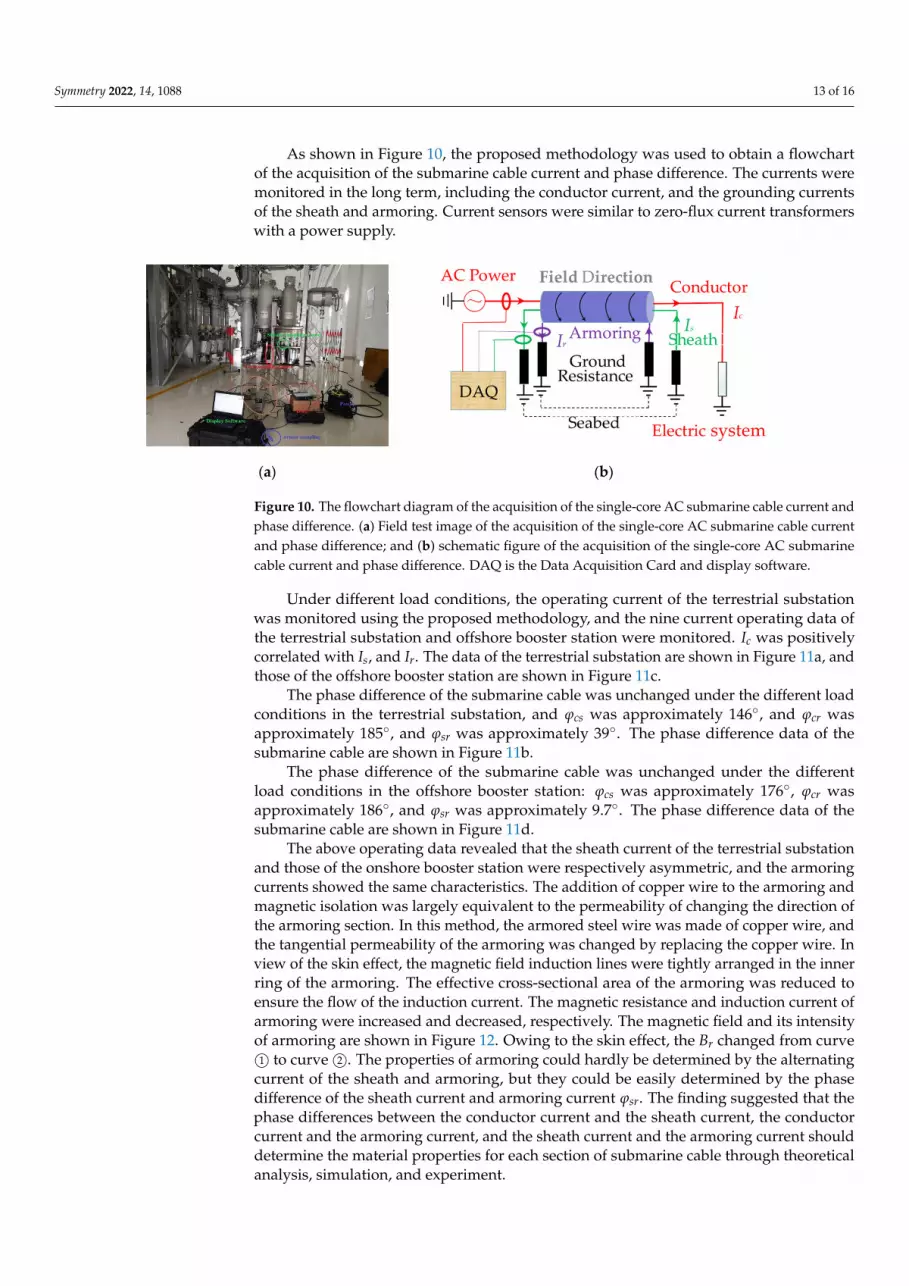
As shown in Figure 10, the proposed methodology was used to obtain a flowchartof the acquisition of the submarine cable current and phase difference. The currents weremonitored in the long term, including the conductor current, and the grounding currentsof the sheath and armoring. Current sensors were similar to zero-flux current transformerswith a power supply.
Symmetry 2022, 14, x FOR PEER REVIEW 14 of 18
were semiconducting PE, the sheath and armoring of the submarine cable should be treated as multipoint earthing in the sea. The sheath and armoring of the submarine cable of Section II, III, and IV were treated as multipoint earthing submerged in the sea. The sheath and armoring of the submarine cable of Sections I and V were treated as two-point earthing.
As shown in Figure 10, the proposed methodology was used to obtain a flowchart of the acquisition of the submarine cable current and phase difference. The currents were monitored in the long term, including the conductor current, and the grounding currents of the sheath and armoring. Current sensors were similar to zero-flux current transform-ers with a power supply.
(a) (b)
Figure 10. The flowchart diagram of the acquisition of the single-core AC submarine cable current and phase difference. (a) Field test image of the acquisition of the single-core AC submarine cable current and phase difference; and (b) schematic figure of the acquisition of the single-core AC sub-marine cable current and phase difference. DAQ is the Data Acquisition Card and display software.
Under different load conditions, the operating current of the terrestrial substation was monitored using the proposed methodology, and the nine current operating data of the terrestrial substation and offshore booster station were monitored. Ic was positively correlated with Is, and Ir. The data of the terrestrial substation are shown in Figure 11a, and those of the offshore booster station are shown in Figure 11c.
(a) (b)
Figure 10. The flowchart diagram of the acquisition of the single-core AC submarine cable current andphase difference. (a) Field test image of the acquisition of the single-core AC submarine cable currentand phase difference; and (b) schematic figure of the acquisition of the single-core AC submarinecable current and phase difference. DAQ is the Data Acquisition Card and display software.
Under different load conditions, the operating current of the terrestrial substationwas monitored using the proposed methodology, and the nine current operating data ofthe terrestrial substation and offshore booster station were monitored. Ic was positivelycorrelated with Is, and Ir. The data of the terrestrial substation are shown in Figure 11a, andthose of the offshore booster station are shown in Figure 11c.
The phase difference of the submarine cable was unchanged under the different loadconditions in the terrestrial substation, and ϕcs was approximately 146, and ϕcr wasapproximately 185, and ϕsr was approximately 39. The phase difference data of thesubmarine cable are shown in Figure 11b.
The phase difference of the submarine cable was unchanged under the differentload conditions in the offshore booster station: ϕcs was approximately 176, ϕcr wasapproximately 186, and ϕsr was approximately 9.7. The phase difference data of thesubmarine cable are shown in Figure 11d.
The above operating data revealed that the sheath current of the terrestrial substationand those of the onshore booster station were respectively asymmetric, and the armoringcurrents showed the same characteristics. The addition of copper wire to the armoring andmagnetic isolation was largely equivalent to the permeability of changing the direction ofthe armoring section. In this method, the armored steel wire was made of copper wire, andthe tangential permeability of the armoring was changed by replacing the copper wire. Inview of the skin effect, the magnetic field induction lines were tightly arranged in the innerring of the armoring. The effective cross-sectional area of the armoring was reduced toensure the flow of the induction current. The magnetic resistance and induction current ofarmoring were increased and decreased, respectively. The magnetic field and its intensityof armoring are shown in Figure 12. Owing to the skin effect, the Br changed from curve1© to curve 2©. The properties of armoring could hardly be determined by the alternating
current of the sheath and armoring, but they could be easily determined by the phasedifference of the sheath current and armoring current ϕsr. The finding suggested that thephase differences between the conductor current and the sheath current, the conductorcurrent and the armoring current, and the sheath current and the armoring current shoulddetermine the material properties for each section of submarine cable through theoreticalanalysis, simulation, and experiment.

Symmetry 2022, 14, 1088 14 of 16
Symmetry 2022, 14, x FOR PEER REVIEW 14 of 18
were semiconducting PE, the sheath and armoring of the submarine cable should be treated as multipoint earthing in the sea. The sheath and armoring of the submarine cable of Section II, III, and IV were treated as multipoint earthing submerged in the sea. The sheath and armoring of the submarine cable of Sections I and V were treated as two-point earthing.
As shown in Figure 10, the proposed methodology was used to obtain a flowchart of the acquisition of the submarine cable current and phase difference. The currents were monitored in the long term, including the conductor current, and the grounding currents of the sheath and armoring. Current sensors were similar to zero-flux current transform-ers with a power supply.
(a) (b)
Figure 10. The flowchart diagram of the acquisition of the single-core AC submarine cable current and phase difference. (a) Field test image of the acquisition of the single-core AC submarine cable current and phase difference; and (b) schematic figure of the acquisition of the single-core AC sub-marine cable current and phase difference. DAQ is the Data Acquisition Card and display software.
Under different load conditions, the operating current of the terrestrial substation was monitored using the proposed methodology, and the nine current operating data of the terrestrial substation and offshore booster station were monitored. Ic was positively correlated with Is, and Ir. The data of the terrestrial substation are shown in Figure 11a, and those of the offshore booster station are shown in Figure 11c.
(a) (b)
Symmetry 2022, 14, x FOR PEER REVIEW 15 of 18
(c) (d)
Figure 11. Diagrams of field test data of the terrestrial substation and offshore booster station cur-rent and phase difference in the single-core AC submarine cable. (a) Diagram of field test data of the terrestrial substation current in the single-core AC submarine cable; (b) diagram of field test data of the terrestrial substation phase difference in the single-core AC submarine cable; (c) diagram of field test data of the offshore booster station current in the single-core AC submarine cable; and (d) diagram of field test data of the offshore booster station phase difference in the single-core AC submarine cable.
The phase difference of the submarine cable was unchanged under the different load conditions in the terrestrial substation, and φcs was approximately 146°, and φcr was ap-proximately 185°, and φsr was approximately 39°. The phase difference data of the subma-rine cable are shown in Figure 11b.
The phase difference of the submarine cable was unchanged under the different load conditions in the offshore booster station: φcs was approximately 176°, φcr was approxi-mately 186°, and φsr was approximately 9.7°. The phase difference data of the submarine cable are shown in Figure 11d.
The above operating data revealed that the sheath current of the terrestrial substation and those of the onshore booster station were respectively asymmetric, and the armoring currents showed the same characteristics. The addition of copper wire to the armoring and magnetic isolation was largely equivalent to the permeability of changing the direc-tion of the armoring section. In this method, the armored steel wire was made of copper wire, and the tangential permeability of the armoring was changed by replacing the cop-per wire. In view of the skin effect, the magnetic field induction lines were tightly ar-ranged in the inner ring of the armoring. The effective cross-sectional area of the armoring was reduced to ensure the flow of the induction current. The magnetic resistance and in-duction current of armoring were increased and decreased, respectively. The magnetic field and its intensity of armoring are shown in Figure 12. Owing to the skin effect, the Br changed from curve ① to curve ②. The properties of armoring could hardly be deter-mined by the alternating current of the sheath and armoring, but they could be easily determined by the phase difference of the sheath current and armoring current φsr. The finding suggested that the phase differences between the conductor current and the sheath current, the conductor current and the armoring current, and the sheath current and the armoring current should determine the material properties for each section of submarine cable through theoretical analysis, simulation, and experiment.
Figure 11. Diagrams of field test data of the terrestrial substation and offshore booster station currentand phase difference in the single-core AC submarine cable. (a) Diagram of field test data of theterrestrial substation current in the single-core AC submarine cable; (b) diagram of field test dataof the terrestrial substation phase difference in the single-core AC submarine cable; (c) diagram offield test data of the offshore booster station current in the single-core AC submarine cable; and(d) diagram of field test data of the offshore booster station phase difference in the single-core ACsubmarine cable.
Symmetry 2022, 14, x FOR PEER REVIEW 16 of 18
(a) (b)
Figure 12. Cloud and curve diagrams of the magnetic field intensity of the armoring. (a) Cloud dia-gram of the magnetic field intensity of the magnetic armoring; and (b) curve diagram of the mag-netic field intensity of the nonmagnetic and magnetic armoring; curve ① indicates the magnetic field intensity of the nonmagnetic armoring, and curve ② indicates the magnetic field intensity of the magnetic armoring.
6. Conclusions Aiming to discover the influence factors of the circulating current in the sheath and
armoring, we proposed a method to evaluate and analyze the circulating current of the sheath and armoring using the transmission impedance characteristics. The conclusions are as follows: 1. The outer sheaths of a single-core AC submarine cable have different electromagnetic
characteristics under the two grounding forms. We clearly explained the formation mechanism for the circulating current of the outer sheath. The outer sheaths are grounded through both ends, which exhibits a shielding effect whereby the magnetic field direction generated by the circulating current of the outer sheath is opposite to the magnetic field direction generated by the conductor current in the single-core AC submarine cable.
2. A detailed equivalent circuit model of a single-core AC submarine cable was pre-sented to facilitate the analysis of the circulating current of the outer sheaths. The impedance matrix was proposed from three coaxial circuit equations, and the phase difference determining the material properties of each metallic section was proposed.
3. We proved by numerical simulation, simulation calculation, and field verification that influence factors such as permeability, resistivity, and ground resistance of the outer sheath layers will affect the symmetrical distribution of the circulating current of the outer sheath. The distribution of the circulating current on the outer sheath is negatively correlated with permeability, resistivity, and ground resistance. The re-sults must be considered in the stage of submarine cable design and selection. This paper proposes a method for evaluating the circulating current of the outer
sheath that can provide a direction for the loss research of single-core AC submarine cable. On this basis, the method of evaluating the loss of the three-core AC submarine cable and direct current submarine cable needs to be further studied. In the future, we must continue to study the insulation performance of the single-core AC submarine cable by transmis-sion impedance characteristics.
Author Contributions: Conceptualization, P.L. and P.G.; methodology, P.L.; software, P.L.; valida-tion, P.L. and P.G; formal analysis, P.L.; investigation, P.L.; resources, P.L.; data curation, P.L. and P.G.; writing—original draft preparation, P.L. and P.G.; writing—review and editing, P.L. and P.G. All authors have read and agreed to the published version of the manuscript.
Funding: This research received no external funding.
Institutional Review Board Statement: Not applicable.
Figure 12. Cloud and curve diagrams of the magnetic field intensity of the armoring. (a) Clouddiagram of the magnetic field intensity of the magnetic armoring; and (b) curve diagram of themagnetic field intensity of the nonmagnetic and magnetic armoring; curve 1© indicates the magneticfield intensity of the nonmagnetic armoring, and curve 2© indicates the magnetic field intensity of themagnetic armoring.
6. Conclusions
Aiming to discover the influence factors of the circulating current in the sheath andarmoring, we proposed a method to evaluate and analyze the circulating current of the

Symmetry 2022, 14, 1088 15 of 16
sheath and armoring using the transmission impedance characteristics. The conclusionsare as follows:
1. The outer sheaths of a single-core AC submarine cable have different electromagneticcharacteristics under the two grounding forms. We clearly explained the formationmechanism for the circulating current of the outer sheath. The outer sheaths aregrounded through both ends, which exhibits a shielding effect whereby the magneticfield direction generated by the circulating current of the outer sheath is opposite tothe magnetic field direction generated by the conductor current in the single-core ACsubmarine cable.
2. A detailed equivalent circuit model of a single-core AC submarine cable was presentedto facilitate the analysis of the circulating current of the outer sheaths. The impedancematrix was proposed from three coaxial circuit equations, and the phase differencedetermining the material properties of each metallic section was proposed.
3. We proved by numerical simulation, simulation calculation, and field verificationthat influence factors such as permeability, resistivity, and ground resistance of theouter sheath layers will affect the symmetrical distribution of the circulating currentof the outer sheath. The distribution of the circulating current on the outer sheath isnegatively correlated with permeability, resistivity, and ground resistance. The resultsmust be considered in the stage of submarine cable design and selection.
This paper proposes a method for evaluating the circulating current of the outer sheaththat can provide a direction for the loss research of single-core AC submarine cable. On thisbasis, the method of evaluating the loss of the three-core AC submarine cable and directcurrent submarine cable needs to be further studied. In the future, we must continue tostudy the insulation performance of the single-core AC submarine cable by transmissionimpedance characteristics.
Author Contributions: Conceptualization, P.L. and P.G.; methodology, P.L.; software, P.L.; validation,P.L. and P.G; formal analysis, P.L.; investigation, P.L.; resources, P.L.; data curation, P.L. and P.G.;writing—original draft preparation, P.L. and P.G.; writing—review and editing, P.L. and P.G. Allauthors have read and agreed to the published version of the manuscript.
Funding: This research received no external funding.
Institutional Review Board Statement: Not applicable.
Informed Consent Statement: Not applicable.
Data Availability Statement: Not applicable.
Conflicts of Interest: The authors declare no conflict of interest.
References1. Soares-Ramos, E.P.; Assis, L.D.O.; Sarrias-Mena, R.; Fernández-Ramírez, L.M. Current status and future trends of offshore wind
power in Europe. Energy 2020, 202, 117787. [CrossRef]2. Taormina, B.; Bald, J.; Want, A.; Thouzeau, G.; Lejart, M.; Desroy, N.; Carlier, A. A review of potential impacts of submarine
power cables on the marine environment: Knowledge gaps, recommendations and future directions. Renew. Sustain. Energy Rev.2018, 96, 380–391. [CrossRef]
3. Worzyk, T. Submarine Power Cables: Design, Installation, Repair, Environmental Aspects; Springer: New York, NY, USA, 2009;Volume 1, pp. 10–48. [CrossRef]
4. Bianchi, G.; Luoni, G. Induced currents and losses in single-core submarine cables. IEEE Trans. Power Appar. Syst. 1976, 95, 49–58.[CrossRef]
5. 575-1988; An American National Standard IEEE guide for the Application of Sheath-Bonding Methods for Single-ConductorCables and The Calculation of Induced Voltages and Cur-Rents in Cable Sheaths. ANSI: New York, NY, USA; IEEE: Piscataway,NJ, USA, 1987. [CrossRef]
6. IEC 60287-1-1; International Electrotechnical Commission. Electric Cables—Calculation of the Current Rating—Part 1-1: CurrentRating Equations (100% Load Factor) and Calculation of Losses. HIS: Geneva, Switzerland, 2006.
7. IEC 60287-2-1; International Electrotechnical Commission. Electric Cables—Calculation of the Current Rating—Part 2-1: ThermalResistance—Calculation of Thermal Resistance. HIS: Geneva, Switzerland, 2006.

Symmetry 2022, 14, 1088 16 of 16
8. IEC 60287-3-1; International Electrotechnical Commission. Electric Cables—Calculation of the Current Rating—Part 3-1: Sectionson Operating Conditions—Reference Operating Conditions and Selection of Cable Type. HIS: Geneva, Switzerland, 1999.
9. Barrett, J.; Anders, G. Circulating current and hysteresis losses in screens, sheaths and armor of electric power cables-mathematicalmodels and comparison with IEC Standard 287. IEE Proc. Sci. Meas. Technol. 1997, 144, 101–110. [CrossRef]
10. Fan, Y.; Liu, S.; Deng, X. Study on the ampacity of single-core submarine power cable with return conductor. In Proceedings ofthe IOP Conference Series: Materials Science and Engineering, Changsha, China, 19–21 April 2019; Volume 563. [CrossRef]
11. Wagenaars, P.; Wouters, P.A.F.; Van Der Wielen, P.J.M.; Steennis, E. Approximation of transmission line parameters of single-coreand three-core XLPE cables. IEEE Trans. Dielectr. Electr. Insul. 2010, 17, 106–115. [CrossRef]
12. Wagenaars, P.; Steennis, E.; Wouters, P.; van der Wielen, P. Measurement of transmission line parameters of three-core powercables with common earth screen. IET Sci. Meas. Technol. 2009, 4, 146–155. [CrossRef]
13. Shaban, M.; Salam, M.; Ang, S.; Voon, W. Induced sheath voltage in power cables: A review. Renew. Sustain. Energy Rev. 2016, 62,1236–1251. [CrossRef]
14. Schelkunoff, S.A. The Electromagnetic Theory of Coaxial Transmission Lines and Cylindrical Shields. Bell Syst. Tech. J. 1934, 13,532–579. [CrossRef]
15. Wang, X.H.; Song, Y.H.; Jung, C.K. Tackling sheath problems: Latest research developments in solving operational sheathproblems in underground power transmission cables. Electr. Power Syst. Res. 2007, 77, 1449–1457. [CrossRef]
16. Liu, G.; Fan, M.; Wang, P.; Zheng, M. Study on Reactive Power Compensation Strategies for Long Distance Submarine CablesConsidering Electrothermal Coordination. J. Mar. Sci. Eng. 2021, 9, 90. [CrossRef]
17. Candela, R.; Gattuso, A.; Mitolo, M.; Sanseverino, E.R.; Zizzo, G. Model for Assessing the Magnitude and Distribution of SheathCurrents in Medium and High Voltage Cable Lines. IEEE Trans. Ind. Appl. 2020, 56, 6250–6257. [CrossRef]
18. Papazyan, R.; Pettersson, P.; Edin, H.; Eriksson, R.; Gafvert, U. Extraction of high frequency power cable characteristics fromS-parameter measurements. IEEE Trans. Dielectr. Electr. Insul. 2004, 11, 261–270. [CrossRef]
19. De Wulf, M.; Wouters, P.; Sergeant, P.; Dupré, L.; Hoferlin, E.; Jacobs, S.; Harlet, P. Electromagnetic shielding of high-voltagecables. J. Magn. Magn. Mater. 2007, 316, 908–911. [CrossRef]
20. Bremnes, J.; Evenset, G.; Ronny, S. Power Loss and Inductance of Steel Armoured Multi-Core Cables: Comparison of IEC Values with‘2.5D’ FEA Results and Measurements; paper B1_116; CIGRÉ: Paris, France, 2010.
21. Clayton, R.P. Analysis of Multiconductor Transmission Lines, 2nd ed.; John Wiley & Sons, Inc.: Hoboken, NJ, USA, 2008; pp. 89–109.22. Wedepohl, L.; Wilcox, D. Transient analysis of underground power-transmission systems: System-model and wave-propagation
characteristics. Proc. IEE 1973, 120, 252–259. [CrossRef]23. Gu, J.; Liu, Z. TOPSIS-Based Algorithm for Resilience Indices Construction and the Evaluation of an Electrical Power Transmission
Network. Symmetry 2022, 14, 985. [CrossRef]24. Yang, Z. The Procurement Technical Agreement of 220 kV Single-Core Submarine Cable in the 300 MW Offshore Wind Power Project;
Zhong-tian Technology Group Co., Ltd.: Nanjing, China, 2016.


