Embed Size (px)
Citation preview
Thanks to the help of timecop (yes he can be nice as long as he is interested ) I managed to
flash my RCTimer 10A and 30A ESC. The procedure should be the exact same for the 18A
and 20A versions. I will have some of these ESC in a few days and will test. Only difference
can be the programming pads order, we will get into that.
Also note that the procedure is most likely the same for the Turnigy Plush if they have the
same chip and pads. Check it all with a multimeter before hand! More and more ESC have
their pinouts posted in this topic and I will update the initial post with them.
Another note. timecop and I also had some RCT 10A that went poof after the reflash. Problem
is discussed in the thread, don't really know if it has been fixed...
1- Required stuff:
- RCTimer or other Atmel chip compatible ESC stripped of it's shrink tube.
Check this list made by TomSn0w of all compatible ESCs with their specs and
appropriate firmware file. Thanks a lot for this!
- An AVR USB programmer. I am using USBASP from Protostack. It is the exact same kind
of programmer used when flashing a Turnigy 9X.
- A way to connect temporarily the programming pads of the ESC to the AVR programmer.
- The hex file for the firmware (.hex is the compiled firmware, you can compile your own if
you want to as well):
1- Go there: https://github.com/sim-/tgy
2- Hit the download button on the top right
3- Right click and save as the tgy.hex file from the bottom on the popup. There are newer
versions posted from time to time. I used the tgy.hex one, but newer ones could be better!
[EDIT: tgy.hex is good for the rctimer ESC and other very classic hw copies with no external
oscillator. Depending on your ESC you might want to ask in this thread if you are better off
using another compiled .hex. nfet and bfet stuff is getting too technical for me still ^^]
- AVRDUDE or AVRStudio or what ever software you want to use to actually flash the
firmware.
-ALTERNATE: Use the tool posted in this thread coded by catch15117, thanks a lot for
this! (not really up to date)
-ALTERNATE2: Another tool posted in this thread by LazyZero, thanks a lot!
2- Step by Step:
- Identify the pads:
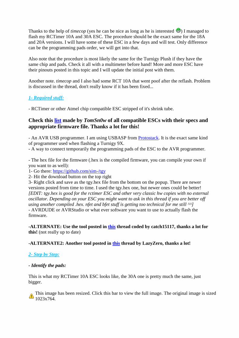
This is what my RCTimer 10A ESC looks like, the 30A one is pretty much the same, just
bigger.
This image has been resized. Click this bar to view the full image. The original image is sized
1023x764.
You can see the 6 programming pads on the bottom of the board in the flash of light
They are in this order, from left to right: RESET, VCC, GND, SCLK, MISO, MOSI
Looking at the RCTimer 30A ESC from the top you will see the same 6 pads, but the order is
reversed it is from left to right: MOSI, MISO, SCLK, GND, VCC, RESET
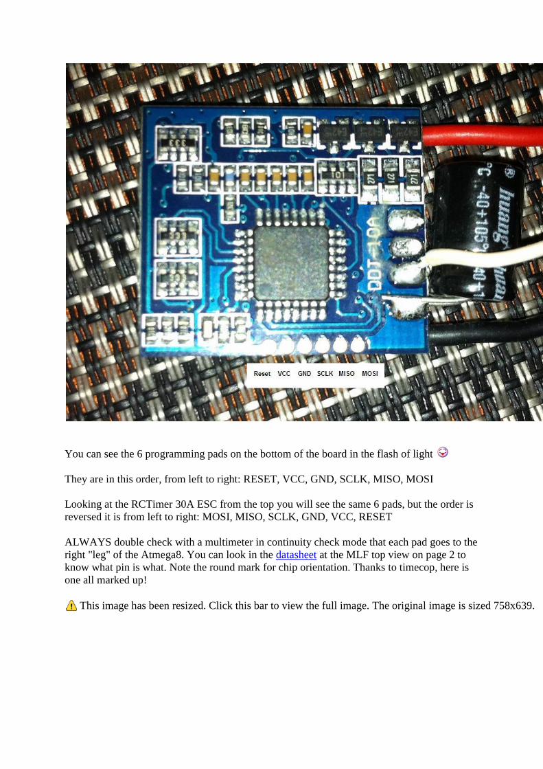
ALWAYS double check with a multimeter in continuity check mode that each pad goes to the
right "leg" of the Atmega8. You can look in the datasheet at the MLF top view on page 2 to
know what pin is what. Note the round mark for chip orientation. Thanks to timecop, here is
one all marked up!
This image has been resized. Click this bar to view the full image. The original image is sized 758x639.
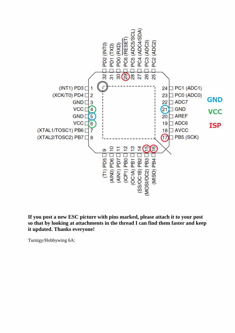
If you post a new ESC picture with pins marked, please attach it to your post
so that by looking at attachments in the thread I can find them faster and keep
it updated. Thanks everyone!
Turnigy/Hobbywing 6A:
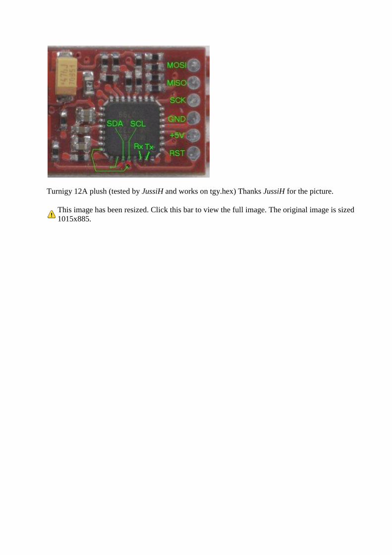
Turnigy 12A plush (tested by JussiH and works on tgy.hex) Thanks JussiH for the picture.
This image has been resized. Click this bar to view the full image. The original image is sized
1015x885.
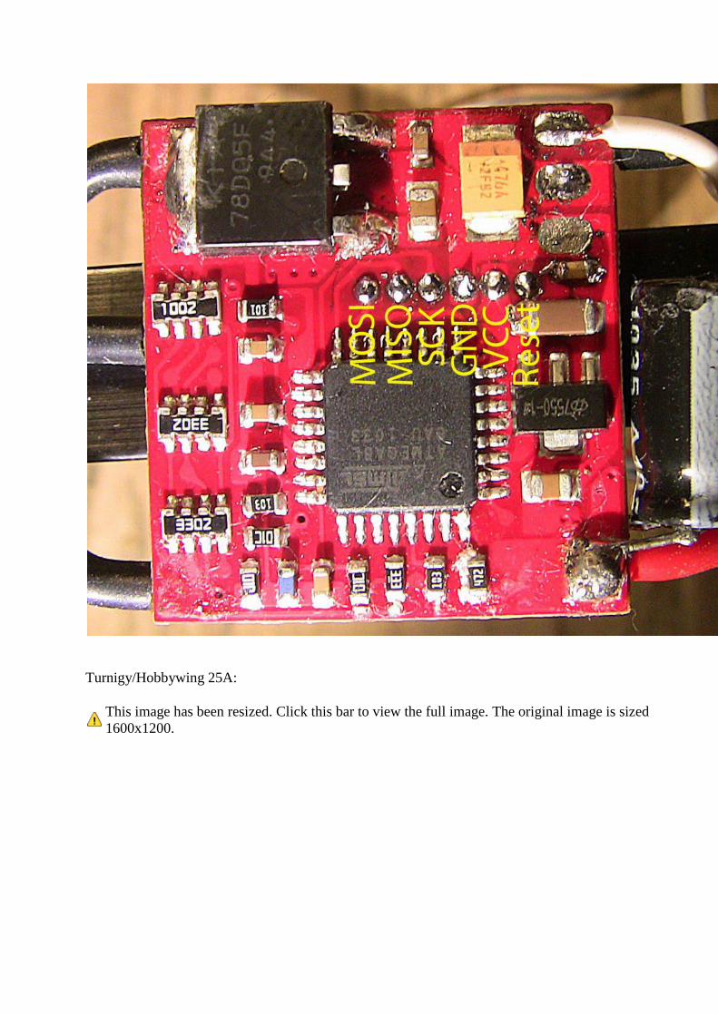
Turnigy/Hobbywing 25A:
This image has been resized. Click this bar to view the full image. The original image is sized
1600x1200.
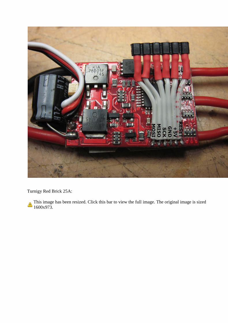
Turnigy Red Brick 25A:
This image has been resized. Click this bar to view the full image. The original image is sized
1600x973.
Thanks to pia32.
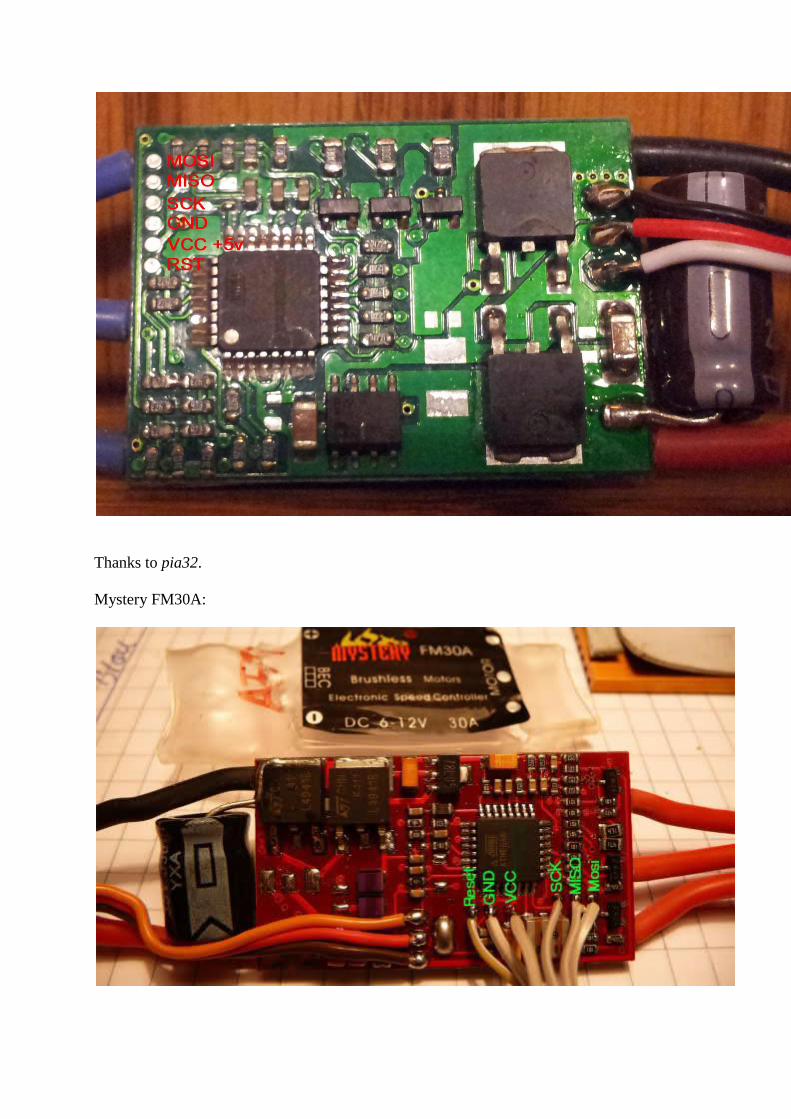
Mystery FM30A:
Thanks to flashervn for this one.
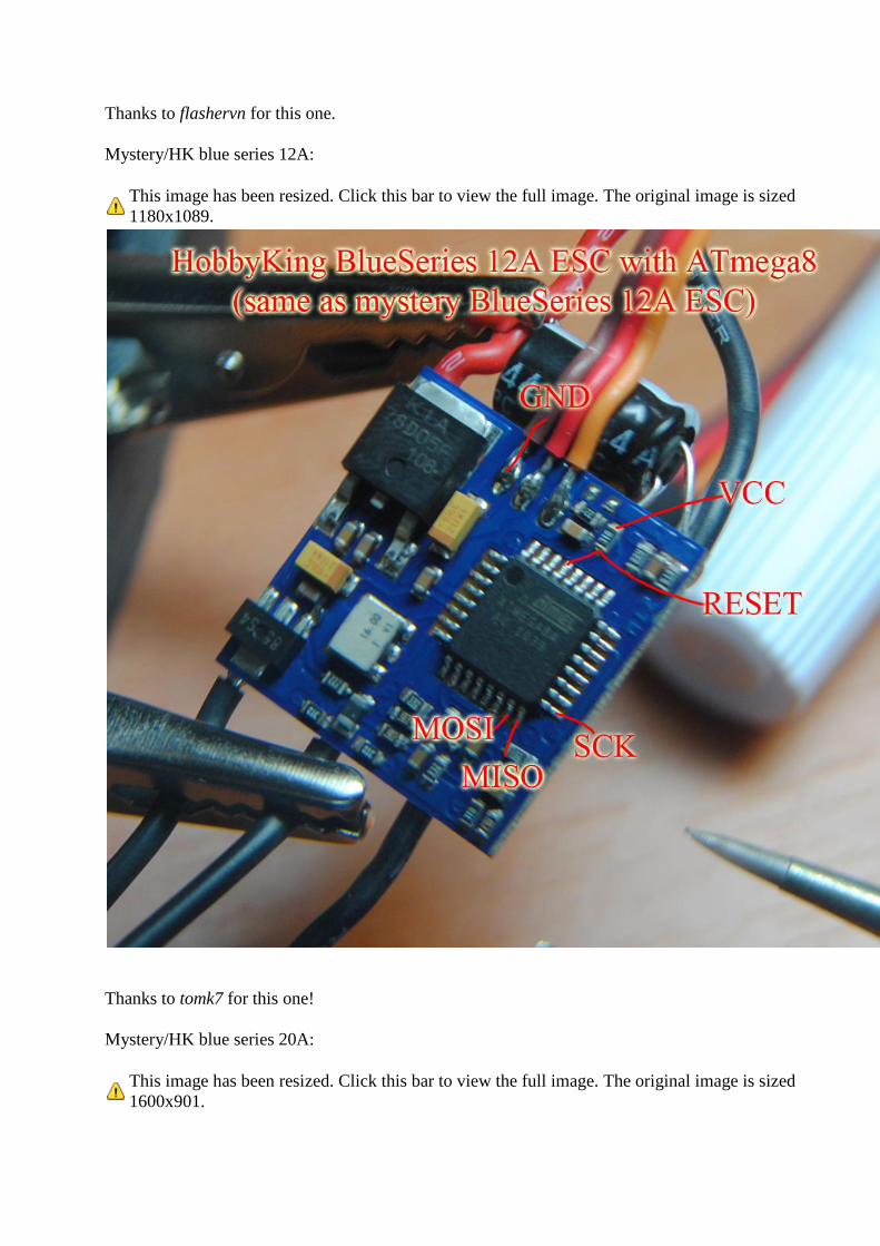
Mystery/HK blue series 12A:
This image has been resized. Click this bar to view the full image. The original image is sized
1180x1089.
Thanks to tomk7 for this one!
Mystery/HK blue series 20A:
This image has been resized. Click this bar to view the full image. The original image is sized
1600x901.
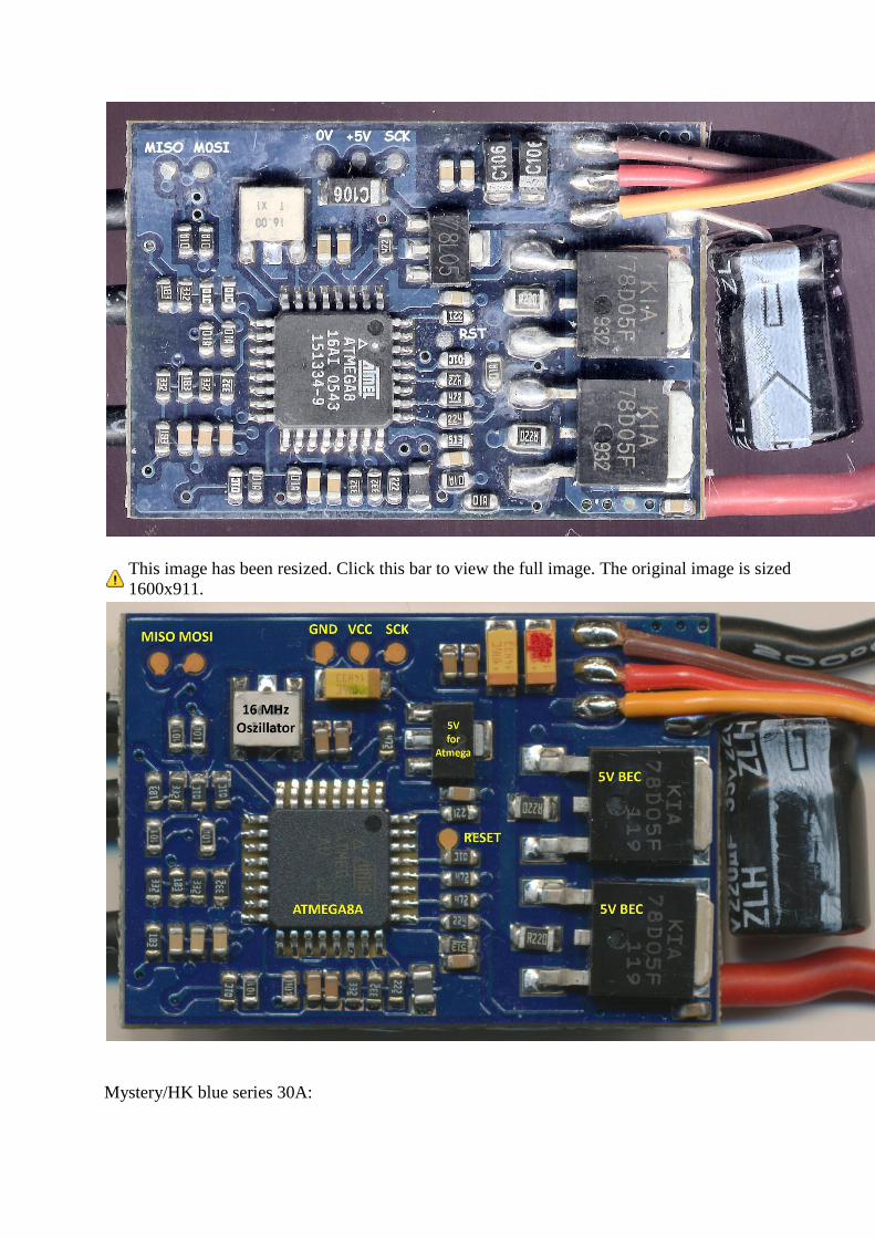
This image has been resized. Click this bar to view the full image. The original image is sized
1600x911.
Mystery/HK blue series 30A:
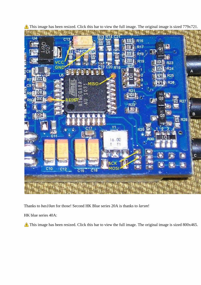
This image has been resized. Click this bar to view the full image. The original image is sized 779x721.
Thanks to bas10an for those! Second HK Blue series 20A is thanks to larsm!
HK blue series 40A:
This image has been resized. Click this bar to view the full image. The original image is sized 800x465.
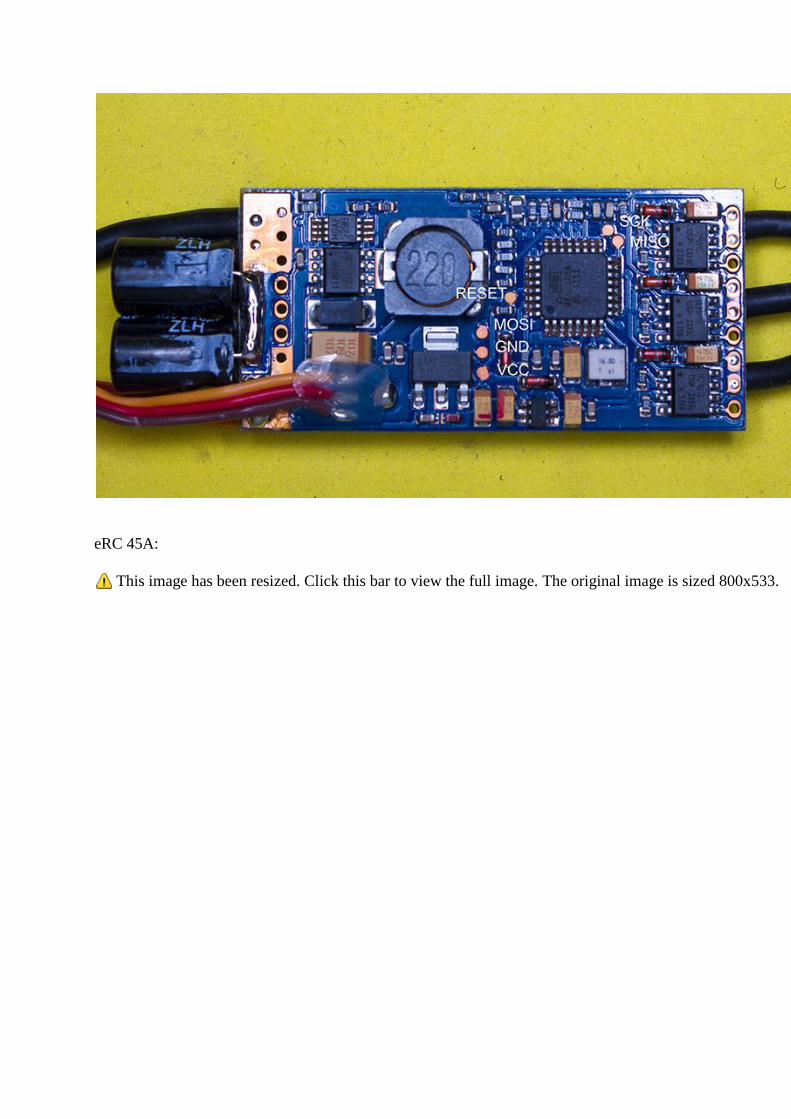
eRC 45A:
This image has been resized. Click this bar to view the full image. The original image is sized 800x533.
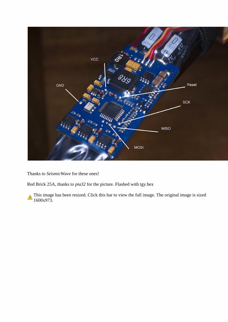
Thanks to SeismicWave for these ones!
Red Brick 25A, thanks to pia32 for the picture. Flashed with tgy.hex
This image has been resized. Click this bar to view the full image. The original image is sized
1600x973.
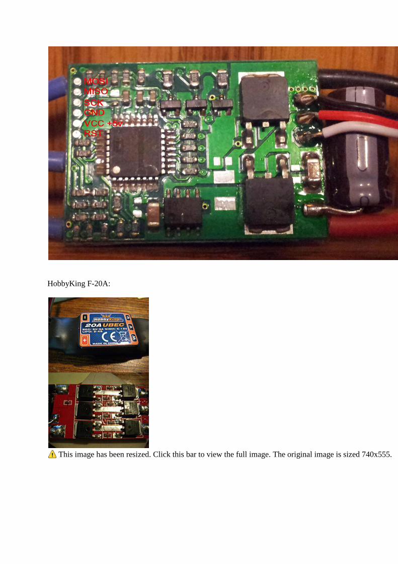
HobbyKing F-20A:
This image has been resized. Click this bar to view the full image. The original image is sized 740x555.
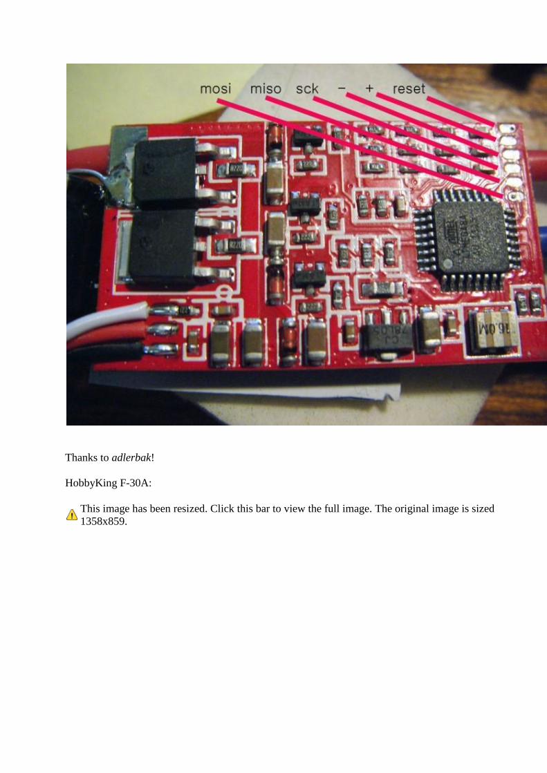
Thanks to adlerbak!
HobbyKing F-30A:
This image has been resized. Click this bar to view the full image. The original image is sized
1358x859.
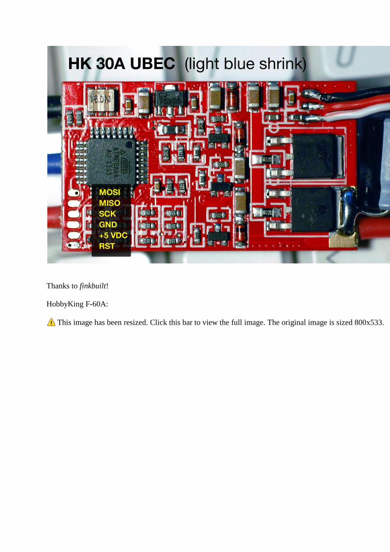
Thanks to finkbuilt!
HobbyKing F-60A:
This image has been resized. Click this bar to view the full image. The original image is sized 800x533.
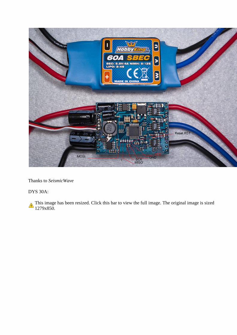
Thanks to SeismicWave
DYS 30A:
This image has been resized. Click this bar to view the full image. The original image is sized
1279x850.
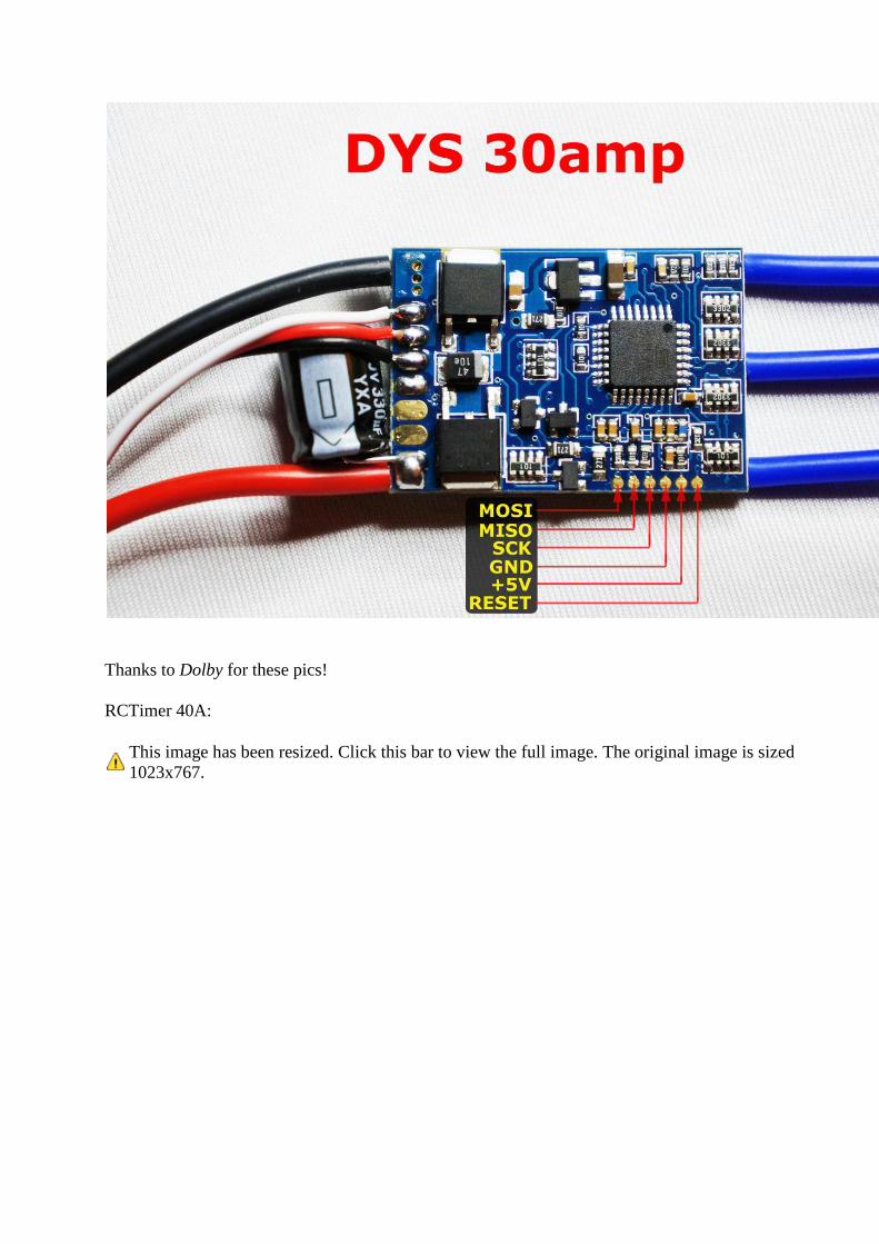
Thanks to Dolby for these pics!
RCTimer 40A:
This image has been resized. Click this bar to view the full image. The original image is sized
1023x767.
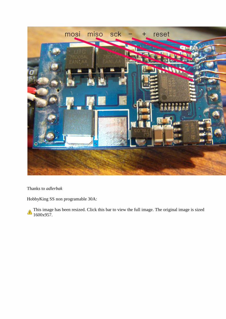
Thanks to adlerbak
HobbyKing SS non programable 30A:
This image has been resized. Click this bar to view the full image. The original image is sized
1600x957.
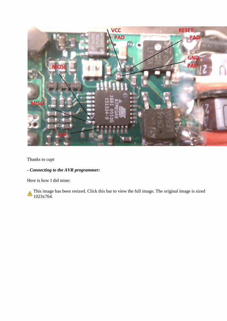
Thanks to capt
- Connecting to the AVR programmer:
Here is how I did mine:
This image has been resized. Click this bar to view the full image. The original image is sized
1023x764.
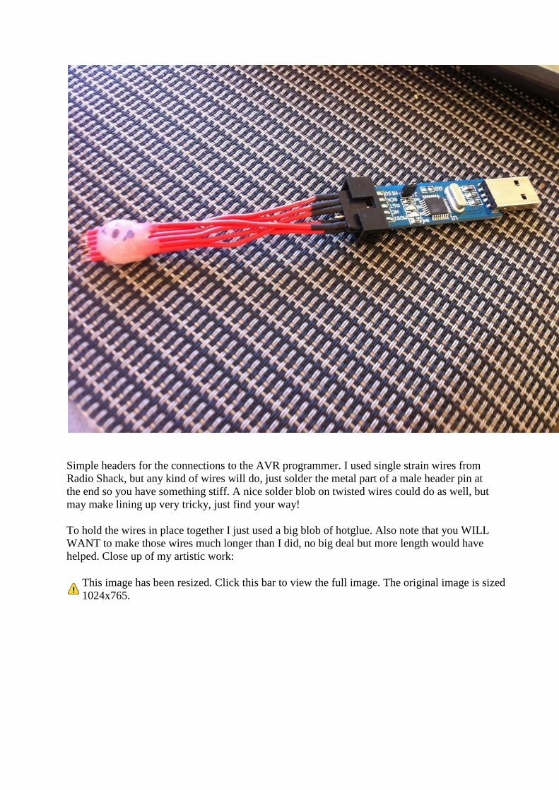
Simple headers for the connections to the AVR programmer. I used single strain wires from
Radio Shack, but any kind of wires will do, just solder the metal part of a male header pin at
the end so you have something stiff. A nice solder blob on twisted wires could do as well, but
may make lining up very tricky, just find your way!
To hold the wires in place together I just used a big blob of hotglue. Also note that you WILL
WANT to make those wires much longer than I did, no big deal but more length would have
helped. Close up of my artistic work:
This image has been resized. Click this bar to view the full image. The original image is sized
1024x765.
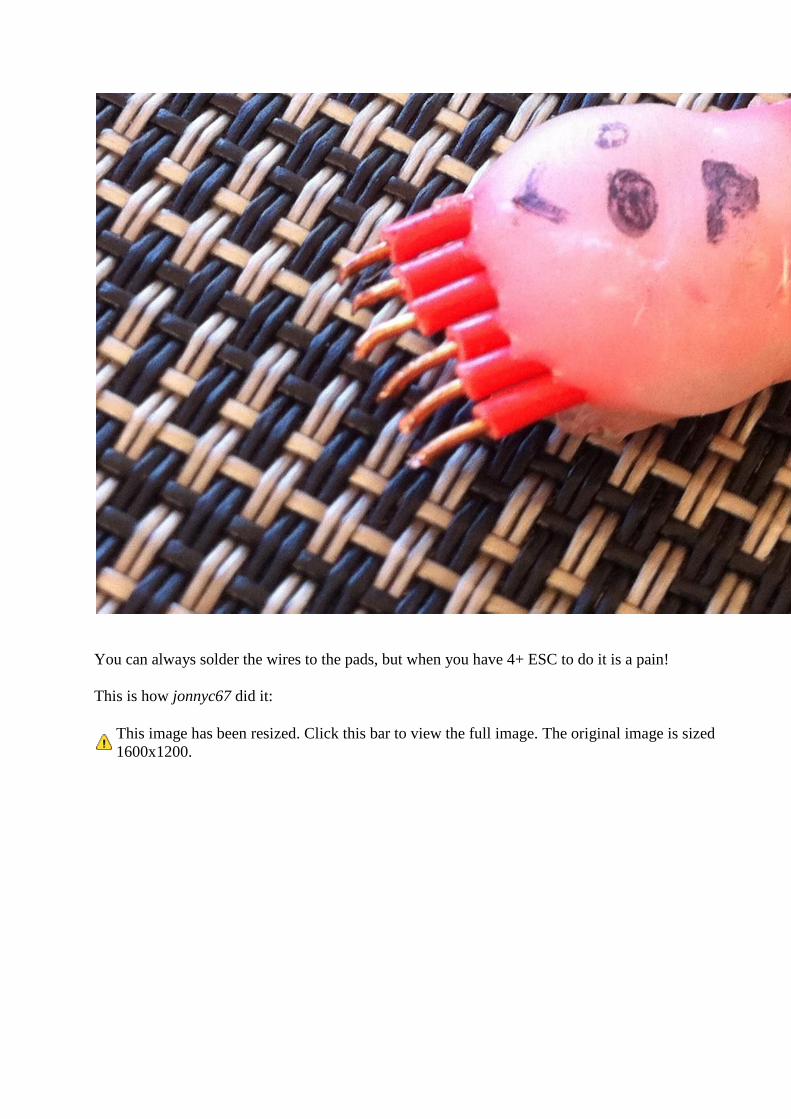
You can always solder the wires to the pads, but when you have 4+ ESC to do it is a pain!
This is how jonnyc67 did it:
This image has been resized. Click this bar to view the full image. The original image is sized
1600x1200.
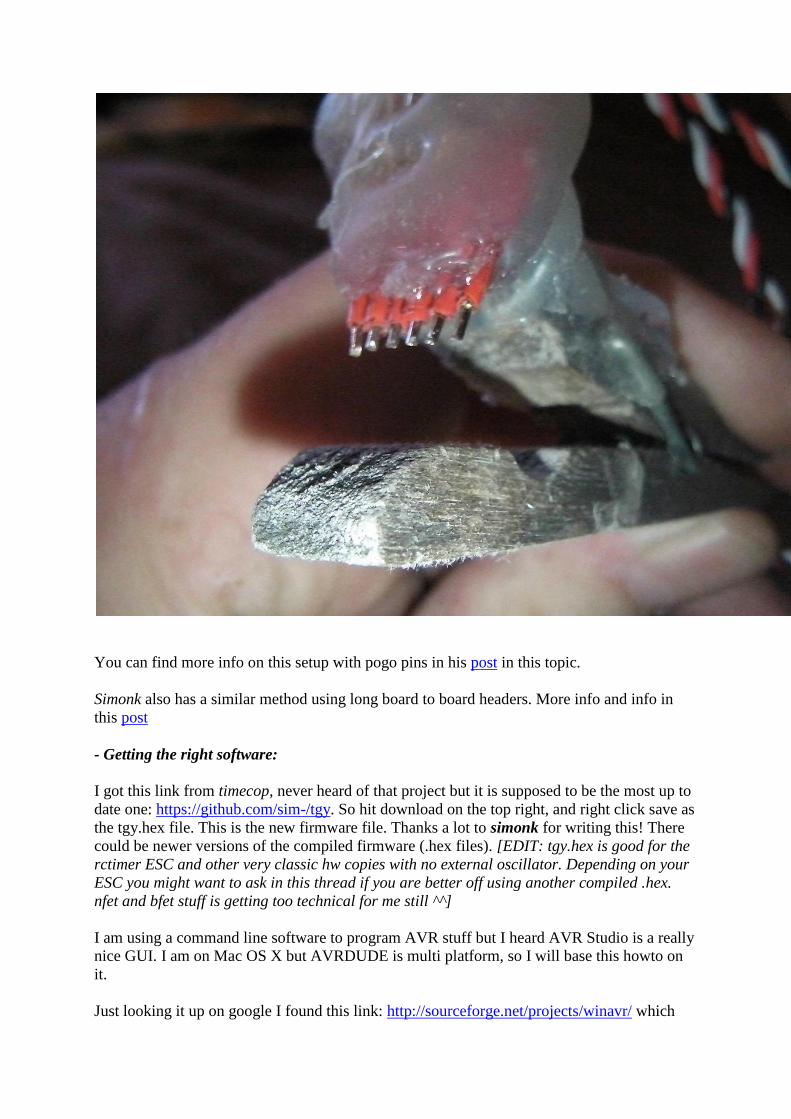
You can find more info on this setup with pogo pins in his post in this topic.
Simonk also has a similar method using long board to board headers. More info and info in
this post
- Getting the right software:
I got this link from timecop, never heard of that project but it is supposed to be the most up to
date one: https://github.com/sim-/tgy. So hit download on the top right, and right click save as
the tgy.hex file. This is the new firmware file. Thanks a lot to simonk for writing this! There
could be newer versions of the compiled firmware (.hex files). [EDIT: tgy.hex is good for the
rctimer ESC and other very classic hw copies with no external oscillator. Depending on your
ESC you might want to ask in this thread if you are better off using another compiled .hex.
nfet and bfet stuff is getting too technical for me still ^^]
I am using a command line software to program AVR stuff but I heard AVR Studio is a really
nice GUI. I am on Mac OS X but AVRDUDE is multi platform, so I will base this howto on
it.
Just looking it up on google I found this link: http://sourceforge.net/projects/winavr/ which
should install AVRDUDE. This link has a tutorial on how to run it in command line.
For OS X go here: http://www.ladyada.net/learn/avr/setup-mac.html Option 1 for install is
supposed to be easy and works.
Linux peeps, well you know what to do, go get the AVRDUDE sources and compile them
This is how I installed it on OS X btw.
- Flashing:
The meat of things! Open up your terminal/cmd line client and navigate to the folder where
you downloaded tgy.hex
Plug in your AVR Programmer into USB and now be VERY careful and press the stiff end of
your wires onto the pins and keep em pressed down. This is where you will need a steady
helping hand or some sort of plastic grips, vice, whatever, just find a way to keep those pins
lined up and contacting the pads. If you are lined up right you will hear the initial beeps and
then continuous beeping.
Now here are the AVRDUDE commands that need to be issued in the terminal while
everything is connected. Quick rundown on the arguments. "-p m8" says that my chip is an
Atmega8, "-c usbasp" is the programmer name, type "avrdude -c asdf" to have the list of the
compatible programmers.
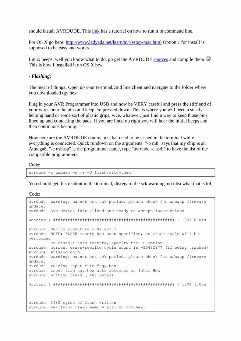
Code:
avrdude -c usbasp -p m8 -U flash:w:tgy.hex
You should get this readout in the terminal, disregard the sck warning, no idea what that is lol
Code:
avrdude: warning: cannot set sck period. please check for usbasp firmware
update.
avrdude: AVR device initialized and ready to accept instructions
Reading | ################################################## | 100% 0.01s
avrdude: Device signature = 0x1e9307
avrdude: NOTE: FLASH memory has been specified, an erase cycle will be
performed
To disable this feature, specify the -D option.
avrdude: current erase-rewrite cycle count is -50462977 (if being tracked)
avrdude: erasing chip
avrdude: warning: cannot set sck period. please check for usbasp firmware
update.
avrdude: reading input file "tgy.hex"
avrdude: input file tgy.hex auto detected as Intel Hex
avrdude: writing flash (1482 bytes):
Writing | ################################################## | 100% 1.08s
avrdude: 1482 bytes of flash written
avrdude: verifying flash memory against tgy.hex:
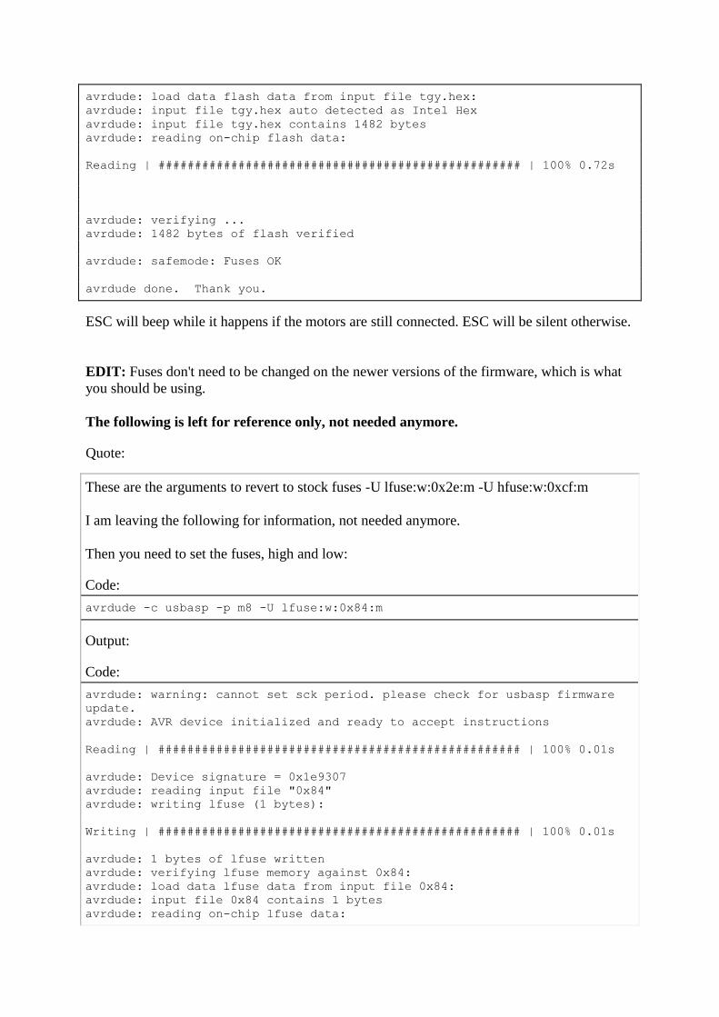
avrdude: load data flash data from input file tgy.hex:
avrdude: input file tgy.hex auto detected as Intel Hex
avrdude: input file tgy.hex contains 1482 bytes
avrdude: reading on-chip flash data:
Reading | ################################################## | 100% 0.72s
avrdude: verifying ...
avrdude: 1482 bytes of flash verified
avrdude: safemode: Fuses OK
avrdude done. Thank you.
ESC will beep while it happens if the motors are still connected. ESC will be silent otherwise.
EDIT: Fuses don't need to be changed on the newer versions of the firmware, which is what
you should be using.
The following is left for reference only, not needed anymore.
Quote:
These are the arguments to revert to stock fuses -U lfuse:w:0x2e:m -U hfuse:w:0xcf:m
I am leaving the following for information, not needed anymore.
Then you need to set the fuses, high and low:
Code:
avrdude -c usbasp -p m8 -U lfuse:w:0x84:m
Output:
Code:
avrdude: warning: cannot set sck period. please check for usbasp firmware
update.
avrdude: AVR device initialized and ready to accept instructions
Reading | ################################################## | 100% 0.01s
avrdude: Device signature = 0x1e9307
avrdude: reading input file "0x84"
avrdude: writing lfuse (1 bytes):
Writing | ################################################## | 100% 0.01s
avrdude: 1 bytes of lfuse written
avrdude: verifying lfuse memory against 0x84:
avrdude: load data lfuse data from input file 0x84:
avrdude: input file 0x84 contains 1 bytes
avrdude: reading on-chip lfuse data:
Reading | ################################################## | 100% 0.00s
avrdude: verifying ...
avrdude: 1 bytes of lfuse verified
avrdude: safemode: Fuses OK
avrdude done. Thank you.
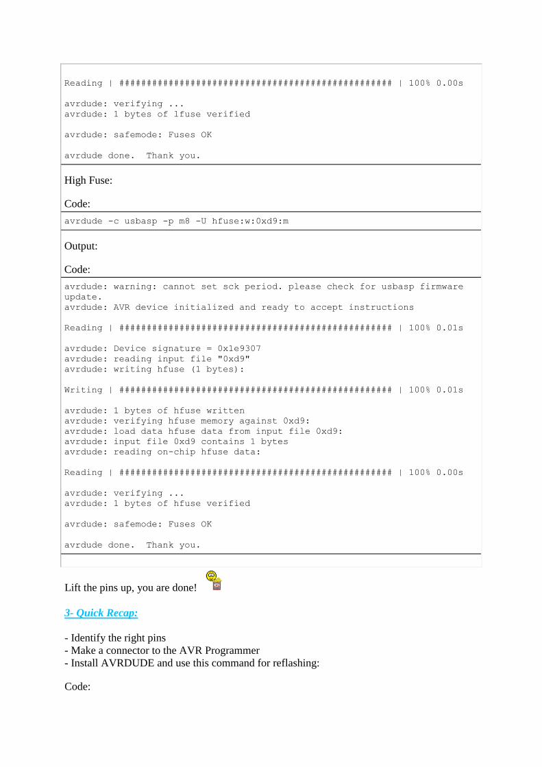
High Fuse:
Code:
avrdude -c usbasp -p m8 -U hfuse:w:0xd9:m
Output:
Code:
avrdude: warning: cannot set sck period. please check for usbasp firmware
update.
avrdude: AVR device initialized and ready to accept instructions
Reading | ################################################## | 100% 0.01s
avrdude: Device signature = 0x1e9307
avrdude: reading input file "0xd9"
avrdude: writing hfuse (1 bytes):
Writing | ################################################## | 100% 0.01s
avrdude: 1 bytes of hfuse written
avrdude: verifying hfuse memory against 0xd9:
avrdude: load data hfuse data from input file 0xd9:
avrdude: input file 0xd9 contains 1 bytes
avrdude: reading on-chip hfuse data:
Reading | ################################################## | 100% 0.00s
avrdude: verifying ...
avrdude: 1 bytes of hfuse verified
avrdude: safemode: Fuses OK
avrdude done. Thank you.
Lift the pins up, you are done!
3- Quick Recap:
- Identify the right pins
- Make a connector to the AVR Programmer
- Install AVRDUDE and use this command for reflashing:
Code:

avrdude -c usbasp -p m8 -U flash:w:tgy.hex
Just did a quick test fly on my tri after the flash, and so far am loving it. Much more precise
response it seems and the noise is 100% times softer.