Embed Size (px)
Citation preview

ChemicalScience
EDGE ARTICLE
Ope
n A
cces
s A
rtic
le. P
ublis
hed
on 2
0 Se
ptem
ber
2021
. Dow
nloa
ded
on 9
/17/
2022
6:2
6:46
AM
. T
his
artic
le is
lice
nsed
und
er a
Cre
ativ
e C
omm
ons
Attr
ibut
ion-
Non
Com
mer
cial
3.0
Unp
orte
d L
icen
ce.
View Article OnlineView Journal | View Issue
Effects of interva
aDepartment of Chemistry, Clemson Univers
E-mail: [email protected] Center for Neutron Research, Nationa
Gaithersburg, Maryland 20899, USA
† Electronic supplementary informationCCDC 2060695–2060698. For ESI and celectronic format see DOI: 10.1039/d1sc04
Cite this: Chem. Sci., 2021, 12, 13379
All publication charges for this articlehave been paid for by the Royal Societyof Chemistry
Received 9th August 2021Accepted 31st August 2021
DOI: 10.1039/d1sc04338b
rsc.li/chemical-science
© 2021 The Author(s). Published by
lence charge transfer interactionbetween p-stacked mixed valent tetrathiafulvaleneligands on the electrical conductivity of 3D metal–organic frameworks†
Shiyu Zhang,a Dillip K. Panda,a Ashok Yadav, a Wei Zhou b and Sourav Saha *a
Achieving a molecular-level understanding of how the structures and compositions of metal–organic
frameworks (MOFs) influence their charge carrier concentration and charge transport mechanism—the
two key parameters of electrical conductivity—is essential for the successful development of electrically
conducting MOFs, which have recently emerged as one of the most coveted functional materials due to
their diverse potential applications in advanced electronics and energy technologies. Herein, we have
constructed four new alkali metal (Na, K, Rb, and Cs) frameworks based on an electron-rich
tetrathiafulvalene tetracarboxylate (TTFTC) ligand, which formed continuous p-stacks, albeit with
different p–p-stacking and S/S distances (dp–p and dS/S). These MOFs also contained different
amounts of aerobically oxidized TTFTCc+ radical cations that were quantified by electron spin resonance
(ESR) spectroscopy. Density functional theory calculations and diffuse reflectance spectroscopy
demonstrated that depending on the p–p-interaction and TTFTCc+ population, these MOFs enjoyed
varying degrees of TTFTC/TTFTCc+ intervalence charge transfer (IVCT) interactions, which
commensurately affected their electronic and optical band gaps and electrical conductivity. Having the
shortest dp–p (3.39 A) and the largest initial TTFTCc+ population (�23%), the oxidized Na-MOF 1-ox
displayed the narrowest band gap (1.33 eV) and the highest room temperature electrical conductivity (3.6
� 10�5 S cm�1), whereas owing to its longest dp–p (3.68 A) and a negligible TTFTCc+ population, neutral
Cs-MOF 4 exhibited the widest band gap (2.15 eV) and the lowest electrical conductivity (1.8 �10�7 S cm�1). The freshly prepared but not optimally oxidized K-MOF 2 and Rb-MOF 3 initially displayed
intermediate band gaps and conductivity, however, upon prolonged aerobic oxidation, which raised the
TTFTCc+ population to saturation levels (�25 and 10%, respectively), the resulting 2-ox and 3-ox
displayed much narrower band gaps (�1.35 eV) and higher electrical conductivity (6.6 � 10�5 and 4.7 �10�5 S cm�1, respectively). The computational studies indicated that charge movement in these MOFs
occurred predominantly through the p-stacked ligands, while the experimental results displayed the
combined effects of p–p-interactions, TTFTCc+ population, and TTFTC/TTFTCc+ IVCT interaction on
their electronic and optical properties, demonstrating that IVCT interactions between the mixed-valent
ligands could be exploited as an effective design strategy to develop electrically conducting MOFs.
Introduction
Electrically conducting metal–organic frameworks (MOFs)1–5
have recently emerged as one of the most attractive smartmaterials because of their diverse functions as super-capacitors,6–8 chemiresistive sensors,9 electrochromic
ity, Clemson, South Carolina 29634, USA.
l Institute of Standards and Technology,
(ESI) available: Experimental details.rystallographic data in CIF or other338b
the Royal Society of Chemistry
devices,10,11 light-harvesting systems,12–16 electrocatalysts,17 andenergy storage systems18–20 that can help advance modernelectronics and energy technologies. The electrical conductivity(s) of MOFs is the product of their charge carrier (i.e., electronsand holes) concentration and charge mobility (i.e., chargetransport capability),1,2 which depend on their structures andcompositions. Therefore, deciphering how framework struc-tures and compositions inuence these two key parameters isvital for the development of electrically conducting MOFs andne-tuning their conductivity for specic applications. WhileMOFs can be easily endowed with the charge carriers by intro-ducing redox-active metal ions, ligands, and guests,21–23
promoting charge movement across 3D frameworks oen
Chem. Sci., 2021, 12, 13379–13391 | 13379

Fig. 1 A representation of how p–p-distance, TTFTCc+ population,and ICVT interactions between the mixed valent TTFTC ligands inMOFs affected their electrical conductivity.
Chemical Science Edge Article
Ope
n A
cces
s A
rtic
le. P
ublis
hed
on 2
0 Se
ptem
ber
2021
. Dow
nloa
ded
on 9
/17/
2022
6:2
6:46
AM
. T
his
artic
le is
lice
nsed
und
er a
Cre
ativ
e C
omm
ons
Attr
ibut
ion-
Non
Com
mer
cial
3.0
Unp
orte
d L
icen
ce.
View Article Online
proves to be a much greater challenge and requires a molecular-level understanding of charge transport mechanisms andstructure–function relationships. Recent studies have revealedthat depending on their structures and compositions, chargemovement in MOFs can occur predominantly through one ofthe following pathways:1–5 (i) through coordination bonds withhigh covalent character made of so N- and S-coordinatingligands and transition metal ions that create signicantmetal–ligand orbital overlap,24–30 (ii) via resonance in p-conju-gated ligands,31–39 (iii) through p-stacked aromatic ligands,40–45
and (iv) via redox hopping mechanism.46 In addition, guestmediated framework oxidation and reduction,47–54 node cross-linking,55 and p-donor/acceptor charge transfer interaction56–59
and also lead to a notable increase of framework conductivity.Although effective through-bond charge movement path-
ways consisting of covalent coordination bonds and p-conju-gated ligands are oen found in various 2D networks andusually lead to high electrical conductivity,9,17,28,29,37–39 they arenot so common and effective in 3D frameworks made of hardcarboxylate and other oxo-ligands,24–27,33–36 which do not createsufficient metal–ligand orbital overlap. As a result, the latteroen rely on through-space charge movement pathways todisplay electrical conductivity.1 In this context, Dinca andcoworkers have demonstrated that several 3D semiconductingMOFs benetted from out-of-plane charge movement alongclosely p-stacked tetrathiafulvalene (TTF)40–42 and hexahydroxy-terphenylene43 ligands, the efficacy of which depended on thep–p-distance between the stacked ligands. We have also shownthat p-donor/acceptor stacks made of complementary redox-active ligands and intercalated guests56,57 facilitated through-space charge delocalization, reducing the electronic bandgaps and enhancing the electrical conductivity of 3D frame-works. Although intervalence charge transfer (IVCT) interac-tions between mixed valent redox-active p-systems areresponsible for the electrical conductivity of many organicsemiconductors and synthetic metals60–62 and similar interac-tions between mixed valent metal ions have also been exploitedto develop electrically conducting MOFs,25–27 mixed-valentligands34,35 are much less prevalent in MOFs, and the effectsof ligand-based IVCT interactions51–53,63,64 on the frameworkconductivity have yet to be studied systematically. Recently,D'Alessandro et al.49–51 and we53 have demonstrated that p-donor/acceptor IVCT interactions between electron-richneutral TTF and extended TTF (ExTTF) and partially oxidized(by air or I2) TTFc+ and ExTTFc+ radical cations facilitatedthrough-space charge delocalization and thereby enhanced theMOF conductivity. The IVCT interaction between isolated p-
Table 1 The key structural parameters of MOFs
Na-MOF1-ox
dp–p (A) 3.391dS/S (A) 3.729: between staggered TTF layers 36�
TTF central C–C bond length (A) 1.342
13380 | Chem. Sci., 2021, 12, 13379–13391
donor/acceptor pairs of p-acidic thiazolothiazole (TTZ) ligandand TTZc� radical cation has also been observed insideMOFs,63,64 but the impact of this phenomenon on the frame-work conductivity remains largely unexplored. Therefore,comprehensive structure–property relationship studies areneeded to establish this promising charge transport mecha-nism as a future design strategy for electrically conductingMOFs.
To demonstrate how the structures and compositions ofMOFs inuence their charge carrier concentration and chargetransport capability, which ultimately dictate their electronicand optical band gaps and electrical conductivity, herein, wehave constructed four new alkali metal-based MOFs (Na, K, Rb,and Cs) using an electron-rich tetrathiafulvalene tetracarbox-ylate (TTFTC) ligand.65,66 The single-crystal structures revealedthat all four frameworks contained extended p-stacks of TTFTCligands, but the p–p and S/S distances (dp–p and dS/S), theangle between the two adjacent TTF layers, i.e., the degree of p-overlap varied signicantly (Table 1). Cyclic voltammetric (CV)analysis shed light on their redox properties and the possibilityof aerobic oxidation of TTFTC ligands. Solid-state quantitativeelectron spin resonance (ESR) spectroscopy conrmed that theseMOFs contained different amounts of aerobically generatedparamagnetic TTFTCc+ radical cations, while diffuse reectancespectroscopy (DRS) revealed intervalence charge transfer (IVCT)
K-MOF 2 Rb-MOF 3 Cs-MOF 4
3.673 3.666 3.7073.791 3.820 3.77465� 64� 87�
1.347 1.330 1.317
© 2021 The Author(s). Published by the Royal Society of Chemistry

Scheme 1 Synthesis and photographs of as-synthesized MOFs.
Edge Article Chemical Science
Ope
n A
cces
s A
rtic
le. P
ublis
hed
on 2
0 Se
ptem
ber
2021
. Dow
nloa
ded
on 9
/17/
2022
6:2
6:46
AM
. T
his
artic
le is
lice
nsed
und
er a
Cre
ativ
e C
omm
ons
Attr
ibut
ion-
Non
Com
mer
cial
3.0
Unp
orte
d L
icen
ce.
View Article Online
interactions between the mixed-valent TTFTC0/c+ ligands, whichcommensurately facilitated charge delocalization and therebydictated their optical band gaps (Eopt) and electrical conductivity(Fig. 1). Density functional theory (DFT) calculations showedthat the p–p-distance and p-overlap between the stacked TTFTCligands in these MOFs inuenced their through-space chargetransport capability, which in turn dictated their electronic bandgap (Eel). In a nutshell, having the shortest p–p-distance and thelargest initial TTFTCc+ population, the oxidized Na-MOF (1-ox)displayed the narrowest band gaps and the highest roomtemperature electrical conductivity, whereas Cs-MOF 4, whichpossessed the longest p–p-distance and a negligible TTFTCc+
population, exhibited the widest band gap and the lowest elec-trical conductivity (Tables 1 and 2). Equipped with intermediatep–p-stacking distances and mediocre initial TTFTCc+ pop-ulations, freshly prepared K-MOF 2 and Rb-MOF 3 initially dis-played intermediate band gaps and electrical conductivity, butupon complete aerobic oxidation, which raised the TTFTCc+
population to the saturation levels, the resulting 2-ox and 3-oxdisplayed much narrower band gaps and higher electricalconductivity (Tables 1 and 2). These comprehensive studiessystematically demonstrated how the structures and composi-tions of four new TTFTC-based MOFs inuenced their chargetransport pathways and consequently, the electronic and opticalband gaps and electrical conductivity, delivering a promisingdesign strategy for the development of electrically conductingMOFs involving IVCT interactions between the p-stacked mixed-valent ligands.
Results and discussionsSyntheses and crystal structures of MOFs
To take advantage of facile aerobic oxidation of electron-richTTFTC to TTFTCc+ radical cation and the subsequent TTFTC/TTFTCc+ IVCT interaction that can promote long-range chargedelocalization, herein, we have constructed a family of TTFTC-based MOFs, in which the p–p-distances, the degree of p-over-lap, and the amount of TTFTCc+ radical cations varied system-atically, showing a clear trend that commensurately inuencedtheir band gaps and electrical conductivity. Solvothermal reac-tions between TTFTC–Me4 tetramethyl ester,67 a precursor toTTFTC ligand, andMOH (M¼ Na, K, Rb, and Cs) in THF/MeOH/H2Omixtures at temperatures below 80 �C yielded needle-shapedcrystals of the corresponding 3D MOF (Na-MOF: 1-ox, K-MOF: 2,Rb-MOF: 3, and Cs-MOF: 4) via in situ saponication of the tetra-ester (Scheme 1, see ESI† for details). The structures, composi-tions, and phase purity of theseMOFs were determined by single-crystal and powder X-ray diffraction (SXRD and PXRD) studies,elemental analysis, and vibrational (infrared and Raman) spec-troscopies. Although these four MOFs were not strictly iso-structural, they all possessed continuous p-stacks of TTFTCligands with increasing p–p- and S/S distances and decreasingTTFTCc+ population, enabling us to identify their structure–property relationships, which were summarized in Tables 1 and2. Unlike previously reported66 TTFTC-based MIL-132–135 serieswhere two trans-COOH groups of each ligand remained proton-ated and contributed to proton conductivity, in our MOFs, all
© 2021 The Author(s). Published by the Royal Society of Chemistry
four carboxylate groups were fully deprotonated and involved inthe secondary building unit (SBU) formation.
The brown-colored as-synthesized Na-MOF ([Na4(TTFTC)(H2-O)2]$0.5H2O) crystallized in an orthorhombic Ibam space groupwith an asymmetric unit containing one Na+ ion, 0.25 TTFTCligand, 0.5 coordinated and 0.125 guest H2O molecules (Fig. 2a–d and S1†). Its SBU consisted of two different hexacoordinatedNa+ ions (violet and cyan polyhedrons in Fig. 2b) bridged by COO�
groups that formed [Na2O10]N sheets located in the ac-planes.These clusters were linked by perfectly planar TTFTC ligandslocated in the ab-planes and stacked co-facially along the c-axis(Fig. 2c) with a uniform interplanar distance (dp–p ¼ 3.39 A, dS/S
¼ 3.73 A). The perfectly octahedral Na+ ions (violet) situated insidethe [Na2O10]N chains were coordinated by six carboxylate-Oatoms, whereas the distorted octahedral Na+ ions (cyan) locatedaround the framework cavities were coordinated to vecarboxylate-O atoms and one H2O molecule. The carboxylategroups of TTFTC had two different coordination patterns: a pair oftrans-COO� groups coordinated two Na+ ions in m2–h
1:h1 bridgingmode, while the other two trans-COO� groups bound three Na+
ions in m3–h1:h2 fashion (Fig. 2d). The two consecutive TTF layers
inside thep-stacks were slightly staggered, as their longmolecularaxes formed a 36� angle, the smallest among all four MOFs. Thealternating TTF layers were perfectly eclipsed by each other(Fig. S1†). Thus, Na-MOF enjoyed the shortest p–p distances andmaximum p-overlap between the TTF layers among the fourMOFs (Table 1), presenting the strongest p–p-interaction and themost favorable conditions for out-of-plane charge movement.Notably, all TTFTC ligands of Na-MOF were perfectly planar andhad the same central C–C bond length (1.347 A), which wasnoticeably longer than that of Cs-MOF (1.317 A, Table 1). Since theTTFc+ radical cations are known to have a planar shape due totheir aromatic nature and longer central C–C bonds due to partialsingle-bond character,66,68 the planar geometry and the uniformly
Chem. Sci., 2021, 12, 13379–13391 | 13381

Fig. 2 (a–d) Na-MOF (1-ox): (a) the crystal structure viewed along the c-axis, (b) the SBU contains two distinct hexacoordinated Na+ ions bridgedby carboxylate groups, (c) the alignment of perfectly planar TTFTC ligands p-stacked along the c-axis, and (d) the coordination pattern of eachTTFTC ligand. (e–h) K-MOF (2): (e) the crystal structure viewed along the c-axis, (f) the SBU features two distinct hepta-coordinated K+ ionsbridged by the carboxylate groups, (g) the alignment of slightly bent TTFTC ligandsp-stacked along the c-axis, and (h) the coordination pattern ofeach TTFTC ligand. (i–l) Rb-MOF (3): (i) the crystal structure viewed along the c-axis, (j) the SBU contains two octa-coordinated (yellow and violetpolyhedrons) and one hepta-coordinated (blue polyhedron) Rb+ ions, (k) the alignment of puckered TTFTC ligands p-stacked along the c-axis,and (l) the coordination pattern of each TTFTC ligand. (m–p) Cs-MOF (4): (m) the crystal structure viewed along the a-axis, (n) the SBU containsfour distinct Cs+ ions (cyan, grey, violet, and yellow polyhedrons) bridged by the carboxylate groups, (o) the alignment of boat-shaped TTFTCligands p-stacked along the b-axis, and (p) the coordination pattern of each TTFTC ligand. C: grey, O: red, S: yellow, Na+: cyan ball, K+: navy blueball, Rb+: green ball, and Cs+: pink ball. The asymmetric units and additional structural features of all four MOFs are shown in Fig. S1.†
Chemical Science Edge Article
Ope
n A
cces
s A
rtic
le. P
ublis
hed
on 2
0 Se
ptem
ber
2021
. Dow
nloa
ded
on 9
/17/
2022
6:2
6:46
AM
. T
his
artic
le is
lice
nsed
und
er a
Cre
ativ
e C
omm
ons
Attr
ibut
ion-
Non
Com
mer
cial
3.0
Unp
orte
d L
icen
ce.
View Article Online
long central C–C bonds of all TTFTC ligands in Na-MOF stronglysuggested that they all enjoyed the same partial TTFTCc+ radicalcation character, i.e., the charges were fully delocalizedthroughout the framework, not just on the crystal surfaces,rendering all ligands the same mixed-valent nature. These struc-tural features also suggested that the solvothermal synthesisyielded Na-MOF in its optimally oxidized form (hence called 1-ox)containing charge delocalized TTFTCc+ radical cations or mixed-valent TTFTC0/c+ ligands. If the oxidation of TTFTC ligands werelimited only to the crystal surface and the resulting TTFTCc+
radical cations had remained isolated not delocalized, then theneutral and oxidized TTFTC ligands would have displayeddifferent structural characteristics, as found recently in a differentTTF-based 2D MOF.68 However, that was not observed in any ofour MOFs presented here. The presence of paramagnetic TTFTCc+
radical cations and the IVCT interaction between mixed-valentTTFTC0/c+ ligands were further evident from the ESR and DRSdata (vide infra). Upon drying and exposure to air, the crystallinebrown powder of the resulting Na-MOF did not change the color
13382 | Chem. Sci., 2021, 12, 13379–13391
and appearance. The PXRD patterns of a freshly prepared anda weeks old Na-MOF powders were in excellent agreement withthe simulated pattern of as-synthesized Na-MOF (Fig. S2a†),conrming that the framework structure and crystallinityremained largely intact upon drying and aerobic oxidation.
The reddish-orange colored as-synthesized K-MOF 2 ([K4-(TTFTC)(H2O)2]$2H2O) crystallized in a monoclinic P21/c spacegroup with an asymmetric unit containing four K+ ions, oneTTFTC ligand, two coordinated and two guest H2O molecules(Fig. 2e–h and S1†). The SBU consisted of two different hepta-coordinated K+ ions (green and violet polyhedrons in Fig. 2f),which were bridged by the carboxylate groups forming 2Dmetalcluster sheets located in the bc-planes. The K+ ions locatedaround the framework cavities (green polyhedrons) were coor-dinated by ve carboxylate-O atoms and two H2O molecules,while those buried inside the metal cluster chains (violet poly-hedrons) were attached to ve carboxylate-O and one S-atom ofTTFTC ligands and one H2O molecule. These clusters wereconnected by the TTF cores aligned roughly along the a-axis and
© 2021 The Author(s). Published by the Royal Society of Chemistry

Edge Article Chemical Science
Ope
n A
cces
s A
rtic
le. P
ublis
hed
on 2
0 Se
ptem
ber
2021
. Dow
nloa
ded
on 9
/17/
2022
6:2
6:46
AM
. T
his
artic
le is
lice
nsed
und
er a
Cre
ativ
e C
omm
ons
Attr
ibut
ion-
Non
Com
mer
cial
3.0
Unp
orte
d L
icen
ce.
View Article Online
stacked along the c-axis at a uniform distance (Fig. 2g, dp–p ¼3.67 A, dS/S ¼ 3.79 A). In addition to all four COO� groups,a pair of trans-S atoms of each TTFTC ligand was also involvedin K+ coordination (Fig. 2h). The carboxylate-O atoms of TTFTCligands had two different coordination modes: those pointingaway from the K+-coordinated S-atoms (O4 and O5) bound oneK+ ion each, whereas the rest (O1–O3 and O6–O8) had a m3-bridging mode. The adjacent TTF layers were more staggered in2, as their longmolecular axes formed a 65� angle (Fig. S1†). Thealternating TTF cores were perfectly eclipsed by each other.Furthermore, all TTFTC ligands in K-MOF 2 were slightly bentand had uniform central C–C bond length (1.347 A, Table 1),indicating that they all possessed the same charge or oxidationstate. The longer central C–C bond of TTFTC ligands in 2 thanin Cs-MOF 4 (Table 1) may be attributed to a partial radicalcation character of the ligands and/or the coordination of theirtwo trans-S atoms with K+ ions in the former. Upon drying andexposure to air, the originally reddish-orange crystals of as-synthesized K-MOF 2 quickly turned dark brown to almostblack within few days, yielding an optimally oxidized 2-ox,which contained more TTFTCc+ radical cations than 2, asdemonstrated by the quantitative ESR analysis (vide infra). ThePXRD proles of freshly prepared and optimally oxidized 2-oxpowders were in good agreement with the simulated pattern ofas-synthesized K-MOF (Fig. S2b†), conrming that the frame-work structure and crystallinity remained largely intact upondrying and aerobic oxidation for several weeks.
The bright orange-colored as-synthesized Rb-MOF 3 ([Rb4(-TTFTC)(H2O)3]$H2O) crystallized in an orthorhombic Pbcn spacegroup with an asymmetric unit featuring two Rb+ ions, 0.5 TTFTCligand, 1.5 coordinated H2O molecules, and 0.5 guest H2Omolecule (Fig. 2i–I and S1†). The SBU consisted of three distinctRb+ ions having different coordination geometries (Fig. 2j)—twoocta-coordinated (violet and yellow polyhedrons) and one hepta-coordinated (blue polyhedron)—which were bridged bycarboxylate-O atoms forming 2D metal cluster sheets. The hepta-coordinated Rb+ ions were surrounded by the TTF cores and lledthe framework pores. Without these Rb+ ions, the overall struc-ture of 3 would closely resemble that of 2. The TTFTC ligands inthis framework were also stacked along the c-axis at a uniforminterplanar distance (Fig. 2k, dp–p ¼ 3.67 A, dS/S ¼ 3.82 A). Theadjacent TTF layers were staggered, which formed a 64� anglebetween their molecular axes, while the alternating TTF layerswere perfectly eclipsed. UnlikeMOFs 1 and 2, all TTFTC ligands of3 were highly bent (chair-shaped) and had shorter central C–Cbonds (1.330 A, Fig. S1† and Table 1), indicating that they werepractically neutral. This was further conrmed by the ESR spec-trum, which showed a negligible TTFTCc+ signal (vide infra). Allfour carboxylate groups, as well as all four S-atoms of each TTFTCligand were coordinated to Rb+ ions (Fig. 2l). Upon drying andlonger exposure to air, the crystalline orange powder of Rb-MOFslowly became dark brown to almost black within a week, indi-cating that some TTFTC ligands in the resulting 3-ox were aero-bically oxidized to TTFTCc+ radical cations and participated inIVCT interaction (vide infra). The PXRD proles of aerobicallyoxidized 3-ox powders were in good agreement with the simulatedpattern of as-synthesized Rb-MOF crystals (Fig. S2c†), conrming
© 2021 The Author(s). Published by the Royal Society of Chemistry
that the framework structure and crystallinity were largelypreserved upon drying and aerobic oxidation.
The bright orange-colored as-synthesized Cs-MOF 4 ([Cs4(-TTFTC)(H2O)2]) crystallized in an orthorhombic Pna21 spacegroup with an asymmetric unit containing four Cs+ ions, oneTTFTC ligand, and two coordinated H2O molecules (Fig. 2m–pand S1†). Its SBU contained four distinct Cs+ ions with differentcoordination geometries and environments (violet, cyan, grey,and yellow polyhedrons in Fig. 2n), which were bridged by thecarboxylate groups. Cs-MOF 4 displayed the longest interplanardistance between the p-stacked TTFTC ligands (Fig. 2o, dp–p ¼3.71 A, dS/S¼ 3.77 A) among the four frameworks. The adjacentTTFTC layers were nearly orthogonal to each other (87� anglebetween their molecular axes), which created the weakest p–p-interaction. Furthermore, all TTFTC ligands in Cs-MOF 4 wereextremely bent (boat-shaped) and had the shortest central C–Cbonds (1.317 A, Table 1), indicating that they were neutralspecies, which was further conrmed by the ESR and DRSanalyses (vide infra). All carboxylate groups and one S atom ofeach TTFTC ligand were involved in the Cs+ ion coordination(Fig. 2p). Unlike MOFs 2 and 3, which gradually became darkerdue to aerobic oxidation leading to the formation of moreTTFTCc+ radical cations, the orange-colored Cs-MOF 4remained unchanged upon drying and exposure to air formonths, showing that it was highly resistant to aerobic oxida-tion. The PXRD proles of dry and air-exposed Cs-MOF powdermatched well with the simulated pattern of the as-synthesizedmaterial (Fig. S2d†), conrming its phase purity and stability.
Notably, the PXRD patterns (Fig. S2†) of all evacuated pris-tine and aerobically oxidized MOFs recorded aer several weekswere still in good agreement with the simulated patterns ob-tained from the SXRD data of the corresponding as-synthesizedMOFs, demonstrating that all these materials largely retainedtheir crystalline structures when stored in screw-capped vialsunder normal laboratory conditions (�20 �C, 30–40% relativehumidity) for several weeks to months.
Thermogravimetric analysis and porosity measurements
Thermogravimetric analysis (TGA) revealed that all four MOFslost ca. 5–10% weight up to 100–150 �C due to the loss ofresidual solvent molecules and then maintained a stableplateau until ca. 300 �C, indicating that the frameworks werestable up to that point before decomposing at even highertemperatures (Fig. S3†). The N2-sorption studies (Fig. S4†)showed that, like previously reported TTFTC-based MIL-132–135, the optimally oxidized 1-ox and 2-ox had very small Bru-nauer–Emmett–Teller (BET) surface area (3.56 and 6.64 m2 g�1,respectively) and pore volume (5.03� 10�3 and 6.52 � 10�3 cm3
g�1, respectively). The Rb- and Cs-MOFs did not display anymeaningful N2 adsorption isotherms. These results were fullyconsistent with their small solvent-accessible pore volumes (Na-MOF: 8.82 A3, 0.5% of unit cell volume; K-MOF: 29.24 A3, 1.4%of unit cell volume; Rb-MOF: 21.65 A3, 1% of unit cell volume;and Cs-MOF: 43.1 A3, 2% of unit cell volume) calculated byMercury soware from the crystal structures aer removing thesolvent molecules using PLATON/SQUEEZE model (Fig. S5†).
Chem. Sci., 2021, 12, 13379–13391 | 13383

Chemical Science Edge Article
Ope
n A
cces
s A
rtic
le. P
ublis
hed
on 2
0 Se
ptem
ber
2021
. Dow
nloa
ded
on 9
/17/
2022
6:2
6:46
AM
. T
his
artic
le is
lice
nsed
und
er a
Cre
ativ
e C
omm
ons
Attr
ibut
ion-
Non
Com
mer
cial
3.0
Unp
orte
d L
icen
ce.
View Article Online
Since our main goal here was to determine how the mixedvalency of electron-rich TTFTC ligands and the IVCT interactionin the resulting TTF/TTFc+ p-donor/acceptor stacks inuencedthe electrical conductivity of these MOFs, the lack of frameworkporosity was not a pertinent concern.
Solid-state ESR analysis: quantication of TTFTCc+ radicalcations in the MOFs
To determine the presence and the population of aerobicallygenerated TTFTCc+ radical cations inside these MOFs, theirsolid-state quantitative ESR spectra (Fig. 3) were recorded atdifferent stages, from which the number of spins, i.e., theunpaired electrons were calculated (see ESI† for details).30,54
Among all four freshly prepared and evacuated MOFs, 1-oxdisplayed the most intense characteristic ESR spectrum ofTTFTCc+ radical cation (g z 2.00), followed by 2 and 3, whereas4 displayed a negligible ESR signal. Based on the ESR signalintensity and assigning each unpaired electron to a TTFTCc+
radical cation, we estimated that freshly prepared 1-ox, 2, 3, and4 contained 1.40 � 1023, 9.42 � 1022, 2.79 � 1021, and 1.60 �1021 spins per mol, respectively, which corresponded to ca. 23%,16%, 0.5%, and 0.3% TTFTCc+ population, respectively (Table2). Upon prolonged exposure to air, the color and ESR signalintensity of brown 1-ox and orange 4 remained unchanged,indicating that the former was already saturated with TTFTCc+
from the beginning, whereas the latter was resistant to aerobicoxidation. In contrast, aer prolonged exposure to air, optimallyoxidized dark brown/black 2-ox and 3-ox powders displayedmore intense ESR spectra, revealing that they contained morespins (1.53 � 1023 and 6.20 � 1022 spins/mol, respectively) andhigher TTFTCc+ population (ca. 25% and 10%, respectively).Given that all TTFTC ligands in each framework had the sameshape and central C–C bond length (vide supra), it appears thatthey all possessed the same amount of spin or partial radicalcation character. In other words, each TTFTC ligand of 1-ox, 2,
Fig. 3 The solid-state quantitative ESR spectra of (a) 1-ox, (b) 2 and 2-ox, (c) 3 and 3-ox, and (d) 4 show the relative populations of para-magnetic TTFTCc+ radical cations in each material.
13384 | Chem. Sci., 2021, 12, 13379–13391
2-ox, 3, 3-ox, and 4 on an average contained 0.23, 0.16, 0.25,0.005, 0.1, and 0.003 unpaired electrons, respectively, i.e., thespins were evenly distributed among all mixed-valent TTFTC0/c+
ligands via IVCT interactions.
Electrochemical behavior of TTFTC ligand and MOFs
To understand the redox properties of these TTFTC-basedMOFs and their ability to undergo aerobic oxidation, theirsolid-state cyclic voltammograms (CVs) were recorded usingdrop-cast lms deposited on Pt-disc working electrodes in 0.1 MTBAPF6/MeCN (Pt-wire counter electrode, Ag/AgCl referenceelectrode) and compared with the solution-phase CVs of the freeligand recorded in the same electrolyte medium (Fig. 4 andS6†). TTFTC–Me4 tetra-ester displayed (Fig. S6a†) two fullyreversible oxidation steps at 880 and 1180 mV corresponding toits radical cation and dication formations, respectively. Bycontrast, TTFTC–H4 tetra-acid displayed (Fig. S6b†) a reversiblerst oxidation step at 580 mV corresponding to its radical cationformation, followed by a quasi-reversible second oxidation peakat 980 mV corresponding to the dication formation. Theseobservations were consistent with the literature reports,66,69,70
which suggested that the rst oxidation of TTF-carboxylic acids,including TTFTC–H4, is a fully reversible process because theresulting TTFc+ radical cations do not undergo any decarboxyl-ation, but the second oxidation step is quasi-reversible due tothe possibility of decarboxylation of the resulting TTF2+
dications.The solid-state CVs of the MOFs (Fig. 4) revelated that the
fully deprotonated TTFTC ligands in these MOFs were oxidizedat much lower potentials than free TTFTC–H4 tetra-acid mole-cules in a MeCN solution. For instance, 1-ox, which containedaerobically oxidized TTFTCc+ radical cations, displayed (Fig. 4a)the rst oxidation peak at �200 mV corresponding to completeelectrochemical ligand oxidation to TTFTCc+ radical cations,
Fig. 4 The CV plots of (a) 1-ox, (b) 2 and 2-ox, (c) 3 and 3-ox, and (d) 4thin-films drop-cast on Pt-disc working electrode in 0.1 M TBAPF6/MeCN (Ag/AgCl reference electrode, Pt counter electrode).
© 2021 The Author(s). Published by the Royal Society of Chemistry
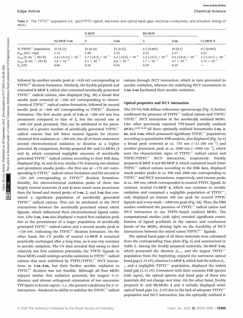
Table 2 The TTFTCc+ population (i.e., spin/TTFTC ligand), electronic and optical band gaps, electrical conductivity, and activation energy ofMOFs
Na-MOF 1-ox
K-MOF Rb-MOF
Cs-MOF 42 2-ox 3 3-ox
% TTFTCc+ population 23 (0.23) 16 (0.16) 25 (0.25) 0.5 (0.005) 10 (0.1) 0.3 (0.003)Eopt (eV)—expt. 1.33 1.99 1.35 2.12 1.37 2.11savg (S cm�1, 293 K) 3.4 (�0.11) � 10�5 1.7 (�0.3) � 10�5 6.3 (�0.6) � 10�5 1.5 (�0.2) � 10�5 4.1 (�0.4) � 10�5 1.3 (�0.3) � 10�7
smax (S cm�1, 293 K) 3.6 � 10�5 2.1 � 10�5 6.6 � 10�5 1.7 � 10�5 4.7 � 10�5 1.75 � 10�7
Ea (eV) 0.06 0.18 0.16 0.19 0.19 —
Edge Article Chemical Science
Ope
n A
cces
s A
rtic
le. P
ublis
hed
on 2
0 Se
ptem
ber
2021
. Dow
nloa
ded
on 9
/17/
2022
6:2
6:46
AM
. T
his
artic
le is
lice
nsed
und
er a
Cre
ativ
e C
omm
ons
Attr
ibut
ion-
Non
Com
mer
cial
3.0
Unp
orte
d L
icen
ce.
View Article Online
followed by another anodic peak at �620 mV corresponding toTTFTC2+ dication formation. Similarly, the freshly prepared andevacuated K-MOF 2, which also contained aerobically generatedTTFTCc+ radical cations, also displayed (Fig. 4b) a broad rstanodic peak centered at �200 mV corresponding to electro-chemical TTFTCc+ radical cation formation, followed by secondanodic peak at �600 mV corresponding to TTFTCc+ dicationformation. The rst anodic peak of 2-ox at �200 mV was lessprominent compared to that of 2, but the second one at�600 mV peak persisted. This can be attributed to the preex-istence of a greater number of aerobically generated TTFTCc+
radical cations that le fewer neutral ligands for electro-chemical rst oxidation at �200 mV, but all of them underwentsecond electrochemical oxidation to dication at a higherpotential. By comparison, freshly prepared Rb- and Cs-MOFs (3and 4), which contained negligible amounts of aerobicallygenerated TTFTCc+ radical cations according to their ESR data,displayed (Fig. 4c and d) very similar CVs featuring two distinctand prominent anodic peaks—the rst one at �170 mV corre-sponding to TTFTCc+ radical cation formation and the second at�550 mV corresponding to TTFTC2+ dication formation.Notably, the electrochemical oxidation peaks of these twolargely neutral materials (3 and 4) were much more prominentthan the broad and muted peaks of 1-ox, 2, and 2-ox that con-tained a signicant population of aerobically generatedTTFTCc+ radical cations. This can be attributed to the IVCTinteractions between the aerobically generated mixed valentligands, which inuenced their electrochemical ligand oxida-tion. Like 2-ox, 3-ox also displayed a muted rst oxidation peakdue to the preexistence of a larger population of aerobicallygenerated TTFTCc+ radical cation and a second anodic peak at�550 mV, indicating the TTFTC2+ dication formation. On theother hand, the CV prole of neutral Cs-MOF 4 remainedpractically unchanged aer a long time, as it was very resistantto aerobic oxidation. The CV data revealed that owing to theirrelatively low rst oxidation potentials, the TTFTC ligands inthese MOFs could undergo aerobic oxidation to TTFTCc+ radicalcations that were stabilized by TTFTC/TTFTCc+ IVCT interac-tions in 1-ox–3-ox, but their further aerobic oxidation toTTFTC2+ dication was not feasible. Although all four MOFsenjoyed similar rst oxidation potential, the longest p–p-distance and almost orthogonal orientation of two successiveTTF layers in 4 (vide supra)—i.e., the poorest conditions for p–p-interaction—hindered its ability to stabilize the TTFTCc+ radical
© 2021 The Author(s). Published by the Royal Society of Chemistry
cations through IVCT interaction, which in turn prevented itsaerobic oxidation, whereas the stabilizing IVCT interactions in1-ox–3-ox facilitated their aerobic oxidation.
Optical properties and IVCT interaction
The UV-Vis-NIR diffuse reectance spectroscopy (Fig. 5) furtherconrmed the presence of TTFTCc+ radical cations and TTFTC/TTFTCc+ IVCT interaction in the aerobically oxidized MOFs.Like other previously reported TTF-based partially oxidizedMOFs,42,49–51,68 all three optimally oxidized frameworks 1-ox, 2-ox, and 3-ox, which possessed signicant TTFTCc+ populationsaccording to quantitative ESR analysis, also displayed (Fig. 5a–c)a broad peak centered at ca. 750 nm (�13 300 cm�1) andanother prominent peak at ca. 2000 nm (�5000 cm�1), whichwere the characteristic signs of TTFTCc+ radical cation andTTFTC/TTFTCc+ IVCT interaction, respectively. Freshlyprepared K-MOF 2 and Rb-MOF 3, which contained much fewerTTFTCc+ radical cations according to the ESR data, displayedmuch weaker peaks at ca. 800 and 2000 nm corresponding toTTFTCc+ and IVCT interactions, respectively, and intense peaksat ca. 500 nm, which corresponded to neutral TTFTC ligand. Incontrast, neutral Cs-MOF 4, which was resistant to aerobicoxidation and contained a negligible population of TTFTCc+,only displayed an intense 500 nm peak for neutral TTFTCligands and a very weak�1900 nm peak (Fig. 5d). Thus, the DRSstudies conrmed the presence of TTFTCc+ radical cation andIVCT interaction in our TTFTC-based oxidized MOFs. Thecomputational studies (vide infra) revealed signicant contri-butions of ligand p-orbitals in the valence and conductionbands of the MOFs, shining light on the feasibility of IVCTinteractions between the mixed valent TTFTC0/c+ ligands.
The optical band gaps of all these materials were calculatedfrom the corresponding Tauc plots (Fig. 6) and summarized inTable 2. Among the freshly prepared materials, Na-MOF 1-ox,which possessed the shortest dp–p and the largest TTFTCc+
population from the beginning, enjoyed the narrowest opticalband gap (1.33 eV), whereas Cs-MOF 4, which had the widest dp–p and a negligible TTFTCc+ population, displayed the widestband gap (2.11 eV). Consistent with their constant ESR spectra(vide supra), the optical spectra and band gaps of these twomaterials did not change over time. On the other hand, freshlyprepared K- and Rb-MOFs 2 and 3 initially displayed wideroptical band gaps (ca. 2 eV) due to the lack of adequate TTFTCc+
population and IVCT interaction, but the optimally oxidized 2-
Chem. Sci., 2021, 12, 13379–13391 | 13385

Fig. 5 The diffuse-reflectance spectra of (a) 1-ox (dotted red line), (b) 2 (solid blue line) and 2-ox (dotted blue line), (c) 3 (solid green line) and 3-ox (dotted green line), and (d) 4 (solid pink line). Insets: the NIR region (1200–2400 nm) featuring the characteristic TTFTC/TTFTCc+ IVCT peaks.
Fig. 6 The Tauc plots of 1-ox (dotted red line), 2 (solid blue line), 2-ox(dotted blue line), 3 (solid green line), 3-ox (dotted green line), and (d) 4(solid pink line) reveal their direct optical band gaps.
Chemical Science Edge Article
Ope
n A
cces
s A
rtic
le. P
ublis
hed
on 2
0 Se
ptem
ber
2021
. Dow
nloa
ded
on 9
/17/
2022
6:2
6:46
AM
. T
his
artic
le is
lice
nsed
und
er a
Cre
ativ
e C
omm
ons
Attr
ibut
ion-
Non
Com
mer
cial
3.0
Unp
orte
d L
icen
ce.
View Article Online
ox and 3-ox enjoyed much narrower band gaps (1.35 and1.37 eV, respectively), which were comparable to that of 1-ox.Thus, the presence of adequate TTFTCc+ radical cations enabledTTFTC/TTFTCc+ IVCT interaction in the aerobically oxidizedMOFs leading to their much narrower band gaps than theneutral forms.
Electronic band structures, band gaps, and density of states
The electronic band structures, band gaps, and density of statesof MOFs 1-ox, 2, and 4 (Fig. 7a–c) were computed by DFTcalculations, which provided valuable insights into theirpredominant charge transport mechanism and revealed thecorrelations between p–p stacking distances, band gaps, and
13386 | Chem. Sci., 2021, 12, 13379–13391
electrical conductivity of these frameworks (Table 2). Thestructural complexity stemming from the presence of the S-coordinated Rb+ ions inside the ‘pores’ of 3 made it extremelydifficult and time-consuming to calculate its band structure.Nevertheless, the strong similarities between the overall struc-tures and p–p distances of MOFs 2 and 3 helped us to under-stand their similar electronic and optical properties.
Having the shortest p–p-distance (3.39 A) and maximum p-overlap (i.e., the least staggered orientation) between theperfectly planar successive TTF layers, Na-MOF 1-ox enjoyed thenarrowest electronic band gap (Eel ¼ 1.67 eV) and the mostdispersed valence band (ca. 0.43 eV dispersion). The effect of thepartial TTFTCc+ radical cation nature of the ligands in as-synthesized Na-MOF was partly built into its SXRD structure(i.e., the planar geometry and longer central C–C bonds), whichalso possibly contributed to its narrower calculated Eel thanother as-synthesized MOFs containing much fewer TTFTCc+
radical cations. By comparison, K-MOF 2 and Cs-MOF 4, whichhad much larger dp–p (ca. 3.7 A) and less p-overlap between thep-stacked TTFTC ligands, displayed much wider electronicband gaps (Eel ¼ 2.0 and 2.15 eV, respectively) and lessdispersed valence bands (0.16 and 0.07 eV, respectively).Notably, calculated Eel and experimental Eopt (DRS) of neutralCs-MOF 4, which barely contained any TTFTCc+, were in goodagreement because its Eopt was not inuenced by any IVCTinteraction. Similarly, the calculated Eel of 2 based on the single-crystal structure of neutral as-synthesized K-MOF was in goodagreement with the Eopt of freshly prepared 2 used for DRSanalysis but signicantly wider than that of aerobically oxidized2-ox (Eopt ¼ 1.35 eV), which contained a much larger TTFTCc+
© 2021 The Author(s). Published by the Royal Society of Chemistry
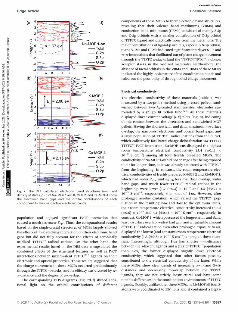
Fig. 7 The DFT calculated electronic band structures (a–c) anddensity of states (d–f) of Na-MOF 1-ox, K-MOF 2, and Cs-MOF 4 showthe electronic band gaps and the orbital contributions of eachcomponent to their respective electronic bands.
Edge Article Chemical Science
Ope
n A
cces
s A
rtic
le. P
ublis
hed
on 2
0 Se
ptem
ber
2021
. Dow
nloa
ded
on 9
/17/
2022
6:2
6:46
AM
. T
his
artic
le is
lice
nsed
und
er a
Cre
ativ
e C
omm
ons
Attr
ibut
ion-
Non
Com
mer
cial
3.0
Unp
orte
d L
icen
ce.
View Article Online
population and enjoyed signicant IVCT interaction thatcaused a much narrower Eopt. Thus, the computational resultsbased on the single-crystal structures of MOFs largely showedthe effects of p–p stacking interaction on their electronic bandgaps but did not fully account for the effects of aerobicallyoxidized TTFTCc+ radical cations. On the other hand, theexperimental results based on the DRS data encapsulated thecombined effects of the structural features as well as IVCTinteractions between mixed-valent TTFTC0/c+ ligands on theirelectronic and optical properties. These results suggested thatthe charge movement in these MOFs occurred predominantlythrough the TTFTC p-stacks, and its efficacy was dictated by p–p-distance and the degree of p-overlap.
The corresponding DOS diagrams (Fig. 7d–f) shined addi-tional light on the orbital contributions of different
© 2021 The Author(s). Published by the Royal Society of Chemistry
components of these MOFs to their electronic band structures,revealing that their valence band maximums (VBMs) andconduction band minimums (CBMs) consisted of mainly S-3pand C-2p orbitals with a smaller contribution of O-2p orbitalof TTFTC ligand and practically none from the metal ions. Themajor contributions of ligand-p orbitals, especially S-3p orbital,to the VBMs and CBMs indicated signicant interlayer S/S andp–p-interactions that facilitated out-of-plane charge movementthrough the TTFTC p-stacks (and the TTFTC/TTFTCc+ p-donor/acceptor stacks in the oxidized materials). Furthermore, theabsence of metal orbitals in the VBMs and CBMs of these MOFsindicated the highly ionic nature of the coordination bonds andruled out the possibility of through-bond charge movement.
Electrical conductivity
The electrical conductivity of these materials (Table 2) wasmeasured by a two-probe method using pressed pellets sand-wiched between two Ag-coated stainless-steel electrodes sur-rounded by a snugly t Teon tube.30,53 All these materialsdisplayed linear current–voltage (I–V) plots (Fig. 8), indicatingohmic contact between the electrodes and sandwiched MOFpellets. Having the shortest dp–p and dS/S, maximum p-surfaceoverlap, the narrowest electronic and optical band gaps, anda large population of TTFTCc+ radical cations from the outset,which collectively facilitated charge delocalization via TTFTC/TTFTCc+ IVCT interaction, Na-MOF 1-ox displayed the highestroom temperature electrical conductivity (3.4 (�0.1) �10�5 S cm�1) among all four freshly prepared MOFs. Theconductivity of Na-MOF 1-ox did not change aer being exposedto air for longer time, as it was already saturated with TTFTCc+
from the beginning. In contrast, the room temperature elec-trical conductivities of freshly prepared K-MOF 2 and Rb-MOF 3,which had wider dp–p and dS/S, less p-surface overlap, widerband gaps, and much fewer TTFTCc+ radical cations in thebeginning, were lower (1.7 (�0.3) � 10�5 and 1.5 (�0.2) �10�5 S cm�1, respectively) than that of 1-ox. However, aerprolonged aerobic oxidation, which raised the TTFTCc+ pop-ulation in the resulting 2-ox and 3-ox to the optimum levels,their room temperature electrical conductivity increased to 6.3(�0.6) � 10�5 and 4.1 (�0.4) � 10�5 S cm�1, respectively. Incontrast, Cs-MOF 4, which possessed the longest dp–p and dS/S,leastp-surface overlap, widest bad gap, and a negligible amountof TTFTCc+ radical cation even aer prolonged exposure to air,displayed the lowest (and constant) room temperature electricalconductivity (1.3 (�0.3) � 10�7 S cm�1) among all these mate-rials. Interestingly, although 1-ox has shorter p–p-distancebetween the adjacent ligands and a greater TTFTCc+ populationthan 3-ox, the former displayed slightly lower electricalconductivity, which suggested that other factors possiblycontributed to the electrical conductivity of the latter. Whilethese MOFs show clear trends of increasing p–p- and S/S-distances and decreasing p-overlap between the TTFTCligands, they are not strictly isostructural and have somenotable differences in the coordination environments of TTFTCligands. Notably, unlike other three MOFs, in Rb-MOF all four S-atoms were coordinated to Rb+ ions and it contained a hepta-
Chem. Sci., 2021, 12, 13379–13391 | 13387

Fig. 8 The linear I–V plots of (a) 1-ox (dotted red line), (b) 2 (solid blue line) and 2-ox (dotted blue line), (c) 3 (solid green line) and 3-ox (dottedgreen line), and (d) 4 (solid pink line) recorded at 293 K, from which their respective electrical conductivity was calculated.
Fig. 9 The Arrhenius plots of temperature-dependent electricalconductivity of 1-ox (dotted red line), 2 (solid blue line), 2-ox (dottedblue line), 3 (solid green line), and 3-ox (dotted green line), from whichtheir respective Ea values were calculated.
Chemical Science Edge Article
Ope
n A
cces
s A
rtic
le. P
ublis
hed
on 2
0 Se
ptem
ber
2021
. Dow
nloa
ded
on 9
/17/
2022
6:2
6:46
AM
. T
his
artic
le is
lice
nsed
und
er a
Cre
ativ
e C
omm
ons
Attr
ibut
ion-
Non
Com
mer
cial
3.0
Unp
orte
d L
icen
ce.
View Article Online
coordinated Rb+ ion surrounded by the TTF core that lled thepores. These structural features possibly contributed to thehigher electrical conductivity of 3-ox. Finally, the conductivitiesof free ligands (Fig. S7†) were several orders of magnitude lowerthan that of all four MOFs: TTFTC–Me4 ester acted as an insu-lator with a conductivity below the measurable limit (s <10�12 S cm�1), whereas TTFTC–H4 tetra-acid displayed a barelymeasurable conductivity (8.5 � 10�11 S cm�1).
It is worth noting that these pellet conductivity values ofMOFs are usually 1–2 orders of magnitude underestimated thanthe corresponding single-crystal conductivity values due to thecontributions of grain boundary and contact resistances in theformer. Furthermore, the single-crystal structures combinedwith the calculated electronic band structures and DOS of theseMOFs suggested that the charge movement through the TTFTCp-stacks or TTFTC/TTFTCc+ IVCT stacks located along certaindirections (the c-axis in 1–3 and a-axis in 4), should be aniso-tropic and therefore, the single-crystal conductivity measuredalong these directions should be higher than the bulk electricalconductivity measured with pressed pellets containingrandomly oriented MOF crystals. However, single-crystalconductivity measurements require large robust crystals andsophisticated setups, which were not available for these studies.
Finally, the thermal activation energies (Ea) of electricalconduction in these materials were determined from theArrhenius plots (Fig. 9 and Table 2) of their respectivetemperature-dependent conductivity values (Fig. S8†). Onceagain, having the shortest p–p-distance and a large TTFTCc+
population from the outset, which provided signicant charge-carrier concentration and facilitated charge movement throughIVCT interaction, 1-ox enjoyed the lowest activation energy (Ea¼
13388 | Chem. Sci., 2021, 12, 13379–13391
0.06 eV), followed by the optimally oxidized 2-ox (Ea ¼ 0.16 eV)and 3-ox (Ea ¼ 0.19 eV), which also contained signicantamounts of TTFTCc+ radical cations but less effective p–p-overlap than 1-ox. The poor electrical conductivity of largelyneutral 4, which was caused by (i) inadequate charge carrierconcentration (contained only 0.3% TTFTCc+) and (ii) the lack ofefficient charge movement through the TTF-stacks having largep–p-distances and highly staggered orientation, did not changemuch with temperature up to 70 �C, indicating that it has a highthermal activation energy. The PXRD proles of the MOF pelletsused for electrical measurements were in good agreement with
© 2021 The Author(s). Published by the Royal Society of Chemistry

Edge Article Chemical Science
Ope
n A
cces
s A
rtic
le. P
ublis
hed
on 2
0 Se
ptem
ber
2021
. Dow
nloa
ded
on 9
/17/
2022
6:2
6:46
AM
. T
his
artic
le is
lice
nsed
und
er a
Cre
ativ
e C
omm
ons
Attr
ibut
ion-
Non
Com
mer
cial
3.0
Unp
orte
d L
icen
ce.
View Article Online
that of the corresponding bulk powders (Fig. S2†), conrmingthat their structures and crystallinity were largely preservedduring these measurements. Thus, the electronic properties ofthese materials were directly impacted by their charge carrierconcentration, i.e., the TTFTCc+ population, as well as the effi-cacy of charge movement pathways, which was largely dictatedby p–p- and TTFTC/TTFTCc+ IVCT interactions.
Conclusions
In summary, we have synthesized four new TTFTC-based 3DMOFs and demonstrated how their structures, compositions,and the oxidation states of ligands inuenced their electronic,optical, and charge transport properties. While all four frame-works contained extended TTF-stacks, the p–p-distance, theextent of p-overlap, and the TTFTCc+ population varied signi-cantly, which commensurately impacted their electronic andoptical band gaps, electrical conductivity, and activation energyof electrical conduction. Having the most effective p–p-inter-action as well as the highest TTFTCc+ population from theoutset, which enabled most facile through-space charge delo-calization via IVCT interaction, Na-MOF 1-ox displayed thenarrowest electronic and optical band gaps, the highest elec-trical conductivity, and the lowest activation energy among allfour freshly prepared MOFs, whereas the opposite was true forCs-MOF 4. In comparison, freshly prepared and not optimallyoxidized K-MOF 2 and Rb-MOF 3 possessed intermediate p–p-overlap and modest TTFTCc+ population in the beginning,which increased upon aerobic oxidation. As a result, theyinitially displayed intermediate band gaps and electricalconductivities, which improved dramatically once they becamesaturated with charge delocalized TTFTCc+ radical cations aerlonger aerobic oxidation. The computational results based onthe single-crystal structures of MOFs primarily showed theeffects of structural features, i.e., dp–p, dS/S, and the degree ofoverlap on their electronic properties, whereas the experimentalresults encompassed the combined effects of structural featuresand TTFTCc+ population on the electronic and optical proper-ties of these MOFs. The foregoing results demonstrated thatboth TTFTCc+ population, which dictated the charge carrierconcentration, and the p–p-interaction, which controlled theefficacy of IVCT interaction and charge delocalization, playedimportant roles on the electrical conductivity and band gaps ofthese frameworks. Importantly, these studies presented a rare,if not the rst, comprehensive understanding of how the mixedvalency of an electroactive ligand and the subsequent IVCTinteraction inuenced the electrical conductivity and band gapsof a family of 3D MOFs having systematically variable structuralparameters and compositions, delivering a promising designstrategy for electrically conductive MOFs.
Data availability
All relevant experimental and computational details areprovided in the ESI.†
© 2021 The Author(s). Published by the Royal Society of Chemistry
Author contributions
Conceptualization and supervision: SS; synthesis and charac-terization (XRD, PXRD, TGA, IR, EPR, CV, and DRS): SZ, DKP,and AY; electrical conductivity measurement: SZ and DKP;theoretical calculations: WZ; writing, reviewing, & editing: SS,SZ, and WZ. All authors proof-read, provided comments, andapproved the nal version of this manuscript.
Conflicts of interest
The authors declare no conicts of interest.
Acknowledgements
This work was supported by the National Science Foundation(award no. DMR-1809092 and CHE-1660329) of the UnitedStates. We thank Dr Collin McMillen for his assistance withsingle-crystal X-ray diffraction analysis, Prof. Thao Tran andXudong Huai for NIR-DRS analysis, and Prof. George Chuma-nov and Dr Tatiana Estrada-Mendoza for Raman spectroscopy.The DFT calculations were performed in part on the NIST EnkiHPC cluster.
References
1 L. S. Xie, G. Skorupskii and M. Dinca, Chem. Rev., 2020, 120,8536.
2 L. Sun, M. G. Campbell and M. Dinca, Angew. Chem., Int. Ed.,2016, 55, 3566.
3 V. Stavila, A. A. Talin and M. D. Allendorf, Chem. Soc. Rev.,2014, 43, 5994.
4 I. Stassen, N. Burtch, A. Talin, P. Falcaro, M. Allendorf andR. Ameloot, Chem. Soc. Rev., 2017, 46, 3185.
5 H. Wang, Q.-L. Zhu, R. Zou and Q. Xu, Chem, 2017, 2, 52.6 L. Wang, Y. Han, X. Feng, J. Zhou, P. Qi and B. Wang, Coord.Chem. Rev., 2016, 307, 361.
7 D. Sheberla, J. C. Bachman, J. S. Elias, C.-J. Sun, Y. Shao-Hornand M. Dinca, Nat. Mater., 2017, 16, 220.
8 W. H. Li, K. Ding, H. R. Tian, M. S. Yao, B. Nath, W. H. Deng,Y. Wang and G. Xu, Adv. Funct. Mater., 2017, 27, 1702067.
9 M. G. Campbell, D. Sheberla, S. F. Liu, T. M. Swager andM. Dinca, Angew. Chem., Int. Ed., 2015, 54, 4349.
10 C. R. Wade, M. Li and M. Dinca, Angew. Chem., Int. Ed., 2013,52, 13377.
11 K. AlKaabi, C. R. Wade and M. Dinca, Chem, 2016, 1, 264.12 E. A. Dolgopolova, V. A. Galitskiy, C. R. Martin,
H. N. Gregory, B. J. Yarbrough, A. M. Rice, A. A. Berseneva,O. A. Ejegbavwo, K. S. Stephenson, P. Kittikhunnatham,S. G. Karakalos, M. D. Smith, A. B. Greytak, S. Garashchukand N. B. Shustova, J. Am. Chem. Soc., 2019, 141, 5350.
13 J. Liu, W. Zhou, J. Liu, I. Howard, G. Kilibarda, S. Schlabach,D. Coupry, M. Addicoat, S. Yoneda, Y. Tsutsui, T. Sakurai,S. Seki, Z. Wang, P. Lindemann, E. Redel, T. Heine andC. Woll, Angew. Chem., Int. Ed., 2015, 54, 7441.
14 W. A. Maza, A. J. Haring, S. R. Ahrenholtz, C. C. Epley,S. Y. Lin and A. J. Morris, Chem. Sci., 2016, 7, 719.
Chem. Sci., 2021, 12, 13379–13391 | 13389

Chemical Science Edge Article
Ope
n A
cces
s A
rtic
le. P
ublis
hed
on 2
0 Se
ptem
ber
2021
. Dow
nloa
ded
on 9
/17/
2022
6:2
6:46
AM
. T
his
artic
le is
lice
nsed
und
er a
Cre
ativ
e C
omm
ons
Attr
ibut
ion-
Non
Com
mer
cial
3.0
Unp
orte
d L
icen
ce.
View Article Online
15 M. A. Gordillo, D. K. Panda and S. Saha, ACS Appl. Mater.Interfaces, 2018, 11, 3196.
16 C.-C. Chueh, C.-I. Chen, Y.-A. Su, H. Konnerth, Y.-J. Gu,C.-W. Kung and K. C.-W. Wu, J. Mater. Chem. A, 2019, 7,17079.
17 E. M. Miner, S. Gul, N. D. Ricke, E. Pastor, J. Yano,V. K. Yachandra, T. V. Voorhis and M. Dinca, ACS Catal.,2017, 7, 7726.
18 Y. Zhang, S. N. Riduan and J. Wang, Chem. –Eur. J., 2017, 23,16419.
19 S. S. Park, Y. Tulchinsky and M. Dinca, J. Am. Chem. Soc.,2017, 139, 13260.
20 D. K. Panda, K. Maity, A. Palukoshka, F. Ibrahim and S. Saha,ACS Sustain. Chem. Eng., 2019, 7, 4619.
21 F. A. A. Paz, J. Klinowski, S. M. F. Viela, J. P. C. Tome,J. A. S. Cavaleiro and J. Rocha, Chem. Soc. Rev., 2012, 41,1088.
22 W. Lu, Z. Wei, Z.-Y. Gu, T.-F. Liu, J. Park, J. Park, J. Tian,M. Zhang, Q. Zhang, T. Gentle III, M. Bosch andH.-C. Zhou, Chem. Soc. Rev., 2014, 43, 5561.
23 D. D'Alessandro, Chem. Commun., 2016, 52, 8957.24 L. Sun, C. H. Hendon, M. A. Minier, A. Walsh and M. Dinca,
J. Am. Chem. Soc., 2015, 137, 6164.25 L. S. Xie, L. Sun, R. Wan, S. S. Park, J. A. DeGayner,
C. H. Hendon and M. Dinca, J. Am. Chem. Soc., 2018, 140,7411.
26 F. Gandara, F. J. Uribe-Romo, D. K. Britt, H. Furukawa,L. Lei, R. Cheng, X. Duan, M. O'Keeffe and O. M. Yaghi,Chem. –Eur. J., 2012, 18, 10595.
27 J. G. Park, M. L. Aubrey, J. Oktawiec, K. Chakarawet,L. E. Darago, F. Grandjean, G. J. Long and J. R. Long, J.Am. Chem. Soc., 2018, 140, 8526.
28 X. Huang, P. Sheng, Z. Tu, F. Zhang, J. Wang, H. Geng,Y. Zou, C. Di, Y. Yi, Y. Sun, W. Xu and D. Zhu, Nat.Commun., 2015, 6(1–8), 7408.
29 A. Pathak, J.-W. Shen, M. Usman, L.-F. Wei, S. Mendiratta,Y.-S. Chang, B. Sainbileg, C.-M. Ngue, R.-S. Chen,M. Hayashi, T.-T. Luo, F.-R. Chen, T. W. Tseng, L.-C. Chenand K.-L. Lu, Nat. Commun., 2019, 10(1–7), 1721.
30 A. Yadav, D. K. Panda, S. Zhang, W. Zhou and S. Saha, ACSAppl. Mater. Interfaces, 2020, 12, 40613.
31 S. Takaishi, M. Hosoda, T. Kajiwara, H. Miyasaka,M. Yamashita, Y. Nakanishi, Y. Kitagawa, K. Yamaguchi,A. Kobayashi and H. Kitagawa, Inorg. Chem., 2009, 48, 9048.
32 C. Avendano, Z. Zhang, A. Ota, H. Zhao and K. R. Dunbar,Angew. Chem., Int. Ed., 2011, 50, 6543.
33 C. A. Farnandez, P. C. Martin, T. Schaef, M. E. Bowden,P. K. Thallapally, L. Dang, W. Xu, X. Chen andB. P. McGrail, Sci. Rep., 2014, 4, 6114.
34 L. E. Darago, M. L. Aubrey, C. J. Yu, M. I. Gonzalez andJ. R. Long, J. Am. Chem. Soc., 2015, 137, 15703.
35 M. E. Ziebel, L. E. Darago and J. R. Long, J. Am. Chem. Soc.,2018, 140, 3040.
36 M. Hmadeh, Z. Lu, Z. Liu, F. Gandara, H. Furukawa, S. Wan,V. Augustyn, R. Chang, L. Liao, F. Zhou, E. Perre, V. Ozolins,K. Suenaga, X. Duan, B. Dunn, Y. Yamamto, O. Terasaki andO. M. Yaghi, Chem. Mater., 2012, 24, 3511.
13390 | Chem. Sci., 2021, 12, 13379–13391
37 T. Kambe, R. Sakamoto, T. Kusamoto, T. Pal, N. Fukui,K. Hoshiko, T. Shimojima, Z. Wang, T. Hirahara,K. Ishizaka, S. Hasegawa, F. Liu and H. Nishihara, J. Am.Chem. Soc., 2014, 136, 14357.
38 D. Sheberla, L. Sun, M. A. Blood-Forsythe, S. l. Er,C. R. Wade, C. K. Brozek, A. n. Aspuru-Guzik andM. Dinca, J. Am. Chem. Soc., 2014, 136, 8859.
39 J.-H. Dou, L. Sun, Y. Ge, W. Li, C. H. Hendon, J. Li, S. Gul,J. Yano, E. A. Stach and M. Dinca, J. Am. Chem. Soc., 2017,139, 13608.
40 T. C. Narayan, T. Miyakai, S. Seki and M. Dinca, J. Am. Chem.Soc., 2012, 134, 12932.
41 S. S. Park, E. R. Hontz, L. Sun, C. H. Hendon, A. Walsh,T. V. Voorhis and M. Dinca, J. Am. Chem. Soc., 2015, 137,1774.
42 L. S. Xie, E. V. Alexandrov, G. Skorupskii, D. M. Proserpio andM. Dinca, Chem. Sci., 2019, 10, 8558.
43 G. Skorupskii, B. A. Trump, T. W. Kasel, C. M. Brown,C. H. Hendon and M. Dinca, Nat. Chem., 2020, 12, 131.
44 X. Kuang, S. Chen, L. Meng, J. Chen, X. Wu, G. Zhang,G. Zhong, T. Hu, Y. Li and C.-Z. Lu, Chem. Commun., 2019,55, 1643.
45 D. Chen, H. Xing, Z. Su and C. Wang, Chem. Commun., 2016,52, 2019.
46 S. Goswami, I. Hod, J. D. Duan, C.-W. Kung, M. Rimoldi,C. D. Malliakas, R. H. Palmer, O. K. Farha and J. T. Hupp,Chem. Soc., 2019, 141, 17696.
47 M.-H. Zeng, Q.-X. Wang, Y.-X. Tan, S. Hu, H.-X. Zhao,L.-S. Long and M. Kurmoo, J. Am. Chem. Soc., 2010, 132,2561.
48 Y. Kobayashi, B. Jacobs, M. D. Allendorf and J. R. Long,Chem. Mater., 2010, 22, 4120.
49 H.-Y. Wang, J.-Y. Ge, C. Hua, C.-Q. Jiao, Y. Wu, C. F. Leong,D. M. D'Alessandro, T. Liu and J.-L. Zuo, Angew. Chem., Int.Ed., 2017, 56, 5465.
50 C. F. Leong, C.-H. Wang, C. D. Ling and D. M. D'Alessandro,Polyhedron, 2018, 154, 334.
51 J. Su, T.-H. Hu, R. Murase, H.-Y. Wang, D. M. D'Alessandro,M. Kurmoo and J.-L. Zuo, Inorg. Chem., 2019, 58, 3698.
52 J. Su, S. Yuan, H.-Y. Wang, L. Huang, J.-Y. Ge, E. Joseph,J. Qin, T. Cagin, J.-L. Zuo and H.-C. Zhou, Nat. Commun.,2017, 8, 2008.
53 M. A. Gordillo, P. A. Benavides, D. K. Panda and S. Saha, ACSAppl. Mater. Interfaces, 2020, 12, 12955.
54 H. C. Wentz, G. Skorupskii, A. B. Bonm, J. L. Mancuso,C. H. Hendon, E. H. Oriel, G. T. Sazama andM. G. Campbell, Chem. Sci., 2020, 11, 1342.
55 A. A. Talin, A. Centrone, A. C. Ford, M. E. Foster, V. Stavila,P. Haney, R. A. Kinney, V. Szalai, F. E. Gabaly, H. P. Yoon,F. Leonard and M. D. Allendorf, Science, 2014, 343, 66.
56 Z. Guo, D. K. Panda, K. Maity, D. Lindsey, T. G. Parker,T. E. Albrecht-Schmitt, J. L. Barreda-Esparza, P. Xiong,W. Zhou and S. Saha, J. Mater. Chem. C, 2016, 4, 894.
57 Z. Guo, D. K. Panda, M. A. Gordillo, A. Khatun, H. Wu,W. Zhou and S. Saha, ACS Appl. Mater. Interfaces, 2017, 9,32413.
© 2021 The Author(s). Published by the Royal Society of Chemistry

Edge Article Chemical Science
Ope
n A
cces
s A
rtic
le. P
ublis
hed
on 2
0 Se
ptem
ber
2021
. Dow
nloa
ded
on 9
/17/
2022
6:2
6:46
AM
. T
his
artic
le is
lice
nsed
und
er a
Cre
ativ
e C
omm
ons
Attr
ibut
ion-
Non
Com
mer
cial
3.0
Unp
orte
d L
icen
ce.
View Article Online
58 S. Goswami, D. Ray, K. Otake, C.-W. Kung, S. J. Garibay,T. Islamoglu, A. Atilgan, Y. Cui, C. J. Cramer, O. K. Farhaand J. T. Hupp, Chem. Sci., 2018, 9, 4477.
59 A. M. Rice, E. A. Dolgopolova, B. J. Yarbrough, G. A. Leith,C. R. Martin, K. S. Stephenson, R. A. Heugh, A. J. Brandt,D. A. Chen, S. G. Karakalos, M. D. Smith, K. B. Hatzell,P. J. Pellechia, S. Garashchuk and N. B. Shustova, Angew.Chem., Int. Ed., 2018, 57, 11310.
60 M. R. Bryce and L. C. Murphy, Nature, 1984, 309, 119.61 J. R. Kirtley and J. Mannhart, Nature Mat., 2008, 7, 520.62 Y.-S. Guan, Y. Hu, H. Zhang, G. Wu, H. Yan and S. Ren,
Chem. Commun., 2019, 55, 7179.63 B. Ding, C. Hua, C. J. Kepert and D. M. D'Alessando, Chem.
Sci., 2019, 10, 1392.64 P. W. Dohney, J. K. Clegg, F. Tuna, D. Collison, C. J. Kepert
and D. M. D'Alessando, Chem. Sci., 2020, 11, 5213.
© 2021 The Author(s). Published by the Royal Society of Chemistry
65 Y.-R. Qin, Q.-Y. Zhu, L.-B. Huo, Z. Shi, G.-Q. Bia and J. Dai,Inorg. Chem., 2010, 49, 7372.
66 T. L. A. Nguyen, R. Demir-Kakan, T. Devic, M. Morcrette,T. Ahnfeldt, P. Auban-Senzier, N. Stock, A.-M. Goncalvez,Y. Filinchuk, J.-M. Tarascon and G. Ferey, Inorg. Chem.,2010, 49, 7135.
67 Y. Qian, Y. Lin, S. Liu, S. Zhang, H. Chen, Y. Wang, Y. Yan,X. Guo and J. Huang, Chem. Commun., 2013, 49, 704.
68 J. Su, N. Xu, R. Murase, Z.-M. Yang, D. M. D'Alessandro,J.-L. Zuo and J. Zhu, Angew. Chem., Int. Ed., 2021, 60, 4789.
69 F. Pontillart, Y. E. Gal, S. Gilhen, O. Cador and L. Ouahab,Chem. Commun., 2009, 3777.
70 C. J. Kepert, D. Hesek, P. D. Beer and M. J. Rosseinsky,Angew. Chem., Int. Ed., 1998, 37, 3158.
Chem. Sci., 2021, 12, 13379–13391 | 13391


