Embed Size (px)
Citation preview

SOUTHWEST RESEARCH INSTITUTE®
POWERTRAIN ENGINEERING
C>SOUTHWEST RESEARCH INSTITUTE swri.org
Evaluating Technologies and Methods to Lower Nitrogen Oxide Emissions from Heavy-Duty Vehicles
Christopher Sharp, Ian Smith Southwest Research Institute
1

POWERTRAIN ENGINEERING
C>SOUTHWEST RESEARCH INSTITUTE swri.org
Agenda
• Introduction • General Program Details
• CNG Program • Diesel Program
• Question and Answer
2

75 ... 55 I , _,_..
50 I I
44 42
25 ;
I I 26
22
I ~ I
ol 1H.h p j I §
l. ~ - !. 11 i i:
19 19
i i !, t
n 5
-~ 17
.. IL
i' i r
17 li i i i . .. i
i t
i
C>SOUTHWEST RESEARCH INSTITUTE
■ ---~-20 I 5 - Projected
POWERTRAIN ENGINEERING
swri.org
1979
Motivation • Ozone nonattainment areas across the United States
continue to grow – Growth in population – Continued tightening of ozone standard
• 2015 EPA rulemaking changed NAAQS for ozone to 70 ppb
• CARB Inventory shows on-road heavy-duty trucks are ~20% of all NOX emissions
• California requires more reduction in NOX emissions to meet the current NAAQS for ozone and PM
– The current 0.20 g/bhp-hr NOX standard isn’t enough 3

POWERTRAIN ENGINEERING
C>SOUTHWEST RESEARCH INSTITUTE swri.org
CARB Low NOX Programs at SwRI • Stage 1 – EvaluatingTechnologies and Methods to Lower Nitrogen Oxide
Emissions from Heavy-Duty Vehicles (2014-2017)
– CNG and Diesel – Initial Technology Evaluation – Primary focus on Regulatory Cycles – Focus of today’s presentation...
• Stage 2 – Heavy-Duty Low Load Emission Control (2017-2018)
– Diesel – Expand previous technology evaluation to low-load and urban
operating cycles
• Stage 3 – Further Evaluation and Development of Low NOX Technologies on 2017 (non-Turbocompound) Engine Platform (2017-2018)
– Diesel – Focus on both Low Load (Real world) and Regulatory cycles
4

POWERTRAIN ENGINEERING
C>SOUTHWEST RESEARCH INSTITUTE swri.org
Program Objectives (Stage 1) • Development target is to demonstrate 90%
reduction from current HD NOX standards – 0.02 g/bhp-hr – Aged parts
• Solution must be technically feasible for production
• Solution must be consistent with path toward meeting future GHG standards
– CO2, CH4, N2O
• Diesel engine and CNG engine
5

C>SOUTHWEST RESEARCH INSTITUTE
100
80
60 %
40
20
~----------~ --~------~ 100
NYNF IANF IAFY NYNF
80
60
40
20
0
0 +--~~-~-~-~~~~-~-~-~~~----1
0 100 200 300 400 500 600 700 800 900 1000 1100 1200
Time, s
POWERTRAIN ENGINEERING
swri.org
%
120
140
160
180
200
100
80
60
40
20
Test Cycle Selection U.S. Heavy Duty FTP
• Primary Cycles for Program
– US HD FTP – primary focus – WHTC – secondary focus – RMC-SET – required for GHG
assessment – Primary Cycles are calibration focus – CARB Idle
Final NYBCx4 Cycle Note: Normalized torque < 0 indicates closed-throttle motoring torque speed
Example Vocational Cycle - NYBC
• Additional Vocational Cycles
– NYBC, ARB Creep, OCTA
Nor
mal
ized
Torq
ue, %
100
80
60
40
20
0
-
0
20
40
60
80
100
Nor
mal
ized
Spee
d, %
-– Lower load operation (drayage, etc.) -– Demonstration only (no additional -
-0 400 800 1200 1600 2000 2400calibration)
Time, sec
6

I . I I - .- H -I
~ .. n .I I,, ~ - rl -· 'I h,-I
r '
I u- '
~ I l . I+ I I
Ii I 17
' ' " ~
I ~ - . I ~
. . ~J J [1 j J ~I
I
l J
Qt
I
I
-J '
I
-
~ I I
H
[[
RESEARCH INSTITIJTE CSOVTHWEST
POWERTRAIN ENGINEER'.NG
swn.org
120
140
160
180
200
100
80
60
40
20
120
140
160
180
200
100
80
60
40
20
120
140
160
180
200
100
80
60
40
20
80
60
40
20
Vocational (Low Load) Cycles Final NYBCx4 Cycle Final Cruise + Creep x 10 Cycle Note: Normalized torque < 0 Note: Normalized torque < 0
indicates closed-throttle motoring indicates closed-throttle motoring torque speed torque speed
100 100
Nor
mal
ized
Torq
ue, %
N
orm
alize
d To
rque
, %
Nor
mal
ized
Torq
ue, %
80
60
40
20
0 100 0 100
Nor
mal
ized
Spee
d, %
N
orm
alize
d Sp
eed,
%
Nor
mal
ized
Spee
d, %
80
60
40
20
80
60
40
20
-
-
-
-
-
-
-
-
- 0 - 0 0 400 800 1200 1600 2000 2400 0 400 800 1200 1600 2000 2400 2800 3200
Time, sec
Final OCTA Cycle Note: Normalized torque < 0 indicates closed-throttle motoring torque speed
100
80
60
40
20
0
Time, sec
• NYBC Cycle – Prep cycle + 30min idle + Test Cycle – 6% average power on duty cycle
• Cruise Creep Cycle – Engine Warm up + Test Cycle
100
- 80 – “Cruise” mode is preconditioning – “Creep” mode is 3% average power
• OCTA Cycle - 60
- 40
- 20
- 0 – Prep cycle + Test Cycle (no dwell) 0 400 800 1200 1600 2000
Time, sec – 15% average power
7

SOUTHWEST RESEARCH INSTITUTE®
POWERTRAIN ENGINEERING
C>SOUTHWEST RESEARCH INSTITUTE swri.org
Evaluating Technologies and Methods to Lower Nitrogen Oxide Emissions from Heavy-Duty Vehicles:
Natural Gas Engine
Ian Smith,Thomas Briggs and Christopher Sharp Southwest Research Institute
8

POWERTRAIN ENGINEERING
C>SOUTHWEST RESEARCH INSTITUTE swri.org
NOX Emission Goals: Reduction and Efficiency Two main goals: • Achieve 0.02 g/bhp-hr NOX emissions over the U.S. Heavy-Duty FTP, RMC-
SET and the European WHTC • Minimize the impact to GHG emissions
– Provide the pathway towards meeting Phase 2 GHG standards 0.2
0.18 0.16 0.14 0.12
0.1 0.08 0.06 0.04 0.02
0
CO2 Emissions (g/bhp-hr) Secondary objectives: • Observe the emissions over the CARB extended idle test as well as
3 low-load vocational cycles
NO
X Em
issi
ons
(g/b
hp-h
r)
500 515 530 545 560 575
9

Cl'II\.Jll'IICCl"l.1 1'11\.J
C>SOUTHWEST RESEARCH INSTITUTE swri.org
Test Engine
2014 model year Cummins ISX12-G engine certified to 2010 U.S. Heavy-Duty emissions standards
• 238 kW @ 1800 RPM // 1559 Nm @ 1200 RPM • High-pressure loop, cooled EGR • Stoichiometric – single-point, upstream fueling • Three-way catalyst • Bus application
10

--Cold Sta rt NOx --Hot Start NOx --Speed
2500
2000
1500 ~ 1000 E X e-0 500 z ""O
-~ 6 QJ QJ a.
"' "' '3 QJ
C: E 4 'oi, :, C: u ...
2
0 0 200 400 600 800 1000 1200
Time (sec)
-- old Start Cat Bed Temp --Hot Start Cat Bed Temp --Speed
u e 800 QJ 1-""0 600 QJ co
]. 400 ~ "' u 200
0
-,--½--------------------~ 2500
2000
1500
1000 ~ 500 -o
QJ
+--1---------'----~~~~'._=---.:::"'"!!""~----l- o ~
0 200 400 600
Time (sec)
800 1000 1200
"' QJ C:
'oi, C: ...
@SOUTHWEST RESEARCH INSTITUTE
E li 500
-~ 400 0
E 300 E <( 200
100
0
--Ammoni a --Speed
,------------,;;;;;;;;;;;;;;;;;;;;;;;;;;;;;;;;;;,--, 2000
+----r-----------L_-------11-----+ 1500
-+-------tr-------------------1----+- 1000 E -+-----------------------+- 500 e,
0 500 1000 1500 2000
Time (sec)
POWERTRAIN ENGINEERING
swri.org
""O QJ QJ a. "' QJ C: 'oi, C:
UJ
Baseline Emissions: Certification Cycles Looking at the emissions gives insight into areas of improvement
• Cold-start NOX • RMC-SET emissions – NH3 emissions – Catalyst light-off – Slightly rich AFR – Open-loop fueling set-point
• Hot-start NOX emissions – AFR control
Pollutant FTP RMC-SET WHTC NOX, g/bhp-hr 0.115 0.012 0.308 NH3, avg. ppm 75 160 88 CO2, g/bhp-hr 541.8 453.8 505.1
11

NOxg/hr - N0>1 Ave to 1800s. - NH3ppm - C.-.tBcddcgC - Speed RPM
1200 135
"[ CARB Extended Idle 120 1000 ~
:c IOS z --.. u
800 .. 90 .,
:!!. .., ~ 75
., 600
., 0 GO ~ z e
45 400 f
30 1 ~
WO " 15 C ·;;, .5
0 0 0 600 1200 1800 2400 3000 3600
Time !sec)
POWERTRAIN ENGINEERING
@SOUTHWEST RESEARCH INSTITUTE swri.org
Baseline Emissions: Low Load Cycles
The engine was tested over low load cycles to examine performance off-cycle
• Low load vocational cycles representative of the engine’s use in a bus application – CARB Extended Idle – OCTA – NYBC – Cruise-Creep
Tailpipe, g/hp-hr ppm NOX PM NMHC CO CO2 CH4 NH3
NYBC 0.907 0.0009 0.190 1.580 672.4 1.893 11.7 Cruise-Creep 0.070 0.0038 0.157 2.774 612.3 1.596 124.4 OCTA 0.112 0.0024 0.107 2.350 552.8 1.078 91.9
12

S
Stoc
N
POWERTRAIN ENGINEERING
@SOUTHWEST RESEARCH INSTITUTE swri.org
Base
line
Engi
ne
Engine Hardware Improvements
The baseline engine was upgraded with new hardware and engine control unit/calibration to achieve the 0.02 g/bhp-hr NOX emission target
ingle Underfloor TWC (22.4 L)
Close-coupled TWC (9 L) & Underfloor TWC
(20 L)
k CM2180A ECMAftermarket EControls ECU
o CCV System Full CCV System
• Lower PM and gaseous emissions
• Lower oil consumption
Low
NO
X D
emon
stra
tion
Engi
ne
Motivation for CCV System 2012 ISLG FTP NOX
Blowby Emissions (g/bhp-hr)
Cold Start 0.044
Hot Start 0.008
Composite 0.013
13

Air Intake
C>SOUTHWEST RESEARCH INSTITUTE
lntercooler
~
Compressor
Throttle
Boost
Recirculation
Circuit
POWERTRAIN ENGINEERING
swri.org
Engine Hardware Improvements
Additional hardware was added to increase the EGR tolerance and transient performance of the engine
• EGR Tolerance – Baseline: Capacitive discharge
ignition coil system – Demonstration: Improved fuel-air-EGR
mixer and higher energy DC ignition coil system
• Additional Improvements – Continuous flow valve (CFV) for fueling – Electronically controlled wastegate – Boost recirculation valve
To Intake Manifold
14

Sw
C>SOUTHWEST RESEARCH INSTITUTE
--Speed --Load
... L!O!.._. ____ L_I0 ____ _...._...._-'1-----~ ------~ 100
80
60
40
·t----t----Y-1Ht---t-1'----t---.f'\-----.----~ ---------, 20 !----'-- l.af-----1,,J-1.,;,--v---\,_..,._ _______ + o
100 80 I 60 40
20 0 -
0 20 40 60 80 100 120 140
-- rpm -- T_delay_FB I 1000 ~ 750 QI
S00 0 t'.
250 0 ~
2000 0 C .. e ~ Q.
.!::- 1500 '0 QI QI
~ 1000 ., C ·ac C 500 ...
0 0 200 400 600 800 1000 1200
Time (secl
POWERTRAIN ENGINEERING
swri.org
Closed Loop Fueling Large focus on keeping the engine within closed loop fueling
itching O2 sensor UEGO Sensor
Base
line
Engi
ne
Low
NO
X D
emon
stra
tion
Engi
ne
Rev. 2
Closed Loop Timing
Rev 1 Baseline
• Pre- & post- • UEGO sensor located catalyst just downstream of switching O2 turbocharger sensors
• Transport and feedback delay minimized • Accurate measurements of fuel supply,
intake and exhaust volume required
15

Cold - CC Cata lyst
·· ·· · ·· Hot - UF Catalyst 800
700 u :;- 600 (II
~ 500 ~
~ 400 E
: 300
! 200 "' u 100
0
0 50
· · · · ·· · Cold - UF Catalyst
--Baseli ne
100 150 Time (sec}
200
--Hot - CC Catalyst
250 300
- Catalyst Heating Strategy - No Catalyst Heating Strategy 9
8
:§ 7
C 6 0
·;;;; "' .E s
UJ X
4 0 z (II
3 > ·.;
"' :i 2 E ::, u 1
0
~ I
f--- -f I ~
r1r --I
0 so
C>SOUTHWEST RESEARCH INSTITUTE
100 150 Time (sec}
200
I
250 300
POWERTRAIN ENGINEERING
swri.org
--
Cold Start Improvements
• Catalyst heating strategy – Ignition timing retard after
TDC (up to 15° aTDC) – Slight enrichment – EGR use disabled for first 30
seconds
• Emissions difference – 4x decrease in NOX emissions
with catalyst heating – Slight performance detriment
during ignition timing retard – Once catalyst is up to
temperature, near-zero NOX emissions
16
12%
9"
6%
I 3%
~ .¥
~ 0%
"
0 200
--VECorre ction --Speed --Load
400 600
lime (sec)
] oil .,, ! "' .,,
100 i E Q z
so
1000
C>SOUTHWEST RESEARCH INSTITUTE
12%
9%
6'6
I 3'6
.2 i ~
0%
;:,
0 200
--VECo,rection --Sp eed --Load
400 600
lime (sec)
800 1000
POWERTRAIN ENGINEERING
swri.org
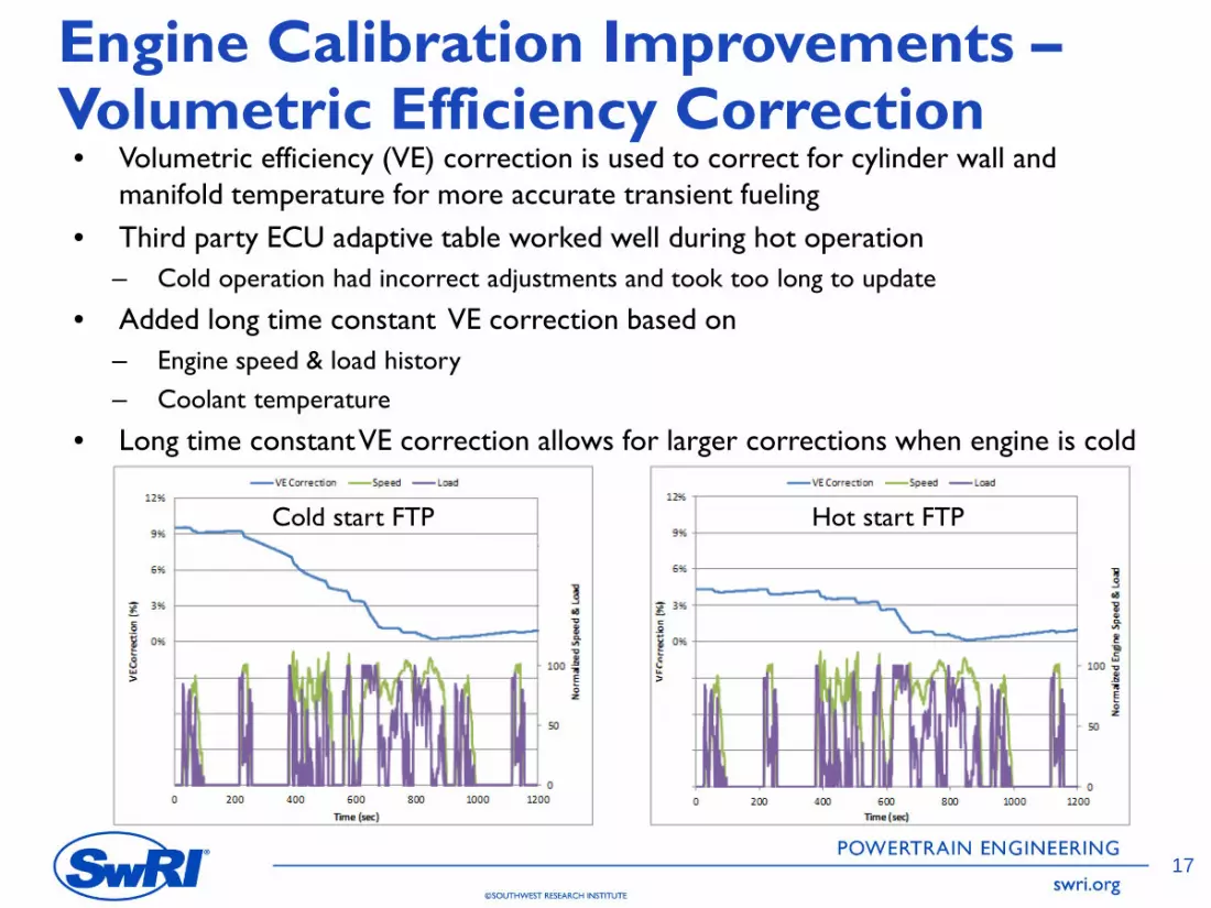
Engine Calibration Improvements – Volumetric Efficiency Correction• Volumetric efficiency (VE) correction is used to correct for cylinder wall and
manifold temperature for more accurate transient fueling • Third party ECU adaptive table worked well during hot operation
– Cold operation had incorrect adjustments and took too long to update
• Added long time constant VE correction based on – Engine speed & load history – Coolant temperature
• Long time constant VE correction allows for larger corrections when engine is cold
Cold start FTP Hot start FTP
17

:§ a· z QJ
.::: ni :i E E ::, u
--Demonstration Cold Start --Demonstration Hot Start --- - Baseline Cold Start
---- Baseline Hot Start --Speed
6
4
2
0
0
I I I
,,----------,----------------,--
___________________ ,--,-----------
200 400 600 Time (sec)
800
E C. ~ £ z
2500
2000
1500
1000 E C.
500 ..:.. -0 QJ QJ C. V,
0
QJ C ·.,, C w
1000 1200
500
400
300
200
100
0
--Demonstration Ammonia --Baseline Ammonia --Speed
~-------------------------------~ 2500
+----------------------------------+ 2000
+------r------..-----------'----------ti---+ 1500
+---t--------------------------~t---+ 1000 E +----------------------------------+ 500 _g:
-0 QJ QJ C. V,
QJ C ·.,, C w
2400 2800 3200 3600
Time(sec)
4000 4400 4800
POWERTRAIN ENGINEERING
C>SOUTHWEST RESEARCH INSTITUTE swri.org
Improved Calibration & Hardware Results: FTP & RMC-SET
• Demonstration cold start emissions equivalent to baseline hot start
• Near zero NOx emissions over the RMC-SET
• Significantly lower NH3 emissions
18

1.2 .------------Low Control Temp+ 90 deg C
~ 0.8
.. i 0.6
2' UJ 04
- EC lambda
- 2ndAir - CatBed
Low Control Temp
0.2
0 -----,.----.----------~-.-------+ 0 10 20 30 40 50 60
Time seconds
POWERTRAIN ENGINEERING
C>SOUTHWEST RESEARCH INSTITUTE swri.org
CNG Catalyst Final Aging Field Cycle - OCTA Standard Bench Cycle
Exhaust T degC CC TC1 bed degC CC TC2 bed degC CC TC3 (rear gas) degC
CC TC4 (front gas) degC UF TC5 (rear gas) degC UF TC6 bed degC Aftertreatment Out T degC (Accelerated Aging) 650
965°C 600
550
Average ~ 550°C – 600°C
1900 2100 2300 2500 2700 2900 3100 3300 3500 3700 3900
500
875°C 450
400
Cycle is 13 miles of driving FUL = 137 hours FUL = 435,000 miles
FUL = Full Useful Life
• OCTA bus cycle used for field duty cycle • Standard Bench Cycle for 3-way catalyst aging
– Low Control Temp = 875°C – Exotherm peak (LCT + 90°C) = 965°C – This results in “reference” temperature = 900°C based on an actual cycle run
• 137 hours on SBC = 435,000 miles (includes factor of 1.2 for oil poisoning) – Performed using natural gas fired FOCAS® burner stand
19

POWERTRAIN ENGINEERING
C>SOUTHWEST RESEARCH INSTITUTE swri.org
CARB Demonstration
Testing performed over the span of a couple weeks • US certification cycles
– 5 repeats of cold + 3 hot FTP & RMC-SET – CARB extended idle (optional certification cycle)
• Non-US certification cycles – 3 repeats of cold + 3 hot WHTCs
• Low load vocational – 3 repeats of NYBC, OCTA, and Cruise-Creep
• Testing performed in compliance with 40 CFR 1065 • Raw and dilute emissions measurements to verify low emissions levels
– Both raw and dilute measurements required two different gas calibration ranges for cold and hot start
» Ex. 250 ppm NOX range for cold-start and 25 ppm NOX range for hot-start
20

0.1 '-..c
I
a. ::E 0.08 ......... 0.0 Vl'
§ 0.06 Vl Vl
E LU 0.04
X
0 z
0.02
0
■ Day 1 ■ Day 2 ■ Day 3 ■ Day 4 ■ Day 5
Co ld Hot 1 Hot 2 Hot 3 Composite RMC-SET
POWERTRAIN ENGINEERING
@SOUTHWEST RESEARCH INSTITUTE swri.org
NOX Emissions: FTP, RMC-SET & WHTC
Certification cycles were the primary focus for calibration efforts
NOX Emissions Comparison, g/bhp-hr FTP
RMC-SET WHTC
Cold Hot Composite Cold Hot Composite Baseline 0.247 0.093 0.115 0.012 0.310 0.308 0.308
Low NOX Engine 0.065 0.001 0.010 0.001 0.043 0.006 0.011 Reduction 74% 99% 91% 92% 86% 98% 96%
21

@SOUTHWEST RESEARCH INSTITUTE
■ 2014 CO2 Std. ■ 2017 CO2 Standard ■ CO2 ■ CO2+ 25xCH4 >.l
700
650
600
~ 550 c.. .s:: .-e_ 500 ~ ON 450 u
400
350
300
1
0.9
0.8
0.7
Vocational (FTP) Tractor (SET)
■ CH4 Std ■ CH4
0.92
~ 0.6 +----------------------, a. ~ 0.5
'tio 0.4 +----------------------,
a" 0.3
0.2
0.1
0
Vocational (FTP) Tractor (SET)
POWERTRAIN ENGINEERING
swri.org
Other Emissions: FTP, RMC-SET & WHTC
GHG emissions and ammonia were of interest
Other Emissions Comparison Pollutant FTP RMC-SET WHTC
Baseline CH4, g/bhp-hr 0.96 1.20 1.54 NH3, avg. ppm 76 162 100 CO2, g/bhp-hr 542 454 510 CH4, g/bhp-hr 0.15 0.92 0.10
Low NOX Engine NH3, avg. ppm 52 37 44 CO2, g/bhp-hr 547 445 513 CH4, g/bhp-hr 84% 23% 94%
Reduction NH3, avg. ppm 32% 77% 56% CO2, g/bhp-hr -0.9% 2.0% -0.6%
22

tio ox z (1/ :,, ·;:
"' :i E E ::, u
4
3
2
1
0
--Demonstration NOx --Baseline NOx --Speed
2000
lSOO
1000 E a.
>------------------------+ 500 ~
" (1/ (1/
a. II\ (1/ C:
·a:o C:
UJ
1910 2410 2~10 Time {sec)
3410
tio ox z (1/ :,, ·;:
"' :i E E ::, u
@SOUTHWEST RESEARCH INSTITUTE
--Demonstration NOx --Baseli ne NOx --Speed
2000
1500
1000 E a.
500 ~
" (1/
20
15
10
5
0
~
~ __.,.-r-
~
0 (1/
a. II\ (1/ C:
·a:o C:
UJ
4200 4700 5200 5700 6200 Time (sec)
POWERTRAIN ENGINEERING
swri.org
Low LoadVocational Cycles
Near zero NOX emissions with no GHG/fuel penalty over low load cycles
OCTA Tailpipe Emissions, g/bhp-hr
NYBC Tailpipe Emissions, g/bhp-hr
NOX CO2 CH4 NOX CO2 CH4
Baseline 0.112 552.8 1.078 0.907 672.4 1.893 Low NOX Engine 0.000 552.3 0.039 0.002 667.1 0.421
Reduction 99.7% 0% 96% 99.8% 1% 78%
OCTA NYBC
23

:§ 0 z QI
-~ "' :i E E ::;i u
--Demonstrat ion NOx --Baseli ne NOx --Speed
2000
1500
1000 E i-----------------------1- 500 ~
4
3
2
1
0 1910 2410 2910
Time {sec) 3410
0
"O QI QI a.
V'I QI C: ·;;;, C:
uJ
@SOUTHWEST RESEARCH INSTITUTE
800
E 1:l: 600
£ z 400
200
0
1910
--Demonstra tion NH3 --Baseline NH3 --Speed
2410 2910 Time {sec)
3410
2000
1500
1000 -E
500 e-"O QI QI a.
V'I QI C:
·;;;, C:
uJ
POWERTRAIN ENGINEERING
swri.org
OCTA Demonstration Results Much improved air-fuel ratio control during heavily transient operation
• OCTA – Zero tailpipe NOX emissions – Significantly reduced methane and
NMHC emissions – No impact to CO2
OCTA Tailpipe Emissions, g/bhp-hr ppm NOX PM NMHC CO CO2 CH4 NH3
Baseline 0.112 0.0024 0.107 2.350 552.8 1.078 91.9 Low NOX Engine 0.000 0.0010 0.000 1.256 552.3 0.039 47.3
Reduction 99.7% 60% 100% 47% 0% 96% 49%
24

--NOxg/hr --Speed --cccatalyst --UFCatalyst
--------------------- 1200
... .i::.
~ 1
0 0.8 z 0.6
0.4
0.2
0
1200 2000 2800 3600 Time (sec)
4400
""O C:
"' 1000 u
800
400
200
QI)
!E ., Cl. ...... ::, -~ -g ., ., Cl. Cl. E Vl
~ -~ ""O QI) ., C: a, u.o .... "' > "iii ;. u
--Demonstration NH3 ppm --Baseline NH3 ppm --Speed
400 E Cl.
.!:: 300 £ z
200
100
0 1200 2000 2800 3600 4400
Time (sec)
1200
900
600 E 300 e-0
""O ., ., Cl. V, ., C: '00 C: u.o
C>SOUTHWEST RESEARCH INSTITUTE
POWERTRAIN ENGINEERING
swri.org
Low Load CARB Extended Idle
• CARB Extended Idle – Catalyst temperature stays above
400°C – Zero NOX emissions – Decreased NH3 for elevated idle
compared to baseline » Operating closer to
stoichiometric » NH3 emissions trending down
over time
25

.... ..,
I I
I I
I II
.... ~ ..., ..c--- •
POWERTRAIN ENGINEERING
@SOUTHWEST RESEARCH INSTITUTE swri.org
Conclusions This engine and calibration met the 0.02 g/bhp-hr NOX emission target with Full Useful Life aged catalysts
0.2 0.18 0.16 • Required: 0.14
– Close-coupled and underfloor TWC 0.12 0.1
– Rapid catalyst heating strategy 0.08 0.06
– Improved AFR control 0.04
– Improved EGR tolerance 0.02 0
500 515 530 545 560 575
2014 CO2 2010 NOX
2027 CO2 90% lower NOX
» New hardware CO2 Emissions (g/bhp-hr)
NO
X Em
issi
ons (
g/bh
p-hr
)
NOX Emissions Comparison, g/bhp-hr FTP
RMC-SET WHTC
Cold Hot Composite Cold Hot Composite Baseline 0.247 0.093 0.115 0.012 0.310 0.308 0.308
Low NOX Engine 0.065 0.001 0.010 0.001 0.043 0.006 0.011 Reduction 74% 99% 91% 92% 86% 98% 96%
26

California Environmental Protection Agency
9 Air Resources Board
EControls. by El{OVATION CONTROLS
POWERTRAIN ENGINEERING
C>SOUTHWEST RESEARCH INSTITUTE swri.org
Natural Gas Engine Acknowledgements
James Chiu
California Air Resources Board
EControls
27

SOUTHWEST RESEARCH INSTITUTE®
POWERTRAIN ENGINEERING
C>SOUTHWEST RESEARCH INSTITUTE swri.org
Evaluating Technologies and Methods to Lower Nitrogen Oxide Emissions from
Heavy-Duty Vehicles: Diesel Engine
Christopher A. Sharp, SwRI Cynthia C.Webb, Low Emission Technology Solutions
Dr. Cary Henry, Gary Neely, Jayant Sarlashkar, Sankar Rengarajan, SwRI Dr. SeungjuYoon, California Air Resources Board
CARB Research Seminar June 15, 2017
31

0.80 0.71
0.70
0.60 ~
.c c. 0.50 .c
■ Day l --~0.40 ■ Day2 ><
~ 0.30 ■ Day3 "' 0 .14 a,
0.20 0 .047 0.084 • •
0.10
0.00 Cold Ho t Composite RMC-SET
POWERTRAIN ENGINEERING
C>SOUTHWEST RESEARCH INSTITUTE swri.org
Program Engine – 2014 Volvo MD13TC EuroVI • A diesel engine with cooled EGR,
DPF and SCR – 361kw @ 1477 rpm – 3050 Nm @ 1050 rpm
• Representative of OEM’s planned
Tailpipe NOx, g/hp-hr FTP RMC
Average 0.14 0.084 SD 0.012 0.0093 COV 8.5% 11% SD % Std 5.9% 4.6%
U.S. direction for future GHG Engine-out NOX ~ 3 g/hp-hr standards on Tractor engines No tailpipe NH3
• Incorporates waste heat recovery – Tailpipe N2O ~ 0.05 g/hp-hr mechanical turbo-compound (TC)
CO2,
g/h
p-hr
MD13TC Baseline 2017 GHG Standards
600
500
400
300
200
100
0
547
458
555
460
Vocational (FTP) Tractor (SET)
32

Program Engine - Challenges 2011 MD13 VGT 2014 MD13TC
Exha
ust T
empe
ratu
re, °
C
500
450
400
350
300
250
200
150
100
50
0 0 200 400 600 800 1000 1200
Time, sec
• Turbocompound engine exhaust 50°C lower in early cold cycle • Mechanical turbocompound system allowed no method to bypass • MD13TC Platform was likely closer to a worst-case situation for ultra-low NOX
POWERTRAIN ENGINEERING
C>SOUTHWEST RESEARCH INSTITUTE swri.org
33
200 I-
New Calibration
Baseline Calibration
0 -t----.------.------1------.----~-----l
0 200 400 600 800 1000 1200
C>SOUTHWEST RESEARCH INSTITUTE
Lower NOx t han baseline w hen AT is
1 1600
1400
~ 1200 ~
cold Different base engine c_a_l _ __,
" 1000 0 2 800 J!l ..2 600 i5
400
200
0 .m•~~~±~ 0 200 400 600 800 1000 1200
90 ~ ----------1-------------80 4---
70 :§ 60
" 0 so -t--------1'-- +-----.,,.,.------_j 2 E 40 a 30 t-------+ --+:..~ 'F------==-- New
20 Calibration 10
0 0 200 400 600 800 1000 1200
POWERTRAIN ENGINEERING
swri.org
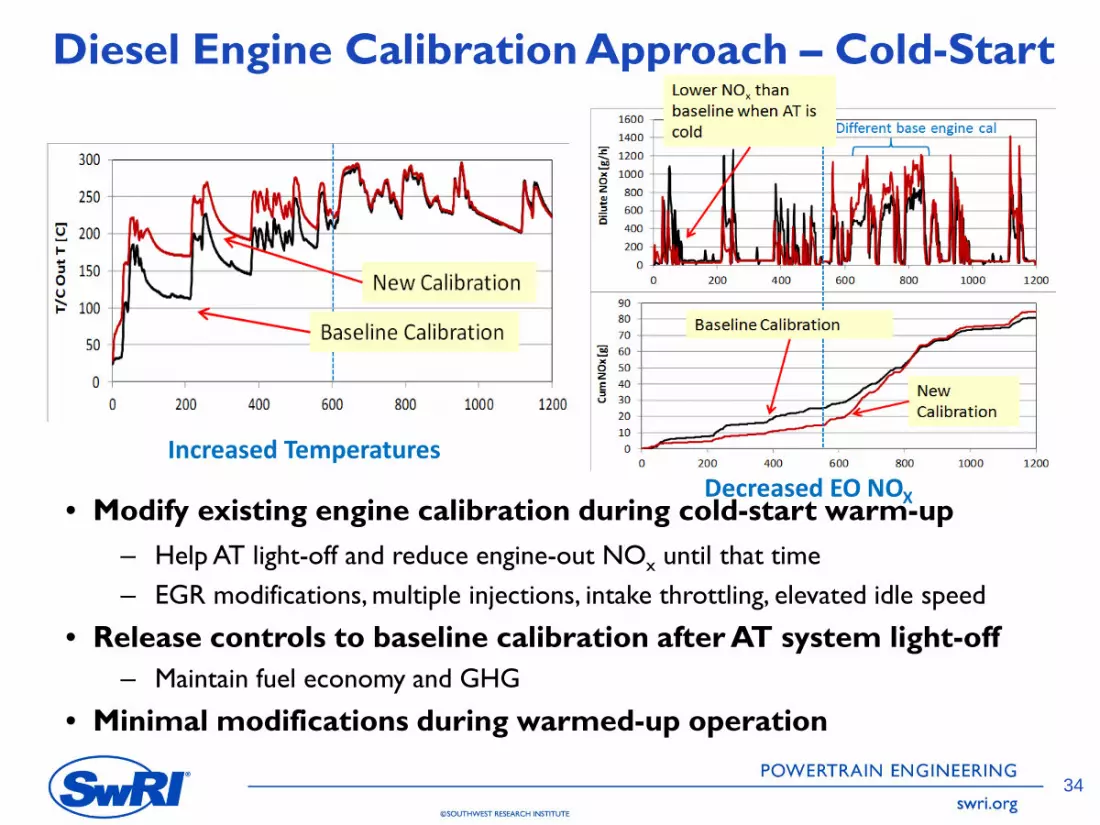
Diesel Engine Calibration Approach – Cold-Start
Increased Temperatures
• Modify existing engine calibration during cold-start warm-up – Help AT light-off and reduce engine-out NOx until that time – EGR modifications, multiple injections, intake throttling, elevated idle speed
• Release controls to baseline calibration after AT system light-off – Maintain fuel economy and GHG
• Minimal modifications during warmed-up operation
Decreased EO NOX
34

•Burner •EHC
•DEF
•NH3 injection •Heated Dosing
Heat Addition Options
Component Options
•Burner
•E HC
•Fuel Dosing
•DOC
•PNA
•Compact M ixing
•NH3 injection •Heated Dosing
•SCR
•ASC
•Blank
Examined 33 out of 500 possible configurations of component and heat addition options
POWERTRAIN ENGINEERING
C>SOUTHWEST RESEARCH INSTITUTE swri.org
Diesel Aftertreatment Technology Options
Traditional Approach Advanced Approach
Examined 33 out of 500 possible configurations of component and heat addition options
35

POWERTRAIN ENGINEERING
C>SOUTHWEST RESEARCH INSTITUTE swri.org
Catalyst Aging Approaches • Development Aged (hydrothermal only, oven
aging permitted) – All parts for technology screening and development – Projected from FUL of Active Regeneration on baseline engine
data • Advanced Systems – 100 hours at 650°C
– Represented about 75% FUL compared to Final Aging protocol
• Final Aged (on engine) – For final demonstration – final down-selected parts only – Protocol developed based on final Active Regeneration
Frequency (which was 1.7%) – Based on SwRI DAAAC protocol – 1000-hour planned duration
• 100% of FUL hydrothermal exposure • 25% of FUL chemical exposure
FUL = Full Useful Life DAAAC = Diesel Aftertreatment Accelerated Aging Cycles
36

Cold Collbrarlon Low T~mp,:1011111: Enabl~t O. H T
... ~ ( ,..
ce: o.u 1111 ,i ~ 0.1 &I
15 Q.
l§ o.oa
Acronym
DOC
SatT-
0 DEf Only Heated D0s1n1
H3
1111plemcntal Cnrrgy
• ' fflf ..,.,.,.,
•
• Burner EHC
rac:11 ion I App 0&c:hos
• •
0
H I I I
Multiple potential pathways to achieve NOx emissions below 0.02 g/bhp-hr
POWERTRAIN ENGINEERING
C>SOUTHWEST RESEARCH INSTITUTE swri.org
ScreeningTest Results for Diesel Aftertreatment System Configurations
37
Multiple potential pathways to achieve NOX emissions below 0.02 g/bhp-hr
0.16
~ 0.14 ,', C.
~ 0.12 1>Q
~ 0.1 z -~ 0.08 Ill 0 C. E 0.06 0 u
"ia 0.04 <J C GI 0 0.02 C.
0
--. --
--
-
-"" u B <I)
' u <I)
<C
-----0:
~ + 0: u <I)
+ u.. w 0 + u.. n. 0 + u 0 0
Traditional Approach
--" "••• . --
------
0 0
rl -"" u u u 0
-"" ti, u 0
~ ti, ~ u 0: <I) u <C "'
-----+ 0: 0:
~ u <I) + + 0:
u u.. w <I) 0 + + u.. u.. w n. 0 0 + + u..
n. u 0 0 + 0 u + 0 a:, 0 ~
-·o. ___ o
···-
rl u u
~ ~ 0: u <I)
+ 0: u "' + u.. w 0 + u.. n. 0 + u 0 0 + a:,
~
u <I)
<C
~ + 0:
~ + rl 0 I + u.. n. 0
0 0 0
·· ...
-
·-o
~ ~ 0:
l7: + 5 <I)
+ u.. w 0 + u.. n. 0 + u 0 0 + a:,
~
ci
~ 1 u.. 0: u <I)
+ 0: u "' + rl 0
l u.. n. 0 + u 0 0 + 0: u <I)
g +
((')
I z
Potent ial Composite NOX
:
0
u <I)
~
~ + rl 0 I + u I w + u.. n. 0 + u 0 0
Advanced Technology Approacn
n • (J_
u ------v
~ <C
~ + u.. 0: u <I)
+
~ + u.. w 0 + u 0 0 + a:,
~
~ ~ 0: u <I)
+ u.. 0: u "' + u.. w 0 + u 0 0 + a:,
~
0
n- -----8 __
u <I)
~ 0:
l7: + 5 <I)
+ u..
~ + rl 0 I + u 0 0
u <I)
~
~ + u.. 0: u <I)
+ u.. w 0 + <C z n.
---
u
~ ~
~ + u.. 0:
~ + u.. w 0 + ((')
I z + <C z n.
······
0
u <I)
~
~ + u.. 0:
~ + rl 0 I + <C z n.
-----
0
v -
u <I)
<C
~ + u.. 0: u <I)
+ rl 0 I + N <C z n.
-· O Potent ial Composite Fuel Penalty
0
-u <I)
~
~ + u.. 0:
~ + .-i 0 I + <C z n.
Alterna te Approaches
_n 0
0 -------o
~ ~ 0: u <I)
+ u.. 0:
~ + rl 0 I + <C it +
~ 0 ...J + ((')
I z
u <I)
<C
~ + u.. 0: u <I)
+ u.. w 0 + a:,
~ + <C z n.
2.0% ~
i "ia
1.5% C GI C.
"ii ::,
u.. GI ~
1.0% Ill 0 C. E 0 u
0.5% ] C GI
0 C.
0.0%
Advanced Approaches can reach lower NOx at a given GHG • act (depending on impact on Rege
POWERTRAIN ENGINEERING
C>SOUTHWEST RESEARCH INSTITUTE swri.org
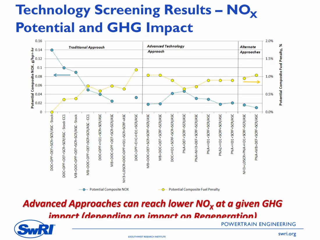
Technology Screening Results – NOX Potential and GHG Impact
38
Advanced Approaches can reach lower NOX at a given GHG impact (depending on impact on Regeneration)

cc z A.
C>SOUTHWEST RESEARCH INSTITUTE
ct: z Q.
W SCRF
ICIP Ill: u Cl)
POWERTRAIN ENGINEERING
swri.org
On-Engine Evaluation of FinalTechnologies
1
Additional
• 0.025 to 0.030 g/hp-hr with 2kw EHC (HD1) • 0.022 to 0.025 g/hp-hr with 3” zeolite LO-SCR • 0.022 to 0.025 g/hp-hr with 6kw EHC Exhaust from and 3.5kW HD1
2
3
4 • 0.022 to 0.025 g/hp-hr with 1kw HD2 and 3”
zeolite LO-SCR • (note evaluation with gaseous NH3 at LO-SCR
in and DEF/HD1 at SCRF in)
• Not evaluated due to insufficient heat potential for 0.02 or below
• 0.012 g/hp-hr with 10kw mini-burner
Selected for the final demonstration
DEF
+V
Manifold
LO-
SC
R
PN
A
SC
R
AS
C
SCRF
NH3
39

IEO IN Ox IPINA--Out IN Ox .........,._ ........, M IB
C I . · ...,_....,,,,,.,,
z a.
131L
261L
@SOUTHWEST RESEARCH INSTITUTE
IM ~d-lBed IN H3
IC u fl)
131L 13,IL
TIP IN(lx
I = Te1m1p Sensor
POWERTRAIN ENGINEERING
swri.org
Final ARB Low NOX Configuration
• All catalysts are coated on 13” diameter substrates • SCRF is 13” X 12” on high porosity filter substrate • Remaining catalysts are 13” X 6” on “thin wall, low thermal mass
substrates” • All sensors shown are production-type
NOX Levels with Development Aged Parts, g/hp-hr
Cold-FTP Hot-FTP Composite RMC-SET
Engine-Out 2.8 3.0 3.0 2.1
Tailpipe 0.06 0.008 0.016 0.015
40

Final ARB Low NOX Aftertreatment Configuration
MB
PNA
Multi-bed SCRF-SCR
Doser/Mixer
PNA Downpipe (equivalent to truck configuration)
Final configuration components were insulated (shown here without)
POWERTRAIN ENGINEERING
C>SOUTHWEST RESEARCH INSTITUTE swri.org
• Modular components used in order to support the screening process • Downpipe equivalent to underfloor mounting based on actual vehicle
configuration (no close coupling)
41

Low NOX AT Configuration Details Final configuration components were
MB
Mixer
SCRF
SCR
SCR/ASC NH3 Sensor
insulated (shown here without)
DEF Nozzle
POWERTRAIN ENGINEERING
C>SOUTHWEST RESEARCH INSTITUTE swri.org
• Production air-assist DEF dosing system was retained (Albonair) • All aftertreatment sensors are production type
– Latest generation NOX sensors – Production thermocouple type temp sensors (CAN) – Production NH3 sensor
• Thermal packaging of dosing/mixing section could be improved to reduce heat input
42

0 erating NH3
conditions Coverage
Target SCRT0
UREA model Urea INJECTOR
injection
Engine-out control ler SCR SCR NOx
NH3
N02/N0x Coverage NH3 SENSOR
model Observer Closed-loop
control ler Exhaust flow
NH3 slip model
POWERTRAIN ENGINEERING
C>SOUTHWEST RESEARCH INSTITUTE swri.org
Cell Cell Cell
Model-Based SCR Controller with Mid-Bed NH3
TIn
SCR Model
Thermal Model
Kinetic Model
Twall
TIn
SCR Model
Thermal Model
Kinetic Model
Twall
TIn TInSensor Feedback ṁexh ṁexh ṁexh ṁexh
NOX NOX NOX NOX
NH3 NH3 NH3 NH3
NO2/ NO2/ NO2/ NO2/ NOX NOX NOX NOX
θ1 θ2 θ3
SCR Model
Thermal Model
Kinetic Model
Twall
• Separate coverage observer models for SCR and SCRF • Primary calibration parameters are controller gains and coverage targets
– Same calibration used for FTP, RMC-SET, CARB Idle, vocational cycles – Slightly modified coverage targets for WHTC
43
- EO NOx - PNA-Out NOx - Tailpipe NOx - SCRF Out NOx
-PNAOutt - SCRF Inlet T - SCRF Out T ASC Out T
1200
1000
800 200 u b0 41
E "Cl
OJ C. C.
.. 600 150 ::::,
x .. Ill
0 .. z 41
C. E
400 100 ~
200
0
0 50 100 150 200 250 300 350 400 450
Time, sec
POWERTRAIN ENGINEERING
C>SOUTHWEST RESEARCH INSTITUTE swri.org
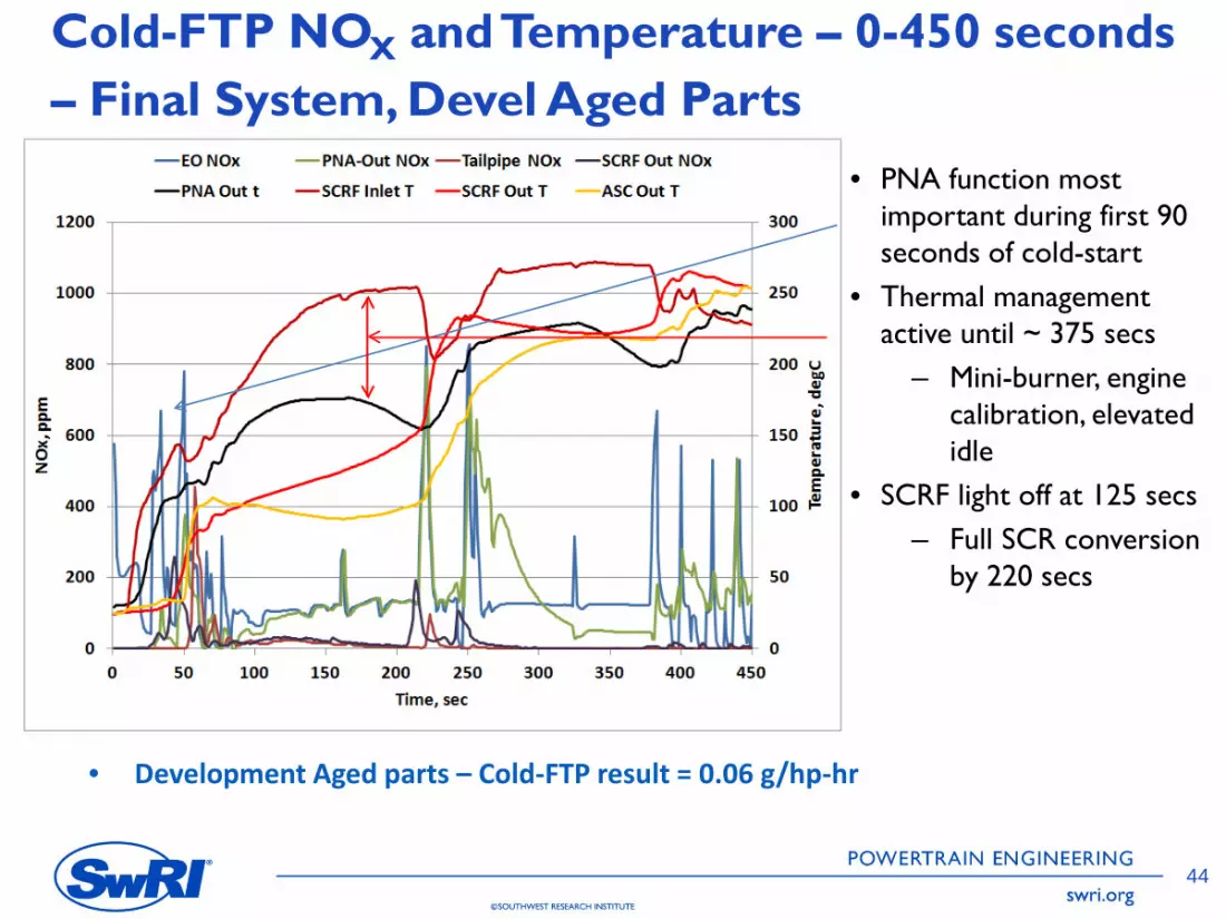
Cold-FTP NOX and Temperature – 0-450 seconds – Final System, Devel Aged Parts
• PNA function most important during first 90 seconds of cold-start
• Thermal management active until ~ 375 secs
– Mini-burner, engine calibration, elevated idle
• SCRF light off at 125 secs – Full SCR conversion
by 220 secs
• Development Aged parts – Cold-FTP result = 0.06 g/hp-hr
44
POWERTRAIN ENGINEERING
C>SOUTHWEST RESEARCH INSTITUTE swri.org
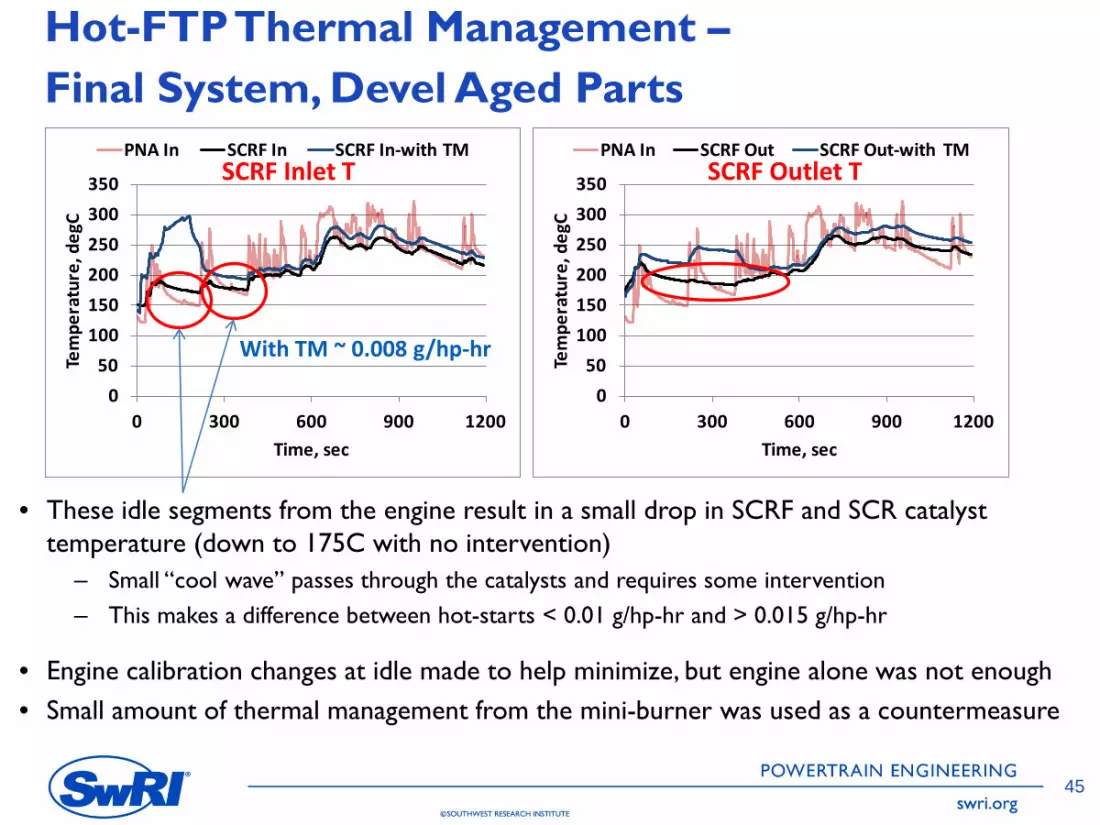
Hot-FTP Thermal Management – Final System, Devel Aged Parts
PNA In SCRF In SCRF In-with TM PNA In SCRF Out SCRF Out-with TM SCRF Inlet T 350 SCRF Outlet T 350
Tem
pera
ture
, deg
C 300 300
Tem
pera
ture
, deg
C
250 250 200 200 150 150 100 With TM ~ 0.008 g/hp-hr
50 100
50 0 0
0 300 600 900 1200 0 300 600 900 1200 Time, sec Time, sec
• These idle segments from the engine result in a small drop in SCRF and SCR catalyst temperature (down to 175C with no intervention)
– Small “cool wave” passes through the catalysts and requires some intervention – This makes a difference between hot-starts < 0.01 g/hp-hr and > 0.015 g/hp-hr
• Engine calibration changes at idle made to help minimize, but engine alone was not enough • Small amount of thermal management from the mini-burner was used as a countermeasure
45

625
Final Aging Protocol
Time [s] Ac
tive
Rege
nera
tion
Mod
e
Pass
ive
Oxi
datio
n /
Soot
& A
sh A
ccum
ulat
ion
Mod
e
Low Temperature Soot & Ash Accumulation Mode
30 g/hr Soot Rate Exhaust Flow = 975 kg/hr
High
Tem
p O
pera
tion
/ HC
-Rem
oval
Mod
e
POWERTRAIN ENGINEERING
C>SOUTHWEST RESEARCH INSTITUTE swri.org
0 1000 2000 3000 4000 5000 6000 7000 8000 9000
2009 Cummins ISX 600 575 550 525
mule engine (DAAAC modified) 4-hour duration
500 475 450 425 400 375 350
Regeneration is via in-exhaust injection upstream of PNA Final duration was
325 847 hours 300 275 250
100% FUL thermal exposure
225 23% FUL chemical 200 exposure
• This is based on regeneration frequency of ~ 1.7% (near x2 from base engine) – Resulted in 194 hours of regeneration for FUL thermal equivalent – This is more than 300 Active Regeneration events
SCRF
Inle
t Tem
pera
ture
[°C]
46

Final Aging - Issues • Early PNA face coking – resolved by adjusting cycle but resulted in large HC buildup
that had to be baked off • Regeneration process had to be adjusted to insure complete soot cleaning – some
early localized exotherms possible
• Mechanical Canning failure on PNA at 710 hours – PNA mat failed – Large buildup of HC and soot on PNA – had to be recovered – Ingestion of mat into SCRF (mal-distribution and local exotherms ?) – had to be
mechanically removed without disturbing deep ash
PNA SCRF Inlet SCRF Channels
Normal Ash Load
Abnormal Mat/Ash
POWERTRAIN ENGINEERING
C>SOUTHWEST RESEARCH INSTITUTE swri.org
47

@SOUTHWEST RESEARCH INSTITUTE
■
■
■
■
swri.org
Final Tailpipe NOX Results
0.71
0.04
7
0.14
0
0.08
4
0.11
5
0.03
0.00
5
0.00
8
0.01
0
0.06
0.00
8
0.01
6
0.01
5
0.01
9
0.11
0.02
1 0.03
4
0.03
8
0.03
6
0.00
0.05
0.10
0.15
0.20
Tailp
ipe
NO X
, g/h
p-hr
Baseline Degreened Devel-Aged Final-Aged
48
Aftertreatment NOX Conversion Efficiency, %
Test Config FTP Transient
RMC-SET WHTC Cold Hot Composite
Baseline 75% 98.5% 95% 97% 97%
Devel Aged 98% 99.7% 99.5% 99.3% 99.4%
Final Aged 96% 99.3% 98.8% 98.2% 98.8%
Note: IRAF calculation for NOX would add adjustment of + 0.004 g/hp-hr to Final Aged results with Low NOX Engine (+0.003 g/hp-hr for Devel Aged and Degreened).

' I ,.,,. .. ' I II " ·~ A f I I . , ... I '1• I I
I I I I I I I I I ,, I ,, ,,
POWERTRAIN ENGINEERING
@SOUTHWEST RESEARCH INSTITUTE swri.org
Cold-FTP Final Aged vs Devel Aged PNA Performance
0
50
100
150
200
250
300
350
-2.0
-1.0
0.0
1.0
2.0
3.0
4.0
0 100 200 300 400 500 600 700
PNA
Inle
t Tem
p, d
egC
PNA
Stor
ed N
Ox,
gra
ms
Time, sec
Devel Aged-Final Controls Final Aged Inlet Temp
SCRF Light-Off
Full SCR Conversion
NOX reduction across system components
0-200 secs, % NOX conv
Full Cycle, % NOX conv
Devel Aged
Final Aged
Devel Aged
Final Aged
PNA 44% 27% -10% -5%
SCRF 64% 28% 90% 84%
SCR- 10% 13% 80% 80% SCR/ASC
• Cold-start performance change is primarily due to loss of NOX storage capacity on PNA – More NOX reaches SCRF before it reaches light-off temperature,
downstream SCR still too cold to help
49

~
' I ~ ' 1 fl1I ' -
l I
j L fDJ & L A I l
POWERTRAIN ENGINEERING
C>SOUTHWEST RESEARCH INSTITUTE swri.org
350
300
Hot-FTP Final Aged vs Devel Aged SCRF Performance
Devel Aged-Final Controls Final Aged Devel Aged Final Controls Final Aged
400 50.0
Final Controls = 90%, 0.30 g/hp-hr 45.0 Final Aged = 87%, 0.40 g/hp-hr
Tailp
ipe
NO
x, g
/hr
SCRF-Out
0 200 400 600 800 1000 1200
Tailpipe Final Controls = 99.7%, 0.009 g/hp-hr 40.0 Final Aged = 99.3%, 0.020 g/hp-hr
35.0
SCRF
-Out
NO
x, g
/hr
250
200
150
100
50
0
30.0
25.0
20.0
0 200 400 600 800 1000 1200
15.0
10.0
5.0
0.0
Time, sec Time, sec
• Hot-start performance change due primarily to change in SCRF performance – Lower NH3 storage capacity, higher tendency towards ammonia oxidation – More demand on downstream SCR catalyst
• Early cycle tailpipe performance still maintained but later there is more NH3 release to downstream catalyst
– Small increase in late cycle NO generation due to larger amount of NH3 to be oxidized
50

Poll utant FTP W HTC
Engine Cold
RM C-SET Composite Hot Composite
Baseline CO2, g/hp-hr 574 543 547 458 485 N2O, g/hp-hr 0.024 0 .047 0.044 0.05 0.06
Devel Aged CO2, g/hp-hr 600 547 555 462 491
Low NOx N2O, g/hp-hr 0.075 0 .087 0.085 0.033 0.085
Engine Fina l Aged
CO2, g/hp-h r 604 549 558 464 494 N2O, g/h p-hr 0.101 0 .108 0.107 0.055 0.086
BSCO2, g/hp-hr
Cold Hot Composite RMC
Baseline Engine 574.2 542.6 547.4 457.7
Final ULN Config 604.4 548.8 558.2 463.6
% change 5.3% 1.1% 2.0% 1.3%
M ini-burner air 0.4% 0.2% 0.2%
Increased SCRF Regenerat ion 0.3% 0.3%
Total FTP CO2 Impact 2.5% 1.6%
POWERTRAIN ENGINEERING
C>SOUTHWEST RESEARCH INSTITUTE swri.org
Final GHG Results Cycle Measured CO2 and N2O Emissions
Overall CO2 / Fuel Consumption Impact • WHTC very similar to FTP • Slight increase for Final Aged (about
0.3%) due to backpressure and slightly higher MB fueling to reach temperature thresholds
• CO2 impact on FTP driven by low temperatures from turbocompound
– Different GHG approach would require less thermal management
• Impact could be reduced via better packaging and integration
51

500
450
400 u b,O
" -a_ 350 I:! :,
i! 300 8. E ~ 250
.:. 'i' 200 ..
.c:
---b,O 150 a' z
100
50
0
- EO NOx - TP NOx - DOC In T - SCR In T - AT Out T - Sp.eed
2000
1000
. 0
1200 1600 2000 2400 2800 3200 3600 4000 4400 4800
Time, sec
E ~
-u'
" 8. U'l
@SOUTHWEST RESEARCH INSTITUTE
- EONOx - TPNOx - PNAlnT - SCRFlnT - SCRln T - AT Out T - Speed
500 2000
450
1000 u 400 b,O 01
-.;, 01' 350
. 0 ] ~ 01 C. E {!
' 9 ..c ..... b,O ~-z
300
250
200
150
100
50
0
1200 1600 2000 2400 2800 3200 3600 4000 4400 4,800
TTme,sec
POWERTRAIN ENGINEERING
swri.org
E ~ -a 01 OI C. ell
CARB Idle Test Result – Final Aged Parts
Baseline Engine Ultra-Low NOX Engine Low Idle (550 rpm) PTO Idle (1100 rpm)
TP NOX, g/hr
Avg Fuel Rate, kg/hr
TP NOX, g/hr
Avg Fuel Rate, kg/hr
Baseline 11.7 1.18 52.7 3.16
ULN 0.2 1.00 14.6 3.21 Engine
• Low Idle – 98% reduction • PTO Idle – 72% reduction • Partially engine-out changes,
mostly improved AT performance • Thermal management needed for
PTO idle segment
52

- -
POWERTRAIN ENGINEERING
@SOUTHWEST RESEARCH INSTITUTE swri.org
4000
3000
2000
1000
4000
3000
2000
1000
Example Vocational Cycle – NYBCx4
-
-
-
-
0
1000
2000
0
200
400
600
800
1000
1200
0 500 1000 1500 2000 2500 3000 3500 4000
Spee
d
NO
x, g
/hr -
or-T
emp,
deg
C
Time, sec
EO NOx TP NOx DOC In T DPF Out T Aftertreatment Out T Speed
-
-
-
-
0
1000
2000
0
100
200
300
400
500
600
700
800
900
1000
0 500 1000 1500 2000 2500 3000 3500 4000
Spee
d, rp
m
NO
x, g
/h -o
r-Te
mp,
deg
C
Time, sec
EO NOx TP NOx PNA In T SCRF In T SCR In T Speed
Baseline Engine Ultra-Low NOX Engine (Final Aged Parts) EO,
g/hp hr
TP, g/hp
hr
NOx Conversion, %
Fuel Rate, kg/hr
Baseline 6.1 2.3 62 % 5.3
• Duty cycle is average 6% of maximum engine power (not including idle segment)
– Test cycle starts after the idle ULN Engine 3.9 0.38 90% 5.3
– Precondition before idle with % Change -35% -84% n/a None same cycle
53

POWERTRAIN ENGINEERING
C>SOUTHWEST RESEARCH INSTITUTE swri.org
Summary (1) • Multiple technology approaches to reach ultra-low
NOX levels – Appropriate choice depends on engine and GHG approach
• Final system was able to achieve 99% conversion efficiency on composite FTP / WHTC fully aged
– This is despite Final aging AT failure issues and a very difficult low temperature test engine
• For this turbocompound engine, 0.02 g/hp-hr was very challenging
– Development aged parts < 0.02 g/hp-hr – Final aged parts > 0.02 g/hp-hr – System complexity and GHG impact higher due to very
low temperatures
54

POWERTRAIN ENGINEERING
C>SOUTHWEST RESEARCH INSTITUTE swri.org
Summary (2)
• Questions still open regarding durability – Final aging issues make it difficult to assess system
degradation
• NOX performance gap between regulatory and vocational cycles is smaller with ULN engine than baseline engine
– This is driven to some degree by calibration approach
• Significant potential for low NOX levels on vocational and field cycles
– More work is being done to examine potential NOX reduction and GHG impact
55

POWERTRAIN ENGINEERING
C>SOUTHWEST RESEARCH INSTITUTE swri.org
Next Steps • Stage 1b – Aging andTesting of another set of Stage 1 parts
(Planned) – Answer durability questions with an undisturbed aging process – Provide more representative parts for Stage 2
• Stage 2 – Low Load NOX Control using Stage 1 engine (In Progress)
– Develop Low Load duty cycle profiles from vehicle data – Develop low load calibrations/approaches for the Stage 1 engine – Examine different “load” metrics for low load cycles
• Torque, fueling, CO2, mass-over-time
• Stage 3 – Low NOX Development and Demonstration on a non-turbocompound engine (Planned)
– Engine platform more representative of mainstream approach to GHG regulations
– Combination of both regulatory and low-load cycles
56

POWERTRAIN ENGINEERING
C>SOUTHWEST RESEARCH INSTITUTE swri.org
Acknowledgements
• California Air Resources Board • Program Partners
– Volvo – Manufacturers of Emission Controls
Association (MECA) • MECA member companies who have provided emission control hardware
• Program Advisory Group members
57

POWERTRAIN ENGINEERING
C>SOUTHWEST RESEARCH INSTITUTE swri.org
More Information
• California ARB website – http://www.arb.ca.gov/research/veh-
emissions/low-nox/low-nox.htm
• SwRI Contact – Christopher Sharp – +1 210-522-2661 – [email protected]
58


![LIN·GUAM RO IAN]CAM](https://img.pdfslide.net/doc/110x75/6335f8d6d2b7284203082322/linguam-ro-iancam.jpg)


