Embed Size (px)
Citation preview

L E A R N T O W I R E L O C K O U T R E L A Y S
A N D M I C R O P R O C E S S O R R E L A Y S
C I R C U I T B R E A K E R C O N T R O L S C H E M E
P O W E R S Y S T E M S E N G I N E E R I N G
A L E E N M O H A M M E D

CONTENTS
2 R e a s o n i n g f o r t h e o n e l i n e
1 S u b s t a t i o n r e l a y o n e l i n e
3 T r i p & c l o s e b r e a k e r s c h e m e
4 S u b s t a t i o n r e l a y o n e l i n e
5 T e s t y o u r k n o w l e d g e

01 THE RING SUBSTATION
02 METHODOLOGY
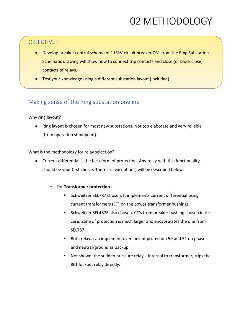
OBJECTIVE:
• Develop breaker control scheme of 115kV circuit breaker CB1 from the Ring Substation.
Schematic drawing will show how to connect trip contacts and close (or block close)
contacts of relays.
• Test your knowledge using a different substation layout (included).
Making sense of the Ring substation oneline
Why ring layout?
• Ring layout is chosen for most new substations. Not too elaborate and very reliable
(from operation standpoint).
What is the methodology for relay selection?
• Current differential is the best form of protection. Any relay with this functionality
should be your first choice. There are exceptions, will be described below.
o For Transformer protection –
▪ Schweitzer SEL787 chosen. It implements current differential using
current transformers (CT) on the power transformer bushings.
▪ Schweitzer SEL487E also chosen. CT’s from breaker bushing chosen in this
case. Zone of protection is much larger and encapsulates the one from
SEL787.
▪ Both relays can implement overcurrent protection 50 and 51 on phase
and neutral/ground as backup.
▪ Not shown, the sudden pressure relay – internal to transformer, trips the
86T lockout relay directly.

02 METHODOLOGY
o For Bus protection –
▪ Ring layouts do not need separate relays for bus protection. All pieces of
bus fall inside either transformer or transmission line zone of protection.
▪ For any other bus layout (straight, breaker-and-a-half, etc), bus
differential relay is required. A short-circuit on a bus generates incredibly
high fault currents. If CT saturation is possible then use high impedance
bus differential relay like SEL587Z. Otherwise a low impedance relay like
SEL487B works just fine.
o For Line protection –
▪ Relay choice for line protection cannot automatically be a line differential
relay. It is driven by following reasoning
• Which relay is at the remote-end? Different relays at each end of
transmission line will not work. Most times the concerned party
will upgrade the relays at the remote-end substation to match the
ones at the new substation.
• How will relays communicate - Fiber, power-line carrier,
microwave, leased telephone lines? Implementing current
differential on a transmission line requires a high bandwidth –
high throughput communication medium. Fiber is popular
medium in this regard. It allows relays like SEL411L to
communicate the phase current information to each end.
• When fiber is not present, power-line carrier is the next best
option. However, line differential protection scheme cannot be
implemented. With this medium, distance (a.k.a. impedance)
relaying using pilot schemes is used. Popular pilot protection
scheme is Directional Comparison Blocking.
• Distance relaying requires line potentials (because Z=V/I ohms).

02 METHODOLOGY
o For Breaker protection –
▪ Schweitzer SEL351S chosen. A breaker fail check is initiated every time a
high voltage breaker is asked to trip. SEL351S relay checks if the breaker
has opened or not. If not then it trips breaker failure lockout relay.
▪ Some relays like SEL487E include breaker failure functionality of SEL351S.
However, the choice to discard 351S and implement its functionality in
another multifunction relay is at engineer’s discretion.
The Fine Print The relaying oneline shown above will be used to explain the breaker control scheme. As such it
omits additional details like
• Backup protection relays not shown.
• 12.47kV & 4.16kV bus protection not shown.
• Auxiliary tripping relays not shown.
• Equipment rating and CT ratios not shown.
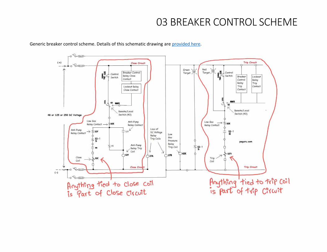
03 BREAKER CONTROL SCHEME Generic breaker control scheme. Details of this schematic drawing are provided here.

03 BREAKER CONTROL SCHEME
Tripping scheme for 115kV circuit breaker CB1 115kV circuit breaker CB1 from the ring bus substation is chosen. Note this breaker is in the 115kV Line 2 zone of protection and transformer TR1 zone of protection. Reasoning for selecting shown relays to trip the breaker: - SEL411L: Needs to trip this breaker to protect transmission line 2. - SEL351S: Needs to trip this breaker to protect it. Implements breaker failure logic. - Lockout 86 relays: Need to trip this breaker to isolate the equipment it is protecting. For instance, 86T isolates transformer, 86BF-CB3 isolates CB3, etc.

03 BREAKER CONTROL SCHEME
Closing scheme for 115kV circuit breaker CB1 Reason for selecting relays as shown - SEL351S: Dedicated breaker control relay, controls close of CB1 either through push button or logic. - SEL411L: This is a line protection relay but is capable of implementing reclosing. Therefore, it is wired in parallel with SEL351S. Reclosing relay requires voltage input. - Lockout 86 relays: Transformer T1 failure, fault within overall transformer differential scheme, breaker CB2 failure, breaker CB3 failure prevent CB1 from closing.

04 THE STRAIGHT BUS SUBSTATION

05 EXERCISE

05 EXERCISE

05 EXERCISE
SOLUTION

05 EXERCISE

05 EXERCISE

05 EXERCISE

Questions? Ask at https://www.reddit.com/r/SubstationEngineering/
For additional information on substation engineering, visit https://peguru.com