Embed Size (px)
Citation preview

CM6200CIRCULAR MILLING MACHINECM6200 OPERATING MANUAL
ORIGINAL INSTRUCTIONS
P/N 63674May 2021Revision 9


©2021 CLIMAX or its subsidiaries.All rights reserved.
Except as expressly provided herein, no part of this manual may be reproduced, copied, transmitted, dissem-inated, downloaded, or stored in any storage medium, without the express prior written consent of CLIMAX. CLIMAX hereby grants permission to download a single copy of this manual and of any revision hereto onto an electronic storage medium to be viewed and to print one copy of this manual or any revision hereto, pro-vided that such electronic or printed copy of this manual or revision must contain the complete text of this copyright notice and provided further that any unauthorized commercial distribution of this manual or any revision hereto is prohibited.At CLIMAX, we value your opinion.For comments or questions about this manual or other CLIMAX documentation, please [email protected] comments or questions about CLIMAX products or services, please call CLIMAX or e-mail [email protected]. For quick and accurate service, please provide your representative with the following:
• Your name• Shipping address• Telephone number• Machine model• Serial number (if applicable)• Date of purchase
CLIMAX World Headquarters2712 East 2nd Street Newberg, Oregon 97132 USATelephone (worldwide): +1-503-538-2815Toll-free (North America): 1-800-333-8311Fax: 503-538-7600
H&S Tool World Headquarters715 Weber Dr.Wadsworth, OH 44281 USATelephone: +1-330-336-4550Fax: 1-330-336-9159hstool.com
CLIMAX | H&S Tool (UK Headquarters)Unit 7 Castlehill Industrial EstateBredbury Industrial ParkHorsfield WayStockport SK6 2SU, UKTelephone: +44 (0) 161-406-1720
CLIMAX | H&S Tool (European Headquarters)Am Langen Graben 852353 Düren, GermanyTelephone: +49 24-219-1770E-mail: [email protected]
CLIMAX | H&S Tool (Asia Pacific Head-quarters)
316 Tanglin Road #02-01Singapore 247978Telephone: +65 9647-2289 Fax: +65 6801-0699
CLIMAX | H&S Tool (Middle East Headquarters)Warehouse #5, Plot: 369 272 Um Sequim RoadAl Quoz 4PO Box 414 084Dubai, UAETelephone: +971 04-321-0328
P/N 63674, Rev. 9 Page A

CLIMAX GLOBAL LOCATIONS
Page B CM6200 Operating Manual

CE DOCUMENTATION
P/N 63674, Rev. 9 Page C

Standard No.
EN 3744 & EN 11201
The Declared Sound Power Level is: LWA= 74.4 dBA
The Declared Operator Sound Pressure Level is: LpA= 65.2 dBA
The Declared Bystander Sound Pressure Level is: LpA= 65.3 dBA
Page D CM6200 Operating Manual

LIMITED WARRANTYClimax Portable Machine Tools, Inc (hereafter referred to as “CLIMAX”) warrants that all new machines are free from defects in materials and workmanship This warranty is available to the original purchaser for a period of one year after delivery If the original purchaser finds any defect in materials or workmanship within the warranty period, the original purchaser should contact its factory representative and return the entire machine, shipping prepaid, to the factory CLIMAX will, at its option, either repair or replace the defective machine at no charge and will return the machine with shipping prepaid.CLIMAX warrants that all parts are free from defects in materials and workmanship, and that all labor has been performed properly This warranty is available to the customer purchasing parts or labor for a period of 90 days after delivery of the part or repaired machine or 180 days on used machines and components If the customer purchasing parts or labor finds any defect in materials or workmanship within the warranty period, the purchaser should contact its factory representative and return the part or repaired machine, shipping pre-paid, to the factory CLIMAX will, at its option, either repair or replace the defective part and/ or correct any defect in the labor performed, both at no charge, and return the part or repaired machine shipping prepaid.These warranties do not apply to the following:
• Damage after the date of shipment not caused by defects in materials or workmanship• Damage caused by improper or inadequate machine maintenance• Damage caused by unauthorized machine modification or repair• Damage caused by machine abuse• Damage caused by using the machine beyond its rated capacity
All other warranties, express or implied, including without limitation the warranties of merchantability and fitness for a particular purpose are disclaimed and excluded.Terms of SaleBe sure to review the terms of sale which appear on the reverse side of your invoice These terms control and limit your rights with respect to the goods purchased from CLIMAX.About This ManualCLIMAX provides the contents of this manual in good faith as a guideline to the operator. CLIMAX cannot guarantee that the information contained in this manual is correct for applications other than the application described in this manual product specifications are subject to change without notice.
P/N 63674, Rev. 9 Page E

This page intentionally left blank
Page F CM6200 Operating Manual

TABLE OF CONTENTSCHAPTER/SECTION PAGE
1 INTRODUCTION . . . . . . . . . . . . . . . . . . . . . . . . . . . . . . . . . . . . . . . . . . . . . . . . . . . . . . . . . . . . 11.1 HOW TO USE THIS MANUAL . . . . . . . . . . . . . . . . . . . . . . . . . . . . . . . . . . . . . . . . . . . . . . . . . . . . . . . . . . 11.2 SAFETY ALERTS . . . . . . . . . . . . . . . . . . . . . . . . . . . . . . . . . . . . . . . . . . . . . . . . . . . . . . . . . . . . . . . . . . 11.3 GENERAL SAFETY PRECAUTIONS. . . . . . . . . . . . . . . . . . . . . . . . . . . . . . . . . . . . . . . . . . . . . . . . . . . . . . 21.4 MACHINE-SPECIFIC SAFETY PRECAUTIONS. . . . . . . . . . . . . . . . . . . . . . . . . . . . . . . . . . . . . . . . . . . . . . . 31.5 RISK ASSESSMENT AND HAZARD MITIGATION . . . . . . . . . . . . . . . . . . . . . . . . . . . . . . . . . . . . . . . . . . . . . 41.6 RISK ASSESSMENT CHECKLIST . . . . . . . . . . . . . . . . . . . . . . . . . . . . . . . . . . . . . . . . . . . . . . . . . . . . . . . 51.7 LABEL IDENTIFICATION . . . . . . . . . . . . . . . . . . . . . . . . . . . . . . . . . . . . . . . . . . . . . . . . . . . . . . . . . . . . . 61.8 ITEMS REQUIRED BUT NOT SUPPLIED. . . . . . . . . . . . . . . . . . . . . . . . . . . . . . . . . . . . . . . . . . . . . . . . . . . 9
2 OVERVIEW . . . . . . . . . . . . . . . . . . . . . . . . . . . . . . . . . . . . . . . . . . . . . . . . . . . . . . . . . . . . . . . 112.1 FEATURES AND OPTIONS . . . . . . . . . . . . . . . . . . . . . . . . . . . . . . . . . . . . . . . . . . . . . . . . . . . . . . . . . . 11
2.1.1 Features . . . . . . . . . . . . . . . . . . . . . . . . . . . . . . . . . . . . . . . . . . . . . . . . . . . . . . . . . . . . . . . . . 122.1.2 Available machine options . . . . . . . . . . . . . . . . . . . . . . . . . . . . . . . . . . . . . . . . . . . . . . . . . . . 122.1.3 Rotary table speeds using hydraulic motors when single-point machining. . . . . . . . . . . . . . . 13
2.2 MACHINE COMPONENTS . . . . . . . . . . . . . . . . . . . . . . . . . . . . . . . . . . . . . . . . . . . . . . . . . . . . . . . . . . . 142.3 MACHINE ENVELOPE AND OPERATING DIMENSIONS . . . . . . . . . . . . . . . . . . . . . . . . . . . . . . . . . . . . . . . 172.4 SPECIFICATIONS. . . . . . . . . . . . . . . . . . . . . . . . . . . . . . . . . . . . . . . . . . . . . . . . . . . . . . . . . . . . . . . . . 19
2.4.1 Weight specifications . . . . . . . . . . . . . . . . . . . . . . . . . . . . . . . . . . . . . . . . . . . . . . . . . . . . . . . 192.4.2 Hydraulic motor specifications . . . . . . . . . . . . . . . . . . . . . . . . . . . . . . . . . . . . . . . . . . . . . . . . 19
3 SETUP. . . . . . . . . . . . . . . . . . . . . . . . . . . . . . . . . . . . . . . . . . . . . . . . . . . . . . . . . . . . . . . . . . . 213.1 RECEIPT AND INSPECTION . . . . . . . . . . . . . . . . . . . . . . . . . . . . . . . . . . . . . . . . . . . . . . . . . . . . . . . . . 213.2 PREPARING THE MACHINE FOR USE. . . . . . . . . . . . . . . . . . . . . . . . . . . . . . . . . . . . . . . . . . . . . . . . . . . 22
3.2.1 Pre-setup check . . . . . . . . . . . . . . . . . . . . . . . . . . . . . . . . . . . . . . . . . . . . . . . . . . . . . . . . . . . 223.2.2 Assessing the work area . . . . . . . . . . . . . . . . . . . . . . . . . . . . . . . . . . . . . . . . . . . . . . . . . . . . . 22
3.3 LIFTING AND RIGGING . . . . . . . . . . . . . . . . . . . . . . . . . . . . . . . . . . . . . . . . . . . . . . . . . . . . . . . . . . . . . 223.4 INSTALLATION HAZARDS . . . . . . . . . . . . . . . . . . . . . . . . . . . . . . . . . . . . . . . . . . . . . . . . . . . . . . . . . . . 253.5 INSTALLING MACHINE ON WORKPIECE . . . . . . . . . . . . . . . . . . . . . . . . . . . . . . . . . . . . . . . . . . . . . . . . . 26
3.5.1 Overview of CM6200 circular milling machine setup . . . . . . . . . . . . . . . . . . . . . . . . . . . . . . . 263.5.2 ID mount leg assembly . . . . . . . . . . . . . . . . . . . . . . . . . . . . . . . . . . . . . . . . . . . . . . . . . . . . . . 293.5.3 OD mount leg assembly . . . . . . . . . . . . . . . . . . . . . . . . . . . . . . . . . . . . . . . . . . . . . . . . . . . . . 33
3.6 MOUNTING THE MACHINING ARM . . . . . . . . . . . . . . . . . . . . . . . . . . . . . . . . . . . . . . . . . . . . . . . . . . . . . 353.6.1 Mounting the machining arm to the rotary table . . . . . . . . . . . . . . . . . . . . . . . . . . . . . . . . . . . 353.6.2 Repositioning the machining arm . . . . . . . . . . . . . . . . . . . . . . . . . . . . . . . . . . . . . . . . . . . . . . 363.6.3 Milling, grinding, or single-point setup. . . . . . . . . . . . . . . . . . . . . . . . . . . . . . . . . . . . . . . . . . . 38
3.7 POSITIONING THE COUNTERWEIGHT . . . . . . . . . . . . . . . . . . . . . . . . . . . . . . . . . . . . . . . . . . . . . . . . . . 393.8 MOUNTING MACHINE TO WORKPIECE. . . . . . . . . . . . . . . . . . . . . . . . . . . . . . . . . . . . . . . . . . . . . . . . . . 40
P/N 63674, Rev. 9 Page i

TABLE OF CONTENTS (CONTINUED)CHAPTER/SECTION PAGE
3.8.1 ID mounting the machine horizontally . . . . . . . . . . . . . . . . . . . . . . . . . . . . . . . . . . . . . . . . . . . 403.8.2 OD mounting the machine horizontally . . . . . . . . . . . . . . . . . . . . . . . . . . . . . . . . . . . . . . . . . . 413.8.3 ID mounting the machine vertically . . . . . . . . . . . . . . . . . . . . . . . . . . . . . . . . . . . . . . . . . . . . . 413.8.4 OD mounting the machine vertically . . . . . . . . . . . . . . . . . . . . . . . . . . . . . . . . . . . . . . . . . . . . 423.8.5 Inverted mounting . . . . . . . . . . . . . . . . . . . . . . . . . . . . . . . . . . . . . . . . . . . . . . . . . . . . . . . . . . 43
3.9 CENTERING AND LEVELING THE MACHINE . . . . . . . . . . . . . . . . . . . . . . . . . . . . . . . . . . . . . . . . . . . . . . 473.10 FIXATION OF ID MOUNT . . . . . . . . . . . . . . . . . . . . . . . . . . . . . . . . . . . . . . . . . . . . . . . . . . . . . . . . . . . 483.11 INSTALLING CABLES. . . . . . . . . . . . . . . . . . . . . . . . . . . . . . . . . . . . . . . . . . . . . . . . . . . . . . . . . . . . . . 50
4 OPERATION. . . . . . . . . . . . . . . . . . . . . . . . . . . . . . . . . . . . . . . . . . . . . . . . . . . . . . . . . . . . . . .534.1 OPERATION SETUP. . . . . . . . . . . . . . . . . . . . . . . . . . . . . . . . . . . . . . . . . . . . . . . . . . . . . . . . . . . . . . . 53
4.1.1 Pre-start checks . . . . . . . . . . . . . . . . . . . . . . . . . . . . . . . . . . . . . . . . . . . . . . . . . . . . . . . . . . . 544.1.2 Tool setup . . . . . . . . . . . . . . . . . . . . . . . . . . . . . . . . . . . . . . . . . . . . . . . . . . . . . . . . . . . . . . . . 544.1.3 Spindle tramming . . . . . . . . . . . . . . . . . . . . . . . . . . . . . . . . . . . . . . . . . . . . . . . . . . . . . . . . . . 55
4.2 CONTROL PENDANT . . . . . . . . . . . . . . . . . . . . . . . . . . . . . . . . . . . . . . . . . . . . . . . . . . . . . . . . . . . . . . 594.2.1 Coordinate systems . . . . . . . . . . . . . . . . . . . . . . . . . . . . . . . . . . . . . . . . . . . . . . . . . . . . . . . . 594.2.2 Machine controls overview . . . . . . . . . . . . . . . . . . . . . . . . . . . . . . . . . . . . . . . . . . . . . . . . . . . 604.2.3 Main menu . . . . . . . . . . . . . . . . . . . . . . . . . . . . . . . . . . . . . . . . . . . . . . . . . . . . . . . . . . . . . . . 644.2.4 Machine setup. . . . . . . . . . . . . . . . . . . . . . . . . . . . . . . . . . . . . . . . . . . . . . . . . . . . . . . . . . . . . 664.2.5 Incremental move . . . . . . . . . . . . . . . . . . . . . . . . . . . . . . . . . . . . . . . . . . . . . . . . . . . . . . . . . . 684.2.6 Absolute move . . . . . . . . . . . . . . . . . . . . . . . . . . . . . . . . . . . . . . . . . . . . . . . . . . . . . . . . . . . . 694.2.7 Incremental velocity move. . . . . . . . . . . . . . . . . . . . . . . . . . . . . . . . . . . . . . . . . . . . . . . . . . . . 704.2.8 Absolute velocity move . . . . . . . . . . . . . . . . . . . . . . . . . . . . . . . . . . . . . . . . . . . . . . . . . . . . . . 714.2.9 Pop-up screens. . . . . . . . . . . . . . . . . . . . . . . . . . . . . . . . . . . . . . . . . . . . . . . . . . . . . . . . . . . . 724.2.10 Alarm history screens . . . . . . . . . . . . . . . . . . . . . . . . . . . . . . . . . . . . . . . . . . . . . . . . . . . . . . . 734.2.11 Status screen . . . . . . . . . . . . . . . . . . . . . . . . . . . . . . . . . . . . . . . . . . . . . . . . . . . . . . . . . . . . . 744.2.12 System info . . . . . . . . . . . . . . . . . . . . . . . . . . . . . . . . . . . . . . . . . . . . . . . . . . . . . . . . . . . . . . . 75
4.3 CIRCULAR MILLING . . . . . . . . . . . . . . . . . . . . . . . . . . . . . . . . . . . . . . . . . . . . . . . . . . . . . . . . . . . . . . . 754.3.1 Installing the milling head cutter . . . . . . . . . . . . . . . . . . . . . . . . . . . . . . . . . . . . . . . . . . . . . . . 764.3.2 Setting the DRO (milling head equipment) . . . . . . . . . . . . . . . . . . . . . . . . . . . . . . . . . . . . . . . 764.3.3 Safe operating ranges. . . . . . . . . . . . . . . . . . . . . . . . . . . . . . . . . . . . . . . . . . . . . . . . . . . . . . . 764.3.4 Replacing the milling assembly. . . . . . . . . . . . . . . . . . . . . . . . . . . . . . . . . . . . . . . . . . . . . . . . 794.3.5 Performing circular milling. . . . . . . . . . . . . . . . . . . . . . . . . . . . . . . . . . . . . . . . . . . . . . . . . . . . 80
4.4 GRINDING OPTION . . . . . . . . . . . . . . . . . . . . . . . . . . . . . . . . . . . . . . . . . . . . . . . . . . . . . . . . . . . . . . . 814.4.1 Grinding attachment setup . . . . . . . . . . . . . . . . . . . . . . . . . . . . . . . . . . . . . . . . . . . . . . . . . . . 814.4.2 Operation . . . . . . . . . . . . . . . . . . . . . . . . . . . . . . . . . . . . . . . . . . . . . . . . . . . . . . . . . . . . . . . . 82
4.5 SINGLE-POINT OPTION . . . . . . . . . . . . . . . . . . . . . . . . . . . . . . . . . . . . . . . . . . . . . . . . . . . . . . . . . . . . 82
Page ii CM6200 Operating Manual

TABLE OF CONTENTS (CONTINUED)CHAPTER/SECTION PAGE
4.5.1 Configuring the rotary union for ID or OD mount . . . . . . . . . . . . . . . . . . . . . . . . . . . . . . . . . 844.5.2 Replacing the milling assembly. . . . . . . . . . . . . . . . . . . . . . . . . . . . . . . . . . . . . . . . . . . . . . . . 894.5.3 Installing the hydraulic drive in the single-point configuration . . . . . . . . . . . . . . . . . . . . . . . . . 904.5.4 Installing the feed box . . . . . . . . . . . . . . . . . . . . . . . . . . . . . . . . . . . . . . . . . . . . . . . . . . . . . . . 914.5.5 Reversing the feed box direction. . . . . . . . . . . . . . . . . . . . . . . . . . . . . . . . . . . . . . . . . . . . . . . 924.5.6 Operating the pneumatic feed system . . . . . . . . . . . . . . . . . . . . . . . . . . . . . . . . . . . . . . . . . . 944.5.7 Adjusting cut characteristics . . . . . . . . . . . . . . . . . . . . . . . . . . . . . . . . . . . . . . . . . . . . . . . . . . 95
4.6 DISASSEMBLY . . . . . . . . . . . . . . . . . . . . . . . . . . . . . . . . . . . . . . . . . . . . . . . . . . . . . . . . . . . . . . . . . . 95
5 MAINTENANCE AND TROUBLESHOOTING . . . . . . . . . . . . . . . . . . . . . . . . . . . . . . . . . . . . 975.1 MAINTENANCE INTERVALS . . . . . . . . . . . . . . . . . . . . . . . . . . . . . . . . . . . . . . . . . . . . . . . . . . . . . . . . . 975.2 MAINTENANCE TASKS . . . . . . . . . . . . . . . . . . . . . . . . . . . . . . . . . . . . . . . . . . . . . . . . . . . . . . . . . . . . . 98
5.2.1 Check the pneumatic conditioning unit emergency stop. . . . . . . . . . . . . . . . . . . . . . . . . . . . . 985.2.2 Check the pneumatic conditioning unit drop-out circuit. . . . . . . . . . . . . . . . . . . . . . . . . . . . . . 985.2.3 Maintain the rotary table and drive assembly . . . . . . . . . . . . . . . . . . . . . . . . . . . . . . . . . . . . . 995.2.4 Replacing the PLC battery . . . . . . . . . . . . . . . . . . . . . . . . . . . . . . . . . . . . . . . . . . . . . . . . . . . 995.2.5 Drag brake settings . . . . . . . . . . . . . . . . . . . . . . . . . . . . . . . . . . . . . . . . . . . . . . . . . . . . . . . . 1005.2.6 Adjusting the drag brake . . . . . . . . . . . . . . . . . . . . . . . . . . . . . . . . . . . . . . . . . . . . . . . . . . . . 100
5.3 RECOMMENDED LUBRICANTS . . . . . . . . . . . . . . . . . . . . . . . . . . . . . . . . . . . . . . . . . . . . . . . . . . . . . . 1025.3.1 Main ring gear lubrication . . . . . . . . . . . . . . . . . . . . . . . . . . . . . . . . . . . . . . . . . . . . . . . . . . . 1045.3.2 Linear rail maintenance. . . . . . . . . . . . . . . . . . . . . . . . . . . . . . . . . . . . . . . . . . . . . . . . . . . . . 104
5.4 TROUBLESHOOTING . . . . . . . . . . . . . . . . . . . . . . . . . . . . . . . . . . . . . . . . . . . . . . . . . . . . . . . . . . . . . 1055.4.1 The machine isn’t turning . . . . . . . . . . . . . . . . . . . . . . . . . . . . . . . . . . . . . . . . . . . . . . . . . . . 1055.4.2 The machine isn’t feeding or is slow and unresponsive . . . . . . . . . . . . . . . . . . . . . . . . . . . . 1055.4.3 The machine is cutting poorly . . . . . . . . . . . . . . . . . . . . . . . . . . . . . . . . . . . . . . . . . . . . . . . . 1055.4.4 The machine isn’t cutting flat. . . . . . . . . . . . . . . . . . . . . . . . . . . . . . . . . . . . . . . . . . . . . . . . . 1065.4.5 The spindle isn’t turning . . . . . . . . . . . . . . . . . . . . . . . . . . . . . . . . . . . . . . . . . . . . . . . . . . . . 1065.4.6 The machine stops suddenly . . . . . . . . . . . . . . . . . . . . . . . . . . . . . . . . . . . . . . . . . . . . . . . . 1065.4.7 The cut depth changes involuntarily . . . . . . . . . . . . . . . . . . . . . . . . . . . . . . . . . . . . . . . . . . . 1065.4.8 The servo system alarm or warning . . . . . . . . . . . . . . . . . . . . . . . . . . . . . . . . . . . . . . . . . . . 106
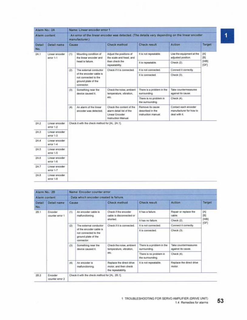
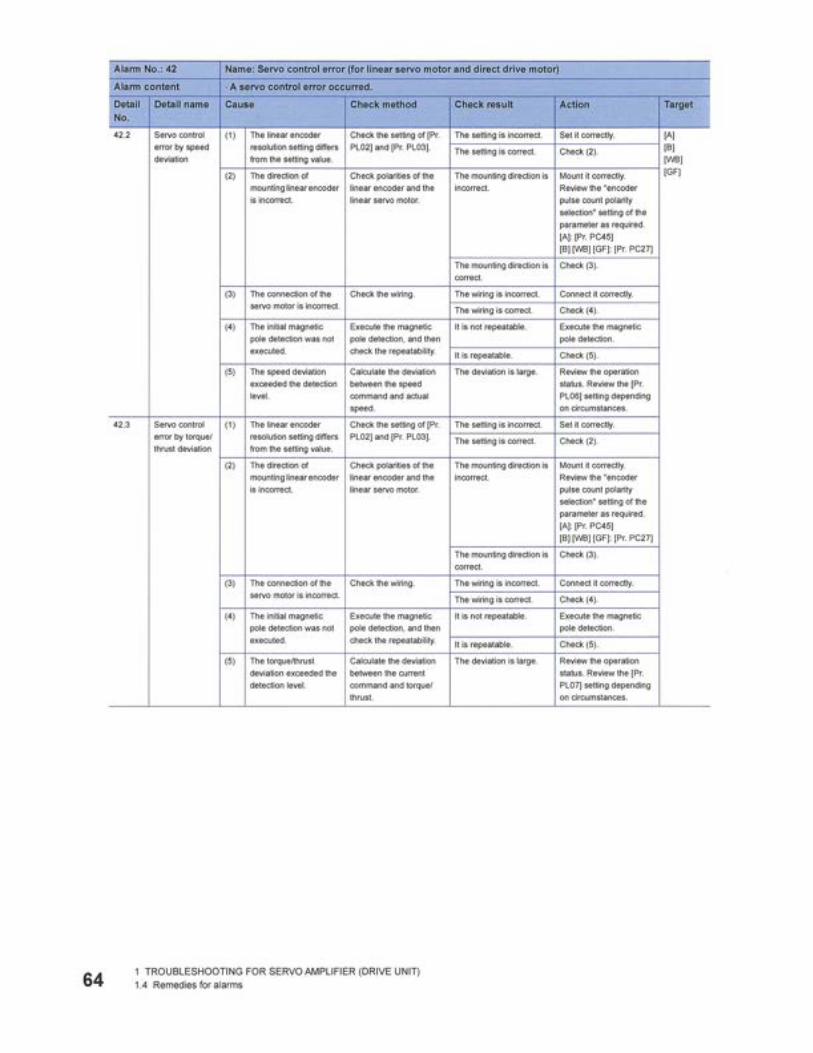
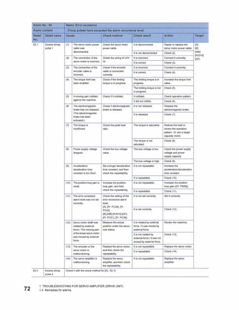
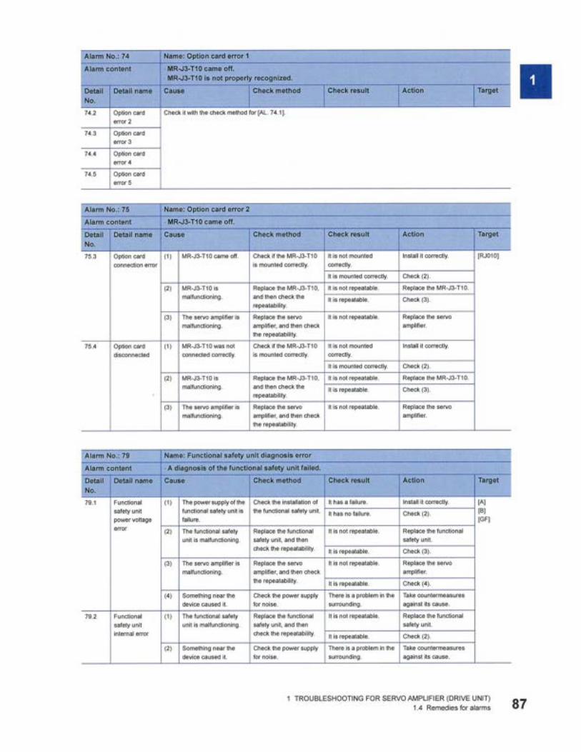
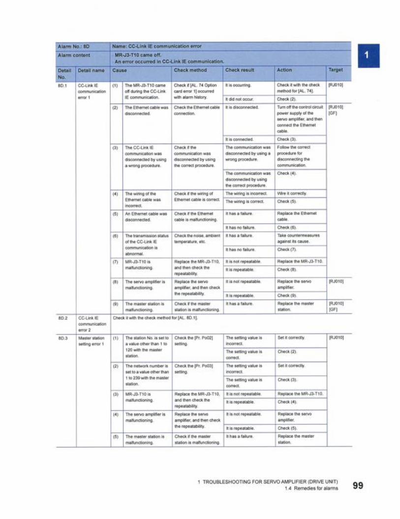
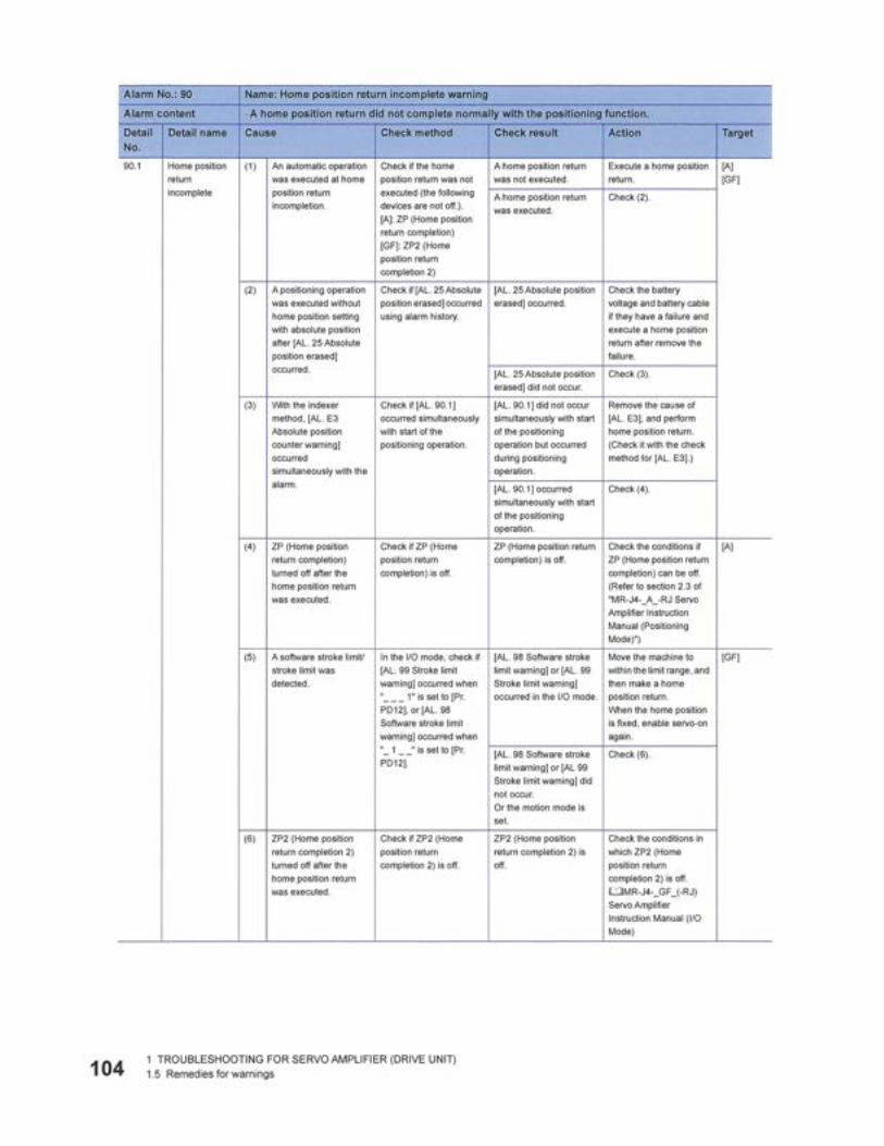
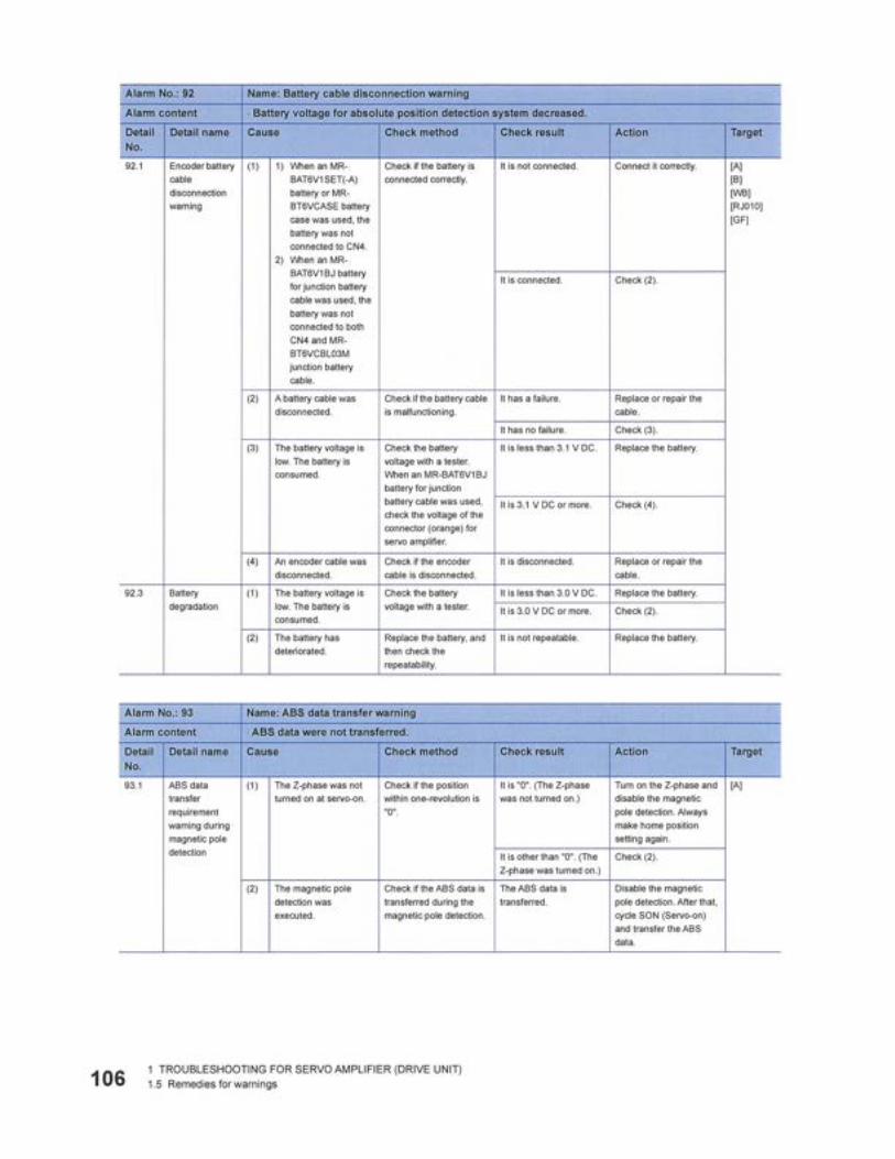
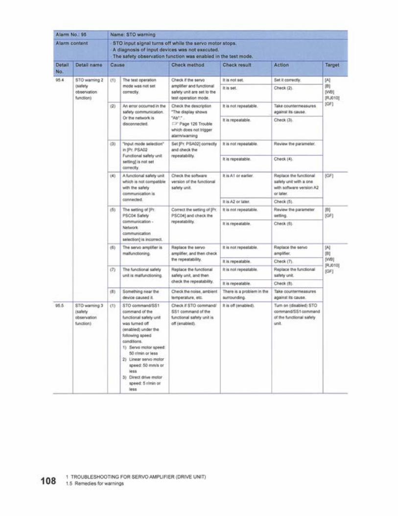
5.5 MR-J3 SERVO AMPLIFIER ERROR CODES. . . . . . . . . . . . . . . . . . . . . . . . . . . . . . . . . . . . . . . . . . . . . . 107
6 STORAGE AND SHIPPING . . . . . . . . . . . . . . . . . . . . . . . . . . . . . . . . . . . . . . . . . . . . . . . . . 1176.1 STORAGE . . . . . . . . . . . . . . . . . . . . . . . . . . . . . . . . . . . . . . . . . . . . . . . . . . . . . . . . . . . . . . . . . . . . 117
6.1.1 Short-term storage . . . . . . . . . . . . . . . . . . . . . . . . . . . . . . . . . . . . . . . . . . . . . . . . . . . . . . . . 1176.1.2 Long-term storage. . . . . . . . . . . . . . . . . . . . . . . . . . . . . . . . . . . . . . . . . . . . . . . . . . . . . . . . . 118
6.2 SHIPPING. . . . . . . . . . . . . . . . . . . . . . . . . . . . . . . . . . . . . . . . . . . . . . . . . . . . . . . . . . . . . . . . . . . . . 1186.3 DECOMMISSIONING. . . . . . . . . . . . . . . . . . . . . . . . . . . . . . . . . . . . . . . . . . . . . . . . . . . . . . . . . . . . . . 118
P/N 63674, Rev. 9 Page iii

TABLE OF CONTENTS (CONTINUED)CHAPTER/SECTION PAGE
APPENDIX A ASSEMBLY DRAWINGS . . . . . . . . . . . . . . . . . . . . . . . . . . . . . . . . . . . . . . . . .119 APPENDIX B SCHEMATICS. . . . . . . . . . . . . . . . . . . . . . . . . . . . . . . . . . . . . . . . . . . . . . . . . .159 APPENDIX C SDS . . . . . . . . . . . . . . . . . . . . . . . . . . . . . . . . . . . . . . . . . . . . . . . . . . . . . . . . . .177 APPENDIX D MR-J4 SERVO AMPLIFIER MANUAL . . . . . . . . . . . . . . . . . . . . . . . . . . . . . . .179Page iv CM6200 Operating Manual

LIST OF FIGURESFIGURE PAGE
2-1 ID mount components . . . . . . . . . . . . . . . . . . . . . . . . . . . . . . . . . . . . . . . . . . . . . . . . . . . . . . . . . . . . . .142-2 Rotation direction for hydraulic motor, rotation table, and milling head . . . . . . . . . . . . . . . . . . . . . . . . .152-3 OD mount components . . . . . . . . . . . . . . . . . . . . . . . . . . . . . . . . . . . . . . . . . . . . . . . . . . . . . . . . . . . . . .162-4 ID mount machine dimensions . . . . . . . . . . . . . . . . . . . . . . . . . . . . . . . . . . . . . . . . . . . . . . . . . . . . . . . .172-5 OD mount machine dimensions . . . . . . . . . . . . . . . . . . . . . . . . . . . . . . . . . . . . . . . . . . . . . . . . . . . . . . .182-6 Hydraulic motor specifications . . . . . . . . . . . . . . . . . . . . . . . . . . . . . . . . . . . . . . . . . . . . . . . . . . . . . . . .203-1 Lifting eye identification label . . . . . . . . . . . . . . . . . . . . . . . . . . . . . . . . . . . . . . . . . . . . . . . . . . . . . . . . .233-2 Hoist rings for assembled machine lifting . . . . . . . . . . . . . . . . . . . . . . . . . . . . . . . . . . . . . . . . . . . . . . . .233-3 Hoist rings for lifting assembled machine in vertical position . . . . . . . . . . . . . . . . . . . . . . . . . . . . . . . . .243-4 Lifting assembly on machine . . . . . . . . . . . . . . . . . . . . . . . . . . . . . . . . . . . . . . . . . . . . . . . . . . . . . . . . .243-5 Vertical installation hazard . . . . . . . . . . . . . . . . . . . . . . . . . . . . . . . . . . . . . . . . . . . . . . . . . . . . . . . . . . .253-6 Measure workpiece. . . . . . . . . . . . . . . . . . . . . . . . . . . . . . . . . . . . . . . . . . . . . . . . . . . . . . . . . . . . . . . . .263-7 Leg measurement . . . . . . . . . . . . . . . . . . . . . . . . . . . . . . . . . . . . . . . . . . . . . . . . . . . . . . . . . . . . . . . . . .273-8 Setup finger . . . . . . . . . . . . . . . . . . . . . . . . . . . . . . . . . . . . . . . . . . . . . . . . . . . . . . . . . . . . . . . . . . . . . .283-9 Load tested lifting assembly P/N 68425 . . . . . . . . . . . . . . . . . . . . . . . . . . . . . . . . . . . . . . . . . . . . . . . . .283-10 Locking nut and leveling jaw. . . . . . . . . . . . . . . . . . . . . . . . . . . . . . . . . . . . . . . . . . . . . . . . . . . . . . . . .293-11 Locking symbols on end cap. . . . . . . . . . . . . . . . . . . . . . . . . . . . . . . . . . . . . . . . . . . . . . . . . . . . . . . . .293-12 Locations to apply anti-seize . . . . . . . . . . . . . . . . . . . . . . . . . . . . . . . . . . . . . . . . . . . . . . . . . . . . . . . .303-13 Jacking screw . . . . . . . . . . . . . . . . . . . . . . . . . . . . . . . . . . . . . . . . . . . . . . . . . . . . . . . . . . . . . . . . . . . .303-14 Jacking screw groove (leveling foot). . . . . . . . . . . . . . . . . . . . . . . . . . . . . . . . . . . . . . . . . . . . . . . . . . .313-15 Non-leveling jacking foot. . . . . . . . . . . . . . . . . . . . . . . . . . . . . . . . . . . . . . . . . . . . . . . . . . . . . . . . . . . .323-16 OD mount leg assembly . . . . . . . . . . . . . . . . . . . . . . . . . . . . . . . . . . . . . . . . . . . . . . . . . . . . . . . . . . . .333-17 OD mount centering plate. . . . . . . . . . . . . . . . . . . . . . . . . . . . . . . . . . . . . . . . . . . . . . . . . . . . . . . . . . .343-18 OD chucking leg dimensions . . . . . . . . . . . . . . . . . . . . . . . . . . . . . . . . . . . . . . . . . . . . . . . . . . . . . . . .353-19 Clamp screws and stop pin. . . . . . . . . . . . . . . . . . . . . . . . . . . . . . . . . . . . . . . . . . . . . . . . . . . . . . . . . .363-20 Counterweight. . . . . . . . . . . . . . . . . . . . . . . . . . . . . . . . . . . . . . . . . . . . . . . . . . . . . . . . . . . . . . . . . . . .373-21 Machining arm . . . . . . . . . . . . . . . . . . . . . . . . . . . . . . . . . . . . . . . . . . . . . . . . . . . . . . . . . . . . . . . . . . .373-22 Installed milling head . . . . . . . . . . . . . . . . . . . . . . . . . . . . . . . . . . . . . . . . . . . . . . . . . . . . . . . . . . . . . .383-23 Counterweight bolt-hole positions. . . . . . . . . . . . . . . . . . . . . . . . . . . . . . . . . . . . . . . . . . . . . . . . . . . . .393-24 Counterweight and machining arm on the rotary table . . . . . . . . . . . . . . . . . . . . . . . . . . . . . . . . . . . . .403-25 Horizontally mounted machine . . . . . . . . . . . . . . . . . . . . . . . . . . . . . . . . . . . . . . . . . . . . . . . . . . . . . . .403-26 OD mount centering plate adjustments. . . . . . . . . . . . . . . . . . . . . . . . . . . . . . . . . . . . . . . . . . . . . . . . .413-27 Assembly before inversion . . . . . . . . . . . . . . . . . . . . . . . . . . . . . . . . . . . . . . . . . . . . . . . . . . . . . . . . . .443-28 Plywood and straps for inversion . . . . . . . . . . . . . . . . . . . . . . . . . . . . . . . . . . . . . . . . . . . . . . . . . . . . .443-29 CM6200 in vertical position. . . . . . . . . . . . . . . . . . . . . . . . . . . . . . . . . . . . . . . . . . . . . . . . . . . . . . . . . .453-30 Vertical CM6200 on blocks with straps re-attached . . . . . . . . . . . . . . . . . . . . . . . . . . . . . . . . . . . . . . .453-31 Lifting the CM6200 off the blocks . . . . . . . . . . . . . . . . . . . . . . . . . . . . . . . . . . . . . . . . . . . . . . . . . . . . .463-32 Inverting the CM6200 . . . . . . . . . . . . . . . . . . . . . . . . . . . . . . . . . . . . . . . . . . . . . . . . . . . . . . . . . . . . . .463-33 Blocking locations . . . . . . . . . . . . . . . . . . . . . . . . . . . . . . . . . . . . . . . . . . . . . . . . . . . . . . . . . . . . . . . . .473-34 Attached dial indicator . . . . . . . . . . . . . . . . . . . . . . . . . . . . . . . . . . . . . . . . . . . . . . . . . . . . . . . . . . . . .473-35 Leveling chuck foot assembly . . . . . . . . . . . . . . . . . . . . . . . . . . . . . . . . . . . . . . . . . . . . . . . . . . . . . . . .484-1 Spindle lock and DRO. . . . . . . . . . . . . . . . . . . . . . . . . . . . . . . . . . . . . . . . . . . . . . . . . . . . . . . . . . . . . . .554-2 Dial indicator on the face mill . . . . . . . . . . . . . . . . . . . . . . . . . . . . . . . . . . . . . . . . . . . . . . . . . . . . . . . . .564-3 Indicator touching machine ram surface. . . . . . . . . . . . . . . . . . . . . . . . . . . . . . . . . . . . . . . . . . . . . . . . .56
P/N 63674, Rev. 9 Page v

LIST OF FIGURES (CONTINUED)FIGURE PAGE
4-4 Spindle rotated to the ram surface . . . . . . . . . . . . . . . . . . . . . . . . . . . . . . . . . . . . . . . . . . . . . . . . . . . . 574-5 Milling head mounting plate and tramming points . . . . . . . . . . . . . . . . . . . . . . . . . . . . . . . . . . . . . . . . . 574-6 Y-axis screw adjustment . . . . . . . . . . . . . . . . . . . . . . . . . . . . . . . . . . . . . . . . . . . . . . . . . . . . . . . . . . . . 584-7 X-axis screw location. . . . . . . . . . . . . . . . . . . . . . . . . . . . . . . . . . . . . . . . . . . . . . . . . . . . . . . . . . . . . . . 594-8 Machining pass results . . . . . . . . . . . . . . . . . . . . . . . . . . . . . . . . . . . . . . . . . . . . . . . . . . . . . . . . . . . . . 594-9 Absolute coordinates . . . . . . . . . . . . . . . . . . . . . . . . . . . . . . . . . . . . . . . . . . . . . . . . . . . . . . . . . . . . . . . 604-10 Incremental coordinates . . . . . . . . . . . . . . . . . . . . . . . . . . . . . . . . . . . . . . . . . . . . . . . . . . . . . . . . . . . 604-11 CM6200 control pendant . . . . . . . . . . . . . . . . . . . . . . . . . . . . . . . . . . . . . . . . . . . . . . . . . . . . . . . . . . . 614-12 Opening splash screen at startup . . . . . . . . . . . . . . . . . . . . . . . . . . . . . . . . . . . . . . . . . . . . . . . . . . . . 614-13 Reset start screen . . . . . . . . . . . . . . . . . . . . . . . . . . . . . . . . . . . . . . . . . . . . . . . . . . . . . . . . . . . . . . . . 624-14 Reset depressed screen . . . . . . . . . . . . . . . . . . . . . . . . . . . . . . . . . . . . . . . . . . . . . . . . . . . . . . . . . . . 634-15 Pop-up screen after emergency stop initiation . . . . . . . . . . . . . . . . . . . . . . . . . . . . . . . . . . . . . . . . . . 634-16 Pop-up screen reset request . . . . . . . . . . . . . . . . . . . . . . . . . . . . . . . . . . . . . . . . . . . . . . . . . . . . . . . . 644-17 Reversed power warning. . . . . . . . . . . . . . . . . . . . . . . . . . . . . . . . . . . . . . . . . . . . . . . . . . . . . . . . . . . 644-18 Main menu without servo motor warning. . . . . . . . . . . . . . . . . . . . . . . . . . . . . . . . . . . . . . . . . . . . . . . 654-19 Machine Setup screen. . . . . . . . . . . . . . . . . . . . . . . . . . . . . . . . . . . . . . . . . . . . . . . . . . . . . . . . . . . . . 664-20 Machine setup number input pad . . . . . . . . . . . . . . . . . . . . . . . . . . . . . . . . . . . . . . . . . . . . . . . . . . . . 674-21 Setup parameters verification screen . . . . . . . . . . . . . . . . . . . . . . . . . . . . . . . . . . . . . . . . . . . . . . . . . 674-22 Incremental move screen . . . . . . . . . . . . . . . . . . . . . . . . . . . . . . . . . . . . . . . . . . . . . . . . . . . . . . . . . . 684-23 Absolute move screen. . . . . . . . . . . . . . . . . . . . . . . . . . . . . . . . . . . . . . . . . . . . . . . . . . . . . . . . . . . . . 694-24 Incremental velocity move screen . . . . . . . . . . . . . . . . . . . . . . . . . . . . . . . . . . . . . . . . . . . . . . . . . . . . 704-25 Absolute velocity move screen . . . . . . . . . . . . . . . . . . . . . . . . . . . . . . . . . . . . . . . . . . . . . . . . . . . . . . 714-26 Status screen. . . . . . . . . . . . . . . . . . . . . . . . . . . . . . . . . . . . . . . . . . . . . . . . . . . . . . . . . . . . . . . . . . . . 744-27 System info screen . . . . . . . . . . . . . . . . . . . . . . . . . . . . . . . . . . . . . . . . . . . . . . . . . . . . . . . . . . . . . . . 754-28 DRO buttons and display. . . . . . . . . . . . . . . . . . . . . . . . . . . . . . . . . . . . . . . . . . . . . . . . . . . . . . . . . . . 764-29 Cross-slide plate . . . . . . . . . . . . . . . . . . . . . . . . . . . . . . . . . . . . . . . . . . . . . . . . . . . . . . . . . . . . . . . . . 794-30 Tool head assembly adapter . . . . . . . . . . . . . . . . . . . . . . . . . . . . . . . . . . . . . . . . . . . . . . . . . . . . . . . . 794-31 Grinding head leveling screws. . . . . . . . . . . . . . . . . . . . . . . . . . . . . . . . . . . . . . . . . . . . . . . . . . . . . . . 824-32 Rotary union configuration components . . . . . . . . . . . . . . . . . . . . . . . . . . . . . . . . . . . . . . . . . . . . . . . 844-33 Feed box detail . . . . . . . . . . . . . . . . . . . . . . . . . . . . . . . . . . . . . . . . . . . . . . . . . . . . . . . . . . . . . . . . . . 854-34 Pneumatic feed box location . . . . . . . . . . . . . . . . . . . . . . . . . . . . . . . . . . . . . . . . . . . . . . . . . . . . . . . . 864-35 ID mount configuration of the rotary union . . . . . . . . . . . . . . . . . . . . . . . . . . . . . . . . . . . . . . . . . . . . . 874-36 OD mount configuration of the rotary union . . . . . . . . . . . . . . . . . . . . . . . . . . . . . . . . . . . . . . . . . . . . 884-37 OD mount configuration of rotary union . . . . . . . . . . . . . . . . . . . . . . . . . . . . . . . . . . . . . . . . . . . . . . . 894-38 Cross-slide plate . . . . . . . . . . . . . . . . . . . . . . . . . . . . . . . . . . . . . . . . . . . . . . . . . . . . . . . . . . . . . . . . . 904-39 Tool head assembly adapter . . . . . . . . . . . . . . . . . . . . . . . . . . . . . . . . . . . . . . . . . . . . . . . . . . . . . . . . 904-40 Servo motor and gearbox . . . . . . . . . . . . . . . . . . . . . . . . . . . . . . . . . . . . . . . . . . . . . . . . . . . . . . . . . . 914-41 Rotary union . . . . . . . . . . . . . . . . . . . . . . . . . . . . . . . . . . . . . . . . . . . . . . . . . . . . . . . . . . . . . . . . . . . . 914-42 Pneumatic feed box adapter . . . . . . . . . . . . . . . . . . . . . . . . . . . . . . . . . . . . . . . . . . . . . . . . . . . . . . . . 924-43 Feed direction of feed box. . . . . . . . . . . . . . . . . . . . . . . . . . . . . . . . . . . . . . . . . . . . . . . . . . . . . . . . . . 924-44 Removal of bolts to reverse feed direction . . . . . . . . . . . . . . . . . . . . . . . . . . . . . . . . . . . . . . . . . . . . . 924-45 Feed direction arrow . . . . . . . . . . . . . . . . . . . . . . . . . . . . . . . . . . . . . . . . . . . . . . . . . . . . . . . . . . . . . . 934-46 Feed box mode positions . . . . . . . . . . . . . . . . . . . . . . . . . . . . . . . . . . . . . . . . . . . . . . . . . . . . . . . . . . 934-47 Feed hose disconnect method . . . . . . . . . . . . . . . . . . . . . . . . . . . . . . . . . . . . . . . . . . . . . . . . . . . . . . 944-48 PCU valves . . . . . . . . . . . . . . . . . . . . . . . . . . . . . . . . . . . . . . . . . . . . . . . . . . . . . . . . . . . . . . . . . . . . . 94Page vi CM6200 Operating Manual

LIST OF FIGURES (CONTINUED)FIGURE PAGE
4-49 Hose tower stow position. . . . . . . . . . . . . . . . . . . . . . . . . . . . . . . . . . . . . . . . . . . . . . . . . . . . . . . . . . . 965-1 PLC battery specification. . . . . . . . . . . . . . . . . . . . . . . . . . . . . . . . . . . . . . . . . . . . . . . . . . . . . . . . . . . . 995-2 Top view of drag brake . . . . . . . . . . . . . . . . . . . . . . . . . . . . . . . . . . . . . . . . . . . . . . . . . . . . . . . . . . . . 1005-3 Side view of drag brake . . . . . . . . . . . . . . . . . . . . . . . . . . . . . . . . . . . . . . . . . . . . . . . . . . . . . . . . . . . . 100A-1 Rotary table assembly (P/N 62028) . . . . . . . . . . . . . . . . . . . . . . . . . . . . . . . . . . . . . . . . . . . . . . . . . . 120A-2 Rotary table assembly parts list (P/N 62028) . . . . . . . . . . . . . . . . . . . . . . . . . . . . . . . . . . . . . . . . . . . 121A-3 Rotary table assembly (P/N 96031) . . . . . . . . . . . . . . . . . . . . . . . . . . . . . . . . . . . . . . . . . . . . . . . . . . 122A-4 Rotary table assembly parts list (P/N 96031) . . . . . . . . . . . . . . . . . . . . . . . . . . . . . . . . . . . . . . . . . . . 123A-5 Encoder guard assembly (P/N 62869) . . . . . . . . . . . . . . . . . . . . . . . . . . . . . . . . . . . . . . . . . . . . . . . . 124A-6 Load tested lifting assembly (P/N 68425) . . . . . . . . . . . . . . . . . . . . . . . . . . . . . . . . . . . . . . . . . . . . . . 125A-7 ID mount assembly (P/N 62038) . . . . . . . . . . . . . . . . . . . . . . . . . . . . . . . . . . . . . . . . . . . . . . . . . . . . . 126A-8 Adjustable chuck foot assembly (P/N 89730) . . . . . . . . . . . . . . . . . . . . . . . . . . . . . . . . . . . . . . . . . . . 127A-9 Non-leveling foot assembly (P/N 91317). . . . . . . . . . . . . . . . . . . . . . . . . . . . . . . . . . . . . . . . . . . . . . . 128A-10 OD mount assembly (P/N 62039) . . . . . . . . . . . . . . . . . . . . . . . . . . . . . . . . . . . . . . . . . . . . . . . . . . . 129A-11 Machining arm assembly (P/N 72676) . . . . . . . . . . . . . . . . . . . . . . . . . . . . . . . . . . . . . . . . . . . . . . . 130A-12 Machining arm assembly parts list (P/N 72676) . . . . . . . . . . . . . . . . . . . . . . . . . . . . . . . . . . . . . . . . 131A-13 Machining arm milling head tram assembly (P/N 63124) . . . . . . . . . . . . . . . . . . . . . . . . . . . . . . . . . 132A-14 Counterweight arm assembly (P/N 62031) . . . . . . . . . . . . . . . . . . . . . . . . . . . . . . . . . . . . . . . . . . . . 133A-15 Face mount assembly (P/N 63106). . . . . . . . . . . . . . . . . . . . . . . . . . . . . . . . . . . . . . . . . . . . . . . . . . 134A-16 Grinding attachment w/tool head assembly (P/N 63239) . . . . . . . . . . . . . . . . . . . . . . . . . . . . . . . . . 135A-17 Grinder for SP CM6200 with gear reducer assembly (P/N 63240) . . . . . . . . . . . . . . . . . . . . . . . . . . 136A-18 Grinder for SP pneumatic (P/N 62537) . . . . . . . . . . . . . . . . . . . . . . . . . . . . . . . . . . . . . . . . . . . . . . . 137A-19 Plate swivel milling head assembly (P/N 63250) . . . . . . . . . . . . . . . . . . . . . . . . . . . . . . . . . . . . . . . 138A-20 Milling head and drawbolt assembly (P/N 73354). . . . . . . . . . . . . . . . . . . . . . . . . . . . . . . . . . . . . . . 139A-21 Milling head 2-29/32 brg 8 stroke #50 taper (P/N 72277) . . . . . . . . . . . . . . . . . . . . . . . . . . . . . . . . . 140A-22 Milling head assembly parts list 1 (P/N 72277) . . . . . . . . . . . . . . . . . . . . . . . . . . . . . . . . . . . . . . . . . 141A-23 Milling head assembly parts list 2 (P/N 72277) . . . . . . . . . . . . . . . . . . . . . . . . . . . . . . . . . . . . . . . . . 142A-24 Milling head extension assembly (P/N 65840) . . . . . . . . . . . . . . . . . . . . . . . . . . . . . . . . . . . . . . . . . 143A-25 Servo drive assembly (P/N 83156) . . . . . . . . . . . . . . . . . . . . . . . . . . . . . . . . . . . . . . . . . . . . . . . . . . 144A-26 Servo drive gearbox assembly (P/N 62032) . . . . . . . . . . . . . . . . . . . . . . . . . . . . . . . . . . . . . . . . . . . 145A-27 Single point EU assembly (P/N 83100). . . . . . . . . . . . . . . . . . . . . . . . . . . . . . . . . . . . . . . . . . . . . . . 146A-28 Single point EU assembly parts list (P/N 83100) . . . . . . . . . . . . . . . . . . . . . . . . . . . . . . . . . . . . . . . 147A-29 Single point assembly (P/N 62037). . . . . . . . . . . . . . . . . . . . . . . . . . . . . . . . . . . . . . . . . . . . . . . . . . 148A-30 Single point assembly parts list (P/N 62037) . . . . . . . . . . . . . . . . . . . . . . . . . . . . . . . . . . . . . . . . . . 149A-31 Rotary union assembly (P/N 63121) . . . . . . . . . . . . . . . . . . . . . . . . . . . . . . . . . . . . . . . . . . . . . . . . . 150A-32 Pneumatic conditioning unit (P/N 97742) . . . . . . . . . . . . . . . . . . . . . . . . . . . . . . . . . . . . . . . . . . . . . 151A-33 Air control assembly for pneumatic feed (P/N 63156). . . . . . . . . . . . . . . . . . . . . . . . . . . . . . . . . . . . 152A-34 Single-point hydraulic drive assembly (P/N 83186) . . . . . . . . . . . . . . . . . . . . . . . . . . . . . . . . . . . . . 153B-1 MR-J3 and MR-J4 pendant cable schematic (P/N E00009) . . . . . . . . . . . . . . . . . . . . . . . . . . . . . . . . 160B-2 MR-J3 system layout (P/N A00033) . . . . . . . . . . . . . . . . . . . . . . . . . . . . . . . . . . . . . . . . . . . . . . . . . . 161B-3 MR-J3 and MR-J4 mill tether assembly (P/N B00070) . . . . . . . . . . . . . . . . . . . . . . . . . . . . . . . . . . . . 162B-4 MR-J3 and MR-J4 junction box assembly (P/N B00083) . . . . . . . . . . . . . . . . . . . . . . . . . . . . . . . . . . 163B-5 MR-J3 and MR-J4 operator pendant assembly (P/N B00110) . . . . . . . . . . . . . . . . . . . . . . . . . . . . . . 164B-6 MR-J3 control panel exterior assembly sheet 1 (P/N B00116) . . . . . . . . . . . . . . . . . . . . . . . . . . . . . . 165B-7 MR-J3 control panel interior assembly sheet 2 (P/N B00116) . . . . . . . . . . . . . . . . . . . . . . . . . . . . . . 166P/N 63674, Rev. 9 Page vii

LIST OF FIGURES (CONTINUED)FIGURE PAGE
B-8 MR-J3 assembly sheet 1 (P/N C00088) . . . . . . . . . . . . . . . . . . . . . . . . . . . . . . . . . . . . . . . . . . . . . . . 167B-9 MR-J3 schematic sheet 2 (P/N C00088). . . . . . . . . . . . . . . . . . . . . . . . . . . . . . . . . . . . . . . . . . . . . . . 168B-10 MR-J3 schematic sheet 3 (P/N C00088). . . . . . . . . . . . . . . . . . . . . . . . . . . . . . . . . . . . . . . . . . . . . . 169B-11 MR-J4 layout (P/N A00093) . . . . . . . . . . . . . . . . . . . . . . . . . . . . . . . . . . . . . . . . . . . . . . . . . . . . . . . 170B-12 MR-J4 control panel assembly exterior (P/N B000394) . . . . . . . . . . . . . . . . . . . . . . . . . . . . . . . . . . 171B-13 MR-J4 control panel assembly interior (P/N B00394) . . . . . . . . . . . . . . . . . . . . . . . . . . . . . . . . . . . . 172B-14 MR-J4 schematic sheet 1 (P/N C00526). . . . . . . . . . . . . . . . . . . . . . . . . . . . . . . . . . . . . . . . . . . . . . 173B-15 MR-J4 schematic sheet 2 (P/N C00526). . . . . . . . . . . . . . . . . . . . . . . . . . . . . . . . . . . . . . . . . . . . . . 174B-16 MR-J4 schematic sheet 3 (P/N C00526). . . . . . . . . . . . . . . . . . . . . . . . . . . . . . . . . . . . . . . . . . . . . . 175Page viii CM6200 Operating Manual

LIST OF TABLESTABLE PAGE
1-1 Risk assessment checklist before set-up . . . . . . . . . . . . . . . . . . . . . . . . . . . . . . . . . . . . . . . . . . . . . . . . 51-2 Risk assessment checklist after set-up . . . . . . . . . . . . . . . . . . . . . . . . . . . . . . . . . . . . . . . . . . . . . . . . . . 51-3 Label identification . . . . . . . . . . . . . . . . . . . . . . . . . . . . . . . . . . . . . . . . . . . . . . . . . . . . . . . . . . . . . . . . . 62-1 Rotary table speeds when single-point machining . . . . . . . . . . . . . . . . . . . . . . . . . . . . . . . . . . . . . . . . 132-2 ID mount identification. . . . . . . . . . . . . . . . . . . . . . . . . . . . . . . . . . . . . . . . . . . . . . . . . . . . . . . . . . . . . . 142-3 OD mount component identification . . . . . . . . . . . . . . . . . . . . . . . . . . . . . . . . . . . . . . . . . . . . . . . . . . . 162-4 Subassembly weights . . . . . . . . . . . . . . . . . . . . . . . . . . . . . . . . . . . . . . . . . . . . . . . . . . . . . . . . . . . . . . 193-1 Lifting assembly identification . . . . . . . . . . . . . . . . . . . . . . . . . . . . . . . . . . . . . . . . . . . . . . . . . . . . . . . . 243-2 Locking nut and leveling jaw identification . . . . . . . . . . . . . . . . . . . . . . . . . . . . . . . . . . . . . . . . . . . . . . 293-3 Jacking screw groove identification. . . . . . . . . . . . . . . . . . . . . . . . . . . . . . . . . . . . . . . . . . . . . . . . . . . . 313-4 Non-leveling jacking foot identification . . . . . . . . . . . . . . . . . . . . . . . . . . . . . . . . . . . . . . . . . . . . . . . . . 323-5 ID chucking leg setup specifications . . . . . . . . . . . . . . . . . . . . . . . . . . . . . . . . . . . . . . . . . . . . . . . . . . . 323-6 OD chucking leg setup chart . . . . . . . . . . . . . . . . . . . . . . . . . . . . . . . . . . . . . . . . . . . . . . . . . . . . . . . . . 343-7 Clamp screws and stop pin identification . . . . . . . . . . . . . . . . . . . . . . . . . . . . . . . . . . . . . . . . . . . . . . . 363-8 Position of machining arm and counterweight . . . . . . . . . . . . . . . . . . . . . . . . . . . . . . . . . . . . . . . . . . . 383-9 OD mount centering plate identification . . . . . . . . . . . . . . . . . . . . . . . . . . . . . . . . . . . . . . . . . . . . . . . . 413-10 Vertical CM6200 identification. . . . . . . . . . . . . . . . . . . . . . . . . . . . . . . . . . . . . . . . . . . . . . . . . . . . . . . 453-11 Leveling chuck foot identification . . . . . . . . . . . . . . . . . . . . . . . . . . . . . . . . . . . . . . . . . . . . . . . . . . . . 484-1 Milling head mounting plate identification . . . . . . . . . . . . . . . . . . . . . . . . . . . . . . . . . . . . . . . . . . . . . . . 584-2 Maximum SFPM/SMPM capable from the hydraulic motor at 60 Hz and 20 gpm (76 lpm) . . . . . . . . . 774-3 Maximum SFPM/SMPM capable from the hydraulic motor at 50 hz and 16.6 gpm (63 lpm) . . . . . . . . 784-4 Operating range color definitions . . . . . . . . . . . . . . . . . . . . . . . . . . . . . . . . . . . . . . . . . . . . . . . . . . . . . 784-5 Cross-slide plate identification . . . . . . . . . . . . . . . . . . . . . . . . . . . . . . . . . . . . . . . . . . . . . . . . . . . . . . . 794-6 Rotary union configuration component identification . . . . . . . . . . . . . . . . . . . . . . . . . . . . . . . . . . . . . . 844-7 Feed box detail identification. . . . . . . . . . . . . . . . . . . . . . . . . . . . . . . . . . . . . . . . . . . . . . . . . . . . . . . . . 854-8 Pneumatic feed box identification . . . . . . . . . . . . . . . . . . . . . . . . . . . . . . . . . . . . . . . . . . . . . . . . . . . . . 864-9 ID mount configuration identification . . . . . . . . . . . . . . . . . . . . . . . . . . . . . . . . . . . . . . . . . . . . . . . . . . . 874-10 OD mount configuration identification . . . . . . . . . . . . . . . . . . . . . . . . . . . . . . . . . . . . . . . . . . . . . . . . . 884-11 OD mount rotary union configuration identification . . . . . . . . . . . . . . . . . . . . . . . . . . . . . . . . . . . . . . . 894-12 Cross-slide plate identification . . . . . . . . . . . . . . . . . . . . . . . . . . . . . . . . . . . . . . . . . . . . . . . . . . . . . . 904-13 Servo motor and gearbox identification. . . . . . . . . . . . . . . . . . . . . . . . . . . . . . . . . . . . . . . . . . . . . . . . 914-14 Feed box mode identification . . . . . . . . . . . . . . . . . . . . . . . . . . . . . . . . . . . . . . . . . . . . . . . . . . . . . . . 934-15 PCU valves identification . . . . . . . . . . . . . . . . . . . . . . . . . . . . . . . . . . . . . . . . . . . . . . . . . . . . . . . . . . 945-1 Maintenance intervals and tasks. . . . . . . . . . . . . . . . . . . . . . . . . . . . . . . . . . . . . . . . . . . . . . . . . . . . . . 985-2 Approved lubricants . . . . . . . . . . . . . . . . . . . . . . . . . . . . . . . . . . . . . . . . . . . . . . . . . . . . . . . . . . . . . . 102A-1 Spare parts . . . . . . . . . . . . . . . . . . . . . . . . . . . . . . . . . . . . . . . . . . . . . . . . . . . . . . . . . . . . . . . . . . . . . 154A-1 Tool kit P/N 62029 . . . . . . . . . . . . . . . . . . . . . . . . . . . . . . . . . . . . . . . . . . . . . . . . . . . . . . . . . . . . . . . 158P/N 63674, Rev. 9 Page ix

This page intentionally left blank
Page x CM6200 Operating Manual

1 INTRODUCTION
IN THIS CHAPTER:1.1 HOW TO USE THIS MANUAL - - - - - - - - - - - - - - - - - - - - - - - - - - - - - - - - - - - - - - 11.2 SAFETY ALERTS - - - - - - - - - - - - - - - - - - - - - - - - - - - - - - - - - - - - - - - - - - - 11.3 GENERAL SAFETY PRECAUTIONS - - - - - - - - - - - - - - - - - - - - - - - - - - - - - - - - - - - 21.4 MACHINE-SPECIFIC SAFETY PRECAUTIONS - - - - - - - - - - - - - - - - - - - - - - - - - - - - - - - 31.5 RISK ASSESSMENT AND HAZARD MITIGATION - - - - - - - - - - - - - - - - - - - - - - - - - - - - - - 41.6 RISK ASSESSMENT CHECKLIST - - - - - - - - - - - - - - - - - - - - - - - - - - - - - - - - - - - - 51.7 LABEL IDENTIFICATION - - - - - - - - - - - - - - - - - - - - - - - - - - - - - - - - - - - - - - - - 61.8 ITEMS REQUIRED BUT NOT SUPPLIED - - - - - - - - - - - - - - - - - - - - - - - - - - - - - - - - - - 91.1 HOW TO USE THIS MANUAL
This manual describes information necessary for the setup, operation, mainte-nance, storage, shipping, and decommissioning of the CM6200.The first page of each chapter includes a summary of the chapter contents to help you locate specific information. The appendices contain supplemental product information to aid in setup, operation, and maintenance tasks.Read this entire manual to familiarize yourself with the CM6200 before attempting to set it up or operate it.
1.2 SAFETY ALERTS
Pay careful attention to the safety alerts printed throughout this manual. Safety alerts will call your attention to specific hazardous situations that may be encoun-tered when operating this machine. Examples of safety alerts used in this manual are defined here:1
DANGERindicates a hazardous situation which, if not avoided, WILL result in death or serious injury
WARNINGindicates a hazardous situation which, if not avoided, COULD result in death or serious injury
1. For more information on safety alerts, refer to ANSI/NEMA Z5356-2011, Product safety Information in Product Manuals, Instructions, and Other Collateral Materials
P/N 63674, Rev. 9 Page 1

General safety precautions
CAUTIONindicates a hazardous situation which, if not avoided, could result in minor or moderate injury
NOTICEindicates a hazardous situation which, if not avoided, could result in property damage, equipment failure, or undesired work results
1.3 GENERAL SAFETY PRECAUTIONS
CLIMAX leads the way in promoting the safe use of portable machine tools. Safety is a joint effort. You, the end user, must do your part by being aware of your work environment and closely following the operating procedures and safety pre-cautions contained in this manual, as well as your employer’s safety guidelines.Observe the following safety precautions when operating or working around the machine:
Training – Before operating this or any machine tool, you should receive instruction from a qualified trainer. Contact CLIMAX for machine-specific training information.
Risk assessment – Working with and around this machine poses risks to your safety. You, the end user, are responsible for conducting a risk assess-ment of each job site before setting up and operating this machine.
Intended use – Use this machine in accordance with the instructions and precautions in this manual. Do not use this machine for any purpose other than its intended use as described in this manual.
Personal protective equipment – Always wear appropriate personal pro-tective gear when operating this or any other machine tool. Flame-resistant clothing with long sleeves and legs is recommended when operating the machine, as hot flying chips from the workpiece may burn or cut bare skin.
Work area – Keep the work area around the machine clear of clutter. Restrain cords and hoses connected to the machine. Keep other cords and hoses away from the work area.
Lifting – Many CLIMAX machine components are very heavy. Whenever possible, lift the machine or its components using proper hoisting equip-ment and rigging. Always use designated lifting points on the machine. Follow and lifting instructions in the setup procedures of this manual.
Lock out/tag out – Lock out and tag out the machine before performing maintenance.
Moving parts – CLIMAX machines have numerous exposed moving parts and interfaces that can cause severe impact, pinching, cutting, and other
Page 2 CM6200 Operating Manual

Machine-specific safety precautions
injuries. Except for stationary operating controls, avoid contact with mov-ing parts by hands or tools during machine operation. Remove gloves and secure hair, clothing, jewelry, and pocket items to prevent them from becoming entangled in moving parts.
Sharp edges – Cutting tools and workpieces have sharp edges that can eas-ily cut skin. Wear protective gloves and exercise caution when handling a cutting tool or workpiece.
Hot surfaces – During operation, motors, pumps, hydraulic pump units (HPUs), and cutting tools can generate enough heat to cause severe burns. Pay attention to hot surface labels, and avoid contact with bare skin until the machine has cooled.
1.4 MACHINE-SPECIFIC SAFETY PRECAUTIONS
Eye hazard – This machine produces metal chips during operation. Always wear eye protection when operating the machine.
Sound level – This machine produces potentially harmful sound levels. Hearing protection is required when operating this machine or working around it. During testing, the machine produced the following sound lev-els1:• Sound power – 74.4 dBA• Operator sound pressure – 65.2 dBA• Bystander sound pressure – 65.3 dBA
Hazardous environments – Do not operate the machine in environments where explosive materials, toxic chemicals, or radiation may be present. Do not expose the machine to rain or other wet conditions.
Rotating machinery – Rotating machinery can seriously injure an operator. Lock out all power sources before you interact with the machine.
Secure loose clothing and long hair – Rotating machinery can cause serious injuries. Do not wear loose fitting clothing or jewelry. Tie back long hair or wear a hat.
Hoses, pendants, and electrical cables – Follow all of these guidelines: • Do not abuse the pendant cable as this can damage the cable and ped-
ant. • Never use the cord for carrying, pulling or unplugging. • Remove any and all kinks before straightening the cable. • Keep cords and hoses away from heat, oil, sharp edges or moving parts. • Plugs must match the outlet. • Never modify the plugs in any way. • Do not use an adapter plug with grounded power tools.
1. Machine sound testing was conducted in accordance with European Harmonized Standards EN ISO 3744:2010 and EN 11201:2010
P/N 63674, Rev. 9 Page 3

Risk assessment and hazard mitigation
• Do not expose the machine to rain or wet conditions. • Always examine hoses and cables for damage before use. • Be cautious and never drop electrical equipment, this will damage the
components.Adjustments and maintenance – All adjustments, lubrication and mainte-
nance should be done with the machine stopped, and locked out from all power sources. The shut-off valve should be locked and tagged out before any main-tenance occurs.
Controls –The machine controls are designed to withstand the rigors of nor-mal use and external factors. The on-off switches are clearly visible and identifiable. If a compressed air supply failure occurs, be sure to turn off the on-off valve before leaving the machine.
1.5 RISK ASSESSMENT AND HAZARD MITIGATION
Machine Tools are specifically designed to perform precise material-removal oper-ations.Stationery Machine Tools include lathes and milling machines and are typically found in a machine shop. They are mounted in a fixed location during operation and are considered to be a complete, self-contained machine. Stationery Machine Tools achieve the rigidity needed to accomplish material-removal operations from the structure that is an integral part of the machine tool.Portable Machine Tools are designed for on-site machining applications. They typ-ically attach directly to the workpiece itself, or to an adjacent structure, and achieve their rigidity from the structure to which it is attached. The design intent is that the Portable Machine Tool and the structure to which it is attached become one complete machine during the material-removal process.To achieve the intended results and to promote safety, the operator must under-stand and follow the design intent, set-up, and operation practices that are unique to Portable Machine Tools.The operator must perform an overall review and on-site risk assessment of the intended application. Due to the unique nature of portable machining applications, identifying one or more hazards that must be addressed is typical. When performing the on-site risk assessment, it is important to consider the Porta-ble Machine Tool and the workpiece as a whole.
Page 4 CM6200 Operating Manual

Risk assessment checklist
1.6 RISK ASSESSMENT CHECKLIST
The following checklist is not intended to be an all inclusive list of things to watch out for when setting up and operating this Portable Machine Tool. However, these checklists are typical of the types of risks the assembler and operator should con-sider. Use these checklists as part of your risk assessment:
TABLE 1-1. RISK ASSESSMENT CHECKLIST BEFORE SET-UP
Before set-up
I took note of all the warning labels on the machine.
I removed or mitigated all identified risks (such as tripping, cutting, crushing, entan-glement, shearing, or falling objects).
I considered the need for personnel safety guarding and installed any necessary guards.
I read the setup instructions (Section 3) and took inventory of all the items required but not supplied (Section 1.8).
I created a lift plan, including identifying the proper rigging, for each of the setup lifts required during the setup of the support structure and machine.
I located the fall paths involved in lifting and rigging operations. I have taken pre-cautions to keep workers away from the identified fall path.
I considered how this machine operates and identified the best placement for the controls, cabling, and the operator.
I evaluated and mitigated any other potential risks specific to my work area.
TABLE 1-2. RISK ASSESSMENT CHECKLIST AFTER SET-UP
After set-up
I checked that the machine is safely installed (according to Section 3) and the potential fall path is clear. If the machine is installed at an elevated position, I checked that the machine is safeguarded against falling.
I identified all possible pinch points, such as those caused by rotating parts, and informed the affected personnel.
I planned for containment of any chips or swarf produced by the machine.
I followed the required maintenance intervals (Section 5.1) with the recommended lubricants (Section 5.3).
I checked that all affected personnel have the recommended personal protective equipment, as well as any site-required or regulatory equipment.
I checked that all affected personnel understand and are clear of the danger zone.
I evaluated and mitigated any other potential risks specific to my work area.
P/N 63674, Rev. 9 Page 5

Label identification
1.7 LABEL IDENTIFICATION
The following warning labels should be on your machine. If any are defaced or missing, contact CLIMAX immediately for replacements.
TABLE 1-3. LABEL IDENTIFICATION
P/N 27462
Single point machine warn-ing label
P/N 29152
Mass plate
P/N 29154
CLIMAX serial number, year and model number plate
P/N 35772
Ball valve direc-tion label
P/N 35828
Serial year model plate
P/N 46286
Circular mill crush hazard danger label
P/N 46902
Hot surface warning
Page 6 CM6200 Operating Manual

Label identification
P/N 59035
Wear eye protec-tion warning label
P/N 59037
Wear ear protection warning label
P/N 59039
Lift point warn-ing label
P/N 59044
Read opera-tors manual warning label
P/N 62884
Flange facer impact hazard danger label
P/N 64156
Counter-weight and arm position label
P/N 69422
Info and serial number tag
P/N 84019
CLIMAX logo label
TABLE 1-3. LABEL IDENTIFICATION (CONTINUED)
P/N 63674, Rev. 9 Page 7

Label identification
For identification of location placement, see the exploded views in Appendix A.
P/N 79385
Warning label: see the manual for lift instructions
P/N 80510
Warning label: danger of cut fingers in rotat-ing blade
P/N 82157
Torque warning label
P/N 82163
Warning label: hand crush
P/N 82164
Warning label: body crush
P/N 82172
OD mount guard placement label danger label
P/N 82195
Lockout/electrical warning label
TABLE 1-3. LABEL IDENTIFICATION (CONTINUED)
Page 8 CM6200 Operating Manual

Items required but not supplied
1.8 ITEMS REQUIRED BUT NOT SUPPLIED
• Torque wrench• Level• Dial indicator• Support blocks• Scab plates (steel plates that are bolted, clamped, or welded to the
flange or web of a workpiece to mount or secure the attachment of a machine tool to the workpiece)
P/N 63674, Rev. 9 Page 9

Items required but not supplied
This page intentionally left blank
Page 10 CM6200 Operating Manual

2 OVERVIEW
IN THIS CHAPTER:2.1 FEATURES AND OPTIONS - - - - - - - - - - - - - - - - - - - - - - - - - - - - - - - - - - - - - - -112.1.1 FEATURES - - - - - - - - - - - - - - - - - - - - - - - - - - - - - - - - - - - - - - - - - -122.1.2 AVAILABLE MACHINE OPTIONS - - - - - - - - - - - - - - - - - - - - - - - - - - - - - - - - - -122.1.3 ROTARY TABLE SPEEDS USING HYDRAULIC MOTORS WHEN SINGLE-POINT MACHINING - - - - - - - -13
2.2 MACHINE COMPONENTS - - - - - - - - - - - - - - - - - - - - - - - - - - - - - - - - - - - - - - -142.3 MACHINE ENVELOPE AND OPERATING DIMENSIONS - - - - - - - - - - - - - - - - - - - - - - - - - - -172.4 SPECIFICATIONS - - - - - - - - - - - - - - - - - - - - - - - - - - - - - - - - - - - - - - - - - - -19
2.4.1 WEIGHT SPECIFICATIONS - - - - - - - - - - - - - - - - - - - - - - - - - - - - - - - - - - - -192.4.2 HYDRAULIC MOTOR SPECIFICATIONS - - - - - - - - - - - - - - - - - - - - - - - - - - - - - - -19
2.1 FEATURES AND OPTIONS
The CM6200 is a highly configurable machine with many options and accessories. This manual covers the use and operation of some of those possible options. The machine configuration purchased may not contain all of the options and accesso-ries detailed herein. If a specific machine application requires additional options or accessories please contact a CLIMAX sales representative for assistance in obtain-ing the needed components.The CM6200 is designed to perform various machining operations on a circular workpiece, such as a flange. The machine consists primarily of a rotary table with a precision circular bearing and a servo electric drive. An adjustable machining arm and counterweight arm are mounted on the table to provide precise machining in any orientation. A milling head is mounted on a radial slide. The CM6200 mounts to the workpiece by either an ID or OD mount system. The most common application of the CM6200 is for wind tower connection flanges. It is used for large diameter flanges with the following dimensions:
• For ID mounting, 78.9–177.2" (2,000– 4,500 mm) inside diameter (see Figure 2-4 on page 17)The ID mount machining range is 78.9–197" (2,000– 5,004 mm) with a 8" (203 mm) face mill.
• For OD mounting, 135.5–200.4" (3,442–5,090 mm) outside diameter (see Figure 2-5 on page 18)The OD mount machining range is 67.5–197" (1,715– 5,004 mm) with a 8" (203 mm) face mill.
• For face mounting, 67.5" (1,715 mm) or larger (see Figure 2-5 on page 18)
P/N 63674, Rev. 9 Page 11

Features and options
The machine is easily mounted into place by chucking bolts in the inner diameter of the working surface. The machine can easily be leveled and centered into place. The machining arm rotates about the bearing allowing the milling head, (or the optional grinder, or single point tooling) to cut smoothly. For milling (or optional grinding) applications, the radial and axial travel can be manually actuated with a hand wheel. The milling head can rotate a full 360° with an optional swivel plate.
2.1.1 FeaturesThe CM6200 includes the following features:
Kingpin clearance – 25" (635 mm) diameter for dock and construction cranes.
Rigid rotational drive system – Large diameter and preloaded bearing provides optimal rigidity during machining.
Adjustable turning and counterweight arms – Both the machining arm and counterweight arm can be adjusted for the desired swing clearance and machining range. The counterweight is recommended, but not required for horizontal machining applications.
Chucking design – Tubular rigid chucking system with a level in place and adjustable feet designed for simple and speedy setup.
Modular design – Allows many of the machine components to be removed to facilitate easier setup and storage.
Touch screen controls – The servo option comes complete with full touch screen pendant controls.
2.1.2 Available machine optionsThe CM6200 is configurable for many specific machining needs. The following are available options:
ID mount – This machine can be mounted on the inside of the workpiece using chucking bolts on the inner surface.
OD mount – This machine can be mounted to the outside diameter of the workpiece using our optional OD mount kit, and customer-supplied outrig-gers or scab plates.
ID and OD mount – This machine can be mounted to the workpiece using a combination of the ID and OD machines.
Face mounting – A face mount kit is available to allow mounting the chuck directly to the work piece or a customer supplied mounting apparatus.
Single point machining – Provides flange facing capabilities at larger diameters. This option is compatible with all options.
Grinding attachment – Provides much finer surface finish capabilities. This
Page 12 CM6200 Operating Manual

Features and options
option is compatible with all options.Contact CLIMAX for more information on these functions and options, or if a spe-cific machine application requires additional options or accessories.
2.1.3 Rotary table speeds using hydraulic motors when single-point machin-ing
Table 2-1 shows the effective maximum rotary speeds for each available hydraulic motor when single-point machining (that is, flange facing).
TABLE 2-1. ROTARY TABLE SPEEDS WHEN SINGLE-POINT MACHINING
Motor P/N
Hydraulic motor displacement
Maximum speeda at 20 gpm
a.Maximum rotary table RPM
Maximum speedb at 10 gpm
b.Maximum rotary table RPM
60 Hz HPU 50 Hz HPU 60 Hz HPU 50 Hz HPU
46950 11.9 in3 (195.0 cm3) 32 rpm 26 rpm 16 rpm 13 rpm
46375 14.9 in3 (244.2 cm3) 25 rpm 20 rpm 13 rpm 10 rpm
46549 18.7 in3 (306.4 cm3) 20 rpm 16 rpm 10 rpm 8 rpm
46550 24.0 in3 (393.3 cm3) 16 rpm 13 rpm 8 rpm 6.5 rpm
48968 29.8 in3 (488.3 cm3) 13 rpm 10 rpm 6 rpm 5 rpm
P/N 63674, Rev. 9 Page 13

Machine components
2.2 MACHINE COMPONENTS
FIGURE 2-1. ID MOUNT COMPONENTS
MILLING HEAD
COUNTERWEIGHTASSEMBLY
HOSE TOWERENCODER GUARD
MACHINING ARM
HOIST RINGS
HOIST RINGS DRAG BRAKE
ADJUSTABLE CHUCK ASSEMBLY
RADIAL TRAVEL BRAKE
AXIAL TRAVEL BRAKE
6
1
7
5
8
9
10
11
32
4
TABLE 2-2. ID MOUNT IDENTIFICATION
Number Component
1 Machining arm
2 Hose tower
3 Encoder guard
4 Counterweight assembly
5 Adjustable chuck assembly
6 Hoist rings
7 Drag brake
8 Milling head
9 Axial travel brake
10 Radial travel brake
11 Hoist rings
Page 14 CM6200 Operating Manual

Machine components
FIGURE 2-2. ROTATION DIRECTION FOR HYDRAULIC MOTOR, ROTATION TABLE, AND MILLING HEAD
PORT APORT B
PORT A
PORT B
P/N 63674, Rev. 9 Page 15

Machine components
FIGURE 2-3. OD MOUNT COMPONENTS
CM6200 OD MOUNT MILLING200 CIRCULAR MILL OD MOUNT
MILLING HEAD
SAFETY SHIELD
CENTERING PLATE
LEVELING PLATE
COUNTERWEIGHT ASSEMBLY
ADJUSTABLE CHUCK ASSEMBLY
MACHINING ARM
HOIST RINGS
6
1
75
83
2
4
TABLE 2-3. OD MOUNT COMPONENT IDENTIFICATION
Number Component
1 Adjustable chuck assembly
2 Machining arm
3 Safety shield
4 Milling head
5 Counterweight assembly
6 Leveling plate
7 Centering plate
8 Hoist rings
Page 16 CM6200 Operating Manual

Machine envelope and operating dimensions
2.3 MACHINE ENVELOPE AND OPERATING DIMENSIONS
FIGURE 2-4. ID MOUNT MACHINE DIMENSIONS
12.10 .25[307 ± 6 mm]
MINIMUMBORE DEPTH
NOTE: ± .25 TOLERANCE IS BASED ON TRAVEL OF LEVELING FOOT
135.6
[3444 mm]MINIMUM SWING CLEARANCE
73.5
[1867 mm]MINIMUM MILLING DIAMETER
(CENTER OF MILL)
189.0
[4800 mm]MAXIMUM MILLING DIAMETER
(CENTER OF MILL)
78.9
[2004 mm]MINIMUM CHUCKING DIAMETER
WITHOUT LOCKNUTS
177.2
[4500 mm]MAXIMUM CHUCKING DIAMETER
200.25
[5087 mm]MAXIMUM SWING CLEARANCE
81.1
[2060 mm]MINIMUM CHUCKING DIAMETER
WITH LOCKNUTS
6.900 .25[784 ± 6 mm]MAXIMUM
ROTATING HEIGHTW/O HOSE TOWER
31.357[784 ± 6 mm]MAXIMUM
ROTATING HEIGHTW/O HOSE TOWER
P/N 63674, Rev. 9 Page 17

Machine envelope and operating dimensions
FIGURE 2-5. OD MOUNT MACHINE DIMENSIONS
2.2 [120 mm]
CLEARANCE W/TOOLHEAD FULLY
RETRACTED210.4 [5344 mm] MAX
145.5 [3696 mm] MIN
5.0 [127 mm]
10.0 [254 mm]
42.4
[1077 mm]
2.0
[48.3 mm]
199.0
[5055 mm]MAXIMUM MACHINING
DIAMETER
69.5
[1765.3 mm]MINIMUM MACHINING
DIAMETER
67.5[1714.5 mm]CHUCK MOUNTINGFACE TO FACE
Page 18 CM6200 Operating Manual

Specifications
2.4 SPECIFICATIONS
2.4.1 Weight specifications
2.4.2 Hydraulic motor specificationsRefer to Figure 2-6 on page 20 for the maximum speeds, pressures, and flow rates for the various hydraulic motors. Do not exceed these limits or the limits of the HPU.
WARNINGExceeding the designated parameters of the hydraulic system can cause the machine to malfunction, leading to damage to the machine or injury to personnel.
TABLE 2-4. SUBASSEMBLY WEIGHTS
Subassembly Part Number Weight
Rotary table: 62028 3,493 lb (1584 kg)
Machining arm: 72676 1,310 lb (594 kg)
Counterweight arm: 62031 1,590 lb (721 kg)
12" ID mount leg section: 62038 70.5 lb (32 kg)
17.5" ID mount leg section: 62038 90.4 lb (41 kg)
27.5" ID mount leg section: 62038 110 lb (50 kg)
5" OD mount leg section: 60755 25.5 lb (11.6 kg)
12.5" OD mount leg section: 57724 66.5 lb (30.2 kg)
17.5" OD mount leg section: 57851 80.3 lb (36.4 kg)
27.5" OD mount leg section: 57852 108 lb (49.0 kg)
Milling head: 72277 112 lb (55 kg)
P/N 63674, Rev. 9 Page 19

Specifications
FIGURE 2-6. HYDRAULIC MOTOR SPECIFICATIONS
For temperature ranges of operating conditions, refer to the HPU manual.
Page 20 CM6200 Operating Manual

3 SETUP
IN THIS CHAPTER:3.1 RECEIPT AND INSPECTION - - - - - - - - - - - - - - - - - - - - - - - - - - - - - - - - - - - - - -213.2 PREPARING THE MACHINE FOR USE - - - - - - - - - - - - - - - - - - - - - - - - - - - - - - - - - -223.2.1 PRE-SETUP CHECK - - - - - - - - - - - - - - - - - - - - - - - - - - - - - - - - - - - - - - -223.2.2 ASSESSING THE WORK AREA - - - - - - - - - - - - - - - - - - - - - - - - - - - - - - - - - -22
3.3 LIFTING AND RIGGING - - - - - - - - - - - - - - - - - - - - - - - - - - - - - - - - - - - - - - - - -223.4 INSTALLATION HAZARDS - - - - - - - - - - - - - - - - - - - - - - - - - - - - - - - - - - - - - - -253.5 INSTALLING MACHINE ON WORKPIECE - - - - - - - - - - - - - - - - - - - - - - - - - - - - - - - - -26
3.5.1 OVERVIEW OF CM6200 CIRCULAR MILLING MACHINE SETUP - - - - - - - - - - - - - - - - - - - -263.5.2 ID MOUNT LEG ASSEMBLY - - - - - - - - - - - - - - - - - - - - - - - - - - - - - - - - - - -293.5.3 OD MOUNT LEG ASSEMBLY - - - - - - - - - - - - - - - - - - - - - - - - - - - - - - - - - - -33
3.6 MOUNTING THE MACHINING ARM - - - - - - - - - - - - - - - - - - - - - - - - - - - - - - - - - - - -353.6.1 MOUNTING THE MACHINING ARM TO THE ROTARY TABLE - - - - - - - - - - - - - - - - - - - - - -353.6.2 REPOSITIONING THE MACHINING ARM - - - - - - - - - - - - - - - - - - - - - - - - - - - - - -363.6.3 MILLING, GRINDING, OR SINGLE-POINT SETUP - - - - - - - - - - - - - - - - - - - - - - - - - -38
3.7 POSITIONING THE COUNTERWEIGHT - - - - - - - - - - - - - - - - - - - - - - - - - - - - - - - - - -393.8 MOUNTING MACHINE TO WORKPIECE - - - - - - - - - - - - - - - - - - - - - - - - - - - - - - - - - -40
3.8.1 ID MOUNTING THE MACHINE HORIZONTALLY - - - - - - - - - - - - - - - - - - - - - - - - - - -403.8.2 OD MOUNTING THE MACHINE HORIZONTALLY - - - - - - - - - - - - - - - - - - - - - - - - - - -413.8.3 ID MOUNTING THE MACHINE VERTICALLY - - - - - - - - - - - - - - - - - - - - - - - - - - - - -413.8.4 OD MOUNTING THE MACHINE VERTICALLY - - - - - - - - - - - - - - - - - - - - - - - - - - - -423.8.5 INVERTED MOUNTING - - - - - - - - - - - - - - - - - - - - - - - - - - - - - - - - - - - - - -43
3.9 CENTERING AND LEVELING THE MACHINE - - - - - - - - - - - - - - - - - - - - - - - - - - - - - - - -473.10 FIXATION OF ID MOUNT - - - - - - - - - - - - - - - - - - - - - - - - - - - - - - - - - - - - - - -483.11 INSTALLING CABLES - - - - - - - - - - - - - - - - - - - - - - - - - - - - - - - - - - - - - - - -50
This chapter covers information about how to set up the CM6200 machine for inner diameter (ID), outer diameter (OD), inverted mounting, face mounting, and counterweight mounting. Your machine may not have all these components. Con-tact CLIMAX for training and more parts.
3.1 RECEIPT AND INSPECTION
Your CLIMAX product was inspected and tested prior to shipment, and packaged for normal shipment conditions. CLIMAX does not guarantee the condition of your machine upon delivery. When you receive your CLIMAX product, perform the following receipt checks.
1. Inspect the shipping containers for damage.2. Check the contents of the shipping containers against the included invoice
to ensure that all components have been shipped.3. Inspect all components for damage.
P/N 63674, Rev. 9 Page 21

Preparing the machine for use
4. When unpacking the machine, place machine on 4" (102 mm) high blocks to prevent damaging the components.
5. Use solvent to remove any protective coatings.The machine ships from CLIMAX with a heavy coating of LPS 3. The recom-mended cleaner is LPS PreSolve Orange Degreaser. During machine use, an alter-nate long-term corrosion preventative may be used. Always use the correct cleaner for the applied protective coating.Contact CLIMAX immediately to report damaged or missing components.
3.2 PREPARING THE MACHINE FOR USE
3.2.1 Pre-setup checkThe CM6200 can be set up and mounted in many ways. Before setting up the mill, check the following:
• The machine assemblies are positioned correctly.• There is enough room to position the entire machine on or near the
work piece.• All connections are correctly attached.
3.2.2 Assessing the work areaThe CM6200 often is used in dangerous locations (in elevated positions, near other operating equipment, overhead, etc.). CLIMAX cannot foresee where this machine will be used; therefore, you must perform a site-specific risk assessment (Section 1.5 on page 4 and Section 1.6 on page 5) for each job before starting work.The CM6200 has remote operation features that enable you to choose the optimum location to work from (Section 1.6 on page 5).
WARNINGAlways follow safe work practices, including site-specific safety requirements. It is your responsibility to perform a risk assessment before you set up the machine and each time before you operate the machine.
3.3 LIFTING AND RIGGING
DANGERThe CM6200 can weigh 10,000 lbs (4,536 kg) when fully assembled in the ID configuration, and 12,000 lbs (5,456 kg) in the OD configuration.
Page 22 CM6200 Operating Manual

Lifting and rigging
Use caution and follow all site rigging procedures such as a lift plan, never allowing anyone under the load, etc. Falling or uncontrolled swinging of machinery can cause serious injury or death to the operator and bystanders.
The CM6200 has lifting points for individual sub-assemblies and for the completely assembled machine. The lifting points are labeled with the label shown in Figure 3-1.
CAUTIONLift the machine only by the hoist rings marked by Figure 3-1.
The sub-assemblies can be disassembled and individually lifted by the labeled lifting eyes on each sub-assembly.
DANGERDo not lift the assembled machine by the lifting eyes or hoist rings on the counterweight or the machining arm! Only lift the assembled machine by the four hoist rings shown in Figure 3-2 and Figure 3-3. Lifting the assembled machine by other lifting points can cause the machine to fall from the rigging. Falling machinery can cause serious injury or death.
FIGURE 3-2. HOIST RINGS FOR ASSEMBLED MACHINE LIFTING
FIGURE 3-1. LIFTING EYE IDENTIFICATION LABEL
8x
P/N 63674, Rev. 9 Page 23
Lifting and rigging
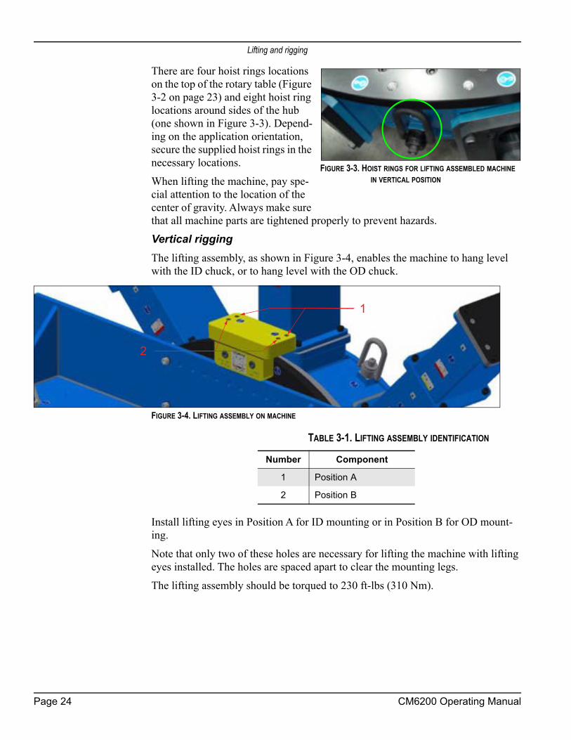
There are four hoist rings locations on the top of the rotary table (Figure 3-2 on page 23) and eight hoist ring locations around sides of the hub (one shown in Figure 3-3). Depend-ing on the application orientation, secure the supplied hoist rings in the necessary locations. When lifting the machine, pay spe-cial attention to the location of the center of gravity. Always make sure that all machine parts are tightened properly to prevent hazards.Vertical riggingThe lifting assembly, as shown in Figure 3-4, enables the machine to hang level with the ID chuck, or to hang level with the OD chuck.
FIGURE 3-4. LIFTING ASSEMBLY ON MACHINE
Install lifting eyes in Position A for ID mounting or in Position B for OD mount-ing. Note that only two of these holes are necessary for lifting the machine with lifting eyes installed. The holes are spaced apart to clear the mounting legs.The lifting assembly should be torqued to 230 ft-lbs (310 Nm).
FIGURE 3-3. HOIST RINGS FOR LIFTING ASSEMBLED MACHINE IN VERTICAL POSITION
2
1
TABLE 3-1. LIFTING ASSEMBLY IDENTIFICATION
Number Component
1 Position A
2 Position B
Page 24 CM6200 Operating Manual

Installation hazards
3.4 INSTALLATION HAZARDS
The installation stage can be dangerous, as it relies on the operator and other per-sonnel following the recommended safety precautions. Consider the following warnings carefully before undertaking the assembly process.
WARNINGSwinging or falling machinery could seriously injure or be fatal to personnel who are near the machine. Secure all components to the machine before lifting. Serious injury or fatalities can result from improper lifting methods.
WARNINGIf not properly secured, this machine can fall and cause fatal injuries to personnel. Pay special attention to vertical flange installations.• Chucking feet must be secured to the workpiece. • Setup fingers and safety weld plates should be utilized when possible.
To avoid the risk of a falling machine, secure the machine by tack-welding safety blocks over the upper jaws or by using clamps bolted to the underside of the leveling chuck feet (safety blocks and clamps not included with the machine).
WARNINGDo not remove the crane until at least one of the securing methods is in place and the chuck feet jacking screws are torqued to 325 ft-lb (441 Nm).
NOTICEIf the torque value cannot be achieved without acceptable workpiece deformation, the operator must apply their own secondary support and restraint devices.
FIGURE 3-5. VERTICAL INSTALLATION HAZARD
P/N 63674, Rev. 9 Page 25

Installing machine on workpiece
WARNINGDo not extend the chuck feet jacking screws past the full-extension groove in the threaded screw. If needed, add additional leg sections to minimize the length of the threaded jacking screw that is exposed.
3.5 INSTALLING MACHINE ON WORKPIECE
3.5.1 Overview of CM6200 circular milling machine setupInspect and perform necessary maintenance on the machine before mounting on a workpiece. The following steps are an overview of the processes involved with setting up the CM6200 in the ID mounting configuration. The OD mount setup is listed in Section 3.5.3 on page 33.Do the following to mount the machine to the workpiece:
1. Check that power sources are disconnected.2. Measure the surface for
mounting and select proper parts for machining, attach-ing (customer-supplied) scab plates or other mount-ing surfaces as needed (Fig-ure 3-6).
3. Before inserting the circu-lar mill into the work piece, confirm the legs are securely attached to the machine.
a) For ID mounting: Confirm that the ID mounting legs are set to a diameter smaller than the internal mounting diameter.
FIGURE 3-6. MEASURE WORKPIECE
Page 26 CM6200 Operating Manual

Installing machine on workpiece
b) For OD mounting: Confirm that the OD mounting legs are set to a diameter larger than the flange diameter (Figure 3-7). See Section 3.5.2 on page 29 and Section 3.5.3 on page 33 for the com-plete procedure for chuck leg setup.
NOTICEIf mounting the CM6200 in the vertical position, then the machining arm and counterweight should be attached to the rotary table (step 5) before mounting the machine to the workpiece (step 8).This will reduce the possibility of an unintentional rotational shift during the installation process.
4. Position the counterweight and machining arm in location slots that are equidistant from the machine center, with the same location number, in order to balance the machine.
5. Secure the machining arm and counterweight to the rotary table. See Section 3.6 on page 35 and Section 3.7 on page 39 for specific torque val-ues.
6. Attach the crane slings to the lifting points on the rotary table.
WARNINGOnly use individual slings for each hoist rings and be sure that they are of appropriate and equal length, and rated for the machine weight, and sling angle.
7. Lift the machine slowly and carefully. If it is out of balance, lower the machine to the ground. Make adjustments before attempting to lift and maneuver it again.
FIGURE 3-7. LEG MEASUREMENT
P/N 63674, Rev. 9 Page 27
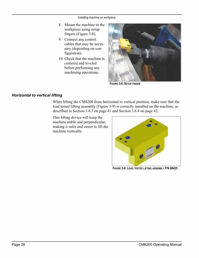
Installing machine on workpiece
8. Mount the machine to the workpiece using setup fingers (Figure 3-8).
9. Connect any control cables that may be neces-sary (depending on con-figuration).
10. Check that the machine is centered and leveled before performing any machining operations.
Horizontal to vertical liftingWhen lifting the CM6200 from horizontal to vertical position, make sure that the load tested lifting assembly (Figure 3-9) is correctly installed on the machine, as described in Section 3.8.3 on page 41 and Section 3.8.4 on page 42. This lifting device will keep the machine stable and perpendicular, making it safer and easier to lift the machine vertically.
FIGURE 3-8. SETUP FINGER
FIGURE 3-9. LOAD TESTED LIFTING ASSEMBLY P/N 68425
Page 28 CM6200 Operating Manual

Installing machine on workpiece
3.5.2 ID mount leg assembly The highlighted items in Figure 3-10 are 4”-4UN triple lead threaded. The leveling chuck feet jaws include clamps for internal flanges up to 8" (210 mm).
On the end cap, the highlighted lock symbols are for the jacking screw locking system (see Figure 3-11).
NOTICEAfter the final adjustments are complete on the chuck feet, tighten one of the three socket head set screw (P/N 74499 M12 x 40mm long to 29 ft-lbs (40 Nm) (shown circled in Figure 3-11) to lock the jacking screw position. Loosen this screw before making additional jacking adjustments—or removing the machine from the flange.
NOTICEThe chuck legs will alternate high and low around the hub for double plane. For single plane, the jacking screws will normally all be mounted high.
TABLE 3-2. LOCKING NUT AND LEVELING JAW IDENTIFICATION
Number Component
1 Internal locking nut
2 Leveling jaw
FIGURE 3-10. LOCKING NUT AND LEVELING JAW
14
20 10
18
16
12
86
15
12
16
14
15
1
2
FIGURE 3-11. LOCKING SYMBOLS ON END CAP
P/N 63674, Rev. 9 Page 29

Installing machine on workpiece
WARNING Use supplemental rigging, such as setup fingers, when mounting the machine, in case it falls out or through the chucking diameter.
The rotary table can be set up in the ID or the optional OD configuration. An ID configuration allows mounting internally on a flange. An OD configuration allows attaching the machine to the outside of a flange. See Section 4.5.1 on page 84.The double-plane setup in the ID configuration uses alternating legs so that the leveling legs are higher than the non-leveling legs. This arrangement may provide additional stability to the machine, depending on the nature of the workpiece.
NOTICEIf the workpiece will not accommodate the double-plane setup, then other methods for increasing stability of the machine should be used. See Section 3.5.3 on page 33 for attachment methods.
Do the following to set up the rotary table mounting feet:1. Measure the workpiece bore.2. Select the appropriate parts for assembly.3. Apply anti-seize (provided in the tool kit) to the following locations:
• The threads and contacting faces of each chuck extension leg section, as shown in Figure 3-12.
FIGURE 3-12. LOCATIONS TO APPLY ANTI-SEIZE
• The jacking screw threads, to prevent thread galling (Figure 3-13.)
FIGURE 3-13. JACKING SCREW
Page 30 CM6200 Operating Manual

Installing machine on workpiece
4. Refer to the exploded view drawings Figure A-7 on page 126, Figure A-8 on page 127, and Figure A-9 on page 128, Table 3-5 on page 32 and Table 3-6 on page 34 when assembling the chuck legs.
5. The chuck legs will alternate high and low around the hub. Secure the chuck arms to the hub with the bolts supplied.
6. After attaching the end cap to the chuck extensions leg, install the leveling and non-leveling chuck feet assemblies. The leveling chuck feet must be mounted to the four upper leg end caps. The non-leveling chuck feet must be mounted to the lower leg end caps.
7. Secure the chuck arms to the hub with the bolts supplied.8. After attaching the end cap to the chuck extensions leg, install the leveling
chuck feet assemblies.
CAUTIONThe jacking screw must be inserted so that the full extension groove is inside the end cap.
Do not extend the jacking feet past the full-extension groove in the threaded screw (Figure 3-14), as that may overload the jacking screw and result in damage to the screw.
If needed, add additional leg sections to minimize the length of the threaded jacking screw that is exposed.
TABLE 3-3. JACKING SCREW GROOVE IDENTIFICATION
Number Component
1 Jacking screw groove
FIGURE 3-14. JACKING SCREW GROOVE (LEVELING FOOT)
1
P/N 63674, Rev. 9 Page 31
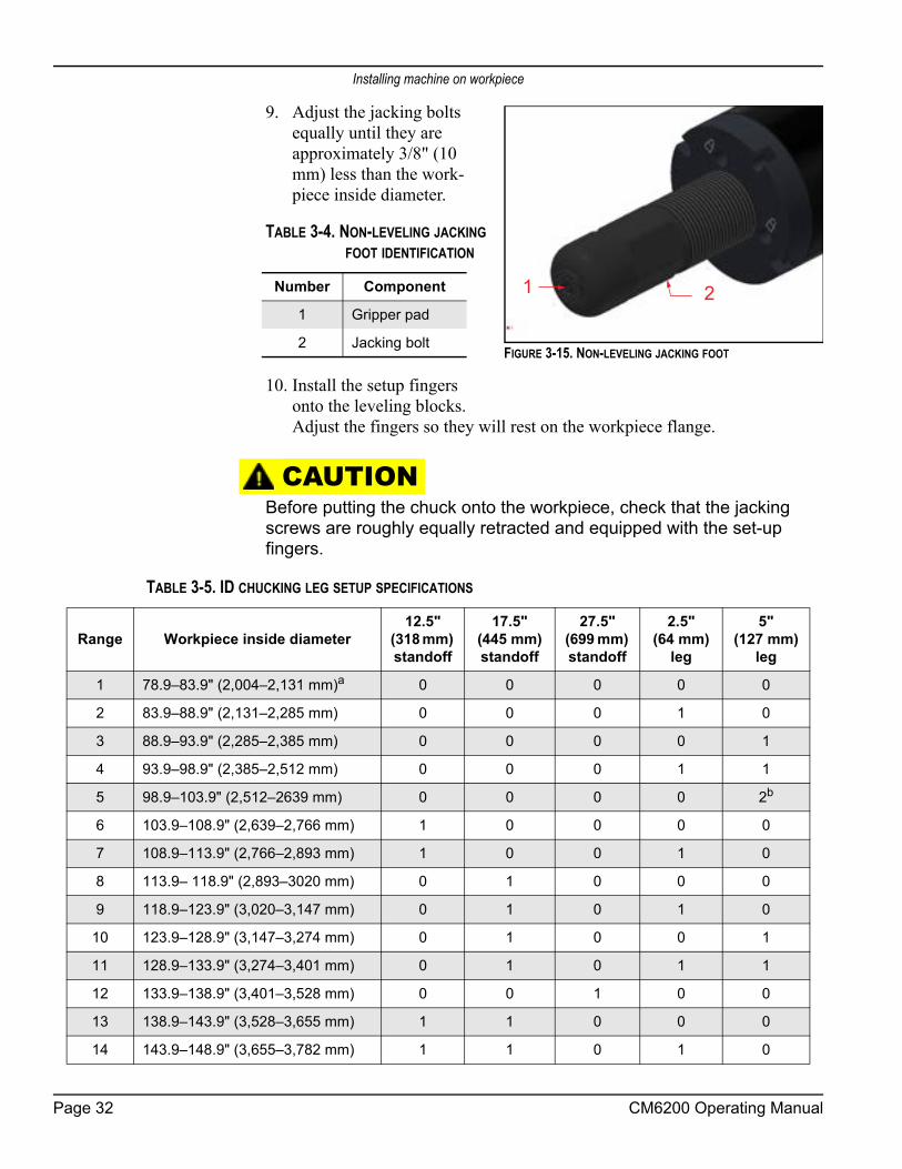
Installing machine on workpiece
9. Adjust the jacking bolts equally until they are approximately 3/8" (10 mm) less than the work-piece inside diameter.
10. Install the setup fingers onto the leveling blocks. Adjust the fingers so they will rest on the workpiece flange.
CAUTIONBefore putting the chuck onto the workpiece, check that the jacking screws are roughly equally retracted and equipped with the set-up fingers.
TABLE 3-4. NON-LEVELING JACKING FOOT IDENTIFICATION
Number Component
1 Gripper pad
2 Jacking bolt
21
FIGURE 3-15. NON-LEVELING JACKING FOOT
TABLE 3-5. ID CHUCKING LEG SETUP SPECIFICATIONS
Range Workpiece inside diameter12.5"
(318 mm) standoff
17.5" (445 mm) standoff
27.5" (699 mm) standoff
2.5" (64 mm)
leg
5" (127 mm)
leg
1 78.9–83.9" (2,004–2,131 mm)a 0 0 0 0 0
2 83.9–88.9" (2,131–2,285 mm) 0 0 0 1 0
3 88.9–93.9" (2,285–2,385 mm) 0 0 0 0 1
4 93.9–98.9" (2,385–2,512 mm) 0 0 0 1 1
5 98.9–103.9" (2,512–2639 mm) 0 0 0 0 2b
6 103.9–108.9" (2,639–2,766 mm) 1 0 0 0 0
7 108.9–113.9" (2,766–2,893 mm) 1 0 0 1 0
8 113.9– 118.9" (2,893–3020 mm) 0 1 0 0 0
9 118.9–123.9" (3,020–3,147 mm) 0 1 0 1 0
10 123.9–128.9" (3,147–3,274 mm) 0 1 0 0 1
11 128.9–133.9" (3,274–3,401 mm) 0 1 0 1 1
12 133.9–138.9" (3,401–3,528 mm) 0 0 1 0 0
13 138.9–143.9" (3,528–3,655 mm) 1 1 0 0 0
14 143.9–148.9" (3,655–3,782 mm) 1 1 0 1 0
Page 32 CM6200 Operating Manual

Installing machine on workpiece
3.5.3 OD mount leg assemblyDo the following to mount the OD leg assembly:
1. Identify the necessary length of the OD mount leg sections based on mea-surements of the outer diameter of the workpiece and the OD configura-tions in Table 3-6 on page 34.
2. Assemble the OD mount legs (Figure 3-16) according to the exploded view in Figure A-10 on page 129.
FIGURE 3-16. OD MOUNT LEG ASSEMBLY
15 148.9–153.9" (3,782–3,909 mm) 1 1 0 0 1
16 153.9– 58.9" (3,909–4,036 mm) 1 1 0 1 1
17 158.9–163.9" (4,036–4,163 mm) 1 0 1 0 0
18 163.9– 168.9" (4,163–4,290 mm) 1 0 1 1 0
19 168.9–173.9" (4,290–4,417 mm) 1 0 1 0 1
20 173.9–178.9" (4,417–4,544 mm) 1 0 1 1 1
21 178.9–183.9" (4,544–4,671 mm) 0 1 1 0 1
a. Do not use the internal locking nut.b. There are twelve 5" legs in the bill of materials. When two 5" legs per leg assembly are required (16 total), screwtwo 2.5" legs together to created the additional four 5" legs.
TABLE 3-5. ID CHUCKING LEG SETUP SPECIFICATIONS
Range Workpiece inside diameter12.5"
(318 mm) standoff
17.5" (445 mm) standoff
27.5" (699 mm) standoff
2.5" (64 mm)
leg
5" (127 mm)
leg
P/N 63674, Rev. 9 Page 33

Installing machine on workpiece
3. Attach the centering plate onto the ends of each OD mount leg (Figure 3-17).
NOTICEIn Table 3-6, the first four rows highlighted in dark gray are not practical because of the minimum arm swing length. See Figure 3-18 on page 35.
FIGURE 3-17. OD MOUNT CENTERING PLATE
TABLE 3-6. OD CHUCKING LEG SETUP CHART
Diameter 12.5" (318 mm) standoff
17.5" (445 mm) standoff
27.5" (699 mm) standoff
5" (127 mm)
legRange Aa Bb Cc
1 92.5" (2,350 mm)
102.38" (2,600 mm)
110.4" (2,804 mm) 1 0 0 0
2 102.5" (2,604 mm)
112.38" (2,854 mm)
120.4" (3,058 mm) 0 1 0 0
3 112.5" (2,858 mm)
122.38" (3,108 mm)
130.4" (3,312 mm) 0 1 0 1
4 122.5" (3,112 mm)
132.38" (3,362 mm)
140.4" (3,566 mm) 0 0 1 0
5 127.5" (3,239 mm)
137.38" (3,489 mm)
145.4" (3,693 mm) 1 1 0 0
6 137.5" (3,493 mm)
147.38" (3,743 mm)
155.4" (3,947 mm) 1 1 0 1
7 147.5" (3,747 mm)
157.38" (3,997 mm)
165.4" (4,201 mm) 1 0 1 0
8 157.5" (4,001 mm)
167.38" (4,251 mm)
175.4" (4,455 mm) 1 0 1 1
9 167.5" (4,255 mm)
177.38" (4,505 mm)
185.4" (4,709 mm) 0 1 1 1
10 182.5" (4,636 mm)
192.38" (4,886 mm)
200.4" (5,090 mm) 1 1 1 0
11 192.5" (4,890 mm)
202.38" (5,140 mm)
210.4" (5,344 mm) 1 1 1 1
a. A is measured from mounting face to mounting face of the vertical supports.b. B is the swing clearance inside the vertical supports for the machining arm.c. C is measured from center of mounting plate to center of mounting plate.
Page 34 CM6200 Operating Manual

Mounting the machining arm
FIGURE 3-18. OD CHUCKING LEG DIMENSIONS
3.6 MOUNTING THE MACHINING ARM
3.6.1 Mounting the machining arm to the rotary tableAfter the chuck legs are correctly configured and assembled on the chuck hub, the machining arm should be mounted on the machine.
NOTICEIf the machine will be mounted in the vertical position, then this step must be completed before mounting the machine.
The machining arm may be mounted in a horizontal orientation after the chuck is mounted to the workpiece, but the machining arm should be mounted first.The CM6200 machining arm is attached to the rotary table with clamps. Two of the clamps (closest to the center hole of the table) attach directly to the CM6200 rotary table top and do not need to be removed.Do the following to mount the machining arm to the rotary table:
1. Keep the machining arm level and flat when lifting by using two of the lift-ing eyes mounted on top of the machining arm.
2. Position the machining arm against the two fixed clamps.
NOTICEThe machining arm mounting surface, opposite the milling head, is notched to allow access by the safety clamp. Make sure the notches fit against the safety pin in the clamp.
3. Install the two remaining clamps and install the 5/8-SHCS screws to secure the clamps.
P/N 63674, Rev. 9 Page 35

Mounting the machining arm
WARNINGTighten the clamp bolts to 110 ft-lb (150 Nm) to prevent unexpected movement that could cause serious injury or death.
TIP:The selector pin does not need to be engaged in a notch after the turning arm adjustment. It is intended just to limit the turning arm’s maximum amount of travel in the event that the turning arm comes loose during operation.
WARNINGDo not disable the safety stop pin. The safety stop pin is intended to prevent unwanted shifting of the machining arm, which could result in serious injury or death.
3.6.2 Repositioning the machining armThe machining arm is incrementally adjustable for versatile positioning and to clear obstructions. Do the following to reposition the machining arm:
1. Loosen the screws holding the four clamps.2. Hold the safety stop pin
open (Figure 3-19). 3. Slide the arm to the neces-
sary position.4. Release the safety stop pin.5. Re-tighten the clamps.
CAUTIONAfter adjusting the machining arm, make sure that the counterweight is set to the corresponding bolt location increment. For precise machining and to avoid damage to the machine, the counterweight and machining arm should always be equally spaced from the center of the machine.
TABLE 3-7. CLAMP SCREWS AND STOP PIN IDENTIFICATION
Number Component
1 Stop pin
2 Clamp screws
FIGURE 3-19. CLAMP SCREWS AND STOP PIN
1
2
Page 36 CM6200 Operating Manual

Mounting the machining arm
The counterweight and machining arm have numbered increments along the mounting surfaces. Each numbered slot in the machining arm coincides with a numbered bolt position on the counterweight arm. Make sure that you move the counterweight one bolt space for each slot you move the machining arm.
FIGURE 3-20. COUNTERWEIGHT
FIGURE 3-21. MACHINING ARM
The milling head has 24" (609.6 mm) of travel along the machining arm.
P/N 63674, Rev. 9 Page 37

Mounting the machining arm
To set the machine for a milling range, use the minimum and maximum of your surface to determine the settings for the machining arm and counterweight, as shown in Table 3-8.
3.6.3 Milling, grinding, or single-point setupSee Section 4.4 on page 81 for grinding configuration. See Section 4.5 on page 82 for single-point configuration. For milling, the milling head mounts to the CM6200 using an adapter plate.Bolt-hole patterns in the adapter plate allow the milling head assembly to be placed in 180° increments.Before lifting the milling head assembly, determine which alignment is required for machining operations.Do the following to install the milling head:
1. Hoist the adapter plate into place and align.2. Mount the adapter to the radial slide saddle and
bolt in place.3. Align milling head plate to dowel pins in
adapter plate.4. Remove all tools and lifting or rigging equip-
ment.5. Check that all fasteners are tightened properly.
TABLE 3-8. POSITION OF MACHINING ARM AND COUNTERWEIGHT
Position Surface range in inches (mm)
1 123–73.5" (3,124.2–1,866.9 mm)
2 129–79.5" (3,276.6–2,019.3 mm)
3 135–85.5" (3,429.0–2,171.7 mm)
4 141–91.5" (3,581.4–2,324.1 mm)
5 147–97.5" (3,733.8–2,476.5 mm)
6 153–103.5" (3,886.2–2,628.9 mm)
7 159–109.5" (4,038.6–2,781.3 mm)
8 165–115.5" (4,191.0–2,933.7 mm)
9 171–121.5" (4,343.4–3,073.4 mm)
10 177–127.5" (4,495.8–3,238.5 mm)
11 183–133.5" (4,648.2–3,390.9 mm)
12 189–149.5" (4,800.6–3,797.3 mm)
FIGURE 3-22. INSTALLED MILL-ING HEAD
Page 38 CM6200 Operating Manual

Positioning the counterweight
3.7 POSITIONING THE COUNTERWEIGHT
After the chuck legs are correctly configured and assembled on the chuck hub, the counterweight should be mounted on the machine.
NOTICEThe counterweight must be installed when the machine is used in a vertical machining application. CLIMAX recommends that you always use the counterweight as it improves the performance of the machine and produces a flatter surface.
The machining arm may be mounted in a horizontal orientation after the chuck is mounted to the workpiece, but the machining arm should be mounted first.The counterweight serves to reduce the load on the servo drive motor and protect the drive system from excessive force. The counterweight also provides stability to the machine that creates more precise machining tolerances. The counterweight has multiple settings and can be positioned by sliding it radially to the next bolt-hole position (Figure 3-23). Follow the parameters in Table 3-8 on page 38 to position the machining arm and counterweight in the necessary position for correct range of the machining operation.
FIGURE 3-23. COUNTERWEIGHT BOLT-HOLE POSITIONS
WARNINGTighten the counterweight arm mounting bolts to 110 ft-lb (150 Nm) to prevent unexpected movement that could cause serious injury or death.
Check that all mounting hardware is secure. A loose counterweight can fall off during operation, seriously injuring the operator or bystanders.
Do the following to mount the counterweight:1. Position the counterweight to the location required by your machining
needs.
P/N 63674, Rev. 9 Page 39

Mounting machine to workpiece
2. Bolt the counterweight securely into place (Fig-ure 3-24).
CAUTIONFor precise machining and to avoid damage to the machine, the counterweight and machining arm should always be equally spaced from the center of the machine. The location numbers should be the same.
3.8 MOUNTING MACHINE TO WORKPIECE
Once the chuck feet are correctly configured and attached to the chuck, the machine is ready to be mounted to the workpiece.See Section 3.4 on page 25 for a full list of installation hazards.
3.8.1 ID mounting the machine horizontallyDo the following to ID mount the machine to a horizontal flange:
1. Set the ID mounting chuck feet to a dimension that is 0.01" (0.25 mm) less per leg than the dimension of the inner diameter of the workpiece.
2. Position the machining arm (see Section 3.6 on page 35) and the counter-weight arm (see Section 3.7 on page 39) before lifting (see Section 3.3 on page 22).
3. Lift the machine into the inner diameter of the workpiece—using the four hoist rings on the top hub (as shown in Figure 3-2 on page 23).
4. Extend the chuck feet at the 6:00, 9:00, 12:00, and 3:00 positions to secure the machine into position.
FIGURE 3-24. COUNTERWEIGHT AND MACHINING ARM ON THE ROTARY TABLE
FIGURE 3-25. HORIZONTALLY MOUNTED MACHINE
Page 40 CM6200 Operating Manual

Mounting machine to workpiece
5. Center and level the machine on the flange as described in Section 3.9 on page 47.
3.8.2 OD mounting the machine horizontallyDo the following to OD mount the machine to a horizontal flange:
1. Position the machining arm (see Section 3.6 on page 35) and the counter-weight arm (see Section 3.7 on page 39) before lifting (see Section 3.3 on page 22).
2. Lift the machine over the flange using the four indicated lift points (as shown in Figure 3-2 on page 23).
3. Center and level the machine on the flange as described in Section 3.9 on page 47.
4. Tighten the nut (shown in the middle of Figure 3-26) to 230 ft-lbs (310 Nm).
3.8.3 ID mounting the machine verticallyWhen mounting the CM6200 in the vertical position, make sure that the lifting assembly (P/N 68425 in Figure 3-9 on page 28) is properly installed on the machine. This lifting device will help keep the machine stable and perpendicular, making it safer and easier to mount the machine vertically.Do the following to ID mount the machine to a vertical flange:
1. Set the ID mounting chuck feet to a dimension that is 0.01" (0.254 mm) less per leg than what is required.
2. Position the machining arm (see Section 3.6 on page 35) and the counter-weight arm (see Section 3.7 on page 39) before lifting (see Section 3.3 on page 22).
TABLE 3-9. OD MOUNT CENTERING PLATE IDENTIFICATION
Number Component
1 Tightening
2 Leveling
3 Centering
1
3
2
FIGURE 3-26. OD MOUNT CENTERING PLATE ADJUSTMENTS
P/N 63674, Rev. 9 Page 41

Mounting machine to workpiece
WARNINGSecure all moving parts to prevent them from swinging to the lowest point.
3. Attach and torque to 230 ft-lbs (310 Nm) the lifting assembly (P/N 68425 in Figure 3-9).
4. Lift the machine into the inner diameter of the flange using the lifting assembly, until the setup fingers rest against the flange.
5. Extend the chuck feet at the 6:00, 9:00, 12:00, and 3:00 positions to secure the machine into position.
6. Use a second method of fixation, in addition to the locking feet. See Sec-tion 3.5.3 on page 33 for fixation options for ID mounting.
DANGEREither the weld plate or the flange clamp must be used for securing the CM6200 in the workpiece, in addition to locking the jacking feet. Failure to properly secure the machine may result in the machine falling from the workpiece, potentially causing serious injury or death.
7. Remove all tools from workpiece and machine.8. Center and level the machine on the flange as described in Section 3.9 on
page 47.
3.8.4 OD mounting the machine verticallyWhen mounting the CM6200 in the vertical position, make sure that the lifting assembly (P/N 68425 in Figure 3-9) is properly installed on the machine. This lift-ing device will help keep the machine stable and perpendicular, making it safer and easier to mount the machine vertically.Do the following to OD mount the machine to a vertical flange:
1. Position the machining arm (see Section 3.6 on page 35) and the counter-weight arm (see Section 3.7 on page 39) before lifting (see Section 3.3 on page 22).
WARNINGSecure all moving parts to prevent them from swinging to the lowest point.
2. Attach and torque to 230 ft-lbs (310 Nm) the lifting assembly (P/N 68425, Figure 3-9).
3. Lift the machine over the flange using the lifting assembly, until the setup fingers rest against the flange.
Page 42 CM6200 Operating Manual

Mounting machine to workpiece
4. Securely attach the OD leg to (customer-supplied) scab plates or other suit-able mounting structure (see Section 3.8 on page 40).
DANGERFailure to properly secure the machine may result in the machine falling from the workpiece, potentially causing serious injury or death.
5. Remove all tools from workpiece and machine.6. Center and level the machine on the flange as described in Section 3.9 on
page 47.7. Tighten the nut (shown in the middle of Figure 3-26 on page 41) to 230 ft-
lbs (310 Nm).
3.8.5 Inverted mountingThe CM6200 can also be mounted in an inverted position on the workpiece. The machining arm and counterweight are below the chuck in this position, as opposed to being above the chuck in the horizontal position. The horizontal mount proce-dure should be followed to mount the inverted ID mount. Use extreme caution when rotating the machine.
DANGERSwinging or falling machinery could seriously injure or be fatal to personnel who are near machine. Secure all components to the machine and prevent the rotary table from turning before lifting the machine. Serious injury or fatalities can result from improper lifting methods.
Refer to Section 3.3 on page 22 for instructions on lifting the device, paying spe-cial attention to Figure 3-2 on page 23 and the use of the lifting assembly as shown in Figure 3-4 on page 24.
DANGEREither the weld plate or the flange clamp must be used for securing the CM6200 in the workpiece, in addition to locking the jacking feet. Failure to properly secure the machine may result in the machine falling from the workpiece, potentially causing serious injury or death.
TIP:The preferred method for inverting the machine is with two cranes.
P/N 63674, Rev. 9 Page 43
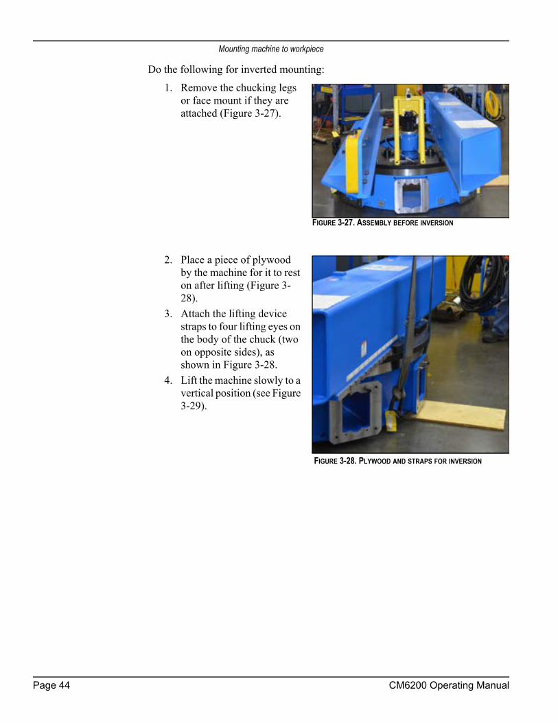
Mounting machine to workpiece
Do the following for inverted mounting:1. Remove the chucking legs
or face mount if they are attached (Figure 3-27).
2. Place a piece of plywood by the machine for it to rest on after lifting (Figure 3-28).
3. Attach the lifting device straps to four lifting eyes on the body of the chuck (two on opposite sides), as shown in Figure 3-28.
4. Lift the machine slowly to a vertical position (see Figure 3-29).
FIGURE 3-27. ASSEMBLY BEFORE INVERSION
FIGURE 3-28. PLYWOOD AND STRAPS FOR INVERSION
Page 44 CM6200 Operating Manual

Mounting machine to workpiece
FIGURE 3-29. CM6200 IN VERTICAL POSITION
5. If using two cranes, detach the lower straps seen in Figure 3-29.6. Raise the machine high
enough to place blocks under the turning arm and chuck body.
7. Lower the machine onto the blocks (see Figure 3-30). If using two cranes, re-attach the straps to the bottom lift-ing eyes.
TABLE 3-10. VERTICAL CM6200 IDENTIFICATION
Number Component
1 Lower straps
1
FIGURE 3-30. VERTICAL CM6200 ON BLOCKS WITH STRAPS RE-ATTACHED
P/N 63674, Rev. 9 Page 45

Mounting machine to workpiece
8. Lift the machine vertically clear of the floor and blocks (see Figure 3-31).
9. Remove the blocks.
10. Raise the lower straps until the machine is completely inverted (see Figure 3-32).
11. Replace the blocks under the turning arm and coun-terweight arm.
FIGURE 3-31. LIFTING THE CM6200 OFF THE BLOCKS
FIGURE 3-32. INVERTING THE CM6200
Page 46 CM6200 Operating Manual

Centering and leveling the machine
12. Lower the machine onto the blocks (see Figure 3-33).
13. Install the appropriate mounting apparatus (ID mount, OD mount, or face mount).
3.9 CENTERING AND LEVELING THE MACHINE
NOTICEWhen machining outdoors or in direct sunlight, be aware that temperature changes can affect final tolerances. CLIMAX recommends setting up temporary shade in these circumstances.
Do the following to precision center and level the machine:1. Use a dial indicator to indi-
cate the workpiece surface for level while rotating the machine.
2. Level the machine by doing the following:
FIGURE 3-33. BLOCKING LOCATIONS
FIGURE 3-34. ATTACHED DIAL INDICATOR
P/N 63674, Rev. 9 Page 47

Fixation of ID mount
a) For ID, adjust the lev-eling screws in each of the leveling chuck feet (see Figure 3-35).
b) For OD, adjust the leveling set screws above the centering plate (see Figure 3-26 on page 41).
3. Reposition the dial indicator to check machine centering.4. Center the machine by doing the following:
a) For ID, adjust the opposing pairs of chuck feet (one foot shown in Figure 3-35).
b) For OD, adjust the centering set screws in the centering plate (see Figure 3-26 on page 41).
5. Check the machine for level and center again.6. Repeat step 2 through step 6 until the machine is aligned.7. Fix the machine in place according to Section 3.10 on page 48 (for ID) and
Section 3.5.3 on page 33 (for OD).8. Recheck machine alignment. If any adjustments are necessary, repeat "Fix-
ation of ID mount" on page 48 (for ID) and Section 3.5.3 on page 33 (for OD).
9. Mark the high point of the flange so that the initial milling depth can be set at this point.
10. Remove any rigging.
3.10 FIXATION OF ID MOUNT
In ID configurations, the CM6200 is held in the workpiece by friction force from torquing eight chuck feet jacking screws.
TABLE 3-11. LEVELING CHUCK FOOT IDENTIFICATION
Number Component
1 Set-up finger
2 Jaw adjuster
3 Base adjuster
4 Jacking bolt
5 Leveling screw
3
15
2
4
FIGURE 3-35. LEVELING CHUCK FOOT ASSEMBLY
Page 48 CM6200 Operating Manual

Fixation of ID mount
NOTICEAll chuck feet jacking screws must be torqued to at least 325 ft-lb (441 Nm). Minimum jacking bolt torque value was determined with lubricated thread bolts and a dry bolt/workpiece interface.
Before installing the CM6200 on the workpiece, check the following:• The workpiece surface area that will contact the CM6200 jacking
screws is dry and completely free of oil, grease, or other lubricant.
WARNINGMoisture, oil, or lubricants on the chucking foot contact areas of the workpiece may result in insufficient jacking friction force and allow the machine to shift or fall out of the workpiece.
• Chuck feet jacking screw threads are coated with anti-seize lubricant.
WARNINGFailure to apply anti-seize lubricant to the jacking screw threads may result in lower-than-anticipated jacking bolt clamping force, which may allow the machine to shift or fall out of the workpiece.
Do the following to install the ID mount:1. Tighten all the leveling jacking screws to a minimum torque of 325 ft-lb
(441 Nm). Alternate opposite jacking legs when tightening to ensure that the setup alignment is not disturbed.
2. Extend all the non-leveling chuck feet jacking screws and tighten to a min-imum torque of 325 ft-lb (441 Nm).
WARNINGThe leveling and non-leveling chuck feet must be tightened to the torque specifications listed in the instructions above. Failure to sufficiently tighten chuck feet may cause the machine to slip or fall from the workpiece, potentially resulting in severe injury or death. Refer to Section 3.5.3 for methods of securing the CM6200 in the workpiece.
3. Secure the jacking screws using the methods described in Section 3.5.3 on page 33.
4. Remove setup fingers if the machine operation cannot be accomplished with setup fingers still attached to the leveling chuck feet.
P/N 63674, Rev. 9 Page 49

Installing cables
WARNINGDo not remove more than one setup finger at time as this can allow the machine to slip in the flange and fall out of the workpiece, causing injury or death.
Setup fingers should only be removed if the mill cannot perform the necessary machining operations on the workpiece with them still attached to the chuck feet. Removing the setup fingers reduces stability of the machine.
In addition to this minimum torque of 325 ft-lb (441 Nm), as many of the follow-ing securing methods as possible should be used in combination. Vertical and inverted mounting applications must use either the weld plate or the flange clamp, in addition to locking the jacking feet. See Section 3.8.3 on page 41 and Section 3.8.5 on page 43 for more information on vertical and inverted mounting.
• Internal locking nut: An internal locking nut is provided with each jacking screw, and it should be tightened when the machine is centered and the jacking screws are torqued to spec. The intent of using the internal locking nut is to help prevent back-off of the jacking screw due to machine vibration during operation. See Section 3.5.2 on page 29.
• Weld plate: These four plates must be thoroughly welded onto the workpiece (with a fillet weld the length of each end and a couple short fillets across the front) with the machine in place, and bolted onto the adjustable leveling chuck foot.
• Flange clamp: The flange clamps are provided with the adjustable lev-eling jacking bolts and are composed by the setup finger and the inter-nal flange clamp. These elements will clamp onto an interior surface of the mounting flange.
DANGERDo not remove the crane until the jacking screws are tightened to the specified torque (325 ft-lb [441 Nm]) and at least one of the securing methods is in place.
3.11 INSTALLING CABLES
WARNINGFalling or rotating machinery can seriously injure the operator. Make sure the machine is secured to the workpiece before connecting power cables.
Page 50 CM6200 Operating Manual

Installing cables
Do the following to enable the electric power connection:1. Check that all cable plugs and fittings are clean.2. Replace any worn or damaged parts.3. Check that the main disconnect power switch is in the OPEN position.4. Check that the E-stop on the pendant control is depressed.5. Lock out all power.6. Connect the main control cable to the main junction box on the CM6200
pendant.7. Connect the conduit to the servo motor.8. Attach the carabiner conduit support to the hose tower.9. Connect the other end to the HPU control panel.10. Secure the conduit clamp to the HPU frame.11. Connect all other control cables to the HPU electrical panel.
NOTICEThe servo motor must be connected to the HPU—but not attached to the machine. There is a danger of damaging the servo drive if the motor is disconnected when the HPU is powered up.
CAUTIONTo avoid damaging the power lines, ensure that they are clear of moving parts and pinch points during operation.
12. Check that all personnel are clear of the rotary table.13. Close the main disconnect switch on the HPU.14. Twist and release the e-stop on the HPU control panel.15. Twist and release the e-stop on the control pendant.16. Start the HPU.17. Jog the spindle motor to be sure the spindle is rotating in the expected
direction.18. If the direction needs to be changed, stop the jog. For hydraulically pow-
ered spindle motors, remove and switch the hoses so that the direction of flow is correct. For electrically powered spindle motors, switch the direc-tion of the servo system on the control panel.
CAUTIONDisconnecting the main control cable while under power may damage electrical components in the main panel.
P/N 63674, Rev. 9 Page 51

Installing cables
This page intentionally left blank
Page 52 CM6200 Operating Manual
4 OPERATION
IN THIS CHAPTER:4.1 OPERATION SETUP - - - - - - - - - - - - - - - - - - - - - - - - - - - - - - - - - - - - - - - - - -534.1.1 PRE-START CHECKS - - - - - - - - - - - - - - - - - - - - - - - - - - - - - - - - - - - - - -544.1.2 TOOL SETUP - - - - - - - - - - - - - - - - - - - - - - - - - - - - - - - - - - - - - - - - -544.1.3 SPINDLE TRAMMING - - - - - - - - - - - - - - - - - - - - - - - - - - - - - - - - - - - - - -55
4.2 CONTROL PENDANT - - - - - - - - - - - - - - - - - - - - - - - - - - - - - - - - - - - - - - - - -594.2.1 COORDINATE SYSTEMS - - - - - - - - - - - - - - - - - - - - - - - - - - - - - - - - - - - - -594.2.2 MACHINE CONTROLS OVERVIEW - - - - - - - - - - - - - - - - - - - - - - - - - - - - - - - - -604.2.3 MAIN MENU - - - - - - - - - - - - - - - - - - - - - - - - - - - - - - - - - - - - - - - - - -644.2.4 MACHINE SETUP - - - - - - - - - - - - - - - - - - - - - - - - - - - - - - - - - - - - - - - -664.2.5 INCREMENTAL MOVE - - - - - - - - - - - - - - - - - - - - - - - - - - - - - - - - - - - - - -684.2.6 ABSOLUTE MOVE - - - - - - - - - - - - - - - - - - - - - - - - - - - - - - - - - - - - - - -694.2.7 INCREMENTAL VELOCITY MOVE - - - - - - - - - - - - - - - - - - - - - - - - - - - - - - - - -704.2.8 ABSOLUTE VELOCITY MOVE - - - - - - - - - - - - - - - - - - - - - - - - - - - - - - - - - - -714.2.9 POP-UP SCREENS - - - - - - - - - - - - - - - - - - - - - - - - - - - - - - - - - - - - - - -724.2.10 ALARM HISTORY SCREENS - - - - - - - - - - - - - - - - - - - - - - - - - - - - - - - - - - -734.2.11 STATUS SCREEN - - - - - - - - - - - - - - - - - - - - - - - - - - - - - - - - - - - - - - -744.2.12 SYSTEM INFO - - - - - - - - - - - - - - - - - - - - - - - - - - - - - - - - - - - - - - - -75
4.3 CIRCULAR MILLING - - - - - - - - - - - - - - - - - - - - - - - - - - - - - - - - - - - - - - - - - -754.3.1 INSTALLING THE MILLING HEAD CUTTER - - - - - - - - - - - - - - - - - - - - - - - - - - - - -764.3.2 SETTING THE DRO (MILLING HEAD EQUIPMENT) - - - - - - - - - - - - - - - - - - - - - - - - -764.3.3 SAFE OPERATING RANGES - - - - - - - - - - - - - - - - - - - - - - - - - - - - - - - - - - -764.3.4 REPLACING THE MILLING ASSEMBLY - - - - - - - - - - - - - - - - - - - - - - - - - - - - - - -794.3.5 PERFORMING CIRCULAR MILLING - - - - - - - - - - - - - - - - - - - - - - - - - - - - - - - -80
4.4 GRINDING OPTION - - - - - - - - - - - - - - - - - - - - - - - - - - - - - - - - - - - - - - - - - -814.4.1 GRINDING ATTACHMENT SETUP - - - - - - - - - - - - - - - - - - - - - - - - - - - - - - - - -814.4.2 OPERATION - - - - - - - - - - - - - - - - - - - - - - - - - - - - - - - - - - - - - - - - - -82
4.5 SINGLE-POINT OPTION - - - - - - - - - - - - - - - - - - - - - - - - - - - - - - - - - - - - - - - -824.5.1 CONFIGURING THE ROTARY UNION FOR ID OR OD MOUNT - - - - - - - - - - - - - - - - - - - -84
4.5.1.1 ID MOUNT CONFIGURATION - - - - - - - - - - - - - - - - - - - - - - - - - - - - - - - -874.5.1.2 OD MOUNT CONFIGURATION - - - - - - - - - - - - - - - - - - - - - - - - - - - - - - -88
4.5.2 REPLACING THE MILLING ASSEMBLY - - - - - - - - - - - - - - - - - - - - - - - - - - - - - - -894.5.3 INSTALLING THE HYDRAULIC DRIVE IN THE SINGLE-POINT CONFIGURATION - - - - - - - - - - - - -904.5.4 INSTALLING THE FEED BOX - - - - - - - - - - - - - - - - - - - - - - - - - - - - - - - - - - -914.5.5 REVERSING THE FEED BOX DIRECTION - - - - - - - - - - - - - - - - - - - - - - - - - - - - - -924.5.6 OPERATING THE PNEUMATIC FEED SYSTEM - - - - - - - - - - - - - - - - - - - - - - - - - - -944.5.7 ADJUSTING CUT CHARACTERISTICS - - - - - - - - - - - - - - - - - - - - - - - - - - - - - - -95
4.6 DISASSEMBLY - - - - - - - - - - - - - - - - - - - - - - - - - - - - - - - - - - - - - - - - - - - -95
4.1 OPERATION SETUP
Do not operate this machine without adequate training to fully understand the safe setup, operation, and maintenance procedures.
P/N 63674, Rev. 9 Page 53

Operation setup
WARNINGOnly operators who have been trained on the use of the CM6200 should setup and operate the machine. Do not operate this machine in inclement weather without protection from the elements.To avoid serious personal injury, keep clear of moving machinery during operation. Always be aware of the location of all personnel near the machine.
NOTICEThe servo motor must be connected to the HPU—but not attached to the machine. There is a danger of damaging the servo drive if the motor is disconnected when the HPU is powered up.
4.1.1 Pre-start checks
WARNINGRotating machinery can cause serious injuries. Turn off and lock out the machine before making the pre-operation checks. When operating, always be aware of the location of all people near the machine.
Before starting the machine, always check for the following items:• The machining arm and counterweight are secured to the turntable with
a torque of 110 ft-lb (150 Nm).
CAUTIONCheck that the machine (including the spindle and all movable parts) can rotate without collisions.
• The machine is securely mounted to the work piece.• The spindle is secured to the machining arm and the adapter plate.• All jacking and clamping screws are secured (torqued to 325 ft-lb [441
Nm]).• Cables and hoses are secured away from the path of moving machine
parts.• All handles and tools are removed from the machine.• The area is clearly marked with a safety zone.
4.1.2 Tool setupThe milling head has four tramming screws adjacent to the mounting screws of the housing. This allows the milling head to be jacked away from the adapter plate to tram the vertical orientation of the spindle. On top of the plate, two additional screws allow for adjusting the tilt angle of the milling head.
Page 54 CM6200 Operating Manual

Operation setup
Since the milling head is mounted on a center pivot, the angle of the milling head must be aligned before machining can begin. This adjustment is made using the adjustment screws in the blocks mounted either below or above the housing. The rotational adjustment screws allow the housing to be rotated slightly to achieve vertical or horizontal orientation relative to the machining arm.Do the following to adjust the milling head and spindle:
1. Loosen the lock.2. Adjust the milling head
and spindle.3. Use the DRO to position
the milling head.4. Tighten the lock before
machining.
4.1.3 Spindle tramming Spindle tramming is the process of orienting the spindle.
NOTICEThe spindle must be oriented perpendicular to the machine tool itself rather than to the workpiece, which is not a reliable reference point.
Do the following to tram the spindle:1. If the spindle drive motor is installed, remove it from the spindle gearbox
to allow easy hand-rotation of the spindle.
FIGURE 4-1. SPINDLE LOCK AND DRO
P/N 63674, Rev. 9 Page 55

Operation setup
2. Install a magnetic-base dial indicator to the body of the face milling cutter (see Fig-ure 4-2).
TIP:A right-angle fixture oriented from the linear slide rail can serve as a reference point that is perpendicular to the milling arm.
3. Extend the indicator out to make contact with the bot-tom of the machine ram sur-face (see Figure 4-3).
4. With the stylus of the indica-tor touching the ram surface, set the dial of the indicator to “0.”
FIGURE 4-2. DIAL INDICATOR ON THE FACE MILL
FIGURE 4-3. INDICATOR TOUCHING MACHINE RAM SURFACE
Page 56 CM6200 Operating Manual

Operation setup
5. Rotate the spindle 180° to the machine ram surface (see Figure 4-4).
TIP:With the standard spindle, the angle is limited to ±1°. If a greater angle is needed, a swivel head adapter will be needed. For further information, contact CLIMAX.
6. Note the dial reading. If it is more than 0.001" (0.03 mm) out of tramming tolerance, do the following:
a) Loosen the four cap screws so that they are just slightly snug (between 1–3 ft-lb ([1–4 Nm]), as shown in Figure 4-5, so that the tramming setscrews can adjust the plate.
FIGURE 4-5. MILLING HEAD MOUNTING PLATE AND TRAMMING POINTS
FIGURE 4-4. SPINDLE ROTATED TO THE RAM SURFACE
3
3
3
3
1
2
2
2
2
P/N 63674, Rev. 9 Page 57

Operation setup
NOTICEThere are two cap screws on each side of the milling head, which is mounted in the center of the tramming plate shown in Figure 4-5.
b) Adjust the Y-axis screws until the indica-tor reads within 0.001” (0.03 mm). See Figure 4-6.
TABLE 4-1. MILLING HEAD MOUNTING PLATE IDENTIFICATION
Number Component
1 Y-axis tramming points rotation
2 Loosen first
3 X-axis tramming point
FIGURE 4-6. Y-AXIS SCREW ADJUSTMENT
Page 58 CM6200 Operating Manual

Control pendant
c) Adjust the X-axis screws (where shown in Figure 4-7) until the indicator reads within 0.001" (0.03 mm).
7. Repeat the process of sweeping the indicator at the 0° and 180° locations and adjusting the spindle orien-tation until the same read-ing is achieved at both locations.
8. Once both axes are within tolerance, tighten the mount-ing bolts to 45 ft-lbs (61 Nm).
TIP:Keep the dial indicator installed during the final tightening of the mounting screws, so you can recheck that the housing does not move during tensioning.
9. Reinstall the spindle drive motor (if necessary).When ready to operate the machine, note the machined surface after the first pass.A crosshatched pattern is the opti-mal result, as shown in the right of Figure 4-8. If the results are heel-edged, as shown in the left of Figure 4-8, adjust the X-axis screws according to step c on page 59.
4.2 CONTROL PENDANT
4.2.1 Coordinate systemsThis machine has two separate coordinate systems that track the position of the machine. The zero point can be reset at any time on either of the coordinate sys-tems without affecting the position in the other system.
FIGURE 4-7. X-AXIS SCREW LOCATION
FIGURE 4-8. MACHINING PASS RESULTS
P/N 63674, Rev. 9 Page 59

Control pendant
NOTICEThe machine will respond to movement instructions differently based on what coordinate system is being used.
Absolute coordinatesIn the absolute coordinate system all move destinations are relative to a designated absolute zero position. For example: a destination input of 90 degrees will result in the machine moving to the absolute 90 degree position, regardless of where the current position of the machine happens to be. The machine will end up at the 90 degree position, whether the move direction is in the + or - direction. The direction of travel for absolute coordinates can be controlled. A move from 0 to 90 degrees in the plus direction results in 90 degrees of rotation in the plus direction. A move from 0 to 90 degrees in the minus direction results in 270 degrees of rotation in the minus direction with the final position still being the absolute 90 degrees posi-tion.
Incremental coordinatesIn the incremental coordinates sys-tem, the move increments are always relative to the current posi-tion of the machine. For example: if the machine is at the 180 degree point relative to absolute zero, a move of minus 90 will result in a final absolute position of 90 degrees. A move of plus 90 will result in an absolute position of 270 degrees.
4.2.2 Machine controls overviewThe HMI control pendant is the interface for managing the operations of the CM6200. You will use the following screens to control and setup the various func-tions of the machine. The control pendant is shown in Figure 4-11 on page 61.
FIGURE 4-9. ABSOLUTE COORDINATES
FIGURE 4-10. INCREMENTAL COORDINATES
Page 60 CM6200 Operating Manual

Control pendant
FIGURE 4-11. CM6200 CONTROL PENDANT
When the HMI is turned on, the screen shown in Figure 4-12 will appear. The default setting will be set for all of the parameters of the machine.
FIGURE 4-12. OPENING SPLASH SCREEN AT STARTUP
NOTICEUser settings are not saved when the unit is shut off.
Following the Splash Screen, the Start Screen (Figure 4-13 on page 62) will appear on the HMI. The user is cautioned about operating the machine and must reset the
P/N 63674, Rev. 9 Page 61

Control pendant
parameters and connections by pressing the RESET button to navigate to the main menu.
FIGURE 4-13. RESET START SCREEN
If the E-Stop button is still depressed when the machine is powered up, the blue start (RESET) button will not be active and the text below the button will give instructions for starting.
Page 62 CM6200 Operating Manual

Control pendant
FIGURE 4-14. RESET DEPRESSED SCREEN
FIGURE 4-15. POP-UP SCREEN AFTER EMERGENCY STOP INITIATION
This pop-up screen also appears after the E-STOP is initiated. After the operator resolves the fault, the Start System Screen will appear.Other possible faults in the system will be displayed with pop-up screens:
P/N 63674, Rev. 9 Page 63

Control pendant
FIGURE 4-16. POP-UP SCREEN RESET REQUEST
FIGURE 4-17. REVERSED POWER WARNING
After the faults are resolved, the reset button will become active and the system may be reset. After resetting the system, the HMI will redirect to the Main Menu Screen.
CAUTIONDo not disconnect any cables from the system while energized! This will result in damage to the system.
WARNINGServo motor warning: do not connect or disconnect cables while the unit is energized.
4.2.3 Main menuThe Main Menu Screen, shown in Figure 4-18, provides access to all the main screens for machine operation.
Page 64 CM6200 Operating Manual

Control pendant
FIGURE 4-18. MAIN MENU WITHOUT SERVO MOTOR WARNING
All buttons are touch activated. Some of the buttons will also activate sub-screens for input. Further explanations on each screen are provided below. Buttons are color coded to assist with recognition for different modes of operation. Incremental coordinate functions are coded with a green color and absolute coordi-nate functions are coded with a light blue color.
P/N 63674, Rev. 9 Page 65

Control pendant
4.2.4 Machine setupThe Machine Setup Screen, shown in Figure 4-19, displays the parameters of the machine that can be adjusted by the operator.
FIGURE 4-19. MACHINE SETUP SCREEN
The standard factory settings for this machine are shown in Figure 4-19. Do not change the Motor Rev/Table Rev data, as this data is based on the actual total gear ratio for this machine.The Rapid Speed is set on this screen. This feature is available in other screens, but is edited here.Auto Feed Reduction (AFR) is ENABLED by default. This feature helps protects the machine from being damaged by overload. If the machine encounters resis-tance from high spots or other irregularities during machining that push past the AFR THRESHOLD setting, the system will count for the AFR DELAY TIME and automatically reduce the feed rate by the AFR REDUCTION % specified. If the resistance is still present, the system will continue to monitor it in the AFR DELAY TIME intervals and continue to reduce the feed by the AFR REDUC-TION % each time. The operator can return the machine to normal speeds manu-ally at the control pendant.
Page 66 CM6200 Operating Manual

Control pendant
By touching any of the number fields, the input screen below will appear (Figure 4-20). Enter the necessary data and press ENTER.All settings on this page are retentive and are held in permanent memory even when the machine is discon-nected from power.If any of the setup parameters have not been set to a valid number, the message shown in Figure 4-21 will be displayed. Acknowledge this pop-up by pressing the OK, and enter the required data into the SETUP screen.
FIGURE 4-21. SETUP PARAMETERS VERIFICATION SCREEN
FIGURE 4-20. MACHINE SETUP NUMBER INPUT PAD
P/N 63674, Rev. 9 Page 67

Control pendant
4.2.5 Incremental move The Incremental Move Screen, shown in Figure 4-22, allows the operations of the CM6200 to be controlled according to a incremental coordinate system.
FIGURE 4-22. INCREMENTAL MOVE SCREEN
Incremental moves are relative to the current position, in the direction and speed you enter.An incremental move will always be the distance entered in the “input increment” field, and in the selected direction and speed.
NOTICEBased on the requested configuration of the CM6200 options, only certain functions will be enabled and visible. As a result, some functions shown above may not be available on the control pendant supplied.
Page 68 CM6200 Operating Manual

Control pendant
4.2.6 Absolute moveThe Absolute Move Screen, shown in Figure 4-23, allows the operations of the CM6200 to be controlled according to a absolute coordinate system.
FIGURE 4-23. ABSOLUTE MOVE SCREEN
Absolute moves are relative to the absolute zero position, which can be anywhere along the circumference of a 360-degree circle. Not to be confused with incremen-tal moves, the absolute move will move to the destination entered, at the direction and speed you entered, relative to the ZERO position.
NOTICEBased on the requested configuration of the CM6200 options, only certain functions will be enabled and visible. As a result, some functions shown above may not be available on the control pendant supplied.
P/N 63674, Rev. 9 Page 69

Control pendant
4.2.7 Incremental velocity move The Incremental Velocity Move Screen, shown in Figure 4-24, allows the move-ment of the CM6200 to be controlled based on percent of the maximum speed.
FIGURE 4-24. INCREMENTAL VELOCITY MOVE SCREEN
Note the color code and the identification dot for the increment versus the absolute velocity movement screens. To move to any position incrementally, hold down the JOG button or touch the start button.
WARNINGBased on the requested configuration of the CM6200 options, only certain functions will be enabled and visible. As a result, some functions shown above may not be available on the control pendant supplied.
Page 70 CM6200 Operating Manual

Control pendant
4.2.8 Absolute velocity move The Absolute Velocity Move Screen, shown in Figure 4-25, allows the movement of the CM6200 to be controlled based on percent of the maximum speed.
FIGURE 4-25. ABSOLUTE VELOCITY MOVE SCREEN
Note the color and the identification dot for absolute coordinates. The function is the same as the incremental screen, but the move will be in relation to the absolute zero.
NOTICEBased on the requested configuration of the CM6200 options, only certain functions will be enabled and visible. As a result, some functions shown above may not be available on the control pendant supplied.
P/N 63674, Rev. 9 Page 71

Control pendant
4.2.9 Pop-up screens
Page 72 CM6200 Operating Manual

Control pendant
4.2.10 Alarm history screens
P/N 63674, Rev. 9 Page 73

Control pendant
4.2.11 Status screenThe status screen, shown in Figure 4-26, shows the current status of the compo-nents of the CM6200.
FIGURE 4-26. STATUS SCREEN
The status screen is normally only used for troubleshooting or when contacting CLIMAX for help with issues.
NOTICEBased on the requested configuration of the CM6200 options, only certain functions will be enabled and visible. As a result, some functions shown above may not be available on the control pendant supplied.
Page 74 CM6200 Operating Manual
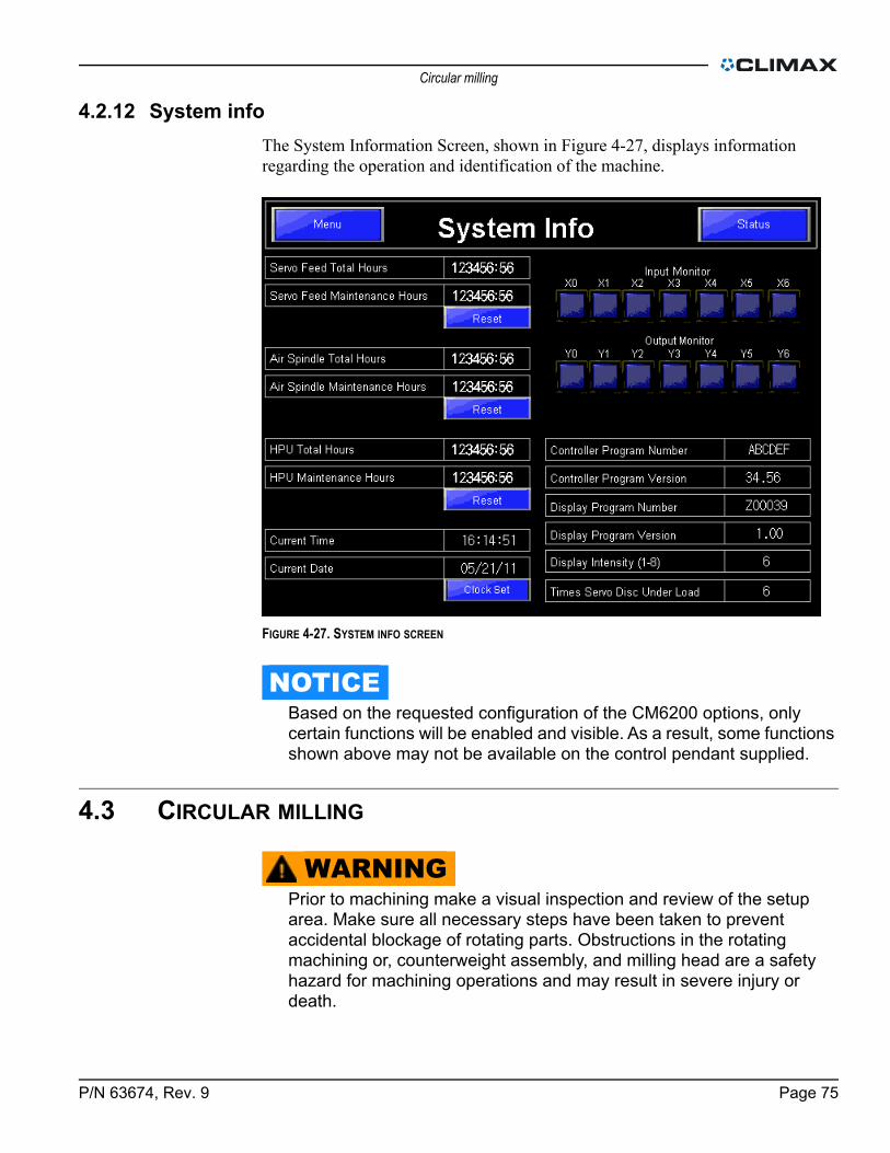
Circular milling
4.2.12 System infoThe System Information Screen, shown in Figure 4-27, displays information regarding the operation and identification of the machine.
FIGURE 4-27. SYSTEM INFO SCREEN
NOTICEBased on the requested configuration of the CM6200 options, only certain functions will be enabled and visible. As a result, some functions shown above may not be available on the control pendant supplied.
4.3 CIRCULAR MILLING
WARNINGPrior to machining make a visual inspection and review of the setup area. Make sure all necessary steps have been taken to prevent accidental blockage of rotating parts. Obstructions in the rotating machining or, counterweight assembly, and milling head are a safety hazard for machining operations and may result in severe injury or death.
P/N 63674, Rev. 9 Page 75

Circular milling
4.3.1 Installing the milling head cutterDo the following to install the milling head cutter:
1. Check that the cutter is sharp and free of nicks.2. Check that the spindle is completely stopped and machine power is locked
out.3. Clean dirt and chips from the spindle taper surface.4. Insert the cutter into the spindle. Be sure the cutter is engaged with the
drive lugs.5. Install the draw bolt to secure the cutter into the spindle.
4.3.2 Setting the DRO (milling head equipment)For most operations, simply turn on the DRO and press the ZERO/ABS button to zero the display before making any adjustments to the milling head. The DRO will display the correct distances in the digital readout (see Figure 4-28).
4.3.3 Safe operating rangesTable 4-2 on page 77 shows the surface feet per minute (sfpm) and surface meters per minute (smpm) for a given tool diameter and hydraulic motor size at 60 Hz and 20 gallons per minute (gpm) or 76 liters per minute (lpm). Table 4-3 on page 78 shows the same information at 50 Hz and 16.6 gpm (63 lpm).
CAUTIONDo not pick a motor and tool combination that is less than 150 sfpm (45.72 smpm) at 20 gpm (76 lpm). The resulting peak force at the cutter
FIGURE 4-28. DRO BUTTONS AND DISPLAY
Page 76 CM6200 Operating Manual

Circular milling
could damage the machine. It is acceptable to run a tool at less than 150 sfpm (45.72 smpm) as long as at 20 gpm (76 lpm) it is greater than 150 sfpm (45.72 smpm).
If the operator chooses to run the machine beyond the design limitations, they do so at their own risk.
TABLE 4-2. MAXIMUM SFPM/SMPM CAPABLE FROM THE HYDRAULIC MOTOR AT 60 HZ AND 20 GPM (76 LPM)
Tooling diameter
Optional hydraulic motor sizes
6.2 cu-in (101.6 cucm)
8.0 cu-in (131
cucm)
9.6 cu-in (157.3 cu-cm)
11.9 cu-in (195.0 cucm)
14.9cu-in
(244.17 cu-cm)
18.7 cu-in (244.2 cucm)
24.0 cu-in (393.3 cucm)
29.8 cu-in (488.3 cucm)
1" (25 mm)
194 sfpm (59.1
smpm)
151 sfpm (46
smpm)
125 sfpm (38.1
smpm)
101 sfpm (30.8
smpm)
81 sfpm (24.7
smpm)
64 sfpm (24.7
smpm)
50 sfpm (15.2
smpm)
40 sfpm (12.2
smpm)
2" (51 mm)
389 sfpm (118.6 smpm)
302 sfpm (92.1
smpm)
250 sfpm (76.2
smpm)
202 sfpm (61.6
smpm)
161 sfpm (49.1
smpm)
129 sfpm (39.3
smpm)
100 sfpm (30.5
smpm)
80 sfpm (24.4
smpm)
4" (102 mm)
777 sfpm (236.8 smpm)
603 sfpm (183.8 smpm)
500 sfpm (152.4 smpm)
403 sfpm (122.8 smpm)
323 sfpm (98.5
smpm)
258 sfpm (78.6
smpm)
200 sfpm (61.0
smpm)
160 sfpm (48.8
smpm)
5" (127 mm)
971 sfpm (296.0 smpm)
754 sfpm (229.8 smpm)
624 sfpm (190.2 smpm)
504 sfpm (153.6 smpm)
403 sfpm (122.8 smpm)
322 sfpm (98.2
smpm)
250 sfpm (76.2
smpm)
200 sfpm (61.0
smpm)
6" (152 mm)
1,166 sfpm
(355.4 smpm)
905 sfpm (275.8 smpm)
749 sfpm (228.3 smpm)
605 sfpm (184.4 smpm)
484 sfpm (147.5 smpm)
386 sfpm (117.7 smpm)
300 sfpm (91.4
smpm)
240 sfpm (73.2
smpm)
8" (203 mm)
1,554 sfpm
(473.7 smpm)
1,206 sfpm
(367.6 smpm)
905 sfpm (275.8 smpm)
806 sfpm (245.7 smpm)
645 sfpm (196.6 smpm)
515 sfpm (157.0 smpm)
400 sfpm (121.9 smpm)
320 sfpm (97.5
smpm)
10" (254 mm)
1,943 sfpm
(592.2 smpm)
1,508 sfpm
(459.6 smpm)
1,206 sfpm
(367.6 smpm)
1,008 sfpm
(307.2 smpm)
806 sfpm (245.7 smpm)
644 sfpm (196.3 smpm)
500 sfpm (152.4 smpm)
401 sfpm (122.2 smpm)
P/N 63674, Rev. 9 Page 77
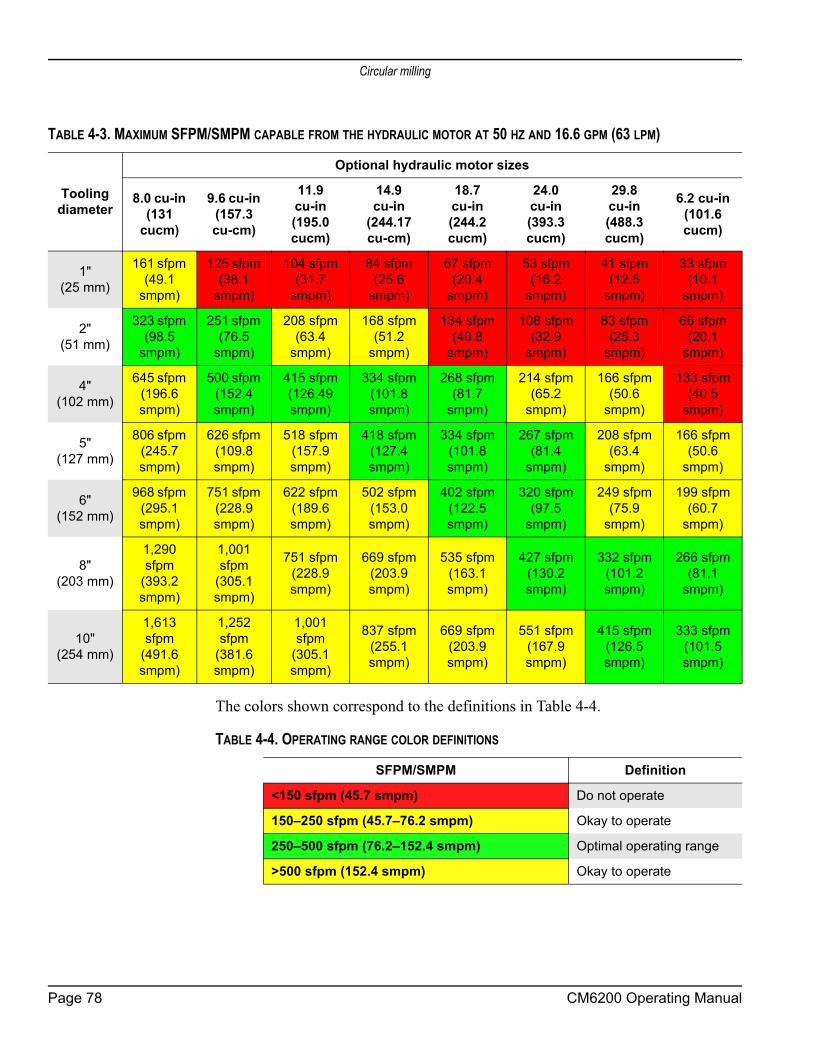
Circular milling
The colors shown correspond to the definitions in Table 4-4.
TABLE 4-3. MAXIMUM SFPM/SMPM CAPABLE FROM THE HYDRAULIC MOTOR AT 50 HZ AND 16.6 GPM (63 LPM)
Tooling diameter
Optional hydraulic motor sizes
8.0 cu-in (131
cucm)
9.6 cu-in (157.3 cu-cm)
11.9 cu-in (195.0 cucm)
14.9cu-in
(244.17 cu-cm)
18.7 cu-in (244.2 cucm)
24.0 cu-in (393.3 cucm)
29.8 cu-in (488.3 cucm)
6.2 cu-in (101.6 cucm)
1" (25 mm)
161 sfpm (49.1
smpm)
125 sfpm (38.1
smpm)
104 sfpm (31.7
smpm)
84 sfpm (25.6
smpm)
67 sfpm (20.4
smpm)
53 sfpm (16.2
smpm)
41 sfpm (12.5
smpm)
33 sfpm (10.1
smpm)
2" (51 mm)
323 sfpm (98.5
smpm)
251 sfpm (76.5
smpm)
208 sfpm (63.4
smpm)
168 sfpm (51.2
smpm)
134 sfpm (40.8
smpm)
108 sfpm (32.9
smpm)
83 sfpm (25.3
smpm)
66 sfpm (20.1
smpm)
4" (102 mm)
645 sfpm (196.6 smpm)
500 sfpm (152.4 smpm)
415 sfpm (126.49 smpm)
334 sfpm (101.8 smpm)
268 sfpm (81.7
smpm)
214 sfpm (65.2
smpm)
166 sfpm (50.6
smpm)
133 sfpm (40.5
smpm)
5" (127 mm)
806 sfpm (245.7 smpm)
626 sfpm (109.8 smpm)
518 sfpm (157.9 smpm)
418 sfpm (127.4 smpm)
334 sfpm (101.8 smpm)
267 sfpm (81.4
smpm)
208 sfpm (63.4
smpm)
166 sfpm (50.6
smpm)
6" (152 mm)
968 sfpm (295.1 smpm)
751 sfpm (228.9 smpm)
622 sfpm (189.6 smpm)
502 sfpm (153.0 smpm)
402 sfpm (122.5 smpm)
320 sfpm (97.5
smpm)
249 sfpm (75.9
smpm)
199 sfpm (60.7
smpm)
8" (203 mm)
1,290 sfpm
(393.2 smpm)
1,001 sfpm
(305.1 smpm)
751 sfpm (228.9 smpm)
669 sfpm (203.9 smpm)
535 sfpm (163.1 smpm)
427 sfpm (130.2 smpm)
332 sfpm (101.2 smpm)
266 sfpm (81.1
smpm)
10" (254 mm)
1,613 sfpm
(491.6 smpm)
1,252 sfpm
(381.6 smpm)
1,001 sfpm
(305.1 smpm)
837 sfpm (255.1 smpm)
669 sfpm (203.9 smpm)
551 sfpm (167.9 smpm)
415 sfpm (126.5 smpm)
333 sfpm (101.5 smpm)
TABLE 4-4. OPERATING RANGE COLOR DEFINITIONS
SFPM/SMPM Definition
<150 sfpm (45.7 smpm) Do not operate
150–250 sfpm (45.7–76.2 smpm) Okay to operate
250–500 sfpm (76.2–152.4 smpm) Optimal operating range
>500 sfpm (152.4 smpm) Okay to operate
Page 78 CM6200 Operating Manual

Circular milling
4.3.4 Replacing the milling assemblyDo the following to replace the milling assembly with the single-point tool head assembly:
1. Completely de-energize and lock out the power source.2. Remove the milling head
assembly, including the miller head adapter plate, from the cross-slide plate (see Figure 4-38, which is also seen in Fig-ure A-11 on page 130).
3. Attach the single-point tool head assembly (P/N 62984) to the cross-slide plate.
4. Attach the tool head assembly to the adapter (see Figure 4-39, which is seen in Figure A-27 on page 146).
TABLE 4-5. CROSS-SLIDE PLATE IDENTIFI-CATION
Number Component
1 Saddle plate
2 Milling head adapter plate
2
3
4
1
1
2
FIGURE 4-29. CROSS-SLIDE PLATE
10
15
2
4
2013
3
9
FIGURE 4-30. TOOL HEAD ASSEMBLY ADAPTER
P/N 63674, Rev. 9 Page 79

Circular milling
4.3.5 Performing circular millingMachining in either direction is possible with a facing mill on general flanges. It is recommended to make one pass in one direction and the next pass in the opposite direction.
CAUTION If conditions or tooling requires that all passes be made in a single direction, then withdraw the spindle at the end of each one or two passes and reverse the table to prevent excessive twisting and kinking of hoses and electric cables.
Do the following to perform circular milling: 1. Set the spindle over the workpiece to the desired starting point.2. Set the speed of the rotary table to zero.3. Start the turntable and set a desired speed for milling.4. Stop the table.5. Advance the spindle toward the work until the cutter just contacts the sur-
face. Reset the DRO.6. Feed the spindle away from the piece so that it is no longer over the surface
that will be machined.7. Adjust the spindle to set the desired depth of cut.8. Turn on the power and start spindle rotation.9. Radially feed the cutter into the workpiece using the radial axis feed.10. When the cutter is fully engaged in the work, start the rotary table rotation.
CAUTIONNever stop the spindle until the rotary table is completely stopped. Stopping the spindle before the rotary table stops will damage the machine.
TIP: Setup fingers may need to be removed when milling.
DANGERRemoving the setup fingers from the machine will reduce stability of the machine. Make sure that the machine is secured onto the workpiece according the specifications listed in Section 3.4 on page 25 before removing setup fingers.
Page 80 CM6200 Operating Manual

Grinding option
11. Adjust the speed control knob on the pendant until the turntable is rotating at the necessary speed.
WARNINGTo protect yourself from flying chips, wear eye protection while operating the machine.
12. To stop machine rotation, press the stop button for the circular mill control pendant.
13. Repeat cutting passes as required. For very fine finishes make several rough cuts and one fine finish cut.
Move the cutter radially off the work piece between cuts or when the cut is com-plete.
4.4 GRINDING OPTION
4.4.1 Grinding attachment setupThe grinding attachment uses the same mount adapter as the single point tool option. See the exploded views (Figure A-16 on page 135, Figure A-17 on page 136, or Figure A-18 on page 137) for more information about the parts needed for grinding.Do the following to set up the grinding attachment:
1. Set up the machine in the flange, according to the mounting instruction in Section 3.4 on page 25.
2. Install the grinding head to the arm (see Section 4.5.2 on page 89 for instructions on replacing the milling head).
3. Use the screws provided to attach the grinder to the face of the tool head.4. Attach hoses from the grinding attachment to the PCU.
NOTICEOnly make a maximum of two or three passes in either direction. Then reverse direction to prevent binding up the hoses.
P/N 63674, Rev. 9 Page 81

Single-point option
5. Adjust leveling screws until you achieve the desired grinding angle (Figure 4-31).
6. Use height adjusting screw on the grinding head to adjust the height.
7. Check that the guard is in place and all fasteners are tight.
4.4.2 OperationGrinding should be done after the flange has been cut flat with a single point tool or the milling head.
1. Turn on grinding head and ramp to desired operating speed.2. Set the spindle to touch the surface and make a light grind.3. Check the surface finish.4. Make any necessary adjustments to the grinder settings.5. When the finish is satisfactory, continue grinding the surface as required.
WARNINGStay clear of the grinder during operation. Chips of metal may be thrown into the air from the grinder. Wear eye protection while operating the machine.
6. When the grinding operation is complete, lift the spindle and shut off the grinder.
4.5 SINGLE-POINT OPTION
As seen in Figure 4-32 on page 84, the single-point option requires an adapter and tool head assembly, plus the pneumatic systems for feed control. This adapter mounts directly to the existing tool arm. See also Figure 4-33 on page 85 and Fig-ure 4-34 on page 86.
FIGURE 4-31. GRINDING HEAD LEVELING SCREWS
Page 82 CM6200 Operating Manual

Single-point option
For the hydraulic motor mount assembly, see Section 4.5.3 on page 90.The PCU supplies air to the pneumatic feed box through the rotary union.The single-point tool holder mounts to the saddle plate on the turning arm in place of the milling head. See Section 4.5.2 on page 89.The pneumatic feed box and adapter mounts on the end of the ball screw on the turning arm.The rotary union assembly mounts to the center of the rotary table and transmits fluid to the hydraulic motor and air to the feed box. See Section 4.5.3 on page 90. The air valve that cycles the feed box is also located here.The emergency stop procedure is in Section 5.2.1 on page 98.
P/N 63674, Rev. 9 Page 83

Single-point option
4.5.1 Configuring the rotary union for ID or OD mount
FIGURE 4-32. ROTARY UNION CONFIGURATION COMPONENTS
PNEUMATIC
CONDITIONING
UNIT FOR FEED
HYDRAULIC MOTOR
MOUNT (REPLACES
SERVO MOTOR)
1/4" TUBING
FROM PORT 1
PORT 3 ROTARY
UNION CENTERREMOTE
PNEUMATIC
FEED BOX
PORT 1 ROTARY
UNION CENTER
1/4" TUBING TO
FEED BOX
BOLT (HANDLE TO
INSTALL AND REMOVE
BUSHING SLEEVE)
PORT 3 SIDE
TO FEED BOX
PORT 1 SIDE
TO AIR VALVE
3
1
5
6
7
8
9
10
2
4
TABLE 4-6. ROTARY UNION CONFIGURATION COMPONENT IDENTIFICATION
Number Component
1 Pneumatic conditioning unit for feed
2 Port 1 rotary union center
3 Port 3 rotary union center
4 Remote pneumatic feed box (see Figure 4-33 on page 85 and Figure 4-34 on page 86 for more detail)
5 1/4" tubing to feed box
6 1/4" tubing from port 1
7 Port 3 side to feed box
8 Port 1 side to air valve
9 Hydraulic motor mount (replaces servo motor)
10 Bolt (handle to install and remove the bushing sleeve)
Page 84 CM6200 Operating Manual

Single-point option
FIGURE 4-33. FEED BOX DETAIL
TABLE 4-7. FEED BOX DETAIL IDENTIFICATION
Number Component
1 1/8" tubing from port 3
2 1/4" tubing from air valve
3 Mounts to the ball screw on the end of the turning arm
4 Mounting arrow shows the feed direction
MOUNTS TO THE BALL
SCREW ON THE END
OF THE TURNING ARM
MOUNTING
ARROW
SHOWS FEED
DIRECTION
1/8" TUBING
FROM PORT 3 1/4" TUBING
FROM AIR VALVE
3
12
4
P/N 63674, Rev. 9 Page 85

Single-point option
FIGURE 4-34. PNEUMATIC FEED BOX LOCATION
TABLE 4-8. PNEUMATIC FEED BOX IDENTIFICATION
Number Component
1 Pneumatic feed box
2 Spring point tool holder bracket
SPRING POINT
TOOL HOLDER
BRACKET
PNEUMATIC
FEEDBOX
1 2
Page 86 CM6200 Operating Manual
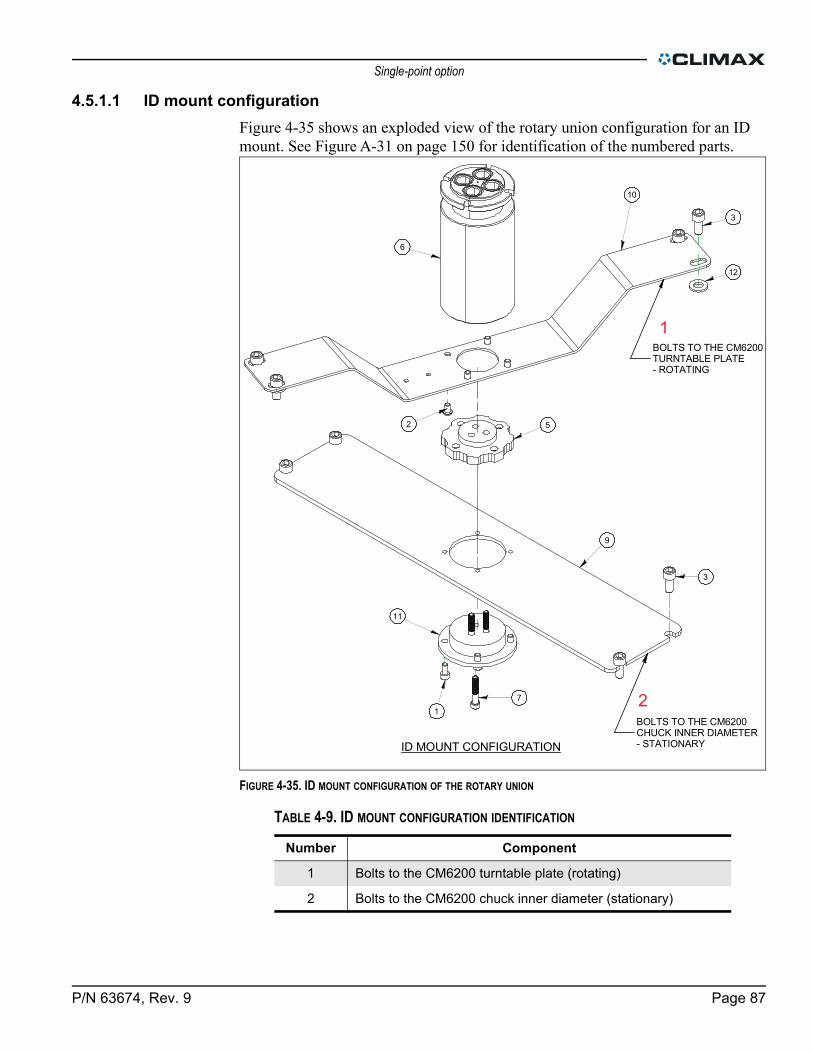
Single-point option
4.5.1.1 ID mount configurationFigure 4-35 shows an exploded view of the rotary union configuration for an ID mount. See Figure A-31 on page 150 for identification of the numbered parts.
FIGURE 4-35. ID MOUNT CONFIGURATION OF THE ROTARY UNION
TABLE 4-9. ID MOUNT CONFIGURATION IDENTIFICATION
Number Component
1 Bolts to the CM6200 turntable plate (rotating)
2 Bolts to the CM6200 chuck inner diameter (stationary)
ID MOUNT CONFIGURATION
71
11
9
3
5
10
6
3
2
12
BOLTS TO THE CM6200TURNTABLE PLATE- ROTATING
BOLTS TO THE CM6200CHUCK INNER DIAMETER- STATIONARY
1
2
P/N 63674, Rev. 9 Page 87

Single-point option
Do the following to configure the rotary union for an ID mount, referring to Figure 4-35:
1. Bolt the torque restraint arm to the CM6200 turntable plate. It will rotate with the machine.
2. Bolt the rotary union mount to the CM6200 chuck inner diameter. It will remain stationary.
4.5.1.2 OD mount configurationFigure 4-36 shows the parts used to configure the OD mount of the rotary union. See Figure A-31 on page 150 for part identification.
FIGURE 4-36. OD MOUNT CONFIGURATION OF THE ROTARY UNION
Do the following to configure the rotary union for an ID mount, referring to Figure 4-37:
1. Replace the M8 x 45 mm SHCS with M8 x 25 mm SHCS. Keep the same cam in place.
2. Invert the torque restrain arm and re-bolt it to the turntable.
TABLE 4-10. OD MOUNT CONFIGURATION IDENTIFICATION
Number Component
1 Replace M8 x 45 mm SHCS with M8 x 25 mm SHCS
2 P/N 60837 M8 SHCS used to secure the rotary union to the mount
3 Hoses exit through the center of the chuck
4 P/N 62891 mount rotary union remains on the CM6200 chuck
8 Invert P/N 62893 restraint torque arm and re-bolt to the turntable
OD MOUNT CONFIGURATION
INVERT 62893RESTRAINT TORQUE
ARM AND REBOLTTO TURNTABLE
62891 MOUNT ROTARYUNION REMAINS ON
CM6200 CHUCK
REPLACE M8 X 45mm SHCSWITH M8 X 25mm SHCS
60837 M8 SHCSUSED TO SECURETHE ROTARY UNIONTO THE MOUNT
HOSES EXIT THROUGHCENTER OF CHUCK
1
2
3
5
4
Page 88 CM6200 Operating Manual

Single-point option
3. Secure the rotary union to the mount with the M8 SHCS (P/N 55799). The rotary union mount remains on the CM6200 chuck.
FIGURE 4-37. OD MOUNT CONFIGURATION OF ROTARY UNION
4.5.2 Replacing the milling assemblyDo the following to replace the milling assembly with the single-point tool head assembly:
1. Completely de-energize and lock out the power source.
TABLE 4-11. OD MOUNT ROTARY UNION CONFIGURATION IDENTIFICATION
Number Component
1 M8 x 25 mm socket head cap screw (SHCS)
2 Torque restraint arm (P/N 62893) – inverted
3 M8 SHCS (P/N 55799)
4 Direction that the hoses exit
5 Rotary union mount (P/N 62891) – stationary
6 Cam (P/N 58039)
ROTARY UNION
MOUNT (P/N 62891)
– STATIONARY
TORQUE RESTRAINT
ARM (P/N 62893) –
INVERTED
M8 x 25 mm
SHCS
M8 SHCS
(P/N 55799)
DIRECTION
HOSES EXIT
1
5
6
3
2
4
CAM (P/N 58039)
P/N 63674, Rev. 9 Page 89

Single-point option
2. Remove the milling head assembly, including the miller head adapter plate, from the cross-slide plate (see Figure 4-38, which is also seen in Fig-ure A-11 on page 130).
3. Attach the single-point tool head assembly (P/N 62984) to the cross-slide plate.
4. Attach the tool head assembly to the adapter (see Figure 4-39, which is seen in Figure A-27 on page 146).
4.5.3 Installing the hydraulic drive in the single-point configurationDo the following to set up the hydraulic drive in the single-point configuration for flange facing:
1. Completely de-energize and lock out the power source.
TABLE 4-12. CROSS-SLIDE PLATE IDENTIFI-CATION
Number Component
1 Saddle plate
2 Milling head adapter plate
2
3
4
1
1
2
FIGURE 4-38. CROSS-SLIDE PLATE
10
15
2
4
2013
3
9
FIGURE 4-39. TOOL HEAD ASSEMBLY ADAPTER
Page 90 CM6200 Operating Manual
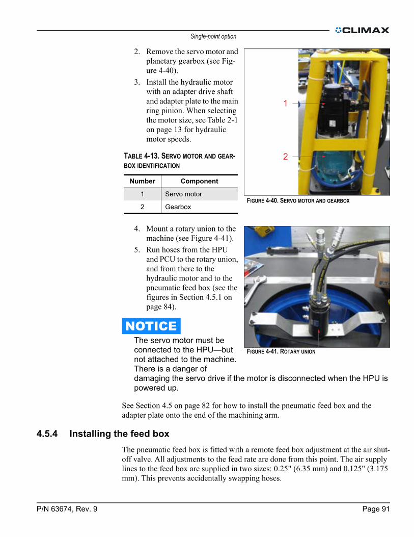
Single-point option
2. Remove the servo motor and planetary gearbox (see Fig-ure 4-40).
3. Install the hydraulic motor with an adapter drive shaft and adapter plate to the main ring pinion. When selecting the motor size, see Table 2-1 on page 13 for hydraulic motor speeds.
4. Mount a rotary union to the machine (see Figure 4-41).
5. Run hoses from the HPU and PCU to the rotary union, and from there to the hydraulic motor and to the pneumatic feed box (see the figures in Section 4.5.1 on page 84).
NOTICEThe servo motor must be connected to the HPU—but not attached to the machine. There is a danger of damaging the servo drive if the motor is disconnected when the HPU is powered up.
See Section 4.5 on page 82 for how to install the pneumatic feed box and the adapter plate onto the end of the machining arm.
4.5.4 Installing the feed boxThe pneumatic feed box is fitted with a remote feed box adjustment at the air shut-off valve. All adjustments to the feed rate are done from this point. The air supply lines to the feed box are supplied in two sizes: 0.25" (6.35 mm) and 0.125" (3.175 mm). This prevents accidentally swapping hoses.
TABLE 4-13. SERVO MOTOR AND GEAR-BOX IDENTIFICATION
Number Component
1 Servo motor
2 Gearbox
1
2
FIGURE 4-40. SERVO MOTOR AND GEARBOX
FIGURE 4-41. ROTARY UNION
P/N 63674, Rev. 9 Page 91

Single-point option
Do the following to install the feed box:1. Install the feed box adapter
assembly (P/N 62994, seen in Figure 4-42) onto the end of the turning arm by bolting it down with the two M6 x 1.0 x 30 mm SHCS.
2. Take the pneumatic feed box assembly (P/N 58671) and mount it onto the feed box adapter assembly by bolting it down with the two M6 x 1.0 x 60 mm SHCS.
When mounting, check that the arrow is pointing in the intended feed direction (see Figure 4-43.)
4.5.5 Reversing the feed box directionThe feed box only feeds in one direction, without a setup change. Do the following to reverse the feed box direction:
1. Remove the feed shaft and two bolts connecting it to the arm (Figure 4-44).
TIP:Disconnecting and switching the hoses will NOT reverse the feed direction.
FIGURE 4-42. PNEUMATIC FEED BOX ADAPTER
FIGURE 4-43. FEED DIRECTION OF FEED BOX
FIGURE 4-44. REMOVAL OF BOLTS TO REVERSE FEED DIREC-TION
Page 92 CM6200 Operating Manual

Single-point option
2. Rotate feed box until the arrow points in the desired feed direction.
3. Reinstall the bolts and feed shaft.
This feed box has two modes, engaged and disengaged (neutral), as seen in Figure 4-45.
FIGURE 4-46. FEED BOX MODE POSITIONS
In neutral, the tool may be manually fed in either direction. Hoses connected to the feed box should have approximately 12" (304.8 mm) of extra length coiled inside the arm to allow the arm to move and still keep the hoses clear of snag hazards.
TABLE 4-14. FEED BOX MODE IDENTIFICATION
Number Component
1 Feed disengaged
2 Feed engaged
FIGURE 4-45. FEED DIRECTION ARROW
1 2
P/N 63674, Rev. 9 Page 93

Single-point option
To disconnect the feed hoses, press down on the collar around the hose and pull the hose out.
4.5.6 Operating the pneumatic feed systemDo the following to operate the pneumatic feed system:
1. Connect the energy sources.
2. Push the START button on the PCU.
3. To adjust the turntable rota-tions per minute (RPM), use the speed adjustment valve to turn on the drive motor.
4. To adjust the feed rate per revolution, turn the feed rate adjustment dial to the minimum feed or to the desired setting, if known.
5. Using the feed on/off valve, turn on the feed and adjust the feed rate for the desired cut.
NOTICETurn the feed on/off valve fully to activate or deactivate the feed rate.
6. Use the speed adjustment valve to adjust the drive motor to achieve the desired cut.
7. When the cut is complete, first stop the feed and then stop the machine rotation.
FIGURE 4-47. FEED HOSE DISCONNECT METHOD
TABLE 4-15. PCU VALVES IDENTIFICATION
Number Component
1 Feed on/off valve
2 Speed adjustment valve
3 Feed rate adjustment
FIGURE 4-48. PCU VALVES
1
2
3
Page 94 CM6200 Operating Manual

Disassembly
WARNINGTo avoid serious injury, do not reach inside the swing of the machining arm during operation.
4.5.7 Adjusting cut characteristicsDo the following to adjust the cut characteristics:
1. When the cut is finished, stop the feed and the machine.2. Machine must be locked out before changing tooling or making any adjust-
ments on the machine.3. Adjust the machine direction, depth of cut, or tool position, as needed.4. Start the machine and feed again to start new cut, as required.5. Repeat until the desired surface is achieved.
WARNINGTo avoid serious injury, do not reach inside the swing of the machining arm during operation.
4.6 DISASSEMBLY
WARNINGIf not properly secured, this machine can fall and cause fatal injuries to personnel. Pay special attention to vertical flange installations.
The machine must be properly rigged and attached to a crane or other suitable lifting apparatus before beginning any disassembly steps. Use supplemental rigging as a precaution.
Do the following to disassemble the machine:1. Position the table and machining arm at the proper lifting position.2. Completely de-energize and lock out the hydraulic power unit.3. Retract the spindle and remove the milling cutter from the spindle.4. Disconnect the power cables and hydraulic hoses.5. Replace any setup fingers that were removed.6. Rig the machine in the same manner that it was installed (see Section 3.3
on page 22).
P/N 63674, Rev. 9 Page 95

Disassembly
7. Put the hose tower in the stow position (see Figure 4-49).
8. Support the machine with a hoist.
9. Loosen the jacking screws. If in the vertical or inclined position, leave the lower stacking bolt in position and loosen the other jacking screws. This keeps the machine from dropping when all other jacking feet are loosened.
10. Using a hoist, remove the machine from the work piece.If storing the machine, see Section 6.
FIGURE 4-49. HOSE TOWER STOW POSITION
Page 96 CM6200 Operating Manual

5 MAINTENANCE AND TROUBLESHOOTING
IN THIS CHAPTER:5.1 MAINTENANCE INTERVALS - - - - - - - - - - - - - - - - - - - - - - - - - - - - - - - - - - - - - - -975.2 MAINTENANCE TASKS - - - - - - - - - - - - - - - - - - - - - - - - - - - - - - - - - - - - - - - - -98
5.2.1 CHECK THE PNEUMATIC CONDITIONING UNIT EMERGENCY STOP - - - - - - - - - - - - - - - - - -985.2.2 CHECK THE PNEUMATIC CONDITIONING UNIT DROP-OUT CIRCUIT - - - - - - - - - - - - - - - - - -985.2.3 MAINTAIN THE ROTARY TABLE AND DRIVE ASSEMBLY - - - - - - - - - - - - - - - - - - - - - - -995.2.4 REPLACING THE PLC BATTERY - - - - - - - - - - - - - - - - - - - - - - - - - - - - - - - - -995.2.5 DRAG BRAKE SETTINGS - - - - - - - - - - - - - - - - - - - - - - - - - - - - - - - - - - - 1005.2.6 ADJUSTING THE DRAG BRAKE - - - - - - - - - - - - - - - - - - - - - - - - - - - - - - - - - 100
5.3 RECOMMENDED LUBRICANTS - - - - - - - - - - - - - - - - - - - - - - - - - - - - - - - - - - - - 1025.3.1 MAIN RING GEAR LUBRICATION - - - - - - - - - - - - - - - - - - - - - - - - - - - - - - - - 1045.3.2 LINEAR RAIL MAINTENANCE - - - - - - - - - - - - - - - - - - - - - - - - - - - - - - - - - - 104
5.4 TROUBLESHOOTING - - - - - - - - - - - - - - - - - - - - - - - - - - - - - - - - - - - - - - - - 1055.4.1 THE MACHINE ISN’T TURNING - - - - - - - - - - - - - - - - - - - - - - - - - - - - - - - - - 1055.4.2 THE MACHINE ISN’T FEEDING OR IS SLOW AND UNRESPONSIVE - - - - - - - - - - - - - - - - - - 1055.4.3 THE MACHINE IS CUTTING POORLY - - - - - - - - - - - - - - - - - - - - - - - - - - - - - - 1055.4.4 THE MACHINE ISN’T CUTTING FLAT - - - - - - - - - - - - - - - - - - - - - - - - - - - - - - - 1065.4.5 THE SPINDLE ISN’T TURNING - - - - - - - - - - - - - - - - - - - - - - - - - - - - - - - - - 1065.4.6 THE MACHINE STOPS SUDDENLY - - - - - - - - - - - - - - - - - - - - - - - - - - - - - - - 1065.4.7 THE CUT DEPTH CHANGES INVOLUNTARILY - - - - - - - - - - - - - - - - - - - - - - - - - - - 1065.4.8 THE SERVO SYSTEM ALARM OR WARNING - - - - - - - - - - - - - - - - - - - - - - - - - - - 106
5.5 MR-J3 SERVO AMPLIFIER ERROR CODES - - - - - - - - - - - - - - - - - - - - - - - - - - - - - - - 107
5.1 MAINTENANCE INTERVALS
CAUTIONFailure to properly clean and maintain the machine can result in machine damage and void the warranty.Always keep chips away from moving machine parts.
Following the maintenance schedule described in Table 5-1 on page 98 is critical to obtain normal machine life. Keep all machine components in clean working condition. Check that parts like the mounting surfaces, hydraulic fittings, and the tools them-selves are free of metal chips, nicks or burrs. To prevent corrosion, thoroughly rinse any machine parts that are exposed to salt water with fresh, clear water.
P/N 63674, Rev. 9 Page 97

Maintenance tasks
5.2 MAINTENANCE TASKS
5.2.1 Check the pneumatic conditioning unit emergency stopBefore each use, check the emergency stop by doing the following:
1. With the machine running, press the emergency stop button (shown in Figure 4-11 on page 61).
2. Check that the machine stops.3. Reset the emergency stop by pulling the button up.
If the machine restarts immediately without any operator action, press the emer-gency stop button again. Discontinue machine use and contact CLIMAX.
5.2.2 Check the pneumatic conditioning unit drop-out circuitThe pneumatic conditioning unit drop-out circuit prevents the machine from restarting unexpectedly after air supply to the PCU is lost and restored.Do the following to check the PCU drop-out circuit:
1. Check that the PCU is connected to an air supply and to the CM6200.2. Check that the air supply lock-out is open (pulled up).3. Press the START button.4. Slowly open the PCU speed adjustment valve until the rotary drive
engages.5. Close (press down) the lock-out valve.6. Check that the machine stops.7. Open the lock-out valve.
If the machine restarts immediately without any operator action, press the emer-gency stop button. Discontinue machine use and contact CLIMAX.
TABLE 5-1. MAINTENANCE INTERVALS AND TASKS
Interval Task See section
Before each useCheck the pneumatic conditioning unit emergency stop. 5.2.1
Check the pneumatic conditioning unit drop-out circuit. 5.2.2
Before and after each use
Remove chips from the circular bearing, reducer mount, and the radial slide.
5.2
After each useWipe the machine down with clean, dry rags. --
Remove debris and moisture from the machine surface. --
Every five years Replace the battery in the PLC.
Page 98 CM6200 Operating Manual

Maintenance tasks
5.2.3 Maintain the rotary table and drive assemblyBefore and after operating the CM6200, wipe or vacuum chips away from the cir-cular bearing, reducer mount, and the radial slide. CLIMAX does not recommend using compressed air around the linear bearing or seals.The main bearings and gear reducer are lubricated for life under normal use.
5.2.4 Replacing the PLC battery
NOTICEThe programmable logic controller (PLC) in the CM6200 control system uses a battery to maintain the program when mains power is turned off. This battery must be replaced periodically or the PLC program will be lost and the machine will not operate until the PLC program has been restored. In order to avoid unexpected shutdown of the CM6200 controls, it is important that the battery be replaced regularly.
The service life of the battery is approximately five years, but that varies depend-ing on the temperature at which the machine is operated and stored (see Figure 5-1).
FIGURE 5-1. PLC BATTERY SPECIFICATION
P/N 63674, Rev. 9 Page 99

Maintenance tasks
5.2.5 Drag brake settingsThe CM6200’s drag brake should be checked periodically for proper adjustment. This adjustment should only be necessary after mainte-nance, or if the machine moves with a jerking motion. The drag brake is intended to remove backlash from the gear, mainly for vertical applications or special tooling.
Figure 5-2 and Figure 5-3 show the location of the drag brake on top of the rotary table. The system will apply resistance to the gear to reduce backlash and maintain steady velocity in vertical or special tooling applications.
5.2.6 Adjusting the drag brake For vertical applications, do the following to adjust the drag brake:
1. Completely de-energize and lock out the machine.2. To set the drag brake, position the machine so that the rotary table is in a
horizontal and level position.3. Remove the motor.
CAUTIONDo not remove the motor unless the machine is horizontal and all rotating parts have been blocked releasing the motor will allow the hub to rotate freely.
4. Completely release the drag brake by backing off the nuts.
FIGURE 5-2. TOP VIEW OF DRAG BRAKE
FIGURE 5-3. SIDE VIEW OF DRAG BRAKE
Page 100 CM6200 Operating Manual

Maintenance tasks
DANGERDo not remove the bolts if the machine is not in the horizontal position as unexpected movement of the CM6200 rotational turntable can result, causing serious injury or death.
5. Carefully and slowly release any machine blocks.6. Check the tension of the hub without the drag brake using a torque wrench
in the gear keyway, it should read approximately 4 in-lbs (0.452 Nm) with-out the drag brake engaged.
7. To tighten the drag brake, tighten the nuts slowly and keep testing the torque until there is an additional 4–5 in-lbs (0.452–0.565 Nm) of torque when the hub is rotated manually.
8. Install the motor for your machining application.
CAUTIONKeep spaces between hardware and slides clean of chips and debris so the machine can move freely.
Horizontal single-point machining or milling applicationsThe drag brake must be disengaged when single pointing. However, there are times when the drag brake must be engaged, such as when milling in any position.
1. Completely lock-out and de-energize the machine. 2. Position the machine so the top plate surface is in a horizontal and level
position.3. Remove the motor.
CAUTIONDo not remove the motor unless the machine is horizontal and all rotating parts have been blocked. Releasing the motor will allow the hub to rotate freely.
4. Completely release the drag brake by backing off the nuts.
DANGERDo not remove the bolts if the machine is not in the horizontal position as unexpected movement of the CM6200 rotational turntable can result, causing serious injury or death.
5. Carefully and slowly release any machine blocks.
P/N 63674, Rev. 9 Page 101

Recommended lubricants
6. Check the tension of the hub without the drag brake using a torque wrench in the gear keyway, it should read approximately 4 in-lbs (0.452 Nm) with-out the drag brake engaged.
7. Rotating the machine manually in the horizontal position should show around 4 in-lbs of torque without the drag brake engaged. This is measured at the motor gear using a torque wrench in the gear keyway.
8. Tighten the lock nuts on top of the drag brake to lock the drag brake in position, and to keep the lock nuts from vibrating loose.
9. Install the motor for your machining application.
5.3 RECOMMENDED LUBRICANTS
CLIMAX recommends using the following lubricants for maintaining the loca-tions indicated. Failure to use the appropriate lubricants can result in damage and premature machine wear.
CAUTIONAvoid damage, premature machine wear, and protect your warranty by using only approved lubricants.
TABLE 5-2. APPROVED LUBRICANTS
Application Area Lubricant Biodegradable Lubricant
Viscosity (cSt) Quantity Frequency
Frequently
Cutting Tool AW 32 CONOCO Eco-terra 32
32 @ 40C
544 @ 100CAs required Continued use while
cutting
Daily
Milling Head Gearbox Mobilith SHC 460 N/A
414 @ 40C
47 @ 100C5 cc Every 8 hours of
use
Dovetail Waysa AW 32 CONOCO Eco-terra 32
32 @ 40C
544 @ 100CAs required Daily during
machine use
Unpainted Sur-faces LPS1 or LPS2 N/A 38 @ 25C As required
Daily during machine use, and before storage
Each Use
Hydraulic Power Units
CASTROL Hyspin AWS-46 (summer) CASTROL BioBar
46 (summer); 32 (winter)
46 @ 40C
682 @ 100CAs required to fill reservoir to mid-sight glass level
Refill every use Replace oil every 2 yearsb
AWS-32 (winter)32 @ 40C
544 @ 100C
Page 102 CM6200 Operating Manual

Recommended lubricants
Eisenberger Ball Screws
CONOCO Poly-Tac EP c
CASTROL BioTac EP 2
129 @ 40C
116 @ 100C1 cc per nut
Once per use or weekly for contin-ued useMicrolube GBU-Y
131 N/A130 @ 40C
15 @ 100C
Linear Rail
THK Rail – THK AFA Grease2 N/A 32 @ 40C
2 cc per bear-ing block
Once per use or weekly for contin-ued useCONOCO Poly-
Tac EP 2CASTROL BioTac EP 2
129 @ 40C
116 @ 100C
Weekly
APU AW 32 N/A
22-68 @ 40°C
4.3-8.7 @ 100°C
Refill oil lubri-cator Each use
Lead Screw on Single Point Tool Head
-NOOK E-100 spray lube
-NOOK PAG-1 grease
CASTROL BioTac EP 2
96 @ 40C
113 @ 100C
Light coating applied by hand or spray
Weekly during machine use
Chuck jacking screws
Moly Grade anti-seize N/A N/A 1 cc per screw
Weekly during machine use, and before storage
Yearly
Rotary Table and Drive Assemblyd
CONOCO Poly-Tac EP 2
CASTROL BioTac EP 2
129 @ 40C
116 @ 100C20 cc Once per year
ID Wiper Seal on Rotary Table
3M Silicone Paste 051135-08946 N/A N/A 3 cc Once per year
Main Table Gear Reducer Mobil 629 Gear Oil N/A
150 @ 40C
158 @ 100CN/A Lubricated for life
under normal use
Electric Motors See vendor litera-ture N/A N/A See vendor
literatureSee vendor litera-ture
a. Use highly anti-corrosive, refined mineral or synthetic oil that forms a strong oil film and is not easily emulsi-fied or washed away by coolant. Hydraulic oils are typically not suitable for slide way lubrication.b. Always replace hydraulic filters when replacing hydraulic oil. Never assume that oil in drums is clean. Always pump oil through a 5 micron hydraulic filter before/while filling reservoir.c. Use of other lubricants on THK products will void manufacturer’s warranty.d. While lithium based grease can be used, a calcium based grease allows for greater lubricity while ingesting higher amounts of water (common in portable machine tools).
TABLE 5-2. APPROVED LUBRICANTS
Application Area Lubricant Biodegradable Lubricant
Viscosity (cSt) Quantity Frequency
P/N 63674, Rev. 9 Page 103

Recommended lubricants
TIP:If an approved lubricant cannot be used, contact CLIMAX for an equivalent alternative.
CAUTIONThe lubricant used on the ID wiper seal should be 3M Silicone Paste P/N 051135-08946 or equivalent. No other lubricants are to be used on this seal.
5.3.1 Main ring gear lubrication
TIP:The main ring gear should be lubricated annually. The ring gear must be lubricated while the table is turning slowly.
DANGERDo not remove the motor if the machine is not in the horizontal position as unexpected movement of the CM6200 rotational turntable can result, causing serious injury or death.
Do the following to lubricate the main ring gear, while referring to Figure A-1 on page 120:
1. Remove the encoder guard.2. Remove the servo motor reducer and drive pinion assembly as a single
unit.3. Slowly allow the table to rotate and lubricate the gear with a thin layer as it
passes by.4. When lubrication is finished, carefully replace the drive pinion assembly
and the encoder guard.
5.3.2 Linear rail maintenanceDuring operation, frequently lubricate the linear rails and ways.Rails, ways and mating parts are critically aligned at the factory. If re-alignment is necessary, contact CLIMAX to arrange for this service.Before and after using the machine, wipe the rails and ways with light way oil.
NOTICEDo not allow anything to be dropped on the rails and do not store items on the rails.
Page 104 CM6200 Operating Manual

Troubleshooting
5.4 TROUBLESHOOTING
This section is intended to help you solve basic machine performance problems. For serious maintenance or if you have questions on the following procedures, contact CLIMAX.
5.4.1 The machine isn’t turningIf the machine is not rotating, check the following:
• The HPU power is on (Section 3.11 on page 50).• There is a good connection between the HPU and servo (Section 3.11
on page 50). Try the following:a) Power down the HPU.b) Clean out any debris in the connections.c) Make sure the connections are latched. d) Check for no damaged or disconnected tethers.
• No chips are embedded in the cables, and the cables aren’t otherwise damaged (Section 1.4 on page 3).
• Any error messages show on the pendant (Section 4.2.2 on page 60).• When in single-point mode, check that the drag brake is disengaged
(Section 5.2.6 on page 100).
5.4.2 The machine isn’t feeding or is slow and unresponsiveIf the machine isn’t feeding properly, check the following:
• The pneumatic connections from the source to the feed have no broken or disconnected lines (Figure 4-47 on page 94).
• The feed box is engaged (Section 4.2 on page 59).• Any dirty filters have been cleaned (Section 5.3 on page 102).• The Z-brake is disengaged (Section 4.1.3 on page 55).
5.4.3 The machine is cutting poorlyIf the machine is cutting poorly, check the following:
• The correct face mill is used for the application (e.g., the right size for the job).
• The face mill is tight in the spindle (Section 4.3.2 on page 76).• No face inserts are broken, dull, or loose. Tighten, replace, or turn if
necessary.• The brake is engaged (Section 5.2.6 on page 100).• No worn or damaged components in the spindle. If any are found, con-
tact CLIMAX for more information.• The feed rate and spindle RPM is correct for the application. The cor-
rect speed will vary by application.
P/N 63674, Rev. 9 Page 105

Troubleshooting
• The clamps are tight on the tool arm (Section 3.6.1 on page 35).• When milling, the drag brake is properly engaged (Section 5.2.6 on
page 100).• The ID chuck has equal clamping pressure (Section 3.5.3 on page 33).
5.4.4 The machine isn’t cutting flatIf the machine isn’t cutting flat, check the following:
• The machine is chucked properly to the workpiece (Section 3.7 on page 39).
• The chuck legs are not overtightened, which may deform the workpiece (Section 3.5.3 on page 33).
• The spindle is trammed (Section 4.1.3 on page 55).
5.4.5 The spindle isn’t turningIf the spindle isn’t turning, check the following:
• The HPU power is on (Section 3.11 on page 50).• The hydraulic hoses are connected (Section 3.11 on page 50).• No error messages show on the pendant (Section 4.2.2 on page 60).• The fluid level is sufficient in the HPU. Refill if necessary.• The spindle is clear of any elements.
5.4.6 The machine stops suddenlyIf the machine stops suddenly, check the following:
• The HPU power is on (Section 3.11 on page 50).• No error messages show on the pendant (Section 4.2.2 on page 60).• The tether is not damaged or disconnected.
5.4.7 The cut depth changes involuntarilyIf the cut depth changes without your direction, check the following:
• The brake is engaged (Section 5.4 on page 105).• There is sufficient friction on the lead screw in the Z direction. If too
loose, tighten the set screws on either side of the bearing block, to increase tension on the tensioning bushings.
5.4.8 The servo system alarm or warningFor any issues with the servo motor junction box, see Appendix D on page 179.For the older servo motor (MR-J3), see Section 5.5 on page 107.
Page 106 CM6200 Operating Manual

MR-J3 servo amplifier error codes
5.5 MR-J3 SERVO AMPLIFIER ERROR CODES
P/N 63674, Rev. 9 Page 107

MR-J3 servo amplifier error codes
Page 108 CM6200 Operating Manual

MR-J3 servo amplifier error codes
P/N 63674, Rev. 9 Page 109

MR-J3 servo amplifier error codes
Page 110 CM6200 Operating Manual

MR-J3 servo amplifier error codes
P/N 63674, Rev. 9 Page 111

MR-J3 servo amplifier error codes
Page 112 CM6200 Operating Manual

MR-J3 servo amplifier error codes
P/N 63674, Rev. 9 Page 113

MR-J3 servo amplifier error codes
Page 114 CM6200 Operating Manual

MR-J3 servo amplifier error codes
For MR-J4 servo amplifier error codes, see Appendix D.
P/N 63674, Rev. 9 Page 115

MR-J3 servo amplifier error codes
This page intentionally left blank
Page 116 CM6200 Operating Manual

6 STORAGE AND SHIPPING
IN THIS CHAPTER:6.1 STORAGE - - - - - - - - - - - - - - - - - - - - - - - - - - - - - - - - - - - - - - - - - - - - - 1176.1.1 SHORT-TERM STORAGE - - - - - - - - - - - - - - - - - - - - - - - - - - - - - - - - - - - 1176.1.2 LONG-TERM STORAGE - - - - - - - - - - - - - - - - - - - - - - - - - - - - - - - - - - - - 118
6.2 SHIPPING - - - - - - - - - - - - - - - - - - - - - - - - - - - - - - - - - - - - - - - - - - - - - 1186.3 DECOMMISSIONING - - - - - - - - - - - - - - - - - - - - - - - - - - - - - - - - - - - - - - - - - 118
6.1 STORAGE
The CM6200 is intended to be stored indoors in a temperature and humidity con-trolled environment. Proper storage of the CM6200 will extend its usefulness and prevent undue damage.Before storing, do the following:
1. Clean the machine with solvent to remove grease, metal chips, and mois-ture.
2. Drain all liquids from the pneumatic conditioning unit.Store the CM6200 in its original shipping container. Keep all packing materials for repackaging the machine.
6.1.1 Short-term storageShort-term storage is defined as three months or less. For short-term storage:
1. Retract the spindles from the work piece.2. Remove the tooling.3. Remove hoses.4. Remove the machine from the work piece.5. Clean the machine to remove dirt, grease, metal chips, and moisture. Make
sure the machine is free from dirt, grease, chips and other debris before storage.
6. Apply a moisture preventative material to unpainted surfaces (LPS-2 for short-term storage, LPS-3 for long-term storage) to prevent corrosion.
7. Store the machine in a stable position on a stand or in storage container a according to your company policies.
P/N 63674, Rev. 9 Page 117

Shipping
6.1.2 Long-term storageLong-term storage is defined as longer than three months. Do the following for long-term storage:
1. Complete steps 1-6 for short-term storage (Section 6.1.2 on page 118).2. Add a desiccant pouch to the shipping container. Replace according to
manufacturer instructions.3. Store the shipping container in an environment out of direct sunlight with
temperature < 70ºF and humidity < 50%.
6.2 SHIPPING
The CM6200 can be shipped in its original shipping container.
6.3 DECOMMISSIONING
To decommission the CM6200 prior to disposal, remove the rotary table hub from the chuck and dispose of the drive assembly separately from the rest of the machine components. Refer to Appendix A for component assembly information.
Page 118 CM6200 Operating Manual

APPENDIX A ASSEMBLY DRAWINGSDrawing listFIGURE A-1. ROTARY TABLE ASSEMBLY (P/N 62028) - - - - - - - - - - - - - - - - - - - - - - - - - - - - - - 120FIGURE A-2. ROTARY TABLE ASSEMBLY PARTS LIST (P/N 62028) - - - - - - - - - - - - - - - - - - - - - - - - - 121FIGURE A-3. ROTARY TABLE ASSEMBLY (P/N 96031) - - - - - - - - - - - - - - - - - - - - - - - - - - - - - - 122FIGURE A-4. ROTARY TABLE ASSEMBLY PARTS LIST (P/N 96031) - - - - - - - - - - - - - - - - - - - - - - - - - 123FIGURE A-5. ENCODER GUARD ASSEMBLY (P/N 62869) - - - - - - - - - - - - - - - - - - - - - - - - - - - - - 124FIGURE A-6. LOAD TESTED LIFTING ASSEMBLY (P/N 68425) - - - - - - - - - - - - - - - - - - - - - - - - - - - 125FIGURE A-7. ID MOUNT ASSEMBLY (P/N 62038) - - - - - - - - - - - - - - - - - - - - - - - - - - - - - - - - - 126FIGURE A-8. ADJUSTABLE CHUCK FOOT ASSEMBLY (P/N 89730) - - - - - - - - - - - - - - - - - - - - - - - - - 127FIGURE A-9. NON-LEVELING FOOT ASSEMBLY (P/N 91317) - - - - - - - - - - - - - - - - - - - - - - - - - - - 128FIGURE A-10. OD MOUNT ASSEMBLY (P/N 62039) - - - - - - - - - - - - - - - - - - - - - - - - - - - - - - - 129FIGURE A-11. MACHINING ARM ASSEMBLY (P/N 72676) - - - - - - - - - - - - - - - - - - - - - - - - - - - - - 130FIGURE A-12. MACHINING ARM ASSEMBLY PARTS LIST (P/N 72676) - - - - - - - - - - - - - - - - - - - - - - - 131FIGURE A-13. MACHINING ARM MILLING HEAD TRAM ASSEMBLY (P/N 63124) - - - - - - - - - - - - - - - - - - - 132FIGURE A-14. COUNTERWEIGHT ARM ASSEMBLY (P/N 62031) - - - - - - - - - - - - - - - - - - - - - - - - - - 133FIGURE A-15. FACE MOUNT ASSEMBLY (P/N 63106) - - - - - - - - - - - - - - - - - - - - - - - - - - - - - - 134FIGURE A-16. GRINDING ATTACHMENT W/TOOL HEAD ASSEMBLY (P/N 63239) - - - - - - - - - - - - - - - - - - - 135FIGURE A-17. GRINDER FOR SP CM6200 WITH GEAR REDUCER ASSEMBLY (P/N 63240) - - - - - - - - - - - - - 136FIGURE A-18. GRINDER FOR SP PNEUMATIC (P/N 62537) - - - - - - - - - - - - - - - - - - - - - - - - - - - - 137FIGURE A-19. PLATE SWIVEL MILLING HEAD ASSEMBLY (P/N 63250) - - - - - - - - - - - - - - - - - - - - - - - 138FIGURE A-20. MILLING HEAD AND DRAWBOLT ASSEMBLY (P/N 73354) - - - - - - - - - - - - - - - - - - - - - - 139FIGURE A-21. MILLING HEAD 2-29/32 BRG 8 STROKE #50 TAPER (P/N 72277) - - - - - - - - - - - - - - - - - - 140FIGURE A-22. MILLING HEAD ASSEMBLY PARTS LIST 1 (P/N 72277) - - - - - - - - - - - - - - - - - - - - - - - - 141FIGURE A-23. MILLING HEAD ASSEMBLY PARTS LIST 2 (P/N 72277) - - - - - - - - - - - - - - - - - - - - - - - - 142FIGURE A-24. MILLING HEAD EXTENSION ASSEMBLY (P/N 65840) - - - - - - - - - - - - - - - - - - - - - - - - - 143FIGURE A-25. SERVO DRIVE ASSEMBLY (P/N 83156) - - - - - - - - - - - - - - - - - - - - - - - - - - - - - - 144FIGURE A-26. SERVO DRIVE GEARBOX ASSEMBLY (P/N 62032) - - - - - - - - - - - - - - - - - - - - - - - - - 145FIGURE A-27. SINGLE POINT EU ASSEMBLY (P/N 83100) - - - - - - - - - - - - - - - - - - - - - - - - - - - - 146FIGURE A-28. SINGLE POINT EU ASSEMBLY PARTS LIST (P/N 83100) - - - - - - - - - - - - - - - - - - - - - - - 147FIGURE A-29. SINGLE POINT ASSEMBLY (P/N 62037) - - - - - - - - - - - - - - - - - - - - - - - - - - - - - - 148FIGURE A-30. SINGLE POINT ASSEMBLY PARTS LIST (P/N 62037) - - - - - - - - - - - - - - - - - - - - - - - - - 149FIGURE A-31. ROTARY UNION ASSEMBLY (P/N 63121) - - - - - - - - - - - - - - - - - - - - - - - - - - - - - 150FIGURE A-32. PNEUMATIC CONDITIONING UNIT (P/N 97742) - - - - - - - - - - - - - - - - - - - - - - - - - - - 151FIGURE A-33. AIR CONTROL ASSEMBLY FOR PNEUMATIC FEED (P/N 63156) - - - - - - - - - - - - - - - - - - - - 152FIGURE A-34. SINGLE-POINT HYDRAULIC DRIVE ASSEMBLY (P/N 83186) - - - - - - - - - - - - - - - - - - - - - 153TABLE A-1. SPARE PARTS - - - - - - - - - - - - - - - - - - - - - - - - - - - - - - - - - - - - - - - - - - - 154TABLE A-1. TOOL KIT P/N 62029 - - - - - - - - - - - - - - - - - - - - - - - - - - - - - - - - - - - - - - - 158
P/N 63674, Rev. 9 Page 119

FIGURE A-1. ROTARY TABLE ASSEMBLY (P/N 62028)
HKPDRAWN:
11/
25
9
24
23
17
6
7
15
16
11
21
22
13
14
1
5
4
18
20
23
8
19
10
7
12
STAMP "5,850"1
26
ALIGN WITH HIGH SIDEOF RING GEAR
(YELLOW MARK)
ANTI-SEIZE
LOCTITE 242(BOTTOM ONLY)
MOLYKOTE III
NOTES1 ADJUST DRAG BRAKE JAM NUTS UNTIL TABLE ROTATES AT PINION WITH 4-5 IN-LBS OF TORQUE
1
1
Page 120 CM6200 Operating Manual

FIGURE A-2. ROTARY TABLE ASSEMBLY PARTS LIST (P/N 62028)
SCREW DRIVE #2 x 1/4 HOLE SIZE .0891058881WASHER 5/8 FLTW SAE1169342WASHER SPRING BELLEVILLE 5/8 X 1-1/4 X .04027172163PLATE MASS CE2915214PLATE SERIAL YEAR MODEL CE 2.0 X 3.02915415O-RING 1/8 X 8-3/4 ID X 9 OD SILICONE4465816SCREW M16 X 2.0 X 55mm SHCS4622287BAR BRAKE SHOE CLAMP4623228LABEL CIRCULAR MILL CRUSH HAZARD4628629SHOE BRAKE 1.6m CIRCULAR MILL54165210SCREW M8 X 1.25 X 60MM SHCS57874211SCREW 16MM DIA X 20MM X M12 X 1.75 SHLDCS582021612SCREW M8 X 1.25 X 45MM SHCS59349413WASHER M8 FLTW 16MM OD 1.6MM THICK59432414CLAMP ARM PINNED62601315CLAMP SAFETY STOP ASSY62602116PIN DOWEL 3/4 DIA X 362605217HOIST RING M24 X 3 X 38MM 70 ID X 130 OD 225 OAL 9250 LBS 4200 KG SWIVEL
62606418
STUD THREADED M16 X 2 X 100MM FULL THD62612419NUT M16 X 2.0 JAMN62613820TOWER HOSE CM620062616121ASSY GUARD ENCODER CM620062869122LABEL FLANGE FACERS IMPACT HAZARD62884123ASSY PINION DRIVE CM620063743124ASSY LIFTING CM6200 LOAD TESTED 5000 KG68425125ASSY TABLE ROTARY CM620096031126
PARTS LISTDESCRIPTIONPART No.QTYITEM
P/N 63674, Rev. 9 Page 121

FIGURE A-3. ROTARY TABLE ASSEMBLY (P/N 96031)
7
42
5
3
1
6
8
1
2
SEE SHEET 2 FOR PARTS LIST & TORQUE SPECIFICATIONS
MOLYKOTE 111
RED GREASE
Page 122 CM6200 Operating Manual

FIGURE A-4. ROTARY TABLE ASSEMBLY PARTS LIST (P/N 96031)
PARTS LISTDESCRIPTIONP/N:QTYITEM
PUSH-ON TRIM SEAL - FLEXIBLE SEGMENTED CORE4562311SCREW M16 X 2.0 X 55mm SHCS46222442SCREW M16 X 2.0 X 80 SHCS58106483LABEL WARNING LIFT POINT ROUND 1.5"59039164ASSY BRG AND GEAR KAYDON 66 OD PRELOADED6156515HUB CHUCK CM62006196716PLATE TABLE ROTARY CM62006260017HOIST RING M24 X 3 X 38MM 70 ID X 130 OD 225 OAL 9250 LBS 4200 KG SWIVEL6260648
1 TORQUE SPECIFICATION: CM6200 BEARING TO CHUCK LABEL BOLT HOLES FROM 1 TO 48 CLOCKWISE AROUND THE BEARING TIGHTEN THE BOLTS USING THE FOLLING PATTERN IN THREE STAGES 70 FT-LBS, 140 FT-LBS, 200 FT-LBS. NOTE: TORQUE VALUES ARE FOR LUBRICATED FASTENERS. ENSURE TO USE BLUE LOCTITE DURING ASSEMBLY. 1 - 25 - 13 - 37 7 - 31 - 19 - 43 4 - 28 - 16 - 40 10 - 34 - 22 - 46 2 - 26 - 14 - 38 3 - 27 - 15 - 39 5 - 29 - 17 - 41 6 - 30 - 18 - 42 8 - 32 - 20 - 44 9 - 33 - 21 - 45 11 - 35 - 23 - 47 12 - 36 - 24 - 48 2 TORQUE SPECIFICATION: CM6200 TOP PLATE TO BEARING LABEL BOLT HOLES FROM 1 TO 44 CLOCKWISE AROUND THE TOP PLATE TIGHTEN THE BOLTS USING THE FOLLING PATTERN IN THREE STAGES 70 FT-LBS, 140 FT-LBS, 200 FT-LBS. NOTE: TORQUE VALUES ARE FOR LUBRICATED FASTENERS. ENSURE TO USE BLUE LOCTITE DURING ASSEMBLY. 1 - 23 - 12 - 34 6 - 28 - 17 - 39 3 - 25 - 14 - 36 8 - 30 - 19 - 41 4 - 26 - 15 - 37 9 - 31 - 20 - 42 2 - 24 - 13 - 35 7 - 29 - 18 - 40 5 - 27 - 16 - 38 10 - 32 - 21 - 43 11 - 33 - 22 - 44
P/N 63674, Rev. 9 Page 123

FIGURE A-5. ENCODER GUARD ASSEMBLY (P/N 62869)
PARTS LISTDESCRIPTIONPART No.QTYITEM
WASHER M10 FLTW DIN 1256287541GUARD ENCODER CM62006261512SCREW M10 X 1.5 X 25mm SHCS3533943CARFLEX X-FLEX 1 INCH NONMETALLIC CONDUIT N/A*14HAN 10B-gs-R-29 HOOD SIDE ENTRY METAL N/A*15HAN 10B-agg-LB-K HOUSING BULKHEAD MOUNTING METAL N/A*164 X 4 X 4 SCREW COVER SC JUNCTION BOX N/A*17ASSY HARDWARE HOSE AND ENCODER GUARD CM62006318018KNOB FOUR ARM 2 DIA X 3/8-16 THREAD 3/4 L MODIFIED5546318.1LABEL WARNING - LOCKOUT/ELECTRICAL GRAPHIC 3" DIA BLUE8219518.2CONDUIT CLEAN ROOM HANGER 1-1/4 OD 3/8-16 THREAD5529028.3EYE LIFTING 3/8 MODIFIED1923918.4SPRING SNAP 5/8 SNAP O X 4-3/4 L BLK5539318.5SCREW M6 X 1.0 X 10MM SHCS5728148.6LABEL WARNING - CONSULT OPERATOR'S MANUAL5904418.7
8.6
5
4
8.5
8.4
8.3
8.38.2
8.1
1
3
2
6
7
* ITEMS 4, 5, 6, AND 7 IN PHANTOM ARE FOR REFERENCE ONLY
8.7
Page 124 CM6200 Operating Manual
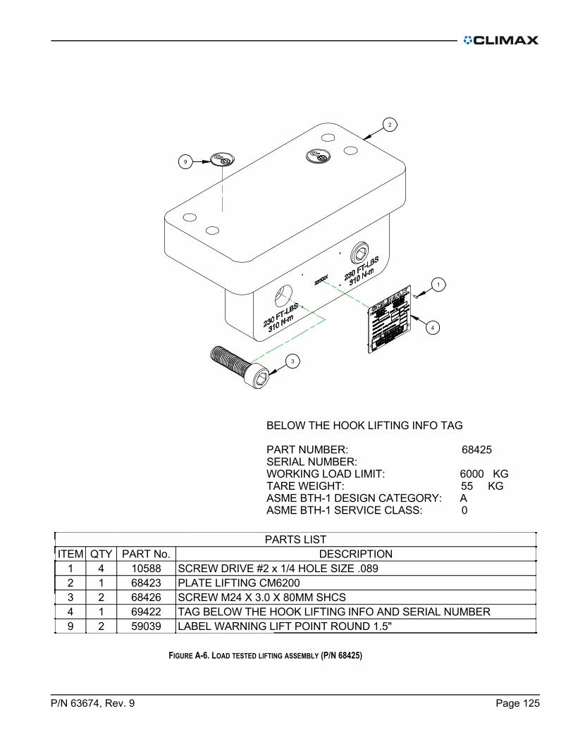
FIGURE A-6. LOAD TESTED LIFTING ASSEMBLY (P/N 68425)
PARTS LIST
DESCRIPTIONPART No.QTYITEM
SCREW DRIVE #2 x 1/4 HOLE SIZE .0891058841
PLATE LIFTING CM62006842312
SCREW M24 X 3.0 X 80MM SHCS6842623
TAG BELOW THE HOOK LIFTING INFO AND SERIAL NUMBER6942214
LABEL WARNING LIFT POINT ROUND 1.5"5903929
9
1
4
3
2
BELOW THE HOOK LIFTING INFO TAG
PART NUMBER: 68425SERIAL NUMBER: WORKING LOAD LIMIT: 6000 KGTARE WEIGHT: 55 KGASME BTH-1 DESIGN CATEGORY: AASME BTH-1 SERVICE CLASS: 0
P/N 63674, Rev. 9 Page 125

FIGURE A-7. ID MOUNT ASSEMBLY (P/N 62038)
PARTS LISTDESCRIPTIONPART No.QTYITEM
(NOT SHOWN) CONTAINER SHIPPING FLAT ROOF 20 X 8.75 X 10.51970011WELDMENT STANDOFF 12.5 FF82005772442WELDMENT STANDOFF 17.5 FF82005785183WELDMENT STANDOFF 27.5 FF82005785244SCREW M20 X 2.5 X 40MM SHCS58203965LABEL WARNING LIFT POINT ROUND 1.5"59039166(NOT SHOWN) LIFTING EYE M6 X 1 X 12 THREAD 19 ID 460 LBS 210 KG 6395447SCREW M12 X 1.75 X 40mm SSSFP74499248LABEL WARNING - LIFT SUB ASSY ONLY GRAPHIC 2 X 3 79385169LABEL CAUTION - TORQUE 150 FT-LBS (203 N-M) GRAPHIC 3 X 1.7821572410CAP END 4.50 DIA 4-4 OD THREAD 2-8 ID THREAD89717811PLATE BASE CHUCK89718812LEG CHUCK TUBE 4.5 OD X 2.5 THREADED89720813LEG CHUCK TUBE 4.5 OD X 5.0 THREADED897211214NUT JACKING LOCK 2-889726815ASSY FOOT CHUCK ADJUSTABLE90836416PLATE MASS CE 1.0 X 1.0 KG ADHESIVE BACKED912171617ASSY FOOT NON LEVELING GRIPPER LARGE FF LINE91232418
11
18
4 2 12 14 13
55
3
3
5
12
5
14
14
13
11
5
6
17
10
9
10
15
8
15
8
16
Page 126 CM6200 Operating Manual

FIGURE A-8. ADJUSTABLE CHUCK FOOT ASSEMBLY (P/N 89730)
PARTS LIST
DESCRIPTIONPART No.QTYITEM
RING O 3/32 X 9/16 ID X 3/4 OD1061121
WASHER THRUST .750 ID X 1.250 OD X .03121173912
WASHER THRUST 1.250 ID X 1.937 OD X .0601666613
PIN DOWEL 3/16 DIA X 1-1/41973524
SCREW M16 X 2.0 X 200 SHCS4422725
SCREW M8 X 1.25 X 10mm SSSDP4425726
SCREW M16 X 2.0 X 40mm SHCS4490547
SCREW M16 X 2.0 X 55mm SHCS4622228
SCREW M16 X 2.0 X 80 SHCS5810629
WASHER SPRING WAVE 1.235 OD X .961 ID X .01458244110
JAW ADJUSTER CM620063582111
BASE ADJUSTER CM620063583112
JAW SCREW CM620063584113
SCREW M30 X 1.5 X .875 HOLLOW LOCK MOD63585114
FINGER SETUP EXTENSION CM620063586115
RESTRAINT SAFETY WELD PLATE CM620063842116
CLAMP INTERNAL FLANGE CM620063853117
SCREW M16 X 2.0 X 120 SHCS64086218
SCREW M16 X 2.0 X 160 SHCS64087219
SS OO C C S
1
7
15
11
4
2
6
16
85789
17
14
13
10
12
3
P/N 63674, Rev. 9 Page 127

FIGURE A-9. NON-LEVELING FOOT ASSEMBLY (P/N 91317)
PARTS LIST
DESCRIPTIONPART No.QTYITEM
SCREW 1/4-20 X 5/8 SHCS1241811
PIN ROLL Ø3/16 X 11295922
WASHER THRUST 1.250 ID X 1.937 OD X .0601666613
GRIPPER SERRATED HSS 1 DIAM X 1/2 CBORED4164414
WASHER SPRING WAVE 1.235 OD X .961 ID X .0145824415
JAW SCREW CM62006358416
CAP FOOT NON LEVELING GRIPPER CM62009118617
6
3
5
7
2
2
1
4
Page 128 CM6200 Operating Manual
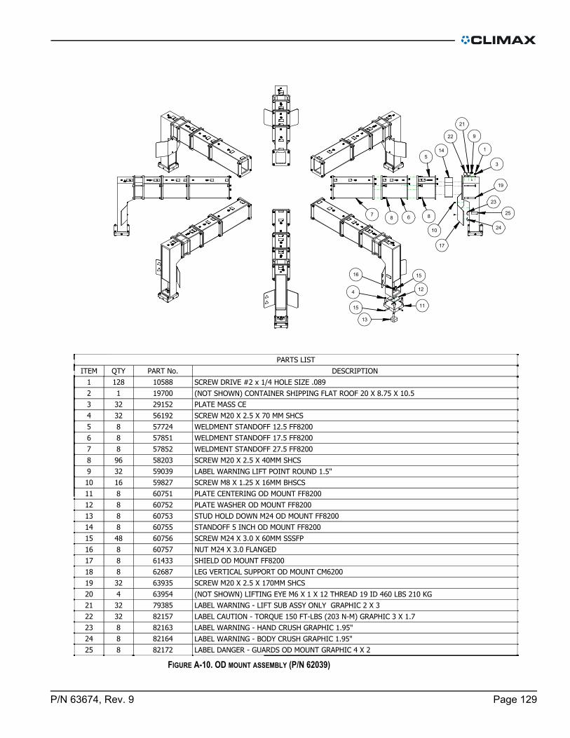
FIGURE A-10. OD MOUNT ASSEMBLY (P/N 62039)
PARTS LISTDESCRIPTIONPART No.QTYITEM
SCREW DRIVE #2 x 1/4 HOLE SIZE .089105881281(NOT SHOWN) CONTAINER SHIPPING FLAT ROOF 20 X 8.75 X 10.51970012PLATE MASS CE29152323SCREW M20 X 2.5 X 70 MM SHCS56192324WELDMENT STANDOFF 12.5 FF82005772485WELDMENT STANDOFF 17.5 FF82005785186WELDMENT STANDOFF 27.5 FF82005785287SCREW M20 X 2.5 X 40MM SHCS58203968LABEL WARNING LIFT POINT ROUND 1.5"59039329SCREW M8 X 1.25 X 16MM BHSCS598271610PLATE CENTERING OD MOUNT FF820060751811PLATE WASHER OD MOUNT FF820060752812STUD HOLD DOWN M24 OD MOUNT FF820060753813STANDOFF 5 INCH OD MOUNT FF820060755814SCREW M24 X 3.0 X 60MM SSSFP607564815NUT M24 X 3.0 FLANGED60757816SHIELD OD MOUNT FF820061433817LEG VERTICAL SUPPORT OD MOUNT CM620062687818SCREW M20 X 2.5 X 170MM SHCS639353219(NOT SHOWN) LIFTING EYE M6 X 1 X 12 THREAD 19 ID 460 LBS 210 KG 63954420LABEL WARNING - LIFT SUB ASSY ONLY GRAPHIC 2 X 3 793853221LABEL CAUTION - TORQUE 150 FT-LBS (203 N-M) GRAPHIC 3 X 1.7821573222LABEL WARNING - HAND CRUSH GRAPHIC 1.95" 82163823LABEL WARNING - BODY CRUSH GRAPHIC 1.95"82164824LABEL DANGER - GUARDS OD MOUNT GRAPHIC 4 X 282172825
5
14
67
8 8
22
21
9
1
3
19
23
2410
17
13
15
4
16 15
12
11
25
P/N 63674, Rev. 9 Page 129

FIGURE A-11. MACHINING ARM ASSEMBLY (P/N 72676)
DETAIL ASCALE 1/10
A
36
2
33
7
17
32
2
30
34
13
2514
123
1
5
11
20
10
3
127
4 8
26
22
23
29
27
28
1922 26
8
37 39
9 3532
1031
10
1015
10
24
16
6
21
18
Page 130 CM6200 Operating Manual

FIGURE A-12. MACHINING ARM ASSEMBLY PARTS LIST (P/N 72676)
PARTS LIST
DESCRIPTIONP/N:QTYITEM
BRG THRUST .625 ID X 1.125 OD X .07811053821
SCREW DRIVE #2 x 1/4 HOLE SIZE .08910588102
WASHER THRUST .625 ID X 1.125 OD X .0601116543
RING O 1/16 X 1 ID X 1-1/8 OD1573124
PIN DOWEL 1/4 DIA X 1/22016615
LABEL WARNING STICKER SINGLE POINT MACHINES2746216
PLATE MASS CE2915217
RING SNAP 1-3/16 ID (30MM) 3377728
SCREW M6 X 1.0 X 20 SHCS35009309
SCREW M6 X 1.0 X 35mm SHCS355042810
SCREW M8 X 1.25 X 6MM SSSFP36087211
BALL NYLON 1/8 DIA43489212
LABEL CIRCULAR MILL CRUSH HAZARD46286213
SCREW M4 X 0.7 X 4 mm SSSFP53365214
SCREW 6MM DIA X 25MM X M5 X 0.8 SHLDCS57581215
LABEL WARNING LIFT POINT ROUND 1.5"59039216
TOOL ARM CM620061980117
BEARING BLOCK BALLSCREW 20MM62281118
HOLDER FELT WIPER MILLING HEAD62321119
WASHER SPRING BELLEVILLE 1/8 ID X 1/4 OD X .013 THK623761220
ROD POLYURETHANE 1/4 DIA X 1/4 LENGTH 95 SHORE A62378221
SEAL FELT 16MM BALL SCREW 1.015 OD MILLING HEAD62379422
MOUNT BALL NUT MILLING HEAD62423123
LABEL DANGER PART LIFT POINT ONLY 2 X 362888224
BRG RETAINING NUT 5/8-18 O-RING SEAL SETSCREW LOCK62898125
WASHER SHIM .75 ID 1.125 OD .062 THICK STEEL62903226
BALL SCREW 20MM RADIAL TRAVEL CM620062930127
BALL SCREW NUT 20MM X 5MM LEAD LEFT HAND 33 MM OD
EICHENBERGER ROUND
62960128
SLIDE RAIL THK SHS25 880MM LG PRELOADED METAL SCRAPERS 2
BLOCKS
62961229
LIFTING EYE M12 X 1.75 X 24 THREAD 30 ID 2270 LBS 1030 KG62964230
TAIL SUPPORT BALL SCREW RADIAL FEED62965131
SCREW 3/4-10 X 3/4 BHSCS62969232
GUIDE WIRE ROPE 3/8"64133333
LABEL COUNTERWEIGHT & ARM POSITION CM620064156134
CAP RAIL 25MM METAL THK SHS685013035
LABEL CLIMAX LOGO 3.5 X 12.570228136
ZIMMER BRAKE 25mm RAIL72262137
PLATE RADIAL TRAVEL CM620072675138
ADAPTER BRAKE 25mm RAIL 4mm THICK72869139
P/N 63674, Rev. 9 Page 131

FIGURE A-13. MACHINING ARM MILLING HEAD TRAM ASSEMBLY (P/N 63124)
PARTS LIST
DESCRIPTIONPART No.QTYITEM
PIN DOWEL 1/2 DIA X 1-1/21183241
SCREW M12 X 1.75 X 25mm SHCS4209462
PLATE MILL TRAMMING CM62006292113
PIN DOWEL 3/4 DIA X 1-1/46355714
2
3
4
1
Page 132 CM6200 Operating Manual

FIGURE A-14. COUNTERWEIGHT ARM ASSEMBLY (P/N 62031)
PARTS LIST
DESCRIPTIONP/N:QTYITEM
SCREW DRIVE #2 x 1/4 HOLE SIZE .0891058841
PLATE MASS CE2915212
HOIST SWIVEL RING M12 X 1.75 1050 KG4300124
WASHER FIXTURING 21MM ID X 35MM OD X 3MM CASE HARDENED5788885
SCREW M20 X 2.5 X 55mm SHCS5874346
LABEL WARNING LIFT POINT ROUND 1.5"5903937
ARM COUNTERWEIGHT CM62006205918
COUNTERWEIGHT CM62006206019
LABEL DANGER PART LIFT POINT ONLY 2 X 362888310
LABEL COUNTERWEIGHT & ARM POSITION CM620064156211
SCREW M20 X 2.5 X 50 mm SHCS40459413
LABEL CLIMAX LOGO 4.75 X 1870229114
2
1
5
5
6
9
4
8
11
7
10
10
7
13
14
P/N 63674, Rev. 9 Page 133

FIGURE A-15. FACE MOUNT ASSEMBLY (P/N 63106)
ASSY EXTENSION MILLING HEAD6584015
WASHER 3/4 FLATW12339324
SCREW M16 X 2 X 60mm SSSFP57348163
SCREW M20 X 2.5 X 40MM SHCS58203322
BRACKET FACE MOUNT CM62006288741
PARTS LIST
DESCRIPTIONPART No.QTYITEM
1
4
2
1
4
2
3
3
5
Page 134 CM6200 Operating Manual

FIGURE A-16. GRINDING ATTACHMENT W/TOOL HEAD ASSEMBLY (P/N 63239)
PARTS LIST
DESCRIPTIONPART No.QTYITEM
WASHER THRUST .75 OD X .312 ID X .031077011
FTG ELBOW 3/8 NPTM X 3/8 NPTF STREET 90 DEG1113212
FTG QUICK COUPLER 1/2B 1/2NPTF FEMALE AIR1320813
FTG NIPPLE 1/2NPTM CLOSE HEX1470414
FTG QUICK COUPLER 1/2B 3/8 NPTM MALE AIR1661515
HOSE ASSY 801 1/2 X 1/2 NPTMS ENDS X 1803219616
SCREW M12 X 1.75 X 40mm SHCS3521547
LABEL DIRECTION OVAL HANDLE BALL VALVE3577218
VALVE BALL 1/2NPTF OVAL HANDLE3632819
FTG ADPTER 3/8 BSPP MALE X 3/8 NPTF52734110
TOOL HEAD ASSY FF LINE57781111
WASHER FIXTURING 21MM ID X 35MM OD X 3MM CASE HARDENED57888112
ARBOR GRINDING WHEEL CBN 10MM SHANK M8 THREAD62624113
ADAPTER SINGLE POINT TOOL HEAD TO MILLING ARM62984114
SCREW M20 X 1.5 X 50MM SHCS63018115
ASSY GRINDING ATTACHMENT63063116
16
13
4
9
1
8
3
11
6
10
2 5
REMOVE FITTING TO INSTALL ITEM 9
12
15
7
14
P/N 63674, Rev. 9 Page 135

FIGURE A-17. GRINDER FOR SP CM6200 WITH GEAR REDUCER ASSEMBLY (P/N 63240)
PARTS LIST
DESCRIPTIONPART No.QTYITEM
SCREW M12 X 1.75 X 25mm SHCS4209461
SCREW M8 X 1.25 X 25mm SHCS4249482
SEAL OIL 60 x 85 x 8 DOUBLE LIP4496413
TUBING PARFLEX 1/2 OD X 3/8 ID POLYURETHANE BLACK X 130"482811304
SPLINE COUPLING BREVINI5192815
ARBOR GRINDING WHEEL CBN 10MM SHANK M8 THREAD6262416
FTG ELBOW 1/2 NPTM x 1/2 O.D. PRESTOLOK TUBING6268117
FTG ADAPTER 12MM TUBE X 1/2 PRESTOLOK TUBING6268218
ASSY GRINDING ATTACHMENT6306319
ASSY TORQUE LIMITER 24 MM OUTPUT63072110
FLANGE ADAPTER BREVINI UNIVERSAL TO NEMA 4263714111
REDUCER 162.8:1 PLANETARY63731112
6
9
8
4
7
10
1
3
5
12
2
11
Page 136 CM6200 Operating Manual

FIGURE A-18. GRINDER FOR SP PNEUMATIC (P/N 62537)
PARTS LIST
DESCRIPTIONP/N:QTYITEM
ARBOR GRINDING WHEEL CBN 10MM SHANK M8 THREAD6262411
FTG ELBOW 1/2 NPTM x 1/2 O.D. PRESTOLOK TUBING6268112
FTG ADAPTER 12MM TUBE X 1/2 PRESTOLOK TUBING6268213
ASSY GRINDING ATTACHMENT6306314
TUBING PARFLEX 1/2 OD X .328 ID POLYURETHANE BLACK79025130IN5
2
5
3
4
1
P/N 63674, Rev. 9 Page 137

FIGURE A-19. PLATE SWIVEL MILLING HEAD ASSEMBLY (P/N 63250)
PARTS LIST
DESCRIPTIONP/N:QTYITEM
PIN DOWEL 1/2 DIA X 12039841
SCREW M12 X 1.75 X 30mm SHCS4069782
PIN DOWEL 3/4 DIA X 34698113
PLATE SWIVEL MILLING HEAD RAM SIDE5362414
SCREW M12 X 1.75 X 50MM SHCS6428125.1
RING CLAMP SWIVEL PLATE MILLING HEAD METRIC7422415.2
PIN DOWEL 5/16 DIA X 3/41654015.3
PLATE SWIVEL MILLING HEAD QUILL SIDE METRIC7425016
5.1
5.3
5.2
4
1
3
6
2
Page 138 CM6200 Operating Manual

FIGURE A-20. MILLING HEAD AND DRAWBOLT ASSEMBLY (P/N 73354)
PARTS LIST
DESCRIPTIONP/N:QTYITEM
DRAWBOLT 1"-8 X 14.5 (INCH NMTB)
DRAWBOLT M24X3 X 14.5 (METRIC NMTB)
DRAWBOLT 1"-8 X 15.5 (INCH V-FLANGE)
DRAWBOLT M24X3 X 15.5 (METRIC V-FLANGE)
62330
62331
62845
62846
11
MILLING HEAD 2-29/32 BRG 8 STROKE #50 TAPER7227712
2
1
COMPLETE ASSY (MILLING HEAD W/DRAWBOLT)
P/N CONFIGURATION
62282 MILLING HEAD 8 STROKE #50 TAPER INCH NMTB
62734 MILLING HEAD 8 STROKE #50 TAPER INCH V-FLANGE
62644 MILLING HEAD 8 STROKE #50 TAPER METRIC NMTB
62735 MILLING HEAD 8 STROKE #50 TAPER METRIC V-FLANGE
P/N 63674, Rev. 9 Page 139

FIGURE A-21. MILLING HEAD 2-29/32 BRG 8 STROKE #50 TAPER (P/N 72277)
46
45
47
42
19
62
2335
41
4
6
7
40
10
59
31
36
22
5422
53
49
60
55
56
50
55
5560
3734
26
8
20
32
33
28
1111
24
2
18
57
18
55
21
61
68
3
9
327
3
3
9
13
14
5
51
47
1
1
20
25
65
45
15
38
62
16
44
70
23
67
5
6
67
43
6
12
39
21
17
29
48
29
52
64
69
3033
71
58
27
66
2
Page 140 CM6200 Operating Manual

FIGURE A-22. MILLING HEAD ASSEMBLY PARTS LIST 1 (P/N 72277)
PARTS LIST
DESCRIPTIONP/N:QTYITEM
BRG THRUST .625 ID X 1.125 OD X .07811053821
SCREW DRIVE #2 x 1/4 HOLE SIZE .0891058882
WASHER THRUST .625 ID X 1.125 OD X .0601116543
PIN DOWEL 1/4 DIA X 3/41172924
BRG CUP 4.4375 OD X .750 WIDE1182125
WASHER THRUST 1.375 ID X 2.062 OD X .0301532646
BRG THRUST 1-375 ID X 2.062 OD X .07811532727
RING O 1/8 X 1 ID X 1-1/4 OD1550918
RING O 1/16 X 1 ID X 1-1/8 OD1573129
SEAL 1.625 ID X 2.250 OD X .31315768110
BALL NYLON 3/16 DIA16594411
RING SNAP 1-5/8 OD .062 WIDE19505112
PIN DOWEL 1/4 DIA X 1/220166113
KEY 1/4 SQ X 1.00 SQ BOTH ENDS20273114
NUT MAIN BRG PRELOAD28219115
PLATE MASS CE29152116
SCREW M12 X 1.75 X 35mm SHCS30207217
RING SNAP 1-3/16 ID (30MM) 33777218
SCREW M16 X 1.5 X 20mm SSSFP34643419
SCREW M6 X 1.0 X 20 SHCS350093220
SCREW M6 X 1.0 X 16mm SHCS35014621
SCREW M6 X 1.0 X 35mm SHCS35504422
SCREW M6 X 1.0 X 25 SHCS356521123
PLATE SERIAL YEAR MODEL CE 1.5 X 2.035828124
SCREW M4 X 0.7 X 8MM SHCS35910225
SCREW M3 X 0.5 X 8mm SHCS35994426
SCREW M8 X 1.25 X 6MM SSSFP36087227
SCREW M6 X 1.0 X 6mm SSSCP36150228
SCREW M8 X 1.25 X 12mm36545229
SCREW M12 X 1.75 X 30mm SHCS40697430
BALL NYLON 1/8 DIA43489231
BRG BALL 1.7717 ID X 2.6772 OD X .4724 W/ 2 SEALS46352232
LABEL WARNING HOT SURFACE GRAPHIC 2.25 TRI46902233
SCALE DIGITAL 8 INCH VERTICAL MOUNT51859134
SCREW M8 X 1.25 X 80MM SHCS52936435
P/N 63674, Rev. 9 Page 141

FIGURE A-23. MILLING HEAD ASSEMBLY PARTS LIST 2 (P/N 72277)
PARTS LIST
DESCRIPTIONP/N:QTYITEM
SCREW M4 X 0.7 X 4 mm SSSFP53365236
SCREW M3 X 0.5 X 4MM BHSCS54024437
SPINDLE BLOCK 2.75 BRG 8 STROKE #50 TAPER60462138
GEAR SET 40T 16DP 2.5PD THREE GEARS BLOCK SPINDLE 2.75 BRG60467139
HOUSING GEARBOX BLOCK SPINDLE 2.75 BRG60468140
COVER GEARBOX BLOCK SPINDLE 2.75 BRG60469141
SHAFT GEAR BLOCK SPINDLE 2.75 BRG60470142
WASHER SPLIT LOCK M12 60702243
LUG DRIVE #50 TAPER BLOCK SPINDLE60704244
BRG CONE 2.75 ID X 1.00 WIDE60705245
SEAL 3.25 ID X 4.000 OD X .37560706146
BRG BALL 1.7717 ID X 2.9528 OD X .629960793247
SLIDE RAIL THK SHS25 442MM LG PRELOADED METAL SCRAPERS 2 BLOCKS62255248
BEARING BLOCK BALLSCREW 20MM62281149
HOLDER FELT WIPER MILLING HEAD62321150
RING SNAP 1.771 OD (45MM) 62322151
BRACKET DRO BLOCK SPINDLE 2.75 BRG62324152
WASHER SPRING BELLEVILLE 1/8 ID X 1/4 OD X .013 THK623761253
ROD POLYURETHANE 1/4 DIA X 1/4 LENGTH 95 SHORE A62378254
SEAL FELT 16MM BALL SCREW 1.015 OD MILLING HEAD62379455
MOUNT BALL NUT MILLING HEAD62423156
BALL SCREW NUT 20MM X 5MM LEAD 33 MM OD EICHENBERGER ROUND62426157
WASHER 1 FLTW ASTM F43662696158
BRG RETAINING NUT 5/8-18 O-RING SEAL SETSCREW LOCK62898159
WASHER SHIM .75 ID 1.125 OD .062 THICK STEEL62903260
SCREW 6MM DIA X 12MM X M5 X 0.8 SHLDCS62909261
BRG NEEDLE 1-3/8 ID X 1-5/8 OD X .750 OPEN63437262
HANDWHEEL ASSY Z-AXIS (NOT SHOWN)63927163
CAP RAIL 25MM METAL THK SHS685011664
NUT LOCKING MODIFIED 2.751-18 FLEXIBLE INSERT LOCKING68623165
ZIMMER BRAKE 25mm RAIL72262166
PLATE MOUNTING BLOCK SPINDLE 2.75 BRG72279167
BALL SCREW MILLING HEAD 2.75 BRG 8" STROKE72283168
HOUSING SPINDLE 2.9062 BRG 8 STROKE72652169
ADAPTER BRAKE 25mm RAIL 4mm THICK72869170
LABEL WARNING CUTTING OF FINGERS/ROTATING BLADE80510171
Page 142 CM6200 Operating Manual
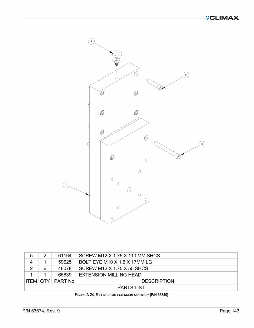
FIGURE A-24. MILLING HEAD EXTENSION ASSEMBLY (P/N 65840)
SCREW M12 X 1.75 X 110 MM SHCS6116425
BOLT EYE M10 X 1.5 X 17MM LG5962514
SCREW M12 X 1.75 X 55 SHCS4607862
EXTENSION MILLING HEAD6583911
PARTS LIST
DESCRIPTIONPART No.QTYITEM
5
4
2
1
P/N 63674, Rev. 9 Page 143

FIGURE A-25. SERVO DRIVE ASSEMBLY (P/N 83156)
PARTS LISTDESCRIPTIONP/N:QTYITEM
ASSY SERVO DRIVE GEARBOX CM62006203211CONFIDENTIAL PROPERTY OF CLIMAX PORTABLE MACHINING & WELDING
1
Page 144 CM6200 Operating Manual

FIGURE A-26. SERVO DRIVE GEARBOX ASSEMBLY (P/N 62032)
PARTS LIST
DESCRIPTIONP/N:QTYITEM
SCREW M12 X 1.75 X 25mm SHCS4209461
SCREW M8 X 1.25 X 25mm SHCS4249482
SEAL OIL 60 x 85 x 8 DOUBLE LIP4496413
SCREW M8 X 1.25 X 20mm SHCS5045844
SPLINE COUPLING BREVINI5192815
FLANGE ADAPTER 110mm PILOT SPECIAL DRILLING5193016
REDUCER 162.8:1 PLANETARY6373117
FACTORY SUPPLIED BREATHER-18
KEY 8mm X 7mm X 30mm RADIUS BOTH ENDS6882319
ASSY GEARBOX VENT LINE69351110
10
3
4
1
6
5
7
2
7
9
1
1
NOTE: REMOVE BREATHER SUPPLIED WITH GEARBOX, INSTALL VENT LINE ASSY 69351, AND ASSEMBLE TO END FITTING
8
P/N 63674, Rev. 9 Page 145ASSY SERVO DRIVE GEARBOX CM620062032

FIGURE A-27. SINGLE POINT EU ASSEMBLY (P/N 83100)
46
6 50
51
1
16
17
22
15
53
49
34
11
40
12
43
45
39
37
41
36
23
18
8
1
5
33
38
14
21
19
2425
5547
7
48
54
9
452
56
202
30
312932
2830
3
26
10
38
42
44
Page 146 CM6200 Operating Manual

FIGURE A-28. SINGLE POINT EU ASSEMBLY PARTS LIST (P/N 83100)
PARTS LISTDESCRIPTIONP/N:QTYITEM
FTG REDUCER BUSHING 1/2 NPTM X 1/4 NPTF STEEL1292031NUT M6 X 1.0 STDN ZINC PLATED2077222SCREW M12 X 1.75 X 40mm SHCS3521543SCREW M5 X 0.8 X 10MM SHCS3591614DUST CAP 1/2 COUPLER 1SO 160283924125FTG QD NIPPLE 3/4B X SAE-12F4061226FTG ADAPTER 1/2 NPTF MALE X 7/8-14 W/ O-RING4694427SCREW M8 X 1.25 X 20mm SHCS5045848SCREW M12 X 1.75 X 150mm SHCS5090719TOOL HEAD ASSY FF LINE57781110WASHER FIXTURING 21MM ID X 35MM OD X 3MM CASE HARDENED57888111FEED BOX PNEUMATIC REMOTE FEED ADJUST58671112PLUMBING PNEUMATIC FEED ASSY59244113FTG MUFFLER 1/4 NPTM 13641114HOSE ASSY 801 1/2 X 1/2 NPTMS ENDS X 1215625115FTG QUICK COUPLER 1/2B 1/2 NPTF MALE AIR24851116QUICK COUPLER 1/4B MALE 1/4 NPTF28493117SCREW M6 X 1.0 X 35mm SHCS35504218WASHER M6 FLTW DIN 12535891219FTG ADAPTER 1/4 NPTM X 1/4 TUBE F PRESTOLOCK NICKEL PLATED51263120VALVE 2-POSITION 3-WAY NORMALLY OPEN59318121HOSE ASSY 801 1/4 X 1/4 NPTM ENDS X 1259341122FTG ELBOW 1/4 NPTMS X 1/4 TUBE F PRESTOLOCK NICKEL PLATED59342123VALVE 1/4 NPTM X 1/4 TUBE F PRESTOLOCK FLOW CONTROL RIGHT ANGLE METERED AT 5 SCFM60669124FTG ADAPTER 1/8 TUBE F PRESTOLOCK X 1/4 NPTM STRAIGHT63083125ADAPTER SINGLE POINT TOOL HEAD TO MILLING ARM62984126ASSY ADAPTER FEEDBOX CM620062994127PIN ROLL 3/16 DIA X 3/410850128SCREW M6 X 1.0 X 30 SHCS35505229RING SNAP 7/8 OD SPIRAL MED DUTY39074230PLATE FEEDBOX ADAPTER CM620062985131SHAFT FEEDBOX ADAPTER INNER CM620062986132SHAFT FEEDBOX ADAPTER OUTER CM620062988133SCREW M20 X 1.5 X 50MM SHCS63018134ASSY ROTARY UNION CM620063121135SCREW M8 X 1.25 X 16mm137874365/16-18 X 1/2 BHSCS21769437SCREW M12 X 1.75 X 25mm SHCS42094838CAM FEED58039139UNION ROTARY HYDRAULIC 4 CHANNEL 1/2 NPTF PORTS MOD58751140SCREW M8 X 1.25 X 45MM SHCS59349341MOUNT ROTARY UNION CM620062891142RESTRAINT TORQUE ROTARY UNION CM620062893143SPACER ROTARY UNION CM620062894144WASHER M12 FLTW 27MM OD 3.1 MM THICK62978445AIR CONTROL ASSY FOR PNEUMATIC FEED 50 FT63156146FTG QD NIPPLE 1/2B ISO 16028 STYLE X SAE-10F63427247DUST CAP QD NIPPLE 1/2B ISO 16028 STYLE RUBBER63428248HOSE ASSY 451 1/2 X SAE-10M X 36 STRAIGHT FITTINGS CE63675249FTG ADAPTER SAE-12M X SAE-10F63682250ADAPTER SINGLE POINT DRIVE SHAFT63774151KEY 8MM X 12MM X 40MM RADIUS BOTH ENDS WITH CB HOLE63782152PLATE ADAPTER HYD MOTOR TO DRIVE ASSY63784153FTG ELBOW 1/2 NPTM X 1/2 NPTF ST 45 DEG64901254FTG QD COUPLER 1/2B ISO 16028 X SAE-10F69486255HOSE ASSY 1/2" 451TC X SAE-10 TO 1/2 NPTM X 12 INCHES CE83120256
P/N 63674, Rev. 9 Page 147

FIGURE A-29. SINGLE POINT ASSEMBLY (P/N 62037)
17
252585
18 1818
2
3
29
23 20
16
FOR
SH
AFT
ADAP
TER
REM
OVA
L
1
21
15
14
9
10 4
11
29
22
18
118
1228
7
27
2619
6
24
24
Page 148 CM6200 Operating Manual

FIGURE A-30. SINGLE POINT ASSEMBLY PARTS LIST (P/N 62037)
PARTS LISTDESCRIPTIONPART No.QTYITEM
FTG REDUCER BUSHING 1/2 NPTM X 1/4 NPTF STEEL1292031NUT M6 X 1.0 STDN ZINC PLATED2077222FTG DUST PLUG 1/2 QD COUPLER2797723FTG DUST CAP 1/2 MALE QUICK COUPLING2797824FTG DUST CUP 60 SERIES 3/4 MALE QUICK CONNECT2956125SCREW M12 X 1.75 X 40mm SHCS3521546SCREW M5 X 0.8 X 10MM SHCS3591617FTG QD NIPPLE 3/4B X SAE-12F4061228FTG QUICK COUPLER MALE 1/2B X SAE-10F4061429FTG QUICK COUPLER FEMALE 60 SERIES 1/2B X SAE-10F40615210FTG ADAPTER 1/2 NPTF MALE X 7/8-14 W/ O-RING46944211SCREW M8 X 1.25 X 20mm SHCS50458412SCREW M12 X 1.75 X 150mm SHCS50907113TOOL HEAD ASSY FF LINE57781114WASHER FIXTURING 21MM ID X 35MM OD X 3MM CASE HARDENED
57888115
FEED BOX PNEUMATIC REMOTE FEED ADJUST58671116HOSE ASSY 451 1/2 X SAE-10M TO 1/2 NPTM X 12 STRAIGHT FITTINGS
59240217
PLUMBING PNEUMATIC FEED ASSY59244118ADAPTER SINGLE POINT TOOL HEAD TO MILLING ARM62984119ASSY ADAPTER FEEDBOX CM620062994120SCREW M20 X 1.5 X 50MM SHCS63018121ASSY ROTARY UNION CM620063121122AIR CONTROL ASSY FOR PNEUMATIC FEED 50 FT63156123HOSE ASSY 451 1/2 X SAE-10M X 36 STRAIGHT FITTINGS CE63675224FTG ADAPTER SAE-12M X SAE-10F63682225ADAPTER SINGLE POINT DRIVE SHAFT63774126KEY 8MM X 12MM X 40MM RADIUS BOTH ENDS WITH CB HOLE
63782127
PLATE ADAPTER HYD MOTOR TO DRIVE ASSY63784128FTG ELBOW 1/2 NPTM X 1/2 NPTF ST 45 DEG64901229
P/N 63674, Rev. 9 Page 149

FIGURE A-31. ROTARY UNION ASSEMBLY (P/N 63121)
PARTS LISTDESCRIPTIONP/N:QTYITEM
SCREW M8 X 1.25 X 16mm13787415/16-18 X 1/2 BHSCS2176942SCREW M12 X 1.75 X 25mm SHCS4209483(NOT SHOWN FOR OD CONFIG ONLY) SCREW M8 X 1.25 X 25MM SHCS4249434CAM FEED5803915UNION ROTARY HYDRAULIC 4 CHANNEL 1/2 NPTF PORTS MOD5875116SCREW M8 X 1.25 X 45MM SHCS5934937(NOT SHOWN FOR OD CONFIG ONLY) SCREW M8 X 1.25 X 16MM HHCS6083748MOUNT ROTARY UNION CM62006289119RESTRAINT TORQUE ROTARY UNION CM620062893110SPACER ROTARY UNION CM620062894111WASHER M12 FLTW 27MM OD 3.1 MM THICK62978412
12
2
3
6
10
5
3
9
11
17
Page 150 CM6200 Operating Manual

FIGURE A-32. PNEUMATIC CONDITIONING UNIT (P/N 97742)
PARTS LISTMFG P/NMANUFACTURERDESCRIPTIONP/N:QTYITEM
N/AN/A5/16-18 X 3/4 BHSCS1477141N/AN/AWASHER 5/16 FLTW SAE1348942N/AN/ANUT 5/16-18 NYLON INSERT LOCKNUT1972943N/AN/ARUBBER BUMPER, 9/16 DIA X 1/8 TALL8346244
VHS40-N04B-S-ZSMCSP VALVE ISOLATION/SHUTOFF WITH 1/2 INCH PORTS9673215AW40-N04-8Z-BSMCSP REGULATOR & FILTER W/ GAGE & SIGHT GLASS 7-125 PSI 1/2
PORTS9673316
AF40P-060SSMCSP FILTER PNEUMATIC9673516.1GC3-10AS-X2103SMCSP INDICATOR PRESSURE 1 MPA FOR SMC FRL9763516.2
E400-N04-ASMCADAPTER PIPE 1/2 INCH NPT FOR SMC SIZE 40 FRLN/A27Y400T-ASMCSPACER WITH BRACKET FOR SMC SIZE 40 FRLN/A28Y400-ASMCSPACER FOR SMC SIZE 40 FRLN/A19
N/AN/ASHEET METAL FRAME FOR SMC PCU 1/2 INCH PORTS97739110
SEE DETAILEDEXPLOSION
1
3210 6.2
7
86.1
6
95
8
7
4
P/N 63674, Rev. 9 Page 151

FIGURE A-33. AIR CONTROL ASSEMBLY FOR PNEUMATIC FEED (P/N 63156)
PARTS LISTDESCRIPTIONPART No.QTYITEM
WASHER THRUST .75 OD X .312 ID X .031077011FTG REDUCER BUSHING 1/2 NPTM X 1/4 NPTF STEEL1292012FTG QUICK COUPLER 1/2B 1/2NPTF FEMALE AIR1320813FTG QUICK COUPLER 1/4B 1/4 NPTF FEMALE AIR2849414FTG ELBOW 1/4 NPTM X 1/4 NPTM 90 DEG3050225FTG QUICK COUPLER 3/8B 1/4 NPTM MALE AIR3093616LABEL DIRECTION OVAL HANDLE BALL VALVE3577217FTG QUICK COUPLER 3/8B 1/2 NPTM FEMALE AIR5512618VALVE BALL 1/4 NPTF X 1/4 NPTF VENTED OVAL HANDLE5920319FTG TEE 1/4 NPTF (3)59695110HOSE ASSY 801 1/4 X 1/4 NPTMS ENDS X 60063155211REGULATOR PNUE. 2-40 PSI DIAL SET SEMI-PRECISION 1/4 NPTF X 1/4 NPTF71317112ASSY PNEUMATIC FILTER & VALVE WITH STAND97742113
12
3
2
5
9
71
11
4
11
5
10
6
8
13
Page 152 CM6200 Operating Manual

FIGURE A-34. SINGLE-POINT HYDRAULIC DRIVE ASSEMBLY (P/N 83186)
PARTS LIST
DESCRIPTIONP/N:QTYITEM
FTG QD NIPPLE 1/2B ISO 16028 STYLE X SAE-10F6342721
DUST CAP QD NIPPLE 1/2B ISO 16028 STYLE RUBBER6342822
HOSE ASSY 451 1/2 X SAE-10M X 36 STRAIGHT FITTINGS CE8318123
3
2
1NOTES:
1. HOSES WILL ATTACH TO HYDRAULIC MOTOR.
2. QUICK COUPLERS AND DUST CAPS WILL ATTACH
TO HOSES ON ROTARY UNION.
P/N 63674, Rev. 9 Page 153

TABLE A-1. SPARE PARTS
Qty Part number Description
4 62606 HOIST RING M24 X 3 X 38MM 70 ID X 130 OD 225 OAL 9250 LBS 4200 KG SWIVEL
64 58202 SCREW 16MM DIA X 20MM X M12 X 175 SHLDCS
Hose Tower / Encoder Guard
1 62616 TOWER HOSE CM6200
2 57874 SCREW M8 X 125 X 60MM SHCS
1 62615 GUARD ENCODER CM6200
Turning Arm Clamps
3 62601 ASSY CLAMP ARM CM6200
1 62602 ASSY CLAMP ARM SAFETY
8 46222 SCREW M16 X 20 X 45MM SHCS
Drag Brakes
16 27172 WASHER SPRING BELLEVILLE 5/8 X 1-1/4 X 040
4 11693 WASHER 5/8 FLTW SAE
4 62612 STUD THREADED M16 X 2 X 100MM FULL THREAD
8 62613 NUT M16 X 20 JAMN
2 46232 BAR BRAKE CLAMP
2 54165 SHOE BRAKE 16M CIRCULAR MILL
Milling
2 62255 SLIDE RAIL THK SHS25 442MM LG PRELOADED METAL SCRAPERS 2 BLOCKS
1 62426 BALL SCREW NUT 20MM X 5MM LEAD 33 MM OD EICHENBERGER ROUND
1 62431 BALL SCREW MILLING HEAD 275 BRG 8" STROKE
1 62719 TOOL 1" KEYED SHAFT MANUAL OPERATOR
1 51859 SCALE DIGITAL 8 INCH VERTICAL MOUNT
1 62645 WRENCH SOCKET 38MM 12 PT 1/2 DRIVE
1 53459 ASSY MOTOR HYD 80 CU IN 2000 SERIES W/ 12" QD MALE
1 53458 ASSY MOTOR HYD 96 CU IN 2000 SERIES W/ 12" QD MALE
1 46950 ASSY MOTOR HYD 119 CU IN 2000 SERIES W/ 12" QD MALE
1 46375 ASSY MOTOR HYD 149 CU IN 2000 SERIES W/ 12" QD MALE
1 46549 ASSY MOTOR HYD 187 CU IN 2000 SERIES W/ 12" QD MALE
Page 154 CM6200 Operating Manual

1 46550 ASSY MOTOR HYD 140 CU IN 2000 SERIES W/ 12" QD MALE
1 47383 MILL FACE 4 DIA ASSY #50 TAPER W/ INSERTS
1 47384 MILL FACE 5 DIA ASSY #50 TAPER W/ INSERTS
1 47385 MILL FACE 6 DIA ASSY #50 TAPER W/ INSERTS
1 47386 MILL FACE 8 DIA ASSY #50 TAPER W/ INSERTS
1 56175 MILL FACE 10 DIA ASSY #50 TAPER W/ INSERTS
1 47229 INSERT CARBIDE SQUARE 528 IC SEMT13T3AGSN-JM
Single Point
3 12920 FTG REDUCER BUSHING 1/2 NPTM X 1/4 NPTF STEEL
2 27977 FTG DUST PLUG 1/2 FEMALE QUICK COUPLING
2 27978 FTG DUST CAP 1/2 MALE QUICK COUPLING
2 40614 FTG QUICK COUPLER MALE 60 SERIES 1/2B X SAE-10F
2 40615 FTG QUICK COUPLER FEMALE 60 SERIES 1/2B X SAE-10F
2 46944 FTG ADAPTER 1/2 NPTF MALE X SAE-10M
1 29066 BIT TOOL HSS 3/4 X 50 LH FINISH SINGLE SC
1 29067 BIT TOOL HSS 3/4 X 50 RH FINISH SINGLE SC
1 46252 WRENCH SOCKET HEX 17MM 1/2 DRIVE
1 57794 KNOB ASSY MODIFIED
2 59240 HOSE ASSY 451 1/2 X SAE-10 TO 1/2 NPTM X 12 STRAIGHT FITTINGS
1 60033 HOLDER INSERT 3/4 SQ SHANK LEFT HAND W/ 10 INSERTS SECO TRI-GON
1 60034 HOLDER INSERT 3/4 SQ SHANK RIGHT HAND W/ 10 INSERTS SECO TRI-GON
1 63121 ASSY ROTARY UNION CM6200
Single Point Axial Feed System
1 58671 FEED BOX PNEUMATIC REMOTE FEED ADJUST
130 50985 TUBING 1/4 OD X 040 WALL DOT 1200 PSI NYLON BLUE
130 59151 TUBING 1/8 OD X 023 WALL DOT 1000 PSI NYLON BLUE
1 59318 VALVE 2-POSITION 3-WAY NORMALLY OPEN
1 58519 SHAFT FEED REMOVABLE FEEDBOX SHAFT
2 58446 CYLINDER AIR 40MM DIA 10MM STROKE SINGLE ACTING SPRING EXTEND INCH
1 57530 BRG NEEDLE 1 ID X 1-5/16 OD X 625 OPEN
TABLE A-1. SPARE PARTS
Qty Part number Description
P/N 63674, Rev. 9 Page 155

2 25957 BRG ROLLER CLUTCH 1 ID X 1312 OD X 625 (KB)
2 25959 SEAL 1000 ID X 1312 OD X 125 (KB)
2 59156 SCREW M6 X 10 X 60MM SHCS
Grinding
1 62633 WHEEL GRINDING 15 DIA CBN 130 GRIT 8MM BORE
1 62634 WHEEL GRINDING 225 DIA CBN 130 GRIT 8MM BORE
1 11132 FTG ELBOW 3/8 NPTM X 3/8 NPTF STREET 90 DEG
1 13208 FTG QUICK COUPLER 1/2B X 1/2 NPTF FEMALE AIR
1 14704 FTG NIPPLE 1/2 NPTM X 1/2 NPTM
1 16615 FTG QUICK COUPLER 1/2B X 3/8 NPTM MALE AIR
1 32196 HOSE ASSY 801 1/2 X 1/2 NPTM X 400
1 36328 VALVE BALL 1/2 NPTF X 1/2 NPTF OVAL HANDLE
1 52734 FTG ADAPTER 3/8 BSPP MALE X 3/8 NPTF
1 57888 WASHER FIXTURING 21MM ID X 35MM OD X 3MM CASE HARDENED
1 62624 ARBOR GRINDING WHEEL CBN 10MM SHANK M8 THREAD
1 63018 SCREW M20 X 15 X 50MM SHCS
Drive
1 62702 GEAR PINION 4DP 18T CM6200
2 63008 BRG BALL 35433 ID X 45276 OD X 5118
1 63014 RING SNAP 3-1/2 OD X 109 THK
2 63042 RING SNAP 4-1/2 OD X 109 THK
ID Chuck
8 89718 PLATE BASE CHUCK
4 91317 ASSY FOOT GRIPPER NON LEVELING
8 89720 LEG CHUCK TUBE 4.5 OD X 2.5 THREADED
12 89721 LEG CHUCK TUBE 4.5 OD X 5.0 THREADED
8 89717 CAP END 4.50 DIA 4-4 OD 3 LEAD THREAD 2-8 ID
4 57724 WELDMENT STANDOFF 125 FF8200
8 57851 WELDMENT STANDOFF 175 FF8200
4 57852 WELDMENT STANDOFF 275 FF8200
96 58203 SCREW M20 X 25 X 40MM SHCS
4 61362 RESTRAINT SAFETY WELD PLATE
TABLE A-1. SPARE PARTS
Qty Part number Description
Page 156 CM6200 Operating Manual

OD Chuck
32 56192 SCREW M20 X 25 X 70 MM SHCS
8 57724 WELDMENT STANDOFF 125 FF8200
8 57851 WELDMENT STANDOFF 175 FF8200
8 57852 WELDMENT STANDOFF 275 FF8200
8 60755 STANDOFF 5 INCH OD MOUNT FF8200
96 58203 SCREW M20 X 25 X 40MM SHCS
16 59827 SCREW M8 X 125 X 16MM BHCS
8 60751 PLATE CENTERING OD MOUNT FF8200
8 60752 PLATE WASHER OD MOUNT FF8200
8 60753 WELDMENT STUD HOLD DOWN OD MOUNT FF8200
40 60756 SCREW M24 X 30 X 60MM SSSFP
8 60757 NUT M24 X 30 FLANGED
32 60760 SCREW M20 X 25 160MM SHCS
8 61433 SHIELD OD MOUNT FF8200
8 62687 LEG VERTICAL SUPPORT OD MOUNT CM6200
Face Mount
32 12339 WASHER 3/4 FLTW
16 57348 SCREW M16 X 20 X 60MM SSSFP
32 58203 SCREW M20 X 25 XX 40MM SHCS
4 62887 BRACKET FACE MOUNT CM6200
Servo / HPU
1 55609 ASSY JUNCTION BOX AND SERVO MOTOR PIGTAILS CM62000 15 KW
1 55608 ASSY CABLE HARNESS CM6000 15 KW 50 FT
1 53433 CABLE EXTENSION 19 PIN 19 CONDUCTOR MOLDED PLUGS 16 METERS (50 Feet) LONG TPE JACKET
1 56204 HPU 25HP 415V TOUCHSCREEN SERVO WITH ANGULAR CONTROL CE
400V Version
1 51558 MOTOR SERVO 15 KW 2000 RPM 400 V MITSUBISHI
1 56000 SERVO AMPLIFIER MRJ3 480V 2 KW MITSUBISHI
200V Version
1 63761 MOTOR SERVO MITSUBISHI 15KW 2000 RPM 200V W/BRAKE
1 63762 SERVO AMPLIFIER MRJ3 200V 2 KW MITSUBISHI
TABLE A-1. SPARE PARTS
Qty Part number Description
P/N 63674, Rev. 9 Page 157

TABLE A-1. TOOL KIT P/N 62029
P/N Description QTY
14735 WRENCH EXTENSION 1/2 DRIVE X 10 1
14818 WRENCH RATCHET 1/2 DRIVE 1
19700 CONTAINER SHIPPING FLAT ROOF 20 X 875 X 105 2
33999 WRENCH HEX SET 050 - 3/8 BONDHUS BALL END (KB) 1
35516 HAMMER DEAD BLOW 1-3/4 DIA HEAD (KB) 1
38678 WRENCH HEX SET 15 - 10MM BONDHUS BALL END (KB) 1
46249 WRENCH HEX BIT SOCKET 14MM X 1/2 1
46250 WRENCH HEX BIT SOCKET 10MM X 1/2 1
46252 WRENCH HEX BIT SOCKET 17MM X 1/2 1
46253 WRENCH HEX BIT SOCKET 12MM X 1/2 1
53197 WRENCH COMBINATION 24mm 12PT 338mmLG SATIN FINISH 1
58350 WRENCH END 46mm X 8-9/16 LONG TIGHT ACCESS 2
58368 INDICATOR ELECTRONIC 500 TRAVEL 2-1/4 DIA FACE 0005" INC 1
58375 WRENCH HEX BIT SOCKET 19MM X 1/2 1
63469 HANDWHEEL MODIFIED 5 DIA 1/2" HEX 1
64370 HOLDER INDICATOR ARTICULATED ARM W/ MAG BASE 282MM REACH NOGA 1
65183 LUBRICANT ANTI SEIZE MOLY GRAPHITE EXTREME PRESSURE 10 OZ CAN 1
65188 WRENCH SPANNER 110MM TO 115MM (4-1/2) DIA 300 DIA PIN 2
69465 WRENCH END 46MM COMBINATION LONG 1
76807 WRENCH 3-1/8” SINGLE OPEN END 1
Page 158 CM6200 Operating Manual

APPENDIX B SCHEMATICSSchematic list
FIGURE B-1. MR-J3 AND MR-J4 PENDANT CABLE SCHEMATIC (P/N E00009) - - - - - - - - - - - - - - - - - - - 160FIGURE B-2. MR-J3 SYSTEM LAYOUT (P/N A00033) - - - - - - - - - - - - - - - - - - - - - - - - - - - - - - 161FIGURE B-3. MR-J3 AND MR-J4 MILL TETHER ASSEMBLY (P/N B00070) - - - - - - - - - - - - - - - - - - - - - 162FIGURE B-4. MR-J3 AND MR-J4 JUNCTION BOX ASSEMBLY (P/N B00083) - - - - - - - - - - - - - - - - - - - - 163FIGURE B-5. MR-J3 AND MR-J4 OPERATOR PENDANT ASSEMBLY (P/N B00110) - - - - - - - - - - - - - - - - - 164FIGURE B-6. MR-J3 CONTROL PANEL EXTERIOR ASSEMBLY SHEET 1 (P/N B00116) - - - - - - - - - - - - - - - - 165FIGURE B-7. MR-J3 CONTROL PANEL INTERIOR ASSEMBLY SHEET 2 (P/N B00116) - - - - - - - - - - - - - - - - 166FIGURE B-8. MR-J3 ASSEMBLY SHEET 1 (P/N C00088) - - - - - - - - - - - - - - - - - - - - - - - - - - - - - 167FIGURE B-9. MR-J3 SCHEMATIC SHEET 2 (P/N C00088) - - - - - - - - - - - - - - - - - - - - - - - - - - - - 168FIGURE B-10. MR-J3 SCHEMATIC SHEET 3 (P/N C00088) - - - - - - - - - - - - - - - - - - - - - - - - - - - - 169FIGURE B-11. MR-J4 LAYOUT (P/N A00093) - - - - - - - - - - - - - - - - - - - - - - - - - - - - - - - - - - 170FIGURE B-12. MR-J4 CONTROL PANEL ASSEMBLY EXTERIOR (P/N B000394) - - - - - - - - - - - - - - - - - - - 171FIGURE B-13. MR-J4 CONTROL PANEL ASSEMBLY INTERIOR (P/N B00394) - - - - - - - - - - - - - - - - - - - - 172FIGURE B-14. MR-J4 SCHEMATIC SHEET 1 (P/N C00526) - - - - - - - - - - - - - - - - - - - - - - - - - - - - 173FIGURE B-15. MR-J4 SCHEMATIC SHEET 2 (P/N C00526) - - - - - - - - - - - - - - - - - - - - - - - - - - - - 174FIGURE B-16. MR-J4 SCHEMATIC SHEET 3 (P/N C00526) - - - - - - - - - - - - - - - - - - - - - - - - - - - - 175
P/N 63674, Rev. 9 Page 159

FIGURE B-1. MR-J3 AND MR-J4 PENDANT CABLE SCHEMATIC (P/N E00009)
Page 160 CM6200 Operating Manual

P Page 161
FIG
/N 63674, Rev. 9
URE B-2. MR-J3 SYSTEM LAYOUT (P/N A00033)

CM6200 Operating Manual
Page 162FIGURE B-3. MR-J3 AND MR-J4 MILL TETHER SCHEMATIC (P/N B00070)

P Page 163
FIG
/N 63674, Rev. 9
URE B-4. MR-J3 AND MR-J4 JUNCTION BOX ASSEMBLY (P/N B00083)

CM6200 Operating Manual
Page 164FIGURE B-5. MR-J3 AND MR-J4 OPERATOR PENDANT ASSEMBLY (P/N B00110)

P Page 165
FIG
/N 63674, Rev. 9
URE B-6. MR-J3 CONTROL PANEL EXTERIOR ASSEMBLY SHEET 1(P/N B00116)

CM6200 Operating Manual
Page 166FIGURE B-7. MR-J3 CONTROL PANEL INTERIOR ASSEMBLY SHEET 2 (P/N B00116)

P Page 167
FIG
/N 63674, Rev. 9
URE B-8. MR-J3 SCHEMATIC SHEET 1 (P/N C00088)

CM6200 Operating Manual
Page 168FIGURE B-9. MR-J3 SCHEMATIC SHEET 2 (P/N C00088)

P Page 169
FIG
/N 63674, Rev. 9
URE B-10. MR-J3 SCHEMATIC SHEET 3 (P/N C00088)

CM6200 Operating Manual
Page 170FIGURE B-11. MR-J4 LAYOUT (P/N A00093)

P Page 171
FIG
/N 63674, Rev. 9
URE B-12. MR-J4 CONTROL PANEL ASSEMBLY EXTERIOR (P/N B000394)

CM6200 Operating Manual
Page 172FIGURE B-13. MR-J4 CONTROL PANEL ASSEMBLY INTERIOR (P/N B00394)

P Page 173
FIG
DA
TE
DA
TE
DA
TE
CA
D/C
AM
ST
D
AD
DIT
ION
AL
INF
OR
MA
TIO
NA
ND
SP
EC
IFIC
AT
ION
SR
EQ
UIR
ED
TO
MA
NU
FA
CT
UR
ET
HIS
PA
RT
AR
EP
RO
VID
ED
INC
LIM
AX
SP
EC
,P
10
0
DR
AW
N:
.X .XX
.XX
XA
NG
LE
S
±.0
30
±.0
10
±.0
05
±.5
°
CO
SM
ET
ICC
LA
SS
EX
CE
PT
AS
NO
TE
D
MA
TE
RIA
L
AP
PR
OV
ED
:
CH
EC
KE
D:
EX
CE
PT
AS
NO
TE
D,
DIM
EN
SIO
NS
AR
EIN
INC
HE
SP
ER
ASM
EY
14
.5
15
50
9
SC
ALE
BSIZ
EC
AG
EC
OD
ED
WG
NO
.
SH
PA
RT
NO
.
CM
62
00
w/
IQA
NP
UM
PM
ULT
IV
OLT
AG
C0
0
RG
5/2
6/1
8
*4
A
PR
OJE
CT
DR
AW
ING
S
TO
PLE
VE
LA
SSE
MB
LY
SC
HE
MA
TIC
LA
YO
UT
:C
ON
TR
OL
PA
NE
L
LA
YO
UT
:P
EN
DA
NT
LA
YO
UT
:M
ISC
CA
BLE
ASSY
1
DR
AW
ING
#C
LIM
AX
PA
RT
#
CA
BLE
ASSY
2
NO
TE
S
EN
CLO
SU
RE
TE
MP
LA
TE
A0
00
93
**
C0
05
26
**
B0
03
94
SE
EC
HA
RT
B0
01
10
*
90
85
8*
B0
00
83
*J-
BO
XA
SSY
B0
00
70
55
60
8M
ILL
TE
TH
ER
ASSY
**
* *
20
8-2
30
V9
02
96
57
5V
90
28
1
60
-02
99
5
VO
LT
AG
EC
on
tro
lP
an
el
Re
f#
38
0-4
60
V9
02
67
/90
26
96
0-0
29
93
60
-03
00
0
Clim
ax
P/N
CH
AR
T
/N 63674, Rev. 9
URE B-14. MR-J4 SCHEMATIC SHEET 1 (P/N C00526)

CM6200 Operating Manual
DA
TE
DA
TE
DA
TE
CA
D/C
AM
ST
D
AD
DIT
ION
AL
INF
OR
MA
TIO
NA
ND
SP
EC
IFIC
AT
ION
SR
EQ
UIR
ED
TO
MA
NU
FA
CT
UR
ET
HIS
PA
RT
AR
EP
RO
VID
ED
INC
LIM
AX
SP
EC
,P
10
0
DR
AW
N:
.X .XX
.XX
XA
NG
LE
S
±.0
30
±.0
10
±.0
05
±.5
°
CO
SM
ET
ICC
LA
SS
EX
CE
PT
AS
NO
TE
D
MA
TE
RIA
L
AP
PR
OV
ED
:
CH
EC
KE
D:
EX
CE
PT
AS
NO
TE
D,
DIM
EN
SIO
NS
AR
EIN
INC
HE
SP
ER
ASM
EY
14
.5
15
50
9
SC
ALE
BSIZ
EC
AG
EC
OD
ED
WG
NO
.
SH
EE
TP
AR
TN
O.
CM
62
00
w/
IQA
NP
UM
PC
ON
MU
LT
IV
OLT
AG
ES
C0
05
RG
5/2
6/1
8
*4
A
PR
OJE
CT
DR
AW
ING
S
TO
PLE
VE
LA
SSE
MB
LY
SC
HE
MA
TIC
LA
YO
UT
:C
ON
TR
OL
PA
NE
L
LA
YO
UT
:P
EN
DA
NT
LA
YO
UT
:M
ISC
CA
BLE
ASSY
1
DR
AW
ING
#C
LIM
AX
PA
RT
#
CA
BLE
ASSY
2
NO
TE
S
EN
CLO
SU
RE
TE
MP
LA
TE
A0
00
93
**
C0
05
26
**
B0
03
94
SE
EC
HA
RT
B0
01
10
*
90
85
8*
B0
00
83
*J-
BO
XA
SSY
B0
00
70
55
60
8M
ILL
TE
TH
ER
ASSY
**
* *
20
8-2
30
V9
02
96
57
5V
90
28
1
60
-02
99
5
VO
LT
AG
EC
on
tro
lP
an
el
Re
f#
38
0-4
60
V9
02
67
/90
26
96
0-0
29
93
60
-03
00
0
Clim
ax
P/N
CH
AR
T
Page 174
FIGURE B-15. MR-J4 SCHEMATIC SHEET 2 (P/N C00526)

P Page 175
FIG
SE
RIA
LN
O.
YE
AR
MO
DE
L
SU
PP
LY
VO
LT
AG
E
LA
RG
EST
LO
AD
AM
PS
SH
OR
TC
IRC
UIT
CU
RR
EN
TR
AT
ING
(kA
)
DIA
GR
AM
No
.
FU
LL
LO
AD
AM
PS
MA
INS
BR
EA
KE
RA
MP
RA
TIN
G
57
5-7
26
4-6
2
C0
05
26
11
0-9
02
08
-23
0/3
/50
-60
90
29
6xxxx
?????
DA
TE
DA
TE
DA
TE
CA
D/C
AM
ST
D
AD
DIT
ION
AL
INF
OR
MA
TIO
NA
ND
SP
EC
IFIC
AT
ION
SR
EQ
UIR
ED
TO
MA
NU
FA
CT
UR
ET
HIS
PA
RT
AR
EP
RO
VID
ED
INC
LIM
AX
SP
EC
,P
10
0
DR
AW
N:
.X .XX
.XX
XA
NG
LE
S
±.0
30
±.0
10
±.0
05
±.5
°
CO
SM
ET
ICC
LA
SS
EX
CE
PT
AS
NO
TE
D
MA
TE
RIA
L
AP
PR
OV
ED
:
CH
EC
KE
D:
EX
CE
PT
AS
NO
TE
D,
DIM
EN
SIO
NS
AR
EIN
INC
HE
SP
ER
ASM
EY
14
.5
15
50
9
SC
ALE
BSIZ
EC
AG
EC
OD
ED
WG
NO
.
PA
RT
NO
.
CM
62
00
w/
IQA
NP
UM
MU
LT
IV
OLT
A
C0
RG
5/2
6/1
8
*4
A
SE
RIA
LN
O.
YE
AR
MO
DE
L
SU
PP
LY
VO
LT
AG
E
LA
RG
EST
LO
AD
AM
PS
SH
OR
TC
IRC
UIT
CU
RR
EN
TR
AT
ING
(kA
)
DIA
GR
AM
No
.
FU
LL
LO
AD
AM
PS
MA
INS
BR
EA
KE
RA
MP
RA
TIN
G
54
4-3
63
7.5
-3
1
C0
05
26
60
38
0-4
60
/3/5
0-6
0
90
26
7/9
02
69
xxxx
?????
SE
RIA
LN
O.
YE
AR
MO
DE
L
SU
PP
LY
VO
LT
AG
E
LA
RG
EST
LO
AD
AM
PS
SH
OR
TC
IRC
UIT
CU
RR
EN
TR
AT
ING
(kA
)
DIA
GR
AM
No
.
FU
LL
LO
AD
AM
PS
MA
INS
BR
EA
KE
RA
MP
RA
TIN
G
52
82
4A
C0
05
26
35
57
5/3
/50
-60
90
28
1xxxx
?????
PR
OJE
CT
DR
AW
ING
S
TO
PLE
VE
LA
SSE
MB
LY
SC
HE
MA
TIC
LA
YO
UT
:C
ON
TR
OL
PA
NE
L
LA
YO
UT
:P
EN
DA
NT
LA
YO
UT
:M
ISC
CA
BLE
ASSY
1
DR
AW
ING
#C
LIM
AX
PA
RT
#
CA
BLE
ASSY
2
NO
TE
S
EN
CLO
SU
RE
TE
MP
LA
TE
A0
00
93
**
C0
05
26
**
B0
03
94
SE
EC
HA
RT
B0
01
10
*
90
85
8*
B0
00
83
*J-
BO
XA
SSY
B0
00
70
55
60
8M
ILL
TE
TH
ER
ASSY
**
* *
20
8-2
30
V9
02
96
57
5V
90
28
1
60
-02
99
5
VO
LT
AG
EC
on
tro
lP
an
el
Re
f#
38
0-4
60
V9
02
67
/90
26
96
0-0
29
93
60
-03
00
0
Clim
ax
P/N
CH
AR
T
/N 63674, Rev. 9
URE B-16. MR-J4 SCHEMATIC SHEET 3 (P/N C00526)

CM6200 Operating Manual
This page intentionally left blank
Page 176

APPENDIX C SDSContact CLIMAX for the current list of safety data sheets.
P/N 63674, Rev. 9 Page 177

This page intentionally left blank
Page 178 CM6200 Operating Manual

APPENDIX D MR-J4 SERVO AMPLIFIER MANUALFor any issues with the MR-J4 servo motor junction box, see the following pages.
P/N 63674, Rev. 9 Page 179

This page intentionally left blank
Page 180 CM6200 Operating Manual