Embed Size (px)
Citation preview
Corporate Headquarters: Cisco Systems, Inc., 170 West Tasman Drive, San Jose, CA 95134-1706 USA
Copyright © 2000-2001. Cisco Systems, Inc. All rights reserved. 78-10930-03
Cisco uBR7200 Series Multipoint WirelessModem Card and Subsystem Installation
Product Numbers: UBR-MCW-MDA, UBR-MCW-MDA=, UBR-ODD-XXA, UBR-WMF4A=,CISCO-WT2772-MAA=
This document explains how to install the components for a multipoint fixed broadband wirelessheadend system using a Cisco uBR7200 series universal broadband router (Cisco uBR7223,Cisco uBR7246, and Cisco uBR7246 VXR). For information on how to install and configure thepoint-to-point fixed broadband wireless system, refer to theCisco uBR7200 Series Universal BroadbandRouter Wireless Modem Card and Subsystem Installation and Configuration document.
This document includes instructions for installing and verifying the following:
• Wireless modem card
• Power feed panel
• Wireless transverter and duplexer
Note Use this installation note in conjunction with theCisco uBR7200 Series UniversalBroadband Router Hardware Installation Guideand Cisco uBR7200 Series UniversalBroadband Router Software Configuration Guide.These documents shipped with yourCisco uBR7200 series router and are also available online and on the DocumentationCD-ROM.
The following sections are included in this document:
• If You Need More Information, page 2
• Multipoint Wireless Modem Card and Subsystem Overview, page 2
• Field-Replaceable Units, page 10
• Installation Prerequisites, page 11
• Removing and Installing the Wireless Modem Card, page 17
• Installing the Power Feed Panel, page 23
• Installing the Wireless Transverter, page 35
• Testing the Installation and Creating an Initial Configuration, page 51
2Cisco uBR7200 Series Multipoint Wireless Modem Card and Subsystem Installation
78-10930-03
If You Need More Information
• Regulatory Compliance and Safety Information, page 56
• Obtaining Documentation, page 91
• Obtaining Technical Assistance, page 92
If You Need More InformationThe Cisco IOS software running on your router contains extensive features and functionality. Theeffective use of many of these features is easier if you have more information. For additional informationon configuring and maintaining the Cisco uBR7200 series router, the following documentation resourcesare available:
• For hardware installation and maintenance information on the Cisco uBR7200 series router, refer totheCisco uBR7200 Series Universal Broadband Router Hardware Installation Guidethat shippedwith your Cisco uBR7223, Cisco uBR7246, or Cisco uBR7246 VXR.
• For software configuration information on the Cisco uBR7200 series router, refer to theCisco uBR7200 Series Universal Broadband Router Software Configuration Guidethat shippedwith your Cisco uBR7223, Cisco uBR7246, or Cisco uBR7246 VXR.
• For Cisco IOS software configuration information, refer to the modular configuration and modularcommand reference publications in the Cisco IOS software configuration documentation set thatcorresponds to the software release installed on your Cisco hardware.
Note You can access Cisco IOS software configuration documentation on the WorldWide Web at http://www.cisco.com, http://www-china.cisco.com, orhttp://www-europe.cisco.com.
• For international agency compliance, safety, and statutory information for wide-area network(WAN) interfaces for the Cisco uBR7200 series, refer to the “Regulatory Compliance and SafetyInformation” appendix in theCisco uBR7200 Series Universal Broadband Router HardwareInstallation Guide.
• To obtain general information about documentation, see the “Obtaining Documentation” section onpage 91, or call customer service at 800 553-6387 or 408 526-7208. Customer service hours are5:00 a.m. to 6:00 p.m. Pacific time, Monday through Friday (excluding Cisco-observed holidays).You can also send e-mail to [email protected], or you can refer to theCisco Information Packetthatshipped with your router.
Multipoint Wireless Modem Card and Subsystem OverviewThe Cisco high-speed multipoint broadband fixed wireless system provides dedicated, full-duplex,wireless data communication between a single headend site and multiple subscriber sites. The systemtransmits and receives in the licensed Multichannel Multipoint Distribution Service (MMDS) band(2.150 to 2.162 GHz and 2.500 to 2.690 GHz) or unlicensed U-NII band (5.725 to 5.825 GHz).
Each headend site in a multipoint system is designed to use antennas that broadcast the radio frequency(RF) signal in a portion of a complete circle, or directionally, in what is called a sector. Each headendsite can be designed and configured to broadcast in a single sector, or in multiple sectors, depending onthe requirements of the network.
3Cisco uBR7200 Series Multipoint Wireless Modem Card and Subsystem Installation
78-10930-03
Multipoint Wireless Modem Card and Subsystem Overview
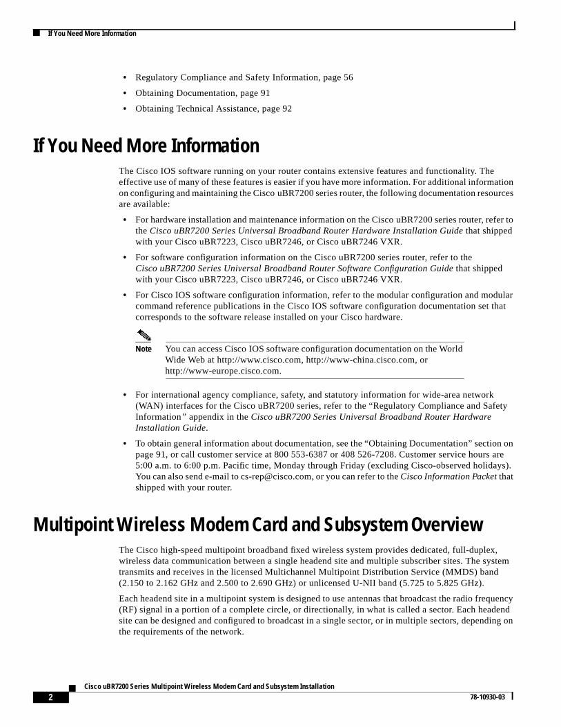
Each sector makes use of a common Cisco uBR7200 series universal broadband router (Cisco uBR7223,Cisco uBR7246, or Cisco uBR7246 VXR), a wireless modem card (see Figure 1), and the subsystemsrequired to support the modem card. Each modem card requires a connection to a power feed panel(see Figure 2), which in turn is connected to two wireless transverters (when diversity is used), and twoantennas (when diversity is used). Diversity, which minimizes the effects of fading, uses two antennasat each site, with each antenna connected to its own transverter. Diversity is strongly recommended formost multipoint system headend sites.
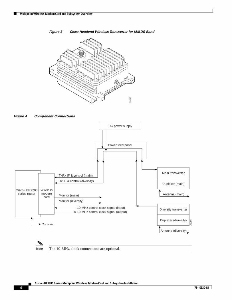
Note The wireless transverter discussed in this document is manufactured and sold byCisco Systems for MMDS links. Transverters for links using other frequency bands mustbe purchased from a third-party vendor. Refer to that vendor’s documentation forinstallation instructions.
Figure 1 Wireless Modem Card
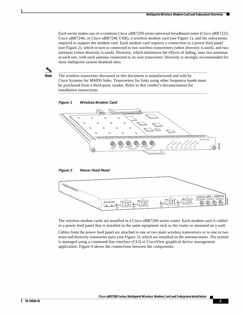
Figure 2 Power Feed Panel
The wireless modem cards are installed in a Cisco uBR7200 series router. Each modem card is cabledto a power feed panel that is installed in the same equipment rack as the router or mounted on a wall.
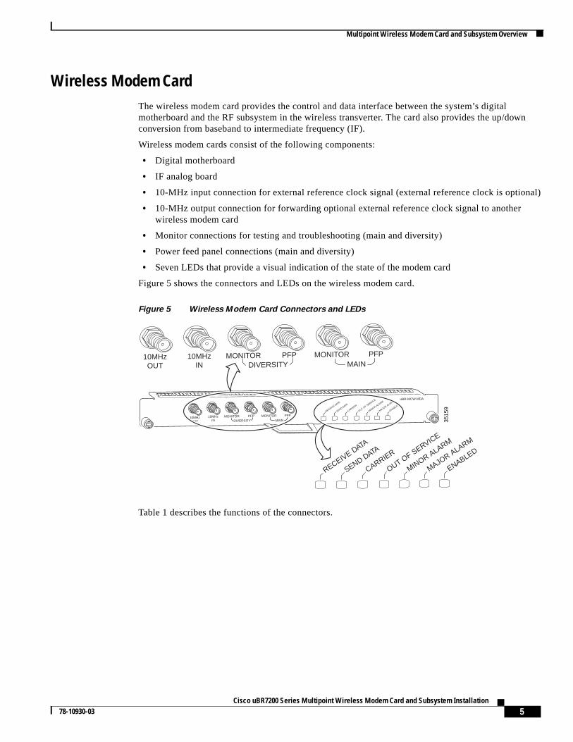
Cables from the power feed panel are attached to one or two main wireless transverters or to one or twomain and diversity transverter pairs (see Figure 3), which are installed on the antenna masts. The systemis managed using a command-line interface (CLI) or CiscoView graphical device managementapplication. Figure 4 shows the connections between the components.
3514
6
10MHzIN
10MHzOUT
MONITORDIVERSITY MAIN
PFP MONITOR
uBR-MCW-MDA
RECEIVE DATA
SEND DATA
CARRIER
OUT OF SERVICE
PFP
MINOR ALARM
MAJOR ALARM
ENABLED
3516
4
CISCO uBR – WMF4APOWER FEED PANEL
OFF1
1 23 4
ONOFF2
PWRON
ONOFF3 ON
OFF4 ON
PWRON
PWRON
PWRON MCW 1 MCW 2 MCW 3 MCW 4
4Cisco uBR7200 Series Multipoint Wireless Modem Card and Subsystem Installation
78-10930-03
Multipoint Wireless Modem Card and Subsystem Overview
Figure 3 Cisco Headend Wireless Transverter for MMDS Band
Figure 4 Component Connections
Note The 10-MHz clock connections are optional.
3507
7
3508
6Cisco uBR7200
series routerWirelessmodem
card
Power feed panel
DC power supply
Main transverter
Duplexer (main)
Antenna (main)
Diversity transverter
Duplexer (diversity)
Antenna (diversity)
TxRx IF & control (main)
Rx IF & control (diversity)
Monitor (main)
Monitor (diversity)
10-MHz control clock signal (input)10-MHz control clock signal (output)
Console
5Cisco uBR7200 Series Multipoint Wireless Modem Card and Subsystem Installation
78-10930-03
Multipoint Wireless Modem Card and Subsystem Overview
Wireless Modem CardThe wireless modem card provides the control and data interface between the system’s digitalmotherboard and the RF subsystem in the wireless transverter. The card also provides the up/downconversion from baseband to intermediate frequency (IF).
Wireless modem cards consist of the following components:
• Digital motherboard
• IF analog board
• 10-MHz input connection for external reference clock signal (external reference clock is optional)
• 10-MHz output connection for forwarding optional external reference clock signal to anotherwireless modem card
• Monitor connections for testing and troubleshooting (main and diversity)
• Power feed panel connections (main and diversity)
• Seven LEDs that provide a visual indication of the state of the modem card
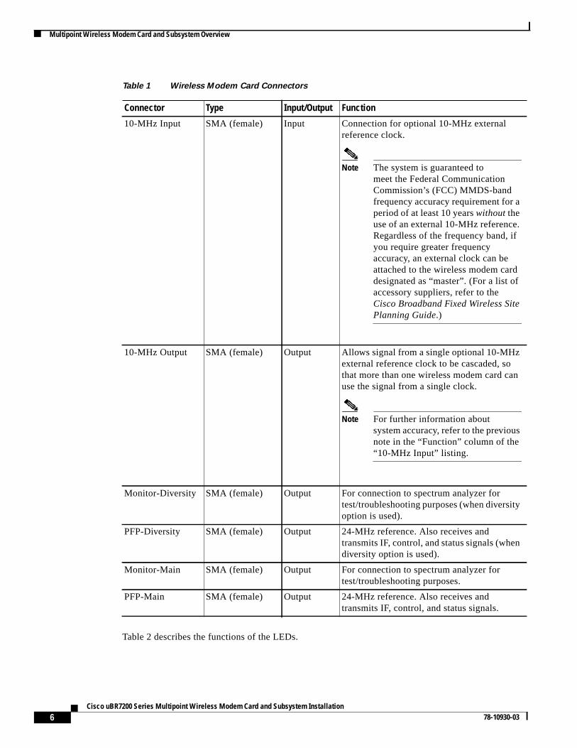
Figure 5 shows the connectors and LEDs on the wireless modem card.
Figure 5 Wireless Modem Card Connectors and LEDs
Table 1 describes the functions of the connectors.
10MHzIN
10MHzOUT
MONITORDIVERSITY MAIN
PFP MONITOR
uBR-MCW-MDA
RECEIVE DATA
SEND DATA
CARRIER
OUT OF SERVICE
PFP
MINOR ALARM
MAJOR ALARM
ENABLED
10MHzIN
10MHzOUT
MONITORDIVERSITY MAIN
PFP MONITOR PFP
3515
9
RECEIVE DATA
SEND DATA
CARRIER
OUT OF SERVICE
MINOR ALARM
MAJOR ALARM
ENABLED
6Cisco uBR7200 Series Multipoint Wireless Modem Card and Subsystem Installation
78-10930-03
Multipoint Wireless Modem Card and Subsystem Overview
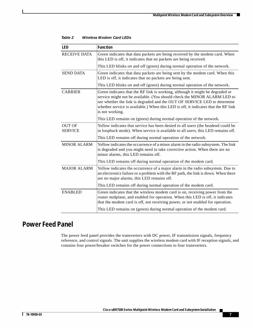
Table 2 describes the functions of the LEDs.
Table 1 Wireless Modem Card Connectors
Connector Type Input/Output Function
10-MHz Input SMA (female) Input Connection for optional 10-MHz externalreference clock.
Note The system is guaranteed tomeet the Federal CommunicationCommission’s (FCC) MMDS-bandfrequency accuracy requirement for aperiod of at least 10 yearswithouttheuse of an external 10-MHz reference.Regardless of the frequency band, ifyou require greater frequencyaccuracy, an external clock can beattached to the wireless modem carddesignated as “master”. (For a list ofaccessory suppliers, refer to theCisco Broadband Fixed Wireless SitePlanning Guide.)
10-MHz Output SMA (female) Output Allows signal from a single optional 10-MHzexternal reference clock to be cascaded, sothat more than one wireless modem card canuse the signal from a single clock.
Note For further information aboutsystem accuracy, refer to the previousnote in the “Function” column of the“10-MHz Input” listing.
Monitor-Diversity SMA (female) Output For connection to spectrum analyzer fortest/troubleshooting purposes (when diversityoption is used).
PFP-Diversity SMA (female) Output 24-MHz reference. Also receives andtransmits IF, control, and status signals (whendiversity option is used).
Monitor-Main SMA (female) Output For connection to spectrum analyzer fortest/troubleshooting purposes.
PFP-Main SMA (female) Output 24-MHz reference. Also receives andtransmits IF, control, and status signals.
7Cisco uBR7200 Series Multipoint Wireless Modem Card and Subsystem Installation
78-10930-03
Multipoint Wireless Modem Card and Subsystem Overview
Power Feed PanelThe power feed panel provides the transverters with DC power, IF transmission signals, frequencyreference, and control signals. The unit supplies the wireless modem card with IF reception signals, andcontains four power/breaker switches for the power connections to four transverters.
Table 2 Wireless Modem Card LEDs
LED Function
RECEIVE DATA Green indicates that data packets are being received by the modem card. Whenthis LED is off, it indicates that no packets are being received.
This LED blinkson and off (green) during normal operation of the network.
SEND DATA Green indicates that data packets are being sent by the modem card. When thisLED is off, it indicates that no packets are being sent.
This LED blinks on and off (green) during normal operation of the network.
CARRIER Green indicates that the RF link is working, although it might be degraded orservice might not be available. (You should check the MINOR ALARM LED tosee whether the link is degraded and the OUT OF SERVICE LED to determinewhether service is available.) When this LED is off, it indicates that the RF linkis not working.
This LED remains on (green) during normal operation of the network.
OUT OFSERVICE
Yellow indicates that service has been denied to all users (the headend could bein loopback mode). When service is available to all users, this LED remains off.
This LED remains off during normal operation of the network.
MINOR ALARM Yellow indicates the occurrence of a minor alarm in the radio subsystem. The linkis degraded and you might need to take corrective action. When there are nominor alarms, this LED remains off.
This LED remains off during normal operation of the modem card.
MAJOR ALARM Yellow indicates the occurrence of a major alarm in the radio subsystem. Due toan electronics failure or a problem with the RF path, the link is down. When thereare no major alarms, this LED remains off.
This LED remains off during normal operation of the modem card.
ENABLED Green indicates that the wireless modem card is on, receiving power from therouter midplane, and enabled for operation. When this LED is off, it indicatesthat the modem card is off, not receiving power, or not enabled for operation.
This LED remains on (green) during normal operation of the modem card.
8Cisco uBR7200 Series Multipoint Wireless Modem Card and Subsystem Installation
78-10930-03
Multipoint Wireless Modem Card and Subsystem Overview
The power feed panel consists of the following components:
• Front panel:
– Four power/breaker switches with power on LED indicators
– Four female SMA connectors for wireless modem card cables
• Rear panel:
– Two DC power supply terminal blocks
– Four female N-type connectors with power on LED indicators for transverter cables
– One ground lug connection
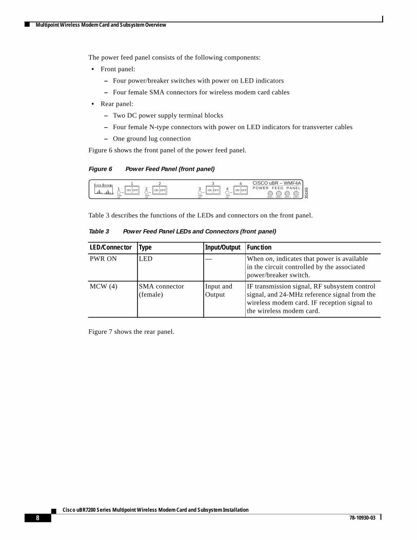
Figure 6 shows the front panel of the power feed panel.
Figure 6 Power Feed Panel (front panel)
Table 3 describes the functions of the LEDs and connectors on the front panel.
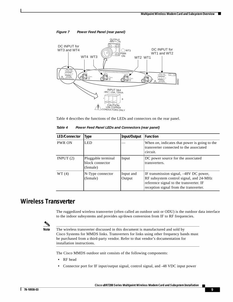
Figure 7 shows the rear panel.
3516
5
CISCO uBR – WMF4APOWER FEED PANEL1
PWRON
ON OFF
PWRON
PWRON
PWRON MCW 1 MCW 2 MCW 3 MCW 4
12
23
34
4
ON OFF ON OFF ON OFF
Table 3 Power Feed Panel LEDs and Connectors (front panel)
LED/Connector Type Input/Output Function
PWR ON LED — Whenon, indicates that power is availablein the circuit controlled by the associatedpower/breaker switch.
MCW (4) SMA connector(female)
Input andOutput
IF transmission signal, RF subsystem controlsignal, and 24-MHz reference signal from thewireless modem card. IF reception signal tothe wireless modem card.
9Cisco uBR7200 Series Multipoint Wireless Modem Card and Subsystem Installation
78-10930-03
Multipoint Wireless Modem Card and Subsystem Overview
Figure 7 Power Feed Panel (rear panel)
Table 4 describes the functions of the LEDs and connectors on the rear panel.
Wireless TransverterThe ruggedized wireless transverter (often called an outdoor unit or ODU) is the outdoor data interfaceto the indoor subsystems and provides up/down conversion from IF to RF frequencies.
Note The wireless transverter discussed in this document is manufactured and sold byCisco Systems for MMDS links. Transverters for links using other frequency bands mustbe purchased from a third-party vendor. Refer to that vendor’s documentation forinstallation instructions.
The Cisco MMDS outdoor unit consists of the following components:
• RF head
• Connector port for IF input/output signal, control signal, and -48 VDC input power
OUTPUT-48V ,7A OUTPUT
-48V ,7A OUTPUT-48V ,7A OUTPUT
-48V ,7A
This equipment has a connection between the earthed conductor of thedc supply circuit and the earthing conductor. See installation instructions.
CAUTION:
OUTPUT-48V ,7A
WT3PWRON
WT4PWRON
WT4 WT3
DC INPUT forWT3 and WT4 DC INPUT for
WT1 and WT2WT1WT2
3606
2
CAUTIONUSE COPPER
CONDUCTORS ONLY
INPUT 3&4-48V 15A, 720VA
- +
CAUTIONUSE COPPER
CONDUCTORS ONLY
INPUT 1&2-48V 15A, 720VA
- +CAUTION
USE COPPERCONDUCTORS ONLY
INPUT 3&4-48V 15A, 720VA
- +
WT3PWRON
WT2PWRON
WT1PWRON
Table 4 Power Feed Panel LEDs and Connectors (rear panel)
LED/Connector Type Input/Output Function
PWR ON LED — Whenon, indicates that power is going to thetransverter connected to the associatedcircuit.
INPUT (2) Pluggable terminalblock connector(female)
Input DC power source for the associatedtransverters.
WT (4) N-Type connector(female)
Input andOutput
IF transmission signal, –48V DC power,RF subsystem control signal, and 24-MHzreference signal to the transverter. IFreception signal from the transverter.
10Cisco uBR7200 Series Multipoint Wireless Modem Card and Subsystem Installation
78-10930-03
Field-Replaceable Units
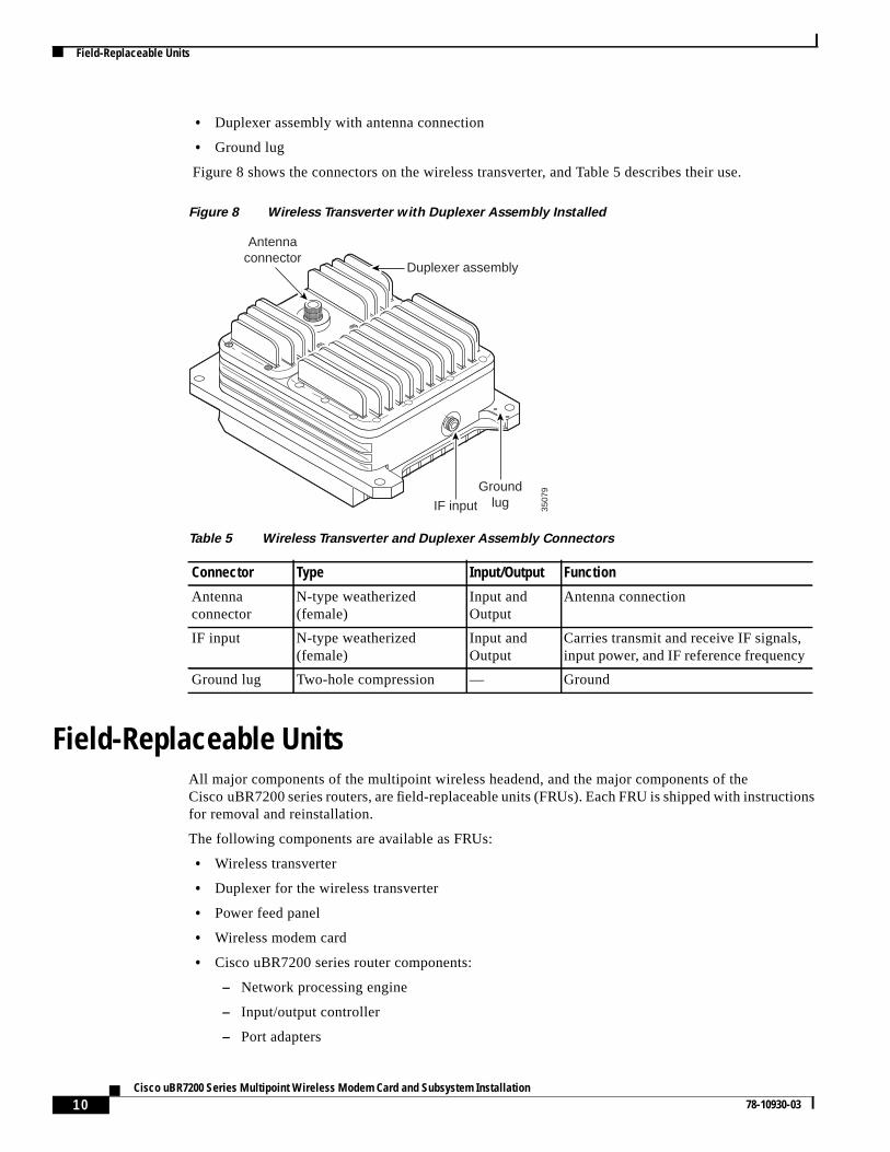
• Duplexer assembly with antenna connection
• Ground lug
Figure 8 shows the connectors on the wireless transverter, and Table 5 describes their use.
Figure 8 Wireless Transverter with Duplexer Assembly Installed
Field-Replaceable UnitsAll major components of the multipoint wireless headend, and the major components of theCisco uBR7200 series routers, are field-replaceable units (FRUs). Each FRU is shipped with instructionsfor removal and reinstallation.
The following components are available as FRUs:
• Wireless transverter
• Duplexer for the wireless transverter
• Power feed panel
• Wireless modem card
• Cisco uBR7200 series router components:
– Network processing engine
– Input/output controller
– Port adapters
Table 5 Wireless Transverter and Duplexer Assembly Connectors
Connector Type Input/Output Function
Antennaconnector
N-type weatherized(female)
Input andOutput
Antenna connection
IF input N-type weatherized(female)
Input andOutput
Carries transmit and receive IF signals,input power, and IF reference frequency
Ground lug Two-hole compression — Ground
3507
9
IF input
Groundlug
Antennaconnector
Duplexer assembly

11Cisco uBR7200 Series Multipoint Wireless Modem Card and Subsystem Installation
78-10930-03
Installation Prerequisites
– Power supplies
– Fan tray
– Chassis
– Subchassis and midplane
– Flash memory cards
– Rack mount and cable-management kit
For ordering information, contact a Cisco customer service representative. See the “Cisco.com” sectionon page 93 for more information.
Installation PrerequisitesThis section provides a list of parts and tools that you need to remove and replace a multipoint wirelessmodem card in the Cisco uBR7200 series router, install the power feed panel in an equipment rack or onthe wall, and install the wireless transverter at the antenna site. This section also includes safety andESD-prevention guidelines to help you avoid injury to yourself and damage to the equipment.
Parts and ToolsThe following sections describe the parts and tools required to install each of the components.
Wireless Modem Card
You need the following tools and parts to remove and replace a multipoint headend wireless modem card.If you need additional equipment, contact a service representative for ordering information. (See the“Cisco.com” section on page 93.)
• New wireless modem card
• Number 2 Phillips screwdriver
• Torque wrench for SMA connectors
• Your own ESD-prevention equipment or the disposable grounding wrist strap included with allupgrade kits, FRUs, and spares
• Antistatic mat or surface
• Static shielding bag
Power Feed Panel
You need the following tools and parts to install the multipoint headend power feed panel in anequipment rack or on a wall. If you need additional equipment, contact a service representative forordering information. (See the “Cisco.com” section on page 93.)
• Power feed panel
• Number 2 Phillips screwdriver
• Torque driver with number 2 Phillips bit
• Torque wrench for N-type connectors
12Cisco uBR7200 Series Multipoint Wireless Modem Card and Subsystem Installation
78-10930-03
Installation Prerequisites
• Bracket kit (provided)
• Rack or wall mount screws
• 1/8-inch flat-blade screwdriver
• 5/8-inch open-ended wrench
• Torque wrench for SMA connectors
• 50-ohm coaxial cables with N-type (male) connectors for IF interface
• –48V DC power supply
• Two removable wiring blocks
• Ground lug (provided in grounding kit)
Wireless Transverter
You need the following tools and parts to install the Cisco MMDS multipoint headend wirelesstransverter. If you need additional equipment, contact a service representative for ordering information.(See the “Cisco.com” section on page 93.)
• Wireless transverter
• Duplexer assembly
• Number 2 Phillips screwdriver
• Torque driver with number 2 Phillips bit
• 9/16-inch open-ended wrench
• 13/16-inch open-ended wrench
• Open-end adjustable wrench
• Torque wrench for N-type connectors
• Weatherproofing cable wrap
• Antenna tools (refer to antenna manufacturer’s instructions)
• Mounting kit (provided)
• 50-ohm coaxial cable with N-type (male) connectors to cable the wireless transverter to the antenna
• Cable-making tools
• Lightning surge suppressor for cable (from wireless transverter to power feed panel) at point wherecable enters building that meets all local and national electrical codes
• Ground lug (provided in grounding kit)
Note Some N-type connectors require specific tools. Obtain this information fromyour cable vendor.
Software and Hardware RequirementsFor this installation and configuration, you need a configured Cisco uBR7200 series router runningCisco IOS Release 12.1(3)XQ1 or later.
13Cisco uBR7200 Series Multipoint Wireless Modem Card and Subsystem Installation
78-10930-03
Installation Prerequisites
Safety GuidelinesFollowing are safety guidelines that you should follow when working with any equipment that connectsto electrical power or telephone wiring.
Safety Warnings
Warning This warning symbol means danger. You are in a situation that could cause bodilyinjury. Before you work on any equipment, be aware of the hazards involved withelectrical circuitry and be familiar with standard practices for preventing accidents.To see translations of the warnings that appear in this publication, refer to the"Regulatory Compliance and Safety Information" section in this document.
Waarschuwing Dit waarschuwingssymbool betekent gevaar. U verkeert in een situatie die lichamelijkletsel kan veroorzaken. Voordat u aan enige apparatuur gaat werken, dient u zichbewust te zijn van de bij elektrische schakelingen betrokken risico's en dient u op dehoogte te zijn van standaard maatregelen om ongelukken te voorkomen. Voorvertalingen van de waarschuwingen die in deze publicatie verschijnen, kunt u hetgedeelte Regulatory Compliance and Safety Information (Informatie over naleving vanveiligheids- en andere voorschriften) raadplegen in dit document.
Varoitus Tämä varoitusmerkki merkitsee vaaraa. Olet tilanteessa, joka voi johtaaruumiinvammaan. Ennen kuin työskentelet minkään laitteiston parissa, ota selvääsähkökytkentöihin liittyvistä vaaroista ja tavanomaisista onnettomuuksienehkäisykeinoista. Tässä julkaisussa esiintyvien varoitusten käännökset löydät tämänasiakirjan Regulatory Compliance and Safety Information -osasta (määräystennoudattaminen ja tietoa turvallisuudesta).
Attention Ce symbole d'avertissement indique un danger. Vous vous trouvez dans une situationpouvant causer des blessures ou des dommages corporels. Avant de travailler sur unéquipement, soyez conscient des dangers posés par les circuits électriques etfamiliarisez-vous avec les procédures couramment utilisées pour éviter les accidents.Pour prendre connaissance des traductions d’avertissements figurant dans cettepublication, consultez la section Regulatory Compliance and Safety Information(Conformité aux règlements et consignes de sécurité) de ce document.
Warnung Dieses Warnsymbol bedeutet Gefahr. Sie befinden sich in einer Situation, die zu einerKörperverletzung führen könnte. Bevor Sie mit der Arbeit an irgendeinem Gerätbeginnen, seien Sie sich der mit elektrischen Stromkreisen verbundenen Gefahrenund der Standardpraktiken zur Vermeidung von Unfällen bewußt. Übersetzungen derin dieser Veröffentlichung enthaltenen Warnhinweise finden Sie im Abschnitt"Regulatory Compliance and Safety Information" (Informationen zu behördlichenVorschriften und Sicherheit) in diesem Dokument.
14Cisco uBR7200 Series Multipoint Wireless Modem Card and Subsystem Installation
78-10930-03
Installation Prerequisites
Note This installationmust be made in accordance with all local and national regulations.Special attentionmust be made to Articles 800, 810, and 820 of the US National ElectricCode, Sections 54 and 60 of the Canadian electric code, and the equivalent sections of allother local and national regulations that address TV, radio, and/or CATV wiring for thecoaxial cable.
Warning This product requires short-circuit (overcurrent) protection to be provided as part of thebuilding installation. Install only in accordance with national and local wiringregulations. To see translations of the warnings that appear in this publication, refer tothe "Regulatory Compliance and Safety Information" section in this document.
Avvertenza Questo simbolo di avvertenza indica un pericolo. La situazione potrebbe causareinfortuni alle persone. Prima di lavorare su qualsiasi apparecchiatura, occorreconoscere i pericoli relativi ai circuiti elettrici ed essere al corrente delle pratichestandard per la prevenzione di incidenti. La traduzione delle avvertenze riportate inquesta pubblicazione si trova nella documento Regulatory Compliance and SafetyInformation (Conformità alle norme e informazioni sulla sicurezza) nel presentedocumento.
Advarsel Dette varselsymbolet betyr fare. Du befinner deg i en situasjon som kan føre tilpersonskade. Før du utfører arbeid på utstyr, må du vare oppmerksom på defaremomentene som elektriske kretser innebærer, samt gjøre deg kjent med vanligpraksis når det gjelder å unngå ulykker. Hvis du vil se oversettelser av de advarslenesom finnes i denne publikasjonen, kan du se i avsnittet Regulatory Compliance andSafety Information (Overholdelse av forskrifter og sikkerhetsinformasjon) i dettedokumentet.
Aviso Este símbolo de aviso indica perigo. Encontra-se numa situação que lhe poderá causardanos físicos. Antes de começar a trabalhar com qualquer equipamento,familiarize-se com os perigos relacionados com circuitos eléctricos, e com quaisquerpráticas comuns que possam prevenir possíveis acidentes. Para ver as traduções dosavisos que constam desta publicação, consulte a secção Regulatory Compliance andSafety Information (Informação de Segurança e Disposições Reguladoras) nestedocumento.
¡Advertencia! Este símbolo de aviso significa peligro. Existe riesgo para su integridad física. Antesde manipular cualquier equipo, considerar los riesgos que entraña la corrienteeléctrica y familiarizarse con los procedimientos estándar de prevención deaccidentes. Para ver una traducción de las advertencias que aparecen en estapublicación, consultar la sección titulada Regulatory Compliance and SafetyInformation (Información sobre seguridad y conformidad con las disposicionesreglamentarias) que aparece en este documento.
Varning! Denna varningssymbol signalerar fara. Du befinner dig i en situation som kan leda tillpersonskada. Innan du utför arbete på någon utrustning måste du vara medveten omfarorna med elkretsar och känna till vanligt förfarande för att förebygga skador. Om duvill se översättningar av de varningar som visas i denna publikation, se avsnittet"Efterrättelse av föreskrifter och säkerhetsinformation" i detta dokument.
15Cisco uBR7200 Series Multipoint Wireless Modem Card and Subsystem Installation
78-10930-03
Installation Prerequisites
Warning A readily accessible two-poled disconnect device must be incorporated in the fixedwiring. To see translations of the warnings that appear in this publication, refer to the"Regulatory Compliance and Safety Information" section in this document.
Electrical Equipment Guidelines
Follow these basic guidelines when working with any electrical equipment:
• Before beginning any procedures requiring access to the chassis interior, locate the emergencypower-off switch for the room in which you are working.
• Disconnect all power and external cables before moving a chassis.
• Do not work alone if potentially hazardous conditions exist.
• Never assume that power has been disconnected from a circuit; always check.
• Do not perform any action that creates a potential hazard to people or makes the equipment unsafe.
• Never install equipment that appears damaged.
• Carefully examine your work area for possible hazards such as moist floors, ungrounded powerextension cables, and missing safety grounds.
• Never install equipment that appears damaged.
Preventing Electrostatic Discharge Damage
Electrostatic discharge (ESD) damages equipment and impairs electrical circuitry. ESD occurs whenprinted circuit boards are improperly handled and results in complete or intermittent failures.
The network processing engine, I/O controller, port adapters, and wireless modem cards consist of aprinted circuit board that is fixed in a metal carrier. Electromagnetic interference (EMI) shielding,connectors, and a handle are integral components of the carrier. Handle the network processing engine,I/O controller, port adapters, and wireless modem cards by their metal carriers and handles; never touchthe printed circuit board when handling any of these components.
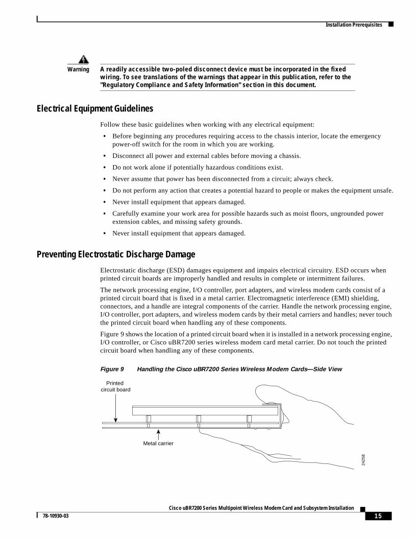
Figure 9 shows the location of a printed circuit board when it is installed in a network processing engine,I/O controller, or Cisco uBR7200 series wireless modem card metal carrier. Do not touch the printedcircuit board when handling any of these components.
Figure 9 Handling the Cisco uBR7200 Series Wireless Modem Cards—Side View
Metal carrier
Printed circuit board
2425
8
16Cisco uBR7200 Series Multipoint Wireless Modem Card and Subsystem Installation
78-10930-03
Installation Prerequisites
Although the metal carrier helps to protect the printed circuit boards from ESD, wear a preventiveantistatic strap whenever handling the network processing engine, I/O controller, port adapters, orwireless modem cards. Ensure that the strap makes good skin contact and connect the strap’s clip to anunpainted chassis surface to safely channel unwanted ESD voltages.
If no wrist strap is available, ground yourself by touching the metal part of the chassis.
Caution Be sure to tighten the captive installation screws on the network processing engine, the I/Ocontroller, and the wireless modem cards (use a number 2 Phillips screwdriver). Thesescrews prevent accidental removal, provide proper grounding for the router, and help toensure that the network processing engine, I/O controller, and modem cards are properlyseated in the router midplane.
Follow these guidelines to prevent ESD damage:
• Always use an ESD-preventive wrist strap or ankle strap when installing or replacing the networkprocessing engine, I/O controller, port adapters, or modem cards. Ensure that the ESD-preventivestrap makes contact with your skin.
• Handle the network processing engine, I/O controller, port adapters, or modem cards by their metalcarrier edges and handles only; avoid touching the printed circuit board components or anyconnector pins.
• When removing the network processing engine, I/O controller, port adapters, or wireless modemcards, place them on an antistatic surface with the printed circuit board components facing upward,or in a static shielding bag. If you are returning an I/O controller, network processing engine, portadapter, or modem card to the factory, immediately place the product in a static shielding bag.
Caution Periodically check the resistance value of the antistatic strap. The measurement should bewithin the range of 1 through 10 megohm.
Warning Do not work on the system or connect or disconnect cables during periods of lightningactivity. To see translations of the warnings that appear in this publication, refer to the"Regulatory Compliance and Safety Information" section in this document.
Warning Read the installation instructions before you connect the system to its power source. Tosee translations of the warnings that appear in this publication, refer to the "RegulatoryCompliance and Safety Information" section in this document.
Warning Before working on equipment that is connected to power lines, remove jewelry(including rings, necklaces, and watches). Metal objects will heat up when connectedto power and ground and can cause serious burns or weld the metal object to theterminals. To see translations of the warnings that appear in this publication, refer to the"Regulatory Compliance and Safety Information" section in this document.
17Cisco uBR7200 Series Multipoint Wireless Modem Card and Subsystem Installation
78-10930-03
Removing and Installing the Wireless Modem Card
Warning Care must be given to connecting units to the supply circuit so that wiring is notoverloaded. To see translations of the warnings that appear in this publication, refer tothe "Regulatory Compliance and Safety Information" section in this document.
Warning This equipment is to be installed and maintained by service personnel only as defined byAS/NZS 3260.
Warning Only trained and qualified personnel should be allowed to install, replace, or service thisequipment. To see translations of the warnings that appear in this publication, refer tothe "Regulatory Compliance and Safety Information" section in this document.
Product Disposal
Warning Ultimate disposal of this product should be handled according to all national laws andregulations. To see translations of the warnings that appear in this publication, refer tothe "Regulatory Compliance and Safety Information" section in this document.
Compliance with U.S. Export Laws and Regulations Regarding EncryptionThis product performs encryption (in the baseline privacy feature) and is regulated for export by theU.S. Government. Following is specific information regarding compliance with U.S. export laws andregulations for encryption products:
• This product isnot authorized for use by persons located outside the United States and Canada thatdo not have export license authority from the U.S. Government.
• This product maynot be exported outside the U.S. and Canada either by physical or electronicmeans without theprior written approval of the U.S. Government.
• Persons outside the U.S. and Canada maynot reexport, resell, or transfer this product by eitherphysical or electronic means withoutprior written approval of the U.S. Government.
Removing and Installing the Wireless Modem CardThe following sections explain how to:
• Remove and replace a previously installed multipoint headend wireless modem card in aCisco uBR7200 series router (see the “Removing the Wireless Modem Card” section on page 18).
• Install a multipoint headend wireless modem card in a Cisco uBR7200 series router (see the“Installing or Replacing the Wireless Modem Card” section on page 18).
18Cisco uBR7200 Series Multipoint Wireless Modem Card and Subsystem Installation
78-10930-03
Removing and Installing the Wireless Modem Card
Removing the Wireless Modem CardTo remove the wireless modem card from a Cisco uBR7200 series router, complete the following steps:
Step 1 Attach an ESD-preventive wrist strap between you and an unfinished chassis surface.
Caution To avoid disruption of normal router operations, donot disconnect the cables until themodem card is shut down using the proper commands.
Step 2 Disconnect all cables from the front of the modem card.
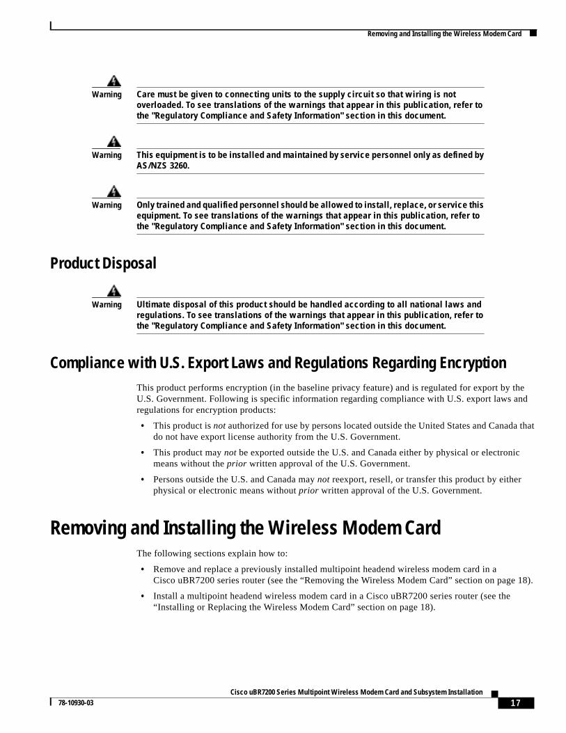
Step 3 Unscrew the captive installation screws on the front of the wireless modem card (see Figure 10).
Figure 10 Captive Installation Screws
Step 4 Grasp the handle on the wireless modem card and carefully pull the modem card from the midplane. Ifyou are removing a blank modem card, pull the blank modem card all the way out of the chassis slot.
Caution Always handle the wireless modem card by the metal carrier and handle; never touch themodem card components or connector pins (see Figure 11).
Step 5 Place the modem card on an antistatic surface with its components facing upward, or in a staticshielding bag. If you are returning the modem card to the factory, immediately place the card in a staticshielding bag.
This completes the procedure for removing a headend wireless modem card from the Cisco uBR7200series router.
Installing or Replacing the Wireless Modem CardTo install or replace the wireless modem card in the Cisco uBR7200 series router, complete thefollowing steps:
Step 1 Attach an ESD-preventive wrist strap between you and an unfinished chassis surface.
Step 2 Grasp the modem card by its metal carrier and position the modem card as shown in Figure 11.
3516
0
Captive installation screw
Captive installation screw
10MHzIN
10MHzOUT
MONITORDIVERSITY MAIN
PFP MONITOR
uBR-MCW-MDA
RECEIVE DATA
SEND DATA
CARRIER
OUT OF SERVICE
PFP
MINOR ALARM
MAJOR ALARM
ENABLED
19Cisco uBR7200 Series Multipoint Wireless Modem Card and Subsystem Installation
78-10930-03
Removing and Installing the Wireless Modem Card
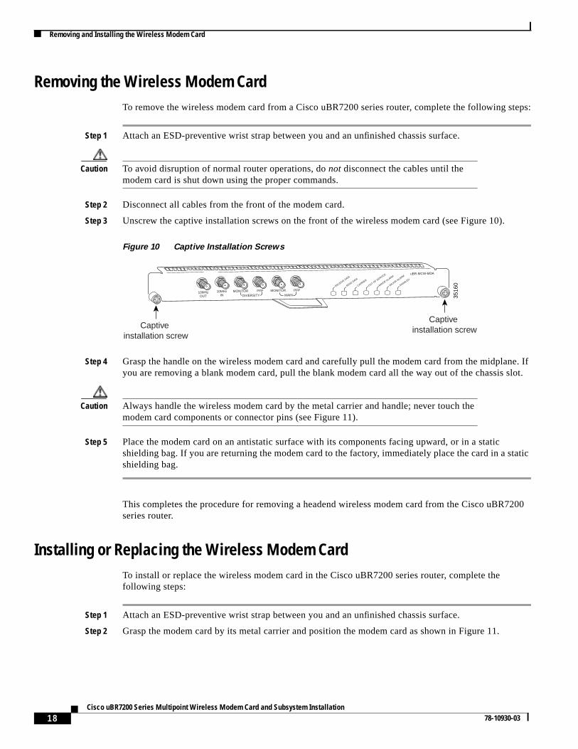
Figure 11 Handling the Cisco uBR7200 Series Wireless Modem Cards—Side View
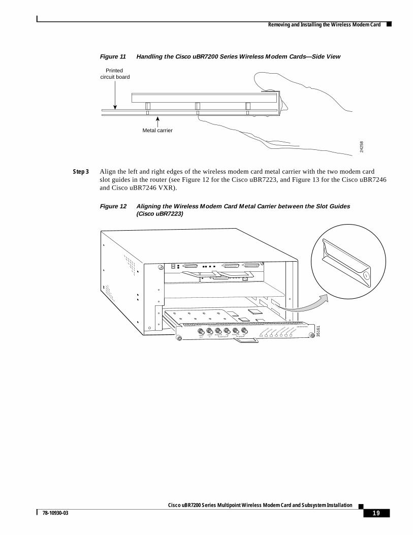
Step 3 Align the left and right edges of the wireless modem card metal carrier with the two modem cardslot guides in the router (see Figure 12 for the Cisco uBR7223, and Figure 13 for the Cisco uBR7246and Cisco uBR7246 VXR).
Figure 12 Aligning the Wireless Modem Card Metal Carrier between the Slot Guides
(Cisco uBR7223)
Metal carrier
Printed circuit board
2425
8
3516
1
DIVERSITY
CONTROL
10MHzIN
MONITORDIVERSITY MAIN
PFP MONITOR
uBR-MCW-PDA
CARRIER
OUT OF SERVICE
MINOR ALARM
MAJOR ALARM
PFP
MAINENABLED
10MHzIN
10MHzOUT
MONITORDIVERSITY MAIN
PFP MONITOR
uBR-MCW-MDA
RECEIVE DATA
SEND DATA
CARRIER
OUT OF SERVICE
PFP
MINOR ALARM
MAJOR ALARM
ENABLED
20Cisco uBR7200 Series Multipoint Wireless Modem Card and Subsystem Installation
78-10930-03
Removing and Installing the Wireless Modem Card
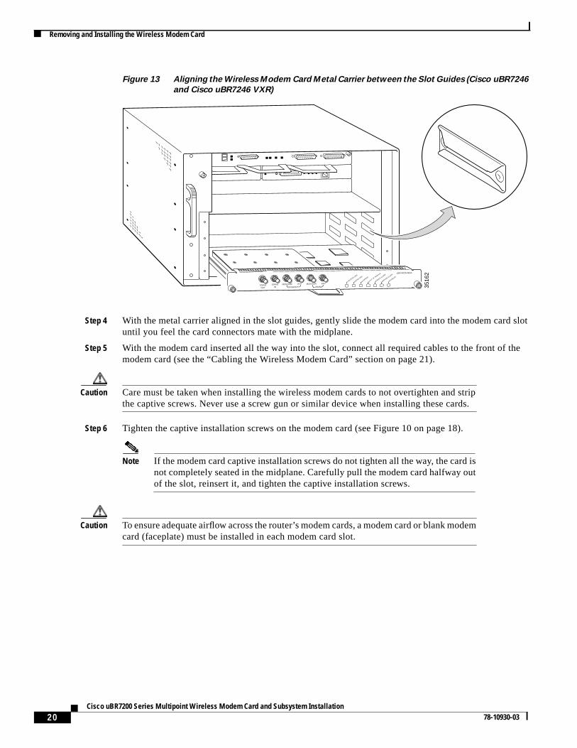
Figure 13 Aligning the Wireless Modem Card Metal Carrier between the Slot Guides (Cisco uBR7246
and Cisco uBR7246 VXR)
Step 4 With the metal carrier aligned in the slot guides, gently slide the modem card into the modem card slotuntil you feel the card connectors mate with the midplane.
Step 5 With the modem card inserted all the way into the slot, connect all required cables to the front of themodem card (see the “Cabling the Wireless Modem Card” section on page 21).
Caution Care must be taken when installing the wireless modem cards to not overtighten and stripthe captive screws. Never use a screw gun or similar device when installing these cards.
Step 6 Tighten the captive installation screws on the modem card (see Figure 10 on page 18).
Note If the modem card captive installation screws do not tighten all the way, the card isnot completely seated in the midplane. Carefully pull the modem card halfway outof the slot, reinsert it, and tighten the captive installation screws.
Caution To ensure adequate airflow across the router’s modem cards, a modem card or blank modemcard (faceplate) must be installed in each modem card slot.
3516
2
DIVERSITY
CONTROL
10MHzIN
MONITORDIVERSITY MAIN
PFP MONITOR
uBR-MCW-PDA
CARRIER
OUT OF SERVICE
MINOR ALARM
MAJOR ALARM
PFP
MAINENABLED
10MHzIN
10MHzOUT
MONITORDIVERSITY MAIN
PFP MONITOR
uBR-MCW-MDA
RECEIVE DATA
SEND DATA
CARRIER
OUT OF SERVICE
PFP
MINOR ALARM
MAJOR ALARM
ENABLED
21Cisco uBR7200 Series Multipoint Wireless Modem Card and Subsystem Installation
78-10930-03
Removing and Installing the Wireless Modem Card
Warning Blank faceplates and cover panels serve three important functions: they preventexposure to hazardous voltages and currents inside the chassis; they containelectromagnetic interference (EMI) that might disrupt other equipment; and they directthe flow of cooling air through the chassis. Do not operate the system unless all cards,faceplates, front covers, and rear covers are in place. To see translations of the warningsthat appear in this publication, refer to the "Regulatory Compliance and SafetyInformation" section in this document.
This completes the procedure for installing a headend wireless modem card in the Cisco uBR7200 seriesrouter.
Cabling the Wireless Modem CardTo attach the cables to the wireless modem card, complete theapplicable procedures that follow:
1. Attaching the IF Cables, page 21
2. Attaching the Monitor Cables (Optional), page 22
3. Cabling the 10-MHz Clock (Optional), page 22
Attaching the IF Cables
To attach the IF cables to the wireless modem card, complete the following steps:
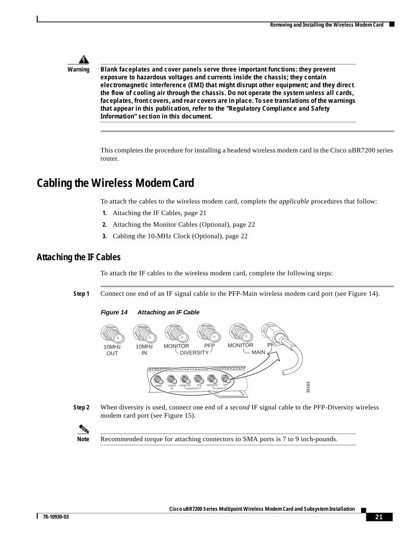
Step 1 Connect one end of an IF signal cable to the PFP-Main wireless modem card port (see Figure 14).
Figure 14 Attaching an IF Cable
Step 2 When diversity is used, connect one end of asecond IF signal cable to the PFP-Diversity wirelessmodem card port (see Figure 15).
Note Recommended torque for attaching connectors to SMA ports is 7 to 9 inch-pounds.
3516
3
10MHzIN
10MHzOUT
MONITORDIVERSITY MAIN
PFP MONITOR PFP
10MHzIN
10MHzOUT
MONITORDIVERSITY MAIN
PFP MONITOR PFP
22Cisco uBR7200 Series Multipoint Wireless Modem Card and Subsystem Installation
78-10930-03
Removing and Installing the Wireless Modem Card
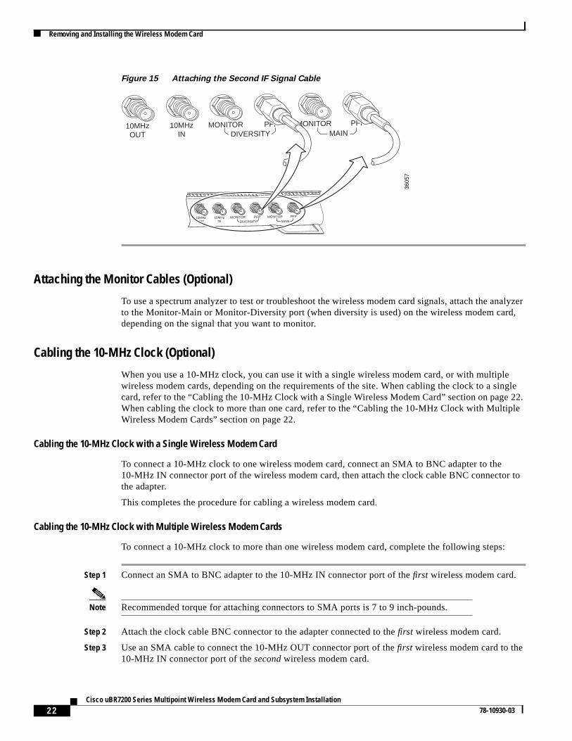
Figure 15 Attaching the Second IF Signal Cable
Attaching the Monitor Cables (Optional)
To use a spectrum analyzer to test or troubleshoot the wireless modem card signals, attach the analyzerto the Monitor-Main or Monitor-Diversity port (when diversity is used) on the wireless modem card,depending on the signal that you want to monitor.
Cabling the 10-MHz Clock (Optional)
When you use a 10-MHz clock, you can use it with a single wireless modem card, or with multiplewireless modem cards, depending on the requirements of the site. When cabling the clock to a singlecard, refer to the “Cabling the 10-MHz Clock with a Single Wireless Modem Card” section on page 22.When cabling the clock to more than one card, refer to the “Cabling the 10-MHz Clock with MultipleWireless Modem Cards” section on page 22.
Cabling the 10-MHz Clock with a Single Wireless Modem Card
To connect a 10-MHz clock to one wireless modem card, connect an SMA to BNC adapter to the10-MHz IN connector port of the wireless modem card, then attach the clock cable BNC connector tothe adapter.
This completes the procedure for cabling a wireless modem card.
Cabling the 10-MHz Clock with Multiple Wireless Modem Cards
To connect a 10-MHz clock to more than one wireless modem card, complete the following steps:
Step 1 Connect an SMA to BNC adapter to the 10-MHz IN connector port of thefirst wireless modem card.
Note Recommended torque for attaching connectors to SMA ports is 7 to 9 inch-pounds.
Step 2 Attach the clock cable BNC connector to the adapter connected to thefirst wireless modem card.
Step 3 Use an SMA cable to connect the 10-MHz OUT connector port of thefirst wireless modem card to the10-MHz IN connector port of thesecond wireless modem card.
3605
7
10MHzIN
10MHzOUT
MONITORDIVERSITY MAIN
PFP MONITOR PFP
10MHzIN
10MHzOUT
MONITORDIVERSITY MAIN
PFP MONITOR PFP
23Cisco uBR7200 Series Multipoint Wireless Modem Card and Subsystem Installation
78-10930-03
Installing the Power Feed Panel
Step 4 Continue this “cascading” procedure to any other wireless modem cards that must share the signal fromthe 10-MHz clock. Always connect the cablefrom the 10-MHz OUT connector port of thepreviouswireless modem card to the 10-MHz IN connector port of thenext wireless modem card.
This completes the procedure for cabling the wireless modem card.
Installing the Power Feed PanelTo install the power feed panel, complete the following procedures:
1. Mounting the Power Feed Panel, page 23
2. Attaching the Ground Lug, page 26
3. Wiring the DC Power, page 27
4. Cabling the Power Feed Panel, page 31
Mounting the Power Feed PanelThe multipoint headend power feed panel can be mounted in a 19-inch rack or mounted on a wall.Depending on your site requirements, the unit can be colocated with the router or placed at an indoorlocation near the bulkhead opening leading to the outdoor wireless transverter.
Note When rack-mounting the headend power feed panel, allow at least one rack unit spacebetween the Cisco uBR7200 series router and the power feed panel or between multiplepower feed panels.
Rack-Mounting the Power Feed Panel
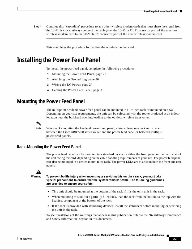
The power feed panel can be mounted in a standard rack with either the front panel or the rear panel ofthe unit facing forward, depending on the cable handling requirements of your site. The power feed panelcan also be mounted in a center-mount telco rack. The power LEDs are visible on both the front and rearpanels.
Warning To prevent bodily injury when mounting or servicing this unit in a rack, you must takespecial precautions to ensure that the system remains stable. The following guidelinesare provided to ensure your safety:
• This unit should be mounted at the bottom of the rack if it is the only unit in the rack.
• When mounting this unit in a partially filled rack, load the rack from the bottom to the top with theheaviest component at the bottom of the rack.
• If the rack is provided with stabilizing devices, install the stabilizers before mounting or servicingthe unit in the rack.
To see translations of the warnings that appear in this publication, refer to the “Regulatory Complianceand Safety Information” section in this document.
24Cisco uBR7200 Series Multipoint Wireless Modem Card and Subsystem Installation
78-10930-03
Installing the Power Feed Panel
Warning This unit is intended for installation in restricted access areas. A restricted access areais where access can only be gained by service personnel through the use of a specialtool, lock and key, or other means of security, and is controlled by the authorityresponsible for the location. To see translations of the warnings that appear in thispublication, refer to the "Regulatory Compliance and Safety Information" section in thisdocument.
Attaching the Brackets
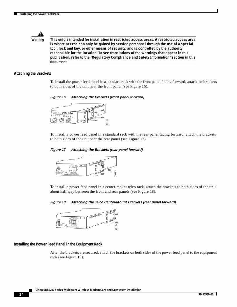
To install the power feed panel in a standard rack with the front panel facing forward, attach the bracketsto both sides of the unit near the front panel (see Figure 16).
Figure 16 Attaching the Brackets (front panel forward)
To install a power feed panel in a standard rack with the rear panel facing forward, attach the bracketsto both sides of the unit near the rear panel (see Figure 17).
Figure 17 Attaching the Brackets (rear panel forward)
To install a power feed panel in a center-mount telco rack, attach the brackets to both sides of the unitabout half way between the front and rear panels (see Figure 18).
Figure 18 Attaching the Telco Center-Mount Brackets (rear panel forward)
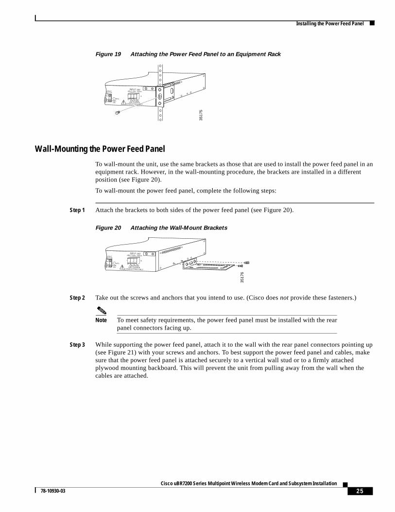
Installing the Power Feed Panel in the Equipment Rack
After the brackets are secured, attach the brackets on both sides of the power feed panel to the equipmentrack (see Figure 19).
3516
6
uBR – WMF4AF E E D P A N E L
MCW 2 MCW 3 MCW 4
3517
3
OUTPUT-48V ,7A
PWRON
WT1CAUTION
USE COPPERCONDUCTORS ONLY
INPUT 1&2-48V 15A, 720VA
- +
OUTPUT-48V ,7A
3517
4CAUTIONUSE COPPER
CONDUCTORS ONLY
-48V 15A, 720VA
- +
PWRON
WT1
INPUT 1&2
25Cisco uBR7200 Series Multipoint Wireless Modem Card and Subsystem Installation
78-10930-03
Installing the Power Feed Panel
Figure 19 Attaching the Power Feed Panel to an Equipment Rack
Wall-Mounting the Power Feed Panel
To wall-mount the unit, use the same brackets as those that are used to install the power feed panel in anequipment rack. However, in the wall-mounting procedure, the brackets are installed in a differentposition (see Figure 20).
To wall-mount the power feed panel, complete the following steps:
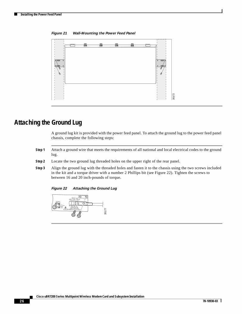
Step 1 Attach the brackets to both sides of the power feed panel (see Figure 20).
Figure 20 Attaching the Wall-Mount Brackets
Step 2 Take out the screws and anchors that you intend to use. (Cisco doesnot provide these fasteners.)
Note To meet safety requirements, the power feed panel must be installed with the rearpanel connectors facing up.
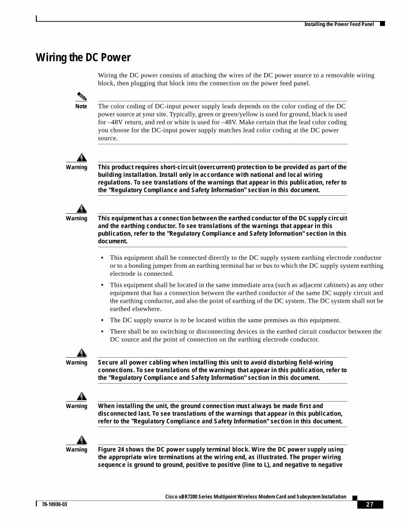
Step 3 While supporting the power feed panel, attach it to the wall with the rear panel connectors pointing up(see Figure 21) with your screws and anchors. To best support the power feed panel and cables, makesure that the power feed panel is attached securely to a vertical wall stud or to a firmly attachedplywood mounting backboard. This will prevent the unit from pulling away from the wall when thecables are attached.
OUTPUT-48V ,7A
3517
5
CAUTIONUSE COPPER
CONDUCTORS ONLY
-48V 15A, 720VA
- +
PWRON
WT1
INPUT 1&2
OUTPUT-48V ,7A
3517
6
CAUTIONUSE COPPER
CONDUCTORS ONLY
-48V 15A, 720VA
- +
PWRON
WT1
INPUT 1&2
26Cisco uBR7200 Series Multipoint Wireless Modem Card and Subsystem Installation
78-10930-03
Installing the Power Feed Panel
Figure 21 Wall-Mounting the Power Feed Panel
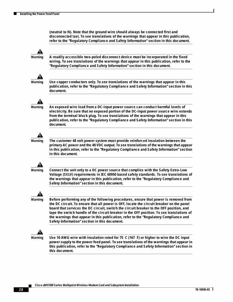
Attaching the Ground LugA ground lug kit is provided with the power feed panel. To attach the ground lug to the power feed panelchassis, complete the following steps:
Step 1 Attach a ground wire that meets the requirements of all national and local electrical codes to the groundlug.
Step 2 Locate the two ground lug threaded holes on the upper right of the rear panel.
Step 3 Align the ground lug with the threaded holes and fasten it to the chassis using the two screws includedin the kit and a torque driver with a number 2 Phillips bit (see Figure 22). Tighten the screws tobetween 16 and 20 inch-pounds of torque.
Figure 22 Attaching the Ground Lug
3517
2
OUTPUT-48 ,7A
ODUOUTPUT-48 ,7A
ODUOUTPUT-48 ,7A
ODUOUTPUT-48 ,7A
ODU
CAUTIONUSE COPPER
CONDUCTORS ONLY
-48V 15A, 720VA
- +OUTPUT
-48V ,7A
3517
7
PWRON
WT1
INPUT 1&2
27Cisco uBR7200 Series Multipoint Wireless Modem Card and Subsystem Installation
78-10930-03
Installing the Power Feed Panel
Wiring the DC PowerWiring the DC power consists of attaching the wires of the DC power source to a removable wiringblock, then plugging that block into the connection on the power feed panel.
Note The color coding of DC-input power supply leads depends on the color coding of the DCpower source at your site. Typically, green or green/yellow is used for ground, black is usedfor –48V return, and red or white is used for –48V. Make certain that the lead color codingyou choose for the DC-input power supply matches lead color coding at the DC powersource.
Warning This product requires short-circuit (overcurrent) protection to be provided as part of thebuilding installation. Install only in accordance with national and local wiringregulations. To see translations of the warnings that appear in this publication, refer tothe "Regulatory Compliance and Safety Information" section in this document.
Warning This equipment has a connection between the earthed conductor of the DC supply circuitand the earthing conductor. To see translations of the warnings that appear in thispublication, refer to the "Regulatory Compliance and Safety Information" section in thisdocument.
• This equipment shall be connected directly to the DC supply system earthing electrode conductoror to a bonding jumper from an earthing terminal bar or bus to which the DC supply system earthingelectrode is connected.
• This equipment shall be located in the same immediate area (such as adjacent cabinets) as any otherequipment that has a connection between the earthed conductor of the same DC supply circuit andthe earthing conductor, and also the point of earthing of the DC system. The DC system shall not beearthed elsewhere.
• The DC supply source is to be located within the same premises as this equipment.
• There shall be no switching or disconnecting devices in the earthed circuit conductor between theDC source and the point of connection on the earthing electrode conductor.
Warning Secure all power cabling when installing this unit to avoid disturbing field-wiringconnections. To see translations of the warnings that appear in this publication, refer tothe "Regulatory Compliance and Safety Information" section in this document.
Warning When installing the unit, the ground connection must always be made first anddisconnected last. To see translations of the warnings that appear in this publication,refer to the "Regulatory Compliance and Safety Information" section in this document.
Warning Figure 24 shows the DC power supply terminal block. Wire the DC power supply usingthe appropriate wire terminations at the wiring end, as illustrated. The proper wiringsequence is ground to ground, positive to positive (line to L), and negative to negative
28Cisco uBR7200 Series Multipoint Wireless Modem Card and Subsystem Installation
78-10930-03
Installing the Power Feed Panel
(neutral to N). Note that the ground wire should always be connected first anddisconnected last. To see translations of the warnings that appear in this publication,refer to the "Regulatory Compliance and Safety Information" section in this document.
Warning A readily accessible two-poled disconnect device must be incorporated in the fixedwiring. To see translations of the warnings that appear in this publication, refer to the"Regulatory Compliance and Safety Information" section in this document.
Warning Use copper conductors only. To see translations of the warnings that appear in thispublication, refer to the "Regulatory Compliance and Safety Information" section in thisdocument.
Warning An exposed wire lead from a DC-input power source can conduct harmful levels ofelectricity. Be sure that no exposed portion of the DC-input power source wire extendsfrom the terminal block plug. To see translations of the warnings that appear in thispublication, refer to the "Regulatory Compliance and Safety Information" section in thisdocument.
Warning The customer 48 volt power system must provide reinforced insulation between theprimary AC power and the 48 VDC output. To see translations of the warnings that appearin this publication, refer to the "Regulatory Compliance and Safety Information" sectionin this document.
Warning Connect the unit only to a DC power source that complies with the Safety Extra-LowVoltage (SELV) requirements in IEC 60950 based safety standards. To see translations ofthe warnings that appear in this publication, refer to the "Regulatory Compliance andSafety Information" section in this document.
Warning Before performing any of the following procedures, ensure that power is removed fromthe DC circuit. To ensure that all power is OFF, locate the circuit breaker on the panelboard that services the DC circuit, switch the circuit breaker to the OFF position, andtape the switch handle of the circuit breaker in the OFF position. To see translations ofthe warnings that appear in this publication, refer to the "Regulatory Compliance andSafety Information" section in this document.
Warning Use 10 AWG wire with insulation rated for 75 C (167 F) or higher to wire the DC inputpower supply to the power feed panel. To see translations of the warnings that appear inthis publication, refer to the "Regulatory Compliance and Safety Information" section inthis document.
29Cisco uBR7200 Series Multipoint Wireless Modem Card and Subsystem Installation
78-10930-03
Installing the Power Feed Panel
To wire the DC power to the power feed panel, complete the following steps for each DC powerconnector:
Step 1 Ensure that the leads are disconnected from the power source.
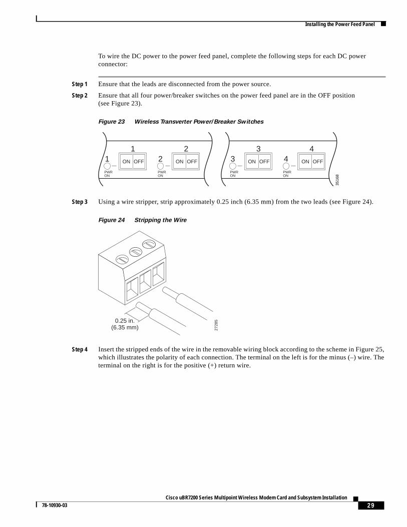
Step 2 Ensure that all four power/breaker switches on the power feed panel are in the OFF position(see Figure 23).
Figure 23 Wireless Transverter Power/Breaker Switches
Step 3 Using a wire stripper, strip approximately 0.25 inch (6.35 mm) from the two leads (see Figure 24).
Figure 24 Stripping the Wire
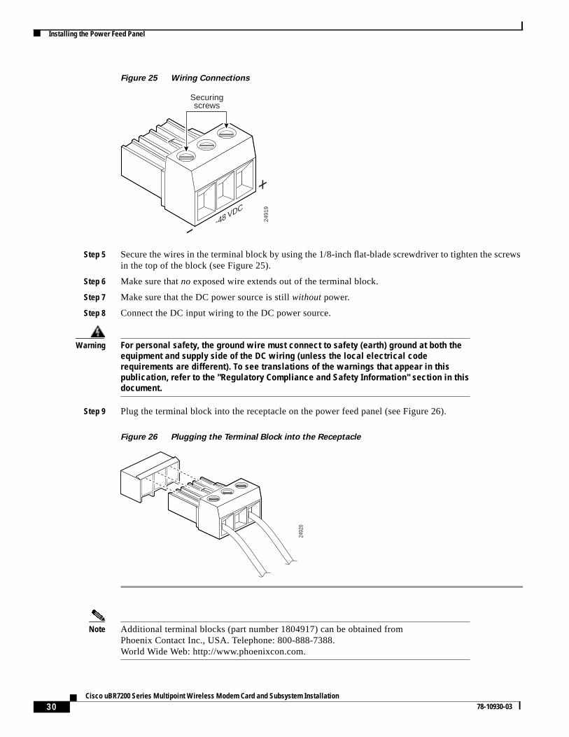
Step 4 Insert the stripped ends of the wire in the removable wiring block according to the scheme in Figure 25,which illustrates the polarity of each connection. The terminal on the left is for the minus (–) wire. Theterminal on the right is for the positive (+) return wire.
3516
8
1
PWRON
ON OFF
PWRON
PWRON
PWRON
12
23
34
4
ON OFF ON OFF ON OFF
0.25 in.(6.35 mm) 27
285
30Cisco uBR7200 Series Multipoint Wireless Modem Card and Subsystem Installation
78-10930-03
Installing the Power Feed Panel
Figure 25 Wiring Connections
Step 5 Secure the wires in the terminal block by using the 1/8-inch flat-blade screwdriver to tighten the screwsin the top of the block (see Figure 25).
Step 6 Make sure thatno exposed wire extends out of the terminal block.
Step 7 Make sure that the DC power source is stillwithout power.
Step 8 Connect the DC input wiring to the DC power source.
Warning For personal safety, the ground wire must connect to safety (earth) ground at both theequipment and supply side of the DC wiring (unless the local electrical coderequirements are different). To see translations of the warnings that appear in thispublication, refer to the "Regulatory Compliance and Safety Information" section in thisdocument.
Step 9 Plug the terminal block into the receptacle on the power feed panel (see Figure 26).
Figure 26 Plugging the Terminal Block into the Receptacle
Note Additional terminal blocks (part number 1804917) can be obtained fromPhoenix Contact Inc., USA. Telephone: 800-888-7388.World Wide Web: http://www.phoenixcon.com.
2491
9
Securingscrews
-48 VDC
-
+
2492
0
31Cisco uBR7200 Series Multipoint Wireless Modem Card and Subsystem Installation
78-10930-03
Installing the Power Feed Panel
Cabling the Power Feed PanelTo attach the cables to the power feed panel, complete the following procedures:
• Connecting the IF Cables from the Wireless Modem Card, page 31
• Connecting the IF Cables to the Wireless Transverter, page 33
Warning Never defeat the ground conductor or operate the equipment in the absence of a suitablyinstalled ground conductor. Contact the appropriate electrical inspection authority or anelectrician if you are uncertain that suitable grounding is available. To see translationsof the warnings that appear in this publication, refer to the "Regulatory Compliance andSafety Information" section in this document.
Note It is not necessary to terminate unused connectors.
Connecting the IF Cables from the Wireless Modem Card
A single power feed panel can support one or two wireless modem cards. Refer to the “Connecting theIF Cables from a Single Wireless Modem Card” section on page 31, when the power feed panel issupporting only one modem card. Refer to the “Connecting the IF Cables from Two Wireless ModemCards” section on page 32, when the power feed panel is supporting two modem cards.
Note Maximum allowable cable loss for the IF cables is 15 dB including the connectors and thepower feed panel. Cable length depends on the cable type used. DC resistance should notexceed 1.6 ohm including the inner conductor and the shielding.
Connecting the IF Cables from a Single Wireless Modem Card
To connect the IF cables from a single wireless modem card to the power feed panel, complete thefollowing steps:
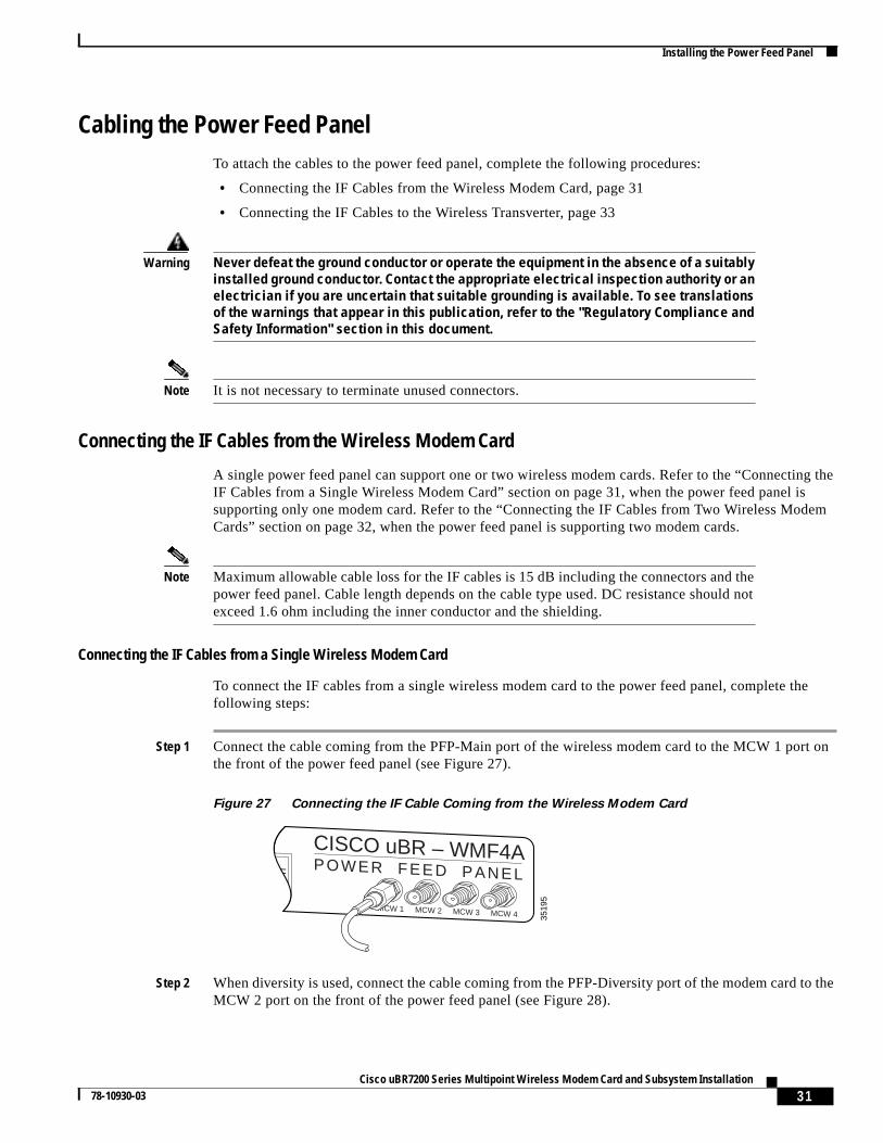
Step 1 Connect the cable coming from the PFP-Main port of the wireless modem card to the MCW 1 port onthe front of the power feed panel (see Figure 27).
Figure 27 Connecting the IF Cable Coming from the Wireless Modem Card
Step 2 When diversity is used, connect the cable coming from the PFP-Diversity port of the modem card to theMCW 2 port on the front of the power feed panel (see Figure 28).
3519
5
CISCO uBR – WMF4APOWER FEED PANEL
MCW 1 MCW 2 MCW 3 MCW 4
4
ON OFF
32Cisco uBR7200 Series Multipoint Wireless Modem Card and Subsystem Installation
78-10930-03
Installing the Power Feed Panel
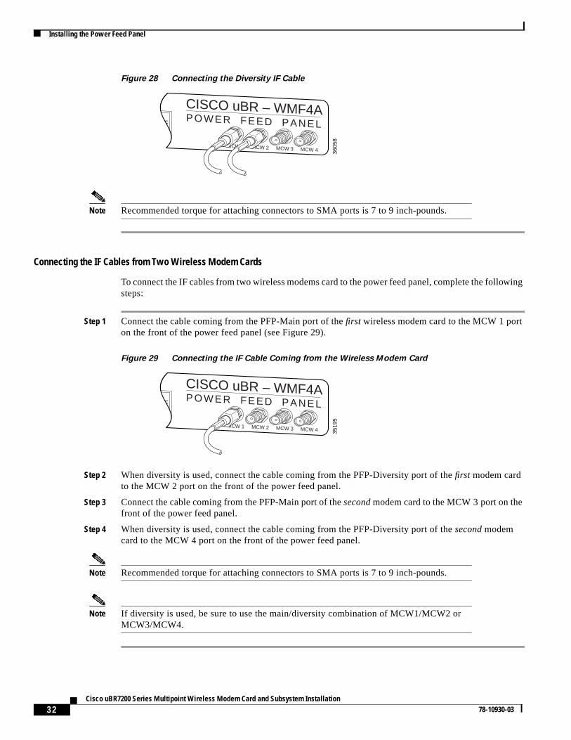
Figure 28 Connecting the Diversity IF Cable
Note Recommended torque for attaching connectors to SMA ports is 7 to 9 inch-pounds.
Connecting the IF Cables from Two Wireless Modem Cards
To connect the IF cables from two wireless modems card to the power feed panel, complete the followingsteps:
Step 1 Connect the cable coming from the PFP-Main port of thefirst wireless modem card to the MCW 1 porton the front of the power feed panel (see Figure 29).
Figure 29 Connecting the IF Cable Coming from the Wireless Modem Card
Step 2 When diversity is used, connect the cable coming from the PFP-Diversity port of thefirst modem cardto the MCW 2 port on the front of the power feed panel.
Step 3 Connect the cable coming from the PFP-Main port of thesecondmodem card to the MCW 3 port on thefront of the power feed panel.
Step 4 When diversity is used, connect the cable coming from the PFP-Diversity port of thesecond modemcard to the MCW 4 port on the front of the power feed panel.
Note Recommended torque for attaching connectors to SMA ports is 7 to 9 inch-pounds.
Note If diversity is used, be sure to use the main/diversity combination of MCW1/MCW2 orMCW3/MCW4.
3605
8
CISCO uBR – WMF4APOWER FEED PANEL
MCW 1 MCW 2 MCW 3 MCW 4
4
ON OFF
3519
5
CISCO uBR – WMF4APOWER FEED PANEL
MCW 1 MCW 2 MCW 3 MCW 4
4
ON OFF
33Cisco uBR7200 Series Multipoint Wireless Modem Card and Subsystem Installation
78-10930-03
Installing the Power Feed Panel
Connecting the IF Cables to the Wireless Transverter
A single power feed panel can support as many as four wireless transverters. Refer to the “Connectingthe IF Cables to Two Wireless Transverters” section on page 33, when the power feed panel is supportingonly two transverters. Refer to the “Connecting the IF Cables to Four Wireless Transverters” section onpage 34, when the power feed panel is supporting four transverters.
Connecting the IF Cables to Two Wireless Transverters
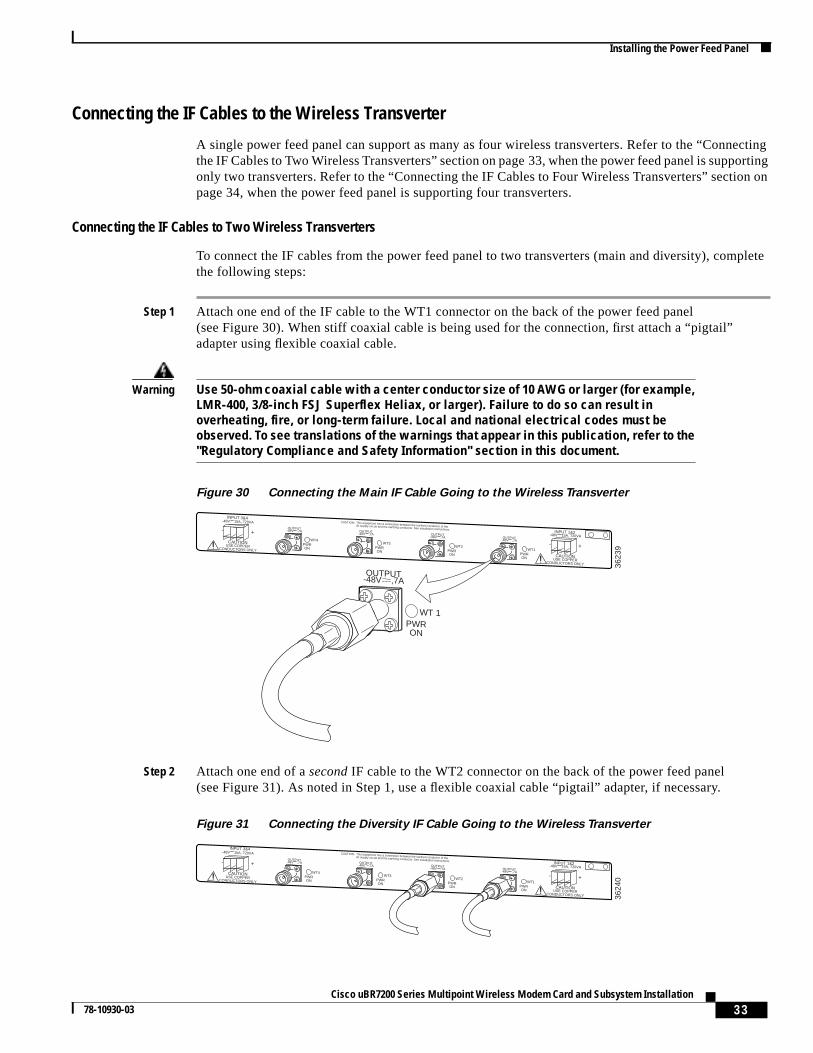
To connect the IF cables from the power feed panel to two transverters (main and diversity), completethe following steps:
Step 1 Attach one end of the IF cable to the WT1 connector on the back of the power feed panel(see Figure 30). When stiff coaxial cable is being used for the connection, first attach a “pigtail”adapter using flexible coaxial cable.
Warning Use 50-ohm coaxial cable with a center conductor size of 10 AWG or larger (for example,LMR-400, 3/8-inch FSJ Superflex Heliax, or larger). Failure to do so can result inoverheating, fire, or long-term failure. Local and national electrical codes must beobserved. To see translations of the warnings that appear in this publication, refer to the"Regulatory Compliance and Safety Information" section in this document.
Figure 30 Connecting the Main IF Cable Going to the Wireless Transverter
Step 2 Attach one end of asecond IF cable to the WT2 connector on the back of the power feed panel(see Figure 31). As noted in Step 1, use a flexible coaxial cable “pigtail” adapter, if necessary.
Figure 31 Connecting the Diversity IF Cable Going to the Wireless Transverter
OUTPUT-48V ,7A OUTPUT
-48V ,7A OUTPUT-48V ,7A OUTPUT
-48V ,7A
This equipment has a connection between the earthed conductor of thedc supply circuit and the earthing conductor. See installation instructions.
CAUTION:
OUTPUT-48V ,7A
PWRON
WT 136
239
CAUTIONUSE COPPER
CONDUCTORS ONLY
-48V 15A, 720VA
- +CAUTION
USE COPPERCONDUCTORS ONLY
-48V 15A, 720VA
- +WT4
PWRON
INPUT 1&2
INPUT 3&4
WT3PWRON
WT2PWRON
WT1PWRON
OUTPUT-48V ,7A OUTPUT
-48V ,7A OUTPUT-48V ,7A OUTPUT
-48V ,7A
This equipment has a connection between the earthed conductor of thedc supply circuit and the earthing conductor. See installation instructions.
CAUTION:
3624
0
CAUTIONUSE COPPER
CONDUCTORS ONLY
-48V 15A, 720VA
- +CAUTION
USE COPPERCONDUCTORS ONLY
-48V 15A, 720VA
- +
WT4PWRON
INPUT 1&2
INPUT 3&4
WT3PWRON
WT2PWRON
WT1PWRON
34Cisco uBR7200 Series Multipoint Wireless Modem Card and Subsystem Installation
78-10930-03
Installing the Power Feed Panel
Note To connect twomain wireless transverters, use connectors WT1 and WT3.
Note Recommended torque for attaching the cables to the N-type ports is 35 to 40 inch-pounds.
Caution Over-tightening the N-type connectors can damage them.
This completes the procedure for cabling and installing the power feed panel.
Connecting the IF Cables to Four Wireless Transverters
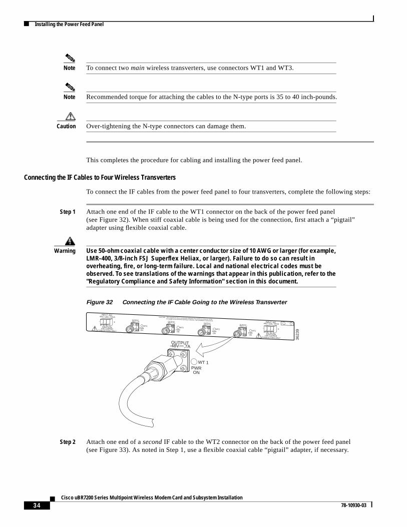
To connect the IF cables from the power feed panel to four transverters, complete the following steps:
Step 1 Attach one end of the IF cable to the WT1 connector on the back of the power feed panel(see Figure 32). When stiff coaxial cable is being used for the connection, first attach a “pigtail”adapter using flexible coaxial cable.
Warning Use 50-ohm coaxial cable with a center conductor size of 10 AWG or larger (for example,LMR-400, 3/8-inch FSJ Superflex Heliax, or larger). Failure to do so can result inoverheating, fire, or long-term failure. Local and national electrical codes must beobserved. To see translations of the warnings that appear in this publication, refer to the"Regulatory Compliance and Safety Information" section in this document.
Figure 32 Connecting the IF Cable Going to the Wireless Transverter
Step 2 Attach one end of asecond IF cable to the WT2 connector on the back of the power feed panel(see Figure 33). As noted in Step 1, use a flexible coaxial cable “pigtail” adapter, if necessary.
OUTPUT-48V ,7A OUTPUT
-48V ,7A OUTPUT-48V ,7A OUTPUT
-48V ,7A
This equipment has a connection between the earthed conductor of thedc supply circuit and the earthing conductor. See installation instructions.
CAUTION:
OUTPUT-48V ,7A
PWRON
WT 1
3623
9
CAUTIONUSE COPPER
CONDUCTORS ONLY
-48V 15A, 720VA
- +CAUTION
USE COPPERCONDUCTORS ONLY
-48V 15A, 720VA
- +WT4
PWRON
INPUT 1&2
INPUT 3&4
WT3PWRON
WT2PWRON
WT1PWRON
35Cisco uBR7200 Series Multipoint Wireless Modem Card and Subsystem Installation
78-10930-03
Installing the Wireless Transverter
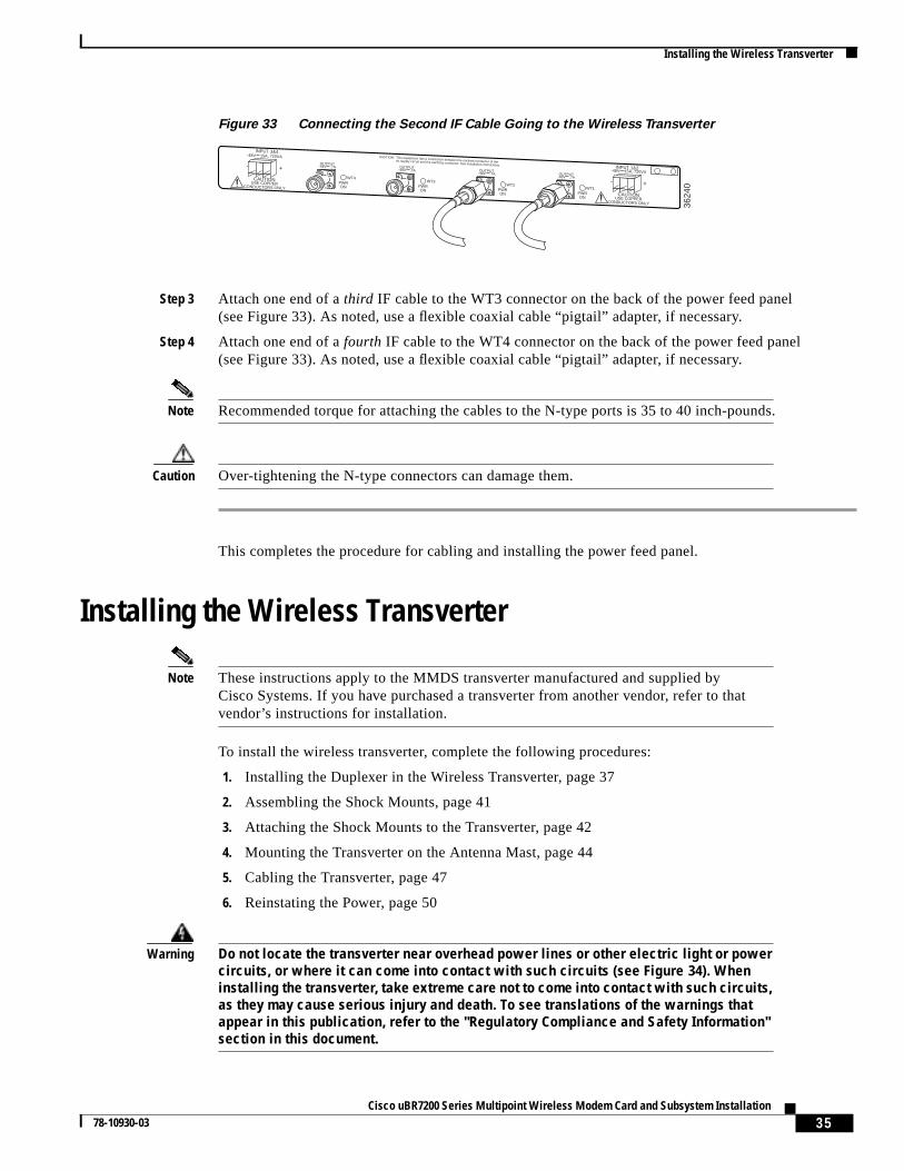
Figure 33 Connecting the Second IF Cable Going to the Wireless Transverter
Step 3 Attach one end of athird IF cable to the WT3 connector on the back of the power feed panel(see Figure 33). As noted, use a flexible coaxial cable “pigtail” adapter, if necessary.
Step 4 Attach one end of afourth IF cable to the WT4 connector on the back of the power feed panel(see Figure 33). As noted, use a flexible coaxial cable “pigtail” adapter, if necessary.
Note Recommended torque for attaching the cables to the N-type ports is 35 to 40 inch-pounds.
Caution Over-tightening the N-type connectors can damage them.
This completes the procedure for cabling and installing the power feed panel.
Installing the Wireless Transverter
Note These instructions apply to the MMDS transverter manufactured and supplied byCisco Systems. If you have purchased a transverter from another vendor, refer to thatvendor’s instructions for installation.
To install the wireless transverter, complete the following procedures:
1. Installing the Duplexer in the Wireless Transverter, page 37
2. Assembling the Shock Mounts, page 41
3. Attaching the Shock Mounts to the Transverter, page 42
4. Mounting the Transverter on the Antenna Mast, page 44
5. Cabling the Transverter, page 47
6. Reinstating the Power, page 50
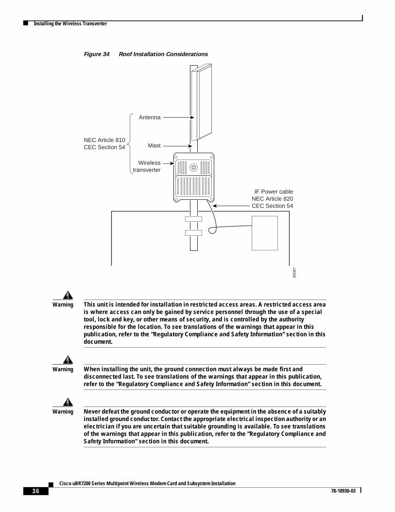
Warning Do not locate the transverter near overhead power lines or other electric light or powercircuits, or where it can come into contact with such circuits (see Figure 34). Wheninstalling the transverter, take extreme care not to come into contact with such circuits,as they may cause serious injury and death. To see translations of the warnings thatappear in this publication, refer to the "Regulatory Compliance and Safety Information"section in this document.
OUTPUT-48V ,7A OUTPUT
-48V ,7A OUTPUT-48V ,7A OUTPUT
-48V ,7A
This equipment has a connection between the earthed conductor of thedc supply circuit and the earthing conductor. See installation instructions.
CAUTION:
3624
0
CAUTIONUSE COPPER
CONDUCTORS ONLY
-48V 15A, 720VA
- +CAUTION
USE COPPERCONDUCTORS ONLY
-48V 15A, 720VA
- +
WT4PWRON
INPUT 1&2
INPUT 3&4
WT3PWRON
WT2PWRON
WT1PWRON
36Cisco uBR7200 Series Multipoint Wireless Modem Card and Subsystem Installation
78-10930-03
Installing the Wireless Transverter
Figure 34 Roof Installation Considerations
Warning This unit is intended for installation in restricted access areas. A restricted access areais where access can only be gained by service personnel through the use of a specialtool, lock and key, or other means of security, and is controlled by the authorityresponsible for the location. To see translations of the warnings that appear in thispublication, refer to the "Regulatory Compliance and Safety Information" section in thisdocument.
Warning When installing the unit, the ground connection must always be made first anddisconnected last. To see translations of the warnings that appear in this publication,refer to the "Regulatory Compliance and Safety Information" section in this document.
Warning Never defeat the ground conductor or operate the equipment in the absence of a suitablyinstalled ground conductor. Contact the appropriate electrical inspection authority or anelectrician if you are uncertain that suitable grounding is available. To see translationsof the warnings that appear in this publication, refer to the "Regulatory Compliance andSafety Information" section in this document.
3508
7
Wirelesstransverter
MastNEC Article 810CEC Section 54
IF Power cableNEC Article 820CEC Section 54
Antenna
37Cisco uBR7200 Series Multipoint Wireless Modem Card and Subsystem Installation
78-10930-03
Installing the Wireless Transverter
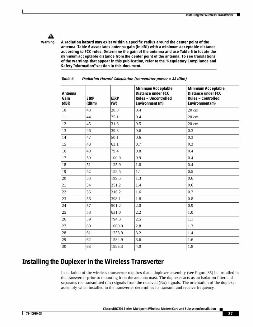
Warning A radiation hazard may exist within a specific radius around the center point of theantenna. Table 6 associates antenna gain (in dBi) with a minimum acceptable distanceaccording to FCC rules. Determine the gain of the antenna and use Table 6 to locate theminimum acceptable distance from the center point of the antenna. To see translationsof the warnings that appear in this publication, refer to the "Regulatory Compliance andSafety Information" section in this document.
Installing the Duplexer in the Wireless TransverterInstallation of the wireless transverter requires that a duplexer assembly (see Figure 35) be installed inthe transverter prior to mounting it on the antenna mast. The duplexer acts as an isolation filter andseparates the transmitted (Tx) signals from the received (Rx) signals. The orientation of the duplexerassembly when installed in the transverter determines its transmit and receive frequency.
Table 6 Radiation Hazard Calculation (transmitter power = 33 dBm)
AntennaGain(dBi)
EIRP(dBm)
EIRP(W)
Minimum AcceptableDistance under FCCRules – UncontrolledEnvironment (m)
Minimum AcceptableDistance under FCCRules – ControlledEnvironment (m)
10 43 20.0 0.4 20 cm
11 44 25.1 0.4 20 cm
12 45 31.6 0.5 20 cm
13 46 39.8 0.6 0.3
14 47 50.1 0.6 0.3
15 48 63.1 0.7 0.3
16 49 79.4 0.8 0.4
17 50 100.0 0.9 0.4
18 51 125.9 1.0 0.4
19 52 158.5 1.1 0.5
20 53 199.5 1.3 0.6
21 54 251.2 1.4 0.6
22 55 316.2 1.6 0.7
23 56 398.1 1.8 0.8
24 57 501.2 2.0 0.9
25 58 631.0 2.2 1.0
26 59 794.3 2.5 1.1
27 60 1000.0 2.8 1.3
28 61 1258.9 3.2 1.4
29 62 1584.9 3.6 1.6
30 63 1995.3 4.0 1.8
38Cisco uBR7200 Series Multipoint Wireless Modem Card and Subsystem Installation
78-10930-03
Installing the Wireless Transverter
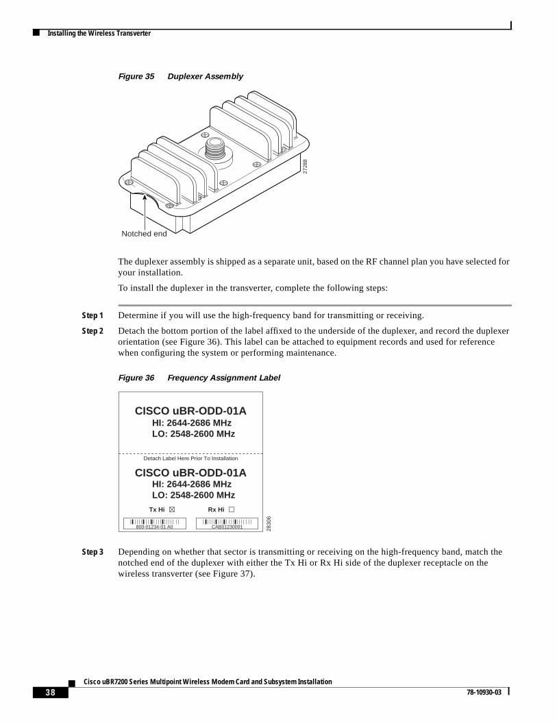
Figure 35 Duplexer Assembly
The duplexer assembly is shipped as a separate unit, based on the RF channel plan you have selected foryour installation.
To install the duplexer in the transverter, complete the following steps:
Step 1 Determine if you will use the high-frequency band for transmitting or receiving.
Step 2 Detach the bottom portion of the label affixed to the underside of the duplexer, and record the duplexerorientation (see Figure 36). This label can be attached to equipment records and used for referencewhen configuring the system or performing maintenance.
Figure 36 Frequency Assignment Label
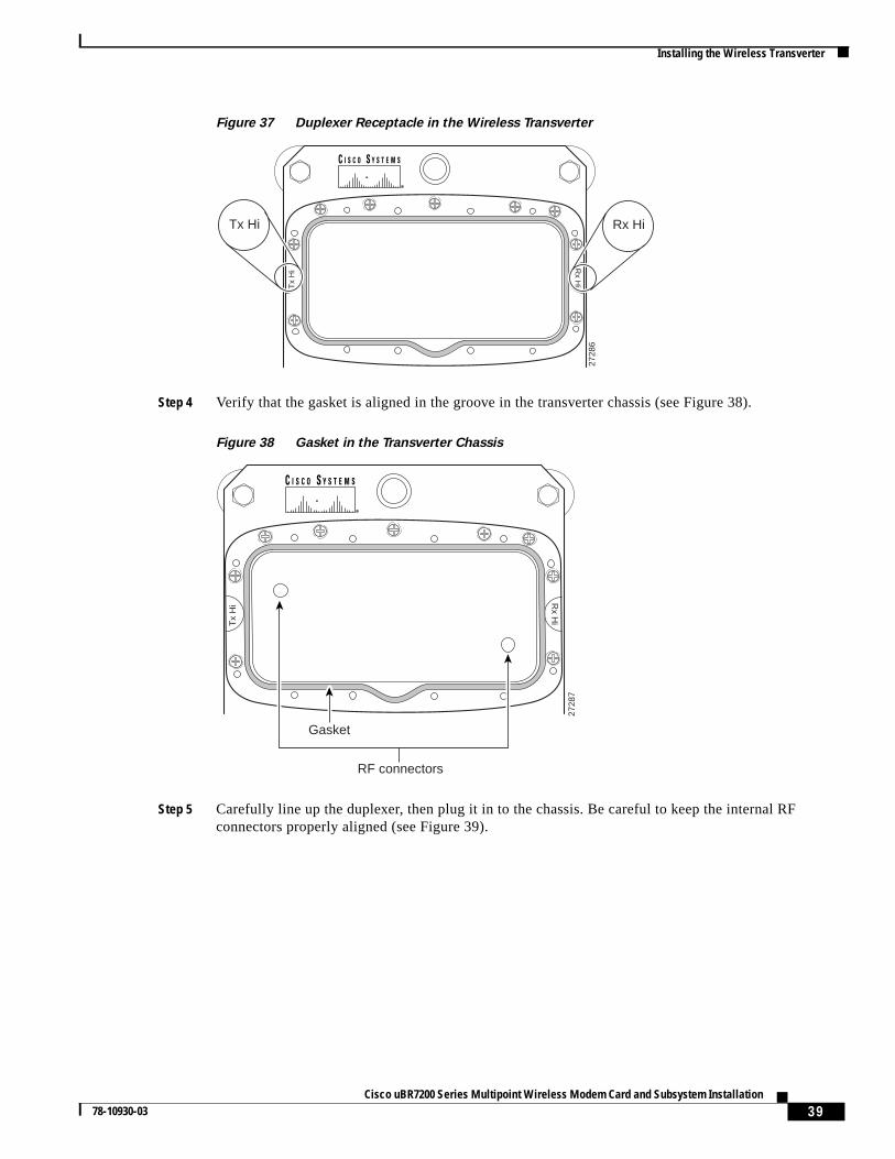
Step 3 Depending on whether that sector is transmitting or receiving on the high-frequency band, match thenotched end of the duplexer with either the Tx Hi or Rx Hi side of the duplexer receptacle on thewireless transverter (see Figure 37).
2728
8
Notched end
2830
6
CISCO uBR-ODD-01AHI: 2644-2686 MHzLO: 2548-2600 MHz
CISCO uBR-ODD-01AHI: 2644-2686 MHzLO: 2548-2600 MHz
Detach Label Here Prior To Installation
Tx Hi Rx Hi
800-01234-01 A0 CAB01230001
39Cisco uBR7200 Series Multipoint Wireless Modem Card and Subsystem Installation
78-10930-03
Installing the Wireless Transverter
Figure 37 Duplexer Receptacle in the Wireless Transverter
Step 4 Verify that the gasket is aligned in the groove in the transverter chassis (see Figure 38).
Figure 38 Gasket in the Transverter Chassis
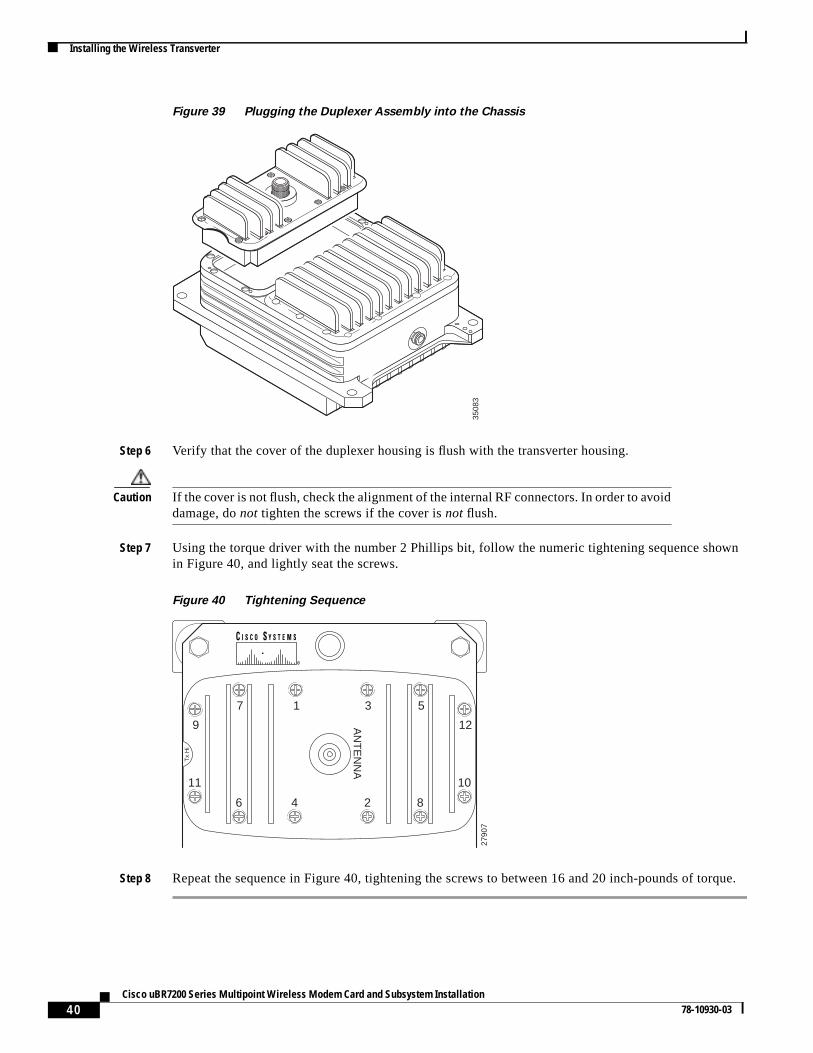
Step 5 Carefully line up the duplexer, then plug it in to the chassis. Be careful to keep the internal RFconnectors properly aligned (see Figure 39).
2728
6
Tx
Hi R
x Hi
Tx Hi Rx Hi
2728
7
Gasket
RF connectors
Tx
Hi R
x Hi
40Cisco uBR7200 Series Multipoint Wireless Modem Card and Subsystem Installation
78-10930-03
Installing the Wireless Transverter
Figure 39 Plugging the Duplexer Assembly into the Chassis
Step 6 Verify that the cover of the duplexer housing is flush with the transverter housing.
Caution If the cover is not flush, check the alignment of the internal RF connectors. In order to avoiddamage, donot tighten the screws if the cover isnot flush.
Step 7 Using the torque driver with the number 2 Phillips bit, follow the numeric tightening sequence shownin Figure 40, and lightly seat the screws.
Figure 40 Tightening Sequence
Step 8 Repeat the sequence in Figure 40, tightening the screws to between 16 and 20 inch-pounds of torque.
3508
3
1
AN
TE
NN
A
3 57
9
Tx
Hi
12
1011
6
2790
7
4 2 8
41Cisco uBR7200 Series Multipoint Wireless Modem Card and Subsystem Installation
78-10930-03
Installing the Wireless Transverter
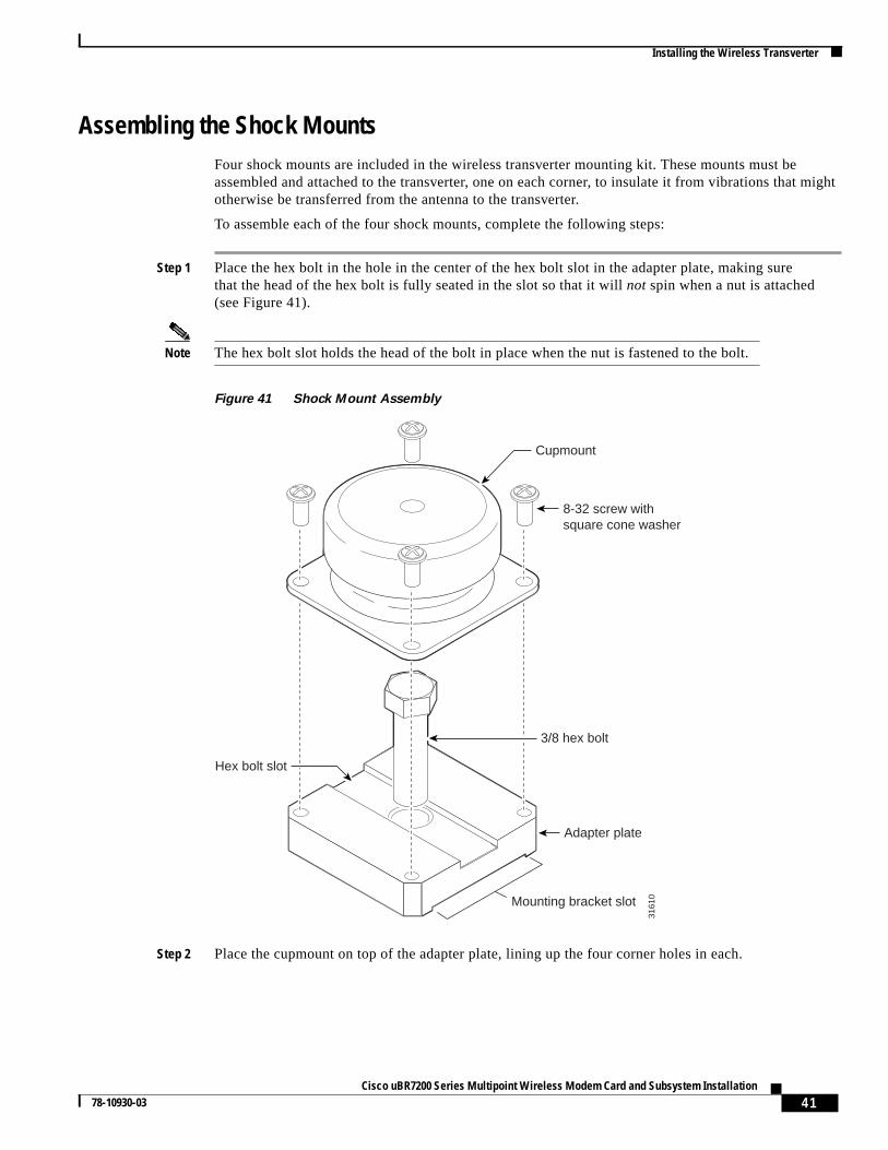
Assembling the Shock MountsFour shock mounts are included in the wireless transverter mounting kit. These mounts must beassembled and attached to the transverter, one on each corner, to insulate it from vibrations that mightotherwise be transferred from the antenna to the transverter.
To assemble each of the four shock mounts, complete the following steps:
Step 1 Place the hex bolt in the hole in the center of the hex bolt slot in the adapter plate, making surethat the head of the hex bolt is fully seated in the slot so that it willnot spin when a nut is attached(see Figure 41).
Note The hex bolt slot holds the head of the bolt in place when the nut is fastened to the bolt.
Figure 41 Shock Mount Assembly
Step 2 Place the cupmount on top of the adapter plate, lining up the four corner holes in each.
3161
0
Cupmount
8-32 screw withsquare cone washer
3/8 hex bolt
Adapter plate
Mounting bracket slot
Hex bolt slot

42Cisco uBR7200 Series Multipoint Wireless Modem Card and Subsystem Installation
78-10930-03
Installing the Wireless Transverter
Step 3 Use the four screws with the square cone washers to attach the cupmount to the adapter plate. Using thetorque driver with the number 2 Phillips bit, tighten the screws to between 16 and 20 inch-pounds oftorque.
Attaching the Shock Mounts to the TransverterTo attach each of the four shock mounts to the transverter, complete the following steps:
Step 1 Put a split lock washer and a flat washer on each of the four 5/16-hex bolts. The split lock washer goeson first (see Figure 42).
Figure 42 Attaching the Shock Mounts to the Transverter
Step 2 Line up the center hole in each cupmount with a mounting hole at the corner of the transverter.
Step 3 Attach each shock mount to the transverter with the hex bolt and washers (see Figure 42), but donotfully tighten the bolts until after the shock mounts are properly aligned. The mounting brackets seatcorrectly in the mounting bracket slotsonly when the shock mounts are properly aligned. Improperalignment prevents the mounting bracket from seating correctly, which could allow the shock mount toslide across the mounting bracket and move the transverter.
Step 4 Align each shock mount so that the mounting bracket slot on the shock mount (see Figure 43) isparallel to one of the shorter sides of the transverter. The mounting bracket slots on the upper shockmounts must be parallel to the top of the transverter. The mounting bracket slots on the lower shockmounts must be parallel to the bottom of the transverter.
3508
1
5/16 hex bolt
Lock washer
Flat washer
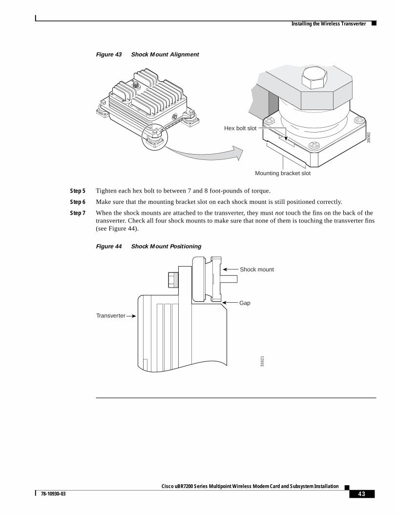
43Cisco uBR7200 Series Multipoint Wireless Modem Card and Subsystem Installation
78-10930-03
Installing the Wireless Transverter
Figure 43 Shock Mount Alignment
Step 5 Tighten each hex bolt to between 7 and 8 foot-pounds of torque.
Step 6 Make sure that the mounting bracket slot on each shock mount is still positioned correctly.
Step 7 When the shock mounts are attached to the transverter, they mustnot touch the fins on the back of thetransverter. Check all four shock mounts to make sure that none of them is touching the transverter fins(see Figure 44).
Figure 44 Shock Mount Positioning
3508
2
Mounting bracket slot
Hex bolt slot
Gap
Shock mount31
621
Transverter
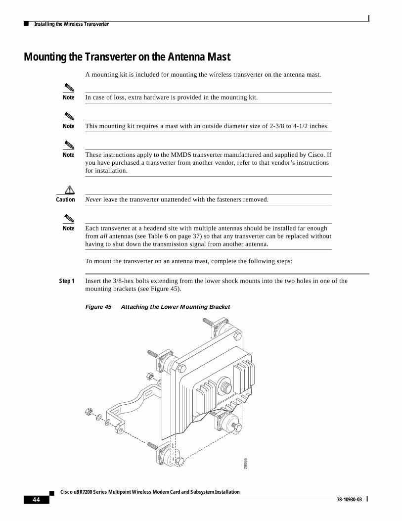
44Cisco uBR7200 Series Multipoint Wireless Modem Card and Subsystem Installation
78-10930-03
Installing the Wireless Transverter
Mounting the Transverter on the Antenna MastA mounting kit is included for mounting the wireless transverter on the antenna mast.
Note In case of loss, extra hardware is provided in the mounting kit.
Note This mounting kit requires a mast with an outside diameter size of 2-3/8 to 4-1/2 inches.
Note These instructions apply to the MMDS transverter manufactured and supplied by Cisco. Ifyou have purchased a transverter from another vendor, refer to that vendor’s instructionsfor installation.
Caution Never leave the transverter unattended with the fasteners removed.
Note Each transverter at a headend site with multiple antennas should be installed far enoughfrom all antennas (see Table 6 on page 37) so that any transverter can be replaced withouthaving to shut down the transmission signal from another antenna.
To mount the transverter on an antenna mast, complete the following steps:
Step 1 Insert the 3/8-hex bolts extending from the lower shock mounts into the two holes in one of themounting brackets (see Figure 45).
Figure 45 Attaching the Lower Mounting Bracket
2899
6
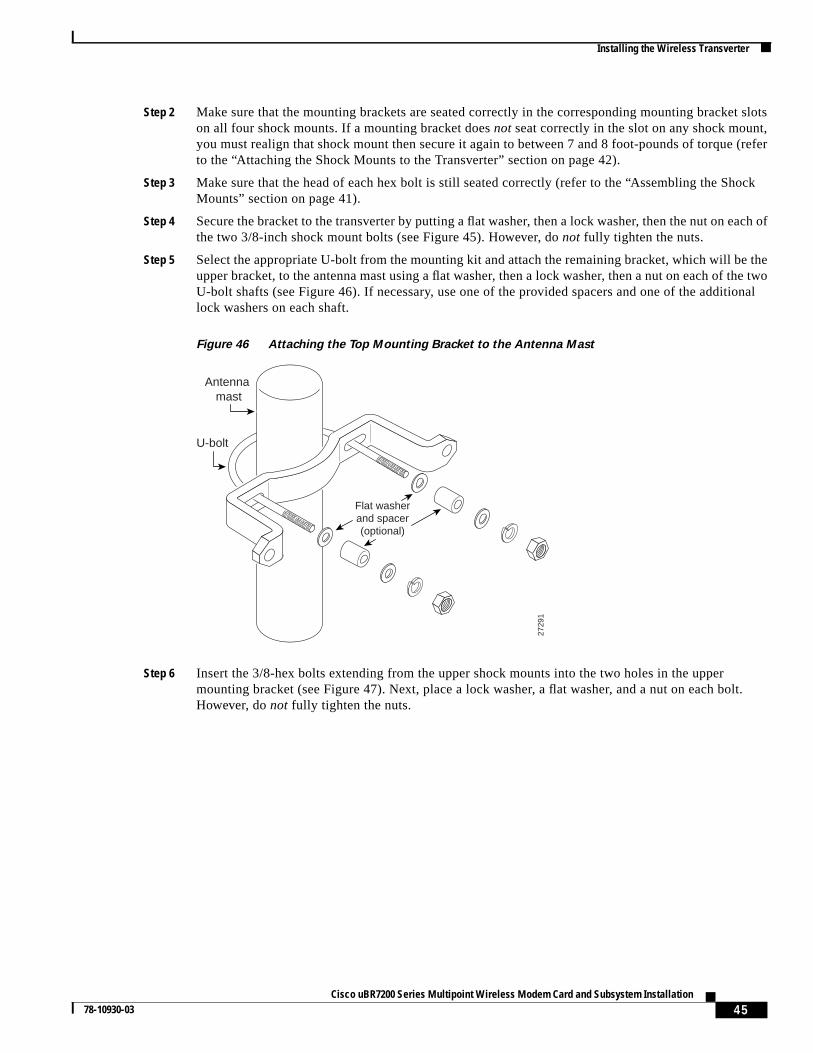
45Cisco uBR7200 Series Multipoint Wireless Modem Card and Subsystem Installation
78-10930-03
Installing the Wireless Transverter
Step 2 Make sure that the mounting brackets are seated correctly in the corresponding mounting bracket slotson all four shock mounts. If a mounting bracket doesnot seat correctly in the slot on any shock mount,you must realign that shock mount then secure it again to between 7 and 8 foot-pounds of torque (referto the “Attaching the Shock Mounts to the Transverter” section on page 42).
Step 3 Make sure that the head of each hex bolt is still seated correctly (refer to the “Assembling the ShockMounts” section on page 41).
Step 4 Secure the bracket to the transverter by putting a flat washer, then a lock washer, then the nut on each ofthe two 3/8-inch shock mount bolts (see Figure 45). However, donot fully tighten the nuts.
Step 5 Select the appropriate U-bolt from the mounting kit and attach the remaining bracket, which will be theupper bracket, to the antenna mast using a flat washer, then a lock washer, then a nut on each of the twoU-bolt shafts (see Figure 46). If necessary, use one of the provided spacers and one of the additionallock washers on each shaft.
Figure 46 Attaching the Top Mounting Bracket to the Antenna Mast
Step 6 Insert the 3/8-hex bolts extending from the upper shock mounts into the two holes in the uppermounting bracket (see Figure 47). Next, place a lock washer, a flat washer, and a nut on each bolt.However, donot fully tighten the nuts.
2729
1
Antenna mast
U-bolt
Flat washerand spacer(optional)
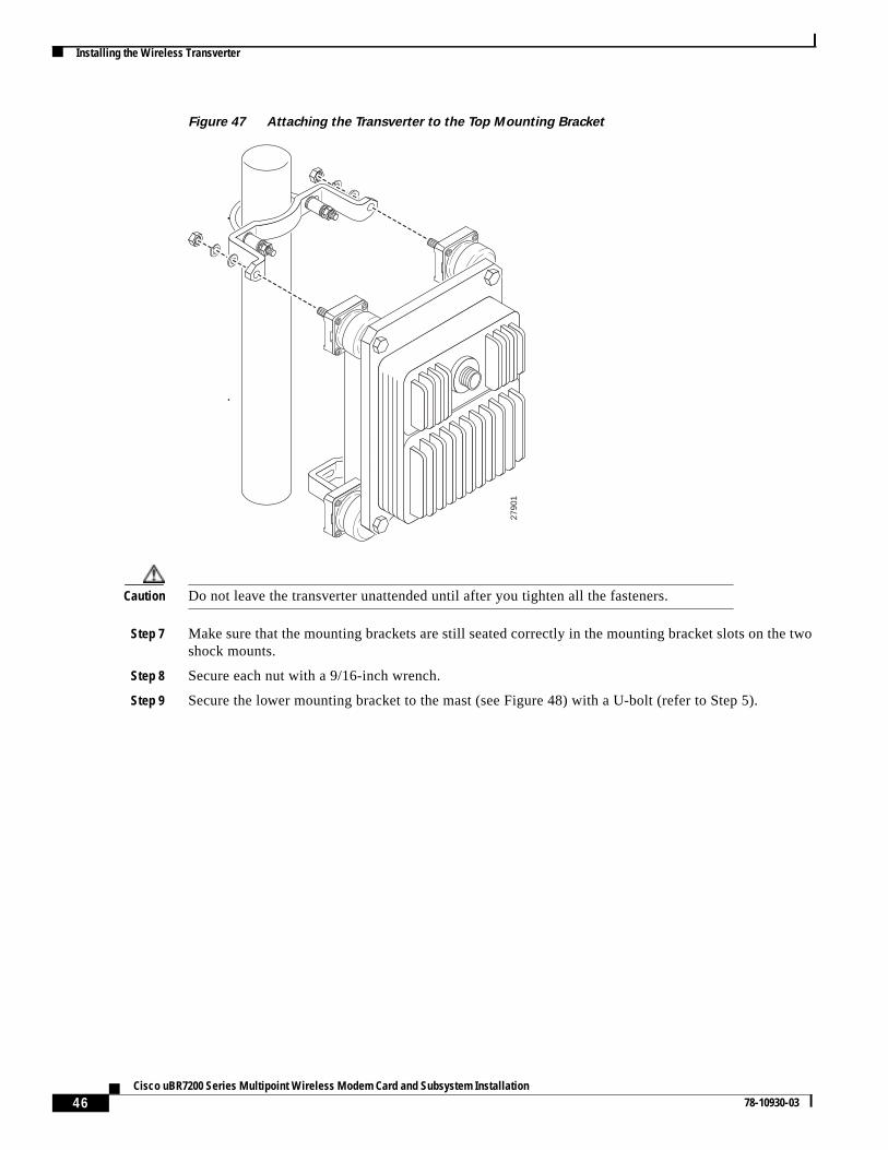
46Cisco uBR7200 Series Multipoint Wireless Modem Card and Subsystem Installation
78-10930-03
Installing the Wireless Transverter
Figure 47 Attaching the Transverter to the Top Mounting Bracket
Caution Do not leave the transverter unattended until after you tighten all the fasteners.
Step 7 Make sure that the mounting brackets are still seated correctly in the mounting bracket slots on the twoshock mounts.
Step 8 Secure each nut with a 9/16-inch wrench.
Step 9 Secure the lower mounting bracket to the mast (see Figure 48) with a U-bolt (refer to Step 5).
2790
1
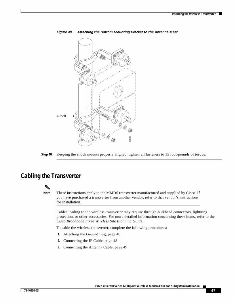
47Cisco uBR7200 Series Multipoint Wireless Modem Card and Subsystem Installation
78-10930-03
Installing the Wireless Transverter
Figure 48 Attaching the Bottom Mounting Bracket to the Antenna Mast
Step 10 Keeping the shock mounts properly aligned, tighten all fasteners to 15 foot-pounds of torque.
Cabling the Transverter
Note These instructions apply to the MMDS transverter manufactured and supplied by Cisco. Ifyou have purchased a transverter from another vendor, refer to that vendor’s instructionsfor installation.
Cables leading to the wireless transverter may require through-bulkhead connectors, lightningprotection, or other accessories. For more detailed information concerning these items, refer to theCisco Broadband Fixed Wireless Site Planning Guide.
To cable the wireless transverter, complete the following procedures:
1. Attaching the Ground Lug, page 48
2. Connecting the IF Cable, page 48
3. Connecting the Antenna Cable, page 49
2790
3
U-bolt
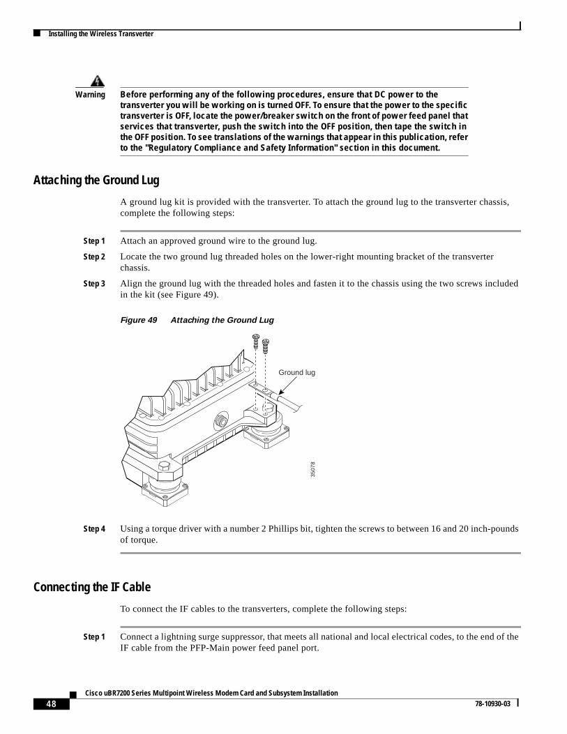
48Cisco uBR7200 Series Multipoint Wireless Modem Card and Subsystem Installation
78-10930-03
Installing the Wireless Transverter
Warning Before performing any of the following procedures, ensure that DC power to thetransverter you will be working on is turned OFF. To ensure that the power to the specifictransverter is OFF, locate the power/breaker switch on the front of power feed panel thatservices that transverter, push the switch into the OFF position, then tape the switch inthe OFF position. To see translations of the warnings that appear in this publication, referto the "Regulatory Compliance and Safety Information" section in this document.
Attaching the Ground Lug
A ground lug kit is provided with the transverter. To attach the ground lug to the transverter chassis,complete the following steps:
Step 1 Attach an approved ground wire to the ground lug.
Step 2 Locate the two ground lug threaded holes on the lower-right mounting bracket of the transverterchassis.
Step 3 Align the ground lug with the threaded holes and fasten it to the chassis using the two screws includedin the kit (see Figure 49).
Figure 49 Attaching the Ground Lug
Step 4 Using a torque driver with a number 2 Phillips bit, tighten the screws to between 16 and 20 inch-poundsof torque.
Connecting the IF Cable
To connect the IF cables to the transverters, complete the following steps:
Step 1 Connect a lightning surge suppressor, that meets all national and local electrical codes, to the end of theIF cable from the PFP-Main power feed panel port.
3507
8
Ground lug
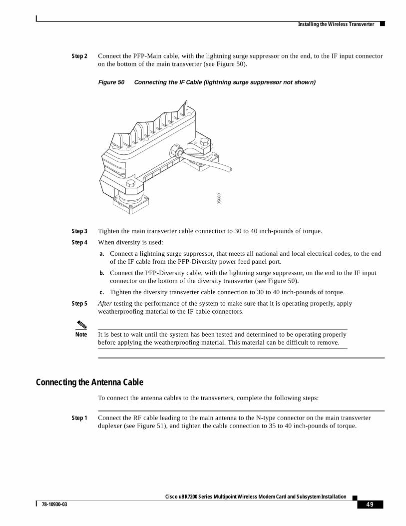
49Cisco uBR7200 Series Multipoint Wireless Modem Card and Subsystem Installation
78-10930-03
Installing the Wireless Transverter
Step 2 Connect the PFP-Main cable, with the lightning surge suppressor on the end, to the IF input connectoron the bottom of the main transverter (see Figure 50).
Figure 50 Connecting the IF Cable (lightning surge suppressor not shown)
Step 3 Tighten the main transverter cable connection to 30 to 40 inch-pounds of torque.
Step 4 When diversity is used:
a. Connect a lightning surge suppressor, that meets all national and local electrical codes, to the endof the IF cable from the PFP-Diversity power feed panel port.
b. Connect the PFP-Diversity cable, with the lightning surge suppressor, on the end to the IF inputconnector on the bottom of the diversity transverter (see Figure 50).
c. Tighten the diversity transverter cable connection to 30 to 40 inch-pounds of torque.
Step 5 After testing the performance of the system to make sure that it is operating properly, applyweatherproofing material to the IF cable connectors.
Note It is best to wait until the system has been tested and determined to be operating properlybefore applying the weatherproofing material. This material can be difficult to remove.
Connecting the Antenna Cable
To connect the antenna cables to the transverters, complete the following steps:
Step 1 Connect the RF cable leading to the main antenna to the N-type connector on the main transverterduplexer (see Figure 51), and tighten the cable connection to 35 to 40 inch-pounds of torque.
3508
0
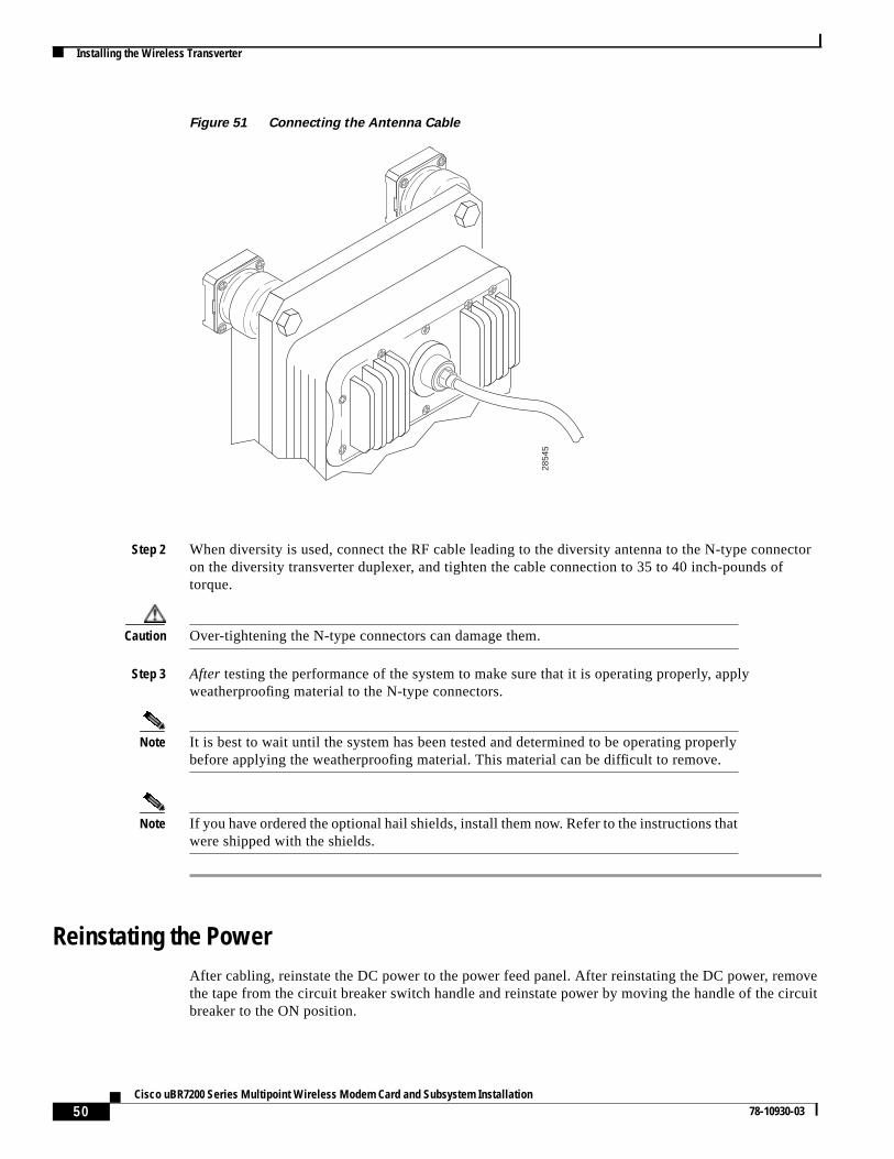
50Cisco uBR7200 Series Multipoint Wireless Modem Card and Subsystem Installation
78-10930-03
Installing the Wireless Transverter
Figure 51 Connecting the Antenna Cable
Step 2 When diversity is used, connect the RF cable leading to the diversity antenna to the N-type connectoron the diversity transverter duplexer, and tighten the cable connection to 35 to 40 inch-pounds oftorque.
Caution Over-tightening the N-type connectors can damage them.
Step 3 After testing the performance of the system to make sure that it is operating properly, applyweatherproofing material to the N-type connectors.
Note It is best to wait until the system has been tested and determined to be operating properlybefore applying the weatherproofing material. This material can be difficult to remove.
Note If you have ordered the optional hail shields, install them now. Refer to the instructions thatwere shipped with the shields.
Reinstating the PowerAfter cabling, reinstate the DC power to the power feed panel. After reinstating the DC power, removethe tape from the circuit breaker switch handle and reinstate power by moving the handle of the circuitbreaker to the ON position.
2854
5
51Cisco uBR7200 Series Multipoint Wireless Modem Card and Subsystem Installation
78-10930-03
Testing the Installation and Creating an Initial Configuration
Note To test the installation and create an initial configuration for the wireless modem card, youmust understand basic Cisco uBR7200 series router operation and be familiar with theCisco IOS software application.
This completes the procedure for installing and cabling a wireless transverter. Consult the instructionsprovided by your antenna manufacturer for additional instructions on cabling antennas.
Testing the Installation and Creating an Initial ConfigurationAfter you have installed or replaced a headend wireless modem card, or a wireless modem card andsubsystem, you need to determine whether the installation is assembled correctly and working properly.You must test the installation to verify the following:
• Power from the power feed panel is reaching the transverter
• Completed signal paths, both control and data, exist between the wireless modem card and thetransverter
• Hardware is seated properly
• Analog and signal processing portions of the wireless modem card are functioning as expected
• Transverter is operating correctly
When you know that the system is working properly, you must create an initial configuration. During theinitial configuration, complete the following tasks:
• Set the power levels
• Configure the automatic level control
• Configure the modulation profile for the link
• Verify the configuration
• Verify the signals
Note You must log in to and create a basic configuration for the Cisco uBR7200 series routerbefore testing the installation and configuring the wireless modem card. Refer to theCisco uBR7200 Series Universal Broadband Router Software Configuration Guidethatshipped with your router for more information.
Required InformationBefore testing the installation and creating an initial configuration for the wireless modem card, youmust have the following information:
• Number of sectors
• Duplexer information
• Transmit and receive frequencies
• IP address and subnet mask of the wireless modem card
• Transmit power
52Cisco uBR7200 Series Multipoint Wireless Modem Card and Subsystem Installation
78-10930-03
Testing the Installation and Creating an Initial Configuration
• Target receive power
• Modulation profile settings (upstream and downstream)
• Microcode path
Note The microcode for the headend system can be downloaded from Cisco.com at the followingURL: http://www.cisco.com/cgi-bin/tablebuild.pl/rhe. The microcode for the subscriberunits can be downloaded from Cisco.com at the following URL:http://www.cisco.com/cgi-bin/tablebuild.pl/rsu.
• Configuration file name and location
• Dynamic Host Configuration Protocol (DHCP) server address
Testing the InstallationTo test the installation, complete the following tasks:
• Storing the Duplexer Information
• Displaying the Transverter Information
• Configuring IF Loopback (Optional)
• Configuring RF Loopback (Optional)
• Verifying the Cable Loss
Note IF loopback and RF loopback are optional, but strongly recommended.
Storing the Duplexer Information
You must store the duplexer information, or “burn” it in to the transverter. Store the duplexer informationin the transverter with theradio int r slot/0 rf-update duplexer command.
Displaying the Transverter Information
Displaying a readout of the transverter information confirms a successful power and control signal pathto the transverter from the power feed panel. You display readout of the transverter information with theshow controller radio slot/0 rf command.
Configuring IF Loopback (Optional)
An IF loopback confirms that the hardware is seated properly in the chassis and that the analog and signalprocessing portions of the wireless modem card are functioning as expected. When two antennas areemployed, each receive path must be tested individually.
IF loopback doesnot test forward error correction (FEC), or the MAC-layer interface of the wirelessmodem card. Other tests must be done for these portions of the card.
53Cisco uBR7200 Series Multipoint Wireless Modem Card and Subsystem Installation
78-10930-03
Testing the Installation and Creating an Initial Configuration
To initiate the IF loopback, shut down the radio link. Enter the following commands:
Router(config-if)# shutRouter(config-if)# loopback local if main 2Router(config-if)# no shutRouter(config-if)# shutRouter(config-if)# loopback local if main 3Router(config-if)# no shutRouter(config-if)# no loopback
When a second antenna is employed, its receive path should also be tested. Issue theshowrunning-configuration command to see the IF configuration. To configure and test the second antenna,enter the following commands:
Router(config-if)# shutRouter(config-if)# loopback local if diversity 2Router(config-if)# no shutRouter(config-if)# shutRouter(config-if)# loopback local if diversity 3Router(config-if)# no shutRouter(config-if)# no loopback
Configuring RF Loopback (Optional)
An RF loopback confirms that the cabling to the transverter is correct, the communication of the datasignal between the power feed panel and transverter has been established, and the transverter is operatingcorrectly. It also measures the cable loss. The path to each transverter must be tested separately becausethere is only one transmit path.
RF loopback doesnot test the duplexer, which is the final stage before the signal is sent to the antenna.Also, loopback doesnot test forward error correction (FEC), or the MAC-layer interface of the wirelessmodem card. Other tests must be done for these portions of the card.
To configure the RF loopback, enter the following commands:
Router(config-if)# shutRouter(config-if)# loopback local rf main 2Router(config-if)# no shutRouter(config-if)# shutRouter(config-if)# loopback local RF main 3Router(config-if)# no shutRouter(config-if)# shutRouter(config-if)# loopback local RF diversity 2Router(config-if)# loopback local RF diversity 3Router(config-if)# no shutRouter(config-if)# shutRouter(config-if)# no loopback
After completing the last command, use theshow running-configuration command to display the RFconfiguration.
Verifying the Cable Loss
Use theshow controller radio slot/0 rf command to display the transverter data, which contains thecable loss information.
54Cisco uBR7200 Series Multipoint Wireless Modem Card and Subsystem Installation
78-10930-03
Testing the Installation and Creating an Initial Configuration
Creating an Initial Configuration
Note You must log in to and create a basic configuration for the Cisco uBR7200 series routerbefore configuring the wireless modem card. Refer to theCisco uBR7200 Series UniversalBroadband Router Software Configuration Guidethat shipped with your router for moreinformation.
Creating an initial configuration for the wireless modem card includes the following tasks:
• Setting the Channels, Frequencies, Power Levels, and Modulation Profiles, page 54
• Configuring the Automatic Level Control, page 54
• Configuring the Modulation Profile for a Wireless Link, page 55
• Verifying the Wireless Modem Card Configuration, page 55
• Verifying the Headend Signal, page 56
• Verifying the Subscriber Signal, page 56
Setting the Channels, Frequencies, Power Levels, and Modulation Profiles
The channels, frequencies, and power levels, both upstream and downstream, must be set correctly toensure correct operation and compliance with the governing regulatory bodies, such as the FCC. Consultthe RF engineers planning your network for this information.
Downstream
When you have the information, enter the following commands to configure the downstream channel,frequency, power level, and modulation profile:
Router(config-if)# radio transmit-power power-levelRouter(config-if)# radio downstream frequency freq width widthRouter(config-if)# radio downstream subchannel sc modulation-profile p
Upstream
When you have the power levels, enter the following commands to configure the upstream channel,frequency, power level, and modulation profile:
Router(config-if)# radio upstream frequency freq width widthRouter(config-if)# radio upstream usportnum subchannel sn modulation-profile pRouter(config-if)# radio transmit-power power-levelRouter(config-if)# radio upstream usportnum target-receive-power power-levelRouter(config-if)# radio upstream usportnum shutdown
Note The upstream signal reception is shut down after configuration, to prevent subscribers fromestablishing a link before the configuration is complete.
Configuring the Automatic Level Control
The automatic level control (ALC) module governs the individual transmit power levels of all subscriberunits. ALC ensures that the target receive power at the headend is maintained over time, by taking powermeasurements of all subscribers several times each second. Taking power measurements in small
55Cisco uBR7200 Series Multipoint Wireless Modem Card and Subsystem Installation
78-10930-03
Testing the Installation and Creating an Initial Configuration
intervals results in better resilience to the fading environment, but also consumes more upstreambandwidth. ALC can be disabled, but this isnot recommended because it results in poor upstream linkperformance. The current system allows only one interval setting for an entire sector. The default intervalis 96 milliseconds.
Enter the following commands to activate the ALC and configure it to 96 milliseconds:
Router# configure terminalRouter(config)# interface radio 6/0Router(config-if)# radio alc interval 96Router(config-if)# endRouter# show interface radio 6/0 alc
Configuring the Modulation Profile for a Wireless Link
The modulation profile describes the physical layer configuration of a wireless channel. Determining thecorrect settings requires extensive site planning and quality of service models. Consult the RF engineersplanning your network for this information.
The specified settings are stored in the router as profiles. These profile settings are entered in the routeronly once, but can be applied to multiple wireless modem cards in the router.
Enter the following commands to configure the modulation profile:
Router# show radio capability modulation-profile int radio 6/0Router# configure terminalRouter(config-if)# radio modulation-profile p bandwidth width throughput x.y mulipath-robust high burst-length mediumRouter(config-if)# endRouter# show radio modulation-profileRouter# configure terminalRouter(config-if)# interface radio 6/0Router(config-if)# radio upstream 0 subchannel sn modulation-profile p
Verifying the Wireless Modem Card Configuration
To verify the configuration, complete the following steps:
Step 1 Enter theshow running-configuration privileged EXEC command to display the configurationcurrently in effect on the Cisco uBR7200 series router.
Step 2 Enter theshow startup-configuration privileged EXEC command to display the system startupconfiguration.
Step 3 If you reissue theshow running-configuration command, the dual antenna IF loopback is selected.This is appropriate even if you are using a single antenna system.
Step 4 If you are using two antennas and problems occur with the dual antenna command, reissue thecommand specifyingloopback local if main or loopback local if diversity to help isolate the problem.
Step 5 It can also be helpful to run a power-on self test (POST), either the first time the link is initiated or eachtime the link is initiated. Enter the following commands to configure a POST that runs thefirst time ano shut command is entered:
Router(config-if)# shutRouter(config-if)# radio self-testRouter(config-if)# no shut
56Cisco uBR7200 Series Multipoint Wireless Modem Card and Subsystem Installation
78-10930-03
Regulatory Compliance and Safety Information
Verifying the Headend Signal
You must set up at least one “dummy” subscriber site to make sure that the headend is broadcasting thecorrect signal. To verify the headend signal, you must use theradio histogram command at the“dummy” subscriber site. This command displays the Signal-to-Interference and Noise Ratio (SINR)histogram for that site. A good signal has aminimum SINR of 30 dB.
Verifying the Subscriber Signal
You must set up at least one “dummy” subscriber site to make sure that the headend will receive thecorrect subscriber signal. To verify the headend reception of the subscriber signal, you must use theradio histogram command at the headend while the “dummy” subscriber site is broadcasting. Thiscommand displays the Signal-to-Interference and Noise Ratio (SINR) histogram for the headendreception of the subscriber signal. A good signal has aminimum SINR of 30 dB.
Regulatory Compliance and Safety InformationThis section provides international agency compliance, safety, and statutory information regarding theinstallation of the Cisco point-to-multipoint headend wireless modem card and subsystem, and containstranslations of the safety warnings used in the document.
FCC Registration and RequirementsThe following paragraph describes requirements and information based on FCC rules.
This Cisco product has been tested and complies with the limits for a Class A digital device, pursuant toPart 15 and Part 21 of the FCC Rules. These limits are designed to provide reasonable protection againstharmful interference when the equipment is operated in a commercial environment. This equipmentgenerates, uses, and can radiate radio-frequency energy and, if not installed and used in accordance withthe instruction manual, can cause harmful interference to radio transmissions.
Translated Safety WarningsThis section provides translations of the warnings found in this document.
Short-Circuit Protection Warning
Warning This product requires short-circuit (overcurrent) protection, to be provided as part ofthe building installation. Install only in accordance with national and local wiringregulations.
Waarschuwing Voor dit product moet kortsluitbeveiliging (overstroombeveiliging) deel uitmaken vande installatie in het gebouw. De installatie moet voldoen aan de nationale en lokalebedradingvoorschriften.
57Cisco uBR7200 Series Multipoint Wireless Modem Card and Subsystem Installation
78-10930-03
Regulatory Compliance and Safety Information
Disconnect Device Warning
Varoitus Tämä tuote vaatii suojauksen oikosulkuja (ylivirtaa) vastaan osana asennustarakennukseen. Asenna ainoastaan kansallisten ja paikallisten johdotussäännöstenmukaisesti.
Attention La protection de ce produit contre les courts-circuits (surtensions) doit être assuréepar la configuration électrique du bâtiment. Vérifiez que l'installation a lieuuniquement en conformité avec les normes de câblage en vigueur au niveau nationalet local.
Warnung Für dieses Produkt ist eine Kurzschlußsicherung (Überstromsicherung) erforderlich,die als Teil der Gebäudeinstallation zur Verfügung gestellt wird. Die Installation solltenur in Übereinstimmung mit den nationalen und regionalen Vorschriften zurVerkabelung erfolgen.
Avvertenza Questo prodotto richiede una protezione contro i cortocircuiti, da fornirsi come parteintegrante delle dotazioni presenti nell’edificio. Effettuare l’installazione rispettandole Norme CEI pertinenti.
Advarsel Dette produktet krever beskyttelse mot kortslutninger (overspenninger) som en del avinstallasjonen. Bare installer utstyret i henhold til nasjonale og lokale krav tilledningsnett.
Aviso Este produto requer proteção contra curto-circuitos (sobreintensidade de corrente),que deve estar instalada nos edifícios. Instale apenas de acordo com as normas deinstalação elétrica nacionais e locais.
Advertencia Este producto necesita estar conectado a la protección frente a cortacircuitos(sobretensiones) que exista en el edificio. Instálelo únicamente en conformidad conlas regulaciones sobre cableado, tanto locales como nacionales, a las que se tengaque atener.
Varning! Denna produkt kräver att kortslutningsskydd (överström) tillhandahålles som en del avbyggnadsinstallationen. Installera bara i enlighet med nationella och lokalakabeldragningsbestämmelser.
Warning A readily accessible two-poled disconnect device must be incorporated in the fixedwiring.
Waarschuwing Er moet een gemakkelijk toegankelijke, tweepolige stroomverbreker opgenomen zijnin de vaste bedrading.
Varoitus Kiinteään johdotukseen on liitettävä kaksinapainen kytkinlaite, johon on helppopäästä käsiksi.
Attention Un disjoncteur bipolaire facile d’accès doit être intégré dans le câblage fixe.
58Cisco uBR7200 Series Multipoint Wireless Modem Card and Subsystem Installation
78-10930-03
Regulatory Compliance and Safety Information
Lightning Activity Warning
Warnung Die feste Verdrahtung muß eine leicht zugängliche, zweipolige Trennvorrichtungenthalten.
Avvertenza Nei cablaggi fissi va incorporato un sezionatore a due poli facilmente accessibile.
Advarsel En lett tilgjengelig, topolet frakoblingsenhet må være innebygd i det fasteledningsnettet.
Aviso Deverá incorporar-se um dispositivo de desconexão de dois pólos de acesso fácil, nainstalação eléctrica fixa.
Advertencia El cableado fijo debe incorporar un dispositivo de desconexión de dos polos y deacceso fácil.
Varning! En lättillgänglig tvåpolig frånkopplingsenhet måste ingå i den fasta kopplingen.
Warning Do not work on the system or connect or disconnect cables during periods of lightningactivity.
Waarschuwing Tijdens onweer dat gepaard gaat met bliksem, dient u niet aan het systeem te werkenof kabels aan te sluiten of te ontkoppelen.
Varoitus Älä työskentele järjestelmän parissa äläkä yhdistä tai irrota kaapeleita ukkosilmalla.
Attention Ne pas travailler sur le système ni brancher ou débrancher les câbles pendant unorage.
Warnung Arbeiten Sie nicht am System und schließen Sie keine Kabel an bzw. trennen Sie keineab, wenn es gewittert.
Avvertenza Non lavorare sul sistema o collegare oppure scollegare i cavi durante un temporalecon fulmini.
Advarsel Utfør aldri arbeid på systemet, eller koble kabler til eller fra systemet når det tordnereller lyner.
Aviso Não trabalhe no sistema ou ligue e desligue cabos durante períodos de mau tempo(trovoada).
¡Advertencia! No operar el sistema ni conectar o desconectar cables durante el transcurso dedescargas eléctricas en la atmósfera.
Varning! Vid åska skall du aldrig utföra arbete på systemet eller ansluta eller koppla losskablar.
59Cisco uBR7200 Series Multipoint Wireless Modem Card and Subsystem Installation
78-10930-03
Regulatory Compliance and Safety Information
Installation Warning
Jewelry Removal Warning
Warning Read the installation instructions before you connect the system to its power source.
Waarschuwing Raadpleeg de installatie-aanwijzingen voordat u het systeem met de voeding verbindt.
Varoitus Lue asennusohjeet ennen järjestelmän yhdistämistä virtalähteeseen.
Attention Avant de brancher le système sur la source d'alimentation, consulter les directivesd'installation.
Warnung Lesen Sie die Installationsanweisungen, bevor Sie das System an die Stromquelleanschließen.
Avvertenza Consultare le istruzioni di installazione prima di collegare il sistema all’alimentatore.
Advarsel Les installasjonsinstruksjonene før systemet kobles til strømkilden.
Aviso Leia as instruções de instalação antes de ligar o sistema à sua fonte de energia.
¡Advertencia! Ver las instrucciones de instalación antes de conectar el sistema a la red dealimentación.
Varning! Läs installationsanvisningarna innan du kopplar systemet till dessströmförsörjningsenhet.
Warning Before working on equipment that is connected to power lines, remove jewelry(including rings, necklaces, and watches). Metal objects will heat up when connectedto power and ground and can cause serious burns or weld the metal object to theterminals.
Waarschuwing Alvorens aan apparatuur te werken die met elektrische leidingen is verbonden,sieraden (inclusief ringen, kettingen en horloges) verwijderen. Metalen voorwerpenworden warm wanneer ze met stroom en aarde zijn verbonden, en kunnen ernstigebrandwonden veroorzaken of het metalen voorwerp aan de aansluitklemmen lassen.
Varoitus Ennen kuin työskentelet voimavirtajohtoihin kytkettyjen laitteiden parissa, ota poiskaikki korut (sormukset, kaulakorut ja kellot mukaan lukien). Metalliesineetkuumenevat, kun ne ovat yhteydessä sähkövirran ja maan kanssa, ja ne voivataiheuttaa vakavia palovammoja tai hitsata metalliesineet kiinni liitäntänapoihin.
60Cisco uBR7200 Series Multipoint Wireless Modem Card and Subsystem Installation
78-10930-03
Regulatory Compliance and Safety Information
Supply Circuit Warning
Attention Avant d’accéder à cet équipement connecté aux lignes électriques, ôter tout bijou(anneaux, colliers et montres compris). Lorsqu’ils sont branchés à l’alimentation etreliés à la terre, les objets métalliques chauffent, ce qui peut provoquer des blessuresgraves ou souder l’objet métallique aux bornes.
Warnung Vor der Arbeit an Geräten, die an das Netz angeschlossen sind, jeglichen Schmuck(einschließlich Ringe, Ketten und Uhren) abnehmen. Metallgegenstände erhitzen sich,wenn sie an das Netz und die Erde angeschlossen werden, und können schwereVerbrennungen verursachen oder an die Anschlußklemmen angeschweißt werden.
Avvertenza Prima di intervenire su apparecchiature collegate alle linee di alimentazione,togliersi qualsiasi monile (inclusi anelli, collane, braccialetti ed orologi). Gli oggettimetallici si riscaldano quando sono collegati tra punti di alimentazione e massa:possono causare ustioni gravi oppure il metallo può saldarsi ai terminali.
Advarsel Fjern alle smykker (inkludert ringer, halskjeder og klokker) før du skal arbeide påutstyr som er koblet til kraftledninger. Metallgjenstander som er koblet tilkraftledninger og jord blir svært varme og kan forårsake alvorlige brannskader ellersmelte fast til polene.
Aviso Antes de trabalhar em equipamento que esteja ligado a linhas de corrente, retire todasas jóias que estiver a usar (incluindo anéis, fios e relógios). Os objectos metálicosaquecerão em contacto com a corrente e em contacto com a ligação à terra, podendocausar queimaduras graves ou ficarem soldados aos terminais.
¡Advertencia! Antes de operar sobre equipos conectados a líneas de alimentación, quitarse las joyas(incluidos anillos, collares y relojes). Los objetos de metal se calientan cuando seconectan a la alimentación y a tierra, lo que puede ocasionar quemaduras graves oque los objetos metálicos queden soldados a los bornes.
Varning! Tag av alla smycken (inklusive ringar, halsband och armbandsur) innan du arbetar påutrustning som är kopplad till kraftledningar. Metallobjekt hettas upp när de kopplasihop med ström och jord och kan förorsaka allvarliga brännskador; metallobjekt kanockså sammansvetsas med kontakterna.
Warning Care must be given to connecting units to the supply circuit so that wiring is notoverloaded.
Waarschuwing Let erop dat de toestellen op voedingscircuits worden aangesloten zonder hetvermogen van de bedrading te overschrijden.
Varoitus Laiteyksiköt on yhdistettävä huolellisesti syöttöpiiriin niin, että johdot eivät oleylikuormitettuja.
Avertissement Veillez à bien connecter les unités au circuit d'alimentation afin de ne pas surchargerles connections.
61Cisco uBR7200 Series Multipoint Wireless Modem Card and Subsystem Installation
78-10930-03
Regulatory Compliance and Safety Information
Service Personnel Warning
Achtung Beim Anschließen der Geräte an das Stromnetz ist darauf zu achten, daß dieSchaltverbindungen nicht überlastet werden.
Avvertenza Fare attenzione quando si collegano le unità al circuito di alimentazione, per nonsovraccaricare i cablaggi.
Advarsel Vær nøye med å koble enheter til strømforsyningskretsen slik at ledningene ikkeoverbelastes.
Aviso Deverá ter precaução ao ligar unidades ao circuito de fornecimento de energia, paranão sobrecarregar a instalação.
¡Atención! Poner mucho cuidado al conectar los equipos al circuito de alimentación a fin de nosobrecargar el cableado.
Varning Var noga vid anslutning av enheter till matarströmkretsen så att ledningarna inteöverbelastas.
Warning Only trained and qualified personnel should be allowed to install, replace, or servicethis equipment.
Waarschuwing Deze apparatuur mag alleen worden geïnstalleerd, vervangen of hersteld doorbevoegd geschoold personeel.
Varoitus Tämän laitteen saa asentaa, vaihtaa tai huoltaa ainoastaan koulutettu ja laitteentunteva henkilökunta.
Attention Il est vivement recommandé de confier l'installation, le remplacement et lamaintenance de ces équipements à des personnels qualifiés et expérimentés.
Warnung Das Installieren, Ersetzen oder Bedienen dieser Ausrüstung sollte nur geschultem,qualifiziertem Personal gestattet werden.
Avvertenza Questo apparato può essere installato, sostituito o mantenuto unicamente da unpersonale competente.
Advarsel Bare opplært og kvalifisert personell skal foreta installasjoner, utskiftninger ellerservice på dette utstyret.
Aviso Apenas pessoal treinado e qualificado deve ser autorizado a instalar, substituir oufazer a revisão deste equipamento.
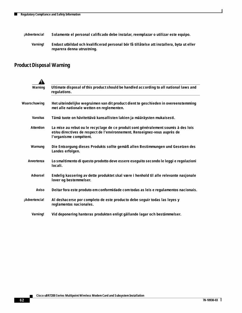
62Cisco uBR7200 Series Multipoint Wireless Modem Card and Subsystem Installation
78-10930-03
Regulatory Compliance and Safety Information
Product Disposal Warning
¡Advertencia! Solamente el personal calificado debe instalar, reemplazar o utilizar este equipo.
Varning! Endast utbildad och kvalificerad personal bör få tillåtelse att installera, byta ut ellerreparera denna utrustning.
Warning Ultimate disposal of this product should be handled according to all national laws andregulations.
Waarschuwing Het uiteindelijke wegruimen van dit product dient te geschieden in overeenstemmingmet alle nationale wetten en reglementen.
Varoitus Tämä tuote on hävitettävä kansallisten lakien ja määräysten mukaisesti.
Attention La mise au rebut ou le recyclage de ce produit sont généralement soumis à des loiset/ou directives de respect de l'environnement. Renseignez-vous auprès del'organisme compétent.
Warnung Die Entsorgung dieses Produkts sollte gemäß allen Bestimmungen und Gesetzen desLandes erfolgen.
Avvertenza Lo smaltimento di questo prodotto deve essere eseguito secondo le leggi e regolazionilocali.
Advarsel Endelig kassering av dette produktet skal være i henhold til alle relevante nasjonalelover og bestemmelser.
Aviso Deitar fora este produto em conformidade com todas as leis e regulamentos nacionais.
¡Advertencia! Al deshacerse por completo de este producto debe seguir todas las leyes yreglamentos nacionales.
Varning! Vid deponering hanteras produkten enligt gällande lagar och bestämmelser.
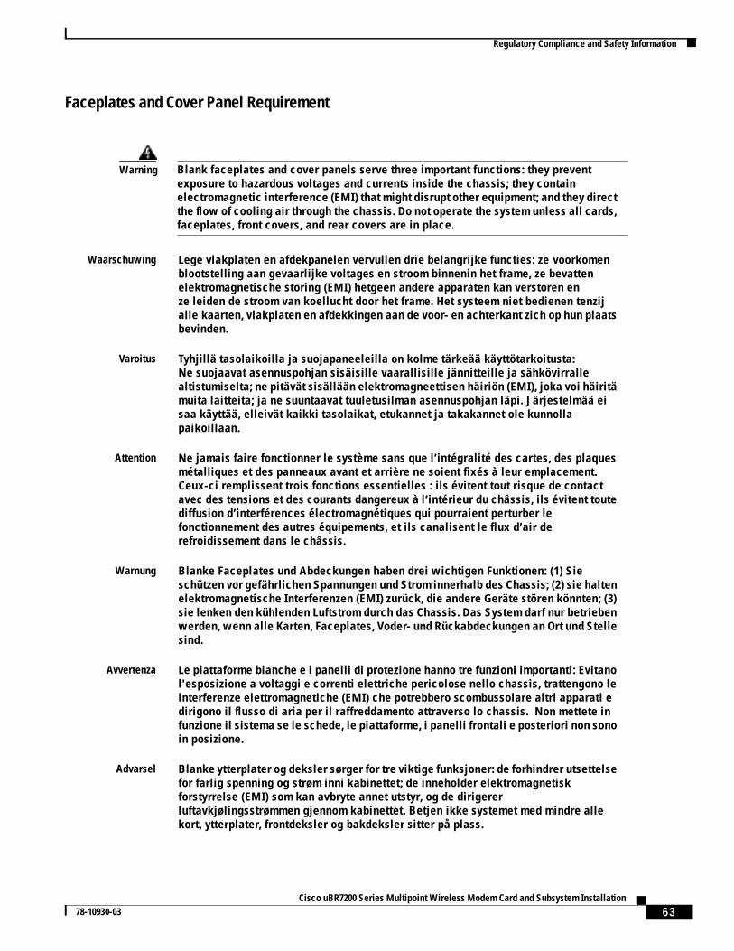
63Cisco uBR7200 Series Multipoint Wireless Modem Card and Subsystem Installation
78-10930-03
Regulatory Compliance and Safety Information
Faceplates and Cover Panel Requirement
Warning Blank faceplates and cover panels serve three important functions: they preventexposure to hazardous voltages and currents inside the chassis; they containelectromagnetic interference (EMI) that might disrupt other equipment; and they directthe flow of cooling air through the chassis. Do not operate the system unless all cards,faceplates, front covers, and rear covers are in place.
Waarschuwing Lege vlakplaten en afdekpanelen vervullen drie belangrijke functies: ze voorkomenblootstelling aan gevaarlijke voltages en stroom binnenin het frame, ze bevattenelektromagnetische storing (EMI) hetgeen andere apparaten kan verstoren enze leiden de stroom van koellucht door het frame. Het systeem niet bedienen tenzijalle kaarten, vlakplaten en afdekkingen aan de voor- en achterkant zich op hun plaatsbevinden.
Varoitus Tyhjillä tasolaikoilla ja suojapaneeleilla on kolme tärkeää käyttötarkoitusta:Ne suojaavat asennuspohjan sisäisille vaarallisille jännitteille ja sähkövirrallealtistumiselta; ne pitävät sisällään elektromagneettisen häiriön (EMI), joka voi häiritämuita laitteita; ja ne suuntaavat tuuletusilman asennuspohjan läpi. Järjestelmää eisaa käyttää, elleivät kaikki tasolaikat, etukannet ja takakannet ole kunnollapaikoillaan.
Attention Ne jamais faire fonctionner le système sans que l’intégralité des cartes, des plaquesmétalliques et des panneaux avant et arrière ne soient fixés à leur emplacement.Ceux-ci remplissent trois fonctions essentielles : ils évitent tout risque de contactavec des tensions et des courants dangereux à l’intérieur du châssis, ils évitent toutediffusion d’interférences électromagnétiques qui pourraient perturber lefonctionnement des autres équipements, et ils canalisent le flux d’air derefroidissement dans le châssis.
Warnung Blanke Faceplates und Abdeckungen haben drei wichtigen Funktionen: (1) Sieschützen vor gefährlichen Spannungen und Strom innerhalb des Chassis; (2) sie haltenelektromagnetische Interferenzen (EMI) zurück, die andere Geräte stören könnten; (3)sie lenken den kühlenden Luftstrom durch das Chassis. Das System darf nur betriebenwerden, wenn alle Karten, Faceplates, Voder- und Rückabdeckungen an Ort und Stellesind.
Avvertenza Le piattaforme bianche e i panelli di protezione hanno tre funzioni importanti: Evitanol'esposizione a voltaggi e correnti elettriche pericolose nello chassis, trattengono leinterferenze elettromagnetiche (EMI) che potrebbero scombussolare altri apparati edirigono il flusso di aria per il raffreddamento attraverso lo chassis. Non mettete infunzione il sistema se le schede, le piattaforme, i panelli frontali e posteriori non sonoin posizione.
Advarsel Blanke ytterplater og deksler sørger for tre viktige funksjoner: de forhindrer utsettelsefor farlig spenning og strøm inni kabinettet; de inneholder elektromagnetiskforstyrrelse (EMI) som kan avbryte annet utstyr, og de dirigererluftavkjølingsstrømmen gjennom kabinettet. Betjen ikke systemet med mindre allekort, ytterplater, frontdeksler og bakdeksler sitter på plass.
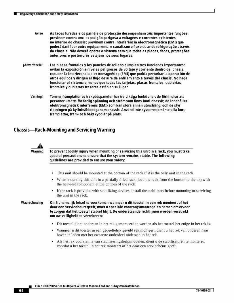
64Cisco uBR7200 Series Multipoint Wireless Modem Card and Subsystem Installation
78-10930-03
Regulatory Compliance and Safety Information
Chassis—Rack-Mounting and Servicing Warning
Aviso As faces furadas e os painéis de protecção desempenham três importantes funções:previnem contra uma exposição perigosa a voltagens e correntes existentesno interior do chassis; previnem contra interferência electromagnética (EMI) quepoderá danificar outro equipamento; e canalizam o fluxo do ar de refrigeração atravésdo chassis. Não deverá operar o sistema sem que todas as placas, faces, protecçõesanteriores e posteriores estejam nos seus lugares.
¡Advertencia! Las placas frontales y los paneles de relleno cumplen tres funciones importantes:evitan la exposición a niveles peligrosos de voltaje y corriente dentro del chasis;reducen la interferencia electromagnética (EMI) que podría perturbar la operación deotros equipos y dirigen el flujo de aire de enfriamiento a través del chasis. No hagafuncionar el sistema a menos que todas las tarjetas, placas frontales, cubiertasfrontales y cubiertas traseras estén en su lugar.
Varning! Tomma framplattor och skyddspaneler har tre viktiga funktioner: de förhindrar attpersoner utsätts för farlig spänning och ström som finns inuti chassit; de innehållerelektromagnetisk interferens (EMI) som kan störa annan utrustning; och de styrriktningen på kylluftsflödet genom chassit. Använd inte systemet om inte alla kort,framplattor, fram- och bakskydd är på plats.
Warning To prevent bodily injury when mounting or servicing this unit in a rack, you must takespecial precautions to ensure that the system remains stable. The followingguidelines are provided to ensure your safety:
• This unit should be mounted at the bottom of the rack if it is the only unit in the rack.
• When mounting this unit in a partially filled rack, load the rack from the bottom to the top withthe heaviest component at the bottom of the rack.
• If the rack is provided with stabilizing devices, install the stabilizers before mounting or servicingthe unit in the rack.
Waarschuwing Om lichamelijk letsel te voorkomen wanneer u dit toestel in een rek monteert of hetdaar een servicebeurt geeft, moet u speciale voorzorgsmaatregelen nemen om ervoorte zorgen dat het toestel stabiel blijft. De onderstaande richtlijnen worden verstrektom uw veiligheid te verzekeren:
• Dit toestel dient onderaan in het rek gemonteerd te worden als het toestel het enige in het rek is.
• Wanneer u dit toestel in een gedeeltelijk gevuld rek monteert, dient u het rek van onderen naarboven te laden met het zwaarste onderdeel onderaan in het rek.
• Als het rek voorzien is van stabiliseringshulpmiddelen, dient u de stabilisatoren te monterenvoordat u het toestel in het rek monteert of het daar een servicebeurt geeft.
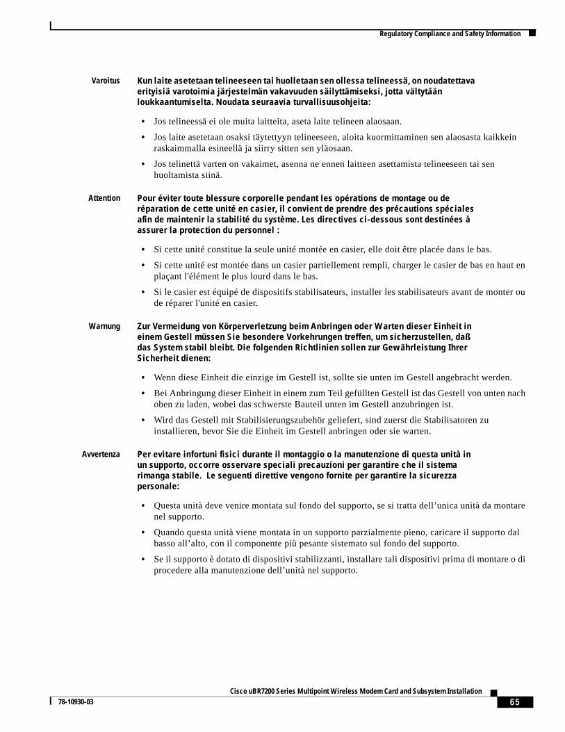
65Cisco uBR7200 Series Multipoint Wireless Modem Card and Subsystem Installation
78-10930-03
Regulatory Compliance and Safety Information
Varoitus Kun laite asetetaan telineeseen tai huolletaan sen ollessa telineessä, on noudatettavaerityisiä varotoimia järjestelmän vakavuuden säilyttämiseksi, jotta vältytäänloukkaantumiselta. Noudata seuraavia turvallisuusohjeita:
• Jos telineessä ei ole muita laitteita, aseta laite telineen alaosaan.
• Jos laite asetetaan osaksi täytettyyn telineeseen, aloita kuormittaminen sen alaosasta kaikkeinraskaimmalla esineellä ja siirry sitten sen yläosaan.
• Jos telinettä varten on vakaimet, asenna ne ennen laitteen asettamista telineeseen tai senhuoltamista siinä.
Attention Pour éviter toute blessure corporelle pendant les opérations de montage ou deréparation de cette unité en casier, il convient de prendre des précautions spécialesafin de maintenir la stabilité du système. Les directives ci-dessous sont destinées àassurer la protection du personnel :
• Si cette unité constitue la seule unité montée en casier, elle doit être placée dans le bas.
• Si cette unité est montée dans un casier partiellement rempli, charger le casier de bas en haut enplaçant l'élément le plus lourd dans le bas.
• Si le casier est équipé de dispositifs stabilisateurs, installer les stabilisateurs avant de monter oude réparer l'unité en casier.
Warnung Zur Vermeidung von Körperverletzung beim Anbringen oder Warten dieser Einheit ineinem Gestell müssen Sie besondere Vorkehrungen treffen, um sicherzustellen, daßdas System stabil bleibt. Die folgenden Richtlinien sollen zur Gewährleistung IhrerSicherheit dienen:
• Wenn diese Einheit die einzige im Gestell ist, sollte sie unten im Gestell angebracht werden.
• Bei Anbringung dieser Einheit in einem zum Teil gefüllten Gestell ist das Gestell von unten nachoben zu laden, wobei das schwerste Bauteil unten im Gestell anzubringen ist.
• Wird das Gestell mit Stabilisierungszubehör geliefert, sind zuerst die Stabilisatoren zuinstallieren, bevor Sie die Einheit im Gestell anbringen oder sie warten.
Avvertenza Per evitare infortuni fisici durante il montaggio o la manutenzione di questa unità inun supporto, occorre osservare speciali precauzioni per garantire che il sistemarimanga stabile. Le seguenti direttive vengono fornite per garantire la sicurezzapersonale:
• Questa unità deve venire montata sul fondo del supporto, se si tratta dell’unica unità da montarenel supporto.
• Quando questa unità viene montata in un supporto parzialmente pieno, caricare il supporto dalbasso all’alto, con il componente più pesante sistemato sul fondo del supporto.
• Se il supporto è dotato di dispositivi stabilizzanti, installare tali dispositivi prima di montare o diprocedere alla manutenzione dell’unità nel supporto.
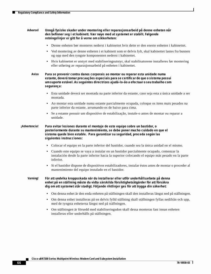
66Cisco uBR7200 Series Multipoint Wireless Modem Card and Subsystem Installation
78-10930-03
Regulatory Compliance and Safety Information
Advarsel Unngå fysiske skader under montering eller reparasjonsarbeid på denne enheten nården befinner seg i et kabinett. Vær nøye med at systemet er stabilt. Følgenderetningslinjer er gitt for å verne om sikkerheten:
• Denne enheten bør monteres nederst i kabinettet hvis dette er den eneste enheten i kabinettet.
• Ved montering av denne enheten i et kabinett som er delvis fylt, skal kabinettet lastes fra bunnenog opp med den tyngste komponenten nederst i kabinettet.
• Hvis kabinettet er utstyrt med stabiliseringsutstyr, skal stabilisatorene installeres før monteringeller utføring av reparasjonsarbeid på enheten i kabinettet.
Aviso Para se prevenir contra danos corporais ao montar ou reparar esta unidade numaestante, deverá tomar precauções especiais para se certificar de que o sistema possuium suporte estável. As seguintes directrizes ajudá-lo-ão a efectuar o seu trabalho comsegurança:
• Esta unidade deverá ser montada na parte inferior da estante, caso seja esta a única unidade a sermontada.
• Ao montar esta unidade numa estante parcialmente ocupada, coloque os itens mais pesados naparte inferior da estante, arrumando-os de baixo para cima.
• Se a estante possuir um dispositivo de estabilização, instale-o antes de montar ou reparar aunidade.
¡Advertencia! Para evitar lesiones durante el montaje de este equipo sobre un bastidor, oposteriormente durante su mantenimiento, se debe poner mucho cuidado en que elsistema quede bien estable. Para garantizar su seguridad, proceda según lassiguientes instrucciones:
• Colocar el equipo en la parte inferior del bastidor, cuando sea la única unidad en el mismo.
• Cuando este equipo se vaya a instalar en un bastidor parcialmente ocupado, comenzar lainstalación desde la parte inferior hacia la superior colocando el equipo más pesado en la parteinferior.
• Si el bastidor dispone de dispositivos estabilizadores, instalar éstos antes de montar o proceder almantenimiento del equipo instalado en el bastidor.
Varning! För att undvika kroppsskada när du installerar eller utför underhållsarbete på dennaenhet på en ställning måste du vidta särskilda försiktighetsåtgärder för att försäkradig om att systemet står stadigt. Följande riktlinjer ges för att trygga din säkerhet:
• Om denna enhet är den enda enheten på ställningen skall den installeras längst ned på ställningen.
• Om denna enhet installeras på en delvis fylld ställning skall ställningen fyllas nedifrån och upp,med de tyngsta enheterna längst ned på ställningen.
• Om ställningen är försedd med stabiliseringsdon skall dessa monteras fast innan enheteninstalleras eller underhålls på ställningen.
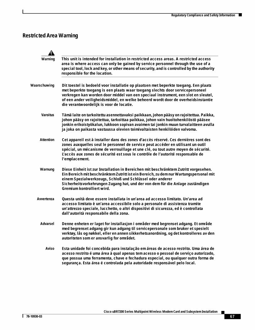
67Cisco uBR7200 Series Multipoint Wireless Modem Card and Subsystem Installation
78-10930-03
Regulatory Compliance and Safety Information
Restricted Area Warning
Warning This unit is intended for installation in restricted access areas. A restricted accessarea is where access can only be gained by service personnel through the use of aspecial tool, lock and key, or other means of security, and is controlled by the authorityresponsible for the location.
Waarschuwing Dit toestel is bedoeld voor installatie op plaatsen met beperkte toegang. Een plaatsmet beperkte toegang is een plaats waar toegang slechts door servicepersoneelverkregen kan worden door middel van een speciaal instrument, een slot en sleutel,of een ander veiligheidsmiddel, en welke beheerd wordt door de overheidsinstantiedie verantwoordelijk is voor de locatie.
Varoitus Tämä laite on tarkoitettu asennettavaksi paikkaan, johon pääsy on rajoitettua. Paikka,johon pääsy on rajoitettua, tarkoittaa paikkaa, johon vain huoltohenkilöstö pääseejonkin erikoistyökalun, lukkoon sopivan avaimen tai jonkin muun turvalaitteen avullaja joka on paikasta vastuussa olevien toimivaltaisten henkilöiden valvoma.
Attention Cet appareil est à installer dans des zones d’accès réservé. Ces dernières sont deszones auxquelles seul le personnel de service peut accéder en utilisant un outilspécial, un mécanisme de verrouillage et une clé, ou tout autre moyen de sécurité.L’accès aux zones de sécurité est sous le contrôle de l’autorité responsable del’emplacement.
Warnung Diese Einheit ist zur Installation in Bereichen mit beschränktem Zutritt vorgesehen.Ein Bereich mit beschränktem Zutritt ist ein Bereich, zu dem nur Wartungspersonal miteinem Spezialwerkzeugs, Schloß und Schlüssel oder andererSicherheitsvorkehrungen Zugang hat, und der von dem für die Anlage zuständigenGremium kontrolliert wird.
Avvertenza Questa unità deve essere installata in un'area ad accesso limitato. Un'area adaccesso limitato è un'area accessibile solo a personale di assistenza tramiteun'attrezzo speciale, lucchetto, o altri dispositivi di sicurezza, ed è controllatadall'autorità responsabile della zona.
Advarsel Denne enheten er laget for installasjon i områder med begrenset adgang. Et områdemed begrenset adgang gir kun adgang til servicepersonale som bruker et spesieltverktøy, lås og nøkkel, eller en annen sikkerhetsanordning, og det kontrolleres av denautoriteten som er ansvarlig for området.
Aviso Esta unidade foi concebida para instalação em áreas de acesso restrito. Uma área deacesso restrito é uma área à qual apenas tem acesso o pessoal de serviço autorizado,que possua uma ferramenta, chave e fechadura especial, ou qualquer outra forma desegurança. Esta área é controlada pela autoridade responsável pelo local.
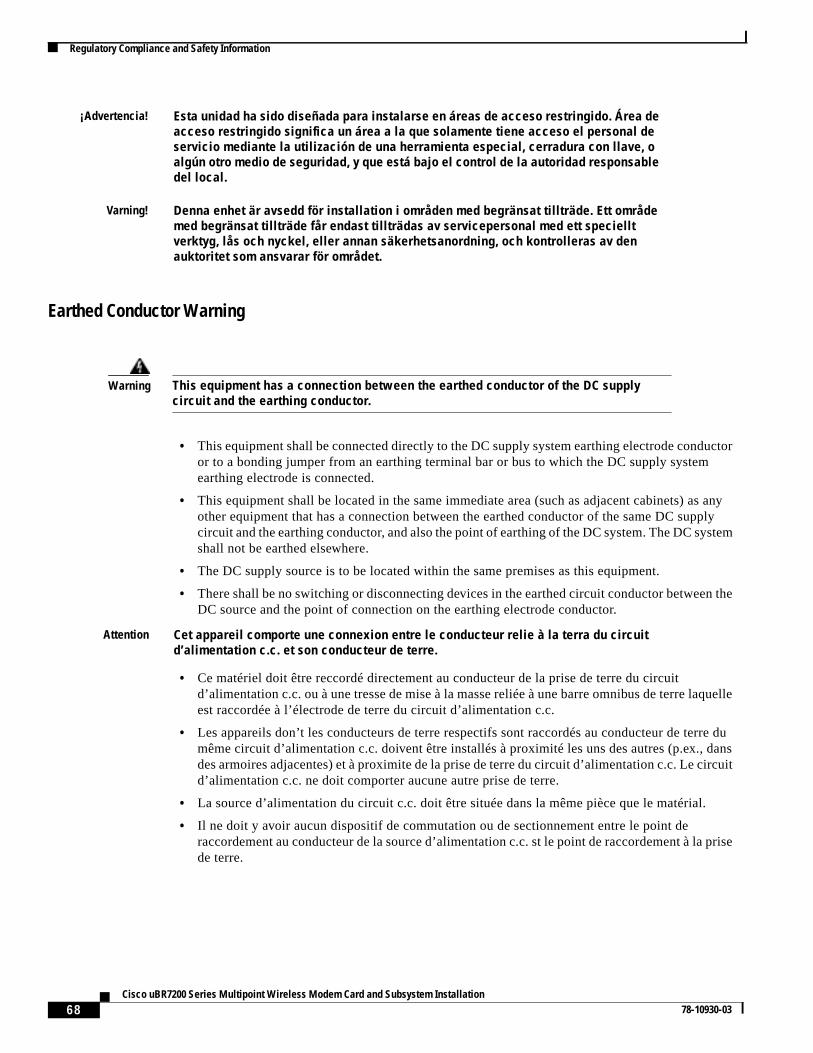
68Cisco uBR7200 Series Multipoint Wireless Modem Card and Subsystem Installation
78-10930-03
Regulatory Compliance and Safety Information
Earthed Conductor Warning
¡Advertencia! Esta unidad ha sido diseñada para instalarse en áreas de acceso restringido. Área deacceso restringido significa un área a la que solamente tiene acceso el personal deservicio mediante la utilización de una herramienta especial, cerradura con llave, oalgún otro medio de seguridad, y que está bajo el control de la autoridad responsabledel local.
Varning! Denna enhet är avsedd för installation i områden med begränsat tillträde. Ett områdemed begränsat tillträde får endast tillträdas av servicepersonal med ett specielltverktyg, lås och nyckel, eller annan säkerhetsanordning, och kontrolleras av denauktoritet som ansvarar för området.
Warning This equipment has a connection between the earthed conductor of the DC supplycircuit and the earthing conductor.
• This equipment shall be connected directly to the DC supply system earthing electrode conductoror to a bonding jumper from an earthing terminal bar or bus to which the DC supply systemearthing electrode is connected.
• This equipment shall be located in the same immediate area (such as adjacent cabinets) as anyother equipment that has a connection between the earthed conductor of the same DC supplycircuit and the earthing conductor, and also the point of earthing of the DC system. The DC systemshall not be earthed elsewhere.
• The DC supply source is to be located within the same premises as this equipment.
• There shall be no switching or disconnecting devices in the earthed circuit conductor between theDC source and the point of connection on the earthing electrode conductor.
Attention Cet appareil comporte une connexion entre le conducteur relie à la terra du circuitd’alimentation c.c. et son conducteur de terre.
• Ce matériel doit être reccordé directement au conducteur de la prise de terre du circuitd’alimentation c.c. ou à une tresse de mise à la masse reliée à une barre omnibus de terre laquelleest raccordée à l’électrode de terre du circuit d’alimentation c.c.
• Les appareils don’t les conducteurs de terre respectifs sont raccordés au conducteur de terre dumême circuit d’alimentation c.c. doivent être installés à proximité les uns des autres (p.ex., dansdes armoires adjacentes) et à proximite de la prise de terre du circuit d’alimentation c.c. Le circuitd’alimentation c.c. ne doit comporter aucune autre prise de terre.
• La source d’alimentation du circuit c.c. doit être située dans la même pièce que le matérial.
• Il ne doit y avoir aucun dispositif de commutation ou de sectionnement entre le point deraccordement au conducteur de la source d’alimentation c.c. st le point de raccordement à la prisede terre.
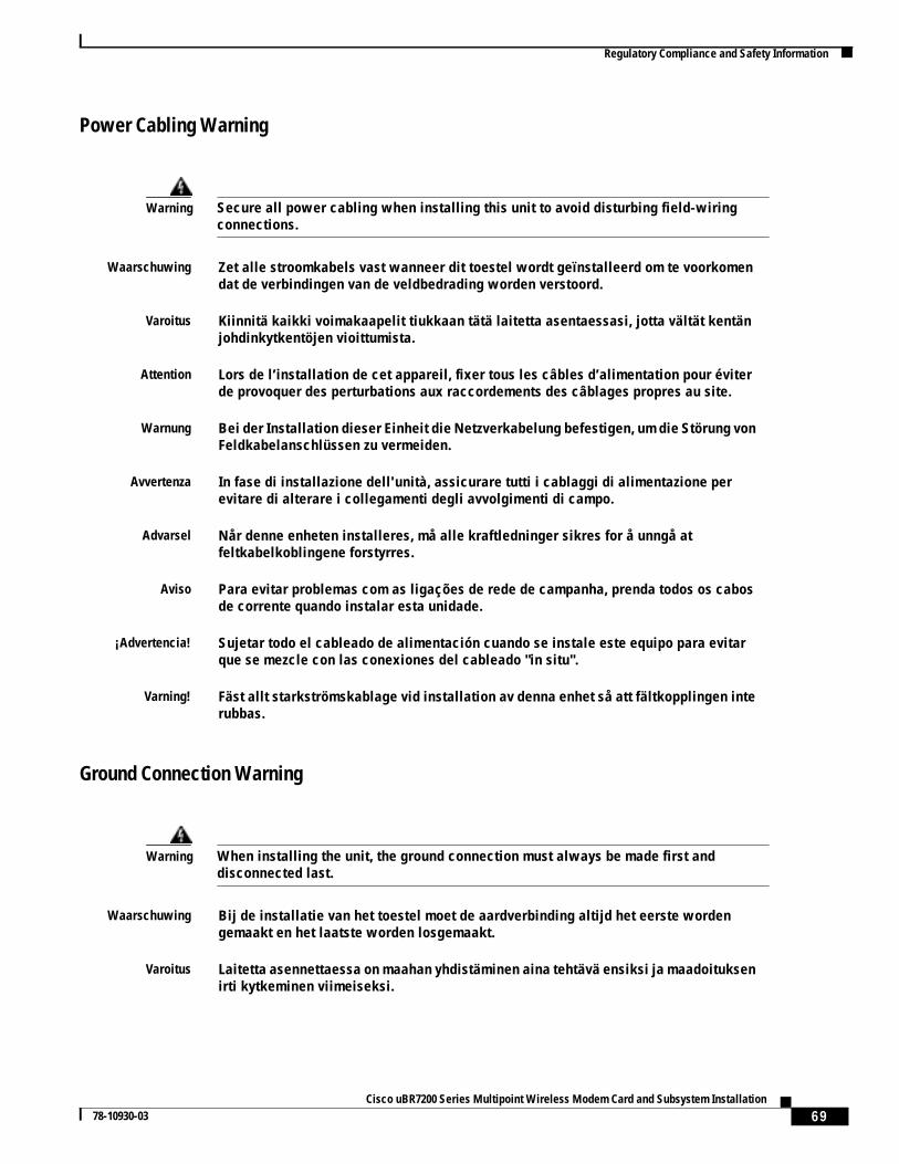
69Cisco uBR7200 Series Multipoint Wireless Modem Card and Subsystem Installation
78-10930-03
Regulatory Compliance and Safety Information
Power Cabling Warning
Ground Connection Warning
Warning Secure all power cabling when installing this unit to avoid disturbing field-wiringconnections.
Waarschuwing Zet alle stroomkabels vast wanneer dit toestel wordt geïnstalleerd om te voorkomendat de verbindingen van de veldbedrading worden verstoord.
Varoitus Kiinnitä kaikki voimakaapelit tiukkaan tätä laitetta asentaessasi, jotta vältät kentänjohdinkytkentöjen vioittumista.
Attention Lors de l’installation de cet appareil, fixer tous les câbles d’alimentation pour éviterde provoquer des perturbations aux raccordements des câblages propres au site.
Warnung Bei der Installation dieser Einheit die Netzverkabelung befestigen, um die Störung vonFeldkabelanschlüssen zu vermeiden.
Avvertenza In fase di installazione dell'unità, assicurare tutti i cablaggi di alimentazione perevitare di alterare i collegamenti degli avvolgimenti di campo.
Advarsel Når denne enheten installeres, må alle kraftledninger sikres for å unngå atfeltkabelkoblingene forstyrres.
Aviso Para evitar problemas com as ligações de rede de campanha, prenda todos os cabosde corrente quando instalar esta unidade.
¡Advertencia! Sujetar todo el cableado de alimentación cuando se instale este equipo para evitarque se mezcle con las conexiones del cableado "in situ".
Varning! Fäst allt starkströmskablage vid installation av denna enhet så att fältkopplingen interubbas.
Warning When installing the unit, the ground connection must always be made first anddisconnected last.
Waarschuwing Bij de installatie van het toestel moet de aardverbinding altijd het eerste wordengemaakt en het laatste worden losgemaakt.
Varoitus Laitetta asennettaessa on maahan yhdistäminen aina tehtävä ensiksi ja maadoituksenirti kytkeminen viimeiseksi.
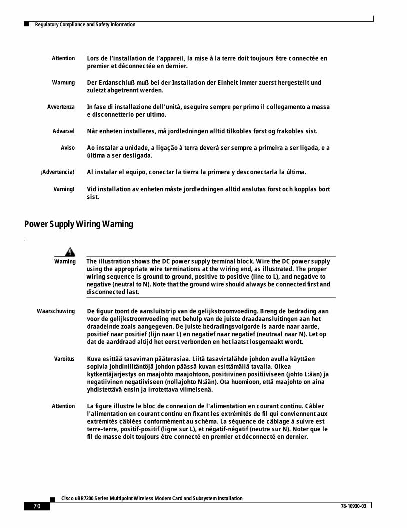
70Cisco uBR7200 Series Multipoint Wireless Modem Card and Subsystem Installation
78-10930-03
Regulatory Compliance and Safety Information
Power Supply Wiring Warning.
Attention Lors de l’installation de l’appareil, la mise à la terre doit toujours être connectée enpremier et déconnectée en dernier.
Warnung Der Erdanschluß muß bei der Installation der Einheit immer zuerst hergestellt undzuletzt abgetrennt werden.
Avvertenza In fase di installazione dell'unità, eseguire sempre per primo il collegamento a massae disconnetterlo per ultimo.
Advarsel Når enheten installeres, må jordledningen alltid tilkobles først og frakobles sist.
Aviso Ao instalar a unidade, a ligação à terra deverá ser sempre a primeira a ser ligada, e aúltima a ser desligada.
¡Advertencia! Al instalar el equipo, conectar la tierra la primera y desconectarla la última.
Varning! Vid installation av enheten måste jordledningen alltid anslutas först och kopplas bortsist.
Warning The illustration shows the DC power supply terminal block. Wire the DC power supplyusing the appropriate wire terminations at the wiring end, as illustrated. The properwiring sequence is ground to ground, positive to positive (line to L), and negative tonegative (neutral to N). Note that the ground wire should always be connected first anddisconnected last.
Waarschuwing De figuur toont de aansluitstrip van de gelijkstroomvoeding. Breng de bedrading aanvoor de gelijkstroomvoeding met behulp van de juiste draadaansluitingen aan hetdraadeinde zoals aangegeven. De juiste bedradingsvolgorde is aarde naar aarde,positief naar positief (lijn naar L) en negatief naar negatief (neutraal naar N). Let opdat de aarddraad altijd het eerst verbonden en het laatst losgemaakt wordt.
Varoitus Kuva esittää tasavirran pääterasiaa. Liitä tasavirtalähde johdon avulla käyttäensopivia johdinliitäntöjä johdon päässä kuvan esittämällä tavalla. Oikeakytkentäjärjestys on maajohto maajohtoon, positiivinen positiiviseen (johto L:ään) janegatiivinen negatiiviseen (nollajohto N:ään). Ota huomioon, että maajohto on ainayhdistettävä ensin ja irrotettava viimeisenä.
Attention La figure illustre le bloc de connexion de l'alimentation en courant continu. Câblerl'alimentation en courant continu en fixant les extrémités de fil qui conviennent auxextrémités câblées conformément au schéma. La séquence de câblage à suivre estterre-terre, positif-positif (ligne sur L), et négatif-négatif (neutre sur N). Noter que lefil de masse doit toujours être connecté en premier et déconnecté en dernier.
71Cisco uBR7200 Series Multipoint Wireless Modem Card and Subsystem Installation
78-10930-03
Regulatory Compliance and Safety Information
Copper Conductors Warning
Warnung Die Abbildung zeigt den Terminalblock des Gleichstrom-Netzgeräts. Verdrahten Siedas Gleichstrom-Netzgerät unter Verwendung von geeigneten Kabelschuhen amVerdrahtungsende (siehe Abbildung). Die richtige Verdrahtungsfolge ist Erde an Erde,positiv an positiv (Leitung an L) und negativ an negativ (neutral an N). Beachten Siebitte, daß der Erdungsdraht immer als erster verbunden und als letzter abgetrenntwerden sollte.
Avvertenza L’illustrazione mostra la morsettiera dell alimentatore CC. Cablare l’alimentatore CCusando i connettori adatti all’estremità del cablaggio, come illustrato. La correttasequenza di cablaggio è da massa a massa, da positivo a positivo (da linea ad L) e danegativo a negativo (da neutro a N). Tenere presente che il filo di massa deve semprevenire collegato per primo e scollegato per ultimo.
Advarsel Figuren viser likestrømforsyningsenhetens tilkoplingsterminal.Likestrømforsyningsenheten tilkoples ved hjelp av ledningsavslutningene, slik somvist i figuren. Riktig tilkoplingssekvens er jord til jord, positiv til positv (linje til L), ognegativ til negativ (nøytral til N). Husk at jordingsledningen alltid bør tilkoples førstog frakoples sist.
Aviso A figura mostra o bloco do terminal de fornecimento de corrente contínua. Ligue ofornecimento de corrente contínua recorrendo aos terminadores localizados naextremidade do cabo, conforme ilustrado. A sequência correcta de instalação éterra-a-terra, positivo-positivo (linha para L), e negativo-negativo (neutro para N).Note que o fio de terra deverá ser sempre o primeiro a ser ligado, e o último a serdesligado.
¡Atención! La figura muestra la caja de bornes de la fuente de alimentación de corriente continua.Cablear la fuente de alimentación de corriente continua, usando los terminalesapropiados, en el extremo del cable tal como se muestra. Las conexiones debenrealizarse en el siguiente orden: tierra con tierra, positivo con positivo (la línea con laL) y negativo con negativo (el neutro con la N). Tenga en cuenta que el conductor detierra siempre tiene que conectarse el primero y desconectarse el último.
Varning! Illustrationen visar anslutningsplinten för likströmförsörjningsenheten. Kopplaledningarna till strömförsörjningsenheten med lämpliga ledningsavslutningar sombilden visar. Korrekt kopplingssekvens är jord till jord, positiv till positiv (linje till L)och negativ till negativ (neutral till N). Observera att jordledningen alltid skallanslutas först och kopplas bort sist.
Warning Use copper conductors only.
Waarschuwing Gebruik alleen koperen geleiders.
Varoitus Käytä vain kuparijohtimia.
Attention Utilisez uniquement des conducteurs en cuivre.
72Cisco uBR7200 Series Multipoint Wireless Modem Card and Subsystem Installation
78-10930-03
Regulatory Compliance and Safety Information
Exposed DC Power Wire Warning
Warnung Verwenden Sie ausschließlich Kupferleiter.
Avvertenza Usate unicamente dei conduttori di rame.
Advarsel Bruk bare kobberledninger.
Aviso Utilize apenas fios condutores de cobre.
¡Advertencia! Emplee sólo conductores de cobre.
Varning! Använd endast ledare av koppar.
Warning An exposed wire lead from a DC-input power source can conduct harmful levels ofelectricity. Be sure that no exposed portion of the DC-input power source wire extendsfrom the terminal block plug.
Waarschuwing Een blootgestelde verbindingsdraad van een ingangsgelijkstroombron kangevaarlijke elektriciteitsniveaus geleiden. Zorg ervoor dat geen blootgesteld deel vanhet draad van de ingangsgelijkstroombron zich uitstrekt vanuit het aansluitblok van determinal.
Varoitus Tasavirtalähteestä tuleva avoin johto voi johtaa vaarallisen määrän sähköä. Varmista,ettei kaapelikengän pistokkeesta tule esille lainkaan tasavirtajohdon avointa osaa.
Attention Pour éviter tout risque de choc électrique, vérifiez que les câbles d'alimentationsecteur sont protégés par une gaine. Aucun fil dénudé ne doit apparaître hors du blocd'alimentation du terminal.
Warnung Eine ungeschützte Kabelleitung von einer Gleichstrom-Eingangsspannungsquellekann schädliche Elektrizitätslevel führen. Achten Sie darauf, daß von demKlemmleistenstecker aus kein ungeschütztes Eingangsgleichstromkabel freiliegt.
Avvertenza Un cavo elettrico scoperto proveniente da un alimentatore DC-INPUT può trasmetterescariche elettriche ad elevata tensione. Assicuratevi che i cavi in uscitadall'alimentatore DC-input non presentino punti scoperti.
Advarsel En avdekket ledning fra en likestrømskilde kan lede farlig elektrisitet. Kontroller atingen avdekkede deler av ledningen til likestrømskilden stikker ut av terminalenskoblingsblokk.
Aviso Um fio condutor exposto de uma unidade de entrada de DC (corrente contínua) podetransportar níveis perigosos de electricidade. Certifique-se de que nenhuma secçãoexposta de um fio condutor da fonte de energia de entrada de DC se extende a partirda ficha da placa de terminais.
73Cisco uBR7200 Series Multipoint Wireless Modem Card and Subsystem Installation
78-10930-03
Regulatory Compliance and Safety Information
48 VDC Power System Warning
¡Advertencia! Un cable desnudo de una fuente de entrada de alimentación de corriente directa (DC)puede conducir niveles de electricidad peligrosos. Asegúrese de que ninguna partedel cable de la fuente de alimentación de DC de entrada sale del enchufe del bloquede terminal.
Varning! En blottad trådledning från en likströmsförsörjningsenhet kan utgöra en ledare förskadliga elektricitetsnivåer. Se till att inte någon blottad ledningsdel frånlikströmsförsörjningsenheten sticker ut från stiftplinten.
Warning The customer 48 volt power system must provide reinforced insulation between theprimary AC power and the 48 VDC output.
Waarschuwing Het 48 volt stroomsysteem van de klant dient versterkte isolatie tussen de primairewisselstroom en de 48 VDC-uitgang te verschaffen.
Varoitus Asiakkaan 48 voltin virtajärjestelmän on tarjottava vahvistettu eriste ensisijaisenvaihtovirtalähteen ja 48 voltin tasavirtaliitännän välille.
Attention Le bloc d'alimentation 48 volts du client doit assurer une isolation renforcée entrel'alimentation CA principale et la sortie 48 V CC.
Warnung Das 48-Volt-Stromsystem des Kunden muß eine verstärkte Isolierung zwischen demprimären Wechselstrom und dem 48 VDC-Output aufweisen.
Avvertenza Il sistema elettrico di 48 volt del cliente deve avere un isolamento fra l'alimentatoreelettrico AC e il VDC 48 di output.
Advarsel Kundens eget 48 volts strømopplegg må ha forsterket isolasjon mellom den primærevekselstrømskilden og den 48 volts likestrømsutgangen.
Aviso O sistema habitual de corrente de 48 volts deverá fornecer isolamento reforçado entrea corrente alternada (AC) principal e a saída de 48 VDC (tensão em corrente contínua).
¡Advertencia! Aviso: El sistema del cliente de 48 voltios debe proporcionar aislamiento reforzadoentre la energía principal AC y la potencia de salida de 48 VDC.
Varning! Kundens 48-volt strömsystem måste vara försett med förstärkt isolering mellan denprimära växelströmmen och utmatningen av 48 V likström.
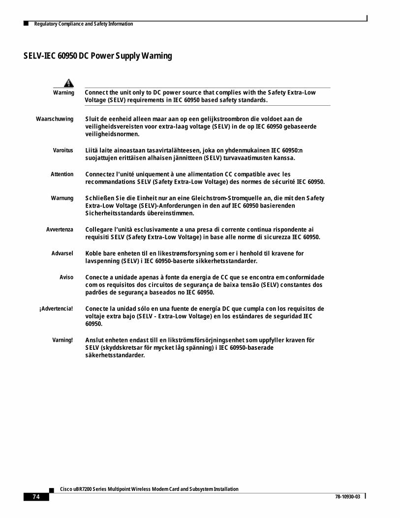
74Cisco uBR7200 Series Multipoint Wireless Modem Card and Subsystem Installation
78-10930-03
Regulatory Compliance and Safety Information
SELV-IEC 60950 DC Power Supply Warning
Warning Connect the unit only to DC power source that complies with the Safety Extra-LowVoltage (SELV) requirements in IEC 60950 based safety standards.
Waarschuwing Sluit de eenheid alleen maar aan op een gelijkstroombron die voldoet aan deveiligheidsvereisten voor extra-laag voltage (SELV) in de op IEC 60950 gebaseerdeveiligheidsnormen.
Varoitus Liitä laite ainoastaan tasavirtalähteesen, joka on yhdenmukainen IEC 60950:nsuojattujen erittäisen alhaisen jännitteen (SELV) turvavaatimusten kanssa.
Attention Connectez l'unité uniquement à une alimentation CC compatible avec lesrecommandations SELV (Safety Extra-Low Voltage) des normes de sécurité IEC 60950.
Warnung Schließen Sie die Einheit nur an eine Gleichstrom-Stromquelle an, die mit den SafetyExtra-Low Voltage (SELV)-Anforderungen in den auf IEC 60950 basierendenSicherheitsstandards übereinstimmen.
Avvertenza Collegare l’unità esclusivamente a una presa di corrente continua rispondente airequisiti SELV (Safety Extra-Low Voltage) in base alle norme di sicurezza IEC 60950.
Advarsel Koble bare enheten til en likestrømsforsyning som er i henhold til kravene forlavspenning (SELV) i IEC 60950-baserte sikkerhetsstandarder.
Aviso Conecte a unidade apenas à fonte da energia de CC que se encontra em conformidadecom os requisitos dos circuitos de segurança de baixa tensão (SELV) constantes dospadrões de segurança baseados no IEC 60950.
¡Advertencia! Conecte la unidad sólo en una fuente de energía DC que cumpla con los requisitos devoltaje extra bajo (SELV - Extra-Low Voltage) en los estándares de seguridad IEC60950.
Varning! Anslut enheten endast till en likströmsförsörjningsenhet som uppfyller kraven förSELV (skyddskretsar för mycket låg spänning) i IEC 60950-baseradesäkerhetsstandarder.
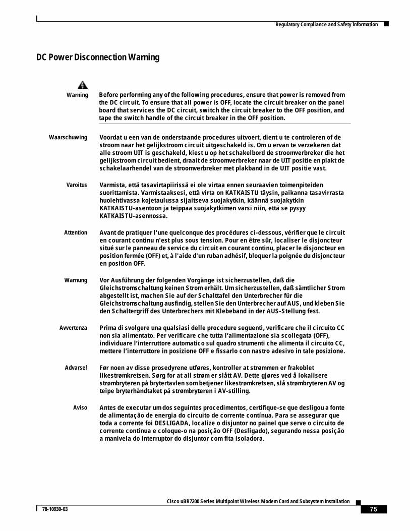
75Cisco uBR7200 Series Multipoint Wireless Modem Card and Subsystem Installation
78-10930-03
Regulatory Compliance and Safety Information
DC Power Disconnection Warning
Warning Before performing any of the following procedures, ensure that power is removed fromthe DC circuit. To ensure that all power is OFF, locate the circuit breaker on the panelboard that services the DC circuit, switch the circuit breaker to the OFF position, andtape the switch handle of the circuit breaker in the OFF position.
Waarschuwing Voordat u een van de onderstaande procedures uitvoert, dient u te controleren of destroom naar het gelijkstroom circuit uitgeschakeld is. Om u ervan te verzekeren datalle stroom UIT is geschakeld, kiest u op het schakelbord de stroomverbreker die hetgelijkstroom circuit bedient, draait de stroomverbreker naar de UIT positie en plakt deschakelaarhendel van de stroomverbreker met plakband in de UIT positie vast.
Varoitus Varmista, että tasavirtapiirissä ei ole virtaa ennen seuraavien toimenpiteidensuorittamista. Varmistaaksesi, että virta on KATKAISTU täysin, paikanna tasavirrastahuolehtivassa kojetaulussa sijaitseva suojakytkin, käännä suojakytkinKATKAISTU-asentoon ja teippaa suojakytkimen varsi niin, että se pysyyKATKAISTU-asennossa.
Attention Avant de pratiquer l'une quelconque des procédures ci-dessous, vérifier que le circuiten courant continu n'est plus sous tension. Pour en être sûr, localiser le disjoncteursitué sur le panneau de service du circuit en courant continu, placer le disjoncteur enposition fermée (OFF) et, à l'aide d'un ruban adhésif, bloquer la poignée du disjoncteuren position OFF.
Warnung Vor Ausführung der folgenden Vorgänge ist sicherzustellen, daß dieGleichstromschaltung keinen Strom erhält. Um sicherzustellen, daß sämtlicher Stromabgestellt ist, machen Sie auf der Schalttafel den Unterbrecher für dieGleichstromschaltung ausfindig, stellen Sie den Unterbrecher auf AUS, und kleben Sieden Schaltergriff des Unterbrechers mit Klebeband in der AUS-Stellung fest.
Avvertenza Prima di svolgere una qualsiasi delle procedure seguenti, verificare che il circuito CCnon sia alimentato. Per verificare che tutta l’alimentazione sia scollegata (OFF),individuare l’interruttore automatico sul quadro strumenti che alimenta il circuito CC,mettere l’interruttore in posizione OFF e fissarlo con nastro adesivo in tale posizione.
Advarsel Før noen av disse prosedyrene utføres, kontroller at strømmen er frakobletlikestrømkretsen. Sørg for at all strøm er slått AV. Dette gjøres ved å lokaliserestrømbryteren på brytertavlen som betjener likestrømkretsen, slå strømbryteren AV ogteipe bryterhåndtaket på strømbryteren i AV-stilling.
Aviso Antes de executar um dos seguintes procedimentos, certifique-se que desligou a fontede alimentação de energia do circuito de corrente contínua. Para se assegurar quetoda a corrente foi DESLIGADA, localize o disjuntor no painel que serve o circuito decorrente contínua e coloque-o na posição OFF (Desligado), segurando nessa posiçãoa manivela do interruptor do disjuntor com fita isoladora.
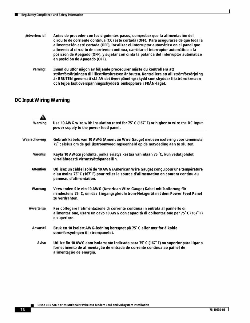
76Cisco uBR7200 Series Multipoint Wireless Modem Card and Subsystem Installation
78-10930-03
Regulatory Compliance and Safety Information
DC Input Wiring Warning
¡Advertencia! Antes de proceder con los siguientes pasos, comprobar que la alimentación delcircuito de corriente continua (CC) esté cortada (OFF). Para asegurarse de que toda laalimentación esté cortada (OFF), localizar el interruptor automático en el panel quealimenta al circuito de corriente continua, cambiar el interruptor automático a laposición de Apagado (OFF), y sujetar con cinta la palanca del interruptor automáticoen posición de Apagado (OFF).
Varning! Innan du utför någon av följande procedurer måste du kontrollera attströmförsörjningen till likströmskretsen är bruten. Kontrollera att all strömförsörjningär BRUTEN genom att slå AV det överspänningsskydd som skyddar likströmskretsenoch tejpa fast överspänningsskyddets omkopplare i FRÅN-läget.
Warning Use 10 AWG wire with insulation rated for 75˚ C (167˚ F) or higher to wire the DC inputpower supply to the power feed panel.
Waarschuwing Gebruik kabels van 10 AWG (American Wire Gauge) met een isolering voor tenminste75˚ celsius om de gelijkstroomvoedingseenheid op de netvoeding aan te sluiten.
Varoitus Käytä 10 AWG:n johdinta, jonka eristys kestää vähintään 75 ˚C, kun vedät johdotvirtalähteestä virransyöttöpaneeliin.
Attention Utilisez un câble isolé de 10 AWG (American Wire Gauge) conçu pour une températured'au moins 75˚ C (167˚ F) pour relier la source d'alimentation en courant continu aupanneau d'alimentation.
Warnung Verwenden Sie ein 10 AWG (American Wire Gauge) Kabel mit Isolierung fürmindestens 75˚ C, um das Eingangsgleichstrom-Netzgerät mit dem Power Feed Panelzu verdrahten.
Avvertenza Per collegare l'alimentazione di corrente continua in entrata al pannello dialimentazione, usare un cavo 10 AWG con capacità di coibentazione per 75˚ C (167˚ F)o superiore.
Advarsel Bruk en 10 isolert AWG-ledning beregnet på 75˚ C eller mer for å koblestrømforsyningen til strømpanelet.
Aviso Utilize fio 10 AWG com isolamento indicado para 75˚ C (167˚ F) ou superior para ligar ofornecimento de alimentação de entrada de corrente contínua ao painel dealimentação de energia.
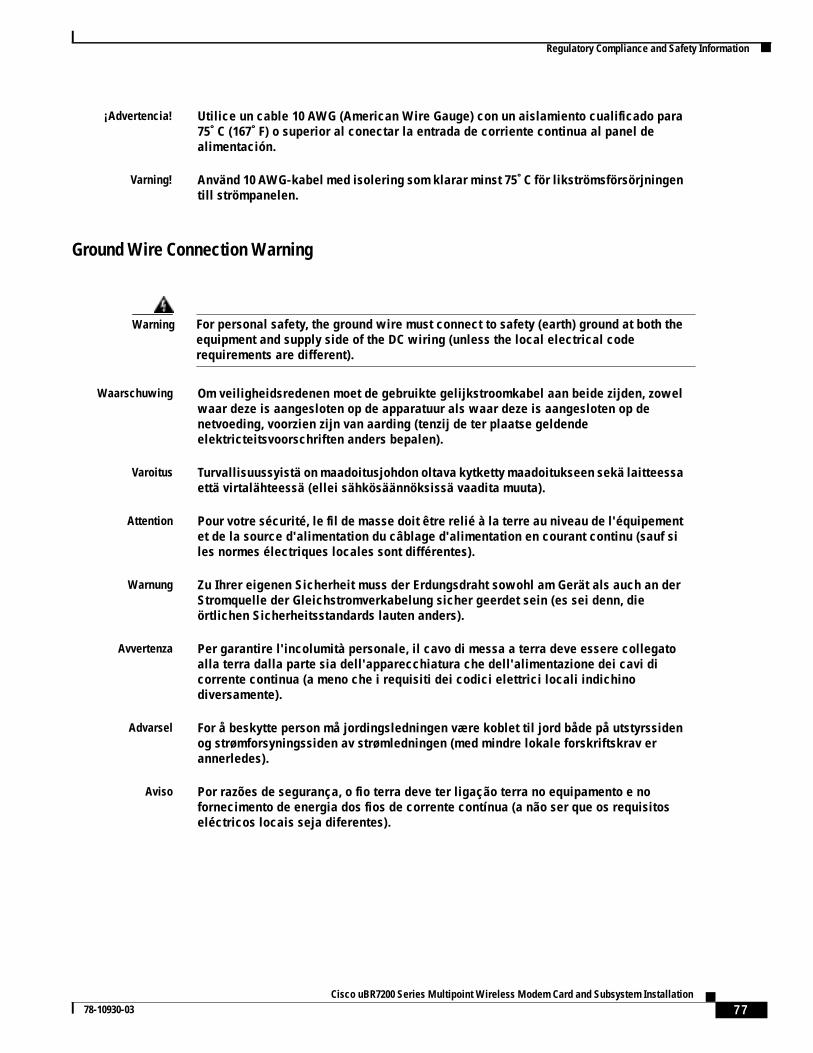
77Cisco uBR7200 Series Multipoint Wireless Modem Card and Subsystem Installation
78-10930-03
Regulatory Compliance and Safety Information
Ground Wire Connection Warning
¡Advertencia! Utilice un cable 10 AWG (American Wire Gauge) con un aislamiento cualificado para75˚ C (167˚ F) o superior al conectar la entrada de corriente continua al panel dealimentación.
Varning! Använd 10 AWG-kabel med isolering som klarar minst 75˚ C för likströmsförsörjningentill strömpanelen.
Warning For personal safety, the ground wire must connect to safety (earth) ground at both theequipment and supply side of the DC wiring (unless the local electrical coderequirements are different).
Waarschuwing Om veiligheidsredenen moet de gebruikte gelijkstroomkabel aan beide zijden, zowelwaar deze is aangesloten op de apparatuur als waar deze is aangesloten op denetvoeding, voorzien zijn van aarding (tenzij de ter plaatse geldendeelektricteitsvoorschriften anders bepalen).
Varoitus Turvallisuussyistä on maadoitusjohdon oltava kytketty maadoitukseen sekä laitteessaettä virtalähteessä (ellei sähkösäännöksissä vaadita muuta).
Attention Pour votre sécurité, le fil de masse doit être relié à la terre au niveau de l'équipementet de la source d'alimentation du câblage d'alimentation en courant continu (sauf siles normes électriques locales sont différentes).
Warnung Zu Ihrer eigenen Sicherheit muss der Erdungsdraht sowohl am Gerät als auch an derStromquelle der Gleichstromverkabelung sicher geerdet sein (es sei denn, dieörtlichen Sicherheitsstandards lauten anders).
Avvertenza Per garantire l'incolumità personale, il cavo di messa a terra deve essere collegatoalla terra dalla parte sia dell'apparecchiatura che dell'alimentazione dei cavi dicorrente continua (a meno che i requisiti dei codici elettrici locali indichinodiversamente).
Advarsel For å beskytte person må jordingsledningen være koblet til jord både på utstyrssidenog strømforsyningssiden av strømledningen (med mindre lokale forskriftskrav erannerledes).
Aviso Por razões de segurança, o fio terra deve ter ligação terra no equipamento e nofornecimento de energia dos fios de corrente contínua (a não ser que os requisitoseléctricos locais seja diferentes).
78Cisco uBR7200 Series Multipoint Wireless Modem Card and Subsystem Installation
78-10930-03
Regulatory Compliance and Safety Information
Ground Conductor Warning
¡Advertencia! Para mayor seguridad, el cable de toma de tierra debe conectarse a una toma de tierrasegura tanto en el equipo como en la parte del cableado de CC (a no ser que las normaseléctricas locales establezcan algo distinto).
Varning! Jordkabeln måste, för personsäkerhetens skull, vara jordad både vid utrustningen ochuttaget för likströmskablaget (om inte de lokala elföreskrifterna säger annorlunda).
Warning Never defeat the ground conductor or operate the equipment in the absence of asuitably installed ground conductor. Contact the appropriate electrical inspectionauthority or an electrician if you are uncertain that suitable grounding is available.
Waarschuwing De aardingsleiding mag nooit buiten werking gesteld worden en de apparatuur magnooit bediend worden zonder dat er een op de juiste wijze geïnstalleerdeaardingsleiding aanwezig is. Neem contact op met de bevoegde instantie voorelektrische inspecties of met een elektricien als u er niet zeker van bent dat er voorpassende aarding gezorgd is.
Varoitus Älä koskaan ohita maajohdinta tai käytä laitteita ilman oikein asennettuamaajohdinta. Ota yhteyttä asianmukaiseen sähkötarkastusviranomaiseen taisähköasentajaan, jos olet epävarma maadoituksen sopivuudesta.
Attention Ne jamais rendre inopérant le conducteur de masse ni utiliser l’équipement sans unconducteur de masse adéquatement installé. En cas de doute sur la mise à la masseappropriée disponible, s’adresser à l’organisme responsable de la sécurité électriqueou à un électricien.
Warnung Auf keinen Fall den Erdungsleiter unwirksam machen oder das Gerät ohne einensachgerecht installierten Erdungsleiter verwenden. Wenn Sie sich nicht sicher sind,ob eine sachgerechte Erdung vorhanden ist, wenden Sie sich an den zuständigenelektrischen Fachmann oder einen Elektriker.
Avvertenza Non escludere mai il conduttore di protezione né usare l’apparecchiatura in assenzadi un conduttore di protezione installato in modo corretto. Se non si sa con certezzache è disponibile un collegamento di messa a terra adeguato, esaminare le Norme CEIpertinenti o rivolgersi a un elettricista qualificato.
Advarsel Omgå aldri jordingslederen og bruk aldri utstyret uten riktig montert jordingsleder. Takontakt med det riktige organet for elektrisk inspeksjon eller en elektriker hvis du erusikker på om det finnes velegnet jording.
Aviso Nunca anule o condutor à terra nem opere o equipamento sem ter um condutor à terraadequadamente instalado. Em caso de dúvida em relação ao sistema de ligação àterra, contacte os serviços locais de inspecção eléctrica ou um electricistaqualificado.
79Cisco uBR7200 Series Multipoint Wireless Modem Card and Subsystem Installation
78-10930-03
Regulatory Compliance and Safety Information
Coaxial Cable Specification Warning
Advertencia No inhabilitar nunca el conductor de tierra ni hacer funcionar el equipo si no existeun conductor de tierra instalado correctamente. Póngase en contacto con unaautoridad apropiada de inspección eléctrica o con un electricista competente si noestá seguro de que hay una conexión a tierra adecuada.
Varning! Koppla aldrig från jordledningen och använd aldrig utrustningen utan en på lämpligtsätt installerad jordledning. Om det föreligger osäkerhet huruvida lämplig jordningfinns skall elektrisk besiktningsauktoritet eller elektriker kontaktas.
Warning Use 50-ohm coaxial cable with a center conductor size of 10 AWG or larger (forexample, LMR-400, 3/8-inch FSJ Superflex Heliax, or larger). Failure to do so can resultin overheating, fire, or long-term failure. Local and national electrical codes must beobserved.
Waarschuwing Gebruik coaxiale kabels van 50 ohm met een centrale ader van tenminste 10 AWG(American Wire Gauge), bijvoorbeeld LMR-400, 3/8-inch FSJ Superflex Heliax, ofgroter. Bij gebruik van andere kabels kan oververhitting optreden of kunnen zich oplange termijn systeemproblemen voordoen. Plaatselijke en nationale voorschriften ophet gebied van elektriciteitsvoorzieningen moeten in acht worden genomen.
Varoitus Käytä 50 ohmin koaksiaalikaapelia, jonka keskijohdin on kooltaan vähintään 10 AWG(esim. LMR-400, 3/8 tuuman FSJ Superflex Heliax tai suurempi). Ellet tee niin, voiseurauksena olla ylikuumeneminen, tulipalo tai pitkäaikainen häiriö. On noudatettavapaikallisia ja kansallisia sähkösäännöksiä.
Attention Utilisez un câble coaxial de 50 ohm doté d'un conducteur central d'au moins 10 AWG(American Wire Gauge), par exemple, LMR-400 ou FSJ Superflex Heliax d'au moins 3/8de pouce. Autrement, il y a risque de surchauffe, d'incendie ou de défaillance grave.Vous devez respecter les normes électriques locales et nationales.
Warnung Verwenden Sie ein 50-Ohm-Koaxialkabel mit einem Zentralleiter von mindestens 10AWG (beispielsweise LMR-400, 3/8-Zoll FSJ Superflex Heliax oder größer).Andernfalls besteht die Gefahr von Überhitzung, Brand oder langfristigen Schäden.Örtliche und nationale Sicherheitsstandards müssen eingehalten werden.
Avvertenza Usare un cavo coassiale da 50 ohm con dimensione di conduttore centrale di 10 AWGo superiore (ad esempio, LMR-400, FSJ Superflex Heliax 3/8 di pollice o superiore). Lamancata osservanza di queste indicazioni può risultare in surriscaldamento, incendioo eventuale malfunzionamento. È necessario osservare le normative in materiaelettrica locali e nazionali.
Advarsel Bruk en 50 ohms koakskabel med en senterleder med en størrelse på 10 AWG ellerstørre (f.eks. LMR-400, 3/8 tommers FSJ Superflex Heliax, eller større). Hvis ikke dettegjøres, kan det føre til overoppheting, brann eller langvarige driftsfeil. Lokale ognasjonale elektrisitetsforskrifter må følges.
80Cisco uBR7200 Series Multipoint Wireless Modem Card and Subsystem Installation
78-10930-03
Regulatory Compliance and Safety Information
Transverter Location Warning
Aviso Utilize um cabo coaxial de 50-ohm com um condutor central de 10 AWG ou superior(por exemplo, LMR-400, FSJ Superflex Heliax 3/8 pol., ou superior). O incumprimentopode ter como resultado sobreaquecimento, incêndio ou falhas a longo prazo. Devemser respeitados os preceitos eléctricos locais e nacionais.
¡Advertencia! Utilice cable axial de 50 ohmios con un conductor central de 10 AWG (American WireGauge) de tamaño o superior (por ejemplo, LMR-400, Superflex Heliax FSJ de 3/8pulgadas o superior). De lo contrario se puede producir sobrecalentamiento,incendios o fallos de funcionamiento a largo plazo. Se deben seguir las normaseléctricas locales y nacionales.
Varning! Använd en koaxialkabel på 50 ohm med en central ledningsyta på minst 10 AWG (t.ex.LMR-400, 3/8-tums FSJ Superflex Heliax eller större). Underlåtenhet att göra det kanorsaka överhettning, brand eller långvarigt funktionsavbrott. De lokala och nationellaelföreskrifterna måste följas.
Warning Do not locate the transverter near overhead power lines or other electric light orpower circuits, or where it can come into contact with such circuits (see Figure 34).When installing the transverter, take extreme care not to come into contact with suchcircuits, as they may cause serious injury and death.
Waarschuwing Zorg dat de transverter niet in de buurt wordt geplaatst van langs het plafond lopendestroomkabels of andere voorzieningen voor licht of elektriciteit of op een plaats waarcontact met dergelijke stroomvoorzieningen mogelijk is. (Zie Figuur 34.) Wees bij hetinstalleren van de transverter uiterst voorzichtig dat u niet in contact komt methierboven bedoelde stroomvoorzieningen, aangezien dit kan leiden tot ernstig letsel,de dood tot gevolg hebbende.
Varoitus Älä sijoita muunninta lähelle voimajohtoja, muita sähkövalo- tai virtapiirejä taipaikkaa, jossa se voi joutua kosketuksiin sellaisten piirien kanssa. (Katso kuva 34.)Kun asennat muunninta, pidä huolta, ettet joudu kosketuksiin mainittujen piirienkanssa, sillä seurauksena voi olla vakava vamma tai kuolema.
Attention Ne placez pas la commutatrice à proximité d'une ligne aérienne ou d'autres circuitsd'éclairage ou d'alimentation, ou dans un endroit où elle risque d'être en contact avecdes circuits de ce type. (Voir Figure 34].) Lors de son installation, assurez-vous bienqu'elle ne touche pas de tels circuits car cela risquerait d'entraîner des blessuresgraves voire mortelles.
Warnung Plazieren Sie den Transverter nicht in der Nähe von Starkstrom-Freileitungen oderSchwach- bzw. Starkstromkreisen oder an Stellen, wo er damit in Kontakt kommenkönnte. (Siehe Abbildung 34) Gehen Sie bei der Installation des Transvertersbesonders vorsichtig vor, damit Sie nicht in Kontakt mit derartigen Stromkreisenkommen, da dies zu schweren Verletzungen sogar mit Todesfolge führen kann.
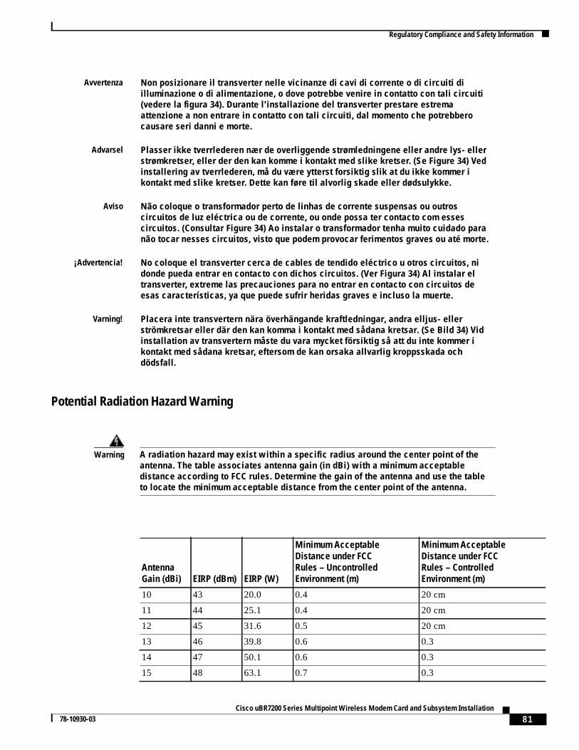
81Cisco uBR7200 Series Multipoint Wireless Modem Card and Subsystem Installation
78-10930-03
Regulatory Compliance and Safety Information
Potential Radiation Hazard Warning
Avvertenza Non posizionare il transverter nelle vicinanze di cavi di corrente o di circuiti diilluminazione o di alimentazione, o dove potrebbe venire in contatto con tali circuiti(vedere la figura 34). Durante l'installazione del transverter prestare estremaattenzione a non entrare in contatto con tali circuiti, dal momento che potrebberocausare seri danni e morte.
Advarsel Plasser ikke tverrlederen nær de overliggende strømledningene eller andre lys- ellerstrømkretser, eller der den kan komme i kontakt med slike kretser. (Se Figure 34) Vedinstallering av tverrlederen, må du være ytterst forsiktig slik at du ikke kommer ikontakt med slike kretser. Dette kan føre til alvorlig skade eller dødsulykke.
Aviso Não coloque o transformador perto de linhas de corrente suspensas ou outroscircuitos de luz eléctrica ou de corrente, ou onde possa ter contacto com essescircuitos. (Consultar Figure 34) Ao instalar o transformador tenha muito cuidado paranão tocar nesses circuitos, visto que podem provocar ferimentos graves ou até morte.
¡Advertencia! No coloque el transverter cerca de cables de tendido eléctrico u otros circuitos, nidonde pueda entrar en contacto con dichos circuitos. (Ver Figura 34) Al instalar eltransverter, extreme las precauciones para no entrar en contacto con circuitos deesas características, ya que puede sufrir heridas graves e incluso la muerte.
Varning! Placera inte transvertern nära överhängande kraftledningar, andra elljus- ellerströmkretsar eller där den kan komma i kontakt med sådana kretsar. (Se Bild 34) Vidinstallation av transvertern måste du vara mycket försiktig så att du inte kommer ikontakt med sådana kretsar, eftersom de kan orsaka allvarlig kroppsskada ochdödsfall.
Warning A radiation hazard may exist within a specific radius around the center point of theantenna. The table associates antenna gain (in dBi) with a minimum acceptabledistance according to FCC rules. Determine the gain of the antenna and use the tableto locate the minimum acceptable distance from the center point of the antenna.
AntennaGain (dBi) EIRP (dBm) EIRP (W)
Minimum AcceptableDistance under FCCRules – UncontrolledEnvironment (m)
Minimum AcceptableDistance under FCCRules – ControlledEnvironment (m)
10 43 20.0 0.4 20 cm
11 44 25.1 0.4 20 cm
12 45 31.6 0.5 20 cm
13 46 39.8 0.6 0.3
14 47 50.1 0.6 0.3
15 48 63.1 0.7 0.3
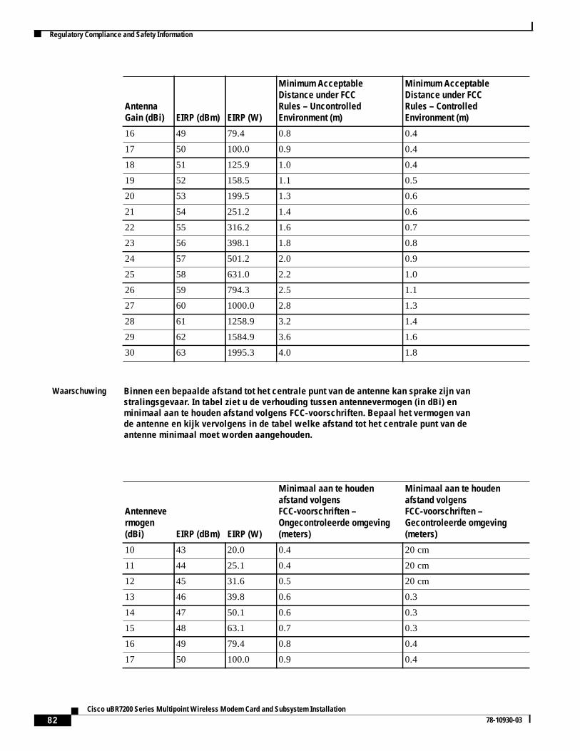
82Cisco uBR7200 Series Multipoint Wireless Modem Card and Subsystem Installation
78-10930-03
Regulatory Compliance and Safety Information
16 49 79.4 0.8 0.4
17 50 100.0 0.9 0.4
18 51 125.9 1.0 0.4
19 52 158.5 1.1 0.5
20 53 199.5 1.3 0.6
21 54 251.2 1.4 0.6
22 55 316.2 1.6 0.7
23 56 398.1 1.8 0.8
24 57 501.2 2.0 0.9
25 58 631.0 2.2 1.0
26 59 794.3 2.5 1.1
27 60 1000.0 2.8 1.3
28 61 1258.9 3.2 1.4
29 62 1584.9 3.6 1.6
30 63 1995.3 4.0 1.8
Waarschuwing Binnen een bepaalde afstand tot het centrale punt van de antenne kan sprake zijn vanstralingsgevaar. In tabel ziet u de verhouding tussen antennevermogen (in dBi) enminimaal aan te houden afstand volgens FCC-voorschriften. Bepaal het vermogen vande antenne en kijk vervolgens in de tabel welke afstand tot het centrale punt van deantenne minimaal moet worden aangehouden.
Antennevermogen(dBi) EIRP (dBm) EIRP (W)
Minimaal aan te houdenafstand volgensFCC-voorschriften –Ongecontroleerde omgeving(meters)
Minimaal aan te houdenafstand volgensFCC-voorschriften –Gecontroleerde omgeving(meters)
10 43 20.0 0.4 20 cm
11 44 25.1 0.4 20 cm
12 45 31.6 0.5 20 cm
13 46 39.8 0.6 0.3
14 47 50.1 0.6 0.3
15 48 63.1 0.7 0.3
16 49 79.4 0.8 0.4
17 50 100.0 0.9 0.4
AntennaGain (dBi) EIRP (dBm) EIRP (W)
Minimum AcceptableDistance under FCCRules – UncontrolledEnvironment (m)
Minimum AcceptableDistance under FCCRules – ControlledEnvironment (m)
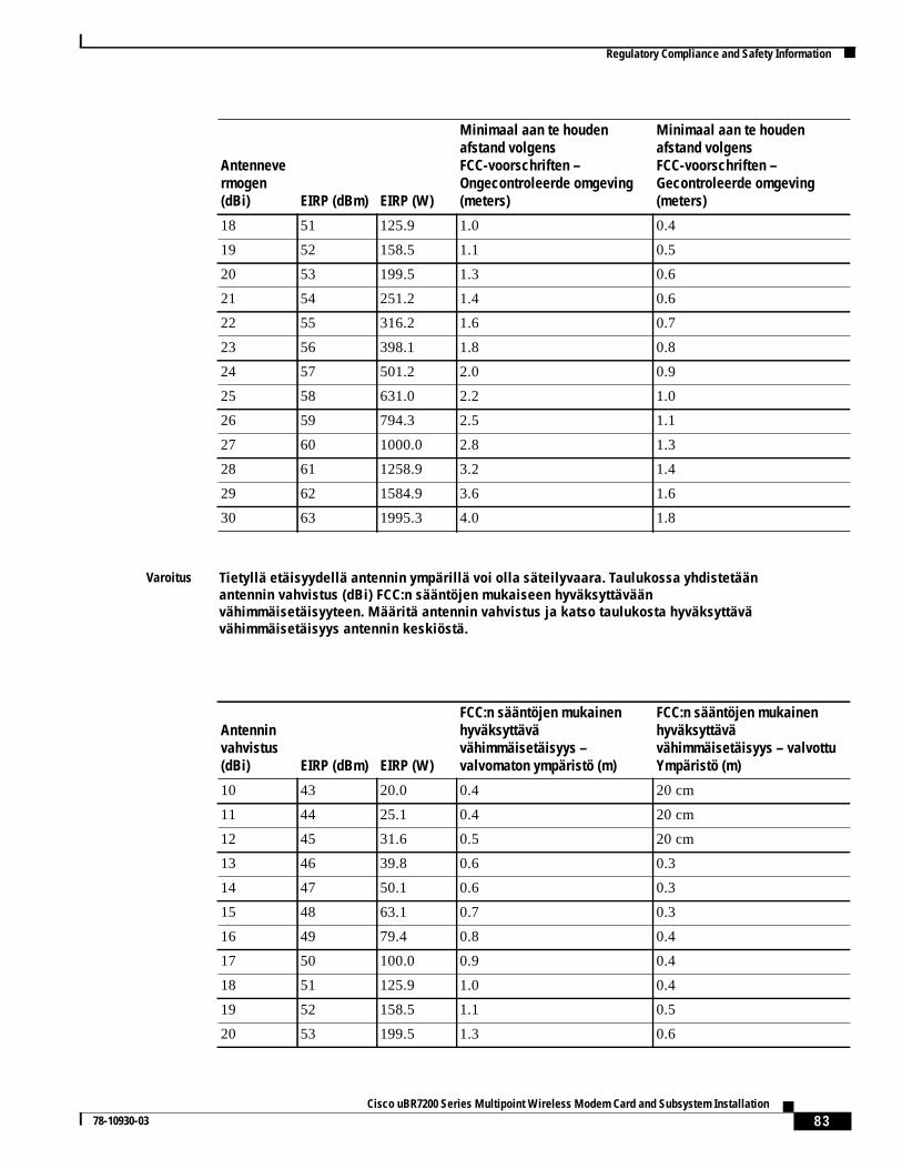
83Cisco uBR7200 Series Multipoint Wireless Modem Card and Subsystem Installation
78-10930-03
Regulatory Compliance and Safety Information
18 51 125.9 1.0 0.4
19 52 158.5 1.1 0.5
20 53 199.5 1.3 0.6
21 54 251.2 1.4 0.6
22 55 316.2 1.6 0.7
23 56 398.1 1.8 0.8
24 57 501.2 2.0 0.9
25 58 631.0 2.2 1.0
26 59 794.3 2.5 1.1
27 60 1000.0 2.8 1.3
28 61 1258.9 3.2 1.4
29 62 1584.9 3.6 1.6
30 63 1995.3 4.0 1.8
Varoitus Tietyllä etäisyydellä antennin ympärillä voi olla säteilyvaara. Taulukossa yhdistetäänantennin vahvistus (dBi) FCC:n sääntöjen mukaiseen hyväksyttäväänvähimmäisetäisyyteen. Määritä antennin vahvistus ja katso taulukosta hyväksyttävävähimmäisetäisyys antennin keskiöstä.
Antenninvahvistus(dBi) EIRP (dBm) EIRP (W)
FCC:n sääntöjen mukainenhyväksyttävävähimmäisetäisyys –valvomaton ympäristö (m)
FCC:n sääntöjen mukainenhyväksyttävävähimmäisetäisyys – valvottuYmpäristö (m)
10 43 20.0 0.4 20 cm
11 44 25.1 0.4 20 cm
12 45 31.6 0.5 20 cm
13 46 39.8 0.6 0.3
14 47 50.1 0.6 0.3
15 48 63.1 0.7 0.3
16 49 79.4 0.8 0.4
17 50 100.0 0.9 0.4
18 51 125.9 1.0 0.4
19 52 158.5 1.1 0.5
20 53 199.5 1.3 0.6
Antennevermogen(dBi) EIRP (dBm) EIRP (W)
Minimaal aan te houdenafstand volgensFCC-voorschriften –Ongecontroleerde omgeving(meters)
Minimaal aan te houdenafstand volgensFCC-voorschriften –Gecontroleerde omgeving(meters)
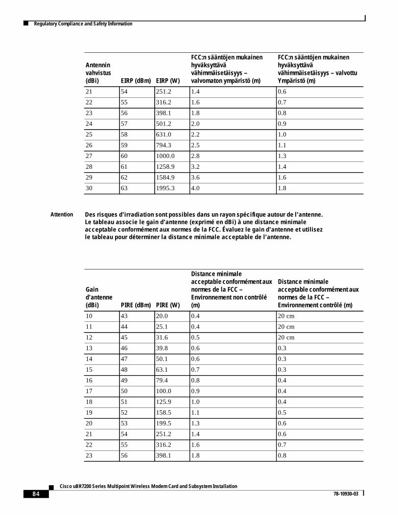
84Cisco uBR7200 Series Multipoint Wireless Modem Card and Subsystem Installation
78-10930-03
Regulatory Compliance and Safety Information
21 54 251.2 1.4 0.6
22 55 316.2 1.6 0.7
23 56 398.1 1.8 0.8
24 57 501.2 2.0 0.9
25 58 631.0 2.2 1.0
26 59 794.3 2.5 1.1
27 60 1000.0 2.8 1.3
28 61 1258.9 3.2 1.4
29 62 1584.9 3.6 1.6
30 63 1995.3 4.0 1.8
Attention Des risques d'irradiation sont possibles dans un rayon spécifique autour de l'antenne.Le tableau associe le gain d'antenne (exprimé en dBi) à une distance minimaleacceptable conformément aux normes de la FCC. Évaluez le gain d'antenne et utilisezle tableau pour déterminer la distance minimale acceptable de l'antenne.
Gaind'antenne(dBi) PIRE (dBm) PIRE (W)
Distance minimaleacceptable conformément auxnormes de la FCC –Environnement non contrôlé(m)
Distance minimaleacceptable conformément auxnormes de la FCC –Environnement contrôlé (m)
10 43 20.0 0.4 20 cm
11 44 25.1 0.4 20 cm
12 45 31.6 0.5 20 cm
13 46 39.8 0.6 0.3
14 47 50.1 0.6 0.3
15 48 63.1 0.7 0.3
16 49 79.4 0.8 0.4
17 50 100.0 0.9 0.4
18 51 125.9 1.0 0.4
19 52 158.5 1.1 0.5
20 53 199.5 1.3 0.6
21 54 251.2 1.4 0.6
22 55 316.2 1.6 0.7
23 56 398.1 1.8 0.8
Antenninvahvistus(dBi) EIRP (dBm) EIRP (W)
FCC:n sääntöjen mukainenhyväksyttävävähimmäisetäisyys –valvomaton ympäristö (m)
FCC:n sääntöjen mukainenhyväksyttävävähimmäisetäisyys – valvottuYmpäristö (m)
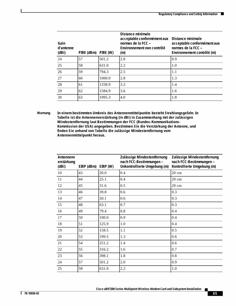
85Cisco uBR7200 Series Multipoint Wireless Modem Card and Subsystem Installation
78-10930-03
Regulatory Compliance and Safety Information
24 57 501.2 2.0 0.9
25 58 631.0 2.2 1.0
26 59 794.3 2.5 1.1
27 60 1000.0 2.8 1.3
28 61 1258.9 3.2 1.4
29 62 1584.9 3.6 1.6
30 63 1995.3 4.0 1.8
Warnung In einem bestimmten Umkreis des Antennenmittelpunkts besteht Strahlungsgefahr. InTabelle ist die Antennenverstärkung (in dBi) in Zusammenhang mit der zulässigenMindestentfernung laut Bestimmungen der FCC (Bundes-Kommunikations-Kommission der USA) angegeben. Bestimmen Sie die Verstärkung der Antenne, undfinden Sie anhand von Tabelle die zulässige Mindestentfernung vomAntennenmittelpunkt heraus.
Antennenverstärkung(dBi) EIRP (dBm) EIRP (W)
Zulässige Mindestentfernungnach FCC-Bestimmungen –Unkontrollierte Umgebung (m)
Zulässige Mindestentfernungnach FCC-Bestimmungen –Kontrollierte Umgebung (m)
10 43 20.0 0.4 20 cm
11 44 25.1 0.4 20 cm
12 45 31.6 0.5 20 cm
13 46 39.8 0.6 0.3
14 47 50.1 0.6 0.3
15 48 63.1 0.7 0.3
16 49 79.4 0.8 0.4
17 50 100.0 0.9 0.4
18 51 125.9 1.0 0.4
19 52 158.5 1.1 0.5
20 53 199.5 1.3 0.6
21 54 251.2 1.4 0.6
22 55 316.2 1.6 0.7
23 56 398.1 1.8 0.8
24 57 501.2 2.0 0.9
25 58 631.0 2.2 1.0
Gaind'antenne(dBi) PIRE (dBm) PIRE (W)
Distance minimaleacceptable conformément auxnormes de la FCC –Environnement non contrôlé(m)
Distance minimaleacceptable conformément auxnormes de la FCC –Environnement contrôlé (m)
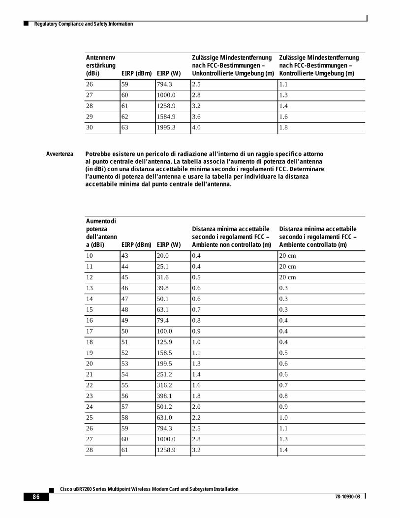
86Cisco uBR7200 Series Multipoint Wireless Modem Card and Subsystem Installation
78-10930-03
Regulatory Compliance and Safety Information
26 59 794.3 2.5 1.1
27 60 1000.0 2.8 1.3
28 61 1258.9 3.2 1.4
29 62 1584.9 3.6 1.6
30 63 1995.3 4.0 1.8
Avvertenza Potrebbe esistere un pericolo di radiazione all'interno di un raggio specifico attornoal punto centrale dell'antenna. La tabella associa l'aumento di potenza dell'antenna(in dBi) con una distanza accettabile minima secondo i regolamenti FCC. Determinarel'aumento di potenza dell'antenna e usare la tabella per individuare la distanzaaccettabile minima dal punto centrale dell'antenna.
Aumento dipotenzadell'antenna (dBi) EIRP (dBm) EIRP (W)
Distanza minima accettabilesecondo i regolamenti FCC –Ambiente non controllato (m)
Distanza minima accettabilesecondo i regolamenti FCC –Ambiente controllato (m)
10 43 20.0 0.4 20 cm
11 44 25.1 0.4 20 cm
12 45 31.6 0.5 20 cm
13 46 39.8 0.6 0.3
14 47 50.1 0.6 0.3
15 48 63.1 0.7 0.3
16 49 79.4 0.8 0.4
17 50 100.0 0.9 0.4
18 51 125.9 1.0 0.4
19 52 158.5 1.1 0.5
20 53 199.5 1.3 0.6
21 54 251.2 1.4 0.6
22 55 316.2 1.6 0.7
23 56 398.1 1.8 0.8
24 57 501.2 2.0 0.9
25 58 631.0 2.2 1.0
26 59 794.3 2.5 1.1
27 60 1000.0 2.8 1.3
28 61 1258.9 3.2 1.4
Antennenverstärkung(dBi) EIRP (dBm) EIRP (W)
Zulässige Mindestentfernungnach FCC-Bestimmungen –Unkontrollierte Umgebung (m)
Zulässige Mindestentfernungnach FCC-Bestimmungen –Kontrollierte Umgebung (m)
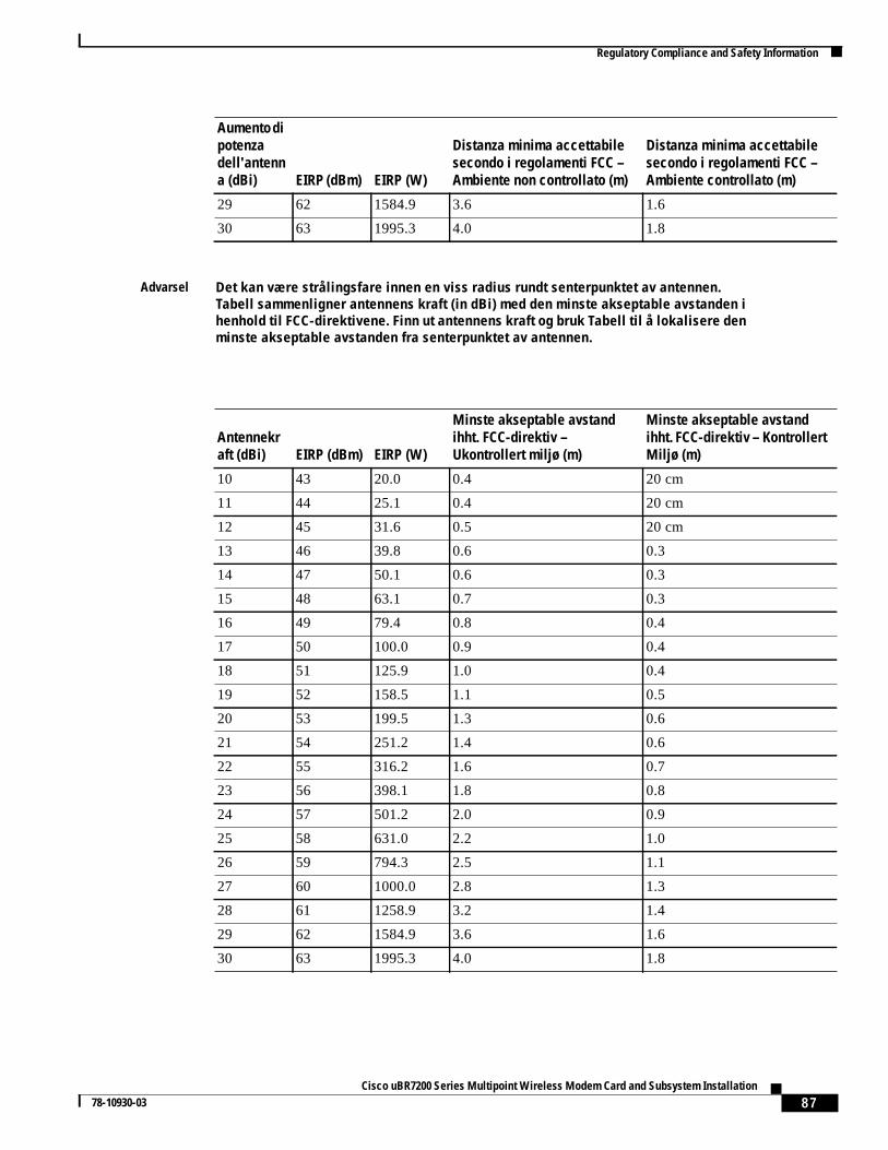
87Cisco uBR7200 Series Multipoint Wireless Modem Card and Subsystem Installation
78-10930-03
Regulatory Compliance and Safety Information
29 62 1584.9 3.6 1.6
30 63 1995.3 4.0 1.8
Advarsel Det kan være strålingsfare innen en viss radius rundt senterpunktet av antennen.Tabell sammenligner antennens kraft (in dBi) med den minste akseptable avstanden ihenhold til FCC-direktivene. Finn ut antennens kraft og bruk Tabell til å lokalisere denminste akseptable avstanden fra senterpunktet av antennen.
Antennekraft (dBi) EIRP (dBm) EIRP (W)
Minste akseptable avstandihht. FCC-direktiv –Ukontrollert miljø (m)
Minste akseptable avstandihht. FCC-direktiv – KontrollertMiljø (m)
10 43 20.0 0.4 20 cm
11 44 25.1 0.4 20 cm
12 45 31.6 0.5 20 cm
13 46 39.8 0.6 0.3
14 47 50.1 0.6 0.3
15 48 63.1 0.7 0.3
16 49 79.4 0.8 0.4
17 50 100.0 0.9 0.4
18 51 125.9 1.0 0.4
19 52 158.5 1.1 0.5
20 53 199.5 1.3 0.6
21 54 251.2 1.4 0.6
22 55 316.2 1.6 0.7
23 56 398.1 1.8 0.8
24 57 501.2 2.0 0.9
25 58 631.0 2.2 1.0
26 59 794.3 2.5 1.1
27 60 1000.0 2.8 1.3
28 61 1258.9 3.2 1.4
29 62 1584.9 3.6 1.6
30 63 1995.3 4.0 1.8
Aumento dipotenzadell'antenna (dBi) EIRP (dBm) EIRP (W)
Distanza minima accettabilesecondo i regolamenti FCC –Ambiente non controllato (m)
Distanza minima accettabilesecondo i regolamenti FCC –Ambiente controllato (m)
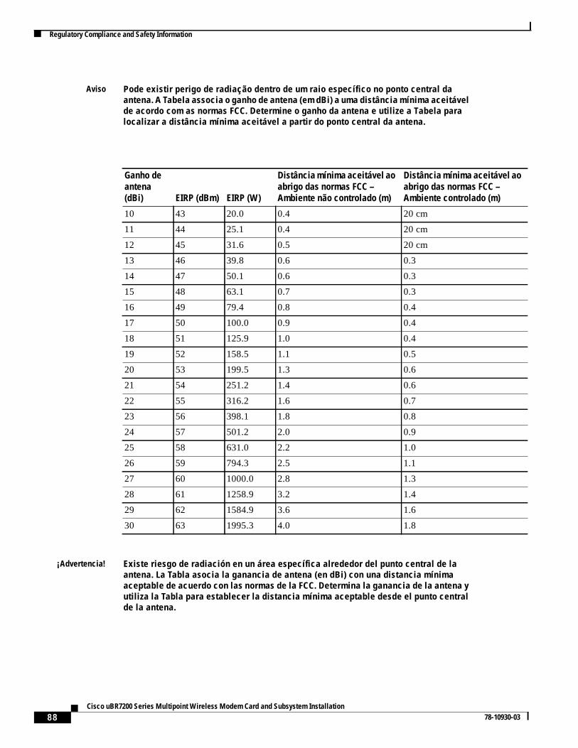
88Cisco uBR7200 Series Multipoint Wireless Modem Card and Subsystem Installation
78-10930-03
Regulatory Compliance and Safety Information
Aviso Pode existir perigo de radiação dentro de um raio específico no ponto central daantena. A Tabela associa o ganho de antena (em dBi) a uma distância mínima aceitávelde acordo com as normas FCC. Determine o ganho da antena e utilize a Tabela paralocalizar a distância mínima aceitável a partir do ponto central da antena.
Ganho deantena(dBi) EIRP (dBm) EIRP (W)
Distância mínima aceitável aoabrigo das normas FCC –Ambiente não controlado (m)
Distância mínima aceitável aoabrigo das normas FCC –Ambiente controlado (m)
10 43 20.0 0.4 20 cm
11 44 25.1 0.4 20 cm
12 45 31.6 0.5 20 cm
13 46 39.8 0.6 0.3
14 47 50.1 0.6 0.3
15 48 63.1 0.7 0.3
16 49 79.4 0.8 0.4
17 50 100.0 0.9 0.4
18 51 125.9 1.0 0.4
19 52 158.5 1.1 0.5
20 53 199.5 1.3 0.6
21 54 251.2 1.4 0.6
22 55 316.2 1.6 0.7
23 56 398.1 1.8 0.8
24 57 501.2 2.0 0.9
25 58 631.0 2.2 1.0
26 59 794.3 2.5 1.1
27 60 1000.0 2.8 1.3
28 61 1258.9 3.2 1.4
29 62 1584.9 3.6 1.6
30 63 1995.3 4.0 1.8
¡Advertencia! Existe riesgo de radiación en un área específica alrededor del punto central de laantena. La Tabla asocia la ganancia de antena (en dBi) con una distancia mínimaaceptable de acuerdo con las normas de la FCC. Determina la ganancia de la antena yutiliza la Tabla para establecer la distancia mínima aceptable desde el punto centralde la antena.
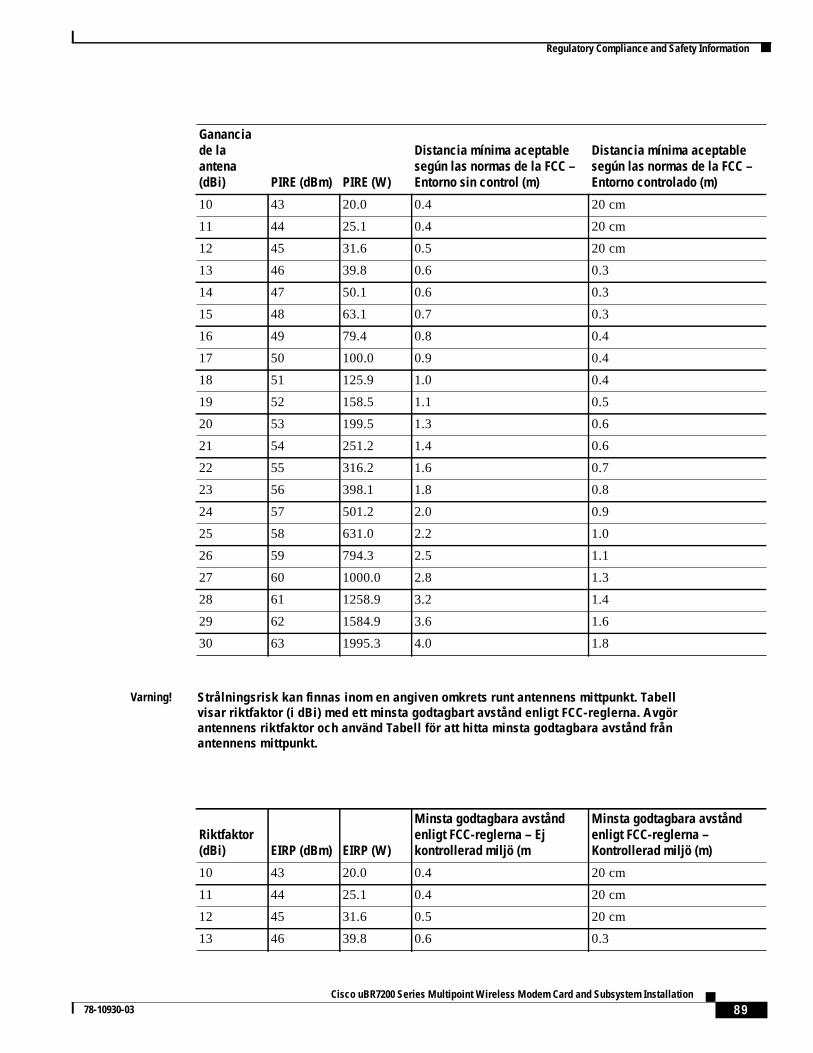
89Cisco uBR7200 Series Multipoint Wireless Modem Card and Subsystem Installation
78-10930-03
Regulatory Compliance and Safety Information
Gananciade laantena(dBi) PIRE (dBm) PIRE (W)
Distancia mínima aceptablesegún las normas de la FCC –Entorno sin control (m)
Distancia mínima aceptablesegún las normas de la FCC –Entorno controlado (m)
10 43 20.0 0.4 20 cm
11 44 25.1 0.4 20 cm
12 45 31.6 0.5 20 cm
13 46 39.8 0.6 0.3
14 47 50.1 0.6 0.3
15 48 63.1 0.7 0.3
16 49 79.4 0.8 0.4
17 50 100.0 0.9 0.4
18 51 125.9 1.0 0.4
19 52 158.5 1.1 0.5
20 53 199.5 1.3 0.6
21 54 251.2 1.4 0.6
22 55 316.2 1.6 0.7
23 56 398.1 1.8 0.8
24 57 501.2 2.0 0.9
25 58 631.0 2.2 1.0
26 59 794.3 2.5 1.1
27 60 1000.0 2.8 1.3
28 61 1258.9 3.2 1.4
29 62 1584.9 3.6 1.6
30 63 1995.3 4.0 1.8
Varning! Strålningsrisk kan finnas inom en angiven omkrets runt antennens mittpunkt. Tabellvisar riktfaktor (i dBi) med ett minsta godtagbart avstånd enligt FCC-reglerna. Avgörantennens riktfaktor och använd Tabell för att hitta minsta godtagbara avstånd frånantennens mittpunkt.
Riktfaktor(dBi) EIRP (dBm) EIRP (W)
Minsta godtagbara avståndenligt FCC-reglerna – Ejkontrollerad miljö (m
Minsta godtagbara avståndenligt FCC-reglerna –Kontrollerad miljö (m)
10 43 20.0 0.4 20 cm
11 44 25.1 0.4 20 cm
12 45 31.6 0.5 20 cm
13 46 39.8 0.6 0.3
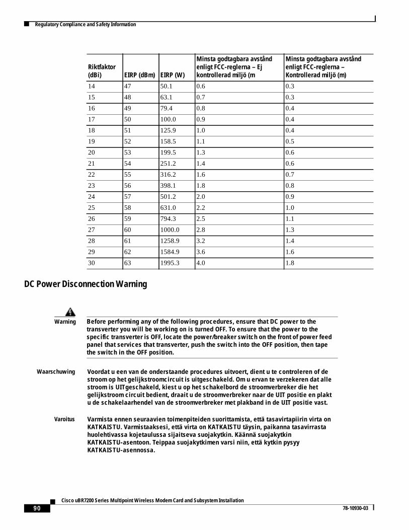
90Cisco uBR7200 Series Multipoint Wireless Modem Card and Subsystem Installation
78-10930-03
Regulatory Compliance and Safety Information
DC Power Disconnection Warning
14 47 50.1 0.6 0.3
15 48 63.1 0.7 0.3
16 49 79.4 0.8 0.4
17 50 100.0 0.9 0.4
18 51 125.9 1.0 0.4
19 52 158.5 1.1 0.5
20 53 199.5 1.3 0.6
21 54 251.2 1.4 0.6
22 55 316.2 1.6 0.7
23 56 398.1 1.8 0.8
24 57 501.2 2.0 0.9
25 58 631.0 2.2 1.0
26 59 794.3 2.5 1.1
27 60 1000.0 2.8 1.3
28 61 1258.9 3.2 1.4
29 62 1584.9 3.6 1.6
30 63 1995.3 4.0 1.8
Warning Before performing any of the following procedures, ensure that DC power to thetransverter you will be working on is turned OFF. To ensure that the power to thespecific transverter is OFF, locate the power/breaker switch on the front of power feedpanel that services that transverter, push the switch into the OFF position, then tapethe switch in the OFF position.
Waarschuwing Voordat u een van de onderstaande procedures uitvoert, dient u te controleren of destroom op het gelijkstroomcircuit is uitgeschakeld. Om u ervan te verzekeren dat allestroom is UITgeschakeld, kiest u op het schakelbord de stroomverbreker die hetgelijkstroom circuit bedient, draait u de stroomverbreker naar de UIT positie en plaktu de schakelaarhendel van de stroomverbreker met plakband in de UIT positie vast.
Varoitus Varmista ennen seuraavien toimenpiteiden suorittamista, että tasavirtapiirin virta onKATKAISTU. Varmistaaksesi, että virta on KATKAISTU täysin, paikanna tasavirrastahuolehtivassa kojetaulussa sijaitseva suojakytkin. Käännä suojakytkinKATKAISTU-asentoon. Teippaa suojakytkimen varsi niin, että kytkin pysyyKATKAISTU-asennossa.
Riktfaktor(dBi) EIRP (dBm) EIRP (W)
Minsta godtagbara avståndenligt FCC-reglerna – Ejkontrollerad miljö (m
Minsta godtagbara avståndenligt FCC-reglerna –Kontrollerad miljö (m)
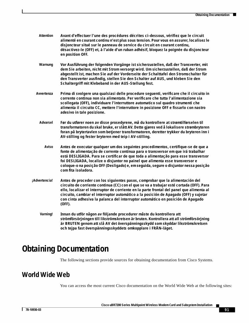
91Cisco uBR7200 Series Multipoint Wireless Modem Card and Subsystem Installation
78-10930-03
Obtaining Documentation
Obtaining DocumentationThe following sections provide sources for obtaining documentation from Cisco Systems.
World Wide WebYou can access the most current Cisco documentation on the World Wide Web at the following sites:
Attention Avant d'effectuer l'une des procédures décrites ci-dessous, vérifiez que le circuitalimenté en courant continu n'est plus sous tension. Pour vous en assurer, localisez ledisjoncteur situé sur le panneau de service du circuit en courant continu,désactivez-le (OFF) et, à l'aide d'un ruban adhésif, bloquez la poignée du disjoncteuren position OFF.
Warnung Vor Ausführung der folgenden Vorgänge ist sicherzustellen, daß der Transverter, mitdem Sie arbeiten, nicht mit Strom versorgt wird. Um sicherzustellen, daß der Stromabgestellt ist, machen Sie auf der Vorderseite der Schalttafel den Stromschalter fürden Transverter ausfindig, stellen Sie den Schalter auf AUS, und kleben Sie denSchaltergriff mit Klebeband in der AUS-Stellung fest.
Avvertenza Prima di svolgere una qualsiasi delle procedure seguenti, verificare che il circuito incorrente continua non sia alimentato. Per verificare che tutta l'alimentazione siascollegata (OFF), individuare l'interruttore automatico sul quadro strumenti chealimenta il circuito CC, mettere l'interruttore in posizione OFF e fissarlo con nastroadesivo in tale posizione.
Advarsel Før du utfører noen av disse prosedyrene, må du kontrollere at strømtilførselen tiltransformatoren du skal bruke, er slått AV. Dette gjøres ved å lokalisere strømbryterenforan på brytertavlen som betjener transformatoren, deretter trykker du bryteren inn iAV-stilling og fester bryteren med teip i AV-stilling.
Aviso Antes de executar qualquer um dos seguintes procedimentos, certifique-se de que afonte de alimentação de corrente contínua para o transversor em que irá trabalharestá DESLIGADA. Para se certificar de que toda a alimentação para esse transversorfoi DESLIGADA, localize o disjuntor no painel que alimenta esse transversor ecoloque-o na posição OFF (Desligado) e, em seguida, segure o disjuntor nessa posiçãocom fita isoladora.
¡Advertencia! Antes de proceder con los siguientes pasos, comprobar que la alimentación delcircuito de corriente continua (CC) con el que se va a trabajar esté cortada (OFF). Paraello, localizar el interruptor de corriente en la parte frontal del panel que alimenta alcircuito, cambiar el interruptor automático a la posición de Apagado (OFF) y sujetarcon cinta adhesiva la palanca del interruptor automático en posición de Apagado(OFF).
Varning! Innan du utför någon av följande procedurer måste du kontrollera attströmförsörjningen till likströmskretsen är bruten. Kontrollera att all strömförsörjningär BRUTEN genom att slå AV det överspänningsskydd som skyddar likströmskretsenoch tejpa fast överspänningsskyddets omkopplare i FRÅN-läget.
92Cisco uBR7200 Series Multipoint Wireless Modem Card and Subsystem Installation
78-10930-03
Obtaining Technical Assistance
• http://www.cisco.com
• http://www-china.cisco.com
• http://www-europe.cisco.com
Documentation CD-ROMCisco documentation and additional literature are available in a CD-ROM package, which shipswith your product. The Documentation CD-ROM is updated monthly and may be more current thanprinted documentation. The CD-ROM package is available as a single unit or as an annual subscription.
Ordering DocumentationCisco documentation is available in the following ways:
• Registered Cisco Direct Customers can order Cisco Product documentation from the NetworkingProducts MarketPlace:
http://www.cisco.com/cgi-bin/order/order_root.pl
• Registered Cisco.com users can order the Documentation CD-ROM through the online SubscriptionStore:
http://www.cisco.com/go/subscription
• Nonregistered CCO users can order documentation through a local account representative by callingCisco corporate headquarters (California, USA) at 408 526-7208 or, in North America, by calling800 553-NETS(6387).
Documentation FeedbackIf you are reading Cisco product documentation on the World Wide Web, you can submit technicalcomments electronically. ClickFeedbackin the toolbar and selectDocumentation. After you completethe form, clickSubmit to send it to Cisco.
You can e-mail your comments to [email protected].
To submit your comments by mail, for your convenience many documents contain a response cardbehind the front cover. Otherwise, you can mail your comments to the following address:
Cisco Systems, Inc.Document Resource Connection170 West Tasman DriveSan Jose, CA 95134-9883
We appreciate your comments.
Obtaining Technical AssistanceCisco provides Cisco.com as a starting point for all technical assistance. Customers and partners canobtain documentation, troubleshooting tips, and sample configurations from online tools. For Cisco.comregistered users, additional troubleshooting tools are available from the TAC website.
93Cisco uBR7200 Series Multipoint Wireless Modem Card and Subsystem Installation
78-10930-03
Obtaining Technical Assistance
Cisco.comCisco.com is the foundation of a suite of interactive, networked services that provides immediate, openaccess to Cisco information and resources at anytime, from anywhere in the world. This highlyintegrated Internet application is a powerful, easy-to-use tool for doing business with Cisco.
Cisco.com provides a broad range of features and services to help customers and partners streamlinebusiness processes and improve productivity. Through Cisco.com, you can find information about Ciscoand our networking solutions, services, and programs. In addition, you can resolve technical issues withonline technical support, download and test software packages, and order Cisco learning materials andmerchandise. Valuable online skill assessment, training, and certification programs are also available.
Customers and partners can self-register on Cisco.com to obtain additional personalized information andservices. Registered users can order products, check on the status of an order, access technical support,and view benefits specific to their relationships with Cisco.
To access Cisco.com, go to the following website:
http://www.cisco.com
Technical Assistance CenterThe Cisco TAC website is available to all customers who need technical assistance with a Cisco productor technology that is under warranty or covered by a maintenance contract.
Contacting TAC by Using the Cisco TAC Website
If you have a priority level 3 (P3) or priority level 4 (P4) problem, contact TAC by going to the TACwebsite:
http://www.cisco.com/tac
P3 and P4 level problems are defined as follows:
• P3—Your network performance is degraded. Network functionality is noticeably impaired, but mostbusiness operations continue.
• P4—You need information or assistance on Cisco product capabilities, product installation, or basicproduct configuration.
In each of the above cases, use the Cisco TAC website to quickly find answers to your questions.
To register for Cisco.com, go to the following website:
http://www.cisco.com/register/
If you cannot resolve your technical issue by using the TAC online resources, Cisco.com registered userscan open a case online by using the TAC Case Open tool at the following website:
http://www.cisco.com/tac/caseopen
Contacting TAC by Telephone
If you have a priority level 1(P1) or priority level 2 (P2) problem, contact TAC by telephone andimmediately open a case. To obtain a directory of toll-free numbers for your country, go to the followingwebsite:
http://www.cisco.com/warp/public/687/Directory/DirTAC.shtml
94Cisco uBR7200 Series Multipoint Wireless Modem Card and Subsystem Installation
78-10930-03
Obtaining Technical Assistance
P1 and P2 level problems are defined as follows:
• P1—Your production network is down, causing a critical impact to business operations if service isnot restored quickly. No workaround is available.
• P2—Your production network is severely degraded, affecting significant aspects of your businessoperations. No workaround is available.
.
This document is to be used in conjunction with theCisco uBR7200 Series Universal Broadband Router Hardware Installation GuideandCisco uBR7200 Series UniversalBroadband Router Software Configuration Guide.
AtmDirector, Browse with Me, CCDA, CCDE, CCDP, CCIE, CCNA, CCNP, CCSI, CD-PAC,CiscoLink, the Cisco NetWorks logo, the Cisco Powered Network logo, CiscoSystems Networking Academy, the Cisco Systems Networking Academy logo, Fast Step, Follow Me Browsing, FormShare, FrameShare, GigaStack, IGX, Internet Quotient, IP/VC,iQ Breakthrough, iQ Expertise, iQ FastTrack, the iQ Logo, iQ Net Readiness Scorecard, MGX, the Networkers logo,Packet, PIX, RateMUX, ScriptBuilder, ScriptShare, SlideCast,SMARTnet, TransPath, Voice LAN, Wavelength Router, WebViewer are trademarks of Cisco Systems, Inc.; Changing the Way We Work, Live, Play, and Learn, Empowering theInternet Generation, are service marks of Cisco Systems, Inc.; and Aironet, ASIST, BPX, Catalyst, Cisco, the Cisco Certified Internetwork Expert logo,Cisco IOS, the Cisco IOS logo, Cisco Systems, Cisco Systems Capital, the Cisco Systems logo, Enterprise/Solver, EtherChannel, EtherSwitch, FastHub, FastSwitch, IOS, IP/TV,LightStream, Network Registrar, Post-Routing, Pre-Routing, Registrar, StrataView Plus, Stratm, SwitchProbe, TeleRouter, and VCO are registeredtrademarks of Cisco Systems,Inc. or its affiliates in the U.S. and certain other countries.
All other brands, names, or trademarks mentioned in this document or Web site are the property of their respective owners. The use of the word partner does not imply a partnershiprelationship between Cisco and any other company. (0011R)
Copyright © 2000-2001, Cisco Systems, Inc.All rights reserved.