Embed Size (px)
Citation preview

arX
iv:1
012.
4578
v1 [
quan
t-ph
] 21
Dec
201
0
Classical and quantum properties ofcylindrically polarized states of light
Annemarie Holleczek∗1,2, Andrea Aiello1,2, Christian Gabriel 1,2,Christoph Marquardt 1,2, Gerd Leuchs1,2
1Max Planck Institute for the Science of Light, Gunter-Scharowsky-Str. 1/Bau 24, 91058Erlangen, Germany
2Institute for Optics, Information and Photonics, University of Erlangen-Nuremberg,Staudtstr. 7/B2, 91058 Erlangen, Germany
Abstract: We investigate theoretical properties of beams of light withnon-uniform polarization patterns. Specifically, we determine all possibleconfigurations of cylindrically polarized modes (CPMs) of the electro-magnetic field, calculate their total angular momentum and highlight thesubtleties of their structure. Furthermore, a hybrid spatio-polarizationdescription for such modes is introduced and developed. In particular,two independent Poincare spheres have been introduced to representsimultaneously the polarization and spatial degree of freedom of CPMs.Possible mode-to-mode transformations accomplishable with the help ofconventional polarization and spatial phase retarders areshown within thisrepresentation. Moreover, the importance of these CPMs in the quantumoptics domain due to their classical features is highlighted.
© 2010 Optical Society of America
OCIS codes:260.0260, 260.5430, 270.0270
References and links1. A. E. Siegman.Lasers. University Science Books, Mill Valley, CA, 1986.2. R. Martinez-Herrero, P. M. Mejıas, and G. Piquero.Characterization of Partially Polarized Light Fields.
Springer, Heidelberg, 1 edition, 2009.3. C. J. R. Sheppard. Polarization of almost-plane waves.Journal of the Optical Society of America A, 17:335,
2000.4. C. Maurer, A. Jesacher, S. Furhapter, S. Bernet, and M. Ritsch-Marte. Tailoring of arbitrary optical vector beams.
New Journal of Physics, 9:78, 2007.5. S. Quabis, R. Dorn, M. Eberler, O. Glockl, and G. Leuchs. Focusing light to a tighter spot.Optics Communica-
tions, 179(1-6):1 – 7, 2000.6. R. Dorn, S. Quabis, and G. Leuchs. Sharper focus for a radially polarized light beam. Phys. Rev. Lett.,
91(23):233901, 2003.7. N. Huse, A. Schonle, and S. W. Hell. Z-polarized confocalmicroscopy.Journal of biomedical optics, 6:273–276,
2001.8. M. Sondermann, R. Maiwald, H. Konermann, N. Lindlein, U. Peschel, and G. Leuchs. Design of a mode con-
verter for efficient light-atom coupling in free space.Applied Physics B, 89:489–492, 2007.9. M. Meier, V. Romano, and T. Feurer. Material processing with pulsed radially and azimuthally polarized laser
radiation.Applied Physics A, 86:329–334, 2006.10. P. Banzer, U. Peschel, S. Quabis, and G. Leuchs. On the experimental investigation of the electric and magnetic
response of a single nano-structure.Opt. Express, 18(10):10905–10923.11. M. Lassen, G. Leuchs, and U. L. Andersen. Continuous variable entanglement and squeezing of orbital angular
momentum states.Phys. Rev. Lett., 102(16):163602, 2009.

12. C. Gabriel, A. Aiello, W. Zhong, T. G. Euser, N. Y. Joly, P.Banzer, M. Fortsch, D. Elser, U. L. Andersen,Ch. Marquardt, P. St. J. Russell, and G. Leuchs. Hybrid-entanglement in continuous variable systems.arXiv,1007.1322, 2010.
13. J. T. Barreiro, T.-C. Wei, and P. G. Kwiat. Remote preparation of single-photon “hybrid” entangled and vector-polarization states.Phys. Rev. Lett., 105(3):030407, Jul 2010.
14. R. Loudon.The Quantum Theory of Light. Oxford University Press, Oxford, UK, 3 edition, 2000.15. M. J. Padgett and J. Courtial. Poincare-sphere equivalent for light beams containing orbital angular momentum.
Opt. Lett., 24(7):430–432, 1999.16. A. Peres.Quantum Theory: Concept and Methods. Kluwer Academic, Boston, 1995.17. M. V. Berry. Optical currents.Journal of Optics A: Pure and Applied Optics, 11(9):094001.18. A. Aiello, N. Lindlein, Ch. Marquardt, and G. Leuchs. Transverse angular momentum and geometric spin hall
effect of light. Phys. Rev. Lett., 103(10):100401, 2009.19. J. M. Jauch and F. Rohrlich.The Theory of Photons and Electrons: The relativistic FieldTheory of Charged
Particles with Spin one-half. Addison-Wesley Publishing Company, Boston, 1955.20. R. M. A. Azzam and N. Bashra.Ellipsometry and Polarized Light. North Holland Personal Library, Amsterdam,
4 edition, 1988.21. L. Allen, M. W. Beijersbergen, R. J. C. Spreeuw, and J. P. Woerdman. Orbital angular momentum of light and
the transformation of laguerre-gaussian laser modes.Phys. Rev. A, 45(11):8185–8189, Jun 1992.22. N. Korolkova, G. Leuchs, R. Loudon, T. C. Ralph, and Ch. Silberhorn. Polarization squeezing and continuous-
variable polarization entanglement.Phys. Rev. A, 65(5):052306, 2002.23. J. N. Damask.Polarization Optics in Telecommunication. Springer, Heidelberg, 2005.24. W. P. Bowen, R. Schnabel, P. K. Lam, and T. C. Ralph. Experimental investigation of criteria for continuous
variable entanglement.Phys. Rev. Lett., 90(4):043601, 2003.25. M. A. Nielsen and I. L. Chuang.Quantum computation and quantum information. Cambridge University Press,
Cambridge, 2000.26. C. V. S. Borges, M. Hor-Meyll, J. A. O. Huguenin, and A. Z. Khoury. Bell-like inequality for the spin-orbit
separability of a laser beam.Phys. Rev. A, 82(3):033833, 2010.
1. Introduction
States of light with spatially inhomogeneous polarizationstructure, such as the radially or az-imuthally polarized vector beams [1, 2, 3], have lately attracted major attention both in thetheoretical and experimental area of research in optics [4]. As devices for their generationhave become commercially available, their application in optical science and engineering arewidespread – ranging from classical to quantum optics experiments. In classical optics, whenstrongly focussed, these complex field distributions exhibit spatially separated longitudinal andtransversal electric and magnetic field components depending on the initial state of polarization[5, 6]. This means, these vector beams can be sharply focussed in the center of the optical axisand therefore find applications in lithography, confocal microscopy [7], optical trapping andtweezing [8] as well as material processing [9]. Moreover, one can gain detailed insight intonanoscale physics due to the intrinsic strong polarizationdependence of these beams [10]. Inthe quantum regime, specially designed spatio-polarization modes can increase the coupling tosingle ions [8]. Additionally, the related orbital angularmomentum states help to investigate en-tanglement [11]. Very recently it has been shown that by quadrature squeezing an azimuthallypolarized optical beam, one can generate quantum states exhibiting hybrid entanglement be-tween the spatial and the polarization degrees of freedom [12, 13].
In this work we aim at establishing a proper theoretical framework for the classical opticsdescription of cylindrically polarized modes (CPMs) of theelectro-magnetic field. We coverthe subtleties in terms of their description, highlight their symmetry properties and determinetheir total angular momentum. Finally, we show a suitable way of constructing a reasonabletool of displaying these modes on a defined pair of Poincare spheres. In particular, in Sec. 1, weillustrate the rotation principles underlying the intrinsic cylindrical polarization of the investi-gated beams. We introduce all possible configurations of these modes and calculate the Schmidtrank, as this is a convincing way to determine the potential inseparability of these modes. Wecomplete the theoretical investigation by deducing the total angular momentum of these CPMs

in Sec. 3. In Sec. 4, we introduce our Poincare sphere representation for the hybrid polariza-tion/spatial degrees of freedom characterizing CPMs. In Sec. 5, we discuss the manipulationsof these states of light on these hybrid Poincare spheres with the help of conventional phase re-tarders. Furthermore, in Sec. 6, we extend our formalism to the quantum domain and illustratethe importance of these modes in quantum experiments. Finally, in the Appendix, we furnishthe reader with the mathematical tools which are essential to fully cover the topics of the maintext.
2. Classical description of light beams with cylindrical polarization
2.1. Introduction to rotation principles
To mathematically introduce the radially and azimuthally polarized vector fields, let us considera well collimated, monochromatic light beam with the wavelengthλ = 2π/k propagating alongthez-axis. The corresponding electric field can be written as
E(r , t) =12
(
u(r)e−iχ +u∗(r)eiχ)
, (1)
whereχ = k(ct− z)− π/2 [14] andr = xx+ yy+ zz. Furthermore,u(r) is a paraxial modefunction of the form
u(r) = f1(r)x+ f2(r)y. (2)
The unit vectorsx andy indicate the polarization in thex andy directions andf1(r) and f2(r)are two independent solutions of the paraxial wave equation:
∂ 2 f1,2∂x2 +
∂ 2 f1,2∂y2 +2ik
∂ f1,2∂z
= 0. (3)
In our investigation we are not interested in the beam propagation, and therefore we shallconsider the longitudinal coordinatez as fixed to a value which will be omitted in subsequentformulas. Therefore, we define thetransverseposition vectorx as:
x = xx+ yy. (4)
Given aglobal Cartesian reference frame{x, y} on thexy-plane, it is always possible to de-fine a local (depending on the position vectorx) polar reference frame{r(θ ), θθθ (θ )} withx = r cosθ , y = r sinθ , wherer ∈ [0,∞[ andθ ∈ [0,2π [. The two coordinate systems are re-lated through the following relation:
r(θ ) = cosθ x+ sinθ y, (5a)
θθθ (θ ) = − sinθ x+ cosθ y. (5b)
Since, by definition, in the{x, y} basis one has
x =
(
10
)
, y =
(
01
)
, (6)
then from Eq. (5) it follows that
r(θ ) = R(θ )x, θθθ (θ ) = R(θ )y, (7)
whereR(θ ) denotes the 2×2 rotation matrix which, in the{x, y} basis, can be written as:
R(θ ) =(
cosθ −sinθsinθ cosθ
)
. (8)

Since rotation operations are additive and commute in two-dimensional spaces, from Eq. (7) itcan be deduced that for anyϕ ∈ R the following holds:
R(ϕ)r(θ ) = R(θ +ϕ)x = r(θ +ϕ), (9)
R(ϕ)θθθ (θ ) = R(θ +ϕ)y = θθθ (θ +ϕ). (10)
These equations shows thatr(θ ) and θθθ (θ ) co-rotate with respect to the applied “external”rotationR(ϕ). More generally, it is not difficult to prove that Eqs. (7) maybe extended totwo
sets of pairs ofco- and counter-rotating unit vectors{r+(θ ), θθθ+(θ )} and {r−(θ ), θθθ−
(θ )},respectively, defined as
r±(θ ) =±R(±θ )x, θθθ±(θ ) =±R(±θ )y, (11)
where now
R(ϕ)r±(θ ) = r±(θ ±ϕ), R(ϕ)θθθ±(θ ) = θθθ
±(θ ±ϕ). (12)
The two sets of pairs of unit vectors are illustrated in Fig. 1. From these equations it is clearthat any either co-rotatingu+(r,θ ) or counter-rotatingu−(r,θ ) vector field may be written as:
u±(r,θ ) = r±(θ )a(r)+ θθθ±(θ )b(r), (13)
wherea(r) andb(r) are arbitrary functions independent ofθ but, although omitted, still depen-dent ofz. By definition, such fields satisfy the following condition:
u±(r,θ ±ϕ) = R(ϕ)u±(r,θ ), (14)
where withR(ϕ)u±(r,θ ) we had indicated the ordinary matrix-times-vector product, namely:
R(ϕ)u±(r,θ ) =(
cosϕ −sinϕsinϕ cosϕ
)(
x ·u±
y ·u±
)
. (15)
Eq. (14) has some interesting consequences: First, we note that, sincex = r cosθ andy =r sinθ , we can rewritex= x(r,θ ) andy= y(r,θ ), having assumedr,θ as independent variables.Then, by definition,
x(r,θ ±ϕ) = r cos(θ ±ϕ) = r(cosθ cosϕ ∓ sinθ sinϕ), (16)
and
y(r,θ ±ϕ) = r sin(θ ±ϕ) = r(sinθ cosϕ ± cosθ sinϕ). (17)
These two equations can be rewritten in compact vector notation as:
x(r,θ ±ϕ) = R(±ϕ)x(r,θ ). (18)
Now, since the argument of the functionsu±(r,θ ) = u±(x) on the left side of Eq. (14) is exactlyx(r,θ ±ϕ), we can use the result above to rewrite Eq. (14) as:
u±(R(±ϕ)x) = R(ϕ)u±(x), (19)

�
�� �
�� �
��� ��
�� �
��θθθθ �
��θθθθ �
θ �
Fig. 1. Illustrating the two sets of pairs of co- and counter-rotating unit vectors
{r+(θ ), θθθ+(θ )} and{r−(θ ), θθθ−
(θ )}, respectively. The vectorr−(θ ) is the mirror-image
with respect to the vertical axisy of r+(θ ), while θθθ−(θ ) is the mirror-image with respect
to the horizontal axisx of θθθ+(θ ).
or, equivalently,
u+(x) = R(ϕ)u+(R(−ϕ)x), (20a)
u−(x) = R(ϕ)u−(R(ϕ)x). (20b)
At this point, one should remember that any 2-dimensional vector fieldV(x,y) transforms un-der aglobal counterclockwise active rotation by an angleϕ into the new fieldW(x,y) whosefunctional expression is determined according to the following rule:
W(x) = R(ϕ)V(R(−ϕ)x). (21)
Thus Eq. (20a) coincidesexactlywith the definition of a vector field which is invariant withrespect to aglobalrotation by an angleϕ . This means that co-rotating beams have a polarizationpatterninvariantwith respect to global rotations. This result is intuitively obvious for radial andazimuthally polarized beams. Conversely, the corresponding Eq. (20b) for the counter-rotatingbeams has a less straightforward geometric interpretation. For this case, one can show that Eq.(20b) can be recast in the form of a global rotation as:
R(2ϕ)u−(x) = R(ϕ)u−(R(−ϕ)x). (22)
This equation simply shows that a global rotation by an angleϕ upon the counter-rotatingmodes is equivalent to alocal rotation by an angle 2ϕ on the same mode.
2.2. Deduction of cylindrically polarized modes
As we are now knowledgeable about all rotation properties which the cylindrically polarizedoptical beams have to obey to, we want to explicitly derive all possible cylindrical configura-tions of these mode functions which fulfill Eq. (14) taken with the “+” sign. However, it will beeventually shown that these coincide with the well-known radially and azimuthally polarizedbeams.

After inverting Eq. (5) and inserting the result into Eq. (2), we obtain as a paraxial modefunction
u(r,θ ) = r(cosθ f1+ sinθ f2)+ θθθ (−sinθ f1+ cosθ f2). (23)
By comparing Eq. (23) with Eq. (13), one obtains at once:
f1(r) = a(r)cosθ −b(r)sinθ , (24a)
f2(r) = a(r)sinθ +b(r)cosθ . (24b)
Sincex= r cosθ andy= r sinθ , Eqs. (24a) and (24b) can be rewritten as:
f1(r) = xα(r)− yβ (r), (25a)
f2(r) = yα(r)+ xβ (r), (25b)
whereα(r) andβ (r) can be determined by keeping in mind thatf1 and f2 need to satisfy theparaxial equation (3). In particular, we want to express thefunctions f1(r) and f2(r) in termsof the first-order Hermite-Gauss [15] solutions of the paraxial wave equation which can be –apart from an irrelevant normalization factor
√
8/π – written atz= 0, as
ψ10(x) = xe−(x2+y2)/w20/w0, (26a)
ψ01(x) = ye−(x2+y2)/w20/w0, (26b)
wherew0 is the beam waist. Thus, from Eqs. (25a) and (25b) and the factthat x ∝ ψ10 andy ∝ ψ01, it follows that:
f1(r) =1√2(Aψ10−Bψ01), (27a)
f2(r) =1√2(Bψ10+Aψ01), (27b)
whereA, B are arbitrary numerical constants. In general, withψnm = ψnm(x,y,z) (n,m∈ N0)we denote the Hermite-Gauss solutions of the paraxial wave equation of the orderN = n+m[15]. Consequently, all possible solutions which fulfill the global law of Eq. (14) with the “+”sign, obviously have the form of:
u =1√2(Aψ10−Bψ01)x+
1√2(Bψ10+Aψ01)y. (28)
By choosing either{A= 1,B= 0} or {A= 0,B= 1} and inserting this in Eq. (28), one obtainsafter normalization:
u+R =
1√2(ψ10x+ψ01y), (29a)
u+A =
1√2(−ψ01x+ψ10y). (29b)
The same steps that lead us to Eqs. (29a) and (29b) could be repeated for the counter-rotatingmodes. However, it is more instructive to note that, from a visual inspection, one can immedi-ately deduce thatu+
R andu+A live in a four dimensional space spanned by the basis formed by
the Cartesian product of the{ψ10,ψ01} mode bases and the polarization vectors{x, y}:
{ψ10,ψ01}⊗{x, y}= {ψ10x,ψ10y,ψ01x,ψ01y}. (30)

However, the two vectors{u+R,u
+A} only form a two dimensional basis and consequently two
more vectors have to be added to span the whole space. By applying a unitary transformationto such a basis, we can obtain a new set of basis vectors, namely {u−
R ,u−A}, where:
u−R =
1√2(−ψ10x+ψ01y), (31a)
u−A =
1√2(ψ01x+ψ10y). (31b)
The vectors{u+R , u
+A , u
−R , u
−A}, whose intensity and polarization profiles are illustratedin Fig. 2,
form a complete four-dimensional basis, orthonormal with respect to the scalar product definedas:
(
u(x),v(x))
=2
∑i=1
∫∫ ∞
−∞u∗i (x)vi(x)dxdy, (32)
whereu(x) and v(x) are two arbitrary vector functions. It should be stressed that the basisvectorsu−
R andu−A do fulfill the rotation law of Eq. (14), but with the “−” sign:
u−(r,θ −α) = R(α)u−(r,θ ). (33)
Furthermore, Eqs. (14) and (33) imply that these two sets of modes do not mix under rotation.This is interesting, as many recent experiments show [6, 12]that co- and counter-rotating modesdo not occur simultaneously.
2.3. Schmidt rank of radially and azimuthally polarized modes
Another important property of CPMs can be characterized by the so-called Schmidt rank ofthe modes. The Schmidt rank [16] is an intriguing quantity asit provides information aboutpotential inseparability of these modes. In the following,we demonstrate how to determine thisrank for the radially and azimuthally polarized optical beams. This can be similarly calculatedfor the counter-rotating modes.
If one has a look at the structure of these basis vectors, one can easily see that they areclearlynon-separable, in the sense that it is not possible to write any of these vector functionsas the product of a uniformly polarized vector field times a scalar function. Such a “degree ofnon-separability” may be quantified by the Schmidt-rank of the function, remembering that allseparable functions have a Schmidt rank of 1. Conversely, weare now going to prove thatu+
Randu+
A admit a Schmidt decomposition with rank 2:Let e1 ande2 be two orthogonal unit vectors defined ase1 = x ande2 = y, with
e∗i ·ej = δi j , i, j ∈ {1,2},
and letv1 andv2 be two orthogonal functions defined as
v1 = ψ10(x,y,z), v2 = ψ01(x,y,z), (34)
where, because of the orthogonality of the Hermite-Gauss modes, one has:∫∫ ∞
−∞v∗i v j dxdy= δi j , i, j ∈ {1,2}.
Then we can immediately write down, for example for theu+R mode:
u+R =
2
∑i=1
(λi)1/2 ei vi , (35)

(a) (d)(b) (c)
Fig. 2. Complex polarization patterns of (a)u+R, (b) u+
A , (c) u−R , (d) u−
A , underlayed withthe doughnut shaped intensity distribution.
with λ1 = λ2 = 1/2. The right side of Eq. (35) represents the Schmidt decomposition of thevector functionu+
R with rank
K = 1/2
∑i=1
λ 2i = 2. (36)
For the functionu+A the same demonstration holds but withv1 andv2 defined as
v1 =−ψ01(x,y,z), v2 = ψ10(x,y,z), (37)
This completes the proof.More generally, the substitution of Eq. (29a) or (29b) respectively into Eq. (14) gives
u+AB =
1√2[ψ10(Ax+By)+ψ01(−Bx+Ay)]
≡ 1√2
f1ψ10+1√2
f2ψ01, (38)
where we have chosen|A|2 + |B|2 = 1 to guarantee normalization:(uAB, uAB) = 1. From Eq.(36) it follows thatu+
AB has Schmidt rank 2 whenever
f∗1 · f2 = AB∗−A∗B= 0, (39)
namely when Im(AB∗) = 0. Conversely,u+AB becomes separable whenf2 =Cf1, namely when
−B=CA, A=CB, whereC is a proportionality constant. The substitution of the latter equationin the previous one furnishes−B=C2B which impliesC = ±i, namelyA= ±iB. In this caseit is easy to see that Eq. (36) reduces to
u+AB =
A√2(x∓ iy)(ψ10± iψ01) , (40)
which means that the only separable cylindrically symmetric co-rotating modes are the circu-larly polarized Laguerre-Gauss modes with one unit (|ℓ| = 1) of orbital angular momentum:φLG±1,0 = (ψ10± iψ01)/
√2. It should be noticed that it is only thanks to the opposite double sign
in the last two terms of Eq. (40) that condition (14) is satisfied.
3. Angular momentum of cylindrically polarized optical beams
To complete our discussion about the properties of the “+” and “−” vector bases, we note thatall four vector functions{u+
R ,u−R ,u
+A ,u
−A} have the total (orbital plus spin) angular momen-
tum (TAM) of zero which is deduced below. Following Berry [17], we can write the “local”

(position-dependent) density of thelinear momentumcarried by the paraxial modeu of theelectromagnetic field as:
p(r) = Im[
u∗ · (∇⊥)u]
+12
Im[
∇⊥× (u∗×u)]
≡ porb(r)+psp(r), (41)
where∇⊥ = x∂x+ y∂y andu∗ · (∇⊥)u = ∑i u∗i (∇⊥ui). A prefactor ofc2ε0/(2ω) has been omit-
ted. The symbol “×” denotes the ordinary cross product inR3. In Eq. (41), the first termporb(r)is called the orbital Poynting current and is independent ofthe polarization state of the beam.Conversely the second term, the so-called spin Poynting currentpsp(r), contains the local “den-sity of spin” of the beam via the term Im(u∗×u) [17]. An explicit calculation from Eq. (41)furnishes:
px(r) =1k
Im [ f ∗1 (∂x f1)+ f ∗2 (∂x f2)]+1k
Im [∂y( f ∗1 f2)] , (42a)
py(r) =1k
Im [ f ∗1 (∂y f1)+ f ∗1 (∂y f2)]−1k
Im [∂x( f ∗1 f2)] , (42b)
pz(r) = | f1|2+ | f2|2 , (42c)
wherek indicates the wave vectork= ω/c. The power of a light beam as actually measured bya photo-detector in the laboratory equals the flow of the Poynting vector of the beam across thedetector surface. Since the electromagnetic linear momentum densityp is equal to 1/c2 timesthe Poynting vector, it follows that a quantity experimentally observable isP · z, where
P=
∫∫
p(r)dxdy
≡ Porb+Psp, (43)
is the linear momentum of the field perunit length. Without loss of generality, we have assumedthat the detector surface coincides with thexy-plane normal to the beam propagation axisz. Thedouble integration in Eq. (43) is extended to the wholexy-plane. This means that for any pairof functions f1 and f2, normalizable in thexy-plane, which drop to zero at infinity, the “spin”surface terms∂y( f ∗1 f2) and∂x( f ∗1 f2) on the right sides of Eq. (42a) and Eq. (42b) respectively,do not contribute to the measured momentum. In other words one hasPsp= 0. It is worth notingthat althoughf1 and f2 are both functions ofr , as opposed tox we can practically evaluate Eq.(43) atz= 0 because the quantityP is independent ofz [18].
Thetotal angular momentum densityis
j(r) = r ×p(r)
= r ×[
porb(r)+psp(r)]
≡ l(r)+ s(r), (44)
where theorbital angular momentum densityis
lx(r) = y(| f1|2+ | f2|2)−zk
Im( f ∗1 ∂y f1+ f ∗2 ∂y f2) , (45a)
ly(r) = − x(| f1|2+ | f2|2)+zk
Im( f ∗1 ∂x f1+ f ∗2 ∂x f2) , (45b)
lz(r) = Im [x( f ∗1 ∂y f1+ f ∗2 ∂y f2)− y( f ∗1 ∂x f1+ f ∗2 ∂x f2)] , (45c)

and the spin angular momentum density is
sx(r) = − zk
Im [∂x( f ∗1 f2)] , (46a)
sy(r) =zk
Im [∂y( f ∗1 f2)] , (46b)
sz(r) = − 1k
Im [x∂x( f ∗1 f2)+ y∂y( f ∗1 f2)] . (46c)
We proceed as in the linear momentum case and we write the angular momentum of the fieldperunit lengthas
J =
∫∫
j(r)dxdy
≡ L +S, (47)
were, similarly toP, alsoL andS are independent ofz [18]. Again, for any pair of functionsf1(r) and f2(r) that vanish sufficiently fast for|xy| → ∞, integration by parts leads toSx = 0=Sy, and to
∫∫
[
x∂x( f ∗1 f2)+ y∂y( f ∗1 f2)]
dxdy=−2∫∫
f ∗1 f2 dxdy. (48)
From this relation it follows straightforwardly that
Sz =− ik
∫∫
(
f ∗1 f2− f1 f ∗2)
dxdy. (49)
Eq. (49) clearly reproduces the well-know expression of thehelicity Sz = i(αβ ∗−α∗β )/k ofa uniformly-polarized beam when one choosesf1 = αψ(r) and f2 = β ψ(r), whereψ(r) is anormalizable function in thexy-plane andα,β a pair of complex number such that|α|2+ |β |2 =1.
At this point, we can easily evaluateJ for the set of our four cylindrically polarized modeswithout performing any actual calculations. In fact, sinceJ is independent ofz, we can evaluateit at z= 0 where bothψ10(x,y,z= 0) andψ01(x,y,z= 0) arereal-valuedfunctions. Then fromEqs. (45-46) it follows at once thatS= 0 and that
Lx =
∫∫
y(| f1|2+ | f2|2)dxdy, (50a)
Ly = −∫∫
x(| f1|2+ | f2|2)dxdy, (50b)
Lz = 0. (50c)
However, it is easy to see from Eqs. (26a) and (26b) that by definition |ψ10(x,y,0)|2 and|ψ01(x,y,0)|2 are even functions with respect to bothx andy coordinates. This automaticallyimplies, because of symmetry, thatLx = 0= Ly.
We have thus demonstrated that the TAM of our modes is strictly zero. Alternatively, thesame result could have been found in a more intuitive but lessformal way by writing the modes{u+
R ,u−R ,u
+A ,u
−A} in the left/right circular polarization basis and in theφLG
±1,0 Laguerre-Gaussspatial basis. In this case, both the polarization and spatial modes carry a unit of angular mo-mentum which may be summed or subtracted from each other, thus leading to a straightforwardphysical interpretation.

S1
S2
S3
S
Fig. 3. Poincare sphere representation for an arbitrary two-dimensional system. Here, theradiusr of the sphere is fixed to one, and spherical angles{ϑ ,φ} are related to the Stokesparameters via the relation:{cosϑ ,sinϑ cosφ ,sinϑ sinφ}= {S1/S0,S2/S0,S3/S0}, whereS0 denotes the total intensity of the beam.
4. Hybrid Poincare sphere representation
In general, fully polarized optical beams, similarly to quantum pure states of two-level systems[19], can be described by points on a sphere of unit radius [20], the so-called polarizationPoincare sphere [PPS, Fig. 4 (b)]. The North and South Polesof this sphere represent left-andright-handed polarization states that correspond to±1 spin angular momentum eigenstates,respectively. Similarly, the spatial-mode Poincare sphere [SMPS, Fig. 4 (a)] [15] sticks to thesame superposition principle but in terms of the spatial distribution of the optical beams. Inthis case, the North and the South Pole of the sphere represent optical beams in the Laguerre-Gaussian modesφLG
±1,0, which correspond to±1 orbital angular momentum eigenstates [21]respectively. Each point on the Poincare sphere, both on the polarization and the spatial-modeone, may be put in one-to-one correspondence with a unit three-dimensional real vector~S={S1/S0,S2/S0,S3/S0}, whereS2
0 = S21+S2
2+S23, as shown in Fig. 3. The three componentsSi ,
i ∈ {1,2,3} are known as the Stokes parameters [20] andS0 denotes the total intensity of thebeam.
(b)(a) (c) (d)
Fig. 4. Fundamental idea behind the new Poincare sphere representation: Combining theSMPS (a) and the PPS (b) to the hybrid Poincare spheres (HPSs) (c) and (d).
In this section, we present a novel representation for cylindrically polarized optical beamsbased on the simultaneous use of both the PPS and the SMPS representation. We show thatit is possible, under certain assumptions, to connect the two polarization and spatial represen-tations to obtain twohybrid Poincare spheres (HPSs) that embody all characteristics of thesecomplex modes of the electromagnetic field. Up to now, onlyuniform polarization patterns

could have been displayed as points on the PPS. However, withthis new representation,non-uniformpolarization patterns are represented for the first time. This is especially helpful – letit be in theoretical considerations or in experiments – if one investigates effects deriving fromthese spatially dependent, complex polarization patterns. Furthermore, manipulations of stateswithin this representation in accordance with the conventional tools such as the PPS and SMPScan be carried out. This is investigated in Sec. 5.
In principle, the two-dimensional polarization and spatial spaces, respectively spanned bythe bases{x, y} and{ψ10,ψ01}, may be combined in several different manners to produce afour-dimensional mixed polarization-spatial mode space.A completerepresentation of such aspace would require the simultaneous display of eight real numbers which is impossible in athree dimensional space. Consequently, our aim is to find an appropriate way for describingthis space by using conventional tools, such as the PPS or theSMPS respectively. We begin bynoticing that if we are permitted to discard some information, then a lower-dimension visualrepresentation may be possible. The characteristics of this picture would then be fixed by thekind of degree of freedom (DOF) we choose to represent. Driven by certain recent experimentalresults [12], here we look for ahybrid representation, which would be suitable to describe phys-ical situations where co- and counter-rotating modes do notmix with each other. This absenceof mixing occurs, for example, when the light propagates through cylindrically symmetric opti-cal systems as fibres, non-astigmatic lenses, et cetera. In this case, the disregarded informationwould amount to the relative phase and amplitude between thesets of co- and counterrotatingmodes. The representation deriving from these constraintsis illustrated in Fig. 4. The North andSouth Pole of sphere (c) represent radially and azimuthallypolarized states whose total angularmomentum (orbital plus spin) is equal to zero. Analogously,sphere (d) represent counter-radialand counter-azimuthal states, still with total zero angular momentum. Each of these two pairsof states represent a novel kind ofhybrid DOF of the electromagnetic field, since such statesdescribe neither purely polarized nor purely spatial modesof the field.
Mathematically, the combination of the SMPS and the PPS is realized by forming the fourdimensional basis given by the Cartesian product of the the spatial mode{ψ10,ψ01} and polar-ization{x, y} bases:
{ψ10,ψ01}⊗{x, y}= {ψ10x,ψ10y,ψ01x,ψ01y}. (51)
To span this four dimensional space, we choose the basis{u+R , u
+A , u
−R , u
−A}. As it was shown
above, these two sets of vector functions, namely the “+” and “−” ones, do not mix underrotation and, moreover, obey the two fundamental rotation laws in Eqs. (14) and (33). Such aphysical constraint may be mathematically implemented by asuperselection rule[16] whichforbids interference between states separated according to the law in Eq. (14). Therefore, weuse this law to split the four dimensional space{ψ10x,ψ10y,ψ01x,ψ01y} into the Cartesian sumof two subspaces spanned by the “+” and “−” sets of modes:
{ψ10,ψ01}⊗{x, y}= {u+R,u
+A}⊕{u−
R,u−A}. (52)
This shows, that depending upon their behavior under rotation, cylindrically polarized opticalbeams may be subdivided in two independent sets which can be represented by points on thesurface of two distinct hybrid Poincare spheres, as illustrated in Fig. 4. It is worth to stress onceagain that a beam represented by an arbitrary superpositionof either the standard basis vectors{ψ10x,ψ10y,ψ01x,ψ01y} or the cylindrical basis vectors{u+
R ,u+A ,u
−R ,u
−A} needs four complex
numbers to be described completely. This amounts to eight real numbers which can be reducedto seven because of normalization. However, our superselection rule defined above reduces thenumber of real parameters necessary to describe cylindrically polarized beams further to 3⊕3,thus permitting the introduction of a “two-Poincare Cartesian sphere” representation.

S1
+
S3
+
S2
+
S1
-
S3
-
S2
-
(a) (b)
Fig. 5. Polarization states on the HPSs, represented on the sphere of the “+” modes (a) andthe “−” modes (b).
Besides evident visualization properties, our representation permits to describe straight for-wardly cylindrically polarized states of light, in terms ofhybrid Stokes parameters, as opposedto the either polarization or spatial Stokes parameters. These hybrid Stokes parameters conveyinformation about both polarization and spatial-mode degrees of freedom simultaneously. Theyare naturally defined as:
S±0 = f±R∗
f±R + f±A∗
f±A , (53a)
S±1 = f±R∗
f±R − f±A∗
f±A , (53b)
S±2 = f±R∗
f±A + f±A∗
f±R , (53c)
S±3 =−i( f±R∗
f±A − f±A∗
f±R ), (53d)
where the symbol∗ denotes the complex conjugation.f±A = (u±A ,E) and f±R = (u±
R ,E) are thefield amplitudes of the electric field vector in the bases{u±
A ,u±R}, where
E = f±A u±A + f±R u±
R . (54)
These amplitudes can be expressed in terms of the spherical coordinates on the two independenthybrid Poincare spheres (HPSs) as
f±A = cos(θ/2), (55a)
f±R = exp(iφ)sin(θ/2). (55b)
The first sphere of the HPSs represents the “+” modes [Fig. 5 (a)] and the second the “−”[Fig. 5 (b)] modes. It is possible to show that these Stokes parameters can be actually measuredby means of conventional optical elements. This characteristic is particularly relevant for thepossible quantum applications of our formalism, where simultaneous measurability of Stokesparameters describing spatially separated optical beams,is crucial [22].
Concerning the structure of the HPSs, an interesting feature is that every point on the merid-ian between the North and the South Pole (θ± ∈ [0,π ], φ± = 0) describes a locally linearpolarization state as illustrated in both Figs. 5 (a) and (b). Except for these points and the twoones on theS3 axis (θ = π
2 ,φ = { π2 ,
32π}) which represent circularly polarized states, all re-
maining points on the spheres describe states of non-uniform elliptical polarization. This isfully consistent with the structure of the conventional PPSor SMPS representation.

S3
+
S1
+
0° 0° to 45°
90° 45°to 90°
S3
-
S1
-
0°0° to 45°
90°45°to 90°
(a) (b)
HWP HWP
HWP HWP
HWP HWP
HWP HWP
S2
-
S2
+
Fig. 6. Manipulation of states on the HPSs, represented on the sphere of the “+” modes (a)and the “−” modes (b).
5. Manipulating states on the HPSs
As in terms of the conventional PPS and SMPS representation,conversions of states by meansof polarization and spatial phase retarders such as waveplates or cylindrical lenses, respectively,are possible. In general, waveplates only act on the polarization part of the vector beam andcylindrical lenses on the spatial mode part, as it was shown in [21]. In terms of the PPS, two in-dependently adjustable quaterwaveplates (QWPs) and one halfwaveplate (HWP) are sufficientto control polarization [20], so reaching every point on this sphere is possible. In analogy tothis, manipulating states on the SMPS is possible, as well. However, one cannot use waveplatesbut instead cylindrical lenses [15] to control the spatial mode. Displaying the information fromboth the PPS and the SMPS simultaneously with the new representation, combinations of bothwaveplates and cylindrical lenses are necessary. The process of converting a state on the HPSsto a different one – for instance, going fromS±1 via S±2 , −S±1 and−S±2 back toS±1 – can beachieved by applying two halfwaveplates and rotating one ofthese as illustrated in Fig. 6. Thefixed HWP induces a local flip of the vectors in the polarization pattern and the other one rotatescontinuously these vectors. However, due to the special cylindrical symmetry of our states, no“arbitrary-to-arbitrary” [23] transformations with the help of waveplates or cylindrical lensesare permitted. Therefore, only a few transformations can beaccomplished without altering thesymmetry of the state. These are listed below:
{θ ,φ}→{θ ′ = π −θ ,φ} φ ∈ {0,π2,π ,
3π2}, (56a)
{θ ,φ}→{θ ′ = π −θ ,φ ′ = π +φ} φ ∈ {0,π2,π ,
3π2}, (56b)
{θ ,φ}→{θ ′ = θ ,φ ′ = π +φ} φ ∈ [0,2π [, (56c)
whereθ ∈ [0,π ] andφ refers to the angles parametrizing a sphere, as shown in Fig.7. Theseconstraints are due to the fact that phase retarders imprinta spatially uniform phase shift ontothe cross section of the beam, which is not, per definition, cylindrically invariant. These con-straints are explicitly deduced in Appendix.
To complete the discussion about possible manipulations, we notice that the two sets{u+
R ,u+A} and{u−
R ,u−A} are connected to each other by a mirror image symmetry operation,

S1
+
S3
+
S2
+
Fig. 7. Transformations on the “+” HPS: Without altering therotational symmetry of thestate, these transformations are possible with the help ofconventionalphase retarders.
which is illustrated in Fig. 8. This can be practically performed by a halfwaveplate [23]. So,
S1
+
S3
+
S2
+
S1
-
S3
-
S2
-
HWP
HWP
Fig. 8. By a mirror image symmetry operation one can pass fromone sphere to the respec-tive other sphere.
jumps between the “+” and the “−” spheres can be carried out easily and they considerablyenlarge the number of possible transformation.

6. Quantum properties of cylindrically polarized states oflight
As we have discussed onlyclassicalproperties of cylindrically polarized states of light so far,we now cover their quantum aspects. In this section, we give afew examples of application ofour hybrid polarization/spatial formalism to some quantumstates of light.
To begin with, let us write the electric-fieldquantum operatorfor paraxial beams of light inthe same units of Eq. (1) as:
E(r , t) = E+(r , t)+ E−(r , t), (57)
whereE− = (E+)†, and
E+(r , t) =12
2
∑λ=1
∑n,m
eλ aλ nmψnme−iχ , (58)
with e1 = x ande2 = y andn,m∈ {0,1,2, . . .}. The paraxial annihilation operators ˆaλ nm satisfythe canonical commutation relations
[
aλ nm, a†λ ′n′m′
]
= δλ λ ′δnn′δmm′ . (59)
In order to have a correct description of quantum noise in light beams with cylindrical polar-ization, we need to establish first a correspondence betweenthe classical and the quantum rep-resentation of these beams. For sake of simplicity, here we restrict our attention to co-rotatingmodes solely, namelyu+
A andu+R . Having in mind this goal, letuAB(r) be the generic cylindrical
mode (the superscript “+” will be omitted from now on) that now we write as
uAB(r) =1√2[x(Aψ10−Bψ01)+ y(Bψ10+Aψ01)]
= AuR+BuA, (60)
where Eqs. (29a) and (29b) were used in the second line and again |A|2+ |B|2 = 1 is assumed.Since(uR,uA) = 0, then two different modesuAB(r) anduA′B′(r) satisfy the relation
(uAB(r),uA′B′(r)) = A∗A′+B∗B′. (61)
Now the question is: What is the correct form of the field operator aAB that annihilates a photonin the modeuAB(r)? We seek an answer to this question by requiring that:
1. Thecoherentstate|α〉 = exp(αa†AB−α∗aAB)|0〉 must produce a coherent signalS =
〈α|E|α〉 equal to the classical electric field:
S =12
[
α uAB(r)e−iχ +α∗u∗
AB(r)eiχ] . (62)
2. Thesingle-photonstate|1〉 = a†AB|0〉 must generate a photon wave-function〈0|E+|1〉
equal to:
〈0|E+|1〉= 12
uAB(r)e−iχ . (63)
With the help of Eq. (60) we guess the following form for the sought annihilation operator ˆaAB:
aAB= A
(
ax10+ ay01√2
)
+B
(−ax01+ ay10√2
)
, (64)
where we have used the polarization indexesx for λ = 1 andy for λ = 2. From Eqs. (59,64) itfollows that:
[
aA′B′ , a†AB
]
= A∗A′+B∗B′, (65)
which, together with Eq. (61), shows that ˆaA′B′ and a†AB commute whenever the two modes
uAB(r) anduA′B′(r) are orthogonal.
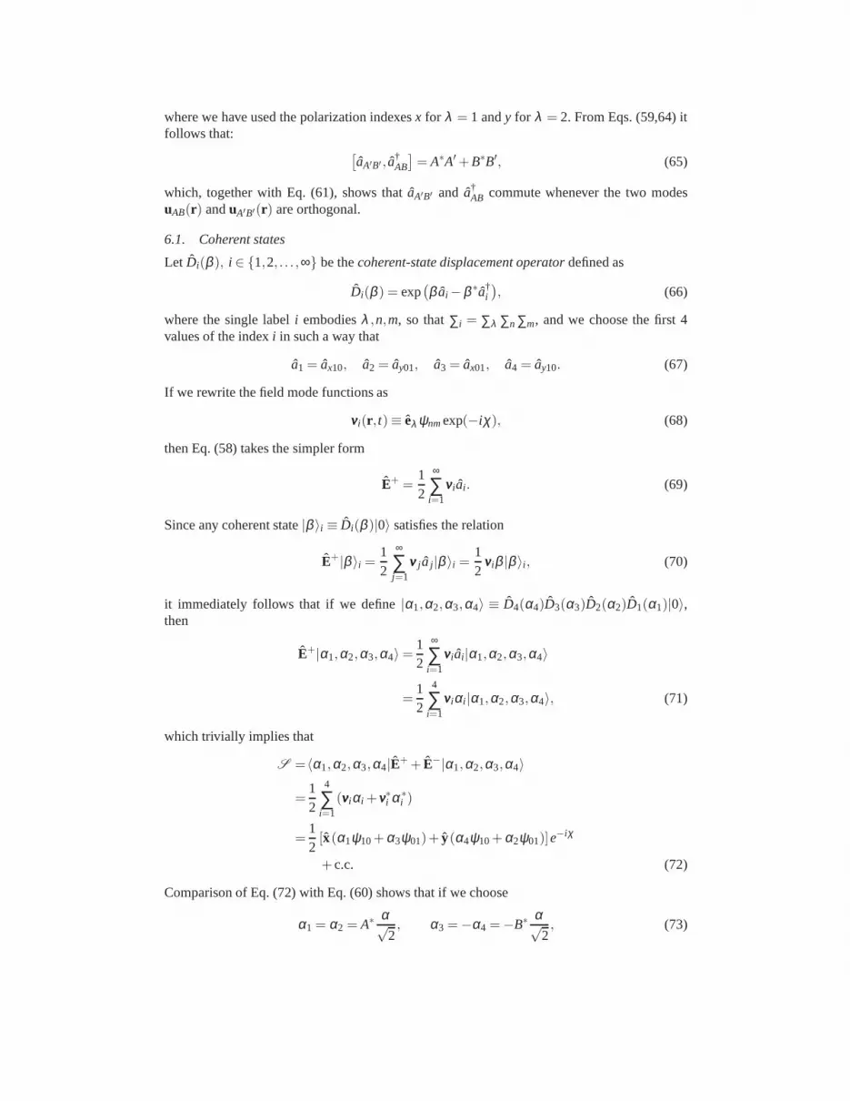
6.1. Coherent states
Let Di(β ), i ∈ {1,2, . . . ,∞} be thecoherent-state displacement operatordefined as
Di(β ) = exp(
β ai −β ∗a†i
)
, (66)
where the single labeli embodiesλ ,n,m, so that∑i = ∑λ ∑n ∑m, and we choose the first 4values of the indexi in such a way that
a1 = ax10, a2 = ay01, a3 = ax01, a4 = ay10. (67)
If we rewrite the field mode functions as
vvvi(r , t)≡ eλ ψnmexp(−iχ), (68)
then Eq. (58) takes the simpler form
E+ =12
∞
∑i=1
vvvi ai . (69)
Since any coherent state|β 〉i ≡ Di(β )|0〉 satisfies the relation
E+|β 〉i =12
∞
∑j=1
vvv j a j |β 〉i =12
vvviβ |β 〉i , (70)
it immediately follows that if we define|α1,α2,α3,α4〉 ≡ D4(α4)D3(α3)D2(α2)D1(α1)|0〉,then
E+|α1,α2,α3,α4〉=12
∞
∑i=1
vvvi ai |α1,α2,α3,α4〉
=12
4
∑i=1
vvviαi |α1,α2,α3,α4〉, (71)
which trivially implies that
S =〈α1,α2,α3,α4|E++ E−|α1,α2,α3,α4〉
=12
4
∑i=1
(vvviαi + vvv∗i α∗i )
=12[x(α1ψ10+α3ψ01)+ y(α4ψ10+α2ψ01)]e
−iχ
+ c.c. (72)
Comparison of Eq. (72) with Eq. (60) shows that if we choose
α1 = α2 = A∗ α√2, α3 =−α4 =−B∗ α√
2, (73)

then we have:
D4(α4)D3(α3)D2(α2)D1(α1)
= exp
[
4
∑i=1
(
αi a†i +α∗
i ai)
]
= exp(
αa†AB−α∗aAB
)
, (74)
and Eq. (62) is automatically satisfied.
6.2. Fock states
The validity of Eq. (63) can be checked by defining the single-photon ladder operatorA(ξ ) as:
A(ξ ) =4
∑i=1
ξ ∗i ai , with
4
∑i=1
|ξi |2 = 1, (75)
that satisfies the canonical commutation relations
[A(ξ ), A†(ξ )] = 1.
Let |1〉 be the single-photon state defined as|1〉= A†(ξ )|0〉. Then
〈0|E+|1〉= 12〈0|
∞
∑i=1
vvvi ai
4
∑j=1
ξ j a†j |0〉
=12 ∑
i, jξ jvvvi〈0|aia
†j |0〉
=12
4
∑i=1
vvviξi . (76)
Now, if we choose
ξ1 = ξ2 = A∗ 1√2, ξ3 =−ξ4 =−B∗ 1√
2, (77)
then we obtain
A(ξ ) =A
(
ax10+ ay01√2
)
+B
(−ax01+ ay10√2
)
= aAB, (78)
in agreement with Eq. (63). Thus, we have proved that Eq. (64)furnishes the correct expressionfor aAB.
6.3. Squeezed states
As a last example, here we write explicitly the expression for an azimuthally polarized squeezedstate. The extension to the other cylindrically polarized states is straightforward and, therefore,will be omitted. As a result of such calculation, we shall findthatclassicalinseparability auto-matically lead toquantumentanglement when the azimuthally polarized beam is prepared in anonclassical state [12].
The “natural” definition ofsqueezing operatorfor the azimuthally polarized field is
SA(ζ ) = exp[1
2ζ ∗(aA
)2− 12
ζ(
a†A
)2]
, (79)

whereζ = seiϑ is the complex squeezing parameter. By substituting Eq. (64) evaluated forA= 0, B= 1 into Eq. (79), it is not difficult to obtain
SA(ζ ) = S3(ζ/2)S4(ζ/2)S34(−ζ/2), (80)
where we have defined the one- and two-mode squeezing operator
Si(ζ ) = exp[1
2ζ ∗(ai
)2− 12
ζ(
a†i
)2]
, (81)
Si j (ζ ) = exp(
ζ ∗ai a j − ζ a†i a†
j
)
. (82)
Thus, the squeezed-vacuum state
|ζ 〉A = S3(ζ/2)S4(ζ/2)S34(ζ )|0〉, (83)
is clearly entangled, since
S34(ζ )|0〉=1
coshs
∞
∑n=0
(e−iϑ tanhs)n|n〉3|n〉4, (84)
represents the well-known entangled two-mode squeezed vacuum [24]. Thus, we have shownthat classical inseparability naturally lead to quantum entanglement.
7. Conclusion
In conclusion, we have established a proper theoretical framework for a classical descriptionof cylindrically polarized states of the electromagnetic field. We have highlighted the rotationprinciples of these modes which can be derived from their very particular intrinsic symmetries.Moreover, we found that all CPMs have a zero total angular momentum and are clearly non-separable which can be proven by their Schmidt rank. This subtlety leads to intriguing featuresof these modes in both the classical and quantum domain of optics, the latter being recentlydemonstrated in experiments [12]. We have exploited these findings to present a new way ofvisualizing CPMs on a pair of hybrid Poincare spheres. Thispermits, at a glance, to easilyrecognize how phase retarders such as waveplates or cylindrical lenses act on these complexpolarization patterns. Furthermore, we have extended our discussion of the properties of thesemodes to the quantum domain and have shown that the classicalinseparability property leadsto the intriguing feature of entanglement.
In general, our results presented here give insight into thetheoretical structure of these modesand their particular behaviour. We believe that the presented formalism and results are of utilityto both the quantum and the classical communities especially in view of the recently growinginterest in the theory and applications of light beams with complex spatial and polarizationpatterns.
The authors thank Peter Banzer for fruitful discussions.
8. Appendix
In our hybrid Poincare sphere representation, only certain transformations are permitted. Dueto the fact that these constraints are not intuitive, we demonstrate here how they can be derived.Generally, besides the particular cases in illustrated Fig. 7, the fundamental rules that an opticaltransformation must obey in order to not violate the global rotation law in Eq. (14) and con-sequently not to generate mixing between the co- and counter-rotating modes, can be deducedfrom perfectly general principles, as follows.
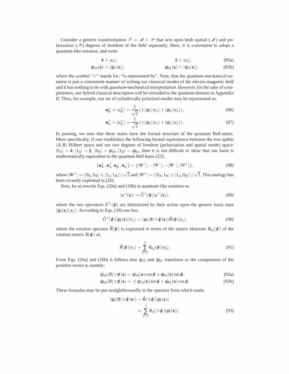
Consider a generic transformationT = M ×P that acts upon both spatial (M ) and po-larization (P) degrees of freedom of the field separately. Here, it is convenient to adopt aquantum-like notation, and write
x .= |e1〉, y .
= |e2〉, (85a)
ψ10(x).= |ψ1(x)〉, ψ01(x)
.= |ψ2(x)〉, (85b)
where the symbol “.=” stands for: “is represented by”. Note, that the quantum-mechanical no-
tation is just a convenient manner of writing ourclassicalmodes of the electro-magnetic fieldand it has nothing to do withquantum-mechanical interpretation. However, for the sake of com-pleteness, our hybrid classical description will be extended to the quantum domain in AppendixII. Thus, for example, our set of cylindrically polarized modes may be represented as:
u±R
.= |u±R〉=
1√2(±|ψ1〉|e1〉+ |ψ2〉|e2〉) , (86)
u±A
.= |u±A 〉=
1√2(∓|ψ2〉|e1〉+ |ψ1〉|e2〉) . (87)
In passing, we note that these states have the formal structure of the quantum Bell-states.More specifically, if one establishes the following formal equivalence between the two qubits(A,B) Hilbert space and our two degrees of freedom (polarization and spatial mode) space:|0A〉 ∼ x, |1A〉 ∼ y, |0B〉 ∼ ψ10, |1B〉 ∼ ψ01, then it is not difficult to show that our basis ismathematically equivalent to the quantum Bell basis [25]:
{u+R , u+
A ,u−R , u−
A} ∼ {|Φ+〉,−|Ψ−〉,−|Φ−〉, |Ψ+〉}, (88)
where|Φ±〉=(|0A,0B〉± |1A,1B〉)/√
2 and|Ψ±〉=(|0A,1B〉± |1A,0B〉)/√
2. This analogy hasbeen recently exploited in [26].
Now, let us rewrite Eqs. (20a) and (20b) in quantum-like notation as:
|u±(x)〉= G±(ϕ)|u±(x)〉, (89)
where the twooperatorsG±(ϕ) are determined by their action upon the generic basis state|ψi(x)〉|ej〉. According to Eqs. (19) one has:
G±(ϕ)|ψi(x)〉|ej〉= |ψi(R(∓ϕ)x)〉R(ϕ)|ej〉, (90)
where the rotation operatorR(ϕ) is expressed in terms of the matrix elementsRk j(ϕ) of therotation matrixR(ϕ) as:
R(ϕ)|ej 〉=2
∑k=1
Rk j(ϕ)|ek〉, (91)
From Eqs. (26a) and (26b) it follows thatψ10 and ψ01 transform as the components of theposition vectorx, namely:
ψ10(R(∓ϕ)x) = ψ10(x)cosϕ ±ψ01(x)sinϕ , (92a)
ψ01(R(∓ϕ)x) = ∓ψ10(x)sinϕ +ψ01(x)cosϕ . (92b)
These formulas may be put straightforwardly in the operatorform which reads:
|ψi(R(∓ϕ)x)〉= R(∓ϕ)|ψi(x)〉
=2
∑l=1
Ril (∓ϕ)|ψl (x)〉. (93)

Note the different order of the indices in the matrix elements appearing in Eq. (91) and Eq.(93). Finally, gathering all these formulas together we obtain:
G±(ϕ)|ψi(x)〉|ej〉= R(∓ϕ)|ψi(x)〉R(ϕ)|ej〉= ∑
k, l
Ril (∓ϕ)|ψl (x)〉Rk j(ϕ)|ek〉,
= ∑k, l
Ril (∓ϕ)RTjk(ϕ)|ψl (x)〉|ek〉,
= ∑k, l
[
R(∓ϕ)⊗R(−ϕ)]
i j ,lk|ψl (x)〉|ek〉,
= R(∓ϕ)⊗ R(−ϕ)|ψi(x)〉|ej〉, (94)
whereAT indicates the transpose of the generic matrixA, and we used the fact that for orthog-onal matrices one hasRT(ϕ) = R(−ϕ). Here, in the direct productR(∓ϕ)⊗ R(−ϕ) the firstoperator acts upon the spatial degrees of freedom solely, while the the second one acts on thepolarization degrees of freedom. Since in all previous calculations the basis state|ψi(x)〉|ej〉was arbitrarily chosen, the relation (94) above is perfectly general and may be rewritten as:
G±(ϕ) = R(∓ϕ)⊗ R(−ϕ). (95)
Now, let M andP be such thatT = M ⊗ P, the two spatial and polarization operators cor-responding to thephysicaltransformationT = M ×P. Then, by definition such operationtransforms|u±(x)〉 into T|u±(x)〉. It is clear that this new state maintains the same symmetryunder rotation of the original state|u±(x)〉 if and only if:
G±(ϕ)T|u±(x)〉= T|u±(x)〉. (96)
By multiplying both sides of Eq. (89) byT, one straightforwardly obtains:
T|u±(x)〉= TG±(ϕ)|u±(x)〉. (97)
Thus, by using Eq. (97) into Eq. (93) one easily obtain:
G±(ϕ)T|u±(x)〉= TG±(ϕ)|u±(x)〉. (98)
or, equivalently:[
G±(ϕ)T − TG±(ϕ)]
|u±(x)〉= 0. (99)
This equation can be easily recast in commutator form by rewriting it as follows:[
G±(ϕ), T]
|u±(x)〉= 0. (100)
Of course, any operatorT that commutes withG±(ϕ), namely[
G±(ϕ), T]
= 0, automaticallyfulfills Eq. (100). However, this condition is sufficient butnot necessarybecause Eq. (100)represents a much weaker constraint, as it only requires that the kernel (or, at least, part of it)of the operator
[
G±(ϕ), T]
coincides with the subspace spanned by either|u+(x)〉 or |u−(x)〉.In other words, all what is required toT by Eq. (100), is that the commutator
[
G±(ϕ), T]
has anull eigenvalue in correspondence of the eigenvector|u±(x)〉.
Now, having this caveat in mind, we can rewrite the condition(100) as follows:[
R(∓ϕ)⊗ R(−ϕ)][
M⊗ P]
=[
M⊗ P][
R(∓ϕ)⊗ R(−ϕ)]
, (101)

or, equivalently:
R(∓ϕ)M[
R(∓ϕ)]−1⊗ R(−ϕ)P
[
R(−ϕ)]−1
= M⊗ P, (102)
where all the operators are understood to be restricted to the subspaces spanned by|g±(x)〉.Obviously, this commutator expression is satisfied whenever the following two conditions areseparately satisfied:
[
R(ϕ),M]
= 0,[
R(ϕ), P]
= 0, (103)
where the arbitrariness of the angleϕ has been exploited. But, again, this condition is sufficientbut not at all necessary. In fact, it is not difficult to see that if one choose either
M =
(
m1 m2
−m2 m1
)
and P=
(
p1 p2
−p2 p1
)
, (104)
or
M =
(
m1 m2
m2 −m1
)
and P=
(
p1 p2
p2 −p1
)
, (105)
with m1,m2, p1, p2 ∈ C, then Eq. (100) is always satisfied but Eqs. (103) are satisfied only bythe first choice (104) that represent orthogonal matrices wheneverm2
1+m22 = 1= p2
1+ p22.
It is worth to notice that a circular polarizer (left or right) is represented by the Jones matrix
P=12
(
1 ±i∓i 1
)
, (106)
which is of the form (104). Conversely, a half-wave plate with fast axis at angleα with respectto the horizontal axis is represented by the Jones matrix
P=
(
cos(2α) sin(2α)sin(2α) −cos(2α)
)
, (107)
which is of the form (105).


