Embed Size (px)
Citation preview

Open Access.© 2019W. Zhang and Y. Yu, published by De Gruyter. This work is licensed under the Creative Commons Attribution4.0 License
Open Phys. 2019; 17:497–504
Research Article
Wei Zhang* and Yandong Yu
Closed-die Forging Technology and NumericalSimulation of Aluminum Alloy Connecting Rodhttps://doi.org/10.1515/phys-2019-0051Received Apr 15, 2019; accepted May 29, 2019
Abstract: In order to improve quality and reveal the law ofprecision forging, closed-die forging technology is used inthis paper to conduct a numerical analysis of the formingprocess of aluminum alloy connecting rod by the DEFORMsoftware. Forming effects under different loading modeswere acquired, and forming process, blank flow character-istics, stress-strain distribution and load-stroke curve char-acteristics were analyzed. Study results indicate that theformingeffect under the loadingmode featuringfirstmove-ment of lateral punch and then movement of upper andlower punches is good with high quality forge piece andno defect,the closed-die forging technology of aluminumalloy connecting rod is reasonable and feasible. Under acertain deformation velocity and deformation mode, alu-minum alloy connecting rod forming load firstly reducesand then increases,the forming load is in direct proportionto deformation velocity. When the forming process is fin-ished, forming load reaches 130T, it accords with the pro-duction practice. The study results provide a certain refer-ence for guiding the formulation of closed-die forging pro-duction technology of aluminum alloy connecting rods.
Keywords: Aluminum Alloy Connecting Rod,Closed-dieForging,Numerical Simulation,DEFORM software
PACS: 81.20.-n,02.60.-x,02.70.Dh
1 IntroductionThe connecting rod, as an important component of theengine, constitutes crank-link mechanism with air cylin-der, piston, bent axle and main bearing [1]. Most connect-
*Corresponding Author: Wei Zhang: Rongcheng College, HarbinUniversity of Science and Technology, Weihai, 264300,China; Email:[email protected] Yu: School of Materials Science and Engineering, HarbinUniversity of Science and Technology, Harbin,150040,China; Email:[email protected]
ing rods of small-scale gasoline engines are made of high-strength aluminum alloy. As the important components ofsmall-scale gasoline engines, connecting rod is not onlycomplicated shape, high requirement for dimensional ac-curacy and favorable wear resistance but also shall nothave defects both inside and on the surface such as crack,mingling, pore, etc.; conventional metal machining tech-nology can reach design requirements of parts, but its pro-duction efficiency is extremely lowandmaterial utilizationefficiency is low, and moreover, industrial production inlarge batches can’t be realized. Nowadays pressure castingor ordinary hot die forging and follow-up machining aregenerally adopted for batch machining in China, throughwhich qualified aluminum alloy parts can be obtained.However, due to poor surface smoothness of aluminum al-loy under pressure casting and casting defects always ex-isting inside parts like pore and mingling, their mechan-ical properties are greatly degraded, thus being difficultto satisfy usability requirement.Meanwhile, product per-cent of pass in the follow-up machining is low (about sev-enty percent) because of existence of casting defects likepore, mingling, etc. Ordinary hot-die forging forming ofaluminum alloy connecting rods features tedious produc-tion procedures, complicated technological process, lowmaterial utilization efficiency (about sixty percent) andhigh production cost as well as defects like surface crack,folding, disorderly metal flow line, etc. Therefore, it willbe of great practical significance to research and developprecision forging forming technologies of aluminum alloyconnecting rod-type forge pieces in order to improve theirmachining quality and mechanical properties [2–4].
Closed-die forging is a forming technology whichplaces workblank inside a closed die cavity under three-way stress state and extrudes it using punches so thatthe die cavity is filled with metal to obtain complicatedtrimming-free flash. However, closed-die forging formingprocess is complicated with many control parameters sothat optimal parameter selection, complicated die designandmachining in the closed forging technology of compli-cated parts become more difficult [5–7]. It’s hard for tradi-tional forming technology and die design method depend-ing on experience and trial and error to satisfy compli-

498 | W. Zhang and Y. Yu
cated forming conditions and high requirements for preci-sion and quality. Therefore, it is necessary to conduct sim-ulation, technological analysis and optimization design ofclosed-die forging process using the numerical simulationtechnology. Cross-sectional change of the aluminum alloyconnecting rod is major along the length direction withgreat forming technical difficulties,whichposes enormouschallenges to the studyof closed-die forging formingof alu-minum alloy connecting rods [8, 9].
On this basis, researchers have carried out a largequantity of research onnumerical simulation of closed-dieforging forming of aluminum alloy connecting rods [10–15], but deviation from actual technology still exists in as-pects of multi-field coupling problem in the thermal de-formation process of aluminum alloy connecting rods andthe influence of changes of different thermal deformationparameters on stress-strain fields. Therefore, how to ac-curately predict relationships between different formingmodes and forming quality, reveal precision forging form-ing laws of aluminum alloy forge pieces and prevent de-fects is an urgent problem to be solved [16–18].
Therefore, theoretical analysis and numerical simula-tion were combined in this paper to establish a finite ele-ment computing model for closed-die forging forming ofaluminum alloy connecting rod, and then aluminum al-loy connecting rod forming process, blank flow character-istics, stress-strain distribution and load-stroke curve char-acteristics were analyzed, aiming at predicting relation-ships between different forming modes and forming qual-itymore accurately so as to provide a reference for develop-ment and optimization of precision forging forming tech-nology of aluminum alloy connecting rods.
2 Finite element analysis model
2.1 Closed-die forging technology
Closed-die forging is also called closed extrusion. Its prin-ciple is: large enough die clamping force is used to com-bine two or several detachable dies into one closed die cav-ity, and metal workblank fills the die cavity through extru-sion under one-way or opposite movement of one or multi-ple punches so as to obtain a flash-free forge piece approx-imate to net dimensions with the same shape and dimen-sions as the die cavity as shown in Figure 1.
Figure 1: Closed-die forging technology.
Figure 2: forged connecting rod.
2.2 forged connecting rod and prefabricatedblank
The aluminum alloy forged connecting rod piece formedthrough three-way closed-die forging is shown in Figure 2.
According to the principle that metal volume remainsunchanged before and after plastic deformation, shape offabricated blank can be determined according to Figure 3.
2.3 Geometric model used in numericalsimulation
During the closed-die forging forming process of alu-minum alloy connecting rod, as plastic deformation ofblank is far greater than its elastic deformation, it is properto numerical simulation using rigid-plastic finite elementmethod [19, 20].
Based onUG andDeform-3D software platform, the ge-ometricmodel used for numerical simulation of closed-die

Closed-die Forging Technology and Numerical Simulation | 499
Figure 3: prefabricated blank of connecting rod.
Figure 4: Geometric model of closed-die forging of connecting rod.
forging of aluminum alloy connecting rod, which is estab-lished using rigid-plastic finite element theory, consists ofupper die, upper round punch, upper square punch, lowerdie, lower round punch, lower square punch and lateralpunch as shown in Figure 4.
Figure 5: Grids of connecting rod workblank.
2.4 Model grid partitioning
The connecting rod workblank belongs to a regular geom-etry, tetrahedron elements are used for grid partitioning,minimum unit edge length of grids is 1mm, grid aspect ra-tio is 3, and total number of grids is 39,572, all of whichsatisfy the requirement for computational accuracy. Gridstructure of the connecting rod workblank is shown in Fig-ure 5.
2.5 Material properties and computationalboundary
AL6061 material is used, the used workblank is regardedas a plastic body, constant shear friction model is used asthe model between workblank and die, the die is regardedas a rigid body, and friction factor is taken as 0.3 [21, 22].In consideration of temperature change, initial workblanktemperature is set as 400°C, temperature between punchand die is set as 200°C, and heat exchange coefficient be-tween die/punch and workblank is 5KW/(m°C), where ve-locity of movement of punch is set as 10mm/s.
2.6 Closed-die forging forming technologyscheme
6061 aluminum alloy connecting rod has complicatedstructure and its forming process is as follows: the prefab-ricated blank is placed in the lower die, and after upperand lower dies are clamped, upper round punch, upper
500 | W. Zhang and Y. Yu
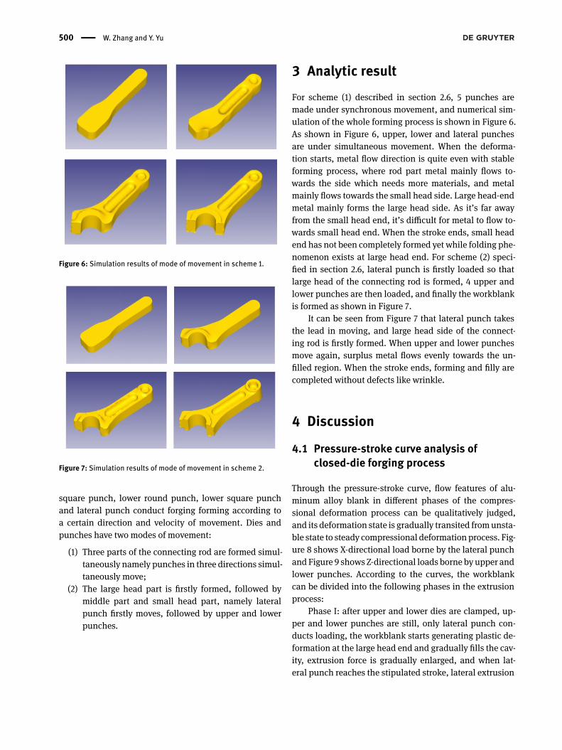
Figure 6: Simulation results of mode of movement in scheme 1.
Figure 7: Simulation results of mode of movement in scheme 2.
square punch, lower round punch, lower square punchand lateral punch conduct forging forming according toa certain direction and velocity of movement. Dies andpunches have two modes of movement:
(1) Three parts of the connecting rod are formed simul-taneously namely punches in three directions simul-taneously move;
(2) The large head part is firstly formed, followed bymiddle part and small head part, namely lateralpunch firstly moves, followed by upper and lowerpunches.
3 Analytic resultFor scheme (1) described in section 2.6, 5 punches aremade under synchronous movement, and numerical sim-ulation of the whole forming process is shown in Figure 6.As shown in Figure 6, upper, lower and lateral punchesare under simultaneous movement. When the deforma-tion starts, metal flow direction is quite even with stableforming process, where rod part metal mainly flows to-wards the side which needs more materials, and metalmainly flows towards the small head side. Large head-endmetal mainly forms the large head side. As it’s far awayfrom the small head end, it’s difficult for metal to flow to-wards small head end. When the stroke ends, small headend has not been completely formed yet while folding phe-nomenon exists at large head end. For scheme (2) speci-fied in section 2.6, lateral punch is firstly loaded so thatlarge head of the connecting rod is formed, 4 upper andlower punches are then loaded, and finally the workblankis formed as shown in Figure 7.
It can be seen from Figure 7 that lateral punch takesthe lead in moving, and large head side of the connect-ing rod is firstly formed. When upper and lower punchesmove again, surplus metal flows evenly towards the un-filled region. When the stroke ends, forming and filly arecompleted without defects like wrinkle.
4 Discussion
4.1 Pressure-stroke curve analysis ofclosed-die forging process
Through the pressure-stroke curve, flow features of alu-minum alloy blank in different phases of the compres-sional deformation process can be qualitatively judged,and its deformation state is gradually transited fromunsta-ble state to steady compressional deformation process. Fig-ure 8 shows X-directional load borne by the lateral punchandFigure 9 shows Z-directional loads borne by upper andlower punches. According to the curves, the workblankcan be divided into the following phases in the extrusionprocess:
Phase I: after upper and lower dies are clamped, up-per and lower punches are still, only lateral punch con-ducts loading, the workblank starts generating plastic de-formation at the large head end and gradually fills the cav-ity, extrusion force is gradually enlarged, and when lat-eral punch reaches the stipulated stroke, lateral extrusion

Closed-die Forging Technology and Numerical Simulation | 501
Figure 8: X-directional load.
Figure 9: Z-directional loads.
force is f=200,000N (namely 20 tons). After lateral punchstops moving, extrusion force abruptly declines.
Phase II: lateral punch keeps still, upper and lowerpunches start extruding, the workblank gradually fills thewhole cavity, and pressure borne by lateral punch gradu-ally increases to 20 tons. At the time, pressures borne byupper and lower punches gradually increase.
Figure 10:When movement of lateral punch ends.
Phase III: upper and lower punches continue to ex-trude. At the final forming time, the workblank is undertriaxial compressive stress so that extrusion force of eachpunch rises at a high velocity. Extrusion force of lateralpunch is f=658,000N (namely 65.8 tons), that of roundpunch is f=103,000N (namely 10.3 tons) and that of squarepunch is f=544,000N (namely 54.4 tons).
After phase III ends, if extrusion is continued, sharpincrease of extrusion forcemay damage the die and punch-ing machine.
4.2 Analysis of workblank flowcharacteristics in the closed-die forgingprocess
Aluminum alloy blank flow analysis results in the extru-sion process are shown in Figure 10 and Figure 11. Fric-tion between die and blank is adhesive friction. Frictionsin different regions have different effects on the blank. Thepunchmakes workblankmove forward in the forming pro-cess while friction between workblank and die discour-ages the workblank from moving forward. Therefore, flowvelocity field distribution is not very even, especially veloc-ity field nearby the die bearing is larger than those in otherregions. According to the least resistance law, metal willflow by selecting a flowable path. The velocity is lower inthe place with large flow resistance. As shown in Figure 11,metal flow vectors are basically identical, so forming is fa-vorable without folding and folding defect will not be gen-erated.

502 | W. Zhang and Y. Yu
Figure 11:When forming ends.
Figure 12: Deformation velocity analysis (1).
4.3 Analysis of workblank deformationvelocity in the closed-die forgingprocess
During the aluminum alloy deformation process, if the de-formation speed is too fast, cracks can be easily generated.It can be seen fromFigure 12 and 13 that deformation veloc-ity of aluminum alloy workblank is high at the large headpart—a region where cracks can be easily generated—inthe early extrusion phase during the forming process. Ifcracks are generated, they can be eliminated by control-ling punch velocity.
Figure 13: Deformation velocity analysis (2).
4.4 Workblank stress-strain analysis in theclosed-die forging process
With the lateral punch into upper and lower dies, stressstarts experiencing obvious changes when lateral punchcontacts the workblank, the stress at contact part betweenworkblank and lower die is larger than that on its up-per surface, and the stress changes the most in the con-tact between the workblank side and the lateral punch.As the deformation proceeds, stress at the contact part ofthe lateral punch gradually increases. Stresses in other re-gions of the workblank somehow increase with relativelyuniform distribution, mainly because metal material itselfflows and self-homogenizes the stress. When stroke of lat-eral punch ends, large head of the connecting rod is notcompletely filled, and maximum stress value of the work-blank is 105MPa(see Figure 14). When upper and lowerpunches start loading, elliptic punch first contacts theworkblank, stress value at the round corner experiencethe greatest change with the maximum strain rate, andmetal at this part is under high stress state. When roundpunch contacts the workblank, round corner where work-blank contacts the die is still the stress concentration part,and stress value is 100MPa or so. When strokes of upperand lower punches end, the forged connecting rod pieceis completely filled, stress value reaches the maximumvalue 147MPa (see Figure 15) with uniform distribution,and bosses of large and small heads are well filled.
Strain condition of theworkblank in the extrusion pro-cess is shown in Figure 16. Equivalent strain distribution isuniform in the whole deformation process, no cracks will

Closed-die Forging Technology and Numerical Simulation | 503
Figure 14: Stress distribution(1).
Figure 15: Stress distribution(2).
be generated, and strain values are not large and all withinthe allowable range.
5 ConclusionIn order to explore closed-die forging forming laws of alu-minum alloy connecting rod and reveal the relationshipbetween punch loading mode and forming quality, start-ing from finite element analysis model, the process ofclosed-die forging of aluminum alloy connecting rod issimulated and analyzed in this paper. The following con-clusions were drawn:
Figure 16: Strain distribution.
(1) Results show that the metal flow process can bedivided into three stages, the final forming con-tour is clear and the filling is full with no fold-ing,insufficient filling and uneven flow line
(2) The loading mode under which lateral punch firstlymoves, followed by upper and lower punches is offavorable forming effect and no defects.
(3) Under a certain deformation velocity and deforma-tionmode, forming load of aluminum alloy connect-ing rod first increases and then decreases and in-creases again, and forming load is in direct propor-tion to deformation velocity,the maximum formingload is 130T.
(4) Theoretical analysis and numerical simulation werecombined in this study. A newmethod of aluminumalloy connecting rod production using closed-dieforging technology was proposed. It can be used asa reference for the development of precision forg-ing process of aluminum alloy connecting rod. How-ever, the influence of process parameters on the mi-crostructure evolution of the forge piece has notbeen deeply studied,so in the future research, pro-duced forge piece will be combined with simulationresults for the sake of correction, which will con-tribute to a more accurate understanding of closed-die forging forming process laws of aluminum alloyconnecting rods.
Acknowledgement: This work was partly supported bythe Training Plan of Young innovative talents in Col-

504 | W. Zhang and Y. Yu
leges and Universities of Heilongjiang Province(GrantNo:UNPYSCT-2016036)
References[1] China forging Association,Die forging process and characteris-
tics of its equipment,Beijing, Machinery Industry Press,2009.[2] Srinivasan N., Prasad Y. V. R. K., Rama Rao P., Hot Deformation
Behavior of Mg-3Al Alloy-A Study Using Processing Map, Mat.Sci. Eng. A, 2008,476(1-2), 146-156.
[3] Behrens B. A., Doege E., Reinsch S., Telkamp K., Daehndel H.,Specker A. Precision Forging Processes for High-duty AutomotiveComponents, J.Mater. Process. Tech., 2007, 185, 139-146.
[4] Shan D.B., Liu F., XuW.C., Lu Y., Experimental Study on Process ofPrecision Forging of an Aluminum-alloy Rotor. J.Mater. Process.Tech., 2005, 170,412-415.
[5] Yuan S.Y., Zhang L.W., Liao S.L., Jiang G.D., Yu Y.S., Qi M., Simu-lation of Deformation and Temperature in Multi-pass ContinuousRolling by Three-dimensional FEM. J.Mater. Process. Tech., 2009,209(6), 2760-2766.
[6] Petrov P., Perfilov V., Stebunov S., Prevention of Lap Formation inNearNet Shape Isothermal Forging Technologyof Part of IrregularShape Made of Aluminum Alloy A92618. J.Mater. Process. Tech.,2006, 177, 218-223.
[7] Zhao D.Y., Zhang L.D., SunH.X., Research on Closed Die ForgingProcess of Car Steering Knuckle. Mater. Sci. Forum, 2008,5, 204-209.
[8] Qu J. J., The Study of the Closed Die Forging Process of AluminumAlloy Connecting Rod. Master thesis of ChongQing University,China, 2015.
[9] Yao B., Fang G.. Numerical Simulation of Pre-forging for Connect-ing Rod of Aotumobile Engine and Optimization of Its Pre-forgingBillet,Cast.Forg.Weld., 2009,7,106-109.
[10] Wu T.B., Ma B., Zhang J.J., Numercial Simulation of the ClosedDie Forging Process for Aluminum Alloy Connecting Rod,Spec.Cast.Nonfer.Alloy, 2015,35(9),991-994.
[11] Ma B., Numerical Analysis and Experimental Research on Form-ing Process of 6061 Aluminum Alloy Connecting Rod Closed-dieForging. Master thesis of Chong Qing University, China,2009.
[12] Zhang J. J., Development ResearchonMulti-wayPrecision ForgingTechnology of High Strength Aluminum Alloy Connecting Rodfor Mini-type Gasoline Engine. Master thesis of ChongQing ofTechnology, China,2009.
[13] Persson A., Hogmark S., Bergström J., Thermal FatigueCracking of Surface Engineered Hot Work Tool Steels.Sur.Coa.Tech.,2005,191,(2-3),216-227.
[14] Santos C.A., Aguilar M.T.P., Campos H.B., Pertence A.E.M., CetlinP.R., Failure Analysis of the Die in the Third Hot forging Stage ofa Gear Blank, Eng.Fai. Anal.,2006,13(6),886 897.
[15] Srinivasan N., Prasad Y. V. R. K., Rama Rao P., Hot DeformationBehavior of Mg-3Al Alloy-A Study Using Processing Map, Mat.Sci. Eng. A, 2008,476(1-2), 146-156.
[16] Yi Y.P., Fu X., Cui J.D., Prediction of grain size for large-sizedaluminium alloy 7050 forging during hot forming.J. Cent. SouthUniv., 2008,15(1),1-5.
[17] Chang C. C., Kuo W. L., Effects of temperature and grain re-finement on the closed-die forging of a micro gear, J.Eng.Man.-En,2010,224(11),1767-1773.
[18] Fang X.W., Liu Z.Y.,Tan J.R.,et. al., Multi-scale Simulation Methodwith Coupled Finite Discrete Element Model and Its Application,Chin. J.Mech.Eng. 2013(04),659-667.
[19] Doege E.,Bohnsack R., Closed die technologies for hot forg-ing,J.Mater. Process. Tech., 2000, 98(2), 165-170.
[20] Song J.H., Im Y. T., Process design for closed-die forging of bevelgear by finite element analyses[J]. J.Mater. Process. Tech., 2007,192(5), 1-7.
[21] Kim N. H., Kang C. G., Kim B. M., Die design optimizationfor axisymmetric hot extrusion of metal matrix composites,In.J.Mech.Sci. 2001, 43(6), 1507-1520.
[22] Sun C.Y.,Zhang Q.D.,Numerical Simulation of Superalloy IN718during Tube Hot Extrusion, Adv. Mater. Res., 2009, 83-86,157-164.


