Embed Size (px)
Citation preview
Cluster Platform KnowledgebaseDocumentation
Release
Alces Software
Dec 11, 2017


Introduction
1 License 3
i

ii

Cluster Platform Knowledgebase Documentation, Release
This site documents the considerations and guidelines for designing and developing a HPC platform for cluster com-puting. The documentation describes general practices and considerations when designing a HPC platform as well asrecommendations and guides used by Alces Software to configure HPC platforms.
Introduction 1

Cluster Platform Knowledgebase Documentation, Release
2 Introduction
CHAPTER 1
License
This documentation is released under the Creative-Commons: Attribution-ShareAlike 4.0 International license.
1.1 Introduction
The purpose of this documentation is to provide a list of considerations and guidelines for the development of a HPCenvironment. This documentation should be followed through in order to properly understand the structure of theenvironment and that certain considerations are not missed out along the way.
To generalise the entire process, it goes as follows:
Hardware Architecture Design -> Hardware Build -> Software Build -> Platform Delivery
Ensuring that a suitable hardware and network architecture is designed before the build process creates a stable basefor the HPC platform.
Performing the hardware build before doing any software configuration guarantees that the network and hardware isproperly setup. A partially built network during software setup can lead to unforeseen issues with communication andconfiguration.
Once the infrastructure has been physically built the software build can proceed. Usually the central servers will beconfigured first before client and compute nodes are configured.
Note: It is recommended to read through all of the documentation before starting to design the HPC platform tounderstand the scope and considerations.
1.2 Overviews
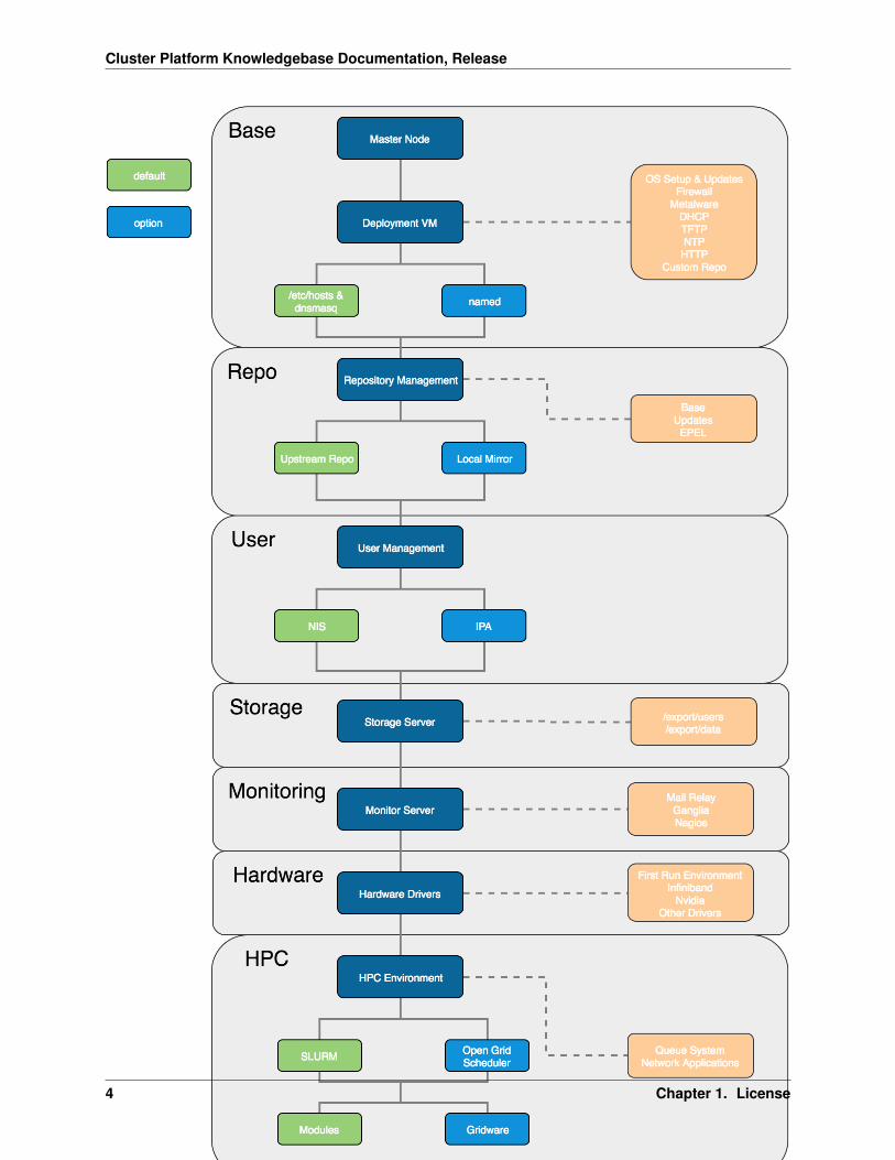
A breakdown of the different section overviews into their relevant packages. (see below diagram)
3
Cluster Platform Knowledgebase Documentation, Release
4 Chapter 1. License
Cluster Platform Knowledgebase Documentation, Release
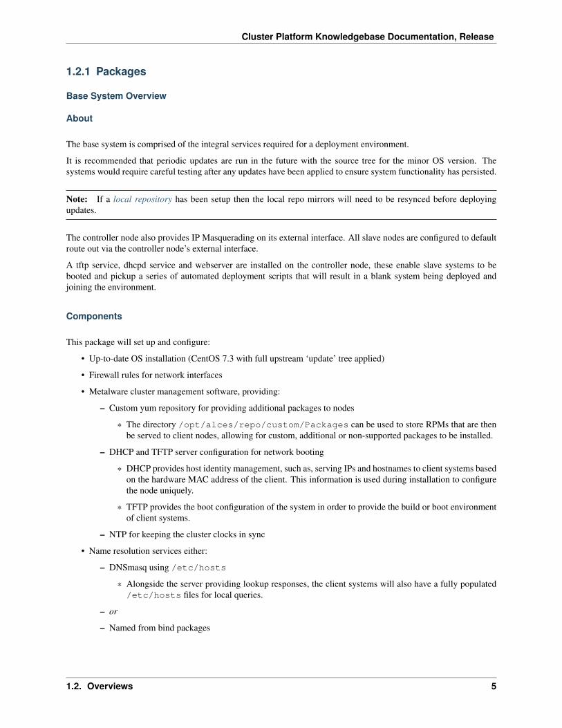
1.2.1 Packages
Base System Overview
About
The base system is comprised of the integral services required for a deployment environment.
It is recommended that periodic updates are run in the future with the source tree for the minor OS version. Thesystems would require careful testing after any updates have been applied to ensure system functionality has persisted.
Note: If a local repository has been setup then the local repo mirrors will need to be resynced before deployingupdates.
The controller node also provides IP Masquerading on its external interface. All slave nodes are configured to defaultroute out via the controller node’s external interface.
A tftp service, dhcpd service and webserver are installed on the controller node, these enable slave systems to bebooted and pickup a series of automated deployment scripts that will result in a blank system being deployed andjoining the environment.
Components
This package will set up and configure:
• Up-to-date OS installation (CentOS 7.3 with full upstream ‘update’ tree applied)
• Firewall rules for network interfaces
• Metalware cluster management software, providing:
– Custom yum repository for providing additional packages to nodes
* The directory /opt/alces/repo/custom/Packages can be used to store RPMs that are thenbe served to client nodes, allowing for custom, additional or non-supported packages to be installed.
– DHCP and TFTP server configuration for network booting
* DHCP provides host identity management, such as, serving IPs and hostnames to client systems basedon the hardware MAC address of the client. This information is used during installation to configurethe node uniquely.
* TFTP provides the boot configuration of the system in order to provide the build or boot environmentof client systems.
– NTP for keeping the cluster clocks in sync
• Name resolution services either:
– DNSmasq using /etc/hosts
* Alongside the server providing lookup responses, the client systems will also have a fully populated/etc/hosts files for local queries.
– or
– Named from bind packages
1.2. Overviews 5
Cluster Platform Knowledgebase Documentation, Release
* Named creates forward and reverse search zones on the controller node that can be queried by allclients. Unlike DNSmasq, the client systems have an empty /etc/hosts as named is serving all ofthe additional host information.
• Management tools built around ipmitool, pdsh and libgenders
– These management tools allow for running commands on multiple systems defined in groups, improvingthe ease and flexibility of environment management.
• Combined logging for clients with rsyslog server
– All clients built from the master write out build progress and syslog messages to /var/log/slave/<NODENAME>/messages.log
Key Files
• /etc/hosts
• /etc/dhcp/dhcpd.*
• /etc/dnsmasq.conf or /etc/named/metalware.conf
• /opt/metalware/*
• /var/lib/metalware/*
• /var/lib/tftpboot/*
• /etc/ntp.conf
• /etc/rsyslog.d/metalware.conf
Licensing
The CentOS Linux distribution is released under a number of Open-source software licenses, including GPL. A copyof the relevant license terms is included with the CentOS software installed on your cluster. The CentOS Linuxdistribution does not require any per-server license registration.
Additionally, the applications and services installed have similar open-source licensing which can be viewed eitheronline or through the manual pages for the specific package.
Repository Overview
About
Upstream repositories for CentOS and EPEL will be mirrored locally to a virtual machine which can provide thepackages to the rest of the nodes in the cluster. The local repository will be used for deployment installations andpackage updates.
Components
Upstream distribution primary repos and EPEL will imported to /opt/alces/repo/ with reposync, any up-stream repo groups will also be imported to allow node redeployment without internet access (and a known workingdisaster recovery configuration).
6 Chapter 1. License
Cluster Platform Knowledgebase Documentation, Release
Key Files
• /etc/yum.repos.d/*
• /opt/alces/repo/*
User Management Overview
About
This package contains the services required to configure a central user management server for the HPC environment.This relieves the need to manage /etc/passwd locally on every system within the HPC environment and providesfurther authentication management of different services.
Components
For user management, one of the following software solutions will be implemented:
• NIS (Network Information Service)
– The Network Information Service (NIS) is a directory service that enables the sharing of user and hostinformation across a network.
• or
• IPA (Identity, Policy, Audit)
– FreeIPA provides all the information that NIS does as well as providing application and service informationto the network. Additionally, FreeIPA uses directory structure such that information can be logically storedin a tree-like structure. It also comes with a web interface for managing the solution.
Key Files
• /etc/sysconfig/network
• /etc/yp.conf, /var/yp/*
• or
• /etc/ipa/*
Storage Overview
About
This package configures an NFS master server to provide user and data filesystems to all slave nodes.
Components
The storage solution is comprised of the following:
• NFS server
1.2. Overviews 7
Cluster Platform Knowledgebase Documentation, Release
– The NFS server serves redundant network storage (depending on hardware and network configuration) tothe client systems in the environment. This allows for distributed access to project and user data.
• Filesystem formatting
– Ext4
– or
– XFS
• Exported filesystems
– /export/users to be mounted at /users on clients
– /export/data to be mounted at /data on clients
Key Files
• /etc/sysconfig/nfs
• /etc/exports
• /etc/fstab
Monitoring Overview
About
This package will configure a monitoring master system with metric collection services and a web front-end. Slavenodes will have the client monitoring service setup to send metrics to the master system.
Components
The monitoring system will provide the following applications:
• Ganglia, a passive monitoring system with metric graphs
– Clients send metrics to the Ganglia host system which are plotted on graphs for viewing data trends for theenvironment. The data is available through both a command-line utility and a web interface.
• Nagios, an active monitoring system with notifications
– Nagios clients are configured on the server and are not required to run client software unless additionalmetrics are needed. The system actively monitors metrics and if the values go over a predefined, customis-able threshold.
Key Files
• /etc/ganglia/gmetad.conf
• /etc/ganglia/gmond.conf
• /etc/httpd/conf.d/ganglia
• /var/lib/ganglia/*
• /etc/nagios/*
8 Chapter 1. License
Cluster Platform Knowledgebase Documentation, Release
• /etc/httpd/conf.d/nagios.conf
• /usr/share/nagios/*
Hardware Drivers Overview
About
Some clusters may require custom hardware drivers for your chosen operating system. This package will create anenvironment that allows nodes to run installers on its first boot to build the driver against the up-to-date OS.
Components
The components in this package are:
• First boot environment for automatically executing installers at boot time
– This provides a system service that can be used to run installation scripts when a system is turned on. Forexample, Nvidia graphics driver can be set to compile after the initial build of the system such that it iscompiled against the correct kernel version.
• Infiniband driver first-boot script
– A script that can install the Mellanox Infiniband driver either from upstream repositories or through localcompilation from the source files
• Nvidia graphics driver first-boot script
Key Files
• /etc/systemd/system/firstrun.service
• /var/lib/firstrun/*
• /var/log/firstrun/*
• /opt/alces/installers/*
HPC Environment Overview
About
This package provides tools for queuing jobs and running applications across the cluster.
Components
The HPC environment will be comprised of:
• Queuing system for optimised resource utilisation
– SLURM
* The SLURM job scheduler is a centrally managed job scheduler that cant constrain resources basedon grid utilisation, user/group assignment and job resource requirements.
1.2. Overviews 9
Cluster Platform Knowledgebase Documentation, Release
– or
– Open Grid Scheduler
* Much like SLURM, OGS provides a centrally managed job scheduler with similar resource manage-ment possibilities.
• Application deployment solution
– Environment modules
* Modules allows for applications to be loaded dynamically in shell sessions. With the paths beingupdated on-the-fly, applications can be installed to a network storage location - minimising installationtime and improving the ease of application use (both in interactive and non-interactive sessions).
– or
– Alces Gridware
* Gridware contains an implementation of environment modules and also provides a useful CLI tool forinstalling and managing applications from a large repository of HPC applications.
Key Files
• /etc/slurm/*
• or
• /opt/gridscheduler/*
• /opt/apps/*
• or
• /opt/gridware/
1.3 Considerations for Network and Hardware Design
In general, the things to consider when designing the hardware and network solution for a HPC platform are:
• The hardware environment
• The types of nodes required in the network
• The different networks to be used by the network
• The level of resilience desired
• The hostname and domain naming convention
These are covered in more detail below. . .
1.3.1 Hardware Environment
The hardware environment will generally be one of two setups, metal or cloud.
• Metal - Metal environments are those which are compromised of on-site systems in a datacenter which areusually running 24/7.
• Cloud - Cloud environments are systems hosted in a third-party datacenter and are usually ephemeral systemsthat are being created and destroyed on demand.
10 Chapter 1. License
Cluster Platform Knowledgebase Documentation, Release
• Metal/Cloud Hybrid - A hybrid environment usually consists of a core metal configuration that uses cloud asan overflow for additional capacity at times of high utilisation.
A hardware environment is mainly focussed on the location, capacity and permanence of the HPC platform and doesnot directly determine the hardware that will be used in the various systems.
1.3.2 Node Types
A complete HPC platform will be comprised of systems that serve different purposes within the network. Ideas ofnode types along with the services and purpose of those nodes can be seen below.
• Login Node - A login node will usually provide access to the HPC platform and will be the central system thatusers access to run applications. How users will access the system should be considered, usually this will beSSH and some graphical login service, such as, VNC.
• Master Node - A master node will usually run services for the HPC platform. Such as, the master process for ajob scheduler, monitoring software and user management services.
• Compute Node - Compute nodes are usually used for running HPC applications that are queued through ajob scheduler. Additionally, these can be used for VM deployments (via software like OpenStack) or othercomputational uses. Compute nodes usually have large amounts of cores and memory as well as high bandwidthinterconnect (like Infiniband).
• Storage Node - The storage node will serve network storage solutions to systems on the network. It would havesome sort of storage array connected to it which would provide large and resilient storage.
The above types are not strict. Services can be mixed, matched and moved around to create the desired balance anddistribution of services and functions for the platform.
1.3.3 Different Networks
The network in the system will most likely be broken up (physically or virtually with VLANs) into separate networksto serve different usages and isolate traffic. Potential networks that may be in the HPC platform are:
• Primary Network - The main network that all systems are connected to.
• Out-of-Band Network - A separate network for management traffic. This could contain on-board BMCs,switch management ports and disk array management ports. Typically this network would only be accessible bysystem administrators from within the HPC network.
• High Performance Network - Usually built on an Infiniband fabric, the high performance network would beused by the compute nodes for running large parallel jobs over MPI. This network can also be used for storageservers to provide performance improvements to data access.
• External Networks - The network outside of the HPC environment that nodes may need to access. For example,the Master Node could be connected to an Active Directory server on the external network and behave as a slaveto relay user information to the rest of the HPC environment.
• Build Network - This network can host a DHCP server for deploying operating systems via PXE boot kickstartinstallations. It allows for systems that require a new build or rebuild to be flipped over and provisioned withoutdisturbing the rest of the network.
• DMZ - A demilitarised zone would contain any externally-facing services, this could be setup in conjunctionwith the external networks access depending on the services and traffic passing through.
The above networks could be physically or virtually separated from one another. In a physical separation scenariothere will be a separate network switch for each one, preventing any sort of cross-communication. In a virtuallyseparated network there will be multiple bridged switches that separate traffic by dedicating ports (or tagging traffic)
1.3. Considerations for Network and Hardware Design 11
Cluster Platform Knowledgebase Documentation, Release
to different VLANs. The benefit of the VLAN solution is that the bridged switches (along with bonded networkinterfaces) provides additional network redundancy.
Note: If a cloud environment is being used then it is most likely that all systems will reside on the primary networkand no others. This is due to the network configuration from the cloud providers.
1.3.4 Resilience
How well a system can cope with failures is crucial when delivering a HPC platform. Adequate resilience can allowfor maximum system availability with a minimal chance of failures disrupting the user. System resilience can beimproved with many hardware and software solutions, such as:
• RAID Arrays - A RAID array is a collection of disks configured in such a way that they become a single storagedevice. There are different RAID levels which improve data redundancy or storage performance (and maybeeven both). Depending on the RAID level used, a disk in the array can fail without disrupting the access to dataand can be hot swapped to rebuild the array back to full functionality.1
• Service Redundancy - Many software services have the option to configure a slave/failover server that can takeover the service management should the master process be unreachable. Having a secondary server that mirrorscritical network services would provide suitable resilience to master node failure.
• Failover Hardware - For many types of hardware there is the possibility of setting up failover devices. Forexample, in the event of a power failure (either on the circuit or in a power supply itself) a redundant powersupply will continue to provide power to the server without any downtime occurring.
There are many more options than the examples above for improving the resilience of the HPC platform, it is worthexploring and considering available solutions during design.
Note: Cloud providers are most likely to implement all of the above resilience procedures and more to ensure thattheir service is available 99.99% of the time.
1.3.5 Hostname and Domain Names
Using proper domain naming conventions during design of the HPC platform is best practice for ensuring a clear,logical and manageable network. Take the below fully qualified domain name:
node01.pri.cluster1.compute.estate
Which can be broken down as follows:
• node01 - The hostname of the system
• pri - The network that the interface of the system is sat on (in this case, pri = primary)
• cluster1 - The cluster that node01 is a part of
• compute - The subdomain of the greater network that cluster1 is a part of
• estate - The top level domain
1 For more information on RAID arrays see https://en.wikipedia.org/wiki/RAID
12 Chapter 1. License
Cluster Platform Knowledgebase Documentation, Release
1.3.6 Security
Network security is key for both the internal and external connections of the HPC environment. Without propersecurity control the system configuration and data is at risk to attack or destruction from user error. Some tips forimproving network security are below:
• Restrict external access points where possible. This will reduce the quantity of points of entry, minimising theattack surface from external sources.
• Limit areas that users have access to. In general, there are certain systems that users would never (and shouldnever) have access to so preventing them from reaching these places will circumvent any potential user errorrisks.
• Implement firewalls to limit the types of traffic allowed in/out of systems.
It is also worth considering the performance and usability impacts of security measures.
Much like with resilience, a Cloud provider will most likely implement the above security features - it is worth knowingwhat security features and limitations are in place when selecting a cloud environment.
Note: Non-Ethernet networks usually cannot be properly secured to the same level so be aware of what the securitydrawbacks are for the chosen network technology.
1.3.7 Additional Considerations and Questions
The below questions should be considered when designing the network and hardware solution for the HPC platform.
• How much power will the systems draw?
– Think about the power draw of the selected hardware, it may be drawing a large amount of amps sosufficient power sources must be available.
• How many users are going to be accessing the system?
– A complex, distributed service network would most likely be overkill and a centralised login/master nodewould be more appropriate.
• What network interconnect will be used?
– It’s most likely that different network technologies will be used for Different Networks. For example, thehigh performance network could benefit from using Infiniband as the interconnect.
• How could the hardware be optimised?
– BIOS settings could be tweaked on the motherboard to give additional performance and stability improve-ments.
– Network switch configurations could be optimised for different types of traffic
• What types of nodes will be in the system?
• What applications are going to be run on the system?
– Are they memory intensive?
– Is interconnect heavily relied upon for computations?
1.3. Considerations for Network and Hardware Design 13
Cluster Platform Knowledgebase Documentation, Release
1.4 Recommendations for Network and Hardware Design
At Alces software, the recommended network design differs slightly depending on the number of users and quantityof systems within the HPC platform.
1.4.1 Hardware Recommendations
Recommendations for blades, network switches and storage technologies can be found here - https://github.com/alces-software/knowledgebase/wiki
1.4.2 Cluster Architectures
With the Network and Hardware Design Considerations in mind, diagrams of different architectures are below. Theyincrease in complexity and redundancy as the list goes on.
14 Chapter 1. License

Cluster Platform Knowledgebase Documentation, Release
1.4. Recommendations for Network and Hardware Design 15
Cluster Platform Knowledgebase Documentation, Release
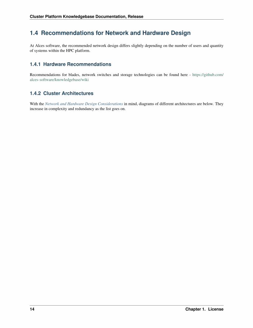
Example 1
16 Chapter 1. License

Cluster Platform Knowledgebase Documentation, Release
The above architecture consists of master, login and compute nodes. The services provided by the master & loginnodes can be seen to the right of each node type. This architecture only separates the services for users and admins.
1.4. Recommendations for Network and Hardware Design 17

Cluster Platform Knowledgebase Documentation, Release
18 Chapter 1. License
Cluster Platform Knowledgebase Documentation, Release
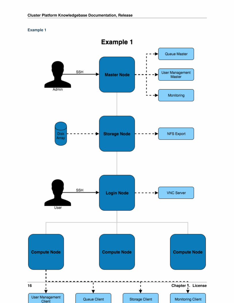
Example 2
1.4. Recommendations for Network and Hardware Design 19

Cluster Platform Knowledgebase Documentation, Release
This architecture provides additional redundancy to the services running on the master node. For example, the diskarray is connected to both master nodes which use multipath to ensure the higher availability of the storage device.
20 Chapter 1. License

Cluster Platform Knowledgebase Documentation, Release
1.4. Recommendations for Network and Hardware Design 21
Cluster Platform Knowledgebase Documentation, Release
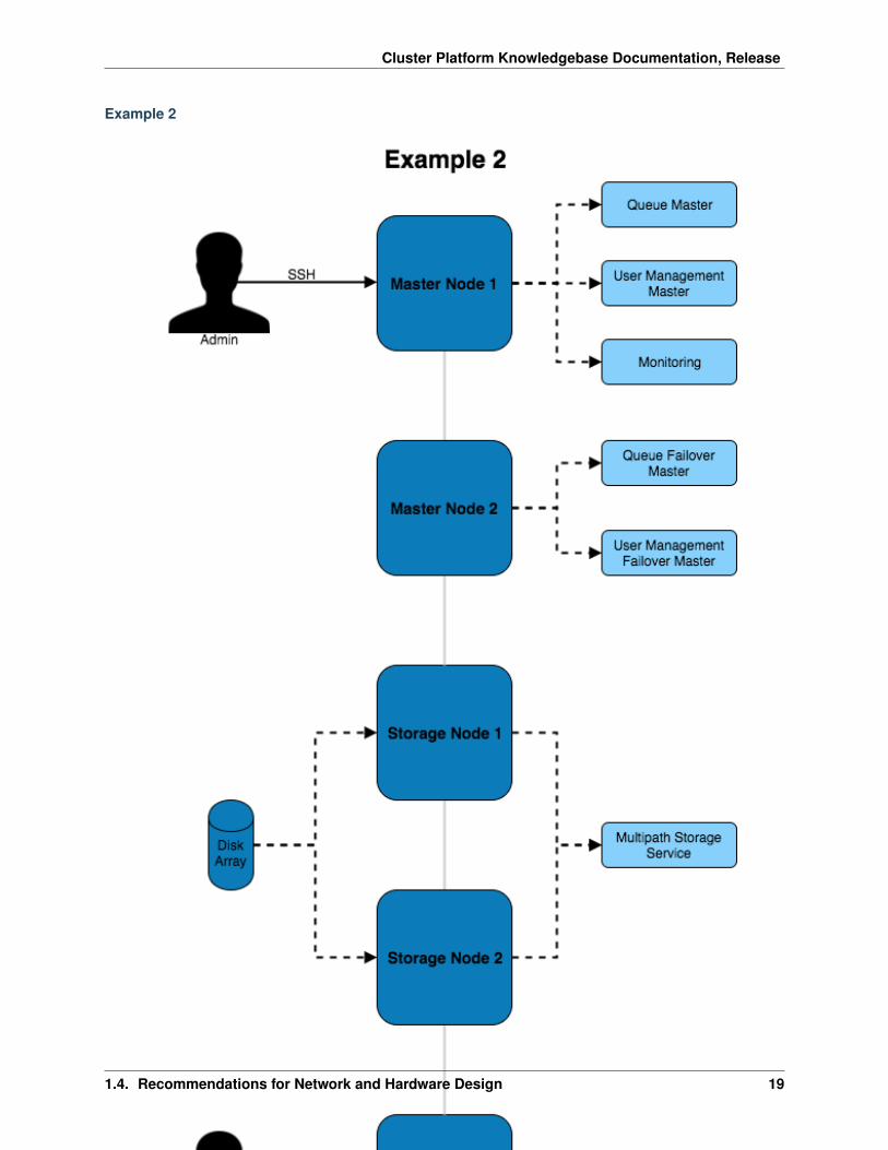
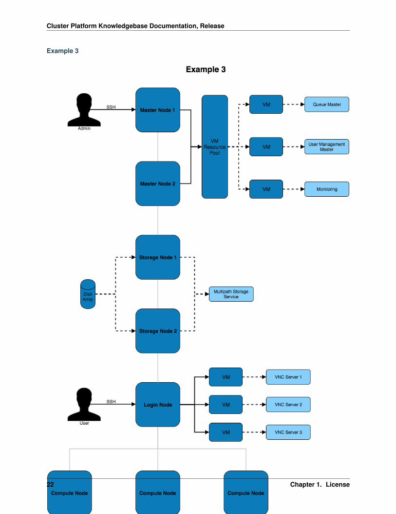
Example 3
22 Chapter 1. License
Cluster Platform Knowledgebase Documentation, Release
This architecture puts services inside of VMs to improve the ability to migrate and modify services with little impactto the other services and systems on the architecture. Virtual machines can be moved between VM hosts live withoutservice disruption allowing for hardware replacements to take place on servers.
1.4.3 Network Designs
The above architectures can be implemented with any of the below network designs.
Example 1
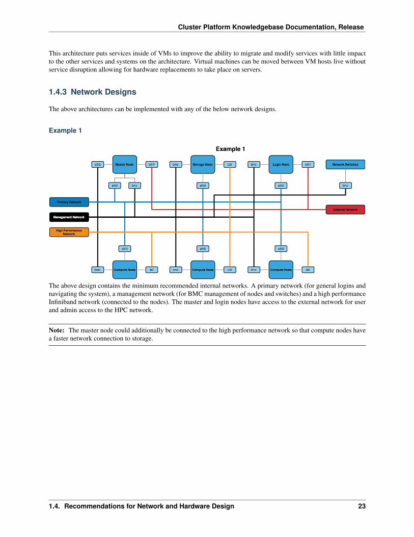
The above design contains the minimum recommended internal networks. A primary network (for general logins andnavigating the system), a management network (for BMC management of nodes and switches) and a high performanceInfiniband network (connected to the nodes). The master and login nodes have access to the external network for userand admin access to the HPC network.
Note: The master node could additionally be connected to the high performance network so that compute nodes havea faster network connection to storage.
1.4. Recommendations for Network and Hardware Design 23
Cluster Platform Knowledgebase Documentation, Release
Example 2
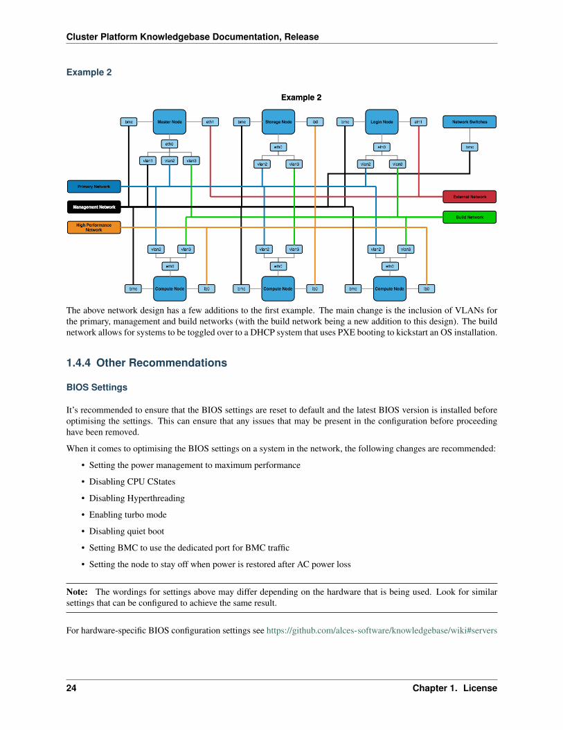
The above network design has a few additions to the first example. The main change is the inclusion of VLANs forthe primary, management and build networks (with the build network being a new addition to this design). The buildnetwork allows for systems to be toggled over to a DHCP system that uses PXE booting to kickstart an OS installation.
1.4.4 Other Recommendations
BIOS Settings
It’s recommended to ensure that the BIOS settings are reset to default and the latest BIOS version is installed beforeoptimising the settings. This can ensure that any issues that may be present in the configuration before proceedinghave been removed.
When it comes to optimising the BIOS settings on a system in the network, the following changes are recommended:
• Setting the power management to maximum performance
• Disabling CPU CStates
• Disabling Hyperthreading
• Enabling turbo mode
• Disabling quiet boot
• Setting BMC to use the dedicated port for BMC traffic
• Setting the node to stay off when power is restored after AC power loss
Note: The wordings for settings above may differ depending on the hardware that is being used. Look for similarsettings that can be configured to achieve the same result.
For hardware-specific BIOS configuration settings see https://github.com/alces-software/knowledgebase/wiki#servers
24 Chapter 1. License
Cluster Platform Knowledgebase Documentation, Release
1.5 Considerations for Infrastructure Design
Infrastructure design largely relates to the considerations made for the Cluster Architectures. Depending on the designbeing used, some of the infrastructure decisions may have already been made.
1.5.1 Infrastructure Service Availability
There are typically 3 possible service availability options to choose from, these are:
• All-in-one
• VM Platform
• High Availability VM Platform
Note: If using a Cloud Platform then the service availability will be handled by the cloud provider. The only additionalconsiderations are how services will be provided in terms of native running services or containerised.
These are covered in more detail below.
All-in-one
This is the most common solution, an all-in-one approach loads services onto a single machine which serves thenetwork. It is the simplest solution as a single OS install is required and no additional configuration of virtual machineservices is needed.
This solution, while quick and relatively easy to implement, is not a recommended approach. Due to the lack ofredundancy options and the lack of service isolation there is a higher risk of an issue effecting one service (or themachine) to have an effect on other services.
VM Platform
A VM platform provides an additional layer of isolation between services. This can allow for services to be configured,migrated and modified without potentially effecting other services.
There are a few solutions for hosting virtual machines, including:
• VirtualBox
• KVM
• Xen
The above software solutions are similar and can all provide a valid virtualisation platform. Further investigation intothe ease of use, flexibility and features of the software is recommended to identify the ideal solution for the HPCplatform.
High Availability VM Platform
For further redundancy, the virtualisation platform can utilise a resource pool. The service will be spread acrossmultiple machines which allows for VMs to migrate between the hosts whilst still active. This live migration canallow for one of the hosts to be taken off of the network for maintenance without impacting the availability of theservice VMs.
1.5. Considerations for Infrastructure Design 25
Cluster Platform Knowledgebase Documentation, Release
1.5.2 Node Network Configuration
In addition to the availability of services, the network configuration on the node can provide better performance andredundancy. Some of the network configuration options that can improve the infrastructure are:
• Channel Bonding - Bonding interfaces allows for traffic to be shared between 2 network interfaces. If thebonded interfaces are connected to separate network switches then this solution
• Interface Bridging - Network bridges are used by interfaces on virtual machines to connect to the rest ofthe network. A bridge can sit on top of a channel bond such that the VMs network connection in constantlyavailable.
• VLAN Interface Tagging - VLAN management can be performed both on a managed switch and on the node.The node is able to create subdivisions of network interfaces to add VLAN tags to packets. This will createseparate interfaces that can be seen by the operating system (e.g. eth0.1 and eth0.2) which can individually haveIP addresses set.
1.5.3 Additional Considerations and Questions
• Could containerised solutions be used instead of VMs?
– Docker or Singularity containerised services can provide similar levels of isolation between services asVMs without the additional performance overhead.
1.6 Recommendations for Infrastructure Design
The example configurations here combine the elements of the examples from Recommendations for Network andHardware Design as well as the different infrastructure solutions from Considerations for Infrastructure Design. Thesefocus on the internal configuration of the master node but these examples can be extrapolated for configuring login,storage, compute or any other nodes that are part of the HPC environment.
1.6.1 Simple Infrastructure
26 Chapter 1. License
Cluster Platform Knowledgebase Documentation, Release
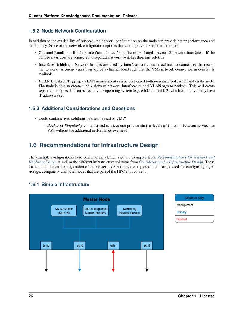
The simplest infrastructure configuration uses the all-in-one approach where services are configured on the masternode’s operating system.
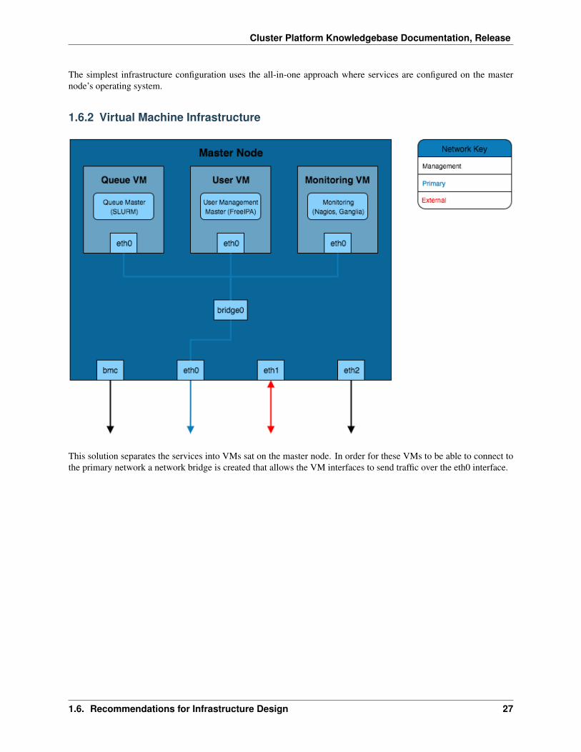
1.6.2 Virtual Machine Infrastructure
This solution separates the services into VMs sat on the master node. In order for these VMs to be able to connect tothe primary network a network bridge is created that allows the VM interfaces to send traffic over the eth0 interface.
1.6. Recommendations for Infrastructure Design 27
Cluster Platform Knowledgebase Documentation, Release
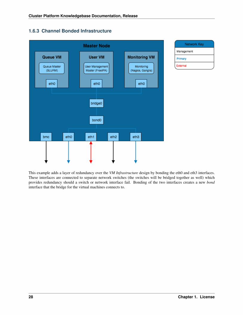
1.6.3 Channel Bonded Infrastructure
This example adds a layer of redundancy over the VM Infrastructure design by bonding the eth0 and eth3 interfaces.These interfaces are connected to separate network switches (the switches will be bridged together as well) whichprovides redundancy should a switch or network interface fail. Bonding of the two interfaces creates a new bondinterface that the bridge for the virtual machines connects to.
28 Chapter 1. License
Cluster Platform Knowledgebase Documentation, Release
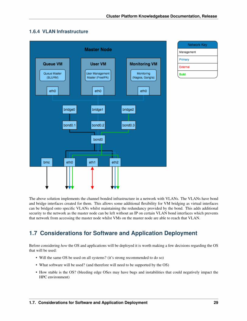
1.6.4 VLAN Infrastructure
The above solution implements the channel bonded infrastructure in a network with VLANs. The VLANs have bondand bridge interfaces created for them. This allows some additional flexibility for VM bridging as virtual interfacescan be bridged onto specific VLANs whilst maintaining the redundancy provided by the bond. This adds additionalsecurity to the network as the master node can be left without an IP on certain VLAN bond interfaces which preventsthat network from accessing the master node whilst VMs on the master node are able to reach that VLAN.
1.7 Considerations for Software and Application Deployment
Before considering how the OS and applications will be deployed it is worth making a few decisions regarding the OSthat will be used:
• Will the same OS be used on all systems? (it’s strong recommended to do so)
• What software will be used? (and therefore will need to be supported by the OS)
• How stable is the OS? (bleeding edge OSes may have bugs and instabilities that could negatively impact theHPC environment)
1.7. Considerations for Software and Application Deployment 29
Cluster Platform Knowledgebase Documentation, Release
1.7.1 Deployment
The deployment of the HPC platform can be boiled down to two main sections, these being:
• Operating System Deployment
• Repository Management
Operating System Deployment
When it comes to performing many operating installations across nodes in the network it can be tricky to find a flexible,manageable, automated solution. Performing manual installations of operating systems may be the ideal solution ifthere are only a few compute nodes, however, there are many other ways of improving the speed of OS deployment:
• Disk Cloning - A somewhat inelegant solution, disk cloning involves building the operating system once andcreating a compressed copy on a hard-drive that can be restored to blank hard-drives.
• Kickstart - A kickstart file is a template for automating OS installations, the configuration file can be servedover the network such that clients can PXE boot the installation. This can allow for easy, distributed deploymentover a local network.
• Image Deployment - Cloud service providers usually deploy systems from template images that set hostnamesand other unique system information at boot time. Customised templates can also be created for streamliningthe deployment and customisation procedure.
It is worth considering manual, cloning and kickstart solutions for your OS deployment, any one of them could be theideal solution depending on the number of machines that are being deployed.
Repository Management
It is worth considering how packages, libraries and applications will be installed onto individual nodes and the net-work as a whole. Operating systems usually have their own package management system installed that uses publicrepositories for pulling down packages for installation. It is likely that all of the packages required for a system arenot in the public repositories so it’s worth considering where these will come from (3rd party repository? downloadeddirectly from the package maintainer? manually compiled?).
Further to managing packages on the local system, the entire network may require applications to be installed, thereare a couple of options for achieving this:
• Server Management Tools - Management tools such as puppet, chef or pdsh can execute commands acrossmultiple systems in parallel. This saves time having to individually login and run commands on each node inthe system.
• Network Package Managers - Software such as Alces Gridware can install an application in a centralisedstorage location such that changes to PATH and LD_LIBRARY_PATH on a node is all that is required for it tostart using the application.
For more information regarding network package managers and application deployment, see Application Deployment
1.7.2 Additional Considerations and Questions
• How will applications outside of the repositories be installed?
– Will the application need to be useable by all nodes in the HPC network? (an NFS export for apps maysolve the issue of multiple installations)
30 Chapter 1. License
Cluster Platform Knowledgebase Documentation, Release
1.8 Master Node Setup
• Run a minimal CentOS installation on the system (this can be performed manually or via an automated installservice if you have one setup)
• It is recommended to update the packages on the system for any bug fixes and patches that may have beenintroduced to core packages:
yum -y update
Note: If kickstarting OS installs on many nodes it is worth considering a local mirror repository for the OS imageand packages so that all nodes aren’t trying to connect to the internet at the same time.
• Disable and stop NetworkManager:
systemctl disable NetworkManagersystemctl stop NetworkManager
• Set the hostname:
echo ‘master.cluster.local’ > /etc/hostname
• Configure bridge interface for primary network (/etc/sysconfig/network-scripts/ifcfg-pri):
DEVICE=priONBOOT=yesTYPE=Bridgestp=noBOOTPROTO=staticIPADDR=10.10.0.11NETMASK=255.255.0.0ZONE=trustedPEERDNS=no
Note: Replace DEVICE, IPADDR and NETMASK with the appropriate values for your system
• Create bridge interfaces for all other networks (e.g. management [mgt] and external [ext])
Note: The external interface may require getting it’s network settings over DHCP, if it does then set BOOTPROTO todhcp instead of static and remove the IPADDR lines.
• Setup config file for network interfaces (do this for all interfaces sitting on the bridges configured above):
TYPE=EthernetBOOTPROTO=noneNAME=p1p1DEVICE=p1p1ONBOOT=“yes”BRIDGE=pri
1.8. Master Node Setup 31
Cluster Platform Knowledgebase Documentation, Release
Note: In the above example, the interface p1p1 is connected to the primary network but instead of giving that an IPit is set to use the pri bridge
• Enable and start firewalld (for masquerading IPs to the external interface and improving the general networksecurity):
systemctl enable firewalldsystemctl start firewalld
• Add ext bridge to external zone (the external zone is a zone configured as part of firewalld):
firewall-cmd --add-interface ext --zone external --permanent
• Add all the other network interfaces to the trusted zone (replace pri with the other network names, excludingext):
firewall-cmd --add-interface pri --zone trusted --permanent
• Reboot the system
• Install components for VM service:
yum groupinstall -y virtualization-platform virtualization-toolsyum install -y virt-viewer virt-install
• Enable and start the virtualisation service:
systemctl start libvirtdsystemctl enable libvirtd
• Create VM pool:
mkdir /opt/vmvirsh pool-define-as local dir - - - - "/opt/vm/"virsh pool-build localvirsh pool-start localvirsh pool-autostart local
1.9 Controller VM Setup
1.9.1 On Master Node
• Create /opt/vm/controller.xml for provisioning a VM called controller (Available here)
– This template creates 3 interfaces on the VM (on the primary, management and external networks)
• Create base qcow2 image controller.qcow2:
qemu-img create -f qcow2 controller.qcow2 80G
• Create the VM:
virsh define controller.xml
32 Chapter 1. License
Cluster Platform Knowledgebase Documentation, Release
• Start the VM:
virsh start controller
• Connect a VNC-like window to the VM to watch it booting and interact with the terminal:
virt-viewer controller
Note: Much like the host system, a minimal installation of CentOS 7 is recommended (as is ensuring that the systemis up-to-date with yum -y update)
1.9.2 On Controller VM
OS Setup
• Set the hostname of the system (the fully-qualified domain name for this system has additionally added thecluster name):
echo 'controller.testcluster.cluster.local' > /etc/hostname
• Setup the network interfaces (if setting a static IP then ensure to set IPADDR, NETMASK and NETWORK for theinterface)
– Eth0 is bridged onto the primary network - set a static IP for that network in /etc/sysconfig/network-scripts/ifcfg-eth0
– Eth1 is bridged onto the management network - set a static IP for that network in /etc/sysconfig/network-scripts/ifcfg-eth1
– Eth2 is bridged onto the external network - this will most likely use DHCP to obtain an IP address /etc/sysconfig/network-scripts/ifcfg-eth2
Note: Add ZONE=trusted to eth0 & eth1, ZONE=external to eth2 to ensure the correct firewall zonesare used by the interfaces.
• Enable and start firewalld:
systemctl enable firewalldsystemctl start firewalld
• Add the interfaces to the relevant firewall zones:
firewall-cmd --add-interface eth0 --zone trusted --permanentfirewall-cmd --add-interface eth1 --zone trusted --permanentfirewall-cmd --add-interface eth2 --zone external --permanent
• Disable network manager:
systemctl disable NetworkManager
• Reboot the VM
1.9. Controller VM Setup 33
Cluster Platform Knowledgebase Documentation, Release
• Once the VM is back up it should be able to ping both the primary and management interfaces on the masternode. If the ping returns properly then metalware can be configured to enable deployment capabilities on theVM.
Metalware Install
• Install metalware (to install a different branch, append alces_SOURCE_BRANCH=develop before /bin/bash in order to install the develop branch):
curl -sL http://git.io/metalware-installer | sudo alces_OS=el7 /bin/bash
• Run the metalware setup script (there are variables within this script that may need updating if your networksetup differs from the examples used in this documentation - it is recommended to download this script beforerunning it to check the variables are correct):
curl -sL https://raw.githubusercontent.com/alces-software/knowledgebase/release/→˓2017.1/epel/7/metalware/metalware.sh | sudo /bin/bash
• Reboot the VM
• Set metalware to use default repository:
metal repo use https://github.com/alces-software/metalware-default.git
• Configure the domain settings (this will prompt for various details regarding the domain setup, such as, rootpassword, SSH RSA key [which can be created with ssh-keygen] and default network parameters):
metal configure domain
• Set the IPMI/BMC admin password in /var/lib/metalware/repo/config/domain.yaml in thebmc: namespace:
bmcpassword: 'Pa55Word'
• Uncomment the PASSWORD= line in /opt/metalware/etc/ipmi.conf and replace password withthe IPMI password above
Note: If you wish to install an OS other than CentOS 7 then see the Configure Alternative Kickstart Profile instruc-tions.
Platform Scripts
Deploying on different hardware and platforms may require additional stages to be run on systems when being de-ployed. This is handled by an additional scripts key platform: in /var/lib/metalware/repo/config/domain.yaml.
There is currently a script for configuring the AWS EL7 platform available on github which can be downloaded to thescripts area:
mkdir -p /opt/alces/install/scripts/cd /opt/alces/install/scripts/wget https://raw.githubusercontent.com/alces-software/knowledgebase/release/2017.1/→˓epel/7/platform/aws.sh
34 Chapter 1. License
Cluster Platform Knowledgebase Documentation, Release
1.10 Deployment Example
1.10.1 Client Deployment Example
• Configure a node group (this example creates a nodes group for compute nodes):
metal configure group nodes
• Start the controller VM listening for PXE requests:
metal hunter -i eth0
• Boot up the client node
• The controller VM will print a line when the node has connected, when this happens enter the hostname for thesystem (this should be a hostname that exists in the group configured earlier)
• Once the hostname has been added the previous metal command can be cancelled (with ctrl-c)
• Generate DHCP entry for the node:
metal dhcp -t default
• Start the controller VM serving installation files to the node (replace slave01 with the hostname of the clientnode):
metal build slave01
Note: If building multiple systems the genders group can be specified instead of the node hostname. For example, allcompute nodes can be built with metal build -g nodes.
• The client node can be rebooted and it will begin an automatic installation of CentOS 7
• The metal build will automatically exit when the client installation has completed
• Passwordless SSH should now work to the client node
1.10.2 Configuring Alternative Kickstart Profile
In this example, a CentOS 6 kickstart profile is configured. This method should be transferrable to other operatingsystems with little modification to the general practice.
• Download the boot files to the PXE_BOOT directory:
PXE_BOOT=/var/lib/tftpboot/boot/curl http://mirror.ox.ac.uk/sites/mirror.centos.org/6/os/x86_64/images/pxeboot/→˓initrd.img > “$PXE_BOOT/centos6-initrd.img”curl http://mirror.ox.ac.uk/sites/mirror.centos.org/6/os/x86_64/images/pxeboot/→˓vmlinuz > “$PXE_BOOT/centos6-kernel”
• Create /var/lib/metalware/repo/pxelinux/centos6 template PXE boot file for the OS:
DEFAULT menuPROMPT 0MENU TITLE PXE MenuTIMEOUT 5
1.10. Deployment Example 35
Cluster Platform Knowledgebase Documentation, Release
TOTALTIMEOUT 5<%= alces.firstboot ? "ONTIMEOUT INSTALL" : "ONTIMEOUT local"%>
LABEL INSTALLKERNEL boot/centos6-kernel
APPEND initrd=boot/centos6-initrd.img ksdevice=<%= networks.pri.→˓interface %> ks=<%= alces.kickstart_url %> network ks.sendmac _ALCES_BASE_→˓HOSTNAME=<%= alces.nodename %> <%= kernelappendoptions %>
IPAPPEND 2
LABEL localMENU LABEL (local)MENU DEFAULTLOCALBOOT 0
• Create /var/lib/metalware/repo/kickstart/centos6 template file for kickstart installations ofthe OS:
#!/bin/bash##(c)2017 Alces Software Ltd. HPC Consulting Build Suite## vim: set filetype=kickstart :
network --onboot yes --device <%= networks.pri.interface %> --bootproto dhcp --→˓noipv6
#MISCtextrebootskipxinstall
#SECURITYfirewall --enabledfirstboot --disableselinux --disabled
#AUTHauth --useshadow --enablemd5rootpw --iscrypted <%= encrypted_root_password %>
#LOCALIZATIONkeyboard uklang en_GBtimezone Europe/London
#REPOSurl --url=http://mirror.ox.ac.uk/sites/mirror.centos.org/6/os/x86_64/
#DISK%include /tmp/disk.part
#PRESCRIPT%preset -x -vexec 1>/tmp/ks-pre.log 2>&1
DISKFILE=/tmp/disk.partbootloaderappend="console=tty0 console=ttyS1,115200n8"
36 Chapter 1. License
Cluster Platform Knowledgebase Documentation, Release
cat > $DISKFILE << EOF<%= disksetup %>EOF
#PACKAGES%packages --ignoremissing
vimemacsxauthxhostxdpyinfoxtermxclocktigervnc-serverntpdatevconfigbridge-utilspatchtcl-develgettext
#POSTSCRIPTS%post --nochrootset -x -vexec 1>/mnt/sysimage/root/ks-post-nochroot.log 2>&1
ntpdate 0.centos.pool.ntp.org
%postset -x -vexec 1>/root/ks-post.log 2>&1
# Example of using rendered Metalware file; this file itself also uses other# rendered files.curl <%= alces.files.main.first.url %> | /bin/bash | tee /tmp/metalware-default-→˓output
curl <%= alces.build_complete_url %>
• When building nodes, use the new template files by specifying them as arguments to the metal build com-mand:
metal build -k centos6 -p centos6 slave01
1.10.3 Configuring UEFI Boot
UEFI network booting is an alternative to PXE booting and is usually the standard on newer hardware, support forbuilding nodes with UEFI booting can be configured as follows.
• Create additional TFTP directory and download EFI boot loader:
mkdir -p /var/lib/tftpboot/efi/cd /var/lib/tftpboot/efi/wget https://github.com/alces-software/knowledgebase/raw/master/epel/7/grub-efi/→˓grubx64.efichmod +x grubx64.efi
1.10. Deployment Example 37
Cluster Platform Knowledgebase Documentation, Release
• For UEFI clients, add the following line to the client config file:
build_method: uefi
• Additionally, a /boot/efi partition will be required for UEFI clients, an example of this partition as part ofthe disk setup (in the client config) is below:
disksetup: |zerombrbootloader --location=mbr --driveorder=sda --append="$bootloaderappend"clearpart --all --initlabel
#Disk partitioning informationpart /boot --fstype ext4 --size=4096 --asprimary --ondisk sdapart /boot/efi --fstype=efi --size=200 --asprimary --ondisk sdapart pv.01 --size=1 --grow --asprimary --ondisk sdavolgroup system pv.01logvol / --fstype ext4 --vgname=system --size=16384 --name=rootlogvol /var --fstype ext4 --vgname=system --size=16384 --name=varlogvol /tmp --fstype ext4 --vgname=system --size=1 --grow --name=tmplogvol swap --fstype swap --vgname=system --size=8096 --name=swap1
1.11 Repository Mirror Server
1.11.1 On Master Node
• Create /opt/vm/repo.xml for deploying the repo VM (Available here)
• Create disk image for the repo VM:
qemu-img create -f qcow2 repo.qcow2 150G
• Define the VM:
virsh define repo.xml
1.11.2 On Controller VM
• Create a group for the repo VM (add at least repo1 as a node in the group, set additional groups of services,cluster,domain allows for more diverse group management):
metal configure group repo
• Customise repo1 node configuration (set the primary IP address to 10.10.0.2):
metal configure node repo1
• Create a deployment file specifically for repo1 at /var/lib/metalware/repo/config/repo1.yaml with the following content:
repoconfig:is_server: true
38 Chapter 1. License
Cluster Platform Knowledgebase Documentation, Release
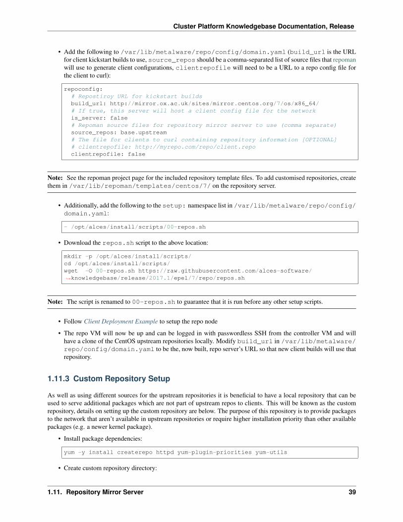
• Add the following to /var/lib/metalware/repo/config/domain.yaml (build_url is the URLfor client kickstart builds to use, source_repos should be a comma-separated list of source files that repomanwill use to generate client configurations, clientrepofile will need to be a URL to a repo config file forthe client to curl):
repoconfig:# Repostiroy URL for kickstart buildsbuild_url: http://mirror.ox.ac.uk/sites/mirror.centos.org/7/os/x86_64/# If true, this server will host a client config file for the networkis_server: false# Repoman source files for repository mirror server to use (comma separate)source_repos: base.upstream# The file for clients to curl containing repository information [OPTIONAL]# clientrepofile: http://myrepo.com/repo/client.repoclientrepofile: false
Note: See the repoman project page for the included repository template files. To add customised repositories, createthem in /var/lib/repoman/templates/centos/7/ on the repository server.
• Additionally, add the following to the setup: namespace list in /var/lib/metalware/repo/config/domain.yaml:
- /opt/alces/install/scripts/00-repos.sh
• Download the repos.sh script to the above location:
mkdir -p /opt/alces/install/scripts/cd /opt/alces/install/scripts/wget -O 00-repos.sh https://raw.githubusercontent.com/alces-software/→˓knowledgebase/release/2017.1/epel/7/repo/repos.sh
Note: The script is renamed to 00-repos.sh to guarantee that it is run before any other setup scripts.
• Follow Client Deployment Example to setup the repo node
• The repo VM will now be up and can be logged in with passwordless SSH from the controller VM and willhave a clone of the CentOS upstream repositories locally. Modify build_url in /var/lib/metalware/repo/config/domain.yaml to be the, now built, repo server’s URL so that new client builds will use thatrepository.
1.11.3 Custom Repository Setup
As well as using different sources for the upstream repositories it is beneficial to have a local repository that can beused to serve additional packages which are not part of upstream repos to clients. This will be known as the customrepository, details on setting up the custom repository are below. The purpose of this repository is to provide packagesto the network that aren’t available in upstream repositories or require higher installation priority than other availablepackages (e.g. a newer kernel package).
• Install package dependencies:
yum -y install createrepo httpd yum-plugin-priorities yum-utils
• Create custom repository directory:
1.11. Repository Mirror Server 39
Cluster Platform Knowledgebase Documentation, Release
mkdir -p /opt/alces/repo/custom/
• Define the repository:
cd /opt/alces/repo/createrepo custom
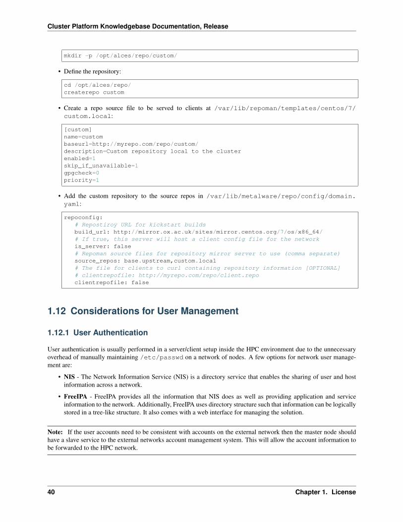
• Create a repo source file to be served to clients at /var/lib/repoman/templates/centos/7/custom.local:
[custom]name=custombaseurl=http://myrepo.com/repo/custom/description=Custom repository local to the clusterenabled=1skip_if_unavailable=1gpgcheck=0priority=1
• Add the custom repository to the source repos in /var/lib/metalware/repo/config/domain.yaml:
repoconfig:# Repostiroy URL for kickstart buildsbuild_url: http://mirror.ox.ac.uk/sites/mirror.centos.org/7/os/x86_64/# If true, this server will host a client config file for the networkis_server: false# Repoman source files for repository mirror server to use (comma separate)source_repos: base.upstream,custom.local# The file for clients to curl containing repository information [OPTIONAL]# clientrepofile: http://myrepo.com/repo/client.repoclientrepofile: false
1.12 Considerations for User Management
1.12.1 User Authentication
User authentication is usually performed in a server/client setup inside the HPC environment due to the unnecessaryoverhead of manually maintaining /etc/passwd on a network of nodes. A few options for network user manage-ment are:
• NIS - The Network Information Service (NIS) is a directory service that enables the sharing of user and hostinformation across a network.
• FreeIPA - FreeIPA provides all the information that NIS does as well as providing application and serviceinformation to the network. Additionally, FreeIPA uses directory structure such that information can be logicallystored in a tree-like structure. It also comes with a web interface for managing the solution.
Note: If the user accounts need to be consistent with accounts on the external network then the master node shouldhave a slave service to the external networks account management system. This will allow the account information tobe forwarded to the HPC network.
40 Chapter 1. License
Cluster Platform Knowledgebase Documentation, Release
1.12.2 User Access
It is also worth considering how users will be accessing the system. A few ways that users can be accessing andinteracting with the HPC environment are:
• SSH - This is the most common form of access for both users and admins. SSH will provide terminal-basedaccess and X forwarding capabilities to the user.
• VNC - The VNC service creates a desktop session that can be remotely connected to by a user, allowing themto run graphical applications inside the HPC network.
• VPN - A VPN will provide remote network access to the HPC environment. This can be especially useful whenaccess to the network is required from outside of the external network. Once connected to the VPN service,SSH or VNC can be used as it usually would be.
Note: If running firewall services within the environment (recommended) then be sure to allow access from the portsused by the selected user access protocols.
1.12.3 Additional Considerations and Questions
• What information will need to be shared between the systems?
• How will users want to access the system?
1.13 Recommendations for User Management
Below are guidelines for setting up both a NIS and an IPA server, only one of these should be setup to prevent conflictsand inconsistencies in user management.
1.13.1 NIS Server Setup
On Master Node
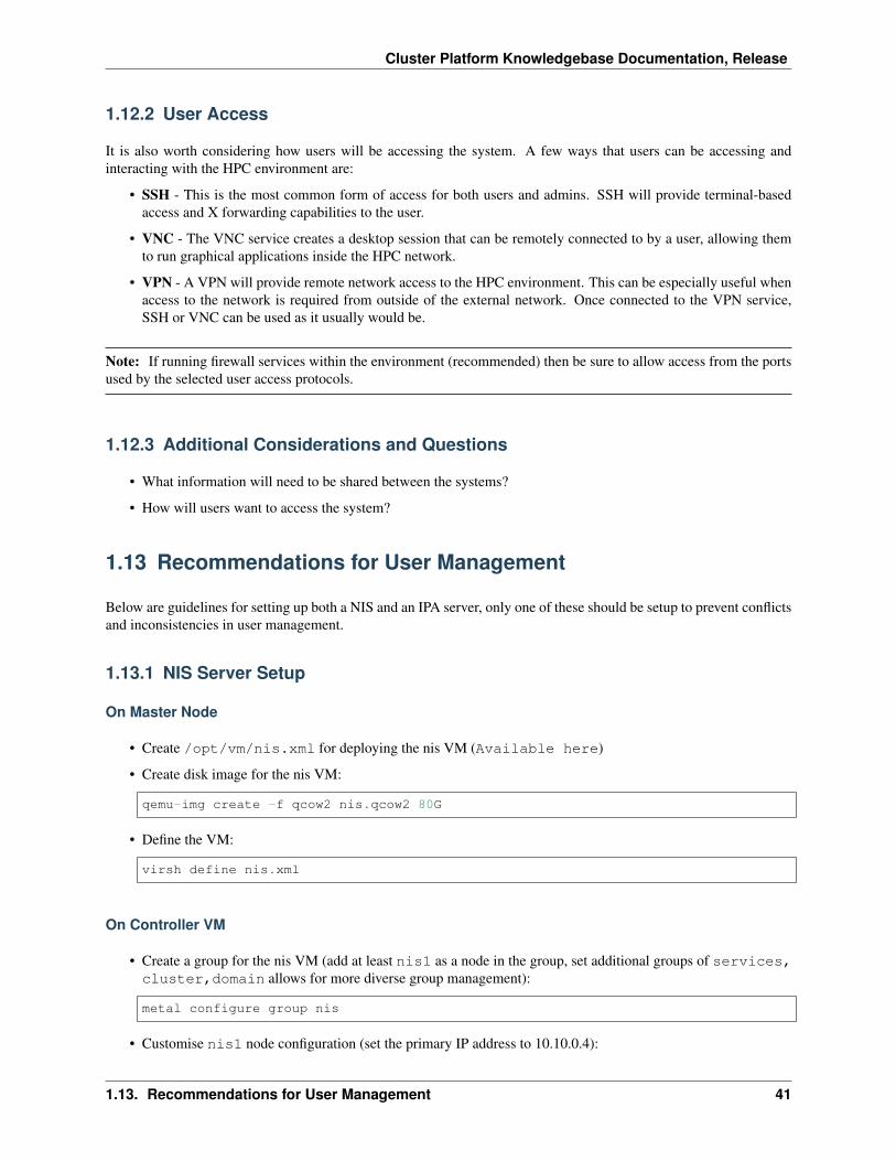
• Create /opt/vm/nis.xml for deploying the nis VM (Available here)
• Create disk image for the nis VM:
qemu-img create -f qcow2 nis.qcow2 80G
• Define the VM:
virsh define nis.xml
On Controller VM
• Create a group for the nis VM (add at least nis1 as a node in the group, set additional groups of services,cluster,domain allows for more diverse group management):
metal configure group nis
• Customise nis1 node configuration (set the primary IP address to 10.10.0.4):
1.13. Recommendations for User Management 41
Cluster Platform Knowledgebase Documentation, Release
metal configure node nis1
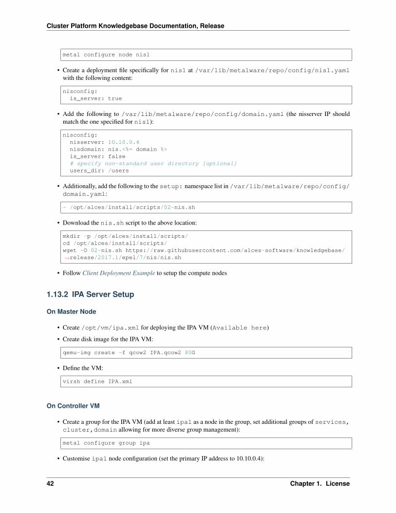
• Create a deployment file specifically for nis1 at /var/lib/metalware/repo/config/nis1.yamlwith the following content:
nisconfig:is_server: true
• Add the following to /var/lib/metalware/repo/config/domain.yaml (the nisserver IP shouldmatch the one specified for nis1):
nisconfig:nisserver: 10.10.0.4nisdomain: nis.<%= domain %>is_server: false# specify non-standard user directory [optional]users_dir: /users
• Additionally, add the following to the setup: namespace list in /var/lib/metalware/repo/config/domain.yaml:
- /opt/alces/install/scripts/02-nis.sh
• Download the nis.sh script to the above location:
mkdir -p /opt/alces/install/scripts/cd /opt/alces/install/scripts/wget -O 02-nis.sh https://raw.githubusercontent.com/alces-software/knowledgebase/→˓release/2017.1/epel/7/nis/nis.sh
• Follow Client Deployment Example to setup the compute nodes
1.13.2 IPA Server Setup
On Master Node
• Create /opt/vm/ipa.xml for deploying the IPA VM (Available here)
• Create disk image for the IPA VM:
qemu-img create -f qcow2 IPA.qcow2 80G
• Define the VM:
virsh define IPA.xml
On Controller VM
• Create a group for the IPA VM (add at least ipa1 as a node in the group, set additional groups of services,cluster,domain allowing for more diverse group management):
metal configure group ipa
• Customise ipa1 node configuration (set the primary IP address to 10.10.0.4):
42 Chapter 1. License
Cluster Platform Knowledgebase Documentation, Release
metal configure node ipa1
• Add the following to /var/lib/metalware/repo/config/domain.yaml (the ipaserver IP shouldmatch the one specified for ipa1):
ipaconfig:serverip: 10.10.0.4servername: ipa1insecurepassword: abcdef123userdir: /users
• Additionally, add the following to the scripts: namespace list in /var/lib/metalware/repo/config/domain.yaml (this script runs the client-side configuration of IPA):
- /opt/alces/install/scripts/02-ipa.sh
• Download the ipa.sh script to the above location:
mkdir -p /opt/alces/install/scripts/cd /opt/alces/install/scripts/wget -O 02-ipa.sh https://raw.githubusercontent.com/alces-software/knowledgebase/→˓release/2017.1/epel/7/ipa/ipa.sh
• Follow Client Deployment Example to setup the IPA node and continue to the next session to configure the IPAserver with a script
Setup IPA Server
• Download the server configuration script to the controller:
cd /opt/alces/install/scripts/wget http://raw.githubusercontent.com/alces-software/knowledgebase/release/2017.1/→˓epel/7/ipa/ipa_server.sh
• Render the script for the IPA server:
metal render /opt/alces/install/scripts/ipa_server.sh ipa1 > /tmp/ipa_server.sh
• Copy the script to the IPA server:
scp /tmp/ipa_server.sh ipa1:/root/
Note: Before launching the script it is currently necessary to disable named on the controller from serving the primaryforward and reverse domains such that the IPA installation will work. This can be re-enabled once the IPA script hasfinished running.
• Launch the script on the IPA server (following any on-screen prompts):
ssh ipa1 "/root/ipa_server.sh"
1.13. Recommendations for User Management 43
Cluster Platform Knowledgebase Documentation, Release
1.14 Considerations for Storage Solution
1.14.1 Storage Hardware
When selecting the storage solution it is worth considering the size, performance and resilience of the desired storagesolution. Usually some sort of storage array will be used, that is, a collection of disks (otherwise known as JBOD -Just a Bunch Of Disks) in the form of an internal or external RAID array.
1.14.2 Network Storage Solutions
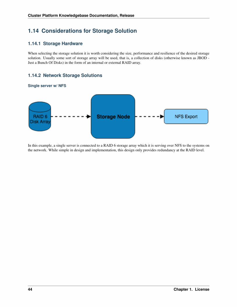
Single server w/ NFS
In this example, a single server is connected to a RAID 6 storage array which it is serving over NFS to the systems onthe network. While simple in design and implementation, this design only provides redundancy at the RAID level.
44 Chapter 1. License
Cluster Platform Knowledgebase Documentation, Release
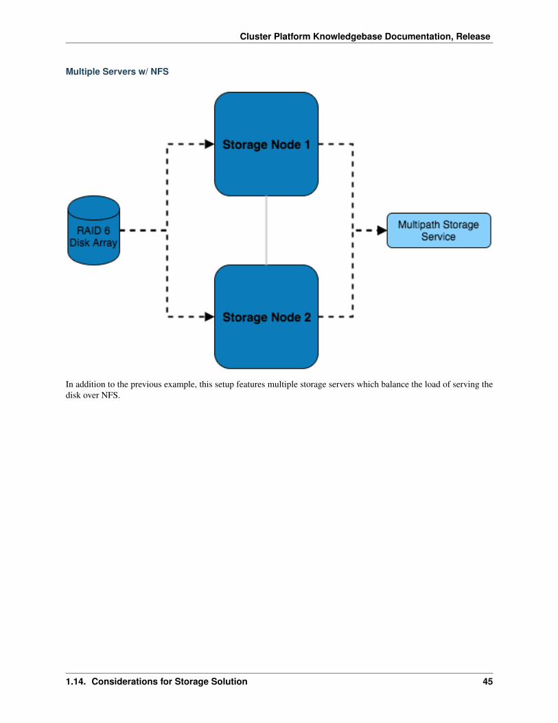
Multiple Servers w/ NFS
In addition to the previous example, this setup features multiple storage servers which balance the load of serving thedisk over NFS.
1.14. Considerations for Storage Solution 45
Cluster Platform Knowledgebase Documentation, Release
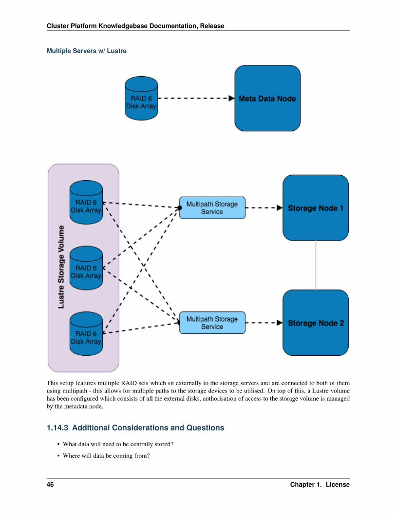
Multiple Servers w/ Lustre
This setup features multiple RAID sets which sit externally to the storage servers and are connected to both of themusing multipath - this allows for multiple paths to the storage devices to be utilised. On top of this, a Lustre volumehas been configured which consists of all the external disks, authorisation of access to the storage volume is managedby the metadata node.
1.14.3 Additional Considerations and Questions
• What data will need to be centrally stored?
• Where will data be coming from?
46 Chapter 1. License
Cluster Platform Knowledgebase Documentation, Release
– Are source files created within the HPC network or do they exist in the external network?
– Will compute nodes be writing out logs/results from running jobs?
– Where else might data be coming from?
• Is scratch space needed?
• What level of redundancy/stability is required for the data?
• How will the data be backed up?
– Will there be off-site backups?
– Should a separate storage medium be used?
– Does all the data need backing up or only certain files?
1.15 Recommendations for Storage Solution
1.15.1 Storage Hardware
For recommended storage hardware technologies, see https://github.com/alces-software/knowledgebase/wiki#storage
1.15.2 Changing Disk Formatting for a Node/Group
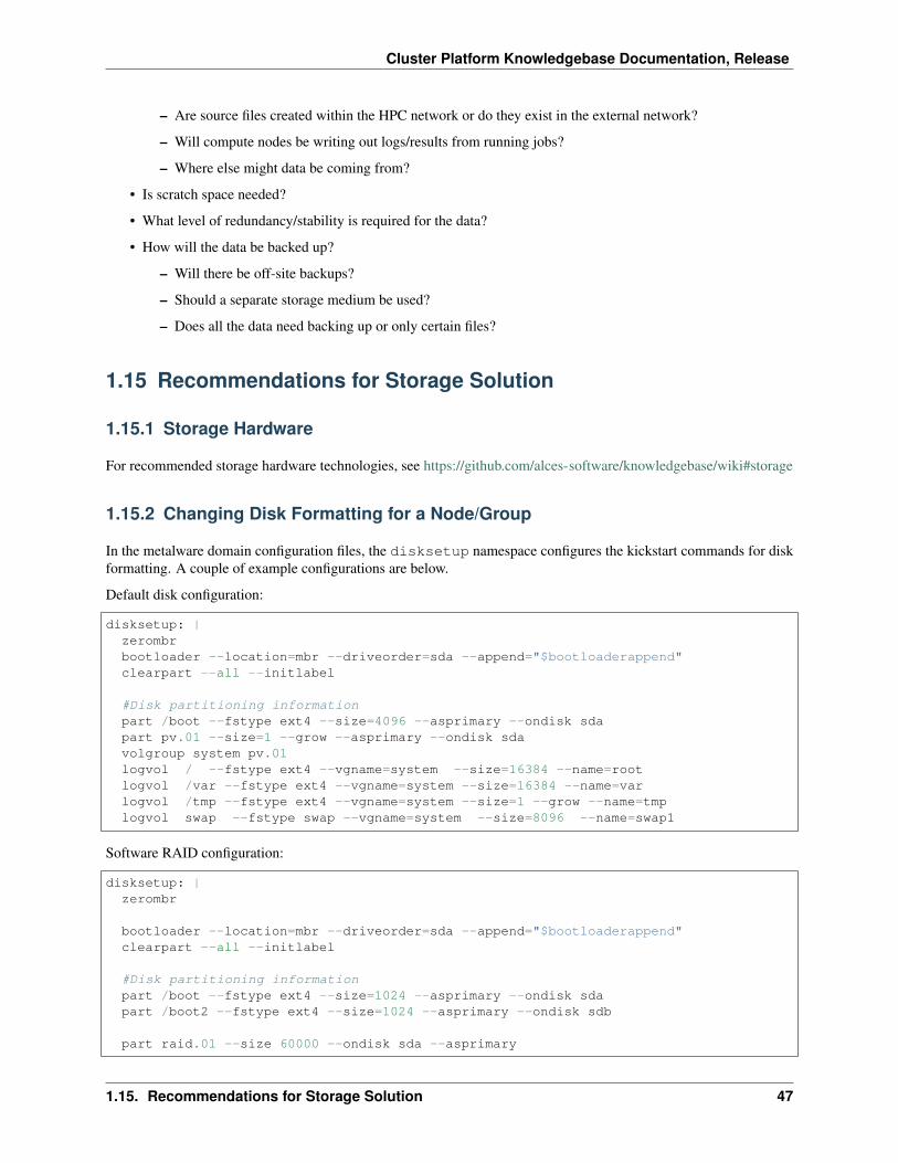
In the metalware domain configuration files, the disksetup namespace configures the kickstart commands for diskformatting. A couple of example configurations are below.
Default disk configuration:
disksetup: |zerombrbootloader --location=mbr --driveorder=sda --append="$bootloaderappend"clearpart --all --initlabel
#Disk partitioning informationpart /boot --fstype ext4 --size=4096 --asprimary --ondisk sdapart pv.01 --size=1 --grow --asprimary --ondisk sdavolgroup system pv.01logvol / --fstype ext4 --vgname=system --size=16384 --name=rootlogvol /var --fstype ext4 --vgname=system --size=16384 --name=varlogvol /tmp --fstype ext4 --vgname=system --size=1 --grow --name=tmplogvol swap --fstype swap --vgname=system --size=8096 --name=swap1
Software RAID configuration:
disksetup: |zerombr
bootloader --location=mbr --driveorder=sda --append="$bootloaderappend"clearpart --all --initlabel
#Disk partitioning informationpart /boot --fstype ext4 --size=1024 --asprimary --ondisk sdapart /boot2 --fstype ext4 --size=1024 --asprimary --ondisk sdb
part raid.01 --size 60000 --ondisk sda --asprimary
1.15. Recommendations for Storage Solution 47
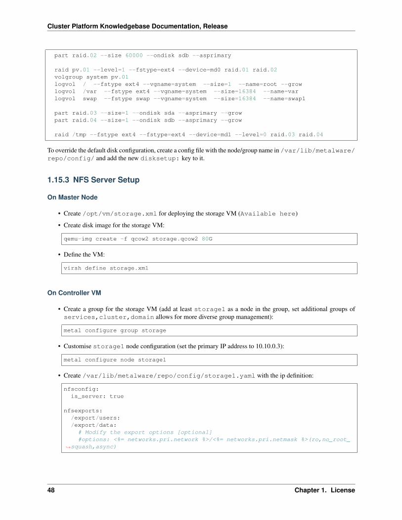
Cluster Platform Knowledgebase Documentation, Release
part raid.02 --size 60000 --ondisk sdb --asprimary
raid pv.01 --level=1 --fstype=ext4 --device=md0 raid.01 raid.02volgroup system pv.01logvol / --fstype ext4 --vgname=system --size=1 --name=root --growlogvol /var --fstype ext4 --vgname=system --size=16384 --name=varlogvol swap --fstype swap --vgname=system --size=16384 --name=swap1
part raid.03 --size=1 --ondisk sda --asprimary --growpart raid.04 --size=1 --ondisk sdb --asprimary --grow
raid /tmp --fstype ext4 --fstype=ext4 --device=md1 --level=0 raid.03 raid.04
To override the default disk configuration, create a config file with the node/group name in /var/lib/metalware/repo/config/ and add the new disksetup: key to it.
1.15.3 NFS Server Setup
On Master Node
• Create /opt/vm/storage.xml for deploying the storage VM (Available here)
• Create disk image for the storage VM:
qemu-img create -f qcow2 storage.qcow2 80G
• Define the VM:
virsh define storage.xml
On Controller VM
• Create a group for the storage VM (add at least storage1 as a node in the group, set additional groups ofservices,cluster,domain allows for more diverse group management):
metal configure group storage
• Customise storage1 node configuration (set the primary IP address to 10.10.0.3):
metal configure node storage1
• Create /var/lib/metalware/repo/config/storage1.yaml with the ip definition:
nfsconfig:is_server: true
nfsexports:/export/users:/export/data:
# Modify the export options [optional]#options: <%= networks.pri.network %>/<%= networks.pri.netmask %>(ro,no_root_
→˓squash,async)
48 Chapter 1. License
Cluster Platform Knowledgebase Documentation, Release
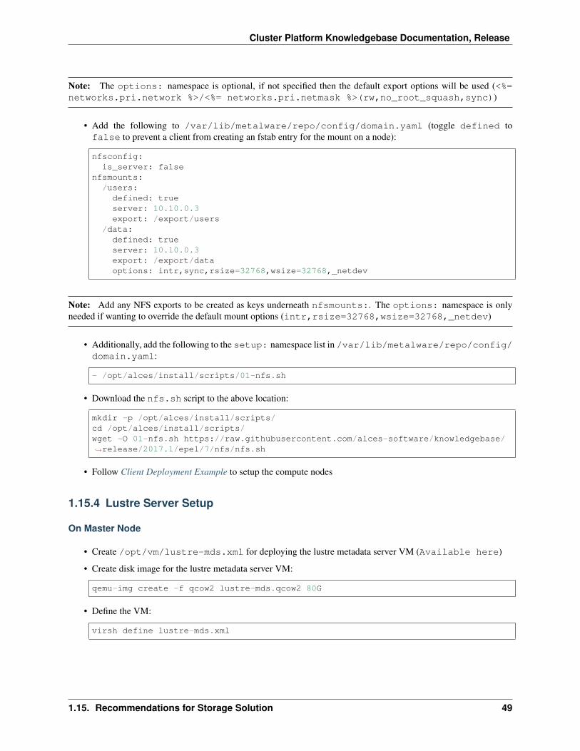
Note: The options: namespace is optional, if not specified then the default export options will be used (<%=networks.pri.network %>/<%= networks.pri.netmask %>(rw,no_root_squash,sync))
• Add the following to /var/lib/metalware/repo/config/domain.yaml (toggle defined tofalse to prevent a client from creating an fstab entry for the mount on a node):
nfsconfig:is_server: false
nfsmounts:/users:
defined: trueserver: 10.10.0.3export: /export/users
/data:defined: trueserver: 10.10.0.3export: /export/dataoptions: intr,sync,rsize=32768,wsize=32768,_netdev
Note: Add any NFS exports to be created as keys underneath nfsmounts:. The options: namespace is onlyneeded if wanting to override the default mount options (intr,rsize=32768,wsize=32768,_netdev)
• Additionally, add the following to the setup: namespace list in /var/lib/metalware/repo/config/domain.yaml:
- /opt/alces/install/scripts/01-nfs.sh
• Download the nfs.sh script to the above location:
mkdir -p /opt/alces/install/scripts/cd /opt/alces/install/scripts/wget -O 01-nfs.sh https://raw.githubusercontent.com/alces-software/knowledgebase/→˓release/2017.1/epel/7/nfs/nfs.sh
• Follow Client Deployment Example to setup the compute nodes
1.15.4 Lustre Server Setup
On Master Node
• Create /opt/vm/lustre-mds.xml for deploying the lustre metadata server VM (Available here)
• Create disk image for the lustre metadata server VM:
qemu-img create -f qcow2 lustre-mds.qcow2 80G
• Define the VM:
virsh define lustre-mds.xml
1.15. Recommendations for Storage Solution 49
Cluster Platform Knowledgebase Documentation, Release
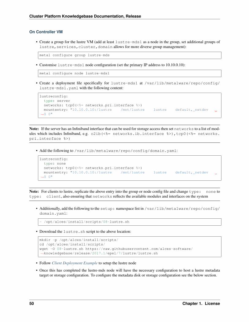
On Controller VM
• Create a group for the lustre VM (add at least lustre-mds1 as a node in the group, set additional groups oflustre,services,cluster,domain allows for more diverse group management):
metal configure group lustre-mds
• Customise lustre-mds1 node configuration (set the primary IP address to 10.10.0.10):
metal configure node lustre-mds1
• Create a deployment file specifically for lustre-mds1 at /var/lib/metalware/repo/config/lustre-mds1.yaml with the following content:
lustreconfig:type: servernetworks: tcp0(<%= networks.pri.interface %>)mountentry: "10.10.0.10:/lustre /mnt/lustre lustre default,_netdev
→˓0 0"
Note: If the server has an Infiniband interface that can be used for storage access then set networks to a list of mod-ules which includes Infiniband, e.g. o2ib(<%= networks.ib.interface %>),tcp0(<%= networks.pri.interface %>)
• Add the following to /var/lib/metalware/repo/config/domain.yaml:
lustreconfig:type: nonenetworks: tcp0(<%= networks.pri.interface %>)mountentry: "10.10.0.10:/lustre /mnt/lustre lustre default,_netdev
→˓0 0"
Note: For clients to lustre, replicate the above entry into the group or node config file and change type: none totype: client, also ensuring that networks reflects the available modules and interfaces on the system
• Additionally, add the following to the setup: namespace list in /var/lib/metalware/repo/config/domain.yaml:
- /opt/alces/install/scripts/08-lustre.sh
• Download the lustre.sh script to the above location:
mkdir -p /opt/alces/install/scripts/cd /opt/alces/install/scripts/wget -O 08-lustre.sh https://raw.githubusercontent.com/alces-software/→˓knowledgebase/release/2017.1/epel/7/lustre/lustre.sh
• Follow Client Deployment Example to setup the lustre node
• Once this has completed the lustre-mds node will have the necessary configuration to host a lustre metadatatarget or storage configuration. To configure the metadata disk or storage configuration see the below section.
50 Chapter 1. License
Cluster Platform Knowledgebase Documentation, Release
Lustre Storage Setup
A lustre storage configuration usually consists of a metadata server (that is used to authorise mount, read and writerequests to the lustre storage volume) and multiple storage servers (with disk arrays attached to them). The aboveconfiguration shows how a metadata server can be configured as part of the network but with some naming tweaks thelustre storage servers can also be added to the environment.
Metadata Storage Target
• To format a metadata storage disk from the metadata server run a command similar to the following (replacinglustre with the desired name of the lustre filesystem and /dev/sda with the path to the disk for storingmetadata):
mkfs.lustre --index=0 --mgs --mdt --fsname=lustre --servicenode=10.10.0.10 --→˓reformat /dev/sda
• To activate the storage, mount it somewhere on the metadata server:
mount -t lustre /dev/sda /mnt/lustre/mdt
Lustre Storage Target
These commands should be performed from different systems connected to the same storage backends across thestorage configuration (depending on the network configuration) to ensure that the device management is distributed.
• A storage target for the lustre filesystem can be formatted as follows (replacing lustre with the name of thefilesystem from mdt configuration, repeat --servicenode=IP-OF-OSSX for each storage system that’salso connected to the same storage backend and replace /dev/mapper/ostX with the path to the storagedevice):
mkfs.lustre --ost --index=0 --fsname=lustre --mgsnode=IP-OF-MDS-NODE --→˓mkfsoptions="-E stride=32,stripe_width=256" --servicenode=IP-OF-OSSX /dev/→˓mapper/ostX
• The device can then be mounted:
mount -t lustre /dev/mapper/ostX /mnt/lustre/ostX
Client Mount
• The following command will mount the example lustre volume created from the above steps:
mount -t lustre 10.10.0.10:/lustre /mnt/lustre
1.16 Considerations for Monitoring the HPC Platform
1.16.1 Types of Monitoring
There are 2 types of monitoring that can be implemented into a network, these are:
• Passive - Passive monitoring tools collect data and store from systems. Usually this date will be displayed ingraphs and is accessible either through command-line or web interfaces. This sort of monitoring is useful forhistorical metrics and live monitoring of systems.
• Active - Active monitoring collects and checks metrics, it will then send out notifications if certain thresholds orconditions are met. This form of monitoring is beneficial for ensuring the health of systems, for example, emailnotifications can be sent out when systems start overheating or if a system is no longer responsive.
1.16. Considerations for Monitoring the HPC Platform 51
Cluster Platform Knowledgebase Documentation, Release
It is worth having both forms of monitoring in place in the network.
1.16.2 Metrics
It is worth considering what metrics for the system will be monitored, a few common ones are listed here:
• CPU
– Load average
– Idle percentage
– Temperature
• Memory
– Used
– Free
– Cached
• Disk
– Free space
– Used space
– Swap (free/used/total)
– Quotas (if configured)
• Network
– Packets in
– Packets out
Note: Cloud service providers usually have both passive and active monitoring services available through their cloudmanagement front-end.
1.16.3 Additional Considerations and Questions
• What metrics should be monitored?
• How frequently should metrics be checked?
• What level of notification is required?
– Escalation upon repeated errors?
1.17 Recommendations for Monitoring the HPC Platform
1.17.1 Setting Up Monitor Server (Ganglia & Nagios)
On Master Node
• Create /opt/vm/monitor.xml for deploying the storage VM (Available here)
52 Chapter 1. License
Cluster Platform Knowledgebase Documentation, Release
• Create disk image for the monitor VM:
qemu-img create -f qcow2 monitor.qcow2 80G
• Define the VM:
virsh define monitor.xml
On Controller VM
• Create a group for the monitor VM (add at least monitor1 as a node in the group, set additional groups ofservices,cluster,domain allows for more diverse group management):
metal configure group monitor
• Customise monitor1 node configuration (set the primary IP address to 10.10.0.5):
metal configure node monitor1
• Create /var/lib/metalware/repo/config/monitor1.yamlwith the following network and serverdefinition:
ganglia:is_server: true
nagios:is_server: true
• Add the following to /var/lib/metalware/repo/config/domain.yaml:
ganglia:server: 10.10.0.5is_server: false
nagios:is_server: false
• Additionally, add the following to the setup: namespace list in /var/lib/metalware/repo/config/domain.yaml:
- /opt/alces/install/scripts/03-ganglia.sh- /opt/alces/install/scripts/04-nagios.sh
• Download the ganglia.sh and nagios.sh scripts to the above location:
mkdir -p /opt/alces/install/scripts/cd /opt/alces/install/scripts/wget -O 03-ganglia.sh https://raw.githubusercontent.com/alces-software/→˓knowledgebase/release/2017.1/epel/7/ganglia/ganglia.shwget -O 04-nagios.sh https://raw.githubusercontent.com/alces-software/→˓knowledgebase/release/2017.1/epel/7/nagios/nagios.sh
• Follow Client Deployment Example to setup the compute nodes
This will setup minimal installations of both Ganglia and Nagios. All nodes within the domain will be built to connectto these services such that they can be monitored. It is possible to expand upon the metrics monitored and notificationpreferences.
1.17. Recommendations for Monitoring the HPC Platform 53
Cluster Platform Knowledgebase Documentation, Release
1.18 First Boot Script Environment
The first boot environment is a service that allows for scripts to be executed on a node at startup, occurring only on thefirst boot after system build.
1.18.1 Creating a First Boot Script
A first boot script is made up of a couple of components:
• Setup script
• First run script
Setup Script
This script will run as part of the node build procedure and will be used to put the first run script into the correctlocation to be executed at boot time.
• Create a script like the following example (replace myfile.bash with the name of the program and betweencat and EOF with the installation commands):
cat << EOF > /var/lib/firstrun/scripts/myfile.bashcurl http://www.system-driver.com/downloads/installer.sh > /tmp/installer.shsh /tmp/installer.sh --quietEOF
• The above script can then be saved somewhere under /opt/alces/install/scripts/ on the deploy-ment VM
• In /var/lib/metalware/repo/config/domain.yaml (or a group/node specific config file) add thepath to the script in the setup: namespace
First Run Script
In the example setup script above it creates a file called /var/lib/firstrun/scripts/myfile.bash whichis the first run script. Any files ending with .bash in /var/lib/firstrun/scripts will be executed on thefirst boot of the node.
1.19 Compute Node Setup
1.19.1 Infiniband Setup
• Create a configuration file specifically for the nodes group /var/lib/metalware/repo/config/nodes.yaml with the ib network setup:
networks:ib:
defined: trueib_use_installer: falsemellanoxinstaller: http://route/to/MLNX_OFED_LINUX-x86_64.tgzip:
54 Chapter 1. License
Cluster Platform Knowledgebase Documentation, Release
Note: If you want to install the Mellanox driver (and not use the IB drivers from the CentOS repositories), setib_use_installer to true and set mellanoxinstaller to the location of the mellanox OFED installer.
• Download the infiniband.sh script from the knowledgebase:
mkdir -p /opt/alces/install/scripts/cd /opt/alces/install/scripts/wget -O 06-infiniband.sh https://raw.githubusercontent.com/alces-software/→˓knowledgebase/release/2017.1/epel/7/infiniband/infiniband.sh
• Add the script to the scripts: namespace list in /var/lib/metalware/repo/config/domain.yaml:
- /opt/alces/install/scripts/06-infiniband.sh
• Follow Client Deployment Example to setup the compute nodes
1.19.2 Nvidia Driver Setup
• Download the Nvidia installer to /opt/alces/installers/ on the controller VM as nvidia.run
• Download the nvidia.sh script from the knowledgebase:
mkdir -p /opt/alces/install/scripts/cd /opt/alces/install/scripts/wget -O 07-nvidia.sh https://raw.githubusercontent.com/alces-software/→˓knowledgebase/release/2017.1/epel/7/nvidia/nvidia.sh
• Add the script to the scripts: namespace list in /var/lib/metalware/repo/config/domain.yaml:
- /opt/alces/install/scripts/07-nvidia.sh
• To run the installer on all nodes in a group (for example, gpunodes) add the following line to the group’sconfig file (in this example, /var/lib/metalware/config/gpunodes.yaml):
nvidia: true
1.20 Considerations for HPC Environment Design
1.20.1 Job Scheduling
In a HPC environment there are large, distributed, multiple processor jobs that the users wish to run. While these jobscan be run manually by simply executing job scripts along with a hostfile containing the compute nodes to execute on,you will soon run into problems with multiple users, job queuing and priorities. This is where job schedulers come in,these provide a centralised server that manages the distribution, prioritisation and execution of job scripts in the HPCnetwork.
Popular job schedulers include:
• Open Grid Scheduler
• PBS
1.20. Considerations for HPC Environment Design 55
Cluster Platform Knowledgebase Documentation, Release
• SLURM
All job schedulers provide a similar level of functionality and customisations so it is worth investigating the featuresof the available solutions to find the one best suited for your environment.
1.20.2 Application Deployment
General management of applications and libraries is mentioned Repository Management however this section focuseson installing applications into the entire HPC environment instead of individually to each node system.
A few things to consider when designing/implementing an application deployment system are:
• How will applications be stored? (central network storage location?)
• What parts of the application need to be seen by the nodes? (application data? program files? libraries?)
• How will dependencies be managed? (more on this below)
An application deployment system can be created yourself or Alces Gridware provides tools and an index of HPCapplications for HPC platform installations.
Dependencies
When it comes to managing dependencies for applications it can either be done with local installations of li-braries/packages or by storing these in a centralised location (as suggested with the applications themselves). De-pendency control is one of the main reasons that using the same OS for all systems is recommended as it eliminatesthe risk of applications only working on some systems within the HPC environment.
1.21 Recommendations for HPC Environment Design
1.21.1 SLURM Setup (From Controller VM)
• Create a group for the slurm VM (add at least slurm1 as a node in the group, set additional groups ofservices,cluster,domain allows for more diverse group management):
metal configure group slurm
• Customise slurm1 node configuration (set the primary IP address to 10.10.0.6):
metal configure node slurm1
• Create /var/lib/metalware/repo/config/slurm1.yaml with the following network and serverdefinition:
slurm:is_server: true
• Add the following to /var/lib/metalware/repo/config/domain.yaml (set server to the host-name of the SLURM VM):
slurm:server: slurm1is_server: falsemungekey: ff9a5f673699ba8928bbe009fb3fe3dead3c860c
56 Chapter 1. License
Cluster Platform Knowledgebase Documentation, Release
• Additionally, add the following to the setup: namespace list in /var/lib/metalware/repo/config/domain.yaml:
- /opt/alces/install/scripts/06-slurm.sh
• Download the slurm.sh script to the above location:
mkdir -p /opt/alces/install/scripts/cd /opt/alces/install/scripts/wget -O 06-slurm.sh https://raw.githubusercontent.com/alces-software/→˓knowledgebase/release/2017.1/epel/7/slurm/slurm.sh
• Build SLURM RPMs in custom repo (/opt/alces/repo/custom/Packages), a guide to building theSLURM RPMs can be found in the SLURM documentation. Once the packages have been moved to the previ-ously mentioned custom repo directory, rebuild the repo with createrepo custom
• Follow Client Deployment Example to setup the SLURM node
Note: All systems that are built will have SLURM installed and the SLURM daemon running which will allow thatnode to submit and run jobs. Should this not be desired then the service can be permanently stopped and disabledwith systemctl disable slurmd && systemctl stop slurmd on the node which is no longer to runSLURM.
1.21.2 Modules Setup (From Deployment VM)
The environment modules software allows for dynamic path changing on a user profile.
• Create a group for the modules VM (add at least apps1 as a node in the group, set additional groups ofservices,cluster,domain allows for more diverse group management):
metal configure group apps
• Customise apps1 node configuration (set the primary IP address to 10.10.0.7):
metal configure node apps1
• Create /var/lib/metalware/repo/config/apps1.yamlwith the following network and server def-inition:
modules:is_server: true
• Add the following to /var/lib/metalware/repo/config/domain.yaml (set server to the IP ofthe apps VM):
modules:server: 10.10.0.7directory: /opt/appsis_server: false
• Additionally, add the following to the setup: namespace list in /var/lib/metalware/repo/config/domain.yaml:
- /opt/alces/install/scripts/07-modules.sh
1.21. Recommendations for HPC Environment Design 57
Cluster Platform Knowledgebase Documentation, Release
• Download the modules.sh script to the above location:
mkdir -p /opt/alces/install/scripts/cd /opt/alces/install/scripts/wget -O 07-modules.sh https://raw.githubusercontent.com/alces-software/→˓knowledgebase/release/2017.1/epel/7/modules/modules.sh
• Follow Client Deployment Example to setup the apps node
Note: The apps directory can be setup on the storage node if one was created, this allows for all NFS exports to comefrom a centralised server.
1.22 Considerations for HPC Platform Verification
Before putting the system into a production environment it is worth verifying that the hardware and software is func-tioning as expected. The 2 key types of verification are:
• Configuration - Verifying that the system is properly functioning as per the server setup.
• Performance - Verifying that the performance of the system is as expected for the hardware, network andapplications.
1.22.1 Verifying Configuration
Simple configuration tests for the previous stages of the HPC platform creation will need to be tested to verify it willperform as both the users and admins expect. For example, the following could be tested:
• Passwordless SSH between nodes performs as expected
• Running applications on different nodes within the network
• Pinging and logging into systems on separate networks
Best practice would be to test the configuration whilst it is being setup at regular intervals to confirm functionality isstill as expected.
1.22.2 Testing System
There are multiple parts of the hardware configuration that can be tested on the systems. The main few areas areCPU, memory and interconnect (but may also include GPUs, disk drives and any other hardware that will be heavilyutilised). Many applications are out there for testing, including:
• Memtester
• HPL/Linpack
• IOZone
• IMB
• GPUBurn
Additionally, benchmarking can be performed using whichever applications the HPC platform is being designed torun to give more representable results for the use case.
58 Chapter 1. License
Cluster Platform Knowledgebase Documentation, Release
1.22.3 Additional Considerations and Questions
• How will you know that a compute node is performing at the expected level?
– Gflops theoretical vs actual performance efficiency
– Network performance (bandwidth, latency, ping interval)
1.23 Recommendations for HPC Platform Verification
For general notes on running memtester, IOZone, IMB and HPL see - https://github.com/alces-software/knowledgebase/wiki/Burn-in-Testing
Further details can be found at:
• Memtester
• IOZone
• IMB
• HPL
1.23.1 Checking Hardware and Software Configuration
• Check CPU type:
pdsh -g groupname 'grep -m 1 name /proc/cpuinfo'
• Check CPU count:
pdsh -g groupname 'grep processor /proc/cpuinfo |wc -l'
• Check RAID active:
pdsh -g groupname 'cat /proc/mdstat | grep md[0-1]'
• Check Infiniband up/active:
pdsh -g groupname 'ibstatus |grep phys'
• Check free memory:
pdsh -g groupname 'free -m |grep ^Mem'
• Check GPU type and count:
pdsh -g groupname 'nvidia-smi'
• Grab serial numbers:
pdsh -g groupname 'dmidecode -t baseboard |grep -i serial'
1.23. Recommendations for HPC Platform Verification 59
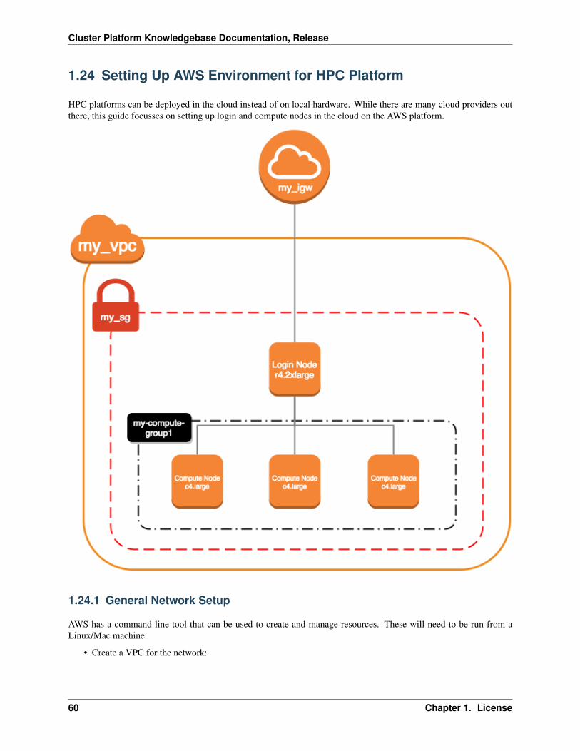
Cluster Platform Knowledgebase Documentation, Release
1.24 Setting Up AWS Environment for HPC Platform
HPC platforms can be deployed in the cloud instead of on local hardware. While there are many cloud providers outthere, this guide focusses on setting up login and compute nodes in the cloud on the AWS platform.
1.24.1 General Network Setup
AWS has a command line tool that can be used to create and manage resources. These will need to be run from aLinux/Mac machine.
• Create a VPC for the network:
60 Chapter 1. License
Cluster Platform Knowledgebase Documentation, Release
aws ec2 create-vpc --cidr-block 10.75.0.0/16
Note: Optionally, a name tag can be created for the VPC (which can make it easier to locate the VPC throughthe AWS web console) with aws ec2 create-tags --resources my_vpc_id --tags Key=Name,Value=Name-For-My-VPC
• Create a security group (replacing my_vpc_id with the VpcId from the above command output):
aws ec2 create-security-group --description my-sg1 --group-name my-sg1 --vpc-id→˓my_vpc_id
• Create a file sg-permissions.json in the current directory with the following content:
[{
"IpProtocol": "-1","IpRanges": [
{"CidrIp": "10.75.0.0/16"
}]
},{
"IpProtocol": "tcp","FromPort": 22,"ToPort": 22,"IpRanges": [
{"CidrIp": "0.0.0.0/0"
}]
},{
"IpProtocol": "tcp","FromPort": 443,"ToPort": 443,"IpRanges": [
{"CidrIp": "0.0.0.0/0"
}]
},{
"IpProtocol": "tcp","FromPort": 80,"ToPort": 80,"IpRanges": [
{"CidrIp": "0.0.0.0/0"
}]
}]
• Add rules to security group (replacing my_sg_id with the GroupId from the above command output):
1.24. Setting Up AWS Environment for HPC Platform 61
Cluster Platform Knowledgebase Documentation, Release
aws ec2 authorize-security-group-ingress --group-id my_sg_id --ip-permissions→˓file://sg-permissions.json
• Define subnet for the VPC (replacing my_vpc_id with the VpcId from earlier):
aws ec2 create-subnet --vpc-id my_vpc_id --cidr-block 10.75.0.0/16
• Create an Internet gateway:
aws ec2 create-internet-gateway
• Attach the Internet gateway to the VPC (replacing my_igw_id with InternetGatewayId from the above com-mand output):
aws ec2 attach-internet-gateway --internet-gateway-id my_igw_id --vpc-id my_vpc_id
• Locate route table for the VPC:
aws ec2 describe-route-tables --filters Name=vpc-id,Values=my_vpc_id
• Create a route within the table (replacing my_rtb_id with RouteTableId from the above command output):
aws ec2 create-route --route-table-id my_rtb_id --destination-cidr-block 0.0.0.0/→˓0 --gateway-id my_igw_id
• Create a file ec2-role-trust-policy.json in the current directory with the following content:
{"Version": "2012-10-17","Statement": [
{"Effect": "Allow","Principal": { "Service": "ec2.amazonaws.com"},"Action": "sts:AssumeRole"
}]
}
• Create autoscaling role:
aws iam create-role --role-name autoscaling --assume-role-policy-document file://→˓ec2-role-trust-policy.json
• Create a file ec2-role-access-policy.json in the current directory with the following content:
{"Version": "2012-10-17","Statement": [
{"Effect": "Allow","Action": ["autoscaling:DescribeAutoScalingGroups","autoscaling:SetDesiredCapacity","autoscaling:UpdateAutoScalingGroup","autoscaling:TerminateInstanceInAutoScalingGroup","ec2:DescribeTags"
],
62 Chapter 1. License
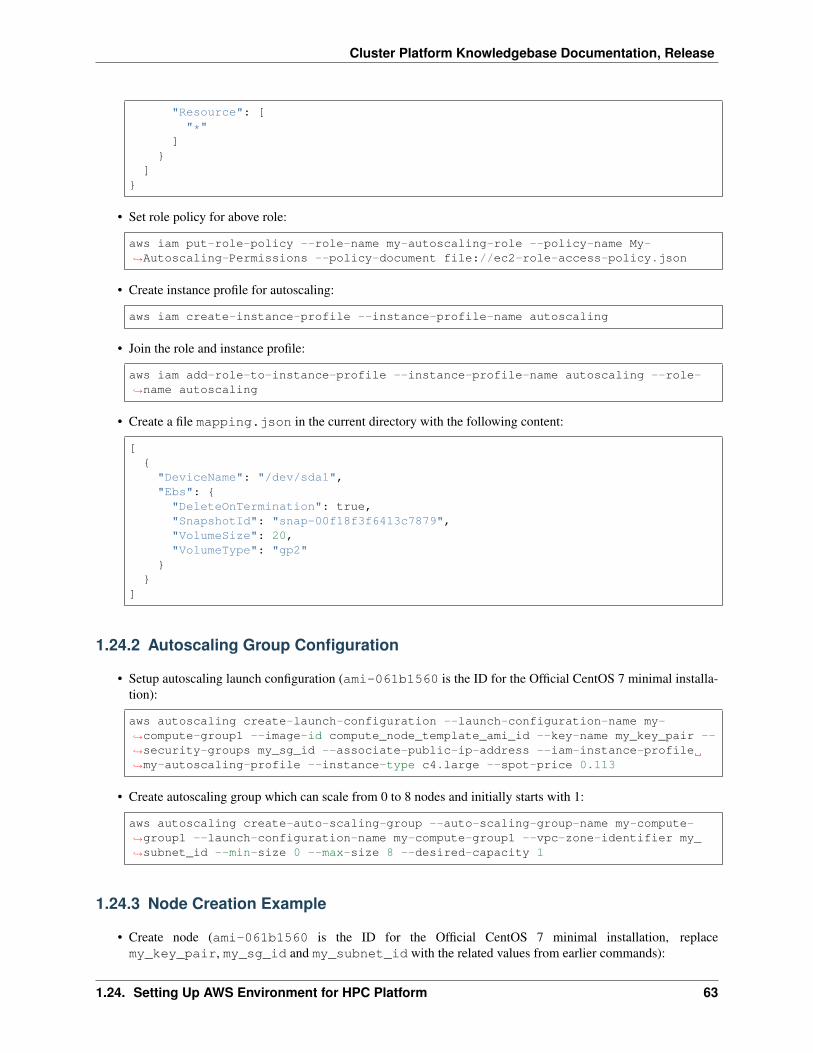
Cluster Platform Knowledgebase Documentation, Release
"Resource": ["*"
]}
]}
• Set role policy for above role:
aws iam put-role-policy --role-name my-autoscaling-role --policy-name My-→˓Autoscaling-Permissions --policy-document file://ec2-role-access-policy.json
• Create instance profile for autoscaling:
aws iam create-instance-profile --instance-profile-name autoscaling
• Join the role and instance profile:
aws iam add-role-to-instance-profile --instance-profile-name autoscaling --role-→˓name autoscaling
• Create a file mapping.json in the current directory with the following content:
[{
"DeviceName": "/dev/sda1","Ebs": {
"DeleteOnTermination": true,"SnapshotId": "snap-00f18f3f6413c7879","VolumeSize": 20,"VolumeType": "gp2"
}}
]
1.24.2 Autoscaling Group Configuration
• Setup autoscaling launch configuration (ami-061b1560 is the ID for the Official CentOS 7 minimal installa-tion):
aws autoscaling create-launch-configuration --launch-configuration-name my-→˓compute-group1 --image-id compute_node_template_ami_id --key-name my_key_pair --→˓security-groups my_sg_id --associate-public-ip-address --iam-instance-profile→˓my-autoscaling-profile --instance-type c4.large --spot-price 0.113
• Create autoscaling group which can scale from 0 to 8 nodes and initially starts with 1:
aws autoscaling create-auto-scaling-group --auto-scaling-group-name my-compute-→˓group1 --launch-configuration-name my-compute-group1 --vpc-zone-identifier my_→˓subnet_id --min-size 0 --max-size 8 --desired-capacity 1
1.24.3 Node Creation Example
• Create node (ami-061b1560 is the ID for the Official CentOS 7 minimal installation, replacemy_key_pair, my_sg_id and my_subnet_id with the related values from earlier commands):
1.24. Setting Up AWS Environment for HPC Platform 63
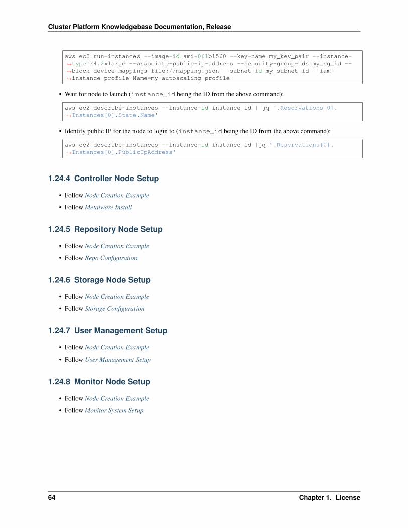
Cluster Platform Knowledgebase Documentation, Release
aws ec2 run-instances --image-id ami-061b1560 --key-name my_key_pair --instance-→˓type r4.2xlarge --associate-public-ip-address --security-group-ids my_sg_id --→˓block-device-mappings file://mapping.json --subnet-id my_subnet_id --iam-→˓instance-profile Name=my-autoscaling-profile
• Wait for node to launch (instance_id being the ID from the above command):
aws ec2 describe-instances --instance-id instance_id | jq '.Reservations[0].→˓Instances[0].State.Name'
• Identify public IP for the node to login to (instance_id being the ID from the above command):
aws ec2 describe-instances --instance-id instance_id |jq '.Reservations[0].→˓Instances[0].PublicIpAddress'
1.24.4 Controller Node Setup
• Follow Node Creation Example
• Follow Metalware Install
1.24.5 Repository Node Setup
• Follow Node Creation Example
• Follow Repo Configuration
1.24.6 Storage Node Setup
• Follow Node Creation Example
• Follow Storage Configuration
1.24.7 User Management Setup
• Follow Node Creation Example
• Follow User Management Setup
1.24.8 Monitor Node Setup
• Follow Node Creation Example
• Follow Monitor System Setup
64 Chapter 1. License


