Embed Size (px)
Citation preview

CMM cable guideDocumentation part number: H-1000-4053-18-C
CMM cable guide
www.renishaw.com
Issued 02 2020 1

General information© 2004 ‐ 2020 Renishaw plc. All rights reserved.
This document may not be copied or reproduced in whole or in part, or transferred to any other media or language, by any means, without
the prior written permission of Renishaw.
The publication of material within this document does not imply freedom from the patent rights of Renishaw plc.
Disclaimer
RENISHAW HAS MADE CONSIDERABLE EFFORTS TO ENSURE THE CONTENT OF THIS DOCUMENT IS CORRECT AT THE DATE OF
PUBLICATION BUT MAKES NO WARRANTIES OR REPRESENTATIONS REGARDING THE CONTENT. RENISHAW EXCLUDES LIABILITY,
HOWSOEVER ARISING, FOR ANY INACCURACIES IN THIS DOCUMENT.
Trademarks
RENISHAW, the probe symbol used in the RENISHAW logo and REVO are registered trademarks of Renishaw plc in the United Kingdom and
other countries. apply innovation and names and designations of other Renishaw products and technologies are trademarks of Renishaw
plc or its subsidiaries.
All brand names and product names used in this document are trade names, service marks, trademarks, or registered trademarks of their
respective owners.
All trademarks and trade names are acknowledged.
WEEE
The use of this symbol on Renishaw products and/or accompanying documentation indicates that the product should not be mixed with the
general household waste upon disposal. It is the responsibility of the end user to dispose of this product at a designated collection point for
waste electrical and electronic equipment (WEEE) to enable reuse or recycling. Correct disposal of this product will help save valuable
resources and prevent potential negative effects on the environment. For more information, please contact your local waste disposal service
or Renishaw distributor.
Warranty
Renishaw plc warrants its equipment for a limited period (as set out in our Standard Terms and Conditions of Sale) provided that it is installed
exactly as defined in associated Renishaw documentation.
Prior consent must be obtained from Renishaw if non-Renishaw equipment (e.g. interfaces and/or cabling) is to be used or substituted. Failure
to comply with this will invalidate the Renishaw warranty.
Claims under warranty must be made from authorised service centres only, which may be advised by the supplier or distributor.
CMM cable guide
www.renishaw.com
Issued 02 2020 2

Care of equipment
Renishaw probes and associated systems are precision tools used for obtaining precise measurements and must therefore be treated with
care.
Changes to Renishaw products
Renishaw reserves the right to improve, change or modify its hardware or software without incurring any obligations to make changes to
Renishaw equipment previously sold.
CMM cable guide
www.renishaw.com
Issued 02 2020 3

Product compliance
EU declaration of conformity
Contact Renishaw plc or visit www.renishaw.com/EU for the full EU declaration.
REACH regulation
Information required by Article 33﴾1﴿ of Regulation ﴾EC﴿ No. 1907/2006 ﴾“REACH”﴿ relating to products containing substances of very highconcern (SVHCs) is available at:
www.renishaw.com/REACH
China RoHS
Contact Renishaw plc or visit www.renishaw.com/ChinaRoHS for the full China RoHS tabulation.
CMM cable guide
www.renishaw.com
Issued 02 2020 4

WarningsIn all applications involving the use of machine tools or co-ordinate measuring machines (CMMs) eye protection is recommended.
There are no user serviceable parts inside Renishaw's main powered units. Return defective units to an authorised Renishaw Customer
Service Centre.
Replace blown fuses with new components of the same type. Refer to the SAFETY section of the relevant product documentation.
For instructions regarding the safe cleaning of Renishaw products refer to the MAINTENANCE section of the relevant product documentation.
Remove power before performing any maintenance operations.
Always allow sufficient time for electrical charge to dissipate from electrical components before handling.
Observe anti-static handing precautions, including the use of earth straps with plug-in cards.
Refer to the machine supplier's operating instructions.
It is the machine supplier's responsibility to ensure that the user is made aware of any hazards involved in operation, including those
mentioned in Renishaw product documentation, and to ensure that adequate guards and safety interlocks are provided.
Under certain circumstances the probe signal may falsely indicate a probe seated condition.
Do not rely on probe signals to stop machine movement.
The expected method of providing an emergency stop for Renishaw products is to remove power.
CMM cable guide
www.renishaw.com
Issued 02 2020 5

IntroductionThis guide contains comprehensive information on the most commonly used Renishaw cables.
It is of particular use to engineers involved in installation or support of Renishaw equipment on CMMs, or where correct cable identification is
required.
Further information for signals, connectors and switch settings of controllers and interfaces can be found in the CMM products switch setting
and connector guide (Renishaw part number H-1000-4068) or relevant installation and user's guides.
Renishaw cables are identified by marker rings or printing to show the 'PL' number.
These markers have a T,V or U suffix to reflect the cable function and design.
Further customised cable solutions are available for specific applications, please contact Renishaw for further details.
CMM product support
Renishaw provides comprehensive world-wide sales and technical support through an extensive network of locally staffed subsidiary offices
and regional service and repair centres, contact us at www.renishaw.com/contact.
CMM cable guide
www.renishaw.com
Issued 02 2020 6

Cable information quick reference tables
Manual probe head cables
PL no. Length Connectors Connectors Part number Page
PL1 260 mm to 710 mm
(10.24 in to 27.95 in)
In-line 5-pin DIN
plug
90° moulded plastic5-pin DIN plug
A-1016-0004 13
PL2 410 mm to 1.27 m
(16.14 in to 50 in)
In-line 5-pin DIN
plug
90° moulded plastic5-pin DIN plug
A-1016-0006 13
PL3 680 mm to 2.32 m
(26.77 in to 91.34 in)
In-line 5-pin DIN
plug
90° moulded plastic5-pin DIN plug
A-1016-0012 13
PL4 4.5 m (177.17 in) In-line 5-pin DIN
plug
90° moulded plastic5-pin DIN plug
A-1016-0001 14
PL14 590 mm to 1.83 m
(23.23 in to 72.05 in)
7-pin Amphenol plug 90° moulded plastic5-pin DIN plug
A-1016-0003 21
PL17 160 mm to 260 mm
(6.3 in to 10.24 in)
90° moulded 5‐pinDIN plug
In-line LEMO plug A-1023-7024 23
PL18 560 mm to 1.06 m
(22.05 in to 41.73 in)
90° moulded 5‐pinDIN plug
In-line LEMO plug A-1023-7025 23
PL27 225 mm to 450 mm
(8.86 in to 17.72 in)
90° moulded 5‐pinDIN plug
90° moulded 5‐pinDIN plug
A-1016-6370 29
PL52 275 mm to 550 mm
(10.83 in to 21.65 in)
5-pin Franz Binder
plug
Moulded 90° 5‐pinDIN plug
A-1016-6500 36
- 160 mm (6.3 in) 90° moulded 5‐pinDIN plug
90° moulded 5‐pinDIN plug
A-1016-6440 12
Motorised probe head cables
PL no. Length Connectors Connectors Part number Page
PL5 400 mm to 800 mm
(15.75 in to 31.5 in)
In-line LEMO plug 90° Tuchel socket A-1016-7672 15
PL6 800 mm to 1.6 m
(61.5 in to 62.99 in)
In-line LEMO plug 90° Tuchel socket A-1016-7673 15
PL12 100 mm (3.94 in) In-line LEMO plug 90° Tuchel socket A-1016-7674 19
PL13 100 mm to 200 mm
(3.94 in to 7.87 in)
In-line LEMO plug 90° Tuchel socket A-1016-7675 15
PL33 3 m (118.11 in) In-line LEMO socket
or plug
90° Tuchel socket A-1023-7056 32
PL93 100 mm (3.94 in) In-line LEMO plug In-line Tuchel socket A-1016-7676 44
CMM cable guide
www.renishaw.com
Issued 02 2020 7

SP80 cables
PL no. Length Connectors Connectors Part number Page
PL156 60 mm (23.62 in) 26-pin high-density
D-type socket
Unterminated A-1016-7129 55
PL157 230 mm (9.06 in) 15-pin high-density
D-type socket
In-line 14-pin LEMO
plug
A-1016-7132 57
PL158 1 m (39.37 in) 26-pin high-density
D-type socket
26-pin D-type plug A-1016-7133 58
Machine cables
PL no. Length Connectors Connectors Part number Page
PLM6 6 m (236.22 in) 15-pin D-type plug 14-pin chassis-
mount LEMO socket
(supplied loose)
A-1016-7564 63
PLM7 4 m (157.48 in) 15-pin D-type plug 14-pin chassis-
mount LEMO socket
(supplied loose)
A-1016-7563 63
PLM8 6 m (236.22 in) 15-pin D-type plug 14-pin in-line LEMO
socket
A-1016-7677 65
PLM9 4 m (157.48 in) 15-pin D-type plug 14-pin in-line LEMO
socket
A-1016-7678 65
Output cables
PL no. Length Connectors Connectors Part number Page
PL7T 3.1 m (122.1 in) 5-pin DIN socket 5-pin DIN socket A-1029-0166 17
PL15 4.5 m (177.17 in) In-line 5-pin DIN
plug
Unterminated A-1004-0110 22
PL26 600 mm (23.62 in) 9-pin D-type plug 7-pin DIN plug A-1057-0132 28
PL37 500 mm (19.69 in) In-line 7-pin DIN
plug
In-line 7-pin DIN
plug
A-1054-0003 34
PL101 500 mm (19.69 in) 15-pin high-density
D-type socket
15-pin high-density
D-type plug
A-1016-7662 47
50 cm (19.7 in) 25-pin D-type socket 9-pin D-type socket A-5567-1622 72
CMM cable guide
www.renishaw.com
Issued 02 2020 8

Adaptor / extension cables - multiwire
PL no. Length Connectors Connectors Part number Page
PL38V 25 m (984.25 in) 90° micro‐D plug 15-pin high-density
D-type plug
A-1016-7625 35
PL42V 15 m (590.55 in) 90° micro‐D plug 15-pin high-density
D-type plug
A-1016-7624 35
PL44V 8 m (314.96 in) 90° micro‐D plug 15-pin high-density
D-type plug
A-1016-7627 35
PL45V 1.9 m (74.8 in) 90° micro‐D plug 15-pin high-density
D-type plug
A-1016-7629 35
PL46V 3.7 m (145.67 in) 90° micro‐D plug 15-pin high-density
D-type plug
A-1016-7628 35
PL56V 12 m (472.44 in) 90° micro‐D plug 15-pin high-density
D-type plug
A-1016-7626 35
PL75V 1 m (39.37 in) 15-pin high-density
D-type socket
15-pin high-density
D-type plug
A-1016-7644 38
Adaptor / extension cables
PL no. Length Connectors Connectors Part number Page
PL10 100 mm (3.94 in) In-line LEMO plug 5-pin DIN socket A-1029-0111 18
PL22 300 mm (11.81 in) 5-pin DIN socket 9-pin D-type plug A-1057-0131 26
PL69V 10.5 m (413.39 in) 15-pin high-density
D-type socket
15-pin high-density
D-type plug
A-1016-7640 38
PL97 260 mm (10.24 in) In-line 6-pin mini
DIN socket
In-line 6-pin mini
DIN plug
A-1016-7660 46
260 mm (10.24 in) 15-pin D-type socket 15-pin high-density
D-type plug
A-1333-0183 71
230 cm (90.6 in) /
140 cm (55.1 in)
A-3065-0150 82
510 cm (200.79 in) A-3065-0160 83
CMM cable guide
www.renishaw.com
Issued 02 2020 9

PICS interconnection cables
PL no. Length Connectors Connectors Part number Page
PL24 5 m (196.85 in) 9-pin D-type socket 9-pin D-type plug A-1016-0121 27
PL25 300 mm (11.81 in) 9-pin D-type socket 9-pin D-type plug A-1016-0120 27
PL70T 400 mm (15.75 in) 9-pin D-type plug 15-pin high-density
D-type socket
A-1016-7634 39
PL72T 2 m (78.7 in) 9-pin D-type socket 9-pin D-type plug A-1016-7637 27
PL76T 1 m (39.37 in) 9-pin D-type socket 9-pin D type socket A-1016-7643 41
PL172 48 cm to 52 cm (18.9
in to 20.5 in)
7-pin DIN plug 15-pin high-density A-5684-1000 61
Controller cables
PL no. Length Connectors Connectors Part number Page
30 cm (11.8 in) A-5629-0071 81
50 cm (19.7 in) 5-pin D-type plug 9-pin D-type socket A-5629-0090 73
PL163 5 m (196.85 in) 9-pin D-type socket 9-pin D-type plug A-1016-8098 60
PL164 10 m (393.7 in) 9-pin D-type socket 9-pin D-type plug A-1016-8099 60
PL171 15 m (590.55 in) 9-pin D-type socket 9-pin D-type plug A-1016-8100 60
97 cm (38.2 in) 25-pin D-type plug 9-pin D-type plug A-5208-0011 75
750 mm (29.53 in) 9-pin D-type plug 25-pin D-type plug A-5121-0062 67
Rack cables
PL no. Length Connectors Connectors Part number Page
PL19 5 m (196.85 in) In-line 25-pin D-type
socket
25-pin D-type plug A-1051-0199 24
PL20 10 m (393.7 in) In-line 25-pin D-type
socket
25-pin D-type plug A-1051-0045 24
PL21 15 m (590.55 in) In-line 25-pin D-type
socket
25-pin D-type plug A-1051-0102 24
PL40 30 m (1181.1 in) In-line 25-pin D-type
socket
25-pin D-type plug A-1054-0002 24
CMM cable guide
www.renishaw.com
Issued 02 2020 10

SCR200 cables
PL no. Length Connectors Connectors Part number Page
PL63 5 m (196.85 in) In-line 6-pin mini
DIN plug
In-line 6-pin mini
DIN plug
A-1016-7630 37
PL64 10 m (393.7 in) In-line 6-pin mini
DIN plug
In-line 6-pin mini
DIN plug
A-1016-7631 37
PL65 20 m (787.4 in) In-line 6-pin mini
DIN plug
In-line 6-pin mini
DIN plug
A-1016-7632 37
Probe cables
PL no. Length Connectors Connectors Part number Page
PL29 740 mm to 1.48 m
(29.13 in to 58.27 in)
90° moulded 5‐pinDIN plug
90° moulded 5‐pinDIN plug
A-1016-6420 29
PL28 275mm to 550 mm
(10.83 in to 21.65 in)
5-pin Franz Binder
plug
Moulded 90° 5‐pinDIN plug
A-1016-6386 30
PL31 300 mm to 600 mm
(11.81 in to 23.62 in)
90° moulded 5‐pinDIN plug
In-line LEMO plug A-1049-8025 31
PL82V 5 m (196.85 in) 12-pin round Hirose-
type plug
15-pin high-density
D-type plug
A-1016-7648 42
PH20 and REVO cables
PL no. Length Connectors Connectors Part number Page
10 m (393.7 in) 15-pin D-type plug 15-pin D-type socket A-5669-0090 76
15 m (590.6 in) 15-pin D-type plug 15-pin D-type socket A-5669-0091 76
20 m (787.4 in) 15-pin D-type plug 15-pin D-type socket A-5669-0092 76
25 m (984.3 in) 15-pin D-type plug 15-pin D-type socket A-5669-0093 76
15 m (590.1 in) 15-pin D-type plug 15-pin D-type socket A-5669-0015 78
25 m (984.3 in) 15-pin D-type plug 15-pin D-type socket A-5759-0025 78
CMM cable guide
www.renishaw.com
Issued 02 2020 11

PHS1 accessories
PL no. Length Connectors Connectors Part number Page
PL104 30 m (1181.1 in) 15-pin high-density
D-type socket
Unterminated A-2150-0481 48
PL105 30 m (1181.1 in) 15-pin high-density
D-type socket
Unterminated A-2150-0482 49
PL106 30 m (1181.1 in) 15-pin high-density
D-type socket
Unterminated A-2150-0483 50
PL107 30 m (1181.1 in) 15-pin high-density
D-type socket
Unterminated A-2150-0484 52
SP600 cable
PL no. Length Connectors Connectors Part number Page
PL112 1.2 m (47.24 in) 26-pin high-density
D-type socket
9-pin D-plug 9-pin
D-socket
A-2172-0004 53
Ethernet cables
PL no. Length Connectors Connectors Part number Page
1 m (39.37 in) RJ45 type plug RJ45 type plug P-CA78-0017 68
360 mm (14.17 in) RJ45 type plug RJ45 type plug P-CA82-0013 69
5 m (196.85 in) RJ45 type plug RJ45 type plug P-CA81-0002 70
CMM cable guide
www.renishaw.com
Issued 02 2020 12

Manual probe head cablePart number Length
A-1016-6440 160 mm (6.3 in)
This straight cable has a 90° moulded plastic 5‐pin DIN plug at each end and electrically connects Renishaw manual probe heads to the CMMquill.
End 'A' and 'B' Wire Signal
1 Red Head LED cathode
2 Screen Screen
3 Yellow Head LED anode
4 Blue Probe circuit
5 Green Probe circuit
CMM cable guide
www.renishaw.com
Issued 02 2020 13

PL1, PL2 and PL3 manual probe head cablesCable name Part number Length
PL1 A-1016-0004 260 mm to 710 mm (10.24 in to 27.95 in)
PL2 A-1016-0006 410 mm to 1.27 m (16.14 in to 50 in)
PL3 A-1016-0012 680 mm to 2.32 m (26.77 in to 91.34 in)
These coiled cables have an in‐line 5‐pin DIN plug at end 'A' and a 90° moulded plastic 5‐pin DIN plug at end 'B'. They electrically connectRenishaw manual probe heads to the CMM quill.
End 'A' Wire End 'B' Signal
1 Red 1 Head LED cathode
2 and shell Screen 2 Screen
3 Yellow 3 Head LED anode
4 Blue 4 Probe circuit
5 Green 5 Probe circuit
CMM cable guide
www.renishaw.com
Issued 02 2020 14
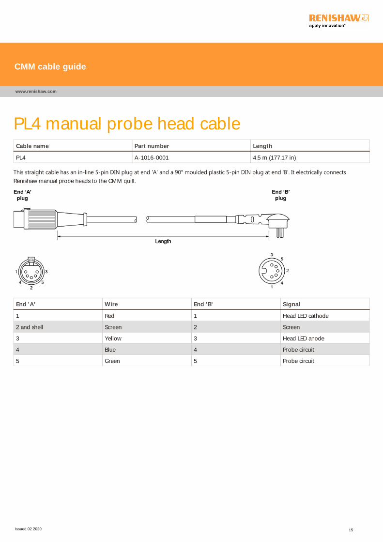
PL4 manual probe head cableCable name Part number Length
PL4 A-1016-0001 4.5 m (177.17 in)
This straight cable has an in‐line 5‐pin DIN plug at end 'A' and a 90° moulded plastic 5‐pin DIN plug at end 'B'. It electrically connectsRenishaw manual probe heads to the CMM quill.
End 'A' Wire End 'B' Signal
1 Red 1 Head LED cathode
2 and shell Screen 2 Screen
3 Yellow 3 Head LED anode
4 Blue 4 Probe circuit
5 Green 5 Probe circuit
CMM cable guide
www.renishaw.com
Issued 02 2020 15

PL5, PL6 and PL13 motorised probe head
cablesCable name Part number Length
PL5 A-1016-7672 400 mm to 800 mm (15.75 in to 31.5 in)
PL6 A-1016-7673 800 mm to 1.6 m (61.5 in to 62.99 in)
PL13 A-1016-7675 100 mm to 200 mm (3.94 in to 7.87 in)
These coiled cables have an in‐line LEMO plug at end 'A' and a 90° Tuchel socket at end 'B'. They electrically connect Renishaw PH10T, PH10Mor PH10MQ motorised probe heads to the CMM quill.
CMM cable guide
www.renishaw.com
Issued 02 2020 16

End 'A' End 'B' Wire Signal Max. line current
1 E Yellow 'B' axis feedback n/a
2 D Red Ground sense n/a
3 C Brown dc reference 12 V n/a
4* M Grey 0 V 1000 mA
5 H White Locking motor 8 V dc
nominal
350 mA
6 L Green 'A' axis motor 12 V dc
nominal
350 mA
7* n/a Not connected Head present n/a
8 F Blue 'A' axis motor 12 V dc
nominal
350 mA
9 A Violet 'B' axis motor / probe
contact
350 mA
10 B Black 'B' axis motor / probe
contact
350 mA
11 N and O Screen Screen n/a
12 G Orange 'A' axis feedback n/a
13 J Turquoise LED and datum 15 mA
14 K Pink Motor probe switch 40 mA
* NOTE: The male pins 4 and 7 of the 14 way LEMO connector (end 'A') are linked together.
CMM cable guide
www.renishaw.com
Issued 02 2020 17

PL7T probe interface cableCable name Part number Length
PL7T A-1029-0166 3.1 m (122.1 in)
This straight cable has a 5-pin DIN plug at each end. It is a probe interface cable used to connect manual probe heads to the interface or OEM
extension.
End 'A' Wire End 'B' Signal
1 Red 1 Head LED cathode
2 and shell Screen 2 and shell Screen
3 Yellow 3 Head LED anode
4 Blue 4 Probe circuit
5 Green 5 Probe circuit
CMM cable guide
www.renishaw.com
Issued 02 2020 18

PL10 manual probe head cableCable name Part number Length
PL10 A-1029-0111 100 mm (3.94 in)
This straight cable has an in-line LEMO plug at end 'A' and an in-line 5-pin DIN socket at end 'B' and. It electrically connects Renishaw manual
probe heads to the CMM quill.
End 'A' End 'B' Wire Signal
1 7 Red Head LED cathode
2 and shell 11 Screen Screen
3 13 Yellow Head LED anode
4 10 Blue Probe circuit
5 9 Green Probe circuit
CMM cable guide
www.renishaw.com
Issued 02 2020 19

PL12 motorised probe head cableCable name Part number Length
PL12 A-1016-7674 100 mm (3.94 in)
This straight cable has an in‐line LEMO plug at end 'A' and a 90° Tuchel socket at end 'B'. It electrically connects Renishaw PH10T, PH10M orPH10MQ motorised probe heads to the CMM quill.
CMM cable guide
www.renishaw.com
Issued 02 2020 20

End 'A' End 'B' Wire Signal Max. line curent
1 E Yellow 'B' axis feedback n/a
2 D Red Ground sense n/a
3 C Brown dc reference 12 V n/a
4* M Grey 0 V 1000 mA
5 H White Locking motor 8 V dc
nominal
350 mA
6 L Green 'A' axis motor 12 V dc
nominal
350 mA
7* - Not connected Head present n/a
8 F Blue 'A' axis motor 12 V dc
nominal
350 mA
9 A Violet 'B' axis motor / probe
contact
350 mA
10 B Black 'B' axis motor / probe
contact
350 mA
11 N and O Screen Screen n/a
12 G Orange 'A' axis feedback n/a
13 J Turquoise LED and datum 15 mA
14 K Pink Motor probe switch 40 mA
* NOTE: The male pins 4 and 7 of the 14 way LEMO connector (end 'A') are linked together.
CMM cable guide
www.renishaw.com
Issued 02 2020 21

PL14 manual probe head cableCable name Part number Length
PL14 A-1016-0003 590 mm to 1.83 m (23.23 in to 72.05 in)
This coiled cable has a 7‐pin Amphenol plug at end 'A' and a 90° moulded plastic 5‐pin DIN plug at end 'B'. It electrically connects Renishawmanual probe heads to the CMM quill.
End 'A' End 'B' Wire Signal
A 2 Screen Screen
B 5 Green Probe circuit
C 4 Blue Probe circuit
D 3 Yellow Head LED anode
E and F linked 1 Red Head LED cathode
H n/a n/a Not connected
CMM cable guide
www.renishaw.com
Issued 02 2020 22

PL15 manual probe head cableCable name Part number Length
PL15 A-1004-0110 4.5 m (177.17 in)
This straight cable has an in-line 5-pin DIN plug at end 'A' and is unterminated at end 'B'. It electrically connects Renishaw manual probe
heads to the CMM quill.
End 'A' Wire End 'B' Signal
1 Red 1 Head LED cathode
2 and shell Screen 2* Screen
3 Yellow 3 Head LED anode
4 Blue 4 Probe circuit
5 Green 5 Probe circuit
* NOTE: Link pin-2 of end 'B' to shell if fitting a connector with a metal cover.
CMM cable guide
www.renishaw.com
Issued 02 2020 23

PL17 and PL18 manual probe head cablesCable name Part number Length
PL17 A-1023-7024 160 mm to 260 mm (6.3 in to 10.24 in)
PL18 A-1023-7025 560 mm to 1.06 m (22.05 in to 41.73 in)
These coiled cables have a 90° moulded 5‐pin DIN plug at end 'A' and an in‐line LEMO plug at end 'B'. They electrically connect Renishawmanual probe heads to the CMM quill.
End 'A' End 'B' Wire Signal
1 7 Red Head LED cathode
2 11 Screen Screen
3 13 Yellow Head LED anode
4 9 Blue Probe circuit
5 10 Green Probe circuit
NOTE: A PL31 cable is available with inverted probe circuit pins if required.
CMM cable guide
www.renishaw.com
Issued 02 2020 24

PL19, PL20, PL21 and PL40 autochange rack
cablesCable name Part number Length
PL19 A-1051-0199 5 m (196.85 in)
PL20 A-1051-0045 10 m (393.7 in)
PL21 A-1051-0102 15 m (590.55 in)
PL40 A-1054-0002 30 m (1181.1 in)
These straight ACR1 autochange rack cables have an in-line 25-pin D-type socket at end 'A' and a 25-pin D-type plug at end 'B'. They relay
communications between the ACC2-2 controller and ACR1 rack. Connections are pin-to-pin, with the red / grey wire connected to pin 1 at
each end.
CMM cable guide
www.renishaw.com
Issued 02 2020 25

Pin number Signal Pin number Signal
1 Supply to ACR1 motor 14 Supply to ACR1 motor
2 0 V rack motor return 15 0 V motor return
3 Rack 0 V return for ACR1 motor 16 Rack 0 V
4 'Screwdriver' position feedback 17 Front IRED beam detector signal
5 Rear IRED beam detector signal 18 Rack probe contact no. 1
6 Rack probe contact no. 2 19 ACR1 overtravel signal no. 1
7 Rack precision reference voltage
for the ACR1 position
potentiometer
20 ACR1 'probe active' indicator no.
1
8 Rack lock error indicator no. 4 21 ACR1 'cycle error' indicator no. 3
9 ACR1 0 V 22 + 15 V supply to ACR1 circuits
10 Rack 'change cycle' indicator no.
0
23 Ground sense
11 Rack 0 V, reserved for future use 24 Rack 0 V, reserved for future use
12 Rack 0 V, reserved for future use 25 Rack 0 V, reserved for future use
13 n/a
CMM cable guide
www.renishaw.com
Issued 02 2020 26

PL22 DIN to PICS adaptor cableCable name Part number Length
PL22 A-1057-0131 300 mm (11.81 in)
This straight cable has a 5-pin DIN socket at end 'A' and a 9-pin D-type plug at end 'B'. When linked to existing SSR (solid state relay) cables it
allows input of the probe signal via Renishaw PICS (product interconnection system) of current interfaces such as PI 4-2 or PI 200.
End 'A' End 'B' Wire Signal*
1 3 Red Head LED cathode
2 and shell Shell Screen Screen
3 4 and 8 Yellow Head LED anode
4 5 Blue Probe circuit
5 9 Green Probe circuit
n/a 1 and 6 linked n/a n/a
CMM cable guide
www.renishaw.com
Issued 02 2020 27

PL24, PL25 and PL72T PICS cableCable name Part number Length
PL24 A-1016-0121 5 m (196.85 in)
PL25 A-1016-0120 300 mm (11.81 in)
PL72T A-1016-7637 2 m (78.7 in)
These straight cables has a 9-pin D-type socket at end 'A' with a 9-pin D-type plug at end 'B'.
End 'A' and 'B' Wire PICS signal input PICS signal output
1 Black STOP STOP
2 Brown PPOFF (probe power off) PPOFF
3 Violet 0 V 0 V
4 Orange Reserved for Renishaw use n/a
5 Red Probe signal SYNC output
6 Yellow + 5 V HALT output
7 Blue PDAMP (probe damping) PDAMP
8 Green LED OFF LED OFF
9 White Probe n/a
Shell Screen Screen Screen
NOTE: Pink wire not used, cut back at both ends.
CMM cable guide
www.renishaw.com
Issued 02 2020 28

PL26 PICS cableCable name Part number Length
PL26 A-1057-0132 600 mm (23.62 in)
This straight cable has a 9-pin D-type plug at end 'A' with a 7-pin DIN plug at end 'B'. These cables are used for adapting SSR output signals to
Renishaw PICS (product interconnection system) inputs. This PICS input signal information is detailed below.
End 'A' End 'B' Wire PICS signal input
1 and 6 linked n/a n/a n/a
2 6 Red PPOFF (probe power off)
3 1 and 7 Blue 0 V
4 and 8 linked 3 Yellow LED OFF
5 5 White Probe signal
9 4 Green Probe return
Shell Shell Screen Screen
CMM cable guide
www.renishaw.com
Issued 02 2020 29

PL27 and PL29 manual probe head cablesCable name Part number Length
PL27 A-1016-6370 225 mm to 450 mm (8.86 in to 17.72 in)
PL29 A-1016-6420 740 mm to 1.48 m (29.13 in to 58.27 in)
These coiled cables have 90° moulded 5‐pin DIN plugs at each end and electrically connect Renishaw manual probe heads to the CMM quill.
End 'A' and 'B' Wire Signal
1 Red Head LED cathode
2 Screen Screen
3 Yellow Head LED anode
4 Blue Probe circuit
5 Green Probe circuit
CMM cable guide
www.renishaw.com
Issued 02 2020 30

PL28 manual probe head cableCable name Part number Length
PL28 A-1016-6386 275mm to 550 mm (10.83 in to 21.65 in)
This is a coiled cable with a round 5‐pin Franz Binder plug at end 'A' and a moulded 90° 5‐pin DIN plug at end 'B'. The cable is used onStiefelmayer CMM's to electrically connect Renishaw manual probe heads to the quill where a non-Stiefelmayer interface is being used. For
applications using Stiefelmayer interfaces see details of the PL52 cable.
End 'A' and 'B' Wire Signal
1 Red Head LED cathode
2 Screen Screen
3 Yellow Head LED anode
4 Blue Probe circuit
5 Green Probe circuit
CMM cable guide
www.renishaw.com
Issued 02 2020 31

PL31 manual probe head cableCable name Part number Length
PL31 A-1049-8025 300 mm to 600 mm (11.81 in to 23.62 in)
These coiled cables have a 90° moulded 5‐pin DIN plug at end 'A' and an in‐line LEMO plug at end 'B'. They electrically connect Renishawmanual probe heads to the CMM quill.
End 'A' End 'B' Wire Signal
1 7 Red Head LED cathode
2 11 Screen Screen
3 13 Yellow Head LED anode
4 10 Blue Probe circuit
5 9 Green Probe circuit
CAUTION: The probe circuit pins of the PL31 are inverted, check polarity requirements before use. If normal polarity is required,
use the PL17 or PL18 cables.
CMM cable guide
www.renishaw.com
Issued 02 2020 32

PL33 motorised probe head cableCable name Part number Length
PL33 A-1023-7056 3 m (118.11 in)
This straight cable has in‐line LEMO socket or plug alternatives supplied loose for fitment on end 'A'. A 90° Tuchel socket is already fitted toend 'B'. This cable electrically connects Renishaw PH10T, PH10M or PH10MQ motorised probe heads to the CMM quill.
NOTE: A-1023-7055 is just the cable with Tuchel socket (without LEMO connectors).
CMM cable guide
www.renishaw.com
Issued 02 2020 33

End 'A' plug End 'A' socket End 'B' Wire Signal Max. line current
1 3 E Yellow 'B' axis feedback n/a
2 2 D Red Ground sense n/a
3 1 C Brown dc reference 12 V n/a
4* 7Ŧ M Grey 0 V 1000 mA
5 6 H White Locking motor 8 V dc
nominal
350 mA
6 5 L White / black 'A' axis motor 12 V
dc nominal
350 mA
7* 4Ŧ n/a Not connected Head present n/a
8 11 F Blue 'A' axis motor 12 V
dc nominal
350 mA
9 10 A Violet 'B' axis motor / probe
contact
350 mA
10 9 B Black 'B' axis motor / probe
contact
350 mA
11 8 N and O Screen Screen n/a
12 14 G Orange 'A' axis feedback n/a
13 13 J White / brown LED and datum 15 mA
14 12 K Green Motor probe switch 40 mA
* NOTE: The male pins 4 and 7 of the 14 way LEMO plug (end 'A) are linked together.
Ŧ NOTE: The female pins 4 and 7 of the 14 way LEMO socket (end 'A') are linked together if this alternative connector type is
required.
CMM cable guide
www.renishaw.com
Issued 02 2020 34

PL37 probe signal cableCable name Part number Length
PL37 A-1054-0003 500 mm (19.69 in)
This straight cable has in-line 7-pin DIN plugs at each end. It electrically connects Renishaw probe interfaces and probe head controllers and
passes SSR (solid state relay) signals between them.
End 'A' and 'B' Wire Signal
1 Yellow LED cathode
2 and shell Screen Screen
3 Green LED anode
4 Red Probe return
5 Blue Probe signal
6 Black Inhibit return
7 White Inhibit signal
CMM cable guide
www.renishaw.com
Issued 02 2020 35

PL38V, PL42V, PL44V, PL45V, PL46V and
PL56V multiwire cablesCable name Part number Length
PL38V A-1016-7625 25 m (984.25 in)
PL42V A-1016-7624 15 m (590.55 in)
PL44V A-1016-7627 8 m (314.96 in)
PL45V A-1016-7629 1.9 m (74.8 in)
PL46V A-1016-7628 3.7 m (145.67 in)
PL56V A-1016-7626 12 m (472.44 in)
These straight cables have a 90° micro‐D plug fitted at one end with a 15‐pin high‐density D‐type plug supplied loose for fitment to the otherend. They are used to electrically connect Renishaw PH6M, PH10M and PH10MQ probe heads to multiwire probe system interfaces or
controllers.
End 'A' and 'B' Wire End 'A' and 'B' Wire
1 Brown 9 Coaxial screen
2 and screen Screen 10 Coaxial inner
3 Green 11 Orange
4 Violet 12 Blue / white
5 Yellow 13 Grey
6 Red 14 Black / white
7 Blue 15 Brown / white
8 White
CMM cable guide
www.renishaw.com
Issued 02 2020 36
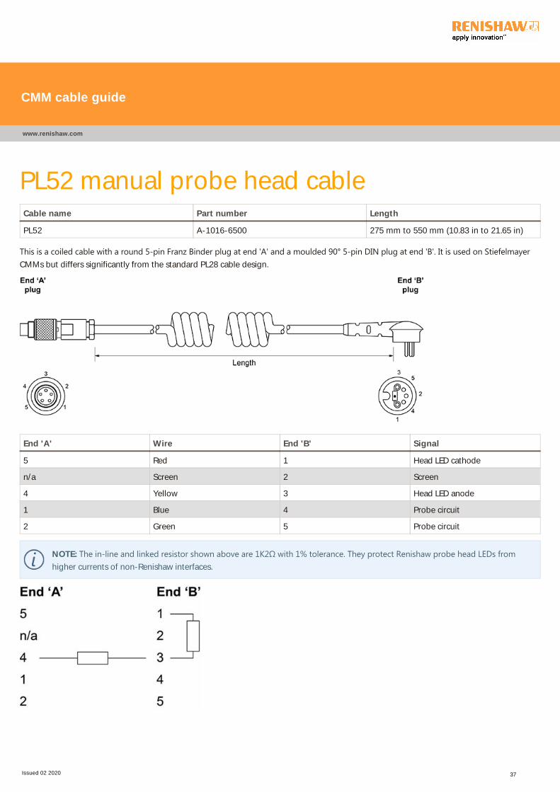
PL52 manual probe head cableCable name Part number Length
PL52 A-1016-6500 275 mm to 550 mm (10.83 in to 21.65 in)
This is a coiled cable with a round 5‐pin Franz Binder plug at end 'A' and a moulded 90° 5‐pin DIN plug at end 'B'. It is used on StiefelmayerCMMs but differs significantly from the standard PL28 cable design.
End 'A' Wire End 'B' Signal
5 Red 1 Head LED cathode
n/a Screen 2 Screen
4 Yellow 3 Head LED anode
1 Blue 4 Probe circuit
2 Green 5 Probe circuit
NOTE: The in‐line and linked resistor shown above are 1K2Ω with 1% tolerance. They protect Renishaw probe head LEDs fromhigher currents of non-Renishaw interfaces.
CMM cable guide
www.renishaw.com
Issued 02 2020 37

PL63, PL64 and PL65 cables for the SCR200
rackCable name Part number Length
PL63 A-1016-7630 5 m (196.85 in)
PL64 A-1016-7631 10 m (393.7 in)
PL65 A-1016-7632 20 m (787.4 in)
These straight cables have in-line 6-pin mini DIN plugs at each end and are used to electrically connect SCR200 racks to PI 200 probe
interfaces used with TP200 probes.
End 'A' and 'B' Wire Signal
1 Red Remote set
2 Blue Error
3 Green Inhibit
4 Yellow Power
5 White 0 V
6 Black n/a
Shell Shell Screen
CMM cable guide
www.renishaw.com
Issued 02 2020 38

PL69V and PL75V multiwire extension cablesCable name Part number Length
PL69V A-1016-7640 10.5 m (413.39 in)
PL75V A-1016-7644 1 m (39.37 in)
These straight cables have a 15-pin high-density D-type socket at end 'A' and a 15-pin high-density D-type plug at end 'B'. They are used to
extend the existing CMM multiwire probe system cables.
End 'A' and 'B' Wire End 'A' and 'B' Wire
1 Brown 9 Coaxial screen
2 Grey 10 Coaxial inner
3 Green 11 Orange
4 Violet 12 White / blue
5 Yellow 13 Black
6 Red 14 White / brown
7 Blue 15 White / black
8 White Shell Screen
CMM cable guide
www.renishaw.com
Issued 02 2020 39

PL70T four-way linking cableCable name Part number Length
PL70T A-1016-7634 A - 400 mm (15.75 in)
B - 500 mm (19.69 in)
C - 2 m (78.74 in)
This four-way linking cable joins four connectors of differing types. End 'A' is a 9-pin D-type plug, end 'B' is a 9-pin D-type socket, end 'C' is a
15-pin high-density D-type socket and end 'D' is a 15-pin high-density D-type plug. It is used to combine a multiwire system with a standard
probe system (using PICS) without the need for an IS 1-2 interface selector to route signals.
CMM cable guide
www.renishaw.com
Issued 02 2020 40

End 'A' Wire End 'B'
A1 Black B1
A2 Brown B2
A3 Violet B3
A4 Orange B4
A5 Red C13
A6 White B6
A7 Yellow B7
A8 Green B8
A9 Blue C3
End 'C' Wire End 'D'
C1 Grey D1
C3 Blue (2 off) A9 / D3
C4 Yellow D4
C5 White D5
C6 Orange D6
C7 Green D7
C8 Red D8
C9 Coax outer D9
C10 Coax core D10
C11 Violet D11
C12 White / blue D12
C13 Red A5
C14 Brown D14
C15 Black D15
CMM cable guide
www.renishaw.com
Issued 02 2020 41

PL76T PICS three-way linking cableCable name Part number Length
PL76T A-1016-7643 1 m (39.37 in)
This straight three-way linking cable joins connectors of differing types. End 'A' has a 9-pin D-type socket, end 'B' has a 9-pin D type socket
and end 'C' has a 9-pin D-type plug. It is used to link a PICS compatible interface into an existing system and to output the signal to the CMM
PC or controller.
End 'A' Wire End 'B' Wire End 'C'
1 Black 1 White 1
2 Brown 2 White 2
3 Violet 3 White 3
4 n/a 4 n/a 4
5 Red 5 White 5
6 Yellow 6 White 6
7 Blue 7 White 7
8 Green 8 White 8
9 White 9 White 9
NOTE: The orange and pink wires are not used, cut back at both ends.
CMM cable guide
www.renishaw.com
Issued 02 2020 42

PL82V video compatible probe cableCable name Part number Length
PL82V A-1016-7648 5 m (196.85 in)
This straight cable has a 12‐pin round Hirose‐type plug at end ‘A' and a 15‐pin high‐density D‐type plug at end ‘B'. It is used to link ﴾the nowobsolete) VP2 video cameras to the VPI 2 video probe interface or to link shank mounted SP600 version scanning probes to AC1 or AC2
cards. The ‘V' suffix on cable markers indicate video system compatibility, signal details are shown below for both applications.
CMM cable guide
www.renishaw.com
Issued 02 2020 43

End 'A' Wire End 'B' MIH-SI signals VP2 probe signals SP600 probe
signals
1 Brown 1 + supply Reference Reference
2 Blue / white 12 LED anode Probe sense return 0 V
3 Green 3 Head clock Identification 0 V + 5 V
4 Violet 4 Head data n/a Y axis
5 Yellow 5 Head data n/a Z axis
6 Red 6 Ground + 12 V + 12 V
7 Blue 7 LED cathode Illumination supply - 12 V
8 White 8 n/a Identification Probe output
9 Orange 11 n/a n/a X axis
10 Grey 2 Head clock n/a n/a
11 Coaxial screen 9 Probe Video 0 V n/a
12 Coaxial inner 10 Ground Video output 0 V power
- - 13 n/a n/a n/a
- - 14 n/a n/a n/a
- - 15 n/a n/a n/a
Shell Screen Shell Ground Ground Ground
CMM cable guide
www.renishaw.com
Issued 02 2020 44

PL93 motorised probe head cableCable name Part number Length
PL93 A-1016-7676 100 mm (3.94 in)
This straight cable has an in-line LEMO plug at end 'A' and an in-line Tuchel socket at end 'B'. It electrically connects Renishaw PH10T, PH10M
or PH10MQ motorised probe heads to the CMM quill.
CMM cable guide
www.renishaw.com
Issued 02 2020 45

End 'A' End 'B' Wire Signal Max. line current
1 E Yellow 'B' axis feedback n/a
2 D Red Ground sense n/a
3 C Brown dc reference 12 V n/a
4* M Grey 0 V 1000 mA
5 H White Locking motor 8 V dc
nominal
350 mA
6 L Green 'A' axis motor 12 V dc
nominal
350 mA
7* n/a Not connected Head present n/a
8 F Blue 'A' axis motor 12 V dc
nominal
350 mA
9 A Violet 'B' axis motor / probe
contact
350 mA
10 B Black 'B' axis motor / probe
contact
350 mA
11 N and O Screen Screen n/a
12 G Orange 'A' axis feedback n/a
13 J Turquoise LED and datum 15 mA
14 K Pink Motor probe switch 40 mA
* NOTE: The male pins 4 and 7 of the 14 way LEMO connector (end 'A') are linked together.
CMM cable guide
www.renishaw.com
Issued 02 2020 46

PL97 twin SCR200 rack adaptor cableCable name Part number Length
PL97 A-1016-7660 260 mm (10.24 in)
This straight three-way adaptor cable has two in-line 6-pin mini DIN sockets at ends 'A' and 'B' with an in-line 6-pin mini DIN plug at end 'C'.
It electrically connects two SCR200 racks to a single PI 200 probe interface for dual use.
End 'A' and 'B' End 'C' Wire Signal
1 1 Red Remote reset
2 2 Blue Error
3 3 Green Inhibit
4 4 Yellow Power
5 5 White 0 V
6 6 Black n/a
Shell Shell Shell Screen
CMM cable guide
www.renishaw.com
Issued 02 2020 47

PL101 multiwire extension cableCable name Part number Length
PL101 A-1016-7662 500 mm (19.69 in)
This straight cable has a 15‐pin high‐density D‐type socket at end ‘A' and a 15‐pin high‐density D‐type plug at end ‘B'. It is used to extend theexisting CMM multiwire probe system cables and to link probe interfaces.
End 'A' and 'B' Wire End 'A' and 'B' Wire
1 Brown 9 Coaxial screen
2 Grey 10 Coaxial inner
3 Green 11 Orange
4 Violet 12 White / blue
5 Yellow 13 Black
6 Red 14 White / brown
7 Blue 15 White / black
8 White Shell Screen
CMM cable guide
www.renishaw.com
Issued 02 2020 48

PL104 power cable for PHS1Cable name Part number Length
PL104 A-2150-0481 30 m (1181.1 in)
This straight cable has a 15‐pin high‐density D‐type socket ﴾NOT supplied﴿ at end ‘A' and is supplied unterminated at end ‘B'. This allows thecable to be threaded through the CMM cable tracks and fitting to a 15-pin high-density D-type plug (not supplied). It provides operating
power to the PHS1 servo-positioning head.
End 'A' and 'B' Wire Signal
6 Blue + 24 V
7 Yellow 0 V M
11 Grey + 24 V
12 Pink 0 V M
14 White + 12 V
15 Brown Ground
Shell Screen Screen
NOTE: Socket contact pin crimp.
CMM cable guide
www.renishaw.com
Issued 02 2020 49

PL105 communications cable for PHS1Cable name Part number Length
PL105 A-2150-0482 30 m (1181.1 in)
This straight cable has a 15‐pin high‐density D‐type socket ﴾NOT supplied﴿ at end ‘A' and is supplied unterminated at end ‘B'. This allows thecable to be threaded through the CMM cable tracks and fitting to a 15-pin high-density D-type plug (NOT supplied). It allows for
communication to and from the PHS1 servo-positioning head.
NOTE: Socket contact pin crimp.
End 'A' and 'B' Wire Signal
3 Black Twisted pair data
5 Red FROM head
8 Black Twisted pair data
10 White TO head
Shell Screen Screen
CMM cable guide
www.renishaw.com
Issued 02 2020 50

PL106 probe signal cable for PHS1Cable name Part number Length
PL106 A-2150-0483 30 m (1181.1 in)
This straight cable has a 15‐pin high‐density D‐type socket ﴾NOT supplied﴿ at end ‘A' and is supplied unterminated at end ‘B'. This allows thecable to be threaded through the CMM cable tracks and fitting to a 15-pin high-density D-type plug (not supplied). It allows for probe signals
to and from the PHS1 servo-positioning head.
CMM cable guide
www.renishaw.com
Issued 02 2020 51

End 'A' Wire End 'B' Signal
1 Brown 1 Signal 5
2 Black / white 2 Screen
3 Green 3 0 V return
4 Violet 4 Signal 2
5 Yellow 5 Signal 3
6 Red 6 Power +
7 Blue 7 Power -
8 White 8 Probe identification
9 Coaxial outer 9 -
10 Coaxial inner 10 -
11 Orange 11 Signal 1
12 Blue / white 12 0 V reference
13 Grey 13 Probe signal
For OTM3M / OTP6M fit in
parallel with pin 3 (cut back if not
required)
Brown / white
-
-
For OTM3M / OTP6M fit in
parallel with pin 3 (cut back if not
required)
Non-contact probe
-
-
Shell Screen Shell Screen
CMM cable guide
www.renishaw.com
Issued 02 2020 52

PL107 overtravel cable for PHS1Cable name Part number Length
PL107 A-2150-0484 30 m (1181.1 in)
This straight cable has a 15-pin high-density D-type socket (NOT supplied) at end 'A' and is supplied unterminated at end 'B', allowing the
cable to be threaded through the CMM cable tracks. It is used for the overtravel signal between the PHS1 servo-positioning head and the
PHS1 PC card.
End 'A' and 'B' Wire
Pins 1 to 13 not used -
14 White
15 Brown
Shell Screen
NOTE: Plug contact pin crimp.
CMM cable guide
www.renishaw.com
Issued 02 2020 53

PL112 PICS adaptor cableCable name Part number Length
PL112 A-2172-0004 1.2 m (47.24 in)
This straight three‐way adaptor cable has a 26‐pin high‐density D‐type socket at end ‘A', then branches out to a 9‐pin D‐plug at end ‘B' and a9‐pin D‐socket at end ‘C'. It electrically connects and adapts PICS signals for Renishaw or equivalent counter cards.
CMM cable guide
www.renishaw.com
Issued 02 2020 54

End 'A' End 'B' End 'C' Wire Signal
1 1 - Red Stop (out)
2 2 - Blue PPOFF (out)
3 3 - Green 0 V (out)
4 4 - Yellow + 5 V (out)
5 5 - White SYNC (out)
6 6 - Black HALT (out)
7 7 - Brown PDAMP (out)
8 8 - Violet LEDOFF (out)
9 9 - Orange READ (out)
10 - 9 Orange Probe return
17 - - - Overtravel return
18 - - - Overtravel
19 - 8 Violet LEDOFF (in)
20 - 7 Brown PDAMP (in)
21 - 6 Black 150 Ohm pull up resistor
22 - 5 White Probe signal
23 - 4 Yellow LED anode (in)
24 - 3 Green 0 V (in)
25 - 2 Blue PPOFF ( in)
26 - 1 Red Stop (in)
Shell Shell Shell Screen Screen
NOTE: Pins 11 to 16 are not connected.
CMM cable guide
www.renishaw.com
Issued 02 2020 55
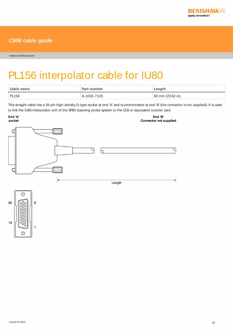
PL156 interpolator cable for IU80Cable name Part number Length
PL156 A-1016-7129 60 mm (23.62 in)
This straight cable has a 26-pin high-density D-type socket at end 'A' and is unterminated at end 'B' (the connector is not supplied). It is used
to link the IU80 interpolator unit of the SP80 scanning probe system to the CC6 or equivalent counter card.
CMM cable guide
www.renishaw.com
Issued 02 2020 56

End 'A' Wire Signal End 'A' Wire Signal
1 Red X axis log A 15 Pink Y axis log A
2 Not connected - 16 Turquoise Y axis log B
3 White / blue IU80 reset 17 Grey Y axis log B
4 Blue IU80 error 18 Not connected -
5 Not connected Not connected 19 Not connected -
6 Green Z axis log 20 Red / blue Z axis log A
7 Not connected - 21 Green / red Z axis log A
8 Yellow / blue Probe present 22 Yellow / red Z axis log B
9 Yellow Green LED off 23 White / red + 9 V to + 18 V
10 White Red LED on 24 Black / red + 5 V
11 Black X axis log A 25 Brown / red 0 V
12 Brown X axis log B 26 Not connected -
13 Violet X axis log B Shell Screen Screen
14 Orange Y axis log A
CMM cable guide
www.renishaw.com
Issued 02 2020 57

PL157 machine cable adaptor for IU80Cable name Part number Length
PL157 A-1016-7132 230 mm (9.06 in)
This straight cable has a 15‐pin high‐density D‐type socket at end ‘A' and an in‐line 14‐pin LEMO plug at end ‘B'. It is used to electricallyconnect the SP80 scanning probe to the CMM quill.
End 'A' End 'B' Wire Signal
1 13 Orange V reference
2 4 Thick white 0 V
3 - - Not connected
4 12 Grey Cos Z
5 2 Red Cos Y
6 8 Yellow Cos X
7 10 Thick brown + 9 V to + 18 V
8 - - Not connected
9 14 Pink Probe present
10 3 Black Green LED on
11 5 Brown Red LED on
12 9 Violet Sin Z
13 1 Blue Sin Y
14 6 Green Sin X
15 - - Not connected
- 11 Inner screen Inner screen
Shell Shell Shell Screen
CMM cable guide
www.renishaw.com
Issued 02 2020 58

PL158 interpolator cable for IU80Cable name Part number Length
PL158 A-1016-7133 1 m (39.37 in)
This straight cable has a 26-pin high-density D-type socket at end 'A' and a 26-pin D-type plug at the other end. It is used to link the IU80
interpolator unit of the SP80 scanning probe system to the CC5, CC6 or equivalent counter card.
CMM cable guide
www.renishaw.com
Issued 02 2020 59

End 'A' Wire End 'B' End 'A' Wire End 'B'
1 Red 1 15 Yellow / red 15
2 Not connected - 16 White / red 16
3 Green 9 17 Black / red 17
4 Yellow 4 18 Brown / red 25
5 White 5 19 Yellow / blue 19
6 Black 6 20 White / blue 20
7 Not connected - 21 Black / blue 21
8 Violet 2 22 Orange / blue 22
9 Orange 7 23 Yellow / green 24
10 Pink 8 24 White / green 23
11 Turquoise 11 25 Not connected -
12 Grey 12 26 Blue 26
13 Blue / red 13 Shell Screen Shell
14 Green / red 14
CMM cable guide
www.renishaw.com
Issued 02 2020 60

PL163, PL164 and PL171 dedicated MCU
cablesCable name Part number Length
PL163 A-1016-8098 5 m (196.85 in)
PL164 A-1016-8099 10 m (393.7 in)
PL171 A-1016-8100 20 m (787.4 in)
These straight cables have a 9-pin D-type socket at end 'A' with a 9-pin D-type plug at end 'B' and are connected pin-to-pin. They are used as
dedicated cables for the Renishaw MCU joystick units, signal information is shown below.
WARNING: These cables are not suitable for Renishaw PICS cables as pin 5 is not connected.
End 'A' and 'B' Wire MCU1 signal
1 Yellow Ground
2 Grey Rx (receive) B
3 Pink RX (receive) A
4 Blue TX (transmit) A
5 Not connected Reserved
6 Green +15 V
7 Brown TX (transmit) B
8 White E-STOP B
9 Red E-STOP A
Shell Screen Screen
CMM cable guide
www.renishaw.com
Issued 02 2020 61
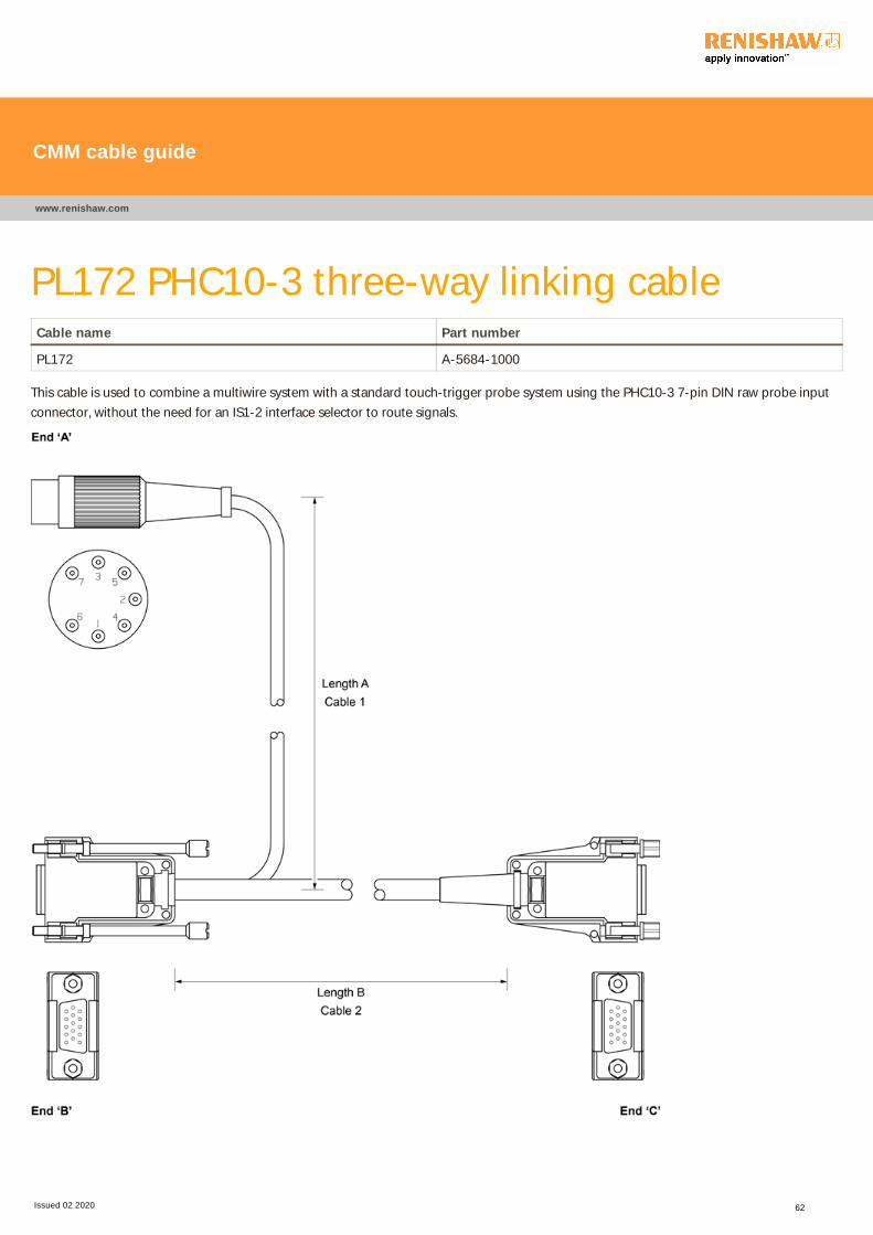
PL172 PHC10-3 three-way linking cableCable name Part number
PL172 A-5684-1000
This cable is used to combine a multiwire system with a standard touch-trigger probe system using the PHC10-3 7-pin DIN raw probe input
connector, without the need for an IS1-2 interface selector to route signals.
CMM cable guide
www.renishaw.com
Issued 02 2020 62

End 'B' Wire End 'A' and 'C'
1 White / brown stripe C1
3 Black (cable 2) A4 - Black (cable 1)
C3
4 Red C4
5 Orange C5
6 Grey C6
7 White C7
8 White / black stripe C8
9 Co-axial outer C9
10 Co-axial core C10
11 Violet C11
12 Blue C12
14 Green C14
15 Yellow C15
A5 - Brown (cable 1)
C13 - Brown (cable 2)
CMM cable guide
www.renishaw.com
Issued 02 2020 63
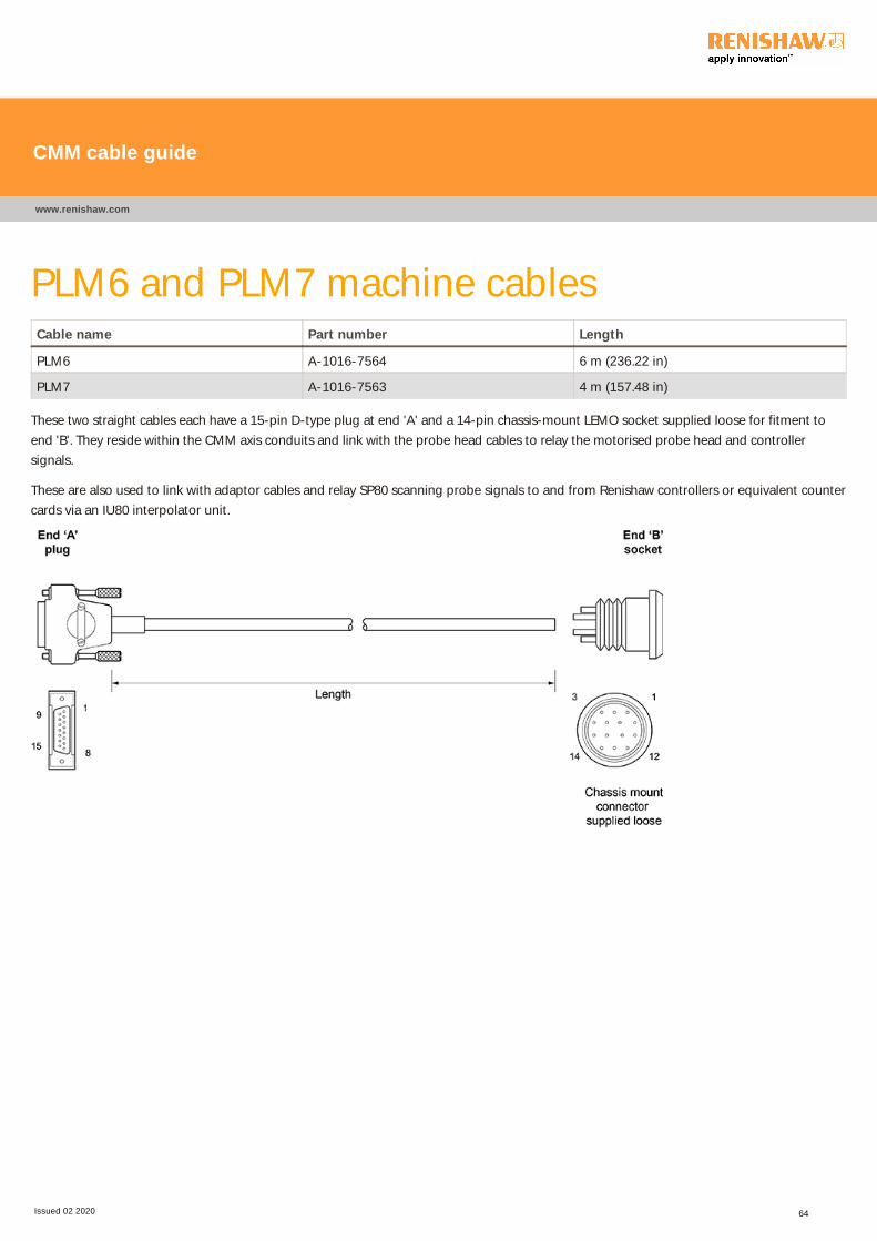
PLM6 and PLM7 machine cablesCable name Part number Length
PLM6 A-1016-7564 6 m (236.22 in)
PLM7 A-1016-7563 4 m (157.48 in)
These two straight cables each have a 15-pin D-type plug at end 'A' and a 14-pin chassis-mount LEMO socket supplied loose for fitment to
end 'B'. They reside within the CMM axis conduits and link with the probe head cables to relay the motorised probe head and controller
signals.
These are also used to link with adaptor cables and relay SP80 scanning probe signals to and from Renishaw controllers or equivalent counter
cards via an IU80 interpolator unit.
CMM cable guide
www.renishaw.com
Issued 02 2020 64

End 'A' End 'B' Wire Signal
1 2 Brown Ground sense
2 7 Turquoise Head present
3 12 Yellow A axis feedback
4 4 Green / red Ground 0 V
5 14 Grey Motor probe switch
6 3 Violet DC reference 12 V
7 9 Pink B axis motor / probe contact
8 13 Blue LED and datum
- - - -
10 5 Green Locking motor 8 V dc nominal
11 8 White A axis motor 12 V dc nominal
12 6 Red A axis motor 12 V dc nominal
- - - -
14 2 Black B axis
15 10 Orange B axis motor / probe contact
'A' body 11* Braid Screen
* NOTE: Separate 7 to 14 strands of braid and cover with sleeving, connect to end 'B' pin 11. Separate remaining strands and trap
evenly under collet and split insert carrier.
CMM cable guide
www.renishaw.com
Issued 02 2020 65

PLM8 and PLM9 machine cablesCable name Part number Length
PLM8 A-1016-7677 6 m (236.22 in)
PLM9 A-1016-7678 4 m (157.48 in)
These two straight cables each have a 15-pin D-type plug at end 'A' and a 14-pin in-line LEMO socket at end 'B'. They reside within the CMM
axis conduits and link with the probe head cables to relay the motorised probe head and controller signals.
These are also used to link with adaptor cables and relay SP80 scanning probe signals to and from Renishaw controllers or equivalent counter
cards via an IU80 interpolator unit.
CMM cable guide
www.renishaw.com
Issued 02 2020 66

End 'A' End 'B' Wire Signal
1 2 Brown Ground sense
2 7 Turquoise Head present
3 12 Yellow A axis feedback
4 4 Green / red Ground 0 V
5 14 Grey Motor probe switch
6 3 Violet DC reference 12 V
7 9 Pink B axis motor / probe contact
8 13 Blue LED and datum
- - - -
10 5 Green Locking motor 8 V dc nominal
11 8 White A axis motor 12 V dc nominal
12 6 Red A axis motor 12 V dc nominal
- - - -
14 1 Black B axis
15 10 Orange B axis motor / probe contact
'A' body 11* Braid Screen
* NOTE: Separate 7 to 14 strands of braid and cover with sleeving, connect to end 'B' pin 11. Separate remaining strands and trap
evenly under collet and split insert carrier.
CMM cable guide
www.renishaw.com
Issued 02 2020 67

SPA2 to UCC2 emergency stop cablePart number Length
A-5121-0062 750 mm (29.53 in)
This straight cable has a 9-pin D-type plug at end 'A' and a 25-pin D-type plug at end 'B'. It is used to relay emergency stop (E-STOP) signals
between the SPA2 servo power amplifier and UCC2 universal controller.
End 'A' End 'B' Signal
3 25 Ground 24 V
6 6 E-STOP 'A'
7 7 E-STOP 'B'
8 4 Engage
9 3 E-STOP 'C'
Shell Screen Shell
CMM cable guide
www.renishaw.com
Issued 02 2020 68
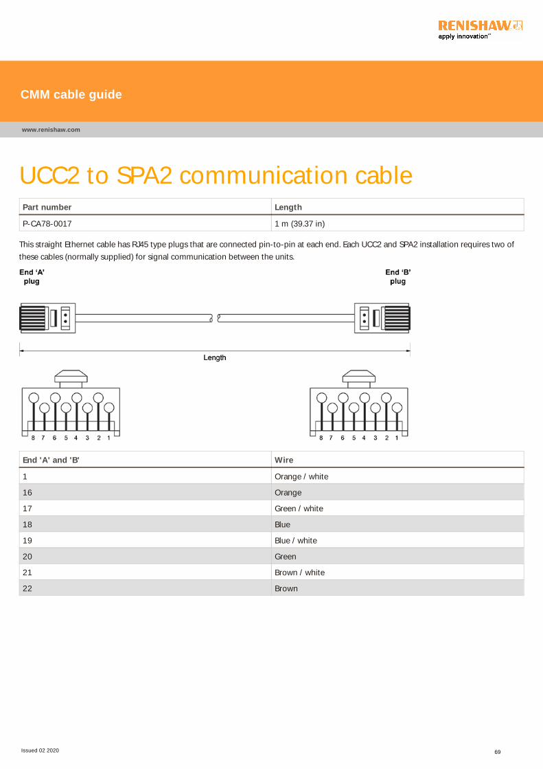
UCC2 to SPA2 communication cablePart number Length
P-CA78-0017 1 m (39.37 in)
This straight Ethernet cable has RJ45 type plugs that are connected pin-to-pin at each end. Each UCC2 and SPA2 installation requires two of
these cables (normally supplied) for signal communication between the units.
End 'A' and 'B' Wire
1 Orange / white
16 Orange
17 Green / white
18 Blue
19 Blue / white
20 Green
21 Brown / white
22 Brown
CMM cable guide
www.renishaw.com
Issued 02 2020 69

UCC2 to SPA2 6th axis cablePart number Length
P-CA82-0013 360 mm (14.17 in)
This straight Ethernet cable has RJ45 type plugs that are connected pin-to-pin at each end. Each 6th axis installation requires one of these
cables for the additional signal communications between units.
End 'A' and 'B' Wire
1 Orange / white
9 Orange
10 Green / white
11 Blue
12 Blue / white
13 Green
14 Brown / white
15 Brown
CMM cable guide
www.renishaw.com
Issued 02 2020 70

CMM PC to UCC2 communications cablePart number Length
P-CA81-0002 5 m (196.85 in)
This straight Ethernet cable has RJ45 type plugs that electrically ‘cross‐over' at each end, therefore they are NOT pin‐to‐pin. One of thesecables is required for communication between the CMM PC and the UCC2 controller.
End 'A' Wire End 'B'
1 Light green 3
2 Green 6
3 White 1
4 Blue 4
5 Light blue 5
6 Orange 2
7 Light brown 7
8 Brown 8
CMM cable guide
www.renishaw.com
Issued 02 2020 71

Scale adaptor cablePart number Length
A-1333-0183 260 mm (10.24 in)
This straight cable has a 15-pin D-type socket at end 'A' and has a 15-pin high-density D-type plug at end 'B'. This custom product cable is
used where scale interpolators are connected or where machine cabling is compatible for its use.
End 'A' and 'B' Wire End 'A' and 'B' Wire
1 Red 9 Orange
2 Blue 10 Pink
3 Green 11 Turquoise
4 Yellow 12 Grey
5 White 13 Red / blue
6 Black 14 Red / green
7 Brown 15 Red / yellow
8 Violet Shell Outer screen
CMM cable guide
www.renishaw.com
Issued 02 2020 72

PHC10 to UCC RS232 comms cablePart number Length
A-5567-1622 50 cm (19.7 in)
This straight cable has a 25-pin D-type socket at end 'A' and a 9-pin D-type socket at end 'B'. It is used to connect PHC10 to UCC.
End 'A' End 'B' Wire Signal
2 2 White TX-RX
3 3 Red RX-TX
4 8 Green RTS-CTS
5 7 Orange CTS-RTS
7 5 Black Ground
Backshell Backshell Screen Screen
CMM cable guide
www.renishaw.com
Issued 02 2020 73

Dual SPA3 E-STOP cable assembly and
external E-STOPPart number Length 1 Length 2
A-5629-0090 50 cm (19.7 in) 17 cm (6.7 in)
This straight cable has a 25-pin D-type plug at end 'A', a 9-pin D-type socket at end 'B', a 9-pin D-type socket at end 'C' and a 9-pin D-type
plug at end 'D'. It is used to connect two SPA3s to UCC2, UCC2-2, UCC T3 PLUS, UCC T5 or UCC S3, and an external E-STOP.
CMM cable guide
www.renishaw.com
Issued 02 2020 74

End 'A'
UCC2 25W D plug
PCB
Colour Signal End 'B'
SPA3 (M) 9W D
socket
End 'C'
SPA3 (S) 9W D
socket
End 'D'
External E-STOP 9W
D plug
1 White A2 6 - -
2 Green Reset 9 - -
2 Green Reset - 9 -
2 Green Reset B - - 9
3 Grey B1 4 - -
3 Grey B1 - 4 -
3 Yellow B2 7 - -
3 Yellow B2 - 7 -
3 Yellow Reset A - - 5
4 White E-STOP A - - 6
5 Brown E-STOP B - - 7
6 Brown GND 3 - -
6 Brown GND - 3 -
CMM cable guide
www.renishaw.com
Issued 02 2020 75

High power option E-STOP cablePart number Length 1 Length 2
A-5208-0011 97 cm (38.2 in) 76 cm (29.9 in)
This straight cable has a a 25-pin D-type plug at end 'A' and a 9-pin D-type plug at ends 'B' and 'C'. It is used to connect two SPA2-2s to a
UCC2-2 controller.
End 'A'
25W D
Colour Signal End 'B'
9W D
End 'C'
9W D
25 Grey GND 24 V 3 3
6 Brown E-STOP 'A'; 6 n/c
7 Yellow E-STOP 'B' 7 7
4 White Engage 8 8
3 Green E-STOP 'C' 9 9
Shell Screen Shell Shell
CMM cable guide
www.renishaw.com
Issued 02 2020 76

High-speed communications cable - crimped
endsPart number Length
A-5669-0090 10 m (393.7 in)
A-5669-0091 15 m (590.6 in)
A-5669-0092 20 m (787.4 in)
A-5669-0093 25 m (984.3 in)
These straight cables are pre-crimped for easy fitment to the 15-pin high-density D-type socket at end 'A' and a 15-pin D-type plug at end 'B'.
They are used to connect REVO-2 or PH20 to the controller.
CMM cable guide
www.renishaw.com
Issued 02 2020 77

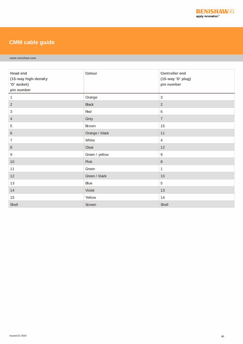
Head end
(15-way high-density
'D' socket)
pin number
Colour Controller end
(15-way 'D' plug)
pin number
1 Orange 3
2 Black 2
3 Red 6
4 Grey 7
5 Brown 15
6 Orange / black 11
7 White 4
8 Clear 12
9 Green / yellow 9
10 Pink 8
11 Green 1
12 Green / black 10
13 Blue 5
14 Violet 13
15 Yellow 14
Shell Screen Shell
CMM cable guide
www.renishaw.com
Issued 02 2020 78

High-speed communications cable (orange)Part number Length
A-5669-0015 15 m (590.1 in)
A-5759-0025 25 m (984.3 in)
This straight cable has a 15-pin high-density D-type socket at end 'A' and a 15-pin D-type plug at end 'B'. It is used to connect REVO-2 or
PH20 to the controller.
CMM cable guide
www.renishaw.com
Issued 02 2020 79
Head end
(15-way high-density
'D' socket)
pin number
Colour Controller end
(15-way 'D' plug)
pin number
1 Orange 3
2 Black 2
3 Red 6
4 Grey 7
5 Brown 15
6 Orange / black 11
7 White 4
8 Clear 12
9 Green / yellow 9
10 Pink 8
11 Green 1
12 Green / black 10
13 Blue 5
14 Violet 13
15 Yellow 14
Shell Screen Shell
CMM cable guide
www.renishaw.com
Issued 02 2020 80

High speed communications cable - cable only
Part number Length
A-5669-0045 250 m
A-5759-0050 500 m
This straight cable is used to connect REVO or PH20 to the controller. It is supplied by the drum to be cut to length as required.
Minimum bend radius / life
Static: 30 mm
Dynamic: 40 mm / 1,000,000 cycles
CMM cable guide
www.renishaw.com
Issued 02 2020 81
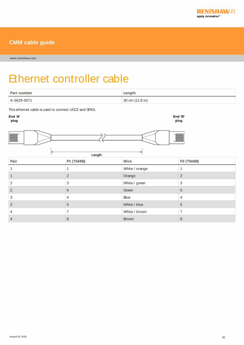
Ethernet controller cablePart number Length
A-5629-0071 30 cm (11.8 in)
This ethernet cable is used to connect UCC2 and SPA3.
Pair P1 (T568B) Wire P2 (T568B)
1 1 White / orange 1
1 2 Orange 2
2 3 White / green 3
2 6 Green 6
3 4 Blue 4
3 5 White / blue 5
4 7 White / brown 7
4 8 Brown 8
CMM cable guide
www.renishaw.com
Issued 02 2020 82

Y-connector cablesThis adaptor kit contains two Y-connector cables and is used to connect REVO-2 to two 'grey' REVO cables.
Head flex comms cable adaptor
Part number Length 1 Length 2
A-3065-0150 230 cm (90.6 in) 140 cm (55.1 in)
CMM cable guide
www.renishaw.com
Issued 02 2020 83

Controller flex comms cable adaptor
Part number Length
A-3065-0160 510 cm (200.79 in)
CMM cable guide
www.renishaw.com
Issued 02 2020 84

End 'A' Function Colour Cable
1 DOWNLINK + Blue POWER & COMMS
2 + V White POWER & COMMS
3 UPLINK + Green POWER & COMMS
4 0 V Black (white) POWER & COMMS
5 D_MOTOR_0 Red MOTOR
6 V + Red POWER & COMMS
7 E_MOTOR_2 Blue MOTOR
8 E_MOTOR_1 Black (green) MOTOR
9 INNER SHIELD - -
10 DOWNLINK - Black (blue) POWER & COMMS
11 UPLINK - Black (green) POWER & COMMS
12 V + Black (red) POWER & COMMS
13 D_MOTOR_1 Black (red) MOTOR
14 D_MOTOR_2 White MOTOR
15 E_MOTOR_0 Green MOTOR
Shell Chassis Braided screen BOTH CABLES
CMM cable guide
www.renishaw.com
Issued 02 2020 85

Y-connector cablesThis adaptor kit contains two Y-connector cables and is used to connect REVO(1) to a single orange high-speed communications cable.
REVO universal cable adaptor
Part number Length
A-3065-0050 160 cm (62.99 in)
CMM cable guide
www.renishaw.com
Issued 02 2020 86

PCI / SPA universal cable adaptor
Part number Length
A-3065-0160 510 cm (200.79 in)
CMM cable guide
www.renishaw.com
Issued 02 2020 87
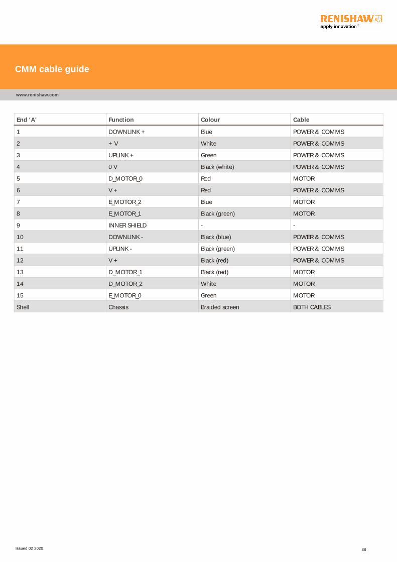
End 'A' Function Colour Cable
1 DOWNLINK + Blue POWER & COMMS
2 + V White POWER & COMMS
3 UPLINK + Green POWER & COMMS
4 0 V Black (white) POWER & COMMS
5 D_MOTOR_0 Red MOTOR
6 V + Red POWER & COMMS
7 E_MOTOR_2 Blue MOTOR
8 E_MOTOR_1 Black (green) MOTOR
9 INNER SHIELD - -
10 DOWNLINK - Black (blue) POWER & COMMS
11 UPLINK - Black (green) POWER & COMMS
12 V + Black (red) POWER & COMMS
13 D_MOTOR_1 Black (red) MOTOR
14 D_MOTOR_2 White MOTOR
15 E_MOTOR_0 Green MOTOR
Shell Chassis Braided screen BOTH CABLES
CMM cable guide
www.renishaw.com
Issued 02 2020 88

For worldwide contact details,please visit our main website at
www.renishaw.com/contact
Renishaw plc
New Mills, Wotton-under-Edge,
Gloucestershire, GL12 8JR
United Kingdom
T +44 (0)1453 524524
F +44 (0)1453 524901
www.renishaw.com/cmmsupport
Issued 02 2020


