Embed Size (px)
Citation preview
DQS-00006-D
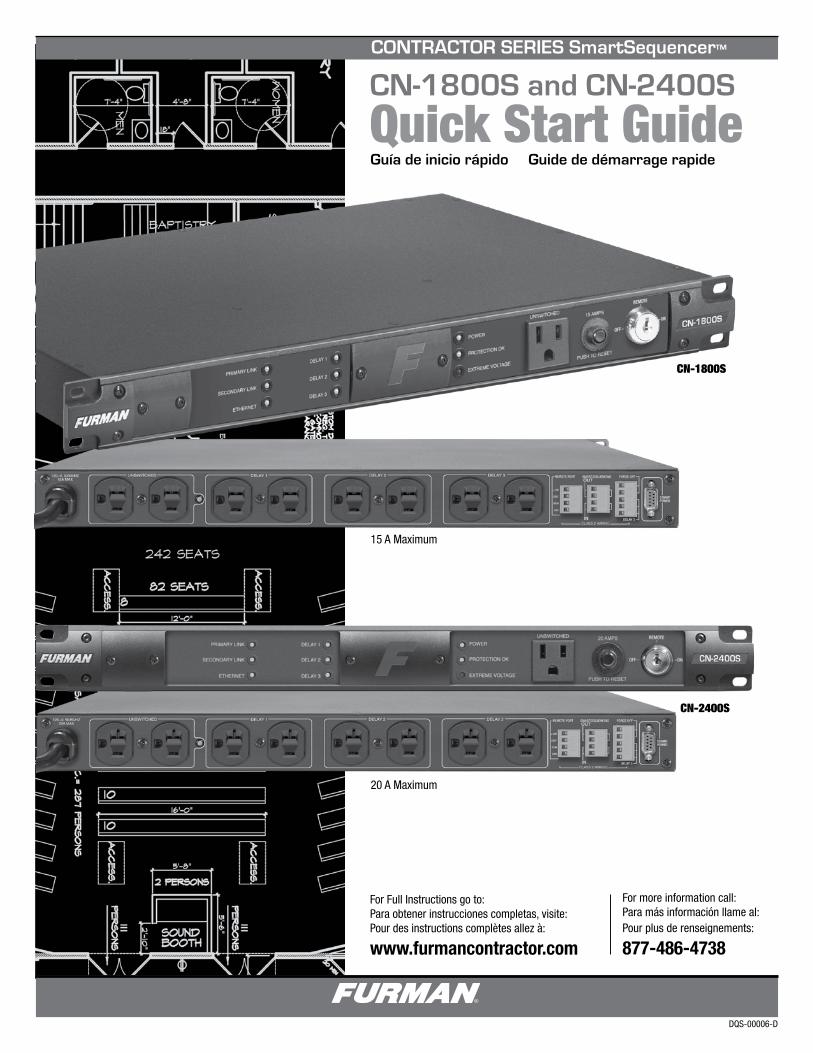
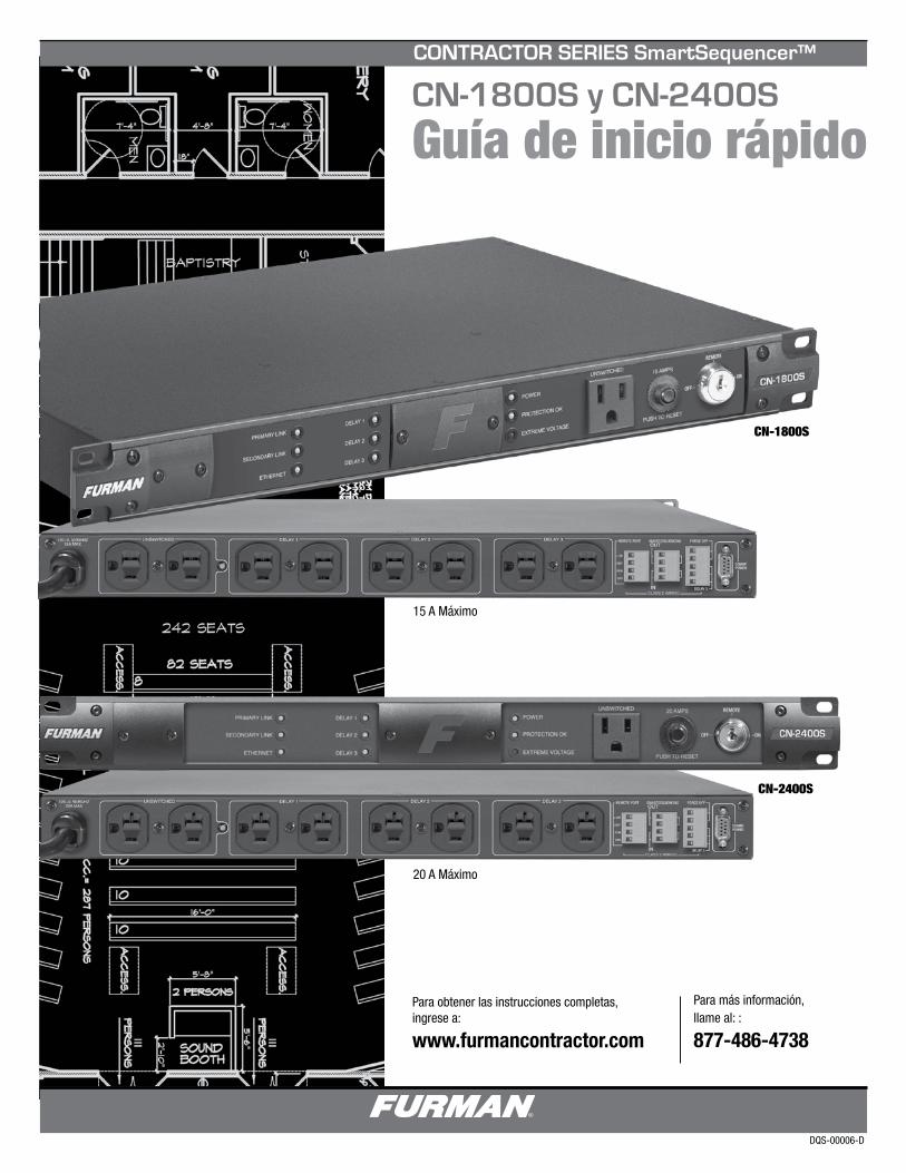
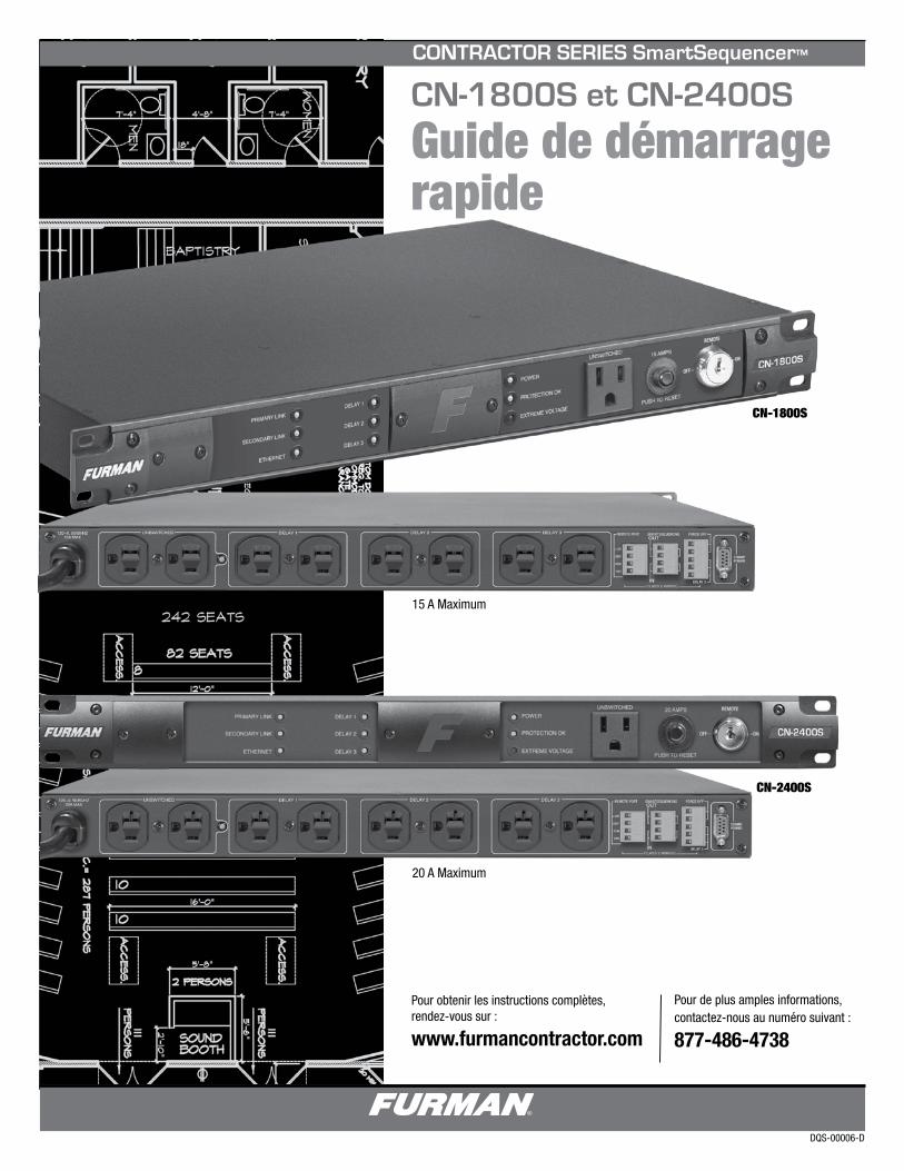
CN-1800S and CN-2400S
Quick Start Guide
CN-1800S
CN-2400S
For Full Instructions go to: Para obtener instrucciones completas, visite:Pour des instructions complètes allez à:
www.furmancontractor.com
Guía de inicio rápido Guide de démarrage rapide
15 A Maximum
20 A Maximum
For more information call: Para más información llame al:Pour plus de renseignements:
877-486-4738
CONTRACTOR SERIES SmartSequencer™
1
Multi-Color LED Indicators for status.
Forced Off immediate shutdown for safety and fire ordinance compliance.
9 outlets (15 Amp CN-1800S)
8 outlets (20 Amp CN-2400S) with one 15 Amp outlet.
10 ft. Power Cord 15 Amp (CN-1800S) or 20 Amp (CN-2400S).
15 Year Limited Product Warranty See actual warranty documentation online at www.furmancontractor.com
1. Please read and follow all instructions.
2. Keep these instructions.
3. Heed all warnings.
4. WARNING: This device is intended for indoor use only. Do not use this device near water. To reduce the risk of fire or electric shock, do not expose this device to rain or moisture.
5. CAUTION: Functioning Always On recep-tacles. To reduce risk of shock, please disconnect the CN-1800S / CN-2400S Sequencer from AC power before servicing any equipment connected to the CN-1800S / CN-2400S Sequencer.
6. Clean only with dry cloth.
7. CAUTION: Do not install near any heat sources such as radiators, heat registers, stoves, or other equipment that may produce heat.
13. Do not defeat the safety purpose of the polarized plug. A polarized plug has two blades, with one wider than the other. The wide blade is provided for your safety. If the provided plug does not fit into your outlet, consult an electrician for replacement of the obsolete outlet. (*See next page for 20A plug)
14. Do not defeat the safety purpose of the grounding prong. A ground type plug has two blades and a third grounding prong. The third prong is provided for your safety. If the provided plug does not fit into your outlet, consult an elec-trician for replacement of the obsolete outlet.
15. WARNING: This device must be connected to an AC outlet with a protective earth ground connection.
SmartSequencing™ technology allows large complex A/V systems to be safely power cycled on and off with a simple key turn or press of a button.
Series Multi-Stage Protection (SMP) ensures zero downtime for mission critical installations by safely eliminating dangerous surges and spikes. Extreme Voltage Shutdown (EVS) with auto reset safeguards against catastrophic under and over voltage conditions.
Linear Filtering Technology (LiFT)ensures maximum equipment performance by reducing AC noise in a linear fashionacross a wide bandwidth.
Remote Access (RS-232) compatibility with programming provides integration with various control system platforms.
Security features include a key switch to prevent unauthorized operation and cover shields to prevent tampering with switch settings.
8. Protect the power cord from being walked on or pinched, particularly at plugs, convenience receptacles, and the point where they exit the device.
9. WARNING: The DE-9 RS-232 communica-tions port provides power for Furman accessories (e.g. BB-RS232). Please verify pin assignment and protocol before connecting any other manu-facturer’s device to this port.
10. Please, only use accessories specified by the manufacturer.
11. Refer all servicing to qualified personnel. Servicing is required when the unit has been damaged in anyway or fails to operate.
12. WARNING: Do not use power cord as the main power disconnect. The device is intended for AC power sequencing.
FEATURES
IMPORTANT SAFETY INSTRUCTIONS
INTRODUCTION
Congratulations and thank you for choosing a Furman Contractor Series Power Conditioner/Sequencer. Furman CN-Series offers maximum protection from AC line hazards encountered by delicate analog and digital pro audio and video
equipment. Additionally, this conditioner features Furman’s exclusive SmartSequencing which defines a new level of Power Management. A Furman unit incorporating SmartSequencing streamlines installations from conception to finish.
We assure you this Furman Contractor Series Conditioner/Sequencer will perform as intended and provide many years of operation.
PRIMARY LINK
SECONDARY LINK
ETHERNET
DELAY 1
DELAY 2
DELAY 3
POWER
PROTECTION OK
EXTREME VOLTAGE
UNSWITCHED 15 AMPS
PUSH TO RESET
ON
OFF
REMOTE
PRIMARY LINK
SECONDARY LINK
ETHERNET
DELAY 1
DELAY 2
DELAY 3
POWER
PROTECTION OK
EXTREME VOLTAGE
UNSWITCHED 20 AMPS
PUSH TO RESET
ON
OFF
REMOTE
PRIMARY LINK
SECONDARY LINK
ETHERNET
DELAY 1
DELAY 2
DELAY 3
POWER
PROTECTION OK
EXTREME VOLTAGE
UNSWITCHED 15 AMPS
PUSH TO RESET
ON
OFF
REMOTE
PRIMARY LINK
SECONDARY LINK
ETHERNET
DELAY 1
DELAY 2
DELAY 3
POWER
PROTECTION OK
EXTREME VOLTAGE
UNSWITCHED 20 AMPS
PUSH TO RESET
ON
OFF
REMOTE
COMM/POWER
UNSWITCHED DELAY 1 DELAY 2 DELAY 3120~V, 50/60/HZ15A MAX
FORCE OFF
DELAY 3
+12V
STAT
REM
GND
NO
NC
C
FO
FOP
P
S
S
OUT
IN
SMARTSEQUENCINGREMOTE PORT
CLASS 2 WIRING
COMM/POWER
UNSWITCHED DELAY 1 DELAY 2 DELAY 3120~V, 50/60/HZ15A MAX
FORCE OFF
DELAY 3
+12V
STAT
REM
GND
NO
NC
C
FO
FOP
P
S
S
OUT
IN
SMARTSEQUENCINGREMOTE PORT
CLASS 2 WIRING
www.furmancontractor.com • 877-486-4738 2
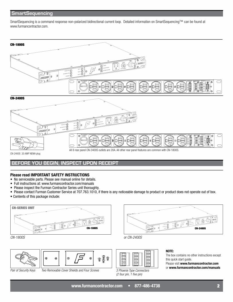
Please read IMPORTANT SAFETY INSTRUCTIONS• No serviceable parts. Please see manual online for details.• Full instructions at: www.furmancontractor.com/manuals• Please inspect the Furman Contractor Series unit thoroughly.• Please contact Furman Customer Service at 707.763.1010, if there is any noticeable damage to product or product does not operate out of box.• Contents of this package include:
CN-SERIES UNIT
CN-2400S
CN-1800S orCN-2400S
PairofSecurityKeys TwoRemovableCoverShieldsandFourScrews
CN-2400S
CN-1800S
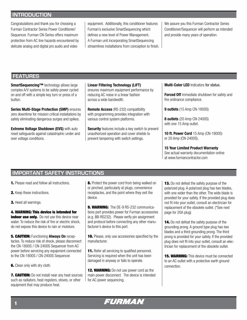
All 8 rear panel CN-2400S outlets are 20A. All other rear panel features are common with CN-1800S.
3PhoenixTypeConnectors(2fourpin,1fivepin)
BEFORE YOU BEGIN, INSPECT UPON RECEIPT
CN-2400S 20 AMP NEMA plug
SmartSequencing
SmartSequencing is a command response non-polarized bidirectional current loop. Detailed information on SmartSequencing™ can be found at www.furmancontractor.com.
CN-1800S
NOTE:The box contains no other instructions except this quick start guide. Please visit www.furmancontractor.com or www.furmancontractor.com/manuals
PRIMARY LINK
SECONDARY LINK
ETHERNET
DELAY 1
DELAY 2
DELAY 3
POWER
PROTECTION OK
EXTREME VOLTAGE
UNSWITCHED
START
SEQUENCE
15 AMPS
PUSH TO RESET
ONOFF
REMOTE
DLYADJ
1 2 3 4 5 6 7 8 9
1M 1 2 3 4 5
2M 4M N.O.N.C.
12V ON12V OFF
GNDON
MOMMNT
PRISEC
EVS AUTOMANUAL
6 7 8 9
1 2 3 4 5 6 7 8 9
ONDLYADJ
PRIMARY LINK
SECONDARY LINK
ETHERNET
DELAY 1
DELAY 2
DELAY 3
POWER
PROTECTION OK
EXTREME VOLTAGE
UNSWITCHED
START
SEQUENCE
15 AMPS
PUSH TO RESET
ONOFF
REMOTE
DLYADJ
1 2 3 4 5 6 7 8 9
1M 1 2 3 4 5
2M 4M N.O.N.C.
12V ON12V OFF
GNDON
MOMMNT
PRISEC
EVS AUTOMANUAL
6 7 8 9
PRIMARY LINK
SECONDARY LINK
ETHERNET
DELAY 1
DELAY 2
DELAY 3
POWER
PROTECTION OK
EXTREME VOLTAGE
UNSWITCHED
START
SEQUENCE
15 AMPS
PUSH TO RESET
ONOFF
REMOTE
DLYADJ
1 2 3 4 5 6 7 8 9
1M 1 2 3 4 5
2M 4M N.O.N.C.
12V ON12V OFF
GNDON
MOMMNT
PRISEC
EVS AUTOMANUAL
6 7 8 9
PRIMARYLINK
SECONDARY LINK
ETHERNET
DELAY 1
DELAY 2
DELAY 3
POWER
PROTECTION OK
EXTREME VOLTAGE
UNSWITCHED
START
SEQUENCE
20 AMPS
PUSH TO RESET
ONOFF
REMOTE1M 2M
12V ON12V OFF
GNDON
MOMMNT
EVS AUTO MANUAL
1 2 3 4 5 6 7 8 9
DLYADJ
4M N.O. N.C.
PRISEC
1 2 3 4 5 6 7 8 9
PRIMARY LINK
SECONDARY LINK
ETHERNET
DELAY 1
DELAY 2
DELAY 3
POWER
PROTECTION OK
EXTREME VOLTAGE
UNSWITCHED
START
SEQUENCE
15 AMPS
PUSH TO RESET
ONOFF
REMOTE
DLYADJ
1 2 3 4 5 6 7 8 9
1M 1 2 3 4 5
2M 4M N.O.N.C.
12V ON12V OFF
GNDON
MOMMNT
PRISEC
EVS AUTOMANUAL
6 7 8 9
1 2 3 4 5 6 7 8 9
ONDLYADJ
DLYADJ
1M 1 2 3 4 5
2M 4M N.O.N.C.
12V ON12V OFF
GNDON
MOMMNT
PRISEC
EVS AUTOMANUAL
6 7 8 9 ON
OFF
Indicates unit is receiving AC power and “Unswitched” outlets are active.
Normally lit, dims or will not illuminate if surge protection has been compromised.
3
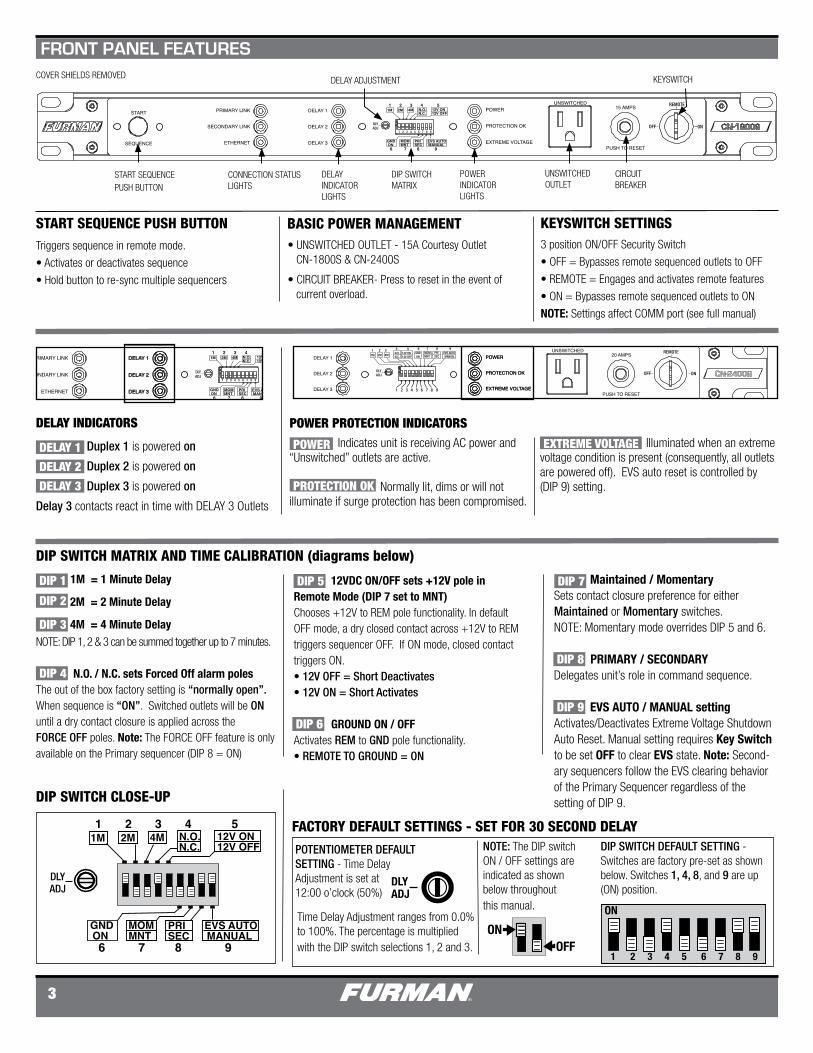
START SEQUENCE PUSH BUTTON
CONNECTION STATUS LIGHTS
DELAY INDICATORLIGHTS
DIP SWITCH MATRIX
POWER INDICATORLIGHTS
UNSWITCHED OUTLET
CIRCUIT BREAKER
KEYSWITCHCOVER SHIELDS REMOVED
Time Delay Adjustment ranges from 0.0% to 100%. The percentage is multiplied with the DIP switch selections 1, 2 and 3.
1M = 1 Minute Delay
2M = 2 Minute Delay
4M = 4 Minute DelayNOTE: DIP 1, 2 & 3 can be summed together up to 7 minutes.
N.O. / N.C. sets Forced Off alarm polesThe out of the box factory setting is “normally open”. When sequence is “ON”. Switched outlets will be ON until a dry contact closure is applied across the FORCE OFF poles. Note: The FORCE OFF feature is only available on the Primary sequencer (DIP 8 = ON)
DIP SWITCH CLOSE-UP
DELAY ADJUSTMENT
FACTORY DEFAULT SETTINGS - SET FOR 30 SECOND DELAY
POTENTIOMETER DEFAULT SETTING - Time Delay Adjustment is set at 12:00 o’clock (50%)
DIP SWITCH DEFAULT SETTING - Switches are factory pre-set as shown below. Switches 1, 4, 8, and 9 are up (ON) position.
Maintained / MomentarySets contact closure preference for either Maintained or Momentary switches.NOTE: Momentary mode overrides DIP 5 and 6. PRIMARY / SECONDARY Delegates unit’s role in command sequence.
EVS AUTO / MANUAL setting Activates/Deactivates Extreme Voltage Shutdown Auto Reset. Manual setting requires Key Switch to be set OFF to clear EVS state. Note: Second-ary sequencers follow the EVS clearing behavior of the Primary Sequencer regardless of the setting of DIP 9.
DIP SWITCH MATRIX AND TIME CALIBRATION (diagrams below)
POWER PROTECTION INDICATORS
Duplex 1 is powered on
Duplex 2 is powered on
Duplex 3 is powered on
Delay 3 contacts react in time with DELAY 3 Outlets
Illuminated when an extreme voltage condition is present (consequently, all outlets are powered off). EVS auto reset is controlled by (DIP 9) setting.
12VDC ON/OFF sets +12V pole in Remote Mode (DIP 7 set to MNT)Chooses +12V to REM pole functionality. In default OFF mode, a dry closed contact across +12V to REM triggers sequencer OFF. If ON mode, closed contact triggers ON.• 12V OFF = Short Deactivates • 12V ON = Short Activates GROUND ON / OFFActivates REM to GND pole functionality. • REMOTE TO GROUND = ON
DIP 1
DIP 2
DIP 3
DIP 4
DIP 5
DIP 6
DIP 7
DIP 8
DIP 9
DELAY INDICATORS
POWER
PROTECTION OK
EXTREME VOLTAGE
FRONT PANEL FEATURES
START SEQUENCE PUSH BUTTONTriggers sequence in remote mode.
• Activates or deactivates sequence
• Hold button to re-sync multiple sequencers
KEYSWITCH SETTINGS3 position ON/OFF Security Switch
• OFF = Bypasses remote sequenced outlets to OFF
• REMOTE = Engages and activates remote features
• ON = Bypasses remote sequenced outlets to ON
NOTE: Settings affect COMM port (see full manual)
BASIC POWER MANAGEMENT• UNSWITCHED OUTLET - 15A Courtesy Outlet CN-1800S & CN-2400S
• CIRCUIT BREAKER- Press to reset in the event of current overload.
DELAY 1
DELAY 2
DELAY 3
NOTE: The DIP switch ON / OFF settings are indicated as shown below throughout this manual.
COMM/POWER
UNSWITCHED DELAY 1 DELAY 2 DELAY 3120~V, 50/60/HZ15A MAX
FORCE OFF
DELAY 3
+12V
STAT
REM
GND
NO
NC
C
FO
FOP
P
S
S
OUT
IN
SMARTSEQUENCINGREMOTE PORT
CLASS 2 WIRING
COMM/POWER
5432
6789
1
ACCESSORY POWER ONLY(NEGATIVE 12VDC RETURN)RECEIVE DATATRANSMIT DATAACCESSORY POWER ONLYSIGNAL GROUNDACCESSORY POWER ONLYREQUEST TO SENDCLEAR TO SENDACCESSORY POWER ONLY(POSITIVE 12V)
PIN NO. 1
2 3 4 5 6 7 8 9
COMM/POWER
FORCE OFF
DELAY 3
+12V
STAT
REM
GND
NO
NC
C
FO
FOP
P
S
S
OUT
IN
SMARTSEQUENCINGREMOTE PORT
CLASS 2 WIRING
COMM/POWER
FORCE OFF
DELAY 3
+12V
STAT
REM
GND
NO
NC
C
FO
FOP
P
S
S
OUT
IN
SMARTSEQUENCINGREMOTE PORT
CLASS 2 WIRING
COMM/POWER
FORCE OFF
DELAY 3
+12V
STAT
REM
GND
NO
NC
C
FO
FOP
P
S
S
OUT
IN
SMARTSEQUENCINGREMOTE PORT
CLASS 2 WIRING
PRIMARY LINK
SECONDARY LINK
ETHERNET
DELAY 1
DELAY 2
DELAY 3
POWER
PROTECTION OK
EXTREME VOLTAGE
UNSWITCHED
START
SEQUENCE
15 AMPS
PUSH TO RESET
ONOFF
REMOTE
DLYADJ
1 2 3 4 5 6 7 8 9
1M 1 2 3 4 5
2M 4M N.O.N.C.
12V ON12V OFF
GNDON
MOMMNT
PRISEC
EVS AUTOMANUAL
6 7 8 9
PRIMARY LINK
SECONDARY LINK
ETHERNET
DELAY 1
DELAY 2
DELAY 3
POWER
PROTECTION OK
EXTREME VOLTAGE
UNSWITCHED
START
SEQUENCE
15 AMPS
PUSH TO RESET
ONOFF
REMOTE
DLYADJ
1 2 3 4 5 6 7 8 9
1M 1 2 3 4 5
2M 4M N.O.N.C.
12V ON12V OFF
GNDON
MOMMNT
PRISEC
EVS AUTOMANUAL
6 7 8 9
www.furmancontractor.com • 877-486-4738 4
10 FT. AC POWER CORD
UNSWITCHED OUTLET BANKALWAYS ON
DELAY 1 OUTLET BANK
DELAY 2 OUTLET BANK
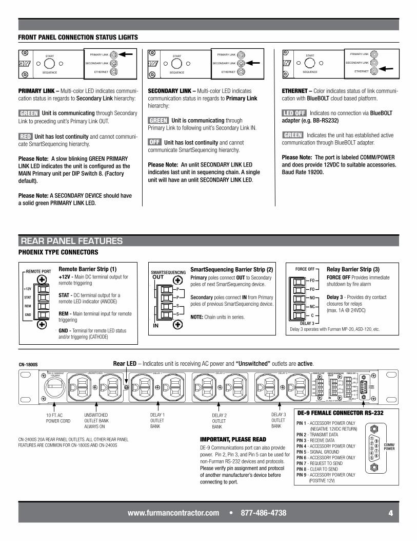
PIN 1 - ACCESSORY POWER ONLY (NEGATIVE 12VDC RETURN)PIN 2 - TRANSMIT DATAPIN 3 - RECEIVE DATAPIN 4 - ACCESSORY POWER ONLYPIN 5 - SIGNAL GROUNDPIN 6 - ACCESSORY POWER ONLYPIN 7 - REQUEST TO SENDPIN 8 - CLEAR TO SENDPIN 9 - ACCESSORY POWER ONLY (POSITIVE 12V)
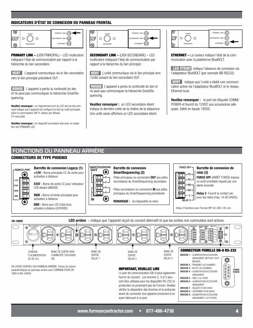
PHOENIX TYPE CONNECTORS
Remote Barrier Strip (1)+12V - Main DC terminal output for remote triggering
STAT - DC terminal output for a remote LED indicator (ANODE)
REM - Main terminal input for remote triggering
SmartSequencing Barrier Strip (2) Primary poles connect OUT to Secondary poles of next SmartSequencing device. Secondary poles connect IN from Primary poles of previous SmartSequencing device.
NOTE: Chain units in series.
Relay Barrier Strip (3)FORCE OFF Provides immediate shutdown by fire alarm
Delay 3 - Provides dry contact closures for relays (max. 1A @ 24VDC)
DE-9 FEMALE CONNECTOR RS-232DELAY 3 OUTLET BANK
CN-2400S 20A REAR PANEL OUTLETS. ALL OTHER REAR PANEL FEATURES ARE COMMON FOR CN-1800S AND CN-2400S
CN-1800S
FRONT PANEL CONNECTION STATUS LIGHTS
ETHERNET – Color indicates status of link communi-cation with BlueBOLT cloud based platform.
Indicates no connection via BlueBOLT adapter (e.g. BB-RS232)
Indicates the unit has established active communication through BlueBOLT adapter.
Please Note: The port is labeled COMM/POWER and does provide 12VDC to suitable accessories.Baud Rate 19200.
Unit has lost continuity and cannot communi-cate SmartSequencing hierarchy.
Please Note: A slow blinking GREEN PRIMARY LINK LED indicates the unit is configured as the MAIN Primary unit per DIP Switch 8. (Factory default).
Please Note: A SECONDARY DEVICE should have a solid green PRIMARY LINK LED.
SECONDARY LINK – Multi-color LED indicates communication status in regards to Primary Link hierarchy: Unit is communicating through Primary Link to following unit’s Secondary Link IN. Unit has lost continuity and cannot communicate SmartSequencing hierarchy.
Please Note: An unlit SECONDARY LINK LED indicates last unit in sequencing chain. A single unit will have an unlit SECONDARY LINK LED.
PRIMARY LINK – Multi-color LED indicates communi-cation status in regards to Secondary Link hierarchy:
Unit is communicating through Secondary Link to preceding unit’s Primary Link OUT.
PRIMARY LINK
SECONDARY LINK
ETHERNET
DELAY 1
DELAY 2
DELAY 3
POWER
PROTECTION OK
EXTREME VOLTAGE
UNSWITCHED
START
SEQUENCE
15 AMPS
PUSH TO RESET
ONOFF
REMOTE
DLYADJ
1 2 3 4 5 6 7 8 9
1M 1 2 3 4 5
2M 4M N.O.N.C.
12V ON12V OFF
GNDON
MOMMNT
PRISEC
EVS AUTOMANUAL
6 7 8 9
PRIMARY LINK
SECONDARY LINK
ETHERNET
DELAY 1
DELAY 2
DELAY 3
POWER
PROTECTION OK
EXTREME VOLTAGE
UNSWITCHED
START
SEQUENCE
15 AMPS
PUSH TO RESET
ONOFF
REMOTE
DLYADJ
1 2 3 4 5 6 7 8 9
1M 1 2 3 4 5
2M 4M N.O.N.C.
12V ON12V OFF
GNDON
MOMMNT
PRISEC
EVS AUTOMANUAL
6 7 8 9
PRIMARY LINK
SECONDARY LINK
ETHERNET
DELAY 1
DELAY 2
DELAY 3
POWER
PROTECTION OK
EXTREME VOLTAGE
UNSWITCHED
START
SEQUENCE
15 AMPS
PUSH TO RESET
ONOFF
REMOTE
DLYADJ
1 2 3 4 5 6 7 8 9
1M 1 2 3 4 5
2M 4M N.O.N.C.
12V ON12V OFF
GNDON
MOMMNT
PRISEC
EVS AUTOMANUAL
6 7 8 9
PRIMARY LINK
SECONDARY LINK
ETHERNET
DELAY 1
DELAY 2
DELAY 3
POWER
PROTECTION OK
EXTREME VOLTAGE
UNSWITCHED
START
SEQUENCE
15 AMPS
PUSH TO RESET
ONOFF
REMOTE
DLYADJ
1 2 3 4 5 6 7 8 9
1M 1 2 3 4 5
2M 4M N.O.N.C.
12V ON12V OFF
GNDON
MOMMNT
PRISEC
EVS AUTOMANUAL
6 7 8 9
GREEN
RED
GREEN
OFF GREEN
LED OFF
Rear LED – Indicates unit is receiving AC power and “Unswitched” outlets are active.
REAR PANEL FEATURES
GND - Terminal for remote LED status and/or triggering (CATHODE)
Delay 3 operates with Furman MP-20, ASD-120, etc.
DE-9 Communications port can also provide power. Pin 2, Pin 3, and Pin 5 can be used for non-Furman RS-232 devices and protocols. Please verify pin assignment and protocol of another manufacturer’s device before connecting to port.
IMPORTANT, PLEASE READ
5
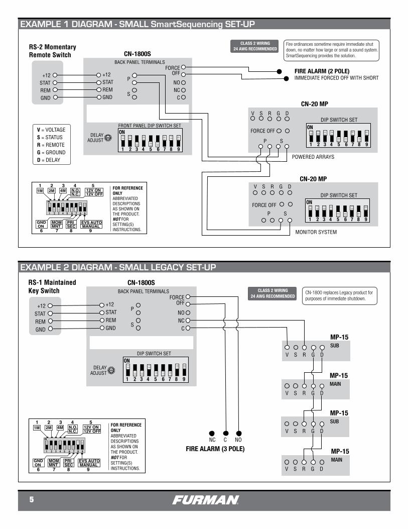
SmartSequencer™ DIAGRAM 1 - SMALL SMARTSEQUENCING SET-UP
CLASS 2 WIRING24 AWG RECOMMENDED
Fire ordinances sometime require immediate shut down, no matter how large or small a sound system. SmartSequencing provides the solution.
RS-2 Momentary Remote Switch CN-1800S
+12STATREMGND
+12STATREMGND
P
S
FIRE ALARM (2 POLE)
V S R G D
P S
FORCE OFF
V S R G D
P S
FRONT PANEL DIP SWITCH SET
POWERED ARRAYS
MONITOR SYSTEM
BACK PANEL TERMINALS
CN-20 MP
CN-20 MP
FORCEOFF
NONC
C
FORCE OFF
DELAYADJUST
IMMEDIATE FORCED OFF WITH SHORT
V = VOLTAGES = STATUSR = REMOTEG = GROUNDD = DELAY
ON
1 2 3 4 5 6 7 8 9
ON
1 2 3 4 5 6 7 8 9
DIP SWITCH SET
DIP SWITCH SET
ON
1 2 3 4 5 6 7 8 9
1M 1 2 3 4 5
2M 4M N.O.N.C.
12V ON12V OFF
GNDON
MOMMNT
PRISEC
EVS AUTOMANUAL
6 7 8 9
1 2 3 4 5 6 7 8 9
ON
FOR REFERENCE ONLYABBREVIATED DESCRIPTIONSAS SHOWN ONTHE PRODUCT.NOT FORSETTING(S)INSTRUCTIONS.
CN-1800S
+12STATREMGND
P
S
BACK PANEL TERMINALSFORCE
OFF
NONC
C
DELAYADJUST
CN-1800 replaces Legacy product for purposes of immediate shutdown.
RS-1 MaintainedKey Switch
+12STATREMGND
FIRE ALARM (3 POLE)
V S R G D
NC C NO
MP-15SUB
MP-15MAIN
V S R G D
V S R G D
MP-15SUB
V S R G D
MP-15MAIN
SmartSequencer™ DIAGRAM 2 - SMALL LEGACY SET-UP
ON
1 2 3 4 5 6 7 8 9
DIP SWITCH SET
CLASS 2 WIRING24 AWG RECOMMENDED
1M 1 2 3 4 5
2M 4M N.O.N.C.
12V ON12V OFF
GNDON
MOMMNT
PRISEC
EVS AUTOMANUAL
6 7 8 9
1 2 3 4 5 6 7 8 9
ON
FOR REFERENCE ONLYABBREVIATED DESCRIPTIONSAS SHOWN ONTHE PRODUCT.NOT FORSETTING(S)INSTRUCTIONS.
EXAMPLE 1 DIAGRAM - SMALL SmartSequencing SET-UP
EXAMPLE 2 DIAGRAM - SMALL LEGACY SET-UP
www.furmancontractor.com • 877-486-4738 6
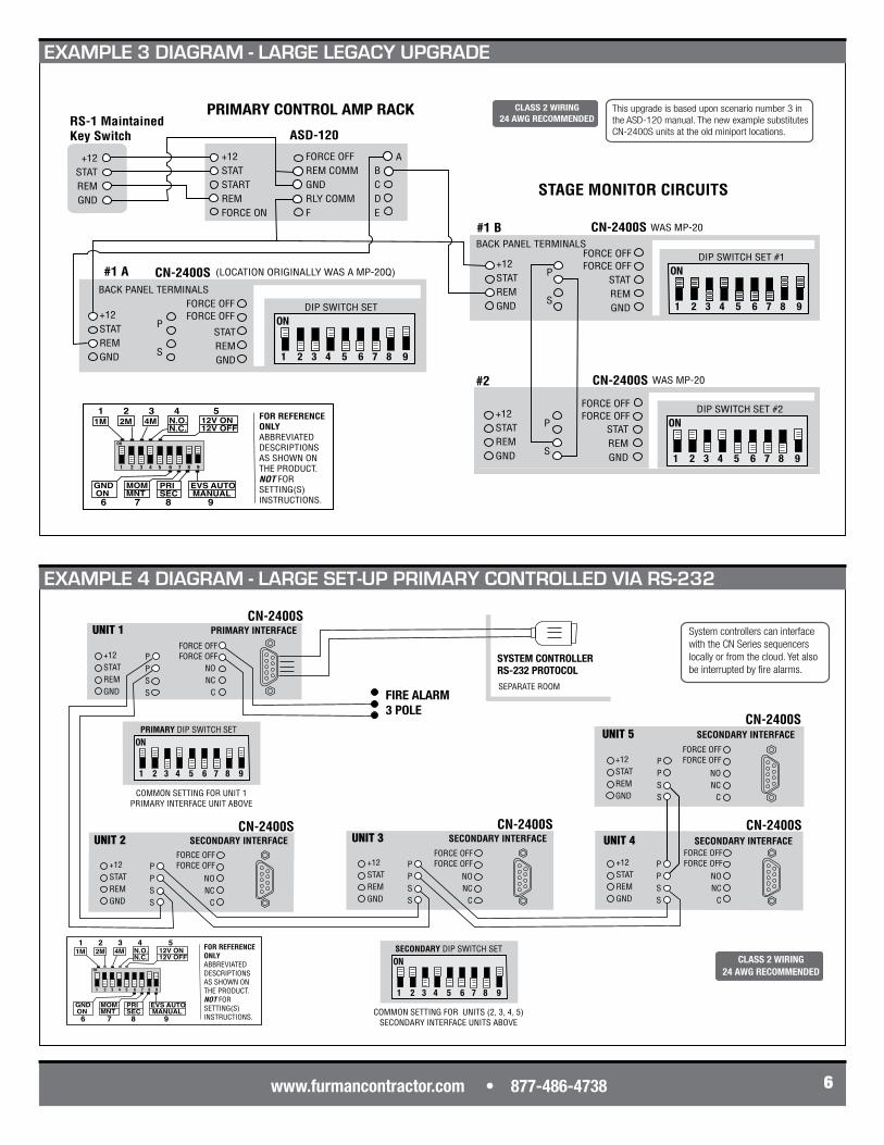
This upgrade is based upon scenario number 3 in the ASD-120 manual. The new example substitutes CN-2400S units at the old miniport locations.
PRIMARY CONTROL AMP RACK
P
S
+12STATSTARTREMFORCE ON
FORCE OFFREM COMMGNDRLY COMMF
ASD-120
ABCDE
CN-2400S
+12STATREMGND
STATREMGND
(LOCATION ORIGINALLY WAS A MP-20Q)
STAGE MONITOR CIRCUITS
WAS MP-20CN-2400S
P
S
+12STATREMGND
STATREMGND
#1 B
WAS MP-20CN-2400S
P
S
+12STATREMGND
STATREMGND
#2
SmartSequencer™ DIAGRAM 3 - LARGE LEGACY UPGRADE
BACK PANEL TERMINALS
BACK PANEL TERMINALS
ON
1 2 3 4 5 6 7 8 9
DIP SWITCH SET #2FORCE OFFFORCE OFF
FORCE OFFFORCE OFF ON
1 2 3 4 5 6 7 8 9
DIP SWITCH SET #1
ON
1 2 3 4 5 6 7 8 9
DIP SWITCH SETFORCE OFFFORCE OFF
RS-1 MaintainedKey Switch
+12STATREMGND
CLASS 2 WIRING24 AWG RECOMMENDED
1M 1 2 3 4 5
2M 4M N.O.N.C.
12V ON12V OFF
GNDON
MOMMNT
PRISEC
EVS AUTOMANUAL
6 7 8 9
1 2 3 4 5 6 7 8 9
ON
FOR REFERENCE ONLYABBREVIATED DESCRIPTIONSAS SHOWN ONTHE PRODUCT.NOT FORSETTING(S)INSTRUCTIONS.
#1 A
PPSS
CN-2400S
+12STATREMGND
UNIT 3 SECONDARY INTERFACE
NONC
C
FORCE OFFFORCE OFF P
PSS
CN-2400S
+12STATREMGND
UNIT 4 SECONDARY INTERFACE
NONC
C
PPSS
CN-2400S
+12STATREMGND
UNIT 5 SECONDARY INTERFACE
NONC
C
PPSS
CN-2400S
+12STATREMGND
UNIT 2 SECONDARY INTERFACE
NONC
C
FORCE OFFFORCE OFF
FORCE OFFFORCE OFF
FORCE OFFFORCE OFF
FORCE OFFFORCE OFF
NONC
C
ON
1 2 3 4 5 6 7 8 9
SECONDARY DIP SWITCH SET
SYSTEM CONTROLLERRS-232 PROTOCOL
CN-2400S
+12STATREMGND
System controllers can interface with the CN Series sequencers locally or from the cloud. Yet also be interrupted by fire alarms.
SmartSequencer™ DIAGRAM 4 - LARGE SMART SET-UP PRIMARY INDEPENDENT MULTI-ROOM
COMMON SETTING FOR UNITS (2, 3, 4, 5) SECONDARY INTERFACE UNITS ABOVE
UNIT 1 PRIMARY INTERFACE
SEPARATE ROOM
PPSS FIRE ALARM
3 POLE
ON
1 2 3 4 5 6 7 8 9
PRIMARY DIP SWITCH SET
COMMON SETTING FOR UNIT 1PRIMARY INTERFACE UNIT ABOVE
CLASS 2 WIRING24 AWG RECOMMENDED
1M 1 2 3 4 5
2M 4M N.O.N.C.
12V ON12V OFF
GNDON
MOMMNT
PRISEC
EVS AUTOMANUAL
6 7 8 9
1 2 3 4 5 6 7 8 9
ON
FOR REFERENCE ONLYABBREVIATED DESCRIPTIONSAS SHOWN ONTHE PRODUCT.NOT FORSETTING(S)INSTRUCTIONS.
EXAMPLE 3 DIAGRAM - LARGE LEGACY UPGRADE
EXAMPLE 4 DIAGRAM - LARGE SET-UP PRIMARY CONTROLLED VIA RS-232
DQS-00006-D
7
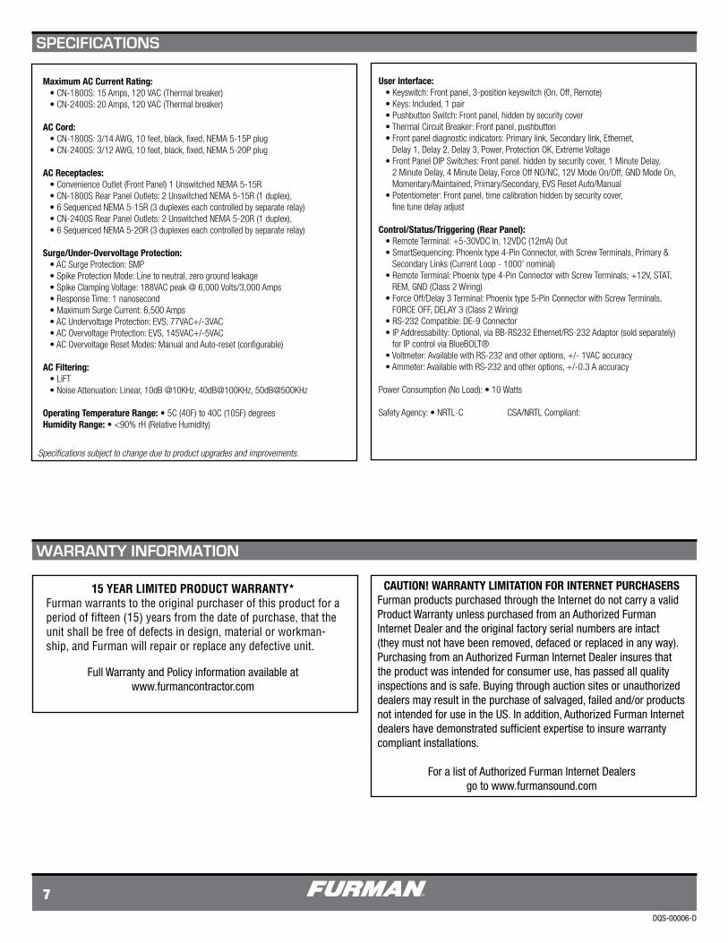
Maximum AC Current Rating: • CN-1800S: 15 Amps, 120 VAC (Thermal breaker) • CN-2400S: 20 Amps, 120 VAC (Thermal breaker)
AC Cord: • CN-1800S: 3/14 AWG, 10 feet, black, fixed, NEMA 5-15P plug • CN-2400S: 3/12 AWG, 10 feet, black, fixed, NEMA 5-20P plug
AC Receptacles: • Convenience Outlet (Front Panel) 1 Unswitched NEMA 5-15R • CN-1800S Rear Panel Outlets: 2 Unswitched NEMA 5-15R (1 duplex), • 6 Sequenced NEMA 5-15R (3 duplexes each controlled by separate relay) • CN-2400S Rear Panel Outlets: 2 Unswitched NEMA 5-20R (1 duplex), • 6 Sequenced NEMA 5-20R (3 duplexes each controlled by separate relay)
Surge/Under-Overvoltage Protection: • AC Surge Protection: SMP • Spike Protection Mode: Line to neutral, zero ground leakage • Spike Clamping Voltage: 188VAC peak @ 6,000 Volts/3,000 Amps • Response Time: 1 nanosecond • Maximum Surge Current: 6,500 Amps • AC Undervoltage Protection: EVS, 77VAC+/-3VAC • AC Overvoltage Protection: EVS, 145VAC+/-5VAC • AC Overvoltage Reset Modes: Manual and Auto-reset (configurable)
AC Filtering: • LiFT • Noise Attenuation: Linear, 10dB @10KHz, 40dB@100KHz, 50dB@500KHz
Operating Temperature Range: • 5C (40F) to 40C (105F) degreesHumidity Range: • <90% rH (Relative Humidity)
User Interface: • Keyswitch: Front panel, 3-position keyswitch (On, Off, Remote) • Keys: Included, 1 pair • Pushbutton Switch: Front panel, hidden by security cover • Thermal Circuit Breaker: Front panel, pushbutton • Front panel diagnostic indicators: Primary link, Secondary link, Ethernet, Delay 1, Delay 2, Delay 3, Power, Protection OK, Extreme Voltage • Front Panel DIP Switches: Front panel. hidden by security cover, 1 Minute Delay, 2 Minute Delay, 4 Minute Delay, Force Off NO/NC, 12V Mode On/Off, GND Mode On, Momentary/Maintained, Primary/Secondary, EVS Reset Auto/Manual • Potentiometer: Front panel, time calibration hidden by security cover, fine tune delay adjust
Control/Status/Triggering (Rear Panel): • Remote Terminal: +5-30VDC In, 12VDC (12mA) Out • SmartSequencing: Phoenix type 4-Pin Connector, with Screw Terminals, Primary & Secondary Links (Current Loop - 1000’ nominal) • Remote Terminal: Phoenix type 4-Pin Connector with Screw Terminals; +12V, STAT, REM, GND (Class 2 Wiring) • Force Off/Delay 3 Terminal: Phoenix type 5-Pin Connector with Screw Terminals, FORCE OFF, DELAY 3 (Class 2 Wiring) • RS-232 Compatible: DE-9 Connector • IP Addressability: Optional, via BB-RS232 Ethernet/RS-232 Adaptor (sold separately) for IP control via BlueBOLT® • Voltmeter: Available with RS-232 and other options, +/- 1VAC accuracy • Ammeter: Available with RS-232 and other options, +/-0.3 A accuracy
Power Consumption (No Load): • 10 Watts Safety Agency: • NRTL-C CSA/NRTL Compliant:
Full Warranty and Policy information available at www.furmancontractor.com
15 YEAR LIMITED PRODUCT WARRANTY* Furman warrants to the original purchaser of this product for a period of fifteen (15) years from the date of purchase, that the unit shall be free of defects in design, material or workman-ship, and Furman will repair or replace any defective unit.
CAUTION! WARRANTY LIMITATION FOR INTERNET PURCHASERSFurman products purchased through the Internet do not carry a valid Product Warranty unless purchased from an Authorized Furman Internet Dealer and the original factory serial numbers are intact (they must not have been removed, defaced or replaced in any way). Purchasing from an Authorized Furman Internet Dealer insures that the product was intended for consumer use, has passed all quality inspections and is safe. Buying through auction sites or unauthorized dealers may result in the purchase of salvaged, failed and/or products not intended for use in the US. In addition, Authorized Furman Internet dealers have demonstrated sufficient expertise to insure warranty compliant installations.
For a list of Authorized Furman Internet Dealers go to www.furmansound.com
SPECIFICATIONS
WARRANTY INFORMATION
Specificationssubjecttochangeduetoproductupgradesandimprovements.
CN-1800S y CN-2400S
Guía de inicio rápido
DQS-00006-D
CN-1800S
CN-2400S
Para obtener las instrucciones completas, ingrese a:
www.furmancontractor.com
15 A Máximo
20 A Máximo
Para más información, llame al: :
877-486-4738
CONTRACTOR SERIES SmartSequencer™
1
Indicadores de estado de LED de varios colores.
Apagado forzado inmediato por seguridad y según las ordenanzas de incendios.
Capacidad de 9 salidas (15 amperios CN-1800S)(15 amperios CN-1800S) ( 8 salidas 20 amperes, uno salida 15 am-peresCN-2400S).
Cable de 10 pies de 15 amperios (CN-1800S) o 20 amperios (CN-2400S).
Garantía limitada de 15 años ver la documentación de la garantía en línea en www.furmancontractor.com
1. Lea y siga todas las instrucciones.
2. Conserve estas instrucciones.
3. Ponga atención en todas las advertencias.
4. ADVERTENCIA: Este dispositivo está dis-eñado para uso interior exclusivamente. No use este dispositivo cerca del agua. Para reducir el riesgo de incendio o descarga eléctrica, no exponga el equipo a la lluvia o a la humedad.
5. PRECAUCIÓN: Funcionamiento tomacorrientes siempre encendidos. Para disminuir los riesgos de descarga, desconecte el secuenciador CN-1800S / CN-2400S de la CA antes de reparar cualquier equipo conectado al secuenciador CN-1800S / CN-2400S.
6. Limpie sólo con un paño seco.
7. PRECAUCIÓN: No instalar cerca de ninguna fuente de calor como radiadores, registros de calor, estufas u otros equipos que puedan generar calor.
13. No inhabilite la función de seguridad del enchufe polarizado. Un enchufe polarizado tiene dos elementos de contacto, uno más ancho que el otro. El más ancho está diseñado para su seguridad. Si el enchufe suministrado no encaja en su tomacorri-ente, consulte a un electricista para el reemplazo del tomacorriente obsoleto.
14. No inhabilite la función de seguridad de la toma de tierra. Un enchufe con toma de tierra tiene dos elementos de contacto y un tercer elemento de tierra. El tercero está diseñado para su seguridad. Si el enchufe suministrado no encaja en su tomacor-riente, consulte a un electricista para el reemplazo del tomacorriente obsoleto.
15. ADVERTENCIA: Este dispositivo debe estar conectado a una salida de CA con un conductor de conexión a tierra de protección.
La tecnología SmartSequencing™ permite que los sistemas A/V grandes y complejos tengan ciclos de encendido y apagado seguros con sólo girar una llave o presionar un botón.
La protección de serie multifase (SMP) ase-gura cero perdida de tiempo para instalaciones de misión critia al eliminar de manera segura las sobretensiones y picos peligrosos. El apagado de voltaje extremo (EVS) con reinicio automático protege contra condiciones catastróficas de bajo o sobre voltaje.
Tecnología de filtro lineal (LiFT)asegura el máximo rendimiento del equipo al disminuir el ruido de la CA de manera lineal a lo largo de una banda ultra ancha.
Compatibilidad de acceso remoto (RS-232)con programación que permite la integración convarias plataformas de sistema de control.
Las características de seguridad incluyen una llave para evitar la operación no autorizada y cubi-ertas de protección para evitar la manipulación de la configuración de las llaves.
8. Proteger el cable de electricidad de pisadas o pinchazos, especialmente en los enchufes, tomas de corriente, y el lugar desde donde salen del dispositivo.
9. ADVERTENCIA: El puerto de comunicaciones DE-9 RS-232 provee electricidad para los accesorios Furman (por ej., BB-RS232). Verifique la asignación de PIN y el protocolo antes de conectar un equipo de otro fabricante a este puerto.
10. Sólo use accesorios especificados por el fabricante
11. Solicite el servicio técnico a personal calificado. Se requiere este servicio cuando la unidad se ha dañado o no funciona normalmente.
12. ADVERTENCIA No use el cable de electricidad como desconexión principal de energía. El disposi-tivo está diseñado para el encendido y apagado en secuencia de la unidad.
CARACTERÍSTICAS
INSTRUCCIONES IMPORTANTES DE SEGURIDAD
INTRODUCCIÓN
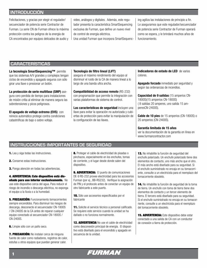
Felicitaciones, y gracias por elegir el regulador/secuenciador de potencia serie Contractor de Furman. La serie CN de Furman ofrece la máxima protección contra los peligros de la energía de CA encontrados por equipos delicados de audio y
video, análogos y digitales. Además, este regu-lador presenta la característica SmartSequencing exclusiva de Furman, que define un nuevo nivel de control de energía eléctrica. Una unidad Furman que incorpora SmartSequenc-
ing agiliza las instalaciones de principio a fin. Le aseguramos que este regulador/secuenciador de potencia serie Contractor de Furman operará como se espera, y le brindará muchos años de funcionamiento.
PRIMARY LINK
SECONDARY LINK
ETHERNET
DELAY 1
DELAY 2
DELAY 3
POWER
PROTECTION OK
EXTREME VOLTAGE
UNSWITCHED 15 AMPS
PUSH TO RESET
ON
OFF
REMOTE
PRIMARY LINK
SECONDARY LINK
ETHERNET
DELAY 1
DELAY 2
DELAY 3
POWER
PROTECTION OK
EXTREME VOLTAGE
UNSWITCHED 20 AMPS
PUSH TO RESET
ON
OFF
REMOTE
PRIMARY LINK
SECONDARY LINK
ETHERNET
DELAY 1
DELAY 2
DELAY 3
POWER
PROTECTION OK
EXTREME VOLTAGE
UNSWITCHED 15 AMPS
PUSH TO RESET
ON
OFF
REMOTE
PRIMARY LINK
SECONDARY LINK
ETHERNET
DELAY 1
DELAY 2
DELAY 3
POWER
PROTECTION OK
EXTREME VOLTAGE
UNSWITCHED 20 AMPS
PUSH TO RESET
ON
OFF
REMOTE
COMM/POWER
UNSWITCHED DELAY 1 DELAY 2 DELAY 3120~V, 50/60/HZ15A MAX
FORCE OFF
DELAY 3
+12V
STAT
REM
GND
NO
NC
C
FO
FOP
P
S
S
OUT
IN
SMARTSEQUENCINGREMOTE PORT
CLASS 2 WIRING
COMM/POWER
UNSWITCHED DELAY 1 DELAY 2 DELAY 3120~V, 50/60/HZ15A MAX
FORCE OFF
DELAY 3
+12V
STAT
REM
GND
NO
NC
C
FO
FOP
P
S
S
OUT
IN
SMARTSEQUENCINGREMOTE PORT
CLASS 2 WIRING
www.furmancontractor.com • 877-486-4738 2
Leer las INSTRUCCIONES IMPORTANTES DE SEGURIDAD• No contiene piezas reparables. Ver manual en línea para detalles.• Instrucciones completas en: www.furmancontractor.com/manuals• Inspeccione completamente la unidad de la serie Contractor de Furman.• Comuníquese con el servicio al consumidor de Furman al 707.763.1010 si existen daños notables en el producto o no funciona al sacarlo de la caja.• Los contenidos de este paquete incluyen:
CN-SERIES UNIT
CN-2400S
CN-1800S oCN-2400S
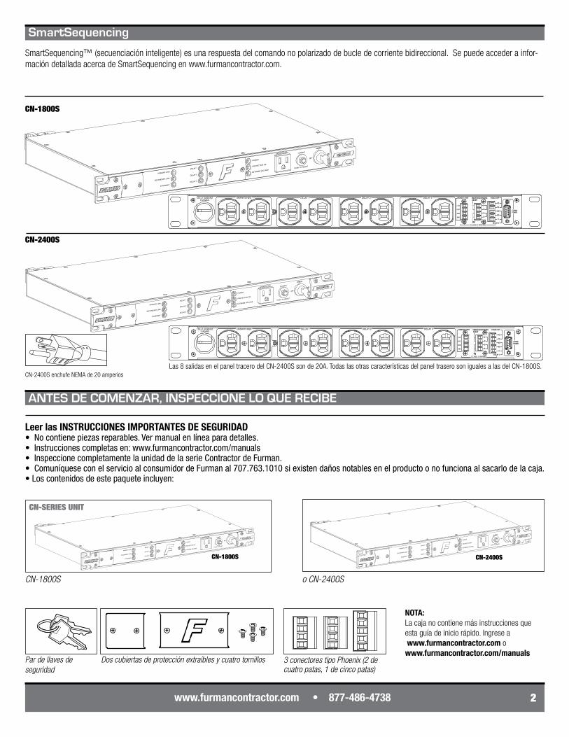
Pardellavesdeseguridad
Doscubiertasdeprotecciónextraíblesycuatrotornillos
CN-2400S
CN-1800S
Las 8 salidas en el panel tracero del CN-2400S son de 20A. Todas las otras características del panel trasero son iguales a las del CN-1800S.
3conectorestipoPhoenix(2decuatropatas,1decincopatas)
ANTES DE COMENZAR, INSPECCIONE LO QUE RECIBE
CN-2400S enchufe NEMA de 20 amperios
SmartSequencing
SmartSequencing™ (secuenciación inteligente) es una respuesta del comando no polarizado de bucle de corriente bidireccional. Se puede acceder a infor-mación detallada acerca de SmartSequencing en www.furmancontractor.com.
CN-1800S
NOTA:La caja no contiene más instrucciones que esta guía de inicio rápido. Ingrese a www.furmancontractor.com o www.furmancontractor.com/manuals
PRIMARY LINK
SECONDARY LINK
ETHERNET
DELAY 1
DELAY 2
DELAY 3
POWER
PROTECTION OK
EXTREME VOLTAGE
UNSWITCHED
START
SEQUENCE
15 AMPS
PUSH TO RESET
ONOFF
REMOTE
DLYADJ
1 2 3 4 5 6 7 8 9
1M 1 2 3 4 5
2M 4M N.O.N.C.
12V ON12V OFF
GNDON
MOMMNT
PRISEC
EVS AUTOMANUAL
6 7 8 9
1 2 3 4 5 6 7 8 9
ONDLYADJ
PRIMARY LINK
SECONDARY LINK
ETHERNET
DELAY 1
DELAY 2
DELAY 3
POWER
PROTECTION OK
EXTREME VOLTAGE
UNSWITCHED
START
SEQUENCE
15 AMPS
PUSH TO RESET
ONOFF
REMOTE
DLYADJ
1 2 3 4 5 6 7 8 9
1M 1 2 3 4 5
2M 4M N.O.N.C.
12V ON12V OFF
GNDON
MOMMNT
PRISEC
EVS AUTOMANUAL
6 7 8 9
PRIMARY LINK
SECONDARY LINK
ETHERNET
DELAY 1
DELAY 2
DELAY 3
POWER
PROTECTION OK
EXTREME VOLTAGE
UNSWITCHED
START
SEQUENCE
15 AMPS
PUSH TO RESET
ONOFF
REMOTE
DLYADJ
1 2 3 4 5 6 7 8 9
1M 1 2 3 4 5
2M 4M N.O.N.C.
12V ON12V OFF
GNDON
MOMMNT
PRISEC
EVS AUTOMANUAL
6 7 8 9
PRIMARYLINK
SECONDARY LINK
ETHERNET
DELAY 1
DELAY 2
DELAY 3
POWER
PROTECTION OK
EXTREME VOLTAGE
UNSWITCHED
START
SEQUENCE
20 AMPS
PUSH TO RESET
ONOFF
REMOTE1M 2M
12V ON12V OFF
GNDON
MOMMNT
EVS AUTO MANUAL
1 2 3 4 5 6 7 8 9
DLYADJ
4M N.O. N.C.
PRISEC
1 2 3 4 5 6 7 8 9
PRIMARY LINK
SECONDARY LINK
ETHERNET
DELAY 1
DELAY 2
DELAY 3
POWER
PROTECTION OK
EXTREME VOLTAGE
UNSWITCHED
START
SEQUENCE
15 AMPS
PUSH TO RESET
ONOFF
REMOTE
DLYADJ
1 2 3 4 5 6 7 8 9
1M 1 2 3 4 5
2M 4M N.O.N.C.
12V ON12V OFF
GNDON
MOMMNT
PRISEC
EVS AUTOMANUAL
6 7 8 9
1 2 3 4 5 6 7 8 9
ONDLYADJDLY
ADJ
1M 1 2 3 4 5
2M 4M N.O.N.C.
12V ON12V OFF
GNDON
MOMMNT
PRISEC
EVS AUTOMANUAL
6 7 8 9
ONOFF
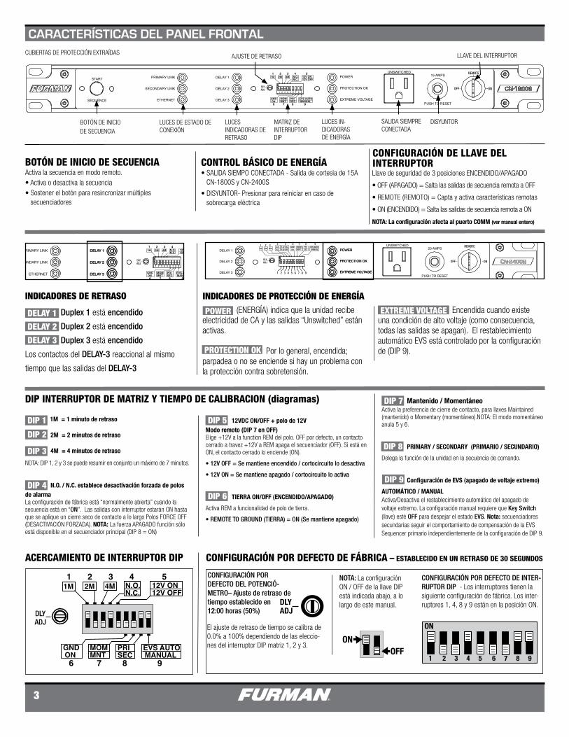
(ENERGÍA) indica que la unidad recibe electricidad de CA y las salidas “Unswitched” están activas.
Por lo general, encendida; parpadea o no se enciende si hay un problema con la protección contra sobretensión.
3
BOTÓN DE INICIO DE SECUENCIA
LUCES DE ESTADO DE CONEXIÓN
LUCES INDICADORAS DE RETRASO
MATRIZ DE INTERRUPTOR DIP
LUCES IN-DICADORAS DE ENERGÍA
SALIDA SIEMPRE CONECTADA
DISYUNTOR
LLAVE DEL INTERRUPTORCUBIERTAS DE PROTECCIÓN EXTRAÍDAS
El ajuste de retraso de tiempo se calibra de 0.0% a 100% dependiendo de las eleccio-nes del interruptor DIP matriz 1, 2 y 3.
1M = 1 minuto de retraso
2M = 2 minutos de retraso
4M = 4 minutos de retraso
NOTA: DIP 1, 2 y 3 se puede resumir en conjunto un máximo de 7 minutos.
N.O. / N.C. establece desactivación forzada de polos de alarmaLa configuración de fábrica está “normalmente abierta” cuando la secuencia está en “ON”. Las salidas con interruptor estarán ON hasta que se aplique un cierre seco de contacto a lo largo Polos FORCE OFF (DESACTIVACIÓN FORZADA). NOTA: La fuerza APAGADO función sólo está disponible en el secuenciador principal (DIP 8 = ON)
ACERCAMIENTO DE INTERRUPTOR DIP
AJUSTE DE RETRASO
CONFIGURACIÓN POR DEFECTO DE FÁBRICA – ESTABLECIDO EN UN RETRASO DE 30 SEGUNDOS
CONFIGURACIÓN POR DEFECTO DEL POTENCIÓ-METRO– Ajuste de retraso de tiempo establecido en12:00 horas (50%)
CONFIGURACIÓN POR DEFECTO DE INTER-RUPTOR DIP - Los interruptores tienen la siguiente configuración de fábrica. Los inter-ruptores 1, 4, 8 y 9 están en la posición ON.
Mantenido / MomentáneoActiva la preferencia de cierre de contacto, para llaves Maintained (mantenido) o Momentary (momentáneo).NOTA: El modo momentáneo anula 5 y 6.
PRIMARY / SECONDARY (PRIMARIO / SECUNDARIO)
Delega la función de la unidad en la secuencia de comando.
Configuración de EVS (apagado de voltaje extremo)
AUTOMÁTICO / MANUALActiva/Desactiva el restablecimiento automático del apagado de voltaje extremo. La configuración manual requiere que Key Switch (llave) esté OFF para despejar el estado EVS. Nota: secuenciadores secundarias seguir el comportamiento de compensación de la EVS Sequencer primario independientemente de la configuración de DIP 9.
DIP INTERRUPTOR DE MATRIZ Y TIEMPO DE CALIBRACION (diagramas)
INDICADORES DE PROTECCIÓN DE ENERGÍA
Duplex 1 está encendido
Duplex 2 está encendido
Duplex 3 está encendido
Los contactos del DELAY-3 reaccional al mismo
tiempo que las salidas del DELAY-3
Encendida cuando existe una condición de alto voltaje (como consecuencia, todas las salidas se apagan). El restablecimiento automático EVS está controlado por la configuración de (DIP 9).
12VDC ON/OFF + polo de 12VModo remoto (DIP 7 en OFF)Elige +12V a la function REM del polo. OFF por defecto, un contacto cerrado a travez +12V a REM apaga el secuenciador (OFF). Si está en ON, el contacto cerrado lo enciende (ON).
• 12V OFF = Se mantiene encendido / cortocircuito lo desactiva
• 12V ON = Se mantiene apagado / cortocircuito lo activa
TIERRA ON/OFF (ENCENDIDO/APAGADO)
Activa REM a funcionalidad de polo de tierra.
• REMOTE TO GROUND (TIERRA) = ON (Se mantiene apagado)
DIP 1
DIP 2
DIP 3
DIP 4
DIP 5
DIP 6
DIP 7
DIP 8
DIP 9
INDICADORES DE RETRASO
POWER
PROTECTION OK
EXTREME VOLTAGE
CARACTERÍSTICAS DEL PANEL FRONTAL
BOTÓN DE INICIO DE SECUENCIAActiva la secuencia en modo remoto.• Activa o desactiva la secuencia• Sostener el botón para resincronizar múltiples secuenciadores
CONFIGURACIÓN DE LLAVE DEL INTERRUPTORLlave de seguridad de 3 posiciones ENCENDIDO/APAGADO
• OFF (APAGADO) = Salta las salidas de secuencia remota a OFF
• REMOTE (REMOTO) = Capta y activa características remotas
• ON (ENCENDIDO) = Salta las salidas de secuencia remota a ON
NOTA: La configuración afecta al puerto COMM (ver manual entero)
CONTROL BÁSICO DE ENERGÍA• SALIDA SIEMPO CONECTADA - Salida de cortesia de 15A CN-1800S y CN-2400S
• DISYUNTOR- Presionar para reiniciar en caso de sobrecarga eléctrica
DELAY 1
DELAY 2
DELAY 3
NOTA: La configuración ON / OFF de la llave DIP está indicada abajo, a lo largo de este manual.
COMM/POWER
UNSWITCHED DELAY 1 DELAY 2 DELAY 3120~V, 50/60/HZ15A MAX
FORCE OFF
DELAY 3
+12V
STAT
REM
GND
NO
NC
C
FO
FOP
P
S
S
OUT
IN
SMARTSEQUENCINGREMOTE PORT
CLASS 2 WIRING
COMM/POWER
5432
6789
1
ACCESSORY POWER ONLY(NEGATIVE 12VDC RETURN)RECEIVE DATATRANSMIT DATAACCESSORY POWER ONLYSIGNAL GROUNDACCESSORY POWER ONLYREQUEST TO SENDCLEAR TO SENDACCESSORY POWER ONLY(POSITIVE 12V)
PIN NO. 1
2 3 4 5 6 7 8 9
COMM/POWER
FORCE OFF
DELAY 3
+12V
STAT
REM
GND
NO
NC
C
FO
FOP
P
S
S
OUT
IN
SMARTSEQUENCINGREMOTE PORT
CLASS 2 WIRING
COMM/POWER
FORCE OFF
DELAY 3
+12V
STAT
REM
GND
NO
NC
C
FO
FOP
P
S
S
OUT
IN
SMARTSEQUENCINGREMOTE PORT
CLASS 2 WIRING
COMM/POWER
FORCE OFF
DELAY 3
+12V
STAT
REM
GND
NO
NC
C
FO
FOP
P
S
S
OUT
IN
SMARTSEQUENCINGREMOTE PORT
CLASS 2 WIRING
PRIMARY LINK
SECONDARY LINK
ETHERNET
DELAY 1
DELAY 2
DELAY 3
POWER
PROTECTION OK
EXTREME VOLTAGE
UNSWITCHED
START
SEQUENCE
15 AMPS
PUSH TO RESET
ONOFF
REMOTE
DLYADJ
1 2 3 4 5 6 7 8 9
1M 1 2 3 4 5
2M 4M N.O.N.C.
12V ON12V OFF
GNDON
MOMMNT
PRISEC
EVS AUTOMANUAL
6 7 8 9
PRIMARY LINK
SECONDARY LINK
ETHERNET
DELAY 1
DELAY 2
DELAY 3
POWER
PROTECTION OK
EXTREME VOLTAGE
UNSWITCHED
START
SEQUENCE
15 AMPS
PUSH TO RESET
ONOFF
REMOTE
DLYADJ
1 2 3 4 5 6 7 8 9
1M 1 2 3 4 5
2M 4M N.O.N.C.
12V ON12V OFF
GNDON
MOMMNT
PRISEC
EVS AUTOMANUAL
6 7 8 9
www.furmancontractor.com • 877-486-4738 4
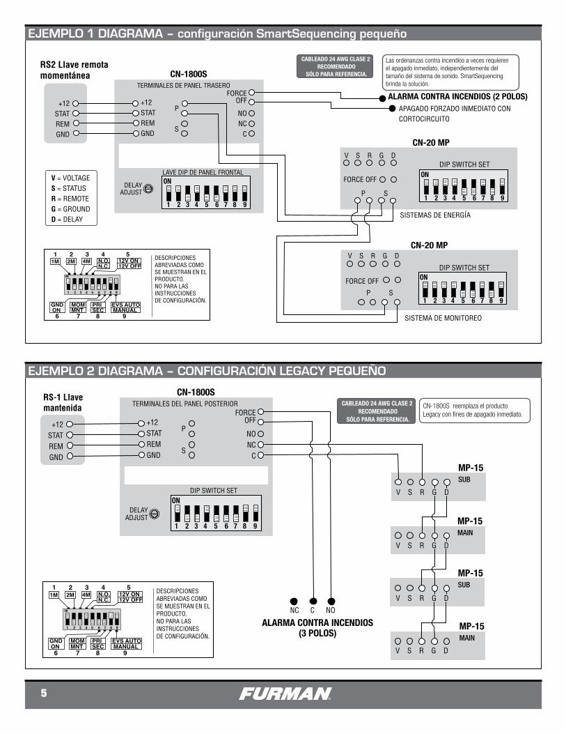
CABLE DE 10 PIES PARA EN-ERGÍA DE CA,
BANCO DE SALIDA ININTERRUMPIDA (SIEMPRE ENCENDIDA)
BANCO DE SALIDA DELAY 1 PIN 1 - SÓLO ENERGÍA ACCESORIA
(RETORNO 12VCC NEGATIVO)PIN 2 - TRANSMITE DATOSPIN 3 - RECIBE DATOSPIN 4 - SÓLO ENERGÍA ACCESORIAPIN 5 - SEÑAL DE TIERRAPIN 6 - SÓLO ENERGÍA ACCESORIAPIN 7 - SOLICITUD PARA ENVIARPIN 8 - LISTO PARA ENVIARPIN 9 - SÓLO ENERGÍA ACCESORIA (12V POSITIVO)
CONECTORES TIPO PHOENIX
Cable de barrera (1)+12V - Terminal de salida principal de CC para activación remota
STAT - Salida de terminal de CC para indicador LED remoto (ANODE)
REM - Entrada principal de terminal para activación remota
Cable de barrera SmartSequencing (2)Los polos primarios se conectan OUT a los polos secundarios del siguiente dispositivo SmartSequencing. Los polos secundarios se conectan de IN a los polos primarios del dispositivo anterior SmartSequencing.
NOTA: Cadena de unidades en serie.
Cable de barrera de relé (3)FORCE OFF (APAGADO FORZADO) Apaga inmediatamente por alarma contra incendios
Delay 3 - (Retraso) 3 – Provee cierres de contacto seco para relés (máx. 1A a 24VCC)
DE-9 CONECTOR HEMBRA RS-232
CN-2400S 20A SALIDAS DEL PANEL POSTERIOR. Todas las demás características del panel posterior son COMUNES PARA CN-1800 y CN-2400S
CN-1800S
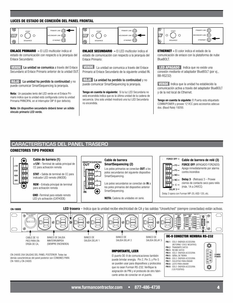
LUCES DE ESTADO DE CONEXIÓN DEL PANEL FRONTAL
ETHERNET – El color indica el estado de la comunicación de enlace con la plataforma de nube BlueBOLT.
Indica que no existe una conexión mediante el adaptador BlueBOLT (por ej., BB-RS232)
Indica que la unidad ha establecido la comunicación activa a través del adaptador BlueBOLT y de la red local de Ethernet.
Tenga en cuenta lo sigulete: El Puerta esta etiquetado COMM/POWER y provee 12 VCC para accesorios adecua-dos. (Baud Rate) 19200.
La unidad ha perdido la continuidad y no puede comunicar SmartSequencing la jerarquía.
Nota: Un parpadeo lento del LED verde en el Enlace Pri-mario indica que la unidad está configurada como la unidad Primaria PRINCIPAL en el Interruptor DIP 8 (por defecto).
Nota: Un dispositivo secundario deberá tener un sólido vínculo primario LED verde.
ENLACE SECUNDARIO – El LED multicolor indica el estado de comunicación con respecto a la jerarquía del Enlace Primario: La unidad se comunica a través del Enlace Primario al Enlace Secundario de la siguiente unidad IN.
La unidad ha perdido la continuidad y no puede comunicar SmartSequencing la jerarquía.
Tenga en cuenta lo siguiente: Si la luz LED Secundaria no está encendida indica que es la última unidad de la cadena de secuencia. Una sola unidad mostrará una luz LED Secundaria no encendida.
ENLACE PRIMARIO – El LED multicolor indica el estado de comunicación con respecto a la jerarquía del Enlace Secundario:
La unidad se comunica a través del Enlace Secundario al Enlace Primario anterior de la unidad OUT.
PRIMARY LINK
SECONDARY LINK
ETHERNET
DELAY 1
DELAY 2
DELAY 3
POWER
PROTECTION OK
EXTREME VOLTAGE
UNSWITCHED
START
SEQUENCE
15 AMPS
PUSH TO RESET
ONOFF
REMOTE
DLYADJ
1 2 3 4 5 6 7 8 9
1M 1 2 3 4 5
2M 4M N.O.N.C.
12V ON12V OFF
GNDON
MOMMNT
PRISEC
EVS AUTOMANUAL
6 7 8 9
PRIMARY LINK
SECONDARY LINK
ETHERNET
DELAY 1
DELAY 2
DELAY 3
POWER
PROTECTION OK
EXTREME VOLTAGE
UNSWITCHED
START
SEQUENCE
15 AMPS
PUSH TO RESET
ONOFF
REMOTE
DLYADJ
1 2 3 4 5 6 7 8 9
1M 1 2 3 4 5
2M 4M N.O.N.C.
12V ON12V OFF
GNDON
MOMMNT
PRISEC
EVS AUTOMANUAL
6 7 8 9
PRIMARY LINK
SECONDARY LINK
ETHERNET
DELAY 1
DELAY 2
DELAY 3
POWER
PROTECTION OK
EXTREME VOLTAGE
UNSWITCHED
START
SEQUENCE
15 AMPS
PUSH TO RESET
ONOFF
REMOTE
DLYADJ
1 2 3 4 5 6 7 8 9
1M 1 2 3 4 5
2M 4M N.O.N.C.
12V ON12V OFF
GNDON
MOMMNT
PRISEC
EVS AUTOMANUAL
6 7 8 9
PRIMARY LINK
SECONDARY LINK
ETHERNET
DELAY 1
DELAY 2
DELAY 3
POWER
PROTECTION OK
EXTREME VOLTAGE
UNSWITCHED
START
SEQUENCE
15 AMPS
PUSH TO RESET
ONOFF
REMOTE
DLYADJ
1 2 3 4 5 6 7 8 9
1M 1 2 3 4 5
2M 4M N.O.N.C.
12V ON12V OFF
GNDON
MOMMNT
PRISEC
EVS AUTOMANUAL
6 7 8 9
VERDE
ROJO
LED APAGADO
LED trasera – Indica que la unidad recibe electricidad de CA y las salidas “Unswitched” (siempre conectadas) están activas.
CARACTERÍSTICAS DEL PANEL TRASERO
GND -Terminal para estado remoto LED y/o activación (CATHODE)
Delay 3 opera con Furman MP-20, ASD-120, etc.
El puerto DE-9 de comunicaciones también puede brindar energía. Pin 2, Pin 3, y Pin 5 se pueden usar para dispositivos y protocolos que no sean Furman RS-232. Verifique la asignación de PIN y el protocolo de otro fabri-cante antes de conectar en el puerto.
IMPORTANTE, LEER
VERDE
ROJO VERDE
BANCO DE SALIDA DELAY 2
BANCO DE SALIDA DELAY 3
5
SmartSequencer™ DIAGRAM 1 - SMALL SMARTSEQUENCING SET-UP
CABLEADO 24 AWG CLASE 2 RECOMENDADO
SÓLO PARA REFERENCIA.
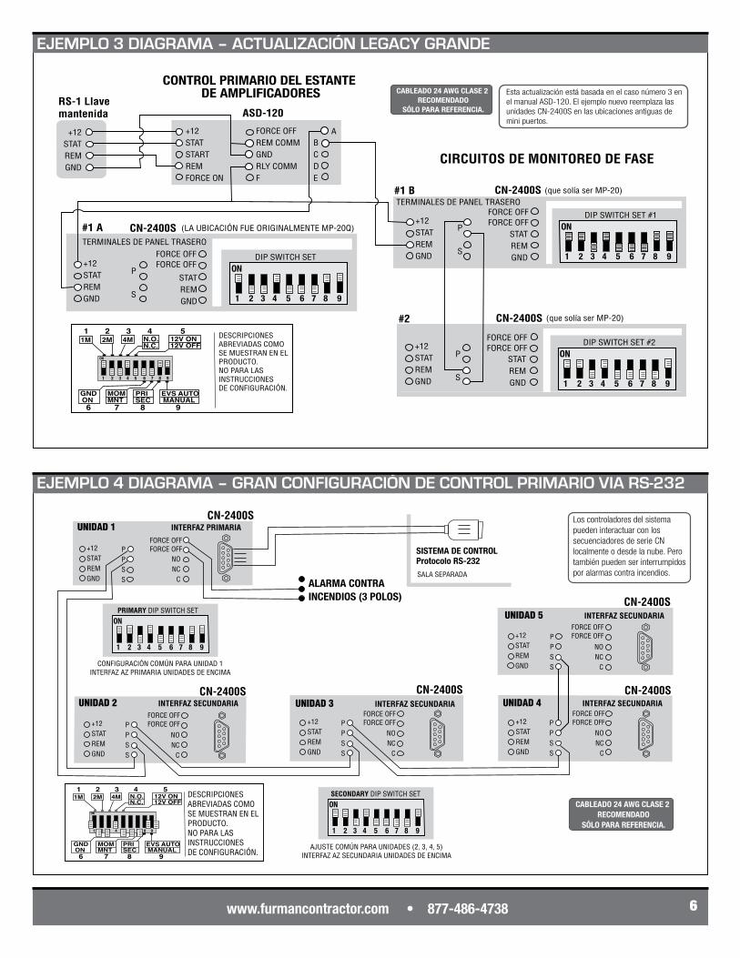
Las ordenanzas contra incendios a veces requieren el apagado inmediato, independientemente del tamaño del sistema de sonido. SmartSequencing brinda la solución.
RS2 Llave remota momentánea CN-1800S
+12STATREMGND
+12STATREMGND
P
S
ALARMA CONTRA INCENDIOS (2 POLOS)
V S R G D
P S
FORCE OFF
V S R G D
P S
LAVE DIP DE PANEL FRONTAL
SISTEMAS DE ENERGÍA
SISTEMA DE MONITOREO
TERMINALES DE PANEL TRASERO
CN-20 MP
CN-20 MP
FORCEOFF
NONC
C
FORCE OFF
DELAYADJUST
APAGADO FORZADO INMEDIATO CON CORTOCIRCUITO
V = VOLTAGES = STATUSR = REMOTEG = GROUNDD = DELAY
ON
1 2 3 4 5 6 7 8 9
ON
1 2 3 4 5 6 7 8 9
DIP SWITCH SET
DIP SWITCH SET
ON
1 2 3 4 5 6 7 8 9
1M 1 2 3 4 5
2M 4M N.O.N.C.
12V ON12V OFF
GNDON
MOMMNT
PRISEC
EVS AUTOMANUAL
6 7 8 9
1 2 3 4 5 6 7 8 9
ON
DESCRIPCIONES ABREVIADAS COMO SE MUESTRAN EN ELPRODUCTO. NO PARA LAS INSTRUCCIONES DE CONFIGURACIÓN.
CN-1800S
+12STATREMGND
P
S
TERMINALES DEL PANEL POSTERIORFORCE
OFF
NONC
C
DELAYADJUST
CN-1800S reemplaza el producto Legacy con fines de apagado inmediato.
CABLEADO 24 AWG CLASE 2 RECOMENDADO
SÓLO PARA REFERENCIA.+12
STATREMGND
ALARMA CONTRA INCENDIOS (3 POLOS)
V S R G D
NC C NO
MP-15SUB
MP-15MAIN
V S R G D
V S R G D
MP-15SUB
V S R G D
MP-15MAIN
SmartSequencer™ DIAGRAM 2 - SMALL LEGACY SET-UP
ON
1 2 3 4 5 6 7 8 9
DIP SWITCH SET
1M 1 2 3 4 5
2M 4M N.O.N.C.
12V ON12V OFF
GNDON
MOMMNT
PRISEC
EVS AUTOMANUAL
6 7 8 9
1 2 3 4 5 6 7 8 9
ON
DESCRIPCIONES ABREVIADAS COMO SE MUESTRAN EN ELPRODUCTO. NO PARA LAS INSTRUCCIONES DE CONFIGURACIÓN.
RS-1 Llave mantenida
EJEMPLO 1 DIAGRAMA – configuración SmartSequencing pequeño
EJEMPLO 2 DIAGRAMA – CONFIGURACIÓN LEGACY PEQUEÑO
www.furmancontractor.com • 877-486-4738 6
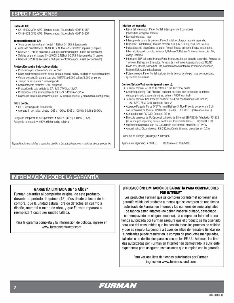
Esta actualización está basada en el caso número 3 en el manual ASD-120. El ejemplo nuevo reemplaza las unidades CN-2400S en las ubicaciones antiguas de mini puertos.
CONTROL PRIMARIO DEL ESTANTE DE AMPLIFICADORES
P
S
+12STATSTARTREMFORCE ON
FORCE OFFREM COMMGNDRLY COMMF
ASD-120
ABCDE
CN-2400S
+12STATREMGND
STATREMGND
(LA UBICACIÓN FUE ORIGINALMENTE MP-20Q)
CIRCUITOS DE MONITOREO DE FASE
(que solía ser MP-20)CN-2400S
P
S
+12STATREMGND
STATREMGND
#1 A
(que solía ser MP-20)CN-2400S
P
S
+12STATREMGND
STATREMGND
#2
SmartSequencer™ DIAGRAM 3 - LARGE LEGACY UPGRADE
ON
1 2 3 4 5 6 7 8 9
DIP SWITCH SET #2FORCE OFFFORCE OFF
FORCE OFFFORCE OFF ON
1 2 3 4 5 6 7 8 9
DIP SWITCH SET #1
ON
1 2 3 4 5 6 7 8 9
DIP SWITCH SETFORCE OFFFORCE OFF
RS-1 Llave mantenida
+12STATREMGND
1M 1 2 3 4 5
2M 4M N.O.N.C.
12V ON12V OFF
GNDON
MOMMNT
PRISEC
EVS AUTOMANUAL
6 7 8 9
1 2 3 4 5 6 7 8 9
ON
DESCRIPCIONES ABREVIADAS COMO SE MUESTRAN EN ELPRODUCTO. NO PARA LAS INSTRUCCIONES DE CONFIGURACIÓN.
CABLEADO 24 AWG CLASE 2 RECOMENDADO
SÓLO PARA REFERENCIA.
TERMINALES DE PANEL TRASERO
TERMINALES DE PANEL TRASERO
#1 B
PPSS
CN-2400S
+12STATREMGND
NONC
C
FORCE OFFFORCE OFF P
PSS
CN-2400S
+12STATREMGND
NONC
C
PPSS
CN-2400S
+12STATREMGND
NONC
C
PPSS
CN-2400S
+12STATREMGND
UNIDAD 2 INTERFAZ SECUNDARIA
NONC
C
FORCE OFFFORCE OFF
FORCE OFFFORCE OFF
FORCE OFFFORCE OFF
FORCE OFFFORCE OFF
NONC
C
UNIDAD 3 INTERFAZ SECUNDARIA UNIDAD 4 INTERFAZ SECUNDARIA
UNIDAD 5 INTERFAZ SECUNDARIA
CABLEADO 24 AWG CLASE 2 RECOMENDADO
SÓLO PARA REFERENCIA.
ON
1 2 3 4 5 6 7 8 9
SECONDARY DIP SWITCH SET
SISTEMA DE CONTROLProtocolo RS-232
CN-2400S
+12STATREMGND
Los controladores del sistema pueden interactuar con los secuenciadores de serie CN localmente o desde la nube. Pero también pueden ser interrumpidos por alarmas contra incendios.
SmartSequencer™ DIAGRAM 4 - LARGE SMART SET-UP PRIMARY INDEPENDENT MULTI-ROOM
AJUSTE COMÚN PARA UNIDADES (2, 3, 4, 5)INTERFAZ AZ SECUNDARIA UNIDADES DE ENCIMA
UNIDAD 1 INTERFAZ PRIMARIA
SALA SEPARADA
PPSS ALARMA CONTRA
INCENDIOS (3 POLOS)
ON
1 2 3 4 5 6 7 8 9
PRIMARY DIP SWITCH SET
CONFIGURACIÓN COMÚN PARA UNIDAD 1INTERFAZ AZ PRIMARIA UNIDADES DE ENCIMA
1M 1 2 3 4 5
2M 4M N.O.N.C.
12V ON12V OFF
GNDON
MOMMNT
PRISEC
EVS AUTOMANUAL
6 7 8 9
1 2 3 4 5 6 7 8 9
ON
DESCRIPCIONES ABREVIADAS COMO SE MUESTRAN EN ELPRODUCTO. NO PARA LAS INSTRUCCIONES DE CONFIGURACIÓN.
EJEMPLO 3 DIAGRAMA – ACTUALIZACIÓN LEGACY GRANDE
EJEMPLO 4 DIAGRAMA – GRAN CONFIGURACIÓN DE CONTROL PRIMARIO VIA RS-232
DQS-00006-D
7
Cable de CA: • CN-1800S: 3/14 AWG, 10 pies, negro, fijo, enchufe NEMA 5-15P • CN-2400S: 3/12 AWG, 10 pies, negro, fijo, enchufe NEMA 5-20P
Tomacorrientes de CA: • Toma de corriente (Panel frontal) 1 NEMA 5-15R ininterrumpida • Salidas de panel trasero CN-1800S:2 NEMA 5-15R ininterrumpidos (1 dúplex), • 6 NEMA 5-15R de secuencia (3 dúplex controladas por un relé por separado) • Salidas de panel trasero CN-2400S: 2 NEMA 5-20R ininterrumpidos (1 dúplex), • 6 NEMA 5-20R de secuencia (3 dúplex controladas por un relé por separado)
Protección contra bajo-sobrevoltaje: • Protección por sobretensión de CA: SMP • Modo de protección contra picos: Línea a neutro, no hay pérdida en conexión a tierra • Voltaje de sujeción para picos: pico 188VAC a 6.000 voltios/3.000 amperios • Tiempo de respuesta: 1 nanosegundo • Sobrecorriente máxima: 6.500 amperios • Protección de bajo voltaje de CA: EVS, 77VCA+/-3VCA • Protección contra sobrevoltaje de CA: EVS, 145VCA+/-5VCA • Modos de reinicio de sobrevoltaje de CA: Reinicio manual y automático (configurable)
Filtro de CA: • LiFT (Tecnología de filtro lineal) • Atenuación del ruido: Lineal, 10dB a 10KHz, 40dB a 100KHz, 50dB a 500KHz
Rango de Temperatura de Operacion: • de 5 ºC (40 ºF) a 40 ºC (105 ºF)Rango de humedad: • <90% rH (humedad relativa)
Interfaz del usuario: • Llave del interruptor: Panel frontal, interruptor de 3 posiciones (encendido, apagado, remoto) • Llaves: Incluidas, 1 par • Interrupto de boton de presión: Panel frontal, oculta por tapa de seguridad • Disyuntor: Panel frontal, llave de presión, 15A (CN-1800S), 20A (CN-2400S) • Indicadores de diagnóstico de panel frontal: Enlace primario, Enlace secundario, Ethernet, Apagado remoto, Retraso 1, Retraso 2, Retraso 3, Power, Protección OK, Voltaje Extremo • Interruptor DIP del panel frontal: Panel frontal, oculto por tapa de seguridad, Retraso de 1 minuto, Retraso de 2 minutos, Retraso de 4 minutos, Apagada forzado NO/NC, Modo 12V On/Off, Modo GND On, Momentáneo/Mantenido, Primario/Secundario, Reinicio EVS Automático/Manual • Potenciómetro: Panel frontal, calibración de tiempo oculto por tapa de seguridad, ajuste fino de retraso
Control/Estado/Activación (panel trasero): • Terminal remota: +5-30VCC entrada, 12VCC (12mA) salida • SmartSequencing: Tipo Phoenix, conector de 4 pin, con terminales de tornillo, enlaces primario y secundario (lazo actual - 1000’ nominal) • Terminal remoto: Tipo Phoenix, conector de 4 pin con terminales de tornillo; +12V, STAT, REM, GND (cableado clase 2) • Apagado Forzado (Force Off)/ Terminal Retraso 3: Tipo Phoenix, conector de 5 pin con terminales de tornillo; APAGADO FORZADO, RETRASO 3 (cableado clase 2) • Compatible con RS-232: Conector DB-9 • Direccionamiento de IP: Opcional, a través de Ethernet BB-RS232/ Adaptador RS-232 (se vende por separado) para el control de IP mediante Telnet, HTTP, BlueBOLT® • Voltímetro: Disponible con RS-232/opción de Ethernet, precisión +/- 1VCA • Amperímetro: Disponible con RS-232/opción de Ethernet, precisión +/- 0.3 A
Consumo de energía (sin carga): • 10 Watts Agencia de seguridad: • NRTL-C Conforme con CSA/NRTL:
Para la garantía completa y la información de política, ingrese en www.furmancontractor.com
GARANTÍA LIMITADA DE 15 AÑOS*Furman garantiza al comprador original de este producto, durante un período de quince (15) años desde la fecha de la compra, que la unidad estará libre de defectos en cuanto a diseño, material o mano de obra, y que Furman reparará o reemplazará cualquier unidad fallada.
¡PRECAUCIÓN! LIMITACIÓN DE GARANTÍA PARA COMPRADORES POR INTERNET
Los productos Furman que se compren por Internet no tienen una garantía válida del producto a menos que se compren de una tienda autorizada de Furman en Internet y los números de serie originales
de fábrica estén intactos (no deben haberse quitado, desechado ni reemplazado de ninguna manera). La compra por Internet a una
tienda autorizada por Furman asegura que el producto se ha diseñado para uso del consumidor, que ha pasado todas las pruebas de calidad y que es seguro. La compra a través de sitios de remate o tiendas no autorizadas puede resultar en la compra de productos manipulados, fallados o no destinados para su uso en los EE. UU. Además, las tien-das autorizadas por Furman en Internet han demostrado la suficiente experiencia para asegurar instalaciones que cumplan con la garantía.
Para ver una lista de tiendas autorizadas por Furmaningrese en www.furmansound.com
ESPECIFICACIONES
INFORMACIÓN SOBRE LA GARANTÍA
Especificacionessujetasacambiosdebidoalasactualizacionesymejorasdelosproductos.
DQS-00006-D
CN-1800S et CN-2400S
Guide de démarrage rapide
CN-1800S
CN-2400S
Pour obtenir les instructions complètes, rendez-vous sur :
www.furmancontractor.com
15 A Maximum
20 A Maximum
Pour de plus amples informations, contactez-nous au numéro suivant :
877-486-4738
CONTRACTOR SERIES SmartSequencer™
1
MIndicateurs LED multicolores consacrés aux statuts.
Arrêt immédiat forcé conforme aux ordon-nances de sécurité et de lutte contre les incend-ies.
9 sorties de capacité 15 A (CN-1800S) ou 20 A (CN-2400S).
Cordon d’alimentation de 3 m 15 A (CN-1800S) ou 20 A (CN-2400S).
Garantie limitée d’une durée de 15 ans, consultez en ligne la documentation actuelle liée à la garantie à l’adresse www.furmancontractor.com
1. Veuillez lire et respecter l’ensemble des instructions.
2. Conservez ces instructions.
3. Soyez attentif aux avertissements
AVERTISSEMENT : cet appareil n’est destiné qu’à un usage en intérieur. N’utilisez pas cet appareil à proximité de l’eau. Afin de réduire le risque d’incendie ou de choc électrique, n’exposez pas cet appareil à la pluie ni à l’humidité.
5. ATTENTION : fonctionne toujours sur secteur. Afin de réduire les risques d’électrocution, veuillez débrancher le séquenceur CN-1800S / CN-2400S de la prise AC avant de procéder à l’entretien de tout équipe-ment connecté au séquencer CN-1800S / CN-2400S.
6. Nettoyez uniquement à l’aide d’un tissu sec.
7. ATTENTION : n’installez pas l’appareil à proximité de sources de chaleur telles que les radiateurs, les registres d’air chaud, les cuisinières ou tout autre équipement susceptible de produire de la chaleur.
13. Ne cherchez pas à contrecarrer la sécurité de la fiche polarisée. Une fiche polarisée possède deux broches, dont l’une est plus large que l’autre. La broche la plus large est destinée à votre sécurité. Si la fiche fournie ne correspond pas à votre prise de courant, consultez un électricien pour le remplacement de la prise obsolète. (*voir plus bas pour la fiche 20A)
14. Ne cherchez pas à contrecarrer l’usage de la broche de mise à la terre. Une fiche de mise à la terre possède deux broches plus une troisième destinée à la mise à la terre. La troisième broche est destinée à votre sécurité. Si la fiche fournie ne correspond pas à votre prise de courant, consultez un électricien pour le remplacement de la prise obsolète.
15. AVERTISSEMENT : cet appareil doit être connecté à une prise AC dotée d’une mise à la terre.
La technologie SmartSequencing™ (synchronisation intelligente) permet aux systèmes A/V complexes d’être alimentés en toute sécurité grâce à un simple tour de clé ou en appuyant sur un bouton.
Le Series Multi-Stage Protection(SMP – Protection multi-étapes de série) garantit l’absence de temps d’arrêt pour l’ensemble des installations en éliminant de façon sûre les surtensions transitoires. Extreme Voltage Shutdown (EVS) – Arrêt sous tension extrême) avec protection de réinitiali-sation automatique contre toute sous-tension ou surtension catastrophique.
Linear Filtering Technology (LiFT – Technologie de filtre linéaire))Garantit la performance optimale de l’équipement en réduisant le bruit AC de façon linéaire à travers une large bande passante.
Compatibilité accès à distance (RS-232)Équipé d’une programmation et permettant l‘intégration à diverses plateformes de contrôle.
Les fonctions de sécurité comprennent un interrupteur à clé permettant d’éviter le fonc-tionnement non autorisé et des écrans de protec-tion permettant d’éviter la modification intempes-tive des paramètres.
8. Évitez que le cordon soit piétiné ou plié, particu-lièrement au niveau des branchements, des prises de courant et de l’appareil.
9. AVERTISSEMENT : le port de communication DE-9 RS-232 fournit le courant aux accessoires Furman (exemple : BE-RS232). Veuillez vérifier la disposition des broches et le protocole avant de connecter à ce port tout appareil provenant d’un autre fabricant.
10. Veuillez n’utiliser que les accessoires spécifiés par le fabricant.
11. Confiez l’entretien à un personnel qualifié. L’entretien est nécessaire lorsque l’unité a été endom-magée de quelque façon que ce soit ou lorsqu’elle ne fonctionne pas correctement.
12. AVERTISSEMENT : n’utilisez pas le cordon électrique afin de débrancher le courant principal. L’appareil est destiné à la synchronisation AC.
CARACTÉRISTIQUES
INSTRUCTIONS IMPORTANTES DE SÉCURITÉ
INTRODUCTION
Félicitations et merci d’avoir choisi le séquencer/conditionneur de courant de la série Contractor de Furman. La série CN de Furman offre une protection maximale contre tous les risques liés à l’alimentation AC pouvant être rencontrés par les équipements professionnels audio et vidéo
numériques ou analogiques. De plus, ce condi-tionneur est équipé du SmartSequencing exclusif de Furman établissant un nouveau standard en termes de gestion de l’alimentation. Un appareil Furman intégrant des composants SmartSequencing de A à Z.
Nous vous garantissons que ce séquenceur/conditionneur de courant de la série Contractor de Furman jouera pleinement son rôle durant de longues années.
PRIMARY LINK
SECONDARY LINK
ETHERNET
DELAY 1
DELAY 2
DELAY 3
POWER
PROTECTION OK
EXTREME VOLTAGE
UNSWITCHED 15 AMPS
PUSH TO RESET
ON
OFF
REMOTE
PRIMARY LINK
SECONDARY LINK
ETHERNET
DELAY 1
DELAY 2
DELAY 3
POWER
PROTECTION OK
EXTREME VOLTAGE
UNSWITCHED 20 AMPS
PUSH TO RESET
ON
OFF
REMOTE
PRIMARY LINK
SECONDARY LINK
ETHERNET
DELAY 1
DELAY 2
DELAY 3
POWER
PROTECTION OK
EXTREME VOLTAGE
UNSWITCHED 15 AMPS
PUSH TO RESET
ON
OFF
REMOTE
PRIMARY LINK
SECONDARY LINK
ETHERNET
DELAY 1
DELAY 2
DELAY 3
POWER
PROTECTION OK
EXTREME VOLTAGE
UNSWITCHED 20 AMPS
PUSH TO RESET
ON
OFF
REMOTE
COMM/POWER
UNSWITCHED DELAY 1 DELAY 2 DELAY 3120~V, 50/60/HZ15A MAX
FORCE OFF
DELAY 3
+12V
STAT
REM
GND
NO
NC
C
FO
FOP
P
S
S
OUT
IN
SMARTSEQUENCINGREMOTE PORT
CLASS 2 WIRING
COMM/POWER
UNSWITCHED DELAY 1 DELAY 2 DELAY 3120~V, 50/60/HZ15A MAX
FORCE OFF
DELAY 3
+12V
STAT
REM
GND
NO
NC
C
FO
FOP
P
S
S
OUT
IN
SMARTSEQUENCINGREMOTE PORT
CLASS 2 WIRING
www.furmancontractor.com • 877-486-4738 2
Veuillez lire les INSTRUCTIONS IMPORTANTES DE SÉCURITÉ• Aucune pièce remplaçable. Veuillez consulter le manuel en ligne pour de plus amples détails.• Les instructions complètes peuvent être consultées à l’adresse : www.furmancontractor.com/manuals• Veuillez inspecter minutieusement l’appareil Furman Contractor Series.• Veuillez contacter le service clientèle de Furman au numéro 707.763.1010 en cas de constatation de dégât ou si le produit ne fonctionne pas dès la première utilisation.• Le contenu de ce paquet comprend
CN-SERIES UNIT
CN-2400S
CN-1800S orCN-2400S
Pairedeclésdesécurité
Deuxécransdeprotectionamoviblesetquatrevis
CN-2400S
CN-1800S
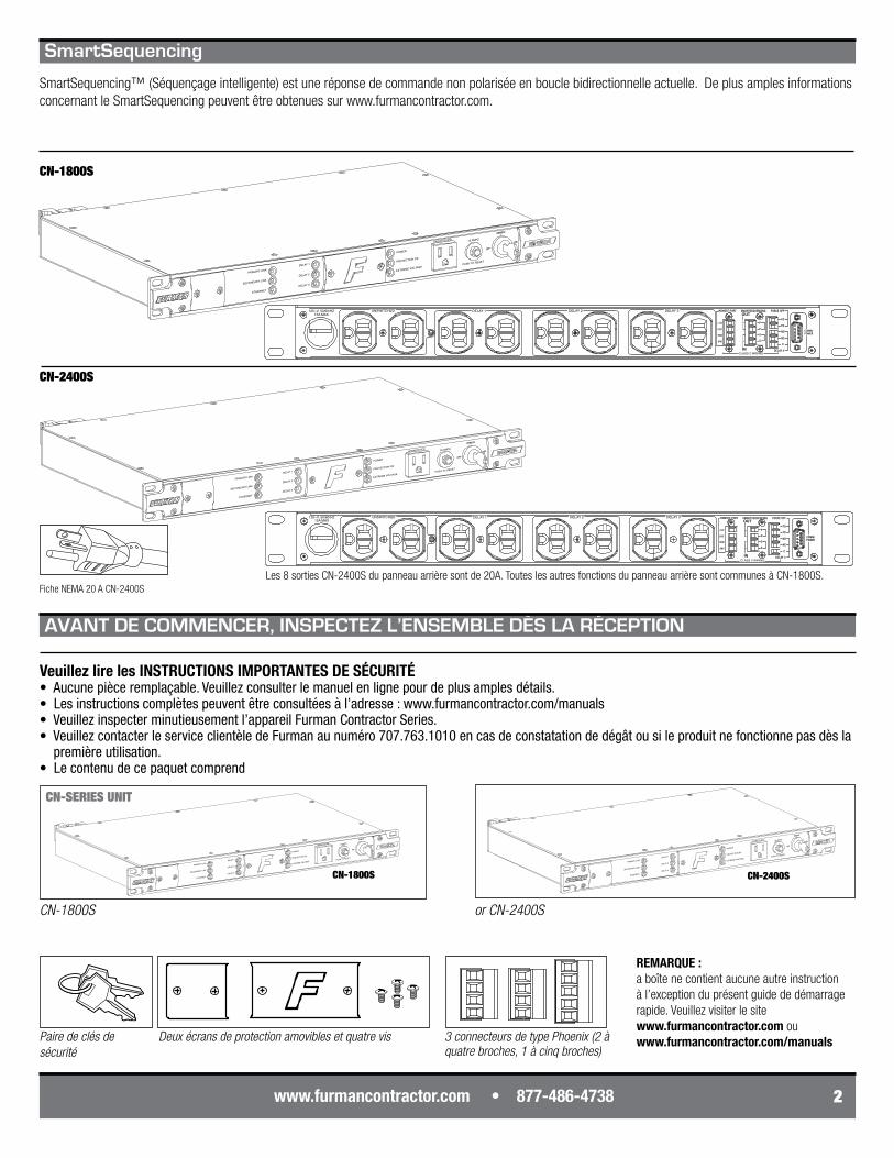
Les 8 sorties CN-2400S du panneau arrière sont de 20A. Toutes les autres fonctions du panneau arrière sont communes à CN-1800S.
3connecteursdetypePhoenix(2àquatrebroches,1àcinqbroches)
AVANT DE COMMENCER, INSPECTEZ L’ENSEMBLE DÈS LA RÉCEPTION
Fiche NEMA 20 A CN-2400S
SmartSequencing
SmartSequencing™ (Séquençage intelligente) est une réponse de commande non polarisée en boucle bidirectionnelle actuelle. De plus amples informations concernant le SmartSequencing peuvent être obtenues sur www.furmancontractor.com.
CN-1800S
REMARQUE : a boîte ne contient aucune autre instruction à l’exception du présent guide de démarrage rapide. Veuillez visiter le site www.furmancontractor.com ou www.furmancontractor.com/manuals
PRIMARY LINK
SECONDARY LINK
ETHERNET
DELAY 1
DELAY 2
DELAY 3
POWER
PROTECTION OK
EXTREME VOLTAGE
UNSWITCHED
START
SEQUENCE
15 AMPS
PUSH TO RESET
ONOFF
REMOTE
DLYADJ
1 2 3 4 5 6 7 8 9
1M 1 2 3 4 5
2M 4M N.O.N.C.
12V ON12V OFF
GNDON
MOMMNT
PRISEC
EVS AUTOMANUAL
6 7 8 9
1 2 3 4 5 6 7 8 9
ONDLYADJ
PRIMARY LINK
SECONDARY LINK
ETHERNET
DELAY 1
DELAY 2
DELAY 3
POWER
PROTECTION OK
EXTREME VOLTAGE
UNSWITCHED
START
SEQUENCE
15 AMPS
PUSH TO RESET
ONOFF
REMOTE
DLYADJ
1 2 3 4 5 6 7 8 9
1M 1 2 3 4 5
2M 4M N.O.N.C.
12V ON12V OFF
GNDON
MOMMNT
PRISEC
EVS AUTOMANUAL
6 7 8 9
PRIMARY LINK
SECONDARY LINK
ETHERNET
DELAY 1
DELAY 2
DELAY 3
POWER
PROTECTION OK
EXTREME VOLTAGE
UNSWITCHED
START
SEQUENCE
15 AMPS
PUSH TO RESET
ONOFF
REMOTE
DLYADJ
1 2 3 4 5 6 7 8 9
1M 1 2 3 4 5
2M 4M N.O.N.C.
12V ON12V OFF
GNDON
MOMMNT
PRISEC
EVS AUTOMANUAL
6 7 8 9
PRIMARYLINK
SECONDARY LINK
ETHERNET
DELAY 1
DELAY 2
DELAY 3
POWER
PROTECTION OK
EXTREME VOLTAGE
UNSWITCHED
START
SEQUENCE
20 AMPS
PUSH TO RESET
ONOFF
REMOTE1M 2M
12V ON12V OFF
GNDON
MOMMNT
EVS AUTO MANUAL
1 2 3 4 5 6 7 8 9
DLYADJ
4M N.O. N.C.
PRISEC
1 2 3 4 5 6 7 8 9
PRIMARY LINK
SECONDARY LINK
ETHERNET
DELAY 1
DELAY 2
DELAY 3
POWER
PROTECTION OK
EXTREME VOLTAGE
UNSWITCHED
START
SEQUENCE
15 AMPS
PUSH TO RESET
ONOFF
REMOTE
DLYADJ
1 2 3 4 5 6 7 8 9
1M 1 2 3 4 5
2M 4M N.O.N.C.
12V ON12V OFF
GNDON
MOMMNT
PRISEC
EVS AUTOMANUAL
6 7 8 9
1 2 3 4 5 6 7 8 9
ONDLYADJ
DLYADJ
1M 1 2 3 4 5
2M 4M N.O.N.C.
12V ON12V OFF
GNDON
MOMMNT
PRISEC
EVS AUTOMANUAL
6 7 8 9
ONOFF
alimentation) indique que l’appareil reçoit du courant alternatif et que les sorties non commutées sont actives.
s’allume, s’estompe ou ne s’allume pas si la protection contre les surtensions a été compromise.
3
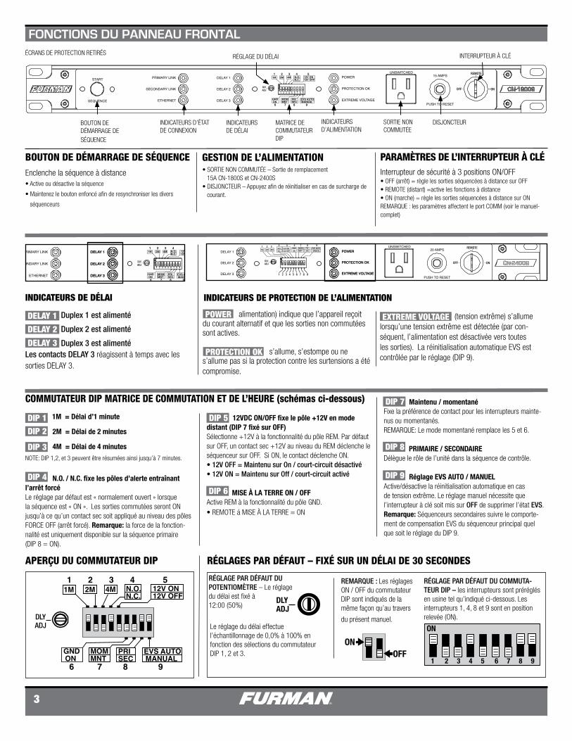
BOUTON DE DÉMARRAGE DE SÉQUENCE
INDICATEURS D’ÉTAT DE CONNEXION
INDICATEURS DE DÉLAI
MATRICE DE COMMUTATEUR DIP
INDICATEURS D’ALIMENTATION
SORTIE NON COMMUTÉE
DISJONCTEUR
INTERRUPTEUR À CLÉÉCRANS DE PROTECTION RETIRÉS
Le réglage du délai effectue l’échantillonnage de 0,0% à 100% en fonction des sélections du commutateur DIP 1, 2 et 3.
1M = Délai d’1 minute
2M = Délai de 2 minutes
4M = Délai de 4 minutes
NOTE: DIP 1,2, et 3 peuvent être résumées ainsi jusqu’à 7 minutes.
N.O. / N.C. fixe les pôles d’alerte entraînant l’arrêt forcéLe réglage par défaut est « normalement ouvert » lorsque la séquence est « ON ». Les sorties commutées seront ON jusqu’à ce qu’un contact sec soit appliqué au niveau des pôles FORCE OFF (arrêt forcé). Remarque: la force de la fonction-nalité est uniquement disponible sur la séquence primaire (DIP 8 = ON).
APERÇU DU COMMUTATEUR DIP
RÉGLAGE DU DÉLAI
RÉGLAGES PAR DÉFAUT – FIXÉ SUR UN DÉLAI DE 30 SECONDES
RÉGLAGE PAR DÉFAUT DU POTENTIOMÈTRE – Le réglage du délai est fixé à 12:00 (50%)
RÉGLAGE PAR DÉFAUT DU COMMUTA-TEUR DIP – les interrupteurs sont préréglés en usine tel qu’indiqué ci-dessous. Les interrupteurs 1, 4, 8 et 9 sont en position relevée (ON).
Maintenu / momentanéFixe la préférence de contact pour les interrupteurs mainte-nus ou momentanés.REMARQUE: Le mode momentané remplace les 5 et 6. PRIMAIRE / SECONDAIRE Délègue le rôle de l’unité dans la séquence de contrôle.
Réglage EVS AUTO / MANUEL Active/désactive la réinitialisation automatique en cas de tension extrême. Le réglage manuel nécessite que l’interrupteur à clé soit mis sur OFF de supprimer l’état EVS. Remarque: Séquenceurs secondaires suivre le comporte-ment de compensation EVS du séquenceur principal quel que soit le réglage du DIP 9.
COMMUTATEUR DIP MATRICE DE COMMUTATION ET DE L’HEURE (schémas ci-dessous)
INDICATEURS DE PROTECTION DE L’ALIMENTATION
Duplex 1 est alimenté
Duplex 2 est alimenté
Duplex 3 est alimentéLes contacts DELAY 3 réagissent à temps avec les sorties DELAY 3.
(tension extrême) s’allume lorsqu’une tension extrême est détectée (par con-séquent, l’alimentation est désactivée vers toutes les sorties). La réinitialisation automatique EVS est contrôlée par le réglage (DIP 9).
12VDC ON/OFF fixe le pôle +12V en mode distant (DIP 7 fixé sur OFF)Sélectionne +12V à la fonctionnalité du pôle REM. Par défaut sur OFF, un contact sec +12V au niveau du REM déclenche le séquenceur sur OFF. Si ON, le contact déclenche ON.• 12V OFF = Maintenu sur On / court-circuit désactivé• 12V ON = Maintenu sur Off / court-circuit activé MISE À LA TERRE ON / OFFActive REM à la fonctionnalité du pôle GND. • REMOTE á MISE À LA TERRE = ON
DIP 1 DIP 2
DIP 3
DIP 4
DIP 5
DIP 6
DIP 7
DIP 8
DIP 9
INDICATEURS DE DÉLAI
POWER
PROTECTION OK
EXTREME VOLTAGE
FONCTIONS DU PANNEAU FRONTAL
BOUTON DE DÉMARRAGE DE SÉQUENCEEnclenche la séquence à distance• Active ou désactive la séquence
• Maintenez le bouton enfoncé afin de resynchroniser les divers
séquenceurs
PARAMÈTRES DE L’INTERRUPTEUR À CLÉInterrupteur de sécurité à 3 positions ON/OFF• OFF (arrêt) = règle les sorties séquencées à distance sur OFF• REMOTE (distant) =active les fonctions à distance• ON (marche) = règle les sorties séquencées à distance sur ONREMARQUE : les paramètres affectent le port COMM (voir le manuel-complet)
GESTION DE L’ALIMENTATION• SORTIE NON COMMUTÉE – Sortie de remplacement 15A CN-1800S et CN-2400S• DISJONCTEUR – Appuyez afin de réinitialiser en cas de surcharge de courant.
DELAY 1
DELAY 2
DELAY 3
REMARQUE : Les réglages ON / OFF du commutateur DIP sont indiqués de la même façon qu’au travers
du présent manuel.
COMM/POWER
UNSWITCHED DELAY 1 DELAY 2 DELAY 3120~V, 50/60/HZ15A MAX
FORCE OFF
DELAY 3
+12V
STAT
REM
GND
NO
NC
C
FO
FOP
P
S
S
OUT
IN
SMARTSEQUENCINGREMOTE PORT
CLASS 2 WIRING
COMM/POWER
5432
6789
1
ACCESSORY POWER ONLY(NEGATIVE 12VDC RETURN)RECEIVE DATATRANSMIT DATAACCESSORY POWER ONLYSIGNAL GROUNDACCESSORY POWER ONLYREQUEST TO SENDCLEAR TO SENDACCESSORY POWER ONLY(POSITIVE 12V)
PIN NO. 1
2 3 4 5 6 7 8 9
COMM/POWER
FORCE OFF
DELAY 3
+12V
STAT
REM
GND
NO
NC
C
FO
FOP
P
S
S
OUT
IN
SMARTSEQUENCINGREMOTE PORT
CLASS 2 WIRING
COMM/POWER
FORCE OFF
DELAY 3
+12V
STAT
REM
GND
NO
NC
C
FO
FOP
P
S
S
OUT
IN
SMARTSEQUENCINGREMOTE PORT
CLASS 2 WIRING
COMM/POWER
FORCE OFF
DELAY 3
+12V
STAT
REM
GND
NO
NC
C
FO
FOP
P
S
S
OUT
IN
SMARTSEQUENCINGREMOTE PORT
CLASS 2 WIRING
PRIMARY LINK
SECONDARY LINK
ETHERNET
DELAY 1
DELAY 2
DELAY 3
POWER
PROTECTION OK
EXTREME VOLTAGE
UNSWITCHED
START
SEQUENCE
15 AMPS
PUSH TO RESET
ONOFF
REMOTE
DLYADJ
1 2 3 4 5 6 7 8 9
1M 1 2 3 4 5
2M 4M N.O.N.C.
12V ON12V OFF
GNDON
MOMMNT
PRISEC
EVS AUTOMANUAL
6 7 8 9
PRIMARY LINK
SECONDARY LINK
ETHERNET
DELAY 1
DELAY 2
DELAY 3
POWER
PROTECTION OK
EXTREME VOLTAGE
UNSWITCHED
START
SEQUENCE
15 AMPS
PUSH TO RESET
ONOFF
REMOTE
DLYADJ
1 2 3 4 5 6 7 8 9
1M 1 2 3 4 5
2M 4M N.O.N.C.
12V ON12V OFF
GNDON
MOMMNT
PRISEC
EVS AUTOMANUAL
6 7 8 9
www.furmancontractor.com • 877-486-4738 4
CORDON D’ALIMENTATION AC DE 3m,
BANC DE SORTIE NON COMMUTÉE TOUJOURS ON,
BANC DE SORTIE DELAY 1
BANC DE SORTIE DELAY 2
BROCHE 1 – ALIMENTATION ACCESSOIRE UNIQUEMENT (RETOUR 12VCC NÉGATIF)BROCHE 2 - TRANSMET LES DONNÉESBROCHE 3 - RECOIT LES DONNÉESBROCHE 4 – ALIMENTATION ACCESSOIRE UNIQUEMENTBROCHE 5 – MISE À LA TERREBROCHE 6 – ALIMENTATION ACCESSOIRE UNIQUEMENTBROCHE 7 – REQUÊTE POUR ENVOIBROCHE 8 – SUPPRIMER POUR ENVOIBROCHE 9 – ALIMENTATION ACCESSOIRE UNIQUEMENT (12V POSITIF)
CONNECTEURS DE TYPE PHOENIX
Barrette de connexion Legacy (1)+12V - Borne principale CC de sortie pour activation à distance
STAT - Borne de sortie CC pour indicateur LED distant (ANODE)
REM - Borne d’entrée principale pour activation à distance
Barrette de connexion SmartSequencing (2) Pôles principaux se connectent OUT aux pôles secondaires du SmartSequencing secondaire.
Pôles secondaires se connectent IN aux pôles principaux du SmartSequencing précédente
REMARQUE : les dispositifs en série.
Barrette de connexion de relai (3)FORCE OFF (ARRÊT FORCÉ) Impose un arrêt immédiat imposé par une alerte incendie
Delay 3 -Fournit le contact sec pour les relais (max. 1A @ 24VDC)
CONNECTEUR FEMELLE DB-9 RS-232BANC DE SORTIE DELAY 3
CN-2400S SORTIES 20A PANNEAU ARRIÈRE. Toutes les autres caractéristiques du panneau arrière sont COMMUN POUR CN-1800 et NC-2400S
CN-1800S
INDICATEURS D’ÉTAT DE CONNEXION DU PANNEAU FRONTAL
ETHERNET – La couleur indique l’état de la com-munication avec la plateforme BlueBOLT. indique l’absence de connexion via l’adaptateur BlueBOLT (par exemple BB-RS232)
indique que l’unité a établi une communi-cation active via l’adaptateur BlueBOLT et le réseau Ethernet local.
Veuillez remarquer : le port est étiqueté COMM/POWER et fournit du 12VDC aux accessoires adé-quats. Débit en bauds 19200.
L’appareil a perdu la continuité du lien et ne peut pas communiquer la hiérarchie SmartSe-quencing.
Veuillez remarquer : un clignotement lent du LED vert du lien prin-cipal indique que l’appareil est configuré en tant qu’unité principale selon le commutateur DIP 8. (Valeur par défaut).S’il vous plaît
Veuillez remarquer : Un dispositif secondaire doit avoir un solide lien vert PRIMAIRE LED.
SECONDARY LINK – (LIEN SECONDAIRE) – LED multicolore indiquant l’état de communication par rapport à la hiérarchie du lien principal : L’unité communique via le lien principal vers l’unité suivant du lien secondaire OUT .
L’appareil a perdu la continuité du lien et ne peut pas communiquer la hiérarchie SmartSe-quencing.
Veuillez remarquer : un LED secondaire éteint indique la dernière unité de la chaîne de la séquence. Une unité seule affichera un LED secondaire éteint.
PRIMARY LINK – (LIEN PRINCIPAL) – LED multicolore indiquant l’état de communication par rapport à la hiérarchie du lien secondaire :
L’appareil communique via le lien secondaire vers le lien principal précédent OUT .
PRIMARY LINK
SECONDARY LINK
ETHERNET
DELAY 1
DELAY 2
DELAY 3
POWER
PROTECTION OK
EXTREME VOLTAGE
UNSWITCHED
START
SEQUENCE
15 AMPS
PUSH TO RESET
ONOFF
REMOTE
DLYADJ
1 2 3 4 5 6 7 8 9
1M 1 2 3 4 5
2M 4M N.O.N.C.
12V ON12V OFF
GNDON
MOMMNT
PRISEC
EVS AUTOMANUAL
6 7 8 9
PRIMARY LINK
SECONDARY LINK
ETHERNET
DELAY 1
DELAY 2
DELAY 3
POWER
PROTECTION OK
EXTREME VOLTAGE
UNSWITCHED
START
SEQUENCE
15 AMPS
PUSH TO RESET
ONOFF
REMOTE
DLYADJ
1 2 3 4 5 6 7 8 9
1M 1 2 3 4 5
2M 4M N.O.N.C.
12V ON12V OFF
GNDON
MOMMNT
PRISEC
EVS AUTOMANUAL
6 7 8 9
PRIMARY LINK
SECONDARY LINK
ETHERNET
DELAY 1
DELAY 2
DELAY 3
POWER
PROTECTION OK
EXTREME VOLTAGE
UNSWITCHED
START
SEQUENCE
15 AMPS
PUSH TO RESET
ONOFF
REMOTE
DLYADJ
1 2 3 4 5 6 7 8 9
1M 1 2 3 4 5
2M 4M N.O.N.C.
12V ON12V OFF
GNDON
MOMMNT
PRISEC
EVS AUTOMANUAL
6 7 8 9
PRIMARY LINK
SECONDARY LINK
ETHERNET
DELAY 1
DELAY 2
DELAY 3
POWER
PROTECTION OK
EXTREME VOLTAGE
UNSWITCHED
START
SEQUENCE
15 AMPS
PUSH TO RESET
ONOFF
REMOTE
DLYADJ
1 2 3 4 5 6 7 8 9
1M 1 2 3 4 5
2M 4M N.O.N.C.
12V ON12V OFF
GNDON
MOMMNT
PRISEC
EVS AUTOMANUAL
6 7 8 9
VERT
ROUGE
LED ÉTEINT
LED arrière – indique que l’appareil reçoit du courant alternatif et que les sorties non commutées sont actives.
FONCTIONS DU PANNEAU ARRIÈRE
GND - Borne pour LED d’état et/ou activation à distance (CATHODE) Delay 3 fonctions avec Furman MP-20, ASD-120, etc.
Le port de communication DB-9 peut également fournir du courant. Les broches 2, 3 et 5 peu-vent être utilisées pour les dispositifs RS-232 et protocoles ne provenant pas de Furman. Veuillez vérifier la disposition des broches et le protocole avant de connecter tout appareil provenant d’un autre fabricant à ce port.
IMPORTANT, VEUILLEZ LIRE
VERT
ROUGE VERT
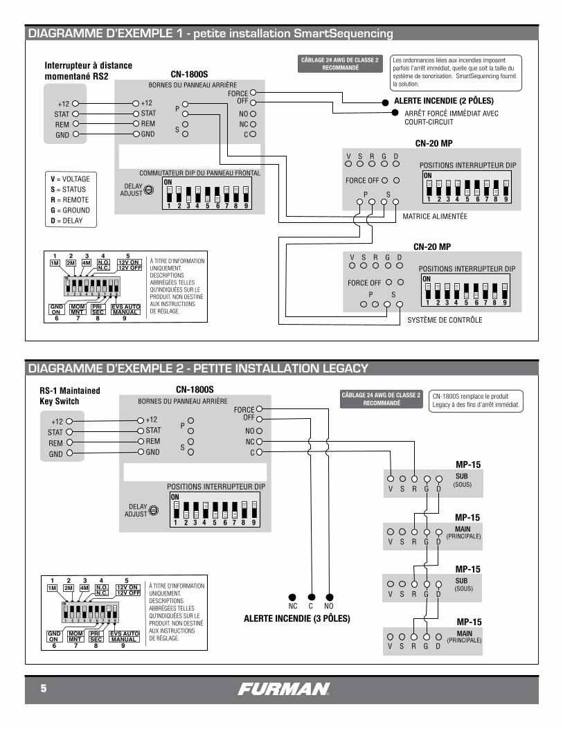
5
SmartSequencer™ DIAGRAM 1 - SMALL SMARTSEQUENCING SET-UP
CÂBLAGE 24 AWG DE CLASSE 2 RECOMMANDÉ
Les ordonnances liées aux incendies imposent parfois l’arrêt immédiat, quelle que soit la taille du système de sonorisation. SmartSequencing fournit la solution.
Interrupteur à distance momentané RS2 CN-1800S
+12STATREMGND
+12STATREMGND
P
S
ALERTE INCENDIE (2 PÔLES)
V S R G D
P S
FORCE OFF
V S R G D
P S
COMMUTATEUR DIP DU PANNEAU FRONTAL
MATRICE ALIMENTÉE
SYSTÈME DE CONTRÔLE
BORNES DU PANNEAU ARRIÈRE
CN-20 MP
CN-20 MP
FORCEOFF
NONC
C
FORCE OFF
DELAYADJUST
ARRÊT FORCÉ IMMÉDIAT AVEC COURT-CIRCUIT
V = VOLTAGES = STATUSR = REMOTEG = GROUNDD = DELAY
ON
1 2 3 4 5 6 7 8 9
ON
1 2 3 4 5 6 7 8 9
POSITIONS INTERRUPTEUR DIP
ON
1 2 3 4 5 6 7 8 9
1M 1 2 3 4 5
2M 4M N.O.N.C.
12V ON12V OFF
GNDON
MOMMNT
PRISEC
EVS AUTOMANUAL
6 7 8 9
1 2 3 4 5 6 7 8 9
ON
À TITRE D’INFORMATION UNIQUEMENT.DESCRIPTIONS ABBRÉGÉES TELLES QU’INDIQUÉES SUR LE PRODUIT. NON DESTINÉ AUX INSTRUCTIONS DE RÉGLAGE.
POSITIONS INTERRUPTEUR DIP
CN-1800S
+12STATREMGND
P
S
FORCEOFF
NONC
C
DELAYADJUST
CN-1800S remplace le produit Legacy à des fins d’arrêt immédiat.
CÂBLAGE 24 AWG DE CLASSE 2 RECOMMANDÉ
+12STATREMGND
ALERTE INCENDIE (3 PÔLES)
V S R G D
(SOUS)
NC C NO
MP-15SUB
MP-15MAIN
V S R G D
V S R G D
MP-15SUB
V S R G D
MP-15MAIN
SmartSequencer™ DIAGRAM 2 - SMALL LEGACY SET-UP
ON
1 2 3 4 5 6 7 8 9
1M 1 2 3 4 5
2M 4M N.O.N.C.
12V ON12V OFF
GNDON
MOMMNT
PRISEC
EVS AUTOMANUAL
6 7 8 9
1 2 3 4 5 6 7 8 9
ON
À TITRE D’INFORMATION UNIQUEMENT.DESCRIPTIONS ABBRÉGÉES TELLES QU’INDIQUÉES SUR LE PRODUIT. NON DESTINÉ AUX INSTRUCTIONS DE RÉGLAGE.
POSITIONS INTERRUPTEUR DIP
BORNES DU PANNEAU ARRIÈRE
(PRINCIPALE)
(SOUS)
(PRINCIPALE)
RS-1 MaintainedKey Switch
DIAGRAMME D’EXEMPLE 1 - petite installation SmartSequencing
DIAGRAMME D’EXEMPLE 2 - PETITE INSTALLATION LEGACY
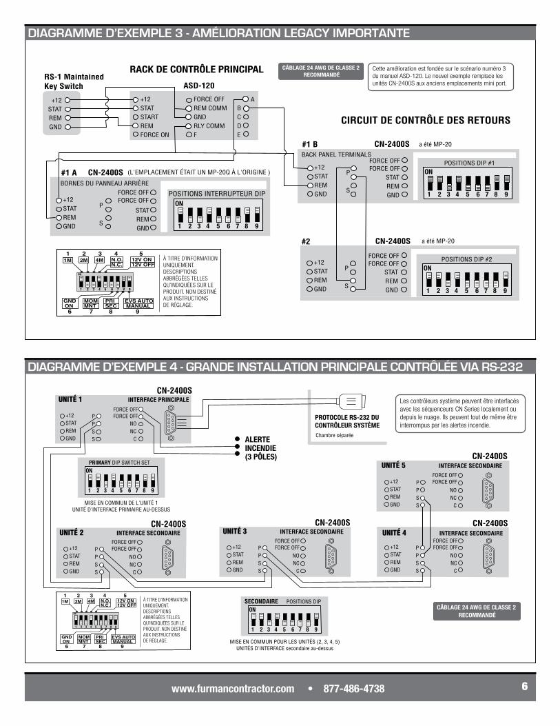
www.furmancontractor.com • 877-486-4738 6
Cette amélioration est fondée sur le scénario numéro 3 du manuel ASD-120. Le nouvel exemple remplace les unités CN-2400S aux anciens emplacements mini port.
RACK DE CONTRÔLE PRINCIPAL
P
S
+12STATSTARTREMFORCE ON
FORCE OFFREM COMMGNDRLY COMMF
ASD-120
ABCDE
CN-2400S
+12STATREMGND
STATREMGND
(L'EMPLACEMENT ÉTAIT UN MP-20Q À L'ORIGINE )
CIRCUIT DE CONTRÔLE DES RETOURS
a été MP-20CN-2400S
P
S
+12STATREMGND
STATREMGND
#1 B
a été MP-20CN-2400S
P
S
+12STATREMGND
STATREMGND
#2
SmartSequencer™ DIAGRAM 3 - LARGE LEGACY UPGRADE
BACK PANEL TERMINALS
ON
1 2 3 4 5 6 7 8 9
POSITIONS DIP #2FORCE OFFFORCE OFF
FORCE OFFFORCE OFF ON
1 2 3 4 5 6 7 8 9
POSITIONS DIP #1
ON
1 2 3 4 5 6 7 8 9
FORCE OFFFORCE OFF
RS-1 MaintainedKey Switch
+12STATREMGND
1M 1 2 3 4 5
2M 4M N.O.N.C.
12V ON12V OFF
GNDON
MOMMNT
PRISEC
EVS AUTOMANUAL
6 7 8 9
1 2 3 4 5 6 7 8 9
ON
À TITRE D’INFORMATION UNIQUEMENT.DESCRIPTIONS ABBRÉGÉES TELLES QU’INDIQUÉES SUR LE PRODUIT. NON DESTINÉ AUX INSTRUCTIONS DE RÉGLAGE.
CÂBLAGE 24 AWG DE CLASSE 2 RECOMMANDÉ
BORNES DU PANNEAU ARRIÈRE
POSITIONS INTERRUPTEUR DIP
#1 A
PPSS
CN-2400S
+12STATREMGND
UNITÉ 3 INTERFACE SECONDAIRE
NONC
C
FORCE OFFFORCE OFF P
PSS
CN-2400S
+12STATREMGND
UNITÉ 4 INTERFACE SECONDAIRE
NONC
C
PPSS
CN-2400S
+12STATREMGND
UNITÉ 5 INTERFACE SECONDAIRE
NONC
C
PPSS
CN-2400S
+12STATREMGND
UNITÉ 2 INTERFACE SECONDAIRE
NONC
C
FORCE OFFFORCE OFF
FORCE OFFFORCE OFF
FORCE OFFFORCE OFF
FORCE OFFFORCE OFF
NONC
C
ON
1 2 3 4 5 6 7 8 9
SECONDAIRE POSITIONS DIP
PROTOCOLE RS-232 DU CONTRÔLEUR SYSTÈME
CN-2400S
+12STATREMGND
Les contrôleurs système peuvent être interfacés avec les séquenceurs CN Series localement ou depuis le nuage. Ils peuvent tout de même être interrompus par les alertes incendie.
SmartSequencer™ DIAGRAM 4 - LARGE SMART SET-UP PRIMARY INDEPENDENT MULTI-ROOM
MISE EN COMMUN POUR LES UNITÉS (2, 3, 4, 5)UNITÉS D'INTERFACE secondaire au-dessus
UNITÉ 1 INTERFACE PRINCIPALE
Chambre séparée
PPSS
ON
1 2 3 4 5 6 7 8 9
PRIMARY DIP SWITCH SET
MISE EN COMMUN DE L'UNITÉ 1UNITÉ D'INTERFACE PRIMAIRE AU-DESSUS
1M 1 2 3 4 5
2M 4M N.O.N.C.
12V ON12V OFF
GNDON
MOMMNT
PRISEC
EVS AUTOMANUAL
6 7 8 9
1 2 3 4 5 6 7 8 9
ON
À TITRE D’INFORMATION UNIQUEMENT.DESCRIPTIONS ABBRÉGÉES TELLES QU’INDIQUÉES SUR LE PRODUIT. NON DESTINÉ AUX INSTRUCTIONS DE RÉGLAGE.
CÂBLAGE 24 AWG DE CLASSE 2 RECOMMANDÉ
ALERTE INCENDIE (3 PÔLES)
DIAGRAMME D’EXEMPLE 3 - AMÉLIORATION LEGACY IMPORTANTE
DIAGRAMME D’EXEMPLE 4 - GRANDE INSTALLATION PRINCIPALE CONTRÔLÉE VIA RS-232
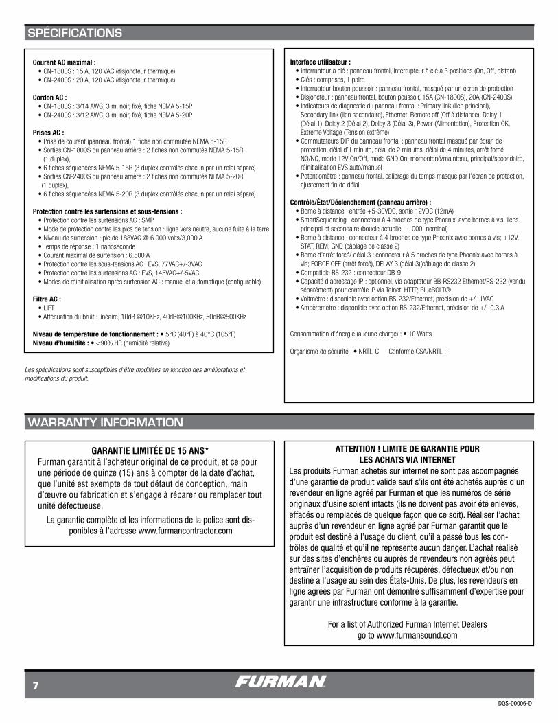
DQS-00006-D
7
Courant AC maximal : • CN-1800S : 15 A, 120 VAC (disjoncteur thermique) • CN-2400S : 20 A, 120 VAC (disjoncteur thermique)
Cordon AC : • CN-1800S : 3/14 AWG, 3 m, noir, fixé, fiche NEMA 5-15P • CN-2400S : 3/12 AWG, 3 m, noir, fixé, fiche NEMA 5-20P
Prises AC : • Prise de courant (panneau frontal) 1 fiche non commutée NEMA 5-15R • Sorties CN-1800S du panneau arrière : 2 fiches non commutés NEMA 5-15R (1 duplex), • 6 fiches séquencées NEMA 5-15R (3 duplex contrôlés chacun par un relai séparé) • Sorties CN-2400S du panneau arrière : 2 fiches non commutés NEMA 5-20R (1 duplex), • 6 fiches séquencées NEMA 5-20R (3 duplex contrôlés chacun par un relai séparé)
Protection contre les surtensions et sous-tensions : • Protection contre les surtensions AC : SMP • Mode de protection contre les pics de tension : ligne vers neutre, aucune fuite à la terre • Niveau de surtension : pic de 188VAC @ 6.000 volts/3,000 A • Temps de réponse : 1 nanoseconde • Courant maximal de surtension : 6.500 A • Protection contre les sous-tensions AC : EVS, 77VAC+/-3VAC • Protection contre les surtensions AC : EVS, 145VAC+/-5VAC • Modes de réinitialisation après surtension AC : manuel et automatique (configurable)
Filtre AC : • LiFT • Atténuation du bruit : linéaire, 10dB @10KHz, 40dB@100KHz, 50dB@500KHz
Niveau de température de fonctionnement : • 5°C (40°F) à 40°C (105°F)Niveau d’humidité : • <90% HR (humidité relative)
Interface utilisateur : • interrupteur à clé : panneau frontal, interrupteur à clé à 3 positions (On, Off, distant) • Clés : comprises, 1 paire • Interrupteur bouton poussoir : panneau frontal, masqué par un écran de protection • Disjoncteur : panneau frontal, bouton poussoir, 15A (CN-1800S), 20A (CN-2400S) • Indicateurs de diagnostic du panneau frontal : Primary link (lien principal), Secondary link (lien secondaire), Ethernet, Remote off (Off à distance), Delay 1 (Délai 1), Delay 2 (Délai 2), Delay 3 (Délai 3), Power (Alimentation), Protection OK, Extreme Voltage (Tension extrême) • Commutateurs DIP du panneau frontal : panneau frontal masqué par écran de protection, délai d’1 minute, délai de 2 minutes, délai de 4 minutes, arrêt forcé NO/NC, mode 12V On/Off, mode GND On, momentané/maintenu, principal/secondaire, réinitialisation EVS auto/manuel • Potentiomètre : panneau frontal, calibrage du temps masqué par l’écran de protection, ajustement fin de délai
Contrôle/État/Déclenchement (panneau arrière) : • Borne à distance : entrée +5-30VDC, sortie 12VDC (12mA) • SmartSequencing : connecteur à 4 broches de type Phoenix, avec bornes à vis, liens principal et secondaire (boucle actuelle – 1000’ nominal) • Borne à distance : connecteur à 4 broches de type Phoenix avec bornes à vis; +12V, STAT, REM, GND (câblage de classe 2) • Borne d’arrêt forcé/ délai 3 : connecteur à 5 broches de type Phoenix avec bornes à vis; FORCE OFF (arrêt forcé), DELAY 3 (délai 3)(câblage de classe 2) • Compatible RS-232 : connecteur DB-9 • Capacité d’adressage IP : optionnel, via adaptateur BB-RS232 Ethernet/RS-232 (vendu séparément) pour contrôle IP via Telnet, HTTP, BlueBOLT® • Voltmètre : disponible avec option RS-232/Ethernet, précision de +/- 1VAC • Ampèremètre : disponible avec option RS-232/Ethernet, précision de +/- 0.3 A
Consommation d’énergie (aucune charge) : • 10 Watts Organisme de sécurité : • NRTL-C Conforme CSA/NRTL :
La garantie complète et les informations de la police sont dis-ponibles à l’adresse www.furmancontractor.com
GARANTIE LIMITÉE DE 15 ANS* Furman garantit à l’acheteur original de ce produit, et ce pour une période de quinze (15) ans à compter de la date d’achat, que l’unité est exempte de tout défaut de conception, main d’œuvre ou fabrication et s’engage à réparer ou remplacer tout unité défectueuse.
ATTENTION ! LIMITE DE GARANTIE POUR LES ACHATS VIA INTERNET
Les produits Furman achetés sur internet ne sont pas accompagnés d’une garantie de produit valide sauf s’ils ont été achetés auprès d’un revendeur en ligne agréé par Furman et que les numéros de série originaux d’usine soient intacts (ils ne doivent pas avoir été enlevés, effacés ou remplacés de quelque façon que ce soit). Réaliser l’achat auprès d’un revendeur en ligne agréé par Furman garantit que le produit est destiné à l’usage du client, qu’il a passé tous les con-trôles de qualité et qu’il ne représente aucun danger. L’achat réalisé sur des sites d’enchères ou auprès de revendeurs non agréés peut entraîner l’acquisition de produits récupérés, défectueux et/ou non destiné à l’usage au sein des États-Unis. De plus, les revendeurs en ligne agréés par Furman ont démontré suffisamment d’expertise pour garantir une infrastructure conforme à la garantie.
For a list of Authorized Furman Internet Dealers go to www.furmansound.com
SPÉCIFICATIONS
WARRANTY INFORMATION
Lesspécificationssontsusceptiblesd’êtremodifiéesenfonctiondesaméliorationsetmodificationsduproduit.


