Embed Size (px)
Citation preview
FACTORY AUTOMATION
18 million compact PLCs worldwide
Over 35 years experience
Positioning/ motion control
Networking
Remote maintenance
Security
COMPACT PLC FAMILYMELSEC PLC

2
Global player
Global impact of Mitsubishi Electric
Through Mitsubishi Electric’s vision, “Changes for the Better“ are possible for a brighter future.
We bring together the best minds to cre-ate the best technologies. At Mitsubishi Electric, we understand that technol-ogy is the driving force of change in our lives. By bringing greater comfort to daily life, maximising the efficiency of businesses and keeping things running across society, we integrate technology and innovation to bring changes for the better.
Mitsubishi Electric is involved in many areas including the following
Energy and electric systemsA wide range of power and electrical products from generators to large-scale displays.
Electronic devicesA wide portfolio of cutting-edge semiconductor devices for systems and products.
Home applianceDependable consumer products like air conditioners and home entertainment systems.
Information and communication systemsCommercial and consumer-centric equipment, products and systems.
Industrial automation systemsMaximising productivity and efficiency with cutting-edge automation technology.
3
Global leader 4
What makes a world leading PLC? 5
Range overview 6
iQ-F – the next level of industry 7
FX3U/FX3UC – a perfect PLC concept 8
FX3G/FX3GC/FX3GE – customized control 9
FX3S – new possibilities 10
Programming and software 11
Networking 12
Analog solutions 13
Drive control solutions 14
Visualization solutions 15
Section 2: Technical Informations
Contents
Contents

4
Global leader
Global leader
18 million FXThe FX Family of PLCs is the PLC of choice across the world, industries and applications. Mitsubishi Electric has always worked closely with its custom-ers to design the PLC that they want for their applications. The manufacturing and use of 18 million FX CPUs is a dem-onstration that this close working rela-tionship has delivered quality, reliability and the product that customers want.
Over 35 yearsThe FX Family of PLCs has been an im-portant part of control engineering for over 35 years. Throughout its history, the product has evolved from the original F series into today’s current iQ-F series.
The FX Family has proven to be highly reliable and it consistently improves its compatibility with previous PLC gen-erations.
International acceptanceShipping approvals such as ABS, Lloyds Register, DNV/GL, Bureau Veritas, NK, RINA, KR for example plus CE compli-ance for Low Voltage and EMC directives as well as manufacturing to Automo-tive industry quality levels, make the FX Family PLCs products to trust.
The MELSEC iQ-F series is the fourth generation compact programmable controllers of Mitsubushi Electric. It offers outstanding performance, superior drive
control and an intuitive programming environment.
5
World leading PLCs
What makes a world leading PLC range?
Ease of useControl systems that require minimal setup and keep program development time short.
AffordableA high performance to cost ratio makes economical design solutions for a di-verse range of applications a reality.
These features combined with Mitsubishi Electric´s legacy in quality and reliability ensure that the fourth generation of mi-cro controllers will continue to be at the forefront of the compact PLC market and provide customers with a leading edge.
FlexibleA configurable design that permits open communication, large I/O handling, as well as precise positioning and analog control, creating systems that adapt to customer requirements.
Customer ConfidenceWith a design philosophy spanning more than a quarter century, a cus-tomer base spread across the globe, a host of industrial certifications and al-most 16 million CPUs sold, the FX series continues to sustain its position as the compact PLC of choice.
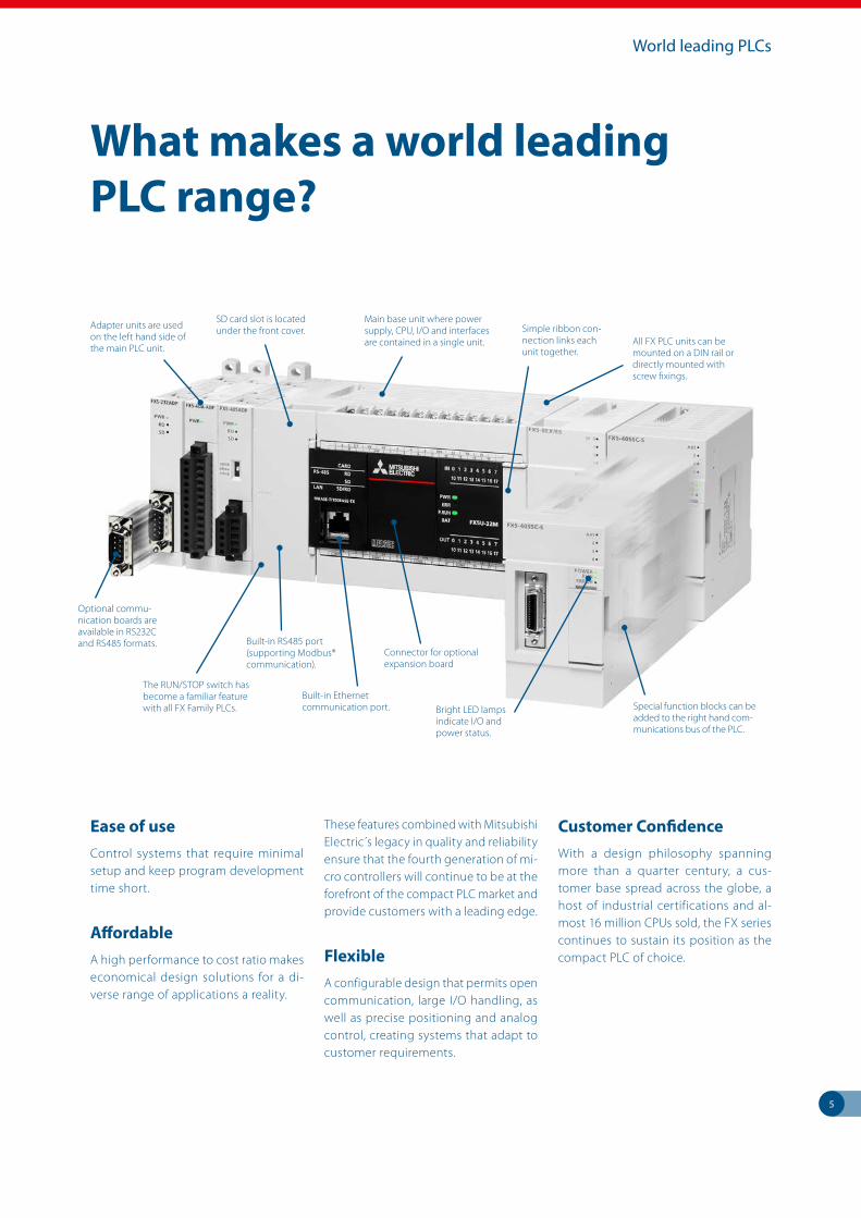
Adapter units are used on the left hand side of the main PLC unit.
SD card slot is located under the front cover.
Main base unit where power supply, CPU, I/O and interfaces are contained in a single unit.
Bright LED lamps indicate I/O and power status.
Simple ribbon con-nection links each unit together.
Optional commu-nication boards are available in RS232C and RS485 formats.
All FX PLC units can be mounted on a DIN rail or directly mounted with screw fixings.
The RUN/STOP switch has become a familiar feature with all FX Family PLCs. Special function blocks can be
added to the right hand com-munications bus of the PLC.
Built-in Ethernet communication port.
Built-in RS485 port (supporting Modbus® communication).
Connector for optional expansion board
6
A solution for every applicationMicro PLCs have opened up a world of opportunities in Industrial Automation due to their small size and low cost. Now many applications benefit from enhanced performance, easier manu-facturing, maintenance and greater reliability.
The FX Family has been a part of this rev-olution for over 35 years and has devel-oped a range of products to suit most applications. The FX Family consists of four main ranges which are distinct and independent but compatible.
Depending on your application and control needs, you can choose from the small, economical standalone FX3S series over the powerful FX3G, FX3GC, FX3GE, FX3U and FX3UC series to the ultimate FX5U and FX5UC series.
With the FX Family there really is a solu-tion to most applications.
The power to perform
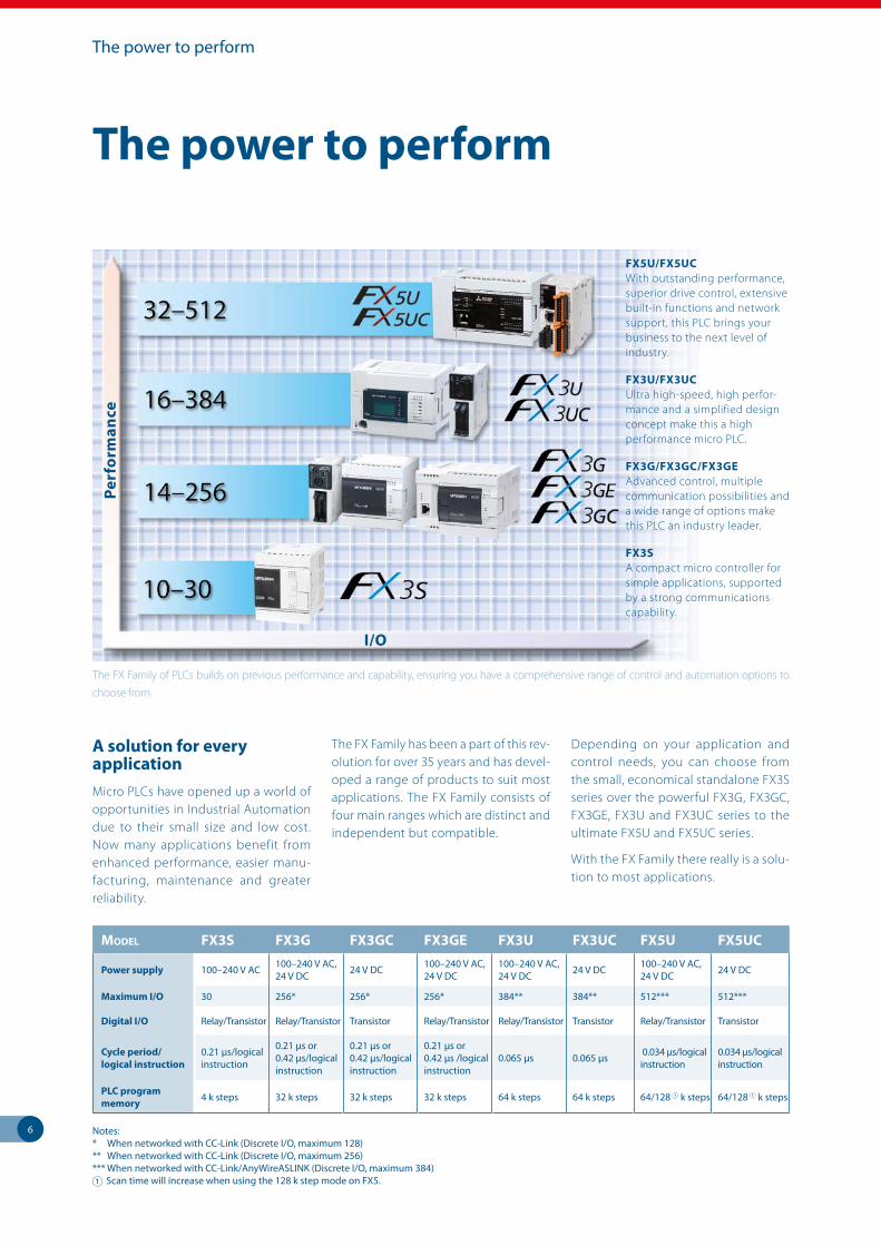
The FX Family of PLCs builds on previous performance and capability, ensuring you have a comprehensive range of control and automation options to
choose from.
I/O
Perf
orm
ance
FX5U/FX5UCWith outstanding performance, superior drive control, extensive built-in functions and network support, this PLC brings your business to the next level of industry.
FX3U/FX3UCUltra high-speed, high perfor-mance and a simplified design concept make this a high performance micro PLC.
FX3G/FX3GC/FX3GEAdvanced control, multiple communication possibilities and a wide range of options make this PLC an industry leader.
FX3SA compact micro controller for simple applications, supported by a strong communications capability.
Model FX3S FX3G FX3GC FX3Ge FX3U FX3UC FX5U FX5UC
Power supply 100–240 V AC 100–240 V AC, 24 V DC 24 V DC 100–240 V AC,
24 V DC100–240 V AC, 24 V DC 24 V DC 100–240 V AC,
24 V DC 24 V DC
Maximum I/O 30 256* 256* 256* 384** 384** 512*** 512***
Digital I/O Relay/Transistor Relay/Transistor Transistor Relay/Transistor Relay/Transistor Transistor Relay/Transistor Transistor
Cycle period/ logical instruction
0.21 µs/logical instruction
0.21 µs or 0.42 µs/logical instruction
0.21 µs or 0.42 µs/logical instruction
0.21 µs or 0.42 µs /logical instruction
0.065 µs 0.065 µs 0.034 μs/logical instruction
0.034 μs/logical instruction
PLC program memory 4 k steps 32 k steps 32 k steps 32 k steps 64 k steps 64 k steps 64/128 1 k steps 64/128 1 k steps
Notes: * When networked with CC-Link (Discrete I/O, maximum 128) ** When networked with CC-Link (Discrete I/O, maximum 256) *** When networked with CC-Link/AnyWireASLINK (Discrete I/O, maximum 384)1 Scan time will increase when using the 128 k step mode on FX5.
The power to perform

7
iQ-F – the next level of industry
iQ-F – the next level of industry
FX5U/FX5UC at a glance
FAST INSTRUCTION TIMESBasic instructions: 0.034 μs/ instruction (contact instruction) Applied instructions: 0.034 μs/in-struction (MOV instruction)
LARGE MEMORY64,000/128,000* steps of built-in program memory.
APPLICABLE STANDARDSAll products support EN and UL/cUL standards. Various shipping approvals are supported as well.
LARGE DEVICE MEMORYAuxiliary relays 32,768 points Timers 1024 points Counters 1024 points Data registers 8000 points Link registers 32,768 points File registers 32,768 points
* Scan time will increase when using the 128 k step mode on FX5.
FX5U – Top of the line
The FX5U is the latest and also the most powerful compact PLC in the FX Family. Mitsubishi Electric has given the com-pact controllers a huge performance boost, focusing on processing power, expansion, built-in functionality and positioning & motion functions.
High-speed system bus
Built-in high-speed processing and positioning
Built-in analog inputs and analog output
Built-in Ethernet port
Webserver
Modbus® function
Enhanced security functions
Battery-less
FX5 and various FX3 extension mo-dules connectable
Controls up to 512 input/output points (up to 384 connected I/O and up to 512 remote I/O via CC-Link)
FX5UC – High-end in ultra-compact design
The FX5UC combines the powerful features of the FX5U in an even smaller housing. This ultra-compact PLC with 24 V DC power supply and connector-type transistor I/O is designed for space conscious applications and helps to downsize your system.
Reduced size and wiring using con-nector- or spring clamp-type I/O
High-speed system bus
Built-in high-speed processing and positioning
Built-in Ethernet port
Webserver
Modbus® function
Enhanced security functions
Battery-less
FX5 and various FX3 extension mo-dules connectable
Controls up to 512 input/output points (up to 384 connected I/O and up to 512 remote I/O via CC-Link)
Speed Analog
Positioning
MemoryExpandability
Communication
Speed Analog
Positioning
MemoryExpandability
Communication
8
FX3U/FX3UC – a perfect PLC concept
FX3U/FX3UC – a perfect PLC concept
FX3U/FX3UC at a glance
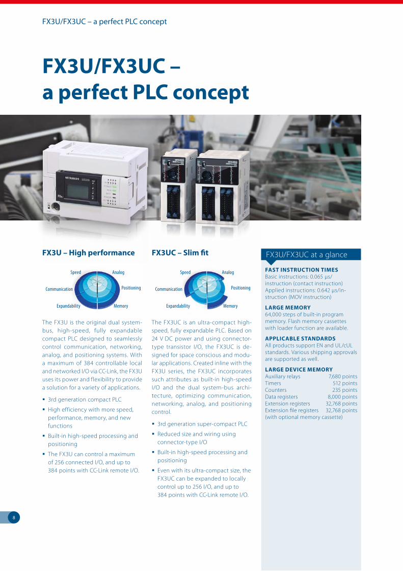
FAST INSTRUCTION TIMESBasic instructions: 0.065 μs/ instruction (contact instruction) Applied instructions: 0.642 μs/in-struction (MOV instruction)
LARGE MEMORY64,000 steps of built-in program memory. Flash memory cassettes with loader function are available.
APPLICABLE STANDARDSAll products support EN and UL/cUL standards. Various shipping approvals are supported as well.
LARGE DEVICE MEMORYAuxiliary relays 7,680 points Timers 512 points Counters 235 points Data registers 8,000 points Extension registers 32,768 points Extension file registers 32,768 points (with optional memory cassette)
FX3U – High performance
The FX3U is the original dual system-bus, high-speed, fully expandable compact PLC designed to seamlessly control communication, networking, analog, and positioning systems. With a maximum of 384 controllable local and networked I/O via CC-Link, the FX3U uses its power and flexibility to provide a solution for a variety of applications.
3rd generation compact PLC
High efficiency with more speed, performance, memory, and new functions
Built-in high-speed processing and positioning
The FX3U can control a maximum of 256 connected I/O, and up to 384 points with CC-Link remote I/O.
FX3UC – Slim fit
The FX3UC is an ultra-compact high-speed, fully expandable PLC. Based on 24 V DC power and using connector-type transistor I/O, the FX3UC is de-signed for space conscious and modu-lar applications. Created inline with the FX3U series, the FX3UC incorporates such attributes as built-in high-speed I/O and the dual system-bus archi-tecture, optimizing communication, networking, analog, and positioning control.
3rd generation super-compact PLC
Reduced size and wiring using connector-type I/O
Built-in high-speed processing and positioning
Even with its ultra-compact size, the FX3UC can be expanded to locally control up to 256 I/O, and up to 384 points with CC-Link remote I/O.
Speed Analog
Positioning
MemoryExpandability
Communication
Speed Analog
Positioning
MemoryExpandability
Communication
9
FX3G/FX3GC/FX3GE – customized control
FX3G/FX3GC/FX3GE – customized control
FX3G/FX3GC/FX3GE at a glance
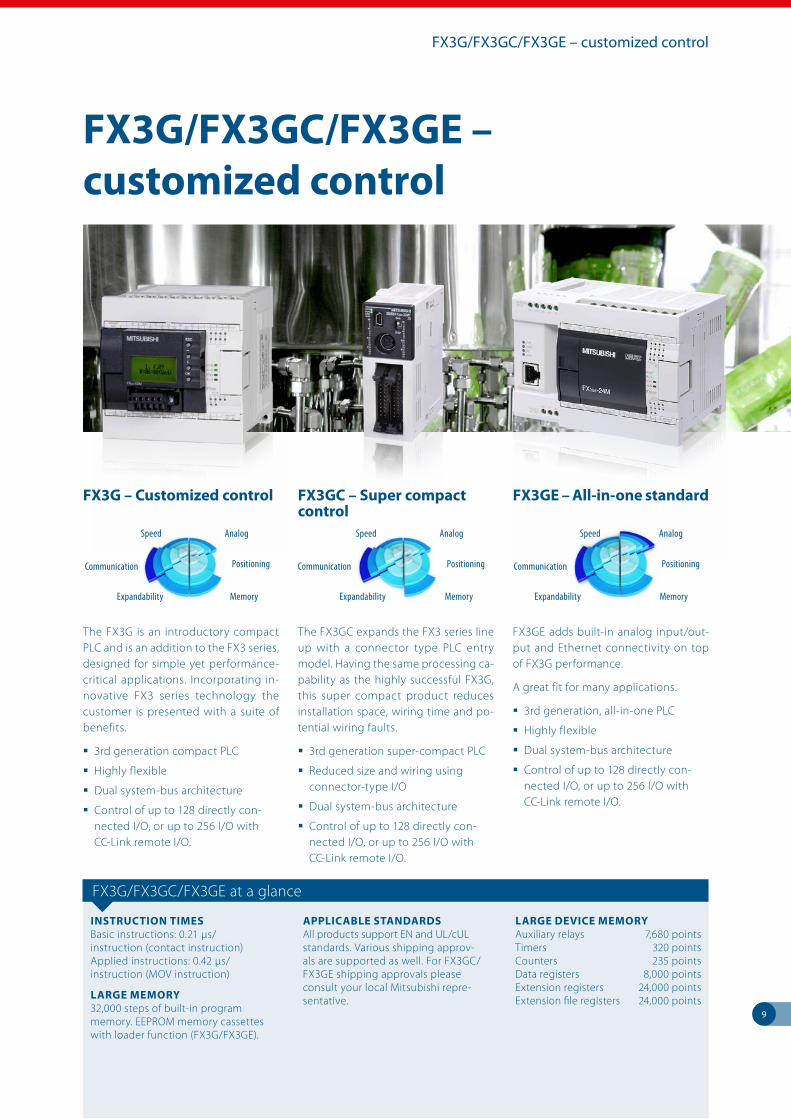
INSTRUCTION TIMESBasic instructions: 0.21 μs/ instruction (contact instruction) Applied instructions: 0.42 μs/ instruction (MOV instruction)
LARGE MEMORY32,000 steps of built-in program memory. EEPROM memory cassettes with loader function (FX3G/FX3GE).
APPLICABLE STANDARDSAll products support EN and UL/cUL standards. Various shipping approv-als are supported as well. For FX3GC/FX3GE shipping approvals please consult your local Mitsubishi repre-sentative.
LARGE DEVICE MEMORYAuxiliary relays 7,680 points Timers 320 points Counters 235 points Data registers 8,000 points Extension registers 24,000 points Extension file registers 24,000 points
FX3G – Customized control
The FX3G is an introductory compact PLC and is an addition to the FX3 series, designed for simple yet performance-critical applications. Incorporating in-novative FX3 series technology the customer is presented with a suite of benefits.
3rd generation compact PLC
Highly flexible
Dual system-bus architecture
Control of up to 128 directly con-nected I/O, or up to 256 I/O with CC-Link remote I/O.
FX3GC – Super compact control
The FX3GC expands the FX3 series line up with a connector type PLC entry model. Having the same processing ca-pability as the highly successful FX3G, this super compact product reduces installation space, wiring time and po-tential wiring faults.
3rd generation super-compact PLC
Reduced size and wiring using connector-type I/O
Dual system-bus architecture
Control of up to 128 directly con-nected I/O, or up to 256 I/O with CC-Link remote I/O.
FX3GE – All-in-one standard
FX3GE adds built-in analog input/out-put and Ethernet connectivity on top of FX3G performance.
A great fit for many applications.
3rd generation, all-in-one PLC
Highly flexible
Dual system-bus architecture
Control of up to 128 directly con-nected I/O, or up to 256 I/O with CC-Link remote I/O.
Speed Analog
Positioning
MemoryExpandability
Communication
Speed Analog
Positioning
MemoryExpandability
Communication
Speed Analog
Positioning
MemoryExpandability
Communication
10
FX3S – new possibilities
FX3S – new possibilities
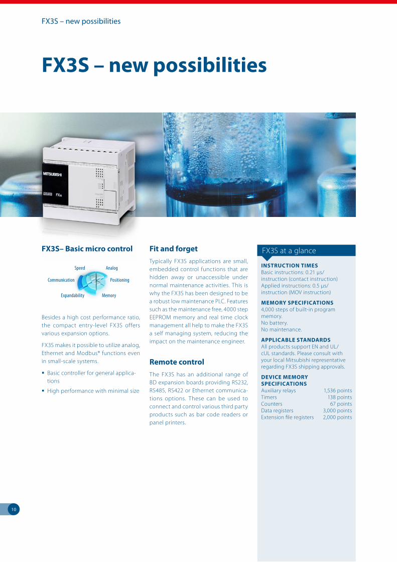
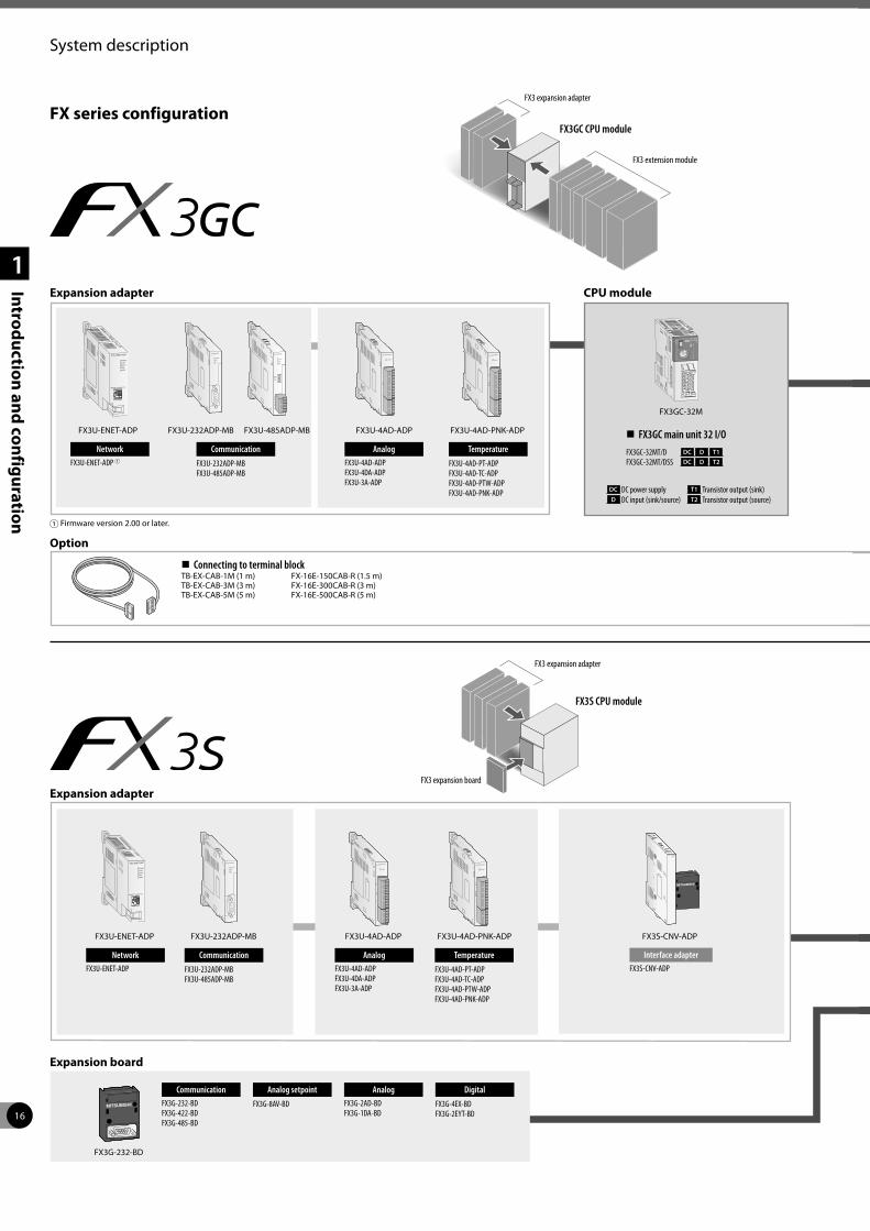
FX3S– Basic micro control
Besides a high cost performance ratio, the compact entry-level FX3S offers various expansion options.
FX3S makes it possible to utilize analog, Ethernet and Modbus® functions even in small-scale systems.
Basic controller for general applica-tions
High performance with minimal size
Fit and forgetTypically FX3S applications are small, embedded control functions that are hidden away or unaccessible under normal maintenance activities. This is why the FX3S has been designed to be a robust low maintenance PLC. Features such as the maintenance free, 4000 step EEPROM memory and real time clock management all help to make the FX3S a self managing system, reducing the impact on the maintenance engineer.
Remote controlThe FX3S has an additional range of BD expansion boards providing RS232, RS485, RS422 or Ethernet communica-tions options. These can be used to connect and control various third party products such as bar code readers or panel printers.
FX3S at a glance
INSTRUCTION TIMESBasic instructions: 0.21 μs/ instruction (contact instruction) Applied instructions: 0.5 μs/ instruction (MOV instruction)
MEMORY SPECIFICATIONS4,000 steps of built-in program memory. No battery. No maintenance.
APPLICABLE STANDARDSAll products support EN and UL/cUL standards. Please consult with your local Mitsubishi representative regarding FX3S shipping approvals.
DEVICE MEMORY SPECIFICATIONSAuxiliary relays 1,536 points Timers 138 points Counters 67 points Data registers 3,000 points Extension file registers 2,000 points
Speed Analog
Positioning
MemoryExpandability
Communication
MELSOFTGX Works3
Mnai tenance System
Design
Programmin
gD
ebugging
11
Programming
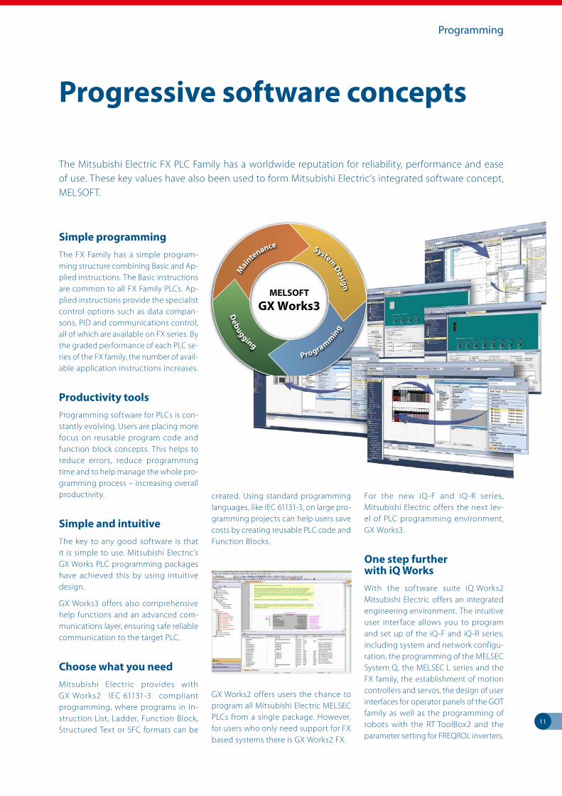
Simple programmingThe FX Family has a simple program-ming structure combining Basic and Ap-plied instructions. The Basic instructions are common to all FX Family PLCs. Ap-plied instructions provide the specialist control options such as data compari-sons, PID and communications control, all of which are available on FX series. By the graded performance of each PLC se-ries of the FX family, the number of avail-able application instructions increases.
Productivity toolsProgramming software for PLCs is con-stantly evolving. Users are placing more focus on reusable program code and function block concepts. This helps to reduce errors, reduce programming time and to help manage the whole pro-gramming process – increasing overall productivity.
Simple and intuitiveThe key to any good software is that it is simple to use. Mitsubishi Electric’s GX Works PLC programming packages have achieved this by using intuitive design.
GX Works3 offers also comprehensive help functions and an advanced com-munications layer, ensuring safe reliable communication to the target PLC.
Choose what you needMitsubishi Electric provides with GX Works2 IEC 61131-3 compliant programming, where programs in In-struction List, Ladder, Function Block, Structured Text or SFC formats can be
created. Using standard programming languages, like IEC 61131-3, on large pro-gramming projects can help users save costs by creating reusable PLC code and Function Blocks.
GX Works2 offers users the chance to program all Mitsubishi Electric MELSEC PLCs from a single package. However, for users who only need support for FX based systems there is GX Works2 FX.
For the new iQ-F and iQ-R series, Mitsubishi Electric offers the next lev-el of PLC programming environment, GX Works3.
One step further with iQ WorksWith the software suite iQ Works2 Mitsubishi Electric offers an integrated engineering environment. The intuitive user interface allows you to program and set up of the iQ-F and iQ-R series, including system and network configu-ration, the programming of the MELSEC System Q, the MELSEC L series and the FX family, the establishment of motion controllers and servos, the design of user interfaces for operator panels of the GOT family as well as the programming of robots with the RT ToolBox2 and the parameter setting for FREQROL inverters.
Progressive software concepts
The Mitsubishi Electric FX PLC Family has a worldwide reputation for reliability, performance and ease of use. These key values have also been used to form Mitsubishi Electric’s integrated software concept, MELSOFT.
12
Networking and communication solutions
Example of remote pumping station.
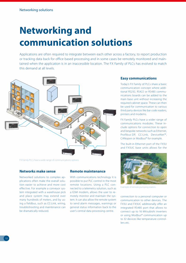
Applications are often required to integrate between each other across a factory, to report production or tracking data back for office based processing and in some cases be remotely monitored and main-tained when the application is in an inaccessible location. The FX Family of PLCs has evolved to match this demand at all levels.
Networks make senseNetworked solutions to complex ap-plications often make the overall solu-tion easier to achieve and more cost effective. For example a conveyor sys-tem integrated with a warehouse pick and place system may extend over many hundreds of meters, and by us-ing a fieldbus, such as CC-Link, wiring, troubleshooting and maintenance can be dramatically reduced.
Remote maintenanceWith communications technology it is possible to put PLC control in the most remote locations. Using a PLC con-nected to a telemetry solution, such as a GSM modem, allows the user to re-motely monitor and maintain the sys-tem. It can also allow the remote system to send alarm messages, warnings or general status information back to the user’s central data processing centre.
Easy communicationsToday’s FX Family of PLCs share a basic communication concept where addi-tional RS232, RS422 or RS485 commu-nications boards can be added to the main base unit without increasing the required cabinet space. These can then be used for communication to various third party devices like bar code readers, printers and modems.
FX Family PLCs have a wider range of communications modules. These in-clude options for connection to open and bespoke networks such as Ethernet, Profibus DP, CC-Link, DeviceNet™, CANopen or Modbus® for example.
The built-in Ethernet port of the FX5U and FX5UC base units allows for the
connection to a personal computer or communication to other devices. The FX5U and FX5UC additionally offer an integrated RS485 port that allows to connect up to 16 Mitsubishi inverters or using Modbus® communication up to 32 devices like temperature control-lers etc.
FX Family PLCs have a wide range of commu nications options.
Networking solutions
13
Analog solutions
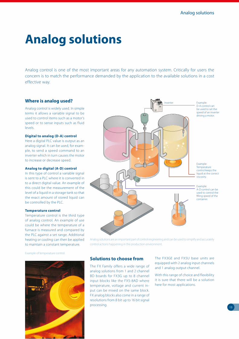
Where is analog used?Analog control is widely used. In simple terms it allows a variable signal to be used to control items such as a motor’s speed or to sense inputs such as fluid levels.
Digital to analog (D-A) control Here a digital PLC value is output as an analog signal. It can be used, for exam-ple, to send a speed command to an inverter which in turn causes the motor to increase or decrease speed.
Analog to digital (A-D) control In this type of control a variable signal is sent to a PLC where it is converted in to a direct digital value. An example of this could be the measurement of the level of a liquid in a storage tank so that the exact amount of stored liquid can be controlled by the PLC.
Temperature controlTemperature control is the third type of analog control. An example of use could be where the temperature of a furnace is measured and compared by the PLC against a set range. Additional heating or cooling can then be applied to maintain a constant temperature.
Solutions to choose fromThe FX Family offers a wide range of analog solutions from 1 and 2 channel BD boards for FX3G up to 8 channel input blocks like the FX5-8AD where temperature, voltage and current in-put can be mixed on the same block. FX analog blocks also come in a range of resolutions from 8 bit up to 16 bit signal processing.
The FX3GE and FX5U base units are equipped with 2 analog input channels and 1 analog output channel.
With this range of choice and flexibility it is sure that there will be a solution here for most applications.
Analog solutions
Example of temperature control.
Analog control is one of the most important areas for any automation system. Critically for users the concern is to match the performance demanded by the application to the available solutions in a cost effective way.
Analog solutions are an important part of control engineering and can be used to simplify and accurately
control actions happening in the production environment.
Example: D-A control can be used to set the speed of an inverter driving a motor.
Example: Temperature control keeps the liquid at the correct viscosity.
Example: A-D control can be used to control the filling speed of the container.
Inverter
14
Drive control solutions
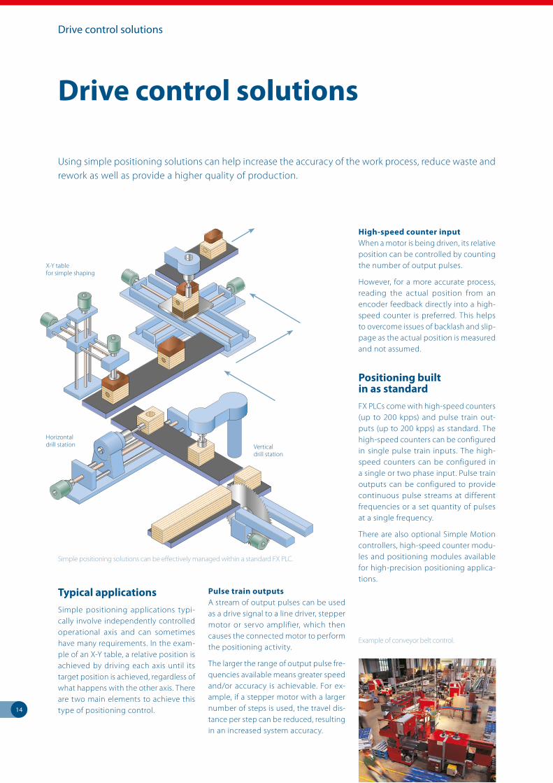
Typical applicationsSimple positioning applications typi-cally involve independently controlled operational axis and can sometimes have many requirements. In the exam-ple of an X-Y table, a relative position is achieved by driving each axis until its target position is achieved, regardless of what happens with the other axis. There are two main elements to achieve this type of positioning control.
Pulse train outputsA stream of output pulses can be used as a drive signal to a line driver, stepper motor or servo amplifier, which then causes the connected motor to perform the positioning activity.
The larger the range of output pulse fre-quencies available means greater speed and/or accuracy is achievable. For ex-ample, if a stepper motor with a larger number of steps is used, the travel dis-tance per step can be reduced, resulting in an increased system accuracy.
High-speed counter inputWhen a motor is being driven, its relative position can be controlled by counting the number of output pulses.
However, for a more accurate process, reading the actual position from an encoder feedback directly into a high-speed counter is preferred. This helps to overcome issues of backlash and slip-page as the actual position is measured and not assumed.
Positioning built in as standardFX PLCs come with high-speed counters (up to 200 kpps) and pulse train out-puts (up to 200 kpps) as standard. The high-speed counters can be configured in single pulse train inputs. The high-speed counters can be configured in a single or two phase input. Pulse train outputs can be configured to provide continuous pulse streams at different frequencies or a set quantity of pulses at a single frequency.
There are also optional Simple Motion controllers, high-speed counter modu-les and positioning modules available for high-precision positioning applica-tions.
Drive control solutions
Using simple positioning solutions can help increase the accuracy of the work process, reduce waste and rework as well as provide a higher quality of production.
Horizontal drill station
X-Y table for simple shaping
Vertical drill station
Example of conveyor belt control.
Simple positioning solutions can be effectively managed within a standard FX PLC.
15
The right tool for the right jobFor maximum efficiency, each user requires access to information at their work place in a form that highlights the important data for them first. This means a range of different tools are re-quired. As an example, here are three possible scenarios.
The machine operatorMachines often have a lot of manufac-turing debris around or are subject to hygienic cleaning as in the food indus-try. Any display located in this environ-ment would need to have a high Ingress Protection (IP) rating, indicating a high degree of waterproofness.
It may also be a benefit to the opera-tor to have a large and clear display to reduce the chances for error from mis-reading, due to poor light or small fonts being used. It is also recognized that the use of graphics also reduces the chanc-es for reading errors with complex data.
The maintenance teamThe critical information for a main-tenance engineer is the error and diagnostic data within the PLC as this is used to diagnose any process prob-lems. However, additional information regarding the operational “hours run” or cycles processed, which could be called soft information as it is calculated on operational parameters, could allow the maintenance engineer to predict possible failure and arrange preventa-tive maintenance.
Access to this data could be through the machine operator’s terminal, across a network or through a dedicated dis-play mounted inside or on the control cabinet itself.
The business managerIn a production controllers office it would be better to display information through a network to their existing desktop PC. In this application a piece of software such as an OPC/OPC-UA server/client, a Java applet, an Active X control or a SCADA system would allow lots of data from lots of sources to be displayed in a clear and concise way giving the pro-duction controller the overview of the business operation that they need.
Data the way you want it Mitsubishi Electric offers a wide range of visualization solutions from simple data displays such as the FX3U-7DM, advanced Graphic Operator Terminals like the GOT series, and a wide choice of software solutions from the MELSOFT software suite.
This powerful combination of hardware and software means there is a cost ef-fective solution for most applications.
Visualization solutions
In the food industry hygiene is very important.
The FX3U-7DM can be directly mounted within
the PLC (FX3U) or mounted on the front cabinet.
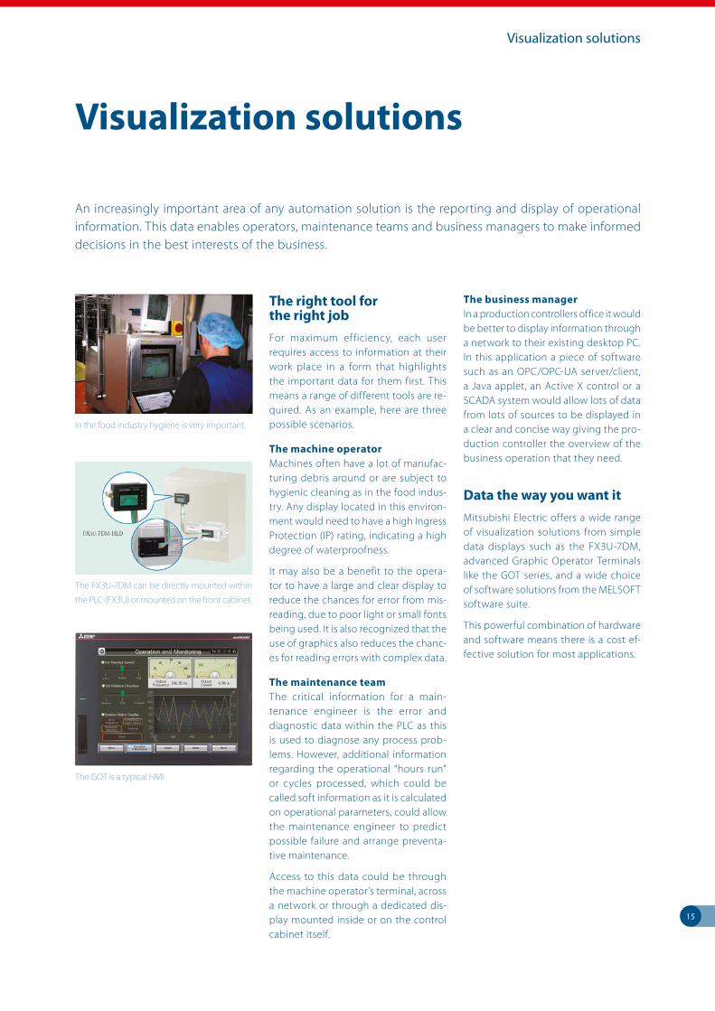
The GOT is a typical HMI
Visualization solutions
An increasingly important area of any automation solution is the reporting and display of operational information. This data enables operators, maintenance teams and business managers to make informed decisions in the best interests of the business.
16
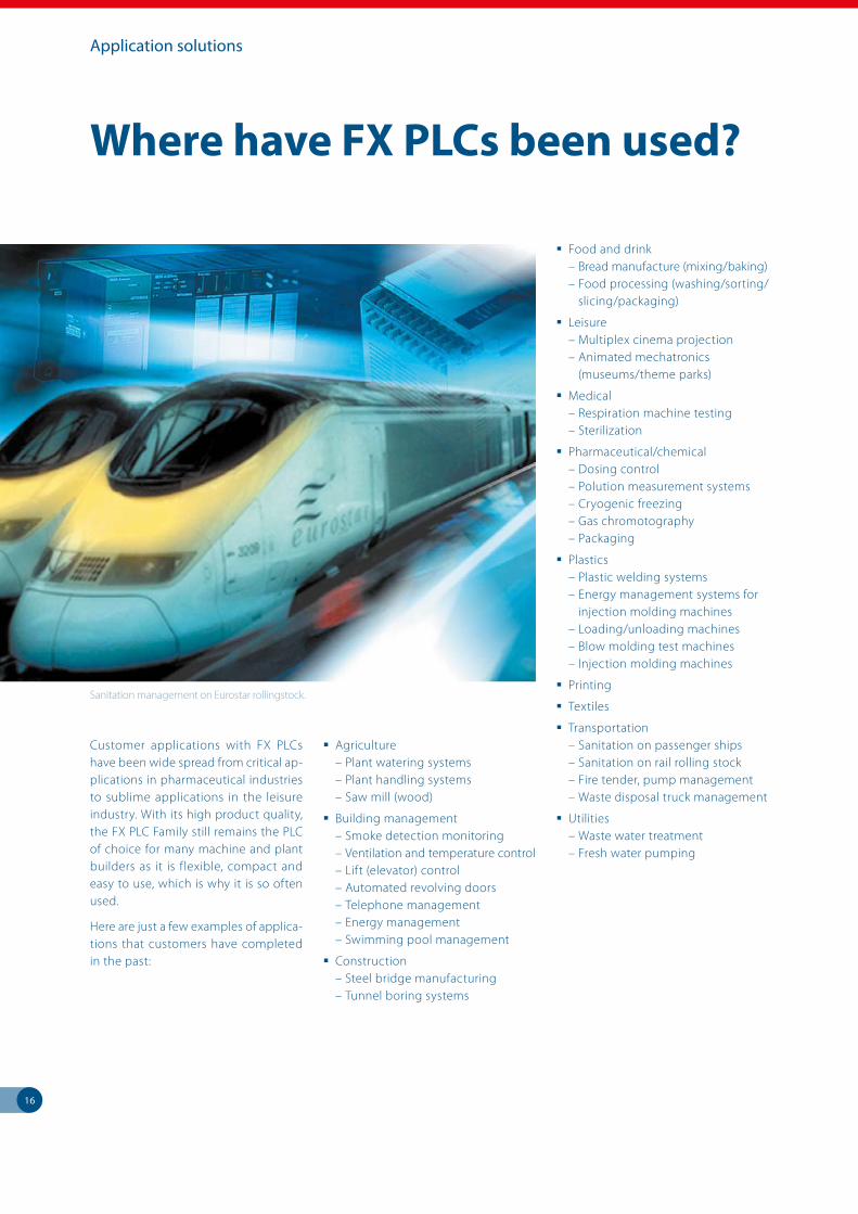
Where have FX PLCs been used?
Customer applications with FX PLCs have been wide spread from critical ap-plications in pharmaceutical industries to sublime applications in the leisure industry. With its high product quality, the FX PLC Family still remains the PLC of choice for many machine and plant builders as it is flexible, compact and easy to use, which is why it is so often used.
Here are just a few examples of applica-tions that customers have completed in the past:
Agriculture – Plant watering systems – Plant handling systems – Saw mill (wood)
Building management – Smoke detection monitoring – Ventilation and temperature control – Lift (elevator) control – Automated revolving doors – Telephone management – Energy management – Swimming pool management
Construction – Steel bridge manufacturing – Tunnel boring systems
Food and drink – Bread manufacture (mixing/baking) – Food processing (washing/sorting/ slicing/packaging)
Leisure – Multiplex cinema projection – Animated mechatronics (museums/theme parks)
Medical – Respiration machine testing – Sterilization
Pharmaceutical/chemical – Dosing control – Polution measurement systems – Cryogenic freezing – Gas chromotography – Packaging
Plastics – Plastic welding systems – Energy management systems for injection molding machines – Loading/unloading machines – Blow molding test machines – Injection molding machines
Printing
Textiles
Transportation – Sanitation on passenger ships – Sanitation on rail rolling stock – Fire tender, pump management – Waste disposal truck management
Utilities – Waste water treatment – Fresh water pumping
Sanitation management on Eurostar rollingstock.
Application solutions
FX5U/FX5UC FX3U/FX3UC/FX3GE/FX3GC/FX3G/FX3S ALPHA
Technical Information Section
2
More information?
This product catalogue is designed to give an overview of the extensive range FX Family of MELSEC PLCs. If you cannot find the information you require in this catalogue, there are a number of ways you can get further details on configuration and technical issues, pricing and availability.
For technical issues visit the https://eu3a.mitsubishielectric.com website. Our website provides a simple and fast way of accessing further technical data and up to the minute details on our products and services. Manuals and catalogues are available in several different languages and can be downloaded for free.
For technical, configuration, pricing and availability issues contact our distributors and partners. Mitsubishi Electric partners and distributors are only too happy to help answer your technical questions or help with configuration building. For a list of Mitsubishi Electric partners please see the back of this catalogue or alternatively take a look at the “contact us” section of our website https://eu3a.mitsubishielectric.com.
About this technical catalogue
This catalogue is a guide to the range of products available. For detailed configuration rules, system building, installation and configuration the associated product manuals must be read. You must satisfy yourself that any system you design with the products in this catalogue is fit for purpose, meets your requires and conforms to the product configuration rules as defined in the product manuals.
Specifications are subject to change without notice. All trademarks acknowledged.
© Mitsubishi Electric Europe B.V., Factory Automation - European Business Group
The products of Mitsubishi Electric Europe B.V., that are listed and described in this document, are neither subject to approval for export nor subject to the Dual-Use List.
Further publications within the industrial automation range
Modular PLC FamilyProduct catalogues for programmable logic controllers and accessories for the MELSEC iQ-R series/System Q/L series
HMI FamilyProduct catalogue for operator terminals, supervision software and accessories
FR FamilyProduct catalogue for frequency inverters and accessories
MR FamilyProduct catalogue for servo amplifiers and servo motors as well as motion controller and accessories
Robots FamilyProduct catalogue for industrial robots and accessories
LVS FamilyProduct catalogue for low voltage switchgears,magnetic contactors and circuit breakers
Automation BookOverview on all Mitsubishi Electric automation products, like frequency inverters, servo/motion, robots etc.
Brochures
3
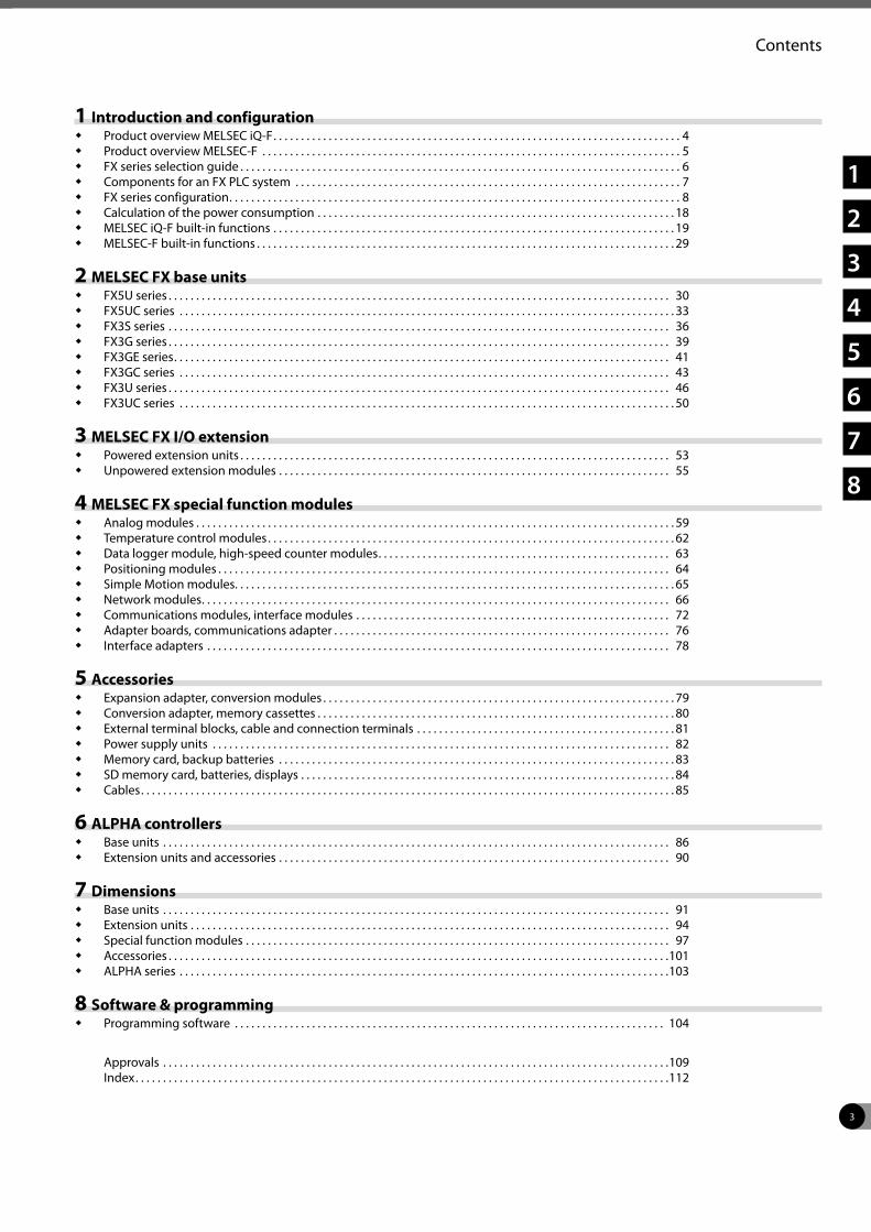
Contents
1 Introduction and configuration Product overview MELSEC iQ-F . . . . . . . . . . . . . . . . . . . . . . . . . . . . . . . . . . . . . . . . . . . . . . . . . . . . . . . . . . . . . . . . . . . . . . . . . . 4 Product overview MELSEC-F . . . . . . . . . . . . . . . . . . . . . . . . . . . . . . . . . . . . . . . . . . . . . . . . . . . . . . . . . . . . . . . . . . . . . . . . . . . . 5 FX series selection guide . . . . . . . . . . . . . . . . . . . . . . . . . . . . . . . . . . . . . . . . . . . . . . . . . . . . . . . . . . . . . . . . . . . . . . . . . . . . . . . . 6 Components for an FX PLC system . . . . . . . . . . . . . . . . . . . . . . . . . . . . . . . . . . . . . . . . . . . . . . . . . . . . . . . . . . . . . . . . . . . . . . 7 FX series configuration . . . . . . . . . . . . . . . . . . . . . . . . . . . . . . . . . . . . . . . . . . . . . . . . . . . . . . . . . . . . . . . . . . . . . . . . . . . . . . . . . . 8 Calculation of the power consumption . . . . . . . . . . . . . . . . . . . . . . . . . . . . . . . . . . . . . . . . . . . . . . . . . . . . . . . . . . . . . . . . . 18 MELSEC iQ-F built-in functions . . . . . . . . . . . . . . . . . . . . . . . . . . . . . . . . . . . . . . . . . . . . . . . . . . . . . . . . . . . . . . . . . . . . . . . . . 19 MELSEC-F built-in functions . . . . . . . . . . . . . . . . . . . . . . . . . . . . . . . . . . . . . . . . . . . . . . . . . . . . . . . . . . . . . . . . . . . . . . . . . . . . 29
2 MELSEC FX base units FX5U series . . . . . . . . . . . . . . . . . . . . . . . . . . . . . . . . . . . . . . . . . . . . . . . . . . . . . . . . . . . . . . . . . . . . . . . . . . . . . . . . . . . . . . . . . . . 30 FX5UC series . . . . . . . . . . . . . . . . . . . . . . . . . . . . . . . . . . . . . . . . . . . . . . . . . . . . . . . . . . . . . . . . . . . . . . . . . . . . . . . . . . . . . . . . . . 33 FX3S series . . . . . . . . . . . . . . . . . . . . . . . . . . . . . . . . . . . . . . . . . . . . . . . . . . . . . . . . . . . . . . . . . . . . . . . . . . . . . . . . . . . . . . . . . . . 36 FX3G series . . . . . . . . . . . . . . . . . . . . . . . . . . . . . . . . . . . . . . . . . . . . . . . . . . . . . . . . . . . . . . . . . . . . . . . . . . . . . . . . . . . . . . . . . . . 39 FX3GE series . . . . . . . . . . . . . . . . . . . . . . . . . . . . . . . . . . . . . . . . . . . . . . . . . . . . . . . . . . . . . . . . . . . . . . . . . . . . . . . . . . . . . . . . . . 41 FX3GC series . . . . . . . . . . . . . . . . . . . . . . . . . . . . . . . . . . . . . . . . . . . . . . . . . . . . . . . . . . . . . . . . . . . . . . . . . . . . . . . . . . . . . . . . . 43 FX3U series . . . . . . . . . . . . . . . . . . . . . . . . . . . . . . . . . . . . . . . . . . . . . . . . . . . . . . . . . . . . . . . . . . . . . . . . . . . . . . . . . . . . . . . . . . . 46 FX3UC series . . . . . . . . . . . . . . . . . . . . . . . . . . . . . . . . . . . . . . . . . . . . . . . . . . . . . . . . . . . . . . . . . . . . . . . . . . . . . . . . . . . . . . . . . . 50
3 MELSEC FX I/O extension Powered extension units . . . . . . . . . . . . . . . . . . . . . . . . . . . . . . . . . . . . . . . . . . . . . . . . . . . . . . . . . . . . . . . . . . . . . . . . . . . . . . 53 Unpowered extension modules . . . . . . . . . . . . . . . . . . . . . . . . . . . . . . . . . . . . . . . . . . . . . . . . . . . . . . . . . . . . . . . . . . . . . . . 55
4 MELSEC FX special function modules Analog modules . . . . . . . . . . . . . . . . . . . . . . . . . . . . . . . . . . . . . . . . . . . . . . . . . . . . . . . . . . . . . . . . . . . . . . . . . . . . . . . . . . . . . . . 59 Temperature control modules . . . . . . . . . . . . . . . . . . . . . . . . . . . . . . . . . . . . . . . . . . . . . . . . . . . . . . . . . . . . . . . . . . . . . . . . . . 62 Data logger module, high-speed counter modules . . . . . . . . . . . . . . . . . . . . . . . . . . . . . . . . . . . . . . . . . . . . . . . . . . . . . 63 Positioning modules . . . . . . . . . . . . . . . . . . . . . . . . . . . . . . . . . . . . . . . . . . . . . . . . . . . . . . . . . . . . . . . . . . . . . . . . . . . . . . . . . . 64 Simple Motion modules. . . . . . . . . . . . . . . . . . . . . . . . . . . . . . . . . . . . . . . . . . . . . . . . . . . . . . . . . . . . . . . . . . . . . . . . . . . . . . . . 65 Network modules . . . . . . . . . . . . . . . . . . . . . . . . . . . . . . . . . . . . . . . . . . . . . . . . . . . . . . . . . . . . . . . . . . . . . . . . . . . . . . . . . . . . . 66 Communications modules, interface modules . . . . . . . . . . . . . . . . . . . . . . . . . . . . . . . . . . . . . . . . . . . . . . . . . . . . . . . . . 72 Adapter boards, communications adapter . . . . . . . . . . . . . . . . . . . . . . . . . . . . . . . . . . . . . . . . . . . . . . . . . . . . . . . . . . . . . 76 Interface adapters . . . . . . . . . . . . . . . . . . . . . . . . . . . . . . . . . . . . . . . . . . . . . . . . . . . . . . . . . . . . . . . . . . . . . . . . . . . . . . . . . . . . 78
5 Accessories Expansion adapter, conversion modules . . . . . . . . . . . . . . . . . . . . . . . . . . . . . . . . . . . . . . . . . . . . . . . . . . . . . . . . . . . . . . . . 79 Conversion adapter, memory cassettes . . . . . . . . . . . . . . . . . . . . . . . . . . . . . . . . . . . . . . . . . . . . . . . . . . . . . . . . . . . . . . . . . 80 External terminal blocks, cable and connection terminals . . . . . . . . . . . . . . . . . . . . . . . . . . . . . . . . . . . . . . . . . . . . . . . 81 Power supply units . . . . . . . . . . . . . . . . . . . . . . . . . . . . . . . . . . . . . . . . . . . . . . . . . . . . . . . . . . . . . . . . . . . . . . . . . . . . . . . . . . . 82 Memory card, backup batteries . . . . . . . . . . . . . . . . . . . . . . . . . . . . . . . . . . . . . . . . . . . . . . . . . . . . . . . . . . . . . . . . . . . . . . . . 83 SD memory card, batteries, displays . . . . . . . . . . . . . . . . . . . . . . . . . . . . . . . . . . . . . . . . . . . . . . . . . . . . . . . . . . . . . . . . . . . . 84 Cables . . . . . . . . . . . . . . . . . . . . . . . . . . . . . . . . . . . . . . . . . . . . . . . . . . . . . . . . . . . . . . . . . . . . . . . . . . . . . . . . . . . . . . . . . . . . . . . . . 85
6 ALPHA controllers Base units . . . . . . . . . . . . . . . . . . . . . . . . . . . . . . . . . . . . . . . . . . . . . . . . . . . . . . . . . . . . . . . . . . . . . . . . . . . . . . . . . . . . . . . . . . . . 86 Extension units and accessories . . . . . . . . . . . . . . . . . . . . . . . . . . . . . . . . . . . . . . . . . . . . . . . . . . . . . . . . . . . . . . . . . . . . . . . 90
7 Dimensions Base units . . . . . . . . . . . . . . . . . . . . . . . . . . . . . . . . . . . . . . . . . . . . . . . . . . . . . . . . . . . . . . . . . . . . . . . . . . . . . . . . . . . . . . . . . . . . 91 Extension units . . . . . . . . . . . . . . . . . . . . . . . . . . . . . . . . . . . . . . . . . . . . . . . . . . . . . . . . . . . . . . . . . . . . . . . . . . . . . . . . . . . . . . . 94 Special function modules . . . . . . . . . . . . . . . . . . . . . . . . . . . . . . . . . . . . . . . . . . . . . . . . . . . . . . . . . . . . . . . . . . . . . . . . . . . . . 97 Accessories . . . . . . . . . . . . . . . . . . . . . . . . . . . . . . . . . . . . . . . . . . . . . . . . . . . . . . . . . . . . . . . . . . . . . . . . . . . . . . . . . . . . . . . . . . .101 ALPHA series . . . . . . . . . . . . . . . . . . . . . . . . . . . . . . . . . . . . . . . . . . . . . . . . . . . . . . . . . . . . . . . . . . . . . . . . . . . . . . . . . . . . . . . . .103
8 Software & programming Programming software . . . . . . . . . . . . . . . . . . . . . . . . . . . . . . . . . . . . . . . . . . . . . . . . . . . . . . . . . . . . . . . . . . . . . . . . . . . . . . 104
Approvals . . . . . . . . . . . . . . . . . . . . . . . . . . . . . . . . . . . . . . . . . . . . . . . . . . . . . . . . . . . . . . . . . . . . . . . . . . . . . . . . . . . . . . . . . . . .109Index . . . . . . . . . . . . . . . . . . . . . . . . . . . . . . . . . . . . . . . . . . . . . . . . . . . . . . . . . . . . . . . . . . . . . . . . . . . . . . . . . . . . . . . . . . . . . . . . .112
1
2
3
4
5
6
7
8
4
1
Introduction and configuration
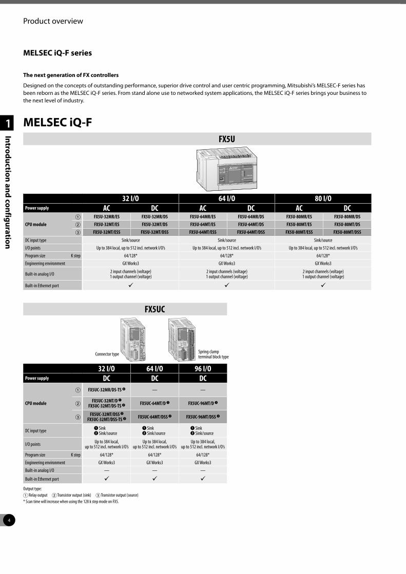
Product overview
The next generation of FX controllers
Designed on the concepts of outstanding performance, superior drive control and user centric programming, Mitsubishi’s MELSEC-F series has been reborn as the MELSEC iQ-F series. From stand alone use to networked system applications, the MELSEC iQ-F series brings your business to the next level of industry.
MELSEC iQ-F series
MELSEC iQ-FFX5U
32 I/O 64 I/O 80 I/OPower supply AC DC AC DC AC DC
CPU module
1 FX5U-32MR/ES FX5U-32MR/DS FX5U-64MR/ES FX5U-64MR/DS FX5U-80MR/ES FX5U-80MR/DS2 FX5U-32MT/ES FX5U-32MT/DS FX5U-64MT/ES FX5U-64MT/DS FX5U-80MT/ES FX5U-80MT/DS3 FX5U-32MT/ESS FX5U-32MT/DSS FX5U-64MT/ESS FX5U-64MT/DSS FX5U-80MT/ESS FX5U-80MT/DSS
DC input type Sink/source Sink/source Sink/source
I/O points Up to 384 local, up to 512 incl. network I/O’s Up to 384 local, up to 512 incl. network I/O’s Up to 384 local, up to 512 incl. network I/O’s
Program size K step 64/128* 64/128* 64/128*
Engineering environment GX Works3 GX Works3 GX Works3
Built-in analog I/O 2 input channels (voltage)1 output channel (voltage)
2 input channels (voltage)1 output channel (voltage)
2 input channels (voltage)1 output channel (voltage)
Built-in Ethernet port ü ü ü
FX5UC
32 I/O 64 I/O 96 I/OPower supply DC DC DC
CPU module
1 FX5UC-32MR/DS-TS 2 — —
2 FX5UC-32MT/D 1FX5UC-32MT/DS-TS 2 FX5UC-64MT/D 1 FX5UC-96MT/D 1
3 FX5UC-32MT/DSS 2FX5UC-32MT/DSS-TS 2 FX5UC-64MT/DSS 2 FX5UC-96MT/DSS 2
DC input type1 Sink2 Sink/source
1 Sink2 Sink/source
1 Sink2 Sink/source
I/O points Up to 384 local, up to 512 incl. network I/O’s
Up to 384 local, up to 512 incl. network I/O’s
Up to 384 local, up to 512 incl. network I/O’s
Program size K step 64/128* 64/128* 64/128*
Engineering environment GX Works3 GX Works3 GX Works3
Built-in analog I/O — — —
Built-in Ethernet port ü ü üOutput type:1 Relay output 2 Transistor output (sink) 3 Transistor output (source) * Scan time will increase when using the 128 k step mode on FX5.
Connector type Spring clamp terminal block type
5
1
Introduction and configuration
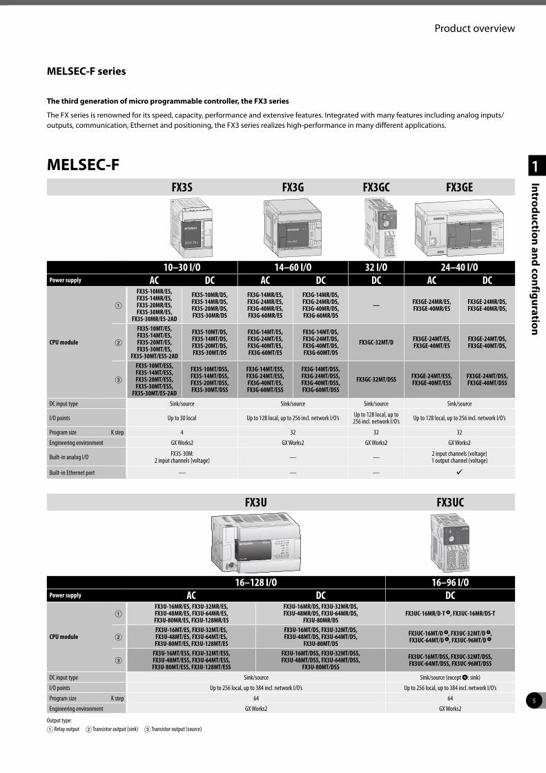
Product overview
The third generation of micro programmable controller, the FX3 series
The FX series is renowned for its speed, capacity, performance and extensive features. Integrated with many features including analog inputs/outputs, communication, Ethernet and positioning, the FX3 series realizes high-performance in many different applications.
MELSEC-F series
MELSEC-F
FX3U FX3UC
16–128 I/O 16–96 I/OPower supply AC DC DC
CPU module
1FX3U-16MR/ES, FX3U-32MR/ES,FX3U-48MR/ES, FX3U-64MR/ES,FX3U-80MR/ES, FX3U-128MR/ES
FX3U-16MR/DS, FX3U-32MR/DS, FX3U-48MR/DS, FX3U-64MR/DS,
FX3U-80MR/DSFX3UC-16MR/D-T 4, FX3UC-16MR/DS-T
2FX3U-16MT/ES, FX3U-32MT/ES, FX3U-48MT/ES, FX3U-64MT/ES,FX3U-80MT/ES, FX3U-128MT/ES
FX3U-16MT/DS, FX3U-32MT/DS,FX3U-48MT/DS, FX3U-64MT/DS,
FX3U-80MT/DSFX3UC-16MT/D 4, FX3UC-32MT/D 4,FX3UC-64MT/D 4, FX3UC-96MT/D 4
3FX3U-16MT/ESS, FX3U-32MT/ESS,FX3U-48MT/ESS, FX3U-64MT/ESS,FX3U-80MT/ESS, FX3U-128MT/ESS
FX3U-16MT/DSS, FX3U-32MT/DSS,FX3U-48MT/DSS, FX3U-64MT/DSS,
FX3U-80MT/DSSFX3UC-16MT/DSS, FX3UC-32MT/DSS,FX3UC-64MT/DSS, FX3UC-96MT/DSS
DC input type Sink/source Sink/source (except 4: sink)
I/O points Up to 256 local, up to 384 incl. network I/O’s Up to 256 local, up to 384 incl. network I/O’s
Program size K step 64 64
Engineering environment GX Works2 GX Works2
Output type:1 Relay output 2 Transistor output (sink) 3 Transistor output (source)
FX3S FX3G FX3GC FX3GE
10–30 I/O 14–60 I/O 32 I/O 24–40 I/OPower supply AC DC AC DC DC AC DC
CPU module
1
FX3S-10MR/ES, FX3S-14MR/ES,FX3S-20MR/ES,FX3S-30MR/ES,
FX3S-30MR/ES-2AD
FX3S-10MR/DS, FX3S-14MR/DS, FX3S-20MR/DS, FX3S-30MR/DS
FX3G-14MR/ES, FX3G-24MR/ES,FX3G-40MR/ES, FX3G-60MR/ES
FX3G-14MR/DS, FX3G-24MR/DS,FX3G-40MR/DS,FX3G-60MR/DS
— FX3GE-24MR/ES, FX3GE-40MR/ES
FX3GE-24MR/DS, FX3GE-40MR/DS,
2
FX3S-10MT/ES, FX3S-14MT/ES,FX3S-20MT/ES,FX3S-30MT/ES,
FX3S-30MT/ESS-2AD
FX3S-10MT/DS, FX3S-14MT/DS, FX3S-20MT/DS, FX3S-30MT/DS
FX3G-14MT/ES, FX3G-24MT/ES,FX3G-40MT/ES, FX3G-60MT/ES
FX3G-14MT/DS, FX3G-24MT/DS,FX3G-40MT/DS, FX3G-60MT/DS
FX3GC-32MT/D FX3GE-24MT/ES, FX3GE-40MT/ES
FX3GE-24MT/DS, FX3GE-40MT/DS,
3
FX3S-10MT/ESS, FX3S-14MT/ESS,FX3S-20MT/ESS,FX3S-30MT/ESS,
FX3S-30MT/ES-2AD
FX3S-10MT/DSS, FX3S-14MT/DSS, FX3S-20MT/DSS, FX3S-30MT/DSS
FX3G-14MT/ESS, FX3G-24MT/ESS,FX3G-40MT/ES, FX3G-60MT/ESS
FX3G-14MT/DSS, FX3G-24MT/DSS,FX3G-40MT/DSS, FX3G-60MT/DSS
FX3GC-32MT/DSS FX3GE-24MT/ESS, FX3GE-40MT/ESS
FX3GE-24MT/DSS, FX3GE-40MT/DSS
DC input type Sink/source Sink/source Sink/source Sink/source
I/O points Up to 30 local Up to 128 local, up to 256 incl. network I/O’s Up to 128 local, up to 256 incl. network I/O’s Up to 128 local, up to 256 incl. network I/O’s
Program size K step 4 32 32 32
Engineering environment GX Works2 GX Works2 GX Works2 GX Works2
Built-in analog I/O FX3S-30M:2 input channels (voltage) — — 2 input channels (voltage)
1 output channel (voltage)
Built-in Ethernet port — — — ü
6
System description
1
Introduction and configuration
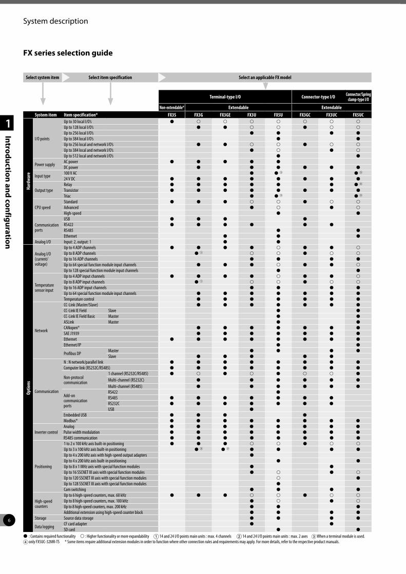
FX series selection guide
Select system item Select item specification Select an applicable FX model
Terminal-type I/O Connector-type I/O Connector/Spring clamp-type I/O
Non-extendable* Extendable ExtendableSystem item Item specification* FX3S FX3G FX3GE FX3U FX5U FX3GC FX3UC FX5UC
Hard
war
e
I/O points
Up to 30 local I/O’s P p p p p p p pUp to 128 local I/O’s P P p p P p pUp to 256 local I/O’s P P P PUp to 384 local I/O’s P PUp to 256 local and network I/O’s P P p p P p pUp to 384 local and network I/O’s P p P pUp to 512 local and network I/O’s P P
Power supply AC power P P P P PDC power P P P P P P
Input type 100 V AC P P 3 P 3
24 V DC P P P P P P P P
Output typeRelay P P P P P P P 4
Transistor P P P P P P P PTriac P P 3 P 3
CPU speedStandard P P P p p P p pAdvanced P p P pHigh-speed P P
Communicationports
USB P P P PRS422 P P P P P PRS485 P PEthernet P P P
Analog I/O Input: 2, output: 1 P P
Optio
ns
Analog I/O(current/voltage)
Up to 4 ADP channels P P P P p P P pUp to 8 ADP channels P 1 p p P p pUp to 16 ADP channels P P P PUp to 64 special function module input channels P P P p P P pUp to 128 special function module input channels P P
Temperaturesensor input
Up to 4 ADP input channels P P P P p P P pUp to 8 ADP input channels P 1 p p P p pUp to 16 ADP input channels P P P PUp to 64 special function module input channels P P P P P P PTemperature control P P P P P P P
Network
CC-Link (Master/Slave) P P P P P P PCC-Link IE Field Slave P PCC-Link IE Field Basic Master P PASLink Master P PCANopen® P P P P P P PSAE J1939 P P P P P P PEthernet P P P P P P P PEthernet/IP P P
Profibus DP Master P P P PSlave P P P P P
Communication
N : N network/parallel link P P P P P P P PComputer link (RS232C/RS485) P P P P P P P P
Non-protocol communication
1 channel (RS232C/RS485) P p P p P p p PMulti-channel (RS232C) P P P P P PMulti-channel (RS485) P P P P P P
Add-oncommunicationports
RS422 PRS485 P P P P P P PRS232C P P P P P P PUSB P
Embedded USB P P P PModbus® P P P P P P P P
Inverter controlAnalog P P P P P P P PPulse width modulation P P P P P P P PRS485 communication P P P P P P P P
Positioning
1 to 2 x 100 kHz axis built-in positioning P P P p p P p pUp to 3 x 100 kHz axis built-in positioning P 2 P 2 P P P PUp to 4 x 200 kHz axis with high-speed output adapters PUp to 4 x 200 kHz axis built-in positioning P PUp to 8 x 1 MHz axis with special function modules P PUp to 16 SSCNET III axis with special function modules P p P pUp to 120 SSCNET III axis with special function modules p PUp to 128 SSCNET III axis with special function modules PCam switching P P P P
High-speed counters
Up to 6 high-speed counters, max. 60 kHz P P P p p P p pUp to 8 high-speed counters, max. 100 kHz P p P pUp to 8 high-speed counters, max. 200 kHz P P PAdditional extension using high-speed counter block P P P P
Storage Source data storage P P P P
Data logging CF card adapter P PSD card P P
P : Contains required functionality p : Higher functionality or more expandability 1 14 and 24 I/O points main units : max. 4 channels 2 14 and 24 I/O points main units : max. 2 axes 3 When a terminal module is used.4 only FX5UC-32MR-TS * Some items require additional extension modules in order to function where other connection rules and requirements may apply. For more details, refer to the respective product manuals.
7
System description
1
Introduction and configuration
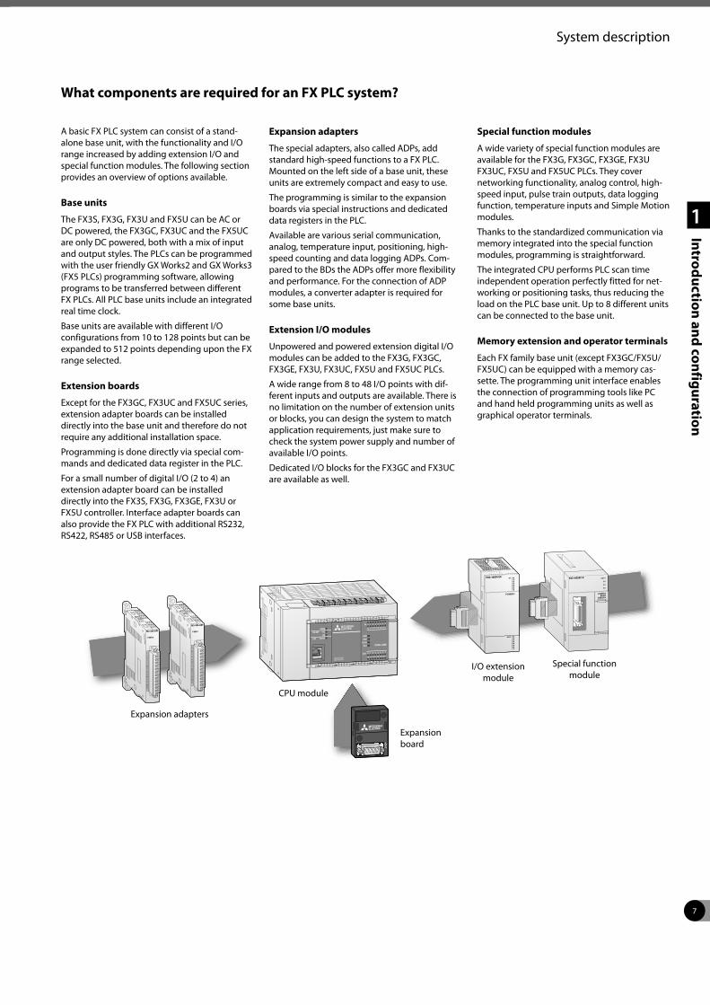
What components are required for an FX PLC system?
A basic FX PLC system can consist of a stand-alone base unit, with the functionality and I/O range increased by adding extension I/O and special function modules. The following section provides an overview of options available.
Base units
The FX3S, FX3G, FX3U and FX5U can be AC or DC powered, the FX3GC, FX3UC and the FX5UC are only DC powered, both with a mix of input and output styles. The PLCs can be programmed with the user friendly GX Works2 and GX Works3 (FX5 PLCs) programming software, allowing programs to be transferred between different FX PLCs. All PLC base units include an integrated real time clock.
Base units are available with different I/O configurations from 10 to 128 points but can be expanded to 512 points depending upon the FX range selected.
Extension boards
Except for the FX3GC, FX3UC and FX5UC series, extension adapter boards can be installed directly into the base unit and therefore do not require any additional installation space.
Programming is done directly via special com-mands and dedicated data register in the PLC.
For a small number of digital I/O (2 to 4) an extension adapter board can be installed directly into the FX3S, FX3G, FX3GE, FX3U or FX5U controller. Interface adapter boards can also provide the FX PLC with additional RS232, RS422, RS485 or USB interfaces.
Expansion adapters
The special adapters, also called ADPs, add standard high-speed functions to a FX PLC. Mounted on the left side of a base unit, these units are extremely compact and easy to use.
The programming is similar to the expansion boards via special instructions and dedicated data registers in the PLC.
Available are various serial communication, analog, temperature input, positioning, high-speed counting and data logging ADPs. Com-pared to the BDs the ADPs offer more flexibility and performance. For the connection of ADP modules, a converter adapter is required for some base units.
Extension I/O modules
Unpowered and powered extension digital I/O modules can be added to the FX3G, FX3GC, FX3GE, FX3U, FX3UC, FX5U and FX5UC PLCs.
A wide range from 8 to 48 I/O points with dif-ferent inputs and outputs are available. There is no limitation on the number of extension units or blocks, you can design the system to match application requirements, just make sure to check the system power supply and number of available I/O points.
Dedicated I/O blocks for the FX3GC and FX3UC are available as well.
Special function modules
A wide variety of special function modules are available for the FX3G, FX3GC, FX3GE, FX3U FX3UC, FX5U and FX5UC PLCs. They cover networking functionality, analog control, high-speed input, pulse train outputs, data logging function, temperature inputs and Simple Motion modules.
Thanks to the standardized communication via memory integrated into the special function modules, programming is straightforward.
The integrated CPU performs PLC scan time independent operation perfectly fitted for net-working or positioning tasks, thus reducing the load on the PLC base unit. Up to 8 different units can be connected to the base unit.
Memory extension and operator terminals
Each FX family base unit (except FX3GC/FX5U/FX5UC) can be equipped with a memory cas-sette. The programming unit interface enables the connection of programming tools like PC and hand held programming units as well as graphical operator terminals.
Expansion adapters
I/O extension module
Special function module
CPU module
Expansion board
8
System description
1
Introduction and configuration
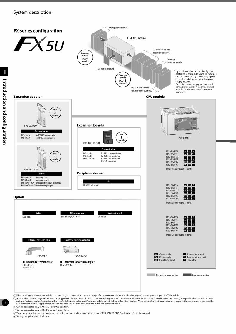
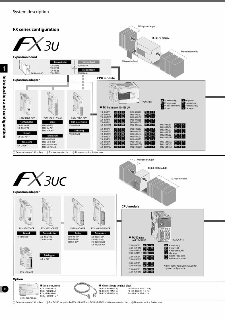
FX series configuration
Battery
FX3U-32BL
Extended extension cable Connector conversion adapter
Extended extension cableFX5-30EC 2FX5-65EC 2
Connector conversion adapterFX5-CNV-BC
HMIGOT2000, GOT Simple
Connector connection Cable connection
FX5U-32MR/ES AC D2 R
FX5U-32MT/ES AC D2 T1
FX5U-32MT/ESS AC D2 T2
FX5U-32MR/DS DC D2 R
FX5U-32MT/DS DC D2 T1
FX5U-32MT/DSS DC D2 T2
Input: 16 points/Output: 16 points
AC AC power supply T1 Transistor output (sink)DC DC power supply T2 Transistor output (source)D2 DC input (sink/source) R Relay output
1 When adding the extension module, it is necessary to connect it to the front stage of extension module in case of a shortage of internal power supply in CPU module.2 Attach when connecting an extension cable type module to a distant location or when making two-tier connections. The connector conversion adapter (FX5-CNV-BC) is required when connected with
an input/output module (extension cable type), high-speed pulse input/output module, or an intelligent function module. When using also the bus conversion module in the same system, connect the FX5 extension power supply module or the powered I/O module right after the extended extension cable.
3 Can be connected only to the AC power type system.4 Can be connected only to the DC power type system.5 There are restrictions on the number of extension devices and the connection order of FX5-4AD-TC-ADP. For details, refer to the manual.6 Spring clamp terminal block type.
Expansion adapter
Expansion boards
Peripheral device
Option
Max.
2modules
Max.
4modules
Communication
FX5-232ADP For RS232C communicationFX5-485ADP For RS485 communication
Analog
FX5-4AD-ADP For analog inputFX5-4DA-ADP For analog outputFX5-4AD-PT-ADP For resistance temperature detector inputFX5-4AD-TC-ADP 5 For thermocouple input
CPU module
Communication
FX5-232ADP For RS232C communicationFX5-485ADP For RS485 communicationFX5-422-BD-GOT For RS422 communication
(For GOT connection)
Max.
1module
FX5U-64MR/ES AC D2 R
FX5U-64MT/ES AC D2 T1
FX5U-64MT/ESS AC D2 T2
FX5U-64MR/DS DC D2 R
FX5U-64MT/DS DC D2 T1
FX5U-64MT/DSS DC D2 T2
Input: 32 points/Output: 32 points
FX5U-80MR/ES AC D2 R
FX5U-80MT/ES AC D2 T1
FX5U-80MT/ESS AC D2 T2
FX5U-80MR/DS DC D2 R
FX5U-80MT/DS DC D2 T1
FX5U-80MT/DSS DC D2 T2
Input: 40 points/Output: 40 points
FX5U-32M
FX5-422-BD-GOT
FX5-232ADP
FX5-4AD-ADP
FX5 expansion adapter
FX5 extension module (Extension cable type)
Connector conversion module
FX5 extension module (Extension connector type)
FX5 expansion board
Extension module
Max.16modules*
Expansion adapter
Max.6modules
FX5U CPU module
* Up to 12 modules can be directly con-nected to CPU module. Up to 16 modules can be connected by connecting a pow-ered I/O module or an extension power supply module. Extension power supply modules and connector conversion modules are not included in the number of connected modules.
SD memory cardSDHC memory card (16 GB)
Engineering toolGX Works3
FX5-65EC FX5-CNV-BC
POWERRUN
ERROR
9
System description
1
Introduction and configuration
POWERRUN
ERROR
Extension power supply module
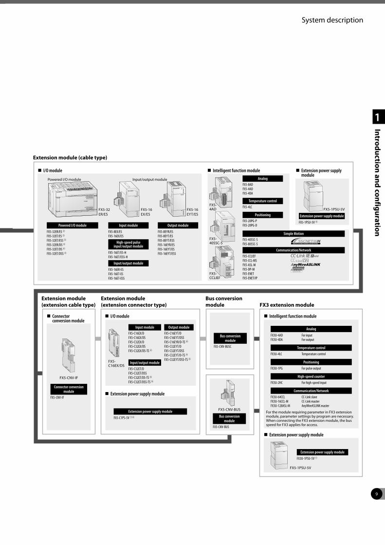
FX5-1PSU-5V 3Powered I/O module
FX5-32ER/ES 3FX5-32ET/ES 3FX5-32ET/ESS 3FX5-32ER/DS 4FX5-32ET/DS 4FX5-32ET/DSS 4
Output module
FX5-8EYR/ESFX5-8EYT/ESFX5-8EYT/ESSFX5-16EYR/ESFX5-16EYT/ESFX5-16EYT/ESS
Intelligent function module
For the module requiring parameter in FX3 extension module, parameter settings by program are necessary. When connecting the FX3 extension module, the bus speed for FX3 applies for access.
I/O module
Powered I/O module Input/output module
Extension module (cable type)
Intelligent function module Extension power supply module
Extension module (extension cable type)
Extension module (extension connector type)
Connector conversion module
I/O module
Bus conversion module FX3 extension module
Connector conversionmodule
FX5-CNV-IF
Input moduleFX5-C16EX/DFX5-C16EX/DSFX5-C32EX/DFX5-C32EX/DSFX5-C32EX/DS-TS 6
Input/output module
FX5-C32ET/DFX5-C32ET/DSSFX5-C32ET/DS-TS 6FX5-C32ET/DSS-TS 6
Output moduleFX5-C16EYT/DFX5-C16EYT/DSSFX5-C16EYR/D-TS 6FX5-C32EYT/DFX5-C32EYT/DSSFX5-C32EYT/D-TS 6FX5-C32EYT/DSS-TS 6
Extension power supply module
Extension power supply module
FX5-C1PS-5V 14
Bus conversion module
FX5-CNV-BUSC
Bus conversion module
FX5-CNV-BUS
Extension power supply module
Extension power supply module
FX3U-1PSU-5V 1
Analog
FX3U-4AD For inputFX3U-4DA For output
Temperature control
FX3U-4LC Temperature control
Positioning
FX3U-1PG For pulse output
High-speed counter
FX3U-2HC For high-speed input
Communication/Network
FX3U-64CCL CC-Link slaveFX3U-16CCL-M CC-Link masterFX3U-128ASL-M AnyWireASLINK master
FX5- 40SSC-S
FX5-1PSU-5V
FX5-CNV-IF
FX5-CNV-BUS
FX5-1PSU-5V
Input module
FX5-8EX/ESFX5-16EX/ES
High-speed pulse input/output module
FX5-16ET/ES-HFX5-16ET/ESS-H
Input/output module
FX5-16ER-ESFX5-16ET-ESFX5-16ET-ESS
FX5-32 ER/ES
FX5-16 EX/ES
FX5-16 EYT/ES
Simple MotionFX5-40SSC-SFX5-80SSC-S
Temperature controlFX5-4LC
Communication/NetworkFX5-CCLIEFFX5-CCL-MSFX5-ASL-MFX5-DP-M FX5-ENETFX5-ENET/IP
FX5- CCLIEF
FX5- 4AD
AnalogFX5-8ADFX5-4ADFX5-4DA
PositioningFX5-20PG-PFX5-20PG-D
FX5- C16EX/DS
10
System description
1
Introduction and configuration
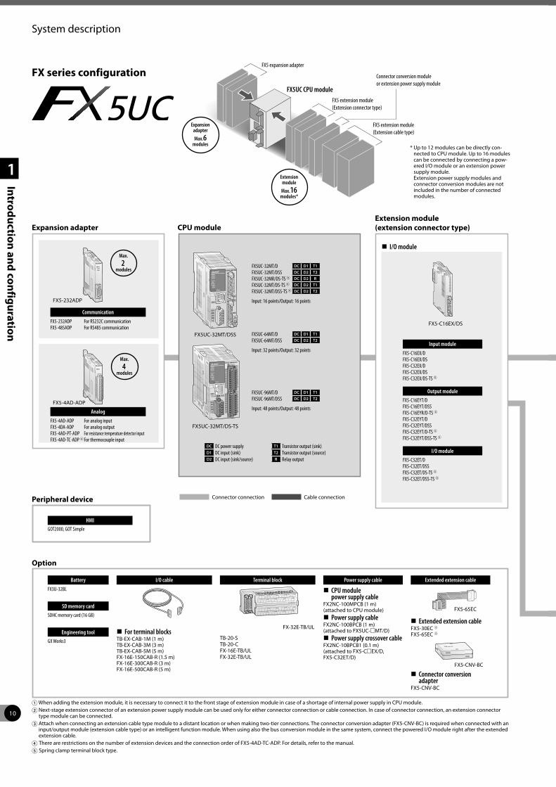
FX series configuration
Expansion adapter CPU moduleExtension module (extension connector type)
Communication
FX5-232ADP For RS232C communicationFX5-485ADP For RS485 communication
Max.
2modules
Max.
4modules
Analog
FX5-4AD-ADP For analog inputFX5-4DA-ADP For analog outputFX5-4AD-PT-ADP For resistance temperature detector inputFX5-4AD-TC-ADP 4 For thermocouple input
Peripheral device
Option
Battery
FX3U-32BL
SD memory card
SDHC memory card (16 GB)
Engineering tool
GX Works3
I/O cable
For terminal blocksTB-EX-CAB-1M (1 m)TB-EX-CAB-3M (3 m)TB-EX-CAB-5M (5 m)FX-16E-150CAB-R (1.5 m)FX-16E-300CAB-R (3 m)FX-16E-500CAB-R (5 m)
Terminal block
TB-20-STB-20-CFX-16E-TB/ULFX-32E-TB/UL
Power supply cable Extended extension cable
CPU module power supply cable
FX2NC-100MPCB (1 m)(attached to CPU module)
Power supply cableFX2NC-100BPCB (1 m)(attached to FX5UC-mMT/D)
Power supply crossover cableFX2NC-10BPCB1 (0.1 m)(attached to FX5-CmEX/D, FX5-C32ET/D)
Extended extension cableFX5-30EC 3FX5-65EC 3
Connector conversion adapter
FX5-CNV-BC
HMIGOT2000, GOT Simple
Connector connection Cable connection
FX5UC-32MT/D DC D1 T1
FX5UC-32MT/DSS DC D2 T2
FX5UC-32MR/DS-TS 5 DC D2 R
FX5UC-32MT/DS-TS 5 DC D2 T1
FX5UC-32MT/DSS-TS 5 DC D2 T2
Input: 16 points/Output: 16 points
DC DC power supply T1 Transistor output (sink)D1 DC input (sink) T2 Transistor output (source)D2 DC input (sink/source) R Relay output
FX5UC-64MT/D DC D1 T1
FX5UC-64MT/DSS DC D2 T2
Input: 32 points/Output: 32 points
FX5UC-96MT/D DC D1 T1
FX5UC-96MT/DSS DC D2 T2
Input: 48 points/Output: 48 points
Input module
FX5-C16EX/DFX5-C16EX/DSFX5-C32EX/DFX5-C32EX/DSFX5-C32EX/DS-TS 5
Output module
FX5-C16EYT/DFX5-C16EYT/DSSFX5-C16EYR/D-TS 5FX5-C32EYT/DFX5-C32EYT/DSSFX5-C32EYT/D-TS 5FX5-C32EYT/DSS-TS 5
I/O module
FX5-C32ET/DFX5-C32ET/DSSFX5-C32ET/DS-TS 5FX5-C32ET/DSS-TS 5
1 When adding the extension module, it is necessary to connect it to the front stage of extension module in case of a shortage of internal power supply in CPU module.2 Next-stage extension connector of an extension power supply module can be used only for either connector connection or cable connection. In case of connector connection, an extension connector
type module can be connected.3 Attach when connecting an extension cable type module to a distant location or when making two-tier connections. The connector conversion adapter (FX5-CNV-BC) is required when connected with an
input/output module (extension cable type) or an intelligent function module. When using also the bus conversion module in the same system, connect the powered I/O module right after the extended extension cable.
4 There are restrictions on the number of extension devices and the connection order of FX5-4AD-TC-ADP. For details, refer to the manual.5 Spring clamp terminal block type.
FX5-232ADP
FX5-4AD-ADP
FX5UC-32MT/DS-TS
I/O module
FX5-C16EX/DS
FX-32E-TB/UL
FX5-65EC
FX5-CNV-BC
FX5 expansion adapter
FX5 extension module (Extension cable type)
Connector conversion module or extension power supply module
FX5 extension module (Extension connector type)
Extension module
Max.16modules*
Expansion adapter
Max.6modules
FX5UC CPU module
* Up to 12 modules can be directly con-nected to CPU module. Up to 16 modules can be connected by connecting a pow-ered I/O module or an extension power supply module. Extension power supply modules and connector conversion modules are not included in the number of connected modules.
POWERRUN
ERROR
FX5UC-32MT/DSS
11
System description
1
Introduction and configuration
POWERRUN
ERROR
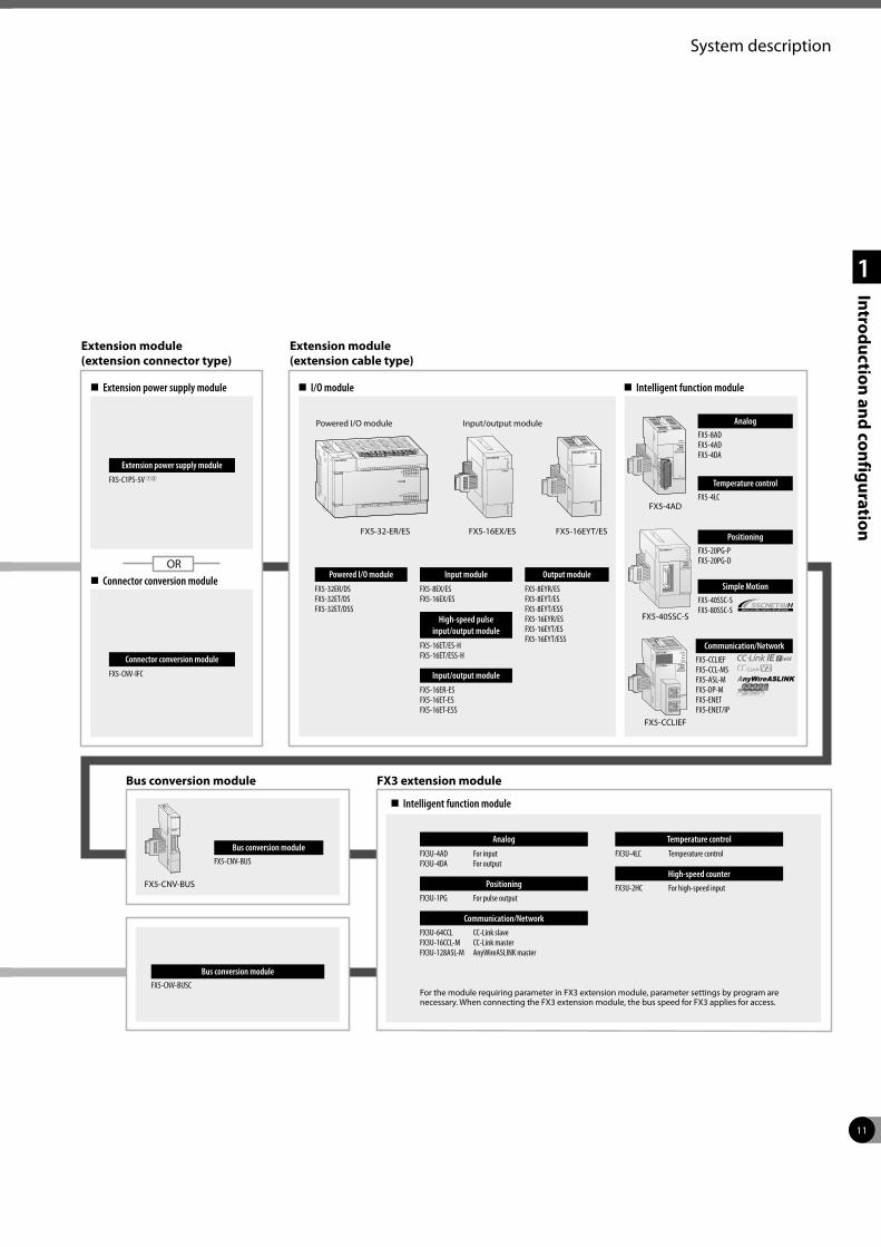
Extension module (extension connector type)
Extension module (extension cable type)
Extension power supply module
Connector conversion module
OR
I/O module Intelligent function module
Extension power supply module
FX5-C1PS-5V 12
Connector conversion module
FX5-CNV-IFC
Powered I/O module
FX5-32ER/DSFX5-32ET/DSFX5-32ET/DSS
Output module
FX5-8EYR/ESFX5-8EYT/ESFX5-8EYT/ESSFX5-16EYR/ESFX5-16EYT/ESFX5-16EYT/ESS
Powered I/O module Input/output module
Intelligent function module
Bus conversion module FX3 extension module
Bus conversion moduleFX5-CNV-BUS
Bus conversion moduleFX5-CNV-BUSC
Analog
FX3U-4AD For inputFX3U-4DA For output
Positioning
FX3U-1PG For pulse output
Communication/Network
FX3U-64CCL CC-Link slaveFX3U-16CCL-M CC-Link masterFX3U-128ASL-M AnyWireASLINK master
Temperature control
FX3U-4LC Temperature control
High-speed counter
FX3U-2HC For high-speed input
For the module requiring parameter in FX3 extension module, parameter settings by program are necessary. When connecting the FX3 extension module, the bus speed for FX3 applies for access.
FX5-CNV-BUS
Input module
FX5-8EX/ESFX5-16EX/ES
High-speed pulse input/output module
FX5-16ET/ES-HFX5-16ET/ESS-H
Input/output module
FX5-16ER-ESFX5-16ET-ESFX5-16ET-ESS
Communication/NetworkFX5-CCLIEFFX5-CCL-MSFX5-ASL-MFX5-DP-MFX5-ENETFX5-ENET/IP
AnalogFX5-8ADFX5-4ADFX5-4DA
FX5-CCLIEF
FX5-32-ER/ES FX5-16EX/ES FX5-16EYT/ES
FX5-40SSC-S
Simple MotionFX5-40SSC-SFX5-80SSC-S
Temperature controlFX5-4LC
PositioningFX5-20PG-PFX5-20PG-D
FX5-4AD
12
System description
1
Introduction and configuration
Expansion board
Expansion adapter CPU module
CommunicationFX3U-232-BDFX3U-422-BDFX3U-485-BDFX3U-USB-BDFX3U-422-BD
Interface boardFX3U-CNV-BD
Analog setpointFX3U-8AV-BD
FX3U-ENET-ADP FX3U-4AD-PTW-ADP FX3U-4HSX-ADP
CommunicationFX3U-232ADP-MBFX3U-485ADP-MB
Network
FX3U-ENET-ADP 1
Data logging
FX3U-CF-ADP 2
AnalogFX3U-4AD-ADPFX3U-4DA-ADPFX3U-3A-ADP 2
Temperature
FX3U-4AD-PT-ADPFX3U-4AD-TC-ADPFX3U-4AD-PTW-ADPFX3U-4AD-PNK-ADP
High-speed counterFX3U-4HSX-ADP
Positioning
FX3U-2HSY-ADP
FX3U-16MR/ES AC D R
FX3U-16MT/ES AC D T1
FX3U-16MT/ESS AC D T2
FX3U-16MR/DS DC D R
FX3U-16MT/DS DC D T1
FX3U-16MT/DSS DC D T2
FX3U-32MR/ES AC D R
FX3U-32MT/ES AC D T1
FX3U-32MT/ESS AC D T2
FX3U-32MS/ES AC D TR
FX3U-32MR/DS DC D R
FX3U-32MT/DS DC D T1
FX3U-32MT/DSS DC D T2
FX3U-32MR/UA1 AC E R
FX3U main unit 16–128 I/O
FX3U-48MR/ES AC D R
FX3U-48MT/ES AC D T1
FX3U-48MT/ESS AC D T2
FX3U-48MR/DS DC D R
FX3U-48MT/DS DC D T1
FX3U-48MT/DSS DC D T2
FX3U-64MR/ES AC D R
FX3U-64MT/ES AC D T1
FX3U-64MT/ESS AC D T2
FX3U-64MS/ES AC D TR
FX3U-64MR/DS DC D R
FX3U-64MT/DS DC D T1
FX3U-64MT/DSS DC D T2
FX3U-64MR/UA1 AC E R
FX3U-80MR/ES AC D R
FX3U-80MT/ES AC D T1
FX3U-80MT/ESS AC D T2
FX3U-80MR/DS DC D R
FX3U-80MT/DS DC D T1
FX3U-80MT/DSS DC D T2
FX3U-128MR/ES AC D R
FX3U-128MT/ES AC D T1
FX3U-128MT/ESS AC D T2
AC AC power supply R Relay outputDC DC power supply T1 Transistor (sink)D DC input (sink/source) T2 Transistor (source)E AC input TR Triac output
FX3U-32M
1 Firmware version 3.10 or later. 2 Firmware version 2.61. 3 Firmware version 3.00 or later.
Expansion adapter
FX3U-4AD-ADP FX3U-4AD-PNK-ADP
AnalogFX3U-4AD-ADPFX3U-4DA-ADPFX3U-3A-ADP 2
Temperature
FX3U-4AD-PT-ADPFX3U-4AD-TC-ADPFX3U-4AD-PTW-ADPFX3U-4AD-PNK-ADP
FX3U-ENET-ADP FX3U-232ADP-MB
NetworkFX3U-ENET-ADP 1
Communication
FX3U-232ADP-MBFX3U-485ADP-MB
Data logging
FX3U-CF-ADP 2
FX3U-CF-ADP
Option
FX3UC-16MT/D* DC D1 T1
FX3UC-16MT/DSS DC D2 T2
FX3UC-16MR/D-T* DC D1 R
FX3UC-16MR/DS-T DC D2 R
FX3UC-32MT/D* DC D1 T1
FX3UC-32MT/DSS DC D2 T2
FX3UC-64MT/D* DC D1 T1
FX3UC-64MT/DSS DC D2 T2
FX3UC-96MT/D* DC D1 T1
FX3UC-96MT/DSS DC D2 T2
FX3UC main unit 16–96 I/O FX3UC-64M
DC DC power supplyD1 DC input (sink)D2 DC input(sink/source)R Relay output
T1 Transistor output (sink)T2 Transistor output (source)
* Refer to the hardware manual for system configuration.
FX3U-FLROM-64L
Memory cassetteFX3U-FLROM-16FX3U-FLROM-64FX3U-FLROM-64LFX3U-FLROM-1M 3
OR
1 Firmware version 3.10 or later. 2 The FX3UC supports the FX3U-CF-ADP and FX3U-3A-ADP from firmware version 2.61. 3 Firmware version 3.00 or later.
FX series configuration
FX3U CPU module
CPU module
FX3UC CPU module
FX3 expansion board
FX3 expansion adapter
FX3 extension module
FX3 expansion adapter
FX3 extension module
Connecting to terminal blockTB-EX-CAB-1M (1 m)TB-EX-CAB-3M (3 m)TB-EX-CAB-5M (5 m)
FX-16E-150CAB-R (1.5 m)FX-16E-300CAB-R (3 m)FX-16E-500CAB-R (5 m)
13
System description
1
Introduction and configuration
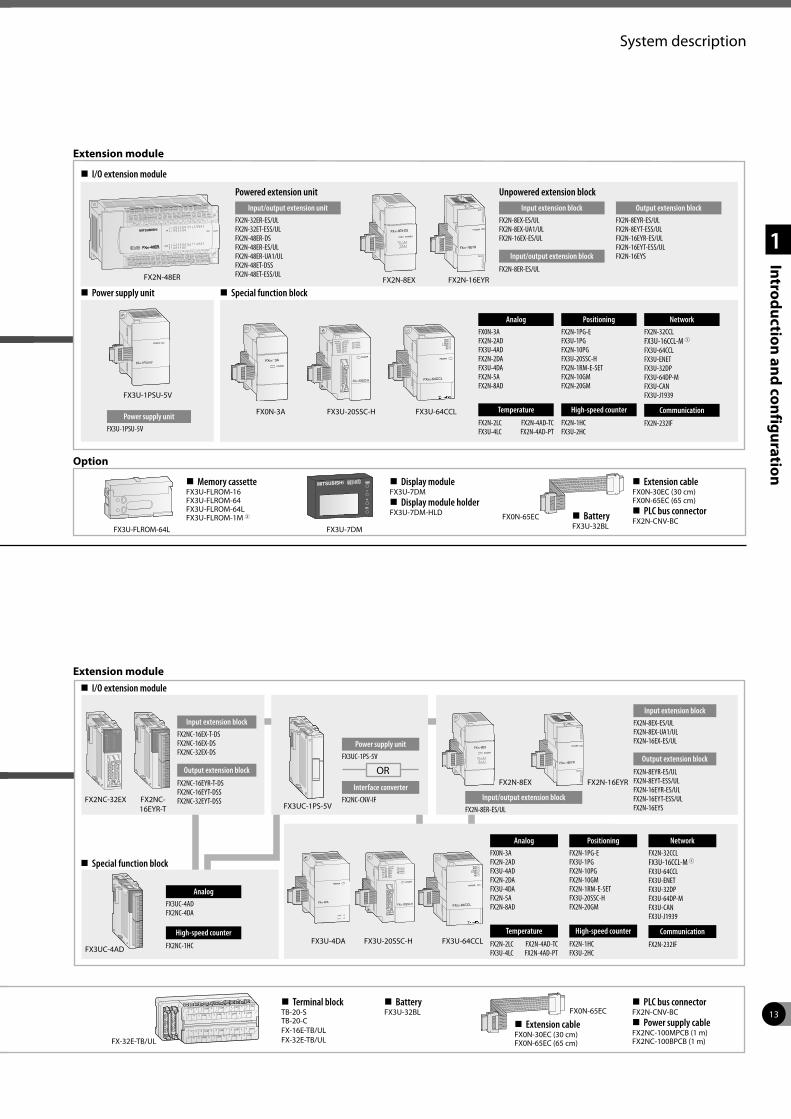
1 Firmware version 3.10 or later. 2 The FX3UC supports the FX3U-CF-ADP and FX3U-3A-ADP from firmware version 2.61. 3 Firmware version 3.00 or later.
Extension module
I/O extension module
Power supply unit Special function block
Option
FX2N-48ER FX2N-8EX FX2N-16EYR
FX0N-3A FX3U-20SSC-H FX3U-64CCL
FX3U-7DMFX3U-FLROM-64L
Powered extension unit
Input/output extension unitFX2N-32ER-ES/ULFX2N-32ET-ESS/ULFX2N-48ER-DSFX2N-48ER-ES/ULFX2N-48ER-UA1/ULFX2N-48ET-DSSFX2N-48ET-ESS/UL
FX3U-1PSU-5V
Power supply unitFX3U-1PSU-5V
Unpowered extension block
Input extension blockFX2N-8EX-ES/ULFX2N-8EX-UA1/ULFX2N-16EX-ES/UL
Input/output extension block
FX2N-8ER-ES/UL
AnalogFX0N-3AFX2N-2ADFX3U-4ADFX2N-2DAFX3U-4DAFX2N-5AFX2N-8AD
Temperature
FX2N-2LC FX2N-4AD-TCFX3U-4LC FX2N-4AD-PT
Output extension blockFX2N-8EYR-ES/ULFX2N-8EYT-ESS/ULFX2N-16EYR-ES/ULFX2N-16EYT-ESS/ULFX2N-16EYS
PositioningFX2N-1PG-EFX3U-1PGFX2N-10PGFX3U-20SSC-HFX2N-1RM-E-SETFX2N-10GMFX2N-20GM
High-speed counter
FX2N-1HCFX3U-2HC
NetworkFX2N-32CCLFX3U-16CCL-M 1FX3U-64CCLFX3U-ENETFX3U-32DPFX3U-64DP-MFX3U-CANFX3U-J1939
Communication
FX2N-232IF
Memory cassetteFX3U-FLROM-16FX3U-FLROM-64FX3U-FLROM-64LFX3U-FLROM-1M 3
Display moduleFX3U-7DM
Display module holderFX3U-7DM-HLD FX0N-65EC
Extension cableFX0N-30EC (30 cm)FX0N-65EC (65 cm)
PLC bus connectorFX2N-CNV-BC Battery
FX3U-32BL
Extension module I/O extension module
Special function block
FX2NC-32EX FX2NC-16EYR-T FX3UC-1PS-5V
FX2N-8EX FX2N-16EYR
FX3U-4DA FX3U-20SSC-H FX3U-64CCLFX3UC-4AD
Input extension blockFX2NC-16EX-T-DSFX2NC-16EX-DSFX2NC-32EX-DS
Output extension block
FX2NC-16EYR-T-DSFX2NC-16EYT-DSSFX2NC-32EYT-DSS
Power supply unitFX3UC-1PS-5V
AnalogFX3UC-4ADFX2NC-4DA
High-speed counter
FX2NC-1HC
OR
Interface converterFX2NC-CNV-IF Input/output extension block
FX2N-8ER-ES/UL
Input extension blockFX2N-8EX-ES/ULFX2N-8EX-UA1/ULFX2N-16EX-ES/UL
Output extension block
FX2N-8EYR-ES/ULFX2N-8EYT-ESS/ULFX2N-16EYR-ES/ULFX2N-16EYT-ESS/ULFX2N-16EYS
AnalogFX0N-3AFX2N-2ADFX3U-4ADFX2N-2DAFX3U-4DAFX2N-5AFX2N-8AD
Temperature
FX2N-2LC FX2N-4AD-TCFX3U-4LC FX2N-4AD-PT
PositioningFX2N-1PG-EFX3U-1PGFX2N-10PGFX2N-10GMFX2N-1RM-E-SETFX3U-20SSC-HFX2N-20GM
High-speed counter
FX2N-1HCFX3U-2HC
NetworkFX2N-32CCLFX3U-16CCL-M 1FX3U-64CCLFX3U-ENETFX3U-32DPFX3U-64DP-MFX3U-CANFX3U-J1939
Communication
FX2N-232IF
Terminal blockTB-20-STB-20-CFX-16E-TB/ULFX-32E-TB/UL
BatteryFX3U-32BL
FX-32E-TB/UL
FX0N-65EC
Extension cableFX0N-30EC (30 cm)FX0N-65EC (65 cm)
PLC bus connectorFX2N-CNV-BC
Power supply cableFX2NC-100MPCB (1 m)FX2NC-100BPCB (1 m)
14
System description
1
Introduction and configuration
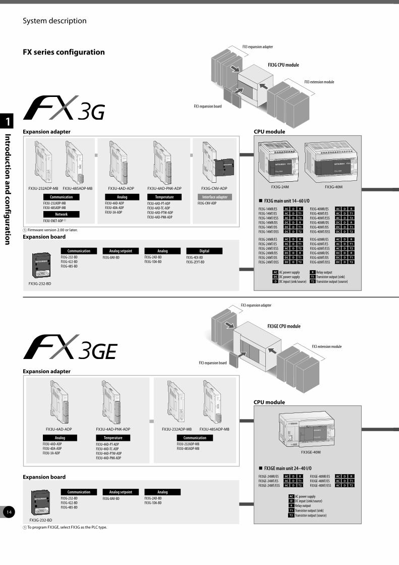
Expansion adapter
Expansion board
CPU module
FX3U-232ADP-MB FX3U-485ADP-MB FX3U-4AD-ADP FX3U-4AD-PNK-ADP FX3G-CNV-ADP FX3G-24M FX3G-40M
AnalogFX3U-4AD-ADPFX3U-4DA-ADPFX3U-3A-ADP
Temperature
FX3U-4AD-PT-ADPFX3U-4AD-TC-ADPFX3U-4AD-PTW-ADPFX3U-4AD-PNK-ADP
CommunicationFX3U-232ADP-MBFX3U-485ADP-MB
Network
FX3U-ENET-ADP 1
Interface adapterFX3G-CNV-ADP
FX3G-14MR/ES AC D R
FX3G-14MT/ES AC D T1
FX3G-14MT/ESS AC D T2
FX3G-14MR/DS DC D R
FX3G-14MT/DS DC D T1
FX3G-14MT/DSS DC D T2
FX3G main unit 14–60 I/O
FX3G-24MR/ES AC D R
FX3G-24MT/ES AC D T1
FX3G-24MT/ESS AC D T2
FX3G-24MR/DS DC D R
FX3G-24MT/DS DC D T1
FX3G-24MT/DSS DC D T2
FX3G-40MR/ES AC D R
FX3G-40MT/ES AC D T1
FX3G-40MT/ESS AC D T2
FX3G-40MR/DS DC D R
FX3G-40MT/DS DC D T1
FX3G-40MT/DSS DC D T2
FX3G-60MR/ES AC D R
FX3G-60MT/ES AC D T1
FX3G-60MT/ESS AC D T2
FX3G-60MR/DS DC D R
FX3G-60MT/DS DC D T1
FX3G-60MT/DSS DC D T2
AC AC power supply R Relay outputDC DC power supply T1 Transistor output (sink)D DC input (sink/source) T2 Transistor output (source)
1 Firmware version 2.00 or later.
CommunicationFX3G-232-BDFX3G-422-BDFX3G-485-BD
AnalogFX3G-2AD-BDFX3G-1DA-BD
FX3G-232-BD
INPUTV1+ I1+ V2+ I2+ VI-
ANALOG
OUTPUT
V+ I+ VI-
X17X16
X21X20
X23X22
X25X24
X27X26
ANALOG
100M
SD/RD
ERR
OPEN
10BASE-T/100BASE-TX
0 1 2 3 4 5 6 7
10 11 12 13 14 15 16 17
0 1 2 3 4 5 6 7
10 11 12 13 14 15 16 17
20 21 22 23 24 25 26 27
X11 X13 Y15 Y17 LOTY12 Y145
Y16
FX3GE-40M
CPU module
Expansion adapter
Expansion board
CommunicationFX3G-232-BDFX3G-422-BDFX3G-485-BD
AnalogFX3G-2AD-BDFX3G-1DA-BD
FX3G-232-BD
FX3U-4AD-ADP FX3U-4AD-PNK-ADP
AnalogFX3U-4AD-ADPFX3U-4DA-ADPFX3U-3A-ADP
Temperature
FX3U-4AD-PT-ADPFX3U-4AD-TC-ADPFX3U-4AD-PTW-ADPFX3U-4AD-PNK-ADP
FX3U-232ADP-MB FX3U-485ADP-MB
CommunicationFX3U-232ADP-MBFX3U-485ADP-MB
1 To program FX3GE, select FX3G as the PLC type.
FX3GE-24MR/ES AC D R
FX3GE-24MT/ES AC D T1
FX3GE-24MT/ESS AC D T2
FX3GE main unit 24–40 I/O
FX3GE-40MR/ES AC D R
FX3GE-40MT/ES AC D T1
FX3GE-40MT/ESS AC D T2
AC AC power supplyD DC input (sink/source)R Relay output
T1 Transistor output (sink)T2 Transistor output (source)
FX series configuration
Analog setpoint
FX3G-8AV-BD
Digital
FX3G-4EX-BDFX3G-2EYT-BD
Analog setpoint
FX3G-8AV-BD
FX3G CPU module
FX3GE CPU module
FX3 expansion board
FX3 expansion adapter
FX3 extension module
FX3 expansion board
FX3 expansion adapter
FX3 extension module
15
System description
1
Introduction and configuration
INPUTV1+ I1+ V2+ I2+ VI-
ANALOG
OUTPUT
V+ I+ VI-
X17X16
X21X20
X23X22
X25X24
X27X26
ANALOG
100M
SD/RD
ERR
OPEN
10BASE-T/100BASE-TX
0 1 2 3 4 5 6 7
10 11 12 13 14 15 16 17
0 1 2 3 4 5 6 7
10 11 12 13 14 15 16 17
20 21 22 23 24 25 26 27
X11 X13 Y15 Y17 LOTY12 Y145
Y16
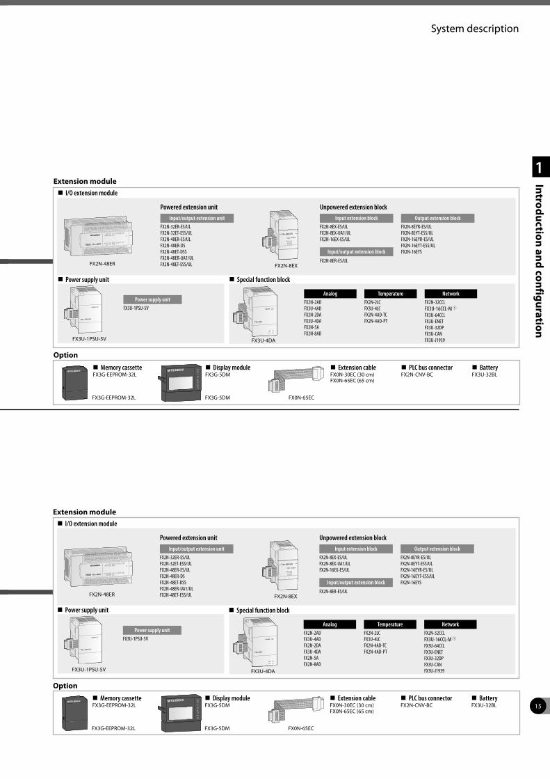
Extension module I/O extension module
Power supply unit Special function block
Option
FX2N-48ER FX2N-8EX
Powered extension unit
Input/output extension unitFX2N-32ER-ES/ULFX2N-32ET-ESS/ULFX2N-48ER-ES/ULFX2N-48ER-DSFX2N-48ET-DSSFX2N-48ER-UA1/ULFX2N-48ET-ESS/UL
FX3U-1PSU-5V
Power supply unitFX3U-1PSU-5V
Unpowered extension block
Input extension blockFX2N-8EX-ES/ULFX2N-8EX-UA1/ULFX2N-16EX-ES/UL
Input/output extension block
FX2N-8ER-ES/UL
Output extension blockFX2N-8EYR-ES/ULFX2N-8EYT-ESS/ULFX2N-16EYR-ES/ULFX2N-16EYT-ESS/ULFX2N-16EYS
AnalogFX2N-2ADFX3U-4ADFX2N-2DAFX3U-4DAFX2N-5AFX2N-8AD
TemperatureFX2N-2LCFX3U-4LCFX2N-4AD-TCFX2N-4AD-PT
NetworkFX2N-32CCLFX3U-16CCL-M 1FX3U-64CCLFX3U-ENETFX3U-32DPFX3U-CANFX3U-J1939FX3U-4DA
FX0N-65ECFX3G-5DMFX3G-EEPROM-32L
Memory cassetteFX3G-EEPROM-32L
Display moduleFX3G-5DM
Extension cableFX0N-30EC (30 cm)FX0N-65EC (65 cm)
PLC bus connectorFX2N-CNV-BC
BatteryFX3U-32BL
16
System description
1
Introduction and configuration
FX3U-4AD-ADP FX3U-4AD-PNK-ADP
AnalogFX3U-4AD-ADPFX3U-4DA-ADPFX3U-3A-ADP
Temperature
FX3U-4AD-PT-ADPFX3U-4AD-TC-ADPFX3U-4AD-PTW-ADPFX3U-4AD-PNK-ADP
FX3U-ENET-ADP FX3U-232ADP-MB
NetworkFX3U-ENET-ADP 1
Communication
FX3U-232ADP-MBFX3U-485ADP-MB
FX3U-485ADP-MB
1 Firmware version 2.00 or later.
Expansion adapter
Option
FX3GC-32M
FX3GC-32MT/D DC D T1
FX3GC-32MT/DSS DC D T2
FX3GC main unit 32 I/O
DC DC power supply T1 Transistor output (sink)D DC input (sink/source) T2 Transistor output (source)
CPU module
Expansion adapter
Expansion board
FX3U-4AD-ADP FX3U-4AD-PNK-ADP
AnalogFX3U-4AD-ADPFX3U-4DA-ADPFX3U-3A-ADP
Temperature
FX3U-4AD-PT-ADPFX3U-4AD-TC-ADPFX3U-4AD-PTW-ADPFX3U-4AD-PNK-ADP
FX3U-ENET-ADP FX3U-232ADP-MB
NetworkFX3U-ENET-ADP
Communication
FX3U-232ADP-MBFX3U-485ADP-MB
CommunicationFX3G-232-BDFX3G-422-BDFX3G-485-BD
AnalogFX3G-2AD-BDFX3G-1DA-BD
FX3G-232-BD
FX3S-CNV-ADP
Interface adapterFX3S-CNV-ADP
FX series configuration
Analog setpoint
FX3G-8AV-BD
Digital
FX3G-4EX-BDFX3G-2EYT-BD
FX3GC CPU module
FX3S CPU module
FX3 expansion adapter
FX3 extension module
FX3 expansion adapter
FX3 expansion board
Connecting to terminal blockTB-EX-CAB-1M (1 m)TB-EX-CAB-3M (3 m)TB-EX-CAB-5M (5 m)
FX-16E-150CAB-R (1.5 m)FX-16E-300CAB-R (3 m)FX-16E-500CAB-R (5 m)
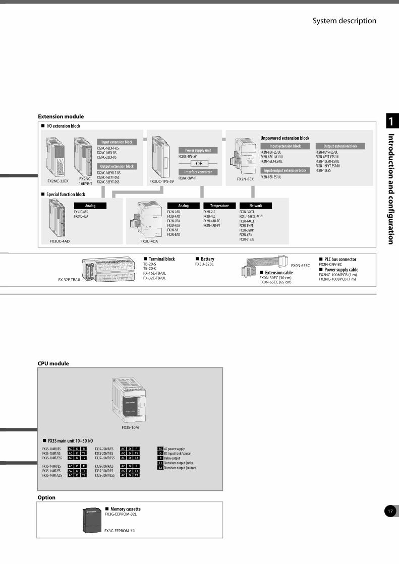
17
System description
1
Introduction and configuration
FX-32E-TB/UL
FX0N-65EC
Extension cableFX0N-30EC (30 cm)FX0N-65EC (65 cm)
PLC bus connectorFX2N-CNV-BC
Power supply cableFX2NC-100MPCB (1 m)FX2NC-100BPCB (1 m)
AnalogFX2N-2ADFX3U-4ADFX2N-2DAFX3U-4DAFX2N-5AFX2N-8AD
TemperatureFX2N-2LCFX3U-4LCFX2N-4AD-TCFX2N-4AD-PT
NetworkFX2N-32CCLFX3U-16CCL-M 1FX3U-64CCLFX3U-ENETFX3U-32DPFX3U-CANFX3U-J1939FX3U-4DA
AnalogFX3UC-4ADFX2NC-4DA
FX3UC-4AD
Extension module
Special function block
I/O extension block
FX2NC-32EX FX2NC-16EYR-T
Input extension blockFX2NC-16EX-T-DSFX2NC-16EX-DSFX2NC-32EX-DS
Output extension block
FX2NC-16EYR-T-DSFX2NC-16EYT-DSSFX2NC-32EYT-DSS FX3UC-1PS-5V
Power supply unitFX3UC-1PS-5V
OR
Interface converterFX2NC-CNV-IF FX2N-8EX
Unpowered extension block
Input extension blockFX2N-8EX-ES/ULFX2N-8EX-UA1/ULFX2N-16EX-ES/UL
Input/output extension block
FX2N-8ER-ES/UL
Output extension blockFX2N-8EYR-ES/ULFX2N-8EYT-ESS/ULFX2N-16EYR-ES/ULFX2N-16EYT-ESS/ULFX2N-16EYS
CPU module
Option
FX3G-EEPROM-32L
Memory cassetteFX3G-EEPROM-32L
FX3S-10M
FX3S-10MR/ES AC D R
FX3S-10MT/ES AC D T1
FX3S-10MT/ESS AC D T2
FX3S-14MR/ES AC D R
FX3S-14MT/ES AC D T1
FX3S-14MT/ESS AC D T2
FX3S main unit 10–30 I/O
FX3S-20MR/ES AC D R
FX3S-20MT/ES AC D T1
FX3S-20MT/ESS AC D T2
FX3S-30MR/ES AC D R
FX3S-30MT/ES AC D T1
FX3S-30MT/ESS AC D T2
AC AC power supplyD DC input (sink/source)R Relay output
T1 Transistor output (sink)T2 Transistor output (source)
Terminal blockTB-20-STB-20-CFX-16E-TB/ULFX-32E-TB/UL
BatteryFX3U-32BL
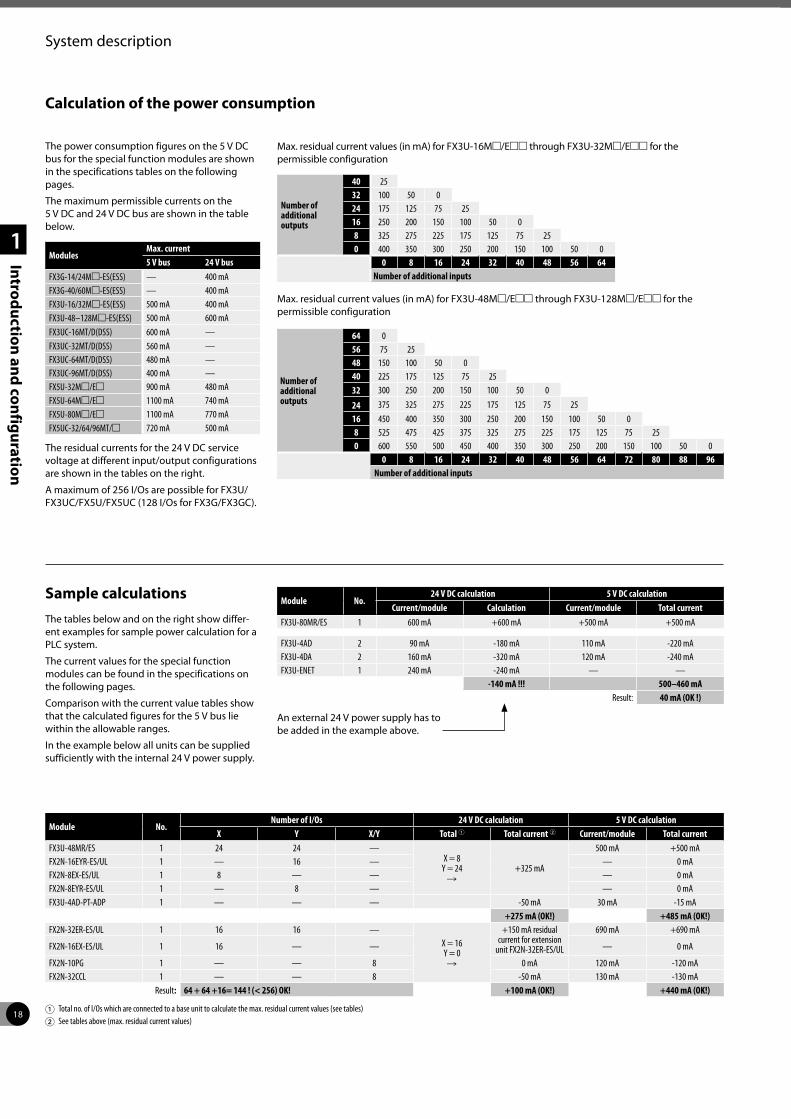
18
System description
1
Introduction and configuration
Calculation of the power consumption
The power consumption figures on the 5 V DC bus for the special function modules are shown in the specifications tables on the following pages.
The maximum permissible currents on the 5 V DC and 24 V DC bus are shown in the table below.
ModulesMax. current 5 V bus 24 V bus
FX3G-14/24Mm-ES(ESS) — 400 mAFX3G-40/60Mm-ES(ESS) — 400 mAFX3U-16/32Mm-ES(ESS) 500 mA 400 mAFX3U-48–128Mm-ES(ESS) 500 mA 600 mAFX3UC-16MT/D(DSS) 600 mA —FX3UC-32MT/D(DSS) 560 mA —FX3UC-64MT/D(DSS) 480 mA —FX3UC-96MT/D(DSS) 400 mA —FX5U-32Mm/Em 900 mA 480 mAFX5U-64Mm/Em 1100 mA 740 mAFX5U-80Mm/Em 1100 mA 770 mAFX5UC-32/64/96MT/m 720 mA 500 mA
The residual currents for the 24 V DC service voltage at different input/output configurations are shown in the tables on the right.
A maximum of 256 I/Os are possible for FX3U/FX3UC/FX5U/FX5UC (128 I/Os for FX3G/FX3GC).
Max. residual current values (in mA) for FX3U-16Mm/Emm through FX3U-32Mm/Emm for the permissible configuration
Number of additional outputs
40 2532 100 50 024 175 125 75 2516 250 200 150 100 50 08 325 275 225 175 125 75 250 400 350 300 250 200 150 100 50 0
0 8 16 24 32 40 48 56 64Number of additional inputs
Max. residual current values (in mA) for FX3U-48Mm/Emm through FX3U-128Mm/Emm for the permissible configuration
Number of additional outputs
64 056 75 2548 150 100 50 040 225 175 125 75 2532 300 250 200 150 100 50 0
24 375 325 275 225 175 125 75 2516 450 400 350 300 250 200 150 100 50 08 525 475 425 375 325 275 225 175 125 75 250 600 550 500 450 400 350 300 250 200 150 100 50 0
0 8 16 24 32 40 48 56 64 72 80 88 96Number of additional inputs
Sample calculationsThe tables below and on the right show differ-ent examples for sample power calculation for a PLC system.
The current values for the special function modules can be found in the specifications on the following pages.
Comparison with the current value tables show that the calculated figures for the 5 V bus lie within the allowable ranges.
In the example below all units can be supplied sufficiently with the internal 24 V power supply.
Module No.24 V DC calculation 5 V DC calculation
Current/module Calculation Current/module Total currentFX3U-80MR/ES 1 600 mA +600 mA +500 mA +500 mA
FX3U-4AD 2 90 mA -180 mA 110 mA -220 mAFX3U-4DA 2 160 mA -320 mA 120 mA -240 mAFX3U-ENET 1 240 mA -240 mA — —
-140 mA !!! 500–460 mAResult: 40 mA (OK !)
An external 24 V power supply has to be added in the example above.
Module No.Number of I/Os 24 V DC calculation 5 V DC calculation
X Y X/Y Total 1 Total current 2 Current/module Total currentFX3U-48MR/ES 1 24 24 —
X = 8 Y = 24
R+325 mA
500 mA +500 mAFX2N-16EYR-ES/UL 1 — 16 — — 0 mAFX2N-8EX-ES/UL 1 8 — — — 0 mAFX2N-8EYR-ES/UL 1 — 8 — — 0 mAFX3U-4AD-PT-ADP 1 — — — -50 mA 30 mA -15 mA
+275 mA (OK!) +485 mA (OK!)FX2N-32ER-ES/UL 1 16 16 —
X = 16 Y = 0 R
+150 mA residual current for extension
unit FX2N-32ER-ES/UL
690 mA +690 mA
FX2N-16EX-ES/UL 1 16 — — — 0 mA
FX2N-10PG 1 — — 8 0 mA 120 mA -120 mAFX2N-32CCL 1 — — 8 -50 mA 130 mA -130 mA
Result: 64 + 64 +16= 144 ! (< 256) OK! +100 mA (OK!) +440 mA (OK!)
1 Total no. of I/Os which are connected to a base unit to calculate the max. residual current values (see tables)2 See tables above (max. residual current values)
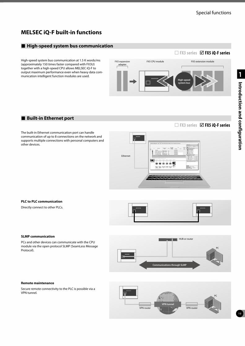
19
Special functions
1
Introduction and configuration
High-speed system bus communication ¨ FX3 series þ FX5 iQ-F seriesHigh-speed system bus communication at 1.5 K words/ ms (approximately 150 times faster compared with FX3U) together with a high-speed CPU allows MELSEC iQ-F to output maximum performance even when heavy data com-munication intelligent function modules are used.
SLMP communication
PCs and other devices can communicate with the CPU module via the open protocol SLMP (SeamLess Message Protocol).
HUB or router
PC
Communications through SLMP
MELSEC iQ-F built-in functions
High-speed system bus
FX5 expansion adapter
FX5 CPU module FX5 extension module
Built-in Ethernet port ¨ FX3 series þ FX5 iQ-F series
Ethernet
Remote maintenance
Secure remote connectivity to the PLC is possible via a VPN tunnel.
PC
VPN tunnel
VPN router VPN router
PLC to PLC communication
Directly connect to other PLCs.
The built-in Ethernet communication port can handle communication of up to 8 connections on the network and supports multiple connections with personal computers and other devices.
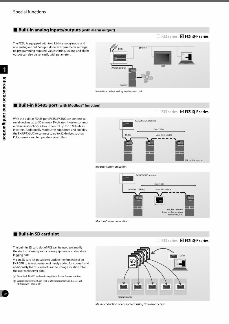
20
Special functions
1
Introduction and configuration
Built-in analog inputs/outputs (with alarm output)
¨ FX3 series þ FX5 iQ-F seriesThe FX5U is equipped with two 12-bit analog inputs and one analog output. Setup is done with parameter settings, no programming required. Value shifting, scaling and alarm output can also be set easily with parameters.
Analog output
Inverter
GOT
EthernetFX5U
Built-in RS485 port (with Modbus® function)
¨ FX3 series þ FX5 iQ-F seriesWith the built-in RS485 port FX5U/FX5UC can connect to serial devices up to 50 m away. Dedicated inverter commu-nication instructions allow to control up to 16 Mitsubishi inverters. Additionally Modbus® is supported and enables the FX5U/FX5UC to connect to up to 32 devices such as PLCs, sensors and temperature controllers.
FX5U/FX5UC (master)
Max. 50 m
Max. 16 modulesRS485
Mitsubishi inverter
FX5U/FX5UC (master)
Max. 50 m
Max. 32 stationsModbus® (RS485)
Modbus® devices (Inverter, temperature
controllers, etc.)
Built-in SD card slot ¨ FX3 series þ FX5 iQ-F seriesThe built-in SD card slot of FX5 can be used to simplify the startup of mass production equipment and also store logging data.
Via an SD card it’s possible to update the firmware of an FX5 CPU to take advantage of newly added functions 1 and additionally the SD card acts as the storage location 2 for the user web server data.
1 Please check if the FX5 hardware is compatible to the new firmware functions.
2 Supported by FX5U/FX5UC Ver. 1.100 or later, serial number 17Xmmmm and GX Works3 Ver. 1.047Z or later
Office
Production site
Inverter control using analog output
Inverter communication
Modbus® communication
Mass-production of equipment using SD memory card
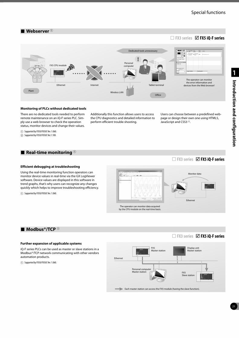
21
Special functions
1
Introduction and configuration
Webserver 1
¨ FX3 series þ FX5 iQ-F series
Monitoring of PLCs without dedicated tools
There are no dedicated tools needed to perform remote maintenance on an iQ-F series PLC. Sim-ply use a web browser to check the operation status, monitor devices and change their values.
1 Supported by FX5U/FX5UC Ver. 1.060.2 Supported by FX5U/FX5UC Ver.1.100.
Additionally this function allows users to access the CPU diagnostics and detailed information to perform efficient trouble shooting.
Users can choose between a predefined web-page or design their own one using HTML5, JavaScript and CSS3 2.
!
Real-time monitoring 1 ¨ FX3 series þ FX5 iQ-F seriesEfficient debugging at troubleshooting
Using the real-time monitoring function operators can monitor device values in real-time via the GX LogViewer software. Device values are displayed in this software in trend graphs, that’s why users can recognize any changes quickly which helps to improve troubleshooting efficiency.
1 Supported by FX5U/FX5UC Ver. 1.060.
FX5 CPU module
Ethernet Internet
Wireless LAN
Tablet terminal
Personalcomputer
Plant
Office
Dedicated tools unnecessary
The operator can monitorthe error information and
devices from the Web browser!
The operator can monitor data acquiredby the CPU module on the real-time basis.
Ethernet
Monitor data
Modbus®/TCP 1 ¨ FX3 series þ FX5 iQ-F seriesFurther expansion of applicable systems
iQ-F series PLCs can be used as master or slave stations in a Modbus®/TCP network communicating with other vendors automation products.
1 Supported by FX5U/FX5UC Ver. 1.060.
Each master station can access the FX5 module (having the slave function).
Ethernet
FX5Master station
Display unitMaster station
Personal computerMaster station FX5
Slave station
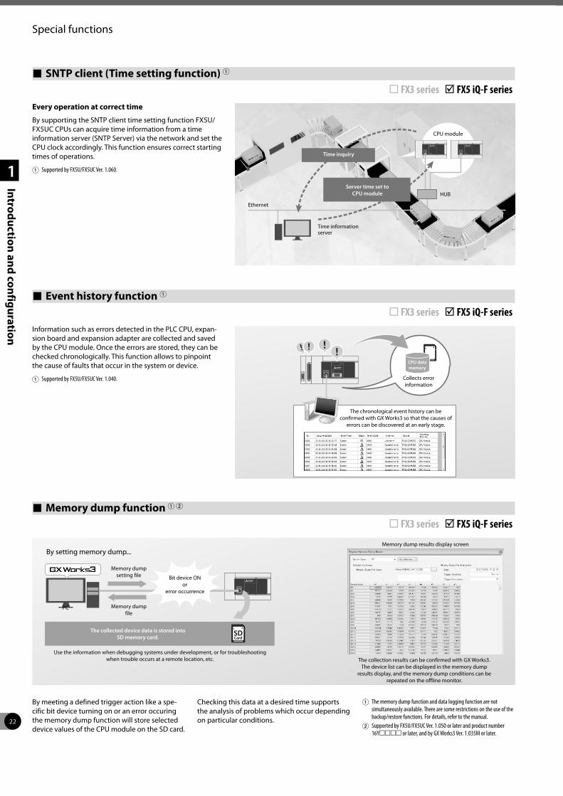
22
Special functions
1
Introduction and configuration
SNTP client (Time setting function) 1 ¨ FX3 series þ FX5 iQ-F seriesEvery operation at correct time
By supporting the SNTP client time setting function FX5U/FX5UC CPUs can acquire time information from a time information server (SNTP Server) via the network and set the CPU clock accordingly. This function ensures correct starting times of operations.
1 Supported by FX5U/FX5UC Ver. 1.060.
Ethernet
Time inquiry
CPU module
Time informationserver
HUBServer time set to
CPU module
Event history function 1 ¨ FX3 series þ FX5 iQ-F seriesInformation such as errors detected in the PLC CPU, expan-sion board and expansion adapter are collected and saved by the CPU module. Once the errors are stored, they can be checked chronologically. This function allows to pinpoint the cause of faults that occur in the system or device.
1 Supported by FX5U/FX5UC Ver. 1.040.
Memory dump function 1 2 ¨ FX3 series þ FX5 iQ-F series
By meeting a defined trigger action like a spe-cific bit device turning on or an error occuring the memory dump function will store selected device values of the CPU module on the SD card.
Checking this data at a desired time supports the analysis of problems which occur depending on particular conditions.
1 The memory dump function and data logging function are not simultaneously available. There are some restrictions on the use of the backup/restore functions. For details, refer to the manual.
2 Supported by FX5U/FX5UC Ver. 1.050 or later and product number 16Ymmmm or later, and by GX Works3 Ver. 1.035M or later.
PC
By setting memory dump...
Memory dumpfile
Memory dumpsetting file Bit device ON
orerror occurrence
The collected device data is stored intoSD memory card.
Use the information when debugging systems under development, or for troubleshootingwhen trouble occurs at a remote location, etc. The collection results can be confirmed with GX Works3.
The device list can be displayed in the memory dump results display, and the memory dump conditions can be
repeated on the offline monitor.
Memory dump results display screen
CPU data memory
Collects error information
The chronological event history can be confirmed with GX Works3 so that the causes of
errors can be discovered at an early stage.
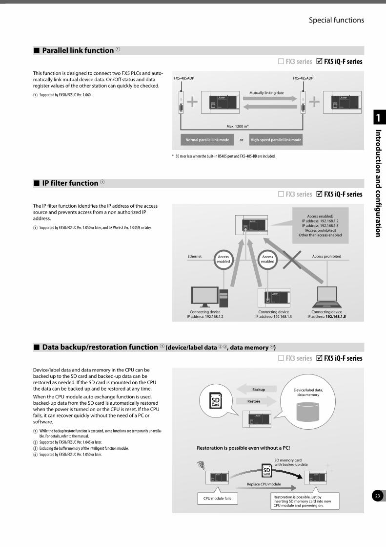
23
Special functions
1
Introduction and configuration
Parallel link function 1 ¨ FX3 series þ FX5 iQ-F seriesThis function is designed to connect two FX5 PLCs and auto-matically link mutual device data. On/Off status and data register values of the other station can quickly be checked.
1 Supported by FX5U/FX5UC Ver. 1.060.
IP filter function 1 ¨ FX3 series þ FX5 iQ-F seriesThe IP filter function identifies the IP address of the access source and prevents access from a non authorized IP address.
1 Supported by FX5U/FX5UC Ver. 1.050 or later, and GX Works3 Ver. 1.035M or later.
Access prohibitedEthernet Access enabled
Access enabled
Access enabled]IP address: 192.168.1.2IP address: 192.168.1.3
[Access prohibited]Other than access enabled
Connecting deviceIP address: 192.168.1.2
Connecting deviceIP address: 192.168.1.3
Connecting deviceIP address: 192.168.1.5
Data backup/restoration function 1 (device/label data 2 3, data memory 4) ¨ FX3 series þ FX5 iQ-F seriesDevice/label data and data memory in the CPU can be backed up to the SD card and backed-up data can be restored as needed. If the SD card is mounted on the CPU the data can be backed up and be restored at any time.
When the CPU module auto exchange function is used, backed-up data from the SD card is automatically restored when the power is turned on or the CPU is reset. If the CPU fails, it can recover quickly without the need of a PC or software.
1 While the backup/restore function is executed, some functions are temporarily unavaila-ble. For details, refer to the manual.
2 Supported by FX5U/FX5UC Ver. 1.045 or later.3 Excluding the buffer memory of the intelligent function module.4 Supported by FX5U/FX5UC Ver. 1.050 or later.
CPU module fails
SD memory cardwith backed up data
Device/label data,data memory
Restoration is possible even without a PC!
Restoration is possible just byinserting SD memory card into newCPU module and powering on.
Replace CPU module
Backup
Restore
FX5-485ADP FX5-485ADP
Mutually linking date
Max. 1200 m*
or High-speed parallel link modeNormal parallel link mode
* 50 m or less when the built-in RS485 port and FX5-485-BD are included.
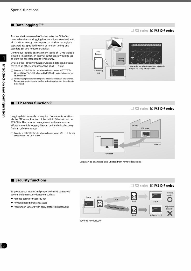
24
Special functions
1
Introduction and configuration
Security functions ¨ FX3 series þ FX5 iQ-F seriesTo protect your intellectual property the FX5 comes with several built-in security functions such as:
z Remote password/security key
z Privilege based program access
z Program on SD card with copy protection password
No key or key B
Key A
Key A Key A
Key A
Key A
Unauthorized copy
Copy
Program is executed
Program cannot be executed
Data logging 1 2 ¨ FX3 series þ FX5 iQ-F seriesTo meet the future needs of Industry 4.0, the FX5 offers comprehensive data logging functionality as standard, with all data from energy consumption to product throughput captured, at a specified interval or random timing, on a standard SD card for further analysis.
Continuous logging at a maximum speed of 10-ms cycles is possible. In addition, an internal buffer capacity can be set to store the collected results temporarily.
By using the FTP server function, logged data can be trans-ferred to an office computer acting as a FTP client.
1 Supported by FX5U/FX5UC Ver. 1.040 or later and product number 16Ymmmm or later, by GX Works3 Ver. 1.030G or later, and by CPU Module Logging Configuration Tool Ver. 1.64S or later.
2 The data logging function and memory dump function cannot be used simultaneously. There are some restrictions on the use of the backup/restore functions. For details, refer to the manual.
Data can be visually displayed and efficiently analyzed by using GX LogViewer.
Data logging
SD memory card
Logging setting
Security key function
FTP server function 3 ¨ FX3 series þ FX5 iQ-F series
Logging data can easily be acquired from remote locations via the FTP server function of the built-in Ethernet port on FX5 CPUs. This reduces management and maintenance efforts as multiple logging files can be handled collectively from an office computer.
1 Supported by FX5U/FX5UC Ver. 1.040 or later and product number 16Ymmmm or later, and by GX Works3 Ver. 1.030G or later. Office
FTP client
Logs can be examined and utilized from remote locations!
PC
FactoryFTP server
Ethernet
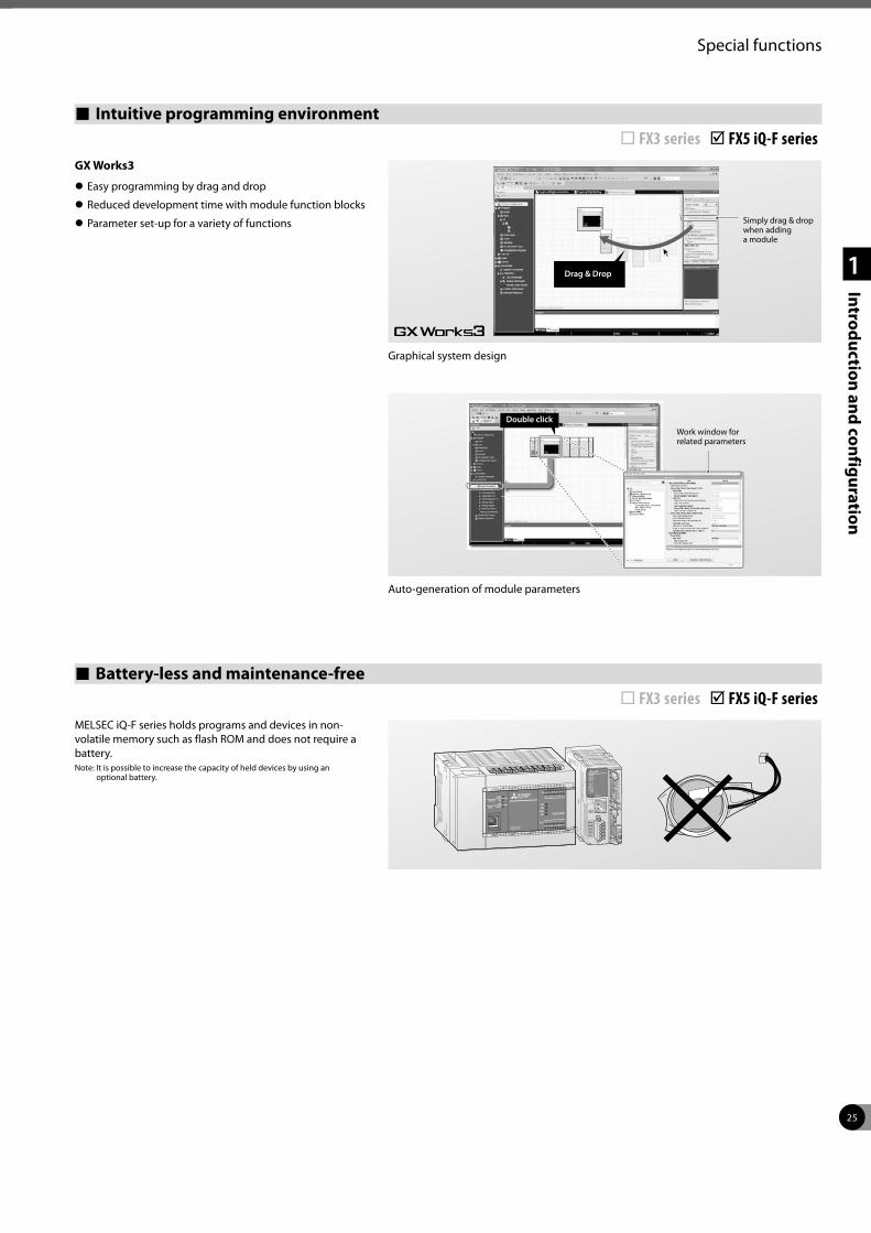
25
Special functions
1
Introduction and configuration
Intuitive programming environment ¨ FX3 series þ FX5 iQ-F seriesGX Works3
z Easy programming by drag and drop
z Reduced development time with module function blocks
z Parameter set-up for a variety of functions Simply drag & drop when adding a module
Drag & Drop
Graphical system design
Work window for related parameters
Auto-generation of module parameters
Double click
Battery-less and maintenance-free ¨ FX3 series þ FX5 iQ-F seriesMELSEC iQ-F series holds programs and devices in non-volatile memory such as flash ROM and does not require a battery.Note: It is possible to increase the capacity of held devices by using an
optional battery.
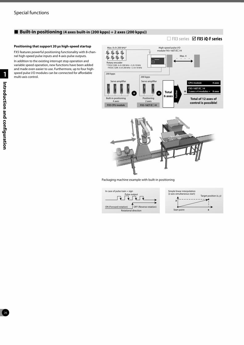
26
Special functions
1
Introduction and configuration
Built-in positioning (4 axes built-in (200 kpps) + 2 axes (200 kpps)) ¨ FX3 series þ FX5 iQ-F seriesPositioning that support 20 μs high-speed startup
FX5 features powerful positioning functionality with 8-chan-nel high-speed pulse inputs and 4-axis pulse outputs.
In addition to the existing interrupt stop operation and variable speed operation, new functions have been added and made even easier to use. Furthermore, up to four high-speed pulse I/O modules can be connected for affordable multi-axis control.
Packaging machine example with built-in positioning
200 kpps200 kpps
Max. 8 ch 200 kHz*
Rotary encoder* FX5U-32M : 6 ch 200 kHz + 2 ch 10 kHz
FX5UC-32M : 6 ch 200 kHz + 2 ch 10 kHz
High-speed pulse I/O module FX5-16ET/Em-H
Max. 4
Servo amplifierServo amplifier
Built-in positioning 4 axes
Positioning 2 axes
FX5-16ET/Em-HFX5 CPU module
Total6 axes
CPU module 4 axes
Furt
her
Total of 12 axes of control is possible!
FX5-16ET/Em-H 2 axes x 4 modules = 8 axes
x
y
In case of pulse train + signPulse output
ON (Forward rotation) OFF (Reverse rotation)
Rotational direction
Simple linear interpolation (2-axis simultaneous start)
Start point
Target position (x, y)
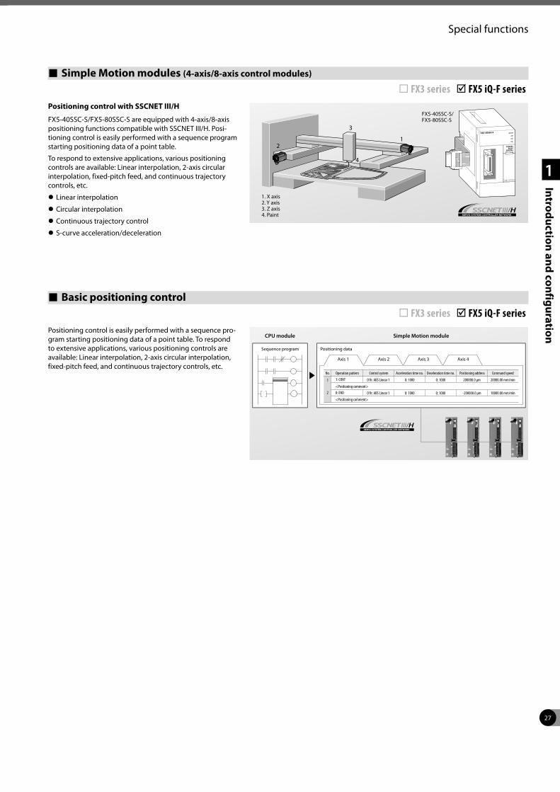
27
Special functions
1
Introduction and configuration
Simple Motion modules (4-axis/8-axis control modules)
¨ FX3 series þ FX5 iQ-F seriesPositioning control with SSCNET III/H
FX5-40SSC-S/FX5-80SSC-S are equipped with 4-axis/8-axis positioning functions compatible with SSCNET III/H. Posi-tioning control is easily performed with a sequence program starting positioning data of a point table.
To respond to extensive applications, various positioning controls are available: Linear interpolation, 2-axis circular interpolation, fixed-pitch feed, and continuous trajectory controls, etc.
z Linear interpolation
z Circular interpolation
z Continuous trajectory control
z S-curve acceleration/deceleration
1
3
4
2
1. X axis 2. Y axis 3. Z axis 4. Paint
FX5-40SSC-S/ FX5-80SSC-S
Basic positioning control ¨ FX3 series þ FX5 iQ-F seriesPositioning control is easily performed with a sequence pro-gram starting positioning data of a point table. To respond to extensive applications, various positioning controls are available: Linear interpolation, 2-axis circular interpolation, fixed-pitch feed, and continuous trajectory controls, etc.
Sequence program
CPU module Simple Motion module
Positioning data
Axis 1 Axis 2 Axis 3 Axis 4
Operation patternNo.
1
2
Control system Acceleration time no. Deceleration time no. Positioning address Command speed
1: CONT
0: END<Positioning comment>
<Positioning comment>
01h: ABS Linear 1
01h: ABS Linear 1
0: 1000
0: 1000
0: 1000
0: 1000
200000.0 μm
-200000.0 μm
20000.00 mm/min
10000.00 mm/min
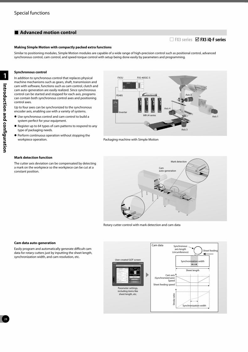
28
Special functions
1
Introduction and configuration
Advanced motion control
¨ FX3 series þ FX5 iQ-F series
Synchronous control
In addition to synchronous control that replaces physical machine mechanisms such as gears, shaft, transmission and cam with software, functions such as cam control, clutch and cam auto-generation are easily realized. Since synchronous control can be started and stopped for each axis, programs can contain both synchronous control axes and positioning control axes.
Up to four axes can be synchronized to the synchronous encoder axis, enabling use with a variety of systems.
z Use synchronous control and cam control to build a system perfect for your equipment.
z Register up to 64 types of cam patterns to respond to any type of packaging needs.
z Perform continuous operation without stopping the workpiece operation.
Mark detection function
The cutter axis deviation can be compensated by detecting a mark on the workpiece so the workpiece can be cut at a constant position.
Cam data auto-generation
Easily program and automatically generate difficult cam data for rotary cutters just by inputting the sheet length, synchronization width, and cam resolution, etc.
Packaging machine with Simple Motion
Making Simple Motion with compactly packed extra functions
Similar to positioning modules, Simple Motion modules are capable of a wide range of high-precision control such as positional control, advanced synchronous control, cam control, and speed-torque control with setup being done easily by parameters and programming.
Rotary cutter control with mark detection and cam data
FX5U FX5-40SSC-S
RS485
InverterMR-J4 series
Axis 3
Axis 1
Axis 2
Axis 4
Mark detection
Cam auto-generation
User-created GOT screen
Parameter settings, including items like
sheet length, etc.
Synchronous axis length
(circumference)
Cam data
Sheet feeding
Synchronization width
Sheet length
Synchronization width
Sheet feeding speed
Cam axis (Synchronized axis)
Speed
Stro
ke ra
tio
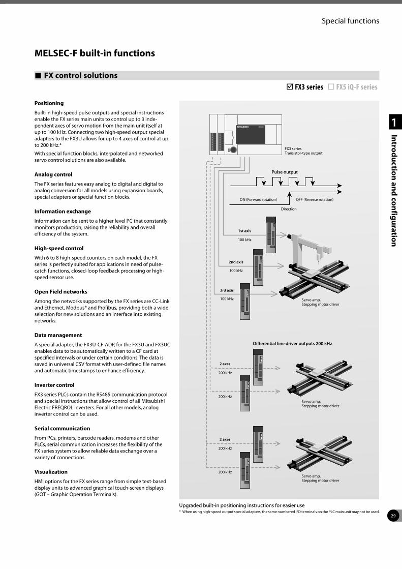
29
Special functions
1
Introduction and configuration
FX control solutions þ FX3 series ¨ FX5 iQ-F series
MELSEC-F built-in functions
Positioning
Built-in high-speed pulse outputs and special instructions enable the FX series main units to control up to 3 inde-pendent axes of servo motion from the main unit itself at up to 100 kHz. Connecting two high-speed output special adapters to the FX3U allows for up to 4 axes of control at up to 200 kHz.*
With special function blocks, interpolated and networked servo control solutions are also available.
Analog control
The FX series features easy analog to digital and digital to analog conversion for all models using expansion boards, special adapters or special function blocks.
Information exchange
Information can be sent to a higher level PC that constantly monitors production, raising the reliability and overall efficiency of the system.
High-speed control
With 6 to 8 high-speed counters on each model, the FX series is perfectly suited for applications in need of pulse-catch functions, closed-loop feedback processing or high-speed sensor use.
Open Field networks
Among the networks supported by the FX series are CC-Link and Ethernet, Modbus® and Profibus, providing both a wide selection for new solutions and an interface into existing networks.
Data management
A special adapter, the FX3U-CF-ADP, for the FX3U and FX3UC enables data to be automatically written to a CF card at specified intervals or under certain conditions. The data is saved in universal CSV format with user-defined file names and automatic timestamps to enhance efficiency.
Inverter control
FX3 series PLCs contain the RS485 communication protocol and special instructions that allow control of all Mitsubishi Electric FREQROL inverters. For all other models, analog inverter control can be used.
Serial communication
From PCs, printers, barcode readers, modems and other PLCs, serial communication increases the flexibility of the FX series system to allow reliable data exchange over a variety of connections.
Visualization
HMI options for the FX series range from simple text-based display units to advanced graphical touch-screen displays (GOT – Graphic Operation Terminals).
* When using high-speed output special adapters, the same numbered I/O terminals on the PLC main unit may not be used.Upgraded built-in positioning instructions for easier use
FX3 series Transistor-type output
Pulse output
ON (Forward rotation) OFF (Reverse rotation)
Direction
100 kHz
100 kHz
100 kHz
200 kHz
200 kHz
200 kHz
200 kHz
1st axis
2nd axis
3rd axis
2 axes
2 axes
Differential line driver outputs 200 kHz
Servo amp, Stepping motor driver
Servo amp, Stepping motor driver
Servo amp, Stepping motor driver
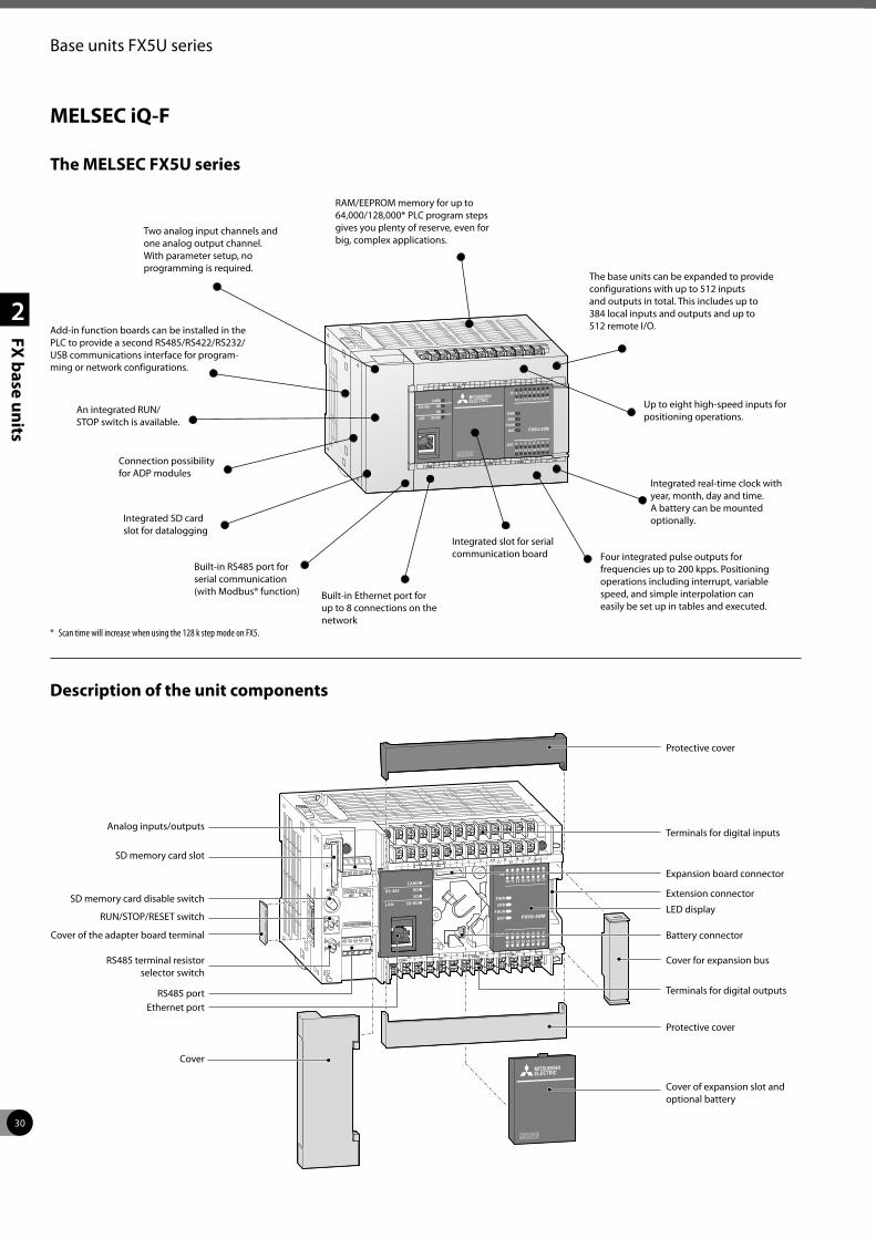
30
2
FX base units
Base units FX5U series
The MELSEC FX5U series
Description of the unit components
Analog inputs/outputs
SD memory card slot
SD memory card disable switch
RUN/STOP/RESET switch
Cover of the adapter board terminal
RS485 terminal resistor selector switch
RS485 portEthernet port
Cover
Cover of expansion slot and optional battery
Protective cover
Terminals for digital outputs
Cover for expansion bus
Battery connector
LED display
Extension connector
Expansion board connector
Terminals for digital inputs
Protective cover
Add-in function boards can be installed in the PLC to provide a second RS485/RS422/RS232/USB communications interface for program-ming or network configurations.
An integrated RUN/STOP switch is available.
Four integrated pulse outputs for frequencies up to 200 kpps. Positioning operations including interrupt, variable speed, and simple interpolation can easily be set up in tables and executed.
Integrated real-time clock with year, month, day and time.A battery can be mounted optionally.
The base units can be expanded to provide configurations with up to 512 inputs and outputs in total. This includes up to 384 local inputs and outputs and up to 512 remote I/O.
RAM/EEPROM memory for up to 64,000/128,000* PLC program steps gives you plenty of reserve, even for big, complex applications.
Connection possibility for ADP modules
Up to eight high-speed inputs for positioning operations.
Built-in Ethernet port for up to 8 connections on the network
Two analog input channels and one analog output channel. With parameter setup, no programming is required.
Built-in RS485 port for serial communication (with Modbus® function)
MELSEC iQ-F
Integrated SD card slot for datalogging
Integrated slot for serial communication board
* Scan time will increase when using the 128 k step mode on FX5.
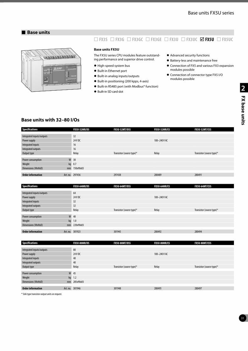
31
2
FX base units
Base units FX5U series
Base units FX5U
The FX5U series CPU modules feature outstand-ing performance and superior drive control.
z High-speed system bus
z Built-in Ethernet port
z Built-in analog inputs/outputs
z Built-in positioning (200 kpps, 4-axis)
z Built-in RS485 port (with Modbus® function)
z Built-in SD card slot
z Advanced security functions
z Battery-less and maintenance free
z Connection of FX5 and various FX3 expansion modules possible
z Connection of connector type FX5 I/O modules possible
Base units with 32–80 I/Os
Specifications FX5U-32MR/DS FX5U-32MT/DSS FX5U-32MR/ES FX5U-32MT/ESS
Integrated inputs/outputs 32Power supply 24 V DC 100–240 V ACIntegrated inputs 16Integrated outputs 16Output type Relay Transistor (source type)* Relay Transistor (source type)*
Power consumption W 30Weight kg 0.7Dimensions (WxHxD) mm 150x90x83
Order information Art. no. 297436 297438 280489 280491
Specifications FX5U-64MR/DS FX5U-64MT/DSS FX5U-64MR/ES FX5U-64MT/ESS
Integrated inputs/outputs 64Power supply 24 V DC 100–240 V ACIntegrated inputs 32Integrated outputs 32Output type Relay Transistor (source type)* Relay Transistor (source type)*
Power consumption W 40Weight kg 1.0Dimensions (WxHxD) mm 220x90x83
Order information Art. no. 301923 301945 280492 280494
Specifications FX5U-80MR/DS FX5U-80MT/DSS FX5U-80MR/ES FX5U-80MT/ESS
Integrated inputs/outputs 80Power supply 24 V DC 100–240 V ACIntegrated inputs 40Integrated outputs 40Output type Relay Transistor (source type)* Relay Transistor (source type)*
Power consumption W 45Weight kg 1.2Dimensions (WxHxD) mm 285x90x83
Order information Art. no. 301946 301948 280495 280497
* Sink type transistor output units on request.
Base units ¨ FX3S ¨ FX3G ¨ FX3GC ¨ FX3GE ¨ FX3U ¨ FX3UC þ FX5U ¨ FX5UC
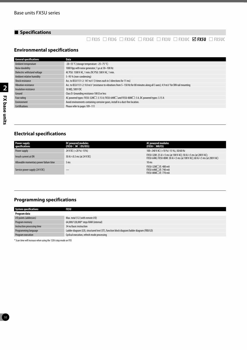
32
2
FX base units
Base units FX5U series
Specifications ¨ FX3S ¨ FX3G ¨ FX3GC ¨ FX3GE ¨ FX3U ¨ FX3UC þ FX5U ¨ FX5UC
Environmental specifications
Electrical specifications
Programming specifications
General specifications DataAmbient temperature -20–55 °C (storage temperature: -25–75 °C)Noise durability 1000 Vpp with noise generator; 1 µs at 30–100 HzDielectric withstand voltage AC PSU: 1500 V AC, 1 min./DC PSU: 500 V AC, 1 min. Ambient relative humidity 5–95 % (non-condensing)Shock resistance Acc. to IEC61131-2: 147 m/s2 (3 times each in 3 directions for 11 ms)Vibration resistance Acc. to IEC61131-2: 9.8 m/s2 (resistance to vibrations from 5–150 Hz for 80 minutes along all 3 axes); 4.9 m/s2 for DIN rail mountingInsulation resistance 10 MΩ, 500 V DCGround Class D: Grounding resistance 100 Ω or lessFuse rating AC powered types: FX5U-32Mm: 3.15 A; FX5U-64Mm and FX5U-80Mm: 5 A, DC powered types: 3.15 AEnvironment Avoid environments containing corrosive gases, install in a dust-free location.Certifications Please refer to pages 109–111
Power supply specifications
DC powered modules (FX5U-mMm/DS/DSS)
AC powered modules (FX5U-mMR/ES)
Power supply 24 V DC (+20 %/-15%) 100–240 V AC (+10 %/-15 %), 50/60 Hz
Inrush current at ON 50 A/<0.5 ms (at 24 V DC) FX5U-32M: 25 A/<5 ms (at 100 V AC); 50 A/<5 ms (at 200 V AC);FX5U-64M, FX5U-80M: 30 A/<5 ms (at 100 V AC); 60 A/<5 ms (at 200 V AC)
Allowable momentary power failure time 5 ms 10 ms
Service power supply (24 V DC) —FX5U-32Mm/E: 480 mAFX5U-64Mm/E: 740 mAFX5U-80Mm/E: 770 mA
System specifications FX5UProgram dataI/O points (addresses) Max. total 512 (with remote I/O)Program memory 64,000/128,000* steps RAM (internal)Instruction processing time 34 ns/basic instructionProgramming language Ladder diagram (LD), structured text (ST), function block diagram/ladder diagram (FBD/LD)Program execution Cyclical execution, refresh mode processing
* Scan time will increase when using the 128 k step mode on FX5
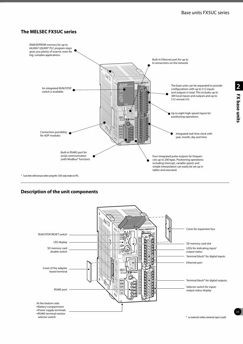
33
2
FX base units
Base units FX5UC series
The MELSEC FX5UC series
An integrated RUN/STOP switch is available.
Integrated real-time clock with year, month, day and time
The base units can be expanded to provide configurations with up to 512 inputs and outputs in total. This includes up to 384 local inputs and outputs and up to 512 remote I/O.
RAM/EEPROM memory for up to 64,000/128,000* PLC program steps gives you plenty of reserve, even for big, complex applications.
Connection possibility for ADP modules
Description of the unit components
RUN/STOP/RESET switch
LED display
SD memory carddisable switch
Cover of the adapterboard terminal
RS485 port
At the bottom side:P Battery compartmentP Power supply terminalsP RS485 terminal resistor
selector switch
Cover for expansion bus
Selector switch for input/ output status display
Terminal block* for digital outputs
Ethernet port
Terminal block* for digital inputs
LEDs for indicating input/ output status
SD memory card slot
Built-in RS485 port for serial communication (with Modbus® function)
Built-in Ethernet port for up to 8 connections on the network
Four integrated pulse outputs for frequen-cies up to 200 kpps. Positioning operations including interrupt, variable speed, and simple interpolation can easily be set up in tables and executed.
Up to eight high-speed inputs for positioning operations.
* Scan time will increase when using the 128 k step mode on FX5.
* or connector (when connector type is used)
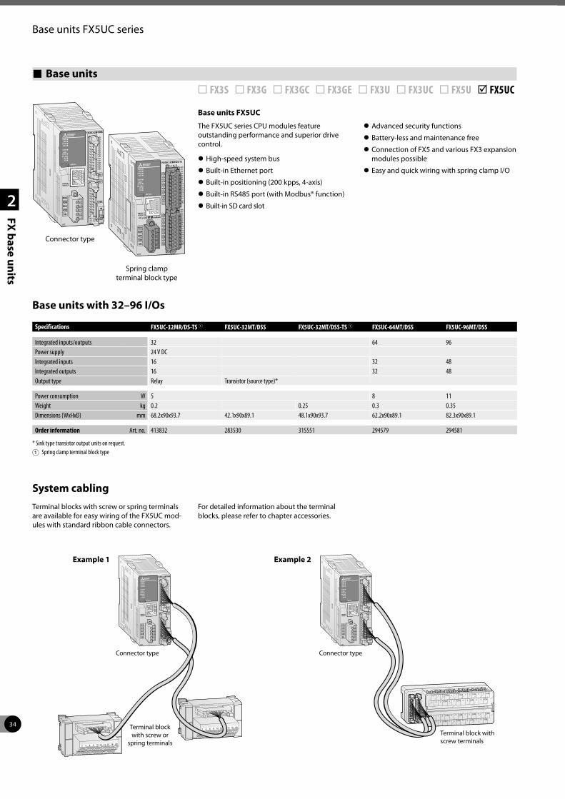
34
2
FX base units
Base units FX5UC series
Base units ¨ FX3S ¨ FX3G ¨ FX3GC ¨ FX3GE ¨ FX3U ¨ FX3UC ¨ FX5U þ FX5UC
Base units FX5UC
The FX5UC series CPU modules feature outstanding performance and superior drive control.
z High-speed system bus
z Built-in Ethernet port
z Built-in positioning (200 kpps, 4-axis)
z Built-in RS485 port (with Modbus® function)
z Built-in SD card slot
z Advanced security functions
z Battery-less and maintenance free
z Connection of FX5 and various FX3 expansion modules possible
z Easy and quick wiring with spring clamp I/O
Base units with 32–96 I/Os
Specifications FX5UC-32MR/DS-TS 1 FX5UC-32MT/DSS FX5UC-32MT/DSS-TS 1 FX5UC-64MT/DSS FX5UC-96MT/DSS
Integrated inputs/outputs 32 64 96Power supply 24 V DCIntegrated inputs 16 32 48Integrated outputs 16 32 48Output type Relay Transistor (source type)*
Power consumption W 5 8 11 Weight kg 0.2 0.25 0.3 0.35Dimensions (WxHxD) mm 68.2x90x93.7 42.1x90x89.1 48.1x90x93.7 62.2x90x89.1 82.3x90x89.1
Order information Art. no. 413832 283530 315551 294579 294581
* Sink type transistor output units on request.1 Spring clamp terminal block type
System cablingTerminal blocks with screw or spring terminals are available for easy wiring of the FX5UC mod-ules with standard ribbon cable connectors.
For detailed information about the terminal blocks, please refer to chapter accessories.
Connector type
Spring clamp terminal block type
2018161412108642
2018161412108642
Connector typeConnector type
Terminal block with screw or
spring terminalsTerminal block with screw terminals
Example 1 Example 2
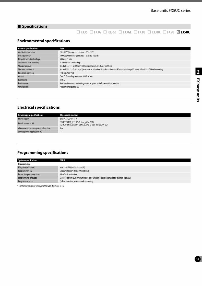
35
2
FX base units
Base units FX5UC series
Specifications ¨ FX3S ¨ FX3G ¨ FX3GC ¨ FX3GE ¨ FX3U ¨ FX3UC ¨ FX5U þ FX5UC
Environmental specifications
Electrical specifications
Programming specifications
General specifications DataAmbient temperature -20–55 °C (storage temperature: -25–75 °C)Noise durability 1000 Vpp with noise generator; 1 µs at 30–100 HzDielectric withstand voltage 500 V AC, 1 min. Ambient relative humidity 5–95 % (non-condensing)Shock resistance Acc. to IEC61131-2: 147 m/s2 (3 times each in 3 directions for 11 ms)Vibration resistance Acc. to IEC61131-2: 4.9 m/s2 (resistance to vibrations from 8.4–150 Hz for 80 minutes along all 3 axes); 4.9 m/s2 for DIN rail mountingInsulation resistance ≥10 MΩ, 500 V DCGround Class D: Grounding resistance 100 Ω or lessFuse rating 3.15 AEnvironment Avoid environments containing corrosive gases, install in a dust-free location.Certifications Please refer to pages 109–111
Power supply specifications DC powered modulesPower supply 24 V DC (+20 %/-15 %)
Inrush current at ON FX5UC-32MT/m: 35 A/<0.5 ms (at 24 V DC) FX5UC-64MT/m, FX5UC-96MT/m: 40 A/<0.5 ms (at 24 V DC)
Allowable momentary power failure time 5 msService power supply (24 V DC) —
System specifications FX5UCProgram dataI/O points (addresses) Max. total 512 (with remote I/O)Program memory 64,000/128,000* steps RAM (internal)Instruction processing time 34 ns/basic instructionProgramming language Ladder diagram (LD), structured text (ST), function block diagram/ladder diagram (FBD/LD)Program execution Cyclical execution, refresh mode processing
* Scan time will increase when using the 128 k step mode on FX5
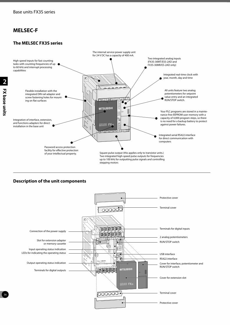
36
2
FX base units
Base units FX3S series
The MELSEC FX3S series
Description of the unit components
Connection of the power supply
Slot for extension adapter or memory cassette
Input operating status indicationLEDs for indicating the operating status
Output operating status indication
Terminals for digital outputs
Protective cover
RS422 interface
USB interface
RUN/STOP switch
2 analog potentiometers
Terminals for digital inputs
Terminal cover
Protective cover
Terminal cover
Cover for interface, potentiometer and RUN/STOP switch
Cover for extension slot
All units feature two analog potentiometers for setpoint value entry and an integrated RUN/STOP switch.
Integration of interface, extension, and functions adapters for direct installation in the base unit
Integrated serial RS422 interface for direct communication with computers
Flexible installation with the integrated DIN rail adapter and screw fastening holes for mount-ing on flat surfaces
Password access protection facility for effective protection of your intellectual property.
Your PLC programs are stored in a mainte-nance-free EEPROM user memory with a capacity of 4,000 program steps, so there is no need for a backup battery to protect against power failures.
Integrated real-time clock with year, month, day and time
Square pulse output (this applies only to transistor units.) Two integrated high-speed pulse outputs for frequencies up to 100 kHz for outputting pulse signals and controlling stepping motors
The internal service power supply unit for 24 V DC has a capacity of 400 mA.
High-speed inputs for fast counting tasks with counting frequencies of up to 60 kHz and interrupt processing capabilities
Two integrated analog inputs (FX3S-30MT/ESS-2AD and FX3S-30MR/ES-2AD only)
MELSEC-F
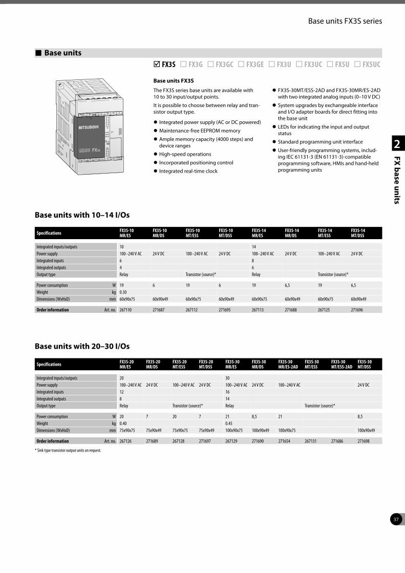
37
2
FX base units
Base units FX3S series
Base units þ FX3S ¨ FX3G ¨ FX3GC ¨ FX3GE ¨ FX3U ¨ FX3UC ¨ FX5U ¨ FX5UC
Base units FX3S
The FX3S series base units are available with 10 to 30 input/output points.
It is possible to choose between relay and tran-sistor output type.
z Integrated power supply (AC or DC powered)
z Maintenance-free EEPROM memory
z Ample memory capacity (4000 steps) and device ranges
z High-speed operations
z Incorporated positioning control
z Integrated real-time clock
z FX3S-30MT/ESS-2AD and FX3S-30MR/ES-2AD with two integrated analog inputs (0–10 V DC)
z System upgrades by exchangeable interface and I/O adapter boards for direct fitting into the base unit
z LEDs for indicating the input and output status
z Standard programming unit interface
z User-friendly programming systems, includ-ing IEC 61131-3 (EN 61131-3)-compatible programming software, HMIs and hand-held programming units
Base units with 10–14 I/Os
Base units with 20–30 I/Os
Specifications FX3S-10 MR/ES
FX3S-10 MR/DS
FX3S-10 MT/ESS
FX3S-10 MT/DSS
FX3S-14 MR/ES
FX3S-14 MR/DS
FX3S-14 MT/ESS
FX3S-14 MT/DSS
Integrated inputs/outputs 10 14Power supply 100–240 V AC 24 V DC 100–240 V AC 24 V DC 100–240 V AC 24 V DC 100–240 V AC 24 V DCIntegrated inputs 6 8Integrated outputs 4 6Output type Relay Transistor (source)* Relay Transistor (source)*
Power consumption W 19 6 19 6 19 6,5 19 6,5Weight kg 0.30Dimensions (WxHxD) mm 60x90x75 60x90x49 60x90x75 60x90x49 60x90x75 60x90x49 60x90x75 60x90x49
Order information Art. no. 267110 271687 267112 271695 267113 271688 267125 271696
Specifications FX3S-20 MR/ES
FX3S-20 MR/DS
FX3S-20 MT/ESS
FX3S-20 MT/DSS
FX3S-30 MR/ES
FX3S-30 MR/DS
FX3S-30 MR/ES-2AD
FX3S-30 MT/ESS
FX3S-30 MT/ESS-2AD
FX3S-30 MT/DSS
Integrated inputs/outputs 20 30Power supply 100–240 V AC 24 V DC 100–240 V AC 24 V DC 100–240 V AC 24 V DC 100–240 V AC 24 V DCIntegrated inputs 12 16Integrated outputs 8 14Output type Relay Transistor (source)* Relay Transistor (source)*
Power consumption W 20 7 20 7 21 8,5 21 8,5Weight kg 0.40 0.45Dimensions (WxHxD) mm 75x90x75 75x90x49 75x90x75 75x90x49 100x90x75 100x90x49 100x90x75 100x90x49
Order information Art. no. 267126 271689 267128 271697 267129 271690 271654 267131 271686 271698
* Sink type transistor output units on request.
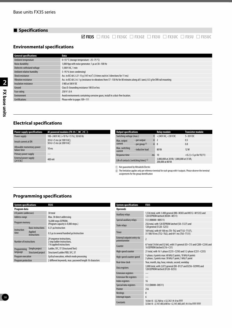
38
2
FX base units
Base units FX3S series
Environmental specifications
Electrical specifications
Programming specifications
Specifications þ FX3S ¨ FX3G ¨ FX3GC ¨ FX3GE ¨ FX3U ¨ FX3UC ¨ FX5U ¨ FX5UC
General specifications DataAmbient temperature 0–55 °C (storage temperature: -25–75 °C)Noise durability 1,000 Vpp with noise generator; 1 µs at 30–100 HzDielectric withstand voltage 1,500 V AC, 1 minAmbient relative humidity 5–95 % (non-condensing)Shock resistance Acc. to IEC 68-2-27: 15 g (147 m/s2) (3 times each in 3 directions for 11 ms)Vibration resistance Acc. to IEC 68-2-6: 1 g (resistance to vibrations from 57–150 Hz for 80 minutes along all 3 axes); 0.5 g for DIN rail mountingInsulation resistance 5 MΩ at 500 V DC Ground Class D: Grounding resistance 100 Ω or lessFuse rating 250 V 1.0 AEnvironment Avoid environments containing corrosive gases, install in a dust-free location.Certifications Please refer to pages 109–111
Power supply specifications AC powered modules (FX-3S-mMm/Em)Power supply 100–240 V AC (+10 %/-15 %), 50/60 Hz
Inrush current at ON 30 A/<5 ms (at 100 V AC); 50 A/<5 ms (at 200 V AC)
Allowable momentary power failure time 10 ms
Primary power supply —External power supply (24 V DC) 400 mA
Output specifications Relay module Transistor moduleSwitching voltage (max.) V <240 V AC, <30 V DC 5–30 V DC
Max. output current
- per output A 2 0.5- per group b A 8 0.8
Max. switching current - inductive load 80 VA 12 W
Response time ms 10 <0.2 (<5 µs for Y0,Y1)
Life of contacts (switching times) a 3,000,000 at 20 VA; 1,000,000 at 35 VA; 200,000 at 80 VA
1 Not guaranteed by Mitsubishi Electric2 The limitation applies only per reference terminal for each group with 4 outputs. Please observe the terminal
assignments for the group identification
System specifications FX3SProgram dataI/O points (addresses) 30 totalAddress range Max. 30 direct addressing
Program memory 16,000 steps EEPROM, (Program capacity is 4,000 steps.)
Instruction time
Basic instructions 0.21 µs/instructionApplied instructions 0.5 μs to several hundred μs/instruction
Number of instructions29 sequence instructions,2 step ladder instructions,116 applied instructions
Programming language
Simple project Ladder, SFC, ST (Structured Text)Structured project Structured Ladder/FBD, SFC, ST
Program execution Cyclical execution, refresh mode processingProgram protection 2 different keywords, max. password length 16 characters
System specifications FX3SOperands
Auxiliary relays 1,536 total, with 1,408 general (M0–M383 and M512–M1535) and 128 EEPROM latched (M384–M511)
Special auxiliary relays 512 (M8000–M8511)
State relays 256 total, with 128 EEPROM latched (S0–S127) and 128 general (S128–S255)
Timer 169 total, with 69 100 ms (T0–T62 and T132–T137),31 100/10 ms (T32–T62), and 69 1 ms (T63–T131)
External setpoint entry via potentiometer 2
Counter 67 total (16 bit and 32 bit), with 51 general (C0–C15 and C200–C234) and16 EEPROM latched (C16–C31)
High-speed counter 21 total, with 16 1-phase (C235–C250) and 5 2-phase (C251–C255)
High-speed counter speed 1-phase, 6 points max: 60 kHz/2 points, 10 kHz/4 points2-phase, 2 points max: 30 kHz/1 point, 5 kHz/1 point
Real-time clock Year, month, day, hour, minute, second, weekday
Data registers 3,000 total, with 2,872 general (D0–D127 and D256–D2999) and 128 EEPROM latched (D128–D255)
Extension registers —Extension file registers —Index registers 16Special data registers 512 (D8000–D8511)Pointer 256Nestings 8Interrupt inputs 6
Constants 16 bit: K: -32,768 to +32,767; H: 0 to FFFF32 bit: K: -2,147,483,648 to +2,147,483,647; H: 0 to FFFF FFFF
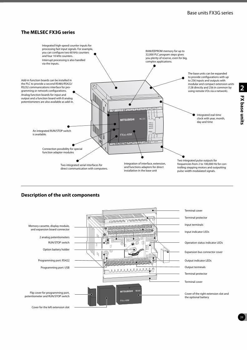
39
2
FX base units
Base units FX3G series
The MELSEC FX3G series
Add-in function boards can be installed in the PLC to provide a second RS485/RS422/RS232 communications interface for pro-gramming or network configurations.Analog function boards for input and output and a function board with 8 analog potentiometers are also available as add-in.
An integrated RUN/STOP switch is available.
Two integrated pulse outputs for frequencies from 2 to 100,000 Hz for con-trolling stepping motors and outputting pulse-width modulated signals.
Integrated real-time clock with year, month, day and time
The base units can be expanded to provide configurations with up to 256 inputs and outputs with modular and compact extension units (128 directly and 256 in common by using remote I/Os via a network).
RAM/EEPROM memory for up to 32,000 PLC program steps gives you plenty of reserve, even for big, complex applications.
Integrated high-speed counter inputs for processing fast input signals. For example, you can configure two 60 kHz counters and four 10 kHz counters.Interrupt processing is also handled via the inputs.
Description of the unit components
Memory cassette, display module, and expansion board connector
2 analog potentiometers
Option battery holder
Programming port: RS422
Programming port: USB
Terminal cover
Terminal protector
Output indicator LEDs
Terminal protector
Terminal cover
Cover for the left extension slot
Flip cover for programming port, potentiometer and RUN/STOP switch
Expansion bus connector cover
Operation status indicator LEDs
Input indicator LEDs
Input terminals
Connection possibility for special function adapter modules
Two integrated serial interfaces for direct communication with computers.
RUN/STOP switch
Cover of the right extension slot and the optional battery
Output terminals
Integration of interface, extension, and functions adapters for direct installation in the base unit
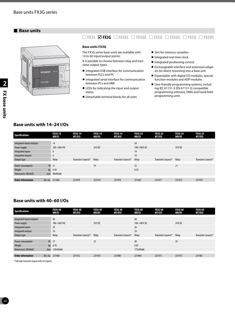
40
2
FX base units
Base units FX3G series
Base units ¨ FX3S þ FX3G ¨ FX3GC ¨ FX3GE ¨ FX3U ¨ FX3UC ¨ FX5U ¨ FX5UC
Base units FX3G
The FX3G series base units are available with 14 to 60 input/output points.
It is possible to choose between relay and tran-sistor output types.
z Integrated USB interface for communication between PLCs and PC
z Integrated serial interface for communication between PCs and HMI
z LEDs for indicating the input and output status
z Detachable terminal blocks for all units
z Slot for memory cassettes
z Integrated real-time clock
z Integrated positioning control
z Exchangeable interface and extension adapt-ers for direct mounting into a base unit
z Expandable with digital I/O modules, special function modules and ADP modules
z User-friendly programming systems, includ-ing IEC 61131-3 (EN 61131-3) compatible programming software, HMIs and hand-held programming units
Base units with 14–24 I/Os
Base units with 40–60 I/Os
Specifications FX3G-14 MR/ES
FX3G-14 MT/ESS
FX3G-14 MR/DS
FX3G-14 MT/DSS
FX3G-24 MR/ES
FX3G-24 MT/ESS
FX3G-24 MR/DS
FX3G-24 MT/DSS
Integrated inputs/outputs 14 24Power supply 100–240 V AC 24 V DC 100–240 V AC 24 V DCIntegrated inputs 8 14Integrated outputs 6 10Output type Relay Transistor (source)* Relay Transistor (source)* Relay Transistor (source)* Relay Transistor (source)*
Power consumption W 31 19 32 21Weight kg 0.50 0.55Dimensions (WxHxD) mm 90x90x86
Order information Art. no. 231466 231470 231474 231478 231467 231471 231475 231479
Specifications FX3G-40 MR/ES
FX3G-40 MT/ESS
FX3G-40 MR/DS
FX3G-40 MT/DSS
FX3G-60 MR/ES
FX3G-60 MT/ESS
FX3G-60 MR/DS
FX3G-60 MT/DSS
Integrated inputs/outputs 40 60Power supply 100–240 V AC 24 V DC 100–240 V AC 24 V DCIntegrated inputs 24 36Integrated outputs 16 24Output type Relay Transistor (source)* Relay Transistor (source)* Relay Transistor (source)* Relay Transistor (source)*
Power consumption W 37 25 40 29Weight kg 0.70 0.85Dimensions (WxHxD) mm 130x90x86 175x90x86
Order information Art. no. 231468 231472 231476 231480 231469 231473 231477 231481
* Sink type transistor output units on request.
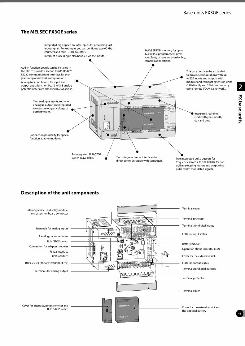
41
2
FX base units
Base units FX3GE series
INPUTV1+ I1+ V2+ I2+ VI-
ANALOG
OUTPUT
V+ I+ VI-
ANALOG
100M
SD/RD
ERR
OPEN
10BASE-T/100BASE-TXLOT
The MELSEC FX3GE series
An integrated RUN/STOP switch is available.
Integrated real-time clock with year, month, day and time
RAM/EEPROM memory for up to 32,000 PLC program steps gives you plenty of reserve, even for big, complex applications.
Integrated high-speed counter inputs for processing fast input signals. For example, you can configure two 60 kHz counters and four 10 kHz counters.Interrupt processing is also handled via the inputs.
Description of the unit components
Memory cassette, display module, and extension board connector
Terminals for analog inputs
RUN/STOP switch
Connection for adapter modules
RS422 interface
Terminal protector
Terminals for digital outputs
Cover for the extension slot
Terminal protector
Terminal cover
Terminals for analog output
RJ45 socket (10BASE-T/100BASE-TX)
Operation status indicator LEDs
Battery bracket
LEDs for input status
Terminals for digital inputs
Connection possibility for special function adapter modules
Two integrated serial interfaces for direct communication with computers.
2 analog potentiometers
Terminal cover
LEDs for output status
USB interface
Cover for interface, potentiometer and RUN/STOP switch
Cover for the extension slot and the optional battery
Add-in function boards can be installed in the PLC to provide a second RS485/RS422/RS232 communications interface for pro-gramming or network configurations.Analog function boards for input and output and a function board with 8 analog potentiometers are also available as add-in.
The base units can be expanded to provide configurations with up to 256 inputs and outputs with modular and compact extension units (128 directly and 256 in common by using remote I/Os via a network).
Two integrated pulse outputs for frequencies from 2 to 100,000 Hz for con-trolling stepping motors and outputting pulse-width modulated signals.
Two analogue inputs and one analogue output are integrated to measure output voltage or current values.
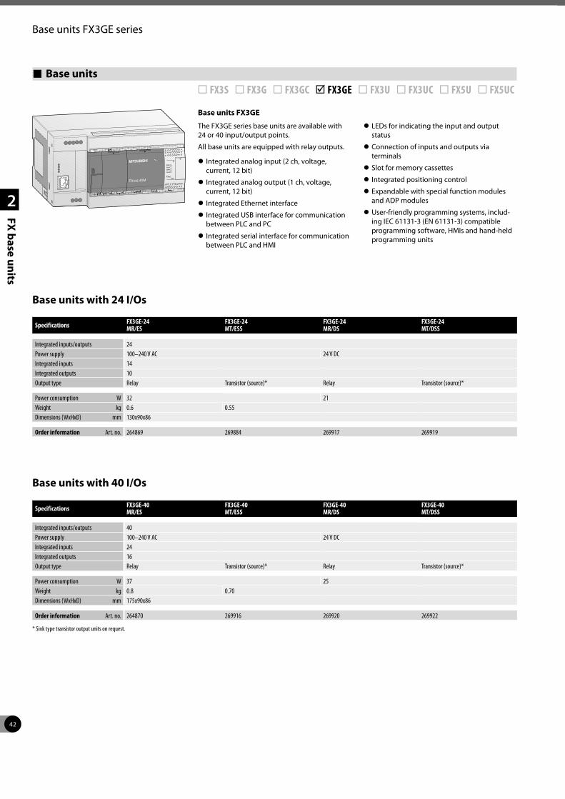
42
2
FX base units
Base units FX3GE series
Base units ¨ FX3S ¨ FX3G ¨ FX3GC þ FX3GE ¨ FX3U ¨ FX3UC ¨ FX5U ¨ FX5UC
Base units FX3GE
The FX3GE series base units are available with 24 or 40 input/output points.
All base units are equipped with relay outputs.
z Integrated analog input (2 ch, voltage, current, 12 bit)
z Integrated analog output (1 ch, voltage, current, 12 bit)
z Integrated Ethernet interface
z Integrated USB interface for communication between PLC and PC
z Integrated serial interface for communication between PLC and HMI
z LEDs for indicating the input and output status
z Connection of inputs and outputs via terminals
z Slot for memory cassettes
z Integrated positioning control
z Expandable with special function modules and ADP modules
z User-friendly programming systems, includ-ing IEC 61131-3 (EN 61131-3) compatible programming software, HMIs and hand-held programming units
Base units with 24 I/Os
Specifications FX3GE-24 MR/ES
FX3GE-24 MT/ESS
FX3GE-24 MR/DS
FX3GE-24 MT/DSS
Integrated inputs/outputs 24Power supply 100–240 V AC 24 V DCIntegrated inputs 14Integrated outputs 10Output type Relay Transistor (source)* Relay Transistor (source)*
Power consumption W 32 21Weight kg 0.6 0.55Dimensions (WxHxD) mm 130x90x86
Order information Art. no. 264869 269884 269917 269919
Specifications FX3GE-40 MR/ES
FX3GE-40 MT/ESS
FX3GE-40 MR/DS
FX3GE-40 MT/DSS
Integrated inputs/outputs 40Power supply 100–240 V AC 24 V DC Integrated inputs 24Integrated outputs 16Output type Relay Transistor (source)* Relay Transistor (source)*
Power consumption W 37 25Weight kg 0.8 0.70Dimensions (WxHxD) mm 175x90x86
Order information Art. no. 264870 269916 269920 269922
* Sink type transistor output units on request.
Base units with 40 I/Os
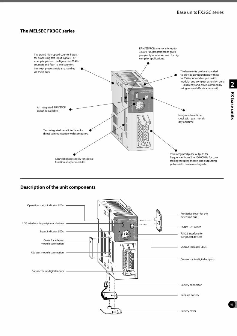
43
2
FX base units
Base units FX3GC series
The MELSEC FX3GC series
Description of the unit components
Operation status indicator LEDs
USB interface for peripheral devices
Cover for adapter module connection
Adapter module connection
Connector for digital inputs
Back-up battery
Battery connector
Connector for digital outputs
Output indicator LEDs
RS422 interface for peripheral devices
RUN/STOP switch
Protective cover for the extension bus
Input indicator LEDs
Battery cover
Integrated high-speed counter inputs for processing fast input signals. For example, you can configure two 60 kHz counters and four 10 kHz counters.Interrupt processing is also handled via the inputs.
RAM/EEPROM memory for up to 32,000 PLC program steps gives you plenty of reserve, even for big, complex applications.
The base units can be expanded to provide configurations with up to 256 inputs and outputs with modular and compact extension units (128 directly and 256 in common by using remote I/Os via a network).
Integrated real-time clock with year, month, day and time
Two integrated pulse outputs for frequencies from 2 to 100,000 Hz for con-trolling stepping motors and outputting pulse-width modulated signals.
Connection possibility for special function adapter modules
Two integrated serial interfaces for direct communication with computers.
An integrated RUN/STOP switch is available.
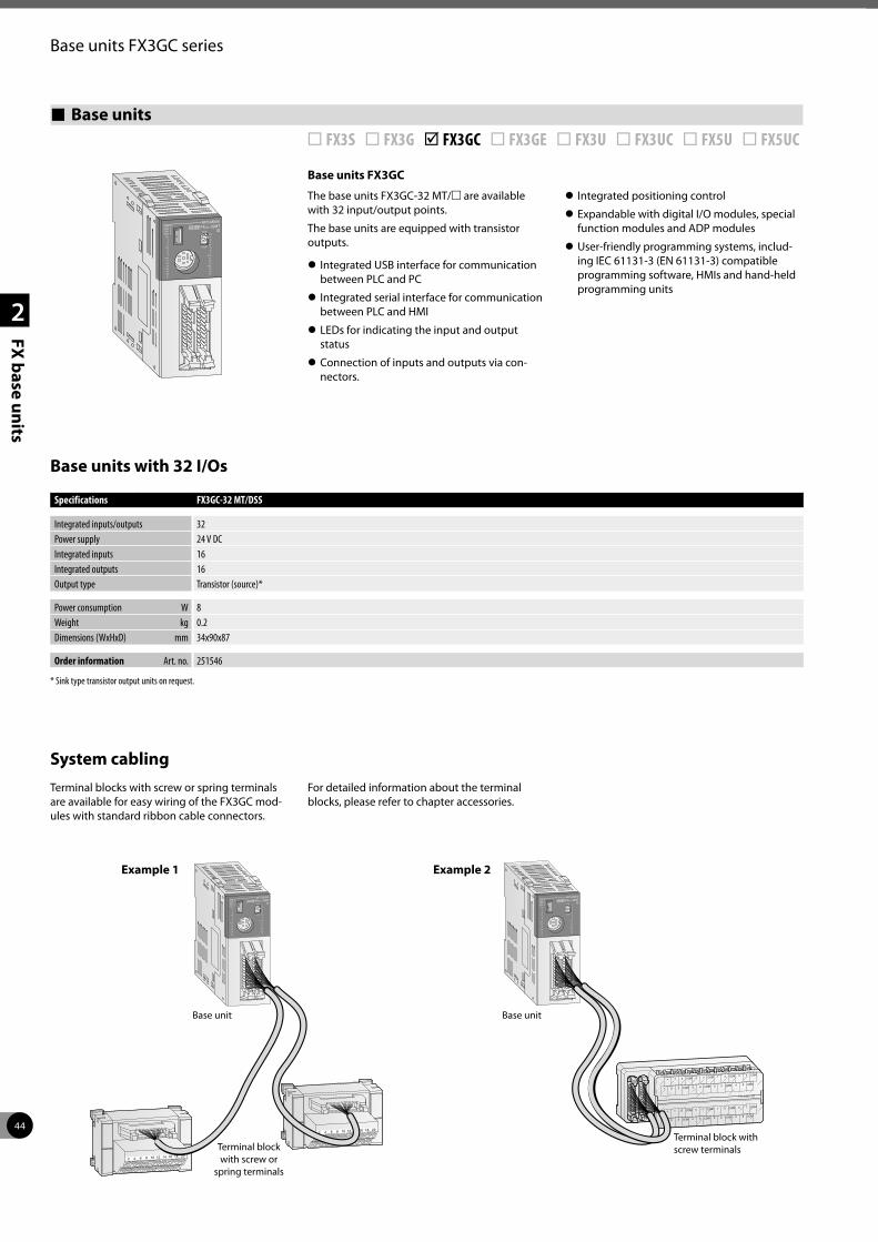
44
2
FX base units
Base units FX3GC series
Base units ¨ FX3S ¨ FX3G þ FX3GC ¨ FX3GE ¨ FX3U ¨ FX3UC ¨ FX5U ¨ FX5UC
Base units FX3GC
The base units FX3GC-32 MT/m are available with 32 input/output points.
The base units are equipped with transistor outputs.
z Integrated USB interface for communication between PLC and PC
z Integrated serial interface for communication between PLC and HMI
z LEDs for indicating the input and output status
z Connection of inputs and outputs via con-nectors.
z Integrated positioning control
z Expandable with digital I/O modules, special function modules and ADP modules
z User-friendly programming systems, includ-ing IEC 61131-3 (EN 61131-3) compatible programming software, HMIs and hand-held programming units
Base units with 32 I/Os
Specifications FX3GC-32 MT/DSS
Integrated inputs/outputs 32Power supply 24 V DCIntegrated inputs 16Integrated outputs 16Output type Transistor (source)*
Power consumption W 8Weight kg 0.2Dimensions (WxHxD) mm 34x90x87
Order information Art. no. 251546
* Sink type transistor output units on request.
System cablingTerminal blocks with screw or spring terminals are available for easy wiring of the FX3GC mod-ules with standard ribbon cable connectors.
For detailed information about the terminal blocks, please refer to chapter accessories.
2018161412108642
2018161412108642
Base unitBase unit
Terminal block with screw or
spring terminals
Terminal block with screw terminals
Example 1 Example 2
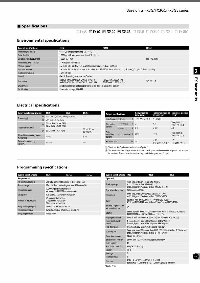
45
2
FX base units
Base units FX3G/FX3GC/FX3GE series
Environmental specifications
Electrical specifications
Programming specifications
General specifications FX3G FX3GE FX3GCAmbient temperature 0–55 °C (storage temperature: -25–75 °C)Noise durability 1,000 Vpp with noise generator; 1 µs at 30–100 HzDielectric withstand voltage 1,500 V AC, 1 min 500 V AC, 1 minAmbient relative humidity 5–95 % (non-condensing)Shock resistance Acc. to IEC 68-2-27: 15 g (147 m/s2) (3 times each in 3 directions for 11 ms)Vibration resistance Acc. to IEC 68-2-6: 1 g (resistance to vibrations from 57–150 Hz for 80 minutes along all 3 axes); 0.5 g for DIN rail mountingInsulation resistance 5 MΩ, 500 V DCGround Class D: Grounding resistance 100 Ω or less
Fuse rating For FX3G-14Mm and FX3G-24Mm: 250 V 1 A; For FX3G-40Mm and FX3G-60Mm: 250 V 3.15 A
FX3GE-24Mm: 250 V 1 A; FX3GE-40Mm: 250 V 3.15 A 125 V 3.15 A
Environment Avoid environments containing corrosive gases, install in a dust-free location.Certifications Please refer to pages 109–111
Power supply specifications FX3G FX3GE FX3GC
Power supplyAC 100–240 V (+10 % /-15 %), 50/60 Hz —DC 24 V DC (+20 %/-15 %)
Inrush current at ONAC 30 A/<5 ms (at 100 V AC);
50 A/<5 ms (at 200 V AC) —
DC 30 A/<1 ms (at 24 V DC) 30 A/<0.5 ms (at 24 V DC)
Allowable momentary power failure time 10 ms 5 ms
External power supply (24 V DC) 400 mA —
Output specifications Relay modules FX3G/FX3GE
Transistor modules FX3G/FX3GE
Transistor modules FX3GC
Switching voltage (max.) V <240 V AC, <30 V DC 5–30 V DC
Max. output current
- per output A 2 0.5 Y000, Y001: 0.3Y002–Y017: 0.1
- per group A 8 b 0.8 b 0.8Max. switching current
- inductive load W 80 VA 12 W Y000, Y001: 7.2Y002–Y017: 2.4
Response time ms 10 <0.2 (<5 µs for Y0, Y1) 1
<0.2 (<5 µs for Y0, Y1)
1 The 40 and 60 I/O points main units supports 5 μs for Y2.2 This limitation applies only per reference terminal for each group, 4 and 8 outputs for relays and 2 and 4 outputs
for transistors. Please observe the terminal assignments for the group identification.
System specifications FX3G FX3GE FX3GCProgram dataI/O points (addresses) 256 total (combined local and CC-Link remote I/O)Address range Max. 128 direct addressing and max. 128 remote I/O
Program memory 32,000 steps EEPROM (internal), exchangeable EEPROM memory cassette
Cycle period 0.21 μs or 0.42 μs/contact instruction
Number of instructions29 sequence instructions,2 step ladder instructions,124 applied instructions
Programming language Step ladder, instruction list, SFCProgram execution Cyclical execution, refreshmode processingProgram protection Via password
System specifications FX3G FX3GE FX3GCOperands
Auxiliary relays7,680 total, with 384 general (M0–M383),1,152 EEPROM latched (M384–M1535),and 6,144 general/optional latched (M1536–M7679)
Special auxiliary relays 512 (M8000–M8511)
State relays 4,096 total, with 1,000 EEPROM latched (S0–S999)and 3,096 general/optional latched (S1000–S4095)
Timer 320 total, with 206 100 ms (T0–T199 and T250–T255),46 10 ms (T200–T245), and 68 1 ms (T246–T249 and T256–T319)
External setpoint entry via potentiometer 2*
Counter 235 total (16 bit and 32 bit), with 36 general (C0–C15 and C200–C219) and199 EEPROM latched (C16–C199 and C220–C234)
High-speed counter 21 total, with 16 1-phase (C235–C250) and 5 2-phase (C251–C255)High-speed counter speed
1-phase, 6 points max: 60 kHz/4 points, 10 kHz/2 points2-phase, 3 points max: 30 kHz/2 points, 5 kHz/1 point
Real-time clock Year, month, day, hour, minute, second, weekday
Data registers 8,000 total, with 128 general (D0–D127), 972 EEPROM latched (D128–D1099), and 6,900 general/optional latched (D1100 - D7999)
Extension registers 24,000 (R0–R23999)Extension file registers 24,000 (ER0–R23999) internal/optional memory*Index registers 16Special data registers 512 (D8000–D8511)Pointer 2,048Nestings 8Interrupt inputs 6
Constants 16 bits: K: -32,768 to +32,767; H: 0 to FFFF32 bits: K: 2,147,483,648 to +2,147,483,647; H: 0 to FFFF FFFF
* Not for FX3GC
Specifications ¨ FX3S þ FX3G þ FX3GC þ FX3GE ¨ FX3U ¨ FX3UC ¨ FX5U ¨ FX5UC
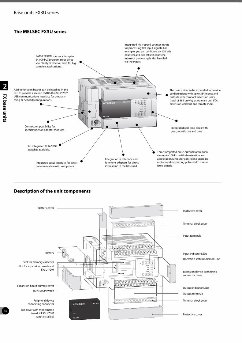
46
2
FX base units
Base units FX3U series
The MELSEC FX3U series
Add-in function boards can be installed in the PLC to provide a second RS485/RS422/RS232/USB communications interface for program-ming or network configurations.
An integrated RUN/STOP switch is available.
Three integrated pulse outputs for frequen-cies up to 100 kHz with deceleration and acceleration ramps for controlling stepping motors and outputting pulse-width modu-lated signals.
Integrated real-time clock with year, month, day and time
The base units can be expanded to provide configurations with up to 384 inputs and outputs with compact extension units (total of 384 only by using main unit I/Os, extension unit I/Os and remote I/Os).
Integrated high-speed counter inputs for processing fast input signals. For example, you can configure six 100 kHz counters and two 10 kHz counters.Interrupt processing is also handled via the inputs.
RAM/EEPROM memory for up to 64,000 PLC program steps gives you plenty of reserve, even for big, complex applications.
Description of the unit components
Battery cover
Connection possibility for special function adapter modules
Integrated serial interface for direct communication with computers
Protective cover
Battery
Slot for expansion boards and FX3U-7DM
Expansion board dummy cover
RUN/STOP switch
Peripheral device connecting connector
Top cover with model name (used, if FX3U-7DM
is not installed)
Terminal block cover
Output terminals
Output indicator LEDs
Extension device connecting connector cover
Operation status indicator LEDs
Input indicator LEDs
Input terminals
Terminal block cover
Protective cover
Integration of interface and functions adapters for direct installation in the base unit
Slot for memory cassettes
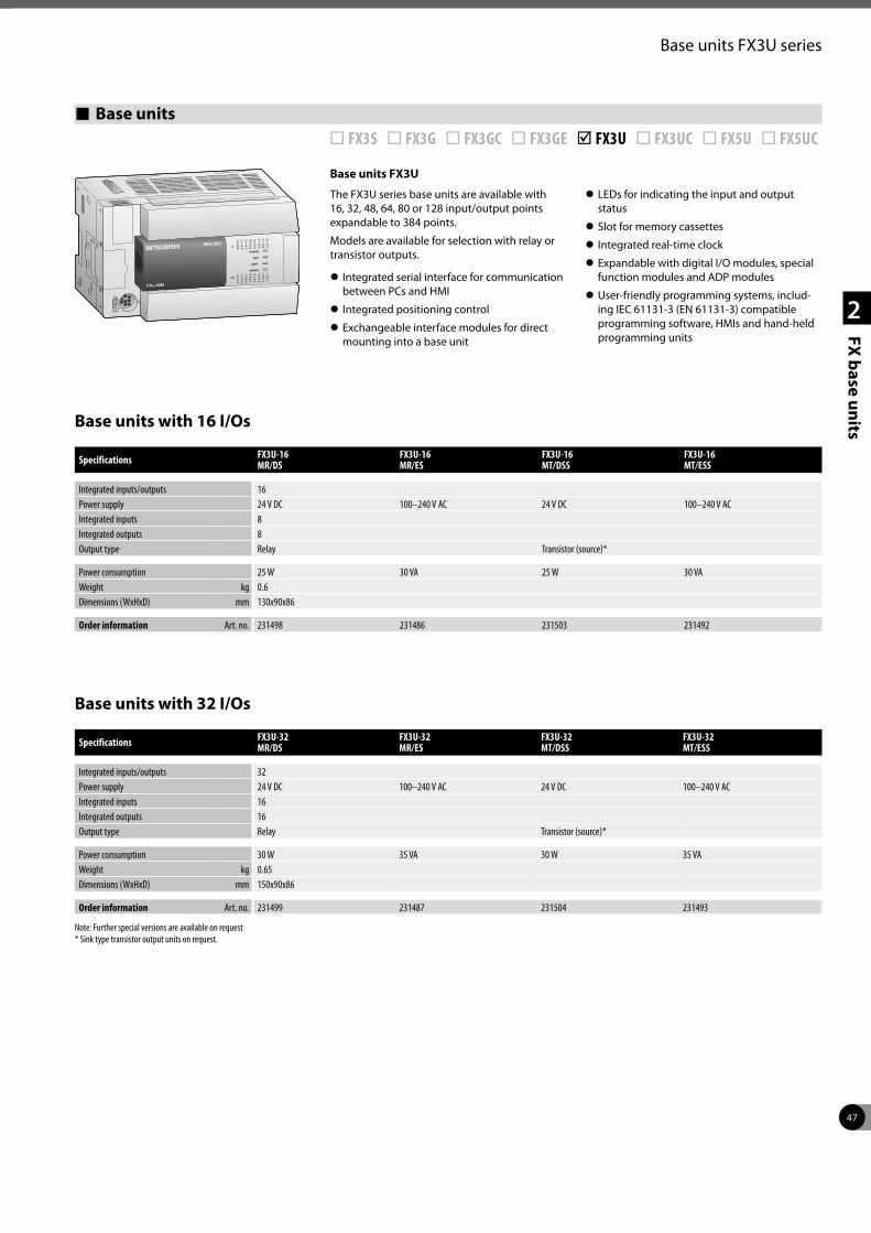
47
2
FX base units
Base units FX3U series
Base units ¨ FX3S ¨ FX3G ¨ FX3GC ¨ FX3GE þ FX3U ¨ FX3UC ¨ FX5U ¨ FX5UC
Base units FX3U
The FX3U series base units are available with 16, 32, 48, 64, 80 or 128 input/output points expandable to 384 points.
Models are available for selection with relay or transistor outputs.
z Integrated serial interface for communication between PCs and HMI
z Integrated positioning control
z Exchangeable interface modules for direct mounting into a base unit
z LEDs for indicating the input and output status
z Slot for memory cassettes
z Integrated real-time clock
z Expandable with digital I/O modules, special function modules and ADP modules
z User-friendly programming systems, includ-ing IEC 61131-3 (EN 61131-3) compatible programming software, HMIs and hand-held programming units
Base units with 16 I/Os
Base units with 32 I/Os
Specifications FX3U-16 MR/DS
FX3U-16 MR/ES
FX3U-16 MT/DSS
FX3U-16 MT/ESS
Integrated inputs/outputs 16Power supply 24 V DC 100–240 V AC 24 V DC 100–240 V ACIntegrated inputs 8Integrated outputs 8Output type Relay Transistor (source)*
Power consumption 25 W 30 VA 25 W 30 VAWeight kg 0.6Dimensions (WxHxD) mm 130x90x86
Order information Art. no. 231498 231486 231503 231492
Specifications FX3U-32 MR/DS
FX3U-32 MR/ES
FX3U-32 MT/DSS
FX3U-32 MT/ESS
Integrated inputs/outputs 32Power supply 24 V DC 100–240 V AC 24 V DC 100–240 V ACIntegrated inputs 16Integrated outputs 16Output type Relay Transistor (source)*
Power consumption 30 W 35 VA 30 W 35 VAWeight kg 0.65Dimensions (WxHxD) mm 150x90x86
Order information Art. no. 231499 231487 231504 231493
Note: Further special versions are available on request * Sink type transistor output units on request.
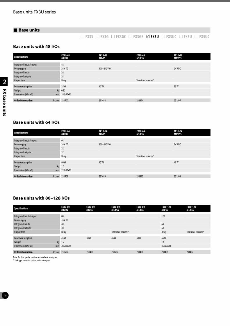
48
2
FX base units
Base units FX3U series
Base units with 48 I/Os
Base units with 64 I/Os
Base units with 80–128 I/Os
Specifications FX3U-48 MR/DS
FX3U-48 MR/ES
FX3U-48 MT/ESS
FX3U-48 MT/DSS
Integrated inputs/outputs 48Power supply 24 V DC 100–240 V AC 24 V DCIntegrated inputs 24Integrated outputs 24Output type Relay Transistor (source)*
Power consumption 35 W 40 VA 35 WWeight kg 0.85Dimensions (WxHxD) mm 182x90x86
Order information Art. no. 231500 231488 231494 231505
Specifications FX3U-64 MR/DS
FX3U-64 MR/ES
FX3U-64 MT/ESS
FX3U-64 MT/DSS
Integrated inputs/outputs 64Power supply 24 V DC 100–240 V AC 24 V DCIntegrated inputs 32Integrated outputs 32Output type Relay Transistor (source)*
Power consumption 40 W 45 VA 40 WWeight kg 1.0Dimensions (WxHxD) mm 220x90x86
Order information Art. no. 231501 231489 231495 231506
Specifications FX3U-80 MR/DS
FX3U-80 MR/ES
FX3U-80 MT/DSS
FX3U-80 MT/ESS
FX3U-128 MR/ES
FX3U-128 MT/ESS
Integrated inputs/outputs 80 128Power supply 24 V DCIntegrated inputs 40 64Integrated outputs 40 64Output type Relay Transistor (source)* Relay Transistor (source)*
Power consumption 45 W 50 VA 45 W 50 VA 65 VAWeight kg 1.2 1.8Dimensions (WxHxD) mm 285x90x86 350x90x86
Order information Art. no. 231502 231490 231507 231496 231491 231497
Note: Further special versions are available on request * Sink type transistor output units on request.
Base units ¨ FX3S ¨ FX3G ¨ FX3GC ¨ FX3GE þ FX3U ¨ FX3UC ¨ FX5U ¨ FX5UC
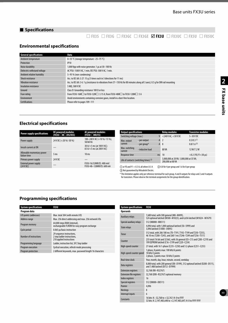
49
2
FX base units
Base units FX3U series
Specifications ¨ FX3S ¨ FX3G ¨ FX3GC ¨ FX3GE þ FX3U ¨ FX3UC ¨ FX5U ¨ FX5UC
Environmental specifications
Electrical specifications
Programming specifications
General specifications DataAmbient temperature 0–55 °C (storage temperature: -25–75 °C)Protection IP10Noise durability 1,000 Vpp with noise generator; 1 µs at 30–100 HzDielectric withstand voltage AC PSU: 1500 V AC, 1 min./DC PSU: 500 V AC, 1 min. Ambient relative humidity 5–95 % (non-condensing)Shock resistance Acc. to IEC 68-2-27: 15 g (3 times each in 3 directions for 11 ms)Vibration resistance Acc. to IEC 68-2-6: 1 g (resistance to vibrations from 57–150 Hz for 80 minutes along all 3 axes); 0.5 g for DIN rail mountingInsulation resistance 5 MΩ, 500 V DCGround Class D: Grounding resistance 100 Ω or lessFuse rating From FX3U-16Mm to FX3U-32Mm: 3.15 A; from FX3U-48Mm to FX3U-128Mm: 5 AEnvironment Avoid environments containing corrosive gases, install in a dust-free location.Certifications Please refer to pages 109–111
Power supply specifications DC powered modules (FX3U-mMm/DS/DSS)
AC powered modules (FX3U-mMR/ES)
Power supply 24 V DC (+20 %/-30 %) 100–240 V AC (+10 %/-15 %), 50/60 Hz
Inrush current at ON — 30 A/<5 ms (at 100 V AC); 65 A/<5 ms (at 200 V AC)
Allowable momentary power failure time 5 ms 10 ms
Primary power supply 24 V DC —External power supply (24 V DC) — FX3U-16/32MR/ES: 400 mA/
FX3U-48–128MR/ES: 600 mA
Output specifications Relay modules Transistor modulesSwitching voltage (max.) V <240 V AC, <30 V DC 5–30 V DC
Max. output current
- per output A 2 0.5/0.3 a
- per group* A 8 0.8/1.6 b
Max. switching current - inductive load 80 VA 12 W/7.2 W
Response time ms 10 <0.2 (Y0,Y1<30 µs)
Life of contacts (switching times) c 3,000,000 at 20 VA; 1,000,000 at 35 VA; 200,000 at 80 VA
a or Y0 and Y1 = 0.3 A; all others 0.5 A b 0.8 for 4 per group and 1.6 for 8 per groupc Not guaranteed by Mitsubishi Electric.* This limitation applies only per reference terminal for each group, 4 and 8 outputs for relays and 2 and 4 outputs
for transistors. Please observe the terminal assignments for the group identification.
System specifications FX3UProgram dataI/O points (addresses) Max. total 384 (with remote I/O)Address range Max. 256 direct addressing and max. 256 network I/Os
Program memory 64,000 steps RAM (internal), exchangeable FLROM for easy program exchange
Cycle period 0.065 µs/basic instruction
Number of instructions29 sequence instructions,2 step ladder instructions,218 applied instructions
Programming language Ladder, instruction list, SFC Step ladderProgram execution Cyclical execution, refresh mode processingProgram protection 2 different keywords, max. password length 16 characters
System specifications FX3UOperands
Auxiliary relays 7,680 total, with 500 general (M0–M499), 524 optional latched (M500–M1023), and 6,656 latched (M1024 - M7679)
Special auxiliary relays 512 (M8000–M8511)
State relays 4,096 total, with 1,000 optional latched (S0–S999) and 3,096 latched (S1000–S4095)
Timer 512 total, with 206 100 ms (T0–T191, T192–T199 and T250–T255), 46 10 ms (T200–T245), and 260 1 ms (T246–T249 and T256–T511)
Counter 235 total (16 bit and 32 bit), with 36 general (C0–C15 and C200–C219) and 199 EEPROM latched (C16–C199 and C220–C234)
High-speed counter 21 total, with 16 1-phase (C235–C250) and 5 2-phase (C251–C255)
High-speed counter speed1 phase, 8 points max: 100 kHz/6 points 10 kHz/2 points 2 phase, 2 points max: 50 kHz/2 points
Real-time clock Year, month, day, hour, minute, second, weekday
Data registers 8,000 total, with 200 general (D0–D199), 312 optional latched (D200–D511),and 7,488 latched (D512–D7999)
Extension registers 32,768 (R0–R32767)Extension file registers 32,768 (ER0–R32767) optional memoryIndex registers 16Special registers 512 (D8000–D8511)Pointer 4,096Nestings 8Interrupt inputs 6
Constants 16 bits: K: -32,768 to +32,767; H: 0 to FFFF32 bits: K: 2,147,483,648 to +2,147,483,647; H: 0 to FFFF FFFF
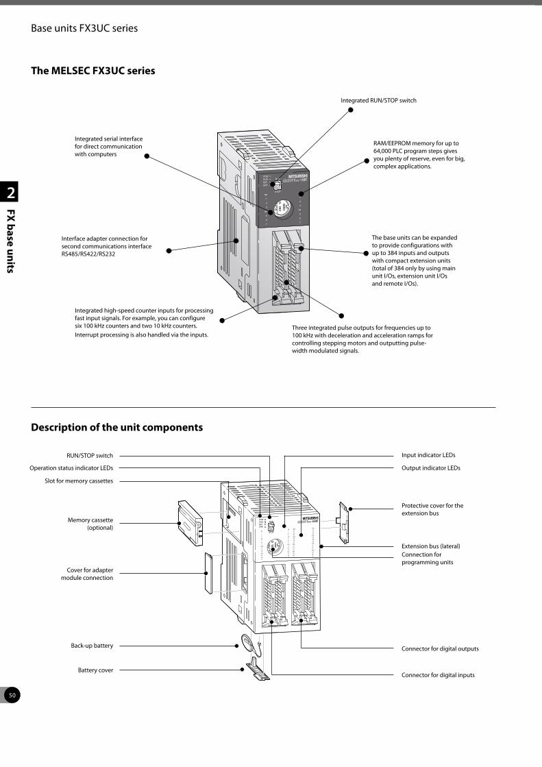
50
2
FX base units
Base units FX3UC series
The MELSEC FX3UC series
Interface adapter connection for second communications interface RS485/RS422/RS232
Three integrated pulse outputs for frequencies up to 100 kHz with deceleration and acceleration ramps for controlling stepping motors and outputting pulse-width modulated signals.
RAM/EEPROM memory for up to 64,000 PLC program steps gives you plenty of reserve, even for big, complex applications.
The base units can be expanded to provide configurations with up to 384 inputs and outputs with compact extension units (total of 384 only by using main unit I/Os, extension unit I/Os and remote I/Os).
Integrated RUN/STOP switch
Integrated serial interface for direct communication with computers
Description of the unit components
RUN/STOP switch
Integrated high-speed counter inputs for processing fast input signals. For example, you can configure six 100 kHz counters and two 10 kHz counters.Interrupt processing is also handled via the inputs.
Connector for digital inputs
Operation status indicator LEDs
Slot for memory cassettes
Memory cassette(optional)
Cover for adapter module connection
Back-up battery
Battery cover
Connector for digital outputs
Connection for programming units
Extension bus (lateral)
Protective cover for the extension bus
Output indicator LEDs
Input indicator LEDs
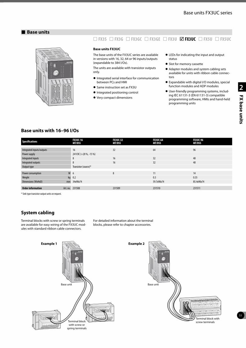
51
2
FX base units
Base units FX3UC series
Base units ¨ FX3S ¨ FX3G ¨ FX3GC ¨ FX3GE ¨ FX3U þ FX3UC ¨ FX5U ¨ FX5UC
Base units FX3UC
The base units of the FX3UC series are available in versions with 16, 32, 64 or 96 inputs/outputs (expandable to 384 I/Os).
The units are available with transistor outputs only.
z Integrated serial interface for communication between PCs and HMI
z Same instruction set as FX3U
z Integrated positioning control
z Very compact dimensions
z LEDs for indicating the input and output status
z Slot for memory cassette
z Adapter modules and system cabling sets available for units with ribbon cable connec-tors
z Expandable with digital I/O modules, special function modules and ADP modules
z User-friendly programming systems, includ-ing IEC 61131-3 (EN 61131-3) compatible programming software, HMIs and hand-held programming units
Base units with 16–96 I/Os
System cablingTerminal blocks with screw or spring terminals are available for easy wiring of the FX3UC mod-ules with standard ribbon cable connectors.
For detailed information about the terminal blocks, please refer to chapter accessories.
Specifications FX3UC-16 MT/DSS
FX3UC-32 MT/DSS
FX3UC-64 MT/DSS
FX3UC-96 MT/DSS
Integrated inputs/outputs 16 32 64 96Power supply 24 V DC (+20 %, -15 %)Integrated inputs 8 16 32 48Integrated outputs 8 16 32 48Output type Transistor (source)*
Power consumption W 6 8 11 14Weight kg 0.2 0.3 0.35Dimensions (WxHxD) mm 34x90x74 59.7x90x74 85.4x90x74
Order information Art. no. 231508 231509 231510 231511
* Sink type transistor output units on request.
2018161412108642
2018161412108642
Base unitBase unit
Terminal block with screw or
spring terminals
Terminal block with screw terminals
Example 1 Example 2

52
2
FX base units
Base units FX3UC series
Specifications ¨ FX3S ¨ FX3G ¨ FX3GC ¨ FX3GE ¨ FX3U þ FX3UC ¨ FX5U ¨ FX5UC
Environmental specifications
Electrical specifications
Programming specifications
General specifications DataAmbient temperature 0–55 °C (storage temperature: -25–75 °C)Protection IP10Noise durability 1000 Vpp with noise generator; 1 µs at 30–100 HzDielectric withstand voltage AC PSU: 1500 V AC, 1 min./DC PSU: 500 V AC, 1 min. Ambient relative humidity 5–95 % (non-condensing)Shock resistance Acc. to IEC 68-2-27: 15 g (3 times each in 3 directions for 11 ms)Vibration resistance Acc. to IEC 68-2-6: 1 g (resistance to vibrations from 57–150 Hz for 80 minutes along all 3 axes); 0.5 g for DIN rail mountingInsulation resistance 500 V DC, 5 MΩGround Class D: Grounding resistance 100 Ω or lessEnvironment Avoid environments containing corrosive gases, install in a dust-free location.Certifications Please refer to pages 109–111
Power supply specifications All modulesPower supply 24 V DC (+20 %/-30 %)Inrush current at ON —Allowable momentary power failure time 5 ms
Primary power supply 24 V DCExternal power supply (24 V DC) —
Output specifications Alle modulesSwitching voltage (max.) V 5–30 V DC
Max. output current
- per output A 0.1/0.3 a
- per group* A 0.8/1.6Max. switching current - inductive load 2.4 W/7.2 W b
Response time ms <0.2 (Y0,Y1<30 µs)
Life of contacts (switching times) c 3,000,000 at 20 VA; 1,000,000 at 35 VA; 200,000 at 80 VA
a or Y0 and Y1 = 0.3 A; all others 0.1 A b 7.2 W for Y0 to Y3, all other outputs 2.4 Wc Not guaranteed by Mitsubishi Electric.* This limitation applies only per reference terminal for each group, 4 and 8 outputs for relays and 2 and 4 outputs
for transistors. Please observe the terminal assignments for the group identification.
System specifications FX3UCProgram dataI/O points (addresses) Max. total 384 (with remote I/O)Address range Max. 256 direct addressing and max. 256 network I/Os
Program memory 64,000 steps RAM (internal), exchangeable FLROM for easy program exchange
Cycle period 0.065 µs/basic instruction
Number of instructions29 sequence instructions, 2 step ladder instructions, 218 applied instructions
Programming language Ladder, instruction list, SFC Step ladderProgram execution Cyclical execution, refresh mode processing
Program protection 2 different keywords, max. password length 16 characters
System specifications FX3UCOperands
Auxiliary relays 7,680 total, with 500 general (M0–M499), 524 optional latched (M500–M1023), and 6,656 latched (M1024 - M7679)
Special auxiliary relays 512 (M8000–M8511)
State relays 4,096 total, with 1,000 optional latched (S0–S999) and 3,096 latched (S1000–S4095)
Timer 512 total, with 206 100 ms (T0–T191, T192–T199 and T250–T255), 46 10 ms (T200–T245), and 260 1 ms (T246–T249 and T256–T511)
Counter 235 total (16 bit and 32 bit), with 36 general (C0–C15 and C200–C219) and 199 EEPROM latched (C16–C199 and C220–C234)
High-speed counter 21 total, with 16 1-phase (C235–C250) and 5 2-phase (C251–C255)
High-speed counter speed1 phase, 8 points max: 100 kHz/6 points 10 kHz/2 points 2 phase, 2 points max: 50 kHz/2 points
Real-time clock Year, month, day, hour, minute, second, weekday
Data register 8,000 total, with 200 general (D0–D199), 312 optional latched (D200–D511),and 7,488 latched (D512–D7999)
Extension registers 32,768 (R0–R32767)Extension file register 32,768 (ER0–R32767) optional memoryIndex register 16Special register 512 (D8000–D8511)Pointer 4,096Nestings 8Interrupt inputs 6
Constants 16 bits: K: -32,768 to +32,767; H: 0 to FFFF32 bits: K: 2,147,483,648 to +2,147,483,647; H: 0 to FFFF FFFF
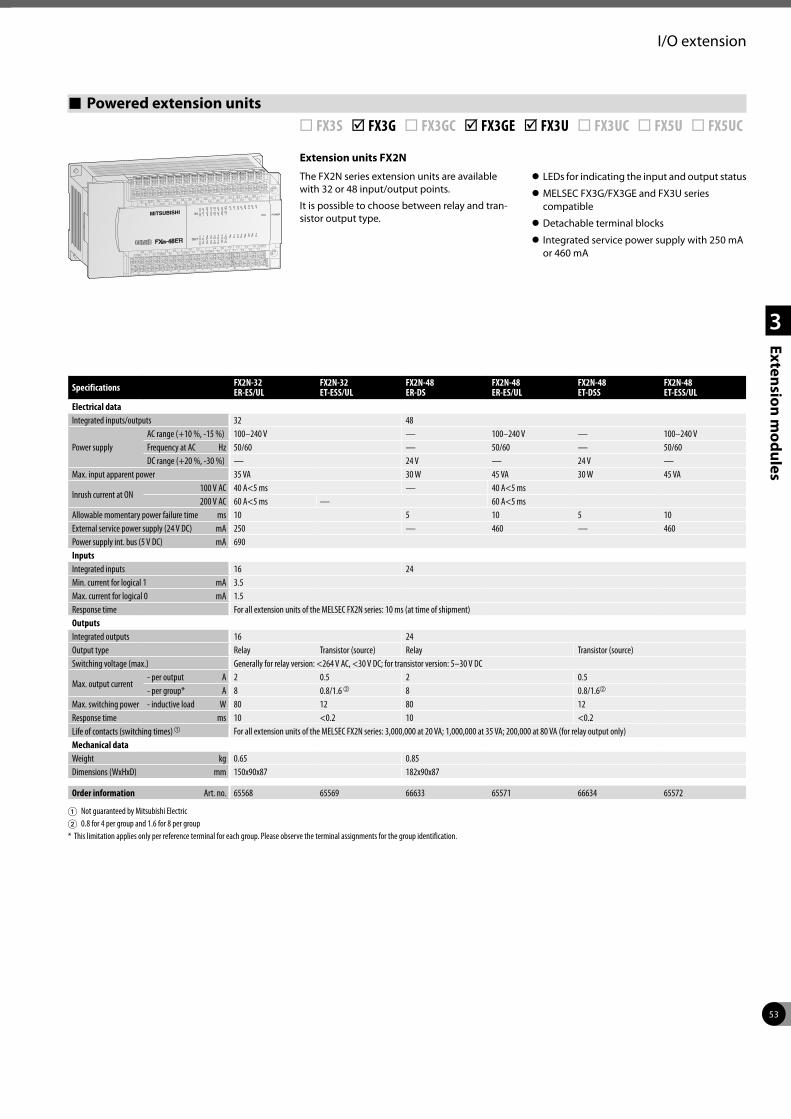
53
1
2
3
Extension modules
I/O extension
Powered extension units ¨ FX3S þ FX3G ¨ FX3GC þ FX3GE þ FX3U ¨ FX3UC ¨ FX5U ¨ FX5UC
Extension units FX2N
The FX2N series extension units are available with 32 or 48 input/output points.
It is possible to choose between relay and tran-sistor output type.
z LEDs for indicating the input and output status
z MELSEC FX3G/FX3GE and FX3U series compatible
z Detachable terminal blocks
z Integrated service power supply with 250 mA or 460 mA
Specifications FX2N-32 ER-ES/UL
FX2N-32 ET-ESS/UL
FX2N-48 ER-DS
FX2N-48 ER-ES/UL
FX2N-48 ET-DSS
FX2N-48 ET-ESS/UL
Electrical dataIntegrated inputs/outputs 32 48
Power supplyAC range (+10 %, -15 %) 100–240 V — 100–240 V — 100–240 VFrequency at AC Hz 50/60 — 50/60 — 50/60DC range (+20 %, -30 %) — 24 V — 24 V —
Max. input apparent power 35 VA 30 W 45 VA 30 W 45 VA
Inrush current at ON 100 V AC 40 A<5 ms — 40 A<5 ms 200 V AC 60 A<5 ms — 60 A<5 ms
Allowable momentary power failure time ms 10 5 10 5 10External service power supply (24 V DC) mA 250 — 460 — 460Power supply int. bus (5 V DC) mA 690InputsIntegrated inputs 16 24Min. current for logical 1 mA 3.5Max. current for logical 0 mA 1.5Response time For all extension units of the MELSEC FX2N series: 10 ms (at time of shipment)OutputsIntegrated outputs 16 24Output type Relay Transistor (source) Relay Transistor (source)Switching voltage (max.) Generally for relay version: <264 V AC, <30 V DC; for transistor version: 5–30 V DC
Max. output current- per output A 2 0.5 2 0.5 - per group* A 8 0.8/1.6 b 8 0.8/1.6b
Max. switching power - inductive load W 80 12 80 12Response time ms 10 <0.2 10 <0.2Life of contacts (switching times) a For all extension units of the MELSEC FX2N series: 3,000,000 at 20 VA; 1,000,000 at 35 VA; 200,000 at 80 VA (for relay output only)Mechanical dataWeight kg 0.65 0.85Dimensions (WxHxD) mm 150x90x87 182x90x87
Order information Art. no. 65568 65569 66633 65571 66634 65572
1 Not guaranteed by Mitsubishi Electric 2 0.8 for 4 per group and 1.6 for 8 per group* This limitation applies only per reference terminal for each group. Please observe the terminal assignments for the group identification.
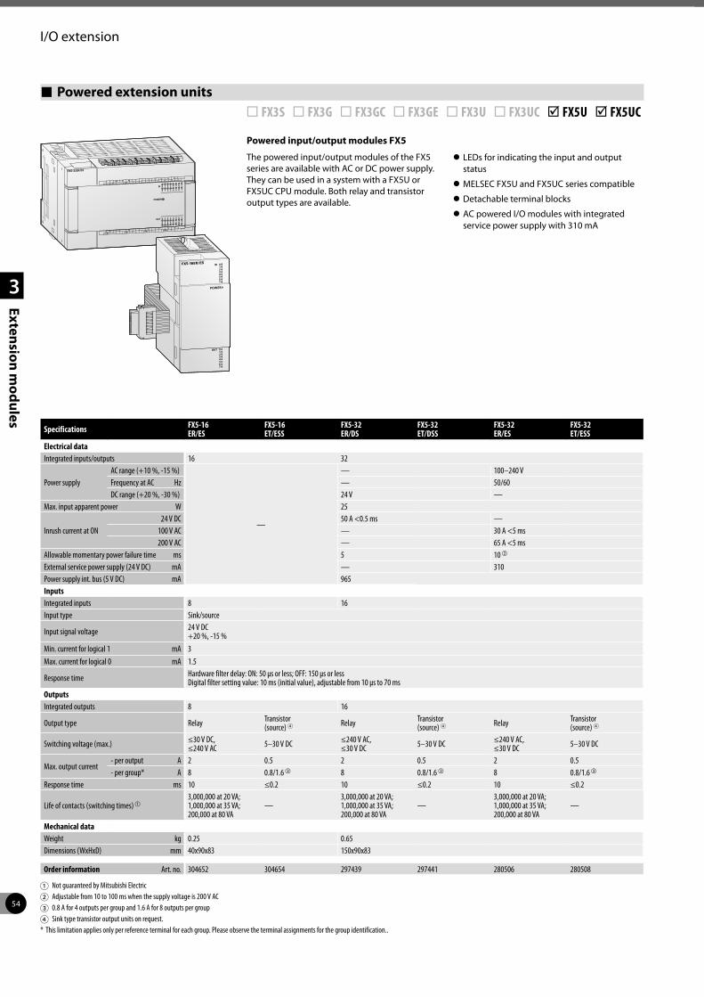
54
1
2
3
Extension modules
I/O extension
Powered extension units ¨ FX3S ¨ FX3G ¨ FX3GC ¨ FX3GE ¨ FX3U ¨ FX3UC þ FX5U þ FX5UC
Powered input/output modules FX5
The powered input/output modules of the FX5 series are available with AC or DC power supply. They can be used in a system with a FX5U or FX5UC CPU module. Both relay and transistor output types are available.
z LEDs for indicating the input and output status
z MELSEC FX5U and FX5UC series compatible
z Detachable terminal blocks
z AC powered I/O modules with integrated service power supply with 310 mA
Specifications FX5-16 ER/ES
FX5-16 ET/ESS
FX5-32 ER/DS
FX5-32 ET/DSS
FX5-32 ER/ES
FX5-32 ET/ESS
Electrical dataIntegrated inputs/outputs 16 32
Power supplyAC range (+10 %, -15 %)
—
— 100–240 VFrequency at AC Hz — 50/60DC range (+20 %, -30 %) 24 V —
Max. input apparent power W 25
Inrush current at ON 24 V DC 50 A <0.5 ms — 100 V AC — 30 A <5 ms 200 V AC — 65 A <5 ms
Allowable momentary power failure time ms 5 10 b
External service power supply (24 V DC) mA — 310Power supply int. bus (5 V DC) mA 965InputsIntegrated inputs 8 16Input type Sink/source
Input signal voltage 24 V DC +20 %, -15 %
Min. current for logical 1 mA 3Max. current for logical 0 mA 1.5
Response time Hardware filter delay: ON: 50 µs or less; OFF: 150 µs or lessDigital filter setting value: 10 ms (initial value), adjustable from 10 µs to 70 ms
OutputsIntegrated outputs 8 16
Output type Relay Transistor(source) 4 Relay Transistor
(source) 4 Relay Transistor(source) 4
Switching voltage (max.) ≤30 V DC, ≤240 V AC 5–30 V DC ≤240 V AC,
≤30 V DC 5–30 V DC ≤240 V AC, ≤30 V DC 5–30 V DC
Max. output current- per output A 2 0.5 2 0.5 2 0.5- per group* A 8 0.8/1.6 c 8 0.8/1.6 c 8 0.8/1.6 c
Response time ms 10 ≤0.2 10 ≤0.2 10 ≤0.2
Life of contacts (switching times) a3,000,000 at 20 VA; 1,000,000 at 35 VA; 200,000 at 80 VA
—3,000,000 at 20 VA; 1,000,000 at 35 VA; 200,000 at 80 VA
—3,000,000 at 20 VA; 1,000,000 at 35 VA; 200,000 at 80 VA
—
Mechanical dataWeight kg 0.25 0.65Dimensions (WxHxD) mm 40x90x83 150x90x83
Order information Art. no. 304652 304654 297439 297441 280506 280508
1 Not guaranteed by Mitsubishi Electric 2 Adjustable from 10 to 100 ms when the supply voltage is 200 V AC3 0.8 A for 4 outputs per group and 1.6 A for 8 outputs per group4 Sink type transistor output units on request.* This limitation applies only per reference terminal for each group. Please observe the terminal assignments for the group identification..
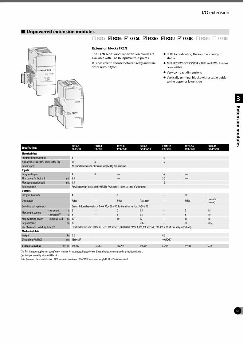
55
I/O extension
1
2
3
Extension modules
Unpowered extension modules ¨ FX3S þ FX3G þ FX3GC þ FX3GE þ FX3U þ FX3UC ¨ FX5U ¨ FX5UC
Extension blocks FX2N
The FX2N series modular extension blocks are available with 8 or 16 input/output points.
It is possible to choose between relay and tran-sistor output type.
z LEDs for indicating the input and output status
z MELSEC FX3G/FX3GC/FX3GE and FX3U series compatible
z Very compact dimensions
z Vertically terminal blocks with a cable guide to the upper or lower side
IN
2
OUT
OUT
Specifications FX2N-8 ER-ES/UL
FX2N-8 EX-ES/UL
FX2N-8 EYR-ES/UL
FX2N-8 EYT-ESS/UL
FX2N-16 EX-ES/UL
FX2N-16 EYR-ES/UL
FX2N-16 EYT-ESS/UL
Electrical dataIntegrated inputs/outputs 8 16Number of occupied I/O points in the PLC 16 8 16Power supply All modular extension blocks are supplied by the base unit.InputsIntegrated inputs 4 8 — 16 —Min. current for logical 1 mA 3.5 — 3.5 —Max. current for logical 0 mA 1.5 — 1.5 —Response time For all extension blocks of the MELSEC FX2N series: 10 ms (at time of shipment)OutputsIntegrated outputs 4 — 8 — 16
Output type Relay — Relay Transistor — Relay Transistor (source)
Switching voltage (max.) Generally for relay version: <240 V AC, <30 V DC; for transistor version: 5–30 V DC
Max. output current- per output A 2 — 2 0.5 — 2 0.5- per group a A 8 — 8 0.8 — 8 1.6
Max. switching power - inductive load VA 80 — 80 12 — 80 12Response time ms 10 <0.2 — 10 <0.2Life of contacts (switching times) b For all extension units of the MELSEC FX2N series: 3,000,000 at 20 VA; 1,000,000 at 35 VA; 200,000 at 80 VA (for relay output only)Mechanical dataWeight kg 0.2 0.3Dimensions (WxHxD) mm 43x90x87 40x90x87
Order information Art. no. 166285 166284 166286 166287 65776 65580 65581
1 This limitation applies only per reference terminal for each group. Please observe the terminal assignments for the group identification.2 Not guaranteed by Mitsubishi ElectricNote: To connect these modules to a FX3GC base unit, an adapter FX2N-CNV-IF or a power supply FX3UC-1PS-5V is required.
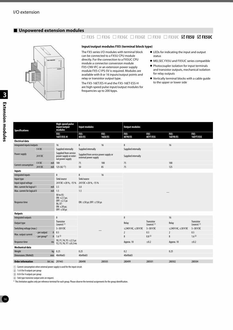
56
I/O extension
1
2
3
Extension modules
Unpowered extension modules ¨ FX3S ¨ FX3G ¨ FX3GC ¨ FX3GE ¨ FX3U ¨ FX3UC þ FX5U þ FX5UC
Input/output modules FX5 (terminal block type)
The FX5 series I/O modules with terminal block can be connected to a FX5U CPU module directly. For the connection to a FX5UC CPU module a connector conversion module FX5-CNV-IFC or an extension power supply module FX5-C1PS-5V is required. Modules are available with 8 or 16 inputs/output points and relay or transistor output type.
The FX5-16ET/ES-H and the FX5-16ET-ESS-H are high-speed pulse input/output modules for frequencies up to 200 kpps.
z LEDs for indicating the input and output status
z MELSEC FX5U and FX5UC series compatible
z Photocoupler isolation for input terminals and transistor outputs, mechanical isolation for relay outputs
z Vertically terminal blocks with a cable guide to the upper or lower side
Specifications
High-speed pulse input/output modules
Input modules Output modules
FX5- 16ET/ESS-H
FX5- 8EX/ES
FX5- 16EX/ES
FX5- 8EYR/ES
FX5- 8EYT/ESS
FX5- 16EYR/ES
FX5- 16EYT/ESS
Electrical dataIntegrated inputs/outputs 16 8 16 8 16
Power supply
5 V DC Supplied internally Supplied internally Supplied internally
24 V DCSupplied from service power supply or exter-nal power supply
Supplied from service power supply or external power supply Supplied internally
Current consumption5 V DC mA 100 75 100 75 10024 V DC mA 125 (82 a) 50 85 75 125
InputsIntegrated inputs 8 8 16
—
Input type Sink/source Sink/sourceInput signal voltage 24 V DC +20 %, -15 % 24 V DC +20 %, -15 %Min. current for logical 1 mA 3.5 3.0Max. current for logical 0 mA 1.5 1.5
Response time
X0 to X5:ON: ≤2.5 µs; OFF: ≤2.5 µsX6, X7: ON: ≤30 µs; OFF: ≤50 µs
ON: ≤50 µs; OFF: ≤150 µs
OutputsIntegrated outputs 8
—
8 16
Output type Transistor(source) 4 Relay Transistor
(source) 4 Relay Transistor(source) 4
Switching voltage (max.) 5–30 V DC ≤240 V AC, ≤30 V DC 5–30 V DC ≤240 V AC, ≤30 V DC 5–30 V DC
Max. output current- per output A 0.5 2 0.5 2 0.5- per group* A 1.6 b 8 0.8 c 8 1.6 b
Response time ms Y0, Y1, Y4, Y5: ≤2.5 µsY2, Y3, Y6, Y7: ≤0.2 ms Approx. 10 ≤0.2 Approx. 10 ≤0.2
Mechanical dataWeight kg 0.25 0.25 0.2 0.25Dimensions (WxHxD) mm 40x90x83 40x90x83 40x90x83
Order information Art. no. 297443 280498 280505 280499 280501 280502 280504
1 Current consumption when external power supply is used for the input circuit.2 1.6 A for 8 outputs per group3 0.8 A for 4 outputs per group4 Sink type transistor output units on request.* This limitation applies only per reference terminal for each group. Please observe the terminal assignments for the group identification.
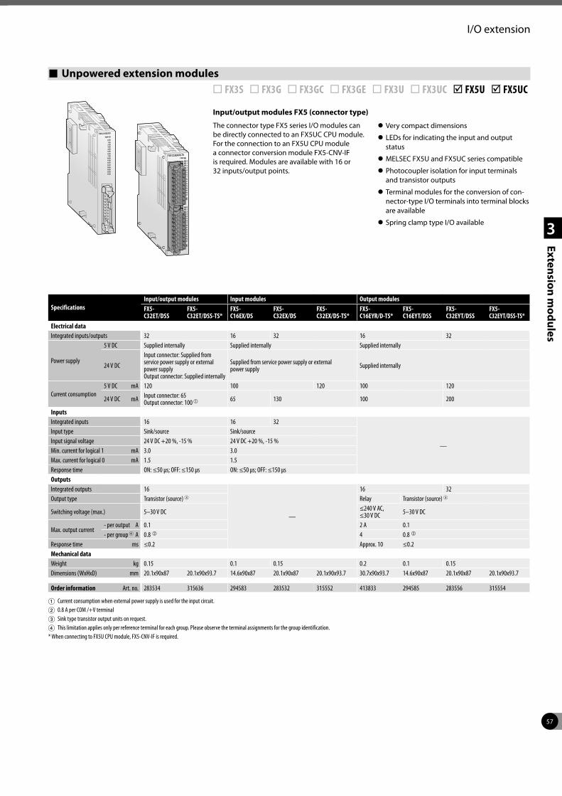
57
I/O extension
1
2
3
Extension modules
Unpowered extension modules ¨ FX3S ¨ FX3G ¨ FX3GC ¨ FX3GE ¨ FX3U ¨ FX3UC þ FX5U þ FX5UC
Input/output modules FX5 (connector type)
The connector type FX5 series I/O modules can be directly connected to an FX5UC CPU module. For the connection to an FX5U CPU module a connector conversion module FX5-CNV-IF is required. Modules are available with 16 or 32 inputs/output points.
z Very compact dimensions
z LEDs for indicating the input and output status
z MELSEC FX5U and FX5UC series compatible
z Photocoupler isolation for input terminals and transistor outputs
z Terminal modules for the conversion of con-nector-type I/O terminals into terminal blocks are available
z Spring clamp type I/O available
SpecificationsInput/output modules Input modules Output modulesFX5-C32ET/DSS
FX5-C32ET/DSS-TS*
FX5-C16EX/DS
FX5-C32EX/DS
FX5-C32EX/DS-TS*
FX5-C16EYR/D-TS*
FX5-C16EYT/DSS
FX5-C32EYT/DSS
FX5-C32EYT/DSS-TS*
Electrical dataIntegrated inputs/outputs 32 16 32 16 32
Power supply
5 V DC Supplied internally Supplied internally Supplied internally
24 V DC
Input connector: Supplied from service power supply or external power supplyOutput connector: Supplied internally
Supplied from service power supply or external power supply Supplied internally
Current consumption5 V DC mA 120 100 120 100 120
24 V DC mA Input connector: 65Output connector: 100 a 65 130 100 200
InputsIntegrated inputs 16 16 32
—
Input type Sink/source Sink/sourceInput signal voltage 24 V DC +20 %, -15 % 24 V DC +20 %, -15 %Min. current for logical 1 mA 3.0 3.0Max. current for logical 0 mA 1.5 1.5Response time ON: ≤50 µs; OFF: ≤150 µs ON: ≤50 µs; OFF: ≤150 µsOutputsIntegrated outputs 16
—
16 32Output type Transistor (source) 3 Relay Transistor (source) 3
Switching voltage (max.) 5–30 V DC ≤240 V AC, ≤30 V DC 5–30 V DC
Max. output current- per output A 0.1 2 A 0.1- per group 4 A 0.8 b 4 0.8 b
Response time ms ≤0.2 Approx. 10 ≤0.2Mechanical dataWeight kg 0.15 0.1 0.15 0.2 0.1 0.15Dimensions (WxHxD) mm 20.1x90x87 20.1x90x93.7 14.6x90x87 20.1x90x87 20.1x90x93.7 30.7x90x93.7 14.6x90x87 20.1x90x87 20.1x90x93.7
Order information Art. no. 283534 315636 294583 283532 315552 413833 294585 283556 315554
1 Current consumption when external power supply is used for the input circuit.2 0.8 A per COM /+V terminal 3 Sink type transistor output units on request.4 This limitation applies only per reference terminal for each group. Please observe the terminal assignments for the group identification.* When connecting to FX5U CPU module, FX5-CNV-IF is required.
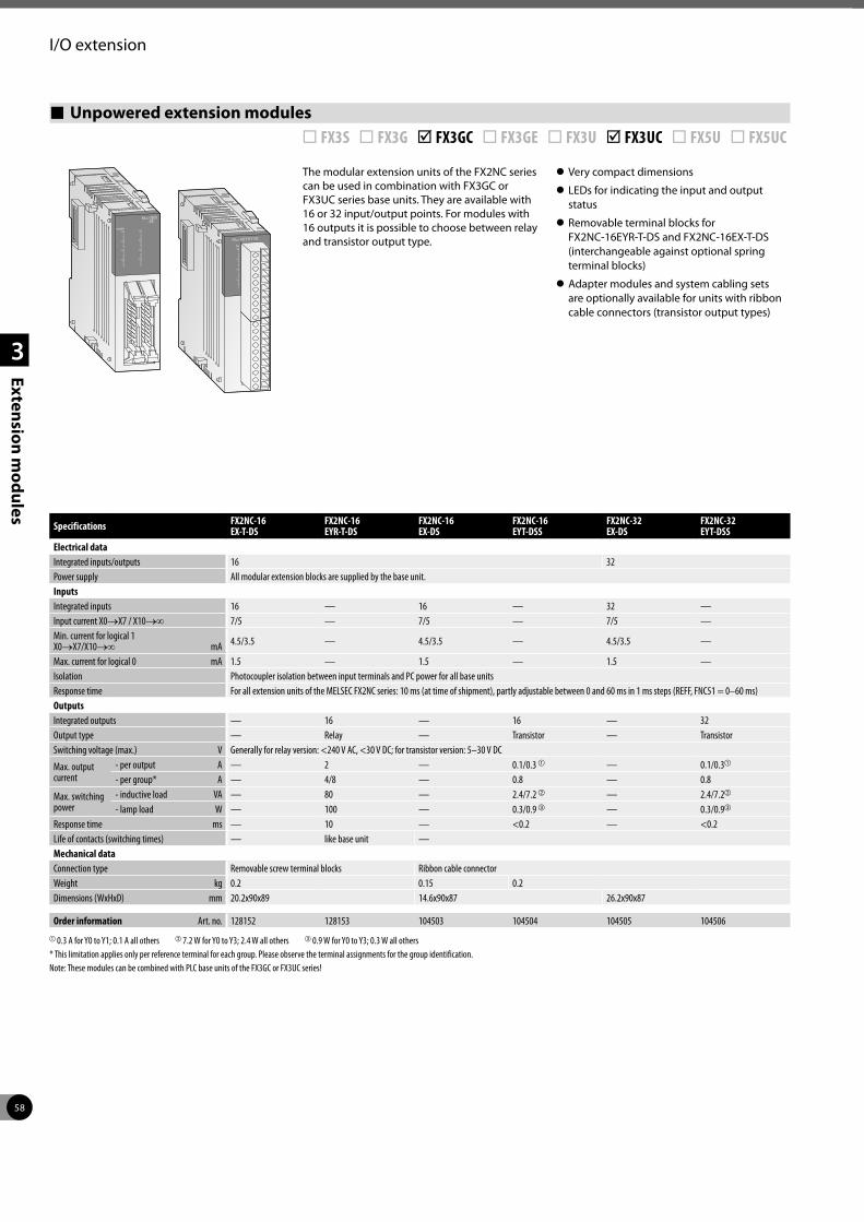
58
I/O extension
1
2
3
Extension modules
POWERX0
123
X4567
X0123
X4567
X0123
X4567
X0123
X4567
FX2NC-32EX-DS
Unpowered extension modules ¨ FX3S ¨ FX3G þ FX3GC ¨ FX3GE ¨ FX3U þ FX3UC ¨ FX5U ¨ FX5UC
PWY0
123
Y4567
Y0123
Y4567
FX2NC-16EYR-T-DS
The modular extension units of the FX2NC series can be used in combination with FX3GC or FX3UC series base units. They are available with 16 or 32 input/output points. For modules with 16 outputs it is possible to choose between relay and transistor output type.
z Very compact dimensions
z LEDs for indicating the input and output status
z Removable terminal blocks for FX2NC-16EYR-T-DS and FX2NC-16EX-T-DS (interchangeable against optional spring terminal blocks)
z Adapter modules and system cabling sets are optionally available for units with ribbon cable connectors (transistor output types)
Specifications FX2NC-16 EX-T-DS
FX2NC-16 EYR-T-DS
FX2NC-16 EX-DS
FX2NC-16 EYT-DSS
FX2NC-32 EX-DS
FX2NC-32 EYT-DSS
Electrical dataIntegrated inputs/outputs 16 32Power supply All modular extension blocks are supplied by the base unit.InputsIntegrated inputs 16 — 16 — 32 —Input current X0→X7 / X10→∞ 7/5 — 7/5 — 7/5 —Min. current for logical 1 X0→X7/X10→∞ mA 4.5/3.5 — 4.5/3.5 — 4.5/3.5 —
Max. current for logical 0 mA 1.5 — 1.5 — 1.5 —Isolation Photocoupler isolation between input terminals and PC power for all base unitsResponse time For all extension units of the MELSEC FX2NC series: 10 ms (at time of shipment), partly adjustable between 0 and 60 ms in 1 ms steps (REFF, FNC51 = 0–60 ms)OutputsIntegrated outputs — 16 — 16 — 32Output type — Relay — Transistor — TransistorSwitching voltage (max.) V Generally for relay version: <240 V AC, <30 V DC; for transistor version: 5–30 V DC
Max. output current
- per output A — 2 — 0.1/0.3 a — 0.1/0.3a
- per group* A — 4/8 — 0.8 — 0.8
Max. switching power
- inductive load VA — 80 — 2.4/7.2 b — 2.4/7.2b
- lamp load W — 100 — 0.3/0.9 c — 0.3/0.9c
Response time ms — 10 — <0.2 — <0.2Life of contacts (switching times) — like base unit —Mechanical dataConnection type Removable screw terminal blocks Ribbon cable connectorWeight kg 0.2 0.15 0.2Dimensions (WxHxD) mm 20.2x90x89 14.6x90x87 26.2x90x87
Order information Art. no. 128152 128153 104503 104504 104505 104506a 0.3 A for Y0 to Y1; 0.1 A all others b 7.2 W for Y0 to Y3; 2.4 W all others c 0.9 W for Y0 to Y3; 0.3 W all others* This limitation applies only per reference terminal for each group. Please observe the terminal assignments for the group identification.Note: These modules can be combined with PLC base units of the FX3GC or FX3UC series!
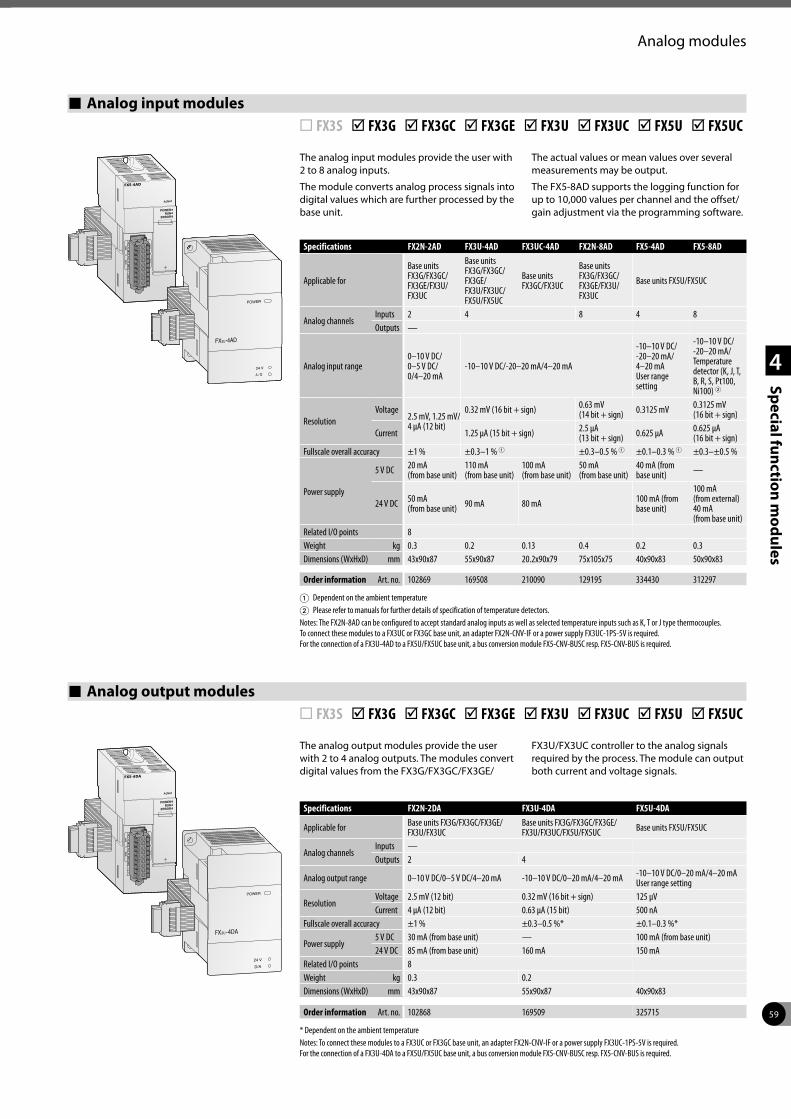
59
1
2
3
4
Special function modules
POWERRUN
ERROR
Analog modules
Analog output modules ¨ FX3S þ FX3G þ FX3GC þ FX3GE þ FX3U þ FX3UC þ FX5U þ FX5UC
The analog output modules provide the user with 2 to 4 analog outputs. The modules convert digital values from the FX3G/FX3GC/FX3GE/
FX3U/FX3UC controller to the analog signals required by the process. The module can output both current and voltage signals.
FX -4DA3U
24 V
D/A
Specifications FX2N-2DA FX3U-4DA FX5U-4DA
Applicable for Base units FX3G/FX3GC/FX3GE/FX3U/FX3UC
Base units FX3G/FX3GC/FX3GE/FX3U/FX3UC/FX5U/FX5UC Base units FX5U/FX5UC
Analog channelsInputs —Outputs 2 4
Analog output range 0–10 V DC/0–5 V DC/4–20 mA -10–10 V DC/0–20 mA/4–20 mA -10–10 V DC/0–20 mA/4–20 mA User range setting
ResolutionVoltage 2.5 mV (12 bit) 0.32 mV (16 bit + sign) 125 µVCurrent 4 µA (12 bit) 0.63 µA (15 bit) 500 nA
Fullscale overall accuracy ±1 % ±0.3–0.5 %* ±0.1–0.3 %*
Power supply 5 V DC 30 mA (from base unit) — 100 mA (from base unit)24 V DC 85 mA (from base unit) 160 mA 150 mA
Related I/O points 8Weight kg 0.3 0.2Dimensions (WxHxD) mm 43x90x87 55x90x87 40x90x83
Order information Art. no. 102868 169509 325715
* Dependent on the ambient temperatureNotes: To connect these modules to a FX3UC or FX3GC base unit, an adapter FX2N-CNV-IF or a power supply FX3UC-1PS-5V is required. For the connection of a FX3U-4DA to a FX5U/FX5UC base unit, a bus conversion module FX5-CNV-BUSC resp. FX5-CNV-BUS is required.
Analog input modules ¨ FX3S þ FX3G þ FX3GC þ FX3GE þ FX3U þ FX3UC þ FX5U þ FX5UC
The analog input modules provide the user with 2 to 8 analog inputs.
The module converts analog process signals into digital values which are further processed by the base unit.
The actual values or mean values over several measurements may be output.
The FX5-8AD supports the logging function for up to 10,000 values per channel and the offset/gain adjustment via the programming software.
Specifications FX2N-2AD FX3U-4AD FX3UC-4AD FX2N-8AD FX5-4AD FX5-8AD
Applicable for
Base units FX3G/FX3GC/FX3GE/FX3U/FX3UC
Base units FX3G/FX3GC/FX3GE/ FX3U/FX3UC/ FX5U/FX5UC
Base units FX3GC/FX3UC
Base units FX3G/FX3GC/FX3GE/FX3U/FX3UC
Base units FX5U/FX5UC
Analog channelsInputs 2 4 8 4 8Outputs —
Analog input range0–10 V DC/ 0–5 V DC/ 0/4–20 mA
-10–10 V DC/-20–20 mA/4–20 mA
-10–10 V DC/ -20–20 mA/ 4–20 mA User range setting
-10–10 V DC/ -20–20 mA/ Temperature detector (K, J, T, B, R, S, Pt100, Ni100) 2
ResolutionVoltage
2.5 mV, 1.25 mV/ 4 µA (12 bit)
0.32 mV (16 bit + sign) 0.63 mV (14 bit + sign) 0.3125 mV 0.3125 mV
(16 bit + sign)
Current 1.25 µA (15 bit + sign) 2.5 µA (13 bit + sign) 0.625 µA 0.625 µA
(16 bit + sign)Fullscale overall accuracy ±1 % ±0.3–1 % 1 ±0.3–0.5 % 1 ±0.1–0.3 % 1 ±0.3–±0.5 %
Power supply
5 V DC 20 mA (from base unit)
110 mA (from base unit)
100 mA (from base unit)
50 mA (from base unit)
40 mA (from base unit) —
24 V DC 50 mA (from base unit) 90 mA 80 mA 100 mA (from
base unit)
100 mA (from external)40 mA (from base unit)
Related I/O points 8Weight kg 0.3 0.2 0.13 0.4 0.2 0.3Dimensions (WxHxD) mm 43x90x87 55x90x87 20.2x90x79 75x105x75 40x90x83 50x90x83
Order information Art. no. 102869 169508 210090 129195 334430 312297
1 Dependent on the ambient temperature2 Please refer to manuals for further details of specification of temperature detectors.Notes: The FX2N-8AD can be configured to accept standard analog inputs as well as selected temperature inputs such as K, T or J type thermocouples. To connect these modules to a FX3UC or FX3GC base unit, an adapter FX2N-CNV-IF or a power supply FX3UC-1PS-5V is required. For the connection of a FX3U-4AD to a FX5U/FX5UC base unit, a bus conversion module FX5-CNV-BUSC resp. FX5-CNV-BUS is required.
POWERRUN
ERROR
3UFX -4AD
A / D
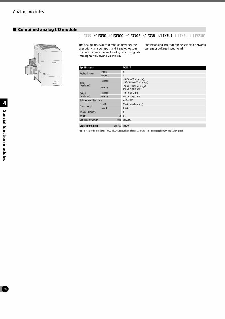
60
1
2
3
4
Special function modules
Analog modules
Combined analog I/O module ¨ FX3S þ FX3G þ FX3GC þ FX3GE þ FX3U þ FX3UC ¨ FX5U ¨ FX5UC
The analog input/output module provides the user with 4 analog inputs and 1 analog output. It serves for conversion of analog process signals into digital values, and vice versa.
For the analog inputs it can be selected between current or voltage input signal.
FX -5A2N
24 V
AD / DA
Specifications FX2N-5A
Analog channelsInputs 4Outputs 1
Input (resolution)
Voltage -10–10 V (15 bit + sign), -100–100 mV (11 bit + sign)
Current -20–20 mA (14 bit + sign), 0/4–20 mA (14 bit)
Output (resolution)
Voltage -10–10 V (12 bit)Current 0/4–20 mA (10 bit)
Fullscale overall accuracy ±0.3–1 %*
Power supply 5 V DC 70 mA (from base unit)24 V DC 90 mA
Related I/O points 8Weight kg 0.3Dimensions (WxHxD) mm 55x90x87
Order information Art. no. 153740
Note: To connect the module to a FX3UC or FX3GC base unit, an adapter FX2N-CNV-IF or a power supply FX3UC-1PS-5V is required.
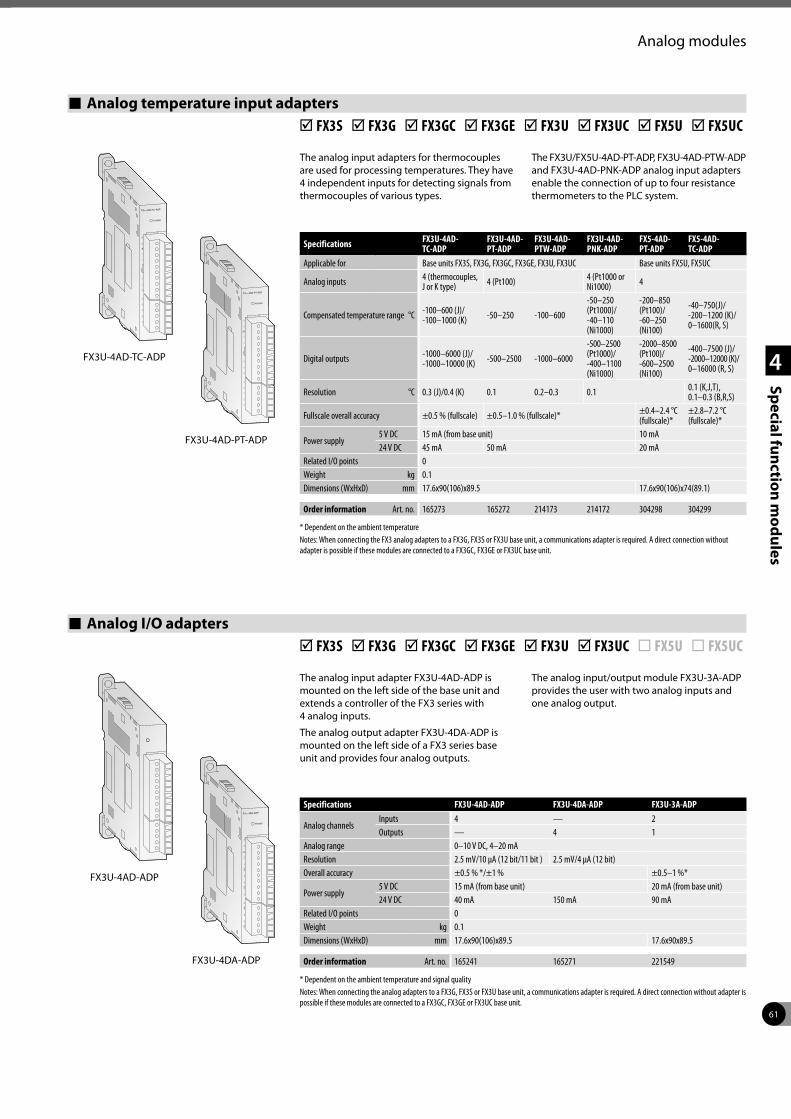
61
1
2
3
4
Special function modules
Analog modules
Specifications FX3U-4AD- TC-ADP
FX3U-4AD- PT-ADP
FX3U-4AD- PTW-ADP
FX3U-4AD- PNK-ADP
FX5-4AD- PT-ADP
FX5-4AD- TC-ADP
Applicable for Base units FX3S, FX3G, FX3GC, FX3GE, FX3U, FX3UC Base units FX5U, FX5UC
Analog inputs 4 (thermocouples, J or K type) 4 (Pt100) 4 (Pt1000 or
Ni1000) 4
Compensated temperature range °C -100–600 (J)/ -100–1000 (K) -50–250 -100–600
-50–250 (Pt1000)/ -40–110 (Ni1000)
-200–850 (Pt100)/ -60–250 (Ni100)
-40–750(J)/ -200–1200 (K)/ 0–1600(R, S)
Digital outputs -1000–6000 (J)/ -1000–10000 (K) -500–2500 -1000–6000
-500–2500 (Pt1000)/ -400–1100 (Ni1000)
-2000–8500 (Pt100)/ -600–2500 (Ni100)
-400–7500 (J)/ -2000–12000 (K)/ 0–16000 (R, S)
Resolution °C 0.3 (J)/0.4 (K) 0.1 0.2–0.3 0.1 0.1 (K,J,T), 0.1–0.3 (B,R,S)
Fullscale overall accuracy ±0.5 % (fullscale) ±0.5–1.0 % (fullscale)* ±0.4–2.4 °C (fullscale)*
±2.8–7.2 °C (fullscale)*
Power supply 5 V DC 15 mA (from base unit) 10 mA24 V DC 45 mA 50 mA 20 mA
Related I/O points 0Weight kg 0.1Dimensions (WxHxD) mm 17.6x90(106)x89.5 17.6x90(106)x74(89.1)
Order information Art. no. 165273 165272 214173 214172 304298 304299
* Dependent on the ambient temperatureNotes: When connecting the FX3 analog adapters to a FX3G, FX3S or FX3U base unit, a communications adapter is required. A direct connection without adapter is possible if these modules are connected to a FX3GC, FX3GE or FX3UC base unit.
Analog temperature input adapters þ FX3S þ FX3G þ FX3GC þ FX3GE þ FX3U þ FX3UC þ FX5U þ FX5UC
The analog input adapters for thermocouples are used for processing temperatures. They have 4 independent inputs for detecting signals from thermocouples of various types.
The FX3U/FX5U-4AD-PT-ADP, FX3U-4AD-PTW-ADP and FX3U-4AD-PNK-ADP analog input adapters enable the connection of up to four resistance thermometers to the PLC system.
Analog I/O adapters þ FX3S þ FX3G þ FX3GC þ FX3GE þ FX3U þ FX3UC ¨ FX5U ¨ FX5UC
The analog input adapter FX3U-4AD-ADP is mounted on the left side of the base unit and extends a controller of the FX3 series with 4 analog inputs.
The analog output adapter FX3U-4DA-ADP is mounted on the left side of a FX3 series base unit and provides four analog outputs.
The analog input/output module FX3U-3A-ADP provides the user with two analog inputs and one analog output.
FX3U-4AD-TC-ADP
FX3U-4AD-PT-ADP
FX3U-4AD-ADP
FX3U-4DA-ADP
Specifications FX3U-4AD-ADP FX3U-4DA-ADP FX3U-3A-ADP
Analog channelsInputs 4 — 2Outputs — 4 1
Analog range 0–10 V DC, 4–20 mAResolution 2.5 mV/10 µA (12 bit/11 bit ) 2.5 mV/4 µA (12 bit)Overall accuracy ±0.5 % */±1 % ±0.5–1 %*
Power supply 5 V DC 15 mA (from base unit) 20 mA (from base unit)24 V DC 40 mA 150 mA 90 mA
Related I/O points 0Weight kg 0.1Dimensions (WxHxD) mm 17.6x90(106)x89.5 17.6x90x89.5
Order information Art. no. 165241 165271 221549
* Dependent on the ambient temperature and signal qualityNotes: When connecting the analog adapters to a FX3G, FX3S or FX3U base unit, a communications adapter is required. A direct connection without adapter is possible if these modules are connected to a FX3GC, FX3GE or FX3UC base unit.
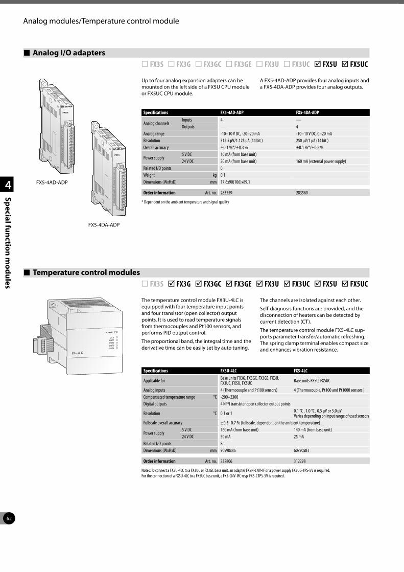
62
1
2
3
4
Special function modules
Analog modules/Temperature control module
Analog I/O adapters ¨ FX3S ¨ FX3G ¨ FX3GC ¨ FX3GE ¨ FX3U ¨ FX3UC þ FX5U þ FX5UC
Up to four analog expansion adapters can be mounted on the left side of a FX5U CPU module or FX5UC CPU module.
A FX5-4AD-ADP provides four analog inputs and a FX5-4DA-ADP provides four analog outputs.
Specifications FX5-4AD-ADP FX5-4DA-ADP
Analog channelsInputs 4 —Outputs — 4
Analog range -10–10 V DC, -20–20 mA -10–10 V DC, 0–20 mAResolution 312.5 µV/1.125 μA (14 bit ) 250 µV/1 μA (14 bit )Overall accuracy ±0.1 %*/±0.3 % ±0.1 %*/±0.2 %
Power supply 5 V DC 10 mA (from base unit) 24 V DC 20 mA (from base unit) 160 mA (external power supply)
Related I/O points 0Weight kg 0.1Dimensions (WxHxD) mm 17.6x90(106)x89.1
Order information Art. no. 283559 283560
* Dependent on the ambient temperature and signal quality
Temperature control modules ¨ FX3S þ FX3G þ FX3GC þ FX3GE þ FX3U þ FX3UC þ FX5U þ FX5UC
FX -4LC3U
OUT1OUT2
OUT3
OUT4
24 V
The temperature control module FX3U-4LC is equipped with four temperature input points and four transistor (open collector) output points. It is used to read temperature signals from thermocouples and Pt100 sensors, and performs PID output control.
The proportional band, the integral time and the derivative time can be easily set by auto tuning.
The channels are isolated against each other.
Self-diagnosis functions are provided, and the disconnection of heaters can be detected by current detection (CT).
The temperature control module FX5-4LC sup-ports parameter transfer/automatic refreshing. The spring clamp terminal enables compact size and enhances vibration resistance.
Specifications FX3U-4LC FX5-4LC
Applicable for Base units FX3G, FX3GC, FX3GE, FX3U, FX3UC, FX5U, FX5UC Base units FX5U, FX5UC
Analog inputs 4 (Thermocouple and Pt100 sensors) 4 (Thermocouple, Pt100 and Pt1000 sensors )Compensated temperature range °C -200–2300Digital outputs 4 NPN transistor open collector output points
Resolution °C 0.1 or 1 0.1 °C , 1.0 °C , 0.5 μV or 5.0 μVVaries depending on input range of used sensors
Fullscale overall accuracy ±0.3–0.7 % (fullscale, dependent on the ambient temperature)
Power supply 5 V DC 160 mA (from base unit) 140 mA (from base unit)24 V DC 50 mA 25 mA
Related I/O points 8Dimensions (WxHxD) mm 90x90x86 60x90x83
Order information Art. no. 232806 312298
Notes: To connect a FX3U-4LC to a FX3UC or FX3GC base unit, an adapter FX2N-CNV-IF or a power supply FX3UC-1PS-5V is required. For the connection of a FX5U-4LC to a FX5UC base unit, a FX5-CNV-IFC resp. FX5-C1PS-5V is required.
FX5-4AD-ADP
FX5-4DA-ADP
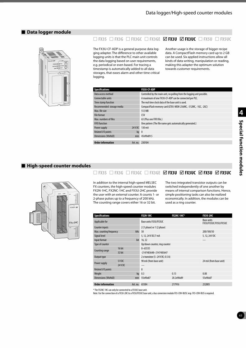
63
1
2
3
4
Special function modules
Data logger/High-speed counter modules
Data logger module ¨ FX3S ¨ FX3G ¨ FX3GC ¨ FX3GE þ FX3U þ FX3UC ¨ FX5U ¨ FX5UC
FX3U-CF-ADP CF CARD
POWER FULL
ACCESS
ACCESSON
OFFSLOTBUFFER
ERR.
The FX3U-CF-ADP is a general purpose data log-ging adapter. The difference to other available logging units is that the PLC main unit controls the data logging based on user requirements, e.g. periodical or even based. For tracing a timestamp is automatically added to all data storages, that eases alarm and other time critical logging.
Another usage is the storage of bigger recipe data. A CompactFlash memory card up to 2 GB can be used. Six applied instructions allow all kinds of data writing, manipulation or reading, making this adapter the optimum solution towards customer requirements.
Specifications FX3U-CF-ADPData access method Controlled by the main unit, no polling from the logging unit possible.Connectable units A maximum of one FX3U-CF-ADP can be connected per PLC.Time stamp function The real time clock data of the base unit is used.Recommended storage media CompactFlash memory card (GT05-MEM-256MC, -512MC, -1GC, -2GC)Max. file size 512 MBFile format CSVMax. numbers of files 63 (Plus one FIFO file.)FIFO function One pattern (The file name gets automatically generated.)Power supply 24 V DC 130 mARelated I/O points kg 0Dimensions (WxHxD) mm 45x90x89.5
Order information Art. no. 230104
High-speed counter modules ¨ FX3S ¨ FX3G ¨ FX3GC ¨ FX3GE þ FX3U þ FX3UC þ FX5U þ FX5UC
In addition to the internal high-speed MELSEC FX counters, the high-speed counter modules FX2N-1HC, FX2NC-1HC and FX3U-2HC provide the user with an external counter. It counts 1- or 2-phase pulses up to a frequency of 200 kHz. The counting range covers either 16 or 32 bit.
The two integrated transistor outputs can be switched independently of one another by means of internal comparison functions. Hence, simple positioning tasks can also be realized economically. In addition, the modules can be used as a ring counter.
Specifications FX2N-1HC FX2NC-1HC* FX3U-2HC
Applicable for Base units FX3U/FX3UC Base units FX3U/FX3UC/FX5U/FX5UC
Counter inputs 2 (1 phase) or 1 (2 phase)Max. counting frequency kHz 50 200/100/50Signal level 5, 12, 24 V DC/7 mA 5, 12, 24 V DCInput format bit 16, 32 —Type of counter Up/down counter, ring counter
Counting range16 bit 0–6553532 bit -2147483648–2147483647
Output type 2 x transistor (5–24 V DC; 0.5 A)
Power supply 5 V DC 90 mA (from base unit) 24 mA (from base unit)24 V DC —
Related I/O points 8Weight kg 0.3 0.13 0.08Dimensions (WxHxD) mm 55x90x87 20.2x90x89 55x90x87
Order information Art. no. 65584 217916 232805
* The FX2NC 1HC can only be connected to a FX3UC base unit. Note: For the connection of a FX3U-2HC to a FX5U/FX5UC base unit, a bus conversion module FX5-CNV-BUSC resp. FX5-CNV-BUS is required.

64
1
2
3
4
Special function modules
High-speed counter/Positioning modules
High-speed counter adapters ¨ FX3S ¨ FX3G ¨ FX3GC ¨ FX3GE þ FX3U ¨ FX3UC ¨ FX5U ¨ FX5UC
These adapter modules allow direct processing of positioning application data.
The FX3U-4HSX-ADP provide high-speed counter inputs up to 200 kHz while the FX3U-2HSY-ADP delivers 2 channels of pulse train outputs up to 200 kHz.
FX3U-4HSX-ADP
FX3U-2HSY-ADP
Specifications FX3U-4HSX-ADP FX3U-2HSY-ADPMaximum connectivity 2
Counter Inputs 4 —Outputs — 2
Max. counting frequency
Inputs kHz1 ch 1 input or 1 ch 2 inputs: 200 2 ch 2 inputs: 100
—
Outputs kHz — 200
Input format Differential line receiver (AM26C32 is suitable) Photocoupler isolation on inputs —
Output format —Differential line driver (AM26C31 is suitable) Normal rotation pulse train, reverse pulse train or pulse train + direction signal
Maximum cable length m 10Input potential 5 V DC —Output load — less than 25 mA
Power supply 5 V DC 30 mA (from base unit)24 V DC 30 mA (from base unit) 60 mA (from base unit)
Related I/O points 0Weight kg 0.08Dimensions (WxHxD) mm 17.6x90(106)x89.5
Order information Art. no. 165274 165275
Note: The adapters FX3U-m-ADP can only be used with the FX3U and they require a function extension board.
Single-axis positioning modules ¨ FX3S ¨ FX3G ¨ FX3GC ¨ FX3GE þ FX3U þ FX3UC þ FX5U þ FX5UC
The positioning modules FX3U-1PG, FX2N-10PG and FX5-20PG-P/D are extremely efficient positioning modules for controlling either step drives or servo drives (by external regulator) with a pulse chain. The FX5-20PG-D is a differen-tial driver type with a maximum output pulse of 5 M pulse/s.
They are very suitable for achieving accurate positioning in combination with the MELSEC FX series.
The configuration and allocation of the posi-tion data are carried out directly via the PLC program. A very wide range of manual and automatic functions are available to the user.
Specifications FX3U-1PG FX2N-10PG FX5-20PG-D FX5-20PG-P
Applicable for Base units FX3U/FX3UC/ FX5U/FX5UC Base units FX3U/FX3UC Base units FX5U/FX5UC
Accessible axes 1 2Output frequency Pulses/s 10–200 000 1–1 000 000 5 000 000 1–200 000
Signal level for digital inputs 24 V DC/40 mA 5 V DC/100 mA; 24 V DC/70 mA
5 V DC;24 V DC 24 V DC/5 mA
Power supply 5 V DC 150 mA
(from base unit)120 mA (from base unit) —
24 V DC — 165 mA(external power supply)
120 mA (from base unit)
Related I/O points 8Weight kg 0.3 0.2Dimensions (WxHxD) mm 43x90x87 50x90x83
Order information Art. no. 259298 140113 409825 312301
Note: For the connection of a FX3U-1PG to a FX5U/FX5UC base unit, a bus conversion module FX5-CNV-BUSC resp. FX5-CNV-BUS is required.
POWERRUN
ERROR
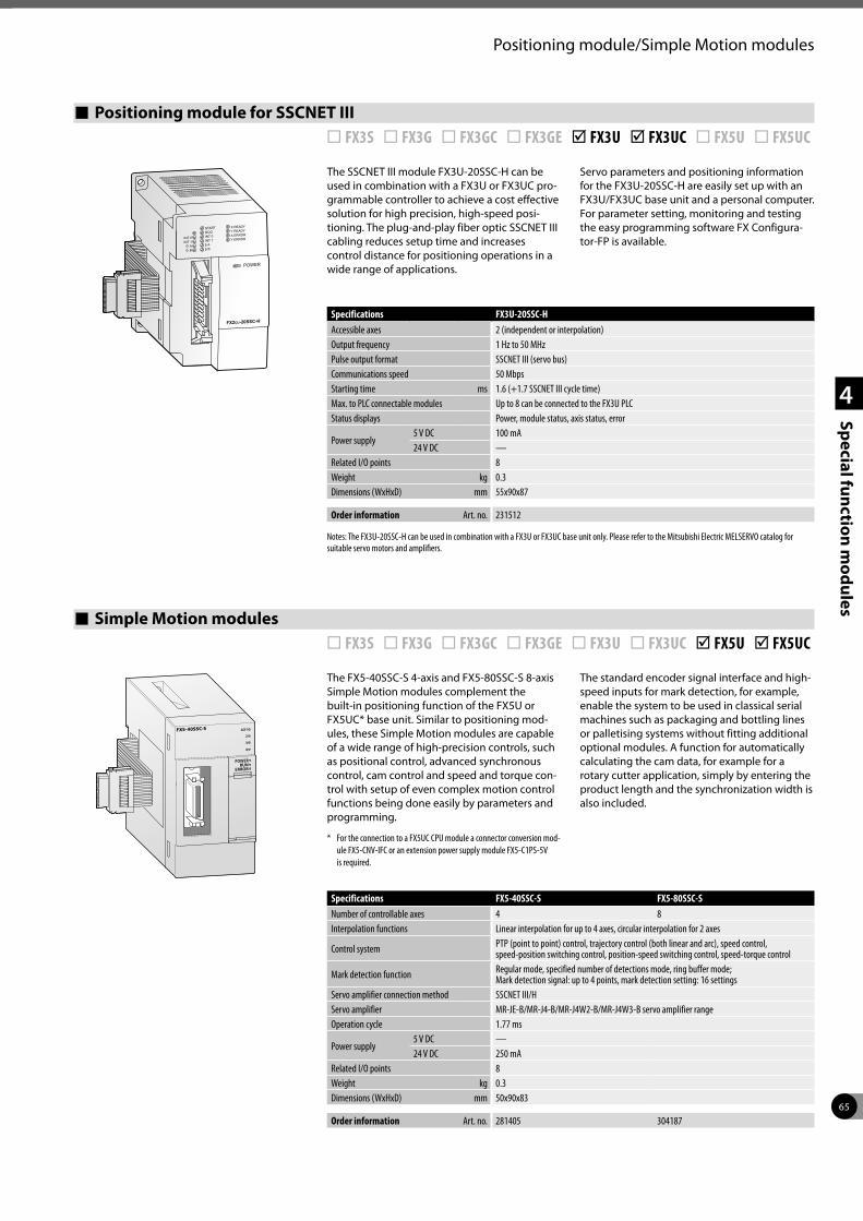
65
1
2
3
4
Special function modules
Positioning module/Simple Motion modules
Positioning module for SSCNET III ¨ FX3S ¨ FX3G ¨ FX3GC ¨ FX3GE þ FX3U þ FX3UC ¨ FX5U ¨ FX5UC
The SSCNET III module FX3U-20SSC-H can be used in combination with a FX3U or FX3UC pro-grammable controller to achieve a cost effective solution for high precision, high-speed posi-tioning. The plug-and-play fiber optic SSCNET III cabling reduces setup time and increases control distance for positioning operations in a wide range of applications.
Servo parameters and positioning information for the FX3U-20SSC-H are easily set up with an FX3U/FX3UC base unit and a personal computer. For parameter setting, monitoring and testing the easy programming software FX Configura-tor-FP is available.
Specifications FX3U-20SSC-HAccessible axes 2 (independent or interpolation)Output frequency 1 Hz to 50 MHzPulse output format SSCNET III (servo bus)Communications speed 50 MbpsStarting time ms 1.6 (+1.7 SSCNET III cycle time)Max. to PLC connectable modules Up to 8 can be connected to the FX3U PLCStatus displays Power, module status, axis status, error
Power supply 5 V DC 100 mA24 V DC —
Related I/O points 8Weight kg 0.3Dimensions (WxHxD) mm 55x90x87
Order information Art. no. 231512
Notes: The FX3U-20SSC-H can be used in combination with a FX3U or FX3UC base unit only. Please refer to the Mitsubishi Electric MELSERVO catalog for suitable servo motors and amplifiers.
Simple Motion modules ¨ FX3S ¨ FX3G ¨ FX3GC ¨ FX3GE ¨ FX3U ¨ FX3UC þ FX5U þ FX5UC
The FX5-40SSC-S 4-axis and FX5-80SSC-S 8-axis Simple Motion modules complement the built-in positioning function of the FX5U or FX5UC* base unit. Similar to positioning mod-ules, these Simple Motion modules are capable of a wide range of high-precision controls, such as positional control, advanced synchronous control, cam control and speed and torque con-trol with setup of even complex motion control functions being done easily by parameters and programming.
* For the connection to a FX5UC CPU module a connector conversion mod-ule FX5-CNV-IFC or an extension power supply module FX5-C1PS-5V is required.
The standard encoder signal interface and high-speed inputs for mark detection, for example, enable the system to be used in classical serial machines such as packaging and bottling lines or palletising systems without fitting additional optional modules. A function for automatically calculating the cam data, for example for a rotary cutter application, simply by entering the product length and the synchronization width is also included.
Specifications FX5-40SSC-S FX5-80SSC-SNumber of controllable axes 4 8Interpolation functions Linear interpolation for up to 4 axes, circular interpolation for 2 axes
Control system PTP (point to point) control, trajectory control (both linear and arc), speed control, speed-position switching control, position-speed switching control, speed-torque control
Mark detection function Regular mode, specified number of detections mode, ring buffer mode;Mark detection signal: up to 4 points, mark detection setting: 16 settings
Servo amplifier connection method SSCNET III/HServo amplifier MR-JE-B/MR-J4-B/MR-J4W2-B/MR-J4W3-B servo amplifier rangeOperation cycle 1.77 ms
Power supply 5 V DC —24 V DC 250 mA
Related I/O points 8Weight kg 0.3Dimensions (WxHxD) mm 50x90x83
Order information Art. no. 281405 304187
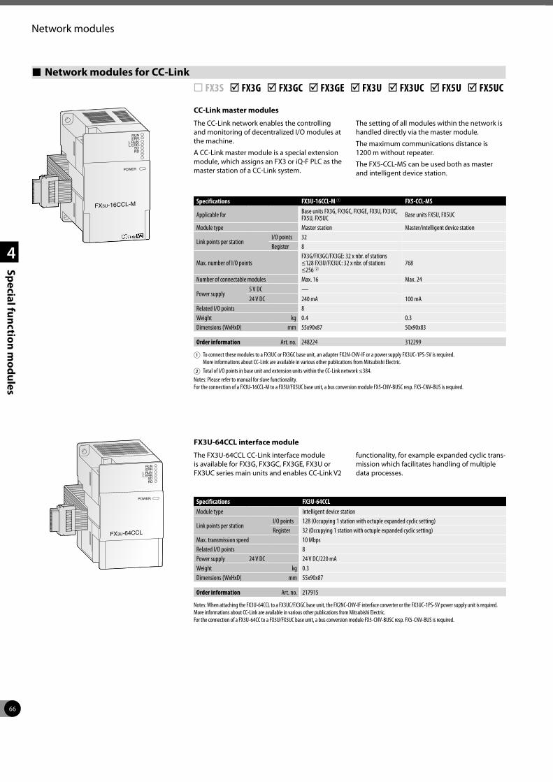
66
1
2
3
4
Special function modules
Network modules
Network modules for CC-Link ¨ FX3S þ FX3G þ FX3GC þ FX3GE þ FX3U þ FX3UC þ FX5U þ FX5UC
CC-Link master modules
The CC-Link network enables the controlling and monitoring of decentralized I/O modules at the machine.
A CC-Link master module is a special extension module, which assigns an FX3 or iQ-F PLC as the master station of a CC-Link system.
The setting of all modules within the network is handled directly via the master module.
The maximum communications distance is 1200 m without repeater.
The FX5-CCL-MS can be used both as master and intelligent device station.
FX3U-64CCL interface module
The FX3U-64CCL CC-Link interface module is available for FX3G, FX3GC, FX3GE, FX3U or FX3UC series main units and enables CC-Link V2
functionality, for example expanded cyclic trans-mission which facilitates handling of multiple data processes.
Specifications FX3U-16CCL-M 1 FX5-CCL-MS
Applicable for Base units FX3G, FX3GC, FX3GE, FX3U, FX3UC, FX5U, FX5UC Base units FX5U, FX5UC
Module type Master station Master/intelligent device station
Link points per stationI/O points 32Register 8
Max. number of I/O pointsFX3G/FX3GC/FX3GE: 32 x nbr. of stations ≤128 FX3U/FX3UC: 32 x nbr. of stations ≤256 2
768
Number of connectable modules Max. 16 Max. 24
Power supply 5 V DC —24 V DC 240 mA 100 mA
Related I/O points 8Weight kg 0.4 0.3Dimensions (WxHxD) mm 55x90x87 50x90x83
Order information Art. no. 248224 312299
1 To connect these modules to a FX3UC or FX3GC base unit, an adapter FX2N-CNV-IF or a power supply FX3UC-1PS-5V is required. More informations about CC-Link are available in various other publications from Mitsubishi Electric.
2 Total of I/O points in base unit and extension units within the CC-Link network ≤384.Notes: Please refer to manual for slave functionality. For the connection of a FX3U-16CCL-M to a FX5U/FX5UC base unit, a bus conversion module FX5-CNV-BUSC resp. FX5-CNV-BUS is required.
Specifications FX3U-64CCLModule type Intelligent device station
Link points per stationI/O points 128 (Occupying 1 station with octuple expanded cyclic setting)Register 32 (Occupying 1 station with octuple expanded cyclic setting)
Max. transmission speed 10 MbpsRelated I/O points 8Power supply 24 V DC 24 V DC/220 mAWeight kg 0.3Dimensions (WxHxD) mm 55x90x87
Order information Art. no. 217915
Notes: When attaching the FX3U-64CCL to a FX3UC/FX3GC base unit, the FX2NC-CNV-IF interface converter or the FX3UC-1PS-5V power supply unit is required. More informations about CC-Link are available in various other publications from Mitsubishi Electric. For the connection of a FX3U-64CC to a FX5U/FX5UC base unit, a bus conversion module FX5-CNV-BUSC resp. FX5-CNV-BUS is required.
FX3U-16CCL-M
RUN
L RUNL ERR.
SDRD
ERR.
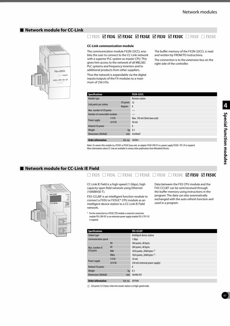
67
1
2
3
4
Special function modules
Network modules
Network module for CC-Link ¨ FX3S þ FX3G þ FX3GC þ FX3GE þ FX3U þ FX3UC ¨ FX5U ¨ FX5UC
CC-Link communication module
The communication module FX2N-32CCL ena-bles the user to connect to the CC-Link network with a superior PLC system as master CPU. This gives him access to the network of all MELSEC PLC systems and frequency inverters and to additional products from other suppliers.
Thus the network is expandable via the digital inputs/outputs of the FX modules to a maxi-mum of 256 I/Os.
The buffer memory of the FX2N-32CCL is read and written by FROM/TO instructions.
The connection is to the extension bus on the right side of the controller.
LRUN • LERR • RD • SD
FX2N-32CCL
Specifications FX2N-32CCLModule type Remote station
Link points per stationI/O points 32Register 8
Max. number of I/O points —Number of connectable modules —
Power supply 5 V DC Max. 130 mA (from base unit)24 V DC 50 mA
Related I/O points 8Weight kg 0.3Dimensions (WxHxD) mm 43x90x87
Order information Art. no. 102961
Notes: To connect this module to a FX3UC or FX3GC base unit, an adapter FX2N-CNV-IF or a power supply FX3UC-1PS-5V is required. More informations about CC-Link are available in various other publications from Mitsubishi Electric.
Network module for CC-Link IE Field ¨ FX3S ¨ FX3G ¨ FX3GC ¨ FX3GE ¨ FX3U ¨ FX3UC þ FX5U þ FX5UC
CC-Link IE Field is a high-speed (1 Gbps), high capacity open field network using Ethernet (1000BASE-T).
FX5-CCLIEF is an intelligent function module to connect a FX5U or FX5UC* CPU module as an intelligent device station to a CC-Link IE Field network.
* For the connection to a FX5UC CPU module a connector conversion module FX5-CNV-IFC or an extension power supply module FX5-C1PS-5V is required.
Data between the FX5 CPU module and the FX5-CCLIEF can be sent/received through the buffer memory using instructions in the program. The data can also automatically exchanged with the auto refresh function and used in a program.
Specifications FX5-CCLIEFStation type Intelligent device stationCommunication speed 1 Gbps
Max. number of I/O points
RX 384 points, 48 bytesRY 384 points, 48 bytesRWr 1024 points, 2048 bytes a
RWw 1024 points, 2048 bytes a
Power supply 5 V DC 10 mA24 V DC 230 mA (external power supply)
Related I/O points 8Weight kg 0.3Dimensions (WxHxD) mm 50x90x103
Order information Art. no. 297444
1 256 points (512 bytes) when the master station is in high-speed mode.
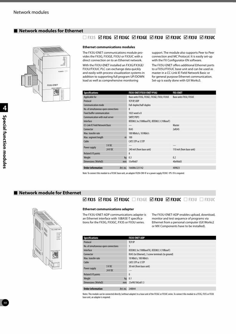
68
1
2
3
4
Special function modules
Network modules
Network modules for Ethernet ¨ FX3S þ FX3G þ FX3GC þ FX3GE þ FX3U þ FX3UC þ FX5U þ FX5UC
Ethernet communications modules
The FX3U-ENET communications module pro-vides the FX3G, FX3GE, FX3U or FX3UC with a direct connection on to an Ethernet network.
With the FX3U-ENET installed an FX3G/FX3GE/FX3U/FX3UC PLC can exchange data quickly and easily with process visualization systems in addition to supporting full program UP/DOWN load as well as comprehensive monitoring
support. The module also supports Peer to Peer connection and MC Protocol. It is easily set-up with the FX Configurator-EN software.
The FX5U-ENET offers additional Ethernet ports to a FX5U/FX5UC base unit and can be used as master in a CC-Link IE Field Network Basic or for general purpose Ethernet communication. Set-up is easily done with GX Works3.
POWER
RUN
C1
INIT.
C2
100M
C3
SD
C4
RD
C5
ERR.
C6
COM.ERR.
C7C8
10BASE-T/100BASE-TX
FX3U-ENET
Specifications FX3U-ENET/FX3U-ENET-P502 FX5-ENETApplicable for Base units FX3G, FX3GC, FX3GE, FX3U, FX3UC Base units FX5U, FX5UCProtocol TCP/IP, UDPCommunication mode Full-duplex/half-duplexNo. of simultaneous open connections 8Fixed buffer communication 1023 word x 8Communication with mail server SMTP, POP3Interface IEEE802.3u (100BaseTX), IEEE802.3 (10BaseT)CC-Link IE Field Network Basic — MasterConnector RJ45 2xRJ45Max. transfer rate 100 Mbits/s, 10 Mbit/sMax. segment length m 100Cable CAT5 STP or 3 STP
Power supply5 V DC — —24 V DC 240 mA (from base unit) 110 mA (from base unit)
Related I/O points 8Weight kg 0.3 0.2Dimensions (WxHxD) mm 55x90x87 40x90x83
Order information Art. no. 166086/225142 409823
Note: To connect this module to a FX3UC base unit, an adapter FX2N-CNV-IF or a power supply FX3UC-1PS-5V is required.
Network module for Ethernet þ FX3S þ FX3G þ FX3GC ¨ FX3GE þ FX3U þ FX3UC ¨ FX5U ¨ FX5UC
Ethernet communications adapter
The FX3U-ENET-ADP communications adapter is an Ethernet interface with 10BASE-T specifica-tions for the FX3G, FX3GC, FX3S or FX3U series.
The FX3U-ENET-ADP enables upload, download, monitor and test sequence of programs via Ethernet from a personal computer (GX Works2 or MX Components have to be installed).
Specifications FX3U-ENET-ADPProtocol TCP/IPNo. of simultaneous open connections 1Interface IEEE802.3u (100BaseTX), IEEE802.3 (10BaseT)Connector RJ45 (to Ethernet), 3 screw terminals (to ground)Max. transfer rate 10 Mbit/s, 100 Mbit/sCable CAT5 STP or 3 STP
Power supply5 V DC 30 mA (from base unit)24 V DC —
Related I/O points 0Weight kg 0.1Dimensions (WxHxD) mm 23x90(106)x81.5
Order information Art. no. 248844
Notes: This module can be connected directly (without adapter) to a base unit of the FX3GC or FX3UC series. To connect this module to a FX3G, FX3S or FX3U base unit, an adapter is required.
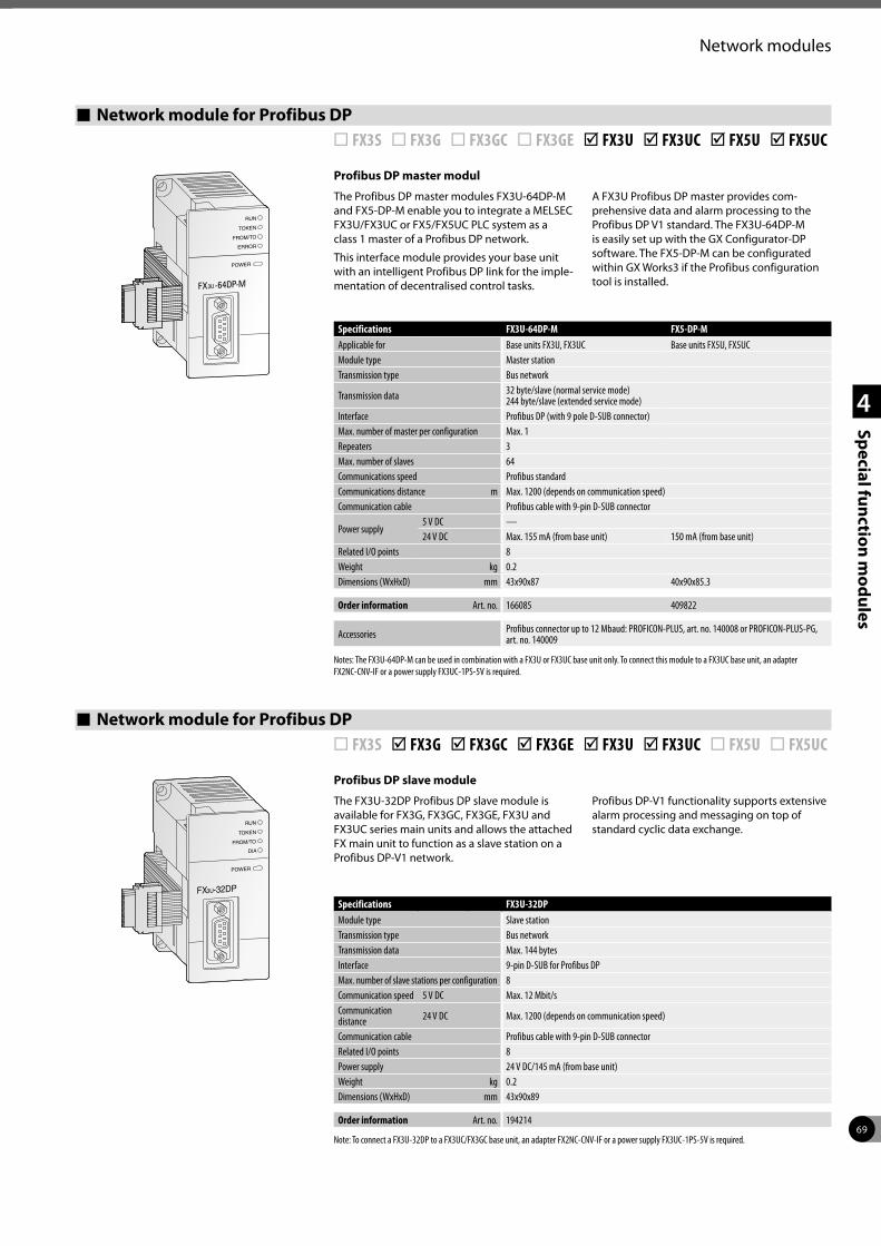
69
1
2
3
4
Special function modules
Network modules
Network module for Profibus DP ¨ FX3S ¨ FX3G ¨ FX3GC ¨ FX3GE þ FX3U þ FX3UC þ FX5U þ FX5UC
Profibus DP master modul
The Profibus DP master modules FX3U-64DP-M and FX5-DP-M enable you to integrate a MELSEC FX3U/FX3UC or FX5/FX5UC PLC system as a class 1 master of a Profibus DP network.
This interface module provides your base unit with an intelligent Profibus DP link for the imple-mentation of decentralised control tasks.
A FX3U Profibus DP master provides com-prehensive data and alarm processing to the Profibus DP V1 standard. The FX3U-64DP-M is easily set up with the GX Configurator-DP software. The FX5-DP-M can be configurated within GX Works3 if the Profibus configuration tool is installed.3UFX -64DP-M
ERROR
FROM/TO
TOKEN
RUN
POWER
Specifications FX3U-64DP-M FX5-DP-MApplicable for Base units FX3U, FX3UC Base units FX5U, FX5UCModule type Master stationTransmission type Bus network
Transmission data 32 byte/slave (normal service mode) 244 byte/slave (extended service mode)
Interface Profibus DP (with 9 pole D-SUB connector) Max. number of master per configuration Max. 1Repeaters 3Max. number of slaves 64Communications speed Profibus standardCommunications distance m Max. 1200 (depends on communication speed)Communication cable Profibus cable with 9-pin D-SUB connector
Power supply5 V DC —24 V DC Max. 155 mA (from base unit) 150 mA (from base unit)
Related I/O points 8Weight kg 0.2Dimensions (WxHxD) mm 43x90x87 40x90x85.3
Order information Art. no. 166085 409822
Accessories Profibus connector up to 12 Mbaud: PROFICON-PLUS, art. no. 140008 or PROFICON-PLUS-PG, art. no. 140009
Notes: The FX3U-64DP-M can be used in combination with a FX3U or FX3UC base unit only. To connect this module to a FX3UC base unit, an adapter FX2NC-CNV-IF or a power supply FX3UC-1PS-5V is required.
Network module for Profibus DP ¨ FX3S þ FX3G þ FX3GC þ FX3GE þ FX3U þ FX3UC ¨ FX5U ¨ FX5UC
Profibus DP slave module
The FX3U-32DP Profibus DP slave module is available for FX3G, FX3GC, FX3GE, FX3U and FX3UC series main units and allows the attached FX main unit to function as a slave station on a Profibus DP-V1 network.
Profibus DP-V1 functionality supports extensive alarm processing and messaging on top of standard cyclic data exchange.
Specifications FX3U-32DPModule type Slave stationTransmission type Bus networkTransmission data Max. 144 bytesInterface 9-pin D-SUB for Profibus DPMax. number of slave stations per configuration 8Communication speed 5 V DC Max. 12 Mbit/sCommunication distance 24 V DC Max. 1200 (depends on communication speed)
Communication cable Profibus cable with 9-pin D-SUB connectorRelated I/O points 8Power supply 24 V DC/145 mA (from base unit)Weight kg 0.2Dimensions (WxHxD) mm 43x90x89
Order information Art. no. 194214
Note: To connect a FX3U-32DP to a FX3UC/FX3GC base unit, an adapter FX2NC-CNV-IF or a power supply FX3UC-1PS-5V is required.
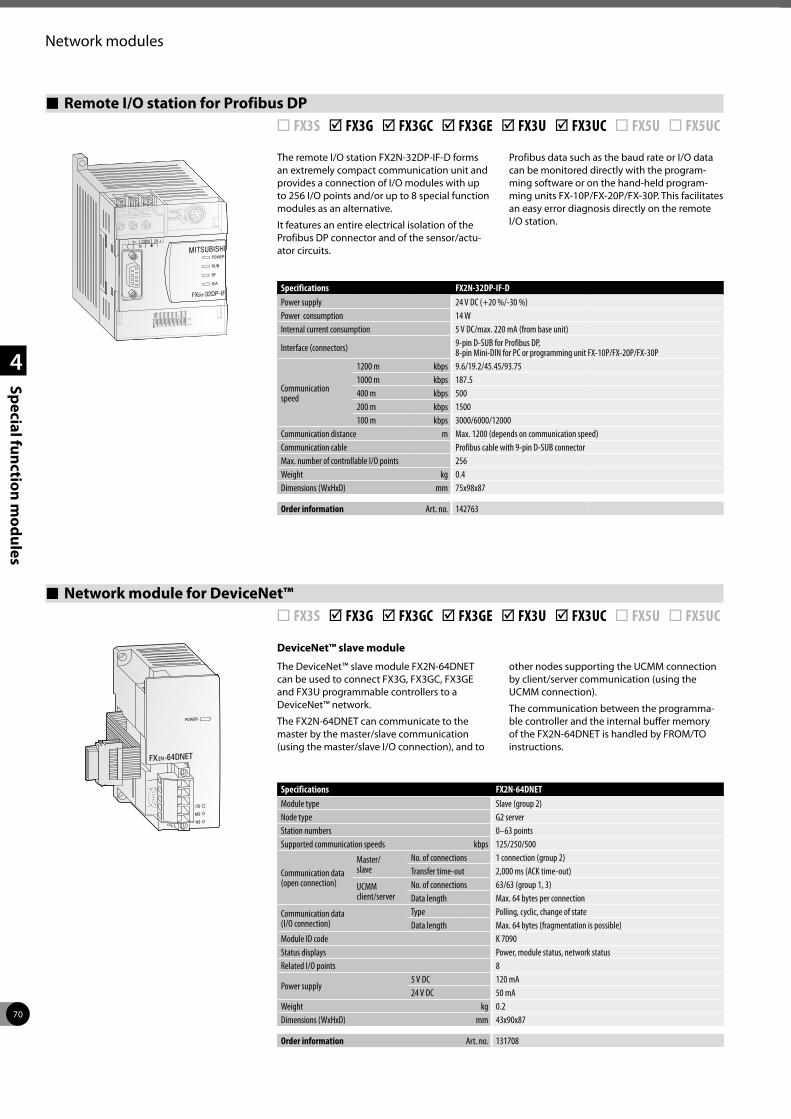
70
1
2
3
4
Special function modules
Network modules
Remote I/O station for Profibus DP ¨ FX3S þ FX3G þ FX3GC þ FX3GE þ FX3U þ FX3UC ¨ FX5U ¨ FX5UC
The remote I/O station FX2N-32DP-IF-D forms an extremely compact communication unit and provides a connection of I/O modules with up to 256 I/O points and/or up to 8 special function modules as an alternative.
It features an entire electrical isolation of the Profibus DP connector and of the sensor/actu-ator circuits.
Profibus data such as the baud rate or I/O data can be monitored directly with the program-ming software or on the hand-held program-ming units FX-10P/FX-20P/FX-30P. This facilitates an easy error diagnosis directly on the remote I/O station.
MITSUBISHICOM 24 +
L N
FX2N-32DP-IF
POWER
RUN
STOP
RUN
BF
DIA
ON
OFF
64 32 16 8 4 2 1
Specifications FX2N-32DP-IF-DPower supply 24 V DC (+20 %/-30 %)Power consumption 14 WInternal current consumption 5 V DC/max. 220 mA (from base unit)
Interface (connectors) 9-pin D-SUB for Profibus DP, 8-pin Mini-DIN for PC or programming unit FX-10P/FX-20P/FX-30P
Communicationspeed
1200 m kbps 9.6/19.2/45.45/93.751000 m kbps 187.5400 m kbps 500200 m kbps 1500100 m kbps 3000/6000/12000
Communication distance m Max. 1200 (depends on communication speed)Communication cable Profibus cable with 9-pin D-SUB connectorMax. number of controllable I/O points 256Weight kg 0.4Dimensions (WxHxD) mm 75x98x87
Order information Art. no. 142763
Network module for DeviceNet™ ¨ FX3S þ FX3G þ FX3GC þ FX3GE þ FX3U þ FX3UC ¨ FX5U ¨ FX5UC
DeviceNet™ slave module
The DeviceNet™ slave module FX2N-64DNET can be used to connect FX3G, FX3GC, FX3GE and FX3U programmable controllers to a DeviceNet™ network.
The FX2N-64DNET can communicate to the master by the master/slave communication (using the master/slave I/O connection), and to
other nodes supporting the UCMM connection by client/server communication (using the UCMM connection).
The communication between the programma-ble controller and the internal buffer memory of the FX2N-64DNET is handled by FROM/TO instructions.
Specifications FX2N-64DNET Module type Slave (group 2)Node type G2 serverStation numbers 0–63 pointsSupported communication speeds kbps 125/250/500
Communication data (open connection)
Master/ slave
No. of connections 1 connection (group 2)Transfer time-out 2,000 ms (ACK time-out)
UCMM client/server
No. of connections 63/63 (group 1, 3)Data length Max. 64 bytes per connection
Communication data (I/O connection)
Type Polling, cyclic, change of stateData length Max. 64 bytes (fragmentation is possible)
Module ID code K 7090Status displays Power, module status, network statusRelated I/O points 8
Power supply5 V DC 120 mA24 V DC 50 mA
Weight kg 0.2Dimensions (WxHxD) mm 43x90x87
Order information Art. no. 131708
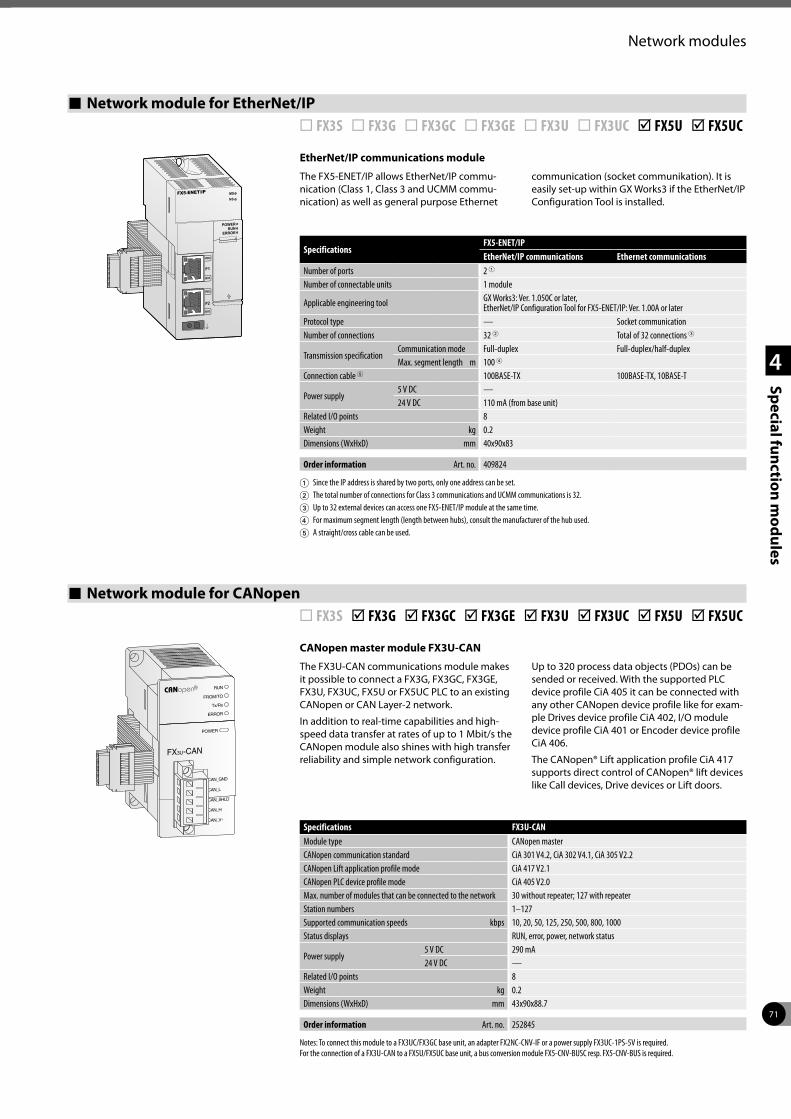
71
1
2
3
4
Special function modules
Network modules
Network module for CANopen ¨ FX3S þ FX3G þ FX3GC þ FX3GE þ FX3U þ FX3UC þ FX5U þ FX5UC
CANopen master module FX3U-CAN
The FX3U-CAN communications module makes it possible to connect a FX3G, FX3GC, FX3GE, FX3U, FX3UC, FX5U or FX5UC PLC to an existing CANopen or CAN Layer-2 network.
In addition to real-time capabilities and high-speed data transfer at rates of up to 1 Mbit/s the CANopen module also shines with high transfer reliability and simple network configuration.
Up to 320 process data objects (PDOs) can be sended or received. With the supported PLC device profile CiA 405 it can be connected with any other CANopen device profile like for exam-ple Drives device profile CiA 402, I/O module device profile CiA 401 or Encoder device profile CiA 406.
The CANopen® Lift application profile CiA 417 supports direct control of CANopen® lift devices like Call devices, Drive devices or Lift doors.
Specifications FX3U-CANModule type CANopen masterCANopen communication standard CiA 301 V4.2, CiA 302 V4.1, CiA 305 V2.2CANopen Lift application profile mode CiA 417 V2.1CANopen PLC device profile mode CiA 405 V2.0Max. number of modules that can be connected to the network 30 without repeater; 127 with repeaterStation numbers 1–127Supported communication speeds kbps 10, 20, 50, 125, 250, 500, 800, 1000Status displays RUN, error, power, network status
Power supply5 V DC 290 mA24 V DC —
Related I/O points 8Weight kg 0.2Dimensions (WxHxD) mm 43x90x88.7
Order information Art. no. 252845
Notes: To connect this module to a FX3UC/FX3GC base unit, an adapter FX2NC-CNV-IF or a power supply FX3UC-1PS-5V is required. For the connection of a FX3U-CAN to a FX5U/FX5UC base unit, a bus conversion module FX5-CNV-BUSC resp. FX5-CNV-BUS is required.
AN_GND
AN_L
AN_SHLD
AN_H
AN_V+
FX3U-CAN
ERROR
Tx/Rx
FROM/TO
RUN
POWER
Network module for EtherNet/IP ¨ FX3S ¨ FX3G ¨ FX3GC ¨ FX3GE ¨ FX3U ¨ FX3UC þ FX5U þ FX5UC
EtherNet/IP communications module
The FX5-ENET/IP allows EtherNet/IP commu-nication (Class 1, Class 3 and UCMM commu-nication) as well as general purpose Ethernet
communication (socket communikation). It is easily set-up within GX Works3 if the EtherNet/IP Configuration Tool is installed.
SpecificationsFX5-ENET/IPEtherNet/IP communications Ethernet communications
Number of ports 2 1
Number of connectable units 1 module
Applicable engineering tool GX Works3: Ver. 1.050C or later,EtherNet/IP Configuration Tool for FX5-ENET/IP: Ver. 1.00A or later
Protocol type — Socket communicationNumber of connections 32 2 Total of 32 connections 3
Transmission specificationCommunication mode Full-duplex Full-duplex/half-duplexMax. segment length m 100 4
Connection cable 5 100BASE-TX 100BASE-TX, 10BASE-T
Power supply5 V DC —24 V DC 110 mA (from base unit)
Related I/O points 8Weight kg 0.2Dimensions (WxHxD) mm 40x90x83
Order information Art. no. 409824
1 Since the IP address is shared by two ports, only one address can be set.2 The total number of connections for Class 3 communications and UCMM communications is 32.3 Up to 32 external devices can access one FX5-ENET/IP module at the same time.4 For maximum segment length (length between hubs), consult the manufacturer of the hub used.5 A straight/cross cable can be used.
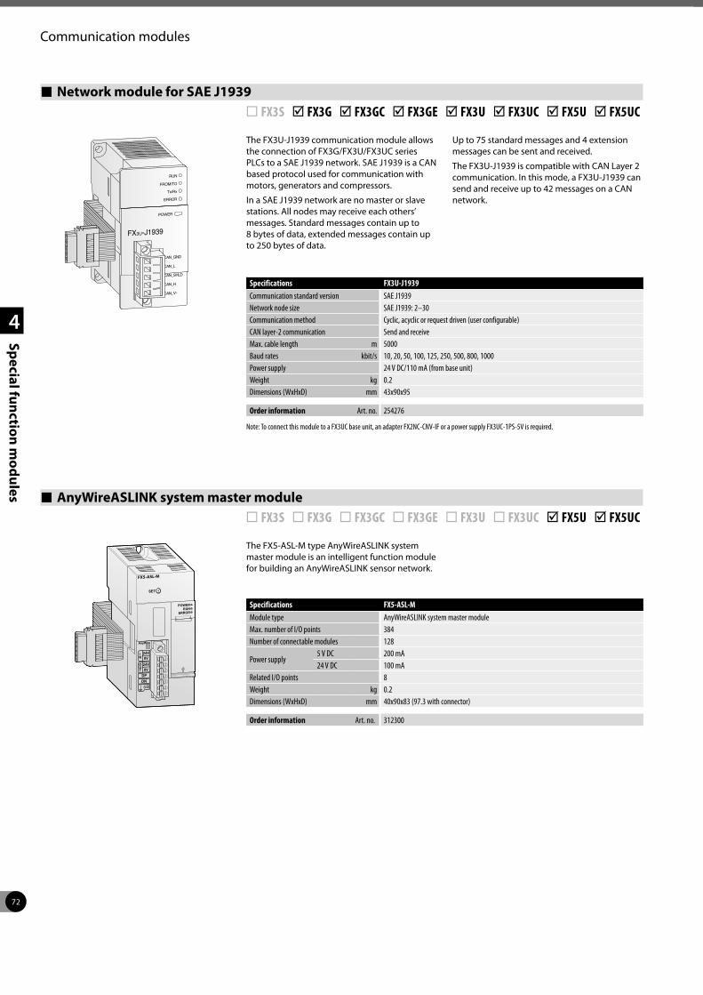
72
1
2
3
4
Special function modules
Communication modules
AnyWireASLINK system master module ¨ FX3S ¨ FX3G ¨ FX3GC ¨ FX3GE ¨ FX3U ¨ FX3UC þ FX5U þ FX5UC
The FX5-ASL-M type AnyWireASLINK system master module is an intelligent function module for building an AnyWireASLINK sensor network.
Specifications FX5-ASL-MModule type AnyWireASLINK system master moduleMax. number of I/O points 384Number of connectable modules 128
Power supply 5 V DC 200 mA24 V DC 100 mA
Related I/O points 8Weight kg 0.2Dimensions (WxHxD) mm 40x90x83 (97.3 with connector)
Order information Art. no. 312300
SET
POWERRUN
ERROR
AnyWire
24V0V
IN
24V0V
DPDN
(LG)
OUT
The FX3U-J1939 communication module allows the connection of FX3G/FX3U/FX3UC series PLCs to a SAE J1939 network. SAE J1939 is a CAN based protocol used for communication with motors, generators and compressors.
In a SAE J1939 network are no master or slave stations. All nodes may receive each others’ messages. Standard messages contain up to 8 bytes of data, extended messages contain up to 250 bytes of data.
Up to 75 standard messages and 4 extension messages can be sent and received.
The FX3U-J1939 is compatible with CAN Layer 2 communication. In this mode, a FX3U-J1939 can send and receive up to 42 messages on a CAN network.
Network module for SAE J1939 ¨ FX3S þ FX3G þ FX3GC þ FX3GE þ FX3U þ FX3UC þ FX5U þ FX5UC
Specifications FX3U-J1939Communication standard version SAE J1939Network node size SAE J1939: 2–30Communication method Cyclic, acyclic or request driven (user configurable)CAN layer-2 communication Send and receiveMax. cable length m 5000Baud rates kbit/s 10, 20, 50, 100, 125, 250, 500, 800, 1000Power supply 24 V DC/110 mA (from base unit)Weight kg 0.2Dimensions (WxHxD) mm 43x90x95
Order information Art. no. 254276
Note: To connect this module to a FX3UC base unit, an adapter FX2NC-CNV-IF or a power supply FX3UC-1PS-5V is required.
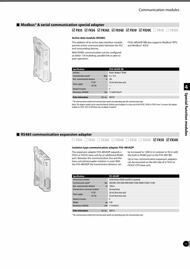
73
1
2
3
4
Special function modules
Communication modules
Modbus® & serial communication special adapter þ FX3S þ FX3G þ FX3GC þ FX3GE þ FX3U þ FX3UC ¨ FX5U ¨ FX5UC
Active data module (RS485)
The addition of an active data interface module permits active communication between the PLC and surrounding devices.
With RS485 communication can be configured as either 1:N multidrop, parallel link or peer to peer operation.
FX3U-485ADP-MB also supports Modbus®/RTU and Modbus® ASCII.
Specifications FX3U-485ADP-MBInterface RS485; Modbus® RS485Communication speed* kbps 0.3–19.2Max. communication distance m 500
Power supply 5 V DC 20 mA (from base unit)24 V DC —
Related I/O points 0Dimensions (WxHxD) mm 17.6x90(106)x74
Order information Art. no. 206191
* The communication method and communication speed vary depending upon the communication type.Notes: This adapter module can be connected directly (without special adapter) to a base unit of the FX3GC, FX3GE or FX3UC series. To connect this adapter module to a FX3G, FX3S or FX3U base unit, an adapter is required.
RS485 communication expansion adapter ¨ FX3S ¨ FX3G ¨ FX3GC ¨ FX3GE ¨ FX3U ¨ FX3UC þ FX5U þ FX5UC
Isolation type communication adapter FX5-485ADP
The expansion adapter FX5-485ADP expands a FX5U or FX5UC base unit by an additional RS485 port. Between the communication line and the base unit photocoupler isolation is used. With the FX5-485ADP the transmission distance can
be increased to 1200 m in contrast to 50 m with the built-in RS485 port or the FX5-485-BD.
Up to two communication expansion adapters can be mounted on the left side of a FX5U or FX5UC CPU base unit.
Specifications FX5-485ADPTransmission standard Conforming to RS485 and RS422 standardsCommunication speed* bps 300/600/1200/2400/4800/9600/19200/38400/57600/115200Max. communication distance m 1200 mExternal device connection method Terminal block
Power supply 5 V DC 20 mA (from base unit)24 V DC 30 mA (from base unit)
Related I/O points 0Weight kg 0.08Dimensions (WxHxD) mm 17.6x106x74
Order information Art. no. 280514
* The communication method and communication speed vary depending upon the communication type.
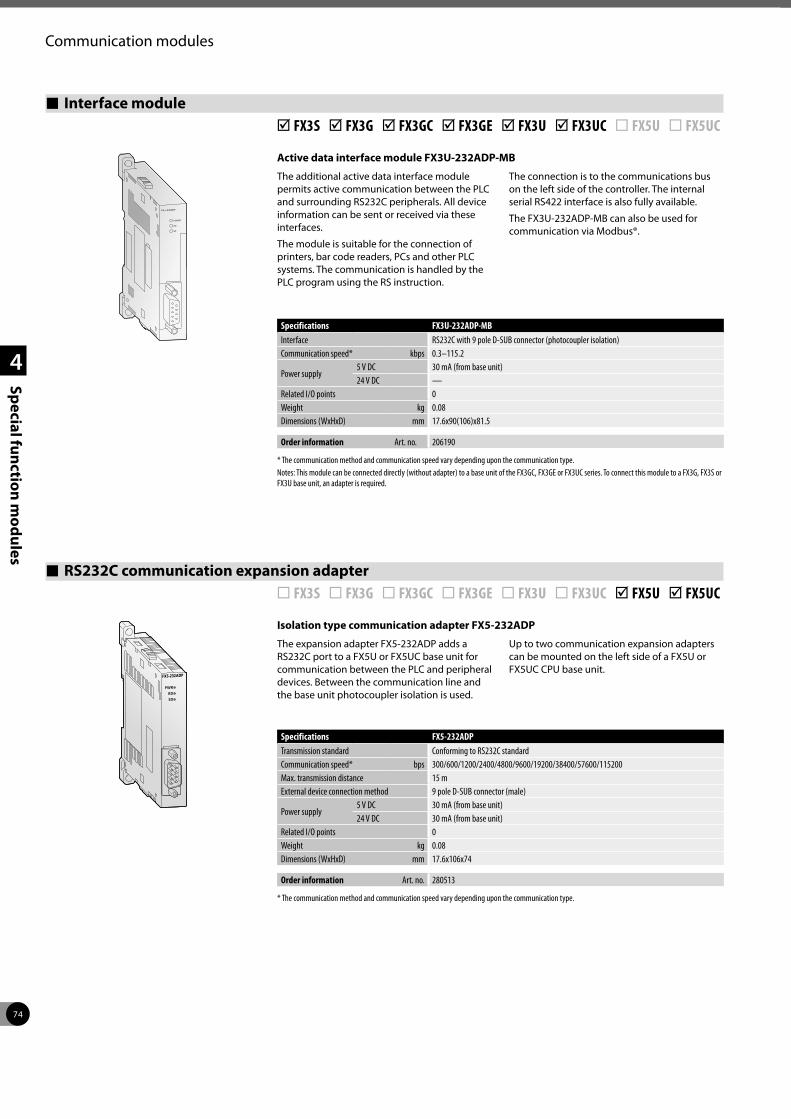
74
1
2
3
4
Special function modules
Communication modules
Active data interface module FX3U-232ADP-MB
The additional active data interface module permits active communication between the PLC and surrounding RS232C peripherals. All device information can be sent or received via these interfaces.
The module is suitable for the connection of printers, bar code readers, PCs and other PLC systems. The communication is handled by the PLC program using the RS instruction.
The connection is to the communications bus on the left side of the controller. The internal serial RS422 interface is also fully available.
The FX3U-232ADP-MB can also be used for communication via Modbus®.
Interface module þ FX3S þ FX3G þ FX3GC þ FX3GE þ FX3U þ FX3UC ¨ FX5U ¨ FX5UC
Specifications FX3U-232ADP-MBInterface RS232C with 9 pole D-SUB connector (photocoupler isolation)Communication speed* kbps 0.3–115.2
Power supply 5 V DC 30 mA (from base unit)24 V DC —
Related I/O points 0Weight kg 0.08Dimensions (WxHxD) mm 17.6x90(106)x81.5
Order information Art. no. 206190
* The communication method and communication speed vary depending upon the communication type.Notes: This module can be connected directly (without adapter) to a base unit of the FX3GC, FX3GE or FX3UC series. To connect this module to a FX3G, FX3S or FX3U base unit, an adapter is required.
Isolation type communication adapter FX5-232ADP
The expansion adapter FX5-232ADP adds a RS232C port to a FX5U or FX5UC base unit for communication between the PLC and peripheral devices. Between the communication line and the base unit photocoupler isolation is used.
Up to two communication expansion adapters can be mounted on the left side of a FX5U or FX5UC CPU base unit.
RS232C communication expansion adapter ¨ FX3S ¨ FX3G ¨ FX3GC ¨ FX3GE ¨ FX3U ¨ FX3UC þ FX5U þ FX5UC
Specifications FX5-232ADPTransmission standard Conforming to RS232C standardCommunication speed* bps 300/600/1200/2400/4800/9600/19200/38400/57600/115200Max. transmission distance 15 mExternal device connection method 9 pole D-SUB connector (male)
Power supply 5 V DC 30 mA (from base unit)24 V DC 30 mA (from base unit)
Related I/O points 0Weight kg 0.08Dimensions (WxHxD) mm 17.6x106x74
Order information Art. no. 280513
* The communication method and communication speed vary depending upon the communication type.
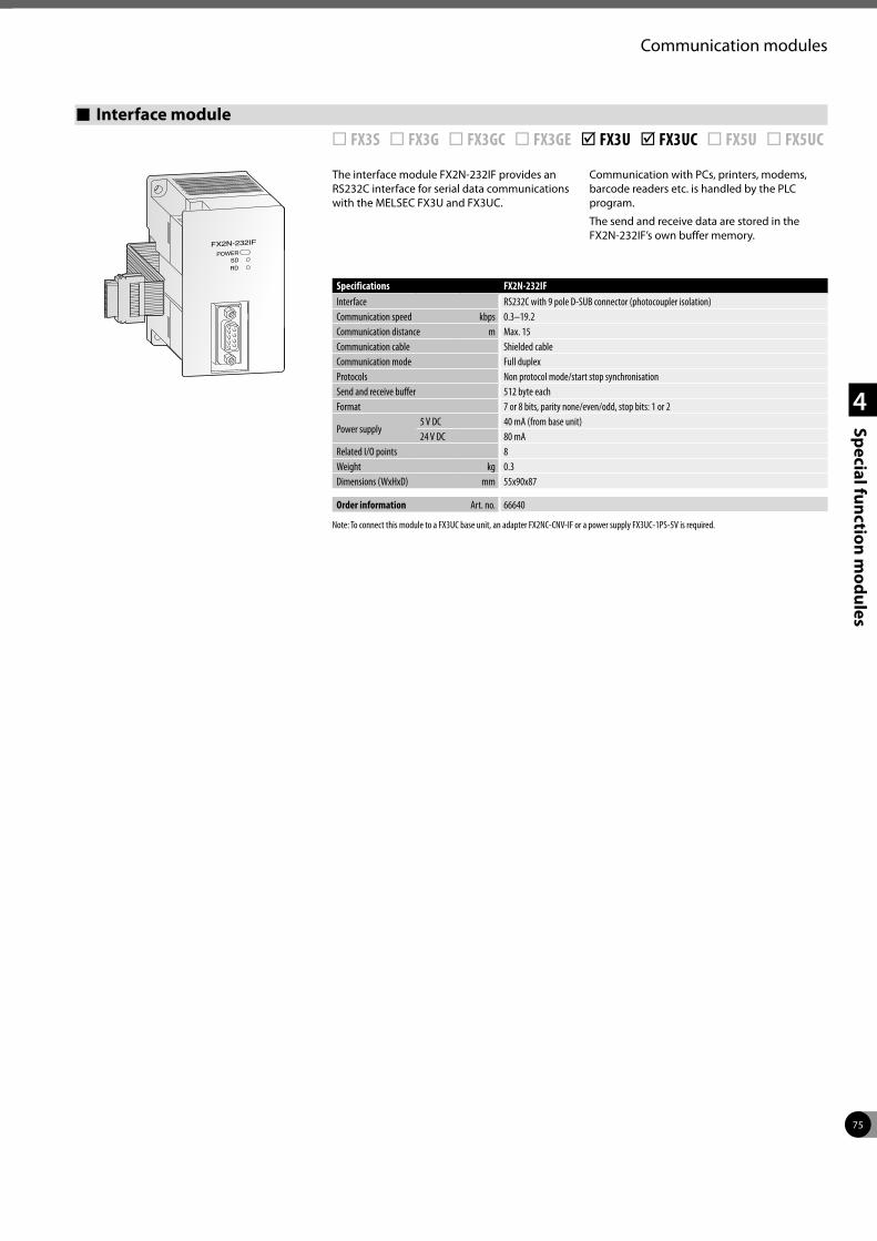
75
1
2
3
4
Special function modules
Communication modules
Interface module ¨ FX3S ¨ FX3G ¨ FX3GC ¨ FX3GE þ FX3U þ FX3UC ¨ FX5U ¨ FX5UC
The interface module FX2N-232IF provides an RS232C interface for serial data communications with the MELSEC FX3U and FX3UC.
Communication with PCs, printers, modems, barcode readers etc. is handled by the PLC program.
The send and receive data are stored in the FX2N-232IF’s own buffer memory.
Specifications FX2N-232IFInterface RS232C with 9 pole D-SUB connector (photocoupler isolation)Communication speed kbps 0.3–19.2Communication distance m Max. 15 Communication cable Shielded cableCommunication mode Full duplexProtocols Non protocol mode/start stop synchronisationSend and receive buffer 512 byte eachFormat 7 or 8 bits, parity none/even/odd, stop bits: 1 or 2
Power supply 5 V DC 40 mA (from base unit)24 V DC 80 mA
Related I/O points 8Weight kg 0.3Dimensions (WxHxD) mm 55x90x87
Order information Art. no. 66640
Note: To connect this module to a FX3UC base unit, an adapter FX2NC-CNV-IF or a power supply FX3UC-1PS-5V is required.
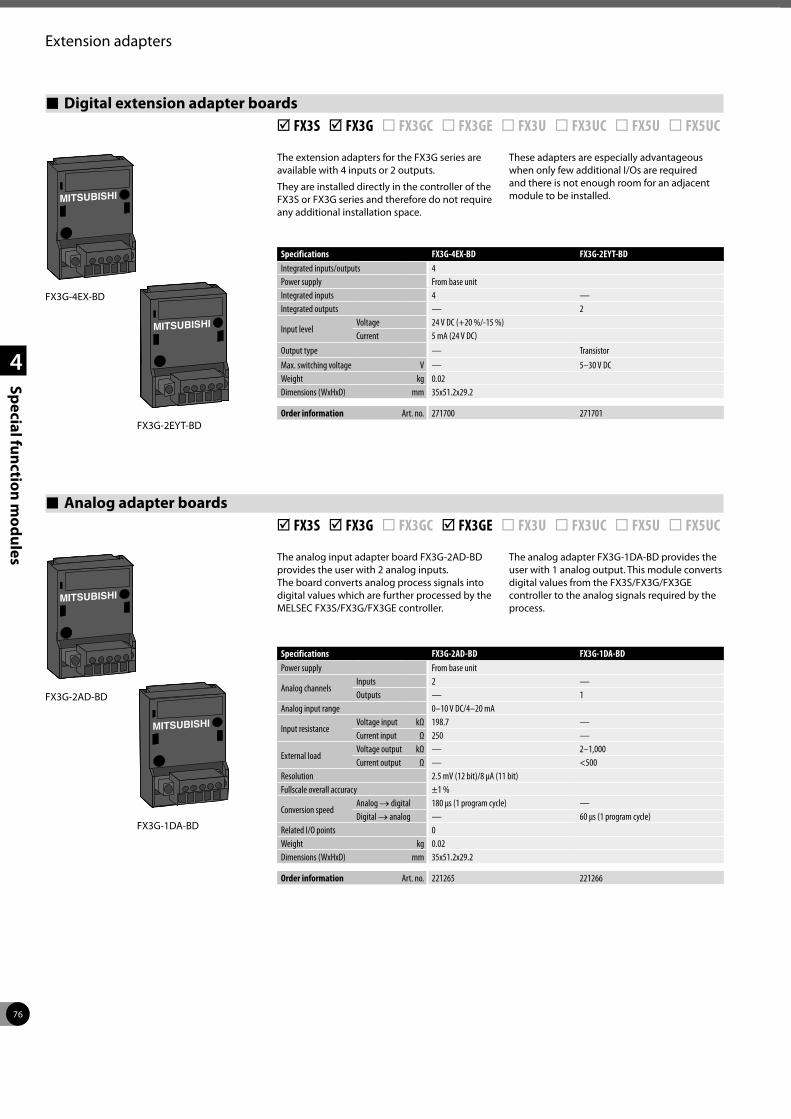
76
1
2
3
4
Special function modules
Extension adapters
Analog adapter boards þ FX3S þ FX3G ¨ FX3GC þ FX3GE ¨ FX3U ¨ FX3UC ¨ FX5U ¨ FX5UC
The analog input adapter board FX3G-2AD-BD provides the user with 2 analog inputs. The board converts analog process signals into digital values which are further processed by the MELSEC FX3S/FX3G/FX3GE controller.
The analog adapter FX3G-1DA-BD provides the user with 1 analog output. This module converts digital values from the FX3S/FX3G/FX3GE controller to the analog signals required by the process.
FX3G-2AD-BD
FX3G-1DA-BD
Specifications FX3G-2AD-BD FX3G-1DA-BDPower supply From base unit
Analog channelsInputs 2 —Outputs — 1
Analog input range 0–10 V DC/4–20 mA
Input resistanceVoltage input kΩ 198.7 —Current input Ω 250 —
External loadVoltage output kΩ — 2–1,000Current output Ω — <500
Resolution 2.5 mV (12 bit)/8 µA (11 bit)Fullscale overall accuracy ±1 %
Conversion speedAnalog → digital 180 µs (1 program cycle) —Digital → analog — 60 µs (1 program cycle)
Related I/O points 0Weight kg 0.02Dimensions (WxHxD) mm 35x51.2x29.2
Order information Art. no. 221265 221266
Digital extension adapter boards þ FX3S þ FX3G ¨ FX3GC ¨ FX3GE ¨ FX3U ¨ FX3UC ¨ FX5U ¨ FX5UC
The extension adapters for the FX3G series are available with 4 inputs or 2 outputs.
They are installed directly in the controller of the FX3S or FX3G series and therefore do not require any additional installation space.
These adapters are especially advantageous when only few additional I/Os are required and there is not enough room for an adjacent module to be installed.
Specifications FX3G-4EX-BD FX3G-2EYT-BDIntegrated inputs/outputs 4Power supply From base unitIntegrated inputs 4 —Integrated outputs — 2
Input levelVoltage 24 V DC (+20 %/-15 %)Current 5 mA (24 V DC)
Output type — TransistorMax. switching voltage V — 5–30 V DCWeight kg 0.02Dimensions (WxHxD) mm 35x51.2x29.2
Order information Art. no. 271700 271701
FX3G-4EX-BD
FX3G-2EYT-BD
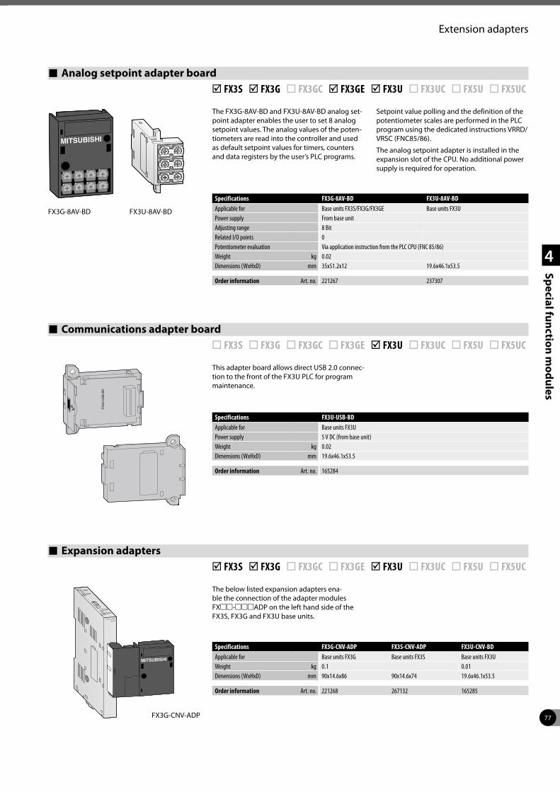
77
1
2
3
4
Special function modules
Extension adapters
Communications adapter board ¨ FX3S ¨ FX3G ¨ FX3GC ¨ FX3GE þ FX3U ¨ FX3UC ¨ FX5U ¨ FX5UC
This adapter board allows direct USB 2.0 connec-tion to the front of the FX3U PLC for program maintenance.
Specifications FX3U-USB-BDApplicable for Base units FX3UPower supply 5 V DC (from base unit)Weight kg 0.02Dimensions (WxHxD) mm 19.6x46.1x53.5
Order information Art. no. 165284
Expansion adapters þ FX3S þ FX3G ¨ FX3GC ¨ FX3GE þ FX3U ¨ FX3UC ¨ FX5U ¨ FX5UC
The below listed expansion adapters ena-ble the connection of the adapter modules FXmm-mmmADP on the left hand side of the FX3S, FX3G and FX3U base units.
Specifications FX3G-CNV-ADP FX3S-CNV-ADP FX3U-CNV-BDApplicable for Base units FX3G Base units FX3S Base units FX3UWeight kg 0.1 0.01Dimensions (WxHxD) mm 90x14.6x86 90x14.6x74 19.6x46.1x53.5
Order information Art. no. 221268 267132 165285
FX3G-CNV-ADP
Analog setpoint adapter board þ FX3S þ FX3G ¨ FX3GC þ FX3GE þ FX3U ¨ FX3UC ¨ FX5U ¨ FX5UC
The FX3G-8AV-BD and FX3U-8AV-BD analog set-point adapter enables the user to set 8 analog setpoint values. The analog values of the poten-tiometers are read into the controller and used as default setpoint values for timers, counters and data registers by the user’s PLC programs.
Setpoint value polling and the definition of the potentiometer scales are performed in the PLC program using the dedicated instructions VRRD/VRSC (FNC85/86).
The analog setpoint adapter is installed in the expansion slot of the CPU. No additional power supply is required for operation.
FX3G-8AV-BD
Specifications FX3G-8AV-BD FX3U-8AV-BDApplicable for Base units FX3S/FX3G/FX3GE Base units FX3UPower supply From base unitAdjusting range 8 BitRelated I/O points 0Potentiometer evaluation Via application instruction from the PLC CPU (FNC 85/86)Weight kg 0.02Dimensions (WxHxD) mm 35x51.2x12 19.6x46.1x53.5
Order information Art. no. 221267 237307
FX3U-8AV-BD
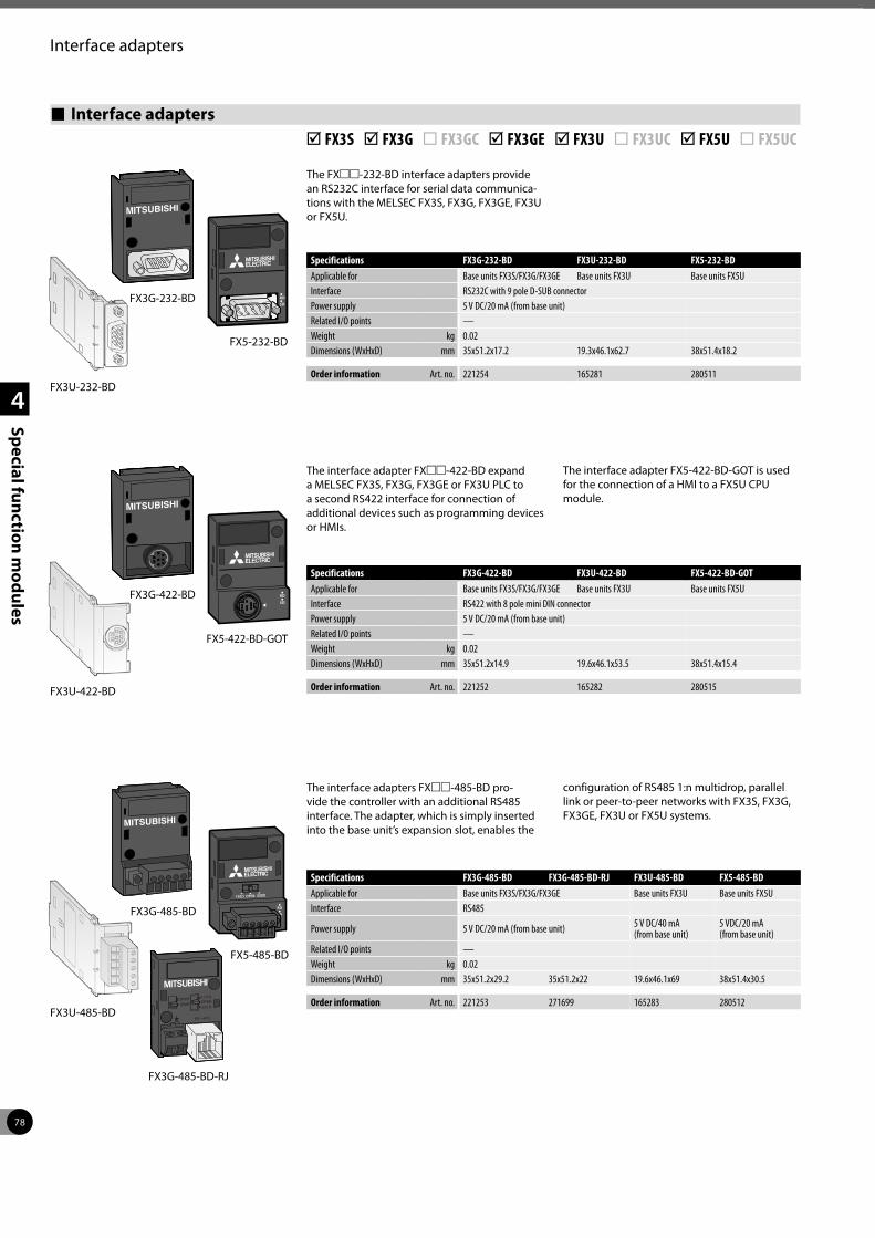
78
1
2
3
4
Special function modules
Interface adapters
Interface adapters þ FX3S þ FX3G ¨ FX3GC þ FX3GE þ FX3U ¨ FX3UC þ FX5U ¨ FX5UC
The FXmm-232-BD interface adapters provide an RS232C interface for serial data communica-tions with the MELSEC FX3S, FX3G, FX3GE, FX3U or FX5U.
The interface adapter FXmm-422-BD expand a MELSEC FX3S, FX3G, FX3GE or FX3U PLC to a second RS422 interface for connection of additional devices such as programming devices or HMIs.
The interface adapter FX5-422-BD-GOT is used for the connection of a HMI to a FX5U CPU module.
The interface adapters FXmm-485-BD pro-vide the controller with an additional RS485 interface. The adapter, which is simply inserted into the base unit’s expansion slot, enables the
configuration of RS485 1:n multidrop, parallel link or peer-to-peer networks with FX3S, FX3G, FX3GE, FX3U or FX5U systems.
Specifications FX3G-232-BD FX3U-232-BD FX5-232-BDApplicable for Base units FX3S/FX3G/FX3GE Base units FX3U Base units FX5UInterface RS232C with 9 pole D-SUB connectorPower supply 5 V DC/20 mA (from base unit)Related I/O points —Weight kg 0.02Dimensions (WxHxD) mm 35x51.2x17.2 19.3x46.1x62.7 38x51.4x18.2
Order information Art. no. 221254 165281 280511FX3U-232-BD
FX3U-422-BD
Specifications FX3G-422-BD FX3U-422-BD FX5-422-BD-GOTApplicable for Base units FX3S/FX3G/FX3GE Base units FX3U Base units FX5UInterface RS422 with 8 pole mini DIN connectorPower supply 5 V DC/20 mA (from base unit) Related I/O points —Weight kg 0.02Dimensions (WxHxD) mm 35x51.2x14.9 19.6x46.1x53.5 38x51.4x15.4
Order information Art. no. 221252 165282 280515
Specifications FX3G-485-BD FX3G-485-BD-RJ FX3U-485-BD FX5-485-BDApplicable for Base units FX3S/FX3G/FX3GE Base units FX3U Base units FX5UInterface RS485
Power supply 5 V DC/20 mA (from base unit) 5 V DC/40 mA (from base unit)
5 VDC/20 mA (from base unit)
Related I/O points —Weight kg 0.02Dimensions (WxHxD) mm 35x51.2x29.2 35x51.2x22 19.6x46.1x69 38x51.4x30.5
Order information Art. no. 221253 271699 165283 280512
FX3G-485-BD-RJ
FX5-232-BD
FX5-422-BD-GOT
FX3U-485-BD
FX5-485-BD
FX3G-232-BD
FX3G-422-BD
FX3G-485-BD
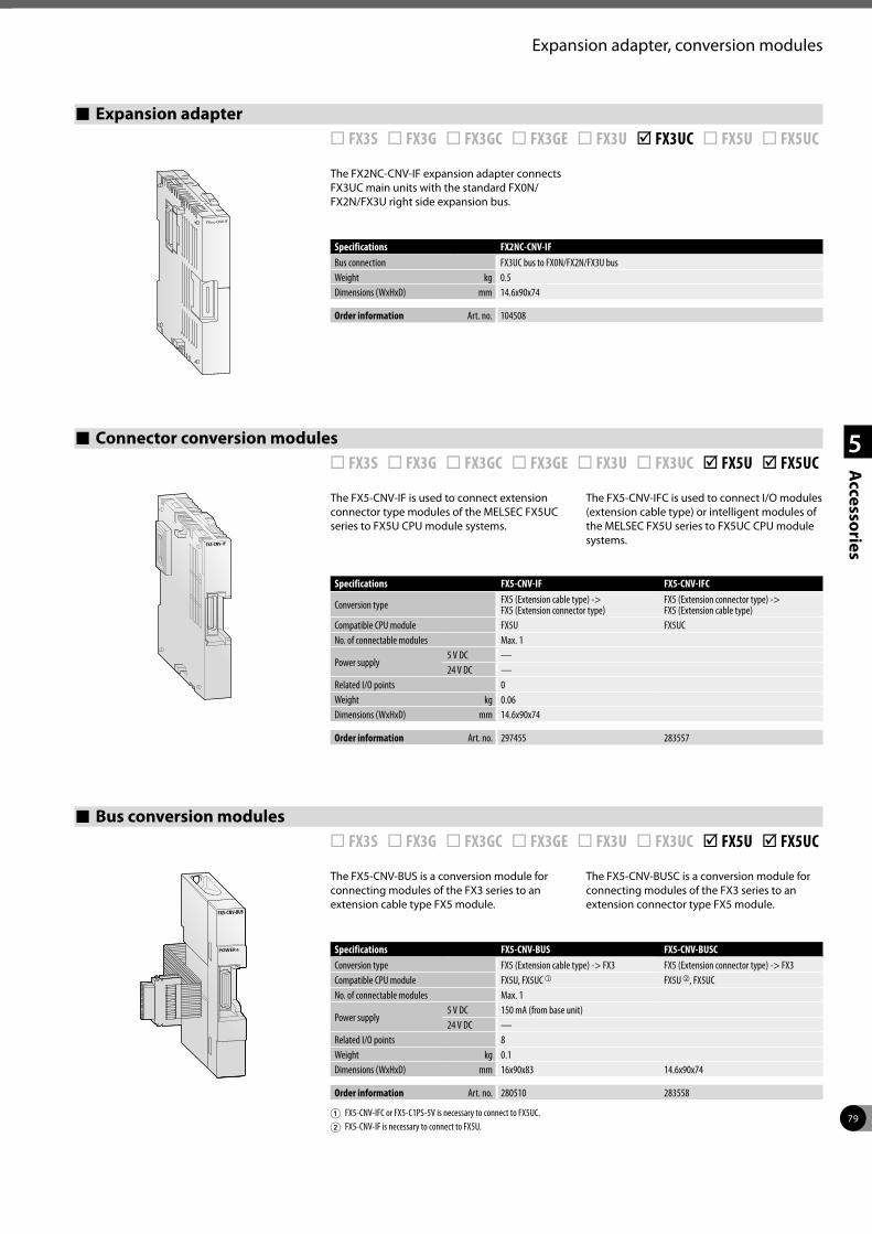
79
1
2
3
4
5
Accessories
Expansion adapter, conversion modules
Expansion adapter ¨ FX3S ¨ FX3G ¨ FX3GC ¨ FX3GE ¨ FX3U þ FX3UC ¨ FX5U ¨ FX5UC
The FX2NC-CNV-IF expansion adapter connects FX3UC main units with the standard FX0N/FX2N/FX3U right side expansion bus.
The FX5-CNV-IF is used to connect extension connector type modules of the MELSEC FX5UC series to FX5U CPU module systems.
The FX5-CNV-IFC is used to connect I/O modules (extension cable type) or intelligent modules of the MELSEC FX5U series to FX5UC CPU module systems.
Connector conversion modules ¨ FX3S ¨ FX3G ¨ FX3GC ¨ FX3GE ¨ FX3U ¨ FX3UC þ FX5U þ FX5UC
Specifications FX2NC-CNV-IFBus connection FX3UC bus to FX0N/FX2N/FX3U busWeight kg 0.5Dimensions (WxHxD) mm 14.6x90x74
Order information Art. no. 104508
Specifications FX5-CNV-IF FX5-CNV-IFC
Conversion type FX5 (Extension cable type) ->FX5 (Extension connector type)
FX5 (Extension connector type) ->FX5 (Extension cable type)
Compatible CPU module FX5U FX5UCNo. of connectable modules Max. 1
Power supply5 V DC —24 V DC —
Related I/O points 0Weight kg 0.06Dimensions (WxHxD) mm 14.6x90x74
Order information Art. no. 297455 283557
The FX5-CNV-BUS is a conversion module for connecting modules of the FX3 series to an extension cable type FX5 module.
The FX5-CNV-BUSC is a conversion module for connecting modules of the FX3 series to an extension connector type FX5 module.
Bus conversion modules ¨ FX3S ¨ FX3G ¨ FX3GC ¨ FX3GE ¨ FX3U ¨ FX3UC þ FX5U þ FX5UC
Specifications FX5-CNV-BUS FX5-CNV-BUSCConversion type FX5 (Extension cable type) -> FX3 FX5 (Extension connector type) -> FX3Compatible CPU module FX5U, FX5UC a FX5U b, FX5UCNo. of connectable modules Max. 1
Power supply5 V DC 150 mA (from base unit)24 V DC —
Related I/O points 8Weight kg 0.1Dimensions (WxHxD) mm 16x90x83 14.6x90x74
Order information Art. no. 280510 283558
1 FX5-CNV-IFC or FX5-C1PS-5V is necessary to connect to FX5UC.2 FX5-CNV-IF is necessary to connect to FX5U.
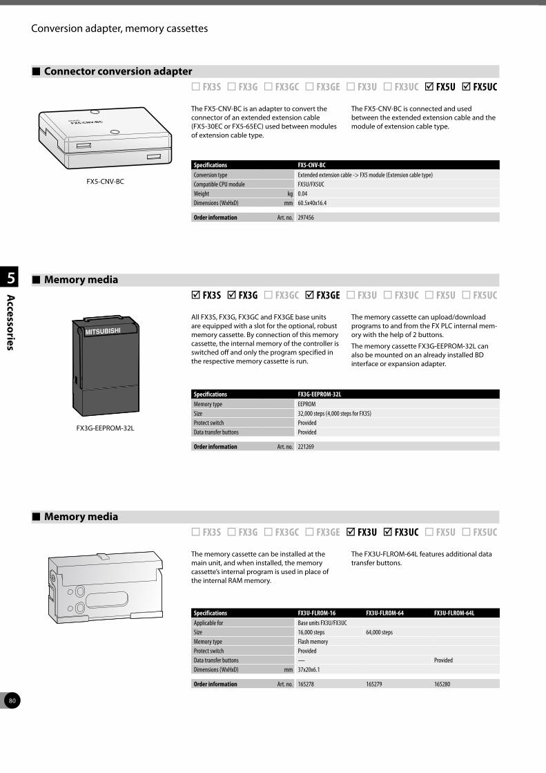
80
1
2
3
4
5
Accessories
Conversion adapter, memory cassettes
All FX3S, FX3G, FX3GC and FX3GE base units are equipped with a slot for the optional, robust memory cassette. By connection of this memory cassette, the internal memory of the controller is switched off and only the program specified in the respective memory cassette is run.
The memory cassette can upload/download programs to and from the FX PLC internal mem-ory with the help of 2 buttons.
The memory cassette FX3G-EEPROM-32L can also be mounted on an already installed BD interface or expansion adapter.
The memory cassette can be installed at the main unit, and when installed, the memory cassette’s internal program is used in place of the internal RAM memory.
The FX3U-FLROM-64L features additional data transfer buttons.
Memory media þ FX3S þ FX3G ¨ FX3GC þ FX3GE ¨ FX3U ¨ FX3UC ¨ FX5U ¨ FX5UC
Memory media ¨ FX3S ¨ FX3G ¨ FX3GC ¨ FX3GE þ FX3U þ FX3UC ¨ FX5U ¨ FX5UC
FX3G-EEPROM-32L
Specifications FX3G-EEPROM-32LMemory type EEPROMSize 32,000 steps (4,000 steps for FX3S)Protect switch ProvidedData transfer buttons Provided
Order information Art. no. 221269
Specifications FX3U-FLROM-16 FX3U-FLROM-64 FX3U-FLROM-64LApplicable for Base units FX3U/FX3UCSize 16,000 steps 64,000 stepsMemory type Flash memoryProtect switch ProvidedData transfer buttons — ProvidedDimensions (WxHxD) mm 37x20x6.1
Order information Art. no. 165278 165279 165280
The FX5-CNV-BC is an adapter to convert the connector of an extended extension cable (FX5-30EC or FX5-65EC) used between modules of extension cable type.
The FX5-CNV-BC is connected and used between the extended extension cable and the module of extension cable type.
Connector conversion adapter ¨ FX3S ¨ FX3G ¨ FX3GC ¨ FX3GE ¨ FX3U ¨ FX3UC þ FX5U þ FX5UC
Specifications FX5-CNV-BCConversion type Extended extension cable -> FX5 module (Extension cable type)Compatible CPU module FX5U/FX5UCWeight kg 0.04Dimensions (WxHxD) mm 60.5x40x16.4
Order information Art. no. 297456
FX5-CNV-BC
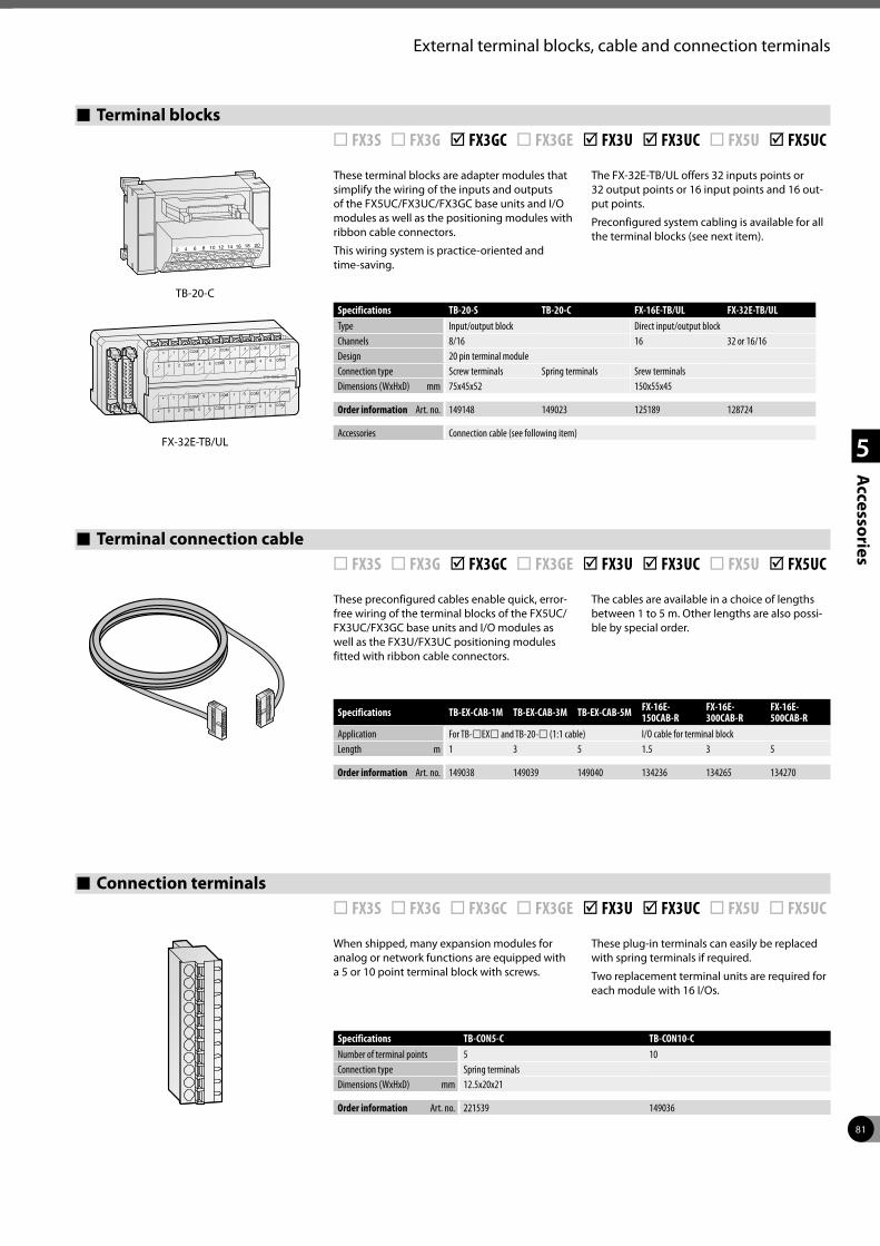
81
1
2
3
4
5
Accessories
External terminal blocks, cable and connection terminals
Terminal blocks ¨ FX3S ¨ FX3G þ FX3GC ¨ FX3GE þ FX3U þ FX3UC ¨ FX5U þ FX5UC
These terminal blocks are adapter modules that simplify the wiring of the inputs and outputs of the FX5UC/FX3UC/FX3GC base units and I/O modules as well as the positioning modules with ribbon cable connectors.
This wiring system is practice-oriented and time-saving.
The FX-32E-TB/UL offers 32 inputs points or 32 output points or 16 input points and 16 out-put points.
Preconfigured system cabling is available for all the terminal blocks (see next item).
TB-20-C
2018161412108642
Specifications TB-20-S TB-20-C FX-16E-TB/UL FX-32E-TB/ULType Input/output block Direct input/output blockChannels 8/16 16 32 or 16/16Design 20 pin terminal moduleConnection type Screw terminals Spring terminals Srew terminalsDimensions (WxHxD) mm 75x45x52 150x55x45
Order information Art. no. 149148 149023 125189 128724
Accessories Connection cable (see following item)
Terminal connection cable ¨ FX3S ¨ FX3G þ FX3GC ¨ FX3GE þ FX3U þ FX3UC ¨ FX5U þ FX5UC
These preconfigured cables enable quick, error-free wiring of the terminal blocks of the FX5UC/FX3UC/FX3GC base units and I/O modules as well as the FX3U/FX3UC positioning modules fitted with ribbon cable connectors.
The cables are available in a choice of lengths between 1 to 5 m. Other lengths are also possi-ble by special order.
When shipped, many expansion modules for analog or network functions are equipped with a 5 or 10 point terminal block with screws.
These plug-in terminals can easily be replaced with spring terminals if required.
Two replacement terminal units are required for each module with 16 I/Os.
Specifications TB-EX-CAB-1M TB-EX-CAB-3M TB-EX-CAB-5M FX-16E-150CAB-R
FX-16E-300CAB-R
FX-16E-500CAB-R
Application For TB-lEXl and TB-20-l (1:1 cable) I/O cable for terminal blockLength m 1 3 5 1.5 3 5
Order information Art. no. 149038 149039 149040 134236 134265 134270
Connection terminals ¨ FX3S ¨ FX3G ¨ FX3GC ¨ FX3GE þ FX3U þ FX3UC ¨ FX5U ¨ FX5UC
Specifications TB-CON5-C TB-CON10-CNumber of terminal points 5 10Connection type Spring terminalsDimensions (WxHxD) mm 12.5x20x21
Order information Art. no. 221539 149036
FX-32E-TB/UL
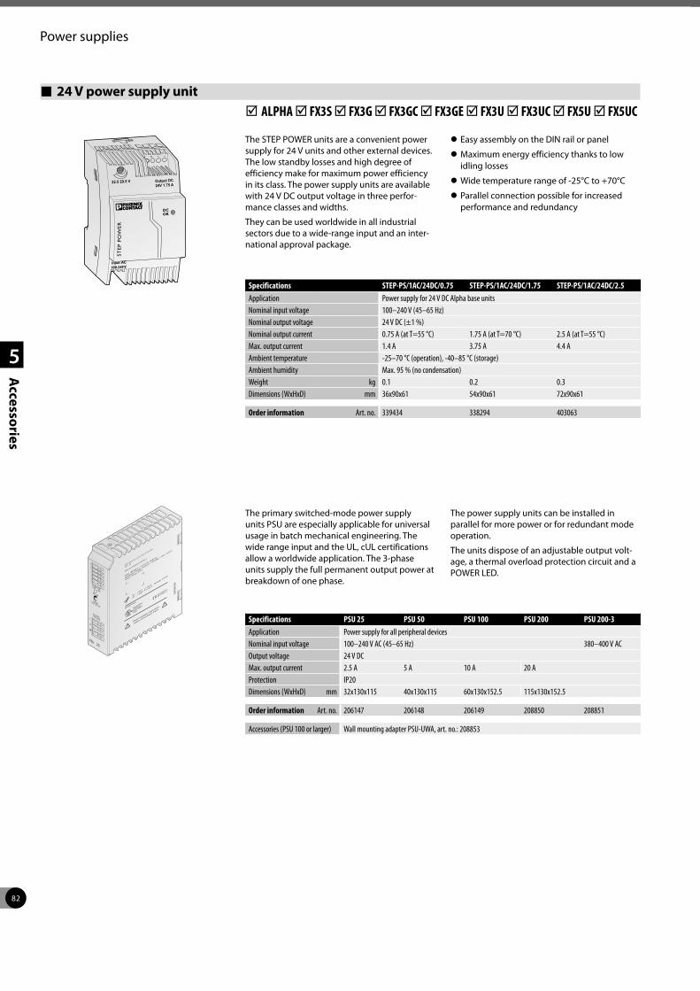
82
1
2
3
4
5
Accessories
Power supplies
24 V power supply unit þ ALPHA þ FX3S þ FX3G þ FX3GC þ FX3GE þ FX3U þ FX3UC þ FX5U þ FX5UC
The STEP POWER units are a convenient power supply for 24 V units and other external devices. The low standby losses and high degree of efficiency make for maximum power efficiency in its class. The power supply units are available with 24 V DC output voltage in three perfor-mance classes and widths.
They can be used worldwide in all industrial sectors due to a wide-range input and an inter-national approval package.
z Easy assembly on the DIN rail or panel
z Maximum energy efficiency thanks to low idling losses
z Wide temperature range of -25°C to +70°C
z Parallel connection possible for increased performance and redundancy
Specifications STEP-PS/1AC/24DC/0.75 STEP-PS/1AC/24DC/1.75 STEP-PS/1AC/24DC/2.5Application Power supply for 24 V DC Alpha base unitsNominal input voltage 100–240 V (45–65 Hz)Nominal output voltage 24 V DC (±1 %)Nominal output current 0.75 A (at T=55 °C) 1.75 A (at T=70 °C) 2.5 A (at T=55 °C)Max. output current 1.4 A 3.75 A 4.4 AAmbient temperature -25–70 °C (operation), -40–85 °C (storage)Ambient humidity Max. 95 % (no condensation)Weight kg 0.1 0.2 0.3Dimensions (WxHxD) mm 36x90x61 54x90x61 72x90x61
Order information Art. no. 339434 338294 403063
The primary switched-mode power supply units PSU are especially applicable for universal usage in batch mechanical engineering. The wide range input and the UL, cUL certifications allow a worldwide application. The 3-phase units supply the full permanent output power at breakdown of one phase.
The power supply units can be installed in parallel for more power or for redundant mode operation.
The units dispose of an adjustable output volt-age, a thermal overload protection circuit and a POWER LED.
Specifications PSU 25 PSU 50 PSU 100 PSU 200 PSU 200-3Application Power supply for all peripheral devicesNominal input voltage 100–240 V AC (45–65 Hz) 380–400 V ACOutput voltage 24 V DCMax. output current 2.5 A 5 A 10 A 20 AProtection IP20Dimensions (WxHxD) mm 32x130x115 40x130x115 60x130x152.5 115x130x152.5
Order information Art. no. 206147 206148 206149 208850 208851
Accessories (PSU 100 or larger) Wall mounting adapter PSU-UWA, art. no.: 208853
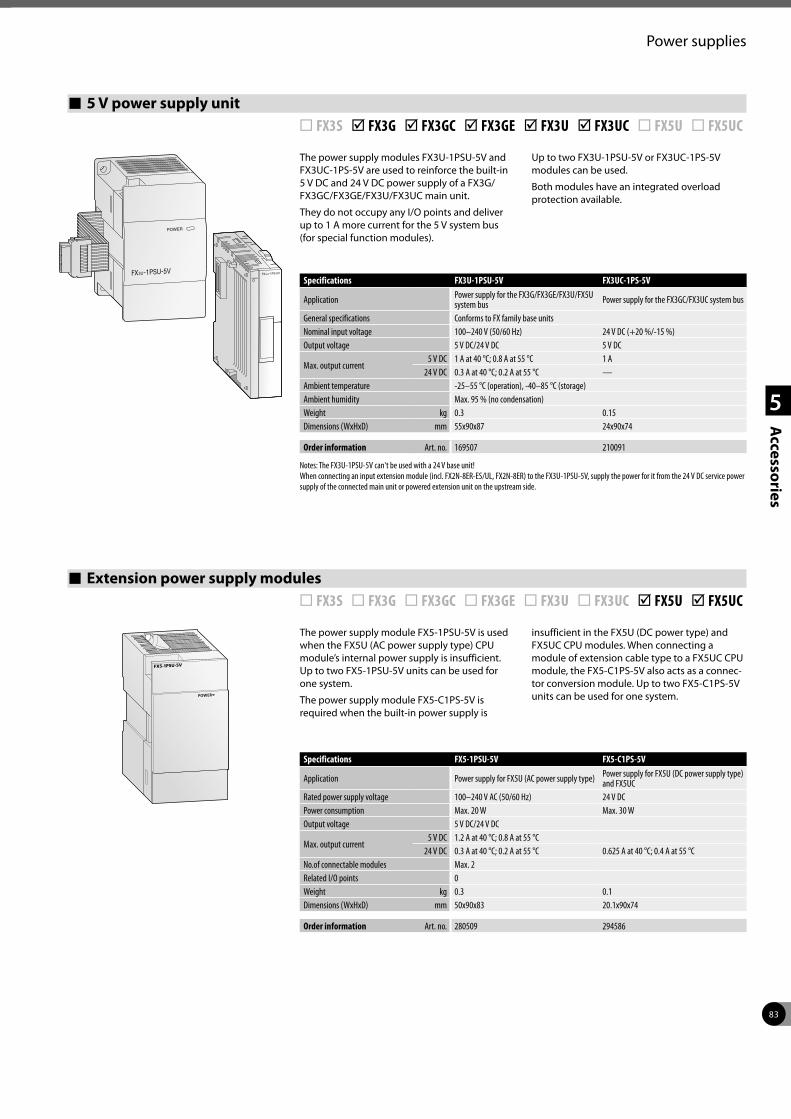
83
1
2
3
4
5
Accessories
Power supplies
The power supply modules FX3U-1PSU-5V and FX3UC-1PS-5V are used to reinforce the built-in 5 V DC and 24 V DC power supply of a FX3G/FX3GC/FX3GE/FX3U/FX3UC main unit.
They do not occupy any I/O points and deliver up to 1 A more current for the 5 V system bus (for special function modules).
Up to two FX3U-1PSU-5V or FX3UC-1PS-5V modules can be used.
Both modules have an integrated overload protection available.
5 V power supply unit ¨ FX3S þ FX3G þ FX3GC þ FX3GE þ FX3U þ FX3UC ¨ FX5U ¨ FX5UC
FX -1PSU-5V3U
Specifications FX3U-1PSU-5V FX3UC-1PS-5V
Application Power supply for the FX3G/FX3GE/FX3U/FX5U system bus Power supply for the FX3GC/FX3UC system bus
General specifications Conforms to FX family base unitsNominal input voltage 100–240 V (50/60 Hz) 24 V DC (+20 %/-15 %)Output voltage 5 V DC/24 V DC 5 V DC
Max. output current5 V DC 1 A at 40 °C; 0.8 A at 55 °C 1 A
24 V DC 0.3 A at 40 °C; 0.2 A at 55 °C —Ambient temperature -25–55 °C (operation), -40–85 °C (storage)Ambient humidity Max. 95 % (no condensation)Weight kg 0.3 0.15Dimensions (WxHxD) mm 55x90x87 24x90x74
Order information Art. no. 169507 210091
Notes: The FX3U-1PSU-5V can't be used with a 24 V base unit! When connecting an input extension module (incl. FX2N-8ER-ES/UL, FX2N-8ER) to the FX3U-1PSU-5V, supply the power for it from the 24 V DC service power supply of the connected main unit or powered extension unit on the upstream side.
The power supply module FX5-1PSU-5V is used when the FX5U (AC power supply type) CPU module’s internal power supply is insufficient. Up to two FX5-1PSU-5V units can be used for one system.
The power supply module FX5-C1PS-5V is required when the built-in power supply is
insufficient in the FX5U (DC power type) and FX5UC CPU modules. When connecting a module of extension cable type to a FX5UC CPU module, the FX5-C1PS-5V also acts as a connec-tor conversion module. Up to two FX5-C1PS-5V units can be used for one system.
Extension power supply modules ¨ FX3S ¨ FX3G ¨ FX3GC ¨ FX3GE ¨ FX3U ¨ FX3UC þ FX5U þ FX5UC
Specifications FX5-1PSU-5V FX5-C1PS-5V
Application Power supply for FX5U (AC power supply type) Power supply for FX5U (DC power supply type) and FX5UC
Rated power supply voltage 100–240 V AC (50/60 Hz) 24 V DCPower consumption Max. 20 W Max. 30 WOutput voltage 5 V DC/24 V DC
Max. output current5 V DC 1.2 A at 40 °C; 0.8 A at 55 °C
24 V DC 0.3 A at 40 °C; 0.2 A at 55 °C 0.625 A at 40 °C; 0.4 A at 55 °CNo.of connectable modules Max. 2Related I/O points 0Weight kg 0.3 0.1Dimensions (WxHxD) mm 50x90x83 20.1x90x74
Order information Art. no. 280509 294586
84
1
2
3
4
5
Accessories
SD memory card, batteries, displays
Backup batteries ¨ FX3S þ FX3G þ FX3GC þ FX3GE þ FX3U þ FX3UC þ FX5U þ FX5UC
Batteries
The battery buffers the internal RAM of the MELSEC PLC in the event of a voltage failure.
The battery FX3U-32BL can be used for all base units of the MELSEC FX3G/FX3GC/FX3GE/FX3U/FX3UC/FX5U/FX5UC series.
Specifications FX2NC-32BL FX3U-32BL
Applicable for FX2N-20GM module Base units FX3G/FX3GC/FX3GE/FX3U/FX3UC/FX5U/FX5UC
Order information Art. no. 128725 165286FX3U-32BL
SD memory card ¨ FX3S ¨ FX3G ¨ FX3GC ¨ FX3GE ¨ FX3U ¨ FX3UC þ FX5U þ FX5UC
The built-in SD memory card slot can be used for data logging and convenient program update.
Specifications SD memory cardMemory Type SDHCMemory capacity 16 GB
Order information Art. no. 340984
Display modules þ FX3S þ FX3G ¨ FX3GC þ FX3GE þ FX3U þ FX3UC ¨ FX5U ¨ FX5UC
Display modules FX3G-5DM/FX3S-5DM
The display modules FX3G-5DM and FX3S-5DM are inserted directly with space-saving into the controller and enable monitoring and editing of the data stored in the PLC.
A display module e.g. can be used instead of digital switches and external 7-segment displays in very confined areas.
Panel FX3U-7DM with built-in holder FX3U-7DM-HLD
Specifications FX3S-5DM FX3G-5DMApplicable for Base units FX3S Base units FX3G/FX3GEDisplay LCD (with backlight)Power supply 5 V DC ±5 % (from base unit)Current consumption mA n/aDimensions (WxHxD) mm 35x51.2x12 49x34x12
Order information Art. no. 282202 221270
Control and display panel FX3U-7DM and holder FX3U-7DM-HLD
The FX3U-7DM display module can be incor-porated in the main unit, or can be installed in
the enclosure using the FX3U-7DM-HLD display module holder.
Specifications FX3U-7DM FX3U-7DM-HLDApplicable for Base units FX3UDisplay 16 letters x 4 lines —Resolution —Power supply 5 V DC (from base unit) —Current consumption mA 20 —Extension cable — IncludedWeight kg 0.02 0.01Dimensions (WxHxD) mm 48x35x11.5 66.3x41.8x13
Order information Art. no. 165268 165287
Please refer to the HMI family catalogue for further operator terminals
FX3S-5DM
FX3G-5DM
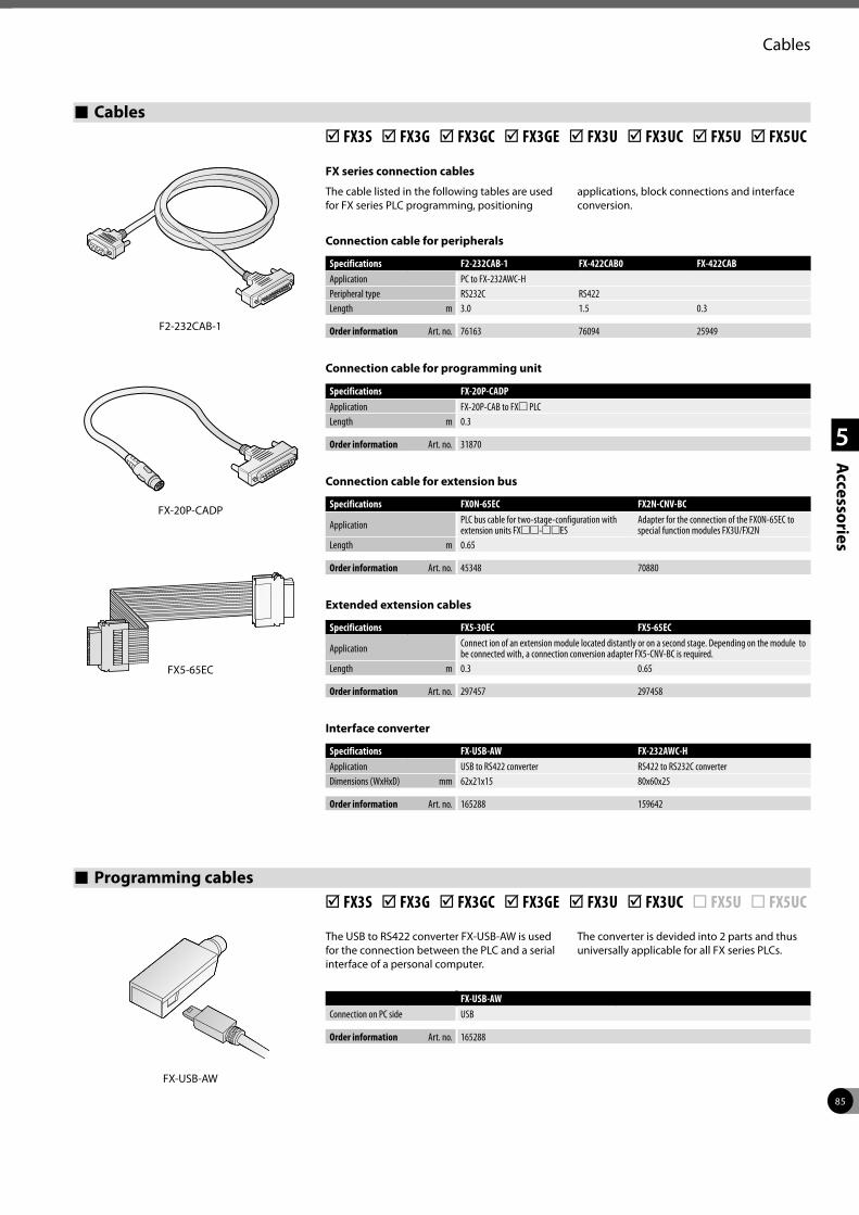
85
1
2
3
4
5
Accessories
Cables
Cables þ FX3S þ FX3G þ FX3GC þ FX3GE þ FX3U þ FX3UC þ FX5U þ FX5UC
FX series connection cables
The cable listed in the following tables are used for FX series PLC programming, positioning
applications, block connections and interface conversion.
Programming cables þ FX3S þ FX3G þ FX3GC þ FX3GE þ FX3U þ FX3UC ¨ FX5U ¨ FX5UC
The USB to RS422 converter FX-USB-AW is used for the connection between the PLC and a serial interface of a personal computer.
The converter is devided into 2 parts and thus universally applicable for all FX series PLCs.
Specifications F2-232CAB-1 FX-422CAB0 FX-422CABApplication PC to FX-232AWC-HPeripheral type RS232C RS422Length m 3.0 1.5 0.3
Order information Art. no. 76163 76094 25949
Connection cable for peripherals
Connection cable for programming unit
Specifications FX-20P-CADPApplication FX-20P-CAB to FXm PLCLength m 0.3
Order information Art. no. 31870
Connection cable for extension bus
Specifications FX0N-65EC FX2N-CNV-BC
Application PLC bus cable for two-stage-configuration with extension units FXmm-mmES
Adapter for the connection of the FX0N-65EC to special function modules FX3U/FX2N
Length m 0.65
Order information Art. no. 45348 70880
Interface converter
Specifications FX-USB-AW FX-232AWC-HApplication USB to RS422 converter RS422 to RS232C converterDimensions (WxHxD) mm 62x21x15 80x60x25
Order information Art. no. 165288 159642
FX-USB-AWConnection on PC side USB
Order information Art. no. 165288
FX-USB-AW
Specifications FX5-30EC FX5-65EC
Application Connect ion of an extension module located distantly or on a second stage. Depending on the module to be connected with, a connection conversion adapter FX5-CNV-BC is required.
Length m 0.3 0.65
Order information Art. no. 297457 297458
Extended extension cables
FX5-65EC
F2-232CAB-1
FX-20P-CADP
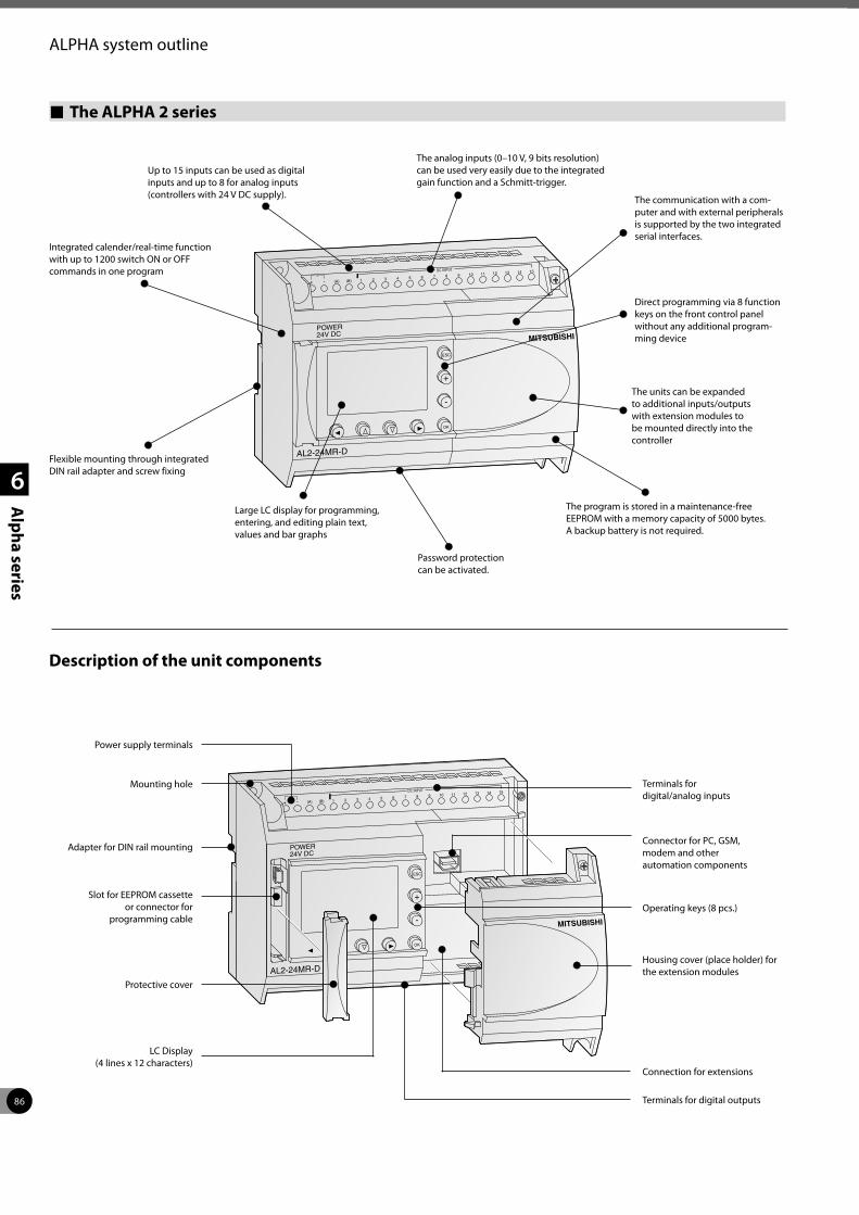
86
1
2
3
4
6
Alpha series
ALPHA system outline
POWER24V DC
AL2-24MR-D
ESC
OK
1(A)7
+ -6
15
511 12 13 14
410
39
2(B)8
DC INPUT
MITSUBISHI
MITSUBISHIPOWER24V DC
AL2-24MR-D
ESC
OK
1(A)7
+ -6
15
511 12 13 14
410
39
2(B)8
DC INPUT
The ALPHA 2 series
Up to 15 inputs can be used as digital inputs and up to 8 for analog inputs (controllers with 24 V DC supply).
Integrated calender/real-time function with up to 1200 switch ON or OFF commands in one program
Flexible mounting through integrated DIN rail adapter and screw fixing
Large LC display for programming, entering, and editing plain text, values and bar graphs
Password protection can be activated.
The program is stored in a maintenance-free EEPROM with a memory capacity of 5000 bytes. A backup battery is not required.
The units can be expanded to additional inputs/outputs with extension modules to be mounted directly into the controller
Direct programming via 8 function keys on the front control panel without any additional program-ming device
The communication with a com-puter and with external peripherals is supported by the two integrated serial interfaces.
The analog inputs (0–10 V, 9 bits resolution) can be used very easily due to the integrated gain function and a Schmitt-trigger.
Description of the unit components
Power supply terminals
Mounting hole
Adapter for DIN rail mounting
Slot for EEPROM cassette or connector for
programming cable
Protective cover
LC Display (4 lines x 12 characters)
Terminals for digital outputs
Connection for extensions
Housing cover (place holder) for the extension modules
Operating keys (8 pcs.)
Connector for PC, GSM, modem and other automation components
Terminals for digital/analog inputs
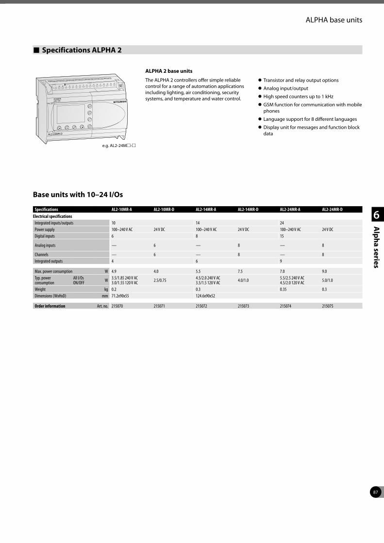
87
1
2
3
4
6
Alpha series
ALPHA base units
Specifications ALPHA 2
ALPHA 2 base units
The ALPHA 2 controllers offer simple reliable control for a range of automation applications including lighting, air conditioning, security systems, and temperature and water control.
z Transistor and relay output options
z Analog input/output
z High speed counters up to 1 kHz
z GSM function for communication with mobile phones
z Language support for 8 different languages
z Display unit for messages and function block data
e.g. AL2-24Mm-m
MITSUBISHIPOWER24V DC
AL2-24MR-D
ESC
OK
1(A)7
+ -6
15
511 12 13 14
410
39
2(B)8
DC INPUT
Base units with 10–24 I/Os
Specifications AL2-10MR-A AL2-10MR-D AL2-14MR-A AL2-14MR-D AL2-24MR-A AL2-24MR-DElectrical specifications
Integrated inputs/outputs 10 14 24Power supply 100–240 V AC 24 V DC 100–240 V AC 24 V DC 100–240 V AC 24 V DCDigital inputs 6 8 15
Analog inputs — 6 — 8 — 8
Channels — 6 — 8 — 8Integrated outputs 4 6 9
Max. power consumption W 4.9 4.0 5.5 7.5 7.0 9.0Typ. power consumption
All I/Os ON/OFF W 3.5/1.85 240 V AC
3.0/1.55 120 V AC 2.5/0.75 4.5/2.0 240 V AC 3.5/1.5 120 V AC 4.0/1.0 5.5/2.5 240 V AC
4.5/2.0 120 V AC 5.0/1.0
Weight kg 0.2 0.3 0.35 0.3Dimensions (WxHxD) mm 71.2x90x55 124.6x90x52
Order information Art. no. 215070 215071 215072 215073 215074 215075
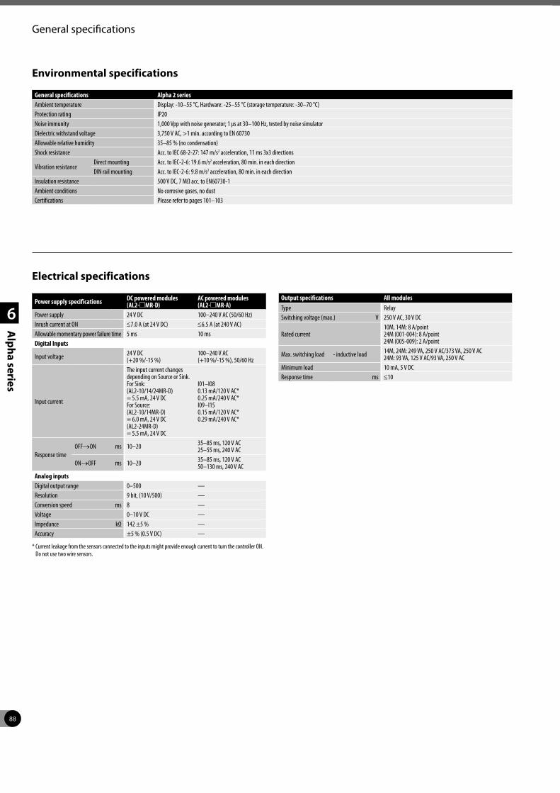
88
1
2
3
4
6
Alpha series
General specifications
Environmental specifications
General specifications Alpha 2 seriesAmbient temperature Display: -10–55 °C, Hardware: -25–55 °C (storage temperature: -30–70 °C)Protection rating IP20Noise immunity 1,000 Vpp with noise generator; 1 µs at 30–100 Hz, tested by noise simulatorDielectric withstand voltage 3,750 V AC, >1 min. according to EN 60730Allowable relative humidity 35–85 % (no condensation)Shock resistance Acc. to IEC 68-2-27: 147 m/s2 acceleration, 11 ms 3x3 directions
Vibration resistanceDirect mounting Acc. to IEC-2-6: 19.6 m/s2 acceleration, 80 min. in each directionDIN rail mounting Acc. to IEC-2-6: 9.8 m/s2 acceleration, 80 min. in each direction
Insulation resistance 500 V DC, 7 MΩ acc. to EN60730-1Ambient conditions No corrosive gases, no dustCertifications Please refer to pages 101–103
Electrical specifications
Power supply specifications DC powered modules (AL2-mMR-D)
AC powered modules (AL2-mMR-A)
Power supply 24 V DC 100–240 V AC (50/60 Hz)Inrush current at ON ≤7.0 A (at 24 V DC) ≤6.5 A (at 240 V AC)Allowable momentary power failure time 5 ms 10 msDigital Inputs
Input voltage 24 V DC (+20 %/-15 %)
100–240 V AC (+10 %/-15 %), 50/60 Hz
Input current
The input current changes depending on Source or Sink. For Sink: (AL2-10/14/24MR-D) = 5.5 mA, 24 V DCFor Source: (AL2-10/14MR-D) = 6.0 mA, 24 V DC (AL2-24MR-D) = 5.5 mA, 24 V DC
I01–I08 0.13 mA/120 V AC* 0.25 mA/240 V AC* I09–I15 0.15 mA/120 V AC* 0.29 mA/240 V AC*
Response timeOFF→ON ms 10–20 35–85 ms, 120 V AC
25–55 ms, 240 V AC
ON→OFF ms 10–20 35–85 ms, 120 V AC 50–130 ms, 240 V AC
Analog inputsDigital output range 0–500 —Resolution 9 bit, (10 V/500) —Conversion speed ms 8 —Voltage 0–10 V DC —Impedance kΩ 142 ±5 % —Accuracy ±5 % (0.5 V DC) —
* Current leakage from the sensors connected to the inputs might provide enough current to turn the controller ON. Do not use two wire sensors.
Output specifications All modulesType RelaySwitching voltage (max.) V 250 V AC, 30 V DC
Rated current10M, 14M: 8 A/point 24M (001-004): 8 A/point 24M (005-009): 2 A/point
Max. switching load - inductive load 14M, 24M: 249 VA, 250 V AC/373 VA, 250 V AC 24M: 93 VA, 125 V AC/93 VA, 250 V AC
Minimum load 10 mA, 5 V DCResponse time ms ≤10
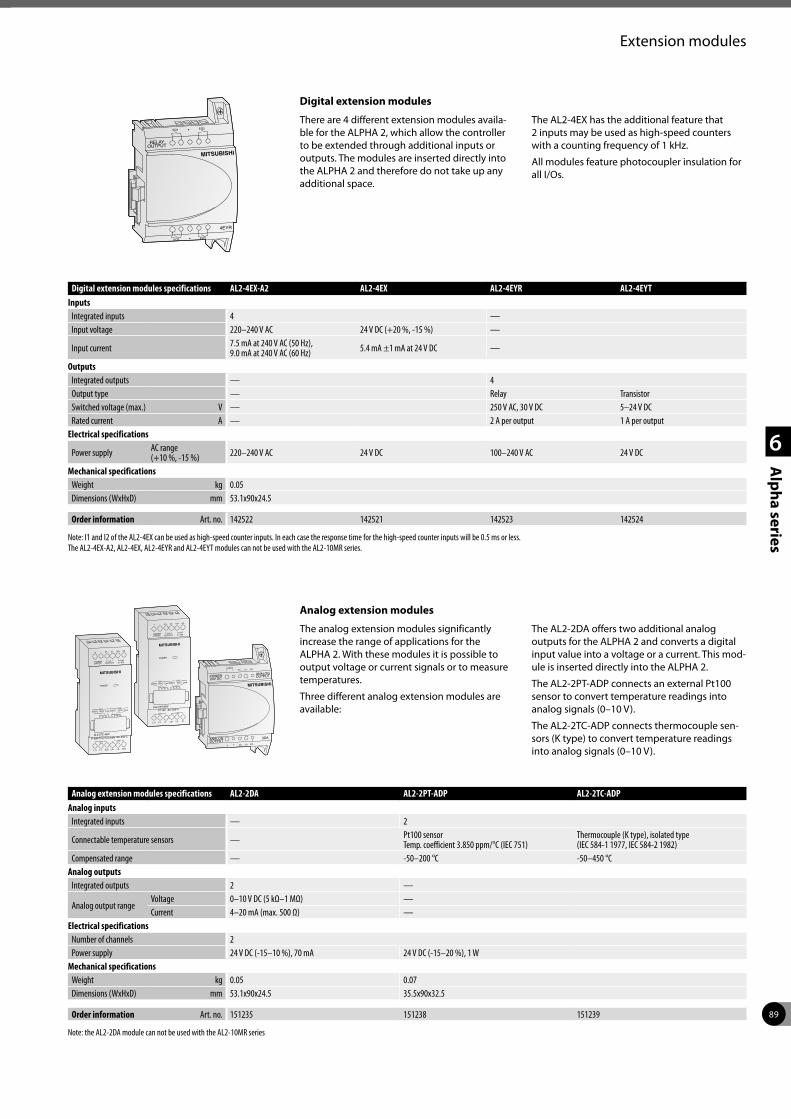
89
1
2
3
4
6
Alpha series
Extension modules
Digital extension modules
There are 4 different extension modules availa-ble for the ALPHA 2, which allow the controller to be extended through additional inputs or outputs. The modules are inserted directly into the ALPHA 2 and therefore do not take up any additional space.
The AL2-4EX has the additional feature that 2 inputs may be used as high-speed counters with a counting frequency of 1 kHz.
All modules feature photocoupler insulation for all I/Os.
MITSUBISHI
EO1
EO3 EO4
EO2
4EYR
RELAYOUTPUT
POWER24V DC
MITSUBISHI
POWER
V1+
SLD
+
K-type Thermocouple -50~450°CAL2-2TC-ADP
L1+
-
L1-
V2+
L2-
V1-
L2+
V2-
SLD
OUTPUTCH1 CH2
0~10V
450°C 450°CCH1 CH2
-50°C -50°CLine Line
CH1 CH2
POWER24V DC
MITSUBISHI
POWER
V1+
I1-
+
PT100 -50~200°CAL2-2PT-ADP
L1+
-
L1-
V2+
L2-
V1-
L2+
V2-
I2-
OUTPUTCH1 CH2
0~10V
200°C 200°CCH1 CH2
-50°C -50°CLine Line
CH1 CH2
MITSUBISHI
2DA
+ V1+ I1+ VI1--
V2+ I2+ VI2-
POWER24V DC
ANALOGOUTPUT
ANALOGOUTPUT
Analog extension modules
The analog extension modules significantly increase the range of applications for the ALPHA 2. With these modules it is possible to output voltage or current signals or to measure temperatures.
Three different analog extension modules are available:
The AL2-2DA offers two additional analog outputs for the ALPHA 2 and converts a digital input value into a voltage or a current. This mod-ule is inserted directly into the ALPHA 2.
The AL2-2PT-ADP connects an external Pt100 sensor to convert temperature readings into analog signals (0–10 V).
The AL2-2TC-ADP connects thermocouple sen-sors (K type) to convert temperature readings into analog signals (0–10 V).
Digital extension modules specifications AL2-4EX-A2 AL2-4EX AL2-4EYR AL2-4EYTInputs
Integrated inputs 4 —Input voltage 220–240 V AC 24 V DC (+20 %, -15 %) —
Input current 7.5 mA at 240 V AC (50 Hz), 9.0 mA at 240 V AC (60 Hz) 5.4 mA ±1 mA at 24 V DC —
OutputsIntegrated outputs — 4Output type — Relay TransistorSwitched voltage (max.) V — 250 V AC, 30 V DC 5–24 V DCRated current A — 2 A per output 1 A per output
Electrical specifications
Power supply AC range (+10 %, -15 %) 220–240 V AC 24 V DC 100–240 V AC 24 V DC
Mechanical specificationsWeight kg 0.05Dimensions (WxHxD) mm 53.1x90x24.5
Order information Art. no. 142522 142521 142523 142524
Note: I1 and I2 of the AL2-4EX can be used as high-speed counter inputs. In each case the response time for the high-speed counter inputs will be 0.5 ms or less. The AL2-4EX-A2, AL2-4EX, AL2-4EYR and AL2-4EYT modules can not be used with the AL2-10MR series.
Analog extension modules specifications AL2-2DA AL2-2PT-ADP AL2-2TC-ADP Analog inputs
Integrated inputs — 2
Connectable temperature sensors — Pt100 sensor Temp. coefficient 3.850 ppm/°C (IEC 751)
Thermocouple (K type), isolated type (IEC 584-1 1977, IEC 584-2 1982)
Compensated range — -50–200 °C -50–450 °CAnalog outputs
Integrated outputs 2 —
Analog output rangeVoltage 0–10 V DC (5 kΩ–1 MΩ) —Current 4–20 mA (max. 500 Ω) —
Electrical specificationsNumber of channels 2Power supply 24 V DC (-15–10 %), 70 mA 24 V DC (-15–20 %), 1 W
Mechanical specificationsWeight kg 0.05 0.07Dimensions (WxHxD) mm 53.1x90x24.5 35.5x90x32.5
Order information Art. no. 151235 151238 151239
Note: the AL2-2DA module can not be used with the AL2-10MR series
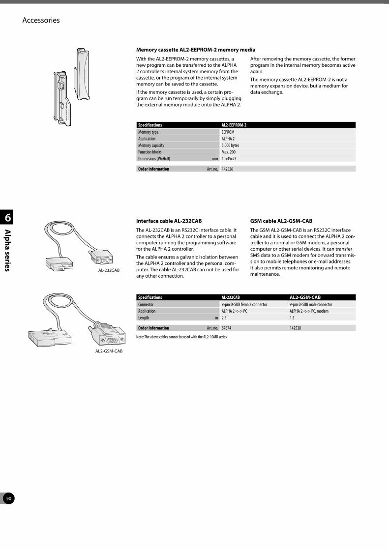
90
1
2
3
4
6
Alpha series
Accessories
AL2-E
EP
RO
MM
AD
E I
N J
APA
N
Memory cassette AL2-EEPROM-2 memory media
With the AL2-EEPROM-2 memory cassettes, a new program can be transferred to the ALPHA 2 controller’s internal system memory from the cassette, or the program of the internal system memory can be saved to the cassette.
If the memory cassette is used, a certain pro-gram can be run temporarily by simply plugging the external memory module onto the ALPHA 2.
After removing the memory cassette, the former program in the internal memory becomes active again.
The memory cassette AL2-EEPROM-2 is not a memory expansion device, but a medium for data exchange.
Specifications AL2-EEPROM-2Memory type EEPROMApplication ALPHA 2Memory capacity 5,000 bytesFunction blocks Max. 200Dimensions (WxHxD) mm 10x45x25
Order information Art. no. 142526
AL2-GSM-CABLOT .24
MITSUBISHI ELECTRIC
AL-232CAB
AL2-GSM-CAB
Interface cable AL-232CAB
The AL-232CAB is an RS232C interface cable. It connects the ALPHA 2 controller to a personal computer running the programming software for the ALPHA 2 controller.
The cable ensures a galvanic isolation between the ALPHA 2 controller and the personal com-puter. The cable AL-232CAB can not be used for any other connection.
GSM cable AL2-GSM-CAB
The GSM AL2-GSM-CAB is an RS232C interface cable and it is used to connect the ALPHA 2 con-troller to a normal or GSM modem, a personal computer or other serial devices. It can transfer SMS data to a GSM modem for onward transmis-sion to mobile telephones or e-mail addresses. It also permits remote monitoring and remote maintenance.
Specifications AL-232CAB AL2-GSM-CAB Connector 9-pin D-SUB female connector 9-pin D-SUB male connectorApplication ALPHA 2 <-> PC ALPHA 2 <-> PC, modemLength m 2.5 1.5
Order information Art. no. 87674 142528
Note: The above cables cannot be used with the AL2-10MR series.
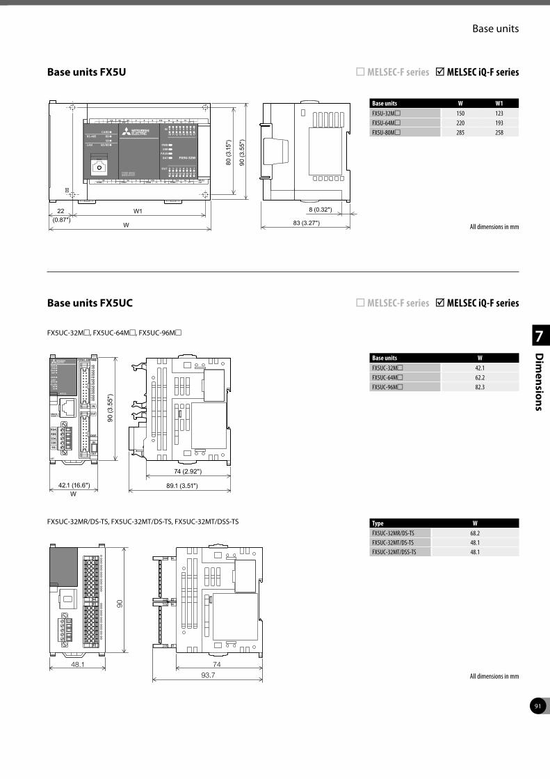
91
1
2
3
4
7
Dim
ensions
Base units
Base units FX5U ¨ MELSEC-F series þ MELSEC iQ-F series
All dimensions in mm
Base units FX5UC ¨ MELSEC-F series þ MELSEC iQ-F series
Base units W W1FX5U-32Mm 150 123FX5U-64Mm 220 193FX5U-80Mm 285 258
All dimensions in mm
W1
W 83 (3.27")
22 (0.87")
8 (0.32")
80 (3
.15"
)
90 (3
.55"
)
90 (3
.55"
)
89.1 (3.51")42.1 (16.6")
74 (2.92")
W
Base units WFX5UC-32Mm 42.1FX5UC-64Mm 62.2FX5UC-96Mm 82.3
90
48.1
93.7
74
FX5UC-32Mm, FX5UC-64Mm, FX5UC-96Mm
FX5UC-32MR/DS-TS, FX5UC-32MT/DS-TS, FX5UC-32MT/DSS-TS Type WFX5UC-32MR/DS-TS 68.2FX5UC-32MT/DS-TS 48.1FX5UC-32MT/DSS-TS 48.1
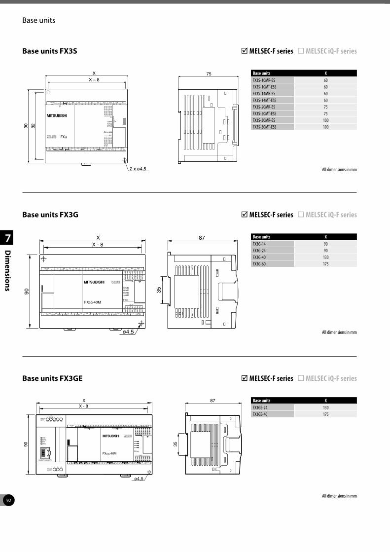
92
1
2
3
4
7
Dim
ensions
Base units
Base units FX3S þ MELSEC-F series ¨ MELSEC iQ-F series
All dimensions in mm
X – 8X
2 x ø4,5
8290
75
87
90
XX - 8
ø4,5
35
Base units XFX3S-10MR-ES 60FX3S-10MT-ESS 60FX3S-14MR-ES 60FX3S-14MT-ESS 60FX3S-20MR-ES 75FX3S-20MT-ESS 75FX3S-30MR-ES 100FX3S-30MT-ESS 100
All dimensions in mm
Base units FX3G þ MELSEC-F series ¨ MELSEC iQ-F series
Base units XFX3G-14 90FX3G-24 90FX3G-40 130FX3G-60 175
All dimensions in mm
87
90
XX - 8
ø4,5
35
Base units FX3GE þ MELSEC-F series ¨ MELSEC iQ-F series
Base units XFX3GE-24 130FX3GE-40 175
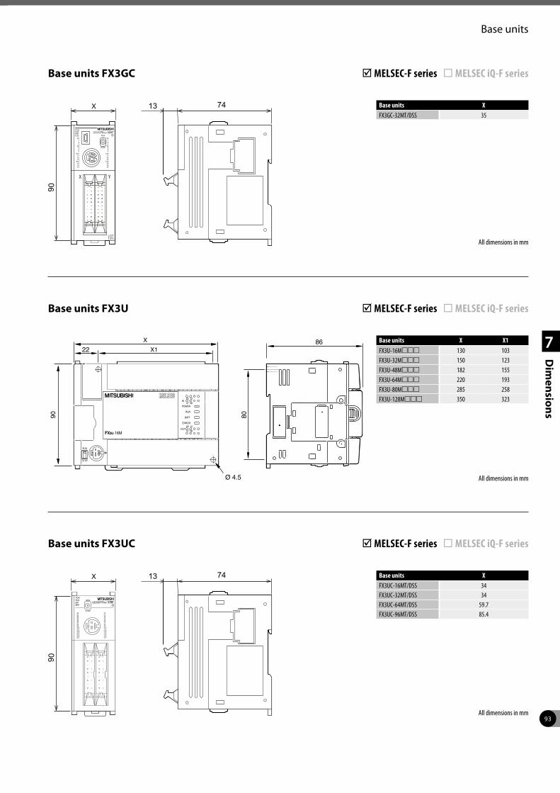
93
1
2
3
4
7
Dim
ensions
Base units
Base units FX3U þ MELSEC-F series ¨ MELSEC iQ-F series
All dimensions in mm
Base units FX3UC þ MELSEC-F series ¨ MELSEC iQ-F series
Base units X X1FX3U-16Mmmm 130 103FX3U-32Mmmm 150 123FX3U-48Mmmm 182 155FX3U-64Mmmm 220 193FX3U-80Mmmm 285 258FX3U-128Mmmm 350 323
All dimensions in mm
ERROR
R
RUN
BATT
POWER
03 12
03 12IN
OUT
47 56
47 56
Y7Y6Y5Y4Y3Y2Y1Y0Y4 Y6 Y7Y3Y2Y1Y0 Y5
X5X0
X1X2
X3 X7X40V
N 24VX6
LS/S
FX3U-16MFX3U
X1
X
Ø 4.5
8090
8622
X Base units XFX3UC-16MT/DSS 34FX3UC-32MT/DSS 34FX3UC-64MT/DSS 59.7FX3UC-96MT/DSS 85.4
All dimensions in mm
Base units FX3GC þ MELSEC-F series ¨ MELSEC iQ-F series
Base units XFX3GC-32MT/DSS 35
X
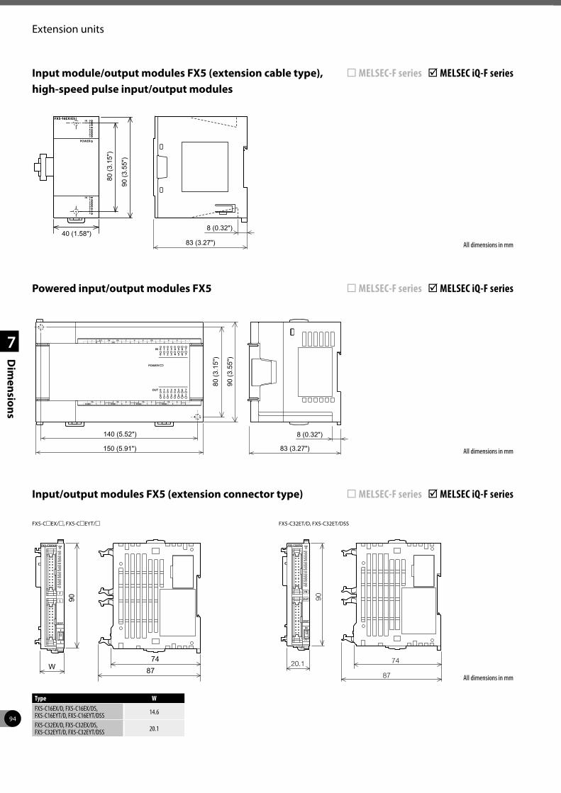
94
1
2
3
4
7
Dim
ensions
Extension units
All dimensions in mm83 (3.27")
8 (0.32")
80 (3
.15"
)
90 (3
.55"
)
140 (5.52")
150 (5.91")
Powered input/output modules FX5 ¨ MELSEC-F series þ MELSEC iQ-F series
Input/output modules FX5 (extension connector type) ¨ MELSEC-F series þ MELSEC iQ-F series
All dimensions in mm
90
8774
W
FX5-CmEX/m, FX5-CmEYT/m
Type WFX5-C16EX/D, FX5-C16EX/DS, FX5-C16EYT/D, FX5-C16EYT/DSS 14.6
FX5-C32EX/D, FX5-C32EX/DS, FX5-C32EYT/D, FX5-C32EYT/DSS 20.1
90
87
7420.1
FX5-C32ET/D, FX5-C32ET/DSS
All dimensions in mm83 (3.27")
8 (0.32")40 (1.58")
80 (3
.15"
)
90 (3
.55"
)
Input module/output modules FX5 (extension cable type), high-speed pulse input/output modules
¨ MELSEC-F series þ MELSEC iQ-F series
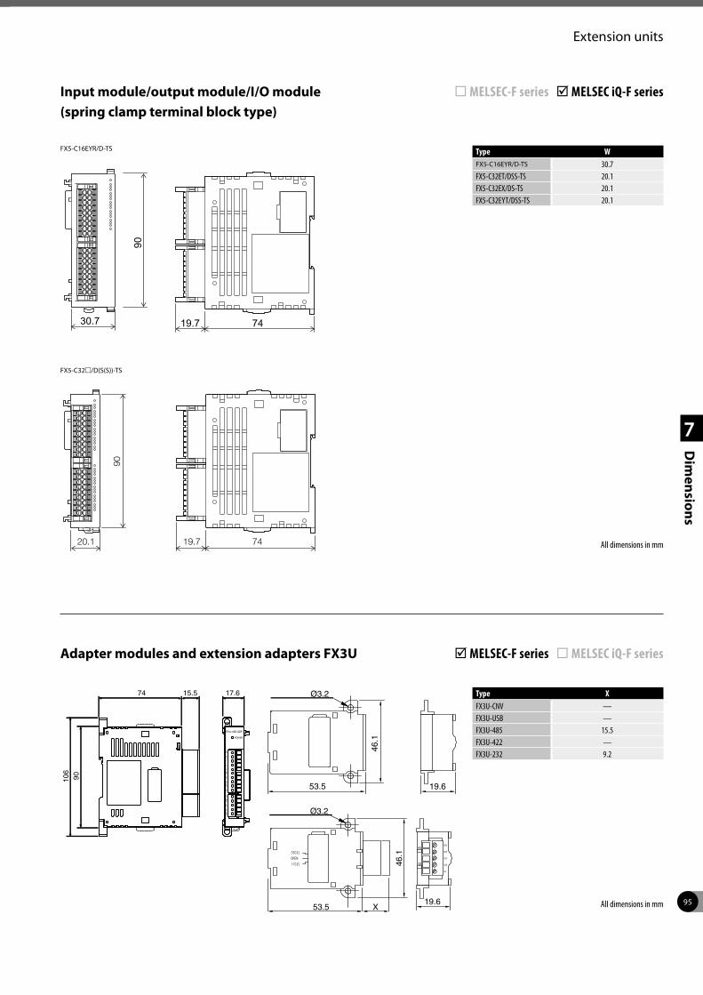
95
1
2
3
4
7
Dim
ensions
Extension units
Type XFX3U-CNV —FX3U-USB —FX3U-485 15.5FX3U-422 —FX3U-232 9.2
All dimensions in mm
Adapter modules and extension adapters FX3U þ MELSEC-F series ¨ MELSEC iQ-F series
17.674 15.5
90106
POWER
FX3U-4AD-ADP
24+
24-
V1+
I1+
COM
1V
2+I2
+CO
M2
V3+
I3+
COM
3V
4+I4
+CO
M4
53.5
46.1
19.6
Ø3.2
53.5 X
46.1
19.6
Ø3.2
All dimensions in mm20.1 7419.7
90
Input module/output module/I/O module (spring clamp terminal block type)
¨ MELSEC-F series þ MELSEC iQ-F series
FX5-C32m/D(S(S))-TS
30.7
90
7419.7
FX5-C16EYR/D-TS Type WFX5-C16EYR/D-TS 30.7FX5-C32ET/DSS-TS 20.1FX5-C32EX/DS-TS 20.1FX5-C32EYT/DSS-TS 20.1
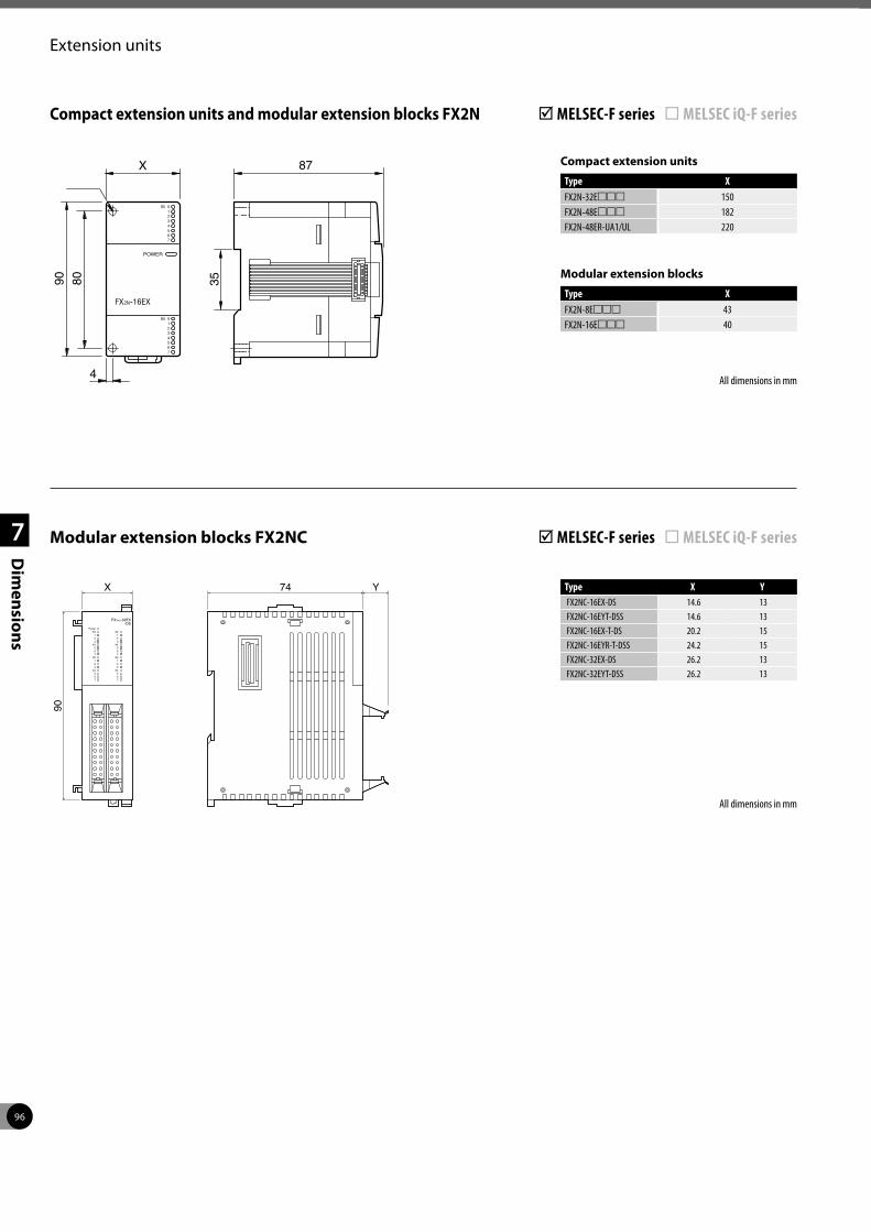
96
1
2
3
4
7
Dim
ensions
Extension units
Modular extension blocks
Type XFX2N-8Emmm 43FX2N-16Emmm 40
Type X YFX2NC-16EX-DS 14.6 13FX2NC-16EYT-DSS 14.6 13FX2NC-16EX-T-DS 20.2 15FX2NC-16EYR-T-DSS 24.2 15FX2NC-32EX-DS 26.2 13FX2NC-32EYT-DSS 26.2 13
All dimensions in mm
Compact extension units and modular extension blocks FX2N þ MELSEC-F series ¨ MELSEC iQ-F series
All dimensions in mm
Modular extension blocks FX2NC þ MELSEC-F series ¨ MELSEC iQ-F series
Compact extension units
Type XFX2N-32Emmm 150FX2N-48Emmm 182FX2N-48ER-UA1/UL 220
80
ø4,587X
90 35
FX -16EX2N
POWER
0
0
1
1
2
2
3
3
4
4
5
5
6
6
7
7
IN
IN
4
1 1
1 1
X0 X0
X0 X0Power
2 2
2 2
3 3
3 3
5 5
5 5
6 6
6 6
7 7
7 7
X4 X4
X4 X4
FX2NC-32EX-DS
X 74 Y
90
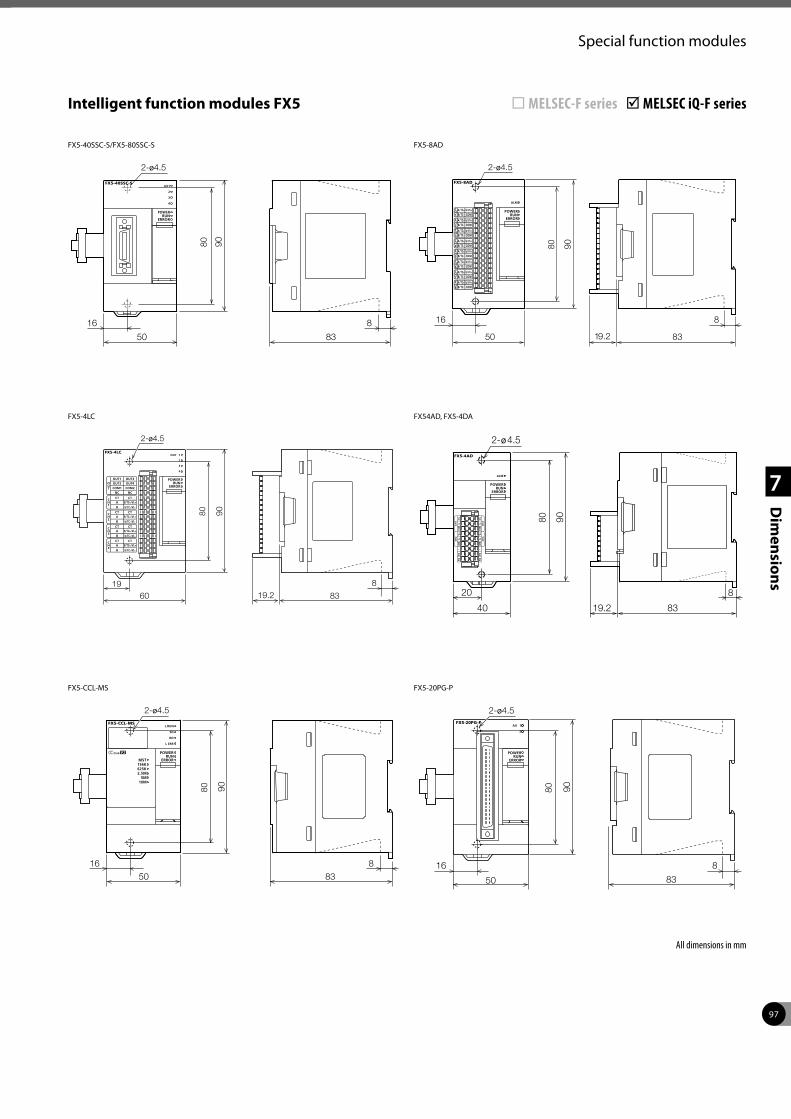
97
1
2
3
4
7
Dim
ensions
Special function modules
16 8
50
80 90
83
2-ø4.5
FX5-40SSC-S/FX5-80SSC-S
Intelligent function modules FX5 ¨ MELSEC-F series þ MELSEC iQ-F series
16
50
80 90
8
8319.2
2-ø4.5
FX5-8AD
1960
80 90
8319.2
2-ø4.5
8
FX5-4LC
20
40
90
8
8319.2
80
2-ø4.5
FX54AD, FX5-4DA
50
80 90
83
2-ø4.5
16 8
FX5-CCL-MS
50
9080
83
2-ø4.5
16 8
FX5-20PG-P
All dimensions in mm
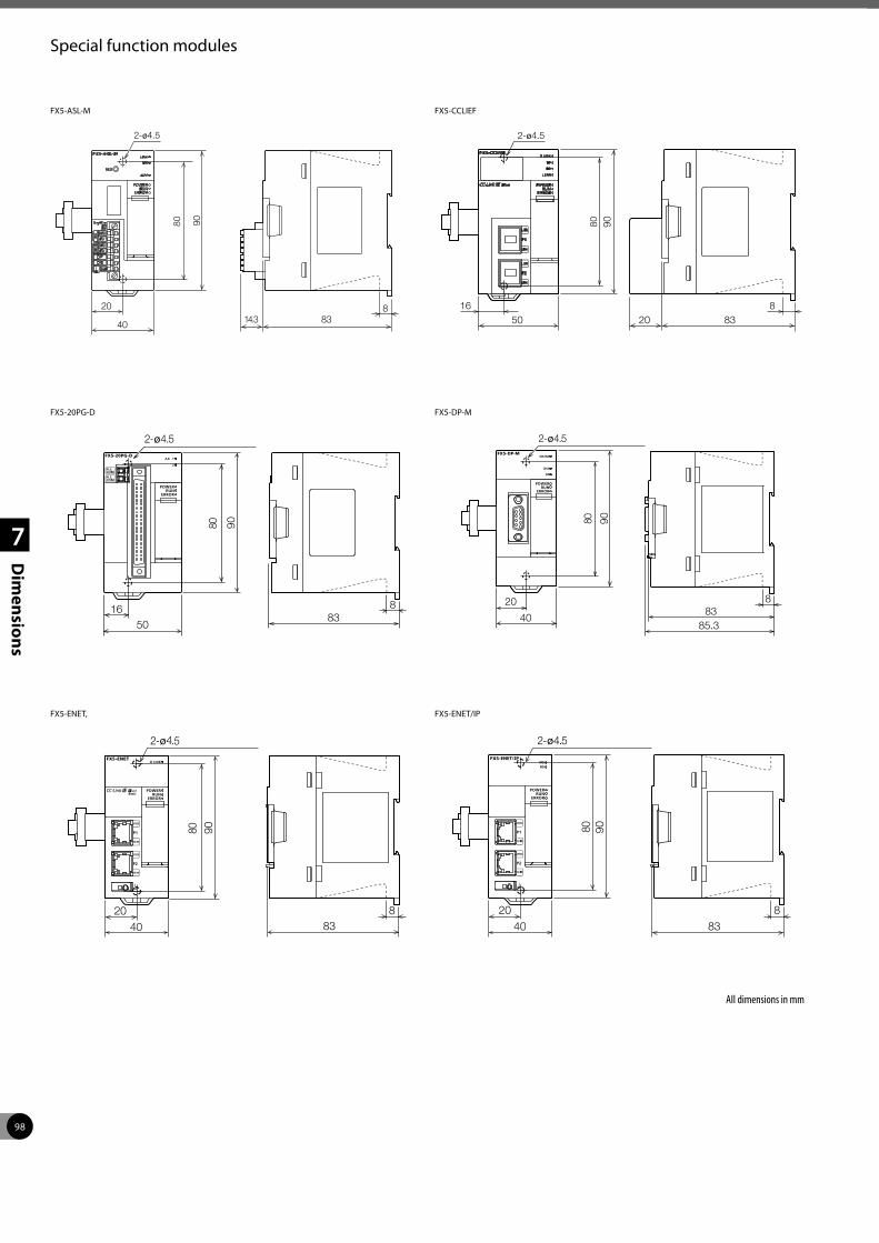
98
1
2
3
4
7
Dim
ensions
Special function modules
20
40
80 90
883
2-ø4.5
14.3
FX5-ASL-M
2-ø4.5
50
80 90
832016 8
FX5-CCLIEF
All dimensions in mm
1650
90
883
2-ø4.5
80
FX5-20PG-D
20
40
90
2-ø4.5
883
85.3
80
FX5-DP-M
883
9080
2040
2-ø4.5
FX5-ENET,
40
90
883
20
80
2-ø4.5
FX5-ENET/IP
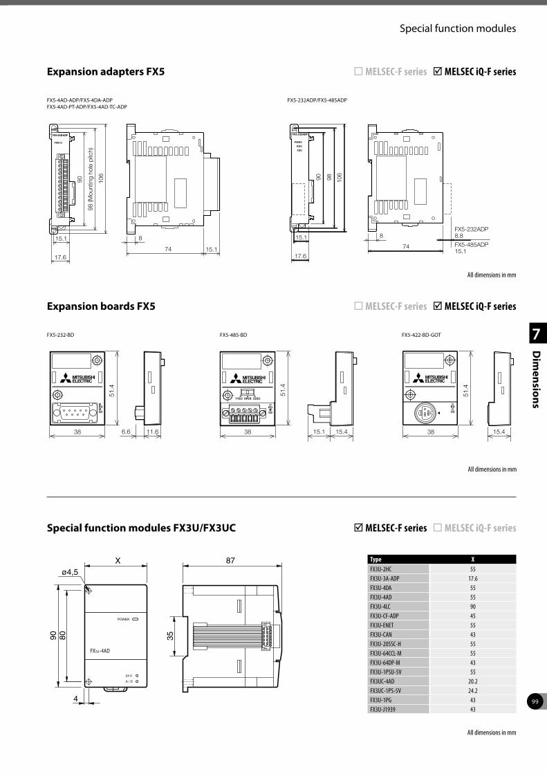
99
1
2
3
4
7
Dim
ensions
Special function modules
Type XFX3U-2HC 55FX3U-3A-ADP 17.6FX3U-4DA 55FX3U-4AD 55FX3U-4LC 90FX3U-CF-ADP 45FX3U-ENET 55FX3U-CAN 43FX3U-20SSC-H 55FX3U-64CCL-M 55FX3U-64DP-M 43FX3U-1PSU-5V 55FX3UC-4AD 20.2FX3UC-1PS-5V 24.2FX3U-1PG 43FX3U-J1939 43
Special function modules FX3U/FX3UC þ MELSEC-F series ¨ MELSEC iQ-F series
87X
8090 35
FX -4AD3U
POWER
24 V
A / D
4
ø4,5
Expansion adapters FX5 ¨ MELSEC-F series þ MELSEC iQ-F series
8
74 15.1
90
98 (M
ount
ing
hole
pitc
h)
106
15.1
17.6
FX5-4AD-ADP/FX5-4DA-ADPFX5-4AD-PT-ADP/FX5-4AD-TC-ADP
74
8
17.6
FX5-232ADP8.8
FX5-485ADP15.1
15.1
90 98
106
FX5-232ADP/FX5-485ADP
All dimensions in mm
Expansion boards FX5 ¨ MELSEC-F series þ MELSEC iQ-F series
15.415.138 11.66.6
51.4
38
51.4
38
51.4
15.4
FX5-232-BD FX5-485-BD FX5-422-BD-GOT
All dimensions in mm
All dimensions in mm
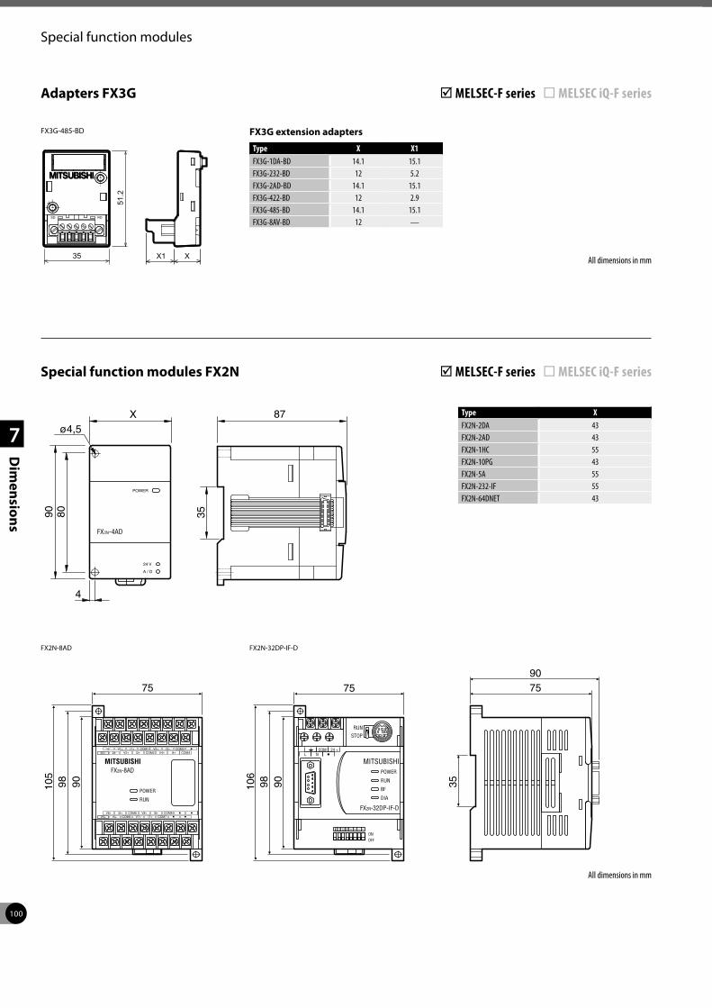
100
1
2
3
4
7
Dim
ensions
Special function modules
Special function modules FX2N þ MELSEC-F series ¨ MELSEC iQ-F series
All dimensions in mm
87X
8090 35
FX -4AD2N
POWER
24 V
A / D
4
ø4,5
35
7590
MITSUBISHIFX2N-8AD
POWER
RUN
9098105
75
V1+24+ 24-
I1+ COM1COM4V2+ I2+
V3+COM2
I3+V4+
COM3I4+
I6+V6+V5+ I5+
COM6 V8+COM5 V7+
I8+I7+
COM8COM7
COM 24 +L N
MITSUBISHIPOWER
RUN
RUN
ONOFF
STOP
BF
DIA
FX2N-32DP-IF-D
64 32 16 8 4 2 1
9098106
75
FX2N-32DP-IF-DFX2N-8AD
FX3G extension adapters
Type X X1FX3G-1DA-BD 14.1 15.1FX3G-232-BD 12 5.2FX3G-2AD-BD 14.1 15.1FX3G-422-BD 12 2.9FX3G-485-BD 14.1 15.1FX3G-8AV-BD 12 —
Adapters FX3G þ MELSEC-F series ¨ MELSEC iQ-F series
All dimensions in mm
FX3G-485-BD
Type XFX2N-2DA 43FX2N-2AD 43FX2N-1HC 55FX2N-10PG 43FX2N-5A 55FX2N-232-IF 55FX2N-64DNET 43
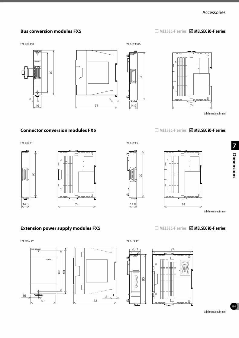
101
1
2
3
4
7
Dim
ensions
Accessories
Bus conversion modules FX5 ¨ MELSEC-F series þ MELSEC iQ-F series
88
16
90
83
FX5-CNV-BUS
90
7414.6
FX5-CNV-BUSC
All dimensions in mm
Connector conversion modules FX5 ¨ MELSEC-F series þ MELSEC iQ-F series
14.6 74
90
FX5-CNV-IF
14.6 74
90FX5-CNV-IFC
All dimensions in mm
Extension power supply modules FX5 ¨ MELSEC-F series þ MELSEC iQ-F series
883
90
80
50
16
FX5-1PSU-5V
20.1 74
90
FX5-C1PS-5V
All dimensions in mm
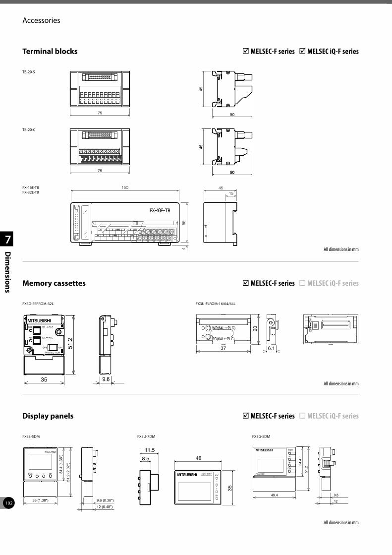
102
1
2
3
4
7
Dim
ensions
Accessories
Terminal blocks þ MELSEC-F series þ MELSEC iQ-F series
TB-20-S
45
5075
45
50
45
5075
TB-20-C
Memory cassettes þ MELSEC-F series ¨ MELSEC iQ-F series
FX3G-EEPROM-32L FX3U-FLROM-16/64/64L
All dimensions in mm
All dimensions in mm
150 4515
554
FX-16E-TBFX-32E-TB
Display panels þ MELSEC-F series ¨ MELSEC iQ-F series
35
48
11.5
8.5
FX3U-7DM FX3G-5DM
34.4
(1.3
6")
51.2
(2.0
2")
35 (1.38") 9.6 (0.38")
12 (0.48")
FX3S-5DM
All dimensions in mm
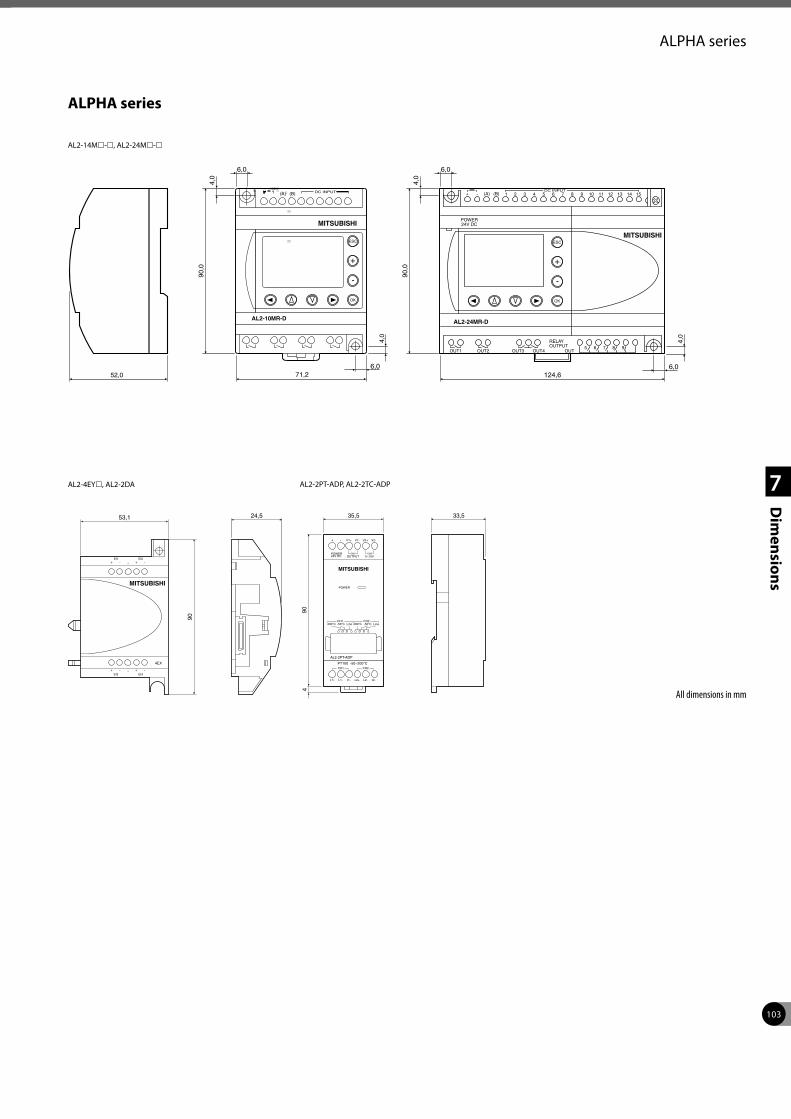
103
1
2
3
4
7
Dim
ensions
ALPHA series
ALPHA series
(A) (B)
6,06,0
124,6
90,0
90,0
4,0
4,0
DC INPUT
6,06,0
4,0
4,0
52,0
ĐĐ
ĐĐĐ
Đ Đ Đ ĐĐ Đ
ĐĐĐĐĐĐĐĐĐ
MITSUBISHI
AL2-10MR-D
ESC
+
-
OK
+ -
POWER24V DC
RELAYOUTPUT 5 6 7 8 9
AL2-24MR-D
6 12 13 14 155 114 103 92 81(A) (B) 7DC INPUT
MITSUBISHIESC
+
-
OK
OUT1 OUT2 OUT3 OUT4 OUT
71,2
AL2-14Ml-l, AL2-24Ml-l
MITSUBISHI
4EX
EI1+
+
+
+
-
-
-
-EI3
EI2
EI4
53,1 24,5
90
MITSUBISHI
POWER
I1-
PT100 -50~200°C
AL2-2PT-ADP
L1+ L1- L2-L2+ I2-
POWER24V DC
V1++ - V2+V1- V2-
OUTPUTCH1 CH2
0~10V
200°C 200°CCH1 CH2-50°C -50°CLine Line
CH1 CH2
35,5
904
33,5
AL2-4EYl, AL2-2DA AL2-2PT-ADP, AL2-2TC-ADP
All dimensions in mm
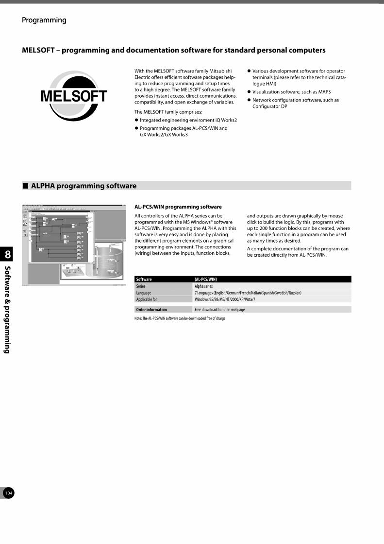
104
Programming
1
2
3
4
8
Software &
programm
ing
Programming
MELSOFT – programming and documentation software for standard personal computers
With the MELSOFT software family Mitsubishi Electric offers efficient software packages help-ing to reduce programming and setup times to a high degree. The MELSOFT software family provides instant access, direct communications, compatibility, and open exchange of variables.
The MELSOFT family comprises:
z Integated engineering enviroment iQ Works2
z Programming packages AL-PCS/WIN and GX Works2/GX Works3
z Various development software for operator terminals (please refer to the technical cata-logue HMI)
z Visualization software, such as MAPS
z Network configuration software, such as Configurator DP
ALPHA programming software
AL-PCS/WIN programming software
All controllers of the ALPHA series can be programmed with the MS Windows® software AL-PCS/WIN. Programming the ALPHA with this software is very easy and is done by placing the different program elements on a graphical programming environment. The connections (wiring) between the inputs, function blocks,
and outputs are drawn graphically by mouse click to build the logic. By this, programs with up to 200 function blocks can be created, where each single function in a program can be used as many times as desired.
A complete documentation of the program can be created directly from AL-PCS/WIN.
Software (AL-PCS/WIN)Series Alpha seriesLanguage 7 languages (English/German/French/Italian/Spanish/Swedish/Russian)Applicable for Windows 95/98/ME/NT/2000/XP/Vista/7
Order information Free download from the webpage
Note: The AL-PCS/WIN software can be downloaded free of charge
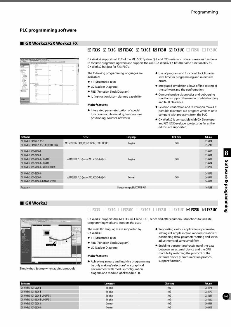
105
Programming
1
2
3
4
8
Software &
programm
ing
PLC programming software
GX Works2/GX Works2 FX þ FX3S þ FX3G þ FX3GC þ FX3GE þ FX3U þ FX3UC ¨ FX5U ¨ FX5UC
GX Works2 supports all PLC of the MELSEC System Q, L and FX3 series and offers numerous functions to faciliate programming work and support the user. GX Works2 FX has the same functionality as GX Works2 but just for FX3 PLC’s.
The following programming languages are available:
z ST (Structured Text)
z LD (Ladder Diagram)
z FBD (Function Block Diagram)
z IL (Instruction List) – planned capability
Main features
z Integrated parameterization of special function modules (analog, temperature, positioning, counter, network)
z Use of program and function block libraries save time for programming and minimizes errors.
z Integrated simulation allows offline testing of the software and the configuration.
z Comprehensive diagnostics and debugging functions support the user in troubleshooting and fault clearance.
z Revision verification and restoration makes it possible to restore old program versions or to compare with programs from the PLC.
z GX Works2 is compatible with GX Developer and GX IEC Developer projects (as far as the editors are supported)
Software Series Language Disk type Art. no.GX Works2 FX V01-2L0C-E
MELSEC FX3S, FX3G, FX3GC, FX3GE, FX3U, FX3UC English DVD255804
GX Works2 FX V01-2L0C-E-INTRODUCTION 256745
GX Works2 V01-2L0C-E
All MELSEC PLCs (except MELSEC iQ-R/iQ-F) English DVD
234630GX Works2 V01-5L0C-E 234631GX Works2 V01-2L0C-E-UPGRADE 234632GX Works2 V01-5L0C-E-UPGRADE 234634GX Works2 V01-2L0C-E-INTRODUCTION 234789
GX Works2 V01-2L0C-GAll MELSEC PLCs (except MELSEC iQ-R/iQ-F) German DVD
244876GX Works2 V01-5L0C-G 244877GX Works2 V01-2L0C-G-INTRODUCTION 244878
Accessory Programming cable FX-USB-AW 165288
GX Works3 ¨ FX3S ¨ FX3G ¨ FX3GC ¨ FX3GE ¨ FX3U ¨ FX3UC þ FX5U þ FX5UC
GX Works3 supports the MELSEC iQ-F (and iQ-R) series and offers numerous functions to faciliate programming work and support the user.
The main IEC languages are supported by GX Works3:
z ST (Structured Text)
z FBD (Function Block Diagram)
z LD (Ladder Diagram)
Main features
z Achieving an easy and intuitive programming by only making “selections” in a graphical environment with module configuration diagram and module label/module FB.
z Supporting various applications (parameter settings of simple motion module, creation of positioning data, parameter setting and servo adjustments of servo amplifier).
z Enabling transmitting/receiving of the data between an external device and the CPU module by matching the protocol of the external device (Communication protocol support function).
Drag & Drop
Simply drag & drop when adding a module
Software Language Disk type Art. no.GX Works3 V01-2L0C-E English DVD 284378GX Works3 V01-5L0C-E English DVD 284379GX Works3 V01-2L0C-E-UPGRADE English DVD 286219GX Works3 V01-5L0C-E-UPGRADE English DVD 286220GX Works3 V01-2L0C-G German DVD 304614GX Works3 V01-5L0C-G German DVD 304645
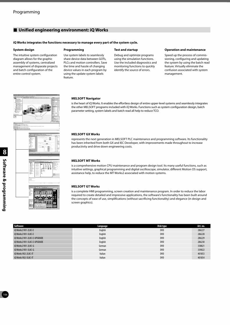
106
Programming
1
2
3
4
8
Software &
programm
ing
iQ Works integrates the functions necessary to manage every part of the system cycle.
System design
The intuitive system configuration diagram allows for the graphic assembly of systems, centralized management of disparate projects and batch configuration of the entire control system.
Programming
Use system labels to seamlessly share device data between GOTs, PLCs and motion controllers. Save the time and hassle of changing device values in each program by using the update system labels feature.
Test and startup
Debug and optimize programs using the simulation functions. Use the included diagnostics and monitoring functions to quickly identify the source of errors.
Operation and maintenance
Speed up the process of commis-sioning, configuring and updating the system by using the batch read feature. Virtually eliminate the confusion associated with system management.
MELSOFT GT Worksis a complete HMI programming, screen creation and maintenance program. In order to reduce the labor required to create detailed and impressive applications, the software’s functionality has been built around the concepts of ease of use, simplifications (without sacrificing functionality) and elegance (in design and screen graphics).
Unified engineering environment: iQ Works
MELSOFT Navigatoris the heart of iQ Works. It enables the effortless design of entire upper-level systems and seamlessly integrates the other MELSOFT programs included with iQ Works. Functions such as system configuration design, batch parameter setting, system labels and batch read all help to reduce TCO.
MELSOFT GX Worksrepresents the next generation in MELSOFT PLC maintenance and programming software. Its functionality has been inherited from both GX and IEC Developer, with improvements made throughout to increase productivity and drive down engineering costs.
MELSOFT MT Worksis a comprehensive motion CPU maintenance and program design tool. Its many useful functions, such as intuitive settings, graphical programming and digital oscilloscope, simulator, different Motion OS support, assistance help, to reduce the MT Works2 associated with motion systems.
Software Language Disk type Art. no.iQ Works2 V01-2L0C-E English DVD 286227iQ Works2 V01-5L0C-E English DVD 286228iQ Works2 V01-2L0C-E-UPGRADE English DVD 286229iQ Works2 V01-5L0C-E-UPGRADE English DVD 286230iQ Works2 V01-2L0C-G German DVD 338821iQ Works2 V01-5L0C-G German DVD 339022iQ Works V02-2L0C-IT Italian DVD 401853iQ Works V02-5L0C-IT Italian DVD 401854
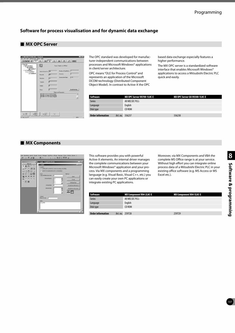
107
Programming
1
2
3
4
8
Software &
programm
ing
Software for process visualisation and for dynamic data exchange
Software MX OPC Server V0700-1L0C-E MX OPC Server UA V0300-1L0C-ESeries All MELSEC PLCsLanguage EnglishDisk type CD ROM
Order information Art. no. 336237 336238
The OPC standard was developed for manufac-turer independent communications between processes and Microsoft Windows® applications in client/server architecture.
OPC means “OLE for Process Control” and represents an application of the Microsoft DCOM technology (Distributed Component Object Model). In contrast to Active-X the OPC
based data exchange especially features a higher performance.
The MX OPC server is a standardized software interface that enables Microsoft Windows® applications to access a Mitsubishi Electric PLC quick and easily.
Software MX Component V04-2L0C-E MX Component V04-5L0C-ESeries All MELSEC PLCsLanguage EnglishDisk type CD ROM
Order information Art. no. 259728 259729
This software provides you with powerful Active-X elements. An internal driver manages the complete communications between your Microsoft Windows® application and your pro-cess. Via MX components and a programming language (e.g. Visual Basic, Visual C++, etc.) you can easily create your own PC applications or integrate existing PC applications.
Moreover, via MX Components and VBA the complete MS Office range is at your service. Without high effort you can integrate online process data of a Mitsubishi Electric PLC in your existing office software (e.g. MS Access or MS Excel etc.).
MX Components
MX OPC Server
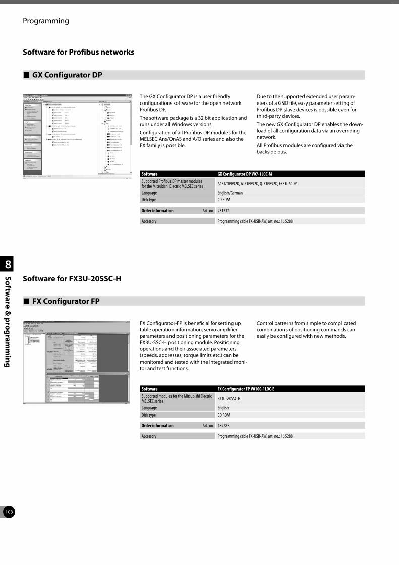
108
Programming
1
2
3
4
8
Software &
programm
ing
Software for Profibus networks
GX Configurator DP
The GX Configurator DP is a user friendly configurations software for the open network Profibus DP.
The software package is a 32 bit application and runs under all Windows versions.
Configuration of all Profibus DP modules for the MELSEC Ans/QnAS and A/Q series and also the FX family is possible.
Due to the supported extended user param-eters of a GSD file, easy parameter setting of Profibus DP slave devices is possible even for third-party devices.
The new GX Configurator DP enables the down-load of all configuration data via an overriding network.
All Profibus modules are configured via the backside bus.
Software GX Configurator DP V07-1L0C-MSupported Profibus DP master modulesfor the Mitsubishi Electric MELSEC series A1SJ71PB92D, AJ71PB92D, QJ71PB92D, FX3U-64DP
Language English/GermanDisk type CD ROM
Order information Art. no. 231731
Accessory Programming cable FX-USB-AW, art. no.: 165288
FX Configurator FP
FX Configurator-FP is beneficial for setting up table operation information, servo amplifier parameters and positioning parameters for the FX3U-SSC-H positioning module. Positioning operations and their associated parameters (speeds, addresses, torque limits etc.) can be monitored and tested with the integrated moni-tor and test functions.
Control patterns from simple to complicated combinations of positioning commands can easily be configured with new methods.
Software FX Configurator FP V0100-1LOC-ESupported modules for the Mitsubishi Electric MELSEC series FX3U-20SSC-H
Language EnglishDisk type CD ROM
Order information Art. no. 189283
Accessory Programming cable FX-USB-AW, art. no.: 165288
Software for FX3U-20SSC-H
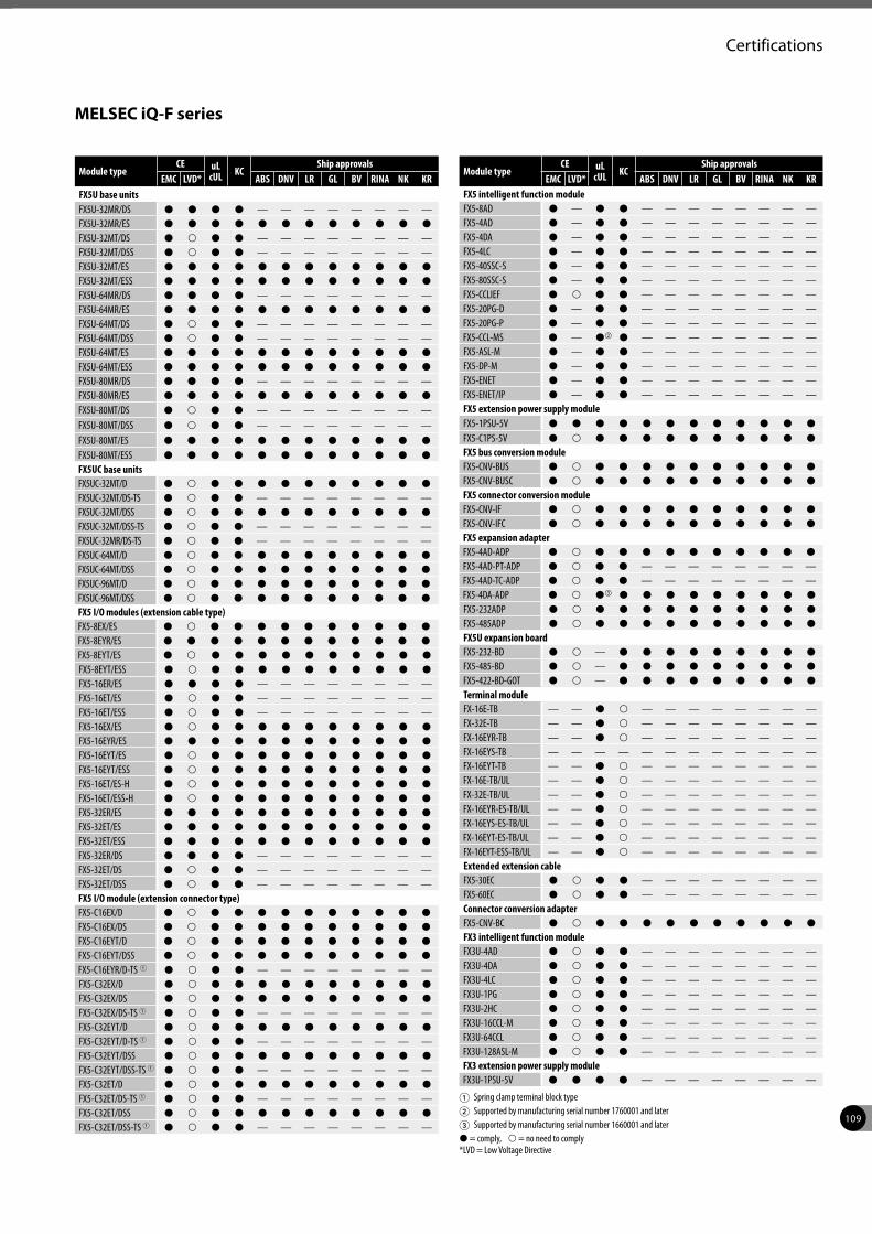
109
Certifications
Module typeCE uL
cUL KCShip approvals
EMC LVD* ABS DNV LR GL BV RINA NK KRFX5U base unitsFX5U-32MR/DS P P P P — — — — — — — —FX5U-32MR/ES P P P P P P P P P P P PFX5U-32MT/DS P p P P — — — — — — — —FX5U-32MT/DSS P p P P — — — — — — — —FX5U-32MT/ES P P P P P P P P P P P PFX5U-32MT/ESS P P P P P P P P P P P PFX5U-64MR/DS P P P P — — — — — — — —FX5U-64MR/ES P P P P P P P P P P P PFX5U-64MT/DS P p P P — — — — — — — —FX5U-64MT/DSS P p P P — — — — — — — —FX5U-64MT/ES P P P P P P P P P P P PFX5U-64MT/ESS P P P P P P P P P P P PFX5U-80MR/DS P P P P — — — — — — — —FX5U-80MR/ES P P P P P P P P P P P PFX5U-80MT/DS P p P P — — — — — — — —FX5U-80MT/DSS P p P P — — — — — — — —FX5U-80MT/ES P P P P P P P P P P P PFX5U-80MT/ESS P P P P P P P P P P P PFX5UC base unitsFX5UC-32MT/D P p P P P P P P P P P PFX5UC-32MT/DS-TS P p P P — — — — — — — —FX5UC-32MT/DSS P p P P P P P P P P P PFX5UC-32MT/DSS-TS P p P P — — — — — — — —FX5UC-32MR/DS-TS P p P P — — — — — — — —FX5UC-64MT/D P p P P P P P P P P P PFX5UC-64MT/DSS P p P P P P P P P P P PFX5UC-96MT/D P p P P P P P P P P P PFX5UC-96MT/DSS P p P P P P P P P P P PFX5 I/O modules (extension cable type)FX5-8EX/ES P p P P P P P P P P P PFX5-8EYR/ES P P P P P P P P P P P PFX5-8EYT/ES P p P P P P P P P P P PFX5-8EYT/ESS P p P P P P P P P P P PFX5-16ER/ES P P P P — — — — — — — —FX5-16ET/ES P p P P — — — — — — — —FX5-16ET/ESS P p P P — — — — — — — —FX5-16EX/ES P p P P P P P P P P P PFX5-16EYR/ES P P P P P P P P P P P PFX5-16EYT/ES P p P P P P P P P P P PFX5-16EYT/ESS P p P P P P P P P P P PFX5-16ET/ES-H P p P P P P P P P P P PFX5-16ET/ESS-H P p P P P P P P P P P PFX5-32ER/ES P P P P P P P P P P P PFX5-32ET/ES P P P P P P P P P P P PFX5-32ET/ESS P P P P P P P P P P P PFX5-32ER/DS P P P P — — — — — — — —FX5-32ET/DS P p P P — — — — — — — —FX5-32ET/DSS P p P P — — — — — — — —FX5 I/O module (extension connector type)FX5-C16EX/D P p P P P P P P P P P PFX5-C16EX/DS P p P P P P P P P P P PFX5-C16EYT/D P p P P P P P P P P P PFX5-C16EYT/DSS P p P P P P P P P P P PFX5-C16EYR/D-TS 1 P p P P — — — — — — — —FX5-C32EX/D P p P P P P P P P P P PFX5-C32EX/DS P p P P P P P P P P P PFX5-C32EX/DS-TS 1 P p P P — — — — — — — —FX5-C32EYT/D P p P P P P P P P P P PFX5-C32EYT/D-TS 1 P p P P — — — — — — — —FX5-C32EYT/DSS P p P P P P P P P P P PFX5-C32EYT/DSS-TS 1 P p P P — — — — — — — —FX5-C32ET/D P p P P P P P P P P P PFX5-C32ET/DS-TS 1 P p P P — — — — — — — —FX5-C32ET/DSS P p P P P P P P P P P PFX5-C32ET/DSS-TS 1 P p P P — — — — — — — —
Module typeCE uL
cUL KCShip approvals
EMC LVD* ABS DNV LR GL BV RINA NK KRFX5 intelligent function moduleFX5-8AD P — P P — — — — — — — —FX5-4AD P — P P — — — — — — — —FX5-4DA P — P P — — — — — — — —FX5-4LC P — P P — — — — — — — —FX5-40SSC-S P — P P — — — — — — — —FX5-80SSC-S P — P P — — — — — — — —FX5-CCLIEF P p P P — — — — — — — —FX5-20PG-D P — P P — — — — — — — —FX5-20PG-P P — P P — — — — — — — —FX5-CCL-MS P — Pb P — — — — — — — —FX5-ASL-M P — P P — — — — — — — —FX5-DP-M P — P P — — — — — — — —FX5-ENET P — P P — — — — — — — —FX5-ENET/IP P — P P — — — — — — — —FX5 extension power supply moduleFX5-1PSU-5V P P P P P P P P P P P PFX5-C1PS-5V P p P P P P P P P P P PFX5 bus conversion moduleFX5-CNV-BUS P p P P P P P P P P P PFX5-CNV-BUSC P p P P P P P P P P P PFX5 connector conversion moduleFX5-CNV-IF P p P P P P P P P P P PFX5-CNV-IFC P p P P P P P P P P P PFX5 expansion adapterFX5-4AD-ADP P p P P P P P P P P P PFX5-4AD-PT-ADP P p P P — — — — — — — —FX5-4AD-TC-ADP P p P P — — — — — — — —FX5-4DA-ADP P p Pc P P P P P P P P PFX5-232ADP P p P P P P P P P P P PFX5-485ADP P p P P P P P P P P P PFX5U expansion boardFX5-232-BD P p — P P P P P P P P PFX5-485-BD P p — P P P P P P P P PFX5-422-BD-GOT P p — P P P P P P P P PTerminal moduleFX-16E-TB — — P p — — — — — — — —FX-32E-TB — — P p — — — — — — — —FX-16EYR-TB — — P p — — — — — — — —FX-16EYS-TB — — — — — — — — — — — —FX-16EYT-TB — — P p — — — — — — — —FX-16E-TB/UL — — P p — — — — — — — —FX-32E-TB/UL — — P p — — — — — — — —FX-16EYR-ES-TB/UL — — P p — — — — — — — —FX-16EYS-ES-TB/UL — — P p — — — — — — — —FX-16EYT-ES-TB/UL — — P p — — — — — — — —FX-16EYT-ESS-TB/UL — — P p — — — — — — — —Extended extension cableFX5-30EC P p P P — — — — — — — —FX5-60EC P p P P — — — — — — — —Connector conversion adapterFX5-CNV-BC P p P P P P P P P P P PFX3 intelligent function moduleFX3U-4AD P p P P — — — — — — — —FX3U-4DA P p P P — — — — — — — —FX3U-4LC P p P P — — — — — — — —FX3U-1PG P p P P — — — — — — — —FX3U-2HC P p P P — — — — — — — —FX3U-16CCL-M P p P P — — — — — — — —FX3U-64CCL P p P P — — — — — — — —FX3U-128ASL-M P p P P — — — — — — — —FX3 extension power supply moduleFX3U-1PSU-5V P P P P — — — — — — — —
MELSEC iQ-F series
1 Spring clamp terminal block type2 Supported by manufacturing serial number 1760001 and later3 Supported by manufacturing serial number 1660001 and laterP = comply, p = no need to comply *LVD = Low Voltage Directive
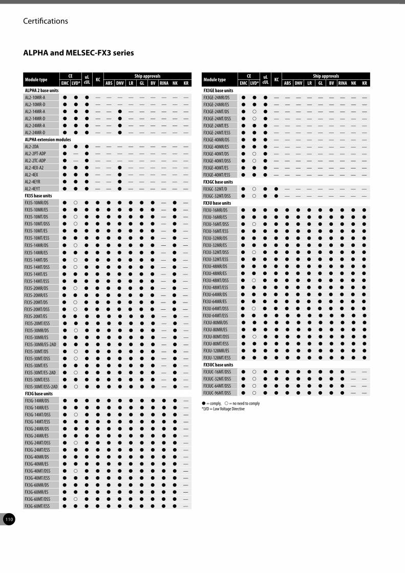
110
Certifications
Module typeCE uL
cUL KCShip approvals
EMC LVD* ABS DNV LR GL BV RINA NK KRALPHA 2 base unitsAL2-10MR-A P P P — — — — — — — — —AL2-10MR-D P P P — — — — — — — — —AL2-14MR-A P P P — — P — — — — — —AL2-14MR-D P P P — — P — — — — — —AL2-24MR-A P P P — — P — — — — — —AL2-24MR-D P P P — — P — — — — — —ALPHA extension modulesAL2-2DA P P P — — — — — — — — —AL2-2PT-ADP P — P — — — — — — — — —AL2-2TC-ADP P — P — — — — — — — — —AL2-4EX-A2 P P P — — P — — — — — —AL2-4EX P P P — — P — — — — — —AL2-4EYR P P P — — P — — — — — —AL2-4EYT P P P — — P — — — — — —FX3S base unitsFX3S-10MR/DS P p P P P P P P P — P —FX3S-10MR/ES P P P P P P P P P — P —FX3S-10MT/DS P p P P P P P P P — P —FX3S-10MT/DSS P p P P P P P P P — P —FX3S-10MT/ES P P P P P P P P P — P —FX3S-10MT/ESS P P P P P P P P P — P —FX3S-14MR/DS P p P P P P P P P — P —FX3S-14MR/ES P P P P P P P P P — P —FX3S-14MT/DS P p P P P P P P P — P —FX3S-14MT/DSS P p P P P P P P P — P —FX3S-14MT/ES P P P P P P P P P — P —FX3S-14MT/ESS P P P P P P P P P — P —FX3S-20MR/DS P p P P P P P P P — P —FX3S-20MR/ES P P P P P P P P P — P —FX3S-20MT/DS P p P P P P P P P — P —FX3S-20MT/DSS P p P P P P P P P — P —FX3S-20MT/ES P P P P P P P P P — P —FX3S-20MT/ESS P P P P P P P P P — P —FX3S-30MR/DS P p P P P P P P P — P —FX3S-30MR/ES P P P P P P P P P — P —FX3S-30MR/ES-2AD P P P P P P P P P — P —FX3S-30MT/DS P p P P P P P P P — P —FX3S-30MT/DSS P p P P P P P P P — P —FX3S-30MT/ES P P P P P P P P P — P —FX3S-30MT/ES-2AD P p P P P P P P P — P —FX3S-30MT/ESS P P P P P P P P P — P —FX3S-30MT/ESS-2AD P p P P P P P P P — P —FX3G base unitsFX3G-14MR/DS P P P P P P P P P P P —FX3G-14MR/ES P P P P P P P P P P P —FX3G-14MT/DSS P p P P P P P P P P P —FX3G-14MT/ESS P P P P P P P P P P P —FX3G-24MR/DS P P P P P P P P P P P —FX3G-24MR/ES P P P P P P P P P P P —FX3G-24MT/DSS P p P P P P P P P P P —FX3G-24MT/ESS P P P P P P P P P P P —FX3G-40MR/DS P P P P P P P P P P P —FX3G-40MR/ES P P P P P P P P P P P —FX3G-40MT/DSS P p P P P P P P P P P —FX3G-40MT/ESS P P P P P P P P P P P —FX3G-60MR/DS P P P P P P P P P P P —FX3G-60MR/ES P P P P P P P P P P P —FX3G-60MT/DSS P p P P P P P P P P P —FX3G-60MT/ESS P P P P P P P P P P P —
Module typeCE uL
cUL KCShip approvals
EMC LVD* ABS DNV LR GL BV RINA NK KRFX3GE base unitsFX3GE-24MR/DS P P P — — — — — — — — —FX3GE-24MR/ES P P P — — — — — — — — —FX3GE-24MT/DS P p P — — — — — — — — —FX3GE-24MT/DSS P p P — — — — — — — — —FX3GE-24MT/ES P P P — — — — — — — — —FX3GE-24MT/ESS P P P — — — — — — — — —FX3GE-40MR/DS P P P — — — — — — — — —FX3GE-40MR/ES P P P — — — — — — — — —FX3GE-40MT/DS P p P — — — — — — — — —FX3GE-40MT/DSS P p P — — — — — — — — —FX3GE-40MT/ES P P P — — — — — — — — —FX3GE-40MT/ESS P P P — — — — — — — — —FX3GC base unitsFX3GC-32MT/D P p P P — — — — — — — —FX3GC-32MT/DSS P p P P — — — — — — — —FX3U base unitsFX3U-16MR/DS P P P P P P P P P P P PFX3U-16MR/ES P P P P P P P P P P P PFX3U-16MT/DSS P p P P P P P P P P P PFX3U-16MT/ESS P P P P P P P P P P P PFX3U-32MR/DS P P P P P P P P P P P PFX3U-32MR/ES P P P P P P P P P P P PFX3U-32MT/DSS P p P P P P P P P P P PFX3U-32MT/ESS P P P P P P P P P P P PFX3U-48MR/DS P P P P P P P P P P P PFX3U-48MR/ES P P P P P P P P P P P PFX3U-48MT/DSS P p P P P P P P P P P PFX3U-48MT/ESS P P P P P P P P P P P PFX3U-64MR/DS P P P P P P P P P P P PFX3U-64MR/ES P P P P P P P P P P P PFX3U-64MT/DSS P p P P P P P P P P P PFX3U-64MT/ESS P P P P P P P P P P P PFX3U-80MR/DS P P P P P P P P P P P PFX3U-80MR/ES P P P P P P P P P P P PFX3U-80MT/DSS P p P P P P P P P P P PFX3U-80MT/ESS P P P P P P P P P P P PFX3U-128MR/ES P P P P P P P P P P P PFX3U-128MT/ESS P P P P P P P P P P P PFX3UC base unitsFX3UC-16MT/DSS P p P P P P P P P P — —FX3UC-32MT/DSS P p P P P P P P P P — —FX3UC-64MT/DSS P p P P P P P P P P — —FX3UC-96MT/DSS P p P P P P P P P P — —
P = comply, p = no need to comply *LVD = Low Voltage Directive
ALPHA and MELSEC-FX3 series
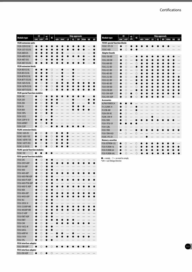
111
Certifications
P = comply, p = no need to comply *LVD = Low Voltage Directive
Module typeCE uL
cUL KCShip approvals
EMC LVD* ABS DNV LR GL BV RINA NK KRFX2N extension unitsFX2N-32ER-ES/UL P P P P P P P P P P — PFX2N-32ET-ESS/UL P P P P P P P P P P — PFX2N-48ER-DS P P P P P P — — — — — PFX2N-48ER-ES/UL P P P P P P P P P P — PFX2N-48ET-DSS P p P P P P — — — P — PFX2N-48ET-ESS/UL P P P P P P P P P P — PFX2N extension blocksFX2N-8ER-ES/UL P P P p — P — P — — — —FX2N-8EX-ES/UL P P P p — P — P — — — —FX2N-8EYR-ES/UL P P P p — P — P — — — —FX2N-8EYT-ESS/UL P P P p — P — P — — — —FX2N-16EX-ES/UL P p P p P P P P P P P PFX2N-16EYR-ES/UL P p P p P P P P P P P PFX2N-16EYT-ESS/UL P p P p P P P P P P P PFX2N special function modulesFX2N-1HC P p P P P P P P P P — PFX2N-2AD P p P P P — — P — — P PFX2N-2DA P p P P P — — P — — P PFX2N-5A P p P P — — — P P P — —FX2N-8AD P p P P — — — P P P P —FX2N-10PG P p P P — — — — — — — —FX2N-32CCL P p — P — — — — — — — —FX2N-32DP-IF-D P P P P — — — — — — — —FX2N-64DNET P p P P — — — — — — — —FX2N-232IF P p — P P P P P P P — —FX2NC extension blocksFX2NC-16EX-DS P p P p P P P — — — — —FX2NC-16EX-T-DS P p P p P P P — — — — —FX2NC-16EYR-T-DS P P P p P P P — — — — —FX2NC-16EYT-DSS P p P p P P P — — — — —FX2NC-32-EX-DS P p P p P P P — — — — —FX2NC special function modulesFX2NC-1HC P P P P — — — — — — — —FX3U special function modulesFX3U-2HC P p P P — — — — — — — —FX3U-2HSY-ADP P p P P P P P P P P P PFX3U-3A-ADP P p P P — — — — — — — —FX3U-4AD P p P P — — — — — — — —FX3U-4AD-ADP P p P P P P P P P P P PFX3U-4AD-PNK-ADP P p P P — — — — — — — —FX3U-4AD-PT-ADP P p P P P P P P P P P PFX3U-4AD-PTW-ADP P p P P — — — — — — — —FX3U-4AD-TC-ADP P p P P P P P P P P P PFX3U-4DA P p P P — — — — — — — —FX3U-4DA-ADP P p P P P P P P P P P PFX3U-4HSX-ADP P p P P P P P P P P P PFX3U-4LC P p P P — — — — — — — —FX3U-20SSC-H P p P P — — — — — — — —FX3U-232ADP-MB P p P P P P P P P P P PFX3U-485ADP-MB P p P P P P P P P P P PFX3U-CF-ADP P p P P — — — — — — — —FX3U-ENET-ADP P p P P — — — — — — — —FX3U-ENET P p P P P P P P — — — —FX3U-CAN P p P — P P P P P P P —FX3U-16CCL-M P p P P — — — — — — — —FX3U-64CCL P p P P — — — — — — — —FX3U-64DP-M P p P — P P — P — — — —FX3U-J1939 P p P — P P P P P P P —FX3U-1PG P p P P — — — — — — — —FX3G interface adapterFX3G-CNV-ADP P p P p P P P P P P P —FX3S interface adapterFX3S-CNV-ADP P p P p — — — — — — — —
Module typeCE uL
cUL KCShip approvals
EMC LVD* ABS DNV LR GL BV RINA NK KRFX3UC special function blocksFX3UC-1PS-5V P p P P P P P P P P — —FX3UC-4AD P p P P — — — — — — — —Adapter boardsFX3G-1DA-BD P p — P P P P P P P P —
FX3G-2AD-BD P p — P P P P P P P P —FX3G-8AV-BD P p — p P P P P P P P —FX3G-232-BD P p — P P P P P P P P —FX3G-422-BD P p — p P P P P P P P —FX3G-485-BD P p — p P P P P P P P —FX3U-232-BD P p — P P P P P P P P PFX3U-422-BD P p — P P P P P P P P PFX3U-485-BD P p — P P P P P P P P PFX3U-CNV-BD P p — p P P P P P P P PFX3U-USB-BD P p — P P P P P P P P PFX3S-CNV-ADP P p P p P P P P P P P PFX3G-CNV-ADP P p P p P P P P P — P —AccessoriesALPHA POWER 24 P P P — — — — — — — — —FX-232AWC-H P p — P — — — — — — — —FX-USB-AW P p — P — — — — — — — —FX2N-CNV-BC P p — p — — — — — — — —FX2NC-CNV-IF P p — — — — P — — — — —FX3G-5DM P p — P P P P P P P P —FX3U-1PSU-5V P P P P — — — — — — — —FX3U-32BL — — — — — — — — — — — —FX3U-7DM P p — P P P P P P P P PFX3U-7DM-HLD — p — p — — — — — — — —FX3UC-1PS-5V — — — — — P — — — — — —Memory cassettesFX3G-EEPROM-32L P p — p P P P P P P P —FX3U-FLROM-16 P p — p P P P P P P P PFX3U-FLROM-64 P p — p P P P P P P P PFX3U-FLROM-64L P p — p P P P P P P P P
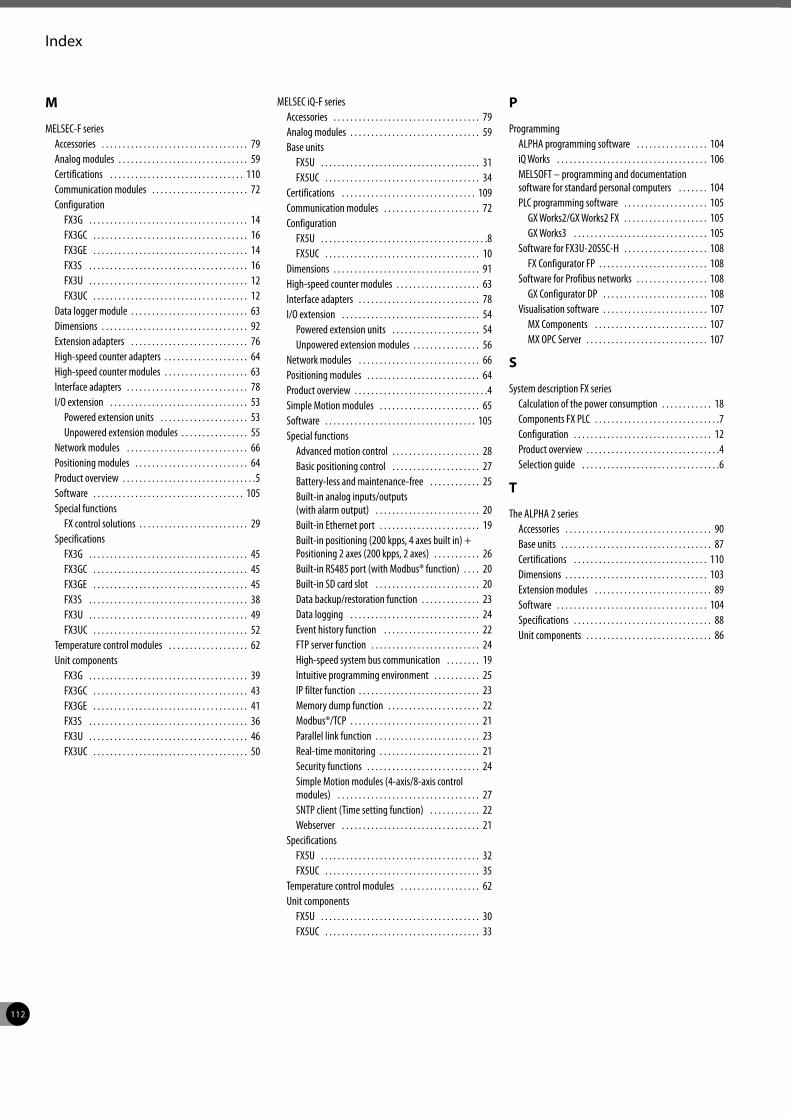
112
Index
M
MELSEC-F seriesAccessories . . . . . . . . . . . . . . . . . . . . . . . . . . . . . . . . . . . 79Analog modules . . . . . . . . . . . . . . . . . . . . . . . . . . . . . . . 59Certifications . . . . . . . . . . . . . . . . . . . . . . . . . . . . . . . . 110Communication modules . . . . . . . . . . . . . . . . . . . . . . . 72Configuration
FX3G . . . . . . . . . . . . . . . . . . . . . . . . . . . . . . . . . . . . . . 14FX3GC . . . . . . . . . . . . . . . . . . . . . . . . . . . . . . . . . . . . . 16FX3GE . . . . . . . . . . . . . . . . . . . . . . . . . . . . . . . . . . . . . 14FX3S . . . . . . . . . . . . . . . . . . . . . . . . . . . . . . . . . . . . . . 16FX3U . . . . . . . . . . . . . . . . . . . . . . . . . . . . . . . . . . . . . . 12FX3UC . . . . . . . . . . . . . . . . . . . . . . . . . . . . . . . . . . . . . 12
Data logger module . . . . . . . . . . . . . . . . . . . . . . . . . . . . 63Dimensions . . . . . . . . . . . . . . . . . . . . . . . . . . . . . . . . . . . 92Extension adapters . . . . . . . . . . . . . . . . . . . . . . . . . . . . 76High-speed counter adapters . . . . . . . . . . . . . . . . . . . . 64High-speed counter modules . . . . . . . . . . . . . . . . . . . . 63Interface adapters . . . . . . . . . . . . . . . . . . . . . . . . . . . . . 78I/O extension . . . . . . . . . . . . . . . . . . . . . . . . . . . . . . . . . 53
Powered extension units . . . . . . . . . . . . . . . . . . . . . 53Unpowered extension modules . . . . . . . . . . . . . . . . 55
Network modules . . . . . . . . . . . . . . . . . . . . . . . . . . . . . 66Positioning modules . . . . . . . . . . . . . . . . . . . . . . . . . . . 64Product overview . . . . . . . . . . . . . . . . . . . . . . . . . . . . . . . .5Software . . . . . . . . . . . . . . . . . . . . . . . . . . . . . . . . . . . . 105Special functions
FX control solutions . . . . . . . . . . . . . . . . . . . . . . . . . . 29Specifications
FX3G . . . . . . . . . . . . . . . . . . . . . . . . . . . . . . . . . . . . . . 45FX3GC . . . . . . . . . . . . . . . . . . . . . . . . . . . . . . . . . . . . . 45FX3GE . . . . . . . . . . . . . . . . . . . . . . . . . . . . . . . . . . . . . 45FX3S . . . . . . . . . . . . . . . . . . . . . . . . . . . . . . . . . . . . . . 38FX3U . . . . . . . . . . . . . . . . . . . . . . . . . . . . . . . . . . . . . . 49FX3UC . . . . . . . . . . . . . . . . . . . . . . . . . . . . . . . . . . . . . 52
Temperature control modules . . . . . . . . . . . . . . . . . . . 62Unit components
FX3G . . . . . . . . . . . . . . . . . . . . . . . . . . . . . . . . . . . . . . 39FX3GC . . . . . . . . . . . . . . . . . . . . . . . . . . . . . . . . . . . . . 43FX3GE . . . . . . . . . . . . . . . . . . . . . . . . . . . . . . . . . . . . . 41FX3S . . . . . . . . . . . . . . . . . . . . . . . . . . . . . . . . . . . . . . 36FX3U . . . . . . . . . . . . . . . . . . . . . . . . . . . . . . . . . . . . . . 46FX3UC . . . . . . . . . . . . . . . . . . . . . . . . . . . . . . . . . . . . . 50
MELSEC iQ-F seriesAccessories . . . . . . . . . . . . . . . . . . . . . . . . . . . . . . . . . . . 79Analog modules . . . . . . . . . . . . . . . . . . . . . . . . . . . . . . . 59Base units
FX5U . . . . . . . . . . . . . . . . . . . . . . . . . . . . . . . . . . . . . . 31FX5UC . . . . . . . . . . . . . . . . . . . . . . . . . . . . . . . . . . . . . 34
Certifications . . . . . . . . . . . . . . . . . . . . . . . . . . . . . . . . 109Communication modules . . . . . . . . . . . . . . . . . . . . . . . 72Configuration
FX5U . . . . . . . . . . . . . . . . . . . . . . . . . . . . . . . . . . . . . . . .8FX5UC . . . . . . . . . . . . . . . . . . . . . . . . . . . . . . . . . . . . . 10
Dimensions . . . . . . . . . . . . . . . . . . . . . . . . . . . . . . . . . . . 91High-speed counter modules . . . . . . . . . . . . . . . . . . . . 63Interface adapters . . . . . . . . . . . . . . . . . . . . . . . . . . . . . 78I/O extension . . . . . . . . . . . . . . . . . . . . . . . . . . . . . . . . . 54
Powered extension units . . . . . . . . . . . . . . . . . . . . . 54Unpowered extension modules . . . . . . . . . . . . . . . . 56
Network modules . . . . . . . . . . . . . . . . . . . . . . . . . . . . . 66Positioning modules . . . . . . . . . . . . . . . . . . . . . . . . . . . 64Product overview . . . . . . . . . . . . . . . . . . . . . . . . . . . . . . . .4Simple Motion modules . . . . . . . . . . . . . . . . . . . . . . . . 65Software . . . . . . . . . . . . . . . . . . . . . . . . . . . . . . . . . . . . 105Special functions
Advanced motion control . . . . . . . . . . . . . . . . . . . . . 28Basic positioning control . . . . . . . . . . . . . . . . . . . . . 27Battery-less and maintenance-free . . . . . . . . . . . . 25Built-in analog inputs/outputs (with alarm output) . . . . . . . . . . . . . . . . . . . . . . . . . 20Built-in Ethernet port . . . . . . . . . . . . . . . . . . . . . . . . 19Built-in positioning (200 kpps, 4 axes built in) + Positioning 2 axes (200 kpps, 2 axes) . . . . . . . . . . . 26Built-in RS485 port (with Modbus® function) . . . . 20Built-in SD card slot . . . . . . . . . . . . . . . . . . . . . . . . . 20Data backup/restoration function . . . . . . . . . . . . . . 23Data logging . . . . . . . . . . . . . . . . . . . . . . . . . . . . . . . 24Event history function . . . . . . . . . . . . . . . . . . . . . . . 22FTP server function . . . . . . . . . . . . . . . . . . . . . . . . . . 24High-speed system bus communication . . . . . . . . 19Intuitive programming environment . . . . . . . . . . . 25IP filter function . . . . . . . . . . . . . . . . . . . . . . . . . . . . . 23Memory dump function . . . . . . . . . . . . . . . . . . . . . . 22Modbus®/TCP . . . . . . . . . . . . . . . . . . . . . . . . . . . . . . . 21Parallel link function . . . . . . . . . . . . . . . . . . . . . . . . . 23Real-time monitoring . . . . . . . . . . . . . . . . . . . . . . . . 21Security functions . . . . . . . . . . . . . . . . . . . . . . . . . . . 24Simple Motion modules (4-axis/8-axis control modules) . . . . . . . . . . . . . . . . . . . . . . . . . . . . . . . . . . 27SNTP client (Time setting function) . . . . . . . . . . . . 22Webserver . . . . . . . . . . . . . . . . . . . . . . . . . . . . . . . . . 21
SpecificationsFX5U . . . . . . . . . . . . . . . . . . . . . . . . . . . . . . . . . . . . . . 32FX5UC . . . . . . . . . . . . . . . . . . . . . . . . . . . . . . . . . . . . . 35
Temperature control modules . . . . . . . . . . . . . . . . . . . 62Unit components
FX5U . . . . . . . . . . . . . . . . . . . . . . . . . . . . . . . . . . . . . . 30FX5UC . . . . . . . . . . . . . . . . . . . . . . . . . . . . . . . . . . . . . 33
P
ProgrammingALPHA programming software . . . . . . . . . . . . . . . . . 104iQ Works . . . . . . . . . . . . . . . . . . . . . . . . . . . . . . . . . . . . 106MELSOFT – programming and documentation software for standard personal computers . . . . . . . 104PLC programming software . . . . . . . . . . . . . . . . . . . . 105
GX Works2/GX Works2 FX . . . . . . . . . . . . . . . . . . . . 105GX Works3 . . . . . . . . . . . . . . . . . . . . . . . . . . . . . . . . 105
Software for FX3U-20SSC-H . . . . . . . . . . . . . . . . . . . . 108FX Configurator FP . . . . . . . . . . . . . . . . . . . . . . . . . . 108
Software for Profibus networks . . . . . . . . . . . . . . . . . 108GX Configurator DP . . . . . . . . . . . . . . . . . . . . . . . . . 108
Visualisation software . . . . . . . . . . . . . . . . . . . . . . . . . 107MX Components . . . . . . . . . . . . . . . . . . . . . . . . . . . 107MX OPC Server . . . . . . . . . . . . . . . . . . . . . . . . . . . . . 107
S
System description FX seriesCalculation of the power consumption . . . . . . . . . . . . 18Components FX PLC . . . . . . . . . . . . . . . . . . . . . . . . . . . . . .7Configuration . . . . . . . . . . . . . . . . . . . . . . . . . . . . . . . . . 12Product overview . . . . . . . . . . . . . . . . . . . . . . . . . . . . . . . .4Selection guide . . . . . . . . . . . . . . . . . . . . . . . . . . . . . . . . .6
T
The ALPHA 2 seriesAccessories . . . . . . . . . . . . . . . . . . . . . . . . . . . . . . . . . . . 90Base units . . . . . . . . . . . . . . . . . . . . . . . . . . . . . . . . . . . . 87Certifications . . . . . . . . . . . . . . . . . . . . . . . . . . . . . . . . 110Dimensions . . . . . . . . . . . . . . . . . . . . . . . . . . . . . . . . . . 103Extension modules . . . . . . . . . . . . . . . . . . . . . . . . . . . . 89Software . . . . . . . . . . . . . . . . . . . . . . . . . . . . . . . . . . . . 104Specifications . . . . . . . . . . . . . . . . . . . . . . . . . . . . . . . . . 88Unit components . . . . . . . . . . . . . . . . . . . . . . . . . . . . . . 86
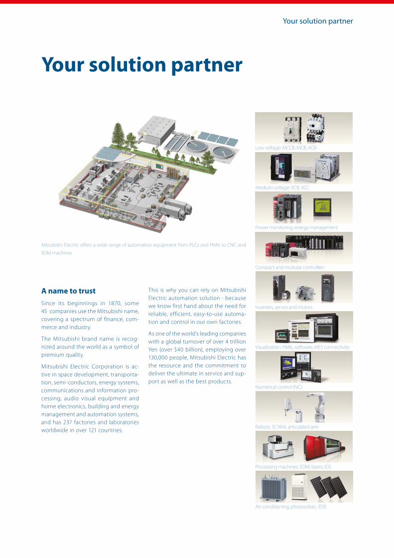
Your solution partner
Mitsubishi Electric offers a wide range of automation equipment from PLCs and HMIs to CNC and
EDM machines
A name to trustSince its beginnings in 1870, some 45 companies use the Mitsubishi name, covering a spectrum of finance, com-merce and industry.
The Mitsubishi brand name is recog-nized around the world as a symbol of premium quality.
Mitsubishi Electric Corporation is ac-tive in space development, transporta-tion, semi-conductors, energy systems, communications and information pro-cessing, audio visual equipment and home electronics, building and energy management and automation systems, and has 237 factories and laboratories worldwide in over 121 countries.
This is why you can rely on Mitsubishi Electric automation solution - because we know first hand about the need for reliable, efficient, easy-to-use automa-tion and control in our own factories.
As one of the world’s leading companies with a global turnover of over 4 trillion Yen (over $40 billion), employing over 130,000 people, Mitsubishi Electric has the resource and the commitment to deliver the ultimate in service and sup-port as well as the best products.
Your solution partner
Low voltage: MCCB, MCB, ACB
Medium voltage: VCB, VCC
Power monitoring, energy management
Compact and modular controllers
Inverters, servos and motors
Visualization: HMIs, software, MES connectivity
Numerical control (NC)
Robots: SCARA, articulated arm
Processing machines: EDM, lasers, IDS
Air-conditioning, photovoltaic, EDS
Global Partner. Local Friend.
European Offices
GermanyMitsubishi Electric Europe B.V.Mitsubishi-Electric-Platz 1D-40882 RatingenPhone: +49 (0)2102 / 486-0
Czech Rep.Mitsubishi Electric Europe B.V.Pekařská 621/7CZ-155 00 Praha 5Phone: +420 255 719 200
FranceMitsubishi Electric Europe B.V.25, Boulevard des BouvetsF-92741 Nanterre CedexPhone: +33 (0)1 / 55 68 55 68
IrelandMitsubishi Electric Europe B.V.Westgate Business Park, BallymountIRL-Dublin 24Phone: +353 (0)1 4198800
ItalyMitsubishi Electric Europe B.V.Viale Colleoni 7 Palazzo SirioI-20864 Agrate Brianza (MB)Phone: +39 039 / 60 53 1
NetherlandsMitsubishi Electric Europe B.V.Nijverheidsweg 23CNL-3641RP MijdrechtPhone: +31 (0) 297 250 350
PolandMitsubishi Electric Europe B.V.ul. Krakowska 48PL-32-083 BalicePhone: +48 (0) 12 347 65 00
RussiaMitsubishi Electric (Russia) LLC2 bld. 1, Letnikovskaya st.RU-115114 MoscowPhone: +7 495 / 721 2070
SpainMitsubishi Electric Europe B.V.Carretera de Rubí 76-80 Apdo. 420E-08190 Sant Cugat del Vallés (Barcelona)Phone: +34 (0) 93 / 5653131
SwedenMitsubishi Electric Europe B.V. (Scandinavia) Hedvig Möllers gata 6SE-223 55 LundPhone: +46 (0) 8 625 10 00
TurkeyMitsubishi Electric Turkey Elektrik Ürünleri A.Ş.Şerifali Mahallesi Kale Sokak No:41 TR-34775 Ümraniye-İSTANBUL Phone: +90 (216) 969 25 00
UKMitsubishi Electric Europe B.V.Travellers LaneUK-Hatfield, Herts. AL10 8XBPhone: +44 (0)1707 / 28 87 80
Representatives
AustriaGEVAWiener Straße 89A-2500 BadenPhone: +43 (0)2252 / 85 55 20
BelarusOOO TECHNIKONProspect Nezavisimosti 177-9BY-220125 MinskPhone: +375 (0)17 / 393 1177
Bosnia and HerzegovinaINEA RBT d.o.o.Stegne 11SI-1000 LjubljanaPhone: +386 (0)1/ 513 8116
BulgariaAKHNATON4, Andrei Ljapchev Blvd., PO Box 21BG-1756 SofiaPhone: +359 (0)2 / 817 6000
CroatiaINEA CRLosinjska 4 aHR-10000 ZagrebPhone: +385 (0)1 / 36 940 - 01/ -02/ -03
Czech RepublicAutoCont C.S. S.R.O.Kafkova 1853/3CZ-702 00 Ostrava 2Phone: +420 595 691 150
DenmarkHANS FØLSGAARD A/STheilgaards Torv 1DK-4600 KøgePhone: +45 4320 8600
EstoniaElectrobit OÜPärnu mnt. 160iEST-11317, TallinnPhone: +372 6518 140
FinlandUTU Automation OyPeltotie 37FIN-28400 UlvilaPhone: +358 (0)207 / 463 500
GreeceUTECO A.B.E.E.5, Mavrogenous Str.GR-18542 PiraeusPhone: +30 (0)211 / 1206-900
HungaryMELTRADE Kft.Fertő utca 14.HU-1107 BudapestPhone: +36 (0)1 / 431-9726
KazakhstanTOO Kazpromavtomatika Ul. Zhambyla 28KAZ-100017 KaragandaPhone: +7 7212 / 50 10 00
LatviaOAK Integrator Products SIA Ritausmas iela 23LV-1058 RigaPhone: +371 67842280
LithuaniaAutomatikos Centras, UAB Neries krantiné 14A-101LT-48397 KaunasPhone: +370 37 262707
MaltaALFATRADE Ltd.99, Paola HillMalta-Paola PLA 1702Phone: +356 (0)21 / 697 816
MoldovaINTEHSIS SRLbld. Traian 23/1MD-2060 KishinevPhone: +373 (0)22 / 66 4242
PortugalFonseca S.A.R. João Francisco do Casal 87/89PT-3801-997 Aveiro, Esgueira Phone: +351 (0)234 / 303 900
RomaniaSirius Trading & ServicesAleea Lacul Morii Nr. 3RO-060841 Bucuresti, Sector 6Phone: +40 (0)21 / 430 40 06
SerbiaINEA SR d.o.o.Ul. Karadjordjeva 12/217SER-11300 SmederevoPhone: +381 69 172 27 25
SlovakiaSIMAP SKDolné Pažite 603/97SK-911 06 TrenčínPhone: +421 (0)32 743 04 72
SloveniaINEA RBT d.o.o.Stegne 11SI-1000 LjubljanaPhone: +386 (0)1 / 513 8116
SwitzerlandOMNI RAY AGIm Schörli 5CH-8600 DübendorfPhone: +41 (0)44 / 802 28 80
UkraineCSC- AUTOMATION Ltd.4 B, Yevhenа Sverstyuka Str.UA-02002 KievPhone: +380 (0)44 / 494 33 44
EgyptEIM Energy3 Roxy SquareET-11341 Heliopolis, CairoPhone: +202 24552559
IsraelGIRIT CELADON Ltd.12 H’aomanut StreetIL-42505 NetanyaPhone: +972 (0)9 / 863 39 80
IsraelILAN & GAVISH Ltd.24 Shenkar St., Kiryat ArieIL-49001 Petah-TikvaPhone: +972 (0)3 / 922 18 24
IsraelSHERF MOTION TECHN. Ltd.Rehov Hamerkava 19IL-58851 HolonPhone: +972 (0)3 / 559 54 62
LebanonCEG LIBANCebaco Center/Block A Autostrade DORALebanon-BeirutPhone: +961 (0)1 / 240 445
South AfricaADROIT TECHNOLOGIES20 Waterford Office Park 189 Witkoppen RoadZA-FourwaysPhone: + 27 (0)11 / 658 8100
Vers
ion
chec
k Mitsubishi Electric Europe B.V. / FA - European Business Group / Mitsubishi-Electric-Platz 1 / D-40882 Ratingen / Germany / Tel.: +49(0)2102-4860 / Fax: +49(0)2102-4861120 / [email protected] / https://eu3a.mitsubishielectric.com
Art. no. 167840-I / 03.2019 / Specifications subject to change / All trademarks and copyrights acknowledged.


