Embed Size (px)
Citation preview
Condition for the deflection of vertical cracksat dissimilar ice interfaces on Europa
Daigo Shoji1
1. Earth-Life Science Institute, Tokyo Institute of Technology, 2-12-1 Ookayama, Meguro-
ku, Tokyo ([email protected])
Abstract
The surface of Europa contains many quasi-circular morphologies called lenticulae. Al-
though the formation mechanism of lenticulae is not understood, sill intrusion from the
subsurface ocean is one promising hypothesis. However, it remains unclear how vertical
cracks from the ocean deflect horizontally to allow sill intrusion in Europa. In this study,
the critical stress intensity factor of Europan ice required for deflection was evaluated by
considering crack theory at the interface between dissimilar materials and experimental
results on ice. For deflection to occur at the interface between two dissimilar ices, the
ratio of the critical stress intensity factor of the interface to that of the upper layer should
be at most 0.45–0.5. This critical ratio may be attained if the interface is caused by brine-
containing ice with a volume fraction of >30 ppt (3%) and pure (no-brine) ice. Thus, a
region with a temperature equal to the eutectic point (e.g., an area of approximately 240
K in the convective layer) is a candidate for the region in which the deflection occurs.
1 Introduction
Europa, one of the four Galilean satellites orbiting Jupiter, is covered with an 80- to 170-
km-thick H2O layer [Anderson et al., 1998]. On the surface of Europa, circular or elliptical
morphologies of a few to a few tens of kilometers in diameter have been observed [e.g.,
Rathbun et al., 1998; Collins et al., 2000; Culha and Manga, 2016]. These structures, called
lenticulae, are further classified into subcategories. Lenticulae with depressed surfaces
1
arX
iv:1
810.
0599
0v1
[as
tro-
ph.E
P] 1
4 O
ct 2
018
are called pits, and convex lenticulae are defined as domes [Culha and Manga, 2016].
Chaotic terrains are defined as circular uplifts with tilted and blocked preexisting crusts
on their surfaces [Culha and Manga, 2016]. On the basis of measurements of the induced
magnetic field, Europa should have a subsurface ocean at a depth of a few to a few tens
of kilometers [e.g., Kivelson et al., 2000]. Although many studies have considered the
formation of lenticulae to be triggered by the interior ocean, the details of the formation
mechanism are controversial, and several models have been suggested to explain lenticula
formation [e.g., Rathbun et al., 1998; Collins et al., 2000; Sotin et al., 2002; Fagents, 2003;
Pappalardo and Barr, 2004; Schmidt et al., 2011].
Recently, Michaut and Manga [2014] have suggested a detailed formation mechanism
for pits, domes, and small chaotic terrains considering sill, which is intrusion of water
in the horizontal direction. If a water sill intrudes into ice, the surface ice is depressed,
leading to pit-type lenticulae. Then, after the sill freezes, the surface becomes convex
because of the resulting volume expansion. This uplift can produce domes or small chaotic
terrains. In this model, pits evolve into domes or small chaotic terrains. Thus, the sill
model can explain the formation and evolution of different types of lenticulae with the
same mechanism.
However, one question that remains unanswered well by the sill model is how a dyke
deflects horizontally into the ice. Formation models of vertical dykes have been suggested.
For example, the freezing of the ocean can induce a stress large enough to produce a crack
at the base of the elastic layer [Manga and Wang, 2007]. Because the time scale of crack
propagation is much smaller than the Maxwell time (viscosity/rigidity) of ice, this crack
can propagate to the subsurface ocean and to the surface. If the strength of the ice is
reduced sufficiently to approximately 104–105 Pa [e.g., Dempsey et al., 1999; Lee et al.,
2005], a tidal stress of approximately 105 Pa [Wahr et al., 2009] may also generate a crack
at the bottom of the ice layer [Crawford and Stevenson, 1988]. Nonsynchronous rotation
also produces large tensile stress [Wahr et al., 2009], which may induce cracking. Detailed
numerical simulations have revealed that, once a crack is formed, a stress of a few MPa,
which is larger than the strength of ice, is induced at the crack tip [Craft et al., 2016].
Once the vertical crack comes into contact with the ocean, water fills the crack up to the
depth at which the buoyancy becomes neutral.
2
Thus, it is probable that vertical dykes of water are formed in Europa’s ice layer.
However, it cannot be said that the vertical crack necessarily deflects horizontally at
the neutral buoyancy level. In terrestrial rock, deflections of dykes have been observed
at heights different from the neutral buoyancy level of magma [Kavanagh et al., 2006].
Craft et al. [2016] performed numerical simulations on dyke propagation to determine the
condition for deflection. Although they found that the effect of tidal bulges may cause the
dyke direction to change, the deflection of vertical cracks is still challenging to understand
[Craft et al., 2016].
In this work, to link the formation of vertical dykes [Crawford and Stevenson, 1988;
Manga and Wang, 2007] and the evolution of water sills [Michaut and Manga, 2014;
Manga and Michaut, 2017], the deflection of cracks at the interface between materials
with dissimilar Young’s moduli is considered. In the case of terrestrial studies, many
sills of magma have been observed at interfaces between materials of different stiffness
[Kavanagh et al., 2006]. Thus, although several causes, such as the surface compressive
stress [Menand et al., 2010], have been suggested, a discontinuous interface is one of
the most promising hypotheses regarding the formation of sills [e.g., Kavanagh et al.,
2006; Gudmundsson, 2011]. The effect of the different Young’s moduli on the deflection
has been evaluated by Craft et al. [2016], and they found that this effect was very
small. However, whether a crack deflects strongly depends on the toughness of the ice
[He and Hutchinson, 1989; He et al., 1994], which is related to the critical stress intensity
factor as well as the Young’s modulus. The critical stress intensity factor is strongly
dependent on the material and conditions, and should thus be determined experimentally.
Currently, the material toughness of Europan ice is unknown. Here, a condition for
crack deflection was determined by applying critical stress intensity factors obtained from
laboratory experiments on ice.
3
2 Condition for deflection
The dissimilarity of two materials can be parameterized by Dundurs’ parameters α and
β [He and Hutchinson, 1989; He et al., 1994], which are given by
α =E1 − E2
E1 + E2
(1)
and
β =1
2
µ1(1− 2ν2)− µ2(1− 2ν1)
µ1(1− ν2) + µ2(1− ν1), (2)
where ν and µ are the Poisson’s ratio and shear modulus, respectively [He and Hutchinson,
1989; He et al., 1994], and the subscripts 1 and 2 represent the two materials (materials
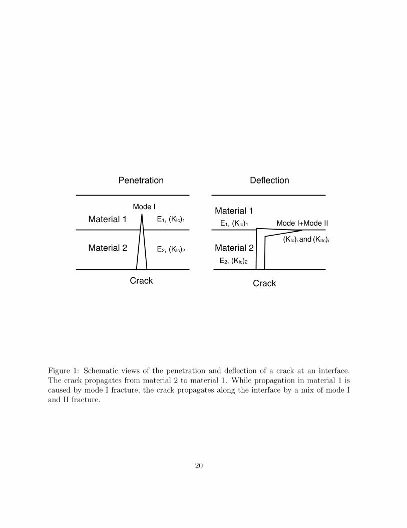
1 and 2 in Fig. 1). Additionally, E = E/(1 − ν2), where E is the Young’s modulus. As
shown below, in the case of Europa, materials 1 and 2 can be regarded as the upper and
lower dissimilar ice layers, respectively (e.g., warm convective ice under a cold stagnant
lid or brine-containing ice under pure ice). If the Poisson’s ratio is fixed, both α and
β depend only on the Young’s modulus because the shear modulus can be represented
as µ = E/2(1 + ν). Here, ν1 and ν2 are assumed to be 0.33 for the sake of simplicity.
Measurements of terrestrial sea ice have shown that the Poisson’s ratio can reach up
to approximately 0.42 [Timco and Weeks, 2010]. However, in this range, the effect of
varying the Poisson’s ration is small. The Young’s modulus E1 of the upper layer scales
as E1 = γE2, where γ is the ratio of E1 to E2. Because of this scaling, E1 and E2 can be
eliminated from Eqs. (1) and (2), allowing α and β to be calculated from γ.
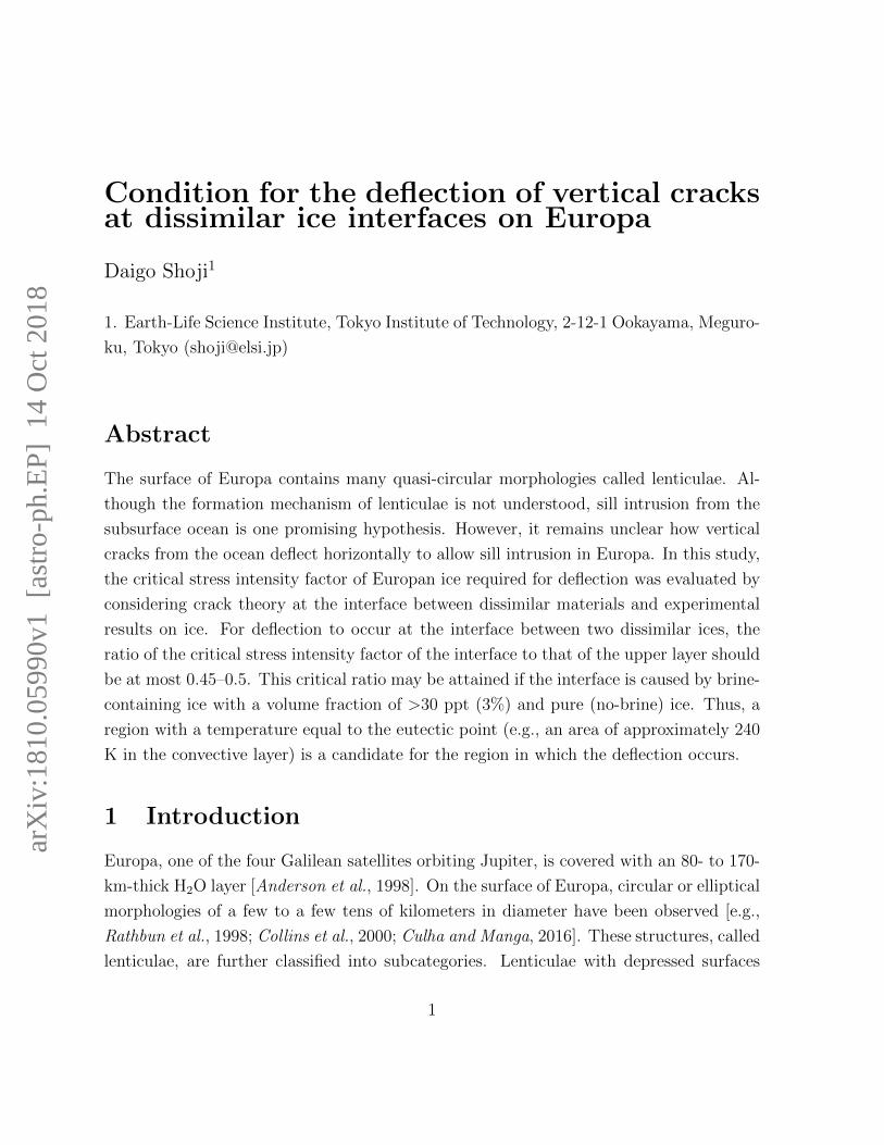
When a crack propagating in material 2 penetrates material 1 (Fig. 1), propagation
after penetration is caused by mode I fracture (crack opening by tensile stress). Thus,
the strain energy release rate Gp of crack propagation in material 1 is given by [He and
Hutchinson, 1989; He et al., 1994]
Gp =1− ν1
2µ1
(KI)21, (3)
where (KI)1 is the stress intensity factor of mode I cracking in material 1. In contrast to
the penetration of the crack into material 1, propagation along the interface between the
4
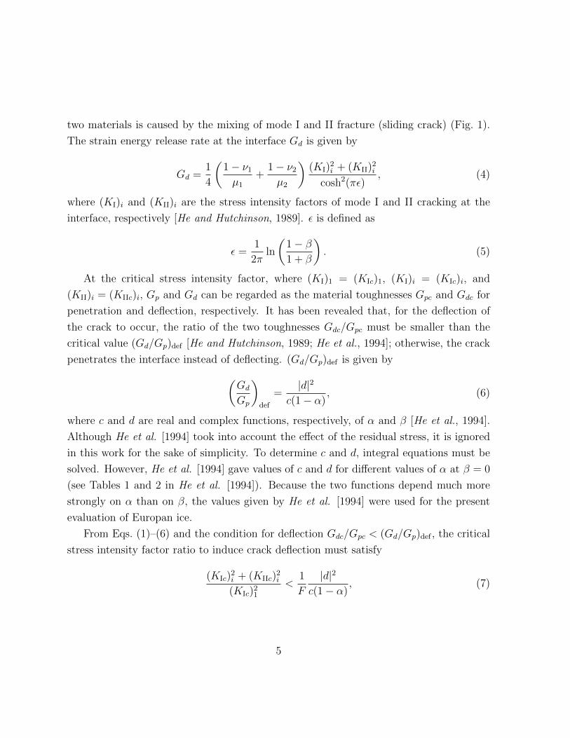
two materials is caused by the mixing of mode I and II fracture (sliding crack) (Fig. 1).
The strain energy release rate at the interface Gd is given by
Gd =1
4
(1− ν1µ1
+1− ν2µ2
)(KI)
2i + (KII)
2i
cosh2(πε), (4)
where (KI)i and (KII)i are the stress intensity factors of mode I and II cracking at the
interface, respectively [He and Hutchinson, 1989]. ε is defined as
ε =1
2πln
(1− β1 + β
). (5)
At the critical stress intensity factor, where (KI)1 = (KIc)1, (KI)i = (KIc)i, and
(KII)i = (KIIc)i, Gp and Gd can be regarded as the material toughnesses Gpc and Gdc for
penetration and deflection, respectively. It has been revealed that, for the deflection of
the crack to occur, the ratio of the two toughnesses Gdc/Gpc must be smaller than the
critical value (Gd/Gp)def [He and Hutchinson, 1989; He et al., 1994]; otherwise, the crack
penetrates the interface instead of deflecting. (Gd/Gp)def is given by(Gd
Gp
)def
=|d|2
c(1− α), (6)
where c and d are real and complex functions, respectively, of α and β [He et al., 1994].
Although He et al. [1994] took into account the effect of the residual stress, it is ignored
in this work for the sake of simplicity. To determine c and d, integral equations must be
solved. However, He et al. [1994] gave values of c and d for different values of α at β = 0
(see Tables 1 and 2 in He et al. [1994]). Because the two functions depend much more
strongly on α than on β, the values given by He et al. [1994] were used for the present
evaluation of Europan ice.
From Eqs. (1)–(6) and the condition for deflection Gdc/Gpc < (Gd/Gp)def , the critical
stress intensity factor ratio to induce crack deflection must satisfy
(KIc)2i + (KIIc)
2i
(KIc)21<
1
F
|d|2
c(1− α), (7)
5
where
F =µ1
2(1− ν1) cosh2(πε)
(1− ν1µ1
+1− ν2µ2
). (8)
Although experiments on the critical stress intensity factor of ice under mixed-mode
fracture is not sufficient, Shen and Lin [1988] have shown that K2Ic + K2
IIc under mixed-
mode fracture is almost the same as K2Ic under pure mode I cracking. Thus, with this
approximation of the critical intensity factor in mixed-mode cracking to that in pure mode
I cracking for simplicity, the condition for deflection is given by
(KIc)i(KIc)1
<
(Kd
Kp
)def
, (9)
where
(Kd
Kp
)def
=
√|d|2
Fc(1− α). (10)
In the case where (KIc)i/(KIc)1 > (Kd/Kp)def , the crack penetrates material 1. Hereafter,
(KIc)i and (KIc)1 are referred to as the critical intensity factors in pure mode I fracture.
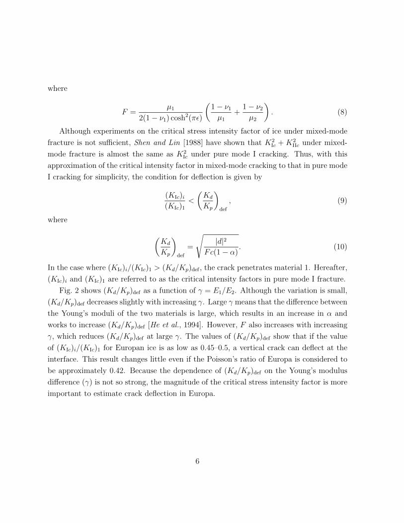
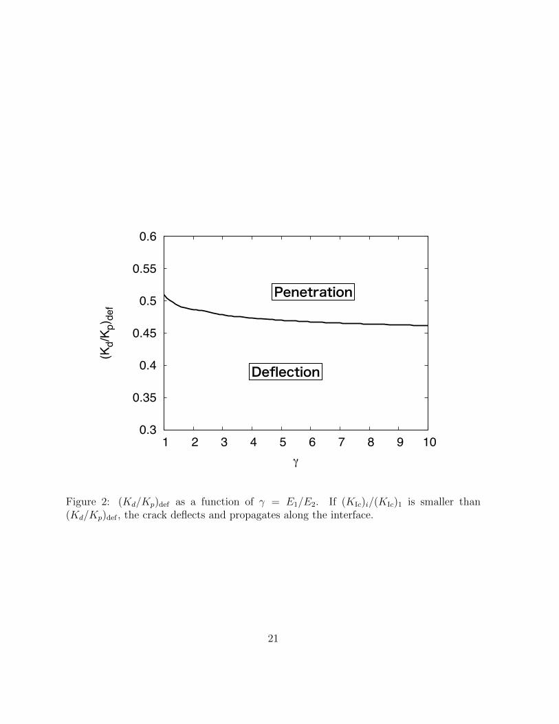
Fig. 2 shows (Kd/Kp)def as a function of γ = E1/E2. Although the variation is small,
(Kd/Kp)def decreases slightly with increasing γ. Large γ means that the difference between
the Young’s moduli of the two materials is large, which results in an increase in α and
works to increase (Kd/Kp)def [He et al., 1994]. However, F also increases with increasing
γ, which reduces (Kd/Kp)def at large γ. The values of (Kd/Kp)def show that if the value
of (KIc)i/(KIc)1 for Europan ice is as low as 0.45–0.5, a vertical crack can deflect at the
interface. This result changes little even if the Poisson’s ratio of Europa is considered to
be approximately 0.42. Because the dependence of (Kd/Kp)def on the Young’s modulus
difference (γ) is not so strong, the magnitude of the critical stress intensity factor is more
important to estimate crack deflection in Europa.
6
3 Mechanism to generate interface
From Fig. 2, for a vertical crack to deflect horizontally, (KIc)i/(KIc)1 should be reduced to
<0.5. The critical stress intensity factor of the ice is dependent on several conditions, such
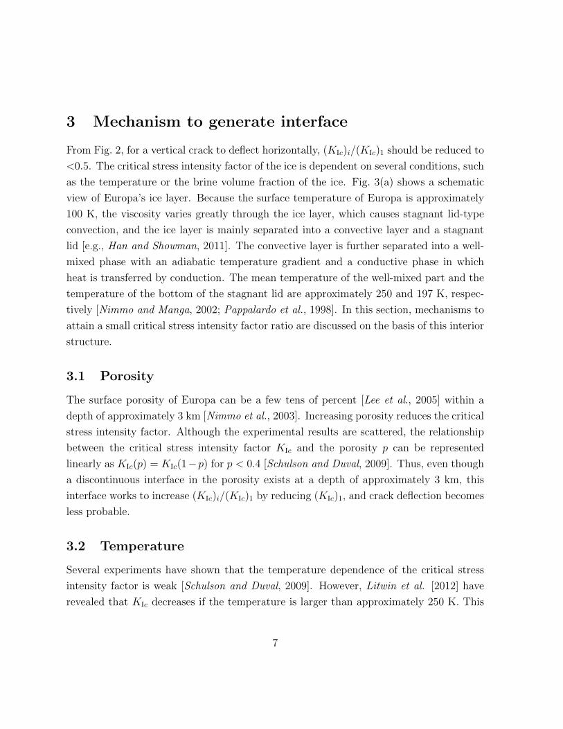
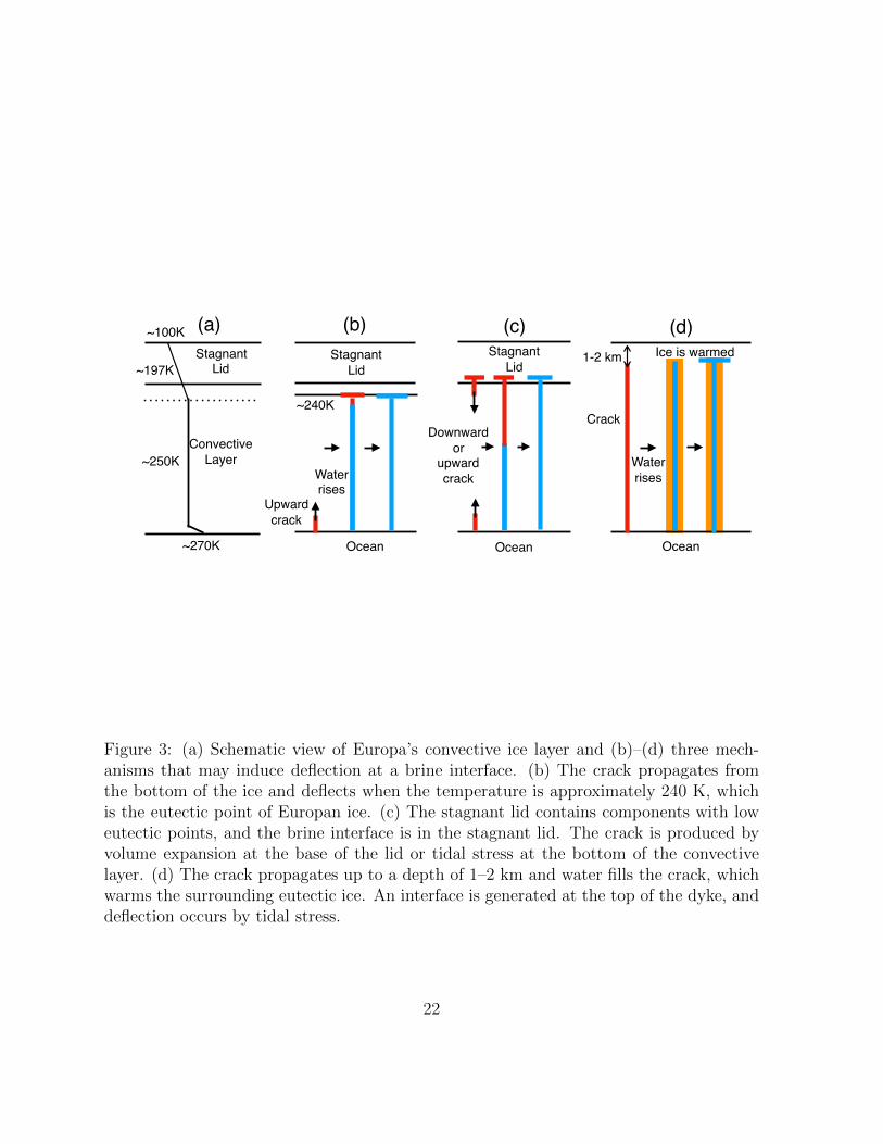
as the temperature or the brine volume fraction of the ice. Fig. 3(a) shows a schematic
view of Europa’s ice layer. Because the surface temperature of Europa is approximately
100 K, the viscosity varies greatly through the ice layer, which causes stagnant lid-type
convection, and the ice layer is mainly separated into a convective layer and a stagnant
lid [e.g., Han and Showman, 2011]. The convective layer is further separated into a well-
mixed phase with an adiabatic temperature gradient and a conductive phase in which
heat is transferred by conduction. The mean temperature of the well-mixed part and the
temperature of the bottom of the stagnant lid are approximately 250 and 197 K, respec-
tively [Nimmo and Manga, 2002; Pappalardo et al., 1998]. In this section, mechanisms to
attain a small critical stress intensity factor ratio are discussed on the basis of this interior
structure.
3.1 Porosity
The surface porosity of Europa can be a few tens of percent [Lee et al., 2005] within a
depth of approximately 3 km [Nimmo et al., 2003]. Increasing porosity reduces the critical
stress intensity factor. Although the experimental results are scattered, the relationship
between the critical stress intensity factor KIc and the porosity p can be represented
linearly as KIc(p) = KIc(1−p) for p < 0.4 [Schulson and Duval, 2009]. Thus, even though
a discontinuous interface in the porosity exists at a depth of approximately 3 km, this
interface works to increase (KIc)i/(KIc)1 by reducing (KIc)1, and crack deflection becomes
less probable.
3.2 Temperature
Several experiments have shown that the temperature dependence of the critical stress
intensity factor is weak [Schulson and Duval, 2009]. However, Litwin et al. [2012] have
revealed that KIc decreases if the temperature is larger than approximately 250 K. This
7
temperature matches well with the mean temperature of the well-mixed phase in the
convective layer (Fig. 3(a)). Thus, the interface between the conductive and well-mixed
phases may be suitable for deflection. However, the rate of decrease in the critical stress
intensity with increasing temperature is approximately 30% [Litwin et al., 2012]. Thus,
(KIc)i/(KIc)1 is approximately 0.7 under the assumption that (KIc)i is similar to KIc of
the well-mixed phase, which does not meet the condition for the deflection of the crack
((KIc)i/(KIc)1 < 0.5).
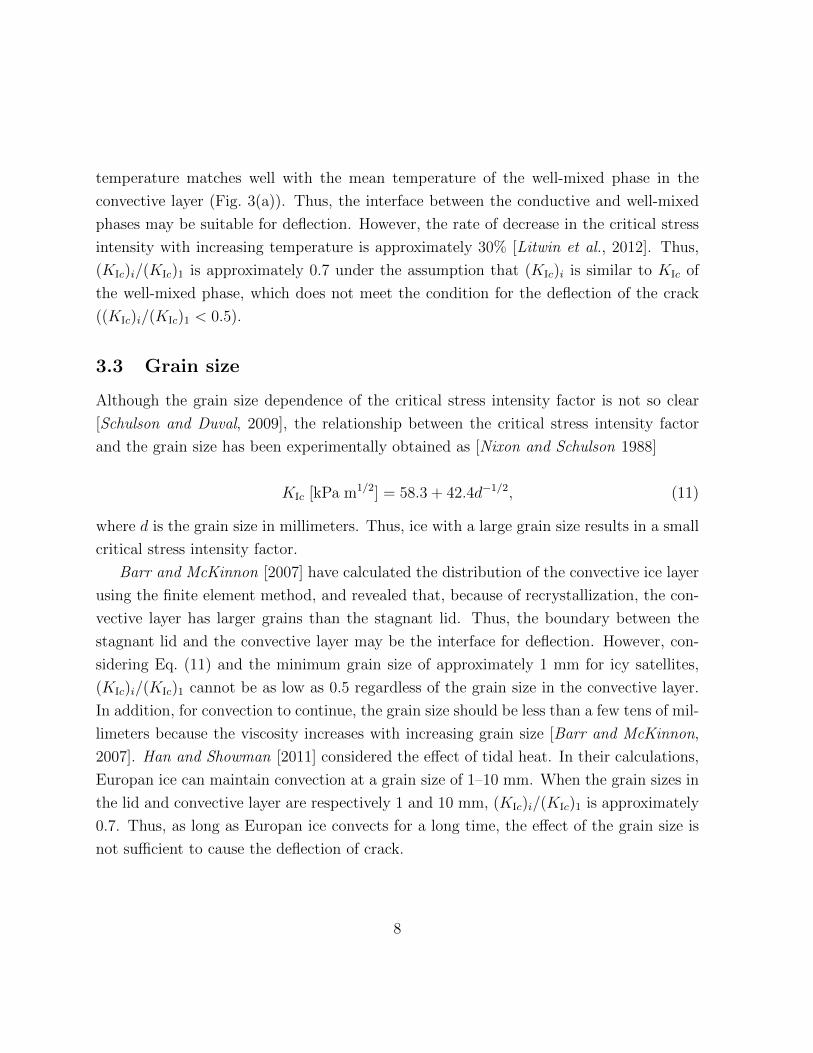
3.3 Grain size
Although the grain size dependence of the critical stress intensity factor is not so clear
[Schulson and Duval, 2009], the relationship between the critical stress intensity factor
and the grain size has been experimentally obtained as [Nixon and Schulson 1988]
KIc [kPa m1/2] = 58.3 + 42.4d−1/2, (11)
where d is the grain size in millimeters. Thus, ice with a large grain size results in a small
critical stress intensity factor.
Barr and McKinnon [2007] have calculated the distribution of the convective ice layer
using the finite element method, and revealed that, because of recrystallization, the con-
vective layer has larger grains than the stagnant lid. Thus, the boundary between the
stagnant lid and the convective layer may be the interface for deflection. However, con-
sidering Eq. (11) and the minimum grain size of approximately 1 mm for icy satellites,
(KIc)i/(KIc)1 cannot be as low as 0.5 regardless of the grain size in the convective layer.
In addition, for convection to continue, the grain size should be less than a few tens of mil-
limeters because the viscosity increases with increasing grain size [Barr and McKinnon,
2007]. Han and Showman [2011] considered the effect of tidal heat. In their calculations,
Europan ice can maintain convection at a grain size of 1–10 mm. When the grain sizes in
the lid and convective layer are respectively 1 and 10 mm, (KIc)i/(KIc)1 is approximately
0.7. Thus, as long as Europan ice convects for a long time, the effect of the grain size is
not sufficient to cause the deflection of crack.
8
3.4 Brine
Measurements of infrared spectra have indicated that hydrated magnesium sulfates and
sodium carbonates are present on the surface of Europa [e.g., Carlson et al., 1999; McCord
et al., 1998; Orlando et al., 2005; Dalton, 2007]. Sodium has also been observed in the
Europan atmosphere [Brown and Hill, 1996; Johnson, 2000; Brown, 2001]. Although
the origin (endogenic or exogenic) of the chemical composition, especially sulfur, requires
further study, it is highly probable that the Europan ocean is rich with chemicals such as
Na2SO4, MgSO4, and NaCl [e.g., Zolotov and Shock, 2003; Brown and Hand, 2013; Hand
and Carlson, 2015; Marison, 2002]. Studies on the interaction between ice and the ocean
have indicated that chemical composition in the ocean can be trapped in the ice and
transported upward by convection [Zolotov et al., 2004; Peddinti and McNamara, 2015].
Thus, brine is generated in the ice layer when the temperature is larger than the eutectic
point.
Although the amount of available data is not sufficient to draw strong conclusions
and the results are scattered, when ice contains brine, the critical stress intensity factor
tends to decrease. Timco and Frederking [1983] have shown that KIc with a brine vol-
ume fraction of approximately 50 ppt can decrease to approximately 80 kPa m1/2 from
approximately 160 kPa m1/2 in the case with no brine. Experiments performed by Urabe
and Yoshitake [1981] with a higher brine fraction demonstrated that it is probable that
KIc is reduced to as low as approximately 30–40 kPa m1/2 at a brine volume fraction of
approximately 130 ppt [Timco, 1985]. Because KIc without brine is approximately 160
kPa m1/2 [Timco and Frederking, 1983], the interface between ice layers with and without
brine may satisfy the condition for deflection.
The Young’s modulus as a function of brine volume vb is given by [Timco and Weeks,
2010]
E [GPa] = 10− 0.0351vb [ppt]. (12)
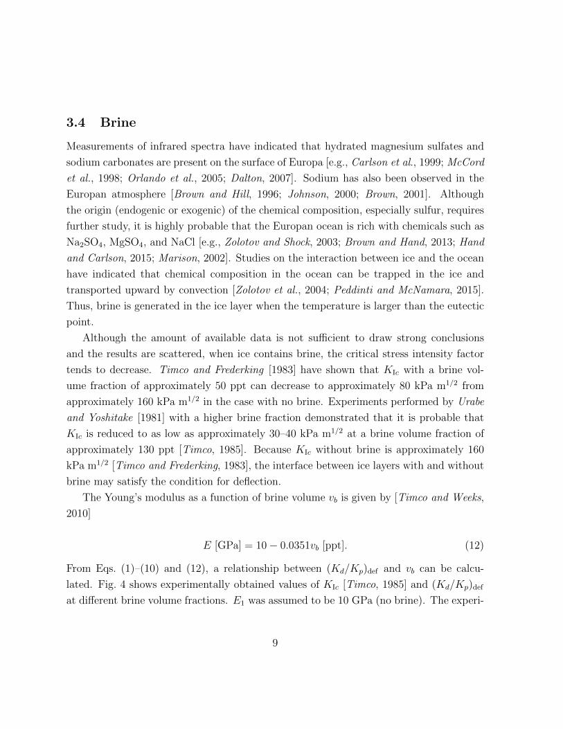
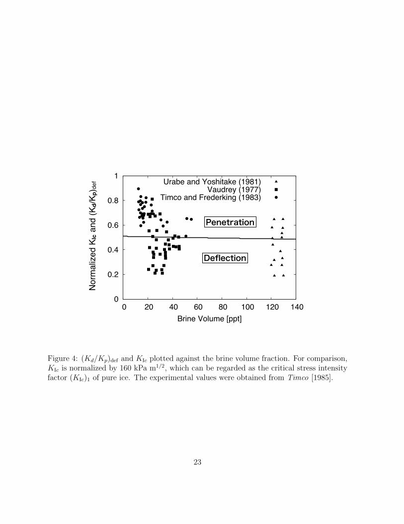
From Eqs. (1)–(10) and (12), a relationship between (Kd/Kp)def and vb can be calcu-
lated. Fig. 4 shows experimentally obtained values of KIc [Timco, 1985] and (Kd/Kp)def
at different brine volume fractions. E1 was assumed to be 10 GPa (no brine). The experi-
9
mental values of KIc are normalized by 160 kPa m1/2, which is consistent with the critical
intensity without brine [Timco and Frederking, 1983] and can be regarded as (KIc)1. Al-
though the experimental results are scattered, on the basis of the assumption that (KIc)i
is not so different from KIc of briny ice, (KIc)i/(KIc)1 may be smaller than (Kd/Kp)def at
vb > 30 ppt. Some experiments have suggested that the KIc value of fresh ice is 120–150
kPa m1/2 [Schulson and Duval, 2009; Litwin et al., 2012]. However, even in the case of
smaller (KIc)1, (KIc)i/(KIc)1 can be lower than the critical value at brine volume fractions
of more than approximately 30–40 ppt. Thus, it is probable that the crack in Europa
deflects along the interface if the amount of brine generated by eutectic ice exceeds 30 ppt
(3%). Although the detailed composition and salinity of Europan ice have not been well
characterized, in the case of terrestrial sea ice, the brine volume fraction can reach up to
20% [Thomas and Dieckmann, 2002; Galley et al., 2015]. Thus, a brine volume fraction
of 3–4% may be generated in Europa.
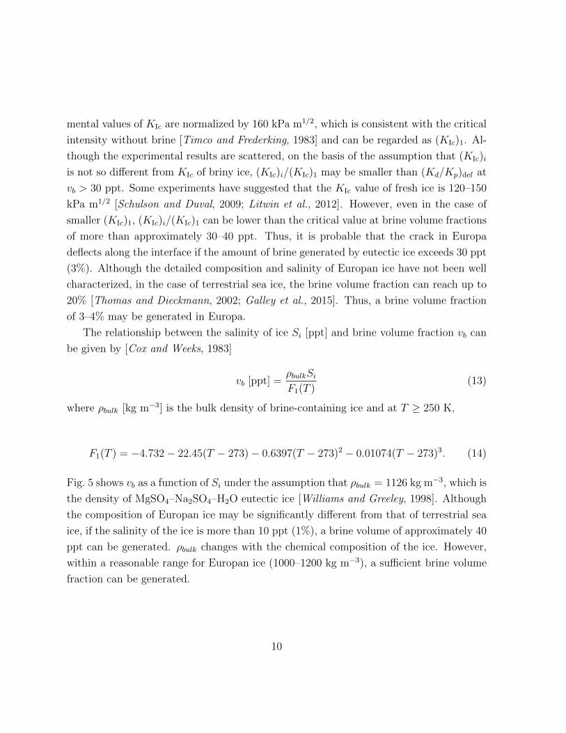
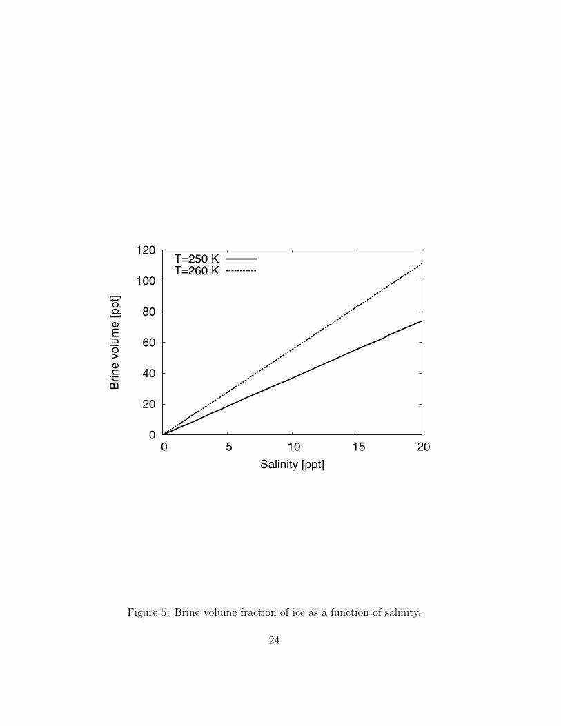
The relationship between the salinity of ice Si [ppt] and brine volume fraction vb can
be given by [Cox and Weeks, 1983]
vb [ppt] =ρbulkSi
F1(T )(13)
where ρbulk [kg m−3] is the bulk density of brine-containing ice and at T ≥ 250 K,
F1(T ) = −4.732− 22.45(T − 273)− 0.6397(T − 273)2 − 0.01074(T − 273)3. (14)
Fig. 5 shows vb as a function of Si under the assumption that ρbulk = 1126 kg m−3, which is
the density of MgSO4–Na2SO4–H2O eutectic ice [Williams and Greeley, 1998]. Although
the composition of Europan ice may be significantly different from that of terrestrial sea
ice, if the salinity of the ice is more than 10 ppt (1%), a brine volume of approximately 40
ppt can be generated. ρbulk changes with the chemical composition of the ice. However,
within a reasonable range for Europan ice (1000–1200 kg m−3), a sufficient brine volume
fraction can be generated.
10
4 Deflection mechanisms based on a brine interface
Of the mechanisms described above, the existence of an interface between layers of ice with
and without brine is a strong candidate for the deflection. Combining the crack formation
models and the interior structure of Europa’s ice layer, three types of deflection are pro-
posed, as shown in Fig. 3. In the first mechanism, the well-mixed phase of the convective
layer contains brine, and a vertical crack generated at the bottom of the ice propagates
upward. Then, the vertical crack is deflected at the interface between the brine-containing
and no-brine ice regions in the convective layer (Fig. 3(b)). As demonstrated by numerical
simulations conducted by Zolotov et al. [2004], brine can be contained in ice when the
ice temperature is greater than 240 K. Thus, deflection may occur in the conductive part
of the convective layer. Because this temperature is too high for ice to show elastic be-
havior, downward cracks produced by volume expansion [Manga and Wang, 2007] cannot
be generated. One problem is that, although sufficient stress is required to induce crack
formation, the magnitude of the tidal stress is 104–105 Pa [Wahr, 2009]. However, the
strength of the ice may be reduced to approximately 104 Pa [e.g., Dempsey et al., 1999;
Lee et al., 2005]. Additionally, stress produced by nonsynchronous rotation is on the order
of a few megapascals [Wahr, 2009]. Thus, a crack can be generated at the bottom of the
ice.
In the second mechanism, the Europan ice contains components with low eutectic
points, such as sulfuric acid or ammonia. In this case, the temperature of the ice around
the interface is reduced to 180–200 K [Marison et al., 2002; Quick and Marsh, 2016]. Thus
the brine interface is located in or bottom of the stagnant lid (Fig. 3(c)). Ice behaves as an
elastic material at temperatures below 185 K [Nimmo et al., 2002]. Thus, in addition to
cracks forming at the bottom of the ice, cracks generated by volume expansion [Manga and
Wang, 2007] may induce deflection if they are initiated slightly under the brine interface.
One advantage of crack generation by volume expansion is that a sufficient magnitude of
stress can be induced [Manga and Wang, 2007], which does not require the reduction of
the strength of the ice.
The third hypothesized mechanism involves a vertical dyke propagating to a depth of
up to 1–2 km and water warming the surrounding ice to the eutectic point. Although
cracks formed by volume expansion can propagate to the surface of Europa [Manga and
11
Wang, 2007], at a depth of approximately 1–2 km, large stress is induced by thermal
contraction [Nimmo, 2004]. If this stress prevents the vertical crack from propagating to
the surface, water fills the whole crack, which warms the surrounding ice to its eutectic
point, thereby forming the brine interface is at the top of the vertical dyke (Fig. 3(d)).
Although lateral stress produced by volume expansion is relaxed within one hour [Manga
and Wang, 2007], tidal stress may generate a horizontal crack at the shallow interface.
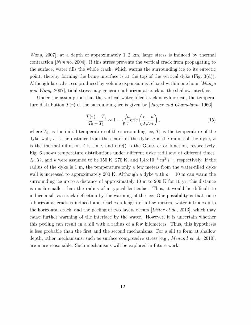
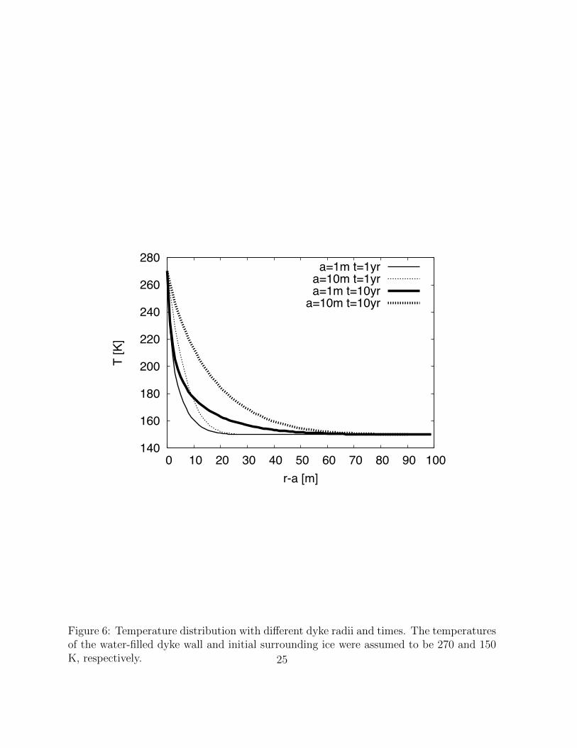
Under the assumption that the vertical water-filled crack is cylindrical, the tempera-
ture distribution T (r) of the surrounding ice is given by [Jaeger and Chamalaun, 1966]
T (r)− T1T0 − T1
∼ 1−√a
rerfc
(r − a2√κt
), (15)
where T0, is the initial temperature of the surrounding ice, T1 is the temperature of the
dyke wall, r is the distance from the center of the dyke, a is the radius of the dyke, κ
is the thermal diffusion, t is time, and efrc() is the Gauss error function, respectively.
Fig. 6 shows temperature distributions under different dyke radii and at different times.
T0, T1, and κ were assumed to be 150 K, 270 K, and 1.4×10⁻⁶ m2 s−1, respectively. If the
radius of the dyke is 1 m, the temperature only a few meters from the water-filled dyke
wall is increased to approximately 200 K. Although a dyke with a = 10 m can warm the
surrounding ice up to a distance of approximately 10 m to 200 K for 10 yr, this distance
is much smaller than the radius of a typical lenticulae. Thus, it would be difficult to
induce a sill via crack deflection by the warming of the ice. One possibility is that, once
a horizontal crack is induced and reaches a length of a few meters, water intrudes into
the horizontal crack, and the peeling of two layers occurs [Lister et al., 2013], which may
cause further warming of the interface by the water. However, it is uncertain whether
this peeling can result in a sill with a radius of a few kilometers. Thus, this hypothesis
is less probable than the first and the second mechanisms. For a sill to form at shallow
depth, other mechanisms, such as surface compressive stress [e.g., Menand et al., 2010],
are more reasonable. Such mechanisms will be explored in future work.
12
5 Conclusion
To link vertical dyke formation and the evolution of sills, the deflection of vertical cracks
at the interface between two ice layers of different stiffness was considered. Whether the
crack deflects or penetrates the interface depends on the toughness of the ice [He and
Hutchinson, 1989; He et al., 1994]. Thus, in addition to the difference in the Young’s
moduli of the two regions, the occurrence of deflection was evaluated with the critical
stress intensity factor of the ice taken into consideration.
For deflection to occur, (KIc)i/(KIc)1 must be at most 0.45–0.5. Of several charac-
teristics of the ice (porosity, temperature, grain size, and brine) that affect the critical
stress intensity factor, the presence of brine in the ice can reduce (KIc)i/(KIc)1 sufficiently.
On the basis of experimental results for brine-containing ice, if the brine volume fraction
is more than 30 ppt, the crack may deflect along the interface. Although the chemical
composition of Europan ice can be significantly different from that of terrestrial sea ice,
a brine volume fraction of 30–40 ppt can be induced by an ice salinity of 1-2 percent.
Brine is contained in ice when the ice temperature is greater than approximately
240 K, as demonstrated in numerical simulations based on reasonable estimates for the
composition of eutectic ice in Europa [e.g., Zolotov et al., 2002]. An interface at this
temperature would be too warm to induce vertical cracks by volume expansion. Thus,
the generation of cracks at the bottom of the convective layer by tidal stress [Crawford
and Stevenson, 1988] and reduced strength [Dempsey et al., 1999] is consistent with the
deflection at a brine interface with this temperature. If the ice contains components
with a low eutectic point, such as ammonia or sulfuric acid [e.g., Marison, 2004], a brine
interface may be generated in the stagnant lid. Because the critical temperature for
elastic behavior is approximately 185 K [Nimmo et al., 2002], stress generated by volume
expansion can induce crack deflection at the interface. The final mechanism considered
herein of warming by a water-filled dyke seems insufficient to induce an interface of a few
kilometers in length.
Although many experiments on ice fracture have been conducted, insufficient data on
mode II cracking and cracking at interfaces have been reported. Thus, (KIc)i was ap-
proximated as the KIc value of brine-containing ice when the ratio of the critical stress
intensity factor was compared with (Kd/Kp)def . Because one of the two layers at the
13
interface do not contain brine, this approximation may be oversimplified. In future work,
cracking along the interface must be experimentally considered. In addition, the present
experimental results on critical intensity factor are scattered because the critical stress
intensity factor changes based on the conditions and specimens used in each experiment.
Additionally, the chemical composition of Europan ice can be different from that of terres-
trial sea ice. Thus, more studies are necessary to evaluate the deflection of vertical cracks
considering the conditions of Europan ice. To assess the detailed dynamics of crack de-
flection, numerical simulation like that conduced by Craft et al. [2016] is also required in
future work. However, in comparison with the formation of vertical cracks in Europa, the
deflection of these cracks has not thoroughly investigated. The detailed formation process
of lenticulae after this deflection has been evaluated [Michaut and Manga, 2014; Manga
and Michaut, 2017]. Thus, the deflection condition assessed in this work can serve as a
first step linking vertical dykes and lenticulae formation.
Acknowledgements
This work was supported by a JSPS Research Fellowship.
References
Anderson, J. D., G. Schubert, R. A. Jacobson, E. L. Lau, W. B. Moore, and W. L.
Sjogren (1998), Europa’s differentiated internal structure: Inferences from four Galileo
encounters, Science, 281, 2019-2022.
Barr, A. C., and W. B. McKinnon (2007), Convection in ice I shells and mantles with
self-consistent grain size, J. Geophys. Res., 112, E02012.
Brown, M. E. (2001), Potassium in Europa’s atmosphere, Icarus, 151, 190-195.
Brown, M. E., and K. P. Hand (2013), Salts and radiation products on the surface of
Europa, Astro n. J., 145(4), 110.
14
Brown, M. E., and R. E. Hill (1996), Discovery of an extended sodium atmosphere
around Europa, Nature, 380, 229-231.
Carlson, R. W., R. E. Johnson, and M. S. Anderson (1999), Sulfuric acid on Europa
and the radiolytic sulfur cycle, Science, 286, 97-99.
Collins, G. C., J. W. Head, R. T. Pappalardo, and N. A. Spaun (2000) Evaluationof
models for the formation of chaotic terrain on Europa, J. Geophys.Res.,105, 204-218.
Cox, G. F. N., and W. F. Weeks (1983) Equations for determining the gas and brine
volumes in sea-ice samples, Journal of Glaciology, 29, 306-316.
Craft, K. L., G. W. Patterson, R. P. Lowell, and L. Germanovich (2016) Fracturing and
flow: investigations into the formation of shallow water sills on Europa, Icarus, 274,
297-331.
Crawford, G. D., and D. J. Stevenson (1988), Gas-driven water volcanism in the resur-
facing of Europa, Icarus, 73, 66-79.
Culha, C., and M. Manga (2016), Geometry and spatial distribution of lenticulae on
europa, Icarus, 271, 49-56.
Dalton, J. B. (2007), Linear mixture modeling of Europa’s non-ice mate-rial based on
cryogenic laboratory spectroscopy, Geophys. Res. Lett. 34, L21205.
Dempsey, J. P., R. M. Adamson, and S. V. Mulmule (1999), Scale effects onthe in-situ
tensile strength and fracture of ice. Part II: First-year sea ice atResolute, N. W. T., Int.
J. Fract., 95, 347-366.
Fagents, S. A. (2003), Considerations for effusive cryovolcanism on Europa: The post-
Galileo perspective, J. Geophys. Res., 108, 5139.
Galley, R. J., B. G. T. Else, N. -X. Geilfus, A. A. Hare, D. Isleifson, D. G. Barber, and
S. Rysgaard (2015), Imaged brine inclusions in young sea ice e shape, distribution and
formation timing. Cold Reg. Sci. Technol., 111, 39-48.
15
Gudmundsson, A. (2011), Deflection of dykes into sills at discontinuities and magma-
chamber formation, Tectonophysics, 500, 50-64.
Han, L., and A. Showman (2011), Coupled convection and tidal dissipation in Europa’s
ice shell using non-Newtonian grain-size-sensitive(GSS) creep rheology, Icarus, 212, 262-
267.
Hand, K. P., and R. W. Carlson (2015), Europa’s surface color suggests an ocean rich
with sodium chloride, Geophys. Res. Lett., 42, 3174-3178.
He, M. Y., A. G. Evans, and J. W. Hutchinson (1994), Crack deflection at an interface
between dissimilar elastic materials: Role of residual stresses, Int. J. Solids Structures,
31, 3443-3455.
He, M. Y., and J. W. Hutchinson (1989), Crack deflection at an interface between
dissimilar elastic materials, Int. J. Solids Structures, 25, 1053-1067.
Jaeger, J. C., and T. Chamalaun (1966), Heat flow in an infinite region bounded inter-
nally by a circular cylinder with forced convection an the surface, Aust. J. Phys., 19,
475-488.
Johnson, R. E. (2000), Sodium at Europa, Icarus, 143, 429-433.
Kavanagh, J. L., T. Menand, and S. Sparks (2006), An experimental investigation of
sill formation and propagation in layered media, Earth Planet. Sci. Lett., 245, 799-813.
Kivelson, M. G., K. K. Khurana, C. T. Russel, M. Volwerk, R. J. Walker, and C. Zimmer
(2000), Galileo magnetometer measurements: A stronger case for a subsurface ocean at
Europa, Science, 289, 1340-1342.
Lee, S., R. T. Pappalardo, and N. C. Makris (2005), Mechanics of tidally driven fractures
in Europa’s ice shell, Icarus, 177, 367-379.
Lister, J. R., G. G. Peng, and J. A. Neufeld (2013), Viscous control of peeling an elastic
sheet by bending and pulling, Phys. Rev. Lett., 111,1-5.
16
Litwin, K. L., B. R. Zygielbaum, P. J. Polito, L. S. Sklar, and G. C. Collins (2012),
Influence of temperature, composition, and grain size on the tensile failure of water ice:
Implications for erosion on titan, J. Geophys. Res., 117, E08013.
Manga, M., and C. Michaut (2017), Formation of lenticulae on Europa by saucer-shaped
sills, Icarus, 266, 261-269.
Manga, M., and C. Y. Wang (2007), Pressurized oceans and the eruption of liquid water
on Europa and Enceladus, Geophys. Res. Lett., 34, L07202.
Marion, G. M. (2002), A molal-based model for strong acid chemistry at low tempera-
tures (<200 to 298 K), Geochim. Cosmochim. Acta, 66, 2499-2516.
McCord, T. B., et al. (1998), Salts on Europa’s surface detected by Galileo’s near
infrared mapping spectrometer, Science, 280, 1242-1245.
Menand, T., K. A. Daniels, and P. Benghiat (2010), Duke propagation and sill formation
in a compressive tectonic environment, J. Geophys. Res., 115, B08201.
Michaut, C., and M. Manga (2014), Domes, pits, and small chaos on Europa produced
by water sills, J. Geophys. Res., 119, 550-573.
Nimmo, F. (2004), Stresses generated in cooling viscoelastic ice shells: applications to
Europa. J. Geophys. Res., 109, E12001.
Nimmo, F., and M. Manga (2002) Causes, characteristics and consequences of convective
diapirism on Europa, Geophys. Res. Lett., 29, 2109.
Nimmo, F., R. T. Pappalardo, and B. Giese (2002), Effective elastic thickness and heat
flux estimates on Ganymede, Geophys. Res. Lett., 29, 1158.
Nixon, W. A. and E. M. Schulson (1988), The fracture toughness of ice over a range of
grain sizes, J. Offshore Mech. Arct. Eng., 110, 192-196.
Orlando, T. M., T. B. McCord, and G. A. Grieves (2005), The chemical nature of
Europa surface material and the relation to a subsurface ocean, Icarus, 177, 528-533.
17
Pappalardo, R. T., and A. C. Barr (2004), The origin of domes on Europa: The role of
thermally induced compositional diapirism, Geophys. Res. Lett., 31, L01701,
Pappalardo, R. T., et al. (1988), Geological evidence for solid-state convection in Eu-
ropa’s ice shell, Nature, 391, 365-368, 1998.
Peddinti, D. A., and A. K. McNamara (2015), Material transport across Europa’s ice
shell, Geophys. Res. Lett., 42, 4288-4293.
Quick, L. C., and B. D. Marsh (2016), Heat transfer and cooling of ascending cryomag-
mas on Europa, J. Volcanol. Geotherm. Res., 319, 66-77.
Rathbun, J. A., G. S. Musser, and S. W. Squyres (1998), Ice diapirs on Eu-
ropa:Implications for liquid water, Geophys. Res. Lett., 25, 4157-4160.
Schulson, E. M., and P. Duval (2009), Creep and Fracture of Ice, Cambridge University
Press.
Schmidt, B., D. Blankenship, G. Patterson, and P. Schenk (2011), Active formation of
chaos terrain over shallow subsurface water on Europa, Nature, 479(7374), 502-505.
Shen, W., and S. Z. Lin, (1988) Fracture toughness of Bohai Bay sea ice, J. Energy
Resour. Technol., 110, 409-413.
Sotin, C., J. W. Head III, and G. Tobie (2002), Europa: Tidal heating of upwelling
thermal plumes and the origin of lenticulae and chaos melting, Geophys.Res. Lett.,
29(8), 1233.
Timco, G.W. (1985), Flexural strength and fracture toughness of urea model ice, J.
Energy Resour. Technol., 107, 498-505.
Timco, G. W., and R. M. W. Frederking (1983), Flexural strength and fracture tough-
ness of sea ice, Cold Reg. Sci. Technol., 8, 35-41.
Timco, G. W., and W. F. Weeks (2010), A review of the engineering properties of sea
ice, Cold Reg. Sci. Technol., 60, 107-129,
18
Thomas, D. N., and G. S. Dieckmann (2002), Antarctic sea ice: A habitat for ex-
tremophiles, Science, 295, 641-644.
Urabe, N., and A. Yoshitake (1981), Fracture Toughness of Sea Ice-In Situ Measurement
and Its Application, Proceedings of the POAC 81, Vol. I, Quebec City, Canada, pp. 356-
365.
Vaudrey, K. D. (1977), Ice Engineering-Study of Related Properties of Floating Ice
Sheets and Summary of Elastic and Viscoelastic Analyses, Technical Report, R860,
Civil Engineering Laboratory, Port Hueneme, Calif.
Wahr, J., Z. A. Selvans, M. E. Mullen, A. C. Barr, G. C. Collins, and M. M. Sel-
vans (2009), Modeling stresses on satellites due to nonsynchronous rotation and orbital
eccentricity using gravity potential theory, Icarus, 200, 188-206.
Williams, K. K., and R. Greeley (1998), Estimates of ice thickness in the Conamara
Chaos region of Europa, Geophys. Res. Lett., 25, 4273-4276.
Zolotov, M. Y., and E. L. Shock (2001), The composition and stability of salts on the
surface of Europa and their oceanic origin, J. Geophys. Res., 32,815-32,827.
Zolotov M. Y., Shock E. L., Barr A. C., and Pappalardo R.T. (2004), Brine pockets
in the icy shell on Europa:Distribution, chemistry, and habitability. In Workshop on
Europa’s icy shell: Past, present, and future. LPI Contribution No. 1195. Houston,
Texas: Lunar and Planetary Institute. pp. 100-101.
19
E1, (KIc)1Material 1
Material 2
Material 1
Material 2
Crack Crack
Penetration Deflection
Mode I
Mode I+Mode II
E2, (KIc)2
E1, (KIc)1
E2, (KIc)2
(KIc)i and (KIIc)i
Figure 1: Schematic views of the penetration and deflection of a crack at an interface.The crack propagates from material 2 to material 1. While propagation in material 1 iscaused by mode I fracture, the crack propagates along the interface by a mix of mode Iand II fracture.
20
0.3
0.35
0.4
0.45
0.5
0.55
0.6
1 2 3 4 5 6 7 8 9 10
(Kd/
K p) d
ef
�
Penetration
Deflection
Figure 2: (Kd/Kp)def as a function of γ = E1/E2. If (KIc)i/(KIc)1 is smaller than(Kd/Kp)def , the crack deflects and propagates along the interface.
21
Stagnant Lid
Downwardor
upwardcrack
Ocean
(c)(a)
Ocean
Waterrises
1-2 km
Crack
Ice is warmed(d)
Upward crack
Ocean
Waterrises
~240K
Stagnant Lid
(b)~100K
~197K
~250K
~270K
Stagnant Lid
ConvectiveLayer
Figure 3: (a) Schematic view of Europa’s convective ice layer and (b)–(d) three mech-anisms that may induce deflection at a brine interface. (b) The crack propagates fromthe bottom of the ice and deflects when the temperature is approximately 240 K, whichis the eutectic point of Europan ice. (c) The stagnant lid contains components with loweutectic points, and the brine interface is in the stagnant lid. The crack is produced byvolume expansion at the base of the lid or tidal stress at the bottom of the convectivelayer. (d) The crack propagates up to a depth of 1–2 km and water fills the crack, whichwarms the surrounding eutectic ice. An interface is generated at the top of the dyke, anddeflection occurs by tidal stress.
22
0
0.2
0.4
0.6
0.8
1
0 20 40 60 80 100 120 140
K d/K
p an
d K2
/K1
Brine Volume [ppt]
Urabe and Yoshitake (1981)Vaudrey (1977)
Timco and Frederking (1983)
Penetration
Deflection
Nor
mal
ized
KIc
and
(Kd/K
p)de
f
Figure 4: (Kd/Kp)def and KIc plotted against the brine volume fraction. For comparison,KIc is normalized by 160 kPa m1/2, which can be regarded as the critical stress intensityfactor (KIc)1 of pure ice. The experimental values were obtained from Timco [1985].
23
0
20
40
60
80
100
120
0 5 10 15 20
Brin
e vo
lum
e [p
pt]
Salinity [ppt]
T=250 KT=260 K
Figure 5: Brine volume fraction of ice as a function of salinity.
24
140
160
180
200
220
240
260
280
0 10 20 30 40 50 60 70 80 90 100
T [K
]
r-a [m]
a=1m t=1yra=10m t=1yra=1m t=10yr
a=10m t=10yr
Figure 6: Temperature distribution with different dyke radii and times. The temperaturesof the water-filled dyke wall and initial surrounding ice were assumed to be 270 and 150K, respectively. 25


