Embed Size (px)
Citation preview
Condition Monitoring Product Catalogue

Introduction
World Class Innovations in Condition Monitoring
CMT is a specialised manufacturer for on-line and on-site condition monitoring solutions. Our equipment enables onsite engineers to make on the spot informed decision helping with the daily maintenance job.
CM Technologies, formerly known as Kittiwake GmbH help prevent unplanned breakdown and maximise plant availability. There are various different on-the-run tools available for condition monitoring:
Condition monitoring for operating fluids (lubricants, fuel, water / on-site or in a lab)Vibration Analysis, Acoustic Emission or SoundMonitoring physical properties (speed, rpm, temperature, pressure, power ....)
Most of the condition monitoring technologies can be used as online or offline version whereas both variants do not provide the same results.
The best solution is often a combination of two or three of the condition monitoring tools, but it depends very much on the type of your condition monitoring equipment you have in use, the criticality of that equipment, the running conditions (speed, rpm, temperature ...) of your equipment, and how perceptive your organization is to training.
CMT, formerly known as Kittiwake GmbH can offer you a complete solution as on- or offline system. We are pleased to help you finding the right solution.
We would like to give this catalogue to interested parties and to customers who would like to acquire more knowledge about available solutions or update their already kept information.
The CMT-Team
Quality assured manufacturing with a focus on continuous improvement
Ever since CM Technologies GmbH was founded, formally known as Kittiwake GmbH, its paramount objective has been to manufacture and sell only high-quality products that reflect the state-of-the-art technology and meet customer requirements, with the aid of motivated employees. This self-imposed quality obligation and our experience in condition monitoring technology have enabled us to succeed in achieving a prominent market position. In line with the aspiration to continue to guarantee the highest degree of quality to our customers in future and not only to cement the reputation of our company and related market position, but to enhance it further, we introduced a quality management system in accordance with DIN EN ISO 9001 across our entire company. In addition, we would like to fulfil our customers’ requirements by maintaining a very close partnership with them, demonstrating that customers can rely on us and that we deserve their trust.
Environmental protection and sustainable development
are priority objectives of CM Technologies GmbH corporate policy. Already from the beginning, the shareholders have adopted guidelines to the environmental care. To achieve this, we have implemented an Integrated Environmental Management System that meets the requirements of ISO 14001. This policy is periodically reviewed and is monitored by measurable objectives, as part of a continual improvement process. All staff are briefed on this policy and made aware of the objectives. The policy is displayed on the company website, to demonstrate our commitment to the environment.
1
Vibration Monitoring
1. Vibration Meter ................................................................... 56
2. Vibration Analyser................................................................ 61
3. Vibration Monitor ................................................................ 67
4. Software .............................................................................. 70
5. Spares and Accessories ....................................................... .72
1. Evaluation Service ................................................................ 89
2. Installation and Commission Service .................................... 90
3. Calibration Service .............................................................. 92
4. Oil Testing Seminar ..............................................................94
5. Monitoring with Vibration Analysis Seminar ......................... 95
6. Diesel Performance Seminar .................................................96
7. Cylinder Drain Oil Management Seminar .............................. 97
8. Marine Water Tests Seminar................................................. 98
Oil Condition Monitoring
1. Onsite Oil Test & Solutions ..................................................... 4
2. Cylinder Drain Oil Management ........................................... 20
3. Independent Laboratory Oil Test .......................................... 28
4. Online Oil Sensors ................................................................ 30
5. Sampling Solutions .............................................................. 35
Water Condition Monitoring
1. Marine Potable Water Test Kit .............................................. 44
2. Marine Sewage Water Test Kits .............................................49
3. Ballast Water Test Kit ............................................................50
4. Cooling and Boiler Water Test Kits ........................................52
5. Marine Automatic Fire Sprinkler System ................................53
6. Produced Foam .....................................................................54
7. Scrubber Caustic Test Kit .......................................................54
8. Cutting Fluid Test Kit.............................................................54
Service and Training
1. Mechanical Peak Pressure Indicator.......................................... 76
2. PREMET M ........................................................................... 77
3. PREMET X ............................................................................ 78
4. PREMET Software ................................................................ 80
5. PREMET Online 24/7 ............................................................84
6. Pressure and Temperature Calibration .................................. 85
Performance and Efficiency Monitoring

2

3
Oil Condition Monitoring
Oil
Co
nd
itio
n M
on
ito
rin
g
1. Onsite Oil Test & Solutions ......................... 4
2. Cylinder Drain Oil Management ............... 20
3. Independent Laboratory Oil Test .............. 28
4. Online Oil Sensors .................................... 30
5. Sampling Solutions .................................. 35
4
Oil
Co
nd
itio
n M
on
ito
rin
g
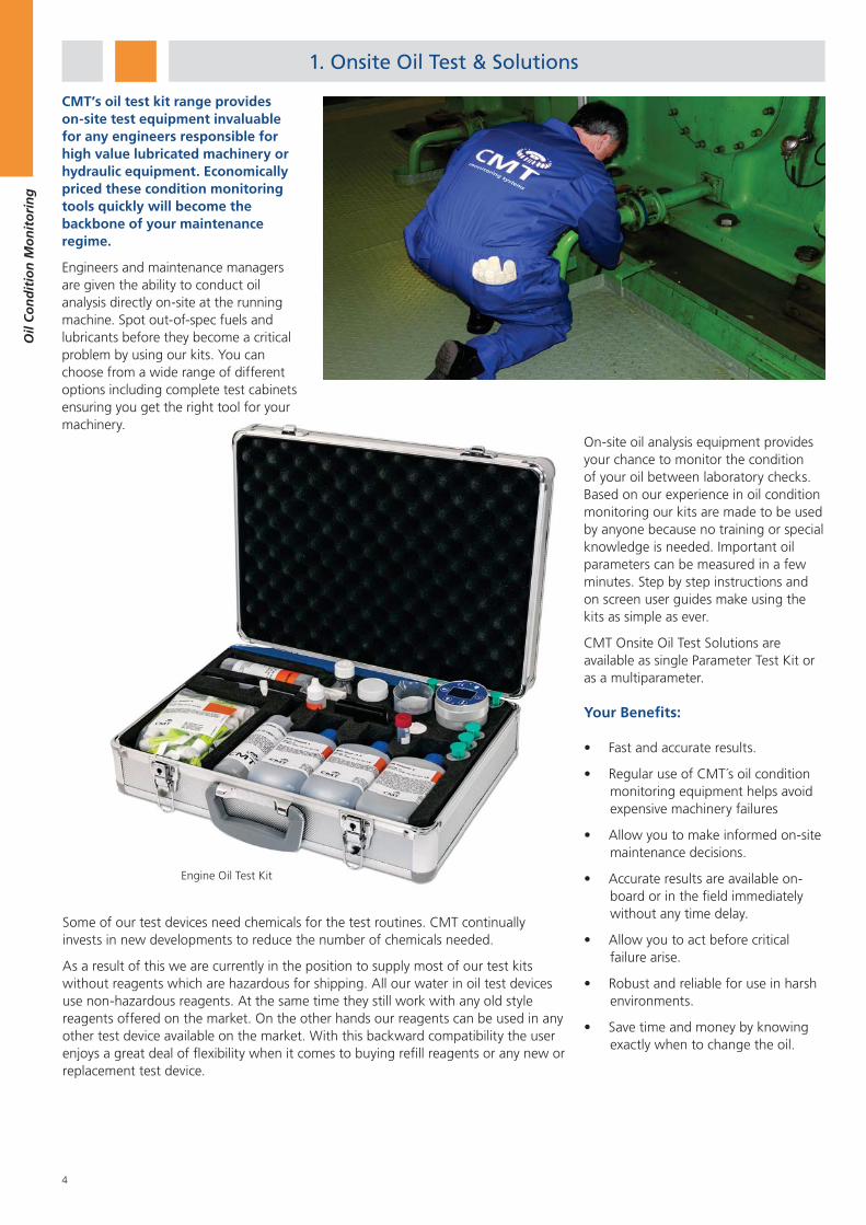
CMT’s oil test kit range provides on-site test equipment invaluable for any engineers responsible for high value lubricated machinery or hydraulic equipment. Economically priced these condition monitoring tools quickly will become the backbone of your maintenance regime.
Engineers and maintenance managers are given the ability to conduct oil analysis directly on-site at the running machine. Spot out-of-spec fuels and lubricants before they become a critical problem by using our kits. You can choose from a wide range of different options including complete test cabinets ensuring you get the right tool for your machinery. ery.
On-site oil analysis equipment provides your chance to monitor the condition of your oil between laboratory checks. Based on our experience in oil condition monitoring our kits are made to be used by anyone because no training or special knowledge is needed. Important oil parameters can be measured in a few minutes. Step by step instructions and on screen user guides make using the kits as simple as ever.
CMT Onsite Oil Test Solutions are available as single Parameter Test Kit or as a multiparameter.
Your Benefits:
Fast and accurate results.
Regular use of CMT´s oil condition monitoring equipment helps avoid expensive machinery failures
Allow you to make informed on-site maintenance decisions.
Accurate results are available on-board or in the field immediately without any time delay.
Allow you to act before critical failure arise.
Robust and reliable for use in harsh environments.
Save time and money by knowing exactly when to change the oil.
Some of our test devices need chemicals for the test routines. CMT continually invests in new developments to reduce the number of chemicals needed.
As a result of this we are currently in the position to supply most of our test kits without reagents which are hazardous for shipping. All our water in oil test devices use non-hazardous reagents. At the same time they still work with any old style reagents offered on the market. On the other hands our reagents can be used in any other test device available on the market. With this backward compatibility the user enjoys a great deal of flexibility when it comes to buying refill reagents or any new or replacement test device.
1. Onsite Oil Test & Solutions
Engine Oil Test Kit
5
Oil
Co
nd
itio
n M
on
ito
rin
g
Multi- Parameter Combinations - Test Kits
Digital / Manual Test Kits
Product name Part number Combination
Viscotube Water in Oil Cell
Combined Water in Oil/BN Cell
Salt Test Insoluble AN Test Viscostick
WaVis Oil Test Kit OTC-CT-20001
Basic Oil Test Kit OTC-CT-20002
Engine Oil Test Kit OTC-CT-20003
Field Oil Test Kit OTC-CT-20004
Engine Oil Test Kit II
OTC-CT-20005
Marine Oil Test Kit OTC-CT-20006
Hydraulic Oil Test Kit
OTC-CT-20007
Water in Oil Cell Density Hydrometer Low Range Falling Ball Viscometer
Free Fatty Acid Test/ AN Test
Visual Test (Cleanliness)
Diesel Oil Test Kit OTC-CT-20008
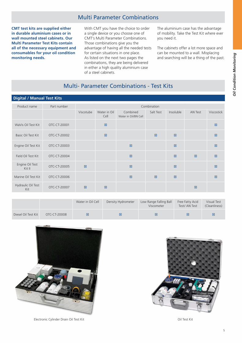
Electronic Cylinder Drain Oil Test Kit
Multi Parameter Combinations
CMT test kits are supplied either in durable aluminium cases or in wall mounted steel cabinets. Our Multi Parameter Test Kits contain all of the necessary equipment and consumables for your oil condition monitoring needs.
With CMT you have the choice to order a single device or you choose one of CMT’s Multi Parameter Combinations.Those combinations give you the advantage of having all the needed tests for certain situations in one place.As listed on the next two pages the combinations, they are being delivered in either a high quality aluminium case of a steel cabinets.
The aluminium case has the advantage of mobility. Take the Test Kit where ever you need it.
The cabinets offer a lot more space and can be mounted to a wall. Misplacing and searching will be a thing of the past.
Oil Test Kit
6
Oil
Co
nd
itio
n M
on
ito
rin
g
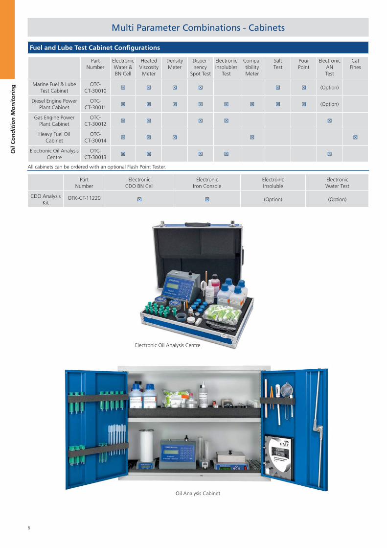
Fuel and Lube Test Cabinet Configurations
Part Number
Electronic Water & BN Cell
Heated Viscosity Meter
Density Meter
Disper-sency
Spot Test
Electronic Insolubles
Test
Compa-tibility Meter
SaltTest
PourPoint
ElectronicAN Test
Cat Fines
Marine Fuel & Lube Test Cabinet
OTC-CT-30010
(Option)
Diesel Engine Power Plant Cabinet
OTC-CT-30011
(Option)
Gas Engine Power Plant Cabinet
OTC-CT-30012
Heavy Fuel Oil Cabinet
OTC-CT-30014
Electronic Oil Analysis Centre
OTC-CT-30013
All cabinets can be ordered with an optional Flash Point Tester.
Electronic Oil Analysis Centre
Multi Parameter Combinations - Cabinets
Part Number
Electronic CDO BN Cell
Electronic Iron Console
Electronic Insoluble
ElectronicWater Test
CDO Analysis Kit
OTK-CT-11220 (Option) (Option)
Oil Analysis Cabinet
7
Oil
Co
nd
itio
n M
on
ito
rin
g
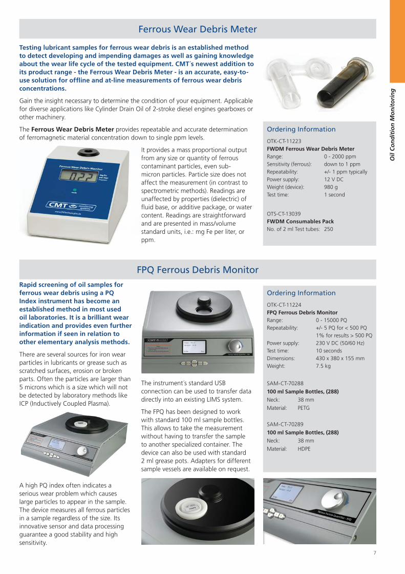
Ferrous Wear Debris Meter
Ordering Information
OTK-CT-11223FWDM Ferrous Wear Debris MeterRange: 0 - 2000 ppmSensitivity (ferrous): down to 1 ppmRepeatability: +/- 1 ppm typicallyPower supply: 12 V DCWeight (device): 980 gTest time: 1 second
OTS-CT-13039FWDM Consumables PackNo. of 2 ml Test tubes: 250
Testing lubricant samples for ferrous wear debris is an established method to detect developing and impending damages as well as gaining knowledge about the wear life cycle of the tested equipment. CMT´s newest addition to its product range - the Ferrous Wear Debris Meter - is an accurate, easy-to-use solution for offline and at-line measurements of ferrous wear debris concentrations.
Gain the insight necessary to determine the condition of your equipment. Applicable for diverse applications like Cylinder Drain Oil of 2-stroke diesel engines gearboxes or other machinery.
The Ferrous Wear Debris Meter provides repeatable and accurate determination of ferromagnetic material concentration down to single ppm levels.
It provides a mass proportional output from any size or quantity of ferrous contaminant particles, even sub-micron particles. Particle size does not affect the measurement (in contrast to spectrometric methods). Readings are unaffected by properties (dielectric) of fluid base, or additive package, or water content. Readings are straightforward and are presented in mass/volume standard units, i.e.: mg Fe per liter, or ppm.
FPQ Ferrous Debris Monitor
Ordering Information
OTK-CT-11224FPQ Ferrous Debris MonitorRange: 0 - 15000 PQRepeatability: +/- 5 PQ for < 500 PQ 1% for results > 500 PQPower supply: 230 V DC (50/60 Hz)Test time: 10 secondsDimensions: 430 x 380 x 155 mmWeight: 7.5 kg
SAM-CT-70288
100 ml Sample Bottles, (288)
Neck: 38 mm
Material: PETG
SAM-CT-70289
100 ml Sample Bottles, (288)
Neck: 38 mm
Material: HDPE
Rapid screening of oil samples for ferrous wear debris using a PQ Index instrument has become an established method in most used oil laboratories. It is a brilliant wear indication and provides even further information if seen in relation to other elementary analysis methods.
There are several sources for iron wear particles in lubricants or grease such as scratched surfaces, erosion or broken parts. Often the particles are larger than 5 microns which is a size which will not be detected by laboratory methods like ICP (Inductively Coupled Plasma).
A high PQ index often indicates a serious wear problem which causes large particles to appear in the sample. The device measures all ferrous particles in a sample regardless of the size. Its innovative sensor and data processing guarantee a good stability and high sensitivity.
The instrument´s standard USB connection can be used to transfer data directly into an existing LIMS system.
The FPQ has been designed to work with standard 100 ml sample bottles. This allows to take the measurement without having to transfer the sample to another specialized container. The device can also be used with standard 2 ml grease pots. Adapters for different sample vessels are available on request.
8
Oil
Co
nd
itio
n M
on
ito
rin
g
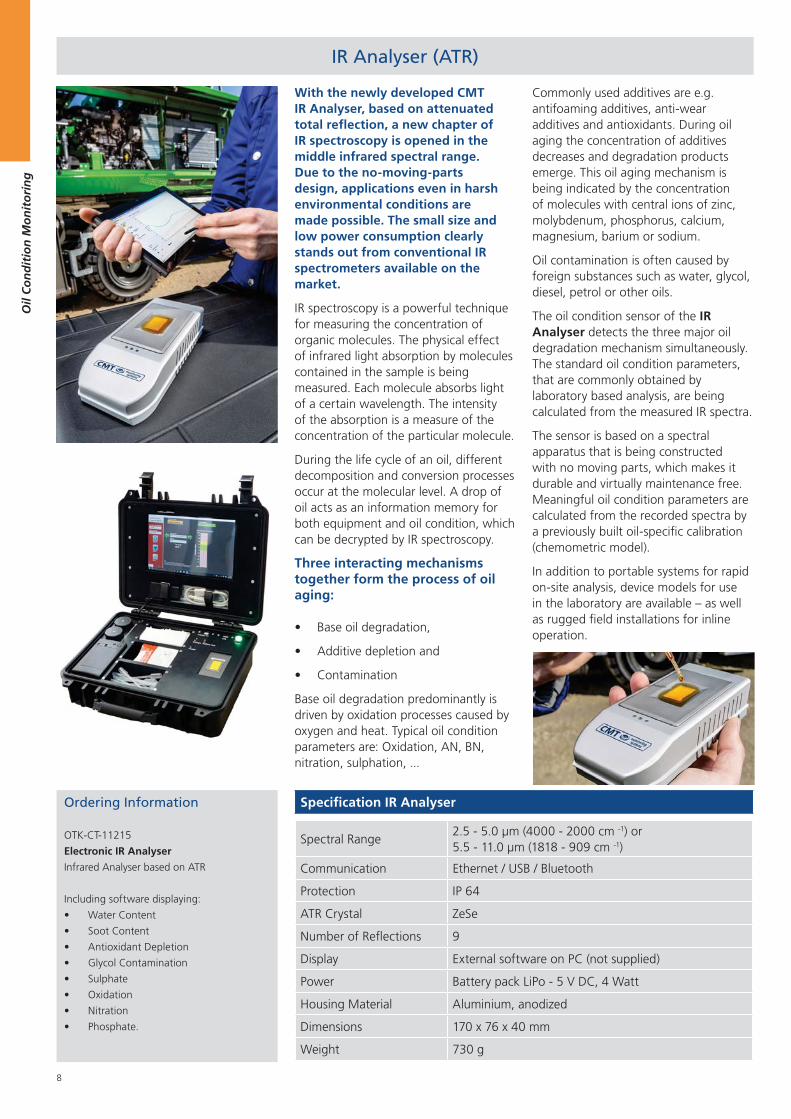
With the newly developed CMT IR Analyser, based on attenuated total reflection, a new chapter of IR spectroscopy is opened in the middle infrared spectral range. Due to the no-moving-parts design, applications even in harsh environmental conditions are made possible. The small size and low power consumption clearly stands out from conventional IR spectrometers available on the market.
IR spectroscopy is a powerful technique for measuring the concentration of organic molecules. The physical effect of infrared light absorption by molecules contained in the sample is being measured. Each molecule absorbs light of a certain wavelength. The intensity of the absorption is a measure of the concentration of the particular molecule.
During the life cycle of an oil, different decomposition and conversion processes occur at the molecular level. A drop of oil acts as an information memory for both equipment and oil condition, which can be decrypted by IR spectroscopy.
Three interacting mechanisms together form the process of oil aging:
Base oil degradation,
Additive depletion and
Contamination
Base oil degradation predominantly is driven by oxidation processes caused by oxygen and heat. Typical oil condition parameters are: Oxidation, AN, BN, nitration, sulphation, ...
Commonly used additives are e.g. antifoaming additives, anti-wear additives and antioxidants. During oil aging the concentration of additives decreases and degradation products emerge. This oil aging mechanism is being indicated by the concentration of molecules with central ions of zinc, molybdenum, phosphorus, calcium, magnesium, barium or sodium.
Oil contamination is often caused by foreign substances such as water, glycol, diesel, petrol or other oils.
The oil condition sensor of the IR Analyser detects the three major oil degradation mechanism simultaneously. The standard oil condition parameters, that are commonly obtained by laboratory based analysis, are being calculated from the measured IR spectra.
The sensor is based on a spectral apparatus that is being constructed with no moving parts, which makes it durable and virtually maintenance free. Meaningful oil condition parameters are calculated from the recorded spectra by a previously built oil-specific calibration (chemometric model).
In addition to portable systems for rapid on-site analysis, device models for use in the laboratory are available – as well as rugged field installations for inline operation.
IR Analyser (ATR)
Ordering Information
OTK-CT-11215
Electronic IR Analyser
Infrared Analyser based on ATR
Including software displaying:
Water Content
Soot Content
Antioxidant Depletion
Glycol Contamination
Sulphate
Oxidation
Nitration
Phosphate.
Specification IR Analyser
Spectral Range2.5 - 5.0 μm (4000 - 2000 cm -1) or5.5 - 11.0 μm (1818 - 909 cm -1)
Communication Ethernet / USB / Bluetooth
Protection IP 64
ATR Crystal ZeSe
Number of Reflections 9
Display External software on PC (not supplied)
Power Battery pack LiPo - 5 V DC, 4 Watt
Housing Material Aluminium, anodized
Dimensions 170 x 76 x 40 mm
Weight 730 g
9
Oil
Co
nd
itio
n M
on
ito
rin
g
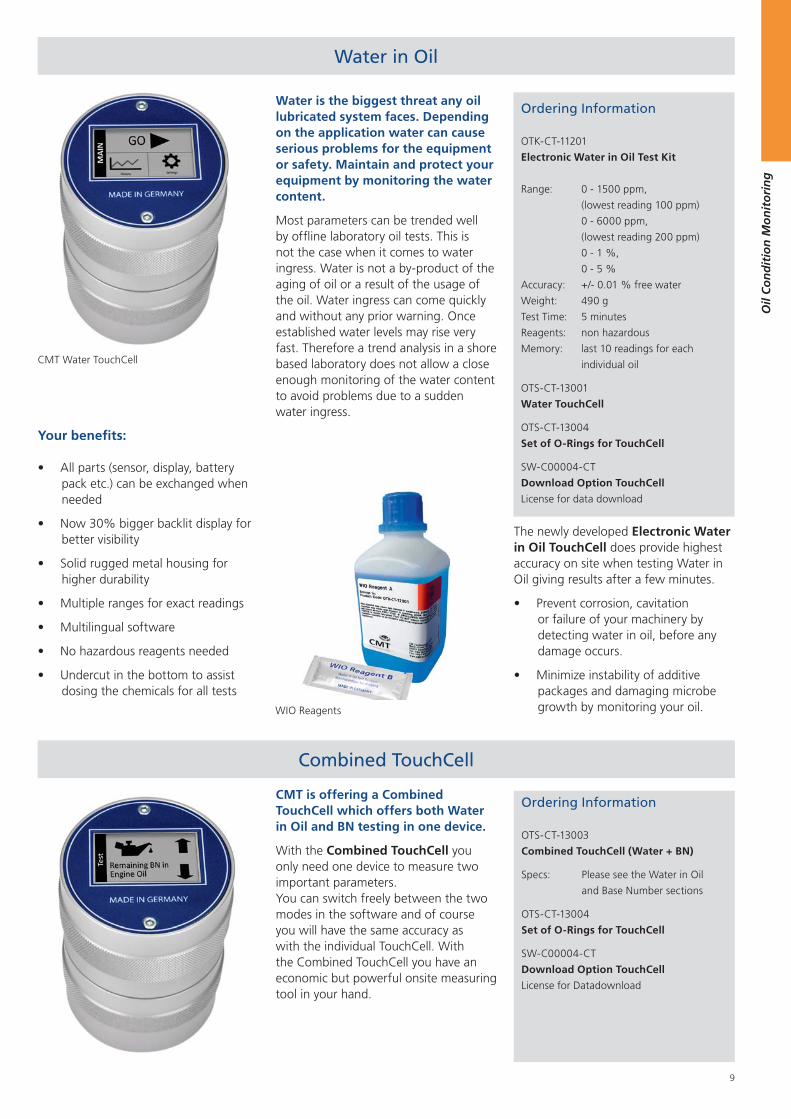
Water is the biggest threat any oil lubricated system faces. Depending on the application water can cause serious problems for the equipment or safety. Maintain and protect your equipment by monitoring the water content.
Most parameters can be trended well by offline laboratory oil tests. This is not the case when it comes to water ingress. Water is not a by-product of the aging of oil or a result of the usage of the oil. Water ingress can come quickly and without any prior warning. Once established water levels may rise very fast. Therefore a trend analysis in a shore based laboratory does not allow a close enough monitoring of the water content to avoid problems due to a sudden water ingress.
Water in Oil
CMT Water TouchCell
Ordering Information
OTK-CT-11201
Electronic Water in Oil Test Kit
Range: 0 - 1500 ppm,
(lowest reading 100 ppm)
0 - 6000 ppm,
(lowest reading 200 ppm)
0 - 1 %,
0 - 5 %
Accuracy: +/- 0.01 % free water
Weight: 490 g
Test Time: 5 minutes
Reagents: non hazardous
Memory: last 10 readings for each
individual oil
OTS-CT-13001
Water TouchCell
OTS-CT-13004
Set of O-Rings for TouchCell
SW-C00004-CT
Download Option TouchCell
License for data download
Ordering Information
OTS-CT-13003
Combined TouchCell (Water + BN)
Specs: Please see the Water in Oil
and Base Number sections
OTS-CT-13004
Set of O-Rings for TouchCell
SW-C00004-CT
Download Option TouchCell
License for Datadownload
WIO Reagents
Your benefits:
All parts (sensor, display, battery pack etc.) can be exchanged when needed
Now 30% bigger backlit display for better visibility
Solid rugged metal housing for higher durability
Multiple ranges for exact readings
Multilingual software
No hazardous reagents needed
Undercut in the bottom to assist dosing the chemicals for all tests
Combined TouchCell
The newly developed Electronic Water in Oil TouchCell does provide highest accuracy on site when testing Water in Oil giving results after a few minutes.
Prevent corrosion, cavitation or failure of your machinery by detecting water in oil, before any damage occurs.
Minimize instability of additive packages and damaging microbe growth by monitoring your oil.
CMT is offering a Combined TouchCell which offers both Water in Oil and BN testing in one device.
With the Combined TouchCell you only need one device to measure two important parameters. You can switch freely between the two modes in the software and of course you will have the same accuracy as with the individual TouchCell. With the Combined TouchCell you have an economic but powerful onsite measuring tool in your hand.
10
Oil
Co
nd
itio
n M
on
ito
rin
g
Base Number (BN)
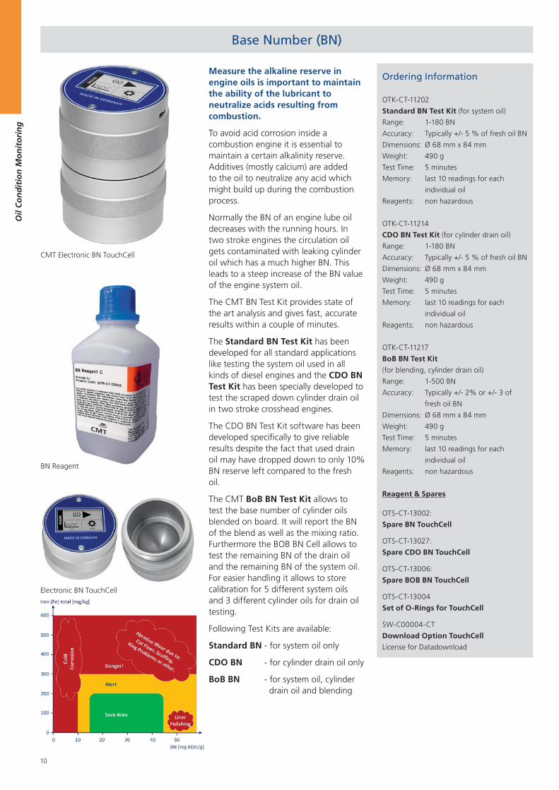
Measure the alkaline reserve in engine oils is important to maintain the ability of the lubricant to neutralize acids resulting from combustion.
To avoid acid corrosion inside a combustion engine it is essential to maintain a certain alkalinity reserve. Additives (mostly calcium) are added to the oil to neutralize any acid which might build up during the combustion process.
Normally the BN of an engine lube oil decreases with the running hours. In two stroke engines the circulation oil gets contaminated with leaking cylinder oil which has a much higher BN. This leads to a steep increase of the BN value of the engine system oil.
The CMT BN Test Kit provides state of the art analysis and gives fast, accurate results within a couple of minutes.
The Standard BN Test Kit has been developed for all standard applications like testing the system oil used in all kinds of diesel engines and the CDO BN Test Kit has been specially developed to test the scraped down cylinder drain oil in two stroke crosshead engines.
The CDO BN Test Kit software has been developed specifically to give reliable results despite the fact that used drain oil may have dropped down to only 10% BN reserve left compared to the fresh oil.
The CMT BoB BN Test Kit allows to test the base number of cylinder oils blended on board. It will report the BN of the blend as well as the mixing ratio. Furthermore the BOB BN Cell allows to test the remaining BN of the drain oil and the remaining BN of the system oil. For easier handling it allows to store calibration for 5 different system oils and 3 different cylinder oils for drain oil testing.
Following Test Kits are available:
Standard BN - for system oil only
CDO BN - for cylinder drain oil only
BoB BN - for system oil, cylinder drain oil and blending
Ordering Information
OTK-CT-11202
Standard BN Test Kit (for system oil)
Range: 1-180 BN
Accuracy: Typically +/- 5 % of fresh oil BN
Dimensions: Ø 68 mm x 84 mm
Weight: 490 g
Test Time: 5 minutes
Memory: last 10 readings for each
individual oil
Reagents: non hazardous
OTK-CT-11214
CDO BN Test Kit (for cylinder drain oil)
Range: 1-180 BN
Accuracy: Typically +/- 5 % of fresh oil BN
Dimensions: Ø 68 mm x 84 mm
Weight: 490 g
Test Time: 5 minutes
Memory: last 10 readings for each
individual oil
Reagents: non hazardous
OTK-CT-11217
BoB BN Test Kit
(for blending, cylinder drain oil)
Range: 1-500 BN
Accuracy: Typically +/- 2% or +/- 3 of
fresh oil BN
Dimensions: Ø 68 mm x 84 mm
Weight: 490 g
Test Time: 5 minutes
Memory: last 10 readings for each
individual oil
Reagents: non hazardous
Reagent & Spares
OTS-CT-13002:
Spare BN TouchCell
OTS-CT-13027:
Spare CDO BN TouchCell
OTS-CT-13006:
Spare BOB BN TouchCell
OTS-CT-13004
Set of O-Rings for TouchCell
SW-C00004-CT
Download Option TouchCell
License for Datadownload
Electronic BN TouchCell
CMT Electronic BN TouchCell
BN Reagent
11
Oil
Co
nd
itio
n M
on
ito
rin
g
Viscosity / Density Meter
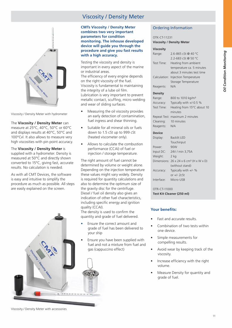
Viscosity / Density Meter with hydrometer
CMTs Viscosity / Density Meter combines two very important parameters for condition monitoring. The inhouse developed device will guide you through the procedure and give you fast results with a high accuracy.
Testing the viscosity and density is important in every aspect of the marine or industrial areas. The efficiency of every engine depends on the right viscosity of the fuel. Viscosity is fundamental to maintaining the integrity of a lube oil film. Lubrication is very important to prevent metallic contact, scuffing, micro welding and wear of sliding surfaces.
Measuring the oil viscosity provides an early detection of contamination, fuel ingress and shear thinning.
Suitable for all mineral oils or fuels down to 1.5 cSt up to 999 cSt (heated viscometer only).
Allows to calculate the combustion performance (CCAI) of fuel or injection / storage temperature.
The right amount of fuel cannot be determined by volume or weight alone. Depending on the injection temperature these values might vary widely. Density is required for quantity calculations and also to determine the optimum size of the gravity disc for the centrifuge. Diesel / fuel oil density also gives an indication of other fuel characteristics, including specific energy and ignition quality (CCAI). The density is used to confirm the quantity and grade of fuel delivered.
Ensure the correct amount and grade of fuel has been delivered to your ship
Ensure you have been supplied with fuel and not a mixture from fuel and gas (cappuccino effect)
Ordering Information
OTK-CT-11231
Viscosity / Density Meter
Viscosity
Range: 2.6-865 cSt @ 40 °C
2.2-683 cSt @ 50 °C
Test Time: Heating from ambient
temperature ca. 5 minutes
about 3 minutes test time
Calculation: Injection Temperature
Storage Temperature
Reagents: N/A
Density
Range: 800 to 1010 kg/m³
Accuracy: Typically with +/-0.5 %
Test Time: Heating from 15°C about 10
minutes
Repeat Test: maximum 2 minutes
Cleaning: 10 minutes
Reagents: N/A
Device
Display: Backlit LED
Touchinput
Power: 90W
Input DC: 24V / min 3,75A
Weight: 2 kg
Dimensions: 26 x 24 x 6 cm³ (H x W x D)
(without stand)
Accuracy: Typically with +/- %
or +/- 2cSt
Interface: Micro-USB
OTR-CT-11000
Test Kit Cleaner (250 ml)
Your benefits:
Fast and accurate results.
Combination of two tests within one device.
Simple measurements for compelling results.
Avoid wear by keeping track of the viscosity.
Increase efficiency with the right volume.
Measure Density for quantity and grade of fuel.
The Viscosity / Density Meter can measure at 25°C, 40°C, 50°C or 60°C and displays results at 40°C, 50°C and 100°Cvl. It also allows to measure very high viscosities with pin point accuracy.
The Viscosity / Density Meter is supplied with a hydrometer. Density is measured at 50°C and directly shown converted to 15°C, giving fast, accurate results. No calculation is needed.
As with all CMT Devices, the software is easy and intuitive to simplify the procedure as much as possible. All steps are easily explained on the screen.
Viscosity / Density Meter with accessories
12
Oil
Co
nd
itio
n M
on
ito
rin
g
Viscostick
With the growing use of low sulphur fuels and increased frequency of bunkering, testing the stability of the fuel oil and its compatibility for blending is becoming increasingly important.
Whilst every fuel oil is manufactured to be stable - in that it does not have the tendency to produce asphaltic sludge - two stable fuel oils are not necessarily compatible when blended or mixed together.
Ordering Information
OTK-CT-11216
Electronic Compatibility Tester
Range: As per ASTM D4740
Accuracy: Variation of 1 rating in
20 repeat tests
Test Time: 20 minutes (attended),
1 hour (unattended)
OTS-CT-13032
Spare Chromatography Paper (100)
OTS-CT-13030
Consumables Glass Pack (10)
OTR-CT-11000
Test Kit Cleaner
Compatibility Tester
Compatibility Tester
Viscosity
Ordering Information
OTK-CT-11005
Viscotube Oil Test Kit
Range: 20-600 cSt @ 40°C, using
three sizes of balls
No. of Tests: Unlimited
Test Time: 1 - 10 minutes
Reagents: N/A
OTK-CT-11004
Viscosity Oil Test Kit
Range: go / no go
Application: Lubricating oils, viscous
hydraulics
No. of Tests: Unlimited
Test Time: 1 minute
Reagents: N/A
OTR-CT-11000
Test Kit Cleaner (250 ml)
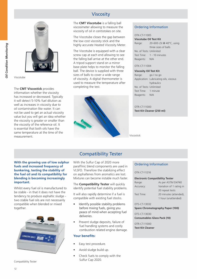
The CMT Viscostick provides information whether the viscosity has increased or decreased. Typically it will detect 5-10% fuel dilution as well as increases in viscosity due to oil contamination like water. It can not be used to get an actual viscosity value but you will get an idea whether the viscosity is greater or smaller than the viscosity of the reference oil. It is essential that both oils have the same temperature at the time of the measurement.
Your benefits:
Easy test procedure.
Avoid sludge build up.
Check fuels to comply with the Sulfur Cap 2020.
Viscotube
With the Sulfur Cap of 2020 more paraffinic blend components are used in VLSFO. Therefore the stabilizing effect on asphaltenes from aromatics are lost. Mixtures can become instable much faster.
The Compatibility Tester will quickly identify potential fuel stability problems.
It will also rapidly determine if a fuel is compatible with existing fuel stocks.
Identify possible stability problems before mixing fuels, giving you peace of mind when accepting fuel deliveries.
Prevent sludge deposits, failure of fuel handling systems and costly combustion related engine damage.
The CMT Viscotube is a falling ball viscosimeter allowing to measure the viscosity of oil in centistokes on site.
The Viscotube closes the gap between the low cost viscosity stick and the highly accurate Heated Viscosity Meter.
The Viscotube is equipped with a clear screw cap at each end allowing to see the falling ball arrive at the other end. A tripod support stand on a mirror base plate helps to monitor the falling ball. The device is supplied with three sizes of balls to cover a wide range of viscosity. A digital thermometer is used to measure the temperature after completing the test.
13
Oil
Co
nd
itio
n M
on
ito
rin
g
Econ and Electronic Cat Fines II Test Patent (No. 3121596, 3121595)
Electronic Cat Fines II
Econ Cat Fines
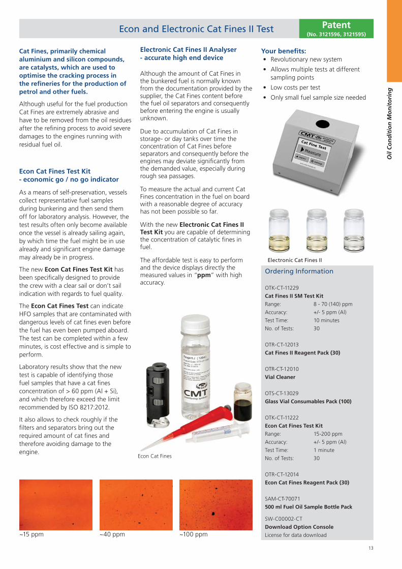
Cat Fines, primarily chemical aluminium and silicon compounds, are catalysts, which are used to optimise the cracking process in the refineries for the production of petrol and other fuels.
Although useful for the fuel production Cat Fines are extremely abrasive and have to be removed from the oil residues after the refining process to avoid severe damages to the engines running with residual fuel oil.
Ordering Information
OTK-CT-11229
Cat Fines II SM Test Kit
Range: 8 - 70 (140) ppm
Accuracy: +/- 5 ppm (Al)
Test Time: 10 minutes
No. of Tests: 30
OTR-CT-12013
Cat Fines II Reagent Pack (30)
OTR-CT-12010
Vial Cleaner
OTS-CT-13029
Glass Vial Consumables Pack (100)
OTK-CT-11222
Econ Cat Fines Test Kit
Range: 15-200 ppm
Accuracy: +/- 5 ppm (Al)
Test Time: 1 minute
No. of Tests: 30
OTR-CT-12014
Econ Cat Fines Reagent Pack (30)
SAM-CT-70071
500 ml Fuel Oil Sample Bottle Pack
SW-C00002-CT
Download Option Console
License for data download~15 ppm ~40 ppm ~100 ppm
Your benefits:Revolutionary new system
Allows multiple tests at different sampling points
Low costs per test
Only small fuel sample size needed
Electronic Cat Fines II Analyser - accurate high end device
Although the amount of Cat Fines in the bunkered fuel is normally known from the documentation provided by the supplier, the Cat Fines content before the fuel oil separators and consequently before entering the engine is usually unknown.
Due to accumulation of Cat Fines in storage- or day tanks over time the concentration of Cat Fines before separators and consequently before the engines may deviate significantly from the demanded value, especially during rough sea passages.
To measure the actual and current Cat Fines concentration in the fuel on board with a reasonable degree of accuracy has not been possible so far.
With the new Electronic Cat Fines II Test Kit you are capable of determining the concentration of catalytic fines in fuel.
The affordable test is easy to perform and the device displays directly the measured values in “ppm” with high accuracy.
Econ Cat Fines Test Kit - economic go / no go indicator
As a means of self-preservation, vessels collect representative fuel samples during bunkering and then send them off for laboratory analysis. However, the test results often only become available once the vessel is already sailing again, by which time the fuel might be in use already and significant engine damage may already be in progress.
The new Econ Cat Fines Test Kit has been specifically designed to provide the crew with a clear sail or don’t sail indication with regards to fuel quality.
The Econ Cat Fines Test can indicate HFO samples that are contaminated with dangerous levels of cat fines even before the fuel has even been pumped aboard. The test can be completed within a few minutes, is cost effective and is simple to perform.
Laboratory results show that the new test is capable of identifying those fuel samples that have a cat fines concentration of > 60 ppm (Al + Si), and which therefore exceed the limit recommended by ISO 8217:2012.
It also allows to check roughly if the filters and separators bring out the required amount of cat fines and therefore avoiding damage to the engine.
14
Oil
Co
nd
itio
n M
on
ito
rin
g
XRF Onboard Sulfur Tester
Ordering Information
OTK-CT-11227
XRF Onboard Sulfur Tester
XRF Onboard Sulfur Tester
Dynamic Range Sulfur 50 ppm - 5 wt%
ApplicationsS in hydrocarbons like crude oil, mineral oil, diesel, gasoline, marine
fuel, jet fuel, kerosene, and lubricants
Method Compliance ASTM D4294, ISO 8754 & IP 336
Measure time 30 - 900 seconds
Calibration- 30 different calibration curves
- Linear (automatic custom Calibration available)
Sample volume cap
bottle
- 7-10 ml
- 25 ml
Connections USB, Ethernet
Data Output Printout, USB and Ethernet to PC
Dimensions 23 cm x 30 cm x 26 cm 7,2 kg
AC Power Supply 110-240 VAC ± 10%, 50-60 Hz
Battery Power 98Wh > 4 hours continuos
Operating temp. 5 °C - 40 °C
Operating Humidity 30 - 85%
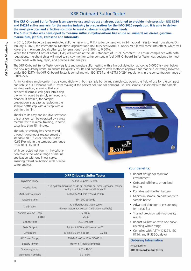
The XRF Onboard Sulfur Tester is an easy-to-use and robust analyzer, designed to provide high-precision ISO 8754 and D4294 sulfur analysis for the marine industry in preparation for the IMO 2020 regulation. It is able to deliver the most practical and effective solution to meet customer’s application needs. The Sulfur Tester was developed to measure sulfur in hydrocarbons like crude oil, mineral oil, diesel, gasoline, marine fuel, jet fuel, kerosene and lubricants.
In 2015, SECA trade partners restricted sulfur emissions to 0.1% sulfur content within 24 nautical miles (or less) from shore. On January 1, 2020, the International Maritime Organization’s (IMO) revised MARPOL Annex VI rule will come into effect, which will lower the maximum global sulfur cap for emissions from 3.50% to 0.50%. While the Emission Control Areas (ECAs) will remain at the 2015 standard of 0.10% S content. To ensure compliance with both regulations, merchant ships will need to strictly monitor sulfur content in fuel. XRF Onboard Sulfur Tester was designed to meet these needs with easy, rapid, and precise sulfur analysis.
The XRF Onboard Sulfur Tester delivers fast and precise sulfur testing with a limit of detection as low as 0.0050% - well below the new regulatory limits. To ensure lab-quality results and compliance with methods approved for marine-fuel testing (covered under ISO 8217), the XRF Onboard Tester is compliant with ISO 8754 and ASTM D4294 regulations in the concentration range of 0.01%-5%.
An innovative sample carrier that is compatible with both sample bottle and sample cup opens the field of use for the compact and robust XRF Onboard Sulfur Tester making it the perfect solution for onboard use. The sample is inserted with the sample window vertical, ensuring that any accidental sample leak goes into a drip tray which could be simply removed and cleaned. If desired, the sample preparation is as easy as replacing the sample bottle cap with a Z-cap with a built-in thin film.
Thanks to its easy and intuitive software this analyzer can be operated by a crew member with minimal training, in some cases less than 15 minutes.
The robust stability has been tested through continuous measurement of standard NIST fuel oil sample 1619b (0.698%) within the temperature range from 10 °C to 30 °C.
With corrected net counts, the calibra-tion covers the whole range of marine application with one linear curve, ensuring robust calibration with precise sulfur analysis.
Your benefits:
Robust design for maritime environment
Onboard, offshore, or on-land testing
Portable with built-in battery
Minimum sample preparation with sample bottle
Advanced detector to ensure long-term stability
Trusted precision with lab-quality results
Robust calibration with one curve covering whole range
Complies with ASTM D4294, ISO 8754, and IP 336Quidetor
15
Oil
Co
nd
itio
n M
on
ito
rin
g
HDXRF Sulfur and Multi Element Analyser
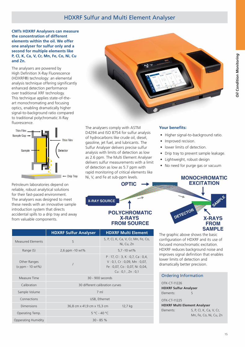
CMTs HDXRF Analysers can measure the concentration of different elements within the oil. We offer one analyser for sulfur only and a second for multiple elements like P, Cl, K, Ca, V, Cr, Mn, Fe, Co, Ni, Cu and Zn.
The analysers are powered by High Definition X-Ray Fluorescence (HDXRF®) technology: an elemental analysis technique offering significantly enhanced detection performance over traditional XRF technology. This technique applies state-of-the-art monochromating and focusing optics, enabling dramatically higher signal-to-background ratio compared to traditional polychromatic X-Ray fluorescence.
Petroleum laboratories depend on reliable, robust analytical solutions for their fast-paced environment. The analysers was designed to meet these needs with an innovative sample introduction system that directs accidental spills to a drip tray and away from valuable components.
Ordering Information
OTK-CT-11226
HDXRF Sulfur Analyser
Elements: S
OTK-CT-11225
HDXRF Multi Element Analyser
Elements: S, P, Cl, K, Ca, V, Cr,
Mn, Fe, Co, Ni, Cu, Zn
HDXRF Sulfur Analyser HDXRF Multi Element
Measured Elements SS, P, Cl, K, Ca, V, Cr, Mn, Fe, Co,
Ni, Cu, Zn
Range (S) 2,6 ppm -10 wt% 5,7 -10 wt%
Other Ranges
(x ppm - 10 wt%)/
P : 17, Cl : 3, K : 0,7, Ca : 0,4,
V : 0,1, Cr : 0,09, Mn : 0,07,
Fe : 0,07, Co : 0,07, Ni :0,04,
Cu : 0,1 , Zn : 0,1
Measure Time 30 - 900 seconds
Calibration 30 different calibration curves
Sample Volume 7 ml
Connections USB, Ethernet
Dimensions 36,8 cm x 41,9 cm x 15,3 cm 12,7 kg
Operating Temp. 5 °C - 40 °C
Opperating Humidity 30 - 85 %
The analysers comply with ASTM D4294 and ISO 8754 for sulfur analysis of hydrocarbons like crude oil, diesel, gasoline, jet fuel, and lubricants. The Sulfur Analyser delivers precise sulfur analysis with limits of detection as low as 2.6 ppm. The Multi Element Analyser delivers sulfur measurements with a limit of detection as low as 5.7 ppm with rapid monitoring of critical elements like Ni, V, and Fe at sub-ppm levels.
Your benefits:
Higher signal-to-background ratio.
Improved recision.
lower limits of detection.
Drip tray to prevent sample leakage.
Lightweight, robust design
No need for purge gas or vacuum
Ni, V, and Fe at sub-ppm levels.
The graphic above shows the basic configuration of HDXRF and its use of focused monochromatic excitation. HDXRF reduces background noise and improves signal definition that enables lower limits of detection and dramatically better precision.
16
Oil
Co
nd
itio
n M
on
ito
rin
g
Ordering Information
OTK-CT-11205
Electronic Insoluble Test Meter
Range: 0-2.4 Vol%
Accuracy: Typically +/-0.1 %
Test Time: < 2 minutes
No. of Tests: 30 Tests
Reagents: non hazardous
Reagent Pack: OTR-CT-12007
OTR-CT-12007
Insoluble Reagent Pack
No. of Tests: 30 Tests
Reagents: non hazardous
OTS-CT-13021
Spare Insoluble PhotoCell
OTS-CT-13029
Glass Vial Consumables Pack (100)
OTK-CT-11002
Insoluble Spot Test Kit
Range: good / poor
Test Time: one hour (unattended)
Reagent: non hazardous
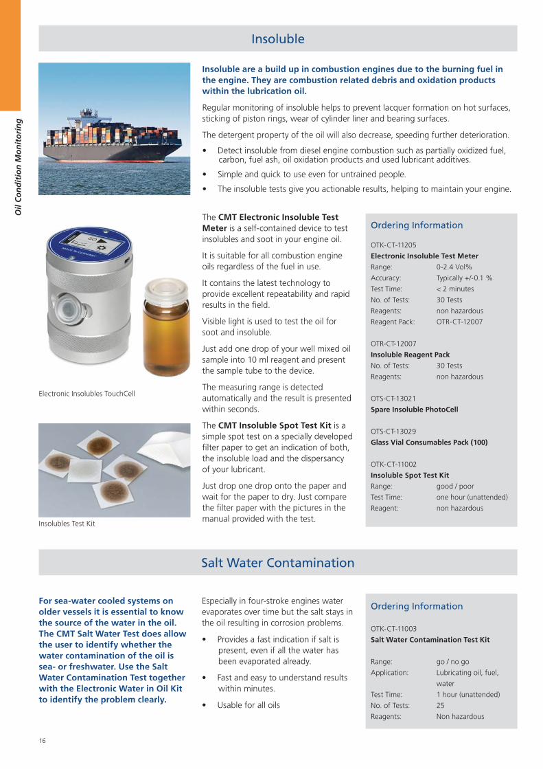
The CMT Electronic Insoluble Test Meter is a self-contained device to test insolubles and soot in your engine oil.
It is suitable for all combustion engine oils regardless of the fuel in use.
It contains the latest technology to provide excellent repeatability and rapid results in the field.
Visible light is used to test the oil for soot and insoluble.
Just add one drop of your well mixed oil sample into 10 ml reagent and present the sample tube to the device.
The measuring range is detected automatically and the result is presented within seconds.
The CMT Insoluble Spot Test Kit is a simple spot test on a specially developed filter paper to get an indication of both, the insoluble load and the dispersancy of your lubricant.
Just drop one drop onto the paper and wait for the paper to dry. Just compare the filter paper with the pictures in the manual provided with the test.
Insoluble
Insolubles Test Kit
Insoluble are a build up in combustion engines due to the burning fuel in the engine. They are combustion related debris and oxidation products within the lubrication oil.
Regular monitoring of insoluble helps to prevent lacquer formation on hot surfaces, sticking of piston rings, wear of cylinder liner and bearing surfaces.
The detergent property of the oil will also decrease, speeding further deterioration.
Detect insoluble from diesel engine combustion such as partially oxidized fuel, carbon, fuel ash, oil oxidation products and used lubricant additives.
Simple and quick to use even for untrained people.
The insoluble tests give you actionable results, helping to maintain your engine.
Electronic Insolubles TouchCell
Salt Water Contamination
For sea-water cooled systems on older vessels it is essential to know the source of the water in the oil. The CMT Salt Water Test does allow the user to identify whether the water contamination of the oil is sea- or freshwater. Use the Salt Water Contamination Test together with the Electronic Water in Oil Kit to identify the problem clearly.
Especially in four-stroke engines water evaporates over time but the salt stays in the oil resulting in corrosion problems.
Provides a fast indication if salt is present, even if all the water has been evaporated already.
Fast and easy to understand results within minutes.
Usable for all oils
Ordering Information
OTK-CT-11003
Salt Water Contamination Test Kit
Range: go / no go
Application: Lubricating oil, fuel,
water
Test Time: 1 hour (unattended)
No. of Tests: 25
Reagents: Non hazardous
17
Oil
Co
nd
itio
n M
on
ito
rin
g
Flash Point Tester
Ordering Information
OTK-CT-11204
Electronic Flash Point Tester
Temp Range: Ambient temperature
(+5) to 300°C
Sample Size: 2-4 ml
Test Time: OK in 2 minutes
Temp Running: 2° C/min.
Test Method: Closed Cup
Resolution: 0.5°C
Accuracy: 0.5°C
Flash Detection: Automatic
Voltage: 110-250 V
Frequency: 50/60 Hz
Power: 200 W
Weight: 4,3 kg
Note: A standard butane (lighter) refill
cartridge is required for operation.
OTR-CT-11000
Test Kit Cleaner (250 ml)
The CMT Flash Point Tester is an automated closed cup instrument using just a 2 ml sample size.
Increased flash point in engine oils to about 200°C is an early indication for fuel dilution which can result in crankcase explosion.
The flammability of a material also determines its safety classification and the regulations under which it must be handled, stored and transported.
The Electronic Flash Point Tester is a compact, bench top / portable, Closed Cup Flash Point Tester designed to carry out ‘flash / no flash’ tests or to determine flash point values up to 300°C using either Ramp or Rapid Equilibrium methods.
The operating principle is that a cup containing the sample to be tested is electrically heated in a ramp function to automatically increment the temperature for repeated tests until a flash is
observed, or the end of the search range is reached, allowing rapid determination of samples.
The device also features a user-friendly yes/no test. It is heated to a user set test temperature. At the set temperature, a shutter in the lid is opened and a test flame is dipped into the vapour space above the sample. It can be determined if a sample has a flash point above or below the test temperature by detecting whether a flash has occurred or not.
Acid Number (AN)
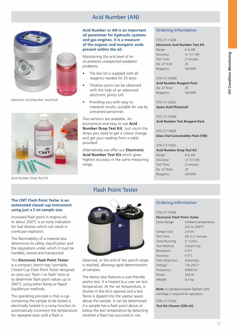
Acid Number or AN is an important oil parameter for hydraulic systems and gas engines. It is a measure of the organic and inorganic acids present within the oil.
Maintaining the acid level of an oil prevents unexpected oxidation problems.
The test kit is supplied with all reagents needed for 25 tests.
Titration point can be observed with the help of an advanced electronic photo cell.
Providing you with easy to interpret results, suitable for use by untrained personnel.
Two versions are available. An economical and easy to use Acid Number Drop Test Kit. Just count the drops you need to get a colour change and get your reading from a table provided.
Alternatively we offer our Electronic Acid Number Test Kit which gives highest accuracy in the same measuring range.
Acid Number Drop Test Kit
Ordering Information
OTK-CT-11209
Electronic Acid Number Test Kit
Range: 0-6 AN
Accuracy: +/- 0.1 AN
Test Time: 2 minutes
No. of Tests: 25
Reagents: UN1993
OTR-CT-12008
Acid Number Reagent Pack
No. of Tests: 25
Reagents: UN1993
OTS-CT-13022
Spare Acid PhotoCell
OTS-CT-12008
Acid Number Test Reagent Pack
OTS-CT-13029
Glass Vial Consumables Pack (100)
OTK-CT-11001
Acid Number Drop Test Kit
Range: 0-6 AN
Accuracy: +/- 0.3 AN
Test Time: 2 minutes
No. of Tests: 25
Reagents: UN1993
Electronic Acid Number TouchCell
18
Oil
Co
nd
itio
n M
on
ito
rin
g
Ordering Information
OTR-CT-12001
Water in Oil Reagent Pack
No. of Tests: 50 Test
OTR-CT-12002
Base Number Reagent Pack
No. of Tests: 50 Test
OTR-CT-12007
Insolubles Reagent Pack
No. of Tests: 30 Test
OTS-CT-12005 AN Reagent Pack 0-3
No. of Tests: 50 Test
UN: UN1993
OTR-CT-12006
AN Reagent Pack 0-6
No. of Tests: 50 Test
UN UN1993
OTR-CT-11000
Test Kit Cleaner
Size 250 ml
OTR-CT-12010
Vial Cleaner
Size 250 ml
Reagents and Consumables
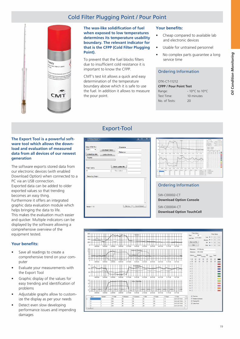
Produced under strict ISO guidelines (DNV GL certified) CMT´s reagents and consumables can be used for nearly all test kits on the market regardless of the manufacturer.
All reagent packs contain necessary consumables as well and are therefore user friendly.
Also packing innovations like the pre portioned sachets of the Water in Oil Reagent B make the usage of the reagents as easy as possible for the user on site.
Also as part of the reagent & consumables range CMT supplies cleaning agents.
A Test Kit Cleaner for cleaning and maintaining the individual test devices and a vial cleaner for cleaning glass materials used in optical measurements can be ordered from us.
Fuel Bacteria Test
Ordering Information
OTK-CT-11006
Fuel Filter Bacteria Test (Dip Slides)
Range: low / moderate / heavy
Test Time: 24 - 48 h at 27 - 30°C
1-4 days at ambient
temperature
No. of Tests: 10
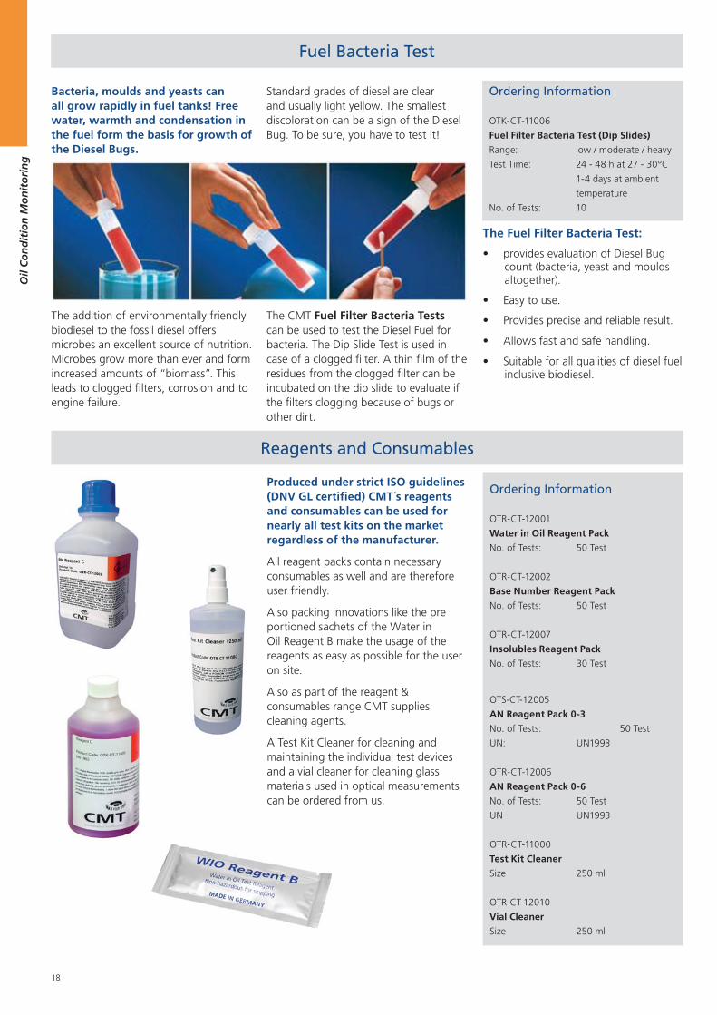
Bacteria, moulds and yeasts can all grow rapidly in fuel tanks! Free water, warmth and condensation in the fuel form the basis for growth of the Diesel Bugs.
The addition of environmentally friendly biodiesel to the fossil diesel offers microbes an excellent source of nutrition. Microbes grow more than ever and form increased amounts of “biomass”. This leads to clogged filters, corrosion and to engine failure.
Standard grades of diesel are clear and usually light yellow. The smallest discoloration can be a sign of the Diesel Bug. To be sure, you have to test it!
The CMT Fuel Filter Bacteria Tests can be used to test the Diesel Fuel for bacteria. The Dip Slide Test is used in case of a clogged filter. A thin film of the residues from the clogged filter can be incubated on the dip slide to evaluate if the filters clogging because of bugs or other dirt.
The Fuel Filter Bacteria Test:
provides evaluation of Diesel Bug count (bacteria, yeast and moulds altogether).
Easy to use.
Provides precise and reliable result.
Allows fast and safe handling.
Suitable for all qualities of diesel fuel inclusive biodiesel.
19
Oil
Co
nd
itio
n M
on
ito
rin
g
Export-Tool
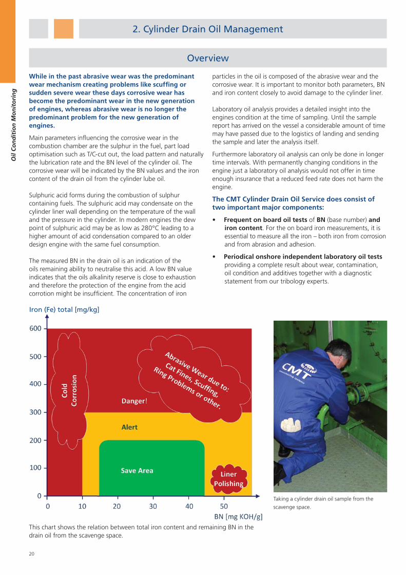
The Export Tool is a powerful soft-ware tool which allows the down-load and evaluation of measured data from all devices of our newest generation
The software exports stored data from our electronic devices (with enabled Download Option) when connected to a PC via an USB connection.Exported data can be added to older exported values so that trending becomes an easy thing.Furthermore it offers an integrated graphic data evaluation module which helps bringing the data to life. This makes the evaluation much easierand quicker. Multiple indicators can be displayed by the software allowing a comprehensive overview of the equipment tested.
Your benefits:
Save all readings to create a comprehensive trend on your com-puter
Evaluate your measurements with the Export Tool
Graphic display of the values for easy trending and identification of problems
Adjustable graphs allow to custom-ize the display as per your needs
Detect even slow developing performance issues and impending damages
Ordering Information
SW-C00002-CT
Download Option Console
SW-C00004-CT
Download Option TouchCell
Ordering Information
OTK-CT-11212
CFPP / Pour Point Test
Range: - 10°C to 10°C
Test Time: 10 minutes
No. of Tests: 20
Cold Filter Plugging Point / Pour Point
The wax-like solidification of fuel when exposed to low temperatures determines its temperature usability boundary. The relevant indicator for that is the CFPP (Cold Filter Plugging Point).
To prevent that the fuel blocks filters due to insufficient cold resistance it is important to know the CFPP.
CMT’s test kit allows a quick and easy determination of the temperature boundary above which it is safe to use the fuel. In addition it allows to measure the pour point.
Your benefits:
Cheap compared to available lab and electronic devices
Usable for untrained personnel
No complex parts guarantee a long service time
20
Oil
Co
nd
itio
n M
on
ito
rin
g
Overview
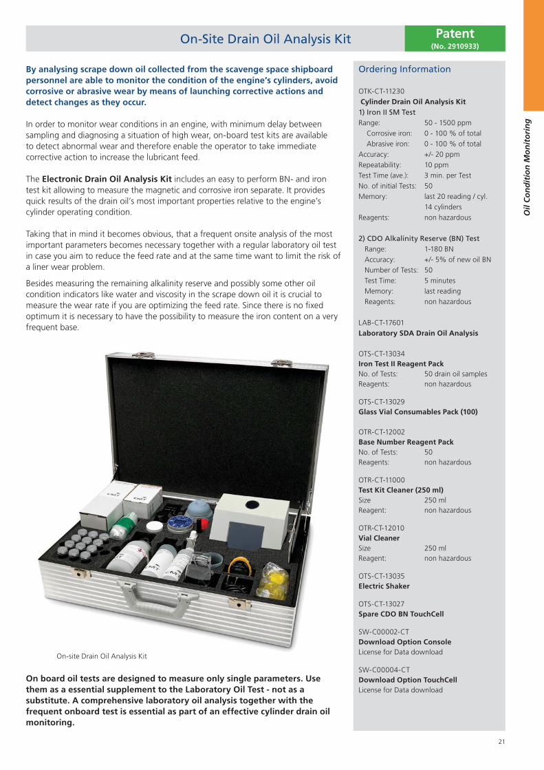
While in the past abrasive wear was the predominant wear mechanism creating problems like scuffing or sudden severe wear these days corrosive wear has become the predominant wear in the new generation of engines, whereas abrasive wear is no longer the predominant problem for the new generation of engines.
Main parameters influencing the corrosive wear in the combustion chamber are the sulphur in the fuel, part load optimisation such as T/C-cut out, the load pattern and naturally the lubrication rate and the BN level of the cylinder oil. The corrosive wear will be indicated by the BN values and the iron content of the drain oil from the cylinder lube oil.
Sulphuric acid forms during the combustion of sulphur containing fuels. The sulphuric acid may condensate on the cylinder liner wall depending on the temperature of the wall and the pressure in the cylinder. In modern engines the dew point of sulphuric acid may be as low as 280°C leading to a higher amount of acid condensation compared to an older design engine with the same fuel consumption.
The measured BN in the drain oil is an indication of the oils remaining ability to neutralise this acid. A low BN value indicates that the oils alkalinity reserve is close to exhaustion and therefore the protection of the engine from the acid corrotion might be insufficient. The concentration of iron
particles in the oil is composed of the abrasive wear and the corrosive wear. It is important to monitor both parameters, BN and iron content closely to avoid damage to the cylinder liner.
Laboratory oil analysis provides a detailed insight into the engines condition at the time of sampling. Until the sample report has arrived on the vessel a considerable amount of time may have passed due to the logistics of landing and sending the sample and later the analysis itself.
Furthermore laboratory oil analysis can only be done in longer time intervals. With permanently changing conditions in the engine just a laboratory oil analysis would not offer in time enough insurance that a reduced feed rate does not harm the engine.
The CMT Cylinder Drain Oil Service does consist of two important major components:
Frequent on board oil tests of BN (base number) and iron content. For the on board iron measurements, it is essential to measure all the iron – both iron from corrosion and from abrasion and adhesion.
Periodical onshore independent laboratory oil tests providing a complete result about wear, contamination, oil condition and additives together with a diagnostic statement from our tribology experts.
This chart shows the relation between total iron content and remaining BN in the drain oil from the scavenge space.
2. Cylinder Drain Oil Management
Taking a cylinder drain oil sample from the
scavenge space.
Iron (Fe) total [mg/kg]
21
Oil
Co
nd
itio
n M
on
ito
rin
g
On-Site Drain Oil Analysis Kit
On board oil tests are designed to measure only single parameters. Use them as a essential supplement to the Laboratory Oil Test - not as a substitute. A comprehensive laboratory oil analysis together with the frequent onboard test is essential as part of an effective cylinder drain oil monitoring.
Ordering Information
OTK-CT-11230 Cylinder Drain Oil Analysis Kit1) Iron II SM TestRange: 50 - 1500 ppm Corrosive iron: 0 - 100 % of total Abrasive iron: 0 - 100 % of totalAccuracy: +/- 20 ppmRepeatability: 10 ppmTest Time (ave.): 3 min. per TestNo. of initial Tests: 50Memory: last 20 reading / cyl. 14 cylindersReagents: non hazardous
2) CDO Alkalinity Reserve (BN) Test Range: 1-180 BN Accuracy: +/- 5% of new oil BN Number of Tests: 50 Test Time: 5 minutes Memory: last reading Reagents: non hazardous
LAB-CT-17601 Laboratory SDA Drain Oil Analysis
OTS-CT-13034 Iron Test II Reagent Pack No. of Tests: 50 drain oil samples Reagents: non hazardous
OTS-CT-13029 Glass Vial Consumables Pack (100) OTR-CT-12002 Base Number Reagent Pack No. of Tests: 50 Reagents: non hazardous
OTR-CT-11000 Test Kit Cleaner (250 ml) Size 250 ml Reagent: non hazardous
OTR-CT-12010 Vial Cleaner Size 250 ml Reagent: non hazardous
OTS-CT-13035 Electric Shaker
OTS-CT-13027 Spare CDO BN TouchCell
SW-C00002-CT Download Option Console License for Data download
SW-C00004-CT Download Option TouchCell License for Data download
On-site Drain Oil Analysis Kit
Patent(No. 2910933)
By analysing scrape down oil collected from the scavenge space shipboard personnel are able to monitor the condition of the engine’s cylinders, avoid corrosive or abrasive wear by means of launching corrective actions and detect changes as they occur.
In order to monitor wear conditions in an engine, with minimum delay between sampling and diagnosing a situation of high wear, on-board test kits are available to detect abnormal wear and therefore enable the operator to take immediate corrective action to increase the lubricant feed.
The Electronic Drain Oil Analysis Kit includes an easy to perform BN- and iron test kit allowing to measure the magnetic and corrosive iron separate. It provides quick results of the drain oil’s most important properties relative to the engine’s cylinder operating condition.
Taking that in mind it becomes obvious, that a frequent onsite analysis of the most important parameters becomes necessary together with a regular laboratory oil test in case you aim to reduce the feed rate and at the same time want to limit the risk of a liner wear problem.
Besides measuring the remaining alkalinity reserve and possibly some other oil condition indicators like water and viscosity in the scrape down oil it is crucial to measure the wear rate if you are optimizing the feed rate. Since there is no fixed optimum it is necessary to have the possibility to measure the iron content on a very frequent base.
22
Oil
Co
nd
itio
n M
on
ito
rin
g
Iron II Test
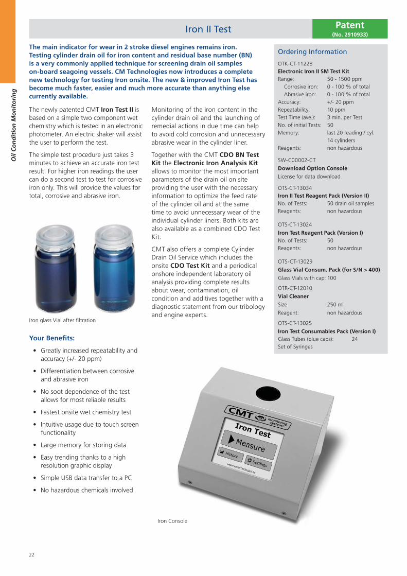
The main indicator for wear in 2 stroke diesel engines remains iron. Testing cylinder drain oil for iron content and residual base number (BN) is a very commonly applied technique for screening drain oil samples on-board seagoing vessels. CM Technologies now introduces a complete new technology for testing Iron onsite. The new & improved Iron Test has become much faster, easier and much more accurate than anything else currently available.
Iron glass Vial after filtration
The newly patented CMT Iron Test II is based on a simple two component wet chemistry which is tested in an electronic photometer. An electric shaker will assist the user to perform the test.
The simple test procedure just takes 3 minutes to achieve an accurate iron test result. For higher iron readings the user can do a second test to test for corrosive iron only. This will provide the values for total, corrosive and abrasive iron.
Your Benefits:
Greatly increased repeatability and accuracy (+/- 20 ppm)
Differentiation between corrosive and abrasive iron
No soot dependence of the test allows for most reliable results
Fastest onsite wet chemistry test
Intuitive usage due to touch screen functionality
Large memory for storing data
Easy trending thanks to a high resolution graphic display
Simple USB data transfer to a PC
No hazardous chemicals involved
Monitoring of the iron content in the cylinder drain oil and the launching of remedial actions in due time can help to avoid cold corrosion and unnecessary abrasive wear in the cylinder liner.
Together with the CMT CDO BN Test Kit the Electronic Iron Analysis Kit allows to monitor the most important parameters of the drain oil on site providing the user with the necessary information to optimize the feed rate of the cylinder oil and at the same time to avoid unnecessary wear of the individual cylinder liners. Both kits are also available as a combined CDO Test Kit.
CMT also offers a complete Cylinder Drain Oil Service which includes the onsite CDO Test Kit and a periodical onshore independent laboratory oil analysis providing complete results about wear, contamination, oil condition and additives together with a diagnostic statement from our tribology and engine experts.
Iron Console
Ordering Information
OTK-CT-11228 Electronic Iron II SM Test KitRange: 50 - 1500 ppm Corrosive iron: 0 - 100 % of total Abrasive iron: 0 - 100 % of totalAccuracy: +/- 20 ppmRepeatability: 10 ppmTest Time (ave.): 3 min. per TestNo. of initial Tests: 50Memory: last 20 reading / cyl. 14 cylindersReagents: non hazardous
SW-C00002-CT
Download Option Console
License for data download
OTS-CT-13034Iron II Test Reagent Pack (Version II)No. of Tests: 50 drain oil samplesReagents: non hazardous
OTS-CT-13024
Iron Test Reagent Pack (Version I)No. of Tests: 50Reagents: non hazardous
OTS-CT-13029
Glass Vial Consum. Pack (for S/N > 400)
Glass Vials with cap: 100
OTR-CT-12010
Vial Cleaner
Size 250 ml
Reagent: non hazardous
OTS-CT-13025
Iron Test Consumables Pack (Version I)Glass Tubes (blue caps): 24Set of Syringes
Patent(No. 2910933)
23
Oil
Co
nd
itio
n M
on
ito
rin
g
Ferrous Wear Debris Meter
Ordering Information
OTK-CT-11223FWDM Ferrous Wear Debris MeterRange: 0 - 2000 ppmSensitivity (ferrous): down to 1 ppmRepeatability: +/- 1 ppm typicallyPower supply: 12 V DCWeight (device): 980 gTest time: 1 second
OTS-CT-13039FWDM Consumables PackNo. of 2 ml Test tubes: 250
Testing lubricant samples for ferrous wear debris is an established method to detect developing and impending damages as well as gaining knowledge about the wear life cycle of the tested equipment. CMT´s newest addition to its product range - the Ferrous Wear Debris Meter - is an accurate, easy-to-use solution for offline and at-line measurements of ferrous wear debris concentrations.
Gain the insight necessary to determine the condition of your equipment. Applicable for diverse applications like Cylinder Drain Oil of 2-stroke diesel engines gearboxes or other machinery.
It provides a mass proportional output from any size or quantity of ferrous contaminant particles, even sub-micron particles. Particle size does not affect
the measurement (in contrast to spectrometric methods). Readings are unaffected by properties (dielectric) of fluid base, or additive package, or water content. Readings are straightforward and are presented in mass/volume standard units, i.e.: mg Fe per liter, or ppm.
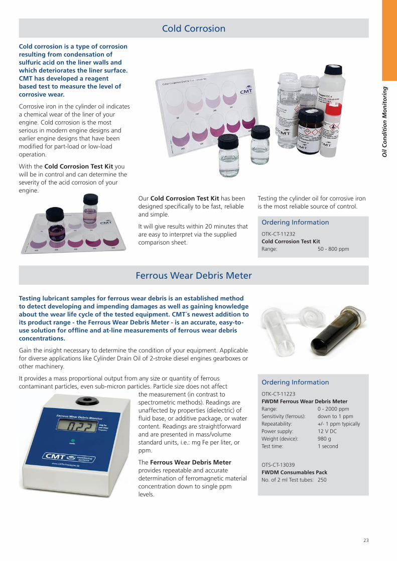
Cold Corrosion
Cold corrosion is a type of corrosion resulting from condensation of sulfuric acid on the liner walls and which deteriorates the liner surface. CMT has developed a reagent based test to measure the level of corrosive wear.
Corrosive iron in the cylinder oil indicates a chemical wear of the liner of your engine. Cold corrosion is the most serious in modern engine designs and earlier engine designs that have been modified for part-load or low-load operation.
With the Cold Corrosion Test Kit you will be in control and can determine the severity of the acid corrosion of your engine.
Our Cold Corrosion Test Kit has been designed specifically to be fast, reliable and simple.
It will give results within 20 minutes that are easy to interpret via the supplied comparison sheet.
Ordering Information
OTK-CT-11232Cold Corrosion Test KitRange: 50 - 800 ppm
The Ferrous Wear Debris Meter provides repeatable and accurate determination of ferromagnetic material concentration down to single ppm levels.
Testing the cylinder oil for corrosive iron is the most reliable source of control.
24
Oil
Co
nd
itio
n M
on
ito
rin
g
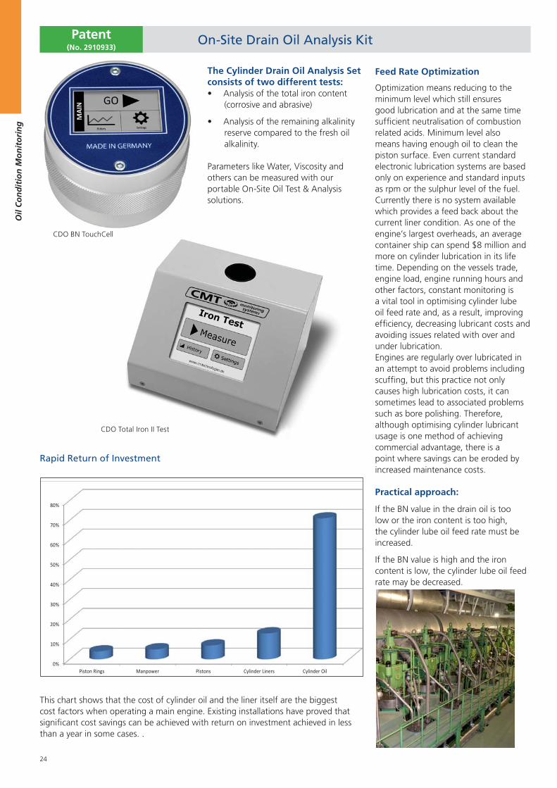
Rapid Return of Investment
This chart shows that the cost of cylinder oil and the liner itself are the biggest cost factors when operating a main engine. Existing installations have proved that significant cost savings can be achieved with return on investment achieved in less than a year in some cases. .
Feed Rate Optimization
Optimization means reducing to the minimum level which still ensures good lubrication and at the same time sufficient neutralisation of combustion related acids. Minimum level also means having enough oil to clean the piston surface. Even current standard electronic lubrication systems are based only on experience and standard inputs as rpm or the sulphur level of the fuel. Currently there is no system available which provides a feed back about the current liner condition. As one of the engine’s largest overheads, an average container ship can spend $8 million and more on cylinder lubrication in its life time. Depending on the vessels trade, engine load, engine running hours and other factors, constant monitoring is a vital tool in optimising cylinder lube oil feed rate and, as a result, improving efficiency, decreasing lubricant costs and avoiding issues related with over and under lubrication.Engines are regularly over lubricated in an attempt to avoid problems including scuffing, but this practice not only causes high lubrication costs, it can sometimes lead to associated problems such as bore polishing. Therefore, although optimising cylinder lubricant usage is one method of achieving commercial advantage, there is a point where savings can be eroded by increased maintenance costs.
Practical approach:
If the BN value in the drain oil is too low or the iron content is too high, the cylinder lube oil feed rate must be increased.
If the BN value is high and the iron content is low, the cylinder lube oil feed rate may be decreased.
CDO Total Iron II Test
CDO BN TouchCell
The Cylinder Drain Oil Analysis Set consists of two different tests:
Analysis of the total iron content (corrosive and abrasive)
Analysis of the remaining alkalinity reserve compared to the fresh oil alkalinity.
Parameters like Water, Viscosity and others can be measured with our portable On-Site Oil Test & Analysis solutions.
On-Site Drain Oil Analysis KitPatent(No. 2910933)
25
Oil
Co
nd
itio
n M
on
ito
rin
g
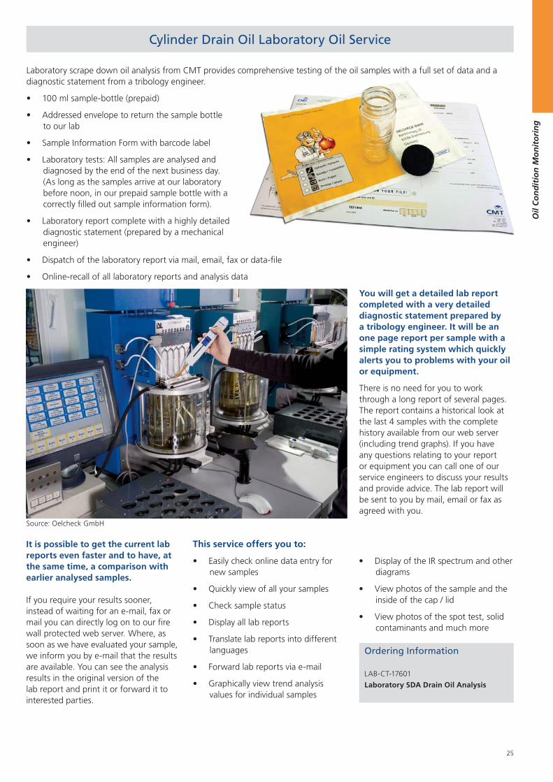
Cylinder Drain Oil Laboratory Oil Service
Laboratory scrape down oil analysis from CMT provides comprehensive testing of the oil samples with a full set of data and a diagnostic statement from a tribology engineer.
100 ml sample-bottle (prepaid)
Addressed envelope to return the sample bottle to our lab
Sample Information Form with barcode label
Laboratory tests: All samples are analysed and diagnosed by the end of the next business day. (As long as the samples arrive at our laboratory before noon, in our prepaid sample bottle with a correctly filled out sample information form).
Laboratory report complete with a highly detailed diagnostic statement (prepared by a mechanical engineer)
Dispatch of the laboratory report via mail, email, fax or data-file
Online-recall of all laboratory reports and analysis data
You will get a detailed lab report completed with a very detailed diagnostic statement prepared by a tribology engineer. It will be an one page report per sample with a simple rating system which quickly alerts you to problems with your oil or equipment.
There is no need for you to work through a long report of several pages. The report contains a historical look at the last 4 samples with the complete history available from our web server (including trend graphs). If you have any questions relating to your report or equipment you can call one of our service engineers to discuss your results and provide advice. The lab report will be sent to you by mail, email or fax as agreed with you.
It is possible to get the current lab reports even faster and to have, at the same time, a comparison with earlier analysed samples.
If you require your results sooner, instead of waiting for an e-mail, fax or mail you can directly log on to our fire wall protected web server. Where, as soon as we have evaluated your sample, we inform you by e-mail that the results are available. You can see the analysis results in the original version of the lab report and print it or forward it to interested parties.
This service offers you to:
Easily check online data entry for new samples
Quickly view of all your samples
Check sample status
Display all lab reports
Translate lab reports into different languages
Forward lab reports via e-mail
Graphically view trend analysis values for individual samples
Display of the IR spectrum and other diagrams
View photos of the sample and the inside of the cap / lid
View photos of the spot test, solid contaminants and much more
Source: Oelcheck GmbH
Ordering Information
LAB-CT-17601
Laboratory SDA Drain Oil Analysis
26
Oil
Co
nd
itio
n M
on
ito
rin
g
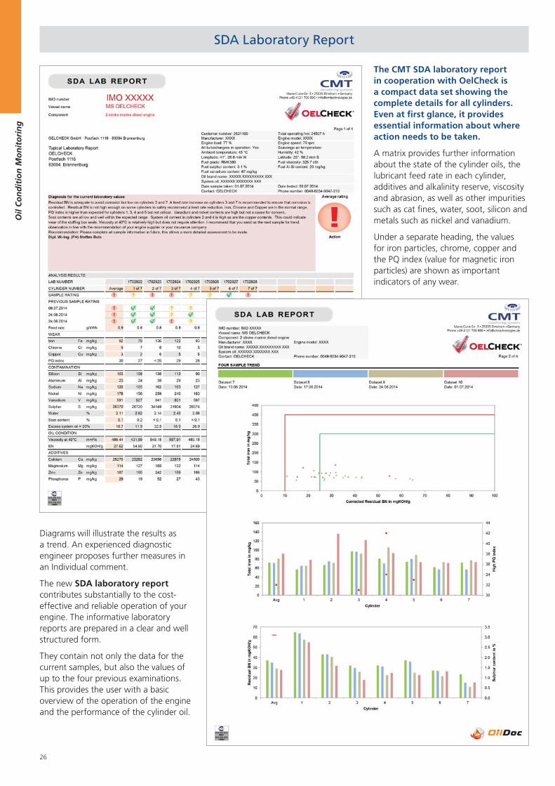
SDA Laboratory Report
The CMT SDA laboratory report in cooperation with OelCheck is a compact data set showing the complete details for all cylinders. Even at first glance, it provides essential information about where action needs to be taken.
A matrix provides further information about the state of the cylinder oils, the lubricant feed rate in each cylinder, additives and alkalinity reserve, viscosity and abrasion, as well as other impurities such as cat fines, water, soot, silicon and metals such as nickel and vanadium.
Under a separate heading, the values for iron particles, chrome, copper and the PQ index (value for magnetic iron particles) are shown as important indicators of any wear.
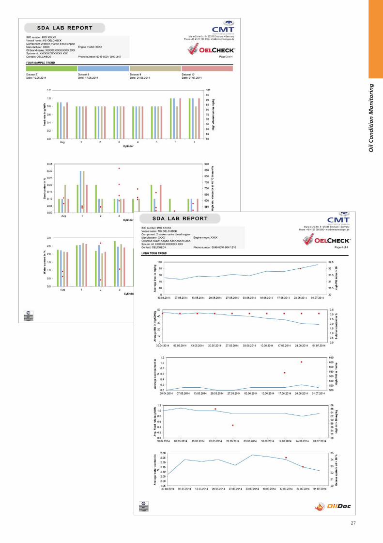
Diagrams will illustrate the results as a trend. An experienced diagnostic engineer proposes further measures in an Individual comment.
The new SDA laboratory report contributes substantially to the cost-effective and reliable operation of your engine. The informative laboratory reports are prepared in a clear and well structured form.
They contain not only the data for the current samples, but also the values of up to the four previous examinations. This provides the user with a basic overview of the operation of the engine and the performance of the cylinder oil.
27
Oil
Co
nd
itio
n M
on
ito
rin
g
Test Lab Report
28
Oil
Co
nd
itio
n M
on
ito
rin
g
3. Independent Laboratory Oil Test
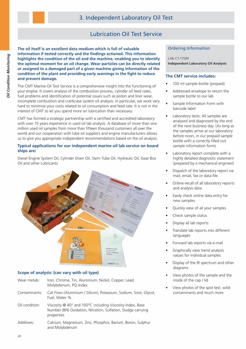
The oil itself is an excellent data medium which is full of valuable information if tested correctly and the findings actioned. This information highlights the condition of the oil and the machine, enabling you to identify the optimal moment for an oil change. Wear particles can be directly related or assigned to a damaged part of a given machine giving information of the condition of the plant and providing early warnings in the fight to reduce and prevent damage.
The CMT Marine Oil Test Service is a comprehensive insight into the functioning of your engine. It covers analysis of the combustion process, cylinder oil feed rates, fuel problems and identification of potential issues such as piston and liner wear, incomplete combustion and crankcase system oil analysis. In particular, we work very hard to minimize your costs related to oil consumption and feed rate. It is not in the interest of CMT to let you spend more on lubrication than necessary.
CMT has formed a strategic partnership with a certified and accredited laboratory with over 15 years experience in used oil lab analysis. A database of more than one million used oil samples from more than fifteen thousand customers all over the world and our cooperation with lube oil suppliers and engine manufacturers allows us to give you appropriate independent recommendations based on the oil analysis.
Typical applications for our independent marine oil lab service on board ships are:
Diesel Engine System Oil, Cylinder Drain Oil, Stern Tube Oil, Hydraulic Oil, Gear Box Oil and other Lubricants
The CMT service includes:
100 ml sample-bottle (prepaid)
Addressed envelope to return the sample bottle to our lab
Sample Information Form with barcode label
Laboratory tests: All samples are analysed and diagnosed by the end of the next business day. (As long as the samples arrive at our laboratory before noon, in our prepaid sample bottle with a correctly filled out sample information form).
Laboratory report complete with a highly detailed diagnostic statement (prepared by a mechanical engineer)
Dispatch of the laboratory report via mail, email, fax or data-file
Online-recall of all laboratory reports and analysis data
Easily check online data entry for new samples
Quickly view of all your samples
Check sample status
Display all lab reports
Translate lab reports into different languages
Forward lab reports via e-mail
Graphically view trend analysis values for individual samples
Display of the IR spectrum and other diagrams
View photos of the sample and the inside of the cap / lid
View photos of the spot test, solid contaminants and much more
Scope of analysis: (can vary with oil type)
Wear metals: Iron, Chrome, Tin, Aluminium, Nickel, Copper, Lead, Molybdenum, PQ-Index
Contaminants: Cat Fines (Aluminium / Silicon), Potassium, Sodium, Soot, Glycol, Fuel, Water %
Oil condition: Viscosity @ 40° and 100°C including Viscosity-Index, Base Number (BN) Oxidation, Nitration, Sulfation, Sludge carrying properties
Additives: Calcium, Magnesium, Zinc, Phosphor, Barium, Boron, Sulphur and Molybdenum
Ordering Information
LAB-CT-17599
Independent Laboratory Oil Analysis
Lubrication Oil Test Service
29
Oil
Co
nd
itio
n M
on
ito
rin
g
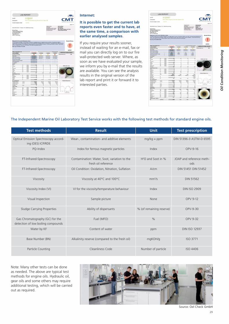
Internet:
It is possible to get the current lab reports even faster and to have, at the same time, a comparison with earlier analysed samples.
If you require your results sooner, instead of waiting for an e-mail, fax or mail you can directly log on to our fire wall-protected web server. Where, as soon as we have evaluated your sample, we inform you by e-mail that the results are available. You can see the analysis results in the original version of the lab report and print it or forward it to interested parties.
Test methods Result Unit Test prescription
Optical Emission Spectroscopy accord-
ing (OES) ICP/RDE
Wear-, contamination- and additive elements mg/kg = ppm DIN 51396-3 ASTM-D 6595
PQ-Index Index for ferrous magnetic particles Index OPV-9-16
FT-Infrared-Spectroscopy Contamination: Water, Soot, variation to the
fresh oil reference
H2O and Soot in % JOAP and reference meth-
ods
FT-Infrared-Spectroscopy Oil Condition: Oxidation, Nitration, Sulfation A/cm DIN 51451 DIN 51452
Viscosity Viscosity at 40°C and 100°C mm2/s DIN 51562
Viscosity Index (VI) VI for the viscosity/temperature behaviour Index DIN ISO 2909
Visual Inspection Sample picture None OPV 9-12
Sludge Carrying Properties Ability of dispersants % (of remaining reserve) OPV-9-30
Gas Chromatography (GC) for the
detection of low boiling compounds
Fuel (MFO) % OPV 9-32
Water by KF Content of water ppm DIN ISO 12937
Base Number (BN) Alkalinity reserve (compared to the fresh oil) mgKOH/g ISO 3771
Particle Counting Cleanliness Code Number of particle ISO 4406
Note: Many other tests can be done as needed. The above are typical test methods for engine oils. Hydraulic oil, gear oils and some others may require additional testing, which will be carried out as required.
The Independent Marine Oil Laboratory Test Service works with the following test methods for standard engine oils.
Source: Oel Check GmbH
30
Oil
Co
nd
itio
n M
on
ito
rin
g
4. Online Oil Sensors
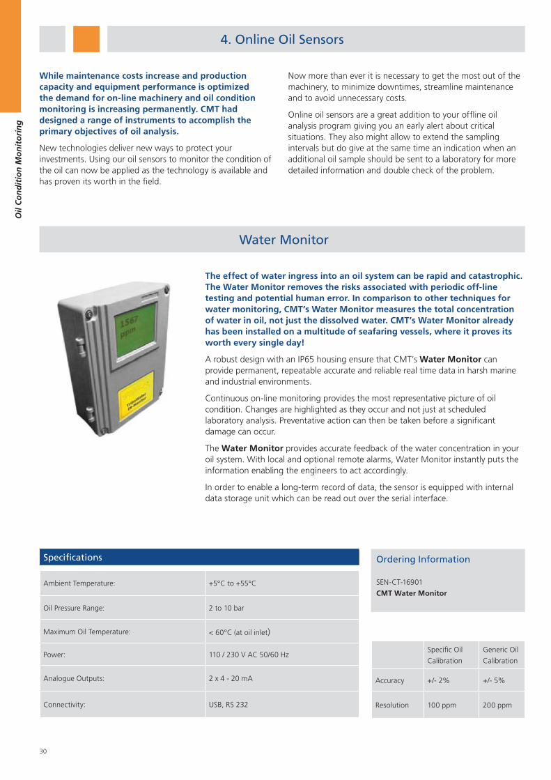
Water Monitor
While maintenance costs increase and production capacity and equipment performance is optimized the demand for on-line machinery and oil condition monitoring is increasing permanently. CMT had designed a range of instruments to accomplish the primary objectives of oil analysis.
New technologies deliver new ways to protect your investments. Using our oil sensors to monitor the condition of the oil can now be applied as the technology is available and has proven its worth in the field.
Now more than ever it is necessary to get the most out of the machinery, to minimize downtimes, streamline maintenance and to avoid unnecessary costs.
Online oil sensors are a great addition to your offline oil analysis program giving you an early alert about critical situations. They also might allow to extend the sampling intervals but do give at the same time an indication when an additional oil sample should be sent to a laboratory for more detailed information and double check of the problem.
The effect of water ingress into an oil system can be rapid and catastrophic. The Water Monitor removes the risks associated with periodic off-line testing and potential human error. In comparison to other techniques for water monitoring, CMT’s Water Monitor measures the total concentration of water in oil, not just the dissolved water. CMT’s Water Monitor already has been installed on a multitude of seafaring vessels, where it proves its worth every single day!
A robust design with an IP65 housing ensure that CMT’s Water Monitor can provide permanent, repeatable accurate and reliable real time data in harsh marine and industrial environments.
Continuous on-line monitoring provides the most representative picture of oil condition. Changes are highlighted as they occur and not just at scheduled laboratory analysis. Preventative action can then be taken before a significant damage can occur.
The Water Monitor provides accurate feedback of the water concentration in your oil system. With local and optional remote alarms, Water Monitor instantly puts the information enabling the engineers to act accordingly.
In order to enable a long-term record of data, the sensor is equipped with internal data storage unit which can be read out over the serial interface.
Ordering Information
SEN-CT-16901
CMT Water Monitor
Specific Oil
Calibration
Generic Oil
Calibration
Accuracy +/- 2% +/- 5%
Resolution 100 ppm 200 ppm
Specifications
Ambient Temperature: +5°C to +55°C
Oil Pressure Range: 2 to 10 bar
Maximum Oil Temperature: < 60°C (at oil inlet)
Power: 110 / 230 V AC 50/60 Hz
Analogue Outputs: 2 x 4 - 20 mA
Connectivity: USB, RS 232
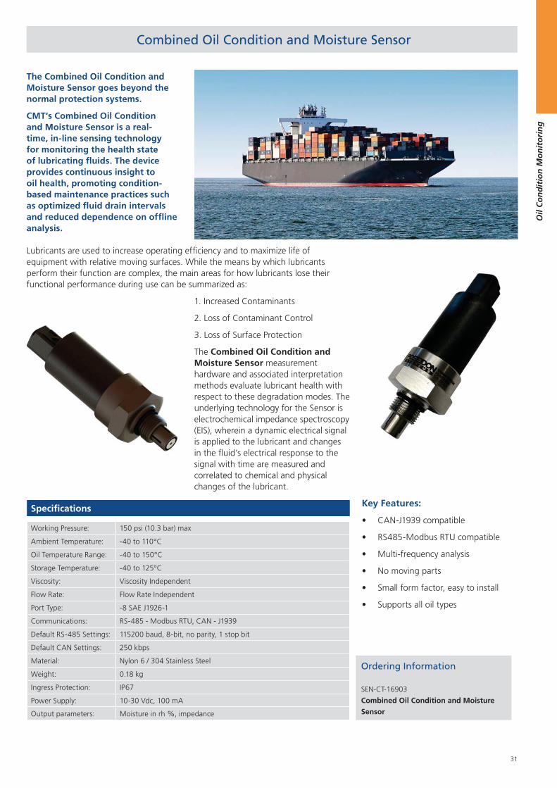
31
Oil
Co
nd
itio
n M
on
ito
rin
g
Combined Oil Condition and Moisture Sensor
The Combined Oil Condition and Moisture Sensor goes beyond the normal protection systems.
CMT’s Combined Oil Condition and Moisture Sensor is a real-time, in-line sensing technology for monitoring the health state of lubricating fluids. The device provides continuous insight to oil health, promoting condition-based maintenance practices such as optimized fluid drain intervals and reduced dependence on offline analysis.
Lubricants are used to increase operating efficiency and to maximize life of equipment with relative moving surfaces. While the means by which lubricants perform their function are complex, the main areas for how lubricants lose their functional performance during use can be summarized as:
Ordering Information
SEN-CT-16903
Combined Oil Condition and Moisture
Sensor
Specifications
Working Pressure: 150 psi (10.3 bar) max
Ambient Temperature: ‐40 to 110°C
Oil Temperature Range: ‐40 to 150°C
Storage Temperature: ‐40 to 125°C
Viscosity: Viscosity Independent
Flow Rate: Flow Rate Independent
Port Type: ‐8 SAE J1926‐1
Communications: RS‐485 ‐ Modbus RTU, CAN ‐ J1939
Default RS‐485 Settings: 115200 baud, 8‐bit, no parity, 1 stop bit
Default CAN Settings: 250 kbps
Material: Nylon 6 / 304 Stainless Steel
Weight: 0.18 kg
Ingress Protection: IP67
Power Supply: 10‐30 Vdc, 100 mA
Output parameters: Moisture in rh %, impedance
Key Features:
CAN-J1939 compatible
RS485-Modbus RTU compatible
Multi-frequency analysis
No moving parts
Small form factor, easy to install
Supports all oil types
1. Increased Contaminants
2. Loss of Contaminant Control
3. Loss of Surface Protection
The Combined Oil Condition and Moisture Sensor measurement hardware and associated interpretation methods evaluate lubricant health with respect to these degradation modes. The underlying technology for the Sensor is electrochemical impedance spectroscopy (EIS), wherein a dynamic electrical signal is applied to the lubricant and changes in the fluid’s electrical response to the signal with time are measured and correlated to chemical and physical changes of the lubricant.
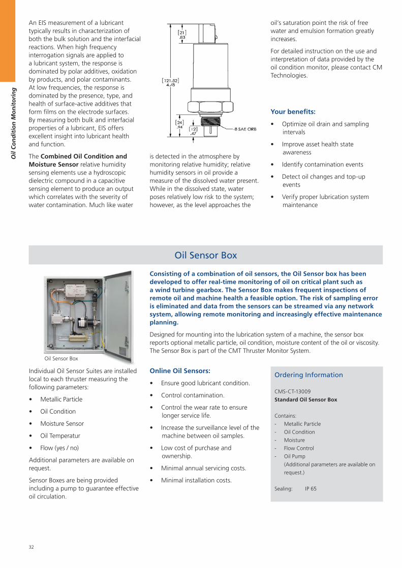
32
Oil
Co
nd
itio
n M
on
ito
rin
g
Individual Oil Sensor Suites are installed local to each thruster measuring the following parameters:
Metallic Particle
Oil Condition
Moisture Sensor
Oil Temperatur
Flow (yes / no)
Additional parameters are available on request.
Sensor Boxes are being provided including a pump to guarantee effective oil circulation.
Oil Sensor Box
Consisting of a combination of oil sensors, the Oil Sensor box has been developed to offer real-time monitoring of oil on critical plant such as a wind turbine gearbox. The Sensor Box makes frequent inspections of remote oil and machine health a feasible option. The risk of sampling error is eliminated and data from the sensors can be streamed via any network system, allowing remote monitoring and increasingly effective maintenance planning.
Designed for mounting into the lubrication system of a machine, the sensor box reports optional metallic particle, oil condition, moisture content of the oil or viscosity. The Sensor Box is part of the CMT Thruster Monitor System.
Online Oil Sensors:
Ensure good lubricant condition.
Control contamination.
Control the wear rate to ensure longer service life.
Increase the surveillance level of the machine between oil samples.
Low cost of purchase and ownership.
Minimal annual servicing costs.
Minimal installation costs.
Ordering Information
CMS-CT-13009
Standard Oil Sensor Box
Contains:
- Metallic Particle
- Oil Condition
- Moisture
- Flow Control
- Oil Pump
(Additional parameters are available on
request.)
Sealing: IP 65
Oil Sensor Box
Your benefits:
Optimize oil drain and sampling intervals
Improve asset health state awareness
Identify contamination events
Detect oil changes and top-up events
Verify proper lubrication system maintenance
oil’s saturation point the risk of free water and emulsion formation greatly increases.
For detailed instruction on the use and interpretation of data provided by the oil condition monitor, please contact CM Technologies.
An EIS measurement of a lubricant typically results in characterization of both the bulk solution and the interfacial reactions. When high frequency interrogation signals are applied to a lubricant system, the response is dominated by polar additives, oxidation by products, and polar contaminants. At low frequencies, the response is dominated by the presence, type, and health of surface‐active additives that form films on the electrode surfaces. By measuring both bulk and interfacial properties of a lubricant, EIS offers excellent insight into lubricant health and function.
The Combined Oil Condition and Moisture Sensor relative humidity sensing elements use a hydroscopic dielectric compound in a capacitive sensing element to produce an output which correlates with the severity of water contamination. Much like water
is detected in the atmosphere by monitoring relative humidity; relative humidity sensors in oil provide a measure of the dissolved water present. While in the dissolved state, water poses relatively low risk to the system; however, as the level approaches the
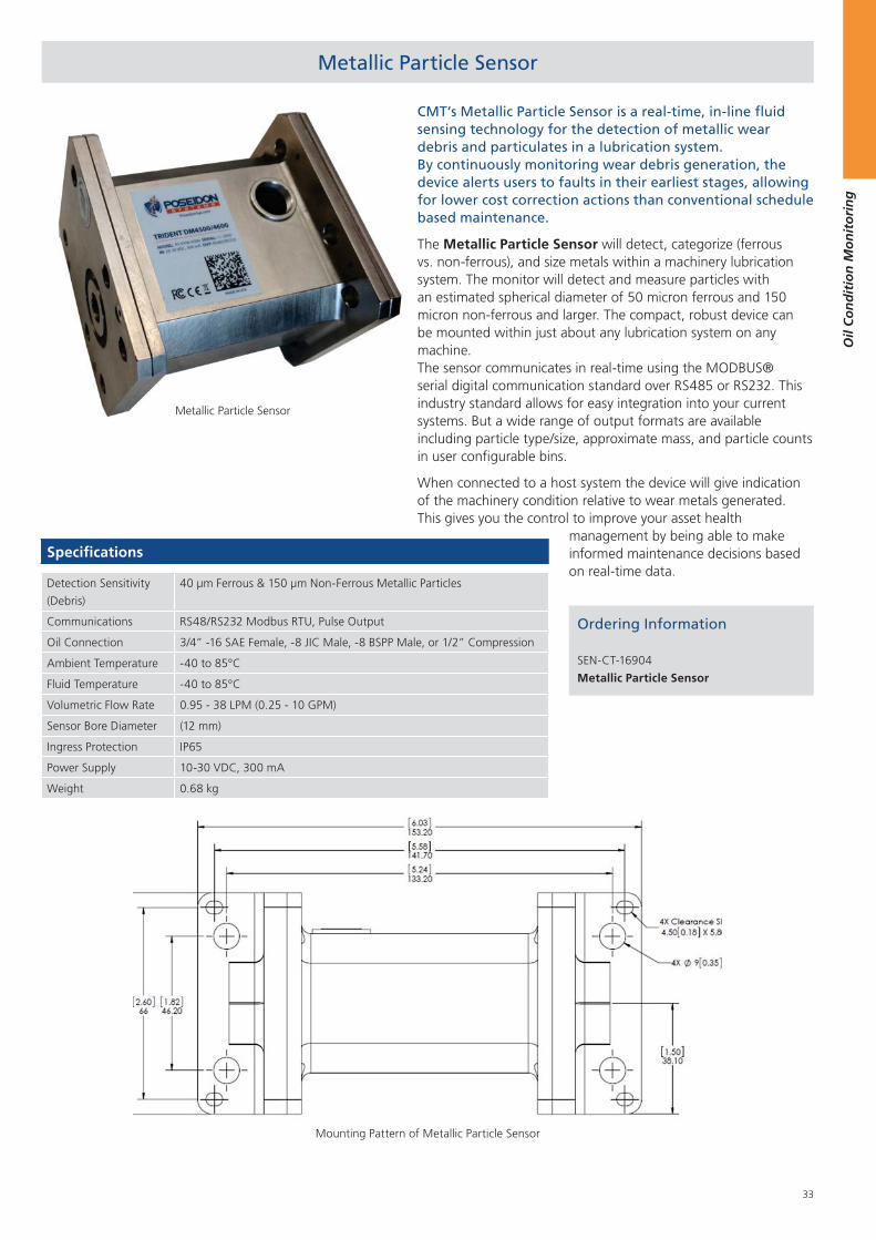
33
Oil
Co
nd
itio
n M
on
ito
rin
g
Metallic Particle Sensor
CMT’s Metallic Particle Sensor is a real-time, in-line fluid sensing technology for the detection of metallic wear debris and particulates in a lubrication system. By continuously monitoring wear debris generation, the device alerts users to faults in their earliest stages, allowing for lower cost correction actions than conventional schedule based maintenance.
The Metallic Particle Sensor will detect, categorize (ferrous vs. non-ferrous), and size metals within a machinery lubrication system. The monitor will detect and measure particles with an estimated spherical diameter of 50 micron ferrous and 150 micron non-ferrous and larger. The compact, robust device can be mounted within just about any lubrication system on any machine. The sensor communicates in real‐time using the MODBUS® serial digital communication standard over RS485 or RS232. This industry standard allows for easy integration into your current systems. But a wide range of output formats are available including particle type/size, approximate mass, and particle counts in user configurable bins.
When connected to a host system the device will give indication of the machinery condition relative to wear metals generated. This gives you the control to improve your asset health
Ordering Information
SEN-CT-16904
Metallic Particle Sensor
Specifications
Detection Sensitivity
(Debris)
40 μm Ferrous & 150 μm Non-Ferrous Metallic Particles
Communications RS48/RS232 Modbus RTU, Pulse Output
Oil Connection 3/4” -16 SAE Female, -8 JIC Male, -8 BSPP Male, or 1/2” Compression
Ambient Temperature -40 to 85°C
Fluid Temperature -40 to 85°C
Volumetric Flow Rate 0.95 - 38 LPM (0.25 - 10 GPM)
Sensor Bore Diameter (12 mm)
Ingress Protection IP65
Power Supply 10-30 VDC, 300 mA
Weight 0.68 kg
management by being able to make informed maintenance decisions based on real‐time data.
Metallic Particle Sensor
Mounting Pattern of Metallic Particle Sensor
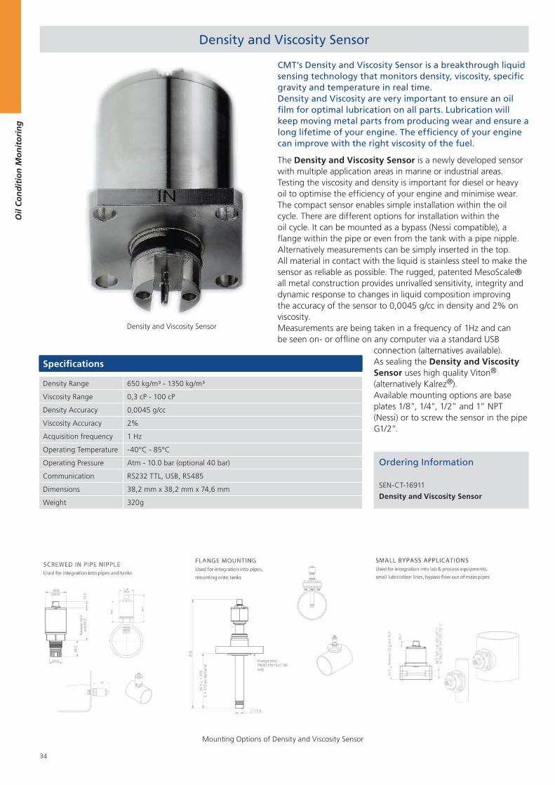
34
Oil
Co
nd
itio
n M
on
ito
rin
g
Density and Viscosity Sensor
CMT’s Density and Viscosity Sensor is a breakthrough liquid sensing technology that monitors density, viscosity, specific gravity and temperature in real time. Density and Viscosity are very important to ensure an oil film for optimal lubrication on all parts. Lubrication will keep moving metal parts from producing wear and ensure a long lifetime of your engine. The efficiency of your engine can improve with the right viscosity of the fuel.
The Density and Viscosity Sensor is a newly developed sensor with multiple application areas in marine or industrial areas. Testing the viscosity and density is important for diesel or heavy oil to optimise the efficiency of your engine and minimise wear. The compact sensor enables simple installation within the oil cycle. There are different options for installation within the oil cycle. It can be mounted as a bypass (Nessi compatible), a flange within the pipe or even from the tank with a pipe nipple. Alternatively measurements can be simply inserted in the top. All material in contact with the liquid is stainless steel to make the sensor as reliable as possible. The rugged, patented MesoScale® all metal construction provides unrivalled sensitivity, integrity and dynamic response to changes in liquid composition improving the accuracy of the sensor to 0,0045 g/cc in density and 2% on viscosity. Measurements are being taken in a frequency of 1Hz and can be seen on- or offline on any computer via a standard USB
Ordering Information
SEN-CT-16911
Density and Viscosity Sensor
Specifications
Density Range 650 kg/m³ - 1350 kg/m³
Viscosity Range 0,3 cP - 100 cP
Density Accuracy 0,0045 g/cc
Viscosity Accuracy 2%
Acquisition frequency 1 Hz
Operating Temperature -40°C - 85°C
Operating Pressure Atm - 10.0 bar (optional 40 bar)
Communication RS232 TTL, USB, RS485
Dimensions 38,2 mm x 38,2 mm x 74,6 mm
Weight 320g
connection (alternatives available). As sealing the Density and Viscosity Sensor uses high quality Viton® (alternatively Kalrez®). Available mounting options are base plates 1/8”, 1/4”, 1/2” and 1” NPT (Nessi) or to screw the sensor in the pipe G1/2”.
Density and Viscosity Sensor
Mounting Options of Density and Viscosity Sensor
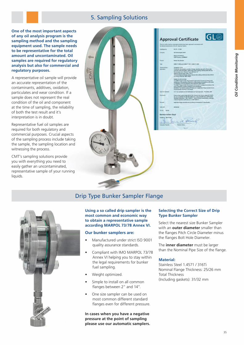
35
Oil
Co
nd
itio
n M
on
ito
rin
g
Sampling Solutions
One of the most important aspects of any oil analysis program is the sampling method and the sampling equipment used. The sample needs to be representative for the total amount and uncontaminated. Oil samples are required for regulatory analysis but also for commercial and regulatory purposes.
A representative oil sample will provide an accurate representation of the contaminants, additives, oxidation, particulates and wear condition. If a sample does not represent the real condition of the oil and component at the time of sampling, the reliability of both the test result and it’s interpretation is in doubt.
Representative fuel oil samples are required for both regulatory and commercial purposes. Crucial aspects of the sampling process include taking the sample, the sampling location and witnessing the process.
CMT’s sampling solutions provide you with everything you need to easily gather an uncontaminated, representative sample of your running liquids.
Using a so called drip sampler is the most common and economic way to obtain a representative sample according MARPOL 73/78 Annex VI.
Our bunker samplers are:
Manufactured under strict ISO 9001 quality assurance standards.
Compliant with IMO MARPOL 73/78 Annex VI helping you to stay within the legal requirements for bunker fuel sampling.
Weight optimized.
Simple to install on all common flanges between 2” and 14”.
One size sampler can be used on most common different standard flanges even for different pressure.
In cases when you have a negative pressure at the point of sampling please use our automatic samplers.
Material: Stainless Steel 1.4571 / 316TiNominal Flange Thickness: 25/26 mmTotal Thickness (Including gaskets): 31/32 mm
Selecting the Correct Size of Drip Type Bunker Sampler
Select the nearest size Bunker Sampler with an outer diameter smaller than the flanges Pitch Circle Diameter minus the flanges Bolt Hole Diameter.
The inner diameter must be larger than the Nominal Pipe Size of the flange.
Drip Type Bunker Sampler Flange
5. Sampling Solutions
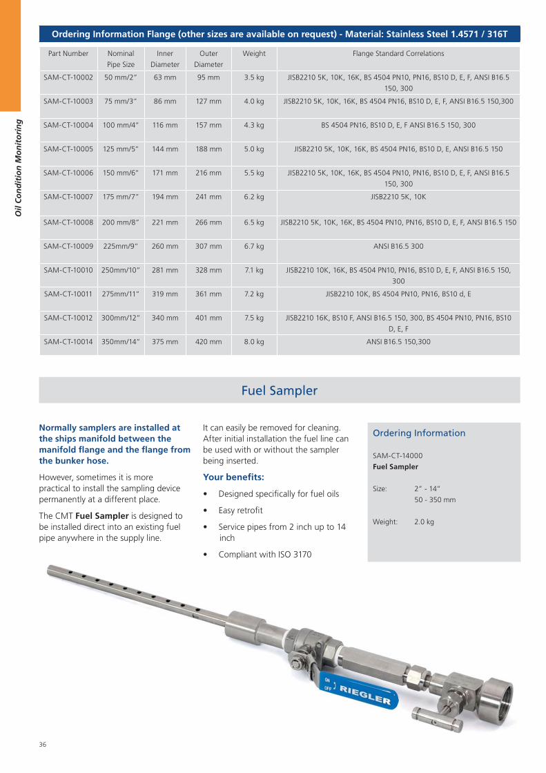
36
Oil
Co
nd
itio
n M
on
ito
rin
g
Fuel Sampler
Normally samplers are installed at the ships manifold between the manifold flange and the flange from the bunker hose.
However, sometimes it is more practical to install the sampling device permanently at a different place.
The CMT Fuel Sampler is designed to be installed direct into an existing fuel pipe anywhere in the supply line.
It can easily be removed for cleaning. After initial installation the fuel line can be used with or without the sampler being inserted.
Your benefits:
Designed specifically for fuel oils
Easy retrofit
Service pipes from 2 inch up to 14 inch
Compliant with ISO 3170
Ordering Information Flange (other sizes are available on request) - Material: Stainless Steel 1.4571 / 316T
Part Number Nominal
Pipe Size
Inner
Diameter
Outer
Diameter
Weight Flange Standard Correlations
SAM-CT-10002 50 mm/2” 63 mm 95 mm 3.5 kg JISB2210 5K, 10K, 16K, BS 4504 PN10, PN16, BS10 D, E, F, ANSI B16.5
150, 300
SAM-CT-10003 75 mm/3” 86 mm 127 mm 4.0 kg JISB2210 5K, 10K, 16K, BS 4504 PN16, BS10 D, E, F, ANSI B16.5 150,300
SAM-CT-10004 100 mm/4” 116 mm 157 mm 4.3 kg BS 4504 PN16, BS10 D, E, F ANSI B16.5 150, 300
SAM-CT-10005 125 mm/5” 144 mm 188 mm 5.0 kg JISB2210 5K, 10K, 16K, BS 4504 PN16, BS10 D, E, ANSI B16.5 150
SAM-CT-10006 150 mm/6” 171 mm 216 mm 5.5 kg JISB2210 5K, 10K, 16K, BS 4504 PN10, PN16, BS10 D, E, F, ANSI B16.5
150, 300
SAM-CT-10007 175 mm/7” 194 mm 241 mm 6.2 kg JISB2210 5K, 10K
SAM-CT-10008 200 mm/8” 221 mm 266 mm 6.5 kg JISB2210 5K, 10K, 16K, BS 4504 PN10, PN16, BS10 D, E, F, ANSI B16.5 150
SAM-CT-10009 225mm/9” 260 mm 307 mm 6.7 kg ANSI B16.5 300
SAM-CT-10010 250mm/10” 281 mm 328 mm 7.1 kg JISB2210 10K, 16K, BS 4504 PN10, PN16, BS10 D, E, F, ANSI B16.5 150,
300
SAM-CT-10011 275mm/11” 319 mm 361 mm 7.2 kg JISB2210 10K, BS 4504 PN10, PN16, BS10 d, E
SAM-CT-10012 300mm/12” 340 mm 401 mm 7.5 kg JISB2210 16K, BS10 F, ANSI B16.5 150, 300, BS 4504 PN10, PN16, BS10
D, E, F
SAM-CT-10014 350mm/14” 375 mm 420 mm 8.0 kg ANSI B16.5 150,300
Ordering Information
SAM-CT-14000
Fuel Sampler
Size: 2” - 14”
50 - 350 mm
Weight: 2.0 kg
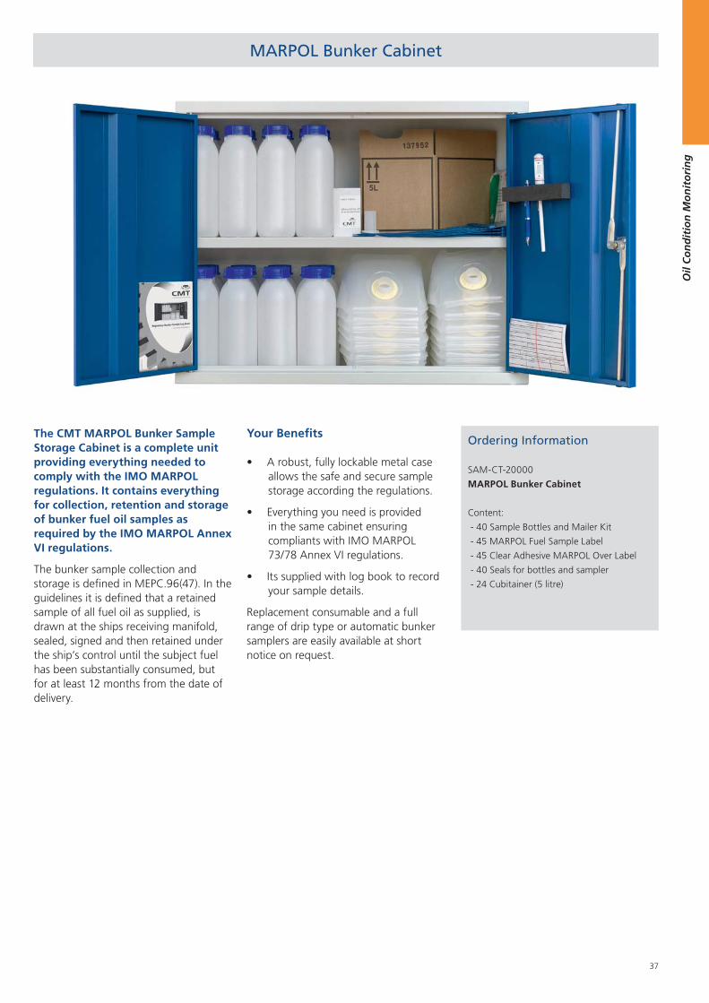
37
Oil
Co
nd
itio
n M
on
ito
rin
g
MARPOL Bunker Cabinet
Ordering Information
SAM-CT-20000
MARPOL Bunker Cabinet
Content:
- 40 Sample Bottles and Mailer Kit
- 45 MARPOL Fuel Sample Label
- 45 Clear Adhesive MARPOL Over Label
- 40 Seals for bottles and sampler
- 24 Cubitainer (5 litre)
The CMT MARPOL Bunker Sample Storage Cabinet is a complete unit providing everything needed to comply with the IMO MARPOL regulations. It contains everything for collection, retention and storage of bunker fuel oil samples as required by the IMO MARPOL Annex VI regulations.
The bunker sample collection and storage is defined in MEPC.96(47). In the guidelines it is defined that a retained sample of all fuel oil as supplied, is drawn at the ships receiving manifold, sealed, signed and then retained under the ship’s control until the subject fuel has been substantially consumed, but for at least 12 months from the date of delivery.
Your Benefits
A robust, fully lockable metal case allows the safe and secure sample storage according the regulations.
Everything you need is provided in the same cabinet ensuring compliants with IMO MARPOL 73/78 Annex VI regulations.
Its supplied with log book to record your sample details.
Replacement consumable and a full range of drip type or automatic bunker samplers are easily available at short notice on request.
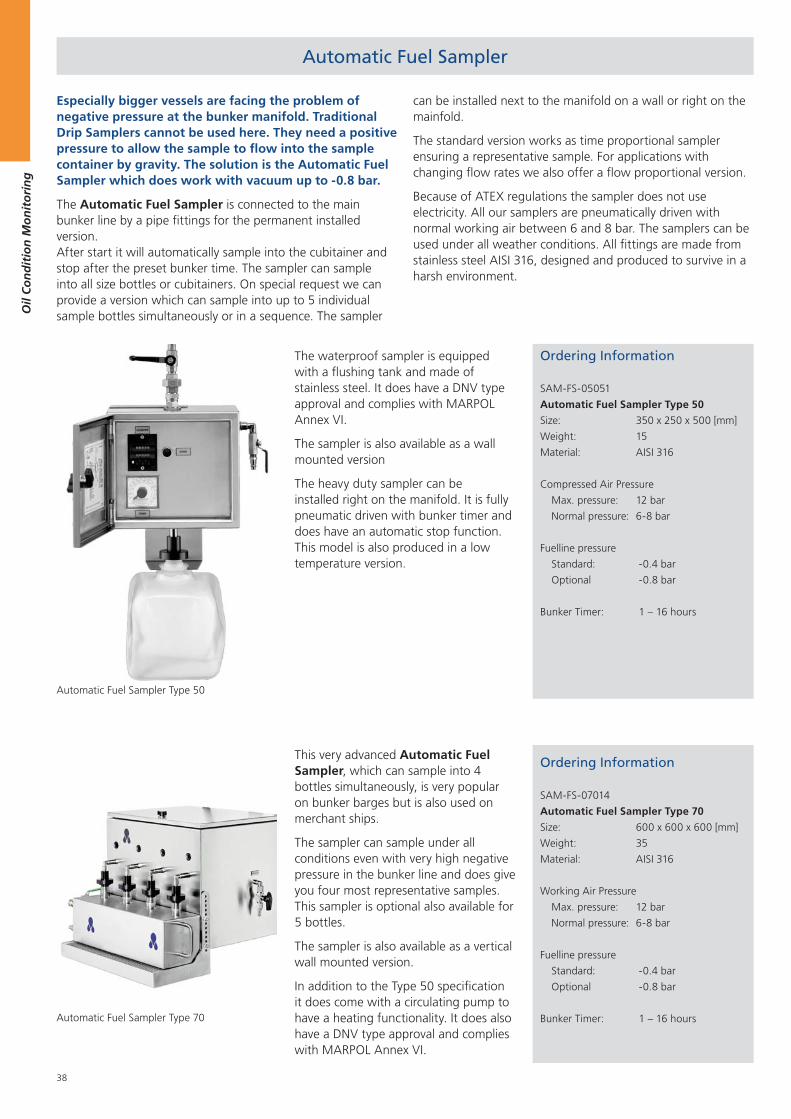
38
Oil
Co
nd
itio
n M
on
ito
rin
g
Especially bigger vessels are facing the problem of negative pressure at the bunker manifold. Traditional Drip Samplers cannot be used here. They need a positive pressure to allow the sample to flow into the sample container by gravity. The solution is the Automatic Fuel Sampler which does work with vacuum up to -0.8 bar.
The Automatic Fuel Sampler is connected to the main bunker line by a pipe fittings for the permanent installed version. After start it will automatically sample into the cubitainer and stop after the preset bunker time. The sampler can sample into all size bottles or cubitainers. On special request we can provide a version which can sample into up to 5 individual sample bottles simultaneously or in a sequence. The sampler
can be installed next to the manifold on a wall or right on the mainfold.
The standard version works as time proportional sampler ensuring a representative sample. For applications with changing flow rates we also offer a flow proportional version.
Because of ATEX regulations the sampler does not use electricity. All our samplers are pneumatically driven with normal working air between 6 and 8 bar. The samplers can be used under all weather conditions. All fittings are made from stainless steel AISI 316, designed and produced to survive in a harsh environment.
The waterproof sampler is equipped with a flushing tank and made of stainless steel. It does have a DNV type approval and complies with MARPOL Annex VI.
The sampler is also available as a wall mounted version
The heavy duty sampler can be installed right on the manifold. It is fully pneumatic driven with bunker timer and does have an automatic stop function. This model is also produced in a low temperature version.
This very advanced Automatic Fuel Sampler, which can sample into 4 bottles simultaneously, is very popular on bunker barges but is also used on merchant ships.
The sampler can sample under all conditions even with very high negative pressure in the bunker line and does give you four most representative samples. This sampler is optional also available for 5 bottles.
The sampler is also available as a vertical wall mounted version.
In addition to the Type 50 specification it does come with a circulating pump to have a heating functionality. It does also have a DNV type approval and complies with MARPOL Annex VI.
Ordering Information
SAM-FS-05051
Automatic Fuel Sampler Type 50
Size: 350 x 250 x 500 [mm]
Weight: 15
Material: AISI 316
Compressed Air Pressure
Max. pressure: 12 bar
Normal pressure: 6-8 bar
Fuelline pressure
Standard: -0.4 bar
Optional -0.8 bar
Bunker Timer: 1 – 16 hours
Ordering Information
SAM-FS-07014
Automatic Fuel Sampler Type 70
Size: 600 x 600 x 600 [mm]
Weight: 35
Material: AISI 316
Working Air Pressure
Max. pressure: 12 bar
Normal pressure: 6-8 bar
Fuelline pressure
Standard: -0.4 bar
Optional -0.8 bar
Bunker Timer: 1 – 16 hours
Automatic Fuel Sampler Type 50
Automatic Fuel Sampler Type 70
Automatic Fuel Sampler
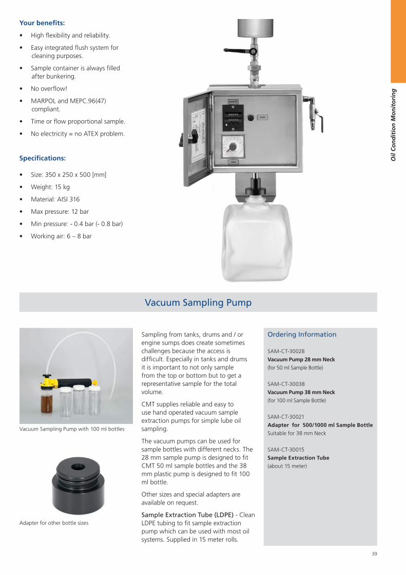
39
Oil
Co
nd
itio
n M
on
ito
rin
g
Sampling from tanks, drums and / or engine sumps does create sometimes challenges because the access is difficult. Especially in tanks and drums it is important to not only sample from the top or bottom but to get a representative sample for the total volume.
CMT supplies reliable and easy to use hand operated vacuum sample extraction pumps for simple lube oil sampling.
The vacuum pumps can be used for sample bottles with different necks. The 28 mm sample pump is designed to fit CMT 50 ml sample bottles and the 38 mm plastic pump is designed to fit 100 ml bottle.
Other sizes and special adapters are available on request.
Sample Extraction Tube (LDPE) - Clean LDPE tubing to fit sample extraction pump which can be used with most oil systems. Supplied in 15 meter rolls.
Ordering Information
SAM-CT-30028
Vacuum Pump 28 mm Neck
(for 50 ml Sample Bottle)
SAM-CT-30038
Vacuum Pump 38 mm Neck
(for 100 ml Sample Bottle)
SAM-CT-30021
Adapter for 500/1000 ml Sample Bottle
Suitable for 38 mm Neck
SAM-CT-30015
Sample Extraction Tube
(about 15 meter)
Your benefits:
High flexibility and reliability.
Easy integrated flush system for cleaning purposes.
Sample container is always filled after bunkering.
No overflow!
MARPOL and MEPC.96(47) compliant.
Time or flow proportional sample.
No electricity = no ATEX problem.
Specifications:
Size: 350 x 250 x 500 [mm]
Weight: 15 kg
Material: AISI 316
Max pressure: 12 bar
Min pressure: - 0.4 bar (- 0.8 bar)
Working air: 6 – 8 bar
Vacuum Sampling Pump with 100 ml bottles
Adapter for other bottle sizes
Vacuum Sampling Pump

40
Oil
Co
nd
itio
n M
on
ito
rin
g
CMT produces various different sample bottles for fuel, oils and water.
Ordering Information
SAM-CT-70040
1000 ml Sample Bottle and Mailer Kit (40)
Neck: 54 mm
Material: HDPE
SAM-CT-70070
1000 ml Sample Bottle Pack (70)
Neck: 54 mm
Material: HDPE
SAM-CT-70500
1000 ml Sample Bottles Pack (100)
Thread: 45 mm
Material: HDPE
UN-Certified
SAM-CT-70041
500 ml Sample Bottle and Mailer Kit (40)
Neck: 54 mm
Material: HDPE
SAM-CT-70071
500 ml Sample Bottle Pack (70)
Neck: 54 mm
Material: HDPE
SAM-CT-70250
120 ml Sample Bottles (250)
Neck: 38 mm
Material: PETG
SAM-CT-70288
100 ml Sample Bottles (288)
Neck: 38 mm
Material: PETG
SAM-CT-70289
100 ml Sample Bottles (288)
Neck: 38 mm
Material: HDPE
SAM-CT-70360
50 ml Sample Bottles (360)
Neck: 28 mm
Material: HDPE
SAM-CT-70024
Cubitainers - 5 litre (24)
Neck: 38 mm
Material: HDPE
SAM-CT-70025
Cubitainers - 10 litre (24)
Neck: 38 mm
Material: HDPE
Sample Bottles - CMT produces a range of HDPE (translucent) and PET (clear) sample bottles for fuel oil and lubricants.
They are designed to allow oil sampling of warm oils direct from the equipment.
Sample Bottles are supplied in following sizes:
50 ml
100 ml
120 ml
500 ml
1000 ml
Standard bottle neck is 38 mm to fit on the CMT vacuum sampling pump. For all other sizes we provide adapters allowing to sample with the CMT vacuum sampling pump.
Cubitainers - fuel samplers use disposable ‘cubitainers’. These hold the oil sample before mixing and transfer to the sample bottles and keep out all external contamination.
1000 ml sample bottles
Cubitainer in a cardboard box
Cubitainer with caps
Sample Bottles and Cubitainer
50 / 100 / 100 / 120 ml sample bottles.
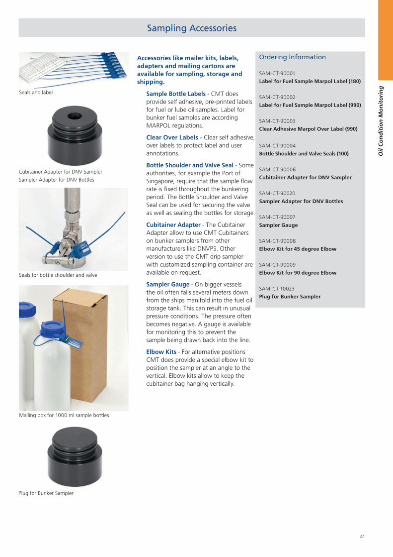
41
Oil
Co
nd
itio
n M
on
ito
rin
g
Accessories like mailer kits, labels, adapters and mailing cartons are available for sampling, storage and shipping.
Ordering Information
SAM-CT-90001
Label for Fuel Sample Marpol Label (180)
SAM-CT-90002
Label for Fuel Sample Marpol Label (990)
SAM-CT-90003
Clear Adhesive Marpol Over Label (990)
SAM-CT-90004
Bottle Shoulder and Valve Seals (100)
SAM-CT-90006
Cubitainer Adapter for DNV Sampler
SAM-CT-90020
Sampler Adapter for DNV Bottles
SAM-CT-90007
Sampler Gauge
SAM-CT-90008
Elbow Kit for 45 degree Elbow
SAM-CT-90009
Elbow Kit for 90 degree Elbow
SAM-CT-10023
Plug for Bunker Sampler
Sample Bottle Labels - CMT does provide self adhesive, pre-printed labels for fuel or lube oil samples. Label for bunker fuel samples are according MARPOL regulations.
Clear Over Labels - Clear self adhesive, over labels to protect label and user annotations.
Bottle Shoulder and Valve Seal - Some authorities, for example the Port of Singapore, require that the sample flow rate is fixed throughout the bunkering period. The Bottle Shoulder and Valve Seal can be used for securing the valve as well as sealing the bottles for storage.
Cubitainer Adapter - The Cubitainer Adapter allow to use CMT Cubitainers on bunker samplers from other manufacturers like DNVPS. Other version to use the CMT drip sampler with customized sampling container are available on request.
Sampler Gauge - On bigger vessels the oil often falls several meters down from the ships manifold into the fuel oil storage tank. This can result in unusual pressure conditions. The pressure often becomes negative. A gauge is available for monitoring this to prevent the sample being drawn back into the line.
Elbow Kits - For alternative positions CMT does provide a special elbow kit to position the sampler at an angle to the vertical. Elbow kits allow to keep the cubitainer bag hanging vertically.
Seals and label
Cubitainer Adapter for DNV Sampler
Sampler Adapter for DNV Bottles
Plug for Bunker Sampler
Sampling Accessories
Seals for bottle shoulder and valve
Mailing box for 1000 ml sample bottles

42
Oil
Co
nd
itio
n M
on
ito
rin
g
43
Wat
er C
on
dit
ion
Mo
nit
ori
ng
Water Condition Monitoring
1. Marine Potable Water Test Kit .................. 44
2. Marine Sewage Water Test Kits ................ 49
3. Ballast Water Test Kit ............................... 50
4. Cooling and Boiler Water Test Kits ........... 52
5. Marine Automatic Fire Sprinkler System ... 53
6. Produced Foam ........................................ 54
7. Scrubber Caustic Test Kit .......................... 54
8. Cutting Fluid Test Kit................................ 54
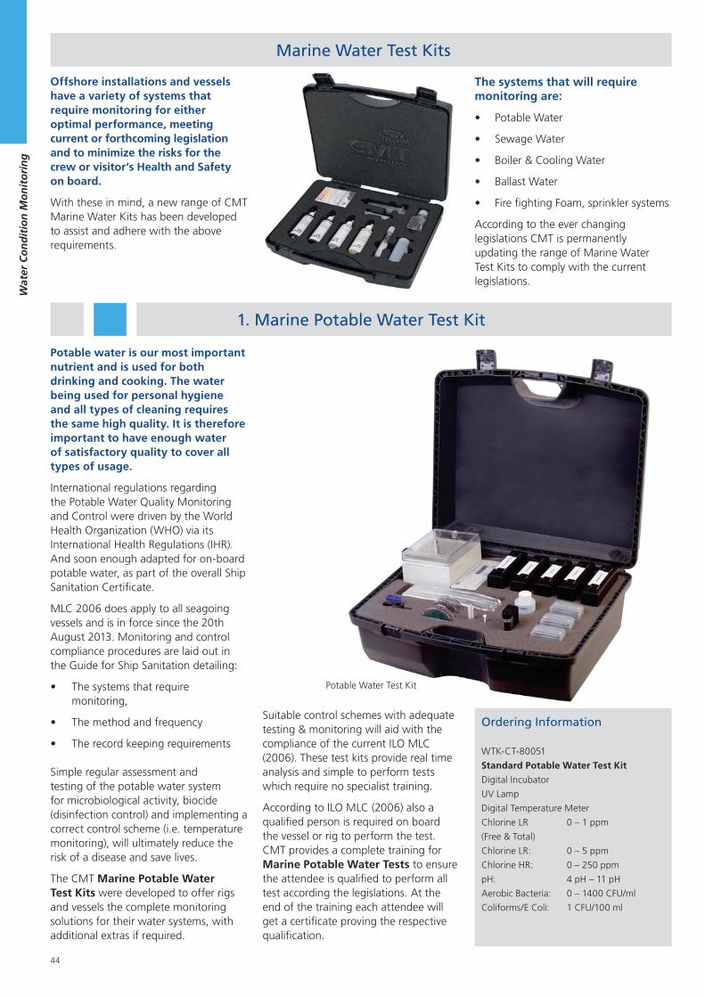
44
Wat
er C
on
dit
ion
Mo
nit
ori
ng
Potable Water Test Kit
Offshore installations and vessels have a variety of systems that require monitoring for either optimal performance, meeting current or forthcoming legislation and to minimize the risks for the crew or visitor’s Health and Safety on board.
With these in mind, a new range of CMT Marine Water Kits has been developed to assist and adhere with the above requirements.
Marine Water Test Kits
1. Marine Potable Water Test Kit
Suitable control schemes with adequate testing & monitoring will aid with the compliance of the current ILO MLC (2006). These test kits provide real time analysis and simple to perform tests which require no specialist training.
According to ILO MLC (2006) also a qualified person is required on board the vessel or rig to perform the test. CMT provides a complete training for Marine Potable Water Tests to ensure the attendee is qualified to perform all test according the legislations. At the end of the training each attendee will get a certificate proving the respective qualification.
The systems that will require monitoring are:
Potable Water
Sewage Water
Boiler & Cooling Water
Ballast Water
Fire fighting Foam, sprinkler systems
According to the ever changing legislations CMT is permanently updating the range of Marine Water Test Kits to comply with the current legislations.
Ordering Information
WTK-CT-80051
Standard Potable Water Test Kit
Digital Incubator
UV Lamp
Digital Temperature Meter
Chlorine LR 0 – 1 ppm
(Free & Total)
Chlorine LR: 0 – 5 ppm
Chlorine HR: 0 – 250 ppm
pH: 4 pH – 11 pH
Aerobic Bacteria: 0 – 1400 CFU/ml
Coliforms/E Coli: 1 CFU/100 ml
Potable water is our most important nutrient and is used for both drinking and cooking. The water being used for personal hygiene and all types of cleaning requires the same high quality. It is therefore important to have enough water of satisfactory quality to cover all types of usage.
International regulations regarding the Potable Water Quality Monitoring and Control were driven by the World Health Organization (WHO) via its International Health Regulations (IHR). And soon enough adapted for on-board potable water, as part of the overall Ship Sanitation Certificate.
MLC 2006 does apply to all seagoing vessels and is in force since the 20th August 2013. Monitoring and control compliance procedures are laid out in the Guide for Ship Sanitation detailing:
The systems that require monitoring,
The method and frequency
The record keeping requirements
Simple regular assessment and testing of the potable water system for microbiological activity, biocide (disinfection control) and implementing a correct control scheme (i.e. temperature monitoring), will ultimately reduce the risk of a disease and save lives.
The CMT Marine Potable Water Test Kits were developed to offer rigs and vessels the complete monitoring solutions for their water systems, with additional extras if required.
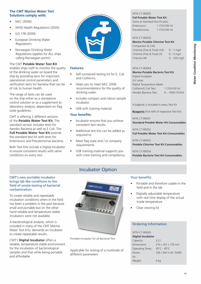
45
Wat
er C
on
dit
ion
Mo
nit
ori
ng
Ordering Information
WTK-CT-80020
Digital Incubator
Capacity: 3.2 l
Dimensions: 215 x 161 x 170 mm
Operating Temp.: 35°C - 45°C
Power: 100 / 240 V AC 50/60
Hz
Weight: 4 kg
Portable Incubator for all Bacterial Test
CMT’s new portable incubator brings lab like conditions to the field of onsite testing of bacterial contamination.
To create reliable and repeatable incubation conditions when in the field has been a problem in the past because small and portable but on the other hand reliable and temperature stable incubators were not available.
A bacteriological analysis, which is included in many of the CMT Marine Water Test Kits, demands an incubator to create repeatable results.
CMT’s Digital Incubator offers a reliable, temperature stable environment for the incubation of bacteriological samples and that while being portable and affordable.
The CMT Potable Water Test Kit enables ships staff to monitor the quality of the drinking water on board the ship by providing tests for important operational control parameters and verification tests for bacteria that can be of risk to human health.
The range of tests can be used on the ship either as a standalone control solution or as a supplement to laboratory analysis, dependant on flag state guidelines.
CMT is offering 2 different versions of the Potable Water Test Kit. The standard version includes tests for Aerobic Bacteria as well as E Coli. The Full Potable Water Test Kit extends the standard test kit with tests for Enterococci and Pseudomonas bacteria.
Both Test Kits include a Digital Incubator to ensure consistent results with same conditions on every test.
Your benefits:
Portable and therefore usable in the field and in the lab
Digitally adjustable temperature with real time display of the actual inside temperature
Clear viewing lid
Incubator Option
Features:
Self-contained testing kit for E. Coli and Coliforms.
Helps you to meet MLC 2006 recommendations for the quality of drinking water.
Includes compact and robust sample incubator.
USB with training material.
Your benefits:
Incubator ensures that you achieve consistent test results.
Additional test kits can be added as required to
Meet flag state and / or company requirements.
USB training material supports you with crew training and competency.
The CMT Marine Water Test Solutions comply with:
MLC (2006)
WHO Health Regulations (2005)
ILO 178 (2009)
European Drinking Water Regulations
Norwegian Drinking Water Regulations (applies for ALL ships calling Norwegian ports!)
WTK-CT-80052
Full Potable Water Test Kit
Same as Standard Test Kit plus:
Enterococci: 1 CFU/100 ml
Pseudomonas: 1 CFU/100 ml
WTK-CT-80053
Marine Potable Chlorine Test Kit
Comparator & Cells
Chlorine (Free & Total) VLR: 0 – 1 mg/l
Chlorine (Free & Total) LR: 0 – 5 mg/l
Chlorine HR: 0 – 250 mg/l
WTK-CT-80054
Marine Potable Bacteria Test Kit
Digital Incubator
UV Lamp
Digital Temperature Meter
Coliform/E Coli Test: 1 CFU/100 ml
Aerobic Bacteria Test : 0 – 1400 CFU/ml
A logbook is included in every Test Kit
Reagents (Full refill of respective Test Kit)
WTK-CT-85051
Standard Potable Water Kit Consumables
WTK-CT-85052
Full Potable Water Test Kit Consumables
WTK-CT-85053
Potable Chlorine Test Kit Consumables
WTK-CT-85054
Potable Bacteria Test Kit Consumables
Applicable for testing of a multitude of different parameters
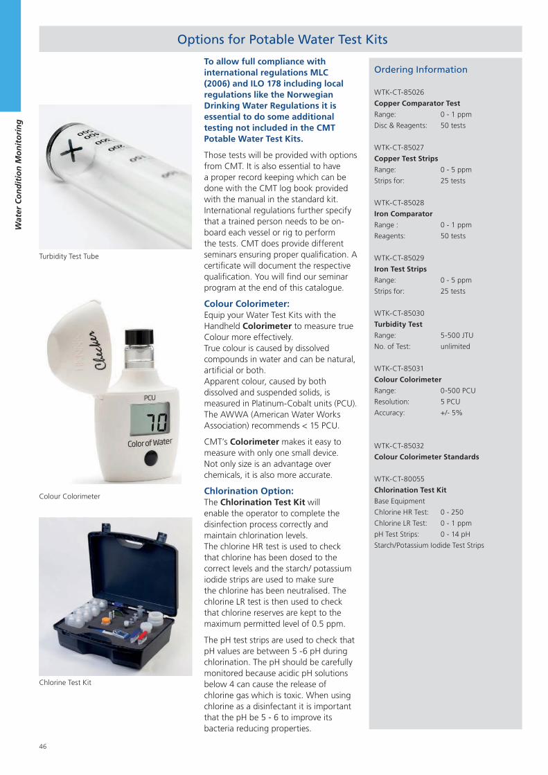
46
Wat
er C
on
dit
ion
Mo
nit
ori
ng
Ordering Information
WTK-CT-85026
Copper Comparator Test
Range: 0 - 1 ppm
Disc & Reagents: 50 tests
WTK-CT-85027
Copper Test Strips
Range: 0 - 5 ppm
Strips for: 25 tests
WTK-CT-85028
Iron Comparator
Range : 0 - 1 ppm
Reagents: 50 tests
WTK-CT-85029
Iron Test Strips
Range: 0 - 5 ppm
Strips for: 25 tests
WTK-CT-85030
Turbidity Test
Range: 5-500 JTU
No. of Test: unlimited
WTK-CT-85031
Colour Colorimeter
Range: 0-500 PCU
Resolution: 5 PCU
Accuracy: +/- 5%
WTK-CT-85032
Colour Colorimeter Standards
WTK-CT-80055
Chlorination Test Kit
Base Equipment
Chlorine HR Test: 0 - 250
Chlorine LR Test: 0 - 1 ppm
pH Test Strips: 0 - 14 pH
Starch/Potassium Iodide Test Strips
Turbidity Test Tube
Options for Potable Water Test Kits
Colour Colorimeter
To allow full compliance with international regulations MLC (2006) and ILO 178 including local regulations like the Norwegian Drinking Water Regulations it is essential to do some additional testing not included in the CMT Potable Water Test Kits.
Those tests will be provided with options from CMT. It is also essential to have a proper record keeping which can be done with the CMT log book provided with the manual in the standard kit. International regulations further specify that a trained person needs to be on-board each vessel or rig to perform the tests. CMT does provide different seminars ensuring proper qualification. A certificate will document the respective qualification. You will find our seminar program at the end of this catalogue.
Colour Colorimeter: Equip your Water Test Kits with the Handheld Colorimeter to measure true Colour more effectively. True colour is caused by dissolved compounds in water and can be natural, artificial or both. Apparent colour, caused by both dissolved and suspended solids, is measured in Platinum-Cobalt units (PCU). The AWWA (American Water Works Association) recommends < 15 PCU.
CMT’s Colorimeter makes it easy to measure with only one small device. Not only size is an advantage over chemicals, it is also more accurate.
Chlorination Option: The Chlorination Test Kit will enable the operator to complete the disinfection process correctly and maintain chlorination levels. The chlorine HR test is used to check that chlorine has been dosed to the correct levels and the starch/ potassium iodide strips are used to make sure the chlorine has been neutralised. The chlorine LR test is then used to check that chlorine reserves are kept to the maximum permitted level of 0.5 ppm.
The pH test strips are used to check that pH values are between 5 -6 pH during chlorination. The pH should be carefully monitored because acidic pH solutions below 4 can cause the release of chlorine gas which is toxic. When using chlorine as a disinfectant it is important that the pH be 5 - 6 to improve its bacteria reducing properties.
Chlorine Test Kit
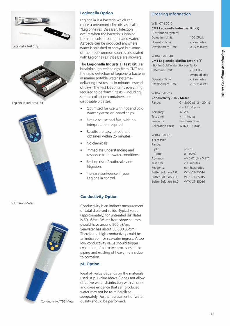
47
Wat
er C
on
dit
ion
Mo
nit
ori
ng
Ordering Information
WTK-CT-80010
CMT Legionella Industrial Kit (5)
(Distribution System)
Detection Limit: 100 CFU/L
Operator Time: < 2 minutes
Development Time: < 35 minutes
WTK-CT-80040
CMT Legionella Biofilm Test Kit (5)
(Biofilm Cold Water Storage Tank)
Detection Limit: 200 CFU/
swapped area
Operator Time: < 2 minutes
Development Time: < 35 minutes
WTK-CT-85012
Conductivity / TDS Meter
Range: 0 – 2000 μS; 2 – 20 mS;
0 – 13000 ppm
Accuracy: +/- 2%
Test time: < 1 minutes
Reagents: non hazardous
Calibration Pack: WTK-CT-85005
WTK-CT-85013
pH Meter
Range:
pH: -2 – 16
Temp: 0 – 90°C
Accuracy: +/- 0.02 pH / 0.3°C
Test time: < 1 minutes
Reagents: non hazardous
Buffer Solution 4.0: WTK-CT-85014
Buffer Solution 7.0: WTK-CT-85015
Buffer Solution 10.0: WTK-CT-85016
Conductivity Option:
Conductivity is an indirect measurement of total dissolved solids. Typical value (approximately) for untreated distillates is 50 μS/cm. Water from shore sources should have around 500 μS/cm. Seawater has about 50,000 μS/cm. Therefore a high conductivity could be an indication for seawater ingress. A too low conductivity value should trigger evaluation of corrosive processes in the piping and existing of heavy metals due to corrosion.
pH Option:
Ideal pH value depends on the materials used. A pH value above 8 does not allow effective water disinfection with chlorine and gives evidence that self produced water may not be re-mineralized adequately. Further assessment of water quality should be performed.
pH / Temp Meter
Legionella Test Strip
Legionella Industrial Kit
Legionella Option
Legionella is a bacteria which can cause a pneumonia-like disease called “Legionnaires’ Disease”. Infection occurs when the bacteria is inhaled from aerosols of contaminated water. Aerosols can be produced anywhere water is splashed or sprayed but some of the most common sources associated with Legionnaires’ Disease are showers.
The Legionella Industrial Test Kit is a breakthrough technology from CMT for the rapid detection of Legionella bacteria in marine potable water systems– delivering test results in minutes instead of days. The test kit contains everything required to perform 5 tests – including sample collection containers and disposable pipettes.
Optimised for use with hot and cold water systems on-board ships.
Simple to use and fast, with no interpretation required.
Results are easy to read and obtained within 25 minutes.
No chemicals.
Immediate understanding and response to the water conditions.
Reduce risk of outbreaks and litigation.
Increase confidence in your Legionella control.
Conductivity / TDS Meter
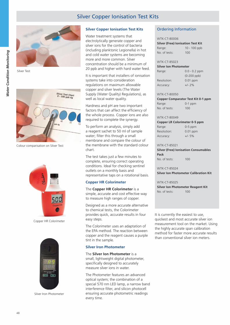
48
Wat
er C
on
dit
ion
Mo
nit
ori
ng
Ordering Information
WTK-CT-80006
Silver (Free) Ionisation Test Kit
Range: 10 - 100 ppb
No. of tests: 100
WTK-CT-85023
Silver Ion Photometer
Range: 0.0 - 0.2 ppm
(0-200 ppb)
Resolution: 0.01 ppm
Accuracy: +/- 2%
WTK-CT-80050
Copper Comparator Test Kit 0-1 ppm
Range: 0-1 ppm
No. of tests: 100
WTK-CT-80049
Copper LR Colorimeter 0-5 ppm
Range: 0-5 ppm
Resolution: 0.01 ppm
Accuracy: +/- 5%
WTK-CT-85021
Silver (Free) Ionisation Consumables
Pack
No. of tests: 100
WTK-CT-85024
Silver Ion Photometer Calibration Kit
WTK-CT-85025
Silver Ion Photometer Reagent Kit
No. of tests: 100
Silver Copper Ionisation Test Kits
Silver Copper Ionisation Test Kits
Water treatment systems that electrolytically generate copper and silver ions for the control of bacteria (including planktonic Legionella) in hot and cold water systems are becoming more and more common. Silver concentration should be a minimum of 20 ppb and higher with hard water feed.
It is important that installers of ionisation systems take into consideration regulations on maximum allowable copper and silver levels (The Water Supply (Water Quality) Regulations), as well as local water quality.
Hardness and pH are two important factors that can affect the efficiency of the whole process. Copper ions are also required to complete the synergy.
To perform an analysis, simply add a reagent sachet to 50 ml of sample water; filter this through a small membrane and compare the colour of the membrane with the standard colour chart.
The test takes just a few minutes to complete, ensuring correct operating conditions. Ideal for checking sentinel outlets on a monthly basis and representative taps on a rotational basis.
Copper HR Colorimeter
The Copper HR Colorimeter is a simple, accurate and cost effective way to measure high ranges of copper.
Designed as a more accurate alternative to chemical tests, the Colorimeter provides quick, accurate results in four easy steps.
The Colorimeter uses an adaptation of the EPA method. The reaction between copper and the reagent causes a purple tint in the sample.
Silver Iron Photometer
The Silver Ion Photometer is a small, lightweight digital photometer, specifically designed to accurately measure silver ions in water.
The Photometer features an advanced optical system; the combination of a special 570 nm LED lamp, a narrow band interference filter, and silicon photocell ensuring accurate photometric readings every time.
Colour comparisation on Silver Test
Silver Test
Copper HR Colorimeter
Silver Iron Photometer
It is currently the easiest to use, quickest and most accurate silver ion measurement tool on the market. Using the highly accurate span calibration method for faster more accurate results than conventional silver ion meters.
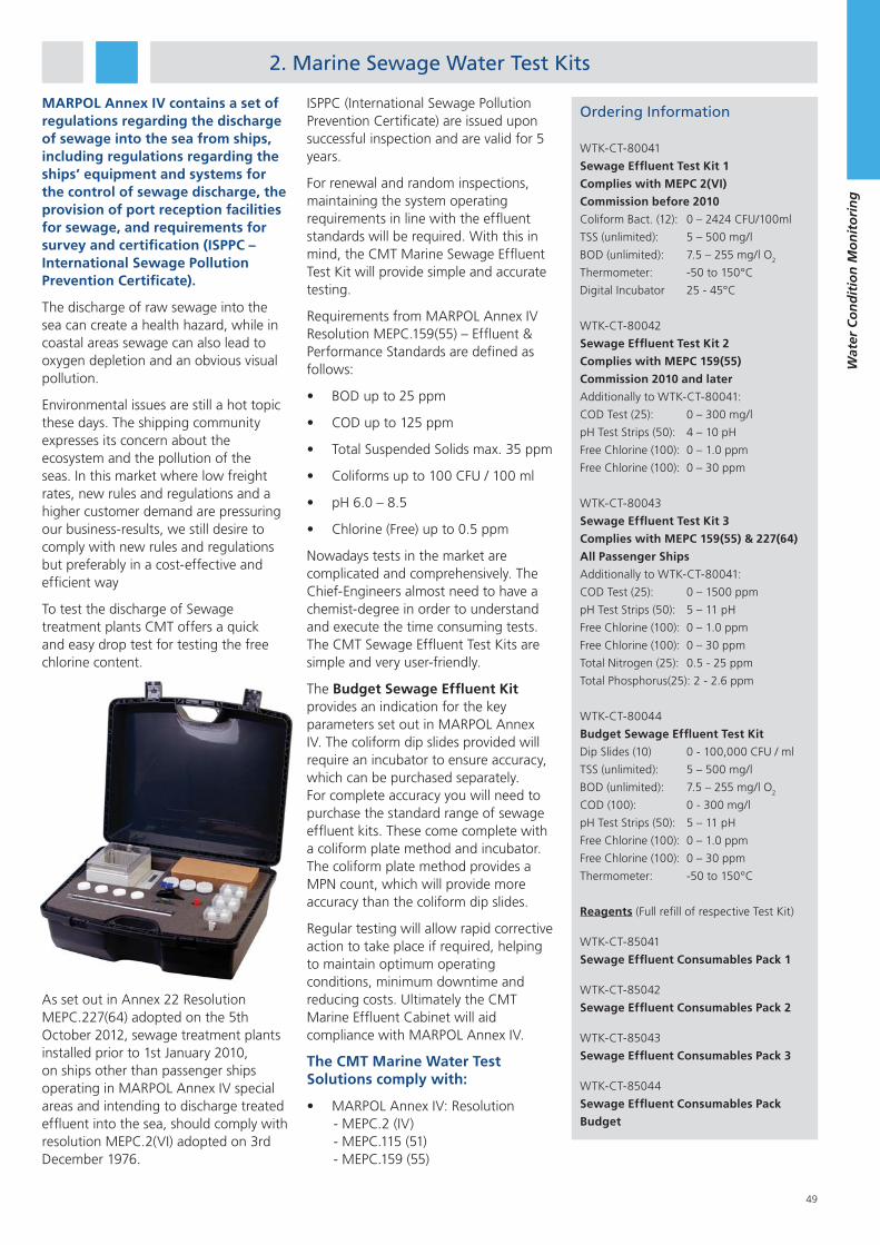
49
Wat
er C
on
dit
ion
Mo
nit
ori
ng
2. Marine Sewage Water Test Kits
MARPOL Annex IV contains a set of regulations regarding the discharge of sewage into the sea from ships, including regulations regarding the ships’ equipment and systems for the control of sewage discharge, the provision of port reception facilities for sewage, and requirements for survey and certification (ISPPC – International Sewage Pollution Prevention Certificate).
The discharge of raw sewage into the sea can create a health hazard, while in coastal areas sewage can also lead to oxygen depletion and an obvious visual pollution.
Environmental issues are still a hot topic these days. The shipping community expresses its concern about the ecosystem and the pollution of the seas. In this market where low freight rates, new rules and regulations and a higher customer demand are pressuring our business-results, we still desire to comply with new rules and regulations but preferably in a cost-effective and efficient way
To test the discharge of Sewage treatment plants CMT offers a quick and easy drop test for testing the free chlorine content.
As set out in Annex 22 Resolution MEPC.227(64) adopted on the 5th October 2012, sewage treatment plants installed prior to 1st January 2010, on ships other than passenger ships operating in MARPOL Annex IV special areas and intending to discharge treated effluent into the sea, should comply with resolution MEPC.2(VI) adopted on 3rd December 1976.
Ordering Information
WTK-CT-80041
Sewage Effluent Test Kit 1
Complies with MEPC 2(VI)
Commission before 2010
Coliform Bact. (12): 0 – 2424 CFU/100ml
TSS (unlimited): 5 – 500 mg/l
BOD (unlimited): 7.5 – 255 mg/l O2
Thermometer: -50 to 150°C
Digital Incubator 25 - 45°C
WTK-CT-80042
Sewage Effluent Test Kit 2
Complies with MEPC 159(55)
Commission 2010 and later
Additionally to WTK-CT-80041:
COD Test (25): 0 – 300 mg/l
pH Test Strips (50): 4 – 10 pH
Free Chlorine (100): 0 – 1.0 ppm
Free Chlorine (100): 0 – 30 ppm
WTK-CT-80043
Sewage Effluent Test Kit 3
Complies with MEPC 159(55) & 227(64)
All Passenger Ships
Additionally to WTK-CT-80041:
COD Test (25): 0 – 1500 ppm
pH Test Strips (50): 5 – 11 pH
Free Chlorine (100): 0 – 1.0 ppm
Free Chlorine (100): 0 – 30 ppm
Total Nitrogen (25): 0.5 - 25 ppm
Total Phosphorus(25): 2 - 2.6 ppm
WTK-CT-80044
Budget Sewage Effluent Test Kit
Dip Slides (10) 0 - 100,000 CFU / ml
TSS (unlimited): 5 – 500 mg/l
BOD (unlimited): 7.5 – 255 mg/l O2
COD (100): 0 - 300 mg/l
pH Test Strips (50): 5 – 11 pH
Free Chlorine (100): 0 – 1.0 ppm
Free Chlorine (100): 0 – 30 ppm
Thermometer: -50 to 150°C
Reagents (Full refill of respective Test Kit)
WTK-CT-85041
Sewage Effluent Consumables Pack 1
WTK-CT-85042
Sewage Effluent Consumables Pack 2
WTK-CT-85043
Sewage Effluent Consumables Pack 3
WTK-CT-85044
Sewage Effluent Consumables Pack
Budget
Nowadays tests in the market are complicated and comprehensively. The Chief-Engineers almost need to have a chemist-degree in order to understand and execute the time consuming tests. The CMT Sewage Effluent Test Kits are simple and very user-friendly.
The Budget Sewage Effluent Kit provides an indication for the key parameters set out in MARPOL Annex IV. The coliform dip slides provided will require an incubator to ensure accuracy, which can be purchased separately. For complete accuracy you will need to purchase the standard range of sewage effluent kits. These come complete with a coliform plate method and incubator. The coliform plate method provides a MPN count, which will provide more accuracy than the coliform dip slides.
Regular testing will allow rapid corrective action to take place if required, helping to maintain optimum operating conditions, minimum downtime and reducing costs. Ultimately the CMT Marine Effluent Cabinet will aid compliance with MARPOL Annex IV.
The CMT Marine Water Test Solutions comply with:
MARPOL Annex IV: Resolution - MEPC.2 (IV) - MEPC.115 (51) - MEPC.159 (55)
ISPPC (International Sewage Pollution Prevention Certificate) are issued upon successful inspection and are valid for 5 years.
For renewal and random inspections, maintaining the system operating requirements in line with the effluent standards will be required. With this in mind, the CMT Marine Sewage Effluent Test Kit will provide simple and accurate testing.
Requirements from MARPOL Annex IV Resolution MEPC.159(55) – Effluent & Performance Standards are defined as follows:
BOD up to 25 ppm
COD up to 125 ppm
Total Suspended Solids max. 35 ppm
Coliforms up to 100 CFU / 100 ml
pH 6.0 – 8.5
Chlorine (Free) up to 0.5 ppm
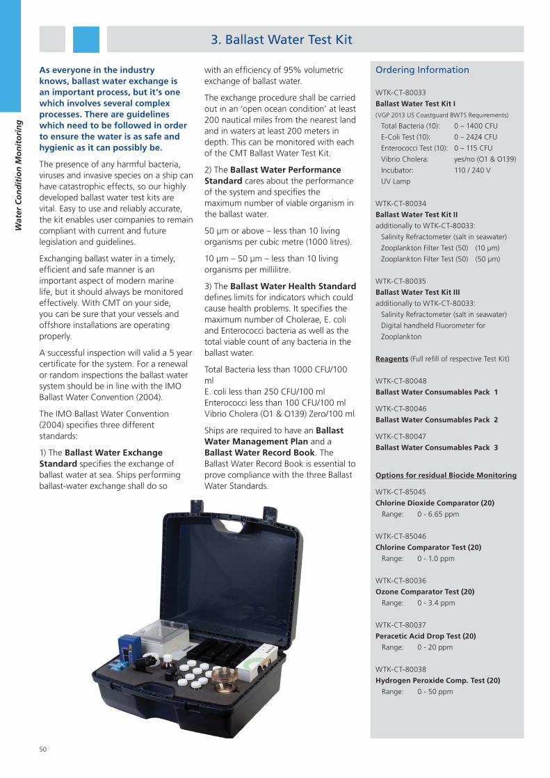
50
Wat
er C
on
dit
ion
Mo
nit
ori
ng
3. Ballast Water Test Kit
As everyone in the industry knows, ballast water exchange is an important process, but it’s one which involves several complex processes. There are guidelines which need to be followed in order to ensure the water is as safe and hygienic as it can possibly be.
The presence of any harmful bacteria, viruses and invasive species on a ship can have catastrophic effects, so our highly developed ballast water test kits are vital. Easy to use and reliably accurate, the kit enables user companies to remain compliant with current and future legislation and guidelines.
Exchanging ballast water in a timely, efficient and safe manner is an important aspect of modern marine life, but it should always be monitored effectively. With CMT on your side, you can be sure that your vessels and offshore installations are operating properly.
A successful inspection will valid a 5 year certificate for the system. For a renewal or random inspections the ballast water system should be in line with the IMO Ballast Water Convention (2004).
The IMO Ballast Water Convention (2004) specifies three different standards:
1) The Ballast Water Exchange Standard specifies the exchange of ballast water at sea. Ships performing ballast-water exchange shall do so
with an efficiency of 95% volumetric exchange of ballast water.
The exchange procedure shall be carried out in an ‘open ocean condition’ at least 200 nautical miles from the nearest land and in waters at least 200 meters in depth. This can be monitored with each of the CMT Ballast Water Test Kit.
2) The Ballast Water Performance Standard cares about the performance of the system and specifies the maximum number of viable organism in the ballast water.
50 μm or above – less than 10 living organisms per cubic metre (1000 litres).
10 μm – 50 μm – less than 10 living organisms per millilitre.
3) The Ballast Water Health Standard defines limits for indicators which could cause health problems. It specifies the maximum number of Cholerae, E. coli and Enterococci bacteria as well as the total viable count of any bacteria in the ballast water.
Total Bacteria less than 1000 CFU/100 mlE. coli less than 250 CFU/100 mlEnterococci less than 100 CFU/100 mlVibrio Cholera (O1 & O139) Zero/100 ml
Ships are required to have an Ballast Water Management Plan and a Ballast Water Record Book. The Ballast Water Record Book is essential to prove compliance with the three Ballast Water Standards.
Ordering Information
WTK-CT-80033
Ballast Water Test Kit I
(VGP 2013 US Coastguard BWTS Requirements)
Total Bacteria (10): 0 – 1400 CFU
E-Coli Test (10): 0 – 2424 CFU
Enterococci Test (10): 0 – 115 CFU
Vibrio Cholera: yes/no (O1 & O139)
Incubator: 110 / 240 V
UV Lamp
WTK-CT-80034
Ballast Water Test Kit II
additionally to WTK-CT-80033:
Salinity Refractometer (salt in seawater)
Zooplankton Filter Test (50) (10 μm)
Zooplankton Filter Test (50) (50 μm)
WTK-CT-80035
Ballast Water Test Kit III
additionally to WTK-CT-80033:
Salinity Refractometer (salt in seawater)
Digital handheld Fluorometer for
Zooplankton
Reagents (Full refill of respective Test Kit)
WTK-CT-80048
Ballast Water Consumables Pack 1
WTK-CT-80046
Ballast Water Consumables Pack 2
WTK-CT-80047
Ballast Water Consumables Pack 3
Options for residual Biocide Monitoring
WTK-CT-85045
Chlorine Dioxide Comparator (20)
Range: 0 - 6.65 ppm
WTK-CT-85046
Chlorine Comparator Test (20)
Range: 0 - 1.0 ppm
WTK-CT-80036
Ozone Comparator Test (20)
Range: 0 - 3.4 ppm
WTK-CT-80037
Peracetic Acid Drop Test (20)
Range: 0 - 20 ppm
WTK-CT-80038
Hydrogen Peroxide Comp. Test (20)
Range: 0 - 50 ppm
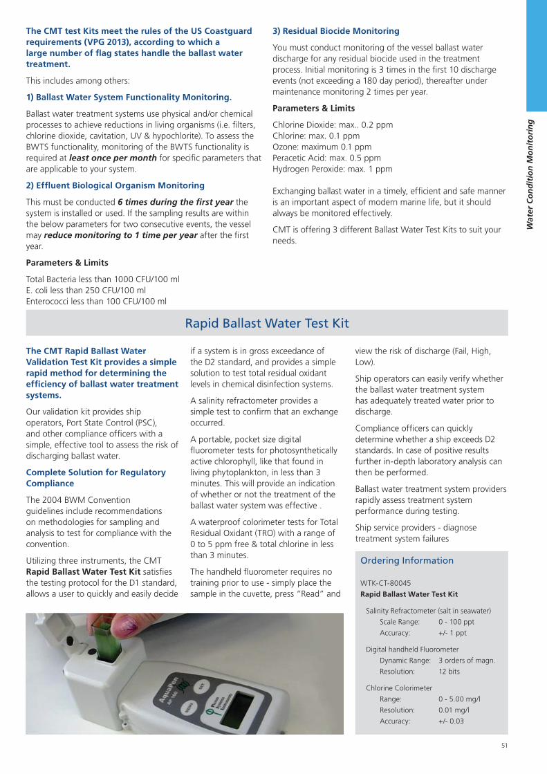
51
Wat
er C
on
dit
ion
Mo
nit
ori
ng
Rapid Ballast Water Test Kit
Ordering Information
WTK-CT-80045
Rapid Ballast Water Test Kit
Salinity Refractometer (salt in seawater)
Scale Range: 0 - 100 ppt
Accuracy: +/- 1 ppt
Digital handheld Fluorometer
Dynamic Range: 3 orders of magn.
Resolution: 12 bits
Chlorine Colorimeter
Range: 0 - 5.00 mg/l
Resolution: 0.01 mg/l
Accuracy: +/- 0.03
The CMT test Kits meet the rules of the US Coastguard requirements (VPG 2013), according to which a large number of flag states handle the ballast water treatment.
This includes among others:
1) Ballast Water System Functionality Monitoring.
Ballast water treatment systems use physical and/or chemical processes to achieve reductions in living organisms (i.e. filters, chlorine dioxide, cavitation, UV & hypochlorite). To assess the BWTS functionality, monitoring of the BWTS functionality is required at least once per month for specific parameters that are applicable to your system.
2) Effluent Biological Organism Monitoring
This must be conducted 6 times during the first year the system is installed or used. If the sampling results are within the below parameters for two consecutive events, the vessel may reduce monitoring to 1 time per year after the first year.
Parameters & Limits
Total Bacteria less than 1000 CFU/100 mlE. coli less than 250 CFU/100 mlEnterococci less than 100 CFU/100 ml
3) Residual Biocide Monitoring
You must conduct monitoring of the vessel ballast water discharge for any residual biocide used in the treatment process. Initial monitoring is 3 times in the first 10 discharge events (not exceeding a 180 day period), thereafter under maintenance monitoring 2 times per year.
Parameters & Limits
Chlorine Dioxide: max.. 0.2 ppmChlorine: max. 0.1 ppmOzone: maximum 0.1 ppmPeracetic Acid: max. 0.5 ppmHydrogen Peroxide: max. 1 ppm
Exchanging ballast water in a timely, efficient and safe manner is an important aspect of modern marine life, but it should always be monitored effectively.
CMT is offering 3 different Ballast Water Test Kits to suit your needs.
The CMT Rapid Ballast Water Validation Test Kit provides a simple rapid method for determining the efficiency of ballast water treatment systems.
Our validation kit provides ship operators, Port State Control (PSC), and other compliance officers with a simple, effective tool to assess the risk of discharging ballast water.
Complete Solution for Regulatory Compliance
The 2004 BWM Convention guidelines include recommendations on methodologies for sampling and analysis to test for compliance with the convention.
Utilizing three instruments, the CMT Rapid Ballast Water Test Kit satisfies the testing protocol for the D1 standard, allows a user to quickly and easily decide
if a system is in gross exceedance of the D2 standard, and provides a simple solution to test total residual oxidant levels in chemical disinfection systems.
A salinity refractometer provides a simple test to confirm that an exchange occurred.
A portable, pocket size digital fluorometer tests for photosynthetically active chlorophyll, like that found in living phytoplankton, in less than 3 minutes. This will provide an indication of whether or not the treatment of the ballast water system was effective .
A waterproof colorimeter tests for Total Residual Oxidant (TRO) with a range of 0 to 5 ppm free & total chlorine in less than 3 minutes.
The handheld fluorometer requires no training prior to use - simply place the sample in the cuvette, press “Read” and
view the risk of discharge (Fail, High, Low).
Ship operators can easily verify whether the ballast water treatment system has adequately treated water prior to discharge.
Compliance officers can quickly determine whether a ship exceeds D2 standards. In case of positive results further in-depth laboratory analysis can then be performed.
Ballast water treatment system providers rapidly assess treatment system performance during testing.
Ship service providers - diagnose treatment system failures
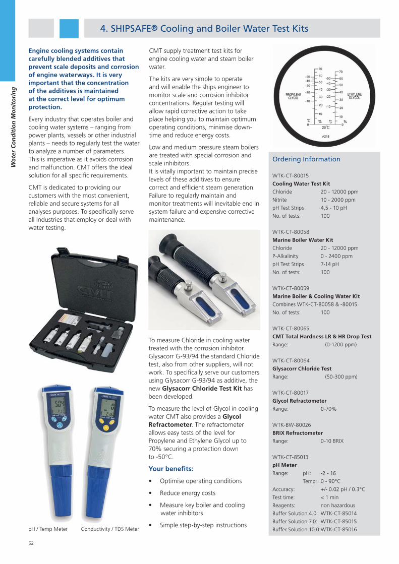
52
Wat
er C
on
dit
ion
Mo
nit
ori
ng
4. SHIPSAFE® Cooling and Boiler Water Test Kits
Engine cooling systems contain carefully blended additives that prevent scale deposits and corrosion of engine waterways. It is very important that the concentration of the additives is maintained at the correct level for optimum protection.
Every industry that operates boiler and cooling water systems – ranging from power plants, vessels or other industrial plants – needs to regularly test the water to analyze a number of parameters. This is imperative as it avoids corrosion and malfunction. CMT offers the ideal solution for all specific requirements.
CMT is dedicated to providing our customers with the most convenient, reliable and secure systems for all analyses purposes. To specifically serve all industries that employ or deal with water testing.
CMT supply treatment test kits for engine cooling water and steam boiler water.
The kits are very simple to operate and will enable the ships engineer to monitor scale and corrosion inhibitor concentrations. Regular testing will allow rapid corrective action to take place helping you to maintain optimum operating conditions, minimise down-time and reduce energy costs.
Low and medium pressure steam boilers are treated with special corrosion and scale inhibitors. It is vitally important to maintain precise levels of these additives to ensure correct and efficient steam generation. Failure to regularly maintain and monitor treatments will inevitable end in system failure and expensive corrective maintenance.
Ordering Information
WTK-CT-80015
Cooling Water Test Kit
Chloride 20 - 12000 ppm
Nitrite 10 - 2000 ppm
pH Test Strips 4,5 - 10 pH
No. of tests: 100
WTK-CT-80058
Marine Boiler Water Kit
Chloride 20 - 12000 ppm
P-Alkalinity 0 - 2400 ppm
pH Test Strips 7-14 pH
No. of tests: 100
WTK-CT-80059
Marine Boiler & Cooling Water Kit
Combines WTK-CT-80058 & -80015
No. of tests: 100
WTK-CT-80065
CMT Total Hardness LR & HR Drop Test
Range: (0-1200 ppm)
WTK-CT-80064
Glysacorr Chloride Test
Range: (50-300 ppm)
WTK-CT-80017
Glycol Refractometer
Range: 0-70%
WTK-BW-80026
BRIX Refractometer
Range: 0-10 BRIX
WTK-CT-85013
pH Meter
Range: pH: -2 - 16
Temp: 0 - 90°C
Accuracy: +/- 0.02 pH / 0.3°C
Test time: < 1 min
Reagents: non hazardous
Buffer Solution 4.0: WTK-CT-85014
Buffer Solution 7.0: WTK-CT-85015
Buffer Solution 10.0: WTK-CT-85016
To measure Chloride in cooling water treated with the corrosion inhibitor Glysacorr G-93/94 the standard Chloride test, also from other suppliers, will not work. To specifically serve our customers using Glysacorr G-93/94 as additive, the new Glysacorr Chloride Test Kit has been developed.
To measure the level of Glycol in cooling water CMT also provides a Glycol Refractometer. The refractometer allows easy tests of the level for Propylene and Ethylene Glycol up to 70% securing a protection down to -50°C.
Your benefits:
Optimise operating conditions
Reduce energy costs
Measure key boiler and cooling water inhibitors
Simple step-by-step instructionspH / Temp Meter Conductivity / TDS Meter
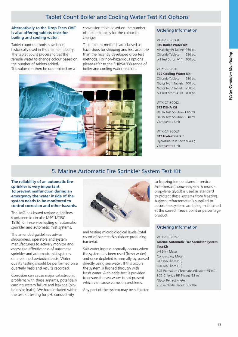
53
Wat
er C
on
dit
ion
Mo
nit
ori
ng
5. Marine Automatic Fire Sprinkler System Test Kit
Alternatively to the Drop Tests CMT is also offering tablets tests for boiling and cooling water.
Tablet count methods have been historically used in the marine industry. The tablet count process forces the sample water to change colour based on the number of tablets added. The value can then be determined on a
Ordering Information
WTK-CT-80057
Marine Automatic Fire Sprinkler System
Test Kit
pH Stick Meter
Conductivity Meter
BT2 Dip Slides (10)
SRB Dip Slides (10)
BC1 Potassium Chromate Indicator (65 ml)
BC2 Chloride HR Titrant (65 ml)
Glycol Refractometer
250 ml Wide Neck HD Bottle
conversion table based on the number of tablets it takes for the colour to change.
Tablet count methods are classed as hazardous for shipping and less accurate than the recently developed drop test methods. For non-hazardous options please refer to the SHIPSAFE® range of boiler and cooling water test kits.
The reliability of an automatic fire sprinkler is very important. To prevent malfunction during an emergency the water inside of the system needs to be monitored to control corrosion and other hazards.
The IMO has issued revised guidelines (contained in circular MSC.1/CIRC. 1516) for in-service testing of automatic sprinkler and automatic mist systems.
The amended guidelines advise shipowners, operators and system manufacturers to actively monitor and assess the effectiveness of automatic sprinkler and automatic mist systems on a planned periodical basis. Water quality testing should be performed on a quarterly basis and results recorded.
Corrosion can cause major catastrophic problems with these systems, potentially causing system failure and leakage (pin-hole size leaks). We have included within the test kit testing for pH, conductivity
and testing microbiological levels (total count of bacteria & sulphate producing bacteria).
Salt water ingress normally occurs when the system has been used (fresh water) and once depleted is normally by-passed directly using sea water. If this occurs the system is flushed through with fresh water. A chloride test is provided to ensure the sea water is not present which can cause corrosion problems.
Any part of the system may be subjected
Tablet Count Boiler and Cooling Water Test Kit Options
to freezing temperatures in service. Anti-freeze (mono-ethylene & mono-propylene glycol) is used as standard to protect these systems from freezing. A glycol refractometer is supplied to ensure the systems are being maintained at the correct freeze point or percentage product.
Ordering Information
WTK-CT-80060
310 Boiler Water Kit
Alkalinity (P) Tablets 250 pc.
Chloride Tablets 250 pc.
pH Test Strips 7-14 100 pc.
WTK-CT-80061
309 Cooling Water Kit
Chloride Tablets 250 pc.
Nitrite No 1 Tablets 100 pc.
Nitrite No 2 Tablets 250 pc.
pH Test Strips 4-10 100 pc.
WTK-CT-80062
313 DEHA Kit
DEHA Test Solution 1 65 ml
DEHA Test Solution 2 30 ml
Comparator Unit
WTK-CT-80063
312 Hydrazine Kit
Hydrazine Test Powder 40 g
Comparator Unit
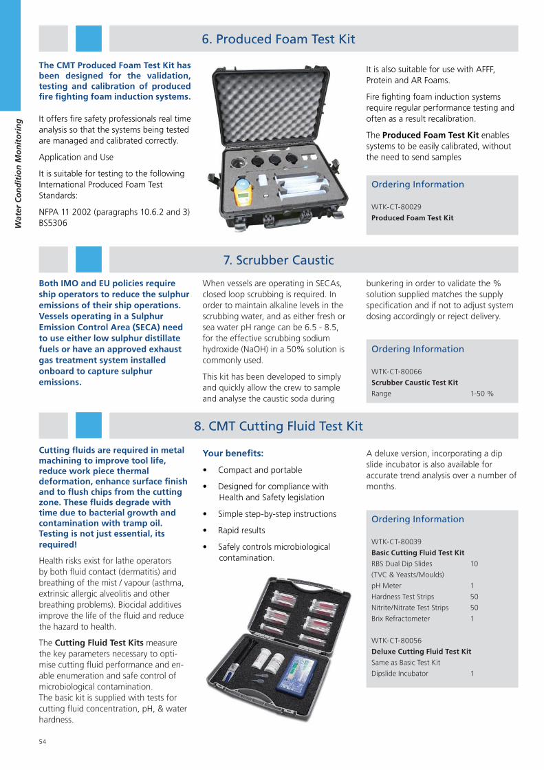
54
Wat
er C
on
dit
ion
Mo
nit
ori
ng
8. CMT Cutting Fluid Test Kit
Cutting fluids are required in metal machining to improve tool life, reduce work piece thermal deformation, enhance surface finish and to flush chips from the cutting zone. These fluids degrade with time due to bacterial growth and contamination with tramp oil. Testing is not just essential, its required!
Health risks exist for lathe operators by both fluid contact (dermatitis) and breathing of the mist / vapour (asthma, extrinsic allergic alveolitis and other breathing problems). Biocidal additives improve the life of the fluid and reduce the hazard to health.
The Cutting Fluid Test Kits measure the key parameters necessary to opti-mise cutting fluid performance and en-able enumeration and safe control of microbiological contamination. The basic kit is supplied with tests for cutting fluid concentration, pH, & water hardness.
Ordering Information
WTK-CT-80039
Basic Cutting Fluid Test Kit
RBS Dual Dip Slides 10
(TVC & Yeasts/Moulds)
pH Meter 1
Hardness Test Strips 50
Nitrite/Nitrate Test Strips 50
Brix Refractometer 1
WTK-CT-80056
Deluxe Cutting Fluid Test Kit
Same as Basic Test Kit
Dipslide Incubator 1
Your benefits:
Compact and portable
Designed for compliance with Health and Safety legislation
Simple step-by-step instructions
Rapid results
Safely controls microbiological contamination.
6. Produced Foam Test Kit
The CMT Produced Foam Test Kit has been designed for the validation, testing and calibration of produced fire fighting foam induction systems.
It offers fire safety professionals real time analysis so that the systems being tested are managed and calibrated correctly.
Application and Use
It is suitable for testing to the following International Produced Foam Test Standards:
NFPA 11 2002 (paragraphs 10.6.2 and 3)BS5306
Ordering Information
WTK-CT-80029
Produced Foam Test Kit
It is also suitable for use with AFFF, Protein and AR Foams.
Fire fighting foam induction systems require regular performance testing and often as a result recalibration.
The Produced Foam Test Kit enables systems to be easily calibrated, without the need to send samples
A deluxe version, incorporating a dip slide incubator is also available for accurate trend analysis over a number of months.
7. Scrubber Caustic
Both IMO and EU policies require ship operators to reduce the sulphur emissions of their ship operations. Vessels operating in a Sulphur Emission Control Area (SECA) need to use either low sulphur distillate fuels or have an approved exhaust gas treatment system installed onboard to capture sulphur emissions.
Ordering Information
WTK-CT-80066
Scrubber Caustic Test Kit
Range 1-50 %
When vessels are operating in SECAs, closed loop scrubbing is required. In order to maintain alkaline levels in the scrubbing water, and as either fresh or sea water pH range can be 6.5 - 8.5, for the effective scrubbing sodium hydroxide (NaOH) in a 50% solution is commonly used.
This kit has been developed to simply and quickly allow the crew to sample and analyse the caustic soda during
bunkering in order to validate the % solution supplied matches the supply specification and if not to adjust system dosing accordingly or reject delivery.
55
Vib
rati
on
Mo
nit
ori
ng
Vibration Monitoring
1. Vibration Meter ................................................................... 56
2. Vibration Analyser................................................................ 61
3. Vibration Monitor ................................................................ 67
4. Software .............................................................................. 70
5. Spares and Accessories ....................................................... .72
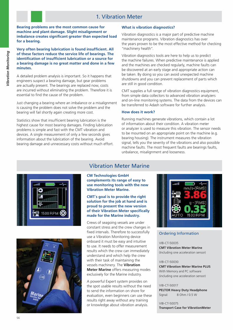
56
Vib
rati
on
Mo
nit
ori
ng
Vibration Meter Marine
Bearing problems are the most common cause for machine and plant damage. Slight misalignment or imbalance creates significant greater than expected load for a bearing.
Very often bearing lubrication is found insufficient. All of these factors reduce the service life of bearings. The identification of insufficient lubrication or a source for a bearing damage is no great matter and done in a few minutes.
A detailed problem analysis is important. So it happens that engineers suspect a bearing damage, but gear problems are actually present. The bearings are replaced now, costs are incurred without eliminating the problem. Therefore it is essential to find the cause of the problem.
Just changing a bearing where an imbalance or a misalignment is causing the problem does not solve the problem and the bearing will fail shortly again creating more cost.
Statistics show that insufficient bearing lubrication is the highest cause for most bearing damages. Finding lubrication problems is simple and fast with the CMT vibration and devices. A single measurement of only a few seconds gives information about the lubrication of the bearing. Avoid bearing damage and unnecessary costs without much effort.
What is vibration diagnostics?
Vibration diagnostics is a major part of predictive machine maintenance programs. Vibration diagnostics has over the years proven to be the most effective method for checking “machinery health“.
Vibration diagnostics tools are here to help us to predict the machine failures. When predictive maintenance is applied and the machines are checked regularly, machine faults can be discovered at an early stage and appropriate action can be taken. By doing so you can avoid unexpected machine shutdowns and you can prevent replacement of parts which are still in good condition.
CMT supplies a full range of vibration diagnostics equipment, from simple data collectors to advanced vibration analyzers and on-line monitoring systems. The data from the devices can be transferred to Adash software for further analysis.
How does it work?
Running machines generate vibrations, which contain a lot of information about their condition. A vibration meter or analyzer is used to measure this vibration. The sensor needs to be mounted on an appropriate point on the machine (e.g. bearing housing). The instrument measures the vibration signal, tells you the severity of the vibrations and also possible machine faults. The most frequent faults are bearings faults, unbalance, misalignment and looseness.
CM Technologies GmbH complements its range of easy to use monitoring tools with the new Vibration Meter Marine.
CMT´s goal is to provide the right solution for the job at hand and is proud to present the new version of their Vibration Meter specifically made for the Marine industry.
Crews of seagoing vessels are under constant stress and the crew changes in fixed intervals. Therefore to successfully use a Vibration Monitoring device onboard it must be easy and intuitive to use. It needs to offer measurement results which the crew can immediately understand and which help the crew with their task of maintaining the vessels machinery. The Vibration Meter Marine offers measuring modes exclusively for the Marine industry.
A powerful Expert system provides on the spot usable results without the need to send the information on shore for evaluation, even beginners can use these results right away without any training or knowledge about vibration analysis.
1. Vibration Meter
Ordering Information
VIB-CT-50035
CMT Vibration Meter Marine
(Including one acceleration sensor)
VIB-CT-50030
CMT Vibration Meter Marine PLUS
With Memory and PC software
(including one acceleration sensor)
VIB-CT-50017
PELTOR Heavy Duty Headphone
Signal: 8 Ohm / 0.5 W
VIB-CT-50075Transport Case for VibrationMeter
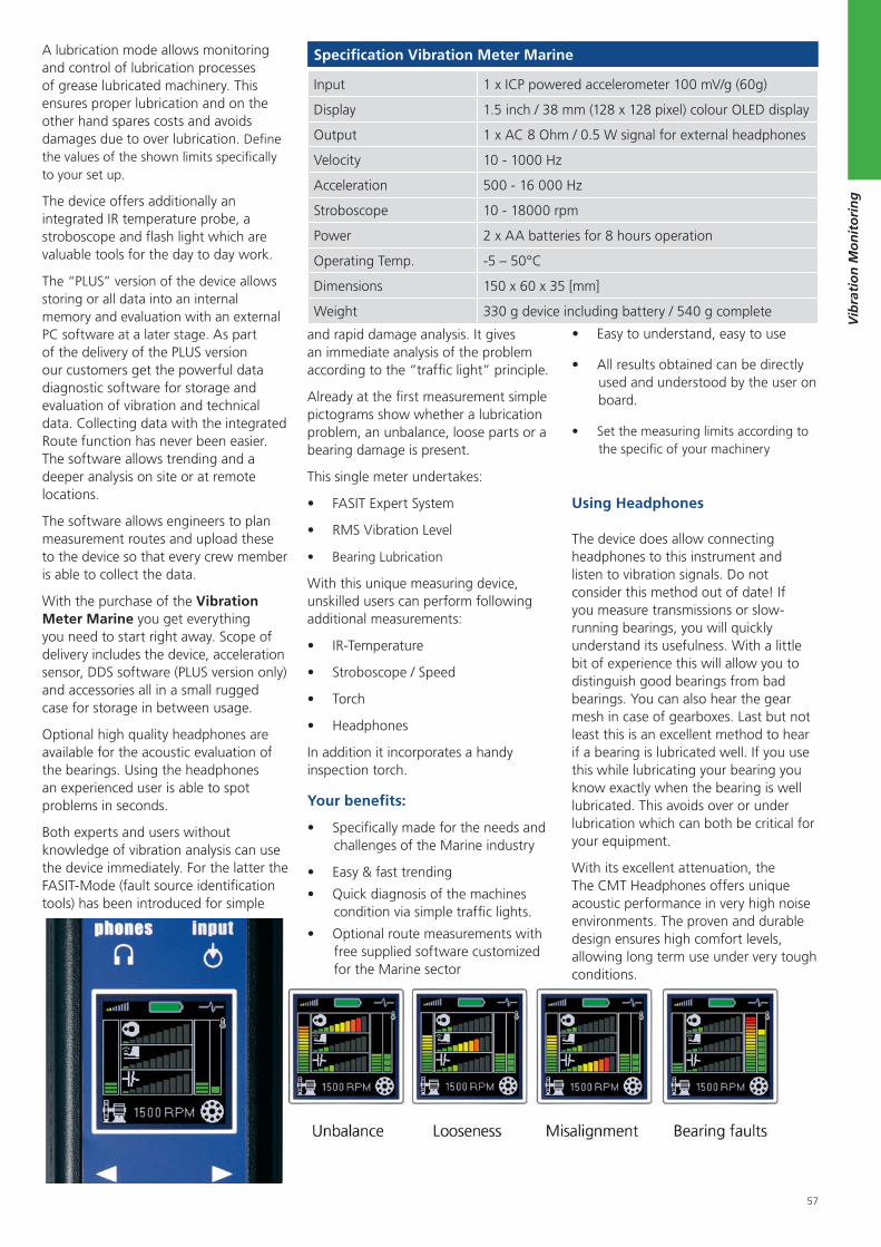
57
Vib
rati
on
Mo
nit
ori
ng
A lubrication mode allows monitoring and control of lubrication processes of grease lubricated machinery. This ensures proper lubrication and on the other hand spares costs and avoids damages due to over lubrication. Define the values of the shown limits specifically to your set up.
The device offers additionally an integrated IR temperature probe, a stroboscope and flash light which are valuable tools for the day to day work.
The “PLUS” version of the device allows storing or all data into an internal memory and evaluation with an external PC software at a later stage. As part of the delivery of the PLUS version our customers get the powerful data diagnostic software for storage and evaluation of vibration and technical data. Collecting data with the integrated Route function has never been easier. The software allows trending and a deeper analysis on site or at remote locations.
The software allows engineers to plan measurement routes and upload these to the device so that every crew member is able to collect the data.
With the purchase of the Vibration Meter Marine you get everything you need to start right away. Scope of delivery includes the device, acceleration sensor, DDS software (PLUS version only) and accessories all in a small rugged case for storage in between usage.
Optional high quality headphones are available for the acoustic evaluation of the bearings. Using the headphones an experienced user is able to spot problems in seconds.
Both experts and users without knowledge of vibration analysis can use the device immediately. For the latter the FASIT-Mode (fault source identification tools) has been introduced for simple
Using Headphones
The device does allow connecting headphones to this instrument and listen to vibration signals. Do not consider this method out of date! If you measure transmissions or slow-running bearings, you will quickly understand its usefulness. With a little bit of experience this will allow you to distinguish good bearings from bad bearings. You can also hear the gear mesh in case of gearboxes. Last but not least this is an excellent method to hear if a bearing is lubricated well. If you use this while lubricating your bearing you know exactly when the bearing is well lubricated. This avoids over or under lubrication which can both be critical for your equipment.
With its excellent attenuation, the The CMT Headphones offers unique acoustic performance in very high noise environments. The proven and durable design ensures high comfort levels, allowing long term use under very tough conditions.
and rapid damage analysis. It gives an immediate analysis of the problem according to the “traffic light” principle.
Already at the first measurement simple pictograms show whether a lubrication problem, an unbalance, loose parts or a bearing damage is present.
This single meter undertakes:
FASIT Expert System
RMS Vibration Level
Bearing Lubrication
With this unique measuring device, unskilled users can perform following additional measurements:
IR-Temperature
Stroboscope / Speed
Torch
Headphones
In addition it incorporates a handy inspection torch.
Your benefits:
Specifically made for the needs and challenges of the Marine industry
Easy & fast trending
Quick diagnosis of the machines condition via simple traffic lights.
Optional route measurements with free supplied software customized for the Marine sector
Easy to understand, easy to use
All results obtained can be directly used and understood by the user on board.
Set the measuring limits according to the specific of your machinery
Specification Vibration Meter Marine
Input 1 x ICP powered accelerometer 100 mV/g (60g)
Display 1.5 inch / 38 mm (128 x 128 pixel) colour OLED display
Output 1 x AC 8 Ohm / 0.5 W signal for external headphones
Velocity 10 - 1000 Hz
Acceleration 500 - 16 000 Hz
Stroboscope 10 - 18000 rpm
Power 2 x AA batteries for 8 hours operation
Operating Temp. -5 – 50°C
Dimensions 150 x 60 x 35 [mm]
Weight 330 g device including battery / 540 g complete
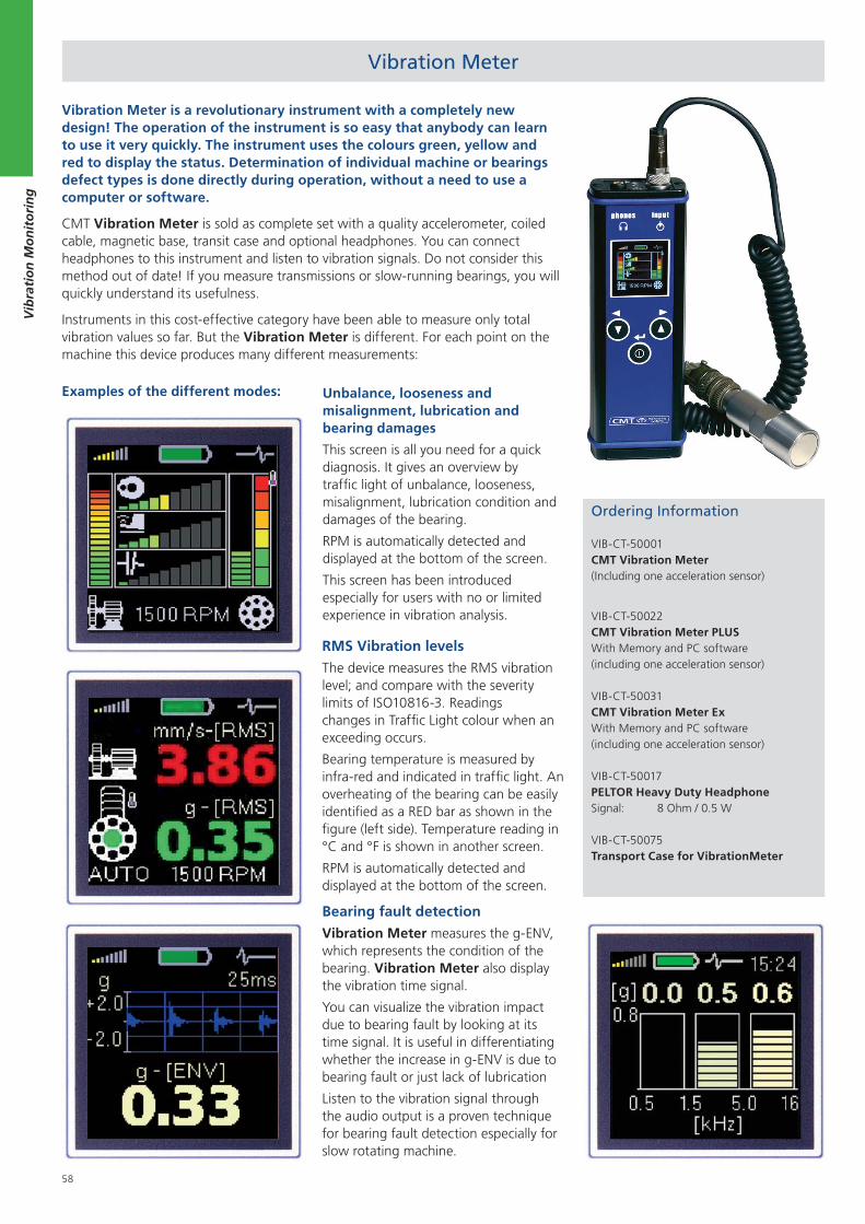
58
Vib
rati
on
Mo
nit
ori
ng
Vibration Meter is a revolutionary instrument with a completely new design! The operation of the instrument is so easy that anybody can learn to use it very quickly. The instrument uses the colours green, yellow and red to display the status. Determination of individual machine or bearings defect types is done directly during operation, without a need to use a computer or software.
CMT Vibration Meter is sold as complete set with a quality accelerometer, coiled cable, magnetic base, transit case and optional headphones. You can connect headphones to this instrument and listen to vibration signals. Do not consider this method out of date! If you measure transmissions or slow-running bearings, you will quickly understand its usefulness.
Instruments in this cost-effective category have been able to measure only total vibration values so far. But the Vibration Meter is different. For each point on the machine this device produces many different measurements:
Examples of the different modes: Unbalance, looseness and misalignment, lubrication and bearing damages
This screen is all you need for a quick diagnosis. It gives an overview by traffic light of unbalance, looseness, misalignment, lubrication condition and damages of the bearing.
RPM is automatically detected and displayed at the bottom of the screen.
This screen has been introduced especially for users with no or limited experience in vibration analysis.
RMS Vibration levels
The device measures the RMS vibration level; and compare with the severity limits of ISO10816-3. Readings changes in Traffic Light colour when an exceeding occurs.
Bearing temperature is measured by infra-red and indicated in traffic light. An overheating of the bearing can be easily identified as a RED bar as shown in the figure (left side). Temperature reading in °C and °F is shown in another screen.
RPM is automatically detected and displayed at the bottom of the screen.
Bearing fault detection
Vibration Meter measures the g-ENV, which represents the condition of the bearing. Vibration Meter also display the vibration time signal.
You can visualize the vibration impact due to bearing fault by looking at its time signal. It is useful in differentiating whether the increase in g-ENV is due to bearing fault or just lack of lubrication
Listen to the vibration signal through the audio output is a proven technique for bearing fault detection especially for slow rotating machine.
Ordering Information
VIB-CT-50001CMT Vibration Meter(Including one acceleration sensor)
VIB-CT-50022CMT Vibration Meter PLUSWith Memory and PC software (including one acceleration sensor)
VIB-CT-50031CMT Vibration Meter ExWith Memory and PC software(including one acceleration sensor)
VIB-CT-50017PELTOR Heavy Duty HeadphoneSignal: 8 Ohm / 0.5 W
VIB-CT-50075Transport Case for VibrationMeter
Vibration Meter
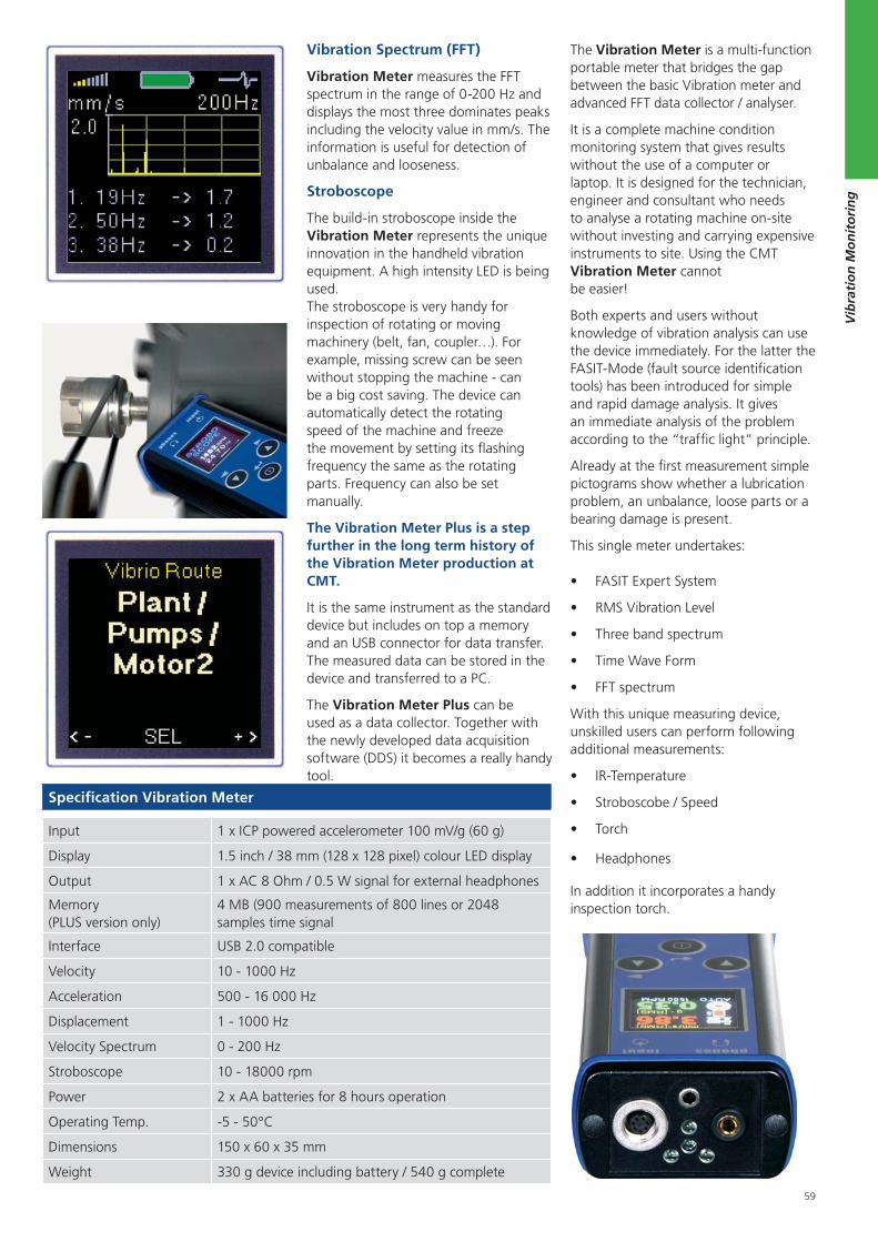
59
Vib
rati
on
Mo
nit
ori
ng
Vibration Spectrum (FFT)
Vibration Meter measures the FFT spectrum in the range of 0-200 Hz and displays the most three dominates peaks including the velocity value in mm/s. The information is useful for detection of unbalance and looseness.
Stroboscope
The build-in stroboscope inside the Vibration Meter represents the unique innovation in the handheld vibration equipment. A high intensity LED is being used. The stroboscope is very handy for inspection of rotating or moving machinery (belt, fan, coupler…). For example, missing screw can be seen without stopping the machine - can be a big cost saving. The device can automatically detect the rotating speed of the machine and freeze the movement by setting its flashing frequency the same as the rotating parts. Frequency can also be set manually.
The Vibration Meter Plus is a step further in the long term history of the Vibration Meter production at CMT.
It is the same instrument as the standard device but includes on top a memory and an USB connector for data transfer. The measured data can be stored in the device and transferred to a PC.
The Vibration Meter Plus can be used as a data collector. Together with the newly developed data acquisition software (DDS) it becomes a really handy tool.
The Vibration Meter is a multi-function portable meter that bridges the gap between the basic Vibration meter and advanced FFT data collector / analyser.
It is a complete machine condition monitoring system that gives results without the use of a computer or laptop. It is designed for the technician, engineer and consultant who needs to analyse a rotating machine on-site without investing and carrying expensive instruments to site. Using the CMT Vibration Meter cannot be easier!
Both experts and users without knowledge of vibration analysis can use the device immediately. For the latter the FASIT-Mode (fault source identification tools) has been introduced for simple and rapid damage analysis. It gives an immediate analysis of the problem according to the “traffic light” principle.
Already at the first measurement simple pictograms show whether a lubrication problem, an unbalance, loose parts or a bearing damage is present.
This single meter undertakes:
FASIT Expert System
RMS Vibration Level
Three band spectrum
Time Wave Form
FFT spectrum
With this unique measuring device, unskilled users can perform following additional measurements:
IR-Temperature
Stroboscobe / Speed
Torch
Headphones
In addition it incorporates a handy inspection torch.
Specification Vibration Meter
Input 1 x ICP powered accelerometer 100 mV/g (60 g)
Display 1.5 inch / 38 mm (128 x 128 pixel) colour LED display
Output 1 x AC 8 Ohm / 0.5 W signal for external headphones
Memory (PLUS version only)
4 MB (900 measurements of 800 lines or 2048 samples time signal
Interface USB 2.0 compatible
Velocity 10 - 1000 Hz
Acceleration 500 - 16 000 Hz
Displacement 1 - 1000 Hz
Velocity Spectrum 0 - 200 Hz
Stroboscope 10 - 18000 rpm
Power 2 x AA batteries for 8 hours operation
Operating Temp. -5 - 50°C
Dimensions 150 x 60 x 35 mm
Weight 330 g device including battery / 540 g complete
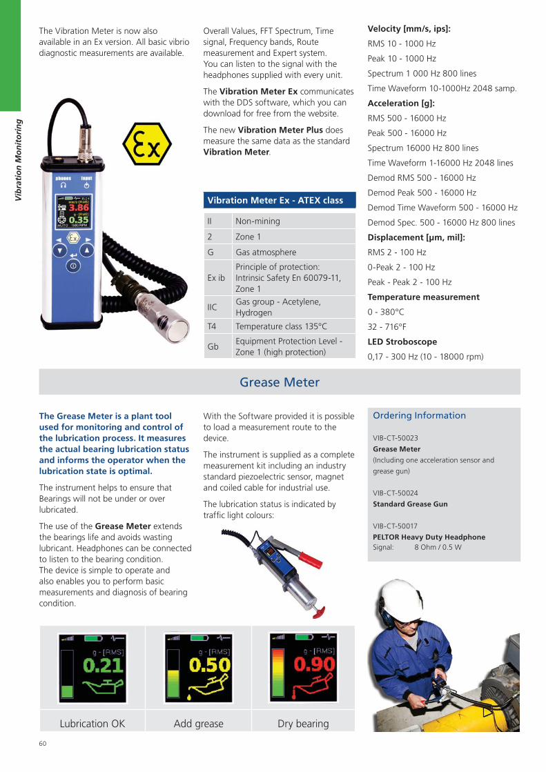
60
Vib
rati
on
Mo
nit
ori
ng
Velocity [mm/s, ips]:
RMS 10 - 1000 Hz
Peak 10 - 1000 Hz
Spectrum 1 000 Hz 800 lines
Time Waveform 10-1000Hz 2048 samp.
Acceleration [g]:
RMS 500 - 16000 Hz
Peak 500 - 16000 Hz
Spectrum 16000 Hz 800 lines
Time Waveform 1-16000 Hz 2048 lines
Demod RMS 500 - 16000 Hz
Demod Peak 500 - 16000 Hz
Demod Time Waveform 500 - 16000 Hz
Demod Spec. 500 - 16000 Hz 800 lines
Displacement [μm, mil]:
RMS 2 - 100 Hz
0-Peak 2 - 100 Hz
Peak - Peak 2 - 100 Hz
Temperature measurement
0 - 380°C
32 - 716°F
LED Stroboscope
0,17 - 300 Hz (10 - 18000 rpm)
The Grease Meter is a plant tool used for monitoring and control of the lubrication process. It measures the actual bearing lubrication status and informs the operator when the lubrication state is optimal.
The instrument helps to ensure that Bearings will not be under or over lubricated.
The use of the Grease Meter extends the bearings life and avoids wasting lubricant. Headphones can be connected to listen to the bearing condition. The device is simple to operate and also enables you to perform basic measurements and diagnosis of bearing condition.
With the Software provided it is possible to load a measurement route to the device.
The instrument is supplied as a complete measurement kit including an industry standard piezoelectric sensor, magnet and coiled cable for industrial use.
The lubrication status is indicated by traffic light colours:
Grease Meter
Lubrication OK Add grease Dry bearing
Ordering Information
VIB-CT-50023
Grease Meter
(Including one acceleration sensor and
grease gun)
VIB-CT-50024
Standard Grease Gun
VIB-CT-50017
PELTOR Heavy Duty HeadphoneSignal: 8 Ohm / 0.5 W
Vibration Meter Ex - ATEX class
II Non-mining
2 Zone 1
G Gas atmosphere
Ex ibPrinciple of protection:Intrinsic Safety En 60079-11,Zone 1
IICGas group - Acetylene,Hydrogen
T4 Temperature class 135°C
GbEquipment Protection Level -Zone 1 (high protection)
The Vibration Meter is now also available in an Ex version. All basic vibrio diagnostic measurements are available.
Overall Values, FFT Spectrum, Time signal, Frequency bands, Route measurement and Expert system. You can listen to the signal with the headphones supplied with every unit.
The Vibration Meter Ex communicates with the DDS software, which you can download for free from the website.
The new Vibration Meter Plus does measure the same data as the standard Vibration Meter.
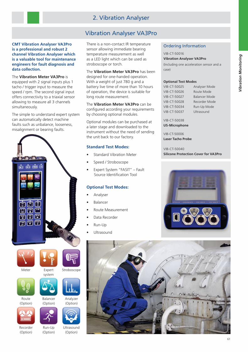
61
Vib
rati
on
Mo
nit
ori
ng
CMT Vibration Analyser VA3Pro is a professional and robust 2 channel Vibration Analyser which is a valuable tool for maintenance engineers for fault diagnosis and data collection.
The Vibration Meter VA3Pro is equipped with 2 signal inputs plus 1 tacho / trigger input to measure the speed / rpm. The second signal input offers connectivity to a triaxial sensor allowing to measure all 3 channels simultaneously.
The simple to understand expert system can automatically detect machine faults such as unbalance, looseness, misalignment or bearing faults.
2. Vibration Analyser
There is a non-contact IR temperature sensor allowing immediate bearing temperature measurement as well as a LED light which can be used as stroboscope or torch.
The Vibration Meter VA3Pro has been designed for one-handed operation. With a weight of just 780 g and a battery live time of more than 10 hours of operation, the device is suitable for long route measurement.
The Vibration Meter VA3Pro can be configured according your requirements by choosing optional modules.
Optional modules can be purchased at a later stage and downloaded to the instrument without the need of sending the unit back to our factory.
Standard Test Modes:
Standard Vibration Meter
Speed / Stroboscope
Expert System “FASIT” – Fault Source Identification Tool
Optional Test Modes:
Analyser
Balancer
Route Measurement
Data Recorder
Run-Up
Ultrasound
Vibration Analyser VA3Pro
Run-Up(Option)
Analyzer(Option)
Route(Option)
StroboscopeExpert system
Balancer(Option)
Meter
Recorder(Option)
Ultrasound(Option)
Ordering Information
VIB-CT-50016
Vibration Analyser VA3Pro
(Including one acceleration sensor and a
case)
Optional Test Modes
VIB-CT-50025 Analyser Mode
VIB-CT-50026 Route Mode
VIB-CT-50027 Balancer Mode
VIB-CT-50028 Recorder Mode
VIB-CT-50034 Run-Up Mode
VIB-CT-50037 Ultrasound
VIB-CT-50038
US-Microphone
VIB-CT-50006
Laser Tacho Probe
VIB-CT-50040
Silicone Protection Cover for VA3Pro
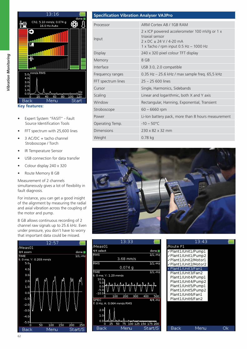
62
Vib
rati
on
Mo
nit
ori
ng
Specification Vibration Analyser VA3Pro
Processor ARM Cortex A8 / 1GB RAM
Input
2 x ICP powered accelerometer 100 mV/g or 1 x triaxial sensor2 x DC ± 24 V / 4-20 mA1 x Tacho / rpm input 0.5 Hz – 1000 Hz
Display 240 x 320 pixel colour TFT display
Memory 8 GB
Interface USB 3.0, 2.0 compatible
Frequency ranges 0.35 Hz – 25.6 kHz / max sample freq. 65,5 kHz
FFT spectrum lines 25 – 25 600 lines
Cursor Single, Harmonics, Sidebands
Scaling Linear and logarithmic, both X and Y axis
Window Rectangular, Hanning, Exponential, Transient
Stroboscope 60 – 6660 rpm
Power Li-Ion battery pack, more than 8 hours measurement
Operating Temp. -10 – 50°C
Dimensions 230 x 82 x 32 mm
Weight 0.78 kg
Key features:
Expert System “FASIT” - Fault Source Identification Tools
FFT spectrum with 25,600 lines
3 AC/DC + tacho channel Stroboscope / Torch
IR Temperature Sensor
USB connection for data transfer
Colour display 240 x 320
Route Memory 8 GB
Measurement of 2 channels simultaneously gives a lot of flexibility in fault diagnosis.
For instance, you can get a good insight of the alignment by measuring the radial and axial vibration across the coupling of the motor and pump.
8 GB allows continuous recording of 2 channel raw signals up to 25.6 kHz. Even under pressure, you don’t have to worry that important data could be missed.
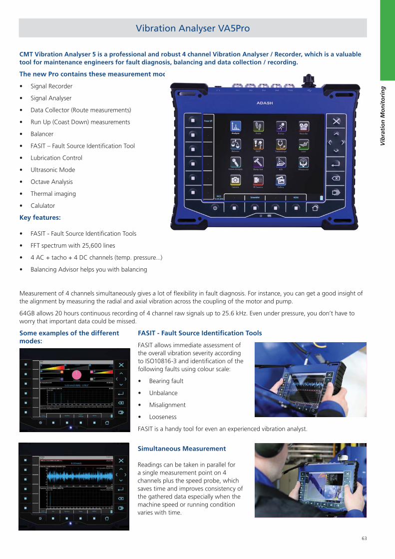
63
Vib
rati
on
Mo
nit
ori
ng
CMT Vibration Analyser 5 is a professional and robust 4 channel Vibration Analyser / Recorder, which is a valuable tool for maintenance engineers for fault diagnosis, balancing and data collection / recording.
The new Pro contains these measurement modes:
Signal Recorder
Signal Analyser
Data Collector (Route measurements)
Run Up (Coast Down) measurements
Balancer
FASIT – Fault Source Identification Tool
Lubrication Control
Ultrasonic Mode
Octave Analysis
Thermal imaging
Calulator
Key features:
FASIT - Fault Source Identification Tools
FFT spectrum with 25,600 lines
4 AC + tacho + 4 DC channels (temp. pressure...)
Balancing Advisor helps you with balancing
Measurement of 4 channels simultaneously gives a lot of flexibility in fault diagnosis. For instance, you can get a good insight of the alignment by measuring the radial and axial vibration across the coupling of the motor and pump.
64GB allows 20 hours continuous recording of 4 channel raw signals up to 25.6 kHz. Even under pressure, you don’t have to worry that important data could be missed.
Vibration Analyser VA5Pro
FASIT - Fault Source Identification Tools
FASIT allows immediate assessment of the overall vibration severity according to ISO10816-3 and identification of the following faults using colour scale:
Bearing fault
Unbalance
Misalignment
Looseness
FASIT is a handy tool for even an experienced vibration analyst.
Simultaneous Measurement Readings can be taken in parallel for a single measurement point on 4 channels plus the speed probe, which saves time and improves consistency of the gathered data especially when the machine speed or running condition varies with time.
Some examples of the different modes:
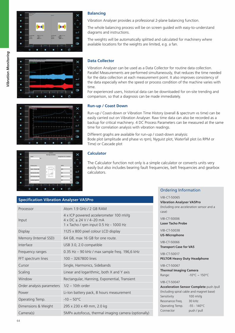
64
Vib
rati
on
Mo
nit
ori
ng
Balancing
Vibration Analyser provides a professional 2-plane balancing function.
The whole balancing process will be on screen guided with easy-to-understand diagrams and instructions.
The weights will be automatically splitted and calculated for machinery where available locations for the weights are limited, e.g. a fan.
Data Collector
Vibration Analyser can be used as a Data Collector for routine data collection. Parallel Measurements are performed simultaneously, that reduces the time needed for the data collection at each measurement point. It also improves consistency of the data especially when the speed or process condition of the machine varies with time. For experienced users, historical data can be downloaded for on-site trending and comparison, so that a diagnosis can be made immediately.
Run-up / Coast Down
Run-up / Coast-down or Vibration Time History (overall & spectrum vs time) can be easily carried out on Vibration Analyser. Raw time data can also be recorded as a backup for critical machinery. 4 DC Process Parameters can be measured at the same time for correlation analysis with vibration readings.
Different graphs are available for run-up / coast-down analysis: Bode plot (amplitude and phase vs rpm), Nyguist plot, Waterfall plot (vs RPM or Time) or Cascade plot
Ordering Information
VIB-CT-50065
Vibration Analyser VA5Pro
(Including one acceleration sensor and a
case)
VIB-CT-50006
Laser Tacho Probe
VIB-CT-50038
US-Microphone
VIB-CT-50066
Transport Case for VA5
VIB-CT-50017
PELTOR Heavy Duty Headphone
VIB-CT-50067
Thermal Imaging Camera
Range: -10°C ~ 150°C
VIB-CT-50047
Acceleration Sensor Complete push /pull
(Including spiral cable and magnet base)
Sensitivity 100 mV/g
Resonance Freq. 30 kHz
Operating Temp. -55 - 140°C
Connector push / pull
Specification Vibration Analyser VA5Pro
Processor Atom 1.9 GHz / 2 GB RAM
Input4 x ICP powered accelerometer 100 mV/g4 x DC ± 24 V / 4–20 mA1 x Tacho / rpm input 0.5 Hz - 1000 Hz
Display 1125 x 800 pixel colour LCD display
Memory (Internal SSD) 64 GB, max 16 GB for one route.
Interface USB 3.0, 2.0 compatible
Frequency ranges 0.35 Hz – 90 kHz / max sample freq. 196,6 kHz
FFT spectrum lines 100 – 3267800 lines
Cursor Single, Harmonics, Sidebands
Scaling Linear and logarithmic, both X and Y axis
Window Rectangular, Hanning, Exponential, Transient
Order analysis parameters 1/2 – 10th order
Power Li-Ion battery pack, 8 hours measurement
Operating Temp. -10 – 50°C
Dimensions & Weight 295 x 230 x 49 mm, 2.0 kg
Camera(s) 5MPx autofocus, thermal imaging camera (optionally)
Calculator The Calculator function not only is a simple calculator or converts units very easily but also includes bearing fault frequencies, belt frequencies and gearbox calculators.
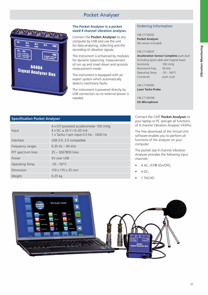
65
Vib
rati
on
Mo
nit
ori
ng
Pocket Analyser
The Pocket Analyser is a pocket sized 4 channel vibration analyser.
Connect the Pocket Analyser to any computer by USB and use the unit for data analysing, collecting and the recording of vibration signals.
The instrument is enhanced by modules for dynamic balancing, measurement of run up and coast down and acoustic measurement mode.
The instrument is equipped with an expert system which automatically detects machinery faults.
The instrument is powered directly by USB connection so no external power is needed.
Ordering Information
VIB-CT-50032
Pocket Analyser
(No sensor included)
VIB-CT-50047
Acceleration Sensor Complete push /pull
(Including spiral cable and magnet base)
Sensitivity 100 mV/g
Resonance Freq. 30 kHz
Operating Temp. -55 - 140°C
Connector push / pull
VIB-CT-50006
Laser Tacho Probe
VIB-CT-50038
US-Microphone
Specification Pocket Analyser
Input4 x ICP powered accelerometer 100 mV/g4 x DC ± 24 V / 4–20 mA1 x Tacho / rpm input 0.5 Hz - 1000 Hz
Interface USB 3.0, 2.0 compatible
Frequency ranges 0.35 Hz – 90 kHz
FFT spectrum lines 25 – 3267800 lines
Power 5V over USB
Operating Temp. -10 – 50°C
Dimension 110 x 115 x 35 mm
Weight 0.25 kg
Connect the CMT Pocket Analyser to your laptop or PC and get all functions of 4 channel Vibration Analyser VA5Pro.
The free download of the Virtual Unit software enables you to perform all functions of the analyzer on your computer.
The pocket size 4 channel Vibration Analyzer provides the following input channels:
4 AC, ICP® (On/Off),
4 DC,
1 TACHO
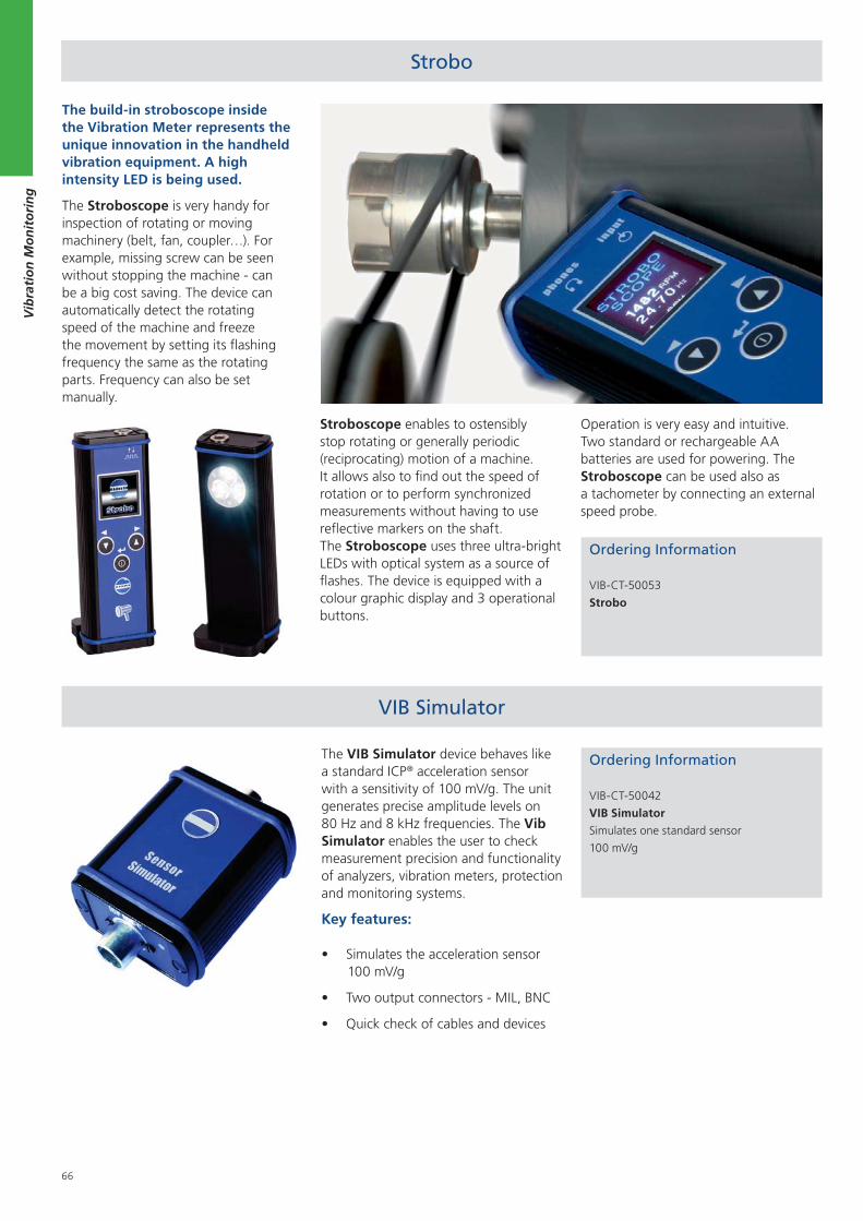
66
Vib
rati
on
Mo
nit
ori
ng
Strobo
The build-in stroboscope inside the Vibration Meter represents the unique innovation in the handheld vibration equipment. A high intensity LED is being used.
The Stroboscope is very handy for inspection of rotating or moving machinery (belt, fan, coupler…). For example, missing screw can be seen without stopping the machine - can be a big cost saving. The device can automatically detect the rotating speed of the machine and freeze the movement by setting its flashing frequency the same as the rotating parts. Frequency can also be set manually.
Ordering Information
VIB-CT-50053
Strobo
y
Stroboscope enables to ostensibly stop rotating or generally periodic (reciprocating) motion of a machine. It allows also to find out the speed of rotation or to perform synchronized measurements without having to use reflective markers on the shaft. The Stroboscope uses three ultra-bright LEDs with optical system as a source of flashes. The device is equipped with a colour graphic display and 3 operational buttons.
Operation is very easy and intuitive. Two standard or rechargeable AA batteries are used for powering. The Stroboscope can be used also as a tachometer by connecting an external speed probe.
The VIB Simulator device behaves like a standard ICP® acceleration sensor with a sensitivity of 100 mV/g. The unit generates precise amplitude levels on 80 Hz and 8 kHz frequencies. The Vib Simulator enables the user to check measurement precision and functionality of analyzers, vibration meters, protection and monitoring systems.
Key features:
Simulates the acceleration sensor 100 mV/g
Two output connectors - MIL, BNC
Quick check of cables and devices
Ordering Information
VIB-CT-50042
VIB Simulator
Simulates one standard sensor
100 mV/g
VIB Simulator
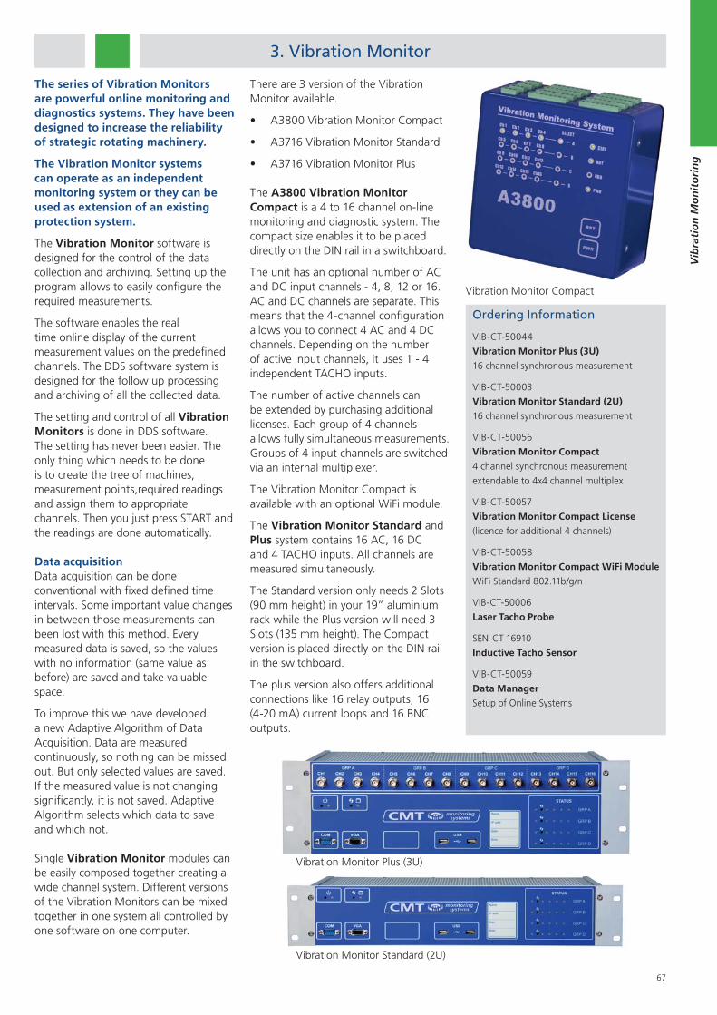
67
Vib
rati
on
Mo
nit
ori
ng
3. Vibration Monitor
Vibration Monitor Plus (3U)
The series of Vibration Monitors are powerful online monitoring and diagnostics systems. They have been designed to increase the reliability of strategic rotating machinery.
The Vibration Monitor systems can operate as an independent monitoring system or they can be used as extension of an existing protection system.
The Vibration Monitor software is designed for the control of the data collection and archiving. Setting up the program allows to easily configure the required measurements.
The software enables the real time online display of the current measurement values on the predefined channels. The DDS software system is designed for the follow up processing and archiving of all the collected data.
The setting and control of all Vibration Monitors is done in DDS software. The setting has never been easier. The only thing which needs to be done is to create the tree of machines, measurement points,required readings and assign them to appropriate channels. Then you just press START and the readings are done automatically.
Data acquisitionData acquisition can be done conventional with fixed defined time intervals. Some important value changes in between those measurements can been lost with this method. Every measured data is saved, so the values with no information (same value as before) are saved and take valuable space.
To improve this we have developed a new Adaptive Algorithm of Data Acquisition. Data are measured continuously, so nothing can be missed out. But only selected values are saved. If the measured value is not changing significantly, it is not saved. Adaptive Algorithm selects which data to save and which not.
Single Vibration Monitor modules can be easily composed together creating a wide channel system. Different versions of the Vibration Monitors can be mixed together in one system all controlled by one software on one computer.
Vibration Monitor Standard (2U)
There are 3 version of the Vibration Monitor available.
A3800 Vibration Monitor Compact
A3716 Vibration Monitor Standard
A3716 Vibration Monitor Plus
The A3800 Vibration Monitor Compact is a 4 to 16 channel on-line monitoring and diagnostic system. The compact size enables it to be placed directly on the DIN rail in a switchboard.
The unit has an optional number of AC and DC input channels - 4, 8, 12 or 16. AC and DC channels are separate. This means that the 4-channel configuration allows you to connect 4 AC and 4 DC channels. Depending on the number of active input channels, it uses 1 - 4 independent TACHO inputs.
The number of active channels can be extended by purchasing additional licenses. Each group of 4 channels allows fully simultaneous measurements. Groups of 4 input channels are switched via an internal multiplexer.
The Vibration Monitor Compact is available with an optional WiFi module.
The Vibration Monitor Standard and Plus system contains 16 AC, 16 DC and 4 TACHO inputs. All channels are measured simultaneously.
The Standard version only needs 2 Slots (90 mm height) in your 19” aluminium rack while the Plus version will need 3 Slots (135 mm height). The Compact version is placed directly on the DIN rail in the switchboard.
The plus version also offers additional connections like 16 relay outputs, 16 (4-20 mA) current loops and 16 BNC outputs.
Ordering Information
VIB-CT-50044
Vibration Monitor Plus (3U)
16 channel synchronous measurement
VIB-CT-50003
Vibration Monitor Standard (2U)
16 channel synchronous measurement
VIB-CT-50056
Vibration Monitor Compact
4 channel synchronous measurement
extendable to 4x4 channel multiplex
VIB-CT-50057
Vibration Monitor Compact License
(licence for additional 4 channels)
VIB-CT-50058
Vibration Monitor Compact WiFi Module
WiFi Standard 802.11b/g/n
VIB-CT-50006
Laser Tacho Probe
SEN-CT-16910
Inductive Tacho Sensor
VIB-CT-50059
Data Manager
Setup of Online Systems
Vibration Monitor Compact
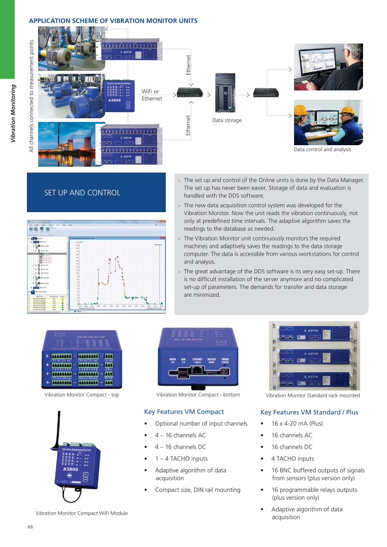
68
Vib
rati
on
Mo
nit
ori
ng
SET UP AND CONTROL
› The set up and control of the Online units is done by the Data Manager. The set up has never been easier. Storage of data and evaluation is handled with the DDS software.
› The new data acquisition control system was developed for the Vibration Monitor. Now the unit reads the vibration continuously, not only at predefined time intervals. The adaptive algorithm saves the readings to the database as needed.
› The Vibration Monitor unit continuously monitors the required machines and adaptively saves the readings to the data storage computer. The data is accessible from various workstations for control and analysis.
› The great advantage of the DDS software is its very easy set-up. There is no difficult installation of the server anymore and no complicated set-up of parameters. The demands for transfer and data storage are minimized.
APPLICATION SCHEME OF VIBRATION MONITOR UNITS
All
chan
nels
con
nect
ed t
o m
easu
rem
ent
poin
ts
Data storage
Data control and analysis
Ethe
rnet
Vibration Monitor Compact - bottomVibration Monitor Compact - top
Key Features VM Compact
Optional number of input channels
4 – 16 channels AC
4 – 16 channels DC
1 – 4 TACHO inputs
Adaptive algorithm of data acquisition
Compact size, DIN rail mounting
Key Features VM Standard / Plus
16 x 4-20 mA (Plus)
16 channels AC
16 channels DC
4 TACHO inputs
16 BNC buffered outputs of signals from sensors (plus version only)
16 programmable relays outputs (plus version only)
Adaptive algorithm of data acquisition
Vibration Monitor Standard rack mounted
Vibration Monitor Compact WiFi Module
Ethe
rnet
WiFi orEthernet
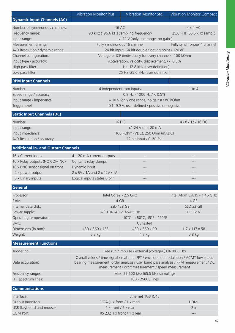
69
Vib
rati
on
Mo
nit
ori
ng
RPM Input Channels
Number: 4 independent rpm inputs 1 to 4
Speed range / accuracy: 0,8 Hz - 1000 Hz / < 0.5%
Input range / impedance: + 10 V (only one range, no gains) / 80 kOhm
Trigger level: 0.1 -9.9 V, user defined / positive or negative
Static Input Channels (DC)
Number: 16 DC 4 / 8 / 12 / 16 DC
Input range: +/- 24 V or 4-20 mA
Input impedance: 100 kOhm (VDC), 250 Ohm (mADC)
A/D Resolution / accuracy: 12 bit input / 0.1% fsd
Vibration Monitor Plus Vibration Monitor Std. Vibration Monitor CompactDynamic Input Channels (AC)
Number of synchronous channels: 16 AC 4 x 4 AC
Frequency range: 90 kHz (196.6 kHz sampling frequency) 25,6 kHz (65,5 kHz sampl.)
Input range: +/- 12 V (only one range, no gains)
Measurement timing: Fully synchronous 16 channel Fully synchronous 4 channel
A/D Resolution / dynamic range: 24 bit input, 64 bit double floating point / 120 dB
Channel configuration: Voltage or ICP (individually for every channel) - 100 kOhm
Input type / accuracy: Acceleration, velocity, displacement, / < 0.5%
High pass filter: 1 Hz -12.8 kHz (user definition)
Low pass filter: 25 Hz -25.6 kHz (user definition)
General
Processor: Intel Core2 - 2.5 GHz Intel Atom E3815 - 1.46 GHz
RAM: 4 GB 4 GB
Internal data disk: SSD 128 GB SSD 32 GB
Power supply: AC 110-240 V, 45-65 Hz DC 12 V
Operating temperature: -10°C - +50°C, 15°F - 120°F
EMC: CE tested
Dimensions (in mm): 430 x 360 x 135 430 x 360 x 90 117 x 117 x 58
Weight: 6,2 kg 4,7 kg 0,8 kg
Measurement Functions
Triggering: Free run / impulse / external (voltage) (0,8-1000 Hz)
Data acquisition: Overall values / time signal / real-time FFT / envelope demodulation / ACMT low speed
bearing measurement, order analysis / user band pass analysis / RPM measurement / DC measurement / orbit measurement / speed measurement
Frequency ranges: Max. 25,600 kHz (65,5 kHz sampling)
FFT spectrum lines: 100 - 25600 lines
Communications
Interface: Ethernet 1GB RJ45
Output (monitor): VGA (1 x front / 1 x rear) HDMI
USB (keyboard and mouse) 2 x front / 2 x rear 2 x
COM Port RS 232 1 x front / 1 x rear ---
Additional In- and Output Channels
16 x Current loops 4 – 20 mA current outputs --- ---
16 x Relay outputs (NO,COM,NC) Contains relay clamps --- ---
16 x BNC sensor signal on front Dynamic input --- ---
4 x power output 2 x 5V / 1A and 2 x 12V / 1A --- ---
8 x Binary inputs Logical inputs states 0 or 1 --- ---
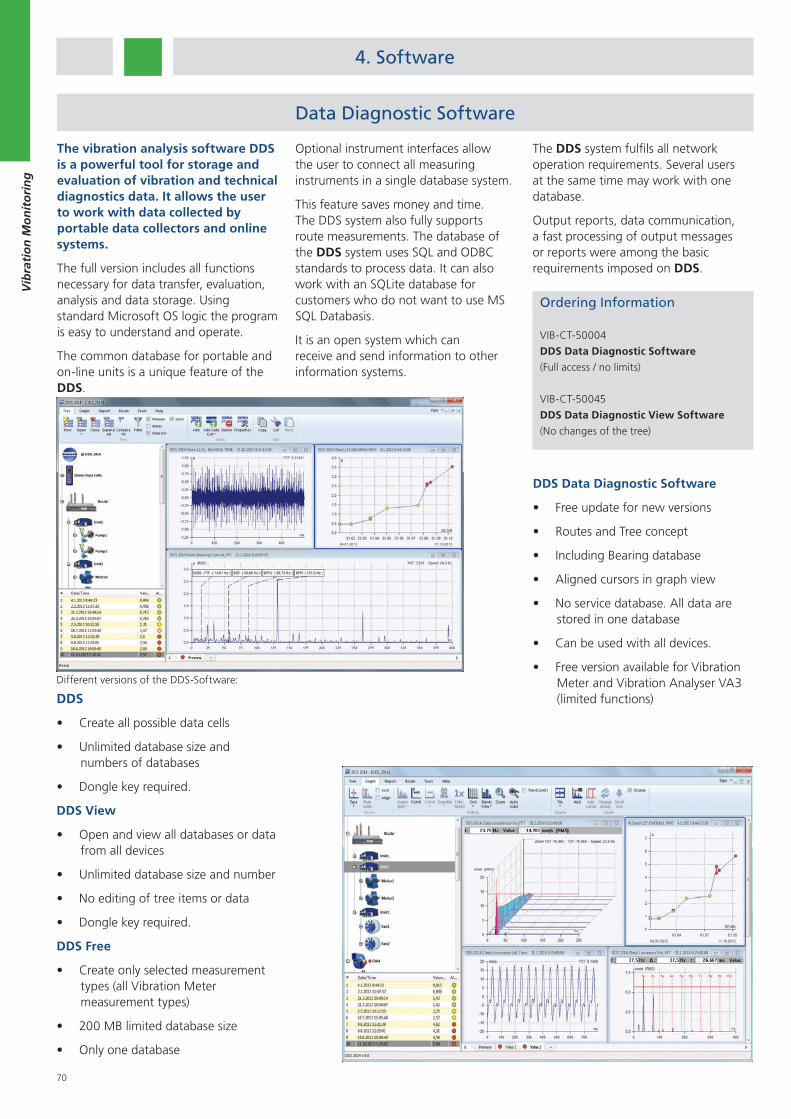
70
Vib
rati
on
Mo
nit
ori
ng
4. Software
The vibration analysis software DDS is a powerful tool for storage and evaluation of vibration and technical diagnostics data. It allows the user to work with data collected by portable data collectors and online systems.
The full version includes all functions necessary for data transfer, evaluation, analysis and data storage. Using standard Microsoft OS logic the program is easy to understand and operate.
The common database for portable and on-line units is a unique feature of the DDS.
DDS Data Diagnostic Software
Free update for new versions
Routes and Tree concept
Including Bearing database
Aligned cursors in graph view
No service database. All data are stored in one database
Can be used with all devices.
Free version available for Vibration Meter and Vibration Analyser VA3 (limited functions)
Data Diagnostic Software
Optional instrument interfaces allow the user to connect all measuring instruments in a single database system.
This feature saves money and time. The DDS system also fully supports route measurements. The database of the DDS system uses SQL and ODBC standards to process data. It can also work with an SQLite database for customers who do not want to use MS SQL Databasis.
It is an open system which can receive and send information to other information systems.
Ordering Information
VIB-CT-50004
DDS Data Diagnostic Software
(Full access / no limits)
VIB-CT-50045
DDS Data Diagnostic View Software
(No changes of the tree)
Different versions of the DDS-Software:
DDS
Create all possible data cells
Unlimited database size and numbers of databases
Dongle key required.
DDS View
Open and view all databases or data from all devices
Unlimited database size and number
No editing of tree items or data
Dongle key required.
DDS Free
Create only selected measurement types (all Vibration Meter measurement types)
200 MB limited database size
Only one database
The DDS system fulfils all network operation requirements. Several users at the same time may work with one database.
Output reports, data communication, a fast processing of output messages or reports were among the basic requirements imposed on DDS.
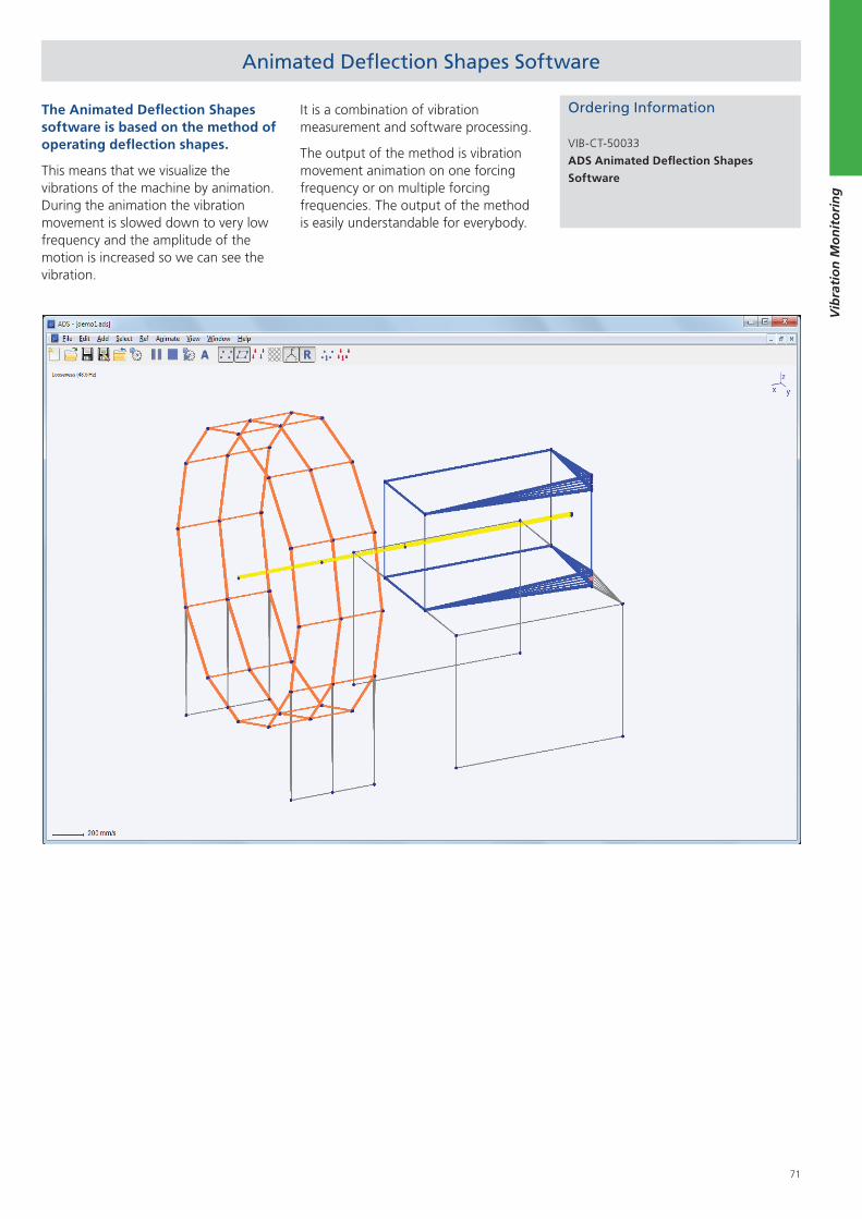
71
Vib
rati
on
Mo
nit
ori
ng
Animated Deflection Shapes Software
The Animated Deflection Shapes software is based on the method of operating deflection shapes.
This means that we visualize the vibrations of the machine by animation. During the animation the vibration movement is slowed down to very low frequency and the amplitude of the motion is increased so we can see the vibration.
It is a combination of vibration measurement and software processing.
The output of the method is vibration movement animation on one forcing frequency or on multiple forcing frequencies. The output of the method is easily understandable for everybody.
Ordering Information
VIB-CT-50033
ADS Animated Deflection Shapes
Software
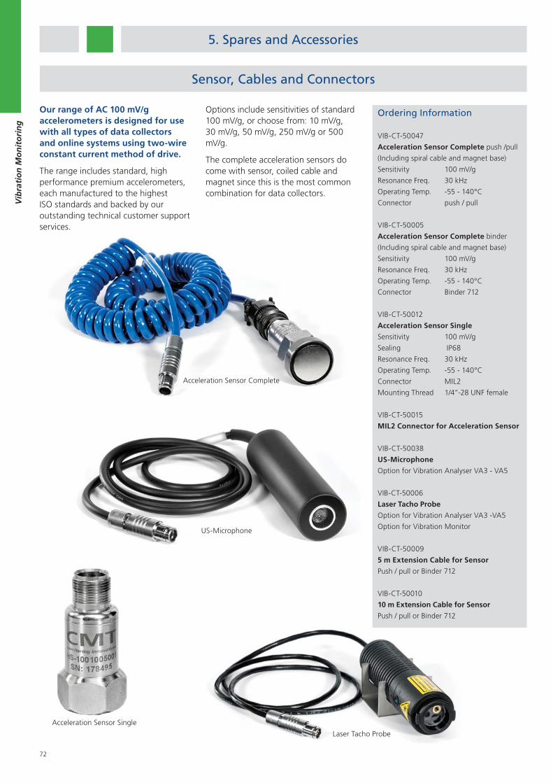
72
Vib
rati
on
Mo
nit
ori
ng
Sensor, Cables and Connectors
Our range of AC 100 mV/g accelerometers is designed for use with all types of data collectors and online systems using two-wire constant current method of drive.
The range includes standard, high performance premium accelerometers, each manufactured to the highest ISO standards and backed by our outstanding technical customer support services.
Options include sensitivities of standard 100 mV/g, or choose from: 10 mV/g, 30 mV/g, 50 mV/g, 250 mV/g or 500 mV/g.
The complete acceleration sensors do come with sensor, coiled cable and magnet since this is the most common combination for data collectors.
Acceleration Sensor Complete
Acceleration Sensor Single
US-Microphone
Laser Tacho Probe
5. Spares and Accessories
Ordering Information
VIB-CT-50047
Acceleration Sensor Complete push /pull
(Including spiral cable and magnet base)
Sensitivity 100 mV/g
Resonance Freq. 30 kHz
Operating Temp. -55 - 140°C
Connector push / pull
VIB-CT-50005
Acceleration Sensor Complete binder
(Including spiral cable and magnet base)
Sensitivity 100 mV/g
Resonance Freq. 30 kHz
Operating Temp. -55 - 140°C
Connector Binder 712
VIB-CT-50012
Acceleration Sensor Single
Sensitivity 100 mV/g
Sealing IP68
Resonance Freq. 30 kHz
Operating Temp. -55 - 140°C
Connector MIL2
Mounting Thread 1/4”-28 UNF female
VIB-CT-50015
MIL2 Connector for Acceleration Sensor
VIB-CT-50038
US-Microphone
Option for Vibration Analyser VA3 - VA5
VIB-CT-50006
Laser Tacho Probe
Option for Vibration Analyser VA3 -VA5
Option for Vibration Monitor
VIB-CT-50009
5 m Extension Cable for Sensor
Push / pull or Binder 712
VIB-CT-50010
10 m Extension Cable for Sensor
Push / pull or Binder 712
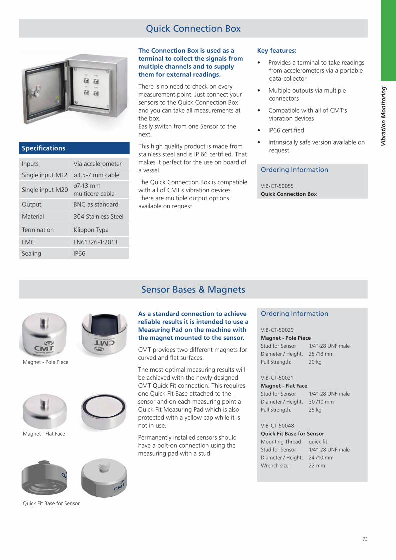
73
Vib
rati
on
Mo
nit
ori
ng
Quick Connection Box
Ordering Information
VIB-CT-50055
Quick Connection Box
The Connection Box is used as a terminal to collect the signals from multiple channels and to supply them for external readings.
There is no need to check on every measurement point. Just connect your sensors to the Quick Connection Box and you can take all measurements at the box. Easily switch from one Sensor to the next.
This high quality product is made from stainless steel and is IP 66 certified. That makes it perfect for the use on board of a vessel.
The Quick Connection Box is compatible with all of CMT’s vibration devices. There are multiple output options available on request.
Specifications
Inputs Via accelerometer
Single input M12 ø3.5-7 mm cable
Single input M20ø7-13 mm multicore cable
Output BNC as standard
Material 304 Stainless Steel
Termination Klippon Type
EMC EN61326-1:2013
Sealing IP66
Ordering Information
VIB-CT-50029
Magnet - Pole Piece
Stud for Sensor 1/4”-28 UNF male
Diameter / Height: 25 /18 mm
Pull Strength: 20 kg
VIB-CT-50021
Magnet - Flat Face
Stud for Sensor 1/4”-28 UNF male
Diameter / Height: 30 /10 mm
Pull Strength: 25 kg
VIB-CT-50048
Quick Fit Base for Sensor
Mounting Thread quick fit
Stud for Sensor 1/4”-28 UNF male
Diameter / Height: 24 /10 mm
Wrench size: 22 mm
As a standard connection to achieve reliable results it is intended to use a Measuring Pad on the machine with the magnet mounted to the sensor.
CMT provides two different magnets for curved and flat surfaces.
The most optimal measuring results will be achieved with the newly designed CMT Quick Fit connection. This requires one Quick Fit Base attached to the sensor and on each measuring point a Quick Fit Measuring Pad which is also protected with a yellow cap while it is not in use.
Permanently installed sensors should have a bolt-on connection using the measuring pad with a stud.
Sensor Bases & Magnets
Magnet - Pole Piece
Magnet - Flat Face
Quick Fit Base for Sensor
Key features:
Provides a terminal to take readings from accelerometers via a portable data-collector
Multiple outputs via multiple connectors
Compatible with all of CMT’s vibration devices
IP66 certified
Intrinsically safe version available on request
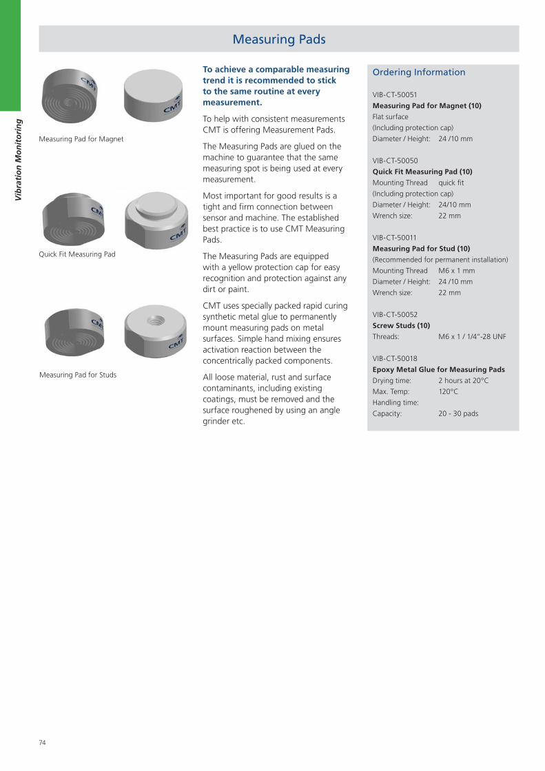
74
Vib
rati
on
Mo
nit
ori
ng
To achieve a comparable measuring trend it is recommended to stick to the same routine at every measurement.
To help with consistent measurements CMT is offering Measurement Pads.
The Measuring Pads are glued on the machine to guarantee that the same measuring spot is being used at every measurement.
Most important for good results is a tight and firm connection between sensor and machine. The established best practice is to use CMT Measuring Pads.
The Measuring Pads are equipped with a yellow protection cap for easy recognition and protection against any dirt or paint.
CMT uses specially packed rapid curing synthetic metal glue to permanently mount measuring pads on metal surfaces. Simple hand mixing ensures activation reaction between the concentrically packed components.
All loose material, rust and surface contaminants, including existing coatings, must be removed and the surface roughened by using an angle grinder etc.
Measuring Pads
Measuring Pad for Magnet
Measuring Pad for Studs
Ordering Information
VIB-CT-50051
Measuring Pad for Magnet (10)
Flat surface
(Including protection cap)
Diameter / Height: 24 /10 mm
VIB-CT-50050
Quick Fit Measuring Pad (10)
Mounting Thread quick fit
(Including protection cap)
Diameter / Height: 24/10 mm
Wrench size: 22 mm
VIB-CT-50011
Measuring Pad for Stud (10)
(Recommended for permanent installation)
Mounting Thread M6 x 1 mm
Diameter / Height: 24 /10 mm
Wrench size: 22 mm
VIB-CT-50052
Screw Studs (10)
Threads: M6 x 1 / 1/4”-28 UNF
VIB-CT-50018
Epoxy Metal Glue for Measuring Pads
Drying time: 2 hours at 20°C
Max. Temp: 120°C
Handling time:
Capacity: 20 - 30 pads
Quick Fit Measuring Pad
75
Perf
orm
ance
an
d E
ffici
ency
Mo
nit
ori
ng
1. Mechanical Peak Pressure Indicator.......................................... 76
2. PREMET M ........................................................................... 77
3. PREMET X ............................................................................ 78
4. PREMET Software ................................................................ 80
5. PREMET Online 24/7 ............................................................84
6. Pressure and Temperature Calibration .................................. 85
Performance and Efficiency Monitoring
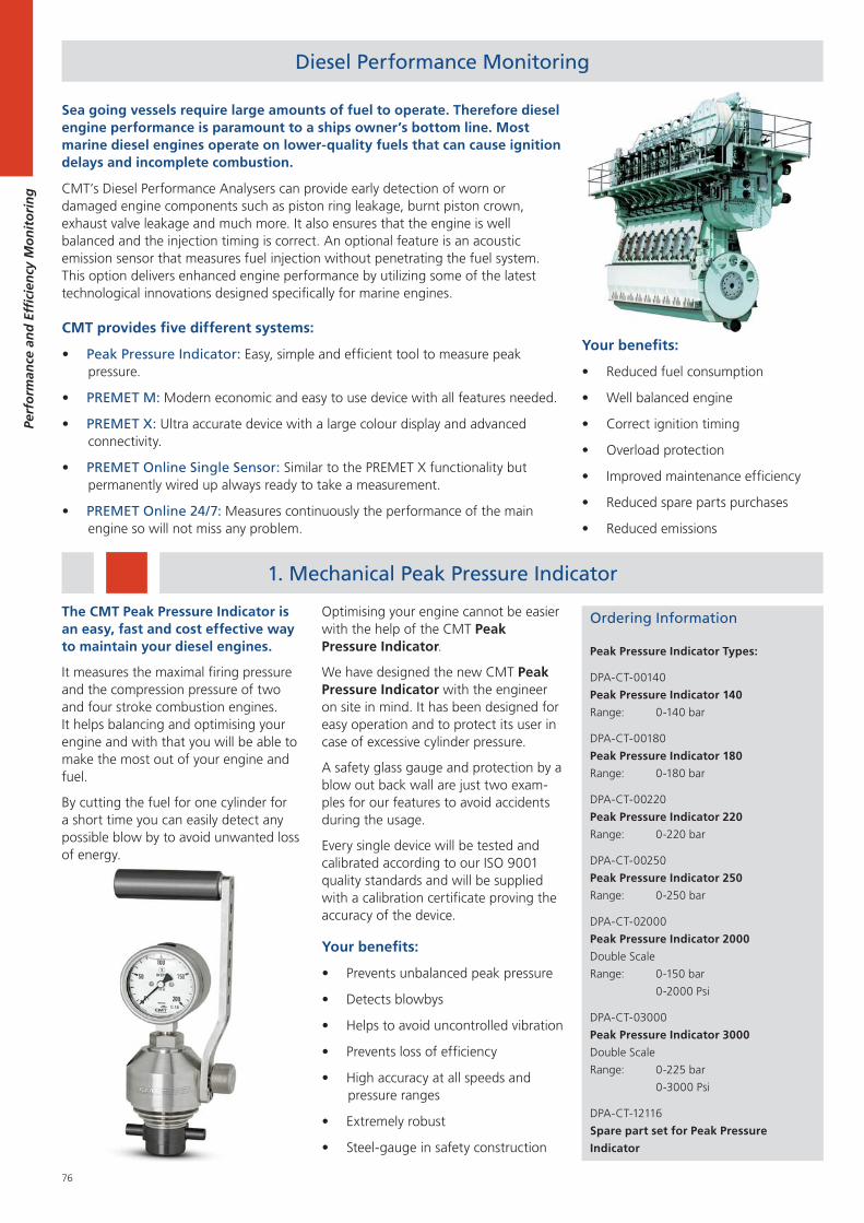
76
Perf
orm
ance
an
d E
ffici
ency
Mo
nit
ori
ng
Diesel Performance Monitoring
CMT provides five different systems:
Peak Pressure Indicator: Easy, simple and efficient tool to measure peak pressure.
PREMET M: Modern economic and easy to use device with all features needed.
PREMET X: Ultra accurate device with a large colour display and advanced connectivity.
PREMET Online Single Sensor: Similar to the PREMET X functionality but permanently wired up always ready to take a measurement.
PREMET Online 24/7: Measures continuously the performance of the main engine so will not miss any problem.
Sea going vessels require large amounts of fuel to operate. Therefore diesel engine performance is paramount to a ships owner’s bottom line. Most marine diesel engines operate on lower-quality fuels that can cause ignition delays and incomplete combustion.
CMT’s Diesel Performance Analysers can provide early detection of worn or damaged engine components such as piston ring leakage, burnt piston crown, exhaust valve leakage and much more. It also ensures that the engine is well balanced and the injection timing is correct. An optional feature is an acoustic emission sensor that measures fuel injection without penetrating the fuel system. This option delivers enhanced engine performance by utilizing some of the latest technological innovations designed specifically for marine engines.
Your benefits:
Reduced fuel consumption
Well balanced engine
Correct ignition timing
Overload protection
Improved maintenance efficiency
Reduced spare parts purchases
Reduced emissions
Ordering Information
Peak Pressure Indicator Types:
DPA-CT-00140
Peak Pressure Indicator 140
Range: 0-140 bar
DPA-CT-00180
Peak Pressure Indicator 180
Range: 0-180 bar
DPA-CT-00220
Peak Pressure Indicator 220
Range: 0-220 bar
DPA-CT-00250
Peak Pressure Indicator 250
Range: 0-250 bar
DPA-CT-02000
Peak Pressure Indicator 2000
Double Scale
Range: 0-150 bar
0-2000 Psi
DPA-CT-03000
Peak Pressure Indicator 3000
Double Scale
Range: 0-225 bar
0-3000 Psi
DPA-CT-12116
Spare part set for Peak Pressure
Indicator
1. Mechanical Peak Pressure Indicator
The CMT Peak Pressure Indicator is an easy, fast and cost effective way to maintain your diesel engines.
It measures the maximal firing pressure and the compression pressure of two and four stroke combustion engines. It helps balancing and optimising your engine and with that you will be able to make the most out of your engine and fuel.
By cutting the fuel for one cylinder for a short time you can easily detect any possible blow by to avoid unwanted loss of energy.
Optimising your engine cannot be easier with the help of the CMT Peak Pressure Indicator.
We have designed the new CMT Peak Pressure Indicator with the engineer on site in mind. It has been designed for easy operation and to protect its user in case of excessive cylinder pressure.
A safety glass gauge and protection by a blow out back wall are just two exam-ples for our features to avoid accidents during the usage.
Every single device will be tested and calibrated according to our ISO 9001 quality standards and will be supplied with a calibration certificate proving the accuracy of the device.
Your benefits:
Prevents unbalanced peak pressure
Detects blowbys
Helps to avoid uncontrolled vibration
Prevents loss of efficiency
High accuracy at all speeds and pressure ranges
Extremely robust
Steel-gauge in safety construction
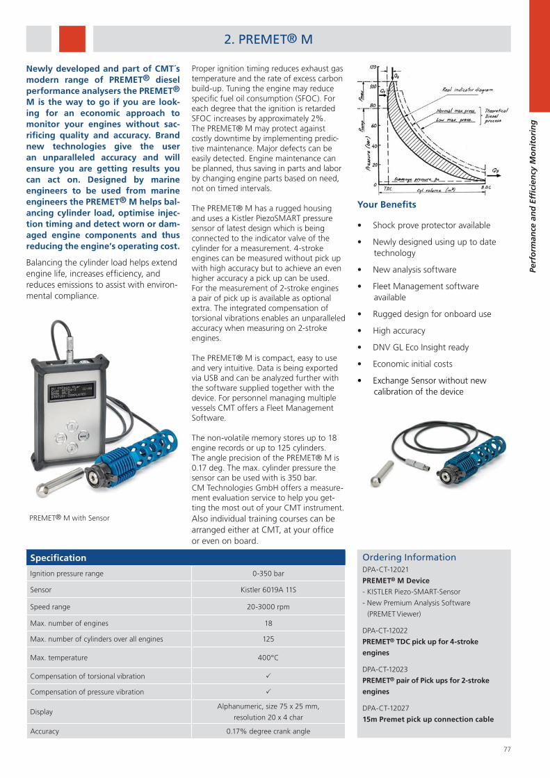
77
Perf
orm
ance
an
d E
ffici
ency
Mo
nit
ori
ng
2. PREMET® M
Ordering InformationDPA-CT-12021
PREMET® M Device
- KISTLER Piezo-SMART-Sensor
- New Premium Analysis Software
(PREMET Viewer)
DPA-CT-12022
PREMET® TDC pick up for 4-stroke
engines
DPA-CT-12023
PREMET® pair of Pick ups for 2-stroke
engines
DPA-CT-12027
15m Premet pick up connection cable
Newly developed and part of CMT´s modern range of PREMET® diesel performance analysers the PREMET® M is the way to go if you are look-ing for an economic approach to monitor your engines without sac-rificing quality and accuracy. Brand new technologies give the user an unparalleled accuracy and will ensure you are getting results you can act on. Designed by marine engineers to be used from marine engineers the PREMET® M helps bal-ancing cylinder load, optimise injec-tion timing and detect worn or dam-aged engine components and thus reducing the engine’s operating cost.
Balancing the cylinder load helps extend engine life, increases efficiency, and reduces emissions to assist with environ-mental compliance.
Your Benefits
Shock prove protector available
Newly designed using up to date technology
New analysis software
Fleet Management software available
Rugged design for onboard use
High accuracy
DNV GL Eco Insight ready
Economic initial costs
Exchange Sensor without new calibration of the device
Proper ignition timing reduces exhaust gas temperature and the rate of excess carbon build-up. Tuning the engine may reduce specific fuel oil consumption (SFOC). For each degree that the ignition is retarded SFOC increases by approximately 2%. The PREMET® M may protect against costly downtime by implementing predic-tive maintenance. Major defects can be easily detected. Engine maintenance can be planned, thus saving in parts and labor by changing engine parts based on need, not on timed intervals.
The PREMET® M has a rugged housing and uses a Kistler PiezoSMART pressure sensor of latest design which is being connected to the indicator valve of the cylinder for a measurement. 4-stroke engines can be measured without pick up with high accuracy but to achieve an even higher accuracy a pick up can be used. For the measurement of 2-stroke engines a pair of pick up is available as optional extra. The integrated compensation of torsional vibrations enables an unparalleled accuracy when measuring on 2-stroke engines.
The PREMET® M is compact, easy to use and very intuitive. Data is being exported via USB and can be analyzed further with the software supplied together with the device. For personnel managing multiple vessels CMT offers a Fleet Management Software.
The non-volatile memory stores up to 18 engine records or up to 125 cylinders. The angle precision of the PREMET® M is 0.17 deg. The max. cylinder pressure the sensor can be used with is 350 bar.CM Technologies GmbH offers a measure-ment evaluation service to help you get-ting the most out of your CMT instrument.Also individual training courses can be arranged either at CMT, at your officeor even on board.
Specification
Ignition pressure range 0-350 bar
Sensor Kistler 6019A 11S
Speed range 20-3000 rpm
Max. number of engines 18
Max. number of cylinders over all engines 125
Max. temperature 400°C
Compensation of torsional vibration
Compensation of pressure vibration
DisplayAlphanumeric, size 75 x 25 mm,
resolution 20 x 4 char
Accuracy 0.17% degree crank angle
PREMET® M with Sensor
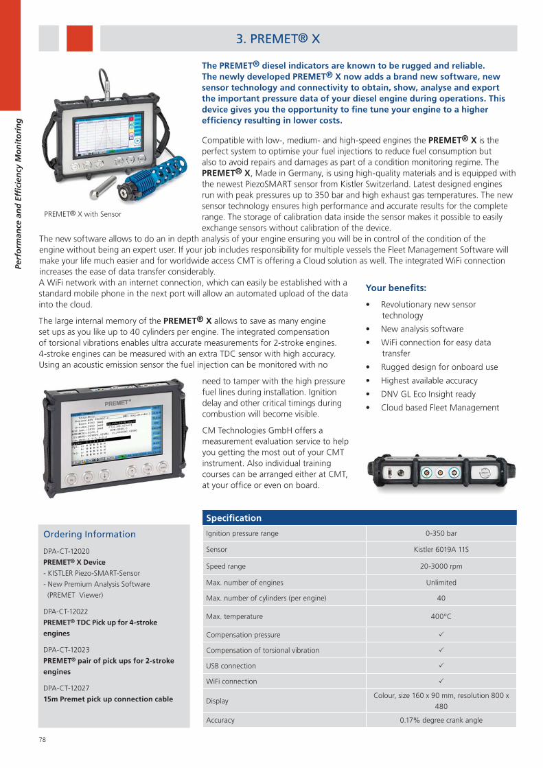
78
Perf
orm
ance
an
d E
ffici
ency
Mo
nit
ori
ng
Ordering Information
DPA-CT-12020
PREMET® X Device
- KISTLER Piezo-SMART-Sensor
- New Premium Analysis Software
(PREMET Viewer)
DPA-CT-12022
PREMET® TDC Pick up for 4-stroke
engines
DPA-CT-12023
PREMET® pair of pick ups for 2-stroke
engines
DPA-CT-12027
15m Premet pick up connection cable
Specification
Ignition pressure range 0-350 bar
Sensor Kistler 6019A 11S
Speed range 20-3000 rpm
Max. number of engines Unlimited
Max. number of cylinders (per engine) 40
Max. temperature 400°C
Compensation pressure
Compensation of torsional vibration
USB connection
WiFi connection
DisplayColour, size 160 x 90 mm, resolution 800 x
480
Accuracy 0.17% degree crank angle
3. PREMET® X
The PREMET® diesel indicators are known to be rugged and reliable. The newly developed PREMET® X now adds a brand new software, new sensor technology and connectivity to obtain, show, analyse and export the important pressure data of your diesel engine during operations. This device gives you the opportunity to fine tune your engine to a higher efficiency resulting in lower costs.
Compatible with low-, medium- and high-speed engines the PREMET® X is the perfect system to optimise your fuel injections to reduce fuel consumption but also to avoid repairs and damages as part of a condition monitoring regime. The PREMET® X, Made in Germany, is using high-quality materials and is equipped with the newest PiezoSMART sensor from Kistler Switzerland. Latest designed engines run with peak pressures up to 350 bar and high exhaust gas temperatures. The new sensor technology ensures high performance and accurate results for the complete range. The storage of calibration data inside the sensor makes it possible to easily exchange sensors without calibration of the device.
The new software allows to do an in depth analysis of your engine ensuring you will be in control of the condition of the engine without being an expert user. If your job includes responsibility for multiple vessels the Fleet Management Software will make your life much easier and for worldwide access CMT is offering a Cloud solution as well. The integrated WiFi connection increases the ease of data transfer considerably.
PREMET® X with Sensor
A WiFi network with an internet connection, which can easily be established with a standard mobile phone in the next port will allow an automated upload of the data into the cloud.
The large internal memory of the PREMET® X allows to save as many engine set ups as you like up to 40 cylinders per engine. The integrated compensation of torsional vibrations enables ultra accurate measurements for 2-stroke engines. 4-stroke engines can be measured with an extra TDC sensor with high accuracy. Using an acoustic emission sensor the fuel injection can be monitored with no
Your benefits:
Revolutionary new sensor technology
New analysis software
WiFi connection for easy data transfer
Rugged design for onboard use
Highest available accuracy
DNV GL Eco Insight ready
Cloud based Fleet Management
need to tamper with the high pressure fuel lines during installation. Ignition delay and other critical timings during combustion will become visible.
CM Technologies GmbH offers a measurement evaluation service to help you getting the most out of your CMT instrument. Also individual training courses can be arranged either at CMT, at your office or even on board.
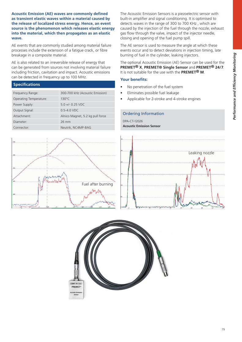
79
Perf
orm
ance
an
d E
ffici
ency
Mo
nit
ori
ng
Acoustic Emission (AE) waves are commonly defined as transient elastic waves within a material caused by the release of localized stress energy. Hence, an event source is the phenomenon which releases elastic energy into the material, which then propagates as an elastic wave.
AE events that are commonly studied among material failure processes include the extension of a fatigue crack, or fibre breakage in a composite material.
AE is also related to an irreversible release of energy that can be generated from sources not involving material failure including friction, cavitation and impact. Acoustic emissions can be detected in frequency up to 100 MHz.
Specifications
Frequency Range: 300-700 kHz (Acoustic Emission)
Operating Temperature: 130°C
Power Supply: 5.0 +/- 0.25 VDC
Output Signal: 0.5-4.0 VDC
Attachment: Alnico Magnet, 5.2 kg pull force
Diameter: 26 mm
Connector: Neutrik, NC4MP-BAG
Ordering Information
DPA-CT-12026
Acoustic Emission Sensor
Leaking nozzle
Fuel after burning
The Acoustic Emission Sensors is a piezoelectric sensor with built-in amplifier and signal conditioning. It is optimised to detects waves in the range of 300 to 700 KHz , which are caused by the injection of the fuel through the nozzle, exhaust gas flow through the valve, impact of the injector needle, closing and opening of the fuel pump spill.
The AE sensor is used to measure the angle at which these events occur and to detect deviations in injection timing, late burning of fuel in the cylinder, leaking injectors.
The optional Acoustic Emission (AE) Sensor can be used for the PREMET® X, PREMET® Single Sensor and PREMET® 24/7. It is not suitable for the use with the PREMET® M.
Your benefits:
No penetration of the fuel system
Eliminates possible fuel leakage
Applicable for 2-stroke and 4-stroke engines
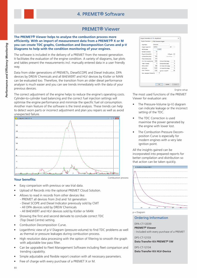
80
Perf
orm
ance
an
d E
ffici
ency
Mo
nit
ori
ng
Your benefits:
Easy comparison with previous or sea trial data.
Upload of Records into the optional PREMET Cloud Solution.
Allows to read in records from other devices like: - PREMET all devices from 2nd and 1st generation - Diesel SCOPE and Diesel Indicator previously sold by CMT - All DPA devices sold by DREW Chemicals - All BAEWERT and HLV devices sold by Kistler or MAN
Showing the first and second derivate to conclude correct TDC (Top Dead Centre) setting.
Combustion Decomposition Curve.
Logarithmic view of p-V Diagram (pressure-volume) to find TDC problems as well as thermal or pressure leakages during combustion process.
High resolution data processing with the option of filtering to smooth the graph with adjustable low pass filter.
Can be upgraded to Fleet Management Software including fleet comparison and trending capability.
Simple adjustable and flexible report creation with all necessary parameters.
Free of charge with every purchase of a PREMET X or M.
The PREMET® Viewer helps to analyse the combustion process more efficiently. With an import of measurement data from a PREMET® X or M you can create TDC graphs, Combustion and Decomposition Curves and p-V Diagrams to help with the condition monitoring of your engines.
The software is included in the delivery of a PREMET from the newest generation. It facilitates the evaluation of the engine condition. A variety of diagrams, bar plots and tables present the measurements incl. manually entered data in a user friendly way.
Data from older generations of PREMETs, DieselSCOPE and Diesel Indicator, DPA devices by DREW Chemicals and all BAEWERT and HLV devices by Kistler or MAN can be evaluated too. Therefore, the transition from an older diesel performance analyser is much easier and you can see trends immediately with the data of your previous devices.
The correct adjustment of the engine helps to reduce the engine’s operating costs. Cylinder-to-cylinder load balancing and the correct fuel injection settings will optimise the engine performance and minimize the specific fuel oil consumption. Another main feature of the software is the trend analysis. These trends can help to detect worn parts or incorrect adjustment and plan you repairs as well as avoid unexpected failure.
Ordering Information
DPA-CT-12039
PREMET® Viewer
- Included with every purchase of a PREMET
DPS-CT-12133
Data Transfer Kit PREMET® SW
DPS-CT-12134
Data Transfer Kit HLV-Device
The most used functions of the PREMET Viewer for evaluation are:
The Pressure-Volume (p-V) diagram can indicate leakage or the incorrect setting of the TDC.
The TDC Correction is used maximise the power generated by the engine with lower lost.
The Combustion Pressure Decom-position Curve is especially for modern engines with a very late ignition point.
All the insights gained can be incorporated into prepared reports for better compilation and distribution so that action can be taken quickly.
p-v Diagram
Combustion process
Engine setup
PREMET® Viewer
4. PREMET® Software
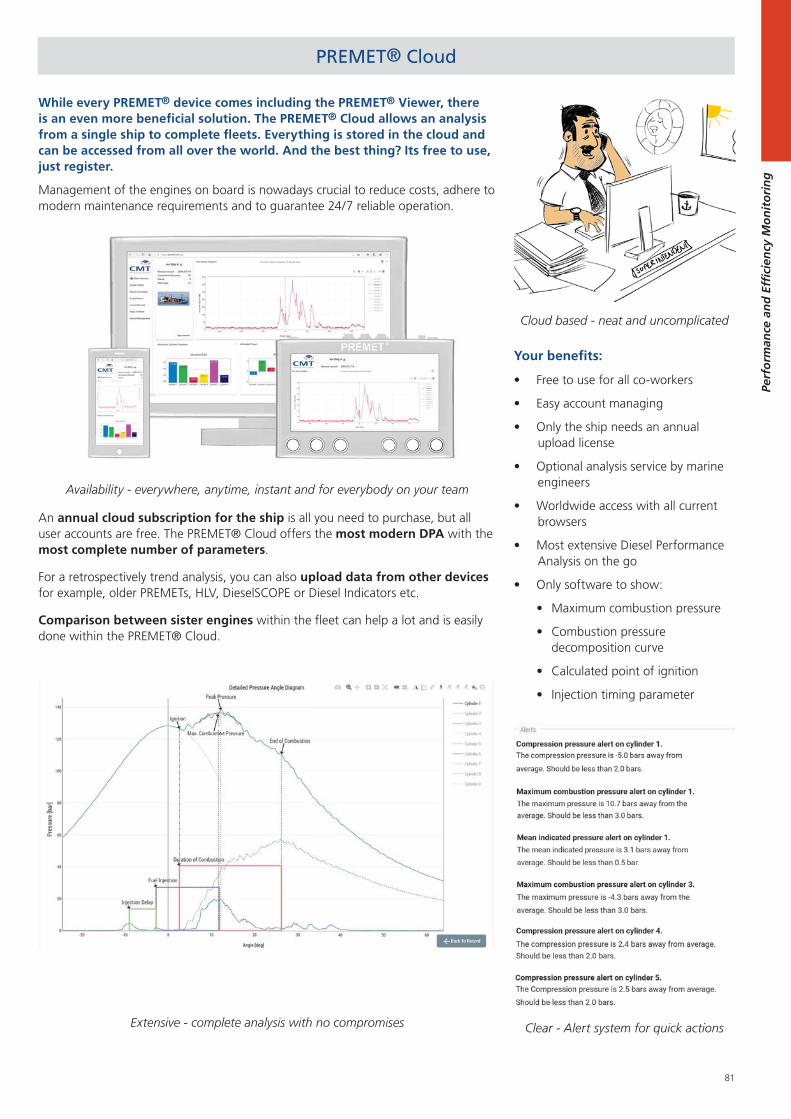
81
Perf
orm
ance
an
d E
ffici
ency
Mo
nit
ori
ng
PREMET® Cloud
Your benefits:
Free to use for all co-workers
Easy account managing
Only the ship needs an annual upload license
Optional analysis service by marine engineers
Worldwide access with all current browsers
Most extensive Diesel Performance Analysis on the go
Only software to show:
Maximum combustion pressure
Combustion pressure decomposition curve
Calculated point of ignition
Injection timing parameter
While every PREMET® device comes including the PREMET® Viewer, there is an even more beneficial solution. The PREMET® Cloud allows an analysis from a single ship to complete fleets. Everything is stored in the cloud and can be accessed from all over the world. And the best thing? Its free to use, just register.
Management of the engines on board is nowadays crucial to reduce costs, adhere to modern maintenance requirements and to guarantee 24/7 reliable operation.
An annual cloud subscription for the ship is all you need to purchase, but all user accounts are free. The PREMET® Cloud offers the most modern DPA with the most complete number of parameters.
For a retrospectively trend analysis, you can also upload data from other devices for example, older PREMETs, HLV, DieselSCOPE or Diesel Indicators etc.
Comparison between sister engines within the fleet can help a lot and is easily done within the PREMET® Cloud.
Availability - everywhere, anytime, instant and for everybody on your team
Extensive - complete analysis with no compromises
Cloud based - neat and uncomplicated
Clear - Alert system for quick actions
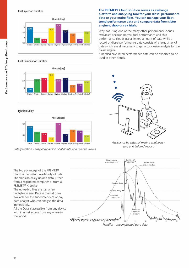
82
Perf
orm
ance
an
d E
ffici
ency
Mo
nit
ori
ng
Assistance by external marine engineers - easy and tailored reports
The PREMET® Cloud solution serves as exchange platform and analysing tool for your diesel performance data or your entire fleet. You can manage your fleet, trend performance data and compare data from sister engines, shop or sea trials.
Why not using one of the many other performance clouds available? Because normal fuel performance and ship performance clouds use a limited amount of data while a record of diesel performance data consists of a large array of data which are all necessary to get a conclusive analysis for the diesel engine. If needed calculated performance data can be exported to be used in other clouds.
Plentiful - uncompressed pure data
Interpretation - easy comparison of absolute and relative values
The big advantage of the PREMET® Cloud is the instant availability of data. The ship can easily upload data. Either from a registered computer or from a PREMET® X device. The uploaded files are just a few kilobytes in size. Data is then at once available for the superintendent or any data analyst who can analyse the data immediately. All the Data is accessible from any device with internet access from anywhere in the world.
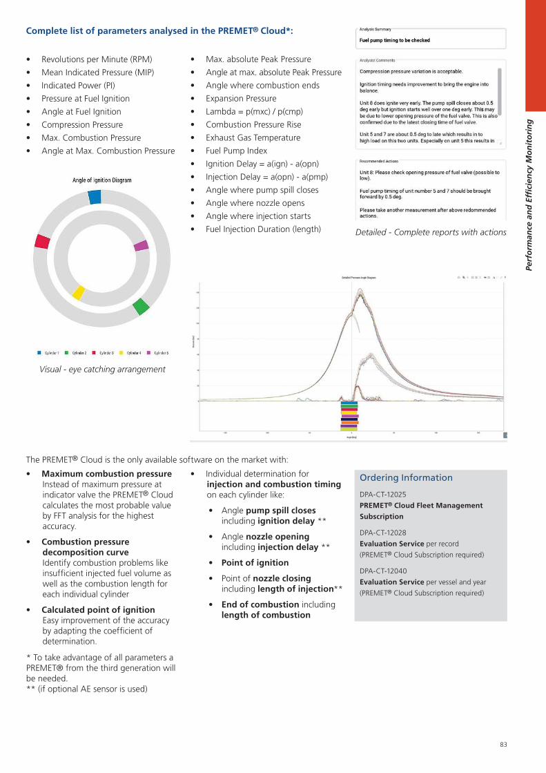
83
Perf
orm
ance
an
d E
ffici
ency
Mo
nit
ori
ng
Complete list of parameters analysed in the PREMET® Cloud*:
The PREMET® Cloud is the only available software on the market with:
Max. absolute Peak Pressure
Angle at max. absolute Peak Pressure
Angle where combustion ends
Expansion Pressure
Lambda = p(mxc) / p(cmp)
Combustion Pressure Rise
Exhaust Gas Temperature
Fuel Pump Index
Ignition Delay = a(ign) - a(opn)
Injection Delay = a(opn) - a(pmp)
Angle where pump spill closes
Angle where nozzle opens
Angle where injection starts
Fuel Injection Duration (length)
Individual determination for injection and combustion timing on each cylinder like:
Angle pump spill closes including ignition delay **
Angle nozzle opening including injection delay **
Point of ignition
Point of nozzle closing including length of injection**
End of combustion including length of combustion
* To take advantage of all parameters a PREMET® from the third generation will be needed.** (if optional AE sensor is used)
Maximum combustion pressure Instead of maximum pressure at indicator valve the PREMET® Cloud calculates the most probable value by FFT analysis for the highest accuracy.
Combustion pressure decomposition curve Identify combustion problems like insufficient injected fuel volume as well as the combustion length for each individual cylinder
Calculated point of ignition Easy improvement of the accuracy by adapting the coefficient of determination.
Revolutions per Minute (RPM)
Mean Indicated Pressure (MIP)
Indicated Power (PI)
Pressure at Fuel Ignition
Angle at Fuel Ignition
Compression Pressure
Max. Combustion Pressure
Angle at Max. Combustion Pressure
Visual - eye catching arrangement
Detailed - Complete reports with actions
Ordering Information
DPA-CT-12025
PREMET® Cloud Fleet Management
Subscription
DPA-CT-12028
Evaluation Service per record
(PREMET® Cloud Subscription required)
DPA-CT-12040
Evaluation Service per vessel and year
(PREMET® Cloud Subscription required)
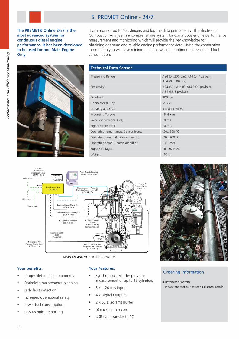
84
Perf
orm
ance
an
d E
ffici
ency
Mo
nit
ori
ng
5. PREMET Online - 24/7
Technical Data Sensor
Measuring Range: A24 (0...200 bar), A14 (0...103 bar),
A34 (0...300 bar)
Sensitivity: A24 (50 μA/bar), A14 (100 μA/bar),
A34 (33,3 μA/bar)
Overload: 300 bar
Connector (IP67): M12x1
Linearity at 23°C: < ± 0,75 %FSO
Mounting Torque:
Zero Point (no pressure): 10 mA
Signal Stroke FSO 10 mA
Operating temp. range, Sensor front: -50...350 °C
Operating temp. at cable connect.: -20...200 °C
Operating temp. Charge amplifier: -10...85°C
Supply Voltage: 16...30 V DC
Weight: 150 g
Ordering Information
Customized system
- Please contact our office to discuss details
Your benefits:
Longer lifetime of components
Optimized maintenance planning
Early fault detection
Increased operational safety
Lower fuel consumption
Easy technical reporting
Data Logger Box( CA 04204 )
PC in Remote Location( engine control room )
Cat 5/6Ethernet cable
max length 100m( CA 04106 )
Extension Cable1x15
( CA 04007 )
Pair of pick-ups withMagnetic TDC Pick-up
( CA 04058 )
Pressure Sensor Cable Cyl N( CA 04102 )
Cylinder PressureSensor
Kistler 6613CQPermanent mount
Scavenging AirPressure Sensor( CA 04110 )
N - Cylinder Numberfrom 4 to 16
Scavenging AirPressure Sensor Cable
( CA 04111 )
MAIN ENGINE MONITORING SYSTEM
Electromagnetic AcousticEmission Sensor, 15m cable
( CA 04127 )
Ship Speed
Flow MeterNetwork
Junction Box( CA 04205)
TDC
Flywheel
Torque Meter Pressure Sensor Cable Cyl 1( CA 04102 )
Your Features:
Synchronous cylinder pressure measurement of up to 16 cylinders
3 x 4-20 mA Inputs
4 x Digital Outputs
2 x 62 Diagrams Buffer
p(max) alarm record
USB data transfer to PC
The PREMET® Online 24/7 is the most advanced system for continuous diesel engine performance. It has been developed to be used for one Main Engine Only.
It can monitor up to 16 cylinders and log the data permanently. The Electronic Combustion Analyser is a comprehensive system for continuous engine performance measurement and monitoring which will provide the key knowledge for obtaining optimum and reliable engine performance data. Using the combustion information you will have minimum engine wear, an optimum emission and fuel consumption.
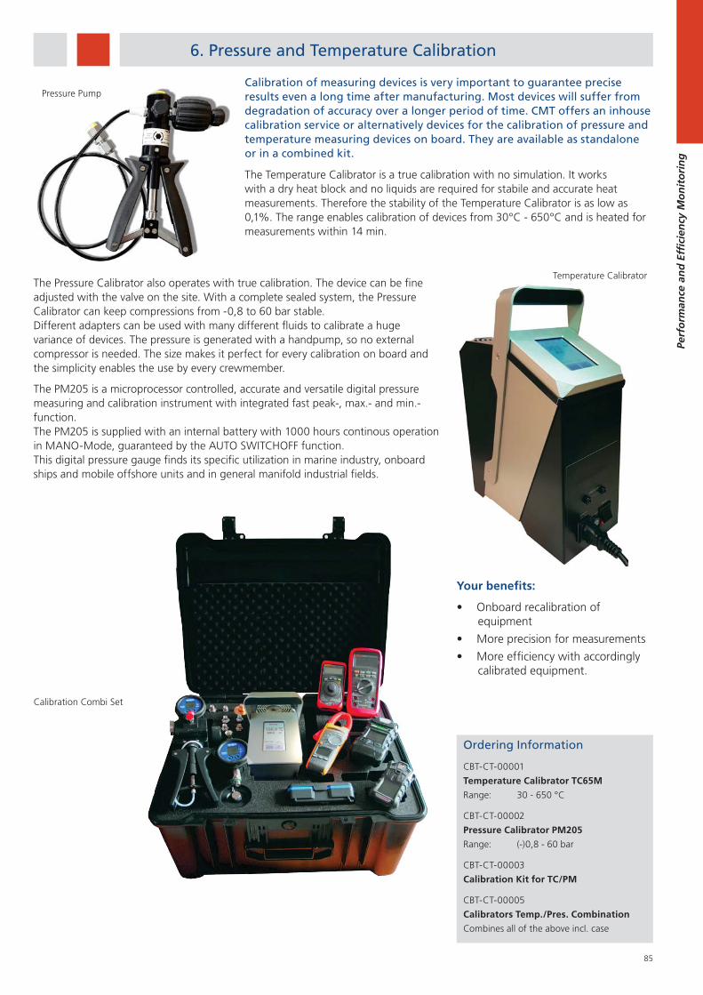
85
Perf
orm
ance
an
d E
ffici
ency
Mo
nit
ori
ng
6. Pressure and Temperature Calibration
Calibration of measuring devices is very important to guarantee precise results even a long time after manufacturing. Most devices will suffer from degradation of accuracy over a longer period of time. CMT offers an inhouse calibration service or alternatively devices for the calibration of pressure and temperature measuring devices on board. They are available as standalone or in a combined kit.
The Temperature Calibrator is a true calibration with no simulation. It works with a dry heat block and no liquids are required for stabile and accurate heat measurements. Therefore the stability of the Temperature Calibrator is as low as 0,1%. The range enables calibration of devices from 30°C - 650°C and is heated for measurements within 14 min.
Your benefits:
Onboard recalibration of equipment
More precision for measurements
More efficiency with accordingly calibrated equipment.
Pressure Pump
The Pressure Calibrator also operates with true calibration. The device can be fine adjusted with the valve on the site. With a complete sealed system, the Pressure Calibrator can keep compressions from -0,8 to 60 bar stable. Different adapters can be used with many different fluids to calibrate a huge variance of devices. The pressure is generated with a handpump, so no external compressor is needed. The size makes it perfect for every calibration on board and the simplicity enables the use by every crewmember.
The PM205 is a microprocessor controlled, accurate and versatile digital pressure measuring and calibration instrument with integrated fast peak-, max.- and min.- function. The PM205 is supplied with an internal battery with 1000 hours continous operation in MANO-Mode, guaranteed by the AUTO SWITCHOFF function. This digital pressure gauge finds its specific utilization in marine industry, onboard ships and mobile offshore units and in general manifold industrial fields.
Ordering Information
CBT-CT-00001
Temperature Calibrator TC65M
Range: 30 - 650 °C
CBT-CT-00002
Pressure Calibrator PM205
Range: (-)0,8 - 60 bar
CBT-CT-00003
Calibration Kit for TC/PM
CBT-CT-00005
Calibrators Temp./Pres. Combination
Combines all of the above incl. case
Calibration Combi Set
Temperature Calibrator

86
Perf
orm
ance
an
d E
ffici
ency
Mo
nit
ori
ng
87
Serv
ice
and
Tra
inin
g
1. Evaluation Service ................................................................ 89
2. Installation and Commission Service .................................... 90
3. Calibration Service .............................................................. 92
4. Oil Testing Seminar ..............................................................94
5. Monitoring with Vibration Analysis Seminar ......................... 95
6. Diesel Performance Seminar .................................................96
7. Cylinder Drain Oil Management Seminar .............................. 97
8. Marine Water Tests Seminar................................................. 98
Service and Training
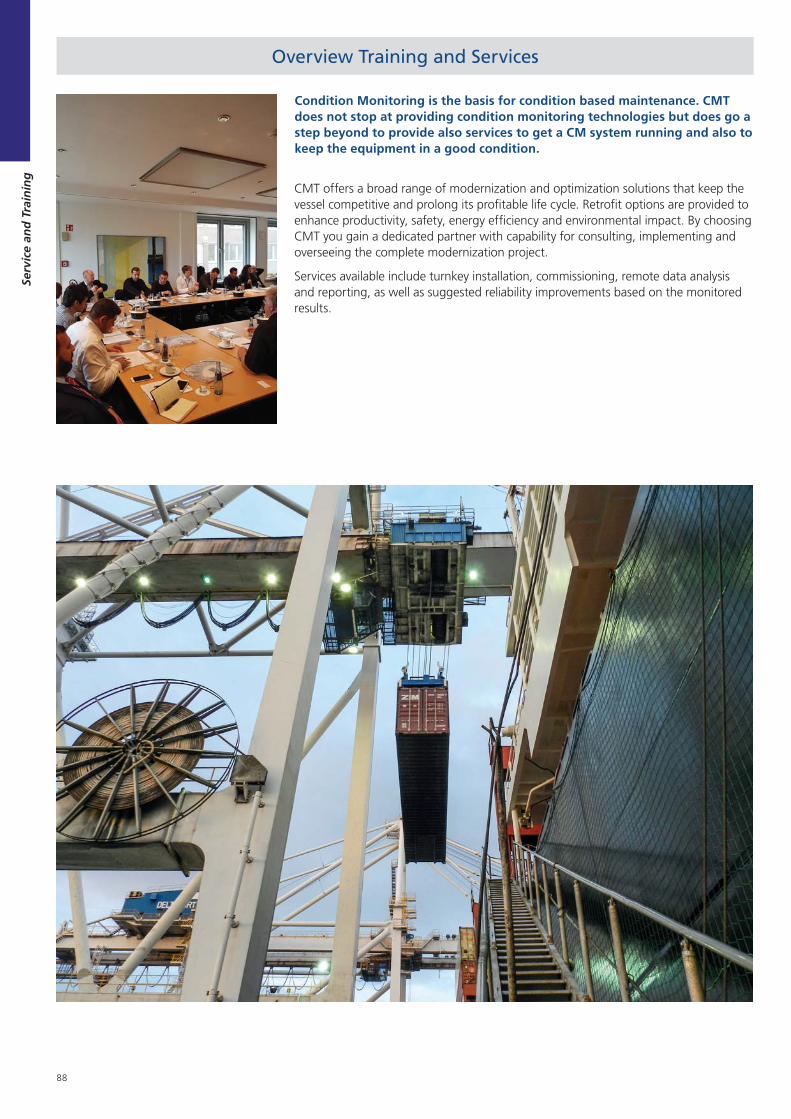
88
Serv
ice
and
Tra
inin
g
Overview Training and Services
Condition Monitoring is the basis for condition based maintenance. CMT does not stop at providing condition monitoring technologies but does go a step beyond to provide also services to get a CM system running and also to keep the equipment in a good condition.
CMT offers a broad range of modernization and optimization solutions that keep the vessel competitive and prolong its profitable life cycle. Retrofit options are provided to enhance productivity, safety, energy efficiency and environmental impact. By choosing CMT you gain a dedicated partner with capability for consulting, implementing and overseeing the complete modernization project.
Services available include turnkey installation, commissioning, remote data analysis and reporting, as well as suggested reliability improvements based on the monitored results.
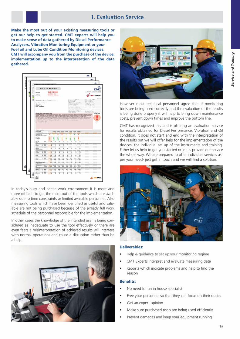
89
Serv
ice
and
Tra
inin
g
1. Evaluation Service
In today’s busy and hectic work environment it is more and more difficult to get the most out of the tools which are avail-able due to time constraints or limited available personnel. Also measuring tools which have been identified as useful and valu-able are not being purchased because of the already full work schedule of the personnel responsible for the implementation.
In other cases the knowledge of the intended user is being con-sidered as inadequate to use the tool effectively or there are even fears a misinterpretation of achieved results will interfere with normal operations and cause a disruption rather than be a help.
However most technical personnel agree that if monitoring tools are being used correctly and the evaluation of the results is being done properly it will help to bring down maintenance costs, prevent down times and improve the bottom line.
CMT has recognized this and is offering an evaluation service for results obtained for Diesel Performance, Vibration and Oil condition. It does not start and end with the interpretation of the results but we will offer help for the implementation of the devices, the individual set up of the instruments and training. Either let us help to get you started or let us provide our service the whole way. We are prepared to offer individual services asper your need- just get in touch and we will find a solution.
Make the most out of your existing measuring tools or get our help to get started. CMT experts will help you to make sense of data gathered by Diesel PerformanceAnalysers, Vibration Monitoring Equipment or yourFuel oil and Lube Oil Condition Monitoring devices.CMT will accompany you from the purchase of the device, implementation up to the interpretation of the data gathered.
Deliverables:
Help & guidance to set up your monitoring regime
CMT Experts interpret and evaluate measuring data
Reports which indicate problems and help to find the reason
Benefits:
No need for an in house specialist
Free your personnel so that they can focus on their duties
Get an expert opinion
Make sure purchased tools are being used efficiently
Prevent damages and keep your equipment running

90
Serv
ice
and
Tra
inin
g
Our long experience with installation and commissioning on board seagoing vessels ensures cost-effective retrofit or new building installations including final commissioning that are carried out with a minimum on interruption to your business. As a turn-key supplier we can handle every phase of a project from design and engineering to installation, commissioning and training.
CMT has a qualified team of installation and commissioning engineers with a wealth of experience in on site requirements. Installations and commissioning can be offered with all equipment purchased from CMT.
2. Installation and Commission Service
The expanding world fleet operates in an uncertain environment, with ever tougher competition and increasing price pressures, which puts the spotlight on safe and cost-effective ship operation. This requires a partner able to maintain the new, more advanced vessels as well as keeping the ageing fleet operating safely, more efficiently, and up to date to stricter standards. Off-hire must be mitigated or prevented.
Highly skilled and qualified support for the start-up of your condition monitoring system.
We have teams of experienced and qualified technicians to provide you with support for the turn-key installation and commissioning of condition monitoring systems purchased from CMT.
When we provide installation and commissioning services – whether for a control systems or a complete package – our technicians work alongside the project managers and engineers to ensure smooth and efficient installation to the highest standard.
In the early stages of your system life we want to ensure you get everything you need to meet project time lines and site needs.
Our services include:
Installation
Pre-commissioning and Commissioning
Site Acceptance Testing
Personnel Introductory Training
Support at system start up
Operating and Maintenance Documents
Spares installation / repair
Fault Finding
A tailored commissioning visit proposal can also be produced (if not offered as part of the original contract) based on a set of specific terms and conditions. CMT service engineers regularly travel the World, keeping our valued overseas clients equipment in full working order. In most cases seven days notice is needed to arrange a commissioning visit.
Even if the condition monitoring equipment was not installed by CMT, our team will be happy to quote for a commissioning visit, safety inspection, or full material handling service contract. Just make a request and we’ll take care of your condition monitoring equipment service needs.
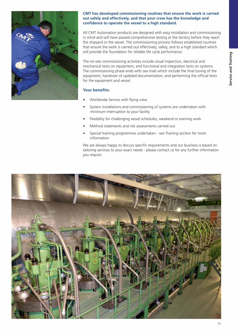
91
Serv
ice
and
Tra
inin
g
CMT has developed commissioning routines that ensure the work is carried out safely and effectively, and that your crew has the knowledge and confidence to operate the vessel to a high standard.
All CMT Automation products are designed with easy installation and commissioning in mind and will have passed comprehensive testing at the factory before they reach the shipyard or the vessel. The commissioning process follows established routines that ensure the work is carried out effectively, safely, and to a high standard which will provide the foundation for reliable life cycle performance.
The on-site commissioning activities include visual inspection, electrical and mechanical tests on equipment, and functional and integration tests on systems. The commissioning phase ends with sea trials which include the final tuning of the equipment, handover of updated documentation, and performing the official tests for the equipment and vessel.
Your benefits:
Worldwide Service with flying crew.
System installations and commissioning of systems are undertaken with minimum interruption to your facility
Flexibility for challenging vessel schedules, weekend or evening work
Method statements and risk assessments carried out
Special training programmes undertaken - see Training section for more information
We are always happy to discuss specific requirements and our business is based on tailoring services to your exact needs - please contact us for any further information you require.
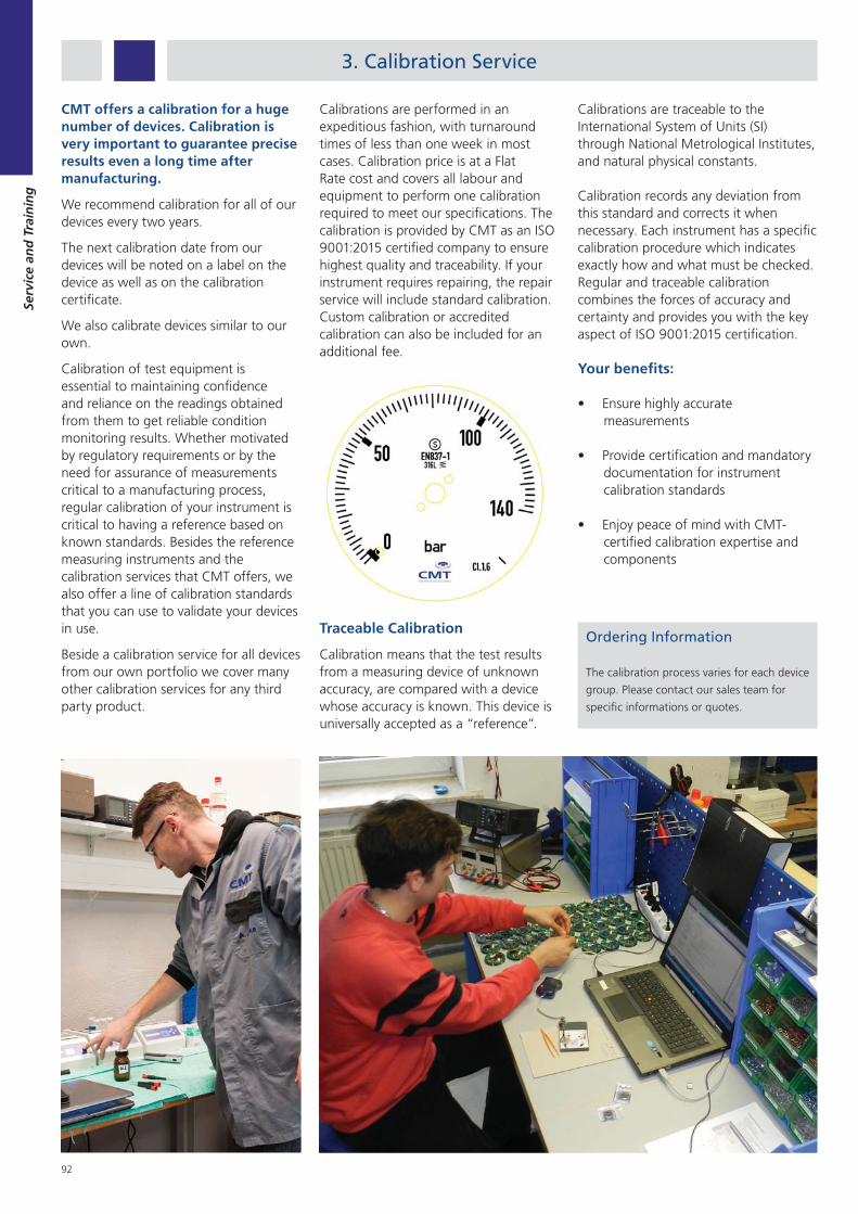
92
Serv
ice
and
Tra
inin
g
3. Calibration Service
CMT offers a calibration for a huge number of devices. Calibration is very important to guarantee precise results even a long time after manufacturing.
We recommend calibration for all of our devices every two years.
The next calibration date from our devices will be noted on a label on the device as well as on the calibration certificate.
We also calibrate devices similar to our own.
Calibration of test equipment is essential to maintaining confidence and reliance on the readings obtained from them to get reliable condition monitoring results. Whether motivated by regulatory requirements or by the need for assurance of measurements critical to a manufacturing process, regular calibration of your instrument is critical to having a reference based on known standards. Besides the reference measuring instruments and the calibration services that CMT offers, we also offer a line of calibration standards that you can use to validate your devices in use.
Beside a calibration service for all devices from our own portfolio we cover many other calibration services for any third party product.
Calibrations are performed in an expeditious fashion, with turnaround times of less than one week in most cases. Calibration price is at a Flat Rate cost and covers all labour and equipment to perform one calibration required to meet our specifications. The calibration is provided by CMT as an ISO 9001:2015 certified company to ensure highest quality and traceability. If your instrument requires repairing, the repair service will include standard calibration. Custom calibration or accredited calibration can also be included for an additional fee.
Traceable Calibration
Calibration means that the test results from a measuring device of unknown accuracy, are compared with a device whose accuracy is known. This device is universally accepted as a “reference”.
Ordering Information
The calibration process varies for each device
group. Please contact our sales team for
specific informations or quotes.
Calibrations are traceable to the International System of Units (SI) through National Metrological Institutes, and natural physical constants.
Calibration records any deviation from this standard and corrects it when necessary. Each instrument has a specific calibration procedure which indicates exactly how and what must be checked. Regular and traceable calibration combines the forces of accuracy and certainty and provides you with the key aspect of ISO 9001:2015 certification.
Your benefits:
Ensure highly accurate measurements
Provide certification and mandatory documentation for instrument calibration standards
Enjoy peace of mind with CMT-certified calibration expertise and components
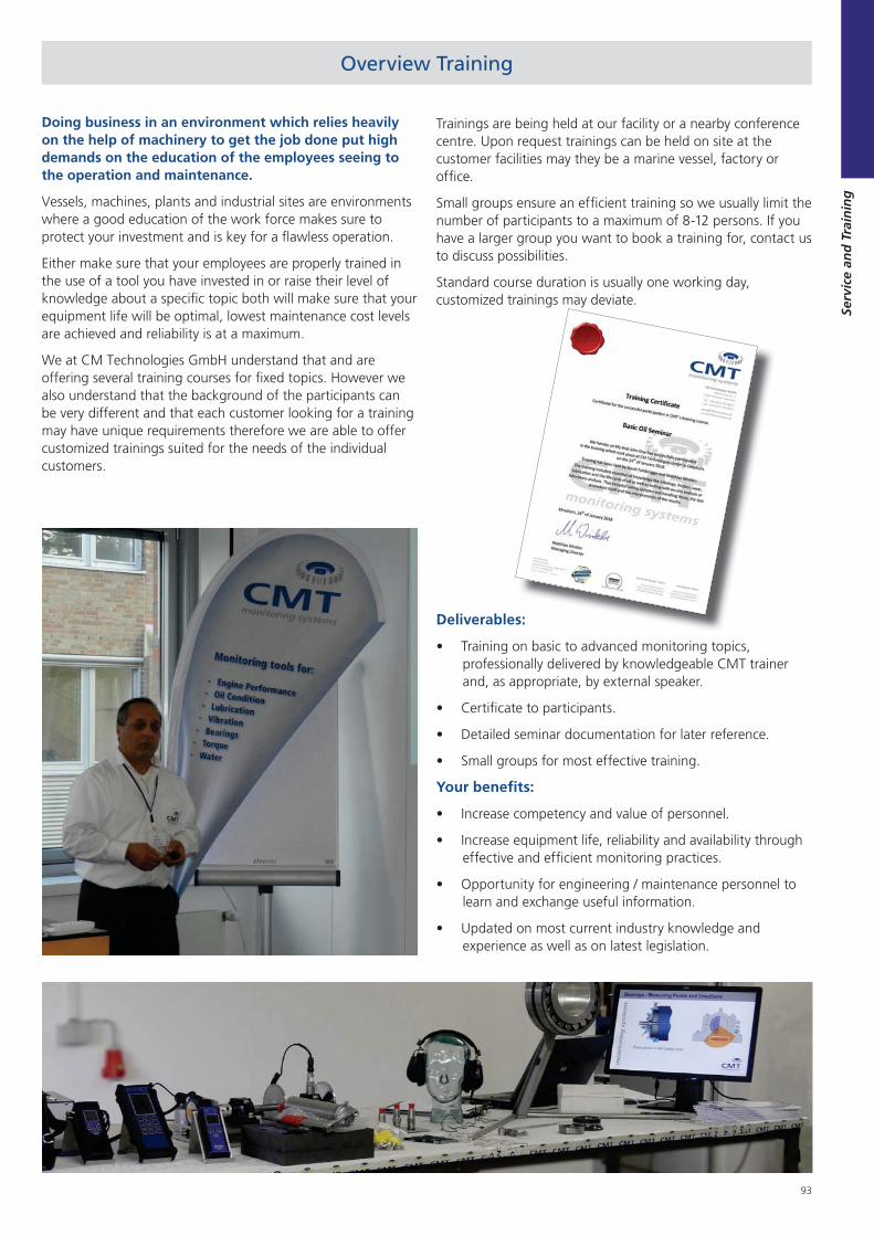
93
Serv
ice
and
Tra
inin
g
Trainings are being held at our facility or a nearby conference centre. Upon request trainings can be held on site at the customer facilities may they be a marine vessel, factory or office.
Small groups ensure an efficient training so we usually limit the number of participants to a maximum of 8-12 persons. If you have a larger group you want to book a training for, contact us to discuss possibilities.
Standard course duration is usually one working day, customized trainings may deviate.
Overview Training
Doing business in an environment which relies heavily on the help of machinery to get the job done put high demands on the education of the employees seeing to the operation and maintenance.
Vessels, machines, plants and industrial sites are environments where a good education of the work force makes sure to protect your investment and is key for a flawless operation.
Either make sure that your employees are properly trained in the use of a tool you have invested in or raise their level of knowledge about a specific topic both will make sure that your equipment life will be optimal, lowest maintenance cost levels are achieved and reliability is at a maximum.
We at CM Technologies GmbH understand that and are offering several training courses for fixed topics. However we also understand that the background of the participants can be very different and that each customer looking for a training may have unique requirements therefore we are able to offer customized trainings suited for the needs of the individual customers.
Deliverables:
Training on basic to advanced monitoring topics, professionally delivered by knowledgeable CMT trainer and, as appropriate, by external speaker.
Certificate to participants.
Detailed seminar documentation for later reference.
Small groups for most effective training.
Your benefits:
Increase competency and value of personnel.
Increase equipment life, reliability and availability through effective and efficient monitoring practices.
Opportunity for engineering / maintenance personnel to learn and exchange useful information.
Updated on most current industry knowledge and experience as well as on latest legislation.
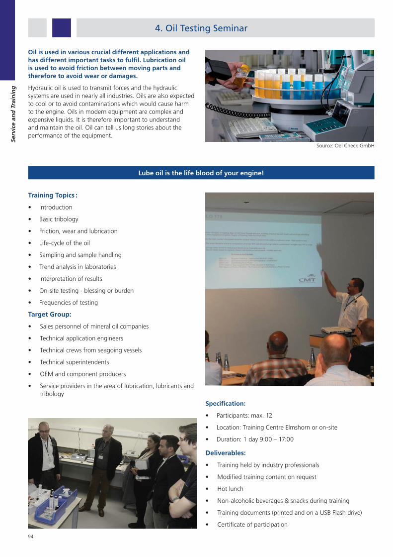
94
Serv
ice
and
Tra
inin
g
4. Oil Testing Seminar
Source: Oel Check GmbH
Oil is used in various crucial different applications and has different important tasks to fulfil. Lubrication oil is used to avoid friction between moving parts and therefore to avoid wear or damages.
Hydraulic oil is used to transmit forces and the hydraulic systems are used in nearly all industries. Oils are also expected to cool or to avoid contaminations which would cause harm to the engine. Oils in modern equipment are complex and expensive liquids. It is therefore important to understand and maintain the oil. Oil can tell us long stories about the performance of the equipment.
Lube oil is the life blood of your engine!
Training Topics :
Introduction
Basic tribology
Friction, wear and lubrication
Life-cycle of the oil
Sampling and sample handling
Trend analysis in laboratories
Interpretation of results
On-site testing - blessing or burden
Frequencies of testing
Target Group:
Sales personnel of mineral oil companies
Technical application engineers
Technical crews from seagoing vessels
Technical superintendents
OEM and component producers
Service providers in the area of lubrication, lubricants and tribology
Specification:
Participants: max. 12
Location: Training Centre Elmshorn or on-site
Duration: 1 day 9:00 – 17:00
Deliverables:
Training held by industry professionals
Modified training content on request
Hot lunch
Non-alcoholic beverages & snacks during training
Training documents (printed and on a USB Flash drive)
Certificate of participation
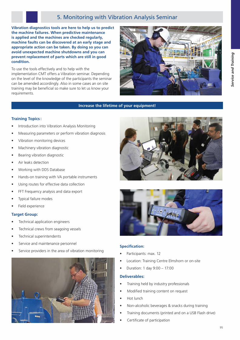
95
Serv
ice
and
Tra
inin
g
5. Monitoring with Vibration Analysis Seminar
Increase the lifetime of your equipment!
Vibration diagnostics tools are here to help us to predict the machine failures. When predictive maintenance is applied and the machines are checked regularly, machine faults can be discovered at an early stage and appropriate action can be taken. By doing so you can avoid unexpected machine shutdowns and you can prevent replacement of parts which are still in good condition.
To use the tools effectively and to help with the implementation CMT offers a Vibration seminar. Depending on the level of the knowledge of the participants the seminar can be amended accordingly. Also in some cases an on site training may be beneficial so make sure to let us know your requirements.
Training Topics :
Introduction into Vibration Analysis Monitoring
Measuring parameters or perform vibration diagnosis
Vibration monitoring devices
Machinery vibration diagnostic
Bearing vibration diagnostic
Air leaks detection
Working with DDS Database
Hands-on training with VA portable instruments
Using routes for effective data collection
FFT Frequency analysis and data export
Typical failure modes
Field experience
Target Group:
Technical application engineers
Technical crews from seagoing vessels
Technical superintendents
Service and maintenance personnel
Service providers in the area of vibration monitoringSpecification:
Participants: max. 12
Location: Training Centre Elmshorn or on-site
Duration: 1 day 9:00 – 17:00
Deliverables:
Training held by industry professionals
Modified training content on request
Hot lunch
Non-alcoholic beverages & snacks during training
Training documents (printed and on a USB Flash drive)
Certificate of participation
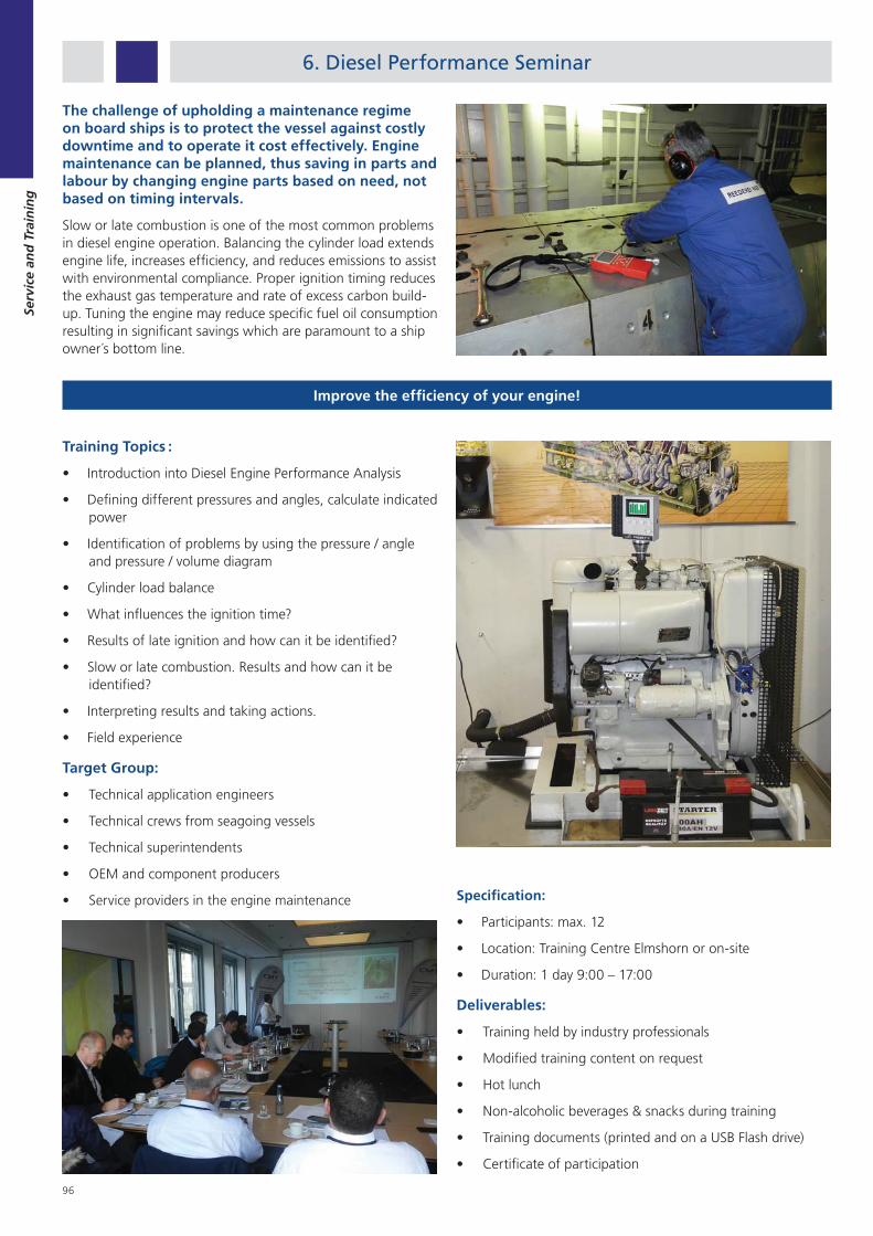
96
Serv
ice
and
Tra
inin
g
6. Diesel Performance Seminar
Improve the efficiency of your engine!
The challenge of upholding a maintenance regime on board ships is to protect the vessel against costly downtime and to operate it cost effectively. Engine maintenance can be planned, thus saving in parts and labour by changing engine parts based on need, not based on timing intervals.
Slow or late combustion is one of the most common problems in diesel engine operation. Balancing the cylinder load extends engine life, increases efficiency, and reduces emissions to assist with environmental compliance. Proper ignition timing reduces the exhaust gas temperature and rate of excess carbon build-up. Tuning the engine may reduce specific fuel oil consumption resulting in significant savings which are paramount to a ship owner´s bottom line.
Training Topics :
Introduction into Diesel Engine Performance Analysis
Defining different pressures and angles, calculate indicated power
Identification of problems by using the pressure / angle and pressure / volume diagram
Cylinder load balance
What influences the ignition time?
Results of late ignition and how can it be identified?
Slow or late combustion. Results and how can it be identified?
Interpreting results and taking actions.
Field experience
Target Group:
Technical application engineers
Technical crews from seagoing vessels
Technical superintendents
OEM and component producers
Service providers in the engine maintenance Specification:
Participants: max. 12
Location: Training Centre Elmshorn or on-site
Duration: 1 day 9:00 – 17:00
Deliverables:
Training held by industry professionals
Modified training content on request
Hot lunch
Non-alcoholic beverages & snacks during training
Training documents (printed and on a USB Flash drive)
Certificate of participation
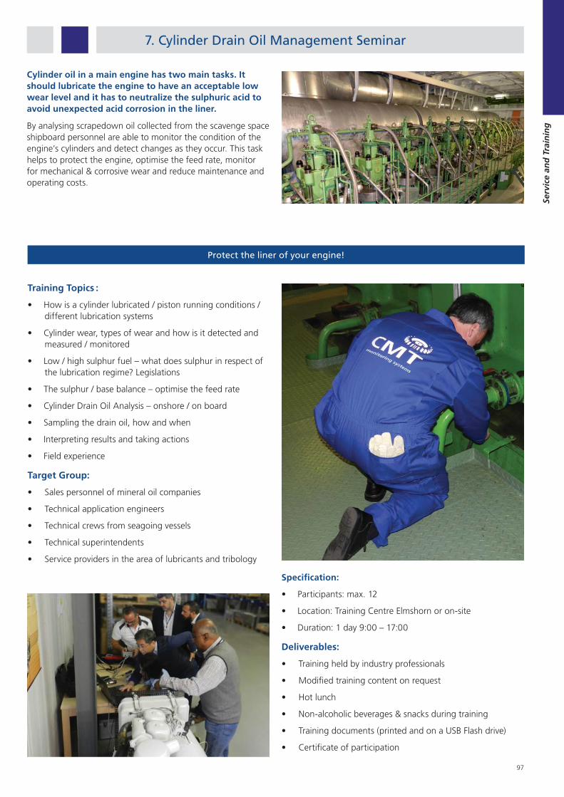
97
Serv
ice
and
Tra
inin
g
7. Cylinder Drain Oil Management Seminar
Cylinder oil in a main engine has two main tasks. It should lubricate the engine to have an acceptable low wear level and it has to neutralize the sulphuric acid to avoid unexpected acid corrosion in the liner.
By analysing scrapedown oil collected from the scavenge space shipboard personnel are able to monitor the condition of the engine’s cylinders and detect changes as they occur. This task helps to protect the engine, optimise the feed rate, monitor for mechanical & corrosive wear and reduce maintenance and operating costs.
Protect the liner of your engine!
Training Topics :
How is a cylinder lubricated / piston running conditions / different lubrication systems
Cylinder wear, types of wear and how is it detected and measured / monitored
Low / high sulphur fuel – what does sulphur in respect of the lubrication regime? Legislations
The sulphur / base balance – optimise the feed rate
Cylinder Drain Oil Analysis – onshore / on board
Sampling the drain oil, how and when
Interpreting results and taking actions
Field experience
Target Group:
Sales personnel of mineral oil companies
Technical application engineers
Technical crews from seagoing vessels
Technical superintendents
Service providers in the area of lubricants and tribology
Specification:
Participants: max. 12
Location: Training Centre Elmshorn or on-site
Duration: 1 day 9:00 – 17:00
Deliverables:
Training held by industry professionals
Modified training content on request
Hot lunch
Non-alcoholic beverages & snacks during training
Training documents (printed and on a USB Flash drive)
Certificate of participation

98
Serv
ice
and
Tra
inin
g
8. Marine Water Tests Seminar
Water is an important topic onboard a vessel which due to different regulations concerning it also a quite complicated one. As key topics we have identified Potable Water, Sewage Water and Ballast Water for which we each offer training courses.
If you would like to combine topics let us know and we will work on a customized seminar that is tailored to your needs. Our experienced seminar speaker will tackle topics that need to be addressed as well as answer questions which originate from the daily work experience of the participants.
Safe potable water secures good health!
Training Topics :
Introduction into potable water
Risks for fresh water supply and making on board
Hazardous contaminations (microbes / chemical elements)
Different methods of disinfection
Legionella and other bacteria
Legislation framework
Risk Management and Water Safety Plan
Ship owners / masters duties
Water testing: What, When, Where, Why?
How to use on-board test kits
Target Group:
Technical application engineers
Technical crews from seagoing vessels
Technical superintendents
Service and maintenance personnel
OEM and component producers
Service providers in the area of water monitoring
Specification:
Participants: max. 12
Location: Training Centre Elmshorn or on-site
Duration: 1 day 9:00 – 17:00
Deliverables:
Training held by industry professionals
Modified training content on request
Hot lunch
Non-alcoholic beverages & snacks during training
Training documents (printed and on a USB Flash drive)
Certificate of participation

99
Serv
ice
and
Tra
inin
g

100

101
No
tes
Notes
1. Notes about Condition Monitoring ..........101

102
No
tes
Notes

CM Technologies GmbHMarie-Curie-Str. 5
25337 Elmshorn, GermanyTel: +49 (4121) 700890
Email: [email protected]: www.CMTechnologies.de
DO-C12001-CT (Issue 10.16) 11/2021


