Embed Size (px)
Citation preview

Int. J. Electrochem. Sci., 10 (2015) 4183 - 4192
International Journal of
ELECTROCHEMICAL SCIENCE
www.electrochemsci.org
Constant Glucose Biosensor Based on Vertically Aligned
Carbon Nanotube Composites
Amin TermehYousefi1,*
, Samira Bagheri2, Nahrizul Adib Kadri
3, Mohamad Rusop Mahmood
4,
Shoichiro Ikeda1
1 ChECA IKohza , Dept. Environmental & Green Technology (EGT) , Malaysia Japan International
Institute of Technology (MJIIT), University Technology Malaysia (UTM), Kuala Lumpur, Malaysia 2
Nanotechnology & Catalysis Research Centre (NANOCAT), IPS Building, University Malaya, 50603
Kuala Lumpur, Malaysia 3
Department of Biomedical Engineering, Faculty of Engineering, University Malaya, 50603 Kuala
Lumpur, Malaysia 4
NANO-SciTech Centre, Institute of Science, Universiti Teknologi MARA (UiTM), Shah Alam,
Selangor, Malaysia *E-mail: [email protected]
Received: 18 November 2014 / Accepted: 1 March 2015 / Published: 23 March 2015
In this contribution, a reagent free glucose biosensor was prepared based on multi walled carbon
nanotubes (MWCNTs) composite via the electrochemical method. The synthesized MWCNTs were in
turn successfully optimized by the chemical vapor deposition (CVD) method. The glucose oxidase
(GOx) was immobilized on a carbon nanotubes/gelatin (Gl) composite using the entrapment technique,
with an 8.42 s-1
direct electron transfer rate between GOx and MWCNTs/Gl, which was then drop-
casted onto a glassy carbon electrode (GCE). The bioactivity of GOx on modified GCE was retained
during the electrochemical reactions. The cyclic voltammetric results coupled with the
chronoamperometric response and obtained from modified GCE indicated that a
GOx/MWCNTs/Gl/GC electrode can be utilized as a glucose biosensor via its display of high
sensitivity and stability. The biosensor exhibited a wide linearity range to 8.9 mM glucose, with the
detection limit of 0.54 mM and a stability of 75.4% current diminish after 25 days. The proposed
fabrication method of glucose biosensor was in line with the developments of electrochemical research
for glucose determination of human serum in the context of electrochemical reactions. The results
indicated that the biosensor possessed good stability and acceptable fabrication reproducibility.
Keywords: Chemical vapor deposition; Biosensors; Electrocatalyst; Gelatin; Multi walled Carbon
nanotube; Glucose oxidase
Int. J. Electrochem. Sci., Vol. 10, 2015
4184
1. INTRODUCTION
Glucose measuring is a routine medical analysis procedure. A total of 5% of the population of
developed countries are suffering from diabetes [1]. Thus, the development of new methods for simple,
rapid, reliable, sensitive, reproducible glucose detection became rather imperative to researchers
around the globe. The reliability of electrochemical techniques and precise biological recognition
process prompted researchers to fabricate electrochemical biosensors in the simplest and most reliable
scheme for the purpose of bio-sensing glucose [2]. To achieve enzyme-catalyzed oxidation of glucose
at anodic potentials, the amperometric glucose biosensors with optimized features, such as selectivity
and sensitivity, with fast response, small sizes, and good stability with lower costs is required [3].
Carbon nanostructures have been vastly used for this aim, due to its desirable properties. Carbon
nanotubes (CNTs) particularly, display unrivaled properties in electrochemical biosensors, due to its
high surface area for sensing interaction, as well as excessive sensitivity to chemical doping effects
during the interplay with diverse biological molecules [4]. CNTs-based paste electrodes [5], electrodes
modified by CNTs [6], metallic nanoparticles modified CNTs-based electrodes [7], and CNTs-based
electrodes with immobilized enzymes [8] are some of the recent techniques being implemented for
CNTs-based biosensors [9].
In order to optimize the reactivity of CNTs, they were modified to reclaim the oxidation or
reduction of biological molecules during the adsorbent and interaction of biosensors. The total charge
carrier of CNTs density will change by adsorbent biomolecules and the alteration of the conductance,
making CNTs-based biosensor capable of powering a full device in continuous monitoring of
biological molecules [10]. According to previous results, functionalization via enzymes is the most
effective approach in modifying the surface of CNTs to make electrochemical biosensors [11, 12].
Polymeric entrapment or covalent immobilization methods enhances the direct and fast electron
transfer of enzymes, and are rapidly emerging as a new research area in the functionalization of CNTs
[13].
Gelatin is a natural polymer product obtained from collagen [14]. It is one of the major proteins
in skin, bones, and white connective tissues, which are widely used in immobilization matrices for the
preparation of biosensors [15]. Its great gel forming ability, as well as high biocompatibility with
extremely heterogeneous polymer networks and different sizes of polypeptides and its molecular
weight distribution in the range of 15,000 to 250,000 makes it ideal for the preparation of
electrochemical biosensors [16]. Taking into account previous reports on the advantageous properties
of gelatin in electrochemical biosensors [17, 18], the MWCNT gelatin matrix was used to improve the
direct electron transfer processes between GOx and modified GCE through hydrophobic–hydrophobic
interactions in forming stable dispersions of MWCNTs. The employed MWCNT were successfully
synthesized on a silicon substrate in an optimized process, using renewable natural camphor oil via the
chemical vapor deposition (CVD) method. A high linear range and advisable sensitivity for glucose
was obtained with the GOx/MWCNTs/Gl/GC electrode. Additionally, high activity and excellent
stability of fabricated glucose biosensor can offer desirable outcomes for glucose detection approaches
based on functionalized MWCNT composites.

Int. J. Electrochem. Sci., Vol. 10, 2015
4185
2. EXPERIMENTAL PROCEDURE
2.1 Chemicals and Apparatus
Glucose oxidase (GOx), Gelatin (from bovine bones), and D-Glucose and K3[Fe(CN)6] were
purchased from Sigma–Aldrich Co., Ltd. (Malaysia). A phosphate buffer saline (PBS, pH 7) was
utilized as its supporting electrolyte. Uric acid, ascorbic acid, cysteine, oxalic acid lactose, and sucrose
were of analytical grade and purchased from Merck. Other reagents were purchased from Aldrich, and
used as received without further purification.
All voltammetric analysis (cyclic voltammetry) were carried out with the
Potentiostat/Galvanostat (Autolab, Metrohm (Netherlands)) coupled to a Pentium IV personal
computer. The experiments were conducted using a conventional three-electrode electrochemical cell
at room temperature. A modified glassy carbon electrode was used as a working electrode, while a
saturated Ag|AgCl|KCl 3 M was used as a reference electrode, and a platinum wire was utilized as a
counter electrode. All potentials were measured and reported against the Ag|AgCl|KCl 3M reference
electrode. The CNTs was prepared by the chemical vapor deposition method and used to modify the
working electrode.
The synthesized CNTs were characterized by FESEM (ZEISS Supra 40VP) operated at 5 kV to
evaluate the structure and the aspect ratio of the sample. The Raman spectra were obtained using
micro-Raman spectroscopy (Horiba Jobin Yvon-DU420A-OE-325) with Ar+ ion (wavelength 514.5
nm) to determine the adsorption, desorption, and surface area of the samples. Hitachi H-9500
Transmission Electron Microscopy (TEM) and Hitachi S-3500N scanning electron microscope (SEM),
equipped with electron diffraction analysis, was used for the chemical characterization of the
specimens, as well as surface imaging. All experiments were conducted at room temperature.
2.2. Synthesis and Purification of MWCNTs
The experimental setup of growing MWCNTs is based on horizontal electronic furnaces
covering the quartz tube during CNTs fabrication. Camphor oil, as a precursor, was mixed with
ferrocene and introduced to the inlet of the quartz tube fitted by the first furnace to release the
vaporized CNTs. The reaction temperature was increased to 180 °C, and maintained for 30 min to
ensure that the precursor and catalysts were completely pyrolyzed. Ferrocene decomposes to form the
iron catalyst necessary for the experiment, while camphor acts as a carbon source (feedstock) of the
substrate in the second furnace. The CVD experiments began when the deposition temperature of the
second furnace were optimal (825 °C). The exhaust argon gas in the quartz tube induced the movement
of the amorphous vaporized carbon into the second furnace via a mass flow controller, thereby
allowing CNT growth on the surface of the proposed substrate. After 1 h of reaction, a conventional
cooling method was employed to slowly cool the reactor to room temperature in an Ar environment
[19]. The MWCNTs were purified based on the literature by heating in the air at 600 °C for 100 min,
and soaked in 6 M of hydrochloric acid (HCl) solution for 1 day, followed by centrifuging [20]. The

Int. J. Electrochem. Sci., Vol. 10, 2015
4186
precipitate obtained by centrifuging was washed with deionized water (DI) and well dried under air.
The MWCNTs were chemically functionalized by MWCNTs, according to the literature. MWCNTs
were then briefly heated in air at 600 °C for 2 h, and then soaked in 6 M HCl solution for 24 h and
centrifuged. The precipitate was rinsed with deionized water and dried under air. A mixture of sulfuric
acid and nitric acid (3:1) was used to chemically functionalize MWCNTs via ultrasonic agitation for 8
h [21]. The functionalized MWNTs were then rinsed with DI water (until pH 7.0 was reached) and
well dried after the separation process thrice by centrifuging the MWCNTs.
2.3. Fabrication of GOx /MWCNTs/Gl/GCE
We prepared the MWCNTs/gelatin composites by dispersing 1 mg of synthesized MWCNTs in
1 ml of 3% gelatin solution by 25 min ultra-sonication, and subsequently, the GOx was added to the
MWCNTs/gelatin composite at a 1:1 volume ratio. The bare glassy carbon electrode was polished on
chamois leather with 0.02 μm alumina powder, and sonicated in deionized water and absolute ethanol,
respectively. Then 3µl of MWCNTs/gelatin/ GOx was drop casted onto a 3mm glassy carbon
electrode, while the modified GC electrode was well dried at 4 C for 12h.
3. RESULTS AND DISCUSSION
3.1. Raman Characterization
Figure 1. Raman spectra of synthesized MWCNTs. Inset is the Raman shifts of D-band and G-band to
estimate the IG/ID
Figure 1 shows the Raman spectra of MWCNTs. Generally, peak intensities, ranging from
approximately 1300 cm-1
to 1350 cm-1
, and approximately 1580 cm-1
to 1600 cm-1
, represent the

Int. J. Electrochem. Sci., Vol. 10, 2015
4187
disordered D line and graphitic G line, respectively. The D peaks corresponding to the disorder of the
multilayer vertical CNTs was 1346.35 cm-1
, while the G peak(s) was at ~1588.40 cm-1
. The IG/ID ratio,
which was calculated to estimate the variation in the growth CNTs’ quality, was 1.22. The absence of
the radial breathing mode (RBM) in the Raman shift proves that the grown CNTs is more than likely
to contain more than a single wall, or that the diameter of the growth CNTs exceeds 3 nm [22-24].
3.2. Electron Microscopy (EM) Characterization
3.2.1. Field Emission Scanning Electron Microscopy (FESEM)
As shown in Figure 2, the FESEM results corresponding to the growth mechanism of
MWCNTs highlighted the high aspect ratio and uniformity of the synthesized CNTs using the CVD
method. The average diameter of CNTs is enhanced by applying it at higher deposition temperatures,
which leads to the growth of more crystalline CNTs with lower than average diameter. Using the data
collected from the aspect ratio of the FESEM images, the growth rate of the nanotubes can be
calculated using the formula α = β (μm) / γ (min), where β is the distribution length of the tubes, and γ
is the deposition time. Therefore, the growth rate of the synthesized CNTs is 3.03 μm/min at 30
minutes deposition time, which included the optimized temperature and time [25].
Figure 2. SEM image of synthesized MWCNTs
3.2.2. Transmission Electron Microscopy (TEM)
Figure 3 shows the TEM results of the grown MWCNTs via the CVD method. Most of the
tubes are closed, and the feedstock is well graphitized. The TEM image also confirms the complete
removal of catalyst particle and the absence of amorphous carbon. The results also indicated that each
CNT wall is made up of 10-15 graphitic sheets [26].

Int. J. Electrochem. Sci., Vol. 10, 2015
4188
Figure 3. TEM image of synthesized MWCNTs
3.3 Direct electron transfer of GOx /MWCNTs/Gl/GCE
The cyclic voltammograms of GOx/MWCNTs/Gl/GCE in nitrogen saturated pH 7 PBS at
different scan rates in the range of 20-200 mV/s is shown in Figure 4a. The well-defined and nearly
symmetric redox peaks are detected with a formal potential of +0.3 V.
Figure 4. A) Cyclic voltammograms of the GOx/MWCNTs/Gl/GCE in 0.1 M PBS with nitrogen
saturated at different scan rates (from inner to outer curves: 20, 40, 60, 80, 100, 120, 150, 200
mV/s). B) Ipa and Ipc vs. scan rates.
The controlled electrodes illustrated that the redox peaks are derived from GOx, which is
similar to the reported results [27, 28]. The peak separation (∆Ep), ranging from 25 mV at a scan rate

Int. J. Electrochem. Sci., Vol. 10, 2015
4189
of 20 mV s−1
, to 65 mV at 200 mV s−1
. The redox peaks showed that GOx entrapped in the
nanocomposite film undergoes a quasi-reversible electron transfer process [29]. According to the
cyclic voltammograms of the GOx/MWCNTs/Gl/GCE, the electron transfer between the electrode and
the active site of GOx was not shielded by the globular protein shell of GOx. Figure 4.b shows a
linearity of the anodic or cathodic peak currents at different scan rates, which confirms the surface-
confined electrode reactions. The electron transfer rate between the electrode and GOx was determined
to be 8.42 s−1
using the Laviron’s method [30]. Meanwhile, it was also observed that the matrix
prominently facilitates active sites of GOx in its approach to the electrode, and confirmed that the
GOx/MWCNTs/Gl is stable on glassy carbon electrode [31].
3.4. Biocatalytic Activity of GOx/MWCNTs/Gl/GC Electrode
Figure 5 demonstrates the cyclic voltammograms of the GOx/MWCNTs/Gl/GCE in nitrogen
saturated pH 7 PBS containing 0.5 mM potassium ferricyanide as its mediator. Figure 5.a describes the
redox behavior of potassium ferricyanide on GOx/MWCNTs/Gl/GCE in the absence of glucose, while
Figure 5.b ascribes the redox behaviors when 1.3 mM glucose was added into the solution. It was
observed that the redox anodic peak current increases. These behaviors demonstrated that
GOx/MWCNTs/Gl/GCE is capable of electrocatalyzing the glucose oxidation by taking potassium
ferricyanide as a mediator in nitrogen saturated solutions [32, 33].
To optimize the sensitivity and stability of the biosensor by chronoamperometric measurement,
the amount of enzyme loading and pH of the buffer were studied. The mix pH 7 PBS, containing 1 mg
of GOx with 1 ml of MWCNTs/Gl composite, shows a maximum response of 1.3 mM glucose at an
applied potential of +0.3 V. Consequently, this optimized volume ratio of GOx solution and
nanocomposite was used to prepare the biosensor. The dependence of pH from 6.0 to 8.0 on the
response, to 1.3 mM glucose in the presence of potassium ferricyanide (0.5 mM) for the biosensor was
explored at an applied potential of +0.3 V, allowing us to obtain the highest current response that
correspond to a pH of 7 [34].
Figure 5. a) Cyclic voltammograms of the GOx/MWCNTs/Gl/GCE at scan rate of 20 mV/s in 0.1 M
nitrogen saturated PBS and 0.5 mM potassium ferricyanide, a) in absence of glucose, b) in the
presence of 1.3 mM glucose.

Int. J. Electrochem. Sci., Vol. 10, 2015
4190
3.5. Amprometric determination of glucose on GOx/MWCNTs/Gl/GC Electrode
The characteristics of the GOx/MWCNTs/Gl/GC electrode at optimal conditions obtained
previously were investigated by chronoamperometric measurement. Figure 6.a displays a
representative current–time response for the successive addition of 1.3mM of glucose in each
successive adding. The calibration curve in Figure 6.b, with a dynamic linear range, spans the glucose
concentration from 0.1 to 8.9 mM, and at higher concentrations, it deviates from linearity, which
represents a typical Michaelis–Menten kinetics characteristic. The sensitivity of fabricated modified
glassy carbon electrode is 0.244 µAmM−1, which is higher than the reported 0.183µAmM
−1 [35].
According to the results, the fabricated biosensor has higher biological affinity to glucose. The
immobilized process might result in the micro-environment changing the enzyme and affecting its
intrinsic properties, which could improve its affinity to glucose. The direct electron transfer of GOx in
the biosensor exhibits higher stability, and its voltammetric response remains stable after a continuous
potential scanning for 75 cycles. After the electrochemical measurement, the sensor was rinsed with
deionized water and stored, and accordingly, there is nearly no decrease of the catalytic current to
glucose after keeping the biosensor for 25 days at 4 °C. Some possible interference species, such as
ascorbic acid, cysteine, uric acid, lactose and sucrose on the detection of glucose were subsequently
investigated.
Figure 6. A) The chronoamperometric response of GOx/MWCNTs/Gl/GCE on successive addition of
1.3 mM glucose in each successive adding at applied potential of +.3 V. B) The calibration
curve of the electrocatalytic current on different concentration of glucose.
3.6. Reproducibility and stability of GOx/MWCNTs/Gl/GC Electrode
The storage stability and reproducibility of the modified GOx/MWCNTs/Gl/GC electrode were
also studied. The relative standard deviation (RSD) of the modified electrode response to 1.3 mM
glucose was 2.6–5.6 % for five successive additions. The RSD for detection of 1.3 mM glucose with
four modified electrodes prepared under the same conditions was 3.4–6.1 %. When the modified
Int. J. Electrochem. Sci., Vol. 10, 2015
4191
electrode was stored dry and measured at intervals of 1 week, it retained about 75.4% of its original
sensitivity after 25 days.
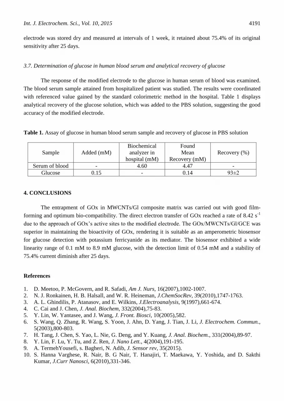
3.7. Determination of glucose in human blood serum and analytical recovery of glucose
The response of the modified electrode to the glucose in human serum of blood was examined.
The blood serum sample attained from hospitalized patient was studied. The results were coordinated
with referenced value gained by the standard colorimetric method in the hospital. Table 1 displays
analytical recovery of the glucose solution, which was added to the PBS solution, suggesting the good
accuracy of the modified electrode.
Table 1. Assay of glucose in human blood serum sample and recovery of glucose in PBS solution
Sample Added (mM)
Biochemical
analyzer in
hospital (mM)
Found
Mean
Recovery (mM)
Recovery (%)
Serum of blood - 4.60 4.47 -
Glucose 0.15 - 0.14 93±2
4. CONCLUSIONS
The entrapment of GOx in MWCNTs/Gl composite matrix was carried out with good film-
forming and optimum bio-compatibility. The direct electron transfer of GOx reached a rate of 8.42 s-1
due to the approach of GOx’s active sites to the modified electrode. The GOx/MWCNTs/Gl/GCE was
superior in maintaining the bioactivity of GOx, rendering it is suitable as an amperometric biosensor
for glucose detection with potassium ferricyanide as its mediator. The biosensor exhibited a wide
linearity range of 0.1 mM to 8.9 mM glucose, with the detection limit of 0.54 mM and a stability of
75.4% current diminish after 25 days.
References
1. D. Meetoo, P. McGovern, and R. Safadi, Am J. Nurs, 16(2007),1002-1007.
2. N. J. Ronkainen, H. B. Halsall, and W. R. Heineman, J.ChemSocRev, 39(2010),1747-1763.
3. A. L. Ghindilis, P. Atanasov, and E. Wilkins, J.Electroanalysis, 9(1997),661-674.
4. C. Cai and J. Chen, J. Anal. Biochem, 332(2004),75-83.
5. Y. Lin, W. Yantasee, and J. Wang, J. Front. Biosci, 10(2005),582.
6. S. Wang, Q. Zhang, R. Wang, S. Yoon, J. Ahn, D. Yang, J. Tian, J. Li, J. Electrochem. Commun.,
5(2003),800-803.
7. H. Tang, J. Chen, S. Yao, L. Nie, G. Deng, and Y. Kuang, J. Anal. Biochem., 331(2004),89-97.
8. Y. Lin, F. Lu, Y. Tu, and Z. Ren, J. Nano Lett., 4(2004),191-195.
9. A. TermehYousefi, s. Bagheri, N. Adib, J. Sensor rev, 35(2015).
10. S. Hanna Varghese, R. Nair, B. G Nair, T. Hanajiri, T. Maekawa, Y. Yoshida, and D. Sakthi
Kumar, J.Curr Nanosci, 6(2010),331-346.

Int. J. Electrochem. Sci., Vol. 10, 2015
4192
11. W. Yang, P. Thordarson, J. J. Gooding, S. P. Ringer, and F. Braet, J. Nanotechnology,
18(2007),412001.
12. J. Wang and Y. Lin, J. Trends Anal. Chem, 27(2008),619-626.
13. T. Ahuja, I. A. Mir, and D. Kumar, J. Biomaterials, 28(2007),791-805.
14. V. Crescenzi, A. Francescangeli, and A. Taglienti, J. Biomacromolecules, 3(2002),1384-1391.
15. D. B. Khadka and D. T. Haynie, J. Nanomedicine, 8(2012),1242-1262.
16. A. Guiseppi-Elie, J. Biomaterials, 31(2010),2701-2716.
17. C. Ozdemir, F. Yeni, D. Odaci, and S. Timur, J. Food Chem., 119(2010),380-385.
18. A. K. Sarma, P. Vatsyayan, P. Goswami, and S. D. Minteer, J. Biosensors and Bioelectronics,
24(2009),2313-2322.
19. A. TermehYousefi, S. Bagheri, K. Shinji, J. Rouhi, M. Rusop Mahmood, and S. Ikeda, J. Biomed
Res Int, (2014).
20. S. K. Pillai, S. S. Ray, and M. Moodley, J. JNN, 7(2007),3011-3047.
21. X. Xing, S. Liu, J. Yu, W. Lian, and J. Huang, J. Biosensors and Bioelectronics, 31(2012),277-
283.
22. J. Yun, C. Lee, Q. Zheng, and S. Baik, J. JNN, 12(2012),6534-6537.
23. A. Termehyousefi, S. Bagheri, N. Kadri, F. M. Elfghi, M. Rusop, and S. Ikeda, J. Mater. Manuf.
Processes, 30(2015),59-62.
24. S. Sung, S. Tsai, C. Tseng, F. Chiang, X. Liu, and H. Shih, J. Appl. Phys. Lett., 74(1999),197-199.
25. A. Termeh Yousefi, S. Bagheri, K. Shinji, M. Rusop Mahmood, and S. Ikeda, J. Mater. Res.
Innovations, (2014).
26. M. Kumar and Y. Ando, J. JNN, 10(2010),3739-3758.
27. Y. Yin, Y. Lü, P. Wu, and C. Cai, J. Sensors, 5(2005),220-234.
28. X. Tu, Y. Zhao, S. Luo, X. Luo, and L. Feng, J. Microchim. Acta, 177(2012),159-166.
29. A. Guiseppi-Elie, C. Lei, and R. H. Baughman, J. Nanotechnology, 13(2002),559.
30. E. Laviron, J. Electroanal chem, 101(1979),19-28.
31. M. Pellissier, F. Barrière, A. J. Downard, and D. Leech, J. Electrochem Commun, 10(2008),835-
838.
32. Y. Liu, M. Wang, F. Zhao, Z. Xu, and S. Dong, J. Biosens Bioelectron, 21(2005),984-988.
33. F. Chekin, S. Bagheri, A. K. Arof, and S. B. A. Hamid, J. Solid State Electr, 16(2012),3245-3251.
34. D. Zhang, K. Zhang, Y. L. Yao, X. H. Xia, and H. Y. Chen, J. Langmuir, 20(2004),7303-7307.
35. G. Cui, S. J. Kim, S. H. Choi, H. Nam, G. S. Cha, and K.-J. Paeng, J. Anal Chem, 72(2000),1925-
1929.
© 2015 The Authors. Published by ESG (www.electrochemsci.org). This article is an open access
article distributed under the terms and conditions of the Creative Commons Attribution license
(http://creativecommons.org/licenses/by/4.0/).


