Embed Size (px)
Citation preview
1
DEPARTMENT OF SPORTS & YOUTH AFFAIRS
GOVT. OF KERALA
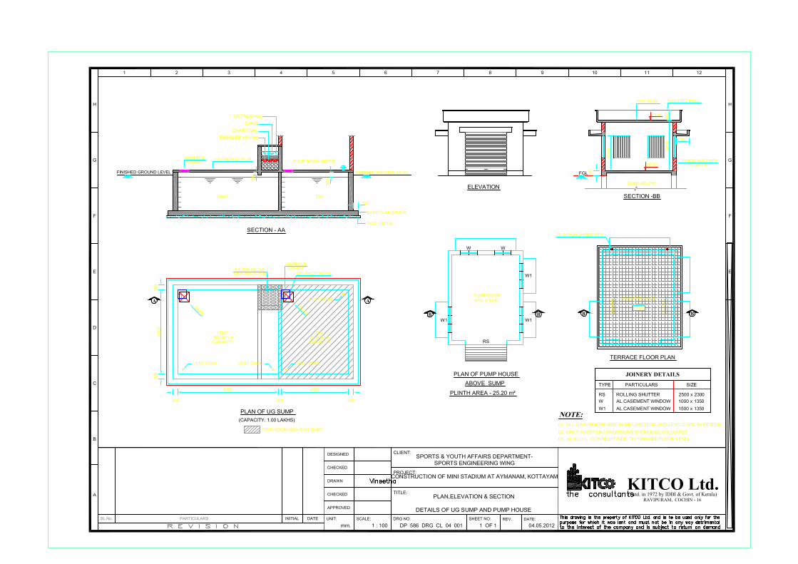
Construction of Mini Stadium at Aymanam,
Kottayam
TENDER DOCUMENT
Tender no: DSYA/KITCO/CL/15/2018
KITCO LTD. P.B.No. 4407, Femith’s Building, Puthiya Road, NH Bypass, Cochin-682 028
2
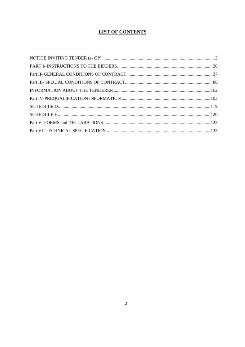
LIST OF CONTENTS
NOTICE INVITING TENDER (e- GP) ................................................................................................... 3
PART I- INSTRUCTIONS TO THE BIDDERS .................................................................................... 20
Part II- GENERAL CONDITIONS OF CONTRACT ........................................................................... 37
Part III- SPECIAL CONDITIONS OF CONTRACT............................................................................. 88
INFORMATION ABOUT THE TENDERER ..................................................................................... 102
Part IV-PREQUALIFICATION INFORMATION .............................................................................. 103
SCHEDULE D ...................................................................................................................................... 119
SCHEDULE E ...................................................................................................................................... 120
Part V- FORMS and DECLARATIONS .............................................................................................. 123
Part VI- TECHNICAL SPECIFICATION ........................................................................................... 133

3
NOTICE INVITING TENDER (e- GP)
KITCO Ltd, Femith’s, PB No. 4407, Puthiya Road, NH Bypass, Vennala, Kochi – 682 028
Dated.19.07.2018
e-Government Procurement (e-GP) NOTICE INVITING TENDER
TENDER NO: DSYA/KITCO/CL/15/2018
KITCO Ltd, Femith’s, PB No. 4407, Puthiya Road, NH Bypass, Vennala, Kochi – 682 028,
for and on behalf of the Secretary, Sports and Youth Affairs, Government of Kerala invites
online bids for the work detailed below from the eligible bidders. The details of the works are
as follows:
1 Name of Work Construction of Mini Stadium at Aymanam,
Kottayam
2 Location of Work Aymanam, Kottayam
3 Brief description of work Construction of Mini Stadium at Aymanam,
Kottayam
4 Bidding procedure Two stage
5 Earnest Money Deposit ( EMD) 1,00,000/-
6 Bid submission fee 8,850/- (inclusive of GST)
7 Period of completion 9 months
8 Classification of Bidder A Class
9 Bid documents Can be downloaded from
www.etenders.kerala.gov.in
10 Last date and time for
submission of bids
13.08.2018 at 3.00pm
11 Date and time of opening of
tender
17.08.2018 at 3.30pm

4
12 AS details G.O.No. (Rt) No. 33 . 2017 DSYA dated 13.02.2017
13 TS details 14/KIIFB/2018-19 dt.18.06.2018
14 Pre-Bid Venue, date and time 31.07.2018 at 11.00 am
15 Form of contract Item rate
Tender documents and tender schedule can be downloaded free of cost from the e-GP
Website www.etenders.kerala.gov.in. All bid documents are to be submitted online only and
in the designated cover(s)/ envelope(s) on the e-GP website. Tenders/ bids shall be accepted
only through online mode on the e-GP website and no manual submission of the same shall
be entertained. Late tenders will not be accepted.
The scanned copies of various certificates duly attested, bid capacity certificate, EMD
exemption certificate (if any) and duly signed copy of bid documents shall be submitted
online. Bid shall only be submitted through online. More details on EMD & bid submission
fee are mentioned in the bid document.
The bids shall be opened online on the date and time as mentioned above at the office
of KITCO Ltd in the presence of the Bidders / their authorized representatives who wish to
attend at the above address. If the tender opening date happens to be on a holiday or non-
working day due to any other valid reason, the tender opening process will be done on the
next working day at same time and place.
Online Tenders/ bids are to be accompanied with a preliminary agreement executed in
Kerala stamp paper worth Rs.200/-. Tenders/ bids received online without the scanned copy
of EMD, bid submission fee and preliminary agreement will not be considered and shall be
summarily rejected.
Bidders may contact e-Procurement support desk of Kerala State IT Mission over telephone at
0471-2577088, 2577188, 2577388 or 0484-2336006, 2332262 – through
email:[email protected] for assistance related to e-tendering.
5
Further details on the project can be had from the NIT or Office
of the KITCO Ltd, Femith’s, PB No. 4407, Puthiya Road, NH Bypass, Vennala, Kochi
– 682 028 during working hours.
All other existing conditions related to tender will be applicable in this tender also unless
expressly defined in the bidding document. KITCO Ltd will not be responsible for any error
like missing of schedule data while downloading by the Bidder. Details required for e-
payment (Details of bank account having core banking facility and e-mail address of the
contractor) shall be furnished along with the tender. Tenders not accompanied by these
details will be rejected. All subsequent G.O's connected to tenders are also applicable to this
tender.
KITCO Ltd, Femith’s, PB No. 4407, Puthiya Road, NH Bypass, Vennala, Kochi – 682 028
reserves the right to accept or reject any or all tenders without assigning any reason thereof.
Managing Director,
KITCO Ltd,
Femith’s, PB No. 4407,
Puthiya Road, NH Bypass,
Vennala, Kochi – 682 028
(For and on behalf of Secretary, Sports and Youth
Affairs, Government of Kerala )
20
PART I- INSTRUCTIONS TO THE BIDDERS
1. GENERAL
1.1 Scope of the Bid:-
For and on behalf of the Secretary, Sports and Youth affairs, KITCO invites bids from
eligible contractors for the work detailed in the Notice Inviting Tender (NIT).
Throughout these bidding documents:
a) The terms 'in writing' means communicated in written form and delivered against
receipt;
b) except where the context requires otherwise, words indicating the singular also include
the plural and words indicating the plural also include the singular; and
c) “day” means calendar day.
d) the terms “bid” and “tender” and their derivatives “bidder/tenderer, bid/tender,
bidding/tendering etc.,” are synonymous.
e) The term “SPV” means Special Purpose Vehicle.
The bids invited shall be for item rate contract.
The mode of this tender is e tender.
1.2 Source of funds
This project has been approved by KIIFB as per the details provided in the NIT. Payment to
the contractor shall be made directly by KIIFB through Direct Beneficiary Transfer (DBT)
upon certification of completion of the Mile Stones mentioned in this tender by the SPV.
1.3 Eligible Bidders
The Bidder shall have appropriate class registration in CPWD/State
PWDs/MES/Railway/Govt. undertakings. The Bidder shall have valid PF, ESI, PAN, GST
registrations.
The Bidder shall have successfully completed at least one similar work costing more than
80% of the Probable Amount of Contract (PAC) of the work described in the NIT during the
last seven years as prime contractor.
or
The Bidder shall have successfully completed two similar works each costing more than 60%
of the Probable Amount of Contract (PAC) of the work described in the NIT during the last
seven years as prime contractor.
21
Or
The Bidder shall have successfully completed three similar works each costing more than
40% of the Probable Amount of Contract (PAC) of the work described in the NIT during the
last seven years as prime contractor.
The bidder shall have an average annual turnover not less than 30% of PAC of the work.
Similar work means Civil and building works including related electrical and fire fighting
works.
Only those bidders having a valid and active registration, on the date of bid submission, shall
submit bids online on the e-tender portal/ website.
Ineligible bidders or bidders who do not posses valid & active registration, on the date of bid
submission, are strictly advised to refrain themselves from participating in this tender. If such
instances are noticed, the same shall be treated as “fake bidding” by the respective bidder and
such bidder shall be blacklisted as per SPV rules in force.
All Bidders are required to register in the e-procurement portal. The Bidder intending to
participate in the bid is required to register in the portal using his/her Login ID and attach
his/her valid Digital Signature Certificate (DSC) to his/her unique Login ID. He/ She have to
submit the relevant information as asked for about the firm/contractor. The bidders, who
submit their bids for this tender after digitally signing using their Digital Signature Certificate
(DSC), accept that they have clearly understood and agreed the terms and conditions
including all the Forms/ Annexure of this tender.
A firm/bidder shall submit only one bid in the same bidding process, either individually as a
bidder or as a partner in a joint venture. A bidder who submits or participates in more than one
bid will cause all the proposals in which the bidder has participated to be disqualified.
Joint ventures, Consortiums Partnership firms of two or more registered contactors are
permitted subjected to the conditions set out in the pre-qualification criteria. The lead partner
who meets all the prequalification criteria shall be the bidder or the JV company should have
done similar projects in the same name and shall meet all the prequalification criteria.
1.4 Cost of Bidding
The bidder shall bear all costs associated with the preparation and submission of its bid, and
the SPV will in no case be responsible or liable for those costs, regardless of the conduct or
outcome of the bidding process.
The tender document(s), may be downloaded free of cost from the e-Government
Procurement (e-GP) website (www.etenders.kerala.gov.in). No payment is required for
downloading the tender documents from the above website however a bid submission fee, as
mentioned in the NIT, is required to be submitted along with the online bid.
22
1.5 Site Visit
The bidder is advised to visit and examine the Site of Works and its surroundings and obtain
for itself on its own responsibility all information that may be necessary for preparing the bid
and entering into a contract for construction of the Works. He shall examine the site condition
and satisfy himself of the availability of materials at nearby places, difficulties which may
arise during execution before submitting the bids. The costs of visiting the Site shall be at the
bidder’s own expense.
The bidder and any of his personnel or agents will be granted permission by the SPV to enter
upon its premises and lands for the purpose of such visit, but only upon the express condition
that the bidder, his personnel or agents will release and indemnify the SPV and its personnel
and agents from and against all liability in respect thereof, and will be responsible for death or
personal injury, loss of or damage to property, and any other loss, damage, costs, and
expenses incurred as a result of the inspection.
1.6 Getting information from web portal
All prospective bidders are expected to see all information regarding submission of bid for the
Work published in the e tender website during the period from the date of publication of NIT
for the Work and up to the last date and time for submission of bid. Non observance of
information published in the website shall not be entertained as a reason for any claim or
dispute regarding a tender at any stage.
All corrigenda shall be published on www.etenders.kerala.gov.in and shall not be available
elsewhere.
All bids shall be submitted online on the e-GP website only in the relevant envelope(s)/
cover(s), as per the type of tender. No manual submission of bids shall be entertained for the
tenders published through e-GP system under any circumstances.
The e-GP system shall not allow submission of bids online after the stipulated date & time.
The bidder is advised to submit the bids well before the stipulated date & time to avoid any
kind of network issues, traffic congestion, etc. In this regard, the SPV shall not be
responsible for any kind of such issues faced by bidder.
1.7 Bidding Documents
Content of Bidding Documents
The bidding documents shall consists of the following unless otherwise specified
a) Notice Inviting Tender(NIT)
b) Instructions to Bidders
c) General and special Conditions of Contract
d) Technical Specifications
e) Form of Bid, Appendix to Bid, Preliminary agreement format
23
f) Bill of Quantities
g) Drawings
The Bidder is required to login to the e-procurement portal and download the listed
documents from the website as mentioned in NIT.
The bidder shall save it in their system and undertake the necessary preparatory work off-line
and upload the completed bid at their convenience before the closing date and time of
submission.
The bidder is expected to examine carefully all instructions, conditions of contract, contract
data, forms, terms, technical specifications, bill of quantities, Annexures and drawings in the
Bid Document. Failure to comply with the requirements of Bid Document shall be at the
bidders own risk.
1.8 Clarification of Bidding Documents and Pre-Bid meeting
A prospective bidder requiring any clarification of the bidding documents shall contact the
office of the Tendering Authority on any working day between 10 am and 5 pm.
In case the clarification sought necessitates modification of the bid documents, being
unavoidable, SPV may make required modification and publish them in the website through
corrigendum to this bid document.
The SPV/Tender Inviting authority may decide to conduct a pre-bid meeting to clarify the
queries raised by prospective bidders. The venue, date and time for such pre-bid meetings, if
any, will be notified in the NIT. The bidder is requested as far as possible to submit any
questions in writing or by e-mail, to reach the SPV not later than three days before the
meeting. It may not be practicable at the meeting to answer questions received late, but
questions and responses will be transmitted in accordance with the following:
a) Minutes of the meeting including the text of the questions raised and the responses given
together with any responses prepared after the meeting will be published in the e-tenders
portal as corrigendum.
b) Any modification of the tender documents which may become necessary as a result of
the pre-bid meeting shall be made by the SPV exclusively through the issue of an
addendum and not through the minutes of the pre-bid meeting.
c) Non-attendance at the pre-bid meeting will not be cause for disqualification of a bidder.
d) Non-attendance at the pre-bid meeting will not be cause for escape from any bid
requirements whatsoever.
Amendment to bidding documents
Before the deadline for submission of bids, the SPV may modify the bidding document by
issuing addenda.
Any addendum thus issued shall be a part of the bidding documents which will be published
24
in the e-tender website. The SPV will not be responsible for the prospective bidders not
viewing the website on time.
If the addendum thus published does involves major changes in the scope of work, the SPV
may at his own discretion, extend the deadline for submission of bids for a suitable period to
enable prospective bidders take reasonable time for bid preparation taking in to account the
addendum published.
1.9 Preparation of Bids
Language of the Bid
All documents relating to the bid shall be in the English language.
1.10 Documents Comprising the Bid
The online bid submitted by the bidder shall comprise the following:
a) Details required for e-payment (Details of bank account having core banking facility and
e-mail address of the contractor) in the prescribed format.
b) Online payment of bid submission fee as detailed in the e- tender web site.
c) Bid Security / EMD
d) Duly filled-complete Bid document with all the required certificates copies in the
appropriate covers as required in the web portal
e) Priced Bill of Quantities
f) Copy of Registration Certificate attested by a Gazetted Officer.
g) Duly signed preliminary agreement.
The relevant CPWD/MoRTH specifications and BIS/IS codes and the relevant sections of the
National Building Code shall be considered as part of the bid documents though individual
copies are not attached along with the bid documents.
Bidders shall not make any addition, deletion or correction in any of the bid documents. If
tampering of documents is noticed during tender evaluation, the bid will be rejected and the
bidder will be blacklisted.
1.10.01 The First Stage (Cover 1- Prequalification cum Technical Bid Document):
Pre-Qualification cum Technical bid proposal shall contain the scanned copies of the
following documents which every bidder has to upload:
i. Document proof of Eligibility Criteria mentioned in Notice Inviting Tender.
ii. Online Tenders/bids are to be accompanied with a preliminary agreement executed in
Kerala stamp paper worth Rs.200/-.
25
iii. The format for information about the tenderer attached in special conditions of contract
and tender form in NIT shall be duly filled by the tenderer and should upload the same as
pdf format with technical bid.
The department doesn’t take any responsibility for any technical snag or failure that has
taken place during document upload. Hard copy of Preliminary agreement shall be submitted
to the office of KITCO Ltd, Ernakulam before the price bid opening. The other credentials
shall be submitted to the above office as and when requested from our end.
1.10.02 The Second Stage (Cover 2- Financial Bid):
The Bidder shall complete the Price bid as per format given for download along with this
tender.
Note: The blank price bid should be downloaded and saved on bidder’s computer without
changing file-name otherwise price bid will not get uploaded. The bidder should fill in the
details in the same file and upload the same back to the website.
Fixed price: Prices quoted by the Bidder shall be fixed during the bidder's performance of the
contract and not subject to variation on any account. A bid submitted with an adjustable/
variable price quotation will be treated as non - responsive and rejected.
1.11 Bid Prices
The Bidder shall bid for the whole work as described in the Bill of Quantities.
For item rate tenders, the bidder shall fill in rates in figures and should not leave any cell
blank. The line item total in words and the total amount shall be calculated by the system and
shall be visible to the Bidder. If any item is omitted by the lowest bidder, the bidder shall
execute the same at “Zero” cost.
The rates quoted by the bidder shall include cost of all materials and conveyance, labour
charges, hire charges of plant and machinery, overheads and all incidental charges for
execution of the contract.
The quoted rates shall also include expenses towards all Quality Control tests prescribed in
the IS codes or as directed by the Engineering In-Charge and to be done at
Government/Aided Engineering Colleges or Polytechnic Colleges or NABL Accredited
laboratories.
All taxes and other levies payable by the contractor under the contract, or for any other cause
as of the date 28 days prior to the deadline for submission of bids shall be included in the
rates, prices and total of bid price in item rate contracts.
No material will be issued by SPV for executing the building works under this contract.
26
The rates and prices quoted by the bidder shall remain firm during the entire period of
contract.
A bidder who submits bid for this contract shall bear in mind that payment for the bills
submitted shall be subject to availability of funds. Payments shall only be released after
issuing Letter of Credit from the Government based on the seniority of pending bills.
Contractor is not eligible for interest for delayed payment.
1.12 Currencies of Bid and Payment
The currency of bid and payment shall be quoted by the bidder entirely in Indian Rupees. All
payments shall be made in Indian Rupees only.
1.13 Bid Validity
Bids shall remain valid for the period of 120 days after the deadline for bid submission as
specified in the NIT. A bid valid for a shorter period shall be rejected by the SPV as non
responsive.
In exceptional circumstances, prior to expiry of the original bid validity period, the SPV may
request the bidders to extend the period of validity for a specified additional period. The
request and the responses thereto shall be made in writing or by e-mail. A bidder may refuse
the request without forfeiting its bid security. A bidder agreeing to the request will not be
required or permitted to modify its bid, but will be required to extend the validity of its bid
security for the period of the extension and in compliance with other clause of the contract in
all respects.
1.14 Tender fee /Bid security/Earnest Money Deposit(EMD)
The Bidder shall pay, a tender document fees of Rs.8,850/- (inclusive of GST) and Earnest
Money Deposit or Bid Security of Rs.1,00,000/-. The Bid security is required to protect the
purchaser against risk of Bidder’s conduct, which would warrant the forfeiture of security.
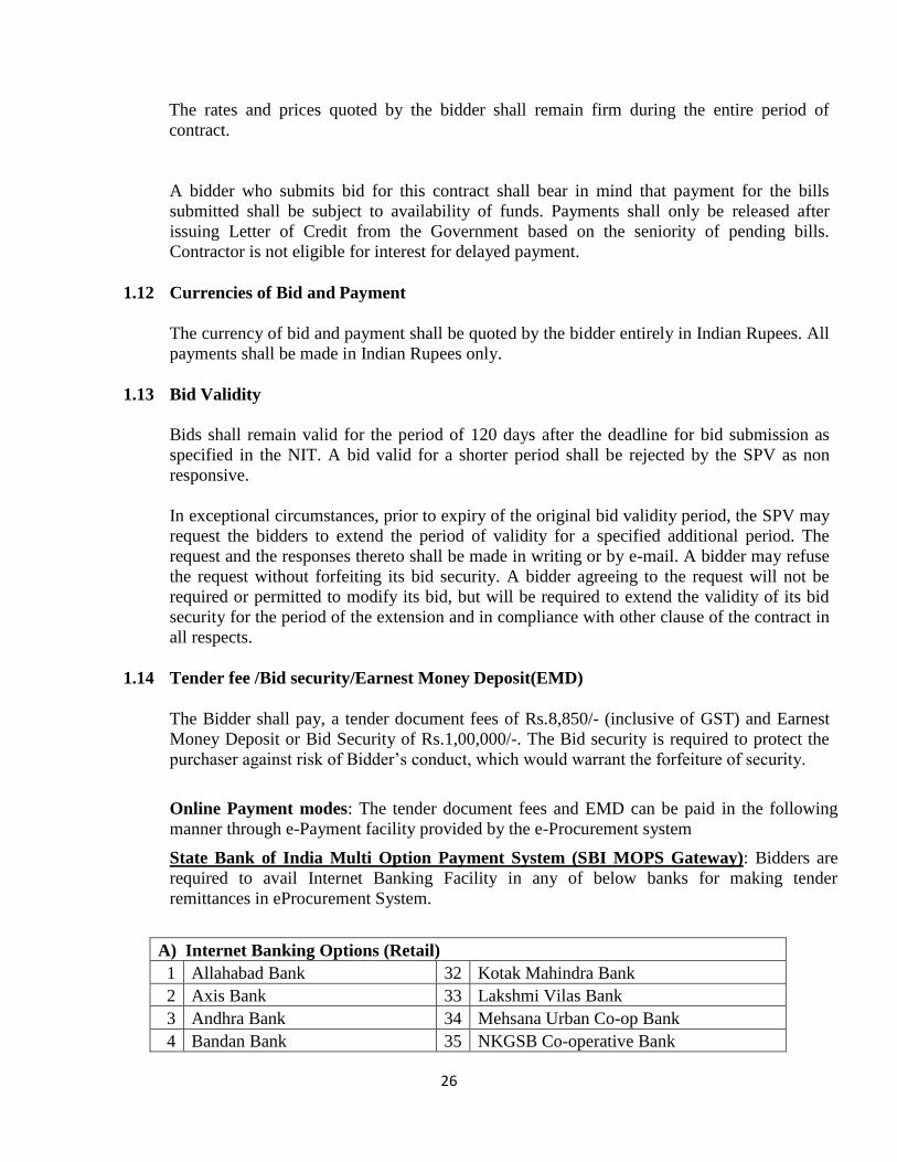
Online Payment modes: The tender document fees and EMD can be paid in the following
manner through e-Payment facility provided by the e-Procurement system
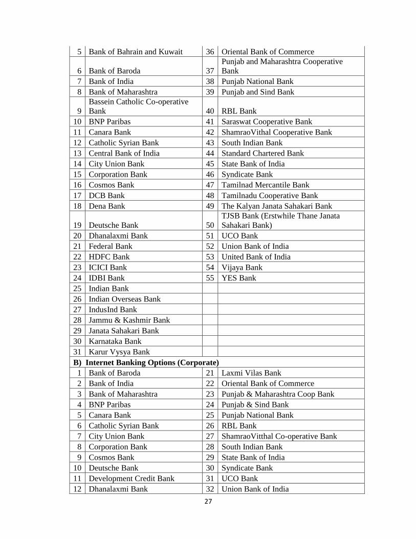
State Bank of India Multi Option Payment System (SBI MOPS Gateway): Bidders are
required to avail Internet Banking Facility in any of below banks for making tender
remittances in eProcurement System.
A) Internet Banking Options (Retail)
1 Allahabad Bank 32 Kotak Mahindra Bank
2 Axis Bank 33 Lakshmi Vilas Bank
3 Andhra Bank 34 Mehsana Urban Co-op Bank
4 Bandan Bank 35 NKGSB Co-operative Bank
27
5 Bank of Bahrain and Kuwait 36 Oriental Bank of Commerce
6 Bank of Baroda 37
Punjab and Maharashtra Cooperative
Bank
7 Bank of India 38 Punjab National Bank
8 Bank of Maharashtra 39 Punjab and Sind Bank
9
Bassein Catholic Co-operative
Bank 40 RBL Bank
10 BNP Paribas 41 Saraswat Cooperative Bank
11 Canara Bank 42 ShamraoVithal Cooperative Bank
12 Catholic Syrian Bank 43 South Indian Bank
13 Central Bank of India 44 Standard Chartered Bank
14 City Union Bank 45 State Bank of India
15 Corporation Bank 46 Syndicate Bank
16 Cosmos Bank 47 Tamilnad Mercantile Bank
17 DCB Bank 48 Tamilnadu Cooperative Bank
18 Dena Bank 49 The Kalyan Janata Sahakari Bank
19 Deutsche Bank 50
TJSB Bank (Erstwhile Thane Janata
Sahakari Bank)
20 Dhanalaxmi Bank 51 UCO Bank
21 Federal Bank 52 Union Bank of India
22 HDFC Bank 53 United Bank of India
23 ICICI Bank 54 Vijaya Bank
24 IDBI Bank 55 YES Bank
25 Indian Bank
26 Indian Overseas Bank
27 IndusInd Bank
28 Jammu & Kashmir Bank
29 Janata Sahakari Bank
30 Karnataka Bank
31 Karur Vysya Bank
B) Internet Banking Options (Corporate)
1 Bank of Baroda 21 Laxmi Vilas Bank
2 Bank of India 22 Oriental Bank of Commerce
3 Bank of Maharashtra 23 Punjab & Maharashtra Coop Bank
4 BNP Paribas 24 Punjab & Sind Bank
5 Canara Bank 25 Punjab National Bank
6 Catholic Syrian Bank 26 RBL Bank
7 City Union Bank 27 ShamraoVitthal Co-operative Bank
8 Corporation Bank 28 South Indian Bank
9 Cosmos Bank 29 State Bank of India
10 Deutsche Bank 30 Syndicate Bank
11 Development Credit Bank 31 UCO Bank
12 Dhanalaxmi Bank 32 Union Bank of India
28
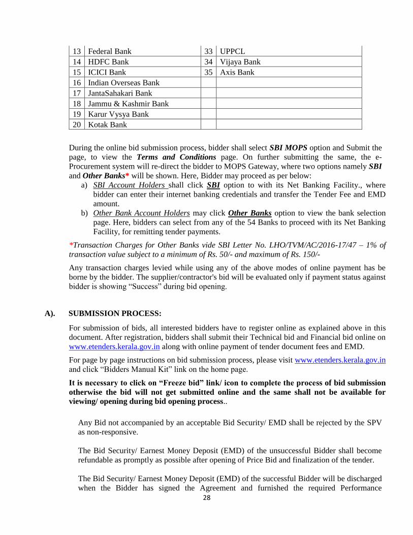
13 Federal Bank 33 UPPCL
14 HDFC Bank 34 Vijaya Bank
15 ICICI Bank 35 Axis Bank
16 Indian Overseas Bank
17 JantaSahakari Bank
18 Jammu & Kashmir Bank
19 Karur Vysya Bank
20 Kotak Bank
During the online bid submission process, bidder shall select SBI MOPS option and Submit the
page, to view the Terms and Conditions page. On further submitting the same, the e-
Procurement system will re-direct the bidder to MOPS Gateway, where two options namely SBI
and Other Banks* will be shown. Here, Bidder may proceed as per below:
a) SBI Account Holders shall click SBI option to with its Net Banking Facility., where
bidder can enter their internet banking credentials and transfer the Tender Fee and EMD
amount.
b) Other Bank Account Holders may click Other Banks option to view the bank selection
page. Here, bidders can select from any of the 54 Banks to proceed with its Net Banking
Facility, for remitting tender payments.
*Transaction Charges for Other Banks vide SBI Letter No. LHO/TVM/AC/2016-17/47 – 1% of
transaction value subject to a minimum of Rs. 50/- and maximum of Rs. 150/-
Any transaction charges levied while using any of the above modes of online payment has be
borne by the bidder. The supplier/contractor's bid will be evaluated only if payment status against
bidder is showing “Success” during bid opening.
A). SUBMISSION PROCESS:
For submission of bids, all interested bidders have to register online as explained above in this
document. After registration, bidders shall submit their Technical bid and Financial bid online on
www.etenders.kerala.gov.in along with online payment of tender document fees and EMD.
For page by page instructions on bid submission process, please visit www.etenders.kerala.gov.in
and click “Bidders Manual Kit” link on the home page.
It is necessary to click on “Freeze bid” link/ icon to complete the process of bid submission
otherwise the bid will not get submitted online and the same shall not be available for
viewing/ opening during bid opening process..
Any Bid not accompanied by an acceptable Bid Security/ EMD shall be rejected by the SPV
as non-responsive.
The Bid Security/ Earnest Money Deposit (EMD) of the unsuccessful Bidder shall become
refundable as promptly as possible after opening of Price Bid and finalization of the tender.
The Bid Security/ Earnest Money Deposit (EMD) of the successful Bidder will be discharged
when the Bidder has signed the Agreement and furnished the required Performance
29
Security/Security Deposit.
Waiving of Bid Security- In respect of organizations, which are exempted by Government to
that effect. In this case, the bidder shall produce copy of Government order showing
exception in remittance of bid security while participating in the tender process.
The Bid Security/ Earnest Money Deposit may be forfeited:
a) if the Bidder withdraws the Bid after Bid opening during the period of Bid validity
including extended period of validity; or
b) if any modification is effected to the tender documents.
c) in the case of a successful Bidder, if the Bidder fails within the specified time limit
to:
i. sign the Agreement; or
ii. Furnish the required Performance Security/Security Deposit
iii. If the bidder fails to convince the SPV about the reasonability of his bid prices in
the case of an unbalanced bid.
The Bid Security/ EMD deposited with the SPV will not carry any interest.
Any bid not accompanied by the Tender Fee as notified shall be rejected by the SPV as
nonresponsive.
Tender Fee remitted will not be refunded.
1.15 Alterations and additions
The bid shall contain no alterations or additions, except those to comply with instructions
issued by SPV, or as necessary to correct errors made by the bidder, in which case such
corrections shall be initialed by the person or persons signing the bid.
The tenderer shall not attach any conditions of his own to his tender.
The tender price must be based on the tender documents. The tenderer is not required to
present alternative construction options and he shall use without exception the Bills of
Quantities as provided, with the amendments as notified in tender notices, if any, for the
calculation of his tender price. Any tenderer who fails to comply with this clause will be
disqualified.
1.16 Submission of Bids
All documents of the Bid shall be typed or written in indelible ink and shall be signed by the
bidder or person duly authorised to sign on behalf of the Bidder. All pages of the Bid
document shall be initialed by the person or persons signing the Bid. The initials should also
accompany stamp of the name of bidder or his firm/organization.
The Bidder shall submit their bid online only through the e-GP web site of Kerala
(www.etenders.kerela.gov.in) as per the procedure laid down for e-submission as detailed by
30
the web site. For e-tenders, the bidders shall download the tender documents including the
BOQ file from the e tendering portal http://www. etenders.kerala.gov.in. They shall fill up
the documents and submit online using their Digital Signature Certificate. On successful
submission of bids, a system generated receipt can be downloaded by the bidder for future
reference. Copies of all certificates and documents shall be uploaded while submitting the
tender online.
The bidder must attach the scanned copies of solvency certificates clearly indicating to what
extent they are solvent from the Tahsildar of the Taluk where they reside along with their
online tenders. The bidder shall produce the original copies of the above solvency
certificates, in physical format, if required by the SPV for verification. The bidder must
attach the scanned copy of the recent return statement filed by the bidder before the
appropriate Income tax authority along with their online tenders. The bidder shall produce
the necessary income tax documents, if required by the SPV for verification. In the case of
proprietary or partnership firm, it will be necessary to submit online the scanned copy of the
certificates aforementioned for the proprietor or proprietors and for each of the partners as
the case may be.
The bidder shall digitally sign all statements, documents, certificates uploaded by him,
owning sole and complete responsibility for their correctness/authenticity of these
documents.
After submitting the tender/bid online, the bidder shall prepare hard copies of certificates and
other relevant documents duly signed by the bidder or his authorised representative together
with one set of complete signed copy of the bid document(except price bid). This whole set
of certificates with complete bid documents shall be send to the SPV’s office address(as
given in the NIT) by registered post/Speed post of India Post in such a way that it shall be
delivered to the SPV before the deadline of opening of technical bid. The SPV reserves the
right to reject any bid, for which the signed hard copy of bid document is not received before
the date of opening of technical bid.
The Price bid shall only be submitted through online. Upon pre-qualification, the SPV/tender
inviting authority shall inform the date of opening of the price bid to the qualified bidders
through e -portal.
The SPV/tendering authority shall not be responsible for any failure, malfunction or
breakdown of the electronic system while downloading or uploading the documents by the
Bidder during the e- procurement process.
For page by page instructions on bid submission process, please visit
www.etenders.kerala.gov.in and click “Bidders Manual Kit” link on the home page.
It is necessary to click on “Freeze bid” link/ icon to complete the process of bid
submission otherwise the bid will not get submitted online and the same shall not be
available for viewing/ opening during bid opening process.
Tenders/bids received online without the preliminary agreement will not be considered and
31
shall be summarily rejected. Further details can be had from the Notice Inviting Tender
(NIT) or Office of the KITCO Ltd. during working hours.
1.17 Deadline for Submission of the Bids
Bid shall be received only ONLINE on or before the date and time as notified in NIT.
The SPV, in exceptional circumstances and at its own discretion, may extend the last date for
submission of bids, in which case all rights and obligations of the SPV and the bidders
previously subject to the original date will then be subject to the new date of submission.
The Bidder will not be able to submit his bid after expiry of the date and time of submission
of bid (server time).
1.18 Modification, Resubmission and Withdrawal of Bids
Resubmission or modification of bid by the bidders for any number of times before the date
and time of submission is allowed. Resubmission of bid shall require uploading of all
documents including price bid afresh.
If the bidder fails to submit his modified bids within the pre- defined time of receipt, the
system shall consider only the last bid submitted.
The Bidder can withdraw his/her bid before the date and time of receipt of the bid. The
system shall not allow any withdrawal after the date and time of submission.
1.19 Bid Opening and Evaluation
Bid Opening
Bids shall be opened on the specified date & time, by the SPV/tender inviting authority or his
authorised representative in the presence of bidders or their designated representatives who
choose to attend.
Opening of bids shall be carried out in the same order as it is occurring in invitation of bids
or as in order of receipt of bids in the portal. The bidders & guest users can view the
summary of opening of bids from any system. Bidders are not required to be present during
the bid opening at the opening location if they so desire.
In the event of the specified date of bid opening being declared a holiday for the SPV, the
bids will be opened at the same time on the next working day.
1.20 Confidentiality
Information relating to the examination, clarification, evaluation, and comparison of Bids
and recommendations for the award of a contract shall not be disclosed to Bidders or any
32
other persons not officially concerned with such process until the award has been announced
in favour of the successful bidder.
Any effort by a Bidder to influence the SPV during processing of bids, evaluation, bid
comparison or award decisions shall be treated as Corrupt & Fraudulent Practices, mentioned
under ITB and may result in the rejection of the Bidders' bid.
1.21 Clarification of Bids
To assist in the examination, evaluation, and comparison of bids, and qualification of the
bidders; the SPV may ask the bidder for required clarification on the information submitted
with the bid. The request for clarification and the response shall be in writing or by e- mail,
but no change in the price or substance of the Bid shall be sought, offered, or permitted.
No Bidder shall contact the SPV on any matter relating to the submitted bid from the time of
the bid opening to the time the contract is awarded. If the Bidder wishes to bring additional
information to the notice of the SPV, it shall do so in writing.
1.22 Examination of Bids, and Determination of Responsiveness
During the detailed evaluation of bid/Technical Bid, the SPV will determine whether each
Bid
a. meets the eligibility criteria as required in the NIT;
b. meets the qualification criteria in accordance with the provision of NIT; and
c. is accompanied by the required bid security and the required documents and
certificates.
A substantially responsive bid is one which conforms to all the terms, conditions, and
requirements of the bidding documents, without material deviation or reservation. A material
deviation or reservation is one
a. which affects in any substantial way the scope, quality, or performance of the
Works;
b. which limits in any substantial way, inconsistent with the bidding documents, the
SPV's rights or the Bidder's obligations under the Contract; or
c. whose rectification would affect unfairly the competitive position of other Bidders
presenting substantially responsive Bids.
If a Bid is not substantially responsive, it may be rejected by the SPV, and may not
subsequently be made responsive by correction or withdrawal of the nonconforming material
deviation or reservation.
Non submission of legible or required documents or evidences may render the bid non-
responsive.
The Technical evaluation of all the bids shall be carried out as per information furnished by
33
Bidders. The SPV will evaluate bid and finalize list of responsive bidders.
In the case of bids where pre-qualification is required, the technical bid submitted by the
responsive bidders shall be evaluated as per the pre-qualification criteria by a Committee of
Engineers of SPV to finalise the pre-qualified bidder.
The Financial Bids of the technically responsive/ pre-qualified bidders shall be opened. The
Bid Inviting Officer shall log on to the system in sequence and open the Financial Bid. At the
time of opening of “Financial Bid”, bidders, whose Technical Bids were found responsive,
may be present.
Bidder can witness the principal activities and view the documents/summary reports for that
particular work by logging on to the portal with his DSC from anywhere.
Single tender received in response to the first tender call shall be rejected.
1.23 Negotiation on Bids
The tender inviting authority may resort to negotiations on the Bids submitted by the
responsive bidders. The rates negotiated by the bidders are final and shall not be changed at
any stage during the period of contract.
1.24 Award of Contract
The SPV will award the Contract to the Bidder whose bid has been determined to be
substantially responsive and who has offered the lowest evaluated bid price.
In the eventuality of failure on the part of the lowest successful bidder to produce the original
documents, or submit the performance security, the Bidder shall be debarred in future from
participating in all the Bids for three years and will be recommended for blacklisting by the
competent authority. In such a situation, the next successful bidder will be requested to
produce further documents for consideration of his bid at the rate quoted by the first lowest
bidder. Otherwise the tender will be cancelled.
If the rate quoted for individual item/items is unbalanced or unworkable or below the
estimated rate, the successful bidder shall provide additional performance guarantee in the
form of Cash or Bank Guarantee to ensure the successful completion of the individual
item/items. The Accepting Authority may decide the amount of such performance guarantee
based on the difference between quoted rate and estimated rate.
If two or more bidders quote the same lowest rate/amount, the bid accepting authority will
finalize the tender through a transparent lottery system, where all lowest bidders/their
authorized representatives, will remain present.
1.25 SPV’s Right to Accept any Bid and to Reject any or all Bids
The SPV reserves the right to accept or reject any Bid and to cancel the Bidding process and
reject all Bids at any time prior to the award of Contract, without thereby incurring any
34
liability to the affected Bidder or Bidders or any obligation to inform the affected Bidder or
Bidders of the grounds for the SPV’s action.
1.26 Notification of Award and Signing of Agreement
The Bidder, whose Bid has been accepted, shall be notified of award by the SPV prior to
expiration of the Bid validity period by facsimile or e-mail confirmed by letter sent through
post. This letter (hereinafter and in the Conditions of Contract called the "Letter of
Acceptance") will state the sum that the SPV will pay the Bidder in consideration of the
execution, completion and remedying defects of the Works by the Contractor as prescribed
by the Contract (hereinafter and in the Contract called the "Contract Price").
The notification of award will constitute the formation of the Contract, subject only to the
furnishing of a performance security in accordance with the provisions within 15 days of
issue of letter of acceptance.
If the successful bidder fails to furnish the required performance security, within the above
stipulated time, further ten days time will be allowed at the request of the contractor, for
which the successful bidder has to remit a fine equal to 1% of the Contract Price as per their
quote subject to a minimum of Rs.10,000 and maximum of Rs.2,50,000/-. The fine shall be
remitted in cash at the office of the Agreement Authority before executing agreement.
The Agreement will be signed by the Tender Inviting authority and kept ready for signature
of the successful bidder in the office of the Tender Inviting authority within 30 days
following the issue of the Letter of Acceptance.
Upon the furnishing by the successful Bidder of the Performance Security, the Tender
Inviting authority will promptly notify the other Bidders that their Bids have been
unsuccessful and refund the Bid Security/Earnest Money Deposit.
1.27 Performance Security/Security Deposit/Performance Guarantee
Within 15 days of issue of letter of acceptance, the Contractor should submit 5% of the
Contact Value as Performance Guarantee. Of this, 50% of the Performance Guarantee shall
be in the form of DD in favour of KITCO Ltd payable at Ernakulam from Nationalised
\Scheduled Bank. Balance 50% of Performance guarantee shall be in the form of Bank
Guarantee.
In addition to Performance Guarantee, Security Deposit shall be collected by deduction from
the running/final bill of the Contractors @ 2.5% of the gross amount of each running and / or
final claims.
All the deposits of EMD, PERFORMANCE GUARANTEE AND SECURITY DEPOSIT
will not bear any interest whatsoever.
Additional performance guaranty will be required to be deposited, if the quoted amount by
the bidder is below the estimated rate. This additional performance guaranty shall be equal to
the unbalanced price in the estimate item rates and quoted item rates. This will be released
only after satisfactory completion of the work without any interest.
35
The Guarantee amount shall be payable to the SPV without any condition whatsoever.
The Performance Guarantee shall cover additionally the following guarantees to the SPV:
The successful bidder guarantees the successful and satisfactory construction of the
infrastructure and other related works under the contract, as per the specifications and
documents.
The successful bidder further guarantees that the infrastructure and equipments provided and
installed by them shall be free from all defects in material and workmanship and shall, upon
written notice from the SPV, fully remedy free of expenses to the SPV, such defects as
developed under the normal use of the said infrastructure within the period of defect liability
period mentioned in the Contract.
The Contract Performance Guarantee is intended to secure the performance of the entire
Contract. However, it is not construed as limiting the damages stipulated in the other clauses
in the bidding documents.
The SPV shall be at liberty to deduct/appropriate from the Contract Performance
Guarantee/Security Deposit such sums as are due and payable by the contractor to the SPV as
may be determined in terms of the contract, and the amount appropriated from the Contract
Performance Guarantee/Security Deposit shall have to be restored by Contractor
subsequently.
On satisfactory completion of the work and after one year from the date of completion
certificate the 50% of Performance Guarantee kept in the form of Bank Guarantee will be
refunded to the Contractor based on the report from the Engineer-in-Charge.
On completion of Defects Liability Period the Engineer-in-Charge, shall recommend on
demand from the Contractor to refund to him the 50% of Performance Guarantee kept in the
form of DD and the Security Deposit deducted from RA Bills, and the same will be refunded
by the Accepting Authority provided that the Engineer-in-Charge is satisfied that there is no
demand outstanding against the Contractor.
Failure of the successful Bidder to comply with the requirements of sub-clause mentioned
above shall constitute sufficient grounds for cancellation of the award and forfeiture of the
Bid Security.
1.28 Corrupt or Fraudulent Practices
It is required that the bidders observe the highest standard of ethics during the procurement
and execution of such contracts. In pursuance of this policy, it is defined, for the purposes of
this provision, the terms set forth below as follows:
“Corrupt practice” means the offering, giving, receiving or soliciting of anything of value to
influence the action of a public official in the procurement process or in contract execution;
36
and
“Fraudulent practice” means a misrepresentation of facts in order to influence a procurement
process or the execution of a contract to the detriment of the SPV and includes collusive
practice among Bidders (prior to or after bid submission) designed to establish bid prices at
artificial non-competitive levels and to deprive the Government of the benefits of free and
open competition.
“collusive practice” is an arrangement between two or more parties designed to achieve an
improper purpose, including to influence improperly the actions of another party;
“Coercive practice” is impairing or harming, or threatening to impair or harm, directly or
indirectly, any party or the property of the party to influence improperly the actions of a
party.
The SPV will reject a proposal for evaluation, and/or award if it determines that the Bidder
recommended for award has engaged in any of the corrupt or practices in competing for the
contract in question and will declare the firm ineligible, either indefinitely or for a stated
period of time, to be awarded a contract, if it at any time determines that the firm has engaged
in corrupt or fraudulent practices in competing for, or in executing the contract.
1.29 Settlement of disputes
Any legal dispute arising out of or in any way connected with this contract shall be deemed to
have arisen at site and shall be settled in a court of competent jurisdiction located in
Ernakulam, Kerala.
1.30 Forms and declarations
Various forms and formats for declarations to be submitted by the Bidder for Bid submission
and pre-qualification detail submissions are included in the sections- Forms and Pre-
qualification Information. Bidders are requested to fill in the required forms and declarations
and submit the same with their bids both online and in hard copy.
37
Part II- GENERAL CONDITIONS OF CONTRACT
2.1 Definitions
Client/Owner means the Secretary, Sports and Youth Affairs, Government of Kerala or
his assigned nominees.
Payment authority means KIIF-B in this case who shall make the payment on
recommendation of the SPV based on milestones included in this tender.
SPV means the consultant nominated by the Client to take up the design, monitoring and
implementation of the project on their behalf.
Accepting Authority/Agreement Authority means the officer who has invited and
received bids for the project and has executed agreement on behalf of the SPV.
Engineer means all Engineers in charge of the project nominated by the SPV.
Field Engineer means engineers at the project site who are directly in charge of execution
of the project.
Engineer’s Representative means any staff posted to the project site to supervise the
execution of the project and to maintain documents.
Contract is the contract between the Accepting Authority and the selected bidder to
execute, complete and maintain the project.
Contractor means person or persons or firms who have entered into contract for the
execution of the work subject to the eligibility conditions of the NIT.
Contract Price is the price stated in the Letter of Acceptance and thereafter as adjusted in
accordance with the provision of the contract.
Contract Documents defines the documents and other information which comprise the
contract.
Bid or Tender means the Contractor’s priced offer to the SPV for the execution and
completion of the project and the remedying of any defects therein in accordance with
the provisions of Contract.
Bill of Quantities means the priced and completed Bill of Quantities forming part of the
bid.
Specification means the instructions, provisions, conditions and detailed requirements
contained in the tender documents which form part of the contract and any modification
or addition made or approved by the Accepting Authority.
38
Drawings means all drawings, calculations and technical information related to the
project provided by the Engineer from time to time to the Contractor under the Contract.
Letter of Acceptance means intimation issued by the Accepting Authority as formal
acceptance of Bid by the SPV.
Date of commencement means the day ten days subsequent to the date of agreement
unless rescheduled by an order in writing of the Accepting Authority for reasons
attributable to the SPV/Client.
Time of completion means the period allowed for completing all works related to the
project including carrying out and passing the required quality control tests prescribed in
the IS codes or as directed by the Engineer In Charge.
Date of completion is the actual date of completion of all works related to the project as
certified by the Engineer In Charge
Quality control tests means all relevant tests prescribed in the relevant IS codes
applicable to the project which are to be made and passed before each part bill is
presented for payment.
A Defect is any work not completed/done in accordance with the contract/schedule.
Defects Liability Period is the period mentioned in the contract data and calculated from
the date of completion.
Plant is any integral part of the works which is to have a mechanical, electrical,
electronic or biological function.
Equipment means contractor’s machinery and vehicles brought temporarily to site for
execution of the project.
Site means the places provided by the SPV/Owner where the project is to be executed. It
may also include any other place or places as forming part of the site, mentioned in the
Contract.
Materials means all supplies, including consumables used by the contractor for
incorporation in the works.
Works are what the Contract requires the contractor to construct, install and run over to
the satisfaction of SPV as defined in Contract Data.
Days are calendar days and months are calendar months.
“Government Approvals” shall mean all permits, licenses, authorizations, consents,
clearances, decrees, waivers, privileges, approvals from and filing with government
instrumentalities necessary for the development, construction and operation of the
project.
39
Measurement Books shall mean as the books with serially numbered and maintained
during the currency of the Project to record all measurements qualifying for payment.
Except for quantities of work paid on level basis, all measurements shall be recorded in
the measurement book. For measurements taken on level basis, the levels shall be entered
in properly numbered field books. All measurement books and Field Books shall be
certified by the Engineer-in-Charge before entering measurements.
"Codes" shall mean the following, including the latest amendments, and/or
replacements, if any:
a. Standards of Bureau of Indian Standards relevant to the works under the
Contract and their specifications.
b. Other Internationally approved Standards and/or rules and regulations touching
the subject matter of the Contract.
c. Any other laws, rules, regulations and Acts applicable in the country with
respect to labour, safety, compensation, insurance etc.
Words importing singular only shall also include the plural and vice-versa where the
context so requires.
Words importing "Person" shall include firms, companies, corporations, and associations
or bodies of individuals, whether incorporated or not.
Terms and expressions, not defined herein, shall have the same meaning as are assigned
to them in the Indian Contract Act, and failing that in the General Clauses Act.
2.2 Scope, extent, intent etc.
Scope: The general character and the scope of the Work shall be as illustrated and
defined in the Drawings, Specifications, Schedule of Rates and other Contract
Documents.
Extent: The Contractor shall carry out and complete the Work under the Contract in
every respect, and his work shall include the supply of all labour, equipment, materials,
plant and machinery, tools, transportation, form work, scaffolding and everything else
necessary for the proper execution and completion of the Work in accordance with the
Contract Documents and to the directions and satisfaction of the Engineer. The
Contractor shall be fully responsible and liable for everything and all matters in
connection with or arising out of or being a result or consequence of his carrying out or
omitting to carry out any part of the Work. Where any parts of the Work may be
executed by Sub- Contractors, such responsibility and liability of the Contractor shall
cover and extend to the work of all such Sub-Contractors.
Intent: The Contract Documents are complementary and what is called for by any one
shall be binding as if called for by all. Wherever it is mentioned in the Contract
Documents that the Contractor shall perform certain work or provide certain facilities,
40
it is understood that the Contractor shall do so at his own cost. Materials or work
described in words which so applied have a well-known technical or trade meaning
shall be held to refer to such recognised standards as are applicable.
2.3 SITE
Contractor to satisfy himself about site conditions: The Contractor represents that
before tendering for the Work the Contractor has visited the Site and satisfied himself
about the Site conditions for construction and for logistics and smooth flow of workmen
and materials as well as permission from Authorities for this purpose. The Contractor
has examined the Site and taken note of character of the soil and of the excavations, the
correct dimensions of the Work, and facilities for obtaining any special articles called
for in the Contract Documents. The Contractor has also made its own assessment and
obtained all information on the Site constraints and on all matters that will affect the
execution, continuation and progress, and completion of the Works. Any extra claims or
extension of time made in consequence of any misunderstanding, incorrect information
on any of these points or on the grounds of insufficient description or information shall
not be entertained or allowed at any stage.
It will be the responsibility of the bidder to obtain necessary land for stacking the
materials for arranging the work, if additional area is required.
Land required for the work may not be available in full. Further land will be handed
over as and when it is received from the Land Acquisition Authority. The bidder shall
not be eligible for any extra or enhance claims or for compensation due to the non-
availability of entire land. He shall also not be eligible for any claims or compensative
for the non- completion of the work within the agreed time and for continuing the work
in the extended period of agreed time due to the above reasons.
In the case of any delay in shifting the Telephone posts, Electric posts, Electric over
head line and cables, water lines etc. by the concerned authority, SPV shall not in any
way be liable for damages provided a proportionate extension of time of completion of
work will be granted in deserving cases on application by the bidder.
For new road construction works, the road shall be opened to traffic after completion of
the sub base course, for minimum of one monsoon.
B.T. should be carried out on and over metalled surface after the above period.
For new works having guarantee period of 36 months in the agreement, the bidder is
bound to do the black topping work along with the original work, after the full
settlement of the road is over and he is bound to rectify the damage.
Access to site by the contractor: The access to the Site will be shown immediately on
award of the Contract to the Contractor and the Site shall be shared with other
Contractors and Sub-Contractors as applicable. The Contractor shall upon being given
such access commence the Work and diligently proceed with the execution of the work
41
in accordance with the Contract Documents. Access to the Site by the Contractor shall
be merely a license for carrying out the construction of the Work under the Contract,
and the Contractor shall not by his being allowed such entry on the Site, acquire any
right, lien or interest either in the Work carried out by him under the Contract or
anything appurtenant or attached thereto or to any part of the Site, and his claim will
only be in the nature of money found due and payable to him in accordance with the
certificates issued by the Engineer-in-charge under the provisions contained herein. The
Work shall be free from all liens, charges or claims of whatsoever nature from any party
other than the Engineer-in-charge. The Engineer-in-charge shall have a lien over all
work performed by the Contractor, Sub-Contractors and Vendor/Sub Contractors and
also for the materials and equipment brought on Site by them.
Treasures, Antiquities found are property of Owner: All fossils, antiquities and other
objects of interest or value, which may be found on the Site at the commencement or
during the progress of the Work, shall be the property of the Owner. The Contractor
shall carefully take out and preserve all such fossils, antiquities and objects and shall
immediately deliver the same in their discovered state into the possession of the Owner.
The SPV does not undertake to construct or make available any approach road or other
means of approach to the proposed work site and the bidder shall get acquainted with
the available means of approaches to the proposed site and quote for the various items.
The SPV shall not be liable for any claim raised later on the plea of non-availability or
non-access to the site.
2.4 Nature of contract
The Contract shall be an item rate Contract wherein the item rates are for the finished
work as per the Contract Documents. The contract price is tentative based on the
estimated quantities and is liable to change as per the actual quantities executed and
approved by the Engineer-in charge. The Contractor understands and agrees that the
amount payable is assessed on a re-measurable basis in accordance with the tendered
rates. The Contract Price shall include payment for the supply of all labour (including
payment to his Sub-Contractors), equipment, materials, plant and machinery, tools,
transportation, framework, scaffolding, works under this contract and all applicable
taxes including the Goods and Services Tax (GST), duties, octroi, levies, royalties, fees,
insurance premiums, contributions towards employees benefits including Employee
State Insurance and Provident Funds, arrangement of power and water and all services
and activities constituting the Scope of Work defined in the General Conditions of
Contract. The Contract Price shall also include the Contractor's establishment,
infrastructure, overheads & profits, quality control tests and all other charges, and shall
generally be inclusive of every cost and expense required by the Contract to be borne
by the Contractor and necessary for the proper execution and completion of the Work
under the Contract, in conformity with the Contract Documents and the best
engineering and construction practices and to the satisfaction of the SPV/Client.
No escalation of the prices shall be allowed during the period of the contract for any
reasons whatsoever and the prices quoted by the Contractor shall be deemed to be fixed.
42
2.5 Notices, Fees, Byelaws, Regulations, etc
The Contractor shall comply with all applicable laws and Government Acts including
the Byelaws or regulations of Central and / or Local Authorities relating to the Work in
so far as labour, construction, fabrication and installation activities are concerned, and
he shall obtain from the Central and / or Local Authorities all permissions and approvals
required for the plying of trucks, construction machinery etc., and also for construction
of temporary offices, labour camps, stores and other temporary structures in connection
with the Work, and the Contractor shall give all notices and pay all fees and charges
that are and that can be demanded by law there under. In the Contract Price for the
Work, the Contractor shall allow for such compliance and work, and for the giving of
all such notices, and shall include the payment of all such fees and charges.
2.6 Licenses and permits
The Contractor shall directly obtain all licences and permits for the materials under
Government control, and those required to be obtained by the Contractor for the
execution of the Work. The Contract Price shall include all transportation charges and
the other expenses that may be incurred in this connection.
2.7 Contract documents
The following documents shall constitute the Contract documents:
a. Articles of Agreement,
b. Notice Inviting Tender
c. Letter of Acceptance of Tender indicating deviations, if any, from the conditions
of Contract incorporated in the Tender document issued to the bidder and/or the
Bid submitted by the bidder,
d. Conditions of Contract, including general terms and conditions, instructions to
bidders, additional terms and conditions, technical terms and conditions, erection
terms and conditions, special conditions, if any etc. forming part of the
Agreement,
e. Specifications, where it is part of Tender Documents,
f. Scope of works/Bills of quantities/schedule of works/quantities and
g. Contract Drawings/finalized work programme.
After acceptance of Tender the Contractor shall be deemed to have carefully examined
all Contract Documents to his satisfaction. If he shall have any doubt as to the meaning
of any portion of the Contract Documents, he shall before signing the Contract, set forth
the particulars thereof, and submit them to the SPV in writing in order that such doubt
may be removed. The SPV will provide such clarifications as may be necessary in
writing to the Contractor. Any information otherwise obtained from the SPV or the
Engineer shall not in any way relieve the Contractor of his responsibility to fulfil his
obligations under the Contract.
43
The agreement, unless otherwise agreed to, shall be signed within 30 days of the issue
of the letter of Acceptance of Tender, at the office of the SPV on a date and time to be
mutually agreed. The Contractor shall provide for signing of the contract, performance
guarantee in copies as required, appropriate power of attorney and other requisite
materials. In case it is agreed mutually that the contract is to be signed beyond the
stipulated time, the bid guarantee submitted with the tender will have to be extended
accordingly.
The agreement will be signed in originals and the Contractor shall be provided with one
signed copy and the rest will be retained by the SPV. None of these documents shall be
used by the Contractor for any purpose other than this Contract and the Contractor shall
ensure that all persons employed for this Contract strictly adhere to this and maintain
secrecy, as required of such documents.
The Contract shall be considered as having come into force from the date of the letter
of ‘Acceptance of Tender’ issued by the SPV.
The laws applicable to this Contract shall be the laws in force in India.
2.8 Assignment and subletting of contract
The Contractor shall not assign this Contract. The Contractor shall not sub-let the
Contract or any part thereof other than for supply of raw materials, for minor works
or any special type of works for which makes are identified in the Contract or as
approved by the Engineer-in charge . Suppliers of the equipment not identified in the
Contract or any change in the identified supplier shall be subject to approval by the
Engineer. The experience list of such equipment Vendor/Sub Contractors under
consideration by the Contractor for this Contract shall be furnished to the Engineer for
approval prior to procurement of all such items/equipments. Such assignment /sub-
letting shall not relieve the Contractor from any obligation, duty or responsibility under
the Contract. Any assignment as above without prior written approval of Engineer shall
be void.
2.9 Patent rights and royalties
Royalties and fees for patent covering materials, articles, apparatus, devices, equipment
or processes used in the works shall be deemed to have been included in the Contract
price. The Contractor shall satisfy all demands that may be made at any time for such
royalties or fees and he alone shall be liable for any damages or claims for patent
infringements and shall keep the SPV indemnified in that regard. The Contractor shall,
at his own cost and expense, defend all suits or proceedings that may be instituted for
alleged infringement of any patent involved in the works, and, in case of an award of
damages, the Contractor shall pay for such award. In the event of any suit or other
proceedings instituted against the SPV, the same shall be defended at the cost and
expense of the Contractor who shall also satisfy/comply any decree, order or award
made against the SPV. But it shall be understood that no such machine, plant, work,
material or thing for any purpose or any manner other than that for which they have
44
been furnished and installed by the Contractor and specified under these specifications.
Final payment to the Contractor by the SPV will not be made while any such suit or
claim remains unsettled. In the event any apparatus or equipment, or any matter thereof
furnished by the Contractor, is in such suit or proceedings held to constitute
infringement, and its use is enjoined, the Contractor shall, at his option and at his own
expense, either procure for the SPV, the right to continue use of said apparatus,
equipment or part thereof, replace it with non-infringing apparatus or equipment or
modify it, so it becomes non-infringing.
2.10 Contract price
The total sum of prices quoted by the Contractor for individual items in the BOQ in his
bid shall be for the entire scope of work including furnishing and erection of any
equipment covered under the specifications and documents and shall be treated as the
Contract price.
2.11 Changed quantity
The SPV/Engineer reserves the right to vary the quantities of items or groups of items
to be ordered as specified in the Bill of quantities, as may be necessary, during the
execution of the Contract. The Contractor is bound to execute such varied quantities of
work at his quoted price.
2.12 Deductions from contract price
All costs, damages or expenses, which the SPV may have paid, for which under the
Contract the Contractor is liable, will be claimed by the SPV. The SPV shall deduct the
amount, from any money due or becoming due by him to the Contractor under the
Contract or may be recovered by actions of law or otherwise, if the Contractor fails to
satisfy the SPV of such claims.
2.13 Insurance
Insurance Policies: Before commencing the execution of the Work, the Contractor,
without limiting his obligations and responsibilities under this Contract shall insure in
the name of the contractor, against his liability for any material or physical damage, loss
or injury which may occur to any property, including that of the Sub-Contractors,
Vendor/Sub Contractors or to any person including any employee of the Sub-
Contractors, Vendor/Sub Contractors or a member of the general public, by or arising
out of the execution of the Work or in carrying out the Contract. It shall be obligatory
for the Contractor to obtain and retain for all relevant times the insurance cover (in the
joint names of the contractor and SPV, latter being the beneficiary) under the following
policies:
Contractor's All Risk Insurance and Extensions on first loss basis: Policy to inter alias
cover the following:
45
a. Contract works for entire Contract Value plus cost of SPV supplied material (if
any) valid for the completion period and any extension thereof.
b. Earthquake, Civil commotion, riots, war and other disturbances.
c. Debris removal.
d. Extended Maintenance Cover till completion of Defects Liability Period and
any extension thereof.
e. Third Party Insurance including Cross Liability: To cover for any damages to
third party. The limit of indemnity in respect of any one Accident or series of
accidents arising out of one event shall be Rs. 10,00,000/(Rupees ten lakhs
only). Policy shall be valid till completion of work and any extensions thereof
and shall include any damage to the properties and/or injury including
death to the persons of the general public and anyone else deemed to be
third party.
Workmen’s Compensation Insurance Policy to cover Contractor's liability under
Workmen's Compensation Act-1923, Minimum Wages Act-1948, Contract Labour
(Regulation and Abolition) Act-1970 and other relevant Acts listed elsewhere. This
shall be valid for the period up to Final Completion of the Work, and any extensions
thereof plus handing over period.
Premium for all insurance policies shall be paid and borne by the Contractor and shall
not be reimbursable. The Contractor shall provide to the Engineer-in-Charge all policies
of insurance in original. These policies shall be fully executed and shall state that the
policies cannot be cancelled until completion of the Contract including defects liability
period and any extensions thereof. The Contractor shall obtain similar policies from all
Sub-Contractors and thereby assume responsibility for any claims or losses to the SPV
and Engineer-in-charge resulting from failure of any of the Sub-Contractors to obtain
adequate insurance protection in connection with their work and shall indemnify and
keep indemnified the SPV and Engineer-in-charge including their employees, officers,
servants, agents and any other person moving in the premises, accordingly.
Failure to insure: If the Contractor fails to comply with the terms of this clause, the
Engineer-in-charge may effect and / or keep current (but without obligation to do so)
the insurance at the cost and expense of the Contractor and at two times the expenses
incurred, deduct the expenses from any moneys that may be or become payable to the
Contractor or may, at his option, refuse payment of any certificate to the Contractor
until the Contractor complies with this condition.
Unlimited liability: In addition to the liability imposed by law upon the Contractor for
injury (including death) to persons or damage to property by reason of the negligence of
the Contractor or his agents, which liability is not impaired or otherwise affected
hereby, the Contractor hereby assumes liability for and agrees to save the SPV and
Engineer-in-Charge including their employees, officers, servants, agents and any other
person moving in the premises harmless and indemnifies them from every expense,
liability or payment by reason of any injury (including death) to persons or damage to
46
property suffered through any act or omission of the Contractor, his employees, agents,
servants, workmen, suppliers or any of his Sub-Contractors, or any person directly or
indirectly employed by any of them or from the conditions of the Site or any part of the
Site which is in the control of the Contractor or his employees or any of his Sub-
Contractors, or any one directly or indirectly employed by either of them or arising in
any way from the Work.
All insurance claims, payable by the insurers, shall be paid to the SPV which shall be
released to the Contractor in instalments as may be certified by the Engineer-in-charge
for the purpose of rebuilding or replacement or repair of the works and/or goods
destroyed or damaged for which payment was received from the insurers.
2.14 Liability for accidents and damages
Under the Contract, the Contractor shall be responsible for any loss or damage to the
works under this contract until the works are completed and taken over in accordance
with the Contract.
2.15 Time of Completion
Time is the essence of the contract: The time allowed for carrying out the Work as
entered in the tender shall be strictly observed by the Contractor and shall be deemed to
be of the essence of the Contract and shall be reckoned from the date of award of the
Contract. The Work shall proceed with due diligence until Final Completion. The
Contractor shall submit a revised WBS schedule in MS Project in line with KIIFB
norms indicating the milestones which shall be the basis for bill payments and the
overall completion time and submit the same for the approval of the Engineer-in-
Charge. The Contractor shall comply with the time schedule as approved by the
Engineer-in-Charge. In the event of the Contractor failing to comply with the overall
and individual milestones contained in the time schedules, he shall be liable to pay
liquidated damages as provided for in this Contract.
Completion Period: The date of commencement of the Work shall be as mentioned in
the Letter of Acceptance. The Milestone dates shall also be mentioned in the Letter of
Acceptance. In case the Contractor fails to meet the above stipulated completion period,
Contractor shall be liable to pay to the SPV, the liquidated damages as specified in
General Conditions of Contract. In addition to his own work in the overall time period,
the Contractor shall provide for the works of other Sub-contractors and Vendor/Sub
Contractors, including those employed directly by the SPV / Engineer-in-Charge.
The contractor has to take over charge of the site by signing the acknowledgement form
and commence the work within 15 days from the date of issue of Letter of Acceptance.
If the site is not taken over by the contractor by signing the acknowledgement form,
Engineer will forward the filled up form by registered/speed post with date of taking
over as the 15th day from the date of Letter of Acceptance on the next day.
47
The contractor has to resubmit the acknowledgement form duly signed within three
days of receipt and commence the works in the project.
It shall be deemed that the contractor has taken over charge of the site on the fifteenth
day from the date of Letter of acceptance irrespective of whether he has received the
acknowledgement by post or has resubmitted it with his signature. The work will be
terminated at his risk and cost if he does not resubmit the acknowledgement form and
commence the work as required.
Recovery towards risk and cost will be made from the performance security deposit, if
the contractor does not turn up to take charge of the site within the time prescribed and
further they shall not be allowed to take part in any of the tenders called by the
Accepting Authority.
The works shall be carried out in accordance with the programme submitted by the
contractor and agreed to by the Accepting Authority at the time of executing agreement
and updated subsequently with the approval of the Accepting Authority.
2.16 FINES FOR EXTENSION OF TIME OF COMPLETION.
The contractor is bound to complete the work within the stipulated period as per the
agreement. When the contract period has to be extended wholly or partly due to default
on part of the contractor, the Accepting Authority may sanction extension of time after
imposing fine prescribed as follows:
Period Rate of fine
First extension 1% of the PAC subject to a minimum of
Rs.1,000/- and maximum of Rs.50,000/-
Beyond First extension 2% of the PAC subject to a minimum of
Rs.2,000/- and maximum of
Rs.1,00,000/extension
2.17 Liquidated damages (LD) for delay in completion
If the Contractor fails to maintain the required progress in terms of the agreed time and
progress chart or to complete the work and clear the site on or before the date of
completion of Contract or extended date of completion, he shall without prejudice to
any other right or remedy available under the law to the SPV on account of such breach,
pay as compensation/ Liquidated damages @ 0.1(point one) percent of the contract
price per week of delay. The aggregate of such compensation/ compensations shall not
exceed 10 (ten) percent of the total value as shown in the contract. This will also apply
to items or group of items for which separate period of completion has been specified.
The amount of compensation may be adjusted or set off against any sum payable to the
contractor under this or any other contract with the SPV.
48
The SPV, if satisfied, that the work can be completed by the Contractor within a
reasonable time after the specified time of completion, may allow further extension of
time at its discretion with or without the levy of liquidated damages. In the event of
extension granted being with Liquidated Damages, the SPV will be entitled without
prejudice to any other right or remedy available in that behalf, to recover from the
Contractor as agreed damages equivalent to @ 0.1(point one) percent of the contract
price per week of delay.
If the contractor achieves balance milestones, even though he has failed to achieve
initial milestones, and the work has been completed in the specified/original time of
completion, the SPV may release the already levied liquidated damages at his sole
discretion.
The SPV, if not satisfied that the works can be completed by the Contractor and in the
event of failure on the part of the Contractor to complete work within further extension
of time allowed as aforesaid, shall be entitled, without prejudice to any other right, or
remedy available in that behalf, to terminate the contract.
The SPV, if not satisfied with the progress of the contact and in the event of failure of
the Contractor to recoup the delays in the mutually agreed time frame, shall be entitled
to terminate the contract.
In the event of such termination of the contract as described in the tender, the SPV, shall
be entitled to recover Liquidated Damages up to ten percent (10%) of the contract
value and forfeit the security deposit made by the Contractor besides getting the work
completed by other means at the risk and cost of the Contractor.
The SPV may waive the payment of compensation, depending upon merit of the case,
on request received from the Contractor if the entire work is completed within the date
as specified in the Contract or as validly extended without stipulating any penalty.
2.18 Contractor's default
If the Contractor shall neglect to execute the works with the diligence and expedition or
shall refuse or neglect to comply with any reasonable orders given to him, in writing by
the Engineer in connection with the works or shall contravene the provisions of the
Contract, the SPV may give notice in writing to the Contractor to make good the failure,
neglect or contravention complained of. Should the Contractor fail to comply with the
notice within thirty (30) days from the date of service thereof, then and in such case the
SPV shall be at liberty to employ other workmen and forthwith execute such part of the
works as the Contractor may have neglected to do or if the SPV shall think fit, it shall
be lawful for him, without prejudice to any other right he may have under the Contract,
to take the works wholly or in part thereof and in that event the SPV shall have free use
of all Contractor's equipment that may have been at the time on the site in connection
with the works without being responsible to the Contractor for fair wear and tear thereof
and to the exclusion of any right of the Contractor over the same, and the SPV shall be
entitled to retain and apply any balance which may otherwise be due on the Contract by
49
him to the Contractor, or such part thereof as may be necessary, the payment of the cost
of executing the said part of the works or of completing the works as the case may be. If
the cost of completing the works or executing a part thereof as aforesaid shall exceed
the balance due to the Contractor, the Contractor shall pay such excess. Such payment
of excess amount shall be independent of the liquidated damages for delay, which the
Contractor shall have to pay if the completion of works is delayed. In addition, such
action by the SPV as aforesaid shall not relieve the Contractor of his liability to pay
liquidated damages for delay in completion of works as defined in the tender. The
termination of the Contract under this clause shall not entitle the Contractor to reduce
the value of the performance bank guarantee nor the time thereof. The performance
guarantee shall be valid for the full value and for the full period of the Contract
including guarantee period.
The bidding documents will clearly state that if the Contractor fails to complete the
work and the order is cancelled, the amount due to him on account of work executed by
him, if payable, shall be paid to him only after due recoveries as per the provisions of
the Contract and that too after alternative arrangements to complete the work has been
made.
2.19 Delays by SPV or his authorized agent
In case the Contractor's performance is delayed due to any act of omission on the part of
the SPV or his authorized agents, then the Contractor shall be given due extension of
time for the completion of the works, to the extent such omission on the part of the SPV
has caused delay in the Contractor's performance of his work. Regarding reasonableness
or otherwise of the extension of time, the decision of the Engineer shall be final. The
reasons for such delays shall be recorded in the hindrance register and shall be certified
by the Engineer In Charge of the work.
2.20 Extension of time of completion
On happening of any events causing delay as stated hereinafter, the Contractor shall
intimate immediately in writing to the Engineer-in- charge:
a. Due to any reasons defined as Force Majeure conditions like strikes, fire, inclement
weather, un-avoidable causalities, acts of god or any cause whatsoever beyond the
control of the Contractor, continuously for more than one month.
b. delay on the part of the Contractors or tradesmen engaged by the SPV not
forming part of the Contract, holding up further progress of the work
c. non-availability of design or detailed drawings or specifications time, which are to
be made available by the SPV during progress of the work
d. Any other causes which, at the sole discretion of the SPV is beyond the control of
the Contractor.
A "Hindrance Register" shall be maintained by both the Engineer- in-charge and the
Contractor at site to record the various hindrances, as mentioned above, encountered
50
during the course of execution.
The Contractor may request the SPV in writing for extension of time within
14(fourteen) days of happening of such event causing delay stating also, if practicable,
the period for which extension is desired. The SPV may, considering the eligibility of
the request, give a fair and reasonable extension of time for completion of the work.
Such extension shall be communicated to the Contractor in writing by the SPV through
the Engineer-in-charge within one month of the date of receipt of such request. The
Contractor shall however use his best efforts to prevent or make good the delay by
putting his endeavours constantly as may be reasonably required of him to the
satisfaction of the Engineer-in-charge. Related entries in the hindrance register shall
also to be submitted along with the request for extension.
Provisional extension of time may also be granted by the Engineer –In charge during
the course of execution, on written request for extension of time within 07 (Seven) days
of happening of such events as stated above, reserving the SPV's right to impose/ waive
liquidated damages at the time of granting final extension of time as per Contract
agreement.
When the period fixed for the completion of the Contract is about to expire, the question
of extension of the Contract may be considered at the instance of the Contractor or the
SPV or the both. The extension will have to be by party's agreement, expressed or
implied.
In case the Contractor does not apply for grant of extension of time within 07 (Seven)
days of hindrance occurring in execution of the work and the SPV wants to continue
with the work beyond the stipulated date of completion for reason of the work having
been hindered, the Engineer-in charge at his sole discretion can grant provisional
extension of time even in the absence of application from the Contractor. Such
extension of time granted by the Engineer-in-charge is valid provided the Contractor
accepts the same either expressly or implied by his actions before and subsequent to the
date of completion. Such extension of time shall be without prejudice to SPV's right to
levy compensation under the relevant clause of Contract.
2.21 Termination, suspension, cancellation & foreclosure of contract
The SPV shall, in addition to other remedial steps to be taken as provided in the
conditions of Contract, be entitled to cancel the Contract in full or in part, if the
Contractor
a. makes default in proceeding with the works with due diligence and continues to
do so even after a notice in writing from the Engineer-in charge, then on the
expiry of the period as specified in the notice, Or
b. commits default/breach in complying with any of the terms and conditions of
the Contract and does not remedy it or fails to take effective steps for the
remedy to the satisfaction of the Engineer-in charge, then on the expiry of the
period as may be specified by the Engineer-in-charge in a notice in writing. Or
51
c. fails to complete the work or items of work with individual dates of completion,
on or before the date/dates of completion or as extended by the SPV, then on the
expiry of the period as may be specified by the Engineer-in-charge in a notice in
writing, Or
d. shall offer or give or agree to give any person in the service of the SPV or to any
other person on his behalf any gift or consideration of any kind as an
inducement or reward for act/acts of favour in relation to the obtaining or
execution of this or any other Contract for the SPV, Or
e. shall try to obtain a Contract from the SPV by way of ring Tendering or other
non-bonafide method of competitive Tendering, Or
f. transfers, sublets, assigns the entire work or any portion thereof without the prior
approval in writing from the Engineer-in-charge. The Engineer-in-charge may
by giving a written notice, cancel the whole Contract or portion of it in default.
The SPV shall in such an event give fifteen (15) days notice in writing to the Contractor
of his decision to do so.
The Contractor upon receipt of such notice shall discontinue the work on the date and to
the extent specified in the notice, make all reasonable efforts to obtain cancellation of
all orders and Contracts to the extent they are related to the work terminated and terms
satisfactory to the SPV, stop all further sub-Contracting or purchasing activity related to
the work terminated, and assist the SPV in maintenance, protection, and disposition of
the works acquired under the Contract by the SPV.
The Contract shall stand terminated under the following circumstances unless the SPV
is satisfied that the legal representatives of the individual Contractor or of the proprietor
of the proprietary concern and in the case of partnership the surviving partners, are
capable of carrying out and completing the Contract and the SPV shall in any way not
be liable to payment of any compensation to the estate of deceased Contractor and/or to
the surviving partners of the Contractor's firm on account of the termination of the
Contract:
a. If the Contractor being an individual in the case of proprietary concern or in the
case of a partnership firm any of its partners is declared insolvent under the
provisions of insolvency act for the time being in force, or makes any conveyance
or assignment of his effects or composition or arrangement for the benefit of his
creditors amounting to proceedings for liquidation or composition under any
insolvency act.
b. If the Contractor shall suffer an execution being levied on his/their goods, estates
and allow it to be continued for a period of 21(twenty-one) days.
c. On the death of the Contractor being a proprietary concern or of any of the partners
in the case of a partnership concern and the SPV is not satisfied that the legal
representative of the deceased proprietor or the other surviving partners of the
partnership concern are capable of carrying out and completing the Contract. The
52
decision of the SPV in this respect shall be final and binding which is to be
intimated in writing to the legal representative or to the partnership concern.
d. If the Contractor is an individual or a proprietary concern and the individual or the
proprietor dies and if the Contractor is a partnership concern and one of the
partners dies, then unless the SPV is satisfied that the legal representatives of the
individual Contractor or of the proprietor of the proprietary concern and in the
case of partnership the surviving partners, are capable of carrying out and
completing the Contract the SPV shall be entitled to cancel the Contract as to its
incomplete part without being in any way liable to payment of any compensation
to the estate of deceased Contractor and/or to the surviving partners of the
Contractor's firm on account of the cancellation of the Contract. The decision
of the SPV that the legal representatives of the deceased Contractor or surviving
partners of the Contractor's firm cannot carry out and complete the Contract shall
be final and binding on the parties. In the event of such cancellation the SPV shall
not hold the estate of the deceased Contractor and/or the surviving partners of the
estate of the deceased Contractor and/or the surviving partners of the Contractor's
firm liable to damages for not completing the Contract.
On cancellation of the Contract or on termination of the Contract, the Engineer-in-
charge shall have powers
a. to take possession of the site and any materials, constructional plant, implements,
stores, etc. thereon.
b. to carry out the incomplete work by any means at the risk of the Contractor
c. to determine the amount to be recovered from the Contractor for completing the
remaining work or in the event the remaining work is not to be completed the
loss/damage suffered, if any, by the SPV after giving credit for the value of the
work executed by the Contractor up to the time of termination/cancellation less on
account payments made till date and value of Contractor's materials, plant,
equipment, etc., taken possession of after termination/cancellation.
d. to recover the amount determined as above, if any, from any money due to the
Contractor or any account or under any other Contract and in the event of any
shortfall, the Contractor shall be called upon to pay the same on demand. The
need for determination of the amount of recovery of any extra cost/expenditure or
of any loss/damage suffered by the SPV shall not however arise in the case of
termination of the Contract for death/demise of the Contractor as stated in
clause.20.4 (d).
e. Additionally, the SPV will reserve the right to debar such defaulting Contractor
from participating in future Tenders for a minimum period of one year.
53
2.21.01 Suspension of work - The SPV shall have power to suspend the progress of the work or
any part thereof and the Engineer-in-charge may direct the Contractor in writing to
suspend the work, for such period and in such manner as may be specified therein, on
account of any default on the part of the Contractor, or for proper execution of the work
for reasons other than any default on the part of the Contractor, or on ground of safety
of the work or part thereof. In the event of suspension for reason other than any
default on the part of the Contractor, extension of time shall be allowed by the SPV
equal to the period of such suspension. Any necessary and demonstrable costs incurred
by the Contractor as a result of such suspension of the works will be paid by the SPV,
provided such costs are substantiated to the satisfaction of the Engineer. The SPV shall
not be responsible for any liabilities if suspension or delay is due to some default on the
part of the Contractor or his sub-Contractor. The work shall, throughout the stipulated
period of contract, be carried out with all due diligence on the part of the contractor. In
the event of termination or suspension of the contract, on account of default on the part
of the contractor, as narrated hereinbefore, the security deposit and other dues of this
work or any other work done under this SPV shall be forfeited and brought under the
absolute disposal of the SPV provided, that the amount so forfeited shall not exceed 10%
of the contract value.
2.21.02 Foreclosure of Contract in full or in part - If at any time after acceptance of the
Tender, the SPV decides to abandon or reduce the scope of the work for any reason
whatsoever the SPV, through its Engineer-in-charge, shall give notice in writing to that
effect to the Contractor. In the event of abandonment/reduction in the scope of work, the
SPV shall be liable:
a. To pay the Contractor at the Contract rates full amount for works executed and
measured at site up to the date of such abandonment/reduction in the work.
b. The Contractor shall, if required by the Engineer-in-charge, furnish to him books
of accounts, papers, relevant documents as may be necessary to enable the
Engineer-in-charge to assess the amount payable, the Contractor shall not have
any claim for compensation whatsoever either for abandonment or for reduction in
the scope of work, other than those as specified above.
c. The clause (a) and (b) will be applicable only of contractor is not liable for the
foreclosure of the work.
d. If the progress of the work or of any portion of the work is unsatisfactory, the
Engineer-in-Charge, after giving the contractor 15(fifteen) days’ notice in writing,
without cancelling or terminating the contract, shall be entitled to employ another
agency for executing the job or to carry out the work by SPV through tendering /
limited tendering process, either wholly or partly, debiting the contractor with cost
involved in engaging another agency or with the cost of labour and the prices of
materials, as the case may be. The certificate to be issued by the Engineer-in-
Charge for the cost of the work so done shall be final and conclusive and the extra
cost, if any, shall be borne by the contractor. However, when this clause is
invoked, penalty will not be applicable.
54
2.22 No waiver of rights
Neither the inspection by the SPV or the Engineer or any of their officials, employees or
agents nor any order by the SPV or the Engineer for payment of money or any payment
for or acceptance of, the whole or any part of the works by the SPV or the Engineer, nor
any extension of time, nor any possession taken by the Engineer shall operate as a
waiver of any provision of the Contract, or of any power herein reserved to the SPV, or
any right to damages herein provided, nor shall any waiver of any breach in the
Contract be held to be a waiver of any other or subsequent breach.
2.23 Certificate not to affect right of SPV and liability of contractor
No interim payment certificate of the Engineer, nor any sum paid on account, by the
SPV, nor any extension of time for execution of the works granted by the Engineer shall
affect or prejudice the rights of the SPV against the Contractor or relieve the Contractor
of his obligations for the due performance of the Contract, or be interpreted as approval
of the works done or of the equipment furnished and no certificate shall create
liability for the SPV to pay for alterations, amendments, variations or additional works
not ordered, in writing, by the Engineer or discharge the liability of the Contractor for
the payment of damages whether due, ascertained, or certified or not, or any sum
against the payment of which he is bound to indemnify the SPV, nor shall any such
certificate nor the acceptance by him of any sum paid on account or otherwise affect of
prejudice the rights of the Contractor against the SPV.
2.24 Grafts and commissions etc.
Any graft, commission, gift or advantage given, promised or offered by or on behalf of
the Contractor or his partner, agent, officers, director, employee or servant or any one of
his or their behalf in relation to the obtaining or to the execution of this or any other
Contract with the SPV, shall, in addition to any criminal liability which it may incur,
subject the Contractor to the cancellation of this and all other Contracts and also to
payment of any loss or damage to the SPV resulting from any cancellation. The SPV
shall then be entitled to deduct the amount so payable from any moneys otherwise due
to the Contractor under the Contract.
2.25 Language and measures
All documents pertaining to the Contract including specifications, schedules, notices,
correspondence, operating and maintenance instructions, drawings or any other writing
shall be written in English language. The metric system of measurement shall be used
exclusively in the Contract. Measurements, quantities, prices or rates and amounts shall
have two digit precision.
55
2.26 Release of information
The Contractor shall not communicate or use in advertising, publicity, sales releases or
in any other medium photographs or other reproduction of the works under this
Contract, or descriptions of the site, dimensions, quantity, quality or other information,
concerning the works unless prior written permission has been obtained from the SPV.
2.27 Completion of contract
Unless otherwise terminated under the provisions of any other relevant clause, this
Contract shall be deemed to have been completed at the expiration of the guarantee
period as provided in the conditions of contract.
2.28 Enforcement of terms
The failure of either party to enforce at any time of the provisions of this Contract or
any rights in respect thereto or to exercise any option herein provided, shall in no way
be construed to be a waiver of such provisions, rights or options or in any way to affect
the validity of the Contract. The exercise by either party of any of its rights herein shall
not preclude or prejudice either party from exercising the same or any other right it may
have hereunder.
2.29 Engineer’s decision
In respect of all matters which are left to the decision of the Engineer including the
granting or with holding of the certificates, the Engineer shall, if required to do so by
the Contractor, give in writing a decision thereon.
If in the opinion of the Contractor, a decision made by the Engineer is not in
accordance with the meaning and intent of the Contract, the Contractor may file with
the Engineer within 15(fifteen) days after receipt of the decision, a written objection to
the decision. Failure to file an objection within the allotted time will be considered as
acceptance of the Engineer’s decision and the decision shall become final and binding.
The Engineer's decision and the filling of the written objection thereto shall be a
condition precedent to the right to any legal proceedings. It is the intent of the
agreement that there shall be no delay in the execution of the works and the decision of
the Engineer as rendered shall be promptly observed.
2.30 Co-operation with other Contractors, Consultants & Engineers
The Contractor shall agree to co-operate with the SPV's other Contractors Consultants
and consulting Engineers, if employed in the site, and freely exchange with them such
technical information as is necessary for the satisfactory execution of works.
56
2.31 Variations or additions
No alterations, amendments, omissions, suspensions or variations of the works
(hereinafter referred to as “Variation”) under the Contract as detailed in the Contract
documents, shall be made by the Contractor except as directed in writing by the
Engineer, but the Engineer shall have full power subject to the provision hereinafter
contained from time to time during the execution of the Contract, by notice in writing,
to instruct the Contractor to make such variation without prejudice to the Contract. The
Contractor shall carry out such variation and be bound by the same conditions as far as
applicable as though the said variation occurred in the Contract documents. If any
suggested variation would, in the opinion of the Contractor, if carried out, prevent him
from fulfilling any of his obligations or guarantees under the Contract, he shall notify
the Engineer there of in writing and the Engineer shall decide forthwith, whether or not
the same shall be carried out and if the Engineer confirm his instructions, Contractor's
obligations and guarantees shall be modified to such an extent as may be mutually
agreed. Any agreed difference in cost occasioned by any such variation shall be added
to or deducted from the Contract price as the case may be.
In the event of the Engineer requiring any variation, such reasonable and proper notice
shall be given to the Contractor to enable him to work his arrangements accordingly,
and in cases where goods or materials are already prepared or any design, drawings of
pattern made or work done requires to be altered, a reasonable and agreed sum in
respect there of shall be paid to the Contractor.
In any case in which the Contractor has received instructions from the Engineer as to
the requirement of carrying out the altered or additional substituted work which either
then or later on, will in the opinion of the Contractor, involve a claim for additional
payments, the Contractor shall immediately and in no case later than ten (10) days, after
receipt of the instructions aforesaid and before carrying out the instructions, advise the
Engineer to that effect. But the Engineer shall not become liable for the payment of any
charges in respect of any such variations, unless the specifications of the same shall be
confirmed in writing by the Engineer.
If any variation in the works, results in reduction of Contract price, the parties shall,
agree, in writing, so to the extent of any change in the price, before the Contractor
proceeds with the change.
In all the above cases, in the event of a disagreement as to the reasonableness of the said
sum, the decision of the Engineer shall prevail.
Notwithstanding anything stated above in this clause, the Engineer shall have the full
power to instruct the Contractor, in writing, during the execution of the Contract, to
vary the quantities of the items or groups of items. The Contractor shall carry out such
variations and be bound by the same conditions, as though the said variations occurred
in the Contract documents. However, the Contract price shall be adjusted at the rates
and the prices provided for the original quantities in the Contract.
57
2.32 Replacement of defective parts and materials
If during the progress of the works the Engineer shall decide and inform in writing to
the Contractor, that any part of work or materials used therein is unsound or imperfect
or has furnished any work is inferior than the quality specified, the Contractor on
receiving details of such defects or deficiencies shall at his own expense within seven
(7) days of his receiving the notice, or otherwise, within such time as may be
reasonably necessary for making it good, proceed to alter, re- construct or remove such
work and furnish fresh materials up to the standards of the specifications.
In case the Contractor fails to do so, the Engineer may on giving the Contractor seven
(7) days' notice in writing of his intentions to do so, proceed to remove the portion of
the works or materials so complained of and, at the cost of the Contractor, perform all
such work or furnish all such equipment provided that nothing in this clause shall be
deemed to deprive the SPV of or affect any rights under the Contract which the SPV
may otherwise have in respect of such defects and deficiencies.
The Contractor's full and extreme liability under this clause shall be satisfied by the
payments to the SPV of the extra cost, of such replacement procured, including
erection, as provided for in the Contract, such extra cost being the ascertained
difference between the price paid by the SPV for such replacements and the Contract
price portion for such defective work and repayments of any sum paid by the SPV to the
Contractor in respect of such defective work. Should the SPV not so replace the
defective work or materials, the Contractor's extreme liability under this clause shall be
limited to repayment of all sums paid by the SPV under the Contract for such defective
works or works using the defective materials.
2.33 Defense of suits
If any action in court is brought against the SPV or Engineer or an officer or agent of
the SPV for the failure or neglect on the part of the Contractor to perform any acts,
matters, covenants or things under the Contract, or for damage or injury caused by the
alleged omission or negligence on the part of the Contractor, his agents, representatives
or his sub-Contractors, workmen, suppliers or employees, the Contractor shall in all
such cases indemnify and keep the SPV, and the Engineer and/or his representative,
harmless from all losses, damages, expenses or decrees arising out of such action.
2.34 Limitations of liabilities
The final payment by the SPV in pursuance of the Contract shall mean the release of the
Contractor from all his liabilities under the Contract. Such final payment shall be made
only at the end of the guarantee period as detailed in clause 48 and till such time as the
Contractual liabilities and responsibilities of the Contractor, shall prevail. All other
payments made under the Contract shall be treated as on account payments.
58
2.35 Taxes, Permits & Licenses
The Contractor shall be liable and pay all taxes including GST, duties, levies, lawfully
assessed against the SPV or the Contractor in pursuance of the Contract. In addition, the
Contractor shall be responsible for payment of all Indian duties, levies and taxes
lawfully assessed against the Contractor for his personal income and property only. This
clause shall be read in conjunction with relevant clauses of Instruction to Bidders.
2.36 Payment
The payment to the Contractor for the performance of the works under the Contract will
be made by KIIF-B based on the agreed Mile stones and as per the guidelines and
conditions specified herein. All payment made during the Contract shall be Direct
Beneficiary Transfer (DBT) through account payments only. The final payment will be
made on completion of all the works and on fulfilment by the Contractor of all his
liabilities under this contract.
All payments under the Contract shall be in Indian Rupees only.
Bills shall be submitted by the contractor monthly for the work in progress or final bill
on completion of the work as per the specification, terms and conditions of the contract.
The contractor shall not make any claim for interest or for damages for any delay in
settling the bills. No such claims shall be admitted by SPV/Client/KIIFB. Should the
contractor be unable to prepare the bill for himself, the Engineer In charge shall depute
a subordinate to measure the work performed in the presence of the Bidder, whose
counter signature to the measurement list will be a sufficient warrant to the Engineer In
Charge to prepare the bill for him. However payment will be based on the milestones
specified in the tender.
Selected bidder will be required to produce income-tax and sales tax clearance
certificates before final payment is made for the work, and before security deposits
released.
2.37 Method of measurement:
All Works shall be measured for making payments to the Contractor. To evaluate Work
under this Contract and instructed as per work order/change orders issued by the
Engineer-in-Charge, the standard method of measurement in accordance with the
Standards laid down by Bureau of Indian Standards (IS: 1200) shall be followed.
However, if definite methods of measurements are stipulated in the Schedule of Rates
or Specifications, then the same shall supersede BIS methods and shall be followed. In
the event of any dispute with regard to the method of measurement of any work, the
decision of the Engineer- in-Charge shall be final and binding and no extra claims shall
be entertained or allowed at any stage in this regard.
59
It shall be the responsibility of the contractor to take measurements and levels and get it
recorded in Measurement Books and Field books through his technical personnel
employed at site approved by the agreement authority. The technical personnel shall
have qualifications as per requirements in this contract. The person recording the
measurements jointly with the contractor shall be responsible for the correctness of the
measurements recorded. Both the person recording the measurement and the contractor
shall affix name and signature at the end of each page of the measurement book with
name and date. The contractor shall record a certificate in each running account bill to
the effect that the measurements are taken by his employee and are a true reflection of
the quantity of work done or item supplied by him and hence acceptable.
If an item of work is measured in incomplete stages, up to date measurements shall be
recorded each time and the quantity for payment at any stage shall be worked out
by deducting the total quantity already paid from the up to date quantity measured at
that time. In case of works, which will be concealed, measurements shall be taken prior
to such concealment and got checked by the SPV’s officers concerned. For works like
demolition of an existing structure which cannot be measured after execution of the
work, pre-measurement shall be taken.
Electronic devices shall as far as possible be utilized for recording measurements,
levels for computation of earthwork quantities and quantity of bituminous surfacing
works and other purposes for which such devices are available. In the case of level
measurements using electronic device, the readings taken shall be downloaded and a
computerized print out of the levels shall be taken. The print out shall be signed by the
contractor and his technical personnel with name and date in all pages. The name of
instrument used along with its serial number should be shown in the computerized print
out duly certified by the Assistant Engineer concerned. A soft copy of the readings/data
downloaded from the electronic level along with a hard copy of the signed
computerized print out shall be kept as record. Computerized calculation methods shall
also be adopted for quantity computation for earthwork/bituminous surfacing works
wherever available.
As a general rule, earth work shall be measured by level section where the total quantity
exceeds 300 cum. and where the site conditions are such that level sections, will give
correct indications of the quantity of work involved. The limit for measurement on level
basis for works of other nature shall be 100 cubic metre. If the site conditions are not
suitable for working out the quantities through level sections, orders of the Agreement
Authority shall be obtained for taking measurements otherwise, than by level sections in
cases where the total quantity exceeds 300 /100 cubic metre as the case may be. The
agreement authority shall approve the proposals for earthwork in the initial level sheets.
The final level proposal shall be checked by the disbursing officer before payments are
made.
All measurements taken by the contractor including those on level basis are to be
checked by the Engineer. He shall affix dated initials on all pages as a token of having
checked the measurements. Measurements taken on level basis by a contractor
including that using electronic devices can be simultaneously/independently checked by
the Engineer and certificate to this effect recorded in the field book on the last page of
60
the measurements. He shall also affix dated initials on all pages as token of having
checked the level measurements. Engineer is fully responsible for the correctness of all
measurements after it is checked by him. In the case of measurements taken on level
basis, the Engineer in Charge shall independently check all points in a minimum 20% of
the critical cross- sections. This is applicable to level measurements taken using
electronic devices also.
If an item of work is measured in incomplete stages, up to date measurements shall be
recorded each time and the quantity for payment at any stage shall be worked out by
deducting the total quantity already paid from the up to date quantity measured at that
time. In case of works, which will be concealed, measurements shall be taken prior to
such concealment and got checked by the SPV’s officers concerned. For works like
demolition of an existing structure which cannot be measured after execution of the
work, pre-measurement shall be taken and got certified from the Engineer-in- charge.
Electronic devices shall as far as possible be utilized for recording measurements, levels
for computation of earthwork quantities and other purposes for which such devices are
available. In the case of level measurements using electronic device, the readings taken
shall be downloaded and a computerized print out of the levels shall be taken. The print
out shall be signed by the contractor and his technical personnel with name and date in
all pages. The name of instrument used along with its serial number should be shown in
the computerized print out duly certified by the Engineer-in-charge’s representative
concerned. A soft copy of the readings/data downloaded from the electronic level along
with a hard copy of the signed computerized print out shall be kept as record.
Computerized calculation methods shall also be adopted for quantity computation for
earthwork/bituminous surfacing works wherever available.
2.38 Covering up:
The Contractor shall give at least 24 hours clear notice in writing to the Engineer-in-
Charge before covering up any of the Work in foundations or any other such areas in
order that inspection of the Work may be carried out for maintaining proper quality
control. In the event of the Contractor failing to provide such notice he shall, at his own
expense, uncover such work as required to allow the inspection to be taken and
thereafter shall reinstate the Work to the satisfaction of the Engineer-in-Charge.
2.39 Rectification of improper work noticed:
If it shall appear to the Engineer-in-Charge during the progress of the work that any
work has been executed with unsound, imperfect or unskillful workmanship or with
materials of any inferior description or that any materials or articles provided by the
Contractor for the execution of the Work are unsound or of a quality inferior to that
contracted for or otherwise not in accordance with the Contract, the Contractor shall, on
demand in writing from the Engineer-in-Charge specifying the work, materials or
articles complained of, notwithstanding that the same may have been passed and
certified, forthwith rectify or remove and reconstruct the work so specified in whole, or
in part as the case may require or as the case may be, remove the materials or articles so
specified and provide other proper and suitable materials or articles at his own proper
61
charge and cost and in the event of his failing to do so within a period so specified by
the Engineer-in-Charge in his demand aforesaid, the Engineer-in-Charge may rectify or
remove and re-execute the work or remove and replace with others, the materials or
articles complained of as the case may be at the risk and expense in all respects of the
Contractor, and deduct the expenses from the Security Depositor any sums that may be
due at any time thereafter may become due to the Contractor or from his performance
bond.
2.40 Change orders (Approval for Variations)
SPV reserves the right to alter the Scope of Work and consequently the Contract Price
shall be suitably adjusted for such changes by reference to the rates in the Schedule of
Rate. All change orders shall be issued by the Engineer-in-Charge and the onus shall be
on the Contractor to obtain such prior written consent of the Engineer-in-Charge/SPV.
If the rates for the extra, additional, altered or substituted items of work are not
specifically provided in the Contract Schedule of Rates then such rates shall be derived
from the similar items in the Standard Data Analysis published by the Central Public
Works Department. If, market rate of a specific item/items are taken for the rate
analysis, then provision for cost escalation (i.e. application of relevant cost index) for
such items shall not be allowed. The Engineer/SPV’s interpretation as to what is a
similar class of work and his decision on the method in which the rate is to be derived
shall be final and binding on the Contractor.
If the rates for the extra, additional, altered or substituted items of work cannot be
determined in the manner specified above, then the rates for such work shall be
determined on the basis of actual /theoretical consumption of materials, and actual /
theoretical use of labour, as detailed below; consideration of actual or theoretical
consumption shall be at sole discretion of the Engineer-in-Charge.
a. Cost of materials actually used by the Contractor and /or by theoretical analysis of
consumption of materials at work, at no more than prevailing local market rates,
actually incorporated in the work.
b. Cost of labour actually used at the Site and /or by theoretical analysis of labour
utilization on the work at no more than prevailing local market rates, actually
incorporated in the Work.
c. 1% of the costs in respect of (a) and (b) above, towards water charges, can be
added, if required as per the Engineer-in –charge.
d. 15% of the costs in respect of (a) ,(b) and (c) above, towards Contractor's
establishment, electricity charges, tool & plants, all other costs, overhead &
profit plus applicable WCT shall be added.
e. For this purpose the Contractor shall submit to the Engineer-in- Charge
detailed analysis of the rate proposed by the Contractor supported by
relevant vouchers along with the estimated quantity of work item involved.
62
If the Contractor and the Engineer-in-Charge cannot agree on a rate as determined in
accordance with this sub-clause, then the Engineer-in-Charge may determine a
reasonable rate which shall be final and binding on the Contractor or, at the SPVs
/Engineer-in-Charge’s option, may order and direct the work to be carried out by such
other persons or agencies as it may think fit, and such other persons or agencies shall
not, in any manner be prevented or obstructed in their work or from entering upon the
work by the Contractor for the purpose of carrying out such work. The Contractor shall
not be entitled to any payment whatsoever in connection with such work carried out by
such other persons or agencies.
Before any extra work is undertaken by the Contractor, he shall ensure that he has
received from the Engineer-in-Charge a specific Change Order on a mutually agreed
proforma, signed and approved by the Engineer-in-Charge. No additional payments
shall be made to the Contractor without prior agreement and receipt of the necessary
signed Change Order. Each Change Order shall clearly state the value of the additional
work agreed to and signed for by the Engineer-in-Charge. The Contractor shall at
monthly intervals submit to the Engineer-in-Charge an account giving particulars, as
full and detailed as possible, of additional work ordered in writing by the Engineer-in-
Charge and which the Contractor has executed during the preceding month. In case, any
Change Order instructed by the Engineer-in-Charge causes a delay in the completion of
the Work causing the Contractor to overrun the time fixed for completion of the work,
the contractor shall notify the Engineer-in-Charge in writing about such expected
delay, before /issuance of such change order by the Engineer-in-Charge. If necessary
and if requested by the contractor within 3(three) days of the receipt of the change order
in writing, the Engineer-in-charge shall organize with due dispatch, a joint review on
the question of expected delay, to be held and had amongst the Contractor, Engineer-in-
Charge and the SPV with or without the assistance of the Consultants and the issue of
such expected delay would be immediately resolved through such joint review to
facilitate extension of time for completion of the Work.
2.41 Deductions for uncorrected work:
If the Engineer-in-Charge deems it inexpedient to get corrected or rectified any work of
the Contractor which is defective or damaged or of substandard quality or is generally
not in accordance with the Contract Documents, then an equitable and appropriate
deduction shall be made thereof from the Contract Price, and the Engineer-in-Charge’s
decision in this respect shall be final and binding on the Contractor.
Furthermore if, by reason of any accident, or failure, or other event occurring to, in or in
connection with the work, or any part thereof, either during the execution of the Work
or during the Defects Liability Period, any remedial or other work or repair shall, in the
opinion of the Engineer-in-Charge, be urgently necessary for the safety of the Work, or
any part thereof, and the Contractor is unable or unwilling to immediately and at once
do such work or repair, the Engineer-in-Charge may employ and pay other persons or
agencies to carry out such work or repair as the Engineer-in-Charge may consider
necessary. If the work or repair so done by other persons or agencies is work which, in
the opinion of the Engineer-in-Charge, the Contractor was liable to do at his own
expense under the Contract, then all expenses incurred by the SPV / Engineer-in-Charge
63
in connection with such work or repair shall be recovered from the Contractor and shall
be deducted by the SPV / Engineer-in-Charge from any money that may be payable or
that may become payable to the Contractor or from the Contractor’s performance bond.
The defective or uncorrected work of the Contractor at any stage (during or after
completion of work) may adversely affect or damage the work of other Vendor/Sub
Contractors/Sub Contractors. Contractor shall at his own cost immediately rectify,
correct or replace both his defective work as well as the work of the other Vendor/Sub
Contractors/Sub Contractors so damaged, within the time period stipulated by the
Engineer-in-Charge, so as not to effect the progress and quality of other Vendor/Sub
Contractor/Sub Contractor’s work. In case the Contractor fails to do the necessary
corrections to the satisfaction of Engineer-in-Charge or unduly delays the correction
work, then the Engineer-in-Charge shall be at liberty to get the correction work done
and if the correction work is not possible, then any extra work necessary to cover the
defect or damage, done through same / any other Vendor/Sub Contractor at Contractor’s
cost.
Actual costs including any incidentals thereof incurred by the Engineer-in-Charge on
such corrections / extra works shall be recovered from the payments or any amounts due
to the Contractor.
2.42 Virtual completion of works:
The Contractor shall complete the works by the intended date of completion. In case
Extension of Time has been granted, the extended date of completion shall be
considered. The works shall be considered as virtually complete only upon satisfactory
correction of all defects notified by the Engineer, and only after the work has been
completed in every respect in conformity with the Contract Documents and after all the
systems and services have been tested and commissioned, and after the site has been
cleared and when the Engineer-in-Charge has certified in writing that the work is
virtually complete. The Defects Liability Period shall commence from the date of such
Certificate of Virtual Completion.
Should, before Virtual Completion, the SPV / Engineer-in- Charge decide to occupy
any portion of the Work or use any part of any equipment, the same shall not constitute
an acceptance of any part of the Work or of any equipment, unless so stated in writing
by the Engineer-in-Charge.
Prior to the issue of the Virtual Completion Certificate, the Contractor shall submit and
hand-over to the Engineer-in-Charge the keys to all locks, all operation and
maintenance manuals for systems and services, material reconciliation statements,
warrantees, as built drawings, any spares called for in the Contract, and everything else
necessary for the proper use and maintenance of the Work complete with all systems
and services.
It is clarified that all materials whether SPV supplied or not shall be procured by the
contractor at his own cost for carrying out correction work. No charges shall be paid on
this account.
64
2.43 Programme chart / milestones:
The Contractor should strictly adhere to the agreed milestones for the work. If the
milestones are not achieved by the Contractor, the Contractor shall pay the SPV
liquidated damages as per conditions of GCC. However, release of interim Liquidated
Damages can be considered in case the very next Milestone is achieved on time.
Extension of time for any milestone if allowed has to be obtained in writing from the
Engineer-in-Charge well in advance of completion dates.
2.44 Penalty / fine for non-compliance of safety codes & labour laws:
If the Engineer-in-Charge notifies the Contractor of non- compliance with safety codes
and the labour laws etc. Contractor shall immediately if so directed or in any event not
more than 10(ten) hours after receipt of such notice, make all reasonable effort to
correct such non-compliance and to ensure that there is no reoccurrence of such non-
compliance.
If the Contractor fails to do so, the Engineer-in-Charge shall levy fine of Rs.500
(Rupees five hundred only) per head per day per incident for not complying with safety
codes & labour laws etc.
2.45 Guarantees:
The Contractor understands and agrees that the Engineer-in- Charge is expressly relying
and will continue to rely on the skill and judgment of the Contractor in executing the
Work and remedying any defects in the Work. The Contract represents and warrants
that :-
a. The Contractor shall perform the Work in a timely manner, in strict accordance
with the Contract Documents, and consistent with generally accepted
professional, construction and construction-supervision practices and standards
provided by an experienced and competent professional contractor and
construction supervisor rendered under the same or similar circumstances.
b. The Contractor is and will be responsible to the Engineer-in- Charge for the acts
and omissions of all Sub-Contractors and their respective employees, agents and
invitees and all the persons performing any of the Work.
c. Besides the guarantees required and specified elsewhere in the Contract
Documents, the Contractor shall in general guarantee all work executed by the
Contractor and the Sub-Contractors for Defects Liability Period from the date of
issue of the Virtual Completion Certificate. Those parts of the Work or
equipment or installations, for which extended guarantee periods are stipulated
elsewhere in the Contract Documents, shall be guaranteed for such periods that
are so stipulated. The duration of the Defects Liability Period, unless specified
otherwise, shall be the extent of length of such guarantee periods.
65
The Contractor represents, warrants and guarantees to Engineer, inter alias that:
a. The construction of the Project shall be approved and capable of use, operation,
performance and maintenance for accomplishing the purpose for which it has been
built and acquired.
b. The Work shall comply with the Specifications, Drawings, and other Contract
Documents.
c. The Work shall, for Defect Liability Period from the date of issue of the Virtual
Completion Certificate, be free from all defects and the Project shall be of
structural soundness, durability, ease of maintenance, weather tightness etc.
d. The materials, workmanship, fabrication and construction shall be of the specified
and agreed quality and all materials shall be new.
e. The Work performed for the Engineer-in-Charge shall be free from all liens,
charges, claims of whatsoever nature from any party other than the Engineer-in-
Charge.
Where, during such guarantee periods as mentioned above, any material or equipment
or workmanship or generally any item of work fails to comply or perform in conformity
with the requirements stipulated in the Contract Documents or in accordance with the
criteria and provisions of the guarantee, the Contractor shall be responsible for and shall
bear and pay all costs and expenses for replacing and/or rectifying and making good
such materials, equipment, workmanship, and items of work and, in addition, the
Contractor shall be also responsible for and shall bear and pay all costs and expenses in
connection with any damages and/or losses suffered as a consequence of such failure.
All guarantees required under the Contract shall be in the format approved by the
Engineer-in-Charge and submitted to the Engineer-in- Charge by the Contractor when
requesting certification of the final bill.
2.46 Defects liability:
The Defect Liability Period shall be 36 months or as mentioned in the contract data.
Maintenance by contractor during defects liability period: All defective items of work
and defects noticed and brought to the attention of the Contractor during the Defects
Liability Period shall be promptly and expeditiously attended to and replaced and/or
rectified and made good by the Contractor at his own cost, to the complete satisfaction
of the Engineer-in-Charge.
Replacement and/or rectification and making good by contractors of all defective
materials, equipment and/or workmanship during defects liability period: The
Contractor shall replace and/or rectify and make good, at his own cost, and to the
satisfaction of the Engineer-in-Charge, all defective items of work and defects arising,
in the opinion of the Engineer-in-Charge, from materials, equipment, and/or
66
workmanship not performing or being in accordance with the Drawings or
Specifications or the instructions of the Engineer-in-Charge or other Contract
Documents or the best engineering and construction practices, and which may appear or
come to notice within Defects Liability Period after Virtual Completion of the Work.
Any item, material or matter repaired or replaced shall receive a new Defects
Liability Period of like duration beginning upon the date the repaired or replaced item,
material or matter is returned for use to the Engineer-in-Charge, provided that the
aggregate guarantee period shall not exceed 24 months. The Contractor shall be also
liable for all costs associated with damages and/or losses which are a consequence of
such defective items of work and defects, and such costs shall be recouped by Engineer-
in-Charge from the Contractor and shall be recovered from the Security Deposit held
and/or from the Contractor's final bill (if the final bill has not been certified and paid for
at the time), or the same would otherwise be recovered from the Contractor.
Such defective items of work and defects as mentioned above shall, upon instruction
and direction in writing of the Engineer-in-Charge and within such time as shall be
specified therein, be replaced and/or rectified and made good by the Contractor at his
own cost. In case of default or failure by the Contractor to replace and/or rectify and
make good such defective items of work and defects, the Engineer-in-Charge may
employ and pay other persons or agencies to replace and/or rectify and make good such
defective items of work and defects, and all costs, damages, losses and expenses there
for, consequent thereon and incidental thereto shall be to the account of the Contractor
and such costs, damages, losses, and expenses shall be recouped by the Engineer- in-
Charge from the Contractor and shall be recovered from the Security Deposit held
and/or from the Contractor's final bill (if the final bill has not been certified and paid for
at the time). Should the Security Deposit held (and the amount in respect of the final bill
if it has not been certified and paid for at the time) be insufficient to meet such costs,
damages, losses and expenses, as determined by the Engineer-in- Charge, then the
Contractor shall be legally bound to pay the balance amount due under the claim to the
Engineer-in-Charge within one month of receiving notification to that effect from the
Engineer-in- Charge. In the event of failure on the part of the Contractor to pay the
balance amount due within one month as stated above, the Engineer-in- Charge shall be
entitled to invoke the performance bond and the Contractor shall raise no objection in
this regard. In respect of those parts of the Work for which longer guarantee periods are
stipulated elsewhere in the Contract Documents, the Defects Liability Period for such
parts of the Works shall be until the end of the respective guarantee period that is
stipulated for each such part. No payment shall be made to the contractor on this
account.
All the material whether SPV supplied or not shall be supplied by the Contractor at his
own cost for undertaking any correction/rectification/replacement of defective/damaged
or uncorrected works.
2.47 Final completion of the work :
The Work shall be considered as finally complete at the end of the Defects Liability
Period subject to the Contractor having replaced and/or rectified and made good all the
defective items of work and defects and hand over the Work in accordance with clause
67
above, to the satisfaction of the Engineer-in-Charge, and provided that the Contractor
has performed all his obligations and fulfilled all his liabilities under the Contract, and
when the Engineer-in-Charge has certified in writing that the Work are finally
complete. Such Final Completion in respect of those parts of the Work, for which
extended guarantee periods are stipulated elsewhere in the Contract Documents, shall be
achieved at the end of such stipulated guarantee periods.
2.48 Taking over of the works
The Contractor shall be responsible to maintain all his works till completion of the
Defects Liability Period and to handover the work to the Engineer-in-Charge. In this
regards the works would be jointly inspected by a team comprising of representatives of
Contractor and the Engineer-in-Charge, for noting any discrepancy, defect,
shortcomings. Within the time period specified by the Engineer-in-Charge the
Contractor shall rectify, correct or replace the defective works so noted during the joint
inspection, at his own cost to the satisfaction of the Engineer-in-Charge. On acceptance
of the Contractor’s work, the contractor shall prepare the inventory of his works, and
hand over the Work & the inventory to the Engineer-in-Charge.
During carrying out the rectification, correction or replacement works as mentioned
above the Contractor shall take all necessary precautions to safeguard the existing
finishing and works of other Vendor/Sub Contractors against any damage. In case the
works of other Vendor/Sub Contractors are damaged by the Contractor while
undertaking the rectification / replacement work, the Contractor shall rectify / replace
the works so damaged at his own cost to the satisfaction of the Engineer-in-Charge.
On failure of the contractor to rectify, correct or replace the defective works or on
undue delay on part of the contractor for the same, the Engineer-in-Charge shall be at
liberty to undertake the correction works by itself or through any Vendor/Sub
Contractor at the Contractor’s cost. All such costs including any incidentals thereof
incurred by the Engineer-in-Charge shall be recovered from the Contractor’s payments
or from any amounts due to the Contractor.
Taking over of the works prior to completion of the Defects Liability Period by the
Engineer-in-Charge shall not discharge the contractor of his responsibilities for the
balance Defects Liability Period and the Defects Liability Period shall remain in force
till completion of Defects Liability Period.
On removal of all the defects, handing over to the Engineer-in- Charge and successful
completion of the Defects Liability Period by the Contractor, the Engineer-in-Charge
shall issue the Final Completion Certificate to the contractor and the Defects Liability
Period shall deemed to be complete.
2.49 Force majeure
Force Majeure is herein defined as any cause which is beyond the control of the
Contractor or the SPV as the case may be which they could not foresee or with a
reasonable amount of diligence could not have foreseen and which substantially affect
68
the performance of the Contract, such as:
a. Natural phenomena, including but not limited to floods, draughts, earthquakes
and epidemics:
b. Acts of any government, including but not limited to war, declared or undeclared,
priorities, quarantines, embargoes,
Provided either party shall within fifteen (15) days from the occurrence of such a cause
notify the other in writing of such causes.
a. The contractor will advise, in the event of his having resort to this clause by a
registered letter duly certified by the local chamber of commerce or statutory
authorities, the beginning and end of the clause of delay, within fifteen days of
the occurrence and cessation of such force majeure condition.
b. For delays arising out of Force Majeure, the contractor will not claim extension
in completion date for a period exceeding the period of delay attributable to
causes of Force Majeure and neither SPV nor the Contractor shall be liable to pay
extra costs (like increase in rates, remobilization advance, idle charges for labour
and machinery etc.) provided it is mutually established that the Force Majeure
conditions did actually exist.
c. If any of the Force Majeure conditions exists in the place of operation of the
bidder even at the time of submission of the bid he will categorically specify
them in the bid and state whether they have been taken into consideration in their
bids.
The Contractor or the SPV shall not be liable for delays in performing his obligations
resulting from any force Majeure cause as referred to and/or defined above. The date of
completion will, subject to hereinafter provided, be extended by a reasonable time even
though such cause may occur after Contractor's performance of his obligations has been
delayed for other causes.
2.50 Intellectual property rights:
All communications, whether written or oral, including but not limited to this Contract,
its Annexure, Drawings, data sheets, Specifications, bills of material, sketches,
calculations, designs and all other materials shall be treated as confidential and shall be
the exclusive property of the SPV unless otherwise agreed in writing and must be given
to the SPV upon request, but in any event all such materials shall be delivered to the
Engineer-in-Charge upon termination/expiry of this Contract.
The Contractor agrees that it and its employees, agents, Sub- Contractors and
consultants shall not (without the prior written consent of the SPV) during the term of
this Contract or thereafter, disclose, make commercial or other use of, give or sell to any
person, firm or corporation, any information received directly or indirectly from the
69
Engineer-in-Charge or acquired or developed in the course of the Work, Project or this
Contract, including by way of example only, ideas, inventions, methods, designs,
formulae, systems, improvements, prices, discounts, business affairs, trade secrets,
products, product specifications, manufacturing processes, data and know-how and
technical information of any kind whatsoever unless such information has been publicly
disclosed by authorised officials of the SPV. The Contractor agrees that prior to
assigning any employee or agent or hiring any Sub -Contractor or consultant to work on
this Project, such employee, agent, Sub-Contractor or consultant shall be required to
execute a document containing in substance and form, a confidentiality provision
similar to this provision.
The Contractor shall not, without the Engineer-in-Charge’s prior consent:
a. Take any photographs or videos of the Project (or any part thereof) for use
otherwise than in connection with carrying out and completion of the Project;
b. Write for publication, or cause, information or comment or pictures about the
Project;
c. Supply to any third person such as actual and prospective clients, contractors,
publishers, other interested parties and the like, the designs and any articles or
information relating to the Project; and
d. Give interviews to the press including television, radio print and the like regarding
the Project or the Contractor’s involvement in the Work.
Notwithstanding the foregoing, this provision shall not limit the obligation of the
Contractor to take photographs and/or videos on a weekly basis for the purpose of
providing the progress reports and other communications with the Engineer/SPV.
The Contractor, Sub-Contractors and their respective employees, representatives,
agents, servants, workmen and suppliers shall not, during or after the termination/expiry
of this Contract, disclose any information pertaining to this Contract or the Project to
any person without the prior written consent of the Engineer-in-Charge except when
called upon to do so by a valid and lawful direction or order of a statutory or
Government authority or an order of a court of law or where any of the parties require
production of this document and related information for establishing their respective
legal rights.
2.51 Governing law:
The governing Law of the Contract shall be Indian law.
2.52 Standards of conduct:
The Contractor, in performing its obligations under this Contract, shall establish and
maintain appropriate business standards, procedures and control, including those
necessary to avoid any real or apparent impropriety or adverse impact on the interests of
the SPV / Engineer-in-Charge. The SPV / Engineer-in-Charge will in no event
70
reimburse the Contractor for any costs incurred for purposes inconsistent with such
policies.
Compliance with Laws, Rules and Regulations: Contractor represents, warrants,
certificates and covenants that in connection with performance under this contract that:
a. It shall, and the Work to be provided hereunder shall, comply with all applicable
Local, National, and Central Laws, rules and regulations, including but not
limited to those governing building constructions, environmental, safety of
persons and property, Employee State Insurance, workmen compensation,
Provident Fund and applicable industrial/labour laws, and land development
laws, rules and regulations.
b. No services provided hereunder will be produced using forced, indentured or
convict labour or using the labour of persons in violation of the minimum
working age law in the country where the Work are rendered;
c. It shall comply with all laws regarding improper or illegal payments, gifts or
gratuities; and Contractor agrees not to pay, promise to pay or authorize the
payment of any money or anything of value, directly or indirectly, to any person
or entity for the purpose of illegally or improperly inducing a decision or
obtaining or retaining business or any advantage in connection with this Contract;
d. It has not paid or provided and shall not pay, any gratuity for the benefit of any
agent, representative or employee of the SPV other than in accordance with the
SPV’s applicable policies; and
e. It has not, and shall not, engage in any sharing or exchange of prices, costs or
other competitive information or take any other collusive conduct with any third
party supplier or bidder in connection with the preparation or submission of any
bid or proposal to the Engineer-in-Charge or the negotiation of this Contract.
f. It will also comply with all rules and regulations of the SPV which may be in
effect at the Facility site regarding employment, passes, badges, smoking, fire
prevention, safety and conduct or property. On behalf of the Engineer-in-Charge,
Contractor shall request and monitor that such is observed by any Contractor,
subcontractors, Vendor/Sub Contractors and each of their employees.
2.53 Warranty as to documents submitted to SPV audit:
The Contractor represents that all documents, including invoice, vouchers, financials to
settlements, billings and other reports submitted or to be submitted by the Contractor to
the Engineer-in-Charge in support of an application payment are true, correct, complete
and accurate in all respects. Upon request of the Engineer-in-Charge, the Contractor
agrees to cooperate fully with the Engineer-in-Charge in the conduct of a billing and
technical audit by an independent agency for the Work. The Contractor accepts that the
contract / work shall be subject to the technical audit by an independent technical

71
auditor appointed by the SPV to audit the quality and quantities of the works done by
the contractor, and agrees to render all necessary assistance to such agencies /
professionals, whose reports / assessments shall be final and binding. Contractor shall
fulfil the requirements as per the auditor’s assessments at his own cost within the time
stipulated by the Engineer-in-Charge.
2.54 Changes in Contractor’s constitution:
Where the contractor is a Partnership, prior approval in writing shall be obtained from
the Engineer-in-Charge before any change is made in the Constitution of the
partnership.
Where the Contractor is an individual or a Hindu Undivided Family business, such
written approval from the Engineer-in-Charge shall likewise be obtained before
Contractor enters into any partnership agreement in which the partnership would have
the right to carry out the work previously to be undertaken by the Contractor.
If such written prior approval is not obtained by the Contractor, appropriate action shall
be taken by the Engineer-in charge as per the contract terms and conditions.
2.55 Grounds for withholding payments:
The Engineer-in-Charge may withhold the whole or part of any compensation due to the
Contractor to the extent necessary to protect the SPV from any loss on account of any
breach of Contractor’s obligations under the Contract. When the cause for withholding
is rectified, such amounts then due and owing shall be paid or credited to the
Contractor.
2.56 CONTRACTOR’S SITE ORGANIZATION AND RESOURCES
2.56.01 Contractors representative and supervisory staff
The Contractor shall at his cost provide and ensure continued effective supervision of
the Work with the help of the Contractors Representative, assisted by team of qualified,
experienced and competent engineers, supervisors and adequate staff, to the
satisfaction of the Engineer-in-Charge for the entire duration of the Work. The
Contractor shall submit his proposed site organization chart for the approval of the
Engineer-in-Charge. The Contractors Representative shall be on the Site at all times as
the Work and the Project progresses and shall be responsible for carrying out the Work
to the true meaning of the Drawings, Specifications, Conditions of Contract, Schedule
of Rates, the other Contract Documents, and instructions and directions of the Engineer-
in-Charge. The instructions and directions given in writing to the Contractor’s
Representative or to any of his assistants at the Site by the Engineer-in-Charge shall be
deemed to have been given to the Contractor officially. Attention is called to the
importance of the Contractor requesting written instruction from the Engineer-in-
Charge before undertaking any Work where the Engineer-in-Charge's and/or SPV's
72
direction or instructions are required. Any such Work done in advance of such
instructions will be liable to be removed at the Contractor's expense and will not be paid
for unless specifically approved in writing by the Engineer-in-Charge, as the case may
be. All key staff employed at the Site by the Contractor shall be considered essential to
the performance of the Work and the Project Co-ordination Services, and all key staff
shall be subject to the approval of the Engineer-in-Charge. However such approval shall
not relieve the Contractor of any of his Contractual obligations. No staff including the
resident engineer and other technical supervisory staff shall be removed or transferred
from the Work without the prior written permission of the Engineer-in-Charge. The
Engineer-in-Charge shall, however, have the authority to order the removal from Site of
any undesirable personnel. If key staff becomes unavailable for assignment to the Work
or the Project Co-ordination Services for reasons beyond the Contractor’s control, the
Contractor shall immediately notify the Engineer-in-Charge to evaluate the impact on
the project. Prior to substitution or addition of any key staff, the Contractor shall obtain
the Engineer-in-Charge’s written consent as to the acceptability of replacements or
additions to such personnel. The Contractor shall at all times be fully responsible for the
acts, omissions, defaults and neglect of all of his representatives, agents, servants,
workmen and suppliers and those of his Sub-Contractors.
2.56.02 Man-power and plant and machinery
The Contractor shall at his own cost provide and install all equipment, materials,
plant/machines. Provision of Passenger Lift, Batching Plant, Concrete Pumps, Cranes,
and Material Hoists each of adequate capacity, will be required in case of bulk
concreting and fast construction. Other equipments like concrete mixers (weigh
batchers in case of design mixes), ladders, and scaffolding etc, necessary for the
execution of the Work in conformity with the Contract Documents and to the
satisfaction of the Engineer-in-Charge will also be provided by the contractor at his own
cost in adequate quantity. All machines, tools, trucks, formwork material, man-power
and everything else necessary for the proper and satisfactory execution and completion
of the Work in accordance with the Contract Documents shall be provided by the
Contractor at his own cost. The pre-qualification approval of the list of equipments
however shall not relieve the Contractor of any of his responsibilities, obligations and
liabilities under the Contract. The Contractor shall augment his manpower, plant and
machinery without extra cost to the Engineer-in-Charge whenever required or so
directed by the Engineer-in-Charge in order to conform to the approved construction
programme for the achievement of milestones and Virtual Completion.
The batching plant shall be computerised (Microprocessor based) with printing facility
so as to keep the printed out-put for each batch of concrete mix and for each component
(stone aggregates, sand, cement, fly ash, water, plasticiser & any other concrete
admixture) for each batch of design mix concrete.
2.56.03 Contractor store, site offices and other facilities
Contractor has inspected the site and has made his own assessment towards the
availability of space at site for his stores, yards, offices, placement of batching plant,
steel & shuttering yards, cranes, material hoists and other facilities. A mutually
73
determined area within the constraints of the Site will be allowed to the Contractor free
of cost for the purpose of storing his tools, plant, materials, Site office, cement godown,
canteen, plant & machinery etc. In case contractor is not able to accommodate his
facilities within the site, or in the opinion of the Engineer-in-Charge contractors
facilities are to be removed or relocated in the interest of the progress of work
(contractors and / or any other agencies / Vendor/Sub Contractors) the contractor shall
make his own arrangements elsewhere outside the site at his own cost for the same.
Water tank for the purpose of construction, Site offices, toilets, workshops and storage
sheds etc. shall be built by the Contractor at the Contractors cost. Water tank/s
constructed for the purpose of construction should be of such dimensions as to provide
storage for at least two days consumption. Site offices shall be of such dimensions to
accommodate the Contractors own office. A separate sanitary facility shall be provided
and maintained for, Engineers and workers. The same shall be cleared after construction
period. The Contractor shall remove all the temporary construction constructed by them
at the Site for the purpose of completing the Work after the Project is completed. Costs
of all such facilities including construction & removal shall be borne by the Contractor.
Construction of labour hutments will be allowed inside on the Site, if required only
upon the written assurance of the contractor that he shall indemnify the SPV, Client,
Consultant and others from any issues arising out of such provision of labour hutments
both social and legal. The Contractor shall at his own cost make all arrangements for
space, lodging, transportation etc. for the labour.
2.56.04 Security
The Contractor shall at his cost provide at all times adequate number of watchmen to
guard the Site, materials and equipment, to the satisfaction of the Engineer-in-Charge.
The Contractor shall at all times be fully responsible for the security of all materials and
equipment on the Site, whether his own or those of any Sub-Contractor. SPV /
Engineer-in-Charge shall not be responsible for any loss due to theft, fire, accident or
any other reasons, whatsoever.
-
2.56.05 Telephone / Communication/Other services
The contractor shall make his own arrangement for the telephones and communication
at site with information to the Engineer-in-Charge.
2.56.06 Sanitary Convenience:
The Contractor shall at his expense provide and erect with prior permission and details
to the Engineer-in-Charge all necessary sanitary conveniences including septic tank and
soak pits at the Site for the staff and all workmen of his own, his Sub-Contractors, the
SPV’s Representative and the Engineer-in-Charge. The sanitary conveniences shall be
strategically located around the Site to provide ready access to all site operatives and
employees. The Contractor shall maintain such convenience in a clean, hygienic,
orderly condition and shall clean, disinfect and deodorize the ground after their
removal, and meet all statutory requirements.
74
2.56.07 Scaffolding, staging, guard rails, barricades:
The Contractor shall at his own cost provide steel scaffolding, staging, guard rails,
barricades and safety barriers around all excavations, openings and at all edges,
temporary stairs and other temporary measures required during construction. The
supports for the scaffolding, staging guard rails, barricades and safety barriers and
temporary stairs shall be strong, adequate for the particular situations, tied together with
horizontal pieces and braced properly. The temporary access to the various parts of the
building under construction shall be rigid and strong enough to avoid any chance of
mishaps. The entire scaffolding arrangement together with the staging, guard rails,
barricades and safety barriers, and temporary stairs shall be to the approval of the
Engineer-in-Charge which approval however shall not relieve the Contractor of any of
his responsibilities, obligations and liabilities for safety and for timely completion of the
Work. The use of wooden scaffolding on the Site is strictly forbidden.
2.56.08 Temporary Roads:
The Contractor shall at his own cost construct and maintain temporary roads/access
ways to suit Site requirements at locations mutually agreed with the Engineer-in-
Charge. Such roads/access ways will also be used by other Contractors/Vendor/Sub
Contractors/Officials working at the Site.
2.56.09 Safety Equipment & Personnel:
The Contractor shall provide sufficient helmets, safety boots/shoes, nets and protective
clothing for use by the Project management team, his own staff and staff of its sub-
contractors. The Contractor shall make available at all times when work is being
undertaken, a vehicle suitable for the emergency evacuation of personnel from the site
to a hospital staffed and equipped to receive injured personnel.
2.56.10 Temporary Lighting:
The Contractor shall make his own arrangement in respect of the provision of adequate
lighting at all places where adequate visibility is not there or at night works and also
provide general lighting of site as a whole in a proper safe and satisfactory manner.
2.56.11 Protection of Environment:
The Contractor understands that the Site is free from pollutants at the time of access to
the Site and commencement of the Work. The Contractor shall comply with all
applicable environmental laws and regulations and shall ensure that the Site is and
remains free from pollutants at the end of the Project. The Contractor shall ensure inter-
alia, that neither the soil nor the ground water is polluted or contaminated by fuels or
lubricants emitted by machinery operated on the Site or by other dangerous or
poisonous substances which are or are deemed to be hazardous to the environment.
75
Notwithstanding the above, the Contractor shall comply with all the directions and
decisions of the Engineer-in-Charge in this regard.
2.56.12 First Aid Facilities:
The Contractor shall provide adequate first aid facilities at site.
2.56.13 Labour regulations:
The Contractor shall be wholly and solely responsible for full compliance with the
provisions under all labour laws and /or regulations such as Payment of Wages Act
1948, Employees Liability Act 1938, Workmen's Compensation Act-1923, Employees
State Insurance Act-1948, Employees Provident Fund Act-1952, Industrial Disputes
Act- 1947, the Maternity Benefit Act-1961, the Contract Labour (Regulation and
Abolition) Act-1970 and the Factories Act-1948 or any modifications thereof or any
other law relating thereto and rules there under introduced from time to time. The
Contractor shall assume liability and shall indemnify the SPV and Engineer-in-Charge
from every expense, liability or payment by reason of the application of any labour law,
act, rules or regulations existing or to be introduced at a future date during the term of
the Contract. Insurance cover towards the above shall be effected by the Contractor as
called for in Clause 4.13. In general, in respect of all labour directly or indirectly
employed in the Work for the performance of Contractor's part of the Contract, the
Contractor shall comply with all the rules framed by the Government authorities
concerned from time to time for protection of the health and welfare of the workers. The
Contractor shall at his own cost obtain a valid licence for himself and the SPV /
Principal SPV under the Contract Labour (R & A) Act 1970 and the Contract labour
(Regulation and Abolition) Central Rules 1971 and under any other applicable rules
before the commencement of the Work and continue to have a valid licences until the
completion of the Work.
Payment of wages: The Contractor shall pay to labour employed by him either directly
or through Sub-Contractors wages not less than fair wages as defined in the relevant
Central / Local Labour Regulations or as per the provisions of the Contract Labour
(Regulation and Abolition) Act 1970 and the Contract Labour Regulation and Abolition
of Central Rules 1971, wherever applicable. He shall also abide by the minimum wages
and other regulations applicable to the labour engaged in the Work, as laid down by the
concerned Central / local authorities (State, District or other local Authorities). In case
the contractor fails to pay fare wages as required by the authorities then the SPV/
Engineer-in- Charge shall be entitled to do so and receives such amounts including
associated cost incurred by them in doing so from the contractor.
Model Rules: The Contractor shall at his own expense comply with or cause to be
complied with, Model Rules for labour welfare framed by Government or other local
bodies from time to time for the protection of health and for making sanitary
arrangements, Malaria control, etc. for workers employed directly or indirectly on the
Work and in the workers hutment area. In case the Contractor fails to make
arrangements as aforesaid, the SPV shall be entitled to do so and recover the cost
thereof from the Contractor.
76
Safety Codes: In respect of all labour, directly or indirectly employed on the Work for
the performance and execution of the Contractor's Work under the Contract, the
Contractor shall at his own expense arrange for all the safety provisions as listed in (i)
Safety codes of Central Public Works SPV and Bureau of Indian Standards,(ii) The
Electricity Act, (iii) The Mines Act, and Regulations, (iv) Regulations of employment
& conditions of service Act 1996, Rules and Orders made there under and such other
acts as applicable. Precautions as stated in the safety clauses are of minimum necessity
and shall not preclude the Contractor taking additional safety precautions as may be
warranted for the particular type of work or situations. Also mere observance of these
precautions shall not absolve the Contractor of his liability in case of loss or damage to
property or injury to any person including but not limited to the Contractor's labour, the
SPV's, Consultant's, SPV’s Representative’s and Engineer-in-Charge's
representatives or any member of the public or resulting in the death of any of these.
Protective gear such as safety helmets, boots, belts, gloves, spectacles, nets, fire
extinguishers etc. shall be provided by the Contractor at his own cost to all his
manpower at the Site. The Contractor shall impose such requirements on all Sub-
Contractors and Vendor/Sub Contractors also. It shall be the responsibility of the
Contractor to ensure that such protective gear is worn at all times by all personnel
working at the Site during the term of the Project. The SPV, Engineer-in- Charge and
SPVs Representative shall each have the right to stop any person not wearing such
protective gear from working on the Site.
In case the Contractor fails to make arrangements and provide necessary facilities as
aforesaid, the Engineer-in-Charge shall be entitled (but not obliged) to do so and
recover the costs thereof from the Contractor. The decision of the Engineer-in-Charge
in this regard shall be final and binding on the Contractor.
2.56.14 Safety/Site Conditions:
The Contractor shall take full responsibility for the adequacy, stability and safety of all
Site operations and ensure that the methods of carrying out the Work and the Project by
the Contractor including his workmen, employees, Sub-Contractors and Vendor/Sub
Contractors meet all the necessary safety standards and requirements. In order to fulfil
this obligation the Contractor shall appoint a suitably qualified safety officer for the
Site, who shall be responsible for incorporation, implementation and enforcement of all
safety measures and requirements for maintaining safe working conditions, safety of
manpower and equipment, general safety and security of Site as per the various safety
codes and stipulations mentioned in contract documents. The Contractor shall provide
Id-Cards (Identity Cards) to each of his worker with designated number & colour only
of the card as directed by the Engineer-in-Charge.
The Contractor has full responsibility for maintaining the Site in good and clean
condition and removing all trash and debris on a daily basis to the satisfaction of the
Engineer-in-Charge. The Contractor is responsible for providing adequate sanitary
facilities and maintaining them in a clean and healthy condition. If the Contractor fails
to comply with the above the Engineer-in-Charge will have the authority to get the same
cleaned by an external agency and debit the expenses incurred on the same to the
77
Contractors account; but without being under any legal obligation to do so.
If, by reason of any accident, or failure, or other event occurring to, in, or in connection
with the Project, or any part thereof, either during the execution of the Work, or during
the Defects Liability Period, any remedial or other work is, in the opinion of SPVs
Representative or the Engineer-in-Charge urgently necessary for the implementation of
the safety programme of the Project by the Contractor and the Contractor is unable or
unwilling at once to do such work, the Engineer-in-Charge shall be entitled to employ
and pay other persons to carry out such work as the Engineer-in-Charge may consider
necessary. If the work or repair so done by the Engineer-in-Charge is work which, in
the opinion of the Engineer-in-Charge, the Contractor is liable to do at its own cost,
then all costs consequent thereon or incidental thereto shall be recoverable from the
Contractor and may be deducted by the Engineer-in-Charge from any of the Security
Deposit and any moneys due or to become due to the Contractor and the Engineer-in-
Charge shall notify the Contractor accordingly, provided that the Engineer-in-Charge
shall, as soon after the occurrence of any such emergency as may be reasonably
practicable, notify the Contractor thereof. The Contractor shall ensure that all operations
by the Contractor, his workmen, employees, Sub-Contractors to complete the Project
and the remedying of any defects therein shall, so far as compliance with the
requirements of this Agreement permit, be carried on so as not to interfere unnecessarily
or improperly with:
a) The convenience of the public, or
b) The access to, use and occupation of public or private roads, railways and
footpaths to or of properties whether in the possession of SPV/Engineer-in-
Charge or of any other person.
c) The SPVs /Engineer-in-Charge’s operation and utilization of the facility at the
Site; and
d) The Work of Vendor/Sub Contractors/other contractors.
If any hazardous or obnoxious materials (as defined by Indian law) are specified for use
or are being used by Sub-Contractors or Vendor/Sub Contractors, the Contractor shall
keep record of such material and forthwith give written notice to the Engineer-in-
Charge and shall ensure that the Sub- Contractors and Vendor/Sub Contractors, as
applicable, use, store and dispose of such hazardous or obnoxious materials strictly in
accordance with all applicable laws.
Additional Safety Regulations: The Contractor shall continuously maintain adequate
protection for the Work against fire and other hazards and shall protect the SPVs
/Engineer-in-Charges property from damage or loss during the performance of this
Contract. The Contractor also shall adequately protect property adjacent to the Work.
The Contractor shall take all necessary precautions for the safety of its employees,
Subcontractors and the Vendor/Sub Contractors performing the Work and later phases
of the Project and shall comply with all applicable safety laws and regulations to
prevent accidents or injury to persons on, about, or adjacent to the Site. The Contractor
shall be responsible for co- ordinating a safe working programme with the Engineer-in-
Charge. Such a programme shall include, and the Contractor shall be responsible for
78
maintaining, the following safe working conditions and practices:
a) All combustible material, food matter, garbage, scrap, and other debris
generated during the performance of the Work shall be collected and removed
from the Site on daily basis. Arrangements for scrap burning should be
discussed with Engineer-in-Charge.
b) An adequate number and type of fire extinguishers and sand buckets shall be
provided at the Site for fire control and shall be kept/maintained in satisfactory
and effective working condition, at all times.
c) The Contractor and its employees, labourers and subcontractors shall strictly
obey all "No Smoking" restrictions.
d) The Contractor shall not operate or use or manipulate utilities already
established at the Site without the Engineer- in-Charge’s prior written approval.
Safety with regard to site and housekeeping:- The contractor shall depute a dedicated
team of adequate number of worker under the responsibility of the Safety In-charge for
carrying out the safety and housekeeping work at site on daily basis. Following shall be
ensured by the Contractor and his safety & housekeeping team:
a) The use of intoxicants or unlawful drugs at the Site, in any degree, shall be
strictly prohibited. The Contractor shall rigorously enforce this regulation.
b) When overhead work is in progress in or around an occupied area, signs to
denote such work prominently displaying "Overhead Work" shall be used and
a barricade shall protect the area. Safety nets and appropriate catchments
provisions shall be provided at suitable levels so as not to allow any material
to fall on the ground.
c) Dusty work, such as concrete breaking or demolition, in or near occupied
areas, shall proceed only after wetting down the area and taking steps
necessary to prevent dust from penetrating occupied areas and creating a
nuisance.
d) Care shall be taken not to block any door, passageway, and safety exit, fire
fighting equipment, or safety equipment with materials or equipment.
e) Materials must be piled, stacked, or stored in a neat and orderly manner. All
stacking in the site, whether inside or outside a building, shall be parallel to
or at right angles to the building line or fence. The stacking of materials shall
be organised on daily basis.
f) When noisy operations of a prolonged nature are necessary in or near an
occupied area, arrangements must be made with the Engineer-in-Charge for
scheduling to minimize any nuisance in the occupied area.
g) All critical and dangerous locations / areas at site shall be marked with
caution signs, indications and directions in the form of well designed and
uniform signage, the design of signage shall be approved by the Engineer-in-
Charge.
If the Engineer-in-Charge notifies the Contractor of non- compliance with all or any of
the foregoing regulations, the Contractor shall immediately, if so directed, or in any
event not more than eighteen (18) hours after receipt of such notice, make all
reasonable efforts to correct such non-compliance. If the Contractor fails to do so, the
79
Engineer-in-Charge may suspend all or any part of the Work. When the Contractor has
undertaken satisfactory corrective action, Engineer-in- Charge shall lift the suspension
of the Work. The Contractor shall not claim any extension of time to complete the Work
or additional fees due to any such work suspension.
Notwithstanding anything herein before contained, the Contractor shall be liable to
ensure and implement all safety measures, whether or not statutorily prescribed, to
safeguard, preserve and protect the life, health and welfare of every workman
employed/deployed/engaged directly or indirectly by the Contractor on the Site and in
relation to or connected with the Work and all Vendor/Sub Contractors employed in
later phases of the Project in addition to installing, providing every prescribed safety
and protective equipment, clothing etc., and the mere absence of any reference to or
specification of a particular statute or rule or regulation in this Contract shall not
absolve the Contractor of an obligation to comply with every such law, rule or
regulation. The obligations stipulated shall not in any manner be deemed to limit or
restrict any obligation or duty that any law, rule or regulation may otherwise impose
upon the Contractor. The Contractor shall be liable for all consequences/liabilities
arising out of his violating any of the aforesaid provisions, including fines, penalties,
compensations, damages, prosecutions, proceedings, medical expenditure and costs,
rehabilitation costs and all other expenses connected therewith.
2.56.15 Child Labour:
The Contractor shall not employ any labour less than 18(eighteen) years of age on the
job. No children shall be permitted on the Site.
2.56.16 Contribution towards workers/employee benefits, funds etc
The Contractor shall include in the Contract Price all expenses necessary to meet his
obligations for making contributions toward employee benefits funds (Such as
provident fund, Employees State Insurance benefits, ESI, old age pension and/or any
other benefits/compensation legally payable) in compliance with all the statutory
regulations and requirements. All records in this connection shall be properly
maintained by the Contractor and produced for scrutiny by the concerned authorities
and the Engineer-in-Charge and the SPV whenever called for.
Employees State Insurance Scheme (ESI): The Contractor shall be liable to pay his
contribution and Employees contribution to the State Insurance Scheme in respect of all
labour employed by him or for the execution of the contract in accordance with the
provision of “The Employees State Insurance Act, 1948” as amended from time to time.
Employees Provident Fund (EPF): The Contractor shall obtain prescribed
recommendations from the Regional Provident Funds Commissioner under the
Employees‟ Provident Fund and Miscellaneous Provisions Act, 1952 and shall cause
provident fund contribution from all eligible employees and Contractor’s contribution to
be deposited regularly with the prescribed authority and in token of which shall submit
every month necessary receipts/ documentary evidence as may be required by the
Engineer-in-Charge. The contractor shall also provide its Provident Fund registration
80
number/ certificate to Engineer-in- Charge. In case the contractor fails to comply with
above provisions as required by the authorities then the Engineer-in-Charge shall be
entitled to do so and recover such amounts including the associated costs incurred by
them in doing so, from the contractor. The Contractor must fully satisfy himself as to
these points and allow coverage for the same in the rates while giving his tender.
Nothing extra shall be paid on these accounts.
2.56.17 Setting out and site surveys
The Contractor shall establish, maintain and assume responsibility for all bench marks
and grid lines, and all other levels, lines, dimensions and grades that are necessary for
the execution of the Work, in conformity with the Contract Documents. The Contractor
shall establish his relation to the permanent benchmarks and boundary lines established
at the Site. The Contractor shall verify and co-relate all the survey data available at the
Site before commencing the Work and shall immediately report in writing any errors or
inconsistencies to the Engineer-in-charge. Commencement of Work by the Contractor
shall be regarded as his acceptance of the correctness of all survey and setting out data
available at the Site and no claims shall be entertained or allowed in respect of any
errors or discrepancies found at a later date. If at any time error in this regard appears
during his progress of the Work, the Contractor shall at his own expense rectify such
error to the satisfaction of the Engineer-in-charge. The approval by the Engineer-in-
Charge of the setting out by the Contractor shall not relieve the Contractor from any of
his responsibilities, obligations, and liabilities under the Contract.
The Contractor shall be entirely and exclusively responsible for the horizontal, vertical
and other alignment for all levels and dimensions and for the correctness of every part
of the Work, and he shall rectify effectively any errors or imperfections therein. All
such rectifications shall be carried out by the Contractor at his own cost and to the
instructions and satisfaction of the Engineer-in-Charge. The Contractor shall employ
qualified surveyors to carry out all the surveys and setting out works.
2.56.18 Drawings, specifications, interpretations etc
For guidance of the contractor, Architectural, Structural and Finishing drawings which
are available with the tender is to be used. These drawings are broadly indicative of the
work to be carried out. These drawings are not the ”Construction Drawings‟ and details
indicated there in are for guidance only and are liable to be modified by the Engineer-
in-Charge during course of actual construction. No claim what so ever shall be
admissible on account of changes that may be introduced later by the Engineer-in-
Charge.
In general, the Drawings shall indicate the dimensions, positions and type of
construction, the Specifications shall stipulate the quality and the methods and
performance criteria, and the Schedule of Rates shall indicate the rates for each item of
work for evaluating change orders. However, the above Contract Documents being
complementary, what is called for by any one shall be binding as if called for by all.
Wherever there is a discrepancy between drawings and specifications, the drawings
shall be followed. In interpreting the specifications, the following order of decreasing
81
importance shall be followed:
a. Specification mentioned in Schedule of Quantities
b. Unit Rate Specifications and Technical Specifications,
c. Special Conditions of Contract
d. Drawings
Matters not contained in the specifications and in case of any ambiguities in written
specifications of the contract, the works shall be executed as per relevant Bureau of
Indian Standards codes and Central Public Works Department specifications in that
order of preference. If such codes have not been framed, the decision of the Engineer-
in-charge shall be final. Any work indicated on the Drawings and not mentioned in the
Specifications or vice versa, shall be deemed as though fully set forth in each. Work not
specifically detailed, called for, marked or specified shall be the same as similar parts
that are detailed, marked or specified. From time to time during the progress of the
work, the Contractor will be issued with revisions of Drawings and written instructions
by the Engineer-in-Charge in connection with and necessary for the proper execution
and completion of the Work. All such revisions of Drawings and written instructions
shall be part of the Contract Documents and the Contractor shall be bound to carry out
the work that is shown and detailed on all such Drawings and shall be bound to follow
and comply with all such instructions.
It shall be the responsibility of the Contractor to ascertain and ensure that all the Work
is carried out in accordance with the latest revisions of the Drawings issued to him.
Should the Contractor fail to do this, all the rectifications and remedial work that may
be required to conform to the latest revisions of the Drawings shall be at the
Contractor's expense.
Wherever it is mentioned in the Conditions of Contract, Specifications, and other
Contract Documents that the Contractor shall perform certain work or provide certain
facilities, it is understood that the Contractor shall do so at his own cost, unless
otherwise provided in the Documents.
No deviations shall be made by the Contractor, in the execution of the Work from the
Drawings, Specifications, and other Contract Documents. Only the Engineer-in-Charge
shall issue interpretations and clarifications.
The Contractor shall immediately in writing bring any errors or inconsistencies in the
Drawings and Specifications to the attention of the Engineer-in-Charge for
interpretation or correction before proceeding with the affected portion of the Work,
and no claims or losses alleged to have been caused by such discrepancies shall be
entertained or allowed at any stage. Local conditions, which may affect the Work, shall
likewise be brought to the Engineer-in-Charge’s attention at once. If at any time it is
discovered that work, which has been done or is being done is not in accordance with
the approved Drawings and Specifications, the Contractor shall correct the work
immediately. Correction of such work shall be at the expense of the Contractor and
shall not form a basis for any claims for payment or extension of time. The Contractor
shall carry out all the rectification work only after obtaining approval for the same from
the Engineer-in-Charge.
82
No scaling of any Drawing shall be done to obtain the dimensions. Figured dimensions
on the Drawings shall be used for carrying out the Work. Drawings with large-scale
details shall take precedence over small scale Drawings. Where any Drawings and
details have not been provided but are necessary for the execution of the Work, it shall
be the responsibility of the Contractor to seek these drawings and details in writing from
the Engineer-in-Charge at least four weeks prior to the latest date by which the
Contractor needs these drawings and details to suit the programmed execution of the
Work. No extension of time shall be allowed for any delays caused due to the
Contractor's failure to seek such details.
Drawings, Schedule of Rates, Specifications, and other Contract Documents, and all
copies thereof furnished by the Engineer-in-Charge shall become the SPV's property.
They shall not be used on any other work and shall be returned to the SPV at his request
or at the completion of the Contract.
2.56.19 Overtime work
If it is necessary for the Contractor or any Sub-Contractor to work on other than
working days or outside the normal working hours in order to keep up to the time
schedule and meet the Construction Programme, the Contractor shall obtain the prior
approval of the Engineer-in-Charge in writing, which approval shall not be
unreasonably withheld. The additional cost of wages and any other costs incurred as a
result of overtime or any shift work (except supervision expenses incurred by the
Engineer-in-Charge) shall be borne by the Contractor.
Where work is being carried out in or around an operating plant / office or occupied
building /premises and is liable to cause disturbance or interruption in working of the
Plant / Office or inconvenience to the occupants of the premises, the Contractor shall
work only at specified places and times as mutually arranged between the Contractor
and the Engineer-in-Charge so as not to cause any disturbance. Due to this the
Contractor may be required to work during off-hours, Sundays and holidays. The
Contractor shall not be entitled for any extra payment for doing work in the manner
described above.
2.56.20 Materials, workmanship, storage, inspections etc
a) The SPV will not supply any material. Sole responsibility rests with the
contractor for procurement of all materials required for completion of work
within the stipulated time.
b) It shall be the responsibility of the contractor to take delivery of the
materials and arrange for its loading, transport and unloading at the site of
work, at his own cost. The materials shall be issued during working hours
only.
c) The Contractor shall bear all incidental charges for the storage and safe
custody of materials as directed by the Engineer-in-Charge, at site after
these have been issued to him.
d) It shall be the responsibility of the Contractor to arrange in time all the
83
materials required for the works. If, however, in the opinion of the
Engineer-in-Charge / SPV, the execution of the work is likely to be delayed
due to the Contractor’s inability to make arrangements for supply of
materials which normally he has to arrange for, the Engineer-in-Charge /
SPV shall have the right, at his own discretion to arrange for issue of such
materials from the market or elsewhere and the Contractor will be bound to
take such materials at the rate decided by the SPV. This however, does not
in any way absolve the Contractor from responsibility of making
arrangements for the supply of such material in part or full, should such a
situation occur nor shall this constitute a reason for the delay in the
execution of the work.
e) The Contractor shall, if desired by the Engineer-in-Charge / SPV, be
required to execute an indemnity bond in the prescribed form for safe
custody and accounting of all materials issued by the SPV.
f) A day to day account of the materials issued by the SPV shall be
maintained by the Contractor, indicating the daily receipt, consumption and
balance in hand, in a manner prescribed by the Engineer-in-Charge.
g) The Contractor shall see that only the required quantities of materials are
got issued. The contractor shall not be entitled to cartage and incidental
charges for returning the surplus materials, if any, to a place as directed by
the Project Manger.
h) Materials supplied by the SPV, if any, shall not be used for any other
purpose other than that issued for.
2.56.21 Contractor Supplied material
a) All the materials including reinforcement steel & cement shall be procured
by the contractor. Quoted rate to include labour, basic cost of material, cost
of accessories, taxes, payment to suppliers, transportation, handling,
storage, safety, wastage, accounting and reconciliation and to provide Form
-C & 38 and any other documents/formalities for purchase of materials, cost
of electricity, water, GST and Contractor’s overheads and profits etc.
b) In case the Contractor fails / refuses to procure and provide any material,
the Engineer-in-Charge in the interest of the work may resort to procure and
provide such materials at the risk and cost of the Contractor. Under such
circumstances a procurement charge @ 15% of the respective item rates
shall be imposed on the Contractor and recovered from his bills / any
outstanding payments.
c) The materials shall be fully accounted for by the Contractor as required
hereinafter. In accounting for the materials with allowances to cover all
wastages and losses that may have been incurred in the process of handling,
storing, cutting, fabrication, fixing and installing. The contractor shall
submit statement of account and reconciliation of material lying in
Contractor’s stores along with each Running Account Bill and consolidated
statement of reconciliation along with Final Bill.
d) The Contractor shall, at all times when requested, satisfy the Engineer-in-
Charge by the production of records or books or submissions of returns that
84
the materials are being used for the purpose for which they are procured and
the Contractor shall at all times keep the records updated to enable the
Engineer-in-Charge to apply such checks as he may desire to impose. The
Contractor shall, at all times, permit the Engineer-in-Charge to inspect his
godown. The Contractor shall not, without prior written permission of the
Engineer- in-Charge, utilise or dispose of the materials for any purpose
other than intended in the Contract.
2.56.22 Materials and workmanship:
a) The Contractor shall be responsible for the establishment of a full and
comprehensive quality control system for the Work. The system shall
include, but not be limited to, the means of controlling the testing and
receipt of materials, the inspection of the Work, the filing and ordering of
drawings and correspondence and the duties and responsibilities of staff
members.
b) All materials and equipment to be incorporated in the Work shall be new.
The materials, equipment, and workmanship shall be of the best quality of
the specified type, in conformity with Contract Documents and the best
engineering and construction practices, and to the complete satisfaction of
the Engineer-in-Charge. This requirement shall be strictly enforced at all
times and stages of the Work and no request for change whatsoever shall
be entertained on the grounds of anything to the contrary being the
prevailing practice. The Contractor shall immediately remove from the
Work any materials, equipment and/or workmanship which, in the
opinion of the Engineer-in-Charge, are defective or unsuitable or not in
conformity with the Contract Documents and best engineering and
construction practices, and the Contractor shall replace such rejected
materials, equipment and/or workmanship with proper, specified, required
and approved materials, equipment and/or workmanship, all at his own
cost within a period of seven (7) days from the date of issuance of such
notice.
c) The Contractor shall, whenever required to do so by the Engineer-in-
Charge, immediately submit satisfactory evidence and necessary test
results as to the kind and quality of the materials and equipment.
2.56.22 Approved makes or brands:
a) List of approved makes are also included in the tender. Others of equivalent
quality may be used provided that Engineer-in-Charge considers the
substituted materials as being equivalent to the brand specified, and prior
approval for the use of such substituted materials is obtained in writing from
the Engineer-in-Charge.
b) Unless substitutions are approved by the Engineer-in-Charge in writing in
advance, no deviations from the Specifications and other Contract Documents
shall be permitted, the Contractor shall indicate and submit written evidence of
those materials or equipment called for in the Specifications and other
85
Contract Documents that are not obtainable for incorporation in the Work
within the time limit of the Contract. Failure to indicate this in writing will be
deemed sufficient cause for denial of any request for an extension of time and
/or additional cost because of such circumstances.
c) Alternative equivalent brands if suggested by the Contractor during
construction may be considered if approved brand is not available in market,
provided the suggested brand fully meets the requirements and is acceptable to
the Engineer-in- Charge.
d) If the Engineer in charge approves a brand that is not specified deductions will
be made in the rates based on the tax invoice submitted by the contractor.
Contractor shall be responsible for providing, at his own cost, proper and adequate
security for all the materials and equipment stored at the Site so as to prevent any theft,
pilferage etc., and the Contractor shall be responsible and liable for all the matters in
connection with such security or the lack thereof. Where, after permission has been
sought and obtained from the Engineer-in-Charge, any material or equipment is kept on
any portion of the structure, this shall be done in such a manner as to prevent any
overloading whatsoever of the structure, to the complete satisfaction of the Engineer-in-
Charge. The cost associated with any damage to any portion of the structure in this
respect shall be to the account of the Contractor and shall be borne by them. Should
delays be caused on account of removal and replacement of any materials or equipment
or on account of any lack of security, the Contractor shall not be entitled to any
extension of time or increase in the Contract Price. Wherever applicable the storage of
materials shall be in accordance with the relevant Indian Standard Specifications.
Reinforcement bars shall be stored diameter-wise over raised sleepers and protected
from rain in suitable manner as approved by the Engineer-in-Charge. Similarly,
structural steel sections shall also be stored in the yard in a proper orderly manner.
Certificates: The Contractor shall furnish, at his own cost, test certificates, calibration
certificates for the various materials and equipment as called for by the Engineer-in-
Charge. Such test certificates should be for the particular consignment/lot/piece as
decided by the Engineer-in-Charge. The details in respect of the test and calibration
certificates shall be as decided by the Engineer-in-Charge for the relevant items.
2.57 Construction programme and Site order book
2.57.1 Construction Programme:
The contractor should furnish an overall construction programme for the approval of the
Engineer-in charge before the start of the works. The construction programme shall
clearly show all the sequential activities of work required to be carried out from the
commencement of the Work up to the Virtual Completion.
The construction programme shall be based on the required milestones as per the
schedule of financial aspects.
Every month, or sooner if required by the Engineer-in-Charge, the approved programme
charts shall be reviewed in relation to the actual progress of the Work, and shall be
86
updated as necessary. If at any time it appears to the Engineer-in-Charge that the actual
progress of the Work does not conform to the approved programme, the Contractor
shall produce, at its expense and without reimbursement therefore, a revised programme
showing the modifications to the approved programme and the additional input of
resources by the Contractor necessary to ensure completion of the Work within the time
stipulated for completion.
The submission to and approval by the Engineer-in-Charge of such programmes or the
furnishing of such particulars shall not relieve the Contractor of any of his
responsibilities, obligations and liabilities under the Contract.
2.57.2 Site Order Book – A site order book must be maintained and always be available at
site to record the instructions by Engineer-in-Charge. The Contractor must see that the
instructions noted therein are properly carried out.
A register showing the stock, receipts, daily issue/consumption of cement and balance
quantity available etc. should be maintained at site and made available on demand by
the Engineer-in-Charge.
2.57.3 Site Register:
The Contractor shall maintain a site register that records the name and time of arrival
and departure, at Site, of any visitors.
Reason for Hindrance for delay of work with details like number of days etc. shall be
recorded with the knowledge of the Engineer-in- Charge/SPV which shall need to be
produced during the consideration of pray for extension of time.
2.57.4 Protections of works:
The Contractor shall take full responsibility for the proper care and protection of the
Work from commencement of work until completion and handing over of the Work to
the Engineer-in-Charge at no additional cost. The Contractor shall protect and preserve
the Work in every way from any damage, fire or accident, including by providing
temporary roofs, boxing or other construction as required by the Engineer-in- Charge.
This protection shall be provided for all property on the Site as well as adjacent to the
Site. The Contractor shall adequately protect, to the satisfaction of the Engineer-in-
Charge, all the items of finishing work to prevent any chipping, cracking, breaking of
edges or any damage of any kind whatsoever and to prevent such work from getting
marked or stained or dirty. Should the Contractor fail to protect the Work or any part
thereof and should any damage be caused to the same, the Contractor shall be
responsible for all replacement and rectification, as directed by the Engineer-in-Charge,
and all costs and expenses in connection with such replacement and rectification shall
be to the account of the Contractor and shall be borne by him.
The Contractor shall in connection with the Work provide and maintain at his own cost
all lights, security guards, fencing and anything else necessary for the protection of the
Work and for the safety of the public and everyone associated with the Work, all to the
87
approval and satisfaction of the Engineer-in-Charge.
All operations necessary for the execution of the Work shall be carried out so as not to
interfere with the convenience of the public, or with the traffic, or the access to, use and
occupation of public or private roads and footpaths or of properties whether in the
possession of the SPV or of any other person. The Contractor shall save harmless and
indemnify the SPV & Engineer-in-Charge in respect of all claims, proceedings,
damages, costs, charges, and expenses whatsoever arising out of or in relation to any
such matters.
2.57.5 Cleaning of works and clearing of site:
The Contractor shall maintain the Site, adjoining areas within 20 meters all around site
and all Work thereon in neat, clean and tidy- conditions at all times. The Contractor
shall remove all rubbish and debris from the Site and adjoining areas on daily basis and
as directed by the Engineer-in-Charge. Suitable steel skips shall be provided at strategic
locations around the Site to receive waste and packaging materials.
Just prior to the Virtual Completion of the Work, or whenever so directed by the
Engineer-in-Charge, the Contractor shall carry out all the work necessary to ensure that
the Site & 20 meter area all around site is clear and the Work are clean in every respect,
the surplus materials, debris, sheds and all other temporary structures are removed from
the Site, all plant and machinery of the Contractor are removed from site, the areas
under floors are cleared of rubbish, the gutters and drains are cleared, the doors and
sashes are eased, the locks and fastenings are oiled, all electrical, plumbing and other
services are tested and commissioned, the keys are clearly labelled and handed to the
Engineer-in-Charge, so that at the time of Virtual Completion the whole Site and the
Work are left fit for immediate occupation and use, to the approval and satisfaction of
the Engineer-in-Charge and the SPV.
Should the Contractor fail to comply with the cleaning requirements, whether
progressively or before completion, or fail to clear the Site and 20 meter area all around
site as directed and required, then the Engineer-in-Charge, after giving due notice in
writing to the Contractor, shall have the right to employ other persons or agencies to
carry out the cleaning and/or clearing work and all costs incurred on such work shall be
recovered from the Contractor and shall be deducted by the SPV / Engineer-in-Charge
from any money that may be payable or that may become payable to the Contractor.
88
Part III- SPECIAL CONDITIONS OF CONTRACT
3.1 GENERAL
The Special Conditions of Contract are an extension of and are to be read in
conjunction with the General Conditions of Contract. Should there be any
contradictory requirements in the two, the requirement as per the Special Conditions of
Contract shall prevail.
3.2 MOBILISATION ADVANCE
No mobilization will be paid to the Contractor
3.3 SECURED ADVANCE
No secured advance will be paid to the Contractor
3.4 RELEASE OF PAYMENTS TO THE CONTRACTOR
Payment to the contractor will be made on the basis of Milestones given below. The
contractor has to make a request for completion of the mile stone with substantiating
evidences/documents.
The SPV shall scrutinize and certify the bill for payment to KIIFB within 20 days of
submission of the bill by the contractor.
However, detailed measurements shall be jointly recorded by the contractor in the
presence of the representative of the Engineer in charge for reconciliation of quantities
and records.
Payment towards all interim bills shall be made by KIIFB through direct payment
transfer mechanism to the designated Bank / Treasury account of the contractor on the
bills certified and forwarded by SPV.
3.5 MILESTONE OF THE CONTRACT
Milestone 1 :- on completion of 10% of contract value
Milestone 2 :- on completion of 20% of contract value
Milestone 3 : - on completion of 30% of contract value level
Milestone 4: - on completion of 40% of contract value.
Milestone 5: - on completion of 50% of contract value.
Milestone 6: - on completion of 60% of contract value
Milestone 7:- on completion of 70% of contract value
Milestone 8: on completion of 80% of contract value
89
Milestone 9: on completion of 90% of contract value
Milestone 10: on final completion and handing over of project to the satisfaction of SPV.
3.6 REFERENCE DRAWINGS
The Contractor shall maintain on site one set of all Drawings issued to him for
reference.
3.7 COMPLETION DRAWINGS (AS BUILT) & MEASUREMENT BOOKS
On completion of the Work, the Contractor shall submit three (3) complete sets of
drawings and marked up prints of "AS BUILT" drawings verified and approved by the
Engineer-in-Charge. These drawings shall include and show all the changes / deviations
made from the working drawings during the course of construction and also the other
details as called for by the Engineer-in-Charge. During the execution of the Works a set
of drawings shall be retained in the Contractors Site Offices for the exclusive purpose of
recording changes made to the Work as the construction proceeds. The drawings shall
be prepared on computer through AutoCAD Software and provided to the Engineer-in-
Charge in Soft Copy. Along with the completion drawings the Contractor shall also
prepare and submit to the Engineer-in-Charge all Measurement Books in the form of a
bound books and a soft copy of the same. Measurement Books shall incorporate the
standard measurements of the items as per the completion / as built drawings in
modules finalized in consultation with the Engineer-in-Charge.
3.8 TESTING OF INSTALLATIONS:
All water retaining structures and the basement shall be tested as specified for the
waterproof qualities, in the presence of the Engineer-in- Charge. The Contractor shall
also perform all such tests as may be necessary and required by the Engineer-in-Charge
to ensure quality of the executed works and by local authorities to meet Municipal and
other bye-laws, regulations in force. The Contractor shall provide all labour, equipment,
and materials etc., required for the performance of the tests.
3.9 WATER AND ELECTRICITY
Contractor shall make his own arrangement for electricity and water for construction
purposes. The water used for construction purpose shall be potable and tested once in
every 6 (six) months. The source of water shall be approved by the Engineer-in-charge.
There is no water arrangement at site from which the Contractor may draw water for
construction purpose. The contractor shall arrange the water good for construction and
personal use at his own cost and shall be responsible for all further connections, pumps,
pipes, storage facilities and all other things necessary to distribute and use services from
this distribution point.
The electricity required for Construction Work shall be arranged by the Contractor from
the authorities and/ or generators at his own cost. Contractor shall be responsible for all
distribution points as may be required for the Work. The Contractor shall also make
90
arrangement for alternative standby services at his own cost in the form of additional
Generators of adequate capacity (day and night) so that there is no delay in progress of
Work as per construction schedule submitted by him and approved by the Engineer-in-
Charge. The Contractor shall also share electricity from his Generators and electric
connection with other Contractors, Sub-contractors, Vendor/Sub Contractors &
Engineer-in-Charge etc. and share proportionate cost (excluding the Engineer-in-Charge
for whom the electric supply is free) with them at tariff prevalent as per State
Electricity Board. The point of supply shall be at Generator / Electric supply Board. The
cost of energy meter shall be borne by the contractor. Contractor shall ensure adequate
capacity of generators to support such load sharing with other Vendor/Sub Contractors.
The Contractor shall prepare schematic distribution diagrams of distribution of
electricity and water for construction purposes incorporating all safeties and get them
approved by the Engineer-in- Charge, the distribution at site shall be in accordance to
the approved schematic. The contractor shall ensure incorporation and strict
implementation of all safety parameters, equipments, instruments and directions given
by the Engineer-in-Charge from time to time in this regard.
The contractor shall install the temporary distribution lines for water and electricity
ensuring that work of other agencies / Vendor/Sub Contractors is not interrupted or
hampered. In case during the course of construction these lines foul or interrupt or
hamper the work of other agencies / Vendor/Sub Contractors, the contractor shall
remove and relocate the service lines and relocate the same at his own cost within the
time stipulated by the Engineer-in-Charge.
All statutory Fees, & miscellaneous expenses and costs for electric power and Water
connection for construction purposes shall be borne by the Contractor.
3.10 DRILLING, CUTTING ETC.
All cutting and drilling of walls or other elements of the building or structure for the
proper entry/installation of inserts, boxes, equipment, etc. shall be carried out using
electrically operated tools only. Manual drilling, cutting, chiselling, etc. shall not be
permitted. No structural member shall be cut or chased without the written permission
of the Engineer-in-Charge. Cutting and drilling of structural members shall be carried
out using vibration free diamond wire sawing and diamond drilling only with prior
permission from the Engineer-in-Charge. The costs for procurement and using such
equipment are deemed to be included in the Contract and no extra costs will be paid.
3.11 APPROVAL BY STATUTORY BODIES:
The contractor shall be responsible for providing required notices to authorities and to
obtain and retain with him at his own cost all other approvals from the statutory bodies
pertaining to works under this tender and temporary structures to be constructed at site
or equipments to be erected, labour, Employee Insurance, Provident Funds, Tax
department, local bodies, fire and electrical departments/inspectorate, ground water
department etc and any other approval required to facilitate performance of Contractor’s
work under the Contract till completion. Refusal by statutory authorities to issue any
91
certificate or any other approvals due to the Contractor’s failure to observe the relevant
rules and regulations in connection of the construction in accordance with the
sanctioned plans and/or specifications shall render the Contractor liable for damages
and in addition, render him liable to obtain such certificates at his cost. SPV shall
provide necessary technical assistance for getting approvals from all statutory bodies,
but this do not relieve the contractor from his responsibilities.
3.12 PROTECTION / PRESERVATION OF TREES:
Contractor shall take all measures necessary to ensure the protection and preservation of
existing trees within / outside the boundary of the site. Contractor shall be responsible
of any damage / casualty to the trees happening as a result of his working at site and for
any action, claim, penalty or expenses imposed by the forest / any other SPV. No claim
/ payment shall be payable to the contractor on this account.
3.13 SUB-CONTRACTING
Maximum value of works to be sub-contracted is limited to 25% of Contract value. The
value of a sub-contract and Provisional Sums items as and when awarded, should be
intimated by the Contractor to the Engineer-in charge and it should also be certified that
the cumulative value of the sub-contracts awarded so far is within the aforesaid limit of
25%. A copy of the contract between the Contractor and Sub-Contractor shall be given
to the Engineer within 15 days of signing and in any case 7 days before the Sub
Contractor starts the Work and thereafter the Contractor shall not carry any
modification without the consent in writing of the Engineer. The terms and conditions
of sub-contracts and the payments that have to be made to the sub-contractors shall be
the sole responsibility of the Contractor. Payments to be made to such sub- contractors
will be deemed to have been included in the Contract price. However, for major sub-
contracts (each costing over Rs 50 lakhs), it will be obligatory on the part of the
Contractor to obtain consent of the Engineer. The Engineer will give his consent after
assessing and satisfying himself of the capability, experience and equipment resources
of the sub-contractor. In case the SPV intends to withhold his consent, he should inform
the Contractor within 15 days to enable him to make alternative arrangements to fulfil
his programme.
The Contractor shall provide sufficient superintendence, whether on the site or
elsewhere, to ensure that the work to be carried out by a sub-contractor complies with
the requirements of the Contract.
The proposed sub-contract terms and conditions shall impose on the sub-contractor such
terms of the Contract as are applicable and appropriate to the part of the Works to be
sub-contracted, to enable the Contractor to comply with his obligations under the
Contract.
Notwithstanding any consent to sub-contract given by the Engineer, if in his opinion it
is consider necessary, the Engineer-in- charge shall have full authority to order the
removal of any sub- contractor from the Site or off-Site place of manufacture or storage.
92
3.14 SPECIALISED WORKS TO BE CARRIED OUT BY LICENSED
PERSONS/FIRMS:
Technically competent persons or firms holding valid licenses obtained from competent
local authority/ proven experience record shall only carry out any special works and
service installations included in the scope of the Work such as electrical, fire fighting,
plumbing, water proofing, turfing, ant termite etc. The credentials and experience of
these parties shall be submitted for approval of SPV prior to starting of work.
3.15 CONTRACTOR'S TEMPORARY WORKS DESIGN
The Contractor shall, prior to commencing the construction of any temporary Works
like earth protection works for deep excavations, temporary platforms/formworks for
heavy concreting etc , submit a certificate to the Engineer signed by him certifying that
the temporary Works have been properly and safely designed and checked to carry the
intended load without failure and that the Contractor has checked the effect of the
Temporary Works on the Permanent Works and has found this to be satisfactory. The
SPV and the Engineer shall not be responsible for any failure of such temporary
structures and the Contractor is bound to take care of all expenses related to such
failures, its rectification and subsequent remedial measures if any at no extra cost.
3.16 CONTRACTORS TECHNICAL PERSONNEL AT SITE
The contractor shall employ engineering personnel as detailed below for tenure of the
contract for works supervision depending upon the cost of work.
a) For works from upto Rs.25 Crores-
• Project Manager- 1no (Civil Engineering Graduate with minimum 10 yrs
experience)
• Sr. Site Engineers- 1 nos (Civil Engineering graduates with minimum 5 year
experience)
• Jr. Site Engineers- 1 nos(Civil Engineering graduates or diploma holders
with minimum 1 year experience)
• Sr. Site Engineers- 1 no (Mechanical/Electrical Engineering graduates with
minimum 5 year experience)
b) For Works above Rs 25 crores an additional Sr. site engineer (Civil) shall be
provided.
In case Contractor fails to provide sufficient person as per terms given above, SPV
reserves the right to deduct Rs 50,000/- for project managers, Rs 40,000/- for site
engineers, Rs 30,000/- for Jr Site engineers from the Contractor’s bill for every month
of absence.
93
3.17. NAME BOARD AND PUBLICITY
The contractor is not entitled to do any publicity on account of the project. Contractor
shall not put any hoarding, publish any advertisement, put any banner or circulate any
pamphlet or adopt any other publicity methods except with prior written approval
of the Engineer-in-Charge. A name board may be made and displayed by the Contractor
at his own cost at the Site at some approved place. The drawing of the Name Board
shall be got approved from the Engineer-in- Charge. The contents of the board shall be
as follows:-
i. Name of the Project.
ii. Name of the Owner
iii. Name of the SPV.
iv. Engineer-in-Charge with their addresses.
v. Contracting Agency.
Contract Amount, Date of Start and Expected date of Completion
3.18 CONTRACTORS EQUIPMENTS AT SITE
The contractor shall own/possess/deploy the minimum tools and plants as specified in
the Contract data for the satisfactory execution of the work
3.19 GST AND ANY OTHER TAXES & DUTIES
Unit rate shall be inclusive of all applicable taxes including GST and duties and any
other additional taxes. This being a project of Government of Kerala, the applicable
GST is 12%.
Royalty charges & taxes if any on account of supply of materials for all works shall be
paid by the Contractor at his own cost. No extra claim in this regard shall be
admissible.
3.20 TURNOVER TAXES/WORKS CONTRACT TAXES:
Deductions will be made from the bills towards GST and any other laws. As per the
existing provisions.
a) Cess for the construction of works under building and other Construction Workers
Welfare Cess Act-1996. The Contractor shall remit the building and other
Construction Workers Welfare Cess at 1% on the total cost of construction
including the cost of materials and shall produce the certificate of remittance of
Cess to SPV. In case the Contractor fails to remit the Cess the applicable Cess will
be recovered from the final bill of the contractor.
94
b) All plumbing and sanitary works shall be executed by a qualified and licensed
plumber. The Contractor shall satisfy the Engineer-in-charge as to the competence
and qualification of the workmen employed for plumbing and sanitary works.
c) All shuttering used in the work shall be either steel shuttering or of plywood with
smooth surfaces so as to give a smooth finish to the concrete.
d) All fixtures & fittings (plumbing fixtures, sanitary materials, doors & window
fixtures etc.) have to be got approved by the Engineer-in-charge in writing before
fixing the same. However samples of all these fixtures & fittings have to be got
approved well in advance of bulk procurement action.
3.21 CEMENT
The cement to be used shall be ordinary portland cement conforming to IS: 8112-1989
for 43/53 Grade OPC/PPC unless otherwise mentioned. The cement should be procured
from reputed manufacturers and as approved by the Engineer-in-Charge. Whenever
possible, all the cement shall be obtained from one constant source throughout the
contract. Cement of different types shall not be mixed one with the other. Different
brands of cements or same brand of cement from different sources shall be not used
without prior approval of the Engineer-in-Charge.
The cement shall be delivered at site in original sealed bags which shall be labeled with
the weight, date of manufacture, brand and type. Cement received in torn or hand-
stitched bags shall not be used. For volumetric batching of, concrete, cement should be
mixed only by box measurement. All cement should be fresh when delivered and shall
be stored in an approved manner in stores built by the Contractor at his own cost. Set
cement shall not be allowed to be used for any work.
With each and every delivery of cement, the Contractor shall provide a certificate that
the cement conforms to the relevant Indian standards. Seven days test, to determine the
strength of cement, of each batch shall be done immediately upon arrival of the said
material and the cement shall be used only after the test result is approved by the
Engineer-in-Charge. The cost of the above tests shall be borne by the Contractor.
3.22 QUALITY CONTROL ON CEMENT CONSUMPTION
After the completion or at the stage of the determination of the contract, the theoretical
quantity of cement shall be computed on the basis of statement showing quantity of
cement to be used in different items of work as provided in Data Book. In case any
item is executed for which standard co-efficient for the consumption of cement is not
available in the above mentioned statement or cannot be derived from the statement, the
same shall be calculated on the basis of formula to be laid down by the Engineer-in-
Charge.
Over this theoretical quantity of cement required a variation up to (-) 2% may be
allowed for less consumption of cement at the discretion of the Engineer-in-Charge
95
provided Engineer-in-Charge is otherwise satisfied with the quality of the works
executed. Such variation if more than (-) 2% will attract action of levy of compensation
at the rate of twice the prevailing market rate of cement of the quantities consumed less
over permissible (-) 2% variation provided Engineer-in-Charge decides to accept the
work depending upon its quality etc.
3.23 CONSUMPTION OF CEMENT
Quantity of cement will be decided based on the DESIGN MIX. For concreting under
water, 10% extra quantity will be allowed.
The contractor should submit design for the same before starting the work and after
getting the trial mix approved by the Engineer, follow the same for execution of work.
Only the approved design mix shall be used for the concrete. The following minimum
quantity of cement should be used of various grades of concrete:
M20 : 320 Kgs/Cum
M25 : 330 Kgs/Cum
M30 : 340 Kgs/Cum
M35 : 350 Kgs/Cum
M40 : 360 Kgs/Cum
Note: While doing mix design , design mix should be prepared with atleast 3 brands
of cement from approved list to overcome situations of non-availability of a
particular brand of cement.
3.24 CONCRETE PLANT
Modern dependable batch type mixing plants capable of producing concrete at the
desired output to meet the scheduled requirements shall be provided at locations and in
the manner approved by the Engineer.
3.25 STEEL
Steel reinforcing bars shall be round bars of grade I quality conforming to IS: 432 or
High Yield Strength Deformed Round Bars conforming to IS:1786 and have to be
purchased from approved manufacturer approved by ACCEPTING AUTHORITY. The
Contractor shall place direct order on the manufacturing company without involving
dealer or distributor.
With each and every delivery of consignment of steel the contractor shall provide the
certificate that the steel conforms to the relevant Indian Standard. Any test required to
be carried out on steel at all stages of construction shall deemed to be included in
Contractor’s scope of work. Type of test, frequency of test, acceptance criteria etc. for
steel will be as per specification.
With 43 /53 grade
OPC/PPC
96
Conversion of length of various sizes of MS bars and for Tor Steel bars into weight are
as under:-
Size (Dia) mm Weight : Kg/M Size (Dia) mm Weight : Kg/M
6 0.222 25 3.855
8 0.395 28 4.836
10 0.617 32 6.316
12 0.888 36 7.994
16 1.579 40 9.869
18 1.999 45 12.490
20 2.467 50 15.424
22 2.985
The actual quantity of steel shall be taken for measurement purpose as the quantity
fixed as per approved design/drawings or as authorised by ACCEPTING AUTHORITY
including authorised lap length/chairs etc. as per the standard sectional weights given in
the above table or the actual weight whichever is less. Actual sectional weight of the
steel if weighs less than 2% of the standard weights shown above shall be rejected.
Nothing will be paid extra for wastage and rolling margin.
In the case of structural steel sectional the theoretical weight shall be calculated from
the steel tables or actual weight whichever is less.
The average sectional weight for each diameter shall be arrived at from samples from
each lot of steel received at site. The actual steel consumed shall be worked out by this
procedure. The discretion of the Engineer-in-Charge shall be final for the procedure to
be followed for determining the average sectional weight of each lot. Quantity of each
diameter of steel received at site at work each day will constitute one single lot for this
purpose.
3.26 READY-MIX CONCRETE:
Ready-mixed concrete supplied by ready-mixed concrete plant shall be preferred. For
large and medium project sites the concrete shall be sourced from ready-mixed concrete
plants or from on site or off site batching and mixing plants (see IS 4926).
If ready mix concrete is used, it is mandatory to use the ready mix concrete from RMC
plant which is registered under Quality Council of India.
3.27 SITE OFFICE
A site office of size 4mx3m to be provided by the Contractor for the use of Consultant.
The Office should have with required furniture toilet facility, water and power.
The following minimum furniture / equipments shall be provided.
97
a. Executive tables - 2 Nos
b. Chairs - 6 Nos
c. Steel Almirah - 2 Nos
d. Ceiling/Wall/Pedestal fan - 2 Nos
e. Fluorescent light fixtures - 2 Nos
f. Power socket for laptop - 2 Nos
The Contractor has to dismantle and remove the temporary office after the completion
of the Project.
3.28 PROGRAMME OF WORKS AND PROGRESS REPORTS
a) The entire work is scheduled to be completed as stipulated in NIT. The Contractor
shall programme the different items of work in accordance with the detailed time
schedule approved by the Engineer-in-charge.
b) CONTRACTOR TO SUBMIT PROGRAMME
After the acceptance of his Tender, the Contractor shall, within fifteen days, submit
to the Engineer-in-Charge for his approval, a detailed programme taking into
account the total time period stipulated in the contract showing the order, the
procedure and method in which he proposes to carry out the works.
He shall furnish the particulars in writing of his arrangements of manpower, plant
and machinery, shuttering and all other resources owned and dedicated to this work.
Cash flow during the execution of project for procurement of materials and for
carrying out of the works including temporary works which the Contractor intends
to construct shall also be furnished.
In support of this programme, the Contractor shall submit a work schedule in the
form of a CPM/PERT Chart. The Engineer-in-Charge shall if necessary modify the
programme submitted by the Contractor and approval shall be given by the
Engineer-in-Charge indicating the major milestones. The programme approved by
the Engineer-in-Charge shall be final and binding on the Contractor. The approval
by the Engineer-in-Charge of such programme, or furnishing of such particulars
shall not relieve the Contractor of any of his duties or responsibilities under the
contract.
During the progress of work, the Contractor shall be required to furnish the resource
mobilisation plan as required by Engineer-in-Charge to keep up the target date of
completion.
This CPM/PERT programme will be required to be updated every three months or
more frequently as directed by the Engineer-in-Charge, based on the actual progress,
resource mobilisation and other field conditions actually prevailing.
c) PROGRESS REPORTS AND SCHEDULES
The Contractor shall submit to the Engineer-in-Charge by the third day of every
98
fortnight, six (6) copies of a report in a duly approved format showing the progress
made in construction of the works mobilisation of resources etc. during the previous
fortnight.
d) The Contractor shall also submit by the end of every month his anticipated progress
schedule for all items of work for the following month in six (6) copies in an
approved proforma to the Engineer-in-Charge.
e) The Contractor shall also submit Photographs of completed works along with
Monthly Progress Report (both soft copy & hard copy of approved size)
3.29 ROOFING
The Contractor or his accredited representative shall be present at site while fixing the
structure / truss. The Contractor shall survey the structure, checking line, level and
fixing points before commencement and report immediately to the Engineer-in-charge if
the structure is unsuitable to receive the Aluminium Self-Supported Profile/ Flashings.
Contractor shall co-ordinate with the structure/civil contractor and take necessary action
to guarantee the water tightness of the roofing sheet including the cost of all accessories
like hats, brackets etc. complete as per the approval of Engineer in charge, without any
additional payment. If the line and level of the steel structure is not within the tolerance
of 10mm, hats /brackets shall be provided and the rate for the roofing shall include the
cost of GI brackets/hats etc. Nothing extra will be paid for this.
3.30 CLEARING SITE
Contractor should supplying manpower & machinery for cleaning and clearing the
debris at all levels and disposing complete as directed by Engineer-in-Charge .
3.31 DOCUMENTATION
The Contractor shall prepare and submit the detailed documentation of all the structures
by means of Photography (hard copy and soft copy), Video by a professional
photographer covering various views of the project up to the satisfaction of the
Consultant/Client and all as built drawings along with the final bill.
3.32 PAYMENT TERMS FOR THE SUPPLY AND INSTALLATION OF
ELECTRICAL WORKS
On progress of supply: Upto 75% of the supply value as assessed by the Engineer-in-
Charge, for the materials supplied shall be paid as on account payment on the strength of
certificate issued by the Engineer-in-charge.
On progress of erection: Upto 90% of the contract amount, less the initial payments till
date, shall be paid on final completion of the entire supplies & installation work under
contract, for which payments are claimed.
On taking over: 100% of the contract amount, less amount already paid and security
deposits due, if any, shall be paid on completion of testing, trial run and satisfactory
commissioning of the installation and issue of the final completion certificate, and on
acceptance of the same by NGC, after obtaining the clearance from the statutory
authorities.
99
3.33 Approval form statutory Authorities
All the equipment to be supplied and works to be executed shall conform to the State
Electrical Inspectorate / Central Electrical Authority Standards including all protection
and metering accessories. Nothing extra will be paid in this regard.
Contractor has to obtain necessary scheme approval, if any, from the statutory
authorities concerned immediately after the award of work.
All testing/calibration etc., are to be carried out as per the requirements of statutory
authorities concerned.
On completion of work, the contractor has to obtain necessary safety/energization
certificate from the statutory authorities concerned by submitting necessary completion
certificate, drawings, equipment details, load details, test results etc., before
energization.
All costs incurred in obtaining such approval/certificates are to be borne by the
contractor. Statutory fees paid shall be reimbursed on presentation of documents.
If the current rating of any of the switchgears including circuit breakers mentioned in the
Schedule of requirements is not available or is not in conformation to the Inspectorate
standards then it shall be rated to the nearest higher rating available with the current
rating/fuse rating as specified.
3.34 Structural Alterations to Building
No structural member in the building shall be damaged/altered, without prior approval
from the Engineer-in-charge.
Structural provisions like openings, if any, provided by Purchaser for the work, shall be
used. Where these require modifications, such contingent works shall be carried out by
the contractor, at his cost.
All cut out openings in floors provided by Purchaser shall be closed, after installation,
in accordance with the schedule of work.
All cuttings made by the contractor in connection with the works shall be filled by him
at his cost to the original finish.
3.35 Electrical Completion Drawings and Certificate
For all work completion report as given in the pro-forma for test results shall be
submitted to the Engineer-in-charge, after completion of work.
On completion of work, the Contractor shall submit “As fitted drawings” drawn to a
suitable scale in tracing sheet indicating the following along with three copies and one
set of computer floppy diskettes/CD ROMS of the same to the Engineer-in-charge
before the submission of the final bill.
1. The Schematic diagram of LT & control wiring showing all protective schemes, if
applicable.
2. General layout of the site showing therein routes of cables and equipment position.
3. Schedule of lengths, types and sizes of cables.
100
4. Position of all cable joints type wise, supports, stays, struts, lightning arrestors, feeder
pillars, structures, earthing and pipes or closed ducts.
5. Position of cable route markers and joint markers with respect to permanent land marks
available at site.
6. Name of work, job number, accepted tender reference, actual date of completion, names
of Division/Sub-Division, and name of the firm who executed the work with their
signature(s).
7. Routine and type test certificates (3 sets)
8. Detailed Operation and Maintenance Manuals (3 sets)
9. Detailed erection, testing and commissioning manuals (3 sets).
3.36 Deviations from Specification
Deviations from the specification, if any, proposed by the bidder will be considered,
provided they meet with the requirements and are necessary to improve utility,
performance and efficiency. The deviations proposed by the bidder shall include the
technical merits and the financial implications.
Conformity to IE Act, IE Rules and Standards
The work shall be carried out in the best workmanlike manner in conformity with this
specification, the relevant specification/codes of practice of the Bureau of Indian
Standards or IEC recommendations (Except where specified otherwise) and other relevant
standards with latest amendments, approved drawings and the instructions issued by the
Engineer-in-charge or his authorised representative, from time to time. Equipment meeting
any other authoritative standard, which ensures an equal or better quality than the above
standards, will also be acceptable.
In addition to the standards, all works shall also conform to the requirements of the
followings:
a) All Electrical works shall be carried out in accordance with the provisions of Indian
Electricity Act- 1910, Indian Electricity Rules 1956 amended upto date (Date of call of
tender unless specified otherwise)
b) The works shall also conform to relevant Bureau of Indian Standards’ Codes of practice
(COP) for the type of work involved.
c) Materials to be used in work shall be ISI marked wherever applicable.
d) In all electrical installation works, relevant Safety codes of practices shall be followed.
e) Fire Insurance Regulations/Tariff Advisory Committee.
f) Regulations laid down by the Chief Electrical Inspector of the State Electrical
Inspectorate/State Electricity Board/ Central Electrical Authority or any other agencies
concerned.
g) Regulations laid down by the Factory Inspector of the State.
h) Any other regulations laid down by the local authorities.
i) Installation & operating manuals of original manufacturers of equipment.
101
Data/Drawings/Documents
The bidder shall submit the following data/information/drawings/documents as indicated
below:
i) List of deviations clause by clause and reasons.
ii) Descriptive literature of the various equipment offered with catalogues, if any.
iii) Guaranteed technical particulars of the equipment and performance particulars
iv) Approximate dimensions and weights and preliminary G.A drawings.
v) List of optional features with extra price.
vi) Make of various equipment and associated components/accessories.
vii) Where applicable, preliminary schematic of the equipment/ system offered in the
tender.
Within 4 weeks of order, Contractor shall submit 4 sets of following documents for
purchaser/Consultant’s approval.
i) G.A Drawings with dimensions and weight, plan and sections and fixing/foundation
details.
ii) Where applicable, control scheme drawings with write-up and all terminal numbers
for external hook up.
Subsequently, 4 sets of the revised documents shall be submitted incorporating Consultants
comments as Final Drawings for Purchaser’s reference and records before the equipment is
offered for inspection.
Liaison with all statutory authorities including KSEB for getting sanction/approval/safety
certificate/ power connection including submission of necessary forms to KSEB/ Electrical
inspectorate as required is included in the scope of this work. Necessary fee for the above
will be reimbursed from National Games Secretariat on production of actual bills.
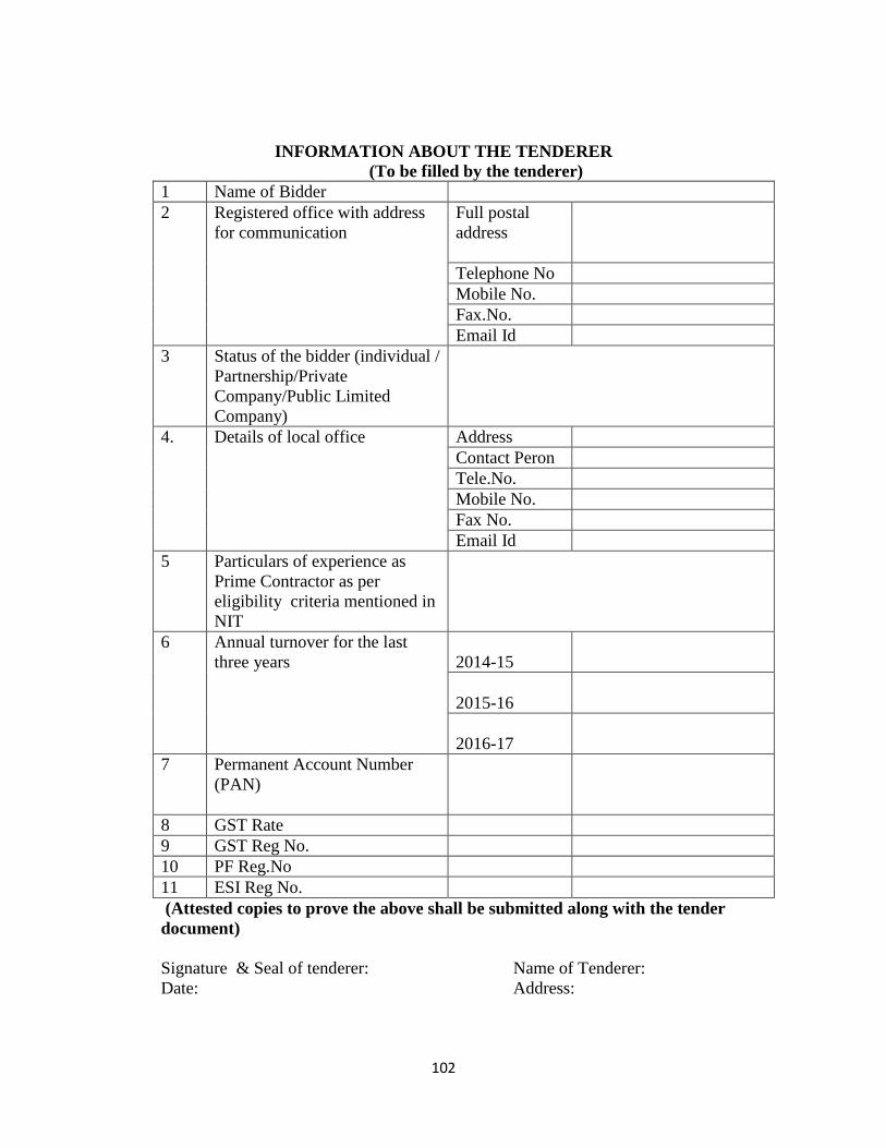
102
INFORMATION ABOUT THE TENDERER
(To be filled by the tenderer)
1 Name of Bidder
2 Registered office with address
for communication
Full postal
address
Telephone No
Mobile No.
Fax.No.
Email Id
3 Status of the bidder (individual /
Partnership/Private
Company/Public Limited
Company)
4. Details of local office Address
Contact Peron
Tele.No.
Mobile No.
Fax No.
Email Id
5 Particulars of experience as
Prime Contractor as per
eligibility criteria mentioned in
NIT
6 Annual turnover for the last
three years
2014-15
2015-16
2016-17
7 Permanent Account Number
(PAN)
8 GST Rate
9 GST Reg No.
10 PF Reg.No
11 ESI Reg No.
(Attested copies to prove the above shall be submitted along with the tender
document)
Signature & Seal of tenderer: Name of Tenderer:
Date: Address:

103
Part IV-PREQUALIFICATION INFORMATION
104
PRE-QUALIFICATION INFORMATION
GENERAL
The following criteria specified for pre-qualification shall be met by the bidder in
addition to the requirements specified elsewhere in the bidding document. The bidder is
required to submit all details as below along with his bid online and subsequently a
signed hardcopy of all these details shall be submitted to the tendering authority as
detailed in the clause of section “instructions to the bidders”
A Bidder shall be pre - qualified so that his financial/price bid can be opened.
Prequalification questionnaire completed in all respect shall be submitted on or before
closing date to the Tender inviting authority.
Bidder has to bear all cost and expenses in making this PQ offer, in providing
clarification on attending discussions, conferences or site visits.
Incomplete offers are liable to be rejected
The language for submission of bid should be English.
The enclosed Forms/schedules should be filled in completely and all questions should
be answered. If any particular query is not relevant, it should be stated as “not
applicable”.
If the offer is submitted by a Bidder backed up by specialized sub contractors, the
Bidder and each of the sub contractor should fill in all the schedules completed. The
main Bidder should be clearly identified and the extent of responsibility of each of the
sub contractors should be defined.
Financial rate, project value of work etc. should be given in equivalent Indian Rupees
only.
If the application is made by a firm in partnership, it should be signed by all the partners
of the firm, above their full name and current address, or by a partner holding power of
attorney for the firm by signing the application in which case a certified copy of the
power of attorney shall accompany the application, A certified copy of the partnership
deed, current address of the firm and the full name and current address of all the
partners of the firm shall also accompany the application.
If the application is made by a limited company or a Ltd corporation, it shall be signed
duly by authorized person holding the power of attorney for signing the application in
which case a certified copy of the power of attorney shall accompany the application of
such Ltd. Company or Corporation will be required to furnish satisfactory evidence of
105
its existences before the contract is awarded.
If the application is made by a group of firm, it shall be accompanied by a document
signed by all partied to joint venture / consortium confirmed therein a clear and definite
manner the proposed administrative arrangements for the management and execution of
the Bidder, the definition of duties, responsibilities and scope of work to be under taken
by each such party, the authorized representative of the joint venture and an undertaking
that the parties are jointly and severally liable to the SPV for the performance of each of
the parties to the joint venture on works at a similar nature within the past five years,
current works on hand and other contractual commitments.
All the partners of the bidding firms/joint ventures/partnership firms/consortiums shall
be of Indian Nationals or Indian registered companies.
To be eligible for award of contract, bidders shall provide evidence satisfactory to the
SPV, not withstanding any previously conducted prequalification of potential bidders,
of their capability and adequacy of resources affectively to carry out the subject
contract. To this and all bids submitted shall include the following information
(a) Copies of original documents defining the constitution of legal status, place of
registration and principal place of business of the company of firm or partnership
or, if a joint venture of each party there to constituting the Bidder.
(b) Where the Bidder is a joint venture of two or more firms a statement signed by all
parties to the joint venture of the proposed Administrative arrangements to the
management and execution of the contract, the duties responsibilities, and scope of
works to be undertaken by each party, the authorized representative of the joint
venture, with an undertaking that the several parties are jointly and severally liable
to the SPV for the performance of contract.
(c) Details or the experience and past performance of the Bidder for the each party to a
joint venture of works of similar nature within a past five years, and details of
current work in hand and other contractual commitments.
(d) Major item of construction equipment of key personnel proposed for use in
carrying out the contract in the form at prescribed in schedule- D
(e) The qualification and experience of key personnel proposed for administration and
execution of the contract both on and off site in the form at prescribed in schedule-
C supported by the copies of their professional qualification certificates.
(f) Proposal for sub- contracting elements of the works amounting to more than 10 %
of the tender amount for each elements the listed in Schedule-E
(g) Reports on the financial standing of the tenderer/each party to a joint
ventures/consortium/others including profit and loss statements balance sheets and
auditor’s for the past five years, on estimate financial projection for the next two
years and on authority form the Bidder (or authorized representative of a joint
venture) to seek reference from the Bidder’s bankers.
(h) Information regarding any current litigation in which the Bidder is involved.
106
The information furnished must be sufficient to show that the application (along with all
parties to consortium/ joint venture), having already earlier carried but satisfactorily
work of similar size, nature and complicity. The applicant’s attention is explicitly drawn
to the that even after pre-qualification of potential bidders has already been carried out
all tenders shall included statement of the chance that may have occurred single
prequalification with particular reference to the various items listed above and that
furthermore, contract work shall be awarded to the successful Bidder only on the basis
of a careful scrutiny of all the above information furnished by the applicant.
The applicant is expected to have visited at the project site before submitting
Prequalification.
While submitting the schedule duly filled up the applicant shall enclose latest copies of
broachers and technical documentation giving more information about the firm and all
the members of the consortium / joint venture.
The SPV/ Engineer reserves the right to reject any of the all prequalification applicants,
without assigning any reason and the SPV’s decision shall be final and binding to all
concerned.
2. ELIGIBILITY AND QUALIFICATION OF TENDERER
The Bidder should have appropriate class registration in CPWD/State
PWDs/MES/Railway/Govt. undertakings. The Bidder should have valid PF, ESI, PAN,
GST registrations.
The Bidder should have successfully completed at least one similar work costing more
than 80% of the Probable Amount of Contract (PAC) of the work during the last seven
years as Prime Contractor.
or
The Bidder should have successfully completed two similar works each costing more
than 60% of the Probable Amount of Contract (PAC) of the work during the last seven
years as Prime Contractor.
Or
The Bidder should have successfully completed three similar works each costing more
than 40% of the Probable Amount of Contract (PAC) of the work during the last seven
years as Prime Contractor.
The bidder should have an average annual turnover not less than 30% of PAC of the
work.
Similar nature of works- Works of any magnitude with a minimum as stated above
which is of the same nature and type of the work tendered as per the Contract Data.
107
In order to prove the above eligibility, the bidder must produce an experience certificate
from the Engineer/ Client for whom he has done the work. The experience certificate
shall show in detail at least, the agreed PAC, the completed value of work, its start and
end date, whether the work has been completed satisfactorily, the salient features of the
work like type of foundation, no. of stories, type of superstructure , type of finishing etc.
In all the above cases, while considering the value of completed works, the full value of
completed work will be considered whether or not the date of commencement is within
the said 07 (year) years period. Certificates which do not prove the above details will
not be considered for evaluation and the bidder will be disqualified without further
notice.
The bidder shall submit certified audited copies of its balance sheet and profit and loss
account to demonstrate its annual financial turnover during the last 5(five) years, ending
31st March of the previous financial year. Annual financial turnover and cost of
completed works of previous years shall be given a weightage of 5% per year (average
annual rate of inflation) to bring them at current price level.
The bidder should possess adequate working capital of more than 10% of the probable
estimated cost of work for which he is bidding. For this the bidder shall submit his
Bank’s certificates specifically showing access to lines of credit and valid proofs
showing availability of other financial resources to meet the requirement. Bank’s
certificates does not showing the amount for the subject work/with specific conditions is
liable to rejected and the bidder will be disqualified without any notice. In case of bank
certificates showing sanctioned credit limit and utilised credit limit, the SPV shall take
the balance available credit limit only for evaluation purpose.
The bidder shall provide evidence satisfactory to the SPV of its eligibility, capability
and adequacy of resources to effectively perform the subject contract. To this end, the
tenderer shall be required to submit the following information
a) The bidder shall submit details of experience and past performance of works of
similar nature in the last seven years with certified/attested/notorised copies of
certificates from the Clients.
b) The bidder shall provide the details of his ongoing works in which the name of
work, name of client/Engineer, contract/agreement no and date, Contract
amount, start date of work, amount of work completed at the time of this bid
submission, probable date of completion etc.
c) The qualifications and experience of key personnel proposed for administration
and execution of the contract both on and off site with copies of their
qualification information.
d) Major items of construction plant and equipment proposed for use in the
performance of the contract. It may be noted that, if the bidder does not
possess/intend to hire the minimum required plants and equipment as given in
the special conditions of contract and contract data, he may be disqualified for
this work. Hence, it is advised that the bidder shall closely look in to the
108
requirements of the subject work and the minimum required plants and
machinery. Proof of purchase of such equipment in the bidders name shall be
submitted along with the technical proposal.
e) Details of subcontractors to whom it is proposed to sub-contract any portion of
the contract and for whom authority will be required for such subcontracting in
accordance with the conditions of contract, especially for specialised works, if
any, in the contract.
f) A draft programme of works as described in this document, which shall form
part of the contract if the tender is accepted. Any change in the programme or
schedule shall be subject to the approval of the SPV.
g) Details of any current litigation or arbitration proceedings or court cases in
which the tenderer is involved as one of the parties. In case the bidder is
blacklisted or debarred from any Government Works by any Government SPV,
the same shall be informed with details in the bid document. In such cases, the
SPV reserves the right either to accept or reject the bid.
h) Duly filled Requisition for e-Payment form.
In addition to above, the intending Tenderer has to submit the following:
a) Permanent Income Tax Account Number and tax paid details for the last five
years.
b) Particulars of Registration with appropriate Sales Tax Authorities (in relation
with Work Contract Tax) if applicable.
c) Particulars of Registration / clearance from the appropriate Provident Fund
Authorities, if applicable.
d) Registration of the firm, in case of partnership firm, Joint venture and
consortium. The details of registration shall be submitted (Tenders from
unregistered firm/not accompanying requisite details will be rejected).
e) Service Tax Registration, if service tax is payable.
Copies of all the certificates and deeds are to be submitted duly authenticated by the
bidder.
3. JOINT VENTURE/CONSORTIUM:-
Tenders submitted by a joint venture/consortium/partnership of two or more
firms/contractors as partners shall comply with the following requirements;
a) The tender and in case of a successful tender, contract form signed shall be
legally binding on all partners.
b) One of the partners shall be nominated as being lead contractor, and this
109
authorization shall be evidenced by submitting a power of attorney signed by
legally authorized signatories of all the partners.
c) The lead contractor shall be authorized to incur liability and receive instructions
for and on behalf of any and all the partners of the joint venture/consortium and
the entire execution of the contract including payment shall be done exclusively
with the lead contractor.
d) All partners of the joint venture/consortium shall be liable jointly and severally
for the execution of the contract in accordance with the contract terms, and a
relevant statement to this effect shall be included in the authorization
mentioned in (b) above as well as in the form of tender and the contract form
(in case of the accepted tender).
e) Parties should specify their role in the joint venture whether technical or
financial and corresponding sharing percentage.
f) A copy of the registered contract entered into by the joint
venture/consortium/partnership partners shall be submitted with the tender.
g) A tenderer who gives false information in the tender document about its
qualification or who refuses to enter into a contract after notification of contract
award shall be considered for debarment from participating in future public
procurement.
h) The qualification criteria parameter e.g. experience, financial resources etc. of
the individual partners of the joint venture will be added together and the total
criteria should not be less than as spelt out in the qualification criteria. Hence,
the details of all the partners shall be submitted irrespective of their share in the
joint venture or consortium.
i) The formation of joint venture or change in joint venture character / partner
after submission of the bid and any change in the biding regarding joint venture
will not be permitted.
j) The pre-qualification of a joint venture does not necessarily pre-qualify any of
its partners individually or as a partner in any other joint venture or association.
In case of dissolution of a joint venture, each one of the constituent firms may
pre-qualify if they meet all the pre-qualification requirements, subject to the
written approval of the SPV.
k) The contract agreement, in case of successful bidder, should be signed jointly
by each Joint Venture partners.
l) An entity can be a partner in only one Joint Venture/consortium/partnership
firm. Bid or bids submitted by Joint Ventures/consortium/partnership firm
including the same entity as partner will be rejected.
m) In case of consortium / associate route of participation, consortium partners
must collectively meet the technical and financial qualification requirements. In
this route individual associates may or may not possess any of the technical and
financial qualification requirements. In such a case the bidder:
110
a. Shall furnish a registered/notarised Memorandum of Understanding with
associates/ Consortium partners (as per format given)
b. Shall furnish a registered/ notarised JDU (Joint deed of undertaking) prior
to signing of contract (provided the bidder in Letter of Acceptance on the
basis of bid valuation) as per format given in bid documents. Bidders will
be required to submit a registered Memorandum of Understanding (MOU)
entered with the associates along with the bid in technical bid.
4. PRE-QUALIFICATION DOCUMENT
Name of Work:- < >
Bids for Prequalification or contract are invited for a project which included in the
Contract Data hereunder. General Bidders booked up by the specialist sub-
contractors or alternatively Joint ventures of consortia, who wish to bid for the work
should apply for Pre- qualification in the manner set out in this documents as per the
above given conditions and criteria.
Name : Address
: Telephone :
ENGINEER
Name : Address :
Telephone :
Name : Address :
Telephone :
Name of work : <Here all the contract sub section with their nomenclature of
improvement may be listed>.
Location of work and site conditions:-
Broad / Scope of Work
Major items of improvements envisaged through this work
Salient features

111
PRE- QUALIFICATION APPLICATION
Contract No :
Name of Work:
To
……………………………………………………..
………………………………………………………. Dear
Sir,
Having examined the pre-qualification documents including scope of works and time frame of
construction, I / We hereby submit all the necessary information and relevant documents for
prequalification me / us for bidding for the above mentioned work.
The application is made by me on behalf of …………… ………………
………………………………………………………………………………………….group of
firms) in the capacity of …………………………………………………… … ….
……………………………………………………………….. duly authorised to submit the offer.
The necessary evidence, admissible in law in respect of authority assigned to me / us on behalf of
the group of firms for applying and for completion of the contract documents is attached
herewith.
I / We understand that Engineer / SPV reserves the right to reject any applications without
assigning any reason.
Name of Bidder:
(Name including titled capacity in which application is
made)
Place:
Date:
Encl:
112
1. Schedule duly filled in the prescribed form.
2. Evidence of authority to sign.
3. Latest brochures.
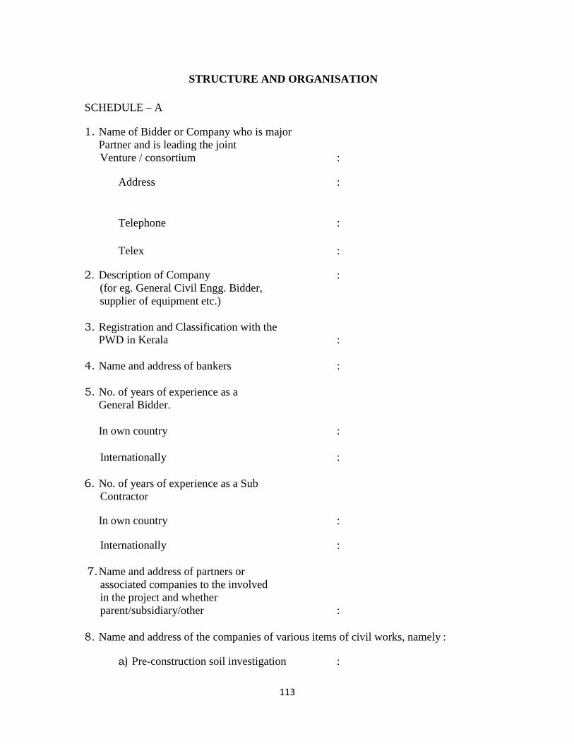
113
STRUCTURE AND ORGANISATION
SCHEDULE – A
1. Name of Bidder or Company who is major
Partner and is leading the joint
Venture / consortium :
Address :
Telephone :
Telex :
2. Description of Company :
(for eg. General Civil Engg. Bidder,
supplier of equipment etc.)
3. Registration and Classification with the
PWD in Kerala :
4. Name and address of bankers :
5. No. of years of experience as a
General Bidder.
In own country :
Internationally :
6. No. of years of experience as a Sub
Contractor
In own country :
Internationally :
7. Name and address of partners or
associated companies to the involved
in the project and whether
parent/subsidiary/other :
8. Name and address of the companies of various items of civil works, namely :
a) Pre-construction soil investigation :
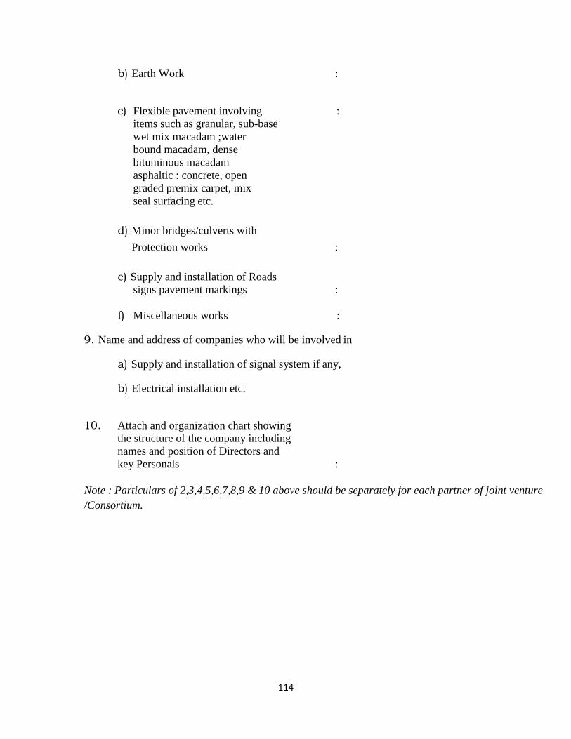
114
b) Earth Work :
c) Flexible pavement involving :
items such as granular, sub-base
wet mix macadam ;water
bound macadam, dense
bituminous macadam
asphaltic : concrete, open
graded premix carpet, mix
seal surfacing etc.
d) Minor bridges/culverts with
Protection works :
e) Supply and installation of Roads
signs pavement markings :
f) Miscellaneous works :
9. Name and address of companies who will be involved in
a) Supply and installation of signal system if any,
b) Electrical installation etc.
10. Attach and organization chart showing
the structure of the company including
names and position of Directors and
key Personals :
Note : Particulars of 2,3,4,5,6,7,8,9 & 10 above should be separately for each partner of joint venture
/Consortium.
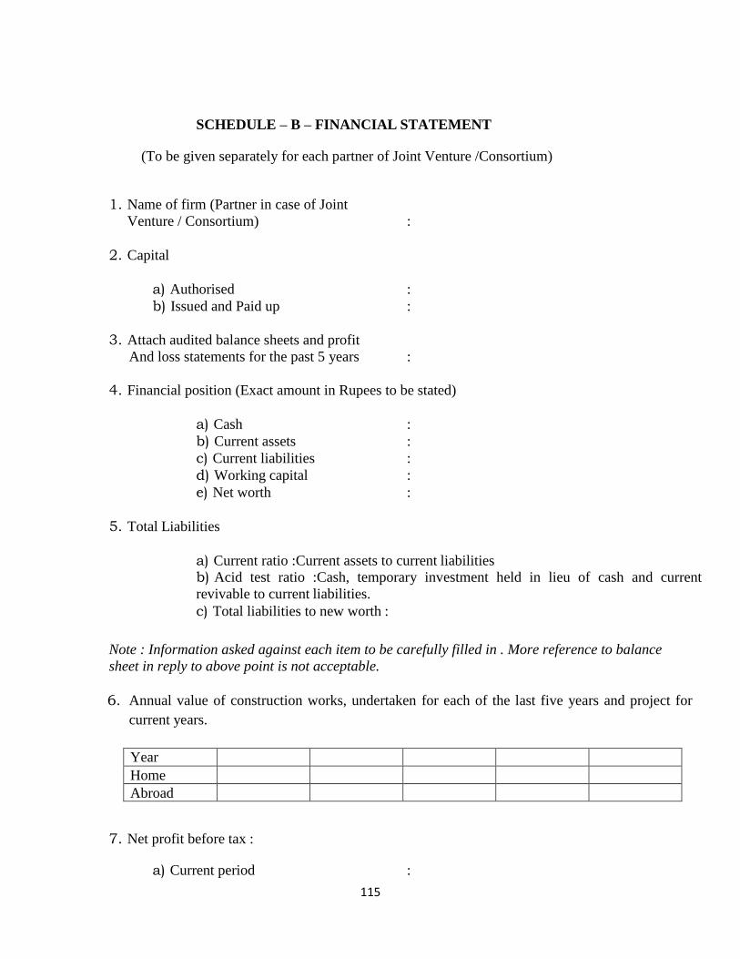
115
SCHEDULE – B – FINANCIAL STATEMENT
(To be given separately for each partner of Joint Venture /Consortium)
1. Name of firm (Partner in case of Joint
Venture / Consortium) :
2. Capital
a) Authorised :
b) Issued and Paid up :
3. Attach audited balance sheets and profit
And loss statements for the past 5 years :
4. Financial position (Exact amount in Rupees to be stated)
a) Cash :
b) Current assets :
c) Current liabilities :
d) Working capital :
e) Net worth :
5. Total Liabilities
a) Current ratio :Current assets to current liabilities
b) Acid test ratio :Cash, temporary investment held in lieu of cash and current
revivable to current liabilities.
c) Total liabilities to new worth :
Note : Information asked against each item to be carefully filled in . More reference to balance
sheet in reply to above point is not acceptable.
6. Annual value of construction works, undertaken for each of the last five years and project for
current years.
Year
Home
Abroad
7. Net profit before tax :
a) Current period :
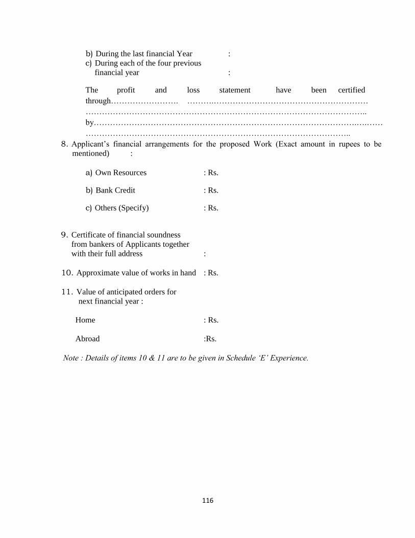
116
b) During the last financial Year :
c) During each of the four previous
financial year :
The profit and loss statement have been certified
through……………………. ……….…………………………………………………
…………………………………………………………………………………………..
by…………………………………………………………………………………….….……
……………………………………………………………………………………..
8. Applicant’s financial arrangements for the proposed Work (Exact amount in rupees to be
mentioned) :
a) Own Resources : Rs.
b) Bank Credit : Rs.
c) Others (Specify) : Rs.
9. Certificate of financial soundness
from bankers of Applicants together
with their full address :
10. Approximate value of works in hand : Rs.
11. Value of anticipated orders for
next financial year :
Home : Rs.
Abroad :Rs.
Note : Details of items 10 & 11 are to be given in Schedule ‘E’ Experience.

117
Schedule C – PERSONNEL DETAILS OF PERSONNEL WITH THE APPLICANT
Name of Applicant :
Sl.No. Description Of the Applicant’s pay roll
1. Project Manager
2. Works Manager (Main Civil Works)
3. No. of Engineering Graduates
a. Design
b. Construction supervision
4. No. of Administrative Graduates
5. No. of skilled employees
6. No. of unskilled employees
7. Please indicate whether design, wherever required
as per condition of bid, will be carried out in-
house or with the help of consultants. If in house,
please indicate the details of design carried out
over the past five years. If to be done by back up
consultants, please give the data such as name of
company key personnel and professional
qualifications, present position, total experience,
number of Engg. Staff under each category of
specialization and details of work excavated.
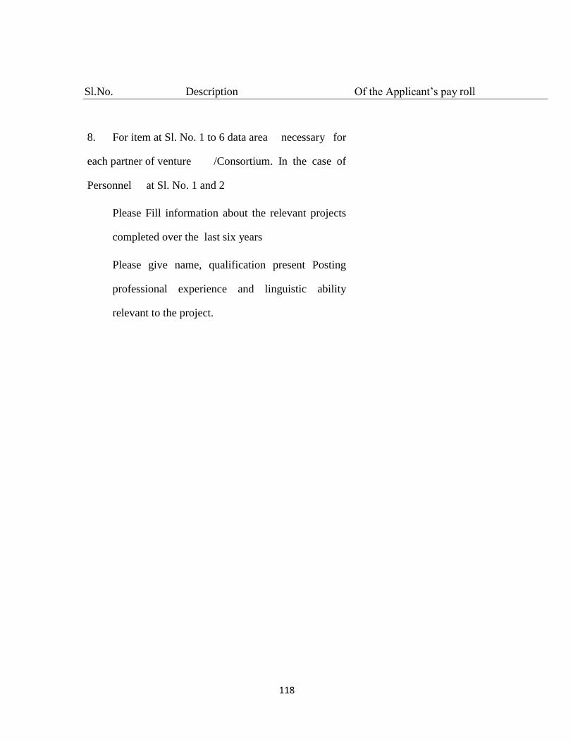
118
Sl.No. Description Of the Applicant’s pay roll
8. For item at Sl. No. 1 to 6 data area necessary for
each partner of venture /Consortium. In the case of
Personnel at Sl. No. 1 and 2
Please Fill information about the relevant projects
completed over the last six years
Please give name, qualification present Posting
professional experience and linguistic ability
relevant to the project.
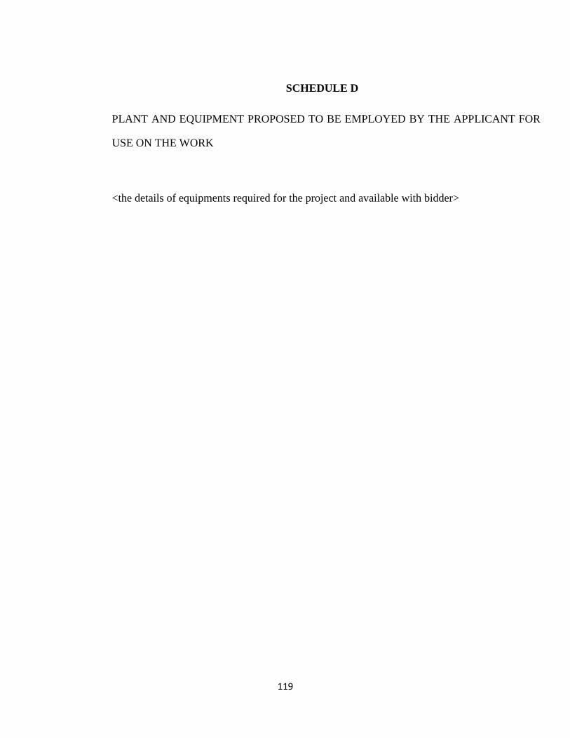
119
SCHEDULE D
PLANT AND EQUIPMENT PROPOSED TO BE EMPLOYED BY THE APPLICANT FOR
USE ON THE WORK
<the details of equipments required for the project and available with bidder>
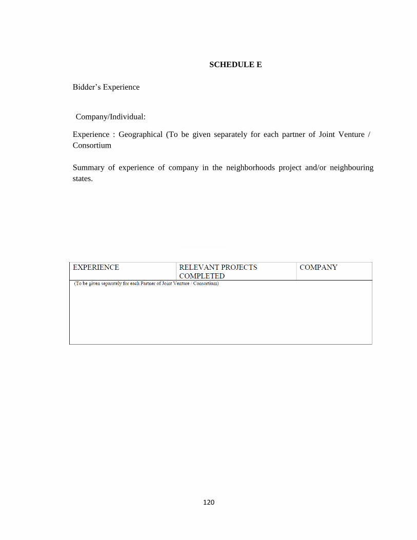
120
SCHEDULE E
Bidder’s Experience
Company/Individual:
Experience : Geographical (To be given separately for each partner of Joint Venture /
Consortium
Summary of experience of company in the neighborhoods project and/or neighbouring
states.
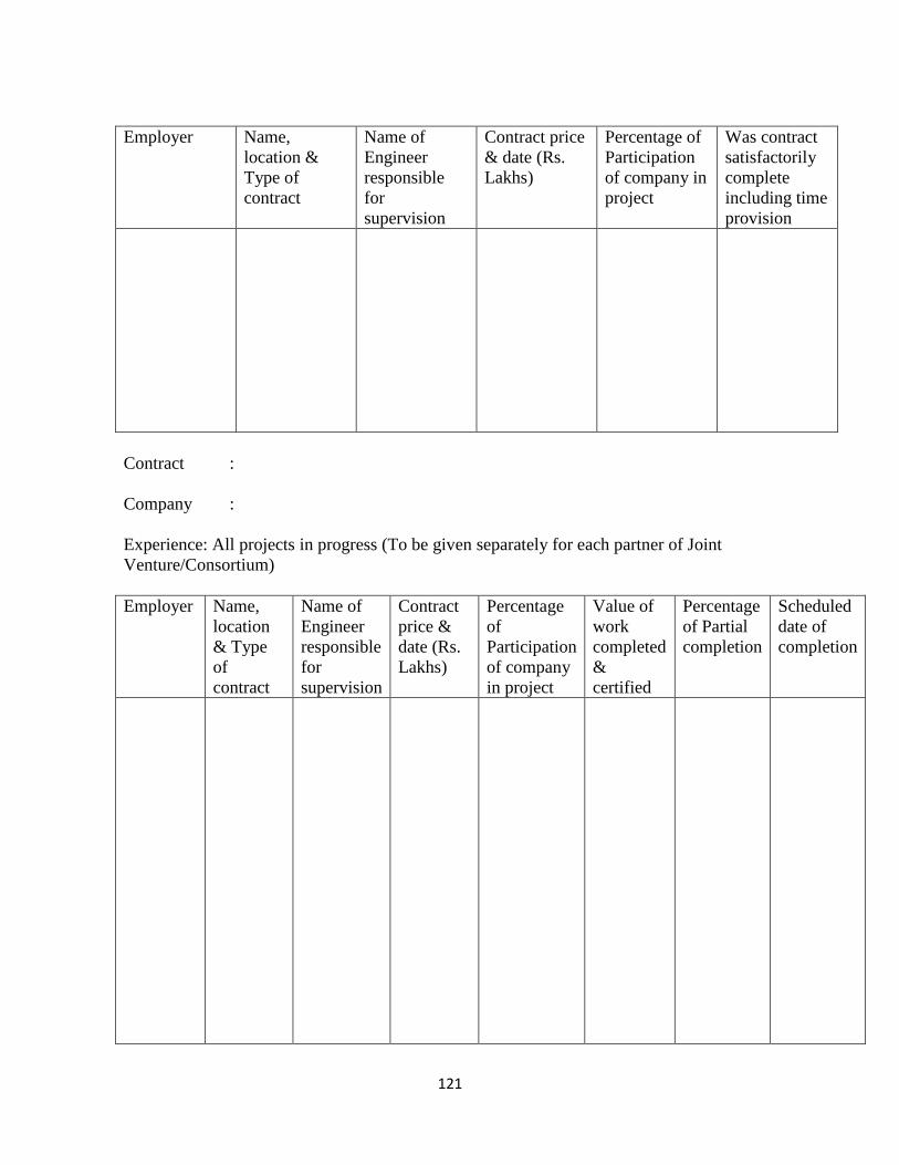
121
Employer Name,
location &
Type of
contract
Name of
Engineer
responsible
for
supervision
Contract price
& date (Rs.
Lakhs)
Percentage of
Participation
of company in
project
Was contract
satisfactorily
complete
including time
provision
Contract :
Company :
Experience: All projects in progress (To be given separately for each partner of Joint
Venture/Consortium)
Employer Name,
location
& Type
of
contract
Name of
Engineer
responsible
for
supervision
Contract
price &
date (Rs.
Lakhs)
Percentage
of
Participation
of company
in project
Value of
work
completed
&
certified
Percentage
of Partial
completion
Scheduled
date of
completion
122
SCHEDULE ‘F’ – ADDITIONAL INFORMATION
(The applicant can add here any further information relevant to the evaluation of their pre-
qualification bid)
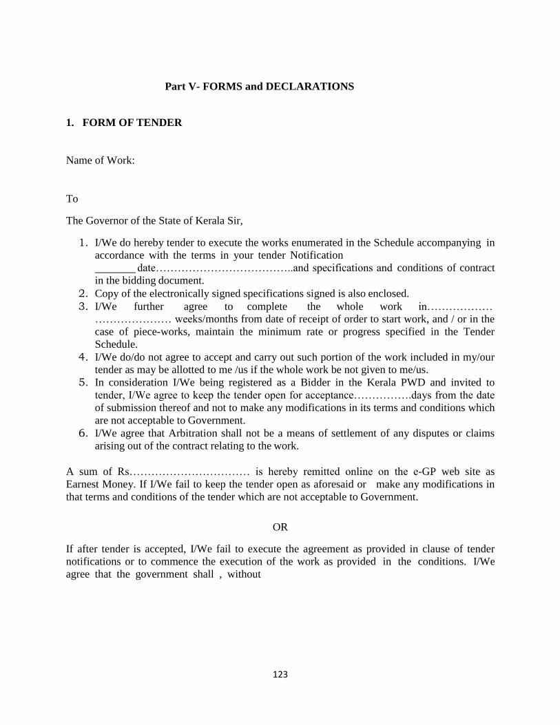
123
Part V- FORMS and DECLARATIONS
1. FORM OF TENDER
Name of Work:
To
The Governor of the State of Kerala Sir,
1. I/We do hereby tender to execute the works enumerated in the Schedule accompanying in
accordance with the terms in your tender Notification
date………………………………..and specifications and conditions of contract
in the bidding document.
2. Copy of the electronically signed specifications signed is also enclosed.
3. I/We further agree to complete the whole work in………………
………………… weeks/months from date of receipt of order to start work, and / or in the
case of piece-works, maintain the minimum rate or progress specified in the Tender
Schedule.
4. I/We do/do not agree to accept and carry out such portion of the work included in my/our
tender as may be allotted to me /us if the whole work be not given to me/us.
5. In consideration I/We being registered as a Bidder in the Kerala PWD and invited to
tender, I/We agree to keep the tender open for acceptance…………….days from the date
of submission thereof and not to make any modifications in its terms and conditions which
are not acceptable to Government.
6. I/We agree that Arbitration shall not be a means of settlement of any disputes or claims
arising out of the contract relating to the work.
A sum of Rs…………………………… is hereby remitted online on the e-GP web site as
Earnest Money. If I/We fail to keep the tender open as aforesaid or make any modifications in
that terms and conditions of the tender which are not acceptable to Government.
OR
If after tender is accepted, I/We fail to execute the agreement as provided in clause of tender
notifications or to commence the execution of the work as provided in the conditions. I/We
agree that the government shall , without
124
prejudice to any other right or remedy be at liberty to forfeit the said earnest money absolutely
and also recover from me/us the entire loss that may be caused to the Government by the
retender or rearrangement of the work or otherwise under the provision of the Revenue Recovery
Act or otherwise.
Acc:
i. Tender Schedule (submitted with Financial Bid) :
ii. Earnest Money Rs……………..
iii. Signed copy of full tender/bid documents:
iv. Signed copy of drawings :
Nationality :
Signature
Full Name of Bidder:
Place of Residence:
125
2. PRELIMINARY AGREEMENT FORMAT
PRELIMINARY AGREEMENT
(To be executed on stamp per Rs.200/-)
Preliminary Agreement entered into on …. day of ………………………………………………..
between KITCO Ltd. for and on behalf of the Secretary, Sports and Youth Affairs, Government of
Kerala (hereinafter called for the Government) of the one part and Sri
…………..,………………………………………………… hereinafter called the Bidder of the
other part for the execution of the agreement as well as for the execution of the work
“…………………………………………………………………………….”
WHEREAS the Government invited tenders for the work of as
……………………………………………………………. by Notification No………………..
Dated …………….. in the www.etender.kerala.gov.in (e-GP website).
I undersigned hereby offer to construct the proposed work in strict accordance with the
Contract/bid document for the consideration to be calculated in terms of the priced schedule of
quantities.
I undertake to complete the whole of the works as per the attached schedule from the date of issue
of intimation by you that our tender has been accepted and upon being permitted to enter site. I
further undertake that on failure, subject to the conditions of the contract relating to extension of
time, I shall pay agreed Liquidated Damages for the period during which the work shall remain
incomplete.
I hereby deposit with you as Earnest money Rs…………./- (Rupees ………….. only) [carrying no
interest] by means of online payment in the e-GP web site of Kerala in favour of KITCO Ltd.
Secretary, Sports and Youth Affairs, Government of Kerala and I agree that this sum shall be
forfeited in the event of the SPV accepting my tender and I fail to take up the contract when called
upon to do so as per clause of the bid document.
I further agree for the deduction of 2.5% from the ‘Interim Payment/RA Bill’ and upto a maximum
of 5% of the contract value towards the ‘Security Deposit’, which will be returned as per the
relevant clauses in the agreement.
I will furnish the Performance Guarantee Bond as per the approved format, if our bid is accepted,
Earnest money deposited shall be treated as security for the proper fulfilment of the same and shall
execute an agreement for the work in the prescribed form. If I fails to do this or maintain a
specified rate of progress (as specified in the Milestone details of contract data in the bid
document), the earnest money and security deposit shall be forfeited by the SPV and fresh tenders
shall be called for or the matter otherwise disposed off. If as a result of such measures due to the
default of the Bidder to pay the requisite deposit, sign contract or take possession of the work any
loss to Government due to the same will be recovered from me/us as arrears of revenue. I/We shall
have no claim whatever to the difference. Recoveries on this or any other account will be made
from the sum that may be due to us on this or any or other subsisting contracts or under the
Revenue Recovery act or otherwise the Government/SPV may decide.
NOW THEREFOR IN THE PRESENCE OF WITNESS it is mutually agreed as follows.
1) The terms and conditions for the said contract having been stipulated in the said tender document
and forms to which the I/We have agreed and a copy of which is here to be appended which forms
the part of this agreement, it is agreed that the terms and conditions stipulated therein shall bind the
parties to this agreement except to the extend to which they are abrogated or altered by express
126
terms and conditions herein agreed to and in which respect the express provisions herein shall
supersede those of said tender form.
2) I hereby agreed and undertake to perform and fulfill all the operations and obligations connected
with the execution of the said contract work ………………………………..(hereinafter the name
of the work) if awarded in favour of me.
3) If the Bidder does not come forward and to execute the original agreement after the said work is
awarded and selection notice issued in his favour or commits breach of any of the conditions of the
contract as stipulated in clause of the notice inviting tenders as quoted above, within the period
stipulated then the Government/SPV may rearrange the work otherwise at the risk and cost of the
bidder or get it done by SPV at the risk and the cost of the Bidder and the loss so sustained by the
Government can be realized from the Bidder under the Revenue recovery Act as if arrears of land
revenue as assessed quantified and fixed by an adjudicating authority by officers authorized by
Government in this behalf, after giving due notice to the Bidder. The decision taken by such
authority officer or officers shall be final and conclusive and shall be binding on the Bidder.
4) The Bidder further agrees that any amount found due to the Government under or by virtue of
this agreement shall be recoverable from the Bidder from his EMD and his properties movable and
immovable as arrears of Land Revenue under the provision of the Revenue Recovery Act for the
time being in force or in any other manner as the Government may deem fit in this regard.
5) The Bidder further assures that it is clearly understood that the settlement of claims either by part
bills or by final bills will be made only according to the allotment of funds with the officer in
charge of the work under the respective heads of account in which the work is sanctioned and
arranged and also subject to the seniority of such bills. No claims for interest or for damages
whatsoever shall be made for the related settlement of claims of bills.
IN WITNESS THERE OF
Signed and delivered by Sri Cyriac Davies, Managing Director, KITCO LTD. (SPV)
for on behalf of the Secretary, Sports and Youth Affairs
In the presence of witnesses:
1.
2.
Signed and delivered by ………………………………………..(Bidder)
for on behalf of the Secretary, Sports and Youth Affairs
In the presence of witnesses: 1.
2.
127
3. Format for Integrity Pact
(Certificate to be furnished by the bidder with the tender document downloaded from e-GP
Web-site)
CERTIFICATE
I/We………………………………… undertake that the tender submitted by us is downloaded
from e-GP Website (www.etenders.kereala.gov.in) and is same in content and form (verbatim),
and any deviation, of detected, at any stage, would entitle the SPV to reject our bidding/ offer
without assigning any reason or recourse to any penal action and would be legally binding on us.
Signature……………………..(of tenderer)
Seal……………………………
128
4. Format for Affidavit
Non-Judicial Stamp Paper
AFFIDAVIT
I/We, …………………………………………………………..,
bidder/Partner/Legal Attorney/Accredited Representative of M/s
…………………………… solemnly declare that:
1. I/We are submitting Tender for the Work
…………………………………………… against Tender Notice No…………. dated ………..
2. None of the Partners of our firm is relative of employee of
………………………… (Name of the SPV) who is involved with the arrangement and
execution of this work.
3. All information furnished by us in respect of fulfilment of eligibility criteria and
qualification information of this Tender is complete, correct and true.
4. All documents/credentials submitted along with this Tender are genuine, authentic, true
and valid.
5. I/we undertake to deploy all plant and machinery, tools and tackles, man and materials
etc. as required for execution of the work.
6. I/We hereby declare that I/We have perused in detail and examined closely the Central
Public Works SPV Specifications, Kerala PWD Manual, Kerala PWD Quality Manual and
Laboratory Manual, before I/We submit the tender/ bid and I/We agree to be bound by and
comply with all such specifications and requirements.
7. If any information and document submitted is found to be false/incorrect at any time,
SPV may cancel my/our Tender and action as deemed fit may be taken against us, including
termination of contract, forfeiture of all dues including Earnest Money, revoking of Bank
Guarantees and banning/delisting of our firm and all partners of the firm etc.
Signature of the Tenderer,
Seal of Notary Dated
…………………
129
5. Form of Performance Security (Guarantee) by Bank
1) This deed of Guarantee made on the day of ………………. (month & year) between
Bank of…………………. …………. (hereinafter called the “Bank”) represented by (name
of authorised signatory ) of the one part, and the
<tender inviting authority> (hereinafter called “the SPV”) represented by
(name) of the other part.
2) Whereas SPV has awarded the contract for …………… (Name of work as per
Notice Inviting Tender) (hereinafter called the contract) to
…………………………… (Name of the Contractor) hereinafter called the “Contractor”.
3) AND WHEREAS the Contractor is bound by the said Contract to submit to the SPV
a Performance Security for a total amount of
`…………………(Amount in figures and words).
4) Now we the Undersigned ……………………………………. (Name of the Bank and
Branch) being fully authorized to sign and to incur obligations for and on behalf of and in the
name of………………………….. (Full name of Bank), hereby declare that the said Bank will
guarantee the SPV the full amount of `.
…………………………… (Amount in figures and Words) as stated above.
5) After the Contractor has signed the aforementioned Contract with the SPV, the Bank is
engaged to pay the SPV, any amount up to and inclusive of the aforementioned full amount upon
written order from the SPV to indemnify the SPV for any liability of damage resulting from any
defects or shortcomings of the Contractor or the debts he may have incurred to any parties
involved in the Works under the Contract mentioned above, whether these defects or
shortcomings or debts are actual or estimated or expected. The Bank will deliver the money
required by the SPV immediately on demand without delay and demur and without reference to
the Contractor and without the necessity of a previous notice or of judicial or administrative
procedures and without it being necessary to prove to the Bank the liability or damages resulting
from any defects or shortcomings or debts of the Contractor. The Bank shall pay to the SPV any
money so demanded notwithstanding any dispute/disputes raised by the Contractor in any suit or
proceedings pending before any Court, Tribunal or Arbitrator/s relating thereto and the liability
under this guarantee shall be absolute and unequivocal.
130
6) This Guarantee is valid till ………………….. (valid till 28(twenty-eight) days from the
completion of defects liability period as per clause of bidding document).
7) At any time during the period in which this Guarantee is still valid, if the SPV agrees to
grant a time extension to the Contractor or if the Contractor fails to complete the Works within
the time of completion as stated in the Contract, or fails to discharge himself of the liability or
damages or debts as stated under Para 5, above, it is understood that the Bank will extend this
Guarantee under the same conditions for the required time on demand by the SPV and at the cost
of the Contractor.
8) The Guarantee hereinbefore contained shall not be affected by any change in the
Constitution of the Bank or of the Contractor.
9) The neglect or forbearance of the SPV in enforcement of payment of any moneys, the
payment whereof is intended to be hereby secured or the giving of time by the SPV for the
payment hereof shall in no way relieve the bank of their liability under this deed.
10) The expressions “the SPV”, “the Bank” and “the Contractor” hereinbefore used shall
include their respective successors and assigns.
11) Notwithstanding anything contained herein:
a) Our liability under this Bank Guarantee shall not exceed
`……………(Rupees………)
b) This Bank Guarantee shall be valid up to …………….
IN WITNESS WHEREOF I/We of the bank have signed and sealed this guarantee on the
…………. day of …………… (Month & year) being herewith duly authorized.
For and on behalf of the…………………………. Bank.
Signature of Authorized Bank official
131
Name : ……………………………..
Designation : …………………………….. Stamp/Seal of the
Bank : ……………………………..
Signed, sealed and delivered for and on behalf of the Bank by the above named
………………. in the presence of :
Witness 1. Witness 2.
Signature ……………………… Signature ………………………. Name
…………………………… Name ………………………….. Address
……………………….. Address …………………………
132
6. Requisition Form for e-Payment
Requisition for e-Payment
[ To be attached with tender form as per G.O (P) No.06/2012/PWD dated 10/01/2012
]
Certified that I am having a Savings / Current Account in <Name of Bank> at
<Name of Branch> with IFSC Code
The Account Number is:
I wish to receive all payments in this account through NEFT and RTGS systems, as the case may
be, for all payments relating to this work.
Name of Bidder
Place:
Date:
133
7. SAMPLE GUARANTEE BOND for termite-proof/water and leak-proof work.
This AGREEMENT made this ........................ day of ......................two
thousand...............................between M/s ................ (Hereinafter called the
Guarantor/Contractor of the one part) and the...................................... (SPV on behalf of the
Hon. Governor of Kerala hereinafter called the Government of the other part).
WHEREAS this agreement is supplementary to the contract (hereinafter called the Contract)
dated ................... made between the Guarantor of the one part and the SPV of the other part,
whereby the Contractor, inter alia, undertook to render the buildings and structures in the said
Contract recited, completely termite- proof/water and leak-proof.
AND WHEREAS the Guarantor agreed to give a guarantee to the effect that the said structure
will remain termite-proof for ten years to be reckoned from the date after the maintenance period
prescribed in the contract expires.
During this period of guarantee the Guarantor shall make good all defects and for that matter,
shall replace at his risk and cost such wooden members as may be damaged by termites, and in
case of any other defect being found he shall render the building waterproof/termite-proof at his
cost to the satisfaction of the Engineer- in-charge, and shall commence the works of such
rectification within seven days from date of issuing notice from the Engineer-in-
charge/Competent authority calling upon him to rectify the defects, failing which the work shall
be got done by the SPV by some other Contractor at the Guarantor’s cost and risk, and in the
later case the decision of the Engineer-in-charge as to the cost recoverable form the Guarantor
shall be final and binding.
That if the Guarantor fails to execute the waterproofing/anti-termite treatment or commits
breaches hereunder then the Guarantor will indemnify principal and his successors against all
loss, damage, cost, expense or otherwise which may be incurred by him by reason of any default
on the part of the Guarantor in performance and observance of this supplemental agreement. As
to the amount of loss and/or damage and/or cost incurred by the Government, the decision of the
Engineer-in-charge will be final and binding on the parties.
134
IN WITNESS WHEREOF these presents have been executed by the Obligor
.................. and by
................................. for and on behalf of the Governor of Kerala on the day, month and
year first above written.
Signed, sealed and delivered by OBLIGOR in the presence of witnesses 1.
2.
Signed for and on behalf of THE GOVERNER OF KERALA
by
…………........………… in the presence of witnesses
1.
2.
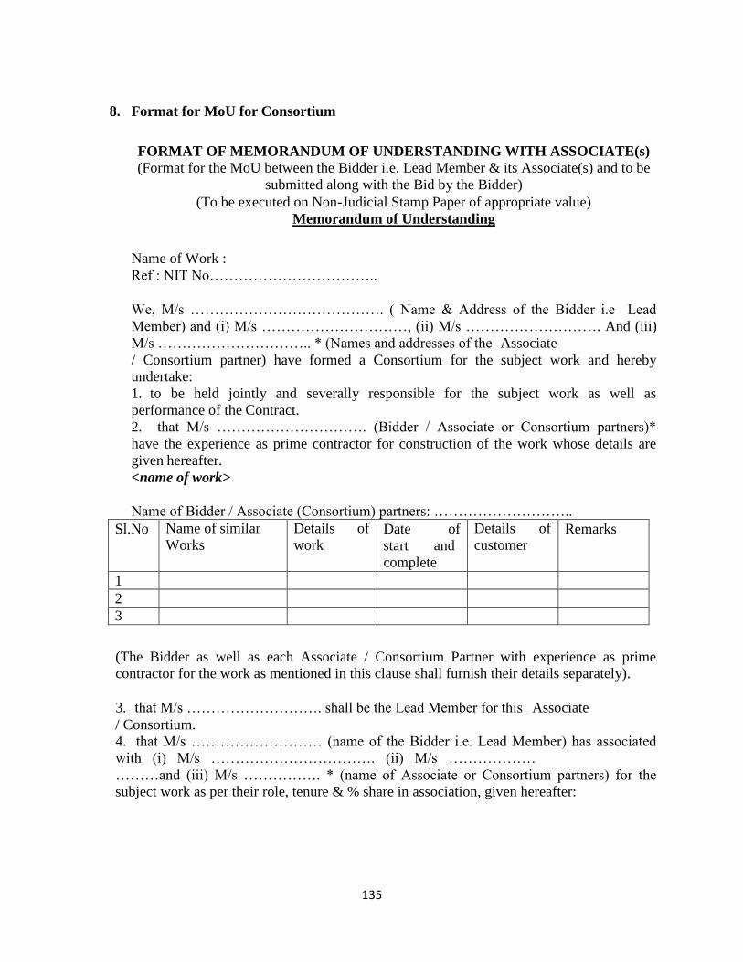
135
8. Format for MoU for Consortium
FORMAT OF MEMORANDUM OF UNDERSTANDING WITH ASSOCIATE(s)
(Format for the MoU between the Bidder i.e. Lead Member & its Associate(s) and to be
submitted along with the Bid by the Bidder)
(To be executed on Non-Judicial Stamp Paper of appropriate value)
Memorandum of Understanding
Name of Work :
Ref : NIT No……………………………..
We, M/s …………………………………. ( Name & Address of the Bidder i.e Lead
Member) and (i) M/s …………………………, (ii) M/s ………………………. And (iii)
M/s ………………………….. * (Names and addresses of the Associate
/ Consortium partner) have formed a Consortium for the subject work and hereby
undertake:
1. to be held jointly and severally responsible for the subject work as well as
performance of the Contract.
2. that M/s …………………………. (Bidder / Associate or Consortium partners)*
have the experience as prime contractor for construction of the work whose details are
given hereafter.
<name of work>
Name of Bidder / Associate (Consortium) partners: ………………………..
Sl.No Name of similar
Works
Details of
work Date of
start and
complete
Details of
customer Remarks
1
2
3
(The Bidder as well as each Associate / Consortium Partner with experience as prime
contractor for the work as mentioned in this clause shall furnish their details separately).
3. that M/s ………………………. shall be the Lead Member for this Associate
/ Consortium.
4. that M/s ……………………… (name of the Bidder i.e. Lead Member) has associated
with (i) M/s ……………………………. (ii) M/s ………………
………and (iii) M/s ……………. * (name of Associate or Consortium partners) for the
subject work as per their role, tenure & % share in association, given hereafter:
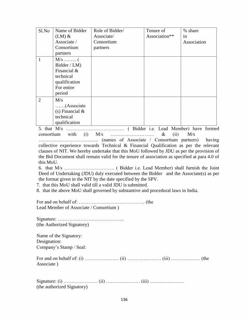
136
Sl.No Name of Bidder
(LM) &
Associate /
Consortium
partners
Role of Bidder/
Associate/
Consortium
partners
Tenure of
Association**
% share
in
Association
1 M/s …….. (
Bidder / LM)
Financial &
technical
qualification
For entire
period
2 M/s
……(Associate (s) Financial &
technical
qualification
5. that M/s ……………………………… ( Bidder i.e. Lead Member) have formed
consortium with (i) M/s ……………………… & (ii) M/s
………………………………. (names of Associate / Consortium partners) having
collective experience towards Technical & Financial Qualification as per the relevant
clauses of NIT. We hereby undertake that this MoU followed by JDU as per the provision of
the Bid Document shall remain valid for the tenure of association as specified at para 4.0 of
this MoU.
6. that M/s …………………………. ( Bidder i.e. Lead Member) shall furnish the Joint
Deed of Undertaking (JDU) duly executed between the Bidder and the Associate(s) as per
the format given in the NIT by the date specified by the SPV.
7. that this MoU shall valid till a valid JDU is submitted.
8. that the above MoU shall governed by substantive and procedural laws in India.
For and on behalf of: ………………………………….. (the
Lead Member of Associate / Consortium )
Signature: …………………………………..
(the Authorized Signatory)
Name of the Signatory:
Designation:
Company’s Stamp / Seal:
For and on behalf of: (i) ………………… (ii) ………………… (iii) ……………… (the
Associate )
Signature: (i) ………………… (ii) ………………… (iii) …………………
(the authorized Signatory)
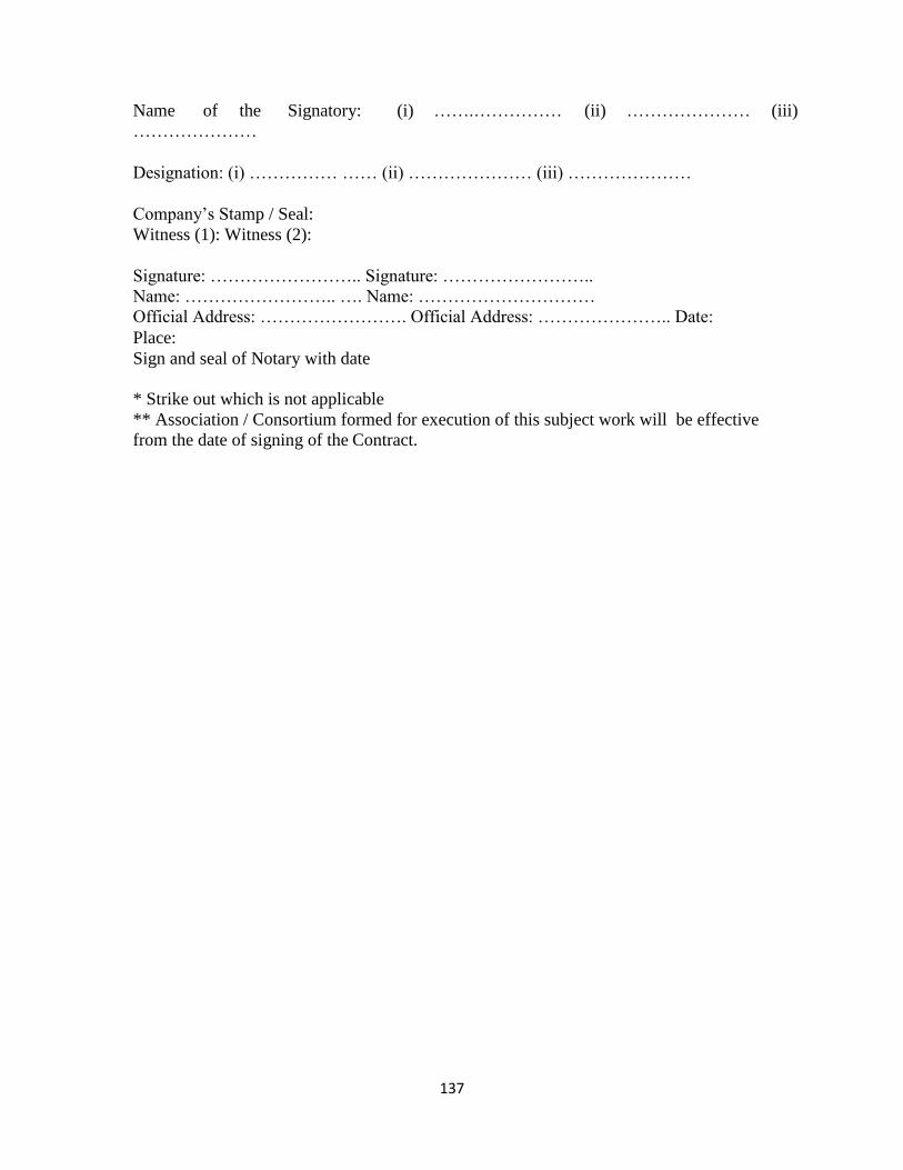
137
Name of the Signatory: (i) …….…………… (ii) ………………… (iii)
…………………
Designation: (i) …………… …… (ii) ………………… (iii) …………………
Company’s Stamp / Seal:
Witness (1): Witness (2):
Signature: …………………….. Signature: ……………………..
Name: …………………….. …. Name: …………………………
Official Address: ……………………. Official Address: ………………….. Date:
Place:
Sign and seal of Notary with date
* Strike out which is not applicable
** Association / Consortium formed for execution of this subject work will be effective
from the date of signing of the Contract.
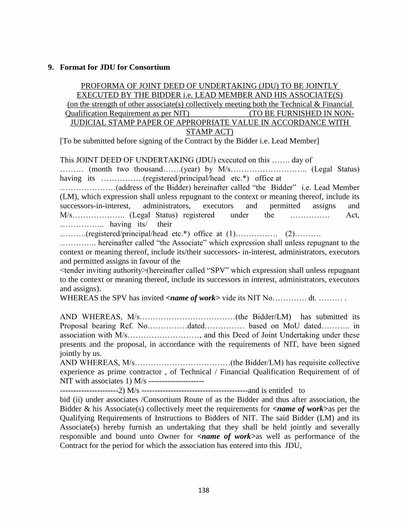
138
9. Format for JDU for Consortium
PROFORMA OF JOINT DEED OF UNDERTAKING (JDU) TO BE JOINTLY
EXECUTED BY THE BIDDER i.e. LEAD MEMBER AND HIS ASSOCIATE(S)
(on the strength of other associate(s) collectively meeting both the Technical & Financial
Qualification Requirement as per NIT) (TO BE FURNISHED IN NON-
JUDICIAL STAMP PAPER OF APPROPRIATE VALUE IN ACCORDANCE WITH
STAMP ACT)
[To be submitted before signing of the Contract by the Bidder i.e. Lead Member]
This JOINT DEED OF UNDERTAKING (JDU) executed on this ……. day of ……… (month two thousand…….(year) by M/s……………………….. (Legal Status)
having its …………….(registered/principal/head etc.*) office at
…………………(address of the Bidder) hereinafter called “the Bidder” i.e. Lead Member
(LM), which expression shall unless repugnant to the context or meaning thereof, include its
successors-in-interest, administrators, executors and permitted assigns and
M/s……………….. (Legal Status) registered under the …………… Act,
…………….. having its/ their
……….(registered/principal/head etc.*) office at (1)……………. (2)……….
………….. hereinafter called “the Associate” which expression shall unless repugnant to the
context or meaning thereof, include its/their successors- in-interest, administrators, executors
and permitted assigns in favour of the
<tender inviting authority>(hereinafter called “SPV” which expression shall unless repugnant
to the context or meaning thereof, include its successors in interest, administrators, executors
and assigns).
WHEREAS the SPV has invited <name of work> vide its NIT No…………. dt. ……… .
AND WHEREAS, M/s………………………………(the Bidder/LM) has submitted its
Proposal bearing Ref. No……………dated…………… based on MoU dated……….. in
association with M/s………………………, and this Deed of Joint Undertaking under these
presents and the proposal, in accordance with the requirements of NIT, have been signed
jointly by us.
AND WHEREAS, M/s………………………………(the Bidder/LM) has requisite collective
experience as prime contractor , of Technical / Financial Qualification Requirement of of
NIT with associates 1) M/s ---------------------
----------------------2) M/s ----------------------------------------and is entitled to
bid (ii) under associates /Consortium Route of as the Bidder and thus after association, the
Bidder & his Associate(s) collectively meet the requirements for <name of work>as per the
Qualifying Requirements of Instructions to Bidders of NIT. The said Bidder (LM) and its
Associate(s) hereby furnish an undertaking that they shall be held jointly and severally
responsible and bound unto Owner for <name of work>as well as performance of the
Contract for the period for which the association has entered into this JDU,
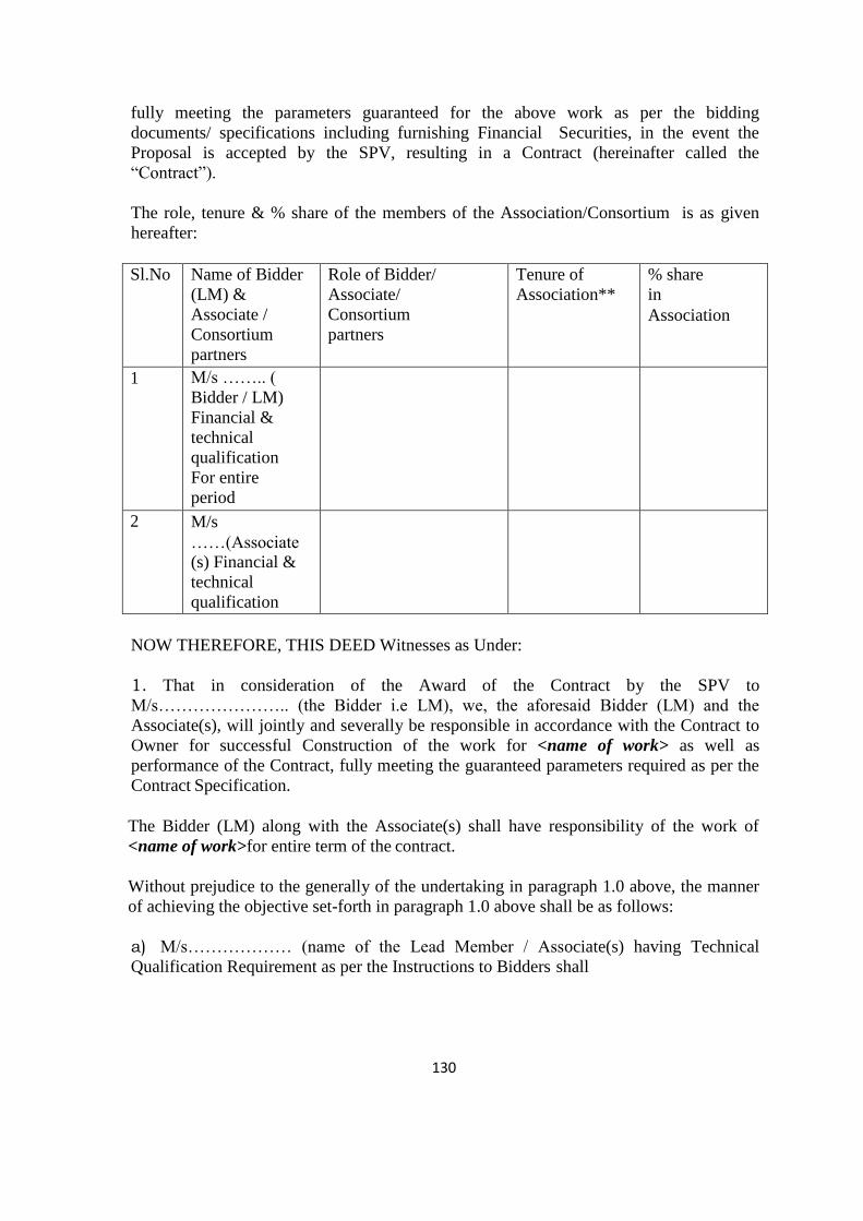
130
fully meeting the parameters guaranteed for the above work as per the bidding
documents/ specifications including furnishing Financial Securities, in the event the
Proposal is accepted by the SPV, resulting in a Contract (hereinafter called the
“Contract”).
The role, tenure & % share of the members of the Association/Consortium is as given
hereafter:
Sl.No Name of Bidder
(LM) &
Associate /
Consortium
partners
Role of Bidder/
Associate/
Consortium
partners
Tenure of
Association**
% share
in
Association
1 M/s …….. (
Bidder / LM)
Financial &
technical
qualification
For entire
period
2 M/s
……(Associate (s) Financial &
technical
qualification
NOW THEREFORE, THIS DEED Witnesses as Under:
1. That in consideration of the Award of the Contract by the SPV to
M/s………………….. (the Bidder i.e LM), we, the aforesaid Bidder (LM) and the
Associate(s), will jointly and severally be responsible in accordance with the Contract to
Owner for successful Construction of the work for <name of work> as well as
performance of the Contract, fully meeting the guaranteed parameters required as per the
Contract Specification.
The Bidder (LM) along with the Associate(s) shall have responsibility of the work of
<name of work>for entire term of the contract.
Without prejudice to the generally of the undertaking in paragraph 1.0 above, the manner
of achieving the objective set-forth in paragraph 1.0 above shall be as follows:
a) M/s……………… (name of the Lead Member / Associate(s) having Technical
Qualification Requirement as per the Instructions to Bidders shall

131
be required to furnish the details and to advise and provide necessary technical assistance to
M/s……………… (the Bidder i.e. LM) for the work for
<name of work>, their quality surveillance during construction, Erection, Installation &
commissioning and performance of the subject work. Lead Member / All such Associate (s)
further shall depute their technical experts from time to time to the project site to facilitate
successful performance for the work of for <name of work>, as stipulated in the aforesaid
Bidding Documents. Other Associate(s) shall also render all the assistance during the period
of contract.
b) The Lead Member / Associate(s) will be responsible to deliver the work of for <name of
work>, in accordance with the Bidder’s consent.
c) In the event, the Lead Member / Associate(s) and the Bidder (LM) fail to demonstrate
successful performance of the work of for <name of work>, as set forth in the Bidding
Documents, the Associate(s) and the Bidder (LM) will be jointly responsible for taking
proper corrective measures.
d) Implementation of the corrected design and all other necessary corrective repairs,
replacements or modifications to the work of for <name of work>, if required, shall be the
joint responsibility of the Associate(s) & the Bidder (LM). e) The Lead Member /
Associate(s) will be fully responsible for the quality of all the works/ components
manufactured at its works or at its Vendor/Sub Contractor’s works and, if necessary, their
repair or replacement, for incorporation in the work of for <name of work>, and timely
completion as per the Contract.
f) However, the Lead Member / Associate(s) having the qualification requirement in terms of
of Instructions to Bidders of NIT, shall have exclusive responsibility for the work of for
<name of work>, as per the tenure specified in this JDU.
. We, the Bidder(LM) and the Associate(s) are fully aware that for non- fulfillment of any of
the obligations either towards <name of work>, the SPV is free to take up the matter either
with the Lead Member and/ or any or all of the Associate(s) as per the SPV’s convenience.
3.0 This Joint Deed of Undertaking shall be construed and interpreted in accordance with the
Laws of India. The High Court of Kerala shall have exclusive jurisdiction in all matters
arising there under.
4.0 We, the Bidder (LM) and the Associate(s), undertake not to revoke this Undertaking for
the full term of the Contract and further stipulate that the undertaking herein contained shall
terminate upon satisfactory completion of such period or the subject work.
5.0 In case of award, the Bidder (LM) & his Associate(s) shall furnish a Financial Security in
favour of the Owner from any reputed commercial bank as indicated in the NIT. The value of
such Financial Security Contract Performance Guarantee shall be guaranteed towards the
faithful performance/ compliance of this Joint Deed of Undertaking in accordance
132
with the terms & conditions specified herein. The guarantee shall be unconditional,
irrevocable and valid as stipulated under the Contract. The guarantee amount shall be payable
to Owner
on demand without any demur, reservation, protest or contest.
6.0 That this Deed will form an integral part of the Contract awarded to the Bidder (LM) on
acceptance of its Proposal and shall be operative from the date of the Contract coming into
force.
IN WITNESS WHERE OF, the Associate(s) and the Bidder (LM) have, through their
authorized representatives, set their hands and seal on the day, month and year first
mentioned above.
BIDDER
For and on behalf of M/s…………………………………(name of the Bidder/LM)
Signature……………………………… (the
Authorized Signatory)
Name of the Signatory……………………………………………
Designation……………………………………………………
Bidder’s Stamp/Seal …………………………………………………….
WITNEESS (1) WITNEESS (2)
Signature……………………… Signature……………………
Name…………………………………. Name………………………..
Official Address……………………… Official Address………………
ASSOCIATE(S)
For and on behalf of M/s…………………………………
(Name of the Associates)
Signature M/s…………………………………...
(Authorized Signatory)
Name of the Signatory ………………………………………..
Designation ………………………………………..
Company’s Stamp/Seal ………………………………………..
WITNEESS (1) WITNEESS (2)
Signature……………………… Signature……………………
Name…………………………………. Name………………………..
Official Address……………………… Official Address……………… Sign
and seal of Notary with date
* Association/Consortium formed for execution of this subject work will be effective from the
date of signing of the Contract.
133
Part VI- TECHNICAL SPECIFICATION
\\datalibrary1\2018-19\DP-888 DSYA\Tender\tender 5 projects 10.7.18\Aymanm\1.2 techspecification-civil works- final corrected 07.07.2015.docdmr 134
134
TECHNICAL SPECIFICATIONS – CIVIL WORKS
1. The following technical specification, code of practice etc. referred herein is form
a part of the Item Specification and work shall be executed accordingly. Items
which are not covered under Technical Specification shall be carried out as per
relevant IS Specification or as per manufactures specification or as directed by
Engineer-in-charge.
2. In case of discrepancy between technical specification and item specification
provided along with Bill of Quantities, the Item Specification shall prevail.
3. All the measurements shall be as per latest edition of B.I.S.
1.1.00 EARTH WORK
Applicable Codes
The following Indian Standard Codes, unless otherwise specified herein, shall be
applicable. In all cases, the latest revision of the codes shall be referred to.
a) IS - 4081 Safety code for blasting and related drilling operation.
b) IS - 1200 Method of measurement of building works.
c) IS - 3764 Safety code for excavation work.
d) IS - 3385 Code of practice for measurement of Civil Engineering works.
e) IS - 2720 Part II Determination of moisture content.
Part VIII Determination of moisture content dry density relation using light
compaction.
Part XXVIII Determination of dry density of soils, in-place by the sand replacement
method.
Part XXIX Determination of dry density of soils, in-place, by the core cutter
method.
General
Contractor shall carry out the survey of the site before excavation and set properly all
lines and establish levels for various works such as earthwork in excavation for
levelling, basement, foundations, plinth filling, roads, drains, cable trenches, pipelines,
etc. It is necessary to establish permanent bench mark at such point which will not be
affected by subsequent work. Such survey shall be carried out by taking accurate cross
sections of the area perpendicular to established reference/grid lines at 5 m intervals or
nearer as determined by Engineer-in-charge based on ground profile.
The area to be excavated/ filled shall be cleared of fences, trees, plants, logs, slumps,
bush, vegetations, rubbish slush, etc., and other objectionable matter. If any roots or
stumps of trees are found during excavation, they shall also be removed. The material
so removed shall be burnt or disposed off as directed by Engineer. Where earthfill is
\\datalibrary1\2018-19\DP-888 DSYA\Tender\tender 5 projects 10.7.18\Aymanm\1.2 techspecification-civil works- final corrected 07.07.2015.docdmr 135
135
intended, the area shall be stripped of all loose/soft patches, top soil containing
deleterious matter/materials before fill commences.
In firm soil if the excavation is deeper than 2 m and in loose, soft or slushy soil, the
width of the step shall be suitably increased or the sides sloped or shoring and strutting
may be done as per the Engineer’s instructions without any extra cost.
For excavation in trenches for pipes nothing extra shall be payable for the lift
irrespective of the depth unless specifically mentioned otherwise in the Schedule of
Quantities.
The trenches which are ready for concreting shall be got approved by the Engineer.
The excavated stacked earth shall be refilled in the trenches and sides of foundation in
200 mm layers and the balance surplus shall be first filled in layers in plinth and the
remaining surplus shall be disposed off by uniform spreading within the site/outside the
site as directed by the Engineer.
Adequate protective measures shall be taken by the Contractor to see that the
excavation for the building foundation does not affect the adjoining structure’s stability
and safety. Contractor will be responsible if he has not taken precaution for the safety of
the people, workers property or neighbour’s property caused by his negligence during
the constructional operations.
Lead
Lead for disposal of excavated material inside the site and at convenient places in the
surrounding areas have been specified in the respective items of work and no other extra
lead is intended.
Classification
Any earthwork will be classified under any of the following categories:
All kinds of soils
These shall include all kinds containing kankar, sand, silt, moorum and/or shingle,
gravel, clay, loam peat, ash, shale, etc., which can generally be excavted by spade, pick-
axe and shovel and which is not classified under ordinary rock, and hard rock defined
below. This shall also include excavation in macadam and tarred roads and pavements.
This shall also include rock boulders up to 200 dm3. Rubble masonry to be dismantled
below ground level will also be measured under this item.
Ordinary Rock
These shall include generally any rock which can be excavated by splitting with
crowbars or picks and does not require blasting, wedging or similar means for
excavation such as lime stone, sand stone, hard laterite, hard conglomerate and
unreinforced cement concrete below ground level.
\\datalibrary1\2018-19\DP-888 DSYA\Tender\tender 5 projects 10.7.18\Aymanm\1.2 techspecification-civil works- final corrected 07.07.2015.docdmr 136
136
Hard Rock
This shall include rock which cannot be easily excavated with pick-axes, hammer, crow
bars and wedges but has to be either heated where blasting is prohibited or has to be
blasted. They shall be stacked separately for measurement as directed by the Engineer-
in-charge.
Blasting in rocks
Unless otherwise stated herein, IS 4081, safety code for blasting and related drilling
operations shall be followed. After removal of over burden, if any, excavation shall be
continued in rock to such widths, lengths, depths and profiles as are shown on the
drawings or such other lines and grades as may be specified by Engineer. As far as
possible all blasting shall be completed prior to commencement of construction. At all
stages of excavation, precautions, shall be taken to preserve the rock below and beyond
the lines specified for the excavating, in the soundest possible condition. The quantity
and strength of explosive used, shall be such as will neither damage nor crack the
rock outside the limits of excavation. All precautions, as directed by Engineer shall be
taken during the blasting operations and care shall be taken that no damage is caused to
adjoining buildings or structure as a result of blasting operations. In case of damage to
permanent or temporary structures, Contractor shall repair the same to the satisfaction of
Engineer at his cost. As excavation approaches its final lines and levels, the depth of the
charge holes and amount of explosives used shall be progressively and suitably reduced.
Specific permission of Engineer will have to be taken by Contractor for blasting rock
and he shall also obtain a valid blasting licence from the authorities concerned. If
permission for blasting is refused by Engineer, the rock shall be removed by wedging,
pick barring, heating and quenching or other approved means. All loose/loosened rock
in the sides shall be removed by barring wedging, etc. The unit rates for excavation in
hard rock shall include the cost of all these operations.
Contractor shall employ a competent and experienced supervisor and licensed blaster in
charge for each set of operation, who shall be held personally responsible to ensure that
all safety regulations are carried out.
Before any blasting is carried out, Contractor shall intimate Engineer-in-charge and
obtain his approval in writing for resorting to such operations. He shall intimate the
hours of firing charges, the nature of explosive to be used and the precautions taken for
ensuring safety.
Filling in plinth with selected excavated earth
Plinth shall be filled in layers 15 - 30 cm, of thickness or as specified in items
specification watered and compacted with hand rammers as directed by the Engineer-in-
charge, so as to avoid any settlement at later stage. For the final layer the surface shall
be flooded with water and water allowed to stand for 24 hours. The finished level of the
filling shall be trimmed to the level specified.
Where specified in the item description given in the Schedule of Quantities that the
compaction of the plinth fill shall be carried out by means of 10/12 tonnes rollers
smooth wheeled, sheep-foot or wobble wheeled rollers. As rolling proceeds water
\\datalibrary1\2018-19\DP-888 DSYA\Tender\tender 5 projects 10.7.18\Aymanm\1.2 techspecification-civil works- final corrected 07.07.2015.docdmr 137
137
sprinkling shall be done to assist consolidation. Water shall not be sprinkled in case of
sandy fill.
Filling excavated earth in ground for land development
No earthfill shall commence until surface water discharges and streams have been
properly intercepted or otherwise dealt with as directed by Engineer-in-charge.
Filling shall be carried out as indicated in the drawings and as directed by Engineer-in-
charge. If no compaction is called for, the fill may be deposited to the full height in one
operation and levelled. If the fill has to be compacted, it shall be placed in layers not
exceeding 600 mm and levelled uniformly and compacted before the next layer is
deposited.
Field compaction is called for, test shall be carried out at different stages of filling and
also after the fill to the entire height has been completed. This shall hold good for
embankments as well. The tests for field compaction shall be specified by the Engineer
and the Contractor shall arrange to carry out such tests to the satisfaction of the
Engineer-in-charge.
Contractor shall protect the earthfill from being washed away by rain or damaged in any
other way. Should any slip occur, Contractor shall remove the affected material and
make good the slip at his own cost.
The fill shall be carried out to such dimension and levels as indicated on the drawings
after the stipulated compaction. The fill shall be considered as incomplete if the desired
compaction has not been obtained.
Filling in plinth and ground with earth brought from outside
Filling shall be carried out with approved material. The material and source shall be
subject to prior approval of Engineer-in-charge. The approved area, from where the fill
material is to be dug, shall be cleared of all bushes, roots plants, rubbish, etc., top soil
containing salts, sulphate and other foreign material shall be removed. The materials so
removed shall be burnt or disposed off as directed by Engineer-in-charge. The
Contractor shall make necessary access roads to those areas and maintain the same, if
such access road does not exist, at his cost.
If any material is rejected by Engineer-in-charge, Contractor shall remove the same
forthwith from the site at no extra cost to the owner. Surplus fill material shall be
disposed of by uniform spreading within the site as instructed by the Engineer-in-charge.
At places backfilling shall be carried out with local sand if directed by Engineer. The
sand used shall be kept flooded with water for 24 hours to ensure maximum
consolidation. Any temporary work required to contain sand under flooded condition
shall be to Contractor’s account. The surface of the consolidated sand shall be dressed
to require level or slope. Construction of floors or other structures on sand fill shall not
be started until Engineer has inspected and approved the fill.
\\datalibrary1\2018-19\DP-888 DSYA\Tender\tender 5 projects 10.7.18\Aymanm\1.2 techspecification-civil works- final corrected 07.07.2015.docdmr 138
138
1.2.00 PILE WORKS
All piles have to be socketed 50cm in hard rock.
Bored Cast-in-situ Pile Foundation
The tenderer has to acquaint himself with the site condition before tendering for the
work.
The contractor shall be responsible for the correctness of location of pile points as given
with the pile layout drawing which will be supplied to the contractor. If any lateral shift
or tilt of the pile is noticed, the contractor will have to drive alternate pile at his own cost
as directed by the Engineer-in-charge whose decision shall be final. Any excess quantity
of RCC pile cap if necessitated due to driving such alternate pile will have to be done by
the contractor, at his own cost.
Piles have to be socketed in hard rock by 500mm.
The length of pile for payment shall be from bottom of pile cap to the bottom tip of pile.
Concreting of pile shall be done upto ground level and later chipped off upto cut-off
level by the contractor. Charges for these shall be deemed to have been included in the
rate quoted for piling.
Main steel of piles shall be kept projecting from the top to the extent of 50 times the
diameter of the bar for use as dowels in pile cap/grade beam.
Cement and steel to be used on the work shall conform to prevailing IS standards.
Any ground with high water table or in soft soil having unstable pile bores, boring and
under ream may be carried out with suitable drilling works.
The bentonite suspension used in bore holes is basically a clay of montmorillonite group
having exchangeable sodium cations.
The bentonite suspension used for piling work shall satisfy the following requirements:
The liquid limit of bentonite when tested in accordance with IS:2720 (Part V) 1965 shall
be more than 300 percent and less than 450 percent.
The sand content of the bentonite powder shall not be greater than 7 percent.
Bentonite solution should be made by mixing it with fresh water using pump for
circulation. The relative density of the bentonite solution should be about 1.12.
Concreting shall be done as soon as possible after completing the pile bore. The bore
hole full of drilling mud should not be left unconcreted for more than 12 to 24 hours
depending upon the stability of bore hole.
For placing concrete in pile bores, a funnel should be used and method of concreting
should be such that the entire volume of the pile bore is filled up without the formations
of voids and/or mixing of soil and drilling fluid in the concrete.
In empty bore holes for piles a small quantity of concrete is poured to give about a 100
mm layer of concrete at the bottom. Reinforcement is lowered next and positioned
\\datalibrary1\2018-19\DP-888 DSYA\Tender\tender 5 projects 10.7.18\Aymanm\1.2 techspecification-civil works- final corrected 07.07.2015.docdmr 139
139
correctly. Then concrete is poured to fill up the bore hole. Care should be taken that
soil is not scrapped from sides if rodding is done for compaction. Vibrators shall not be
used.
In case the pile bore is stabilized with drilling mud or by maintaining water head within
the bore hole, the bottom of bore hole shall be carefully cleaned by flushing it with
fresh drilling mud, and pile bore will be checked for its depth immediately before
concreting.
Concreting shall be done by tremie method. The tremie should have a valve at its bottom
and lowered with its valve closed at the start and filled up with concrete. The valve is
then opened to permit the flow of concrete which permits the upward displacement of
drilling mud. The pouring should be continuous and tremie is gradually lifted up such
that the tremie pipe opening remains always in the concrete. If the final stage the
quantity of concrete in tremie should be enough so that on final withdrawal some
concrete spills over the ground.
The work shall be done as per IS:2911 (Part I/Section II) 1979 latest edition
LOADTEST ON PILES
General
The bearing capacity of a single or group of piles shall be determined from test
loading. It is most direct method for determining safe load on pile and it is more
reliable on account of its being in-situ test. The load test on a concrete pile shall
not be carried out earlier than 28 days of its casting. Initial test shall be carried on
test pile which is not used as working pile and Routine tests shall be carried out as a
check on working pile. Routine test shall be one-half percent to two percent of
total number of piles or as specified, applicable to vertical and lateral load. Load
Test shall generally conform to provision made in IS 2911 (Part IV) which provides
guidelines for determination of safe loads and conducting of different types of tests.
Types of loadings/tests
(i) Vertical Load Test (Compression)
(ii) Cyclic Vertical Load Test
(iii) Lateral Load Test
Vertical Load Test
General: Compression load shall be applied to the pile top by means of a
hydraulic jack against suitable load frame which is capable of providing reaction
and settlement is recorded by suitable dial gauges. The contractor shall apprise of
Engineer-in-Charge before test is conducted.
\\datalibrary1\2018-19\DP-888 DSYA\Tender\tender 5 projects 10.7.18\Aymanm\1.2 techspecification-civil works- final corrected 07.07.2015.docdmr 140
140
Preparation of Pile Head: Pile head shall be chipped off to horizontal plane,
projecting steel shall be cut or bent and top finished smooth and leveled with
plaster of Paris or similar synthetic material as specified to give a plane surface
which is normal to the axis of the pile. A bearing plate with a hole at the centers
shall be placed on the head of pile for the jacks to rest.
Loading Platform: A proper loading platform is installed as specified. Contractor
shall ensure that when the hydraulic jack and load measuring devices are mounted
on pile head the whole system will be stable on the maximum specified load. For
single pile two dial gauges shall be fixed to the pile and bear on surfaces on
reference frame. The dial gauges shall be placed in diametrically opposite
positions and be equidistant from the pile axis. Four dial gauges are used for groups,
having 0.01 mm sensitivity. The arrangement shall be approved by the Engineer-in-
charge.
Application of Load: The test is carried out by applying a series of downward
incremental load (20 per cent of safe loads on pile). In this method application of
increment of test load and taking of measurement or displacement in each stage is
maintained till the rate of displacement is either 0.1 mm in first 30 minutes or 0.2
mm in first one hour or 2 hours, whichever occurs first. The test load shall be
maintained for 24 hours. This method is applicable for both initial and routine
test. For testing of raker piles the loading shall be along its axis. Safe load on single
pile for initial test is least of following:
(i) Two-thirds of the final load at which the total displacement attains a value of 12 mm
unless otherwise stated, in such case the safe load should be corresponding to total
displacement permissible.
(ii) 50 per cent of the final load at which the total displacement equal 10 per cent
of pile diameter and 7.5 per cent of bulb diameter in case of under-reamed piles.
Routine test shall be carried for a test load of one and half times the working
load, maximum settlement not to exceed 12 mm or as stated.
Safe load on group of piles for initial test shall be least of the two
(i) Final load at which total displacement is 25 mm or as stated.
(ii) Two-thirds of final load at which the total displacement is 40 mm.
Routine test shall be carried for a test load equal to not less than working load,
the maximum settlement not to exceed 25 mm.
Maintained Load Method: This is applicable for both initial and routine test. In
this method application of increment of test load and taking of measurement or
displacement in each stage of loading is maintained till rate of displacement of
the pile top is either 0.1 mm in first 30 minutes or 0.2 mm in first one hour or till
\\datalibrary1\2018-19\DP-888 DSYA\Tender\tender 5 projects 10.7.18\Aymanm\1.2 techspecification-civil works- final corrected 07.07.2015.docdmr 141
141
2 hours, whichever occurs first. If the limit of permissible displacement as given
in . . . . . . . . . . . . . . . . . . is not exceeded, testing of pile is not required to be continued
further. The test load shall be maintained for 24 hours.
Pile test data such as load, displacement and time shall be recorded in suitable
prescribed tabular form. Results can be presented by suitable curves.
Test shall be carried out in proper manner and to the entire satisfaction of the
Engineer-in-charge. After the test is completed the test cap shall be dismantled and
pile surface shall be resorted to original shape.
Measurement: Each completed test shall be enumerated for initial test, routine test
separately.
Rate: The rate includes the cost of labour, material and all the operations
described above such as preparatory work including installation of loading platform,
applying load, preparing pile head for load test, trimming of pile head etc. complete.
Cyclic Vertical Load Testing
General: This process shall be used in case of initial test to find out separately skin
friction and point bearing load on single piles of uniform diameter in conformity of provisions of IS Code 2911 (Part 4) for conducting of the test.
Preparatory Pile Head: As mentioned above
Loading Platform: As mentioned above
Application of Load: Relevant provision as per clause . . . . . . . . . . . . . . . . . shall be applicable. The test may be continued up to 50 per cent over the safe load.
Test procedure given in Appendix E shall be followed.
Test shall be carried out in proper manner and to the entire satisfaction of the
Engineer-in-charge. After the test is completed, the test cap shall be dismantled
and pile surface shall be restored to original shape.
Measurement: Each completed test shall be enumerated for different load
ranges.
Rate: The rate includes the cost of labour, materials and all the operations described above such as preparatory work, trimming of pile head etc. complete.
Lateral Load Testing
Load Platform: A proper loading platform shall be installed as specified. Hydraulic jack is mounted with gauge between two piles or pile groups under test. Dial gauge tips shall rest on central portion of glass plate fixed on the side of pile.
\\datalibrary1\2018-19\DP-888 DSYA\Tender\tender 5 projects 10.7.18\Aymanm\1.2 techspecification-civil works- final corrected 07.07.2015.docdmr 142
142
Application of Load: Full load imposed by the jack shall be taken as lateral resistance on each pile or group. Load should be applied in increments of about 20 per cent of the estimated safe load. The next increment shall be applied after the rate of displacement is approximately equal to 0.1 mm per 30 minutes.
The safe lateral load on pile; is least of the following:
(i) Fifty per cent of the final load at which total displacement increases to 12 mm.
(ii) Final load when total displacement is 5 mm.
(iii) Load corresponding to any other specified displacement as per requirement. Pile
group shall be tested as per actual conditions as far as possible.
Displacements: Displacement is read by at least two dial gauges of 0.1 mm sensitivity
spaced at 30 cm and kept horizontally one above the other and displacement is
interpolated at cut off level. One dia gauge placed diametrically opposite to jack shall
directly measure displacement. Where, it is not possible to locate one of the dial gauges
in the line of the jack axes, then two dial gauge may be kept at a distance of 30 cm at a
suitable height and the displacement interpolated at load point from similar triangles.
Note: One of the methods of keeping dial gauge on pile surface is to chip off uneven concrete on the side of the pile and to fix a piece of glass 20 to 30 mm square. The dial gauge tips shall rest on the central portion of the glass plate.
Arrangement and test procedure shall be duly approved by the Engineer-in-Charge.
Measurement: Each completed test shall be enumerated for different load
ranges.
Rate: The rate includes the costs of labour, materials and all the operations
described above.
1.3.00 CONCRETE AND ALLIED WORKS
Applicable Codes
The following codes and standards are made a part of the Specifications. All standards,
codes of practices referred to herein shall be the latest edition including all applicable
official amendments and revisions.
In case of discrepancy between this specification and those referred to herein, this
specification shall prevail.
Materials
1) IS 269 : Specification for ordinary, rapid hardening and low heat portland cement
2) IS 455 : Specification for Portland blast furnace slag.
3) IS 1489 :Specification for Portland-pozalana cement
\\datalibrary1\2018-19\DP-888 DSYA\Tender\tender 5 projects 10.7.18\Aymanm\1.2 techspecification-civil works- final corrected 07.07.2015.docdmr 143
143
4) IS 4031 :Methods of physical tests for hydraulic cement
5) IS 650 :Specification for standard sand for testing of cement
6) IS 383 :Specification for coarse and fine aggregates from natural sources for
concrete
7) IS 2386 (Parts I to VIII) : Methods of test for aggregates for concrete
8) IS 516 :Methods of test for strength of concrete
9) IS 1199 :Methods of sampling and analysis of concrete
10) IS 2396 (I) IS 5640 :Flakiness Index of aggregates
11) IS 3025 : Methods of sampling and test (physical and chemical water used in
industry)
12) IS 432(Part I & II) :Specification for mild steel and medium tensile steel bars and
hard drawn steel wire for concrete reinforcement
13) IS 1139 : Specification for hot rolled mild steel and medium tensile steel deformed
bars for concrete reinforcement
14) IS 1566 :Specification for plain hard drawn steel wire fabric for concrete
reinforcement
15) IS 1785 :Specification for plain hard drawn (Part I) steel wire for prestressed
concrete
16) IS 1786 :Specification for cold twisted steel bars for concrete reinforcement
17) IS 2090 :Specification for high tensile steel bars used in prestressed concrete
18) IS 4990 :Specification for plywood for concrete shuttering work
19) IS 2645 :Specification for integral cement water-proofing compounds
Equipment
1) IS 1791 :Specification for batch type concrete mixers
2) IS 2438 :Specification for roller pan mixer
3) IS 2505 :Specification for concrete vibrators immersion type
4) IS 2506 :Specification for screed board concrete vibrators
5) IS 2514 :Specification for concrete vibrating tables
6) IS 3366 :Specification for pan vibrators
7) IS 4656 :Specification for form vibrators for concrete
8) IS 2722 :Specification for portable swing weigh-batchers for concrete (single and
double bucket type)
9) IS 2750 : Specification for steel scaffoldings
\\datalibrary1\2018-19\DP-888 DSYA\Tender\tender 5 projects 10.7.18\Aymanm\1.2 techspecification-civil works- final corrected 07.07.2015.docdmr 144
144
Codes of Practice
1) IS 456 : Code of practice for plain and reinforced concrete
2) IS 1343 :Code of practice for prestressed concrete
3) IS 457 :Code of practice for general construction of plain and reinforced concrete
for dams and other massive structures
4) IS 3370 (Part I to IV) :Code of practice for concrete structures for storage of
liquids.
5) IS 3935 : Code of practice for composite construction
6) IS 3201 : Criteria for design and construction of precast concrete trusses
7) IS 2204 : Code of practice for construction of reinforced concrete shell roof
8) IS 2210 : Criteria for the design of RC shell structures and folded plates
9) IS 2751 : Code of practice for welding of mild steel bars used for reinforced
concrete construction
10 IS 2502: Code of practice for bending and fixing of bars for concrete
reinforcement
11) IS 3558: Code of practice for use of immersion vibrators for consolidating
concrete
12) IS 3414: Code of practice for design and installation of joints in buildings
13) IS 4014 (Part I&II): Code of practice for steel tubular, scaffolding
14) IS 2571: Code of practice for laying insitu - cement concrete flooring
Construction Safety
1) IS 3696 : Safety code for scaffolds and ladders
Measurement
1) IS 1200 :Method of measurement of building works
IS 3385 :Code of practice for measurement of civil engineering works
General
The quality of materials, method and control of manufacture and transportation of all
concrete work irrespective of mix, whether reinforced or otherwise shall conform to the
applicable portions of this specification.
Materials
The ingredients to be used in the manufacture of standard concrete shall consist solely of
standard type portland cement, clean sand, natural coarse aggregate, clean water and
admixtures.
\\datalibrary1\2018-19\DP-888 DSYA\Tender\tender 5 projects 10.7.18\Aymanm\1.2 techspecification-civil works- final corrected 07.07.2015.docdmr 145
145
Cement
If the Contractor is instructed to supply cement, then the following points shall be
applicable:
a. The cement to be used shall be ordinary Portland/Portland Pozolana cement
conforming to IS: 8112-1989 & IS:1489 part I respectively for 43 Grade
OPC/PPC unless otherwise mentioned. The cement procured should be of reputed
brands such as Malabar Cements, ACC, L&T, Shankar Cement, etc. and as
approved by the Engineer-in-Charge. As far as possible, all the cement shall be
obtained from a single source throughout the contract. Cement of different types
shall not be mixed together. Different brands of cements or same brand of cement
from different sources shall not be used without prior approval of the Engineer-in-
Charge.
The cement shall be delivered at site in original sealed bags which shall be labelled
with the weight, date of manufacture, brand and type. Cement received in torn or
hand-stitched bags shall not be used. For volumetric batching of, concrete,
cement should be mixed only by box measurement. All cement should be fresh
when delivered and shall be stored in an approved manner in stores built by the
Contractor at his own cost. Set cement shall not be allowed to be used for any
work.
b. A certified report attesting to the conformance of the cement to IS specifications
by the cement manufacturer’s chemist shall be furnished to engineer if demanded.
c. Cement held in storage for a period of sixty (60) days or longer shall be tested.
Should at any time Engineer have reasons to consider that any cement is defective,
then irrespective of its origin, and/or manufacturers test certificate, such cement
shall be tested immediately at contractor’s cost at an approved laboratory and until
the results of such tests are found satisfactory, it shall not be used in any work.
Contractor shall not be entitled to any claim of any nature on this account.
d. Contractor will have to make his own arrangements for storage of adequate
quantity of cement.
e. The site engineer shall be regularly notified when supplies of cement are made to
the site store. Copies of invoices shall be made available to the site engineer and a
common cement register shall be kept at his office showing the supply stock and
issue on a daily basis.
If the cement is supplied by the Client
a) Contractor will have to make his own arrangements for the storage of cement. If
supplies are arranged by owner, cement will be issued in quantities to cover work
requirements of one month or more, as deemed fit by Engineer and it will be the
responsibility of contractor to ensure adequate and proper storage. The storage
arrangements shall be such that there is no dead storage. The storage arrangement
shall be approved by Engineer.
\\datalibrary1\2018-19\DP-888 DSYA\Tender\tender 5 projects 10.7.18\Aymanm\1.2 techspecification-civil works- final corrected 07.07.2015.docdmr 146
146
Aggregates
Aggregate in general designates both fine and coarse inert materials used in the
manufacture of concrete. Fine aggregate is aggregate all of which passes through 4.75
mm IS sieve. Coarse aggregate is aggregate most of which is retained on 4.75 mm sieve.
Specification mentioned against various item of work may also be followed.
All fine and coarse aggregates proposed for use in the work shall be subject to
Engineer’s approval and after specific materials have been accepted the source of supply
of such materials should not be changed without prior approval of Engineer.
Aggregates shall, except as noted above, consist of natural sands, crushed stone and
gravel from a source known to produce satisfactory aggregate for concrete and shall be
chemically inert, strong, hard, durable against weathering, of limited porosity and free
from deleterious materials that may cause corrosion of the reinforcement or may impair
the strength and/or durability of concrete. The grading of aggregates shall be such as to
produce a dense concrete of specified strength and consistency that will work readily
into position without segregation and shall be based on the mix design and preliminary
tests on concrete specified later.
Sampling and testing
Samples of the aggregates for mix design and determination of suitability shall be taken
under the supervision of Engineer and delivered to the laboratory, well in advance of the
scheduled placing of concrete. Records of tests which have been made on proposed
aggregates and on concrete made from this source of aggregates shall be furnished to
Engineer in advance of the work for use in determining aggregate suitability. The costs
of all such tests, sampling, etc., shall be borne by contractor.
Storage of Aggregates
All coarse and fine aggregates shall be stacked in stock separately in stock piles in the
materials yard near the work site or if instructed in bins properly constructed to avoid
inter mixing of different aggregates. Contamination with foreign materials and with
earth during storage and while heaping the materials shall be avoided. The aggregate
must be of specified quality not only at the time of receiving at site but more so at the
time of loading into mixer.
Screening and Washing
a) Sand shall be prepared for use for such screening or washing, or both, as
necessary, to remove all objectionable foreign matter while separating the sand
grains to the required size fractions.
b) Natural gravel and crushed rock shall be screened and/or washed for the removal
of dirt or dust coating, if so demanded by Engineer
Water
Water used for both mixing and curing shall be free from injurious amounts of
deleterious materials. Potable waters are generally satisfactory for mixing and curing
concrete.
\\datalibrary1\2018-19\DP-888 DSYA\Tender\tender 5 projects 10.7.18\Aymanm\1.2 techspecification-civil works- final corrected 07.07.2015.docdmr 147
147
In case of doubt, the suitability of water for making concrete shall be ascertained by the
compressive strength and initial setting time test specified in IS-456. The sample of
water taken for testing shall be typical of the water proposed to be used for concreting,
due account being paid to seasonal variation. The sample shall not receive any treatment
before testing other than that envisaged in the regular supply of water proposed for use
in concrete. The sample shall be stored in a clean container previously rinsed out with
similar water.
Brick aggregates
The brickbats shall be of new bricks well burnt, hard, durable and broken to sizes, well
graded. It shall be free from dust, the size shall be of 37 mm and down. It shall be free
from earth and other impurities.
Mix Design
Classification
In case of concrete works, mix design may be necessary as per IS:456 for certain items
as directed by Engineer-in-charge. All concrete in the works shall be of design mix as
defined in IS 456, unless it is a nominal mix concrete such as 1:3:6, 1:4:8, 1:5:10.
Whether reinforced or otherwise, all design mix concrete works to be carried out under
this specification shall be divided into the following classifications. (Also refer Clause
1.2.6.3 for testing of concrete).
MINIMUM COMPRESSIVE STRENGTH OF 15 CM CUBES AT
7 AND 28 DAYS AFTER MIXING, CONDUCTED IN ACCORDANCE WITH IS 516
Class Specified Characteristic
Compressive Strength
of 15cm Cube at 28
Days in
Assumed Standard
Deviation as per table
no.8 of IS 456
Max. size of
aggregate mm
M 40 40.0 5.0 40 or 20
M 35 35.0 5.0 40 or 20
M 30 30.0 5.0 40 or 20
M 25 25.0 4.0 40 or 20
M 20 20.0 4.0 40 or 20
M 15 15.0 3.5 40 or 20
It shall be very clearly understood that whenever the class of concrete such as M 20 is
specified it shall be the Contractor’s responsibility to ensure that minimum crushing
strength stipulated for the respective class of concrete is obtained at works. The
maximum total quantity of aggregate by weight per 50 kg of cement shall not exceed
250 kg except when otherwise specifically permitted by Engineer.
\\datalibrary1\2018-19\DP-888 DSYA\Tender\tender 5 projects 10.7.18\Aymanm\1.2 techspecification-civil works- final corrected 07.07.2015.docdmr 148
148
To fix the grading of aggregates, water cement ratio, workability and the quantity of
cement required to give preliminary and works cubes of the minimum strength specified,
the proportions of the mix shall be determined by weight. Adjustment of aggregate
proportions due to moisture present in the aggregate shall be made. Mix proportioning
shall be carried out according to Indian Standard Specifications.
Whenever there is a change either in required strength of concrete or water cement ratio
or workability or the source of aggregates and/or cement, preliminary tests shall be
repeated to determine the revised proportions, of the mix to suit the altered conditions.
While fixing the value for water cement ratio for preliminary mixes, assistance may be
derived from the graph (appendix IS 456) showing the relationship between the 28 day
compressive strengths of concrete mixes with different water cement ratios and the 7
days compressive strength of cement tested in accordance with IS 269.
Preliminary tests
Test specimens shall be prepared with at least two different water/cement ratios for each
class of concrete, consistent with workability required for the nature of the work. The
materials and proportions used in making preliminary tests shall be similar in all respects
to those to be actually employed in the works as the object of these tests is to determine
the proportions of cement, aggregates and water necessary to produce concrete of
required consistency and to give the specified strength. It will be the Contractor’s sole
responsibility to carry out these tests and he shall therefore furnish to Engineer a
statement of proportions proposed to be used for the various concrete mixes.
Materials shall be brought to the room temperature and all materials shall be in a dry
condition. The quantities of water, cement and aggregates for each mix shall be
determined by weight/volume to an accuracy of 1 part in 1000 parts.
Mixing shall be done by a mixer machine as per IS 516 in such a manner as to avoid loss
of water. The cement and fine aggregate shall first be mixed dry until the mixture is
uniform in colour. The coarse aggregate shall then be added, mixed and water added
and mixed thoroughly for a period of not less than 3 minutes until the resulting concrete
is uniform in appearance. Each mix of concrete shall be of such a quantity as to leave
about 10% excess concrete after moulding the desired number of test specimens.
The consistency of each mix of concrete shall be measured immediately after mixing, by
the slump test in accordance with IS 1199. If in the slump test, care is taken to ensure
that no water or other materials is lost, the materials used for the slump test may be
remixed with the reminder of the concrete for making the specimen test cubes. The
period of remixing shall be as short as possible yet sufficient to produce a homogeneous
mass.
Compression tests of concrete cubes shall be made as per IS 516 on 15 cm cubes. Each
mould shall be provided with a metal base having a plane surface so as to support the
mould during filling without leakage. The base plate shall be preferably attached to the
mould by springs or screws. The parts of the mould when assembled shall be positively
and rigidly held together. Before placing concrete the mould and base plate shall be
cleaned and oiled. The dimensions and internal faces of the mould shall be accurate
within the following limits:
\\datalibrary1\2018-19\DP-888 DSYA\Tender\tender 5 projects 10.7.18\Aymanm\1.2 techspecification-civil works- final corrected 07.07.2015.docdmr 149
149
Height and distance between the opposite faces of the mould shall be of specified size
plus or minus 0.2 mm. The angle between the adjacent internal faces and between
internal faces and top and bottom planes of mould shall be 90 Deg. plus or minus 5 Deg.
The interior faces of the mould shall be plane surfaces with a permissible variation 0.03
mm.
Concrete test cubes shall be moulded by placing fresh concrete in the mould and
compacted as specified in IS 516.
Curing shall be as specified in IS 516. The cubes shall be kept in moist air of at least
90% relative humidity at a temp. of 27 Deg. Cent. plus or minus 2 Deg. Cent. for 24
hours plus or minus half hour from the time of adding water to the dry ingredients.
Thereafter they shall be removed from the moulds and kept immersed in clean, fresh
water and kept at 27 Deg. Cent. plus or minus 2 Deg. Cent. temp. until required for test.
Curing water shall be renewed every seven days. A record of maximum and minimum
temperatures at the place of storage of the cubes shall be maintained during the period
they remain in storage.
Testing of specimens
The strength shall be determined based on not less than five cubes test specimens for
each age and each water cement ratio. All these laboratory test results shall be tabulated
and furnished to Engineer. The test result shall be accepted by Engineer if the average
compressive strengths of the specimens are tested subject to the condition that only one
out of the five consecutive test may give a value less than the specified strength for that
age. The Engineer may direct the Contractor to repeat the tests if the results are not
satisfactory and also to make such changes as he considers necessary to meet the
requirements specified. All these preliminary tests shall be conducted by the Contractor
at his own cost in an approved laboratory.
Proportioning, consistency, batching and mixing of concrete
Aggregate
The proportions which shall be decided by conducting preliminary test shall be by
volume. These proportions of cement, fine and coarse aggregates shall be maintained
during subsequent concrete mixing. The supply of properly graded aggregate of uniform
quality shall be maintained over the period of work, the grading of aggregates shall be
controlled by obtaining the coarse aggregate in different sizes and blending them in the
right proportions. The different sizes shall be stocked in separate stock piles. The
grading of coarse and fine aggregate shall be checked as frequently as possible as
determined by Engineer, to ensure maintaining of grading in accordance with the
samples used in preliminary mix design. The material shall be stock piled well in
advance of use.
Cement
The cement shall be measured by weight.
\\datalibrary1\2018-19\DP-888 DSYA\Tender\tender 5 projects 10.7.18\Aymanm\1.2 techspecification-civil works- final corrected 07.07.2015.docdmr 150
150
Water
Only such quantity of water shall be added to the cement and aggregates in the concrete
mix as to ensure dense concrete, specified surface finish, satisfactory workability,
consistent with the strength stipulated for each class of concrete. The water added to the
mix shall be such as not to cause segregation of material or the collection of excessive
free water on the surface of the concrete.
The water cement (W/C) ratio will be decided by Engineer-in-charge on weight basis
and this shall be strictly followed at site.
Proportioning by Water/Cement ratio
The W/C ratio specified for use by Engineer shall be maintained. The Contractor shall
determine the water content of the aggregates as frequently as directed by Engineer as
the work progress and as specified in IS 2386 (Part-III) and the amount of water
added at the mixer shall be adjusted as directed by Engineer so as to maintain the
specified W/C ratio. To allow for the variation in volume of aggregates due to variation
in their moisture content suitable adjustments in the volume of aggregates shall also be
made.
Consistency and slump
Concrete shall be of a consistency and worability suitable for the conditions of the job.
After the amount of water required is determined, the consistency of the mix shall be
maintained throughout the progress of the corresponding parts of the work and approved
tests e.g. slump tests, compacting factor tests, in accordance with IS 1199 shall be
conducted from time to time to ensure the maintenance of such consistency.
Slumps for Various Types of Construction
Only sufficient quantity of water shall be added to concrete during the mixing to produce
a mix of sufficient workability to enable it to be well consolidated, to be worked into the
corners of the shuttering and around the reinforcement, to give the specified surface
finish, and to have the specified surface strength. The following slumps shall be adopted
for different kinds of works:
Placing Conditions Degree of
Workability
Slump
(mm)
[1] [2] [3]
Blinding concrete:
Shallow sections;
Pavements using pavers
Mass concrete:
Lightly reinforced sections in slabs,
beams, walls, columns:
Floors;
Hand placed pavements;
Canal lining;
Strip footings
Very low
Low
25-75
\\datalibrary1\2018-19\DP-888 DSYA\Tender\tender 5 projects 10.7.18\Aymanm\1.2 techspecification-civil works- final corrected 07.07.2015.docdmr 151
151
Heavily reinforced sections in slabs,
beams, walls, columns;
Slipform work; Pumped concrete
Trench fill;
In-situ pilling
Tremie concrete
Medium
High
Very high
50-100
75-100
100-150
Sampling and testing concrete in the field
Facilities required for sampling materials and concrete in the field shall be provided by
the Contractor at no extra cost. The following equipment with operator shall be made
available at Engineer’s request (all must be in serviceable condition):
a) One concrete cube testing machine suitable for 15 cm cubes of 100 tonnes capacity
with proving calibration ring.
b) Twelve cast iron cube moulds of 15 cm size
c) One Lab. balance to weigh upto 5 kg with sensivity of 10 gm.
d) One set of sieves for coarse and fine aggregates
e) One set of slump cone complete with tamping rod
f) A set of measures from 5 litre to 0.1 litre
g) One electric oven with thermostat upto 120 Deg. Cent.
h) One flakiness gauge
i) One elongation index gauge
j) One sedimentation pipette
k) One Pyconometer
l) Two calibrated glass jar of 1 litre capacity
Arrangement can be made by the contractor to have the cubes tested in an approved
laboratory in lieu of a testing machine at site at his expense, with the prior consent of the
Engineer.
At least 6 test cubes of each class of concrete shall be made for every 15.0 cu.m. of
concrete or part thereof. Such samples shall be drawn on each day for each type of
concrete. Of each set of 6 cubes, three shall be tested at 7 days age and three at 28 days
age. The laboratory test results shall be tabulated and furnished to Engineer. Engineer
will pass the concrete if average strength of the specimens tested is not less than the
strength specified, subject to the condition that only one out of three consecutive tests
may give a value less than the specified strength but this shall not be less than 90% of
the specified strength. The cubes shall be tested on 7th and 28th day from the day of
casting of the cubes.
\\datalibrary1\2018-19\DP-888 DSYA\Tender\tender 5 projects 10.7.18\Aymanm\1.2 techspecification-civil works- final corrected 07.07.2015.docdmr 152
152
Admixtures
Admixtures may be used in concrete only with the approval of Engineer based upon
evidence that, with the passage of time, neither the compressive strength nor its
durability reduced. Calcium chloride shall not be used for accelerating setting of the
cement for any concrete containing reinforcement, or embedded steel parts. When
calcium chloride is permitted to be used, such as in mass concrete works, it shall be
dissolved in water and added to the mixing water in an amount not to exceed 1.5% of the
volume of the cement in concrete. When admixtures are used, the designed concrete
mix shall be corrected accordingly. Admixtures shall be used as per manufacturer’s
instructions and in the manner and with the control specified by Engineer-in-charge.
Air entraining agents
Where specified and approved by Engineer, neutralised vinyl resin or any other
approved air-entraining agent may be used to produce the specified amount of air in the
concrete mix and these agents shall conform to the requirements of ASTM standard
6260, air entraining admixtures for concrete. The recommended total air content of the
concrete is 4% plus minus 1%. The method of measuring air content shall be as per IS
1199.
Water reducing admixtures
Where specified and approved by Engineer-in-charge water reducing lignosulfonate
mixture shall be added in quantities specified by Engineer. The admixtures shall be
added in the form of a solution.
Retarding admixtures
Where specified and approved by Engineer-in-charge retarding agents shall be added to
the concrete mix in quantities specified by Engineer.
Water proofing agent
Where specified and approved by Engineer-in-charge water proofing agent conforming
to IS 2645 shall be added in quantities specified by Engineer.
Optional tests
Engineer-in-charge may order tests to be carried out on cement, sand, coarse aggregate
and water in accordance with the relevant Indian Standards. Tests on cement shall
include (i) fineness test (ii) test for normal consistency (iii) test for setting time (iv) test
for soundness (v) test for tensile strength (vi) test for compressive strength (vii) test for
heat of hydration by experiment and by calculations in accordance with IS 269. Tests on
sand shall include (i) sieve test (ii) test for organic impurities (iii) decantation test for
determining clay and silt content (iv) specific gravity test (v) test for unit weight and
bulkage factor. Tests on coarsed aggregate shall include (i) test for sieve analysis (ii)
specific gravity and unit weight of dry loose and rodded aggregate (iii) soundness and
alkali aggregate reactivity (iv) pertrographic examination (v) deleterious materials and
organic impurities (vi) test for aggregate crushing value. Any or all these tests would
normally be ordered to be carried out only if Engineer feels the materials are not in

\\datalibrary1\2018-19\DP-888 DSYA\Tender\tender 5 projects 10.7.18\Aymanm\1.2 techspecification-civil works- final corrected 07.07.2015.docdmr 153
153
accordance with the specifications or if the specified concrete strengths are not obtained
and shall be performed by contractor at site or at an approved test laboratory.
If the work cubes do not give the stipulated strengths Engineer-in-charge reserves the
right to ask contractor to dismantle such portions of the work which in his opinion are
unacceptable and re-do the work to the standard stipulated at contractor’s cost.
Preparation prior to concrete placement
Before the concrete is actually placed in position, the insides of the form work shall be
inspected to see that they have been cleaned and oiled. Temporary openings shall be
provided to facilitate inspection, especially at bottom of columns and walls forms to
permit removal of saw dust, wood shavings, binding wire, rubbish dirt, etc. Openings
shall be placed or holes drilled so that these materials and water can be removed easily.
Such openings/holes shall be later suitably plugged.
The various agencies shall be permitted ample time to install drainage and plumbing
lines in floor and treech drains, conduits, hangers, anchors, inserts, sleeves, bolts, frames
and other miscellaneous embedments to be cast in the concrete as indicated on the
drawings or as is necessary for the proper execution of the work. Contractor shall
cooperate fully with all such agencies and shall permit the use of scaffolding form work,
etc., by other agencies at no extra cost.
All embedded parts, inserts, etc., supplied by Owner or Contractor shall be correctly
positioned and securely held in the forms to prevent displacement during depositing and
vibrating of concrete.
Anchor bolts shall be positioned and kept in place with the help of properly
manufactured templates. The use of all such templates, fixture, etc., shall be deemed to
be included in the rates.
Slots, openings, holes, pockets, etc., shall be provided in the concrete work in the
positions indicated in the drawings or as directed by Engineer-in-charge.
Prior to concrete placement all work shall be inspected and approved by Engineer and if
found unsatisfactory, concrete shall not be poured until after all defects have been
corrected at Contractor’s cost. Cat ladders shall be provided on the reinforcement to
facilitate labour movement.
Approval by Engineer for all materials and work as required herein shall not relieve
contractor from his obligation to produce finished concrete in accordance with the
drawings and specifications.
No concrete shall be placed in wet weather or on water covered surface. Any concrete
that has been washed by heavy rains, the work shall be entirely removed, if there is any
sign of cement and having been washed from the concrete mixture. To guard against
damage which may be caused by rains, the works shall be covered with tarpaulins
immediately after the concrete has been placed and compacted. Any water accumulating
on the surface of the newly placed concrete shall be removed by approved means and no
further concrete shall be placed thereon until such water is removed. To avoid flow of
water over/around freshly placed concrete, suitably drains and sumps shall be provided.
\\datalibrary1\2018-19\DP-888 DSYA\Tender\tender 5 projects 10.7.18\Aymanm\1.2 techspecification-civil works- final corrected 07.07.2015.docdmr 154
154
Immediately before concrete placement begins, proposed surfaces except framework,
which will come in contact with the concrete to be placed, shall be covered with a
bonding mortar.
Transportation
All buckets, containers or conveyors used for transporting concrete shall be mortar tight.
Irrespective of the method of transportation adopted, concrete shall be delivered with the
required consistency and plasticity without segregation or loss of slump. However,
chutes shall not be used for transport of concrete without the written permission of
Engineer and concrete shall not be rehandled before placing.
Concrete must be placed in its final position before it becomes too stiff to work. On no
account, water shall be added after the initial mixing concrete which has become stiff or
has been contaminated with foreign materials shall be rejected and disposed off as
directed by Engineer.
All equipment used for mixing, transporting and placing of concrete shall be maintained
in clean condition. All pans, buckets, hoppers, chutes, pipelines and other equipment
shall be thoroughly cleaned after each period of placement.
Procedure for placing of concrete
Before any concrete is placed, the entire placing programme, consisting of equipment,
layout proposed procedures and methods shall be submitted to engineer for approval if
so demanded by Engineer and no concrete shall be placed until Engineer’s approval has
been received. Conveyor for conveying concrete shall be of such size and design as to
ensure a practically continuous flow of concrete during depositing without segregation
of materials, considering the size of the job and placement location.
Concrete shall be placed in its final position before the cement shall normally be
compacted in its final position within thirty minutes of leaving the mixer and once
compacted it shall not be disturbed.
Concrete, in all cases, be deposited as nearly as practicable directly in i ts final position,
and shall not be rehandled or caused to flow in a manner which will cause segregation,
loss of materials, displacement of reinforcement, shuttering or embedded inserts or
impair its strength. For locations where direct placement is not possible, and in narrow
forms, contractor shall provide suitable drop and elephant trunks to confine the
movement of concrete. Special care shall be taken when concrete is dropped from a
height especially if reinforcement is in the way, particularly in columns and thin walls.
Except when otherwise approved by Engineer, concrete shall be placed in shovels or
other approved implements and shall not be dropped from a height more than 1 M or
handled in a manner which will cause segregation.
The following specification shall apply when placing of concrete by use of mechanical
equipment is specifically called for while inviting bids or is warranted considering the
nature of work involved. The control of placing shall begin at the mixer discharger,
concrete shall be discharged by a vertical drop into the middle of the bucket or hopper
and this principle of a vertical discharge of concrete shall be adhered to thoroughly all
stages of delivery until the concrete comes to rest in its final position.
\\datalibrary1\2018-19\DP-888 DSYA\Tender\tender 5 projects 10.7.18\Aymanm\1.2 techspecification-civil works- final corrected 07.07.2015.docdmr 155
155
Central bottom dump buckets of a type that provides for positive regulation of the
amount and rate of deposition of concrete in all dumping position, shall be employed.
In placing concrete in large open areas, the bucket shall be spotted directly over the
position designated and then lowered for dumping. The open bucket shall clear the
concrete already in place and the height of drop shall not exceed 1 M. The bucket shall
be opened slowly to avoid high vertical bounce. Dumping of buckets on the swing or in
any manner which results in separation of ingredients or disturbance of previously
placed concrete will not be permitted.
Concrete placed in restricted forms by wheel barrows, buggies, cars, short chutes or
hand shovelling shall be subject to the requirement for vertical delivery of limited height
to avoid segregation and shall be deposited as nearly as practicable in its final position.
Where it is necessary to use transfer chutes, specific approval of Engineer must be
obtained to the type, length, slopes, baffles, vertical terminals and timing of operations,
the discharge and without segregation. To allow for the loss of mortar against the sides
of the chutes, the first mix shall have less coarse aggregate. During cleaning of chutes
the waste water shall be kept clear of the forms. Concrete shall not be permitted to fall
from the end of the chutes by more than 1 M. Chutes when approved for use shall have
slopes not flatter than 1:2 chutes shall be of metal or metal lined and of rounded cross
section. The slopes of all chutes sections shall be approximately the same. The
discharge end of the chutes shall be maintained above the surface of the concrete in the
forms.
Concrete may be conveyed and placed by mechanically operated equipment e.g. pumps
or pneumatic placers only with the written permission of Engineer. The slump shall be
held to the minimum, necessary for conveying concrete by this method.
When pumping is adopted, before pumping of concrete is started, the pipeline shall be
lubricated with one or two batches of mortar composed of one part cement and two parts
sand. The concrete mix shall be specially designed to suit pumping. Care shall be taken
to avoid stoppages in work once pumping has started.
When pneumatic placer is used, the manufacturer’s advice on layout of pipeline shall be
followed to avoid blockages and excessive wear. Restraint shall be provided at the
discharge box to cater for the reaction at this end. Manufacturer’s advice shall be
followed regarding concrete quality and all other related matters when pumping or
pneumatic placing equipment are used.
Concreting, once started, shall be continuous until the pour is completed. Concrete shall
be placed in successive horizontal layers of uniform thickness ranging from 15 to 90 mm
as directed by Engineer. These shall be placed as rapidly practicable to prevent the
formation of cold joints or planes of weakness between each succeeding layer within the
pour. The thickness of each layer shall be such that it can be deposited before the
previous layer has stiffened. The bucket loads or other units of deposit shall be spotted
progressively along the face of the layer with such overlap as well facilitate spreading
the layer to uniform depth and texture with a minimum of shovelling. Any tendency to
segregation shall be corrected by shovelling stones into mortar rather than mortar on to
stones. Such a condition shall be corrected by redesign of mix or other means, as
directed by Engineer.
\\datalibrary1\2018-19\DP-888 DSYA\Tender\tender 5 projects 10.7.18\Aymanm\1.2 techspecification-civil works- final corrected 07.07.2015.docdmr 156
156
The top surface of each pour and bedding planes shall be approximately horizontal
unless otherwise instructed.
Compaction
Concrete shall be compacted during placing with approved vibrating equipment until
the concrete has been consolidated to the maximum practicable density, is free of
pockets of coarse aggregate and fits tightly against all form surfaces, reinforcement and
embedded fixtures. Particular care shall be taken to ensure that all concrete placed
against the forms faces and into corners of forms or against hardened concrete at joints is
free from voids or cavities. The use of vibrators shall be consistent with the concrete
mix and caution exercised not to over-vibrate the concrete to the point that segregation
results.
Vibrators shall conform to IS specifications. Type of vibrator to be used shall depend on
the structure where concrete is to be placed. Shutter vibrators to be effective, shall be
firmly secured to the formwork which must be sufficiently rigid to transmit the vibration
and strong enough not to be damaged by it. Immersion vibrators shall have no load
frequency, amplitude and acceleration as per IS 2505 depending on the size of vibrator.
Immersion vibrators in sufficient numbers and each of adequate size shall be used to
properly consolidate all concrete. Tapping or external vibrating of forms by hand tools
or immersion vibrators will not be permitted.
The exact manner of application and the most suitable machines for the purpose must be
carefully considered and operated by experienced men. Immersion vibrators shall be
inserted vertically at points not more than 450 mm apart and withdrawn when air
bubbles cease to come to the surface. Immersion vibrators shall be withdrawn very
slowly. In no case shall immersion vibrators be used to transport concrete inside the
forms. Particular attention shall be paid to vibration at the top of a lift e.g. in a column
or wall.
When placing concrete in layers, which are advancing horizontally as the work
progresses, great care shall be exercised to ensure adequate vibration, blending and
mixing of the concrete between the succeeding layers.
The immersion vibrator shall penetrate the layer being placed and also penetrate the
layer below with the underlayer is still plastic to ensure good bond and homogeneity
between the two layers and prevent the formation of cold joints.
Care shall be taken to prevent contact of immersion vibrators against reinforcement
steel. Immersion vibrators shall not be allowed to come in contact with reinforcement
steel after start of initial set. They shall also not be allowed to come in contact with
forms or finished surfaces.
Form attached vibrators shall be used only with specific authorisation of Engineer.
The surface vibrators will not be permitted under normal conditions. However for thin
slabs vibration by specially designed vibrators may be permitted upon approval of
Engineer.
\\datalibrary1\2018-19\DP-888 DSYA\Tender\tender 5 projects 10.7.18\Aymanm\1.2 techspecification-civil works- final corrected 07.07.2015.docdmr 157
157
The formation of stone pockets or mortar bondages in corner and against faces of forms
shall not be permitted. Should these occur, they shall be dug out, reformed and refilled
to sufficient depth and shape for through bonding, as directed by Engineer.
Placement interval
Except when placing with slip forms each placement of concrete in multiple lift work,
shall be allowed to set for atleast 24 hours after the final set of concrete and before the
start of a subsequent placement.
Special provision in placing
When placing concrete in walls with openings and in floors of integral slab and beam
construction and other similar conditions, the placing shall stop when the concrete
reaches the top of the opening in walls and bottom horizontal surface of the slab, as the
case may be placing shall be resumed before the concrete in place takes initial set, but
not until it has time to settle as determined by Engineer.
Placing concrete through reinforcement steel
When placing concrete through reinforced steel, care shall be taken to prevent
segregation of the coarse aggregate. When the congestion of steel makes placing
difficult it may be necessary to temporarily move the top steel aside to get proper
placement and restore reinforcing steel to design position.
Bleeding
Bleeding of free water, on top of concrete being deposited, in to the forms shall be
caused to stop the concrete pour. The conditions causing this defect corrected before
any further concreting is resumed.
Curing, protecting, repairing and finishing
Curing
All concrete shall be cured by keeping it continuously damp for the period of time
required for complete hydration and hardening to take place. Preference shall be given
to the use of continuous sprays or ponded water continuously saturated covering of
sacks, canvas, hessian, polythene sheets or other absorbent materials, or approved
effective curing compounds applied with spraying equipment capable of producing a
smooth, even textured coat. Extra precautions shall be exercised in curing concrete
during cold and hot water as outlined hereinafter. The quality of curing water shall be
the same as that used for mixing concrete.
Certain types of finish or preparation for overlaying concrete must be done at certain
stage of the curing process and special treatment may be required for specific concrete
surface finish.
Curing of concrete made of high alumina cement and supersulphated cement shall be
carried out as directed by Engineer.
Fresh concrete shall be kept continuously wet for a minimum period of 15 days from the
date of placing of concrete following a lapse of 12 to 14 hours after laying of concrete.
\\datalibrary1\2018-19\DP-888 DSYA\Tender\tender 5 projects 10.7.18\Aymanm\1.2 techspecification-civil works- final corrected 07.07.2015.docdmr 158
158
The curing of horizontal surfaces exposed to the drying winds shall however begin
immediately the concrete has hardened. Water shall be applied uniformly to concrete
surfaces within 1 hour after concrete has set. Water shall be applied to formed surfaces
immediately upon removal of forms. Quantity of water applied shall be controlled so as
to prevent erosion of freshly placed concrete.
Curing shall be assured by use of an ample water supply under pressure in pipes with all
necessary appliance of hose, sprinklers and spraying devices. Continuous fine mist
spraying or sprinkling shall be used, unless otherwise specified or approved by Engineer.
Whenever, by the judgement of Engineer, it may be necessary to omit the continuous
spray method, a covering of clean sand or other approved means such as wet gunny
bags which will prevent loss of moisture from the concrete, may be used. No type of
covering will be approved which would stain or damage the concrete during or after the
curing period. Covering shall be kept continuously wet during the curing period.
For curing of concrete in pavements, side-walks floors, flat roofs or other level surfaces,
the ponding method of curing is preferred. The method of containing the ponded water
shall be approved by Engineer. Special attention shall be given to edges and corners of
the slabs to ensure proper protection to these area. The ponded area shall be kept
continuously filled with water during the curing period.
Surface coating type compounds shall be used only by special permission of Engineer,
curing compounds shall be liquid type white pigmented. Other curing compounds shall
be used on surfaces where future blending with concrete, water or acid proof membrane
or painting is specified.
All equipment and materials required for curing shall be on hand and ready for use
before concrete is placed.
Protecting fresh concrete
Fresh concrete shall be protected from defacements and damage due to construction
operation by leaving forms in place for an ample period as specified later in this
specifications. Newly placed concrete shall be protected by approved means such as
tarpaulins from rain, sun and winds. Steps as approved by Engineer shall also be taken
to protect immature concrete from damage by debris, excessive loading, vibration,
abrasion or contact with other materials, etc., that may impair the strength and/or
durability of the concrete. Workmen shall be warned against and prevented from
disturbing green concrete during its setting period. If it is necessary that workmen enter
the area of freshly placed concrete, Engineer may require that bridges be placed over the
area.
Repair and replacement of unsatisfactory concrete
Immediately after the shuttering is removed, the surface of concrete shall be very
carefully inspected and all defective areas called to the attention of Engineer who may
permit patching of the defective areas or also reject the concrete unit either partially or
entirely. Rejected concrete shall be removed and replaced by contractor at no additional
expense to owner. Holes left by form bolts, etc., shall be filled up and made good with
mortar composed of one part of cement to one and half parts of sand passing 2.36 mm
\\datalibrary1\2018-19\DP-888 DSYA\Tender\tender 5 projects 10.7.18\Aymanm\1.2 techspecification-civil works- final corrected 07.07.2015.docdmr 159
159
IS sieve after removing any loose stones adhering to the concrete shall be finished as
described under the particular items of work.
Superficial honeycombed surfaces and rough patches shall be similarly made good
immediately after removal of shuttering in the presence of Engineer and superficial
water and air holes shall be filled in. The mortar shall be well worked into the surface
with a wooden float. Excess water shall be avoided. Unless instructed otherwise by
Engineer the surface of the exposed concrete placed against shuttering shall be rubbed
down immediately on removal of shuttering to remove fine or other irregularities and
necessary care being taken to avoid damage to the surface. Surface irregularities shall
be removed by grinding.
If reinforcement is exposed or the honey combing occurs at vulnerable positions eg. ends
of beams or columns it may be necessary to cut out the member completely or in part
and reconstruct. The decision of Engineer shall be final in this regard. If only patching
is necessary, the defective concrete shall be cut out till solid concrete is reached (or to a
minimum depth of 25 mm) the edges being cut perpendicular to the affected surface or
with small under cut if possible. Achors, tees or dovetail slots shall be provided
whenever necessary to attach the new concrete securely in place an area extending
several centimetres beyond the edges and the surfaces of the prepared voids shall be
saturated with water for 24 hours immediately before the patching material is placed.
The use of epoxy for bonding fresh concrete used for repairs will be permitted upon
written approval of Engineer. Epoxy shall be applied in strict accordance with the
instructions of the manufacturer.
Small size holes having surface dimensions about equal to the depth of the hole, holes
left after removal of form bottom, grout insert holes and slots cut for repair of cracks
shall be repaired as follows. The hole to be patched shall be roughened and thoroughly
soaked with clean water until absorption stops.
A 5 mm thick layer of grout of equal parts of cement and sand shall be well brushed into
the surface to be patched, followed immediately by the patching concrete which shall be
well consolidated with a wooden float. The concrete patch shall be built up in 10 mm
thick layers. After an hour or more, depending upon weather conditions, it shall be
worked off flush with a wooden float and smooth finish obtained by wiping with
hessian, a steel trowel shall be used for this purpose. The mix for patching shall be of
same materials and in the same proportions as that used in the concrete being repaired,
although some reduction in the maximum size of the coarse aggregates may be necessary
and the mix shall be kept as dry as possible.
Mortar filling by air pressure (guniting) shall be used for repairing of areas too large
and/or too shallow for patching with mortar. Patched surfaces shall be given a final
treatment to match the colour and texture of the surrounding concrete. While cement
shall be substituted for ordinary cement, if so directed by Engineer, to match the shade
of the patch with original concrete.
The patched area shall be covered immediately with an approved non-staining water
saturated material such as gunny bag which shall be kept continuously wet and protected
against sun and wind for a period of 24 hours. Thereafter, the patched area shall be kept
wet continuously by fine spray of sprinkling for not less than 10 days.
\\datalibrary1\2018-19\DP-888 DSYA\Tender\tender 5 projects 10.7.18\Aymanm\1.2 techspecification-civil works- final corrected 07.07.2015.docdmr 160
160
All materials, procedures and preparation used in the repairing of concrete and also the
finished repair work shall be subject to the approval of Engineer. All fillings shall be
tightly bonded to the concrete and shall be sound, free from shrinkage cracks after the
fillings have been cured and finished.
Finishing
The type of finish for formed concrete surface shall be as follows, unless, otherwise
specified by the Engineer.
For surfaces against which backfill or concrete is to be placed, no treatment is required
except repairing of defective area.
For surface below grade which will receive waterproofing treatment the concrete shall
be free of surface irregularities which would interfere with proper application of the
waterproofing material which is specified for use.
Unless specified, surfaces which will be exposed when the structure is in service shall
receive no special finish, except repairing of damage or defective concrete removal of
fins and abrupt irregularities, fillings of holes let by form ties and rods and clean up of
loose or adhering debris.
Surfaces which will be exposed to the weather and which would normally be level, shall
be sloped for drainage. Unless the drawing specifies such as stair treads, walls shall be
sloped across the width approximately 1 in 30 broader surface such as walkways, roads,
parking areas and platforms shall be sloped about 1 in 50. Surfaces that will be covered
by backfill or concrete subfloors to be covered either concrete topping, terrazzo or
quarry tile and similar surfaces shall be smooth screeded and levelled to produce even
surfaces. Surface irregularities shall not exceed 6 mm. Surfaces which will not be
covered by backfill, concrete or tile toppings such as outside decks, floors of galleries
and sumps, parapets, gutters, sidewall floors and slabs shall be consolidated, screeded
and floated. Excess water and laitance shall be removed before finishing. Floating may
be done with hand or power tools and started as the screeded surface has attained a
stiffness to permit finishing operation and these shall be the minimum required to
produce a surface uniform in texture and free from screed marks or other imperfections.
Joints edges panels and forms linings shall be of uniform size and be as large as
practicable and installed with closed joints. Upon removal of forms the joint marks shall
be smoothed off and all blemishes, projections etc., removed leaving the surfaces
reasonably smooth and unmarked.
Integral cement concrete finish
When specified on the drawings and integral cement concrete finish of specified
thickness for floors and slabs shall be applied either monolithic or bonded as specified
on the drawing as per IS 2571. The surface shall be compacted and then floated with a
wood float or power floating machine. The surface shall be tested with a straight edge
and any high and low spots eliminated. Floating or trowelling of finish shall be
permitted only after all surface water has evaporated. Dry cement or a mixture of dry
cement and sand shall not be sprinkled directly on the surface of the cement finish to
absorb moisture or to stiffen the mix.
\\datalibrary1\2018-19\DP-888 DSYA\Tender\tender 5 projects 10.7.18\Aymanm\1.2 techspecification-civil works- final corrected 07.07.2015.docdmr 161
161
Exposed Concrete finish/Rendering
A rubbed finish shall be provided only on exposed concrete surfaces as specified on the
drawings. Upon removal of forms, all fins and other projections on the surfaces shall be
carefully removed, off-sets levelled and voids and damaged sections be immediately
saturated with water and repaired by filling with a concrete or mortar of the same
composition as was used in the surface. Then surface shall be thoroughly wetted and
rubbed with carborundum or other abrassive. Cement mortar may be used in the
rubbing, but the finished surface shall be brush coated with either cement grout after
rubbing. The finished surfaces shall present a uniform and smooth appearance.
Form Work
The formwork shall consist of shores, bracings, sides of beams and columns, bottom of
slabs, etc., including ties anchors, hangers inserts, etc., complete which shall be properly
designed and planned for the work. False work shall be so constructed that necessary
adjustment can be made to compensate for take up and settlements. Wedge may be used
at the top or bottom of timber shores but not at both ends to facilitate vertical adjustment
or dismantling of the formwork.
Design of formwork
The design of the formwork as well as its construction shall be the responsibility of
Contractor. If so instructed, the drawings and/or calculation for the design for the
formwork shall be submitted to Engineer for approval before proceeding with work, at
no extra cost. Engineer’s approval shall not however relieve Contractor of the full
responsibility for the design and construction of the formwork. The design shall take
into account all the load vertical and lateral that the forms will be carrying l ive and
vibration loadings.
Type of formwork
Formwork may be of timber, plywood, metal, plastic or concrete. For special finishes
the formwork may be lined with plywood, steel, sheets, oil, tempered hard board, etc.
Sliding forms and slip forms may be used with the approval of Engineer.
Form work requirements
Forms shall conform to the shapes, lines, grades and dimensions including camber of the
concrete as called for on the drawings. Ample studs, braces, ties, straps, etc., shall be
used to hold the forms in proper position without any distortion whatsoever until the
concrete is set sufficiently to permit removal of forms. Forms shall be strong enough to
permit the use of immersion vibrators. In special cases form vibrators may also be used.
The shuttering shall be close boarded. Timber shall be well seasoned, free from sap,
shakes, loose knots, worm holes, warps or other surface defects in contact with concrete.
Faces coming in contact with the concrete shall be free from adhering grout, plaster,
paint, projecting nails, splits or other defects. Joints shall be sufficiently tight splits or
\\datalibrary1\2018-19\DP-888 DSYA\Tender\tender 5 projects 10.7.18\Aymanm\1.2 techspecification-civil works- final corrected 07.07.2015.docdmr 162
162
other defects. Joints shall be sufficiently tight to prevent loss of water or any fine
material from concrete.
Plywood shall be used for exposed concrete surfaces; where called for. Sawn and
wrought timber may be used for unexposed surfaces. Inside faces of forms for concrete
surfaces which are to be rubbed finished shall be planed to remove irregularities or
unevenness in the face. Formwork with linings shall be permitted.
All new and used form timber shall be maintained in a good condition with respect to
shape, strength, rigidity, water tightness, smoothness and cleanliness of surfaces. Form
timber unsatisfactory in any respect shall not be used and if rejected by Engineer shall be
removed from the site.
Shores supporting successive members shall be placed directly over those below or be so
designed and placed that the load will be transmitted directly to them. Trussed supports
shall be provided for shores that cannot be secured on adequate foundations.
Formwork, during any stage of construction showing signs of distortion or distored to
such a degree that the intended concrete work will not conform to the exact contours
indicated on the drawings, shall be repositioned and strengthened. Poured concrete
affected by the faulty formwork, shall be removed completely and the formwork be
corrected prior to placing of new concrete.
Excessive construction camber to compensate for shrinkage, settlement may impair the
structural strength of members and shall not be permitted.
Forms shall be so designed that their removal will not damage the concrete. Face
formwork shall provide true vertical and horizontal joints, conform to the architectural
features of the structure as to location of joints and be as directed by engineer.
Where exposed smooth or rendered concrete finishes are required the forms shall be
constructed with special care so that the resulting concrete surfaces require a minimum
finish.
Formwork For Slope Surfaces
Forms for sloped surfaces shall be built so that the formwork can be placed board-by-
board immediately ahead of concrete placement so as to enable ready access for
placement, vibration inspection and repair of the concrete.
The formwork shall also be built so that the boards can be removed one by one from the
bottom up as soon as the concrete has attained sufficient stiffness to prevent sagging.
Surfaces of construction joints and finished surfaces with slopes steeper than 4
horizontal: 1 vertical shall be formed as required herein.
Formwork for Curved Surfaces
The contractor shall interpolate intermediate sections as necessary and shall construct
the forms so that the curvature will be continuous between sections. Where necessary to
meet requirements for curvature, the form timber shall be built up of laminated splines
cut to make tight, smooth form surfaces.
\\datalibrary1\2018-19\DP-888 DSYA\Tender\tender 5 projects 10.7.18\Aymanm\1.2 techspecification-civil works- final corrected 07.07.2015.docdmr 163
163
After the forms have been constructed, all surface imperfections shall be corrected and
all surface irregularities at matching faces of form material shall be deressed to the
specified curvature.
Formwork for Exposed Concrete Surfaces
Where it is desired, directed or shown on the drawings to have original fair face finish of
concrete surface without any rendering or plastering, formwork shall be carried out by
using wood planks, plywood or steel plates of approved quality and as per direction of
the Engineer.
The contractor shall use one type of material for all such exposed concrete faces and the
forms shall be constructed so as to produce uniform and consistent texture and pattern on
the face of the concrete. Patches or forms for these surfaces will not be permitted. The
formwork shall be placed so that all horizontal formworks are continuous across the
entire surface.
To achieve a finish which shall be free of board marks, the formwork shall be faced with
plywood or equivalent material in large sheets. The sheets shall be arranged in an
approved pattern. Wherever possible, joints between sheets shall be arranged to
coincide with architectural features, chills, window heads or change in direction of the
surface. All joints between shuttering plates or panels shall be vertical or horizontal
unless otherwise directed. Suitable joints shall be provided between sheets. The joints
shall be arranged and fitted so that no blemish or mark is imparted to the finished
surfaces.
To achieve a finish which shall give the rough appearance of concrete cast against sawn
boards, formwork boards unless otherwise stated shall be of 150 mm wide, securely
jointed with tongue and grooved joints if required to prevent grout loss with tie rod
positions and direction of boards carefully controlled. Sawn boards shall be set
horizontally, vertically or at an inclination shown in the drawings. All bolt holes shall
be accurately aligned horizontally and vertically and shall be filled with matching mortar
recessed 5 mm back from the surrounding concrete face.
Forms for exposed concrete surfaces shall be constructed with grade strips (the
underside of which indicated top of pour) at horizontal construction joints, unless the
use of groove strips is specified on the drawings. Such forms shall be removed and reset
from lift to lift, they shall not be continuous from lift to lift. Sheeting of reset forms
shall be tightened against the concrete so that the forms will not be spread and permit
abrupting irregularities or loss of mortar. Supplementary form ties shall be used as
necessary to hold the reset forms tight against the concrete.
For fair faced concrete, the position of through bolts will be restricted and generally
indicated on the drawings.
Chamfer strips shall be placed in the corners of forms for exposed exterior corners so as
to produce 20 mm beveled edges except where otherwise shown in the drawings.
Interior corners and edges at formed joints shall not be beveled unless shown on the
drgs. Mouldings for grooves, drip courses and bands shall be made in the form itself.
\\datalibrary1\2018-19\DP-888 DSYA\Tender\tender 5 projects 10.7.18\Aymanm\1.2 techspecification-civil works- final corrected 07.07.2015.docdmr 164
164
The wood planks, plywood and steel plates used in formwork for obtaining exposed
surfaces shall not be used for more than 3 times in case of wood planks, 6 times for
plywood and 10 times for steel plates respectively. However, no forms will be allowed
for reuse, if in the opinion of the Engineer it is doubtful to produce desired texture of
exposed concrete.
In order to obtain exposed concrete work of uniform colour it shall be necessary to
ensure that the sand used for all exposed concrete work shall be of approved uniform
colour. Moreover the cement used in the concrete for any complete element shall be
from single consignment.
No exposed concrete surface shall be rendered or painted with cement or otherwise.
Plastering of defective concrete as a means of achieving the required finish shall not be
permitted, except in the case of minor porosity on the surface, the Engineer may allow a
surface treatment by rubbing down with cement and sand mortar of the same richness
and colour as for the concrete. This treatment shall be made immediately after removing
the formwork.
The contractor shall also take all precautionary measures to prevent breaking and
chipping of corners and edges of completed work until the building is handed over.
Bracings struts and props
Shuttering shall be braced, strutted, propped and so supported that it shall not deform
under weight and pressure of the concrete and also due to the movement of men and
other materials. Bamboos shall not be used as props or cross bearers.
The shuttering for beams and slabs shall be so erected that the shuttering on the sides of
the beams and under the soffit of slabs can be removed without disturbing the beam
bottoms. Re propping of beams shall not be done except when props have to be
reinstated to take care of construction loads anticipated to be in excess of the design
load. Vertical props shall be supported on wedges or other measures shall be taken
whereby the props can be generally lowered vertically while striking the shuttering. If
the shuttering for a column, is erected for the full height of the column, one side shall be
left open and built up in sections as placing of concrete from the sides to limit the drop
of concrete to 3 M or as directed by Engineer.
Mould Oil
Care shall be taken to see that the faces of form work coming in contact with concrete
are perfectly cleaned and two coats of mould oil or any other approved material applied
before fixing reinforcement and placing concrete. Such coating shall be insoluble in
water, non-staining and not injurious to the concrete. It shall not become flaky or be
removed by rain or wash water. Reinforcement and/or other items to be cast in the
concrete shall not be placed until coating of the forms is complete, adjoining concrete
surface shall also be protected against contamination from the coating material.
Chamfers and fillets
All corners and angles exposed in the finished structure shall be formed with moulding
to form chamfers or fillets on the finished concrete. The standard dimension of
chamfers and fillers, unless otherwise specified shall be 20 mm x 20 mm. Care shall be
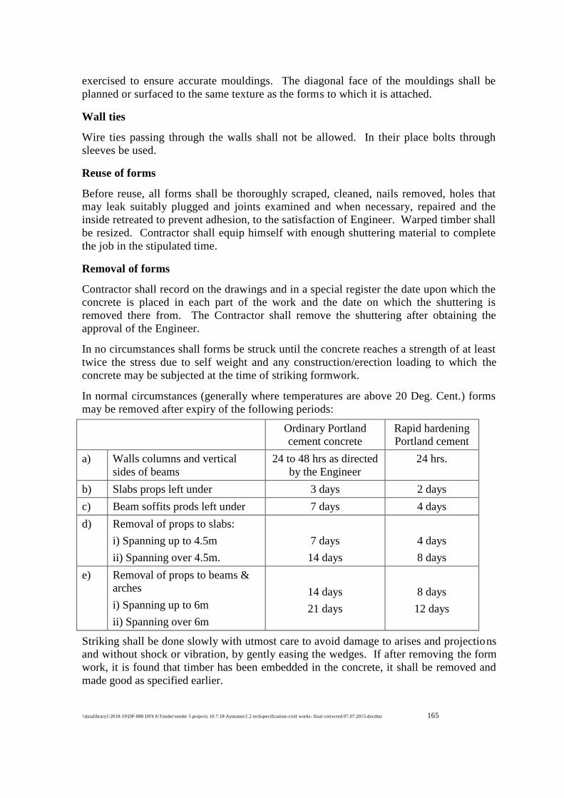
\\datalibrary1\2018-19\DP-888 DSYA\Tender\tender 5 projects 10.7.18\Aymanm\1.2 techspecification-civil works- final corrected 07.07.2015.docdmr 165
165
exercised to ensure accurate mouldings. The diagonal face of the mouldings shall be
planned or surfaced to the same texture as the forms to which it is attached.
Wall ties
Wire ties passing through the walls shall not be allowed. In their place bolts through
sleeves be used.
Reuse of forms
Before reuse, all forms shall be thoroughly scraped, cleaned, nails removed, holes that
may leak suitably plugged and joints examined and when necessary, repaired and the
inside retreated to prevent adhesion, to the satisfaction of Engineer. Warped timber shall
be resized. Contractor shall equip himself with enough shuttering material to complete
the job in the stipulated time.
Removal of forms
Contractor shall record on the drawings and in a special register the date upon which the
concrete is placed in each part of the work and the date on which the shuttering is
removed there from. The Contractor shall remove the shuttering after obtaining the
approval of the Engineer.
In no circumstances shall forms be struck until the concrete reaches a strength of at least
twice the stress due to self weight and any construction/erection loading to which the
concrete may be subjected at the time of striking formwork.
In normal circumstances (generally where temperatures are above 20 Deg. Cent.) forms
may be removed after expiry of the following periods:
Ordinary Portland
cement concrete
Rapid hardening
Portland cement
a) Walls columns and vertical
sides of beams
24 to 48 hrs as directed
by the Engineer
24 hrs.
b) Slabs props left under 3 days 2 days
c) Beam soffits prods left under 7 days 4 days
d) Removal of props to slabs:
i) Spanning up to 4.5m
ii) Spanning over 4.5m.
7 days
14 days
4 days
8 days
e) Removal of props to beams &
arches
i) Spanning up to 6m
ii) Spanning over 6m
14 days
21 days
8 days
12 days
Striking shall be done slowly with utmost care to avoid damage to arises and projections
and without shock or vibration, by gently easing the wedges. If after removing the form
work, it is found that timber has been embedded in the concrete, it shall be removed and
made good as specified earlier.
\\datalibrary1\2018-19\DP-888 DSYA\Tender\tender 5 projects 10.7.18\Aymanm\1.2 techspecification-civil works- final corrected 07.07.2015.docdmr 166
166
Reinforced temporary openings shall be provided as directed by Engineer to facilitate
removal of formwork which otherwise may be inaccessible.
Tie rods, clamps, form bolts etc., which must be entirely removed from walls or similar
structures shall be loosened not sooner than 24 hours nor later than 40 hrs. after the
concrete has been deposited. Ties, except those required to hold forms in place, may be
removed at the same time, Ties, withdrawn from walls and grade beams shall be pulled
towards the inside face cutting ties back from the faces of walls and grade beams will
not be permitted.
For liquid retaining structures no sleeves for through bolts shall be used nor shall
through bolts be removed as indicated above. The bolts, in this case, shall be cut at
25mm depth from the surface and then the hole shall be made good by sand, cement
mortar of the same proportions as the concrete just after striking the formwork.
Reinforcement Steel
General
Reinforcement bars, if supplies are arranged by contractor unless otherwise specified,
shall be either plain round mild steel bars grade I as per IS 432 (Part I) or medium
tensile steel bar as per IS 432 (Part I) or hot rolled mild steel and medium tensile steel
deformed bars as per IS 1139 or cold twisted steel bars as per IS 1786, as shown and
specified on the drawings. Wire mesh or fabric shall be in accordance with IS 1566.
Substitution of reinforcement will not be permitted except upon written approval from
Engineer.
Plain round mild steel bars grade II as per IS 432 (Part I) may be used with prior
approval of Engineer in writing and with 10% increase in the reinforcement area but its
use shall not be permitted in structures located in earthquake zones subjected to severe
damage (as per IS 1895) and for structures subject to dynamic loading (other than wind
loading), such as frames supporting rotary or reciprocating machinery, etc.
All reinforcement shall be clean, free from grease, oil, paint, loose mill scale, loose rust,
dust, bituminous material or any other substances that will destroy or reduce the bond.
All rods shall be thoroughly cleaned before being fabricated. Pitted and defective rods
shall not be used.
All concrete in the works shall be of design mix as defined in IS 456, unless it is a
nominal mix concrete such as 1:3:6, 1:4:8 or 1:5:10. Whether reinforced or otherwise,
all design mix concrete works to be carried out under this specification shall be divided
into the following classifications:
Providing, fabricating and placing in position reinforcement steel
The quality of the steel shall be as mentioned in the materials section. The bars shall be
fabricated as per the drawings and binding with 16 gauge GI binding wire etc. Laps and
splices for reinforcement shall be as shown on the drawings. Splices in adjacent bars
shall be approved by Engineer. The bars shall not be lapped unless the length required
exceeds the maximum available lengths of bars at site.
\\datalibrary1\2018-19\DP-888 DSYA\Tender\tender 5 projects 10.7.18\Aymanm\1.2 techspecification-civil works- final corrected 07.07.2015.docdmr 167
167
Bending
Reinforcing bars supplied bent or in coils, shall be straightened before they are cut to
size. Straightening of bars shall be done in cold and without damaging the bars. This is
considered as a part of reinforcement binding fabricating work.
All bars shall be accurately bent according to the sizes and shapes shown on the detailed
working drawings/bar bending schedules. They shall be bent gradually by machine or
other approved means. Reinforcing bars shall not be straightened and rebent in a manner
that will injure the material, bars containing cracks or splits shall be rejected. They shall
be bent cold, except bars of over 32 mm in diameter which may be bent hot if
specifically approved by Engineer. Bars bent hot shall not be heated beyond cherry red
colour (not exceeding 845oC) and after bending shall be allowed to cool slowly without
quenching. Bars incorrectly bent shall be used only if the means used for straightening
and rebending shall not injure the material. No reinforcement shall be bent when in
position in the work without approval whether or not it is partially embedded in
hardened concrete. Bars having kind or bends other than those required by design shall
not be used.
Fixing
Reinforcement shall be accurately fixed by any approved means and maintained in the
correct position shown in the drawings by the use of block, spacers and chairs as per IS
2502 to prevent displacement during placing and compaction of concrete. Bars intended
to be in contact at crossing points shall be strongly bound together at all such points with
two no. 16 gauge anhealed soft iron wire. The vertical distance required between
successive layers of bar in beams or other members shall be maintained by providing of
mild steel spacer bars at such intervals that the main bars do not perceptibly sag between
adjacent spacer bars.
Cover
Unless indicated otherwise on the drawings, clear concrete cover for reinforcement
(exclusive of plaster or other decorative finish) shall be as follows:
a) At each end of reinforcing bar, not less than 25 mm nor less than twice the
diameter of the bar whichever is less.
b) For a longitudinal reinforcing bar in a column, not less than 40 mm, nor less than
the diameter of the bar. In case of columns of minimum dimensions of 20 cm or
under, with reinforcing bars of 12 mm and less in diameter, a cover of 25 mm may
be used.
c) For longitudinal reinforcing bars in a beam 25 mm nor less than the diameter of
the bar.
d) For tensile, compressive, shear, or other reinforcement in a slab or wall not less
than 12 mm nor less than the diameter of such reinforcement.
e) For any other reinforcement not less than 12 mm nor less than the diameter of such
reinforcement.
\\datalibrary1\2018-19\DP-888 DSYA\Tender\tender 5 projects 10.7.18\Aymanm\1.2 techspecification-civil works- final corrected 07.07.2015.docdmr 168
168
f) For footings and other principal structural members in which the concrete is
deposited directly against the ground, cover to the bottom reinforcement shall be
75 mm. If concrete is poured on a layer of lean concrete the bottom cover may be
reduced to 50 mm.
g) For concrete surfaces exposed to the weather or the ground after removal of forms,
such as retaining walls, footing sides and top, etc., not less than 50 mm for bars
larger than 16 mm dia and not less than 40 mm for bars 16 mm dia or smaller.
h) Increased cover thickness shall be provided, as indicated on the drawings, for
surfaces exposed to the action of harmful chemicals (or exposed to earth
contaminated by such chemical, acid, alkali, saline atmosphere, sulphurous smoke,
etc.
i) For reinforced concrete members, totally or periodically immersed in sea water or
subject to sea water spray, the cover of concrete shall be 50 mm more than those
specified in (i) to (v) above.
j) For liquid retaining structures the minimum cover to all steel shall be 40 mm or the
diameter of the main bars, whichever is greater. In the presence of sea water and
soils and waters of a corrosive character the cover shall be increased by 10 mm.
k) Protection to reinforcement in case of concrete exposed to harmful surroundings
may also be given by providing a dense impermeable concrete with approved
protective coatings, as specified by the Engineer.
l) The correct cover shall be maintained by cement mortar cover blocks.
Reinforcement for footings, beams and slabs on sub-grade shall be supported on
precast concrete blocks as approved by engineer. The use of pebbles or stones
shall not be permitted.
Inspection
Erected and secured reinforcement shall be inspected, jointly measured and recorded and
approved by Engineer prior to placement of concrete.
1.4.00 MASONRY WORKS
Applicable codes and specifications
a) The following codes, standards and specifications are made a part of this
specification. All standards, tentative specifications, codes of practices referred to
herein shall be the latest edition including all applicable official amendments and
revisions.
IS:1077 - Common burnt clay building bricks
IS:3102 - Classification of burnt clay bricks
IS:2180 - Burnt clay building bricks, heavy duty
IS:3495 - Method of sampling and testing clay building bricks
IS:2691 - Burnt clay facing bricks
\\datalibrary1\2018-19\DP-888 DSYA\Tender\tender 5 projects 10.7.18\Aymanm\1.2 techspecification-civil works- final corrected 07.07.2015.docdmr 169
169
IS:2221 - Code of practice for brick work
IS:2185 - Load bearing hollow concrete blocks
IS:5498 - Lime-cement-cinder hollow concrete blocks
IS:3115 - Lime-cement cinder soild blocks
IS:1597 - Code of practice for construction of stone masonry (Part I)
Brick
Bricks used in works shall be bricks of specified crushing strength as described in the
Schedule of Quantities. They shall have the following general properties:
They shall be sound, hard, homogenous in texture, well burnt in kiln without being
verified, table moulded, deep red, cherry or copper coloured, of regular shape and size
and shall have sharp and square edges and parallelled faces. The bricks shall be free
from pores, chips, flaws or humps of any kind. Bricks containing unground particles
and which absorb water more than 1/5th of their weight when soaked in water for twenty
four hours shall be rejected. Overburnt or under burnt bricks shall be liable to rejection.
These bricks shall give a clear ringing sound when struck.
Samples of bricks shall be submitted before starting the brickwork to the Engineer for
approval. Bricks supplied shall conform to these approved samples. Brick sample shall
be got tested as per IS:3495 by Contractor at no extra cost. Bricks rejected by Engineer
shall be removed from the site of works within 24 hours.
Mortar
Mix for cement mortar shall be as specified in the respective items of work. Gauge
boxes for sand shall be of such dimensions that one complete bag of cement containing
50 kgs. of cement forms one unit. The sand shall be free from clay, shale, loam, alkali,
and organic matter and of sound, hard, clean and durable practices. Sand shall be
approved by the engineer. If so directed by the engineer sand shall be thoroughly
washed till it is free of any contamination.
For preparing cement mortar the ingredients shall first be mixed thoroughly in dry
condition. Water shall then be added and mixing continued to give a uniform mix of
required consistency. Cement mortar shall preferably be machine mixed, through
mixing in a thorough manner may be allowed. The mortar so mixed shall be used within
30 minutes of mixing. Mortar left unused in the specified period shall be rejected.
The Contractor shall arrange for test on mortar samples if so directed by the engineer
retempering of mortar shall not be permitted.
Workmanship
All bricks shall be thoroughly soaked in clean water for at least one hour immediately
before being laid. The cement mortar for brick masonry work shall be as specified in the
respective item of work. Brick work 230 mm thick and over shall be laid in English
bond unless otherwise specified. While laying bricks shall be pressed into the mortar
\\datalibrary1\2018-19\DP-888 DSYA\Tender\tender 5 projects 10.7.18\Aymanm\1.2 techspecification-civil works- final corrected 07.07.2015.docdmr 170
170
and shoved into final position so as to embed the brick fully in mortar. Bricks shall be
laid with frogs uppermost.
All brick work shall be plumb, square and true to dimensions. Vertical joints in alternate
courses shall come directly one over the other and be in line. Horizontal courses shall be
leveled. The thickness of brick courses shall be kept uniform. For walls of thickness
greater than 230 mm both faces shall be kept in vertical planes. No broken bricks shall
be used except as closers. Care shall be taken that the bricks forming the top corners and
ends of the wall shall be properly radiated and keyed into position. Holes kept in
masonry for scaffolding shall be closed before plastering. All interconnected brickwork
shall be carried out at nearly one level (so that there is uniform distribution of pressure
on the supporting structure) and no portion of the work shall be left more than one
course lower than the adjacent work where this is not possible, the work shall be raked
back accordingly to bond (and not saw toothed) at an angle not exceeding 45o.
Bricks shall be so laid that all joints are well filled with mortar. The thickness of joints
shall not be less than 6 mm and not more than 10 mm. The face joint shall be raked to a
minimum depth of 12 mm by raking tools daily during the progress of work when the
mortar is still green so as to provide a proper key for the plaster or pointing to be done.
Where plastering or pointing is not required to be done the joints shall be uniform in
thickness and be struck flush and finished at the time of laying. The face of brickwork
shall be cleaned daily and all mortar droppings removed. The surface of each course
shall be thoroughly cleaned of all dirt before another course is laid on top. If the mortar
in the lower course has begun to set the joints shall be raked out to depth of 12 mm
before another course is laid.
All brick work shall be built tightly against columns, floor slabs or other structural
member.
Where drgs. indicate that structural steel columns are to be fireproofed with brick work
the brick shall be built closely against all flanges and webs with all spaces between the
steel and bricks works filled solid with mortar. Steel members partly embedded in
brickwork and not indicated to be fireproofed with concrete shall be covered with not
less than 12 mm thick mortar unless directed otherwise by engineer.
The work shall be cured for 15 days.
Miscellaneous inserts in masonry e.g. sleeves, wall ties, anchors, conduits, structural
sheet, steel lintels, etc., shall be installed by the Contractor. Furnishing fixing of any of
these inserts by the Contractor will be paid for separately under steel work. Openings,
arches, etc., shall be provided as shown on the drawings, chasses, pockets, etc., shall be
provided as shown on the drawings to receive rain water pipes, etc. Wall ties and
flashings shall be built into the brickwork in accordance with the drawings and
specifications.
Rubble Masonry
Stones for this work shall be hard, durable rock, close or fine grained and uniform in
colour free from veins, flaws and other defects and shall conform to IS:1597 (Part I).
The stones shall be laid in mortar proportions specified for the particular item of work.
Stones shall be got approved.
\\datalibrary1\2018-19\DP-888 DSYA\Tender\tender 5 projects 10.7.18\Aymanm\1.2 techspecification-civil works- final corrected 07.07.2015.docdmr 171
171
For all work below ground level the masonry shall be random rubble uncoursed with
ordinary quarry dressed stones or hearting and faced with selected quarry dressed stones.
For all work above ground level the masonry shall be random rubble faced with hammer
dressed stones with squared quoins at joints and corners.
No stones shall tail into the wall, either with a point or to length less than 11-2 times its
height. The thickness of the joints shall not exceed 12 mm.
Spauls and pinnings shall not be allowed to show on the face of the wall. Two bond
stones each of minimum area of 500 sq.cm for every 1.0 sq.m. of each wall face shall be
provided. These shall be through stones in walls 600 mm thick and under, in walls
thicker than 600 mm the length of bond stones shall be 2/3 times the thickness of walls.
The stones for hearting of the wall shall not be less than 150 mm in any direction. Chips
and spauls shall be wedged in to avoid thick mortar beds and joints. The wall faces,
corners and joints or openings shall be truly vertical the quoins shall be of selected
stones, neatly dressed with chiesel to form the required angle and laid header and
stretcher alternatively.
The exposed face of the work shall be carefully and neatly pointed with mortar in all
joints on the other side the joints shall be neatly struck with trowel while the mortar is
fresh.
The mortar for the work shall be as specified in the respective item of work. Curing of
masonry shall continue for a minimum of ten days.
1.5.00 WOODWORK
Applicable Codes
1) IS:4021 - Timber door, window and ventilator frames
2) IS:2202 - Wooden flush door shutters (solid core type) Part I
3) IS:1003 - Timber panelled and glazed shutters (Part I & II)
4) IS:4020 - Method of tests for wooden flush doors: Type tests
5) IS:1761 - Transparent sheet glass for glazing and framing purposes
6) IS:3097 - Specification for veneered particle boards (Exterior Grade)
General
Wood used for all work shall be the best of the respective class specified, and properly
seasoned, suitable for joinery work should be of natural growth, uniform in texture,
straight grained, free from sapwood, dead knots, open shakes, rot, decay and any other
defects and blemishes.
For joints following principles to be observed:
At the joints the weakness of pieces must be minimum as far as possible. To place each
abutting surface in a joint as neatly as possible, perpendicular to pressure. To form and
fit accurately every pair of surface that come in contact.

\\datalibrary1\2018-19\DP-888 DSYA\Tender\tender 5 projects 10.7.18\Aymanm\1.2 techspecification-civil works- final corrected 07.07.2015.docdmr 172
172
All joining shall be wrought on all faces and finished off by hand with sand paper with
slightly rounded arises.
The joints shall be pinned with hard wood pins and put together with white lead.
Jointing shall be by means of mortice and tenon or dovetailed joints as approved. For
external work the joints shall be coated with white or red lead before the members are
put together. For internal joints where there is no chance of moisture the joint shall be
glued. Driving of screws with hammer is prohibited. The screws shall be soaked in
oil before driving them home. The heads of the screws and nails shall be sunk and
puttied.
Any joinery work which shall split, fracture, shrink or show flaws or other defects due to
unsoundness, inadequate seasoning or bad workmanship, shall be removed and replaced
with sound materials at the contractor’s expense.
Door frames shall be rebated. All dimensions shall be as per drawings. The verticals of
door frames shall project about 50 mm below finished floor, surface coming in contact
with brick work shall be painted with bitumen or solignum as directed by the engineer.
The door frame shall be provided with 3 nos. MS 230x30x3 mm flat split hold fasts on
each side, respectively. These hold fasts shall be embedded in masonry or concrete
work with concrete block of mix 12:2:4 and size 230x300x250. The work shall conform
to IS:4021.
The door shall be panelled or solid flush doors or as described in the item of work. All
doors shall be supplied with approved fittings such as hinges, mortice lock of approved
make with handles on both sides, oxidised brass tower bolts and latch arrangements,
door stops, etc., and as shown in drawings. External flush doors shall be made of
weatherproof plywood as per item description in the Schedule of Quantities.
The workmanship of all doors and window shutters shall conform to the requirements of
IS:1003 (Parts I & II) and IS:2202 (Part I). Flush door panels shall be got tested as per
IS:4020 in standard Laboratories.
Beading and architraves shall conform to the shapes shown on drawings or as approved
and fixed by means of screws (counter sunk or otherwise) or bolts.
Glass
Sheet glass or plate glass shall be of Indian make as specified in the Schedule of
Quantities/as directed. It shall be free from waves and bubbles and all defects. The
thickness of the glass shall be as follows:
2 mm thick glass for panes upto 900 sq.cm. area
3 mm thick glass for panes from 900 - 5500 sq.cm. area
4 mm thick glass for panes 5500 - 8400 sq.c.m. area
5.5 mm thick glass or plate glass for panes above 8400 sq.cm.
It should be clearly understood that glass which does not have uniform refractive index
or which is wavy, will be rejected. The glazing shall be fixed with teak wood beading
and putty.
\\datalibrary1\2018-19\DP-888 DSYA\Tender\tender 5 projects 10.7.18\Aymanm\1.2 techspecification-civil works- final corrected 07.07.2015.docdmr 173
173
It shall conform to IS:1761. The putty shall be made up of one part of white lead, 3
parts of finely powdered chalk and adding boiled linseed oil to make a stiff elastic paste.
No voids shall be left in the putty. Woodwork shall not be painted, oiled or otherwise
treated before it has been approved by the engineer.
The window frame shall be provided with 2 nos. MS 230x30x3 mm flat split hold fasts
on each side, respectively. These hold fasts shall be embedded in masonry or concrete
work with concrete block of mix 1:2:4 and size 230x300x250 mm.
The type of windows shall be as specified. Each leaf of the shutter shall have one pair of
hinges for a width of less than or equal to 2 feet, for width more than 2 feet extra nos. of
hinges shall be provided as directed by the Engineer at no extra cost. The glazed
windows shall be provided with glass of thickness as specified in the item description.
Architraves shall be provided as per drawing.
Door, Window and Ventilator frames
Timber for door, window and ventilators frames shall be as specified. Timber shall be
sawn in the direction of the grains. All members of a frame shall be of the same
species of timber and shall be straight without any warp or bow. Frames shall have
smooth, well-planed (wrought) surfaces except the surfaces touching the walls, lintels,
sill etc., which may be left clean sawn. Rebates, rounding or moulding shall be done
before the members are jointed into frames. The depth of the rebate for housing the
shutters shall be 15 mm, and the width of the rebates shall be equal to the
thickness of the shutters. A tolerance of ± 2 mm shall be permitted in the specified
finished dimensions of timber sections in frames.
Joints
The Jamb posts shall be through tenoned in to the mortise of the transoms to the full
thickness of the transoms and the thickness of the tenon shall be not less than 2.5 cm.
The tenons shall closely fit into the mortise without any wedging or filling. The contact
surface of tenon and mortise before putting together shall be glued with polyvinyl
acetate dispersion based adhesive conforming to IS 4835 or adhesive conforming IS 851
and pinned with 10 mm dia hard wood dowels, or bamboo pins or star shaped metal
pins. The joints shall be at right angles when checked from the inside surfaces of the
respective members. The joints shall be pressed in position. Each assembled door frame
shall be fitted with a temporary stretcher and a temporary diagonal brace on the rebated
faces.
Fixing of Frames
The frames shall be got approved by the Engineer-in-Charge before being painted, oiled or
otherwise treated and before fixing in position. The surface of the frames abutting masonry or
concrete and the portions of the frames embedded in floors shall be given a coating of coal tar.
Frames shall be fixed to the abutting masonry or concrete with holdfasts or metallic fasteners as
specified. After fixing, the jamb posts of the frames shall be plugged suitably and finished neat.
Vertical members of the door frames shall be embedded in the floor for the full thickness of the
floor finish and shall be suitably strutted and wedged in order to prevent warping during
construction. A minimum of three hold fasts shall be fixed on each side of door and window
\\datalibrary1\2018-19\DP-888 DSYA\Tender\tender 5 projects 10.7.18\Aymanm\1.2 techspecification-civil works- final corrected 07.07.2015.docdmr 174
174
frames one at centre point and other two at 30 cm from the top and bottom of the frames. In case
of window and ventilator frames of less than 1 m in height two hold fasts shall be fixed on each
side at quarter point of the frames. Hold fasts and metallic fasteners shall be measured and paid
for separately.
Measurements
Wood work wrought, framed and fixed shall be measured for finished dimension without any
allowance for the wastage or for dimensions beyond specified dimension. However, in case of
members having mouldings, roundings or rebates and members of circular or varying sections,
finished dimensions shall be taken as the sides of the smallest square or rectangle from which
such a section can be cut. Length of each member shall be measured over all to the nearest cm so
as to include projection for tenons. Width and thickness shall be measured to the nearest mm and
the quantity shall be worked out in unit of upto three places of decimal.
Rate
The rate shall include the cost of material and labour involved in all the operations described
above except the hold fasts or metallic fasteners which will be paid for separately.
Panelled Glazed or Panelled and Glazed shutters
Panelled or glazed shutters for doors, windows, ventilators and cupboards shall be constructed in
the form of timber frame work of stiles and rails with panel inserts of timber, plywood, block
board,veneered particle board, fibre board wire gauze or float glass. The shutters may be single
or multipanelled, as shown in the drawings or as directed by the Engineer-in-Charge. Timber for
frame work, material for panel inserts and thickness of shutters shall be as specified. All
members of the shutters shall be straight without any warp or bow and shall have smooth well
planed face at right angles to each other. Any warp or bow shall not exceed 1.5 mm for door
shutter and 1 mm for window and ventilator shutters The right angle for the shutter shall be
checked by measuring the diagonals and the difference between the two diagonals should not be
more than 3 mm. Generally panelled glazed or panelled and glazed shutter shall conform to IS
1003 (Part. 1 & 2).
Frame Work
Timber for stiles and rails shall be of the same species and shall be sawn in the directions of
grains. Sawing shall be truly straight and square. The timber shall be planed smooth and
accurate to the required dimensions. The stiles and rails shall be joined to each other by plain or
haunched mortise and tenon joints and the rails shall be inserted 25 mm short of the width of the
stiles. The bottom rails shall have double tenon joints and for other rails single tenon joints shall
be provided. The lock rails of door shutter shall have its centre line at a height of 800 mm from
the bottom of the shutters unless otherwise specified. The thickness of each tenon shall be
approximately one-third the finished thickness of the members and the width of each tenon shall
not exceed three times its thickness.
Gluing of Joints :
The contact surfaces of tenon and mortise shall be treated, before putting together, with bulk
type synthetic resin adhesive conforming to IS 851 suitable for construction in wood or synthetic
resin adhesive (Phenolic and aminoplastic) conforming to IS 848 or polyvinyl acetate dispersion
based adheshive conforming to IS 4835 and pinned with 10 mm dia hardwood dowels or
\\datalibrary1\2018-19\DP-888 DSYA\Tender\tender 5 projects 10.7.18\Aymanm\1.2 techspecification-civil works- final corrected 07.07.2015.docdmr 175
175
bamboopins or star shaped metal pins; after the frames are put together and pressed in position
by means of press.
Stiles and bottom rail shall be made out of one piece of timber only. Intermediate rail exceeding
200 mm in width may be of one or more pieces of timber. The width of each piece shall be not
less than 75 mm. Where more than one piece of timber is used for rails, they shall be joined with
a continuous tongued and grooved joint glued together and reinforced with metal dowels at
regular intervals not exceeding 200 mm.
Door Shutters
Rebating
The shutters shall be single-leaf or double leaved as shown in the drawings or as directed by the
Engineer-in-Charge. In case of double leaved shutters, the meeting of the stiles shall be rebated
by onethird the thickness of the shutter.
Panelling
The panel inserts shall be either framed into the grooves or housed in the rebate of stiles and
rails. The depth of the groove shall be 12 mm and its width shall accommodate the panel inserts
such that the faces are closely fitted to the sides of the groove. Panel inserts shall be framed into
the grooves of stiles and rails to the full depth of the groove leaving space of 1.5 mm. Width and
depth of the rebate shall be equal to half the thickness of stiles and rails. Glass panels, asbestos
panels wire gauze panels and panel inserts of cupboard shutters shall be housed in the rebates of
stiles and rails.
Timber Panels
Timber panels shall be preferably made of timber of large width; the minimum width and
thickness of the panel shall be 100 mm, and 15 mm respectively. When made from more than
one piece, the pieces shall be jointed with a continuous tongued and grooved joint glued together
and reinforced with headless nails at regular intervals not exceeding 100 mm. Depth and
thickness of such joint shall be equal to one-third of thickness of panel. The panels shall be
designed such that no single panel exceeds 0.5 square metre in area. The grains of timber panels
shall run along the longer dimensions of the panels. All panels shall be of the same species of
timber unless otherwise specified.
Plywood Panels
Plywood boards used for panelling of shutters shall be BWP type or grade. Each panels shall be
a single piece of thickness, 9 mm for two or more panel construction and 12 mm thickness for
single panel construction unless otherwise specified.
Veneered Particle Board Panels
Veneered Particle board used for panelling of shutters shall be Exterior Grade bonded with
BWP type synthetic resin adhesive as. Each panel shall be a single piece of thickness 12 mm
unless otherwise specified.
\\datalibrary1\2018-19\DP-888 DSYA\Tender\tender 5 projects 10.7.18\Aymanm\1.2 techspecification-civil works- final corrected 07.07.2015.docdmr 176
176
Glass Panels
Glass panelling (Glazing) shall be done as specified in Glazing in the shutters of doors,
windows and ventilators of bath, WC and Lavatories shall be provided with frosted glass the
weight of which shall be not less than 10 kg/sqm. Frosted glass panes shall be fixed with
frosted face on the inside. Glass panels shall be fixed by providing a thin layer of putty
conforming to IS 419 applied between glass pane and all along the length of the rebate and
also between glass panes and wooden beading.
Putty can be prepared by mixing one part of white lead with three parts of finely powdered
chalk and then adding boiled linseed oil to the mixture to form a stiff paste and adding varnish
to the paste at the rate of 1 litre of varnish to 18 kg of paste. Fixing of glass panes without
beading shall not be permitted. Glazing shall be done after the shutters have been primed and
prepared for painting, so that wood may not draw oil out of putty.
Finish
Panels of shutters shall be flat and well sanded to a smooth and level surface.
Beading
Beadings in panelled shutter shall be provided where specified in architectural drawings or
directed by the Engineer-in-Charge. Each length of beading shall be single piece. Joints at the
corners shall be mitred and exposed edges shall be rounded. Beading shall be fixed with
headless nails at 75 mm intervals. For external shutters, the beading shall be fixed on the
outside face.
Machine/Factory made Shutters
Machine made shutters, where specified, shall be procured from an approved factory. For
machine made shutters, operations like sawing, planning, making tongue and tenons, cutting
grooves, mortises and rebates, drilling holes and pressing of joints shall be done by suitable
machines. Machines made shutters shall be brought to the site fully assembled but without any
priming coat. Panel inserts of sheet glass and wire gauze may, however, be fixed at site.
Fixing of Shutters
For side hung shutters of height upto 1.2 m, each leaf shall be hung on two hinges at quarter
points and for shutter of height more than 1.2 m, each leaf shall be hung on three hinges one at
the centre and the other two at 200 mm from the top and bottom of the shutters. Top hung and
bottom hung shutters shall be hung on two hinges fixed at quarter points of top rail or bottom
rail. Centre hung shutter shall be suspended on a suitable pivot in the centre of the frame. Size
and type of hinges and pivots shall be as specified. Flap of hinges shall be neatly counter sunk
into the recesses cut to the exact dimensions of flap. Screws for fixing the hinges shall be
screwed in with screw driver and not hammered in. Unless otherwise specified, shutters of
height more than 1.2 mm shall be hung on butt hinges of size 100 mm and for all other shutters
of lesser height butt hinges of size 75 mm shall be used. For shutter of more than 40 mm
thickness butt hinges of size 125 × 90 × 4 mm shall be used. Continuous (piano) hinges shall
be used for fixing cup-board shutters where specified.
\\datalibrary1\2018-19\DP-888 DSYA\Tender\tender 5 projects 10.7.18\Aymanm\1.2 techspecification-civil works- final corrected 07.07.2015.docdmr 177
177
Fittings
Fittings shall be provided as per schedule of fittings decided by Engineer-in-Charge. Cost of
providing and fixing shutter shall include cost of hinges and necessary screws for fixing the
same. All other fittings shall be paid for separately.
Wooden Cleats and Blocks
Wooden cleats and blocks shall be fixed to doors and windows as directed by Engineer-in-
Charge, as per size and shape approved by him. These are included in the cost of providing
and fixing the shutters.
Measurements
Framework and panelling shall be measured separately.
Framework of Shutters
The overall length and width of the framework of the shutters shall be measured nearest to a
cm in fixed position (overlaps not to be measured in case of double leaved shutters) and the
area calculated in square metres correct to two places of decimal. No deduction shall be made
to form panel openings or louvers. No extra payments shall be made for shape, joints and
labour involved in all operations described above.
For panelling of each type or for glazed panel length and width of opening for panels inserts or
glazed panels shall be measured correct to a cm before fixing the beading and the area shall be
calculated to the nearest 0.01 sq.m. The portions of the panel inserts or glazed panel inside the
grooves or rebates shall not be measured for payment.
Rate
Rate includes the cost of materials and labour involved in all the operations described above.
The framework and panelling of each type or glazed panels shall be paid separately. The rate
for framework includes the cost of butt hinges and necessary screws as specified .However,
extra shall be paid for providing moulded beading where specified. Nothing extra shall be paid
for plain beading.
FINISHING WORKS
Applicable Codes
1) IS:2394- Code of practice for application of lime plaster finish
2) IS:1477- Code of practice for painting of ferrous metals in buildings and allied
finishes (Part I & II)
3) IS: 427 - Distemper, dry colour as required
4) IS:2395 - Code of practice for painting concrete, masonry and plaster surfaces
5) IS: 428 - Distemper, oil emulsion, colour as required
\\datalibrary1\2018-19\DP-888 DSYA\Tender\tender 5 projects 10.7.18\Aymanm\1.2 techspecification-civil works- final corrected 07.07.2015.docdmr 178
178
Plastering
The surface to be plastered shall be washed with fresh clean water free from all dirt,
loose material grease, etc., and thoroughly wetted for 6 hours before plastering work is
commenced. Concrete surfaces to be plastered will however be kept dry. The wall
should not be too wet but only damp at the time of plastering. The damping shall be
uniform to get uniform bond between the plaster and the wall. The junction between the
brick work and RCC should be fixed with chicken wire mesh/PVC strip as directed
before plaster.
The proportion of the mortar shall be as specified under the respective items of work.
Cement shall be mixed thoroughly in dry condition and then just enough water added to
obtain a workable consistency. The quality of water, sand and cement shall be as
mentioned in the Specifications for Concrete & allied works. The mortar thus mixed
shall be used immediately and in no case shall the mortar be allowed to stand for more
than 30 minutes after mixing with water. The plaster shall be laid in a single coat. The
mortar shall be splashed on the prepared surface with a trowel and finished smooth by
trowelling. The plastered surface shall be rubbed with iron plate till the surface shows
cement paste. The work shall be in line and level. Curing of plaster shall be started as
soon as the applied plaster has hardened enough so as not to be damaged. Curing shall
be done by continuously applying water in a fine spray and shall be carried out for at
least 7 days.
The plaster shall be carried out on jambs, lintel and sill faces top and undersides, etc., as
shown in the drawing or as directed by the engineer.
Providing & Applying Cement paint
This may be “SNOWCEM” or of equivalent make. The surface shall be prepared as
specified in the specification for white wash. This shall be applied with brush on the
plastered wall. The strokes shall be even and it shall be cured atleast for 7 days. No
patch or brush stroke shall be seen. Three coats shall be applied.
Providing & Fixing chicken wire mesh
The wire mesh shall be of 24 gauge and it shall be fixed with nails at the junction of
brick masonry and RCC elements or as specified by the Engineer-in-charge. The
chicken wire mesh shall not sag in between the nails. This shall be done before the
application of plaster. It should be extended atleast 15 cm on both sides. The rate
includes for carrying out the work at all heights.
1.6.00 FLOORING
Applicable codes
1) IS:1443- Code of practice for laying and finishing of cement concrete flooring
tiles.
2) IS:2114 -Code of practice for laying in situ terrazzo floor finish
3) IS: 777 - Glazed earthenware tiles
\\datalibrary1\2018-19\DP-888 DSYA\Tender\tender 5 projects 10.7.18\Aymanm\1.2 techspecification-civil works- final corrected 07.07.2015.docdmr 179
179
Ceramic tiles in flooring, skirting and dado
The ceramic tiles in flooring and dado shall be of first class quality as specified in the
item specification and shall be approved by the Engineer. The tiles shall be of standard
size without warp and with straight edges, true and even in shape and size and of
uniform colour. The tiles surface shall be of fine grained texture, dense and
homogeneous. The thickness of the tile shall be as per the item specification. The tiles
shall be submerged in water till the bubbles cease.
They should be laid on a base of 12 mm thick mortar bed (cement or lime 1:3 sand) and
cement (3 kg/sq.m) paste. They shall be laid truly vertical on walls and truly horizontal
on floors or to slopes as directed. The joint shall be very thin, uniform and perfectly
straight. The tiles in dado shall be finished in such a way that, only the tile thickness
projects over the finished plaster or as specified otherwise. Where full tiles are not
possible, the same should be cut or sawn to the required size and their edge rubbed to
ensure straight and true joints. After the tiles are laid extra cement grout shall be
removed. The joints shall be cleaned with wire brush and then the joint shall be floated
with white or gray cement as approved by the Engineer. The tiles shall be cleaned after
the work is complete.
Vitrified Tile Flooring
The vitrified tiles shall be of approved quality, size and uniform thickness and shall be
hard, sound, dense and homogeneous in texture. It shall be uniform in shade free from
stains, cracks and defects.
The Dimensional variations, surface quality, physical properties and chemical properties
of tiles shall be as per internationally accepted relevant standards.
The edges are straight, with square edges and free from chippings. Tiles should be laid
on a bed of cement mortar as specified in item specifications. Thickness of mortar
bedding shall be specified in the item specifications and a neat cement shall be spread
over the mortar bed. The tiles shall be placed one by one, keeping in check the level and
line of the flooring. Tiles are wetted before placing. The tiles are then gently tapped
with wooden mallet till it is firmly and properly bedded. There should be no voids left.
The joint should be finished with tile joint filler of approved make and shade. The
pattern of the flooring shall be as per the architectural drawings or as directed by
Engineer-in-charge.
The base concrete or the RCC slab on which the tiles are to be laid shall be cleaned,
batted and mopped. the minimum thickness of bed mortar shall not be less than 12mm.
Any undulation in the base concrete or RCC slab shall be corrected by cement mortar
without any extra cost and any additional leveling required beyond max. mortar
thickness to be carried out with cement concrete.
The flooring shall be cured for a minimum period of 7 days. The surface of the flooring
shall be laid to levels and slopes as directed by Engineer-in-charge.
The tiles which are fixed in the floor adjoining the wall shall enter not less than 12mm
under the skirting or dado. The junction between the wall plaster and the floor shall be
finished neatly and without waviness.
\\datalibrary1\2018-19\DP-888 DSYA\Tender\tender 5 projects 10.7.18\Aymanm\1.2 techspecification-civil works- final corrected 07.07.2015.docdmr 180
180
The free edges shall be cut as per the pattern and shall be polished to match with
flooring.
Engineer-in-charge has liberty to ask for any tests with respect to physical and chemical
properties, etc. and the contractor shall arrange the same without any extra cost.
Granite Stone Flooring
The granite has to be processed by water cut method and shall be machine polished
using Auto polisher or line polisher to mirror finish to have a gloss meter reading of 90
above.
The stone shall be of approved quality, size and uniform thickness and shall be hard,
sound, dense and homogenous in texture. It shall be uniform in shade free from stains,
cracks, decay and weathering.
The edges are machine cut to fine, straight, with square edges and free from chippings.
Stone should be laid on a bed of cement mortar as specified in item specifications.
Thickness of mortar bedding shall be specified in the item specifications and a neat
cement shall be spread over the motor bed and the slab/tiles shall be placed one by one,
keeping in check the level and line of the flooring. Tiles are wetted before placing. The
tiles are then gently tapped with wooden mallet till it is firmly and properly bedded.
There should be no voids left. The joint should be paper joint. The pattern of the
flooring shall be as per the architectural drawings or as directed by Engineer-in-charge.
The base concrete or the RCC slab on which the tiles are to be laid shall be cleaned,
batted and mopped. The minimum thickness of bed mortar shall not be less than 12 mm.
Any undulation in the base concrete or RCC slab shall be corrected by cement mortar
without any extra cost and any additional leveling required beyond max. mortar
thickness to be carried out with cement concrete.
The flooring shall be cured for a minimum period of 7 days. The surface of the flooring
shall be laid to levels and slopes as directed by Engineer-in-charge.
Due care shall be taken to match the grains of tiles which shall be selected judiciously
having uniform pattern.
The tiles which are fixed in the floor adjoining the wall shall enter not less than 12 mm
under the skirting or dado. The junction between the wall plaster and the floor shall be
finished neatly and without waviness.
The free edges shall be cut as per the pattern and shall be polished to match with
flooring.
Before starting the work, the contractor shall generally get samples of granite tiles
polished to the satisfactory level for approval of Engineer-in-charge and shall be kept in
the custody of the Engineer-in-charge and the tiles/slabs supplied and used on the work
\\datalibrary1\2018-19\DP-888 DSYA\Tender\tender 5 projects 10.7.18\Aymanm\1.2 techspecification-civil works- final corrected 07.07.2015.docdmr 181
181
shall confirm to the samples with regard to soundness, colour, shades, general texture
and finishing/polishing.
Engineer-in-charge has liberty to ask for any tests with respect to physical properties,
level of polishing, etc. and the contractor shall arrange the same without any extra cost.
Granite slabs in steps
It shall be of single piece and type/size shall be to match the sizes of the treads/risers.
The edges shall be machine cut to the required shape.
Providing & Laying 52mm thick IPS flooring
The mix shall be 1 part cement, 2 parts coarse sand and 4 parts graded stone aggregate.
The flooring shall be laid in panels of uniform sizes not exceeding 2 sq.m. They shall be
laid in alternate panels on alternate days. The edges shall be protected properly.
Glass/PVC/Aluminium strips shall be provided to separate the panels, as per the item
description in the Schedule of Quantities. The slope shall be maintained as directed by
the Engineer.
The mix shall be prepared by volumes. Mixing shall be done in mixers. The concrete
shall be placed in position and levelled up with the help of wooden straight edge and
trowel and beaten up well till slurry comes on top and holes filled up with concrete.
If IPS has to be laid directly on RCC slab, the surface of the RCC slab shall be
roughened up with brushes while the concrete is green. Before laying the floor, the
laitance loose materials, cake of mortar dropping shall be removed and the surface of the
slab hacked and a coat of cement slurry @ 2 kg. Of cement per sq.m. shall be applied so
as to get ;a good bond between the slab and IPS. If IPS has to be provided on lean
concrete no slurry is required.
The flooring shall be finished with 12mm thick (1:3) cement – sand mortar and cement
slurry @ 2 kg. Of cement per Sq.m and water shall be applied on top with wooden float
till the voids in the concrete are filled with mortar cream. The surface must be uniform
and even in colour. Dry cement or cement sand mixer shall not be sprinkled to absorb
excess moisture in the flooring, colour pigments shall be added to the flooring if
instructed by the Engineer. Curing shall be done for seven days. The edges of the
panels shall be protected from damage.
ACRYLIC POLYMER MODIFIED CEMENTITIOUS WATER PROOFING
Providing Acrylic polymer water proofing compound with the following specification:
1. Cleaning shall be carried out using coir brush, wire brush etc., and chip off all loose
cement particles. Cut open the cracks and filling the same with approved non
shrinking grout. Seal the all honey combed area with non shrinking grout. “ V”
Grooves shall be cut along with construction joints, chipping all honeycombed
concrete and filling the same with approved mortar.(cement , sand 1:3 added with
mortar @3.5kg/bag of cement. Nipples of 12 mm diameter shall be fixed along with
\\datalibrary1\2018-19\DP-888 DSYA\Tender\tender 5 projects 10.7.18\Aymanm\1.2 techspecification-civil works- final corrected 07.07.2015.docdmr 182
182
construction joints, honeycombed area and other weak concrete junctions and
grouted under pressure using neat cement slurry admixed with expansive grouting.
2. Acrylic polymer based waterproofing system shall be applied in 2 coats on the
surface. One coat after other when the first coat is fully dry. 24 Kg powder with 4kg
liquid and 4 liters of water will cover 150 Sqft for two coats.
3. Providing plastering 1:3 cement, sand including cost of applying one coat of polymer
bonding slurry added with Acrylic polymer based waterproofing system 5ltr per
bag of cement.
WOODEN FLOORING
SUNDEK AIR-CUSH WOODEN SPORTS FLOORING SYSTEM
SPECIFICATION:
Supply, installation & finishing of Sundek Air-Cush wooden sports flooring system
confirming the requirement of WSF (World Squash Federation) consisting of:
The Surface Board: Kiln Seasoned imported Hard Maple (Sycamore) wood surface
board finished with 21 mm thick, 60 to 70 mm width and in random length in tongue and
groove shape. The edges of the boards will have a finger lock grove and the bottom side
with air pass groove and applied with polyurethane lacquer.
The Under Frame: Made of commercial quality Fir/Spruce/Pine wood runners of 70
mm X 45 mm treated with anti-termite solution and fixed on the bottom side with 10
mm thick air cushioning pads by nails through the two wings at 300 mm clc.
The Installation: A vapour barrier of 6 ml. (600 micron) thick will be placed on the
leveled IPS sub-floor before laying the under frame. The runners having air cell
cushioning pads will be placed on the vapour barrier in perfect level at 300 mm clc in
one direction. The surface boards will be screwed to the runners through the tongue only
and will lock the screwed tongue by the groove of the adjoining boards. The ends of the
boards will be locked by inserting the wooden fingers through the edge grooves and
fixed with suitable adhesive. An expansion gap of 8 to 10 mm will be left open between
the wooden flooring and the surrounding tiled area/wall
The Finishing: After Installation the floor will be machine sanded in uniform level and
finished with imported non-skid DIN certified Bona-Tech Polyurethane lacquer. Game
line marking will be carried out in required colors before applying the finish coat
Kota Stone Flooring
Kota Stone Slabs
The slabs shall be of selected quality, hard, sound, dense and homogeneous in texture
free from cracks, decay, weathering and flaws. They shall be hand or machine cut to the
requisite thickness. They shall be of the colour indicated in the drawings or as instructed
by the Engineer-in-Charge. The slabs shall have the top (exposed) face polished before
being brought to site, unless otherwise specified. The slabs shall conform to the size
required. Before starting the work the contractor shall get the samples of slabs approved
by the Engineer-in-Charge.
\\datalibrary1\2018-19\DP-888 DSYA\Tender\tender 5 projects 10.7.18\Aymanm\1.2 techspecification-civil works- final corrected 07.07.2015.docdmr 183
183
Dressing
Every slab shall be cut to the required size and shape and fine chisel dressed on the sides
to the full depth so that a straight edge laid along the side of the stone shall be in full
contact with it. The sides (edges) shall be table rubbed with coarse sand or machine
rubbed before paving. All angles and edges of the slabs shall be true, square and free
from chippings and the surface shall be true and plane. The thickness of the slab after it
is dressed shall be 20, 25, 30 or 40 mm as specified in the description of the item.
Tolerance of ±2 mm shall be allowed for the thickness. In respect of length and breadth
of slabs Tolerance of ± 5 mm for hand cut slabs and ± 2 mm for machine cut slabs shall
be allowed.
Preparation of Surface and Laying
Base concrete or the RCC slab on which the slabs are to be laid shall be cleaned, wetted
and mopped. The bedding for the slabs shall be with cement mortar 1:4 (1 cement : 4
coarse sand) or as given in the description of the item.
The average thickness of the bedding mortar under the slab shall be 20 mm and the
thickness at any place under the slab shall be not less than 12 mm.
The slabs shall be laid in the following manner:
Mortar of the specified mix shall be spread under the area of each slab, roughly to the
average thickness specified in the item. The slab shall be washed clean before laying. It
shall be laid on top, pressed, tapped with wooden mallet and brought to level with the
adjoining slabs. It shall be lifted and laid aside. The top surface of the mortar shall then
be corrected by adding fresh mortar at hollows. The mortar is allowed to harden a bit
and cement slurry of honey like consistency shall be spread over the same at the rate of
4.4 kg of cement per sqm. The edges of the slab already paved shall be buttered with
grey or white cement with or without admixture of pigment to match the shade of the
marble slabs as given in the description of the item. The slab to be paved shall then be
lowered gently back in position and tapped with wooden mallet till it is properly bedded
in level with and close to the adjoining slabs with as fine a joint as possible. Subsequent
slabs shall be laid in the same manner. After each slab has been laid, surplus cement on
the surface of the slabs shall be cleaned off. The flooring shall be cured for a minimum
period of seven days. The surface of the flooring as laid shall be true to levels, and,
slopes as instructed by the Engineer-in-Charge. Joint thickness shall not be more than 1
mm. Due care shall be taken to match the grains of slabs which shall be selected
judiciously having uniform pattern of Veins/streaks or as directed by the Engineer-in-
Charge.
The slabs shall be matched as shown in drawings or as instructed by the Engineer-in-
Charge.
Slabs which are fixed in the floor adjoining the wall shall enter not less than 12 mm
under the plaster skirting or dado. The junction between wall plaster and floor shall be
finished neatly and without waviness.
Kota slabs flooring shall also be laid in combination with other stones and/or in simple
regular pattern/design as described in item of work and/or drawing.
\\datalibrary1\2018-19\DP-888 DSYA\Tender\tender 5 projects 10.7.18\Aymanm\1.2 techspecification-civil works- final corrected 07.07.2015.docdmr 184
184
Polishing and Finishing
The specifications shall be as described in 1.7.5 except that (a) first polishing with
coarse grade carborundum stone shall not be done, (b) cement slurry with or without
pigment shall not be applied on the surface before polishing.
Measurements
Kota stone flooring with different kind of marble shall be measured separately and in
square metre correct to two places of decimal. Length and breadth shall be measured
correct to a cm before laying skirting, dado or wall plaster. No deduction shall be made
nor extra paid for voids not exceeding 0.20 square metre. Deductions for ends of
dissimilar materials or other articles embedded shall not be made for areas not exceeding
0.10 square metre. Nothing extra shall be paid for laying the floor at different levels in
the same room. Steps and treads of stairs paved with marble stone slabs shall also be
measured under the item of Kota Stone flooring. Extra shall, however, be paid for such
areas where the width of treads does not exceed 30 cm. Nosing for treads shall be
measured in running metre and paid for extra. The width of treads shall be measured
from the outer edge of the nosing, as laid, before providing the riser.
Rate
The rate shall include the cost of all materials and labour involved in all the operations
described above. However, extra shall be paid for making special type of pattern/
design/flowers as per drawings. No deductions shall be made in rate even if flooring is
done without any pattern/design.
CEMENT CONCRETE FLOORING WITH METALLIC HARDENER TOPPING
Wherever floors are required to withstand heavy wear and tear, use of floor hardener
shall be avoided as far as possible by using richer mixes of concrete, unless the use of a
metallic hardner is justified on the basis of cost. Where metallic hardener topping is
used, it shall be 12 mm thick.
Metallic Hardening Compound
The compound shall be of approved quality consisting of uniformally graded iron
particles, free from non-ferrous metal particles, oil, grease sand, soluble alkaline
compounds. Where so directed by the Engineer-in-Charge .
Base Concrete
Flooring shall be laid on base concrete where so provided. The base concrete shall be
provided with the slopes required for the flooring. Flooring in verandah, Courtyard,
kitchens & baths shall have slope ranging from 1 : 48 to 1 : 60 depending upon location
and as decided by the Engineer-in-Charge.
Floors in water closet portion shall have slope of 1:30 or as decided by the Engineer-in-
Charge to drain off washing water. Further, necessary drop in flooring in bath, WC,
kitchen near floor traps ranging from 6 mm to 10 mm will also be provided to avoid
spread of water. Necessary margin to accommodate this drop shall be made in base
\\datalibrary1\2018-19\DP-888 DSYA\Tender\tender 5 projects 10.7.18\Aymanm\1.2 techspecification-civil works- final corrected 07.07.2015.docdmr 185
185
concrete. Plinth masonry off set shall be depressed so as to allow the base concrete to
rest on it.
The flooring shall be commenced preferably within 48 hours of the laying of base
concrete. The surface of the base shall be roughened with steel wire brushes without
disturbing the concrete. Immediately before laying the flooring, the base shall be wetted
and a coat of cement slurry @ 2 kg of cement spread over an area of one sqm so as to get
a good bond between the base and concrete floor.
If the cement concrete flooring is to be laid directly on the RCC slab, the top surface of
RCC slab shall be cleaned and the laitance shall be removed and a coat of cement slurry
@ 2 kg of cement spread over an area of one sqm so as to get a good bond between the
base and concrete floor.
Under Layer
Cement concrete flooring of specified thickness and mix (mentioned in item for under
layer) shall be laid as under layer. The top surface shall be roughened with brushes while
the concrete is still green and the forms/strips shall be kept projecting up 12 mm over the
concrete surface, to receive the metallic hardening compound topping.
Topping
This shall consist of 12 mm thick layer of mix 1:2 (1 cement : 2 stone aggregate 6 mm
nominal size) by volume or as otherwise specified with which metallic hardening
compound is mixed in the ratio of 1 : 4 (1 metallic concrete hardener : 4 cement) by
weight. Metallic hardener shall be dry mixed thoroughly with cement on a clean dry
pacca platform. This dry mixture shall be mixed with stone aggregate 6 mm nominal size
or as otherwise specified in the ratio of 1 : 2 (1 cement : 2 stone aggregate) and well
turned over. Just enough water shall then be added to this dry mix as required for floor
concrete.
The mixture so obtained shall be laid in 12 mm thickness, on cement concrete floor
within 2 to 4 hours of its laying. The topping shall be laid true to provide a uniform and
even surface. It shall be firmly pressed into the bottom concrete so as to have good bond
with it. After the initial set has started, the surface shall be finished smooth and true to
slope with steel floats.
The junction of floor with wall plaster, dado or skirting and finishing operations shall be
dealt with as described .The men engaged on finishing operations shall be provided with
raised wooden platform to sit on, so as to prevent damage to new work.
Curing
The curing shall be done for a minimum period of ten days. Curing shall not be
commenced until the top layer has hardened. Covering with empty gunnies bag shall be
avoided as the colour of the flooring is likely to be bleached due to the remanents of
cement dust from the bags.
\\datalibrary1\2018-19\DP-888 DSYA\Tender\tender 5 projects 10.7.18\Aymanm\1.2 techspecification-civil works- final corrected 07.07.2015.docdmr 186
186
Precautions
Flooring in lavatories and bath room shall be laid only after fixing of water closet and
squatting pans and floor traps. Traps shall be plugged while laying the floors and opened
after the floors are cured and cleaned. Any damage done to W.C.’s squatting pans and
floor traps during the execution of work shall be made good.
During cold weather, concreting shall not be done when the temperature falls below 4°C.
The concrete placed shall be protected against frost by suitable covering. Concrete
damaged by frost shall be removed and work redone. During hot weather, precautions
shall be taken to see that the temperature of wet concrete does not exceed 38° C. No
concreting shall be laid within half an hour of the closing time of the day, unless
permitted by the Engineer-in-Charge. To facilitate rounding of junction of skirting, dado
and floor, the skirting/dado shall be laid along with the border or adjacent panels of
floor.
Measurement
Length and breadth shall be measured before laying skirting, dado or wall plaster. No
deduction shall be made nor extra paid for voids not exceeding 0.20 sqm. Deductions for
ends of dissimilar materials or other articles embedded shall not be made for areas not
exceeding 0.10 sqm. The flooring done either with strips (in one operation) or without
strips (in alternate panels) shall be treated as same and measured together.
Rate
The rate shall include the cost of all materials and labour involved in all the operations
described above including application of cement slurry on RCC slab or on base concrete
including roughening and cleaning the surface but excluding the cost of strips which
shall be paid separately under relevant item. Nosing of steps where provided shall be
paid for separately in running metre. Nothing extra shall be paid for laying the floor at
different levels in the same room or courtyard and rounding off edges of sunk floors. In
case the flooring is laid in alternate panels, nothing extra shall be paid towards the cost
of shuttering used for this purpose.
CEMENT PLASTER IN RISERS OF STEPS, SKIRTING, DADO
Plaster at the bottom of wall not exceeding 30 cm in height above the floor shall be
classified as skirting. It shall be flush with wall plaster or projecting out uniformly by 6
mm from the wall plaster, as specified. The work shall be preferably carried out
simultaneously with the laying of floor. It’s corners and junctions with floor shall be
finished neatly as specified.
Thickness
The thickness of the plaster specified shall be measured exclusive of the thickness of key
i.e. grooves or open joints in brick work. The average thickness shall not be less than the
\\datalibrary1\2018-19\DP-888 DSYA\Tender\tender 5 projects 10.7.18\Aymanm\1.2 techspecification-civil works- final corrected 07.07.2015.docdmr 187
187
specified thickness. The average thickness should be regulated at the time of plastering
by keeping suitable thickness of the gauges. Extra thickness required in rounding of
corners at junctions of wall shall be ignored.
Preparation of Wall Surface
The joints shall be raked out to a depth of at least 15 mm in masonry walls. In case of
concrete walls, the surfaces shall be roughened by hacking. The surface shall be cleaned
thoroughly, washed with water and kept wet before skirting is commenced.
Application
Skirting with specified mortar and to specified thickness shall be laid immediately after
the surface is prepared. It shall be laid along with the border or adjacent panels of floor.
The joints in skirting shall be kept true and straight in continuation of the line of joints in
borders or adjacent panels. The skirting shall be finished smooth with top truly
horizontal and joints truly vertical except where otherwise indicated.
Finishing
The finishing of surface shall be done simultaneously with the borders or the adjacent
panels of floor. The cement to be applied in the form of slurry for smooth finishing shall
be at the rate of 2 kg of cement per litre of water applied over an area of 1 sqm. Where
skirting is flush with plaster, a groove 10 mm wide and upto 5 mm deep shall be
provided in plaster at the junction of skirting with plaster.
Curing
Curing shall be commenced on the next day of plastering when the plaster has hardened
sufficiently and shall be continued for a minimum period of 7 days.
Measurement
Length and height shall be measured correct to a cm and its area shall be calculated in
sqm correct to two places of decimals for a specified the thickness. Length shall be
measured as the finished length of skirting. Height shall be measured from the finished
level of floor correct to 5 mm.
Rate
Rate shall include the cost of all materials and labour involved in all the operations
described above
\\datalibrary1\2018-19\DP-888 DSYA\Tender\tender 5 projects 10.7.18\Aymanm\1.2 techspecification-civil works- final corrected 07.07.2015.docdmr 188
188
WOODEN FLOORING
Seasoning and Preservation
All timber used for timber floors shall be thoroughly seasoned in accordance with IS
1141. After seasoning the timber shall be treated with preservative in accordance with IS
401. Seasoning and preservative treatment shall be paid for separately unless otherwise
specifically included in the description of the item of flooring.
Supporting Joists
Main beams and joists of the class of wood sections specified in the description of the
item for beams and joists, or as instructed by the Engineer-in-Charge shall be fixed in
position to dead levels. The width of the joints shall not be less than 50 mm. The
arrangement and spacing of beams joists etc. shall be as per design furnished.
Boards
It shall be of the class of timber and thickness specified in the description of the item.
The timber shall be as specified. Only selected boards of uniform width shall be used.
Unless otherwise specified or shown in the drawings, the width of boards selected shall
not be less than 100 mm nor more than 150 mm. The same width of boards shall not be
maintained throughout except where the width of the room is not an exact multiple of the
boards. In the latter case, the difference shall be equally adjusted between the two end
boards (adjacent to walls). The length of the boards shall not exceed 3 metre anywhere.
Ordinarily, the minimum length of boards shall be such that the boards shall rest at least
on three supports, except where otherwise required by the pattern specified in the
drawings or as directed by the Engineer-in-Charge. The boards shall be planed true on
the top face only unless otherwise specified in the description of the item. Where the
bottom face is exposed and it is also required to be planed, then such planning shall be
paid for extra. Unless otherwise described in the item, the longitudinal joints of planks
shall be tongued and grooved to a minimum depth of 12 mm while the heading joints
shall be of the square butt type and shall occur over the centre line of the supporting
joists. Heading joists in adjacent boards shall be placed over the same joists.
Iron Screws
Iron screws shall be of the slotted counter sunk head type, of length not less than the
thickness of planks plus 25 mm, subject to a minimum of 40 mm, and of designation No.
9 conforming to IS 451.
Fixing
The joists on which the planks shall be fixed shall be checked and corrected to levels.
The end boards shall be accurately fixed with the sides parallel and close to the walls.
Each adjoining board shall be carefully jointed and shall be tightened in position and
screwed. For fixing the boards to the joists, two screws shall be used at each end of the
boards and one screw at each of the intermediate joists in a zig zag manner. The screws
\\datalibrary1\2018-19\DP-888 DSYA\Tender\tender 5 projects 10.7.18\Aymanm\1.2 techspecification-civil works- final corrected 07.07.2015.docdmr 189
189
shall be countersunk and screw holes filled with approved stopping. The junction
between timber flooring and adjacent flooring shall be formed by inserting a metal strip
(brass or aluminium) at the junction. The metal strip shall be fixed to the end of the
planks by screws. The strips shall be paid for extra. The flooring shall be truly level and
plane. The joints shall be truly parallel and or perpendicular to the walls, unless
otherwise specified. The floor shall be planed in both directions and made perfectly
even, true and smooth.
Note : No wood of any kind shall be placed within 60 cm of any fire place or flue.
Provision shall be made for ventilation in the space below the floor in case of ground
floor and between floor and top of ceiling in the case of upper floors. Such arrangements
shall be paid for separately.
Finishing
The surface of the floor shall be bees waxed or finished otherwise as directed by the
Engineer-in- Charge. The lower face shall be painted or treated with wood preservative
as directed. The finishing shall be paid for separately unless specifically included in
description of the flooring item.
Measurements
Length and breadth of superficial area of the finished work shall be measured correct to
a cm. The area shall be calculated in square metre correct to two places of decimal. No
deduction shall be made nor extra paid for voids not exceeding 0.20 square metre.
Deductions for ends of dissimilar materials or other articles embedded shall not be made
for areas not exceeding 0.10 square metre.
Rate
The rate shall include the cost of the labour and materials involved in all the operations
described above, with the exceptions noted in the relevant sub-paras.
CONCRETE BLOCK
Concrete block, hollow (open or closed cavity) or solid shall be referred to by its
nominal dimensions. The term nominal means that the dimension includes the
thickness of the mortar joint. Actual dimensions (length and depth only) shall be 10 mm
short of the nominal dimensions.
The nominal dimensions of concrete block shall be as follows:
Length : 400, 500 or 600 mm
Height : 200 or 100 mm
Width : 50,75, 100, 150,200, 250 or 300 mm.
\\datalibrary1\2018-19\DP-888 DSYA\Tender\tender 5 projects 10.7.18\Aymanm\1.2 techspecification-civil works- final corrected 07.07.2015.docdmr 190
190
In addition, block shall be manufactured in half lengths of 200, 250 or 300 mm to
correspond to the full lengths. Full length and half length U-blocks may also be
manufactured for the purposes of band and lintels.
The nominal dimensions of the units are so designed that taking account of the thickness
or mortar joints, they will produce wall lengths and heights which will conform to the
principles of modular co-ordination.
Blocks of sizes other than those specified in 1.17.1 may also be used by mutual
agreement between the purchaser and the supplier. In the case of special concrete
masonry units such as jallie wall blocks and ornamental blocks, the specified sizes may
not necessarily apply.
The variation in the length of the units shall not be more than+ 5 mm and variation in
height and width of units, not more than + 3 mm.
Subject to the tolerances specified in 1.17.2 and provisions of the faces of masonry units
shall be flat and rectangular, opposite faces shall be parallel, and all angles shall be
square. The bedding surfaces shall .be at right angles to the faces of the blocks.
Blocks with Special Faces Blocks with special faces shall be manufactured and supplied
as agreed upon between the supplier and the purchaser.
MATERIALS
Cement
Cement complying with any of the following Indian Standards may be used:
33 grade ordinary Portland cement, conforming to IS 269, 43 grade ordinary Portland
cement, conforming to 1S 8112, Portland slag cement conforming to IS 455, Portland
pozzalana cement, fly ash based conforming to IS 1484 (Part 1), Portland pozzolana
cement, calcined clay based conforming to IS 1484 (Part 2), Super sulphated cement
conforming to IS 6909, Rapid hardening Portland cement conforming to IS 8041, White
Portland cement conforming to IS 8042,
a) Hydrophobic Portland cement conforming to IS 8043, and
b) 53 grade ordinary Portland cement conforming to IS 12269.
When cement conforming to IS 269 or IS8112 or IS 12269 is used, replacement of
cement by fly ash conforming to IS 3812 (Part 1) may be permitted up to a limit of 25
percent. However, it shall be ensured that blending of fly ash with cement is as intimate
as possible, to achieve maximum uniformity.
\\datalibrary1\2018-19\DP-888 DSYA\Tender\tender 5 projects 10.7.18\Aymanm\1.2 techspecification-civil works- final corrected 07.07.2015.docdmr 191
191
Aggregates
The aggregates used in the manufacture of blocks at the mixer or the mixing platform
shall be clean and free from deleterious matter and shall conform to the requirements of
IS 383.
The grading of the combined aggregates shall conform as near as possible to the
requirements indicated in IS 383.
Fly ash
Conforming to IS 3812 (Part 2) may be used for part replacement of fine aggregate upto
a limit of 20 .percent (see also 6.1.1of IS 2185 (Part 1) :2005).
Water
The water used in the manufacture of concrete masonry units shall be free from matter
harmful to concrete or reinforcement, or matter likely to cause efflorescence in the units
and shall conform to the requirements of IS 456.
Additives or Admixtures
Additives or admixtures may be added either as additives to the cement during
manufacture, or as admixtures to the concrete mix. Additives or admixtures used in the
manufacture of concrete masonry units may be:
Where accelerating, water reducing, air-entraining and super plasticizer conforming to
IS 9103, Waterproofing agents conforming to IS 2645, and Colouring pigments no
Indian Standards apply; the additives or admixtures shall be shown by test or experience,
to be not detrimental to the durability of the concrete.
MANUFACTURE
Mix
The concrete mix used for blocks shall not be richer than one part by volume of cement
to 6 parts by volume of combined aggregates before mixing.
In machine-moulded blocks, the web markings on the units as they come from the
machine give a good indication as to whether the proper consistency of concrete has
been used. In addition to the grading of the aggregate and the quantity of the cement, the
amount of water required for mix will depend to an extent on the type of machine on
which blocks are produced. The amount of water required for mix should be
electronically measured and controlled in the mixing drum.
\\datalibrary1\2018-19\DP-888 DSYA\Tender\tender 5 projects 10.7.18\Aymanm\1.2 techspecification-civil works- final corrected 07.07.2015.docdmr 192
192
Mixing
Batching of the ingredients should be done accurately and concrete mixing shall be done
in a mixer to achieve homogeneous mix.
Mixing shall be continued until there is a uniform distributicm of the materials, and the
mass is uniform in colour and consistency.
Placing and Compaction
The block should be compacted by vibro-compaction and finished to proper size -
without broken edges.
After ejection demoulding, the “blocks shall be handled carefully to avoid damage. The
blocks shall be protected until they are sufficiently hardened before starting curing.
Curing
The blocks hardened in accordance with1.17.8.3.2 shall then be cured as per 13.5 of IS
456 or by mist curing .So as to deliver the specified strength of block.
The blocks hardened in accordance with 7.3.2 may alternatively be cured by steam.
Drying
After curing the blocks in accordance with 1.17.8.3.4 they shall be dried for a period of 4
weeks before being used on the work. In case of curing as per 7.4.2, once low pressure
steam curing has been done, the blocks shall -be dried at ambient temperature for a
period of seven days. The blocks shall then be stacked with voids horizontal to facilitate
through passage of air. It shall be ensured that the blocks have been thoroughly dried and
allowed to complete their initial drying shrinkage before supply to the work-site.
SURFACE TEXTURE AND FINISH
Concrete masonry units can be given a variety of surface textures ranging from a very
fine close texture to a coarse open texture by the proper selection. grading, and
proportioning of aggregates at the time
1S 2185 (Part 1): 2005 of manufacture. Textures may also be developed by treating the
face of the units while still-green by wire brushing or combing, slightly eroding the
\\datalibrary1\2018-19\DP-888 DSYA\Tender\tender 5 projects 10.7.18\Aymanm\1.2 techspecification-civil works- final corrected 07.07.2015.docdmr 193
193
surface by playing a fine spray of water upon it, and by splitting (split block). Colour
maybe introduced by incorporating non-fading mineral pigments in the facing concrete,
or by applying a coloured cement grout or paint to the face of the units soon atler they
are removed from the moulds. Selected coloured aggregates may also be used in the
facing and exposed by washing with water or dilute hydrochloric acid followed by
thorough washing with water to ensure no traces of acid are left on the surface. 8.-2 Well
made concrete masonry may not require plaster in case of.unimportant buildings in low
rainfall areas; two or three coats of a cement paint being sufficient to render it resistant
to rain water. If, however, it is intended to plaster concrete masonry, the block shall have
a sufficiently rough surface to afford a good key to the plaster. Water proofing
admixtures may be used for preparing the plaster.
PHYSICAL REQUIREMENTS
General
All units shall be sound and free of cracks or other defects which interfere with the
proper pIacing of the unit or impair the strength or performance of the construction.
Minor chiping resulting from the customery methods of handling during delivery, shall
not be deemed grounds for rejection.
Where units are to be used in exposed wall construction, the face or faces that are to be
exposed shall be free of chips, cracks, or other imperfections, except that if not more
than 5 percent of a consignment contains slight cracks or small chippings not larger than
25 mm, this shall not be deemed grounds for rejection.
Dimensions
The overall dimensions of the units when measured as given-in Annex B –IS2185 (Part
I):2005 shall in accordance with 4 subject to the tolerances mentioned therein.
Compressive Strength
The minimum compressive strength at 28 days being the average of eight units, and the
minimum compressive strength at 28 days of individual units, when tested in the manner
described in Annex D - IS2185 (Part I):2005 shall be as prescribed in BOQ.
Water Absorption
The water absorption, being the average of three units, when determined in the manner
prescribed in Annex E- IS2185 (Part I):2005 shall not be more than 10 percent by mass.
\\datalibrary1\2018-19\DP-888 DSYA\Tender\tender 5 projects 10.7.18\Aymanm\1.2 techspecification-civil works- final corrected 07.07.2015.docdmr 194
194
Drying Shrinkage
The drying shrinkage of the units when unrestrained being the average of three units,
shall be determined in the manner described in Annex F - IS2185 (Part I):2005 and shall
not exceed 0.06 percent.
Moisture Movement
The moisture movement of the dried blocks on immersion in water, being the average of
three units, when determined in the manner described in Annex G – IS 2185 (Part
I):2005, shall not exceed 0.09 percent.
TESTS
Tests as described in Annex B to Annex G of IS 2185 shall be conducted on samples of
units selected according to the sampling procedure given in 11, to ensure conformity
with the physical requirements laid down in 9.
SAMPLING
The blocks required for carrying out the tests laid down in this standard shall be taken by
one of the methods given in 11.2 and 11.3. In either case, a sample of20 blocks shall be
taken from every lot/consignment of 5000 blocks or part thereof from the same grade,
size and same batch of manufacture.
The required number of blocks shall be taken at regular intervals during the loading of
the vehicle or the unloading of the vehicle depending on whether sample is to be taken
before delivery or after delivery. When this is not practicable, the sample shall be taken
from the stack in which case the required number of blocks shall be taken at random
from across the top of the stacks, the sides accessible and from the interior of the.stacks
by opening trenches from the top.
The sample of blocks shall be marked for future identification of the consignment it
represents. The blocks shall be kept under cover and protected from extreme conditions
of temperature, rekrtive humidity and wind until they are required for test. The tests
shall be undertaken as soon as practicable after the sample has been taken.
Number of Tests
All the 20 blocks shall be checked for dimensions and inspected for visual defects (see
9.1 and 9.2).
\\datalibrary1\2018-19\DP-888 DSYA\Tender\tender 5 projects 10.7.18\Aymanm\1.2 techspecification-civil works- final corrected 07.07.2015.docdmr 195
195
Out of the 20 blocks, 3 blocks shall be subjected to the test for block density (see 9.3), 8
blocks to the test for compressive strength (see 9.4), 3 blocks to the test for water
absorption (see 9.5), and 3 blocks to the test for drying shrinkage (see 9.6) and later to
the test for moisture movement (see 9.7). The remaining 3 blocks shall be reserved for
retest for drying shrinkage and moisture movement, if a need arises. 12 CRITERIA FOR
CONFORMITY
The lot shall be considered as conforming to the requirements of the specification if the
conditions mentioned in 12.2 to 12.5 are satisfied.
The number of blocks with dimensions outside the tolerance limit and/or with visual
defects, among 1S 2185 (Part 1) :2005 those inspected shall be not more than two,
For block density, the mean value determined shall be greater than or equal to the
minimum limit specified in 9.3. For compressive strength, the average value and
minimum individual value determined shall be greater than or equal to the value
specified in 9.4.
For drying shrinkage and moisture movement, all the test specimens shall satisfy the
requirements of the test. If one or more specimens fail to satisfy the requirements, the
remaining 3 blocks shall be subjected to these tests. All these blocks shall satisfy the
requirements.
For water absorption, the mean value determined shall be equal or less than maximum
limit specified in 9.5.
MANUFACTURER’S CERTIFICATE
The manufacturer shall satisfy himself that the masonry units conform to the
requirements of this standard and, if requested, shall supply a certificate to this effect to
the purchaser or his representative.
INDEPENDENT TESTS
If the purchaser or his representative requires independent tests, the samples shall be
taken before or immediately after delivery, at the option of the purchaser or his
representative and the tests shall be carried out in accordance with this standard.
The manufacturer shall supply free of charge the units required for testing.
\\datalibrary1\2018-19\DP-888 DSYA\Tender\tender 5 projects 10.7.18\Aymanm\1.2 techspecification-civil works- final corrected 07.07.2015.docdmr 196
196
Cost of Testing
Unless otherwise specified in the enquiry or order, the cost of the tests shall be borne as
follows:
By the manufacturer in the event of the results showing that the blocks do not conform
to this specification, or By the purchaser in the event of the results showing that the
blocks conform to this specification.
MARKING
Concrete masonry units manufactured in accordance with this specification shall be
marked permanently with the following information:
Identification of the manufacturer;
Grade of the unit [for example A(7.O)]; and Year of manufacture, if required by the
purchaser.
1.7.00 STEEL WORK
Providing and fixing steel doors/windows/ventilators
The steel doors, windows, ventilators shall conform to IS:7452 and 1036. All steel
doors, windows, ventilators, louvres, etc. shall be of sizes as specified and conform to
the description in the respective items of work. Whether or not specifically mentioned,
all fixtures and fittings necessary for the satisfactory operation of the doors and windows
shall be provided. Doors, windows and ventilators shall be obtained from an approved
manufacturer. Specific approval for such purchase shall be obtained before hand.
Sample shall also be got approved before further manufacture starts, unless this is
waived in writing by the ENGINEER. All steel door shall be of pressed steel (18 gauge)
flush type with or without removable transom. All doors shall be provided with a three
way bolting device and locking arrangement with duplicate keys and handles on both
sides and operable from either side. The CONTRACTOR shall obtain windows with
friction hinges in place of windows with peg stays if so directed by the ENGINEER. For
centre hung and top hung ventilators suitable spring catch/pulley and chord arrangement
shall be provided for facility of opening. Whenever fly mesh over windows have been
called for, they shall be fixed on the window and suitable lever type or rototype
arrangement shall be provided for opening or closing of the glazed panels from inside.
Prior approval of Engineer shall be taken before order is placed with the manufacturer.
Where specified, steel door supplied shall be airtight. For this purpose, the
CONTRACTOR shall provide necessary padding material such as rubber, felt or any
other approved material.
\\datalibrary1\2018-19\DP-888 DSYA\Tender\tender 5 projects 10.7.18\Aymanm\1.2 techspecification-civil works- final corrected 07.07.2015.docdmr 197
197
The rate quoted shall be inclusive of glazing with 4mm thick glass free from all
blemishes. The workmanship shall conform to IS:1081. The rate quoted shall also be
inclusive of fixing doors, windows, ventilators, louvres, etc. in brick work, steel framing,
etc. by making holes/drilling holes in steel work where required complete.
The rate shall also include cost of painting two coats of approved enamel paint over two
coat of approved zinc chromate primer.
Providing and fixing inserts in concrete works
Inserts are required to be fixed/embedded as indicated in construction drawings and/or as
directed by Engineer-in-charge in foundations, columns and other miscellaneous
concrete works. These inserts comprise plates, angles, pipe sleeves, anchor bolt
assemblies, etc.
The rate quoted by the Tenderer shall hold good for accurately fixing the inserts at the
correct levels/alignment and shall include for the cost of any temporary or permanent
supports/anchors such as bars including cutting, bending, welding, etc. as required.
Steel templates shall be used by Contractor to locate and very accurately position bolts,
group of bolts, inserts, embedded parts, etc. at his cost. Such templates shall be
previously approved by the Engineer. Templates shall invariably be supported such that
the same is not disturbed due to vibration, movement of labourers, materials, shuttering
work, reinforcement, etc. while concreting. The Contractor will have to suitably bend,
cut or otherwise adjust the reinforcement in concrete at the locations of inserts as
directed by the Engineer at no extra cost to OWNER. If the Engineer so directs, the
inserts will have to be welded to reinforcement to keep them in place. Contractor shall
be responsible for the accuracy of dimensions, levels, alignments and centre lines of the
inserts in accordance with the drawings and for maintenance of the same until the
erection of equipment/structure or final acceptance by Owner.
Contractor shall ensure proper protection of all bolts, inserts, etc. from weather and other
damages by greasing or other approved means such as applying white lead putty and
wrapping them with gunny bags or canvas or by other means as directed by Engineer to
avoid damage due to movement of his labourers, material, equipment, etc. No extra
claim from the Contractor on this account shall be entertained. Contractor shall be
solely responsible for all the damages caused to bolts, inserts, etc. due to his negligence
and in case damages do occur, they shall be rectified to the satisfaction of Engineer at
the Contractor’s cost.
Providing and fixing in position grill, railing, steel ladder, etc.
This work shall be carried out as per the detailed drawings. The MS sections shall be of
approved quality. The welding shall be perfect and the junctions shall be ground
properly. The frames shall be provided with hold fasts and the same shall be grouted
with CC blocks in brick work. It shall be painted with two coats of zinc chromate
primer and two coats of synthetic enamel paint of approved make and colour.
Providing & Fixing MS holding down bolts
The MS holding down bolts of specified dia, length and shape shall be provided as per
the drawings in line & level. These shall be fixed to RCC work or brick work by
\\datalibrary1\2018-19\DP-888 DSYA\Tender\tender 5 projects 10.7.18\Aymanm\1.2 techspecification-civil works- final corrected 07.07.2015.docdmr 198
198
grouting it with concrete. The bolt shall be provided with nuts and washers. The grease
shall be applied to the threaded portion with the help of templates. If the bolts need
some adjustment it shall be provided with a wooden piece 75x75 mm or 50 mm dia GI
pipe around bolt shall be provided at the time of concreting and shall be removed after
initial set.
Stainless Steel
All stainless steel works mentioned in this tender to be carried out using 304 grade SS.
Alloy 304 (UNS S30400) stainless steel is a variation of the 18% chromium – 8% nickel
austenitic alloy, the most familiar and most frequently used alloy in the stainless steel
family. This stainless steel alloy may be considered for a wide variety of applications
and exhibits good corrosion resistance, ease of fabrication, excellent formability, and
high strength with low weight.
General Properties
Alloys 304 stainless steels are variations of the 18 percent chromium – 8 percent nickel
austenitic alloy. These alloys may be considered for a wide variety of applications where
one or more of the following properties are important:
Resistance to corrosion
Prevention of product contamination
Resistance to oxidation
Ease of fabrication
Excellent formability
Beauty of appearance
Ease of cleaning
High strength with low weight
Good strength and toughness at cryogenic temperatures
Ready availability of a wide range of product forms
Chemical Composition as per ASTM A240 and ASME SA-240:
Physical Properties
Density:
0.285 lb/in3 (7.90 g/cm3)
Modulus of Elasticity in Tension:
29 x 106 psi (200 GPa)
\\datalibrary1\2018-19\DP-888 DSYA\Tender\tender 5 projects 10.7.18\Aymanm\1.2 techspecification-civil works- final corrected 07.07.2015.docdmr 199
199
Mechanical Properties
Minimum mechanical properties for annealed Alloys 304 austenitic stainless steel plate
as required by ASTM specifications A240 and ASME specification SA-240 are shown
below.
Welding
The austenitic stainless steels are considered to be the most weldable of the high-alloy
steels and can be welded by all fusion and resistance welding processes. The Alloys 304
are typical of the austenitic stainless steels.
Two important considerations in producing weld joints in the austenitic stainless steels
are: 1) preservation of corrosion resistance, and 2) avoidance of cracking.
A temperature gradient is produced in the material being welded which ranges from
above the melting temperature in the molten pool to ambient temperature at some
distance from the weld. The higher the carbon level of the material being welded, the
greater the likelihood that the welding thermal cycle will result in the chromium carbide
precipitation which is detrimental to corrosion resistance. To provide material at the best
level of corrosion resistance, low carbon material (Alloy 304L) should be used for
material put in service in the welded condition. Alternately, full annealing dissolves the
chromium carbide and restores a high level of corrosion resistance to the standard carbon
content materials.
Weld metal with a fully austenitic structure is more susceptible to cracking during the
welding operation. For this reason, Alloys 304 and 304L are designed to resolidify with a
small amount of ferrite to minimize cracking susceptibility.
Alloy 309 (23% Cr – 13.5% Ni) or nickel-base filler metals are used in joining the 18-8
austenitic alloys to carbon steel.
Heat Treatment
The austenitic stainless steels are heat treated to remove the effects of cold forming or to
dissolve precipitated chromium carbides. The surest heat treatment to accomplish both
requirements is the solution anneal which is conducted in the 1850°F to 2050°F range
(1010°C to 1121°C). Cooling from the anneal temperature should be at sufficiently high
rates through 1500-800°F (816°C - 427°C) to avoid re-precipitation of chromium
carbides.
These materials cannot be hardened by heat treatment.
\\datalibrary1\2018-19\DP-888 DSYA\Tender\tender 5 projects 10.7.18\Aymanm\1.2 techspecification-civil works- final corrected 07.07.2015.docdmr 200
200
Cleaning
Despite their corrosion resistance, stainless steels need care in fabrication and use to
maintain their surface appearance even under normal conditions of service.
In welding, inert gas processes are used. Scale or slag that forms from welding processes
is removed with a stainless steel wire brush. Normal carbon steel wire brushes will leave
carbon steel particles in the surface which will eventually produce surface rusting. For
more severe applications, welded areas should be treated with a descaling solution such
as a mixture of nitric and hydrofluoric acids, and these should be subsequently washed
off.
Stainless steel finishes
Standard mill finishes can be applied to flat rolled stainless steel directly by the rollers and
by mechanical abrasives. Steel is first rolled to size and thickness and then annealed to
change the properties of the final material. Any oxidation that forms on the surface (scale)
is removed by pickling, and the passivation layer is created on the surface. A final finish
can then be applied to achieve the desired aesthetic appearance.
Coarse abrasive finish applied mechanically
Brushed finish
Satin finish
Matte finish
Reflective finish
Mirror finish
Bead blast finish
heat colored finish-wide range of electropolished & heat colored
STEEL WORK IN SINGLE SECTION FIXED INDEPENDENTLY WITH
CONNECTING PLATE
The steel work in single section of R.S. joists, flats, Tees Angles fixed independently
with or without connecting plate, is described in these clauses.
Fabrication
The steel sections as specified shall be straightened and cut square to correct lengths
and measured with a steel tape. The cut ends exposed to view shall be finished
smooth. No two pieces shall be welded or otherwise jointed to make up the required
length of member.

\\datalibrary1\2018-19\DP-888 DSYA\Tender\tender 5 projects 10.7.18\Aymanm\1.2 techspecification-civil works- final corrected 07.07.2015.docdmr 201
201
All straightening and shaping to form, shall be done by pressure. Bending or
cutting shall be carried out in such a manner as not to impair the strength of the
metal.
Painting
All surfaces which are to be painted, oiled or otherwise treated shall be dry and
thoroughly cleaned to remove all loose scale and loose rust. Surfaces not in
contact but inaccessible after shop assembly, shall receive the full specified
protective treatment before assembly. This does not apply to the interior of sealed
hollow sections. Part to be encased in concrete shall not be painted or oiled.
Painting as per specification shall be applied before any member of steel
structure are placed in position or taken out of workshop.
Erection
Steel work shall be hoisted and placed in position carefully without any damage
to itself and other building work and injury to workmen. Where necessary
mechanical appliances such as lifting tackle winch etc. shall be used. The
suitability and capacity of all plant and equipment used for erection shall be upto
the satisfaction of the Engineer-in-charge.
Measurements
The work as fixed in place shall be measured in running metres correct to a
millimetre and weights calculated on the basis of standard tables correct to the
nearest kilogram. The standard weight of steel sections shall conform to IS 808
with tolerance in sizes as per IS 1852. Steel sections shall be acceptable within
tolerance limits. Payment for steel sections shall be made as per actual weight
within tolerances. Sections having weight on higher side than permissible
tolerance, may be acceptable but payment shall be made on the basis of standard
weight only. Steel sections having weight variations lower side than permissible
variation shall not be acceptable.
Unless otherwise specified, weight of cleats, brackets, packing pieces, bolts, nuts,
washers, distance pieces, separaters, diaphgram gussets (taking overall square
dimension) fish plates, etc. shall be added to the weight of respective items. In
riveted work allowance is to be made for weight of rivet heads.
Unless otherwise specified an addition of 2.5% of the weight of structure shall be
made for shop and site rivet heads in riveted steel structures.
No deduction shall be made for rivet/ or bolt holes (excluding holes for anchor or
holding down bolts).
Deduction in case of rivet or bolt hole shall however be made if its area exceeds
0.02 sqm.
\\datalibrary1\2018-19\DP-888 DSYA\Tender\tender 5 projects 10.7.18\Aymanm\1.2 techspecification-civil works- final corrected 07.07.2015.docdmr 202
202
The weight of steel sheets, plates and strips shall be taken from relevant Indian
standards based on 7.85 Kg/m2 for every millimetre sheet thickness. For rolled
sections, steel rods and steel strips, weight given in relevant Indian Standards
shall be used.
Rate
Rate includes the cost of labour and materials required for all the operations
described above.
STEEL WORK IN BUILT UP SECTIONS (RIVETED AND BOLTED)
The steel work in built up section (Riveted and bolted) such as trusses, framed
work etc. is specified in this clause.
Laying Out
A figure of the steel structure to be fabricated shall be drawn on a level platform
to full scale. This may be done in full or in parts, as shown on drawings or as
directed by the Engineer-in-Charge. Steel tape shall be used for measurements.
Fabrication
Fabrication shall generally be done as specified in IS 800. In major works or
where so specified, shop drawings giving complete information for the
fabrication of the component parts of the structure including the location, type,
size, length and details or rivets, bolts or welds, shall be prepared in advance of
the actual fabrication and approved by the Engineer-in-charge. The drawings
shall indicate the shop and field rivets, bolts and welds. The steel members shall
be distinctly marked or stenciled with paint with the identification marks as given
in the shop drawings.
Great accuracy shall be observed in the fabrication of various members, so that
these can be assembled without being unduly packed, strained or forced into
position and when built up, shall be true and free from twist, kinks, buckles or
open joints. Wooden or metal sheet templates shall be made to correspond to
each member, and position of rivet holes shall be marked accurately on them and
holes drilled. The templates shall then be laid on the steel members, and holes for
riveting and bolting marked on them. The ends of the steel members shall also be
marked for cutting as per required dimensions. The base of steel columns and the
positions of anchor bolts shall be carefully set out at the required location.
The steel section shall be straight or to be straightened or flattened by pressure
unless required to be of curvilinear form and shall free from twists. These shall
be cut square either by shearing or sawing to correct length and measured by
steel tape. No tow pieces shall be welded or joined to make up for the required
length of member.
\\datalibrary1\2018-19\DP-888 DSYA\Tender\tender 5 projects 10.7.18\Aymanm\1.2 techspecification-civil works- final corrected 07.07.2015.docdmr 203
203
Making Holes : Holes through more than one thickness of materials for
members, such as compound stanchion and girder flanges shall, where possible,
be drilled after the members are assembled and tightly clamped or bolted
together. Punching may be permitted before assembly, provided the holes are
punched 3mm less in diameter than the required size and reamed after assembly
to the full diameter. The thickness of material punched shall be not greater than
16 mm.
Rivet Holes
The diameter for rivets and black bolts holes shall be taken as the nominal
diameter of a rivet/ black bolts plus 1.5 mm for rivets/ bolts of nominal diameter
less than or equal to 25mm” and 2.0 mm for rivets of nominal diameter
exceeding 25 mm, unless specified otherwise. Holes for turned and fitted bolts
shall be drilled or reamed large by 0.2 to 8 mm depending upon the dia. of bolts.
Holes shall have their axis perpendicular to the surface bored through. The
drilling or reaming shall be free from burrs, and the holes shall be clean and
accurate. Holes for rivets and bolts shall not be formed by gas cutting process.
Holes for counter sunk bolts shall be made in such a manner that their heads sit
flush with the surface after fixing.
Assembly : Before making holes in individual members, for fabrication and steel
work intended to be riveted or bolted together shall be assembled and clamped
properly and tightly so as to ensure close abutting, or lapping of the surfaces of
the different members. All stiffeners shall be fixed (or placed) tightly both at top
and bottom without being drawn or caulked. The abutting joints shall be cut or
dressed true and straight, and fitted close together.
Web plates of girders, which have no cover flange plates, shall have their ends
flush with the tops of angles unless otherwise required. The web plate when
spliced, shall have clearance of not more than 5mm. The erection clearance of
cleated ends of members connecting steel to steel shall preferably be not greater
than 1.5 mm. The erection clearance at the ends of beams without web cleats
shall not be more than 3 mm at each end but where for practical reasons, greater
clearance is necessary, seating designed suitably shall be provided.
Column splices and butt joints of struts and compression members requiring
contact for tress transmission shall be accurately, machined and close butted over
the whole section. In column caps and bases, the ends of shafts together with the
attached gussets, angles, channels etc. after riveting together shall be accurately
machined so that the parts connected, butt against each other over the entire
surfaces of contact. Connecting angles or channels shall be fabricated and placed
in position with great accuracy so that they are not unduly reduced in thickness
by machining. The ends of all bearing stiffeners shall be machined or grounded
to fit tightly both at top and bottom.
\\datalibrary1\2018-19\DP-888 DSYA\Tender\tender 5 projects 10.7.18\Aymanm\1.2 techspecification-civil works- final corrected 07.07.2015.docdmr 204
204
Riveting : Rivets shall be used, where slip under load has to be avoided.
Preliminaries before Rivetings:- Members to be riveted shall have all parts firmly
placed and held together before and during riveting, and special care shall be
taken in this respect for all single riveted connections. For multiple riveted
connections, a service bolt shall be provided in every third or fourth hole.
Process of Riveting
The riveting shall be carried out by using machines of the steady pressure type.
However, where such facilities are not available hand riveting may be permitted
by the Engineer-in-charge. The rivets shall be heated red hot, care being taken to
control the temperature of heating so as not to burn the steel. Rivets of diameter
less than10mm may be driven cold. Rivets shall be finished neat with heads full
and of equal size. The heads shall be central on shanks and shall grip the
assembled members firmly. All loose, burnt, or badly formed rivets with
eccentric or deficient heads shall be cut out and replaced. In cutting out rivets,
care shall be taken so as not to injure the assembled members. Caulking and
recapping shall not be permitted.
For testing rivets, a hammer weighing approx. 0.25 kg shall be used and both
heads of the rivet (Specially the machine head) shall be tapped. When so tested,
the rivets shall not give a hollow sound and a jar where so specified, other tests
shall be carried out to ensure the soundness of rivets. All rivets heads shall be
painted with approved steel primer paint within a week of their fixing.
Bolting : The nominal length of the bolt shall be the distance from the underside
of the head to the further end of the shank. The nominal diameter of the bolt shall
be the diameter at the shank above the screwed threads. Bolts, nuts and washers
shall be thoroughly cleaned and dipped in double boiled linseed oil, before use.
All bolts heads and nuts shall be hexagonal unless specified otherwise. The
screwed threads shall conform to IS 1363 and the threaded surface shall not be
tapered. The bolts shall be of such length as to project at least two clear threads
beyond the nuts when fixed in position, and these shall fit in the holes without
any shake. The nuts shall fit in the threaded ends of bolts properly. Where
necessary, washers shall be tapered or otherwise suitably shaped to give the
heads and nuts of bolts a satisfactory bearing. The threaded portion of each bolt
shall project through the nut at least two thread. In all cases where the full
bearing area of the bolt is to be developed, the bolt shall be provided with a
washer of sufficient thickness under the nuts to avoid any threaded portion of the
bolt being within the thickness of the parts bolted together.
Where there is a risk of the nuts being removed or becoming loose due to
vibrations or reversal of stresses, these shall be secured from slackening by the
use of lock nut, spring washers as directed by the Engineer-in-charge.
Erection
Steel members shall be hoisted and erected in position carefully, without any
damage to itself, other structures and equipment and injury to workmen. The
\\datalibrary1\2018-19\DP-888 DSYA\Tender\tender 5 projects 10.7.18\Aymanm\1.2 techspecification-civil works- final corrected 07.07.2015.docdmr 205
205
method of hoisting and erection proposed to be adopted by the contractor shall be
got approved from the Engineer-in-charge in advance. The contractor however
shall be fully responsible for the work being carried out in a safe and proper
manner without unduly stressing the various members and proper equipment such
as derricks, lifting tackles, winches, ropes etc. shall be used.
The work of erection may be done in suitable units as may be directed by the
Engineer-in-Charge. Fabricated members shall be lifted at such points so as to
avoid deformation or excessive stress in members. The structure or part of it
placed in position shall be secured against over-turning or collapse by suitable
means. During execution, the steel members shall be securely bolted or otherwise
fastened when necessary temporarily braced to provide for all loads including
those due to erection equipments and its operation to be carried safely by
structure during erection. The steel members shall be placed in proper position as
per approved drawing, final riveting or permanent bolting shall be done only
after proper alignment has been checked and confirmed.
Trusses shall be lifted only at nodes. The trusses above 10 m in span shall not be
lifted by slinging at two mid points of rafters, which shall be temporary braced
by a wooden member of a suitable section. After the trusses are placed in
position, purlins and wind bracings shall be fixed as soon as possible. The end of
the truss which faces the prevailing winds shall be fixed with holding down bolts,
and the other end kept free to move. In case of trusses of spans upto 10m the free
end of the truss shall be laid on lead sheet or steel plate as per design, and the
holes for holding down bolts shall be made in the form of oblong slots so as to
permit the free movements of the truss end. For larger spans the truss shall be
provided with proper bearing as per design.
Columns and stanchions shall be erected truly vertical with the necessary cross
bracing etc. and the base shall be properly fixed with the foundation concrete by
means of anchor bolts etc. as per drawing.
Anchor bolts to be placed in the concrete foundation should be held in position
with a wooden template. At the time of concreting anchor bolt locations shall be
provided with suitable timber mould or pipe sleeve to allow for adjustment which
shall be removed after initial setting of concrete. The spaces left around anchor
bolts shall be linked to a stopping channel in the concrete leading to the side of
the pedestal and on the underside of the base plate to allow the spaces being
grouted up after the base plate is fixed in the position along with the column
footing. Grouting shall be of cement mortar 1:3(1 cement: 3 coarse sand) or as
specified.
Bedding of Column, Stanchions etc.:- Bedding shall not be carried out until the
steel work has been finally levelled, plumbed and connected together. The
stanchion shall be supported on steel wedges and adjusted to make the column
plumb. For multistoried buildings, the bedding shall not be done until sufficient
number of bottom lengths of stanchions have been properly lined, levelled and
plumbed and sufficient floor beams are fixed in position. The base plates shall be
\\datalibrary1\2018-19\DP-888 DSYA\Tender\tender 5 projects 10.7.18\Aymanm\1.2 techspecification-civil works- final corrected 07.07.2015.docdmr 206
206
wedged clear of the bases by M.S. wedges and adjusted where necessary to
plumb the columns. The gaps under the base plate may be made upto 25 mm
which shall be pressure grouted with cement grouts. With small columns, if
permitted by the Engineer-in-charge, the column base shall be floated on a thick
cement grout on the concrete pedestal. The anchor bolt holes in the base plate
may be made about 10 to 15 mm larger than the bolts. In such cases suitable
washers shall be provided.
Painting
Before the members of the steel structure are placed in position or taken out of
the workshop these shall be painted as specified
Measurements
The work as fixed in position shall be measured in running metres correct to a
millimeter and their weight calculated on the basis of standard tables correct to
the nearest kilogram. The standard weight of steel sections shall conform to IS
808 with tolerance in sizes as per IS 1852. Steel sections shall be acceptable
within tolerance limits. Payment for steel sections shall be made as per actual
weight within tolerances. Sections having weight on higher side than permissible
tolerance, may be acceptable but payment shall be made on the basis of standard
weight only. Steel sections having weight variations lower than permissible
variation shall not be acceptable.
Unless otherwise specified. Weight of cleats, brackets, packing pieces, bolts nuts,
washers, distance pieces, separators diaphragm gussets (taking overall square
dimensions) fish plates etc. shall be added to the weight of respective items. No
deductions shall be made for skew cuts. In riveted work, allowance is to be made
for weight of rivet heads. Unless otherwise specified and addition of 2.5% of the
weight of structure shall be made for shop and site rivet heads in riveted steel
structures. No deduction shall be made for rivet/ or bolt holes (excluding holes
for anchor or holding down bolts). Deduction in case of rivet or bolt hole shall,
however, be made if its area exceeds 0.02 m2. The weight of steel sheet and
strips shall be taken from relevant Indian Standards based on 7.85 kg/m2 for
every millimeter sheet thickness. For rolled sections, steel rods and steel strips,
weight given in relevant Indian Standards shall be used.
Rate
The rate shall include the cost of all materials and labour involved in all the
operation described above.
STEEL WORK IN BUILT UP SECTION (WELDED)
The steel work in built up sections (welded) such as in trusses, form work etc. is
specified in this clause.
\\datalibrary1\2018-19\DP-888 DSYA\Tender\tender 5 projects 10.7.18\Aymanm\1.2 techspecification-civil works- final corrected 07.07.2015.docdmr 207
207
Laying out
It shall be as specified
Fabrication
Straightening, shaping to form, cutting and assembling, shall be as per 10.3.2 as far
as applicable, except that the words “riveted or bolted” shall be read as “welded”
and holes shall only be used for the bolts used for temporary fastening as shown in
drawings.
Welding : Welding shall generally be done by electric arc process as per IS 816
and IS 823.
The electric arc method is usually adopted and is economical. Where electricity
for public is not available generators shall be arranged by the contractor at his
own cost unless otherwise specified. Gas welding shall only by resorted to using
oxyacetylene flame with specific approval of the Engineer-in-charge. Gas welding
shall not be permitted for structural steel work Gas welding required heating of
the members to be welded along with the welding rod and is likely to create
temperature stresses in the welded members. Precautions shall therefore be taken
to avoid distortion of the members due to these temperature stresses.The work
shall be done as shown in the shop drawings which should clearly indicate various
details of the joint to be welded, type of welds, shop and site welds as well as the
types of electrodes to be used. Symbol for welding on plans and shops drawings
shall be according to IS 813. As far as possible every efforts shall be made to limit
the welding that must be done after the structure is erected so as to avoid the
improper welding that is likely to be done due to heights and difficult positions on
scaffolding etc. apart from the aspect of economy. The maximum dia of electrodes
for welding work shall be as per IS 814. Joint surfaces which are to be welded
together shall be free from loose mill scale, rust, paint, grease or other foreign
matter, which adversely affect the quality of weld and workmanship.
Precautions : All operation connected with welding and cutting equipment shall
conform to the safety requirements given in IS 818 for safety requirements and
Health provision in Electric and gas welding and cutting operations.
Operation, Workmanship and process of Welding is described in Appendix B,
Inspection and testing of welds shall be as per IS 822.
Assembly : Before welding is commenced, the members to be welded shall first
be brought together and firmly clamped or tack welded to be held in position.
This temporary connection has to be strong enough to hold the parts accurately in
place without any disturbance. Tack welds located in places where final welds
will be made later shall conform to the final weld in quality and shall be cleaned
off slag before final weld is made.
\\datalibrary1\2018-19\DP-888 DSYA\Tender\tender 5 projects 10.7.18\Aymanm\1.2 techspecification-civil works- final corrected 07.07.2015.docdmr 208
208
Erection : The specification shall be as described except that while erecting a
welded structure adequate means shall be employed for temporary fastening the
members together and bracing the frame work until the joints are welded. Such
means shall consists of applying of erection bolts, tack welding or other positive
devices imparting sufficient strength and stiffness to resist all temporary loads
and lateral forces including wind. Owing to the small number of bolts ordinarily
employed for joints which are to be welded, the temporary support of heavy
girders carrying columns shall be specially attended.
Different members which shall be fillet welded, shall be brought into as close
contact as possible. The gap due to faulty workmanship or incorrect fit if any
shall not exceed. 1.5 mm if gap exceeds 1.5 mm or more occurs locally the size
of fillet weld shall be increased at such position by an amount equal to the width
of the gap.
Painting : Before the member of the steel structures are placed in position or
taken out of the workshop these shall be painted as specified .
Measurements
The mode of measurements shall be the same as specified except that weight of
welding material shall not be added in the weight of members for payment and
nothing extra shall be paid for making and filling holes for temporary fastening
of members during erection before welding.
Rate
The rate shall include the cost of all labour and materials involved in all the
operations described above.
Tubular / Hollow Section Trusses
Structural Steel Tube
These shall be of:
1. Hot finished welded (HFW) type, or
2. Hot finished seamless (HFS) type, or
3. Electric resistance or induction butt welded (ERW), YST 310
Conforming to the requirement of IS 4923. Tubes shall be designed by their nominal
bore. These shall be light, medium or heavy as specified depending upon the wall
thickness. They shall be free from cracks, surface flaws, laminations and other defects.
The ends shall be cut clean and square with axis of tube, unless otherwise specified.
\\datalibrary1\2018-19\DP-888 DSYA\Tender\tender 5 projects 10.7.18\Aymanm\1.2 techspecification-civil works- final corrected 07.07.2015.docdmr 209
209
Minimum Thickness of Metals
Wall thickness of tubes used for construction exposed to weather shall be not less than 4
mm and for construction not exposed to weather it shall be not less than 3.2 mm where
structures are not readily accessible for maintenance, the minimum thickness shall be 5
mm.
Fabrication
The component parts of the structure shall be assembled in such a manner that they are
neither twisted nor otherwise damaged and be so prepared that the specified cambers, if
any, are, maintained. The tubular steel work shall be painted with one coat of approved
steel primer after fabrication. All fabrication and welding is to be done in an approved
workshop. The joint details shall be generally as per S.P-38 of B.I.S publication.
Straightening
All material before being assembled shall be straightened, if necessary, unless required
to be of curvilinear form and shall be free from twist.
Bolting
Washers shall be specially shaped where necessary, or other means, used to give the nuts
and the heads of bolts a satisfactory bearing.
In all cases, where the full area of the bolts is to be developed, the threaded portion of
the bolt shall not be within the thickness of the parts bolted together and washers of
appropriate thickness shall be provided to allow the nuts to be completely tightened.
Welding
Where welding is adopted, it shall be as per IS 816.
Caps and Bases for Columns
The ends of all the tubes, for columns transmitting loads through the ends, should be
true and square to the axis of the tubes and should be provided with a cap or base
accurately fitted to the end of the tube and screwed, welded or shrunk on. The cap or
base plate should be true and square to the axis of the column.
Sealing of Tubes
When the end of a tube is not automatically sealed by virtue of its connection be welding
to another member the end shall be properly and completely sealed. Before sealing, the
inside of the tubes should be dry and free from loose scale.
\\datalibrary1\2018-19\DP-888 DSYA\Tender\tender 5 projects 10.7.18\Aymanm\1.2 techspecification-civil works- final corrected 07.07.2015.docdmr 210
210
Flatened Ends
In tubular construction the ends of tubes may be flattened or otherwise formed to
provide for welded. Riveted or bolted connections provide that the methods adopted for
such flattening do not injure the material. The change of sections shall be gradual.
Hoisting and Erection
Tubular trusses shall be hoisted and erected in position carefully, without damage to
themselves, other structure, equipment and injury to workman. The method of hoisting
and erection proposed to be adopted shall be got approved from the Engineer-in-charge.
The contractor shall however be fully responsible, for the work being carried out in a
safe and proper manner without unduly stressing the various members. Proper
equipment such as derricks, lifting tackles, winches, ropes etc. shall be used.
Measurements
The work as fixed in place shall be measured in running metres correct to a centimeter
on their weights calculated on the basis of standard tables correct to the nearest kilogram
unless otherwise specified. Weight of cleats, brackets, packing pieces bolts nuts, washers
distance pieces separators diapharam gussests (taking overall square dimensions) fish
plates, etc. shall be added to the weight of respective items unless otherwise specified.
No deduction shall be made for skew cuts.
Rate
The rate shall include the cost of labour and materials involved in all the operations
described above including application of pain.
STEEL WORK IN SINGLE SECTION FIXED INDEPENDENTLY WITH
CONNECTING PLATE
The steel work in single section of R.S. joists, flats, Tees Angles fixed independently with or
without connecting plate, is described in these clauses.
Fabrication
The steel sections as specified shall be straightened and cut square to correct lengths and
measured with a steel tape. The cut ends exposed to view shall be finished smooth. No two
pieces shall be welded or otherwise jointed to make up the required length of member.
All straightening and shaping to form, shall be done by pressure. Bending or cutting shall be
carried out in such a manner as not to impair the strength of the metal.
Painting
All surfaces which are to be painted, oiled or otherwise treated shall be dry and thoroughly
cleaned to remove all loose scale and loose rust. Surfaces not in contact but inaccessible after
shop assembly, shall receive the full specified protective treatment before assembly. This
does not apply to the interior of sealed hollow sections. Part to be encased in concrete shall
\\datalibrary1\2018-19\DP-888 DSYA\Tender\tender 5 projects 10.7.18\Aymanm\1.2 techspecification-civil works- final corrected 07.07.2015.docdmr 211
211
not be painted or oiled. Painting as per specification shall be applied before any member of
steel structure are placed in position or taken out of workshop.
Erection
Steel work shall be hoisted and placed in position carefully without any damage to itself and
other building work and injury to workmen. Where necessary mechanical appliances such as
lifting tackle winch etc. shall be used. The suitability and capacity of all plant and equipment
used for erection shall be upto the satisfaction of the Engineer-in-charge.
Measurements
The work as fixed in place shall be measured in running metres correct to a millimetre and
weights calculated on the basis of standard tables correct to the nearest kilogram. The
standard weight of steel sections shall conform to IS 808 with tolerance in sizes as per IS
1852. Steel sections shall be acceptable within tolerance limits. Payment for steel sections
shall be made as per actual weight within tolerances. Sections having weight on higher side
than permissible tolerance, may be acceptable but payment shall be made on the basis of
standard weight only. Steel sections having weight variations lower side than permissible
variation shall not be acceptable.
Unless otherwise specified, weight of cleats, brackets, packing pieces, bolts, nuts, washers,
distance pieces, separaters, diaphgram gussets (taking overall square dimension) fish plates,
etc. shall be added to the weight of respective items. In riveted work allowance is to be made
for weight of rivet heads.
Unless otherwise specified an addition of 2.5% of the weight of structure shall be made for
shop and site rivet heads in riveted steel structures.
No deduction shall be made for rivet/ or bolt holes (excluding holes for anchor or holding
down bolts).
Deduction in case of rivet or bolt hole shall however be made if its area exceeds 0.02 sqm.
The weight of steel sheets, plates and strips shall be taken from relevant Indian standards
based on 7.85 Kg/m2 for every millimetre sheet thickness. For rolled sections, steel rods and
steel strips, weight given in relevant Indian Standards shall be used.
Rate
Rate includes the cost of labour and materials required for all the operations described above.
STEEL WORK IN BUILT UP SECTIONS (RIVETED AND BOLTED)
The steel work in built up section (Riveted and bolted) such as trusses, framed work etc. is
specified in this clause.
Laying Out
A figure of the steel structure to be fabricated shall be drawn on a level platform to full scale.
This may be done in full or in parts, as shown on drawings or as directed by the Engineer-in-
Charge. Steel tape shall be used for measurements.
\\datalibrary1\2018-19\DP-888 DSYA\Tender\tender 5 projects 10.7.18\Aymanm\1.2 techspecification-civil works- final corrected 07.07.2015.docdmr 212
212
Fabrication
Fabrication shall generally be done as specified in IS 800. In major works or where so
specified, shop drawings giving complete information for the fabrication of the component
parts of the structure including the location, type, size, length and details or rivets, bolts or
welds, shall be prepared in advance of the actual fabrication and approved by the Engineer-
in-charge. The drawings shall indicate the shop and field rivets, bolts and welds. The steel
members shall be distinctly marked or stenciled with paint with the identification marks as
given in the shop drawings.
Great accuracy shall be observed in the fabrication of various members, so that these can be
assembled without being unduly packed, strained or forced into position and when built up,
shall be true and free from twist, kinks, buckles or open joints. Wooden or metal sheet
templates shall be made to correspond to each member, and position of rivet holes shall be
marked accurately on them and holes drilled. The templates shall then be laid on the steel
members, and holes for riveting and bolting marked on them. The ends of the steel members
shall also be marked for cutting as per required dimensions. The base of steel columns and
the positions of anchor bolts shall be carefully set out at the required location.
The steel section shall be straight or to be straightened or flattened by pressure unless
required to be of curvilinear form and shall free from twists. These shall be cut square either
by shearing or sawing to correct length and measured by steel tape. No tow pieces shall be
welded or joined to make up for the required length of member.
Making Holes : Holes through more than one thickness of materials for members, such as
compound stanchion and girder flanges shall, where possible, be drilled after the members
are assembled and tightly clamped or bolted together. Punching may be permitted before
assembly, provided the holes are punched 3mm less in diameter than the required size and
reamed after assembly to the full diameter. The thickness of material punched shall be not
greater than 16 mm.
Rivet Holes
The diameter for rivets and black bolts holes shall be taken as the nominal diameter of a
rivet/ black bolts plus 1.5 mm for rivets/ bolts of nominal diameter less than or equal to
25mm” and 2.0 mm for rivets of nominal diameter exceeding 25 mm, unless specified
otherwise. Holes for turned and fitted bolts shall be drilled or reamed large by 0.2 to 8 mm
depending upon the dia. of bolts. Holes shall have their axis perpendicular to the surface
bored through. The drilling or reaming shall be free from burrs, and the holes shall be clean
and accurate. Holes for rivets and bolts shall not be formed by gas cutting process.
Holes for counter sunk bolts shall be made in such a manner that their heads sit flush with the
surface after fixing.
Assembly : Before making holes in individual members, for fabrication and steel work
intended to be riveted or bolted together shall be assembled and clamped properly and tightly
so as to ensure close abutting, or lapping of the surfaces of the different members. All
stiffeners shall be fixed (or placed) tightly both at top and bottom without being drawn or
caulked. The abutting joints shall be cut or dressed true and straight, and fitted close together.
Web plates of girders, which have no cover flange plates, shall have their ends flush with the
tops of angles unless otherwise required. The web plate when spliced, shall have clearance of
\\datalibrary1\2018-19\DP-888 DSYA\Tender\tender 5 projects 10.7.18\Aymanm\1.2 techspecification-civil works- final corrected 07.07.2015.docdmr 213
213
not more than 5mm. The erection clearance of cleated ends of members connecting steel to
steel shall preferably be not greater than 1.5 mm. The erection clearance at the ends of beams
without web cleats shall not be more than 3 mm at each end but where for practical reasons,
greater clearance is necessary, seating designed suitably shall be provided.
Column splices and butt joints of struts and compression members requiring contact for tress
transmission shall be accurately, machined and close butted over the whole section. In
column caps and bases, the ends of shafts together with the attached gussets, angles, channels
etc. after riveting together shall be accurately machined so that the parts connected, butt
against each other over the entire surfaces of contact. Connecting angles or channels shall be
fabricated and placed in position with great accuracy so that they are not unduly reduced in
thickness by machining. The ends of all bearing stiffeners shall be machined or grounded to
fit tightly both at top and bottom.
Riveting : Rivets shall be used, where slip under load has to be avoided. Preliminaries before
Rivetings:- Members to be riveted shall have all parts firmly placed and held together before
and during riveting, and special care shall be taken in this respect for all single riveted
connections. For multiple riveted connections, a service bolt shall be provided in every third
or fourth hole.
Process of Riveting
The riveting shall be carried out by using machines of the steady pressure type. However,
where such facilities are not available hand riveting may be permitted by the Engineer-in-
charge. The rivets shall be heated red hot, care being taken to control the temperature of
heating so as not to burn the steel. Rivets of diameter less than10mm may be driven cold.
Rivets shall be finished neat with heads full and of equal size. The heads shall be central on
shanks and shall grip the assembled members firmly. All loose, burnt, or badly formed rivets
with eccentric or deficient heads shall be cut out and replaced. In cutting out rivets, care shall
be taken so as not to injure the assembled members. Caulking and recapping shall not be
permitted.
For testing rivets, a hammer weighing approx. 0.25 kg shall be used and both heads of the
rivet (Specially the machine head) shall be tapped. When so tested, the rivets shall not give a
hollow sound and a jar where so specified, other tests shall be carried out to ensure the
soundness of rivets. All rivets heads shall be painted with approved steel primer paint within
a week of their fixing.
Bolting : The nominal length of the bolt shall be the distance from the underside of the head
to the further end of the shank. The nominal diameter of the bolt shall be the diameter at the
shank above the screwed threads. Bolts, nuts and washers shall be thoroughly cleaned and
dipped in double boiled linseed oil, before use. All bolts heads and nuts shall be hexagonal
unless specified otherwise. The screwed threads shall conform to IS 1363 and the threaded
surface shall not be tapered. The bolts shall be of such length as to project at least two clear
threads beyond the nuts when fixed in position, and these shall fit in the holes without any
shake. The nuts shall fit in the threaded ends of bolts properly. Where necessary, washers
shall be tapered or otherwise suitably shaped to give the heads and nuts of bolts a satisfactory
bearing. The threaded portion of each bolt shall project through the nut at least two thread. In
all cases where the full bearing area of the bolt is to be developed, the bolt shall be provided
with a washer of sufficient thickness under the nuts to avoid any threaded portion of the bolt
being within the thickness of the parts bolted together.
\\datalibrary1\2018-19\DP-888 DSYA\Tender\tender 5 projects 10.7.18\Aymanm\1.2 techspecification-civil works- final corrected 07.07.2015.docdmr 214
214
Where there is a risk of the nuts being removed or becoming loose due to vibrations or
reversal of stresses, these shall be secured from slackening by the use of lock nut, spring
washers as directed by the Engineer-in-charge.
Erection
Steel members shall be hoisted and erected in position carefully, without any damage to
itself, other structures and equipment and injury to workmen. The method of hoisting and
erection proposed to be adopted by the contractor shall be got approved from the Engineer-
in-charge in advance. The contractor however shall be fully responsible for the work being
carried out in a safe and proper manner without unduly stressing the various members and
proper equipment such as derricks, lifting tackles, winches, ropes etc. shall be used.
The work of erection may be done in suitable units as may be directed by the Engineer-in-
Charge. Fabricated members shall be lifted at such points so as to avoid deformation or
excessive stress in members. The structure or part of it placed in position shall be secured
against over-turning or collapse by suitable means.During execution, the steel members shall
be securely bolted or otherwise fastened when necessary temporarily braced to provide for all
loads including those due to erection equipments and its operation to be carried safely by
structure during erection. The steel members shall be placed in proper position as per
approved drawing, final riveting or permanent bolting shall be done only after proper
alignment has been checked and confirmed.
Trusses shall be lifted only at nodes. The trusses above 10 m in span shall not be lifted by
slinging at two mid points of rafters, which shall be temporary braced by a wooden member
of a suitable section. After the trusses are placed in position, purlins and wind bracings shall
be fixed as soon as possible. The end of the truss which faces the prevailing winds shall be
fixed with holding down bolts, and the other end kept free to move. In case of trusses of
spans upto 10m the free end of the truss shall be laid on lead sheet or steel plate as per
design, and the holes for holding down bolts shall be made in the form of oblong slots so as
to permit the free movements of the truss end. For larger spans the truss shall be provided
with proper bearing as per design.
Columns and stanchions shall be erected truly vertical with the necessary cross bracing etc.
and the base shall be properly fixed with the foundation concrete by means of anchor bolts
etc. as per drawing.
Anchor bolts to be placed in the concrete foundation should be held in position with a
wooden template. At the time of concreting anchor bolt locations shall be provided with
suitable timber mould or pipe sleeve to allow for adjustment which shall be removed after
initial setting of concrete. The spaces left around anchor bolts shall be linked to a stopping
channel in the concrete leading to the side of the pedestal and on the underside of the base
plate to allow the spaces being grouted up after the base plate is fixed in the position along
with the column footing. Grouting shall be of cement mortar 1:3(1 cement: 3 coarse sand) or
as specified.
Bedding of Column, Stanchions etc.:- Bedding shall not be carried out until the steel work
has been finally levelled, plumbed and connected together. The stanchion shall be supported
on steel wedges and adjusted to make the column plumb. For multistoried buildings, the
bedding shall not be done until sufficient number of bottom lengths of stanchions have been
properly lined, levelled and plumbed and sufficient floor beams are fixed in position. The
base plates shall be wedged clear of the bases by M.S. wedges and adjusted where necessary
\\datalibrary1\2018-19\DP-888 DSYA\Tender\tender 5 projects 10.7.18\Aymanm\1.2 techspecification-civil works- final corrected 07.07.2015.docdmr 215
215
to plumb the columns. The gaps under the base plate may be made upto 25 mm which shall
be pressure grouted with cement grouts. With small columns, if permitted by the Engineer-in-
charge, the column base shall be floated on a thick cement grout on the concrete pedestal.
The anchor bolt holes in the base plate may be made about 10 to 15 mm larger than the bolts.
In such cases suitable washers shall be provided.
Painting
Before the members of the steel structure are placed in position or taken out of the workshop
these shall be painted as specified
Measurements
The work as fixed in position shall be measured in running metres correct to a millimeter and
their weight calculated on the basis of standard tables correct to the nearest kilogram. The
standard weight of steel sections shall conform to IS 808 with tolerance in sizes as per IS
1852. Steel sections shall be acceptable within tolerance limits. Payment for steel sections
shall be made as per actual weight within tolerances. Sections having weight on higher side
than permissible tolerance, may be acceptable but payment shall be made on the basis of
standard weight only. Steel sections having weight variations lower than permissible
variation shall not be acceptable.
Unless otherwise specified. Weight of cleats, brackets, packing pieces, bolts nuts, washers,
distance pieces, separators diaphragm gussets (taking overall square dimensions) fish plates
etc. shall be added to the weight of respective items. No deductions shall be made for skew
cuts. In riveted work, allowance is to be made for weight of rivet heads. Unless otherwise
specified and addition of 2.5% of the weight of structure shall be made for shop and site rivet
heads in riveted steel structures. No deduction shall be made for rivet/ or bolt holes
(excluding holes for anchor or holding down bolts). Deduction in case of rivet or bolt hole
shall, however, be made if its area exceeds 0.02 m2. The weight of steel sheet and strips shall
be taken from relevant Indian Standards based on 7.85 kg/m2 for every millimeter sheet
thickness. For rolled sections, steel rods and steel strips, weight given in relevant Indian
Standards shall be used.
Rate
The rate shall include the cost of all materials and labour involved in all the operation
described above.
STEEL WORK IN BUILT UP SECTION (WELDED)
The steel work in built up sections (welded) such as in trusses, form work etc. is specified in
this clause.
Laying out
It shall be as specified
\\datalibrary1\2018-19\DP-888 DSYA\Tender\tender 5 projects 10.7.18\Aymanm\1.2 techspecification-civil works- final corrected 07.07.2015.docdmr 216
216
Fabrication
Straightening, shaping to form, cutting and assembling, shall be as per 10.3.2 as far as
applicable, except that the words “riveted or bolted” shall be read as “welded” and holes shall
only be used for the bolts used for temporary fastening as shown in drawings.
Welding : Welding shall generally be done by electric arc process as per IS 816 and IS 823.
The electric arc method is usually adopted and is economical. Where electricity for public is
not available generators shall be arranged by the contractor at his own cost unless otherwise
specified. Gas welding shall only by resorted to using oxyacetylene flame with specific
approval of the Engineer-in-charge. Gas welding shall not be permitted for structural steel
work Gas welding required heating of the members to be welded along with the welding rod
and is likely to create temperature stresses in the welded members. Precautions shall
therefore be taken to avoid distortion of the members due to these temperature stresses.The
work shall be done as shown in the shop drawings which should clearly indicate various
details of the joint to be welded, type of welds, shop and site welds as well as the types of
electrodes to be used. Symbol for welding on plans and shops drawings shall be according to
IS 813. As far as possible every efforts shall be made to limit the welding that must be done
after the structure is erected so as to avoid the improper welding that is likely to be done due
to heights and difficult positions on scaffolding etc. apart from the aspect of economy. The
maximum dia of electrodes for welding work shall be as per IS 814. Joint surfaces which are
to be welded together shall be free from loose mill scale, rust, paint, grease or other foreign
matter, which adversely affect the quality of weld and workmanship.
Precautions : All operation connected with welding and cutting equipment shall conform to
the safety requirements given in IS 818 for safety requirements and Health provision in
Electric and gas welding and cutting operations.
Operation, Workmanship and process of Welding is described in Appendix B,
Inspection and testing of welds shall be as per IS 822.
Assembly : Before welding is commenced, the members to be welded shall first be brought
together and firmly clamped or tack welded to be held in position. This temporary connection
has to be strong enough to hold the parts accurately in place without any disturbance. Tack
welds located in places where final welds will be made later shall conform to the final weld
in quality and shall be cleaned off slag before final weld is made.
Erection : The specification shall be as described except that while erecting a welded
structure adequate means shall be employed for temporary fastening the members together
and bracing the frame work until the joints are welded. Such means shall consists of applying
of erection bolts, tack welding or other positive devices imparting sufficient strength and
stiffness to resist all temporary loads and lateral forces including wind. Owing to the small
number of bolts ordinarily employed for joints which are to be welded, the temporary support
of heavy girders carrying columns shall be specially attended.
Different members which shall be fillet welded, shall be brought into as close contact as
possible. The gap due to faulty workmanship or incorrect fit if any shall not exceed. 1.5 mm
if gap exceeds 1.5 mm or more occurs locally the size of fillet weld shall be increased at such
position by an amount equal to the width of the gap.
\\datalibrary1\2018-19\DP-888 DSYA\Tender\tender 5 projects 10.7.18\Aymanm\1.2 techspecification-civil works- final corrected 07.07.2015.docdmr 217
217
Painting : Before the member of the steel structures are placed in position or taken out of the
workshop these shall be painted as specified .
Measurements
The mode of measurements shall be the same as specified except that weight of welding
material shall not be added in the weight of members for payment and nothing extra shall be
paid for making and filling holes for temporary fastening of members during erection before
welding.
Rate
The rate shall include the cost of all labour and materials involved in all the operations
described above.
TUBULAR / HOLLOW SECTION TRUSSES
Structural Steel Tube
These shall be of:
1. Hot finished welded (HFW) type, or
2. Hot finished seamless (HFS) type, or
3. Electric resistance or induction butt welded (ERW), YST 310
Conforming to the requirement of IS 4923. Tubes shall be designed by their nominal bore.
These shall be light, medium or heavy as specified depending upon the wall thickness. They
shall be free from cracks, surface flaws, laminations and other defects. The ends shall be cut
clean and square with axis of tube, unless otherwise specified.
Minimum Thickness of Metals
Wall thickness of tubes used for construction exposed to weather shall be not less than 4 mm
and for construction not exposed to weather it shall be not less than 3.2 mm where structures
are not readily accessible for maintenance, the minimum thickness shall be 5 mm.
Fabrication
The component parts of the structure shall be assembled in such a manner that they are
neither twisted nor otherwise damaged and be so prepared that the specified cambers, if any,
are, maintained. The tubular steel work shall be painted with one coat of approved steel
primer after fabrication. All fabrication and welding is to be done in an approved workshop.
The joint details shall be generally as per S.P-38 of B.I.S publication.
Straightening
All material before being assembled shall be straightened, if necessary, unless required to be
of curvilinear form and shall be free from twist.
Bolting
Washers shall be specially shaped where necessary, or other means, used to give the nuts and
the heads of bolts a satisfactory bearing.
\\datalibrary1\2018-19\DP-888 DSYA\Tender\tender 5 projects 10.7.18\Aymanm\1.2 techspecification-civil works- final corrected 07.07.2015.docdmr 218
218
In all cases, where the full area of the bolts is to be developed, the threaded portion of the
bolt shall not be within the thickness of the parts bolted together and washers of appropriate
thickness shall be provided to allow the nuts to be completely tightened.
Welding
Where welding is adopted, it shall be as per IS 816.
Caps and Bases for Columns
The ends of all the tubes, for columns transmitting loads through the ends, should be true and
square to the axis of the tubes and should be provided with a cap or base accurately fitted to
the end of the tube and screwed, welded or shrunk on. The cap or base plate should be true
and square to the axis of the column.
Sealing of Tubes
When the end of a tube is not automatically sealed by virtue of its connection be welding to
another member the end shall be properly and completely sealed. Before sealing, the inside of
the tubes should be dry and free from loose scale
Flatened Ends
In tubular construction the ends of tubes may be flattened or otherwise formed to provide for
welded. Riveted or bolted connections provide that the methods adopted for such flattening
do not injure the material. The change of sections shall be gradual.
Hoisting and Erection
Tubular trusses shall be hoisted and erected in position carefully, without damage to
themselves, other structure, equipment and injury to workman. The method of hoisting and
erection proposed to be adopted shall be got approved from the Engineer-in-charge. The
contractor shall however be fully responsible, for the work being carried out in a safe and
proper manner without unduly stressing the various members. Proper equipment such as
derricks, lifting tackles, winches, ropes etc. shall be used.
Measurements
The work as fixed in place shall be measured in running metres correct to a centimeter on
their weights calculated on the basis of standard tables correct to the nearest kilogram unless
otherwise specified. Weight of cleats, brackets, packing pieces bolts nuts, washers distance
pieces separators diapharam gussests (taking overall square dimensions) fish plates, etc. shall
be added to the weight of respective items unless otherwise specified. No deduction shall be
made for skew cuts.
Rate
The rate shall include the cost of labour and materials involved in all the operations
described above including application of pain.
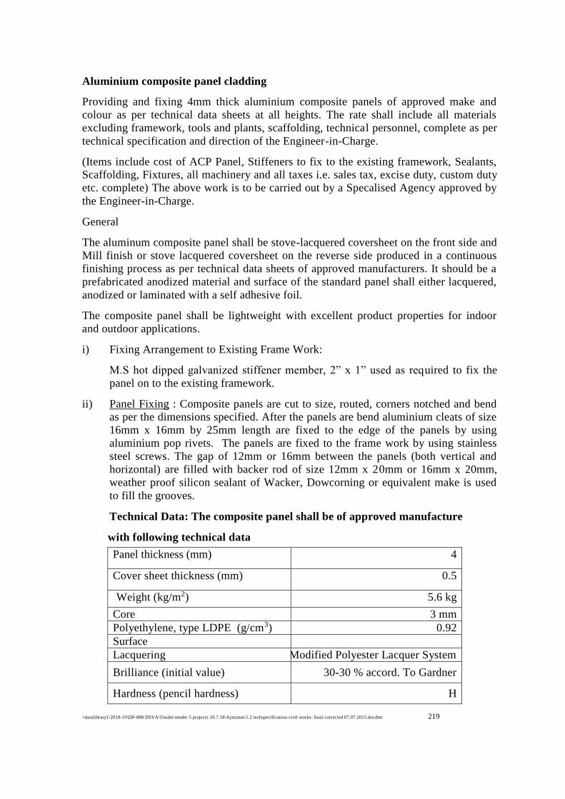
\\datalibrary1\2018-19\DP-888 DSYA\Tender\tender 5 projects 10.7.18\Aymanm\1.2 techspecification-civil works- final corrected 07.07.2015.docdmr 219
219
Aluminium composite panel cladding
Providing and fixing 4mm thick aluminium composite panels of approved make and
colour as per technical data sheets at all heights. The rate shall include all materials
excluding framework, tools and plants, scaffolding, technical personnel, complete as per
technical specification and direction of the Engineer-in-Charge.
(Items include cost of ACP Panel, Stiffeners to fix to the existing framework, Sealants,
Scaffolding, Fixtures, all machinery and all taxes i.e. sales tax, excise duty, custom duty
etc. complete) The above work is to be carried out by a Specalised Agency approved by
the Engineer-in-Charge.
General
The aluminum composite panel shall be stove-lacquered coversheet on the front side and
Mill finish or stove lacquered coversheet on the reverse side produced in a continuous
finishing process as per technical data sheets of approved manufacturers. It should be a
prefabricated anodized material and surface of the standard panel shall either lacquered,
anodized or laminated with a self adhesive foil.
The composite panel shall be lightweight with excellent product properties for indoor
and outdoor applications.
i) Fixing Arrangement to Existing Frame Work:
M.S hot dipped galvanized stiffener member, 2” x 1” used as required to fix the
panel on to the existing framework.
ii) Panel Fixing : Composite panels are cut to size, routed, corners notched and bend
as per the dimensions specified. After the panels are bend aluminium cleats of size
16mm x 16mm by 25mm length are fixed to the edge of the panels by using
aluminium pop rivets. The panels are fixed to the frame work by using stainless
steel screws. The gap of 12mm or 16mm between the panels (both vertical and
horizontal) are filled with backer rod of size 12mm x 20mm or 16mm x 20mm,
weather proof silicon sealant of Wacker, Dowcorning or equivalent make is used
to fill the grooves.
Technical Data: The composite panel shall be of approved manufacture
with following technical data
Panel thickness (mm) 4
Cover sheet thickness (mm) 0.5
Weight (kg/m2) 5.6 kg
Core 3 mm
Polyethylene, type LDPE (g/cm3) 0.92
Surface
Lacquering Modified Polyester Lacquer System
Brilliance (initial value) 30-30 % accord. To Gardner
Hardness (pencil hardness) H
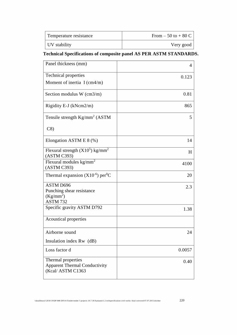
\\datalibrary1\2018-19\DP-888 DSYA\Tender\tender 5 projects 10.7.18\Aymanm\1.2 techspecification-civil works- final corrected 07.07.2015.docdmr 220
220
Temperature resistance From – 50 to + 80 C
UV stability Very good
Technical Specifications of composite panel AS PER ASTM STANDARDS.
Panel thickness (mm) 4
Technical properties
Moment of inertia I (cm4/m)
0.123
Section modulus W (cm3/m) 0.81
Rigidity E-J (kNcm2/m) 865
Tensile strength Kg/mm2 (ASTM
C8)
5
Elongation ASTM E 8 (%) 14
Flexural strength (X105) kg/mm2
(ASTM C393) H
Flexural modules kg/mm2
(ASTM C393) 4100
Thermal expansion (X10-6) per0C 20
ASTM D696
Punching shear resistance
(Kg/mm2)
ASTM 732
2.3
Specific gravity ASTM D792 1.38
Acoustical properties
Airborne sound
Insulation index Rw (dB)
24
Loss factor d 0.0057
Thermal properties
Apparent Thermal Conductivity
(Kcal/ ASTM C1363
0.40
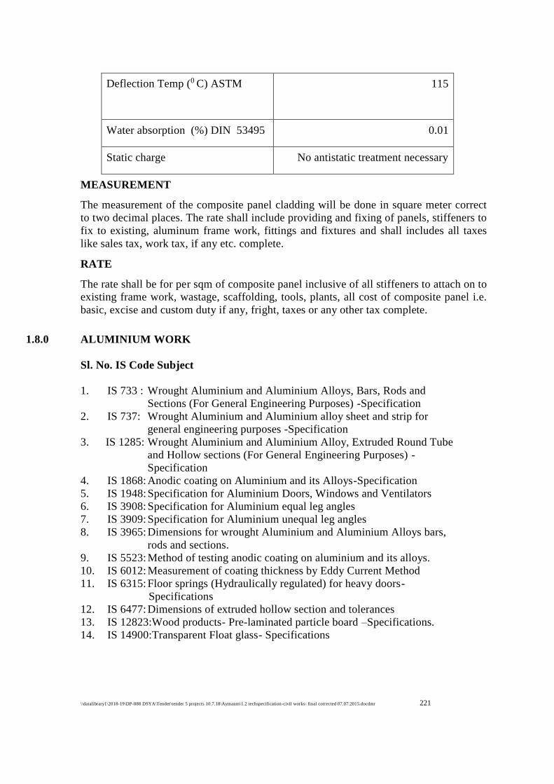
\\datalibrary1\2018-19\DP-888 DSYA\Tender\tender 5 projects 10.7.18\Aymanm\1.2 techspecification-civil works- final corrected 07.07.2015.docdmr 221
221
Deflection Temp (0 C) ASTM
D648
115
Water absorption (%) DIN 53495 0.01
Static charge No antistatic treatment necessary
MEASUREMENT
The measurement of the composite panel cladding will be done in square meter correct
to two decimal places. The rate shall include providing and fixing of panels, stiffeners to
fix to existing, aluminum frame work, fittings and fixtures and shall includes all taxes
like sales tax, work tax, if any etc. complete.
RATE
The rate shall be for per sqm of composite panel inclusive of all stiffeners to attach on to
existing frame work, wastage, scaffolding, tools, plants, all cost of composite panel i.e.
basic, excise and custom duty if any, fright, taxes or any other tax complete.
1.8.0 ALUMINIUM WORK
Sl. No. IS Code Subject
1. IS 733 : Wrought Aluminium and Aluminium Alloys, Bars, Rods and
Sections (For General Engineering Purposes) -Specification
2. IS 737: Wrought Aluminium and Aluminium alloy sheet and strip for
general engineering purposes -Specification
3. IS 1285: Wrought Aluminium and Aluminium Alloy, Extruded Round Tube
and Hollow sections (For General Engineering Purposes) -
Specification
4. IS 1868: Anodic coating on Aluminium and its Alloys-Specification
5. IS 1948: Specification for Aluminium Doors, Windows and Ventilators
6. IS 3908: Specification for Aluminium equal leg angles
7. IS 3909: Specification for Aluminium unequal leg angles
8. IS 3965: Dimensions for wrought Aluminium and Aluminium Alloys bars,
rods and sections.
9. IS 5523: Method of testing anodic coating on aluminium and its alloys.
10. IS 6012: Measurement of coating thickness by Eddy Current Method
11. IS 6315: Floor springs (Hydraulically regulated) for heavy doors-
Specifications
12. IS 6477: Dimensions of extruded hollow section and tolerances
13. IS 12823:Wood products- Pre-laminated particle board –Specifications.
14. IS 14900:Transparent Float glass- Specifications
\\datalibrary1\2018-19\DP-888 DSYA\Tender\tender 5 projects 10.7.18\Aymanm\1.2 techspecification-civil works- final corrected 07.07.2015.docdmr 222
222
Anodized Aluminium
Aluminium with an anodic coating, produced by an electrolytic oxidation process, in
which the surface of the aluminium is covered with a coating, generally an oxide, to give
protective and decorative properties.
Pre-laminated Particle Board
A particle board laminated on both surface by synthetic impregnated base papers under
the influence of heat and pressure with finished foil under the pressure or pressure and
heat depending on type of binder used.
ALUMINIUM
Aluminium Sections
Aluminium sections used for fixed/openable windows, ventilators, partitions, frame
work & doors etc. shall be suitable for use to meet architectural designs to relevant
works and shall be subject to approval of the Engineer-in-Charge for technical,
structural, functional and visual considerations. The aluminium extruded sections shall
conform to IS 733 and IS 1285 for chemical composition and mechanical properties. The
stainless steel screws shall be of grade AISI 304.
The permissible dimensional tolerances of the extruded sections shall be as per IS 6477
and shall be such as not to impair the proper and smooth functioning/operation and
appearance of door and windows.
Aluminium glazed doors, windows etc. shall be of sizes, sections and details as shown in
the drawings. The details shown in the drawings may be varied slightly to suit the
standards adopted by the manufacturers of the aluminium work, with the approval of
Engineer-in-Charge. Before proceeding with any fabrication work, the contractor shall
prepare and submit, complete fabrication and installation drawings for each type of
glazing doors, windows, ventilators and partition etc. for the approval of the Engineer-
in-Charge. If the sections are varied, the contractor shall obtain prior approval of
Engineer-in- Charge and nothing extra shall be paid on this account.
Anodising
Standard aluminium extrusion sections are manufactured in various sizes and shapes in
wide range of solid and hollow profiles with different functional shapes for architectural,
structural glazing, curtain walls, doors, window & ventilators and various other
purposes. The anodizing of these products is required to be done before the fabrication
work by anodizing/electro coating plants which ensures uniform coating in uniform
colour and shades. The extrusions are anodized up to 30 micron in different colours. The
anodized extrusions are tested regularly under strict quality control adhering to Indian
Standard.
\\datalibrary1\2018-19\DP-888 DSYA\Tender\tender 5 projects 10.7.18\Aymanm\1.2 techspecification-civil works- final corrected 07.07.2015.docdmr 223
223
Powder Coating
Material: The powder used for powder coating shall be Epoxy/polyester powder of
make approved by the Engineer-in-Charge. The contractor shall give detailed
programme for powder coating in advance, to facilitate the inspection by Engineer-in-
Charge or his authorized representative.
Pre-treatment: Each aluminium alloy extrusion or performed section shall be
thoroughly cleaned by alkaline or acidic solutions under the conditions specified by
chemical conversion coating supplier and then rinsed. A chemical conversion coating
shall be applied by treatment with a solution containing essentially chromate ions or
chromate and phosphate ions as the active components as applicable. The amount of the
conversion coating deposited depends on the type used by the conversion coating
chemical supplier. The conversion coating shall be thoroughly rinsed either with the
solution specified by the conversion coating chemical supplier or with de-mineralized
water and then dried at the temperature for the time specified by the conversion coating
chemical supplier. The contractor shall submit the detail specifications and application
procedure for application of conversion coating for approval of Engineer-in-Charge. The
metal surface after the conversion coating pretreatment and prior to the application of
the coating shall be free from dust or powdery deposits
Process: The polyester powder shall be applied by electrostatic powder spray method.
Before start of powder coating the contractor shall submit detail specification for
application of polyester powder from manufacturer of the polyester powder for approval
of Engineer-in-Charge. The powder coating shall be applied as per the specification
approved by Engineer-in-Charge.
Thickness: The thickness of the finished polyester powder coating measured by micron
meter shall not be less than 50 micron nor more than 120 micron at any point.
Performance Requirements for the Finish
Surface appearance: The finish on significant surfaces shall show no scratches when
illuminated and is examined at an oblique angle, no blisters, craters; pinholes or
scratches shall be visible from a distance of about 1 m. There shall not be any visible
variation in the colour of finished surfaces of different sections and between the colours
of different surfaces of same section.
Adhesion: When a coated test piece is tested using a spacing of 2 mm between each of
the six parallel cuts (the cut is made through the full depth of powder coating so that
metal surface is visible) and a piece of adhesive tape, approximately 25 mm x 150 mm
approved by the Engineer-in-Charge is applied firmly to the cut area and then removed
rapidly by pulling at right angles to the test area, no pieces of the finish other than debris
from the cutting operation shall be removed from the surface of the finish.
Protection of Powder Coated / Anodizing Finish: It is mandatory that all aluminium
members shall be wrapped with self adhesive non-staining PVC tape, approved by
Engineer-in-Charge.
\\datalibrary1\2018-19\DP-888 DSYA\Tender\tender 5 projects 10.7.18\Aymanm\1.2 techspecification-civil works- final corrected 07.07.2015.docdmr 224
224
Measurement: All the aluminium sections including snap beading fixed in place shall
be measured in running meter along the outer periphery of composite section correct to a
millimeter. The weight calculated on the basis of actual average (average of five
samples) weight of composite section in kilogram correct to the second place of decimal
shall be taken for payment. (Weight shall be taken after anodizing). The weight of cleat
shall be added for payment. Neither any deduction nor anything extra shall be paid for
skew cuts.
Rate: The rate shall include the cost of all the materials, labours involved in all the
operations as described in nomenclature of item and particular specification.
PANELING MATERIAL
Pre-laminated Particle Board
A particles board laminated on both surfaces by synthetic resin impregnated base papers
under heat and pressure. Pre-laminated particle boards shall be of two grades, namely,
Grade I and II corresponding to IS 3087 & 12823. Synthetic resin bonded flat pressed
three layers, multilayer and graded particle board defined in IS 3087 having superfine
surface shall be used for production of prelaminated particle board. For ECO Marks the
particle board shall also conform to the requirements of ECO Mark specified in IS 3087
Float Glass
The glass shall be clear float glass and should be approved by the Engineer in Charge. It
shall be clear, float transparent and free from cracks subject to allowable defects. The
float glass shall conform to the IS 14900.
Thickness : The thickness of float glass shall depend on the size of panel. The tolerance
in thickness shall be as under:
TABLE
Nominal Thickness (in mm ) Tolerance (in mm )
4.0 ± 0.3
5.0 ± 0.3
6.0 ± 0.3
8.0 ± 0.6
EPDM- GASKETS
The EPDM Gaskets shall be of size and profile as shown in drawings and as called for,
to render the glazing, doors, windows, ventilators etc. air and water tight. Samples of
gaskets shall be submitted for approval and the EPDM gasket approved by Engineer-in-
Charge shall only be used. The contractor shall submit documentary proof of using the
above material in the work to the entire satisfaction of Engineer-in-Charge.
\\datalibrary1\2018-19\DP-888 DSYA\Tender\tender 5 projects 10.7.18\Aymanm\1.2 techspecification-civil works- final corrected 07.07.2015.docdmr 225
225
SEALANT
The sealants of approved grade and colour shall only be used. The silicone for perimeter
joints (between Aluminium section and RCC/Stone masonry) shall be of make approved
by the Engineer in Charge.
Method of Application
Surface Preparation : Clean all joints and glazing pockets by removing all foreign
matter and contaminants such as grease, oil, dust, water, frost, surface dirt, old sealants
or glazing compounds and protective coatings.
Masking
Areas adjacent to joints shall be masked to ensure neat sealant lines. Masking tape shall
not be allowed to touch clean surfaces to which the silicone sealant is to adhere. Tooling
shall be completed in one continuous stroke immediately after sealant application and
before a skin forms and masking shall be removed immediately after tooling.
Application
Install backer rod of appropriate size and apply silicone sealant in a continuous operation
using a positive pressure adequate to properly fill and seal the joint. The silicone sealant
shall be tooled with light pressure to spread the sealant against backing material and the
joint surfaces before a skin forms. A tool with convex profile shall be used to keep the
sealant within the joint. Soap or water shall not be used as a tooling aid. Remove
masking tape as soon as silicone joint is tooled.
Tolerance: A tolerance of + 3 mm shall be allowed in the width of silicone joints. The
depth of the joints at throat shall not be less than 6 mm.
DOOR, WINDOW, VENTILATOR AND PARTITION FRAMES
Frame Work
First of all the shop drawings for each type of doors/windows/ventilators etc. shall be
prepared by using suitable sections based on architectural drawings, adequate to meet
the requirement/ specifications and by taking into consideration varying profiles of
aluminium sections being extruded by approved manufacturers. The shop drawings shall
show full size sections of glazed doors, windows, ventilators etc. The shop drawings
shall also show the details of fittings and joints. Before start of the work, all the shop
drawings shall be got approved from the Engineer-in-Charge. Actual measurement of
openings left at site for different type of door/window etc. shall be taken. The fabrication
of the individual door/windows/ventilators etc. shall be done as per the actual sizes of
the opening left at site. The frames shall be truly rectangular and flat with regular shape
corners fabricated to true right angles. The frames shall be fabricated out of section
which have been cut to length, mitered and jointed mechanically using appropriate
machines. Mitered joints shall be corner crimped or fixed with self tapping stainless
steel screws using extruded aluminium cleats of required length and profile. All

\\datalibrary1\2018-19\DP-888 DSYA\Tender\tender 5 projects 10.7.18\Aymanm\1.2 techspecification-civil works- final corrected 07.07.2015.docdmr 226
226
aluminium work shall provide for replacing damaged/broken glass panes without having
to remove or damage any member of exterior finishing material.
Fixing of Frames
The holes in concrete/masonry/wood/any other members for fixing anchor bolts/
fasteners/ screws shall be drilled with an appropriate electric drill. Windows/ doors/
ventilators etc. shall be placed in correct final position in the opening and fixed to Sal
wood backing using stainless steel screws of star headed, counter sunk and matching
size groove. of required size at spacing not more than 250 mm c/c or dash fastener. All
joints shall be sealed with approved silicone sealants.
In the case of composite windows and doors, the different units are to be assembled first.
The assembled composite units shall be checked for line, level and plumb before final
fixing is done. Engineer-in-Charge in his sole discretion may allow the units to be
assembled in their final location if the situation so warrants. Snap beadings and EPDM
gasket shall be fixed as per the detail shown in the shop drawings.
Where aluminium comes into contact with stone masonry, brick work, concrete, plaster
or dissimilar metal, it shall be coated with an approved insulation lacquer, paint or
plastic tape to ensure that electrochemical corrosion is avoided. Insulation material shall
be trimmed off to a clean flush line on completion.
The contractor shall be responsible for the doors, windows etc. being set straight, plumb,
level and for their satisfactory operation after fixing is complete.
Measurements
All the aluminium sections including snap beadings fixed in place shall be measured in
running meter along the outer periphery of composite section correct to a millimeter.
The weight calculated on the basis of actual average (average of five samples) weight of
composite section in kilogram correct to the second place of decimal shall be taken for
payment (weight shall be taken after anodizing). The weight of cleat shall be added for
payment. Neither any deduction nor anything extra shall be paid for skew cuts.
963 SUB HEAD 21.0 : ALUMINIUM WORK
Rate
The rate shall include the cost of all the materials, labour involved in all the operations
as described in nomenclature of item and particular specification.
DOOR, WINDOWS AND VENTILATOR SHUTTERS
Material, fabrication and dimensions of aluminium doors, windows and ventilators
manufactured from extruded aluminium alloy sections of standard sizes and designs
complete with fittings, ready for being fixed into the building shall be as per IS 1948.
\\datalibrary1\2018-19\DP-888 DSYA\Tender\tender 5 projects 10.7.18\Aymanm\1.2 techspecification-civil works- final corrected 07.07.2015.docdmr 227
227
Tolerances
The sizes for doors, windows and ventilators frames shall not vary by more than ±1.5
mm.
Material
Aluminium alloy extruded sections used in the manufacture of extruded window sections
shall conform to IS 733. Hollow aluminium alloy sections used shall conform to IS 1285
Glass Panes
Glass panes shall weigh at least 7.5 kg/m2 and shall be free from flaws, specks or
bubbles. All panes shall have properly squared corners and straight edges.
Screws
Screws threads of machine screws used in the fabrication of aluminium doors, windows
and ventilators shall conform to IS 1362.
Fabrication
Frames: Frames shall be square and flat, the corners of the frame being fabricated to a
true right angle. Both the fixed and opening frames shall be constructed of sections
which have been cut to length, mitered and welded at the corners. Where hollow sections
are used with welded joints, argon-arc welding or flash butt welding shall be employed
(gas welding or brazing not to be done). Subdividing bars of units shall be tenoned and
riveted into the frame.
Side-hung Shutters
For fixing aluminium alloy hinges, slots shall be cut in the fixed frame and the hinges
inserted inside and may be riveted to the frame. The hinges shall normally be of the
projecting type 67 mm wide. The aluminium alloy for cast hinges shall conform to IS
Designation A-5-M of IS 617. Specification for Aluminium and Aluminium Alloy Ingots
and Castings for General Engineering Purpose and for extruded section of hinges to IS
Designation HE10-WP or HE30-WP of IS 733. The pins for hinges shall be of stainless
steel of non-magnetic type or aluminium alloy HR30. Irrespective of hinges being
anodized or not, the aluminium alloy pins shall be anodized to a minimum film thickness
of 0.025 mm shall be sealed with oil, wax or lanolin. Non- projecting types of hinges
may also be used where ever required. Frictions hinges may be provided for side-hung
shutter windows, in which case peg stay may not be required. The handle for side-hung
shutters shall be of cast aluminium conforming to IS Designation A-5-M of IS 617 and
mounted on a handle plate welded or riveted to the opening frame in such a way that it
could be fixed before the shutter is glazed. The handle should have anodized finish with
minimum anodic film thickness of 0.015 mm. The handle shall have a two points nose
which shall engage with an aluminium striking plate on the fixed frame in a slightly
open position as well as in a fast position . The height of the handles in each type of
\\datalibrary1\2018-19\DP-888 DSYA\Tender\tender 5 projects 10.7.18\Aymanm\1.2 techspecification-civil works- final corrected 07.07.2015.docdmr 228
228
side-hung shutters shall be fixed in approximate position . The peg stay shall be either of
cast aluminium conforming to IS 617 or folded from IS Designation NS4 aluminium
alloy sheet conforming to IS:737 specification for wrought aluminium and aluminium
alloys, Sheet and strip. It shall be 300 mm long, The stay shall have holes for keeping
the shutter open in three different positions. The peg and locking bracket shall be riveted
or welded to the fixed frame. Alternatively, and if specifically required by the purchaser,
side-hung shutters may be fitted with an internal removable fly screen of 0.375 mm wire
and equivalent to IS Sieve 100 in a 0.900 mm aluminium alloy sheet conforming to IS
Designation NS3-1/2H of IS 737 applied to the outer frame of the shutter by case or
extruded aluminium alloy turn-buckle at the jambs and by aluminium or plated bronze
shoes at the sill to allow of the screen being readily removed, and with a rotor operator
at the sill to permit the operation of the shutter through an angle of 90º .On fly-screened
shutters the peg stay is omitted and the normal handle shall be replaced by a locking
handle to hold the shutter in the fast position.
Top-Hung Ventilators
The aluminium hinges for top-hung ventilators shall be either cast or fabricated out of
extruded sections and shall be riveted to the fixed rail after cutting a slot in it. The
aluminium alloy for cast hinges shall conform to IS Designation A-5-M of IS 617 and
the extruded section of hinge to IS Designation HE10-WP or HE30_WP of IS 733. The
pegs stay shall be 300 mm long as in side-hung shutter. The locking bracket shall be
fixed to the fixed frame.
Centre-Hung Ventilators
Centre hung ventilators shall be hung on two pairs of cup pivots of aluminium alloy to
IS Designation NS-4 of IS 737 and IS Designation A-5-M of IS 617 or on brass or
bronze cup pivots which should be either chromium or cadmium plated and riveted to
the inner and outer frames of the ventilators to permit the ventilator to swing through an
angle of approximately 85º. The opening portion of the ventilator shall be so balanced
that it remains open at any desired angle under normal weather condition. Cast
aluminium conforming to IS Designation A-5-M of IS 617 or bronze which shall be
either chromium plated or cadmium-plated spring catch shall be fitted in the centre of
the top bar of the ventilators for the operation of the ventilator. This spring catch shall be
secured to the frame and shall close into aluminium catch plate riveted or welded to the
outside of the outer ventilator frame bar Aluminium or cadmium plated brass cord
pulley-wheel in an aluminium bracket shall be fitted at the sill of the ventilator with
aluminium or galvanized or cadmium plated steel screw or, alternatively, welded
together with an aluminium cord eye riveted or welded to the bottom inner frame bar of
the ventilator in a position corresponding to that of pulley
\\datalibrary1\2018-19\DP-888 DSYA\Tender\tender 5 projects 10.7.18\Aymanm\1.2 techspecification-civil works- final corrected 07.07.2015.docdmr 229
229
1.9.0 ROOFING
Providing, Fabricating & Erecting MS Structural steel work for trusses, purlins,
girders, columns, rafters, struts, wind ties, bracings, etc.
All structural steel materials such as angles, RS joists, flats, tees, plates, channels, etc.,
shall conform to the latest edition of IS 226. All structural steel shall be free from twist
before fabrication. Cutting of members shall be done by shearing, cropping, sawing or
gas cutting. Contact surfaces of plates and butt joints shall be accurately machined over
the whole area so that the parts connected shall butt over the entire surface of contact.
Welding of pieces shall be done with the approval of the Engineer.
The components parts shall be assembled in such a manner that they are not damaged in
any way and specific cambers as shown in the drawing or as directed by the Engineer,
shall be provided.
For bolted connection, where necessary washers shall be tapered or otherwise suitably
shaped to give satisfactory bearing. The threaded portion of the bolt shall project
beyond the nut by at least 1.5 thread.
Welding shall be done in accordance with the latest edition of IS 813 and 814, Code of
Practice for use of Electric Arc welding for general Construction in mild steel. In
welding it must be ensured that the base metal is in fused state when filler metal makes
contact with it; filler metal does not overflow upon any unfused base metal; base metal
is not cut along the weld edges; flowing metal floats the slag, oxide and gas bubbles at
the surface behind advance pole. For this current shall be adjusted or the electrode size
is changed. Welding shall be free from cracks, discontinuity, under or over size welding
thickness.
Surface to be welded shall be free from loose mill scale, nut, grease, paint and any other
foreign material. As far as possible avoid the welding at heights and at difficult
positions. Generally fillet welding is preferred. The parts to be welded are brought in as
close contact as practicable and rigidly clamped together.
Before erection, steel work shall be thoroughly cleaned of rust, loose scale, dust,
welding slag, and shall be given one coat of zinc chromate primer of approved make and
one coat of synthetic enamel paint of approved make as specified in the item before
erection and final coat of painting after the erection as directed.
Steel members shall be hoisted and put in position carefully without any damage to the
member and to the building and labour. The trusses shall be lifted at such points that
they do not buckle or deform or be unduly stressed. The end of the truss which faces the
prevailing wind shall be fixed and the other end may be kept free to move. The steel
work shall be securely fastened wherever necessary, temporarily braced, to provide for
all loads to be carried by the member during erection including the load due to the
erection equipment and its operation. No permanent bolting or welding is done until
proper alignment has been obtained. The holes for the rivets shall be determined with
the help of templates and drilled. Erection clearance of the cleared ends shall not be
more than 1.5 mm and without cleating end clearance shall not be more than 3 mm.
\\datalibrary1\2018-19\DP-888 DSYA\Tender\tender 5 projects 10.7.18\Aymanm\1.2 techspecification-civil works- final corrected 07.07.2015.docdmr 230
230
Grouting or embedding of structural steel members done after the approval of the
alignment, level & position of the members by the Engineer.
Important points
Before the actual execution of the job, the Contractor shall prepare fabrication drawings
for all structural steel work from the structural drawings supplied to him and determine
the exact cutting lengths of the members, sizes of gusset plates, welding lengths by
marking out on a level platform to full scale.
Welding plant, electodes and other equipments, scaffolding, labour shall be arranged by
the Contractor at his cost. Erection equipment of required capacity, sufficient number of
spare parts and staff shall be maintained by the Contractor at site at his cost.
Providing & Fixing MS holding down bolts
The MS holding down bolts of specified dia, length and shape shall be provided as per
the drawings in line & level. These shall be fixed to RCC work or brick work by
grouting it with concrete. The bolt shall be provided with nuts and washers. The grease
shall be applied to the threaded portion with the help of templates. If the bolts need
some adjustment it shall be provided with a wooden piece 75x75 mm or 50 mm dia GI
pipe around bolt shall be provided at the time of concreting and shall be removed after
initial set.
Mangalore Step Tile Type Galvalume Sheet
Material
The sheeting shall be Mangalore step tile type having 750 – 780 mm cover width with
26/28 mm high crest at 190/200 mm centers with a rib between two crest made out of
0.5 mm TCT minimum 300 MPA yield strength cold rolled steel with hot dip metallic
coating of Aluminium Zinc Alloy (Galvalume) 150 g/ sqm, total of both sides, Az 150
as per ASTM A 792 or AS 1397 with polyster colour coating, in length upto 6 m to suit
requirements.
Supply and fixing
Sheets shall be factory formed to required lengths to suit shop drawings. Sheets shall be
fixed to purlins with GI wafer head self-drilling screws. The panels shall be fixed to the
concealed clips.
ACCESSORIES
Cappings, Flashings and Trims:
Profile
Sheets shall be site roll formed so as to provide a single length panel from ridge to
eaves. All transverse capping to be notched to match profile of external/internal sheet
except where metal closures are used.
All exposed flashing edges must have a 10mm hem and a 45° drip. All closure flashings
shall be hemmed.
\\datalibrary1\2018-19\DP-888 DSYA\Tender\tender 5 projects 10.7.18\Aymanm\1.2 techspecification-civil works- final corrected 07.07.2015.docdmr 231
231
Material
In substrate, and finish as external sheeting.
Fixing
Cappings etc. shall be screwed to external sheeting at crests with hex head self drilling
stitching fasteners at max. 500mm centers along the length of the capping/flashing. All
fasteners must be installed at 90° to the material being fastened. If this is not done, the
screw must be withdrawn and the hole closed with an oversize screw and EPDM washer.
All longitudinal joints in cappings and flashings shall be overlapped a minimum of
50mm and sealed with a continuous run of sealant. Backing plates shall be provided in
16G steel wherever required at end conditions for proper support of cappings and
closures.
FIXING ACCESSORIES
External fasteners
The sheets shall be fixed with GI clips fixed to the purlins with wafer head self-drilling
fasteners.
Sealants
All laps in flashing and capping shall be sealed with a non-hardening neutral cure silicon
sealant.
WIND LOADING
Permissible span versus load data table should be furnished with the offer. Load testing
as per IS-801, BS and AS shall have to be arranged by the sheeting manufacturer to
demonstrate compliance with load/span data conforming to spans and loads (as per
IS-875 part 3) at manufacturer's plant.
External roof sheeting shall be capable of withstanding wind uplift and point loads as per
IS codes for purlin support spacing as shown on the drawings.
DRAWINGS AND LITERATURE
After award of work the agency shall be required to do the detailed design and
engineering of the roof system. He shall prepare detailed shop drawings, bill of
materials, and submit the same for approval of the Engineer-in-charge before
commencement of work. He shall also prepare and furnish technical manuals and
erection guides for the project.
TESTING AND ACCEPTANCE CRITERIA
Materials
Prior to delivery, manufacturer’s test certificates shall be supplied for all materials
certifying grade and conformity with applicable standards. At owner's discretion on
number and frequency, random samples drawn from material at site will be got tested at
an independent test house/laboratory approved by the owner. The materials shall be
tested for and demonstrate to meet performance criteria and requirements listed
elsewhere.
\\datalibrary1\2018-19\DP-888 DSYA\Tender\tender 5 projects 10.7.18\Aymanm\1.2 techspecification-civil works- final corrected 07.07.2015.docdmr 232
232
Load testing
Profiles shall be load tested to justify load/span data furnished by manufacturer in
accordance with IS-801/AS/BS standards. Profiles must exhibit deflection less than
L/150 under live load and point load (as per IS 875) and less than L/100 under wind
load.
Measurement
The length and breadth shall be measured correct to a cm. for providing & fixing the
Galvalume Roofing System and the area calculated in sqm correct to two places of
decimal (Payment for flashing, gutter & down take pipe & ridge will be measured
separately).
Rates
The rate for Providing & fixing the Roofing System shall include cost of all material and
labour involved in all the operations described above i.e. basic, excise and custom duty
if any, freight, taxes or any other tax complete.
POLYESTER COLOUR COATED GALVALUME PROFILE ROOFING SHEET
Supplying and fixing on purlins polyester coated galvalume profiled sheets 445 mm wide
pan and 50 mm depth rib made out of 0.55mm TCT, cold rolled steel of 300 Mpa (min.)
yield strength conforming to ASTM A 368 or AS 1595 with hot dip metallic coating of
minimum 150gm/sq.m zinc-aluminium alloy coating mass(55% Aluminium, 43% Zinc
and 1.5% Silicon) total of both sides as per ASTM A 792 or AS 1397.The colour shall
have a total coating thickness of 35 microns of polyester paint system as per AS/NZS-
2728:1997 (Category 3) of approved colour, comprising of 20 microns exterior coat on top
surface and 5 microns primer coat on both surfaces. Roofing sheets shall be factory cut
and supplied in required lengths (of upto 12 m) to suit site conditions & design drawings.
Roofing sheets shall be crest fixed to purlins with hot dip galvanized self drilling fastners
with integral EPDM washers (one fastener on each crest). Also, fasteners to be provided
on side laps. Minimum sheet overlap at end laps shall be 150mm. Penetrations and end
laps in sheet shall be sealed by using proper sealant. Profiled HDPE fillers shall be
provided wherever required to close voids between cappings and troughs of the sheet to
provide a weather tight exterior. Rate shall include cost and conveyance of all materials,
lead, lift, scaffolding, labour charges, etc. complete at all level and as directed by
Engineer-in-charge.
Rate shall include cost and conveyance of all materials, lead, lift, scaffolding, labour
charges, etc. complete at all level and as directed by Engineer-in-charge.
SCOPE
The scope of work is to provide profile roofing sheet on areas shown on the drawings.
The work shall include the design, engineering, manufacture, supply, and installation of
the roofing system on the roof of buildings as described in the schedule and shown on
the drawings, including all fixings, flashings, finishing, gutters, down-spouts etc.
\\datalibrary1\2018-19\DP-888 DSYA\Tender\tender 5 projects 10.7.18\Aymanm\1.2 techspecification-civil works- final corrected 07.07.2015.docdmr 233
233
INSTALLATION
General
The contractor shall supply and install the roofing, gutters, down-spouts, as specified
and as approved by the Engineer-in-charge with uniform and consistent product quality.
All panels shall be factory formed and all materials shall be delivered to site with
manufacturer’s name or trade mark, grade of coating, length, thickness and item
identification with respect to shop drawings legibly marked on top of each item or
shown on a label fixed to each bundle. The material may also be marked with a standard
mark where applicable.
Accessories
Cappings, Flashings and Trims:
All exposed flashing edges must have a 10mm hem and a 45° drip. All closure flashings
shall be hemmed.
Material
In substrate, and finish as external sheeting.
Fixing
Cappings etc. shall be screwed to external sheeting at crests with hex head self drilling
stitching fasteners at max. 500mm centers along the length of the capping/flashing. All
fasteners must be installed at 90° to the material being fastened. If this is not done, the
screw must be withdrawn and the hole closed with an oversize screw and EPDM washer.
All longitudinal joints in cappings and flashings shall be overlapped a minimum of
50mm and sealed with a continuous run of sealant. Backing plates shall be provided in
16G steel wherever required at end conditions for proper support of cappings and
closures.
Fixing Accessories
External fasteners
Fasteners for roof sheeting clips and self drilling stitching fasteners for
cappings/flashings shall be mechanically galvanised carbon steel self drilling self
tapping fasteners.
Sealants
All laps in flashing and capping shall be sealed with a non-hardening neutral cure silicon
sealant.
Wind Loading
Permissible span versus load data table should be furnished with the offer. Load testing
as per IS-801, BS and AS shall have to be arranged by the sheeting manufacturer to
\\datalibrary1\2018-19\DP-888 DSYA\Tender\tender 5 projects 10.7.18\Aymanm\1.2 techspecification-civil works- final corrected 07.07.2015.docdmr 234
234
demonstrate compliance with load/span data conforming to spans and loads (as per
IS-875 part 3) at manufacturer's plant.
External roof sheeting shall be capable of withstanding wind uplift and point loads as per
IS codes for purlin support spacing as shown on the drawings.
Drawings and Literature
After award of work the agency shall be required to do the detailed design and
engineering of the roof system. He shall prepare detailed shop drawings, bill of
materials, and submit the same for approval of the Engineer-in-charge before
commencement of work. He shall also prepare and furnish technical manuals and
erection guides for the project.
Testing And Acceptance Criteria
Materials
Prior to delivery, manufacturers test certificates shall be supplied for all materials
certifying grade and conformity with applicable standards. At owner's discretion on
number and frequency, random samples drawn from material at site will be got tested at
an independent test house/laboratory approved by the owner. The materials shall be
tested for and demonstrate to meet performance criteria and requirements listed
elsewhere.
Load testing
Profiles shall be load tested to justify load/span data furnished by manufacturer in
accordance with IS-801/AS/BS standards. Profiles must exhibit deflection less than
L/150 under live load and point load (as per IS 875) and less than L/100 under wind
load.
Measurement
The length and breadth shall be measured correct to a cm. for Providing & fixing
Polyester coated Galvalume steel Manglore steptile Roofing System and the area
calculated in sqm correct to two places of decimal (Payment for flashing, gutter & down
take pipe & ridge will be measured separately).
Rates
The rate for Providing & fixing Polyester coated Galvalume steel Mangalore steptile
Roofing System shall include cost of all material and labour involved in all the
operations described above i.e. basic, excise and custom duty if any, freight, taxes or any
other tax complete.
Providing and fixing ridge/ valley capping in required width(minimum 500mm) with
plain galvalume colour coated sheet made out of 0.5mm TCT, minimum 300 MPa cold
rolled steel with hot dip metallic coating of Aluminium Zinc alloy (Galvalume) 150
gms/sqm, total of both sides, AZ 150 as per ASTM A 792 or AS1397, with polyester
colour coating including cost and conveyance of all materials, scaffolding, lead, lift,
labour charges, etc. complete at all levels as directed by Engineer-in-charge
\\datalibrary1\2018-19\DP-888 DSYA\Tender\tender 5 projects 10.7.18\Aymanm\1.2 techspecification-civil works- final corrected 07.07.2015.docdmr 235
235
Technical details same as Item No.1 above but for ridge/ valley capping etc. all complete
and in straight lengths.
Measurement
The length shall be measured correct to a cm. for Providing & fixing Polyester coated
Galvalume steel Roofing System for ridge/ valley capping and the length shall be
measured in running meter correct to two places of decimal.
FALSE CEILING WITH GYPSUM BOARD
GENERAL
This section covers the requirements for all materials, labour, tools and equipment for
suspended false ceiling.
CODES AND STANDARDS.
The codes and standards generally applicable to the work of this section are listed
hereinafter:
IS: 2095 Part - I 1996 & 2052-1981 - Gypsum board.
IS: 277 -1982 - Zinc Coating 120 gms Per sqm (both size inclusive) minimum -
For galvanising of M.S. sheets/Sections
The following clauses are intended to amplify the requirements of the reference
documents listed above and the contractor shall comply with these clauses.
MATERIALS
FRAME WORK
A GRID of 450 x 1200 mm is made up of GI sections duly suspended from the RCC
roof slab.
The sizes of the members shall be:
a) Perimeter channels:.0.5mm thick having one flange of 20mm and another flange of
30mm and a Web of 27 mm.
b) Intermediate channel: Channel Section of size 15x45x0.90 mm thick
c) Ceiling section: 0.5 mm thick having knurled web of 51.5 mm and 2 flanges of 26
mm each with lips of 10.5 mm.
d) Ceiling angle: 25mmx25mmx0.5mm
\\datalibrary1\2018-19\DP-888 DSYA\Tender\tender 5 projects 10.7.18\Aymanm\1.2 techspecification-civil works- final corrected 07.07.2015.docdmr 236
236
BOARDS
The boards to be used in the false ceiling shall be single layered tapered edge Gypsum
Board ceiling 12.5 mm thick conforming to IS 2095-1996 and 2542-1981.
FIXING THE G.I. SUSPENSION SYSTEM TO THE CEILING
The system described here consists of various G.I. components (of sizes mentioned
above) used to form a concealed suspended frame work of 450 mm x 1200 mm with one
layer of 12.5mm thick Gypsum board confirming IS. 2542 -1981 & IS. 2095 -1982
screwed on the underside of the frame work with self tapping screws.
The G.I. perimeter channels shall be fixed along the perimeter of the ceiling while
intermediate channels shall be suspended at 1200 mm c/c with G.I. Angle, G.I. cleats
and metal expansion fasteners as per item specification. Ceiling sections are then fixed
to the intermediate channels with connecting clips perpendicular to the intermediate
channel at 450 mm c/c and then parallel to the ceiling section with 25mm dry wall
screws at 230 mm centre.
FINISHING
The boards shall be finished as per the manufacturer's recommendations. All joints shall
be carried out in three separate stages. Filling and tape embedding, finishing and
applying a surface treatment to even out differences in surface texture and section.
Filling: All boards shall be securely and correctly attached, protruding screws or nail
heads should be driven home. Gaps greater than 3mm between boards should be treated
with jointing compound pressed firmly into the gap so that it is completely filled.
Jointing compound used for this purpose should be stiffer than normal.
Tape Embedding: The joint fiber tape shall then pressed into the band of jointing
compound firmly embedded and free from trapped air bubbles, with sufficient joints
material under the tape to ensure good adhesion.
Immediately after the tape has been fixed a new layer of material is applied over it, flush
with the surface of the board. Before the material begins to stiffen surplus material
wiped from the edges of the joint by light sanding without disturbing the main joint
filling. Once the material has dried any slight depressions in the surface can be filled
again and projections cut back.
When the material has dried about 1 hour after application, a thin layer of Gypboard
jointing compound is applied in a broad band 200 mm wide. The edges of this band
should be immediately feathered out with a light sanding. When the joint material has
completely dried another application is made, 250 mm wide and sanded out as before.
FINISH
i) The entire false ceiling system shall be finished to the required line & levels as per
\\datalibrary1\2018-19\DP-888 DSYA\Tender\tender 5 projects 10.7.18\Aymanm\1.2 techspecification-civil works- final corrected 07.07.2015.docdmr 237
237
specifications/drawing & instructions of Engineer-in-Charge to the complete
satisfaction of Engineer-in-Charge. Any part of work not found meeting the
requirement shall be re-done by the contractor at his own cost. The decision of
Engineer-in-Charge shall be final and binding in all respect and nothing extra shall
be payable in this regard.
ii) The false ceiling finished to the required line and level shall be applied with two
coats of approved primer as per manufacturers specification and two coats of
approved quality and colour plastic emulsion paint.
iii) The work shall be got executed through specialized agency having sufficient
experience in such works to be approved by Engineer-in-Charge.
The first coat of finish shall be allowed to dry before final coat is applied.
CUTOUTS FOR LIGHT AND A/C FIXTURES
Rate quoted shall include the cost of making cutouts required for fixing light
fixtures, air-conditioning diffusers, and fire detectors, etc. as well as for two coats of
primer suitable as per manufacturer's specifications. No extra payment shall be made
for making cutouts.
The rate also includes the cost of angle bead to be provided for vertical drops as per
drawing.
The area of vertical drops shall also be measured for payment.
UNPLASTICISED POLYVINYL CHLORIDE PIPES AND FITTINGS
UPVC Pipes
Pipes shall conform to Type A pipes of IS 13592. The internal and external surfaces
of the pipes shall be smooth and clean and free from grooving and other defects. The
end shall be clearly cut and shall be square with the axis of the pipe. The end may be
chamfered on the plain sides. Slight shallow longitudinal grooves or irregularities in
the wall thickness shall be permissible provided the wall thickness remains within
the permissible limit.
Colour of Pipe
Surface colour of the pipes shall be dark shade of grey or as specified .
Marking
Each pipe shall be clearly and indelibly marked with the following informations at
intervals not more than 3 meter.
(a) Manufacturer’s name or trade mark.
\\datalibrary1\2018-19\DP-888 DSYA\Tender\tender 5 projects 10.7.18\Aymanm\1.2 techspecification-civil works- final corrected 07.07.2015.docdmr 238
238
(b) Nominal outside dia of pipe.
(c) Type ‘A’
(d) Batch number.
Dimensions
Diameter and Wall Thickness: Mean outside diameter, outside diameter at any point
and wall thickness for type –A manufactured plain or with socket shall be as given
in Table- 1 of IS 13592.
UPVC rain water pipes shall be of the dia, specified in the description of the item
and shall be in nominal lengths of 2,3,4 or 6 metres either plain or with
sliding/grooved socket unless shorter lengths are required at junctions with fittings.
Tolerances on specified length shall be + 10 mm and – 0 mm.
Fixing and Jointing
Pipes shall be either fixed on face of wall or embedded in masonry as required in the
description of the item. Plain pipes shall be secured to the walls at all joints with
PVC Pipes clips by means of 50 x 50 x 50 mm hard wood plugs, screwed with M.S.
screws of required length i/c cutting brick work and fixing in cement mortar 1:4 (1
cement : 4 coarse sand ). The clips shall be kept about 25 mm clear off finished face
of wall, so as to facilitate cleaning of pipes. Pipes shall be fixed perfectly vertical or
to the lines as directed. The pipes shall be fitted to fittings with seal ring conforming
to IS 5382 allowing 10 mm gap for thermal expansion.
Installation in Wall/Concrete
The walls/concrete slots should allow for a stress free installation. Pipes and fittings
to be inserted into the slots without a cement base have to be applied first with a thin
coat of PVC solvent cement followed by sprinkling of dry sand (medium size).
Allow it to dry. The process gives a sound base for cement fixation. This process is
repeated while joining PVC material to CI/AC materials.
Fittings
Fittings used shall be of the same make as that of the PVC pipes Injeciton moulded
or fabricated by the manufacturer and shall have a minimum wall thickness of 3.2
mm. The fittings shall be supplied with grooved socketted ends with square grooves
and provided with Rubber Gasket conforming to IS 5382. The plain ends of the
fittings should be chamfered. The fittings shall be joined with the help of Rubber
lubricant. The details of fittings refer IS 13592.
Measurements
The fittings shall be measured by numbers. The pipes shall be measured net when
fixed correct to a cm. excluding all fittings along its length.
\\datalibrary1\2018-19\DP-888 DSYA\Tender\tender 5 projects 10.7.18\Aymanm\1.2 techspecification-civil works- final corrected 07.07.2015.docdmr 239
239
Rate
The rate shall include the cost of all materials and labour involved in all the
operations described above including jointing but excluding the supply and fixing of
wall plugs and PVC clips which shall be paid for separately.
Note : These pipes shall be used only in shaft or unexposed location to avoid
damage to these pipes due to willful act.
Cement Plaster
The cement plaster shall be 12 mm, 15 mm or 20 mm thick as specified in the item.
Scaffolding
For all exposed brick work or tile work double scaffolding independent of the work
having two sets of vertical supports shall be provided. The supports shall be sound
and strong, tied together with horizontal pieces over which scaffolding planks shall
be fixed. For all other work in buildings, single scaffolding shall be permitted. In
such cases the inner end of the horizontal scaffolding pole shall rest in a hole
provided only in the header course for the purpose. Only one header for each pole
shall be left out. Such holes for scaffolding shall, however, not be allowed in
pillars/columns less than one metre in width or immediately near the skew backs of
arches. The holes left in masonry works for scaffolding purposes shall be filled and
made good before plastering.
Note : In case of special type of brick work, scaffolding shall be got approved
from Engineer-in-charge in advance.
Preparation of Surface
The joints shall be raked out properly. Dust and loose mortar shall be brushed out.
Efflorescence if any shall be removed by brushing and scrapping. The surface shall
then be thoroughly washed with water, cleaned and kept wet before plastering is
commenced. In case of concrete surface if a chemical retarder has been applied to
the form work, the surface shall be roughened by wire brushing and all the resulting
dust and loose particles cleaned off and care shall be taken that none of the retarders
is left on the surface.
Mortar
The mortar of the specified mix using the type of sand described in the item shall be
used. It shall be as specified. For external work and under coat work, the fine
aggregate shall conform to grading IV. For finishing coat work the fine aggregate
conforming to grading zone V shall be used.
\\datalibrary1\2018-19\DP-888 DSYA\Tender\tender 5 projects 10.7.18\Aymanm\1.2 techspecification-civil works- final corrected 07.07.2015.docdmr 240
240
Application of Plaster
Ceiling plaster shall be completed before commencement of wall plaster.
Plastering shall be started from the top and worked down towards the floor. All
putlog holes shall be properly filled in advance of the plastering as the scaffolding is
being taken down. To ensure even thickness and a true surface, plaster about 15 ×
15 cm shall be first applied, horizontally and vertically, at not more than 2 metres
intervals over the entire surface to serve as gauges. The surfaces of these gauged
areas shall be truly in the plane of the finished plaster surface. The mortar shall then
be laid on the wall, between the gauges with trowel. The mortar shall be applied in a
uniform surface slightly more than the specified thickness. This shall be brought to a
true surface, by working a wooden straight edge reaching across the gauges, with
small upward and sideways movements at a time. Finally the surface shall be
finished off true with trowel or wooden float according as a smooth or a sandy
granular texture is required. Excessive troweling or over working the float shall be
avoided.
All corners, arrises, angles and junctions shall be truly vertical or horizontal as the
case may be and shall be carefully finished. Rounding or chamfering corners, arrises,
provision of grooves at junctions etc. where required shall be done without any extra
payment. Such rounding, chamfering or grooving shall be carried out with proper
templates or battens to the sizes required.
When suspending work at the end of the day, the plaster shall be left, cut clean to
line both horizontally and vertically. When recommencing the plastering, the edge of
the old work shall be scrapped cleaned and wetted with cement slurry before plaster
is applied to the adjacent areas, to enable the two to properly join together.
Plastering work shall be closed at the end of the day on the body of wall and not
nearer than 15 cm to any corners or arrises. It shall not be closed on the body of the
features such as plasters, bands and cornices, nor at the corners of arrises. Horizontal
joints in plaster work shall not also occur on parapet tops and copings as these
invariably lead to leakages. The plastering and finishing shall be completed within
half an hour of adding water to the dry mortar. No portion of the surface shall be left
out initially to be patched up later on. The plastering and finishing shall be
completed within half an hour of adding water to the dry mortar.
Thickness
Where the thickness required as per description of the item is 20 mm the average
thickness of the plaster shall not be less than 20 mm whether the wall treated is of
brick or stone. In the case of brick work, the minimum thickness over any portion of
the surface shall be not less than 15 mm while in case of stone work the minimum
thickness over the bushings shall be not less than 12 mm.
\\datalibrary1\2018-19\DP-888 DSYA\Tender\tender 5 projects 10.7.18\Aymanm\1.2 techspecification-civil works- final corrected 07.07.2015.docdmr 241
241
Curing
Curing shall be started as soon as the plaster has hardened sufficiently not to be
damaged when watered. The plaster shall be kept wet for a period of at least 7 days.
During this period, it shall be suitably protected from all damages at the contractor’s
expense by such means as the Engineer-in-Charge may approve. The dates on which
the plastering is done shall be legibly marked on the various sections plastered so
that curing for the specified period thereafter can be watched.
Finish
The plaster shall be finished to a true and plumb surface and to the proper degree of
smoothness as required. The work shall be tested frequently as the work proceeds
with a true straight edge not less than 2.5 m long and with plumb bobs. All
horizontal lines and surfaces shall be tested with a level and all jambs and corners
with a plumb bob as the work proceeds.
Precaution
Any cracks which appear in the surface and all portions which sound hollow when
tapped, or are found to be soft or otherwise defective, shall be cut out in rectangular
shape and redone as directed by the Engineer-in-Charge.
(i) When ceiling plaster is done, it shall be finished to chamfered edge at an angle at
its junction with a suitable tool when plaster is being done. Similarly when the
wall plaster is being done, it shall be kept separate from the ceiling plaster by a
thin straight groove not deeper than 6 mm drawn with any suitable method with
the wall while the plaster is green.
(ii) To prevent surface cracks appearing between junctions of column/beam and
walls, 150 mm wide chicken wire mesh should be fixed with U nails 150 mm
centre to centre before plastering the junction. The plastering of walls and
beam/column in one vertical plane should be carried out in one go. For providing
and fixing chicken wire mesh with U nails payment shall be made separately.
Measurements
Length and breadth shall be measured correct to a cm and its area shall be
calculated in square metres correct to two places of decimal.
Thickness of the plaster shall be exclusive of the thickness of the key i.e. grooves,
or open joints in brick work.
The measurement of wall plaster shall be taken between the walls or partitions (the
dimensions before the plaster shall be taken) for the length and from the top of the
\\datalibrary1\2018-19\DP-888 DSYA\Tender\tender 5 projects 10.7.18\Aymanm\1.2 techspecification-civil works- final corrected 07.07.2015.docdmr 242
242
floor or skirting to the ceiling for the height. Depth of coves or cornices if any shall
be deducted.
The following shall be measured separately from wall plaster.
(a) Plaster bands 30 cm wide and under
(b) Cornice beadings and architraves or architraves moulded wholly in plaster.
(c) Circular work not exceeding 6 m in radius.
Plaster over masonry pilasters will be measured and paid for as plaster only.
A coefficient of 1.63 shall be adopted for the measurement of one side plastering
on honey comb work having 6 x 10 cm. opening.
Moulded cornices and coves.
(a) Length shall be measured at the centre of the girth.
(b) Moulded cornices and coves shall be given in square metres the area being
arrived at by multiplying length by the girth.
(c) Flat or weathered top to cornices when exceeding 15 cm in width shall not
be included in the girth but measured with the general plaster work.
(d) Cornices which are curved in their length shall be measured separately.
Exterior plastering at a height greater than 10 m from average ground level shall be
measured separately in each storey height. Patch plastering (in repairs) shall be
measured as plastering new work, where the patch exceed 2.5 sqm. extra payment
being made for preparing old wall, such as dismantling old plaster, raking out the
joints and cleaning the surface. Where the patch does not exceed 2.5 sqm in area it
shall be measured under the appropriate item under sub head ‘Repairs to
Buildings.’
Deductions in measurements, for opening etc. will be regulated as follows:
(a) No deduction will be made for openings or ends of joists, beams, posts,
girders, steps etc. upto 0.5 sqm in area and no additions shall be made
either, for the jambs, soffits and sills of such openings. The above
procedure will apply to both faces of wall.
(b) Deduction for opening exceeding 0.5 sqm but not exceeding 3 sqm each
shall be made for reveals, jambs, soffits sills, sills, etc. of these openings.
(i) When both faces of walls are plastered with same plaster, deductions shall
be made for one face only.
\\datalibrary1\2018-19\DP-888 DSYA\Tender\tender 5 projects 10.7.18\Aymanm\1.2 techspecification-civil works- final corrected 07.07.2015.docdmr 243
243
(ii) When two faces of walls are plastered with different types of plaster or if
one face is plastered and other is pointed or one face is plastered and other
is unplastered, deduction shall be made from the plaster or pointing
on the side of the frame for the doors, windows etc. on which width of
reveals is less than that on the other side but no deduction shall be made
on the other side.
Where width of reveals on both faces of wall are equal, deduction of 50%
of area of opening on each face shall be made from area of plaster and/or
pointing as the case may be.
(iii) For opening having door frame equal to or projecting beyond thickness of
wall, full deduction for opening shall be made from each plastered face of
wall.
(c) For opening exceeding 3 sqm in area, deduction will be made in the
measurements for the full opening of the wall treatment on both faces,
while at the same time, jambs, sills and soffits will be measured for
payment. In measuring jambs, sills and soffits, deduction shall not be
made for the area in contact with the frame of doors, windows etc.
Rate
The rate shall include the cost of all labour and materials involved in all the
operations described
Cement Plaster with a Floating Coat of Neat Cement
When the plaster has been brought to a true surface with the wooden straight edge
it shall be uniformly treated over its entire area with a paste of neat cement and
rubbed smooth, so that the whole surface is covered with neat cement coating. The
quantity of cement applied for floating coat shall be 1 kg per sqm. Smooth
finishing shall be completed with trowel immediately and in no case later than
half an hour of adding water to the plaster mix. The rest of the specifications
described and shall apply.
\\datalibrary1\2018-19\DP-888 DSYA\Tender\tender 5 projects 10.7.18\Aymanm\1.2 techspecification-civil works- final corrected 07.07.2015.docdmr 244
244
18 MM CEMENT PLASTER (TWO COAT WORK)
The specification for scaffolding and preparation of surface shall be as described
Mortar
The mix and type of fine aggregate specified in the description of the item shall be
used for the respective coats. Generally the mix of the finishing coat shall not be
richer than the under coat unless otherwise described in item. Generally coarse
sand shall be used for the under coat and fine sand for the finishing coat, unless
otherwise specified for external work and under coat work, the fine aggregate
shall conform to grading zone IV. For finishing coat work the fine aggregate
conforming to grading zone V shall be used.
Application
The plaster shall be applied in two coats i.e. 12 mm under coat and then 6 mm
finishing coat and shall have an average total thickness of not less than 18 mm.
12 mm Under Coat : This shall be applied as specified except that when the
plaster has been brought to a true surface a wooden straight edge and the surface
shall be left rough and furrowed 2 mm deep with a scratching tool diagonally both
ways, to form key for the finishing coat. The surface shall be kept wet till the
finishing coat is applied.
6 mm Finishing Coat : The finishing coat shall be applied after the under coat
has sufficiently set but not dried and in any case within 48 hours and finished in
the manner specified
Specifications for Curing, Finishing, Precautions, Measurements and Rate shall
be as described
6mm Cement Plaster on Cement Concrete and Reinforced Cement
Concrete Work
Scaffolding
Stage scaffolding shall be provided for the work. This shall be independent of the
walls.
Preparation of Surface
Projecting burrs of mortar formed due to the gaps at joints in shuttering shall be
removed. The surface shall be scrubbed clean with wire brushes. In addition
concrete surfaces to be plastered shall be pock marked with a pointed tool, at
\\datalibrary1\2018-19\DP-888 DSYA\Tender\tender 5 projects 10.7.18\Aymanm\1.2 techspecification-civil works- final corrected 07.07.2015.docdmr 245
245
spacing of not more than 5 cm. Centres, the pock being made not less than 3 mm
deep. This is to ensure a proper key for the plaster. The mortar shall be washed
off and surface, cleaned off all oil, grease etc. and well wetted before the plaster
is applied.
Mortars
Mortar of the specified mix using the types of sand described in the item shall be
used. It shall be as specified .
Application
To ensure even thickness and a true surface, gauges of plaster 15 x 15 cm. shall
be first applied at not more than 1.5 m intervals in both directions to serve as
guides for the plastering. Surface of these gauged areas shall be truly in the plane
of the finished plaster surface. The plaster shall be then applied in a uniform
surface to a thickness slightly more than the specified thickness and shall then be
brought to true and even surface by working a wooden straight edge reaching
across the gauges. Finally the surface shall be finished true with a trowel or with
wooden float to give a smooth or sandy granular texture as required. Excess
troweling or over working of the floats shall be avoided. The plastering and
finishing shall be completed within half an hour of adding water to the dry
mortar. Plastering of ceiling shall not be commenced until the slab above has
been finished and centring has been removed. In the case of ceiling of roof slabs,
plaster shall not be commenced until the terrace work has been completed. These
precautions are necessary in order that the ceiling plaster is not disturbed by the
vibrations set up in the above operations.
Finish
The plaster shall be finished to a true and plumb surface and to the proper degree
of smoothness as required. The work shall be tested frequently as the work
proceeds with a true straight edge not less than 2.5 m long and with plumb bobs.
All horizontal lines and surfaces shall be tested with a level and all jambs and
corners with a plumb bob as the work proceeds.
Thickness
The average thickness of plaster shall not be less than 6 mm. The minimum
thickness over any portion of the surface shall not be less than 5 mm.
Curing
The specifications shall be as detailed
Precautions
The specifications shall be as detailed
\\datalibrary1\2018-19\DP-888 DSYA\Tender\tender 5 projects 10.7.18\Aymanm\1.2 techspecification-civil works- final corrected 07.07.2015.docdmr 246
246
Measurements
Length and breadth shall be measured correct a cm. and its area shall be
calculated in sqm. correct to two places of decimal. Dimensions before plastering
shall be taken.
Thickness of plaster shall be exclusive of the thickness of the key i.e. depth or
rock marks and hacking.
Plastering on ceiling at height greater than 5 m above the corresponding floor
level shall be so described and shall be measured separately stating the height in
stages of 1 m or part thereof.
Plastering on the sides and soffits of the projected beams of ceiling at a height
greater than 5 m above the corresponding floor level shall be measured and
added to the quantity measured. Plastering on spherical and groined ceiling and
circular work not exceeding 6 m in radius, shall be measured and paid for
separately.
Flowing soffits (viz. portion under spiral stair case etc.) shall be measured and
paid for separately.
Ribs and mouldings on ceiling shall be measured as for cornices, deductions
being made from the plastering on ceiling in case the width of the moulding
exceed 15 cm.
Deduction shall not be made for openings or for ends of columns, or columns
caps of 0.5 sqm each in area and under. No additions will be made either for the
plastering of the sides of such openings. For openings etc. of areas exceeding 0.5
sqm deduction will be made for the full opening but the sides of such openings
shall be measured for payment.
Rate
The rate shall include the cost of all labour and materials involved in all the
operations described above.
Cement Water Proofing Compound
It shall be used for cement mortar for plastering or concrete work.
Water Proofing Compound
Integral cement water proofing compound conforming to IS 2645 and of
approved brand and manufacture, enlisted by the Engineer-in-Charge from time
to time shall be used.
\\datalibrary1\2018-19\DP-888 DSYA\Tender\tender 5 projects 10.7.18\Aymanm\1.2 techspecification-civil works- final corrected 07.07.2015.docdmr 247
247
The contractor shall bring the materials to the site in their original packing. The
containers will be opened and the material mixed with dry cement in the
proportion by weight, recommended by the manufacturers or as specifically
described in the description of the item. Care shall be taken in mixing, to see that
the water proofing material gets well and integrally mixed with the cement and
does not run out separately when water is added.
It shall be measured by weight.
The rate shall include the cost of all labour and materials involved in all the
operations described Above
Pointing on Brick work, Tile work and Stone work
Scaffolding
For all exposed brick work, tile work or stone work independent double
scaffolding having two sets of vertical supports shall be provided. The supports
shall be sound and strong tied together with horizontal pieces over which
scaffolding planks shall be fixed. For all other work in building, single
scaffolding shall be permitted. In such cases, the inner end of the horizontal
scaffolding pole shall rest in a hole provided only in the header course for the
purpose. Only one header for each pole shall be left out. Such holes for
scaffolding shall, however, not be allowed in pillars/columns less than one metre
in width, or immediately near the skew backs of arches. The holes left in
masonry works for scaffolding purposes shall be filled and made good before
plastering.
Note : In case of special type of work, scaffolding shall be got approved from
Engineer-in-Charge in advance.
Preparation of surface
The joints shall be raked out properly. Dust and loose mortar shall be brushed
out. Efflorescence if any shall be removed by brushing and scraping. The surface
shall then be thoroughly washed with water, cleaned and kept wet before pointing
is commenced. In case of concrete surface if a chemical retarder has been applied
to the form work, the surface shall be roughened by wire brushing and all the
resulting dust and loose particles cleaned off and care shall be taken that none of
the retarders is left on the surface. The joints shall be raked to such a depth that
the minimum depth of the new mortar measured from either the sunk surface of
the finished pointing or from the edge of the brick shall not be less than 12 mm.
Mortar
Mortar of specified mix shall be used.
\\datalibrary1\2018-19\DP-888 DSYA\Tender\tender 5 projects 10.7.18\Aymanm\1.2 techspecification-civil works- final corrected 07.07.2015.docdmr 248
248
Application and Finishing
The mortar shall be pressed into the raked out joints, with a pointing trowel,
either flush, sunk or raised, according to the type of pointing required. The
mortar shall not spread over the corner, edges or surface of the masonry. The
pointing shall then be finished with the proper tool, in the manner described
below:
Flush Pointing : The mortar shall be pressed into the joints and shall be finished
off flush and level with the edges of the bricks, tiles or stones so as to give a
smooth appearance. The edges shall be neatly trimmed with a trowel and straight
edge.
Ruled Pointing : The joints shall be initially formed as for flush pointing and
then while the mortar is still green, a groove of shape and size as shown in
drawings or as instructed, shall be formed by running a forming tool, straight
along the centre line of the joints. This operation shall be continued till a smooth
and hard surface is obtained. The vertical joints shall also be finished in a similar
way. The vertical lines shall make true right angles at their junctions with the
horizontal lines and shall not project beyond the same.
Cut or Weather Struck Pointing : The mortar shall first be pressed into the
joints. The top of the horizontal joints shall then be neatly pressed back about 3
mm or as directed, with the pointing tool so that the joints are sloping from top to
bottom. The vertical joints shall be ruled pointed. The junctions of vertical joints
with the horizontal joints shall be at true right angles.
Finishing
Raised and Cut Pointing : Raised and cut pointing shall project from the wall
facing with its edges cut parallel so as to have a uniformly raised band about 6
mm raised and width 10 mm more as directed.
The superfluous mortar shall then be cut off from the edges of the lines and the
surface of the masonry shall also be cleaned off all mortar. The finish shall be
such that the pointing is to the exact size and shape required and the edges are
straight, neat and clean.
Curing
The pointing shall be kept wet for seven days. During this period it shall be
suitably protected from all damages. The pointing lines shall be truly horizontal
and vertical except where the joints are slanting as in rubble random masonry.
Lines of joints from different directions should meet neatly at the junctions
instead of crossing beyond.
\\datalibrary1\2018-19\DP-888 DSYA\Tender\tender 5 projects 10.7.18\Aymanm\1.2 techspecification-civil works- final corrected 07.07.2015.docdmr 249
249
Measurements
Length and breadth shall be measured correct to a cm and its area shall be
calculated in square metres upto two places of decimal.
The various types of pointing for example, struck, keyed, flush, tuck, etc. shall
each be measured separately.
Pointing on different types of walls, floors, roofs etc. shall each be measured
separately. The type and material of the surface to be pointed shall be described.
Pointing in a single detached joint as for flashing shall be given in running
metres.
For jambs, soffits, sills etc. for opening not exceeding 0.5 sqm each in area, ends
of joists, beams, posts, girders, steps etc. not exceeding 0.5 sqm each in area and
opening not exceeding 3 sqm each deductions and additions shall be made in the
following way, in case of pointing on external face only.
(a) No deduction shall be made for ends of joists, beams, posts etc. and openings
not exceeding 0.5 sqm each, and no addition shall be made for reveals,
jambs, soffits, sills, etc. of these openings.
(b) Deductions for openings exceeding 0.5 sqm but not exceeding 3 sqm each
shall be made as follows and no additions shall be made for reveals,
jambs, soffits, sills, etc. for these openings.
(c) When both the faces of the wall are pointed with the same pointing
deduction shall be made for one face only.
(d) When two faces of wall are pointed with different pointings or if one face
is plastered and other is pointed or plastered, deduction shall be made from
the plaster or pointing on the side of frames for doors, windows, etc. on
which the width of the reveal is less than that on the other side, but no
deduction shall be made from the other side.
(e) Where width of reveals on both faces of wall are equal, deduction of 50%
of area of opening on each face shall be made from area of pointing or
laster as the case may be.
(f) For opening having door frame equal to or projecting beyond thickness of
wall, full deduction for opening shall be made from each pointed face of
wall.
In case of openings of area above 3 sqm each, deduction shall be made for the
openings, but jambs, soffits and sills shall be measured.
\\datalibrary1\2018-19\DP-888 DSYA\Tender\tender 5 projects 10.7.18\Aymanm\1.2 techspecification-civil works- final corrected 07.07.2015.docdmr 250
250
The following shall be measured separately.
(a) Raking out joints for old work only shall be measured and given in square
metres.
(b) Raking out joints of old work built in mud mortar, lime mortar and cement
mortar shall each be measured separately.
(c) Raking out joints of different types of old walls, floors etc. shall each be
measured separately.
(d) Raking single detached joints as for flashing old work shall be given in
running metres.
Rate
The rate shall include the cost of all materials and labour involved in all the
operations described above.
White Washing with Lime
Scaffolding
Wherever scaffolding is necessary, it shall be erected on double supports tied
together by horizontal pieces, over which scaffolding planks shall be fixed. No
ballies, bamboos or planks shall rest on or touch the surface which is being white
washed.
For all exposed brick work or tile work, double scaffolding having two sets of
vertical supports shall be provided. The supports shall be sound and strong, tied
together with horizontal pieces over which scaffolding planks shall be fixed.
Note : In case of special type of brick work, scaffolding shall be got approved
from Engineer-in-Charge in advance.
Where ladders are used, pieces of old gunny bags shall be tied on their tops to
avoid damage or scratches to walls.
For white washing the ceiling, proper stage scaffolding shall be erected.
Preparation of Surface
Before new work is white washed, the surface shall be thoroughly brushed free
from mortar droppings an foreign matter. In case of old work, all loose particles
and scales shall be scrapped off and holes in plaster as well as patches of less than
50 cm area shall be filled up with mortar of the same mix. Where so specifically
ordered by the Engineer-in-Charge, the entire surface of old white wash shall be
thoroughly removed by scrapping and this shall be paid for separately. Where
\\datalibrary1\2018-19\DP-888 DSYA\Tender\tender 5 projects 10.7.18\Aymanm\1.2 techspecification-civil works- final corrected 07.07.2015.docdmr 251
251
efflorescence is observed the deposits may be brushed clean and washed. The
surface shall then be allowed to dry for atleast 48 hours before white washing is
done.
White Washing with Whiting
Preparation of Mix
Whiting (ground white chalk) shall be dissolved in sufficient quantity of warm
water and thoroughly stirred to form a thin slurry which shall then be screened
through a clean coarse cloth. Two kg of gum and 0.4 kg of copper sulphate
dissolved separately in hot water shall be added for every cum of the slurry which
shall then be diluted with water to the consistency of milk so as to make a wash
ready for use.
Dry Distempering
Materials
Dry distemper of required colour (IS 427) and of approved brand and manufacture
shall be used. The shade shall be got approved from the Engineer-in-Charge
before application of the distemper. The dry distemper colour as required shall be
stirred slowly in clean water using 6 decilitres (0.6 litre) of water per kg of
distemper or as specified by the makers. Warm water shall preferably be used. It
shall be allowed to stand for at least 30 minutes (or if practicable over night)
before use. The mixture shall be well stirred before and during use to maintain an
even consistency. Distemper shall not be mixed in larger quantity than is actually
required for one day’s work.
Preparation of Surface
Before new work is distempered, the surface shall be thoroughly brushed free from
mortar droppings and other foreign matter and sand papered smooth.
New plastered surfaces shall be allowed to dry completely, before applying,
distemper.
In the case of old work, all loose pieces and scales shall be removed by sand
papering. The surface shall be cleaned of all grease, dirt, etc.
Pitting in plaster shall be made good with plaster of paris mixed with the colour to
be used.
The surface shall then be rubbed down again with a fine grade sand paper and
made smooth. A coat of the distemper shall be applied over the patches. The
patched surface shall be allowed to dry thoroughly before the regular coat of
distemper is applied.
\\datalibrary1\2018-19\DP-888 DSYA\Tender\tender 5 projects 10.7.18\Aymanm\1.2 techspecification-civil works- final corrected 07.07.2015.docdmr 252
252
Priming Coat
A priming coat of whiting shall be applied over the prepared surface in case of new
work, if so stipulated in the description of the item. No white washing coat shall be
used as a priming coat for distemper. The treated surface be allowed to dry before
distemper coat is given.
Application
In the case of new work, the treatment shall consist of a priming coat of whiting
followed by the application of two or more coats of distemper till the surface
shows an even colour.
For old work, the surface prepared as described shall be applied one or more coats
of distemper till the surface attains an even colour.
The application of each coat shall be as follows:
The entire surface shall be coated with the mixture uniformly, with proper
distemper brushes (ordinary white wash brushed shall not be allowed) in
horizontal strokes followed immediately by vertical ones which together shall
constitute one coat.
The subsequent coats shall be applied only after the previous coat has dried.
The finished surface shall be even and uniform and shall show no brush marks.
Enough distemper shall be mixed to finish one room at a time. The application of
a coat in each room shall be finished in one operation and no work shall be started
in any room, which cannot be completed the same day.
After each day’s work, the brushes shall be washed in hot water and hung down
to dry. Old brushes which are dirty or caked with distemper shall not be used.
The specifications in respect of scaffolding, protective measures, measurements
and rate shall be as described above.
Oil Emulsion (Oil Bound) Washable Distempering
Materials
Oil emulsion (Oil Bound) washable distemper (IS 428) of approved brand and
manufacture shall be used. The primer where used as on new work shall be
cement primer or distemper primer as described in the item. These shall be of the
same manufacture as distemper. The distemper shall be diluted with water or any
\\datalibrary1\2018-19\DP-888 DSYA\Tender\tender 5 projects 10.7.18\Aymanm\1.2 techspecification-civil works- final corrected 07.07.2015.docdmr 253
253
other prescribed thinner in a manner recommended by the manufacturer. Only
sufficient quantity of distemper required for day’s work shall be prepared. The
distemper and primer shall be brought by the contractor in sealed tins in
sufficient quantities at a time to suffice for a fortnight’s work, and the same shall
be kept in the joint custody of the contractor and the Engineer-in-Charge. The
empty tins shall not be removed from the site of work, till this item of work has
been completed and passed by the Engineer-in-Charge.
Preparation of the Surface
For new work the surface shall be thoroughly cleaned of dust, old white or colour
wash by washing and scrubbing. The surface shall then be allowed to dry for at
least 48 hours. It shall then be sand papered to give a smooth and even surface.
Any unevenness shall be made good by applying putty, made of plaster of paris
mixed with water on the entire surface including filling up the undulations and
then sand papering the same after it is dry.
In the case of old work, all loose pieces and scales shall be removed by sand
papering. The surface shall be cleaned of all grease, dirt etc. Pitting in plaster
shall be made good with plaster of paris mixed with the colour to be used. The
surface shall then be rubbed down again with a fine grade sand paper and made
smooth. A coat of the distemper shall be applied over the patches. The patched
surface shall be allowed to dry thoroughly before the regular coat of distemper is
applied.
Application
Priming Coat : The priming coat shall be with distemper primer or cement
primer, as required in the description of the item. The application of the
distemper primer shall be as described as above Note : If the wall surface plaster
has not dried completely, cement primer shall be applied before distempering the
walls. But if distempering is done after the wall surface is dried completely,
distemper primer shall be applied. Oil bound distemper is not recommended to be
applied, within six months of the completion of wall plaster. However, newly
plastered surfaces if required to be distempered before a period of six months
shall be given a coat of alkali resistant priming Paint conforming to IS 109 and
allowed to dry for atleast 48 hours before distempering is commenced. For old
work no primer coat is necessary.
Distemper Coat : For new work, after the primer coat has dried for at least 48
hours, the surface shall be lightly sand papered to make it smooth for receiving
the distemper, taking care not to rub out the priming coat. All loose particles
shall be dusted off after rubbing. One coat of distemper properly diluted with
thinner (water or other liquid as stipulated by the manufacturer) shall be applied
with brushes in horizontal strokes followed immediately by vertical ones which
together constitutes one coat. The subsequent coats shall be applied in the same
way. Two or more coats of distemper as are found necessary shall be applied
over the primer coat to obtain an even shade. A time interval of at least 24 hours
\\datalibrary1\2018-19\DP-888 DSYA\Tender\tender 5 projects 10.7.18\Aymanm\1.2 techspecification-civil works- final corrected 07.07.2015.docdmr 254
254
shall be allowed between successive coats to permit proper drying of the
preceding coat. For old work the distemper shall be applied over the prepared
surface in the same manner as in new work. One or more coats of distemper as
are found necessary shall be applied to obtain an even and uniform shade. 15 cm
double bristled distemper brushes shall be used. After each days work, brushes
shall be thoroughly washed in hot water with soap solution and hung down to
dry. Old brushes which are dirty and caked with distemper shall not be used on
the work.
Rate
The rate shall include the cost of all labour and materials involved in all the
above operations (including priming coat) described above.
CEMENT PRIMER COAT
Cement primer coat is used as a base coat on wall finish of cement, lime or lime
cement plaster or on non-asbestos cement surfaces before oil emulsion distemper
Paints are applied on them. The cement primer is composed of a medium and
pigment which are resistant to the alkalies present in the cement, lime or lime
cement in wall finish and provides a barrier for the protection of subsequent coats
of oil emulsion distemper Paints. Primer coat shall be preferably applied by
brushing and not by spraying. Hurried priming shall be avoided particularly on
absorbent surfaces. New plaster patches in old work should also be treated with
cement primer before applying oil emulsion Paints etc.
Preparation of the Surface
The surface shall be thoroughly cleaned of dust, old white or colour wash by
washing and scrubbing. The surface shall then be allowed to dry for at least 48
hours. It shall then be sand papered to give a smooth and even surface. Any
uneveness shall be made good by applying putty, made of plaster of paris mixed
with water on the entire surface including filling up the undulations and then
sand papering the same after it is dry.
Application
The cement primer shall be applied with a brush on the clean dry and smooth
surface. Horizontal strokes shall be given first and vertical strokes shall be
applied immediately afterwards. This entire operation will constitute one coat.
The surface shall be finished as uniformly as possible leaving no brush marks. It
shall be allowed to dry for at least 48 hours, before oil emulsion Paint is applied.
\\datalibrary1\2018-19\DP-888 DSYA\Tender\tender 5 projects 10.7.18\Aymanm\1.2 techspecification-civil works- final corrected 07.07.2015.docdmr 255
255
CEMENT PAINT
Material
The cement Paint shall be (conforming to IS 5410) of approved brand and
manufacture. The cement Paint shall be brought to the site of work by the
contractor in its original containers is sealed condition. The material shall be
brought in at a time in adequate quantities to suffice for the whole work or at
least a fortnight’s work. The materials shall be kept in the joint custody of the
Contractor and the Engineer-in-Charge. The empty containers shall not be
removed from the site of work till the relevant item of the work has been
completed and permission obtained from the Engineer-in-Charge.
Preparation of Surface
For New Work, the surface shall be thoroughly cleaned of all mortar dropping,
dirt dust, algae, grease and other foreign matter by brushing and washing. Pitting
in plaster shall be made good and a coat of water proof cement Paint shall be
applied over patches after wetting them thoroughly.
Preparation of Mix
Cement Paint shall be mixed in such quantities as can be used up within an hour
of its mixing as otherwise the mixture will set and thicken, affecting flow and
finish. Cement Paint shall be mixed with water in two stages. The first stage shall
comprise of 2 parts of cement Paint and one part of water stirred thoroughly and
allowed to stand for 5 minutes. Care shall be taken to add the cement Paint
gradually to the water and not vice versa. The second stage shall comprise of
adding further one part of water to the mix and stirring thoroughly to obtain a
liquid of workable and uniform consistency. In all cases the manufacturer’s
instructions shall be followed meticulously. The lids of cement Paint drums shall
be kept tightly closed when not in use, as by exposure to atmosphere the cement
Paint rapidly becomes air set due to its hygroscopic qualities. In case of cement
Paint brought in gunny bags, once the bag is opened, the contents should be
consumed in full on the day of its opening. If the same is not likely to be
consumed in full, the balance quantity should be transferred and preserved in an
airtight container to avoid its exposure to atmosphere.
Application
The solution shall be applied on the clean and wetted surface with brushes or
spraying machine. The solution shall be kept well stirred during the period of
application. It shall be applied on the surface which is on the shady side of the
building so that the direct heat of the sun on the surface is avoided. The method
\\datalibrary1\2018-19\DP-888 DSYA\Tender\tender 5 projects 10.7.18\Aymanm\1.2 techspecification-civil works- final corrected 07.07.2015.docdmr 256
256
of application of cement Paint shall be as per manufacturer’s specification. The
completed surface shall be watered after the day’s work.
The second coat shall be applied after the first coat has been set for at least 24
hours. Before application of the second or subsequent coats, the surface of the
previous coat shall not be wetted.
For new work, the surface shall be treated with three or more coats of water proof
cement Paint as found necessary to get a uniform shade.
For old work, the treatment shall be with one or more coats as found necessary to
get a uniform shade.
Precaution
Water proof cement Paint shall not be applied on surfaces already treated with
white wash, colour wash, distemper dry or oil bound, varnishes, Paints etc. It
shall not be applied on gypsums, wood and metal surfaces. If water proofing
cement is required to be applied on existing surface, previously treated with
white wash, colour wash etc., the surface shall be thoroughly cleaned by
scrapping off all the white wash, colour wash etc. completely. Thereafter, a coat
of cement primer shall be applied followed by two or more coat of water proof
cement.
Exterior Painting on Wall
Material
The paint shall be (Texured exterior paint/Acrylic smooth exterior paint/premium
acrylic smooth exterior paint) of approved brand and manufacture. This paint
shall be brought to the site of work by the contractor in its original containers in
sealed condition. The material shall be brought in at a time in adequate quantities
to suffice for the whole work or at least a fornight’s work. The materials shall be
kept in the joint custody of the contractor and the Engineer-in-Charge. The
empty containers shall not be removed from the site of work till the relevant item
of work has been completed and permission obtained from the Engineer-in-
Charge.
Preparation of Surface
For new work, the surface shall be thoroughly cleaned off all mortar dropping,
dirt dust, algae, fungus or moth, grease and other foreign matter of brushing and
washing, pitting in plaster shall make good, surface imperfections such as cracks,
holes etc. should be repaired using white cement. The prepared surface shall have
received the approval of the Engineer in charge after inspection before painting is
commenced.
\\datalibrary1\2018-19\DP-888 DSYA\Tender\tender 5 projects 10.7.18\Aymanm\1.2 techspecification-civil works- final corrected 07.07.2015.docdmr 257
257
Application
Base coat of water proofing cement paint
Before pouring into smaller containers for use, the paint shall be stirred
thoroughly in its container, when applying also the paint shall be continuously
stirred in the smaller containers so that its consistency is kept uniform. Dilution
ratio of paint with potable water can be altered taking into consideration the
nature of surface climate and as per recommended dilution given by
manufacturer. In all cases, the manufacturer’s instructions & directions of the
Engineer-in-charge shall be followed meticulously. The lids of paint drums shall
be kept tightly closed when not in use as by exposure to atmosphere the paint
may thicken and also be kept safe from dust.
Paint shall be applied with a brush on the cleaned and smooth surface. Horizontal
strokes shall be given, First and vertical strokes shall be applied immediately
afterwards. This entire operation will constitute one coat. The surface shall be
finished as uniformly as possible leaving no brush marks.
1.10 SANITARY AND WATER SUPPLY
Applicable Codes:
1. IS:77-1984 Flushing Cistterns for water closets and urinals
2. IS:775/1970 Cast iron brackets and supports for wash basins and
sinks
3. IS:1300/1994 Phenolic moulding materials
4. IS:1795/1982 Pillar taps for water supply purposes
5. IS:2326/1987 Automatic flushing cisterns for urinals
6. IS:2548/1983 Plastic seats and covers for water closets (Part-I & II)
7. IS:2556/1994 Specification for vitreous sanitary appliances
8. IS:2963/1979 Copper alloy waste fittings for wash basins and sinks
9. IS:3076/1985 Low density polyethylene pipes for potable water
supplies
10. IS:3489/1985 Specification for enameled steel bath tubs
11. IS:4984/1987 High density polyethylene pipes for potable water
supplies, sewage and industrial effluents
12. IS:4985/1988 Specification for unplasticised PVC pipes for potable
water supplies
13. IS:6411/1985 Specification for gel-coated-glass fibre reinforced
polyester resin bath tub
\\datalibrary1\2018-19\DP-888 DSYA\Tender\tender 5 projects 10.7.18\Aymanm\1.2 techspecification-civil works- final corrected 07.07.2015.docdmr 258
258
14. IS:7231/1984 Plastic flushing cisterns
15. IS:13983/1994 Stainless steel sinks for domestic purposes
16. IS:13592 Code of practise for PVC pipes for sanitary
applications
17. IS:14735 PVC pipe fittings
18. IS:5382 Rubber rings
Scope of Work
Scope of work shall cover the following
1. Supplying, laying, jointing and testing PVC SWR pipe (type B), with specials
such as tees, bend, door bend, coupling, Y with door, unions, rubber ring, etc.
cutting, earth work excavation, back filling, making good the walls, testing the
line, etc.
2. Supplying and fixing gully traps with gully chamber, ventilation cowl, floor trap,
etc.
3. Commissioning the Sanitary Piping System
4. Maintaining the commissioned line for a defect liability period of 12 months.
Drawings
Checked and approved drawings showing location of sanitary and water supply fixtures
will be furnished to the Contractor and all drawing so furnished shall form a part of this
specification. The Contractor shall refer these drawings for all information contained
thereon which pertains to and required for this work.
All connected works will be measured and paid under respective items of work unless
specifically mentioned otherwise.
Providing & Laying non-pressure hume pipe
The pipe shall be with or without reinforcement as required and of the class as specified.
These shall conform to IS:456. The reinforced cement concrete pipes shall be
manufactured by centrifugal (or spun) process while unreinforced cement concrete pipes
by spun or presssure process. All pipes shall be true to shape, straight, perfectly sound
and free from cracks and flaws, the external and internal surface of the pipes shall be
smooth and hard. The pipes shall be free from defects resulting from imperfect grading
of the aggregate mixing or moulding. The unreinforced pipes (non pressure pipes) shall
withstand a test pressure equivalent to 0.7 kg/sq.cm (7 m head) of water.
Concrete used for the manufacture of unreinforced and reinforced concrete pipes and
collars shall not be leaner than 1:2:4 (1 cement : 2 coarse sand : 4 graded stone
aggregate). The max. size of aggregate should not exceed one third of the thickness of
the pipe or 20 mm whichever is smaller. The reinforcement in the reinforced concrete
pipes shall extend throughout the length of the pipe. The circumferential and
longitudinal reinforcements shall be adequate to withstand the specified hydrostatic
\\datalibrary1\2018-19\DP-888 DSYA\Tender\tender 5 projects 10.7.18\Aymanm\1.2 techspecification-civil works- final corrected 07.07.2015.docdmr 259
259
pressure and further bending stresses due to the weight of water when running full across
a span equal to the length of pipe plus three times its own weight. The minimum cover
for reinforcement of spun pipes and for all other pipes shall be as given below:
Pipe thickness Spun pipes Pipes other than spun pipe
mm mm
Less than 30 mm 9 12
30 mm to 75 mm 12 18
75 mm and over 18 18
Where the pipe shall be bedded directly on soil, the bed shall be suitably rounded to fit
the lower part of the pipe, the cost for this operation being included in the rate for laying
the pipe.
Loading, transporting, and unloading of concrete pipes shall be done with care.
Handling shall be as to avoid impact. Gradual unloading by inclined plane or by chain
block is recommended. All pipe sections and connections shall be inspected carefully
before being laid. Broken or defective pipes or connections shall not be used. Pipes
shall be lowered into the trenches carefully. Mechanical appliances may be used. Pipes
shall be laid true to the line and grade as specified, laying of pipe shall proceed upgrade
of a slope.
1.10.3.4 If the pipe have spigot and socket joints, the socket ends shall face up-stream. In the
case of pipes with joints to be made with loose collars, the collars shallbe slipped on
before the next pipe is laid. Adequate and proper expansion joints shall be provided
where directed.
In case where the foundation conditions are unusual such as in the proximity of trees or
holes under existing or proposed tracks, manholes etc. the pipe shall be encased all-
round in 15 cm thick cement concrete 1:5:10 (1 cement : 5 coarse sand : 10 graded stone
aggregate 40 mm nominal size) or compacted sand or gravel.
In case where the natural foundation is inadequate the pipes shall be laid either in
concrete or cradle supported on proper foundations or on any other suitably designed
structure. If a concrete cradle bedding is used the depth of concrete below the bottom of
the pipe shall be atleast 1/4th of the internal dia of the pipe subject to a minimum of
10cm and a maximum of 30cm. The concrete shall extend up the sides of the pipes at
least at a distance of 1/4th of the outside diameter for pipes 300 cm and over in diameter.
The pipe shall be laid in this concrete bedding before the concrete has set, pipes laid in
trenches in earth shall be bedded evenly and firmly and as far up the haunches of the
pipes as to safely transit the load expected from, the backfill through the pipe to the bed.
This shall be done either by excavating the bottom of the trench to fit the curve of the
pipe or by compacting the earth under the curve of the pipe to form an even bed.
Necessary provision shall be made for joint wherever required. When the pipe is laid in
a trench in rock, hard clay, shale or other hard material the space below the pipe shall be
excavated and replaced with an equalising bed of concrete, sand or compacted earth. In
no case shall pipe be laid directly on such hard material. When the pipes are laid
completely above the ground the foundations shall be made and sufficiently compacted
\\datalibrary1\2018-19\DP-888 DSYA\Tender\tender 5 projects 10.7.18\Aymanm\1.2 techspecification-civil works- final corrected 07.07.2015.docdmr 260
260
to support the pipe line without any material settlement. Alternatively the pipe line
shall be supported on rigid foundations at intervals. Suitable arrangements shall be
made to retain the pipe line in the proper alignment such as by shaping the top of the
supports to fit the lower part of the pipe. The distance between the supports shall in no
case exceed the length of the pipe. The pole shall be supported as far as possible
close to the joints. In no case shall the joint come in the centre of the span. Care shall
be taken to see that superimposed loads greater than the total load equivalent to the
weight of the pipe when running full shall not be permitted. Suitably designed anchor
blocks at change of directions and grades for pressure line shall be provided where
required.
Jointing of the pipes shall be done as described below:
a) Collar shall be spaced symmetrically over the two pipes and the space between collar
and pipe filled with cement mortar 1:1 thoroughly rammed with caulking tools. The
joint shall be finished with a fillet sloping at 45 o joints shall be protected and cured
for about 10 days. If specified in the item specification wedge shaped groove in the
end of the pipe shall be filled with a special bituminous plastic compound for
bitumen soaked spunyarn. The collar shall then be slipped over the end of pipe and
next pipe butters well against the plastic compound by suitable appliance so as to
compress the plastic compound in the grooves, care being taken not to disturb
concentricity and level of the pipes.
Providing & Laying concealed PVC rain water line
The strength of the pipe shall be 6kg/sqcm. It shall be of approved make. It shall be
provided with all necessary specials. It shall be jointed with adhesive as per the
manufacturer’s specifications.
Specification for laying and jointing sanitary pipes
Jointing
1. Make sure the spigot end and inside of socket is clean and the sealing ring is
placed evenly in the socket
2. During cutting of pipes, make sure that they are cut square. Chamfer the end cut
to angle of 15o with a medium file.
3. A correct depth of entry of the spigot into the socket is required to allow thermal
movement. To achieve this, push spigot fully into the socket (remove sealing ring
at this time) and make a mark on the spigot. Withdraw the spigot by 10mm and
mark the spigot with a bold line. This bold mark indicates the correct depth of
entry to allow the necessary expansion gap.
4. Apply rubber lubricant evenly on the chamfered spigot and the sealing ring.
Then insert the spigot into socket and pull out the pipe to allow 10mm expansion
gap.
\\datalibrary1\2018-19\DP-888 DSYA\Tender\tender 5 projects 10.7.18\Aymanm\1.2 techspecification-civil works- final corrected 07.07.2015.docdmr 261
261
Precautions
1. Avoid over tightening of door caps. Proper placement of rubber ring should be
confirmed before tightening
2. Avoid misalignment of vertical Pipe stacks and incorrect spacing of Pipe clips.
3. Cutting of pipes should be straight, as diagonal cutting leads to leakages.
4. All entry to main stacks should be protected with water seal trap, wherever there
is mixing of Soil & Waste lines.
5. Keep a gap of 10mm between all Pipes and Fittings to accommodate thermal
expansion and contraction of pipes for longer life of the system.
6. Horizontal lines within bathrooms should be cement encased and tested before
compacting of sunken floor to avoid any accidental damages.
Installation in walls/concrete
The wall/concrete slots should allow for a stress-free installation.
Testing Non-pressure Installation above ground
The PVC drainage system can be put to use immediately after installation, as no waiting
time required for joints to be set and dried. The water level shall then be raised to a height
of not less than three meters above the highest point of the section being tested as directed
by the Engineer-in-charge. Every joint shall be carefully examined for leaks
Providing & Laying PVC line for Sanitary application.
The strength of the pipe shall be to withstand 6kg/cm2 pressure rating. It shall be of
approved make. It shall be provided with all necessary specials. It shall be jointed with
manufacturer’s specifications.
PVC PIPNG
A. Transportation and Stacking
Because of the lightweight, there may be a tendency for the PVC pipes to be
thrown much more than their metal counterparts. This should be discouraged and
reasonable care should be taken in handling and storage to prevent damage to the
pipes. On no account should pipes be dragged along the ground. Pipes should be
given adequate support at all times. These pipes should not be stacked in large
piles, specially under warm temperature conditions, as the bottom pipes may be
distorted thus giving rise to difficulty in pipe alignment and jointing. For
temporary storage in the field, where racks are not provided, care should be taken
that the ground is level, and free from loose stones. Pipes stored thus should not
exceed three layers and should be so stacked as to prevent movement. It is also
recommended not to store one pipe inside another. It is advisable to follow the
practices mentioned as per IS 7634 - Part I.
Laying and Jointing procedure
\\datalibrary1\2018-19\DP-888 DSYA\Tender\tender 5 projects 10.7.18\Aymanm\1.2 techspecification-civil works- final corrected 07.07.2015.docdmr 262
262
B. Trench Preparation
The trench bed must be free from any rock projections. The trench bottom where
it is rocky and uneven a layer of sand or alluvial earth equal to 1/3 dia of pipe or
100mm whichever is less should be provided under the pipes.
The trench bottom should be carefully examined for the presence of hard objects
such as flints, rock, projections or tree roots. In uniform, relatively soft fine
grained soils found to be free of such objects and where the trench bottom can
readily be brought to an even finish providing a uniform support for the pipes over
their lengths, the pipes may normally be laid directly on the trench bottom. In
other cases, the trench should be cut correspondingly deeper and the pipes laid on
a prepared under-bedding, which may be drawn from the excavated material if
suitable.
C. Laying and Jointing
As a rule, trenching should not be carried out too far ahead of pipe laying. The
trench should be as narrow as practicable. This may be kept from 0.30m over the
outside diameter of pipe and depth may be kept at 1.0 to 1.2m depending upon
traffic conditions. Pipe lengths are placed end to end along the trench. The glued
spigot an socket jointing technique as mentioned later is adopted. The jointed
lengths are then lowered in the trench and when sufficient length has been laid,
the trench is filled.
If trucks, lorries, or other heavy traffic will pass across the pipeline, concrete tiles
600 x 600mm of suitable thickness and reinforcement should be laid about 2m
above the pipe to distribute the load. If the pipeline crosses a river, the pipe
should be buried at least 2m below bed level to protect the pipe.
For bending, the cleaned pipe is filled with sand and compacted by trapping with
wooden stick and pipe ends plugged. The pipe section is heated with flame and
the portion bent as required. The bend is then cooled with water, the plug
removed, the sand poured out and the pipe (bend) cooled again. Heating in hot air
over hot oil bath, hot gas or other heating devices with solvent cement. Threaded
joints are also feasible but are not recommended. Jointing of PVC pipes can be
made in following ways:
i) Solvent cement
ii) Rubber ring joint
iii) Flanged joint
iv) Threaded joint
For further details on laying & jointing of PVC pipes, reference can be made to IS
4985-1998, IS 7634 - Part 1-3.
Socket and spigot joint is usually preferred for all PVC pipes upto 150mm in dia.
The socket length should at least be one and half times the outer dia for sizes upto
100mm dia and equal to the outer dia for larger sizes.
\\datalibrary1\2018-19\DP-888 DSYA\Tender\tender 5 projects 10.7.18\Aymanm\1.2 techspecification-civil works- final corrected 07.07.2015.docdmr 263
263
For pipe installation, solvent gluing is preferable to welding. The glued spigot
socket connection has greater strength than can ever be achieved by welding. The
surfaces to be glued are thoroughly scoured with dry cloth and preferably
chamfered to 30o. If the pipes have become heavily contaminated by grease or
oil, methylene cement is applied with a brush evenly to the outside surface of the
spigot on one pipe and to the inside of the socket on the other. The spigot is then
inserted immediately in the socket upto the shoulder and thereafter a quarter (90o)
turn is given to evenly distribute the cement over the treated surface. The excess
cement which is pushed out of the socket must be removed at once with a clean
cloth. Jointing must be carried out in minimum possible time, time of making
complete joint not being more than one minute. Joints should not be disturbed for
at least 5 minutes. Half strength is attained in 30 minutes and full in 24 hours.
Gluing should be avoided in rainy or foggy weather, as the colour of glue will turn
cloudy and milky as a result of water contamination.
D. Pre-fabricated Connections
In laying, long lengths of pipe, prefabricated double socketed connections are
frequently used to join successive pipe lengths of either the same or one size
different. The socket in this case must be formed over a steel mandrel. A short
length of pipe is flared at both ends and used as the socket connection. The
mandrel used is sized such that the internal dia of the flared socket matches the
outer dia of the spigot to be connected. By proper sizing of the two ends of a
connector, it is possible to achieve reduction (or expansion) of pipe size across the
connector.
E. Standard Threaded Connections
Normally PVC pipes should not be threaded. For the connections of PVC pipes to
metal pipes, a piece of a special thick wall PVC connecting tube threaded at one
end is used. The other end is connected to the normal PVC pipe by means of a
glued spigot and socket joint. Before installation, the condition of the threads
should be carefully examined for cracks and impurities.
Glue can be used for making joints leak proof. Yarn and other materials generally
used with metal pipe and fittings should not be used. Generally, it is advisable to
use PVC as the spigot portion of the joint.
F. Pressure Testing
The method which is commonly in use is filling the pipe with water, taking care to
evacuate any entrapped air and slowly raising the system to appropriate test
pressure. The field test pressure to be imposed should be not less than the
maximum of the following:
a. 1 1/2 times the maximum sustained operating pressure
b. 1 1/2 times the maximum pipeline static pressure
c. Sum of the maximum sustained operating pressure and the maximum surge
pressure.
\\datalibrary1\2018-19\DP-888 DSYA\Tender\tender 5 projects 10.7.18\Aymanm\1.2 techspecification-civil works- final corrected 07.07.2015.docdmr 264
264
d. Sum of the maximum pipeline static pressure and maximum surge pressure,
subject to a maximum equal to the work test pressure for any pipe fitting
incorporated.
After the specified test time has elapsed, usually one hour, a measured quantity of water
is pumped into the line to bring it to the original test pressure, if there has been loss of
pressure during the test. The pipe shall be judged to have passed the test satisfactorily if
the quantity of water required to restore the test pressure of 30m for 24 hours does not
exceed 1.5 litres per 10mm of nominal bore for a length of 1 Km.
Testing
Water test and air test shall be conducted as stipulated in IS:5329.
Providing & Constructing manholes
At every change of alignment, gradient or diameter of a drain, there shall be a manhole or
inspection chamber. Bends and junctions in the drains shall be grouped together in
manhole as far as possible. The maximum distance between manholes shall be 30 m.
Manholes of different types and sizes as specified shall be constructed in the sewer line at
such places and to such levels and dimensions as shown in the drawings or as directed by
the Engineer-in- Charge. The size specified shall indicate the inside dimensions between
brick faces of the manholes.
Where the diameter of the drain is increased, the crown of the pipe shall be fixed at the
same level and necessary slope given in the invert of the manhole chamber. In exceptional
cases and where unavoidable, the crown of the branch sewer may be fixed at lower level
but in such cases the peak flow level of the two sewers shall be kept the same.
Sewers of unequal sectional area shall not be jointed at the same invert in a manhole. The
invert of the smaller sewer at its junction with main shall be at least 2/3 the diameter of the
main above the invert of the main. The branch sewers shall deliver sewage in the manhole
in the direction of main flow and the junction must be made with care so that flow in main
is not impeded.
No drain from house fittings, e.g. gully trap or soil pipe, etc. to manhole shall normally
exceed a length of 6 m unless it is unavoidable. Manholes 90 × 80 cm are generally
constructed within compound for house drainage only and near the buildings for house
drainage.
Manholes 1.2 m × 90 cm are generally constructed for main drainage work for depths less
than 1.5 m. Manhole 1.4 m × 90 cm is of the arched type and is generally constructed for
main drainage works where depth is 1.50 m or more. The width of manholes shall be
increased more than 90 cm on bends or junctions or pipes with diameter greater than 450
mm and that the benching width on either side of the channel is minimum 20 cm.
Manholes 1.4 m internal diameter are generally constructed for main drainage works
where depth is 2.45 m or more as an alternative to manholes of arch type. The diameter
shall be increased suitably, for pipes with diameter greater than 450 mm in the same
\\datalibrary1\2018-19\DP-888 DSYA\Tender\tender 5 projects 10.7.18\Aymanm\1.2 techspecification-civil works- final corrected 07.07.2015.docdmr 265
265
manner as in the case of rectangular manholes. Before deciding size of manholes, Local
Municipal Bye Laws shall be consulted. When manholes are constructed on foot path,
these shall be provided with cover of medium duty casting and when built within the width
of the road under vehicular traffic, these shall be provided with cover of heavy duty
casting.
Excavation
The excavation for manhole shall be true to dimensions and levels shown on the plans or
as directed by the Engineer-in-Charge.
Bed Concrete
The manhole shall be built on a bed of cement concrete 1:4:8 (1 cement: 4 coarse sand: 8
graded stone aggregate 40 mm nominal size) unless required by local authorities. The
thickness of the bed concrete shall be 20 cm for manholes up to 4.25 m depth and 30 cm
for depths beyond 4.25 m unless otherwise specified or directed by the Engineer-in-
Charge. In bad ground, special foundations as suitable shall be provided.
Brick Work
The brick work shall be with class 75 bricks in cement mortar 1:4 (1 cement: 4 coarse
sand). The external joints of the brick masonry shall be finished smooth, and the joints of
the pipes with the masonry shall be made perfectly leak proof. For arched type and
circular manholes, brick masonry in arches and arching over the pipes shall be in cement
mortar 1.3 (1 cement: 3 fine sand). In the case of manholes of circular type the excess
shaft shall be corbelled inwardly on three sides at the top to reduce its size to
the cover frame to be fitted.
The walls shall be built of one brick thickness for depths up to 4.25 m. Below a depth of
4.25 m in ordinary subsoil the wall thickness shall be increased to one and half brick and
at 9.75 m below ground two brick thick walls shall be built.
Plaster and Pointing
The walls of the manholes shall be plastered inside with 12 mm thick cement plaster 1:3 (1
cement: 3 coarse sand) finished smooth. In the case of arched type manhole the walls of
the manhole shall be plastered inside all-around only up to the crown level, and flush
pointed for the shaft with cement mortar 1:2 (1 cement: 2 fine sand). Where the saturated
soil is met with, also the external surface of the walls of the manhole shall be plastered
with 12 mm thick cement plaster 1:3 (1 cement: 3 coarse sand) finished smooth up to 30
cm above the highest sub-soil water level with the approval of the Engineer-in-Charge.
The plaster shall further be water proofed with addition of approved water proofing
compound in a quantity as per manufacturer’s specifications. In case Local Authorities/
Bye Laws specify richer specifications, the same shall be adopted.
For earth work excavation, bed concrete brick work, plaster and pointing, R.C.C. work and
refilling of earth, respective specifications shall be followed.
\\datalibrary1\2018-19\DP-888 DSYA\Tender\tender 5 projects 10.7.18\Aymanm\1.2 techspecification-civil works- final corrected 07.07.2015.docdmr 266
266
Benching
The channels and benching shall be done in cement concrete 1:2:4 (1 cement: 2 coarse
sand: 4 graded stone aggregate 20 mm nominal size) and rendered smooth with neat
cement. The depth of channels and benching shall be as shown in table.
Foot Rests
All manholes deeper than 0.8 m shall be provided with M.S. foot rests. These shall be
embedded 20 cm deep in 20 x 20 x 10 cm blocks of cement concrete 1:3:6 (1 cement: 3
coarse sand 6 graded stone aggregate 20 mm nominal size). The concrete block with M.S.
foot rest placed in its centre shall be cast in situ along with the masonry and surface
finished with 12 mm thick cement plaster 1:3 (1 cement: 3 coarse sand) finished smooth.
Foot rests which shall be of 20 × 20 Sq. M.S. bars shall be fixed 40 cm apart vertically and
staggered laterally and shall project 10 cm beyond the surface of the wall. The top foot rest
shall be 45 cm below the manhole cover.
Foot rests shall be painted with coal tar, the portion embedded in the cement concrete
block being painted with thick cement slurry before fixing.
Manhole Covers and Frames
The frame of manhole shall be firmly embedded to correct alignment and levels in R.C.C.
slab or plain concrete as the case may be on the top of the masonry. After completion of
the work, manhole covers shall be sealed by means of thick grease.
Measurements
Manholes shall be enumerated under relevant items. The depth of the manhole shall be
reckoned from the top level of C.I. cover to the invert level of channel. The depth shall be
measured correct to a cm. The extra depth shall be measured and paid as extra over the
specified depth.
Rate
The rate shall include the cost of materials and labour involved in all the operations
described above but excludes the cost of (i) excavation, (ii) M.S. foot rests and (iii) 12 mm
thick cement plaster with water proofing material applied at the external surface of the
manhole if required. These items shall be paid for separately under relevant items of work.
Payment for extra depths of manholes shall be made separately under relevant items of
work.
Providing & Constructing Soak pit
The earth excavation shall be carrying out to the exact dimensions as shown in the
drawing.
Construction
The earth excavation shall conform to the general specifications for earth work. After the
excavation is complete the soak pit shall be filled with brick bats. The brick bats shall be
from properly burnt bricks.
\\datalibrary1\2018-19\DP-888 DSYA\Tender\tender 5 projects 10.7.18\Aymanm\1.2 techspecification-civil works- final corrected 07.07.2015.docdmr 267
267
10 cm wide and 10 cm deep brick edging with bricks of class designation 75 shall be
provided round the soak pit.
Measurements
Soak pits shall be enumerated.
Rate
Rate shall include the cost of labour and materials involved in all the operations.
Providing & Constructing Drop connection
In cases where branch sewer enters the manholes of main pipe sewer at a higher level
than the main sewer, a drop connection should be provided. Pipes and specials
conforming to IS:1729 shall be of the same size as the branch pipe sewer.
For 150 mm and 250 mm main line if the difference in level between the water line
(peak flow level and the invert level) of branch line is less than 60 cm a drop connection
may be provided within the manhole by giving a suitable ramp. If the difference in level
is more than 60 cm the drop should be provided externally.
The excavation shall be done for the drop connection at the place where the branch line
meets the manhole. The excavation shall be carried up to the bed concrete of the
manhole and to the full width of the branch line excavation and backfilling shall be done
as per respective specifications.
At the end of branch sewer line SCI tee shall be fixed to the line which shall be extended
through the wall of manhole by a horizontal piece of SCI pipe to form an inspection of
cleaning eye. The open end shall be provided with chain and lid. The SCI drop pipe
shall be connected to the tee at the top and to the SCI bend at the bottom. The bend shall
be extended through the wall of the manhole by a piece of pipe which shall discharge
into the channel. Necessary channel shall be made with cement concrete of grade M-150
and finished smooth to connect the main channel. The joint between CI pipe and fittings
shall be lead caulked. The joint between SCI tee and SW branch line shall be made with
cement morotar 1:1 (1 cement : 1 fine sand) as for emased alround with minimum 15 cm
thick concrete 1:5:10 (1 cement : 5 coarse sand : 10 graded stone aggregate 40 mm
nominal size) and cured. For encasing the concrete around the drop connection the
necessary centering and shuttering shall be provided the holes made in the walls of the
manhole shall be made good with brick work in cement mortar 1:5 (1 cement : 5 coarse
sand) and plastered with cement mortar 1:3 (1 cement : 3 fine sand) on the inside of the
manhole wall. The excavated earth shall be back filled in the trench in level with the
original ground level.
1.11 Anti Termite Treatment
The chemicals used for anti termite treatment shall be Chloropyrifos E.C. with a
concentration of 1% (by weight) (5 lts. to be mixed with 100 lts. of water).
Method of Treatment
The treatment shall be as per IS specifications vide IS : 6313 part II 1981.
\\datalibrary1\2018-19\DP-888 DSYA\Tender\tender 5 projects 10.7.18\Aymanm\1.2 techspecification-civil works- final corrected 07.07.2015.docdmr 268
268
Treatment for Masonry Foundations and Basements
The bottom surface and the side (upto a height of about 300mm) of the excavations
made for masonry foundations and basements shall be treated with the chemical at the
rate of 5 litres per square metre surface area.
After the masonry foundations and the retaining wall of the basements come up, the
backfill in immediate contact with the foundation structure shall be treated at the rate of
7.5 litres per square metre of vertical surface of the sub-structure for each side. If water
is used for ramming the earth fill, the chemical treatment shall be carried out after the
ramming operation is done by rodding the earth at 150 mm centres close to the wall
surface and working the rod backward and forward parallel to the wall surface and
spraying the chemical emulsion at the above dosage. After the treatment, the soil should
be tampted in place. The earth is usually returned in layers and the treatment shall be
carried out in similar stages. The chemical emulsion shall be directed towards the
masonry surfaces so that the earth in contact with these surfaces is wall treated with the
chemical.
Treatment for RCC Foundations and Basements
The treatment described in the above paras applies essentially to masonry foundations
where there are voids in the joints through which termites are able to seek entry into the
buildings. Hence the foundations require to be completely enveloped by a chemical
barrier. In the case of RCC foundations, the concrete is dense being a (cement : fine
aggregates : coarse aggregates, by volume) mix or richer, the termite are unable to
penetrate it. It is, therefore, unnecessary to start the treatment from the bottom of
excavations. The treatment shall start at a depth of 500mm below the ground level
except when such ground level is raised or lowered by filling or cutting after the
foundations have been cast. In such case the depth of 500mm shall be determined from
the new soil level resulting from the filling or cutting mentioned above, and soil in
immediate contact with the vertical surfaces of RCC foundations shall be treated at the
rate of 7.5 litres per square metre.
Treatment of Top Surface of Plinth Filling
The top surface of the consolidated earth within plinth walls shall be treated with
chemical emulsion at the rate of 5 litres per square meter of the surface before the sand
bed or sub-grade is laid. If the filled earth has been well rammed and the surface does
not allow the emulsion to see through, holes up to 50 to 75 mm deep at 150mm centres
both ways may be made with 12mm diameter mild steel rod on the surface to facilitate
saturation of the soil with the chemical emulsion.
Treatment at Junction of the Wall and the Floor
Special care shall be taken to establish continuity of the vertical chemical barrier on
inner wall surface from ground level up to the level of the filled earth surface. To
achieve this, a small channel 30x30mm shall be made at all the junctions of wall and
columns with the floor (before laying the sub-grade) and rod holes made in the channel
upto the ground level 150mm apart and the iron rod moved backward and forward to
break up the earth and chemical emulsion poured along the channel at the rate of 7.5
\\datalibrary1\2018-19\DP-888 DSYA\Tender\tender 5 projects 10.7.18\Aymanm\1.2 techspecification-civil works- final corrected 07.07.2015.docdmr 269
269
litres per square metre of the vertical wall or column surface so as to soak the soil right
to the bottom. The soil should be tamped back into place after this operation.
Treatment of Soil along External Perimeter of Building
After the building is complete, the earth along the external perimeter of the building
should be rodded at intervals of 150mm and to a depth of 300mm. The rods should be
moved backward and forward parallel to the wall to break up the earth and chemical
emulsion poured along the wall at the rate of 7.5 litres per square metres of vertical
surfaces. After the treatment, the earth should be tampted back into place. Should the
earth outside the building be graded on completion of building, this treatment should be
carried out on completion of such grading.
In the event of filling being more than 300mm, the external perimeter treatment shall
extend to the full depth of filling up to the ground level so as to ensure continuity of the
chemical barrier.
1.12.0 DISMANTLING AND DEMOLITION
General
The term dismantling implies carefully taking up or down and removing without
damage. This shall consist of dismantling one or more parts of the building as specified
or shown on the drawings.
The term Demolition implies taking up or down or breaking up. This shall consist of
demolishing whole or part of work including all relevant items as specified or shown on
drawings.
Precautions
Necessary propping, shoring and /or underpinning shall be provided for the safety of the
adjoining work or property, which is to be left in tact, before dismantling and
demolishing is taken up and the work shall be carried out in such a way that no damage
is caused to the adjoining work or property.
Wherever required, temporary enclosures or partitions/barricades shall also be provided.
Necessary precautions shall be taken to keep the dust-nuisance down as and when
necessary.
Dismantling shall be commenced in a systematic manner. All materials which are likely
to be damaged by dropping from a height or demolishing roofs, masonry etc., shall be
carefully dismantled first. The dismantled articles shall be passed by hand where
necessary and lowered to the ground and not thrown. The materials then be properly
stacked as directed by the Engineer-in-charge. Methodology of dismantling shall be got
approved in toto by Engineer-in-charge prior to take up work at site.
All materials obtained from dismantling or demolition shall be the property of CIAL
unless otherwise specified and shall be kept in safe custody until handed over to the
Engineer-in-charge.
Any serviceable material, obtained during dismantling or demolition shall be separated
out and stacked properly as indicated by the Engineer-in-charge within a lead of 150m,
\\datalibrary1\2018-19\DP-888 DSYA\Tender\tender 5 projects 10.7.18\Aymanm\1.2 techspecification-civil works- final corrected 07.07.2015.docdmr 270
270
or as specified in the item. All under serviceable materials, rubbish etc., shall be
disposed off as directed by the Engineer-in-charge.
Treatment
All the dismantled area shall be rendered clean off all debris, dust etc. The sides of
jambs, sills, soffits etc., of the openings if any, after taking out doors and window
chowkhats, unless and otherwise to be treated, shall be plastered in C.M 1:3 with neeru
finish to render true sides, corners, edges etc. Reinforcement shall be cut either by
hacksaw or gas cutting as approved by Engineer-in-charge. All services shall be
disconnected prior to taking up job.
Rates
The rate shall include cost of all such operations mentioned above including necessary
labour, materials, transport, scaffolding, stacking the serviceable materials, disposing the
unserviceable materials within the lead specified, all as directed by the Engineer-in-
charge.
1.13 Epoxy based chemical for anchoring system
16mm Rebar:
Providing and fixing 16mm dia rebar using approved chemical anchoring groute for
extension of coloumns. The system should consist of approved chemical anchoring
groute, an epoxy based bonded anchor consisting of a twin foil pack. The system should
have a valid ETA approval and should be installed as per manufacturer’s specifications.
The injection mortar should bear CE marking on the foils. The manufacturers should
carry out a pull out test at site and confirm the load details with site report & test reports.
The chemical anchor works on the principle of adhension between the steel, chemical
and concrete and should have an approval to be installed in dry concrete.
Application Methodology:
Drill 20mm diameter holes in the concrete surface for a depth of 250mm
excluding the plaster thickness using approved drilling machine and
equivalent PGM approved drill bits.
Drilled hole to be cleaned using wire-brush and compressed air, as per
manufacturers specification.
Approved chemical to be dispensed-43ml (20% wastage considered as
concrete is old) into the cleaned hole using MD2000 dispensing gun.
Insert the rebar slowly twisted into the borehole filled with chemical grout
Leave the chemical for curing for the specific time (8Hrs) as per the
manufacturers specification.
\\datalibrary1\2018-19\DP-888 DSYA\Tender\tender 5 projects 10.7.18\Aymanm\1.2 techspecification-civil works- final corrected 07.07.2015.docdmr 271
271
Once the chemical is cured, the same may be fully loaded.
10mm Rebar
Providing and fixing 10mm dia rebar using approved chemical anchoring grout for
extension of parapet. The system should consist of approved chemical anchoring grout,
an epoxy based bonded anchor consisting of a twin foil pack. The system should have a
valid ETA approval and should be installed as per manufacturer’s specifications. The
injection mortar should bear CE marking on the foils. The manufacturers should carry
out a pull out test at site and confirm the load details with site report & test reports.
The chemical anchor works on the principle of adhension between the steel, chemical
and concrete and should have an approval to be installed in dry concrete.
Application Methodology:
Drill 14mm diameter holes in the concrete surface for a depth of 300mm
excluding the plaster thickness using approved drilling machine and
equivalent PGM approved drill bits.
Drilled hole to be cleaned using wire-brush and compressed air, as per
manufacturers specification.
Approved chemical to be dispensed-34.5ml (20% wastage considered as
concrete is old) into the cleaned hole using MD2000 dispensing gun.
Insert the rebar slowly twisted into the borehole filled with chemical grout
Leave the chemical for curing for the specific time (8Hrs) as per the
manufacturers specification.
Once the chemical is cured, the same may be fully loaded.
Measurement
Epoxy based chemical anchoring shall be measured in number.
Rates
The rates shall be inclusive of all cost of materials, conveyance, labour, hire charges for
tools and plants, taxes, octroi etc. for all heights and lifts in all the operations described
above.
SPECIFICATIONS FOR FITTINGS AND FIXTURES
SCOPE OF WORK:
The work covered under these specifications consist of supplying different types of
fittings and fixtures required for doors, windows, ventilators etc. The supply shall be
in accordance with the specification, drawings / approved samples. Samples of various
fittings and fixtures proposed to be incorporated in the work shall be submitted by the
contractor for approval of the Engineer-in-charge before order for bulk supply is placed.
\\datalibrary1\2018-19\DP-888 DSYA\Tender\tender 5 projects 10.7.18\Aymanm\1.2 techspecification-civil works- final corrected 07.07.2015.docdmr 272
272
GENERAL:
All fittings and fixtures shall conform to relevant IS code and made of brass, anodised
aluminium, iron oxidised (M.S.) or as specified. These shall be well made reasonably
smooth and free from sharp edges, corners, flaws and other defects. Screw holes shall be
counter sunk to suit the heads of the specified screws. All hinges pins shall be of steel
for brass hinges and aluminium alloy NR-6 or steel pins for aluminium hinges with
nylon washers or as specified. Al riveted heads pertaining to hinge pins shall be well
formed. Screws supplied for fittings shall be of the same metal and finish as the fittings.
However brass cadmium plated/chromium plated screws shall be supplied with
aluminium fittings. Samples of each fixture/ fitting shall be furnished by the contractor
for approval of the Engineer-in-Charge. Order for procurement of fittings and fixtures in
bulk shall be placed only after approval by the Engineer-in-Charge.
The fittings and fixtures to be incorporated in the work shall be strictly according to the
approved sample. Fittings shall be fixed in proper position as shown in the drawing and
as directed by the Engineer-in-Charge. These shall be truly vertical or horizontal as the
case may be. Screws shall be driven home with a screwdriver and not hammered in.
Recess shall be cut to the exact size and depth for the counter sinking of hinges. The
fittings and fixtures shall be fixed in a workman like manner and any damages done
either to fittings and fixtures or to the shutter frames etc. should be rectified by the
contractor at his own cost.
Fittings shall be of Mild steel, Stainless steel, aluminium, brass or as specified. The
fittings shall be well made, smooth, and free from sharp edges and corners, flaws and
other defects.
Mild steel fittings shall be bright satin finish black stone enameled or copper oxidized
(black finish), nickel chromium plated or as specified.
Brass fittings shall be finished bright satin finish or nickel chromium plated or copper
oxidized or as specified.
Aluminium fittings shall be anodised to natural matt finish or dyed anodic coating less
than grade AC 10 of IS: 1868
Stainless steel fittings shall be non-magnetic, rust & moisture proof, strong & sturdy. Pin
of hinges shall also be of stainless steel.
BUTT HINGES:
Brass and aluminium hinges shall be manufactured from the extruded sections and shall
be free from cracks and other defects. M.S. butt hinges shall be cranked and
manufactured from M.S. sheets. Al butt hinges shall conform to latest I.S.
specifications butt hinges shall generally condorm to releval I.S viz IS 1341 (M.S.) IS
: 205 (Cast brass & aluminium, IS : 362 (Parliament hinges); IS : 453 sprig hinges, IS :
3818 (Piano hinges) etc. The size of butt hinges shall be taken as the length of the
\\datalibrary1\2018-19\DP-888 DSYA\Tender\tender 5 projects 10.7.18\Aymanm\1.2 techspecification-civil works- final corrected 07.07.2015.docdmr 273
273
hinge. Width of the hinge shall be measured from the entre line of hinge pin to end of
flange.
PARLIAMENTARY HINGES:
These shall be manufactured from extruded section for brass and aluminium and from
M.S. sheets for iron oxidised and shal be free from cracks and other defects. The size of
the parliamentary hinges shall be taken as the width between open flanges, while the
depth shall be as specified.
PIANO HINGES:
These shall be generally conformed to I.S. 3818 and shall be made of either brass
oxidized, aluminium anodized, iron oxidized (M.S.) or as specified. Piano hinges shall
be fixed in the entire length of the cupboard shutters in a single piece. No joints shall be
allowed.
TOWER BOLTS:
These shall generally conform to IS 204 (Part II & I). They shall be well made and
shall be free from defects.
The tower bolts shall be of the following types:
i) MS semi barrel tower bolt with ms sheet pressed barrel and G.I. bolt or with ms barrel
and ms Sheet bolt.
ii) Oxidised brass barrel tower bolt with brass sheet barrel and rolled or drawn brass bolt.
iii) Anodised aluminium tower bolt with barrel and bolt of extruded sections of aluminium
alloy.
In case of M.S. tower bolt plates and straps after assembly shall be firmly riveted or
spot welded properly.
The knobs of brass tower bolts shall be cast and the bolt fixed into the knob firmly as
per I.S. specifications. The tower bolt shall be finished to correct shape and pattern so as
to have a smooth action. Wherever specified, aluminium barrel tower bolts shall be
manufactured from extruded sections of barrel & bolts.
Knobs shall be properly screwed to the bolt and riveted at the back. The size of the
tower bolt shall be taken as the length of barrel without top socket.
DOOR LATCH:
This shall be of MS, cast brass or as specified shall have smooth sliding action. MS
Latch shall be copper oxidised (black finish) or as specified. Brass Latch shall be
finished bright, CP or oxidised or as specified.
\\datalibrary1\2018-19\DP-888 DSYA\Tender\tender 5 projects 10.7.18\Aymanm\1.2 techspecification-civil works- final corrected 07.07.2015.docdmr 274
274
ALDROPS:
These shall be oxidized brass or anodized aluminium, iron oxidized or as specified and
shall be capable of smooth sliding action and shall be as per relevant I.S. Brass sliding
door bolt (aldrop) shall be made from rolled brass generally confirming to IS : 2681.
M.S. sliding door bolt shall generally conform to I.S.281.
The hasp shall be of cast brass and screwed to the bolt in a workman like manner.
Alternatively the hasp and the bolt may be in one piece. Bolts shall be finished to shape
and threaded with worth standard and provided with round brass washers and nuts of
square or hexagonal shape. Al components shall be smooth and polished. The leading
dimensions of aldrop shall be as the length of the bolt and specified diameter.
DOOR HANDLES- BOW/PLATE HANDLES:
These should generally conform to IS : 208. Unless otherwise specified door handles
shall be of 100 mm size & windows handles of 75 mm size. These shall be of cast brass
of specified size, shape and pattern as approved by the Engineer- in-charge. All edges
and corners shall be finished smooth and correct to shape and dimensions.
Brass handles shall be finished bright, chromium plated or oxidized as specified.
Anodized aluminium or iron oxidized (m.s.) handles shall be of specified size, shape and
pattern. The size of the handle is taken as the inside grip of the handle. In case of iron
oxidized handles, the same shall be manufactured from m.s. sheet pressed into oval
section as per I.S.
MORTISE LOCK & LATCH:
This should generally conform to I.S. 2209. Handles shall conform to IS 4992.
Mortise lock with latches and a pair of level handles shall be 6 levers, with zinc alloy
pressure die cast/brass or as specified body of approved quality, and shall be right or left
handed as specified. The pair of handles shal be either brass chromium plated or
anodized aluminium of approved shape and pattern or as specified. It shall be of the
best Indian make of approved quality. The size of the lock shall be determined by its
length. The lock for single leaf door shall have plain face and that for double leaf door a
rebated face. Level handles with springs shall be mounted on plates and shall be of
approved quality, anodized aluminium or as specified.
HYDRAULIC DOOR CLOSER:
This shall be generally conform to IS : 3564. Hydraulic door closer shall be of approved
quality and make. The operation of the Hydraulic door closer shall be very smooth.
This should be of H.D.-66 for external/main doors and elegant - 63 for all internal doors.
The overall height should not be more than 170 mm. for H.D.-66 and 160 mm. for
elegant - 63, base shall be 110 x 60 mm. for H.D.-66 and 100 x 55 mm. for elegant - 63
weighing not less than 4.5 kg. for H.D.-66 and 4 Kg. for elegant - 63. Speed of the
\\datalibrary1\2018-19\DP-888 DSYA\Tender\tender 5 projects 10.7.18\Aymanm\1.2 techspecification-civil works- final corrected 07.07.2015.docdmr 275
275
Hydraulic door closer shall be adjustable and latch closing also shall be adjustable type.
Suspension and lubrication of door closer shall be in perfect line and level.
The contractor shall provide for al the incidentals required for fixing these fixtures and
fittings such as cadmium plated screws etc. Fittings and fixtures shall be fixed securely
in a workman like manner al as directed by the Engineer-in- charge. Any of the fixtures
damaged during the fixing shall be removed and new one fixed in their place and the
surface of joinery made good where affected, at his own expense. Mortise plates shall
be used over holes where the bolts enter in the wood work. Metal sockets shall be
provided to all bolts where the shoot enter brick, stone, concrete etc. The incidental
Fixtures like mortise plates, metal sockets, screws etc. shall not be paid for separately.
MORTICE NIGHT LATCH:
This is a mortice lock having a single spring bolt withdrawn from the outside by using
the key and from inside by turning the knob and with an arrangement whereby the lock
can be prevented from being opened by its key from outside while the night latch is used
from inside the room.
This should generally conform to IS: 3847. It shall be cast or sheet brass, cast or sheet
aluminium aloy or mild steel as specified and of approved make. These shall be bright
finished or copper oxidized (black) finish as specified. Normal size of the latch shall be
denoted by the length of the face over the body in millimeters.
FLOOR DOOR STOPPER:
The floor door stopper shall conform to IS: 1823. This shall be made of cast brass of
overall size as specified and shall have rubber cushion. The shape and pattern of
stopper shall be approved by the Engineer-in-Charge. It shall be of brass finished bright,
chromium plated or oxidized or as specified. The size of door stopper shall be
determined by the length of its plate. The body of the door stopper shall be cast in one
piece. All parts of the door stopper shall be of good workmanship and finish and free
from surface and casting defects. Aluminium stopper shall have anodic coating of not
less than grade AC-10 of IS 1868.
MODE OF MEASUREMENT:
All the fittings with all the necessary accessories shall be measured in numbers and the
rate shall include the cost of all materials including taxes, excise duty, if any, loading,
unloading, transporting, cost of screws, bolts and other accessories complete, if the
same are not to be paid for separately as per schedule of quantities.
LANDSCAPING
Flush door shutters shall have a solid core and may be of the decorative or non-
decorative (Paintable type as per IS 2202 (Part I). Nominal thickness of shutters may
be 25, 30 or 35 mm.
\\datalibrary1\2018-19\DP-888 DSYA\Tender\tender 5 projects 10.7.18\Aymanm\1.2 techspecification-civil works- final corrected 07.07.2015.docdmr 276
276
Thickness and type of shutters shall be as specified.
Width and height of the shutters shall be as shown in the drawings or as indicated by the
Engineering in Charge. All four edges of the shutters shall be square. The shutter shall
be free from twist or warp in its plane. The moisture content in timbers used in the
manufacture of flush door shutters shall be not more than 12 per cent when tested
according to IS 1708.
Core
The core of the flush door shutters shall be a block board having wooden strips held in a
frame constructed of stiles and rails. Each stile and rail shall be a single piece without
any joint. The width of the stiles and rails including lipping, where provided shall not be
less than 45 mm and not more than 75 mm. The width of each wooden strip shall not
exceed 30 mm. Stiles, rails and wooden strips forming the core of a shutter shall be of
equal and uniform thickness. Wooden strips shall be parallel to the stiles. End joints of
the pieces of wooden strips of small lengths shall be staggered. In a shutter, stiles and
rails shall be of one species of timber. Wooden strips shall also be of one species only
but it may or may not be of the same species as that of the stiles and rails. Any species of
timber may be used for core of flush door. However, any non-coniferous (Hard wood)
timber shall be used for stiles, rails and lipping.
Face Panel
The face panel shall be formed by gluing, by the hot-press process on both faces of the
core, either plywood or cross-bands and face veneers. The thickness of the cross bands
as such or in the plywood shall be between 1.0 mm and 3.0 mm. The thickness of the
face veneers as such or in the plywood shall be between 0.5 mm and 1.5 mm for
commercial veneers and between 0.4 mm and 1.0 mm decorative veneers, provided that
the combined thickness of both is not less than 2.2 mm. The direction of the veneers
adjacent to the core shall be at right angles to the direction of the wooden strips.
Finished faces shall be sanded to smooth even texture. Commercial face veneers shall
conform to marine grade plywood and decorative face veneers shall conform to type I
decorative plywood in IS 1328.
Lipping
Lipping, where specified, shall be provided internally on all edges of the shutters.
Lipping shall bedone with battens of first class hardwood or as specified of depth not
less than 25 mm. For double leaved shutters, depth of the lipping at meeting of stiles
shall be not less than 35 mm. Joints shall not be permitted in the lipping.
Rebating
In the case of double leaves shutters the meeting of stiles shall be rebated by 8 mm to 10
mm. The rebating shall be either splayed or square type as shown in drawing where
lipping is provided. The depth of lipping at the meeting of stiles shall not be less than 30
mm.
\\datalibrary1\2018-19\DP-888 DSYA\Tender\tender 5 projects 10.7.18\Aymanm\1.2 techspecification-civil works- final corrected 07.07.2015.docdmr 277
277
Opening for Glazing
When required by the purchaser opening for glazing shall be provided and unless
otherwise specified the opening for glazing shall be 250 mm in height and 150 mm or
200 mm in width unless directed otherwise. The bottom of the opening shall be at a
height of 1.4 m from the bottom of the shutter. Opening for glazing shall be lipped
internally with wooden batten of width not less than 25 mm. Opening for glazing shall
be provided where specified or shown in the drawing.
Venetian Opening
Where specified the height of the venetian opening shall be 350 mm from the bottom of
the shutter. The width of the opening shall be as directed but shall provide for a clear
space of 75 mm between the edge of the door and venetian opening but in no case the
opening shall extend beyond the stiles of the shutter. The top edge of the opening shall
be lipped internally with wooden battens of width not less than 25 mm. Venetian
opening shall be provided where specified or shown in the drawing.
Tolerance
Tolerance on width and height shall be + 3 mm and tolerance on nominal thickness shall
be ± 1.2mm. The thickness of the door shutter shall be uniform throughout with a
permissible variation of not more than 0.8 mm when measured at any two points.
Adhesive
Adhesive used for bonding various components of flush door shutters namely, core, core
frame, lipping, cross-bands, face veneers, plywood etc. and for bonding plywood shall
conform to BWP type, phenol formaldehyde synthetic resin adhesive conforming to IS
848.
Tests
Samples of flush door shutters shall be subjected to the following tests:
(a) End Immersion Test
(b) Knife Test
(c) Glue Adhesion Test
One end of each sample shutter shall be tested for End Immersion Test. Two specimens
of 150 x 150 mm size shall be cut from the two corners at the other end of each sample
shutter for carrying out Glue Adhesion Test. Knife Test shall be done on the remaining
portion of each sample shutter.

\\datalibrary1\2018-19\DP-888 DSYA\Tender\tender 5 projects 10.7.18\Aymanm\1.2 techspecification-civil works- final corrected 07.07.2015.docdmr 278
278
Sample Size
Shutters of decorative and non-decorative type from each manufacturer, irrespective of
their thickness, shall be grouped separately and each group shall constitute a lot. The
number of shutters (sample size) to be selected at random from each lot for testing If the
total number of shutters of each type in a work (and not the lot) is less than twenty five,
testing may be done at the discretion of the Engineer-in-Charge and in such cases extra
payment shall be made for the sample shutter provided the sample does not fail in any of
the test specified
Fixing of Shutters
For side hung shutters of height upto 1.2 m, each leaf shall be hung on two hinges at
quarter points and for shutter of height more than 1.2 m, each leaf shall be hung on three
hinges one at the centre and the other two at 200 mm from the top and bottom of the
shutters. Top hung and bottom hung shutters shall be hung on two hinges fixed at quarter
points of top rail or bottom rail. Centre hung shutter shall be suspended on a suitable
pivot in the centre of the frame. Size and type of hinges and pivots shall be as specified.
Flap of hinges shall be neatly counter sunk into the recesses cut to the exact dimensions
of flap. Screws for fixing the hinges shall be screwed in with screw driver and not
hammered in. Unless otherwise specified, shutters of height more than 1.2 mm shall be
hung on butt hinges of size 100 mm and for all other shutters of lesser height butt hinges
of size 75 mm shall be used. For shutter of more than 40 mm thickness butt hinges of
size 125 × 90 × 4 mm shall be used. Continuous (piano) hinges shall be used for fixing
cup-board shutters where specified.
Measurements
Length and width of the shutters shall be measured to the nearest cm in closed position
covering the rebates of the frames but excluding the gap between the shutter and the
frame. Overlap of two shutters shall not be measured. All work shall be measured net as
fixed and area calculated in square metres to nearest two places of decimal. No
deduction shall be made for providing venetian opening and opening for glazing.
Rates
The rate includes the cost of material and labour involved in all the operations described
above. Extra rate shall be payable for providing rebates in double leaved shutters.
Glazing when provided shall be measured & paid for separately as specified.
\\datalibrary1\2018-19\DP-888 DSYA\Tender\tender 5 projects 10.7.18\Aymanm\1.2 techspecification-civil works- final corrected 07.07.2015.docdmr 279
279
ROLLING SHUTTERS
Rolling shutters shall conform to IS 6248. These shall include necessary locking
arrangement and handles etc. These shall be suitable for fixing in the position as
specified i.e. outside or inside on Or below lintel or between jambs of the opening. The
door shall be either push and pull type or operated with mechanical device supplied by
the firm. Shutters upto 10 sq. metre shall be of push and pull type and shutters with an
area of over 10 sq. metre shall generally be provided with reduction gear operated by
mechanical device with chain or handle, if bearings are specified for each of operation,
these shall be paid for separately.
Shutter :
The shutter be built up of inter locking lath section formed from cold rolled steel strips.
The thickness of the sheets from which the lath sections have been rolled shall be not
less than 0.90 mm for the shutters upto 3.5 m width and not less than 1.2mm for shutters
above 3.5m width. Shutters above 9 metres width should be divided in 2 parts with
provision of one middle fixed or movable guide channel or supported from the back side
to resist wind pressure. The lath section shall be rolled so as to have interlocking curls at
both edges and a deep corrugation at the centre with a bridge depth of not less than 12
mm to provide sufficient curtain of stiffness for resisting manual pressures and normal
wind pressure. Each lath section shall be continuous single piece without any welded
joint. When interlocked, the lath sections shall have a distance of 75 mm rolling centers.
Each alternate lath section shall be fitted with malleable cast iron or mild steel clips
securely riveted at either ends, thus locking in the lath section at both ends preventing
lateral movement of the individual lath sections. The clips shall be so designed as to fit
the contour of the lath sections.
Spring :
The spring shall be of coiled type. The spring shall be manufactured from high tensile
spring steel wire or strips of adequate strength conforming to IS 4454- Part I .
Roller and Brackets :
The suspension shaft of the roller shall be made of steel pipe conforming to heavy duty
as per IS 1161. For shutter upto 6 metre width and height not exceeding 5metre, steel
pipes of 50 mm nominal bore shall be used. The shaft shall be supported on mild steel
brackets of size 375 x 375 x 3.15 mm for shutters upto a clear height of 3.5 metre. The
size of mild steel brackets shall be 500 x 500 x 10 mm for shutters of clear height above
3.5 m and upto 6.5 m. The suspension shaft clamped to the brackets shall be fitted with
rotatable cast iron pulleys to which the shutter is attached. The pulleys and pipe shaft
shall connected by means of pretensioned helical springs to counter balance the weight
of the shutter and to keep the shutter in equilibrium in any partly open position.
\\datalibrary1\2018-19\DP-888 DSYA\Tender\tender 5 projects 10.7.18\Aymanm\1.2 techspecification-civil works- final corrected 07.07.2015.docdmr 280
280
When the width of the opening is greater than 3.5 mtr. The cast iron pulleys shall be
interconnected with a cage formed out of mild steel flats of at least 32 x 6 mm and mild
steel dummy rings made of similar flats to distribute the torque uniformly. Self aligning
two row ball bearing with special cast iron casings shall be provided at the extreme
pulley and caging rings shall have a minimum spacing of 15mm and at least 4 number
flats running throughout length of roller shall be provided.
In case of shutters of large opening with mechanical device for opening the shutter the
roller shall be fitted with a purion wheel at one end which in contact with a worm fitted
to the bracket plate, caging and pulley with two ball bearing shall be provided.
Guide Channels
The guide channels shall be of mild steel deep channel section and of rolled, pressed or
built up (fabricated) construction. The thickness of the sheet used shall not be less than
3.15 mm. The depth of the guide should be such that there is sufficient clearance
between the curtain ‘and the inner surface of the guide to avoid any rubbing or
obstruction for free movement of the curtain. The curtain shall project into the guide at
least 40 mm up to 3.5 m width and 60 mm for greater width and there shall be a
clearance of 10 mm minimum between the guide wall and the end clips of the curtain to
permit free movement of the curtain under normal wind pressure. Where the shutter is
installed in heavy windy zones special wind locking arrangements shall be provided
to prevent the curtain coming out of the guide.
The gap, on either side, between the edge of curtain and the inside edge of the guide
channel shall be about 5 mm to allow for the free movement of the curtain and at the
same time to prevent rattling of the curtain due to wind.
Size of the guide channel - The depth and width of the guide channel shall be as under:
a) Depth Clear width of shutter Depth of guide channel, Min
Up to 3.5 m 65 mm
3.5 m up to 8 m 75 mm
8 m and above 100 mm
b) Width of guide channel shall be 25 mm for lath sections with bridge depth of about 12
mm and 32 mm for lath sections with bridge depth of about 16 mm.
Each guide channel shall be provided with a minimum of three fixing cleats or supports
for attachment to the walls or column-by means of bolts or screws. The spacing of cleats
shall not exceed 0.75 m. Alternatively, the guide channels may also be provided with
suitable dowels, hooks or pins for embedding in the walls.
The guide-channels shall be attached to the jambs, plumb and true, either in the
overlapping fashion, projecting fashion or embedded in grooves, depending on the
method of fixing.
\\datalibrary1\2018-19\DP-888 DSYA\Tender\tender 5 projects 10.7.18\Aymanm\1.2 techspecification-civil works- final corrected 07.07.2015.docdmr 281
281
Cover
Top cover shall be of mild steel sheets not less than 0.90 mm thick and stiffened with
angle or flat stiffeners at top and bottom edges to retain shape.
Lock plates with sliding bolts, handles and anchoring rods shall be as per IS 6248.
Fixing
The arrangement for fixing in different situations in the opening shall be as per IS 6248.
Brackets shall be fixed on the lintel or under the lintel as specified with rawl. Plugs and
screws bolts etc. The shaft along with the spring shall then be fixed on the brackets.
The lath portion (shutter) shall be laid on ground and the side guide channels shall be
bound with ropes etc. The shutter shall then be placed in position and top fixed with pipe
shaft with bolts and nuts. The side guide channels and cover frames shall then be fixed
to the walls through the plate welded to the guides. These plates and bracket shall be
fixed by means of steel screws bolts, and rawl plugs concealed in plaster to make their
location invisible. Fixing shall be done accurately in a workmen like manner that the
operation of the shutter is easy and smooth.
Measurements
Clear width and clear height of the opening for rolling shutter shall be measured correct
to a mm. The clear distance between the two jambs of the opening shall be clear width
and the clear distance between the sill and the soffit (bottom of lintel) of the opening
shall be the clear height.
The area shall be calculated in square metres correct to two places of decimal.
Rate
The rate shall include the cost of materials and labour involved in all the operations
described above including cost of top cover and spring except ball bearing and
mechanical device of chain and crank operation, which shall be paid for separately.
DRY STONE PITCHING
Stones
These shall be clean, hard stones, free from decay and weathering. They shall be in
block and hammer dressed on all sides. The size of the pitching stones shall be
approximately 22.5 cm.in depth and not less than 15 cm. in any other direction.
Supplying and Stacking of Hard Stone (For Stone Pitching)
Hard stone hammer dressed having no side less than 15 cm. with minimum depth of 20
cm
\\datalibrary1\2018-19\DP-888 DSYA\Tender\tender 5 projects 10.7.18\Aymanm\1.2 techspecification-civil works- final corrected 07.07.2015.docdmr 282
282
Preparation of surface
The sides and bottom of earth work to be pitched, shall be brought to the required slope
and gradient and shall be compacted to a firm and even surface.
Pitching
Pitching shall be of 22.5 depth unless specified otherwise. Profiles shall be put up by
means of pegs and strings or by placing stones, at intervals of not more than 15 cm.
Stones shall then be laid closely in position in between the profile and firmly embedded
with joints staggered and with exposed faces true to line, gradient and in uniform slope
throughout. Cross bands of approximately 22.5 cm. width through bond stones equal to
the full depth of pitching shall be provided at an interval of approximately 3 metres
centre to centre both longitudinally and transversely. The interestices between adjacent
stones shall be filled in with stones of proper size, well driven in with crow bars to
ensure tight packing and complete filling of all interstices. Such filling shall be carried
on simultaneously with the placing in position of the large stones and shall in no case be
permitted to fall behind. Final wedging shall be done with the largest sized chip
practicable, each chip being well driven home with a hammer so that no chip is possible
of being picked up or removed by hand.
Measurements
The measurements shall be taken in sqm. The area of pitching for drains shall be
calculated by multiplying the perimeter (bed width plus side slopes) by the length of the
pitching. The length, width and side slope shall be measured correct to a cm.
Rate
The rate shall include the cost of the materials and labour involved in all the operations
described above, except pitching stone, if specified, shall be paid for separately
Fencing with G.I. Barbed Wire and RCC Posts
Materials
R.C.C. posts and struts shall be as specified. G.I. Barbed wire shall be as per IS 278.
Spacing of Posts and Struts
\\datalibrary1\2018-19\DP-888 DSYA\Tender\tender 5 projects 10.7.18\Aymanm\1.2 techspecification-civil works- final corrected 07.07.2015.docdmr 283
283
The spacing of posts shall be three metres centre to centre, unless otherwise specified, or
as directed by the Engineer-in-Charge to suit the dimensions of the area to be fenced.
Every 15th, last but one end post and corner posts shall be strutted on both sides and end
posts on one side only.
Fixing of Posts and Struts
Pits 45 x 45 cm and 75 cm deep or as directed shall first be excavated true to line and
level to receive the posts. In the case of struts, pits 70 x 45 x 75 cm deep or as directed
shall be excavated to suit the inclination of the strut so that it is surrounded by concrete
by not less than 15 cm at any point. The pits shall be filled with a layer of 15 cm thick
cement concrete 1:3:6 (1 cement: 3 fine sand: 6 graded stone aggregate 40 nominal size).
The posts and struts shall then be placed in the pits, the posts projecting 1.2 m or to the
specified height above ground, true to line and position. The cement concrete 1:3:6 shall
be filled in upto 15 cm for posts and 25 cm for struts below ground level at the base of
the concrete so that the posts are embedded in the cement concrete block of size 45 x 45
x 60 cm and strut in block of size 70 x 45 x 50 cm. The concrete in foundations shall be
watered for at least 7 days to ensure proper curing. The remaining portions of pits shall
be filled up with excavated earth and the surplus earth disposed off as directed by the
Engineer-in-Charge and site cleared.
Fixing G.I. Barbed Wire
The barbed wire shall be stretched and fixed in specified number of rows and two
diagonals. The bottom row shall be 14 cm above ground and the rest at 12.5 cm centre to
centre. The diagonals shall be stretched between adjacent posts from top wire of one
post to the bottom wire of the second post. The diagonal wires will be interwoven with
horizontal wires by fixing the odd-rows of wires first , then the diagonal cross wires and
lastly the even rows of wires. The barbed wire shall be held to the R.C.C. posts by
means of G.I. staples fixed to wooden plugs or G.I. binding wire tied to 6 mm barnibs
fixed while casting the posts. Turn buckles and straining bolts shall be used at the end
posts, if so specified.
Measurements
Total length of G.I. barbed wire shall be measured in running meter correct to a cm.
Rate
The rate shall include the cost of labour and materials involved in all the operations
described above but excluding the cost of posts, struts, turn buckle, straining bolts and
excavation and concrete in foundations for which separate payments shall be made under
respective items.
\\datalibrary1\2018-19\DP-888 DSYA\Tender\tender 5 projects 10.7.18\Aymanm\1.2 techspecification-civil works- final corrected 07.07.2015.docdmr 284
284
.
G.I. Barbed wire fencing with angle iron posts
Materials
G.I. Barbed wire shall be as per IS 278 and angle iron shall be as per specified in steel
work. The angle shall be of size 40 × 40 × 6 mm unless otherwise specified or as
directed by the Engineer-in-Charge.
Spacing of Posts and Struts
The spacing of posts shall be 3.00 m centre to centre, unless otherwise specified or as
directed by the Engineer-in-Charge to suit the dimensions of the area to be fenced. Every
15th, last but one end posts and corner post shall be strutted on both sides and end post
on one side only.
Fixing of Posts and Struts
Pits 45 x 45 cm and 75 cm deep or as directed shall first be excavated true to line and
level to receive the posts. In the case of struts, pits 70 x 45 x 75 cm deep or as directed
shall be excavated to suit the inclination of the strut so that it is surrounded by concrete
by not less than 15 cm at any point. The pits shall be filled with a layer of 15 cm thick
cement concrete 1:3:6 (1 cement: 3 fine sand: 6 graded stone aggregate 40 nominal size).
The posts and struts shall then be placed in the pits, the posts projecting 1.2 m or to the
specified height above ground, true to line and position. The cement concrete 1:3:6 shall
be filled in upto 15 cm for posts and 25 cm for struts below ground level at the base of
the concrete so that the posts are embedded in the cement concrete block of size 45 x 45
x 60 cm and strut in block of size 70 x 45 x 50 cm. The concrete in foundations shall be
watered for at least 7 days to ensure proper curing. The remaining portions of pits shall
be filled up with excavated earth and the surplus earth disposed off as directed by the
Engineer-in-Charge and site cleared. In addition, angle iron post at bottom shall be split
and banded at right angle in opposite direction for 10 cm length to get proper grip.
Fixing G.I. Barbed Wire
The barbed wire shall be stretched and fixed in specified number of rows and two
diagonals. The bottom row should be 14 cm above ground and the rest at spacing of 2.5
cm centre to centre. The diagonal shall be stretched between adjacent posts from the top
wire of one post to the bottom wire of 2nd post. The diagonal wire will be inter woven
with horizontal wires by fixing the odd rows of wires first, then the diagonal cross wires
and lastly even rows of wires. The barbed wire shall be held by tearing the holes of 10
mm dia in the post and tied with G.I. wire, turn buckles and straining bolts shall be used
at the end post, if so specified.
\\datalibrary1\2018-19\DP-888 DSYA\Tender\tender 5 projects 10.7.18\Aymanm\1.2 techspecification-civil works- final corrected 07.07.2015.docdmr 285
285
Measurements
Total length of G.I. barbed wire shall be measured in running meter correct to a cm.
Rates
The rate shall include the cost of labour and materials involved in all the operations
described above but excluding the cost of post struts turn buckle straining bolts and
excavation and concrete in foundation for which separate payments shall be made under
respective item. Angle iron post shall be paid as per similar item of subhead Steel work
No extra payment
Factory made Cement Concrete Interlocking Paver Block
Base
Interlocking paver block to be fixed on the bed 50 mm or specified otherwise thick of
coarse sand/6mm metal of approved specification and filling the joints with the sand of
approved type and quality or as specified and as directed by Engineer-in-charge.
Interlocking Paver Block
Factory made precast paver block of specified grade to be used. Paver blocks to be of
approved brand and manufacturer and of approved quality. Minimum strength as
prescribed by manufacturer and as per direction of Engineer-in-Charge for the grade
specified to be tested as per method mentioned in specification
Measurement & Rates
Area provided with paver block to be measured in sqm. correct upto two places of
decimal. The rate include the cost of the material, labour, tools etc. required in all the
operations described above shall be made for making holes in angle and nothing shall be
deducted on account of holes.
G.I. Chain link fabric fencing
Material
G.I. Chain link fabric fencing of required width in mesh size 50 x 50 or 25 x 25 mm or
specified otherwise of approved brand and made of specified dia GI wire PVC coated of
specified thickness / or not as specified in item of required colour or shade to be used.
Fixing : GI chain link shall be stretched and fixed in specified width, strengthening with
2 mm dia wire or nuts bolts & washers as required to be done complete as per the
direction of Engineer-in- Charge.
\\datalibrary1\2018-19\DP-888 DSYA\Tender\tender 5 projects 10.7.18\Aymanm\1.2 techspecification-civil works- final corrected 07.07.2015.docdmr 286
286
Measurements : The length and width shall be measured correct to a cm. The area shall
be calculated in square metre, correct to two places of decimal.
The rate shall include the cost of material and labour involved in all the operations
described as above.
1.18.0 CONSTRUCTION JOINT TREATMENT
Construction joint treatment shall conform to the following requirements.
Joint Preparation
Concrete surfaces to which additional concrete is to be bonded shall be prepared for
receiving the next lift or adjacent concrete by cleaning with either air-water
cutting, sandblasting, high-pressure water jet, or other approved method. Air-water
cutting will not be permitted on formed surfaces or surfaces congested with reinforcing
steel. Regardless of the method used, the resulting surfaces shall be free from all
laitance and inferior concrete so that clean, well bonded coarse aggregate is exposed
uniformly throughout the lift surface. The edges of the coarse aggregate shall not be
undercut. The surface shall be washed clean again as the last operation prior to placing
the next lift. There shall be no standing water on the surface upon which concrete is
placed.
Air-Water Cutting
Air-water cutting of a construction joint shall be performed at the proper time and only
on horizontal construction joints. The air pressure used in the jet shall be 620 to
760 kPa 90 to 110 psi, and the water pressure shall be just sufficient to bring the water
into effective influence of the air pressure. When approved by the Contracting Officer, a
retarder complying with the requirements of COE CRD-C 94 may be applied to the
surface of the lift to prolong the period of time during which air-water cutting is
effective. Prior to receiving approval, the Contractor shall furnish samples of the
material to be used and shall demonstrate the method to be used in applications. After
cutting, the surface shall be washed and rinsed as long as there is any trace of cloudiness
of the wash water. Where necessary to remove accumulated laitance, coatings, stains,
debris, and other foreign material, high-pressure water jet or sandblasting will be
required as the last operation before placing the next lift.
High-Pressure Water Jet
A stream of water under a pressure of not less than 20.7 MPa 3,000 psi may be used for
cleaning. Its use shall be delayed until the concrete is sufficiently hard so that only the
surface skin or mortar is removed and there is no undercutting of coarse-aggregate
particles. If the water jet is incapable of a satisfactory cleaning, the surface shall be
cleaned by sandblasting.
\\datalibrary1\2018-19\DP-888 DSYA\Tender\tender 5 projects 10.7.18\Aymanm\1.2 techspecification-civil works- final corrected 07.07.2015.docdmr 287
287
Wet Sandblasting
This method may be used when the concrete has reached sufficient strength to prevent
undercutting of the coarse aggregate particles. The surface of the concrete shall then
be washed thoroughly to remove all loose materials.
Waste Disposal
The method used in disposing of waste water employed in cutting, washing, and rinsing
of concrete surfaces shall be such that the waste water does not stain, discolor, or affect
exposed surfaces of the structures, or damage the environment of the project area. The
method of disposal shall be subject to approval.
PLACING
Placing Procedures
The surfaces of horizontal construction joints shall be kept continuously wet for the first
12 hours during the 24-hour period prior to placing concrete. Surfaces may be
dampened immediately before placement if necessary. Concrete placement will not be
permitted when, in the opinion of the Contracting Officer, weather conditions prevent
proper placement and consolidation. Concrete shall be deposited as close as possible to
its final position in the forms and, in so depositing, there shall be no vertical drop greater
than 1.5 m 5 feet except where suitable equipment is provided to prevent segregation and
where specifically authorized.
Depositing of the concrete shall be so regulated that it may be effectively consolidated in
horizontal layers 600 mm 2.0 feet or less in thickness with a minimum of lateral
movement. The amount deposited in each location shall be that which can be readily
and thoroughly consolidated. Sufficient placing capacity shall be provided so that
concrete placement can be kept plastic and free of cold joints while concrete is being
placed. Concrete shall be placed by methods that will prevent segregation or loss of
ingredients. Any concrete transferred from one conveying device to another shall be
passed through a hopper that is conical in shape. The concrete shall not be dropped
vertically more than 1.5 m 5 feet, except where a properly designed and sized
elephant truck with rigid drop chute bottom section is provided to prevent segregation
and where specifically authorized. In no case will concrete be discharged to free-fall
through reinforcing bars.
Placement by Pump
When concrete is to be placed by pump, the nominal maximum-size coarse aggregate
shall not be reduced to accommodate the pumps. The distance to be pumped shall not
\\datalibrary1\2018-19\DP-888 DSYA\Tender\tender 5 projects 10.7.18\Aymanm\1.2 techspecification-civil works- final corrected 07.07.2015.docdmr 288
288
exceed limits recommended by the pump manufacturer. The concrete shall be supplied
to the concrete pump continuously. When pumping is completed, concrete remaining
in the pipeline shall be ejected without contamination of concrete in place. After each
operation, equipment shall be thoroughly cleaned, and flushing water shall be wasted
outside of the forms. Grout used to lubricate the pumping equipment at the beginning of
the placement will not be incorporated into the placement.
Time Interval Between Mixing and Placing
Concrete shall be placed within 30 minutes after discharge into nonagitating equipment.
When concrete is truck-mixed or when a truck mixer or agitator is used for transporting
concrete mixed by a concrete plant mixer, the concrete shall be delivered to the site of
the work, and discharge shall be completed within 1-1/2 hours after introduction of the
cement to the aggregates. When the length of haul makes it impossible to deliver truck-
mixed concrete within these time limits, batching of cement and a portion of the mixing
water shall be delayed until the truck mixer is at or near the construction site.
Cold-Weather Placing
When cold-weather placing of concrete is likely to be subjected to freezing temperatures
before the expiration of the curing period, it shall be placed in accordance with
procedures previously submitted in accordance with
paragraph SUBMITTALS. The ambient temperature of the space adjacent to the
concrete placement and surfaces to receive concrete shall be above 0 degrees C 32
degrees F. The placing temperature of the concrete having a minimum dimension less
than 300 mm 12 inches shall be between 12 and 24 degrees C 55 and 75 degrees F when
measured in accordance with ASTM C 1064/C 1064M. The placing temperature of the
concrete having a minimum dimension greater than 300 mm 12 inches shall be between
10 and 20 degrees C 50 and 70 degrees F. Heating of the mixing water or aggregates
will be required to regulate the concrete-placing temperatures. Materials entering the
mixer shall be free from ice, snow, or frozen lumps. Salt, chemicals, or other materials
shall not be mixed with the concrete to prevent freezing.
Hot-Weather Placing
NOTE: See the appropriate DM for the proper placing temperature.
Concrete shall be properly placed and finished with procedures previously submitted in
accordance with paragraph SUBMITTALS. The concrete-placing temperature shall not
exceed [_____] degrees C F when measured in accordance with ASTM C 1064/C
1064M. Cooling of the mixing water and aggregates, or both, may be required to obtain
an adequate placing temperature. A retarder meeting the requirements of paragraph
WATER-REDUCING OR RETARDING ADMIXTURES may be used to facilitate
placing and finishing. Steel forms and reinforcement shall be cooled prior to concrete
\\datalibrary1\2018-19\DP-888 DSYA\Tender\tender 5 projects 10.7.18\Aymanm\1.2 techspecification-civil works- final corrected 07.07.2015.docdmr 289
289
placement when steel temperatures are greater than 50 degrees C 120 degrees F.
Conveying and placing equipment shall be cooled if necessary to maintain proper
concrete-placing temperature.
Consolidation
Immediately after placement, each layer of concrete, including flowing concrete, shall be
consolidated by internal vibrating equipment. Vibrators shall not be used to transport
concrete within the forms. Hand spading may be required, if necessary, with
internal vibrating along formed surfaces permanently exposed to view. Form or surface
vibrators shall not be used unless specifically approved. The vibrator shall be inserted
vertically at uniform spacing over the entire area of placement. The distance between
insertions shall be approximately 1-1/2 times the radius of action of the vibrator.
The vibrator shall penetrate rapidly to the bottom of the layer
and at least 150 mm 6 inches into the preceding unhardened layer if such exists. It shall
be held stationary until the concrete is consolidated and then withdrawn slowly.
Placing Concrete in Ogee Section
The unformed portion of the ogee section shall be finished by placing concrete slightly
above grade and striking off to grade by accurate screeding. Screeding may be
accomplished by semi-mechanical devices or by a mechanical screed that consolidates
and screeds the surface in one operation. Ribs embedded in the fresh concrete as guides
for screeds will not be permitted.
Placing Concrete Underwater
Concrete, described in Bid Item [_____], shall be deposited in water by a tremie
or concrete pump. The methods and equipment used shall be subject to approval.
Concrete buckets will not be permitted for underwater placement of concrete except to
deliver concrete to the tremie. The tremie shall be watertight and sufficiently large to
permit a free flow of concrete. The discharge end of the pump line or tremie shaft shall
be kept continuously submerged in the concrete. The underwater seal shall be effected
in a manner that will not produce undue turbulence in the water.
The termite shaft shall be kept full of concrete to a point well above the water surface.
Placement shall proceed without interruption until the concrete has been brought to the
required height. The termite shall not be moved horizontally during a placing operation,
and a sufficient number of termites shall be provided so that the maximum horizontal
flow will be limited to 5 m 15 feet.
\\datalibrary1\2018-19\DP-888 DSYA\Tender\tender 5 projects 10.7.18\Aymanm\1.2 techspecification-civil works- final corrected 07.07.2015.docdmr 290
290
1.19.0 LANDSCAPING
Soil and it’s preparation
The soil shall be prepared by mixing it with sand in the specified proportions to improve
the quality. Rubble and large particles in the soil shall be removed as directed before
backfilling in pits and trenches. The excavated earth if found satisfactory shall be reused
for backfilling after mixing with sand and manure. In case the excavated earth is found
unsuitable for back filling, good earth (top soil red earth) shall be brought from outside.
The cost of sand and red earth if brought from outside shall be measured in stacks and
paid separately. Any surplus earth shall be disposed off as directed without any extra
cost.
Organic Manures for the preparation of pits and trenches
Organic manures to be used for preparation of pits and soil beds shall be dried, well
decomposed old cow dung and shall be measured in stacks and paid separately. All
other manures which are necessary for the upkeep and proper maintenance of the plants
shall be supplied by the contractor free of cost as and when directed by the Engineer-in-
charge.
Pots and containers
Pots and containers for indoor plants shall be of the specified size. They shall be of
approved quality and shape. The pots should have proper drainage facilities which is
vital to the plant. The pots shall also be provided with two coats of approved paint
without any extra cost.
For maintaining plants in the nursery, polythene bags may be used which has holes
punched at the bottom for proper drainage. The containers and pots shall be filled with
approved medium which shall vary from plant to plant and shall be done as directed by
the Engineer-in-charge. Potting shall be done as per standard practices. Repotting if
required shall be done by the Contractor at no extra cost during the maintenance period.
Watering
It shall be the responsibility of the Contractor to adequately water the plants different
times during the day as directed, without any extra cost.
Fertilizers
Application of fertilizers which shall vary according to the plant species shall be done at
specified intervals as directed at no extra cost. The Contractor shall make available
approved fertilizers well in advance for timely application.
Pesticides, Fungicides, Termicides
It shall be the responsibility of the Contractor to protect the plants from diseases by
periodic spraying of selected fungicides and pesticides for which nothing extra shall be
paid. Only green and blue colour coded inorganic Fertilizers/pesticides shall be used.
Prohibited Fertilizers/Pesticides shall not be used.
\\datalibrary1\2018-19\DP-888 DSYA\Tender\tender 5 projects 10.7.18\Aymanm\1.2 techspecification-civil works- final corrected 07.07.2015.docdmr 291
291
Infrastructure available to the Contractor
The contractor shall have to make all arrangements for maintaining the nursery which
includes, obtaining power connection, providing facilities for pumping water, yard
lighting and other amenities inside the nursery for which nothing extra shall be paid.
Owner does not guarantee a perennial source of water in the nursery. If this source go
dry due to some reason it shall be the responsibility of the Contractor to make alternate
arrangements for the safe maintenance of the plants.
Watering of the Planted Species
The Contractor shall visit the site and acquaint himself of the infrastructure available to
him for watering the plants. Owner shall permit the contractor to avail the existing
facilities such as pipe networks and water sources available in the site for watering the
plants. However, pumping of water through this pipe network, cost and maintenance of
pumps and motors, maintenance of the pipe lines, valves, power charges and other
incidental expenses shall be borne by the Contractor at no extra cost. However if any of
these facilities fail to work or if the water sources go dry it shall be the sole
responsibility of the contractor to make alternate arrangements for the conveyance of
water from external sources and watering the plants at no extra cost.
Maintenance crew
The Contractor shall be responsible for employing specified number of skilled gardeners
and supervising staff as directed by the Engineer-in-charge for the proper upkeep of the
plants during the period of execution and the period of maintenance of 6 months from
the date of taking over of the site. The duty hours of the staff and gardeners shall be
specified by the Engineer-in-charge. The supervising staff and the gardeners shall report
to the concerned officer deputed by Owner and it shall be the responsibility of the
contractor to ensure the presence of the staff in the site during working hours and he
shall have to maintain such records on his employees as directed. In case any of his staff
proceeds on leave the contractor shall substitute additional personnel to carry out the
work.
The contractor shall ensure proper conduct and discipline from his staff. If any of the
employees of the Contractor fails to discharge his duties to the best interest of the
project, the Engineer-in-charge shall give it in writing to the Contractor to replace that
employee and within one week the Contractor shall have to replace him with a suitable
person.
The Contractor shall have to bear all expenses of his maintenance crew including salary
and all additional benefits such as insurance of the workers, medical aids and/or other
benefits and nothing extra shall be admissible due to any reason whatsoever. The
contractor shall have to maintain proper attendance records for the compliance of the
prevailing labour laws of the state and shall also maintain necessary documents and
records to comply with statutory regulations such as ESI, Bonus, Gratuity and/or other
Acts prevailing in the State.
\\datalibrary1\2018-19\DP-888 DSYA\Tender\tender 5 projects 10.7.18\Aymanm\1.2 techspecification-civil works- final corrected 07.07.2015.docdmr 292
292
The Contractor shall provide necessary transport facilities within the site for
transportation of his personnel equipment and tools. The Contractor shall make
available necessary tools, garden implements, equipment, transport facilities, in required
numbers as directed at no extra cost and safe storage and maintenance of the same shall
be his responsibility.
The Contractor shall engage security staff round the clock for the safety of the plants at
the nursery and other locations in the site and nothing extra shall be paid for the same.
The contractor shall also bear all incidental expenses for movement of plants/pots within
the site, shifting of pots and plants to and from the nursery at regular intervals, repott ing
of plants if required, changing the media at specified intervals, trimming the plants
and/or other works as directed by the Engineer-in-charge for the proper maintenance.
General
The various plants shall be delivered at the site as per the prescribed time schedule and
shall be maintained at the site before planting. The contractor has to bear all expenses
for application of manure, fungicides, insecticides at specified intervals as directed by
the Engineer-in-charge for the proper upkeep of the plants, during the maintenance
period. Nothing extra shall be paid for such incidental expenses for the healthy
maintenance of the plants.
It shall be sole responsibility of the Contractor to maintain all the plants, and other allied
items of work executed under this contract in a healthy and sound conditions throughout
the period of execution, and the period of maintenance. Should any plant found
defective during the maintenance period by the Engineer-in-charge, the Contractor shall
replace the same with healthy ones and maintain them for further specified period as
directed by the Engineer-in-charge.
In case the Contractor fails to replace the defective plants during the maintenance period
a minimum recovery of double the rate of planting charges of that particular plant
species shall be effected. The Engineer-in-charge reserves the right to impose additional
penalty depending on the growth and category of the defective plant, and this shall be
recovered from any amount payable to the Contractor as per the terms of the contract.
The Contractor shall procure at least 10% of the total number of plants in each species
(or more if directed by the Engineer-in-charge) at no extra cost and maintain at the site
to take care of the mortality of planted species.
The Contractor shall submit a programme chart giving the details of his schedule of
procurement of various species and planting them at various locations, the details
regarding the number of staff and labourers proposed to be employed by him for this
work, etc. to the Engineer-in-charge before the commencement of the work
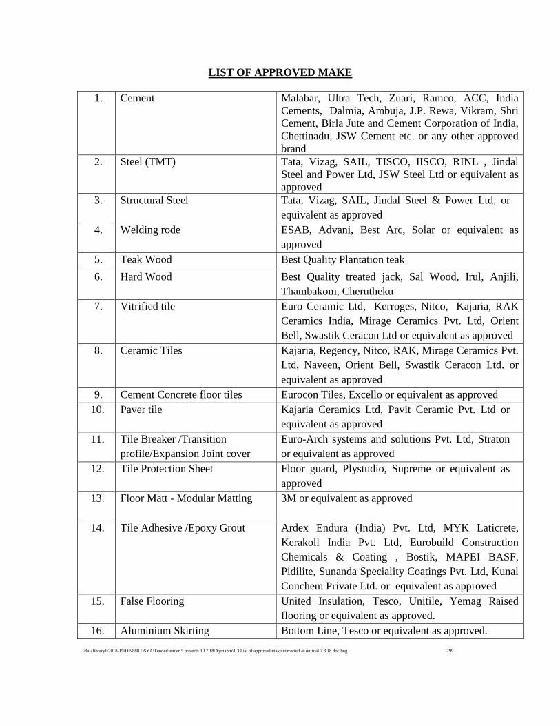
\\datalibrary1\2018-19\DP-888 DSYA\Tender\tender 5 projects 10.7.18\Aymanm\1.3 List of approved make corrected as onfinal 7.3.18.doc/bng 299
LIST OF APPROVED MAKE
1. Cement Malabar, Ultra Tech, Zuari, Ramco, ACC, India
Cements, Dalmia, Ambuja, J.P. Rewa, Vikram, Shri
Cement, Birla Jute and Cement Corporation of India,
Chettinadu, JSW Cement etc. or any other approved
brand
2. Steel (TMT) Tata, Vizag, SAIL, TISCO, IISCO, RINL , Jindal
Steel and Power Ltd, JSW Steel Ltd or equivalent as
approved
3. Structural Steel Tata, Vizag, SAIL, Jindal Steel & Power Ltd, or
equivalent as approved
4. Welding rode ESAB, Advani, Best Arc, Solar or equivalent as
approved
5. Teak Wood Best Quality Plantation teak
6. Hard Wood Best Quality treated jack, Sal Wood, Irul, Anjili,
Thambakom, Cherutheku
7. Vitrified tile Euro Ceramic Ltd, Kerroges, Nitco, Kajaria, RAK
Ceramics India, Mirage Ceramics Pvt. Ltd, Orient
Bell, Swastik Ceracon Ltd or equivalent as approved
8. Ceramic Tiles Kajaria, Regency, Nitco, RAK, Mirage Ceramics Pvt.
Ltd, Naveen, Orient Bell, Swastik Ceracon Ltd. or
equivalent as approved
9. Cement Concrete floor tiles Eurocon Tiles, Excello or equivalent as approved
10. Paver tile Kajaria Ceramics Ltd, Pavit Ceramic Pvt. Ltd or
equivalent as approved
11. Tile Breaker /Transition
profile/Expansion Joint cover
Euro-Arch systems and solutions Pvt. Ltd, Straton
or equivalent as approved
12. Tile Protection Sheet Floor guard, Plystudio, Supreme or equivalent as
approved
13. Floor Matt - Modular Matting 3M or equivalent as approved
14. Tile Adhesive /Epoxy Grout Ardex Endura (India) Pvt. Ltd, MYK Laticrete,
Kerakoll India Pvt. Ltd, Eurobuild Construction
Chemicals & Coating , Bostik, MAPEI BASF,
Pidilite, Sunanda Speciality Coatings Pvt. Ltd, Kunal
Conchem Private Ltd. or equivalent as approved
15. False Flooring United Insulation, Tesco, Unitile, Yemag Raised
flooring or equivalent as approved.
16. Aluminium Skirting Bottom Line, Tesco or equivalent as approved.
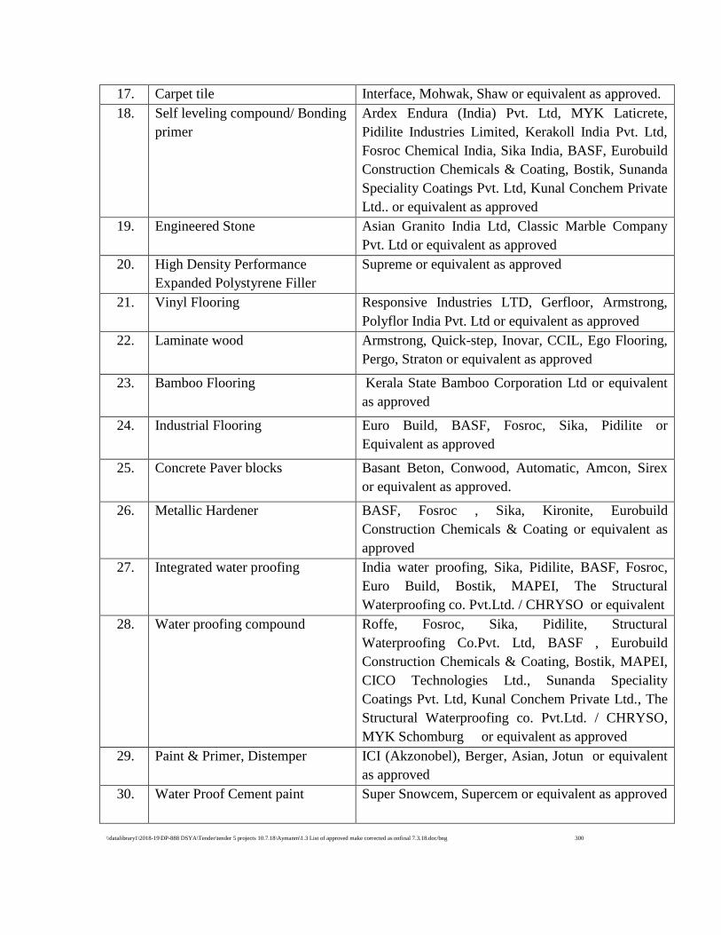
\\datalibrary1\2018-19\DP-888 DSYA\Tender\tender 5 projects 10.7.18\Aymanm\1.3 List of approved make corrected as onfinal 7.3.18.doc/bng 300
17. Carpet tile Interface, Mohwak, Shaw or equivalent as approved.
18. Self leveling compound/ Bonding
primer
Ardex Endura (India) Pvt. Ltd, MYK Laticrete,
Pidilite Industries Limited, Kerakoll India Pvt. Ltd,
Fosroc Chemical India, Sika India, BASF, Eurobuild
Construction Chemicals & Coating, Bostik, Sunanda
Speciality Coatings Pvt. Ltd, Kunal Conchem Private
Ltd.. or equivalent as approved
19. Engineered Stone Asian Granito India Ltd, Classic Marble Company
Pvt. Ltd or equivalent as approved
20. High Density Performance
Expanded Polystyrene Filler
Supreme or equivalent as approved
21. Vinyl Flooring Responsive Industries LTD, Gerfloor, Armstrong,
Polyflor India Pvt. Ltd or equivalent as approved
22. Laminate wood Armstrong, Quick-step, Inovar, CCIL, Ego Flooring,
Pergo, Straton or equivalent as approved
23. Bamboo Flooring Kerala State Bamboo Corporation Ltd or equivalent
as approved
24. Industrial Flooring Euro Build, BASF, Fosroc, Sika, Pidilite or
Equivalent as approved
25. Concrete Paver blocks Basant Beton, Conwood, Automatic, Amcon, Sirex
or equivalent as approved.
26. Metallic Hardener BASF, Fosroc , Sika, Kironite, Eurobuild
Construction Chemicals & Coating or equivalent as
approved
27. Integrated water proofing India water proofing, Sika, Pidilite, BASF, Fosroc,
Euro Build, Bostik, MAPEI, The Structural
Waterproofing co. Pvt.Ltd. / CHRYSO or equivalent
28. Water proofing compound Roffe, Fosroc, Sika, Pidilite, Structural
Waterproofing Co.Pvt. Ltd, BASF , Eurobuild
Construction Chemicals & Coating, Bostik, MAPEI,
CICO Technologies Ltd., Sunanda Speciality
Coatings Pvt. Ltd, Kunal Conchem Private Ltd., The
Structural Waterproofing co. Pvt.Ltd. / CHRYSO,
MYK Schomburg or equivalent as approved
29. Paint & Primer, Distemper ICI (Akzonobel), Berger, Asian, Jotun or equivalent
as approved
30. Water Proof Cement paint Super Snowcem, Supercem or equivalent as approved
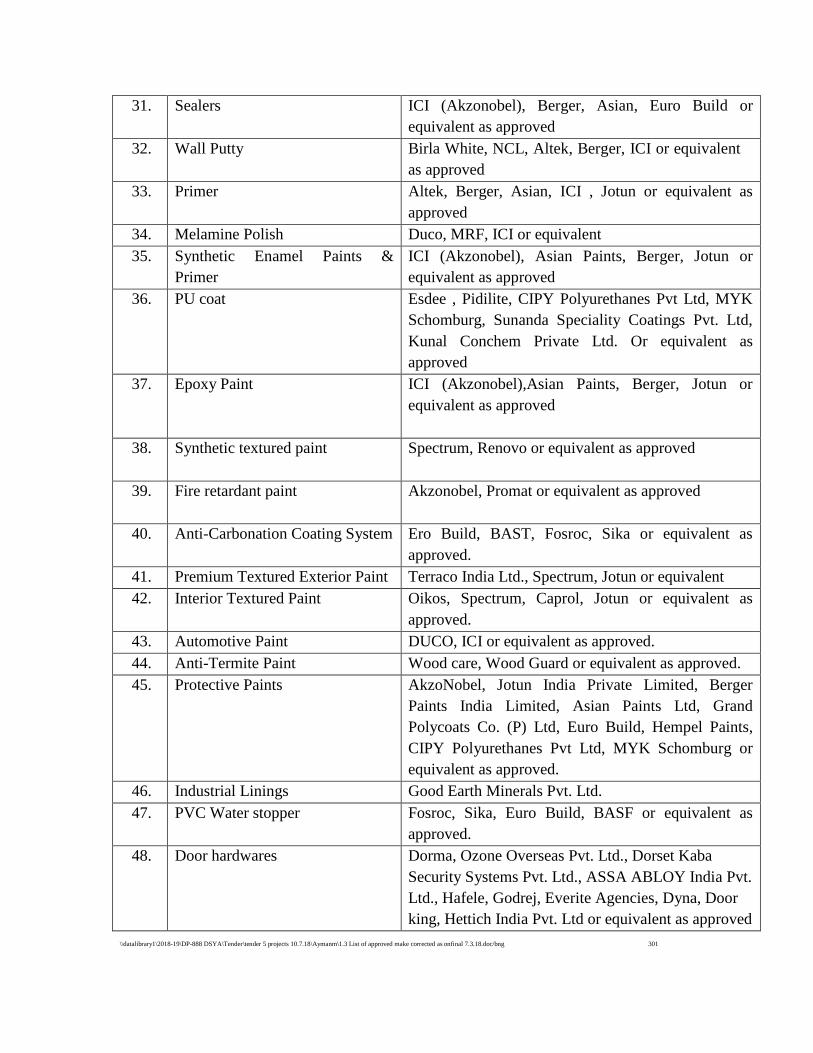
\\datalibrary1\2018-19\DP-888 DSYA\Tender\tender 5 projects 10.7.18\Aymanm\1.3 List of approved make corrected as onfinal 7.3.18.doc/bng 301
31. Sealers ICI (Akzonobel), Berger, Asian, Euro Build or
equivalent as approved
32. Wall Putty Birla White, NCL, Altek, Berger, ICI or equivalent
as approved
33. Primer Altek, Berger, Asian, ICI , Jotun or equivalent as
approved
34. Melamine Polish Duco, MRF, ICI or equivalent
35. Synthetic Enamel Paints &
Primer
ICI (Akzonobel), Asian Paints, Berger, Jotun or
equivalent as approved
36. PU coat Esdee , Pidilite, CIPY Polyurethanes Pvt Ltd, MYK
Schomburg, Sunanda Speciality Coatings Pvt. Ltd,
Kunal Conchem Private Ltd. Or equivalent as
approved
37. Epoxy Paint ICI (Akzonobel),Asian Paints, Berger, Jotun or
equivalent as approved
38. Synthetic textured paint Spectrum, Renovo or equivalent as approved
39. Fire retardant paint Akzonobel, Promat or equivalent as approved
40. Anti-Carbonation Coating System Ero Build, BAST, Fosroc, Sika or equivalent as
approved.
41. Premium Textured Exterior Paint Terraco India Ltd., Spectrum, Jotun or equivalent
42. Interior Textured Paint Oikos, Spectrum, Caprol, Jotun or equivalent as
approved.
43. Automotive Paint DUCO, ICI or equivalent as approved.
44. Anti-Termite Paint Wood care, Wood Guard or equivalent as approved.
45. Protective Paints AkzoNobel, Jotun India Private Limited, Berger
Paints India Limited, Asian Paints Ltd, Grand
Polycoats Co. (P) Ltd, Euro Build, Hempel Paints,
CIPY Polyurethanes Pvt Ltd, MYK Schomburg or
equivalent as approved.
46. i Industrial Linings Good Earth Minerals Pvt. Ltd.
47. PVC Water stopper Fosroc, Sika, Euro Build, BASF or equivalent as
approved.
48. Door hardwares Dorma, Ozone Overseas Pvt. Ltd., Dorset Kaba
Security Systems Pvt. Ltd., ASSA ABLOY India Pvt.
Ltd., Hafele, Godrej, Everite Agencies, Dyna, Door
king, Hettich India Pvt. Ltd or equivalent as approved
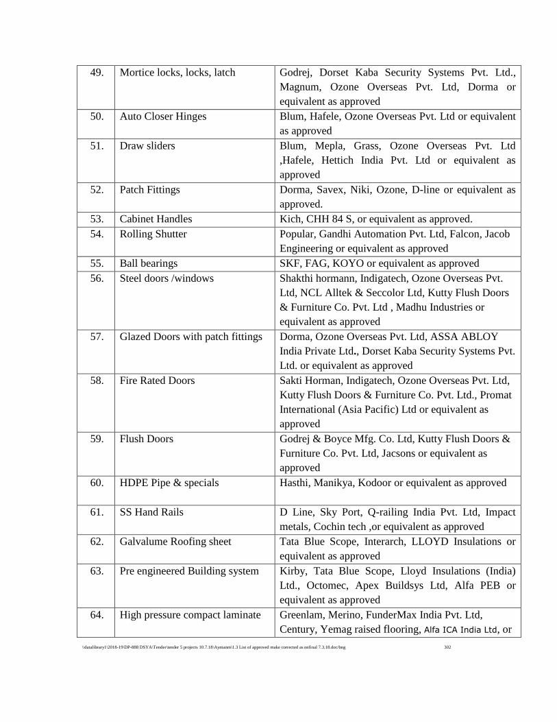
\\datalibrary1\2018-19\DP-888 DSYA\Tender\tender 5 projects 10.7.18\Aymanm\1.3 List of approved make corrected as onfinal 7.3.18.doc/bng 302
49. Mortice locks, locks, latch Godrej, Dorset Kaba Security Systems Pvt. Ltd.,
Magnum, Ozone Overseas Pvt. Ltd, Dorma or
equivalent as approved
50. Auto Closer Hinges Blum, Hafele, Ozone Overseas Pvt. Ltd or equivalent
as approved
51. Draw sliders Blum, Mepla, Grass, Ozone Overseas Pvt. Ltd
,Hafele, Hettich India Pvt. Ltd or equivalent as
approved
52. Patch Fittings Dorma, Savex, Niki, Ozone, D-line or equivalent as
approved.
53. Cabinet Handles Kich, CHH 84 S, or equivalent as approved.
54. Rolling Shutter Popular, Gandhi Automation Pvt. Ltd, Falcon, Jacob
Engineering or equivalent as approved
55. Ball bearings SKF, FAG, KOYO or equivalent as approved
56. Steel doors /windows Shakthi hormann, Indigatech, Ozone Overseas Pvt.
Ltd, NCL Alltek & Seccolor Ltd, Kutty Flush Doors
& Furniture Co. Pvt. Ltd , Madhu Industries or
equivalent as approved
57. Glazed Doors with patch fittings Dorma, Ozone Overseas Pvt. Ltd, ASSA ABLOY
India Private Ltd., Dorset Kaba Security Systems Pvt.
Ltd. or equivalent as approved
58. Fire Rated Doors Sakti Horman, Indigatech, Ozone Overseas Pvt. Ltd,
Kutty Flush Doors & Furniture Co. Pvt. Ltd., Promat
International (Asia Pacific) Ltd or equivalent as
approved
59. Flush Doors Godrej & Boyce Mfg. Co. Ltd, Kutty Flush Doors &
Furniture Co. Pvt. Ltd, Jacsons or equivalent as
approved
60. HDPE Pipe & specials Hasthi, Manikya, Kodoor or equivalent as approved
61. SS Hand Rails D Line, Sky Port, Q-railing India Pvt. Ltd, Impact
metals, Cochin tech ,or equivalent as approved
62. Galvalume Roofing sheet Tata Blue Scope, Interarch, LLOYD Insulations or
equivalent as approved
63. Pre engineered Building system Kirby, Tata Blue Scope, Lloyd Insulations (India)
Ltd., Octomec, Apex Buildsys Ltd, Alfa PEB or
equivalent as approved
64. High pressure compact laminate Greenlam, Merino, FunderMax India Pvt. Ltd,
Century, Yemag raised flooring, Alfa ICA India Ltd, or

\\datalibrary1\2018-19\DP-888 DSYA\Tender\tender 5 projects 10.7.18\Aymanm\1.3 List of approved make corrected as onfinal 7.3.18.doc/bng 303
equivalent as approved
65. Laminates Kitply, Formica, Greenlam, National, Century,
Decolam, Merino or equivalent as approved
66. Plain float glass /lacquered glass
& Mirror
Saint Gobain, Asahi, Pilkington ,Modiguard or
equivalent as approved
67. Marine Plywood Century, Kitply, Anchor, Green Ply, Apple Ply or
equivalent as approved
68. Pre Laminated Ply Greenlam, Merino Industries Ltd, Kitply, or
equivalent as approved
69. Frosted Film Birla 3M, Lumar, Garware, Ultra Mark or equivalent
as approved.
70. MDF Board Bajaj Eco-tech, Anchor, Nuwud, Jacsons, Green or
equivalent as approved
71. Veneers Century, Kitply, Anchor, Green ply, Kenwood ,
Jacsons or equivalent as approved
72. Particle board Jacksons (Exterior grade), Associate or equivalent as
approved
73. Bison board Bison panel, PE,NCL or equivalent
74. Aluminum composite panel Durabuild, Alcomex (Dongshine), Alucobond,
Alubond, Eurobond, Alstrong, Aludecor, Alstone
International or equivalent
75. Polycarbonate GE Lexan, Macrolux or equivalent as approved
76. Sun control firm Garware, 3M or equivalent as approved
77. MP Tiles Comtrust, Lafarge, Monier or equivalent as approved
78. Aluminium roofing sheet Rigidal ,Novills, Kalzip or equivalent as approved
79. Adhesive Tape/Double sided tape/
Single sided multipurpose
Adhesive
3 m, Scotch Tape, Bow Tape, Norton or equivalent as
approved
80. Epoxy Flooring Fosroc, STP Ltd, Cera –chem, Don Chemicals,
Apurva India Ltd ,Eurobuild construction chemicals
& coating, Pidilite, CIPY Polyurethanes Pvt Ltd,
MYK Schomburg or equivalent as approved
81. Secondary Reinforcement Recron 3S, Euro Build, Kamachi Sponge & Power
Corporation Ltd. or equivalent as approved
82. Silicon Sealant Dow corning, GE Silicon, Euro Build, CIPY
Polyurethanes Pvt Ltd, MYK Schomburg or
equivalent as approved
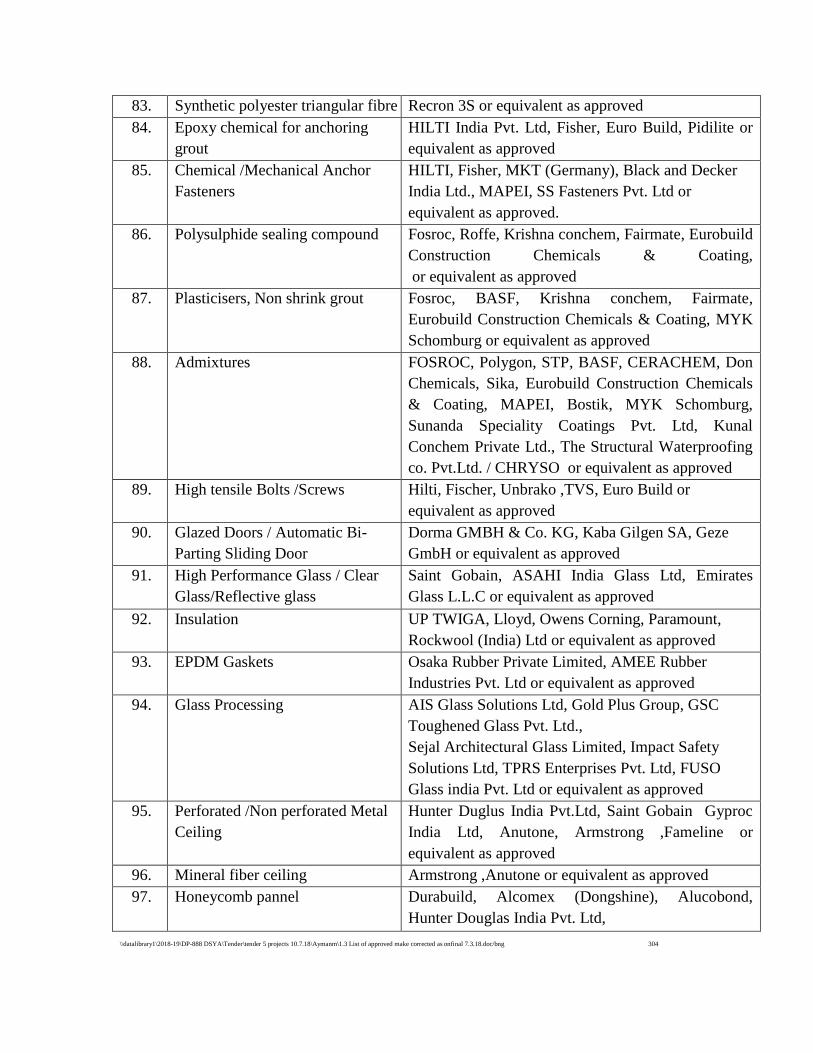
\\datalibrary1\2018-19\DP-888 DSYA\Tender\tender 5 projects 10.7.18\Aymanm\1.3 List of approved make corrected as onfinal 7.3.18.doc/bng 304
83. Synthetic polyester triangular fibre Recron 3S or equivalent as approved
84. Epoxy chemical for anchoring
grout
HILTI India Pvt. Ltd, Fisher, Euro Build, Pidilite or
equivalent as approved
85. Chemical /Mechanical Anchor
Fasteners
HILTI, Fisher, MKT (Germany), Black and Decker
India Ltd., MAPEI, SS Fasteners Pvt. Ltd or
equivalent as approved.
86. Polysulphide sealing compound Fosroc, Roffe, Krishna conchem, Fairmate, Eurobuild
Construction Chemicals & Coating,
or equivalent as approved
87. Plasticisers, Non shrink grout Fosroc, BASF, Krishna conchem, Fairmate,
Eurobuild Construction Chemicals & Coating, MYK
Schomburg or equivalent as approved
88. Admixtures FOSROC, Polygon, STP, BASF, CERACHEM, Don
Chemicals, Sika, Eurobuild Construction Chemicals
& Coating, MAPEI, Bostik, MYK Schomburg,
Sunanda Speciality Coatings Pvt. Ltd, Kunal
Conchem Private Ltd., The Structural Waterproofing
co. Pvt.Ltd. / CHRYSO or equivalent as approved
89. High tensile Bolts /Screws Hilti, Fischer, Unbrako ,TVS, Euro Build or
equivalent as approved
90. Glazed Doors / Automatic Bi-
Parting Sliding Door
Dorma GMBH & Co. KG, Kaba Gilgen SA, Geze
GmbH or equivalent as approved
91. High Performance Glass / Clear
Glass/Reflective glass
Saint Gobain, ASAHI India Glass Ltd, Emirates
Glass L.L.C or equivalent as approved
92. Insulation UP TWIGA, Lloyd, Owens Corning, Paramount,
Rockwool (India) Ltd or equivalent as approved
93. EPDM Gaskets Osaka Rubber Private Limited, AMEE Rubber
Industries Pvt. Ltd or equivalent as approved
94. Glass Processing AIS Glass Solutions Ltd, Gold Plus Group, GSC
Toughened Glass Pvt. Ltd.,
Sejal Architectural Glass Limited, Impact Safety
Solutions Ltd, TPRS Enterprises Pvt. Ltd, FUSO
Glass india Pvt. Ltd or equivalent as approved
95. Perforated /Non perforated Metal
Ceiling
Hunter Duglus India Pvt.Ltd, Saint Gobain Gyproc
India Ltd, Anutone, Armstrong ,Fameline or
equivalent as approved
96. Mineral fiber ceiling Armstrong ,Anutone or equivalent as approved
97. Honeycomb pannel Durabuild, Alcomex (Dongshine), Alucobond,
Hunter Douglas India Pvt. Ltd,
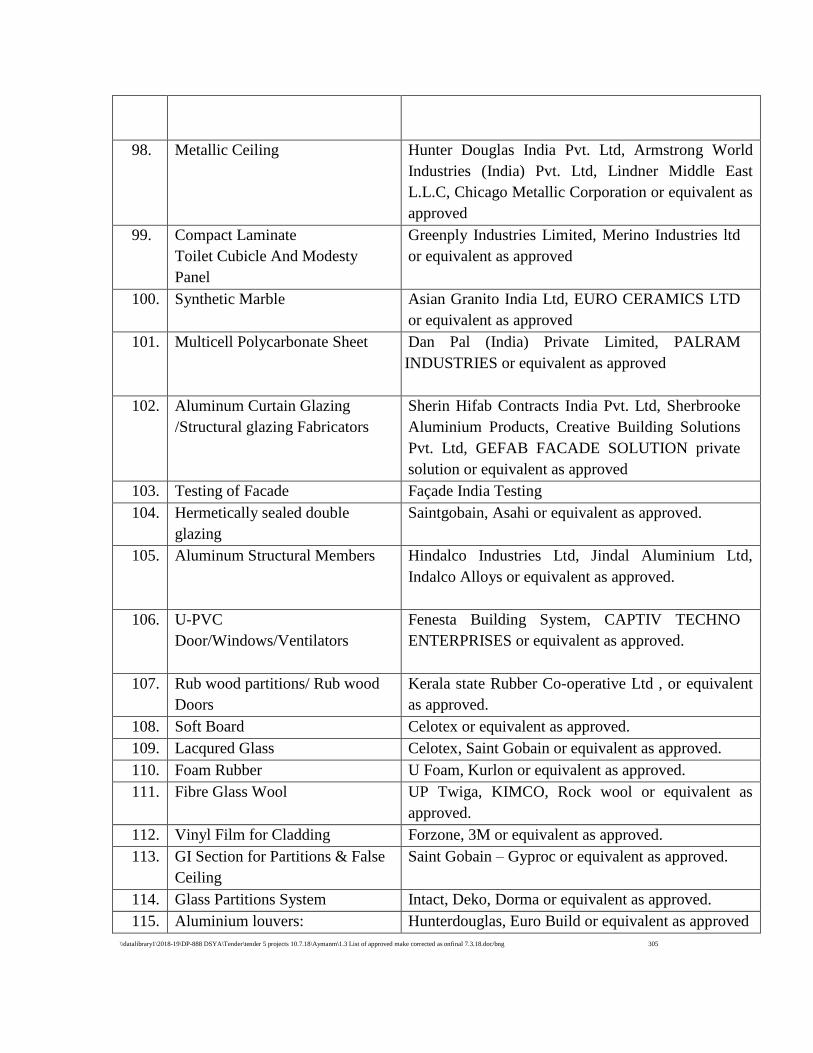
\\datalibrary1\2018-19\DP-888 DSYA\Tender\tender 5 projects 10.7.18\Aymanm\1.3 List of approved make corrected as onfinal 7.3.18.doc/bng 305
98. Metallic Ceiling Hunter Douglas India Pvt. Ltd, Armstrong World
Industries (India) Pvt. Ltd, Lindner Middle East
L.L.C, Chicago Metallic Corporation or equivalent as
approved
99. Compact Laminate
Toilet Cubicle And Modesty
Panel
Greenply Industries Limited, Merino Industries ltd
or equivalent as approved
100. Synthetic Marble Asian Granito India Ltd, EURO CERAMICS LTD
or equivalent as approved
101. Multicell Polycarbonate Sheet Dan Pal (India) Private Limited, PALRAM
INDUSTRIES or equivalent as approved
102. Aluminum Curtain Glazing
/Structural glazing Fabricators
Sherin Hifab Contracts India Pvt. Ltd, Sherbrooke
Aluminium Products, Creative Building Solutions
Pvt. Ltd, GEFAB FACADE SOLUTION private
solution or equivalent as approved
103. Testing of Facade Façade India Testing
104. Hermetically sealed double
glazing
Saintgobain, Asahi or equivalent as approved.
105. Aluminum Structural Members Hindalco Industries Ltd, Jindal Aluminium Ltd,
Indalco Alloys or equivalent as approved.
106. U-PVC
Door/Windows/Ventilators
Fenesta Building System, CAPTIV TECHNO
ENTERPRISES or equivalent as approved.
107. Rub wood partitions/ Rub wood
Doors
Kerala state Rubber Co-operative Ltd , or equivalent
as approved.
108. Soft Board Celotex or equivalent as approved.
109. Lacqured Glass Celotex, Saint Gobain or equivalent as approved.
110. Foam Rubber U Foam, Kurlon or equivalent as approved.
111. Fibre Glass Wool UP Twiga, KIMCO, Rock wool or equivalent as
approved.
112. Vinyl Film for Cladding Forzone, 3M or equivalent as approved.
113. GI Section for Partitions & False
Ceiling
Saint Gobain – Gyproc or equivalent as approved.
114. Glass Partitions System Intact, Deko, Dorma or equivalent as approved.
115. Aluminium louvers: Hunterdouglas, Euro Build or equivalent as approved
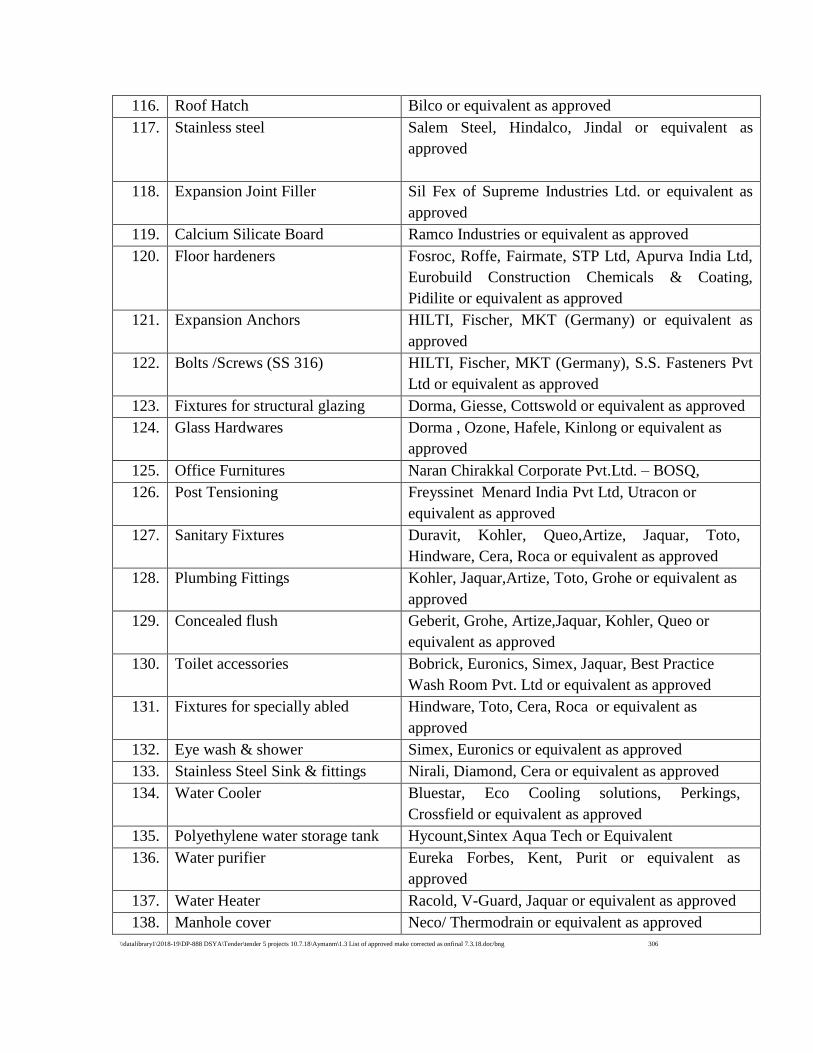
\\datalibrary1\2018-19\DP-888 DSYA\Tender\tender 5 projects 10.7.18\Aymanm\1.3 List of approved make corrected as onfinal 7.3.18.doc/bng 306
116. Roof Hatch Bilco or equivalent as approved
117. Stainless steel Salem Steel, Hindalco, Jindal or equivalent as
approved
118. Expansion Joint Filler Sil Fex of Supreme Industries Ltd. or equivalent as
approved
119. Calcium Silicate Board Ramco Industries or equivalent as approved
120. Floor hardeners Fosroc, Roffe, Fairmate, STP Ltd, Apurva India Ltd,
Eurobuild Construction Chemicals & Coating,
Pidilite or equivalent as approved
121. Expansion Anchors HILTI, Fischer, MKT (Germany) or equivalent as
approved
122. Bolts /Screws (SS 316) HILTI, Fischer, MKT (Germany), S.S. Fasteners Pvt
Ltd or equivalent as approved
123. Fixtures for structural glazing Dorma, Giesse, Cottswold or equivalent as approved
124. Glass Hardwares Dorma , Ozone, Hafele, Kinlong or equivalent as
approved
125. Office Furnitures Naran Chirakkal Corporate Pvt.Ltd. – BOSQ,
126. Post Tensioning Freyssinet Menard India Pvt Ltd, Utracon or
equivalent as approved
127. Sanitary Fixtures Duravit, Kohler, Queo,Artize, Jaquar, Toto,
Hindware, Cera, Roca or equivalent as approved
128. Plumbing Fittings Kohler, Jaquar,Artize, Toto, Grohe or equivalent as
approved
129. Concealed flush Geberit, Grohe, Artize,Jaquar, Kohler, Queo or
equivalent as approved
130. Toilet accessories Bobrick, Euronics, Simex, Jaquar, Best Practice
Wash Room Pvt. Ltd or equivalent as approved
131. Fixtures for specially abled Hindware, Toto, Cera, Roca or equivalent as
approved
132. Eye wash & shower Simex, Euronics or equivalent as approved
133. Stainless Steel Sink & fittings Nirali, Diamond, Cera or equivalent as approved
134. Water Cooler Bluestar, Eco Cooling solutions, Perkings,
Crossfield or equivalent as approved
135. Polyethylene water storage tank Hycount,Sintex Aqua Tech or Equivalent
136. Water purifier Eureka Forbes, Kent, Purit or equivalent as
approved
137. Water Heater Racold, V-Guard, Jaquar or equivalent as approved
138. Manhole cover Neco/ Thermodrain or equivalent as approved
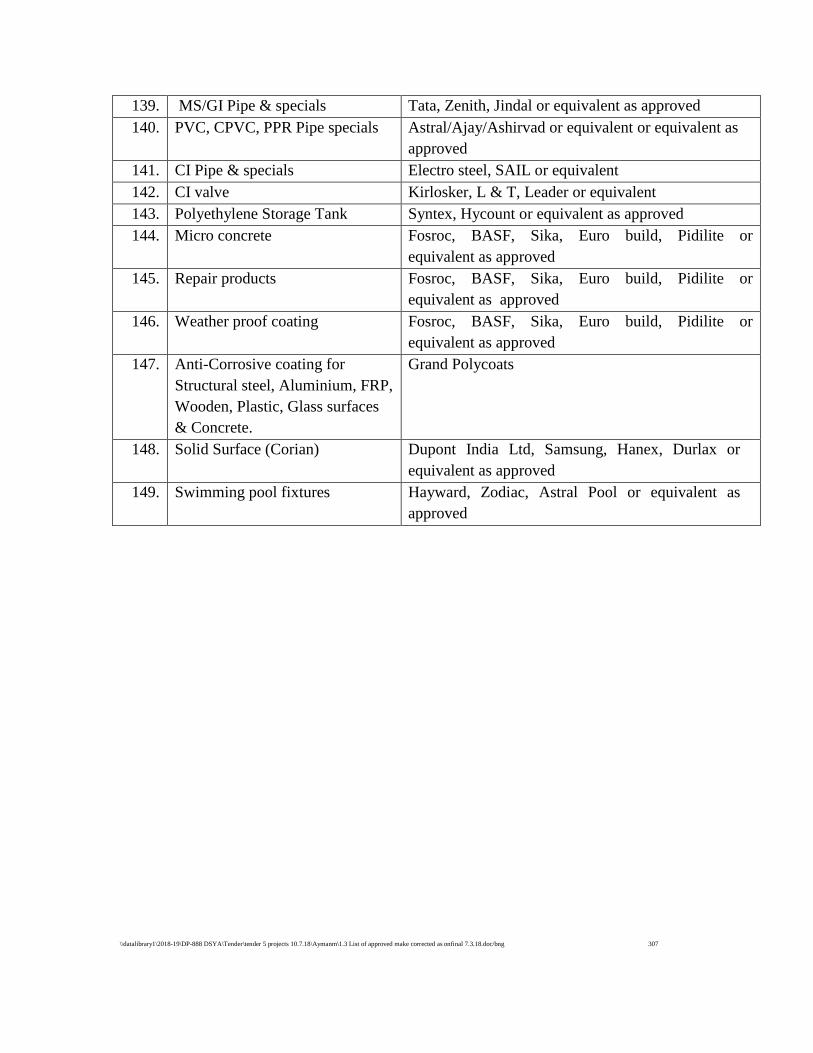
\\datalibrary1\2018-19\DP-888 DSYA\Tender\tender 5 projects 10.7.18\Aymanm\1.3 List of approved make corrected as onfinal 7.3.18.doc/bng 307
139. MS/GI Pipe & specials Tata, Zenith, Jindal or equivalent as approved
140. PVC, CPVC, PPR Pipe specials Astral/Ajay/Ashirvad or equivalent or equivalent as
approved
141. CI Pipe & specials Electro steel, SAIL or equivalent
142. CI valve Kirlosker, L & T, Leader or equivalent
143. Polyethylene Storage Tank Syntex, Hycount or equivalent as approved
144. Micro concrete Fosroc, BASF, Sika, Euro build, Pidilite or
equivalent as approved
145. Repair products Fosroc, BASF, Sika, Euro build, Pidilite or
equivalent as approved
146. Weather proof coating Fosroc, BASF, Sika, Euro build, Pidilite or
equivalent as approved
147. Anti-Corrosive coating for
Structural steel, Aluminium, FRP,
Wooden, Plastic, Glass surfaces
& Concrete.
Grand Polycoats
148. Solid Surface (Corian) Dupont India Ltd, Samsung, Hanex, Durlax or
equivalent as approved
149. Swimming pool fixtures Hayward, Zodiac, Astral Pool or equivalent as
approved
\\datalibrary1\2018-19\DP-888 DSYA\Tender\tender 5 projects 10.7.18\Aymanm\1.4 Tech spec Electrical.doc 308
TECHNICAL SPECIFICATIONS- ELECTRICAL WORKS
1.0 Details of Tender
The tender specifications consist of 10 sub heads as shown below:
1. General
2. LT Panel boards
3. Cables and Cabling.
4. Wiring System
5. Light Fixtures and Fans
6. MCB and MCB distribution Boards.
7. Earthing
8. Installation
9. Measurement
10. Approved makes of Equipment and Materials
1.1 General
The bidder should note that the specifications furnished in the tender is of general nature
only and it is the responsibility of the bidder to design, supply, install and commission the
equipment and services required for the satisfactory performance of the installation. All the
items of equipment required for the safe and satisfactory operation of the installation shall
be supplied and installed by the bidder.
The intent of this specification is to define the requirements for the design, manufacture,
shop testing, supply, installation, testing and commissioning of the electrical system like
LT panel boards, Power & control cables, wiring and accessories,earthing , Lightning
protection, etc as per schedule of requirements.
1.2 LT Panel Boards
General
The switch boards are to be fabricated by a firm having CPRI test certificate for short
circuit rating and IP classification etc for similar panels.
Switch Board Construction
The switch boards are to be manufactured/assembled as per the latest BIS speciifcations,
IP42 classification for indoor and IP54 for outdoor duty, Indian electricity rules, including
special requirements of state/ Central Electrical Inspectorate and the detailed specifications
mentioned. This shall be floor mounted, free standing type, suitable for indoor installation
in dust, vermin and weather proof construction.
Housing Details
The SB shall be fabricated out of 14 SWG sheet steel. It shall be provided with hinged
doors on the front with necessary handles and earthed using flexible copper conductor. The
doors shall be provided with neoprene gaskets. Suitable channel base frame should be
provided for the panel board.
\\datalibrary1\2018-19\DP-888 DSYA\Tender\tender 5 projects 10.7.18\Aymanm\1.4 Tech spec Electrical.doc 309
Detachable gland plates of 3mm thickness shall be provided at the bottom and top of the
cable chamber, suitable for the termination of cables with compression type glands to the
sizes as specified. Adequate space should be provided in the cable chamber for safe
bending and termination of cables.
The enclosure shall be provided with lifting hooks, supporting legs and double earth
terminals with double washers.
The switch board shall be in cubicle design (each feeder components are housed in
individual cubicle) and fully compartmentalized having total segregation between each
cubicle. Suitable cable and busbar alleys as well as separate metering and relaying
compartments shall be provided. All components of the switch board shall be approachable
from front. The Busbar chamber cover should be bolted type. The maximum operating
handle/push button height of any feeder shall not be more than 1800 mm with reference to
panel bottom. Supporting arrangement for dressing of power and control cables in cable
alleys also shall be provided. The front openable/lockable door shall act as a cover for the
switch boards.The busbar should be extendable at both ends. No busbar should be
protruded in the cable alley.
Powder coating
All metal sheets shall undergo 7 tank metal treatment, thorough derusting-rinsing-
degreasing-rinsing- phosphating-rinsing and then passivation. All metal surfaces shall be
thoroughly cleaned and degreased to remove all scales, rust, grease and dirt. Fabricated
structures shall be pickled and treated to remove any trace of acid. The undersurface shall
be made free from all imperfections before undertaking powder coating.
Contractor shall obtain details of approved colour from the Engineer-in-charge before
powder coating.
Panel finish shall be free from imperfections like pin holes, orange peels, run-off paint, etc.
All unpainted steel parts shall be cadmium plated or suitably treated to prevent rust,
corrosion, etc.
Insulation resistance to earth:
This is to be measured with all fuse links in place, all switches, all lamps and appliance in
position by applying a voltage not less than twice the working voltage (subject to a limit of
500V). Insulation resistance of the whole or any part of the installation to earth must not
be less than 50 Megaohms divided by the number of outlets. In any case it should not be
less than 1 Megaohm for the whole installation.
Insulation resistance between conductors:
Tests should be made between all the conductors connected to one pole or phase conductor
of the supply and all the conductors connected to the middle wire or neutral or the other
pole or phase conductors of the supply. For this test, all lamps shall be removed and all
switches put on. The result of the test must be 50 Megaohms divided by the number of
outlets (point and switch positions) .In any case it should not be less than 1 Megaohm for
the whole installation.
\\datalibrary1\2018-19\DP-888 DSYA\Tender\tender 5 projects 10.7.18\Aymanm\1.4 Tech spec Electrical.doc 310
Bus bar sizing connection and supports:
The busbars shall be made from high conductivity electrolytic grade aluminium conductor
conforming to IS 5082. The busbars and supports shall be capable of withstanding the rated
and short circuit current as per the single line diagram/ feeder details. Minimum size of
main power bus bars shall be of incomer switch rating and interconnecting busbar to
feeders should be rated to switch rating. Maximum current density permissible for
Aluminium bus bars shall be 0.8 Amps/Sq.mm without considering derating factors. An
earthing busbar of minimum 150 sq.mm section copper shall be provided outside panel at
bottom throughout the length of the panel.Bus bar shall be designed as per electrical
inpectorate rules and regulations.
The busbars shall be provided with heat shrinkable PVC insulated sleeve. Supports for
busbars shall be made of suitable size cast resin ribbed insulators and these should be
adequate in number so as to avoid any sag in the busbars. (Hylam supports may not be
used)
Minimum clearance between phase to phase shall be 32mm and that between phase to
neutral/ earth shall be 26 mm.
Power Connection
a) For power interconnections within the panel board
Rigid Aluminium conductor, with PVC insulation, of adequate cross section i.e., current
carrying capacity not less than the outgoing switch rating shall be used. Cable lugs/ sockets
of suitable size and type shall be used for all interconnections.
For incoming and outgoing feeders of the switch boards, Aluminium conductor cable will
be used and hence the panel has to be designed for receiving these and wherever required
cable boxes shall be provided in panel by removable gland plates and shall be provided on
top/bottom of panel, for cable entries.
In case of panel boards having busduct as incomer, the panel board should be designed to
accommodate proper connection/termination of the bus duct.
To prevent accidental contacts, all interconnecting cables/ busbars and all terminals also
shall be shrouded.
Provision for clamping the cables inside the cable alley should be provided.
Standard colour code of red, yellow and blue for phases and black for Neutral to be
followed for all busbars /conductors.
b) Auxiliary wiring and Terminals
Wiring for all controls, protection, metering, signaling, etc. inside the switchboard shall be
done with 1100 volts grey colour HFFR (Halogen free fire retardant) copper conductor
cables. Minimum size of these conductors shall be 2.5 sq.mm. Control wiring to
components fixed on doors shall be flexible type.
The complete panel would be sub-divided into different sections and each section shall
have its own control circuit with fuse and indication.
\\datalibrary1\2018-19\DP-888 DSYA\Tender\tender 5 projects 10.7.18\Aymanm\1.4 Tech spec Electrical.doc 311
All control wiring should be provided with necessary cable sockets/ lugs at both ends.
Conductors shall be terminated using compression type lugs. Each termination shall be
identified at both the ends by PVC ferrules.
The identification termination numbers should match with those on the drawings.
Component of switch boards
The panel shall be provided with ACB, MCCBs, SDFUs, fuses, meters, relays and
instruments, etc. of size, capacity as specified in schedule of requirements and
specification. The switch gears should be positioned inside the panel board as per
manufacturers standards.
Moulded Case Circuit Breakers
General
Moulded case circuit breakers (MCCBs) shall be incorporated wherever required and shall
be of current limiting type and preferably double break. MCCBs shall confirm to IS 13947-
1/IEC 60947-1 for general rules and IS 13947-2/IEC 60947-2 for circuit breakers in all
respects. MCCB shall be suitable for isolation as per standard, single phase 240V or three
phase 415 V, 50Hz, AC and shall have a rated insulation voltage of 750 V AC. The
MCCBs shall have thermal memory and shall have no Line-Load restriction. All the
breakers shall have tropicalisation as a standard feature.
Construction
The MCCB case & cover shall be made of high strength heat resistant and flame retardant
thermosetting insulating material.
The operating handle shall be quick make, quick break trip free type. The operating handle
shall have suitable ’ON’,’OFF’,’TRIPPED’ indicators.
In order to ensure suitability for isolation complying with IS13947-2/IEC 60947-2, the
operating mechanism shall be designed such that the toggle or handle can only be in ‘OFF’
position.
Three phase MCCBs shall have a common operating handle for simultaneous operation and
tripping of all the three phases.
Rating & Breaking Capacity:
The rating of the circuit breaker shall be as per the drawings and schedule of
quantities.
The MCCB shall have Service Breaking Capacity (Ics) equal to Ultimate Breaking capacity
(Icu).
The Breaking Capacity (Icu) in kA for different ratings at 415V AC, 50Hz, 0.2 p.f shall
preferably be as follows:
\\datalibrary1\2018-19\DP-888 DSYA\Tender\tender 5 projects 10.7.18\Aymanm\1.4 Tech spec Electrical.doc 312
25kA for ratings upto 100A
35KA for ratings above 100A and upto 250A
50KA for ratings above 250A and upto 630A.
Protection
All breakers of 250A and above shall have micro-processor based trip unit with adjustable
overload protection from 40% to 100% of the nominal current(In) and extra current
limiting type. The short circuit protection should be adjustable from 2 to 10 times the rated
current(Ir) with tripping time fixed. The Instantaneous Short Circuit protection to be
fixed,without any time delay at 11 times the nominal current(In). MCCBs upto 250A shall
be thermal magnetic with adjustable overload protection or as specified in BOQ.
The microprocessor control unit shall have - true RMS sensing , Electromagnetic
compatibility(EMC), thermal memory. The mP release shall be immune to harmonics.
630A MCCBs shall have fault indication of (O/C, S/C and E/F).
The MCCBs shall be possible to fully co-ordinate the over-load & short-circuit tripping of
the circuit breakers with the upstream and downstream circuit breakers to provide Total
Discrimination.
MCCB should have the flexibility of connecting the load either on the top or on the bottom
side with out deration.
Accessories
MCCBs shall be provided with the following accessories and all these devices shall be
fittable at site. The accessories shall be seperated from Power circuit. Preferably the Shunt
trip release and undervoltage release shall be snap-in type and fitted with terminal blocks.
Shunt trip
Auxiliary switch
Extended rotary Handle.
Interlocking
MCCBs shall be provided with the following interlocking devices for interlocking the door
of the switchboard.
Handle interlock to prevent unnecessary manipulations of the breaker.
Door interlock to prevent door beingopened when breaker is in ON position.
Door-interlock defeat to open the door even if the breaker is in ON position.
Front operated rorary handle should have OFF-position pad-locking facility.
Indicating Lamps
Type : Panel mounting wide band LED type with in built surge
suppressor to protect LED against switching surges and
built-in low voltage glow protection of 25V.
Standards applicable : IEC 947-5-1
Diameter : 22mm
Operating voltage : 240V AC
Illumination Level : Minimum 100 lux on the front face of the lens.
Colour of lamps : as per standards
\\datalibrary1\2018-19\DP-888 DSYA\Tender\tender 5 projects 10.7.18\Aymanm\1.4 Tech spec Electrical.doc 313
Measuring instruments
These shall be of square pattern having dimensions of 96x96 mm flush mounting type.
Instruments like ammeter, Voltmeter, frequency meter etc. and instrumental transformers/
transducers etc. are also included in the scope of supply.
All AC meters shall be of class 1 accuracy.
Voltmeter shall be suitable for direct line connection. Voltmeters shall be connected
through MCBs only.
Earthing
Two independent earthing points shall be provided outside the panel near bottom and these
shall be inter-connected with Cu earthing busbars of size 25 x 6 mm. All earthing points
inside the distribution board shall be interconnected to these earthing points with suitable
size copper conductor.
Name plates
Switch board/distribution board shall be provided with danger plate and name plates for all
incoming and outgoing feeders. These name plates shall be of PVC (black colour base &
white letters engraved) screwed to panel. PVC identification ferrule numbers shall be used
for all internal wiring. The name plate shall contain the following information.
Panel Board Identification name & number
Feeder name.
Switch/ fuse rating.
Cable size.
Feeder Cable from …../ to…….
Supports
Busbars shall be rigidly fixed to the supports, of SMC/DMC solid block type base.
Busbars shall be firmly held within the slots in sheet type supports, which in turn shall be
rigidly fixed to the chamber.
Clearances
The minimum clearances to be maintained for enclosed indoor air insulated busbars for
medium voltage applications shall be as follows:
Between Min. clearances
Phase to earth 26 mm
Phase to phase 32 mm
Arrangement of busbars and main connections
Busbars and main connections, which are substantially in one plane, shall be arranged in
the order given below:
\\datalibrary1\2018-19\DP-888 DSYA\Tender\tender 5 projects 10.7.18\Aymanm\1.4 Tech spec Electrical.doc 314
i) AC System
a) The order of phase connections shall be red, yellow and blue.
b) When the run of the conductors is horizontal, the red shall be on the top or farthest
away as viewed from the front.
c) When the run of the conductors is vertical, the red shall be on the left, or farthest
away as viewed from the front.
d) When the system has a neutral connection in the same plane as the phase
connections, the neutral shall occupy the bottom position if horizontal and extreme
right if vertical, or nearest position when viewed from the front.
e) Unless the neutral connections can be readily distinguished from the phase
connections, the order shall be red, yellow, blue and black.
Approvals
The drawing showing general arrangements and detailed wiring diagram for the Panels
shall be submitted to the Engineer-in-charge for approval, prior to manufacture and the
same shall be got inspected, prior to despatch to project site. The complete switch board
and its component shall conform to Indian Electricity Rules & Relevant IS.
1.3 Cables & Cabling
Scope
The scope under this section covers the following:
a) Power cables
b) Control cables
Armouring and Serving
All multicore cables liable for mechanical damage shall be armoured.
Cables, when armoured, shall have galvanised steel wire (flat or round) for armouring.
Steel wire armouring is preferred where the cables are liable to tensile stresses in
applications such as vertical runs, suspended on brackets or laid in soil that is likely to
subside.
Storage and handling
1. Storage:
(i) The cable drums shall be stored on a well drained, hard surface, so that the
drums do not sink in the ground causing rot and damage to the cable drums.
Paved surface is preferred, particularly for long term storage.
(ii) The drums shall always be stored on their flanges, and not on their flat sides.
\\datalibrary1\2018-19\DP-888 DSYA\Tender\tender 5 projects 10.7.18\Aymanm\1.4 Tech spec Electrical.doc 315
(iii) Both ends of the cables should be properly sealed to prevent ingress/absorption
of moisture by the insulation during storage.
(iv) Protection from rain and sun is preferable for long-term storage for all types of
cables. There should be enough ventilation between cable drums.
(v) Damaged battens of drums etc. should be replaced, as may be necessary.
2. Handling:
(i) When the cable drums have to be moved over short distances, they should be
rolled in the direction of the arrow marked on the drum.
(ii) For manual transportation over long distances, the drum should be mounted on
cable drum wheels, strong enough to carry the weight of the drum, and pulled
by means of ropes. Alternatively, they may be mounted on a trailer or on a
suitable mechanical transport.
(iii) For loading into and unloading from vehicles, a crane or a suitable lifting
tackle should be used. Small sized cable drums can also be rolled down
carefully on a suitable ramp or rails, for unloading, provided no damage is
likely to be caused to the cable or to the drum.
Standards
The following standards shall be applicable:
1. IS : 1753 : Specification for Aluminium conductors for insulated cables.
2. IS : 2982 : Specification for copper conductors in insulated cables.
3. IS : 5831 : Specification for XLPE insulated and PVC sheath of electric cables.
4. IS : 6474 : Polythene insulation and sheath of electric cables.
5. IS:3975 : Specification for mild steel wires, strips and tapes for armouring of
cables.
6. IS : 694 : PVC insulated cables.
7. IS : 7098 : Specification for XLPE insulated PVC sheathed cables.
8. IS : 3961 : Recommended current ratings of cables.
9. IS : 5819 : Recommended short circuit ratings for high voltage PVC cables.
Power cables (LV) 1.1kV grade XLPE insulated cable
Power cables for use on 415 V system shall be of 1100 volt grade, Aluminium conductor,
XLPE insulated, PVC sheathed, armoured and overall PVC sheathed cable, strictly as per
relevent IS specification. Unarmoured cable to be used only if specifically mentioned in
schedule of requirements. Bi-metalic plate washers should be provided wherever cables,
lugs, and switch terminals are of different materials. Cables and cable lugs should be of
same material where ever possible.
The size of these cables shall be as specified in schedule of requirements or as per erection
drawings. No Aluminium conductor cable of size less than 4 sq.mm shall be used.
Control Cables
Control cables for use on 415 V system shall be HFFR (halogen free Fire retardent) type
1100 volts grade, copper conductor, PVC insulated, PVC sheathed, armoured/ steel braided
\\datalibrary1\2018-19\DP-888 DSYA\Tender\tender 5 projects 10.7.18\Aymanm\1.4 Tech spec Electrical.doc 316
and overall PVC sheathed, strictly as per IS : 1554 (Part I) - 1978. Unarmoured cables to be
used only if specifically mentioned in schedule of requirements.Control cable carrying
current should be black colour and voltage circuit shall be of grey colour and shall be
segregated.
The size of these cables shall be as specified in schedule of requirements or as per erection
drawing. No cable of size less than 2.5 sq.mm. shall be used.
Cable Glands
Cable glands shall be of heavy duty compression type of brass, chrome plated. These shall
have a screwed nipple with conduit electrical thread and checknut. These shall be suitable
for armoured/unarmoured cables, which is being used.
Cable Connectors
Cable connectors, lugs/sockets, shall be of copper/aluminium alloy, suitably tinned,
solderless, crimping type. These shall be suitable for the cable being connected and type of
function (such as power, control or connection to instruments, etc.)
Cable Indicators
These shall be self-sticking type and of 2 mm thick lead strap for overall cable. PVC
identification numbers, ferrule shall be used for each wire.
Cable Route Markers
These shall be galvanised Cast Iron plate with marking (LT/HT) diameter 150 mm with
600 mm long 25x25 mm MS. angle riveted/bolted with this plate.
G.I. Pipes for Cables
For laying of cables under floor, ground etc. G.I. class ‘B’ pipes shall be used. MS.
conduits is not acceptable for this purpose. All accessories of pipes shall be threaded types.
Size of pipe shall depend upon the overall outer diameter of cable to be drawn through
pipe. No G.I pipe less than 40 mm dia. shall be used for this purpose. To determine the size
of pipe, assume that 40% area of pipe shall be free after drawing of cable.
1.4 Wiring Systems
Materials
A. Wires
Wires shall comply the following features:
PVC insulated with a rating of 105 deg.C bright annealed electrolytic grade (99.9%
pure) copper stranded for uniformity of resistance, dimension and flexibility.
Fire Resistant Low Smoke (FRLS), suitable upto 660V grade wires for single phase
circuits and 1100 V grade for 3 phase circuits as per IS 694/1990 amended upto
date.
\\datalibrary1\2018-19\DP-888 DSYA\Tender\tender 5 projects 10.7.18\Aymanm\1.4 Tech spec Electrical.doc 317
Colour coded as below:
Phase - R - Red
Phase - Y - yellow
Phase - B - Blue
Neutral - Black
Earth - Green
B. Conduits
Two types of Conduit Wiring System shall be followed.
Rigid Steel Conduit Wiring System
Rigid PVC (heavy gauge) Conduit Wiring System
i. General requirements:
a) All rigid conduit pipes shall be ISI marked. The wall thickness shall not be less than
1.6 mm for conduit upto 32 mm dia and not less than 2 mm for conduits above 32
mm dia.
b) The maximum number of PVC insulated cables conforming to IS:694-1990 that can
be drawn in one conduit is given size wise in Table I, and the number of cables per
conduit shall not be exceeded. Conduit sizes shall be selected accordingly in each
run.
c) No conduit less than 20 mm in diameter shall be used.
Flexible conduits will only be permitted for interconnections between switchgear,
DB’s and conduit terminations in wall.
All flexible conduits used in the system should be Halogen free, flame retardant and
self extinguishing polyamide conduits.
ii. Conduit Accessories
a) The conduit wiring system shall be complete in all respects, including their
accessories.
b) All conduit accessories shall be of solvent cement plastering type, and should have
undergone circumstances pin grip type of clamp grip type accessories shall be used.
c) Bends, couplers, etc. shall be solid type in recessed type of works and may be solid
or inspection type as required.
d) 1) Saddles for surface conduit work on wall shall not be less than 0.55 mm (24
gauge) for conduits up to 25 mm dia. and not less than 0.9 mm (20 gauge) for
larger diameter.
2) The minimum width and the thickness of grider clips used for fixing conduits to
steel joists, and clamps shall be as per Table II.
\\datalibrary1\2018-19\DP-888 DSYA\Tender\tender 5 projects 10.7.18\Aymanm\1.4 Tech spec Electrical.doc 318
iii. Outlets
a) The switch box or regulator box shall be made of metal on all sides, except on the
front. In the case of cast boxes, the wall thickness shall be at least 2 mm and in case
of welded mild steel sheet boxes, the wall thickness shall not less than 1.2 mm (18
gauge) for boxes upto a size of 20 cm x 30 cm, and above this size 1.6 mm (16
gauge) thick MS boxes shall be used. The metallic boxes shall be duly painted with
anticorrosive paint before erection.
b) An earth terminal with stud and 2 metal washers shall be provided in each MS box
for termination of protective conductors and for connection to socket outlet/metallic
body of fan regulator etc.
c) Clear depth of the box shall not be less than 60 mm, and this shall be increased
suitably to accommodate mounting of fan regulators in flush pattern.
d) The fan regulators can also be mounted on the switch box covers, if so stipulated in
the tender specifications, or if so directed by the Engineer-in-charge.
e) Except where otherwise stated, 3 mm thick phenolic laminated sheets as per clause
shall be fixed on the front with brass screws, or cadmium plated iron screws as
approved by the Engineer-in-charge.
TABLE I
MAXIMUM NUMBER OF PVC INSULATED 650/1100 V GRADE ALUMINIUM/
COPPER CONDUCTOR CABLE CONFORMING TO IS: 694-1990 IN
RIGID PVS/STEEL CONDUITS
Nominal cross
sectional area of
conductor in
sq.mm
20 mm 25 mm 32 mm 38 mm 51 mm 64 mm
S B S B S B S B S B S B
1.5
2.5
4
8
10
16
25
35
50
70
5 4
5 3
3 2
2 -
2 -
- -
- -
- -
- -
- -
10 8
8 6
6 5
5 4
4 3
2 2
- -
- -
- -
- -
18 12
12 10
10 8
8 7
6 5
3 3
3 2
- -
- -
- -
- -
- -
- -
- -
8 6
6 5
5 3
3 2
- -
- -
- -
- -
- -
- -
- -
10 7
8 6
6 5
5 3
4 3
- -
- -
- -
- -
- -
12 8
9 7
8 6
6 5
5 4
\\datalibrary1\2018-19\DP-888 DSYA\Tender\tender 5 projects 10.7.18\Aymanm\1.4 Tech spec Electrical.doc 319
Note:
1) The above table shows the maximum size of conduits for a simultaneous drawing of
cables.
2) The columns headed S apply to runs of conduits which have distance not exceeding
4.25 m between draw in boxes and which do not deflect from the straight by an
angle of more than 15 degrees. The columns headed B applies to runs of conduit
which deflect from straight by an angle of more than 15 degrees.
3) Conduit sizes are the nominal external diameters.
TABLE II
GIRDER CLIPS CLAMPS
Size of conduit Width Thickness
20 mm
25 mm
32 mm & above
19 mm
19 mm
25 mm
0.9 mm (20 SWG)
0.9 mm (20 SWG)
1.2 mm (18 SWG)
WIRING
A. POINT WIRING
i) Definition
A point (other than socket outlet point) shall include all works necessary in complete
wiring to the following outlets from the controlling switch or MCB. The scope of
wiring for a point shall, however, includes the wiring work necessary in tapping
from another point in the same distribution circuit: -
(a) Ceiling rose or connector (in the case of points for ceiling /exhaust fan points, pre-
wired light fittings and call bells).
(b) Ceiling rose (in the case of pendants except stiff pendants).
(c) Back plate (in the case of stiff pendants).
(d) Lamp holder (in the case of gooseneck type wall brackets, batten holders and fittings
which are not pre-wired).
In the case of call bell points, the words “from the controlling switch or MCB” shall
be read as “from the ceiling rose meant for connection to bell push”.
ii) Scope
(a) Following shall be deemed to be included in point wiring.
1) Conduit, accessories for the conduit and wiring cables between the switch box and
the point outlet.
2) Ceiling rose or Connectors shall be provided near the fitting as required.
3) For points coming in false ceiling, as far as possible, wiring shall be terminated in a
junction box/connector very close to the points. The cost of additional length of
wires used in this regard shall be treated as replacement of 3Rx1.5sqmm wire
against the items specified in BOQ in fixing of fitting using chain/down rod.
4) For points coming in false ceiling, all conduits shall be adequately supported. For
this purpose, MS supports shall be provided as specified in BOQ as a separate item.
5) Loop wiring in rigid/flexible conduit
\\datalibrary1\2018-19\DP-888 DSYA\Tender\tender 5 projects 10.7.18\Aymanm\1.4 Tech spec Electrical.doc 320
6) All fixing accessories such as clips, nails, screws, Phil plug, raw plug etc. as
required.
7) Metal switch boxes for control switches, regulators, sockets etc. recessed or surface
type, and phenolic laminated sheet covers in case of piano type switches and outer &
inner cover plates in case of modular type switches.
8) Outlet boxes, junction boxes, pull-through boxes etc. but excluding metal boxes if
any, provided with switchboards for loose wires/conduit terminations.
9) All the civil works such as chipping, plastering, Making good all damages connected
with the fixing of switch boxes, conduit laying etc are included in the scope.
10) Control switch as specified.
11) Connections to ceiling rose, connector, lamp holder, switch etc.
12) Interconnecting wiring between points on the same circuit, in the same switch box or
from another.
13) Loop earthing in rigid/flexible conduit
14) Protective (loop earthing) conductor from one metallic switch box to another in the
distribution circuits, and for socket outlets. (The length of protective conductor run
along with the circuits/submains is excluded from the scope of points).
B. Following shall be deemed to be included in group control point wiring.
1) Conduit, accessories for the conduit and wiring cables between the Control location
(DP/SP MCB/Isolator/ DP switch) to the first point and wiring cable between points
forming the particular number of group (providing MCB or switch is not included
in this scope).
2) Ceiling rose or Connectors shall be provided near the fitting as required.
3) For points coming in false ceiling, as far as possible, wiring shall be terminated in a
junction box/connector very close to the points. The cost of additional length of
wires used in this regard shall be treated as replacement of 3R x 1.5sqmm wire
against the items specified in BOQ in fixing of fitting using chain/down rod.
4) For points coming in false ceiling, all conduits shall be adequately supported. When
large number of points comes in false ceiling, conduits shall be run in adequate
steel supports/tray. The size and cross section of the above mentioned supports shall
be planned as per the site condition and got approved by the engineer in charge
before commencing the work. MS supports provided shall be as specified in BOQ
and will be a separate item.
5) Loop wiring in rigid/flexible conduit
6) All fixing accessories such as clips, nails, screws, Phil plug, rawl plug etc. as
required.
7) Junction boxes, pull-through boxes etc. but excluding metal boxes if any, provided
with MCBDB for loose wires/conduit terminations.
8) Connections to ceiling rose, connector, MCB etc.
9) Loop earthing in rigid/flexible conduit
C. CIRCUITS AND SUBMAIN WIRING i) Circuit wiring
Circuit wiring shall mean the wiring from the distribution board up to the tapping point
for the nearest first point of that distribution circuit, viz. Upto the nearest first switch
box.
ii) Sub main wiring
Sub main wiring shall mean the wiring from one main/ distribution switchboard to
another.
\\datalibrary1\2018-19\DP-888 DSYA\Tender\tender 5 projects 10.7.18\Aymanm\1.4 Tech spec Electrical.doc 321
D. WIRING IN CONDUIT
The wiring in conduit shall comply the following:
Wire sizes
Copper conductor
Light point / Sub main wiring 1.5 sq.mm
Light Circuit Point 2.5 sq.mm
Power points 4.0 sq.mm
Machinery as per schedule of requirements
Jointing of wires is not permissible, however looping may be done from point (same
circuit) or using a terminal strip in junction box where site condition warrants, prior
permission from Engineer-in-Charge shall be obtained.
Metallic/non-metallic trunking may be used if number of conduits is many. The metallic
trunking shall be earthed securely at DB end and throughout the length. Single trunking
with metallic partition may be used for wiring different services.
E. WIRING ACCESSORIES
i) Control switches for points
(a) Control switch shall be placed only in the live conductor of the circuit. No single
pole switch or fuse shall be inserted in the protective (earth) conductor, or earthed
neutral conductor of the circuit.
(b) Combined switch cum socket shall not be permitted.
ii) Socket outlets
The 5A/6A socket outlet shall be 5 pin socket outlet with 5A/6A switch, where so
specified in the tender documents.
The power point outlet shall be 15A/5A or 16A/6A 6 pin socket outlet with
15A/16A switch, where so specified in the tender documents.
iii) Switch box covers
Phenolic laminated sheet of 3 mm thick of approved shade shall be used for switch
box covers in case of piano type switches. For Modular type switches/ sockets
suitable outer and inner cover plates as specified shall be provided over the standard
box as recommended by the manufacturers of modular type switch/ sockets and no
separate sheet cover is required to be provided.
iv) Ceiling rose
(a) Ceiling rose shall be of 3-plate type.
A ceiling rose shall not be used on circuit the voltage of which normally exceeds
250V.
(b) Only one flexible cord shall be connected to a ceiling rose. Specially designed
ceiling roses shall be used for multiple pendants.
(c) A ceiling rose shall not embody fuse terminal as an integral part of it.
(d) Where ever ceiling roses are not used the wires are to be terminated in good quality
connectors of 6A capacity inside PVC junction boxes.
\\datalibrary1\2018-19\DP-888 DSYA\Tender\tender 5 projects 10.7.18\Aymanm\1.4 Tech spec Electrical.doc 322
(e) All the junction boxes are to be covered with good quality round cover plate of
approved colour.
v) Lamp holders
(a) The standard constructional feature of manufacturers (ISI approved) of lamp
holders is acceptable.
(b) Where the lamp holders are part of light fixtures the holders shall be suitable for the
type of lamps used.
F. MS Items
i) Scope
Supply, fabrication, painting and fixing of M.S items such as Flat / Tees / Angles /
Channels etc. required for the cable bay/conduit tray and necessary civil works such
as grouting, finishing etc.
Scope covers supply of all anchor fasteners, anchor bolts and all connected civil
works such as cutting holes on wall, making good the same.
ii) Material
The steel sections used should be of good quality, manufactured by reputed
companies. Steel sections of reputed manufacturers (like SAIL, Vaizah steel etc)
shall be used. If smaller sections of these makes are not available, re-rolled steels of
reputed make shall be used. In any case the make of steel should be got approved
from engineer in charge before its supply.
1.5 Light fixtures and Fans
The type of fittings shall be as specified in BOQ of tender documents.
i) The contractors shall supply the specified model and make of the fittings. The
standard constructional features of specified make and model as given in the tender
document are acceptable. However, one sample of each of every fitting shall be
produced for approval.
ii) Though a particular model number of a fitting is mentioned in the tender, Client
reserve the right to reject the make if the quality of these fitting is found to be not
up to the standard.
iii) Fittings using discharge lamps shall be complete with power factor correction
capacitors, either internally or externally. An earth terminal with suitable marking
shall be provided for each fitting for discharge lamps.
iv) The contractors shall supply the specified type of lamp mentioned in the BOQ. All
the accessories of the light fittings should be fitted with nut bolt and not to be
riveted.
v) Unless otherwise specified, Copper chokes of Fluorescent Tube light Fittings shall
be of super low loss type (Not more than 6 watts) or as specified in BOQ.
vi) Ceiling fans including their suspension shall conform to relevant Indian Standards.
vii) Wall Fans, Air Circulators, Exhaust fans etc shall conform to relevant Indian
Standards.
\\datalibrary1\2018-19\DP-888 DSYA\Tender\tender 5 projects 10.7.18\Aymanm\1.4 Tech spec Electrical.doc 323
1.6 M C B Distribution Boards (MCB DBs) and accessories.
A) M C B Distribution Boards (MCB DBs)
All SPN & TPN DBs are to be weather proof, thermo plastic or MS powder coated
suitable for flush mounting with double door and to be provided with inbuilt
additional compartment for looping of loose wires/adapter boxes for entry of
armoured cables with IP 42 category of protection and conform to IS: 8623.
i) Material
The DBs are to be fabricated out of CRCA sheets suitable for all weather operation.
The current carrying parts are to be made of electrolytic grade copper and are to
be rated for the duty intended. The DBs should have knock out holes at the bottom,
and detachable plate with knock out holes at the top.
ii) Painting
The DBs are to be subjected to seven tank phosphatising processes (Degreasing,
pickling, surface activation, phosphatising and passivation) and to be powder coated
ensuring rust prevention and scratch resistant.
iii) Accessories
Following accessories are to be provided: -
(a) Copper bus bars of rated current capacity per phase.
(b) Special brass terminals to ensure perfect connections of incoming cable with the
bus bars.
(c) Brass neutral bars three numbers, one for each phase, isolated and insulated from
the enclosures with suitable cross sectional area.
(d) Earth bars for firm earthing and for facilitating individual earthings for each
outgoing terminal.
(e) Sufficient number of blanking plates.
(f) Provision for accomodating four pole MCB and RCCB as incomer.
B) Miniature Circuit Breakers (MCBs)
All MCBs should conform to IS:8828(1996), BS: 3871, IEC:898(1995) and rated
for 10kA category of short circuit duty and tested for breaking capacity upto 10 kA.
B curve type MCBs should be used for resistive loads, C curve type for inductive
loads and D curve type for UPS loads. MCBs shall be suitable for use in frequency
range 40 Hz to 60 Hz and shall accommodate AC/DC supply according to
requirements. It should have inverse time overload and short circuit tripping
mechanism with trip free operation and toggle shall give positive contact indication.
Arc chutes should be provided for effective quenching of arc during operations and
fault conditions. Terminals should be provided with proper shrouding arrangement.
Silver cadmium Oxide tipped contacts should be provided in MCBs. Pressure clamp
terminals for users upto 4 sq.mm and bolted lugs for higher rating should be
provided. Multipole MCBs should be provided with common operating handle and
integral tripping. The MCBs shall be of IP 20 degree of protection. The power loss
per pole shall be in accordance with IS:8828(1996) and shall be furnished by the
manufacturer.
MCB casing shall be made of self extinguishing tropicalised material. It shall be
suitable for mounting on 35 mm DIN rail/surface mounting. Line supply may be
connected to either top or bottom terminals i.e there shall be no line load restriction.
Degree of protection, when the MCB is flush mounted, shall be IP 40. MCB shall
be supplied with clamping terminals fully open. Contact closing shall be
\\datalibrary1\2018-19\DP-888 DSYA\Tender\tender 5 projects 10.7.18\Aymanm\1.4 Tech spec Electrical.doc 324
independent of the speed of the operator. The MCB shall be capable of being used
as incomer circuit breaker and shall be suitable for use as an isolator. In case of
multiple MCBs ina single location (DB), it shall be possible to remove MCB
without having to disturb other MCBs in the vicinity. All MCB’s shall be capable
of carring 35sq.mm. cable termination. Both the upper and lower terminals of
MCB’s shall be bi-connect type, ie., capable of connecting busbar and cable at both
the end.
C) Residual Current Circuit Breaker (RCCB)
Residual Current Circuit Breakers based on residual current operation should
provide complete protection against Earth leakage faults. The breakers should
conform to IS: 12640-1988, IEC 601008-1 and IS: 8828-1996 should be rated for 6
kA or more. The RCCB shall have threshold sensitivities (non-user adjustable) of
30mA, 100 mA & 300 mA with inbuilt time delay of 200 ms for discrimination
with downstream RCCB. The short circuit withstand capacity of the RCCB shall
not be less than 6 kA. It shall be operationally independent of line voltage. The
breaker should be maintenance free. The breaker should be capable of detecting
earth leakage currents and disconnecting the faulty lines. The RCCBs should be
capable of preventing the risk of unwanted tripping due to transient voltages
(lightning, line disturbances on other equipment) and transient currents (from high
capacitive circuits). The RCCB should be unaffected by the DC pulsated
components, present if any in the circuit, and should not give nuisance tripping. A
test devise should be incorporated to check the integrity of the system and tripping
mechanism. Terminals should ensure easy termination of cables and should provide
covers to shield incoming and outgoing terminals with IP 20 degree of protection.
The breaker should be suitable for DIN rail mounting. All RCCB’s shall be capable
of carring 35sq.mm. cable termination. Both the upper and lower terminals of
RCCB’s shall be bi-connect type, ie., capable of connecting busbar and cable at
both the end.
1.7 Earthing
Types
The type of earth electrode shall be any of the following, as specified.
1. Pipe earth electrode; as per IS:3043
General
All cladding or steel work should be bonded to the earthing system, as should all structural
steel work. A main earth bar should be provided, so disposed as to allow of the shortest
subsidiary connections to all major equipment, such as DG set, Substations and electrical
panel boards. When piles are used they should be bonded by welding and connected to
earth bonding bars. All earth connections shall be visible for inspection.
i) Electrode materials and dimensions
a) The materials and minimum sizes of earth electrodes shall be as per fault level
calculation.
\\datalibrary1\2018-19\DP-888 DSYA\Tender\tender 5 projects 10.7.18\Aymanm\1.4 Tech spec Electrical.doc 325
b) GI pipe electrodes shall be cut tapered at the bottom, and provided with holes of 12
mm dia, drilled not less than 7.5 cm from each other upto 2 m of length from the
bottom.
c) Pipe electrode shall be buried in the ground vertically with its top not less than 20cm
below the ground level. The installation shall be carried out as per IS:3043 and as
directed by the engineer in charge.
d) Plate electrode shall be buried in ground with its face vertical, and its top not less
than 2m below the ground level. The installation shall be carried out as per IS:3043
and as directed by the engineer in charge.
e) When more than one electrode is to be installed the distance between the pipe
electrode shall be 5m and that between plates shall be 8m.
f) The strip or conductor electrode shall be buried in trench not less than 0.5m deep.
g) If the conditions necessitate the use of more than one strip or conductor electrode,
they shall be laid as widely distributed as possible, in a single straight trench where
feasible, or preferably in a number of trenches radiating from one point or as directed
by the Engineer-in-charge.
h) All joints in copper conductor should be tinned properly.
Earthing Conductor
a) The earthing conductor (protective conductor from earth electrode upto the main
earthing terminal/earth bus, as the case may be) shall be of the same material as the
electrode, viz. GI or copper, and in the form of wire or strip as specified.
b) Protective (Earth continuity/Loop earthing) Conductor)
c) The material and size of protective conductors shall be as specified by the Engineer-
in-charge.
Location for Earth Electrodes
i) Normally an earth electrode shall not be located closer than 1.5 m from any building. Care
shall be taken to see that the excavation for earth electrode does not affect the foundation of
the building; in such cases, electrodes may be located further away from the building, with
the prior approval of the Engineer-in-Charge.
Protective (Loop earthing/earth continuity) Conductor:
i) Earth terminal of every switchboard in the distribution system shall be bonded to the main
earth bus.
ii) Two protective conductors shall be provided for a switchboard.
iii) A protective conductor shall securely connect the earth connector in every distribution
board (DB) to the earth bus.
\\datalibrary1\2018-19\DP-888 DSYA\Tender\tender 5 projects 10.7.18\Aymanm\1.4 Tech spec Electrical.doc 326
iv) All metallic switch boxes and regulator boxes in a circuit shall be connected to the earth
connector in the DB by protective conductor.
v) Provision should be given for the testing of earth electrodes by connecting a group of rod
driven electrodes to the main earth grid through a bolted link adjacent to the electrodes in a
sunken concrete box. Simpler disconnecting arrangements are not acceptable.
Marking
i) Earth bars/terminals at all switch boards shall be marked permanently as E
ii) Main earth terminal shall be marked Safety Earth – Do Not Disconnect.
1.8 INSTALLATION
Scope
The intent of this specification is to define the requirements for the installation, testing and
commissioning of the electrical items mentioned in the schedule of requirements. The work
shall, however at all times carried out strictly as per the instructions of the Engineer-in-
Charge.
The Contractor shall furnish all tools, welding equipment, rigging materials, testing
equipment, test connections and kits etc. Required for complete installation, testing and
commissioning of the items included in the Contract.
The Contractor shall carry out touch-up painting on any equipment indicated by the
Engineer-in-Charge, if the finish paint on the equipment is soiled or marred during
installation handling.
The interconnecting control cables between LT panel boards ,230V auxillary power supply
etc. should be done by the contractor as required.
The installation shall conform in all respects with Indian Standard Code of Practice.
LT Panel Boards
Switchgears shall be installed in accordance with specified code of practice and the
Consultants instructions. The panels shall be delivered in convenient shipping section by
the contractors. The Contractor shall be responsible for final assembly and inter-connection
of busbars/wiring. Foundation channel shall be grouted in the flooring by the Contractor.
Switchgear panels shall be aligned and levelled on their base channels and bolted or tack
welded to them as per the instructions of the Engineer-in-charge. The earth bus shall be
made continuous throughout the length. Loosely supplied relays and instruments shall be
mounted and connected on the switchgear. Wherever the instruments and relays are
supplied separately, they shall be mounted only after the associated control panel have been
erected and aligned.
After erection the switchboard shall be inspected for dust and vermin proofness. Any hole,
which might allow dust or vermin etc. to enter the panel, shall be plugged suitably at no
extra cost.
\\datalibrary1\2018-19\DP-888 DSYA\Tender\tender 5 projects 10.7.18\Aymanm\1.4 Tech spec Electrical.doc 327
If the instrument transformers are supplied separately they shall be erected as per the
direction of the Engineer-in-charge. The Contractor shall fix the cable glands after drilling
the bottom top plates of all switch boards with suitable holes at no extra cost.
Range of overload relays/timers etc. shall be checked with requirement of purchaser
actually to be connected at site and if the same is under-sized/over-sized, it shall be brought
to the notice of Engineer-in-charge and shall arrange procurement of correct rated
components. However, the Contractor shall not charge anything extra for cost/labour for
such replacements.
Testing
The Contractor shall perform operating tests on all switchgear and panels to verify
operation of switchgear/panels and correctness of the interconnections between various
items of the equipment. This shall be done by applying normal ac or dc voltage to the
circuits and operating the equipment for functional checking of all control circuits, eg.
closing, tripping, control interlock, supervision and alarm circuits.
All connections in the switchgear shall be tested from point to point for possible grounds or
short circuit.
All electrical equipment alarms shall be tested for proper operation by causing alarms to
sound under simulated abnormal conditions.
The Contractor shall arrange testing and calibrations of relays. The testing equipment
including primary and secondary injection sets (if required) etc. shall also have to be
arranged by the Contractor. Payment for above work shall be deemed to have been
included in the erection of switch boards/control panels.
Insulation resistance tests shall be carried out by following rating meggers:
a) Control circuits upto 220 V : by 500 V megger
b) Power circuits, busbars, connections
Upto 11kV : by 1000V meggar
Before electrical panel is energised, the insulation resistance of each bus shall be measured
from phase to ground. Measurement shall be repeated with circuit breakers in operating
positions and contact open. Before switchgear is energised, the insulation resistance of all
DC control circuits shall be measured from line to ground.
The following tests shall be performed on all circuit breakers during erection:
i) Contact alignment and wipe shall be checked an adjusted where necessary in
accordance with the breakers manufacture’s instructions.
ii) Each circuit breaker shall be closed manually and its insulation resistance measured
from phase to phase and phase to ground before erection.
iii) All adjustable direct acting trip devices shall be set using values given by the
Engineer-in-charge/manufacturer.
iv) The dielectric strength of insulating oil wherever applicable shall be checked
\\datalibrary1\2018-19\DP-888 DSYA\Tender\tender 5 projects 10.7.18\Aymanm\1.4 Tech spec Electrical.doc 328
Before switchgear is energised the following tests shall be performed on each circuit
breaker in its test position.
i) Close and trip the circuit breaker from its local & remote control switch, push button
or operating handle. Switchgear control bus may be energised to permit test operation
of circuit breaker with AC closing with prior permission of the Engineer-in-charge.
ii) Test operation of circuit breaker latch, check carriage limit switch if provided.
iii) Test proper operation of lockout device in the closing circuit, wherever provided by
simulating conditions, which would cause a lockout to occur.
iv) Trip breaker either manually or by applying current or voltage to each of its
associated protective relays.
Before switchgear is energised, the test covered above shall be prepeated with each
breaker in its normal operating position.
All electrical equipment alarms shall be tested for proper operation by causing alarms
to sound under simulated abnormal conditions.
The Contractor shall arrange testing and calibrations of relays. The testing
equipment including primary and secondary injection sets (if required) etc. shall also
have to be arranged by the contractor. Payment for the above work shall be deemed to
have been included in the erection of switch boards/control panels.
Proforma for Panels
a) Circuit (breaker or Supplier module designation/bus no.)
b) Insulation resistance tests (contacts open, breaker racked in position).
a) Between each phase of bus : Mega ohm
b) Between each phase and earth : Mega ohm
c) DC and AC control & auxiliary circuits : Mega ohm
d) Between each phase of CT/PT and
CT & PT circuit if any : Mega ohm
c) CT checks:
i) CT ratio
ii) CT secondary resistance
iii) CT polarity check
d) Check for contact alignment and wipe.
e) Check/test all releases/relays.
f) Check mechanical interlocks.
g) Check switchgear/control panel wiring.
h) Check electrical interlocks.
i) Checking of breaker/control circuits for
i) Closing-local and remote (wherever applicable)
ii) Tripping-local and remote (wherever applicable)
j) Opening time of breaker/contactor.
k) Closing time of breaker/contactor.
(This Performa shall be jointly signed by the Engineer-in-charge and the Contractor.)
\\datalibrary1\2018-19\DP-888 DSYA\Tender\tender 5 projects 10.7.18\Aymanm\1.4 Tech spec Electrical.doc 329
Completion tests
After supply and installation of complete project or a particular building/area, the
contractor shall carry out following tests before switching on the power to installation and
the results shall be recorded and submitted to the engineer-in-charge. If results are not
satisfactory/as per the standard, the contractor shall identify the defects/short coming and
shall rectify the same. Nothing extra shall be paid for carrying out these tests and
contractor has to arrange all necessary instruments.
Insulation resistance to earth
This to be measured with all fuse links in place all switches on all lamps and appliance in
position by applying a voltage not less than twice the working voltage (subject to a limit of
500V). Insulation resistance of the whole or any part of the installation to earth must not
be less than 50 Megaohms divided by the number of outlets (points and switch positions)
except that it need not exceed 1 Megaohm for the whole installation.
Insulation resistance between conductors
Test to be made between all the conductors connected to one pole or phase conductor of the
supply and all the conductors connected to the middle wire or neutral or the other pole or
phase conductors of the supply. For this test, all lamps shall be removed and all switches
put on. The result of the test must be 50 Megaohms divided by the number of outlets (point
and switch positions) but need not exceed one Megaohm for the whole installation.
Polarity of single pole switches
Test shall be made to verify that all non-linked single pole switches are on phase conductor
(Live) and not on the neutral or earthed conductor.
Resistance of metal conduits/sheaths (Earth continuity test)
In case of cables encased in metal conduit or metallic sheathing, the total resistance of the
conduit or sheathing from the earthing point to any other position in the completed
installation shall not exceed 2 ohms.
Busbar chamber
Busbar chambers shall be installed on fixed type switch boards with GI bolts and nuts.
Connections
i) Connections to busbars shall be made either by clamping arrangement, or by bolts and nuts
as required. Tapped holes with studs may be permitted only for copper busbars for tapping
conductor size upto 16 sq.mm.
ii) All connections shall be made such that there is a clear metal to metal area contact at the
tappings so that the current density of the busbars at the point of connection does not
exceed permissible limits, avoiding local heating.
iii) For tap-off connections from busbars, PVC insulated wiring cables may be used for current
capacity upto 100A. and for higher current capacities, solid conductors/strips suitably
insulated with PVC sleeve/tape shall be used.
\\datalibrary1\2018-19\DP-888 DSYA\Tender\tender 5 projects 10.7.18\Aymanm\1.4 Tech spec Electrical.doc 330
iv) The bolts and nuts used for connections to busbars shall be of aluminium alloy, tinned
forged brass or galvanised iron. Suitable precaution shall be taken against heating due to
bi-metallic contact, spring washers and plate washers, shall be used with the studs/nuts to
ensure proper contact pressure.
Cabling
Cable network shall include power, control and lighting cables, which shall be laid in
underground trenches, Hume pipes, open trenches, cable trays, GI pipes, or on building
structure surfaces as detailed in the relevant drawings. Cable schedules or as per the
Engineer-in-charge’s instructions. Supply and installation of cable trays, GI pipes/conduits,
cable glades sockets at both ends, isolators, junction boxes, remote push buttons stations,
etc. shall be under the scope of the Contractor.
General requirements for handling of cables
a) Before laying cables, these shall be tested for physical damage, continuity absence of cross
phasing, insulation resistance to earth and between conductors. Insulation resistance tests
shall be carried out with 500/1000 volt Megger.
b) The cables shall be supplied at site, wound on wooden drum as far as possible. For smaller
length and sizes, cables in properly coiled form can be accepted. The cables shall laid by
mounting the drum of the cable on drum carriage. Where the carriage is not available, the
drum shall be mounted on a properly supported axle, and the cable laid out from the top of
the drum. In no case the cable will be rolled on, as it produces kinks which may damage the
conductor.
c) Sharp bending and kinking of cables shall be avoided. The bending radius for PVC
insulated and sheath armoured cable shall not be less than 10 D Where ‘D’ is overall
diameter of the cable.
d) While drawing cables through GI pipes, conduits, RCC pipe, ensure that size of pipe is
such that, after drawing cables, 40 % area is free. After drawing cable, the end of pipe shall
be sealed with cotton/bituminous compound.
e) High voltage (11 kV and above), medium voltage (230 V and above) and other control
cables shall be separated from each other by adequate spacing or running through
independent pipes/trays.
f) Armoured cables shall never be concealed in walls/floors / roads without GI pipes, conduits
RCC pipes.
g) Joints in the cable throughout its length of laying shall be avoided as far as possible and if
unavoidable, prior approval of site engineer shall be taken. If allowed, proper straight
through epoxy resin type joint shall be made, without any additional cost.
h) A minimum loop of 3 M shall be provided on both ends of the cable, or after every 50 M of
unjointed length of cable and on both ends of straight through cable joint. This additional
length shall be used for fresh termination in future. Cable for this loop shall be paid for
supply and laying.
\\datalibrary1\2018-19\DP-888 DSYA\Tender\tender 5 projects 10.7.18\Aymanm\1.4 Tech spec Electrical.doc 331
i) Cable shall be neatly arranged in the trenches/trays in such a manner so that criss-crossing
is avoided and final take off to the motor/switchgear is facilitated. Arrangement of cables
within the trenches/trays shall be the responsibility of the Contractor.
j) All cable routes shall be carefully measured and cable cut to the required lengths and undue
wastage of cables to be avoided. The routes indicated in the drawings is indicative only and
the same may be rechecked with the Engineer-in-charge before cutting of cables. While
selecting cable routes, interference with structures, foundations, pipe line, future expansion
of buildings, etc. should be avoided.
k) All temporary ends of cables must be protected against dirt and moisture to prevent damage
to the insulation. For this purpose, ends of all PVC insulated cables shall be taped with an
approved PVC or rubber insulating tape. Use of friction type or other fabric type tape is not
permitted. Lead sheathed cables shall be plumbed with lead alloy.
l) Wherever cable rises from underground/concrete trenches to motors/ switchgears/ push
buttons, these shall be taken in GI pipes of suitable size, for mechanical protection upto
300 mm distance of concerned cable gland or as instructed by the Engineer-in-charge.
m) Where cables pass through foundation/walls of other underground structures, the necessary
ducts or openings will be provided in advance for the same. However, should it become
necessary to cut holes in existing foundations or structures the electrical Contractor shall
determine their location and obtain approval of the Engineer-in-charge before cutting is
done.
Installation of Cables
Wherever cables are taken through masonry works and road crossings etc., they shall be
protected by running through GI pipes and Hume pipes respectively. Depth shall be 1200
mm from top of finished road surface and it shall extend for about 1070 mm on both sides
of the roads.
Utmost care shall be taken to avoid scratches, kinks and cuts on the conductor while
transporting the cables to site or during installation. Suitable inhibiting grease shall be
liberally applied to bare conductors, wherever they exist.
The junction boxes, cable end boxes etc. wherever required to be provided shall have
sufficient wiring spaces with regard to the sizes of cables indicated in the drawings.
Wherever required, the items to be supplied for electrification shall be complete with
requisite type of cable glands, cable boxes, termination etc. and other accessories which
are necessary for the satisfactory installation/operation of the installations as per relevant
statutory rules and regulations.
Installation of all cables should be as per E.I. Standards. Fuses should be graded properly
and should be selected based on the rating of cables. The cables shall be laid in
trenches/overhead racks wherever available. The cables from cable trenches to the switcher
shall be buried (as per standard practices and or taken through GI pipes to 1.2 m above
ground/racks floor level. The cables taken over racks/ walls/ columns/ trusses shall be
properly clamped using aluminium clamps of 16 SWG 1/4 hard or 3/4 hard sheet, the width
varying from 12.5 to 25 mm at intervals of 750 mm. 225 mm minimum horizontal
interaxial spacing shall be maintained when more than one cable is laid in same trench.
Suitable and permanent type of cable markers is to be provided indicating the route and
\\datalibrary1\2018-19\DP-888 DSYA\Tender\tender 5 projects 10.7.18\Aymanm\1.4 Tech spec Electrical.doc 332
position of joints of cable. Loops should be provided at either ends of the cable.
Identification tags should be provided for each cable in the trench at a distance of 3 metres.
Supply and installation of danger notice boards, where required, and other provisions under
the statutory rules and regulations shall be included in the scope of this work.
The Contractor has to provide materials and carry out the wiring work including earthing
according to IS 3043 unless otherwise specified and get it approved before using for work,
by the authorised engineer of the Purchaser.
The complete installation work shall be conforming to NEC-1985 and complying with the
Indian Electricity Rules and to meet the approval of the State Electrical Inspector etc.
Installation of all switch boards and distribution boards should be in conformity with Rule
51(1)(c) of I.E.R. 1958. MV installation should conform to I.S. 7732.
The cable terminations and earth terminations, wherever required, shall only be using
compression type cable glands and suitable lugs.
All the materials to be supplied for this work shall be got approved by the concerned
engineer at site.
The work will be considered complete only if the following tests are conducted, by the
contractor at his own cost, satisfactorily in the presence of the site Engineer and are:
a) Insulation test
b) Earth resistance test and
c) Continuity test
Laying of Cables (underground system)
a) Cables shall be so laid in ground that these will not interfere with other underground
structures. All water pipes, sewage lines or other structures, which become exposed by
excavation, shall be properly supported and protection from injury until the filling has been
rammed solidly in places under and around them. Any telephone or other cables coming in
the way are to be properly shielded diverted as directed by the Purchaser.
b) Cables shall be laid at minimum depth of 750 mm in case of LT & 1200 mm in case of HT,
from ground level. Excavation will be generally in ordinary alluvial soil. The width of the
trench shall be sufficient for laying of required number of cables.
c) Sand bedding 75 mm thick shall be made below and above the cables. A layer of bricks
(full size) shall be laid on the edge, above sand bedding on the sides of cables and a flat
brick to cover cable completely. More than one cable can be laid in the same trench by
providing a brick on edge between two cables. However the relating location of cables in
trench shall be maintained till termination. The surface of the ground after back filling the
earth shall be made good so as to conform in all respects to the surrounded ground and to
the entire satisfaction to the Engineer-in-charge.
d) For all underground cables, route markers should be used.
i) Separate cable route markers should be used for LT, HT and telephone cables.

\\datalibrary1\2018-19\DP-888 DSYA\Tender\tender 5 projects 10.7.18\Aymanm\1.4 Tech spec Electrical.doc 333
ii) Route markers should be grounded in ground with with 1:2:4 cement concrete
pedestal size 230 x 230 x 300 mm.
iii) Cable markers should be installed at an interval not exceeding 50 M along the
straight routes of cables at a distance of 0.5 M away from centre of cable with the
arrow marked on the cable markers plate indicating the location of cable. Cable
markers should also be used to identify change in direction of cable route and for
location of every joint in underground cable.
e) RCC hume pipes for crossing road in cable laying shall be provided by Contractor. RCC
hume pipe at the ends shall be sealed by bituminous compound after laying and testing of
cable by electrical Contractor without any extra charge.
Laying of Cables under Floors
a) GI class A pipe shall be used for laying of outgoing cables from distribution boards to
various equipment. Preferably one cable shall be drawn through one pipe. Size of pipe shall
be such that after drawing of cable 40 % area is free. If length of pipe is more than 30 M,
free area may be increased to 50 %.
b) Use of elbows is not allowed at all and number of bends shall be kept minimum. Instead of
using bends with sockets, pipe bending machine shall be used for making long smooth
bends at site.
c) Ends of pipe shall be sealed temporarily while laying with cotton/jute/rubber stopper etc. to
avoid entry of building material.
d) Exact locations of equipment shall be ascertain prior to laying of pipe.
Laying of Cable in Masonry Trenches
a) Masonry/concrete trenches of laying of cable shall be provided by Contractor. However
steel members such as MS angles/flats etc. shall be provided & grouted by electrical
Contractor to support the cables. Cables shall be clamped to these supports with
aluminium saddles/damps. More than one tier of cables can be provided in the same
trench if the number of cables is more.
b) Entry of cables in trenches shall be sealed with bituminous MASTIC compound to stop
entry of water in trenches.
Laying of Cables in Cable Racks
Cable Racks to be used for cables laid indoors except for single cables. The cable racks
shall be of ladder type fabricated out of structural steel, MS, GI or aluminium perforated as
indicated. The cable racks shall be of adequate strength to carry the weight of cables with
out sagging. Structural bracket grounted in the build up trenches to support the cable such
supports shall be at intervals of not less than 750 mm centres. All the structural steel work
shall be finished with two coats of paint over primer.
a) Cables shall be fixed in cable trays in single tier formation and shall be clamped with
aluminium flat clamps and galvanised bolts/unit.
\\datalibrary1\2018-19\DP-888 DSYA\Tender\tender 5 projects 10.7.18\Aymanm\1.4 Tech spec Electrical.doc 334
b) Earthing flat/wire can also be laid in cable tray along with cables.
c) After laying of cables minimum 20 % area shall be spare.
Laying of Cables on Building Surface/Structure
a) Such type of cable laying shall be avoided as far as possible and will be allowed only
for individual cables or small group of cables which run along structure.
b) Cables shall be rigidly supported on structural steel/masonry using individual
cast/malleable iron galvanised saddles and these supports shall be approximately 400 to
500 mm for cables upto 25 mm overall diameter and maximum 1000 mm for cables
larger than 25 mm. Unsightly sagging of cables shall be prevented. Only aluminium/GI
clamps with GI bolts/nuts shall be used.
c) If drilling of steel structure must be resorted to, approval must be secured from the
Engineer-in-charge and steel must be drilled where the minimum weakening of the
structure will result.
Termination and Jointing of Cables
a) Use of Glands
All PVC cable upto 1.1 kV grade, armoured or unarmoured shall be terminated at the
equipment/junction box/ isolators/push buttons/control accessories, etc. by means of
suitable size compression type cable glands armour of cable shall be connected to earth
point. The Contractor shall drill holes for fixing glands wherever necessary. Wherever
threaded cable gland is to be screwed into threaded opening of different size, suitable
galvanised threaded reducing bushing shall be used for approved type.
In case of termination of cables at the bottom of the panel over a cable trench having no
access from the bottom, a close fit holes should be drilled in the bottom plate for all the
cables in one line, then bottom plate should be split in two parts along the centre line of
holes. After installation of bottom plate and cables with glands, it shall be sealed with cold
sealing compound.
b) Use of Lugs/Sockets
All cable leads shall be terminated at the equipment terminals, by means of crimped type
solder less connectors unless the terminals at the equipment ends are suitable for direct
jointing without lugs/sockets.
The following is the recommended procedure for crimped joints and the same shall be
followed:
i) Strip off the insulation of the cable end with every precaution, not to severe or
damage any stand. All insulation to be removed from the stripped portion of the
conductor and ends of the insulation should be clean and square.
ii) The cable should be kept clean as far as possible before assembling it with the
terminal/socket. For preventing the ingress of moisture and possibility of re-oxidation
after crimping of the aluminium conductors, the socket should be fitted with
\\datalibrary1\2018-19\DP-888 DSYA\Tender\tender 5 projects 10.7.18\Aymanm\1.4 Tech spec Electrical.doc 335
corrosion inhibiting compound. This compound should also be applied over the
stripped portion of the conductor and the palm surface of socket.
iii) Correct size and type of socket/ferrule/lug should be selected depending on size of
conductor and type of connection to be made.
iv) Make the crimped joint by suitable crimping tool.
v) If after crimping the conductor in socket/lug, same portion of the conductor remains
without insulation the same should be covered sufficiently with PVC tape.
c) Dressing of Cable inside the Equipment
After fixing of cable glands, the individual cores of cable shall be dressed and taken along
the cableways (if provided) or shall be fixed to the panels with polyethylene straps. Cable
shall be dressed in such a manner that small loop of each core is available inside the panel.
For motors of 20 HP and above, terminal box if found not suitable for proper dressing of an
aluminium cables, the Contractor shall modify the same without any additional cost.
Cables inside the equipment shall be measured and paid for.
d) Identification of Cables/Wires/Cores
Power cables shall be identified with red, yellow & blue PVC tapes for trip circuits
identification, additional red ferrules shall be used only in the particular cores of control
cable at the termination points in the switchgear/control panels and control switches.
In case of control cables all cores shall be identified at both ends by their wire numbers by
means of PVC ferrules or self sticking cable markers, wire numbers shall be as per
schematic/connection drawing. For power circuit also wire numbers shall be provided if
required as per the drawings of switchgear manufacturer.
Testing of Cables
a) Before energising, the insulation resistance of every circuit shall be measured from
phase to phase and from phase to ground. This requires 3 measurements if one side is
grounded and 6 measurements for 3 phase circuits.
b) Where splices or terminations are required in circuits rated above 650 volts, measure
insulation resistance of each length of cable before splicing and/or terminating.
Report measurements after splices and/or terminations are complete.
c) DC High Voltage test shall be made after installation on the following:
i) All 1100 Volts grade cables in which straight through joints have been made.
ii) All cables above 1100 V grade.
For record purposes test data shall include the measured values of leakage current versus
time.
\\datalibrary1\2018-19\DP-888 DSYA\Tender\tender 5 projects 10.7.18\Aymanm\1.4 Tech spec Electrical.doc 336
The DC High Voltage test shall be performed as detailed below:
Cables shall be installed in final position with the entire straight through joints complete.
Terminations shall be kept unfinished so that motors, switchgear, transformer etc. are not
subjected to test voltage.
The test voltage and duration shall be as per relevant codes and practices of Indian
Standards Institution.
Proforma for Testing Cables
Proforma - A
Date of Test
a) Drum No. from which cable taken
b) Cable from to
c) Length of run of this table metre
d) Insulation resistance test:
Voltage of Megger ...….. Volts
i) between core-1 to earth...... Megaohm
ii) between core-2 to earth...... Megaohm
iii) between core-3 to earth...... Megaohm
iv) between core-1 to core-2..... Megaohm
v) between core-2 to core-3..... Megaohm
vi) between core-3 to core-1..... Megaohm
e) Highvoltage test Voltage Duration
i) between cores and earth
ii) between individual cores
Signature of Signature of
Engineer-in-Charge Contractor
Proforma - B
Cable Laying
(To be shown for each cable separately, voltage wise)
Date(s) of Test:..............
Voltage of Megger used:...............
——————————————————————————————
Continuity IR value (mega ohm)
of cores ———————————————————————
Before laying Before back filling
—————— ———————
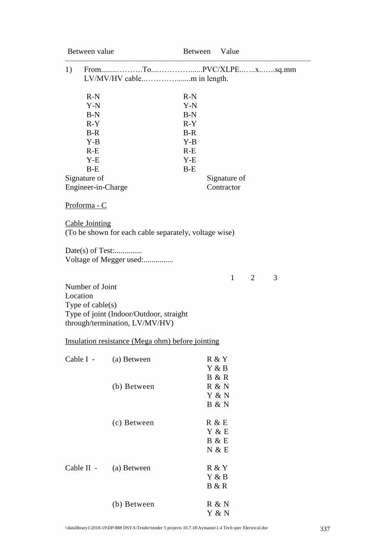
\\datalibrary1\2018-19\DP-888 DSYA\Tender\tender 5 projects 10.7.18\Aymanm\1.4 Tech spec Electrical.doc 337
Between value Between Value
——————————————————————————————
1) From........……….To....…………......PVC/XLPE..…..x..…..sq.mm
LV/MV/HV cable..………….......m in length.
R-N R-N
Y-N Y-N
B-N B-N
R-Y R-Y
B-R B-R
Y-B Y-B
R-E R-E
Y-E Y-E
B-E B-E
Signature of Signature of
Engineer-in-Charge Contractor
Proforma - C
Cable Jointing
(To be shown for each cable separately, voltage wise)
Date(s) of Test:..............
Voltage of Megger used:...............
1 2 3
Number of Joint
Location
Type of cable(s)
Type of joint (Indoor/Outdoor, straight
through/termination, LV/MV/HV)
Insulation resistance (Mega ohm) before jointing
Cable I - (a) Between R & Y
Y & B
B & R
(b) Between R & N
Y & N
B & N
(c) Between R & E
Y & E
B & E
N & E
Cable II - (a) Between R & Y
Y & B
B & R
(b) Between R & N
Y & N
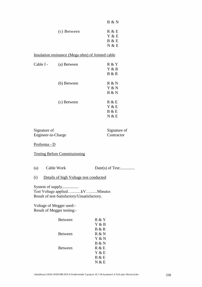
\\datalibrary1\2018-19\DP-888 DSYA\Tender\tender 5 projects 10.7.18\Aymanm\1.4 Tech spec Electrical.doc 338
B & N
(c) Between R & E
Y & E
B & E
N & E
Insulation resistance (Mega ohm) of Jointed cable
Cable I - (a) Between R & Y
Y & B
B & R
(b) Between R & N
Y & N
B & N
(c) Between R & E
Y & E
B & E
N & E
Signature of Signature of
Engineer-in-Charge Contractor
Proforma - D
Testing Before Commissioning
(a) Cable Work Date(s) of Test:..............
(i) Details of high Voltage test conducted
System of supply................
Test Voltage applied….........kV….......Minutes
Result of test-Satisfactory/Unsatisfactory.
Voltage of Megger used:-
Result of Megger testing:-
Between R & Y
Y & B
B & R
Between R & N
Y & N
B & N
Between R & E
Y & E
B & E
N & E
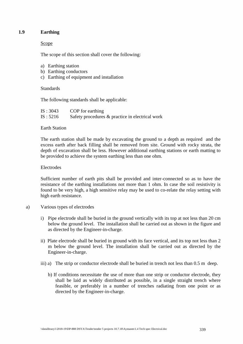
\\datalibrary1\2018-19\DP-888 DSYA\Tender\tender 5 projects 10.7.18\Aymanm\1.4 Tech spec Electrical.doc 339
1.9 Earthing
Scope
The scope of this section shall cover the following:
a) Earthing station
b) Earthing conductors
c) Earthing of equipment and installation
Standards
The following standards shall be applicable:
IS : 3043 COP for earthing
IS : 5216 Safety procedures & practice in electrical work
Earth Station
The earth station shall be made by excavating the ground to a depth as required and the
excess earth after back filling shall be removed from site. Ground with rocky strata, the
depth of excavation shall be less. However additional earthing stations or earth matting to
be provided to achieve the system earthing less than one ohm.
Electrodes
Sufficient number of earth pits shall be provided and inter-connected so as to have the
resistance of the earthing installations not more than 1 ohm. In case the soil resistivity is
found to be very high, a high sensitive relay may be used to co-relate the relay setting with
high earth resistance.
a) Various types of electrodes
i) Pipe electrode shall be buried in the ground vertically with its top at not less than 20 cm
below the ground level. The installation shall be carried out as shown in the figure and
as directed by the Engineer-in-charge.
ii) Plate electrode shall be buried in ground with its face vertical, and its top not less than 2
m below the ground level. The installation shall be carried out as directed by the
Engineer-in-charge.
iii) a) The strip or conductor electrode shall be buried in trench not less than 0.5 m deep.
b) If conditions necessitate the use of more than one strip or conductor electrode, they
shall be laid as widely distributed as possible, in a single straight trench where
feasible, or preferably in a number of trenches radiating from one point or as
directed by the Engineer-in-charge.
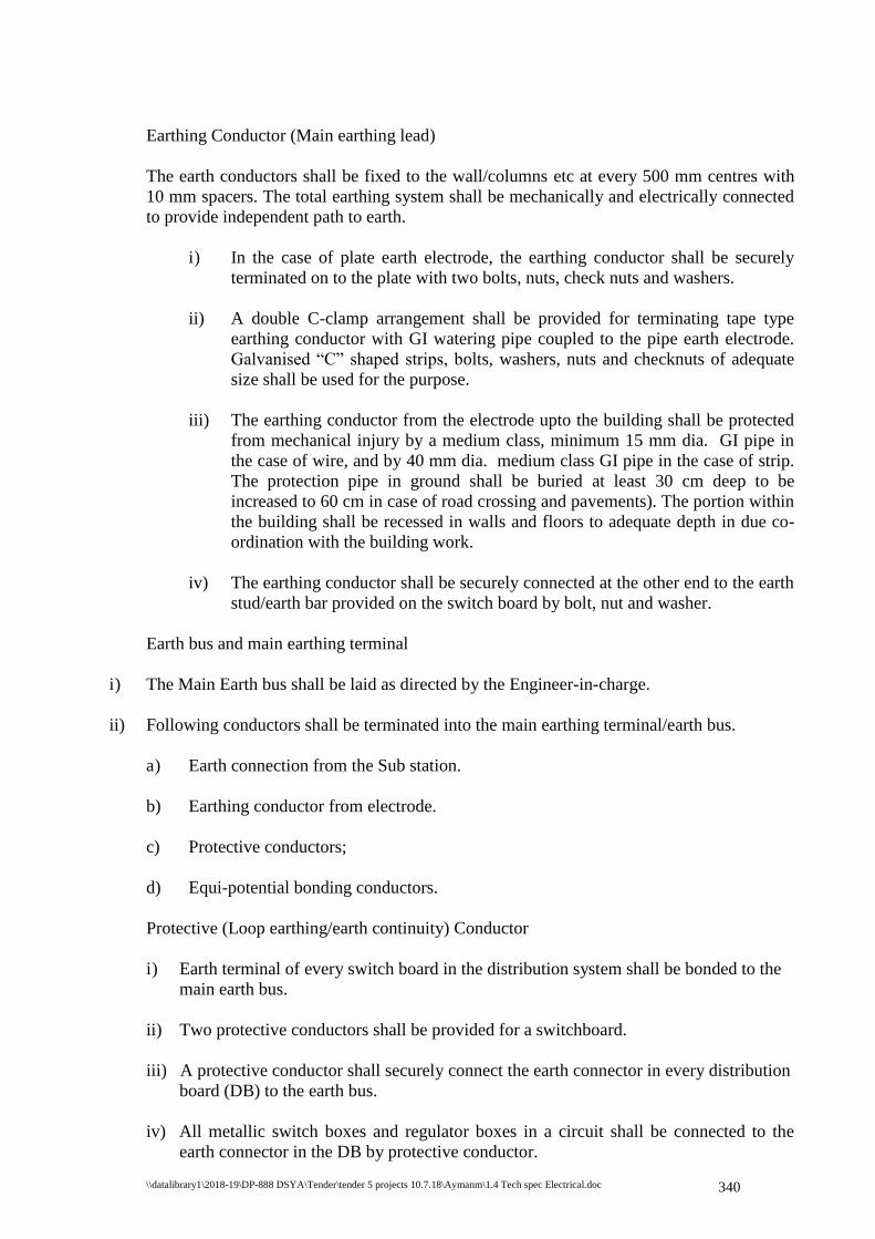
\\datalibrary1\2018-19\DP-888 DSYA\Tender\tender 5 projects 10.7.18\Aymanm\1.4 Tech spec Electrical.doc 340
Earthing Conductor (Main earthing lead)
The earth conductors shall be fixed to the wall/columns etc at every 500 mm centres with
10 mm spacers. The total earthing system shall be mechanically and electrically connected
to provide independent path to earth.
i) In the case of plate earth electrode, the earthing conductor shall be securely
terminated on to the plate with two bolts, nuts, check nuts and washers.
ii) A double C-clamp arrangement shall be provided for terminating tape type
earthing conductor with GI watering pipe coupled to the pipe earth electrode.
Galvanised “C” shaped strips, bolts, washers, nuts and checknuts of adequate
size shall be used for the purpose.
iii) The earthing conductor from the electrode upto the building shall be protected
from mechanical injury by a medium class, minimum 15 mm dia. GI pipe in
the case of wire, and by 40 mm dia. medium class GI pipe in the case of strip.
The protection pipe in ground shall be buried at least 30 cm deep to be
increased to 60 cm in case of road crossing and pavements). The portion within
the building shall be recessed in walls and floors to adequate depth in due co-
ordination with the building work.
iv) The earthing conductor shall be securely connected at the other end to the earth
stud/earth bar provided on the switch board by bolt, nut and washer.
Earth bus and main earthing terminal
i) The Main Earth bus shall be laid as directed by the Engineer-in-charge.
ii) Following conductors shall be terminated into the main earthing terminal/earth bus.
a) Earth connection from the Sub station.
b) Earthing conductor from electrode.
c) Protective conductors;
d) Equi-potential bonding conductors.
Protective (Loop earthing/earth continuity) Conductor
i) Earth terminal of every switch board in the distribution system shall be bonded to the
main earth bus.
ii) Two protective conductors shall be provided for a switchboard.
iii) A protective conductor shall securely connect the earth connector in every distribution
board (DB) to the earth bus.
iv) All metallic switch boxes and regulator boxes in a circuit shall be connected to the
earth connector in the DB by protective conductor.
\\datalibrary1\2018-19\DP-888 DSYA\Tender\tender 5 projects 10.7.18\Aymanm\1.4 Tech spec Electrical.doc 341
v) The earth pin of socket outlets as well as metallic body of fan regulators shall be
connected to the earth stud in switch boxes by protective conductor.
Marking
i) Earth bars/terminals at all switch boards shall be marked permanently, either as E or
as
ii) Main earth terminal shall be marked “Safety Earth – Do Not Disconnect”.
Proforma for testing Earth Electrodes
i) Total number of earth electrodes...............
ii) Earth resistance of each earth electrode:
Sl.No. Location Value
Signature of Signature of
Engineer-in-Charge Contractor
1.10 Measurement
Quantities
The quantities set out in the Schedule of Requirements are the estimated quantities of the
work, but they are not to be taken as the actual and exact quantities of the Work to be
executed by the Contractor in fulfillment of his obligations under the Contract.
Works to be Measured
The Consultant/Client shall, except as otherwise stated, ascertain and determine by
measurement the value in terms of the Contract of work done in accordance with the
Contract. He shall, when he required any part or parts of the Work to be measured, give
notice to the Contractor’s authorised agent or representative, who shall forthwith attend or
send a qualified agent to assist the Engineer in making such measurement, and shall furnish
all particulars required by either of them. Should the Contractor not attend, or neglect or
omit to send such agent, then the measurement made by the Engineer or agent approved by
him shall be taken to be the correct measurement of the work. For the purpose of
measuring such permanent work as is to be measured by records and drawings, the
Consultant shall prepare records and drawing month by month of such work and the
Contractor, as and when called upon to do so in writing, shall, within fourteen days, attend
to examine and agree such records and drawings with the Consultant and shall sign the
same when so agree such records and drawings, they shall be taken to be correct. If, after
examination of such records and drawings the Contractor does not agree the same or does
not sign the same as agreed, they shall nevertheless be taken to be correct, unless the
Contractor shall, within fourteen days of such examination, lodge with the Consultant, for
decision by the Consultant, notice in writing of the respects in which such records and
drawing are claimed by him to be incorrect.
\\datalibrary1\2018-19\DP-888 DSYA\Tender\tender 5 projects 10.7.18\Aymanm\1.4 Tech spec Electrical.doc 342
Mode of Measurement
The Works shall be measured net, as prescribed in the specification of work,
notwithstanding any general or local custom, except where otherwise specifically described
or prescribed in the Contract. Wherever not specifically mentioned in the Contract, the
mode of measurement as prescribed in the relevant IS codes shall be applicable and binding
to the Contract. Only the latest editions of all the codes of practices including all latest
official amendments and revisions shall be applicable.
Battery Limit
Scope of work includes:
1. Supply and Installation of metering panel with Energy meter tested at meter testing
division of KSEB.
2. Cable laying, termination at both ends, testing & commissioning of LT cables from
KSEB overhead line (pole) to metering panel, from metering panel to LT panel
boards, and further to DBs and various electrical loads.
3. Cable laying in buried route/ trenches/ trays as per specification, termination at both
ends, testing and commissioning of LT power and control/ instrumentation cables,
cables between switch boards and sub switch boards and various equipments in the
building.
4. Wherever buried cables are envisaged, scope of work includes digging of earth
along the cable route, filling up of sand protective covering as per specification,
laying of cable, covering the cables with sand bricks, back filling of earth etc., as
per specification. Installation of Hume pipes including excavation, erection, back
filling etc. Cable markers shall be supplied and installed as per specification.
5. Supply, installation, testing and commissioning of light fittings, fan, sockets, DBs,
LT Panel boards including necessary wiring as required.
6. Earthing system includes supply, installation and testing of earth pits and relevant
earth conductors as per specification for metering panels, MCBDBs & pumps.
7. Civil work includes grouting of equipments including distribution boards, fixing of
cable trays with all necessary supports etc.
8. The rates quoted for installation should include the charges for painting the conduits
& supports as directed by Purchaser/Consultant.
9. Liaison with all statutory authorities including KSEB for getting
sanction/approval/safety certificate/ power connection/power allocation including
submission of necessary forms to KSEB/ Electrical inspectorate as required is
included in the scope of this work.
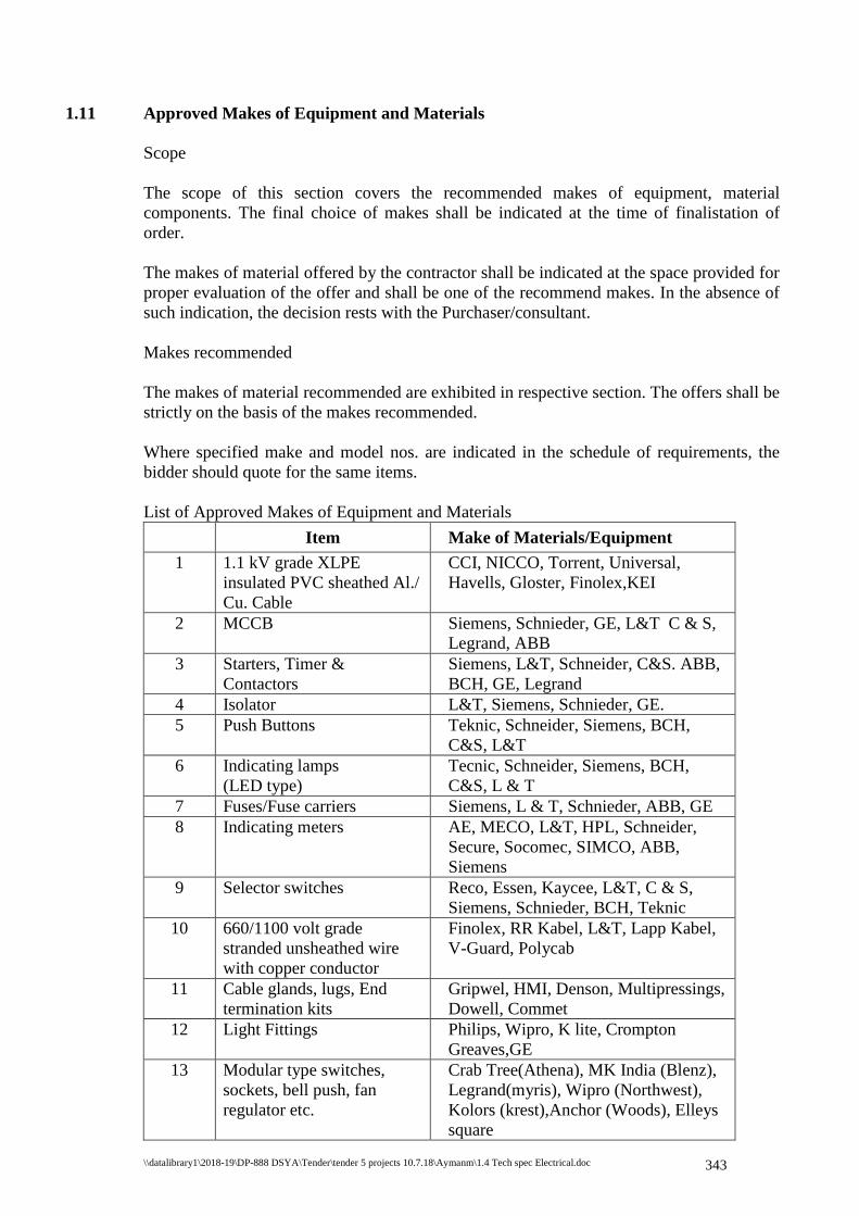
\\datalibrary1\2018-19\DP-888 DSYA\Tender\tender 5 projects 10.7.18\Aymanm\1.4 Tech spec Electrical.doc 343
1.11 Approved Makes of Equipment and Materials
Scope
The scope of this section covers the recommended makes of equipment, material
components. The final choice of makes shall be indicated at the time of finalistation of
order.
The makes of material offered by the contractor shall be indicated at the space provided for
proper evaluation of the offer and shall be one of the recommend makes. In the absence of
such indication, the decision rests with the Purchaser/consultant.
Makes recommended
The makes of material recommended are exhibited in respective section. The offers shall be
strictly on the basis of the makes recommended.
Where specified make and model nos. are indicated in the schedule of requirements, the
bidder should quote for the same items.
List of Approved Makes of Equipment and Materials
Sl.No Item Make of Materials/Equipment
1 1.1 kV grade XLPE
insulated PVC sheathed Al./
Cu. Cable
CCI, NICCO, Torrent, Universal,
Havells, Gloster, Finolex,KEI
2 MCCB Siemens, Schnieder, GE, L&T C & S,
Legrand, ABB
3 Starters, Timer &
Contactors
Siemens, L&T, Schneider, C&S. ABB,
BCH, GE, Legrand
4 Isolator L&T, Siemens, Schnieder, GE.
5 Push Buttons Teknic, Schneider, Siemens, BCH,
C&S, L&T
6 Indicating lamps
(LED type)
Tecnic, Schneider, Siemens, BCH,
C&S, L & T
7 Fuses/Fuse carriers Siemens, L & T, Schnieder, ABB, GE
8
Indicating meters AE, MECO, L&T, HPL, Schneider,
Secure, Socomec, SIMCO, ABB,
Siemens
9 Selector switches Reco, Essen, Kaycee, L&T, C & S,
Siemens, Schnieder, BCH, Teknic
10 660/1100 volt grade
stranded unsheathed wire
with copper conductor
Finolex, RR Kabel, L&T, Lapp Kabel,
V-Guard, Polycab
11 Cable glands, lugs, End
termination kits
Gripwel, HMI, Denson, Multipressings,
Dowell, Commet
12 Light Fittings Philips, Wipro, K lite, Crompton
Greaves,GE
13 Modular type switches,
sockets, bell push, fan
regulator etc.
Crab Tree(Athena), MK India (Blenz),
Legrand(myris), Wipro (Northwest),
Kolors (krest),Anchor (Woods), Elleys
square

\\datalibrary1\2018-19\DP-888 DSYA\Tender\tender 5 projects 10.7.18\Aymanm\1.4 Tech spec Electrical.doc 344
14 Ceiling/wall fan Crompton Greaves, Polar, Usha,
Khaithan
15 Exhaust fan Crompton Greaves, Polar, Usha,
Khaithan, Almonard
16 Metalclad plug/ socket Legrand, C&S,
17 MCB, RCCB,RCBO Legrand, Siemes, L&T, Hagger,
Schnieder,Indoasian(gold plus)
18 MCB Distribution Boards Legrand, Siemens, L&T, Hagger,
Schnieder, Indoasian-goldplus
19 Rigid PVC/
Flexible Poly amide M S
Conduits & Accessories
Precision, Balco, Konseal ISI marked,
Clipsal
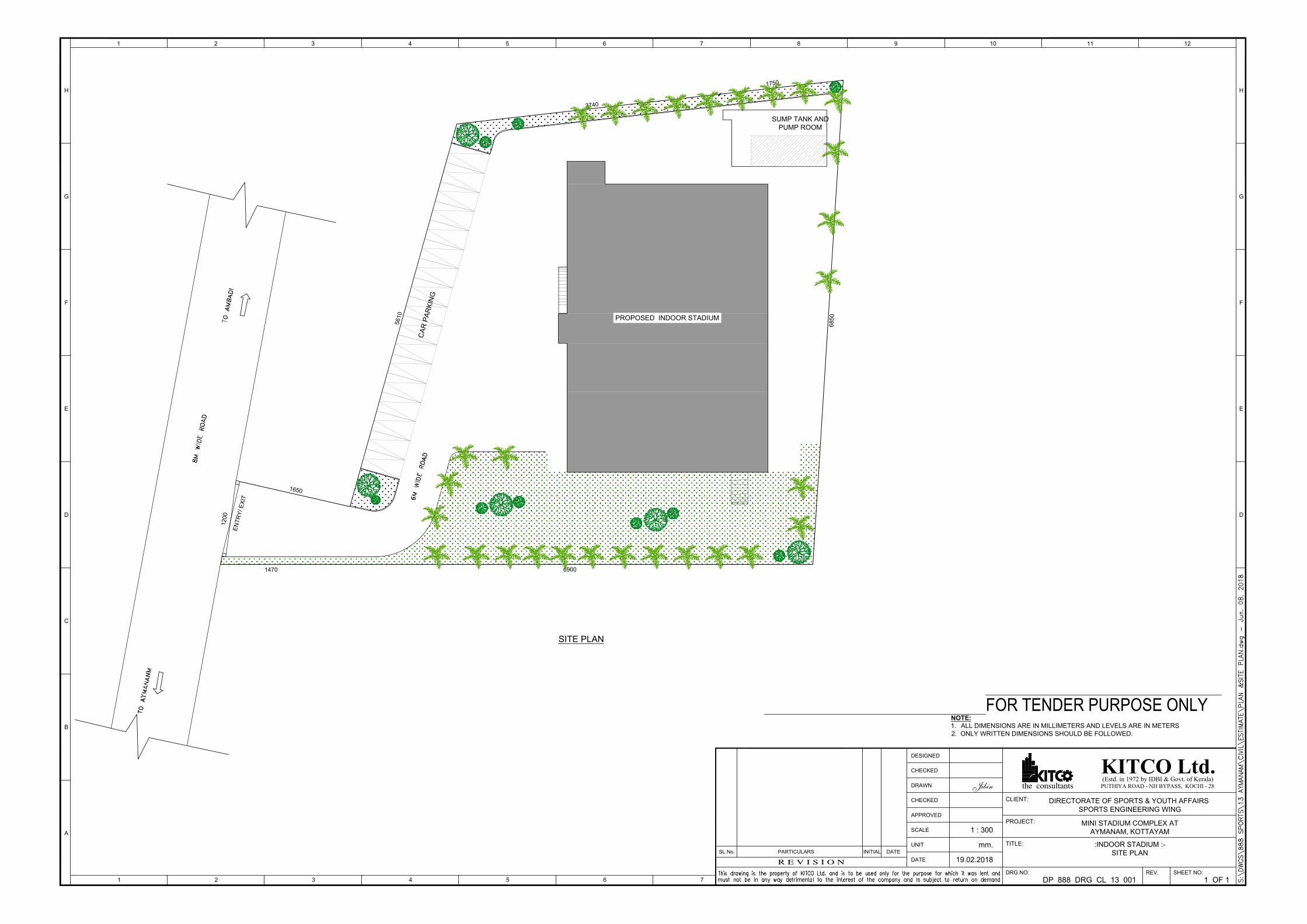
6900
6850
5
6
1
0
1
6
5
0
1470
1
2
0
0
3740
1
7
5
0
E
N
T
R
Y
/ E
X
IT
PROPOSED INDOOR STADIUM
C
A
R
P
A
R
K
IN
G
SITE PLAN
SUMP TANK AND
PUMP ROOM
3 4
A
B
1 2
C
H
F
E
G
D
4321 65 121110987
D
E
F
H
G
5 6
SL.No.
R E V I S I O N
PARTICULARS DATEINITIAL
7
DESIGNED
CHECKED
DATE
UNIT
APPROVED
CHECKED
SCALE
DRAWN
(Estd. in 1972 by IDBI & Govt. of Kerala)KITCO Ltd.PUTHIYA ROAD - NH BYPASS, KOCHI - 28the consultants
DRG NO:
TITLE:
PROJECT:
CLIENT:
SHEET NO:REV.
DIRECTORATE OF SPORTS & YOUTH AFFAIRS
SPORTS ENGINEERING WING
MINI STADIUM COMPLEX AT
AYMANAM, KOTTAYAM
:INDOOR STADIUM :-
SITE PLAN
DP 888 DRG CL 13 001 1 OF 1
19.02.2018
mm.
1 : 300
Jibin
FOR TENDER PURPOSE ONLY
NOTE:
1. ALL DIMENSIONS ARE IN MILLIMETERS AND LEVELS ARE IN METERS
2. ONLY WRITTEN DIMENSIONS SHOULD BE FOLLOWED.
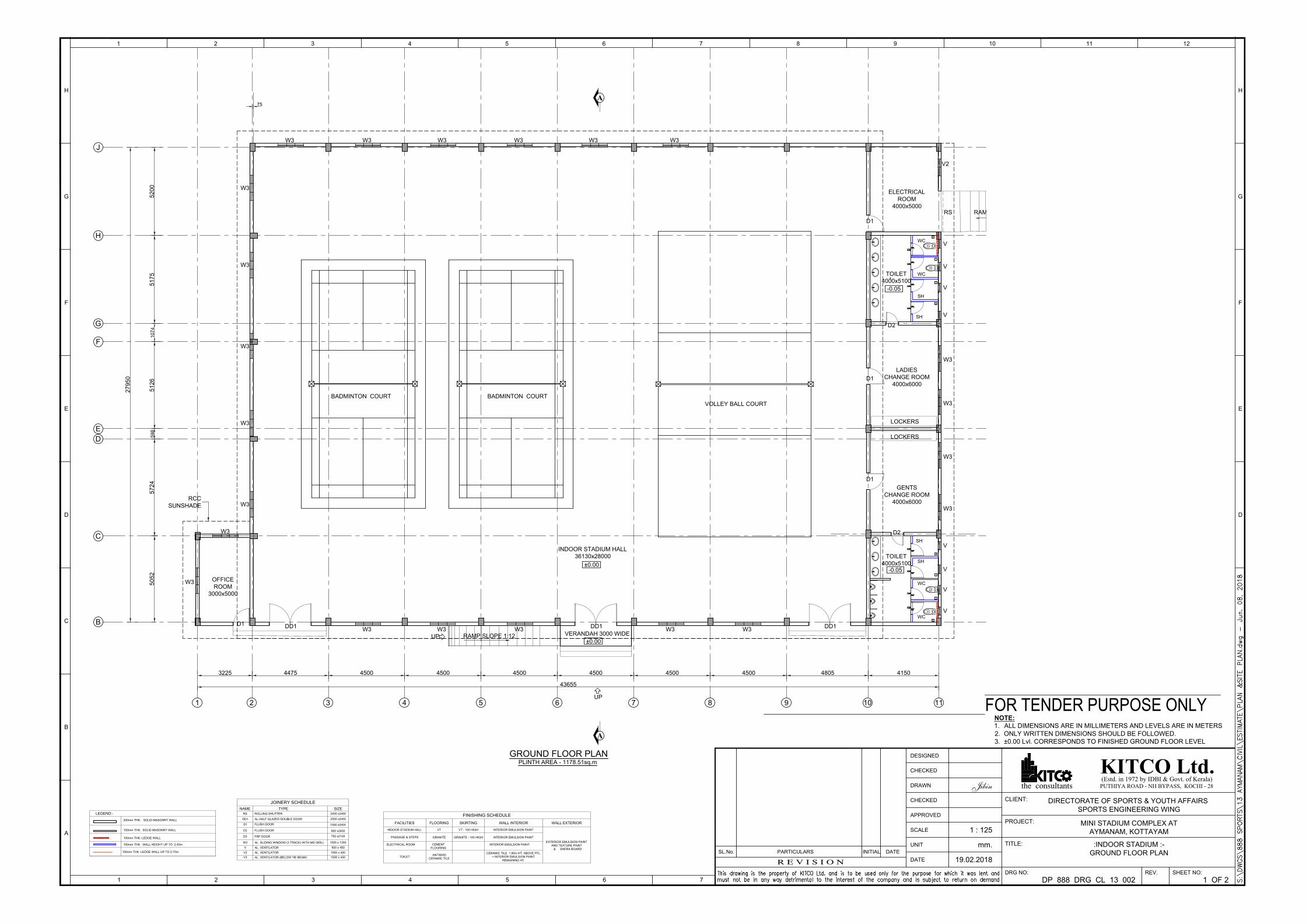
1 2 3 4 5 6 7 8 9 10 11
B
C
D
5052
5724
5126
5175
27950
3225 4475 4500 4500 4500 4500 4500 4500 4805 4150
43655
J
F
G
5200
75
H
1074
598
E
WC
SH
SH
WC
SH
D2
WC
SH
WC
D2
D1
D1
GENTS
CHANGE ROOM
4000x6000
W3
W3
W3
W3
LADIES
CHANGE ROOM
4000x6000
OFFICE
ROOM
3000x5000
W3
D1
W3
DD1
TOILET
4000x5100
V
V
V
V
V
V
V
V
VERANDAH 3000 WIDE
BADMINTON COURT BADMINTON COURT
VOLLEY BALL COURT
INDOOR STADIUM HALL
36130x28000
±0.00
±0.00
-0.05
TOILET
4000x5100
-0.05
DD1 DD1
W3W3W3W3W3
W3 W3 W3 W3 W3W3
W3
W3
W3
W3
W3
GROUND FLOOR PLAN
PLINTH AREA - 1178.51sq.m
RAMP SLOPE 1:12
UP
RCC
SUNSHADE
A
A
LOCKERS
LOCKERS
D1
ELECTRICAL
ROOM
4000x5000
RAMP 1:10 SLOPERS
V2
UP
100mm THK. SOLID MASONRY WALL
100mm THK. WALL HEIGHT UP TO 2.40m
100mm THK. LEDGE WALL
200mm THK. SOLID MASONRY WALL
100mm THK. LEDGE WALL UP TO 0.75m
LEGEND:-
JOINERY SCHEDULE
NAME TYPE SIZE
D2 FLUSH DOOR
D3 FRP DOOR
900 x2400
750 x2100
V AL. VENTILATOR 500 x 450
V2 AL. VENTILATOR 1000 x 450
DD1 AL.HALF GLAZED DOUBLE DOOR 2500 x2400
D1 FLUSH DOOR
1000 x2400
W3 AL. SLIDING WINDOW (3 TRACK) WITH MS GRILL 1500 x 1350
V3 AL. VENTILATOR (BELOW TIE BEAM) 1500 x 450
RS ROLLING SHUTTER 2400 x2400
FINISHING SCHEDULE
FACILITIES FLOORING SKIRTING WALL INTERIOR WALL EXTERIOR
INDOOR STADIUM HALL VT VT - 100 HIGH INTERIOR EMULSION PAINT
EXTERIOR EMULSION PAINT
AND TEXTURE PAINT
& SHERA BOARD
PASSAGE & STEPS GRANITE GRANITE - 100 HIGH INTERIOR EMULSION PAINT
TOILET
ANTISKID
CERAMIC TILE
CERAMIC TILE 1.80m HT. ABOVE FFL.
+ INTERIOR EMULSION PAINT
REMAINING HT.
ELECTRICAL ROOM INTERIOR EMULSION PAINTCEMENT
FLOORING
NOTE:
1. ALL DIMENSIONS ARE IN MILLIMETERS AND LEVELS ARE IN METERS
2. ONLY WRITTEN DIMENSIONS SHOULD BE FOLLOWED.
3. ±0.00 Lvl. CORRESPONDS TO FINISHED GROUND FLOOR LEVEL
3 4
A
B
1 2
C
H
F
E
G
D
4321 65 121110987
D
E
F
H
G
5 6
SL.No.
R E V I S I O N
PARTICULARS DATEINITIAL
7
DESIGNED
CHECKED
DATE
UNIT
APPROVED
CHECKED
SCALE
DRAWN
(Estd. in 1972 by IDBI & Govt. of Kerala)KITCO Ltd.PUTHIYA ROAD - NH BYPASS, KOCHI - 28the consultants
DRG NO:
TITLE:
PROJECT:
CLIENT:
SHEET NO:REV.
DIRECTORATE OF SPORTS & YOUTH AFFAIRS
SPORTS ENGINEERING WING
MINI STADIUM COMPLEX AT
AYMANAM, KOTTAYAM
:INDOOR STADIUM :-
GROUND FLOOR PLAN
DP 888 DRG CL 13 002 1 OF 2
19.02.2018
mm.
1 : 125
Jibin
FOR TENDER PURPOSE ONLY
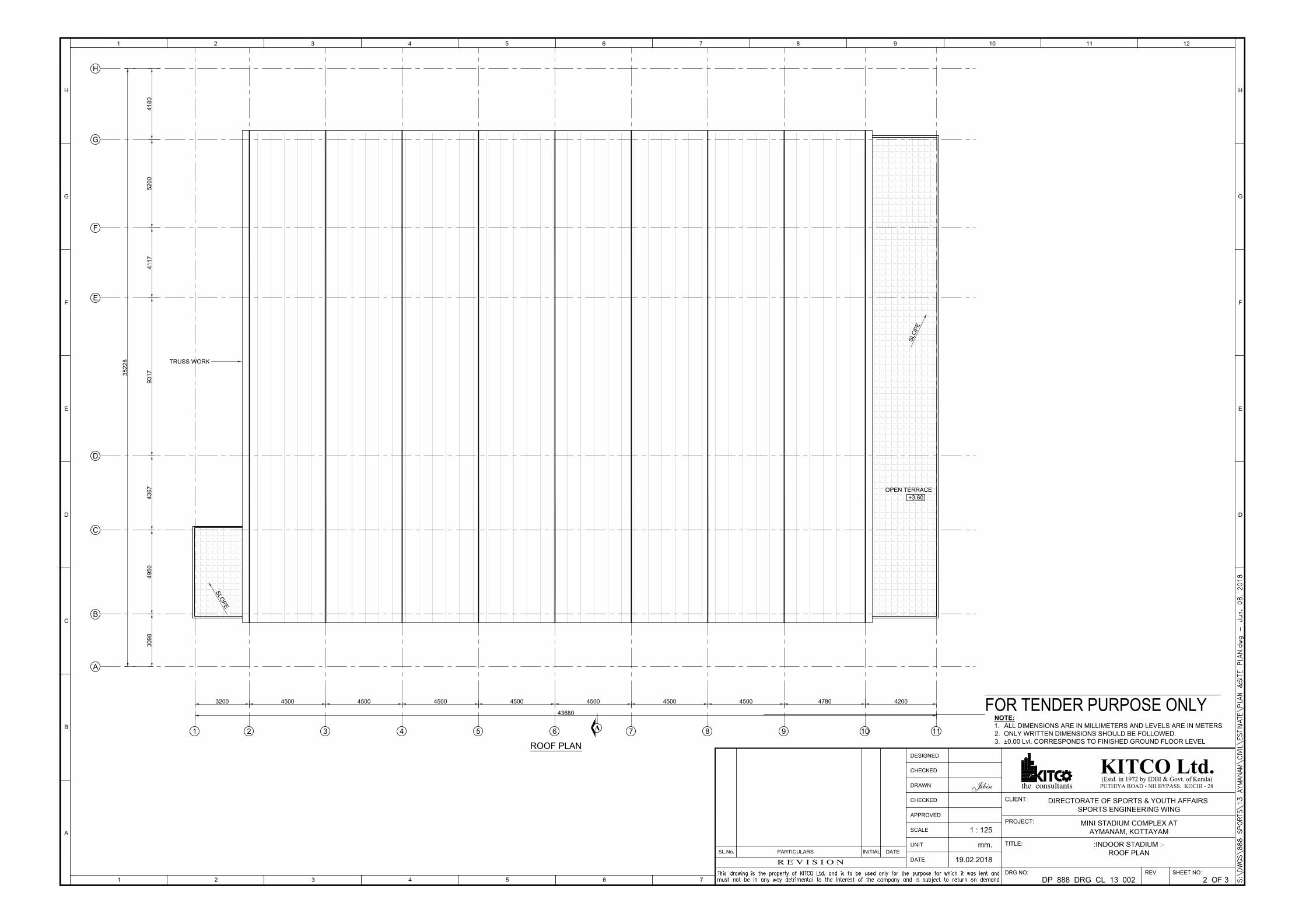
ROOF PLAN
TRUSS WORK
A1 2 3 4 5 6 7 8 9 10 11
A
B
C
D
E
30
98
49
50
43
67
93
17
41
17
35
22
8
3200 4500 4500 4500 4500 4500 4500 4500 4780 4200
43680
H
41
80
F
G
52
00
OPEN TERRACE
+3.60
S
L
O
P
E
S
L
O
P
E
3 4
A
B
1 2
C
H
F
E
G
D
4321 65 121110987
D
E
F
H
G
5 6
SL.No.
R E V I S I O N
PARTICULARS DATEINITIAL
7
DESIGNED
CHECKED
DATE
UNIT
APPROVED
CHECKED
SCALE
DRAWN
(Estd. in 1972 by IDBI & Govt. of Kerala)KITCO Ltd.PUTHIYA ROAD - NH BYPASS, KOCHI - 28the consultants
DRG NO:
TITLE:
PROJECT:
CLIENT:
SHEET NO:REV.
DIRECTORATE OF SPORTS & YOUTH AFFAIRS
SPORTS ENGINEERING WING
MINI STADIUM COMPLEX AT
AYMANAM, KOTTAYAM
:INDOOR STADIUM :-
ROOF PLAN
DP 888 DRG CL 13 002 2 OF 3
19.02.2018
mm.
1 : 125
Jibin
FOR TENDER PURPOSE ONLY
NOTE:
1. ALL DIMENSIONS ARE IN MILLIMETERS AND LEVELS ARE IN METERS
2. ONLY WRITTEN DIMENSIONS SHOULD BE FOLLOWED.
3. ±0.00 Lvl. CORRESPONDS TO FINISHED GROUND FLOOR LEVEL
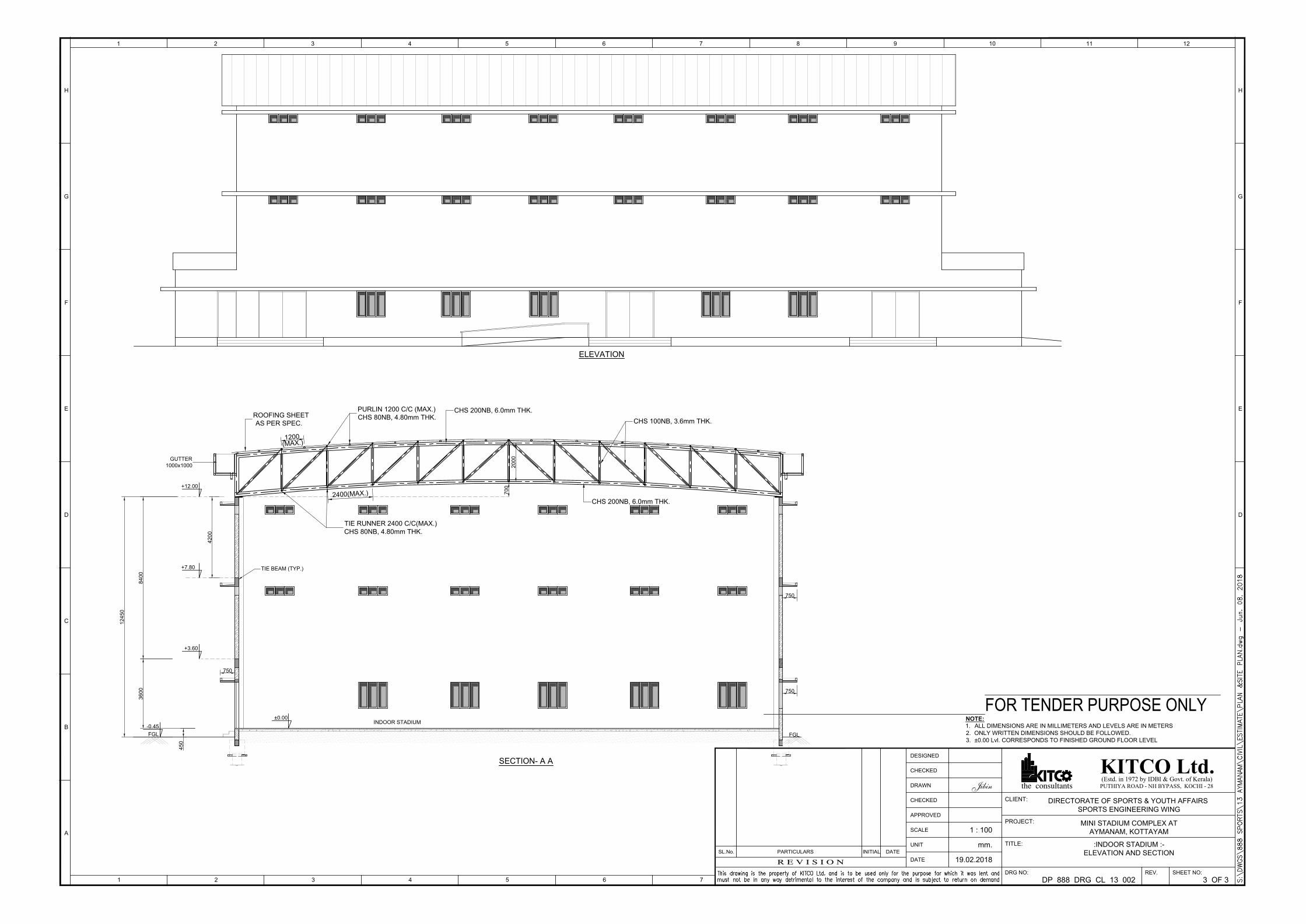
ELEVATION
42
00
±0.00
+3.60
+12.00
45
0
36
00
84
00
12
45
0
750
FGL
-0.45
750
SECTION- A A
INDOOR STADIUM
+7.80
FGL
750
TIE BEAM (TYP.)
GUTTER
1000x1000
PURLIN 1200 C/C (MAX.)
CHS 80NB, 4.80mm THK.
CHS 200NB, 6.0mm THK.
ROOFING SHEET
AS PER SPEC.
TIE RUNNER 2400 C/C(MAX.)
CHS 80NB, 4.80mm THK.
70
0
20
00
CHS 100NB, 3.6mm THK.
CHS 200NB, 6.0mm THK.
1200
(MA
X.)
2400(MA
X.)
3 4
A
B
1 2
C
H
F
E
G
D
4321 65 121110987
D
E
F
H
G
5 6
SL.No.
R E V I S I O N
PARTICULARS DATEINITIAL
7
DESIGNED
CHECKED
DATE
UNIT
APPROVED
CHECKED
SCALE
DRAWN
(Estd. in 1972 by IDBI & Govt. of Kerala)KITCO Ltd.PUTHIYA ROAD - NH BYPASS, KOCHI - 28the consultants
DRG NO:
TITLE:
PROJECT:
CLIENT:
SHEET NO:REV.
DIRECTORATE OF SPORTS & YOUTH AFFAIRS
SPORTS ENGINEERING WING
MINI STADIUM COMPLEX AT
AYMANAM, KOTTAYAM
:INDOOR STADIUM :-
ELEVATION AND SECTION
DP 888 DRG CL 13 002 3 OF 3
19.02.2018
mm.
1 : 100
Jibin
FOR TENDER PURPOSE ONLY
NOTE:
1. ALL DIMENSIONS ARE IN MILLIMETERS AND LEVELS ARE IN METERS
2. ONLY WRITTEN DIMENSIONS SHOULD BE FOLLOWED.
3. ±0.00 Lvl. CORRESPONDS TO FINISHED GROUND FLOOR LEVEL
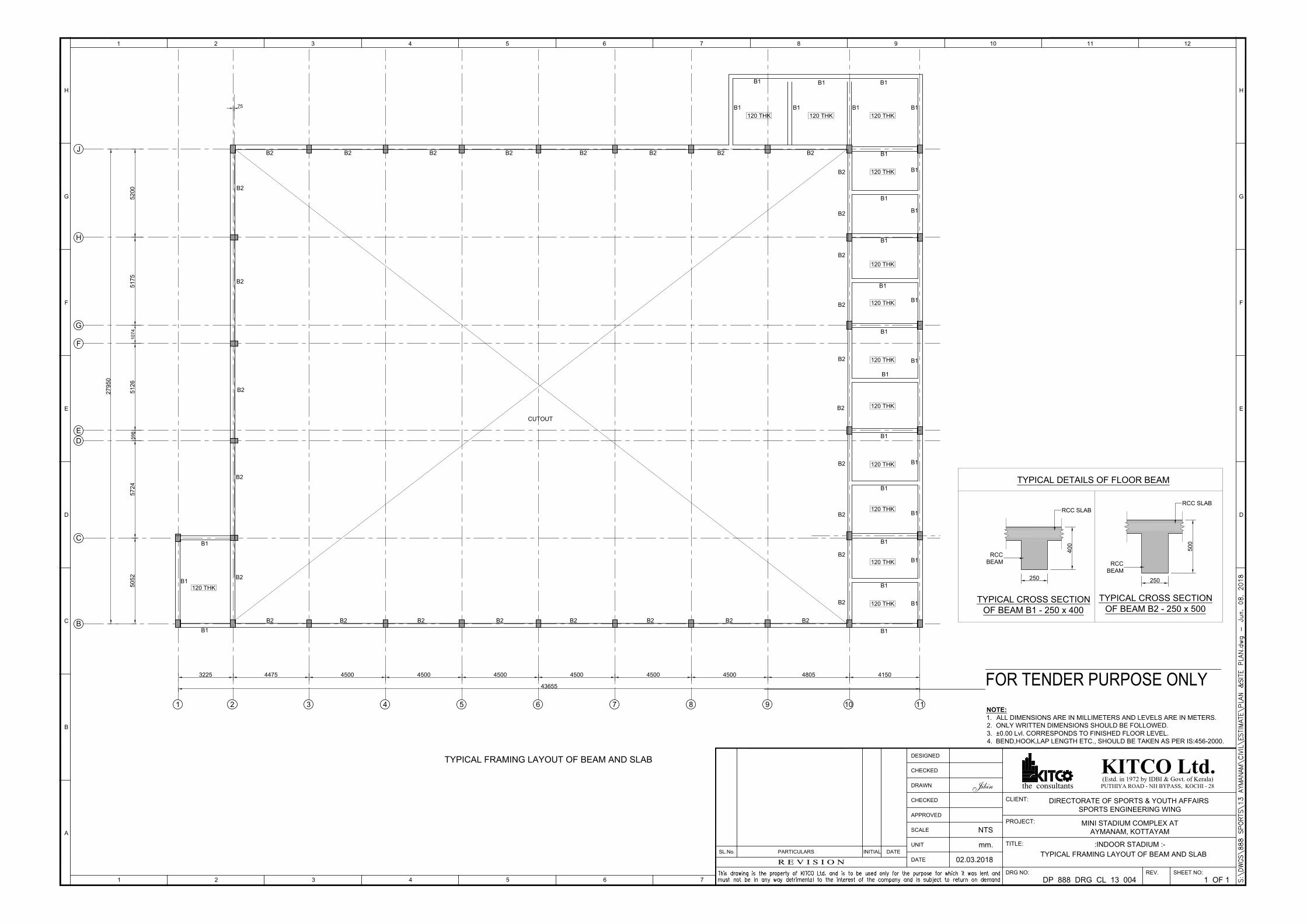
1 2 3 4 5 6 7 8 9 10 11
B
C
D
50
52
57
24
51
26
51
75
27
95
0
3225 4475 4500 4500 4500 4500 4500 4500 4805 4150
43655
J
F
G
52
00
75
H
10
74
59
8
E
TYPICAL FRAMING LAYOUT OF BEAM AND SLAB
120 THK
120 THK
120 THK
120 THK
120 THK
120 THK
120 THK120 THK120 THK
CUTOUT
B1
B1
B1
B1
B1
B1
B1
B1
B1
B1
B1
B1B1B1
B1
B1 B1
B2 B2 B2 B2 B2 B2 B2 B2
B2
B2
B2
B2
B2B2B2B2B2B2B2B2
B2
B2
B2
B2
B2
B1
B1
B1
B1
B2
B1
B2
B1
B2
120 THK
120 THK
B1
120 THK
B1
B1
B2
B1
B2
120 THK
B1
B2
B1
250
40
0
RCC SLAB
RCC
BEAM
TYPICAL CROSS SECTION
OF BEAM B1 - 250 x 400
250
50
0
RCC SLAB
RCC
BEAM
TYPICAL CROSS SECTION
OF BEAM B2 - 250 x 500
TYPICAL DETAILS OF FLOOR BEAM
3 4
A
B
1 2
C
H
F
E
G
D
4321 65 121110987
D
E
F
H
G
5 6
SL.No.
R E V I S I O N
PARTICULARS DATEINITIAL
7
DESIGNED
CHECKED
DATE
UNIT
APPROVED
CHECKED
SCALE
DRAWN
(Estd. in 1972 by IDBI & Govt. of Kerala)KITCO Ltd.PUTHIYA ROAD - NH BYPASS, KOCHI - 28the consultants
DRG NO:
TITLE:
PROJECT:
CLIENT:
SHEET NO:REV.
DIRECTORATE OF SPORTS & YOUTH AFFAIRS
SPORTS ENGINEERING WING
MINI STADIUM COMPLEX AT
AYMANAM, KOTTAYAM
:INDOOR STADIUM :-
TYPICAL FRAMING LAYOUT OF BEAM AND SLAB
DP 888 DRG CL 13 004 1 OF 1
02.03.2018
mm.
NTS
Jibin
FOR TENDER PURPOSE ONLY
NOTE:
1. ALL DIMENSIONS ARE IN MILLIMETERS AND LEVELS ARE IN METERS.
2. ONLY WRITTEN DIMENSIONS SHOULD BE FOLLOWED.
3. ±0.00 Lvl. CORRESPONDS TO FINISHED FLOOR LEVEL.
4. BEND,HOOK,LAP LENGTH ETC., SHOULD BE TAKEN AS PER IS:456-2000.
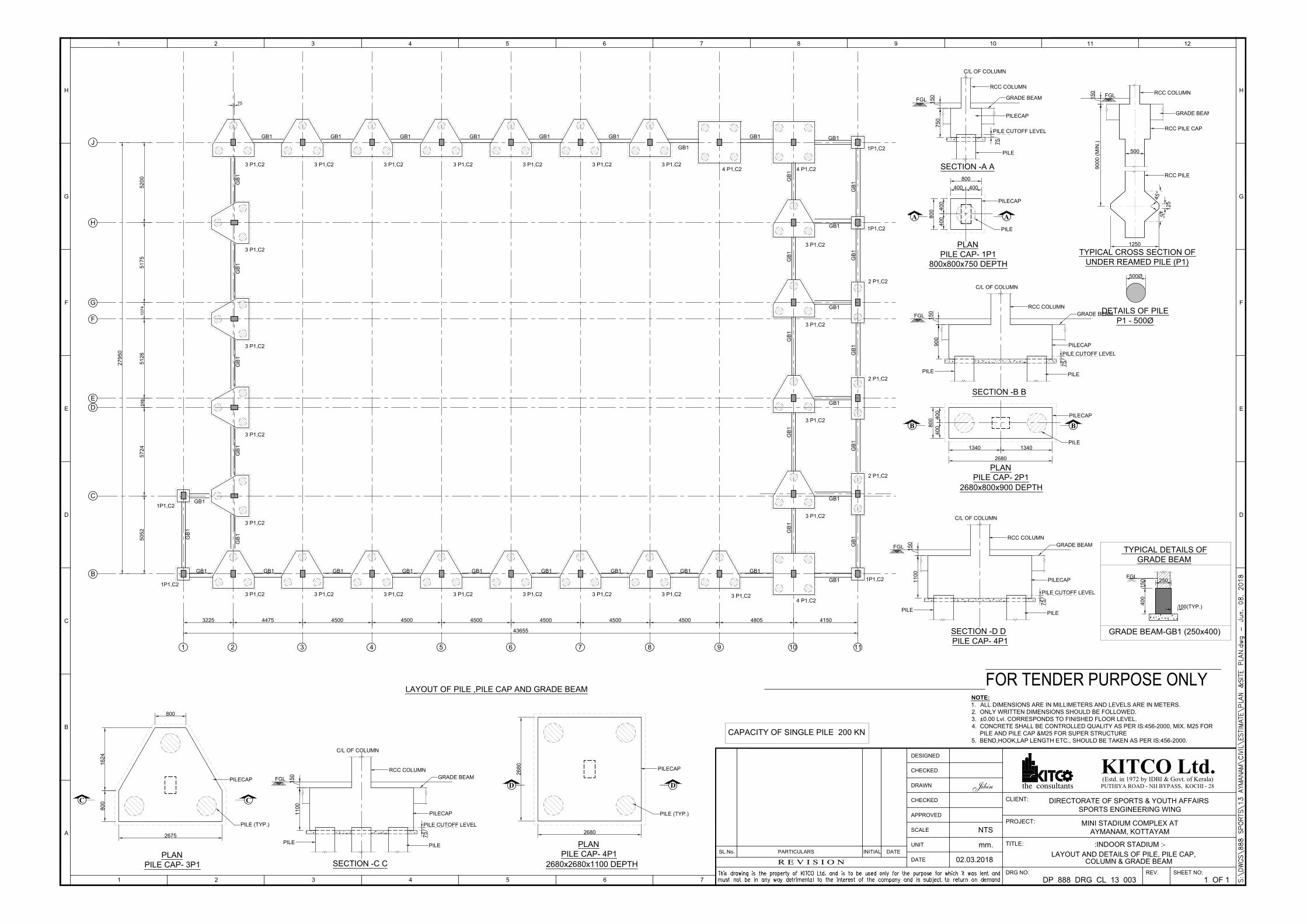
1 2 3 4 5 6 7 8 9 10 11
B
C
D
5052
5724
5126
5175
27950
3225 4475 4500 4500 4500 4500 4500 4500 4805 4150
43655
J
F
G
5200
75
H
1074
598
E
1P1,C2
2 P1,C2
2 P1,C2
2 P1,C2
4 P1,C2
1P1,C2
1P1,C2
3 P1,C2 3 P1,C2 3 P1,C2 3 P1,C2 3 P1,C2 3 P1,C2 3 P1,C2
3 P1,C2
3 P1,C2
3 P1,C2
3 P1,C2
3 P1,C2
1P1,C2
1P1,C2
3 P1,C2 3 P1,C2 3 P1,C2 3 P1,C2 3 P1,C2 3 P1,C2
3 P1,C2
3 P1,C2
3 P1,C2
3 P1,C2
3 P1,C2
4 P1,C2
LAYOUT OF PILE ,PILE CAP AND GRADE BEAM
GB
1G
B1
GB
1G
B1
GB
1
GB1
GB1 GB1 GB1 GB1 GB1 GB1 GB1 GB1 GB1
GB1 GB1 GB1 GB1 GB1 GB1
GB1
GB1
GB
1G
B1
GB
1G
B1
GB
1
GB
1G
B1
GB
1G
B1
GB
1
GB1
GB
1
GB1
GB1
GB1
GB1
4 P1,C2
GB1
PILE CUTOFF LEVEL
75
FGL
PILECAP
RCC COLUMN
PLAN
PILE CAP- 1P1
400 400
800
400
400
800
A A
SECTION -A A
750
PILE
150
PILECAP
PILE
C/L OF COLUMN
800x800x750 DEPTH
GRADE BEAM
500
4
5
°
12
5
9000 (M
IN
.)
RCC COLUMN
RCC PILE CAP
RCC PILE
1250
4
5
°
TYPICAL CROSS SECTION OF
UNDER REAMED PILE (P1)
500Ø
DETAILS OF PILE
P1 - 500Ø
FGL
150
GRADE BEAM
PLAN
PILE CAP- 2P1
2680x800x900 DEPTH
FGL
PILECAP
RCC COLUMN
SECTION -B B
90
0
15
0
PILE CUTOFF LEVEL
75
PILE
PILE
PILECAP
PILE
B B
C/L OF COLUMN
40
04
00
80
0
1340 1340
2680
GRADE BEAM
2675
800
PILE (TYP.)
PILECAP
PLAN
PILE CAP- 3P1
C C
80
01
62
4
FGL
PILECAP
RCC COLUMN
SECTION -C C
11
00
15
0
PILE CUTOFF LEVEL
75
PILE
PILE
C/L OF COLUMN
GRADE BEAM
PLAN
PILE CAP- 4P1
2680
2680
PILE (TYP.)
PILECAP
2680x2680x1100 DEPTH
DD
FGL
PILECAP
RCC COLUMN
SECTION -D D
1100
150
PILE CUTOFF LEVEL
75
PILE
PILE
C/L OF COLUMN
PILE CAP- 4P1
GRADE BEAM
40
01
50
100(TYP.)
TYPICAL DETAILS OF
GRADE BEAM
GRADE BEAM-GB1 (250x400)
250
FGL
3 4
A
B
1 2
C
H
F
E
G
D
4321 65 121110987
D
E
F
H
G
5 6
SL.No.
R E V I S I O N
PARTICULARS DATEINITIAL
7
DESIGNED
CHECKED
DATE
UNIT
APPROVED
CHECKED
SCALE
DRAWN
(Estd. in 1972 by IDBI & Govt. of Kerala)KITCO Ltd.PUTHIYA ROAD - NH BYPASS, KOCHI - 28the consultants
DRG NO:
TITLE:
PROJECT:
CLIENT:
SHEET NO:REV.
DIRECTORATE OF SPORTS & YOUTH AFFAIRS
SPORTS ENGINEERING WING
MINI STADIUM COMPLEX AT
AYMANAM, KOTTAYAM
:INDOOR STADIUM :-
LAYOUT AND DETAILS OF PILE, PILE CAP,
COLUMN & GRADE BEAM
DP 888 DRG CL 13 003 1 OF 1
02.03.2018
mm.
NTS
Jibin
FOR TENDER PURPOSE ONLY
NOTE:
1. ALL DIMENSIONS ARE IN MILLIMETERS AND LEVELS ARE IN METERS.
2. ONLY WRITTEN DIMENSIONS SHOULD BE FOLLOWED.
3. ±0.00 Lvl. CORRESPONDS TO FINISHED FLOOR LEVEL.
4. CONCRETE SHALL BE CONTROLLED QUALITY AS PER IS:456-2000, MIX. M25 FOR
PILE AND PILE CAP &M25 FOR SUPER STRUCTURE
5. BEND,HOOK,LAP LENGTH ETC., SHOULD BE TAKEN AS PER IS:456-2000.
CAPACITY OF SINGLE PILE 200 KN
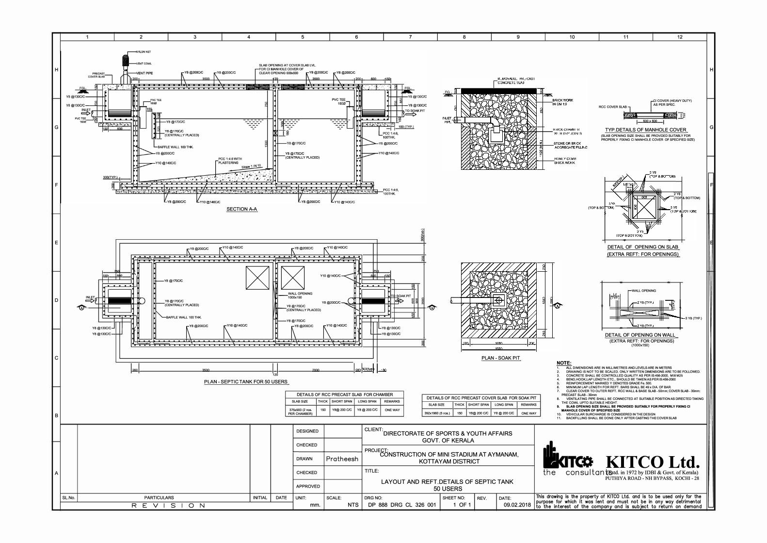
H
G
F
E
D
C
B
A
SL.No.
I.en,
.
INLET I
s lo
. . . .
c::::::::>Y I
i6, I
I
Y8@130C/CJ
YB@130C/C-
'
R
2
�
)
. -. . .
3 4
SECTION A-A
I\ YB @200C/C r(10@140C/C
_ _ _ _ _ .... _ _ _ .a.--------
,--YB @170C/C
�
Y8@170C/C >---(CENTRALLY PLACED)
�AFFLE WALL 100 THK.
r
8@200C/C �
0@140C/C
_ _ _ _ _ _ _ _ _ _ _ _ _ ... _, _ _ _ _ _ _ _ _-----------------------
3500
5
f\ YB @200C/C r(10 @140C/C
--"'-----""-'---- -
�
Y10 @140C/C-<
_ WALL OPENING 1000x150
YB @200C/C - ( YB @170C/C
-(CENTRALLY PLACED) ""'
-Y8@170C/C
R
B@200C/C �
0@140C/C
--- ... ... ... ... ... -,._ ---- - - - - - - - - - - - - - - -
u 2000
6
7'
,n
. . . .
7
,m
. � ·I I T SOAK PIT
� "' ·I I
ij
I
LY8@130C/C
-f-Y8@130C/C
8
i
I� ! .-...
9
PLAN · SOAK PIT
10
NOTE:
11 12
RCC COVER SLAB
I COVER (HEAVY DLITY) AS PER SPEC.
60Ch 600
TYP.DETAILS OF MANHOLE COVER (SLAB OPENING SIZE SHALL BE PROVIDED SUITABLY FOR PROPERLY FIXING Cl MANHOLE COVER OF SPECIFIED SIZE)
(TOP&BO
2 Y8 (TOP & BOTIOM)
DETAIL OF OPENING ON SLAB (EXTRA REFT: FOR OPENINGS)
WALL OPENING Ld
(TYP.)
DETAIL OF OPENING ON WALL (EXTRA REFT: FOR OPENINGS)
(1000x150)
3 YB (TYP.)
T.°""ALL DIMENSIONS ARE IN MILLIMETRES AND LEVELS ARE IN METERS 2. DRAWING IS NOT TO BE SCALED. ONLY WRITTEN DIMENSIONS ARE TO BE FOLLOWED. 3. CONCRETE SHALL BE CONTROLLED QUALITY AS PER IS:456-2000, MIX M25
PLAN - SEPTIC TANK FOR 50 USERS 4. BEND,HOOK,LAP LENGTH ETC., SHOULD BE TAKEN AS PER IS:456-2000 5. REINFORCEMENT MARKED Y DENOTES GRADE Fe. 500.
PARTICULARS
E V S 0 INITIAL DATE
N
DETAILS OF RCC PRECAST SLAB FOR CHAMBER
SLAB SIZE I THICK I SHORT SPAN I LONG SPAN I REMARKS DETAILS OF RCC PRECAST COVER SLAB FOR SOAK PIT
SLAB SIZE I THICK I SHORT SPAN I LONG SPAN I REMARKS 375x900 (2 nos. I 150 I YB@ 200 C/C I YB@ 200 C/C I ONE WAY
PER CHAMBER) 392x1960 (5 nos.) I 150 I YB@ 200 C/C I YB@ 200 C/C I ONE WAY
DESIGNED
CHECKED
CLIENT:DIRECTORATE OF SPORTS & YOUTH AFFAIRS GOVT. OF KERALA
1-------+------< PROJECT: DRAWN
CHECKED
APPROVED
Pratheesh CONSTRUCTION OF MINI STADIUM AT AYMANAM,
KOTTAYAM DISTRICT
TITLE:
LAYOUT AND REFT.DETAILS OF SEPTIC TANK
50 USERS
6. MINIMUM LAP LENGTH FOR REFT. BARS SHALL BE 49 x D1A. OF BAR. 7. CLEAR COVER TO OUTER REFT. RCC WALL & BASE SLAB - 50mm; COVER SLAB - 30mm:
PRECAST SLAB - 30mm 8. VENTILATING PIPE SHALL BE CONNECTED AT SUITABLE POSITION AS DIRECTED TAKING
THE COWL UPTO SUITABLE HEIGHT 9. SLAB OPENING SIZE SHALL BE PROVIDED SUITABLY FOR PROPERLY FIXING Cl
MANHOLE COVER OF SPECIFIED SIZE
10 VEHICULAR SURCHARGE IS CONSIDERED IN THE DESIGN 11. BACKFILLING SHALL BE DONE ONLY AFTER CASTING THE COVER SLAB
KITCO Ltd. the con SU I tan ts;;td. in 1972 by IDBI & Govt. ofKerala)
PUTHIY A ROAD - NH BYPASS, KOCHI - 28
UNIT: SCALE: DRG NO:
mm. NTS DP 888 DRG CL 326 001
SHEET NO: REV.
1 OF 1
DATE:
09.02.2018
This drawing is the property of KITCO Ltd. and is to be used only for the purpose for which it was lent and must not be in any way detrimental to the interest of the com on and is sub· ct to return on demand
H
G