Embed Size (px)
Citation preview
..._ --->< , w UJ 0
Consultancy report
Final report - IMSTAND(:) -·
Open Information Interchange study on image/graphics
standards
Pira lnlllrnalloMI RegisrMd ofb: Randalls Roact LHtherhead. Surrey KT22 7RU. Uruted Kingdom
Telephone: L.eatherhead (code UK +44) 0372 376161 Telex: 929810 Fax: (code UK +44) 0372 386556 RegtsrMd f1Uff'll»r: 252163 England (Lmted liability)
Conclusions Markets and user issues for image interchange The relationships of the graphic standards The graphic standards Vector or geometric data
CFF2 CGM CGRM DDES2-IADD DXF GGCA GKS GKS-30 IGES PHIGS SET PDES/STEP VDAFS
Raster graphics DOES Fax groups 3 & 4 Fractal Transfonn coding GIF IPI-IIF JBIG JPEG and JFIF Photo-CO TIFF TIFFnT
Document/metafile Acrobat (Carousel) Hynme IPTC liM ODA OPI PIMIPIL Postscript (Levels 1 ,2) Quicklime SGML SGML and images SPDL
Miscellaneous ACR-NEMA CGI Colour spaces TWAIN
Pre-press vendor specific formats
1 3
15 17 17 17 18 20 21 22 23 24 25 26 28 29 30 31 31 31 33 34 35 36 38 38 40 45 47 48 48 51 52 52 55 57 58 60 61 62 64 65 65 67 68 70 70

Appendix 1 73 Summary of standards for image compression 75 Coding Scheme 83 Transform Coding Scheme 85 Comparison of different compression methods 92
Appendix 2 93 Ust of participants and contributors 94
•
•
•
Conclusions The measure of success for a graphic standard can be established on three levels.
1 The availability of systems which confonn to its specification 2 The degree to which a standard is regularly employed in
commercial applications 3 The establishment of a common perceptual framework for further
activities, eg the concept of programmer portability as well as actual infonnation interchange.
The expert input to the project recognised the following as being factors key to a standards• success which may be influenced beneficially by the Oil Initiative.
• fonnal specification • the availability of rigourous conformance tests • previous agreement, amongst users, on the need for a standard in
a particular application domain • the standard should enable increased openness and offer a
market advantage to product developers • the existence of application profiles for particular market sectors.
The study has revealed that categorising standards by application domain is not satisfactory. It is clear that many standards cross application boundaries. The IPI-IIF standard offers the potential for a widely used, inter-disciplinary, multidimensional format. It promises the ability for transparent data exchange across the boundaries of application specialities.
An integrated vehicle for the transfer of image and non-image related attributes, in their widest sense, does not exist. Current graphic standards development focuses on the image data.
1
fJ
e The process of standards development needs to be accelerated in order to catch and improve incipient de-facto standards. However, taken to its logical end this results in a paradoxical situation. It is recognised that standardising current practice is no longer timely enough (see ODES) but anticipating future practice is error prone.
Due to ambiguities in the drafting of standards people not directly involved with their development may interpret them differently. As standards become more complex so the danger of misinterpretation becomes greater. It is also noted that there is a need for the harmonisation of data modelling languages.
Conformance testing is often inadequate. For example SPDL is an open ended format, therefore, H is impossible to test an interpreter exhaustively against every possible production. Often the conformance statements in standards are already very poor often due to the difficulty adequately to describe conformance in a way that allows useful testing.
Users do not have the standards they require because they are often not vociferous enough. FrequenUy there is seen to be a conflict of interest between a proprietary standard, developed by a vendor group, and the requirements of the end users. The conflict, either real or imagined~ relates to issues of openness and information interchange. The commercial value of official standards is only understood by a small minority of end users and the process of standards development, due to the very real cost of involvement, discourages their participation.
2
•
•
•
Markets and user issues for image interchange The study has revealed that categorising standards by application domain is not satisfactory. It is clear that although official standards have been developed with clear1y defined and commercially valuable objectives they have, in many instances, been overtaken by proprietary alternatives.
From the software developers' point of view the commercial desirability of •owning• a de facto standard is obvious. From the end users viewpoint, whatever the application domain, fitness for purpose is the goveming factor.
Where computer graphics are related to commercial enterprise directly, productivity is the single most important factor. It was productivity which supported dedicated, high cost, specialised equipment in publishing and pre-press combined with the fact that their end product was a universal format - an image on film. System interconnectivity was of secondary importance. Equally in highly specialised areas, such as scientific and medical analysis, the need to translate data, outside the locally defined function, was not of sufficient importance to influence standards development. It should be recognised that in both engineering and medicine they are equally concemed with image data, meaning values which may be used to render an image (eg a set of x-ray attenuation values calculated from a set of measurements made by a CT machine), as well as image data which has been obtained by
digitising a picture (ega radiograph).
Over the last four years there has been a dramatic increase in the need for graphic infonnation interchange. Where official standards have tried to address this need, the ISOITC1301WG2 ITS series is a case in point, they have failed to provide a practical working solution. The reason for this failure is a combination of the productivity limitations of the standard and the speed with which solutions have been provided by proprietary altematives - notably TIFF combined with PostScript.
3
,.
•
Each of the specialist application domains have developed standards that, with the exception of CGM, have largely addressed the need to transfer infonnation within their own working environments. A good example of this requirement is demonstrated by the data communication needs of the folding box designers and manufacturers.
With the introduction of computer aided draughting systems for the design of folding boxes and automated CNC-controlled dieboard cutting machines (lasers and jigsaws) for their construction, communication protocols have been developed to meet the special requirements of both sides (DDES2 & CFF2).
In almost all cases folding boxes are designed by sample makers inside printing companies. The actual manufacture of the dieboards, needed for punching the carton blanks, is completed by independent, highly specialized trade shops.
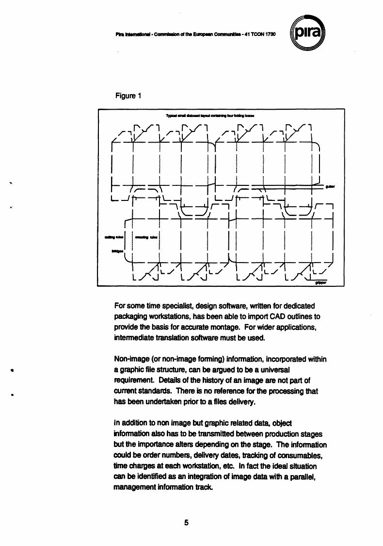
Data exchanged between the designers and the dieboard manufacturers must not only include the shape of a certain package, but a host of other details which include; the number of stations; types of cutting and creasing rules; positions; widths of bridges; size of dieboard; gutter width and much more (see Figure 1).
The primary function of the cutter guide graphic, shown in Figure 1, is to provide construction data for the manufacture of the guide itself. It does, however, also represent a precise definition of the area of a pack. As such it is required by the art studio which will be creating the pack decoration. The outline provides the basis for layout and design assembly. Without direct information interchange the dimensions must be translated by the graphic designer. At this stage there is an obvious duplication of effort as well as a likely point for the introduction of errors.
4
...
•
•
--·~ciU.~COmmunlloo·41TCON1730 6 Figure 1
For some time specialist, design software, written for dedicated packaging workstations, has been able to import CAD ouUines to provide the basis for accurate montage. For wider applications, intermediate translation software must be used.
Non-image (or non-image forming) information, incorporated within a graphic file structure, can be argued to be a universal requirement. Details of the history of an image are not part of current standards. There is no reference for the processing that has been undertaken prior to a files delivery.
In addition to non image but graphic related data, object information also has to be transmitted between production stages but the importance alters depending on the stage. The information could be order numbers, delivery dates, tracking of consumables, time charges at each workstation, etc. In fact the ideal situation can be identified as an integration of image data with a parallel, management information track.
5
•
•.
•
..
In the case of medical imaging, •management infonnation• can be
expanded past the point of a particular image•s chronicle to include:
• a patienfs medical history • details of the examination which produced the image eg equipment
settings and environment • hospital management data eg appointment times, dates and a
progress record of the treatment.
Data compression and increasing computer power reduce the importance of minimal file size. In the event that a single standard is developed for pan-industry applications the inclusion of some redundant infonnation, relative to a specific production function, may be tolerated. This does, however, raise the question of confidentiality and qualifications for access.
In the main graphic file fonnats reflect the structure of a particular software product developers requirements. If the product becomes widely distributed then this proprietary fonnat takes on the additional role as a interchange or transfer medium. There are a great many different file fonnats, in every-day use. each related to combinations of particular software suites and hardware platfonns.
There are two fundamentally different types of computer graphic files:
• Raster or bltmapped • Vector
Raster files describe the colour (and therefore, tone) of every addressable position of a given image - the pixel. Complex pictures are built up by varying the attributes of the pixels within the image. The total image is stored as a reference grid, or map, of each pixel•s value - hence the tenn bltmapped image. The size of raster files corresponds directly to the number of addressable positions and colours in the image. The actual size of the image, when reproduced, depends entirely on the resolution of the viewing or printing device.
6
Vector files, on the other hand, contain no infonnation about specific dots. Instead, vector files are a list of mathematical descriptions of graphic objects used to create an image. They are the building components of the image rather than a representation of the finished graphic. In its simplest fonn, a line, a vector file contains the data as to the line's start position, its length, the direction it travels and its weight and colour. To become an image the vector must be drawn by an application. Because the image is redrawn, from fundamental instructions within the file, the resolution of the final result is dependent on the output, or viewing device. Vector images are not linked to any particular piece of hardware; it is up to the application software to interpret the instructions correctly.
7
•
P1ra lrHmlllloMI· Cormlllllon ollhe E....-n Cornmunllle • 41 TCON 1730
Table 1
Fomw Raster Vector Owner
BMP ., Micromft Wmdows Bi1map - Micromft Corporation
COR I " Coral Draw fonnat- Coral Systems Corpomtion
CUT I ., Dr Halo paint eoftwant - Madia Cybernetics
OAW " Migrografx Designer
DXJ ! " AutDCAD dmwing exchange fonnat
EPI((~ ; , " Encapsulatacl PostScript - Alllys Corp/Aic:tua/ Adobe
GEM I ., GEM metatle fonnat • Digital R..arch
GIF
' , Graphics lntan:hange Format- CompuServe Inc
HPO&. " Hewlett Packard Graphics Language
IMG ., GEM Image Fie fonnat • Digital Reaearch
MSP , Microaoft W11dows Paint • Microeoft Corporation
PCL(HPQJ ., Hewlett Packard Printllr Command Language
PCX
PIC
PICT
PNTG
SCR
TGA
TIFF
WMF
WPG
., Zloft PC PaWttbrush • ZSoft Corpomtion
" Lotus 1·2-3 graphic flea - Lotus
., ., Apple Compulilr Inc
., MacPailt • Apple Computer Inc
., Scnen captan fonnat • Microeoft Corporation
., TARGA format • Truevilion Inc
., Taggld Image Fie Fonnat • AIGIIIMiciOIOft
" ., Wlldows Metafile Fonnat • Micro8oft Corporation
., " WOidPerfect Graphic h fonnat ·WordPerfect Corp
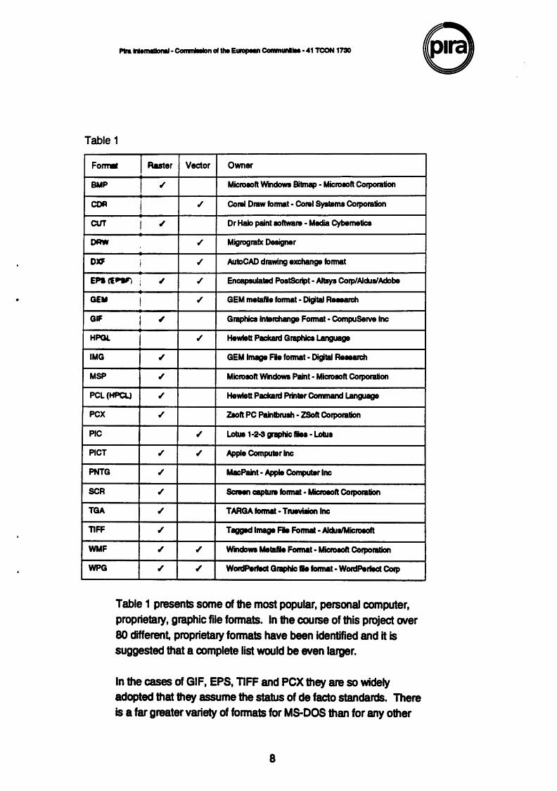
Table 1 presents some of the most popular, personal computer, proprietary, graphic file formats. In the course of this project over 80 different, proprietary formats have been identified and it is suggested that a complete list would be even larger.
In the cases of GIF, EPS, TIFF and PCX they are so widely adopted that they assume the status of de facto standards. There is a far greater variety of formats for M8-DOS than for any other
8
---~ .... ~COINNirli-·41TCON173D 8 operating system and it is common for the fonnat to be identified by its three letter file extension. This can lead to confusion when different fonnats have the same extension - PIC, SCR, DRW and IMG are some examples. In the case of PIC there are at least four alternatives including both raster and vector fonnats. Table 1 refers to the most frequent interpretation of the extension.
Applications which allow the importation of infonnation from other sources use specialist filters which translate the incoming information. They can be considered as a set of rules which have been const~cted to cope with the peculiarities of structure and format for each application covered. The problem with a foced set of rules is that they are valid only as long as the originating software remains unchanged. With the rapid development of software and the frequent issue of new versions, the useful life of input and output filters is relatively short. It is also true that in translating one file structure to another, via a set of fixed rules, the translation suffers due to ambiguities that defy a fixed definition. It is very common for import filters to have limitations in their ability to cope with the full range of functions which are supported in the native format Typical limitations are lack of support for:
• gradient fills and patterns • specific fonts, character spacing and orientation • linked objects, such as text following a curved path • translation of colour data.
In the worst cases •approximations• or •intelligent guesses• are performed by the filter and the result can require more work in the secondary application than if it had generated the graphic in the first place.
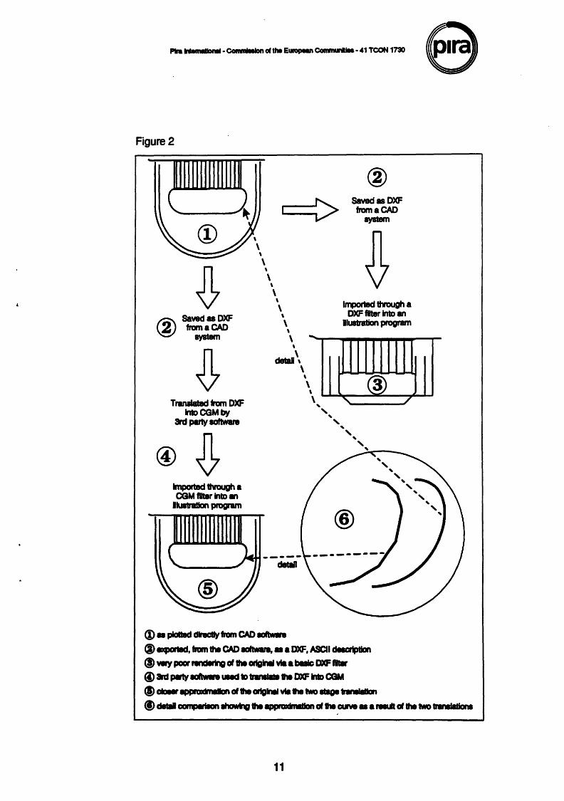
Figure 2 is an illustration of the problems associated with import filters and intermediate translation routines. The original graphic (1) is the handle of a plastic container. The drawing was created in specialist CAD software which was able to produce accurate plots from which construction measurements could be taken. The drawing was saved as a DXF file (2). At this stage the file was processed through two different channels.
9
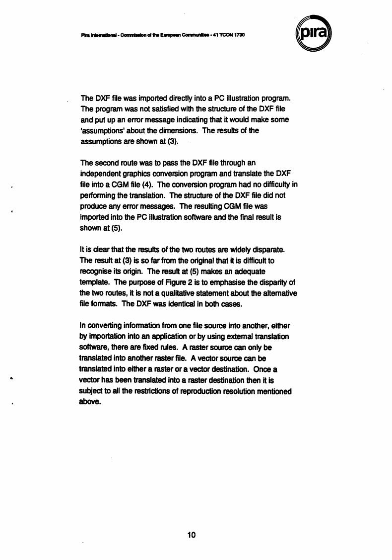
The DXF file was imported directly into a PC illustration program. The program was not satisfied with the structure of the DXF file and put up an error message indicating that it would make some •assumptions• about the dimensions. The results of the assumptions are shown at (3).
The second route was to pass the DXF file through an independent graphics conversion program and translate the DXF file into a CGM file (4). The conversion program had no difficulty in performing the translation. The structure of the DXF file did not produce any error messages. The resulting CGM file was imported into the PC illustration software and the final result is shown at (5).
It is clear that the results of the two routes are widely disparate. The result at (3) is so far from the original that it is difficult to recognise its origin. The result at (5) makes an adequate template. The purpose of Figure 2 is to emphasise the disparity of the two routes, it is not a qualitative statement about the altemative file formats. The DXF was identical in both cases.
In converting information from one file source into another, either by importation into an application or by using extemal translation software, there are fixed rules. A raster source can only be translated into another raster file. A vector source can be
translated into either a raster or a vector destination. Once a vector has been translated into a raster destination then it is subject to all the restrictions of reproduction resolution mentioned above.
10
P1ra IIUmiiiiOMI· Commllllon cl the Europeu Comlftldl.a • 41 TCON 1730
Figure2
\
\
SavedasDXF from a CAD
system
r.i'\ Saved as DXF \.!!!) frarnaCAD
aystem
\
\ \
\
Imported through a DXF filar Into an
Dluatration program \
\ \
detal\ \
--
'
Translated from DXF lntDCGMby
3rd party IOftwar8
Imported through a CGM filter Into an
llultration program
(i) a plall8d dncllyfrom CAD IOftwn
\ \
\ @
' ' ' ' ' ' ' ' ' __;;'--~
(I) 8Xp0118d, tram the CAD IGftwln. a a DXF, ASCII delcrlpllon
®wry poor NndlrtnD of the ortalnll via a bMic I»CF...., (i) 8n:l J*lY IOftwn &ad 1D n._ .. DXF lniD CGM
(I) claelr ~~of lie arlgNI via the two ._.hnllallan
/
@) delllll campMion lhcJwlrv h appraxiltl&llon of .. curve • a ..wt of h two lrWIIIalianl
11
Translation from one system, or graphic, fonnat to another is, at best, a minor delay which involves additional software expense (in pre-press it also involves additional hardware). But, at worst, translation can be the cause of file corruption, loss of data and scaling or colour inconsistencies. The incompatibility of successive versions of the same software is commonplace. Incompatibility of different software translations is inevitable, and has to be one of the strongest arguments for trans-application standards.
The publishing community is increasingly becoming involved in using digital images and has ever growing requirements related to image interchange. The issue of image interchange arises both in the process of publishing and in published products themselves. The publishing process has had a strong electronic component for some time, although increasing demands are continually made; the growth of electronic publishing has increased the demands related to the product.
The process of publishing, being very often a workgroup activity, implies exchange of infonnation, including images, between those involved in the process. This is the case over a wide variety of publishing markets, for instance newspapers, magazines, joumals, book publishing and technical documentation production. The move towards common open system platforms using common applications reinforces the similarity of the requirements these apparently varied markets have .
. The following lists illustrate requirements which exist across a broad spectrum of publishing. However, they are aspirations which it is foolish to isolate in one application domain as they are relevant to the interchange of information, expressed graphically, in whatever context.
12
Image archive/database • incorporate images in databases (comprising text and image
fields) in a standard way. • hardware with storage capacity sufficient to hold large image
databases on a scale not supported by current CD-ROM jukebox systems
• fast image input devices for efficient input of long series of images • ease of retrieval of images held in image archive databases (and
separately from other information stored eg structured text information)
• easy exchange of images between databases (migration support for moving images to slower or offline storage)
• image compression support for reduction of storage space • ability to link databases containing images to other databases • ability to incorporate retrieve and display images in CO-ROMs in a
standard way
Application/user interface • integration of viewer software, database access, printer drivers for
quality hard copy etc. in a standard way • availability of standard viewer application software on a wide
variety of platforms • availability of images at different levels of resolution for final output • support of image compression techniques by application
developers • ease of integration of image handling functionality into applications • adequate user interfaces for retrieval, browsing, selection and
reading of documents with images on screen
Interchange over networks • efficient and easy transfer of images over networks (local and
distributed) eg between an editor's workbench and an image archive
• file transfer of images between different sites without loss of information
• file transfer of images (perhaps incorporated within other data) at a rate sufficient to allow interactive features such as browsing through pages
• ease of transfer of images between platforms
13
P1ra.............,. · CGmm1111on of the EulapeM Comrnunllls • 41 TCON 1730
• image compression support for reduction of transmission times • registration and identification of images • feedback (automated ideally) to suppliers of images
Hypermedia • import multimedia infonnation into hyperdocuments • create hyperlinks between images and other images or text • format having 'placemarkers' for multimedia inserts even if the
multimedia facilities are not fully in place
General • full-text search of images of text pages • resolution independence prior to output. • full support for working in colour and transferring colour images • ease of output of images to standard output devices • output of images captured in colour as black and white • photorealism - rendering of three-dimensional images that are
virtually indistinguishable from photographs • stability of the interchange standards over time
Image archive/database • incorporate images in databases (comprising text and image
fields) in a standard way • hardware with storage capacity sufficient to hold large image
databases on a scale not supported by current CD-ROM jukebox systems
• fast image input devices for efficient input of long series of images • ease of retrieval of images held in image archive databases (and
separately from other infonnation stored eg structured text infonnation)
• easy exchange of images between databases (migration support for moving images to slower or offline storage)
• image compression support for reduction of storage space • ability to link databases containing images to other databases • ability to incorporate retrieve and display images in CO-ROMs in a
standard way
14
- --CGoo-altho e._ COimlunlloo ·41 TCON 1730 e The relationships of the graphic standards
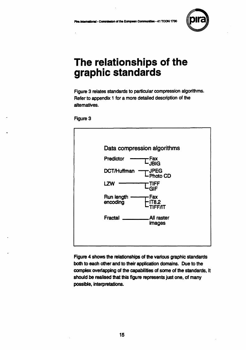
Figure 3 relates standards to particular compression algorithms. Refer to appendix 1 for a more detailed description of the altematives.
Figure 3
Data compression algorithms
Predictor Fax LJBIG
OCT/Huffman -,-JPEG L.Photo CD
LZW c~~~r Run length CFax encoding IT8.2
TIFF/IT
Fractal ____ All raster images
Figure 4 shows the relationships of the various graphic standards both to each other and to their application domains. Due to the complex overlapping of the capabilities of some of the standards, it should be realised that this figure represents just one, of many possible, interpretations.
15
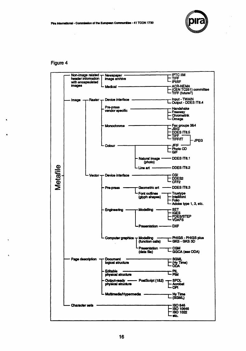
Figure 4
-- Non-image related I Newspaper C IPTC liM header infonnation inage archive TIFF wilh encapsulated IPIJIIF images Medcal ---------...- ACR-NEMA t: CCEN TC251) committee
tiFF (future?)
~Image -r-Raster. ~Device interface --------Input· TWAIN L OUtput • ODES IT8.4
~ Pre-preas ------...-Handshake vendor specific t Freeway
~Monochrome
QuomeUnk Omega
-------..,-Fax groups 3&4
~JBIG ODES IT8.5
TIFF/IT JPEG TIFF~ ~Colour -----------.C-JFIF
Photo CD GIF
~ Natural image -ODES IT8.1 (photo)
~ u,. art DOES IT8.2
- Vector·r- Device interface -------r-CGI
t:~~r L
Geornetric art -ODES IT8.3
Font outlines E Truetype (glyph shapes) lntallifent
Folio Adobe type 1, 3, etc.
~Engineering lModeling E ~EJ"s POESISTEP VDAFS
Pruantation - DXF
._ Comput8rgraptica I Modeling L PHIGS- PHIGS plus . (function calla) GKS • GKS 30
Pruantation ---c CGM (data file) GGCA <-ODA)
~ Page ducriplion - r- Docum.1t ---------SGML logical atructul8 l::: ~me)
~ Edtable PIL ptfflical atruclu18 L... PIM
~~- POitScript(1&2) l:SPDL piTtSical atnlctu.. Acrobat
OPt
c~t-cr -------------..... 180646 ~18010646
[~1022
16
The graphic standards Vector or geometric data
CFF2
Expanded name Common File Fonnat, Rev. 2
Areas covered Vector and text interchange by modem or diskette
Standard details
Not approved by any standardization organisation
CFF2 has been developed upon the first revisions of DDES-IADD by some of the European packaging CAD-CAM suppliers but changed to the special requirements of the European users. It is widely used throughout Europe for communication in the converting industry. It especially takes care of the European multiple language structure.
Characteristics/description
The main idea of CFF2 is to enable senders/receivers of data needed for the manufacture of dieboarcls or artwork to overcome the language barrier. This is done by using decoding files resident in every machine enabling the user to work in his own language. Only a limited set of ASCII characters is allowed. KERMIT is often used as intercommunication protocol between different hardware.
Definitions for text and dimension lines are as well implemented in some systems.
Since CFF2 is not yet an official European standard, the full description and syntax may be obtained from one of the main suppliers of CAD-CAM-Systems for the packaging industry.
17
CGM
Expanded name Computer Graphics Metafile
Area covered Metafile
Sponsoring body and standard details
• ISO/IEC JTCI/SC24 • IS 8632-1989 • IS 8532-1992
Further details available from:
Local national standards organisations
Characteristics/description CGM is a machine and operating system independent interchange fonnat. It contains both elements to represent geometric graphics (e.g. polygons, circles) as well as raster graphics (e.g. pixel arrays). It contains a functional specification and multiple encodings for different purposes.
The Computer Graphics Metafile is the only standard for graphical database specification designed to serve a wide range of applications. CGM is a static picture-capture metafile. That is, it contains no elements (functions) with dynamic effects on partially defined pictures. A change of transfonnation to achieve zoom is an example of a dynamic effect. CGM is not an application programmer standard, as GKS and PHIGS are. Rather it is a specification for system designers and system implementers.
Usage (Market segment and penetration)
CGM is primarily intended for vector-based images and though it can cany raster components would not be considered for solely raster based images. It is also the basis of the •GGCA • rGeometric Graphics Content Architecture•) part of ODA.
18
CGM has since it was first published in 1987 gained a significant market. This is due to various facts, among which are the use in the US DOD CALS initiative as the graphic exchange fonnat, and the use as the container for geometric graphic content architecture in ODA. Many graphics packages today are capable of generating andlor interpreting CGM files. With the publication of the new version ( 1992) the functionality has been broadened by many features earlier only available in POLs like PostScript. The CGM of 1992 provides features not even available in PostScript level 2, e.g. colour interpolation for area fill which is very common in publishing applications. The early problems in computer graphics standards with fonts have also been greatly improved in CGM by the inclusion of a font name list which allows the use of professional fonts also in graphics. This altogether makes CGM a very good candidate for graphics exchange in publishing.
There are three standardised encodings: clear-text, character and binary. Clear-text is human-readable: character is more compact, but still uses • Ascn• characters, so can be interchanged without protocol problems: binary is more compact still, and quick to encode and decode, but completely unreadable. Thus the binary encoding may be more suitable for local storage and archive, the character for interchange, and the clear-text for development and debugging of applications.
These three encodings are standardised as part of the CGM standard. As an alternative to reduce data volume, however, the encoded data could be compressed using L2W (Lempel, Ziv and Welch) compression, or a similar algorithm. L2W is very widely used, though currenUy subject to patent claims by IBM and Unisys. L2W effectively replaces repetitions of character strings or· bi1streams by short codes, and will therefore give high compression on the clear-text encoding, and significant but lower compression on the character and binary encodings.
19
CGRM
Expanded name Information processing systems - Computer graphics - Computer Graphics Reference Model
Area covered
Sponsoring body and standard details • ISO/IEC JTC1/SC24
ISO 11072: 1992 JTC1 is the first (and only) Joint Technical Committee of ISO and IEC, and deals with Information Technology. SC24 is the Sub Committee of JTC1 which deals with Computer Graphics.
Further details available from:
Local national standards organisations
Characteristicsldescription During the 1980s, SC24 and its predecessors developed what they now call the "first generation• of computer graphics standards, such as GKS, CGM, CGI and PHIGS. As this work was completed, it was realised that while each of these standards addresses particular requirements, the overall result is somewhat unsatisfactory, since on the one hand there is some duplication of material between the standards, while at the same time on the other hand there are significant differences in the view each one has of the computer graphics process, leading to difficulties in inter operating between the different standards.
It was therefore decided to stand back and take a broader view before embarking on the •second generation• of work. This •broader vieW' resulted in the CGRM (Computer Graphics Reference Model) ISO 11072. The CGRM is intended to provide the framework for development of all future computer graphics standards. Where possible, existing standards will be brought into line with it as they are revised.
20
--·~GIU..._Ccllllnunlllo·41 TCON 1730 e The CGRM is based on a layered model, and thus has a superficial similarity to the ISO OSI 7-layer model. However, CGRM has only five layers. These lead from the abstract description of the object being modelled, through the definition of the viewing conditions, and the instructions to the renderer, to a raster image able to be displayed or printed without further processing. Thus the generality is lost as a particular image of the object is developed.
Usage (Market segment and penetration) The intention is that future standardisation of computer graphic data fonnats and processing will be based on the CGRM layers, while continuing the existing practices of standardising different data encodings (eg clear-text and binary) to meet different processing requirements, and different language bindings of functions (eg C and Ada) to meet different implementation environments.
Thus CGRM is primarily intended for the developer of computer graphics standards, ie SC241tself. However, it will also be •required reading• for the user of •second-generation• computer graphics standards, to gain ·an understanding of the model used in their development, and so of which standard is appropriate for a particular purpose. and how the standards fit together in the implementation as a whole. By •user" here is meant the system implementor: the end-user of a product based on such standards should not need even to have heard of CGRM.
DDES2-IADD
Expanded name ODES = Digital Data Exchange Specification DDES2 = Version identifier of the IADD fonnat IADD = lntemational Association of Diecutting-Diemaking
Ante covered Vector and text interchange by modem or diskette.
21
Standard details American National Standard ANSIIT8.6-1991
Fur'lt* details available from: Loca NlbOnal standards organisations
~stic•description
The DOES2-IADD protocol is mainly used in the United States and c.n.ca
With h Introduction of CAD-CAM systems for the design of bell .g boxes of both solid and corrugated packages on one side ~ uamated CNC-controlled dieboard cutting machines ( Lasers ~ ;tguws ) on the other side, communication protocols have been developed to meet the special requirements of both sides. In almost 1111 cases folding boxes are designed by sample makers inside printing companies, whereas the dieboards needed for punching the packages on so called Autoplatines are cut, ruled and rubbered by independent highly specialized trade shops.
The infonnation exchanged between the parties must not only include the shape of a certain package, but the number of stations, types of cutting and creasing rules, positions, widths of bridges, size of dieboard, gutter width and many more.
DXF
Expanded name Drawing Interchange Fonnat
Area covered Vector graphics principally used for CAD drawings.
Sponsoring body and standard details Autodesk Inc
22
\
_ --~a11110 ..._.CGnlnlldllo ·41 TCON 17110 8 Further details available from: Autodesk Inc 2320 Marinship Way Sausalito, CA 94965, USA
Characteristics/description The Drawing Interchange format is Autodesk•s format for allowing the transfer of AutoCad drawings between CAD and illustration applications.
The ASCII encoded drawings may be re-created with a very simple interpreter but the file size is very large and not all drawing functions are supported by the format. Due to its pure ASCII text structure the drawing, and its attributes, can be changed by
accessing the DXF file in isolation from its generating software.
Usage (Market segment and penetration) This is used for interchange between CAD and other vector drawing packages with the emphasis on PC and UNIX computers. Most personal computer drawing and illustration software supports the import and export of this fonnat.
GGCA
Expanded name Geometric Graphics Content Architecture
Area covered Vector graphics
Sponsoring body and standard details • ISOnEC,ECMA,CCITT • IS 1989 • Part 8 of the ODA standard
Further details available from: Local national standards organisations
23
P1ra lnternlllloMI· ConautaaiDn ol the EllftJPIM C0n1nun1Jae • 41 TCON 1730
Characteristics/description Provides for inclusion of geometric graphics into ODA documents
Usage (Market segment and penetration)
seeCGM
GKS
Expanded name Graphical Kemel System
Area covered vector graphics
Sponsoring body and standard details 180/IEC JTC1/SC24 IS 7942 • 1985 DP (Draft proposal) amendments and enhancements 1991
Further details available from:
Local national standards organisations
Characteristics/description GKS is a machine, language, operating system, and deviceindependent specification of a set of services for displaying and interacting with 20 pictures.
• GKS specifies a basic set of graphics functions for applications that produce computer generated two-dimensional pictures on graphics output devices
• supports operator input and interaction by supplying basic functions for graphical input and picture segmentation
• allows storage and dynamic modification of pictures • positioned at programmer-interface level • once a segment is created, its contents can not be modified
24
Usage (Market segment and penetration) This is in effect a subroutine library rather than a data format, and as such, standardised language bindings are provided for Fortran, Pascal, and C programs to invoke the functions.
Today GKS is a standard software delivered with many workstations as part of the operating system. It is bundled with the basic software delivered. It is difficult however to judge the number of applications really built on top of GKS. Besides GKS has laid the ground work for a common tenninology and common concepts across the whole of computer graphics, and also has provided guidelines for the development of specific chip•s functionality.
GKS-30
Expanded name
Graphical Kemel System- 3 dimensions
Area covered vector graphics
Sponsoring body and standard details ISOIIEC JTC1/SC24 IS 8805 - 1988
Further details available from:
Local national standards organisations
Characteristicsldescription
GKS-30 is a machine, language, operating system, and deviceindependent specification of a set of services for displaying and interacting with 20 and 30 pictures. GKS is a subset of GKS-30 functionality.
25
• Graphics only • Entirely a three dimensional system. • GKS-30 extends each GKS primitive to three dimensions and
adds one new primitive, fill area set. • Central to the GKS-30 model is the concept of a single
transformation pipeline that supports only 30 constructs and treats 20 operations as shorthand 30 operations.
• GKS-30 will behave like GKS when only 20 functions are used. Thus GKS programs will operate correctly within the GKS-30 environment.
• GKs· & GKS-30 functions may be freely mixed.
Usage (Market segment and penetration) GKS-30 is not as wide spread as GKS; for most 30 applications structuring is an important and required functional which is only supported to a nesting level of one.
IGES
Expanded name Initial Graphics Exchange Specification
Area covered Geometric (vector) and non-geometric entities
Sponsoring body and standard details • NBS/ANSI • Version 1.0 1980 (NBS) • Version 2.0 1983 (NBS/ANSI) • Version 3.0 1986 • Version 4.01987
26
··---------~-~--
Further details available from: American National Standards Institute 11 West 42nd Street 13th Floor New York NY 10036 USA
Characteristicsfdescription
.---
• Principal standard for the exchange of product definition data in the US
• Two different data formats; ASCII and binary • An IGES file is divided into 5 separate sections • Originally conceived as a standard for drawing-oriented product
models. For this reason it contains, in addition to geometric elements, numerous non-geometric elements
• The non-geometric entities serve to enrich the model (e.g. annotation and dimensioning appropriate to the model can be added)
Usage (Market segment and penetration) Engineering modelling, CAD/CAM
Most CAD packages provide pre- and post processors for IGES. It was brought into being through a USA DoD initiative, and so was compulsory for suppliers to the US defence industry. This usage made it available to manufacturing industry in general. The DoD has developed military standards defining application profiles or levels of compliance for different industry sectors, eg mechanical engineering drawings, pipework layouts, circuit board designs.
The initial encoding is somewhat verbose (though still trivially small compared to a raster file) and very dated (Hollerith 80-column card imagesl), but it works: availability of the binary format is uncertain. It is not now intended to develop IGES further: the teams which worked on it are now developing STEP and PDES, which will succeed it
27
P1ra INernllllonal· C01111...eon of theE~ Communllee • 41 TC0N 1730
PHIGS; PHIGS Plus
Expanded name Programmer's Hierarchical Interactive Graphics System
Area covered vector graphics
Sponsoring body and standard details • ISO/IEC JTC1/SC24 • IS 9592 ·1990
Further details available from: Local national standards organisations
Characteristics/description PHIGS is a machine, language, operating system, and deviceindependent specification of a set of services for displaying and interacting with 30 geometric model.
• Aimed at applications that manipulate complex objects of 20 and 30 data in a highly interactive environment
• Not restricted to graphics. Provides data structure definition and editing facilities which are not necessarily related to graphical output
• Positioned at programmer-interface level. • Structures can be modified at any time in any way.
Usage (Market segment and penetration)
Today PHIGS is delivered with many especially high performance workstations. It has provided a significant impact on concepts of hierarchical graphical systems and is used (at least conceptually) in many applications. It is difficult however to judge the number of applications really built on top of PHIGS.
An amendment, •PHIG8-plus•, includes various extensions, for example •NURBS• (non-uniform rationalised B-splines) an enhanced way of dealing with curved lines.
28
___ _,., .. .._Colnlllldllo-411CON 1730 e
SET
Expanded name Standard d'Echange et de Transfert
Sponsoring body and standard details AFNOR, France 1985
Further details available from: Association Francaise De Normalisation Tour Europe Cedex7 F-92049 Paris Ia Defense France
Characteristics/description Chosen as the standard for several of the EEC co-operative projects such as Airbus and the Hermes Space Shuttle
Usage (Market segment and penetration) SET is heavily used within the European aircraft industries but not much outside.
29
PDES/STEP
Expanded name Product Data Exchange using STEP/Standard for the Exchange of Product Data
Area covered STEP is a multi-part standard for the exchange of product model data The eartier efforts of both the US (IGES, EDIF) and Europa (VDAFS, SET) have provided contributions to the development of STEP. STEP part 46 •Visual Presentation' is of specific significance to this report. It also has been hannonized with the developments in the area of computer graphics standards, e.g. with PHIGS.
Sponsoring body and standard details
• ISO CD 10303 • ISO TC184/SC4 • STEP is the international activity, PDES is the US one • Work on PDES began 19841ed by NBS, now NIST
Further details available from:
Local national standards organisations
Characteristics/description
PDES and STEP are intended to allow the integration of systems that support design, design analysis, manufacb.ning, logistics functions and processes, and automatic, papel1ess updates of system documentation, for example engineering drawings and technical manuals. The geometry model will include solid representations, and related data will include manufacturing features, tolerance specifications, material properties, and surface finish specifications. Initial versions of PDES/STEP will only have functionality equivalent to existing standards such as IGES. with additional functionality to be provided in later versions. This should have advantages in easing migration.
30
.... --~ .... .,_-.......41TCON1730 8 Usage (Market segment and penetration) STEP is a significant and well structured approach to the area of product model data. The development is not finished yet but it will probably be the main standard in this area of product model data exchange. It is both applicable in mechanical as well as electrical engineering. The reason for my emphasis on this standard development is that it has been developed driven the problems caused by the deficiencies of the earlier approaches, especially by the shortcomings of IGES (Which is currently used in many environments, but mostly only for 20 drawing exchange).
VDAFS
Expanded name VDA Surface Interface
Sponsoring body and standard details • Version 1.0 1986 (DIN Standard) • Version 2.0 1987 (VDA Recommendations)
Usage (Market segment and penetration) Mostly used in the Gennan automobile industry
Raster graphics
DOES
Expanded name
•Digital Data Exchange Specifications• - first generation
Area covered
Raster image interchange on magnetic tape
Sponsoring body and standard details
The •ooes• Committee became ANSI-accredited as rrs.1, and this work is now carried out at the international level in ISO/TC1301WG2.
31
•
Characteristicsfdescription
IT8.1 covers colour picture data IT8.2 covers colour line-art data IT8.5 covers monochrome image data. IT8.3 covers geometric data, and is based on IGES.
All the above are based on the ISO 1 001 (ANSI X3.27) standard for Volume and File Structure on Magnetic Tape .
(IT8.4 covers direct connection of a digital colour hardcopy device to an electronic prepress system, and is based on SCSI, not magnetic tape.)
Further details available from:
Local national standards organisations
Usage (Market segment and penetration)
The IT8.1 standard is quite widely implemented. IT8.2 has a number of implementations. Only one or two are believed to exist for IT8.5, and none for IT8.3, whose primary area of application (mask cutters) has more or less ceased to exist, except in Japan.
In general the ITS standards have been well supported by Crosfield and Dainippon Screen of the •big four- vendors, and by many of the smaller andlor newer entrants to prepress, such as Agfa and Barco.
Compression: IT8.2, IT8.4 and IT8.5 include run-length encoding of the pixels for line-art images.
DOES is a prime example of a standard that, numerically, is widely implemented yet in reality is virtually unused. Because all the major pre-press system vendors have implemented the standard on their platfonns there is a high potential for its use in the industry, based on the number of installations. However, the industry has found its use to be impractical and has virtually discarded it Dissatisfaction with the standard is primarily due to the time it takes to translate between vendor's fonnats.
32
___ ~., .. e._ Coomlllnlloo-41 TCON 17ll0 8 Justification for using the high cost, dedicated and largely closed, proprietary pre-press systems has always been their high productivity. Any standard which detracts from that high productivity is bound to fail particularty if there are alternative routes. Developments in the use of PostScript and Tl FF, as means of transporting data between independent systems have undennined the need for the ODES standard.
ODES only addresses the medium of magnetic tape. As the use of direct communication, via ISDN lines, is being adopted by prepress companies both for communication with other stages of production and, more slowly, for communicating with their client base the ODES standard, in its current fonn, will become obsolete.
Fax groups 3 & 4
Area covered Bilevel raster image encoding standard
Sponsoring body and standard details CCITT, Recommendations T.4 and T.6 respectively.
Further details available from: CCITT (Comite Consultatif lntemationale des Telephones et Telegraphes lntemational Telecommunications Union (ITU) Place des Nations CH-1211 Geneva20 Switzertand
Characteristicsldescription
Lossless compression based on run-length and Huffman encoding. Group 3 is 1-dimensional (compression within the line only) and is used in current fax machines on the public telephone network. Group 4 uses 2-dimensional compression (within the line and from
33
line to line) and will be available on fax machines for the ISDN network.
Usage (Market segment and penetration) Also used for some document processing (archive and retrieval) applications. TIFF •class F" uses the fax encoding.
Fractal Transform coding
Area covered Raster image compression method - see appendix (1)
Sponsoring body and standard details Fractal Transfonn coding is a patented approach to image compression developed by Iterated Systems, Inc. in Norcross, Georgia, USA. Technical details of the compression method are not available publicly.
Further details available from: Iterated Systems Ud (European subsidiary) Wyvols Court Swallowfield Nr Reading RG7 1 PY United Kingdom
Usage (Market segment and penetration) Compression is much slower and more computationally intensive than decompression. This defines the applications, for which Fractal Transfonn coding is suitable, as offline rather than realtime.
Iterated Systems have a range of products available, including hardware-assisted compressors, software-only decompressors, and links into third-party DTP products and subroutine libraries.
Microsoft, under license, have used Fractal Transfonn coding for their recently released •encarta• CD-ROM multimedia product.
34
--·CCIItltiniDnGIU..._CIIiiliodllo·41TCON1730 e Available in Europe from April 1993, Encarta is a 28 volume encyclopaedia containing text, animations, maps, drawings and graphs, audio and 7000 fractally compressed photographic images.
GIF
Expanded name •Graphic Interchange Formar.
Area covered Raster image file format
Sponsoring body and standard details •ewned• by CompuServe Inc, but royalty-free limited-use licence available.
Further details available from: Compuserve Incorporated 5000 Artigton Center Boulevard Columbus Ohio 43220 USA
35
Plra lnlernlllloMI· Conltdulon ol the EurapeM COmmunllle • 41 TCON 1730
Ctwracteristicsldescription GIF (Graphics Interchange Format) from CompuServe has been developed solely for format transfer, irrespective of the system. A GIF graphic is stored as a sequence of pixels with RGB colour vlluK The position of individual pixels does not have to be nic:alld separately, since they are stored sequentially from top tell to boaom right. All GIF files start with a signature (version ftUmt)et etc.). This is followed by the screen definition and the gkJCIII caour scale of the GIF-generated hardware. Image deft 40ft. local colour scale and raster data follow. The raster aata • compressed according to the LZW algorithm.
GIF Nes can hold multiple images, so that several definitions (and .no raster data) follow one another in the file. Although it has a binary structure, GIF is used on various operating systems.
UNge (Market segment and penetration) Parbcularty used for e-mail of images for viewing, on screen, over both the CompuServe and Usenet networks. The format is widely supported by many applications for image access/import.
IPI-IIF
Expanded Name •Image Processing and Interchange : Image Interchange FaciliV
Area covered Data format and gateway functionality for raster image interchange
Sponsoring body and standard details • ISO/IEC JTC1/SC24 • ISOIIEC DIS 12087 (comments due in June 1993)
Further details available from: Local national standards organisations
36
---~ ..... ~Cclnlmunlioll-41 TCON 1730 e Characteristics/description
IPI is a three part standard. Part 1 provides a platform independent architecture and a set of common image-related data types, operations, etc. Part 2 provides an API for a useful set of image processing primitives thus providing portability. Part 3 provides an image interchange format richer than either CGM or any de facto format, like TIFF. It provides transparent data exchange.
The data format goes beyond the capabilities of TIFF by allowing more than two dimensions ( eg xyzt) for the •sampling space•. The descriptors are encoded in the ISO standard ASN.1 notation, which allows additional flexibility by a context-sensitive approach, and allows complex image data structures to be described and manipulated.
The gateway functions define the parameters for access to and manipulation ~ the image data structures.
Usage (Market segment and penetration)
IPI is a standard still under development. It is a very generic image standard in that the underlying image model is very broad.
Commercial implementations are not yet available, as the standard is only now becoming stable. A consortium which was planned to develop a general implementation failed to be established because of the difficulty in attracting funding in the current economic climate.
Images in IPI are not merely 20, they can have up to five dimensions allowing to include both time varying images as well as multi-channel images (eg geo-sciences, fluid now, medical imaging}, where there is currently no widely-used inter-disciplinary standard format: however, H is not clear whether it will displace TIFF for two-dimensional graphics images. With the addition of profiles for specific application areas this standard will provide a very good basis for future image based applications.
37
JBIG
Expanded name • Joint Bilevellmage Group•
Area covered Bilevel raster image encoding standard
Sponsoring body and standard details Jointly •owned• by the CCITT and ISO/IEC JTCI/SC29 (ISO/IEC DIS 11544, CCITT T .82)
Further details available from: Local national standards organisations
Characteristicsldescription Lossless compression using predictor methods. More complex but
more effective than the fax algorithms.
Usage (Market segment and penetration) No values for compression ratios to hand, but assuming that it is
comparable with proprietary schemes, I would expect from 3:1 to 10:1 on screened halftone data, and rather better on less •busy• images, eg line art.
JPEG and JFIF
Expanded name • Joint Photographic Expert Group• - see appendix (1)
Area covered •Photographic• raster image compression standard
Sponsoring body and standard details Jointly •ownecr by CCITI and ISOIIEC JTCIISC29 (ISOIIEC DIS 10918-1, CCITI T.81 ).
38
Further details available from: Local national standards organisations
Characteristics/description For compression of monochrome or full-colour "grey-scale• images. Options within the standard: - lossy vs lossless algorithm - Huffman or arithmetic coding The •baseline• version uses the lossy algorithm with Huffman encoding. Typical compression ratios: for the lossless algorithm up to 2:1; for the lossy algorithm, 8:1 for printed material, 30:1 for monitor displays. Sharp edges, as found particularty in synthetic images, lead to either poorer compression ratios or the appearance of artefacts in the image.
The JPEG standard only defines the bitstream of the encoded compressed image data, as it would be sent down the communication line in the originally envisaged primary application of photovideotext. For data processing purposes, the bitstream needs to be encapsulated within a file fonnat, with some additional •header" infonnation to provide a context for the reconstituted stream of pixels (eg how many rows of how many columns make up the given area). There are two •standardised• fonnats. At present the JFIF (JPEG File Interchange Fonnat) defined by cCube is probably the most widely used, but TIFF 6.0 also includes fields (tags) to give JPEG capabilities, and the TIFF encapsulation of JPEG may gain the wider acceptance in the longer tenn.
Usage (Market segment and penetration) Many implementations available, both hardware and software based, including a .,ree• software version. The algorithm is being included in a number of DTP packages which handle images.
39
Photo-CO
Expanded name Photo Compact Disk
Area covered Raster images
Sponsoring body and standard details
Kodak - proprietary standard
Further details available from:
Kodak Umited Research & Development Headstone Drive Harrow Middlesex HA 1 4TY United Kingdom
Characteristics/description Photo CD was introduced by Kodak as a means of storing on CDROM discs, high quality digital colour images captured from film. Each Photo CD disc can hold around one hundred 35mm images film. The technology was originally aimed at consumers although the target audience is about to be broadened to include the professional market The consumer is able to display photographs on TVs using either a Photo CD player or a Philips CD-I system. Images may be selected for reprint or enlargement and images may be manipulated from PC and Macintosh systems equipped with a Photo CO-capable drive and the appropriate software.
Usage (Market segment and penetration)
Kodak's goals with this technology are: • to make digital images are accessible to all • to maximise quality • to keep production costs low • to provide image resolutions which match a wide range of user
requirements.
40
Technical The Kodak Photo CD Imaging Workstation is a set of products that scans film images, writes them to Photo CD discs, and prints them. The workstation includes:
• the Kodak Photo CD Scanner • the Data Manager, a computer workstation used to check if adjust
{if needed) scanned images before transferring them to Photo CD discs.
• the Kodak PCD Writer, which writes images to a Photo CD disc • a printer which creates index prints and high-quality pictures from
images stored on Photo CD discs. • the Kodak PCD CD-ROM Drive, which reads Photo CD discs both
when making prints and enlargements and when copying images from one disc to another.
Scanning The key component of the system is the scanner. It is the speed and quality with which it can scan images that makes the whole Photo CD process viable.
The PCD Scanner scans 35mm film and produces an 8-bit (reduced from 12 bit) RGB digital image with a resolution of 2048 lines by 3072 pixels. This represents 18Mb of data per image. Since only 30 images could be stored on a single CD disc at this resolution the images are reduced by the PCD Data Manager by converting them from RGB to Photo YCC fonnat, a proprietary Kodak fonnat, and by compressing the images using a Huffman Encoding algorithm.
Scans are carried out in 6 seconds, which comprises 1 s for a preview scan and 5 seconds for the full scan. The PCD Data Manager ( a Sun Sparcstation II) automatically adjusts each image for exposure variations, lighting conditions and the make and type
of film. The operator is able to view 6 images at a time at the Data Manager. Images taken in portrait mode can be flagged for rotation at this point Images which are not wanted can be discarded.
41
P1ra lnlerMIIonll· Comm1111on or ttw Eurapew~ Conwnunl ... • 41 TCON 1730
Formats Each image is written to a CD in an Image Pac file. These Image Pac files contain the image at five different resolutions. The range of resolutions is designed to cater for most possible requirements for the image, the two lowest providing thumbnail versions of the image (lowest being 128 by 192 pixels) and the 18Mb providing the amount of data required for top quality thermal printing etc. Between these two extremes are the TV resolution option and the higher resolution HDTV option. Kodak regard this HDTV option as future proofing the system. Both the HDTV and 18Mb options are Huffman encoded, the other three resolution images are uncompressed. These decomposition and compression techniques make it possible to store approximately 1 00 images on a Photo CD disc.
Writing the images
The Data manager writes the Image Pac file to the CD disc and also a copy of the lowest resolution image to an Overview Pac, which acts as a table of contents to the disc. This Overview Pac is printed giving an index of all the images on the disc and included with the disc retumed to the customer.
Writing an image to a CD disc takes 2o-22s, which is longer than the scanning time. Images are buffered prior to writing to help prevent a bottle neck. Kodak have also designed Photo CD Imaging Workstations with multiple writers (up to six) to cope with this problem.
Platforms
TV
The original intended platform for Photo CD was the television, the product being aimed directly at he home consumer.
Computer
In order for Photo COs to be accessible through standard computer platfonns, PC and Macintosh, H is necessary for CD ROM drives to be able to read the photo CD format To this end
42
---~ ..... e._c-.nlloo·41TCON1731J 8 Kodak have been working with hardware vendors and peripheral manufacturers such as Apple, Sony, Philips, Toshiba, Pioneer.
The Photo CD Access Toolkit is available for software developers. They can use this to make the necessary enhancements to allow their products to access Photo Cd images. It comprises a library of C programming language functions.
In order to allow users to access Photo CD images using their Macintosh and Macintosh CD ROM drive, Kodak will supply Photo CD Access Software for £35. However, as noted in section x below (Using the Photo CD technology - feedback) the combination of Macintosh and Macintosh CD ROM drive is the only one that Kodak currently guarantee will work.
CD-I
Photo CD images are currently accessible by CD-I, but a format conversion from Kodak vee to CD-I is required. This currently takes around 15s; Philips are working to reduce this to Ss.
Future Developments
New disc fonnat8
Pro Master Disc Kodak plan to continue developing the Photo CD concept. Several new formats of the CD disc will be announced in 1993.
One fonnat will be designed to cater for the professional user. A new multi-format scanner will be available which can take 120mm film and a variety of other sizes including e-x7·' e-xa·' e-xs·. The Kodak Pro Photo CD Master Disc will store images scanned at resolutions of 4k x 6k, which will occupy 72Mb of disc space. Scanning time for these images will be around 90s. It will only be possible to store approximately 25 images on a disc. For security, encryption of the image will be possible on the pro Master Disc. The user may manipulate and write back the image to the disc, but will need the appropriate Kodak hardware in order to do this.
43
Portfolio Disc Also in 1993 is planned the option to allow users, by means of an authoring package, to write off low-resolution images to create a Portfolio Disc. It will be possible to write up to 800 images per disc. Sound and text can also be added, making this a multimedia facility.
Catalogue Disc A Catalogue Disc format will allow 6-12 thousand images/disc. Software will be embedded to allow the user to browse through the collection of images on the disc.
These additional formats add new functionality to the Photo CD product. There is a danger, however, that the introduction of these multiple disc formats will damage Photo COs reputation in the marketplace, as users become confused by the variety of formats and the requirement for different software and configurations to access each one.
New products
PhotoEdge • Image Enhancement Software
Kodak are planning the release of the product PhotoEdge in 1993. This will be an image enhancement package. The functionality will be very much more limited than products such as PhotoShop; the aim is to allow manipulation of the whole image for characteristics such as contrast and colour.
Renaissance· Software for Graphic Designers
This software, developed by Atex, was retained by Kodak following · the recent sale of Atex. It enables Mac imaging on the PC.
Shoebox • Image Organiser
Due for release in mid 1993, this product will have versions which run on the Macintosh and PC. Shoebox is in essence image database software. It will allow images to be organised for searching and sorting. It will allow multiple images to be displayed at once, and keywords and text to be assigned to images for example.
44
---~ ..... e._Communllllo-41 TCON 17:10 8 Kodak are also planning a jukebox with a capacity of 1 00 CD discs (each containing 100 images) to be available in mid 1993. They say it will be possible to link up to fiVe of these jukeboxes together. The thumbnail images will provide a means of searching amongst such a collection of Photo COs.
Image libraries have shown great interest in Photo CD and the Shoebox product may offer them an initial application that could be useful for organising their collections of images.
Kodak Picture Exchange The Photo CD initiative is regarded as so significant at Kodak that they are planning to branch into an area quite outside their nonnal line of activities. They have plans to set up as publishers themselves and act as image brokers providing a link between image providers (photo agencies, publishers, museums) and users of images (designers and art directors, publishers, corporate image users). They envisage Photo CD being the medium in which the images are held and exchanged. Kodak would be placed in the role of significant telecommunications, database and service managers.
Kodak are planning to trial the concept in the US in 1993, followed by Europe in ear1y 1994.
TIFF
Expanded name .,.ag Image File Fonnar
Area covered Raster image file fonnat
Sponsoring body and standard details Under the benevolent development of Aldus Corporation and Microsoft a version is also being fonnally standardised by the ANSI ITS and ISO!rC130 Committees
45
P1ra IIUrnlllo_, • ~n ol the Emapean Colmumllll • 41 TCON 1730
Further details available from:
Aldus Europe Ltd Craigcook Castle Craigcook Road Edinburgh Scotland EH4 3UH United Kingdom
Alternatively: Aldus Corporation 411 First Avenue South Seattle Washington 98104 USA
Characteristicsldescription Defines a tag-based file descriptor that can characterise almost any form of 20 raster data •Private• tags may be obtained to allow additional parameters to be added to the descriptor.
Usage (Market segment and penetration) Very widely implemented in DTP and desktop applications. TIFF is used not only by scanners as a digital image interchange format but has also been adopted by some application developers as a memory format It has been adopted as the image file interface between DTP and high-end applications.
The wide variation between requirements for different applications has led to partial implementations, in which valid files cannot be read. This situation is being addressed by the TC130 activity, which aims to standardise the TIFF subset required for Graphic Technology applications.
•Standard" TIFF allows the use of PackBits, LZW, Fax and JPEG compression schemes.
46
---~orllloe._~--41TCON1730 8 TIFFnT
Expanded name
TIFF for Image Technology
Area covered
Raster Image file format
Sponsoring body and standard details A first version is being prepared by ANSI ITS and will be the IT8.8 standard. Parallel work is being done in ISOfrC130/WG2.
Further details available from:
Local national standards organisations
Characteristicsldescription TIFF/IT forms a •second-generation• standard, to fulfil three purposes:
• provide the functionality of IT8.1, 2 and 5 to other media than magnetic tape
• provide a data format for •high resolution edge• information • provide a format standard for the subset of TIFF which is
appropriate for prepress applications.
It is specifically designed so that any fields additional to TIFF 6.0 take default values equivalent to TIFF 6.0 practice, so that existing implementations, such as Photoshop, should already be compatible with it.
Usage (Market segment and penetration)
Currently in ANSI public review: not yet in Committee Draft at ISO (note: the ISO .,ast tract(~ procedure will not be used in this case, so that other national comments, particularty from Japan, can be addressed).
It is intended that the TIFF/IT {IT.B) standard will reduce the variation between TIFF implementations which has led to a reputation of valid TIFF files often being unreadable from application to application.
47
Document/metafile
Acrobat (Carousel)
Area covered Page description language. Subset of Postscript
Spons~ring body and standard details Adobe Systems Inc - proprietary standard, due for release early 1993
Further details available from: Adobe Systems Europe BV Office Centre Jozef lsraAiskade 48c 1072 SB Amsterdam The Netherlands
Characteristicsldescription Acrobat (previously known as CAROUSEL) is a development of the Adobe company. Acrobat is based on what Adobe term a Portable Document Format (PDF), which remains close to Postscript but has a range of compression options available to reduce file sizes. It is currently a fixed page format, but there is the possibility of a revisable fonn at a later stage. Also the ability to include video and audio inserts may be included at a later date. Various 'byte accelerator' techniques have been included in the fonnat so that searching for words and phrases is fast. Key features in PDF are a set of 'hot links', 'thumbnail' icons of pages, chapter outlines and page annotations.
The 'chapter outlines• feature enables infonnation to be added to a text eg summaries, indexing infonnation. The thumbnail icons for the document pages facilitate fast browsing and random access. Page annotations act as electronic Post-Its and are user specific; they are not integrated within the document
48
PDF has a set of markers for these hyperfacilities, which can either be added to existing Postscript or passed down from ifront-end' text-processing packages into the final Postscript.
Acrobat Distiller The conversion from Postscript to PDF is carried out by the Distiller program which is part of the Acrobat suite of software. Existing hyperfacility markers are converted during the conversion process. Alternatively hyperfacility markers can be added manually during the distillation process from Acrobat viewers (see Viewers below). A reverse process will enable printable Postscript to be recovered from PDF. The problems for the Distiller program is that it must be able to take any legal Postscript, at Level 1 or Level 2, and distil it to PDF which will be acceptable to all Acrobat viewers on all supported platfonns.
Acrobat Viewers Acrobat viewer software allows the user to view distilled Acrobat pages on a platfonn of his choice. Functionality of the viewer includes, panning, zooming, scrolling, skip pages and navigating around the document. Existing hyperfacility markers will be interpreted and can also be inserted by the user if required.
Adobe plan viewer software for all the popular hardware platfonns. It will be possible to print out all or part of a document to a Postscript printer.
Production issues A future release of Distiller will be a 'publisher's version' containing some automatic indexing and linking tools. Optimum use of Acrobat will be achieved by creating the hypertextuallinks in the original document and passing these down into the final Acrobat fonn. This will be assisted if future versions of popular DTP packages are made Acrobat-friendly and if they are enhanced to produce PDF output. The extent to which suppliers take up this challenge will determine the extent to which Acrobat becomes a useful interchange standard for fonnatted data. As with PostScript. Adobe say they intend to release full details of the
49
P1ra INemllllonll· Comm1111on of theE~ CGmmunllll· 41 TCON 1730
Acrobat fonnat; this should enable third parties to produce cloned
Fonta A key difficulty for Acrobat to overcome in the electronic ~ of a fonnatted document is the availability of screen tanll at the receiving workstation to match those in the document.
One IOUIOn is to distribute the screen fonts with the document, bUt hi can potentially lead to problems with copyright. AllemiiNely the screen and printer fonts that a document needs ~ be tuo~dled into the PostScript for the document itself, but this ~ teed to very large files.
Adobe have employed their Multiple Master Font technology as the SOlutiOn within Acrobat Font characters from a generic font are fitted on the fly to the font metrics of the original font used for any fonts which are not available (either not at the receiving wortcstation or not available for copyright reasons).
Usage (Market segment and penetration) Acrobat and SGML could evolve as mutually supportive, with Acrobat giving SGML additional impetus if it becomes successful. The hypertextual possibilities within Acrobat are related to the structure of a document Automated production of Acrobat hyperlink codes would follow more naturally from data structured using SGML and a Document Type Definition.
Adobe•s Acrobat initiative must be taken seriously at this stage, given PostScript's dominant market position and given that Acrobat is in essence a subset of PostScript and the priority Adobe are giving it in their strategic plans. Adobe would like to establish Acrobat as the document interchange standard for the future. They would like to see Acrobat viewers becoming a standard feature of every workstation. As well as being a multimedia publishing fonnat, Adobe see Acrobat as central to the future of office technology
50
HyTime
Expanded name Hypennedia/Time-based Document Structuring Language
Area covered 'Hyperdocuments' that link and synchronise static and time-based infonnation
Sponsoring body and standard details
• ISO • IS 107441992
Further details available from: Local national standards organisations
Characteristicsldescription HyTime is an SGML application that provides a •description language• for representation of hypertext links, time scheduling and synchronisation in multimedia documents which, are among the significant aspects of hypennedia that are not covered by
existing standards. In keeping with the character of SGML itself, it seeks to standardise as much as necessary and as little as possible: the emphasis is on identifying objects and providing addressing mechanisms and not on establishing particular systems or policies for developers or users. HyTime is independent of basic media content notations, of link types, processing and presentation semantics.
Usage (Market segment and penetration) The standard has been published for a year and there is much interest in Hytime across a broad market spectrum. Applications of Hytime are not yet available and it is likely to take time for there to be so. This is partly a consequence of the complexity and broad scope of the standard. As a result of the separable structure of the standard, it is likely that 'Hytime engines• will tend to concentrate on specific aspects of the standard as opposed to providing full coverage of all possible functionality allowed for. This may lead to different 'Hytime engines' gaining penetration in differing markets.
51
IPTC liM
Expanded name •International Press Telecommunications Council Information Interchange Model•
Area covered Tagged envelope structure for carrying image files
Sponsoring body and standard details Developed by the IPTC, whose members are news agencies and digital wirephoto services, and their customers
Further details available from:
lntemational Press Telecommunications Council 8 Sheet Street Windsor Berkshire SL4 1 BG United Kingdom
Characteristics/description
e
Provides a mechanism for canying either raw pixel data, or standardised or proprietary data formats from a registered list, and supplying the additional descriptive data necessary for the distribution and use of the images in newspaper production environments
Usage (Market segment and penetration) This format is being implemented by the majority of newsphoto service providers as they replace their analogue services with digital ones.
ODA
Expanded name
Office Document Architecture and Interchange Format
52
•
---~., .... ~Caomlunlloo-41TCON1730 8 Area covered Document structuring
Sponsoring body and standard details • ISO/IEC • IS 8613
Further details available from: Local national standards organisations
Characteristicsldescrlption ODA is a multi-part intemational standard. It defines an architecture for office documents that describes a document in tenns of its content and two hierarchical structures: logical structure and layout structure. It defines a method for describing key characteristics of a document in a document profile that can be interchanged in advance of the document itself. It also defines two encodings of this architecture for document interchange: one using ASN.1, and a second using SGML The eight parts published to date are:
• Introduction and general principles • Document structures • (Left for future instructions) • Document profile • Office document interchange fonnat (COIF) • Character content architecture • Raster graphics content architecture • Geometric graphics content architecture
Usage (Market segment and penetration) The document structure adopted by ODA is more than adequate for office and business correspondence, and sufficient for •contentdriven• publications such as books, (leamed) joumals, reports, •serious• magazines and newspapers, etc, where the design is based on rectangles. However, H is not currently adequate to cover •Jayout-drtven• publications such as modem catalogues and brochures, -mbloid• newspapers and magazines, etc, where irregular and •diagonal• layouts are often used.
53
The 1989 version of ODA makes use of the 1987 release of CGM {Computer Graphics Metafile) as a means of incorporating geometric graphics. It is intended that the 1993 release of ODA will make use of an amendment to the 1993 release of CGM.
For the time being, only one of the CGM encodings, the binary one is used within ODA. The amendment will allow all three encodings.
There is the ability within ODA to change some of the presentation attributes of the graphics which are incorporated. The dimensions can be altered and the orientation of graphics can be changed, although only through integral steps of 90 degrees ie 90, 180, 270 and 360. Clipping is available as a functionality.
Defaults are defined within CGM for attributes such as line type
and line colour. It is possible within ODA to cany out some factorisation of the defaults eg make all the lines within a graphic a specific colour with one global change of the default line colour.
Current version of ODA allows for the inclusion of one picture within a metafile.
Raster graphics can also be included within an ODA file. As with the geometric graphics of CGM, attributes can be changed. They are similar; picture dimension, orientation. clipping. Fax group 3 and group 4 encodings can be included in ODA files as well as bitmaps. ODA is restricted to handling rectangular areas for incorporating graphics.
In the currently available 1989 version of ODA, pixels only have two states, set and not set The new 1993 version will incorporate the ability to include coloured raster graphics.
The concept of tiled raster graphics will be included in the 1993 release. This aims to deal with the limitation that graphics such as fax encodings have defined size limits in terms of pixels/line and lineslpicture. The extension to the raster functionality will allow a two-dimensional array of tiles, to be used to form larger pictures.
54
---~oru.e._..Cclmmllnlllo-41 TCON 1730 e There is some discussion regarding the use of the IIF (Image Interchange Format) within ODA. IIF is basically an •umbrella• standard above several different existing image standards including JBIG, JPEG and MPEG. A major aim of IIF is to include still and moving images; existing vector graphics standards could simply have been extended if the aim had been only to encompass still images. IIF includes the concept of two dimensional and three dimensional images; the third dimension can be the temporal one which comes into play for the moving image standards.
OPI
Expanded name •open Prepress Interface•
Area covered
PostScript language comment conventions for placement of publication-quality, separated images
Sponsoring body and standard details Specification owned by Aldus Corporation
Further details available from: Aldus Europe Ud Craigcook Castle Craigcook Road Edinburgh ScoUand EH4 3UH United Kingdom
Altematively: Aldus Corporation 411 First Avenue South Seattle Washington 98104 USA
55
P1ra lnternlllloMI· Cwili....,. of 1M E....,_, COimMmllle • 41 TCON 1730
Characteristics/description Allows the placement of image file separations to be carried out in either a PostScript or a non-PostScript environment, allowing traditional prepress systems to be used with DTP •front-ends•.
The Open Prepress Interface (OPI) is a set of PostScript language comment conventions that allow prepress systems to incorporate high-resolution colour images into publications produced with a page layout program. OPI provides end-users with an effective way to send information from personal computer page layout software to colour prepress systems.
To use OPI, the end-user, who is now a prepress customer, prepares a PostScript file that includes OPI comments. The prepress system then processes this stream by extracting the raster image layout information.
Although OPI was primarily intended to be used to communicate with dedicated high-end colour prepress systems, it can also be used with separation programs running on desk top computers.
In a typical high-end scenario, the prepress customer takes original photographs to a colour prepress vendor before creating the publication in which the photographs will be placed. The prepress vendor creates two versions of each scanned image: a high-resolution version, which is stored on disk or tape, and a lower resolution colour Tag Image File Format (TIFF) version, which is sent to the customer.
The prepress customer places the TIFF files into the publication, using DTP software to size, position, and crop the image as needed. OPI compatible software includes special PostScript language comments to specify each image's filename and positioning, as well as any size and cropping adjustments. The prepress system will use these comments to plan the highresolution images into the publication at the correct size and position.
56
---~ ...... "-CCinlnonlllo-41 TCON 1730 8 Usage (Market segment and penetration)
As it is vendor specific its market penetration is governed by the success of the supporting companies. The most common examples of its commercial application can be found in newspapers and magazines.
PIMIPIL
Expanded name
Page Imaging ModeVPublishers• Interchange Language
Area covered
An editable page description language
Sponsoring body and standard details
Being developed by IT8/SC1, to which the PPISC {originators of PIL) has become a Working Group, as the IT8.9 standard
Further details available from:
Local national standards organisations
Characteristics/description
The need for a •revisable-fonn• page description language, which addresses graphic arts prepress practices but is fully editable on receipt, has long been feH. ITS has been working on this for some time, and when it became clear that Adobe's promise of an •Interchange PostScripr would not materialise in the short tenn, the work continued. ITS's weakness in text handling was recently addressed by the addition of the PPISC group. A PostScript-like encoding has been adopted for the forthcoming ITS.9 standard.
Usage (Market segment and penetration)
PIL is out for ANSI public review, on the way to becoming ITS.9 part 1. PIM is set to become a functional superset of PIL with a PostScript-like encoding, and will be submitted for pubic review at ITS.9 part 2 later this year. The PIM (ITS.9 part 2) activity aims to provide true editability of page plans, and to be displayable in
57
simplified fonn on a standard PostScript device, but will not be a full implementation of PostScript.
Postscript (Levels 1 ,2)
Area covered Vector and Raster graphics
Sponsoring body and standard details Adobe Systems Inc- de facto standard First release Level 1 1985 Level21990
Further details available from: Aldus Europe Ud Craigcook Castle Craigcook Road Edinburgh Scotland EH4 3UH United Kingdom
Alternatively: Aldus Corporation 411 First Avenue South Seattle Washington 98104 USA
Characteristicsldescription
Postscript can be considered from several points of view • general-purpose programming language with powerful built-in
graphics primitives • page-description language that includes programming features • interactive system for controlling raster output devices ( cfasplays
and printers) • under restricted conditions an interchange fonnat. An arbitrary
PostScript file cannot be known to be editable on receipt. though it is possible H enough restrictions are placed on the originator of the file.
58
•
--·~al ... e._~-·1TCON17ll0 8 Postscript•s most obvious language features are that it is an interpreted language, it is stack-based, and it is heavily oriented toward graphics and typography. This design makes it useful as a device-independent page description language for imaging on raster devices. The language evolved from a printer control language into a communications medium on host computers. It is a hybrid between high-level and low-level languages. It is highlevel in the sense that there are individual operators that encompass very powerful functionality, whereas manipulation of objects on the operand stack more closely resembles assemblylanguage programming.
In addition to unifying all previous language extensions, Postscript Level 2 introduced a number of new language features. These include functionality related to dictionaries, memory management, images, resources, filters, binary encoding, user paths, forms, colour spaces, CIE-based colour spaces and pattems.
The imaging model has later content totally replacing eartier content pixel-by-pixel, and so more sophisticated operations, such as image merge, cannot be expressed in standard PostScript alone. The NeXT extensions to PostScript address this, but are not widely implemented. Similar extensions are planned in PIM, and where the primary requirement is an interchange fonnat, PI M should be considered.
Usage (Market segment and penetration) Since its release in 1985 Postscript has found great market penetration as an interactive system for controlling raster output devices (particularly printers but also to a much lesser extent displays). In particular its use with printers in the office market is huge. It has been far less popular as a general-purpose programming language for end users in 11s own right Environmen1s such as the Sun Unix NeWS Server make use of it in this way but despite advantages have not become dominant.
59
•
P1ra lrHmllllonal· CGn11.-aDn clthe E~ CGmmunllls • 41 TCON 1730
Problems of lack of performance have prevented Postscript having a significant impact in the area of screen displays. Ever increasing processing power is likely to lead to increasing use of Postscript for this purpose, which in tum may support its use as a programming language. Until recently, the Postscript interpretation has tended to be a major bottleneck in the output chain involving high resolution output devices. Recent improvements in performance in software drivers for Postscript are bringing about a situation where this is no longer the case. These are likely to lead to increased market penetration by Postscript.
Quicktime
Area covered Addition of time-based functionality to Apple operating system
Sponsoring body and standard details Apple Computers - proprietary standard
Further details available from: Apple Computer Europe Le Wilson 2 Cedex60 92058 Paris Ia Defense France
Altematively: Apple Computer Inc 10201 North De Anza Boulevard MS:23AQ Cupertino Califomia 95014 USA
Characterlsticaldescrlption Quicklime is an operating system extension for the Apple computer that retrofits low resolution video onto the desktop. Quicklime use requires three elements: an operating system extension (Quicklime Extension), a data object (in the MooV fonnat), and a player or application program (eg Apple's Simple
60
Player). Quicklime is different from other recent moving picture formats, including MacroMind Director and HyperCard, in that it neither flips cards nor moves sprites. It involves not so much adding video as adding the notion of time into the operating system. The QuickTime clock determines the right video frame to display at the right time, and it can also orchestrate a sound mixer, a lighting board, or other real-wortd device that needs to be triggered by time cues.
Usage {Market segment and penetration) Quicktime•s market segment is largely that section of the Macintosh user community with a particular interest in multimedia. It is not clear that its penetration has yet become as large as might have been expected. There has been some user hesitation over certain areas of the functionality, for instance the video performance, quality and size of display window. The market appears to be waiting for these obstacles to be overcome.
SGML
Expanded name Standard Generalized Markup Language
Area covered Document structuring
Sponsoring body and standard details • ISO • IS 8879
Further details available from: Local national standards organisations .
Characteristicsldescription This standard defines an object-oriented method for describing documents (and other information objects with appropriate characteristics). The standard is essentially in two parts. The first defines a model for document description, a set of semantics, limited to what is
61
..
Plra llternallonal· COmmllllon ot the Eurupean commun~~ea • 41 TCON 1730
necessary for the model, and an abstract method of coding (syntax). The second part of the standard defines a specific (concrete) syntax, using a subset of the repertoire of ISO 646 for text and markup encoding.
Usage (Market segment and penetration)
SGML and images
Non-SGML Data
SGML recognises that users will want to include non-SGML data within SGML coded data and provides several mechanisms for doing this. Non-SGML data is data that is not parsable in accordance with the SGML standard. It is either data in an undefined character set, bit data, or some mix of the two. In undefined character set data, the bit combinations represent characters, but not in the document character set. In bit data, the bit combinations, although they can be managed as characters, do not represent a character repertoire in the usual way.
As non-SGML data cannot be scanned by the markup parser, and may contain bit combinations that could, for example, erroneously cause the operating system to tenninate the file, it must be stored in an external entity. Its location is made known to the parser by an entity declaration.
Data Content Notations
Use of the data content notation is one method of attaching image data to SGML fonnatted data. The difference between one type of non-SGML data and another is indicated using the data content notation which the standard provides. SGML itself does nothing with notation declarations and does not understand the syntax; they are present just to register the fact that they are being used. However knowing the notation enables any SGML application processing the data, to pass the content of the element concemed to the correct parser for the data concemed. In other words, the actual meaning of what is in an element declared to have a data
62
--·Cooooo_ ..... .._-........41TCXlN1710 e content notation, is entirely application dependent and not standardised at all within SGML itself.
Entity References
Another method is to include an image in an element declaration as an entity reference. The parser will look at the entity declaration as it processes the data. However it is not possible using this method, to include any information about the graphics in the SGML file, such as the size, where to position it on the page, what type of image it is. However, by defining an element and attaching attributes to it this sort of information can be included in the SGML file. Again there is no standard for interpreting the semantics of these attributes within SGML itself and any interpretation is application dependent
Internal coding
SGML is a language for coding hierarchical structures and so can in practise be used to code up any hierarchically structured data intemally. For instance it would be possible to recode the grammar of CGM using the syntax of SGML Then exactly the same information as is available in CGM would be available in SGML coded format. Equally the same could be done with other graphics languages that are based on a hierarchical structure.
Advantages to such an approach have been suggested. These include:
• full hypertext linking into and out of the graphics is enabled using exactly the markup methods and processing used for text elements.
• translation of text in graphics is enabled using the same tools and techniques used to translate text.
• the markup specifically enables re-use of graphic objects. • independence of graphic specification from presentation systems.
Even a bitmap could in theory be coded as a cleartext encoding, by defining the number of scan lines, number of pixels per line etc. Such an encoding would be incredibly verbose and impractical. The question of efficiency regarding the encoding of formats at the level of CGM is also key. It is probably best to use an efficient
63
P1ra lrterMIIonll· C0n1n1111on ol the EurupeM communi ... • 41 TCON 1730
coding for the graphic itself and include it as an entity in the SGML file.
Uuge (Market segment and penetration) SGYL has made its principal impact in markets making use of structured texual (as opposed to graphical) infonnation. This has pafbeulafty included those markets managing and producing ~ documentation, although not exclusively so. SGML has bMrt ~ significant impetus by its adoption within large ......,.. such as the US Defense Departments CALS initiative ~ 11 8doption within the FORMEX standard of the Office of ~ Publications of the European Community. Its take up ......,.... has been slow but steady. It is to be expected that the amvw ol the Hytime and eventually DSSSL standards will increase SGML 'I market penetration.
SPDL
~ndedname
Standard Page Description Language
Area covered Vector and Raster graphics
Sponsoring body and standard details • ISO/IEC • DIS
Further details available from:
Local national standards organisations
Characteristics/description
SPDL has its origins in the desire to provide a complete set of standard interchange languages for all stages of the traditional publishing process. SGML provides the language for use in interchange at the authoring and editorial stages. DSSSL provides the language for specifying to the typesetter (fonnatter) how the document is to be composed and presented. SPDL provides the
64

---~., .. .._c:an-dloo-41TCON17ll0 e language that enables the style and layout decisions of the fonnatter to be realised on a variety of imaging surfaces (screen, paper, film, etc).
The issue of the establishment of confonnance criteria is, of course, one of the reasons for the development of an agreed International Standard. One of the benefits of SPDL, which looks set to be an international reference version of the PostScript language, should be that it will set a standard against which confonnance can be tested. As a result, interchange using the language will, at some defined level of functionality in the language, be reliable.
Usage (Market segment and penetration) The new SPDL standard, being effectively an international reference version of Postscript is likely to benefit greatly from the already significant presence of Postscript across a large range of markets. In providing an ability to carry out conformance testing, this is likely to be welcomed and may lead to use as an interchange language on a scale that has not been seen with Postscript to date.
Miscellaneous
ACR-NEMA
Expanded name The American College of Radiology (ACR) and the National Electrical Manufacturers Association (NEMA) Standard for digital imaging and communications in medicine.
Area covered Medical data processing.
65
P1ra INetnldlonll· Comm1111on of the Eulapean Communllla • 41 TCON 1730
Sponsoring body and standard details American College of Radiology and the National Electrical Manufacturers Association Version 1 - 1985 Version 2 - 1988 Version 3 - DICOM .
Further details available from: American College of Radiology 1891 Preston White Drive Reston VA22091 Virginia USA
Characteristics/description Version 1 specified a hardware interface, a data dictionary and a set of commands. It supported only point-to-point message transmission.
Version 2, published three years after version 1, was developed as a result of practical trials, and devices which conform to the revision are widely available.
In version 3 - the DICOM Standard - the incorporation of an object oriented data model and the addition of support for ISO Standard communications substantially broadened the scope of the standard. The draft of the standard was composed of 9 parts.
Part 1: Introduction and Overview Introduction, history and future directions; goals, rationale, and technical description of the parts of the standard.
Part 2: Confonnance Requirements for functional, messaging, encoding, and network confonnance; structure of a confonnance claim.
Part 3: lnfonnation Objects The set of information objects referenced in service class specifications, attribute list, and semantics of definitions.
66
---~ ..... "---·41TCON1730 e
Part 4: Service Classes Semantics of a command as applied to a data set in a given context. Definition of the object attributes required for a given transaction.
Part 5: Data Interchange Formats Details of data structure and semantics, syntax, usage, compounding of data sets, and basic and advanced functions.
Part 6: Data Dictionary Attributes of information objects classified by group and element number, name, and parameters; description of permitted values.
Part 7: Message Exchange Protocol Examples of command exchanges in both point-to-point and ISO contexts, protocol for command encoding and status indication.
Part 8: Network Interface Definition of a generic upper-layer service common to both OSI and TCP-IP environments, supporting standard networks.
Part 9: Point-to-Point Interface Definition of SD-pin interface, physical protocol, data link frame protocol, virtual channels, and session layer services.
Usage (Market segment and penetration) The ACR-NEMA (DICOM) standard is specific to the medical field and, it can be argued, limited to the US.
Soutce: The ACR-NEMA DICOM Blllndatft W. Dean Bidgood, Jr. and Steven C Hod/
CGI
Expanded name Computer Graphics Interface
67
•
P1ra tnemdoMI • Conwnllllon ~ U. EIJIOPMI' COmmunllee • 41 TCON 1730
Area covered Vector graphics
Sponsoring body and standard details
• 180/IEC • DIS 1990
Further details available from: Local national standards organisations
Characteristicsldescription • Device interface (as opposed to programmer interface) • Functionality defined in such a way that CGI can be used as a
workstation within a graphical system such as GKS.
Usage (Market segment and penetration) The language bindings of CGI are still not yet fonnally standardised, though they are doubtless quite widely used.
Colour spaces
Expanded name
Colour spaces, calibrated colour, and ITS. 7
Area covered
The IPI-cAI Common Architecture for Imaging Draft International Standard identifies the following colour spaces or parameterisations:
• standardised : • CIE: XYZ
• UnearRGB:
68
Yxy uvw Yw L*a*b* L*u*v* NTSC EBU SMPTE CCIR-709
•
_--~altho..._ Cc1mnu111111·41 TCON 1730 8 -GammaRGB: NTCS
EBU SMPTE CCIR-709
- Luminance-Chrominance YIQ
- non-standardised: RGB CMY CMYK IHS
YUV SMPTEYCrCb CCIR-709 YCrCb EBU YCrCb
Ideally, not all of these would have to be supported, but most of them are well established in particular geographical and/or functional market segments.
The work of ITS in preparing the four parts of ITS. 7:
ITS.7-1 :Graphic arts colour transmission input target ITS.7-2: Graphic arts colour reflection input target ITS.7-3: Input data for characterisation of 4-colour process printing ITS. 7-4 : Reference RGB for graphic arts applications brings the prospect of calibrated colour to the prepress world, so that for example CMYK data can be transfonned between the ·swop• and •eurostandard• domains, and standard data is available from which to set up coefficients for transfonns between RGB and CMYK domains.
Further details available from:
Local national standards organisations
Usage (Market segment and penetration) ITS.7 parts 1, 2 and 3 are now in ANSI public review.
69
...
..
P1ra INetnllllonal· Comm1811on af the E ...... Communllls • 41 TCON 1730
TWAIN
Expanded name "Toolkit Without An Important Name•
Area covered Interface between •plug-in" and DTP program, to connect image sources to applications.
Sponsoring body and standard details Produced by consortium of Aldus, Caere, Hewlett-Packard, Logitech and Kodak, on behalf of a much wider community of •endorsers•.
Further details available from: Any of the participating organisations' infonnation services.
Characteristics/description Image applications have to implement a "TW AI N• interface in addition to (or instead of) their proprietary one (eg Quark Xtension, Aldus Addition etc.). Image source suppliers (eg scanner manufacturers) can then write one •plug-in•, eg for the control of a •dumb• scanner, and this can be used from any application as a •pop-up• window, to load data straight into the application, instead of having to switch between the application and a scanner control program with data being held in a temporary file on disk .
Usage (Market segment and penetration) Implementations are just beginning to be seen .
Pre-press vendor specific formats
Expanded name Traditional Prepress Vendors• Open Interfaces
Area covered Various raster image and page plan file fonnats
70
---~ollho.._cao-mlloo-41TCCN1730 8 Sponsoring body and standard details
• Crosfield Electronics "Freeway• • Dainippon Screen •omega• • Unotype-Heii"Chromalink" • Scitex •Handshake•
Further details available from: Crosfield Electronics Ltd Three Cherry Trees Lane Hemel Hempstead Herts HP2 7RH United Kingdom
Dainippon Screen Ud Colindeep Lane London NW6 6HE United Kingdom
Unotype-Hell AG Postfach 56 60 Mergenthaler Allee 55-75 6236 Eschbom bel Frankfurt Gennany
Scitex Europe SA Avenue Louise 120 1050 Brussels Belgium
Characteristicsldescription These products publish the •big four- pre-press vendors• preferred data interchange formats and protocols, allowing other vendors to interface to their products. They are included here only for reference.
71

•
Plra llnlemllllonll· Ccwa1111111on af the eurap.n Coni'IUIIII8 • 41 TCON 1730
Appendix 1
Summary of standards for image compression
This appendix, which is a summary of standards for image compression. has been assembled from 'Report on requirements for publishing tools and image handling. R2042/WMD/FUEIDSIP/003Jb1, July 15 1992'
73

74
..
Plra lnlelnlllloMI· CommiiiiDn o~u. e.,.,.. Cornrnunllll· .c1 TCON 1730
Summary of standards for image compression Various standards bodies are developing algorithms for the compression and decompression of images. Beside these official or de-jure standards there are several common de-facto standards.
The principal industry standards under development or already completed today include:
B/W Images • Fax Group 314 (CCITI)
These standards define a compression method based on run length and Huffman coding for the transmission of facsimile images.
Group 3 compression is included in the current generation of fax equipment. The more advanced Group 4 will gain acceptance in some fields with higher quality requirements in the near future.
• JBIG (CCITI) JBIG losslessly compresses binary (1 bit/pixel) images. Basically it models the redundancy in the image as the correlations of the pixel currently being coded with a set of nearby pixels called the ,em plate•. An example template might be the two pixels preceding this one on the same line, and the five pixels centred above this pixel on the previous line. The current pixel is then arithmetically coded based on the 8 bit (including the pixel being coded) state so fonned. So there are (in this case) 256 contexts to be coded. The arithmetic coder and probability estimator for the contexts are IBM's patented Q-coder. The Q-coder uses low precision, rapidly adaptable (those two are related) probability estimation combined with a multiplyless arithmetic coder.
It is possible to use JBIG on grayscale or colour images by simply applying the algorithm one bit plane at a time. To get good results it is necessary to recode the grey or colour levels first though, so
75
•
•
P1ra IIUrnllonll· Cola1adnlon ol the EurapeM CommuniJie • 41 TCON 1730
that adjacent levels differ in only one bit (Graycoding). This seems to work well up to about six bits per pixel, beyond which JPEG's lossless mode works better.
The intent of JBIG is to replace the current, less effedive Group 3 and 4 fax algorithms.
True colour images • JPEG (CCITT/ISO)
JPEG the most important still image compression mechanism. JPEG stands for 'Joint Photographic Expert Group', the original name of the committee that wrote the standard. JPEG is designed for compressing either full colour or grayscale digital images of •natural•, real wor1d scenes. It does not work as well on nonrealistic images, such as cartoons or line drawings, and does not handle black & white (1 bit/pixel) images, nor does it handle motion pidure compression.
JPEG is basically an implementation of the OCT codec. The JPEG baseline algorithm is •1ossy- and achieves much of its compression by exploiting known limitations of the human eye, notably the fad that small colour details aren't perceived as well as small details of light and dark. Thus, JPEG is intended for compressing images that will be looked at by humans. There is a JPEG variation which provides lossless compression but the compression ratios are not competitive with the lossy algorithm.
The scope of JPEG encompasses several fadors, which include multiple image components, varying sampling formats, multiple colour models, resolution independence, lossy (destrudive), and lossless (nondestructive) algorithms variants. Following is a description of the processing steps involved in the JPEG compression/decompression of an image: Initially the image is divided into 8x8 pixel squares and the OCT is applied to each square, resulting in 64 frequency coefficients. The coefficients are passed through the quantisation algorithm to eliminate unimportant frequencies. The remaining frequencies are
76
•
run through the variable length coding algorithm where the coefficients are encoded as a variable length string of bits (where the most frequently occurring values are represented by the fewest number of bits). Decompression inverts the process and passes the data.
The JPEG coding models include Lossless JPEG, in which dimensional differential pulse code modulation (DPCM) is utilised. In Lossy JPEG a two dimensional discrete cosine transfonn (OCT) is applied to convert blocks of an image from the spatial domain to the frequency domain. The transfonned block is then scanned in a zig zag fashion to produce a frequency spectrum of the image segment.
The function of the OCT is to separate the image into its frequency components; the OCT includes the mapping of coherent blocks of the image into spectral band images. The OCT operation is reversible without loss, with the exception of rounding errors. Low frequency errors are more detectable than high frequency errors to the human eye.
Most image compression occurs during the quantisation phase of JPEG. Quantisation is not reversible without loss, is selective in precision among frequency components, and is responsible for controlling the compression level achieved by the algorithm. Quantisation resolution can be different for each frequency component; lower frequencies are generally coded with greater fidelity. The quantisation resolution in JPEG may be selected specifically for each image. All data is reduced in magnitude though not in the dynamic range represented; many high frequency coefficients are reduced to zero.
The data is further encoded using an entropy coder, which is lossless. In JPEG, the entropy coder is either a Huffman or an arithmetic coder. The choice has no impact on image quality, but arithmetic coding usually produces a smaller compressed file. On typical images, arithmetic coding produces a file 5 or 1 0 percent smaller than Huffman coding. Unfortunately, the particular variant
77
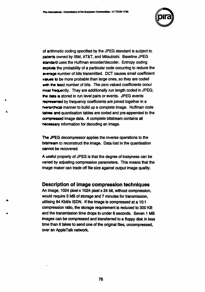
•
•
Plra ... ......,... • COhliJIIIDn of the~ ConinMI1IIIe • 41 TC0N 1730
of arithmetic coding specified by the JPEG standard is subject to patents owned by IBM, AT&T, and Mitsubishi. Baseline JPEG ltMdald uses the Huffman encoder/decoder. Entropy coding tDq)loG the probability of a particular code occurring to reduce the ~'-01 number of bits transmitted. OCT causes small coefficient va.s to be more probable than large ones, so they are coded Wllf\ the least number of bits. The zero valued coefficients occur moat ~ntly. They are additionally run length coded in JPEG; tw c.. • stored in run level pairs or events. JPEG events ,.,...,.ted by frequency coefficients are joined together in a ~ manner to build up a complete image. Huffman code ..._ lr'd quantisation tables are coded and pre-appended to the comcweaed image data. A complete bitstream contains all nec.sary information for decoding an image.
The JPEG decompressor applies the inverse operations to the b1stream to reconstruct the image. Data lost in the quantisation cannot be recovered.
A useful property of JPEG is that the degree of lossyness can be
varied by adjusting compression parameters. This means that the image maker can trade off file size against output image quality.
Description of image compression techniques An image, 1024 pixel x 1024 pixel x 24 bit, without compression, would require 3 MB of storage and 7 minutes for transmission, utilising 64 Kbit/s ISDN. If the image is compressed at a 10:1 compression ratio, the storage requirement is reduced to 300 KB and the transmission time drops to under 6 seconds. Seven 1 MB images can be compressed and transferred to a floppy disk in less time than it takes to send one of the original files, uncompressed. over an Apple Talk network.
78
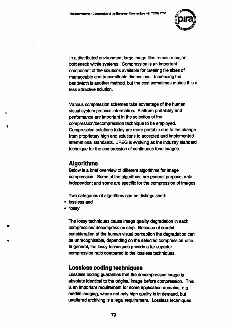
•
Plra INelnllloMI· Ccwamlllllon ~the Eulopean Comlnunllle • 41 TCON 1730
In a distributed environment large image files remain a major bottleneck within systems. Compression is an important component of the solutions available for creating file sizes of manageable and transmittable dimensions. Increasing the bandwidth is another method, but the cost sometimes makes this a less attractive solution.
Various compression schemes take advantage of the human visual system process infonnation. Platfonn portability and perfonnance are important in the selection of the compression/decompression technique to be employed. Compression solutions today are more portable due to the change from proprietary high end solutions to accepted and implemented intemational standards. JPEG is evolving as the industry standard technique for the compression of continuous tone images.
Algorithms Below is a brief overview of different algorithms for image compression. Some of the algorithms are general purpose, data independent and some are specific for the compression of images.
Two categories of algortthms can be distinguished: • lossless and •• lossy'
The lossy techniques cause image quality degradation in each compression/ decompression step. Because of careful consideration of the human visual perception the degradation can be unrecognisable, depending on the selected compression ratio. In general, the lossy techniques provide a far superior compression ratio compared to the lossless techniques.
Lossless coding techniques Lossless coding guaranties that the decompressed image is absolute identical to the original image before compression. This is an important requirement for some application domains, e.g. medial imaging, where not only high quality is in demand, but unaltered archMng is a legal requirement. Lossless techniques
79
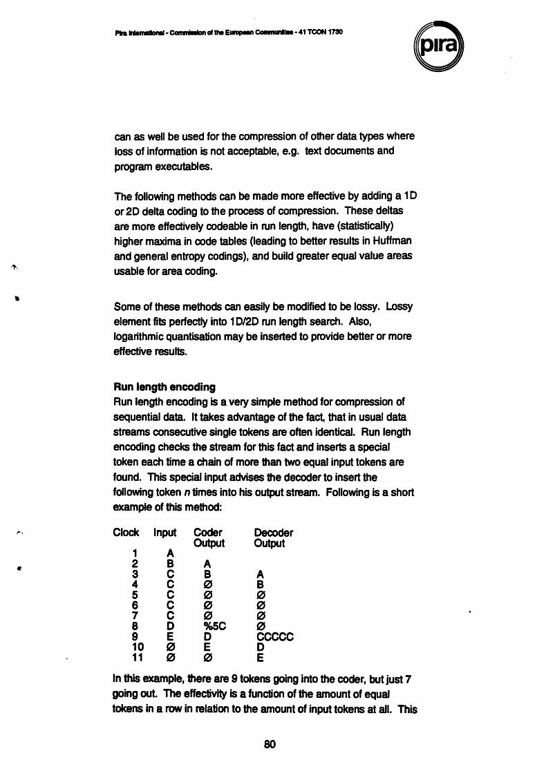
•
~'
II
P1ra lntMnldlonll· CGiauati:IUJtn ollhe E...,.,.n Comrnunllla • 41 TCON 1730
can as well be used for the compression of other data types where loss of information is not acceptable, e.g. text documents and program executables.
The following methods can be made more effective by adding a 1 D or 20 delta coding to the process of compression. These deltas are more effedively codeable in run length, have (statistically) higher maxima in code tables (leading to better results in Huffman and general entropy codings), and build greater equal value areas usable for area coding .
Some of these methods can easily be modified to be lossy. Lossy element fits perfectly into 1 D/20 run length search. Also, logarithmic quantisation may be inserted to provide better or more effective results.
Run length encoding Run length encoding is a very simple method for compression of sequential data. It takes advantage of the fad, that in usual data streams consecutive single tokens are often identical. Run length encoding checks the stream for this fad and inserts a special token each time a chain of more than two equal input tokens are found. This special input advises the decoder to insert the following token n times into his output stream. Following is a short example of this method:
Clock Input
1 A 2 8 3 c 4 c 5 c 6 c 7 c 8 D 9 E 10 t(J 11 t(J
Coder Output
A 8 0 0 0 t(J %5C D E t(J
Decoder Output
A 8 0 0 0 0 ccccc D E
In this example, there are 9 tokens going into the coder, but just 7 going out. The effectivity is a function of the amount of equal tokens in a row in relation to the amount of input tokens at all. This
80
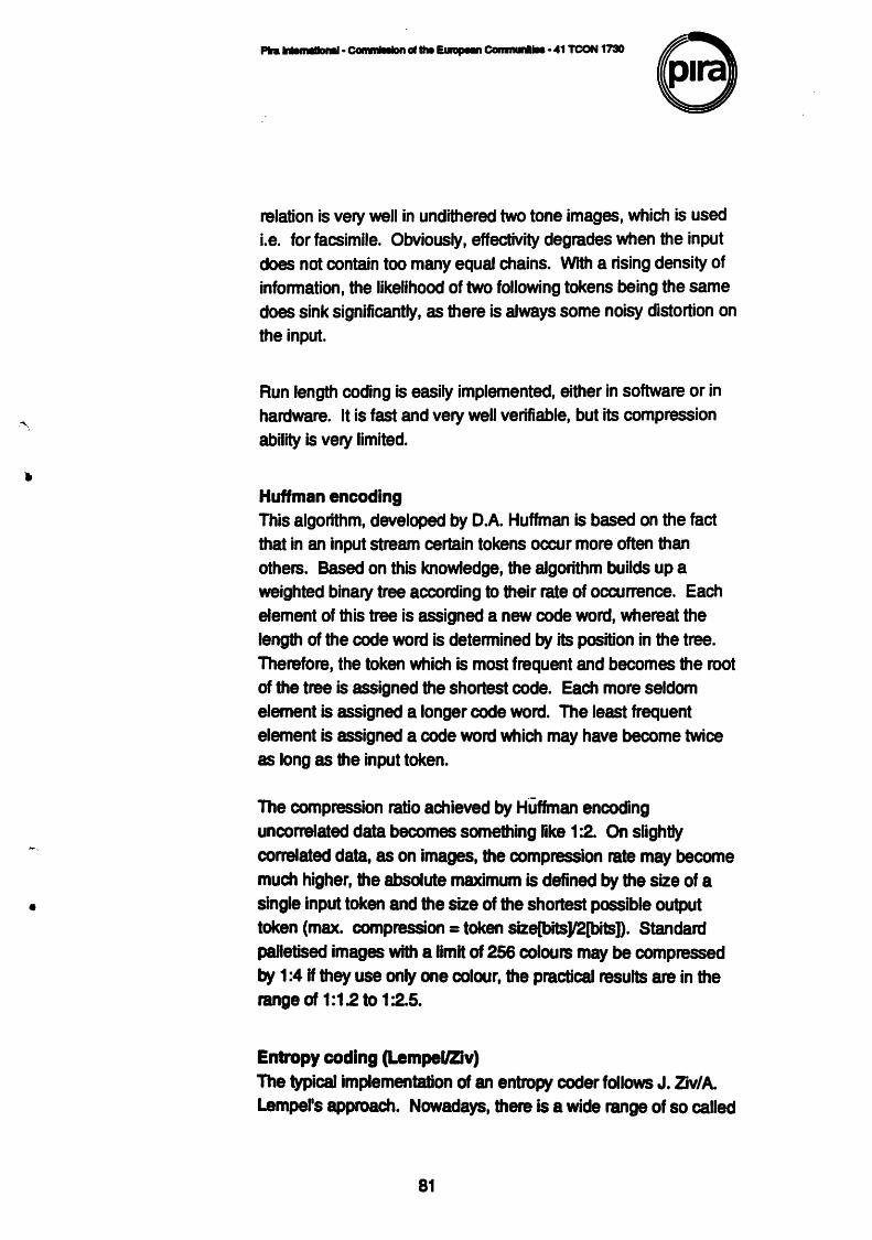
•
•
relation is very well in undithered two tone images, which is used i.e. for facsimile. Obviously, effectivity degrades when the input does not contain too many equal chains. With a rising density of infonnation, the likelihood of two following tokens being the same does sink significantly, as there is always some noisy distortion on the input.
Run length coding is easily implemented, either in software or in hardware. It is fast and very well verifiable, but its compression ability is very limited .
Huffman encoding This algorithm, developed by D.A. Huffman is based on the fact that in an input stream certain tokens occur more often than others. Based on this knowledge, the algorithm builds up a weighted binary tree according to their rate of occurrence. Each element of this tree is assigned a new code word, whereat the length of the code word is detennined by its position in the tree. Therefore, the token which is most frequent and becomes the root of the tree is assigned the shortest code. Each more seldom element is assigned a longer code word. The least frequent element is assigned a code word which may have become twice
as long as the input token.
The compression ratio achieved by Huffman encoding uncorrelated data becomes something like 1 :2. On slightly correlated data, as on images, the compression rate may become much higher, the absolute maximum is defined by the size of a single input token and the size of the shortest possible output token (max. compression= token size[bits]l2[bits]). Standard palletised images with a limit of 256 colours may be compressed by 1 :4 H they use only one colour, the practical results are in the range of 1:1.2 to 1 :2.5.
Entropy coding (Lempei/Ziv) The \'J)ical implementation of an entropy coder follows J. Zjv/ A. Lempel's approach. Nowadays, there is a wide range of so called
81
•
•
modified Lempei/Ziv codings. These algorithms all have a common way of working. The coder and the decoder both build up an equivalent dictionary of metasymbols, each of which represents a whole sequence of input tokenS. If a sequence is repeated after a symbol was found for it, then only the symbol becomes part of the coded data and the sequence of tokens referenced by the symbol becomes part of the decoded data later. As the dictionary is build up based on the data, H is not necessary to put it into the coded data, as it is with the tables in a Huffman coder.
This method becomes very efficient even on virtually random data . The average compression on text and program data is about 1 :2, the ratio on image data comes up to 1 :8 on the average GIF image. Here again, a high level of input noise degrades the efficiency significantly.
Entropy coders are a little tricky to implement, as there are usually a few tables, all growing while the algorithm runs.
LZ coding is subject to patents owned by IBM and Unisys (fonnerly Sperry).
Area coding Area coding is an enhanced fonn of run length coding, reflecting the two dimensional character of images. This is a significant advance over the other lossless methods. For coding an image it does not make too much sense to interpret it as a sequential stream, as it is in fact an array of sequences, building up a two dimensional object. Therefore, as the two dimensions are independent and of same importance, it is obvious that a coding scheme aware of this has some advantages. The algorithms for area coding try to find rectangular regions with the same characteristics. These regions are coded in a descriptive fonn as an Element with two points and a certain structure. The whole input image has to be described in this fonn to allow lossless decoding afterwards.
82
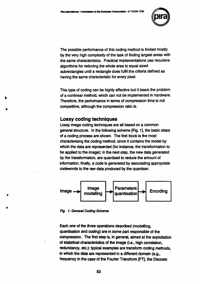
•
The possible performance of this coding method is limited mostly by the very high complexity of the task of finding l~rgest areas with the same characteristics. Practical implementations use recursive algorithms for reducing the whole area to equal sized subrectangles until a rectangle does fulfil the criteria defined as having the same characteristic for every pixel.
This type of coding can be highly effective but it bears the problem of a nonlinear method, which can not be implemented in hardware. Therefore, the performance in terms of compression time is not competitive, although the compression ratio is.
Lossy coding techniques Lossy image coding techniques are all based on a common general structure. In the following scheme [Fig. 1 ], the basic steps of a coding process are shown. The first block is the most characterising the coding method, since it contains the model by which the data are represented (for instance, the transformation to be applied to the image); in the next step, the new data generated by the transformation, are quantised to reduce the amount of information; finally, a code is generated by associating appropriate codewords to the raw data produced by the quantiser.
Image Image
modelling
Rg. 1: General Coding Scheme
Parameters quantisation Encoding
Each one of the three operations described (modelling, quantisation and coding) are in some part responsible of the compression. The first step is, in general, aimed at the exploitation of statistical characteristics of the image (i.e., high correlation, redundancy, etc.): typical examples are transform coding methods, in which the data are represented in a different domain (e.g., frequency in the case of the Fourier Transform [FT], the Discrete
83
•
P1ra IIRmllonll· COiiiililllon of the E&npeM Commla1llla • 41 TCON 1710
Cosine Transform [OCT], the Kahrunen-Loewe Transform [KL T], and so on), where a reduced number of coefficients contains most part of the original information. It is to be pointed out that this first phase does not produce necessarily a loss of information.
The aim of the quantisation, realised in the second step, is to reduce the amount of data used to represent the information into the new domain. Quantisation is in most cases not a reversible operation: therefore, it belongs to the so called 'lossy' methods.
The last operation is usually error free and used to optimise the representation of the information {then, possibly, to further reduce the bit rate), and to introduce some error detection code if needed.
In the following sections, a review of the most important coding schemes for lossy compression is given; in particular, some methods are described in their canonical form {transform coding, region based approximations, fractal coding, wavelets, hybrid methods) and some variations and improvements presented in the scientific literature are reported and discussed.
Transform coding (DCT/WaveletsiGabor) A general transform coding scheme involves subdividing an N _ N image into smaller n _ n blocks and performing a unitary transform on each subimage. A unitary transform is a reversible linear transform whose kernel describes a set of complete, orthonormal discrete basis functions. The goal of the transform is to decorrelate the original signal, and this deconelation generally results in the signal energy being redistributed among only a small set of transform coefficients. In this way, many coefficients may be discarded after quantisation and prior to encoding. Also, visually lossless compression can often be achieved by incorporating the HVS contrast sensitivity function in the quantisation of the coefficients.
84
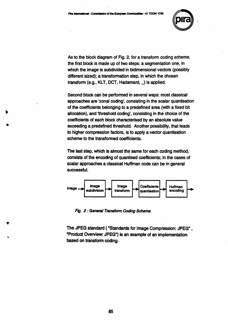
P1ra lrHrMIIDMI • Commllllon ~the Eumpeln Comrnunllll • 41 TCON 1730 8· As to the block diagram of Fig. 2, for a transform coding scheme, the first block is made up of two steps: a segmentation one, in which the image is subdivided in bidimensional vectors (possibly different sized); a transformation step, in which the chosen transform (e.g., KLT, OCT, Hadamard,_) is applied.
Second block can be performed in several ways: most classical approaches are -zonal coding', consisting in the scalar quantisation of the coefficients belonging to a predefined area (with a fixed bit allocation), and 'threshold coding', consisting in the choice of the coefficients of each block characterised by an absolute value exceeding a predefined threshold. Another possibility, that leads to higher compression factors, is to apply a vector quantisation scheme to the transformed coefficients.
The last step, which is almost the same for each coding method, consists of the encoding of quantised coefficients; in the cases of scalar approaches a classical Huffman code can be in general successful.
Image Image subdivision
Image transform
Coefficients quantisation
F1g. 2: General Transform Coding Scheme
Huffman encoding
The JPEG standard ( •standards for Image Compression: JPEG• , •Product Overview: JPEG•) is an example of an implementation based on transform coding.
85
-•
P1ra lrUIIIIIIIIDMI· ~n ~the EurapeM CGmmunllel • 41 TCON 1730
Vector quantisation In this section, the main characteristics of vector quantizers will be briefly discussed, and some improvements presented that can be
adopted in order to reach higher performances.
As is well known, a vector quantiser can be defined as a transform operator Tfrom a K-dimensional Euclidean space RK to a finite subset X in RK made up of N vectors.
In other words, the subset X is the vector codebook, or, more generally, the code book. Clearty, the choice of the set of vectors (x;J is of major importance. The level of distortion due to the transformation Tis generally computed as the MSE between the •real" vector x in RK and the corresponding vector x'= T(x) in X.
This error is such as to minimise the Euclidean distance d.
The optimum scalar quantiser was proposed by Uoyd and Max. Later on, Unde, Buzo and Gray resumed and generalized this method, extending it to the case of a vector quantiser. The algorithm that they proposed is derived from the KNN clu~erisation method, and is performed by iterating the following basic operations:
• subdivide the training set into N groups (called •partitions• or 'Voronoi regions'), which are associated with the N codebook letters, according to a minimum distance criterion;
• the centroids of the Voronoi regions become the updated codebook vectors;
• compute the average distortion: if the percent reduction in the distortion (as compared with the previous step) is below a certain threshold, then STOP.
86
Once the codebook has been designed, the coding process simply consists in the application of the Toperator (as defined above) to the vectors of the original image. In practice, each group of n pixels will be coded as an address in the vector codebook, that is, as a number from 1 to N. The compression ratio Cis therefore given by:
where n represents the number of bits associated with each pixel in the original image.
The LBG algorithm for the design of a vector codebook always reaches a local minimum for the distortion function, but often this solution is not the optimal one. A careful analysis of the LBG algorithm's behaviour allows one to detect two critical points: the choice of the starting codebook and the uniformity of the Voronoi regions• dimensions. For this reason some algorithms have been studied and implemented to reach better performances: as regard to the initialisation of the LBG algorithm, for instance, one can observe that a random choice of the starting codebook requires a large number of iterations before reaching an acceptable amount of distortion. Moreover, if the starting point leads to a local minimum solution, the relative stopping criterion prevents further optimisation steps.
Segmentation and approximation methods In segmentation and approximation methods, the image is modelled as a mosaic of regions, each one characterised by a sufficient degree of uniformity of its pixels with respect to a certain feature (e.g., grey level, texture); to each region, some parameters related to the characterising feature are then associated.
The operations of finding a suitable segmentation and an optimum set of approximating parameters are highly correlated, since the segmentation algorithm must take into account the error produced by the region reconstruction (in order to limit this value within
87
determined bounds). These two operations constitute the first block for this class of coding schemes; second and third steps are strongly dependent on the statistical characteristics of the parameters of the approximation (and therefore on the approximation itself).
Classical examples are •polynomial approximation• and •texture approximation•: in the former, the regions are reconstructed by means of polynomial functions in {x, y); the task of the encoder is to find the optimum coefficients a; for the basis functions ao, a1x, B2f, BsKf, ~' a~, _ In the latter method, the regions are filled by synthesising a parametrised texture based on some model (e.g., fractals, statistical methods, Markov Random Fields [MRF], J. It is to be pointed out that, while in the polynomial approximation the problem of finding optimum coefficients is quite simple (it is possible to use least squares approximation or similar exact formulations), for texture based techniques the problem can be very complex.
Spline approximation methods (Bilinear lnterpolation/Aegularisation) These methods fall in the more general problem of image reconstruction or sparse data interpolation. The basic concept is to interpolate data from a set of points coming from original pixel data or calculated in order to match some error criteria. The problem of interpolating a set of sparse data is generally ill posed, so some regularization algorithm must be adopted in order to obtain a unique solution. The problem is well known in literature, and many interpolation algorithms can be used. In order to apply this kind of techniques to image coding, a good interpolant must be used to match visual criteria. Spline interpolation is a good visual interpolant notwithstanding it requires a great computational effort. Bilinear interpolation is more easy to implement, while maintaining a very good visual quality. Regularization involves the minimisation of an energy function in order to obtain an interpolant which presents some smoothness constraints; it can be combined with non continuities along edges in order to preserve contours
88
-I
P1ra lrHmallonal • Cornmt111on of tt. E~ Communllel • 41 TCON 1730
quality in reconstruction. Generally all interpolants computations require the solution of very large linear systems even if related to very sparse matrices. This leads to the use of recursive solution such as relaxation (suitable for a large parallel implementation), or to the use of gradient descent algorithm.
The use of an interpolation algorithm for image coding is more interesting when related to techniques such as two source decomposition, where the image is modelled as the sum of two sources; one is the stationary part (it can be considered related to the low frequency content), the second is the residual content coming from non-stationarities such as edges. The first of the two sources is coded by means of a prediction scheme that can be one of the previous described interpolants. The second source (the residual) can be coded trough the use of a classical coding method (transfonn coding, vector or scalar quantisation etc.). Moreover two source decomposition is a very effective coding scheme as far as it shows a low tile effect that affects all block coding techniques when compression factors become higher.
Fractal coding (texture synthesis, Iterated functions system
[IFS], recursive IFS [RIFSD
Fractal parameters, including fractal dimension, lacunarity, as well as others described below, have the potential to provide efficient methods of describing imagery in a highly compact fashion for both intra- and interframe applications. Fractal methods have been developed for both noisy and noise free coding methods.
Images of natural scenes are likely candidates because of the fractal structure of the scene content, but results are reported to be applicable to a variety of binary, monochrome, and colour scenes.
In the mid-eighties Dr Michael Bamsley reported the use of •Iterated Function System• for image compression and synthesis. Using sets of affine transfonnations developed for a given image, and a principal result known as the •collage theorem•, intraframe compressions in excess of 1 0,000:1 and interframe compression in excess of 1 ,000,000:1 were reported. The collage theorem states
89
P1ra lrMinllllonll· Commllllon c1 the Ewapean Communllle • 41 TCON 1730
that if an image can be covered (approximately) with compressed affine transfonnations of itself, then the image can be (approximately) reconstructed by computing the attractor (in the sense of non linear dynamic systems) of this set of affine transfonnations.
This convergence was extremely slow, about 100 hours on a Cray, unless assisted by a person and was presented as an illustration of a scientific possibility, not as a commercial reality. In 1987 Bamsley and Sloan formed Iterated Systems Inc to develop a product that would function in a commercial environment. By the end of 1988 Iterated Systems had developed the patented technique called the 'Fractal Transfonn• which has become the basis of their current product range. The development allowed a real wortd image to be reduced to a set of fractal equations based on the image being processed, rather than a huge library of precalculated, reference, fractal patterns. Image compression algorithms which are noise free have been reported to be developed from this transfonn for real time automatic image compression at ratios between 1 0:1 and 1 00:1
Bamsley has not diwlged any technical information about the Fractal Transfonn beyond that in his book •Fractals Everywhere•. The book explains the idea of IFS codes at length but is vague about the application of the collage theorem to specific compression problems.
Researchers at BeiiCore have developed a compression method that incorporates a Peano Scan (the Peano curve is a •space filling• fractal curve} with a fractal based coding schema for intraframe compression, so making it possible to archive high picture quality with bit rates of less than one bit per pixel. A fractal based method was reported eartier by Walach while the concepts of using a Peano Scan has been used for storage, compression and display. The BeiiCore researchers have combined these two fractal concepts into an efficient implementation which is now being incorporated into a VLSI chip. Compression results show
90
P1ra lnlemdonll· Comm1111on ~ U. EU~UP~M Comrnunllle • 41 TCON 1730
good quality imagery at a rate of 0.8-1 bit per pixel. The technique may be implemented in an adaptive fashion since a local estimate of fractal dimension provides an objective measure of image complexity.
An altemative approach to image compression, also incorporating some features of fractal geometry, is based on orthogonal pyramid transforms. These transforms decompose the image as a weighted sum of basis functions. The basis functions have several attractive features including localisation in space and spatial frequency as well as self similarity. This latter feature reflects the notion that basis functions are scaled version of one another, and thus are able to capture image information at all scales in a uniform way. The pyramid transform techniques are based, in part, on an eartier concept of quadrature mirror filters. The pyramid structure results from dealing with the image at multiple resolutions. Results reported show high quality imagery at rates of 0.65 bits per pixel. The MSE is comparable to 16 X 16 block OCT transform coding algorithms but superior in visual image quality.
Efficiency and quality of different lossy compression techniques The performances of lossy picture coding algorithms is usually evaluated on the basis of two parameters:
1. the compression factor (or analogously the bit rate) and 2. the distortion produced on the reconstruction.
The first is an objective parameter, while the second strongly depends on the usage of the coded image. Nevertheless, a rough evaluation of the performances of a method can be made by considering an objective measure of the error, like MSE or SNR.
As to the methods described in the previous pages, average compression ratios and SNR values obtainable are presented in the following table:
91
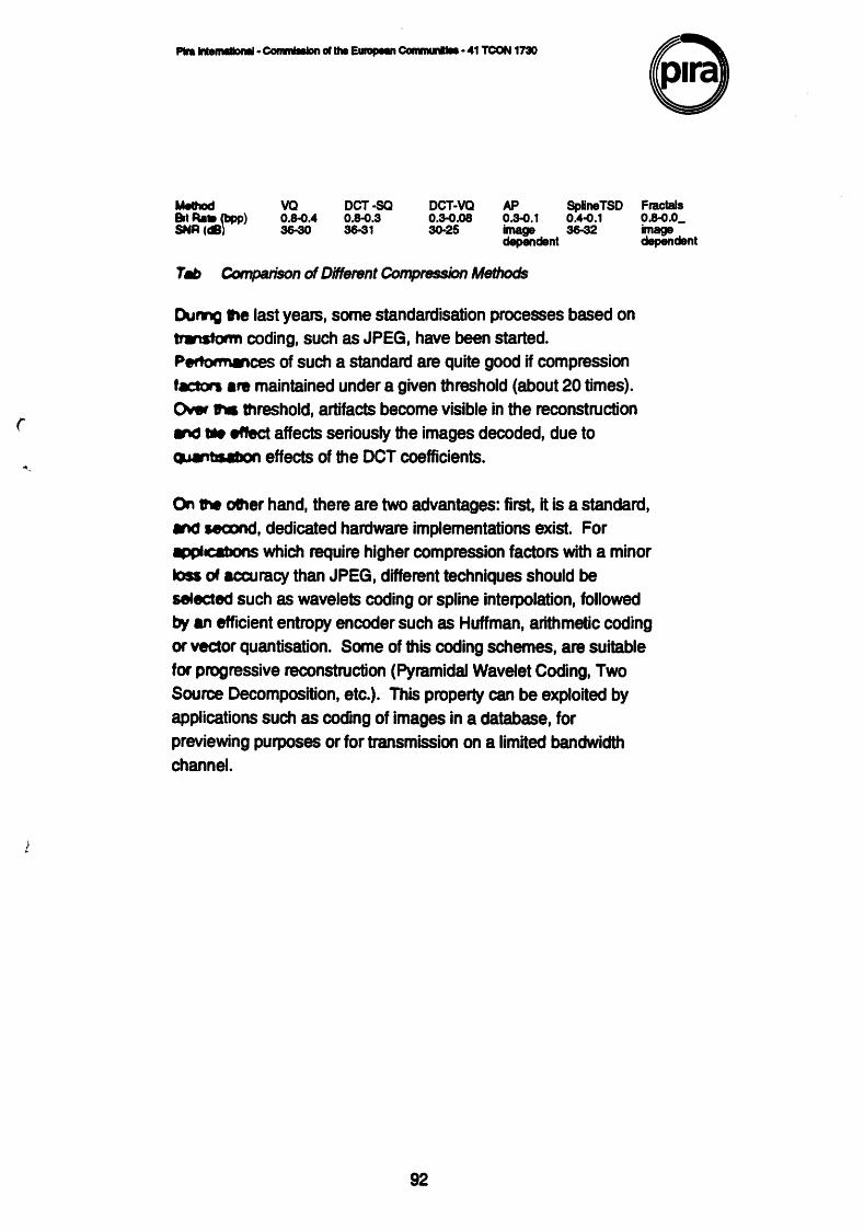
(
1
P1ra IIUrnldloMI· COinmiiiiOn clthe EurupeM Communllll • 41 TCON 1730
Melhod Sit Rail (bpp) SNR Cc8) ..
VQ 0.8-0.4 36-30
DCT·SQ 0.8-0.3 36-31
DCT·VQ 0.3-0.08 3().25
AP SpUneTSD 0.3-0.1 0.4.0.1 image 36-32 depindent
TM» Comparison of Different Compression Methods
Dumg ~ last years, some standardisation processes based on trw astorm coding, such as JPEG, have been started. P~ces of such a standard are quite good if compression t.ctors are maintained under a given threshold (about 20 times). Oww .,. threshold, artifacts become visible in the reconstruction ._, • effect affects seriously the images decoded, due to ~ effects of the OCT coefficients.
Fractals 0.8-0.0_ image dependent
~ 1tw other hand, there are two advantages: first, it is a standard, and second, dedicated hardware implementations exist. For .,PcabOnS which require higher compression factors with a minor loss of accuracy than JPEG, different techniques should be setected such as wavelets coding or spline interpolation, followed by an efficient entropy encoder such as Huffman, arithmetic coding or vector quantisation. Some of this coding schemes, are suitable for progressive reconstruction (Pyramidal Wavelet Coding, Two Source Decomposition, etc.). This property can be exploited by applications such as coding of images in a database, for previewing purposes or for transmission on a limited bandwidth channel.
92

---~ .. lho"-Communlloo·41TCON17ll0 e Appendix2
List of participants and contributors
)
93
MrG Heine MrJ Blay CEC DGXIIi-2 Iterated Systems Ltd Batiment Jean Monnet Wyvols Court Platequ de Kirchberg Swallowfield L.2920 Luxembourg Nr Reading
RG71PY Mr G Stephenson KETc/oCRI Dr-Ing. W Ulmer 2 Rue Jean Monnet Hasembergsteoge 30 L-2180 Luxembourg 7000 Stuttgart-1
Germany MrV Reible
r Detecon GmbH Professor D A Duce Voltastrasse 5 Informatics Department
"r 1 000 Bertin 65 Building R1- 2.58 "' Germany Rutherford Appleton Laboratories
Chilton Dr J Schon hut Did cot Fraunhofer-lnstitut fur Oxon OX11 OQX Graphische Datenverarbeitung Wilhelminenstrasse 7 Mr A Francis 61 00 Darmstadt Page Description Germany 6 Spencer Street
New Bradwell MrP Fry Milton Keynes Kodak Umited MK130DW Research & Development Headstone Drive Mr G Battrick Harrow 25 Pleshey Road Middlesex London HA14TY N70RA
MrM Stroud Mr M Scott-Taggart Adplates Repro House Pira lntemational 29 Clerkenwell Road
' London MrR Minio EC1M 5TA Pira lntemational
DrAHamber MrJ Wheeler Christies lntemational pic Pira lntemational 8 King Street StJarnes•s MrA Brasher London Pira lntemational SW1Y6QT
Mr A J Johnson Crosfield Electronics Ud Three Cherry Trees Lane Hamel Hempstead Herts HP27RH
94


