Embed Size (px)
Citation preview
www.infineon.com
Please note that Cypress is an Infineon Technologies Company.The document following this cover page is marked as “Cypress” document as this is the company that originally developed the product. Please note that Infineon will continue to offer the product to new and existing customers as part of the Infineon product portfolio.
Continuity of document contentThe fact that Infineon offers the following product as part of the Infineon product portfolio does not lead to any changes to this document. Future revisions will occur when appropriate, and any changes will be set out on the document history page.
Continuity of ordering part numbersInfineon continues to support existing part numbers. Please continue to use the ordering part numbers listed in the datasheet for ordering.
www.cypress.com Document No. 001-33780 Rev. *D 1
AN2186
Consumer or Industrial: Acoustic Glass Break Detector
Author: Vadym Grygorenko
Associated Project: Yes
Associated Part Family: CY8C22xxx, CY8C24xxx, CY8C27xxx
Software Version: PSoC® Designer™ 5.4
Related Application Notes: AN2099
AN2186 describes a low-cost, three-band acoustic glass break detector. Digital signal processing provides high
sensitivity and sufficient resistance to false alarms.
1 Introduction
There are a variety of ways to implement glass break recognition. One method is to detect the vibration made by breaking glass. This technology may be realized using a piezo-film sensor for impact detection. Another method is to detect the sound of breaking glass. The simplest of such detectors are responsive to sound level spikes in the 4-5 kHz frequency band. The main disadvantage of the acoustic method is the high probability of false alarms caused by loud music, tinkling of bells, or other sounds. To increase false alarm immunity, two or more frequency bands are treated and information relating to amplitude and timing of the separated channels is analyzed.
It is possible to make dual technology detectors in which one part detects a very low frequency sound pressure wave created by the flexing of glass before breakage and another part is sensitive to high frequencies of the shattered glass. The most advanced detectors are based on neuronets and pattern recognition. However, these detectors require powerful digital signal processors to implement complex algorithms.
The PSoC® solution for a framed-glass break detector presented in this Application Note is based on timing and
amplitude analysis of sound at three frequencies: 35 Hz, 300 Hz, and 5000 Hz. All signal treatments are performed in the software. This allows tuning flexibility and adaptation to different glass types.
2 PSoC Resources
Cypress provides a wealth of data at www.cypress.com to help you to select the right PSoC device for your design, and quickly and effectively integrate the device into your design. In this document, PSoC refers to the PSoC 1 family of devices. To learn more about PSoC 1, refer to the application note AN75320 - Getting Started with PSoC 1.
The following is an abbreviated list for PSoC 1:
Overview: PSoC Portfolio, PSoC Roadmap
Product Selectors: PSoC 1, PSoC 3,
PSoC 4, or PSoC 5LP. In addition, PSoC Designer includes a device selection tool.
Datasheets: Describe and provide electrical
specifications for the PSoC 1 device family.
Application Notes and Code Examples:
Cover a broad range of topics, from basic to advanced level. Many of the application notes include code examples.
Technical Reference Manuals (TRM):
Provide detailed descriptions of the internal architecture of the PSoC 1 devices.
Development Kits:
CY3215A-DK In-Circuit Emulation Lite Development Kit includes an in-circuit emulator (ICE). While the ICE-Cube is primarily used to debug PSoC 1 devices, it can also program PSoC 1 devices using ISSP.
CY3210-PSOCEVAL1 Kit enables you to evaluate and experiment Cypress's PSoC 1 programmable system-on-chip design methodology and architecture.
CY8CKIT-001 is a common development platform for all PSoC family devices.
The MiniProg1 and MiniProg3 devices provide an interface for flash programming.
Consumer or Industrial: Acoustic Glass Break Detector
www.cypress.com Document No. 001-33780 Rev. *D 2
2.1 PSoC Designer
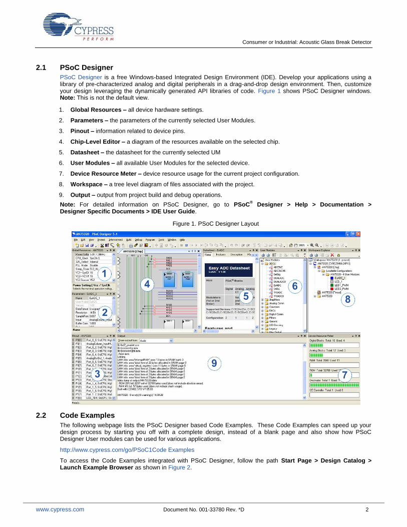
PSoC Designer is a free Windows-based Integrated Design Environment (IDE). Develop your applications using a library of pre-characterized analog and digital peripherals in a drag-and-drop design environment. Then, customize your design leveraging the dynamically generated API libraries of code. Figure 1 shows PSoC Designer windows. Note: This is not the default view.
1. Global Resources – all device hardware settings.
2. Parameters – the parameters of the currently selected User Modules.
3. Pinout – information related to device pins.
4. Chip-Level Editor – a diagram of the resources available on the selected chip.
5. Datasheet – the datasheet for the currently selected UM
6. User Modules – all available User Modules for the selected device.
7. Device Resource Meter – device resource usage for the current project configuration.
8. Workspace – a tree level diagram of files associated with the project.
9. Output – output from project build and debug operations.
Note: For detailed information on PSoC Designer, go to PSoC® Designer > Help > Documentation >
Designer Specific Documents > IDE User Guide.
Figure 1. PSoC Designer Layout
2.2 Code Examples
The following webpage lists the PSoC Designer based Code Examples. These Code Examples can speed up your design process by starting you off with a complete design, instead of a blank page and also show how PSoC Designer User modules can be used for various applications.
http://www.cypress.com/go/PSoC1Code Examples
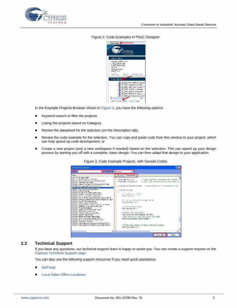
To access the Code Examples integrated with PSoC Designer, follow the path Start Page > Design Catalog > Launch Example Browser as shown in Figure 2.
Consumer or Industrial: Acoustic Glass Break Detector
www.cypress.com Document No. 001-33780 Rev. *D 3
Figure 2. Code Examples in PSoC Designer
In the Example Projects Browser shown in Figure 3, you have the following options.
Keyword search to filter the projects.
Listing the projects based on Category.
Review the datasheet for the selection (on the Description tab).
Review the code example for the selection. You can copy and paste code from this window to your project, which can help speed up code development, or
Create a new project (and a new workspace if needed) based on the selection. This can speed up your design process by starting you off with a complete, basic design. You can then adapt that design to your application.
Figure 3. Code Example Projects, with Sample Codes
2.3 Technical Support
If you have any questions, our technical support team is happy to assist you. You can create a support request on the Cypress Technical Support page.
You can also use the following support resources if you need quick assistance.
Self-help
Local Sales Office Locations
Consumer or Industrial: Acoustic Glass Break Detector
www.cypress.com Document No. 001-33780 Rev. *D 4
3 Detecting Algorithm
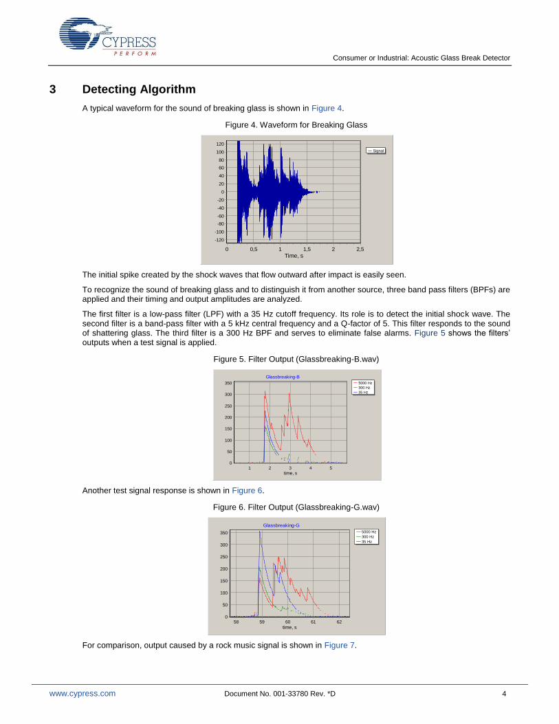
A typical waveform for the sound of breaking glass is shown in Figure 4.
Figure 4. Waveform for Breaking Glass
The initial spike created by the shock waves that flow outward after impact is easily seen.
To recognize the sound of breaking glass and to distinguish it from another source, three band pass filters (BPFs) are applied and their timing and output amplitudes are analyzed.
The first filter is a low-pass filter (LPF) with a 35 Hz cutoff frequency. Its role is to detect the initial shock wave. The second filter is a band-pass filter with a 5 kHz central frequency and a Q-factor of 5. This filter responds to the sound of shattering glass. The third filter is a 300 Hz BPF and serves to eliminate false alarms. Figure 5 shows the filters’ outputs when a test signal is applied.
Figure 5. Filter Output (Glassbreaking-B.wav)
Another test signal response is shown in Figure 6.
Figure 6. Filter Output (Glassbreaking-G.wav)
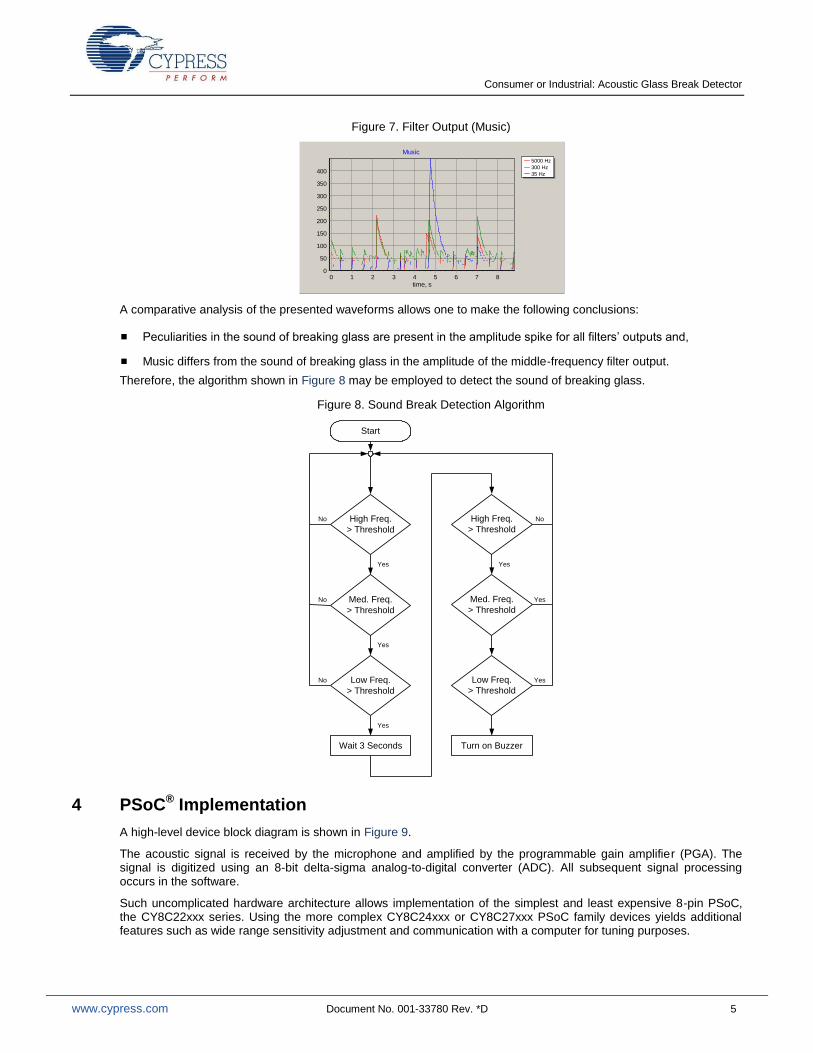
For comparison, output caused by a rock music signal is shown in Figure 7.
Signal
Time, s2,521,510,50
Am
plitu
de
120
100
80
60
40
20
0
-20
-40
-60
-80
-100
-120
5000 Hz
300 Hz
35 Hz
Glassbreaking-B
time, s54321
am
plitu
de
350
300
250
200
150
100
50
0
5000 Hz
300 Hz
35 Hz
Glassbreaking-G
time, s6261605958
am
plitu
de
350
300
250
200
150
100
50
0
Consumer or Industrial: Acoustic Glass Break Detector
www.cypress.com Document No. 001-33780 Rev. *D 5
Figure 7. Filter Output (Music)
A comparative analysis of the presented waveforms allows one to make the following conclusions:
Peculiarities in the sound of breaking glass are present in the amplitude spike for all filters’ outputs and,
Music differs from the sound of breaking glass in the amplitude of the middle-frequency filter output.
Therefore, the algorithm shown in Figure 8 may be employed to detect the sound of breaking glass.
Figure 8. Sound Break Detection Algorithm
Start
Wait 3 Seconds
High Freq.
> Threshold
Med. Freq.
> Threshold
Low Freq.
> Threshold
Turn on Buzzer
High Freq.
> Threshold
Med. Freq.
> Threshold
Low Freq.
> Threshold
Yes
Yes
Yes
Yes
Yes
Yes
No
No
No
No
4 PSoC® Implementation
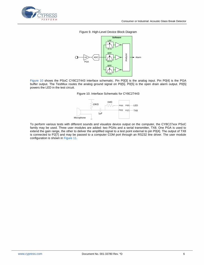
A high-level device block diagram is shown in Figure 9.
The acoustic signal is received by the microphone and amplified by the programmable gain amplifier (PGA). The signal is digitized using an 8-bit delta-sigma analog-to-digital converter (ADC). All subsequent signal processing occurs in the software.
Such uncomplicated hardware architecture allows implementation of the simplest and least expensive 8-pin PSoC, the CY8C22xxx series. Using the more complex CY8C24xxx or CY8C27xxx PSoC family devices yields additional features such as wide range sensitivity adjustment and communication with a computer for tuning purposes.
5000 Hz
300 Hz
35 Hz
Music
time, s876543210
am
plitu
de
400
350
300
250
200
150
100
50
0
Consumer or Industrial: Acoustic Glass Break Detector
www.cypress.com Document No. 001-33780 Rev. *D 6
Figure 9. High-Level Device Block Diagram
ADC
Ana
lyzer
PGA
x48 Alarm
Software
LPF
BPF
BPF
5 kHz
300 Hz
35 Hz
Figure 10 shows the PSoC CY8C27443 interface schematic. Pin P0[3] is the analog input. Pin P0[4] is the PGA buffer output. The TestMux routes the analog ground signal on P0[5]. P0[5] is the open drain alarm output. P0[5] powers the LED in the test circuit.
Figure 10. Interface Schematic for CY8C27443
Microphone
1µF
P0[5]
P0[3]
P0[4]
P2[7] TX8
LED10KΩ
1MΩ
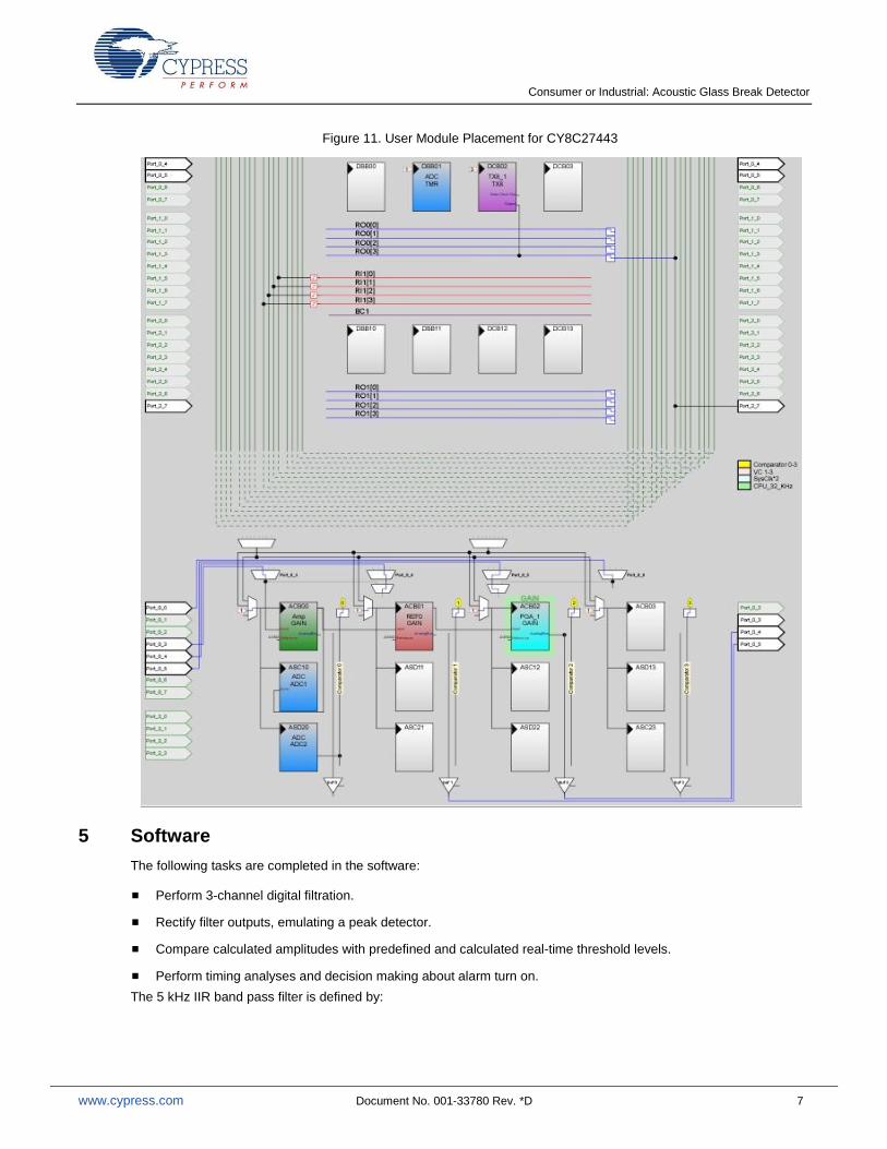
To perform various tests with different sounds and visualize device output on the computer, the CY8C27xxx PSoC family may be used. Three user modules are added: two PGAs and a serial transmitter, TX8. One PGA is used to extend the gain range, the other to deliver the amplified signal to a test point external to pin P0[4]. The output of TX8 is connected to P2[7] and may be passed to a computer COM port through an RS232 line driver. The user module configuration is shown in Figure 11.
Consumer or Industrial: Acoustic Glass Break Detector
www.cypress.com Document No. 001-33780 Rev. *D 7
Figure 11. User Module Placement for CY8C27443
5 Software
The following tasks are completed in the software:
Perform 3-channel digital filtration.
Rectify filter outputs, emulating a peak detector.
Compare calculated amplitudes with predefined and calculated real-time threshold levels.
Perform timing analyses and decision making about alarm turn on.
The 5 kHz IIR band pass filter is defined by:
Consumer or Industrial: Acoustic Glass Break Detector
www.cypress.com Document No. 001-33780 Rev. *D 8
2 2
1 3,
4 4n n n ny x x y Equation 1
y is output and x is input.
The filter described in Equation (1) has a frequency response function with a maximum of 2 at one-fourth the sampling frequency and a Q-factor of approximately 5. In our case, the ADC sample rate is chosen to be 18750 Hz,
24
5 256
MHz
, so the filter is tuned to a frequency or approximately 4.7 kHz.
It is important that coefficients in Equation (1) avoid multiplication and division operations. Addition and arithmetical shift operations are sufficient.
The 300 Hz BPF is also defined by Equation (1). However, it is necessary to reduce the input data sample rate. This is accomplished using another LPF and a decimator. A simple equation is used:
16
1
.16
1
i
in xx Equation 2
In other words, input data to the 300 Hz BPF is an average of the 16 ADC samples.
The LPF is defined by:
2118
1)2(
2
1 nnnnn yxxxy Equation 3
This filter has a cut-off frequency approximately 0.23 times the input sample rate. The gain is 1.78. Input data is measured as the average of the 128 ADC samples to achieve the 35 Hz band.
The averaged values are passed through a first order IIR high pass filter (HPF) with a cut-off frequency of approximately 0.36 Hz to generate offset canceling. This additional filter is based on Application Note AN2099 “Single-Pole IIR Filters. To Infinity And Beyond!”
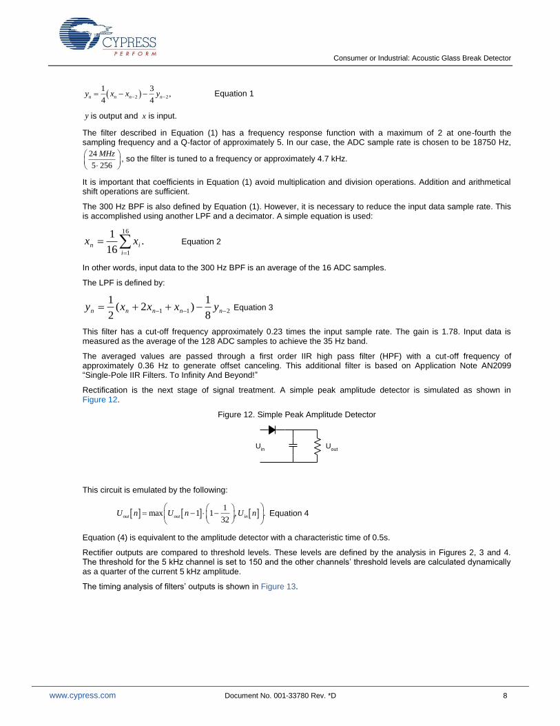
Rectification is the next stage of signal treatment. A simple peak amplitude detector is simulated as shown in Figure 12.
Figure 12. Simple Peak Amplitude Detector
Uin
Uout
This circuit is emulated by the following:
1
max 1 1 , .32
out out inU n U n U n
Equation 4
Equation (4) is equivalent to the amplitude detector with a characteristic time of 0.5s.
Rectifier outputs are compared to threshold levels. These levels are defined by the analysis in Figures 2, 3 and 4. The threshold for the 5 kHz channel is set to 150 and the other channels’ threshold levels are calculated dynamically as a quarter of the current 5 kHz amplitude.
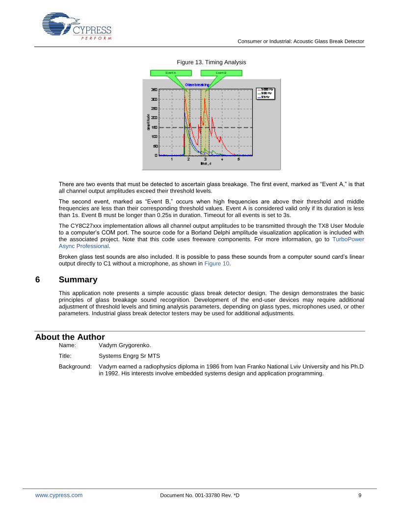
The timing analysis of filters’ outputs is shown in Figure 13.
Consumer or Industrial: Acoustic Glass Break Detector
www.cypress.com Document No. 001-33780 Rev. *D 9
Figure 13. Timing Analysis
There are two events that must be detected to ascertain glass breakage. The first event, marked as “Event A,” is that all channel output amplitudes exceed their threshold levels.
The second event, marked as “Event B,” occurs when high frequencies are above their threshold and middle frequencies are less than their corresponding threshold values. Event A is considered valid only if its duration is less than 1s. Event B must be longer than 0.25s in duration. Timeout for all events is set to 3s.
The CY8C27xxx implementation allows all channel output amplitudes to be transmitted through the TX8 User Module to a computer’s COM port. The source code for a Borland Delphi amplitude visualization application is included with the associated project. Note that this code uses freeware components. For more information, go to TurboPower Async Professional.
Broken glass test sounds are also included. It is possible to pass these sounds from a computer sound card’s linear output directly to C1 without a microphone, as shown in Figure 10.
6 Summary
This application note presents a simple acoustic glass break detector design. The design demonstrates the basic principles of glass breakage sound recognition. Development of the end-user devices may require additional adjustment of threshold levels and timing analysis parameters, depending on glass types, microphones used, or other parameters. Industrial glass break detector testers may be used for additional adjustments.
About the Author Name: Vadym Grygorenko.
Title: Systems Engrg Sr MTS
Background: Vadym earned a radiophysics diploma in 1986 from Ivan Franko National Lviv University and his Ph.D in 1992. His interests involve embedded systems design and application programming.
Consumer or Industrial: Acoustic Glass Break Detector
www.cypress.com Document No. 001-33780 Rev. *D 10
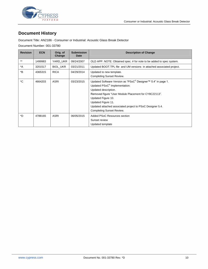
Document History
Document Title: AN2186 - Consumer or Industrial: Acoustic Glass Break Detector
Document Number: 001-33780
Revision ECN Orig. of Change
Submission Date
Description of Change
** 1499983 YARD_UKR 09/24/2007 OLD APP. NOTE: Obtained spec. # for note to be added to spec system.
*A 3201517 BIOL_UKR 03/21/2011 Updated BOOT.TPL file and UM versions in attached associated project.
*B 4365315 RICA 04/29/2014 Updated to new template.
Completing Sunset Review.
*C 4664203 ASRI 03/23/2015 Updated Software Version as “PSoC® Designer™ 5.4” in page 1.
Updated PSoC® Implementation:
Updated description.
Removed figure “User Module Placement for CY8C22113”.
Updated Figure 10.
Updated Figure 11.
Updated attached associated project to PSoC Designer 5.4.
Completing Sunset Review.
*D 4788165 ASRI 06/05/2015 Added PSoC Resources section
Sunset review
Updated template
Consumer or Industrial: Acoustic Glass Break Detector
www.cypress.com Document No. 001-33780 Rev. *D 11
Worldwide Sales and Design Support
Cypress maintains a worldwide network of offices, solution centers, manufacturer’s representatives, and distributors. To find the office closest to you, visit us at Cypress Locations.
Products
Automotive cypress.com/go/automotive
Clocks & Buffers cypress.com/go/clocks
Interface cypress.com/go/interface
Lighting & Power Control cypress.com/go/powerpsoc
Memory cypress.com/go/memory
PSoC cypress.com/go/psoc
Touch Sensing cypress.com/go/touch
USB Controllers cypress.com/go/usb
Wireless/RF cypress.com/go/wireless
PSoC® Solutions
psoc.cypress.com/solutions
PSoC 1 | PSoC 3 | PSoC 4 | PSoC 5LP
Cypress Developer Community
Community | Forums | Blogs | Video | Training
Technical Support
cypress.com/go/support
PSoC is a registered trademark and PSoC Creator is a trademark of Cypress Semiconductor Corp. All other trademarks or registered trademarks referenced herein are the property of their respective owners.
Cypress Semiconductor 198 Champion Court San Jose, CA 95134-1709
Phone : 408-943-2600 Fax : 408-943-4730 Website : www.cypress.com
© Cypress Semiconductor Corporation, 2007-2015. The information contained herein is subject to change without notice. Cypress Semiconductor Corporation assumes no responsibility for the use of any circuitry other than circuitry embodied in a Cypress product. Nor does it convey or imply any license under patent or other rights. Cypress products are not warranted nor intended to be used for medical, life support, life saving, critical control or safety applications, unless pursuant to an express written agreement with Cypress. Furthermore, Cypress does not authorize its products for use as critical components in life-support systems where a malfunction or failure may reasonably be expected to result in significant injury to the user. The inclusion of Cypress products in life-support systems application implies that the manufacturer assumes all risk of such use and in doing so indemnifies Cypress against all charges. This Source Code (software and/or firmware) is owned by Cypress Semiconductor Corporation (Cypress) and is protected by and subject to worldwide patent protection (United States and foreign), United States copyright laws and international treaty provisions. Cypress hereby grants to licensee a personal, non-exclusive, non-transferable license to copy, use, modify, create derivative works of, and compile the Cypress Source Code and derivative works for the sole purpose of creating custom software and or firmware in support of licensee product to be used only in conjunction with a Cypress integrated circuit as specified in the applicable agreement. Any reproduction, modification, translation, compilation, or representation of this Source Code except as specified above is prohibited without the express written permission of Cypress. Disclaimer: CYPRESS MAKES NO WARRANTY OF ANY KIND, EXPRESS OR IMPLIED, WITH REGARD TO THIS MATERIAL, INCLUDING, BUT NOT LIMITED TO, THE IMPLIED WARRANTIES OF MERCHANTABILITY AND FITNESS FOR A PARTICULAR PURPOSE. Cypress reserves the right to make changes without further notice to the materials described herein. Cypress does not assume any liability arising out of the application or use of any product or circuit described herein. Cypress does not authorize its products for use as critical components in life-support systems where a malfunction or failure may reasonably be expected to result in significant injury to the user. The inclusion of Cypress’ product in a life-support systems application implies that the manufacturer assumes all risk of such use and in doing so indemnifies Cypress against all charges. Use may be limited by and subject to the applicable Cypress software license agreement.


