Embed Size (px)
Citation preview


CONTENTS
2 SITE MAPS AND PLANS 2-1
2.1 INTRODUCTION 2-1
3 APPLICATION SITE CONDITION REPORT (SCR) 3-1
4 PROPOSED ACTIVITIES 4-1
4.1 OUTLINE PROCESS DESCRIPTION 4-1 4.2 OVERVIEW OF PROCESS AND OPERATIONS 4-5 4.3 WASTE RECEPTION 4-5 4.4 THE INCINERATION SYSTEM 4-10 4.5 STEAM GENERATION AND TRANSPORTATION 4-17 4.6 ELECTRICITY GENERATION 4-23 4.7 STEAM CONDENSING AND WASTE WATER SYSTEMS 4-25 4.8 PERFORMANCE 4-27 4.9 PROCESS CONTROL 4-31 4.10 ABATEMENT OF POINT SOURCE EMISSIONS TO AIR 4-42 4.11 ABATEMENT OF FUGITIVE EMISSIONS 4-52
5 WASTE INCINERATION DIRECTIVE (WID) COMPLIANCE 5-1
6 PROPOSED MANAGEMENT TECHNIQUES 6-1
6.1 INTRODUCTION 6-1 6.2 BUSINESS MANAGEMENT SYSTEM (BMS) 6-2 6.3 COMPANY POLICY ON IMPLEMENTATION OF THE MANAGEMENT SYSTEM FOR
QUALITY, ENVIRONMENTAL AND HEALTH AND SAFETY MANAGEMENT 6-3 6.4 COMPANY ENVIRONMENTAL POLICY AND MANAGEMENT 6-4 6.5 PERSONNEL AND RESPONSIBILITIES 6-6 6.6 ORGANISATION 6-9 6.7 TECHNIQUES FOR PREVENTING AND MINIMISING ENVIRONMENTAL EFFECTS 6-10 6.8 ENVIRONMENTAL PROGRAMME 6-13 6.9 MAINTENANCE AND REPAIRS 6-14 6.10 EMERGENCY PLANNING AND ACCIDENT PREVENTION 6-16 6.11 MONITORING AND MEASURING PERFORMANCE 6-20 6.12 MONITORING AND CONTROL SYSTEMS 6-20 6.13 TRAINING 6-21 6.14 COMMUNICATION AND REPORTING OF INCIDENTS OF ACTUAL OR POTENTIAL
NON-COMPLIANCE AND COMPLAINTS 6-30 6.15 AUDITING 6-30 6.16 CORRECTIVE ACTION TO ANALYSE FAULTS AND PREVENT RECURRENCE 6-30 6.17 REVIEWING AND REPORTING ENVIRONMENTAL PERFORMANCE 6-30 6.18 MANAGING DOCUMENTATION 6-31 6.19 RELEVANT CORPORATE POLICIES, PROGRAMMES AND CHARTERS 6-32
7 RAW AND AUXILIARY MATERIALS 7-1
7.1 INTRODUCTION 7-1 7.2 WASTE FEEDSTOCK 7-1 7.3 AUXILIARY RAW MATERIALS 7-5 7.4 HAZARDOUS SUBSTANCES AND NON-HAZARDOUS POLLUTANTS 7-9 7.5 WATER USE 7-12
8 CHARACTERISATION AND QUANTIFICATION OF WASTE STREAMS: DESCRIPTION OF PROPOSED MEASURES FOR WASTE MANAGEMENT, STORAGE AND HANDLING 8-1
8.1 INTRODUCTION 8-1 8.2 RECYCLABLE MATERIAL 8-1 8.3 BOTTOM ASH AND FERROUS METALS 8-2 8.4 FGT RESIDUE 8-3 8.5 REJECTED FEEDSTOCK 8-5 8.6 WASTE RECORDS 8-6
9 WASTE STREAM RECOVERY AND DISPOSAL 9-1
9.1 WASTE RECOVERY OR DISPOSAL 9-1 9.2 BOTTOM ASH RE-USE 9-3 9.3 FGT RESIDUE 9-3
10 ENERGY CONSUMPTION, GENERATION AND EFFICIENCY 10-1
10.1 INTRODUCTION 10-1 10.2 MANAGEMENT TECHNIQUES 10-1 10.3 ENERGY CONSUMPTION 10-3 10.4 COMBINED HEAT AND POWER 10-4 10.5 MEASURES TO ENSURE IMPROVEMENT IN ENERGY EFFICIENCY 10-7
11 SYSTEM TO IDENTIFY, ASSESS AND MINIMISE ENVIRONMENTAL RISKS AND HAZARDS OF ACCIDENTS AND THEIR CONSEQUENCES 11-1
11.1 INTRODUCTION 11-1 11.2 SAFETY PROGRAMME 11-1 11.3 EMERGENCY PLAN 11-4 11.4 FIRE PREVENTION/FIRE FIGHTING 11-5 11.5 SITE-SPECIFIC TECHNICAL SAFETY ISSUES 11-6 11.6 ENVIRONMENTAL PROGRAMME 11-20
12 NOISE AND VIBRATION 12-1
12.1 INTRODUCTION 12-1
12.2 NEAREST NOISE SENSITIVE RECEPTORS 12-1 12.3 MAIN SOURCES OF NOISE AND VIBRATION 12-2 12.4 NOISE MEASUREMENT SURVEYS AND MODELLING RELEVANT TO THE
ENVIRONMENTAL IMPACT OF THE SITE 12-4 12.5 RISK ASSESSMENT AND IMPLEMENTATION OF BAT 12-11 12.6 COMPLIANCE AND MONITORING 12-15 12.7 CONCLUSION 12-15
13 MONITORING 13-1
13.1 INTRODUCTION 13-1 13.2 MONITORING STANDARDS (STANDARD REFERENCE METHODS) 13-1 13.3 MONITORING OF EMISSIONS 13-3 13.4 AMBIENT MONITORING 13-7 13.5 MONITORING OF PROCESS VARIABLES 13-7 13.6 REPORTING OF MONITORING RESULTS 13-9
14 DECOMMISSIONING 14-1
14.1 INTRODUCTION 14-1 14.2 DECOMMISSIONING ISSUES CONSIDERED DURING OPERATION 14-1 14.3 SITE CLOSURE PLAN 14-2
15 NATURE, QUANTITY AND SOURCES OF FORESEEABLE EMISSIONS 15-1
15.1 INTRODUCTION 15-1 15.2 EMISSIONS TO AIR 15-1 15.3 EMISSIONS TO SURFACE WATER 15-3 15.4 EMISSIONS TO CONTROLLED WATERS 15-3 15.5 EMISSIONS TO GROUNDWATER 15-3 15.6 EMISSIONS TO SEWER 15-4 15.7 EMISSIONS TO LAND 15-5 15.8 WASTE EMISSIONS 15-5 15.9 NOISE AND VIBRATION EMISSIONS 15-6
16 POTENTIAL SIGNIFICANT ENVIRONMENTAL AND HEALTH EFFECTS 16-1
16.1 INTRODUCTION 16-1 16.2 ENVIRONMENTAL CONSEQUENCES OF RELEASES TO AIR 16-1 16.3 ENVIRONMENTAL CONSEQUENCES OF RELEASES TO SURFACE WATER 16-5 16.4 ENVIRONMENTAL CONSEQUENCES OF RELEASES TO CONTROLLED WATER 16-5 16.5 ENVIRONMENTAL CONSEQUENCES OF RELEASES TO GROUND WATER 16-5 16.6 ENVIRONMENTAL CONSEQUENCES OF RELEASES TO SEWER 16-5 16.7 ENVIRONMENTAL CONSEQUENCES OF RELEASES TO LAND 16-5 16.8 HEALTH IMPACTS OF RELEASES TO AIR 16-5

17 BEST AVAILABLE TECHNIQUES (BAT) 17-1
ENVIRONMENTAL RESOURCES MANAGEMENT VEOLIA ES LEEDS LTD
2-1
2 SITE MAPS AND PLANS
2.1 INTRODUCTION
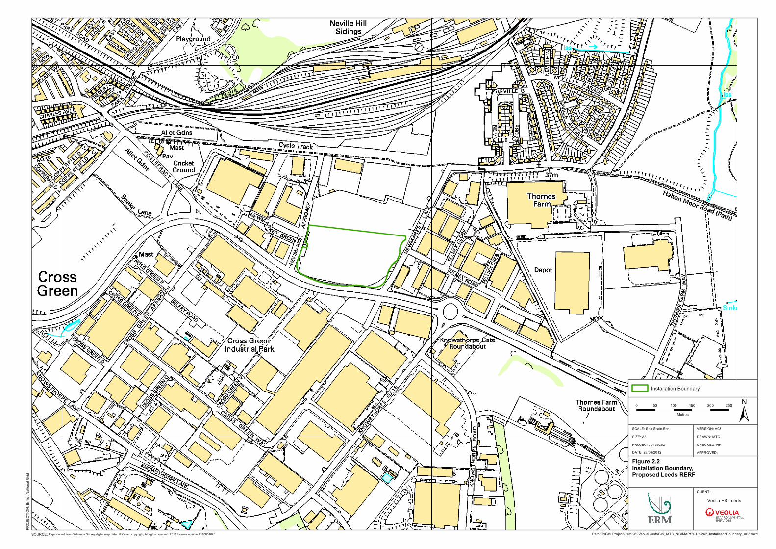
The following maps and plans show the location of the Installation, the location and nature of the various activities on the site and the area of the site covered by the site report. The following drawings are enclosed: 1 : 100,000 Ordnance Survey map showing the location of the site (Figure
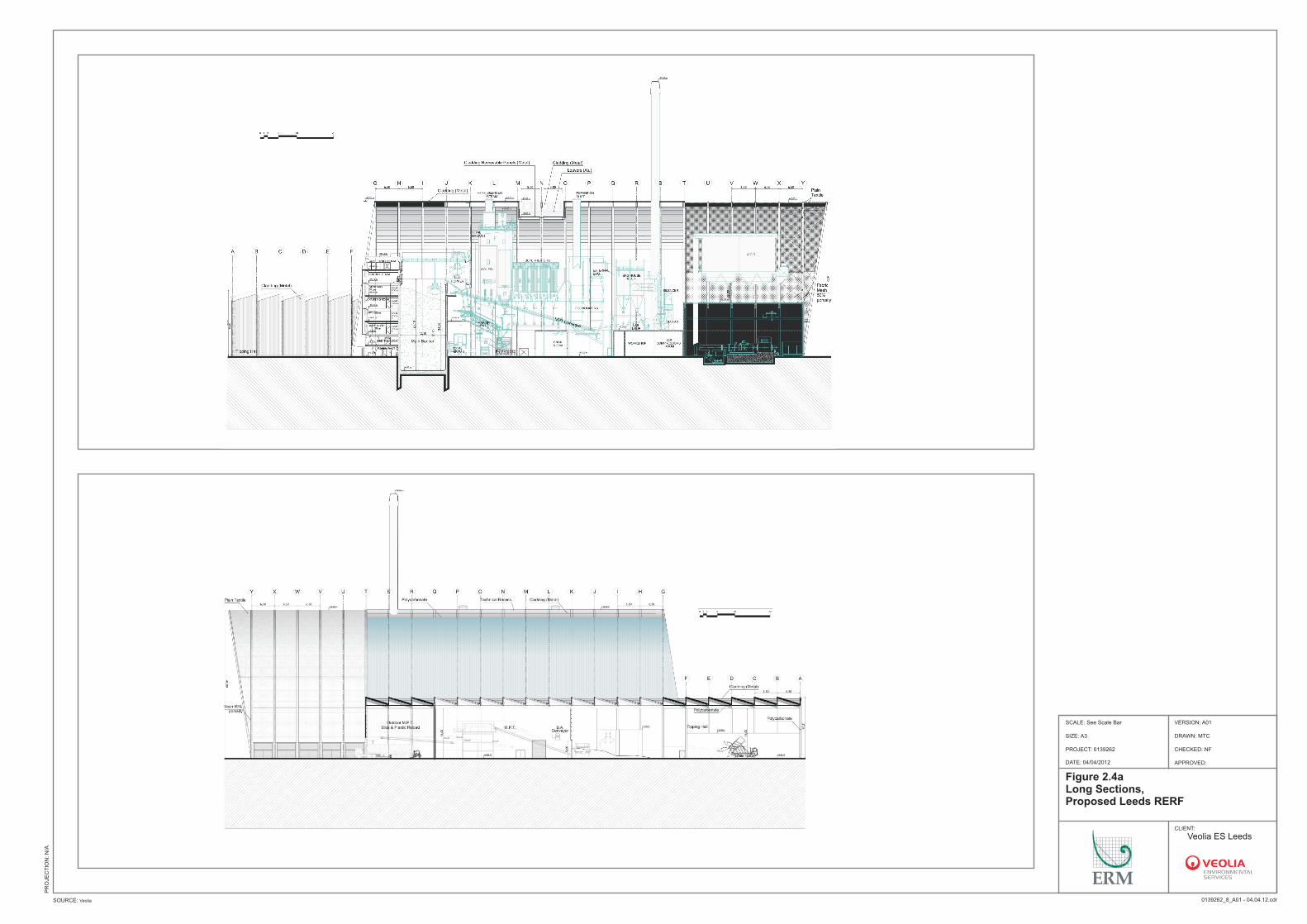
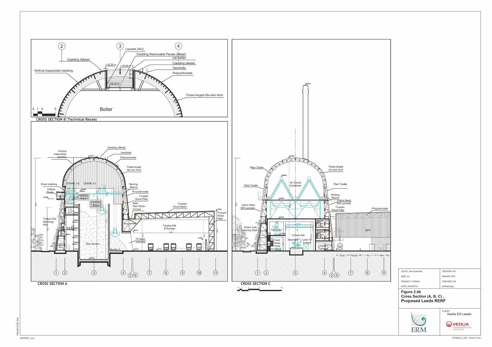
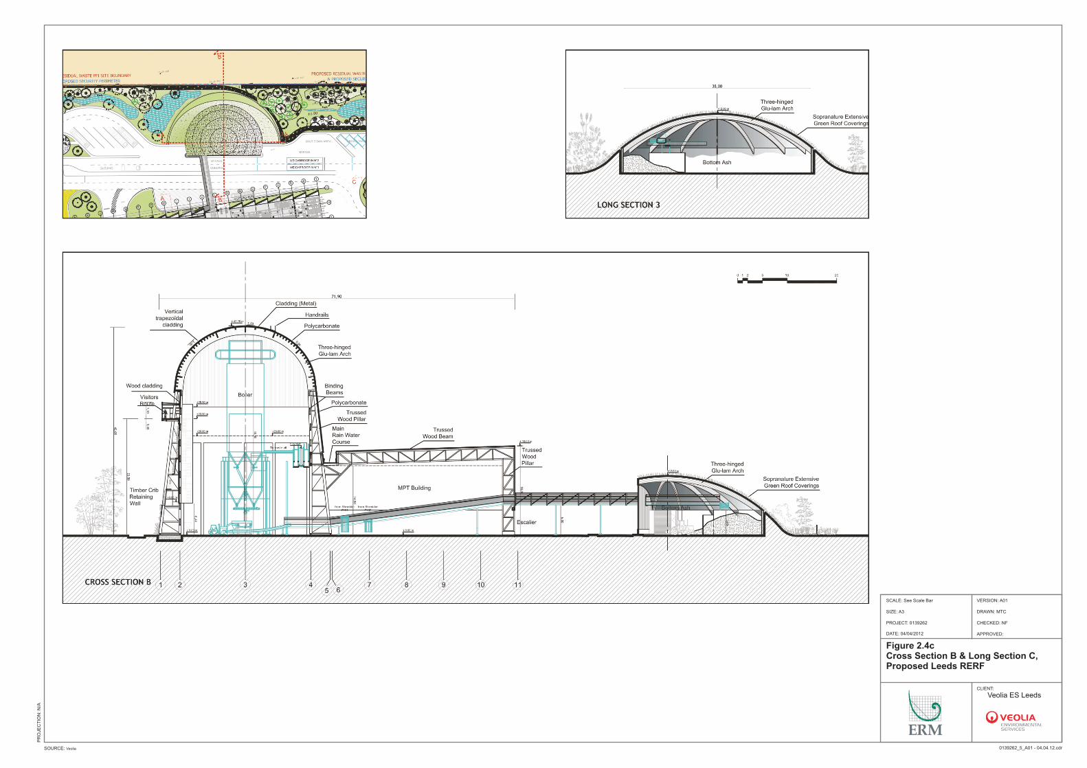
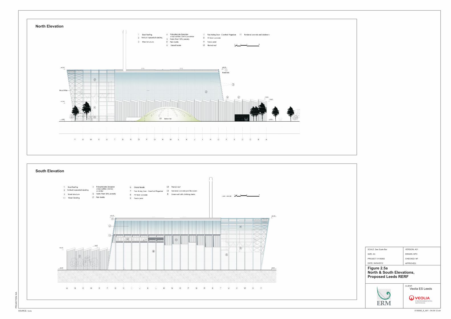
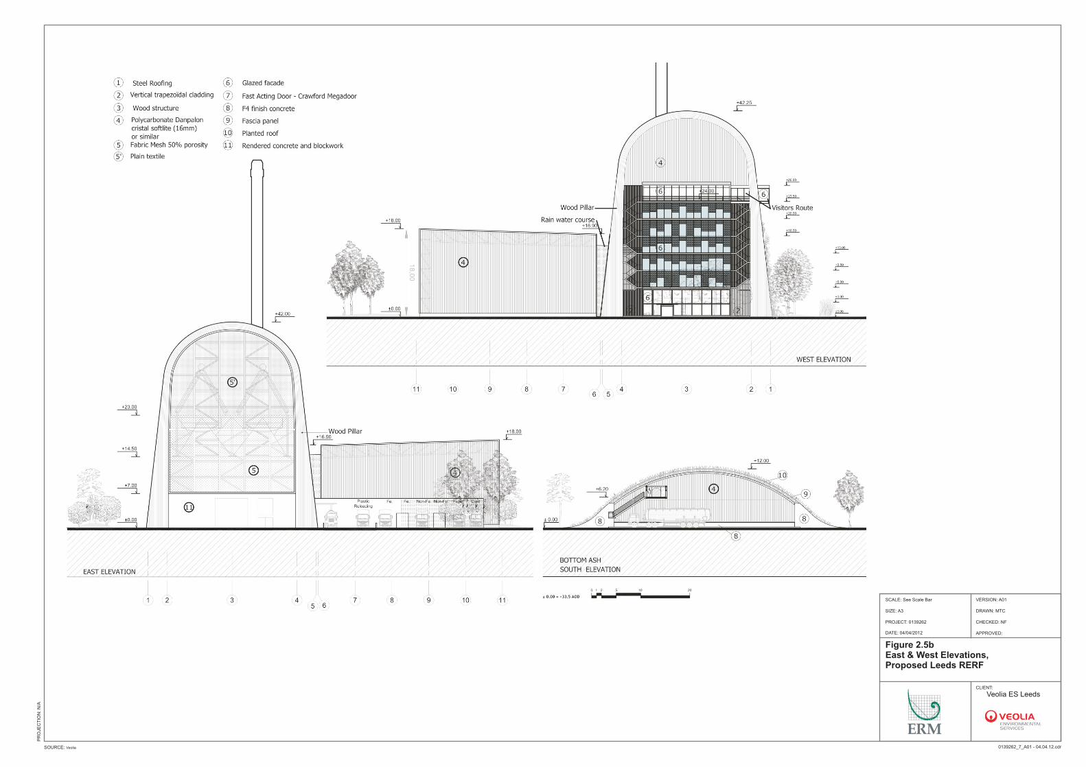
2.1); Map showing the site boundary (Figure 2.2); Detailed site plan (Figure 2.3); Long sections of the building (Figure 2.4a); Cross Sections (A, B, C) of the building (Figure 2.4b); Cross Section B & Long Section C of the building (Figure 2.4c); North and South elevations (Figure 2.5a); and East and West elevations (Figure 2.5b). Section 4, Proposed Activities contains two schematic diagrams, as part of the technical description of the proposed activities.
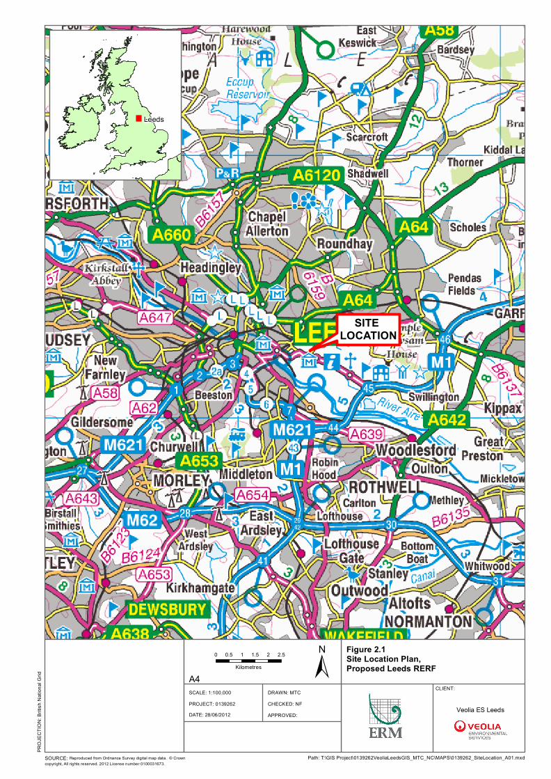
SITE LOCATION
Leeds
DRAWN: MTCCHECKED: NFAPPROVED:
PROJECT: 0139262
CLIENT:
±0 0.5 1 1.5 2 2.5Kilometres
SCALE: 1:100,000
Path: T:\GIS Project\0139262VeoliaLeedsGIS_MTC_NC\MAPS\0139262_SiteLocation_A01.mxd
A4
DATE: 28/06/2012
SOURCE: Reproduced from Ordnance Survey digital map data. © Crowncopyright, All rights reserved. 2012 License number 0100031673.
PROJ
ECTIO
N: Br
itish N
ation
al Gr
id
Veolia ES Leeds
Figure 2.1Site Location Plan, Proposed Leeds RERF
DRAWN: MTCCHECKED: NFAPPROVED:
PROJECT: 0139262
Figure 2.2Installation Boundary,Proposed Leeds RERF
Installation Boundary
CLIENT:
±0 50 100 150 200 250Metres
SOURCE: Reproduced from Ordnance Survey digital map data. © Crown copyright, All rights reserved. 2012 License number 0100031673.
SCALE: See Scale Bar
Path: T:\GIS Project\0139262VeoliaLeedsGIS_MTC_NC\MAPS\0139262_InstallationBoundary_A03.mxd
PROJ
ECTIO
N: Br
itish N
ation
al Gr
id
VERSION: A03SIZE: A3
DATE: 28/06/2012
Veolia ES Leeds
W1
W2
A4A5
A1
A2A3
W3
A7
A8A9
A10
W4
W5
A6
DRAWN: MTCCHECKED: NFAPPROVED:
PROJECT: 0139262
Figure 2.3Site Layout Plan,Proposed Leeds RERF
Installation BoundaryWaste Transfer Station BoundaryEmission Points
CLIENT:
±0 10 20 30 40 50Metres
SOURCE: Reproduced from Ordnance Survey digital map data. © Crown copyright, All rights reserved. 2012 License number 0100031673.
SCALE: See Scale Bar
Path: T:\GIS Project\0139262VeoliaLeedsGIS_MTC_NC\MAPS\0139262_EmissionPoints_A03.mxd
PROJ
ECTIO
N: Br
itish N
ation
al Gr
id
VERSION: A03SIZE: A3
DATE: 28/06/2012
LabelA1A2A3A4A5A6A7A8A9A10W1W2W3W4W5
DescriptionERF ChimneyLime Silo Vent *Activated Carbon Silo Vent *FGT Residue Silo Vent *Diesel GeneratorFuel Tank VentActivated Carbon FiltersBoiler VentBoiler Relief Valve 1Boiler Relief Valve 2Indicative Foul Water Discharge**Indicative Trade Effluent Discharge**Indicative Surface Water Discharge**Indicative Surface Water Discharge**Indicative Surface Water Discharge*** Discharged Internally Inside the Building** Subject to Environment Agency and Yorkshire Water Apporoval
OS GridSE3281 3244SE3280 3245SE3281 3245SE3282 3245SE3284 3245SE3286 3246SE3276 3249SE3279 3244SE3277 3244SE3277 3244
Veolia ES Leeds
DRAWN: MTC
CHECKED: NF
APPROVED:
PROJECT: 0139262
Figure 2.4a Long Sections, Proposed Leeds RERF
CLIENT:
SOURCE: Veolia
SCALE: See Scale Bar
0139262_8_A01 - 04.04.12.cdr
PR
OJE
CT
ION
: N
/A
VERSION: A01
SIZE: A3
DATE: 04/04/2012
Site Boundary
Veolia ES Leeds
±0 50 100 150 200 250
Metres
DRAWN: MTC
CHECKED: NF
APPROVED:
PROJECT: 0139262
Figure 2.4b Cross Section (A, B, C) , Proposed Leeds RERF
CLIENT:
SOURCE: Veolia
SCALE: See Scale Bar
0139262_4_A01 - 04.04.12.cdr
PR
OJE
CT
ION
: N
/A
VERSION: A01
SIZE: A3
DATE: 04/04/2012
Site Boundary
Veolia ES Leeds
±0 50 100 150 200 250
Metres
DRAWN: MTC
CHECKED: NF
APPROVED:
PROJECT: 0139262
Figure 2.4c Cross Section B & Long Section C, Proposed Leeds RERF
CLIENT:
SOURCE: Veolia
SCALE: See Scale Bar
0139262_5_A01 - 04.04.12.cdr
PR
OJE
CT
ION
: N
/A
VERSION: A01
SIZE: A3
DATE: 04/04/2012
Site Boundary
Veolia ES Leeds
±0 50 100 150 200 250
Metres
North ElevationNorth Elevation
South ElevationSouth Elevation
DRAWN: MTC
CHECKED: NF
APPROVED:
PROJECT: 0139262
Figure 2.5a North & South Elevations, Proposed Leeds RERF
CLIENT:
SOURCE: Veolia
SCALE: See Scale Bar
0139262_6_A01 - 04.04.12.cdr
PR
OJE
CT
ION
: N
/A
VERSION: A01
SIZE: A3
DATE: 04/04/2012
Site Boundary
Veolia ES Leeds
±0 50 100 150 200 250
Metres
DRAWN: MTC
CHECKED: NF
APPROVED:
PROJECT: 0139262
Figure 2.5b East & West Elevations, Proposed Leeds RERF
CLIENT:
SOURCE: Veolia
SCALE: See Scale Bar
0139262_7_A01 - 04.04.12.cdr
PR
OJE
CT
ION
: N
/A
VERSION: A01
SIZE: A3
DATE: 04/04/2012
Site Boundary
Veolia ES Leeds
±0 50 100 150 200 250
Metres
ENVIRONMENTAL RESOURCES MANAGEMENT VEOLIA ES LEEDS LTD
3-1
3 APPLICATION SITE CONDITION REPORT (SCR)
The Application Site Condition Report can be found in Volume 3, Annex A.
ENVIRONMENTAL RESOURCES MANAGEMENT VEOLIA ES LEEDS LTD
4-1
4 PROPOSED ACTIVITIES
4.1 OUTLINE PROCESS DESCRIPTION
The RERF will manage residual municipal waste generated within Leeds (following kerbside and other predicted initiatives by the Council and waste collection authorities aimed at meeting their recycling and composting targets), and will have a maximum capacity of 214,000 tonnes per annum (tpa), with commercial and industrial waste of similar nature to household waste utilised to supplement residual municipal waste where necessary. The RERF will consist of a Mechanical Pre-Treatment (MPT) process for the further recovery of recyclables from incoming residual wastes and an Energy Recovery Facility (ERF) for the remaining residual waste fraction. The MPT process will utilise front-end pre-treatment equipment which is designed to beneficially recover further recyclable materials from the incoming residual waste. The wastes will then move on the ERF which will use a reverse acting grate technology. The heat released by the combustion of the waste is recovered in a water tube boiler. The superheated steam produced by the boiler is available to feed a condensing turbo-generator linked to an air-cooled condenser. The ERF is designed to be CHP ready and is capable of generating approximately 13.8 MW (at full capacity) of electricity with approximately 11 MW being exported to the National Grid. This chapter is divided into several sub sections, each covering a different part of the process as follows: overview of process and operations (Section 4.2) waste reception (Section 4.3); mechanical pre-treatment (Section 4.3.3) the incineration system (Section 4.4); steam generation and transportation (Section 4.5); electricity generation (Section 4.6); steam condensing and wastewater (Section 4.7); performance (Section 4.8); process control (Section 4.9) including start-up and shut down procedures
ENVIRONMENTAL RESOURCES MANAGEMENT VEOLIA ES LEEDS LTD
4-2
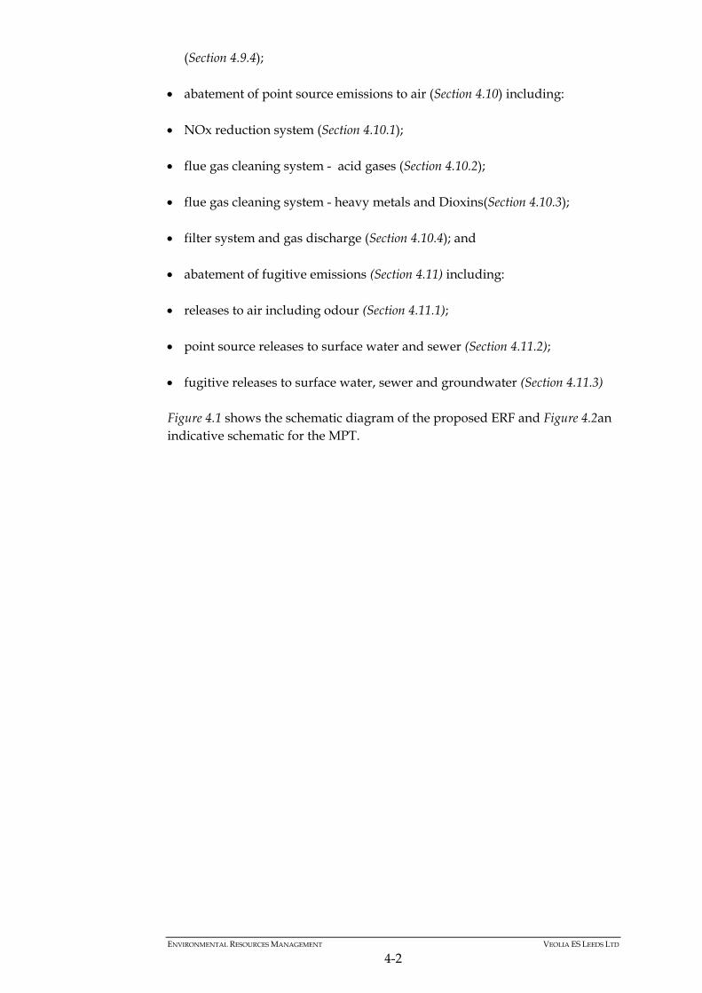
(Section 4.9.4); abatement of point source emissions to air (Section 4.10) including: NOx reduction system (Section 4.10.1); flue gas cleaning system - acid gases (Section 4.10.2);
flue gas cleaning system - heavy metals and Dioxins(Section 4.10.3);
filter system and gas discharge (Section 4.10.4); and abatement of fugitive emissions (Section 4.11) including:
releases to air including odour (Section 4.11.1); point source releases to surface water and sewer (Section 4.11.2);
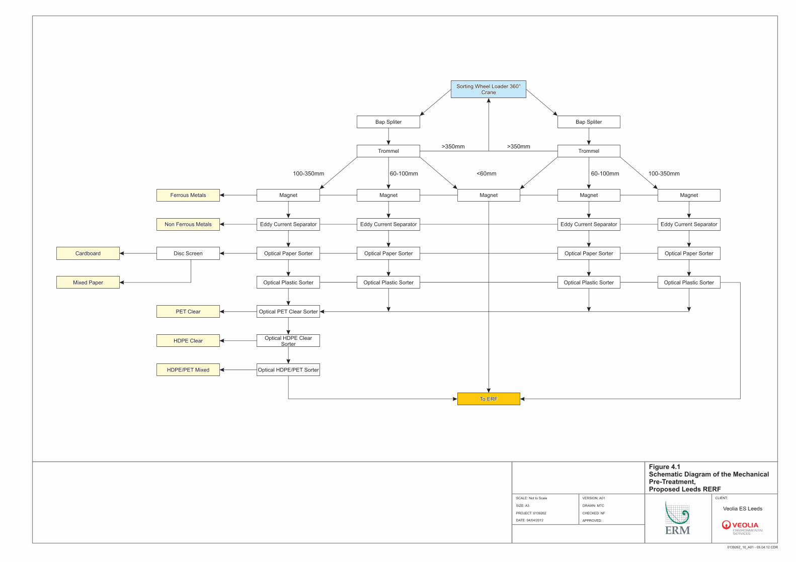
fugitive releases to surface water, sewer and groundwater (Section 4.11.3) Figure 4.1 shows the schematic diagram of the proposed ERF and Figure 4.2an indicative schematic for the MPT.
Sorting Wheel Loader 360° Crane
Sorting Wheel Loader 360° Crane
Bap SpliterBap Spliter Bap SpliterBap Spliter
MagnetMagnetFerrous MetalsFerrous Metals
TrommelTrommel TrommelTrommel
Eddy Current SeparatorEddy Current SeparatorNon Ferrous MetalsNon Ferrous Metals
MagnetMagnet MagnetMagnet MagnetMagnet
Optical Paper SorterOptical Paper SorterCardboardCardboard Disc ScreenDisc Screen
MagnetMagnet
To ERFTo ERF
Eddy Current SeparatorEddy Current Separator Eddy Current SeparatorEddy Current Separator Eddy Current SeparatorEddy Current Separator
Optical Plastic SorterOptical Plastic SorterMixed PaperMixed Paper
Optical Paper SorterOptical Paper Sorter Optical Paper SorterOptical Paper Sorter Optical Paper SorterOptical Paper Sorter
Optical PET Clear SorterOptical PET Clear SorterPET ClearPET Clear
Optical HDPE/PET SorterOptical HDPE/PET SorterHDPE/PET MixedHDPE/PET Mixed
Optical Plastic SorterOptical Plastic Sorter Optical Plastic SorterOptical Plastic Sorter Optical Plastic SorterOptical Plastic Sorter
Optical HDPE Clear Sorter
Optical HDPE Clear Sorter
HDPE ClearHDPE Clear
>350mm>350mm>350mm>350mm
<60mm<60mm60-100mm60-100mm 60-100mm60-100mm 100-350mm100-350mm100-350mm100-350mm
Figure 4.1Schematic Diagram of the Mechanical Pre-Treatment,
Leeds RERFProposed CLIENT:
SOURCE: Unspecified 0139262_10_A01 - 05.04.12.CDR
PR
OJE
CT
ION
:
DRAWN: MTC
CHECKED: NF
APPROVED:
PROJECT: 0139262
SCALE: Not to Scale
DATE: 04/04/2012
VERSION: A01
SIZE: A3
Site Boundary
Veolia ES Leeds
0 15
Metres (approx)
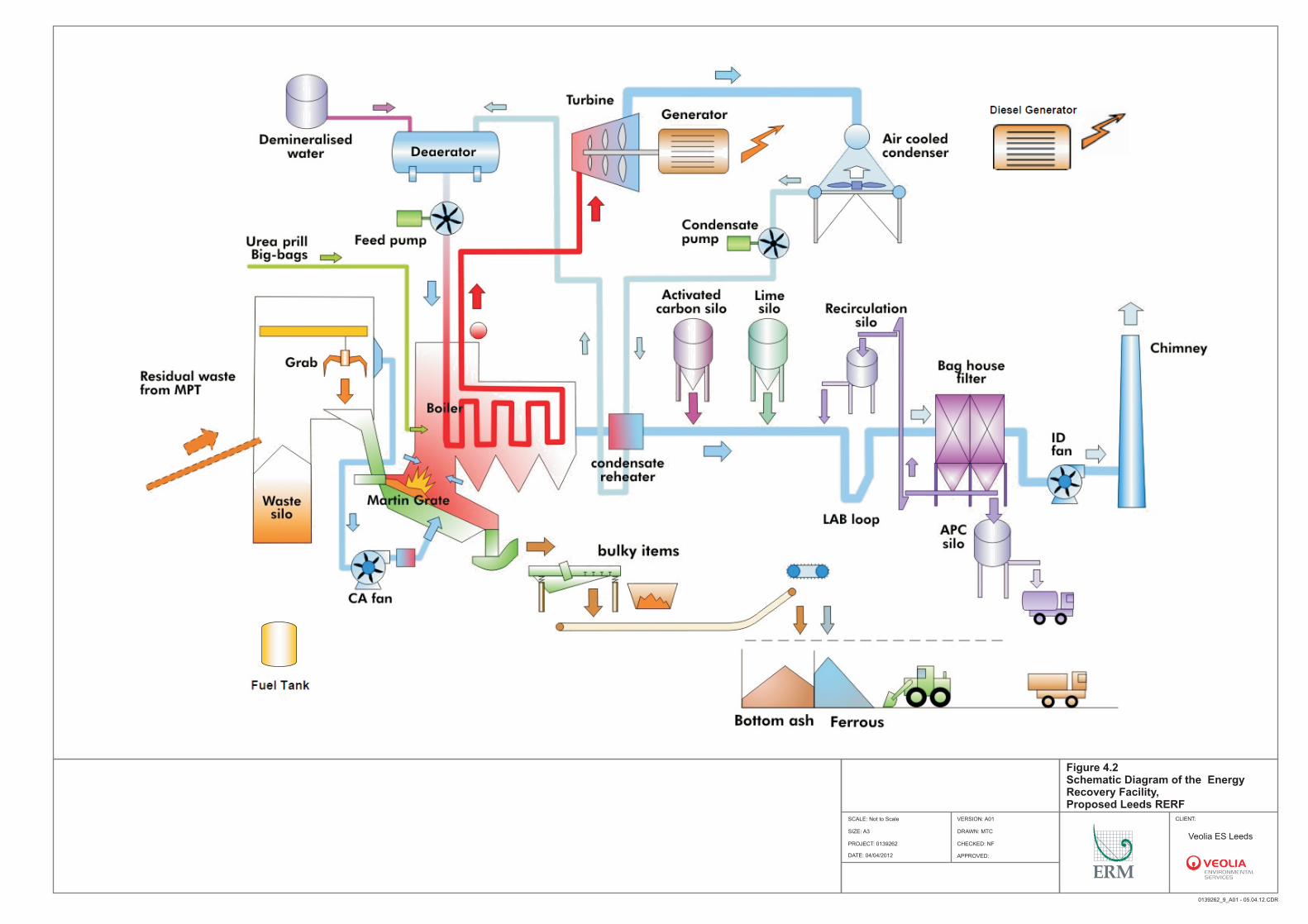
Figure 4.2Schematic Diagram of the Energy Recovery Facility, Proposed Leeds RERF
CLIENT:
SOURCE: Unspecified 0139262_9_A01 - 05.04.12.CDR
PR
OJE
CT
ION
:
DRAWN: MTC
CHECKED: NF
APPROVED:
PROJECT: 0139262
SCALE: Not to Scale
DATE: 04/04/2012
VERSION: A01
SIZE: A3
Site Boundary
Veolia ES Leeds
0 15
Metres (approx)
ENVIRONMENTAL RESOURCES MANAGEMENT VEOLIA ES LEEDS LTD
4-5
4.2 OVERVIEW OF PROCESS AND OPERATIONS
The main operational features and processes associated with the RERF are as follows: reception of waste by road; an MPT process for the removal of recyclables from the residual waste
stream; an ERF with one line for combustion for residual waste (following the MPT
process for the majority of the waste); generation of electricity; clean up of flue gases; storage and removal of process residues; and a design that allows for future Combined Heat and Power (CHP)
development. The remainder of this section describes individual elements of the main process and operations in more detail.
4.3 WASTE RECEPTION
4.3.1 Waste Reception
Incoming residual municipal waste for combustion will be delivered in covered vehicles or containers (see Figure 4.1). All contract waste will be delivered to the facility, either by direct delivery or bulk haulage vehicles by LCC or their contractors. There will also be some third-party (non-contract) commercial wastes delivered into the facility. The RERF has been designed to allow deliveries by all waste vehicle types. The facility is suitably flexible to accept variable delivery rates of waste, according to the day of the week and time of the year. Adequate storage for these fluctuations has therefore been considered. It will operate indefinitely on a continuous and safe basis, in compliance with the Contractor’s operation and maintenance requirements. A specific queuing area is provided before the incoming weighbridges area to avoid the queuing of vehicles on the access roads. Each vehicle will pass across one of the two incoming weighbridges at which point a range of data on the waste load delivered by the vehicle will be recorded. The weighbridge station consists of four 18-metre long weighbridge units (two in, one out, one in the bottom ash building) with computerised operation and a telephone communications link with the RERF control room. The positioning of the incoming weighbridges will offer significant queuing space off the public highway. Four weighbridges will be provided to avoid queuing and to comply with the City Council’s requirements on turnaround times. On the left hand side as the vehicles enter the site will also be a welfare facility for drivers with parking.
ENVIRONMENTAL RESOURCES MANAGEMENT VEOLIA ES LEEDS LTD
4-6
The weighbridges will be manned at all times during opening hours. All vehicles entering the site will be weighed. All the data collected (origin of the vehicle, destination of vehicles, origin and nature of the municipal waste, type of recyclables, by-products, residues, reagents and consumables, net and gross tonnage, date and time) will be monitored and then input to the data management system which will be the Veolia standard Weighbridge Information Management System (WIMS). WIMS is Veolia’s IT system for operating and managing all weighbridge services and it ensures that the weights have been recorded from weighbridges that have been calibrated, verified and stamped in accordance with Section 11 of the Weights and Measures Act 1985, and that they comply with all statutory requirements and local regulations. Veolia ensures that all its weighbridges are verified and certified for trade use at least every twelve months. The vehicles will be identified by number plate recognition. Vehicles will pass over the exit weighbridge to be weighed before leaving the RERF and have exit weight recorded. WIMS will also record the entry and departure times of vehicles arriving at, and leaving the weighbridge and thus calculate, and make available reports on vehicle turnaround times. These times can then be compared to those set in the contractors proposals and the related Performance Management Framework. Efforts will be made to minimise the amount of waste delivered to the RERF that cannot be processed at the site. This will include providing information to waste carriers on what types of waste are acceptable and in certain cases, an audit of waste supplier procedures. The operator will also routinely conduct random waste inspections on the waste delivered at the site to ensure compliance with the waste types in the permit as part of its Management System. Unsuitable waste will be temporarily quarantined in a specific area within the reception hall awaiting disposal at a suitable licensed facility.
4.3.2 Reception Hall
The vehicles then proceed into the RERF reception hall. Within the reception hall, most of the vehicles are directed to the designated MPT unloading area where their load is discharged onto the flat floor. Wheeled loading shovels or wheeled grab machines then move the waste to form a pile. The ability to tip onto a flat floor, allows any difficult items present in the waste, which may cause damage to mechanical pre-treatment equipment, to be removed before being fed into the plant. Mobile machines will then load the waste into the two primary shredders that feed the MPT Facility. The process will be monitored by video cameras at the joint MPT and ERF central control room. Waste which is not processed in the MPT is delivered directly to the ERF waste bunker via the reception hall and the intermediate bunker. The reception hall will provide a minimum of 2 days of waste storage, based on a waste stacking height of 5 m and a bulk density of 350 kg/m3. The operational philosophy will be to clear the reception hall of waste by the end
ENVIRONMENTAL RESOURCES MANAGEMENT VEOLIA ES LEEDS LTD
4-7
of the day. The intermediate bunker with some spreading out into the reception hall will provide some additional storage capacity. Access to and from the reception hall for waste delivery vehicles will be via entrances fitted with fast shutting doors, which will remain closed during non-delivery periods. Periodic cleaning will be carried out to maintain a clean reception area. All waste delivered will be inspected in accordance with the waste delivery protocol. Any non-processable wastes (e.g. engine blocks, gas cylinders etc.) will be removed using the mobile machines. Alternatively, non-processable items will be removed from the tipped waste by an operative if it is safe to do so. Non-processable waste and any prohibited contract waste will be stored in defined areas within the reception hall of the Facility for subsequent transfer off site. For gas bottles, Veolia will carry out a formal Health & Safety study as part of its HAZOP review, to address the potential risk of processing them through the shredders. The majority of the waste to be received from the Council will be kerbside collected household waste or waste of a similar nature. The Facility could receive residual Household Waste Recycling Centre (HWRC) wastes or wastes of a more bulky nature. These could also be delivered into the reception hall. This waste is unlikely to be appropriate for treatment into the MPT plant. This waste will be unloaded in a specific area of the reception hall and, if needed, could be shredded using a dedicated heavy duty shredder and then deposited into the intermediate bunker for transfer up to the main ERF bunker. The shredded waste will be transferred using the crane grab into the ERF bunker. Therefore, the only additional equipment requirement in order for the facility to be able to accept and handle residual HWRC would be a heavy duty shredder in the reception hall. Over and above the City Council’s Contract Waste, some commercial and Industrial waste (of a composition similar in nature to residual municipal waste) will be sourced by the Contractor from the City Council area and delivered to the Facility as third party waste. This waste will be processed as feedstock for the MPT process with recyclables being recovered and the remaining unrecycled material being fed to the ERF. If the processing of this waste through the MPT is not appropriate then the waste shall be processed directly through the ERF via the intermediate bunker area in the reception hall. The operators working within the reception hall will decide the appropriate treatment route for each third party waste delivery.
4.3.3 Mechanical Pre-Treatment
The aim of the Mechanical Pre-Treatment (MPT) is:
extraction of recyclable fractions, providing a contribution to NI-192
recycling; mixing of the waste to obtain a more homogeneous feedstock to
the ERF, for improved overall combustion; and
ENVIRONMENTAL RESOURCES MANAGEMENT VEOLIA ES LEEDS LTD
4-8
reduction in the amount of dense plastics and metals processed in the ERF,
therefore lowering the quantities of reagents required in the Flue Gas
Treatment system.
The MPT process comprises of two identical processing lines with a capacity of 25 tph per line. It is anticipated that the MPT will be operated continuously and will combine a number of screening/mechanical sorting techniques to separate residual municipal waste into various recyclable material streams and non-recyclable residual waste stream components. The facility will employ equipment such as conveyor systems, shredders, screens, magnets, eddy current separators and near infra red optical sorting technology to separate mechanically the materials that may be recyclable. Based upon the anticipated waste composition, the MPT plant could recover up to 20% of the input waste. The minimum recovery performance is anticipated to be 10%. This difference will ensure the materials to be recycled will be of sufficient quality to be marketable. The design of the MPT will focus on removing the following potentially recyclable material fractions: metals (ferrous and non-ferrous); dense plastics (particularly plastic bottles); and recyclable fibre (paper and card). The MPT design is based on equipment which is programmable to remove the recyclable materials most prevalent in the waste stream, and therefore is adaptable to material compositional changes. MPT Input and Initial Separation
Two shredders will be located in the reception hall. The shredders will prepare the waste for the downstream separation equipment. The shredders will open the waste bags and provide some size reduction of the waste. The waste leaving the shredders will be conveyed from the reception hall into the MPT plant processing hall where it will be screened. The primary objective of the screening step will be to separate the large incoming flow into smaller, more homogenously sized waste flows. This will improve the process effectiveness of the downstream sorting equipment, both in terms of efficiency and purity.
ENVIRONMENTAL RESOURCES MANAGEMENT VEOLIA ES LEEDS LTD
4-9
Metal Extraction
Cans and other metal items will be recovered by over-band magnets and eddy current separators and conveyed to the Ferrous and Non-Ferrous storage containers.
Plastics and Fibre Extraction
The remaining residual flows will be conveyed to near infra-red (NIR) auto-sort machines as optical sorting technology is an extremely efficient, precise and flexible system. These machines will recognise colours and materials composition. The software controlling the machines processes this combined information and compares it to an internal materials database. The control system will then determine what the object is and eject it from the flow, should it be targeted as a recyclate. Recyclable Fibre Extraction
The separation of paper and card will be achieved using an NIR auto-sort machine. The paper and card product streams will be conveyed to storage containers. Transfer Handling and Storage of Recyclables
The recovered materials (recyclates) will be stored in containers and collected for transport to appropriate re–processor facilities or onward treatment. Steel and aluminium recyclate will be sold to reprocessing facilities for re–smelting into their respective raw materials. Paper/card will be sold to paper/board mills as feedstock for paper and cardboard manufacture. The separated plastic streams from the auto-sorts will be deposited in bunkers which will feed a common baler. A baler will be used to significantly increase the density of the plastics to improve the efficiency of storage and improve the payload of onward transport to re-processors. Plastics will be sold to plastics reprocessors for further processing – refining, cleaning, shredding to make plastic feed stocks for a variety of manufactured goods and packaging. One additional purpose of the MPT facility is mixing of the waste to obtain a more homogeneous feedstock to the ERF, for improved overall combustion. After plastics and metals separation, residual waste from the MPT is discharged via a conveyor into the ERF bunker. During ERF shutdown, residual waste from the MPT is discharged in the reception hall for later use in the ERF or for transfer off site.
4.3.4 Waste Bunker
The waste bunker has a hydraulic volume of approximately 3,900 m3 and is sized to accommodate a minimum of 2.7 days of waste input.
ENVIRONMENTAL RESOURCES MANAGEMENT VEOLIA ES LEEDS LTD
4-10
The activities which take place within the bunker are: the mixing and moving of waste to prevent the development of anaerobic
conditions and to ensure a good consistency which in turn helps improve the efficiency of combustion;
loading of waste into the furnace feed chute; temporary storage of waste during shutdown/maintenance; and transfer of waste.
The main ERF bunker will be rectangular shaped. It acts as a waste (fuel) storage for feeding the ERF plant. The waste is fed from the ERF bunker into the ERF plant feed hopper using a grabbing crane operated from the control room situated at 20 m. The ERF bunker will not be directly fed by vehicles. It will receive waste either via conveyor from the MPT plant or waste that is deposited into the small intermediate bunker will be transferred by grab crane into the main ERF bunker. Waste is mixed and moved by means of two large hydro-electrically powered grabs mounted on travelling cranes. During operation, one travelling crane will be on duty while the second is on stand-by. Control of the crane can be manual, semi-automatic or fully automatic. In the manual and semi-automatic mode the operator positions the grab to pick up the waste. Once the grab closes it can be guided manually (in manual mode) or automatically (semi-automatic mode) to the feed hopper where it discharges its load. In the fully automatic mode the waste crane follows a pre-programmed sequence of movements to pick up and transfer waste to the feed hopper and for mixing of the waste in the bunker. The crane and grab have been designed to transfer the plant’s daily waste burning capacity into the feed hopper, and to carry out the lifting, moving, mixing and stacking of waste in the storage bunker. During normal operation, it will be possible to empty one zone of the bunker after another. The bunker will be cleared zone by zone in rotation to ensure that the waste does not remain in parts of the bunker for long periods where it could degrade and produce odours. As a contingency against unexpected extended plant shutdown, the reception and waste handling equipment will be designed to allow waste to the transferred out of the ERF. This would only occur in rare circumstances and would not be part of the usual operations of the ERF. This will be achieved by enabling the bunkered waste to be back-loaded into the intermediate bunker using one of the cranes.
4.4 THE INCINERATION SYSTEM
4.4.1 Introduction
The ERF will comprise of one incineration line with a throughput capacity of 20.5 tph of residual waste with a net calorific value (NCV) of 9,000 kJ/kg at
ENVIRONMENTAL RESOURCES MANAGEMENT VEOLIA ES LEEDS LTD
4-11
the maximum continuous rating point of the plant. The annual throughput of the ERF will be 164,000 tonnes per annum based upon a plant availability of 8,000 hours per year. Its maximum theoretical annual throughput will be 179,580 tonnes per annum based on 100% availability. The main elements of the process will be: main ERF bunker; Martin reverse acting grate; steam boiler and a steam turbine generator with optimised steam cycle to
achieve maximum power output; dry flue gas treatment (hydrated lime and powdered activated carbon
addition) with fabric filter system including flue gas treatment residue handling;
oxides of nitrogen reduction will be achieved by dry urea injection; and bottom Ash handling and storage.
4.4.2 Firing Capacity and Stoker Diagram
The firing capacity indicates the possible operating rates (either for waste input or for waste throughput) as a function of the waste lower calorific value (LCV). The grate will be designed to operate continuously with LCV’s ranging from 7,000 KJ/kg (minimum LCV) to 12,500 kJ/kg (maximum LCV) which suits a very broad range of waste. The (hourly) waste throughput, determined as being the tonnage of waste combusted, would be 20.5 tonnes per hour for a waste having a LCV between 7,000 and 9,000 kJ/kg (minimum and design LCV). The (hourly) waste throughput will be reduced according to the LCV for values above the design value of 9,000 kJ/kg with a maximum LCV of 12,500 kJ/kg.
4.4.3 Storage of MPT Residues/ERF Feedstock
Residues from the MPT Facility will be conveyed to the ERF feed bunker, a rectangular construction in concrete. Due to the MPT process, the waste delivered into the ERF bunker will have a more consistent calorific value, homogenised as far as possible, reducing the requirement for in-bunker crane mixing employed at more traditional ERFs.
4.4.4 Waste Charging
Waste will be removed from the waste bunker by the crane/grab and discharged into the feed mechanism. This comprises of a feeding hopper and a feeding chute (Figure 4.2). A shut-off damper extending across the entire width of the feed chute will be installed beneath the feed hopper. This damper would be kept open during normal operation and closed during furnace start-up and shutdowns, to prevent air entering the combustion chamber. The charging hopper damper
ENVIRONMENTAL RESOURCES MANAGEMENT VEOLIA ES LEEDS LTD
4-12
can only be closed when waste is no longer in the chute. In normal operation the feed chute would be kept constantly full of waste thereby creating a seal between the combustion chamber and the outside and preventing backflow of combustion products through the waste feed chute. The camera situated above the hopper and the hopper level detector will allow the operators in the control room to evaluate the waste level in the hoppers and to proceed to the feeding operation when it is required. A level detector would monitor the waste in the feed chute and set off an alarm when the volume of waste falls below a specified level. The weight of waste fed into the hopper is continuously recorded and compiled in daily and monthly statistics. The provision of consistent feed is critical to ensure steady combustion conditions. This is achieved using a feeder system consisting of a moving grate hydraulic ram that keeps the waste moving from the feed chute onto the combustion grate. Waste is fed from the bottom end of the feed chute over a step at the furnace inlet and onto the grate. The step feature at the end of the feeder table causes the waste to tumble onto the grate and so disseminate the loaded material which will become slightly compacted during its passage through the feed chute. Waste charging will be carefully integrated with furnace conditions so that charging cannot take place when the temperatures and air flows are inadequate or certain other operational conditions exist. There is an interlock between the furnace temperature and the waste charging system that ensures that waste is not charged when the furnace temperature is below 850°C. The charging system will be designed in such a way as to ensure that the operation is airtight and that the fan control system is capable of responding to changes in furnace pressure during charging, and to maintain the negative pressure within the furnace which avoids the escape of fumes or excess air flows. Control procedures are designed to ensure that the charging rate is not exceeded.
4.4.5 Grate System
The grate is where combustion of the waste occurs. For efficient operation, it is necessary to maintain a consistent flow of waste and to ensure that combustion is as complete as possible. This is achieved through the design and operation of the combustion grate. The ERF will have a MARTIN reverse acting grate system; a proven grate technology which has been used in over 300 plants world-wide since 1959. The grate is capable of burning a broad range of waste calorific values. This is an appropriate grate system for the mixed residual municipal waste from Leeds.
ENVIRONMENTAL RESOURCES MANAGEMENT VEOLIA ES LEEDS LTD
4-13
The MARTIN reverse acting grate will be made up of alternate steps of fixed and moving grate bar rows which perform slow mixing stokes in an upward direction, opposite to the downward movement of the waste due to the inclination of the grate at approximately 26°. In addition, each stroke will be completed by a “relative movement” whereby each bar moves relative to the adjacent bars. This ensures cleaning of the air gaps between the bars together with a further stoking of the waste layer. The grate surface consists of a high grade heat resisting chromium steel alloy with plates with very narrow apertures between the bars to control air distribution. The grate is designed for the combustion of residual municipal waste with a wide range of calorific values from 7,000 kJ kg-1 up to 12,500 kJ kg-1, without the need for any auxiliary fuel. It incorporates the following significant features: the moving grate bars are ‘reverse acting’ to ensure good mixing,
combustion and flame position control. the grate bars are shaped and have a special movement to reduce clinker
formation. the movement in the opposite direction to the direction of waste transfer
which contributes to an effective mixing of the waste. the air-cooled MARTIN grate will be able to combust waste with a net
calorific value up to 12.5 MJ/kg with long-term proven satisfactory operating performance.
the flow of combustion air will be independently adjustable over each section of the grate length.
These features enable the grate to give consistent performance with a wide range of municipal waste types. These features also provide combustion control, which, in terms of quality and flame position, is essential for consistent boiler performance. The combustion of the waste will be completed on about two-thirds of the grate length. On the last part of the grate, the residue (bottom ash) will be progressively cooled by the under fire (primary) air. In addition, the amount of riddlings which fall through the grate will be very small resulting in reduced losses from unburned material and high-energy recovery. Having controlled the main area of combustion, the bottom end of the grate provides an area for final burn out and a margin for better burning of dense objects. A certain amount of siftings and fine ash can fall through the openings and a collection system for these fines is built in beneath the grate. The system feeds them to the bottom ash discharge system. Combustion air is supplied by a forced draught fan which feeds into a compartmented plenum. The amount of air flowing into each compartment can be adjusted to meet the precise combustion requirements.
ENVIRONMENTAL RESOURCES MANAGEMENT VEOLIA ES LEEDS LTD
4-14
4.4.6 Bottom Ash Management
The bottom ash is the residue remaining after the combustion of waste on the grate. It is discharged from the grate into the ash discharger where it is quenched with water. The ash discharger has the following advantages: it is of extremely robust construction and designed for arduous duty and
continuous operation; it is compact and takes up little floor space; it has a small water trough, but this is more than adequate for residue
quenching and conditioning so that the residue can then be easily handled by conveyors;
it has powerful reciprocating rams, hydraulically operated with variable speed control to push out the residue at the desired rate;
it has no chains or flights, therefore, jamming problems are virtually eliminated and furthermore, wearing problems are avoided;
it provides a gas seal to the ERF and prevents ingress of air and egress of dust and fumes; and
it has few mechanical components, therefore system reliability is dependable and surveillance and maintenance are minimal.
Water consumption is controlled at the optimum requirement for quenching and conditioning, so that when the residue is finally discharged its water content is only about 15 to 20% of the dry residue weight depending on residue quality. The ash discharger is basically composed of two main parts, a structural steel body and mechanical ram. It is robustly constructed in steel plate, heavily ribbed to form a water tight trough with surfaces exposed to the residue being covered with steel lining plates. The trough is filled with water and the water level is automatically maintained with suitable level control device. This equipment is located so that maintenance operations can be carried out externally without difficulty. The ash discharger receives residues and inert material, and the heavy dust and ash particles which fall out of the gas flow during its passage through the boiler.
4.4.7 Grate Siftings Handling
The sifting system comprises a suitable number of mild steel hoppers, each with a butterfly type outlet valve connected with an inclined duct terminating above the ash discharger. The hoppers are situated beneath the grate section with one situated beneath the municipal waste feeder device. Siftings will be collected in the hoppers and cleared at intervals of 2 to 4 discharges per hour. The siftings will be conveyed pneumatically, and delivered to the ash discharger. The butterfly type valves will be operated pneumatically and are designed to prevent leakage of combustion air when in the shut position. Adequate facilities will be provided in the hopper compartments to enable access and inspection to be carried out. The hopper outside surface will be
ENVIRONMENTAL RESOURCES MANAGEMENT VEOLIA ES LEEDS LTD
4-15
lagged to ensure the maximum surface temperature does not exceed 60ºC when the ambient is 25ºC.
4.4.8 Hydraulic Power System
The moving grate steps, feed chute shut-off door, refuse feeder, discharge controller and bottom ash discharger are driven hydraulically through electrohydraulic controls to obtain the required individual speed variations. A single pumping station is provided to serve the hydraulic drives for the grate. The station comprises axial piston pumps, filter, oil tank, hydraulic accumulator and oil cooler. The hydraulic unit is air cooled to dissipate the heat generated by normal operation of the system. A distribution cabinet for all hydraulic drives will contain all electrical controls. The speed of individual operating cylinders is adjusted by oil flow regulators fitted in the cabinet housing.
4.4.9 Combustion Air Distribution
The combustion air system is regulated and controlled under a stable air pressure condition. Constant primary air pressure is maintained automatically at the grate inlet by control of the flow of the combustion air fan. A common combustion air fan supplying both primary and secondary air to the incineration line is provided. This fan is of the centrifugal type with an impeller overhung on the shaft, and is abrasion-resistant with self-cleaning blades. Flow rate control is achieved by frequency converters. Combustion air is distributed from the combustion air fan though duct work and into the air heater. Primary combustion air is distributed from the air heater outlet into the separate air zone compartments / hoppers fitted to the underside of the grate. All compartments have individual orifices covered by dampers, which are remotely controlled and actuated by motorised actuators. Each damper can be individually regulated, if necessary, for particular fire-bed conditions but normally all dampers will be simultaneously remote-controlled. The system is designed to maintain the oxygen content at the required values and the total air flow is divided into the various zones as a function of the damper position regardless of the flow through each zone. Secondary combustion air is distributed from the air heater outlet into the combustion chamber through carefully located nozzles to achieve a turbulent mixing of the combustion gases and a complete combustion, together with a stable flame of controlled height. The combustion air fan draws air from above the municipal waste storage bunker and the MPT reception hall, so that the odours and airborne dust are
ENVIRONMENTAL RESOURCES MANAGEMENT VEOLIA ES LEEDS LTD
4-16
drawn into the incineration line. The air intake over the bunker is fitted with a grid. Ducting is run from the air intakes down to the forced draught fan. The ducting from the air heater to the grate plenum and the secondary air injection points will be thermally insulated. The air heater will be provided to heat the combustion air up to a temperature which is dependent upon the calorific value of the residual municipal waste. The air heater will consist of three sections. For municipal waste with lower heating value (LHV) around design value, only the first and second sections will be used and will be fed from one of the steam turbine pass out. For lower calorific values which require higher combustion air temperature, steam will be taken from the boiler drum to feed the third section. The heater will be designed and constructed to accommodate thermal expansion of the tube bundle and the casing. The air heater will be insulated with mineral wool in order that external temperature does not exceed 60ºC. An inspection door is provided.
4.4.10 Auxiliary Burner
The combustion chamber is provided with two oil-fired auxiliary burners for the following reasons: to raise the temperature in the combustion chamber prior to starting up
from cold and during shutting down of the plant; and to comply with the Waste Incineration Directive (1) on flue gas emissions.
This requires that, whenever the temperature falls below 850ºC at the 2 second point, then the standby burners must operate automatically to maintain the temperature so long as there is municipal waste on the grate.
The total capacity of the burners will be rated at around 60% of the boiler design load. The burner will be supplied with electric ignition, flame safeguard equipment and a valve train, which contains control valves, instrumentation, isolation valves and a local control panel. The flame detection system is provided with a self-checking feature. The flame intensity is converted to an electrical signal, which is used to indicate flame status and initiate the appropriate response. A mechanical shutter is used for the self-checking feature. The equipment includes a local control panel as well as a dedicated safety programmable logic controller (PLC). The local control panel is capable of starting and stopping the burner sequencing through the PLC. Fuel oil will be stored in a tank and also used for onsite plant vehicles refuelling and for the emergency diesel generator system. Transferring of the fuel oil at the set pressure to the start-up burners and other users will be achieved by means of two (2 × 100%) motor-driven pumps. Fuel oil atomisation will be performed by compressed air.
(1) EC Directive on the Incineration of Waste (2000/76/EC), now recast in Industrial Emissions Directive (2010/75/EU)
ENVIRONMENTAL RESOURCES MANAGEMENT VEOLIA ES LEEDS LTD
4-17
4.5 STEAM GENERATION AND TRANSPORTATION
4.5.1 General
Hot gases from the furnace pass to a boiler which transfers the energy from hot gases to the steam through a series of heat exchangers and superheaters. The design of the boiler is such that the velocity of gas flowing through the heat exchangers is low, resulting in a long residence time. This in turn allows for maximum heat exchange and greater production of steam. The steam from the boilers feeds a steam turbine generator which generates electricity. After leaving the turbine, the steam will be cooled using an air cooled condenser. Electricity will be exported to the grid via an 11/33kV connection located to the west of the site. The physical connection to the grid system will be via underground cables.
4.5.2 Steam Generation
Steam Boiler
Heat energy is recovered from the flue gases by means of an integral water tube boiler. The boiler is specially designed for the combustion of residual municipal waste and is of a well proven technology. The design is the outcome of the contractors’ long standing expertise in this field. The boiler design is based on the natural circulation, one-drum and bottom-supported type. It consists of the following gas passes integral with the furnace: 1st pass - radiant combustion chamber, empty vertical pass 2nd pass - vertical pass, with ten evaporator panels 3rd pass - horizontal pass with evaporator and super-heaters 4th and 5th passes - vertical passes with economisers External economiser. The first two passes are enclosed in water wall panels. These air-tight walls are composed of finned tubes welded length-wise. The 3rd, 4th and 5th passes are enclosed in a steel welded casing. The first pass is protected by refractory up to the central screen header. To minimise tube corrosion, inconel overlay welding will be provided in the higher part of the first pass and parts of the second pass zones that experience temperatures above 800°C. In order to optimise efficiency and to minimise fouling, erosion and corrosion, the boiler design was governed by the following main criteria: optimised combustion chamber design; low gas velocity in the combustion chamber in order to reduce
entrainment; refractory protection of combustion chamber water walls in the flame zone
designed to achieve good heat transfer without high hot face temperatures;
ENVIRONMENTAL RESOURCES MANAGEMENT VEOLIA ES LEEDS LTD
4-18
low gas velocities and long residence time before entering the first convective surfaces;
wide tube spacing in the convective banks; convective superheater design for high flue gas temperature and steady
steam temperature; easy access for inspection and maintenance of all pressure parts; on-line surface cleaning based on water injection in the second pass and
mechanical rapping for the horizontal pass; and on-line surface cleaning by vibrating for economiser. The boiler is externally insulated by mineral wool or equivalent. The thickness of the insulation is calculated to produce a uniform cold surface temperature of 60ºC for an ambient air temperature of 25ºC. A modelling programme is used for the proposed boiler type, to optimise the path so as to avoid both velocities that are either too low or too high and excessive turbulences in non-desirable areas. As with all modern boilers, high operating availabilities are critical to the operational performance. The CNIM boiler is subject to continual evolution in terms of the extent of corrosion resistant materials and the positions of the various heat exchange surfaces, whilst maintaining the regulatory condition of 850C/ 2 seconds and combustion control. Water Walls All the evaporating tube panel elements have the same profile. Since all enclosure walls are at a uniform temperature, all expansion is uniform, and there are no possibilities of gas leaks causing damage to insulation or resulting in corrosion attack on the outer metal sheeting. Within the constraints of shipping and handling on the erection site, shop fabrication and testing are maximised. Drum The drum (saturated steam and water) is of transverse arrangement. It will be of fusion welded construction, X-ray tested, stress relieved and fabricated from steel plate according to the requirements of the relevant standard. Steam drum internals include: internal feed water pipe and supports; continuous blow-down and chemical feed pipes and supports; and separators and devices to limit solids carry over to the superheater. Super-heaters
The three convective super-heater bundles are installed in the horizontal pass after the evaporator. Each of them consists of a vertical tube arrangement. The super-heaters are designed to supply steam at a temperature of up to 450ºC. They are divided in three stages operating only on the convective mode. Two
ENVIRONMENTAL RESOURCES MANAGEMENT VEOLIA ES LEEDS LTD
4-19
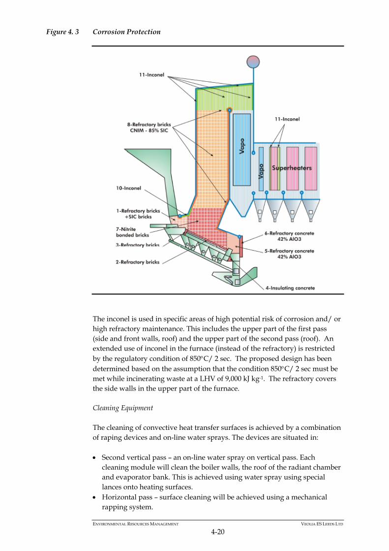
intermediate water injections (spray type attemperators) are provided between super-heaters sections for de-superheating purposes. The attemperators will control the temperature of the superheated steam leaving the super-heaters at around 400ºC. The individual tubes are perpendicular to the main flue gas flow and heat transfer is mainly achieved by convection between the flue gas and the tube metal. The flue gas velocity will be high enough to ensure a sufficient convective heat transfer coefficient. The super-heaters will be located in flue gas stream where the temperature is close to 600ºC to minimise corrosion attack. Parts of the super-heater tubes are made from inconel for corrosion protection. Evaporator The natural circulation evaporator bank is installed after the first empty vertical pass. The main purpose of the evaporator is to reduce the inlet gas temperature of the third superheater to an acceptable level. Economiser The economisers are located in the fourth and fifth vertical passes after the super-heaters. They are provided to pre-heat the feed water prior to entering the boiler steam drum. The economisers consist of several banks of plain tubes supported by water cooled tubes or bars according to flue gas temperature. The economisers are completely drainable and ventable and enclosed in a steel welded casing. An external economiser is provided at the boiler outlet for cooling the flue gas down to around 140°C before entering the flue gas treatment process. The flue gas cooling medium passing through the economiser is return condensate. This improves the efficiency of steam and condensate system. Corrosion Protection In the steam boilers, protection against high temperature corrosion is achieved by means of a combination of refractory lining and the use of corrosion resistant tubes. The furnace and second pass have been zoned as shown in Figure 4.3 with the green zones representing inconel plated zones, while the orange zones are refractory bricks protected walls.
ENVIRONMENTAL RESOURCES MANAGEMENT VEOLIA ES LEEDS LTD
4-20
Figure 4. 3 Corrosion Protection
The inconel is used in specific areas of high potential risk of corrosion and/ or high refractory maintenance. This includes the upper part of the first pass (side and front walls, roof) and the upper part of the second pass (roof). An extended use of inconel in the furnace (instead of the refractory) is restricted by the regulatory condition of 850C/ 2 sec. The proposed design has been determined based on the assumption that the condition 850C/ 2 sec must be met while incinerating waste at a LHV of 9,000 kJ kg-1. The refractory covers the side walls in the upper part of the furnace. Cleaning Equipment The cleaning of convective heat transfer surfaces is achieved by a combination of raping devices and on-line water sprays. The devices are situated in: Second vertical pass – an on-line water spray on vertical pass. Each
cleaning module will clean the boiler walls, the roof of the radiant chamber and evaporator bank. This is achieved using water spray using special lances onto heating surfaces.
Horizontal pass – surface cleaning will be achieved using a mechanical rapping system.
ENVIRONMENTAL RESOURCES MANAGEMENT VEOLIA ES LEEDS LTD
4-21
The fourth and fifth vertical pass – this will use an in-operation vibrating cleaning system.
Ash Hoppers In order to collect the boiler ashes under the gas circuits, the boiler is equipped with hoppers. These boiler ash collection hoppers, formed by fabricated steel, are provided at the bottom of any pass. The hoppers in the high temperature section of the boiler are refractory-lined, while the hoppers in the low temperature section of the boiler are of casing type with thermal insulation externally only. Safety Valves The boiler is fitted with: one main safety valve fitted on the drum, sized to release at least 75% of
the boiler steam rate and burners load; and one safety valve fitted on the superheater at its outlet and sized for
releasing a minimum of 25% of the boiler steam rate. This safety valve is set to open before the main safety valves fitted on the drum to ensure a permanent flow through the superheater.
4.5.3 Steam and Water Piping
The feedwater is heated up in the economiser in counter-current flow to the flue gas to a temperature slightly lower than the evaporation temperature. From the boiler drum, the water flows down through the unheated down-comers and supplier tubes to the lower headers of the evaporator system and thereafter is partly evaporated in the heated evaporator tubes (walls and bundles). The resulting water/ steam mixture flows over the riser tubes back to the drum, where the water steam mixture is separated. The saturated steam from the drum is heated up in the super-heater I and II bundles in counter-current flow and in the final superheater bundles in co-current flow. The live steam temperature is kept constant by two spray-type attemperators located between the super-heater bundles. The attemperators are equipped with orifice-type spray valves. The system includes one drain and a blow-down flash tank. The tank includes a system for disposal of the drain to the recycled water pit. The temperature at the flash tank outlet can be adjusted, depending on the mean blow-down flow recorded, in order to have a temperature of about 60C, i.e. suitable to send this water to the recirculation or disposal system or use it in the slag discharger.
ENVIRONMENTAL RESOURCES MANAGEMENT VEOLIA ES LEEDS LTD
4-22
The high pressure, low pressure, steam and feed water pipework will be designed and manufactured in accordance with relevant British Standard (BS) or equivalent.
4.5.4 Demineralisation Plant
The boiler feed water is produced by one dual demineralisation plant. Mains water will be used to supply the demineralisation plant. The demineralisation plant will be located in a bunded area with additional bunds surrounding each of the demineralisation process tanks. All floors and bunds will be coated to provide acid or alkali resistance. The treated water will be used initially to fill the boiler and feed water system, and then as boiler water make-up during operation. The characteristics of the treated water at the demineralisation plant outlet will be in accordance with the boiler and turbine manufacturers’ specifications.
4.5.5 Demineralised Water Storage Tank
Demineralised water is stored in a water tank which acts as a buffer to ensure that treated water is continuously available and stores treated water during programmed shut-down and emptying operations.
4.5.6 Boiler Water Conditioning
A boiler water treatment system is provided to ensure that the boiler water quality is maintained through the dosing of chemicals such as phosphate and oxygen scavenger. A dosing pump will inject the oxygen scavenger at the boiler feed water pump suction and phosphate will be injected into the boiler drum.
4.5.7 Deaerator
Condensate from the air cooled condenser is returned to the deaerator for suitable heating and degassing. The deaerator is composed of a cylindrical horizontally storage tank fitted with baffles and steam distribution ramp in the bottom and a dome in the upper part of the tank equipped with water spray nozzles and an off gas condenser.
4.5.8 Pumps
Water from the demineralised water tank is transferred to the deaerator by two controlled make-up water pumps (one on standby) of the fast refill and horizontal single-stage-type. The boiler water is supplied to the boiler from the deaerator by feed water pumps. These pumps will be multistage centrifugal pumps.
ENVIRONMENTAL RESOURCES MANAGEMENT VEOLIA ES LEEDS LTD
4-23
4.6 ELECTRICITY GENERATION
4.6.1 General
The steam generated by the heat recovery boiler is used in a condensing turbine to generate electricity. After subtraction of the power required for internal use, the electrical net production will be exported into the grid system via a step up transformer. Upon loss of the main export connection whilst the turbine generator is running, the turbine output shall automatically reduce in a stable manner to island mode without tripping.
4.6.2 Steam Turbine
The total steam quantity generated by the heat recovery boiler will be used in a common condensing and bled turbine to generate electricity. The steam turbine generator will be designed for continuous operation 24 hours per day and 365 days per year. The electricity generated by the steam in the turbine provides the power requirements of the Facility with the excess being exported to the grid through a step up transformer (11 kV to 33 kV). The turbine comprises of a split casing, and is fitted with non-controlled pass outs and an axial exhaust arrangement The selected condensing steam turbine generator will be able to operate in island mode with steam dumped to the condensers at an ambient temperature up to 27 ºC. Upon loss of the main export connection whilst the turbine generator is running, the turbine output will automatically reduce in a stable manner to island mode without tripping. The steam turbine generator will consist of: Turbine Gearbox Lubricating oil system Generator Based on the site specifics of the Facility, an air-cooled condenser (ACC) will be provided as the steam condensing plant for the steam turbine. It will be designed to condense all the exhaust steam leaving the turbine. The turbine is designed to accept the steam flow produced by the incineration line under any anticipated ambient conditions. It will accept the full boiler operating range in conjunction with acceptable waste within the Stoker diagram capability. Upstream steam pressure is regulated through the turbine by the governor-controlled steam admission valves. The governor valves operate sequentially to provide maximum efficiency corresponding to the design rating of the boiler at rated capacity.
ENVIRONMENTAL RESOURCES MANAGEMENT VEOLIA ES LEEDS LTD
4-24
The turbine is protected with an electronic overspeed unit using speed sensors. The subsequent loss of oil pressure causes the stop valves to rapidly close and the governing valves to close.
4.6.3 CHP System
The steam turbine will be designed to be CHP ready by having space provision in the turbine casing for a control valve or by enabling the replacement of the internal adaptative stage.. The control valve or the adaptative stage will allow a controlled bleed of steam for future use in a district heating scheme or other similar heat requiring scheme. In the case of the control valve, the valve will be grid valve type or equivalent. The grid type control valve, unlike an uncontrolled bleed, will allow control of the steam conditions irrespective of changes in the conditions of the incoming steam to the turbine. By allowing extra space in the turbine casing for the addition of the grid valve, this will allow the turbine to be easily adapted when the district heating scheme develops. The grid valve works on the basis of when the grid valve is fully opened, all the steam is guided to the exhaust of the turbine (i.e. generating maximum electrical energy). Then when the grid valve is closing, pressure increases in the bleed pipe and steam is supplied to the district heating. Finally, when the grid valve is fully closed, all the steam is guided to the district heating.
4.6.4 Lube and Control Oil System
A common lube oil system will be used to lubricate the turbine, gearbox and the generator main and subsidiary bearings. A separate system will supply oil for the high pressure hydraulic operation and the servo-control of the governing and emergency shut-off valves. The main oil pump will be either AC electric motor driven or driven directly from the low speed gearwheel of the gearbox. This will supply oil to the complete assembly for both lubrication and power control purposes. An AC starting and standby pump is provided to start in the event of failure of the main pump. An AC uninterruptable power supply (UPS) supplied rundown/cooling pump will also be provided for safe stoppage in case of failure of the main pump. The emergency AC UPS driven pump which operates on low pressure in the event of both the main pumps being unavailable for maintaining bearing lubrication shall maintain effective cooling for a sufficient length of time, while the unit coasts to a halt and is mechanically or hand barred.
ENVIRONMENTAL RESOURCES MANAGEMENT VEOLIA ES LEEDS LTD
4-25
4.6.5 Gearbox
A gearbox is provided in between the turbine and the generator. The gearbox is fitted with the necessary equipment for turbine operation and safety including but not limited to: AC motor and manual engagement; bearing temperature indicators and transmitters; and bearing vibration sensors.
4.6.6 Control System
The turbine control system is based on a programmable numerical device and is designed to carry out the following tasks: speed control while isolated from the grid; and control of HP steam pressure while connected to the grid. A local control panel monitors the turbine and its auxiliaries on start-up and during operation and provides alarm and fault parameters for the generator.
4.6.7 Generator
The generator consists of a synchronous 1500 rpm 4 pole totally enclosed water-to-air cooled (TEWAC) machine excited by rotating diodes with no brushes or rings. The generator will be supplied with appropriate excitation cabinet containing: auto excitation controller for voltage control, power factor; neutral point cabinet with current transformers; earth resistor with a homopolar detection core; and connection terminals.
4.7 STEAM CONDENSING AND WASTE WATER SYSTEMS
4.7.1 Steam Condensing
The exhaust steam from the turbine generator set is condensed in a vacuum condenser (air cooled) by passing through heat exchangers cooled by ambient air flow. The condensate flows, by gravity, into the condensate tank. The vacuum in the condenser is established and maintained by vacuum pumps or by means of motive steam in a series of Venturi type air ejectors. The steam required for the air ejectors is taken from the high pressure steam header. The steam from the ejector is condensed in a dedicated condensing unit cooled by the condensate transferred to the deaerator from the main condensate tank via duty and standby centrifugal pumps.
ENVIRONMENTAL RESOURCES MANAGEMENT VEOLIA ES LEEDS LTD
4-26
The condenser is capable of condensing the entire steam output of the boiler in full by-pass operation of the turbo generator set. Under this situation the operating pressure will be slightly higher than during normal operation with the turbo generator on line.
4.7.2 Air Cooled Condenser (ACC)
The air cooled condenser is a multi-cell unit with each cell comprising: tube bundles in carbon steel with aluminium fins; and cooling fan system comprising the fan with adjustable blades angles(preset
when fan is stationary), a variable speed electric motor and direct drive reduction gear.
The condenser is mounted on a fabricated steel support structure with maintenance access platforms and stairways. The ACC will be an anti-freezing A-frame type mounted on a steel structure. In normal operation the ACC will be operating under vacuum in order to maximize power generation from the steam turbine generator. It should be noted the speed of each fan of the ACC will be controlled by a frequency converter (one per cell). This will provide the opportunity during plant operation to limit down the exhaust pressure of the steam turbine during cold conditions in order to limit the steam velocity at the back end of the steam turbine to prevent any vibration on the machine. It would also assist in taking the benefits of the maximum capacity of the ACC during hot weather conditions
4.7.3 Plant Wastewater Generation
Wastewater arises from the following process areas during normal operation: boiler drains; steam circuit drains; regeneration of the demineralisation plant; washdown water from process area; ash discharger occasional overflow; and The handling of these wastewater streams, together with water which may be generated during abnormal operation and fires, is discussed in Section 4.11. Domestic sewage will be discharged to the public sewer network.
ENVIRONMENTAL RESOURCES MANAGEMENT VEOLIA ES LEEDS LTD
4-27
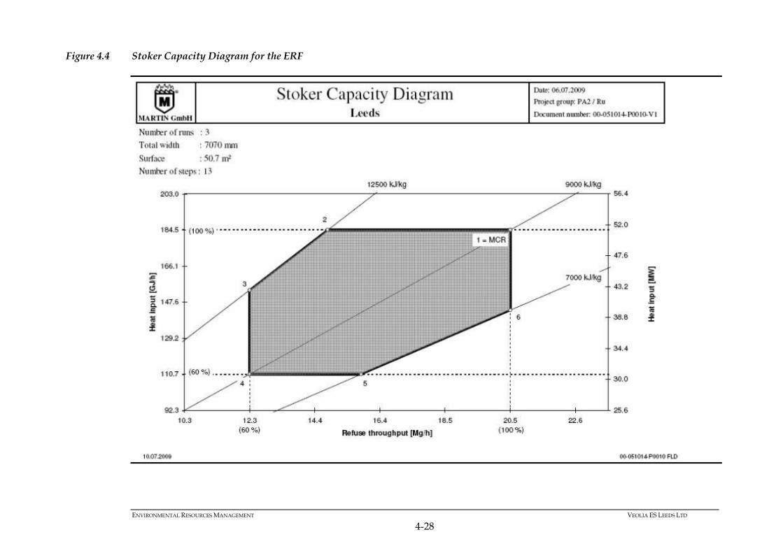
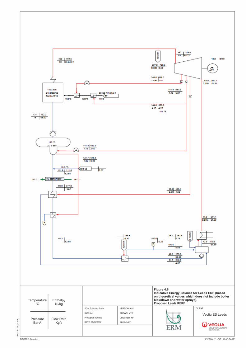
4.8 PERFORMANCE
The following section provides details of the Stoker Capacity diagram, mass and energy balances and emissions performances that will be achieved from the ERF. Figure 4.4 shows the Stoker Capacity Diagram. This provides details of the capacity of the incineration stream of the ERF. The Nominal Design Point is a municipal waste throughput of 20.5 tonnes per hour at a LHV of 9,000 kJ kg-1
which is equal to a thermal input of 51.25 MW. The municipal waste LHV range can vary from 7,000 kJ kg-1 up to 12,500 kJ kg-1. Figure 4.5 shows the mass balance diagram for the ERF. This provides a snapshot of the process detailing the inputs and outputs of the process. The table shows the details of the mass balance for the ERF. This provides an hourly mass balance of the process based on operation at the nominal design point of one stream at 20.5 tonnes per hour with a LHV of 9,000 kJ kg-1. Figure 4.6 shows the heat balance diagram for the ERF. This schematic details the heat gains and losses associated with the process. The table shows the details of the heat balance at nominal conditions for the ERF. This provides an hourly heat balance of the process based on operation at the nominal design point of one stream at 20.5 tonnes per hour with a LHV of 9,000 kJ kg-1. Table 4.1 shows the Flue Gas Treatment Schedule for the proposed facility. This provides details of the guaranteed flue gas emissions limits for the plant. The Operator intends to review with the EA the commissioning protocols to address compliance with regulatory requirements and process emissions to air, water and land and integrity of liquid and solid storage bunkers and bays.
ENVIRONMENTAL RESOURCES MANAGEMENT VEOLIA ES LEEDS LTD
4-28
Figure 4.4 Stoker Capacity Diagram for the ERF
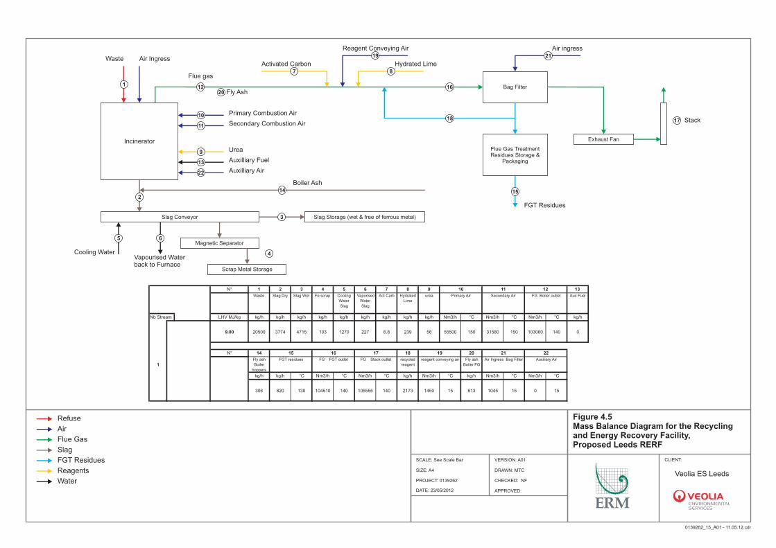
N° 1 2 3 4 5 6 7 8 9 10 11 12 13
Waste Slag Dry Slag Wet Fe scrap Cooling
Water
Slag
Vaporised
Water
Slag
Act Carb Hydrated
Lime
urea Primary Air Secondary Air FG Boiler outlet Aux Fuel
Nb Stream LHV MJ/kg kg/h kg/h kg/h kg/h kg/h kg/h kg/h kg/h kg/h Nm3/h °C Nm3/h °C Nm3/h °C kg/h
9.00 20500 3774 4715 103 1270 227 6.8 239 56 55500 150 31580 150 103060 140 0
N° 14 15 16 17 18 19 20 21 22
1Fly ash
Boiler
hoppers
FGT residues FG FGT outlet FG Stack outlet recycled
reagent
reagent conveying air Fly ash
Boiler FG
Air Ingress Bag Filter Auxiliary Air
kg/h kg/h °C Nm3/h °C Nm3/h °C kg/h Nm3/h °C kg/h Nm3/h °C Nm3/h °C
306 820 130 104510 140 105555 140 2173 1450 15 613 1045 15 0 15
IncineratorIncinerator
Bag FilterBag Filter
Flue Gas Treatment Residues Storage &
Packaging
Flue Gas Treatment Residues Storage &
Packaging
Slag ConveyorSlag Conveyor Slag Storage (wet & free of ferrous metal)Slag Storage (wet & free of ferrous metal)
Exhaust FanExhaust Fan
Magnetic SeparatorMagnetic Separator
Scrap Metal StorageScrap Metal Storage
22
44
66
88
1010
1212
1414
1616
1818
2020
2222
11
33
55
77
99
1111
1313
1515
1717
1919 2121WasteWaste Air IngressAir Ingress
Flue gasFlue gas
Fly AshFly Ash
Activated CarbonActivated Carbon
Reagent Conveying AirReagent Conveying Air
Hydrated LimeHydrated Lime
Air ingressAir ingress
StackStack
Boiler AshBoiler Ash
Auxilliary AirAuxilliary Air
Auxilliary FuelAuxilliary Fuel
UreaUrea
Secondary Combustion AirSecondary Combustion Air
Primary Combustion AirPrimary Combustion Air
Cooling WaterCooling WaterVapourised Water back to FurnaceVapourised Water back to Furnace
FGT ResiduesFGT Residues
DRAWN: MTC
CHECKED: NF
APPROVED:
PROJECT: 0139262
Figure 4.5 Mass Balance Diagram for the Recycling and Energy Recovery Facility,Proposed Leeds RERF
CLIENT:SCALE: See Scale Bar
0139262_15_A01 - 11.05.12.cdr
SOURCE: Unspecified
PR
OJE
CT
ION
: B
ritis
h N
atio
nal G
rid
DATE: 23/05/2012
VERSION: A01
SIZE: A4
Refuse
Air
Flue Gas
Slag
FGT Residues
Reagents
WaterVeolia ES Leeds
DRAWN: MTC
CHECKED: NF
APPROVED:
PROJECT: 139262
Figure 4.6 Indicative Energy Balance for Leeds ERF (based on theoretical values which does not include boiler blowdown and water sprays), Proposed Leeds RERF
CLIENT:SCALE: Not to Scale
0139262_11_A01 - 05.04.12.cdrSOURCE: Supplied
PR
OJE
CT
ION
: N
/A
Site Boundary
DATE: 05/04/2012
VERSION: A01
SIZE: A4
Temperature °C
Temperature °C
Pressure Bar A
Pressure Bar A
Enthalpy kJ/kg
Enthalpy kJ/kg
Flow Rate Kg/s
Flow Rate Kg/s
Veolia ES Leeds
ENVIRONMENTAL RESOURCES MANAGEMENT VEOLIA ES LEEDS LTD
4-31
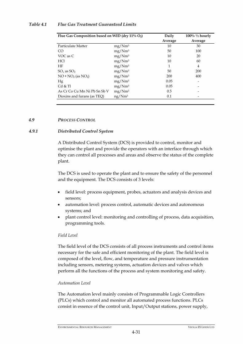
Table 4.1 Flue Gas Treatment Guaranteed Limits
Flue Gas Composition based on WID (dry 11% O2) Daily Average
100% ½ hourly Average
Particulate Matter mg/Nm3 10 30 CO mg/Nm3 50 100 VOC as C mg/Nm3 10 20 HCl mg/Nm3 10 60 HF mg/Nm3 1 4 SOx as SO2 mg/Nm3 50 200 NO + NO2 (as NO2) mg/Nm3 200 400 Hg mg/Nm3 0.05 - Cd & Tl mg/Nm3 0.05 - As Cr Co Cu Mn Ni Pb Sn Sb V mg/Nm3 0.5 - Dioxins and furans (as TEQ) ng/Nm3 0.1 -
4.9 PROCESS CONTROL
4.9.1 Distributed Control System
A Distributed Control System (DCS) is provided to control, monitor and optimise the plant and provide the operators with an interface through which they can control all processes and areas and observe the status of the complete plant. The DCS is used to operate the plant and to ensure the safety of the personnel and the equipment. The DCS consists of 3 levels: field level: process equipment, probes, actuators and analysis devices and
sensors; automation level: process control, automatic devices and autonomous
systems; and plant control level: monitoring and controlling of process, data acquisition,
programming tools.
Field Level
The field level of the DCS consists of all process instruments and control items necessary for the safe and efficient monitoring of the plant. The field level is composed of the level, flow, and temperature and pressure instrumentation including sensors, metering systems, actuation devices and valves which perform all the functions of the process and system monitoring and safety. Automation Level
The Automation level mainly consists of Programmable Logic Controllers (PLCs) which control and monitor all automated process functions. PLCs consist in essence of the control unit, Input/Output stations, power supply,
ENVIRONMENTAL RESOURCES MANAGEMENT VEOLIA ES LEEDS LTD
4-32
the interfaces to the plant control level and subsystems, as well as the application software. Plant Control level
The Plant Control level is a user interface which allows the operator to control the process and monitor the status of the equipment. This level consists of a real time Human Machine Interface (HMI) for the operation, monitoring and visualisation of the process in all areas of the plant such as: waste handling, combustion, flue gas treatment and common plant equipment. All the different process elements are displayed as schematic drawings on screens with both static and dynamic parts which continuously reflect the status of the plant. Safety Devices
The plant is provided with multiple safety devices and systems such as: pressure relief valves and systems; emergency stop push buttons which will take priority over all functions
regardless of whether the operation relates to single item of equipment (a running machine) or to a function group;
primary safety devices (hard-wired safety devices); and safety PLC/hardwired which provide safe operation and shutdown of the
plant and protection of the personnel and the environment.
4.9.2 Validation of Combustion Conditions and Boiler Design
In the design of the furnace and boiler, the specialist contractor uses Computational Fluid Dynamics (CFD) modelling software and a boiler dimensioning software to validate the configuration and dimensions of the furnace in order to optimise the combustion process and the mixing and turbulence in the furnace to minimise emissions of pollutants and optimise burn out of the ash to achieve values below compliance with the required regulations. The results of this optimisation process are used to calculate the coefficients of correlation used in the control system in order to continuously calculate the flue gas temperature after the two seconds residence time. This in-house software has been developed and improved by the contractor. It allows for the calculation of the following: the temperature, velocity and thermal flux profiles in the furnace; the heat flux absorbed by the tubes and membrane walls in order to ensure
the evaporation and the natural circulation in the tubes; the temperature of the refractory materials to study their thermal strength; the boiler behaviour under different combustion condition (including fuel
type, excess air, air temperature, primary and secondary air ratio);

ENVIRONMENTAL RESOURCES MANAGEMENT VEOLIA ES LEEDS LTD
4-33
the boiler performance at part load; and the influence of the boiler fouling on the thermal transfer to the boiler
heating surfaces. The software is coupled with a CFD modelling software which is based on a finite volume method which gives the best compromise between the result accuracy and the time of calculation. All the equations are solved for each finite element cell taking into account the influence of the neighbouring cells and walls. This model takes into account all physical phenomena taking place in the furnace: turbulent flow (to obtain the most realistic flue gas flow solving vorticity
and stream flow function differential equations) combustion (the heat released is calculated in each volume where the
combustion occurs, based on the specific heat of the chemical reaction. For waste incineration, the combustion calculation model is strongly supported by empirical correlation based on the Contractor’s extensive experience) and
thermal transfer by radiation, convection and conduction (the radiation properties of the flue gas and particulate are taken into account using a decomposition of the gas in a sum of several grey gases. These models are able to predict the absorption, emission and diffusion of the radiation energy.)
The results from these softwares are mainly used for the following purposes: Checking residence time, turbulence and temperature along flue gas paths
in the furnace; Calculating the basic parameters to be introduced in the DCS for
continuous control of the flue gas residence time at temperatures above 850°C for more than two second after the last injection of air;
Optimising the location of nozzles for SNCR reagent injection; Determining the most appropriate location of temperature sensors in the
furnace, in order to have the best control of combustion parameters and to ensure safe operating conditions in all cases.
In contrast, the location of secondary air nozzles is mainly related to combustion conditions, and therefore is strongly based on the results available from operational plants, together with specific large-scale laboratory tests. The boiler has a typical temperature profile as follows: CLEAN FOULED furnace outlet (boiler first pass) 870ºC 880°C Protective evaporator inlet 640ºC to 710°C 710°C superheater inlet 590ºC to 640°C 650°C
ENVIRONMENTAL RESOURCES MANAGEMENT VEOLIA ES LEEDS LTD
4-34
economiser inlet 350°C 380ºC to 400°C economiser outlet 180ºC 200°C In order to meet high operating availabilities, the boiler is subject to continual development in terms of corrosion resistant materials and the location of the various heat exchange surfaces. The destruction of dioxin precursors is achieved by ensuring that the flue gas temperature exceeds 850ºC for at least 2 seconds with 6% O2 after the last injection of combustion air which enables a complete burn out in the post combustion chamber of the boiler. Dioxin reformation by the de novo synthesis which may occur in the low temperature section of the boiler (mainly the economiser) where the flue gas temperature range of 200ºC-350ºC, is minimised by; reduction of the surface temperature and therefore deposits formation due
to the reduction of the flue gas temperature at the inlet of the convective bank to 600°C;
low oxygen content in flue gas (oxygen content is typically 7% by volume on dry basis);
reduction in the deposits on boiler tubes by use of efficient cleaning devices;
short residence time of flue gas in the low temperature section of the boiler: this is achieved by a progressive reduction in cross section of the boiler passes so that the gas velocity is maintained throughout the boiler; and
4.9.3 Combustion Control
General
The purpose of the combustion control system is to stabilise combustion parameters and as a consequence, reduce the flue gas pollutants emissions and obtain a steady steam flow. The combustion load control involves two main components: achieving stable steam flow; and optimal furnace temperature and O2 content in the flue gas. In order to comply with the Waste Incineration Directive (1), the combustion gas temperature must be above 850°C for at least 2 seconds. Principles
Conditions within the furnace and boiler are carefully controlled to ensure the efficient combustion of waste, thus minimising the releases of matter such as
(1) EC Directive on the Incineration of Waste (2000/76/EC), now recast in Industrial Emissions Directive (2010/75/EU)
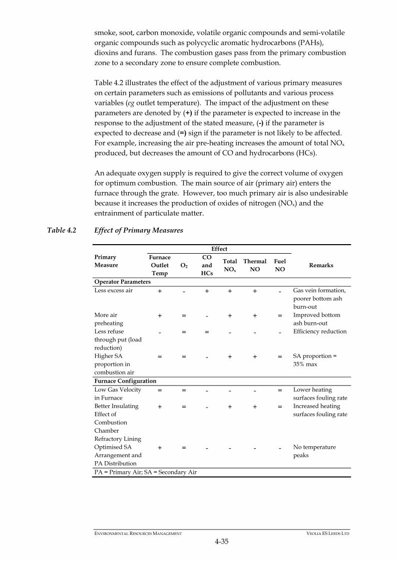
ENVIRONMENTAL RESOURCES MANAGEMENT VEOLIA ES LEEDS LTD
4-35
smoke, soot, carbon monoxide, volatile organic compounds and semi-volatile organic compounds such as polycyclic aromatic hydrocarbons (PAHs), dioxins and furans. The combustion gases pass from the primary combustion zone to a secondary zone to ensure complete combustion. Table 4.2 illustrates the effect of the adjustment of various primary measures on certain parameters such as emissions of pollutants and various process variables (eg outlet temperature). The impact of the adjustment on these parameters are denoted by (+) if the parameter is expected to increase in the response to the adjustment of the stated measure, (-) if the parameter is expected to decrease and (=) sign if the parameter is not likely to be affected. For example, increasing the air pre-heating increases the amount of total NOx produced, but decreases the amount of CO and hydrocarbons (HCs). An adequate oxygen supply is required to give the correct volume of oxygen for optimum combustion. The main source of air (primary air) enters the furnace through the grate. However, too much primary air is also undesirable because it increases the production of oxides of nitrogen (NOx) and the entrainment of particulate matter.
Table 4.2 Effect of Primary Measures
Primary Measure
Effect Furnace Outlet Temp
O2 CO and HCs
Total NOx
Thermal NO
Fuel NO
Remarks
Operator Parameters Less excess air + - + + + - Gas vein formation,
poorer bottom ash burn-out
More air preheating
+ = - + + = Improved bottom ash burn-out
Less refuse through put (load reduction)
- = = - - - Efficiency reduction
Higher SA proportion in combustion air
= = - + + = SA proportion = 35% max
Furnace Configuration Low Gas Velocity in Furnace
= = - - - = Lower heating surfaces fouling rate
Better Insulating Effect of Combustion Chamber Refractory Lining
+ = - + + = Increased heating surfaces fouling rate
Optimised SA Arrangement and PA Distribution
+ = - - - - No temperature peaks
PA = Primary Air; SA = Secondary Air
ENVIRONMENTAL RESOURCES MANAGEMENT VEOLIA ES LEEDS LTD
4-36
Control Systems
The combustion control integrates three complex control systems acting on: control of waste feeding speed and grate movements; primary air control; and control of secondary air injection. The boiler load setting will be governed by waste composition and the desired steam production within the limits of the stoker capacity diagram. The following controlled variables are used for combustion control: load (steam flow); excess air (% of combustion oxygen); and flue gas temperature (furnace temperature or infrared pyrometer). The use of such parameters depends on the control mode selected. Operation
Load: The purpose is to maintain a steady steam flow value at the boiler outlet within the operating range. The quantity and type of air distribution required is based on the given load and assumed average theoretical waste LHV. Primary air quantity: The undergrate air pressure is maintained at a constant value. The primary air control is achieved by variable speed control underneath the incineration grate. The O2 set point generates a common set point for all the air dampers, referred to as "STEP". According to the combustion control operating mode, this set point may be altered by the O2 controller. To allow for accurate combustion control on each part of the run, the "STEP" set point is interpreted as an individual position set point for each damper. Secondary air quantity: The secondary air injection into the furnace achieves a turbulent mixing of the combustion gases and complete combustion, together with a steady flame of controlled height. Depending on the steam flow set point, a minimum secondary air flow is necessary to obtain a good mix of gases produced by the combustion of the waste layer. Furthermore, even when the stoichiometric quantity is already achieved by the primary air, a certain amount of excess air is required to complete the combustion process. The combustion control system regulates the position of the secondary air control valves on the basis of a comparison between the pressure set point and the actual pressure measured. Each of the flow rates in secondary air ducts are monitored with alarms which send a signal in case of deviation from the expected value. Combustion: Ideal combustion conditions for a given load are set by adjusting the combustion load. Taking the waste LHV into account, a certain quantity of
ENVIRONMENTAL RESOURCES MANAGEMENT VEOLIA ES LEEDS LTD
4-37
excess air (related to a given oxygen percentage in the flue gas) is required for the combustion gases to reach suitable temperature. At a given time, when the quantity of air complies with the load, a change in the O2 value indicates that combustion conditions have changed, typically due to the change in the waste LHV. The O2 adjustment is made by correcting the total primary air quantity (STEP). Waste feeding: The feed ram speed and stroke length are controlled in order to balance the ON-time and idle times "optimisation algorithm". When the ON-time controller is not active, the feeder speed and stroke length adjustments are controlled by the operator and are the same for all the feeder actuators. The end positions of the feed rams reflect the stroke length of each feed ram. Independently of the selected combustion control operating mode, the feeder is stopped if the active set point is exceeded (either furnace average temperature or infrared pyrometer temperature or steam flow according to operating mode). Grate movement: The movement of the grate directly affects the waste combustion. This control is integrated into the combustion control programme. In all the combustion control modes, the grate speed can be controlled by the operator. Independently of the selected combustion control operating mode, the grate movements are stopped if the active set point is exceeded (either due to furnace average temperature or infrared pyrometer temperature or steam flow according to operating mode). Control Operating Modes
Preliminary: The combustion control programme may operate according to three different modes selected by the operator according to the boiler status: "Furnace temperature" mode; "Steam flow" mode; and "Infra red pyrometer temperature + steam flow " mode. "Furnace temperature" mode (Start-up mode): This mode is used when starting the ERF until the steam service pressure has been reached and is steady, or when the steam flow and the infrared pyrometer measurements are not available. In this mode, the "Furnace temperature" parameter is adjusted at the set point value set by the operator, by simultaneous action on waste feeders and grates. The operator manually sets the common set point available for all the primary air dampers (STEP). From this set point the combustion controller generates individual set points for each primary air damper according to the set point correction table compiled during commissioning. Each damper is then operated with reference to its position target value.
ENVIRONMENTAL RESOURCES MANAGEMENT VEOLIA ES LEEDS LTD
4-38
"Steam flow" mode (Stand-by mode): This mode may be used when the steam pressure is steady, but only if the infrared pyrometer is not available. In this mode, the combustion controller adjusts the "Steam flow" parameter at the set point set by the operator, by simultaneous action on waste feeders and grates. The air flow is controlled by the combustion control program, which adjusts the common primary air set point (STEP). This set point generates individual set points for each primary air zone according to the set point correction table compiled during commissioning. Each primary air damper position is controlled with reference to its set point value. The STEP value (common set point) is automatically corrected by a PID controller output on the basis of the O2 measurement with reference to the O2 set point set by the operator. "Infrared pyrometer temperature + steam flow" mode (normal mode): This mode is to be used when the steam pressure is steady and the O2 measurement, steam flow and infrared pyrometer measurements are available (and reliable). In this mode, the waste feeding and the primary air flow in all the grates zones are automatically adjusted by the combustion control program in order to maintain a constant temperature in the boiler (flue gas). The waste flow is controlled by the combustion control program, which adjusts steam flow and boiler temperature parameters through to a cascade controller type. The steam flow is used as the measurement input in the first PID block whose set point is the steam flow set point set by the operator. The controller output generates the set point for the second controller. The second PID controller receives the infrared pyrometer temperature measurement, and simultaneously drives the waste feeder and the grates. The air flow is controlled by the combustion control program, which adjusts the common primary air set point (STEP). This set point generates individual set points for each primary air zone according to the set point correction table compiled during commissioning. Each primary air damper position is controlled with reference to its set point value. The STEP value (common set point) is automatically corrected by a PID controller output on the basis of the O2 measurement with reference to the O2 set point set by the operator. ON-Time Controller
The ON-time controller sets the speed and stroke length of the feed rams to ensure that a defined, reproducible proportion of the gross heat release required per time unit is supplied to the combustion system in each feeding cycle irrespective of the waste quality. By automatically adjusting both speed and stroke length, the heating value fluctuations that occur when using waste as fuel are compensated and the actual ON-time per time unit for the feeder and grate is gradually brought closer to the specified ON-time set points.
ENVIRONMENTAL RESOURCES MANAGEMENT VEOLIA ES LEEDS LTD
4-39
Combustion control system with infrared camera
In addition to the basic control system, an infrared camera is installed in the roof of the boiler above the grate. The observation field of the infrared camera covers the entire width of the grate and longitudinally the area from zone 1 up to the middle of zone 4. The objective is to monitor the combustion process on the grate - not the flame above. In consequence the infrared wavelength is selected within a range of minimum radiation of the combustion gases. The infrared camera signals are processed in an image analysis program which provides the surface temperature distribution of the combustion layer on the grate. Soot particle emission from the flame is also eliminated by these image processing algorithms. The surface temperature distribution correlates with the intensity of combustion in the fuel layer on the grate. All important stages of combustion on the grate (drying, ignition and main combustion) can thus be monitored with high spatial resolution in almost real time. The position of the main combustion zone can be determined by the temperature distribution across the surface of fuel bed as well as across the entire grate width and the individual grate runs. Unbalanced conditions, (e.g. due to varying fuel quality) can thus be detected in real time and be eliminated by means of targeted control operations. Additional control systems are used for this purpose. The primary air is distributed to the individual zones in accordance with requirements at that particular time. The total primary air flow and therefore the flue gas flow remain unchanged. The stroke length of each feed ram is adjusted individually to achieve uniform feeding across all grate runs. Overfeeding of individual grate runs (e.g. caused by sudden fluctuation of waste heating values) or differences due to increased friction on the side walls can be avoided in this way. By means of the combustion control system with an infrared camera, fuel-related fluctuations in the combustion process on the grate can be counteracted promptly. The furnace temperature can thus be stabilised significantly as can the steam produced, thereby reducing emission peaks.
ENVIRONMENTAL RESOURCES MANAGEMENT VEOLIA ES LEEDS LTD
4-40
4.9.4 Start-up and Shut-down Procedures
Starting the Plant from Cold
The Waste Incineration Directive (1) requires that the furnace is pre-heated to 850ºC before the introduction of waste. This pre-heating is achieved by oil fired auxiliary burners. Once the threshold temperature has been achieved and the flue gas treatment unit has reached operating temperature, waste can be introduced into the feed hopper and the feeder and grate started. The steam pressure rise in the boiler is monitored carefully in order to avoid thermal/mechanical shock on the boiler drum. The flue gas temperature gradient in the furnace is limited by the sensitivity of the refractories to thermal shock. Controlled Shutdown
For a controlled shut down, the procedure consists of maintaining the burner in operation to maintain the 850°C temperature requirement until all the waste in the furnace has been burnt out. The procedure may be summarised as follows: stop waste loading into the feed hopper and close the hopper gate as soon
as the level in the hopper allows, to prevent air ingress into the furnace; switch the boiler combustion control to manual and gradually reduce the
incineration rate; when the furnace temperature drops to a preset value the auxiliary burner
is automatically started; the burner maintains the minimum 850°C until all waste has been burnt
out; switch off the combustion fans, grate, and reagent feed; the induced draught fan may be maintained in service for cooling purposes
for a period; keep the bottom and boiler ash handling system operating for sufficient
time to clear all ash from the equipment; clean the bag filter if necessary depending on the anticipated length of the
shutdown; and
(1) EC Directive on the Incineration of Waste (2000/76/EC), now recast in Industrial Emissions Directive (2010/75/EU)
ENVIRONMENTAL RESOURCES MANAGEMENT VEOLIA ES LEEDS LTD
4-41
keep the FGT residue conveying system operating for about two hours after extinguishing the furnace or for long enough to clear all residue from the filter hoppers and equipment.
The turbine is shut-down as follows: disengage the steam turbine generator and ensure that an oil pump (either
the auxiliary pump or the emergency pump) continues running to cool the bearings; and
allow the pressure to drop by adjusting the HP steam manifold vent such
that the steam temperature in the drum does not change too rapidly to avoid thermal shock.
Emergency Shutdown
If any incident endangers or is likely to endanger personnel (eg an external steam leak), or there is a risk of serious damage to the plant (eg loss of water from the drum following a burst tube), the emergency shut-down procedure must be followed. In the light of experience, the Operator will draw up precise operating procedures for the various possible scenarios according to the likelihood of incidents in the plant, taking into account the safety of personnel, then as far as possible, the safety of the plant. Regarding the safety of the plant, in an emergency the following operating procedure will be followed.
‘To extinguish combustion in an emergency, either use the emergency stop button or switch off the draught fan which results in immediate and automatic stop of the combustion fans, the grate feed and the burner.’
Staff will ensure that: the above actions have successfully been completed; the air dampers under the grate are closed; and the fuel oil safety valves are fully closed. In order to ensure that the plant operates safely, within the limits of the Environmental Permit and with high availability, various items of standby equipment and control system elements are provided. All equipment within the ERF will be subjected to a Planned and Preventative Maintenance Programme where appropriate to minimise unplanned failures.
ENVIRONMENTAL RESOURCES MANAGEMENT VEOLIA ES LEEDS LTD
4-42
In addition, various actions and monitoring procedures will be carried out by VESL to ensure that the ERF combustion parameters and emissions remain within the Environmental Permit. The list below identifies some typical failures and VESL initiated actions and control measures. Failure of the export/import electrical supply: If the export/import supply fails
the plant continues to operate but in island mode, ie generating its own power. If the turbine trips, then the import electrical supply ensures the safe shutdown of the plant. If the import supply fails, then VESL initiates an Emergency Shutdown, using the Uninterruptable Power Supply (UPS) to supply the CEMS to monitor that combustion conditions and emissions comply with the Permit. Alternatively if the turbine trips, then the emergency diesel generator system ensures the facility can be shutdown safely. If the emergency diesel generator system fails, then VESL initiates an Emergency Shutdown, using the Uninterruptable Power Supply (UPS) to supply the CEMS to monitor that combustion conditions and emissions comply with the Permit.
Failure of the FGT equipment: There are various standby items and storage
capacities within the FGT system. If a total lime system failure occurs, then unspent lime on the filter bags will ensure that during the Emergency Shutdown, the combustion conditions and emissions comply with the Permit.
Failure of the filtration system: Online maintenance is achieved through
isolation of filter sections. In the unlikely occurrence of multiple bag failures the operator will need to isolate failed bags; if the isolation proves ineffective, a Controlled Shutdown is initiated within two hours. The combustion conditions and emissions will comply with the Permit.
Failure of equipment: In the event of a failure of bottom ash and FGT residue
conveyors, then diverter chutes and bypasses are utilised to avoid shutdowns. In the event of a failure of grate rams and fans, VESL initiates Controlled Shutdown. The combustion conditions and emissions will comply with the Permit.
4.10 ABATEMENT OF POINT SOURCE EMISSIONS TO AIR
Once the flue gas leaves the final economiser section of the boiler, the flue gas will have been cooled to around 140-150°C, it will then enter the flue gas treatment process. The flue gas cleaning system will be designed to comply with the emission limit values of the EU Waste Incineration Directive (WID) and the Facility environmental permit. In reality, it will reduce the emissions to well below the requirements of the emission limit values given in WID.
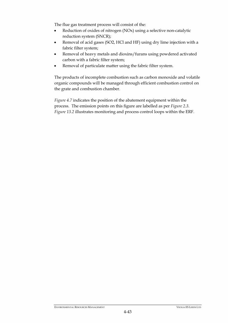
ENVIRONMENTAL RESOURCES MANAGEMENT VEOLIA ES LEEDS LTD
4-43
The flue gas treatment process will consist of the: Reduction of oxides of nitrogen (NOx) using a selective non-catalytic
reduction system (SNCR); Removal of acid gases (SO2, HCl and HF) using dry lime injection with a
fabric filter system; Removal of heavy metals and dioxins/furans using powdered activated
carbon with a fabric filter system; Removal of particulate matter using the fabric filter system. The products of incomplete combustion such as carbon monoxide and volatile organic compounds will be managed through efficient combustion control on the grate and combustion chamber. Figure 4.7 indicates the position of the abatement equipment within the process. The emission points on this figure are labelled as per Figure 2.3. Figure 13.2 illustrates monitoring and process control loops within the ERF.
Activated Carbon Filters
(MPT Building)
Activated Carbon Filters
(MPT Building)
A10
A1
A2
A3A4
A5 A7
A6A7
A8
A9
T°
T°
T°
T°
T°
O2
FT
FT
FT
Hcl
Hcl
Hcl
NH3
SO2
SO2
SO2
CO
Dust
Bed T°
FT
Nox
Nox
Combustion Control
Combustion Control
Urea DeNox
Urea DeNox
NH3
NH3
Figure 4.7Schematic Detailing Abatement Equipment and Release Points of the Energy Recovery Facility, Proposed Leeds RERF
CLIENT:
SOURCE: Unspecified 0139262_12_A01 -17.04.12.CDR
PR
OJE
CT
ION
:
DRAWN: MTC
CHECKED: NF
APPROVED:
PROJECT: 0139262
SCALE: Not to Scale
DATE: 21/06/2012
VERSION: A01
SIZE: A3
Site Boundary
Veolia ES Leeds
T°
O2
FT
Hcl
SO2
Nox
CO
Dust
Bed T°
A12
A13
A14
A15
A16
Boiler 2 Relief Valve 1
Flow Rate
Boiler 2 Relief Valve 2
Hcl Concnetration
Reserve/Standby Diesel Generators
SO Concentration2
Reserve/Standby Diesel Generators
No Concentrationx
Ammonia Tank Vent
CO Concentration
Dust Concentration
Combustion Bed Temperature
NH3 Concentration
Ammonia
ERF Chimney
Lime Silo Vent
Activated Carbon Silo Vent
FGT Residue Silo Vent
Diesel Generator
Fuel Tank Vent
Activated Carbon Filters (MPT building)
Boiler Vent
Boiler Relief Valve 1
Boiler Relief Valve 2
Temperature
Boiler 1 Relief Valve 2
Oxygen Content
A10
A11
A1
A2
A3
A4
A5
A6
A7
A8
A9
0 15
Metres (approx)
ENVIRONMENTAL RESOURCES MANAGEMENT VEOLIA ES LEEDS LTD.
4-45
4.10.1 NOx Reduction System
Reduction of nitrogen oxides is achieved by means of a selective non-catalytic reduction (SNCR) system using dry urea as the reducing reagent. The main reactions are as follows: CO(NH2)2 + ½O2 → CO2 + 2NH2 CO(NH2)2 + H2O → CO2 + 2NH3 The ammonia produced then reacts with NO and NO2 to reduce them to N2. 4NO + 4NH3 + O2 → 4N2 + 6H2O 2NO2 + 4NH3 + O2 → 3N2 + 6H2O The NOx removal efficiency and reagent utilisation are related by a variable known as Normalised Stochiometric Ratio (NSR) defined as follows: NSR = Actual Molar Ratio of Reagent to inlet NOx Stochiometric Molar Ratio of Reagent to inlet NOx
The two key parameters that affect the process performance are the flue gas temperature and the reagent distribution. To optimise the NOx reduction, the reagent needs to be distributed within the optimum temperature zone of the boiler/furnace assembly. The function of the NOx reduction system is to: transfer urea to the storage silo; extract and meter urea; transport and distribute urea via air conveyors; inject urea into the gas flow via the appropriate level of injection nozzles;
and purge the injection system from urea when the boiler is not operating. The injection level and product feed rate can change according to the furnace operating conditions.
The duty and standby urea injection systems are independent, and if one of them is shut down there is no impact on the operation of the other one. The selection of the injection system and air booster is done manually. The whole of the installation is controlled from an electrical control and power distribution cabinet. Two operating modes are available: centralised remote operating mode; and local operating mode.
ENVIRONMENTAL RESOURCES MANAGEMENT VEOLIA ES LEEDS LTD.
4-46
The urea injection metering and injection level selection valve will be controlled from the ERF central control room, while the selection of the distribution level is generated in the electrical panel. The final choice of injection levels and positions will be made during commissioning and fine tuning on site. Nitrous Oxide (N2O) Control
The furnace combustion process will be controlled to minimise the emission of nitrous oxide. This is achieved through the following during commissioning: the set up of the furnace using an infra-red pyrometer to confirm good
combustion conditions; and optimisation of the position of the urea injection nozzles to maximise the
reaction efficiency and avoid urea overdosing hence minimising nitrous oxide emissions. Whilst there is a reduction in the total of NOx produced using urea SNCR, the emissions of nitrous oxide itself increases.
4.10.2 Flue Gas Cleaning System – Acid Gases
Overview
Plants incinerating residual municipal waste generate acid gases, ie hydrogen chloride (HCl), hydrogen fluoride (HF) and sulphur dioxide (SO2) together with trace concentrations of sulphur trioxide (SO3). The treatment of acid gases consists of neutralising them by the addition of a dry alkaline reagent (eg. hydrated lime). In the dry process the alkaline reagent is injected into the flue gases to be treated via a pneumatic conveying system. The acid pollutants in the flue gases are neutralised by contact and reaction with the fine particles of the reagent downstream of the injection point in the flue gas ducting and subsequently in the fabric filter. Hydrogen chloride and hydrogen fluoride react with calcium hydroxide to form respectively calcium chloride (CaC12) and calcium fluoride (CaF2) in accordance with the following reactions: 2 HCl(g) + Ca(OH)2(s) CaCl2(s) + 2 H2O(g) 2 HF(g) + Ca(OH)2(s) CaF2(s) + 2 H2O(g) The sulphur dioxide reacts with the calcium hydroxide to form calcium sulphite in accordance with the following reactions: SO2(g) + Ca(OH)2(s) CaSO3(s) + H2O (g) CaSO3(s)+ ½ O2(g) CaSO4(s)
ENVIRONMENTAL RESOURCES MANAGEMENT VEOLIA ES LEEDS LTD.
4-47
The sulphur trioxide reacts with the calcium hydroxide to form calcium sulphate in accordance with the following reaction: SO3(g) + Ca(OH)2(s) CaSO4(s) + H2O(g) For the dry process, the acid gas neutralisation products are dry solids which are entrained by the flue gases and separated out by a downstream fabric filter. Operating Principle
The flue gases from the boiler outlet pass through the final economiser, where the gas temperature is rapidly reduced to around 140°C - 150°C. The speed of cooling is designed to minimise the reformation of dioxins (which occurs in approximately between 200 –400°C). The gases leave the final economiser and pass through a reaction duct, into which fresh lime and activated carbon is injected along with recirculated reagents (lime and activated carbon). The fresh reagents are transported from storage silos to the injector by a pneumatic conveyor line and thoroughly mixed with the flue gases in the ducting. After the reaction duct the mixture passes to a multi-compartment fabric filter. End Product Recirculation
To optimise the utilisation of the reagents some of the residue is collected in a recirculation silo and from there fed back to the injection point. This recirculation system supports diffusion of reaction products within the particles, thereby presenting a more active surface for the HCl/SO2 when re-injected. Reagent Storage and Distribution
Lime is delivered in tanker loads. The lime silo has an operational storage capacity of seven days operation at MCR with nominal flue gas pollution with a volume of 110m3. Activated carbon is also delivered in tanker loads into a 75 m3 silo, capable of holding more than 30 days’ supply. Like the lime, it is dosed via a volumetric feeder unit on the silo outlet, through a feed chute into the transport pipework and then to the injection point.
4.10.3 Flue Gas Cleaning System –Heavy Metals and Dioxins
Overview
Plants incinerating residual municipal waste also generate small amounts of dioxins, furans and heavy metals in the flue gas. To abate these pollutants, activated carbon is added to the flue gas. Note that whilst a portion of the heavy metals present in the flue gas will condense onto the dry alkaline
ENVIRONMENTAL RESOURCES MANAGEMENT VEOLIA ES LEEDS LTD.
4-48
reagent (lime) used to abate the acid gases; activated carbon is needed to reduce the emissions of mercury to WID limits. Dioxins, furans and heavy metals present in the gas stream will be adsorbed onto the activated carbon. The activated carbon particles are dry solids which are entrained by the flue gases and separated out by a downstream fabric filter. Activated Carbon Storage and Distribution
Activated carbon is delivered in tanker loads and transferred pneumatically into a 75m3 silo. The displaced air resulting from transfer of the activated carbon is de-dusted by means of a fabric filter located on top of the silo. The dosing unit on the silo outlet ensures control of the rate of injection of the activated carbon in the flue gas. The risk of fire or explosion in the activated carbon system is minimised by the following features: large distance between the storage/dosing equipment and the flue gas
duct; temperature sensor in the activated carbon storage silo to detect hot spots
and nitrogen connection for inertisation; and small content of activated carbon in the FGT residue storage silo. The accidental release of activated carbon during filling is minimised through the generously designed filter vent and the adoption of detailed filling and emptying operating procedures. In addition, a vent with a self-cleaning filter is provided at the top of the unit to prevent over pressurisation.
4.10.4 Filter System and Gas Discharge
Fabric Filter
The fabric filter unit comprises compartments each containing several rows of filter bags. These bags are closed at the bottom, open at the top, and are installed over a cage structure that maintains their shape. The bags/cages are fitted into a division plate which separates the inlet and outlet sections of the casing. The flue gas enters the low part of the casing below the division plate and flows through the bags from the outside to inside with the resultant clean gases emerging from the open top of the bag above the division plate. The particulate matter collects on the outer surface of the fabric filter bags where a layer of particulate matter builds up to form a filter cake.
ENVIRONMENTAL RESOURCES MANAGEMENT VEOLIA ES LEEDS LTD.
4-49
As the pressure drop across the filter bag increases due to build up of filter cake. This is continuously monitored and controlled so that when it reaches the set point a bag cleaning sequence is automatically initiated. The filter cleaning operation is performed online by sending a pulse of compressed air down the inside of each bag in a row by row sequence. This causes the filter cake to be released from the surface of the fabric filter and collected in the hopper below. Filter cleaning cycles times are fully adjustable over a wide range of conditions. Manual initiation of filter cleaning is also possible. The fabric filter is provided with a preheating system designed to heat the fabric filter prior to start-up by circulating hot air in a closed circuit around the fabric filter. The system comprises: an electric air heater; fan; and ducting and control instruments. The expected efficiency of the fabric filter is very high at above 99%. For a dry flue gas treatment system using lime as a reagent, small particles around one micron in diameter and below will be removed by agglomeration on the filter cake. The minimum particle size that can be detected depends on the monitoring equipment. Gravimetric methods, which are used to calibrate and verify continuous on-line monitors, will iso-kinetically sample all particle sizes down to about 1 micron. Upstream of the fabric filter, particles typically range from about 1 micron up to 1000 microns. The particles are likely to have a normal distribution around the 100 micron level. Downstream of the fabric filter, there is likely to be a relatively larger proportion of 1µm particles as the filters are inherently more efficient for larger particles. Ultra fine particles (< 0.1 µm) are almost entirely removed through their attraction to filter cake. During normal operation, the quantity of particulates at the outlet of the filter will be usually less than 5 mg Nm-3, with peaks not exceeding 10 mg Nm-3, and is generally independent of the particulate loading upstream of the filter. Bag failure is detected as an increase in particulates emissions. Individual filter compartments can be systematically isolated to identify the one containing the failed bag(s). During filter maintenance, the isolation of a compartment does not impair the overall performance of the filter unit and the plant will continue to operate within the guaranteed limits in Table 4.1.
ENVIRONMENTAL RESOURCES MANAGEMENT VEOLIA ES LEEDS LTD.
4-50
The bags will be protected by an initial coating of hydrated lime (during start up or preceding shut down). The fabric filter unit is located inside the main building and there is adequate height clearance for the removal of bags and cages for maintenance. Enclosed hoppers collect the FGT residue underneath the bags. The hoppers are insulated and heated in order to maintain the wall temperature above 110°C and prevent any clogging in the filter. All surfaces at temperatures in excess of 60°C will be insulated and clad. The cladding and supports will be installed so as to eliminate thermal bridging. Stairs and walkways are to be provided from ground level up to parts of the filter unit that require periodic inspection or maintenance including access for measurement devices and instrumentation. The fabric filter is equipped with a control cabinet containing: switchgear and relays; control system; and interlocking system. The monitoring information relayed to the control room includes the status of each filter unit (ON/OFF/FAULT) and the differential pressure across the unit. Fabric Filter Material
The bag filter fabric is made of P84 media (polyimide) with PTFE resin impregnation. This allows good capture of very fine particles as the solid content of the flue gases is retained and deposited in a filter cake on the surface of the bags. Alternatives include the provision of filter bags with Goretex-type membranes. Although this type of bags allows a better efficiency for very fine particles removal, it can also introduce the following disadvantages: the filter cake adheres better to bags without membrane due to more
irregular surface which can be an important factor in case of strong load variation of flue gas flows;
membranes are very sensitive to unburnt oil droplet impact that can occur during preheating when it is performed with fuel oil; and
cleaning of membrane bags is impossible when dust starts to enter into the filtering media through very fine holes into the membrane.
While Goretex-type membrane filter bags provide better efficiency for very fine particulate removal, the type of bags proposed for the facility present a
ENVIRONMENTAL RESOURCES MANAGEMENT VEOLIA ES LEEDS LTD.
4-51
good compromise in terms of filtering performances, robustness and filter cake control providing enhanced results for pollutants abatement in transitory phases and during the bags cleaning sequences when a significant loss of filter cake is detrimental to the neutralising reactions. FGT Residues
The FGT residue is collected at the fabric filter hopper. These residues are then transferred to the FGT silo or the recirculation silo. Active residuals (i.e. unspent activated carbon and unreacted lime) from the recirculation silo can be re-injected into the process to minimise raw material usage. These residues are injected into the flue gas stream just prior to the fabric filter. ID Fan
The cleaned gases that pass through the filter are drawn by the Induced Draft (ID) fan via the ducting to the chimney. The induced draft fan including silencer will be used for compensation of the upstream plant pressure drops, conveying the flue gas flow throughout the plant and controlling the furnace under-pressure simultaneously. Continuous measurement is made of the following pollutants: particulate, HCl, SO2, CO, NOx, VOC and O2 downstream of the flue gas cleaning system by means of a Continuous Emissions Monitoring System (CEMS). Computer modelling of the flue gas flow through the boiler-flue gas cleaning equipment is conducted to verify the design whenever new configurations are encountered. The induced draught fan is of the centrifugal type with variable speed control. The impeller is of the backward aerofoil type. Blades are made up of abrasion resistant plates and are designed to be self-cleaning. The impeller is overhung on a shaft supported by two grease lubricated anti-friction bearings. The impeller is statically and dynamically balanced before assembly on the shaft. The shaft is directly coupled by a flexible coupling to the variable speed motor. The motor is protected to IP 55 Class F. The impeller is housed in a 5 mm thick casing which can be split for removal of the impeller wheel and shaft. An inspection door and drain plug are provided in the casing. The fan casing is externally insulated. The fan is operated and controlled from the main control room where the main information is displayed. The ducting carrying the flue gases is made of 5 mm mild steel plate ribbed and braced. It is externally insulated with mineral wool and metal clad. Expansion joints will be of the laminated fabric type internally insulated. Openings will be provided in the ducting for sampling measuring and
ENVIRONMENTAL RESOURCES MANAGEMENT VEOLIA ES LEEDS LTD.
4-52
maintenance purposes. The duct work is designed for a nominal flue gas velocity of 20 m s-1 (at full load). Chimney
There is one free standing flue fabricated from steel plate. The chimney flue has: access for cleaning and drainage; lightning protection; sampling points for manual measurement; and connections for continuous emissions monitoring equipment. The chimney is provided with a platform for access to the sampling points for statutory monitoring purposes and for maintenance and inspection of the CEMS equipment in accordance with guidance notes M1 and M2. The flue is thermally insulated to ensure the flue gases are maintained above their dew point.
4.11 ABATEMENT OF FUGITIVE EMISSIONS
4.11.1 Abatement of Fugitive Emissions to Air, including Odour
Incoming residual municipal waste will be delivered in covered vehicles or containers. There will be no large scale storage of fuels or stockpiles of raw materials, other than of municipal waste which is contained in the bunker or within the MPT reception hall. As stated in Section 4.3, vehicular access to the reception hall will be via entrance fitted with a fast shutting door which will remain closed outside of normal delivery periods. Periodic washing down will be carried out to maintain a clean area. As stated in Section 4.4.9, combustion air is drawn from above the waste storage bunker and reception hall so that the odours and airborne dust are drawn into the incineration line. Odorous substances will thus be destroyed by incineration and any dust retained in the bottom ash or in the FGT residue. An activated carbon filter will present on the MPT. This will complement the extraction of air via the combustion air fans of the ERF which creates a negative pressure in the ERF and MPT buildings preventing the fugitive emissions of odour. During ERF shutdown additional units of the activated carbon filter will be brought online to compensate for the lack of negative pressure being drawn from the ERF. These techniques will help to keep the amount of dust in the reception hall to a minimum and to reduce the possibility of the escape of both dust and odour. There will be some unavoidable trivial emissions of solvent vapours from paints and solvents during maintenance (painting). These will be minimised
ENVIRONMENTAL RESOURCES MANAGEMENT VEOLIA ES LEEDS LTD.
4-53
by selecting painting solvent systems (paint and thinners) with the lowest possible volatile organic compound (VOC) content compatible with satisfactory surface protection performance. There are thus no significant fugitive emissions to air of gases, vapours, odours or particulates.
4.11.2 Abatement of Emissions to Surface Water and Sewer – Normal Operations
Process Water Drainage during Normal Operations All process water will drain into the wastewater pit, which will have a connection to the public foul sewer. It is not anticipated that surface water from any external area will drain into this pit. All the water collected in the MPT and the ERF hall and transferred to the wastewater pit is recycled in the ERF process. The RERF is a zero-discharge-to -water facility, and no process water will be discharged into local watercourses or surface water. Surface Water Drainage during Normal Operations During operations the surface water from the site will drain through three separate below ground piped systems, each discharging to one of the existing surface water connections to the public sewer. Use Sustainable Urban Drainage Systems Sustainable Urban Drainage Systems (SUDS) will be used wherever appropriate. The proposed SUDS include the features set out below: Rain water from the roof will be collected in a central channel that outfalls
to a lagoon and to an underground rainwater harvesting tank. This water will be used to supplement the underground fire water tank and the green wall watering tank water supply.
A green wall is proposed along the southern face of the ERF building.
This will have a self-contained drainage system that re-circulates runoff via an internal tank. In the case of an overflow incident from this system, overland flow to the attenuation system would occur, containing flows on site
The surface water run-off from the external access roads, parking and
service areas will drain to two separate below ground drainage systems. One system will discharge to the western outfall and one will discharge to the eastern outfall. Flow from external trafficked areas will pass through a class 1 bypass oil separator prior to discharging to the surface water sewer network.
ENVIRONMENTAL RESOURCES MANAGEMENT VEOLIA ES LEEDS LTD.
4-54
Any run off from the area around the fuel tank will pass through a full retention separator before discharging to the public surface water sewer.
The car parking area to the west of the main building will utilise a
permeable pavement construction. Techniques that control pollution close to the source, such as permeable surfaces or infiltration trenches will be used which can offer a suitable means of treatment for run-off from low risk areas such as roofs, car parks, and non-operational areas. Therefore it is proposed that flow from this area will not pass through an oil separator prior to discharge.
External landscaped areas will not be positively drained. Shallow
channels and swales will be provided to direct any runoff to the wetland areas.
External levels will be set so that any overland flow occurring during
extreme rainfall events will be retained within the landscaping zone, so as not affecting any adjacent land.
The use of infiltration systems will be the preferred option for surface
water disposal, however this is subject to confirmation of the permeability of the underlying ground.
4.11.3 Abatement of Emissions to Surface Water and Sewer – Abnormal Conditions
Under abnormal conditions, the process water will be contained within the wastewater pit. It could then be sampled and either discharged to the foul sewer after suitable mitigation measures have been undertaken with the consent of the water company or sent via a tanker to a suitable facility. The fate of the process water in that case would depend on the abnormal condition itself. Possible abnormal conditions include a very high flow of wastewater due to boiler or deaerator maintenance and shutdowns. No potentially contaminated process water will be discharged into the local surface water sewer or other watercourses.
4.11.4 Firewater
In the event of fire on the site, the plant will be protected with an internal fire protection system. Gipton Fire Station located within 2 miles of the site, and Hunslet Fire Station located within 5 miles of site, can also be mobilised. There will be an underground firewater tank on site (see Figure 7.2). This tank combined with the local water supply main will be sufficient to provide fire protection and comply with the requirements of the Fire Officer. If needed, water from the underground rainwater harvesting tank could also be used to supplement the fire protection.
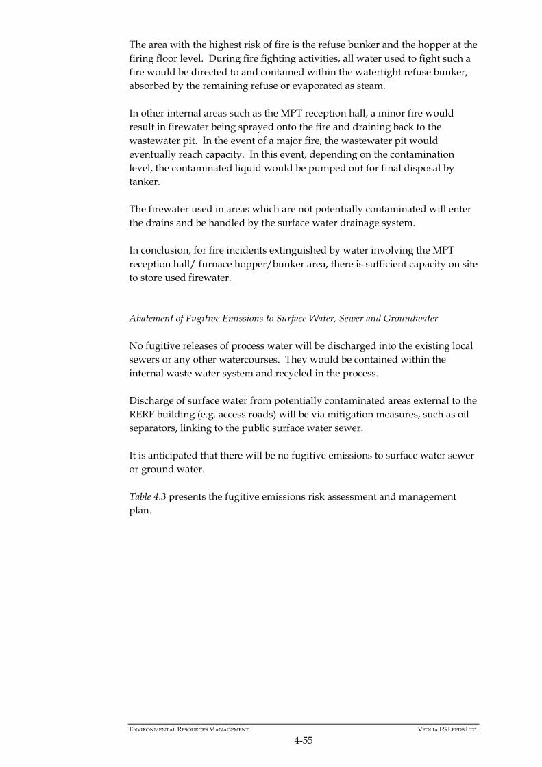
ENVIRONMENTAL RESOURCES MANAGEMENT VEOLIA ES LEEDS LTD.
4-55
The area with the highest risk of fire is the refuse bunker and the hopper at the firing floor level. During fire fighting activities, all water used to fight such a fire would be directed to and contained within the watertight refuse bunker, absorbed by the remaining refuse or evaporated as steam. In other internal areas such as the MPT reception hall, a minor fire would result in firewater being sprayed onto the fire and draining back to the wastewater pit. In the event of a major fire, the wastewater pit would eventually reach capacity. In this event, depending on the contamination level, the contaminated liquid would be pumped out for final disposal by tanker. The firewater used in areas which are not potentially contaminated will enter the drains and be handled by the surface water drainage system. In conclusion, for fire incidents extinguished by water involving the MPT reception hall/ furnace hopper/bunker area, there is sufficient capacity on site to store used firewater. Abatement of Fugitive Emissions to Surface Water, Sewer and Groundwater No fugitive releases of process water will be discharged into the existing local sewers or any other watercourses. They would be contained within the internal waste water system and recycled in the process. Discharge of surface water from potentially contaminated areas external to the RERF building (e.g. access roads) will be via mitigation measures, such as oil separators, linking to the public surface water sewer. It is anticipated that there will be no fugitive emissions to surface water sewer or ground water. Table 4.3 presents the fugitive emissions risk assessment and management plan.
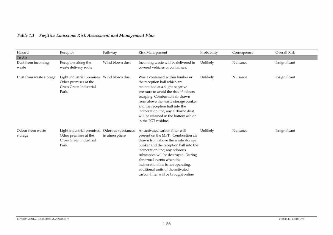
ENVIRONMENTAL RESOURCES MANAGEMENT VEOLIA ES LEEDS LTD
4-56
Table 4.3 Fugitive Emissions Risk Assessment and Management Plan
Hazard Receptor Pathway Risk Management Probability Consequence Overall Risk To Air Dust from incoming waste
Receptors along the waste delivery route
Wind blown dust Incoming waste will be delivered in covered vehicles or containers.
Unlikely Nuisance Insignificant
Dust from waste storage Light industrial premises, Other premises at the Cross Green Industrial Park.
Wind blown dust Waste contained within bunker or the reception hall which are maintained at a slight negative pressure to avoid the risk of odours escaping. Combustion air drawn from above the waste storage bunker and the reception hall into the incineration line; any airborne dust will be retained in the bottom ash or in the FGT residue.
Unlikely Nuisance Insignificant
Odour from waste storage
Light industrial premises, Other premises at the Cross Green Industrial Park.
Odorous substances in atmosphere
An activated carbon filter will present on the MPT. Combustion air drawn from above the waste storage bunker and the reception hall into the incineration line; any odorous substances will be destroyed. During abnormal events when the incineration line is not operating, additional units of the activated carbon filter will be brought online.
Unlikely Nuisance Insignificant
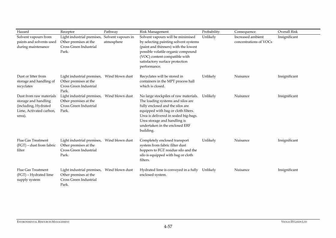
ENVIRONMENTAL RESOURCES MANAGEMENT VEOLIA ES LEEDS LTD
4-57
Hazard Receptor Pathway Risk Management Probability Consequence Overall Risk Solvent vapours from paints and solvents used during maintenance
Light industrial premises, Other premises at the Cross Green Industrial Park.
Solvent vapours in atmosphere
Solvent vapours will be minimised by selecting painting solvent systems (paint and thinners) with the lowest possible volatile organic compound (VOC) content compatible with satisfactory surface protection performance.
Unlikely Increased ambient concentrations of VOCs
Insignificant
Dust or litter from storage and handling of recyclates
Light industrial premises, Other premises at the Cross Green Industrial Park.
Wind blown dust Recyclates will be stored in containers in the MPT process hall which is closed.
Unlikely Nuisance Insignificant
Dust from raw materials storage and handling (including, Hydrated Lime, Activated carbon, urea).
Light industrial premises, Other premises at the Cross Green Industrial Park.
Wind blown dust No large stockpiles of raw materials. The loading systems and silos are fully enclosed and the silos are equipped with bag or cloth filters. Urea is delivered in sealed big-bags. Urea storage and handling is undertaken in the enclosed ERF building.
Unlikely Nuisance Insignificant
Flue Gas Treatment (FGT) – dust from fabric filter
Light industrial premises, Other premises at the Cross Green Industrial Park.
Wind blown dust Completely enclosed transport system from fabric filter dust hoppers to FGT residue silo and the silo is equipped with bag or cloth filters.
Unlikely Nuisance Insignificant
Flue Gas Treatment (FGT) – Hydrated lime supply system
Light industrial premises, Other premises at the Cross Green Industrial Park.
Wind blown dust Hydrated lime is conveyed in a fully enclosed system.
Unlikely Nuisance Insignificant
ENVIRONMENTAL RESOURCES MANAGEMENT VEOLIA ES LEEDS LTD
4-58
Hazard Receptor Pathway Risk Management Probability Consequence Overall Risk Flue Gas Treatment (FGT) – Activated Carbon supply system
Light industrial premises, Other premises at the Cross Green Industrial Park.
Wind blown dust Activated carbon is conveyed in a fully enclosed system.
Unlikely Nuisance Insignificant
Bottom Ash handling operations
Light industrial premises, Other premises at the Cross Green Industrial Park.
Wind blown dust All conveyors are located within the building. Bottom ash storage and handling is undertaken in an enclosed building.
Unlikely Nuisance Insignificant
FGT residue loading operations from the storage silo
Light industrial premises, Other premises at the Cross Green Industrial Park.
Wind blown dust Transfer from the silo into truck in a fully enclosed system and covered building
Unlikely Nuisance Insignificant
Generation of airborne FGT residues during cleaning operations of settled ash deposits.
Light industrial premises, Other premises at the Cross Green Industrial Park.
Wind blown dust Any spillages of FGT residues will be collected manually or by vacuum cleaner in case of larger quantities
Unlikely Nuisance Insignificant
To Water Rainwater runoff from hardstanding areas
Surface water drainage system connected to surface water sewer
Potentially contaminated rainwater
All water from hardstanding areas is directed to site drainage system via a class 1 bypass oil separator.
Unlikely Elevated pollutant concentrations in local water bodies
Insignificant
Firewater runoff from hardstanding areas in the event of a fire
Surface water drainage system connected to surface water sewer
Contaminated firewater
Firewater would drain to the site surface water drainage system.
Unlikely Elevated pollutant concentrations in local water bodies
Insignificant
Spillages and leaks from Aboveground Storage Tanks (ASTs)
Surface water drainage system connected to surface water sewer (and to the site waste water drainage system in process areas)
Spillages of chemical and oils
Above ground storage tanks on-site containing potentially hazardous materials such as fuel, acids, alkalis and oils are double skin or contained within dedicated bunds.
Unlikely Elevated pollutant concentrations in local water bodies
Insignificant
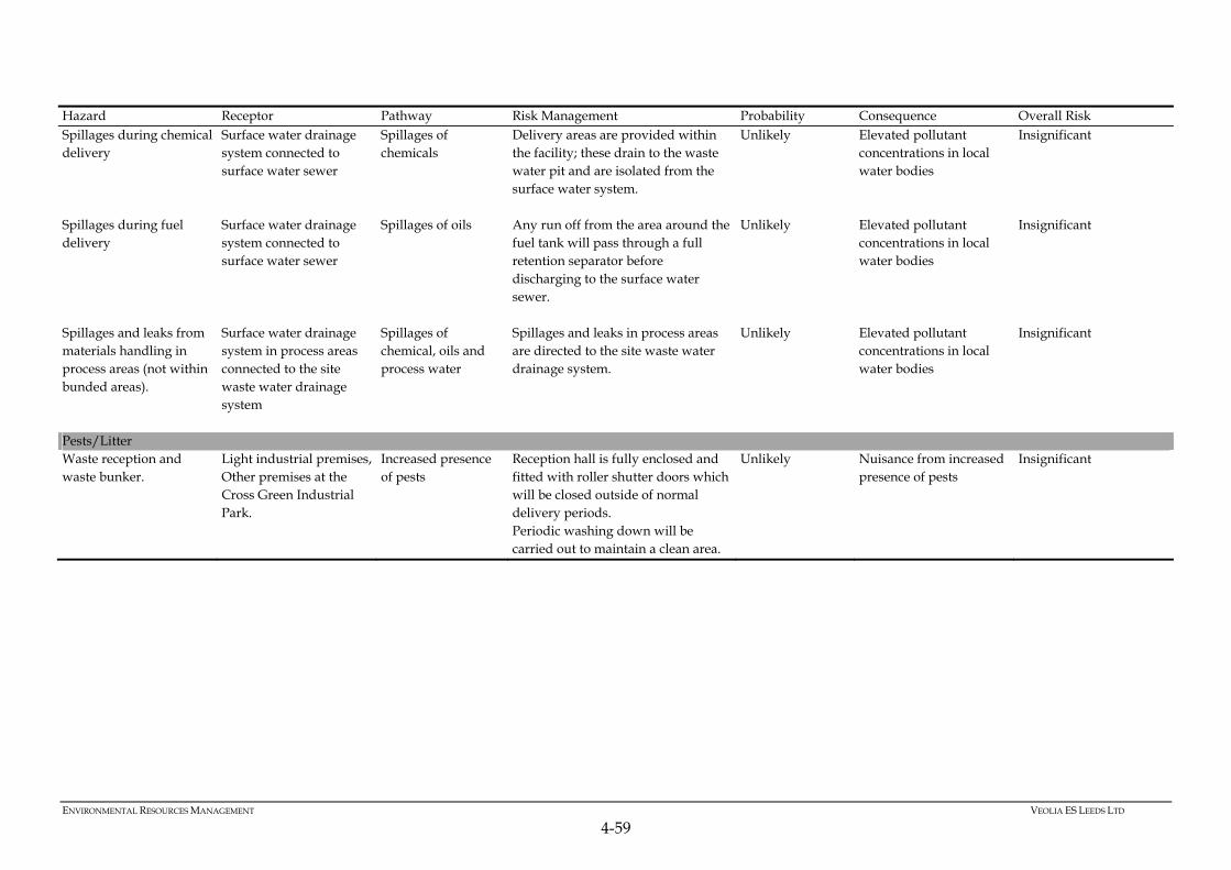
ENVIRONMENTAL RESOURCES MANAGEMENT VEOLIA ES LEEDS LTD
4-59
Hazard Receptor Pathway Risk Management Probability Consequence Overall Risk Spillages during chemical delivery
Surface water drainage system connected to surface water sewer
Spillages of chemicals
Delivery areas are provided within the facility; these drain to the waste water pit and are isolated from the surface water system.
Unlikely Elevated pollutant concentrations in local water bodies
Insignificant
Spillages during fuel delivery
Surface water drainage system connected to surface water sewer
Spillages of oils Any run off from the area around the fuel tank will pass through a full retention separator before discharging to the surface water sewer.
Unlikely Elevated pollutant concentrations in local water bodies
Insignificant
Spillages and leaks from materials handling in process areas (not within bunded areas).
Surface water drainage system in process areas connected to the site waste water drainage system
Spillages of chemical, oils and process water
Spillages and leaks in process areas are directed to the site waste water drainage system.
Unlikely Elevated pollutant concentrations in local water bodies
Insignificant
Pests/Litter Waste reception and waste bunker.
Light industrial premises, Other premises at the Cross Green Industrial Park.
Increased presence of pests
Reception hall is fully enclosed and fitted with roller shutter doors which will be closed outside of normal delivery periods. Periodic washing down will be carried out to maintain a clean area.
Unlikely Nuisance from increased presence of pests
Insignificant
ENVIRONMENTAL RESOURCES MANAGEMENT VEOLIA ES LEEDS LTD
5-1
5 WASTE INCINERATION DIRECTIVE (WID) COMPLIANCE
The Waste Incineration Directive (WID) aims to prevent or limit, as far as practicable, negative effects on the environmental and the resulting risks to human health by requiring the setting and maintenance of stringent operational conditions, technical requirements and emission limit values for plants incinerating and co-incinerating waste. These requirements and how they will be met at the RERF are discussed in detail throughout the application and are cross referenced in the Table 5.1 below.
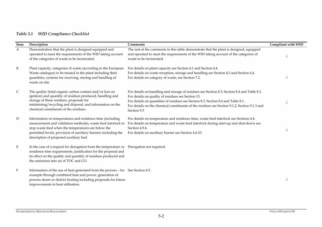
ENVIRONMENTAL RESOURCES MANAGEMENT VEOLIA ES LEEDS LTD
5-2
Table 5.1 WID Compliance Checklist
Item Description Comments Compliant with WID A Demonstration that the plant is designed equipped and
operated to meet the requirements of the WID taking account of the categories of waste to be incinerated.
The rest of the comments in this table demonstrate that the plant is designed, equipped and operated to meet the requirements of the WID taking account of the categories of waste to be incinerated.
√
B Plant capacity, categories of waste (according to the European Waste catalogue) to be treated in the plant including their quantities, systems for receiving, storing and handling of waste on site.
For details on plant capacity see Section 4.1 and Section 4.4. For details on waste reception, storage and handling see Section 4.3 and Section 4.4. For details on category of waste, see Section 7.2. √
C The quality (total organic carbon content and/or loss on ignition) and quantity of residues produced, handling and storage of these residues, proposals for minimising/recycling and disposal, and information on the chemical constituents of the residues.
For details on handling and storage of residues see Section 8.3, Section 8.4 and Table 8.1. For details on quality of residues see Section 13. For details on quantities of residues see Section 8.3, Section 8.4 and Table 8.1. For details on the chemical constituents of the residues see Section 9.1.2, Section 9.1.3 and Section 9.3
√
D Information on temperatures and residence time (including measurement and validation methods), waste feed interlock to stop waste feed when the temperatures are below the permitted levels, provision of auxiliary burners including the description of proposed auxiliary fuel.
For details on temperature and residence time, waste feed interlock see Sections 4.4. For details on temperature and waste feed interlock during start-up and shut-down see Section 4.9.4. For details on auxiliary burner see Section 4.4.10.
√
E In the case of a request for derogation from the temperature or residence time requirements, justification for the proposal and its effect on the quality and quantity of residues produced and the emissions into air of TOC and CO.
Derogation not required.
F Information of the use of heat generated from the process – for example through combined heat and power, generation of process steam or district heating including proposals for future improvements in heat utilisation.
See Section 4.5.
√
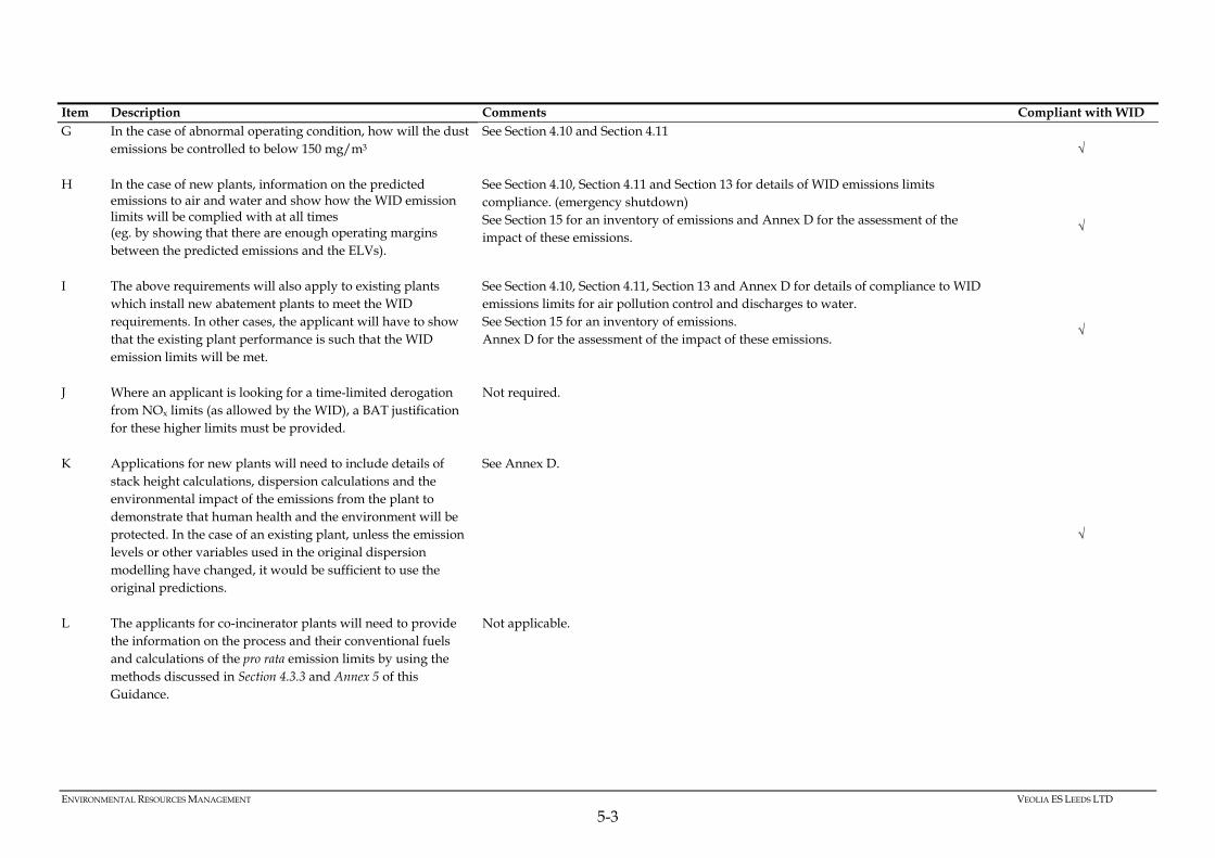
ENVIRONMENTAL RESOURCES MANAGEMENT VEOLIA ES LEEDS LTD
5-3
Item Description Comments Compliant with WID G In the case of abnormal operating condition, how will the dust
emissions be controlled to below 150 mg/m3
See Section 4.10 and Section 4.11 √
H In the case of new plants, information on the predicted emissions to air and water and show how the WID emission limits will be complied with at all times (eg. by showing that there are enough operating margins between the predicted emissions and the ELVs).
See Section 4.10, Section 4.11 and Section 13 for details of WID emissions limits compliance. (emergency shutdown) See Section 15 for an inventory of emissions and Annex D for the assessment of the impact of these emissions.
√
I The above requirements will also apply to existing plants which install new abatement plants to meet the WID requirements. In other cases, the applicant will have to show that the existing plant performance is such that the WID emission limits will be met.
See Section 4.10, Section 4.11, Section 13 and Annex D for details of compliance to WID emissions limits for air pollution control and discharges to water. See Section 15 for an inventory of emissions. Annex D for the assessment of the impact of these emissions.
√
J Where an applicant is looking for a time-limited derogation from NOx limits (as allowed by the WID), a BAT justification for these higher limits must be provided.
Not required.
K Applications for new plants will need to include details of stack height calculations, dispersion calculations and the environmental impact of the emissions from the plant to demonstrate that human health and the environment will be protected. In the case of an existing plant, unless the emission levels or other variables used in the original dispersion modelling have changed, it would be sufficient to use the original predictions.
See Annex D.
√
L The applicants for co-incinerator plants will need to provide the information on the process and their conventional fuels and calculations of the pro rata emission limits by using the methods discussed in Section 4.3.3 and Annex 5 of this Guidance.
Not applicable.
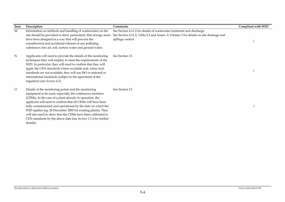
ENVIRONMENTAL RESOURCES MANAGEMENT VEOLIA ES LEEDS LTD
5-4
Item Description Comments Compliant with WID M Information on methods and handling of wastewaters on the
site should be provided to show particularly that storage areas have been designed in a way that will prevent the unauthorized and accidental releases of any polluting substances into air, soil, surface water and ground water.
See Section 4.11.2 for details of wastewater treatment and discharge See Section 4.11.2, Table 4.3 and Annex A Volume 3 for details on site drainage and spillage control.
√
N Applicants will need to provide the details of the monitoring techniques they will employ to meet the requirements of the WID. In particular, they will need to confirm that they will apply the CEN standards where available and, when such standards are not available, they will use ISO or national or international standards (subject to the agreement of the regulator) (see Section 4.5).
See Section 13.
√
O Details of the monitoring points and the monitoring equipment to be used, especially the continuous monitors (CEMs). In the case of a plant already in operation, the applicant will need to confirm that all CEMs will have been fully commissioned and operational by the date on which the WID applies (eg. 28 December 2005 for existing plants). They will also need to show that the CEMs have been calibrated to CEN standards by the above date (see Section 2.5.4 for further details).
See Section 13.
√
ENVIRONMENTAL RESOURCES MANAGEMENT VEOLIA ES LEEDS LTD
6-1
6 PROPOSED MANAGEMENT TECHNIQUES
6.1 INTRODUCTION
Veolia ES Leeds Ltd (‘VESL’) is a subsidiary of Veolia ES (UK) plc (‘VESUK’) which specialises in the provision of waste management services to local authorities and industry in the UK. These services include collection and disposal of waste materials, which involves the following activities: haulage; transfer station operations; recycling and composting operations; energy from waste operations; and landfill. Waste facilities operated within the contract with Leeds City Council (as the waste disposal authority (WDA)) are covered by the VESUK Business Management System (BMS). The BMS is an integrated quality, environment, and health and safety management system and applies to all VESUK activities. It is certificated to relevant management system standards. The BMS complies with the requirements of ISO9001 (Quality), ISO14001 (Environment), OHSAS18001 (Safety) and BS25999 (Business Continuity) management systems. Compliance is verified and certified by external assessors Lloyds Register Quality Assurance (LRQA). Management System Certificate of Approval № LQR 4005031 is found in Annex B. Prior to operation, the BMS and associated controls will be implemented at the proposed Recycling and Energy Recovery Facility (RERF) . The Facility will then be assessed by LRQA against the requirements of the standards and incorporated into Veolia Environmental Services Group Certificate. The BMS ensures control of the activities undertaken by VESUK using defined procedures and work instructions. This is essential to ensure that all activities are completed to customer, regulatory and other requirements. The implementation of Company policies is achieved through operational standards and corresponding company procedures and work instructions. All operations at the Facility will be covered by procedures within the BMS. Performance is reviewed against objectives, and action taken where necessary to facilitate continuous improvement at all levels in the organisation and to ensure that all employees are actively involved. The overall management and design, construction and operation of a RERF is complex, due to the number of staff involved. Such a project is based on the application of strict criteria concerning the design, construction and installation work, and the start-up and operation of the Facility. VESUK has been applying this quality assurance philosophy throughout its regional structures and specifically in its waste treatment facilities.
ENVIRONMENTAL RESOURCES MANAGEMENT VEOLIA ES LEEDS LTD
6-2
This section of the Application provides details of how the RERF is to be managed with respect to risk management, quality assurance, environmental management, maintenance and training at the facility level.
6.2 BUSINESS MANAGEMENT SYSTEM (BMS)
6.2.1 Introduction
To improve the quality of its service to local authorities and to manage environmental impact, VESUK has committed to gain certification of the BMS to ISO 9001, ISO 14001 and OHSAS 18001 at all operational facilities. The BMS has been designed in support of VESUK’s drive for continuous improvement to ensure that delivery of service against agreed requirements to Customers, compliance with regulatory requirements, identification and control of impacts on the environment and maintenance of a safe and healthy workplace for employees. The BMS applies to all phases of contract work and to services provided by the Head Office, Site Offices, and Departments. These services include marketing, tendering, purchasing, design of permanent and temporary works, planning, administration, quality, health safety and environmental management, personnel and training, landfill sites, recycling facilities, transfer stations, composting, environmental monitoring, haulage, information systems, municipal services and waste treatment. At the local level, each facility will establish an organisational structure, plan activities, define responsibilities, and develop practices, procedures, processes, and resources to ensure compliance with Company policies. This in turn will ensure that the facility operates in compliance with regulations and with a continued undertaking to improve. The BMS has been developed and is implemented with the following objectives: 1. To ensure that appropriate management controls are identified and
incorporated into the system. 2. To establish effective control of interfaces between participating
departments and functions. 3. To establish managerial arrangements capable of being independently
audited to demonstrate that the system has been adequately developed and is functioning properly.
4. To define the manner in which activities affecting quality are to be carried
out.
ENVIRONMENTAL RESOURCES MANAGEMENT VEOLIA ES LEEDS LTD
6-3
5. To provide records capable of demonstrating that products and services provided by the company conform to specified requirements.
It consists of the following sections, within which there are appropriately detailed procedures: Tier 1: Policy Statements and System Manual. These documents demonstrate the commitment the Company has in terms of quality assurance, environmental performance and health and safety. The System Manual identifies how the Company applies its commitments to the organisation and operation. Tier 2: Procedures that define clearly how operations and processes must be controlled and to give continuity across the Company. These procedures are applicable to all areas and functions of the Company. Tier 3: Procedures that are specific to an operation, such as energy recovery or mechanical pre-treatment and prescribe how the operation is controlled. Tier 4: Site or Location specific procedures, developed to control particular areas of a site that support the instruction defined in Tier 3 and Tier 2 documents. The VESL BMS will be revised in accordance with Company review procedures and will specifically incorporate the RERF activities of this particular facility. The BMS will ensure that all activities within the Leeds RERF are correctly managed.
6.3 COMPANY POLICY ON IMPLEMENTATION OF THE MANAGEMENT SYSTEM FOR
QUALITY, ENVIRONMENTAL AND HEALTH AND SAFETY MANAGEMENT
The implementation and maintenance of the Business Management System is the responsibility of all staff. Managers must ensure that staff under their jurisdiction are familiar with the requirements of the BMS relevant to their work and that they have access to, and are fully conversant with, applicable procedures. Description of Structure and Responsibility
The programme will be implemented at the Facility by a cross-functional working group, which will be led by the QHSE systems manager with active participation and involvement of the facility General Manager and employees. Maintenance of the programme will also be the responsibility of the Working Group. Overall responsibility for the programme's success/performance will remain with the facility General Manager who will report his evaluation of the
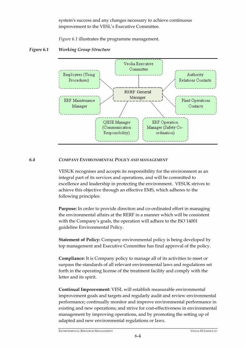
ENVIRONMENTAL RESOURCES MANAGEMENT VEOLIA ES LEEDS LTD
6-4
system's success and any changes necessary to achieve continuous improvement to the VESL’s Executive Committee. Figure 6.1 illustrates the programme management.
Figure 6.1 Working Group Structure
6.4 COMPANY ENVIRONMENTAL POLICY AND MANAGEMENT
VESUK recognises and accepts its responsibility for the environment as an integral part of its services and operations, and will be committed to excellence and leadership in protecting the environment. VESUK strives to achieve this objective through an effective EMS, which adheres to the following principles: Purpose: In order to provide direction and co-ordinated effort in managing the environmental affairs at the RERF in a manner which will be consistent with the Company's goals, the operation will adhere to the ISO 14001 guideline Environmental Policy. Statement of Policy: Company environmental policy is being developed by top management and Executive Committee has final approval of the policy. Compliance: It is Company policy to manage all of its activities to meet or surpass the standards of all relevant environmental laws and regulations set forth in the operating license of the treatment facility and comply with the letter and its spirit. Continual Improvement: VESL will establish measurable environmental improvement goals and targets and regularly audit and review environmental performance; continually monitor and improve environmental performance in existing and new operations; and strive for cost-effectiveness in environmental management by improving operations, and by promoting the setting up of adapted and new environmental regulations or laws.
ENVIRONMENTAL RESOURCES MANAGEMENT VEOLIA ES LEEDS LTD
6-5
Pollution Prevention: VESL will take into account the impact of environmental aspects when making decisions; and implement pollution prevention plans throughout its organisation. Communication: Training and education will be provided to the employees to ensure that they can work safely, efficiently, and in an environmentally sound manner; and communicate openly with employees, the Authority follow-up committee, the public, government, and regulatory agencies concerning the Company's environmental performance and improvement plans. The policy will be posted on the Facility/office information board so as to communicate its directions to employees, clients and service providers, and it will also be transmitted to the public through media channels. VESL will meet its commitment to the continual improvement of the management and operation of its activities which impact on the environment by: complying with the spirit, as well as the letter of environmental legislation
and approved codes of practice, co-operating fully and maintaining open relationships with all regulatory authorities;
assessing the environmental effects of its projects, policies and operations,
with a view to preventing pollution and reducing, controlling environmental impact and providing, where possible, environment benefit;
addressing the use of energy, raw materials, water and emissions to the
environment, including waste; seeking to prevent and limit environmental accidents and developing
contingency procedures in case of such accidents and evaluating control and reducing where practicable, noise within and outside operational sites;
fostering an understanding of the environmental issues arising from its
business activities amongst its employees, suppliers, contractors, customers, shareholders and also within the local community, and encouraging the commitment and involvement of employees to implement the Company policy and objectives;
seeking to influence customers and suppliers of goods and services to
adopt policies which are consistent with the Company’s Environmental Policy and objectives; and
reporting publicly on the Company’s environmental objectives and
performance. VESL will maintain an EMS throughout its operations and sites subject to recognised environmental management programmes. The EMS will include
ENVIRONMENTAL RESOURCES MANAGEMENT VEOLIA ES LEEDS LTD
6-6
the requirement for a comprehensive report and audit programme which will be designed to assist in progressively reducing the impact of the Company’s activities in key environmental areas. An Environmental Review Group, chaired by the Managing Director, will be the strategic body on environmental matters and will commission and agree with Company Departments, a programme of objectives and targets consistent with this Policy. The Environmental Review Group will make regular reports to the Board of VESUK and will review this Policy on a regular basis, in the light of operational experience using the EMS.
6.5 PERSONNEL AND RESPONSIBILITIES
The Energy Recovery Facility (ERF) will operate 7 days per week, 24 hours per day, thus many of the core facility functions will be carried out by the ERF team. The Mechanical Pre-Treatment (MPT) Facility might be operational 7 days per week, although cleaning and maintenance will also take place within those times. In total the staff at the RERF will consist of approximately 45 full time employees. In addition, VESL shall employ sub-contractors if the need arises. The key personnel to be employed at the RERF are described below: The RERF will be staffed at all times by a minimum of two personnel, an
ERF shift team leader and an ERF assistant shift team leader (also known as Shift Plant Operator). For the ERF, a total of five ERF shift teams will be operating, with each shift lasting for a period of 12 hours. A further team of two personnel shall work Monday to Friday during day time hours (typically 8am to 4pm) Therefore, a total of six shift team leaders and six assistant shift team leaders will be required.
There will be three operations and maintenance assistants (O&M
Assistants) - For the MPT Facility, there will be two team leaders supervising two shifts. Each shift will have an electrical mechanical technician and three MPT Operatives. There will also be two cleaners who will work under the supervision of the ERF night shift.
To carry out day-to-day maintenance tasks at the RERF, eight full time
maintenance personnel will be employed including two electronic control and instrumentation engineers and six electrical and mechanical technicians. They will provide maintenance coverage, principally during the day (again with a staggered shift start time), for seven-days a week.
In addition to the people mentioned above, VESL will also employ a number of management/office personnel, including: General Manager;
ENVIRONMENTAL RESOURCES MANAGEMENT VEOLIA ES LEEDS LTD
6-7
Operations manager; Maintenance Manager; MPT Supervisor; Environmental (QHSE) Technician Education & Communications Manager; Office Manager; and A receptionist/clerk. These staff members will be supported by additional roles which are already filled and which take overall responsibility of the RERF activities within VESL. These roles are: Managing Director, Technical Director, and Managers responsible for QHSE, EMS and Communications. All staff will be technically competent and have qualifying experience. The RERF will also benefit by support from VESUK’s purchasing, accounts, commercial, administration and planning departments. Figure 6.2 illustrates the contract structure under which the proposed Facility will be operated.
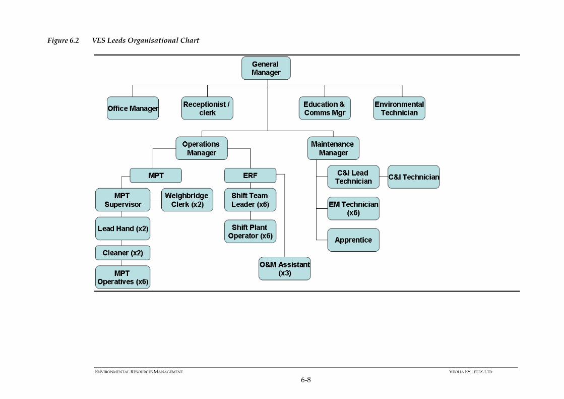
ENVIRONMENTAL RESOURCES MANAGEMENT VEOLIA ES LEEDS LTD
6-8
Figure 6.2 VES Leeds Organisational Chart
ENVIRONMENTAL RESOURCES MANAGEMENT VEOLIA ES LEEDS LTD
6-9
A permit-to-work system will be employed to ensure that operations and maintenance are carried out to the highest standards within the industry.
6.6 ORGANISATION
The staff at the Facility will be divided into two main departments: the Operations Department; and the Maintenance Department. The administrative and commercial functions as well as the Management System Department will be shared between the facility General Manager and Contract Headquarters.
6.6.1 Operations Department
The operations staff shall work under the co-ordination and supervision of the Operations Manager. The shift organisation shall consist in 6 teams of 2 shift crews, each comprising one shift team leader and one shift plant operator. The shift crew will provide 24 hour coverage. Auxiliary plant operators shall be employed during the day shifts for the operation of the weighing station and other equipment such as bottom ash and flue gas treatment residues handling.
6.6.2 Maintenance
The Maintenance Department shall maintain the Waste Treatment Facilities. The Maintenance Personnel shall work under the co-ordination and supervision of the Maintenance Manager. The Maintenance Team, comprising instrumentation and control, electrical and mechanical disciplines, shall work staggered work days to cover 365 days a year. Out of-hours repairs or emergencies requiring Maintenance Personnel will be covered, as required, by call-in and overtime. It is intended that the Permanent Maintenance Staff will be sufficient to conduct routine maintenance and repairs. However, specialist equipment, heavy repair, replacement or outage work will be subcontracted to specialist suppliers or specialist equipment manufacturers under a maintenance contract. Operations employees will be required to perform current maintenance tasks or emergency maintenance under the direction of the Maintenance Personnel.
ENVIRONMENTAL RESOURCES MANAGEMENT VEOLIA ES LEEDS LTD
6-10
6.6.3 Administration
The facility General Manager will be assisted by an Office Manager and the Receptionist/Clerk, for reception, administration and clerical duties.
6.6.4 VESL and VESUK Headquarters
Activities at the RERF will be managed through a Management Team based at the RERF at Cross Green and additionally VESUK Headquarters. Activities related to operations work, the EMS ISO 14001 and engineering studies will involve the input and participation of the facility General Manager and staff. All communication and visiting arrangements will also be co-ordinated through the offices of the RERF in Leeds.
6.7 TECHNIQUES FOR PREVENTING AND MINIMISING ENVIRONMENTAL EFFECTS
Various techniques have been adopted to prevent and minimise environmental effects and these are summarised in the following diagrams. Figure 6.3 presents the steps taken to reduce harmful side effects of the site and its operation. Figure 6.4 presents the steps taken in the design and operation of the installation, to minimise and prevent the transfer of pollution from the installation to its environment.
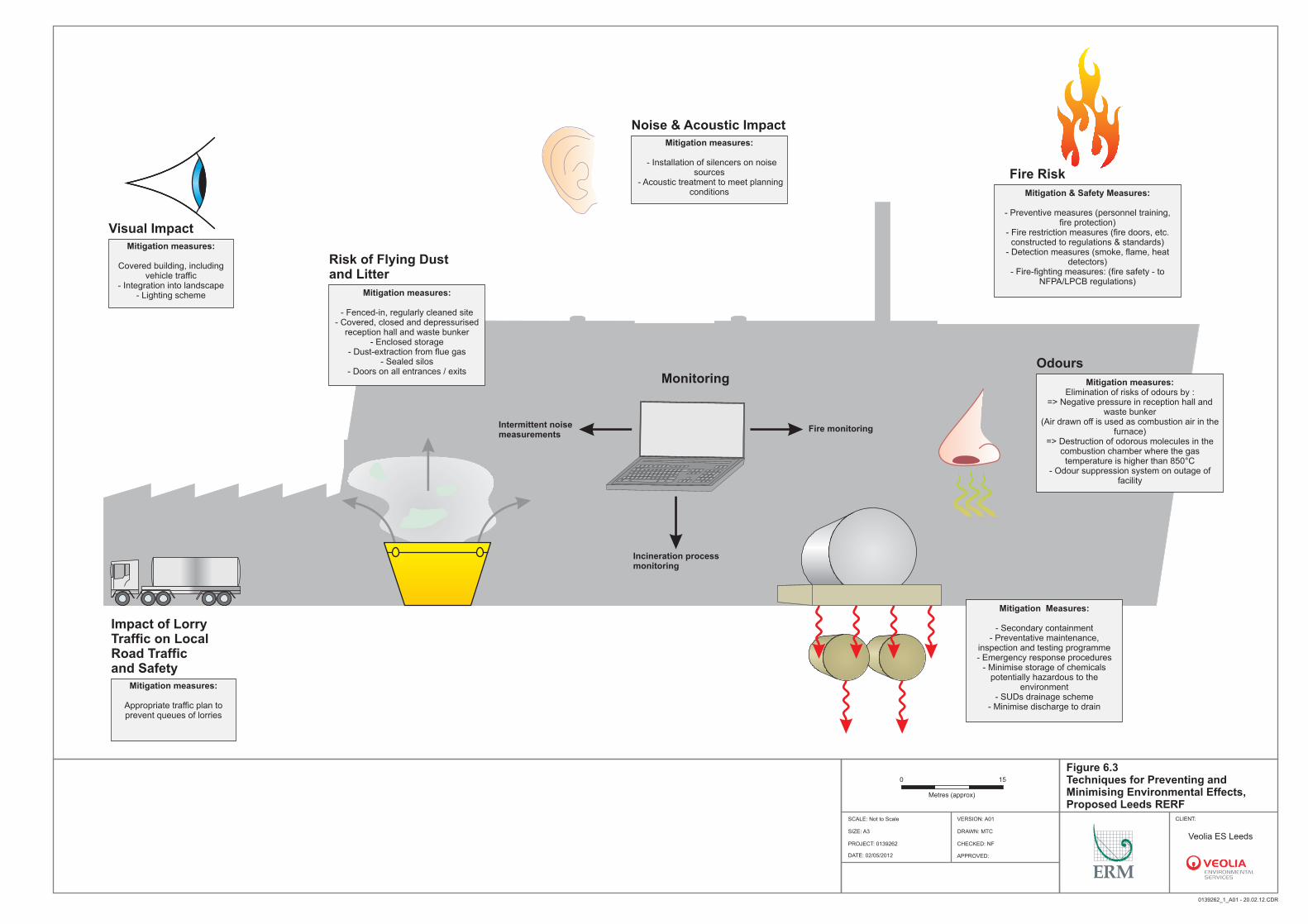
Noise & Acoustic Impact
Visual Impact
Impact of Lorry Traffic on Local Road Traffic and Safety
Risk of Flying Dust and Litter
Monitoring
Intermittent noisemeasurements
Fire monitoring
Incineration processmonitoring
Odours
Fire Risk
Mitigation measures:
Appropriate traffic plan to prevent queues of lorries
Mitigation measures:
Covered building, including vehicle traffic
- Integration into landscape- Lighting scheme Mitigation measures:
- Fenced-in, regularly cleaned site- Covered, closed and depressurised
reception hall and waste bunker- Enclosed storage
- Dust-extraction from flue gas- Sealed silos
- Doors on all entrances / exits
Mitigation measures:
- Installation of silencers on noise sources
- Acoustic treatment to meet planning conditions
Mitigation measures:Elimination of risks of odours by :
=> Negative pressure in reception hall and waste bunker
(Air drawn off is used as combustion air in the furnace)
=> Destruction of odorous molecules in the combustion chamber where the gas temperature is higher than 850°C
- Odour suppression system on outage of facility
Mitigation & Safety Measures:
- Preventive measures (personnel training, fire protection)
- Fire restriction measures (fire doors, etc. constructed to regulations & standards)
- Detection measures (smoke, flame, heat detectors)
- Fire-fighting measures: (fire safety - to NFPA/LPCB regulations)
Mitigation Measures:
- Secondary containment- Preventative maintenance,
inspection and testing programme- Emergency response procedures
- Minimise storage of chemicals potentially hazardous to the
environment - SUDs drainage scheme
- Minimise discharge to drain
Figure 6.3 Techniques for Preventing and Minimising Environmental Effects, Proposed Leeds RERF
CLIENT:
Veolia ES Leeds
SOURCE: Unspecified 0139262_1_A01 - 20.02.12.CDR
PR
OJE
CT
ION
:
DRAWN: MTC
CHECKED: NF
APPROVED:
PROJECT: 0139262
SCALE: Not to Scale
DATE: 02/05/2012
VERSION: A01
SIZE: A3
Site Boundary0 15
Metres (approx)
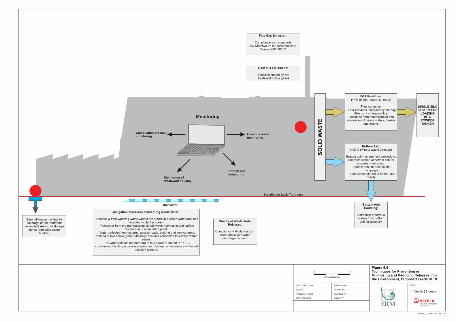
Monitoring
Combustion processmonitoring
Gaseous wastemonitoring
Monitoring ofwastewater quality
Rainwater
Installation Leak-Tightness
Bottom ashmonitoring
Zero infiltration risk due to coverage of the treatment
zones and sealing of storage zones (domestic waste
bunker)
Flue Gas Emission:
Compliance with standards:EC Directive on the Incineration of
Waste 2000/76/EC
Gaseous Emissions:
Pollution limited by dry treatment of flue gases
SO
LID
WA
ST
E
FGT Residues: (~4% of input waste tonnage)
They comprise:- FGT residues captured by the bag
-filter on incineration line,- residues from neutralisation and
elimination of heavy metals, dioxins and furans.
SINGLE SILO SYSTEM FOR
LOADING INTO
POWDER TANKER
Bottom Ash: (~23% of input waste tonnage)
Bottom ash management procedure:Characterisation of bottom ash for
purpose of recycling: - bottom ash characterisation
campaign - periodic monitoring of bottom ash
quality
Bottom Ash Handling:
Extraction of ferrous metals from bottom
ash for recovery.Quality of Waste Water Released:
Compliance with standards in accordance with water
discharge consent.
Mitigation measures concerning waste water:
- Process & floor washing waste waters are stored in a waste water tank and recycled in plant process.
- Rainwater from the roof recycled via rainwater harvesting tank before discharged in attenuation pond.
- Water collected from external access roads, parking and service areas drained to two below ground drainage systems connected to surface water
sewer.- The water release temperature to foul sewer is limited to ~40°C .
- Limitation of boiler purge waste water and startup condensates ==> limited pollutant content.
Figure 6.4 Techniques for Preventing or Minimising and Reducing Releases into the Environment, Proposed Leeds RERF
CLIENT:
SOURCE: Unspecified 0139262_2_A01 - 20.02.12.CDR
PR
OJE
CT
ION
:
DRAWN: MTC
CHECKED: NF
APPROVED:
PROJECT: 0139262
SCALE: Not to Scale
DATE: 20/02/2012
VERSION: A01
SIZE: A3
Site Boundary
Veolia ES Leeds
0 15
Metres (approx)
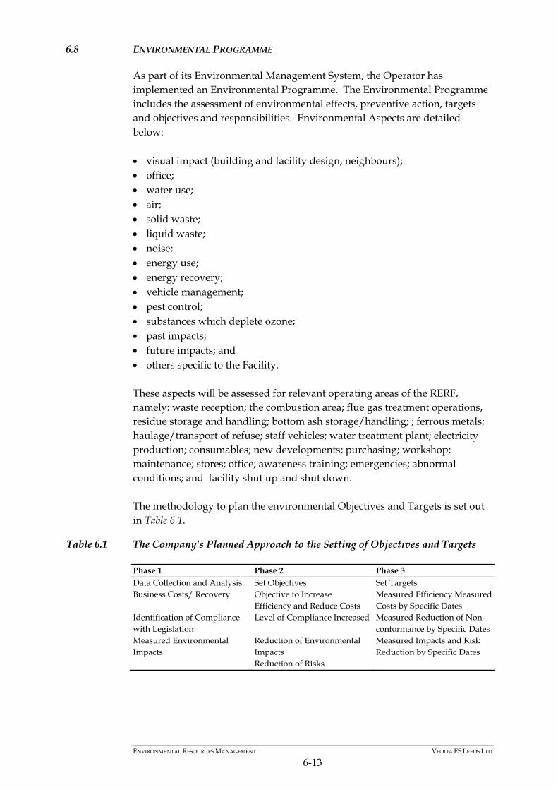
ENVIRONMENTAL RESOURCES MANAGEMENT VEOLIA ES LEEDS LTD
6-13
6.8 ENVIRONMENTAL PROGRAMME
As part of its Environmental Management System, the Operator has implemented an Environmental Programme. The Environmental Programme includes the assessment of environmental effects, preventive action, targets and objectives and responsibilities. Environmental Aspects are detailed below: visual impact (building and facility design, neighbours); office; water use; air; solid waste; liquid waste; noise; energy use; energy recovery; vehicle management; pest control; substances which deplete ozone; past impacts; future impacts; and others specific to the Facility. These aspects will be assessed for relevant operating areas of the RERF, namely: waste reception; the combustion area; flue gas treatment operations, residue storage and handling; bottom ash storage/handling; ; ferrous metals; haulage/transport of refuse; staff vehicles; water treatment plant; electricity production; consumables; new developments; purchasing; workshop; maintenance; stores; office; awareness training; emergencies; abnormal conditions; and facility shut up and shut down. The methodology to plan the environmental Objectives and Targets is set out in Table 6.1.
Table 6.1 The Company's Planned Approach to the Setting of Objectives and Targets
Phase 1 Phase 2 Phase 3 Data Collection and Analysis Set Objectives Set Targets Business Costs/ Recovery Objective to Increase
Efficiency and Reduce Costs Measured Efficiency Measured Costs by Specific Dates
Identification of Compliance with Legislation
Level of Compliance Increased Measured Reduction of Non-conformance by Specific Dates
Measured Environmental Impacts
Reduction of Environmental Impacts Reduction of Risks
Measured Impacts and Risk Reduction by Specific Dates
ENVIRONMENTAL RESOURCES MANAGEMENT VEOLIA ES LEEDS LTD
6-14
The above phasing and feedback review is considered to be part of the Company’s iterative processes of implementing targets within the Environmental Management Cycle. Upon completion of the Environmental Aspects Assessment and the Environmental Objectives and Targets cycle, suitable records and Annual Environmental Reports will be prepared.
6.9 MAINTENANCE AND REPAIRS
6.9.1 Introduction
It will be the responsibility of the Operator’s Site Management Team, with the support of VESUK Headquarters and Veolia Group Technical Assistance Department, to set up the first step of the Maintenance and Repairs Programme (including the computerised maintenance management system) during the commissioning phase. The second step will take place during the first year of operation, and will allow the validation and optimisation of the maintenance system by the Operator's staff. The Operator’s approach enables a maintenance system to be implemented complying with the conceptual design and the operation of the RERF, before the start of commercial operation, and taking into account operating experience from the first year.
6.9.2 Maintenance Support Logistics
Objectives
To define and implement an optimised maintenance system in order to meet the best global possession cost / operational availability ratio when keeping under control the service life of main equipment of the ERF. To control logistic support objectives by: taking into account maintenance support demands in the design of the
Facility's main equipment; integrating maintenance concept in the overall Facility design and lay-out; aiming at coherence between maintenance support items and other logistic
support items; looking for better matching between maintenance load and operational
requirements of the Facility; and
ENVIRONMENTAL RESOURCES MANAGEMENT VEOLIA ES LEEDS LTD
6-15
integrating maintenance in the global performance of the RERF during its service life.
Figure 6.5 illustrates the maintenance objectives for the proposed Facility. Figure 6.1 shows the development phasing philosophy.
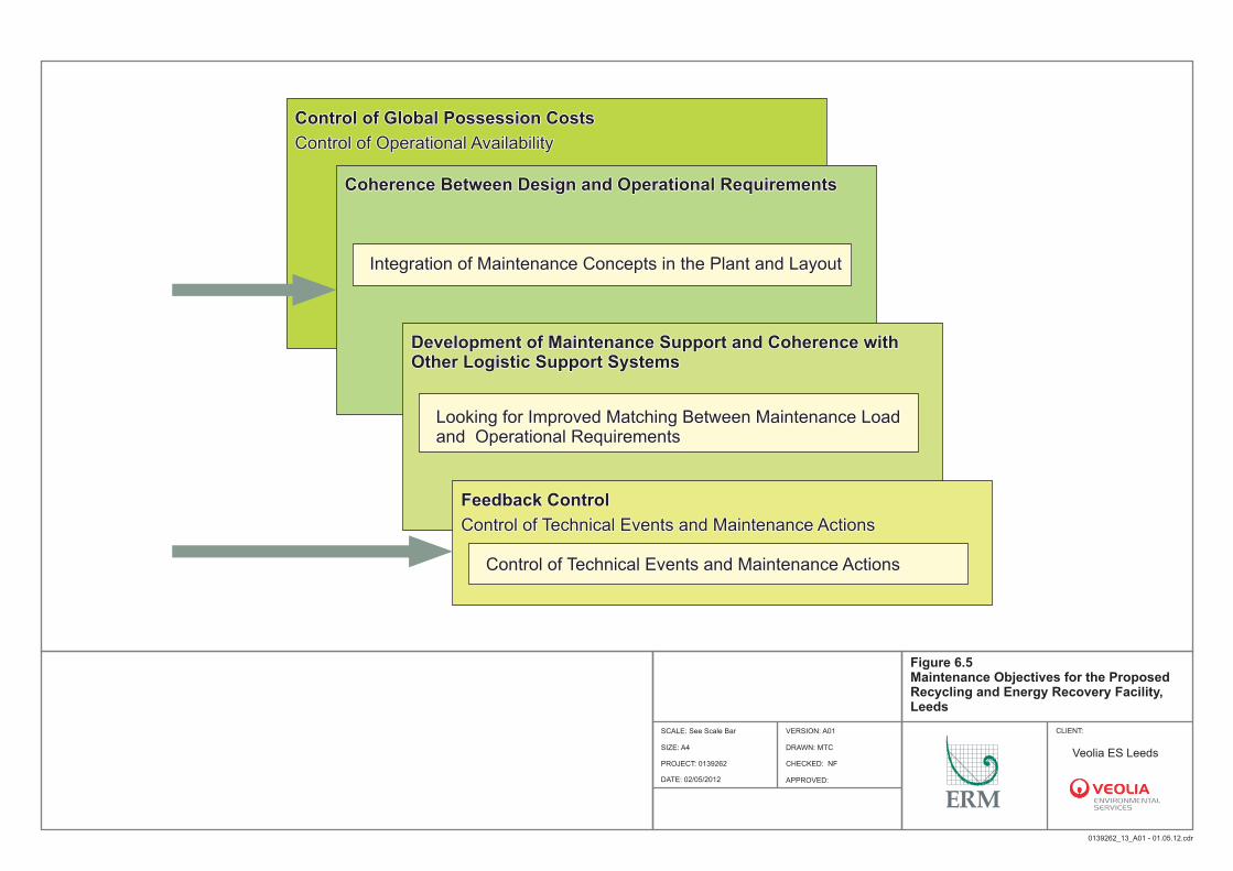
Control of Global Possession CostsControl of Global Possession Costs
Coherence Between Design and Operational RequirementsCoherence Between Design and Operational Requirements
Development of Maintenance Support and Coherence with Other Logistic Support SystemsDevelopment of Maintenance Support and Coherence with Other Logistic Support Systems
Feedback ControlFeedback Control
Control of Operational AvailabilityControl of Operational Availability
Control of Technical Events and Maintenance ActionsControl of Technical Events and Maintenance Actions
Control of Technical Events and Maintenance ActionsControl of Technical Events and Maintenance Actions
Looking for Improved Matching Between Maintenance Load and Operational RequirementsLooking for Improved Matching Between Maintenance Load and Operational Requirements
Integration of Maintenance Concepts in the Plant and LayoutIntegration of Maintenance Concepts in the Plant and Layout
DRAWN: MTC
CHECKED: NF
APPROVED:
PROJECT: 0139262
Figure 6.5 Maintenance Objectives for the Proposed Recycling and Energy Recovery Facility, Leeds
CLIENT:SCALE: See Scale Bar
0139262_13_A01 - 01.05.12.cdr
SOURCE: Unspecified
PR
OJE
CT
ION
: B
ritis
h N
atio
nal G
rid
DATE: 02/05/2012
VERSION: A01
SIZE: A4
Site Boundary
Veolia ES Leeds
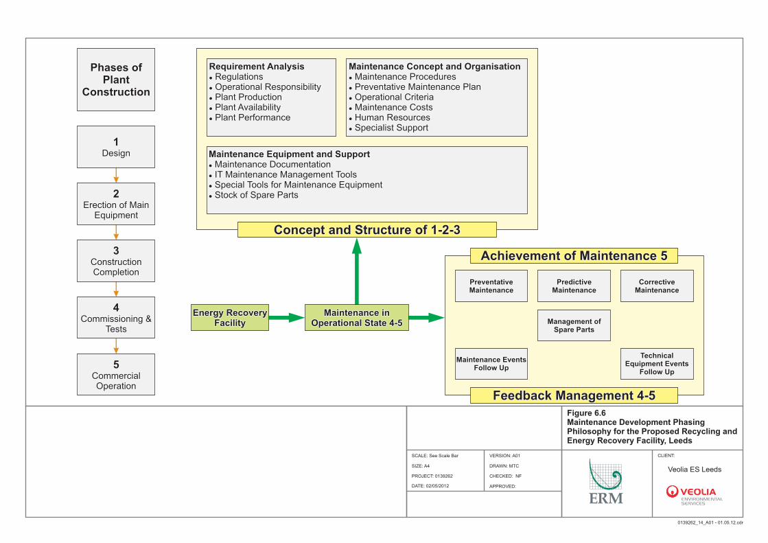
Phases of Plant
Construction
Phases of Plant
Construction
Requirement AnalysislRegulations lOperational Responsibility lPlant ProductionlPlant Availability l Plant Performance
Requirement AnalysislRegulations lOperational Responsibility lPlant ProductionlPlant Availability l Plant Performance
Maintenance Concept and OrganisationlMaintenance Procedures lPreventative Maintenance Plan lOperational CriterialMaintenance CostslHuman ResourceslSpecialist Support
Maintenance Concept and OrganisationlMaintenance Procedures lPreventative Maintenance Plan lOperational CriterialMaintenance CostslHuman ResourceslSpecialist Support
Maintenance Equipment and SupportlMaintenance Documentation lIT Maintenance Management Tools lSpecial Tools for Maintenance EquipmentlStock of Spare Parts
Maintenance Equipment and SupportlMaintenance Documentation lIT Maintenance Management Tools lSpecial Tools for Maintenance EquipmentlStock of Spare Parts
1 Design
1 Design
2 Erection of Main
Equipment
2 Erection of Main
Equipment
3 Construction Completion
3 Construction Completion
4Commissioning &
Tests
4Commissioning &
Tests
Energy Recovery Facility
Energy Recovery Facility
Maintenance in Operational State 4-5
Maintenance in Operational State 4-5
5Commercial Operation
5Commercial Operation
Concept and Structure of 1-2-3Concept and Structure of 1-2-3
Achievement of Maintenance 5Achievement of Maintenance 5
Feedback Management 4-5Feedback Management 4-5
Preventative MaintenancePreventative Maintenance
Management of Spare Parts
Management of Spare Parts
Predictive Maintenance
Predictive Maintenance
Maintenance Events Follow Up
Maintenance Events Follow Up
Corrective MaintenanceCorrective
Maintenance
Technical Equipment Events
Follow Up
Technical Equipment Events
Follow Up
DRAWN: MTC
CHECKED: NF
APPROVED:
PROJECT: 0139262
Figure 6.6 Maintenance Development Phasing Philosophy for the Proposed Recycling and Energy Recovery Facility, Leeds
CLIENT:SCALE: See Scale Bar
0139262_14_A01 - 01.05.12.cdr
SOURCE: Unspecified
PR
OJE
CT
ION
: B
ritis
h N
atio
nal G
rid
DATE: 02/05/2012
VERSION: A01
SIZE: A4
Site Boundary
Veolia ES Leeds
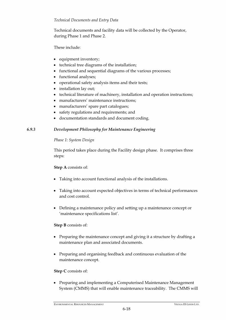
ENVIRONMENTAL RESOURCES MANAGEMENT VEOLIA ES LEEDS LTD.
6-18
Technical Documents and Entry Data
Technical documents and facility data will be collected by the Operator, during Phase 1 and Phase 2. These include: equipment inventory; technical tree diagrams of the installation; functional and sequential diagrams of the various processes; functional analyses; operational safety analysis items and their tests; installation lay out; technical literature of machinery, installation and operation instructions; manufacturers’ maintenance instructions; manufacturers’ spare part catalogues; safety regulations and requirements; and documentation standards and document coding.
6.9.3 Development Philosophy for Maintenance Engineering
Phase 1: System Design
This period takes place during the Facility design phase. It comprises three steps: Step A consists of: Taking into account functional analysis of the installations. Taking into account expected objectives in terms of technical performances
and cost control. Defining a maintenance policy and setting up a maintenance concept or
‘maintenance specifications list’. Step B consists of: Preparing the maintenance concept and giving it a structure by drafting a
maintenance plan and associated documents. Preparing and organising feedback and continuous evaluation of the
maintenance concept. Step C consists of: Preparing and implementing a Computerised Maintenance Management
System (CMMS) that will enable maintenance traceability. The CMMS will
ENVIRONMENTAL RESOURCES MANAGEMENT VEOLIA ES LEEDS LTD.
6-19
be linked to a ‘feedback’ module that will allow technical events, particularly malfunctions and failures, to be analysed.
Phase 1 takes place in the framework of the facility related logistic support and concerns maintenance-related task definition. The supply and implementation of associated management tools require: to reach operational safety objectives; to keep under control operational reliability; to keep under control maintainability; to keep under control operational availability; and to keep under control safety. Phase 2: Putting into Practice and Setting up Systems
Phase 2 requires a 12 month period and will take place during the first year of commercial operation. It comprises one step, Step D, which consists of: Updating initial maintenance plan documents after this one year period. Updating maintenance management data processing using the CMMS
software tool. Managing maintenance feedback and analysis of technical events. Phase 2 concerns the control of maintenance processes, continuous assessment of performances, feedback management and operation in order to: prevent accidental pollution; prevent risks to property and people; and keep under control global possession cost.
6.10 EMERGENCY PLANNING AND ACCIDENT PREVENTION
The system to identify, assess and minimise environmental risks and hazards of accidents and their consequences are detailed in Section 11. The Operator will implement appropriate systems and procedures to address hazards, accidents and safety through instruction, training and information. Some of these are detailed below: staff training and instruction; routine inspection and testing programs; accident investigation and reporting (environmental and personnel health
and safety);
ENVIRONMENTAL RESOURCES MANAGEMENT VEOLIA ES LEEDS LTD.
6-20
first aid and health training; housekeeping, machine safeguards information; and fire hazards and chemical handling instruction. Accidents will be investigated and reviewed by the facility General Manager and Health and Safety Manager. Accidents will be recorded as serious or minor and catalogued into a year-end report. Procedures will be put in place to avoid recurrence. Emergency Procedures are detailed in the Management System. These have been developed to respond to various types of emergency. In particular, emergencies involving fire will be closely interfaced with the Fire Authority. Regular checks and tests will be conducted to ensure the procedures are effective.
6.11 MONITORING AND MEASURING PERFORMANCE
Objectives and measurable goals for environmental performance will be established for the Annual Environmental Management Plan. They will be based on the release limits and similar parameters described in the Environmental Permit, together with other relevant criteria such as: electricity production and on-site usage; resource usage; waste disposals; amount of bottom ash produced; amount of FGT residue produced; environmental incidents and speed of responses; number of environmental complaints; and non conformance reports. The setting, achievement and revision of these will be subject to management review annually.
6.12 MONITORING AND CONTROL SYSTEMS
As described in Section 4, the Facility will be provided with a central control room equipped with microprocessor based systems for facility monitoring, control, warning alarms, trips, safety interlocks and shutdowns. The information display screens will have interactive diagrams to assist the operator interrogate facility status and make adjustments as required. The control system will ensure that the Facility performs as required, but in the event of deviations that are not corrected, alarms will be generated which can lead to a local or total facility shutdown if the deviation worsens. Continuous emission monitors for the flue gas will provide input to the control system.
ENVIRONMENTAL RESOURCES MANAGEMENT VEOLIA ES LEEDS LTD.
6-21
Closed circuit TV will give the operator views of key facility sections. Hence the Operator will have command over all major control areas and can observe the status of the complete Facility. Important parameters will be input from the control systems to data logging. This can generate regular reports for operational purposes. It can also be used to identify trends, and the information can be downloaded for further assessment by management to seek performance improvement. A programme of operational checks will be carried out by operators to monitor the facility conditions. Check sheets will be completed on either a shift or daily frequency to record and report on the inspection of facility items operation eg identification of leaks and undue noise. An environmental site check will be carried out on either a daily or weekly basis to identify operational areas in need of improvement. Remedial action will be taken promptly where possible. Longer term action items will be identified by the facility General Manager and the RERF Operations Manager will review the environmental impact (actual or potential) and take further action as necessary. The impact would be reported to the Environment Agency (EA) if appropriate. Further details on monitoring and control systems are in Section 4.8
6.13 TRAINING
6.13.1 Introduction
To prepare newly hired personnel to assume position at the RERF a comprehensive training programme will be developed and implemented. Its content and duration will depend upon, and be adjusted according to, the expertise and position of the facility staff. The Company has established procedures to ensure that its employees, at all levels, are aware of: their roles and responsibilities in achieving compliance with the
Environmental Policy and Objectives, the requirements of the standard and, in particular, the correct implementation of EMS procedures;
the potential environmental effects of their work activities and the
environmental benefits of improved performance; and the potential consequences of departure from agreed operating procedures.
ENVIRONMENTAL RESOURCES MANAGEMENT VEOLIA ES LEEDS LTD.
6-22
This training will build on the existing Veolia Group experience and in particular hands on training from existing UK facilities (Hampshire, Tyseley, Selchp, Sheffield, Newhaven) and Campus Veolia. Generally, operators will be trained in line with Electricity Training Association standards. Maintenance staff will generally be qualified to apprenticeship standard or equivalent. The objective is the development and subsequent improvement of Environmental Awareness Training and Environmental Information Systems. These aims are achieved through the implementation of: induction environmental training and refresher environmental training for
site based operatives; formal training and support for pursuance of certificate of professional
compliance via ‘WAMITAB’ (Waste Management Industry Training and Advisory Board), COTC Certificate of Technical Competence, NVQ National Vocational Qualifications and other recognised bodies;
in-house training of Site Managers and/or Supervisors; and information and training to management and staff. VESUK will provide appropriate training for all personnel whose work may have a significant effect upon the environment. All personnel performing specific assigned tasks with significant environmental effects are qualified on the basis of appropriate education, training or experience, as required. The categories of staff whose work has a significant effect on the environment have been identified during the review process. In order to fulfil the Company’s environmental training objectives, this section details how environmental training needs are identified, authorised, planned and monitored. The environmental training needs will be identified for all personnel who require environmental training to meet legislative and EMS requirements and/or would benefit from obtaining additional skills and qualifications in line with company requirements. These needs will be agreed with the advice of the Personnel Manager. To ensure that such training has been effective, personnel undergoing in-house training will be monitored as necessary for comprehension and competency prior to receiving any certificates. The Facility Management Team will be recruited before the start-up phase to participate to a specific training programme in the UK. This programme will
ENVIRONMENTAL RESOURCES MANAGEMENT VEOLIA ES LEEDS LTD.
6-23
consist of formal classroom training, adapted to the personnel position, and a hands-on training period in similar Company facilities, currently in operation. During this hands-on training period, the trainee will be given the opportunity to monitor operations and maintenance activities and to discuss various aspects of start-up, operation, maintenance and administration of the facility. The programme will also include a detailed presentation of the Operator’s parent company organisations and key personnel. Other operating personnel will be recruited during the start-up phase in a timely fashion, to work under the close supervision of the Contractor’s personnel (start-up engineers, shift supervisors, subcontractors representatives, other technically qualified persons). In the meantime, the Facility Management Team will ensure, in liaison with the Contractor's representative that the equipment operating and maintenance procedures will be reviewed and applied. During the Commissioning phase and up to facility Acceptance date, the operator personnel will receive practical training on site, set-up and organised by the Contractor and especially concerning operation and maintenance of equipment installed.
6.13.2 Campus Veolia and Institut de l'Environnement Urbain in France
An Initiative of the Veolia Group
The Veolia Group decided to create the Institut de l'Environnement Urbain in 1994, in partnership with the Chamber of Commerce and Industry of Versailles Val d'Oise Yvelines, after observing the need for specialist training in their plants. More recently, Veolia opened Campus Veolia to provide training resource within the UK and tailored to UK local requirements. Observation Concerning Waste Processing Jobs
Jobs in the field of waste processing have changed enormously in recent years from the standpoint of regulations, technology and sociology. Because of these rapid and profound changes, the Group realised it was necessary to create both initial and advanced training. This same approach was applied to the other areas of activity of the Veolia Environnement Group. Training of Future Professionals
Since 1994, young workers and executives have started classroom training at the Apprentice Training Centre of the Institut de l'Environnement Urbain, in the areas of sanitation and waste treatment, industrial cleaning and public transportation.
ENVIRONMENTAL RESOURCES MANAGEMENT VEOLIA ES LEEDS LTD.
6-24
The training is accredited by nationally recognised diplomas, such as: Reception and Vehicle Driving Agent CAP (first-level vocational degree); Waste Management and Urban Sanitation CAP; Building Hygiene and Maintenance CAP; Industrial Vehicle Maintenance BEP (second-level vocational degree); and Urban Services Management University Diploma. The alternating classroom/job training allows the young people to integrate rapidly into the companies, promotes strong commitment by the companies to training young people and above all enhances the jobs done by the people in the companies. Employee Training
The employees of the Group benefit from annual continued professional training. This includes both the many courses directly concerning the jobs or horizontal fields and long courses of study aimed at giving more complete training in a professional function or qualification. Some of the courses organised for the employees are listed below as an illustration: Management; Personal Hygiene; Labour Laws; Selling an Industrial Waste Service; Commercial Relations with Local Communities; Development of Waste Disposal and Sanitation Trades; Preparing to obtain the Waste Management CAP Diploma -Professional
Techniques - Technology- Applied Sciences; and Selective Collection of Household Waste. The companies of the Group participate in construction and implementation, in particular of job training through systems such as project groups, training network and co-ordination by experts. In conclusion, the Veolia Campus and the Institute de l'Environnement Urbain are facilities at the disposal of the Group to meet the needs for professional skills training and to adapt to changes in workplace.
ENVIRONMENTAL RESOURCES MANAGEMENT VEOLIA ES LEEDS LTD.
6-25
6.13.3 Veolia Environment Training and Development
Campus Veolia has been established in response to the training requirements of these UK businesses such as: VESUK, Dalkia, Veolia Water, Veolia Water Systems. Staff and Training Programme
VESUK operates in the following municipal and industrial business sectors: waste management; street cleansing; waste collection; and industrial cleaning. Veolia Environmental Services performs: environmental work with an international dimension; work involving sophisticated techniques and technologies leading to
comprehensive, integrated waste management systems; field work in the heart of the towns and neighbourhoods; work for the long-term future; and service jobs, often local. VESUK has set up an ambitious social policy with several objectives. Contribute to employment by work organisation combining productivity,
quality and development of lasting, durable jobs. Develop the professionalism of present and future employees by preparing
them to master their jobs and by developing their knowledge and technical, commercial and economic experience.
Integrate safety in the performance of their work to decrease sharply the
number of accidents and improve working conditions by developing social dialogue and permanent specialised training.
The proposals below are guided by a strong technical and social ambition to implement actions providing lasting and sustainable advantages situating them in a dynamic perspective in terms of: confirmation of skills; and professional training. Campus Veolia carries out courses on the following subjects: management development; customer service; health and safety; driving skills;
ENVIRONMENTAL RESOURCES MANAGEMENT VEOLIA ES LEEDS LTD.
6-26
environmental issues; human resources and HR procedures; financial management; as well as a series of short courses. Campus Veolia is accredited by the Institute of Leadership and Management, EDEXCEL and OCR. It operates courses in partnership with Kingston University and is licensed by the Institution of Occupational Safety and Health (IOSH)
6.13.4 Continued Professional Training
Introduction
Continued professional training is aimed at ensuring the quality and enhancement of performance and the development of each category of employee, from worker to senior executive. It is prepared in close collaboration with the professionals and specialists of the Company. General/Horizontal Training
Prior to commissioning, the management staff of the RERF will be trained in principles and techniques related to: management and energy recovery of residual municipal waste (waste
characteristics, treatment procedures/processes, outlets and marketing of recyclable, concept of integrated systems);
the ISO 14001 Environmental Management System (regulations,
applications and procedures); knowledge of the company and the jobs performed; the organisation and safety of operation in the areas of the activities
performed by the facility; and the performance of each job involved in the organisation chart from
production to operation. Classroom training followed by a phase of observation and hands-on training in integrated system type waste processing and treatment facilities in the UK would be aimed at general and professional training. General Training
General training will be designed to aid staff in the following tasks: acquiring basic knowledge on the essential subjects covered by the contract; focusing the theoretical training on the functions which participate in the
identity of the waste treatment facility; and
ENVIRONMENTAL RESOURCES MANAGEMENT VEOLIA ES LEEDS LTD.
6-27
ensuring collective mastery of technical and professional concepts, know-
how and cultures. Professional Training
Professional training will be designed to aid staff in the following tasks: mastering the professional techniques and organisations corresponding to
the jobs; being able to use the expertise of the company-group; and preparing and co-ordinating the dissemination of professional training in
the field (for the operators). During and after the RERF commissioning phase, the workers will regularly receive advanced training in operational tasks and missions, in particular as regards: complying with and guaranteeing safety and risk prevention in operation
of the RERF; performing first-level maintenance; and situating the tasks and missions with respect to the nature and content of
the technical and technological processes used for comprehensive/ integrated waste valorisation, from the standpoint of equipment operating procedures, with respect to the standards applying to end products; and maintaining the procedures to ensure the quality of work and services.
6.13.5 Special Training/Development and Enhancement of Expertise
Management Staff - Training Prior to Commissioning of the Facility
The Managers are a key component of the system, with the responsibility of managing the company, the contract, the operations and the employees to accomplish the stated goals in compliance with the stated rules, and to optimise and encourage the use of the production facilities. Training is proposed for Managers on the basic recommendations specifically during commissioning and throughout operation of the Facility, concerning: management of people; administrative and financial management; management of human
resources; and
ENVIRONMENTAL RESOURCES MANAGEMENT VEOLIA ES LEEDS LTD.
6-28
commercial relations and communication. The training, for a period of around 6 days, would be aimed at: strengthening the managerial autonomy of the managers, to help them to
win the commitment of and develop their staff consistently with the programme strategy;
following and analysing the financial accounts; and determining a specific commercial approach and developing labour
relations. Management Staff - Training in Operational Control
The managers and supervisors responsible for operation and maintenance will be trained in the following methods and tools: facility commissioning phase (acceptance, co-operation with teams,
contractors, follow-up procedures); the associated processes, equipment and procedures; productivity, safety and quality objectives and instructions; hands-on supervision (co-ordination of teams, assignment of work, etc);
and execution and supervision of maintenance on all the facilities and systems. This training will be undertaken over a period of about 10 days. It will be practical and hands-on, using the data, ratios and choices made for the facility operational programme. The following objectives will be emphasised: complying with the standards, rules and procedures specified by the
contract; encouraging the profitability of operations; optimising rational and scheduled use and operation of the equipment and
facility flows; and mobilising and encouraging the responsiveness of the operational teams.
ENVIRONMENTAL RESOURCES MANAGEMENT VEOLIA ES LEEDS LTD.
6-29
Environmental Management System Manager
The Environmental Management System Manager is given training in implementing an environment management system. As co-ordinator of the environment system, this professional must be able to apply and monitor ISO 14001 standards. They will be trained by specialists in the field. Environmental analysis of a site includes: environmental diagnostic; environmental analysis; performance of the environment analysis; and choice of significant aspects and drafting of environmental programme
based on and in liaison with the environmental analysis. Creation of an environment management system: presentation of the ISO 14001, accounting and differences; cost/benefit analysis; audit objectives and roles; system creation project approach; and system construction. These training objectives will be: to be capable of conducting an environmental analysis; to draw up the environment programme; to identify the requirements of the ISO 14001 standard; and to be able to create satisfactory conditions favourable to implementation of
environment management within the Company.
Advanced Training on Specific Operational Fields of Work
Operational training for the worker personnel aimed at retraining, review or advanced training in existing professional skills, such as: electricity; foreign language; instruments and controls/automatic controls; heating; and mechanics/welding. This training will be subcontracted and will take place over a period of several years, implemented during the operational life of the Facility.
ENVIRONMENTAL RESOURCES MANAGEMENT VEOLIA ES LEEDS LTD.
6-30
6.14 COMMUNICATION AND REPORTING OF INCIDENTS OF ACTUAL OR POTENTIAL
NON - COMPLIANCE AND COMPLAINTS
All complaints concerning the environmental impact of the RERF will be referred to the facility General Manager or a nominated responsible person in his absence. The complaint will be recorded and appropriate action taken as soon as practicably possible. The Management Team will be contacted as required to remedy the situation. The complainant will be contacted to confirm details of action taken and this contact will be recorded. Contact will be made also with the EA and the local Environmental Health Officer as appropriate to the nature of the complaint.
6.15 AUDITING
Periodic audits will be undertaken to verify the operation of the EMS, compliance with requirements and to assess effectiveness. Both internal and external audits will be conducted. External audits of VESUK activities are conducted throughout the year at selected sites. The QHSE systems manager will establish the audit programme, ensure that it is carried out, and report the outcome to the management. The auditors will report their audits to the facility General Manager and the Managing Director who will formulate any corrective actions necessary and report on their completion; progress will be monitored by the QHSE systems manager. During audits all personnel will be expected to identify any need for improvement.
6.16 CORRECTIVE ACTION TO ANALYSE FAULTS AND PREVENT RECURRENCE
Corrective or preventative action is likely to be required when a deficiency is identified for example in the EMS or in plant environmental performance. For the deficiencies a non-conformance report will be issued. The cause will be investigated by management who will report on a programme of corrective and protective actions to prevent recurrence. The QHSE Systems Manager will authorise the programme and monitor its progress.
6.17 REVIEWING AND REPORTING ENVIRONMENTAL PERFORMANCE
In Section 6.2.2, the Management System details how management will review environmental performance and ensure appropriate action is taken to ensure that the operation of the facility meet both the Veolia Policy commitments and the environmental performance commitments. These reviews will be conducted on a regular basis. The Management System details procedures for all business activities and these will incorporate environmental issues pertinent to the Environmental Permit through for example, the following:
ENVIRONMENTAL RESOURCES MANAGEMENT VEOLIA ES LEEDS LTD.
6-31
the control of modifications or process change through amendments to HAZOP studies and operating procedures;
design and review of new facilities or capital projects and their impact on
the RERF and the wider context within Leeds; and purchasing, capital approval, accounting principles, resource allocation,
and project planning addressing environmental performance. The Operator will prepare reports on environmental performance, based on the results of management reviews to address the information requirements of the EA and contributes to the company Environmental Statement.
6.18 MANAGING DOCUMENTATION
VESUK maintains procedures for document control, environmental monitoring and training within the management system to maintain a system of environmental records which include the following: monitoring of environmental performance at energy from waste locations
and according to specified significant effects;
suppliers details and environmental performance;
training records;
audit results; and
review results. The procedure includes details of availability of records to both employees and interested parties outside the organisation.
6.18.1 Monitoring and Control of Environmental Records
Appropriate personnel will complete environmental monitoring site checklists on a daily basis, and the site will be regularly inspected. Problems identified from the inspections will be brought to the attention of the facility General Manager for rectification. Copies of the completed forms will be maintained by the facility General Manager.
6.18.2 Monitoring and Control of Records
The Environmental Monitoring Checklists will be modified if required by the VESUK Permitting Manager to take into account future legislative requirements. Monitoring data will be collected in accordance with appropriate regulations.
ENVIRONMENTAL RESOURCES MANAGEMENT VEOLIA ES LEEDS LTD.
6-32
Instrumentation used to measure data required for monitoring environmental performance are subject to the inspection and calibration requirements of the Management System.
6.19 RELEVANT CORPORATE POLICIES, PROGRAMMES AND CHARTERS
Veolia Environnement, Veolia Environmental Services Plc’s parent company, adopts a structure of corporate policies, programmes and charters on the following topics: Sustainable Development; Corporate Social Responsibility; Governance and Ethics; and Risk Management.
ENVIRONMENTAL RESOURCES MANAGEMENT VEOLIA ES LEEDS LTD
7-1
7 RAW AND AUXILIARY MATERIALS
7.1 INTRODUCTION
This section covers the use of raw materials and water and the techniques for both minimising their use and their impact by selection. The Sector Guidance requires consideration of: composition; quantities; fate; environmental impact; any reasonable practicable alternatives; and waste minimisation measures.
7.2 WASTE FEEDSTOCK
The main raw material to be treated at the RERF will be residual municipal waste from within Leeds, with capacity for some commercial and industrial waste of similar composition. The majority of this waste is anticipated to be directly delivered to the RERF via refuse collection vehicle (RCV) or by bulk waste vehicle from Waste Transfer Stations. In addition to the energy recovery process, the RERF will house a mechanical pre-treatment (MPT) plant. This plant will combine a number of screening and sorting techniques dividing the recyclables within the residual municipal waste, particularly fibre (paper or card), plastics and metals, into a marketable material stream, leaving a residual waste stream to be processed further within the Facility. The MPT plant will mainly accept the waste categories as detailed in Figure 7.1.
Table 7.1 EWC Codes for Wastes Delivered to the MPT Plant
EWC Codes Description 15 Waste Packaging; Absorbents, Wiping Cloths, Filter Materials and Protective Clothing not Otherwise Specified 15 01 Packaging (including separately collected municipal packaging waste) 15 01 01 Paper and Cardboard Packaging 15 01 06 Mixed packaging 15 01 09 Textile packaging 15 02 03 Absorbents, Filter Materials, Wiping Cloths and
Protective Clothing Other than those Mentioned in 15 02 02
16 Wastes not Otherwise Specified in the List 16 03 off- specification batches and unused products 19 Wastes from Waste Management Facilities Off-Site Waste Water Treatment Plants and the Preparation of Water Intended for Human Consumption and Water for Industrial Use 19 12 wastes from the mechanical treatment of waste (for example sorting, crushing, compacting, pelletising) not otherwise specified 19 12 01 Paper and cardboard 19 12 07 Wood other than that mentioned in 19 12 06 19 12 12 Other wastes (including mixtures of materials) from
mechanical treatment of wastes other than those mentioned in 19 12 11*
ENVIRONMENTAL RESOURCES MANAGEMENT VEOLIA ES LEEDS LTD
7-2
EWC Codes Description 20 Municipal Wastes (household waste and similar commercial, industrial and institutional wastes) Including Separately Collected Fractions 20 01 Separately collected fractions (except 15 01) 20 01 38 Wood other than that mentioned in 20 01 37 20 03 Other municipal wastes 20 03 01 Mixed municipal waste (a) 20 03 02 Waste from markets 20 03 07 Bulky waste (a) includes civic amenity waste from household recycling centre sites
The remaining non-recyclable materials are transferred from the MPT plant to the energy recovery facility (ERF) for incineration.
Table 7.2 EWC Codes for Wastes Delivered Directly into the ERF
EWC Codes Description 02 Wastes from Agriculture, Horticulture, Aquaculture, Forestry, Hunting and Fishing, Food Preparation and Processing (a)
02 02 wastes from the preparation and processing of meat, fish and other foods of animal origin
02 02 02 Animal tissue waste
02 02 03 Materials unsuitable for consumption 16 Wastes not Otherwise Specified in the List 16 02 wastes from electrical and electronic equipment 16 02 16 (b) Components removed from discarded equipment other
than those mentioned in 16 02 15
16 03 Off-specification batches and unused products 16 03 06 Organic wastes other than those mentioned in 16 03 05 18 Wastes from Human or Animal Health Care and/or Related Research (Except Kitchen and Restaurant Wastes Nor Arising from Immediate Health Care) 18 01 wastes from natal care, diagnosis, treatment or prevention of disease in humans 18 01 04 Wastes whose collection and disposal is not subject to
special requirements in order to prevent infection (for example dressings, plaster casts, linen, disposable clothing, diapers)
19 Wastes from Waste Management Facilities Off-Site Waste Water Treatment Plants and the Preparation of Water Intended for Human Consumption and Water for Industrial Use 19 12 wastes from the mechanical treatment of waste (for example sorting, crushing, compacting, pelletising) not otherwise specified 19 12 01 Paper and cardboard 19 12 07 Wood other than that mentioned in 19 12 06 19 12 08 Textiles 19 12 10 Combustible waste (refuse derived fuel) 19 12 12 Other wastes (including mixtures of materials) from
mechanical treatment of wastes other than those mentioned in 19 12 11
20 Municipal Wastes (household waste and similar commercial, industrial and institutional wastes) Including Separately Collected Fractions 20 01 separately collected fractions (except 15 01)
20 01 01 paper and cardboard 20 01 08 Biodegradable kitchen and canteen waste 20 01 10 Clothes
ENVIRONMENTAL RESOURCES MANAGEMENT VEOLIA ES LEEDS LTD
7-3
EWC Codes Description 20 01 11 Textiles 20 01 38 Wood other than that mentioned in 20 01 37 20 01 39 plastics 20 01 99 other fractions not otherwise specified (offensive waste) 20 02 garden and park wastes (including cemetery waste) 20 02 01 Biodegradable waste 20 03 Other municipal waste 20 03 01 Mixed municipal waste 20 03 02 Waste from markets 20 03 03 Street-cleaning residues 20 03 07 Bulky waste (a) 02 02 02 and 02 02 03 wastes will not be processed through the MPT but directly by the ERF. Controls will be in place in order to dispose of these wastes as soon as possible hence reducing any potential odour risk. (b) 16 02 16 are confidential wastes requiring to be destroyed such as security tapes from security companies, CDs, confidential papers, etc and are therefore suitable for incineration. Again these wastes will not be processed through the MPT but directly by the ERF.
The ERF is designed to accept wastes with Low Heat Value (LHV, also called Net Calorific Value - NCV) ranging from 7,000 kJ kg-1 up to 12,500 kJ kg-1. Typical moisture would range between 25 - 40%. A section of the RERF will also have the ability to function as a transfer station. This would only be the case under specific conditions such as a breakdown, malfunction or maintenance of the MPT or the ERF or if the waste cannot be treated at the site for quality reasons and requires to be transferred out for treatment at a suitable permitted facility. Figure 7.1 shows the annual anticipated mass balance of the RERF.
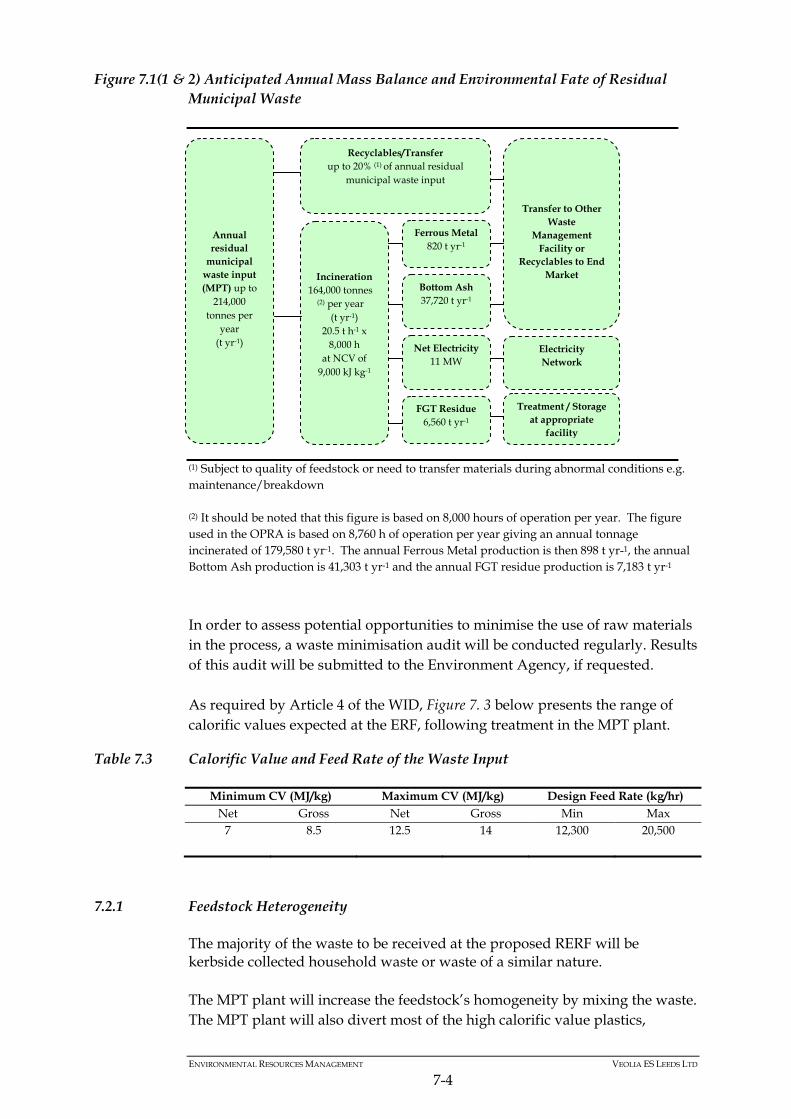
ENVIRONMENTAL RESOURCES MANAGEMENT VEOLIA ES LEEDS LTD
7-4
Figure 7.1(1 & 2) Anticipated Annual Mass Balance and Environmental Fate of Residual Municipal Waste
(1) Subject to quality of feedstock or need to transfer materials during abnormal conditions e.g. maintenance/breakdown (2) It should be noted that this figure is based on 8,000 hours of operation per year. The figure used in the OPRA is based on 8,760 h of operation per year giving an annual tonnage incinerated of 179,580 t yr-1. The annual Ferrous Metal production is then 898 t yr-1, the annual Bottom Ash production is 41,303 t yr-1 and the annual FGT residue production is 7,183 t yr-1
In order to assess potential opportunities to minimise the use of raw materials in the process, a waste minimisation audit will be conducted regularly. Results of this audit will be submitted to the Environment Agency, if requested. As required by Article 4 of the WID, Figure 7. 3 below presents the range of calorific values expected at the ERF, following treatment in the MPT plant.
Table 7.3 Calorific Value and Feed Rate of the Waste Input
Minimum CV (MJ/kg) Maximum CV (MJ/kg) Design Feed Rate (kg/hr) Net Gross Net Gross Min Max
7 8.5 12.5 14 12,300 20,500
7.2.1 Feedstock Heterogeneity
The majority of the waste to be received at the proposed RERF will be kerbside collected household waste or waste of a similar nature. The MPT plant will increase the feedstock’s homogeneity by mixing the waste. The MPT plant will also divert most of the high calorific value plastics,
Incineration 164,000 tonnes
(2) per year (t yr-1)
20.5 t h-1 x 8,000 h
at NCV of 9,000 kJ kg-1
Net Electricity 11 MW
Ferrous Metal 820 t yr-1
Bottom Ash 37,720 t yr-1
FGT Residue 6,560 t yr-1
Electricity Network
Transfer to Other Waste
Management Facility or
Recyclables to End Market
Treatment / Storage at appropriate
facility
Annual residual
municipal waste input (MPT) up to
214,000 tonnes per
year (t yr-1)
Recyclables/Transfer up to 20% (1) of annual residual
municipal waste input
ENVIRONMENTAL RESOURCES MANAGEMENT VEOLIA ES LEEDS LTD
7-5
cardboard and paper, and some minimal calorific value metals from the ERF's waste stream. The ERF main bunker and the intermediate bunker have storage for a minimum of 3 days with the MPT hall providing an additional storage of 2 days minimum. This, coupled with effective bunker management and waste mixing, ensures waste homogeneity. Within the ERF main bunker, waste is mixed and moved using either of the two large grabs to ensure a good consistency, which in turn helps improve the efficiency of combustion and to minimise odour.
7.3 AUXILIARY RAW MATERIALS
7.3.1 Introduction
The RERF uses a variety of other raw materials for: treatment of flue gases; demineralisation of water for boiler water preparation; fuels for auxiliary burners, emergency generator and fuelling site vehicles; and effluent treatment chemicals. The Operator maintains a list of all raw materials used along with the relevant COSHH datasheets, other product datasheets and relevant product literature, as part of Standard Operating Procedures. These procedures cover the following materials: hydrated lime (acid neutralisation for flue gas treatment); dry urea (NOx control for flue gas treatment); activated carbon (dioxin and heavy metal control for flue gas treatment); water treatment chemicals; fuels (diesel); maintenance oils and greases; specialist gases for calibration, electrical equipment, refrigeration, welding
and fire-fighting; and other materials. The consumption of hydrated lime within the flue gas treatment (FGT) system is optimised through design and operation. This ensures that reagent consumption is minimised and consequently FGT residue production is also minimised. Table 7.4 and Table 7.5 present a list of those raw materials that will be used and stored on-site, the location and method of storage, and the environmental fate of each material.
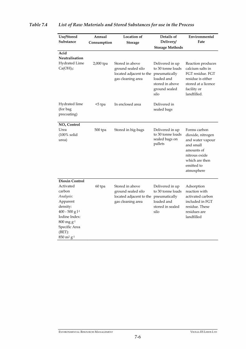
ENVIRONMENTAL RESOURCES MANAGEMENT VEOLIA ES LEEDS LTD
7-6
Table 7.4 List of Raw Materials and Stored Substances for use in the Process
Use/Stored Substance
Annual
Consumption
Location of
Storage
Details of Delivery/
Storage Methods
Environmental Fate
Acid Neutralisation Hydrated Lime Ca(OH)2: Hydrated lime (for bag precoating)
2,000 tpa
<5 tpa
Stored in above ground sealed silo located adjacent to the gas cleaning area In enclosed area
Delivered in up to 30 tonne loads pneumatically loaded and stored in above ground sealed silo Delivered in sealed bags
Reaction produces calcium salts in FGT residue. FGT residue is either stored at a licence facility or landfilled.
NOx Control Urea (100% solid urea)
500 tpa
Stored in big-bags
Delivered in up to 30 tonne loads sealed bags on pallets
Forms carbon dioxide, nitrogen and water vapour and small amounts of nitrous oxide which are then emitted to atmosphere
Dioxin Control Activated carbon Analysis: Apparent density: 400 - 500 g l-1 Iodine Index: 800 mg g-1 Specific Area (BET): 850 m2 g-1
60 tpa
Stored in above ground sealed silo located adjacent to the gas cleaning area
Delivered in up to 30 tonne loads pneumatically loaded and stored in sealed silo
Adsorption reaction with activated carbon included in FGT residue. These residues are landfilled
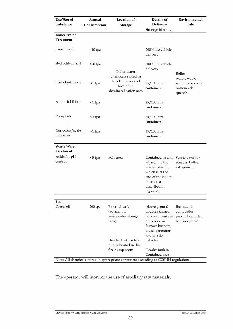
ENVIRONMENTAL RESOURCES MANAGEMENT VEOLIA ES LEEDS LTD
7-7
Use/Stored Substance
Annual
Consumption
Location of
Storage
Details of Delivery/
Storage Methods
Environmental Fate
Boiler Water Treatment Caustic soda Hydrochloric acid Carbohydraxide Amine inhibitor Phosphate Corrosion/scale inhibitors
<40 tpa
<60 tpa
<1 tpa
<1 tpa
<3 tpa
<1 tpa
Boiler water chemicals stored in bunded tanks and
located in demineralisation area
5000 litre vehicle delivery 5000 litre vehicle delivery 25/100 litre containers 25/100 litre containers 25/100 litre containers. 25/100 litre containers
Boiler water/waste water for reuse in bottom ash quench
Waste Water Treatment
Acids for pH control
<5 tpa
FGT area
Contained in tank adjacent to the wastewater pit; which is at the end of the ERF to the east, as described in Figure 7.3
Wastewater for reuse in bottom ash quench
Fuels Diesel oil
500 tpa
External tank (adjacent to wastewater storage tank) Header tank for fire pump located in the fire pump room
Above ground double skinned tank with leakage detection for furnace burners, diesel generator and on site vehicles Header tank in Contained area
Burnt, and combustion products emitted to atmosphere
Note: All chemicals stored in appropriate containers according to COSHH regulations
The operator will monitor the use of auxiliary raw materials.
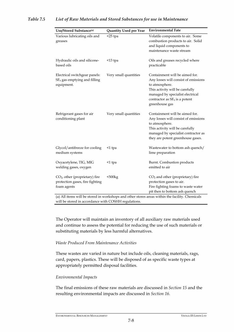
ENVIRONMENTAL RESOURCES MANAGEMENT VEOLIA ES LEEDS LTD
7-8
Table 7.5 List of Raw Materials and Stored Substances for use in Maintenance
Use/Stored Substance(a) Quantity Used per Year Environmental Fate
Various lubricating oils and greases
<25 tpa Volatile components to air. Some combustion products to air. Solid and liquid components to maintenance waste stream
Hydraulic oils and silicone-based oils
<13 tpa Oils and greases recycled where practicable
Electrical switchgear panels: SF6 gas emptying and filling equipment.
Very small quantities Containment will be aimed for. Any losses will consist of emissions to atmosphere. This activity will be carefully managed by specialist electrical contractor as SF6 is a potent greenhouse gas
Refrigerant gases for air conditioning plant
Very small quantities Containment will be aimed for. Any losses will consist of emissions to atmosphere. This activity will be carefully managed by specialist contractor as they are potent greenhouse gases.
Glycol/antifreeze for cooling medium systems
<1 tpa Wastewater to bottom ash quench/ lime preparation
Oxyacetylene, TIG, MIG welding gases, oxygen
<1 tpa Burnt. Combustion products emitted to air
CO2, other (proprietary) fire protection gases, fire fighting foam agents
<500kg CO2 and other (proprietary) fire protection gases to air. Fire fighting foams to waste water pit then to bottom ash quench
(a) All items will be stored in workshops and other stores areas within the facility. Chemicals will be stored in accordance with COSHH regulations.
The Operator will maintain an inventory of all auxiliary raw materials used and continue to assess the potential for reducing the use of such materials or substituting materials by less harmful alternatives. Waste Produced From Maintenance Activities
These wastes are varied in nature but include oils, cleaning materials, rags, card, papers, plastics. These will be disposed of as specific waste types at appropriately permitted disposal facilities. Environmental Impacts
The final emissions of these raw materials are discussed in Section 15 and the resulting environmental impacts are discussed in Section 16.
ENVIRONMENTAL RESOURCES MANAGEMENT VEOLIA ES LEEDS LTD
7-9
Alternatives and Waste Minimisation
The selection and use of all auxiliary raw materials will be regularly reviewed as part of the Business Management System (BMS) which incorporates the Environmental Management System (EMS). The overall environmental impact of each raw material, in terms of its production, supply, storage, use, fate and any disposal, will be considered as well as effectiveness and cost including alternative materials. The BMS will also address waste minimisation issues, to make sure that material consumption, including that of water, is minimised. Section 8 describes the proposed measures for characterising and quantifying the waste streams. These approaches, which will be integrated, will ensure that the environmental impacts of the use of raw materials and water is minimised.
7.4 HAZARDOUS SUBSTANCES AND NON-HAZARDOUS POLLUTANTS
7.4.1 Introduction
Any Environmental Permit is subject to compliance with certain parts of the Groundwater Regulations 2009 (1). In these Regulations, groundwater refers to all water which is below the surface of the ground in the saturation zone and in direct contact with the ground or subsoil. These Regulations act as a preventative tool against the entry of “hazardous substances” and against pollution of groundwater by “non-hazardous pollutants’’ (2). VESL will take all necessary measures to prevent the input of any hazardous substance and non-hazardous pollutants into groundwater. This section: provides key definitions from the Regulations; examines the presence of hazardous substances and non-hazardous
pollutants at the RERF; and examines the potential for discharges of such substances from the RERF
and how the potential is minimised.
7.4.2 Definitions in the Regulations
The following definitions are central to understanding the Regulations:
(1) Secretary of State in Relation to England, and The Welsh Ministers in Relation to Wales. The Groundwater (England
and Wales) Regulations 2009. 2009 no Environmental Protection, England and Wales. Available at: http://www.opsi.gov.uk/si/si2009/draft/ukdsi_9780111480816_en_1 [Accessed: 17 June 2009] (2) Department for Environment. Food and Rural Affairs. Explanatory Memorandum to the Groundwater (England and Wales) Regulations 2009. Available at: http://www.opsi.gov.uk/si/si2009/em/uksiem_20092902_en.pdf. [Accessed: 17
June 2010]
ENVIRONMENTAL RESOURCES MANAGEMENT VEOLIA ES LEEDS LTD
7-10
a hazardous substance is any substance or group of substances that are toxic, persistent and liable to bio-accumulate;
a non-hazardous pollutant is any pollutant other than a hazardous
substance; “direct input” refers to the introduction of a pollutant into groundwater
without percolation through soil or subsoil; and “indirect input” is defined as the introduction of a pollutant into
groundwater after percolation through soil or subsoil. Hazardous substances and non-hazardous pollutants are presented below.
7.4.3 Hazardous Substances
The Regulations state that a hazardous substance includes the following when they are toxic, persistent and liable to bio-accumulate:
organohalogen compounds and substances that may form such compounds in the aquatic environment;
organophosphorous compounds; organotin compounds; substances and preparations, or the breakdown products of such, which
have been proved to possess carcinogenic or mutagenic properties or properties which may affect steroidogenic, thyroid, reproduction or other endocrine-related functions in or via the aquatic environment;
persistent hydrocarbons and persistent and bioaccumulable organic toxic
substances; cyanides; metals (in particular cadmium and mercury) and their compounds; arsenic and its compounds; and biocides and plant protection products.
7.4.4 Non-Hazardous Pollutants
According to the Environment Agency, non-hazardous pollutants are less dangerous, and can be discharged to groundwater under a permit (1). However, these must not cause pollution. Non-hazardous pollutants include any substance capable of causing pollution. The list is much wider than the
(1) Environment Agency. 2009. Groundwater Directives. Available at: http://www.environment-
agency.gov.uk/business/regulation/31881.aspx [Accessed: 17 June 2010]
ENVIRONMENTAL RESOURCES MANAGEMENT VEOLIA ES LEEDS LTD
7-11
List 2 substances outlined in the 1998 Groundwater Regulations which included; the following metalloids and metals and their compounds: zinc, tin,
copper, barium, nickel, beryllium, chromium, boron, lead, uranium, selenium, vanadium, arsenic, cobalt, antimony, thallium, molybdenum, tellurium, titanium and silver;
biocides and their derivatives not appearing in former List I categories; substances which have a deleterious effect on the taste or odour of
groundwater, and compounds liable to cause the formation of such substances in such water and to render it unfit for human consumption;
toxic or persistent organic compounds of silicon, and substances which
may cause the formation of such compounds in water, excluding those which are biologically harmless or are rapidly converted in water into harmless substances;
inorganic compounds of phosphorus and elemental phosphorus; fluorides; and ammonia and nitrites.
7.4.5 Presence of Hazardous and Non-Hazardous Pollutants at the RERF
The composition of residual municipal waste, the main raw material, cannot be controlled by the Operator and is inherently variable and subject to uncertainty. Of the hazardous substances, only mineral oils and hydrocarbons (in fuel oil, lubricants and greases) are to be expected to be present in potentially significant quantities at the RERF. Many of the others are likely to be present in small quantities and at low concentrations. Of the non-hazardous pollutants, many will be contained in small quantities and at low concentrations, both in the residual municipal waste and in other raw materials, such as the water and effluent treatment chemicals. Small quantities of an appropriate biocide will be used in the water treatment process to manage these pollutants and also to avoid fouling in the cooling water system.
7.4.6 Potential for Discharges of Hazardous Substances and Non-Hazardous Pollutants from the RERF
Direct Discharges
There will be no direct discharge of any hazardous substances and non-hazardous pollutants from the RERF.
ENVIRONMENTAL RESOURCES MANAGEMENT VEOLIA ES LEEDS LTD
7-12
Indirect Discharges
There will be no planned indirect discharge of any hazardous substances and non-hazardous pollutants from the RERF. The potential for accidental discharges will be avoided by the appropriate storage and handling of all raw materials and wastes, as described in Sections 7 and 8, including the use of appropriate bunding, spill control equipment and training of staff in its use. The RERF buildings have an impervious surface to prevent indirect discharges. Regular monitoring will be conducted to ensure compliance. The emergency procedures described in Section 11 will assist in minimising the probability of any substances that are accidentally discharged from actually reaching groundwater.
7.5 WATER USE
7.5.1 Water Efficiency
The RERF will use approximately 20,000 m3 of water from the local water mains supply per year. This will primarily be used for boiler water make up and bottom ash quenching. Further water will be used for showers, toilets and sinks in the Facility. During commissioning and maintenance there may be one-off requirements of up to 100 m3 of water per day for filling the boiler and cooling system. The RERF is designed to collect water for re-use in the bottom ash handling system. Similar to the waste minimisation audit, the RERF will be reviewed for water usage as required by the Environment Agency. The audit will include an improvement plan to reduce water usage where possible. Results of the review will be submitted to the Environment Agency for review and developed into an agreed action plan as appropriate. The RERF will have a demand for water for, amongst other things, the ash quench system, boiler water, ancillary processes, domestic and plant systems and fire water. The various requirements for the administrative and process areas are illustrated in Figure 7.2 below.
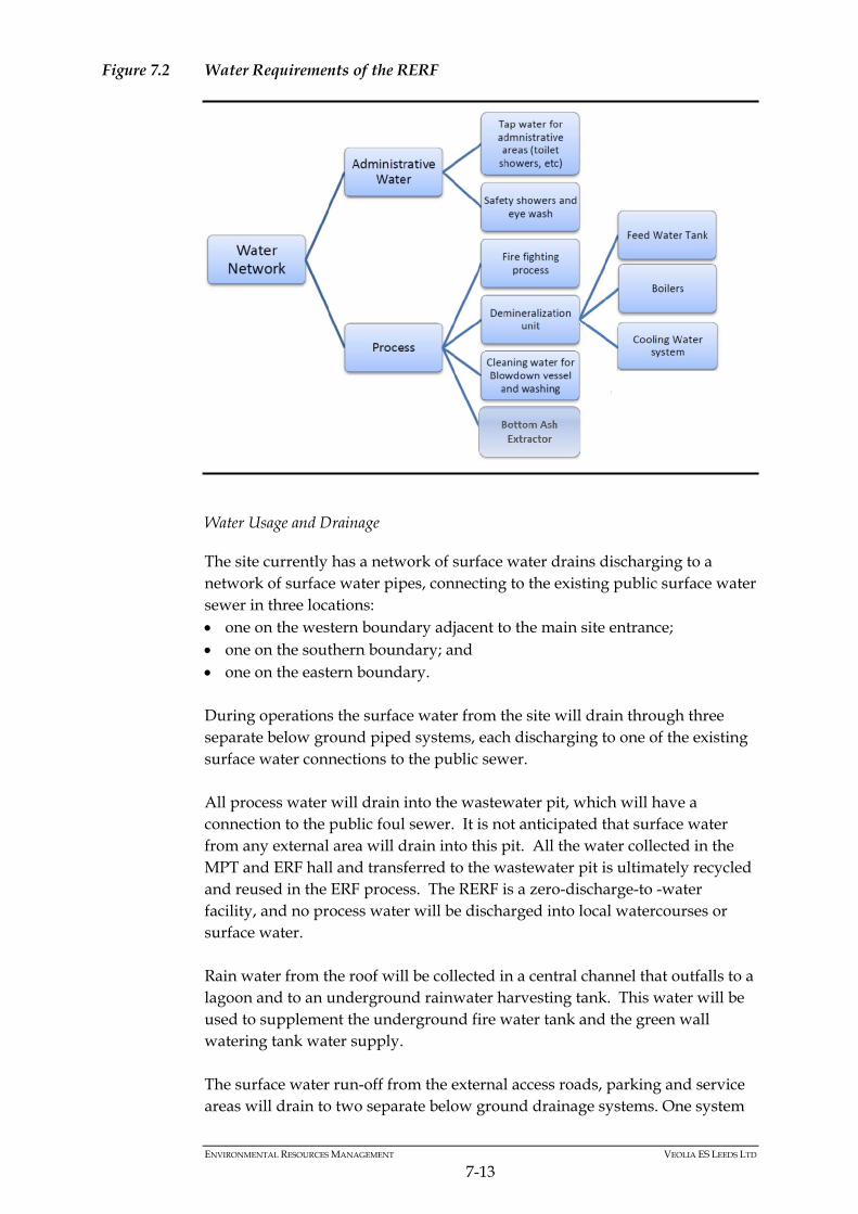
ENVIRONMENTAL RESOURCES MANAGEMENT VEOLIA ES LEEDS LTD
7-13
Figure 7.2 Water Requirements of the RERF
Water Usage and Drainage
The site currently has a network of surface water drains discharging to a network of surface water pipes, connecting to the existing public surface water sewer in three locations: one on the western boundary adjacent to the main site entrance; one on the southern boundary; and one on the eastern boundary. During operations the surface water from the site will drain through three separate below ground piped systems, each discharging to one of the existing surface water connections to the public sewer. All process water will drain into the wastewater pit, which will have a connection to the public foul sewer. It is not anticipated that surface water from any external area will drain into this pit. All the water collected in the MPT and ERF hall and transferred to the wastewater pit is ultimately recycled and reused in the ERF process. The RERF is a zero-discharge-to -water facility, and no process water will be discharged into local watercourses or surface water. Rain water from the roof will be collected in a central channel that outfalls to a lagoon and to an underground rainwater harvesting tank. This water will be used to supplement the underground fire water tank and the green wall watering tank water supply. The surface water run-off from the external access roads, parking and service areas will drain to two separate below ground drainage systems. One system
ENVIRONMENTAL RESOURCES MANAGEMENT VEOLIA ES LEEDS LTD
7-14
will discharge to the western outfall and one will discharge to the eastern outfall. All surface water will be intercepted and conveyed by a series of linear drainage channels and gullies. Flow from external trafficked areas will pass through a class 1 bypass oil separator prior to discharging to the surface water sewer network. Any run off from the area around the fuel tank will pass through a full retention separator before discharging to the public surface water sewer. The car parking area to the west of the main building will utilise a permeable pavement construction. Techniques that control pollution close to the source, such as permeable surfaces or infiltration trenches will be used, which can offer a suitable means of treatment for run-off from low risk areas such as roofs, car parks, and non-operational areas. Therefore it is proposed that flow from this area will not pass through an oil separator prior to discharge. Foul discharges from the amenities associated with the Facility will be discharged direct to the foul sewer. The water consumption will be frequently monitored to ensure that the water is being used effectively in the process. In an effort to minimise water use and where practical, alternative cleaning methods will also be used such as vacuuming, sweeping and mopping as a preference to hosing down. All washing equipment at the ERF will operate using trigger controls. Appropriate measures have been taken in terms of the design of storage tanks and containers to reduce the potential for contamination of surface water and ground water. Further details can be found in Section A3 of the Application Site Condition Report. A schematic of the indicative drainage plan for the site is presented over the page in Figure 7. 3.
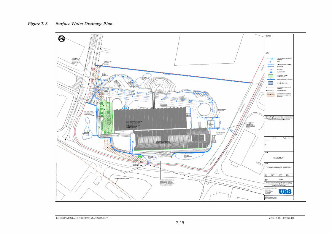
ENVIRONMENTAL RESOURCES MANAGEMENT VEOLIA ES LEEDS LTD.
7-15
Figure 7. 3 Surface Water Drainage Plan
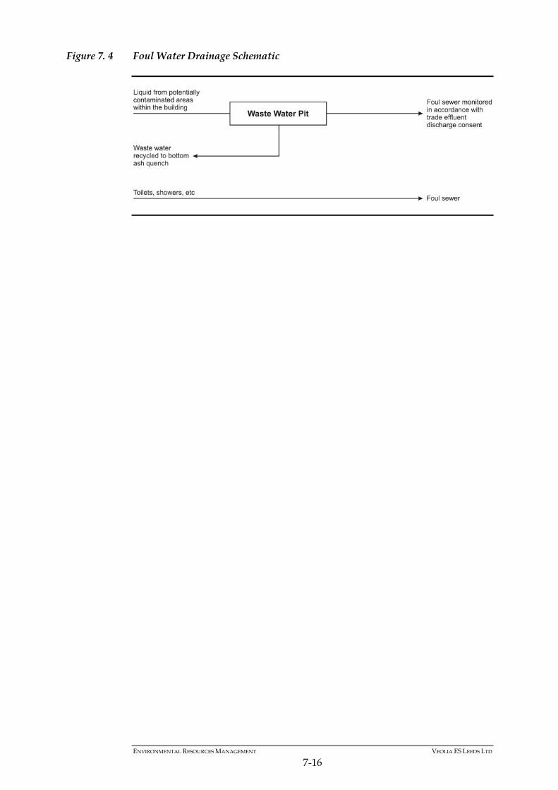
ENVIRONMENTAL RESOURCES MANAGEMENT VEOLIA ES LEEDS LTD
7-16
Figure 7. 4 Foul Water Drainage Schematic
ENVIRONMENTAL RESOURCES MANAGEMENT VEOLIA ES LEEDS LTD
8-1
8 CHARACTERISATION AND QUANTIFICATION OF WASTE STREAMS: DESCRIPTION OF PROPOSED MEASURES FOR WASTE MANAGEMENT, STORAGE AND HANDLING
8.1 INTRODUCTION
The type and character of solid waste streams resulting from the combustion of residual municipal waste with energy recovery depends upon a number of factors, including: residual municipal waste inputs; furnace design; facility operating conditions; and the type and design of pollution abatement technology and energy recovery systems employed. The two main waste streams arising from a modern energy recovery facility (ERF) are known as bottom ash and flue gas treatment residue (FGT residue). In addition, ferrous metals will be extracted from the bottom ash. Recyclables such as fibre (paper and card), plastics and metals would be separated and sorted at the Mechanical Pre-Treatment (MPT) Facility with the rejected feedstock being sent to the ERF. Solid waste generated at the RERF will be inspected and, where appropriate, analysed for waste management purposes. Periodic sampling (frequency to be agreed with the Environment Agency) and analysis of the main waste streams (bottom ash and FGT residue) will also take place, including a regular assessment of bottom ash quality.
8.2 RECYCLABLE MATERIAL
A key component of the RERF is the MPT Facility. This plant will combine a number of screening and sorting techniques dividing the waste in two streams: recyclables within the residual municipal waste, to be further processed
into marketable recyclable material stream; and
a residual stream to be processed at the ERF . Based on the Leeds residual waste composition, the design of the MPT will focus on removing the following potentially recyclable material fractions: metals (ferrous and non-ferrous); plastics (particularly plastic bottles); and fibre (paper and card).
ENVIRONMENTAL RESOURCES MANAGEMENT VEOLIA ES LEEDS LTD
8-2
8.3 BOTTOM ASH AND FERROUS METALS
8.3.1 Identification and Quantification
Waste sources and arrangements for the segregation of key waste streams generated by the main processes on site are presented in Table 8.1. Bottom ash is the combination of grate ash, grate riddlings and boiler dusts, which are quenched in water, passed through a magnetic ferrous separator and then stored in the bottom ash storage area. This area is designed to be contained and local to the collection point in order to reduce the risk of spillage. Bottom ash constitutes approximately 20% by weight of the original waste input into the RERF or 23% of the waste input to the incineration process. This ash is non-hazardous; this will be proven through monitoring to be undertaken during operation, and which follows protocols of the Environmental Services Association and Environment Agency (see Section 13).
8.3.2 Handling Arrangements
Outlet of the Ash Discharger
At the outlet of the ash discharger, the bottom ash falls onto a vibrating conveyor. At the end of this conveyor, a grid for large items separation is installed together with a diverting chute and a skip container. The bottom ash falls through the grid onto a further conveyor located underneath whilst the large items are retained and routed through the diverting chute into the skip container. The discharger is fitted with a bypass chute to divert bottom ash in the event of vibrating conveyor failure, blockage or maintenance. Recovered Ferrous Metals Fraction
The belt conveyor transports the bottom ash to the storage area. At the end of this conveyor, ferrous metals are recovered from the bottom ash by a magnetic separator and discharged into an adjacent storage area. Storage
Bottom ash, free from the ferrous scrap, is conveyed to a storage area. Bottom ash and ferrous storage areas are designed for a capacity of at least seven days. The ash discharger is designed such that excess quench water drains back into the quench bath before the bottom ash is discharged. When the bottom ash is discharged from the ash discharger, its water content is 15% to 20% of the dry bottom ash weight which is sufficient to prevent dust nuisance without further excessive ‘run off’.
ENVIRONMENTAL RESOURCES MANAGEMENT VEOLIA ES LEEDS LTD
8-3
From the ash discharger, the bottom ash is conveyed to a dedicated storage area, the bottom ash hall, where it will be stored for one to four days. Any further water that drains from the bottom ash while it is being stored is routed to the waste water treatment pit where it will be reused within the bottom ash quench process. A shovel loader will load ash and metals directly onto bulk transport vehicles. Emissions Prevention
The ash and ferrous metals storage bays are located in a separate building to the main facility. As a result, the vapours emanating from these areas do not contaminate the atmosphere of the main facility. Loading Vehicles
Vehicles containing bottom ash and ferrous metals are covered to avoid any spillage during transport. Recycling/Disposal
Bottom ash will be recycled at a dedicated facility for use as an aggregate in construction. Where a proportion of bottom ash cannot be recycled after being processed at the designated facility, it will be sent to an appropriate waste management facility. Ferrous metals will be transported to appropriate recycling facilities. Duty of Care
All vehicles transporting bottom ash and ferrous metals from the RERF to specific sites will be weighed. All the data collected (vehicle destination, vehicle registration, type of product, net and gross weight, date and time) will be recorded and controlled using the computerised system. Recycling and disposal sites will be audited to ensure that each is appropriately licensed to receive the type and quantity of waste generated. The audit will be repeated regularly, to ensure that the Operator discharges its responsibilities in accordance with Section 34 (Duty of Care) of the Environmental Protection Act 1990.
8.4 FGT RESIDUE
8.4.1 Identification and Quantification
FGT residue is a combination of dust and spent adsorbents recovered in the bag house filter of the flue gas treatment system. This constitutes approximately 4% by weight of the original waste input into the ERF. FGT residue is conveyed to the FGT residue silo. This area is designed to be
ENVIRONMENTAL RESOURCES MANAGEMENT VEOLIA ES LEEDS LTD
8-4
contained and local to the collection point in order to reduce the risk of spillage. The design and operation of the FGT system ensures that the reagent consumption is optimised. This in turn, ensures that the FGT residue generated is minimised without jeopardising the performance of the system.
8.4.2 Handling Arrangements
Collection
The FGT residue is collected at the bottom of the bag house filter in hoppers. Extraction and Storage
The FGT residue is then extracted by means of a conveyor to the FGT residue silo, which has at least four days storage capacity. A bypass is also available to collect FGT residues in the event of a blockage in the silo itself. The FGT residue silo is designed to discharge FGT residue into powder tankers together with associated control and safety equipment. Alternatively, if required, discharge into sealed big bags will be undertaken. Thesewill be located temporarily in the reception hall to await loading onto bulk haulage vehicle using fork lift. Emissions Prevention
To prevent accidental overflow from the FGT residue silo, high level switches are provided which stops the conveyor and sends an alarm to the operator in control room. Continuous monitoring of the level in the silo is displayed in the control room to anticipate any abnormal levels. A vent with a self-cleaning filter is also provided at the top of the silo to prevent pressurisation during filling and emptying. The loading system is in a covered building and protected from wind and rain. The discharge equipment is specifically designed to avoid spillage of dust into the environment. Reuse/Disposal
FGT residue will be disposed of at an appropriate permitted facility or reused to neutralise acid wastes prior to being landfilled. Duty of Care
The waste sites accepting FGT residue will be audited to ensure that each is appropriately permitted to receive the type and quantity of waste generated. The audits will be repeated regularly, to ensure that the Operator discharges its responsibilities in accordance with Section 34 (Duty of Care) of the Environmental Protection Act 1990.
ENVIRONMENTAL RESOURCES MANAGEMENT VEOLIA ES LEEDS LTD
8-5
All vehicles transporting FGT residue from the RERF to specific sites will be weighed. All the data collected (vehicle destination, vehicle registration, type of product, net and gross weight, date and time) will be recorded and controlled using the computerised system.
8.5 REJECTED FEEDSTOCK
Efforts will be made to minimise the amount of waste delivered to the Facility that cannot be processed at the site. This will include providing information to waste carriers on what types of waste are acceptable and in certain cases, an audit of waste supplier procedures. VESL will conduct random waste inspections on certain delivery vehicles as part of its Management System. This inspection is likely to involve the vehicle discharging its contents on the MPT Facility reception hall floor and a visual check of the waste type to confirm its suitability. A Non Conformance Report will be completed if there are grounds for concern. This waste will be temporarily stored in a specific area awaiting disposal at a suitable permitted facility. The majority of waste delivered to the RERF will be residual municipal waste. However, the following wastes are considered problem wastes and these will tend to be avoided or accepted in small quantities when mixed in the bunker with the residual municipal waste: large quantities of PVC window frames, due to chloride loading; large quantities of excessively wet waste (e.g. wet sludges);
wastes containing wire, which may jam the loading systems or the grate;
and
large wastes that are not suited for incineration, like.g. engine blocks, cookers, etc.
For such problem wastes, backloading from the bunker would be managed by the crane operator, into dedicated skip containers or bulk loading vehicles via back loading into the intermediate bunker. Skip containers will be stored in a designated area of the reception hall which has drainage routed to the bunker. The skip containers or bulk loading vehicles will remove the backloaded material as and when necessary and transport it to permitted landfill, and records kept under Duty of Care Regulations. Typically this is on a weekly basis. All vehicles transporting rejected feedstock will be covered in accordance with Regulations. Minor waste streams generated by ancillary and supporting activities at the site include:
ENVIRONMENTAL RESOURCES MANAGEMENT VEOLIA ES LEEDS LTD
8-6
general (non hazardous) waste including office waste, cardboard, paper,
polythene and plastic;
collected ash and lime resulting from spillages;
items produced as a result of maintenance activities such as used filters, empty containers, rags and papers, absorbent granules, etc; and
scrap metal.
8.6 WASTE RECORDS
8.6.1 Duty of Care
VESL will keep records of the quantity, nature, and origin of any waste disposed of or recovered at the RERF. Solid wastes generated at the RERF will be inspected and analysed for waste management purposes. Records will be maintained of all waste transported to a facility off-site. The following data will be recorded and controlled using a computerised system: weight; type of waste product; vehicle destination; vehicle registration; date and time of transport; waste removal contractor details; and sub-contractor details (if applicable) including carrier’s registration
number. Waste consignment notes and transfer notes for all waste streams removed from the site are retained on-site in accordance with the Management System and the Duty of Care Regulations. Regular sampling and analysis of the main waste streams will also take place, including a regular assessment of bottom ash burnout which will be conducted at a frequency required by the Environment Agency.
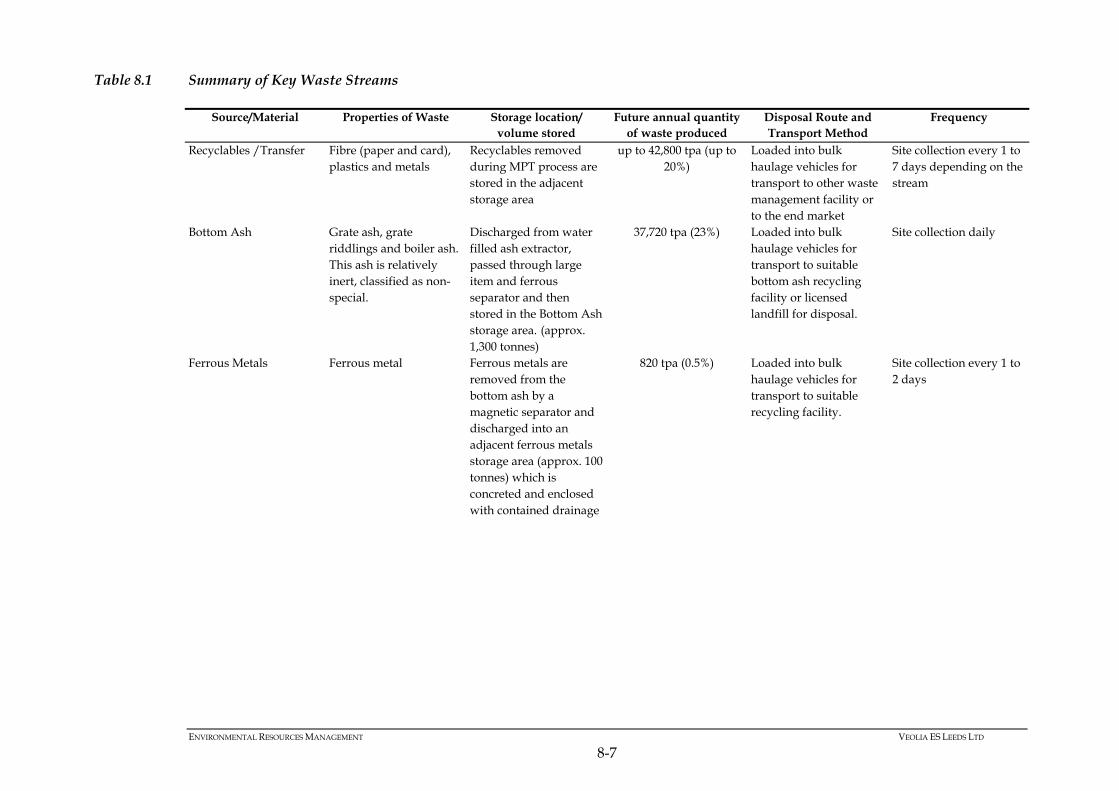
ENVIRONMENTAL RESOURCES MANAGEMENT VEOLIA ES LEEDS LTD
8-7
Table 8.1 Summary of Key Waste Streams
Source/Material Properties of Waste Storage location/ volume stored
Future annual quantity of waste produced
Disposal Route and Transport Method
Frequency
Recyclables /Transfer
Fibre (paper and card), plastics and metals
Recyclables removed during MPT process are stored in the adjacent storage area
up to 42,800 tpa (up to 20%)
Loaded into bulk haulage vehicles for transport to other waste management facility or to the end market
Site collection every 1 to 7 days depending on the stream
Bottom Ash Grate ash, grate riddlings and boiler ash. This ash is relatively inert, classified as non-special.
Discharged from water filled ash extractor, passed through large item and ferrous separator and then stored in the Bottom Ash storage area. (approx. 1,300 tonnes)
37,720 tpa (23%) Loaded into bulk haulage vehicles for transport to suitable bottom ash recycling facility or licensed landfill for disposal.
Site collection daily
Ferrous Metals Ferrous metal Ferrous metals are removed from the bottom ash by a magnetic separator and discharged into an adjacent ferrous metals storage area (approx. 100 tonnes) which is concreted and enclosed with contained drainage
820 tpa (0.5%) Loaded into bulk haulage vehicles for transport to suitable recycling facility.
Site collection every 1 to 2 days
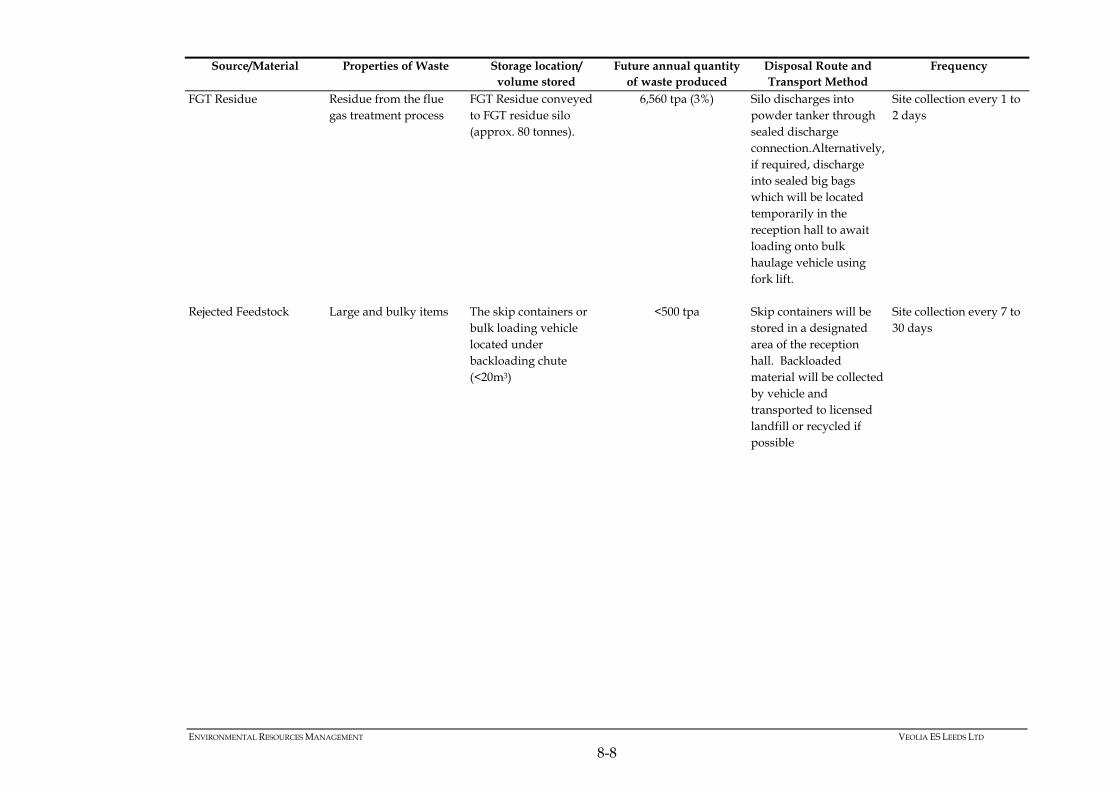
ENVIRONMENTAL RESOURCES MANAGEMENT VEOLIA ES LEEDS LTD
8-8
Source/Material Properties of Waste Storage location/ volume stored
Future annual quantity of waste produced
Disposal Route and Transport Method
Frequency
FGT Residue Residue from the flue gas treatment process
FGT Residue conveyed to FGT residue silo (approx. 80 tonnes).
6,560 tpa (3%) Silo discharges into powder tanker through sealed discharge connection.Alternatively, if required, discharge into sealed big bags which will be located temporarily in the reception hall to await loading onto bulk haulage vehicle using fork lift.
Site collection every 1 to 2 days
Rejected Feedstock Large and bulky items The skip containers or bulk loading vehicle located under backloading chute (<20m3)
<500 tpa Skip containers will be stored in a designated area of the reception hall. Backloaded material will be collected by vehicle and transported to licensed landfill or recycled if possible
Site collection every 7 to 30 days
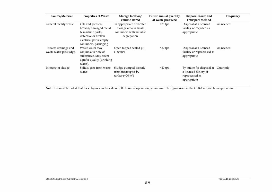
ENVIRONMENTAL RESOURCES MANAGEMENT VEOLIA ES LEEDS LTD
8-9
Source/Material Properties of Waste Storage location/ volume stored
Future annual quantity of waste produced
Disposal Route and Transport Method
Frequency
General facility waste Oils and greases, broken/damaged metal & machine parts, defective or broken electrical parts, empty containers, packaging
In appropriate dedicated storage area in small
containers with suitable segregation
<25 tpa Disposal at a licensed facility or recycled as appropriate
As needed
Process drainage and waste water pit sludge
Waste water may contain a variety of substances. May affect aquifer quality (drinking water).
Open topped sealed pit (150 m3)
<20 tpa Disposal at a licensed facility or reprocessed as appropriate
As needed
Interceptor sludge Solids/grits from waste water
Sludge pumped directly from interceptor by tanker (~20 m3)
<20 tpa By tanker for disposal at a licensed facility or reprocessed as appropriate
Quarterly
Note: It should be noted that these figures are based on 8,000 hours of operation per annum. The figure used in the OPRA is 8,760 hours per annum.


