Embed Size (px)
Citation preview
International Journal of Mineral Processing 114–117 (2012) 69–79
Contents lists available at SciVerse ScienceDirect
International Journal of Mineral Processing
j ourna l homepage: www.e lsev ie r .com/ locate / i jminpro
Continuous energy efficient exfoliation of vermiculite through microwave heating
Olaosebikan Folorunso ⁎, Christopher Dodds, Georgios Dimitrakis, Samuel KingmanProcess and Environmental Research Division, Faculty of Engineering, University of Nottingham, Nottingham, NG7 2RD, UK
⁎ Corresponding author. Tel.: +44 7412512743.E-mail address: [email protected] (O. Foloru
0301-7516/$ – see front matter © 2012 Elsevier B.V. Allhttp://dx.doi.org/10.1016/j.minpro.2012.10.003
a b s t r a c t
a r t i c l e i n f oArticle history:Received 2 March 2012Received in revised form 17 October 2012Accepted 20 October 2012Available online 29 October 2012
Keywords:Vermiculite exfoliationInterlayer waterMicrowave energyMicrowave exfoliationVermiculite
Fundamental knowledge of the dielectric properties of vermiculite, its interaction with electromagnetic fieldsand bulk materials handling technology was used to design and construct a continuous high throughput mi-crowave processing system operating at 2.45 GHz. The design methodology used to engineer the system isreported. Experimental demonstration of the effects of microwave energy on the product bulk density is pro-vided for the three most industrially relevant grades of material and it is shown as to how the performance ofthe system is significantly better than conventional exfoliation technology, in terms of produced bulk densi-ties, energy efficiencies, temperature of the product and plant footprint.
© 2012 Elsevier B.V. All rights reserved.
1. Introduction
Vermiculite is the name of a group of 2.1 phyllosilicateminerals thatare composed of hydrated sheet silicates, which contain layers of watermolecules within their internal structure, it is formed by the hydrother-mal alteration of mica (Walker, 1961; Grim, 1968).When heated rapid-ly, vermiculite exfoliates as the interlayer water turns into steam,forcing the layers apart in an accordion-like expansion (Walker, 1961;El Mouzdahir et al., 2009). The increase in volume of commercialgrade product is 8–12 times that of the unprocessed crude materialthereby producing a highly porous lightweight material (Walker,1961; Basset, 1963; Justo et al., 1989). Vermiculite has a low thermal ca-pacity due to its high surface reflectivity whichmeans it is highly effec-tive at reflecting incident thermal radiation (Andronova, 2007), andtherefore requires a significant amount of energy for its exfoliation(often greater than 1 Mwh/t of material). This is one of the many limi-tations of current industrial processing methodologies based on eitherrotary or vertical furnaces. Chemical and thermal exfoliation of vermic-ulite are the two principal conventional exfoliation techniques whichaccount for about 90% of the commercial exfoliation of vermiculite(TheVermiculite Association, 2011). Chemical exfoliation uses chemicalsubstances likeH2O2,weak acids and someelectrolytes for ion exchangeand one-dimensional swelling of vermiculite structure. This method isnot actually used for commercial exfoliation but mainly for laboratoryresearch work (Walker and Garrett, 1967; Ucgul and Girgin, 2002;Obut and Girgin, 2002). Thermal exfoliation is traditionally carried outusing gas or oil fuelled furnaces, which consume 600–1000 kWh of en-ergy to exfoliate a ton of rawmaterials. Approximately 600,000 tons of
nso).
rights reserved.
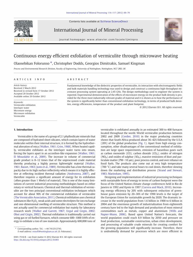
vermiculite is exfoliated annually in an estimated 300 to 400 furnaceslocated throughout the world. World vermiculite production between2002 and 2009 (Cordier, 2010) in the major producing countriesshows that South Africa produced about 36–42% followed by the U.S.A(20%) of the global production (Fig. 1). Apart from high energy con-sumption, other disadvantages of the conventional method of exfolia-tion are large space requirements, emission of hazardous gases suchas carbon monoxide (CO); carbon dioxide (CO2); oxides of nitrogen(NOX) and oxides of sulphur (SOX), massive emissions of dust and par-ticulatematter (PMb10 μm), poor process control, and over reliance onfossil fuels. The products also come out at very high temperature(700 °C) and take many several hours to cool down, therefore slowingdown the marketing and distribution process (Strand and Stewart,1983; Marinshaw, 1995).
Designing and implementation of industrial processing techniqueswith sustainable form of energy in terms of carbon footprint were thefocus of the United Nation climate change conferences held in Rio deJaneiro in 1992 and Kyoto in 1997 (Carrera and Mack, 2010). Increas-ing energy efficiency by 20% with subsequent reduction of green-house gases emission by 20–30% of the 1990 levels is the target ofthe European Union for sustainable growth by 2020. The dramatic in-crease in the world population from 1.6 billion in 1900 to 6 billion in2004 and the enormous growth of industrialization from eighteenthcentury have led to the high demand and production of most mineralcommodities such as metals, copper and aluminium (Wills andNapier-Munn, 2006). Based upon United Nation's forecasts, theworld population could reach 8.9 billion by 2050 and pressure onfood production, sustainable construction, urban cities development,and processing of valuable crude minerals for creating comfort forthe growing population will significantly increase. Therefore, thereis undoubtedly demand for processes which are more efficient in
0
100000
200000
300000
400000
500000
600000
2002 2003 2004 2005 2006 2007 2008 2009
Ver
mic
ulit
e p
rod
uct
ion
(to
nn
es)
Year
Others
Zimbabwe
Brazil
Russia
South Africa
China
USA
Fig. 1. World vermiculite production by country, 2002–2009(t) (Cordier, 2010).
70 O. Folorunso et al. / International Journal of Mineral Processing 114–117 (2012) 69–79
terms of energy consumption, more flexible in terms of operationalcharacteristics and ultimately more sustainable than the currentstate of the art. One technology which has the potential to realizethese benefits is microwave heating.
Microwave technology is not new as over 60 million small scalemicrowave ovens are being used domestically all over the world(NRC, 1994; Ku et al., 2001). Its huge success in processing of foodmaterials created an opportunity for its industrial applications inthe field of mineral processing (Ku et al., 2001). In recent years, mi-crowave energy has also been used in the processing of wide varietiesof feedstock's, such as food stuffs, agricultural products, polymers,waste treatment, and microwave treatment of coal (Kingman andRowson 1998; Kingman et al., 2000; Vorster et al., 2001; Jones et al.,2002).
The concept of using microwave energy to exfoliate vermiculite isnot new. For example US Patent 3758415 (Wada, 1973) reportedpre-treatment of vermiculite ore with polar molecules before micro-wave exfoliation. PCT patent application WO 2006/127025 bySklyarevich and Shevelev (2006) suggested using 83 GHz microwaveenergy with low power density (5 kW/cm2) for expanding perliteand similar hydrated minerals. Low throughputs and difficulties inexfoliating finer grades of vermiculite are major limitations whicharise when consideration of using US Patent 3758415 and PCT patentapplication WO 2006/127025 is given for commercial exfoliation andtherefore the goal of researchers and the wider vermiculite industriesis to find a better method of exfoliating vermiculite ore to give a lowerproduct temperature and lower production costs while also increas-ing the product yield and quality.
There are only a few published articles on the microwave exfolia-tion of vermiculite to date. Obut et al. (2003) used a domesticWhite-Westinghouse (Model KM-90 VP, 2.45 GHz) kitchen micro-wave oven which utilized a generic multimode applicator to studythe effect of different microwave powers (600, 950 and 1300 W) onthe exfoliation behavior of phlogopite and vermiculite alreadypre-treated with water and hydrogen peroxide for exfoliation en-hancement. They concluded that microwave exfoliation dependedupon the interlayer water. Maximum exfoliation values of 10 and 28fold were obtained for phlogopite and vermiculite respectively. Thisconclusion is somewhat surprising as these authors had to result insoaking the vermiculite and phlogopite in microwave adsorbent ma-terials to get them to effectively couple with the applied microwavefield.
Miao et al. (2010) also used the combination of hydrogen peroxidewith a concentration between 5% and 30% and a domestic microwaveoven to study the effect of microwave power, hydrogen peroxide,heating time, and solid immersion time on the exfoliation rate.Their results showed that microwave treatment of vermiculite afterpre-soaking with hydrogen peroxide causes rapid removal of the H2O2
from the interlayer space to expand the vermiculite. Clearly, it is highly
challenging to carry out such a process at commercial or even pilot scaledue to the implications of a highly complexmultiphase plant flowsheetcomposed of a number of complex unit operations.
The recent paper by Marcos and Rodríguez (2010b)) used a do-mestic multimode microwave oven (2.45 GHz, 800 W) to comparemicrowave exfoliation to conventional heating at 1000 °C. The resultsshowed that expansions occurred in the microwave oven at bulk tem-peratures below 100 °C (although localized temperatures would havebeen much higher based on the energy inputs) and that expansiondepends on the type of the container used, particle size and retentiontime in the electric field. However, no suggestions of routes to scaleup were given, nor were issues of microwave safety, energy balancesand the challenges of continuous processing addressed.
Most of the published laboratory investigations of microwave exfoli-ation of vermiculite to date have been carried out using domestic micro-wave ovens (kitchenmicrowaves at 2.45 GHz). Such systems comprise arectangular cavity that supports a number of resonant modes within thefrequency range of the magnetron which generates the microwaveenergy (Metaxas and Meredith, 1983). The limitations of domesticovens are the spatial non-uniform distribution of the electric fieldwhich causes uneven heating of materials, the creation of multiplehotspots within the cavity and the low power density (Meredith,1998). These drawbacks make domestic microwave ovens un-suitablefor scientific investigations as the distribution of the electric field mayvary considerably between discrete treatment of different samples andit is subsequently impossible to predict the distribution of the electricfield in the workload.
2. Aim and objectives
The overall aim of this work is to present the design, commission-ing and operational performance of an energy efficient microwavesystem for the exfoliation of vermiculite based upon a fundamentalunderstanding of the interaction of microwaves with vermiculitetype mineral structures. Specifically the aims are as follows:
1. To derive the mechanism by which microwaves cause vermiculiteto exfoliate
2. To quantify the role of power density in the exfoliation of vermic-ulite of different grain sizes
3. Determine the effect of the vermiculite source location on the bulkinteraction of the vermiculite with electromagnetic waves throughdetermination of dielectric properties
4. Design a safe, continuous system for the controlled processing ofvermiculite in an energy efficient manner
3. Experimental
3.1. Dielectric measurements methods
The interaction of microwave energy with any material is con-trolled by the dielectric properties of the material under treatment.Therefore, the first stage in the design of any microwave treatmentsystem is a detailed measurement campaign to determine theirvalues under relevant environmental conditions.
3.2. Cavity perturbation method
Two methods were employed for the determination of the dielec-tric properties of vermiculite at microwave frequencies; the cavityperturbation method and the waveguide method. The cavity pertur-bation technique was employed to measure the properties of each in-dividual flake and waveguide methods were used to measure theproperties of the bulk ore for the purposes of cavity or applicator de-sign. A detailed discussion of the operational of these methods is out-side the scope of this paper. For further information the reader is
Water cooling
Cavity
FurnaceNetworkanalyser
Cavity tofurnace
movement
Sample holder(Glass tube)
Furnacecontroller
ComputerRobotic-arm
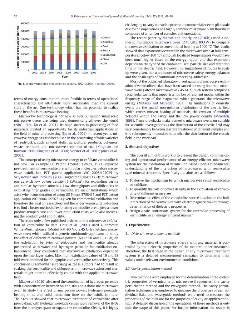
Fig. 2. Diagrammatic view of the resonant cavity (Greenacre, 1996).
71O. Folorunso et al. / International Journal of Mineral Processing 114–117 (2012) 69–79
referred to the following references (Hippel, 1954; Sucher and Fox,1963; Arai et al., 1996; Sheen, 2005; Venkatesh and Raghavan,2005; Sheen et al., 2007; Sheen 2009).
3.3. Experimental procedure
Various grades of vermiculite from three different source regionsincluding, Palabora in South Africa (Fine and superfine grades);China (fine, superfine and large grades) and Australian superfinewere used for extensive studies of the mineralogical and electrical be-havior of its bulk sample which were used for predicting its interac-tions with microwave irradiation.
For measurements based on the cavity perturbation technique(Fig. 2), representative samples of vermiculite were pulverized usingan agatemortar and pestle to prevent steel contamination frommilling,and the vermiculite was then screened through a 180 μm test sieve andthe oversize remaining on a 38 μm test sieve was retained for use. Themeasurements were taken at different densities. The sample used foreach measurement was loosely filled into the quartz tube and its basewas then tapped about 30–50 times on a wooden block to obtain thedesired density. The density variation along the sample height wasavoided by not applying pressure to the sample surface. The tested sam-ple mass was divided by its volume to obtain the bulk density of themeasured sample which was required for the calculation of the dielec-tric properties of the sample.
The imaginary (loss factor) and real component (dielectric constant)of the complex permittivity at room temperature (20 °C)were then cal-culated (Eqs. (1) and (2)) from the measured values of the perturbedquality factor (Q) and resonant frequency respectively (Sucher andFox, 1963). The measurements were carried out at frequency of 911and 2470 MHzat room temperature. The ε″ and ε′ denote the loss factor(ability of material to convert electromagnetic energy to heat and
Table 1Resonant modes for cavity perturbation used for dielectric measurement with theirBessel functions (J1: first order Bessel function of the first kind; and X1,m is functionof air filled cavity).
TM mode Frequency (MHz) Xl,m J1(Xl,m)
TM010 397 2.404826 0.51915TM020 911 5.520078 −0.34026TM030 1430 8.653728 0.27145TM040 1950 11.791535 −0.23246TM050 2470 14.930318 0.20655
dielectric constant (ability of a material to store electromagnetic ener-gy) respectively.
ε″ ¼ J21 x1;m� � 1
Q1− 1
Q2
� �VC
VSð1Þ
ε ′ ¼ 1þ 2J21 x1;m� � f 0−f 1
f 0
VC
VSð2Þ
where VC: cavity volume (m3); VS: volume of sample (m3); f0: resonantfrequency of the empty cavity (Hz); f1: resonant frequency of the cavitywith the sample (Hz); J1: first order Bessel function of the first kind(Table 1); Q1: quality factor of empty cavity; Q2: quality factor of cavitywith dielectric material and X1,m is a function of the geometry of thecavity.
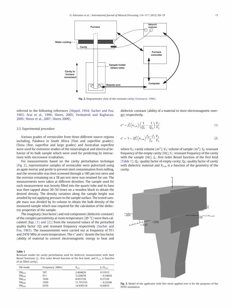
Fig. 3. Model of the applicator with fine mesh applied over it for the purposes of theFDTD simulation.
72 O. Folorunso et al. / International Journal of Mineral Processing 114–117 (2012) 69–79
The thermogravimetric properties of the vermiculite were studiedusing a TA Q500 TGA with a heating rate of 10 °C/min between 25 °Cand 1000 °C. About 15 mg of the sample was placed in an aluminumpan in a nitrogen flow-rate of 70 ml/min. Free water, bound waterand total moisture content of the crude sample were determined gravi-metrically by continuously heating between the sample in a furnace for24 h, 4 h and 3 h at temperatures of 115 °C, 300 °C and 500 °C respec-tively. The samplewas also heated for 1 h at temperatures of 700 °C and900 °C to determine weight loss due to dehydroxylation. Dry sievingtechnique was used (based upon British standard (BS 410-1:2000 and1796-1:1989)) for determining the particle size distribution of thevermiculite.
The mineralogical composition of the samples was determined byX-ray diffraction analysis using a Hilton Brook diffractometer (PhilipPW 1050) at 40 kv, 20 mA (Cu kβ radiation at λ=1.5406 Å) from 3to 65° 2θ range and 2θ step scan of 0.05 s, and the obtained datafrom the XRD were compared and matched with the reflection stan-dards from JADE software which is a powder analysis diffractionpackage used for analyzing the results.
Two litermeasuring cylinderswere used to determine the bulk den-sity of the exfoliated vermiculite. The weight of the empty measuringcylinder was determined and a representative sample of processed
-30-200-100
0100
200300
0
10
20
30
40
50
60
70
Magnitude of E
y [mm]
250 200 150 100 50 0
-200
-150
-100
-50
0
50
100
150
Magnitude of Power
x [mm
y [m
m]
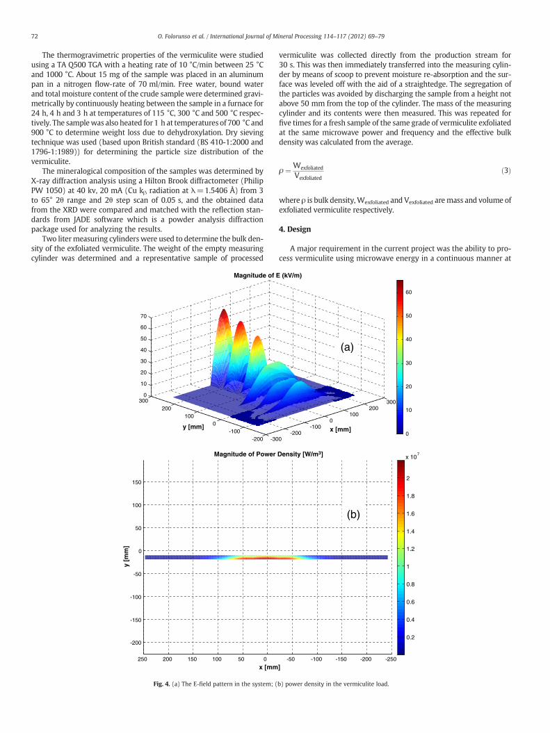
Fig. 4. (a) The E-field pattern in the system; (
vermiculite was collected directly from the production stream for30 s. This was then immediately transferred into the measuring cylin-der by means of scoop to prevent moisture re-absorption and the sur-face was leveled off with the aid of a straightedge. The segregation ofthe particles was avoided by discharging the sample from a height notabove 50 mm from the top of the cylinder. The mass of the measuringcylinder and its contents were then measured. This was repeated forfive times for a fresh sample of the same grade of vermiculite exfoliatedat the same microwave power and frequency and the effective bulkdensity was calculated from the average.
ρ ¼ Wexfoliated
Vexfoliatedð3Þ
where ρ is bulk density,Wexfoliated and Vexfoliated aremass and volume ofexfoliated vermiculite respectively.
4. Design
A major requirement in the current project was the ability to pro-cess vermiculite using microwave energy in a continuous manner at
0-200
-1000
100200
300
x [mm]
(kV/m)
0
10
20
30
40
50
60
-50 -100 -150 -200 -250
Density [W/m3]
]
0.2
0.4
0.6
0.8
1
1.2
1.4
1.6
1.8
2
x 107
(a)
(b)
b) power density in the vermiculite load.
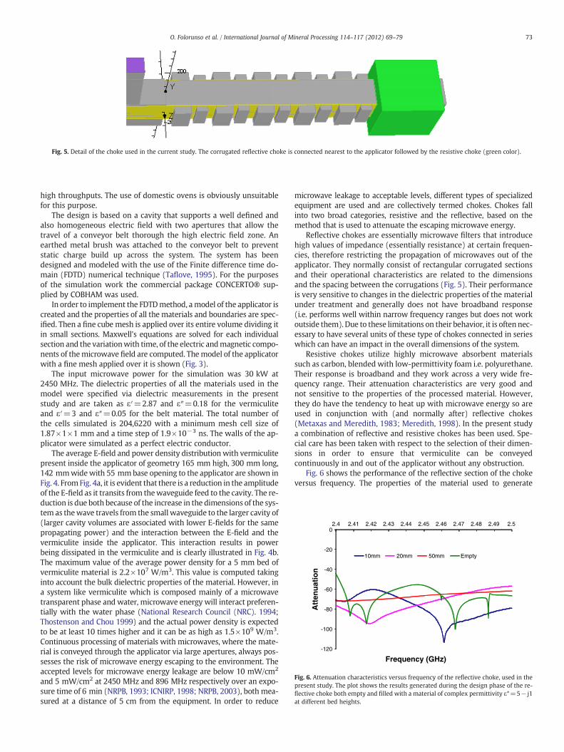
Fig. 5. Detail of the choke used in the current study. The corrugated reflective choke is connected nearest to the applicator followed by the resistive choke (green color).
-120
-100
-80
-60
-40
-20
02.4 2.41 2.42 2.43 2.44 2.45 2.46 2.47 2.48 2.49 2.5
Att
enu
atio
n
Frequency (GHz)
10mm 20mm 50mm Empty
Fig. 6. Attenuation characteristics versus frequency of the reflective choke, used in thepresent study. The plot shows the results generated during the design phase of the re-flective choke both empty and filled with a material of complex permittivity ε*=5− j1at different bed heights.
73O. Folorunso et al. / International Journal of Mineral Processing 114–117 (2012) 69–79
high throughputs. The use of domestic ovens is obviously unsuitablefor this purpose.
The design is based on a cavity that supports a well defined andalso homogeneous electric field with two apertures that allow thetravel of a conveyor belt thorough the high electric field zone. Anearthed metal brush was attached to the conveyor belt to preventstatic charge build up across the system. The system has beendesigned and modeled with the use of the Finite difference time do-main (FDTD) numerical technique (Taflove, 1995). For the purposesof the simulation work the commercial package CONCERTO® sup-plied by COBHAM was used.
In order to implement the FDTDmethod, amodel of the applicator iscreated and the properties of all the materials and boundaries are spec-ified. Then a fine cube mesh is applied over its entire volume dividing itin small sections. Maxwell's equations are solved for each individualsection and the variationwith time, of the electric andmagnetic compo-nents of themicrowave field are computed. Themodel of the applicatorwith a fine mesh applied over it is shown (Fig. 3).
The input microwave power for the simulation was 30 kW at2450 MHz. The dielectric properties of all the materials used in themodel were specified via dielectric measurements in the presentstudy and are taken as ε′=2.87 and ε″=0.18 for the vermiculiteand ε′=3 and ε″=0.05 for the belt material. The total number ofthe cells simulated is 204,6220 with a minimum mesh cell size of1.87×1×1 mm and a time step of 1.9×10⁻³ ns. The walls of the ap-plicator were simulated as a perfect electric conductor.
The average E-field and power density distribution with vermiculitepresent inside the applicator of geometry 165 mm high, 300 mm long,142 mmwidewith 55 mmbase opening to the applicator are shown inFig. 4. FromFig. 4a, it is evident that there is a reduction in the amplitudeof the E-field as it transits from thewaveguide feed to the cavity. The re-duction is due both because of the increase in the dimensions of the sys-tem as thewave travels from the small waveguide to the larger cavity of(larger cavity volumes are associated with lower E-fields for the samepropagating power) and the interaction between the E-field and thevermiculite inside the applicator. This interaction results in powerbeing dissipated in the vermiculite and is clearly illustrated in Fig. 4b.The maximum value of the average power density for a 5 mm bed ofvermiculite material is 2.2×10⁷ W/m3. This value is computed takinginto account the bulk dielectric properties of the material. However, ina system like vermiculite which is composed mainly of a microwavetransparent phase and water, microwave energy will interact preferen-tially with the water phase (National Research Council (NRC). 1994;Thostenson and Chou 1999) and the actual power density is expectedto be at least 10 times higher and it can be as high as 1.5×10⁹ W/m3.Continuous processing of materials with microwaves, where the mate-rial is conveyed through the applicator via large apertures, always pos-sesses the risk of microwave energy escaping to the environment. Theaccepted levels for microwave energy leakage are below 10 mW/cm2
and 5 mW/cm2 at 2450 MHz and 896 MHz respectively over an expo-sure time of 6 min (NRPB, 1993; ICNIRP, 1998; NRPB, 2003), both mea-sured at a distance of 5 cm from the equipment. In order to reduce
microwave leakage to acceptable levels, different types of specializedequipment are used and are collectively termed chokes. Chokes fallinto two broad categories, resistive and the reflective, based on themethod that is used to attenuate the escaping microwave energy.
Reflective chokes are essentially microwave filters that introducehigh values of impedance (essentially resistance) at certain frequen-cies, therefore restricting the propagation of microwaves out of theapplicator. They normally consist of rectangular corrugated sectionsand their operational characteristics are related to the dimensionsand the spacing between the corrugations (Fig. 5). Their performanceis very sensitive to changes in the dielectric properties of the materialunder treatment and generally does not have broadband response(i.e. performs well within narrow frequency ranges but does not workoutside them). Due to these limitations on their behavior, it is often nec-essary to have several units of these type of chokes connected in serieswhich can have an impact in the overall dimensions of the system.
Resistive chokes utilize highly microwave absorbent materialssuch as carbon, blended with low-permittivity foam i.e. polyurethane.Their response is broadband and they work across a very wide fre-quency range. Their attenuation characteristics are very good andnot sensitive to the properties of the processed material. However,they do have the tendency to heat up with microwave energy so areused in conjunction with (and normally after) reflective chokes(Metaxas and Meredith, 1983; Meredith, 1998). In the present studya combination of reflective and resistive chokes has been used. Spe-cial care has been taken with respect to the selection of their dimen-sions in order to ensure that vermiculite can be conveyedcontinuously in and out of the applicator without any obstruction.
Fig. 6 shows the performance of the reflective section of the chokeversus frequency. The properties of the material used to generate
0
0.1
0.2
0.3
0.4
0.5
0.6
0.7
0.8
0.9
1
1.1
100001000100Fra
ctio
nal
Cu
mu
lati
ve F
req
uen
cy
Particle Size ( m)
Chinese Fine
Chinese Superfine
Palabora Fine
Palabora Superfine
Australian superfine
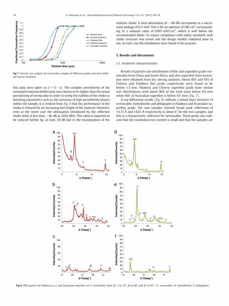
Fig 7. Particle size analysis of vermiculite samples of different grades and from differ-ent source locations.
74 O. Folorunso et al. / International Journal of Mineral Processing 114–117 (2012) 69–79
this data were taken as ε*=5− j1. The complex permittivity of thesimulatedmaterial deliberately was chosen to be higher than the actualpermittivity of vermiculite in order to verify the stability of the choke todetuning parameters such as, the presence of high permittivity phaseswithin the sample. It is evident from Fig. 6 that the performance of thechoke is reduced for an increasing bed height of the material. However,even at the worst case the attenuation introduced by the reflectivechoke alone is less than−60 dB at 2450 MHz. This value is expected tobe reduced further by, at least, 20 dB due to the incorporation of the
10
20
30
40
50
60
70
80
90
100
2-Theta(°)
2-Theta(°)
2-Theta(°)
a V/H
VV
V
d
10
20
30
40
50
60
70
80
90
100b
HP H
VH P/V
V
e
20
40
60
80
100
Inte
nsi
ty(C
ou
nts
)In
ten
sity
(Co
un
ts)
Inte
nsi
ty(C
ou
nts
)
c
VPHV H
3 8 13 18
20 25 30 35 40
41 46 51 56 61
f
Fig 8. XRD pattern of Palabora (a–c) and Australian superfine (d–f) vermiculite, from 2θ
resistive choke. A total attenuation of −80 dB corresponds to a micro-wave leakage of 0.3 mW. This is for an aperture of 100 cm2 correspond-ing to a radiated value of 0.003 mW/cm2, which is well below therecommended limits. To ensure compliance with safety standards eachchoke structure was tested and the design models validated prior touse. In each case the simulations were found to be accurate.
5. Results and discussions
5.1. Feedstock characterization
Results of particle size distribution of fine and superfine grade ver-miculite from China and South Africa, and also superfine from Austra-lian were obtained from dry sieving analyses. About 80% and 95% ofChinese and Palabora fine grade respectively were found to bebelow 1.5 mm. Palabora and Chinese superfine grade have similarsize distributions with about 80% of the total mass below 0.6 mmwhile 80% of Australian superfine is below 0.5 mm (Fig. 7).
X-ray diffraction results (Fig. 8) indicate a mixed layer structure ofvermiculite, hydrobiotite and phlogopite in Palabora and Australian su-perfine grade. The two samples showed broad peak reflections of14.73 Å and 14.61 Å respectively at about 6° for the two samples, andthis is a characteristic reflection for vermiculite. These peaks also indi-cate that the octahedral iron content is small and that the samples are
0
10
20
30
40
50
60
70
80
90
100
V/H
V
P
V
H
0
10
20
30
40
50
60
70
80
90
100H
V V
V
P
P H/PH
V/HV
Inte
nsi
ty(C
ou
nts
)In
ten
sity
(Co
un
ts)
Inte
nsi
ty(C
ou
nts
)
0
10
20
30
40
50
60
70
80
90
100
2-Theta(°)3 8 13 18
2-Theta(°)20 25 30 35 40
2-Theta(°)41 46 51 56 61
V/H
VH V
- 3 to 19°, 20 to 40° and 41 to 65°. (V: vermiculite; H: hydrobiotite; P: phlogopite).
84
86
88
90
92
94
96
98
100
% W
eig
ht
Rem
ain
ing
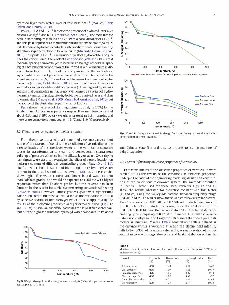
Palabora Superfine Chinese Superfine Australian superfine
88
90
92
94
96
98
100
% W
eig
ht
Rem
ain
ing
0 200 400 600 800 1000
temperature, °C
Palabora Fine
Chinese Large
Chinese Fine
75O. Folorunso et al. / International Journal of Mineral Processing 114–117 (2012) 69–79
hydrated layer with water layer of thickness 4.95 Å (Walker, 1949;Harraz and Hamdy, 2010).
Peaks 6.37 Å and 8.63 Å indicate the presence of hydrated interlayercations like Mg2+ and K+ (El Mouzdahir et al., 2009). The most intensepeak in both samples is found at 7.25° with a basal distance of 11.25 Å,and this peak represents a regular interstratifications of biotite/vermic-ulite known as hydrobiotite which is intermediate phase formed duringalteration sequence of biotite to vermiculite (Muiambo Hermínio et al.,2010). This peak (11.25 Å) is a significant peak of hydrobiotite, and jus-tifies the conclusion of the work of Hendrick and Jefferson (1938) thatthe basal spacing ofmixed layerminerals is an average of the basal spac-ing of each mineral composition of the mixed layer. Vermiculite is dif-ferent from biotite in terms of the composition of the intersilicatelayer. Biotite consists of potassium ionswhile vermiculite consists of bi-valent ions such as Mg2+ sandwiched between two layers of watermolecule (Gruner, 1934; Bassett, 1959). From past research work onSouth African vermiculite (Palabora Europe.), it was agreed by variousauthors that vermiculite in that region was formed as a result of hydro-thermal alteration of phlogopite/hydrobiotite to amixed layer and thento vermiculite (Marcos et al., 2009; MuiamboHermínio et al., 2010) butthe source of the Australian superfine is not known.
Fig. 9 shows the result of thermogravimetric analysis (TGA) for thePalabora and Australian superfine samples. Free moisture content ofabout 4.36 and 3.19% by dry weight is present in both samples andthese were completely removed at 118 °C and 110 °C respectively.
0 200 400 600 800 1000
temperature, °C
Figs. 10 and 11. Comparison of weight change from oven drying heating of vermiculitesamples from different locations.
5.2. Effects of source location on moisture content
From the conventional exfoliation point of view, moisture contentis one of the factors influencing the exfoliation of vermiculite as theintense heating of the interlayer water in the vermiculite structurecauses its transformation to steam and consequent instantaneousbuild up of pressure which splits the silicate layers apart. Oven dryingtechniques were used to investigate the effect of source location onmoisture content of different vermiculite grades (Figs. 10 and 11).The free water, bound water and high temperature hydroxyl watercontent in the tested samples are shown in Table 2. Chinese gradesshow higher free water content and lower bound water contentthan Palabora grades, and would be expected to exfoliate with higherexpansion ratios than Palabora grades but the reverse has beenfound to be the case in industrial systems using conventional heating(Crowson, 2001). However, Chinese grades expand with higher ratioswhen subjected to microwave irradiation as the exfoliation is causedby selective heating of the interlayer water. This is supported by theresults of the dielectric properties and performance curve (Figs. 12and 13, 19). Australian superfine possesses the lowest free water con-tent but the highest bound and hydroxyl water compared to Palabora
84
86
88
90
92
94
96
98
100
0 200 400 600 800 1000
Wei
gh
t (%
)
Temperature (°C)
Australian Palabora
Fig. 9. Weight change from thermo-gravimetric analysis (TGA) of superfine vermicu-lite sample at 10 °C/min.
and Chinese superfine and this contributes to its highest rate ofdehydroxylation.
5.3. Factors influencing dielectric properties of vermiculite
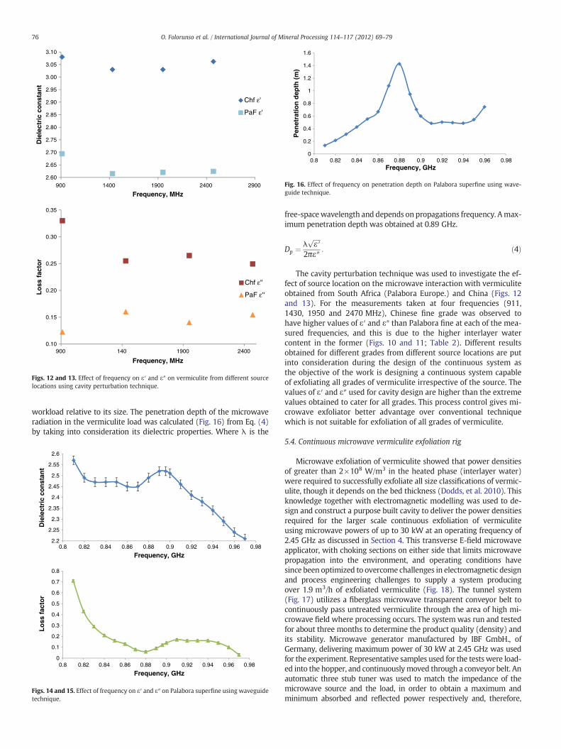
Extensive studies of the dielectric properties of vermiculite werecarried out as the results of the variations in dielectric propertiesunderpin the basis of the engineering modeling, design and construc-tion of the continuous microwave system. The methods describedin Section 3 were used for these measurements. Figs. 14 and 15show the results obtained for dielectric constant and loss factor(ε′ and ε″) using the waveguide method between frequency range0.81–0.97 GHz. The results show that ε′ and ε″ follow a similar pattern.The ε′ decreases from 0.81 GHz to 0.87 GHz after which it increases upto 0.89 GHz before it starts decreasing, while the ε″ decreases from0.81 GHz to 0.88 GHz and then increases to 0.91 GHz before it starts de-creasing up to a frequency of 0.97 GHz. These results show that vermic-ulite is not a Debye solid or itmay consists ofmore than one dipole in itsmolecular structure (Mantas, 1999). Penetration depth is defined asthe distance within a workload at which the electric field intensityfalls to 1/e (0.368) of its surface value and gives an indication of the de-gree of microwave energy absorption and heat distribution within the
Table 2Moisture content analysis of vermiculite from different source locations. (TMC: totalmoisture content).
Sample Free water(%)
Bound water(%)
Hydroxyl water(%)
TMC(%)
Palabora fine 4.32 1.47 3.81 9.60Chinese fine 6.54 1.07 3.26 10.87Palabora superfine 4.29 1.55 3.87 9.71Chinese superfine 4.32 1.29 4.09 9.70Australian superfine 3.19 4.2 8.24 15.63Chinese large 5.27 1.28 3.70 10.25
2.60
2.65
2.70
2.75
2.80
2.85
2.90
2.95
3.00
3.05
3.10
Die
lect
ric
con
stan
t
Frequency, MHz
Frequency, MHz
Chf ε'
PaF ε'
0.10
0.15
0.20
0.25
0.30
0.35
900 1400 1900 2400 2900
900 140 1900 2400
Lo
ss f
acto
r
Chf ε''
PaF ε''
Figs. 12 and 13. Effect of frequency on ε′ and ε″ on vermiculite from different sourcelocations using cavity perturbation technique.
0
0.2
0.4
0.6
0.8
1
1.2
1.4
1.6
Pen
etra
tio
n d
epth
(m
)
Frequency, GHz0.8 0.82 0.84 0.86 0.88 0.9 0.92 0.94 0.96 0.98
Fig. 16. Effect of frequency on penetration depth on Palabora superfine using wave-guide technique.
76 O. Folorunso et al. / International Journal of Mineral Processing 114–117 (2012) 69–79
workload relative to its size. The penetration depth of the microwaveradiation in the vermiculite load was calculated (Fig. 16) from Eq. (4)by taking into consideration its dielectric properties. Where λ is the
2.2
2.25
2.3
2.35
2.4
2.45
2.5
2.55
2.6
Die
lect
ric
con
stan
t
Frequency, GHz
0
0.1
0.2
0.3
0.4
0.5
0.6
0.7
0.8
0.8 0.82 0.84 0.86 0.88 0.9 0.92 0.94 0.96 0.98
Frequency, GHz0.8 0.82 0.84 0.86 0.88 0.9 0.92 0.94 0.96 0.98
Lo
ss f
acto
r
Figs. 14 and 15. Effect of frequency on ε′ and ε″ on Palabora superfine using waveguidetechnique.
free-spacewavelength and depends on propagations frequency. Amax-imum penetration depth was obtained at 0.89 GHz.
Dp ¼ λffiffiffiffiffiε ′
p
2πε″: ð4Þ
The cavity perturbation technique was used to investigate the ef-fect of source location on the microwave interaction with vermiculiteobtained from South Africa (Palabora Europe.) and China (Figs. 12and 13). For the measurements taken at four frequencies (911,1430, 1950 and 2470 MHz), Chinese fine grade was observed tohave higher values of ε′ and ε″ than Palabora fine at each of the mea-sured frequencies, and this is due to the higher interlayer watercontent in the former (Figs. 10 and 11; Table 2). Different resultsobtained for different grades from different source locations are putinto consideration during the design of the continuous system asthe objective of the work is designing a continuous system capableof exfoliating all grades of vermiculite irrespective of the source. Thevalues of ε′ and ε″ used for cavity design are higher than the extremevalues obtained to cater for all grades. This process control gives mi-crowave exfoliator better advantage over conventional techniquewhich is not suitable for exfoliation of all grades of vermiculite.
5.4. Continuous microwave vermiculite exfoliation rig
Microwave exfoliation of vermiculite showed that power densitiesof greater than 2×10⁸ W/m3 in the heated phase (interlayer water)were required to successfully exfoliate all size classifications of vermic-ulite, though it depends on the bed thickness (Dodds, et al. 2010). Thisknowledge together with electromagnetic modelling was used to de-sign and construct a purpose built cavity to deliver the power densitiesrequired for the larger scale continuous exfoliation of vermiculiteusing microwave powers of up to 30 kW at an operating frequency of2.45 GHz as discussed in Section 4. This transverse E-field microwaveapplicator, with choking sections on either side that limits microwavepropagation into the environment, and operating conditions havesince been optimized to overcome challenges in electromagnetic designand process engineering challenges to supply a system producingover 1.9 m3/h of exfoliated vermiculite (Fig. 18). The tunnel system(Fig. 17) utilizes a fiberglass microwave transparent conveyor belt tocontinuously pass untreated vermiculite through the area of high mi-crowave field where processing occurs. The system was run and testedfor about three months to determine the product quality (density) andits stability. Microwave generator manufactured by IBF GmbH., ofGermany, delivering maximum power of 30 kW at 2.45 GHz was usedfor the experiment. Representative samples used for the tests were load-ed into the hopper, and continuouslymoved through a conveyor belt. Anautomatic three stub tuner was used to match the impedance of themicrowave source and the load, in order to obtain a maximum andminimum absorbed and reflected power respectively and, therefore,
c
ge e
h
a
jd
f
bi
k
f
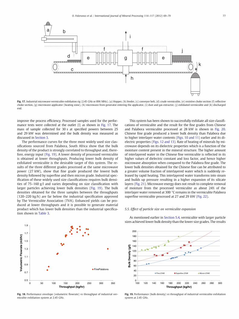
Fig. 17. Industrial microwave vermiculite exfoliation rig (2.45 GHz or 896 MHz). (a) Hopper, (b) feeder, (c) conveyor belt, (d) crude vermiculite, (e) resistive choke section (f) reflectivechoke section, (g) microwave applicator (heating zone), (h) microwave from generator entering the applicator, (i) dust and gas extractor, (j) exfoliated vermiculite and (k) dischargedend.
77O. Folorunso et al. / International Journal of Mineral Processing 114–117 (2012) 69–79
improve the process efficiency. Processed samples used for the perfor-mance tests were collected at the outlet (l) as shown in Fig. 17. Themass of sample collected for 30 s at specified powers between 25and 29 kW was determined and the bulk density was measured asdiscussed in Section 3.
The performance curves for the three most widely used size clas-sifications sourced from Palabora, South Africa show that the bulkdensity of the product is strongly correlated to throughput and, there-fore, energy input (Fig. 19). A lower density of processed vermiculiteis obtained at lower throughputs. Producing lower bulk density ofexfoliated vermiculite is the desirable target of this system. The re-sults of the three different grades processed at the same microwavepower (27 kW), show that fine grade produced the lowest bulkdensity followed by superfine and then micron grade. Industrial spec-ification of these widely used size classifications requires bulk densi-ties of 75–160 g/l and varies depending on size classification withlarger particles achieving lower bulk densities (Fig. 19). The bulkdensities obtained for the three samples between the throughputs(120–220 kg/h) are far below the industrial specification approvedby The Vermiculite Association (TVA). Enhanced yields can be pro-duced at lower throughputs and it is possible to generate materialproduct which has lower bulk densities than the industrial specifica-tion shown in Table 3.
0.5
0.7
0.9
1.1
1.3
1.5
1.7
1.9
0 50 100 150 200 250 300 350
Vo
lum
etri
c F
low
rate
(m
3/h
r)
Throughput (kg/hr)
FinePalabora
Fig. 18. Performance envelope (volumetric flowrate) vs throughput of industrial ver-miculite exfoliation system at 2.45 GHz.
This system has been shown to successfully exfoliate all size classifi-cations of vermiculite and the result for the fine grades from Chineseand Palabora vermiculite processed at 28 kW is shown in Fig. 20.Chinese fine grade produced a lower bulk density than Palabora dueto higher interlayer water contents (Figs. 10 and 11) earlier and its di-electric properties (Figs. 12 and 13). Rate of heating of minerals by mi-crowave depends on its dielectric properties which is a function of themoisture content present in the mineral structure. The higher amountof interlayered water in the Chinese fine vermiculite is reflected in itshigher values of dielectric constant and loss factor, and hence highermicrowave absorption when compared to the Palabora fine grade. Thelower bulk densities obtained for the Chinese fine can be attributed toa greater volume fraction of interlayered water which is suddenly re-leased by rapid heating. This interlayered water transforms into steamand builds up pressure resulting in a higher expansion of its silicatelayers (Fig. 21). Microwave energy does not result to complete removalof moisture from the processed vermiculite as about 24% of theinterlayerwater removed at 300 °C remains in the vermiculite Palaborasuperfine vermiculite processed at 27 and 29 kW (Fig. 22).
5.5. Effect of particle size on vermiculite expansion
As mentioned earlier in Section 5.4, vermiculite with larger particlesizes achieved lower bulk density than the lower size grades. The results
0
20
40
60
80
100
120
140
160
180
200
100 120 140 160 180 200 220 240 260 280 300
Bu
lk D
ensi
ty (
g/l)
Throughput (kg/hr)
Fine 27kW Superfine 27kW Micron 27kW
Fig. 19. Performance (bulk density) vs throughput of industrial vermiculite exfoliationsystem at 2.45 GHz.
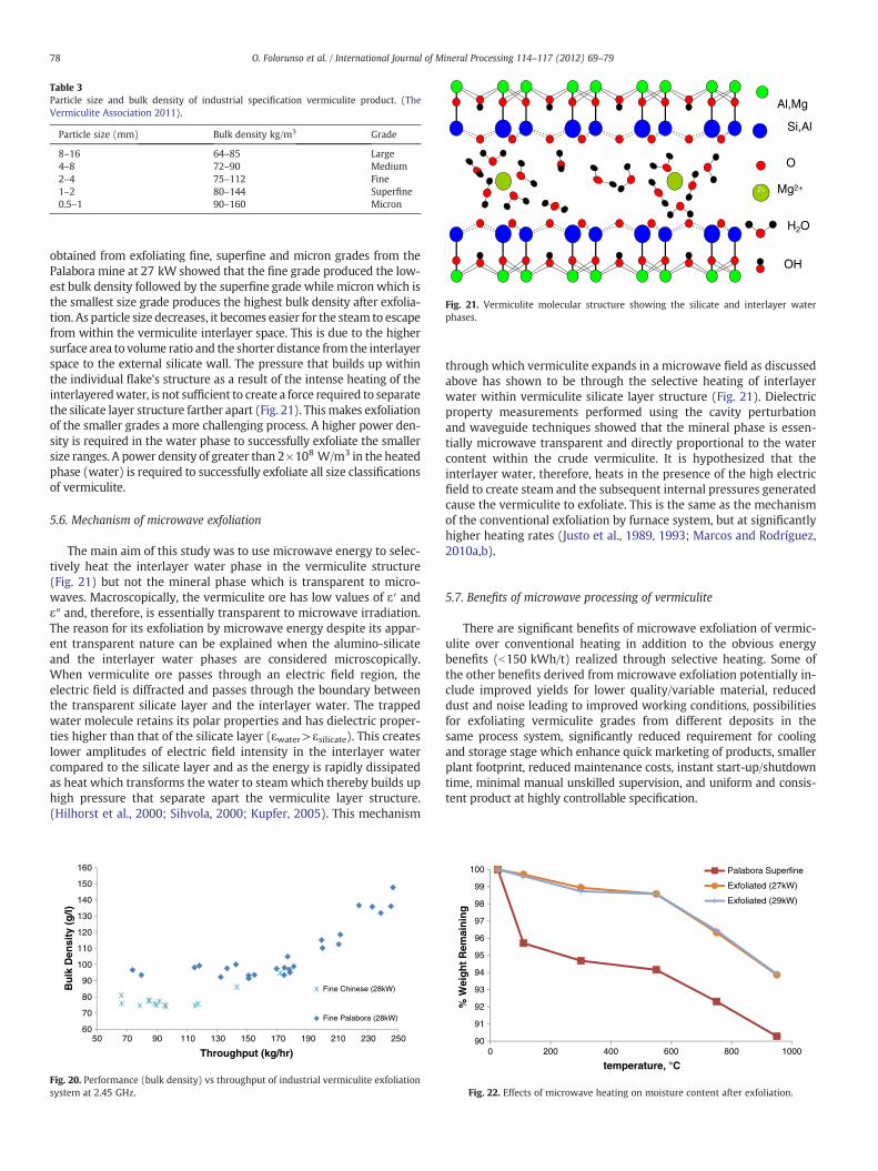
Table 3Particle size and bulk density of industrial specification vermiculite product. (TheVermiculite Association 2011).
Particle size (mm) Bulk density kg/m3 Grade
8–16 64–85 Large4–8 72–90 Medium2–4 75–112 Fine1–2 80–144 Superfine0.5–1 90–160 Micron
H2O
Al,Mg
2+ Mg2+
OH
O
Si,Al
Fig. 21. Vermiculite molecular structure showing the silicate and interlayer waterphases.
78 O. Folorunso et al. / International Journal of Mineral Processing 114–117 (2012) 69–79
obtained from exfoliating fine, superfine and micron grades from thePalabora mine at 27 kW showed that the fine grade produced the low-est bulk density followed by the superfine grade while micron which isthe smallest size grade produces the highest bulk density after exfolia-tion. As particle size decreases, it becomes easier for the steam to escapefrom within the vermiculite interlayer space. This is due to the highersurface area to volume ratio and the shorter distance from the interlayerspace to the external silicate wall. The pressure that builds up withinthe individual flake's structure as a result of the intense heating of theinterlayeredwater, is not sufficient to create a force required to separatethe silicate layer structure farther apart (Fig. 21). Thismakes exfoliationof the smaller grades a more challenging process. A higher power den-sity is required in the water phase to successfully exfoliate the smallersize ranges. A power density of greater than 2×10⁸ W/m3 in the heatedphase (water) is required to successfully exfoliate all size classificationsof vermiculite.
5.6. Mechanism of microwave exfoliation
The main aim of this study was to use microwave energy to selec-tively heat the interlayer water phase in the vermiculite structure(Fig. 21) but not the mineral phase which is transparent to micro-waves. Macroscopically, the vermiculite ore has low values of ε′ andε″ and, therefore, is essentially transparent to microwave irradiation.The reason for its exfoliation by microwave energy despite its appar-ent transparent nature can be explained when the alumino-silicateand the interlayer water phases are considered microscopically.When vermiculite ore passes through an electric field region, theelectric field is diffracted and passes through the boundary betweenthe transparent silicate layer and the interlayer water. The trappedwater molecule retains its polar properties and has dielectric proper-ties higher than that of the silicate layer (εwater>εsilicate). This createslower amplitudes of electric field intensity in the interlayer watercompared to the silicate layer and as the energy is rapidly dissipatedas heat which transforms the water to steam which thereby builds uphigh pressure that separate apart the vermiculite layer structure.(Hilhorst et al., 2000; Sihvola, 2000; Kupfer, 2005). This mechanism
60
70
80
90
100
110
120
130
140
150
160
50 70 90 110 130 150 170 190 210 230 250
Bu
lk D
ensi
ty (
g/l)
Throughput (kg/hr)
Fine Chinese (28kW)
Fine Palabora (28kW)
Fig. 20. Performance (bulk density) vs throughput of industrial vermiculite exfoliationsystem at 2.45 GHz.
through which vermiculite expands in a microwave field as discussedabove has shown to be through the selective heating of interlayerwater within vermiculite silicate layer structure (Fig. 21). Dielectricproperty measurements performed using the cavity perturbationand waveguide techniques showed that the mineral phase is essen-tially microwave transparent and directly proportional to the watercontent within the crude vermiculite. It is hypothesized that theinterlayer water, therefore, heats in the presence of the high electricfield to create steam and the subsequent internal pressures generatedcause the vermiculite to exfoliate. This is the same as the mechanismof the conventional exfoliation by furnace system, but at significantlyhigher heating rates (Justo et al., 1989, 1993; Marcos and Rodríguez,2010a,b).
5.7. Benefits of microwave processing of vermiculite
There are significant benefits of microwave exfoliation of vermic-ulite over conventional heating in addition to the obvious energybenefits (b150 kWh/t) realized through selective heating. Some ofthe other benefits derived from microwave exfoliation potentially in-clude improved yields for lower quality/variable material, reduceddust and noise leading to improved working conditions, possibilitiesfor exfoliating vermiculite grades from different deposits in thesame process system, significantly reduced requirement for coolingand storage stage which enhance quick marketing of products, smallerplant footprint, reduced maintenance costs, instant start-up/shutdowntime, minimal manual unskilled supervision, and uniform and consis-tent product at highly controllable specification.
90
91
92
93
94
95
96
97
98
99
100
0 200 400 600 800 1000
% W
eig
ht
Rem
ain
ing
temperature, °C
Palabora Superfine
Exfoliated (27kW)
Exfoliated (29kW)
Fig. 22. Effects of microwave heating on moisture content after exfoliation.
79O. Folorunso et al. / International Journal of Mineral Processing 114–117 (2012) 69–79
6. Conclusions
A continuous microwave system operating at 2.45 GHz for indus-trial exfoliation of vermiculite was designed and tested. Microwaveenergy causes rapid removal of interlayer water which brings aboutits exfoliation and product with a low density. The designed systemallows improved product yield over conventional systems and ne-gates the requirement for bulky hot air and particulate emissionman-agement systems. The overall process can then be operated withinsubstantially smaller premises or with mobile units, leading to signif-icantly reduced cost.
References
Andronova, V.I., 2007. A study of the crystalline structure of vermiculite from theTebinbulak deposit. Refract. Ind. Ceram. 48 (2), 91–95.
Arai, M., Binner, J.G.P., et al., 1996. Comparison of techniques for measuring high-temperature microwave complex permittivity: measurements on an alumina/zircona systsem. Microw. Power Electromagn. Energy 31 (1), 12–18.
Basset, W.A., 1963. The geology of vermiculite occurrences. Clay Clay Miner. 10, 61–93.Bassett, W.A., 1959. Origin of the vermiculite deposit at Libby, Montana. Am. Miner. 44,
282–299.Carrera, G.D., Mack, A., 2010. Sustainability assessment of energy technologies via so-
cial indicators: result of a survey among European experts. Energy Policy 38,1030–1039.
Cordier, D.J., 2010. Mineral Commodity Summaries 2010. U. S. D. O. T. Interior and U. S. G.Survey. United States Government Printing Office, Washington, p. 193.
Crowson, Philip, 2001. Statistics and Analyses of the World's Minerals Industry. MiningJournal Books Ltd., Kent, UK.
Dodds, C., Dimitrakis, G., et al., 2010. Microwave processing of feedstock. Such as Exfo-liating Vermiculite and other Minerlas, and Treating Contaminated Materials.W.I.P. Organization . (WO 2010/070357).
El Mouzdahir, Y., Elmchaouri, A., et al., 2009. Synthesis of nano-layered vermiculite oflow density by thermal treatment. Powder Technol. 189 (1), 2–5.
Greenacre N. R (1996). Measurement of the high temperature dielectric properties of ce-ramic at microwave frequencies. Electrical and Electronics department. Nottingham,University of Notiingham. PhD.
Grim, R.E., 1968. Clay Mineralogy. McGraw-Hill, New York.Gruner, J.W., 1934. Vermiculite and hydrobiotite structure. Am. Mineral. 19, 557–575.Harraz, H.Z., Hamdy, M.M., 2010. Interstratified vermiculite-mica in the gneiss-
metapelite-serpentinite rocks at Hafafit area, Southern Eastern Desert, Egypt:from metasomatism to weathering. J. Afr. Earth Sci. 58 (2), 305–320.
Hendrick, S.B., Jefferson, M.E., 1938. Crystal structure of vermiculites and mixedveermiculite–chlorites. Am. Miner. 23, 851–863.
Hilhorst, M.A., Dirsken, C., Kampers, F.W.H., Feddes, R.A., 2000. New dielectric mixtureequation for porous materials based on depolarization factors. Soil Sci. Soc. Am. J.64, 1581–1587.
Hippel, A.R.V., 1954. Dielectrics and Waves. John Wiley and Sons, Massachusetts.International Commission on Non-Ionizing Radiation Protection (ICNIRP), 1998.
Guidelines for limiting exposure to time-varying electric, magnetic, and electro-magnetic fields (up to 300 Ghz). Health Phys. 74 (4), 494–523.
Jones, D.A., Lelyveld, T.P., Mavrofidis, S.D., Kingman, S.W., Miles, N.J., 2002. Microwaveheating applications in environmental engineering—a review. Resour. Conserv.Recycl. 34 (2), 75–90.
Justo, A., Maqueda, C., Perez-Rodríguez, J.L., Morillo, E., 1989. Expansibility of some ver-miculites. Appl. Clay Sci. 4 (5–6), 509–519.
Justo, A., Pe'rez-Rodri'guez, J.L., Sanchez-Soto, P.J., 1993. Thermal study of vermiculiteand mica-vermiculite interstratifications. J. Therm. Anal. 40, 59–65.
Kingman, S.W., Rowson, N.A., 1998. Microwave treatment of minerals—a review.Miner. Eng. 11 (11), 1081–1087.
Kingman, S.W., Vorster, W., Rowson, N.A., 2000. The influence of mineralogy on micro-wave assisted grinding. Miner. Eng. 13 (3), 313–327.
Ku, H.S., Elias, Siores, et al., 2001. Microwave processing of materials: part 1. The HongKong Inst. Eng. 8 (3), 31–37.
Kupfer, K., 2005. Electromagnetic Aquametry. Weimar, Germany, Springer.
Mantas, P.Q., 1999. Dielectric response of materials: extension to the Debye model.J. Eur. Ceram. Soc. 19 (12), 2079–2086.
Marcos, C., Rodríguez, I., 2010a. Expansion behaviour of commercial vermiculites at1000 °C. Appl. Clay Sci. 48 (3), 492–498.
Marcos, C., Rodríguez, I., 2010b. Expansibility of vermiculites irradiated with micro-waves. Appl. Clay Sci. 51 (1–2), 33–37.
Marcos, C., Arango, Y.C., Rodriguez, I., 2009. X-ray diffraction studies of the thermal be-haviour of commercial vermiculites. Appl. Clay Sci. 42 (3–4), 368–378.
Marinshaw, R., 1995. Mineral Product Industry: Vermiculite Processing. U. S. E. P. Agency,North Carolina . (U.S. Environmental Protection Agency. 1: Chapters 11 and 12 ofAP-42).
Metaxas, A.C., Meredith, R.J., 1983. Industrial Microwave Heating. The Institution of Engi-neering and Technology, London.
Meredith, R., 1998. Engineers' Handbook of Industrial Microwave Heating. The Institutionof Engineering and Technology, London.
Miao, Zhao, Peng, Tongjiang, et al., 2010. Preparation of expanding vermiulite by chem-ical and microwave methods. Adv. Mater. Res. 96, 155–160.
Muiambo Hermínio, F., Focke Walter, W., Atanasova Maria, Westhuizen Isben van der,Tiedt Louwrens, R., 2010. Thermal properties of sodium-exchanged palaboravermiculite. Appl. Clay Sci. 50 (1), 51–57.
National Radiation Protection Board (NRPB), 2003. Measurement of Radiation Leakagefrom Microwave Ovens. H.P. Agency, Oxfordshire, p. 177.
National Radiological Protection Board (NRPB), 1993. Restriction on Human Exposureto Static and Time Varying Electromagnetic Fields and Radiation. London. 4: 7–63.
National Research Council (NRC), 1994. Microwave Processing of Materials. C. o. E. a. T. S.National Materials Advisory Board. National Academy Press, USA, pp. 1–7.
Obut, A., Girgin, I., 2002. Hydrogen peroxide exfoliation of vermiculite and phlogopite.Miner. Eng. 15 (9), 683–687.
Obut, A., Girgin, I., et al., 2003. Microwave exfoliation of vermiculite and phlogopite.Clay Clay Miner. 51 (4), 452–456.
Sheen, J., 2005. Study of microwave dielectric properties measurements by variousresonance techniques. Meas. 37 (2), 123–130.
Sheen, J., 2009. Measurements of microwave dielectric properties by an amendedcavity perturbation technique. Meas. 42 (1), 57–61.
Sheen, Jyh, Mao, W.L., Liu, Weihsing, 2007. Study on the Measurement Techniques ofMicrowave Dielectric Properties. NST, pp. 349–352.
Sihvola, A., 2000. Electromagnetic Mixing Formulas and Applications. The institution ofElectrical Engineers, London.
Sklyarevich, V. and Shevelev, M., 2006. A method of expanding mineral ores using mi-crowave radiation. Patent Cooperation Treaty (PCT). W. I. P. Organisation. USA. WO2006/127025 A2: 10.
Strand, P.R., Stewart, O.F., 1983. Vermiculite: Industrial Rocks and Minerals. Society ofMining Engineers, New York.
Sucher, M., Fox, J. (Eds.), 1963. Handbook of Microwave Measurements. Polytechnicpress of the Polytechnic Institute of Broklyn, Broklyn.
Taflove, A., 1995. Computational Electrodynamics: the Finite Difference Time DomainMethod. Artech House, Boston, Mass.
The Vermiculite Association, 2011. The World of Vermiculite. Retrieved 20/06/2011,2011, from http://www.vermiculite.org/.
Thostenson, E.T., Chou, T.W., 1999.Microwave processing: fundamentals and applications.Compos. A: Appl. Sci. Manuf. 30 (9), 1055–1071.
Ucgul, Erol, Girgin, I., 2002. Chemical exfoliation characteristics of karakoc phlogopitein hydrogen peroxide solution. Turk. J. Chem. 26, 431–439.
Venkatesh, M.S., Raghavan, G.V.S., 2005. An overview of dielectric properties measur-ing techniques. Can. Biosyst. Eng. 47 (7), 15–30.
Vorster, W., Rowson, N.A., Kingman, S.W., 2001. The effect of microwave radiationupon the processing of Neves Corvo copper ore. Int. J. Miner. Process. 63 (1),29–44.
Wada, T., 1973. Method for the Expansion of Vermiculite. U.S.P. Office. U.S.A, TakedaChemical Industries, Ltd., Osaka Japan, p. 8 (3758415).
Walker, G.F., 1949. Water layers in vermiculite. J. Nat. 163, 726–727.Walker, J.F., 1961. Vermiculite Minerals. The X-ray Identification and Crystal Structures
of Clay Minerlas. Mineralogical Society of Great Britian, London.Walker, J.F., Garrett, W.G., 1967. Chemical exfoliation of vermiculite and the production
of colloidal dispersion. Science 156 (3773), 385–387.Wills, B.A., Napier-Munn, T.J., 2006. Mineral Processing Technology: an Introduction to
the Practical Aspects of Ore Treatment and Mineral Recovery. Elsevier, London.


![cable heating 4PPOE_flatman_01_1113.ppt [Repaired]](https://img.pdfslide.net/doc/110x75/633385233108fad7760f171e/cable-heating-4ppoeflatman011113ppt-repaired.jpg)


