Embed Size (px)
Citation preview
lable at ScienceDirect
International Journal of Pressure Vessels and Piping 88 (2011) 34e44
Contents lists avai
International Journal of Pressure Vessels and Piping
journal homepage: www.elsevier .com/locate/ i jpvp
Crack initiation and crack growth assessment of a high pressure steam chest
Warwick M. Payten a,*, Tao Wei a, Ken U. Snowden a, Philip Bendeich a, Michael Lawa, Damien Charman b
aAustralian Nuclear Science and Technology Organisation (ANSTO), Locked Bag 2001, Kirrawee DC NSW 2232, AustraliabAustpower Engineering, PO Box 1184, Warners Bay NSW 2282, Australia
a r t i c l e i n f o
Article history:Received 9 June 2009Received in revised form9 November 2010Accepted 29 November 2010
Keywords:CreepFatigueDuctility0.5%Cre0.5%Moe0.25%VSteam chest
* Corresponding author. Tel.: þ61 2 9717 3822; faxE-mail address: [email protected] (W.
0308-0161/$ e see front matter Crown Copyright � 2doi:10.1016/j.ijpvp.2010.11.003
a b s t r a c t
Extensive cracking had occurred in a number of high pressure steam chests. An assessment was under-taken based on the R5 British Energy methodology to assess the components for both creepefatiguedamage initiation and crack growth analysis to determinefitness for purpose. The analysis determined thatthe remaining base rupture endurance life of the component was greater then 1 million hours, however,due to the start-up and shutdown ramp rates, creepefatigue damage greater then unity has occurredleading to crack initiation in a number of locations. These crackswere confirmed during internal inspectionof the steam chest. A subsequent crack growth analysis determined that the component could safely bereturned to service for the expected future life of the station.
Crown Copyright � 2010 Published by Elsevier Ltd. All rights reserved.
1. Introduction
Steam chests or throttle valves are a major component in steamgenerating power utilities. Creep rupture and the accumulation ofcreepefatigue damage over time is the principal damage mecha-nismwhich will eventually lead to crack initiation in many of thesecomponents due to the large wall thickness [1]. The primary causeof this creepefatigue damage is thermal stress during start-upsand shutdowns or load shifts [1e3]. In general, the up-shock cycletends to characterise the thermal loading for components such asmain steam pipe work, steam chests, HP rotors, and headersupstream of attemporation. The down-shock cycle is observed inheaders downstream of attemporation and components that formpart of the feedwater system. Some high-temperature componentscan experience both types of cycles for example, the steam chestdownstream of the stop valves where throttling takes place mayexperience a thermal quench [4]. Power stations, due to changes indemand and competition from cheaper energy sources and in thefuture from added carbon taxes are being subjected to two-shiftoperation [5]. Two shifting implies that the station will respondrapidly to load changes on the system, ensuring that the gridmaintains specified frequency and voltage, this implies that as wellas additional cycles on a plant, the ramp rates of the cycles tend tobe faster to ensure adequate load following.
: þ61 2 9543 7179.M. Payten).
010 Published by Elsevier Ltd. All
The utility inspected has eight HP Steam chests across four unitsthey are all of original construction. Since their original installation,they have each undergone routine overhaul. The valves are forgedfrom 0.5%Cre0.5%Moe0.25%V steel. Unlike larger units where thesteam chest and the turbine stop valve are separate components, inthis configuration they are manufactured from a single forging.Inspections have revealed significant cracking at the internal radiiof the steam chest bodies on almost all steam chests. A remaininglife assessment was undertaken of the steam chest, metallurgicalassessment was followed by detailed stress analysis using finiteelement analysis. Both crack initiation and crack growth calcula-tions were undertaken to determine the future operating life of thecomponent. The crack initiation creepefatigue damage calculatedwas based on the R5 methodology [6].
2. Metallurgical assessment
2.1. General
Replicas were taken from a number of internal locations of thesteam chest. All structures revealed by the replicas, including thestructures in the cracked areas, indicated that the original micro-structure of the steam chests consisted of ferrite and bainite. Thebainite content was estimated as being between 10 and 20% byvolume in the steam chests. Thermal degradation of the structuresat all locations in the steam chests had occurred. In most locationsof the steam chests, spheroidisation of the carbides in the bainitewas complete and the bainitic form was moderately degraded in
rights reserved.
Nomenclature
c adjustment factor30c average creep ratesb bending stressda/dN crack extension rateth creep dwell3f ð_3cÞ creep ductility at the instantaneous creep strain ratedc creep damage per cycleD, m creep crack growth constantsa coefficient of expansionr density of materialZ elastic follow-up factordf fatigue damage per cycleNf fatigue enduranceg, n fatigue crack growth constants3f failure ductilitya00, b00 Feltham equation constantsu fermi exponentl heat conduction coefficient
s0 initial dwell stress_3c instantaneous equivalent creep strain rate3min lower shelf ductilityDsel, max maximum elastic equivalent stress rangesm membrane stressE modulus of elasticitysij normal and shear stress tensorsA, b RambergeOsgood constantssref reference stresssRref rupture reference stresstr rupture lifeC specific heatKs shakedown factorDK stress intensityT temperatureD3t total strain rangedT total damage per cycle3max upper shelf ductilitySy yield stress
W.M. Payten et al. / International Journal of Pressure Vessels and Piping 88 (2011) 34e44 35
most areas with almost complete degradation in some. Thesedegrees of spheroidisation corresponded to Stage 4e5 in the Toftand Marsden [7] rating of spheroidisation. In the steam chests, theferrite grain boundaries contained a significant amount of carbideswhile within the grains a cloudy distribution of fine precipitates ofcarbides was present in many of the replicas. EPRI [8] datawas usedto indicate whether the spheroidisation ratings given above wereconsistent with the effect of operating temperature (540 �C) andservice hours. No data was available for the 0.5%Cre0.5%Moe0.25%V steel used for the chests hence data for 1.5%Cre0.5%Mo and 2.25%Cre0.5%Mo steels was substituted. This evaluation indicated thata spheroidisation rating of 4e5 would be expected. A rating of 5would nominally indicate that the temperature might have beenhigher than 540 �C.
2.2. Cracking in the steam chests
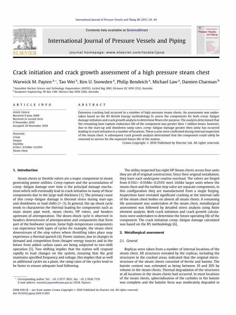
Cracking was found in number of steam chests (Fig. 1) andoccurred predominately at the bottom and top radius corners inboth the stop valve side and governor side of the steam chest.
Fig. 1. Example of cracking in bottom radii of the stop valve. Courtesy Brett LonneeAdelaide Inspection Service Pty Ltd PO Box 3063, Port Adelaide SA 5015.
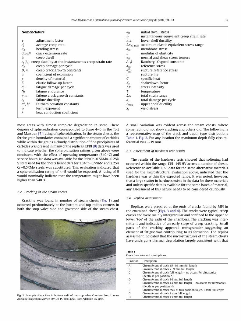
A small variation was evident across the steam chests, wheresome radii did not show cracking and others did. The following isa representative map of the crack and depth type distributionsTable 1, Fig. 2. For any location the maximum depth fully circum-ferential was w19 mm.
2.3. Assessment of hardness test results
The results of the hardness tests showed that softening hadoccurred within the range 135e145 HV across a number of chests.Reference to available EPRI data for the same alternative materialsused for the microstructural evaluation above, indicated that thehardness was within the expected range. It was noted, however,that a large scatter in hardness exists in the data for these materialsand unless specific data is available for the same batch of material,any assessment of this nature needs to be considered cautiously.
2.4. Replica assessment
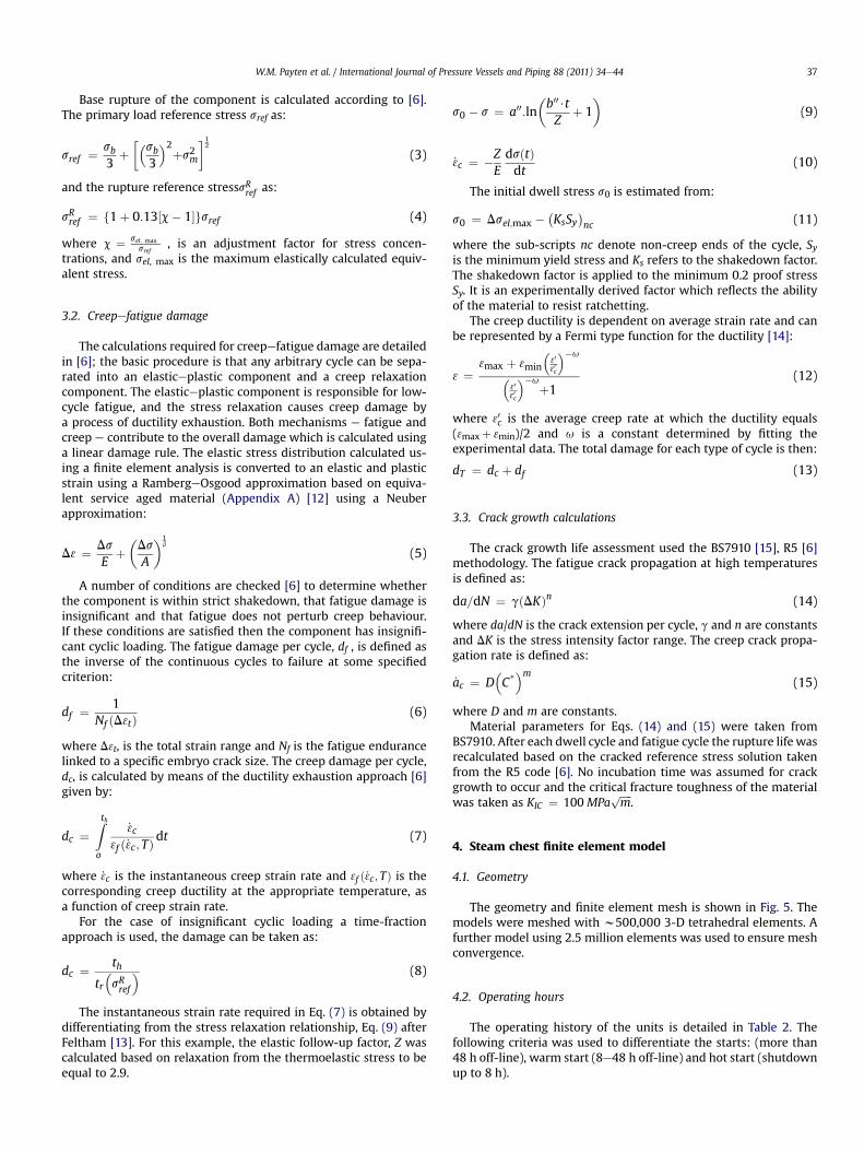
Replicas were prepared at the ends of cracks found by MPI inthe examined chest (Figs. 3 and 4). The cracks were typical creepcracks and were mainly intergranular and confined to the upper orlower ‘toe’ of the radii of the chambers. The cracking was inter-mittent and indicative of an early stage of creep cracking. Smallparts of the cracking appeared transgranular suggesting anelement of fatigue was contributing to its formation. The replicaassessment indicated that the microstructures of the steam chestshave undergone thermal degradation largely consistent with that
Table 1Crack locations and descriptions.
Position Description
A Circumferential crack 15e19 mm full lengthB Circumferential crack 7e9 mm full lengthC Circumferential crack full length e no access for ultrasonics
(depth as per position A)D Circumferential crack 14 mm full lengthE Circumferential crack 14 mm full length e no access for ultrasonics
(depth as per position H)F Circumferential crack max of two position taken, 6 mm full lengthG Circumferential crack 9 mm full lengthH Circumferential crack 14 mm full length
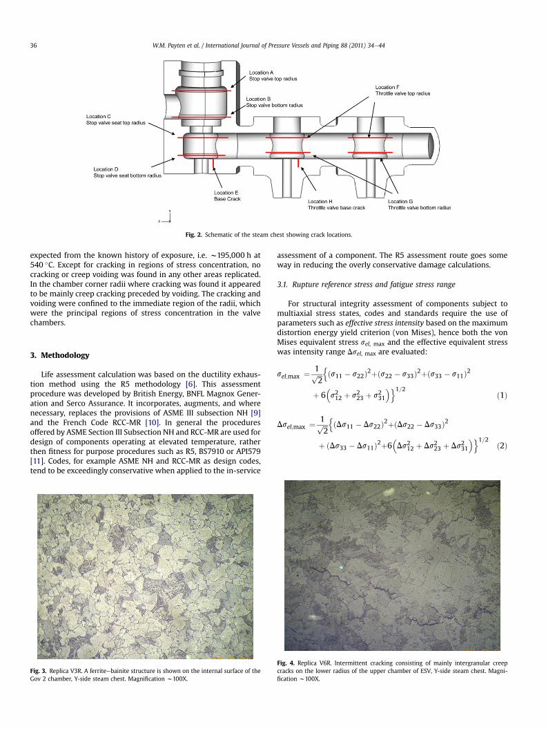
Fig. 2. Schematic of the steam chest showing crack locations.
W.M. Payten et al. / International Journal of Pressure Vessels and Piping 88 (2011) 34e4436
expected from the known history of exposure, i.e. w195,000 h at540 �C. Except for cracking in regions of stress concentration, nocracking or creep voiding was found in any other areas replicated.In the chamber corner radii where cracking was found it appearedto be mainly creep cracking preceded by voiding. The cracking andvoiding were confined to the immediate region of the radii, whichwere the principal regions of stress concentration in the valvechambers.
3. Methodology
Life assessment calculation was based on the ductility exhaus-tion method using the R5 methodology [6]. This assessmentprocedure was developed by British Energy, BNFL Magnox Gener-ation and Serco Assurance. It incorporates, augments, and wherenecessary, replaces the provisions of ASME III subsection NH [9]and the French Code RCC-MR [10]. In general the proceduresoffered by ASME Section III Subsection NH and RCC-MR are used fordesign of components operating at elevated temperature, ratherthen fitness for purpose procedures such as R5, BS7910 or API579[11]. Codes, for example ASME NH and RCC-MR as design codes,tend to be exceedingly conservative when applied to the in-service
Fig. 3. Replica V3R. A ferriteebainite structure is shown on the internal surface of theGov 2 chamber, Y-side steam chest. Magnification w100X.
assessment of a component. The R5 assessment route goes someway in reducing the overly conservative damage calculations.
3.1. Rupture reference stress and fatigue stress range
For structural integrity assessment of components subject tomultiaxial stress states, codes and standards require the use ofparameters such as effective stress intensity based on the maximumdistortion energy yield criterion (von Mises), hence both the vonMises equivalent stress sel, max and the effective equivalent stresswas intensity range Dsel, max are evaluated:
sel;max ¼ 1ffiffiffi2
pnðs11 � s22Þ2þðs22 � s33Þ2þðs33 � s11Þ2
þ 6�s212 þ s223 þ s231
�o1=2 ð1Þ
Dsel;max ¼ 1ffiffiffi2
pnðDs11 � Ds22Þ2þðDs22 � Ds33Þ2
þ ðDs33 � Ds11Þ2þ6�Ds212 þ Ds223 þ Ds231
�o1=2 ð2Þ
Fig. 4. Replica V6R. Intermittent cracking consisting of mainly intergranular creepcracks on the lower radius of the upper chamber of ESV, Y-side steam chest. Magni-fication w100X.
W.M. Payten et al. / International Journal of Pressure Vessels and Piping 88 (2011) 34e44 37
Base rupture of the component is calculated according to [6].The primary load reference stress sref as:
sref ¼ sb3
þ��sb
3
�2þs2m
�12
(3)
and the rupture reference stresssRref as:
sRref ¼ f1þ 0:13½c� 1�gsref (4)
where c ¼ sel; maxsref
, is an adjustment factor for stress concen-trations, and sel, max is the maximum elastically calculated equiv-alent stress.
3.2. Creepefatigue damage
The calculations required for creepefatigue damage are detailedin [6]; the basic procedure is that any arbitrary cycle can be sepa-rated into an elasticeplastic component and a creep relaxationcomponent. The elasticeplastic component is responsible for low-cycle fatigue, and the stress relaxation causes creep damage bya process of ductility exhaustion. Both mechanisms e fatigue andcreep e contribute to the overall damage which is calculated usinga linear damage rule. The elastic stress distribution calculated us-ing a finite element analysis is converted to an elastic and plasticstrain using a RambergeOsgood approximation based on equiva-lent service aged material (Appendix A) [12] using a Neuberapproximation:
D3 ¼ DsE
þ�DsA
�1b
(5)
A number of conditions are checked [6] to determine whetherthe component is within strict shakedown, that fatigue damage isinsignificant and that fatigue does not perturb creep behaviour.If these conditions are satisfied then the component has insignifi-cant cyclic loading. The fatigue damage per cycle, df , is defined asthe inverse of the continuous cycles to failure at some specifiedcriterion:
df ¼ 1Nf ðD3tÞ
(6)
where D3t, is the total strain range and Nf is the fatigue endurancelinked to a specific embryo crack size. The creep damage per cycle,dc, is calculated by means of the ductility exhaustion approach [6]given by:
dc ¼Ztho
_3c3f ð_3c; TÞ
dt (7)
where _3c is the instantaneous creep strain rate and 3f ð_3c; TÞ is thecorresponding creep ductility at the appropriate temperature, asa function of creep strain rate.
For the case of insignificant cyclic loading a time-fractionapproach is used, the damage can be taken as:
dc ¼ thtr�sRref
� (8)
The instantaneous strain rate required in Eq. (7) is obtained bydifferentiating from the stress relaxation relationship, Eq. (9) afterFeltham [13]. For this example, the elastic follow-up factor, Z wascalculated based on relaxation from the thermoelastic stress to beequal to 2.9.
s0 � s ¼ a00:ln�b00$tZ
þ 1�
(9)
_3c ¼ �ZEdsðtÞdt
(10)
The initial dwell stress s0 is estimated from:
s0 ¼ Dsel;max �KsSy
nc (11)
where the sub-scripts nc denote non-creep ends of the cycle, Syis the minimum yield stress and Ks refers to the shakedown factor.The shakedown factor is applied to the minimum 0.2 proof stressSy. It is an experimentally derived factor which reflects the abilityof the material to resist ratchetting.
The creep ductility is dependent on average strain rate and canbe represented by a Fermi type function for the ductility [14]:
3 ¼3max þ 3min
�3030c
��u
�3030c
��uþ1
(12)
where 30c is the average creep rate at which the ductility equals(3maxþ 3min)/2 and u is a constant determined by fitting theexperimental data. The total damage for each type of cycle is then:
dT ¼ dc þ df (13)
3.3. Crack growth calculations
The crack growth life assessment used the BS7910 [15], R5 [6]methodology. The fatigue crack propagation at high temperaturesis defined as:
da=dN ¼ gðDKÞn (14)
where da/dN is the crack extension per cycle, g and n are constantsand DK is the stress intensity factor range. The creep crack propa-gation rate is defined as:
_ac ¼ D�C*
�m(15)
where D and m are constants.Material parameters for Eqs. (14) and (15) were taken from
BS7910. After each dwell cycle and fatigue cycle the rupture life wasrecalculated based on the cracked reference stress solution takenfrom the R5 code [6]. No incubation time was assumed for crackgrowth to occur and the critical fracture toughness of the materialwas taken as KIC ¼ 100MPa
ffiffiffiffiffim
p.
4. Steam chest finite element model
4.1. Geometry
The geometry and finite element mesh is shown in Fig. 5. Themodels were meshed with w500,000 3-D tetrahedral elements. Afurther model using 2.5 million elements was used to ensure meshconvergence.
4.2. Operating hours
The operating history of the units is detailed in Table 2. Thefollowing criteria was used to differentiate the starts: (more than48 h off-line), warm start (8e48 h off-line) and hot start (shutdownup to 8 h).
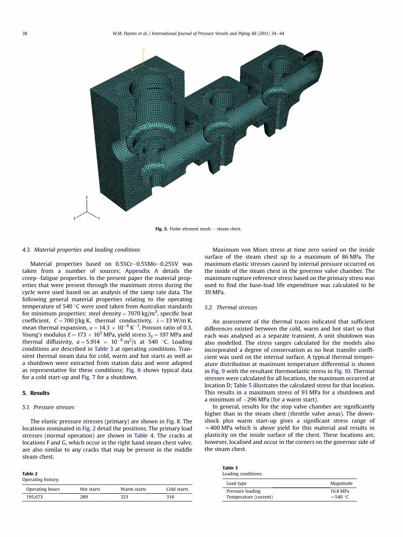
Fig. 5. Finite element mesh e steam chest.
W.M. Payten et al. / International Journal of Pressure Vessels and Piping 88 (2011) 34e4438
4.3. Material properties and loading conditions
Material properties based on 0.5%Cre0.5%Moe0.25%V wastaken from a number of sources; Appendix A details thecreepefatigue properties. In the present paper the material prop-erties that were present through the maximum stress during thecycle were used based on an analysis of the ramp rate data. Thefollowing general material properties relating to the operatingtemperature of 540 �C were used taken from Australian standardsfor minimum properties: steel density¼ 7970 kg/m3, specific heatcoefficient, C¼ 700 J/kg K, thermal conductivity, l¼ 33W/m K,mean thermal expansion, a¼ 14.3 � 10�6 K�1, Poisson ratio of 0.3,Young’s modulus E¼ 173 � 103 MPa, yield stress Sy¼ 197 MPa andthermal diffusivity, a¼ 5.914 � 10�6 m2/s at 540 �C. Loadingconditions are described in Table 3 at operating conditions. Tran-sient thermal steam data for cold, warm and hot starts as well asa shutdown were extracted from station data and were adoptedas representative for these conditions; Fig. 6 shows typical datafor a cold start-up and Fig. 7 for a shutdown.
5. Results
5.1. Pressure stresses
The elastic pressure stresses (primary) are shown in Fig. 8. Thelocations nominated in Fig. 2 detail the positions. The primary loadstresses (normal operation) are shown in Table 4. The cracks atlocations F and G, which occur in the right hand steam chest valve,are also similar to any cracks that may be present in the middlesteam chest.
Table 2Operating history.
Operating hours Hot starts Warm starts Cold starts
195,673 289 323 316
Maximum von Mises stress at time zero varied on the insidesurface of the steam chest up to a maximum of 86 MPa. Themaximum elastic stresses caused by internal pressure occurred onthe inside of the steam chest in the governor valve chamber. Themaximum rupture reference stress based on the primary stress wasused to find the base-load life expenditure was calculated to be39 MPa.
5.2. Thermal stresses
An assessment of the thermal traces indicated that sufficientdifferences existed between the cold, warm and hot start so thateach was analysed as a separate transient. A unit shutdown wasalso modelled. The stress ranges calculated for the models alsoincorporated a degree of conservatism as no heat transfer coeffi-cient was used on the internal surface. A typical thermal temper-ature distribution at maximum temperature differential is shownin Fig. 9 with the resultant thermoelastic stress in Fig. 10. Thermalstresses were calculated for all locations, the maximum occurred atlocation D; Table 5 illustrates the calculated stress for that location.This results in a maximum stress of 93 MPa for a shutdown anda minimum of �296 MPa (for a warm start).
In general, results for the stop valve chamber are significantlyhigher than in the steam chest (throttle valve areas). The down-shock plus warm start-up gives a significant stress range ofw400 MPa which is above yield for this material and results inplasticity on the inside surface of the chest. These locations are,however, localised and occur in the corners on the governor side ofthe steam chest.
Table 3Loading conditions.
Load type Magnitude
Pressure loading 16.8 MPaTemperature (current) w540 �C
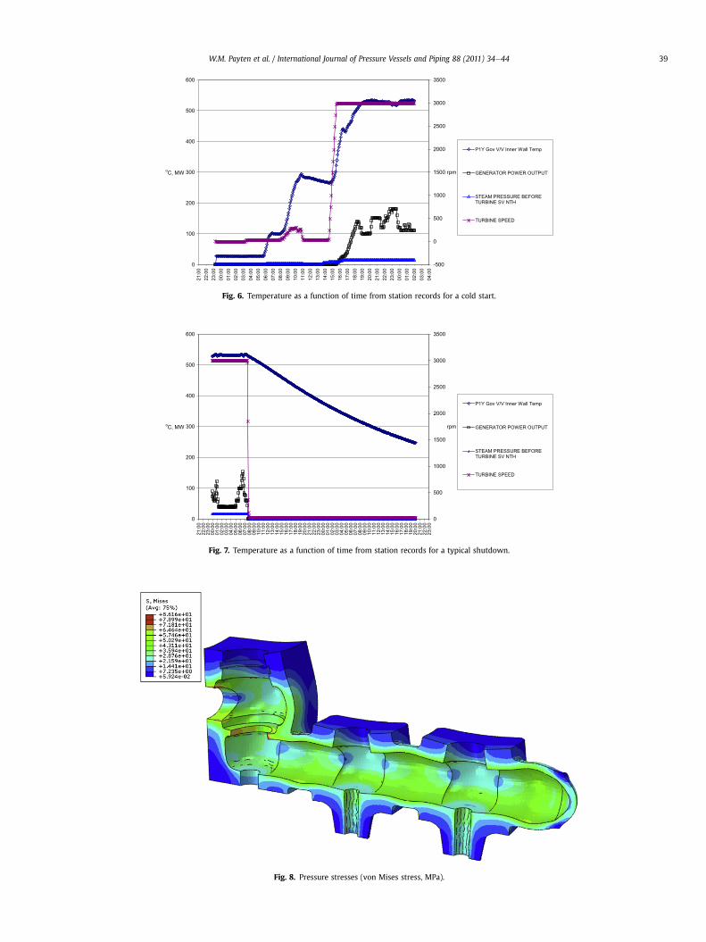
Fig. 6. Temperature as a function of time from station records for a cold start.
Fig. 7. Temperature as a function of time from station records for a typical shutdown.
Fig. 8. Pressure stresses (von Mises stress, MPa).
W.M. Payten et al. / International Journal of Pressure Vessels and Piping 88 (2011) 34e44 39
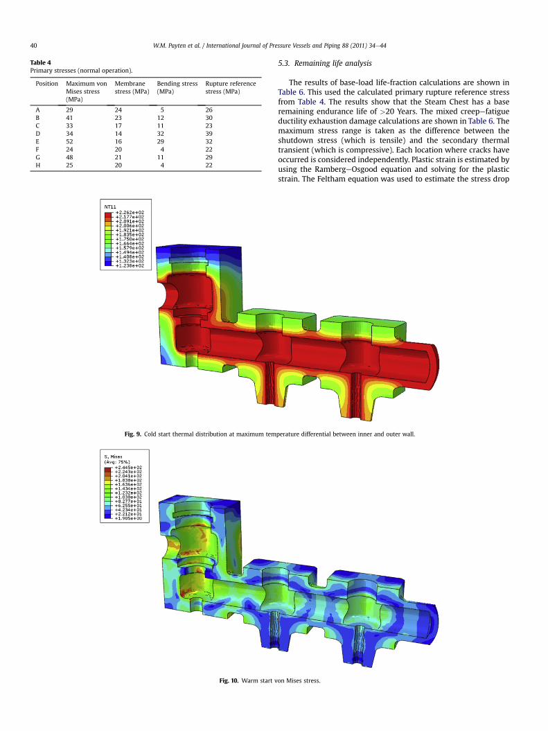
Table 4Primary stresses (normal operation).
Position Maximum vonMises stress(MPa)
Membranestress (MPa)
Bending stress(MPa)
Rupture referencestress (MPa)
A 29 24 5 26B 41 23 12 30C 33 17 11 23D 34 14 32 39E 52 16 29 32F 24 20 4 22G 48 21 11 29H 25 20 4 22
Fig. 9. Cold start thermal distribution at maximum tem
Fig. 10. Warm start v
W.M. Payten et al. / International Journal of Pressure Vessels and Piping 88 (2011) 34e4440
5.3. Remaining life analysis
The results of base-load life-fraction calculations are shown inTable 6. This used the calculated primary rupture reference stressfrom Table 4. The results show that the Steam Chest has a baseremaining endurance life of >20 Years. The mixed creepefatigueductility exhaustion damage calculations are shown in Table 6. Themaximum stress range is taken as the difference between theshutdown stress (which is tensile) and the secondary thermaltransient (which is compressive). Each location where cracks haveoccurred is considered independently. Plastic strain is estimated byusing the RambergeOsgood equation and solving for the plasticstrain. The Feltham equation was used to estimate the stress drop
perature differential between inner and outer wall.
on Mises stress.
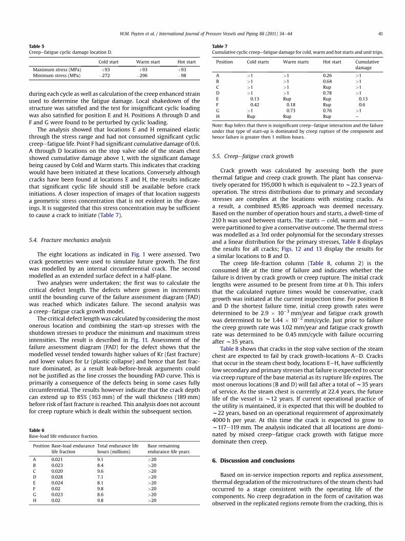
Table 5Creepefatigue cyclic damage location D.
Cold start Warm start Hot start
Maximum stress (MPa) þ93 þ93 þ93Minimum stress (MPa) �272 �296 �98
Table 7Cumulative cyclic creepefatigue damage for cold, warm and hot starts and unit trips.
Position Cold starts Warm starts Hot start Cumulativedamage
A >1 >1 0.26 >1B >1 >1 0.64 >1C >1 >1 Rup >1D >1 >1 0.78 >1E 0.13 Rup Rup 0.13F 0.42 0.18 Rup 0.6G >1 0.73 0.76 >1H Rup Rup Rup e
Note: Rup Infers that there is insignificant creepefatigue interaction and the failureunder that type of start-up is dominated by creep rupture of the component andhence failure is greater then 1 million hours.
W.M. Payten et al. / International Journal of Pressure Vessels and Piping 88 (2011) 34e44 41
during each cycle as well as calculation of the creep enhanced strainused to determine the fatigue damage. Local shakedown of thestructure was satisfied and the test for insignificant cyclic loadingwas also satisfied for position E and H. Positions A through D andF and G were found to be perturbed by cyclic loading.
The analysis showed that locations E and H remained elasticthrough the stress range and had not consumed significant cycliccreepefatigue life. Point F had significant cumulative damage of 0.6.A through D locations on the stop valve side of the steam chestshowed cumulative damage above 1, with the significant damagebeing caused by Cold and Warm starts. This indicates that crackingwould have been initiated at these locations. Conversely althoughcracks have been found at locations E and H, the results indicatethat significant cyclic life should still be available before crackinitiations. A closer inspection of images of that location suggestsa geometric stress concentration that is not evident in the draw-ings. It is suggested that this stress concentration may be sufficientto cause a crack to initiate (Table 7).
5.4. Fracture mechanics analysis
The eight locations as indicated in Fig. 1 were assessed. Twocrack geometries were used to simulate future growth. The firstwas modelled by an internal circumferential crack. The secondmodelled as an extended surface defect in a half-plane.
Two analyses were undertaken; the first was to calculate thecritical defect length. The defects where grown in incrementsuntil the bounding curve of the failure assessment diagram (FAD)was reached which indicates failure. The second analysis wasa creepefatigue crack growth model.
The critical defect lengthwas calculated by considering themostonerous location and combining the start-up stresses with theshutdown stresses to produce the minimum and maximum stressintensities. The result is described in Fig. 11. Assessment of thefailure assessment diagram (FAD) for the defect shows that themodelled vessel tended towards higher values of Kr (fast fracture)and lower values for Lr (plastic collapse) and hence that fast frac-ture dominated, as a result leak-before-break arguments couldnot be justified as the line crosses the bounding FAD curve. This isprimarily a consequence of the defects being in some cases fullycircumferential. The results however indicate that the crack depthcan extend up to 85% (163 mm) of the wall thickness (189 mm)before risk of fast fracture is reached. This analysis does not accountfor creep rupture which is dealt within the subsequent section.
Table 6Base-load life endurance fraction.
Position Base-load endurancelife fraction
Total endurance lifehours (millions)
Base remainingendurance life years
A 0.021 9.1 >20B 0.023 8.4 >20C 0.020 9.6 >20D 0.028 7.1 >20E 0.024 8.1 >20F 0.02 9.8 >20G 0.023 8.6 >20H 0.02 9.8 >20
5.5. Creepefatigue crack growth
Crack growth was calculated by assessing both the purethermal fatigue and creep crack growth. The plant has conserva-tively operated for 195,000 h which is equivalent tow22.3 years ofoperation. The stress distributions due to primary and secondarystresses are complex at the locations with existing cracks. Asa result, a combined R5/R6 approach was deemed necessary.Based on the number of operation hours and starts, a dwell-time of210 h was used between starts. The starts e cold, warm and hot ewere partitioned to give a conservative outcome. The thermal stresswas modelled as a 3rd order polynomial for the secondary stressesand a linear distribution for the primary stresses, Table 8 displaysthe results for all cracks; Figs. 12 and 13 display the results fora similar locations to B and D.
The creep life-fraction column (Table 8, column 2) is theconsumed life at the time of failure and indicates whether thefailure is driven by crack growth or creep rupture. The initial cracklengths were assumed to be present from time at 0 h. This infersthat the calculated rupture times would be conservative, crackgrowth was initiated at the current inspection time. For position Band D the shortest failure time, initial creep growth rates weredetermined to be 2.9 � 10�3 mm/year and fatigue crack growthwas determined to be 1.44 � 10�2 mm/cycle. Just prior to failurethe creep growth rate was 1.02 mm/year and fatigue crack growthrate was determined to be 0.45 mm/cycle with failure occurringafter w35 years.
Table 8 shows that cracks in the stop valve section of the steamchest are expected to fail by crack growth-locations AeD. Cracksthat occur in the steam chest body, locations EeH, have sufficientlylow secondary and primary stresses that failure is expected to occurvia creep rupture of the base material as its rupture life expires. Themost onerous locations (B and D) will fail after a total of w35 yearsof service. As the steam chest is currently at 22.4 years, the futurelife of the vessel is w12 years. If current operational practice ofthe utility is maintained, it is expected that this will be doubled tow22 years, based on an operational requirement of approximately4000 h per year. At this time the crack is expected to grow tow117e119 mm. The analysis indicated that all locations are domi-nated by mixed creepefatigue crack growth with fatigue moredominate then creep.
6. Discussion and conclusions
Based on in-service inspection reports and replica assessment,thermal degradation of the microstructures of the steam chests hadoccurred to a stage consistent with the operating life of thecomponents. No creep degradation in the form of cavitation wasobserved in the replicated regions remote from the cracking, this is
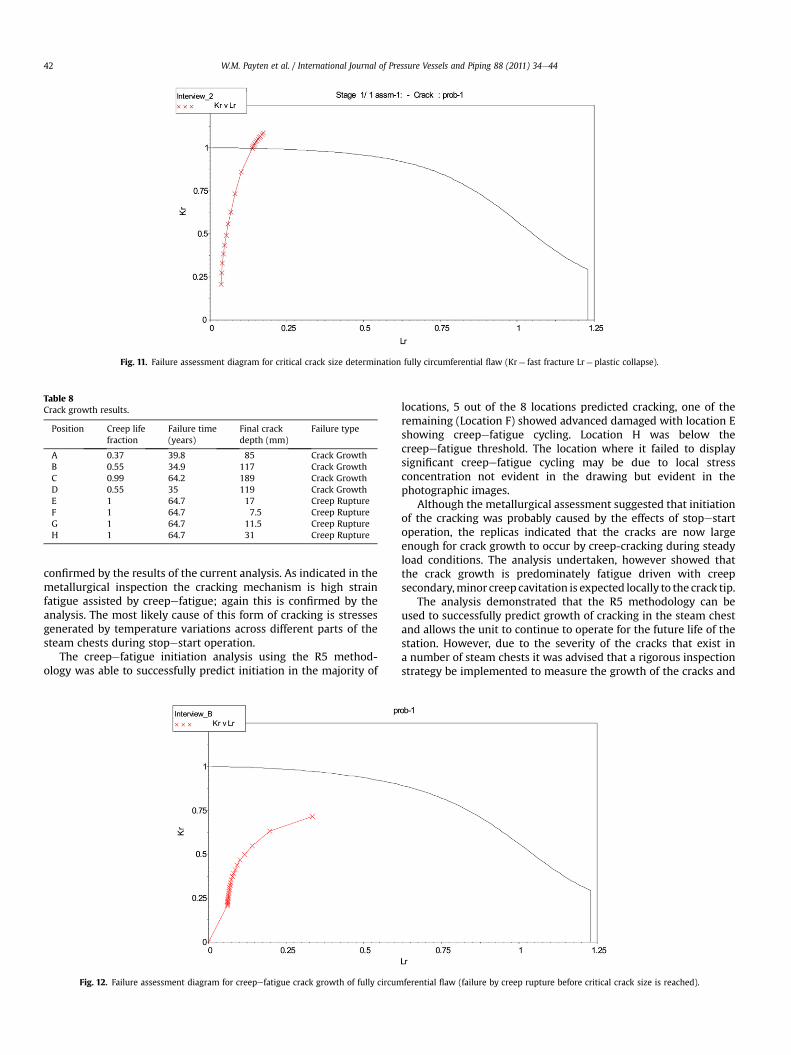
Fig. 11. Failure assessment diagram for critical crack size determination fully circumferential flaw (Kr¼ fast fracture Lr¼ plastic collapse).
Table 8Crack growth results.
Position Creep lifefraction
Failure time(years)
Final crackdepth (mm)
Failure type
A 0.37 39.8 85 Crack GrowthB 0.55 34.9 117 Crack GrowthC 0.99 64.2 189 Crack GrowthD 0.55 35 119 Crack GrowthE 1 64.7 17 Creep RuptureF 1 64.7 7.5 Creep RuptureG 1 64.7 11.5 Creep RuptureH 1 64.7 31 Creep Rupture
W.M. Payten et al. / International Journal of Pressure Vessels and Piping 88 (2011) 34e4442
confirmed by the results of the current analysis. As indicated in themetallurgical inspection the cracking mechanism is high strainfatigue assisted by creepefatigue; again this is confirmed by theanalysis. The most likely cause of this form of cracking is stressesgenerated by temperature variations across different parts of thesteam chests during stopestart operation.
The creepefatigue initiation analysis using the R5 method-ology was able to successfully predict initiation in the majority of
Fig. 12. Failure assessment diagram for creepefatigue crack growth of fully circum
locations, 5 out of the 8 locations predicted cracking, one of theremaining (Location F) showed advanced damaged with location Eshowing creepefatigue cycling. Location H was below thecreepefatigue threshold. The location where it failed to displaysignificant creepefatigue cycling may be due to local stressconcentration not evident in the drawing but evident in thephotographic images.
Although the metallurgical assessment suggested that initiationof the cracking was probably caused by the effects of stopestartoperation, the replicas indicated that the cracks are now largeenough for crack growth to occur by creep-cracking during steadyload conditions. The analysis undertaken, however showed thatthe crack growth is predominately fatigue driven with creepsecondary,minor creep cavitation is expected locally to the crack tip.
The analysis demonstrated that the R5 methodology can beused to successfully predict growth of cracking in the steam chestand allows the unit to continue to operate for the future life of thestation. However, due to the severity of the cracks that exist ina number of steam chests it was advised that a rigorous inspectionstrategy be implemented to measure the growth of the cracks and
ferential flaw (failure by creep rupture before critical crack size is reached).
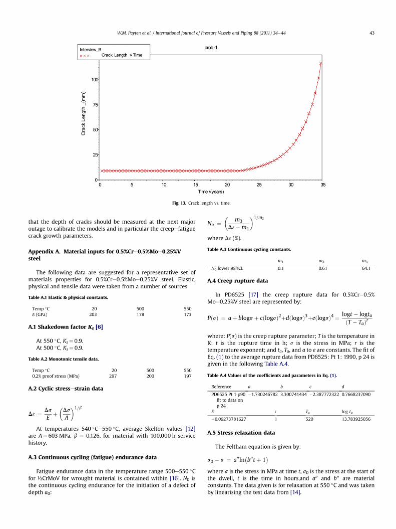
Fig. 13. Crack length vs. time.
Table A.3 Continuous cycling constants.
m1 m2 m3
N0 lower 98%CL 0.1 0.61 64.1
W.M. Payten et al. / International Journal of Pressure Vessels and Piping 88 (2011) 34e44 43
that the depth of cracks should be measured at the next majoroutage to calibrate the models and in particular the creepefatiguecrack growth parameters.
Appendix A. Material inputs for 0.5%Cre0.5%Moe0.25%Vsteel
The following data are suggested for a representative set ofmaterials properties for 0.5%Cre0.5%Moe0.25%V steel. Elastic,physical and tensile data were taken from a number of sources
Table A.1 Elastic & physical constants.
Temp �C 20 500 550E (GPa) 203 178 173
A.1 Shakedown factor Ks [6]
At 550 �C, Ks¼ 0.9.At 500 �C, Ks¼ 0.9.
Table A.2 Monotonic tensile data.
Temp �C 20 500 5500.2% proof stress (MPa) 297 200 197 Table A.4 Values of the coefficients and parameters in Eq. (1).
Reference a b c d
PD6525 Pt 1 p90fit to data onp 24
�1.730246782 3.300741434 �2.387772322 0.7668237090
E r Ta log ta
�0.09273781627 1 520 13.783925056
A.2 Cyclic stressestrain data
D3 ¼ DsE
þ�DsA
�1=b
At temperatures 540 �Ce550 �C, average Skelton values [12]are A¼ 603 MPa, b ¼ 0.126, for material with 100,000 h servicehistory.
A.3 Continuous cycling (fatigue) endurance data
Fatigue endurance data in the temperature range 500e550 �Cfor ½CrMoV for wrought material is contained within [16]. N0 isthe continuous cycling endurance for the initiation of a defect ofdepth a0:
No ¼ m3D3�m1
� �1=m2
where D3 (%).
A.4 Creep rupture data
In PD6525 [17] the creep rupture data for 0.5%Cre0.5%Moe0.25%V steel are represented by:
PðsÞ ¼ aþ blogsþ cðlogsÞ2þdðlogsÞ3þeðlogsÞ4 ¼ logt � logtaðT � TaÞr
where: P(s) is the creep rupture parameter; T is the temperature inK; t is the rupture time in h; s is the stress in MPa; r is thetemperature exponent; and ta, Ta, and a to e are constants. The fit ofEq. (1) to the average rupture data from PD6525: Pt 1: 1990, p 24 isgiven in the following Table A.4.
A.5 Stress relaxation data
The Feltham equation is given by:
s0 � s ¼ a00lnb00t þ 1
where s is the stress in MPa at time t, s0 is the stress at the start ofthe dwell, t is the time in hours,and a00 and b00 are materialconstants. The data given is for relaxation at 550 �C and was takenby linearising the test data from [14].
W.M. Payten et al. / International Journal of Pressure Vessels and Piping 88 (2011) 34e4444
b00 ¼ 3600 h�1
a00 ¼ 1:73� 10�4s20 þ 0:013s0
A.6 Creep ductility data
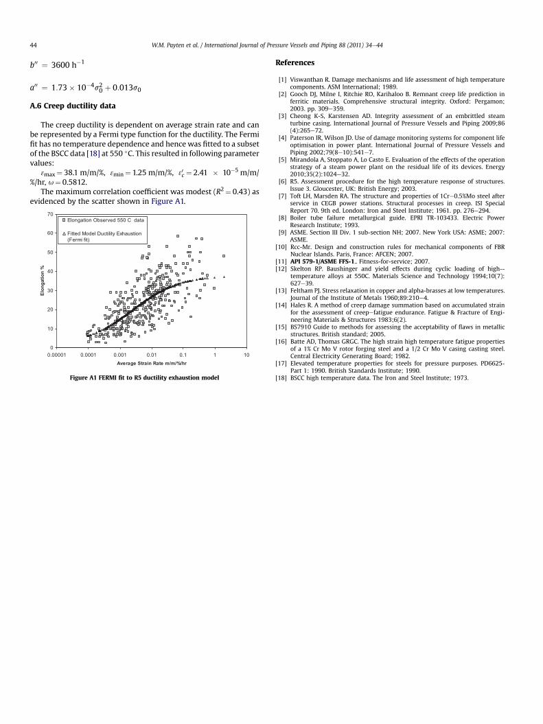
The creep ductility is dependent on average strain rate and canbe represented by a Fermi type function for the ductility. The Fermifit has no temperature dependence and hence was fitted to a subsetof the BSCC data [18] at 550 �C. This resulted in following parametervalues:
3max¼ 38.1 m/m/%, 3min¼ 1.25 m/m/%, 30c ¼ 2.41 � 10�5 m/m/%/hr, u¼ 0.5812.
The maximum correlation coefficient was modest (R2¼ 0.43) asevidenced by the scatter shown in Figure A1.
0
10
20
30
40
50
60
70
0.00001 0.0001 0.001 0.01 0.1 1 10Average Strain Rate m/m/%/hr
Elo
ng
atio
n %
Elongation Observed 550 C data
Fitted Model Ductility Exhaustion(Fermi fit)
Figure A1 FERMI fit to R5 ductility exhaustion model
References
[1] Viswanthan R. Damage mechanisms and life assessment of high temperaturecomponents. ASM International; 1989.
[2] Gooch DJ, Milne I, Ritchie RO, Karihaloo B. Remnant creep life prediction inferritic materials. Comprehensive structural integrity. Oxford: Pergamon;2003. pp. 309e359.
[3] Cheong K-S, Karstensen AD. Integrity assessment of an embrittled steamturbine casing. International Journal of Pressure Vessels and Piping 2009;86(4):265e72.
[4] Paterson IR, Wilson JD. Use of damage monitoring systems for component lifeoptimisation in power plant. International Journal of Pressure Vessels andPiping 2002;79(8e10):541e7.
[5] Mirandola A, Stoppato A, Lo Casto E. Evaluation of the effects of the operationstrategy of a steam power plant on the residual life of its devices. Energy2010;35(2):1024e32.
[6] R5. Assessment procedure for the high temperature response of structures.Issue 3. Gloucester, UK: British Energy; 2003.
[7] Toft LH, Marsden RA. The structure and properties of 1Cre0.5%Mo steel afterservice in CEGB power stations. Structural processes in creep. ISI SpecialReport 70. 9th ed. London: Iron and Steel Institute; 1961. pp. 276e294.
[8] Boiler tube failure metallurgical guide. EPRI TR-103433. Electric PowerResearch Institute; 1993.
[9] ASME. Section III Div. 1 sub-section NH; 2007. New York USA: ASME; 2007:ASME.
[10] Rcc-Mr. Design and construction rules for mechanical components of FBRNuclear Islands. Paris, France: AFCEN; 2007.
[11] API 579-1/ASME FFS-1.. Fitness-for-service; 2007.[12] Skelton RP. Baushinger and yield effects during cyclic loading of high--
temperature alloys at 550C. Materials Science and Technology 1994;10(7):627e39.
[13] Feltham PJ. Stress relaxation in copper and alpha-brasses at low temperatures.Journal of the Institute of Metals 1960;89:210e4.
[14] Hales R. A method of creep damage summation based on accumulated strainfor the assessment of creepefatigue endurance. Fatigue & Fracture of Engi-neering Materials & Structures 1983;6(2).
[15] BS7910 Guide to methods for assessing the acceptability of flaws in metallicstructures. British standard; 2005.
[16] Batte AD, Thomas GRGC. The high strain high temperature fatigue propertiesof a 1% Cr Mo V rotor forging steel and a 1/2 Cr Mo V casing casting steel.Central Electricity Generating Board; 1982.
[17] Elevated temperature properties for steels for pressure purposes. PD6625-Part 1: 1990. British Standards Institute; 1990.
[18] BSCC high temperature data. The Iron and Steel Institute; 1973.


