Embed Size (px)
Citation preview
Design Manual for Roads and Bridges
Highway Structures & BridgesInspection & Assessment
CS 458The assessment of highway bridges andstructures for the effects of special typegeneral order (STGO) and special order (SO)vehicles(formerly BD 86/11)
Revision 0
SummaryThis document contains the requirements for the assessment of highway bridges and structuresto determine the effects of special type general order (STGO) and special order (SO) vehicles.
Application by Overseeing OrganisationsAny specific requirements for Overseeing Organisations alternative or supplementary to those given in this documentare given in National Application Annexes to this document.
Feedback and EnquiriesUsers of this document are encouraged to raise any enquiries and/or provide feedback on the content and usageof this document to the dedicated Highways England team. The email address for all enquiries and feedback is:[email protected]
This is a controlled document.
CS 458 Revision 0 Contents
Contents
Release notes 3
Foreword 4Publishing information . . . . . . . . . . . . . . . . . . . . . . . . . . . . . . . . . . . . . . . . . . . . . . . . 4Contractual and legal considerations . . . . . . . . . . . . . . . . . . . . . . . . . . . . . . . . . . . . . . . . 4
Introduction 5Background . . . . . . . . . . . . . . . . . . . . . . . . . . . . . . . . . . . . . . . . . . . . . . . . . . . . . . 5Assumptions made in the preparation of this document . . . . . . . . . . . . . . . . . . . . . . . . . . . . . 5
Abbreviations and symbols 6
Terms and definitions 8
1. Scope 10Aspects covered . . . . . . . . . . . . . . . . . . . . . . . . . . . . . . . . . . . . . . . . . . . . . . . . . . . 10Implementation . . . . . . . . . . . . . . . . . . . . . . . . . . . . . . . . . . . . . . . . . . . . . . . . . . . . 10Use of GG 101 . . . . . . . . . . . . . . . . . . . . . . . . . . . . . . . . . . . . . . . . . . . . . . . . . . . . 10
2. Assessment processes and basis of assessment 11Structural review . . . . . . . . . . . . . . . . . . . . . . . . . . . . . . . . . . . . . . . . . . . . . . . . . . . 11Basis of assessment . . . . . . . . . . . . . . . . . . . . . . . . . . . . . . . . . . . . . . . . . . . . . . . . . 11
3. Assessment actions 12General . . . . . . . . . . . . . . . . . . . . . . . . . . . . . . . . . . . . . . . . . . . . . . . . . . . . . . . . 12
Carriageway widths and lanes . . . . . . . . . . . . . . . . . . . . . . . . . . . . . . . . . . . . . . . . 12Assessment of STGO vehicles using SV load models . . . . . . . . . . . . . . . . . . . . . . . . . . . . . . 12
Wheel arrangements and tyre contact patch dimensions for SV load models . . . . . . . . . . . . . . . 12SV 80 . . . . . . . . . . . . . . . . . . . . . . . . . . . . . . . . . . . . . . . . . . . . . . . . . . . . . . 12SV 100 . . . . . . . . . . . . . . . . . . . . . . . . . . . . . . . . . . . . . . . . . . . . . . . . . . . . . 13SV 150 . . . . . . . . . . . . . . . . . . . . . . . . . . . . . . . . . . . . . . . . . . . . . . . . . . . . . 14SV 196 . . . . . . . . . . . . . . . . . . . . . . . . . . . . . . . . . . . . . . . . . . . . . . . . . . . . . 15SV-TT . . . . . . . . . . . . . . . . . . . . . . . . . . . . . . . . . . . . . . . . . . . . . . . . . . . . . . 16
Assessment of SO vehicles using SOV load models . . . . . . . . . . . . . . . . . . . . . . . . . . . . . . . 17SOV-250 . . . . . . . . . . . . . . . . . . . . . . . . . . . . . . . . . . . . . . . . . . . . . . . . . . . . 18SOV-350 . . . . . . . . . . . . . . . . . . . . . . . . . . . . . . . . . . . . . . . . . . . . . . . . . . . . 18SOV-450 . . . . . . . . . . . . . . . . . . . . . . . . . . . . . . . . . . . . . . . . . . . . . . . . . . . . 19SOV-600 . . . . . . . . . . . . . . . . . . . . . . . . . . . . . . . . . . . . . . . . . . . . . . . . . . . . 19Lateral wheel arrangement and tyre contact patch dimensions for SOV load models . . . . . . . . . . 19
. . . . . . . . . . . . . . . . . . . . . . . . . . . . . . . . . . . . . . . . . . . . . . . . . . . . . . . . . . . . . 20Assessment for STGO and SO vehicles outside the scope of SV and SOV load models . . . . . . . . . . . 20Application of SV and SOV and real STGO/SO load models . . . . . . . . . . . . . . . . . . . . . . . . . . . 20
Overload factor (OF) . . . . . . . . . . . . . . . . . . . . . . . . . . . . . . . . . . . . . . . . . . . . . . 21Dynamic amplification factor (DAF) . . . . . . . . . . . . . . . . . . . . . . . . . . . . . . . . . . . . . . 21Dispersal of wheel loads . . . . . . . . . . . . . . . . . . . . . . . . . . . . . . . . . . . . . . . . . . . . 22Wheel contact areas for real STGO or SO vehicles . . . . . . . . . . . . . . . . . . . . . . . . . . . . . 22
Associated live loading . . . . . . . . . . . . . . . . . . . . . . . . . . . . . . . . . . . . . . . . . . . . . . . 22Application of load models . . . . . . . . . . . . . . . . . . . . . . . . . . . . . . . . . . . . . . . . . . . . . 22Longitudinal traffic loading for SV or SOV load models and real STGO or SO vehicles . . . . . . . . . . . . 25
Braking loads for SV or SOV load models . . . . . . . . . . . . . . . . . . . . . . . . . . . . . . . . . . 25Braking loads for real STGO or SO real vehicle load models . . . . . . . . . . . . . . . . . . . . . . . . 26Traction loads for SV load models . . . . . . . . . . . . . . . . . . . . . . . . . . . . . . . . . . . . . . 26Traction loads for SOV or real SO or STGO load models . . . . . . . . . . . . . . . . . . . . . . . . . . 26
Centrifugal effects . . . . . . . . . . . . . . . . . . . . . . . . . . . . . . . . . . . . . . . . . . . . . . . . . . 26Masonry arches . . . . . . . . . . . . . . . . . . . . . . . . . . . . . . . . . . . . . . . . . . . . . . . . . . . 27Buried structures . . . . . . . . . . . . . . . . . . . . . . . . . . . . . . . . . . . . . . . . . . . . . . . . . . . 27
1
CS 458 Revision 0 Contents
Reserve factors . . . . . . . . . . . . . . . . . . . . . . . . . . . . . . . . . . . . . . . . . . . . . . . . . . . . 27Vehicle rating . . . . . . . . . . . . . . . . . . . . . . . . . . . . . . . . . . . . . . . . . . . . . . . . . . . . . 27
4. Normative references 28
5. Informative references 29
Appendix A. Type HB to SV conversion charts 30A1 General . . . . . . . . . . . . . . . . . . . . . . . . . . . . . . . . . . . . . . . . . . . . . . . . . . . . . . 30A2 Reserve factor . . . . . . . . . . . . . . . . . . . . . . . . . . . . . . . . . . . . . . . . . . . . . . . . . . 30A3 Conversion charts . . . . . . . . . . . . . . . . . . . . . . . . . . . . . . . . . . . . . . . . . . . . . . . . 30
A3.1 Influence lines . . . . . . . . . . . . . . . . . . . . . . . . . . . . . . . . . . . . . . . . . . . . . . 31A4 Conversion charts limitations . . . . . . . . . . . . . . . . . . . . . . . . . . . . . . . . . . . . . . . . . . 37
Appendix B. Management of STGO vehicle movements 38B1 General . . . . . . . . . . . . . . . . . . . . . . . . . . . . . . . . . . . . . . . . . . . . . . . . . . . . . . 38B2 Screening assessment . . . . . . . . . . . . . . . . . . . . . . . . . . . . . . . . . . . . . . . . . . . . . . 38
B2.1 Screening assessment limitations . . . . . . . . . . . . . . . . . . . . . . . . . . . . . . . . . . . . 39B3 Detailed assessment . . . . . . . . . . . . . . . . . . . . . . . . . . . . . . . . . . . . . . . . . . . . . . . 40
B3.1 Reduction in dynamic amplification factor . . . . . . . . . . . . . . . . . . . . . . . . . . . . . . . 41B3.2 Reduction in associated ALL . . . . . . . . . . . . . . . . . . . . . . . . . . . . . . . . . . . . . . 41B3.3 Reduction in overload factor (OF) . . . . . . . . . . . . . . . . . . . . . . . . . . . . . . . . . . . . 42
B4 Vehicle assessment . . . . . . . . . . . . . . . . . . . . . . . . . . . . . . . . . . . . . . . . . . . . . . . 43
2
CS 458 Revision 0 Release notes
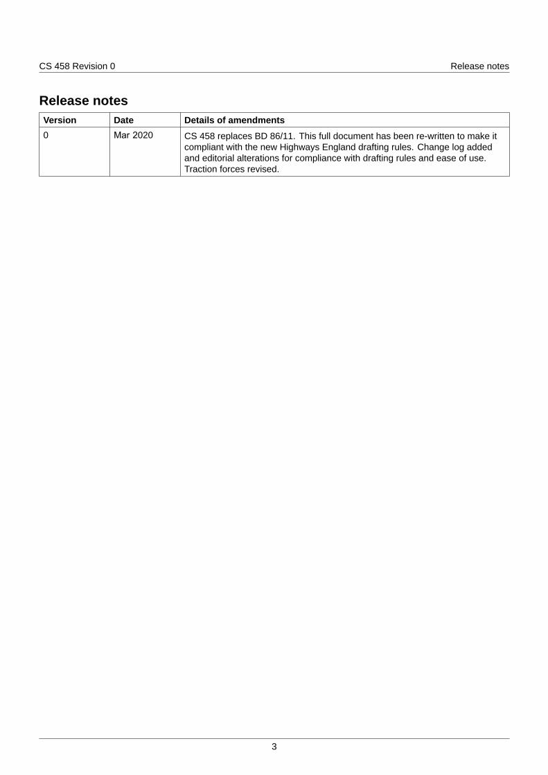
Release notesVersion Date Details of amendments0 Mar 2020 CS 458 replaces BD 86/11. This full document has been re-written to make it
compliant with the new Highways England drafting rules. Change log addedand editorial alterations for compliance with drafting rules and ease of use.Traction forces revised.
3

CS 458 Revision 0 Foreword
Foreword
Publishing informationThis document is published by Highways England.
This document supersedes BD 86/11, which is withdrawn.
Contractual and legal considerationsThis document forms part of the works specification. It does not purport to include all the necessaryprovisions of a contract. Users are responsible for applying all appropriate documents applicable totheir contract.
4
CS 458 Revision 0 Introduction
Introduction
BackgroundThe use of this document enables the effects of special type general order (STGO) and special order(SO) vehicles to be determined for use in the assessment of structural safety and serviceability ofhighway bridges and structures. This document provides key information that is required to managerisks associated with STGO and SO vehicles, and maintain a safe and operational network.
Assumptions made in the preparation of this documentThe assumptions made in GG 101 [Ref 2.N] apply to this document.
5
CS 458 Revision 0 Abbreviations and symbols
Abbreviations and symbols
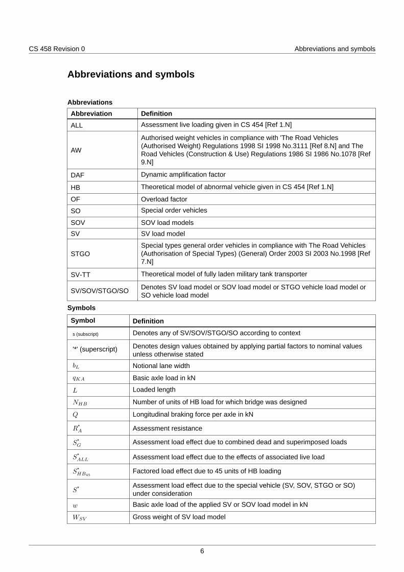
AbbreviationsAbbreviation Definition
ALL Assessment live loading given in CS 454 [Ref 1.N]
AW
Authorised weight vehicles in compliance with 'The Road Vehicles(Authorised Weight) Regulations 1998 SI 1998 No.3111 [Ref 8.N] and TheRoad Vehicles (Construction & Use) Regulations 1986 SI 1986 No.1078 [Ref9.N]
DAF Dynamic amplification factor
HB Theoretical model of abnormal vehicle given in CS 454 [Ref 1.N]
OF Overload factor
SO Special order vehicles
SOV SOV load models
SV SV load model
STGOSpecial types general order vehicles in compliance with The Road Vehicles(Authorisation of Special Types) (General) Order 2003 SI 2003 No.1998 [Ref7.N]
SV-TT Theoretical model of fully laden military tank transporter
SV/SOV/STGO/SO Denotes SV load model or SOV load model or STGO vehicle load model orSO vehicle load model
Symbols
Symbol Definition
s (subscript) Denotes any of SV/SOV/STGO/SO according to context
'*' (superscript) Denotes design values obtained by applying partial factors to nominal valuesunless otherwise stated
bL Notional lane width
qKA Basic axle load in kN
L Loaded length
NHB Number of units of HB load for which bridge was designed
Q Longitudinal braking force per axle in kN
R*A Assessment resistance
S*G
Assessment load effect due to combined dead and superimposed loads
S*ALL Assessment load effect due to the effects of associated live load
S*HB45
Factored load effect due to 45 units of HB loading
S* Assessment load effect due to the special vehicle (SV, SOV, STGO or SO)under consideration
w Basic axle load of the applied SV or SOV load model in kN
WSV Gross weight of SV load model
6
CS 458 Revision 0 Abbreviations and symbols
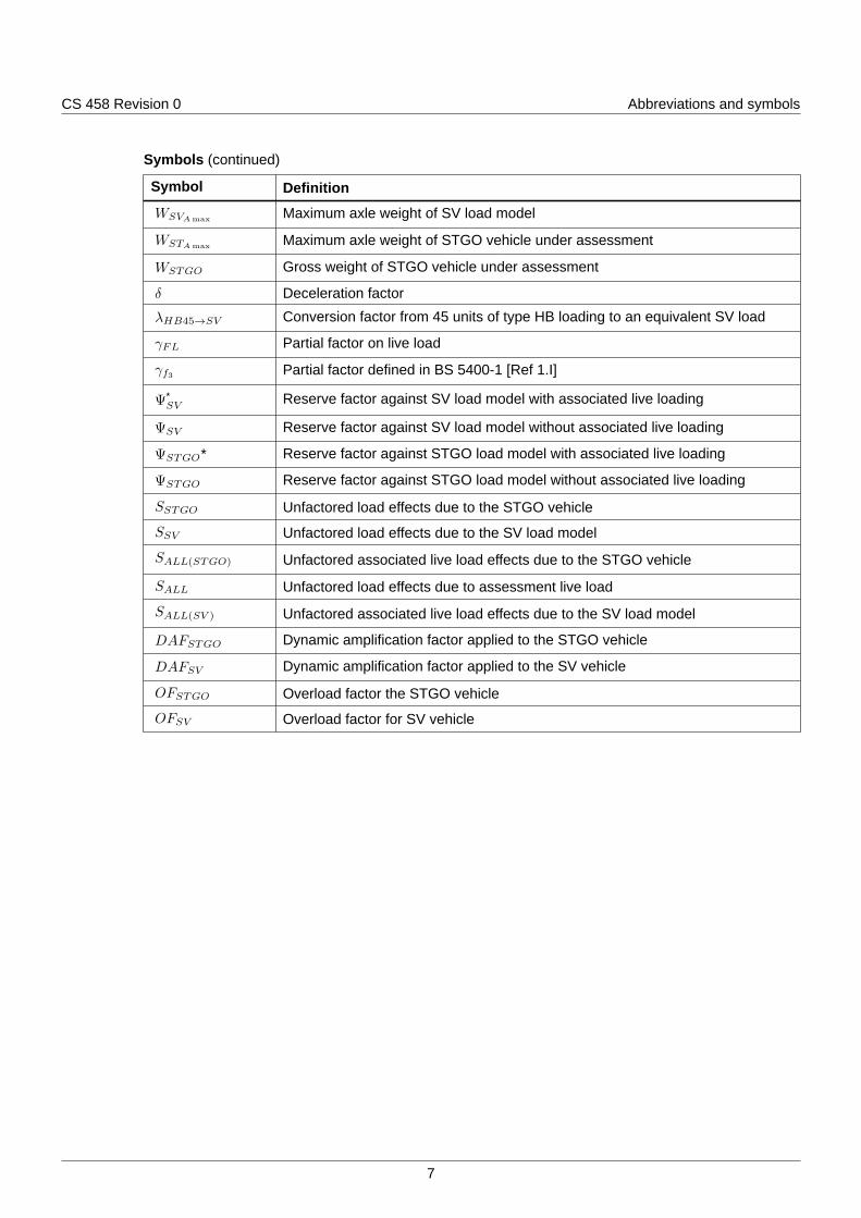
Symbols (continued)
Symbol Definition
WSVAmax Maximum axle weight of SV load model
WSTAmax Maximum axle weight of STGO vehicle under assessment
WSTGO Gross weight of STGO vehicle under assessment
δ Deceleration factor
λHB45→SV Conversion factor from 45 units of type HB loading to an equivalent SV load
γFL Partial factor on live load
γf3 Partial factor defined in BS 5400-1 [Ref 1.I]
Ψ*SV
Reserve factor against SV load model with associated live loading
ΨSV Reserve factor against SV load model without associated live loading
ΨSTGO* Reserve factor against STGO load model with associated live loading
ΨSTGO Reserve factor against STGO load model without associated live loading
SSTGO Unfactored load effects due to the STGO vehicle
SSV Unfactored load effects due to the SV load model
SALL(STGO) Unfactored associated live load effects due to the STGO vehicle
SALL Unfactored load effects due to assessment live load
SALL(SV ) Unfactored associated live load effects due to the SV load model
DAFSTGO Dynamic amplification factor applied to the STGO vehicle
DAFSV Dynamic amplification factor applied to the SV vehicle
OFSTGO Overload factor the STGO vehicle
OFSV Overload factor for SV vehicle
7
CS 458 Revision 0 Terms and definitions
Terms and definitions
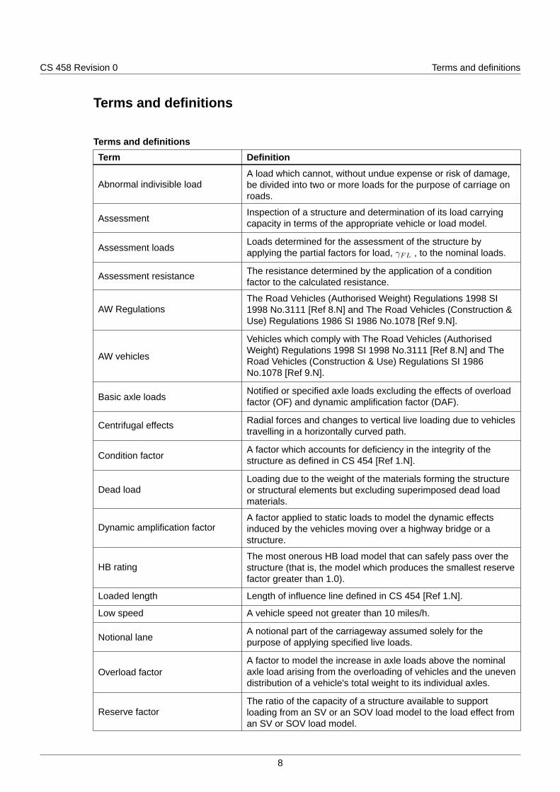
Terms and definitionsTerm Definition
Abnormal indivisible loadA load which cannot, without undue expense or risk of damage,be divided into two or more loads for the purpose of carriage onroads.
AssessmentInspection of a structure and determination of its load carryingcapacity in terms of the appropriate vehicle or load model.
Assessment loadsLoads determined for the assessment of the structure byapplying the partial factors for load, γFL , to the nominal loads.
Assessment resistance The resistance determined by the application of a conditionfactor to the calculated resistance.
AW RegulationsThe Road Vehicles (Authorised Weight) Regulations 1998 SI1998 No.3111 [Ref 8.N] and The Road Vehicles (Construction &Use) Regulations 1986 SI 1986 No.1078 [Ref 9.N].
AW vehicles
Vehicles which comply with The Road Vehicles (AuthorisedWeight) Regulations 1998 SI 1998 No.3111 [Ref 8.N] and TheRoad Vehicles (Construction & Use) Regulations SI 1986No.1078 [Ref 9.N].
Basic axle loadsNotified or specified axle loads excluding the effects of overloadfactor (OF) and dynamic amplification factor (DAF).
Centrifugal effects Radial forces and changes to vertical live loading due to vehiclestravelling in a horizontally curved path.
Condition factorA factor which accounts for deficiency in the integrity of thestructure as defined in CS 454 [Ref 1.N].
Dead loadLoading due to the weight of the materials forming the structureor structural elements but excluding superimposed dead loadmaterials.
Dynamic amplification factorA factor applied to static loads to model the dynamic effectsinduced by the vehicles moving over a highway bridge or astructure.
HB ratingThe most onerous HB load model that can safely pass over thestructure (that is, the model which produces the smallest reservefactor greater than 1.0).
Loaded length Length of influence line defined in CS 454 [Ref 1.N].
Low speed A vehicle speed not greater than 10 miles/h.
Notional laneA notional part of the carriageway assumed solely for thepurpose of applying specified live loads.
Overload factorA factor to model the increase in axle loads above the nominalaxle load arising from the overloading of vehicles and the unevendistribution of a vehicle's total weight to its individual axles.
Reserve factorThe ratio of the capacity of a structure available to supportloading from an SV or an SOV load model to the load effect froman SV or SOV load model.
8
CS 458 Revision 0 Terms and definitions
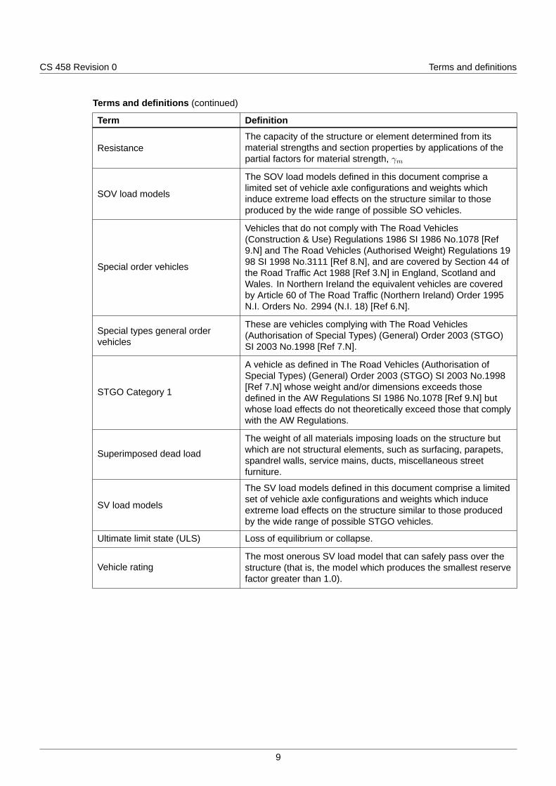
Terms and definitions (continued)
Term Definition
ResistanceThe capacity of the structure or element determined from itsmaterial strengths and section properties by applications of thepartial factors for material strength, γm
SOV load models
The SOV load models defined in this document comprise alimited set of vehicle axle configurations and weights whichinduce extreme load effects on the structure similar to thoseproduced by the wide range of possible SO vehicles.
Special order vehicles
Vehicles that do not comply with The Road Vehicles(Construction & Use) Regulations 1986 SI 1986 No.1078 [Ref9.N] and The Road Vehicles (Authorised Weight) Regulations 1998 SI 1998 No.3111 [Ref 8.N], and are covered by Section 44 ofthe Road Traffic Act 1988 [Ref 3.N] in England, Scotland andWales. In Northern Ireland the equivalent vehicles are coveredby Article 60 of The Road Traffic (Northern Ireland) Order 1995N.I. Orders No. 2994 (N.I. 18) [Ref 6.N].
Special types general ordervehicles
These are vehicles complying with The Road Vehicles(Authorisation of Special Types) (General) Order 2003 (STGO)SI 2003 No.1998 [Ref 7.N].
STGO Category 1
A vehicle as defined in The Road Vehicles (Authorisation ofSpecial Types) (General) Order 2003 (STGO) SI 2003 No.1998[Ref 7.N] whose weight and/or dimensions exceeds thosedefined in the AW Regulations SI 1986 No.1078 [Ref 9.N] butwhose load effects do not theoretically exceed those that complywith the AW Regulations.
Superimposed dead load
The weight of all materials imposing loads on the structure butwhich are not structural elements, such as surfacing, parapets,spandrel walls, service mains, ducts, miscellaneous streetfurniture.
SV load models
The SV load models defined in this document comprise a limitedset of vehicle axle configurations and weights which induceextreme load effects on the structure similar to those producedby the wide range of possible STGO vehicles.
Ultimate limit state (ULS) Loss of equilibrium or collapse.
Vehicle ratingThe most onerous SV load model that can safely pass over thestructure (that is, the model which produces the smallest reservefactor greater than 1.0).
9
CS 458 Revision 0 1. Scope
1. Scope
Aspects covered1.1 This document shall be used for the assessment of highway bridges and structures to determine the
effects of special type general order (STGO) and special order (SO) vehicles.
1.2 The effects of theoretical load models to represent STGO and SO vehicles shall be used to determinethe vehicle ratings and reserve factors for highway bridges and structures.
1.3 The effects of STGO and SO vehicles shall be determined in combination with the effects of permanentactions and with associated live loading to represent the effects of authorised weight (AW) vehicles.
1.4 This document shall not be used for the design of strengthening schemes for highway structures.
1.5 This document shall not be used for the assessment of retaining walls, abutments and wing walls.
NOTE This document applies to the assessment of bridges constructed of steel, concrete, wrought and castiron, timber, stone slab bridge decks, spandrel walls and buried structures.
Implementation1.6 This document shall be implemented forthwith on all schemes involving the assessment of highway
bridges and structures on the Overseeing Organisations' motorway and all-purpose trunk roadsaccording to the implementation requirements of GG 101 [Ref 2.N].
Use of GG 1011.7 The requirements contained in GG 101 [Ref 2.N] shall be followed in respect of activities covered by
this document.
10
CS 458 Revision 0 2. Assessment processes and basis of assessment
2. Assessment processes and basis of assessment
Structural review2.1 The need for an assessment to include the effects of STGO and SO vehicles shall be identified through
the structural review process in accordance with CS 451 [Ref 4.N].
Basis of assessment2.2 The basis of assessment shall be in accordance with CS 454 [Ref 1.N].
NOTE The basis of assessment includes the following:
1) method of assessment;2) limit states;3) partial factors;4) assessment actions;5) assessment action effects;6) assessment resistance;7) verification.
11
CS 458 Revision 0 3. Assessment actions
3. Assessment actions
General3.1 Unless real vehicles are defined for the standard types general order (STGO) and special order (SO)
vehicle assessment, the SV and SOV load models in this document shall be used to determine theeffects of STGO and SO vehicles respectively.
NOTE 1 The SV load models represent vehicles with different axle configurations and weights that can induceextreme load effects on the structure in a similar manner to STGO vehicles.
NOTE 2 The SOV load models represent vehicles with different axle configurations and weights that can induceextreme load effects on the structure in a similar manner to SO vehicles.
NOTE 3 An STGO real vehicle model can be employed to represent a real STGO vehicle.
NOTE 4 An SO real vehicle model can be employed to represent a real SO vehicle.
3.1.1 Where a bridge has an HB rating, the conversion charts Figure A.7 to Figure A.12 in Appendix A maybe used to obtain reserve factors against SV load models if full assessment to the requirements of thisdocument is not undertaken.
Carriageway widths and lanes
3.2 The carriageway width shall be derived in accordance with CS 454 [Ref 1.N].
3.3 The carriageway shall be divided into a number of notional lanes in accordance with CS 454 [Ref 1.N].
Assessment of STGO vehicles using SV load models3.4 Where an assessment for STGO vehicles is undertaken, the assessment of the structure shall be
carried out for all SV load models that can physically fit within the bridge.
3.5 Assessment live loading (ALL) in accordance with CS 454 [Ref 1.N] shall be employed to assess forthe effects of STGO Category 1 vehicles with a maximum gross vehicle weight of 46 tonnes.
3.6 The SV load models representing the different categories of STGO vehicles shall be taken from thefollowing:
1) SV 80;
2) SV 100;
3) SV 150;
4) SV 196;
5) SV-TT.
NOTE 1 For loaded lengths less than 5m, the SV-TT load model is generally most onerous.
NOTE 2 For loaded lengths between 5m and 10m, the SV 100 load model is generally most onerous.
NOTE 3 For loaded lengths over 10m, the SV 196 load model is generally most onerous.
Wheel arrangements and tyre contact patch dimensions for SV load models
3.7 The axle, wheel loads and spaces and tyre contact patch dimensions shall be obtained from Figure 3.8to Figure 3.16.
SV 80
3.8 The SV 80 load model shown in Figure 3.8 shall be used to model the effects of STGO Category 2vehicles.
12
CS 458 Revision 0 3. Assessment actions
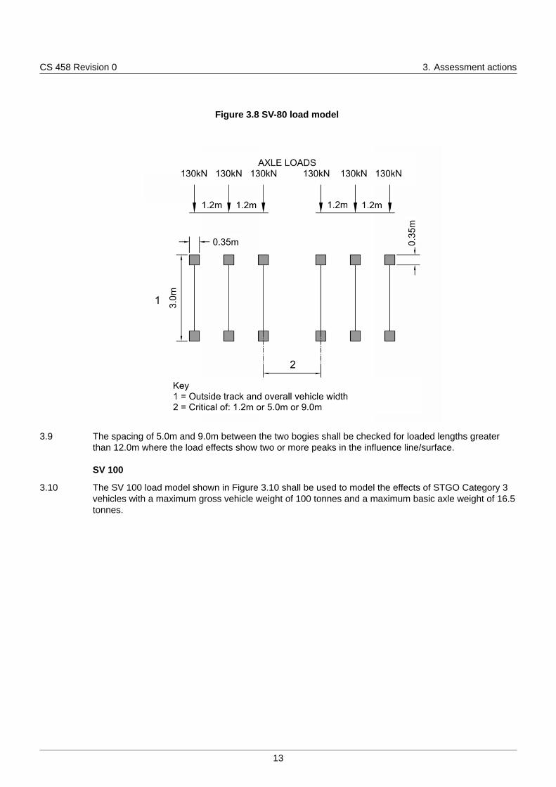
Figure 3.8 SV-80 load model
3.9 The spacing of 5.0m and 9.0m between the two bogies shall be checked for loaded lengths greaterthan 12.0m where the load effects show two or more peaks in the influence line/surface.
SV 100
3.10 The SV 100 load model shown in Figure 3.10 shall be used to model the effects of STGO Category 3vehicles with a maximum gross vehicle weight of 100 tonnes and a maximum basic axle weight of 16.5tonnes.
13
CS 458 Revision 0 3. Assessment actions
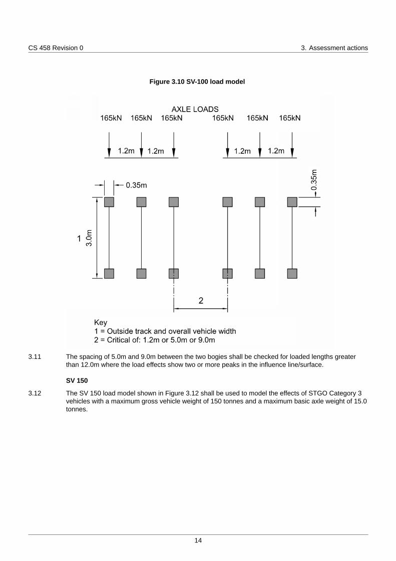
Figure 3.10 SV-100 load model
3.11 The spacing of 5.0m and 9.0m between the two bogies shall be checked for loaded lengths greaterthan 12.0m where the load effects show two or more peaks in the influence line/surface.
SV 150
3.12 The SV 150 load model shown in Figure 3.12 shall be used to model the effects of STGO Category 3vehicles with a maximum gross vehicle weight of 150 tonnes and a maximum basic axle weight of 15.0tonnes.
14
CS 458 Revision 0 3. Assessment actions
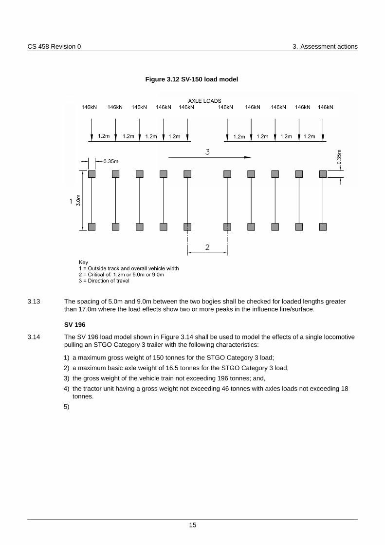
Figure 3.12 SV-150 load model
3.13 The spacing of 5.0m and 9.0m between the two bogies shall be checked for loaded lengths greaterthan 17.0m where the load effects show two or more peaks in the influence line/surface.
SV 196
3.14 The SV 196 load model shown in Figure 3.14 shall be used to model the effects of a single locomotivepulling an STGO Category 3 trailer with the following characteristics:
1) a maximum gross weight of 150 tonnes for the STGO Category 3 load;
2) a maximum basic axle weight of 16.5 tonnes for the STGO Category 3 load;
3) the gross weight of the vehicle train not exceeding 196 tonnes; and,
4) the tractor unit having a gross weight not exceeding 46 tonnes with axles loads not exceeding 18tonnes.
5)
15
CS 458 Revision 0 3. Assessment actions
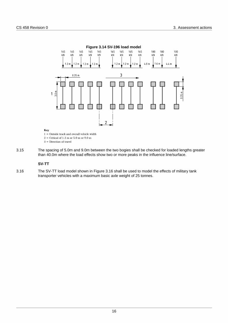
Figure 3.14 SV-196 load model
3.15 The spacing of 5.0m and 9.0m between the two bogies shall be checked for loaded lengths greaterthan 40.0m where the load effects show two or more peaks in the influence line/surface.
SV-TT
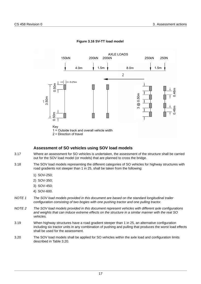
3.16 The SV-TT load model shown in Figure 3.16 shall be used to model the effects of military tanktransporter vehicles with a maximum basic axle weight of 25 tonnes.
16
CS 458 Revision 0 3. Assessment actions
Figure 3.16 SV-TT load model
Assessment of SO vehicles using SOV load models3.17 Where an assessment for SO vehicles is undertaken, the assessment of the structure shall be carried
out for the SOV load model (or models) that are planned to cross the bridge.
3.18 The SOV load models representing the different categories of SO vehicles for highway structures withroad gradients not steeper than 1 in 25, shall be taken from the following:
1) SOV-250;
2) SOV-350;
3) SOV-450;
4) SOV-600.
NOTE 1 The SOV load models provided in this document are based on the standard longitudinal trailerconfiguration consisting of two bogies with one pushing tractor and one pulling tractor.
NOTE 2 The SOV load models provided in this document represent vehicles with different axle configurationsand weights that can induce extreme effects on the structure in a similar manner with the real SOvehicles.
3.19 When highway structures have a road gradient steeper than 1 in 25, an alternative configurationincluding six tractor units in any combination of pushing and pulling that produces the worst load effectsshall be used for the assessment.
3.20 The SOV load models shall be applied for SO vehicles within the axle load and configuration limitsdescribed in Table 3.20.
17
CS 458 Revision 0 3. Assessment actions
Table 3.20 SO vehicles axle load and configuration limits
Configuration parameter Limiting value
Tractor
Maximum weight of the front axle in a 4-axle tractor 10 tonne
Maximum weight of any of the rear three axles in a 4-axle tractor or any axle in a3-axle trailer
16.5 tonne
Minimum spacing between 1st and 2nd axle 1.85 m
Minimum spacing between 2nd and 3rd axle in a 4-axle trailer 1.35 m
Minimum spacing between two rear axles 1.35 m
Trailer
Maximum axle weight 22.5 tonne
Minimum spacing between trailer axles 1.5 m
Minimum spacing between the rear axle of the tractor and the front axle of thetrailer (or rear axle of trailer and front axle of tractor) 5.0 m
Minimum spacing between the two trailer units 40.0 m
Minimum outside track of trailer axles 2.75 m
SOV-250
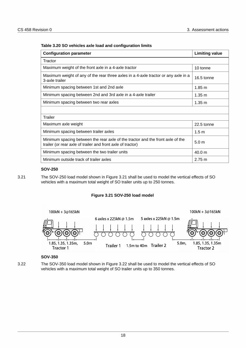
3.21 The SOV-250 load model shown in Figure 3.21 shall be used to model the vertical effects of SOvehicles with a maximum total weight of SO trailer units up to 250 tonnes.
Figure 3.21 SOV-250 load model
SOV-350
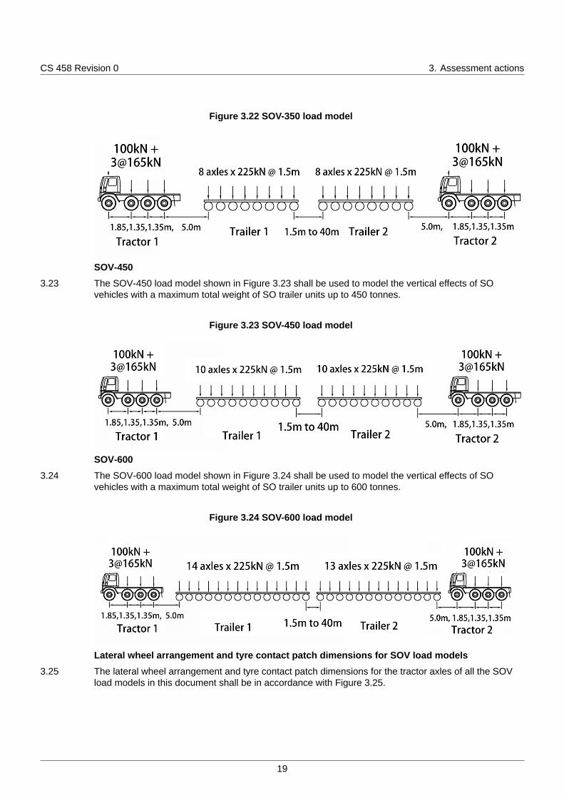
3.22 The SOV-350 load model shown in Figure 3.22 shall be used to model the vertical effects of SOvehicles with a maximum total weight of SO trailer units up to 350 tonnes.
18
CS 458 Revision 0 3. Assessment actions
Figure 3.22 SOV-350 load model
SOV-450
3.23 The SOV-450 load model shown in Figure 3.23 shall be used to model the vertical effects of SOvehicles with a maximum total weight of SO trailer units up to 450 tonnes.
Figure 3.23 SOV-450 load model
SOV-600
3.24 The SOV-600 load model shown in Figure 3.24 shall be used to model the vertical effects of SOvehicles with a maximum total weight of SO trailer units up to 600 tonnes.
Figure 3.24 SOV-600 load model
Lateral wheel arrangement and tyre contact patch dimensions for SOV load models
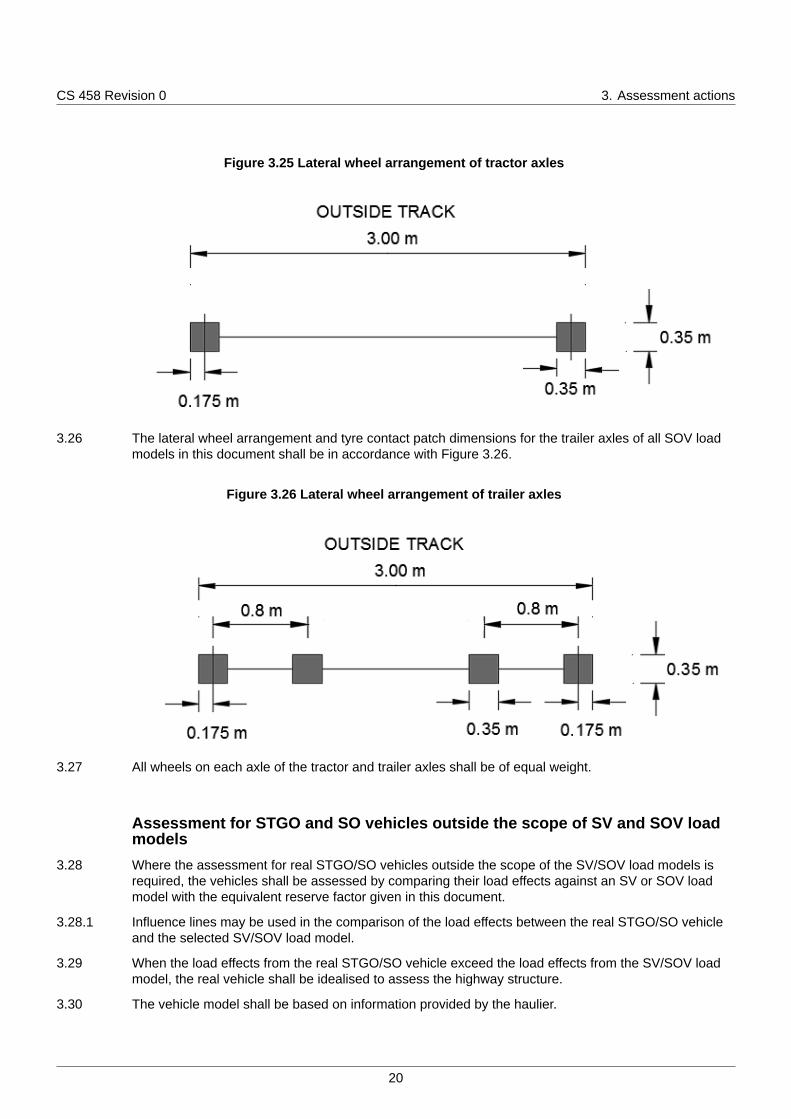
3.25 The lateral wheel arrangement and tyre contact patch dimensions for the tractor axles of all the SOVload models in this document shall be in accordance with Figure 3.25.
19
CS 458 Revision 0 3. Assessment actions
Figure 3.25 Lateral wheel arrangement of tractor axles
3.26 The lateral wheel arrangement and tyre contact patch dimensions for the trailer axles of all SOV loadmodels in this document shall be in accordance with Figure 3.26.
Figure 3.26 Lateral wheel arrangement of trailer axles
3.27 All wheels on each axle of the tractor and trailer axles shall be of equal weight.
Assessment for STGO and SO vehicles outside the scope of SV and SOV loadmodels
3.28 Where the assessment for real STGO/SO vehicles outside the scope of the SV/SOV load models isrequired, the vehicles shall be assessed by comparing their load effects against an SV or SOV loadmodel with the equivalent reserve factor given in this document.
3.28.1 Influence lines may be used in the comparison of the load effects between the real STGO/SO vehicleand the selected SV/SOV load model.
3.29 When the load effects from the real STGO/SO vehicle exceed the load effects from the SV/SOV loadmodel, the real vehicle shall be idealised to assess the highway structure.
3.30 The vehicle model shall be based on information provided by the haulier.
20
CS 458 Revision 0 3. Assessment actions
Application of SV and SOV and real STGO/SO load models3.31 The SV/SOV/STGO/SO load models shall be applied in conjunction with the following:
1) overload factor (OF);
2) dynamic amplification factor (DAF);
3) associated live loading.
3.32 The following loads shall not be applied:
1) accidental wheel loading;
2) footway loading.
Overload factor (OF)
3.33 The overload factor (OF) shall be taken as the following:
1) 1.2 for the worst critical axle;
2) 1.1 for all other axles.
NOTE 1 Overload factor models the excess gross weight and axle weight of the load model due to uneven loaddistribution between axles and overloading of the STGO vehicle.
NOTE 2 Further details of overload factors are given in Appendix B.
Dynamic amplification factor (DAF)
3.34 For the assessment of traffic travelling at normal speed, a dynamic amplification factor (DAF) shall beapplied to each axle of the load model.
NOTE Appendix B includes guidance on the management of STGO travelling at low speed.
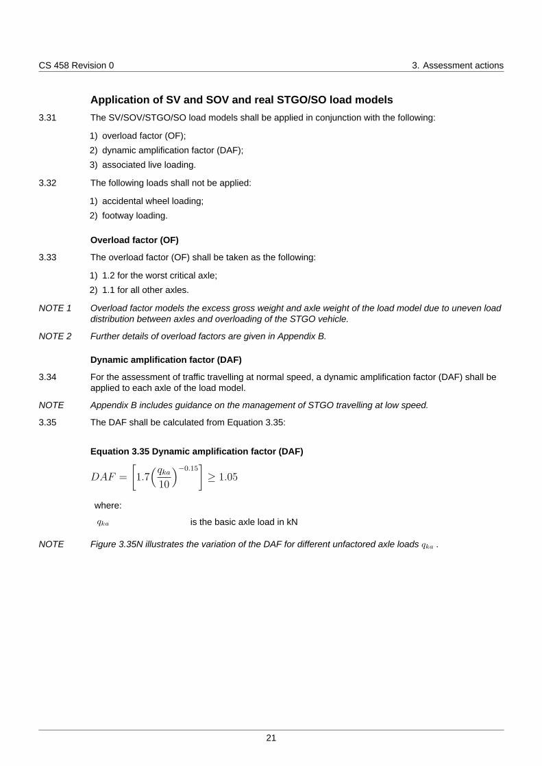
3.35 The DAF shall be calculated from Equation 3.35:
Equation 3.35 Dynamic amplification factor (DAF)
DAF =
[1.7
(qka10
)−0.15]≥ 1.05
where:
qka is the basic axle load in kN
NOTE Figure 3.35N illustrates the variation of the DAF for different unfactored axle loads qka .
21
CS 458 Revision 0 3. Assessment actions
Figure 3.35N Variation of the DAF for different unfactored axle loads
Dispersal of wheel loads
3.36 The dispersal of wheel loads through surfacing, fill, deck and other materials on the structure shall bedetermined in accordance with CS 454 [Ref 1.N].
Wheel contact areas for real STGO or SO vehicles
3.37 Where no information for the wheel contact areas of real STGO or SO vehicles is available, the wheelloads shall be distributed over a contact area of 0.35m x 0.35m.
Associated live loading3.38 An associated live load shall be applied in conjunction with the SV or SOV load models or real STGO or
SO vehicle models unless management procedures prevent such loads from occurring.
3.39 The associated live load shall be as defined by the assessment live loading (ALL) in accordance withCS 454 [Ref 1.N].
NOTE 1 ALL is usually required in association with the SV and STGO models because STGO vehiclescommonly travel without escort.
NOTE 2 ALL is not usually required in association with the SOV and SO models because SO vehicles areusually heavily managed.
3.40 Separate assessments for single wheel or single axle shall not be undertaken for the effects of the ALL.
Application of load models3.41 The design load effects shall be determined from the maximum of two cases:
1) SV/SOV/STGO/SO load model moving at normal speed;
2) SV/SOV/STGO/SO load model moving at low speed.
3.42 Only one SV/SOV/STGO/SO load model shall be applied on any one superstructure.
22
CS 458 Revision 0 3. Assessment actions
3.43 The SV/SOV/STGO/SO load model shall be placed at the most unfavourable position of thesuperstructure to produce the most onerous load effects at the section being assessed.
3.44 Associated live loading, including the lane factors appropriate to that loading, shall be applied on theremaining lanes not occupied by the SV/SOV/STGO/SO load model.
3.45 No knife-edge load component of any associated live loading shall be applied at the notional lanewhere the SV/SOV/STGO/SO load model is located.
3.46 The magnitude of the associated live loading at the notional lane where the SV/SOV/STGO/SO loadmodel is located shall be based on the total loaded length of the adverse notional lanes without anyreduction due to the presence of the SV/SOV/STGO/SO load model.
3.47 The lane factors shall be those for the ALL defined in CS 454 [Ref 1.N].
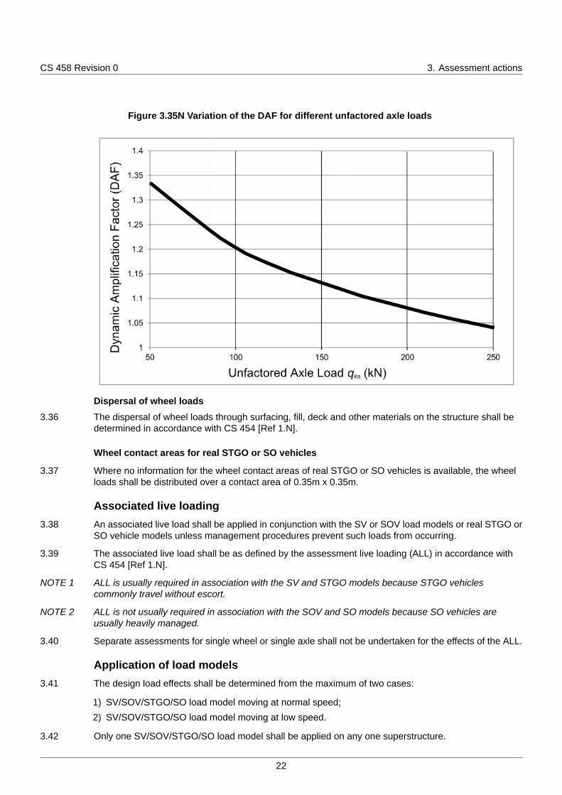
3.48 Where the SV/SOV/STGO/SO load model moves at normal speed, ALL (see Figure 3.48) shall not beapplied at the same notional lane within a 25m distance from the centre of outer front and outer rearaxles of the SV/SOV/STGO/SO load model.
Figure 3.48 Application of ALL UDL with SV/SOV/STGO/SO load model for vehicle atnormal speed, where the SV/SOV/STGO/SO load model lies entirely within the
notional lane.
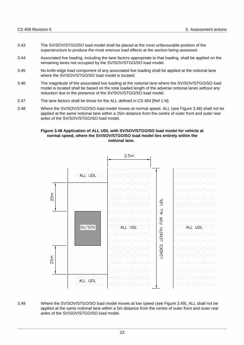
3.49 Where the SV/SOV/STGO/SO load model moves at low speed (see Figure 3.49), ALL shall not beapplied at the same notional lane within a 5m distance from the centre of outer front and outer rearaxles of the SV/SOV/STGO/SO load model.
23
CS 458 Revision 0 3. Assessment actions
Figure 3.49 Application of ALL UDL with SV/SOV/STGO/SO load model for vehicle atlow speed, where the SV/SOV/STGO/SO load model lies entirely within the notional
lane
3.50 Where the SV/SOV/STGO/SO load model straddles between two adjacent lanes, ALL shall not beapplied on the remaining widths of the lanes where the SV/SOV/STGO/SO load model is located if theremaining width between the SV/SOV/STGO/SO load model and the edge of the notional lane is lessthan 2.5m (see Figure 3.50).
24
CS 458 Revision 0 3. Assessment actions
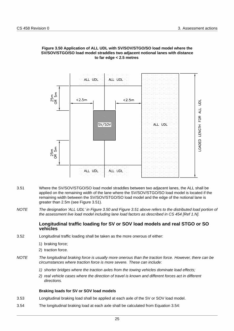
Figure 3.50 Application of ALL UDL with SV/SOV/STGO/SO load model where theSV/SOV/STGO/SO load model straddles two adjacent notional lanes with distance
to far edge < 2.5 metres
3.51 Where the SV/SOV/STGO/SO load model straddles between two adjacent lanes, the ALL shall beapplied on the remaining width of the lane where the SV/SOV/STGO/SO load model is located if theremaining width between the SV/SOV/STGO/SO load model and the edge of the notional lane isgreater than 2.5m (see Figure 3.51).
NOTE The designation 'ALL UDL' in Figure 3.50 and Figure 3.51 above refers to the distributed load portion ofthe assessment live load model including lane load factors as described in CS 454 [Ref 1.N].
Longitudinal traffic loading for SV or SOV load models and real STGO or SOvehicles
3.52 Longitudinal traffic loading shall be taken as the more onerous of either:
1) braking force;
2) traction force.
NOTE The longitudinal braking force is usually more onerous than the traction force. However, there can becircumstances where traction force is more severe. These can include:
1) shorter bridges where the traction axles from the towing vehicles dominate load effects;2) real vehicle cases where the direction of travel is known and different forces act in different
directions.
Braking loads for SV or SOV load models
3.53 Longitudinal braking load shall be applied at each axle of the SV or SOV load model.
3.54 The longitudinal braking load at each axle shall be calculated from Equation 3.54:
25
CS 458 Revision 0 3. Assessment actions
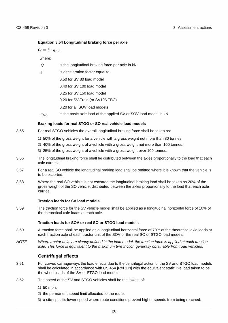
Equation 3.54 Longitudinal braking force per axle
Q = δ · qKA
where:
Q is the longitudinal braking force per axle in kN
δ is deceleration factor equal to:
0.50 for SV 80 load model
0.40 for SV 100 load model
0.25 for SV 150 load model
0.20 for SV-Train (or SV196 TBC)
0.20 for all SOV load models
qKA is the basic axle load of the applied SV or SOV load model in kN
Braking loads for real STGO or SO real vehicle load models
3.55 For real STGO vehicles the overall longitudinal braking force shall be taken as:
1) 50% of the gross weight for a vehicle with a gross weight not more than 80 tonnes;
2) 40% of the gross weight of a vehicle with a gross weight not more than 100 tonnes;
3) 25% of the gross weight of a vehicle with a gross weight over 100 tonnes.
3.56 The longitudinal braking force shall be distributed between the axles proportionally to the load that eachaxle carries.
3.57 For a real SO vehicle the longitudinal braking load shall be omitted where it is known that the vehicle isto be escorted.
3.58 Where the real SO vehicle is not escorted the longitudinal braking load shall be taken as 20% of thegross weight of the SO vehicle, distributed between the axles proportionally to the load that each axlecarries.
Traction loads for SV load models
3.59 The traction force for the SV vehicle model shall be applied as a longitudinal horizontal force of 10% ofthe theoretical axle loads at each axle.
Traction loads for SOV or real SO or STGO load models
3.60 A traction force shall be applied as a longitudinal horizontal force of 70% of the theoretical axle loads ateach traction axle of each tractor unit of the SOV or the real SO or STGO load models.
NOTE Where tractor units are clearly defined in the load model, the traction force is applied at each tractionaxle. This force is equivalent to the maximum tyre friction generally obtainable from road vehicles.
Centrifugal effects3.61 For curved carriageways the load effects due to the centrifugal action of the SV and STGO load models
shall be calculated in accordance with CS 454 [Ref 1.N] with the equivalent static live load taken to bethe wheel loads of the SV or STGO load models.
3.62 The speed of the SV and STGO vehicles shall be the lowest of:
1) 50 mph;
2) the permanent speed limit allocated to the route;
3) a site-specific lower speed where route conditions prevent higher speeds from being reached.
26
CS 458 Revision 0 3. Assessment actions
3.63 The centrifugal effects of the SOV load models shall be omitted.
Masonry arches3.64 The MEXE method shall not be employed to assess the effects of special vehicle types on masonry
arch bridges.
3.65 Where lift-off can occur and the SV/SOV/STGO/SO vehicles are travelling at normal speed, lift-offfactors shall be applied to the three adjacent axles causing the most severe load effects in accordancewith the method described for three-axle bogies in CS 454 [Ref 1.N].
3.66 No lift-off factor shall be applied to any other axles.
NOTE 1 Lift-off can occur at the axle of a SV/SOV/STGO/SO load model where the half of the masonry arch isloaded with three or more axles while the rest is unloaded.
NOTE 2 Lift-off factors are not applied for the low speed case.
3.67 Actions representing the ALL for masonry arches shall be applied in accordance with CS 454 [Ref 1.N].
Buried structures3.68 Buried structures with a cover greater than 0.6m shall be assessed in accordance with the
requirements of CS 454 [Ref 1.N] and CS 459 [Ref 5.N].
Reserve factors3.69 A reserve factor shall be established for each SV, SOV, STGO and SO load model.
3.70 The reserve factors shall be calculated from Equation 3.70.
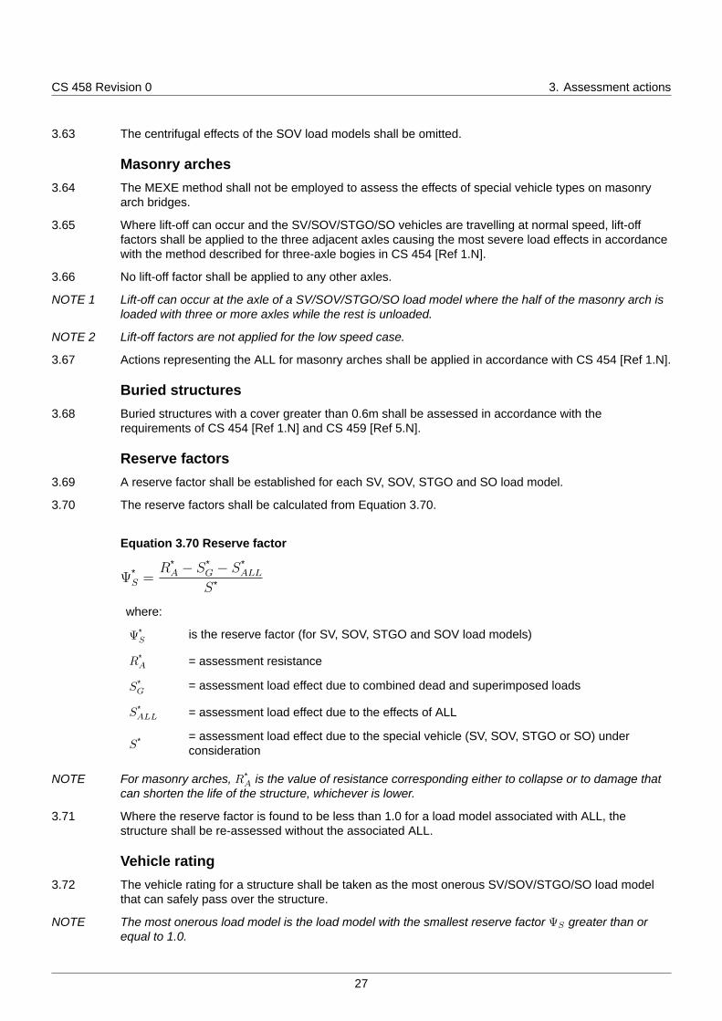
Equation 3.70 Reserve factor
Ψ*S =
R*A − S*
G − S*ALL
S*
where:
Ψ*S
is the reserve factor (for SV, SOV, STGO and SOV load models)
R*A = assessment resistance
S*G
= assessment load effect due to combined dead and superimposed loads
S*ALL = assessment load effect due to the effects of ALL
S* = assessment load effect due to the special vehicle (SV, SOV, STGO or SO) underconsideration
NOTE For masonry arches, R*A is the value of resistance corresponding either to collapse or to damage that
can shorten the life of the structure, whichever is lower.
3.71 Where the reserve factor is found to be less than 1.0 for a load model associated with ALL, thestructure shall be re-assessed without the associated ALL.
Vehicle rating3.72 The vehicle rating for a structure shall be taken as the most onerous SV/SOV/STGO/SO load model
that can safely pass over the structure.
NOTE The most onerous load model is the load model with the smallest reserve factor ΨS greater than orequal to 1.0.
27
CS 458 Revision 0 4. Normative references
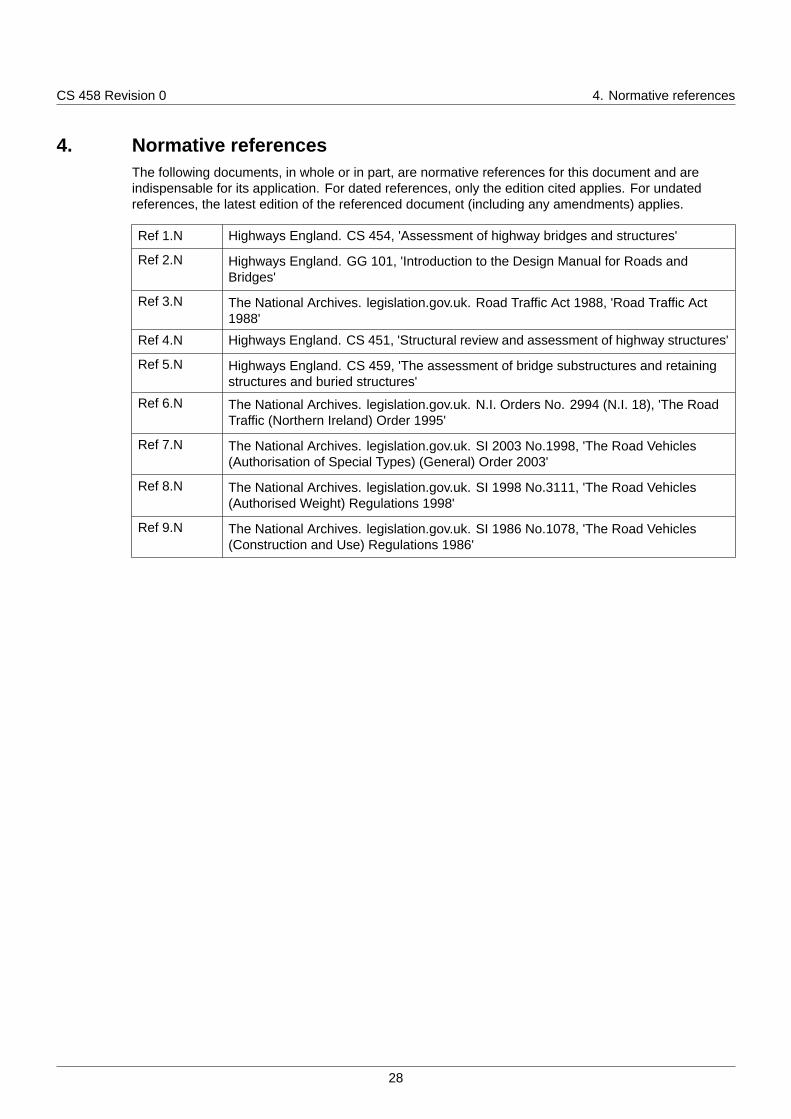
4. Normative referencesThe following documents, in whole or in part, are normative references for this document and areindispensable for its application. For dated references, only the edition cited applies. For undatedreferences, the latest edition of the referenced document (including any amendments) applies.
Ref 1.N Highways England. CS 454, 'Assessment of highway bridges and structures'
Ref 2.N Highways England. GG 101, 'Introduction to the Design Manual for Roads andBridges'
Ref 3.N The National Archives. legislation.gov.uk. Road Traffic Act 1988, 'Road Traffic Act1988'
Ref 4.N Highways England. CS 451, 'Structural review and assessment of highway structures'
Ref 5.N Highways England. CS 459, 'The assessment of bridge substructures and retainingstructures and buried structures'
Ref 6.N The National Archives. legislation.gov.uk. N.I. Orders No. 2994 (N.I. 18), 'The RoadTraffic (Northern Ireland) Order 1995'
Ref 7.N The National Archives. legislation.gov.uk. SI 2003 No.1998, 'The Road Vehicles(Authorisation of Special Types) (General) Order 2003'
Ref 8.N The National Archives. legislation.gov.uk. SI 1998 No.3111, 'The Road Vehicles(Authorised Weight) Regulations 1998'
Ref 9.N The National Archives. legislation.gov.uk. SI 1986 No.1078, 'The Road Vehicles(Construction and Use) Regulations 1986'
28
CS 458 Revision 0 5. Informative references
5. Informative referencesThe following documents are informative references for this document and provide supportinginformation.
Ref 1.I BSI. BS 5400-1, 'Steel, concrete and composite bridges - Part 1: General statement'
29
CS 458 Revision 0 Appendix A. Type HB to SV conversion charts
Appendix A. Type HB to SV conversion charts
A1 GeneralType HB to SV conversion charts given below provide an approximate conversion factor to provide theratio between the effect of 45 units of HB loading and the effect of each SV load model.
These conversion charts can be used after assessing the limitations given in Section A4.
The reserve factor for each SV load model as defined in Section 3 of this document is found byfactoring this conversion factor by the ratio of the actual bridge capacity in HB units, and the value of 45employed in the charts.
A2 Reserve factorThe reserve factor ΨSV for a SV load model can be calculated from Equation A.1 or with the assistanceof the conversion charts illustrated in Figure A.7 to Figure A.12.
Equation A.1 Reserve factor
ΨSV = λHB45→SV × NHB
45
where:
NHB is the number of type HB units for which the bridge was designed or assessed
λHB45→SV is the conversion factor from 45 units of type HB loading to an equivalent SV loadmodel, given by: S*
HB45
S*SV
(see also Figure A.7 to Figure A.12)
S*HB45
is the factored load effect due to 45 units of HB loading
S*SV
is the factored load effect due to SV loading
Load effects S*SV should include:
1) the overload factor (OF);
2) the dynamic amplification factor (DAF);
3) the partial load factor γfL = 1.1 .
Load effects S*HB45 should include a partial load factor of γfL = 1.3 .
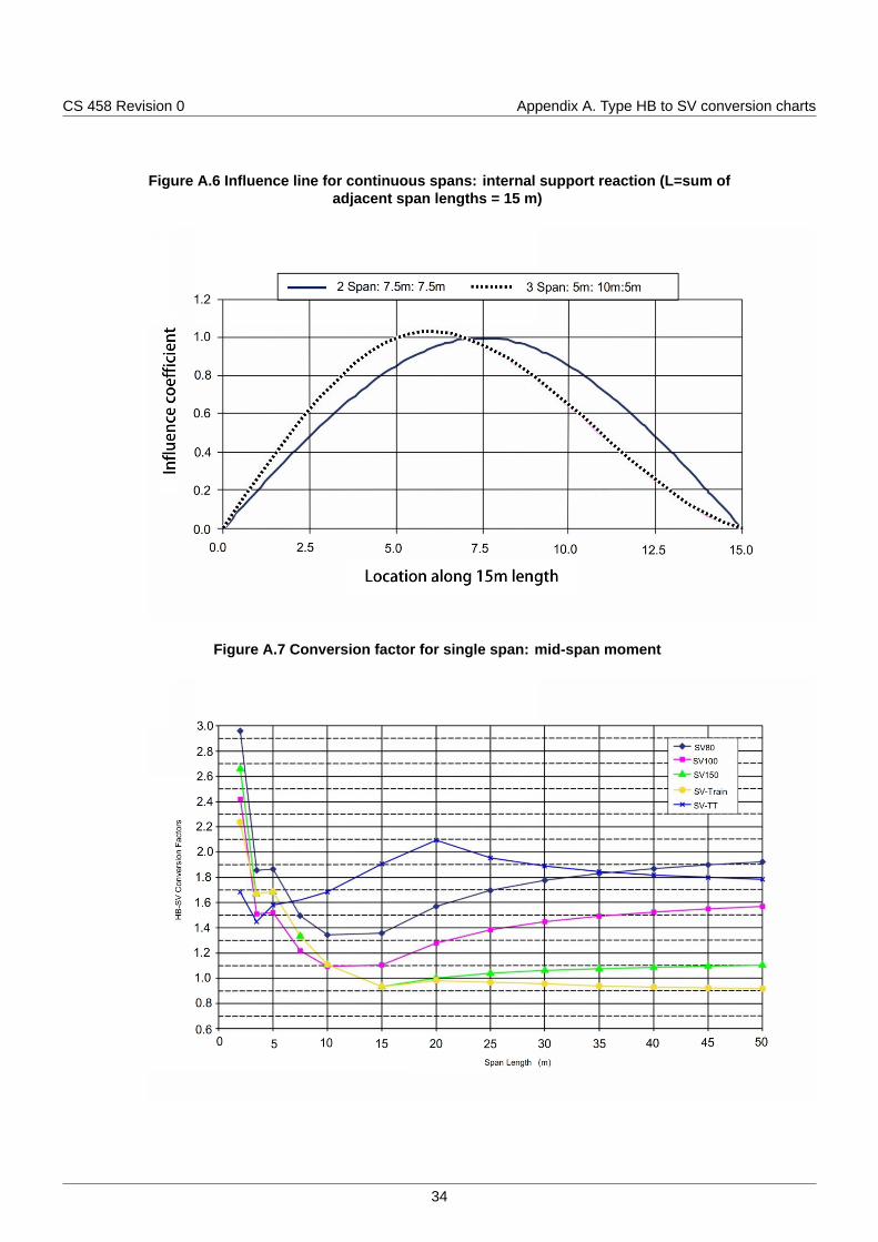
A3 Conversion chartsConversion charts illustrated in Figure A.7 to Figure A.12 provide a conservative estimate of the reservefactor and can be used after the calculation of the load effects SSV for the different SV load models.
Conversion charts should not be used where the illustrated influence lines are not appropriate for theparticular structure. For such cases, the conversion factor should be derived directly from Equation A.1.
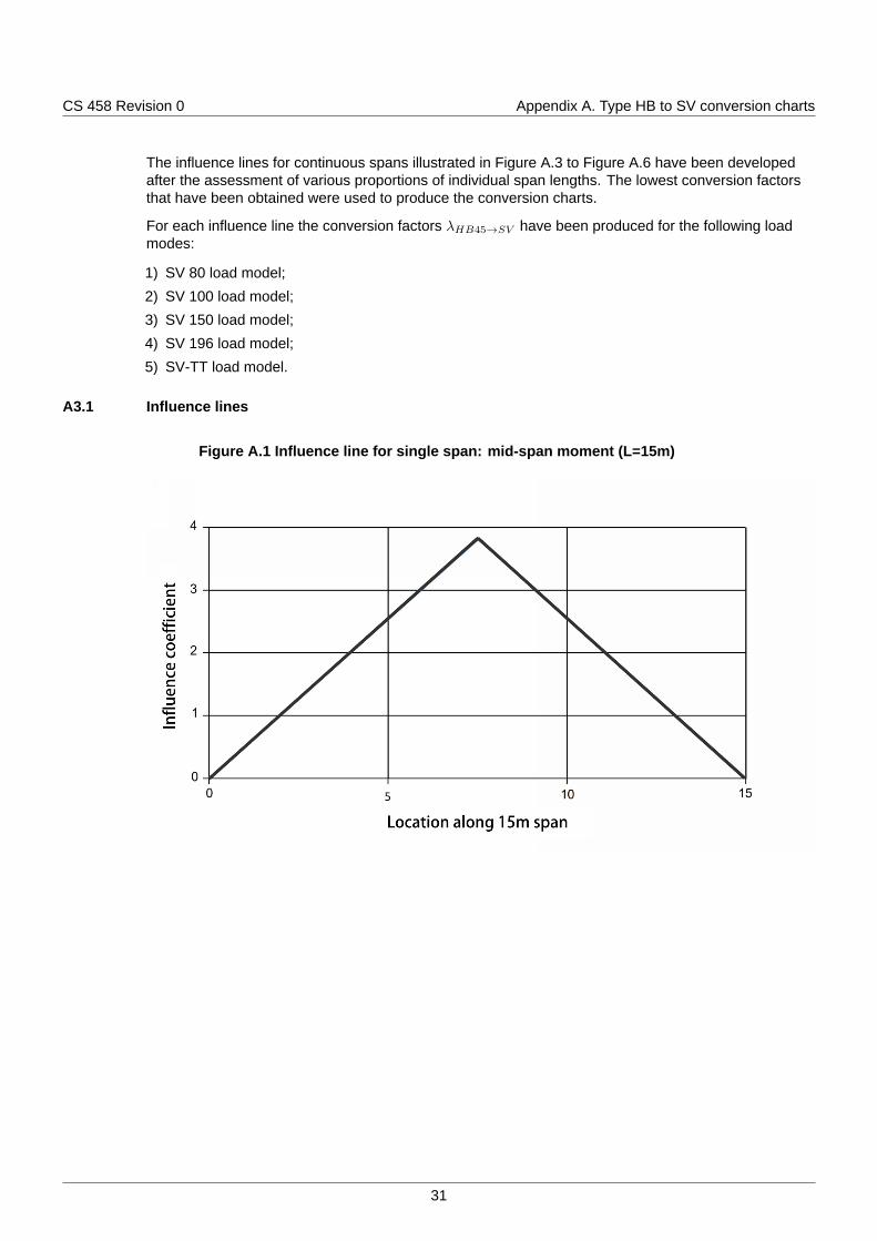
Conversion charts have been developed for a loaded length of 15m and for the following influence lines:
1) simply supported single span: mid-span moment (Figure A.1);
2) simply supported single span: support shear / support reaction (Figure A.2);
3) continuous spans: mid-span moment (Figure A.3);
4) continuous spans: internal support moment (Figure A.4);
5) continuous spans: internal support shear (Figure A.5);
6) continuous spans: internal support reaction (Figure A.6).
30
CS 458 Revision 0 Appendix A. Type HB to SV conversion charts
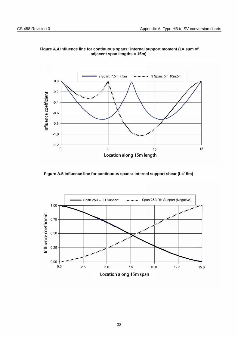
The influence lines for continuous spans illustrated in Figure A.3 to Figure A.6 have been developedafter the assessment of various proportions of individual span lengths. The lowest conversion factorsthat have been obtained were used to produce the conversion charts.
For each influence line the conversion factors λHB45→SV have been produced for the following loadmodes:
1) SV 80 load model;
2) SV 100 load model;
3) SV 150 load model;
4) SV 196 load model;
5) SV-TT load model.
A3.1 Influence lines
Figure A.1 Influence line for single span: mid-span moment (L=15m)
31
CS 458 Revision 0 Appendix A. Type HB to SV conversion charts
Figure A.2 Influence line for single span: support shear / support reaction (L=15m)
Figure A.3 Influence line for continuous spans: mid span moment (L=15m)
32
CS 458 Revision 0 Appendix A. Type HB to SV conversion charts
Figure A.4 Influence line for continuous spans: internal support moment (L= sum ofadjacent span lengths = 15m)
Figure A.5 Influence line for continuous spans: internal support shear (L=15m)
33
CS 458 Revision 0 Appendix A. Type HB to SV conversion charts
Figure A.6 Influence line for continuous spans: internal support reaction (L=sum ofadjacent span lengths = 15 m)
Figure A.7 Conversion factor for single span: mid-span moment
34

CS 458 Revision 0 Appendix A. Type HB to SV conversion charts
Figure A.8 Conversion factor for single span: support shear / support reaction
Figure A.9 Conversion factor for continuous spans: mid-span moment
35
CS 458 Revision 0 Appendix A. Type HB to SV conversion charts
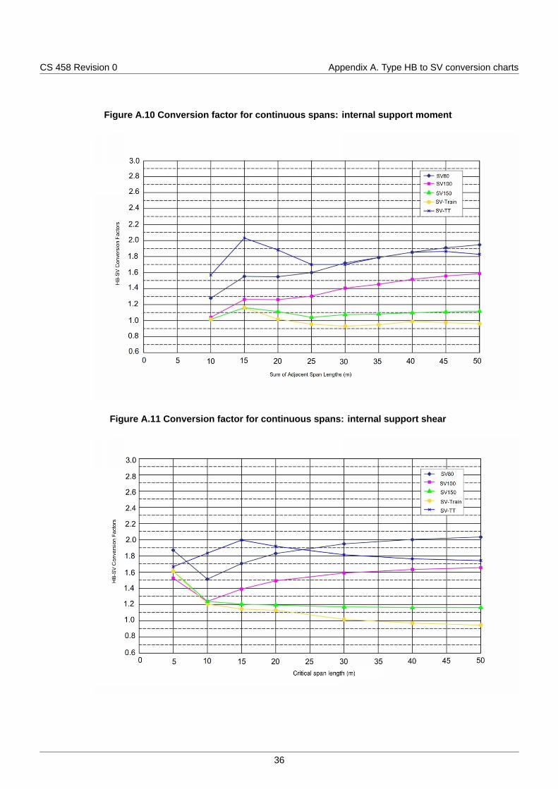
Figure A.10 Conversion factor for continuous spans: internal support moment
Figure A.11 Conversion factor for continuous spans: internal support shear
36

CS 458 Revision 0 Appendix A. Type HB to SV conversion charts
Figure A.12 Conversion factor for continuous spans: internal support reaction
A4 Conversion charts limitationsConversion charts have been produced with the following limitations:
1) conversion charts do not include SV load models moving at low speed;
2) conversion charts don't include the load effects due to ALL. Where assessment live loading (ALL) isassociated with an SV load model, the load effect of the ALL has been assumed to be the same forthe SV load model and type HB load model. Hence, ALL should not be included in calculating theload effects;
3) where two or more notional lanes of widths 2.75m to 3.0m are used in accordance with GG 101 [Ref2.N], conversion charts should not be used. For these cases, it is anticipated that ALL associatedwith type HB load model can result in significantly lower load effects than the ALL associated with anSV load model, due to the width of the type HB load model;
4) conversion charts should not be used where the illustrated influence lines are not appropriate for aparticular structure. For such cases, the conversion factor should be derived directly from EquationA.1;
5) the influence lines may not be appropriate for transversely spanning decks and members, troughdecks, masonry arches, buried structures, and curved superstructures in plan with a radius of lessthan 600m.
37
CS 458 Revision 0 Appendix B. Management of STGO vehicle movements
Appendix B. Management of STGO vehicle movements
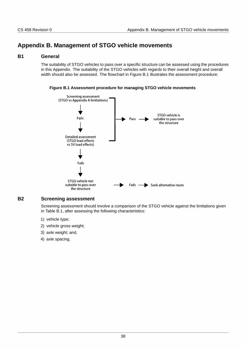
B1 GeneralThe suitability of STGO vehicles to pass over a specific structure can be assessed using the proceduresin this Appendix. The suitability of the STGO vehicles with regards to their overall height and overallwidth should also be assessed. The flowchart in Figure B.1 illustrates the assessment procedure:
Figure B.1 Assessment procedure for managing STGO vehicle movements
B2 Screening assessmentScreening assessment should involve a comparison of the STGO vehicle against the limitations givenin Table B.1, after assessing the following characteristics:
1) vehicle type;
2) vehicle gross weight;
3) axle weight; and,
4) axle spacing.
38
CS 458 Revision 0 Appendix B. Management of STGO vehicle movements
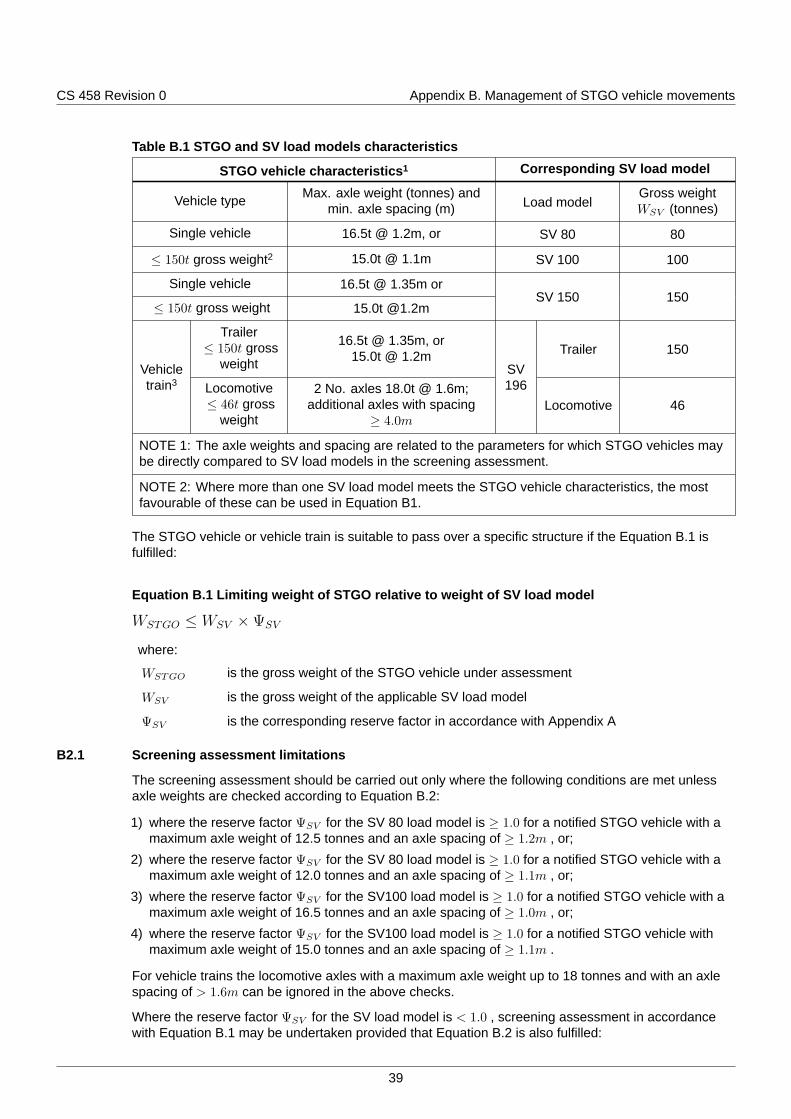
Table B.1 STGO and SV load models characteristics
STGO vehicle characteristics1 Corresponding SV load model
Vehicle type Max. axle weight (tonnes) andmin. axle spacing (m) Load model
Gross weightWSV (tonnes)
Single vehicle 16.5t @ 1.2m, or SV 80 80
≤ 150t gross weight2 15.0t @ 1.1m SV 100 100
Single vehicle 16.5t @ 1.35m or
≤ 150t gross weight 15.0t @1.2mSV 150 150
Trailer≤ 150t gross
weight
16.5t @ 1.35m, or15.0t @ 1.2m Trailer 150
Vehicletrain3 Locomotive
≤ 46t grossweight
2 No. axles 18.0t @ 1.6m;additional axles with spacing
≥ 4.0m
SV196
Locomotive 46
NOTE 1: The axle weights and spacing are related to the parameters for which STGO vehicles maybe directly compared to SV load models in the screening assessment.
NOTE 2: Where more than one SV load model meets the STGO vehicle characteristics, the mostfavourable of these can be used in Equation B1.
The STGO vehicle or vehicle train is suitable to pass over a specific structure if the Equation B.1 isfulfilled:
Equation B.1 Limiting weight of STGO relative to weight of SV load model
WSTGO ≤ WSV ×ΨSV
where:
WSTGO is the gross weight of the STGO vehicle under assessment
WSV is the gross weight of the applicable SV load model
ΨSV is the corresponding reserve factor in accordance with Appendix A
B2.1 Screening assessment limitations
The screening assessment should be carried out only where the following conditions are met unlessaxle weights are checked according to Equation B.2:
1) where the reserve factor ΨSV for the SV 80 load model is ≥ 1.0 for a notified STGO vehicle with amaximum axle weight of 12.5 tonnes and an axle spacing of ≥ 1.2m , or;
2) where the reserve factor ΨSV for the SV 80 load model is ≥ 1.0 for a notified STGO vehicle with amaximum axle weight of 12.0 tonnes and an axle spacing of ≥ 1.1m , or;
3) where the reserve factor ΨSV for the SV100 load model is ≥ 1.0 for a notified STGO vehicle with amaximum axle weight of 16.5 tonnes and an axle spacing of ≥ 1.0m , or;
4) where the reserve factor ΨSV for the SV100 load model is ≥ 1.0 for a notified STGO vehicle withmaximum axle weight of 15.0 tonnes and an axle spacing of ≥ 1.1m .
For vehicle trains the locomotive axles with a maximum axle weight up to 18 tonnes and with an axlespacing of > 1.6m can be ignored in the above checks.
Where the reserve factor ΨSV for the SV load model is < 1.0 , screening assessment in accordancewith Equation B.1 may be undertaken provided that Equation B.2 is also fulfilled:
39
CS 458 Revision 0 Appendix B. Management of STGO vehicle movements
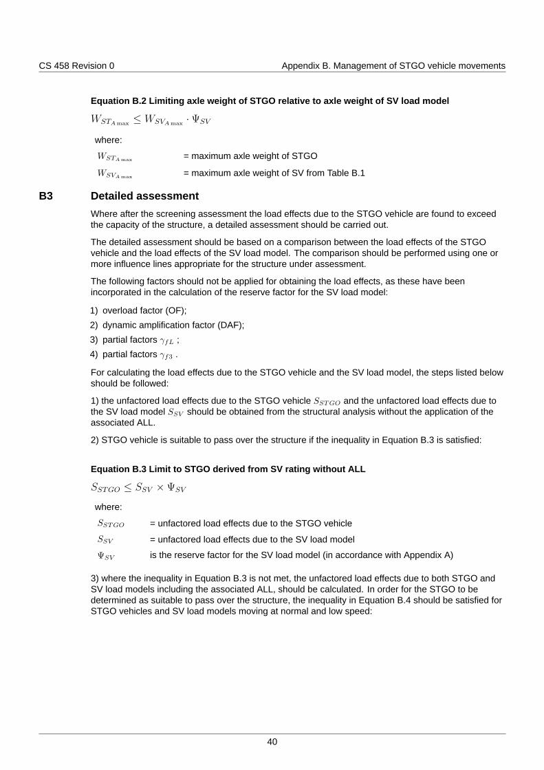
Equation B.2 Limiting axle weight of STGO relative to axle weight of SV load model
WSTAmax≤ WSVAmax
·ΨSV
where:
WSTAmax = maximum axle weight of STGO
WSVAmax = maximum axle weight of SV from Table B.1
B3 Detailed assessmentWhere after the screening assessment the load effects due to the STGO vehicle are found to exceedthe capacity of the structure, a detailed assessment should be carried out.
The detailed assessment should be based on a comparison between the load effects of the STGOvehicle and the load effects of the SV load model. The comparison should be performed using one ormore influence lines appropriate for the structure under assessment.
The following factors should not be applied for obtaining the load effects, as these have beenincorporated in the calculation of the reserve factor for the SV load model:
1) overload factor (OF);
2) dynamic amplification factor (DAF);
3) partial factors γfL ;
4) partial factors γf3 .
For calculating the load effects due to the STGO vehicle and the SV load model, the steps listed belowshould be followed:
1) the unfactored load effects due to the STGO vehicle SSTGO and the unfactored load effects due tothe SV load model SSV should be obtained from the structural analysis without the application of theassociated ALL.
2) STGO vehicle is suitable to pass over the structure if the inequality in Equation B.3 is satisfied:
Equation B.3 Limit to STGO derived from SV rating without ALL
SSTGO ≤ SSV ×ΨSV
where:
SSTGO = unfactored load effects due to the STGO vehicle
SSV = unfactored load effects due to the SV load model
ΨSV is the reserve factor for the SV load model (in accordance with Appendix A)
3) where the inequality in Equation B.3 is not met, the unfactored load effects due to both STGO andSV load models including the associated ALL, should be calculated. In order for the STGO to bedetermined as suitable to pass over the structure, the inequality in Equation B.4 should be satisfied forSTGO vehicles and SV load models moving at normal and low speed:
40
CS 458 Revision 0 Appendix B. Management of STGO vehicle movements
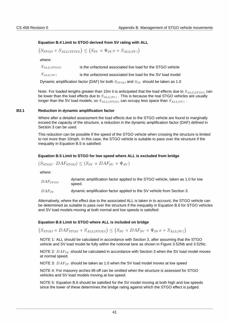
Equation B.4 Limit to STGO derived from SV rating with ALL(SSTGO + SALL(STGO)
)≤
(SSV ×ΨSV x+ SALL(SV )
)where:
SALL(STGO) is the unfactored associated live load for the STGO vehicle
SALL(SV ) is the unfactored associated live load for the SV load model
Dynamic amplification factor (DAF) for both SSTGO and SSV should be taken as 1.0
Note: For loaded lengths greater than 15m it is anticipated that the load effects due to SALL(STGO) canbe lower than the load effects due to SALL(SV ) . This is because the real STGO vehicles are usuallylonger than the SV load models, so SALL(STGO) can occupy less space than SALL(SV ) .
B3.1 Reduction in dynamic amplification factor
Where after a detailed assessment the load effects due to the STGO vehicle are found to marginallyexceed the capacity of the structure, a reduction in the dynamic amplification factor (DAF) defined inSection 3 can be used.
This reduction can be possible if the speed of the STGO vehicle when crossing the structure is limitedto not more than 10mph. In this case, the STGO vehicle is suitable to pass over the structure if theinequality in Equation B.5 is satisfied:
Equation B.5 Limit to STGO for low speed where ALL is excluded from bridge
(SSTGO ·DAFSTGO) ≤ (SSV ×DAFSV ×ΨSV )
where:
DAFSTGOdynamic amplification factor applied to the STGO vehicle, taken as 1.0 for lowspeed.
DAFSV dynamic amplification factor applied to the SV vehicle from Section 3.
Alternatively, where the effect due to the associated ALL is taken in to account, the STGO vehicle canbe determined as suitable to pass over the structure if the inequality in Equation B.6 for STGO vehiclesand SV load models moving at both normal and low speeds is satisfied:
Equation B.6 Limit to STGO where ALL is included on bridge(SSTGO ×DAFSTGO + SALL(STGO)
)≤
(SSV ×DAFSV ×ΨSV x+ SALL(SV )
)NOTE 1: ALL should be calculated in accordance with Section 3, after assuming that the STGOvehicle and SV load model lie fully within the notional lane as shown in Figure 3.52Nb and 3.52Nc.
NOTE 2: DAFSV should be calculated in accordance with Section 3 when the SV load model movesat normal speed.
NOTE 3: DAFSV should be taken as 1.0 when the SV load model moves at low speed
NOTE 4: For masonry arches lift-off can be omitted when the structure is assessed for STGOvehicles and SV load models moving at low speed.
NOTE 5: Equation B.6 should be satisfied for the SV model moving at both high and low speedssince the lower of these determines the bridge rating against which the STGO effect is judged.
41
CS 458 Revision 0 Appendix B. Management of STGO vehicle movements
B3.2 Reduction in associated ALL
Where the load effects due to a STGO vehicle marginally exceed the assessed capacity of thestructure, the STGO vehicle may be suitable to pass over the structure when escorted and the structureis kept clear of associated normal traffic.
Where the STGO vehicle is escorted, two cases can be evaluated:
1) When the associated traffic in the same lane as the STGO vehicle is kept clear over the span, theSTGO is suitable to pass the structure if the inequality in Equation B.7 for both normal speed and lowspeed cases is satisfied:
Equation B.7 Limit to STGO where ALL is clear from the same lane as STGO
SSTGO ≤ (SSV ×ΨSV + SALL))
where:
SSV is the ssessment load effect due to the SV or SOV load model
ΨSV is the reserve factor for SV load
SALL is the assessment load effect due to the effects of ALL
2) When the associated traffic in all lanes of the carriageway is kept clear of the structure, the STGOvehicle is suitable to pass the structure if the inequality in Equation B.8 is satisfied:
Equation B.8 Limit to STGO where ALL is clear of the entire bridge
SSTGO ≤ (SSV ×ΨSV )
where:
SSV is the assessment load effect due to the SV or SOV load model
ΨSV is the reserve factor for SV load
SSTGO is the assessment load effect due to the effects of STGO
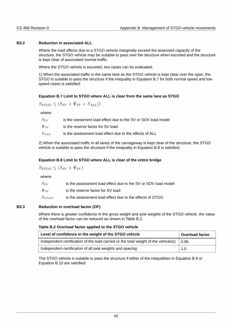
B3.3 Reduction in overload factor (OF)
Where there is greater confidence in the gross weight and axle weights of the STGO vehicle, the valueof the overload factor can be reduced as shown in Table B.2.
Table B.2 Overload factor applied to the STGO vehicle
Level of confidence in the weight of the STGO vehicle Overload factor
Independent certification of the load carried or the total weight of the vehicle(s) 0.95
Independent certification of all axle weights and spacing 1.0
The STGO vehicle is suitable to pass the structure if either of the inequalities in Equation B.9 orEquation B.10 are satisfied:
42
CS 458 Revision 0 Appendix B. Management of STGO vehicle movements
Equation B.9 Limit #1 to STGO where overload allowance may be reduced(SSTGO ×OFSTGO ×DAFSTGO + SALL(STGO)
)≤
(SSV ×OFSV ×ΨSV + SALL(SV )
)where:
OFSV is the overload factor for SV vehicle from Section 3
OFSTGO is the factor for the STGO vehicle from Table B.2
Equation B.10 Limit #2 to STGO where overload allowance may be reduced
(SSTGO ×OFSTGO) ≤ (SSV ×OFSV ×ΨSV )
The overload factor from Section 3 can be applied to the SV load model.
Using inequality in Equation B.10, the reduction in overload factor can be combined with reductions inthe DAF and the associated ALL loading as given in clause B3.1 and clause B3.2 respectively.
B4 Vehicle assessmentWhere individual vehicles (such as mobile cranes) are known to make numerous journeys, theassessor should recognise that rating factors relative to STGO may have been established in previousassessments relative to typical bridge influence lines. Therefore an independent assessment isgenerally not required for such vehicles.
43

© Crown copyright 2020.You may re-use this information (not including logos) free of charge in any format or medium, under the terms of the
Open Government Licence. To view this licence:visit www.nationalarchives.gov.uk/doc/open-government-licence/,
write to the Information Policy Team, The National Archives, Kew, London TW9 4DU,or email [email protected].


