Embed Size (px)
Citation preview
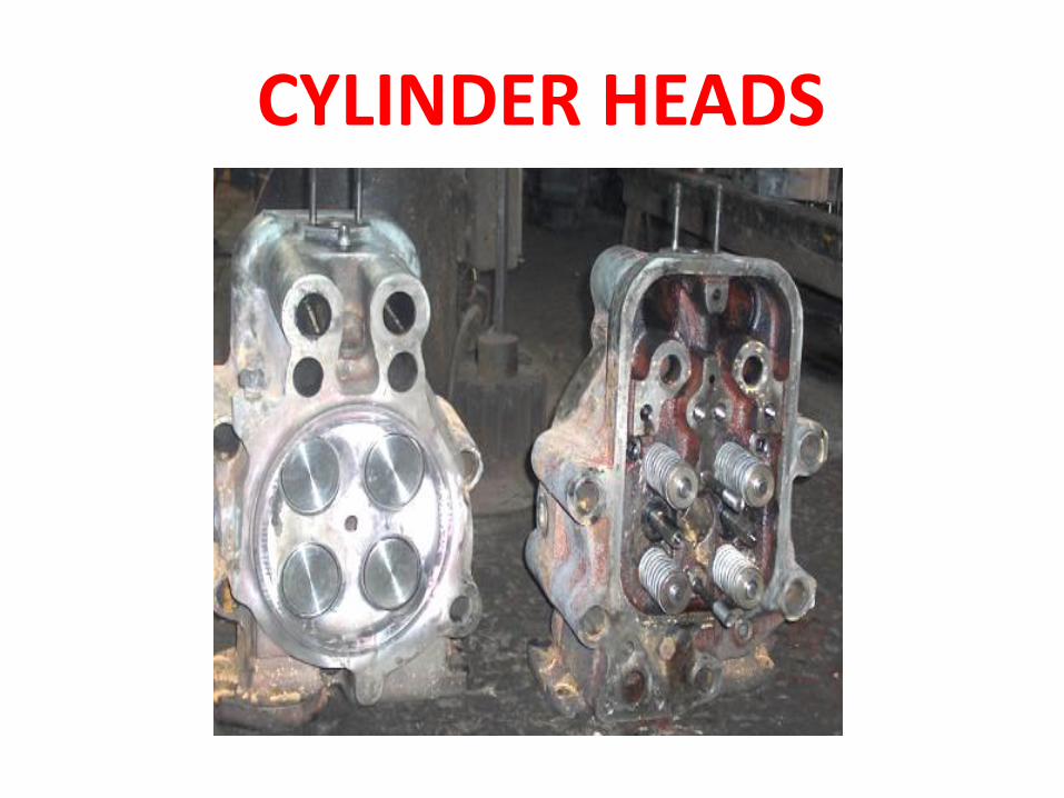
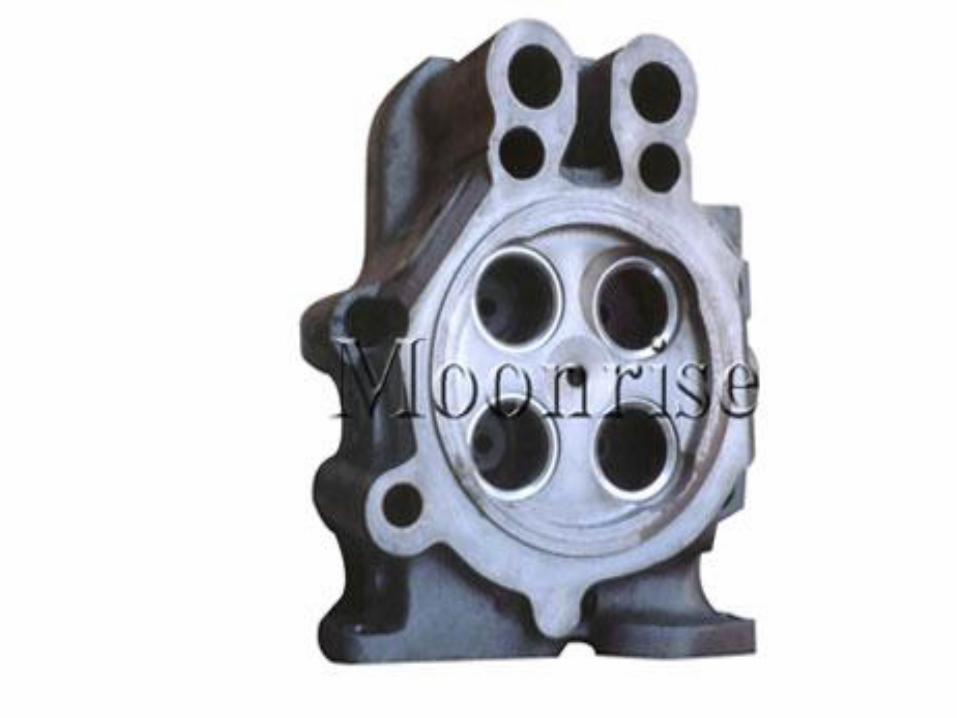
CYLINDER HEADS
• The cylinder head is held on to the cylinder liner by seven hold down studs provided on the cylinder block.
• It is subjected to high shock stress and combustion temperature at the lower face which forms a part of combustion chamber. It is a complicated casting where cooling passages are cored for the purpose of cooling the cylinder head. In addition to this provision is made for space for passage of inlet air and exhaust gas.
• Further, space has to be left for fuel injection nozzles, valve guides and valve seat inserts.
• In ALCO cylinder heads valve seat inserts with lock rings are used as replaceable wearing part.
• The Valve seat inserts which are made of stellite / Weltite are cool down in Liquid Nitrogen and temperature differential of 250 0F is maintained to during fitment of Valve seat Insert into cylinder head.
• The Exhaust valve seat inserts are ground to an angle of 441/2º whereas the valve is ground to 45o and Air valve seat inserts are ground to an angle of 591/2º
whereas the valve is ground to 30o to ensure line contact.
• The valve guides are interference fit to the
cylinder head with an interference of 0.0008"
to 0.0018". After attention to the cylinder
heads the same is hydraulically tested at 70 psi
and 190º F.
• The fitment of cylinder heads are done in
ALCO engines with a torque value of 550 Lbs.
The cylinder head is a metal to metal joint on
to cylinder Liner.
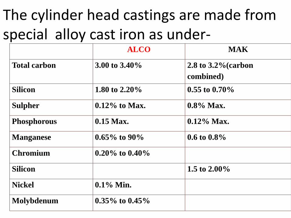
The cylinder head castings are made from special alloy cast iron as under-
ALCO MAK
Total carbon 3.00 to 3.40% 2.8 to 3.2%(carbon
combined)
Silicon 1.80 to 2.20% 0.55 to 0.70%
Sulpher 0.12% to Max. 0.8% Max.
Phosphorous 0.15 Max. 0.12% Max.
Manganese 0.65% to 90% 0.6 to 0.8%
Chromium 0.20% to 0.40%
Silicon 1.5 to 2.00%
Nickel 0.1% Min.
Molybdenum 0.35% to 0.45%
VALVES
The valves are the most important of the
small components of the Diesel engine.
When considering the general designs of
valves it must be remembered that the
valves operate at a very high temperature
varying from 1250 0F to 1700 0F.
The valves as inlet valves get cooled by
fresh flow of cool air whereas the exhaust
valve gives passage to hot exhaust gases.
• For both inlet and exhaust valves the path of
dissipation of heat is
(a) From valve face to seat and then to cylinder head.
(b) from valve stem to valve guide and then to
cylinder head.
The valve seat angle between the seat surface and
cylinder head surface can be either 30ºor 45º.
The more desirable angle is dictated by individual
engine design. The seating force is about 20% greater
with 45ºseat.This assists in preventing the
accumulation of valve seat deposits but increases seat
deformation due to pounding.
•
The valve opening for gas flow is approximately 20% greater with 30 degree seat for the same valve lift.
• Generally narrow seat between valve and valve seat is preferred as it provides less chance of being lift open by foreign material. On the other hand narrow seat reduces heat dissipation from valve to cylinder head through valve seat.
. In ALCO practice in order to provide line contact interference angle is provided. While the valve angle is 45% the seat angle is 44.5.
• In ALCO engine each cylinder has 2 exhaust
and 2 inlet valves of 2.85” in dia. the valves has
stem of alloy steel and austenitic steel head
flash but welded together into a composite unit.
The valve head material being austenitic steel
has high level of stretch resistance and is
capable of hardening above RC-34.
The stem is 5/8th. inch in diameter and made of
SAE 4140. The head is made of special heat
resistant austenitic material (21-4N) in the
following composition.
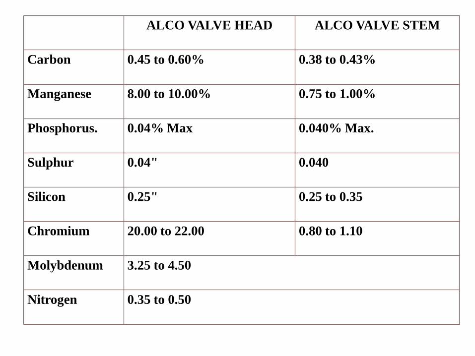
ALCO VALVE HEAD ALCO VALVE STEM
Carbon 0.45 to 0.60% 0.38 to 0.43%
Manganese 8.00 to 10.00% 0.75 to 1.00%
Phosphorus. 0.04% Max 0.040% Max.
Sulphur 0.04" 0.040
Silicon 0.25" 0.25 to 0.35
Chromium 20.00 to 22.00 0.80 to 1.10
Molybdenum 3.25 to 4.50
Nitrogen 0.35 to 0.50
251+ cylinder headsFeatures of 251+ cylinder heads, used in uprated engines-
• Fire deck thickness reduced for better heat transmission.
• Middle deck modified by increasing number of ribs (supports) to increase its mechanical strength. The flying buttress fashion of middle deck improves the flow pattern of water eliminating water stagnation at the corners inside cylinder head.
• Water holding capacity increased by increasing number of cores (14 instead of 11)
• Use of frost core plugs instead of threaded plugs, arrest tendency of leakage.
• Made lighter by 8 kgs (Al spacer is used to make good the gap between rubber grommet and cylinder head.)
• Retaining rings of valve seat inserts eliminated.
BENEFITS
- Better heat dissipation
• Failure reduced by reducing crack and
eliminating sagging effect of fire deck area.
• Less weight
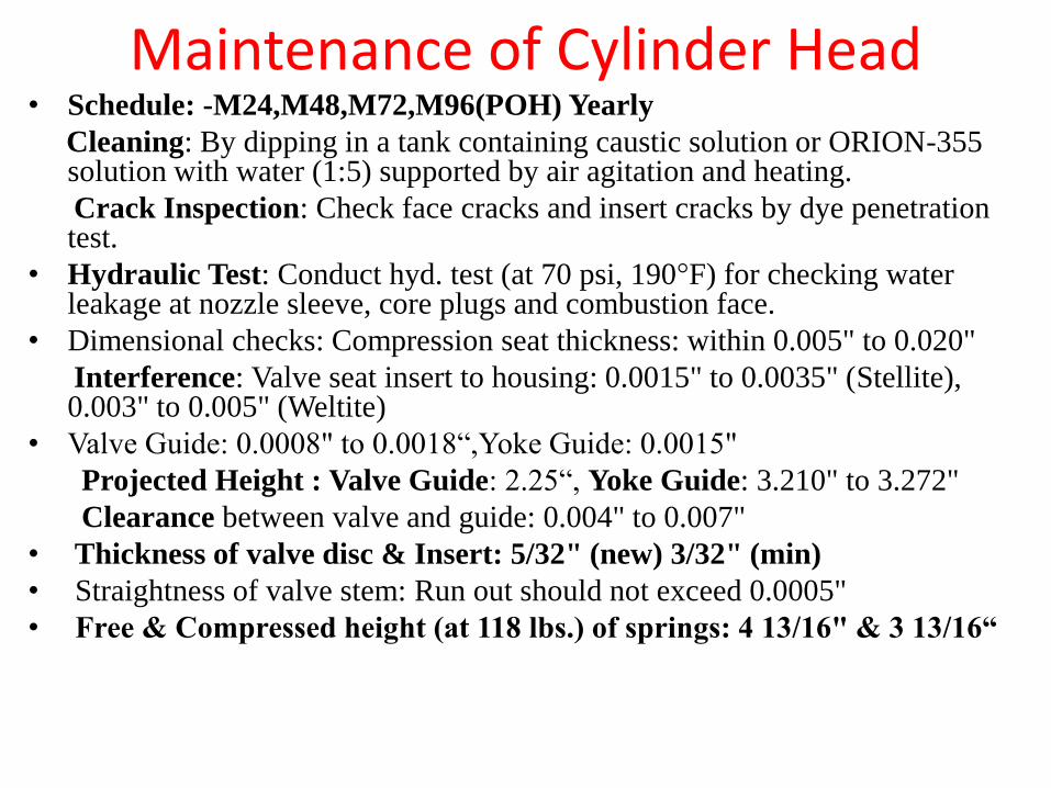
Maintenance of Cylinder Head• Schedule: -M24,M48,M72,M96(POH) Yearly
Cleaning: By dipping in a tank containing caustic solution or ORION-355 solution with water (1:5) supported by air agitation and heating.
Crack Inspection: Check face cracks and insert cracks by dye penetration test.
• Hydraulic Test: Conduct hyd. test (at 70 psi, 190°F) for checking water leakage at nozzle sleeve, core plugs and combustion face.
• Dimensional checks: Compression seat thickness: within 0.005" to 0.020"
Interference: Valve seat insert to housing: 0.0015" to 0.0035" (Stellite), 0.003" to 0.005" (Weltite)
• Valve Guide: 0.0008" to 0.0018“,Yoke Guide: 0.0015"
Projected Height : Valve Guide: 2.25“, Yoke Guide: 3.210" to 3.272"
Clearance between valve and guide: 0.004" to 0.007"
• Thickness of valve disc & Insert: 5/32" (new) 3/32" (min)
• Straightness of valve stem: Run out should not exceed 0.0005"
• Free & Compressed height (at 118 lbs.) of springs: 4 13/16" & 3 13/16“
Checks During Overhauling• Ground the valve seat insert to 44.5°/ 59.5°,
maintain run out of insert within 0.002" with respect to valve guide while grinding.
• Grind the valves to 45°/ 30° and ensure continuous hair line contact with valve guide by checking colour match.
• Ensure no crack has developed to inserts after grinding, checked by dye penetration test.
• Make pairing of springs and check proper draw on valve locks and proper condition of groove and locks while assembling of valves.
• Lap the face joint to ensure leak proof joint with liner.
• PISTONS• The piston is the most important component in the diesel engine
as it takes direct part in transmission of power. It is, therefore, necessary that the designers and users must know the essential details about the piston. The combustion of fuel results in large amount of heat being developed. Out of this about 18% of the heat is absorbed by piston only.
• Type of Pistons:• Broadly speaking, the piston are of two distinct types i.e. Trunk
type and Cross Head type. While various types of trunk type pistons have been put in use cross head type pistons have more or less gone out of use except for large size of marine or stationery engines.
•
FUNCTION:
• The function of the pistons are: -
•
• (a) It compresses the air to required pressure & temperature.
•
• (b) It receives the thrust of expanding gases and transmits the force through connecting rod (for rotating crankshaft).
•
• (c) It forms the crosshead through which side thrust due to angularity of connecting rod is transmitted to the cylinder wall.
•
• (d) With the help of piston rings it prevents leakage of gas from combustion chamber to crank case.
Guiding factors for dimensions are as follows: -
•
• (a) The top portion of the piston is in contact with direct heat of combustion. Inspite of cooling arrangement, it takes up more expansion and as such the need for more clearance at this location.
• (b) Relief has to be provided at the piston pin located to prevent seizure of piston due to bulging of material at this location in course of working.
• Ring Grove Insert•
• The top most ring bears the maximum brunt of high pressure hot gases. This result in heavy wears in the upper ring groove. In order to over come this problem, Ni-resist ring insert are re-fitted in the ring carrier and ring groove is made in the insert. These NI-resist rings apart from being dovetailed in Aluminium casting/forging, are molecularly bounded to the Aluminium body by AI-FIN-process.
6 Piston material: In many ways cast iron is best-suited material for manufacture of piston. The reasons
are as follows: -
• (a) Co-efficient of expansion matches with cylinder liner whereas Aluminium has got twice the co-efficient of cast iron.
• (b) Heat conductivity is 3 times better than Aluminium.
• (c) Compression strength is much more than Aluminium at high temperature.
• (d) Wear is less than Aluminium.
• But the two main disadvantages with cast iron piston are: -
• (a) Weight of Aluminium is 0.097 1bs. per cubic inch in place of cast from which is 0.284 1bs. per cubic inch. Thus cast iron pistons are about 3 times heavier than Aluminium piston in weight.
• (b) Possibilities of cylinder liner being scored are more in case of cast iron piston.
• The factor of weight has become more over riding in view of the high speed of the modern diesel engines and hence Aluminium alloy pistons are favoured.
•
• 7.7 ALCO 251 engines pistons are of Aluminium alloy with composition given below which compares to ASTM B247 alloy 2219.
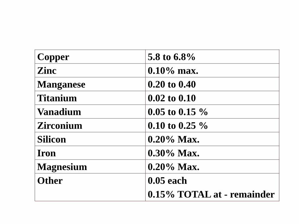
Copper 5.8 to 6.8%
Zinc 0.10% max.
Manganese 0.20 to 0.40
Titanium 0.02 to 0.10
Vanadium 0.05 to 0.15 %
Zirconium 0.10 to 0.25 %
Silicon 0.20% Max.
Iron 0.30% Max.
Magnesium 0.20% Max.
Other 0.05 each
0.15% TOTAL at - remainder
• These pistons are in two parts i.e. the piston body (or skirt) and the ring carrier having interference fit. The joint between the ring carrier and piston is welded at the crown by inert gas welding.
•
• Older design where both the ring carrier and piston body were of cast aluminum alloy caused lot of problems due to dislodging of ring carrier from skirt. This was due to the fact that with cast aluminum adequate interference could not be provided.
• After this a series of modifications were done. The first being forged ring carrier shrunk onto cast piston body. The latest type is where both ring carrier and body are of high density aluminum alloy forging. The interference between ring carrier and piston body was increased from 0.005-0.009” in case of first type of 0.017-0.021” in case of latter types.
• While this modifications was of advantage but due to higher density of the alloy the total weight of the piston increased causing balancing problem. This had to be tackled by cutting out approximately 5/8” from the skirt resulting in the fact the fact that there was no room for the third oil scrapper ring thus the number of piston rings had to be reduced from 6 to 5.
• 7.7.3In this type of piston, the crown is cooled by flowing of lube oil. The oil from piston pin reaches the piston. Passes through the vertical oil hole and then travels through the four circular grooves machined on the spigot portion of the piston body. After passing through the grooves and absorbing heat all the way, the hot oil falls down through the second vertical hole back to the sump.
STEEL CAP PISTONS • Immediately after the forged ring carrier pistons M/s ALCO brought out
steel cap pistons. Special features of this type of piston are: -• (a) These pistons have body of aluminum alloy forging but a cap of steel
in placed of forged aluminum ring carrier.• (b) The steel cap of the piston takes only three compression rings and
the top groove does not have any hi-resist insert like that of aluminum alloy ring carrier.
• (c) As heat transfer is better in steel cap than in aluminum piston, the locos fitted with steel cap piston needs more lube oil pressure and more mass flow of oil so that more heat is absorbed. These are provided by increased flow of lube oil so that more heat is absorbed. These are provided by increased lube oil pressure and increase in oil passage dia.
• (d) The steel cap is assembled and dis-assembled with hydraulic pressure.
• (e) These piston have 5 rings. • (f) The steel caps are hydraulically pressed and secured. The cap is
provided with a spigot and screw arrangement for additional hold on piston body. Steel cap pistons are giving reasonable good service in Indian Railways.
MAHLE PISTON• This type of piston is supplied by the firm M/s Mahle of West Germany. It
is a one piece cast aluminium piston cast with hollow tube coil for
providing cooling oil passage. Being one piece piston there is no question
of dis-loading of the ring carrier and to that extent these pistons are trouble
free. The disadvantage of this type is that no reclamation by changing ring
carrier as in ALCO piston can be done. These pistons have Niresist ring
inserts fitted to take the top ring. They have six piston rings.
• Metallurgical composition of the Mahle piston material is given below: -
• Silicon
• 18.08
• Copper
• 1.0
• Nickel
• 1.0
• Magnesium
• 1.0
• Aluminium remainder
•
• While ALCO Locos have got all three types of
pistons i.e. forged ring carrier type (ALCO),
steel cap type ALCO and Mahle aluminium
piston in use, the WDS4 Locos have got Mahle
piston with its crown partly resembling
Mexican hat and with 5 piston ring. Cooling of
the piston crown is done by a jet of oil passing
from the connecting rod small end crown.
PISTON RINGS:•
• 8.1 Piston rings along with cylinder liner present the major wear and maintenance problem for a diesel engine. The main function of piston rings are: -
• a) Preventing blow by air and high temperature combustion gases & prevent same from getting access to crank case.
• b) Preventing excessive amount of lube oil from reaching combustion chamber.•
• 8.2 The way the piston rings seal the gas and the technique of sealing is given in the sketch attached. It will be seen that the top ring gets the maximum assistance from the high pressure gasses to prevent passage of gases from the combustion chamber to the crank case.
•
• 8.3 TYPES OF PISTON RINGS:• There are many varieties of piston rings as shown in Sketch.• a) Compression rings (i) square face• (ii) Taper face• (iii) Inside bevel• (iv) Key stone.
• b) Oil P scraper rings or oil rings• (i) Wide channel double lip• (ii) Special bevel single lip.• (iii) Comformable rings.• 8.4 The ring arrangements as applicable to our standard class of main
line locos are given over leaf (SK. I-12)• 8.5 Preferred piston ring material is cast iron with open graphite
structure and a hard pearlitic matrix. The piston ring operates during a part of its life under conditions of marginal lubrication. In addition to the open oil retaining structure of cast iron, the graphite further provides for emergency self-lubrication.
• The piston rings generally have following two types of coatings: -• a) Scuff resisting and quick seating coating &• b) Wear and corrosion resistant coatings. •
• While ALCO Locos piston rings have first type of coating, the general motor Locos all the piston rings are chrome plated. The WDS4 Locos top compression ring is chrome plated.
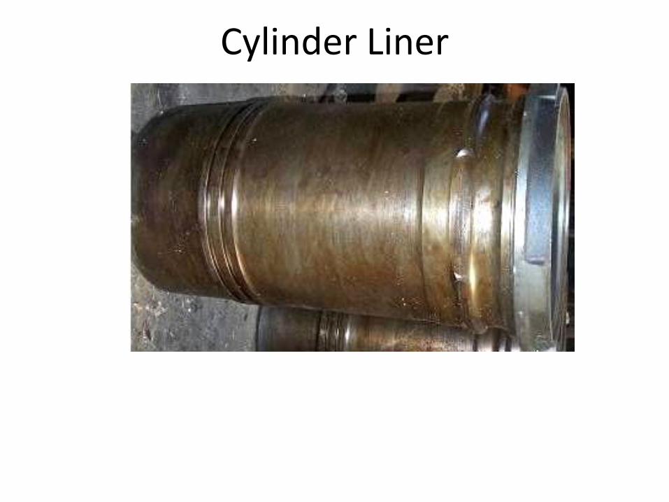
Cylinder Liner
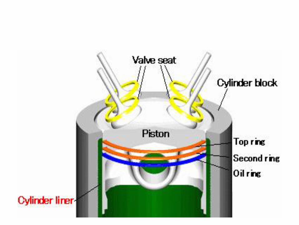
• The barrel or bore in which an engine piston moves back and forth.
• It may be an integral part of the cylinder block, or it may be a separate sleeve or liner.
• The material of a liner must withstand the extreme heat and pressure developed within the combustion chamber at he top of the cylinder and , at the same time , must permit the piston and its sealing rings to move with a minimum of friction.
TYPES OF LINERS
• Liners are mainly of two types i.e.
• a) Dry liner
• b) Wet liner.
• (a) Dry liners are those which never come in contact with coolant but fits in as a sleeve inside and already complete cylinder. The temperature of the inside surface of dry liner is higher than corresponding wet liner. Dry liners are in use in only very small engines.
Wet liners • Wet liners are those which not only form the
cylinder well but also form a part of the water jacket. ALCO Locos are fitted with wet liners, which have slight interference fit on upper and lower decks.
• In addition to this synthetic rubber seals of suitable qualities are to be used, one on the upper deck groove and two on middle deck (Si-rubber on the upper deck groove and two Viton rubber seals on middle deck).
• Defect in gaskets may result in water leakage causing water contamination of crank case oil. The liner bore has chrome plated surface and is honey chromed by electrolytic process. ALCO liners have no step size in the bore.
General Motor cylinder liners are fabricated type embodying the water jacket. In General Motor Locos instead of liner bore being chrome plated the piston rings are chrome plated.
The ALCO cylinder liners are made of high strength close grained alloy cast iron heat treated to relieve stresses.
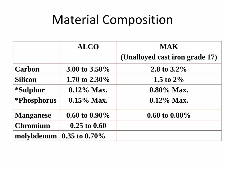
Material Composition
ALCO MAK
(Unalloyed cast iron grade 17)
Carbon 3.00 to 3.50% 2.8 to 3.2%
Silicon 1.70 to 2.30% 1.5 to 2%
*Sulphur 0.12% Max. 0.80% Max.
*Phosphorus 0.15% Max. 0.12% Max.
Manganese 0.60 to 0.90% 0.60 to 0.80%
Chromium 0.25 to 0.60
molybdenum 0.35 to 0.70%
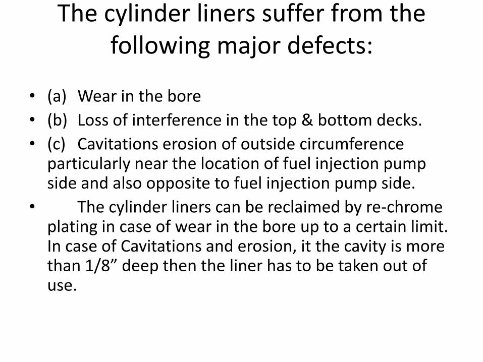
The cylinder liners suffer from the following major defects:
• (a) Wear in the bore
• (b) Loss of interference in the top & bottom decks.
• (c) Cavitations erosion of outside circumference particularly near the location of fuel injection pump side and also opposite to fuel injection pump side.
• The cylinder liners can be reclaimed by re-chrome plating in case of wear in the bore up to a certain limit. In case of Cavitations and erosion, it the cavity is more than 1/8” deep then the liner has to be taken out of use.
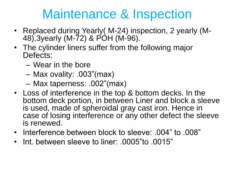
Maintenance & Inspection• Replaced during Yearly( M-24) inspection, 2 yearly (M-
48),3yearly (M-72) & POH (M-96).
• The cylinder liners suffer from the following major Defects:– Wear in the bore
– Max ovality: .003”(max)
– Max taperness: .002”(max)
• Loss of interference in the top & bottom decks. In the bottom deck portion, in between Liner and block a sleeve is used, made of spheroidal gray cast iron. Hence in case of losing interference or any other defect the sleeve is renewed.
• Interference between block to sleeve: .004” to .008”
• Int. between sleeve to liner: .0005”to .0015”
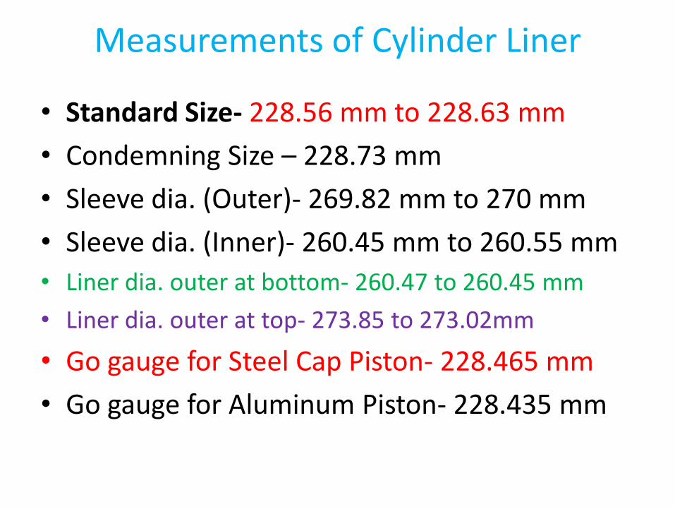
Measurements of Cylinder Liner
• Standard Size- 228.56 mm to 228.63 mm
• Condemning Size – 228.73 mm
• Sleeve dia. (Outer)- 269.82 mm to 270 mm
• Sleeve dia. (Inner)- 260.45 mm to 260.55 mm
• Liner dia. outer at bottom- 260.47 to 260.45 mm
• Liner dia. outer at top- 273.85 to 273.02mm
• Go gauge for Steel Cap Piston- 228.465 mm
• Go gauge for Aluminum Piston- 228.435 mm

Sleeve Fitment
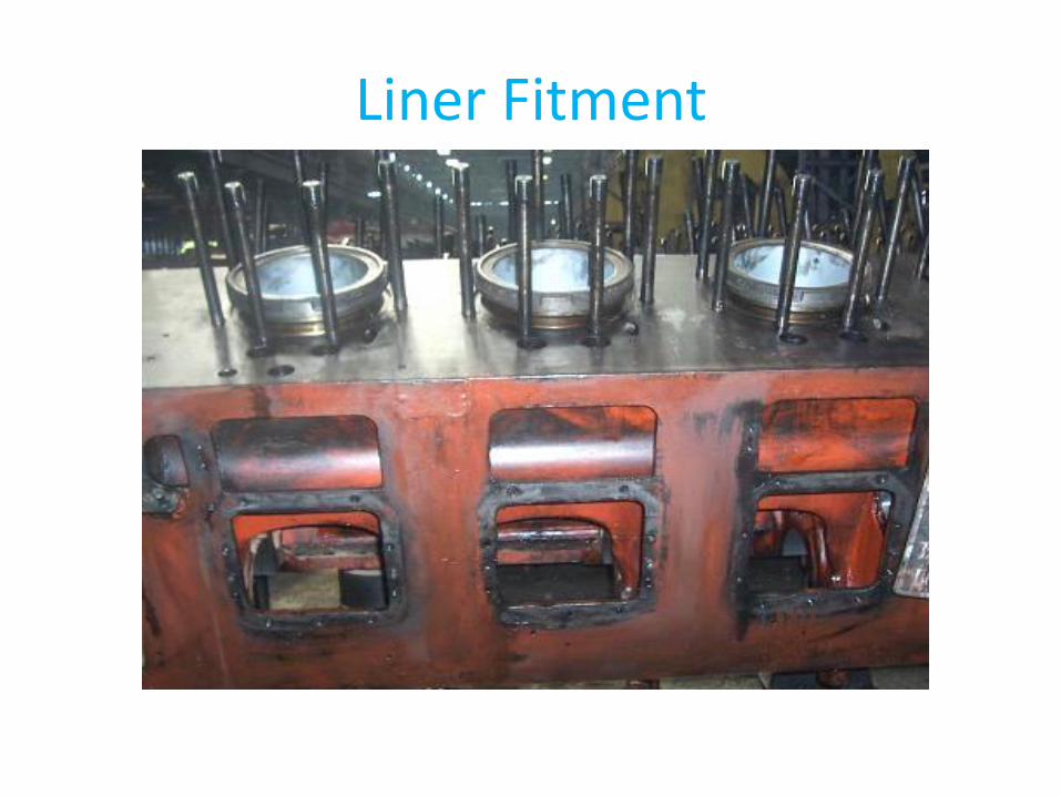
Liner Fitment
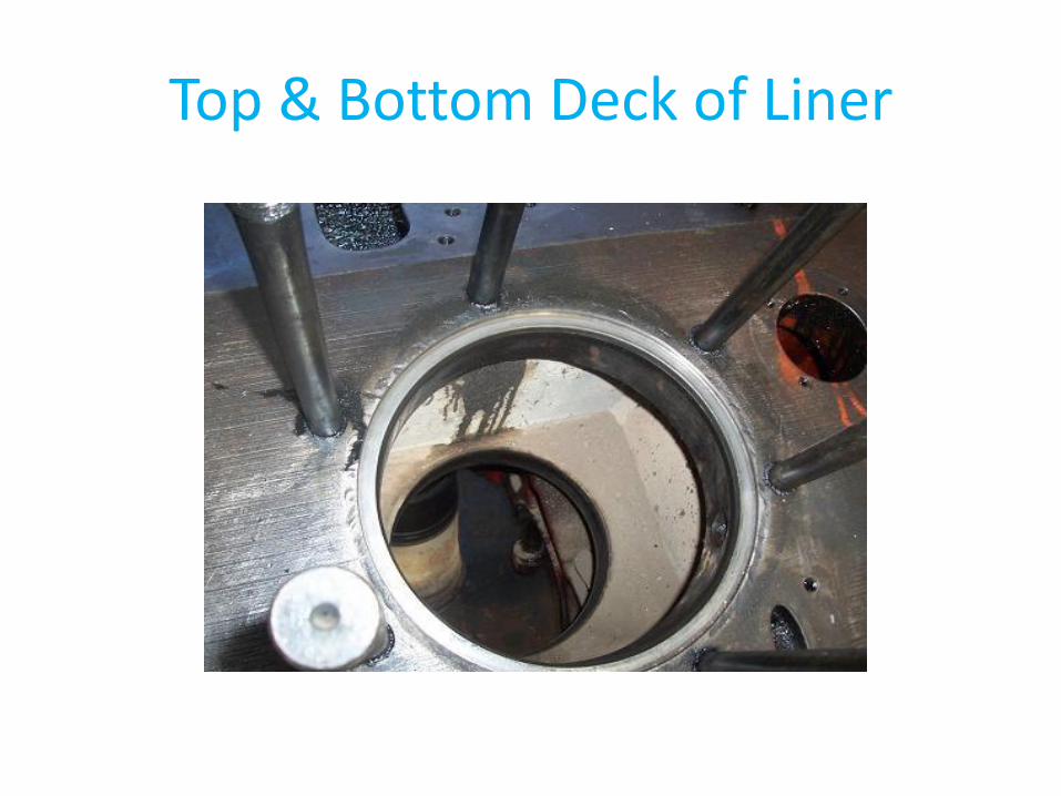
Top & Bottom Deck of Liner
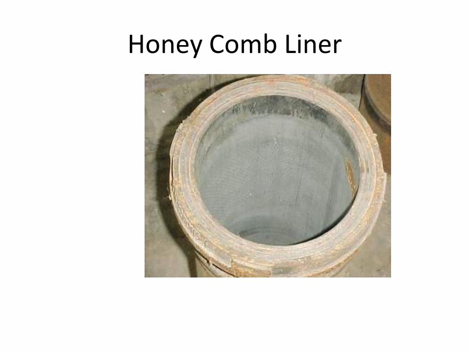
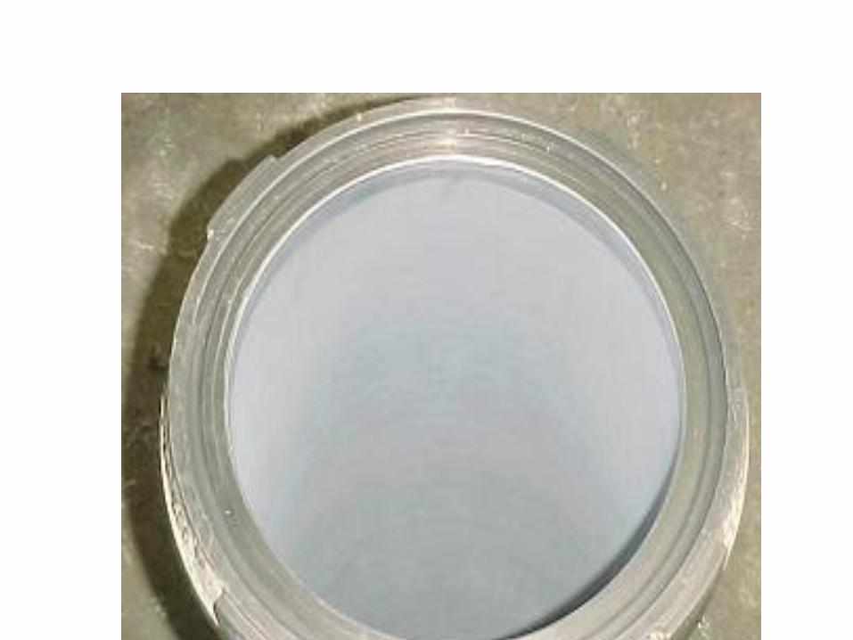
Honey Comb Liner
• HONEY CHROME LINER
• Surface hardened with chrome layer.
• Layer thickness 6-8 thou.
• Surface hardened to 1000 VHN.
• Surface finish to 50-100 RMS
OPEN GRAIN LINER
• Surface hardened with chrome layer.
• Layer thickness 7.5-9.5 thou.
• Surface hardened to 1000 BHN.
• Surface hardened with chrome layer.
• Low manufacturing cost.
• Plating surface finish to 40-80RMS.
• Advantages: Longer life, Lower LOC
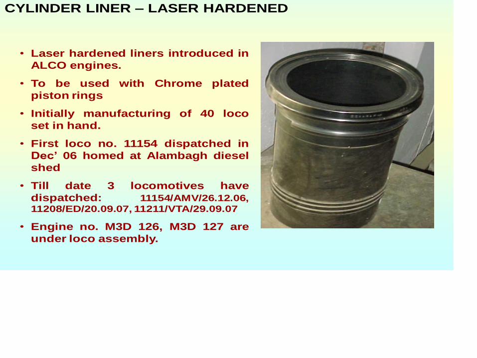
• Laser hardened liners introduced in
ALCO engines.
• To be used with Chrome plated
piston rings
• Initially manufacturing of 40 loco
set in hand.
• First loco no. 11154 dispatched in
Dec’ 06 homed at Alambagh diesel
shed
• Till date 3 locomotives have
dispatched: 11154/AMV/26.12.06,
11208/ED/20.09.07, 11211/VTA/29.09.07
• Engine no. M3D 126, M3D 127 are
under loco assembly.
CYLINDER LINER – LASER HARDENED
Cylinder Liner
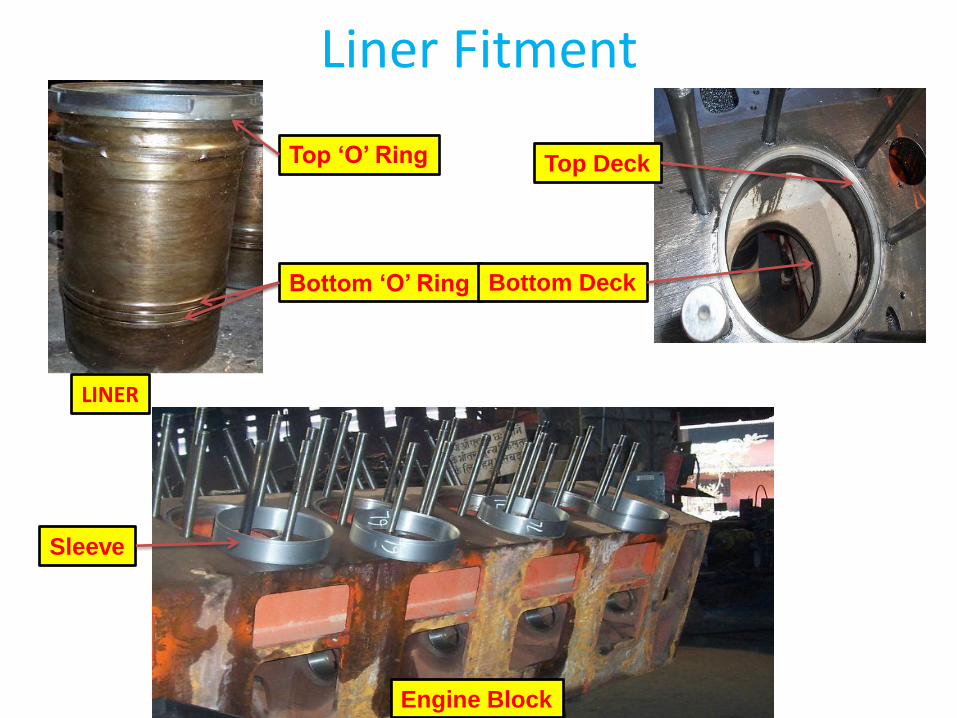
Liner Fitment
Sleeve
Top ‘O’ Ring
Bottom ‘O’ Ring
Top Deck
Bottom Deck
LINER
Engine Block
CONNECTIING ROD
• Connecting rod is a member connecting piston and crank shaft and is a medium for converting the reciprocating motion to rotary motion. In four stroke engines during the compression and power stroke the connecting rod is subject to high compressive load. In suction stroke it under goes tensile stress. In case of two cycle engine the connecting rod is only subject to compressive load.
• Connecting rod length is usually about 4 to 5 times of the crank radius, Most connecting rods are made of “section having a file drilled hole from the big end to the small end.
• The connecting rod assembly consists of: -
•
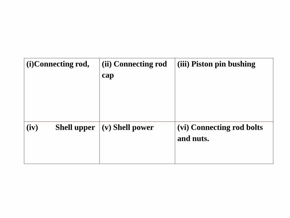
(i)Connecting rod, (ii) Connecting rod
cap
(iii) Piston pin bushing
(iv) Shell upper (v) Shell power (vi) Connecting rod bolts
and nuts.
• During assembly the bolts are to be tightened with specified torque valve and elongation. In case of ALCO Locos the bolts are first to be tightened to 20 foot pounds and then to 100 foot pounds. Then each bolt is loosened and then retightened to elongation value. 0.015” following cross wise pattern. In case of MAK engine the connecting rod is of round section and there is provision for dowel on the bolt head to prevent the bolt from turning.
• Connecting rods are mostly made of carbon steel or alloy steel forgings. The metallurgical composition of connecting rod are given below in percentage.
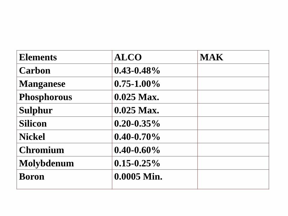
Elements ALCO MAK
Carbon 0.43-0.48%
Manganese 0.75-1.00%
Phosphorous 0.025 Max.
Sulphur 0.025 Max.
Silicon 0.20-0.35%
Nickel 0.40-0.70%
Chromium 0.40-0.60%
Molybdenum 0.15-0.25%
Boron 0.0005 Min.
CAM SHAFT• In diesel engine the cam shaft performs the
vital role of opening and closing inlet and exhaust valves and allowing timely injection of fuel inside the cylinder.
• Usual practice is to provide 3 cams for each cylinder the two outer cams being for exhaust and inlet valves and the central cam being for fuel injection.
• Like most of the Diesel engine manufactures ALCO engines have cams integral with camshaft each camshaft section takes care of two cylinders.
• Providing speed information to Governor
• Driving OST for tripping engine in case of
high speed
• 3 Cams are provided for each Cylinder.
• 2 Outer Cams for Exhaust and Air inlet
valves and central Cam for fuel injection
After profile killing of the cam lobes the cams aregiven for induction hardening. Subsequent to this thecams are put on profile grinding machine which workson the same principle as profile milling machine. Theindividual camshafts are joined together by bolting.The location of dowel hole is of importance as itdetermines the relative angular position of one camshaft section with respect to the adjacent one.
In order to avoid wrong assembly respectivecatalogue Nos. of camshaft sections are punched ontothe shaft.Care has to be taken to see that the correct section isfitted in correct location.
The rifle hole is made in the centre of the shaft forlubrication of cam bearings. Lubrication to cam lobesis provided by oil coming from valve levermechanism via the push rod.
• Cam lobes and rollers are lubricated throughgravity fed oil dropping from cylinder headthrough push rod holes.
• Lateral movement of Camshaft restricted byThrust bearing at free end..
• On the right side, the bearing is contained inOST Housing and on left side in a Thrustbearing housing.
• Camshaft Thrust:0.006”-0.012”(New),0.022” (Limit), Backlash : 0.006” - 0.010”
• At the power take-off end of engine, camshaftgear located on each side, is mounted ontapered end of Camshaft by means of heavylocked Key and Split Camshaft gear nut.
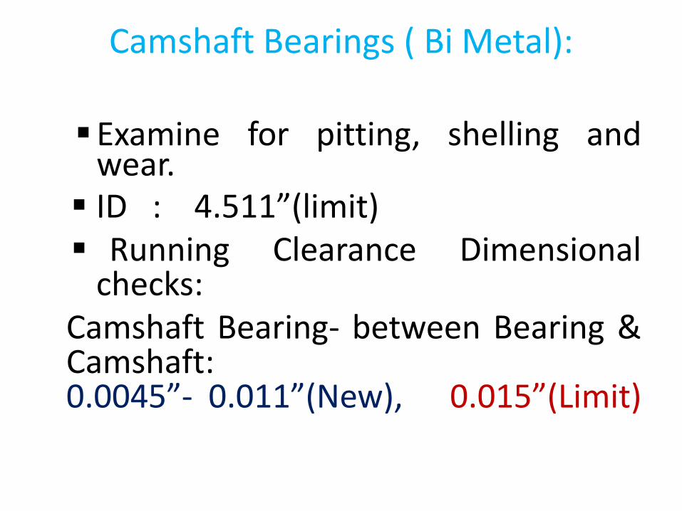
Camshaft Bearings ( Bi Metal):
Examine for pitting, shelling andwear. ID : 4.511”(limit) Running Clearance Dimensional
checks:Camshaft Bearing- between Bearing &Camshaft:0.0045”- 0.011”(New), 0.015”(Limit)
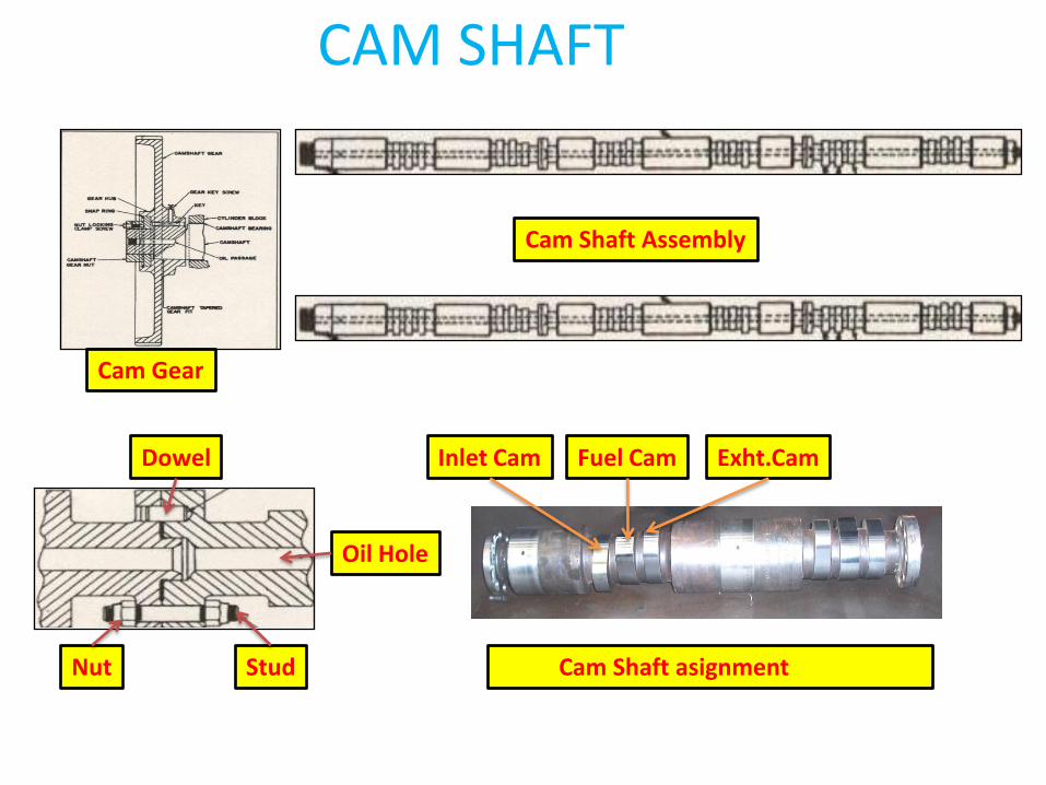
CAM SHAFT
Cam Shaft asignment
Inlet Cam Exht.CamFuel CamDowel
Oil Hole
StudNut
Cam Gear
Cam Shaft Assembly
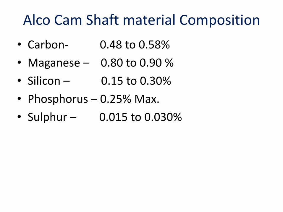
Alco Cam Shaft material Composition
• Carbon- 0.48 to 0.58%
• Maganese – 0.80 to 0.90 %
• Silicon – 0.15 to 0.30%
• Phosphorus – 0.25% Max.
• Sulphur – 0.015 to 0.030%
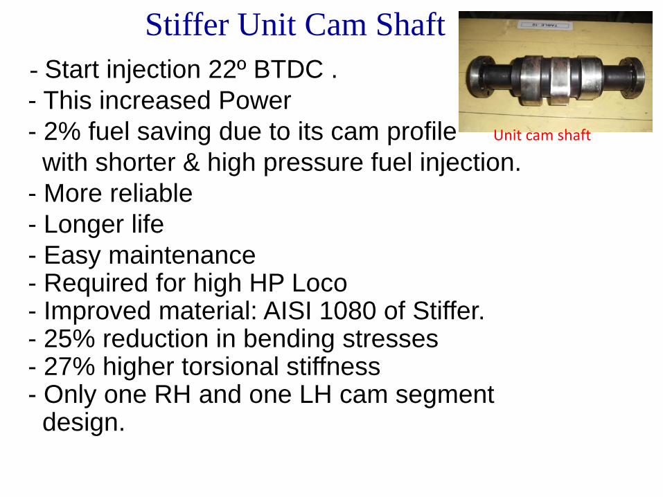
Stiffer Unit Cam Shaft
- Start injection 22º BTDC .
- This increased Power
- 2% fuel saving due to its cam profile
with shorter & high pressure fuel injection.
- More reliable
- Longer life
- Easy maintenance - Required for high HP Loco - Improved material: AISI 1080 of Stiffer.- 25% reduction in bending stresses - 27% higher torsional stiffness - Only one RH and one LH cam segment design.
Unit cam shaft
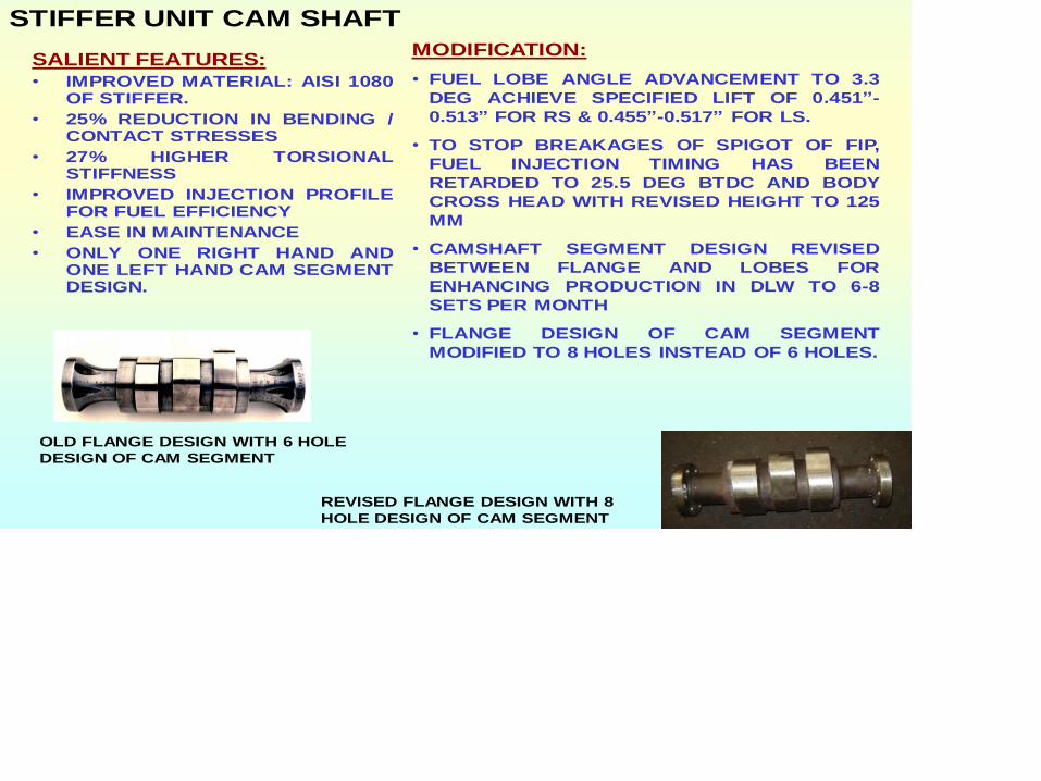
STIFFER UNIT CAM SHAFT
SALIENT FEATURES:
• IMPROVED MATERIAL: AISI 1080OF STIFFER.
• 25% REDUCTION IN BENDING /CONTACT STRESSES
• 27% HIGHER TORSIONALSTIFFNESS
• IMPROVED INJECTION PROFILEFOR FUEL EFFICIENCY
• EASE IN MAINTENANCE
• ONLY ONE RIGHT HAND ANDONE LEFT HAND CAM SEGMENTDESIGN.
MODIFICATION:
• FUEL LOBE ANGLE ADVANCEMENT TO 3.3
DEG ACHIEVE SPECIFIED LIFT OF 0.451”-
0.513” FOR RS & 0.455”-0.517” FOR LS.
• TO STOP BREAKAGES OF SPIGOT OF FIP,
FUEL INJECTION TIMING HAS BEEN
RETARDED TO 25.5 DEG BTDC AND BODY
CROSS HEAD WITH REVISED HEIGHT TO 125
MM
• CAMSHAFT SEGMENT DESIGN REVISED
BETWEEN FLANGE AND LOBES FOR
ENHANCING PRODUCTION IN DLW TO 6-8
SETS PER MONTH
• FLANGE DESIGN OF CAM SEGMENT
MODIFIED TO 8 HOLES INSTEAD OF 6 HOLES.
REVISED FLANGE DESIGN WITH 8
HOLE DESIGN OF CAM SEGMENT
OLD FLANGE DESIGN WITH 6 HOLE
DESIGN OF CAM SEGMENT
Timing Setting
Valve Timing• Rotate the crankshaft and bring the corresponding cylinder
to compression stroke (ensure compression stroke by feeling free rotation of push rods.)
• Check the gap between the valve stem and yoke. It should be 0.034".
FIP Timing• Rotate the engine to bring the injection point against the
corresponding cylinder.• Match the body cut mark of FIP at inspection window with
the given line mark on guide cup .If not, adjust it through timing allen screw provided at the bottom of the FP lifter.
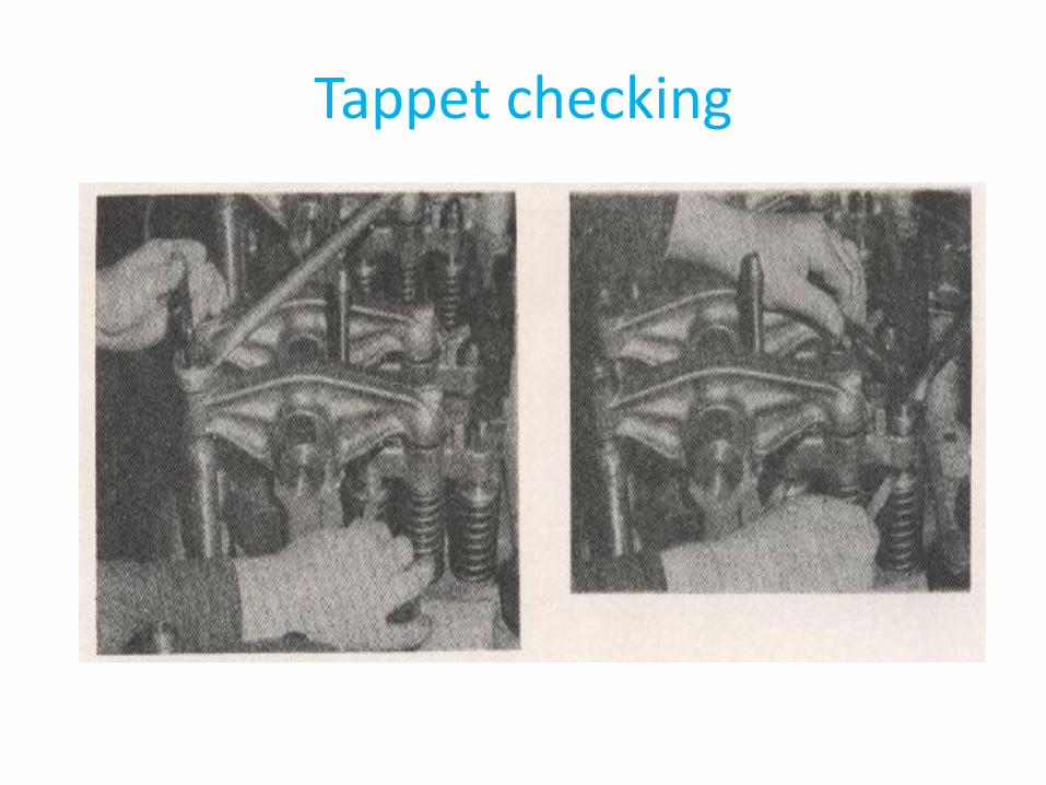
Tappet checking
Crank Shaft• It converts reciprocating motion into rotary
motion.
• The engine crankshaft is the singular costliest item in the diesel engine.
• The crankshaft may be assembled type or two piece bolted type or may be single piece forging. Balance weights can be either bolted up or welded.
• The standard Locos of Indian Railways are with single piece crankshaft with welded counter weights.
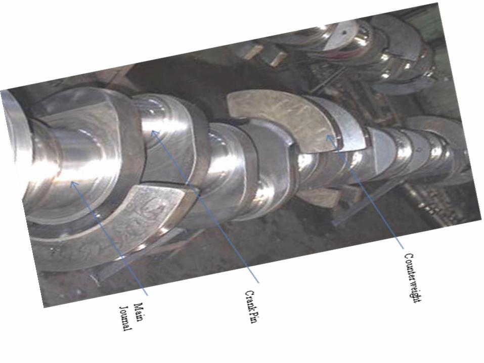
• The portions of crank shaft which form
the axis of rotation are called journals.
• The eccentric portions where piston is
connected through connecting rod are
called crankpins.
- It has 9 main journals and 8 crankpins
to accommodate 16 pistons.
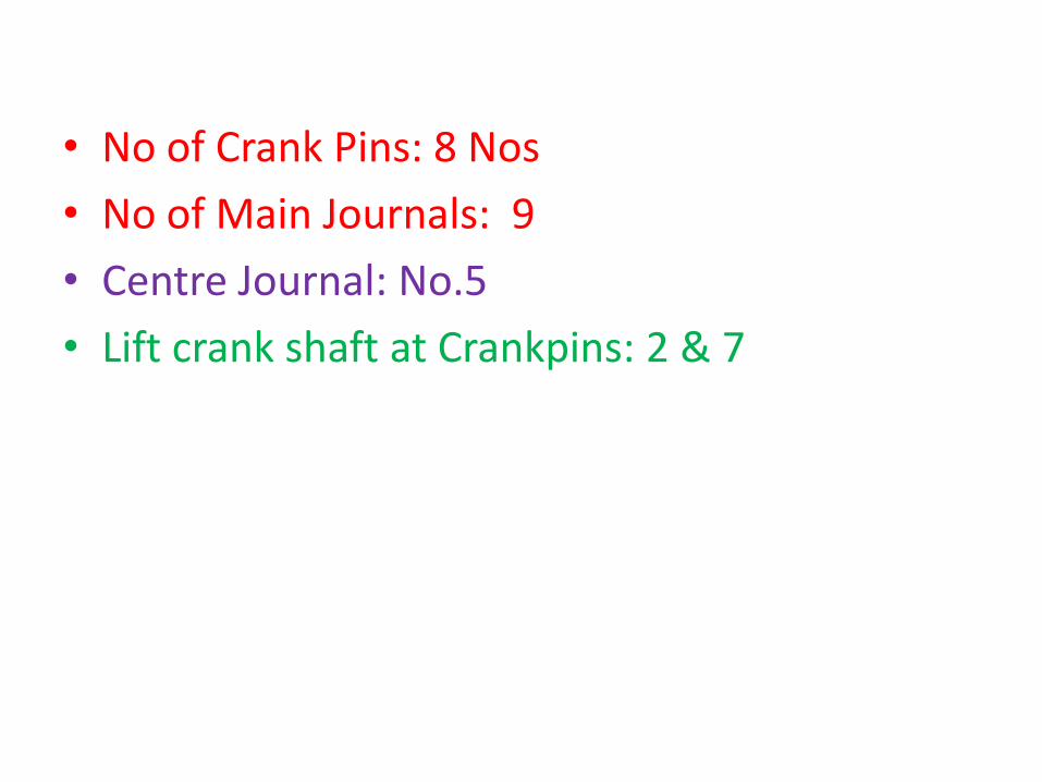
• No of Crank Pins: 8 Nos
• No of Main Journals: 9
• Centre Journal: No.5
• Lift crank shaft at Crankpins: 2 & 7
• It gives mechanical drive to:-
– Camshafts
– Expressor / Compressor
– Radiator Fan
– Water pump
– Lube oil pump,
– Tr. Motor Blower

Alco Crank Shaft Material• Crank Shafts are manufactured from chrome-
molybdenum steel equivalent to SAE 4140.
• Surface Hardening-
• 1)- Induction Hardening(C-40) Depth- 0.124”
• 2)- Nitriding (C-60) Depth- 0.012” to 0.015”
• Checking of crank shaft deflection is one of the standard methods used by engine manufacturers and maintainer for ensuring correct alignment of crankshaft as also engine bearing housing bore central line. The basis involved in this is that if the crank shaft is bent/misaligned or for that matter engine block bore is out of alignment then the distance between the related crank web faces, will vary when the crankshaft is rotated.
• The variation to a small degree will in any case be there. But whenever there is variation more than prescribed limit it may be inferred that either crankshaft is bent or block bore central line is misaligned. In ALCO engines the crankshaft deflection is measured at the crank web nearest to the generator.
• As apart from crank shaft and engine block bore misalignment the relative position of the generator roller bearing with respect to the engine main bearing bore causes further deflection.
• In these Locos a maximum deflection of +0.008" is permissible. The correction of the excess deflection is done by adding or removing shines between magnet frame distance piece and engine block.
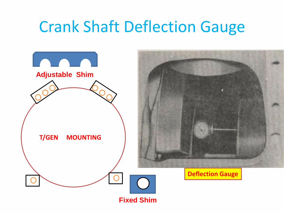
Crank Shaft Deflection Gauge
T/GEN MOUNTING
Adjustable Shim
Fixed Shim
Deflection Gauge
Crank Shaft Maintenance• Visual inspection for damage
• DPT / Magna flux test is conducted to detect surface crack after Cleaning
• Measure the following dimensions:
Crank pin: Check dimension vertically at two locations just beside
two oil holes to check ovality and taperness.– Nominal Dia: 6", Limit upto 5.996“
– Ovality: .002"(max) Taperness: .001"(max)
Main journal: Measure the dimension of crank pin.– Nominal Dia: 8.5", Limit upto 8.496“
– Ovality:002" (max) Taperness: .001" (max)
Eccentricity checking: Eccentricity is checked between any three
consecutive main journals.
Checking Crankshaft Thrust
•At location other than thrust bearing,
use pinch bar between bearing cap and
crankshaft web to pry crankshaft forward
and backward.
• It should be 012”-017”,Limit-035”.
•Measure clearance between thrust face
and crank web.