Embed Size (px)
Citation preview
D660 SeriesServo-Proportional Control Valveswith Integrated ElectronicsISO 4401 Size 05 to 10
OVERVIEW
Section Page
Overview 2–3
Technical Data 4–5
Electronics 6-9
Performance Specs. 10-19
Fail-Safe Versions 20-25
Ordering Information 26-27
MOOG SERVO-PROPORTIONAL CONTROL VALVES
For over 25 years Moog has manufactured proportional control valveswith integrated electronics. During this time more than 150,000 valveshave been delivered. These proportional control valves have beenproven to provide reliable control of including injection and blowmolding equipment, die casting machines, presses, heavy industryequipment, paper and lumber processing and other applications.
D660 SERIES SERVO-PROPORTIONAL CONTROL VALVES
The D660 Series proportional flow control valves are throttle valves for2, 3, 4 and 5-way applications. These valves are suitable forelectrohydraulic position, velocity, pressure or force control systems,including those with high dynamic response requirements.
Over time, Moog servo-proportional valves have undergonecontinuous improvements. Moog’s ServoJet® pilot stage reducesenergy consumption and enhances the valves robustness. This pilotstage uses the jet pipe principle, which has been used reliably withdifferent Moog valves for over 10 years.
We have updated D660 Series servo-proportional valves with newintegrated 24 VDC electronics which improve valve dynamics significantly.
The improved D660 Series is designed to enhance the stability andperformance of the valves in a wider variety of applications, increasethe number of signal options and improve the fail-safe functionality ofan application.
We have also redesigned the valve’s ServoJet® pilot stage, reducinghysteresis and null shift and improving pressure gain. Also, theupdated ServoJet® pilot stage now has the ability to operate at a plusor minus 150 mA rated signal.
The new integrated electronics improve valve dynamics by up to 30percent and now have a 24 VDC supply voltage, as well as 4 to 20 mAspool position output as options.
Changes in the D660 Series allow the 90° phase lag frequency responsecharacteristic for small signals (10% amplitude) to increase from 78 Hzto 90 Hz in the D661 Series, (NG 10).
Other improvements in the D660 Series address many safetyconsiderations in die-casting machines, injection-molding machinesand presses. These include:
The valve now places an enable signal at the operator’s disposal.If no enabled signal is available, the spool in the second stagemoves to a predefined position (hydraulic zero or end position)depending on valve variant.
The valve monitors supply voltage. If voltage on the updatedvalve (18 V up to 32 V) should drop below 18 V, the end positionwill be disconnected and the spool will move to its predefinedposition (fail-safe). It will be monitored as soon as it reaches thisposition and will be confirmed by a logic output.
The logic outputs are short circuit protected. Maximum continuousvoltage is 32 V with surge pulses up to 500 V and burst of 4 kV (perEMC standard).
D
Our quality management systemis certified in accordance with DINEN ISO 9001.
The valve series described in thiscatalogue have successfullypassed EMC tests required by ECDirective. Please refer to therespective references in theelectronics section.
Valves available with explosionprotection to EN 50018, class EExd LL C-C 2 H 2 T5. Note: Installation dimensions andelectric connection altered.Special data sheet on request.
This catalogue is for users with technical knowledge.To ensure that all necessary characteristics forfunction and safety of the system are given, the userhas to check the suitability of the products describedherein. In case of doubt please contact Moog.
2 Moog • D660 Series
Fail-safe optionD660 valves are available with either amechanical or electrically controlled fail-safe option. Certain conditions must existfor the fail-safe to work reliably. See thetype designation section for fail-safe onpage 20 for more information.
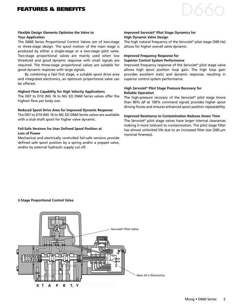
Flexible Design Elements Optimize the Valve to Your ApplicationThe D660 Series Proportional Control Valves are of two-stageor three-stage design. The spool motion of the main stage isproduced by either a single-stage or a two-stage pilot valve.Two-stage proportional valves are mainly used when lowthreshold and good dynamic response with small signals arerequired. The three-stage proportional valves are suitable forgood dynamic response with large signals.
By combining a fast first stage, a suitable spool drive areaand integrated electronics, an optimum proportional valve canbe offered.
Highest Flow Capability for High Velocity ApplicationsThe D07 to D10 (NG 16 to NG 32) D660 Series valves offer thehighest flow per body size.
Reduced Spool Drive Area for Improved Dynamic ResponseThe D07 to D10 (NG 16 to NG 32) D660 Series valves are availablewith a stub shaft spool for higher valve dynamic.
Fail-Safe Versions for User Defined Spool Position at Loss of PowerMechanical and electrically controlled fail-safe versions providedefined safe spool position by a spring and/or a poppet valve,and/or by external hydraulic supply cut off.
Improved ServoJet® Pilot Stage Dynamics for High Dynamic Valve DesignThe high natural frequency of the ServoJet® pilot stage (500 Hz)allows for higher overall valve dynamic.
Improved Frequency Response for Superior Control System PerformanceImproved frequency response of the ServoJet® pilot stage valveallows high spool position loop gain. The high loop gainprovides excellent static and dynamic response, resulting insuperior control system performance.
High ServoJet® Pilot Stage Pressure Recovery for Reliable OperationThe high-pressure recovery of the ServoJet® pilot stage (morethan 80% ∆P at 100% command signal) provides higher spooldriving forces and ensures enhanced spool position repeatability.
Improved Resistance to Contamination Reduces Down TimeThe ServoJet® pilot stage valves have larger internal clearancesmaking it more tolerant to contamination. The pilot stage filterhas almost unlimited life due to an increased filter size (200 µmnominal fineness).
FEATURES & BENEFITS D
2-Stage Proportional Control Valve
New 24 V Electronics
ServoJet® Pilot Valve
X T A P B T2 Y
Moog • D660 Series 3
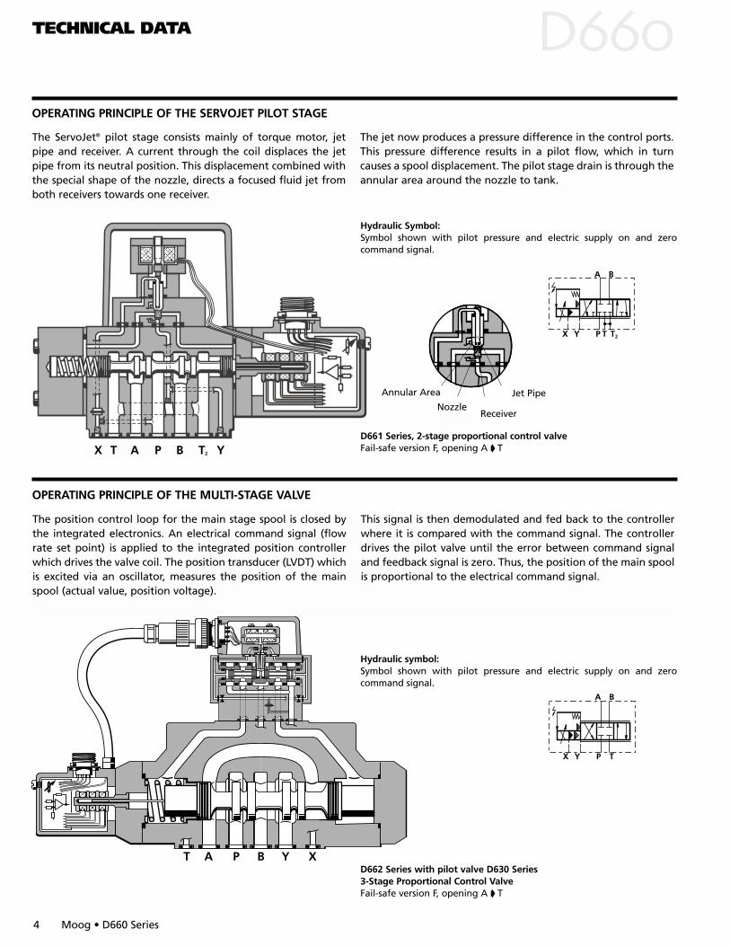
Annular Area
NozzleReceiver
Jet Pipe
TECHNICAL DATA
OPERATING PRINCIPLE OF THE MULTI-STAGE VALVE
D
D661 Series, 2-stage proportional control valve Fail-safe version F, opening A T
Hydraulic Symbol:Symbol shown with pilot pressure and electric supply on and zerocommand signal.
OPERATING PRINCIPLE OF THE SERVOJET PILOT STAGE
The ServoJet® pilot stage consists mainly of torque motor, jetpipe and receiver. A current through the coil displaces the jetpipe from its neutral position. This displacement combined withthe special shape of the nozzle, directs a focused fluid jet fromboth receivers towards one receiver.
The jet now produces a pressure difference in the control ports.This pressure difference results in a pilot flow, which in turncauses a spool displacement. The pilot stage drain is through theannular area around the nozzle to tank.
X T A P B T2 Y
D662 Series with pilot valve D630 Series 3-Stage Proportional Control Valve Fail-safe version F, opening A T
T A P B Y X
Hydraulic symbol:Symbol shown with pilot pressure and electric supply on and zerocommand signal.
The position control loop for the main stage spool is closed bythe integrated electronics. An electrical command signal (flowrate set point) is applied to the integrated position controllerwhich drives the valve coil. The position transducer (LVDT) whichis excited via an oscillator, measures the position of the mainspool (actual value, position voltage).
This signal is then demodulated and fed back to the controllerwhere it is compared with the command signal. The controllerdrives the pilot valve until the error between command signaland feedback signal is zero. Thus, the position of the main spoolis proportional to the electrical command signal.
4 Moog • D660 Series
TECHNICAL DATA
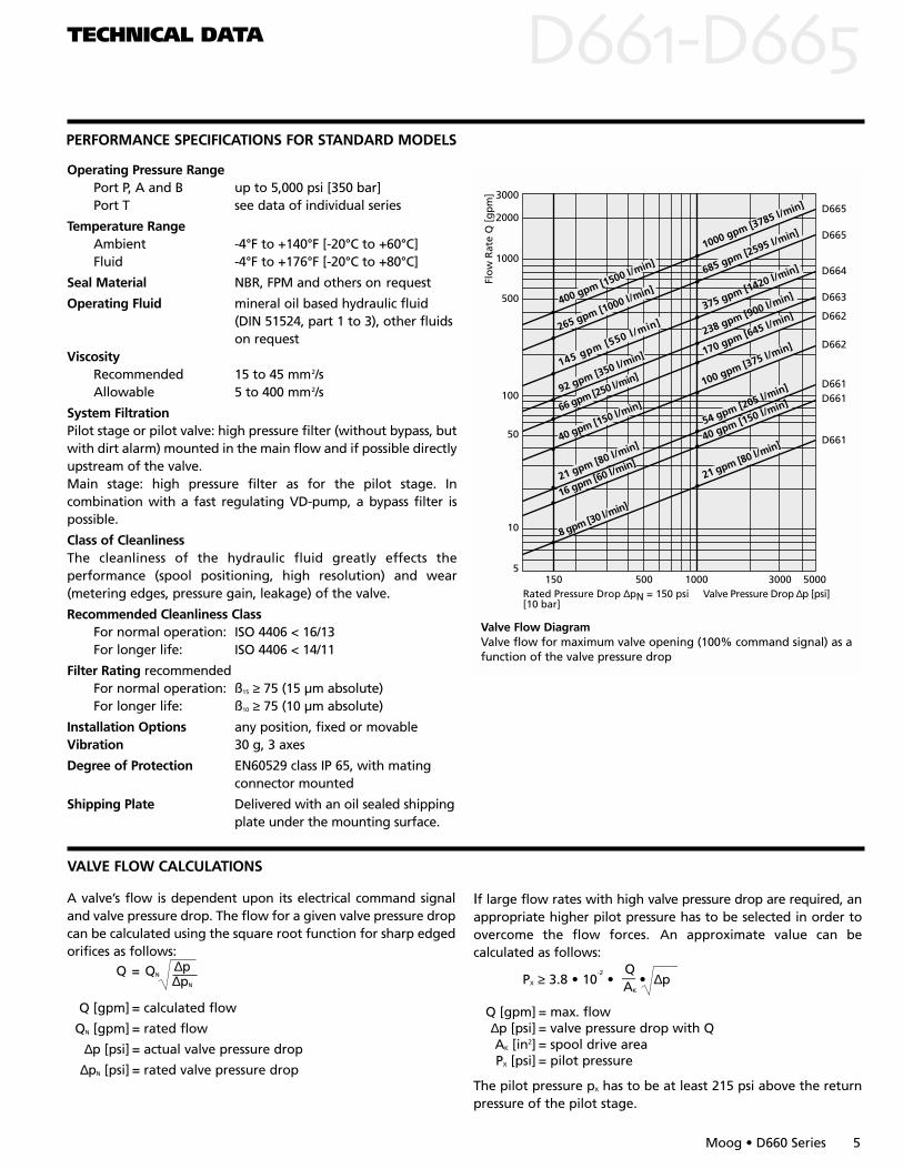
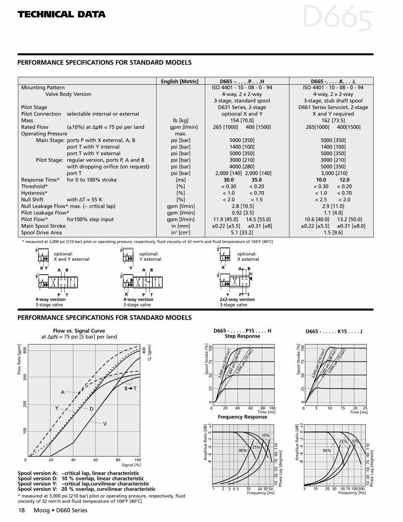
PERFORMANCE SPECIFICATIONS FOR STANDARD MODELS
DD
D665
D665
D664
D663
D662
D662
D661D661
D661
3000
2000
1000
500
100
50
10
5150 1000 3000 5000500
145 gpm [550 l/min]
92 gpm [350 l/min]
40 gpm [150 l/min]
21 gpm [80 l/min]
16 gpm [60 l/min]
8 gpm [30 l/min]
1000 gpm [3785 l/min]
685 gpm [2595 l/min]
375 gpm [1420 l/min]
238 gpm [900 l/min]
170 gpm [645 l/min]
100 gpm [375 l/min]
54 gpm [205 l/min]
40 gpm [150 l/min]
21 gpm [80 l/min]
66 gpm [250 l/min]
400 gpm [1500 l/min]
265 gpm [1000 l/min]
Flo
w R
ate
Q [
gp
m]
Rated Pressure Drop ∆pN = 150 psi[10 bar]
Valve Pressure Drop ∆p [psi]
Valve Flow DiagramValve flow for maximum valve opening (100% command signal) as afunction of the valve pressure drop
Operating Pressure RangePort P, A and B up to 5,000 psi [350 bar]Port T see data of individual series
Temperature Range Ambient -4°F to +140°F [-20°C to +60°C]Fluid -4°F to +176°F [-20°C to +80°C]
Seal Material NBR, FPM and others on request
Operating Fluid mineral oil based hydraulic fluid (DIN 51524, part 1 to 3), other fluids on request
ViscosityRecommended 15 to 45 mm2/sAllowable 5 to 400 mm2/s
System FiltrationPilot stage or pilot valve: high pressure filter (without bypass, butwith dirt alarm) mounted in the main flow and if possible directlyupstream of the valve.Main stage: high pressure filter as for the pilot stage. In combination with a fast regulating VD-pump, a bypass filter ispossible.
Class of CleanlinessThe cleanliness of the hydraulic fluid greatly effects the performance (spool positioning, high resolution) and wear(metering edges, pressure gain, leakage) of the valve.
Recommended Cleanliness ClassFor normal operation: ISO 4406 < 16/13For longer life: ISO 4406 < 14/11
Filter Rating recommendedFor normal operation: ß15 ≥ 75 (15 µm absolute)For longer life: ß10 ≥ 75 (10 µm absolute)
Installation Options any position, fixed or movableVibration 30 g, 3 axes
Degree of Protection EN60529 class IP 65, with mating connector mounted
Shipping Plate Delivered with an oil sealed shippingplate under the mounting surface.
Moog • D660 Series 5
VALVE FLOW CALCULATIONS
A valve’s flow is dependent upon its electrical command signaland valve pressure drop. The flow for a given valve pressure dropcan be calculated using the square root function for sharp edgedorifices as follows:
∆pQ = QN
∆pN
Q [gpm] = calculated flow
QN [gpm] = rated flow
∆p [psi] = actual valve pressure drop
∆pN [psi] = rated valve pressure drop
If large flow rates with high valve pressure drop are required, anappropriate higher pilot pressure has to be selected in order toovercome the flow forces. An approximate value can becalculated as follows:
QPX ≥ 3.8 • 10
-2• — • ∆pAK
Q [gpm] = max. flow∆p [psi] = valve pressure drop with QAK [in2] = spool drive areaPX [psi] = pilot pressure
The pilot pressure pX has to be at least 215 psi above the returnpressure of the pilot stage.
ELECTRONICS DD
6 Moog • D660 Series
GENERAL REQUIREMENTS FOR VALVE ELECTRONICS
Supply 24 VDC, min. 18 VDC, max. 32 VDC. Current consumption max. 300 mA
All signal lines, also those of external transducers, shielded Shielding connected radially to ⊥ (0 V), power supply side
and connected to the mating connector housing (EMC) EMC: Meets the requirements of EN 55011:1998 class B,
EN 50082-2:1995, performance criteria class A Protective grounding lead ≥ .75 mm2 [18 AWG] Note: When making electrical connections to the valve
(shield, protective grounding), appropriate measures mustbe taken to ensure that locally different earth potentials donot result in excessive ground currents.
ELECTRONICS DDVALVE ELECTRONICS WITH SUPPLY VOLTAGE 24 VOLT AND 6+PE POLE CONNECTOR
Moog • D660 Series 7
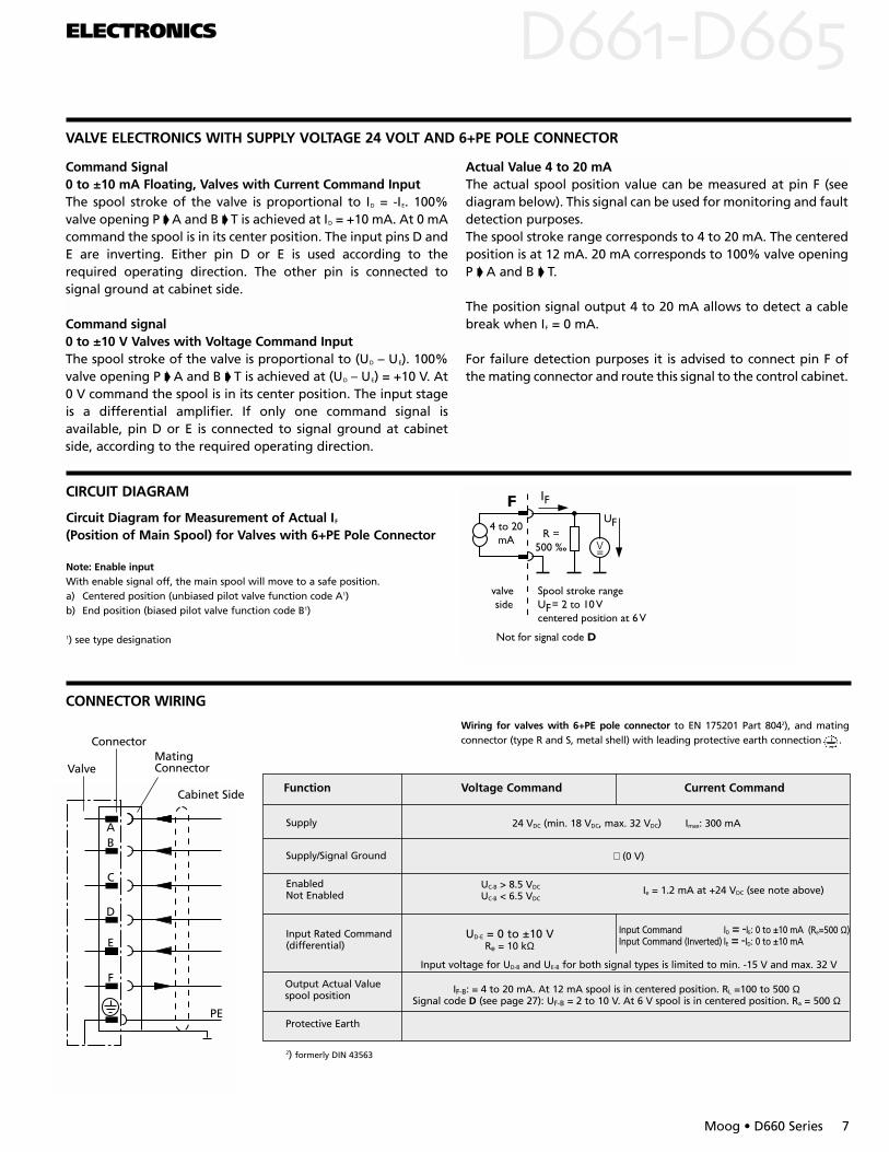
Command Signal 0 to ±10 mA Floating, Valves with Current Command InputThe spool stroke of the valve is proportional to ID = -IE. 100%valve opening P A and B T is achieved at ID = +10 mA. At 0 mAcommand the spool is in its center position. The input pins D andE are inverting. Either pin D or E is used according to therequired operating direction. The other pin is connected tosignal ground at cabinet side.
Command signal 0 to ±10 V Valves with Voltage Command InputThe spool stroke of the valve is proportional to (UD – UE). 100%valve opening P A and B T is achieved at (UD – UE) = +10 V. At0 V command the spool is in its center position. The input stageis a differential amplifier. If only one command signal isavailable, pin D or E is connected to signal ground at cabinetside, according to the required operating direction.
Actual Value 4 to 20 mAThe actual spool position value can be measured at pin F (seediagram below). This signal can be used for monitoring and faultdetection purposes. The spool stroke range corresponds to 4 to 20 mA. The centeredposition is at 12 mA. 20 mA corresponds to 100% valve openingP A and B T.
The position signal output 4 to 20 mA allows to detect a cablebreak when IF = 0 mA.
For failure detection purposes it is advised to connect pin F ofthe mating connector and route this signal to the control cabinet.
CIRCUIT DIAGRAMF IF
4 to 20mA R =
500 ‰
valve side
Spool stroke rangeU = 2 to 10 Vcentered position at 6 V
F
UF
Not for signal code D
Note: Enable inputWith enable signal off, the main spool will move to a safe position.a) Centered position (unbiased pilot valve function code A1)b) End position (biased pilot valve function code B1)
1) see type designation
CONNECTOR WIRING
AB
C
D
E
F
PE
Cabinet Side
MatingConnector
Connector
Valve
Wiring for valves with 6+PE pole connector to EN 175201 Part 8042), and matingconnector (type R and S, metal shell) with leading protective earth connection .
Output Actual Valuespool position
Input Rated Command(differential)
Input Command ID = -IE: 0 to ±10 mA Input Command (Inverted) IE = -ID: 0 to ±10 mA
UD-E = 0 to ±10 VRe = 10 kΩ
Ie = 1.2 mA at +24 VDC (see note above)UC-B > 8.5 VDC
UC-B < 6.5 VDC
EnabledNot Enabled
Supply/Signal Ground ⊥ (0 V)
Voltage CommandFunction Current Command
Supply 24 VDC (min. 18 VDC, max. 32 VDC) Imax: 300 mA
IF-B: = 4 to 20 mA. At 12 mA spool is in centered position. RL =100 to 500 ΩSignal code D (see page 27): UF-B = 2 to 10 V. At 6 V spool is in centered position. Ra = 500 Ω
Protective Earth
Input voltage for UD-B and UE-B for both signal types is limited to min. -15 V and max. 32 V
2) formerly DIN 43563
(Re=500 Ω)
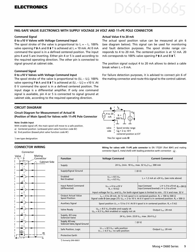
Circuit Diagram for Measurement of Actual IF
(Position of Main Spool) for Valves with 6+PE Pole Connector
VALVE ELECTRONICS WITH SUPPLY VOLTAGE 24 VOLT AND 11+PE POLE CONNECTOR
6 I6
4 to 20mA R =
500 ‰
valve side
Spool stroke rangeU = 2 to 10 Vcentered position at 6 V
U6
Not for signal code D
6
Note: Enable inputWith enable signal off, the main spool will move to a safe position.a) Centered position (unbiased pilot valve function code E1)b) End position (biased pilot valve function code F1)
1) see type designation
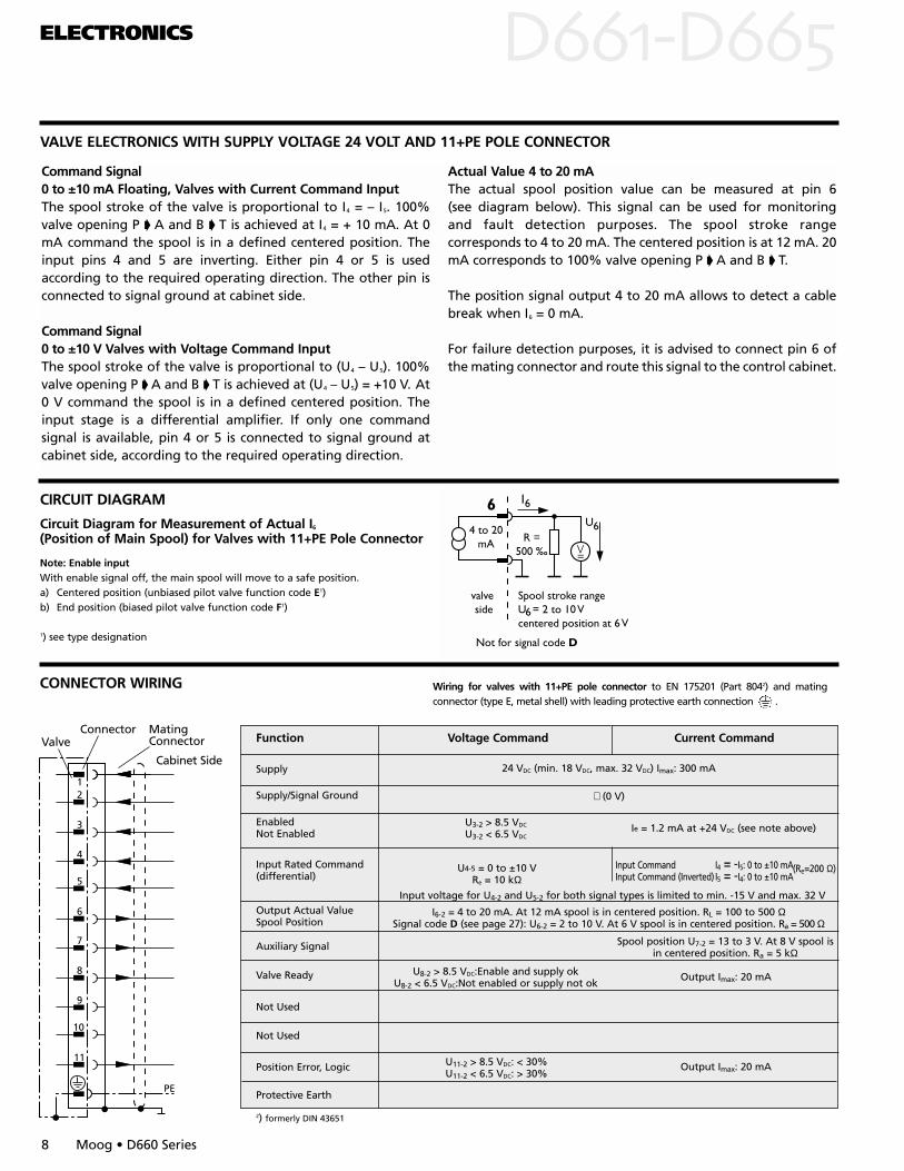
Command Signal 0 to ±10 mA Floating, Valves with Current Command InputThe spool stroke of the valve is proportional to I4 = – I5. 100%valve opening P A and B T is achieved at I4 = + 10 mA. At 0mA command the spool is in a defined centered position. Theinput pins 4 and 5 are inverting. Either pin 4 or 5 is usedaccording to the required operating direction. The other pin isconnected to signal ground at cabinet side.
Command Signal0 to ±10 V Valves with Voltage Command InputThe spool stroke of the valve is proportional to (U4 – U5). 100%valve opening P A and B T is achieved at (U4 – U5) = +10 V. At0 V command the spool is in a defined centered position. Theinput stage is a differential amplifier. If only one commandsignal is available, pin 4 or 5 is connected to signal ground atcabinet side, according to the required operating direction.
Actual Value 4 to 20 mAThe actual spool position value can be measured at pin 6 (see diagram below). This signal can be used for monitoring and fault detection purposes. The spool stroke rangecorresponds to 4 to 20 mA. The centered position is at 12 mA. 20mA corresponds to 100% valve opening P A and B T.
The position signal output 4 to 20 mA allows to detect a cablebreak when I6 = 0 mA.
For failure detection purposes, it is advised to connect pin 6 ofthe mating connector and route this signal to the control cabinet.
ELECTRONICS DD
8 Moog • D660 Series
Output Actual ValueSpool Position
Input Rated Command(differential)
U4-5 = 0 to ±10 VRe = 10 kΩ
Ie = 1.2 mA at +24 VDC (see note above)U3-2 > 8.5 VDC
U3-2 < 6.5 VDC
EnabledNot Enabled
Supply/Signal Ground ⊥ (0 V)
Voltage CommandFunction Current Command
Supply 24 VDC (min. 18 VDC, max. 32 VDC) Imax: 300 mA
Auxiliary Signal
Valve Ready
Spool position U7-2 = 13 to 3 V. At 8 V spool isin centered position. Ra = 5 kΩ
Output Imax: 20 mAU11-2 > 8.5 VDC: < 30%U11-2 < 6.5 VDC: > 30%
Cabinet Side
Valve
Input voltage for U4-2 and U5-2 for both signal types is limited to min. -15 V and max. 32 V
Input Command I4 = -I5: 0 to ±10 mA Input Command (Inverted) I5 = -I4: 0 to ±10 mA
(Re=200 Ω)
Not Used
Position Error, Logic
Protective Earth
Not Used
Output Imax: 20 mAU8-2 > 8.5 VDC:Enable and supply okU8-2 < 6.5 VDC:Not enabled or supply not ok
2) formerly DIN 43651
CONNECTOR WIRING
Connector MatingConnector
12
3
4
5
6
PE
7
8
9
10
11
Wiring for valves with 11+PE pole connector to EN 175201 (Part 8042) and matingconnector (type E, metal shell) with leading protective earth connection .
CIRCUIT DIAGRAM
Circuit Diagram for Measurement of Actual I6
(Position of Main Spool) for Valves with 11+PE Pole Connector
I6-2 = 4 to 20 mA. At 12 mA spool is in centered position. RL = 100 to 500 ΩSignal code D (see page 27): U6-2 = 2 to 10 V. At 6 V spool is in centered position. Ra = 500 Ω
FAIL-SAFE VALVE ELECTRONICS WITH SUPPLY VOLTAGE 24 VOLT AND 11+PE POLE CONNECTOR
ELECTRONICS DD
Moog • D660 Series 9
Cabinet Side
MatingConnector
Valve
Note: Enable inputWith enable signal off, the main spool will move to a safe position.a) Centered position (unbiased pilot valve function code G1)b) End position (biased pilot valve function code H1)
1) see type designation
CONNECTOR WIRING
CIRCUIT DIAGRAM
Circuit Diagram for Measurement of Actual I6(Position of Main Spool) for Valves with 11+PE Pole Connector
6 I6
4 to 20mA R =
500 ‰
valve side
Spool stroke rangeU = 2 to 10 Vcentered position at 6 V
U6
Not for signal code D
6
Wiring for valves with 11+PE pole connector to EN 175201 (Part 8042) and matingconnector (type E, metal shell) with leading protective earth connection . Connector
Output Actual ValueSpool Position
Input Rated Command(differential)
U4-5 = 0 to ±10 VRe = 10 kΩ
Ie = 1.2 mA at +24 VDC (see note above)U3-2 > 8.5 VDC
U3-2 < 6.5 VDC
EnabledNot Enabled
Supply/Signal Ground ⊥ (0 V)
Voltage CommandFunction Current Command
Supply 24 VDC (min. 18 VDC, max. 32 VDC) Imax: 300 mA
I6-2 = 4 to 20 mA. At 12 mA spool is in centered position. RL = 100 to 500 ΩSignal code D (see page 27): U6-2 = 2 to 10 V. At 6 V spool is in centered position. Ra = 500 Ω
Auxiliary Signal
Valve Ready
Spool position U7-2 = 13 to 3 V. At 8 V spool is in centered position. Ra = 5 kΩ
Output Imax: 20 mAU11-2 > 8.5 VDC: safe positionU11-2 < 6.5 VDC: no safe position
Input voltage for U4-2 and U5-2 for both signal types is limited to min. -15 V and max. 32 V
Input Command I4 = -I5: 0 to ±10 mA Input Command (Inverted) I5 = -I4: 0 to ±10 mA
(Re = 200 Ω)
Supply, 4/2-way Solenoid Valve,Signal Ground
Safe Position, Logic
Protective Earth
Supply, 4/2-way Solenoid Valve
Output Imax: 20 mAU8-2 > 8.5 VDC:Enable and supply okU8-2 < 6.5 VDC:Not enabled or supply not ok
2) formerly DIN 43651
24 VDC (min. 22.8 VDC, max. 26.4 VDC)
⊥ (0 V)
Command Signal 0 to ±10 V Valves with Voltage Command InputThe spool stroke of the valve is proportional to I4 = – I5. 100%valve opening P A and B T is achieved at I4 = 10 mA. At 0 mAcommand the spool is in a defined centered position. The inputpins 4 and 5 are inverting. Either pin 4 or 5 is used according tothe required operating direction. The other pin is connected tosignal ground at cabinet side.
Command Signal 0 to ±10 V Valves with Voltage Command InputThe spool stroke of the valve is proportional to (U4 – U5). 100%valve opening P A and B T is achieved at (U4 – U5) = +10 V. At0 V command the spool is in a defined centered position. Theinput stage is a differential amplifier. If only one commandsignal is available, pin 4 or 5 is connected to signal ground atcabinet side, according to the required operating direction.
Actual Value 4 to 20 mAThe actual spool position value can be measured at pin 6 (see diagram below). This signal can be used for monitoring and fault detection purposes. The spool stroke range cor-responds to 4 to 20 mA. The centered position is at 12 mA. 20mA corresponds to 100% valve opening P A and B T.
The position signal output 4 to 20 mA allows to detect a cablebreak when I6 = 0 mA.
For failure detection purposes, it is advised to connect pin 6 ofthe mating connector and route this signal to the control cabinet.
* measured at 3,000 psi [210 bar] pilot or operating pressure, respectively, fluid viscosity of 32 mm2/s and fluid temperature of 104°F [40°C]
PERFORMANCE SPECIFICATIONS FOR STANDARD MODELS
TECHNICAL DATA DPERFORMANCE SPECIFICATIONS FOR STANDARD MODELS
10 Moog • D660 Series
-10
-30
-50
-70
-90
-110
+2
0-2
-4-6
-8
10%
25%90%
Am
plit
ud
e R
atio
[d
B]
Phas
e La
g [
deg
rees
]
5 10 20 30 50 70100Frequency [Hz]
2005 10 20 30 50 70100
-10
-30
-50
-70
-90
-110
+2
0-2
-4-6
-8
10%
25%
90%Am
plit
ud
e R
atio
[d
B]
Frequency [Hz]
Phas
e La
g [
deg
rees
]
Frequency Response
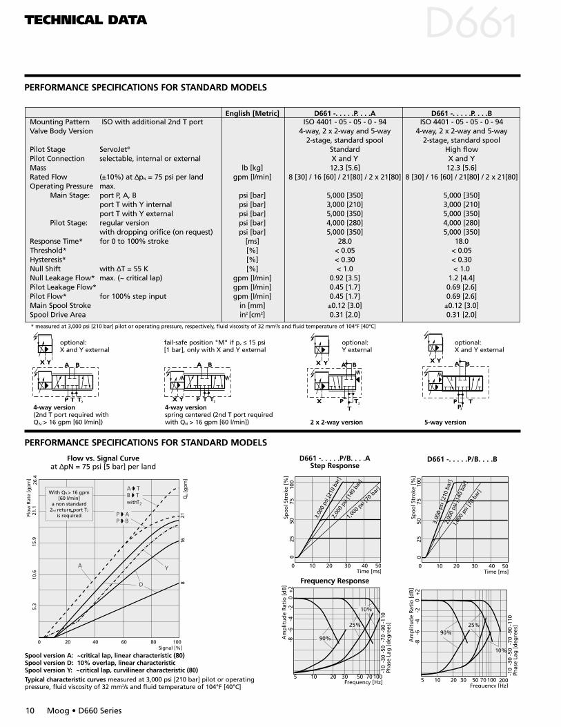
D661 -. . . . .P/B. . . .AStep Response
Spool version A: ~critical lap, linear characteristic (80)Spool version D: 10% overlap, linear characteristicSpool version Y: ~critical lap, curvilinear characteristic (80)Typical characteristic curves measured at 3,000 psi [210 bar] pilot or operatingpressure, fluid viscosity of 32 mm2/s and fluid temperature of 104°F [40°C]
fail-safe position "M" if px ≤ 15 psi[1 bar], only with X and Y external
100
2550
75
0 10 20 30 40
0
2,00
0 ps
i [14
0 ba
r]
1,000
psi
[70 b
ar]
Time [ms]
Spo
ol S
tro
ke [
%]
50
3,00
0 ps
i [21
0 ba
r]
100
2550
75
0 10 20 30 40 50
0
3,00
0 ps
i [21
0 ba
r]2,
000
psi [
140
bar]
1,00
0 ps
i [70
bar
]
Time [ms]
Spo
ol S
tro
ke [
%]
D661 -. . . . .P/B. . . .B
optional: X and Y external
English [Metric] D661 -. . . . .P. . . .A D661 -. . . . .P. . . .BMounting Pattern ISO with additional 2nd T port ISO 4401 - 05 - 05 - 0 - 94 ISO 4401 - 05 - 05 - 0 - 94Valve Body Version 4-way, 2 x 2-way and 5-way 4-way, 2 x 2-way and 5-way
2-stage, standard spool 2-stage, standard spoolPilot Stage ServoJet® Standard High flowPilot Connection selectable, internal or external X and Y X and YMass lb [kg] 12.3 [5.6] 12.3 [5.6]Rated Flow (±10%) at ∆pN = 75 psi per land gpm [l/min] 8 [30] / 16 [60] / 21[80] / 2 x 21[80] 8 [30] / 16 [60] / 21[80] / 2 x 21[80]Operating Pressure max.
Main Stage: port P, A, B psi [bar] 5,000 [350] 5,000 [350]port T with Y internal psi [bar] 3,000 [210] 3,000 [210]port T with Y external psi [bar] 5,000 [350] 5,000 [350]
Pilot Stage: regular version psi [bar] 4,000 [280] 4,000 [280]with dropping orifice (on request) psi [bar] 5,000 [350] 5,000 [350]
Response Time* for 0 to 100% stroke [ms] 28.0 18.0Threshold* [%] < 0.05 < 0.05Hysteresis* [%] < 0.30 < 0.30Null Shift with ∆T = 55 K [%] < 1.0 < 1.0Null Leakage Flow* max. (~ critical lap) gpm [l/min] 0.92 [3.5] 1.2 [4.4]Pilot Leakage Flow* gpm [l/min] 0.45 [1.7] 0.69 [2.6]Pilot Flow* for 100% step input gpm [l/min] 0.45 [1.7] 0.69 [2.6]Main Spool Stroke in [mm] ±0.12 [3.0] ±0.12 [3.0]Spool Drive Area in2 [cm2] 0.31 [2.0] 0.31 [2.0]
Flow vs. Signal Curve at ∆pN = 75 psi [5 bar] per land
with
With QN > 16 gpm[60 l/min]
a non standard2nd return port T2
is required
5.3
10.6
15.9
21.1
2116
8Q
[gp
m]
N
20 40 60 80 100Signal [%]
0
Flo
w R
ate
[gp
m]
26.4
optional:Y external
optional:X and Y external
4-way version(2nd T port required with QN > 16 gpm [60 l/min])
4-way version spring centered (2nd T port requiredwith QN > 16 gpm [60 l/min]) 2 x 2-way version 5-way version
2.83(72)
2.95(75)
.79(20)
2.55
(65)
3.15
(80)
6.26
(159
)
3.11(79)
10.2(258)
1.85
(47)
.26(6.5)
1.65(42)
.43(11)
.45(11.5)
.62 (15.7)
M4
.73(18.7)
.51(
1.3)
8.7(221)
.42 (10.6)3.9 (100)
.39
(9.9
)
.75
(19)
2.54 (64.6)
2.95
(75
)
4.9(
125)
.79(
20)
.91(23)
.51(
13)
Filter
Electrical nulladjust (behindscrew plug)
Set screw 4(M4 x 6)
Set screw 2(M4 x 6)
Set screw 3(M4 x 6)Set screw 1
(M4 x 6)
Mat
ing
co
nn
ecto
r Hea
d r
oo
m f
or
dis
con
nec
tin
g
End cap for spring centering
O-ring counterbore diameteron valve body
Fail-safe M Fail-safe F
2.32(59)
9.37(238)
only with5-way version
P A B T T2 X Y F1 F2 F3 F4
Ø0.45 [11.5] Ø0.45 [11.5] Ø0.45 [11.5] Ø0.45 [11.5] Ø0.45 [11.5] Ø0.25 [6.3] Ø0.25[6.3] M6 M6 M6 M6
x 1.06 [27.0] 0.66 [16.7] 1.47 [37.3] 0.13 [3.2] 2.0 [50.8] -0.31 [-8.0] 2.44 [62.0] 0 2.13 [54.0] 2.13 [54.0] 0
y 0.25 [6.3] 0.84 [21.4] 0.84 [21.4] 1.28 [32.5] 1.28 [32.5] 0.43 [11.0] 0.43 [11.0] 0 0 1.81 [46.0] 1.81 [46.0]
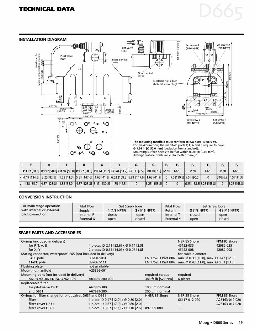
The mounting manifold must conform to ISO 4401-05-05-0-94. Attention: Note O-ring counterbore diameter of X and Y ports. For valves in 4/3-wayversion with QN > 16 gpm [60 l/min] and in 2 x 2-way version the non standard 2ndreturn port T2 must be used.
For maximum flow, the manifold ports P, T, A and B require to have Ø 0.45 in [Ø 11.5 mm] (deviation from standard). Mounting surface needs to be flatwithin .001 in [0.02 mm]. Average surface finish value, Ra, better than 32 .
TECHNICAL DATA D
Moog • D660 Series 11
CONVERSION INSTRUCTION
Pilot Flow Set Screw M4 x 6 Pilot Flow Set Screw M4 x 6Supply bore 1 bore 2 Return bore 3 bore 4Internal P closed open Internal T closed openExternal X open closed External Y open closed
For main stage operation with internal or external pilot connection.
SPARE PARTS AND ACCESSORIES
O-rings (included in delivery) NBR 85 Shore FPM 85 Shorefor P, T, T2, A, B 5 pieces ID 0.49 [12.4] x Ø 0.07 [1.8] 45122-004 42082-004for X, Y 2 pieces ID 0.61 [15.6] x Ø 0.07 [1.8] 45122-011 42082-011
Mating connector, waterproof IP65 (not included in delivery) for cable diameter 6+PE pole B97007-061 EN 175201 Part 804 min. Ø 0.39 [10.0], max. Ø 0.47 [12.0]11+PE pole B97067-111 EN 175201 Part 804 min. Ø 0.43 [11.0], max. Ø 0.51 [13.0]
Flushing plates for P, A, B, T, T2, X, Y for P, T, T2, X, Y for P, T, T2, and X, YB67728-001 B67728-002 B67728-003
Mounting manifolds see special data sheetMounting bolts (not included in delivery) required torque required
M6 x 60 DIN EN ISO 4762-10.9 A03665-060-060 115 in-lb [13.0 Nm] 4 piecesReplaceable filter A67999-200 200 µm nominalO-rings for filter change HNBR 85 Shore NBR 85 Shore FPM 85 Shore
filter 1 piece ID 0.51 [12.0] x Ø 0.59 [2.0] ––– 66117-012-020 A25163-012-020filter cover 1 piece ID 0.67 [17.1] x Ø 0.78 [2.6] B97009-080 ––– –––
INSTALLATION DIAGRAM
PERFORMANCE SPECIFICATIONS FOR STANDARD MODELS
TECHNICAL DATA DPERFORMANCE SPECIFICATIONS FOR STANDARD MODELS
12 Moog • D660 Series
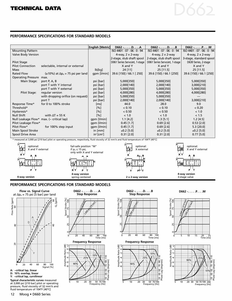
English [Metric] D662 -. . . . .D. . . .A D662 -. . . . .D. . . .B D662 -. . . . .P. . . .MMounting Pattern ISO 4401 - 07 - 06 - 0 - 94 ISO 4401 - 07 - 06 - 0 - 94 ISO 4401 - 07 - 06 - 0 - 94Valve Body Version 4-way, 2 x 2-way 4-way, 2 x 2-way 4-way, 2 x 2-way
2-stage, stub shaft spool 2-stage, stub shaft spool 3-stage, standard spoolPilot Stage D061 Series ServoJet, 1-stage D061 Series ServoJet, 1-stage D630 Series, 2-stagePilot Connection selectable, internal or external X and Y X and Y X and YMass lb[kg] 24 [11] 25 [11.5] 25 [11.5]Rated Flow (±10%) at ∆pN = 75 psi per land gpm [l/min] 39.6 [150] / 66.1 [ 250] 39.6 [150] / 66.1 [250] 39.6 [150] / 66.1 [250]Operating Pressure max.
Main Stage: port P, A, B psi [bar] 5,000[350] 5,000[350] 5,000[350]port T with Y internal psi [bar] 2,000[140] 2,000[140] 3,000[210]port T with Y external psi [bar] 5,000[350] 5,000[350] 5,000[350]
Pilot Stage: regular version psi [bar] 4,000[280] 4,000[280] 4,000[280]with dropping orifice (on request) psi [bar] 5,000[350] 5,000[350] —port T psi [bar] 2,000[140] 2,000[140] 3,000[210]
Response Time* for 0 to 100% stroke [ms] 44.0 28.0 9.0Threshold* [%] < 0.10 < 0.10 < 0.20Hysteresis* [%] < 0.50 < 0.50 < 1.0Null Shift with ∆T = 55 K [%] < 1.0 < 1.0 < 1.5Null Leakage Flow* max. (~ critical lap) gpm [l/min] 1.1 [4.2] 1.3 [5.1] 1.2 [4.5]Pilot Leakage Flow* gpm [l/min] 0.45 [1.7] 0.69 [2.6] 0.53 [2.0]Pilot Flow* for 100% step input gpm [l/min] 0.45 [1.7] 0.69 [2.6] 5.3 [20.0]Main Spool Stroke in [mm] ±0.2 [5.0] ±0.2 [5.0] ±0.2 [5.0]Spool Drive Area in2 [cm2] 0.31 [2.0] 0.31 [2.0] 0.77 [5.0]
* measured at 3,000 psi [210 bar] pilot or operating pressure, respectively, fluid viscosity of 32 mm2/s and fluid temperature of 104°F [40°C]
optional:X and Y external
optional:X and Y external
fail-safe position "M"if pX ≤ 15 psi,only with X and Y external
optional:X external
5 10 20 30 50 70100
-10
-30
-50
-70
-90
-110
+2
0-2
-4-6
-8
10%
25%90%
Am
plit
ud
e R
atio
[d
B]
Frequency [Hz]
Phas
e La
g [
deg
rees
]
2005 10 20 30 50 70100
-10
-30
-50
-70
-90
-110
+2
0-2
-4-6
-8
10%
25%
90%
Am
plit
ud
e R
atio
[d
B]
Frequency [Hz]
Phas
e La
g [
deg
rees
]
D662 -. . . . .D. . . .BStep Response
A: ~critical lap, linearD: 10% overlap, linear Y: ~critical lap, curvilinearTypical characteristic curves measuredat 3,000 psi [210 bar] pilot or operatingpressure, fluid viscosity of 32 mm2/s andfluid temperature of 104°F [40°C]
Flow vs. Signal Curveat ∆pN = 75 psi [5 bar] per land
Frequency Response
Q[g
pm
]N
20 40 60 80 100Signal [%]
40
66
0
Flo
w R
ate
[gp
m]
40
6020
100
2550
75
0 5 10 15 20 25
0
3,00
0 ps
i [21
0 ba
r]
Time [ms]
Spo
ol S
tro
ke [
%]
1,00
0 ps
i [70
bar
]100
2550
75
0 20 40 60 80 100
0
3,00
0 ps
i [21
0 ba
r]
Time [ms]
Spo
ol S
tro
ke [
%]
1,00
0 ps
i [70
bar
]
D662 -. . . . .P. . . .M
5 10 20 30 50 70100
-10
-30
-50
-70
-90
-110
+2
0-2
-4-6
-8
10%25%
90%
Am
plit
ud
e R
atio
[d
B]
Frequency [Hz]
Phas
e La
g [
deg
rees
]
D662 -. . . . .D. . . .AStep Response
Frequency Response
100
2550
75
0 20 40 60 80 100
0
3,00
0 ps
i [21
0 ba
r]1,
000
psi [
70 b
ar]
Time [ms]
Spo
ol S
tro
ke [
%]
4-way version4-way version spring centered 2 x 2-way version
4-way version3-stage valve
6.06(154).43(11)
12.5(317)
.79(20)
1.04(26.5)
.28(7)
.55(13.9)
.05(
1.3)
.26(6.6)
.43(11)
1.75
(44.
5).0
8(2)
.20(
5)
.12(3)
1.81(46)3.75(95)
.79(20)
2.00
(51) 4.
21(1
07)
7.50
(190
)
.71(18)
Filter
7.13
(181
) fr
om
man
ifo
ld
Electrical null adjust(behind screw plug)
Set screw 1(1/16 NPTF)
Set screw 2(M6 x 6)
Filter atrear side
Pilot valveD630
Pilot valve D061-8
Mat
ing
co
nn
ecto
rH
ead
roo
m f
or
dis
con
nec
tin
g4.
92(1
25)
.79(
20)
3.86
(98)
.47(12)
.55(
14)
4.92(125)
For main stage operationwith internal or externalpilot connection.
TECHNICAL DATA
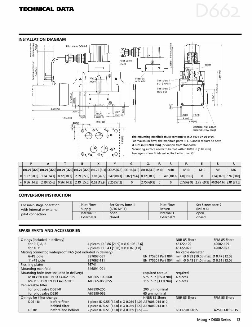
INSTALLATION DIAGRAM
D
Moog • D660 Series 13
CONVERSION INSTRUCTION
SPARE PARTS AND ACCESSORIES
The mounting manifold must conform to ISO 4401-07-06-0-94. For maximum flow, the manifold ports P, T, A and B require to have Ø 0.78 in [Ø 20.0 mm] (deviation from standard).Mounting surface needs to be flat within 0.001 in [0.02 mm].Average surface finish value, Ra, better than 32 .
Pilot Flow Set Screw bore 1 Pilot Flow Set Screw bore 2Supply (1/16 NPTF) Return (M6 x 6)Internal P open Internal T openExternal X closed External Y closed
O-rings (included in delivery) NBR 85 Shore FPM 85 Shorefor P, T, A, B 4 pieces ID 0.86 [21.9] x Ø 0.103 [2.6] 45122-129 42082-129for X, Y 2 pieces ID 0.43 [10.8] x Ø 0.07 [1.8] 45122-022 42082-022
Mating connector, waterproof IP65 (not included in delivery) for cable diameter 6+PE pole B97007-061 EN 175201 Part 804 min. Ø 0.39 [10.0], max. Ø 0.47 [12.0]11+PE pole B97067-111 EN 175201 Part 804 min. Ø 0.43 [11.0], max. Ø 0.51 [13.0]
Flushing plates 76741Mounting manifold B46891-001Mounting bolts (not included in delivery) required torque required
M10 x 60 DIN EN ISO 4762-10.9 A03665-100-060 575 in-lb [65.0 Nm] 4 piecesM6 x 55 DIN EN ISO 4762-10.9 A03665-060-055 115 in-lb [13.0 Nm] 2 pieces
Replaceable filter for pilot valve D061-8 A67999-200 200 µm nominalfor pilot valve D630 A67999-065 65 µm nominal
O-rings for filter change HNBR 85 Shore NBR 85 Shore FPM 85 ShoreD061-8: before filter 1 piece ID 0.55 [14.0] x Ø 0.039 [1.0] A67008-014-010 ––– –––
behind filter 1 piece ID 0.51 [13.0] x Ø 0.059 [1.5] A67008-013-015 ––– –––D630: before and behind 2 piece ID 0.51 [13.0] x Ø 0.059 [1.5] ––– 66117-013-015 A25163-013-015
P A T B X Y G1 G2 F1 F2 F3 F4 F5 F6
Ø0.79 [Ø20] Ø0.79 [Ø20] Ø0.79 [Ø20] Ø0.79 [Ø20] Ø0.25 [6.3] Ø0.25 [6.3] Ø0.16 [4.0] Ø0.16 [4.0] M10 M10 M10 M10 M6 M6
X 1.97 [50.0] 1.34 [34.1] 0.72 [18.3] 2.59 [65.9] 3.02 [76.6] 3.47 [88.1] 3.02 [76.6] 0.72 [18.3] 0 4.0 [101.6] 4.0 [101.6] 0 1.34 [34.1] 1.97[50.0]
y 0.56 [14.3] 2.19 [55.6] 0.56 [14.3] 2.19 [55.6] 0.63 [15.9] 2.25 [57.2] 0 2.75 [69.9] 0 0 2.75[69.9] 2.75 [69.9] -0.06 [-1.6] 2.81 [71.5]
PERFORMANCE SPECIFICATIONS FOR STANDARD MODELS
TECHNICAL DATA DPERFORMANCE SPECIFICATIONS FOR STANDARD MODELS
14 Moog • D660 Series
5 10 20 30 50 70100
-10
-30
-50
-70
-90
-110
+2
0-2
-4-6
-8
10%
25%
90%
Am
plit
ud
e R
atio
[d
B]
Frequency [Hz]
Phas
e La
g [
deg
rees
]
2005 10 20 30 50 70100
-10
-30
-50
-70
-90
-110
+2
0-2
-4-6
-8
10%
25%
90%
Am
plit
ud
e R
atio
[d
B]
Frequency [Hz]
Phas
e La
g [
deg
rees
]
D663 - . . . . . L . . . . BStep Response
Spool version A: ~critical lap, linear characteristicSpool version D: 10% overlap, linear characteristicSpool version Y: ~critical lap, curvilinear characteristicTypical characteristic curves measured at 3,000 psi [210 bar] pilot or operatingpressure, fluid viscosity of 32 mm2/s and fluid temperature of 104°F [40°C]
Flow vs. Signal Curveat ∆pN = 75 psi per land [5 bar]
optional:X and Y external4-way version
Q[g
pm
]N
20 40 60 80 100Signal [%]
A
Y D
2550
75
92.5
100
0
Flo
w R
ate
[gp
m]
English [Metric] D663 -. . . . .L. . . .B D663 -. . . . .P. . . .MMounting Pattern ISO 4401 - 08 - 07 - 0 - 94 ISO 4401 - 08 - 07 - 0 - 94Valve Body Version 4-way, 2 x 2-way 4-way, 2 x 2-way
2-stage, stub shaft spool 3-stage,standard spoolPilot Stage D061 Series ServoJet, 1-stage D630 Series, 2-stagePilot Connection selectable, internal or external X and Y X and YMass lb [kg] 41.9 [19.0] 43.0 [19.5]Rated Flow (±10%) at ∆pN = 75 psi per land gpm [l/min] 92.5 [350] 92.5 [350]Operating Pressure max.
Main Stage: port P, A, B psi [bar] 5,000 [350] 5,000 [350]port T with Y internal psi [bar] 2,000 [140] 3,000 [210]port T with Y external psi [bar] 5,000 [350] 5,000 [350]
Pilot Stage: regular version psi [bar] 4,000 [280] 4,000 [280]with dropping orifice (on request) psi [bar] 5,000 [350] —port T psi [bar] 2,000 [140] 3,000 [210]
Response Time* for 0 to 100% stroke [ms] 37.0 13.0Threshold* [%] < 0.1 < 0.2Hysteresis* [%] < 0.5 < 1.0Null Shift with ∆T = 55 K [%] < 1.0 < 1.5Null Leakage Flow* max. (~ critical lap) gpm [l/min] 1.5 [5.6] 1.3 [5.0]Pilot Leakage Flow* gpm [l/min] 0.69 [2.6] 0.53 [2.0]Pilot Flow* for 100% step input gpm [l/min] 0.69 [2.6] 7.9 [30.0]Main Spool Stroke in [mm] 0.20 [±5.0] 0.20 [±5.0]Spool Drive Area in2 [cm2] 0.43 [2.8] 1.77 [11.4]
optional:X external
optional:X and Y external
D663 - . . . . . P . . . . M
Frequency Response
* measured at 3,000 psi [210 bar] pilot or operating pressure, respectively, fluid viscosity of 32 mm2/s and fluid temperature of 104°F [40°C]
100
2550
75
0 10 20 30 40 50
0
1,00
0 ps
i [70
bar
]
2,00
0 ps
i [14
0 ba
r]
3,00
0 [2
10 b
ar]
Time [ms]
Spo
ol S
tro
ke [
%]
4-way version4-way versionspring centered 2 x 2-way version
4-way version3-stage valve
100
2550
75
0 20 40 60 80 100
0
3,00
0 ps
i [21
0 ba
r]
1,00
0 ps
i [70
bar
]
Time [ms]
Spo
ol S
tro
ke [
%]
fail-safe position "M"if pX ≤ 1 bar,only with X and Y external
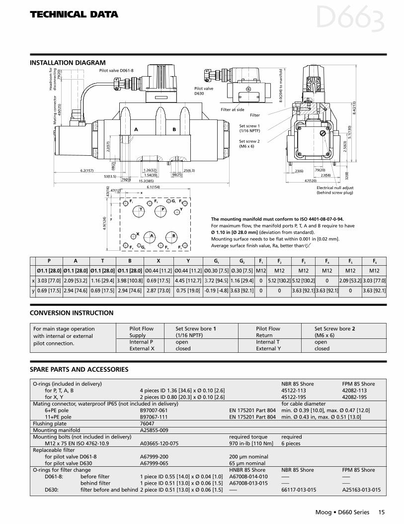
The mounting manifold must conform to ISO 4401-08-07-0-94. For maximum flow, the manifold ports P, T, A and B require to have Ø 1.10 in [Ø 28.0 mm] (deviation from standard).Mounting surface needs to be flat within 0.001 in [0.02 mm].Average surface finish value, Ra, better than 32 .
P A T B X Y G1 G2 F1 F2 F3 F4 F5 F6
Ø1.1 [28.0] Ø1.1 [28.0] Ø1.1 [28.0] Ø1.1 [28.0] Ø0.44 [11.2] Ø0.44 [11.2] Ø0.30 [7.5] Ø.30 [7.5] M12 M12 M12 M12 M12 M12
x 3.03 [77.0] 2.09 [53.2] 1.16 [29.4] 3.98 [100.8] 0.69 [17.5] 4.45 [112.7] 3.72 [94.5] 1.16 [29.4] 0 5.12 [130.2] 5.12 [130.2] 0 2.09 [53.2] 3.03 [77.0]
y 0.69 [17.5] 2.94 [74.6] 0.69 [17.5] 2.94 [74.6] 2.87 [73.0] 0.75 [19.0] -0.19 [-4.8] 3.63 [92.1] 0 0 3.63 [92.1] 3.63 [92.1] 0 3.63 [92.1]
TECHNICAL DATA
INSTALLATION DIAGRAM
D
Moog • D660 Series 15
53(13.5).79(20)
6.2(157)
15.2(385)
2.2(
57)
.08(
2)
1.26(32)1.54(39)
.25(6.3).98(25)
5.1(
130)
2.3(58)
8.4(
213)
2.5(
63)
.32
(8)
4.7(120)
.79(20).23(6)
.47(12)
.63(
16) 6.1(154)
4.9(
124)
Electrical null adjust(behind screw plug)
Set screw 2(M6 x 6)
Set screw 1(1/16 NPTF)
8.0(
204)
to
man
ifo
ld
Filter at sideFilter
Pilot valveD630
Pilot valve D061-8
Mat
ing
co
nn
ecto
rH
ead
roo
m f
or
dis
con
nec
tin
g4.
9(12
5).7
9(20
)
Pilot Flow Set Screw bore 1 Pilot Flow Set Screw bore 2Supply (1/16 NPTF) Return (M6 x 6)Internal P open Internal T openExternal X closed External Y closed
For main stage operationwith internal or externalpilot connection.
O-rings (included in delivery) NBR 85 Shore FPM 85 Shorefor P, T, A, B 4 pieces ID 1.36 [34.6] x Ø 0.10 [2.6] 45122-113 42082-113for X, Y 2 pieces ID 0.80 [20.3] x Ø 0.10 [2.6] 45122-195 42082-195
Mating connector, waterproof IP65 (not included in delivery) for cable diameter 6+PE pole B97007-061 EN 175201 Part 804 min. Ø 0.39 [10.0], max. Ø 0.47 [12.0]11+PE pole B97067-111 EN 175201 Part 804 min. Ø 0.43 in, max. Ø 0.51 [13.0]
Flushing plate 76047Mounting manifold A25855-009Mounting bolts (not included in delivery) required torque required
M12 x 75 EN ISO 4762-10.9 A03665-120-075 970 in-lb [110 Nm] 6 piecesReplaceable filter
for pilot valve D061-8 A67999-200 200 µm nominalfor pilot valve D630 A67999-065 65 µm nominal
O-rings for filter change HNBR 85 Shore NBR 85 Shore FPM 85 ShoreD061-8: before filter 1 piece ID 0.55 [14.0] x Ø 0.04 [1.0] A67008-014-010 ––– –––
behind filter 1 piece ID 0.51 [13.0] x Ø 0.06 [1.5] A67008-013-015 ––– –––D630: filter before and behind 2 piece ID 0.51 [13.0] x Ø 0.06 [1.5] ––– 66117-013-015 A25163-013-015
CONVERSION INSTRUCTION
SPARE PARTS AND ACCESSORIES
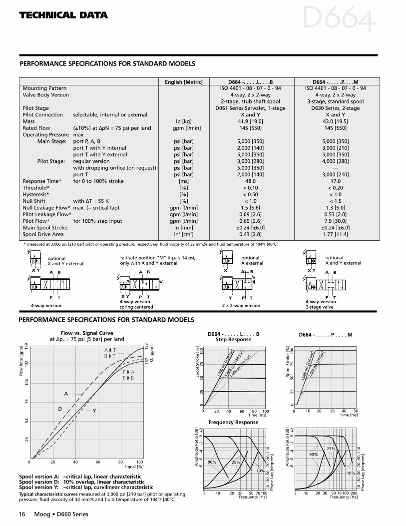
PERFORMANCE SPECIFICATIONS FOR STANDARD MODELS
TECHNICAL DATA DPERFORMANCE SPECIFICATIONS FOR STANDARD MODELS
16 Moog • D660 Series
5 10 20 30 50 70100
-10
-30
-50
-70
-90
-110
+2
0-2
-4-6
-8
10%
25%90%
Am
plit
ud
e R
atio
[d
B]
Frequency [Hz]
Phas
e La
g [
deg
rees
]
2005 10 20 30 50 70100
-10
-30
-50
-70
-90
-110
+2
0-2
-4-6
-8
10%
25%90%
Am
plit
ud
e R
atio
[d
B]
Frequency [Hz]
Phas
e La
g [
deg
rees
]
Flow vs. Signal Curve at ∆pN = 75 psi [5 bar] per land
D664 - . . . . . L . . . . BStep Response
Frequency Response
Spool version A: ~critical lap, linear characteristicSpool version D: 10% overlap, linear characteristicSpool version Y: ~critical lap, curvilinear characteristicTypical characteristic curves measured at 3,000 psi [210 bar] pilot or operatingpressure, fluid viscosity of 32 mm2/s and fluid temperature of 104°F [40°C]
optional:X and Y external
optional:X and Y external
fail-safe position "M" if pX ≤ 14 psi,only with X and Y external
100
2550
75
20 40 60 80 100
0
3,00
0 ps
i [21
0 ba
r]1,
000
psi [7
0 bar
]
Time [ms]
Spo
ol S
tro
ke [
%]
0
2,00
0 ps
i [14
0 ba
r] 100
2550
75
0 10 20 30 40 50
0
3,00
0 ps
i [21
0 ba
r]
Time [ms]
Spo
ol S
tro
ke [
%]
1,00
0 ps
i [70
bar
]
English [Metric] D664 -. . . . .L. . . .B D664 -. . . . .P. . . .MMounting Pattern ISO 4401 - 08 - 07 - 0 - 94 ISO 4401 - 08 - 07 - 0 - 94Valve Body Version 4-way, 2 x 2-way 4-way, 2 x 2-way
2-stage, stub shaft spool 3-stage, standard spoolPilot Stage D061 Series ServoJet, 1-stage D630 Series, 2-stagePilot Connection selectable, internal or external X and Y X and YMass lb [kg] 41.9 [19.0] 43.0 [19.5]Rated Flow (±10%) at ∆pN = 75 psi per land gpm [l/min] 145 [550] 145 [550]Operating Pressure max.
Main Stage: port P, A, B psi [bar] 5,000 [350] 5,000 [350]port T with Y internal psi [bar] 2,000 [140] 3,000 [210]port T with Y external psi [bar] 5,000 [350] 5,000 [350]
Pilot Stage: regular version psi [bar] 3,000 [280] 4,000 [280]with dropping orifice (on request) psi [bar] 5,000 [350] —port T psi [bar] 2,000 [140] 3,000 [210]
Response Time* for 0 to 100% stroke [ms] 48.0 17.0Threshold* [%] < 0.10 < 0.20Hysteresis* [%] < 0.50 < 1.0Null Shift with ∆T = 55 K [%] < 1.0 < 1.5Null Leakage Flow* max. (~ critical lap) gpm [l/min] 1.5 [5.6] 1.3 [5.0]Pilot Leakage Flow* gpm [l/min] 0.69 [2.6] 0.53 [2.0]Pilot Flow* for 100% step input gpm [l/min] 0.69 [2.6] 7.9 [30.0]Main Spool Stroke in [mm] ±0.24 [±6.0] ±0.24 [±6.0]Spool Drive Area in2 [cm2] 0.43 [2.8] 1.77 [11.4]
Q[g
pm
]N
20 40 60 80 100Signal [%]
A
YD
2653
79
137
106
0
Flo
w R
ate
[gp
m]
132
159
153
optional:X external
D664 - . . . . . P . . . . M
* measured at 3,000 psi [210 bar] pilot or operating pressure, respectively, fluid viscosity of 32 mm2/s and fluid temperature of 104°F [40°C]
4-way version4-way versionspring centered 2 x 2-way version
4-way version3-stage valve

P A T B X Y G1 G2 F1 F2 F3 F4 F5 F6
Ø1.26 [32.0] Ø1.26 [32.0] Ø1.26 [32.0] Ø1.26 [32.0] Ø0.44 [11.2] Ø0.44 [11.2] Ø0.30 [7.5] Ø0.30 [7.5] M12 M12 M12 M12 M12 M12
x 3.03 [77.0] 2.09 [53.2] 1.16[29.4] 3.97 [100.8] 0.69 [17.5] 4.45 [112.7] 3.72 [94.5] 1.16[29.4] 0 5.13[130.2] 5.13[130.2] 0 2.09 [53.2] 3.03 [77.0]
y 0.69 [17.5] 2.94 [74.6] 0.69 [17.5] 2.94 [74.6] 2.87 [73.0] 0.75 [19.0] -0.19 [-4.8] 3.63 [92.1] 0 0 3.63 [92.1] 3.63 [92.1] 0 3.63 [92.1]
TECHNICAL DATA D
53(13.5).79(20)
6.2(157)
15.2(385)
2.2(
57)
.08(
2)
1.26(32)1.54(39)
.25(6.3).98(25)
5.1(
130)
2.3(58)
8.4(
213)
2.5(
63)
.32
(8)
4.7(120)
.79(20).23(6)
.47(12)
.63(
16) 6.1(154)
4.9(
124)
Electrical null adjust(behind screw plug)
Set screw 2(M6 x 6)
Set screw 1(1/16 NPTF)
8.0(
204)
to
man
ifo
ld
Filter at sideFilter
Pilot valveD630
Pilot valve D061-8
Mat
ing
co
nn
ecto
rH
ead
roo
m f
or
dis
con
nec
tin
g4.
9(12
5).7
9(20
)
The mounting manifold must conform to ISO 4401-08-07-0-94. For maximum flow, the manifold ports P, T, A and B require to have Ø 1.25 in [Ø 32.0 mm] (deviation from standard).Mounting surface needs to be flat within .001 in [0.02 mm].Average surface finish value, Ra, better than 32 .
O-rings (included in delivery) NBR 85 Shore FPM 85 Shorefor P, T, A, B 4 pieces ID 0.86 [34.6] x Ø 0.10 [2.6] 45122-113 42082-113for X, Y 2 pieces ID 0.45 [20.3] x Ø 0.07 [2.6] 45122-195 42082-195
Mating connector, waterproof IP65 (not included in delivery) for cable diameter 6+PE pole B97007-061 EN 175201 Part 804 min. Ø 0.39 [10.0], max. Ø 0.47 [12.0]11+PE pole B97067-111 EN 175201 Part 804 min. Ø 0.43 [11.0], max. Ø 0.51 [13.0]
Flushing plate 76047Mounting manifold A25855-009Mounting bolts (not included in delivery) required torque required
M12 x 75 DIN EN ISO 4762-10.9 A03665-120 075 970 in-lb [110 Nm] 6 piecesReplaceable filter
for pilot valve D061-8 A67999-200 200 µm nominalfor pilot valve D630 A67999-065 65 µm nominal
O-rings for filter change HNBR 85 Shore NBR 85 Shore FPM 85 ShoreD061-8: before filter 1 piece ID 0.55 [14.0] x Ø 0.04 [1.0] A67008-014-010 ––– –––
behind filter 1 piece ID 0.51 [13.0] x Ø 0.06 [1.5] A67008-013-015 ––– –––D630: filter before and behind 2 piece ID 0.51 [13.0] x Ø 0.06 [1.5] ––– 66117-013-015 A25163-013-015
INSTALLATION DIAGRAM
SPARE PARTS AND ACCESSORIES
CONVERSION INSTRUCTION
Moog • D660 Series 17
Pilot Flow Set Screw bore 1 Pilot Flow Set Screw bore 2Supply (1/16 NPTF) Return (M6 x 6)Internal P open Internal T openExternal X closed External Y closed
For main stage operationwith internal or externalpilot connection.
PERFORMANCE SPECIFICATIONS FOR STANDARD MODELS
TECHNICAL DATA DPERFORMANCE SPECIFICATIONS FOR STANDARD MODELS
18 Moog • D660 Series
D665 - . . . . . P15 . . . . HStep Response
Frequency Response
Spool version A: ~critical lap, linear characteristicSpool version D: 10 % overlap, linear characteristicSpool version Y: ~critical lap,curvilinear characteristicSpool version V: 20 % overlap, curvilinear characteristic* measured at 3,000 psi [210 bar] pilot or operating pressure, respectively, fluidviscosity of 32 mm2/s and fluid temperature of 104°F [40°C]
Flow vs. Signal Curve at ∆pN = 75 psi [5 bar] per land
optional:Y external
optional:X external
optional:X and Y external
100
2550
75
0 20 40 60 80 100
3,00
0 ps
i [21
0 ba
r]2,
000
psi [
140
bar]
1,00
0 ps
i [70
bar
]
0
Time [ms]
Spo
ol S
tro
ke [
%]
100
2550
75
0 5 10 15 20 25
0
3,00
0 ps
i [21
0 ba
r]2,
000
psi [
140
bar]
1,00
0 ps
i [70
bar
]
Time [ms]
Spo
ol S
tro
ke [
%]
English [Metric] D665 -. . . . .P. . . .H D665 -. . . . .K. . . .LMounting Pattern ISO 4401 - 10 - 08 - 0 - 94 ISO 4401 - 10 - 08 - 0 - 94
Valve Body Version 4-way, 2 x 2-way 4-way, 2 x 2-way3-stage, standard spool 3-stage, stub shaft spool
Pilot Stage D631 Series, 2-stage D661 Series ServoJet, 2-stagePilot Connection selectable internal or external optional X and Y X and Y requiredMass lb [kg] 154 [70.0] 162 [73.5]Rated Flow (±10%) at ∆pN = 75 psi per land gpm [l/min] 265 [1000] 400 [1500] 265[1000] 400[1500]Operating Pressure max.
Main Stage: ports P with X external, A, B psi [bar] 5000 [350] 5000 [350]port T with Y internal psi [bar] 1400 [100] 1400 [100]port T with Y external psi [bar] 5000 [350] 5000 [350]
Pilot Stage: regular version, ports P, A and B psi [bar] 3000 [210] 3000 [210]with dropping orifice (on request) psi [bar] 4000 [280] 5000 [350]port T psi [bar] 2,000 [140] 2,000 [140] 3,000 [210]
Response Time* for 0 to 100% stroke [ms] 30.0 35.0 10.0 12.0Threshold* [%] < 0.30 < 0.20 < 0.30 < 0.20Hysteresis* [%] < 1.0 < 0.70 < 1.0 < 0.70Null Shift with ∆T = 55 K [%] < 2.0 < 1.5 < 2.5 < 2.0Null Leakage Flow* max. (~ critical lap) gpm [l/min] 2.8 [10.5] 2.9 [11.0]Pilot Leakage Flow* gpm [l/min] 0.92 [3.5] 1.1 [4.0]Pilot Flow* for100% step input gpm [l/min] 11.9 [45.0] 14.5 [55.0] 10.6 [40.0] 13.2 [50.0]Main Spool Stroke in [mm] ±0.22 [±5.5] ±0.31 [±8] ±0.22 [±5.5] ±0.31 [±8.0]Spool Drive Area in2 [cm2] 5.1 [33.2] 1.5 [9.6]
Q[g
pm
]N
20 40 60 80 100Signal [%]
A
Y D
V
100
0
200
300
400
400
B T
Flo
w R
ate
[gp
m]
5 10 20 30 50
-10
-30
-50
-70
-90
-110
+2
0-2
-4-6
-8
4321
10%
25%90%
Am
plit
ue
Rat
io [
dB
]
Frequency [Hz]
Phas
e La
g [
deg
rees
]
-10
-30
-50
-70
-90
-110
5 10 20 30 50 70 100200
-8-6
-4-2
0+
2
10%25%
90%
Frequency [Hz]
Phas
e La
g [
deg
rees
]
Am
plit
ue
Rat
io [
dB
]
D665 - . . . . . K15 . . . . J
* measured at 3,000 psi [210 bar] pilot or operating pressure, respectively, fluid viscosity of 32 mm2/s and fluid temperature of 104°F [40°C]
4-way version3-stage valve
4-way version3-stage valve
2x2-way version3-stage valve
P A T B X Y G1 G2 F1 F2 F3 F4 F5 F6
Ø1.97 [50.0] Ø1.97 [50.0] Ø1.97 [50.0] Ø1.97 [50.0] Ø0.44 [11.2] Ø0.44 [11.2] Ø0.30 [7.5] Ø0.30 [7.5] M20 M20 M20 M20 M20 M20
x 4.49 [114.3] 3.25 [82.5] 1.63 [41.3] 5.81 [147.6] 1.63 [41.3] 6.63 [168.3] 5.81 [147.6] 1.63 [41.3] 0 7.5 [190.5] 7.5 [190.5] 0 3.0[76.2] 4.5 [114.3]
y 1.38 [35.0] 4.87 [123.8] 1.38 [35.0] 4.87 [123.8] 5.13 [130.2] 1.75 [44.5] 0 6.25 [158.8] 0 0 6.25 [158.8] 6.25 [158.8] 0 6.25 [158.8]
Pilot Flow Set Screw bore Pilot Flow Set Screw boreSupply 1 (1/8 NPTF) 2 (1/16 NPTF) Return 3 (1/8 NPTF) 4 (1/16 NPTF)Internal P closed open Internal T closed openExternal X open closed External Y open closed
TECHNICAL DATA
INSTALLATION DIAGRAM
D
CONVERSION INSTRUCTION
SPARE PARTS AND ACCESSORIES13
.7( 3
49)
9.0(
2 29)
4.4(
112)
.32(
8)
.24(6) .79(20)3.9(99)
7.9(200)
2.3
(59)
6.7(171).87(22)
1.30 (33)
1.87 (50)2.36 (60) 1/8 NPTF
.67(17)19.6 (497) 0.5(
1.3)
.11(
2.8)
9.06(230)
8.0(
203)
.79(20)
.87(
22)
388
fro
m m
anif
old
Set screw 4(1/16 NPTF)
Set screw 2(1/16 NPTF)
Pilot valveD631
Filter behindcover
Filter behindcover
Electrical null adjust(behind screw plug)
Set screw 3(1/8 NPTF)
Set screw 1(1/8 NPTF)
14.9
(125
)M
atin
g c
on
nec
torH
ead
roo
m f
or
dis
con
nec
tin
g.7
9(20
)
Pilot valveD661
O-rings (included in delivery) NBR 85 Shore FPM 85 Shorefor P, T, A, B 4 pieces ID 2.11 [53.6] x Ø 0.14 [3.5] 45122-035 42082-035for X, Y 2 pieces ID 0.55 [14.0] x Ø 0.07 [1.8] 45122-008 42082-008
Mating connector, waterproof IP65 (not included in delivery) for cable diameter 6+PE pole B97007-061 EN 175201 Part 804 min. Ø 0.39 [10.0], max. Ø 0.47 [12.0]11+PE pole B97067-111 EN 175201 Part 804 min. Ø 0.43 [11.0], max. Ø 0.51 [13.0]
Flushing plate not availableMounting manifold A25856-001Mounting bolts (not included in delivery) required torque required
M20 x 90 DIN EN ISO 4762-10.9 A03665-200-090 385 ft-lb [520 Nm] 6 piecesReplaceable filter
for pilot valve D631 A67999-100 100 µm nominaland D661 A67999-200 200 µm nominal
O-rings for filter change for pilot valves D631 and D661 HNBR 85 Shore NBR 85 Shore FPM 85 Shorefilter 1 piece ID 0.47 [12.0] x Ø 0.80 [2.0] ––– 66117-012-020 A25163-012-020filter cover D631 1 piece ID 0.67 [17.0] x Ø 0.80 [2.0] ––– ––– A25163-017-020filter cover D661 1 piece ID 0.67 [17.1] x Ø 0.10 [2.6] B97009-080 ––– –––
For main stage operation with internal or external pilot connection.
The mounting manifold must conform to ISO 4401-10-08-0-94. For maximum flow, the manifold ports P, T, A and B require to have Ø 1.96 in [Ø 50.0 mm] (deviation from standard).Mounting surface needs to be flat within 0.001 in [0.02 mm].Average surface finish value, Ra, better than 32 .
Moog • D660 Series 19
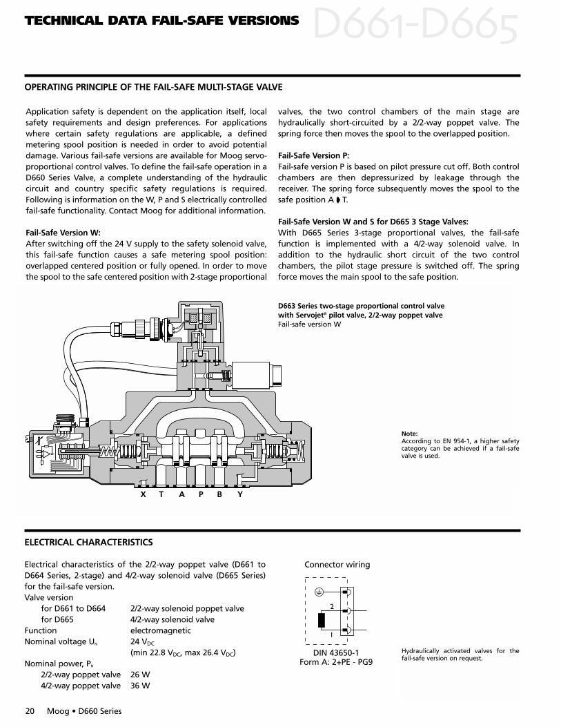
D663 Series two-stage proportional control valve with Servojet® pilot valve, 2/2-way poppet valveFail-safe version W
DDOPERATING PRINCIPLE OF THE FAIL-SAFE MULTI-STAGE VALVE
20 Moog • D660 Series
TECHNICAL DATA FAIL-SAFE VERSIONS
Note:According to EN 954-1, a higher safetycategory can be achieved if a fail-safevalve is used.
Electrical characteristics of the 2/2-way poppet valve (D661 toD664 Series, 2-stage) and 4/2-way solenoid valve (D665 Series)for the fail-safe version.Valve version
for D661 to D664 2/2-way solenoid poppet valvefor D665 4/2-way solenoid valve
Function electromagnetic Nominal voltage UN 24 VDC
(min 22.8 VDC, max 26.4 VDC)Nominal power, PN
2/2-way poppet valve 26 W4/2-way poppet valve 36 W
X T A P B Y
ELECTRICAL CHARACTERISTICS
Hydraulically activated valves for thefail-safe version on request.
DIN 43650-1Form A: 2+PE - PG9
Connector wiring
1
2
Application safety is dependent on the application itself, localsafety requirements and design preferences. For applicationswhere certain safety regulations are applicable, a definedmetering spool position is needed in order to avoid potentialdamage. Various fail-safe versions are available for Moog servo-proportional control valves. To define the fail-safe operation in aD660 Series Valve, a complete understanding of the hydrauliccircuit and country specific safety regulations is required.Following is information on the W, P and S electrically controlledfail-safe functionality. Contact Moog for additional information.
Fail-Safe Version W:After switching off the 24 V supply to the safety solenoid valve,this fail-safe function causes a safe metering spool position:overlapped centered position or fully opened. In order to movethe spool to the safe centered position with 2-stage proportional
valves, the two control chambers of the main stage arehydraulically short-circuited by a 2/2-way poppet valve. Thespring force then moves the spool to the overlapped position.
Fail-Safe Version P:Fail-safe version P is based on pilot pressure cut off. Both controlchambers are then depressurized by leakage through thereceiver. The spring force subsequently moves the spool to thesafe position A T.
Fail-Safe Version W and S for D665 3 Stage Valves:With D665 Series 3-stage proportional valves, the fail-safefunction is implemented with a 4/2-way solenoid valve. Inaddition to the hydraulic short circuit of the two controlchambers, the pilot stage pressure is switched off. The springforce moves the main spool to the safe position.
2.56
(65)
3.15
(80)
6.26
(159
)
.79(20)
2.84(72)
2.95(75)
Filter
Set screw 2(M4 x 6)
Electricalnull adjust(behindscrew plug)
Set screw 4(M4 x 6)
Warning!The electric nulladjust must not be changed if the position of the main-spool is monitored.
6.93
(176
)
11.4(290)
M4
.74(18.7) .62(15.7)
.26(6.5)
.43(11).05(
1.3)
1.85
(47)
4.33(110)
.79(
20)
4.92
(125
)
Mat
ing
co
nn
ecto
rH
ead
roo
m f
or
dis
con
nec
tin
g
Set screw 3(M4 x 6)
Set screw 1(M4 x 6)
A B
P YXVersion WVersion P
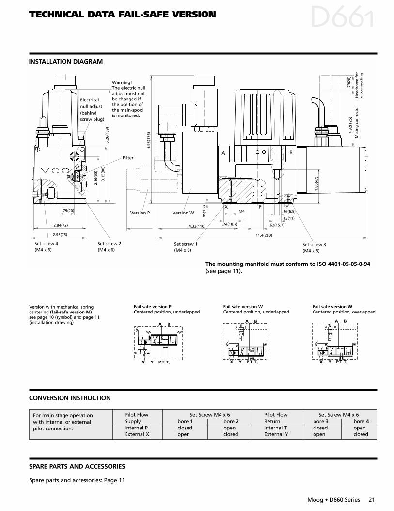
INSTALLATION DIAGRAM
D
Moog • D660 Series 21
CONVERSION INSTRUCTION
TECHNICAL DATA FAIL-SAFE VERSION
Fail-safe version PCentered position, underlapped
Fail-safe version WCentered position, underlapped
Fail-safe version WCentered position, overlapped
A B A B
Spare parts and accessories: Page 11
Version with mechanical springcentering (fail-safe version M)see page 10 (symbol) and page 11(installation drawing)
Pilot Flow Set Screw M4 x 6 Pilot Flow Set Screw M4 x 6Supply bore 1 bore 2 Return bore 3 bore 4Internal P closed open Internal T closed openExternal X open closed External Y open closed
For main stage operation with internal or external pilot connection.
The mounting manifold must conform to ISO 4401-05-05-0-94(see page 11).
SPARE PARTS AND ACCESSORIES
D
22 Moog • D660 Series
TECHNICAL DATA FAIL-SAFE VERSION
8.94
(227
)
1.58
(40)
1.50
(38)
4.21
(107
)
2.01
(51)
.12(3) .79(20)
3.62(92)
3.74(95)
.20(
5)
Filter
Set screw 2 (M6 x 6)
Set screw 1(1/16 NPTF)
Electrical null adjust(under screw plug)
Warning!The electric nulladjust must not be changed if theposition of the main-spool is monitored.
.43(11)
.26(6.6)
.71(18)
3.19(81)
6.06(154)
1.06(27)
12.5(317)
.79(20)
1.04(26.5)
7.32(186)
.08(
2) .05(
1.2)
.27(7)
.55(13.9)
.43(11)
.79(20)
5.98(152)
Mat
ing
co
nn
ecto
rH
ead
roo
m f
or
dis
con
nec
tin
g
4.92
(125
).7
9(20
)
INSTALLATION DIAGRAM
CONVERSION INSTRUCTION
SPARE PARTS AND ACCESSORIES
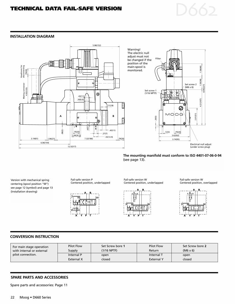
Fail-safe version PCentered position, underlapped
Fail-safe version WCentered position, underlapped
Fail-safe version WCentered position, overlapped
A BA B
Version with mechanical springcentering (spool position "M")see page 12 (symbol) and page 13(installation drawing)
The mounting manifold must conform to ISO 4401-07-06-0-94(see page 13).
Spare parts and accessories: Page 11
Pilot Flow Set Screw bore 1 Pilot Flow Set Screw bore 2Supply (1/16 NPTF) Return (M6 x 6)Internal P open Internal T openExternal X closed External Y closed
For main stage operation with internal or external pilot connection.
1.18
(30)
9.89
(251
)
5.12
(130
)2.
48(6
3)
.79(20)
2.29(58)
4.65(118)
Filter
Set screw 2(M6 x 6)
Set screw 1(1/16 NPTF)
Electrical null adjust(behind screw plug)
Warning!The electric nulladjust must not be changed if theposition of the main-spool is monitored.
.25(6.3)
.99(25)1.26(32)1.54(39)
.24(6).79(20)
.53(13.5)
2.24
(57)
.32(
8)
.08(
2)
7.05(179)
Hea
dro
om
fo
r d
isco
nn
ecti
ng
Mat
ing
co
nn
ecto
r4.
92(1
25)
.79(
20)
6.19(157)
15.17(385)
INSTALLATION DIAGRAM
D
Moog • D660 Series 23
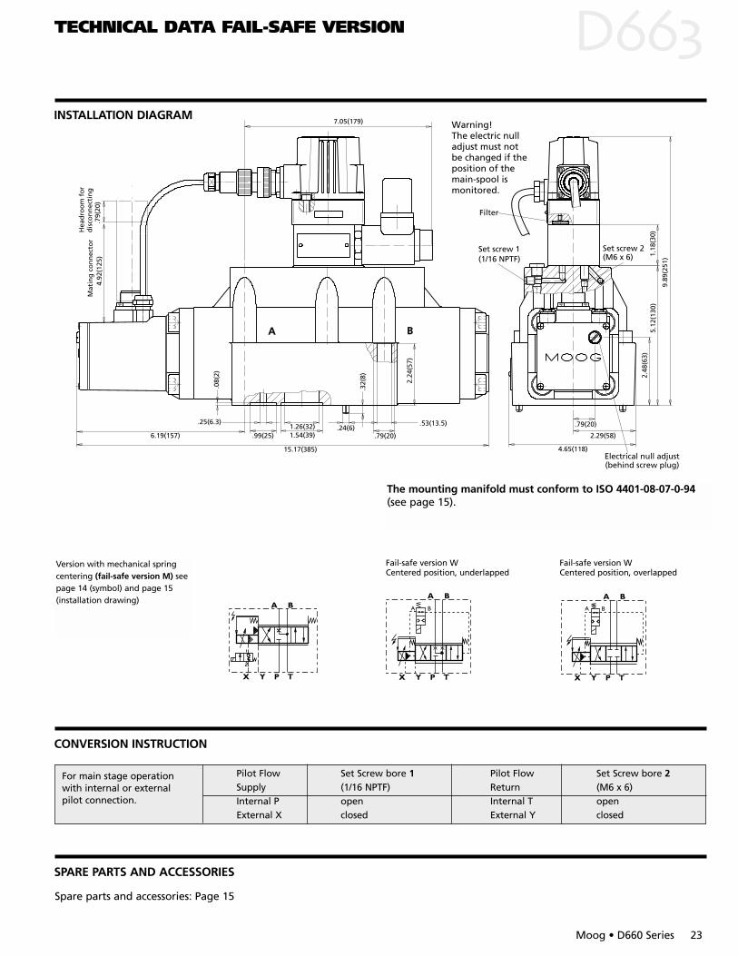
TECHNICAL DATA FAIL-SAFE VERSION
Fail-safe version WCentered position, underlapped
Fail-safe version WCentered position, overlapped
A BA B
CONVERSION INSTRUCTION
SPARE PARTS AND ACCESSORIES
Spare parts and accessories: Page 15
The mounting manifold must conform to ISO 4401-08-07-0-94(see page 15).
Version with mechanical springcentering (fail-safe version M) seepage 14 (symbol) and page 15 (installation drawing)
Pilot Flow Set Screw bore 1 Pilot Flow Set Screw bore 2Supply (1/16 NPTF) Return (M6 x 6)Internal P open Internal T openExternal X closed External Y closed
For main stage operation with internal or external pilot connection.
D
24 Moog • D660 Series
TECHNICAL DATA FAIL-SAFE VERSION
INSTALLATION DIAGRAM
1.18
(30)
9.89
(251
)
5.12
(130
)2.
48(6
3)
.79(20)
2.29(58)
4.65(118)
Filter
Set screw 2(M6 x 6)
Set screw 1(1/16 NPTF)
Electrical null adjust(behind screw plug)
Warning!The electric nulladjust must not be changed if theposition of the main-spool is monitored.
.25(6.3)
.99(25)1.26(32)1.54(39)
.24(6).79(20)
.53(13.5)
2.24
(57)
.32(
8)
.08(
2)
7.05(179)
Hea
dro
om
fo
r d
isco
nn
ecti
ng
Mat
ing
co
nn
ecto
r4.
92(1
25)
.79(
20)
6.19(157)
15.17(385)
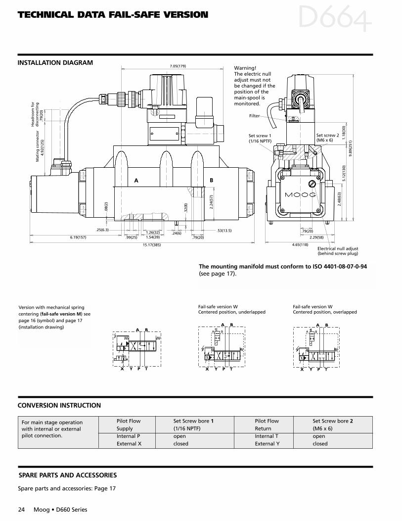
Fail-safe version WCentered position, underlapped
Fail-safe version WCentered position, overlapped
A BA B
CONVERSION INSTRUCTION
SPARE PARTS AND ACCESSORIES
Spare parts and accessories: Page 17
The mounting manifold must conform to ISO 4401-08-07-0-94(see page 17).
Version with mechanical springcentering (fail-safe version M) seepage 16 (symbol) and page 17 (installation drawing)
Pilot Flow Set Screw bore 1 Pilot Flow Set Screw bore 2Supply (1/16 NPTF) Return (M6 x 6)Internal P open Internal T openExternal X closed External Y closed
For main stage operation with internal or external pilot connection.
D
Moog • D660 Series 25
TECHNICAL DATA FAIL-SAFE VERSION
INSTALLATION DIAGRAM
.87(22)1.30(33)
1.97(50)1.97(60)
1/8NPTF
2.32
(59)
.11(
2.8)
19.58(497)
.67(17)
6.74(171)
3.90(99)7.80(198)
7.92(201)
8.27(210)
.32(8)
.32(
8)
16.0
4(40
7)9.
02(2
29)
0.05
(1.3
)
2.29
(58)
Set screw 2(1/16 NPTF)
Set screw 4(1/16 NPTF)
Set screw 3(1/8 NPTF)
Set screw 1 (1/8 NPTF)
Electrical null adjust(behind screw plug)
Filter behind cover
Mat
ing
co
nn
ecto
rHea
dro
om
fo
r d
isco
nn
ecti
ng
4.93
(125
).7
9(20
)
Warning!The electric nulladjust must not be changed if theposition of the main-spool is monitored.
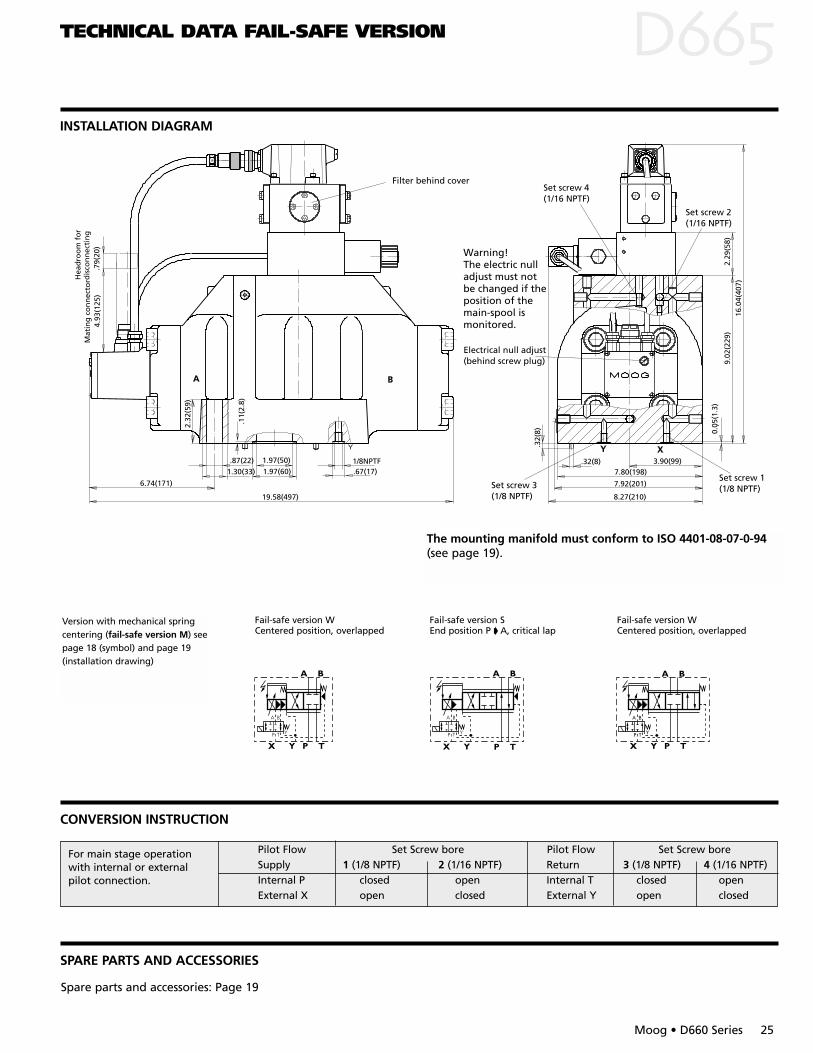
Fail-safe version WCentered position, overlapped
Fail-safe version SEnd position P A, critical lap
Fail-safe version WCentered position, overlapped
YP
A B
T
CONVERSION INSTRUCTION
SPARE PARTS AND ACCESSORIES
Spare parts and accessories: Page 19
The mounting manifold must conform to ISO 4401-08-07-0-94(see page 19).
Version with mechanical springcentering (fail-safe version M) seepage 18 (symbol) and page 19(installation drawing)
Pilot Flow Set Screw bore Pilot Flow Set Screw boreSupply 1 (1/8 NPTF) 2 (1/16 NPTF) Return 3 (1/8 NPTF) 4 (1/16 NPTF)Internal P closed open Internal T closed openExternal X open closed External Y open closed
For main stage operation with internal or external pilot connection.
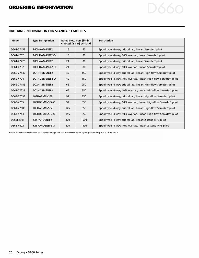
ORDERING INFORMATION DORDERING INFORMATION FOR STANDARD MODELS
26 Moog • D660 Series
Model Type Designation Rated Flow gpm [l/min] Description@ 75 psi [5 bar] per land
D661-2745E P60HAAM4NSF2 16 60 Spool type: 4-way, critical lap, linear; ServoJet® pilot
D661-4737 P60HDAM4NSF2-O 16 60 Spool type: 4-way, 10% overlap, linear; ServoJet® pilot
D661-2722E P80HAAM4NSF2 21 80 Spool type: 4-way, critical lap, linear; ServoJet® pilot
D661-4732 P80HDAM4NSF2-O 21 80 Spool type: 4-way, 10% overlap, linear; ServoJet® pilot
D662-2714E D01HABM6NSF2 40 150 Spool type: 4-way, critical lap, linear; High-flow ServoJet® pilot
D662-4724 D01HDBM6NSF2-O 40 150 Spool type: 4-way, 10% overlap, linear; High-flow ServoJet® pilot
D662-2718E D02HABM6NSF2 66 250 Spool type: 4-way, critical lap, linear; High-flow ServoJet® pilot
D662-2722E D02HDBM6NSF2 66 250 Spool type: 4-way, 10% overlap, linear; High-flow ServoJet® pilot
D663-2709E L03HABM6NSF2 92 350 Spool type: 4-way, critical lap, linear; High-flow ServoJet® pilot
D663-4705 L03HDBM6NSF2-O 92 350 Spool type: 4-way, 10% overlap, linear; High-flow ServoJet® pilot
D664-2708E L05HABM6NSF2 145 550 Spool type: 4-way, critical lap, linear; High-flow ServoJet® pilot
D664-4714 L05HDBM6NSF2-O 145 550 Spool type: 4-way, 10% overlap, linear; High-flow ServoJet® pilot
D665E2301 K15FAHO6NSF2 400 1500 Spool type: 4-way, critical lap, linear; 2-stage MFB pilot
D665-4602 K15FDHO6NSF2-O 400 1500 Spool type: 4-way, 10% overlap, linear; 2-stage MFB pilot
Notes: All standard models use 24 V supply voltage and ±10 V command signal. Spool position output is 2.5 V to 13.5 V.
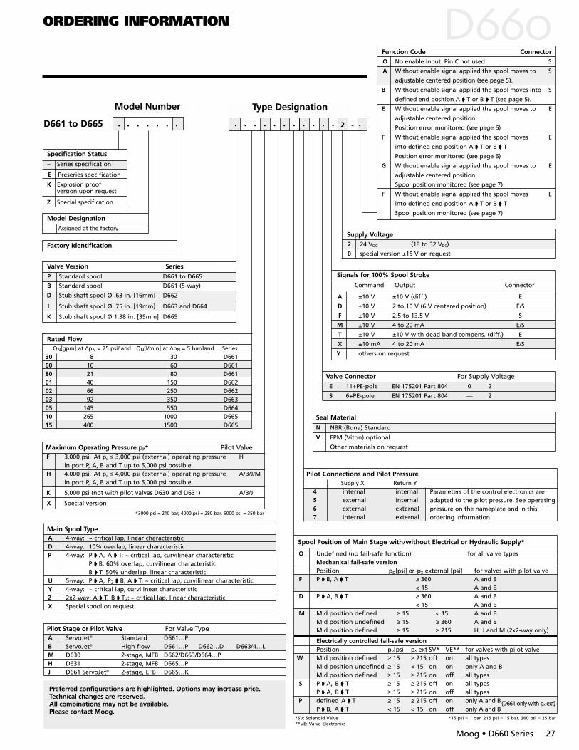
Model Designation
A ±10 V ±10 V (diff.) E
D ±10 V 2 to 10 V (6 V centered position) E/S
F ±10 V 2.5 to 13.5 V S
M ±10 V 4 to 20 mA E/S
T ±10 V ±10 V with dead band compens. (diff.) E
X ±10 mA 4 to 20 mA E/S
Y others on request
Valve Version Series
B Standard spool D661 (5-way)
L Stub shaft spool Ø .75 in. [19mm] D663 and D664
K Stub shaft spool Ø 1.38 in. [35mm] D665
E Preseries specification
D661 to D665 . . . . . . .
Factory Identification
Signals for 100% Spool Stroke
Command Output Connector
Valve Connector For Supply VoltageE 11+PE-pole EN 175201 Part 804 0 2
S 6+PE-pole EN 175201 Part 804 — 2
Seal Material
N NBR (Buna) Standard
Specification Status
– Series specification
Assigned at the factory
Rated Flow
Maximum Operating Pressure pp* Pilot Valve
Main Spool Type
Model Number Type Designation
QN[gpm] at ∆pN = 75 psi/land QN[l/min] at ∆pN = 5 bar/land Series
A 4-way: ~ critical lap, linear characteristicD 4-way: 10% overlap, linear characteristicP 4-way: P A, A T: ~ critical lap, curvilinear characteristic
P B: 60% overlap, curvilinear characteristicB T: 50% underlap, linear characteristic
U 5-way: P A, P2 B, A T: ~ critical lap, curvilinear characteristicY 4-way: ~ critical lap, curvilinear characteristicZ 2x2-way: A T, B T2: ~ critical lap, linear characteristicX Special spool on request
Pilot Stage or Pilot Valve For Valve TypeA ServoJet® Standard D661…PB ServoJet® High flow D661…P D662…D D663/4…LM D630 2-stage, MFB D662/D663/D664…PH D631 2-stage, MFB D665…PJ D661 ServoJet® 2-stage, EFB D665…K
Spool Position of Main Stage with/without Electrical or Hydraulic Supply*
*SV: Solenoid Valve *15 psi = 1 bar, 215 psi = 15 bar, 360 psi = 25 bar**VE: Valve Electronics
Pilot Connections and Pilot PressureSupply X Return Y
4 internal internal5 external internal6 external external7 internal external
Supply Voltage2 24 VDC (18 to 32 VDC)
0 special version ±15 V on request
P Standard spool D661 to D665
D Stub shaft spool Ø .63 in. [16mm] D662
30 8 30 D66160 16 60 D66180 21 80 D66101 40 150 D66202 66 250 D66203 92 350 D66305 145 550 D66410 265 1000 D66515 400 1500 D665
F 3,000 psi. At px ≤ 3,000 psi (external) operating pressure Hin port P, A, B and T up to 5,000 psi possible.
H 4,000 psi. At px ≤ 4,000 psi (external) operating pressure A/B/J/Min port P, A, B and T up to 5,000 psi possible.
K 5,000 psi (not with pilot valves D630 and D631) A/B/J
X Special version
2 -
Parameters of the control electronics areadapted to the pilot pressure. See operatingpressure on the nameplate and in thisordering information.
Function Code ConnectorO No enable input. Pin C not used S
A Without enable signal applied the spool moves to S
adjustable centered position (see page 5).
B Without enable signal applied the spool moves into S
defined end position A T or B T (see page 5).
E Without enable signal applied the spool moves to E
adjustable centered position.
Position error monitored (see page 6)
F Without enable signal applied the spool moves E
into defined end position A T or B T
Position error monitored (see page 6)
G Without enable signal applied the spool moves to E
adjustable centered position.
Spool position monitored (see page 7)
F Without enable signal applied the spool moves E
into defined end position A T or B T
Spool position monitored (see page 7)
V FPM (Viton) optional
Other materials on request
ORDERING INFORMATION D
Z Special specification
K Explosion proof version upon request
*3000 psi = 210 bar, 4000 psi = 280 bar, 5000 psi = 350 bar
Moog • D660 Series 27
Preferred configurations are highlighted. Options may increase price.Technical changes are reserved.All combinations may not be available.Please contact Moog.
O Undefined (no fail-safe function) for all valve typesMechanical fail-safe versionPosition pp[psi] or px external [psi] for valves with pilot valve
F P B, A T ≥ 360 A and B< 15 A and B
D P A, B T ≥ 360 A and B< 15 A and B
M Mid position defined ≥ 15 < 15 A and BMid position undefined ≥ 15 ≥ 360 A and BMid position defined ≥ 15 ≥ 215 H, J and M (2x2-way only)
Electrically controlled fail-safe versionPosition pp[psi] px ext SV* VE** for valves with pilot valve
W Mid position defined ≥ 15 ≥ 215 off on all typesMid position undefined ≥ 15 < 15 on on only A and BMid position defined ≥ 15 ≥ 215 on off all types
S P A, B T ≥ 15 ≥ 215 off on all typesP A, B T ≥ 15 ≥ 215 on off all types
P defined A T ≥ 15 ≥ 215 off on only A and B(D661 only with px ext)P B, A T < 15 < 15 on off only A and B
. . . . . . . . . . . .

ArgentinaAustraliaAustriaBrazilChinaEnglandFinlandFranceGermany
IndiaIrelandItaly JapanKoreaLuxembourgNorwayRussiaSingaporeSpainSwedenUSA
Moog Industrial Controls Division East Aurora, NY 14052-0018Telephone: 716/655-3000Fax: 716/655-1803 Toll Free: 1-800-272-MOOGwww.moog.com
CDL6562 Rev F 500-212 401


