Embed Size (px)
Citation preview
इ रसेट IRISET
TA 2
DATA COMMUNICATION & NETWORKING
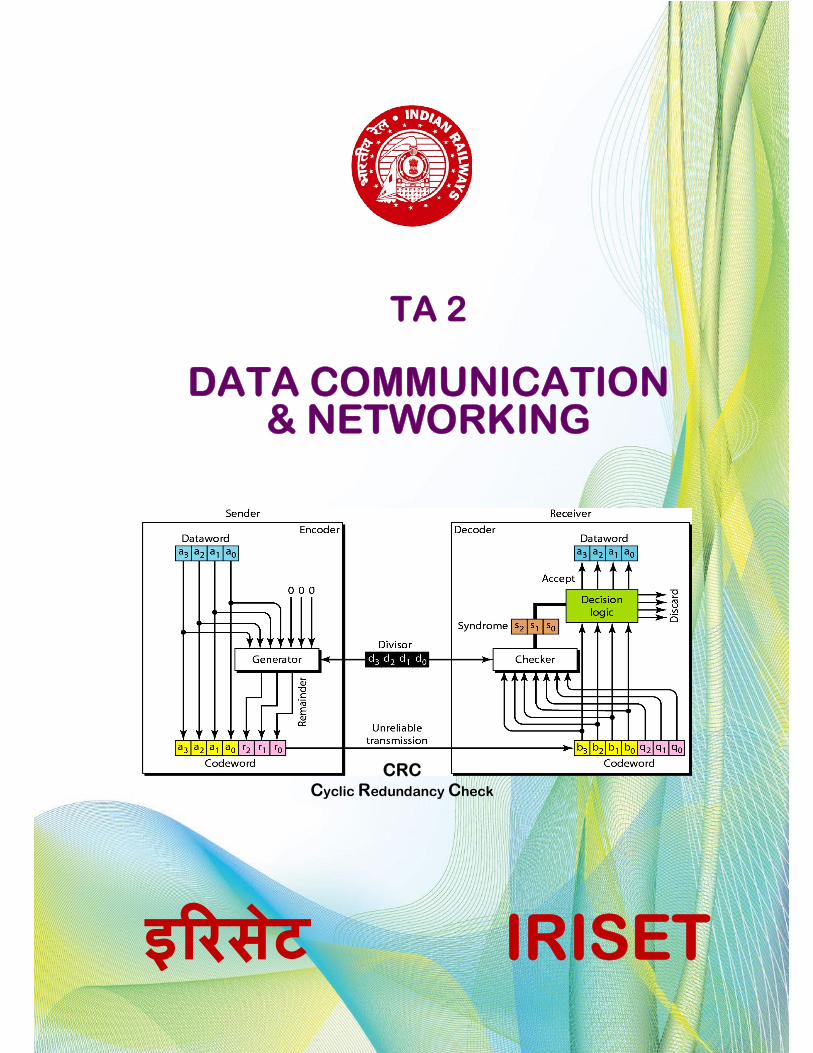
CRC Cyclic Redundancy Check
TA 2
DATA COMMUNICATION & NETWORKING
INDIAN RAILWAY INSTITUTE OF SIGNAL ENGINEERING & TELECOMMUNICATION,
SECUNDERABAD - 500017
January 2020
The Material Presented in this IRISET Notes is for guidance only. It does not over rule or alter any of the Provisions contained in Manuals or Railway Board’s directives
TA 2 DATA COMMUNICATION & NETWORKING
INDEX
S.No. Chapter Page No.
1. Introduction to Data Communication 1.0 Introduction 1.1 Data representation 1.2 Data components 1.3 Fundamental characteristics of data communication 1.4 Data flow 1.5 Data Transmission 1.6 Network 1.7 Categories of networks 1.8 Topology 1.9 Standard organizations 1.10 The OSI model (layered approach to data communications)
1
2. Data Transmission on Physical media 2.0 Introduction 2.1 Data & Signal (Baseband and broadband transmission, transmission
impairments, data rates, bandwidth and baud rate) 2.2 Encoding 2.3 Transmission Media Categories
21
3 Data Transmission on LAN 3.0 Introduction 3.1 Data Link control ( Framing, Line Discipline, Flow control, Error detection and correction, Block coding, CRC Checksum, Error
control) 3.2 LAN Protocols (Character oriented & Bit oriented protocols) 3.3 Media Access (Mac control, Mac/Ethernet frame, CSMA/CD, CSMA/CA) 3.4 Ethernet (evolution, implementation, electrical specifications, media
variants, cables, cross & straight cables) 3.5 PoE (Power over Ethernet) 3.6 Connecting devices ( Hubs, Switches – Manageable, Unmanageable,
Layer 2 & 3) 3.5 VLAN (Virtual LAN) – Creation, Trunking.
29
4 Data Transmission on WAN 4.0 Introduction 4.1 TCP/IP Protocol (TCP header & its description) 4.2 UDP Protocol (UDP header & its description) 4.3 IP Communication (IP header & its description, Data transmission on IP) 4.4 IP Address (Different Classes, Subnetting & Supernetting & Special IP
addresses) 4.5 IP Routing (Static and Dynamic Routing, Different Routing Protocols) 4.6 WAN devices (Routers & its hardware setup and Gateways) 4.7 MPLS (Multi Protocol Label Switching)
51
5 Long Distance Data Transmission 5.0 Introduction 5.1 Modem (Modem working method) 5.2 Classification modems (based on range, line, operation modes etc.) 5.3 Modem Diagnostics (Local, Remote & Digital loops) 5.4 Digital Subscriber line & XDSL modems (ADSL, HDSL, SDSL & VDSL) 5.4 LAN extender 5.5 Media Converter
79
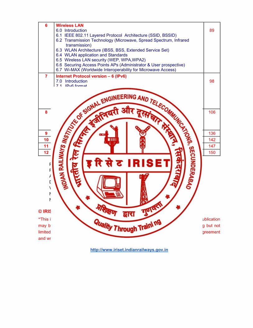
6 Wireless LAN 6.0 Introduction 6.1 IEEE 802.11 Layered Protocol Architecture (SSID, BSSID) 6.2 Transmission Technology (Microwave, Spread Spectrum, Infrared
transmission) 6.3 WLAN Architecture (IBSS, BSS, Extended Service Set) 6.4 WLAN application and Standards 6.5 Wireless LAN security (WEP, WPA,WPA2) 6.6 Securing Access Points APs (Administrator & User prospective) 6.7 Wi-MAX (Worldwide Interoperability for Microwave Access)
89
7 Internet Protocol version – 6 (IPv6) 7.0 Introduction 7.1 IPv6 format 7.2 IPv6 Address Classification 7.3 IPv6 Address types and their formats 7.4 IPv6 Networks 7.5 IPv6 Migration
98
8 Annexure (Line encoding and block coding, High Level data Link Control (HDLC), Quality of service (QoS), Blue tooth & RoIP, Connectors & Interfaces (RS232, V.35, G.703, USB & HMI Connectors), Precautions of handling adaptors, connectors, chords, plugs
106
9 Questions Bank 136
10 Abbreviations/Acronyms 142
11 Glossary 147
12 References 150 Prepared by : S.D. Banerjee, INW1 Reviewed by : B. B. K. Murthy, Prof. - Tele Approved by : C. Chandrasekhara Sastry, Sr. Prof. - Tele DTP and Drawings : K. Srinivas, JE (D) Version No. : 1.0 January 2020 No. of Pages : 153 No. of Sheets : 77
© IRISET
“This is the intellectual property for exclusive use of Indian Railways. No part of this publication
may be stored in a retrieval system, transmitted or reproduced in any way, including but not
limited to photo copy, photograph, magnetic, optical or other record without the prior agreement
and written permission of IRISET, Secunderabad, India”
http://www.iriset.indianrailways.gov.in
IRISET 1 TA2 – Data Communication & Networking
CHAPTER - 1
INTRODUCTION TO DATA COMMUNICATION
1.0 Introduction: In the simplest form, data communication involves the exchange of data between two devices. Here devices includes computers or the variety of devices used in communication system having a processor and memory of its own viz. switches, routers etc. These devices work with a binary language consisting of zeros and ones. Therefore, a computer generates a stream of zeros and ones and sends it to another computer to which it is connected. The connection can be either a simple wire or it can be through wireless media. For data communications to occur, the communicating devices must be part of communication system made up of a combination of hardware (physical equipment) and software (programs).
1.1 DATA REPRESENTATION: Information or data today comes in different forms such as text, numbers, images, audio and video.
a. Text: In data communications, text is represented as a bit pattern, a sequence of bits (0’s or 1’s). Different sets of bit patterns have been designed to represent text symbols. Each set is called a code, and the process of representing symbols is called coding. Earlier we were using ASCII (American Standard Code for Information Interchange) coding system, but today the prevalent coding system is called Unicode, which uses 32 bits to represent a symbol or character used in any language in the world.
b. Numbers: Numbers are also represented by bit patterns. However, a code such as ASCII is not used to represent numbers; the number is directly converted to a binary number to simplify mathematical operations.
c. Images: Images are also represented by bit patterns. In its simplest form, an image is composed of a matrix of pixels (picture elements), where each pixel is a small dot. The size of the pixel depends on the resolution. For example, an image can be divided into 1000 pixels or 10,000 pixels. In the second case, there is a better representation of the image (better resolution), but more memory is needed to store the image. After an image is divided into pixels, each pixel is assigned a bit pattern.
d. Audio: Audio refers to the recording or broadcasting of sound or music. Audio is by nature different from text, number or images. It is continuous, not discrete.
e. Video: Video refers to the recording or broadcasting of a picture or movie. Video can either be produced as a continuous entity (e.g. By a TV camera), or it can be a combination of images, each a discrete entity, arranged to convey the idea of motion.
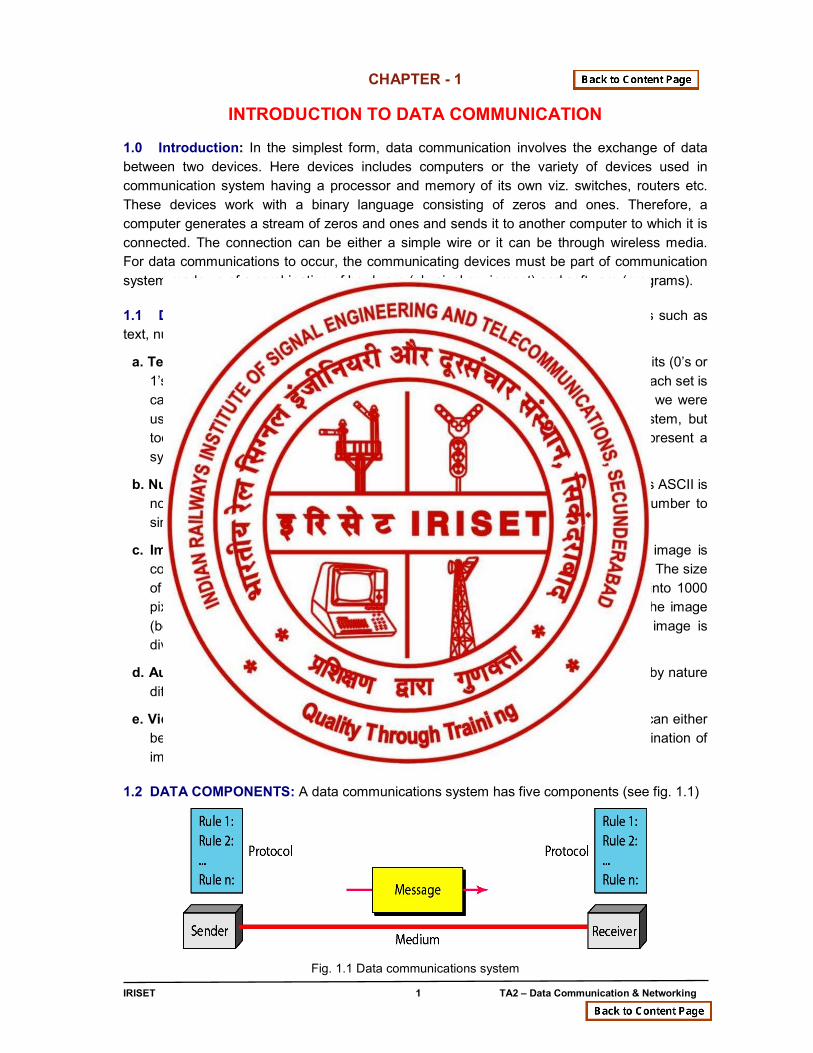
1.2 DATA COMPONENTS: A data communications system has five components (see fig. 1.1)
Fig. 1.1 Data communications system
Introduction to Data Communication
IRISET 2 TA2 – Data Communication & Networking
Message: The message is the information (data) to be communicated. Popular forms of information include text, numbers, pictures, audio and video.
a. Receiver: The receiver is the device that receives the
b. Sender: The sender is a device that sends the data message. It can be computer, workstation, telephone handset, video camera and so on.
c. Message: It can be computer, workstation, telephone handset, television and so on.
d. Transmission medium: The transmission medium is the physical path by which a message travels from sender to receiver. Some examples of transmission media include twisted-pair wires, coaxial cable, fiber optic cable and radio waves.
e. Protocol: A protocol is a set of rules which is used by computers to communicate with each other across a network. A protocol is a convention or standard or software that controls or enables the connection, communication, and data transfer between computing endpoints.
The purpose of protocols specifies one or more of the following properties.
● Detection of the underlying physical connection (wired or wireless), or the existence of the other endpoint or node
● Handshaking ● Negotiation of various connection characteristics. ● How to start and end a message? ● Procedures on formatting a message. ● What to do with corrupted or improperly formatted messages (error correction)? ● How to detect unexpected loss of the connection, and what to do next ? ● Termination of the session or connection.
In data communications, there are widely accepted protocols for sending & receiving data. Both the sender and receiver must use the same protocol when communicating.
Protocols can be broadly classified as
1. Proprietary Protocols (works on a specific make or brand or model device)
2. Open Source Protocols (works on any make or brand or model device)
1.3 Fundamental Characteristics of Data Communication:
The effectiveness of data communications system depends on four fundamental characteristics: delivery, accuracy, timeliness and jitter.
a. Delivery: The system must deliver data to the correct destination. Data must be received by the intended device or user and only by that device or user.
b. Accuracy: The system must deliver the data accurately. Data that have been altered in transmission and left uncorrected are unusable.
c. Timelines: The system must deliver data in a timely manner. Data delivered late are useless. In the case of video and audio, timely delivery means delivering data as they are produced, without significant delay. This kind of delivery is called real time transmission.
d. Jitter: Jitter refers to the variation in the packet arrival time. It is the uneven delay in the delivery of audio or video packets, which results in degradation of the quality. Hence jitter is required to be minimized.
Introduction to Data Communication
IRISET 3 TA2 – Data Communication & Networking
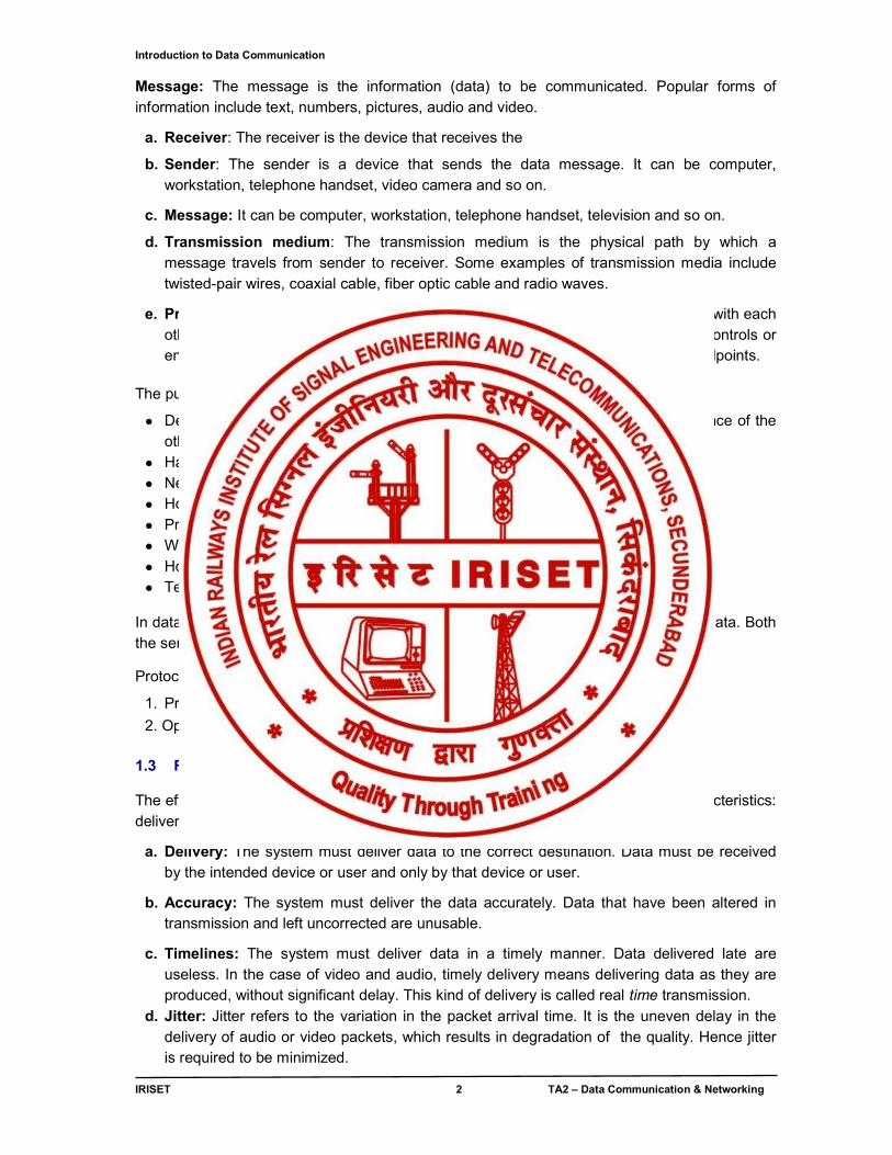
1.4 Data Flow: Communication between two devices can be simplex, half duplex, or full duplex as shown in figure 1.2.
a. Simplex: In simplex mode, the communication is unidirectional, only one of the two devices on a link can transmit; the other can only receive (see figure 1.2a).
Fig. 1.2a Simplex mode
Keyboards and traditional monitors are examples of simplex devices. The keyboard can only introduce input; the monitor can only accept output. The simplex mode can use the entire capacity of the channel to send data in one direction.
b. Half-Duplex: In half duplex mode, each station can both transmit and receive, but not at the same time. When one device is sending, the other can only receive, and vice versa (see fig. 1.2b). In a half duplex transmission, the entire capacity of a channel is taken over by whichever of the two devices is transmitting at a time.
Fig. 1.2b Half Duplex mode
The half duplex mode is used in cases where there is no need for communication in both directions at the same time; Walkie-talkie is the best example for half duplex systems. The entire capacity of the channel can be utilized for each direction.
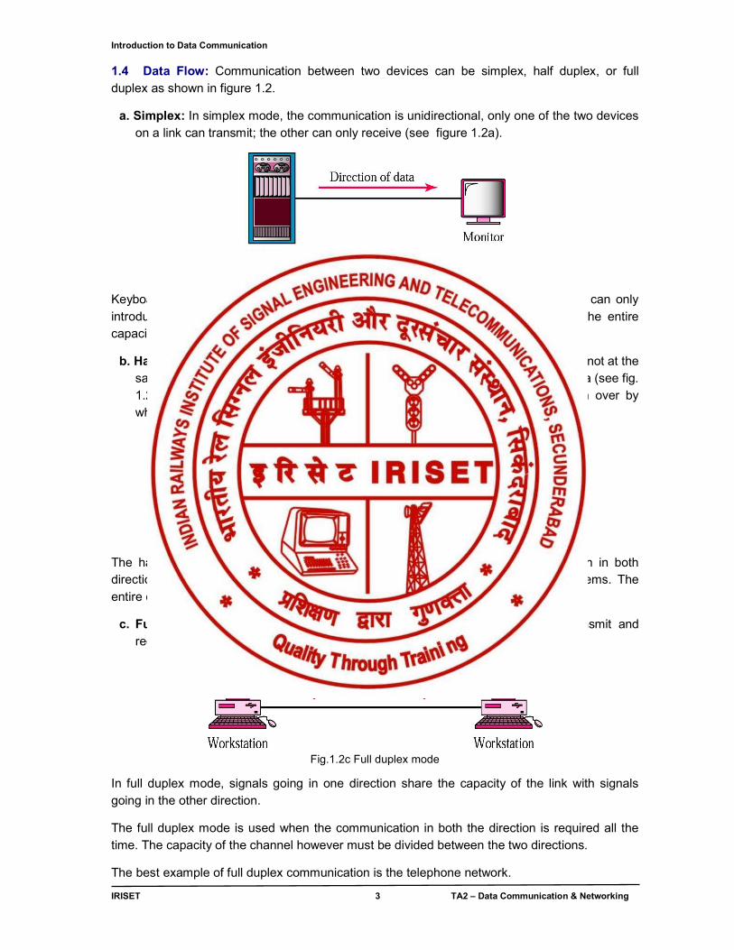
c. Full-Duplex: In full duplex mode (also called duplex), both stations can transmit and receive simultaneously (see fig. 1.2c).
Fig.1.2c Full duplex mode
In full duplex mode, signals going in one direction share the capacity of the link with signals going in the other direction.
The full duplex mode is used when the communication in both the direction is required all the time. The capacity of the channel however must be divided between the two directions.
The best example of full duplex communication is the telephone network.
Introduction to Data Communication
IRISET 4 TA2 – Data Communication & Networking
1.5 DATA TRANSMISSION
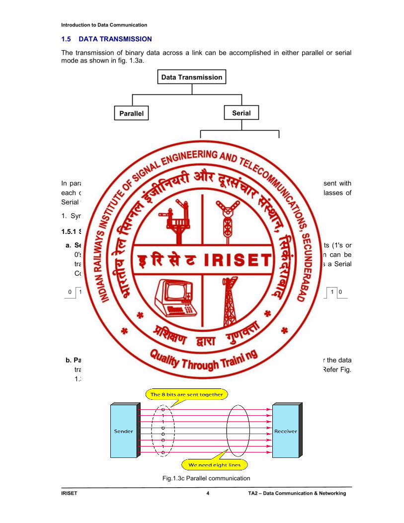
The transmission of binary data across a link can be accomplished in either parallel or serial mode as shown in fig. 1.3a.
Fig 1.3a Data transmission methods
In parallel mode, multiple bits are sent with each clock tick. In serial mode, 1 bit is sent with each clock tick. While there are no sub classes in parallel data, there are two subclasses of Serial transmission:
1. Synchronous. 2. Asynchronous
1.5.1 SERIAL, PARALLEL COMMUNICATION
a. Serial Data Communication: The physical connection determines how many bits (1's or 0's) can be transmitted at a single instance of time. If only 1 bit of information can be transmitted over the data transmission medium at a time then it is considered as a Serial Communication. (Refer Fig. 1.3b)
ReceivesSerial Data1 bit at a timeByte: 0100 1010Serial Communication
0 0 0 00 1 0 1
Data Transmission MediumOnly 1 Wire!
0 0 0 0
Sends SerialData1 bit at a timeByte: 0100 1010
1 1 1 1
Fig.1.3b Serial communication
b. Parallel Data Communication: If more than 1 bit of information is transmitted over the data transmission medium at a time then it is considered as Parallel Communication. (Refer Fig. 1.3c)
Fig.1.3c Parallel communication
Data Transmission
Parallel
Serial
Synchronous
Asynchronous
Introduction to Data Communication
IRISET 5 TA2 – Data Communication & Networking
Communications Advantages Disadvantages
Parallel Fast Transfer Rates Short distances only
Serial Long Distances Slow transfer rates
Table 1.1 Comparison of Parallel and Serial Communication
The transfer rate comparison is relative to serial versus parallel. Data can be transferred at much faster rates over long distances using serial methods than using parallel data transfer. At shorter distances, typically less than 15 feet, parallel data transfers are used.
Serial data communication transfers one bit at a time and does not have the timing problems (race conditions) as that of parallel data communications.
1.5.2 ASYNCHRONOUS / SYNCHRONOUS COMMUNICATION
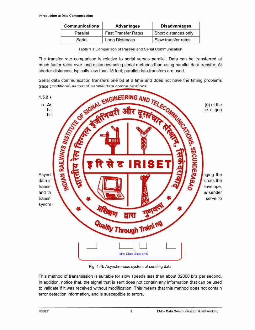
a. Asynchronous Transmission: In asynchronous transmission, we send 1 start bit (0) at the beginning and 1 or more stop bits (1s) at the end of each byte. There may be a gap between each byte.
Fig. 1.4a Asynchronous system of sending data Asynchronous systems send data bytes between the sender and receiver by packaging the data in an envelope as shown in Fig.1.4a this envelope helps transport the character across the transmission line that separates the sender and receiver. The transmitter creates the envelope, and the receiver uses the envelope to extract the data. Each character (data byte) the sender transmits is preceded with a start bit, and suffixed with a stop bit. These extra bits serve to synchronize the receiver with the sender.
Fig. 1.4b Asynchronous system of sending data
This method of transmission is suitable for slow speeds less than about 32000 bits per second. In addition, notice that, the signal that is sent does not contain any information that can be used to validate if it was received without modification. This means that this method does not contain error detection information, and is susceptible to errors.
Introduction to Data Communication
IRISET 6 TA2 – Data Communication & Networking
In addition, for every character that is sent, additional two bits are also sent as shown in fig 1.4b. Consider the sending of a text document which contains 1000 characters. Each character is eight bits, thus the total number of bits sent are 10000 (8 bits per character plus a start and stop bit for each character). These 10000 bits are actually 1250 characters, meaning that an additional 250 equivalent characters are sent due to the start and stop bits. This represents a large overhead in sending data, clearly making this method an inefficient means of sending large amounts of data.
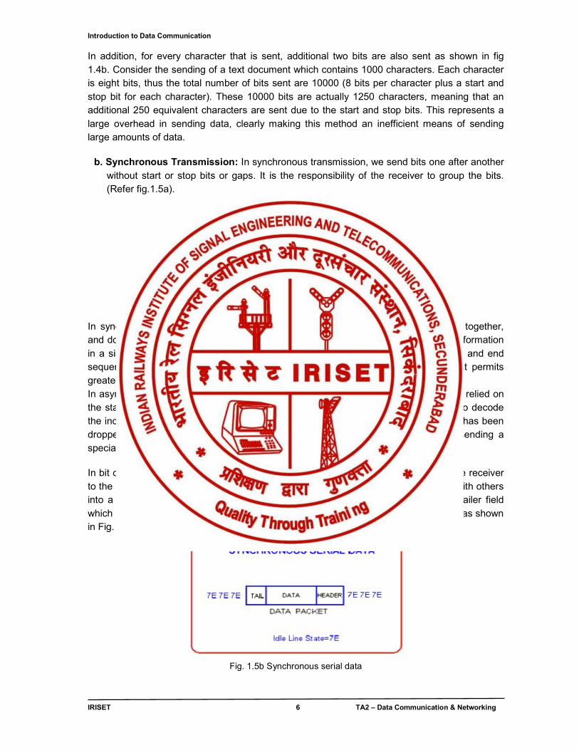
b. Synchronous Transmission: In synchronous transmission, we send bits one after another
without start or stop bits or gaps. It is the responsibility of the receiver to group the bits. (Refer fig.1.5a).
Fig 1.5a Synchronous Transmission
In synchronous transmission, greater efficiency is achieved by grouping characters together, and doing away with the start and stop bits for each character. We still envelop the information in a similar way as before, but this time we send more characters between the start and end sequences. In addition, the start and stop bits are replaced with a new format that permits greater flexibility. An extra ending sequence is added to perform error checking. In asynchronous transmission, if there was no data to transmit, nothing was sent. We relied on the start bit to start the CLOCK on receiving device and thus begin the preparation to decode the incoming character. However, in synchronous transmission, because the start bit has been dropped, the receiver must be kept in a state of readiness. This is achieved by sending a special code by the transmitter whenever it has no data to send.
In bit orientated protocols, the line idle state is changed to 7E, which synchronizes the receiver to the sender. The start and stop bits are removed, and each character is combined with others into a data packet. User data is prefixed with a header field, and suffixed with a trailer field which includes a checksum value (used by the receiver to check for errors in sending) as shown in Fig. 1.5b.
Fig. 1.5b Synchronous serial data
Introduction to Data Communication
IRISET 7 TA2 – Data Communication & Networking
The header field is used to convey address information (sender and receiver), packet type and control data. The data field contains the users’ data (if it can't fit in a single packet, then use multiple packets and number them). Generally, it has a fixed size. The tail field contains
checksum information which the receiver uses to check whether the packet was corrupted during transmission.
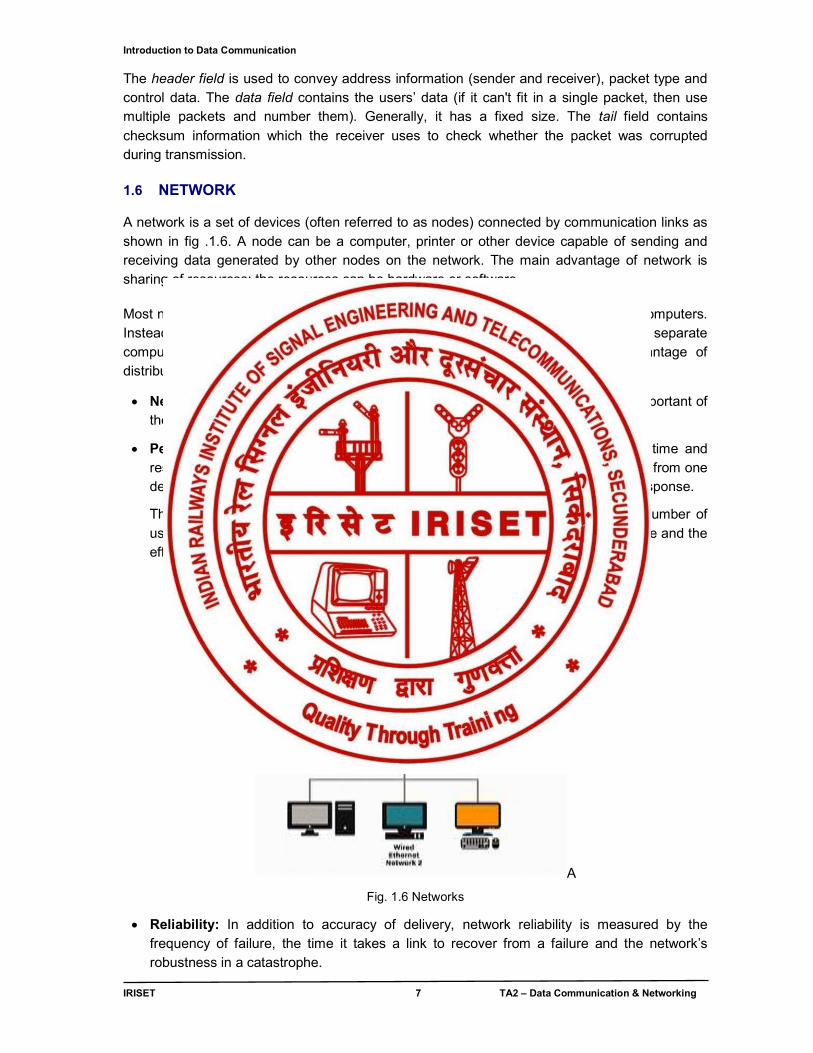
1.6 NETWORK
A network is a set of devices (often referred to as nodes) connected by communication links as shown in fig .1.6. A node can be a computer, printer or other device capable of sending and receiving data generated by other nodes on the network. The main advantage of network is sharing of resources; the resources can be hardware or software Most networks use distributed processing, in which a task is divided among multiple computers. Instead of one single large machine being responsible for all aspects of process, separate computers (usually a personal computer or workstation) handle a subset. Advantage of distributed processing is security, distribution of database, faster problem solving etc.
Network criteria: A network must be able to meet a certain criteria. The most important of these are performance, reliability and security.
Performance: Performance can be measured in many ways, including transit time and response time. Transit time is the amount of time required for a message to travel from one device to another. Response time is the elapsed time between an inquiry and a response.
The performance of a network depends on a number of factors, including the number of users, the type of transmission medium, the capabilities of the connected hardware and the efficiency of the software.
A
Fig. 1.6 Networks
Reliability: In addition to accuracy of delivery, network reliability is measured by the frequency of failure, the time it takes a link to recover from a failure and the network’s robustness in a catastrophe.
Introduction to Data Communication
IRISET 8 TA2 – Data Communication & Networking
Security: Network security issues include protecting data from unauthorized access, protecting data from damage, for development and implementing policies and procedures for recovery from breaches and data losses.
1.7 Categories of Networks
Networks come in all shapes and sizes. Network administrators often classify networks according to geographical size. Networks of similar size have many similar characteristics, as you will learn in later chapters. The following are the most common size classifications:
Local area networks (LANs)
Wide area networks (WANs)
Intranets and Internets
1.7.1 Local Area Networks (LANs) A local area network (LAN) is a group of computers and network communication devices
interconnected within a geographically limited area, such as a building or a campus.
LANs are characterized by the following:
They transfer data at high speeds (higher bandwidth).
They exist in a limited geographical area. Connectivity and resources, especially the transmission media, usually are managed by the company running the LAN.
Fig. 1.7 Local Area Network
1.7.2 Wide Area Networks (WANs) A wide area network (WAN) interconnects LANs. A WAN can be located entirely within a state or a country, or it can be interconnected around the world.
WANs are characterized by the following:
They exist in an unlimited geographical area.
They usually interconnect multiple LANs.
They often transfer data at lower speeds (lower bandwidth).
Introduction to Data Communication
IRISET 9 TA2 – Data Communication & Networking
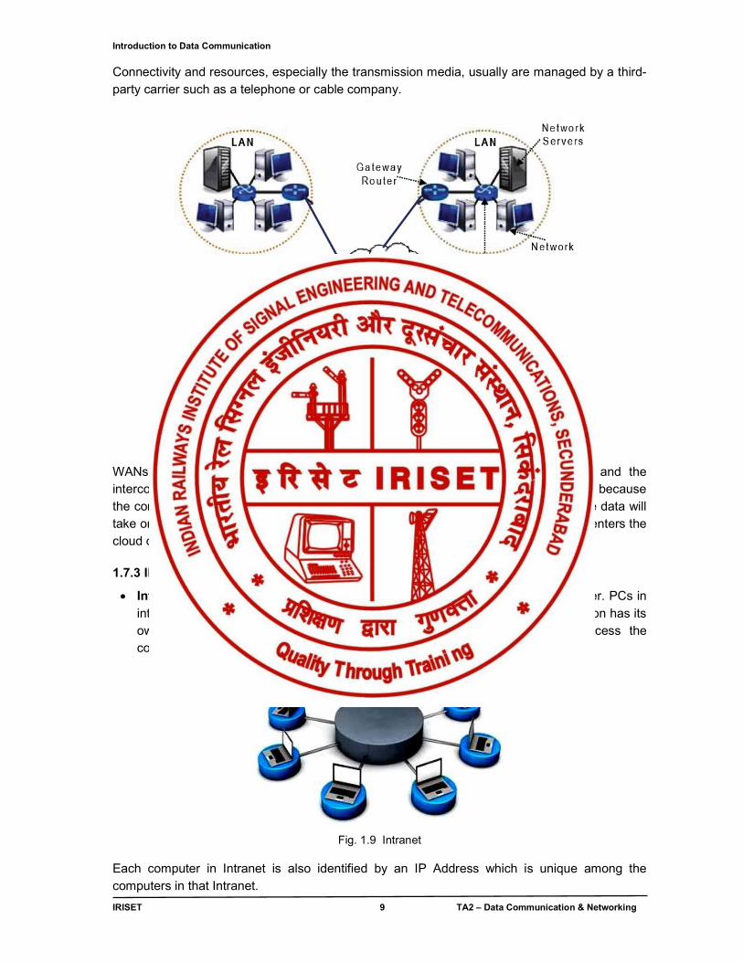
Connectivity and resources, especially the transmission media, usually are managed by a third-party carrier such as a telephone or cable company.
Fig. 1.8 Wide Area Network
WANs Are Interconnected LANs. The linkup of LAN’s is often shown as cloud and the interconnection often is represented by a line going into a cloud. Refer fig 1.7.3. This is because the company running the network typically has only a general idea of the path that the data will take on its journey to the other LAN segment. All the company knows is that the data enters the cloud on one side and exits the other side. 1.7.3 INTRANETS AND INTERNETS
Intranet: Intranet is the system in which multiple PCs are connected to each other. PCs in intranet are not available to the world outside the intranet. Usually each organization has its own Intranet network and members/employees of that organization can access the computers in their intranet.
Fig. 1.9 Intranet
Each computer in Intranet is also identified by an IP Address which is unique among the computers in that Intranet.
Introduction to Data Communication
IRISET 10 TA2 – Data Communication & Networking
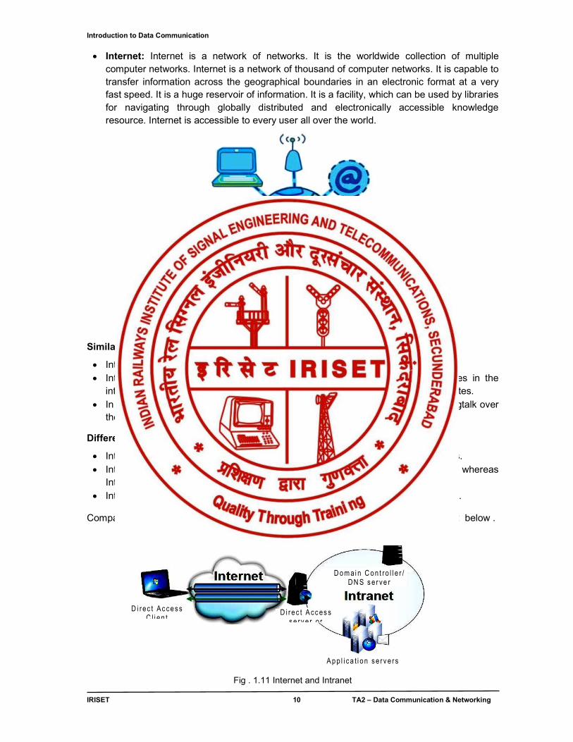
Internet: Internet is a network of networks. It is the worldwide collection of multiple computer networks. Internet is a network of thousand of computer networks. It is capable to transfer information across the geographical boundaries in an electronic format at a very fast speed. It is a huge reservoir of information. It is a facility, which can be used by libraries for navigating through globally distributed and electronically accessible knowledge resource. Internet is accessible to every user all over the world.
Fig. 1.10 Internet Similarities between Internet and Intranet
Intranet uses the internet protocols such as TCP/IP and FTP. Intranet sites are accessible via the web browser in a similar way as websites in the
internet. However, only members of Intranet network can access intranet hosted sites. In Intranet, own instant messengers can be used as similar to yahoo messenger/gtalk over
the internet.
Differences between Internet and Intranet
Internet is general to PCs all over the world whereas Intranet is specific to few PCs. Internet provides a wider and better access to websites to a large population, whereas
Intranet is restricted. Internet is not as safe as Intranet. Intranet can be safely privatized as per the need.
Comparison between Internet and Intranet is appended in fig 17.4 and the table no. 1.2 below .
Fig . 1.11 Internet and Intranet
i n te rnet
D om ai n C on t ro l l e r / D N S s e r ve r
A p p l i c a t i on s e r v e r s
D i r ec t A cc es s s e rv e r o r
D i rec t Ac ces s C l i en t
Introduction to Data Communication
IRISET 11 TA2 – Data Communication & Networking
Parameter Internet Intranet Usage Public Private User Types Any user having dial up of Internet
access line Organization employees and Internal company departments
Usage Access all kind of Information Internal employee communication, telephone directories etc.
Security Low security, Configured under 0 security level in firewall
High security, Configured under 100 security level in firewall
Regulated by Internet Architecture Board (IAB): Oversees the technical and engineering development of the IETF and IRTF. Internet Corporation for Assigned Names and Numbers (ICANN)
It is regulated by an organization
Coverage Wide Area Within an organization Access Large number of users Limited number of users System Failure Unpredictable System availability is high since
system is monitored by authority
Table 1.2 Comparisons of Internet and Intranet
1.8 TOPOLOGY
The networks in which the terminals are interconnected with each other for inter communication within and outside the network is called as Topology.
Basically the Topology is categorized in following four types of designs. (Ref fig no. 1.11 )
1. Mesh topology 2. Star Topology
3. Bus Topology. 4. Ring Topology
Fig. 1.12 Categories of topology
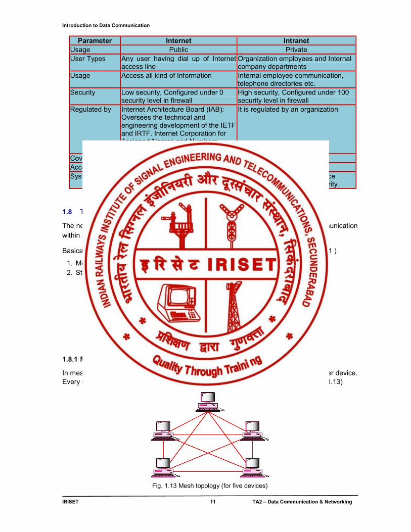
1.8.1 Mesh Topology
In mesh topology every device has a dedicated point to point connectivity to every other device. Every device must have (n-1) I/O ports. All WAN links use mesh topology. (Ref fig no. 1.13)
Fig. 1.13 Mesh topology (for five devices)
Topology
Mesh
Star
Bus
Ring
Introduction to Data Communication
IRISET 12 TA2 – Data Communication & Networking
Advantages
● It is robust. ● Each link can carry its own data load. ● It has privacy or secrecy. ● Fault identification is easy
Mesh disadvantages are larger number of cables & I/O ports are required for each device. Also the bulk of the wires can be greater than the available space.
1.8.2 Star Topology
In star topology each device has a dedicated point to point link only to central controller called as HUB as shown in fig no. 1.14. If one device wants to send data to another device, it sends through the HUB. Generally used in LAN networks
Fig. 1.14 Star topology Advantages
● It is easy to install and reconfigure. ● Each device needs only one link. Hence it is less expensive. ● If a link fails, only that link has to be attended. All other links remain active. ● It is easy to identify fault. ● It is also robust.
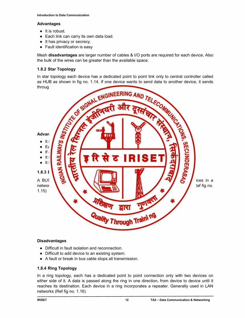
1.8.3 Bus topology
A BUS topology is multipoint. One long cable acts as a backbone to link all devices in a network. The advantage is the installation is easy. Generally used in LAN networks. (Ref fig no. 1.15)
Fig. 1.15 Bus topology
Disadvantages
● Difficult in fault isolation and reconnection. ● Difficult to add device to an existing system. ● A fault or break in bus cable stops all transmission.
1.8.4 Ring Topology
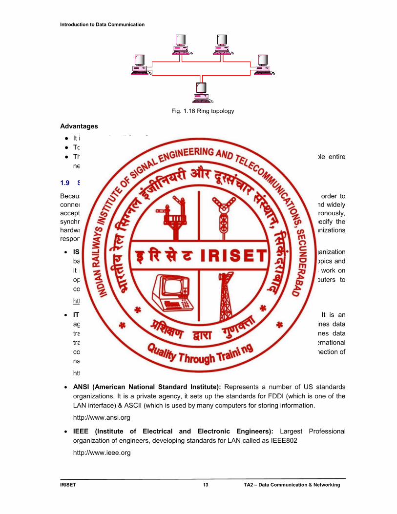
In a ring topology, each has a dedicated point to point connection only with two devices on either side of it. A data is passed along the ring in one direction, from device to device until it reaches its destination. Each device in a ring incorporates a repeater. Generally used in LAN networks (Ref fig no. 1.16)
Introduction to Data Communication
IRISET 13 TA2 – Data Communication & Networking
Fig. 1.16 Ring topology Advantages
● It is easy to install & configure. ● To add or delete a device requires only changing two connections. ● The disadvantages are unidirectional traffic and a break in the ring can disable entire
network.
1.9 STANDARD ORGANISATIONS
Because of the wide number of hardware manufacturers, a standard is essential in order to connect one computer to another computer if a different type. There are recognized and widely accepted standards governing how data is to be transmitted, whether asynchronously, synchronously or parallely. Standards govern the format of the data, and also specify the hardware details like voltages to use, bit durations, speeds etc..The major organizations responsible for standards are
ISO (International Organization for Standards): It is a nongovernmental organization based in Geneva. ISO has standards covering a wide range of computer related topics and it maintains standard for quality assurance. The most significant activities are its work on open systems, which defines the protocols that would allow any two computers to communicate independent of their architecture.
http://www.iso.org
ITUT (International Telecommunication Union): Formerly known as CCITT It is an agency of United Nations, it sets standards for modems (V-Series / Which defines data transmission over phone lines) & switching networks (X-Series / Which defines data transmission over switching digital networks). The ITU co-ordinates international communications and recommend standard interfaces and policies for the interconnection of national networks.
http://www.itu.int
ANSI (American National Standard Institute): Represents a number of US standards organizations. It is a private agency, it sets up the standards for FDDI (which is one of the LAN interface) & ASCII (which is used by many computers for storing information.
http://www.ansi.org
IEEE (Institute of Electrical and Electronic Engineers): Largest Professional organization of engineers, developing standards for LAN called as IEEE802
http://www.ieee.org
Introduction to Data Communication
IRISET 14 TA2 – Data Communication & Networking
EIA/TIA (Electronic Industries Association/Telecommunication Industries Association): Defines physical connection interfaces and Electronic signaling specifications for data communications. Their most well known standard is the RS-232(EIA-232); EIA-449 & EIA-530 defines serial transmission between two digital devices (i.e. computer to modem)
http://www.tiaonline.org , http://www.eciaonline.org
IEC (International Electro Technical Commission): It is a non-governmental agency devising standards for data processing and safety in office equipments. It has devised a compression standard for images like JPEG.
http://www.iec.ch ISOC & IETF (Internet Society & Internet Engineering Task Force): Internet Society
concentrates on user issues Including enhancement to the TCP/IP protocol IETF focuses on technical Internet issues (hardware & software) it Developed SNMP(Simple Network Management Protocol)
http://www.ietf.org, http://www.isoc.org 1.10 THE OSI MODEL (layered approach to data communications)
OSI MODEL - History, Origin, Purpose
Established in 1947, the International Standards Organization (ISO) is a multinational body dedicated to worldwide agreement on international standards. An ISO standard that covers all aspects of network communications is the open systems Interconnection model. It was first introduced in the late 1970s. An open system is a set of protocols that allows any two different systems to communicate regardless of their underlying architecture. The purpose of the OSI model is to show how to facilitate communication between different systems without requiring changes to the logic of the underlying hardware and software. The OSI model is not a protocol; it is a model for understanding and designing a network architecture that is flexible, robust and interoperable. The OSI model is a seven-layer framework that allows communication between all types of computer systems.
1.10.1 OSI (Open System Interconnection) MODEL
What is the OSI Model?
● The OSI Model is a way of thinking about how networks 'work'. ● The OSI Model is a theoretical model--it is not a technology, it is not a protocol, it is not a
program or software. ● The OSI Model sorts out network communication functions into layers ● The OSI Model does not specify how a layer will work internally--that is a matter left to the
programmers. ● The OSI Model specifies how layers should talk to each other. ● The OSI Model specifies that any layer's processes should be invisible to the layer above it,
and below it. ● The OSI Model defines how information should be handled when being transported over a
network. ● The OSI Model defines how software should interact with the network.
Introduction to Data Communication
IRISET 15 TA2 – Data Communication & Networking
1.10.2 Why Should We Learn the OSI model?
● Learning the OSI Model helps us to understand what functions occur where and when ● The OSI Model helps us to understand how a Web browser works ● The OSI Model helps us to understand what Internet Protocol does and how it works ● The OSI Model helps us to understand why we need ARP ● The OSI Model helps us to understand what is MAC address ● Learning the OSI Model makes it easier to learn. ● Learning the OSI Model makes it easier to perform troubleshooting. ● Learning the OSI Model makes it easier to troubleshoot any problem, including computer
problems. ● Learning the OSI Model makes it easier to communicate with other technical people and
discuss technical issues. 1.10.3 OSI model
Fig 1.17 OSI model
Network architecture based on OSI model is shown in fig 1.17 (above) & its functional description is given below.
The Open Systems Interconnection (OSI) model defines a networking framework to implement protocols in layers, with control passed from one layer to the next. It is primarily used today as a teaching tool. It conceptually divides computer network architecture into 7 layers in a logical progression. The lower layers deal with electrical signals, chunks of binary data, and routing of these data across networks. Higher levels cover network requests and responses, representation of data, and network protocols as seen from a user's point of view. Follow fig 1.18.
The OSI model was originally conceived as a standard architecture for building network systems and indeed, many popular network technologies today reflect the layered design of OSI.
Introduction to Data Communication
IRISET 16 TA2 – Data Communication & Networking
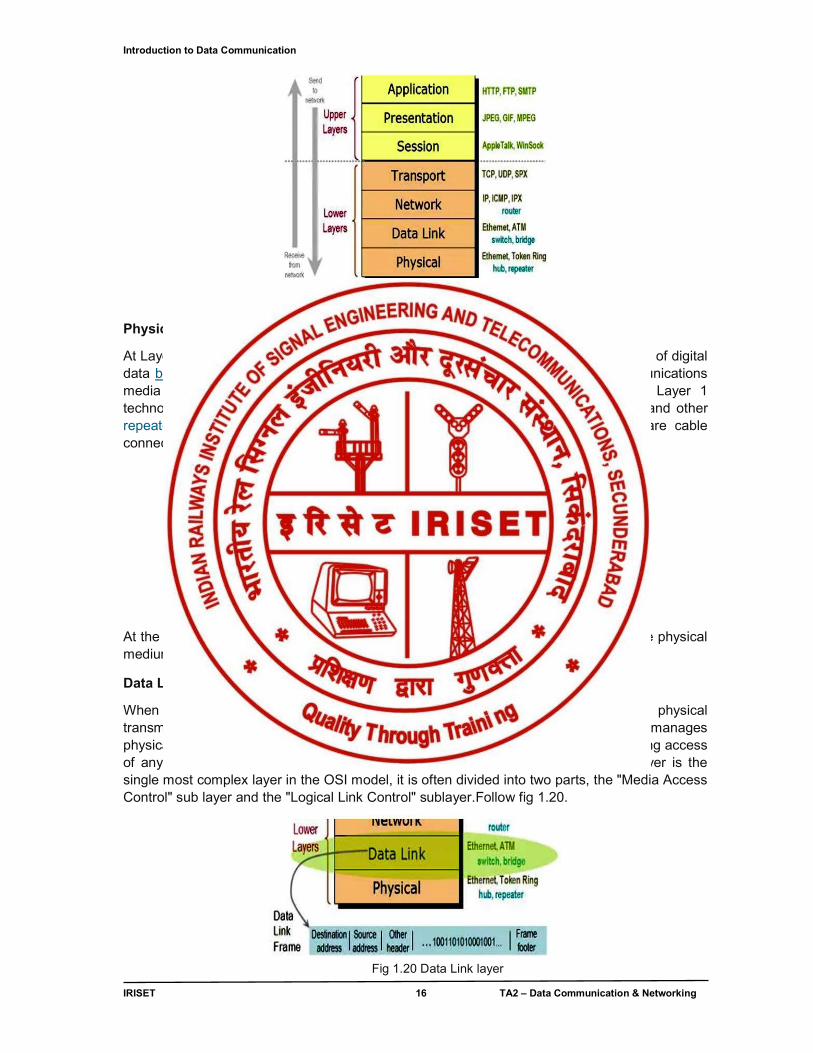
Fig .1.18 OSI layers
Physical Layer
At Layer 1, the Physical layer of the OSI model is responsible for ultimate transmission of digital data bits from the Physical layer of the sending (source) device over network communications media to the Physical layer of the receiving (destination) device. Examples of Layer 1 technologies include Ethernet cables and Token Ring networks. Additionally, hubs and other repeaters are standard network devices that function at the Physical layer, as are cable connectors. Follow fig 1.19.
Fig. 1.19 Physical layer At the Physical layer, data are transmitted using the type of signaling supported by the physical medium: electric voltages, radio frequencies, or pulses of infrared or ordinary light.
Data Link Layer
When obtaining data from the Physical layer, the Data Link layer checks for physical transmission errors and packages bits into data "frames". The Data Link layer also manages physical addressing schemes such as MAC addresses for Ethernet networks, controlling access of any various network devices to the physical medium. Because the Data Link layer is the single most complex layer in the OSI model, it is often divided into two parts, the "Media Access Control" sub layer and the "Logical Link Control" sublayer.Follow fig 1.20.
Fig 1.20 Data Link layer
Introduction to Data Communication
IRISET 17 TA2 – Data Communication & Networking
Network Layer
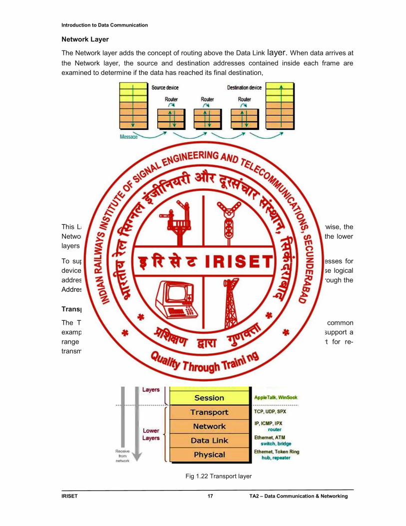
The Network layer adds the concept of routing above the Data Link layer. When data arrives at
the Network layer, the source and destination addresses contained inside each frame are examined to determine if the data has reached its final destination,
Fig 1.21 Network Layer This Layer 3 formats the data into packets delivered up to the Transport layer. Otherwise, the Network layer updates the destination address and pushes the frame back down to the lower layers Follow fig 1.21.
To support routing, the Network layer maintains logical addresses such as IP addresses for devices on the network. The Network layer also manages the mapping between these logical addresses and physical addresses. In IP networking, this mapping is accomplished through the Address Resolution Protocol (ARP).
Transport Layer
The Transport Layer delivers data across network connections. TCP is the most common example of a Transport Layer 4 network protocol. Different transport protocols may support a range of optional capabilities including error recovery, flow control, and support for re-transmission follow Fig 1.22.
Fig 1.22 Transport layer
Introduction to Data Communication
IRISET 18 TA2 – Data Communication & Networking
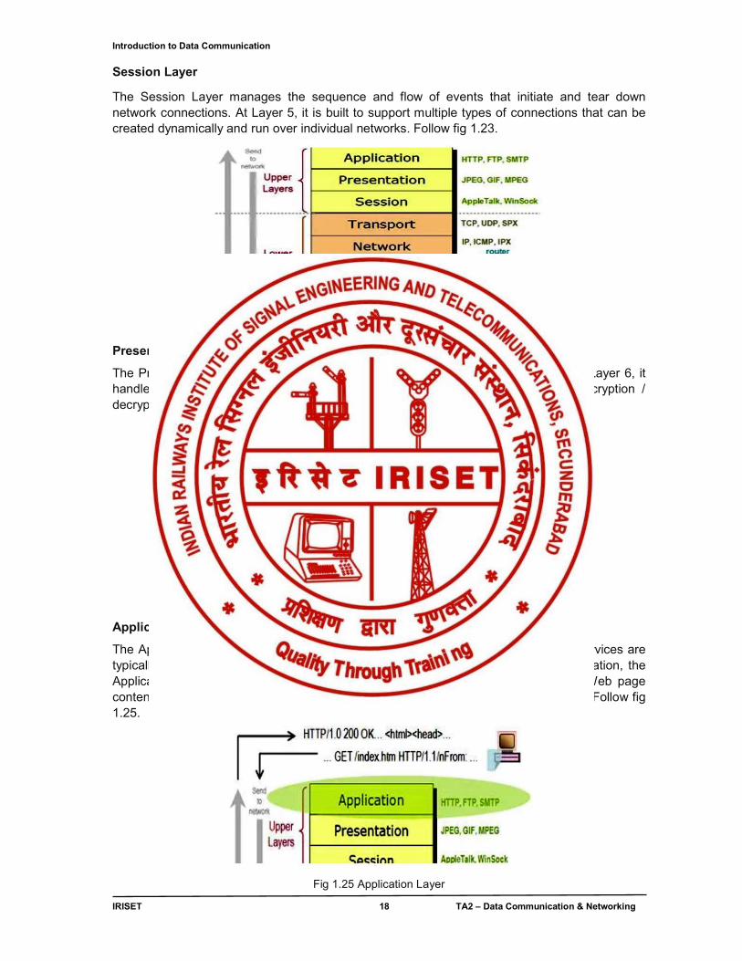
Session Layer
The Session Layer manages the sequence and flow of events that initiate and tear down network connections. At Layer 5, it is built to support multiple types of connections that can be created dynamically and run over individual networks. Follow fig 1.23.
Fig 1.23 Session Layer Presentation Layer
The Presentation layer is the simplest in function of any piece of the OSI model. At Layer 6, it handles syntax processing of message data such as format conversions and encryption / decryption needed to support the Application layer above it .Follow fig 1.24.
.
Fig 1.24, Presentation Layer
Application Layer
The Application layer supplies network services to end-user applications. Network services are typically protocols that work with user's data. For example, in a Web browser application, the Application layer protocol HTTP packages the data needed to send and receive Web page content. This Layer 7 provides data to (and obtains data from) the Presentation layer. Follow fig 1.25.
Fig 1.25 Application Layer
Introduction to Data Communication
IRISET 19 TA2 – Data Communication & Networking
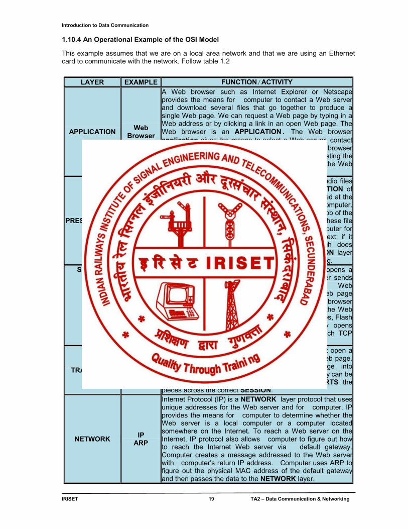
1.10.4 An Operational Example of the OSI Model
This example assumes that we are on a local area network and that we are using an Ethernet card to communicate with the network. Follow table 1.2
LAYER EXAMPLE FUNCTION/ACTIVITY
APPLICATION Web
Browser
A Web browser such as Internet Explorer or Netscape provides the means for computer to contact a Web server and download several files that go together to produce a single Web page. We can request a Web page by typing in a Web address or by clicking a link in an open Web page. The Web browser is an APPLICATION. The Web browser application gives the means to select a Web server, contact the server and request a Web page. The Web browser handles the process of finding the Web server, requesting the desired file and displaying all the files contained in the Web page.
PRESENTATION
HTTP
Web browser supports various image file formats, audio files and HTML. The Web browser handles PRESENTATION of the Web page to the user by converting the files stored at the Web server into formats used to display them on computer. Conversion of data from one format to another is the job of the PRESENTATION layer. A Web browser can convert these file formats into the local formats used on the local computer for displaying images, playing sounds and displaying text; if it cannot, it often can launch an application which does understand the format. Much of the PRESENTATION layer conversions are handled in the program we are running.
SESSION When we request a Web page, the Web browser opens a TCP connection to the Web server. The Web server sends back the Web page and closes the connection. Web browser then opens the Web page. Within the Web page instructions are written in HTML tags which tell the browser where to find additional files to be displayed within the Web page such as style sheets, sound files, images, movies, Flash files and applets. Web browser automatically opens additional TCP connections to the Web server. Each TCP connection is a SESSION.
TRANSPORT TCP
To communicate with a Web server computer must open a TCP connection to the Web server and request a Web page. The TCP connection breaks up the Web page into manageable chunks, labels them with numbers so they can be reassembled in the correct order and TRANSPORTS the pieces across the correct SESSION.
NETWORK IP
ARP
Internet Protocol (IP) is a NETWORK layer protocol that uses unique addresses for the Web server and for computer. IP provides the means for computer to determine whether the Web server is a local computer or a computer located somewhere on the Internet. To reach a Web server on the Internet, IP protocol also allows computer to figure out how to reach the Internet Web server via default gateway. Computer creates a message addressed to the Web server with computer's return IP address. Computer uses ARP to figure out the physical MAC address of the default gateway and then passes the data to the NETWORK layer.
Introduction to Data Communication
IRISET 20 TA2 – Data Communication & Networking
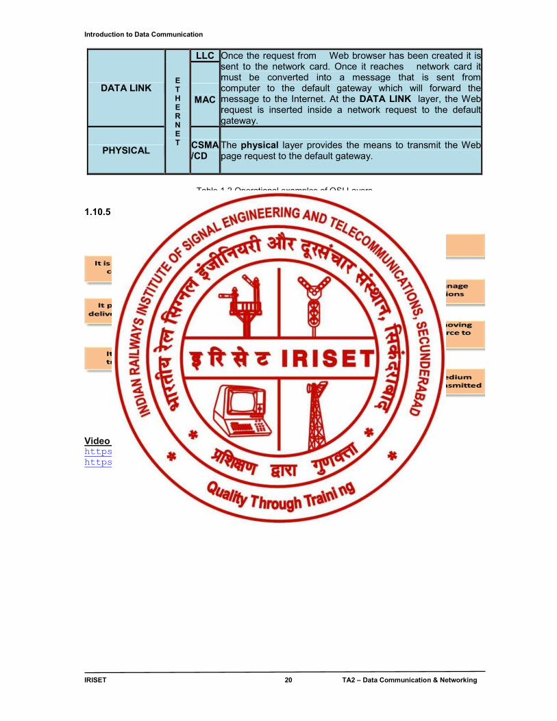
DATA LINK E T H E R N E T
LLC Once the request from Web browser has been created it is sent to the network card. Once it reaches network card it must be converted into a message that is sent from computer to the default gateway which will forward the message to the Internet. At the DATA LINK layer, the Web request is inserted inside a network request to the default gateway.
MAC
PHYSICAL CSMA /CD
The physical layer provides the means to transmit the Web page request to the default gateway.
Table 1.2 Operational examples of OSI Layers
1.10.5 SUMMARY OF OSI LAYERS
Fig 1.26 Summary of OSI model Video links for understanding of OSI layers https://www.youtube.com/watch?v=vv4y_uOneC0 https://www.youtube.com/watch?v=KUoJKwgnGlQ
Data Transmission on Physical Media
IRISET 21 TA2 – Data Communication & Networking
CHAPTER - 2
DATA TRANSMISSION ON PHYSICAL MEDIA
2.0 INTRODUCTION
The following most essential topics covered for “Data Transmission on a Physical media” are
● Data & Signal, Baseband and Broadband transmission, Impairments, Band width ,Data rate and Baud rate
● Encoding ● Transmission Media Categories
2.1 DATA & SIGNAL
Data can be analog or digital. Analog data are continuous and take continuous values. Digital data have discrete states and take discrete values.
Signals can be analog or digital. Analog signals can have an infinite number of values in a range; digital signals can have only a limited number of values.
In data communications, we commonly use periodic analog signals and non-periodic (a periodic) digital signals. Periodic analog signals can be classified as simple or composite. A simple periodic analog signal, a sine wave, cannot be decomposed into simpler signals. A composite Periodic analog signal is composed of multiple sine waves.
The bandwidth of a composite signal is the difference between the Highest and the lowest frequencies contained in that signal.
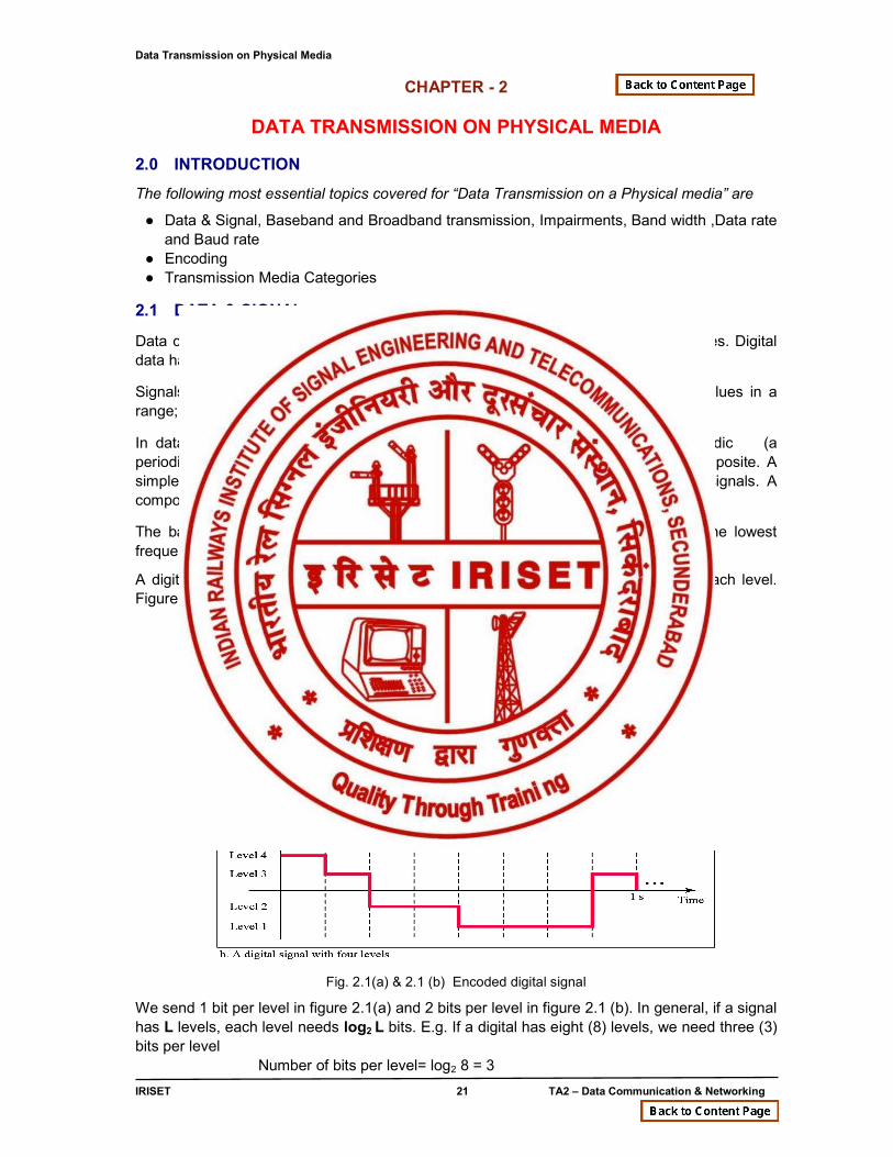
A digital signal can have more than two levels, we can send more than 1 bit for each level. Figure 2.1 shows two signals, one with two levels and the other with four.
Fig. 2.1(a) & 2.1 (b) Encoded digital signal
We send 1 bit per level in figure 2.1(a) and 2 bits per level in figure 2.1 (b). In general, if a signal has L levels, each level needs log2 L bits. E.g. If a digital has eight (8) levels, we need three (3) bits per level
Number of bits per level= log2 8 = 3
Data Transmission on Physical Media
IRISET 22 TA2 – Data Communication & Networking
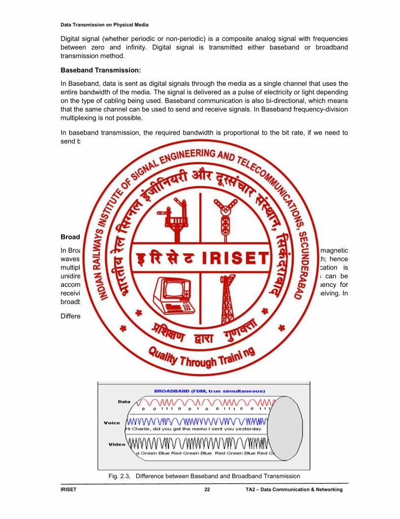
Digital signal (whether periodic or non-periodic) is a composite analog signal with frequencies between zero and infinity. Digital signal is transmitted either baseband or broadband transmission method.
Baseband Transmission:
In Baseband, data is sent as digital signals through the media as a single channel that uses the entire bandwidth of the media. The signal is delivered as a pulse of electricity or light depending on the type of cabling being used. Baseband communication is also bi-directional, which means that the same channel can be used to send and receive signals. In Baseband frequency-division multiplexing is not possible.
In baseband transmission, the required bandwidth is proportional to the bit rate, if we need to send bits faster, we need more bandwidth.
Fig. 2.2 Baseband and Broadband Transmission
Broadband Transmission:
In Broadband information is sent in the form of an analog signal, which flows as electromagnetic waves or optical waves. Each transmission is assigned to a portion of the bandwidth; hence multiple transmissions are possible at the same time. Broadband communication is unidirectional, so in order to send and receive, two pathways are needed. This can be accomplished either by assigning a frequency for sending and assigning a frequency for receiving along the same cable or by using two cables, one for sending and one for receiving. In broadband frequency-division multiplexing is possible.
Difference between Baseband and Broadband is illustrated below in fig 2.3
Fig. 2.3, Difference between Baseband and Broadband Transmission
Data Transmission on Physical Media
IRISET 23 TA2 – Data Communication & Networking
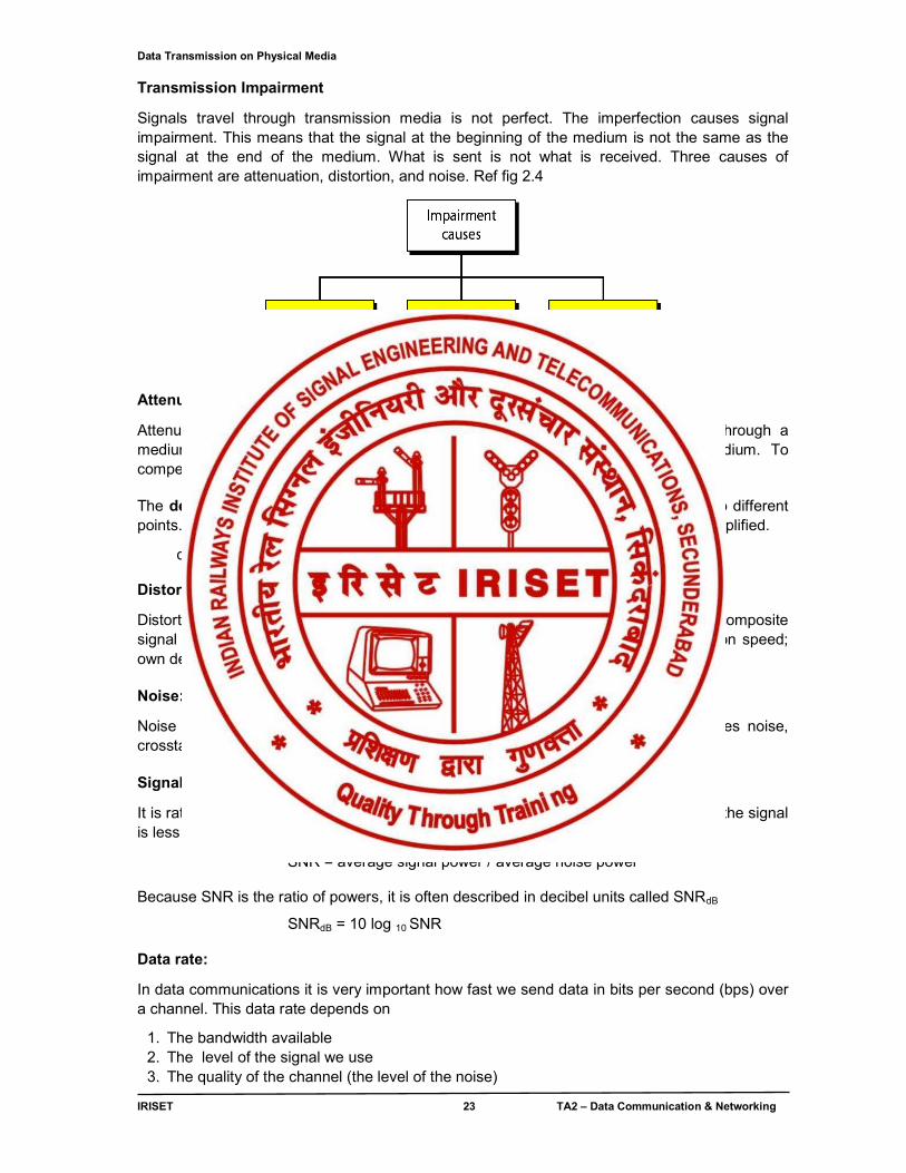
Transmission Impairment
Signals travel through transmission media is not perfect. The imperfection causes signal impairment. This means that the signal at the beginning of the medium is not the same as the signal at the end of the medium. What is sent is not what is received. Three causes of impairment are attenuation, distortion, and noise. Ref fig 2.4
Fig. 2.4, Signal impairment.
Attenuation:
Attenuation means loss of energy. When a simple or composite signal travels through a medium, it loses some of its energy in overcoming the resistance of the medium. To compensate this loss amplifiers are used to amplify the signal. The decibel (dB) measures the relative strengths of two signals or one signal at two different points. The decibel value is negative if a signal is attenuated & positive if a signal is amplified.
dB = 10 log 10 P2 / P1 Distortion:
Distortion means that the signal changes its form or shape. Distortion can occur in a composite signal made of different frequencies. Each signal component has its own propagation speed; own delay in arriving at the destination causes phase difference at the receiver. Noise:
Noise causes signal impairment. Several types of noise, like thermal noise, induces noise, crosstalk noise & impulse noise corrupts the signal Signal-to-Noise Ratio (SNR):
It is ratio of what is wanted (Signal) to what is not wanted (noise). A high SNR means the signal is less corrupted by noise; a low SNR means the signal is more corrupted by noise.
SNR = average signal power / average noise power Because SNR is the ratio of powers, it is often described in decibel units called SNRdB
SNRdB = 10 log 10 SNR Data rate:
In data communications it is very important how fast we send data in bits per second (bps) over a channel. This data rate depends on
1. The bandwidth available 2. The level of the signal we use 3. The quality of the channel (the level of the noise)
Data Transmission on Physical Media
IRISET 24 TA2 – Data Communication & Networking
Data rate is calculated, using two methods
1. Nyquist bit rate (noiseless channel) 2. Shannon capacity (noisy channel)
Nyquist bit rate (noiseless channel):
For a noiseless channel, the nyquist bit rate defines the theoretical maximum bit rate is
Bit Rate = 2 x bandwidth x log 2 L ‘bandwidth’ is the bandwidth of the channel ‘L’ is the number of signal levels used to represent data
On a given specific bandwidth we can increase the bit rate by increasing the number of signal levels. But practically there is a limit, it will burden the receiver. Hence increasing the levels of a signal may reduce the reliability of the system. Shannon capacity (noisy channel):
Practically we cannot have a noiseless channel, hence as per the Shannon capacity the theoretical maximum bit rate of a noisy channel is
Bit Rate = bandwidth x log 2 (1 + SNR) ‘bandwidth’ is the bandwidth of the channel ‘SNR’ is the signal-to-noise ratio
Whatever may be the no. of signal levels, we cannot achieve a data rate higher than the capacity of the channel and it defines the characteristics of the channel, not the method of transmission.
Bandwidth:
In networking, we use the term bandwidth in two contexts.
● The first, bandwidth in hertz, refers to the range of frequencies in a composite signal or the range of frequencies that a channel can pass.
● The second, bandwidth in bits per second, refers to the speed of bit transmission in a channel or link.
An increase in bandwidth in hertz means an increase in bandwidth in bits per second. This relationship depends on whether baseband transmission or broadband (modulation) transmission. Baud Rate:
Baud rate refers to the signal (symbol) rate, how many signal changes are transmitted per second. One goal of the data communications is to increase the data rate while decreasing the signal rate. Increasing the data rate increases the speed of transmission; decreasing the signal rate decreases the bandwidth requirement.
Bit rate is the number of bits per second. Baud rate is the number of signal elements per second. In the analog transmission of digital data, the baud rate is less than or equal to bit rate.
BPS = Baud per second x the number of Bits per Baud
The relationship between the data rate (bit rate) and the signal rate (baud rate) is
S = N x 1 / r baud
Data Transmission on Physical Media
IRISET 25 TA2 – Data Communication & Networking
Where ‘S’ is the baud rate, ‘N’ is the bit rate and ‘r’ is the ratio of number of data elements carried in one signal element.
r = log 2 L, Where ‘L’ is the no. of signal elements. Throughput:
It is a measure of how fast we can actually send data through a network; throughput is also measured as bits per second (bps) as that of bandwidth. But both are not same, throughput is always less than the bandwidth. Bandwidth is a potential measurement of a link; the throughput is an actual measurement of a link. 2.2 ENCODING
Data (or) Signal encoding can be of four types:
DIGITAL-TO-ANALOG CONVERSION ANALOG TO ANALOG CONVERSION ANALOG-TO-DIGITAL CONVERSION DIGITAL-TO-DIGITAL CONVERSION
2.2.1 DIGITAL-TO-ANALOG CONVERSION
Digital-to-analog conversion is the process of changing one of the characteristics of an analog signal based on the information in digital data. (Refer Fig. 2.5)
Fig. 2.5 Digital-to-Analog conversion
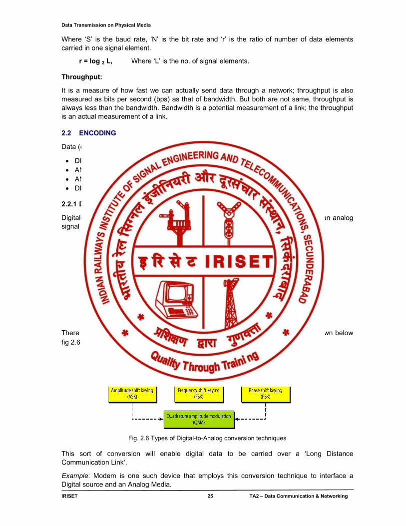
There can be different types of DIGITAL TO ANALOG conversion techniques as shown below fig 2.6
Fig. 2.6 Types of Digital-to-Analog conversion techniques
This sort of conversion will enable digital data to be carried over a ‘Long Distance Communication Link‘.
Example: Modem is one such device that employs this conversion technique to interface a Digital source and an Analog Media.
Data Transmission on Physical Media
IRISET 26 TA2 – Data Communication & Networking
2.2.2 ANALOG TO ANALOG CONVERSION
Analog-to-analog conversion is the representation of analog information by an analog signal. One may ask why we need to modulate an analog signal; it is already analog. Modulation is needed if the medium is band pass in nature or if only a band pass channel is available to us. There can be different types of ANALOG TO ANALOG conversion techniques as shown below fig 2.7
Fig. 2.7 Types of Analog-to-Analog conversion techniques 2.2.3 ANALOG-TO-DIGITAL CONVERSION
A Digital signal is superior to an analog signal. The tendency today is to change an analog signal to digital data before transmission. One such technique is Pulse Code Modulation, is shown (Fig. 2.8), schematically, below.
Fig. 2.8 Analog to Digital conversion
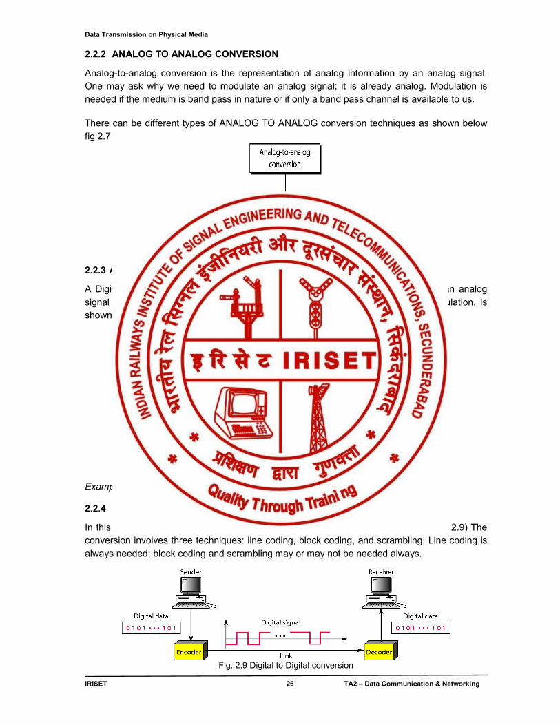
Example: Transmission of Voice, Video, Telemetry 2.2.4 DIGITAL-TO-DIGITAL CONVERSION
In this section, we see how we can represent digital data by using digital signals (Fig 2.9) The conversion involves three techniques: line coding, block coding, and scrambling. Line coding is always needed; block coding and scrambling may or may not be needed always.
Fig. 2.9 Digital to Digital conversion
Data Transmission on Physical Media
IRISET 27 TA2 – Data Communication & Networking
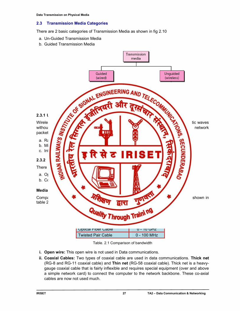
2.3 Transmission Media Categories
There are 2 basic categories of Transmission Media as shown in fig 2.10
a. Un-Guided Transmission Media b. Guided Transmission Media
Fig. 2.10 Transmission Media Categories 2.3.1 Un-guided Transmission Media
Wireless communication is the base of un - guided media. It transports electromagnetic waves without using a physical conductor. The wireless media available for transmitting network packets are 3 types
a. Radio waves – used for Wireless LANs b. Microwaves – used for terrestrial and satellite communication. c. Infrared waves – used for controlling devices like remote controls.
2.3.2 Guided Transmission Media
There 4 basic types of Guided Media:
a. Open Wire b. Coaxial Cable
c. Optical Fiber d. Twisted Pair
Media versus Bandwidth
Comparison of usable bandwidth between the different guided transmission media is shown in table 2.1
Cable Type Bandwidth
Open Wire 0 - 5 MHz
Coaxial Cable 0 - 600 MHz
Optical Fiber Cable 0 - 10 GHz
Twisted Pair Cable 0 - 100 MHz
Table. 2.1 Comparison of bandwidth
i. Open wire: This open wire is not used in Data communications.
ii. Coaxial Cables: Two types of coaxial cable are used in data communications. Thick net (RG-8 and RG-11 coaxial cable) and Thin net (RG-58 coaxial cable). Thick net is a heavy-gauge coaxial cable that is fairly inflexible and requires special equipment (over and above a simple network card) to connect the computer to the network backbone. These co-axial cables are now not used much.
Data Transmission on Physical Media
IRISET 28 TA2 – Data Communication & Networking
iii. Optical Fiber Cables: Fiber-optic cable is a high-speed alternative to copper wire and is often employed as the backbone of larger corporate networks. However, the drop in the price of fiber-optic cable has started to make it a possibility for other LAN uses. Fiber-optic cable uses glass or plastic filaments to move data and provides greater bandwidth as well as longer cable runs (up to 2 kilometers, depending on the network architecture).
iv. Twisted Pair cables: LAN cables are generically called twisted pair cables. There are two (2) types. One is UTP (Unshielded Twisted Pair) and the other is STP (Shielded Twisted Pair). UTP is predominantly used for indoor areas and whereas STP for outdoor & in special areas. These UTP cables are identified with a category rating.
UTP comes in two forms SOLID or STRANDED. SOLID refers to the fact that each internal conductor is made up of a single (solid) wire, STRANDED means that each conductor is made up of multiple smaller wires. The only obvious benefit of using stranded cable (which is typically more expensive) is that it has a smaller 'bend- radius' (we can squeeze the cable round tighter corners with lower loss) or where we plug and unplug the cable frequently. All other things being equal the performance of both types of cable is the same. In general solid cable is used for backbone wiring and stranded for PC to wall plug cables.
Data Transmission on LAN
IRISET 29 TA2 – Data Communication & Networking
CHAPTER - 3
DATA TRANSMISSION ON LAN
3.0 INTRODUCTION
In this chapter, functions associated with “Data Transmission on LAN “are discussed. And the Following Topics are covered:
● Data Link Control - Framing ,Line discipline ,Flow Control & Error Control ● Media Access Control , Ethernet Categories , Ethernet Wiring practices and Power over
Ethernet ● Connecting Devices
3.1 DATA LINK CONTROL
3.1.1 FRAMING
The data link layer needs to pack bits into frames, so that each frame is distinguishable from another. A frame in a character-oriented protocol is shown in fig 3.1(a) & a frame in a bit-oriented protocol is shown in fig 3.1(b)
Fig. 3.1(a) Character-oriented protocol frame
Fig. 3.1(b) Bit-oriented protocol frame
The most important function of a data link layer is LINE DISCIPLINE, FLOW CONTROL and ERROR CONTROL
3.1.2 LINE DISCIPLINE
Whatever the system, no device in it should be allowed to transmit until the device has the evidence that intended receiver is able to receive and is prepared to accept the transmission. What if the receiving device does not expect a transmission, is busy, or is out of commission? With no way to determine the status of the intended receiver, the transmitting device may waste its time sending data to a non functioning receiver or may interfere with signals already on the link. The line discipline functions of the data link layer oversee the establishment of links and the right of a particular device to transmit at a given time.
Line discipline can be done in two ways: enquiry/acknowledgment (ENQ/ACK) and poll/select. The first method is used in peer-to-peer communication; the second method is used in primary-secondary communication.
Data Transmission on LAN
IRISET 30 TA2 – Data Communication & Networking
3.1.3 FLOW CONTROL
The second aspect of data link control, following line discipline, is flow control. In most protocols flow control is a set of procedures that tell the sender how much data it can transmit before it must wait for an acknowledgment from the receiver. Two issues are at stake:
● The flow of data must not be allowed to overwhelm the receiver. Any receiving device has a limited speed at which it can process incoming data and a limited amount of memory, in which to store incoming data. The receiving device must be able to inform the sending device before those limits are reached and to request that the transmitting device send fewer frames or stop temporarily. Incoming data must be checked and processed before they can be used. The rate of such processing is often slower than the rate of transmission. For this reason, each receiving device has a block of memory, called a buffer, reserved for storing incoming data until they are processed. If the buffer begins to fill up, the receiver must be able to tell the sender to halt transmission until it is once again able to receive.
● As frames come in, they are acknowledged, either frame by frame or several frames at a time. If a frame arrives damaged, the receiver sends an error message (a NAK frame).
Flow control refers to a set of procedures used to restrict the amount of data the sender can send before waiting for acknowledgment.
Two methods have been developed to control the flow of data across communications links: Stop-and-Wait and Sliding Window.
For efficient data packet transmission, the transmitter must not be forced to stop sending for an unnecessarily long time. This will happen if the receiving computer sends an acknowledgment signal to stop and does not send another signal to begin transmitting when its buffer has available space or is empty. Other considerations for efficient data packet transmission include:
● Round-trip delay time ● End-to-end delay ● Bandwidth delay
3.1.4 ERROR DETECTION & CORRECTION
Data can be corrupted during transmission. Some applications require that errors be detected and corrected.
Let us first discuss some issues related, directly or indirectly, to error detection and correction.
● In a single-bit error, only 1 bit in the data unit has changed as shown in fig 3.2 (a)
Fig 3.2 (a) Single bit error
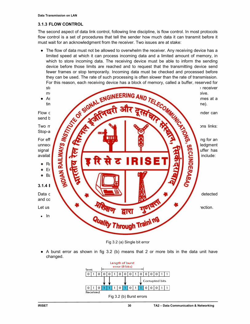
● A burst error as shown in fig 3.2 (b) means that 2 or more bits in the data unit have changed.
Fig 3.2 (b) Burst errors
Data Transmission on LAN
IRISET 31 TA2 – Data Communication & Networking
To detect or correct errors, we need to send extra (redundant) bits with data as shown in fig 3.3 below.
Fig. 3.3 sending redundant bits with data There are different types of error detection methods / codlings are available. The popular methods are Parity checking, Block coding, CRC and Checksum etc.
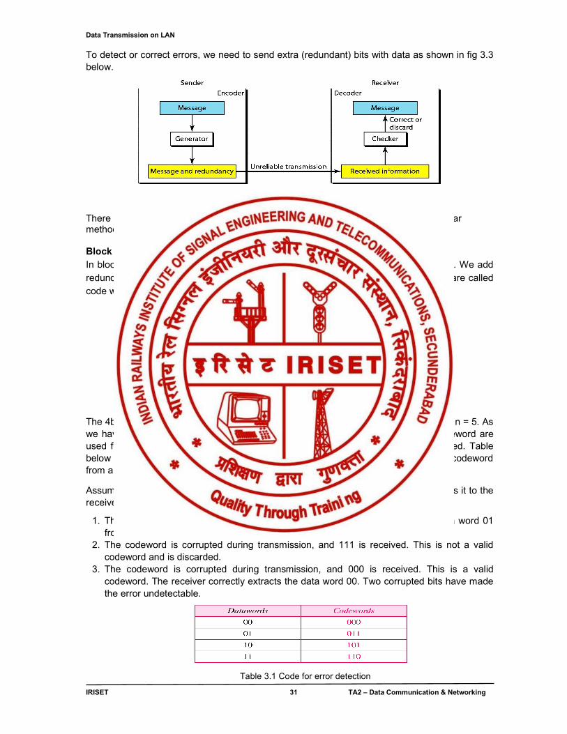
Block Coding: In block coding, we divide our message into blocks, each of k bits, called data words. We add redundant bits to each block to make the length n = k + r. The resulting n-bit blocks are called code words as shown in fig 3.4 below.
Fig 3.4 Block coding (code words) The 4b/5b coding is a good example of block coding. In this coding scheme, k = 4 and n = 5. As we have 2k = 16 data words and 2n = 32 code word. We see that 16 out of 32 codeword are used for message transfer and the rest are either used for other purposes or unused. Table below shows the list of data words and code words. Later, we will see how to derive a codeword from a data word.
Assume that k = 2 and n = 3. The sender encodes the data word 01 as 011 and sends it to the receiver. Consider the following cases as shown in Table 3.1.
1. The receiver receives 011. It is a valid codeword. The receiver extracts the data word 01 from it.
2. The codeword is corrupted during transmission, and 111 is received. This is not a valid codeword and is discarded.
3. The codeword is corrupted during transmission, and 000 is received. This is a valid codeword. The receiver correctly extracts the data word 00. Two corrupted bits have made the error undetectable.
Table 3.1 Code for error detection
Data Transmission on LAN
IRISET 32 TA2 – Data Communication & Networking
An error-detecting code can detect only the types of errors for which it is designed; other types of errors may remain undetected. A block diagram (fig. 3.5) is shown below.
Fig.3.5 Error-detecting coding
By adding more redundant bits to above Example, to see if the receiver can correct an error without knowing what was actually sent. We add 3 redundant bits to the 2-bit data word to make 5-bit code words. Table below shows the data words and code words. Assume the data word is 01. The sender creates the codeword 01011. The codeword is corrupted during transmission, and 01001 is received. First, the receiver finds that the received codeword is not in the table. This means an error has occurred. The receiver, assuming that there is only 1 bit corrupted, uses the following strategy to guess the correct data word as shown in Table 3.2 below.
1. Comparing the received codeword with the first codeword in the table (01001 versus 00000), the receiver decides that the first codeword is not the one that was sent because there are two different bits.
2. By the same reasoning, the original codeword cannot be the third or fourth one in the table. 3. The original codeword must be the second one in the table because this is the only one that
differs from the received codeword by 1 bit. The receiver replaces 01001 with 01011 and consults the table to find the data word 01.
Table 3.2 code for error detection (adding more redundant bits)
Cyclic codes are special linear block codes with one extra property. In a cyclic code, if a codeword is cyclically shifted (rotated), the result is another codeword.
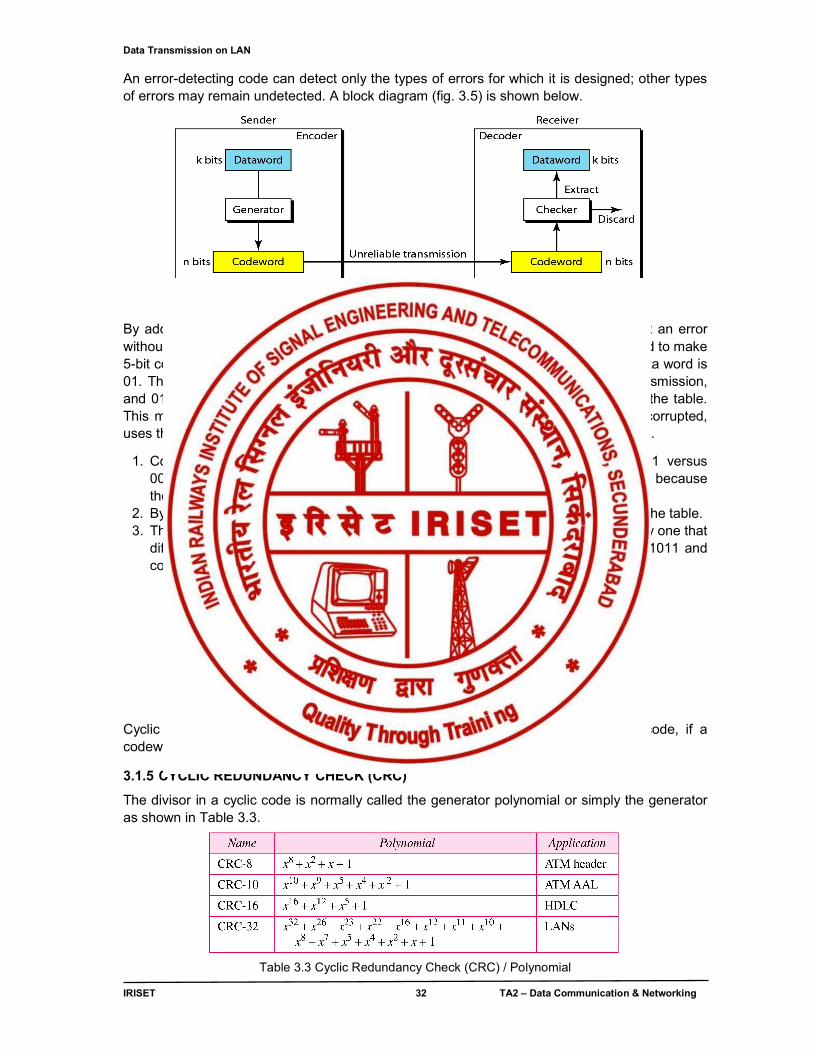
3.1.5 CYCLIC REDUNDANCY CHECK (CRC)
The divisor in a cyclic code is normally called the generator polynomial or simply the generator as shown in Table 3.3.
Table 3.3 Cyclic Redundancy Check (CRC) / Polynomial
Data Transmission on LAN
IRISET 33 TA2 – Data Communication & Networking
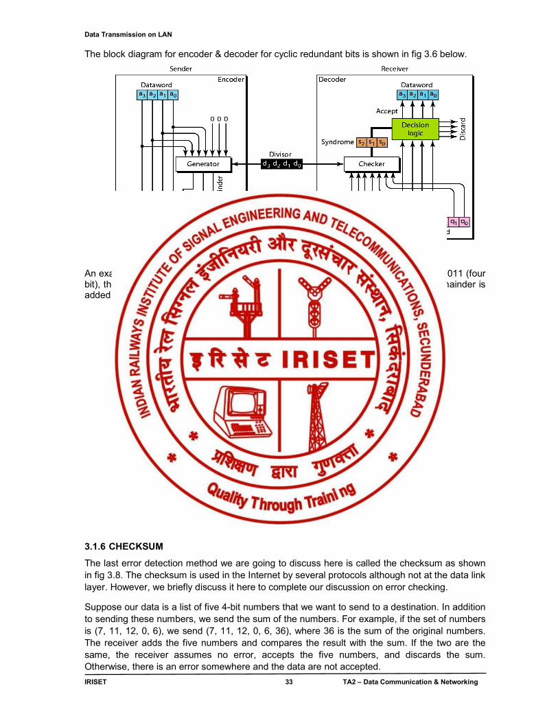
The block diagram for encoder & decoder for cyclic redundant bits is shown in fig 3.6 below.
Fig. 3.6 Encoder & decoder for cyclic redundant bits.
An example for CRC is shown in fig 3.7, let a four bit data be 1001. If the divisor is a 1011 (four bit), then three 0’s are augmented to data word. We get quotient and remainder. Remainder is added to data word to form the code word. This method is more popular.
Fig. 3.7 ,Example for Cyclic Redundancy check 3.1.6 CHECKSUM
The last error detection method we are going to discuss here is called the checksum as shown in fig 3.8. The checksum is used in the Internet by several protocols although not at the data link layer. However, we briefly discuss it here to complete our discussion on error checking.
Suppose our data is a list of five 4-bit numbers that we want to send to a destination. In addition to sending these numbers, we send the sum of the numbers. For example, if the set of numbers is (7, 11, 12, 0, 6), we send (7, 11, 12, 0, 6, 36), where 36 is the sum of the original numbers. The receiver adds the five numbers and compares the result with the sum. If the two are the same, the receiver assumes no error, accepts the five numbers, and discards the sum. Otherwise, there is an error somewhere and the data are not accepted.
Data Transmission on LAN
IRISET 34 TA2 – Data Communication & Networking
We can make the job of the receiver easier if we send the negative (complement) of the sum, called the checksum. In this case, we send (7, 11, 12, 0, 6, −36). The receiver can add all the numbers received (including the checksum). If the result is 0, it assumes no error; otherwise, there is an error.
How can we represent the number 21 in one’s complement arithmetic using only four bits?
The number 21 in binary is 10101 (it needs five bits). We can wrap the leftmost bit and add it to the four rightmost bits. We have (0101 + 1) = 0110 or 6.
How can we represent the number −6 in one’s complement arithmetic using only four bits?
In one’s complement arithmetic, the negative or complement of a number is found by inverting all bits. Positive 6 is 0110; negative 6 is 1001. If we consider only unsigned numbers, this is 9. In other words, the complement of 6 is 9. Another way to find the complement of a number in one’s complement arithmetic is to subtract the number from 2n − 1 (16 − 1 in this case).
Fig. 3.8 Example for Checksum
Sender site:
The message is divided into 16-bit words. The value of the checksum word is set to 0. All words including the checksum are added using one’s complement addition. The sum is complemented and becomes the checksum. The checksum is sent with the data.
Receiver site:
The message (including checksum) is divided into 16-bit words. All words are added using one’s complement addition. The sum is complemented and becomes the new checksum. If the value of checksum is 0, the message is accepted; otherwise, it is rejected.
3.1.7 ERROR CONTROL
There are three protocols in this section that use error control.
● Stop-and-Wait Automatic Repeat Request ● Go-Back-N Automatic Repeat Request ● Selective Repeat Automatic Repeat Request
Data Transmission on LAN
IRISET 35 TA2 – Data Communication & Networking
3.2 LAN PROTOCOLS:
For data transmission on LAN, protocols are used to form frames. Basically there two types of protocols are used. They are
Character Oriented protocols
Bit oriented protocols Character – oriented protocols
In character oriented protocols, data to be carried are 8 bit characters from a coding system such as ASCII. The header, which normally carries the source and destination address and other control information and trailer which carries error detection or error correction redundant bits are also multiples of 8 bits. To separate one frame from the next, an 8 bit flag is added at the beginning and end of the frame
Character orientated protocols are inefficient. This is because a character is used to convey meaning. As the number of meanings increase, the overhead involved also increases, as a character is used to signal the meaning.
Bit - oriented protocols In bit-orientated protocols, each bit has significance. The position and value of each bit in the data stream determines its function. Thus, a single character can hold 256 different meanings in a bit orientated protocol. This reduces the information needed to convey additional information, thus increasing the efficiency of the protocol.
Examples of these types of protocols are,
● X.25 CCITT standard for packet data transmission ● HDLC high level data link control (adopted by ISO in 1970's) ● SDLC synchronous data link control (developed by IBM) ● Links between sender and receiver can be half duplex, full duplex or both. Information can
be sent across the network in two different ways, traveling different routes to the receiver (datagram), or traveling the same route (virtual circuit).
Information is packaged into an envelope, called a FRAME. Each frame has a similar format
● header containing routing and control information ● body containing the actual data to be transmitted to destination and ● tail containing checksum data
Frames are responsible for transporting the data to the next point. Consider data that is to be sent from a source to a destination. This involves several intermediate points (called stations). The data is placed into a frame and sent to the next station, where the frame is checked for validity and if valid, the data extracted. The data is now repackaged into a new frame and sent by that station to the next station, and the process repeats till the data arrives at the destination.
When a station transmits a frame, it keeps a copy of the frame contents till the frame is acknowledged as correctly received by the next station. When a station receives a frame, it is temporarily stored in a buffer and checked for errors. If the frame has errors, the station will ask the previous station to resend the frame. Frames that are received without errors are also acknowledged, at which point the sending station can erase its copy of the frame.
A receiving station has a limited amount of buffer space to store incoming frames. When it runs out of buffer space, it signals other stations that it cannot receive any more frames.
Data Transmission on LAN
IRISET 36 TA2 – Data Communication & Networking
Data is placed into frames for sending across a transmission link. The frame allows intelligent control of the transmission link, as well as supporting multiple stations, error recovery, intelligent (adaptive) routing and other important functions.
For the purposes of sending data on a link, there are two types of stations
● Primary station (issues commands) ● Secondary station (responds to commands)
Primary Station: The primary station is responsible for controlling the data link, initiating error recovery procedures, and handling the flow of transmitting data to and from the primary. In a conversation, there is one primary and one or more secondary stations involved. Secondary Station: A secondary station responds to requests from a primary station, but may under certain modes of operation, initiate transmission of its own. An example of this is when it runs out of buffer space, at which point it sends RNR (receiver not ready) to the primary station. When the buffer space is cleared, it sends RR (receiver ready) to the primary station, informing the primary that it is now ready to receive frames again.
Because frames are numbered, it is possible for a primary station to transmit a number of frames without receiving an acknowledgement for each frame. The secondary can store the incoming frames and reply using a supervisory frame with the sequence number bits in the control field set so as to acknowledge a group of received frames.
If the secondary runs out of buffer space to store incoming Information frames, it can transmit a supervisory frame informing primary stations of its status. Primary stations will thus keep their Information frames and wait till the secondary is again able to process Information frames.
When a secondary cannot process Information frames, it must still be able to process incoming supervisory and unnumbered frames (because of status requests).
At any one time, a number of Information frames can be unacknowledged by a secondary station, and this is called the sliding window value, which defaults to 2, but can be negotiated when a call is first established.
3.3 MEDIA ACCESS
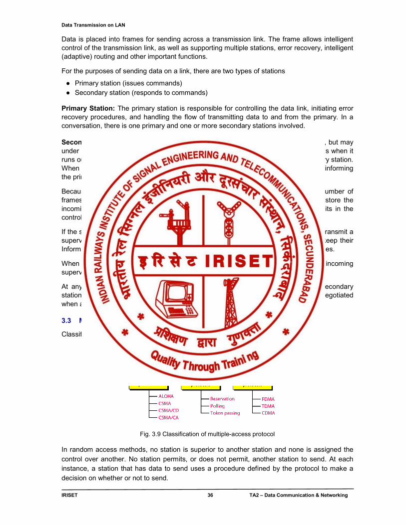
Classification of media access / multiple-access protocols is shown in fig 3.9
Fig. 3.9 Classification of multiple-access protocol
In random access methods, no station is superior to another station and none is assigned the control over another. No station permits, or does not permit, another station to send. At each instance, a station that has data to send uses a procedure defined by the protocol to make a decision on whether or not to send.
Data Transmission on LAN
IRISET 37 TA2 – Data Communication & Networking
In controlled access, the stations consult one another to find which station has the right to send. A station cannot send unless it has been authorized by other stations.
Channelization is a multiple-access method in which the available bandwidth of a link is shared in time, frequency, or through code, between different stations.
3.3.1 MAC - Media Access Control
The IEEE 802.3 Media Access Control layer as shown in fig 3.10 is physically located in the firmware (ROM) of the Network Interface Card. It is the link between the Data Link Layer and the Physical Layer of the OSI model and logically resides in the lower portion of the Data Link Layer. There is only 1 MAC layer for all IEEE 802.3 versions: 802.3, 802.3a, 802.3b, 802.3i, etc.
OSI Model IEEE
DataLink Layer
802.2 LLC
802.3 MAC – CSMA/CD
Physical Layer
802.3 10Base5
Thick Coax
802.3a 10Base2
Thin Coax
802.3b 10Broad 36 Braodband
802.3e 1Base5 StarLAN
802.3i 10BaseT
Twisted Pair
Fig. 3.10 IEEE 802.3 MAC layer versions
The most popular type of IEEE 802.3 Media Access Control protocol is Ethernet protocol and it uses CSMA/CD (Carrier Sense Multiple Access/Collision Detect) to determine Bus Arbitration. The MAC layer is concerned with the order of the bits and converting the Datagram from the Network Layer into Packets/Frames. Fig 3.11 shows the MAC layer / Ethernet frame format.
Preamble S F D D A SA Length IF / DATA
FCS
Fig 3.11, MAC layer / Ethernet frame format
Preamble: The Preamble is used to synchronize the receiving station's clock. It consists of 7 bytes of 10101010.
Start Frame Delimiter (SFD): The Start Frame Delimiter indicates the start of the frame. It consists of 1 byte of 10101011. It is an identical bit pattern to the preamble except for the last bit.
The Destination Address (DA): Indicates the destination (receiving station) of the frame. It is 6 octets long (48 bits), The DA field as shown in fig 3.13 consists of
Fig 3.12 DA Field
I/G: Stands for Individual/Group. It indicates whether the destination is for an individual or for a multicast broadcast.
It is one bit long: 0 = Individual 1 = Group
I/G U/L 46 Address bits
Data Transmission on LAN
IRISET 38 TA2 – Data Communication & Networking
A multicast broadcast can be for everyone or for a group. For a multicast broadcast to all stations, the Destination Address = FFFFFFFFFFFFh (h - hexadecimal notation). To multicast to a specific group, the Network Administrator must assign unique addresses to each station.
U/L: Stands for Universal/Local. It allows for unique addresses. It is used to indicate whether a local naming convention is used - administered by the Network Administrator (not recommended - incredible amount of work) or the burnt-in ROM address is used (recommended).
46 Bit Address: 46 bits address indicating the destination NIC cards address burnt into the firmware (ROM) of the card or the unique name assigned to the card during the card's initialization by the Network Administrator. Source Address (SA): The Source Address indicates the source or transmitting station of the frame. It is identical in format to the Destination Address but always has the I/G bit = 0 (Individual/Group Bit = Individual) Length (L): The Length field indicates the Length of the Information Field. It allows for variable length frames. The minimum Information Field size is 46 octets and the maximum size is 1500 octets. When the Information Field size is less than 46 octets, the Pad field is used. Due to the 802.3 MAC Frame having a Length field, there is no End Delimiter in the MAC Frame. The Length of the field is known and the receiving station counts the number of octets. Information Field (Data): The Information Field contains the Data from the next upper layer: Logical Link Control Layer. It is commonly referred to as the LLC Data. The minimum Information Field size is 46 octets and the maximum size is 1500 octets.
Pad: The Pad is used to add octets to bring the Information Field up to the minimum size of 46 octets if the Info Field is less than the minimum.
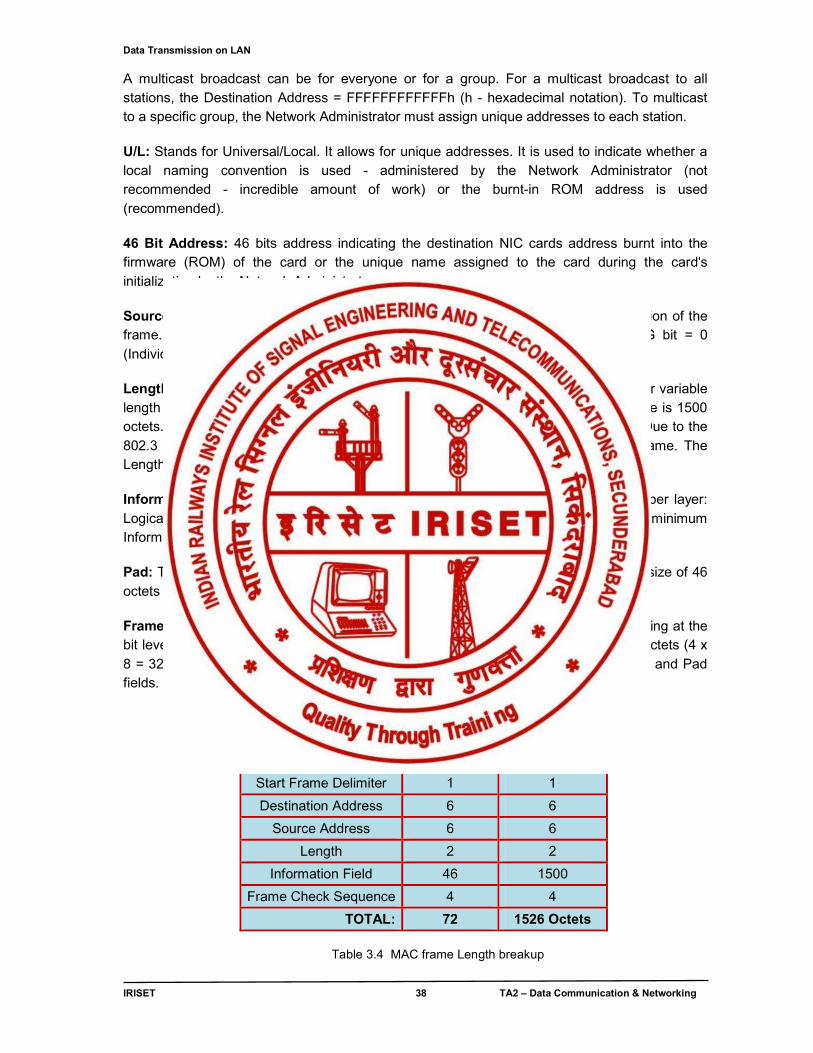
Frame Check Sequence (FCS): The Frame Check Sequence is used for error-checking at the bit level. It is based on 32 bit CRC (Cyclic Redundancy Checking) and consists of 4 octets (4 x 8 = 32 bits). The FCS is calculated according to the contents of the DA, SA, L, Data and Pad fields. Total breakup of MAC Frame Length is shown in table 3.4
Min Size (octets)
Max. Size (octets)
Preamble 7 7
Start Frame Delimiter 1 1
Destination Address 6 6
Source Address 6 6
Length 2 2
Information Field 46 1500
Frame Check Sequence 4 4
TOTAL: 72 1526 Octets
Table 3.4 MAC frame Length breakup
Data Transmission on LAN
IRISET 39 TA2 – Data Communication & Networking
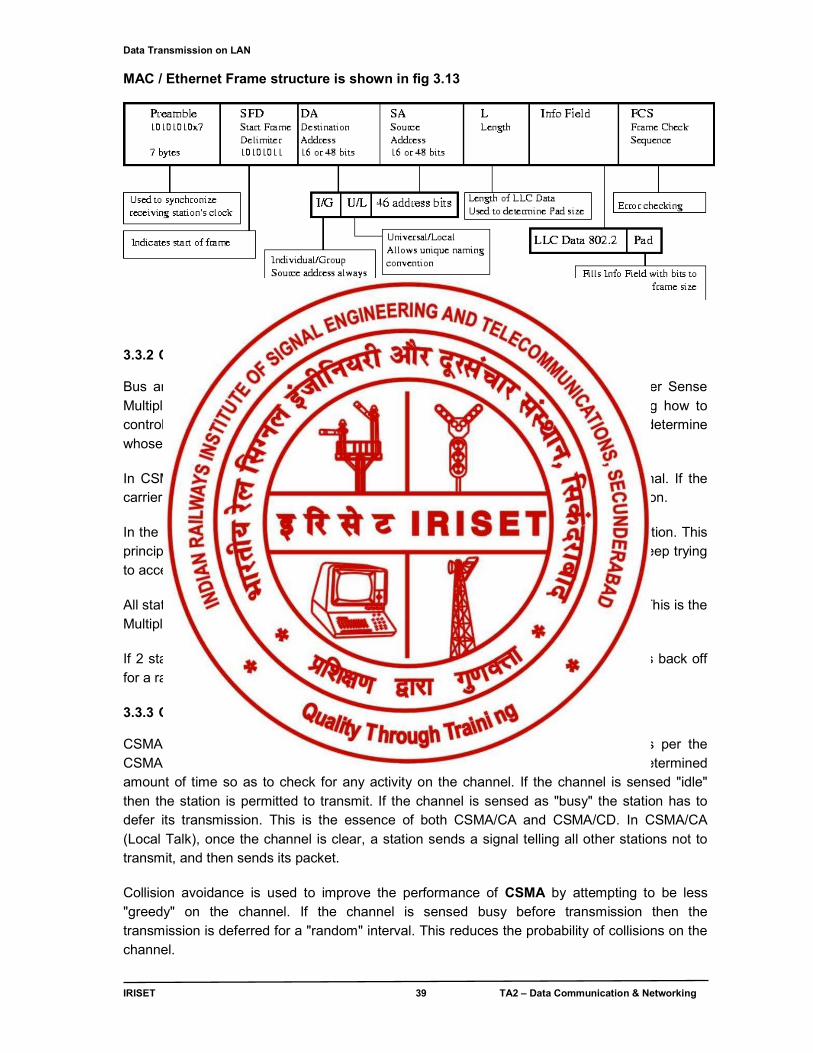
MAC / Ethernet Frame structure is shown in fig 3.13
Fig 3.13 MAC / Ethernet frame structure
3.3.2 CSMA/CD (Carrier Sense Multiple Access/ Collision Detect)
Bus arbitration is performed on all versions of Ethernet using the CSMA/CD (Carrier Sense Multiple Access/ Collision Detect) protocol. Bus arbitration is another way of saying how to control who is allowed to talk on the (medium) and when. Put simply, it is used to determine whose turn it is to talk.
In CSMA/CD, all stations, on the same segment of cable, sense for the carrier signal. If the carrier is sensed, then it is treated that the segment of cable NOT free for communication.
In the absence of carrier, it is treated that the segment of cable is free for communication. This principle of working is called the Carrier Sense portion of CSMA/CD. Sender has to keep trying to access the media by way of sensing the presence/absence of carrier.
All stations share the same segment of cable and can talk on it similar to a party line. This is the Multiple Access portion of CSMA/CD.
If 2 stations attempt to talk at the same time, a collision is detected and both stations back off for a random amount of time and then try again.
3.3.3 CSMA/CA (Carrier Sense Multiple Access/ Collision Avoidance)
CSMA/CA stands for: Carrier Sense Multiple Access With Collision Avoidance. As per the CSMA/CA, a station wishing to transmit has to first listen to the channel for a predetermined amount of time so as to check for any activity on the channel. If the channel is sensed "idle" then the station is permitted to transmit. If the channel is sensed as "busy" the station has to defer its transmission. This is the essence of both CSMA/CA and CSMA/CD. In CSMA/CA (Local Talk), once the channel is clear, a station sends a signal telling all other stations not to transmit, and then sends its packet. Collision avoidance is used to improve the performance of CSMA by attempting to be less "greedy" on the channel. If the channel is sensed busy before transmission then the transmission is deferred for a "random" interval. This reduces the probability of collisions on the channel.
Data Transmission on LAN
IRISET 40 TA2 – Data Communication & Networking
CSMA/CA is used where CSMA/CD cannot be implemented due to the nature of the channel. CSMA/CA is used in 802.11 based wireless LANs and it is not possible to listen while sending, therefore collision detection is not possible.
3.4 ETHERNET
IEEE 802.3 supports a LAN standard originally developed by Xerox and later extended by a joint venture between Digital Equipment Corporation, Intel Corporation and Xerox. This was called Ethernet. The evolution of Ethernet is in fig 3.14
Fig 3.14 Ethernet evolution
IEEE divides the standard Ethernet implementation into four different standards as shown in fig 3.15. 10Base5, 10Base2, 10Base-T and 10Base-F. The first number (10) indicates data rate in MBPS. The last number or letter (5, 2, T and F) indicates maximum cable length or the type of cable. However, the maximum cable length restriction can be changed using networking devices such as repeaters or bridges.
Fig 3.15 Implementation of Ethernet
The backbone of wired Ethernet is coaxial, UTP, fiber in 10Base5, 10Base-T, 10 Base- F respectively. Electrical Specification for Ethernet: Signaling: The baseband systems use Manchester digital encoding. Data Rate: Ethernet LANs can support data rates between 1 and 100 Mbps.
Frame Format: IEEE 802.3 specifies one type of frame as shown in fig 3.13 containing seven fields: preamble, SFD, DA, SA, length/type of PDU, 802.3 frames, and the CRC.
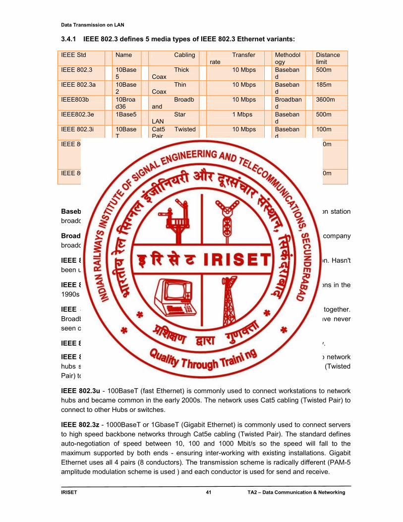
Data Transmission on LAN
IRISET 41 TA2 – Data Communication & Networking
3.4.1 IEEE 802.3 defines 5 media types of IEEE 802.3 Ethernet variants: IEEE Std Name Cabling Transfer
rate Methodology
Distance limit
IEEE 802.3 10Base5
Thick Coax
10 Mbps Baseband
500m
IEEE 802.3a 10Base2
Thin Coax
10 Mbps Baseband
185m
IEEE803b 10Broad36
Broadband
10 Mbps Broadband
3600m
IEEE802.3e 1Base5 Star LAN
1 Mbps Baseband
500m
IEEE 802.3i 10BaseT
Cat5 Twisted Pair
10 Mbps Baseband
100m
IEEE 802.3u 100BaseT
Cat5 Twisted Pair
1000Mbps Full Duplex
Baseband
100m
IEEE 802.3z 1GbaseT
Cat5e Twisted Pair
1 Gbps Full Duplex
Baseband
100m
Table 3.5 Ethernet media variants
Baseband - only a single stream of intelligence or data is transmitted. Ex. A television station broadcasts one television channel from its transmitter.
Broadband - multiple streams of intelligence or data is transmitted. Ex. A cable company broadcasts many television channels on its cable system.
IEEE 802.3 - 10Base5 (Thick Coax or thick net) was the original Ethernet configuration. Hasn't been used since the early 1990s. 10Base5 was replaced by Thin Coax .
IEEE 802.3a - 10Base2 (Thin Coax or thin net) was commonly used for new installations in the 1990s and was replaced by 10BaseT in the mid 1990s.
IEEE 802.3b - 10Broad36 is rarely used; it combined analog and digital signals together. Broadband means that a mixture of signals can be sent on the same medium. I have never seen or heard of a 10Broad36 installation.
IEEE 802.3e - Star LAN was a slow 1 Mbps standard that was used in the 1980s briefly.
IEEE 802.3i - 10BaseT (cheaper net) was commonly used to connect workstations to network hubs starting in the mid 1990s until the early 2000s. The network uses Cat5 cabling (Twisted Pair) to connect to other Hubs.
IEEE 802.3u - 100BaseT (fast Ethernet) is commonly used to connect workstations to network hubs and became common in the early 2000s. The network uses Cat5 cabling (Twisted Pair) to connect to other Hubs or switches.
IEEE 802.3z - 1000BaseT or 1GbaseT (Gigabit Ethernet) is commonly used to connect servers to high speed backbone networks through Cat5e cabling (Twisted Pair). The standard defines auto-negotiation of speed between 10, 100 and 1000 Mbit/s so the speed will fall to the maximum supported by both ends - ensuring inter-working with existing installations. Gigabit Ethernet uses all 4 pairs (8 conductors). The transmission scheme is radically different (PAM-5 amplitude modulation scheme is used ) and each conductor is used for send and receive.
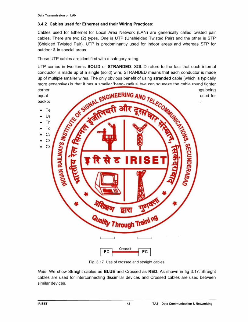
Data Transmission on LAN
IRISET 42 TA2 – Data Communication & Networking
3.4.2 Cables used for Ethernet and their Wiring Practices:
Cables used for Ethernet for Local Area Network (LAN) are generically called twisted pair cables. There are two (2) types. One is UTP (Unshielded Twisted Pair) and the other is STP (Shielded Twisted Pair). UTP is predominantly used for indoor areas and whereas STP for outdoor & in special areas.
These UTP cables are identified with a category rating.
UTP comes in two forms SOLID or STRANDED. SOLID refers to the fact that each internal conductor is made up of a single (solid) wire, STRANDED means that each conductor is made up of multiple smaller wires. The only obvious benefit of using stranded cable (which is typically more expensive) is that it has a smaller 'bend- radius' (we can squeeze the cable round tighter corners with lower loss) or where we plug and unplug the cable frequently. All other things being equal the performance of both types of cable is the same. In general solid cable is used for backbone wiring and stranded for PC to wall plug cables. Refer fig.3.16 for UTP cables .
Technical name-RG-8
Used for 10base t and 100base t networks.
They have different categories from 1-6.
Total length of the segment is 100 meters.
Common implementation in Star Topology.
CAT -3 cable has speed of 10 Mbps.
CAT -5 cable has speed of 100Mbps and CAT -6 above 100Mbps
Fig .3.16 UTP CABLE (4 -pair)
Fig. 3.17 Use of crossed and straight cables
Note: We show Straight cables as BLUE and Crossed as RED. As shown in fig 3.17. Straight cables are used for interconnecting dissimilar devices and Crossed cables are used between similar devices.
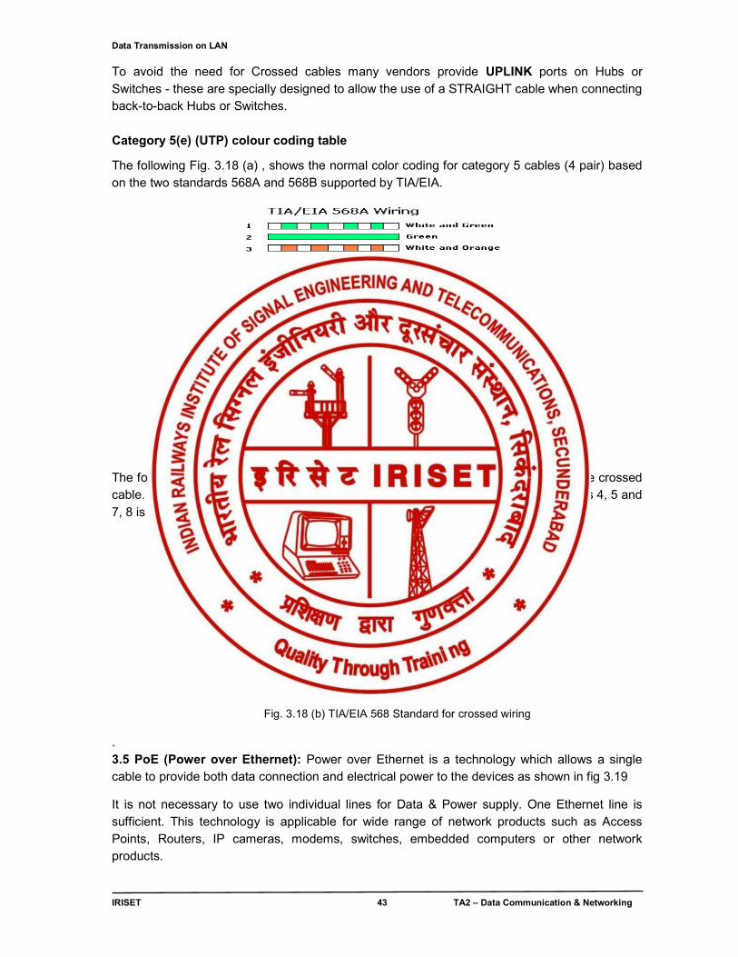
Data Transmission on LAN
IRISET 43 TA2 – Data Communication & Networking
To avoid the need for Crossed cables many vendors provide UPLINK ports on Hubs or Switches - these are specially designed to allow the use of a STRAIGHT cable when connecting back-to-back Hubs or Switches. Category 5(e) (UTP) colour coding table
The following Fig. 3.18 (a) , shows the normal color coding for category 5 cables (4 pair) based on the two standards 568A and 568B supported by TIA/EIA.
Fig. 3.18 (a) TIA/EIA 568 Standard for straight wiring
The following description shows the wiring at both ends (male RJ45 connectors) of the crossed cable. The diagrams Fig. 3.18 (b) below shows crossing of all 4 pairs. Crossing of pairs 4, 5 and 7, 8 is optional.
Fig. 3.18 (b) TIA/EIA 568 Standard for crossed wiring
.
3.5 PoE (Power over Ethernet): Power over Ethernet is a technology which allows a single cable to provide both data connection and electrical power to the devices as shown in fig 3.19
It is not necessary to use two individual lines for Data & Power supply. One Ethernet line is sufficient. This technology is applicable for wide range of network products such as Access Points, Routers, IP cameras, modems, switches, embedded computers or other network products.
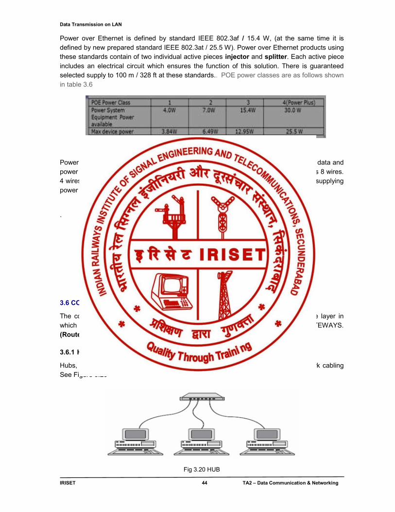
Data Transmission on LAN
IRISET 44 TA2 – Data Communication & Networking
Power over Ethernet is defined by standard IEEE 802.3af / 15.4 W, (at the same time it is defined by new prepared standard IEEE 802.3at / 25.5 W). Power over Ethernet products using these standards contain of two individual active pieces injector and splitter. Each active piece includes an electrical circuit which ensures the function of this solution. There is guaranteed selected supply to 100 m / 328 ft at these standards.. POE power classes are as follows shown in table 3.6
Table 3.6 ,POE classes
Power over Ethernet, is a simple way of connecting the cables in order to transfer the data and power supply along the same Ethernet cable at the same time. Ethernet cable contains 8 wires. 4 wires (1, 2, 3, 6) are used for data transmission and the rest (4, 5, 7, 8) is used for supplying power .
Fig 3.19 Power Over Ethernet (PoE)
3.6 CONNECTING DEVICES
The connecting devices are broadly classified into different categories based on the layer in which they operate in a network. They are HUBs, SWITCHES, ROUTERS & GATEWAYS. (Routers & Gateways are discussed in chapter no. 4)
3.6.1 HUBs
Hubs, also called wiring concentrators, provide a central attachment point for network cabling See Figure 3.20
Fig 3.20 HUB
Data Transmission on LAN
IRISET 45 TA2 – Data Communication & Networking
Hubs come in three types:
Passive Active Switching
The following sections describe each of these types in more detail.
Passive Hubs: Passive hubs do not contain any electronic components and do not process the data signal in any way. The only purpose of a passive hub is to combine the signals from several network cable segments. All devices attached to a passive hub receive all the packets that pass through the hub. Because the hub doesn’t clean up or amplify the signals (in fact, the hub absorbs a small part of the signal), the distance between a computer and the hub can be no more than half the maximum permissible distance between two computers on the network.
For example, if the network design limits the distance between two computers to 200 meters, the maximum distance between a computer and the hub is 100 meters. As you might guess, the limited functionality of passive hubs makes them inexpensive and easy to configure.
Active Hubs: Active hubs incorporate electronic components that can amplify and clean up the electronic signals that flow between devices on the network. This process of cleaning up the signals is called signal regeneration. Signal regeneration has the following benefits:
The network is more robust (less sensitive to errors). Distances between devices can be increased.
These advantages generally outweigh the fact that active hubs cost considerably more than passive hubs. Earlier you learned about repeaters, devices that amplify and regenerate network signals. Because active hubs function in part as repeaters, they occasionally are called multiport repeaters.
Intelligent Hubs: Intelligent hubs are enhanced active hubs. Several functions can add intelligence to a hub i.e Hub management: Hubs now support network management protocols that enable the hub to send packets to a central network console. These protocols also enable the console to control the hub; for example, a network administrator can order the hub to shut down a connection that is generating network errors.
Switching: The latest development in hubs is the switching hub, which includes circuitry that very quickly routes signals between ports on the hub ports on the hub, a switching hub repeats a packet only to the port that connects to the destination computer for the packet.
Many switching hubs have the capability of switching packets to the fastest of several alternative paths. Switching hubs are replacing bridges and routers on many networks.
In essence, a switching hub acts like a very fast bridge, which is what is described in the next section.
3.6.2 SWITCHES
A network switch is a computer networking device that connects network segments. The network switch plays an integral part in most Ethernet LANs.
Data Transmission on LAN
IRISET 46 TA2 – Data Communication & Networking
Switches may operate at one or more OSI layers, including physical, data link, network, or transport (i.e., end-to-end). A device that operates simultaneously at more than one of these layers is called a multilayer switch. Switches provide many additional features not offered by older devices such as hubs and bridges. In particular switches provide the following benefits:
■ Switch ports connected to a single device micro segments the LAN, providing dedicated bandwidth to that single device. Input and output buffers with the switching matrix in high speed backplane enables switching at ethernet speeds and supports micro-segmentation. Refer figure 3.21
■ Switches allow multiple simultaneous conversations between devices on different ports ■ Switch ports connected to a single device support full duplex, in effect doubling the amount
of bandwidth available to the device. ■ Switches support rate adaptation, which means that devices that use different Ethernet
speeds can communicate through the switch that Hubs cannot. Refer figure 3.21 for difference between a HUB and SWITCH.
Fig 3.21 HUB and a SWITCH
A switch creates a different collision domain per switch port. If you have 4 computers A/B/C/D on 4 switch ports, then A and B can transfer data between them as well as C and D at the same time, and they will never interfere with each others' conversations. In the case of a "hub" then they would all have to share the bandwidth, run in Half duplex and there would be collisions and retransmissions. Switches use Layer 2 logics to examine the Ethernet data-link header and choose how to process the frames. In particular, switches make decisions to forward and filter frames, learn MAC addresses, and use STP (Spanning tree protocol) to avoid loops in the following manner
Steps for Data forwarding
Step 1:
Switches forward frames based on the destination address:
a) If the destination address is a broadcast, multicast or unknown destination unicast address, the switch floods the frame.
b) If the destination address is a known unicast address (a unicast address found in the MAC table): i) If the outgoing interface listed in the MAC address table is different from the interface in
which the frame was received, the switch forwards the frame to the outgoing interface. ii) If the outgoing interface is the same as the interface in which the frame was received, the
switch filters the frame, meaning that the switch simply ignores the frame and does not forward it.
Data Transmission on LAN
IRISET 47 TA2 – Data Communication & Networking
Step 2:
Switches use the following logic to learn MAC address table entries:
a) For each received frame, examine the source MAC address and note the inter face from which the frame was received.
b) If they are not already in the table, add the address and interface, setting then activity timer to 0.
c) If it is already in the table, reset the inactivity timer for the entry to 0. Step 3:
Switches use STP to prevent loops by causing some interfaces to block, meaning that they do not send or receive frames. Once a switch learns the topology through a spanning tree protocol, it forwards data link layer frames using a layer 2 forwarding method.
Almost always switch ports are in Full duplex operation by default, unless there is a requirement for interoperability with devices that are strictly Half duplex. Switches tended to use micro segmentation to prevent collisions among devices connected to Ethernets. Micro-segmentation facilitates to have dedicated bandwidth on point to point connections with every computer and to therefore run in Full duplex with no collision. Methods of forwarding that can be used on a Switch
Store and forward: The switch buffers and, typically, performs a checksum on each frame before forwarding it on.
Cut through: The switch reads only up to the frame's hardware address before starting to forward it. There is no error checking with this method.
Fragment free: A method that attempts to retain the benefits of both "store and forward" and "cut through". Fragment free checks the first 64 bytes of the frame, where addressing information is stored. According to Ethernet specifications, collisions should be detected during the first 64 bytes of the frame, so frames that are in error because of a collision will not be forwarded. This way the frame will always reach its intended destination. Error checking of the actual data in the packet is left for the end device typically a router.
Adaptive switching: A method of automatically switching between the other three modes.
TYPES OF SWITCHES
i. Unmanaged switches: These switches have no configuration interface or options. They are plug and play. They are typically the least expensive switches.
ii. Managed switches: These switches have one or more methods to modify the operation of the switch. Common management methods include: a serial console or command line interface accessed via telnet or Secure Shell, an embedded Simple Network Management Protocol (SNMP) agent allowing management from a remote console or management station, or a web interface for management from a web browser.
● Smart (or intelligent) switches — these are managed switches with a limited set of management features. Likewise "web-managed" they provide a web interface (and usually no CLI access) and allow configuration of basic settings, such as VLANs, port-speed and duplex.
● Enterprise Managed (or fully managed) switches - These have a full set of management features, including Command Line Interface, SNMP agent, and web interface. They may have additional features to manipulate configurations, such as the ability to display, modify, backup and restore configurations.
Data Transmission on LAN
IRISET 48 TA2 – Data Communication & Networking
iii. Layer -3 switches: Layer-3 switches are required because the traffic of LAN is no longer local and has crossed the WANs due to converged networks. The speed of LAN is much faster and the L-3 switches can provide routing at switching speeds across the WAN. Further the need of a much faster router, however is very expensive.
Features of L-3 switch are
● Layer-3 switches operate in both layer 2 (data link layer) and 3 (network layer) ● Can perform both MAC switching and IP routing both . ● A combination of switch and router but much faster and easier to configure than router. ● A switch that performs multi port V LAN and data pipelining functions of a standard L–2
switch. ● A switch that can perform basic routing functions between virtual LANs. ● Provides routing at switching speeds.
Difference between a L2 and L3 switch is given in the following fig.3.22 L-2 SWITCH L-3 SWITCH
Fig 3.22 Difference between L-2 and L-3 switch
3.7 VLAN (Virtual LAN)
A virtual LAN, commonly known as a VLAN, is a group of hosts with a common set of requirements that communicate as if they were attached to the same broadcast domain, regardless of their physical location. A VLAN has the same attributes as a physical LAN, but it allows for end stations to be grouped together even if they are not located on the same network switch. Network reconfiguration can be done through software instead of physically relocating them.
IEEE 802.1Q is the networking standard that supports Virtual LANs (VLANs) on an Ethernet network. The standard defines a system of VLAN tagging for Ethernet frames and the accompanying procedures to be used by switches in handling such frames.
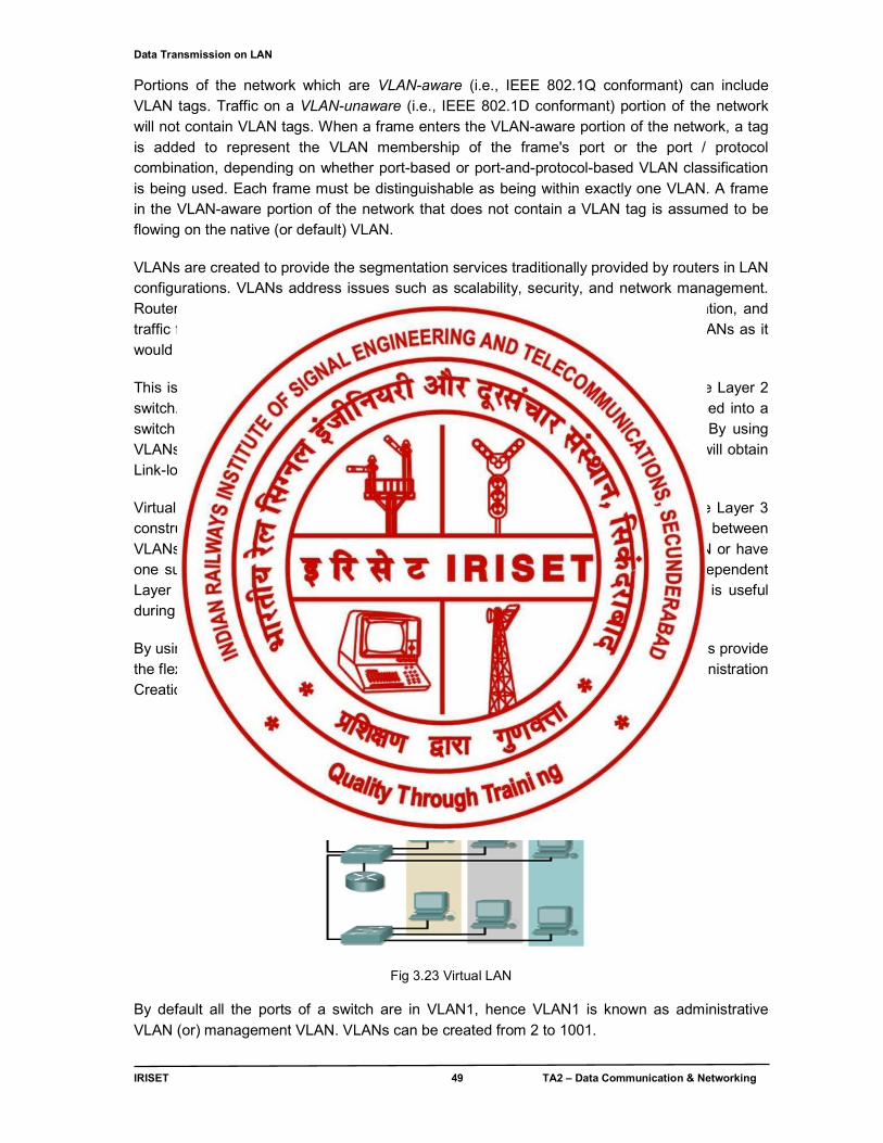
Data Transmission on LAN
IRISET 49 TA2 – Data Communication & Networking
Portions of the network which are VLAN-aware (i.e., IEEE 802.1Q conformant) can include VLAN tags. Traffic on a VLAN-unaware (i.e., IEEE 802.1D conformant) portion of the network will not contain VLAN tags. When a frame enters the VLAN-aware portion of the network, a tag is added to represent the VLAN membership of the frame's port or the port / protocol combination, depending on whether port-based or port-and-protocol-based VLAN classification is being used. Each frame must be distinguishable as being within exactly one VLAN. A frame in the VLAN-aware portion of the network that does not contain a VLAN tag is assumed to be flowing on the native (or default) VLAN. VLANs are created to provide the segmentation services traditionally provided by routers in LAN configurations. VLANs address issues such as scalability, security, and network management. Routers in VLAN topologies provide broadcast filtering, security, address summarization, and traffic flow management. By definition, switches may not bridge IP traffic between VLANs as it would violate the integrity of the VLAN broadcast domain. This is also useful if someone wants to create multiple Layer 3 networks on the same Layer 2 switch. For example, if a DHCP server (which will broadcast its presence) was plugged into a switch it will serve any host on that switch that was configured to use the server. By using VLANs you can easily split the network up so some hosts won't use that server and will obtain Link-local addresses. Virtual LANs are essentially Layer 2 constructs, compared with IP subnets which are Layer 3 constructs. In an environment employing VLANs, a one-to-one relationship often exists between VLANs and IP subnets, although it is possible to have multiple subnets on one VLAN or have one subnet spread across multiple VLANs. Virtual LANs and IP subnets provide independent Layer 2 and Layer 3 constructs that map to one another and this correspondence is useful during the network design process. By using VLANs, one can control traffic patterns and react quickly to relocations. VLANs provide the flexibility to adapt to changes in network requirements and allow for simplified administration Creation of VLAN is shown in the figure 3.23 and 3.24 .
Fig 3.23 Virtual LAN By default all the ports of a switch are in VLAN1, hence VLAN1 is known as administrative VLAN (or) management VLAN. VLANs can be created from 2 to 1001.
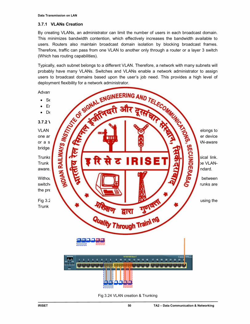
Data Transmission on LAN
IRISET 50 TA2 – Data Communication & Networking
3.7.1 VLANs Creation
By creating VLANs, an administrator can limit the number of users in each broadcast domain. This minimizes bandwidth contention, which effectively increases the bandwidth available to users. Routers also maintain broadcast domain isolation by blocking broadcast frames. Therefore, traffic can pass from one VLAN to another only through a router or a layer 3 switch (Which has routing capabilities).
Typically, each subnet belongs to a different VLAN. Therefore, a network with many subnets will probably have many VLANs. Switches and VLANs enable a network administrator to assign users to broadcast domains based upon the user’s job need. This provides a high level of deployment flexibility for a network administrator.
Advantages of VLANs include the following:
Segmentation of broadcast domains effectively increases available bandwidth
Enhanced security through isolation of user communities
Deployment flexibility based upon job function rather than physical placement
3.7.2 VLAN Switch Port Modes
VLAN Switch ports run in either access or trunk mode. In access mode, the interface belongs to one and only one VLAN. Normally a switch port in access mode attaches to an end user device or a server. An access link connects a VLAN-unaware device to the port of a VLAN-aware bridge.
Trunks, on the other hand, multiplex traffic for multiple VLANs over the same physical link. Trunk links usually interconnect switches. The devices connected to a trunk link must be VLAN-aware. Trunk protocols may be proprietary or may be based upon the IEEE 802.1Q standard.
Without trunk links, multiple access links must be installed to support multiple VLANs between switches. This creates an impractical and not cost-effective administrative challenge. Trunks are the preferred option for interconnecting switches in most cases.
Fig 3.24 shows two VLANs (i.e.VLAN2 & VLAN3) in switch no.1 & no.2 are connected using the Trunk port.
Inter connection of VLANs using Trunk port
Fig 3.24 VLAN creation & Trunking
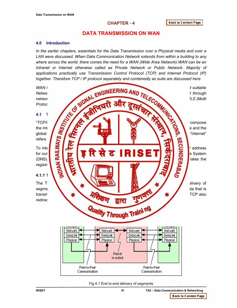
Data Transmission on WAN
IRISET 51 TA2 – Data Communication & Networking
CHAPTER - 4
DATA TRANSMISSION ON WAN
4.0 Introduction
In the earlier chapters, essentials for the Data Transmission over a Physical media and over a LAN were discussed. When Data Communication Network extends from within a building to any where across the world, there comes the need for a WAN (Wide Area Network).WAN can be an Intranet or Internet otherwise called as Private Network or Public Network. Majority of applications practically use Transmission Control Protocol (TCP) and Internet Protocol (IP) together. Therefore TCP / IP protocol separately and combinedly as suite are discussed here
WAN is established with the help of Routers & Long distance communication links and suitable Network Layer Protocol (Ex. IP) and data units are PACKETs. Packets are routed through networks with the help of IP Routing, Static and Dynamic. The converged networks MPLS (Multi Protocol Label Switching)) is also discussed in detail.
4.1 TCP/IP protocol
“TCP/IP” is the acronym that is commonly used for the set of network protocols that compose the Internet Protocol suite. Here the term “Internet” is to describe both the protocol suite and the global wide area network. “TCP/IP” refers specifically to the Internet protocol suite. “Internet” refers to the wide area network and the bodies that govern the Internet.
To interconnect our TCP/IP network with other networks, we must obtain a unique IP address for our network. If hosts on our network are to participate in the Internet Domain Name System (DNS), we must obtain and register a unique domain name. The Inter NIC coordinates the registration of domain names through a group of worldwide registries.
4.1.1 Transmission Control Protocol (TCP)
The Transmission Control Protocol (TCP) is responsible for reliable end to end delivery of segments as shown in fig 4.1. Segments are the term that is used to describe the data that is transmitted and received at the Transport layer of the OSI model where TCP resides. TCP also redirects the data to the appropriate well known ports (upper level service) .
Fig 4.1 End to end delivery of segments
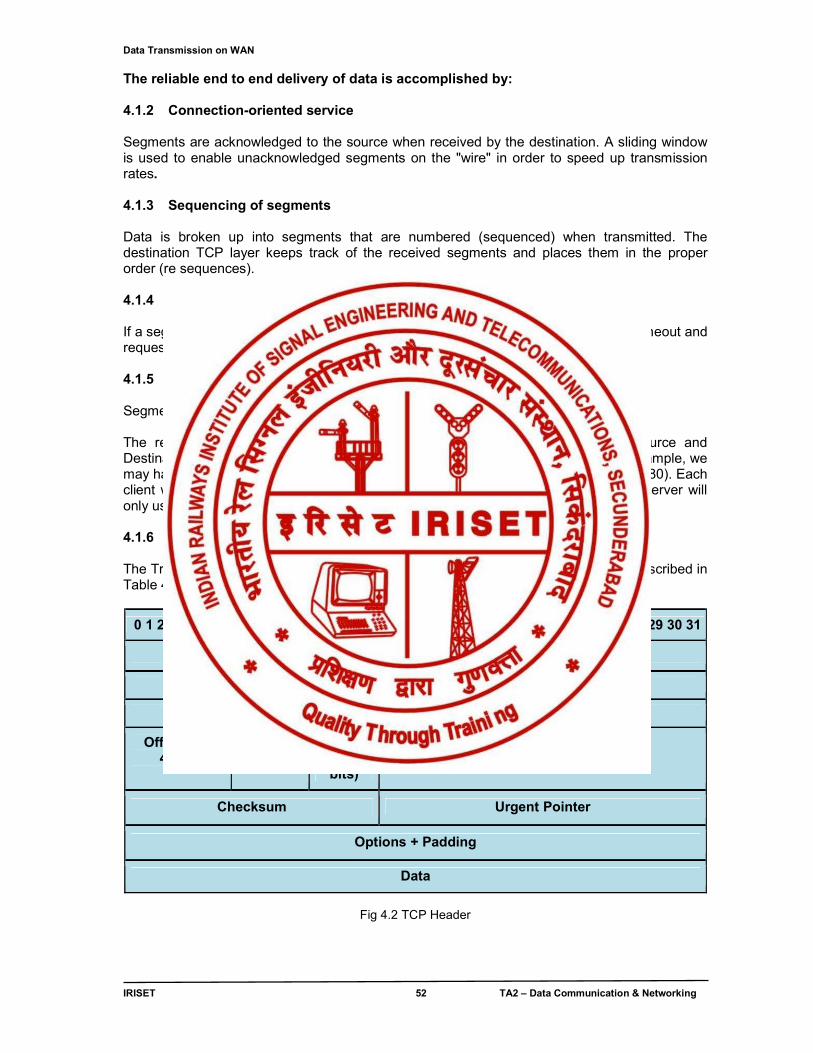
Data Transmission on WAN
IRISET 52 TA2 – Data Communication & Networking
The reliable end to end delivery of data is accomplished by: 4.1.2 Connection-oriented service Segments are acknowledged to the source when received by the destination. A sliding window is used to enable unacknowledged segments on the "wire" in order to speed up transmission rates. 4.1.3 Sequencing of segments Data is broken up into segments that are numbered (sequenced) when transmitted. The destination TCP layer keeps track of the received segments and places them in the proper order (re sequences). 4.1.4 Requesting retransmission of lost data If a segment is lost in transmission (missing sequence number). The destination will timeout and request that all segments starting at the lost segment be retransmitted.
4.1.5 Error checking Segments are checked for data integrity when received using a 32 bit CRC check. The redirection of data to the upper level service is accomplished by using Source and Destination Port numbers. Multiple connections to the same service is allowed. For example, we may have many users (clients) connected to a single web server (http is normally port 80). Each client will have a unique Port number assigned (typically above 8000) but the web server will only use Port 80. 4.1.6 TCP Header The Transmission Control Protocol (TCP) header is shown in fig 4.2 & its fields are described in Table 4.1
0 1 2 3 4 5 6 7 8 9 10 11 12 13 14 15 16 17 18 19 20 21 22 23 24 25 26 27 28 29 30 31
Source Port (16 bits) Destination Port (16 bits)
Sequence Number(32 bits)
Acknowledgement Number(32 bits)
Offset (1st 4bits)
Not used (6 bits)
Flags (last6 bits)
Window
Checksum Urgent Pointer
Options + Padding
Data
Fig 4.2 TCP Header
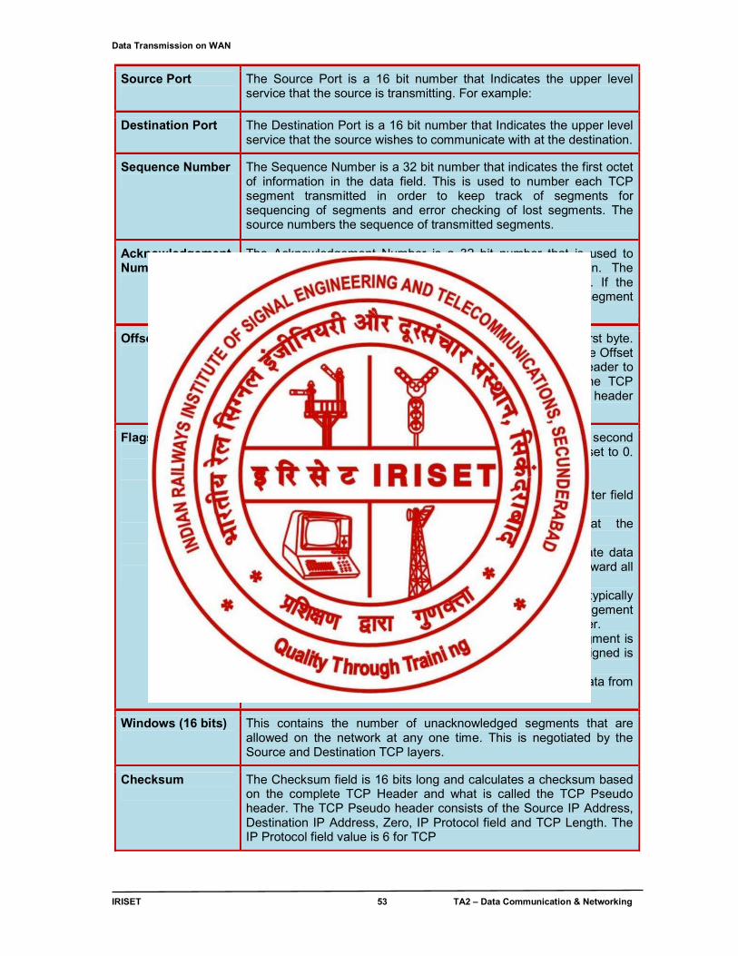
Data Transmission on WAN
IRISET 53 TA2 – Data Communication & Networking
Source Port
The Source Port is a 16 bit number that Indicates the upper level service that the source is transmitting. For example:
Destination Port The Destination Port is a 16 bit number that Indicates the upper level service that the source wishes to communicate with at the destination.
Sequence Number
The Sequence Number is a 32 bit number that indicates the first octet of information in the data field. This is used to number each TCP segment transmitted in order to keep track of segments for sequencing of segments and error checking of lost segments. The source numbers the sequence of transmitted segments.
Acknowledgement Number
The Acknowledgement Number is a 32 bit number that is used to acknowledge the receipt of segments by the destination. The acknowledgement is the next sequence number expected. If the sender does not receive an acknowledgement for a segment transmitted, the sender will time-out and retransmit
Offset (4 bits)
The Offset field consists of the first 4 bits (xxxx0000) of the first byte. The last 4 bits are reserved for future use and are set to 0. The Offset measures the number of 32 bit (4 byte) words in the TCP header to where the Data field starts. This is necessary because the TCP header has a variable length. The minimum length of the TCP header is 20 bytes which gives an Offset value of 5.
Flags (last 6 bits)
The Flags Field consists of the last 6 bits (00xxxxxx) of the second byte with the first 2 bits reserved for future use and they are set to 0. The Flags field consists of the following flag bits: URG (Urgent Flag): When set indicates that the Urgent Pointer field is being used. ACK (Acknowledge Flag): When set indicates that the Acknowledgement Number is being used. PSH (Push Flag): An upper level protocol requires immediate data delivery and would use the Push (PSH) flag to immediately forward all of the queued data to the destination. RST (Reset Flag): When set the connection is reset. This is typically used when the source has timed out waiting for an acknowledgement and is requesting retransmission starting at a sequence number. SYN (Synchronize Flag): When set, it indicates that this segment is the first one in the sequence. The first sequence number assigned is called the Initial Sequence Number (ISN) FIN (Finish Flag): When set, it indicates that this is the last data from the sender.
Windows (16 bits)
This contains the number of unacknowledged segments that are allowed on the network at any one time. This is negotiated by the Source and Destination TCP layers.
Checksum
The Checksum field is 16 bits long and calculates a checksum based on the complete TCP Header and what is called the TCP Pseudo header. The TCP Pseudo header consists of the Source IP Address, Destination IP Address, Zero, IP Protocol field and TCP Length. The IP Protocol field value is 6 for TCP
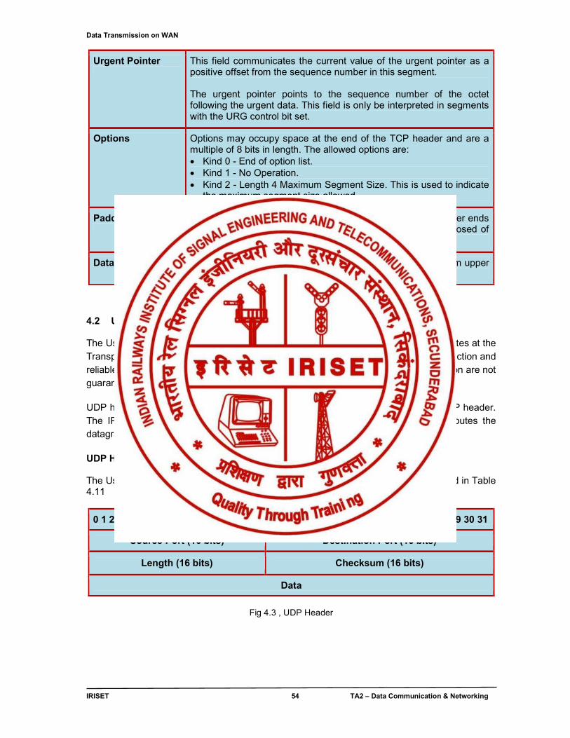
Data Transmission on WAN
IRISET 54 TA2 – Data Communication & Networking
Urgent Pointer
This field communicates the current value of the urgent pointer as a positive offset from the sequence number in this segment. The urgent pointer points to the sequence number of the octet following the urgent data. This field is only be interpreted in segments with the URG control bit set.
Options Options may occupy space at the end of the TCP header and are a multiple of 8 bits in length. The allowed options are: Kind 0 - End of option list. Kind 1 - No Operation. Kind 2 - Length 4 Maximum Segment Size. This is used to indicate
the maximum segment size allowed
Padding
The TCP header padding is used to ensure that the TCP header ends and data begins on a 32 bit boundary. The padding is composed of zeros.
Data Consists of pure form of data (combination of bits) coming from upper layers
Table 4.1 Description of TCP header fields
4.2 User Datagram Protocol (UDP) The User Datagram Protocol (UDP) is a connectionless host to host service that operates at the Transport layer of the OSI model. UDP relies on the upper layer protocol for error correction and reliable service. The protocol is transaction oriented; its delivery and duplicate protection are not guaranteed. The major uses of this protocol are DNS and TFTP. UDP has a small header and for all intensive purposes adds Port addressing to the IP header. The IP header routes data grams to the correct host on the network and UDP routes the datagram to the correct application. UDP Header The User datagram Protocol (UDP) header is shown in fig 4.8 & its fields are described in Table 4.11
0 1 2 3 4 5 6 7 8 9 10 11 12 13 14 15 16 17 18 19 20 21 22 23 24 25 26 27 28 29 30 31
Source Port (16 bits) Destination Port (16 bits)
Length (16 bits) Checksum (16 bits)
Data
Fig 4.3 , UDP Header
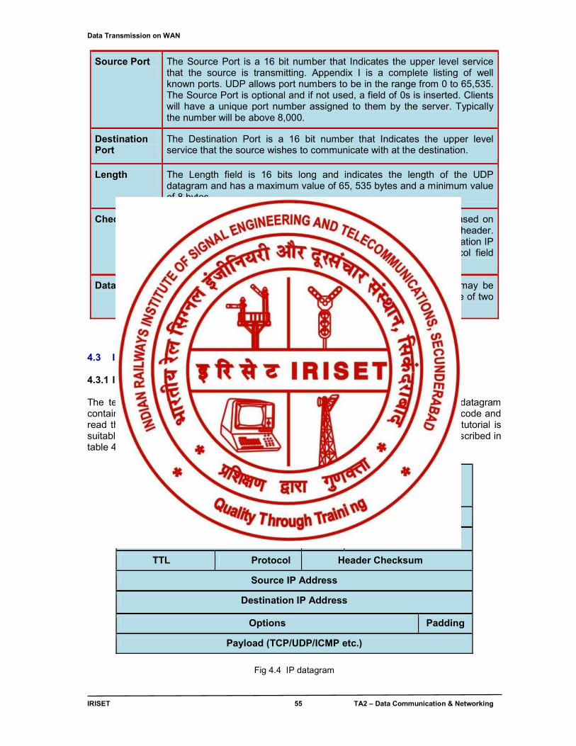
Data Transmission on WAN
IRISET 55 TA2 – Data Communication & Networking
Source Port
The Source Port is a 16 bit number that Indicates the upper level service that the source is transmitting. Appendix I is a complete listing of well known ports. UDP allows port numbers to be in the range from 0 to 65,535. The Source Port is optional and if not used, a field of 0s is inserted. Clients will have a unique port number assigned to them by the server. Typically the number will be above 8,000.
Destination Port
The Destination Port is a 16 bit number that Indicates the upper level service that the source wishes to communicate with at the destination.
Length
The Length field is 16 bits long and indicates the length of the UDP datagram and has a maximum value of 65, 535 bytes and a minimum value of 8 bytes.
Checksum
The Checksum field is 16 bits long and calculates a checksum based on the UDP header, Data field and what is called the UDP Pseudo header. The UDP Pseudo header consists of the Source IP Address, Destination IP Address, Zero, IP Protocol field and UDP Length. The IP Protocol field value is 17 for UDP.
Data
The data field contains the IP header and data. The Data field may be padded with zero octets at the end (if necessary) to make a multiple of two octets
Table 4.2 Description of UDP header fields
4.3 IP COMMUNICATION 4.3.1 IP Datagram Structure The term 'datagram' or 'packet' is used to describe a chunk of IP data. Each IP datagram contains a specific set of fields in a specific order so that the reader knows how to decode and read the stream of data received. The description of the IP datagram format in this tutorial is suitable for most purposes. An IP datagram is illustrated in fig 4.4 and its fields are described in table 4.3
0 .. 7
8 .. 15
16 .. 23
24.. 31
Version IHL TOS Total Length
Identification Flags Fragment Offset
TTL Protocol Header Checksum
Source IP Address
Destination IP Address
Options Padding
Payload (TCP/UDP/ICMP etc.)
Fig 4.4 IP datagram
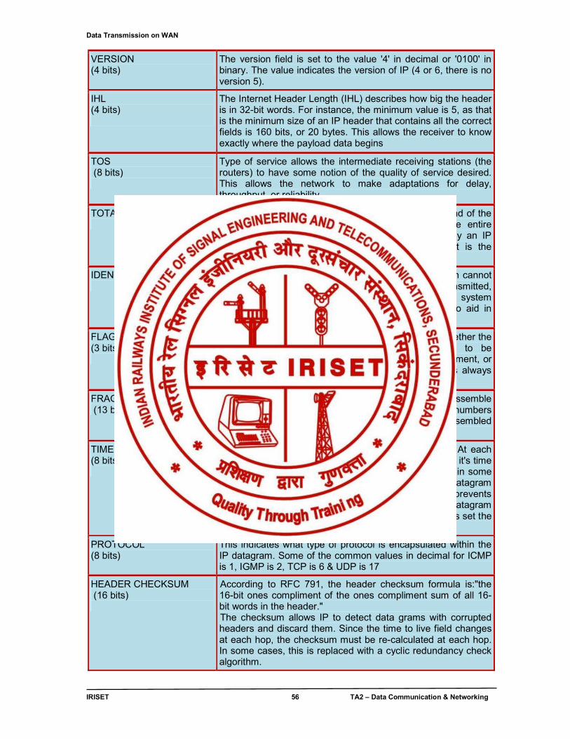
Data Transmission on WAN
IRISET 56 TA2 – Data Communication & Networking
VERSION (4 bits)
The version field is set to the value '4' in decimal or '0100' in binary. The value indicates the version of IP (4 or 6, there is no version 5).
IHL (4 bits)
The Internet Header Length (IHL) describes how big the header is in 32-bit words. For instance, the minimum value is 5, as that is the minimum size of an IP header that contains all the correct fields is 160 bits, or 20 bytes. This allows the receiver to know exactly where the payload data begins
TOS (8 bits)
Type of service allows the intermediate receiving stations (the routers) to have some notion of the quality of service desired. This allows the network to make adaptations for delay, throughput, or reliability.
TOTAL LENGTH (16 bits)
This informs the receiver of the datagram where the end of the data in this datagram is. This is the length of the entire datagram in octets, including the header. This is why an IP datagram can be up to 65,535 bytes long, as that is the maximum value of this 16-bit field.
IDENTIFICATION (16 bits)
Sometimes, a device in the middle of the network path cannot handle the datagram at the size it was originally transmitted, and must break it into fragments. If an intermediate system needs to break up the datagram, it uses this field to aid in identifying the fragments.
FLAGS (3 bits)
The flags field contains single-bit flags that indicate whether the datagram is a fragment, whether it is permitted to be fragmented, and whether the datagram is the last fragment, or there are more fragments. The first bit in this field is always zero.
FRAGMENT OFFSET (13 bits)
When a datagram is fragmented, it is necessary to reassemble the fragments in the correct order. The fragment offset numbers the fragments in such a way that they can be reassembled correctly.
TIME TO LIVE (8 bits)
This field determines how long a datagram will exist. At each hop along a network path, the datagram is opened and it's time to live field is decremented by one (or more than one in some cases). When the time to live field reaches zero, the datagram is said to have 'expired' and is discarded. This prevents congestion on the network that is created when a datagram cannot be forwarded to its destination. Most applications set the time to live field to 30 or 32 by default.
PROTOCOL (8 bits)
This indicates what type of protocol is encapsulated within the IP datagram. Some of the common values in decimal for ICMP is 1, IGMP is 2, TCP is 6 & UDP is 17
HEADER CHECKSUM (16 bits)
According to RFC 791, the header checksum formula is:"the 16-bit ones compliment of the ones compliment sum of all 16-bit words in the header." The checksum allows IP to detect data grams with corrupted headers and discard them. Since the time to live field changes at each hop, the checksum must be re-calculated at each hop. In some cases, this is replaced with a cyclic redundancy check algorithm.
Data Transmission on WAN
IRISET 57 TA2 – Data Communication & Networking
SOURCE ADDRESS (32 bits)
This is the IP address of the sender of the IP datagram.
DESTINATION ADDRESS (32 bits)
This is the IP address of the intended receiver(s) of the datagram. If the host portion of this address is set to all 1's, the datagram is an 'all hosts' broadcast.
OPTIONS & PADDING (variable)
Various options can be included in the header by a particular vendor's implementation of IP. If options are included, the header must be padded with zeroes to fill in any unused octets so that the header is a multiple of 32 bits, and matches the count of bytes in the Internet Header Length (IHL) field
Table 4.3 Description of IP datagram
4.3.1 Internet Protocol (IP)
Internet Protocol (IP) is a piece of software that operates at the NETWORK LAYER and provides the following:
● Unique Addresses ● Connectionless Communication ● Routing ● Data Transmission on IP
4.3.2 UNIQUE ADDRESSES
Everything connected to the Internet must have a unique numerical address. Just like, house has a unique address, so does each computer attached to the Internet. These addresses are not fixed, and can be changed when necessary. These addresses are represented in what is called 'dotted-decimal notation' which means is that there are numbers with dots in between them that look like this: 204.25.183.4.
Always remember that computers use these dotted-decimal 'IP Addresses' to communicate and never use letters or names.
4.3.3 CONNECTIONLESS COMMUNICATION
IP communication is CONNECTIONLESS, and does not bother to set up dedicated end-to-end connections for communication. Upper layer protocols such as TCP are used for setting up connections and tearing them down, managing the recovery of lost data and other errors. These protocols function at the TRANSPORT LAYER of the OSI MODEL or higher.
4.3.4 ROUTING
IP is aware when a computer's address is part of the local group of computers, or somewhere else. ROUTING is the part of IP that allows very intelligent and specialized routing devices (ROUTERS) to recognize that information is not part of the local group of machines, and needs to be forwarded to the destination. These devices are smart enough to 'figure out' how to get to destinations they aren't directly connected to. The process of forwarding the information is called ROUTING. ROUTING is covered in detail in ANOTHER SECTION.
4.3.5 DATA TRANSMISSION ON INTERNET PROTOCOL
Unicast Broadcast Multicast
Data Transmission on WAN
IRISET 58 TA2 – Data Communication & Networking
Unicast: Unicast packets are sent from host to host. The communication is from a single host to another single host. There is one device transmitting a message destined for one receiver.
Broadcast: Broadcast is when a single device is transmitting a message to all other devices in a given address range. This broadcast could reach all hosts on the subnet, all subnets, or all hosts on all subnets. Broadcast packets have the host (and/or subnet) portion of the address set to all ones. By design, most modern ROUTERS will block IP broadcast traffic and restrict it to the local subnet.
Multicast: Multicast is a special protocol for use with IP. MULTICAST enables a single device to communicate with a specific set of hosts, not defined by any standard IP address and mask combination. This allows for communication that resembles a conference call. Anyone from anywhere can join the conference, and everyone at the conference hears what the speaker has to say. The speaker's message isn't broadcasted everywhere, but only to those in the conference call itself. A special set of addresses is used for MULTICAST communication.
4.4 IP ADDRESSES (INTERNET PROTOCOL ADDRESSES)
When using the INTERNET, humans use names such as WWW.GOOGLE.COM or WWW.EBAY.COM. We call those "web addresses" or "URLs" but those are names. They aren't actually addresses; they are just words that can be easily remembered by humans. The INTERNET uses its own set of addresses because computers run the Internet and computers use numbers.
COMPUTERS do their work over the INTERNET and across NETWORKS using numeric addresses. Either end systems are configured with IP addresses (the computer-server that is serving www.google.com for instance). To communicate, a connection is opened from one COMPUTER to the other computer using the IP addresses as the source and destination addresses for that communication.
A COMPUTER gets an address one of two ways, either the network administrator enters it into the COMPUTER manually, or it is learned by the COMPUTER dynamically using a protocol called DHCP. When the IP address is assigned by the NETWORK administrator manually, this is called a ´fixed´ or ´static´ IP address. If an IP address is learned by the COMPUTER automatically when the COMPUTER starts up (via DHCP), it's called a ´dynamic´ IP. DHCP of course, needs to be set up and running for our COMPUTER to learn an IP address.
IP addresses are two types
IPv4 ( IP version 4) IPv6 (IP version 6)
Till now there are only IPv4 addresses are used over the network, due to exhaustion of IPv4 address space, the world is moving towards IPv6. Introduction to IPv6 is given at the end of this chapter.
4.4.1 IPv4 Address
An IP address is a number used to identify the logical connection of a COMPUTER to a physical NETWORK, is a 32-bit BINARY address, composed of four, 8-bit numbers. IP ADDRESS is represented as four decimal numbers between 0 and 255 separated by dots; (e.g. 199.232.66.20). This is referred to as dotted-decimal notation. Anything attached to an IP NETWORK can be assigned an IP address. Addresses are always unique. Because IP addresses are software configured, it is easy to move hosts from one NETWORK to another simply by changing the IP ADDRESS or the network mask. This process is called RENUMBERING.
Data Transmission on WAN
IRISET 59 TA2 – Data Communication & Networking
i. Network and Host Portion of an IP Address
When looking at an IP ADDRESS, the left-most portion of the address identifies which NETWORK the machine (host) belongs to. The right-most portion is used as the address of the host itself. A large number of addresses in use (but not all of them) look something like as shown in table 4.4
VALUE NETWORK HOST
IN DECIMAL 199 232 66 20
IN BINARY 11000111 11101000 01000010 00010100
Table 4.4 Network and Host Portion of an IP Address
In the example shown in table 4.5 above, the network address is 199.232.66 and the host portion of the address is 20, the complete IP address is 199.232.66.20. All the computers on the same local NETWORK would have the same network number in their address. Thus, two computers on the same NETWORK might be 199.232.66.20 and 199.232.66.41.
When two hosts with IP addresses communicate, they send IP data grams. IP DATA GRAMS contain the source and destination addresses of the hosts communicating. Only the addresses are recorded in the packet. There is no information stored in the packet to tell us which part of the address is network and which is host. If this is true, then how will we figure out which part of the address is the network portion, and which is the host portion?
First, we must remember that all hosts on the same NETWORK will have the same network address (the network portion will be the same for all hosts). Only the host portion will be different and unique for each host on the network.
Different networks also have different network addresses. Network A would have a different address from Network B. From the perspective of determining the correct network, the individual host address is irrelevant. We will need it later to find the host itself ON the network, but we don't need to look at it yet, since we need to find the correct NETWORK first.
To find a particular host, we first find the NETWORK that host is on and then ask that NETWORK to find the host. There are two solutions to handling this NETWORK vs. host address problem, and they are similar but separate addressing types: CLASSFUL, and CLASSLESS.
CLASSFUL was the first addressing scheme developed. It helped manage the IP space and make organization of networks and hosts possible, but it could not support the growing complexity of the INTERNET, and wasted a lot of address space, so an new scheme was developed called CLASSLESS.
i. Source Address: The IP ADDRESS of the HOST that sent the DATAGRAM (sender).
ii. Destination Address: The IP ADDRESS of the HOST the DATAGRAM is being sent to (receiver).
iii. MASK: The mask is a value that is stored in the configuration of a computer along with the IP address. The mask gives the computer a simple way to figure out whether the IP address of another computer is on the same local network, or on a different local network. Bear in mind that for this definition of a mask, a 'local network' is defined as a group of computers with IP addresses in a limited range.
iv. Subnet Mask: A piece of information stored on the local HOST that allows it to determine whether a remote HOST is part of the local NETWORK, or is part of a different outside NETWORK.
Data Transmission on WAN
IRISET 60 TA2 – Data Communication & Networking
During the process of delivering (ROUTING) an IP DATAGRAM, only the destination IP ADDRESS is significant. In CLASSFUL ADDRESSING information about the HOST'S location and the NETWORK it is located on is assumed to be encoded into the IP ADDRESS within the DATAGRAM. There aren't any fields provided in an IP DATAGRAM to inform the receiver where the network portion of the IP ADDRESS leaves off and where the HOST portion of the IP ADDRESS begins. (See IPV4
ADDRESSING section for more information).
4.4.2 Classes of IP Addresses
The entire IP ADDRESS space (0.0.0.0 to 255.255.255.255) is divided into 'classes', or special ranges of contiguous IP ADDRESSES (no addresses missing between the first and last address in the range). CLASSFUL ADDRESSING makes it possible to determine the NETWORK portion of the IP ADDRESS by looking at the first four bits of the first octet in the IP ADDRESS. The FIRST FOUR BITS are referred to as the 'most significant bits' of the first octet and are used to DETERMINE WHAT
CLASS OF IP ADDRESS IS BEING USED. The value of the first four bits determines the range of actual numerical values of the first octet of the IP ADDRESSES in that class. From this information, a receiving HOST can determine which part of the IP ADDRESS is being used to identify the specific network on which the HOST resides, and which portion of the IP ADDRESS is used to identify the HOST. The different classes of IP ADDRESSES (Class A, Class B, Class C, Class D & Class E) were created to allow for carving up the entire set of all IP ADDRESSES into chunks of different sizes that would 'fit' the number of HOSTS on the NETWORK for which the IP ADDRESS SPACE was being supplied. The table 4.5 shown below gives a breakdown of how the Classful system breaks up the IP ADDRESS space.
FIRST OCTET IP ADDRESS CHARACTERISTICS
MOST SIGNIFICANT
BITS
VALUE RANGES
ADDR. CLASS
NETWORK
VS. HOST
# NETWORKS # HOSTS
0000 0-126 A N.h.h.h 256 16,777,214
-- 127 - - SPECIAL - LOCAL LOOPBACK
1000 128-191 B N.N.h.h 65,536 65,534
1100 192-223 C N.N.N.h 16,777,216 254
1110 224 - 239 D Special N/A N/A
1111 240 + E Special N/A N/A
Table 4.5 Classful IP Addressing
It is possible to waste IP ADDRESSES by assigning blocks of IP ADDRESSES which fall along octet boundaries (the dots between the NUMBERS in the DECIMAL representation of the IP ADDRESS). Most often a class C address was supplied to anyone requesting space, as few NETWORKS had more than 256 hosts. But the networks grew to more than 256 HOSTS, and needed more space, so Class B addresses were given out. But if a NETWORK has only 500 HOSTS, and in the case of a class B IP ADDRESS block to that network, 65,034 addresses will go unused. This is a terribly inefficient use of space, and as NETWORKS grew larger the INTERNET grew; the need to use the IP ADDRESS space more and more efficiently became ever more critical.
Data Transmission on WAN
IRISET 61 TA2 – Data Communication & Networking
One solution that was created for reduce utilization of IP ADDRESSES was NETWORK ADDRESS
TRANSLATION. This involved the use of PRIVATE IP ADDRESSES and a device that translates PRIVATE IP ADDRESSES into PUBLIC IP ADDRESSES.
As the list of available IP ADDRESSES was depleted it became clear that a new solution was needed that provided more addresses and efforts turned towards developing what is called IP v6.
i. Classful Addressing: COMPUTERS communicating using INTERNET Protocol (IP) send DATA
GRAMS. IP DATAGRAM contains a SOURCE IP ADDRESS, and a DESTINATION IP ADDRESS. However, an IP DATAGRAM does not contain any NETWORK subnet mask information, thus it is difficult to know which groups of COMPUTERS (HOSTS) formed a NETWORK.
ii. Classless Addressing: All IP addresses have a network and host portion. In classful addressing, the NETWORK portion ends on one of the separating dots in the address (on an octet boundary). Classless addressing uses a variable number of bits as shown in table 4.6 for the NETWORK and host portions of the address.
Decimal 192 160 20 48
Binary 11000000 10100000 00010100 0011
0000
<-------- 28 bits Network -------> 4 bits host
Table 4.6 Classless IP Addressing
Classfull addressing divides an IP ADDRESS into the Network and Host portions along octet boundaries. Classless addressing treats the IP ADDRESS as a 32 bit stream of ones and zeroes, where the boundary between NETWORK and host portions can fall anywhere between bit 0 and bit 31. The network portion of an IP ADDRESS is determined by how many 1's are in the subnet mask.
Again, this can be a variable number of bits, and although it can fall on an octet boundary, it does not necessarily need to. A subnet mask is used locally on each host connected to a network, and masks are never carried in IPv4 data grams. All hosts on the same network are configured with the same mask, and share the same pattern of network bits. The host portion of each host's IP address will be unique.
4.4.3 SUBNETTING and SUPERNETTING
Originally the entire range of IP ADDRESSES WAS carved up into small, medium and large chunks of addresses. Networking equipment figured which addresses was all part of a NETWORK by looking at the first four bits of the address. There were five classes of addresses used. Sub-netting is the process of borrowing bits from the host portion of an address to provide bits for identifying additional sub-networks. VLSM is most frequently referred to as sub netting.
i. Variable Length Subnet Masking (VLSM): The INTERNET's explosive growth eventually required the more efficient use of the IP ADDRESS space available. Variable Length Subnet Masking is a technique used to allow more efficient assignment of IP ADDRESSES. Originally INTERNET addresses were carved up into small, medium and large size blocks of contiguous addresses based on the values of the first four bits in the first octet of the IP ADDRESS. These were often referred to as CLASS FULL addresses. By carving CLASS FULL address blocks into smaller CLASSLESS blocks, we waste fewer addresses. The process of carving out smaller blocks from the larger blocks was called SUB NETTING.
Data Transmission on WAN
IRISET 62 TA2 – Data Communication & Networking
Many organization's networks started very small and were assigned class C addresses. A class C address range contains 256 addresses. Soon, these organizations grew and so did their networks. Networks that needed to expand beyond their original class C range used a technique called SUPER NETTING to allow them to turn two contiguous IP address blocks into one network.
ii. Super netting: Super netting is different. Super netting merges several smaller blocks of IP addresses (networks) that are continuous into one larger block of addresses. There can't be any 'holes' in the range. Super netting is done by borrowing network bits to combine several smaller networks into one larger network.
For instance, a class 'C' block has 256 possible addresses in it. This block could be split into four classless blocks of 64 addresses each by borrowing two bits from the host portion of the class 'C' address.
Note: Even after borrowing 2 bits from the host portion towards network portion only two subnets can be created as all bits zero & all bits one condition is not allowed in the subnets.
Standard Class 'C' network
Network Network Network Host CLASS 'C' ADDRESS
192 64 123 0
MASK
(DECIMAL) 255 255 255 0
MASK (BINARY)
11111111 11111111 11111111 00000000
Table 4.7a
The mask and address shown in table 4.7a above combine to give a range of addresses from 192.64.123.1 through 192.64.123.254.
Subnet #1 Network Network Network Subnet Host
192 64 123 64 255 255 255 192
11111111 11111111 11111111 11 000000
Table 4.7b
Subnet 192.64.123.64 /26 will fetch the mask and address shown in table 4.7 b above combine to give a range of addresses from 192.64.123.65 through 192.64.123.126.
Subnet #2 Network Network Network Subnet Host
CLASS 'C' ADDRESS 192 64 123 128 MASK (DECIMAL) 255 255 255 192 MASK (BINARY) 1111111111111111 11111111 11 000000
Table 4.7c
Subnet 192.64.123.128 /26 will fetch the mask and address shown in table 4.7 c above combine to give a range of addresses from 192.64.123.129 through 192.64.123.190.
Data Transmission on WAN
IRISET 63 TA2 – Data Communication & Networking
4.4.4 SPECIAL IP ADDRESSES
There are several IP addresses that are special in one way or another. These addresses are for special purposes or are to be put to special use.
● Addresses significant to every IP subnet ▪ Network Address ▪ Broadcast Address
● Addresses significant to individual hosts ▪ Loopback Address ▪ Private Addresses
▪ Multicast Addresses ▪ Reserved Addresses
1. NETWORK ADDRESS: A network address is an address where all host bits in the IP address are set to zero (0). In every subnet there is a NETWORK address. This is the first and lowest numbered address in the range. The network address is defined as the address that contains all zeroes in the host portion of the address and is used to communicate with devices that maintain the network equipment. 2. BROADCAST ADDRESS: A broadcast address is an address where all host bits in the IP address are set to one (1). This address is the last address in the range of addresses, and is the address whose host portion is set to all ones. All hosts are to accept and respond to the broadcast address. This makes special services possible.
3. LOOPBACK ADDRESS (127.0.0.1): The 127.0.0.0 class 'A' subnet is used for only a single address: the loopback address 127.0.0.1. This address is used to test the local NETWORK interface device's functionality. All NETWORK interface devices should respond to this address. If we ping 127.0.0.1, we can be assured that the network hardware is functioning and that the network software is also functioning.
4. PRIVATE ADDRESSES: RFC 1918 defines a number of IP blocks which were set aside by the American Registry of Internet Numbers (ARIN) for use as PRIVATE ADDRESSES on private networks that are not directly connected to the INTERNET. The private addresses are shown in table 4.5.
Class Start End A 10.0.0.0 10.255.255.255 B 172.16.0.0 172.31.255.255 C 192.168.0.0 192.168.255.255
Table 4.8 Private IP Address
5. MULTICAST ADDRESSES: Multicast (class D) IP addresses shown in table 4.6 are used in special areas like in Routing algorithms (e.g. ospf uses multicast address for route advertisement) and video conferences etc. that cannot be used on the INTERNET.
Class Start End D 224.0.0.0 239.255.255.255
Table 4.9 Multicast IP addresses
6. RESERVED ADDRESSES: There are a number of addresses that are reserved and set aside for future purpose like class E IP addresses. Some special address are shown in table 4.10
Data Transmission on WAN
IRISET 64 TA2 – Data Communication & Networking
Address Block
CIDR Mask
Used for Reference
0.0.0.0 /8 USED TO COMMUNICATE WITH "THIS" NETWORK RFC1700, P. 4
10.0.0.0 /8 PRIVATE-USE NETWORKS RFC 1918
14.0.0.0 /8 PUBLIC-DATA NETWORK RFC1700, P.181
24.0.0.0 /8 CABLE TV NETWORKS --
39.0.0.0 /8 PREVIOUSLY RESERVED AVAILABLE FOR REGIONAL ALLOCATION
RFC1797
127.0.0.0 /8 LOOPBACK ADDRESS RFC1700, P. 5
128.0.0.0 /16 PREVIOUSLY RESERVED AVAILABLE FOR REGIONAL ALLOCATION
--
169.254.0.0 /16 LINK LOCAL (EG. MICROSOFT XP SYSTEMS USE AUTOMATIC
PRIVATE IP ADDRESSING (APIPA) WHICH SELECTS
ADDRESSES IN THIS RANGE.)
Table 4.10 Special IP Addresses
4.5 IP ROUTING: Routing is the process of moving data from one NETWORK to another by forwarding PACKETS via GATEWAYS. With IP based NETWORKS, the routing decision is based on the destination address in the IP PACKET'S header. Routing can be classified as shown in fig 4.5
Fig 4.5 IP Routing
4.5.1 Static Routing: Static routing is the term used to refer to the manual method used to set up routing. An administrator enters routes into the router using configuration commands. This method has the advantage of being predictable, and simple to set up. It is easy to manage in small networks but does not scale well.
i. ADVANTAGES ● Simple to configure ● Easy to predict and understand in small networks
ii. DISADVANTAGES ● Requires extensive planning and has a high management overhead ● Does not dynamically adapt to network topology changes or equipment failures. ● Does not scale well in large networks.
Data Transmission on WAN
IRISET 65 TA2 – Data Communication & Networking
iii. STATIC ROUTE CONFIGURATION (CISCO) ● Default Route ● Static Null Route ● Preferred Routes ● Backup Routes ● Static Load Balancing
a. Default Route: A default route is often called the 'route of last resort'. It is the last route tried when all other routes fail because it has the fewest number of network bits matching and is therefore less specific. A default route is configured on a CISCO router with the following command:
ip route 0.0.0.0 0.0.0.0 <next hop IP address > OR < exit interface type><No.>
b. Static Null Route: Null route, routes traffic to a non-existent interface, what is often called a 'bit bucket'. This traffic is effectively dropped as soon as it is received. A null route is useful for removing packets that cannot make it out of the network or to their destination, and decreases congestion caused by packets with no functional destination. During a denial of service attack, a Null route can temporarily be used near the destination to drop all traffic generated by the attack.
CISCO 'NULL ROUTE' COMMAND: ip route <network> <mask> null0
c. Preferred Routes: The route which has the greatest number of network bits matching the destination address is the preferred route to a destination. This is referred to as 'longest prefix match'.
ip route 202.148.224.0 255.255.255.252 e0 ip route 202.148.224.128 255.255.255.128 e1
d. Backup Routes: In cases where redundancy is required, a second route can be placed on another physical path so that if the first route fails, the second route over the less preferred path(s) will be used. By using a second pair of routes. This method can help compensate for NETWORK failures.
CISCO router commands:
SPECIFIC ROUTES (used unless down) ip route 202.148.224.0 255.255.255.128 e0 ip route 202.148.224.128 255.255.255.128 e1
BACKUP ROUTES (used when one of the specified routes is down) ip route 202.148.224.0 255.255.255.0 e0 ip route 202.148.224.0 255.255.255.0 e1
e. Static Load Balancing: We can create load balancing without using a dynamic routing protocol. Most routers will perform load balancing automatically if several equal cost paths to a destination exist on multiple interfaces. To configure this using static routing, we need only create multiple static routes for more than one interface. This creates more than one equal cost path which will balance the load.
router commands:
ip route 202.148.224.0 255.255.255.0 e0 ip route 202.148.224.0 255.255.255.0 e1
Data Transmission on WAN
IRISET 66 TA2 – Data Communication & Networking
4.5.2 Dynamic Routing
● Interior (Intra domain) ▪ RIP - Routing Information Protocol ▪ OSPF - Open Shortest Path First ▪ IS-IS - Intermediate System to Intermediate System ▪ IGRP - Interior Gateway Routing Protocol ▪ EIGRP - Enhanced Interior Gateway Routing Protocol
● Exterior (Inter domain) ▪ BGP - Border Gateway Protocol
i. RIP (Routing Information Protocol): The Routing Information Protocol (RIP) is a dynamic routing protocol used in local and wide area networks. As such it is classified as an interior gateway protocol (IGP). It uses the distance-vector routing algorithm. The routing algorithm used in RIP, the Bellman-Ford algorithm
RIP is a distance-vector routing protocol, which employs the hop count as a routing metric. The hold down time is 180 seconds. RIP prevents routing loops by implementing a limit on the number of hops allowed in a path from the source to a destination. The maximum number of hops allowed for RIP is 15. This hop limit, however, also limits the size of networks that RIP can support. A hop count of 16 is considered an infinite distance and used to deprecate inaccessible, inoperable, or otherwise undesirable routes in the selection process.
In most current networking environments, RIP is not the preferred choice for routing as its time to converge and scalability are poor compared to EIGRP, OSPF. It is easy to configure, because RIP does not require any parameters on a router unlike other protocols.
RIP Version2 is in vogue, it includes the ability to carry subnet information, thus supporting Classless Inter-Domain Routing (CIDR). To maintain backward compatibility, the hop count limit of 15 remained. RIPv2 has facilities to fully interoperate with the earlier versions. ii. OSPF (Open Shortest Path First): OSPF is an internal routing protocol. (Primarily used inside a single company, it can span multiple sites.) It’s an open standard protocol. Like other dynamic routing protocols, OSPF enables routers to disclose their available routes to other routers.
OSPF is a link-state routing protocol that runs Dijkstra's algorithm to calculate the shortest path to other networks. Taking the bandwidth of the network links into account, it uses cost as it’s metric. OSPF works by developing adjacencies with its neighbors, periodically sending hello packets to neighbors, flooding changes to neighbors when a link's status changes, and sending "paranoia updates" to neighbors of all recent link state changes every 30 minutes.
While OSPF is an excellent routing protocol for networks of all sizes, one of its weaknesses is that it can be quite complex to configure. On the other hand, it offers more features than simpler protocols such as RIP.
Here are some of OSPF's strengths:
❖ It converges quickly, compared to a distance vector protocol ❖ Routing update packets are small, as it does not send the entire Routing table ❖ It is not prone to routing loops. ❖ It scales very well for large networks ❖ It recognizes the bandwidth of a link and takes into account in link selection ❖ It supports VLSM or CIDR ❖ It supports a long list of optional features that many others don’t
Data Transmission on WAN
IRISET 67 TA2 – Data Communication & Networking
iii. BGP (Border Gateway Protocol): The Border Gateway Protocol (BGP) is the core routing protocol of the Internet. It maintains a table of IP networks or 'prefixes' which designate network reachability among autonomous systems (AS). It is described as a path vector protocol. BGP does not use traditional Interior Gateway Protocol (IGP) metrics, but makes routing decisions based on path, network policies and/or rule sets.
BGP was created to replace the Exterior Gateway Protocol (EGP) routing protocol to allow fully decentralized routing in order to allow the removal of the NSFNet Internet backbone network. This allowed the Internet to become a truly decentralized system. Now version four of the BGP is in use on the Internet. All previous versions are now obsolete.
The major enhancement in version 4 was support of Classless Inter-Domain Routing and use of route aggregation to decrease the size of routing tables.
Most Internet users do not use BGP directly. However, since most Internet service providers must use BGP to establish routing between one another (especially if they are multi homed). It is one of the most important protocols of the Internet. Very large private IP networks use BGP internally, however. An example would be the joining of a number of large Open Shortest Path First (OSPF) networks where OSPF by itself would not scale to size. Another reason to use BGP is multi homing, a network for better redundancy either to multiple access points of a single ISP or to multiple ISPs.
BGP neighbors, or peers, are established by manual configuration between routers to create a TCP session on port 179. A BGP speaker will periodically send 19-byte keep-alive messages to maintain the connection (every 60 seconds by default). Among routing protocols, BGP is unique in using TCP as its transport protocol.
When BGP is running inside an autonomous system (AS), it is referred to as Internal BGP (iBGP or Interior Border Gateway Protocol). When it runs between autonomous systems, it is called External BGP (eBGP or Exterior Border Gateway Protocol). Routers on the boundary of one AS, exchanging information with another AS, are called border or edge routers.
4.6 WAN DEVICES 4.6.1 ROUTER A router is a specialized computer connected to more than one NETWORK that runs software that allows it to move data from one NETWORK to another based on routing tables as shown in table 4.11 & routing functions are described in fig 4.3.
Mask ( / n ) Network Address Next hop Address Interface
/ 24 201.4.22.0 180.170.65.200 S1/0 /16 140.24.0.0 156.24.32.43 S2/0
Table 4.11 Typical Routing Table

Data Transmission on WAN
IRISET 68 TA2 – Data Communication & Networking
Fig 4.6 Routing functions
Routers operate at the NETWORK LAYER (OSI LAYER 3). The primary function of a router is to connect networks together and keep certain kinds of BROADCAST traffic under control. There are several companies that make routers: CISCO, JUNIPER, NORTEL, REDBACK, LUCENT, 3COM, and HP just to name a few. Routers operate in the physical, data link, and network layers of the OSI model. The hardware setup of Router is shown in fig 4.4 and each device functionalities are described below.
Fig 4.7 Router hardware setup
PROCESSOR executes instructions coded in operating system (IOS) to perform the basic operations necessary to accomplish the Router’s functionality. (E.g. all the routing functions, network module high level control & system initialization). Generally the processors used are MPC 860 or higher.
BOOT ROM is not erasable and it is used for permanently storing startup diagnostic code (ROM Monitor). The main task for Boot ROM is to perform some hardware diagnostics during boot up on the router (Power on self test - POST) and to load the IOS software from the Flash to the Memory.
SERIAL INTERFACE
ETHERNET INTERFACE
PROCESSOR
BOOT ROM
NVRAM
DRAM
FLASH
CONSOLE INTERFACE
I/O Bus CPU Bus
Data Transmission on WAN
IRISET 69 TA2 – Data Communication & Networking
DRAM is logically divided into Main Processor memory and Shared Input/output (I/O) memory.
● Main Processor Memory It is used to store routing tables, fast switching cache, running configuration, and so on. It can take unused shared I/O memory, if needed.·
● Shared I/O Memory It is used for temporary storage of packets in system buffers at the
time of process switching, and interface buffers during fast switching.
FLASH is the only way to permanently store and move a complete IOS software image, backup configurations, or any other files.
NVRAM is used for permanent storage of the startup configuration that is writeable. It is also used for permanent storage of hardware revision and identification information, and also Media Access Control (MAC) addresses for LAN interfaces. It is a battery backed Static RAM (SRAM).
CONSOLE INTERFACE is used for initial configuration of the Router using emulation software like hyper terminal
ETHERNET INTERFACE is used for connecting the local area network (LAN) of type Ethernet, Fast Ethernet & Gigabit Ethernet etc.
SERIAL INTERFACE is used for connecting wide area networks (WAN) of type synchronous serial, asynchronous serial and smart serial etc.
CPU Bus this is used by the CPU for accessing the various components of the router and transferring the instructions and data to or from specified memory addresses.
I/O Bus this is the bridge interface between the CPU bus and system bus (where the network modules and other interface boards are connected)
Fig 4.8 Routers connecting independent LANs and WANs
Routers relay packets among multiple interconnected networks like LANs & WANs as shown in fig 4.6 they route packets from one network to any of a number of potential destination networks on an internet. A packet sent from a station on one network to a station on a neighboring network goes first to the jointly held router, which switches it over to the destination network. If there is no one router connected to both the sending and receiving networks the sending router transfers the packet across one of the connected networks to the next router in the direction of the ultimate destination. That router forwards the packet to the next router on the path and so on until the destination is reached.
Routers act like stations on a network. But unlike most stations, which are members of only one network, routers have addresses on and link to two or more networks at the same time. In their
Data Transmission on WAN
IRISET 70 TA2 – Data Communication & Networking
simplest function they receive packets from one connected network and pass them to a second, connected, network. However, if a received packet is addressed to a node on a network of which the router is not a member, the router is capable of determining which of its connected networks is the best next relay point for the packet. Once a router has identified the best route for a packet to travel, it passes the packet along the appropriate network to another router. That route checks the destination address, finds what it considers the best route for the packet and passes it to the destination network (if that network is a neighbor), or across a neighboring network to the next router on the chosen path.
Routers perform the following functions
● Restrict NETWORK broadcasts to the local LAN. ● Protocol bridging ● Act as the DEFAULT GATEWAY. ● Learn and advertise loop free paths between sub-networks.
i. Restrict Broadcasts to the Local LAN NETWORKS use BROADCASTS (transmissions sent to all hosts on the NETWORK) to communicate certain kinds of information that the NETWORK uses to function properly (ARP, RARP, DHCP, IPX-SAP broadcasts etc.). As the number of hosts on the NETWORK increases, the amount of what is called "broadcast" traffic increases. If enough broadcast traffic is present on the network, then ordinary communication across the NETWORK becomes difficult. To reduce BROADCASTS, a NETWORK administrator can break up a NETWORK with a large number of hosts into two smaller networks. BROADCASTS are then restricted to each NETWORK, and the router performs as the DEFAULT GATEWAY to reach the hosts on the other NETWORKS.
ii. Protocol Bridging: A router can take in an Ethernet frame, strip the Ethernet data and then drop the IP data into a frame of another type such as Token Ring, DS1/T1, SONET or FDDI. A router also performs 'protocol conversion', provided it has the appropriate hardware and software to support such a function. When converting between protocols, the closest equivalent function in the new protocol is set to mirror the old protocol from which the data was received. The idea is to forward the data from the interface it receives data on to another interface that retransmits the received data onto another interface serving another network using a different protocol.
iii. Act as the Default Gateway: Especially in today's networks, people are connecting to the INTERNET. When a PC wants to talk to a PC on another network, it does so by sending our data to the DEFAULT GATEWAY (our router). The router receives the datagram and, looks for the remote address of that far-off PC and then makes a routing decision. The router then forwards our data out a different interface that is closer to that remote PC. There could be several routers between the originating PC and the remote PC so several routers will take part in handing off the datagram, much like a fireman's bucket brigade.
This allows two networks managed by different organizations to exchange data. They create a NETWORK between them and exchange data between the routers on that network. Because a router can accept traffic from any kind of network it is attached to, and forward it to any other network, it can also allow networks that could not normally communicate with each other to exchange data. In technical terms, a TOKEN RING NETWORK and an ETHERNET NETWORK can communicate over a serial network. Routers make all this possible.
Data Transmission on WAN
IRISET 71 TA2 – Data Communication & Networking
iv. Learn and advertise loop free paths between sub-networks: Over time, networks grew in size. The connections between them outgrew administrator's ability to keep up with them. To make life simpler, routing protocols (RIP, OSPF, IS-IS, IGRP, EIGRP, BGP) were invented so that very large NETWORK systems with lots of sub-networks can automatically learn where each NETWORK is located and advertise that information automatically to other routers. This makes it possible for the networks to automatically learn how they are constructed, find the best ways to get from place to place and move all the data along those best routes as efficiently as possible. This is how data makes it across the INTERNET.
4.6.2 GATEWAY
If two networks operate according to different network protocols, a gateway is used to connect them. Gateways usually operate at OSI layer 4 or higher, and basically translate the protocols to allow terminals on two dissimilar networks to communicate. Some gateways also translate data codes. i.e. From ASCII to EBCDIC. This capability would be useful on a LAN when communication server routes traffic from a PC based network using ASCII to an IBM main frame that uses the EBCDIC code
Gateways can be either or combinations of hardware & software. They may be implemented on a specially designed circuit card by using specialized software in a standard PC. An Internet service provider, which connects users in a home to the internet, is a Gateway. The Computer routing traffic in an organization from individual work stns to an outside networks Web server is a Gateway. Gateways can suffer from slow performance because of protocol translations, so their performance must be considered and tested when a Gateway installation is contemplated. A dedicated computer action as a gateway, if it is of reasonable speed, usually eliminated any performance problems.
Gateways perform an important role in allowing an organization to interconnect different types of LANs so that the network appears as a single entity to the user. The term Gateway is used in many contexts, but in general it refers to a software or hardware interface that enables two different types of networked systems or software to communicate. For example you might use a gateway to
● Converts commonly used protocols e.g. TCP/IP to a specialized protocols ● Translates different addressing schemes. ● Direct electronic mail to the right network destination ● Connect network with different architectures.
4.6.3 Network Address Translation (NAT)
NAT is the process where a network device, usually a firewall, assigns a public address to a computer (or group of computers) inside a private network. The main use of NAT is to limit the number of public IP addresses an organization or company must use, for both economy and security purposes.
The most common form of network translation involves a large private network using addresses in a private range (10.0.0.0 to 10.255.255.255, 172.16.0.0 to 172.31.255.255, or 192.168.0 0 to 192.168.255.255). The private addressing scheme works well for computers that only have to access resources inside the network, like workstations needing access to file servers and printers. Routers inside the private network can route traffic between private addresses with no trouble. However, to access resources outside the network, like the Internet, these computers have to have a public address in order for responses to their requests to return to them. This is where NAT comes into play.
Data Transmission on WAN
IRISET 72 TA2 – Data Communication & Networking
A workstation inside a network makes a request to a computer on the Internet. Routers within the network recognize that the request is not for a resource inside the network, so they send the request to the firewall. The firewall sees the request from the computer with the internal IP. It then makes the same request to the Internet using its own public address, and returns the response from the Internet resource to the computer inside the private network. From the perspective of the resource on the Internet, it is sending information to the address of the firewall. From the perspective of the workstation, it appears that communication is directly with the site on the Internet. When NAT is used in this way, all users inside the private network access the Internet have the same public IP address when they use the Internet. That means only one public addresses is needed for hundreds or even thousands of users.
There are other uses for Network Address Translation (NAT) beyond simply allowing workstations with internal IP addresses to access the Internet. In large networks, some servers may act as Web servers and require access from the Internet. These servers are assigned public IP addresses on the firewall, allowing the public to access the servers only through that IP address. However, as an additional layer of security, the firewall acts as the intermediary between the outside world and the protected internal network. Additional rules can be added, including which ports can be accessed at that IP address. Using NAT in this way allows network engineers to more efficiently route internal network traffic to the same resources, and allow access to more ports, while restricting access at the firewall. It also allows detailed logging of communications between the network and the outside world.
Additionally, NAT can be used to allow selective access to the outside of the network, too. Workstations or other computers requiring special access outside the network can be assigned specific external IPs using NAT, allowing them to communicate with computers and applications that require a unique public IP address. Again, the firewall acts as the intermediary, and can control the session in both directions, restricting port access and protocols.
NAT is a very important aspect of firewall security. It conserves the number of public addresses used within an organization, and it allows for stricter control of access to resources on both sides of the firewall.
4.6.4 Access Control list (ACL):
ACLs are basically a set of commands, grouped together by a number or name that is used to filter traffic entering or leaving an interface.
When activating an ACL on an interface, you must specify in which direction the traffic should be filtered:
▪ Inbound (as the traffic comes into an interface) ▪ Outbound (before the traffic exits an interface)
Inbound ACLs:
Incoming packets are processed before they are routed to an outbound interface. An inbound ACL is efficient because it saves the overhead of routing lookups if the packet will be discarded after it is denied by the filtering tests. If the packet is permitted by the tests, it is processed for routing. Outbound ACLs:
Incoming packets are routed to the outbound interface and then processed through the outbound ACL.
Data Transmission on WAN
IRISET 73 TA2 – Data Communication & Networking
Universal fact about Access control list
ACLs come in two varieties: Numbered and named
Each of these references to ACLs supports two types of filtering: standard and extended. Standard IP ACLs can filter only on the source IP address inside a packet. Whereas an extended IP ACLs can filter on the source and destination IP addresses in the
packet. There are two actions an ACL can take: permit or deny. Statements are processed top-down. Once a match is found, no further statements are processed—therefore, order is important. If no match is found, the imaginary implicit deny statement at the end of the ACL drops the
packet. An ACL should have at least one permit statement; otherwise, all traffic will be dropped
because of the hidden implicit deny statement at the end of every ACL.
No matter what type of ACL you use, though, you can have only one ACL per protocol, per interface, per direction. For example, you can have one IP ACL inbound on an interface and another IP ACL outbound on an interface, but you cannot have two inbound IP ACLs on the same interface.
Standard ACLs
A standard IP ACL is simple; it filters based on source address only. You can filter a source network or a source host, but you cannot filter based on the destination of a packet, the particular protocol being used such as the Transmission Control Protocol (TCP) or the User Datagram Protocol (UDP), or on the port number. You can permit or deny only source traffic.
Extended ACLs:
An extended ACL gives you much more power than just a standard ACL. Extended IP ACLs check both the source and destination packet addresses. They can also check for specific protocols, port numbers, and other parameters, which allow administrators more flexibility and control.
Named ACLs
One of the disadvantages of using IP standard and IP extended ACLs is that you reference them by number, which is not too descriptive of its use. With a named ACL, this is not the case because you can name your ACL with a descriptive name. The ACL named Deny Mike is a lot more meaningful than an ACL simply numbered 1. There are both IP standard and IP extended named ACLs.
Another advantage to named ACLs is that they allow you to remove individual lines out of an ACL. With numbered ACLs, you cannot delete individual statements. Instead, you will need to delete your existing access list and re-create the entire list.
Configuration Guidelines
Order of statements is important: put the most restrictive statements at the top of the list and the least restrictive at the bottom.
ACL statements are processed top-down until a match is found, and then no more statements in the list are processed.
If no match is found in the ACL, the packet is dropped (implicit deny). Each ACL needs either a unique number or a unique name.
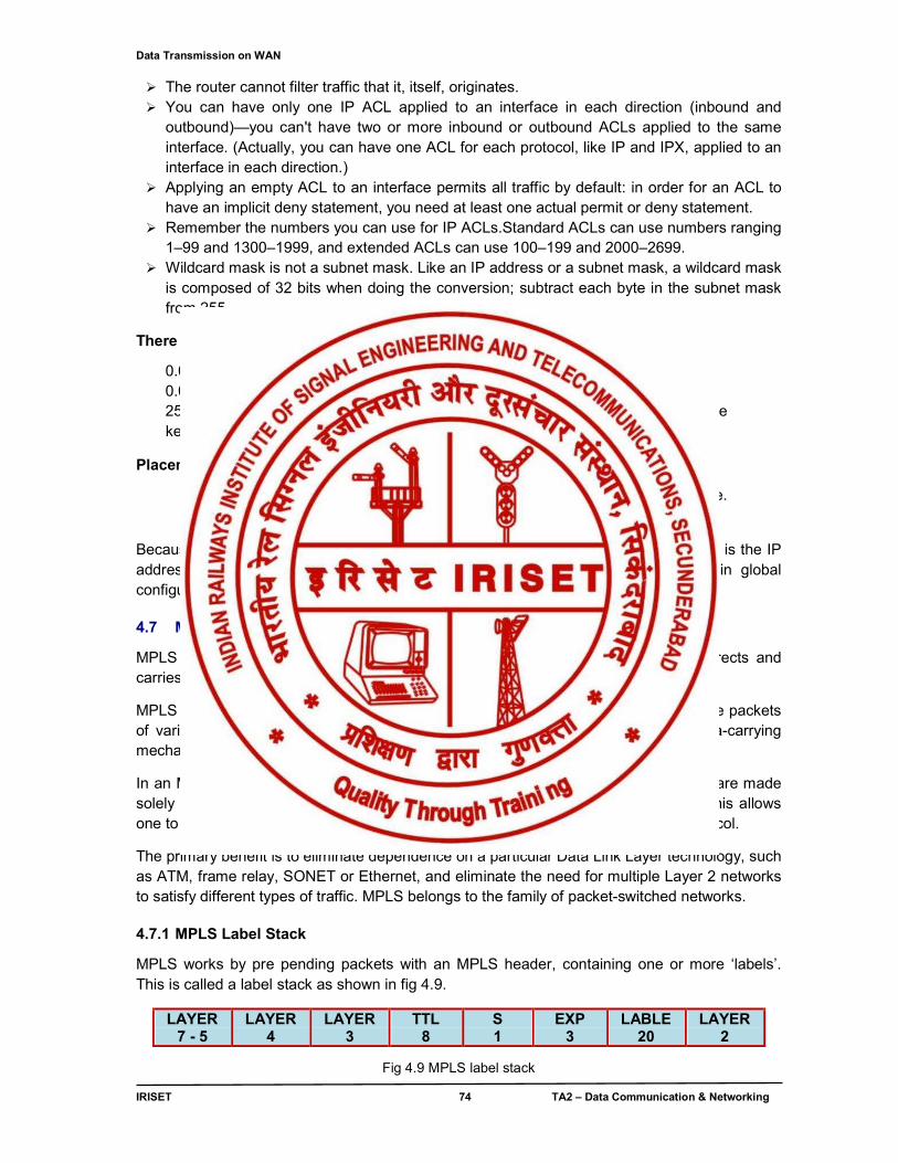
Data Transmission on WAN
IRISET 74 TA2 – Data Communication & Networking
The router cannot filter traffic that it, itself, originates. You can have only one IP ACL applied to an interface in each direction (inbound and
outbound)—you can't have two or more inbound or outbound ACLs applied to the same interface. (Actually, you can have one ACL for each protocol, like IP and IPX, applied to an interface in each direction.)
Applying an empty ACL to an interface permits all traffic by default: in order for an ACL to have an implicit deny statement, you need at least one actual permit or deny statement.
Remember the numbers you can use for IP ACLs.Standard ACLs can use numbers ranging 1–99 and 1300–1999, and extended ACLs can use 100–199 and 2000–2699.
Wildcard mask is not a subnet mask. Like an IP address or a subnet mask, a wildcard mask is composed of 32 bits when doing the conversion; subtract each byte in the subnet mask from 255.
There are two special types of wildcard masks:
0.0.0.0 and 255.255.255.255 0.0.0.0 Wildcard mask is called a host mask 255.255.255.255. If you enter this, the router will cover the address and mask to the keyword any.
Placement of ACLs:
Standard ACLs should be placed as close to the destination devices as possible. Extended ACLs should be placed as close to the source devices as possible.
Because a standard access list filters only traffic based on source traffic, all you need is the IP address of the host or subnet you want to permit or deny. ACLs are created in global configuration mode and then applied on an interface. 4.7 MPLS (Multi Protocol Label Switching):
MPLS is a mechanism in high-performance telecommunications networks which directs and carries data from one network node to the next with the help of labels.
MPLS makes it easy to create "virtual links" between distant nodes. It can encapsulate packets of various network protocols. MPLS is a highly scalable, protocol independant, data-carrying mechanism.
In an MPLS network, data packets are assigned labels. Packet-forwarding decisions are made solely on the contents of this label, without the need to examine the packet itself. This allows one to create end-to-end circuits across any type of transport medium, using any protocol.
The primary benefit is to eliminate dependence on a particular Data Link Layer technology, such as ATM, frame relay, SONET or Ethernet, and eliminate the need for multiple Layer 2 networks to satisfy different types of traffic. MPLS belongs to the family of packet-switched networks. 4.7.1 MPLS Label Stack
MPLS works by pre pending packets with an MPLS header, containing one or more ‘labels’. This is called a label stack as shown in fig 4.9.
LAYER 7 - 5
LAYER 4
LAYER 3
TTL 8
S 1
EXP 3
LABLE 20
LAYER 2
Fig 4.9 MPLS label stack
Data Transmission on WAN
IRISET 75 TA2 – Data Communication & Networking
Each label stack entry contains four fields:
● A 20-bit label value. ● A 3-bit field for QoS priority (experimental). ● A 1-bit bottom of stack flag. If this is set, it signifies the current label is the last in the stack. ● An 8-bit TTL (time to live) field.
These MPLS labeled packets are switched after a Label Lookup/Switch instead of a lookup into the IP table. Label Lookup and Label Switching may be faster than usual RIB lookup because it can take place directly into the switching fabric and not the CPU.
Routers that are performing routing based only on Label Switching are called Label Switch Routers (LSR) and the Routers that are at the exit points of an MPLS network are called Label Edge Routers (LER). Remember that a LER is not usually the one that is popping the label. For more information see Penultimate Hop Popping.
Devices that function as ingress and/or egress routers are often called PE (Provider Edge) routers. Devices that function only as transit routers are similarly called P (Provider) routers. The job of a P router is significantly easier than that of a PE router, so they can be less complex and may be more dependable because of this.
When an unlabeled packet enters the ingress router and needs to be passed on to an MPLS tunnel, the router first determines the forwarding equivalence class the packet should be in, and then inserts one or more labels in the packet’s newly created MPLS header. The packet is then passed on to the next hop router for this tunnel.
When a labeled packet is received by an MPLS router, the topmost label is examined. Based on the contents of the label a swap, push (impose) or pop (dispose) operation can be performed on
the packet’s label stack. Routers can have prebuilt lookup tables that tell them which kind of operation to do based on the topmost label of the incoming packet so they can process the packet very quickly. In a swap operation the label is swapped with a new label, and the packet is forwarded along the path associated with the new label.
In a push operation a new label is pushed on top of the existing label, effectively “encapsulating” the packet in another layer of MPLS. This allows the hierarchical routing of MPLS packets. Notably, this is used by MPLS VPNs.
In a pop operation the label is removed from the packet, which may reveal an inner label below. This process is called “de capsulation”. If the popped label was the last on the label stack, the packet “leaves” the MPLS tunnel. This is usually done by the egress router.
During these operations, the contents of the packet below the MPLS Label stack are not examined. Indeed transit routers typically need only to examine the topmost label on the stack. The forwarding of the packet is done based on the contents of the labels, which allows “protocol independent packet forwarding” that does not need to look at a protocol-dependent routing table and avoids the expensive IP longest prefix match at each hop.
At the egress router, when the last label has been popped, only the payload remains. This can be an IP packet, or any of a number of other kinds of payload packet. The egress router must therefore have routing information for the packet’s payload, since it must forward it without the help of label lookup tables. An MPLS transit router has no such requirement.
Data Transmission on WAN
IRISET 76 TA2 – Data Communication & Networking
In some special cases, the last label can also be popped off at the penultimate hop (the hop before the egress router). This is called Penultimate Hop Popping (PHP). This may be interesting in cases where the egress router has lots of packets leaving MPLS tunnels, and thus spends inordinate amounts of CPU time on this. By using PHP, transit routers connected directly to this egress router effectively offload it, by popping the last label themselves.
MPLS can make use of existing ATM network infrastructure, as its labeled flows can be mapped to ATM virtual circuit a identifiers, and vice-versa.
There are two standardized protocols for managing MPLS paths: CR-LDP (Constraint-based Routing Label Distribution Protocol) and RSVP-TE, an extension of the RSVP protocol for traffic engineering.
An MPLS header does not identify the type of data carried inside the MPLS path. If one wants to carry two different types of traffic between the same two routers, with different treatment from the core routers for each type, one has to establish a separate MPLS path for each type of traffic.
4.7.2 Comparison of MPLS versus IP
MPLS cannot be compared to IP as a separate entity because it works in conjunction with IP and IP’s IGP routing protocols. MPLS gives IP networks simple traffic engineering, the ability to transport Layer3 (IP) VPNs with overlapping address spaces, and support for Layer2 pseudo wires Routers with programmable CPUs and without TCAM/CAM or another method for fast lookups may also see a limited increase in performance.
MPLS relies on IGP routing protocols to construct its label forwarding table, and the scope of any IGP is usually restricted to a single carrier for stability and policy reasons. As there is still no standard for carrier-carrier MPLS it is not possible to have the same MPLS service (Layer2 or Layer3 VPN) covering more than one operator
4.7.3 MPLS local protection
In the event of a network element failure when recovery mechanisms are employed at the IP layer, restoration may take several seconds which is unacceptable for real-time applications (such as VoIP). In contrast, MPLS local protection meets the requirements of real-time applications with recovery times comparable to those of SONET rings (up to 50ms).
4.7.4 Comparison of MPLS versus ATM
While the underlying protocols and technologies are different, both MPLS and ATM provide a connection-oriented service for transporting data across computer networks. In both technologies connections are signaled between endpoints, connection state is maintained at each node in the path and encapsulation techniques are used to carry data across the connection. Excluding differences in the signaling protocols (RSVP/LDP for MPLS and PNNI for ATM) there still remain significant differences in the behavior of the technologies.
The most significant difference is in the transport and encapsulation methods. MPLS is able to work with variable length packets while ATM transports fixed-length (53 byte) cells. Packets must be segmented, transported and re-assembled over an ATM network using an adaption layer, which adds significant complexity and overhead to the data stream. MPLS, on the other hand, simply adds a label to the head of each packet and transmits it on the network.
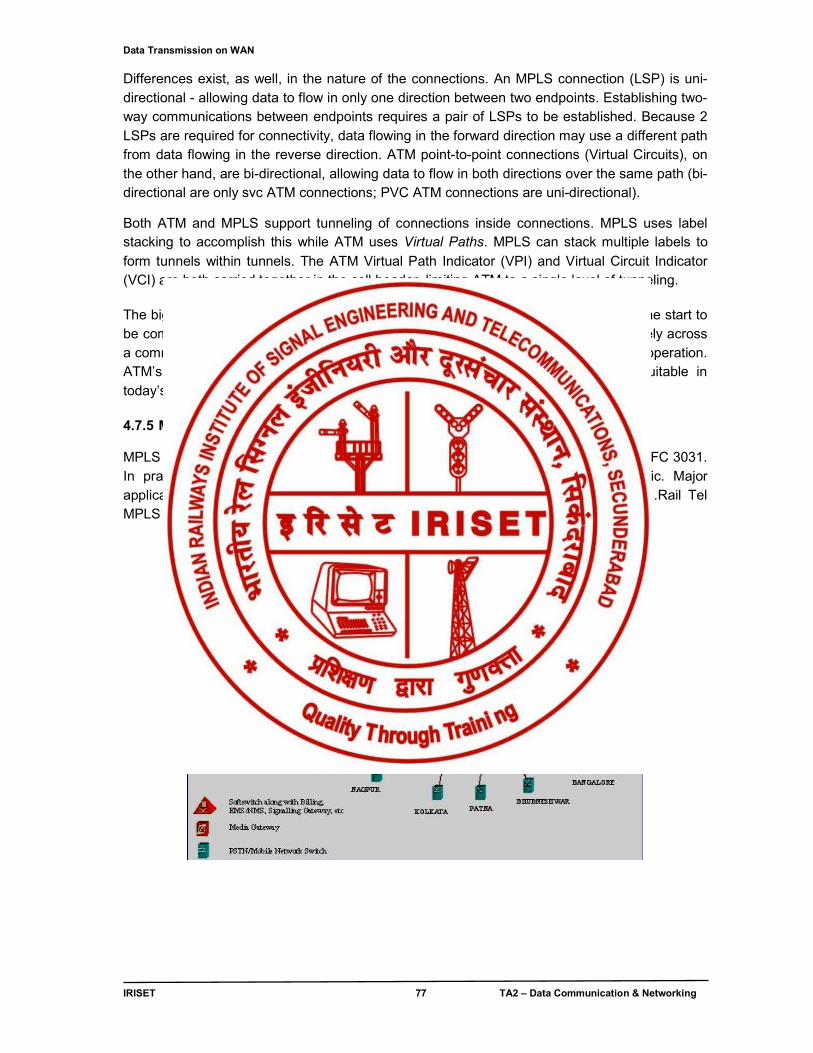
Data Transmission on WAN
IRISET 77 TA2 – Data Communication & Networking
Differences exist, as well, in the nature of the connections. An MPLS connection (LSP) is uni-directional - allowing data to flow in only one direction between two endpoints. Establishing two-way communications between endpoints requires a pair of LSPs to be established. Because 2 LSPs are required for connectivity, data flowing in the forward direction may use a different path from data flowing in the reverse direction. ATM point-to-point connections (Virtual Circuits), on the other hand, are bi-directional, allowing data to flow in both directions over the same path (bi-directional are only svc ATM connections; PVC ATM connections are uni-directional).
Both ATM and MPLS support tunneling of connections inside connections. MPLS uses label stacking to accomplish this while ATM uses Virtual Paths. MPLS can stack multiple labels to
form tunnels within tunnels. The ATM Virtual Path Indicator (VPI) and Virtual Circuit Indicator (VCI) are both carried together in the cell header, limiting ATM to a single level of tunneling.
The biggest single advantage that MPLS has over ATM is that it was designed from the start to be complementary to IP. Modern routers are able to support both MPLS and IP natively across a common interface allowing network operators great flexibility in network design and operation. ATM’s incompatibilities with IP require complex adaptation making it largely unsuitable in today’s predominantly IP networks. 4.7.5 MPLS deployment MPLS is currently in use in large “IP Only” networks, and is standardized by IETF in RFC 3031. In practice, MPLS is mainly used to forward IP data grams and Ethernet traffic. Major applications of MPLS are Telecommunications traffic engineering and MPLS VPN .Rail Tel MPLS network connectivity is shown in fig.4.10 .
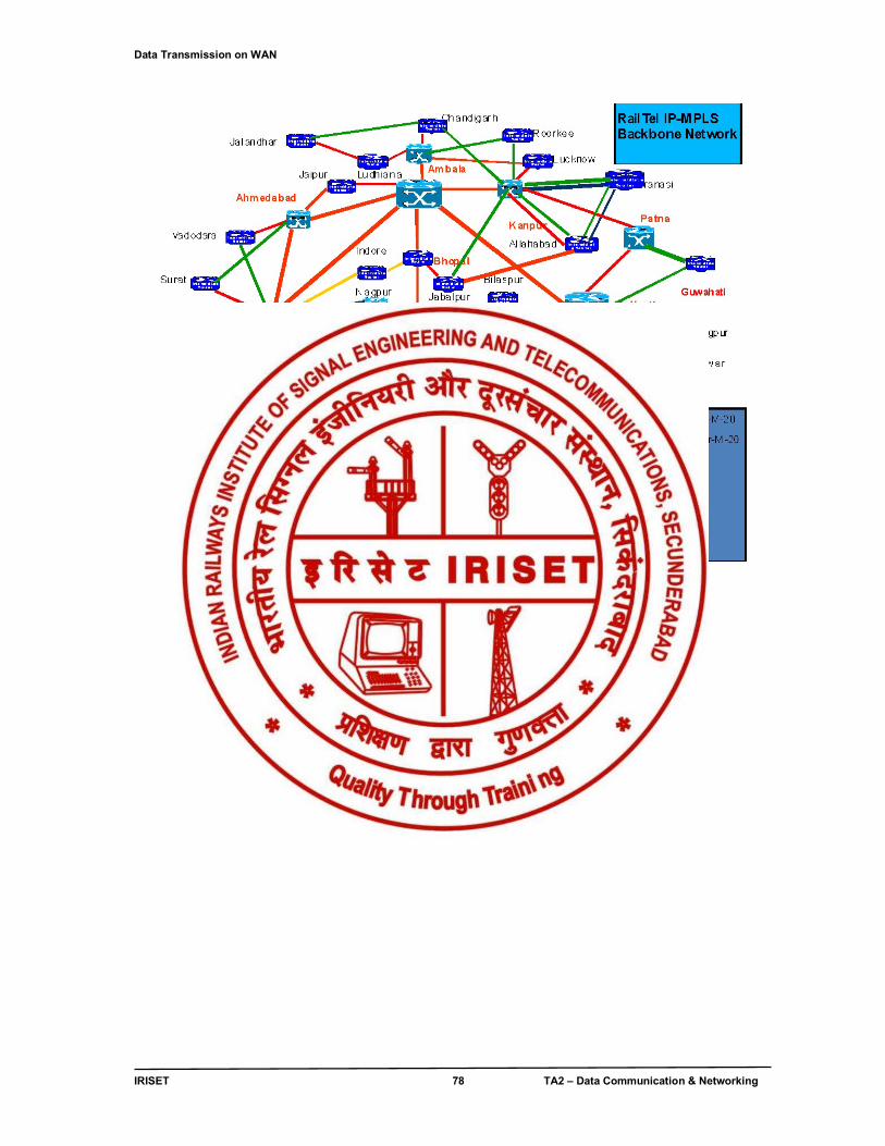
Data Transmission on WAN
IRISET 78 TA2 – Data Communication & Networking
Fig.4.10 RailTel MPLS Network deployment and connectivity
Long Distance Data Transmission
IRISET 79 TA2 – Data Communication & Networking
CHAPTER - 5
LONG DISTANCE DATA TRANSMISSION
5.0 Introduction
In this chapter, topics on Modems, their working and diagnostics features, which are applicable to Railway owned long distance data networks like PRS, FOIS, UTS etc. discussed. The topics on Digital Subscriber Loop (DSL) and extending Networks using LAN extenders and Media Converters for Internet / Railnet connectivity are elaborately covered.
5.1 Modem
A modem is like a telephone set for a computer. Modems let digital devices like computers talk to each other over the ordinary analog telephone system. 5.1.1 Modem working
The conventional Plain Old Telephone System (POTS) is more than 100-years old now. Another common term for POTS is the PSTN (Public Switched Telephone Network). The PSTN was not designed for transmission of digital electronic computer signals, as electronic computers did not exist with the original design of the PSTN. The PSTN was originally designed only to send analog Voice frequency signals; therefore it can only pass low frequency analog signals in the range of 300-to-4000 cycles per second.
Fig. 5.1 Application of modem for Data communication over Analog media
Therefore, modems were invented to use the PSTN to send digital data as shown in fig 5.1 A modem changes, or modulates, digital data into electronic analog signals that the telephone network can carry.
At the other end of the connection, another modem demodulates, or interprets the telephone signals and converts them back to digital computer data signals. The word "modem" is an acronym that comes from combining the words "Modulate" and "Demodulate."
i. Data sent over ordinary telephone lines: Fundamentally, modems send analog data bits sequentially over telephone lines similar to how the telegraph systems sent signals in the form of dots and dashes (Morse Code) to represent information. Morse code is a binary coding system that represents all the letters of the alphabet, punctuation and numerals. Like Morse code used in telegraph systems, modems also use a binary coding system called "ASCII" (American Standard Computer Information Interchange) code. ASCII code is used to represent the alphabet, punctuation and numerals with a unique series of seven ones or zeros in all combinations, which gives the possibility of sending 128 different characters. High-speed modems can send data over the PSTN at rates ranging from 300-to-56,000 bits per second (bps).
DIGITAL
ANALOG DIGITAL
Modem Modem
Long Distance Data Transmission
IRISET 80 TA2 – Data Communication & Networking
ii. Modem speed: Signaling standards determine the modem's speed. Modem speed is measured in bits-per-second (bps). Bps refers to how many bits of data per second a modem can send and receive over the telephone line. 56K for example is 56,000 bits per second. 56K is defined under the ITU V.90 standard. The ITU V.34 standard defines an upper limit data speed of 33,600 bps or 33.6K bps. There are also several other lower speed standards defined by the ITU.
5.2 CLASSIFICATION OF MODEMS
i. Classifying Modems according to Range
a. Short Haul: Short haul modems are cheap solutions to systems of short ranges (up to 15 km), which use private lines and are not part of a public system. Short haul modems can also be used, even if the end-to-end length of the direct connection is longer than 15 km, when both ends of the line are served by the same central office in the telephone system. These lines are called "local loops". Short haul modems are distance-sensitive, because signal attenuation occurs as the signal travels through the line. The transmission rate must be lowered to ensure consistent and error-free transmission on longer distances.
Short haul modems tend to be cheaper than other modems for two reasons:
1. No circuitry is included in them to correct for differences between the carrier frequency of the demodulator and the frequency of the modulator.
2. Generally no circuitry is included to reduce/correct for noise rejection, which is less of a problem over short distances than over long distances.
There are two main types of short haul modems:
Analog modems
Using a simple modulation method, without sophisticated devices for error control or equalizers. These modems usually operate at a maximum rate of 9600 bps, but there are some which supports higher rates (up to 64,000 bps). Line drivers: Increase the digital signal, which transmit to the communication channel and do not transmit the carrier signal, as conventional modems. Line drivers are very cheap and tiny and connect to the RS232 connector of the terminal (since they lack a power supply, they use the signal voltage of the DTE-DCE interface for DC power supply).
b. Voice Grade (VG): Voice-grade modems are used for unlimited destination, using a moderate to high data rate. These modems are expensive and their maintenance and tuning are sophisticated. Communication channels are leased lines and dial-up.
Voice-band telephone network is used for data transmission. A user-to-user connection may be either dedicated or dialed. The links in the connection are the same in the two cases, and the only difference for the user is that for some impairment (particularly attenuation and delay distortion), a dedicated (private or leased) line is guaranteed to meet certain specifications, whereas a dialed connection can only be described statistically.
c. Wideband: Wideband modems are used in large-volume telephone-line multiplexing, dedicated computer-to-computer links. These modems exceed high data rates.
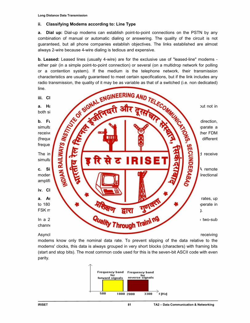
Long Distance Data Transmission
IRISET 81 TA2 – Data Communication & Networking
ii. Classifying Modems according to: Line Type
a. Dial up: Dial-up modems can establish point-to-point connections on the PSTN by any combination of manual or automatic dialing or answering. The quality of the circuit is not guaranteed, but all phone companies establish objectives. The links established are almost always 2-wire because 4-wire dialing is tedious and expensive.
b. Leased: Leased lines (usually 4-wire) are for the exclusive use of "leased-line" modems - either pair (in a simple point-to-point connection) or several (on a multidrop network for polling or a contention system). If the medium is the telephone network, their transmission characteristics are usually guaranteed to meet certain specifications, but if the link includes any radio transmission, the quality of it may be as variable as that of a switched (i.e. non dedicated) line.
iii. Classifying Modems according to: Operation Mode
a. Half Duplex: Half duplex means that signals can be passed in either direction, but not in both simultaneously
b. Full Duplex: Full duplex means that signals can be passed in either direction, simultaneously. Full duplex operation on a two-wire line requires the ability to separate a receive signal from the reflection of the transmitted signal. This is accomplished by either FDM (frequency division multiplexing) in which the signals in the two directions occupy different frequency bands and are separated by filtering, or by Echo Canceling (EC).
The implication of the term full-duplex is usually that the modem can transmit and receive simultaneously at full speed.
c. Simplex: Simplex means that signals can be passed in one direction only. A remote modem for a telemeter system might be simplex and a 2-wire line with a common unidirectional amplifier is Simplex.
iv. Classifying Modems according to: Synchronization
a. Asynchronous Modems: Most of the modems that operate in slow and moderate rates, up to 1800 bps, are asynchronous (using asynchronous data). Asynchronous modems operate in FSK modulation and use two frequencies for transmission and another two for receiving.
In a 2-wire line, full duplex operation can be achieved by splitting the channel into two-sub channels as shown in fig. 5.2.
Asynchronous data is not accompanied by any clock, and the transmitting and receiving modems know only the nominal data rate. To prevent slipping of the data relative to the modems' clocks, this data is always grouped in very short blocks (characters) with framing bits (start and stop bits). The most common code used for this is the seven-bit ASCII code with even parity.
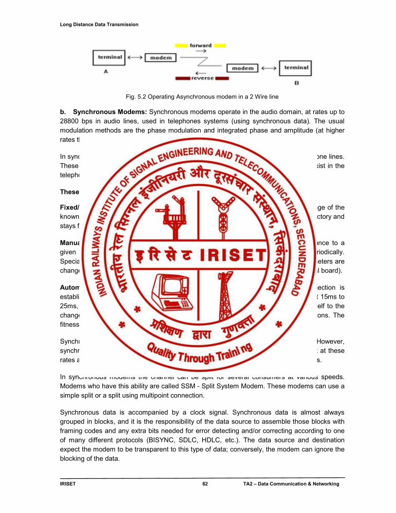
Long Distance Data Transmission
IRISET 82 TA2 – Data Communication & Networking
Fig. 5.2 Operating Asynchronous modem in a 2 Wire line b. Synchronous Modems: Synchronous modems operate in the audio domain, at rates up to 28800 bps in audio lines, used in telephones systems (using synchronous data). The usual modulation methods are the phase modulation and integrated phase and amplitude (at higher rates than 4800 bps). In synchronous modems, equalizers are used, in order to offset the misfit of the telephone lines. These equalizers are inserted in addition to the equalizers that sometimes already exist in the telephone lines.
These equalizers can be classified into three main groups:
Fixed/statistical equalizer - these equalizers offset the signal according to the average of the known attenuation in each frequency. Tuning the equalizer is sometimes done in the factory and stays fixed; usually they are used to operate at low rates in a dial up line.
Manually adjusted equalizer - these equalizers can be tuned to optimal performance to a given line. These equalizers should be re-tuned when the line is replaced and periodically. Specially, it should be tuned frequently when the line is of a low quality and it's parameters are changed frequently. Tuning is done using a button inside the modem (or on the external board).
Automatic equalizer - these equalizers are tuned automatically when the connection is established. Depending on the line quality in a specific moment, in a process of about 15ms to 25ms, after the first tuning, the equalizer samples the line continually and adjusts itself to the changed conditions, so the modem operates at each moment under optimal conditions. The fitness process operates, in some modems, at rates of 2400 times in a second.
Synchronous modems operate in the same manner asynchronous modems. However, synchronous modems operate at higher rates and since the requirements to transmit at these rates are increasing, most of the innovations are implemented for synchronous modems. In synchronous modems the channel can be split for several consumers at various speeds. Modems who have this ability are called SSM - Split System Modem. These modems can use a simple split or a split using multipoint connection. Synchronous data is accompanied by a clock signal. Synchronous data is almost always grouped in blocks, and it is the responsibility of the data source to assemble those blocks with framing codes and any extra bits needed for error detecting and/or correcting according to one of many different protocols (BISYNC, SDLC, HDLC, etc.). The data source and destination expect the modem to be transparent to this type of data; conversely, the modem can ignore the blocking of the data.
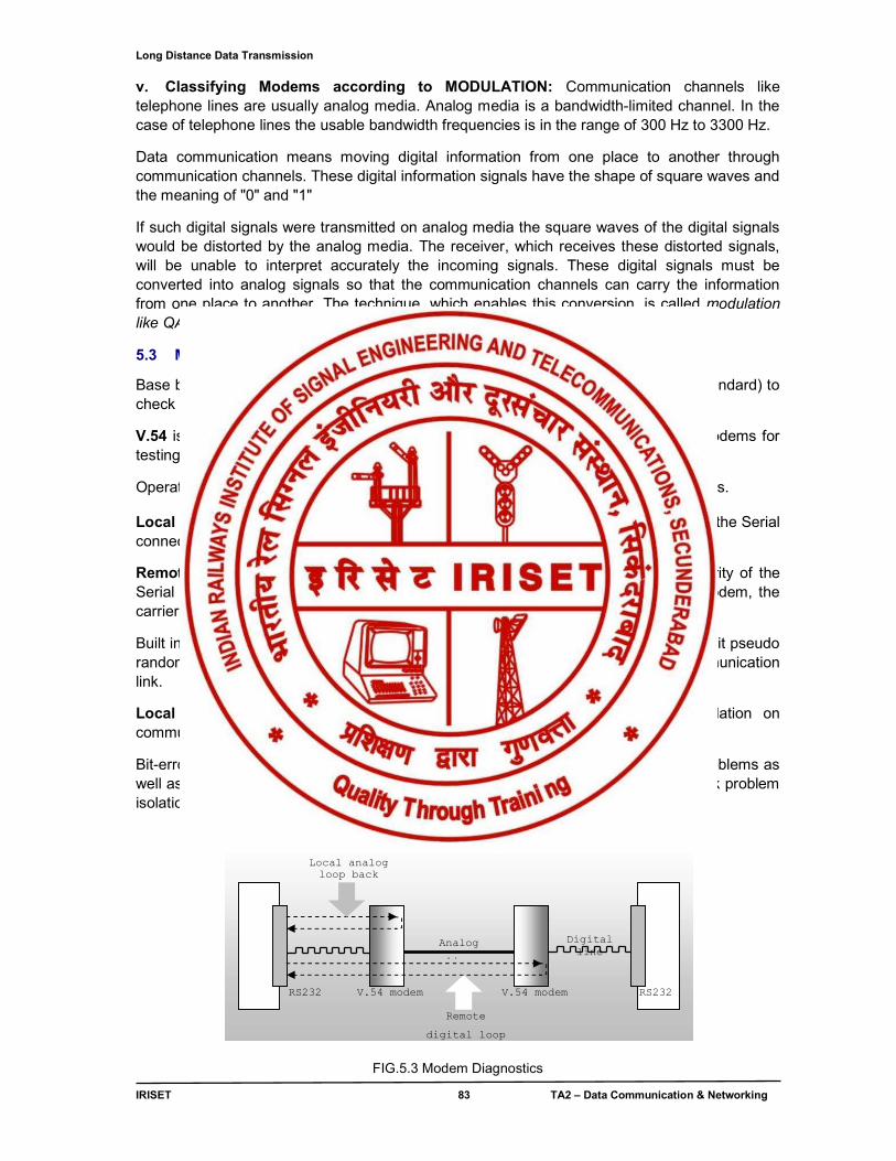
Long Distance Data Transmission
IRISET 83 TA2 – Data Communication & Networking
v. Classifying Modems according to MODULATION: Communication channels like telephone lines are usually analog media. Analog media is a bandwidth-limited channel. In the case of telephone lines the usable bandwidth frequencies is in the range of 300 Hz to 3300 Hz.
Data communication means moving digital information from one place to another through communication channels. These digital information signals have the shape of square waves and the meaning of "0" and "1"
If such digital signals were transmitted on analog media the square waves of the digital signals would be distorted by the analog media. The receiver, which receives these distorted signals, will be unable to interpret accurately the incoming signals. These digital signals must be converted into analog signals so that the communication channels can carry the information from one place to another. The technique, which enables this conversion, is called modulation like QAM, QPSK etc.
5.3 Modem Diagnostics:
Base band modems are provided with inbuilt loop diagnostics (V.54 protocol ITU-T standard) to check the integrity of the leased line connectivity.
V.54 is an ITU standard for various loop back tests that can be incorporated into modems for testing the telephone circuit and isolating transmission problems.
Operating modes includes local & remote loop backs with Digital as well as Analog tests.
Local ANALOG loop: (defined in the V.54 protocol as Loop 3) tests the integrity of the Serial connector chord, the cable connecting the chord to the modem, and the local modem.
Remote DIGITAL loop: (defined in the V.54 protocol as Loop 2) tests the integrity of the Serial connector chord, the cable connecting the chord to the modem, the local modem, the carrier connection, and the remote modem.
Built in BERT, if activated (the modem starts generating and checking standard 511- bit pseudo random pattern) in remote digital loop test mode for quick fault isolation on communication link.
Local DIGITAL loop: To extend digital loop from local modem for fault isolation on communication link on remote side.
Bit-error-rate testing and loopbacks are used by carriers and ISPs to help resolve problems as well as test the quality of T1/E1 links. By early detection of poor quality links and quick problem isolation to improve network's quality of service.
FIG.5.3 Modem Diagnostics
Analog
line
Digital line
V.54 modem V.54 modem RS232 RS232
Local analog loop back
Remote
digital loop
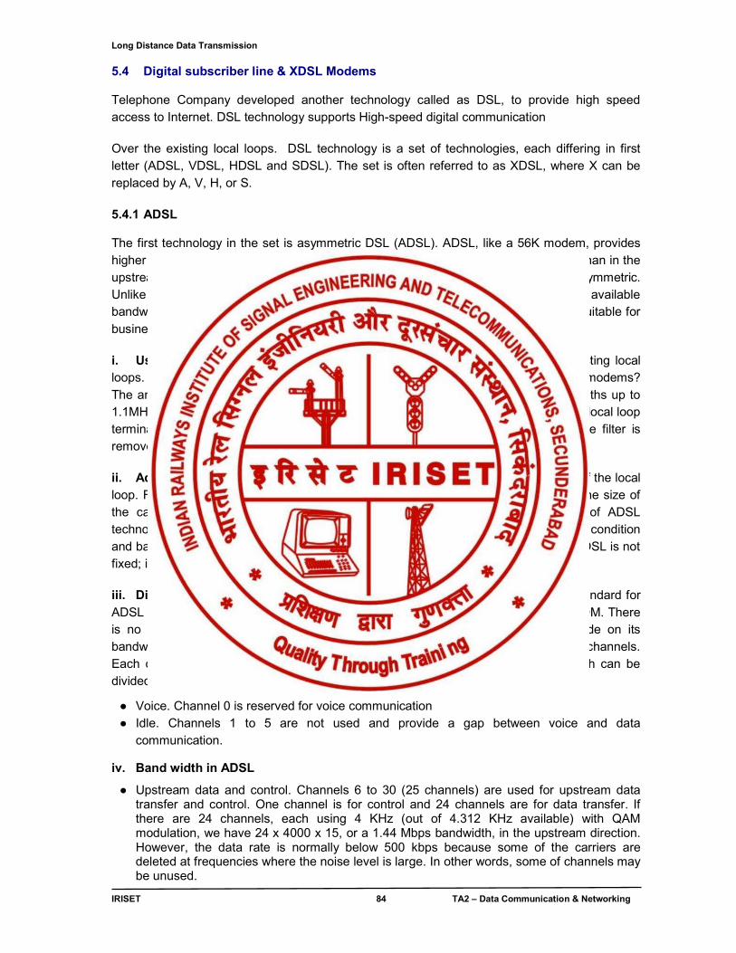
Long Distance Data Transmission
IRISET 84 TA2 – Data Communication & Networking
5.4 Digital subscriber line & XDSL Modems Telephone Company developed another technology called as DSL, to provide high speed access to Internet. DSL technology supports High-speed digital communication
Over the existing local loops. DSL technology is a set of technologies, each differing in first letter (ADSL, VDSL, HDSL and SDSL). The set is often referred to as XDSL, where X can be replaced by A, V, H, or S.
5.4.1 ADSL The first technology in the set is asymmetric DSL (ADSL). ADSL, like a 56K modem, provides higher speed (bit rate) in the downstream direction (from the Internet to the resident) than in the upstream direction (from the resident to the Internet). That is the reason it is called asymmetric. Unlike the asymmetry in 56K modems, the designers of ADSL specifically divided the available bandwidth of the local loop unevenly for the residential customer. The service is not suitable for business customers who need a large bandwidth in both directions. i. Using Existing Local Loops: One interesting point is that ADSL uses the existing local loops. But how does ADSL reach a data rate that was never achieved with traditional modems? The answer is that the twisted-pair local loop is actually capable of handling bandwidths up to 1.1MHz, but the filter installed at the end office of the telephone company where each local loop terminates limits the bandwidth to 4 KHz (sufficient for voice communication). If the filter is removed, however, the entire 1.1MHz is available for data and voice communications.
ii. Adaptive Technology: Unfortunately, 1.1 MHz is just the theoretical bandwidth of the local loop. Factors such as the distance between the residence and the switching office, the size of the cable, the signaling used, and so on affect the bandwidth. The designers of ADSL technology were aware of this problem and used an adaptive technology that tests the condition and bandwidth availability of the line before settling on a data rate. The data rate of ADSL is not fixed; it changes based on the condition and type of the local loop cable.
iii. Discrete Multi tone Technique: The modulation technique that has become standard for ADSL is called the discrete multi tone technique (DMT), which combines QAM and FDM. There is no set way that the bandwidth of a system is divided. Each system can decide on its bandwidth division. Typically, an available bandwidth of 1.104 MHz is divided into 256 channels. Each channel uses a bandwidth of 4.312 KHz, figure 5.3 shows how the bandwidth can be divided into the following:
● Voice. Channel 0 is reserved for voice communication ● Idle. Channels 1 to 5 are not used and provide a gap between voice and data
communication.
iv. Band width in ADSL
● Upstream data and control. Channels 6 to 30 (25 channels) are used for upstream data transfer and control. One channel is for control and 24 channels are for data transfer. If there are 24 channels, each using 4 KHz (out of 4.312 KHz available) with QAM modulation, we have 24 x 4000 x 15, or a 1.44 Mbps bandwidth, in the upstream direction. However, the data rate is normally below 500 kbps because some of the carriers are deleted at frequencies where the noise level is large. In other words, some of channels may be unused.
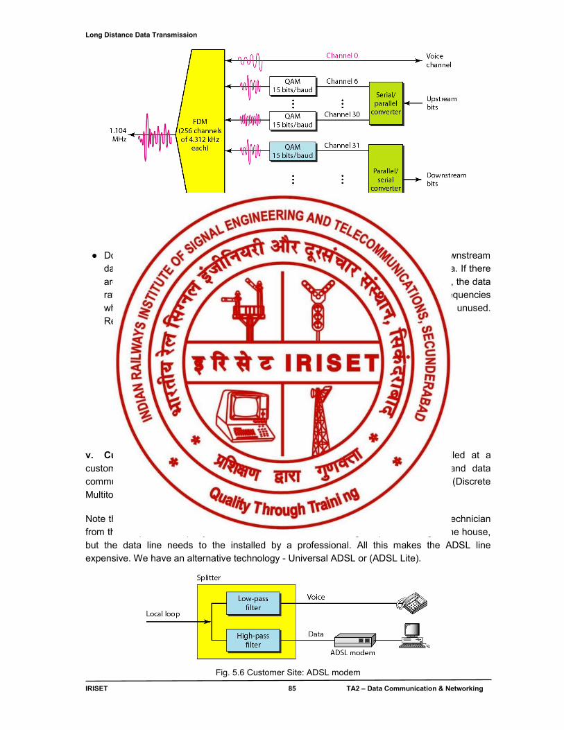
Long Distance Data Transmission
IRISET 85 TA2 – Data Communication & Networking
Fig. 5.4 Discrete Multi tone Technique
● Downstream data and control. Channels 31 to 255 (255 channels) are used for downstream data transfer and control. One channel is for control and 224 channels are for data. If there are 224 channels, we can achieve up to 224 x 4000 x 15, for 13.4 Mbps. However, the data rate is normally below 8 Mbps because some of the carriers are deleted at frequencies where the noise level is large. In other words, some of channels may be unused. Refer Fig. 5.5
Fig. 5.5 Bandwidth division in ADSL
v. Customer Site: ADSL Modem: Figure 5.6 shows an ADSL modem installed at a customer’s site. The local loop connects to a splitter, which separates voice and data communications. The ADSL modem modulates and demodulates the data, using DMT (Discrete Multitone Technique), and creates downstream and upstream channels.
Note that the splitter needs to be installed at the customer’s premises, normally by a technician from the telephone company. The voice line can use the existing telephone wiring in the house, but the data line needs to the installed by a professional. All this makes the ADSL line expensive. We have an alternative technology - Universal ADSL or (ADSL Lite).
Fig. 5.6 Customer Site: ADSL modem
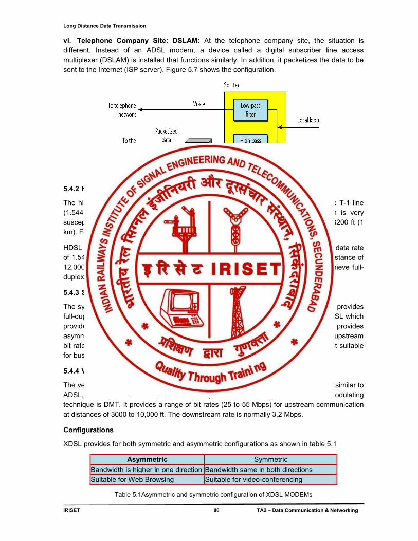
Long Distance Data Transmission
IRISET 86 TA2 – Data Communication & Networking
vi. Telephone Company Site: DSLAM: At the telephone company site, the situation is different. Instead of an ADSL modem, a device called a digital subscriber line access multiplexer (DSLAM) is installed that functions similarly. In addition, it packetizes the data to be sent to the Internet (ISP server). Figure 5.7 shows the configuration.
Fig. 5.7 Telephone Company Site: DSLAM
5.4.2 HDSL
The high-bit-rate digital subscriber line (HDSL) was designed as an alternative to the T-1 line (1.544 Mbps). The T-1 line uses alternate mark inversion (AMI) encoding which is very susceptible to attenuation at high frequencies. This limits the length of a T-1 line to 3200 ft (1 km). For longer distances, a repeater is necessary, which means increased costs.
HDSL uses 2B1Q encoding (see chapter4), which is less susceptible to attenuation. A data rate of 1.544 Mbps (sometimes up to 2 Mbps) can be achieved without repeaters upto a distance of 12,000 ft (3.86km). HDSL uses two twisted pairs (one pair for each direction) to achieve full-duplex transmission.
5.4.3 SDSL
The symmetric digital subscriber line (SDSL) is a one twisted- pair version of HDSL. It provides full-duplex symmetric communication supporting up to 768 kbps in each direction. SDSL which provides symmetric communication can be considered an alternative to ADSL. ADSL provides asymmetric communication, with a downstream bit rate that is much higher than the upstream bit rate. Although this feature meets the needs of most residential subscribers, ti is not suitable for business that sends and receives data in large volumes in both directions.
5.4.4 VDSL
The very high – bit-rate digital subscriber line (VDSL), and alternative approach that is similar to ADSL, uses coaxial, fiber-optic, or twisted-pair cable for short distance. The modulating technique is DMT. It provides a range of bit rates (25 to 55 Mbps) for upstream communication at distances of 3000 to 10,000 ft. The downstream rate is normally 3.2 Mbps.
Configurations
XDSL provides for both symmetric and asymmetric configurations as shown in table 5.1
Asymmetric Symmetric
Bandwidth is higher in one direction Bandwidth same in both directions
Suitable for Web Browsing Suitable for video-conferencing
Table 5.1Asymmetric and symmetric configuration of XDSL MODEMs
Long Distance Data Transmission
IRISET 87 TA2 – Data Communication & Networking
5.4.5 Variations
In XDSL there are currently six (6) variations available p as shown in table 5.2
XDSL Technology
Meaning Rate
DSL Digital Subscriber Line 2 x 64Kbps circuit switched 1 x 16Kbps packet switched (similar to ISDN-BRI)
HDSL High-bit-rate DSL 2.048Mbps over two pairs at a distance up to 4.2Km
S-HDSL/SDSL Single-pair or Symmetric
High-bit-rate DSL 768Kbps over a single pair
ADSL Asymmetric DSL up to 6Mbps in one direction
RADSL Rate Adaptive DSL An extension of ADSL which supports a variety of data rates depending upon the quality of the local loop
VDSL Very High-bit-rate asymmetric DSL
Up to 52Mbps in one direction and 2Mbps in the other direction.
Table 5.2 XDSL variants
5.5 LAN extender: A LAN extender (also network extender or Ethernet extender) is a device used to extend an Ethernet or network segment beyond its inherent distance limitation which is approximately 100 meters (330 ft) for most common forms of twisted pair Ethernet. The extender forwards traffic between LANs transparent to higher network-layer protocols over distances that far exceed the limitations of standard Ethernet. Extenders that use copper wire include 2 and 4 wire variants using unconditioned copper wiring (without load coils), to extend a LANs. Network extenders use various methods (line encodings), such as TC-PAM, 2B1Q or DMT, to transmit information. The LAN extender (Ethernet-Extender) is used in pairs. Different Types of LAN extenders:
● 2BASE-TL — Full-duplex long reach Point-to-Point link over voice-grade copper wiring. 2BASE-TL PHY can deliver a minimum of 2 Mbit/s and a maximum of 5.69 Mbit/s over distances of up to 2700 m (9,000 ft), using ITU-T G.991.2 (G.SHDSL.bis) technology over a single copper pair.
● 10PASS-TS — Full-duplex short reach Point-to-Point link over voice-grade copper wiring. 10PASS-TS PHY can deliver a minimum of 10 Mbit/s over distances of up to 750 m (2460 ft), using ITU-T G.993.1 (VDSL) technology over a single copper pair
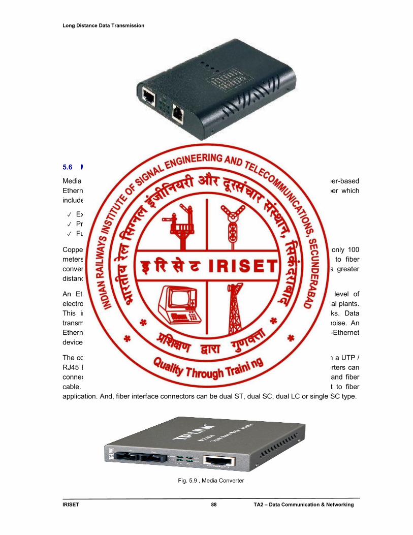
Long Distance Data Transmission
IRISET 88 TA2 – Data Communication & Networking
Fig. 5.8 LAN Extender Unit 5.6 Media Converters:
Media Converters (also Ethernet-Fiber Converters) enable connections of UTP copper-based Ethernet equipment over a fiber optic link to take advantage of the benefits of fiber which include;
✓ Extending links over greater distances using fiber optic cable ✓ Protecting data from noise and interference ✓ Future proofing your network with additional bandwidth capacity
Copper-based Ethernet connections are limited to a data transmission distance of only 100 meters when using unshielded twisted pair (UTP) cable. By using an Ethernet to fiber conversion solution, fiber optic cabling can now be used to extend this link over a greater distance.
An Ethernet to Fiber Media Converter can also be used where there is high level of electromagnetic interference or EMI which is a common phenomenon found in industrial plants. This interference can cause corruption of data over copper-based Ethernet links. Data transmitted over fiber optic cable however is completely immune to this type of noise. An Ethernet to Fiber Optic Converter therefore enables you to inter-connect your copper-Ethernet devices over fiber ensuring optimal data transmission across the plant floor.
The copper transceiver used in an Ethernet-Fiber Converter transforms the signal from a UTP / RJ45 Ethernet link to one that can be used by a fiber optic transceiver. Media converters can connect to various optical fiber cable such as multimode, single mode or single strand fiber cable. Options exist for many distances to suit the needs of a particular Ethernet to fiber application. And, fiber interface connectors can be dual ST, dual SC, dual LC or single SC type.
Fig. 5.9 , Media Converter
Wireless LAN
IRISET 89 TA2 – Data Communication & Networking
CHAPTER - 6
WIRELESS LAN
The following essential topics for the chapter “Wireless LAN” are discussed here.
● Introduction WLAN and Wi-Fi ● IEEE 802.11 Protocol layer ● Transmission Technology
○ Microwave Transmission ○ Spread Spectrum Transmission ○ Infrared Transmission
● WLAN architecture ● IEEE WLAN Application and Standards
○ Types of Wireless LAN ● Wireless LAN security
6.0 Introduction
Wireless local area networks (WLANs) are the same as the traditional LAN but they have a wireless interface. With the introduction of small portable devices such as PDAs (personal digital assistants), the WLAN technology is becoming very popular. WLANs provide high speed data communication in small areas such as a building or an office. It allows users to move around in a confined area while they are still connected to the network.
Wi-Fi (Wireless Fidelity) and Access point
Wi-Fi belongs to wireless local area network (WLAN) devices. Wi-Fi is often used as a synonym for IEEE 802.11 technology & it is also called as IP Radio. A Wi-Fi enabled device such as a personal computer, video game console, mobile phone, MP3 player or personal digital assistant can connect to the Internet when within range of a wireless network connected to the Internet. Access points are specially configured nodes on wireless local area networks (WLANs). Access points act as a central transmitter and receiver of WLAN radio signals. Access points used in home or small business networks are generally small, dedicated hardware devices featuring a built-in network adapter, antenna, and radio transmitter. Access points support Wi-Fi wireless communication standards.
Wireless Application Protocol (WAP)
WAP defines network architecture for content delivery over wireless networks. WAP implements several new networking protocols that perform functions similar to the well-known Web protocols HTTP, TCP and SSL. WAP protocol suite is meant to enable global wireless communication across different wireless technologies e.g. GSM, GPRS, UMTS and 3G. IEEE 802.11 defines the physical layer (PHY) and MAC (Media Access Control) layers based on CSMA/CA (Carrier Sense Multiple Access with Collision Avoidance). This is in contrast to Ethernet which uses CSMA-CD (Carrier Sense Multiple Access with Collision Detection). The 802.11 specification includes provisions designed to minimize collisions, because two mobile units may both be in range of a common access point, but out of range of each other.
Wireless LAN
IRISET 90 TA2 – Data Communication & Networking
6.1 IEEE 802.11 layered protocol architecture
The 802.11 standard defines layered protocol architecture to implement the services as given below.
● Association: Establishes an initial association between a station and an access point. ● Re-association: Enables an established association to be transferred from one access point
to another, allowing a mobile station to move ● Dis-association: A notification from either a station or an access point that an existing
association is terminated ● Authentication: Used to establish the identity of station to each other ● Privacy: used to prevent the content of message from being read by other than the intended
recipient. The standard provides for the optional use of encryption to assure privacy.
Network remains an important issue for WLANs. Authentication is done by the following identifiers.
6.1.1Service set identifier (SSID):
It is a name that identifies a particular 802.11 wireless LAN. A client device receives broadcast messages from all access points within range advertising their SSIDs. The client device can then either manually or automatically—based on configuration—select the network with which to associate. The SSID can be up to 32 characters long. As the SSID displays to users, it normally consists of human-readable characters. However, the standard does not require this. The SSID is defined as a sequence of 1–32 octets each of which may take any value. It is legitimate for multiple access points to share the same SSID if they provide access to the same network as part of an extended service set
6.1.2 Basic service set identifier (BSSID) A related field is the BSSID or Basic Service Set Identifier, which uniquely identifies each BSS (the SSID however, can be used in multiple, possibly overlapping, BSSs). In an infrastructure BSS, the BSSID is the MAC address of the wireless access point (WAP). In an IBSS, the BSSID is a locally administered MAC address generated from a 48-bit random number. The individual/group bit of the address is set to 0. The universal/local bit of the address is set to 1. A BSSID with a value of all 1s is used to indicate the broadcast BSSID. A broadcast BSSID may only be used during probe requests. 6.2 Transmission Technology There are three main ways by which WLANs transmit information: microwave, spread spectrum and infrared. Microwave Transmission: Motorola's WLAN product transmits data by using low powered microwave radio signals. It operates at the 18GHz frequency band. Spread Spectrum Transmission: With this transmission technology, there are two methods used by wireless LAN products : frequency hopping and direct sequence modulation.
Wireless LAN
IRISET 91 TA2 – Data Communication & Networking
● Frequency Hopping: The signal jumps from one frequency to another within a given frequency range. The transmitter device "listens" to a channel, if it detects an idle time (i.e. no signal is transmitted), it transmits the data using the full channel bandwidth. If the channel is full, it "hops" to another channel and repeats the process. The transmitter and the receiver "jump" in the same manner.
● Direct Sequence Modulation: This method uses a wide frequency band together with Code Division Multiple Access (CDMA). Signals from different units are transmitted at a given frequency range. The power levels of these signals are very low (just above background noise). A code is transmitted with each signal so that the receiver can identify the appropriate signal transmitted by the sender unit.
The frequency at which such signals are transmitted is called the ISM (industrial, scientific and medical) band. This frequency band is reserved for ISM devices. The ISM band has three frequency ranges: 902-928, 2400-2483.5 and 5725-5850 MHz.
Infrared Transmission: This method uses infrared light to carry information. There are three types of infrared transmission: diffused, directed and directed point-to-point.
● Diffused: The infrared light transmitted by the sender unit fills the area (e.g. office). Therefore the receiver unit located anywhere in that area can receive the signal.
● Directed: The infrared light is focused before transmitting the signal. This method increases the transmission speed.
● Directed point-to-point: Directed point-to-point infrared transmission provides the highest transmission speed. Here the receiver is aligned with the sender unit. The infrared light is then transmitted directly to the receiver.
6.3 WLAN Architecture
The components of an IEEE 802.11 architecture are WLAN Stations (STA) & Access Point (AP) as building blocks.
● WLAN Stations (STA) - Locate & connect to access points to reach network resources. - Identified by an IEEE 48-bit data link control address
● Access Point (AP) - Connect WLAN stations to the wired or “Distribution” network - Bridges frames to / from WLAN and Distribution network - Identifies by 48-bit data link control address - Range at which stations can communicate with AP is the Basic Service Area
When two or more stations come together to communicate with each other, they form a Basic Service Set (BSS). The minimum BSS consists of two stations. 802.11 LANs use the BSS as the standard building block.
A BSS that stands alone and is not connected to a base is called an Independent Basic Service Set (IBSS) or is referred to as an Ad-Hoc Network. When BSS's are interconnected the network becomes one with infrastructure. 802.11 infrastructure has several elements. Two or more BSS's are interconnected using a Distribution System or DS. This concept of DS increases network coverage. Creating large and complex networks using BSS's and DS's leads us to the next level of hierarchy, the Extended Service Set or ESS. Service sets are discussed below.
Wireless LAN
IRISET 92 TA2 – Data Communication & Networking
6.3.1 Independent Basic Services Set (IBSS) / Ad hoc network A single BSS can be used to form an ad hoc network, with 802.11 it is possible to create an ad-hoc network of client devices without a controlling Access Point as shown in fig 6.1 below called an Independent Basic Service Set (IBSS), in such case the SSID is chosen by the client device that starts the network, and broadcasting of the SSID is performed in a pseudo-random order by all devices that are members of the network. An ad-hoc network typically temporary in nature. They can be formed spontaneously anywhere and be dis-band after a limited period of time.An IBSS is a set of STAs configured in ad hoc (peer-to-peer)mode.
6.3.2 Basic Service Set (BSS): It is the basic building block of the IEEE 802.11 architecture. A BSS is defined as a group of stations that co-ordinate their access to the medium under a given instance of the medium access control as shown in fig 6.1 below. The geographical area covered by the BSS is known as the basic service area (BSA). A BSA may extend over an area with the diameter of tens of meters. Conceptually all the stations in a BSS can communicate directly with all other stations in a BSS.
Fig. 6.1 Typical IBSS & BSS setup It consists of BSS Master & BSS Client
i. BSS Master ● Access point connected to a wired LAN ● 802.11 functionality provided by the access point ● Acts as a gateway between the wireless clients and the wired network ● Clients on the WLAN communicate with one another through the access point ● BSS is identified by the Service Set Identity (SSID)
- Alphanumeric, 2-32 characters, case sensitive
- SSID appears in beacons, probe requests and probe responses. ii. BSS Clients
● Wireless stations ● Use the same SSID to connect to the BSS
Wireless LAN
IRISET 93 TA2 – Data Communication & Networking
6.3.3 Extended service set: An Extended Service Set is a set of one or more interconnected BSSs and integrated local area networks (LANs) as shown in fig 6.2 below that appear as a single BSS to the logical link control layer at any station associated with one of those BSSs.The set of interconnected BSSs must have a common service set identifier (SSID). They can work on the same channel, or work on
different channels to boost aggregate throughput. This is also termed as Bridging mode. The beauty of the ESS is the entire network looks like an independent basic service set to the Logical Link Control layer (LLC). This means that stations within the ESS can communicate or even move between BSS′s transparently to the LLC.
Fig. 6.2 Typical ESS setup
Distribution system: A distribution system (DS) connects access points in an extended service set. The concept of a DS can be used to increase network coverage through roaming between cells. DS can be wired or wireless. Current wireless distribution systems are mostly based on WDS or MESH protocols, though other systems are in use.
6.4 WLAN Applications and Standards Wireless LANs have a great deal of applications. Modern implementations of WLANs range from small in-home networks to large, campus-sized ones to completely mobile networks on airplanes and trains. Users can access the Internet from WLAN hotspots in restaurants, hotels, and now with portable devices that connect to 3G or 4G networks. Often these types of public access points require no registration or password to join the network. Others can be accessed once registration has occurred and/or a fee is paid.Existing Wireless LAN infrastructures can also be used to work as indoor positioning systems with no modification to the existing hardware. 6.4.1 WLAN standards The IEEE Wireless LAN standards and their frequencies, bandwidths & performance are shown in table 6.1.
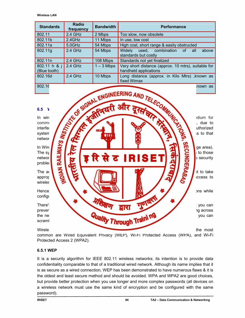
Wireless LAN
IRISET 94 TA2 – Data Communication & Networking
Standards Radio
frequency Bandwidth Performance
802.11 2.4 GHz 2 Mbps Too slow, now obsolete 802.11b 2.4GHz 11 Mbps In use, low cost 802.11a 5.0GHz 54 Mbps High cost, short range & easily obstructed 802.11g 2.4 GHz 54 Mbps Widely used, combination of all above
standards but costly 802.11n 2.4 GHz 108 Mbps Standards not yet finalized 802.11 h & j (Blue tooth)
2.4 GHz 1 – 3 Mbps Very short distance (approx. 10 mtrs), suitable for handheld applications
802.16d 2.4 GHz 10 Mbps Long distance (approx. in Kilo Mtrs) ,known as fixed Wimax
802.16e 2.4 GHz 10 Mbps Long distance (approx. in Kilo Mtrs), known as mobile Wimax
Table 6.1 IEEE wireless LAN standards
6.5 Wireless LAN (WLANs) Security:
In wireless LANs security is a big concern because it uses a more open medium for communication in comparison to wired LANs, wireless networks are less stable, due to interference from other wire-less devices & networks. Whereas in wired LANs only authorized systems are connected by extending a dedicated physical cable to gain the access to that network.
In Wireless networks, Access Points (APs) create the hot spot areas (wireless coverage area). The systems with appropriate wireless adopters of that hot spot area can gain access to those network services, since there is no need of physical connection. This is a very serious security problem in wireless network.
The administrator as well as the users of wireless networks to be very strict vigilant to take appropriate precautions to prevent this serious problem of gaining unauthorized access to wireless networks. Otherwise their data security is under serious threat.
Hence, the administrator as well users have to take the advance security precautions while configuring their wireless networks.
There's no way to selectively hide the presence of your network from strangers, but you can prevent unauthorized people from connecting to it, and you can protect the data traveling across the network from prying eyes. By turning on a wireless network's encryption feature, you can scramble the data and control access to the network.
Wireless network hardware supports several standard encryption schemes, but the most common are Wired Equivalent Privacy (WEP), Wi-Fi Protected Access (WPA), and Wi-Fi Protected Access 2 (WPA2).
6.5.1 WEP
It is a security algorithm for IEEE 802.11 wireless networks; its intention is to provide data confidentiality comparable to that of a traditional wired network. Although its name implies that it is as secure as a wired connection, WEP has been demonstrated to have numerous flaws & it is the oldest and least secure method and should be avoided. WPA and WPA2 are good choices, but provide better protection when you use longer and more complex passwords (all devices on a wireless network must use the same kind of encryption and be configured with the same password).
Wireless LAN
IRISET 95 TA2 – Data Communication & Networking
Wi-Fi Protected Access (WPA) and Wi-Fi Protected Access II (WPA2) are two security protocols and security certification programs developed by the Wi-Fi Alliance to secure wireless computer networks.
6.5.2 WPA
The WPA protocol implements much of the IEEE 802.11i standard. Specifically, the Temporal Key Integrity Protocol (TKIP) was adopted for WPA. WEP used a 40-bit or 104-bit encryption key that must be manually entered on wireless access points and devices and does not change. TKIP employs a per-packet key, meaning that it dynamically generates a new 128-bit key for each packet and thus prevents the types of attacks that compromised WEP.
WPA also includes a message integrity check. This is designed to prevent an attacker from capturing, altering and/or resending data packets. This replaces the cyclic redundancy check (CRC) that was used by the WEP standard. CRC's main flaw was that it did not provide a sufficiently strong data integrity guarantee for the packets it handled.
WPA uses a message integrity check algorithm called Michael to verify the integrity of the packets. Michael is much stronger than a CRC, but not as strong as the algorithm used in WPA2. Researchers have since discovered a flaw in WPA that relied on older weaknesses in WEP and the limitations of Michael to retrieve the key stream from short packets to use for re-injection and spoofing.
6.5.3 WPA2:
WPA2 has replaced WPA. WPA2, which requires testing and certification by the Wi-Fi Alliance, implements the mandatory elements of IEEE 802.11i. In particular, it introduces CCMP, a new AES-based encryption mode with strong security.
Unless you intend to provide public access to your wireless network — and put your business data or your own personal data at risk — you should consider encryption mandatory.
6.6 Securing Access Points (APs):
6.6.1 Administrator prospective:
A wireless (Wi-Fi) administrator has to configure, the following on access points (APs).
❖ SSID (Service Set Identifier): APs broadcast their SSIDs to advertise themselves to the wireless clients and the client can see a list of all available APs and decide which one to join. Disabling SSID broadcasting makes APs harder to identify (invisible mode). This measure is the first and the easiest step toward securing a wireless network.
❖ Default IP, Username and Password of AP: APs come with default IP numbers like 192.168.0.1 or 192.168.1.1, default username like admin or user and default password like admin or user & sometimes without any password. Change the default IP and password with longest possible password with combination of lower case, upper case, numerical and special character and change it every month or so.
❖ DHCP service: In APs by default DHCP service will be enabled, with this any unauthorized user coming in the vicinity of AP will get a valid IP address and can access the services. To prevent unauthorized access it is advised to disable DHCP service.
Wireless LAN
IRISET 96 TA2 – Data Communication & Networking
❖ MAC Filtering: MAC is the unique hardware address of 48 bit usually embedded on the NIC. This address is used by the systems to communicate each other with in that network. Collect the list of MAC addresses of all authorized wireless systems and configuring the MAC filtering (white table) thereby prevent unauthorized access.
❖ Encryption Protocols (WEP, WPA): For more advance security encryption protocols like wired equivalent protocol (WEP) & Wi-Fi protected access (WPA) protocols are configured. These protocols exchange the data in the encrypted form and there by prevent unauthorized access.
❖ Firewall: Enabling firewall feature built in APs prevents hackers on the Internet from getting access to local services
6.6.2 User prospective:
A wireless (Wi-Fi) user while using the services, the following security measures are to be taken for data security.
❖ Public hotspots generally don't use any encryption protocols or any other security measures; hence users are not advised to make important data transactions.
❖ Make sure it's a legitimate hotspot otherwise, user may be trapped by the fake public hotspots like (SSID) “airport", can capture users' log-on information and other valuable data.
❖ Verify PC's software firewall is turned on, and that Windows' file-sharing feature is off.
❖ While using wireless networks it is better not to do important bank transactions, credit card transactions, confidential e-mail access or any other sensitive data transactions unless you're sure you're on a secured network.
❖ Always turn off Wi-Fi service on your system when not in use, otherwise Hackers can use it to create peer-to-peer Wi-Fi connections.
6.7 Wi-MAX (Worldwide Interoperability for Microwave Access):
Wi-MAX is a telecommunications technology that provides wireless transmission of data, designed for long-range networking (spanning miles or kilometers) as opposed to local area wireless networks, using a variety of transmission modes, from point-to-multipoint links to portable and fully mobile internet access as shown in fig 6.3 The technology provides up to 10 Mbps broadband speed without the need for cables. The technology is based on the IEEE 802.16 standard (also called Broadband Wireless Access).
The name "WiMAX" was created by the WiMAX Forum, which was formed in June 2001 to promote conformity and interoperability of the standard. The forum describes WiMAX as "a standards-based technology enabling the delivery of last mile wireless broadband access as an alternative to cable and DSL". Wi-Max Standards & applications
802.16-2004 is also known as 802.16d, which refers to the working party that has developed that standard. It is sometimes referred to as "fixed WiMAX," since it has no support for mobility.
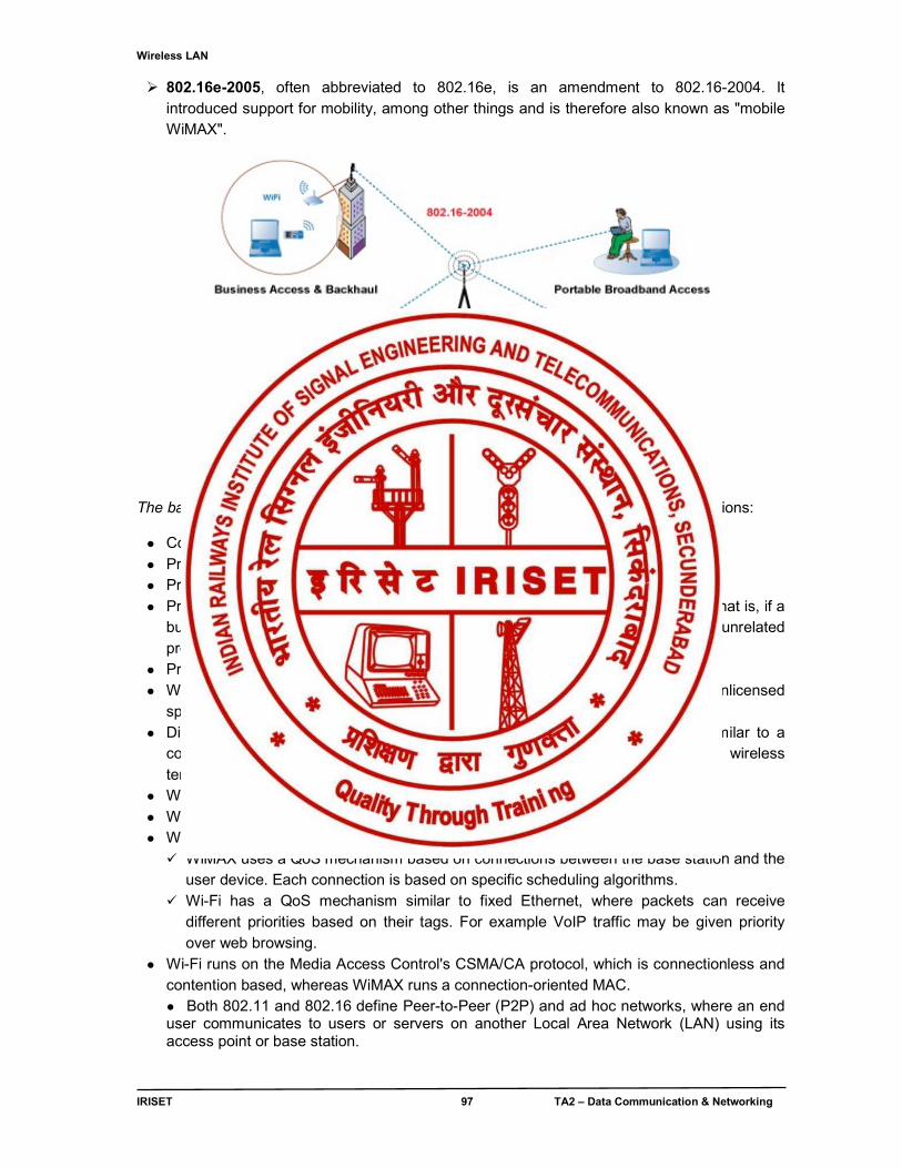
Wireless LAN
IRISET 97 TA2 – Data Communication & Networking
802.16e-2005, often abbreviated to 802.16e, is an amendment to 802.16-2004. It introduced support for mobility, among other things and is therefore also known as "mobile WiMAX".
Fig. 6.3 Typical Wi-Max setup
The bandwidth and range of WiMAX make it suitable for the following potential applications:
● Connecting Wi-Fi hotspots to the Internet. ● Providing a wireless alternative to cable and DSL for "last mile" broadband access. ● Providing data, telecommunications and IPTV services. ● Providing a source of Internet connectivity as part of a business continuity plan. That is, if a
business has both a fixed and a wireless Internet connection, especially from unrelated providers, they are unlikely to be affected by the same service outage.
● Providing portable connectivity. ● WiMAX is a long range system, covering many kilometers that uses licensed or unlicensed
spectrum to deliver a point-to-point connection to the Internet. ● Different 802.16 standards provide different types of access, from portable (similar to a
cordless phone) to fixed (an alternative to wired access, where the end user's wireless termination point is fixed in location.)
● Wi-Fi uses unlicensed spectrum to provide access to a network. ● Wi-Fi is more popular in end user devices. ● WiMAX and Wi-Fi have quite different quality of service (QoS) mechanisms: WiMAX uses a QoS mechanism based on connections between the base station and the
user device. Each connection is based on specific scheduling algorithms. Wi-Fi has a QoS mechanism similar to fixed Ethernet, where packets can receive
different priorities based on their tags. For example VoIP traffic may be given priority over web browsing.
● Wi-Fi runs on the Media Access Control's CSMA/CA protocol, which is connectionless and contention based, whereas WiMAX runs a connection-oriented MAC. ● Both 802.11 and 802.16 define Peer-to-Peer (P2P) and ad hoc networks, where an end user communicates to users or servers on another Local Area Network (LAN) using its access point or base station.
IPv6 Address
IRISET 98 TA2 – Data Communication & Networking
CHAPTER - 7
IPv6 ADDRESS
7.0 Introduction
Internet Protocol Version 6 (IPv6) is the latest revision of the Internet Protocol (IP), the communications protocol that routes traffic across the Internet. It is intended to replace IPv4, which still carries the vast majority of Internet traffic. IPv6 was developed by the Internet Engineering Task Force (IETF) to deal with the long-anticipated problem of IPv4 address exhaustion. Every device on the Internet must be assigned an IP address for identification and location addressing in order to communicate with other devices. With the ever-increasing number of new devices like mobile phones, smart phones, home & industrial appliances, integrated telephony, sensor networks, distributed computing, gaming and on line business etc. are being driven by the internet increasingly. The network security and QoS making transition from IPv4 to IPv6 inevitable. 7.1 IPv6 Format IPv6 uses a 128-bit address, allowing for approximately 340 trillion addresses in contrast to the IPv4 (32-bit address) which is limited to approximately 4.3 billion addresses. IPv6 will eliminate the need for Network Address Translation (NAT); the IP security protocol suite (IPSec) has been built into the IPv6 architecture thereby making way for an intrinsic security mechanism with IPv6 implementation. An IPv6 address is represented by 8 groups of 16-bit values, each group represented as 4 hexadecimal digits and separated by colons (:) called as Hex-colon notation.
e.g.: 2001:0db8:0000:0000:0000:ff00:0042:8329 An IPv6 address may be abbreviated by using one or more of the following rules:
Remove one or more leading zeroes from one or more groups of hexadecimal digits; this is usually done to either all or none of the leading zeroes. (For example, convert the group 0042 to 42)
Omit one or more consecutive sections of zeroes, using a double colon (::) to denote the omitted sections. The double colon may only be used once in any given address, as the address would be indeterminate if the double colon was used multiple times. (For example, 2001:db8::1:2 is valid, but 2001:db8::1::2 is not permitted.)
Below is an example of these rules:
Initial address: 2001:0db8:0000:0000:0000:ff00:0042:8329 After removing all leading zeroes: 2001:db8:0:0:0:ff00:42:8329 After doing both: 2001:db8::ff00:42:8329
Another example is the loopback address, which can be abbreviated to:: 1 by using both rules above
IPv6 Address
IRISET 99 TA2 – Data Communication & Networking
Initial address: 0000:0000:0000:0000:0000:0000:0000:0001 After removing all leading zeroes: 0:0:0:0:0:0:0:1 After doing both::1
Dotted-quad notation
During the transition of the Internet from IPv4 to the IPv6 it is typical to operate in a mixed addressing environment, and for this purpose a special notation has been introduced to express IPv4-compatible IPv6 addresses by writing the final 32 bits of an address in the familiar IPv4 dotted-quad notation. For example, the IPv4-mapped IPv6 address:: ffff:c000:0280 is usually written as ::ffff:192.0.2.128, thus expressing clearly the original IPv4 address that was mapped to IPv6.
2000::/3 The current IPv6 address space for unicast allocations is 1/8 of the total address space
IANA Allocation to Registries (Varies) IANA makes assignments to regional registries. New allocations are /12 bits previous assignments are varied. For example: 2e01:0000::/16 was assigned by IANA to RIPE NCC(the European and Middle Ease registry) in December 2005
“ISP Allocations” Regional registries make assignments to local ISPs. A typical assignment is /32 bits, but more space may be assigned. For example: RIPE NCC assigned 2e01:c000::/19 to France Telecom in December 2005
“End-Site Allocations” ISPs make assignments to their customer. The amount of address space varies, but a /48 allocation is common. Organizations can get their assignments, based on need (Command information has a /32 allocation) smaller organizations may get less space (for small companies a /56 is common).
“Subnet assignments” Organizations make assignments to individual subnets, where the most common size is /64. With 16 bits subnetting bits available, an organization can deploy as many as 65536 subnets.
“Interface ID” Interfaces must have a unique identity on the subnet – often created by embedding the underlying 48-bit (L2) MAC address. Theoretically then, a single subnet could support 264 active hosts – clearly far beyond the practical limt.
Global IPv6 address format
1
2
3
4
5
6
IPv6 Address
IRISET 100 TA2 – Data Communication & Networking
7.2. IPv6 Address classification:
IPv6 addresses are classified as unicast addressing, anycast addressing, and multicast addressing.
A unicast address identifies a single network interface. The Internet Protocol delivers packets sent to a unicast address to that specific interface.
An anycast address is assigned to a group of interfaces, usually belonging to different nodes. A packet sent to an anycast address is delivered to just one of the member interfaces, typically the nearest host, according to the routing protocol’s definition of distance. Anycast addresses cannot be identified easily, they have the same format as unicast addresses, and differ only by their presence in the network at multiple points. Almost any unicast address can be employed as an anycast address.
A multicast address is also used by multiple hosts, which acquire the multicast address destination by participating in the multicast distribution protocol among the network routers. A packet that is sent to a multicast address is delivered to all interfaces that have joined the corresponding multicast group.
IPv6 does not implement broadcast addressing. Broadcast's traditional role is subsumed by multicast addressing to the all-nodes link-local multicast group ff02::1. However, the use of the all-nodes group is not recommended, and most IPv6 protocols use a dedicated link-local multicast group to avoid disturbing every interface in the network.
7.3 IPv6 Address types and their formats
Unicast and anycast addresses are typically composed of two logical parts: a 64-bit network prefix used for routing, and a 64-bit interface identifier used to identify a host Network interface.
General unicast address format (routing prefix size varies)
bits 48 (or more) 16 (or fewer) 64 field routing prefix subnet id interface identifier
The network prefix (the routing prefix combined with the subnet id) is contained in the most significant 64 bits of the address. The size of the routing prefix may vary; a larger prefix size means a smaller subnet id size. The bits of the subnet identifier field are available to the network administrator to define subnets within the given network.
Different ways of assigning IPv6 address to the system:
1. Static Method: address is assigned manually 2. Auto configuration :The system will find out the router using NDP protocol and using
this it will automatically assigns the IPv6 address. 3. EUI-64 (Extended Unique Identifier) Method
Here we provide only network part of IPv6 address and the host part will be automatically assigned from the MAC address of the system. Conversion of 48 bits MAC address to 64 bit EUI-64 format is done in the following steps as shown in the example with the following MAC address.
A0-1D-48-C1-76-14
1. First 24 bits of MAC address is called as OUI (Organizational Unique Identifier and the Second 24 bits of MAC address is called as Unique ID.
IPv6 Address
IRISET 101 TA2 – Data Communication & Networking
2. 7th bit value of OUI should be made as opposite i.e. 0 to 1 and vice versa, taking the above example the seventh bit of A0 (10100000) will become A2 (10100010).
3. FF-FE are inserted between OUI and Unique ID 4. 48 bit MAC is now converted to EUI-64 format as
A2-1D-48-FF-FE-C1-76-14
7.4 IPv6 Networks:
An IPv6 network uses an address block that is a contiguous group of IPv6 addresses of a size that is a power of two. The leading set of bits of the addresses is identical for all hosts in a given network, and is called the network's address or routing prefix.
Network address ranges are written in CIDR notation. A network is denoted by the first address in the block (ending in all zeroes), a slash (/), and a decimal value equal to the size in bits of the prefix. For example, the network written as 2001:db8:1234::/48 starts at address 2001:db8:1234:0000:0000:0000:0000:0000 and ends at 2001:db8:1234:ffff:ffff:ffff:ffff:ffff.
The routing prefix of an interface address may be directly indicated with the address by CIDR notation. For example, the configuration of an interface with address 2001:db8:a::123 connected to subnet 2001:db8:a::/64 is written as 2001:db8:a::123/64.
7.4.1 IPv6 address space:
The management of IPv6 address allocation process is delegated to the Internet Assigned Numbers Authority (IANA) by the Internet Architecture Board and the Internet Engineering Steering Group. Its main function is the assignment of large address blocks to the regional Internet registries (RIRs), which have the delegated task of allocation to network service providers and other local registries. The IANA has maintained the official list of allocations of the IPv6 address space since December 1995.
Only one eighth of the total address space is currently allocated for use on the Internet, 2000::/3, in order to provide efficient route aggregation, thereby reducing the size of the Internet routing tables; the rest of the IPv6 address space is reserved for future use or for special purposes. The address space is assigned to the RIRs in large blocks of /23 up to /12.
The RIRs assign smaller blocks to local Internet registries that distributes them to users. These are typically in sizes from /19 to /32. The addresses are typically distributed in /48 to /56 sized blocks to the end users.
Each RIR can divide each of its multiple /23 blocks into 512 /32 blocks, typically one for each ISP; an ISP can divide its /32 block into 65536 /48 blocks, typically one for each customer; customers can create 65536 /64 networks from their assigned /48 block, each having 264 addresses. In contrast, the entire IPv4 address space has only 232 (about 4.3×10⁹) addresses. By design, only a very small fraction of the address space will actually be used. The large address space ensures that addresses are almost always available, which makes the use of network address translation (NAT) for the purposes of address conservation completely unnecessary.
IPv6 Address
IRISET 102 TA2 – Data Communication & Networking
Special allocation: To allow for provider changes without renumbering, provider-independent address space – assigned directly to the end user by the RIRs – is taken from the special range 2001:678::/29. Internet Exchange Points (IXPs) are assigned special addresses from the range 2001:7f8::/29 for communication with their connected ISPs. Root name servers have been assigned addresses from the same range. Reserved anycast addresses: The lowest address within each subnet prefix (the interface identifier set to all zeroes) is reserved as the "subnet-router" anycast address. Applications may use this address when talking to any one of the available routers, as packets sent to this address are delivered to just one router.
The 128 highest addresses within each /64 subnet prefix are reserved to be used as anycast addresses. These addresses usually have the 57 first bits of the interface identifier set to 1, followed by the 7-bit anycast ID. Prefixes for the network, including subnets, are required to have a length of 64 bits, in which case the universal/local bit must be set to 0 to indicate the address is not globally unique. The address with value 0x7e in the 7 least-significant bits is defined as a mobile IPv6 home agents anycast address. The address with value 0x7f (all bits 1) is reserved and may not be used. No more assignments from this range are made, so values 0x00 through 0x7d are reserved as well.
7.4.2 Special addresses:
There are a number of addresses with special meaning in IPv6:
Unique local addresses: (FC00::/7) Unique local addresses (ULAs) are intended for local communication. They are routable only within a set of cooperating sites (analogous to the private address ranges 10.0.0.0/8, 172.16.0.0/12, and 192.168.0.0/16 of IPv4).
Global Unicast addresses: (2000::/3) Global Unicast addresses are intended for use over the global network like Internet. They are routable over the Internet (analogous to the public IP addresses in IPv4)
Link local addresses: (FE80::/10) Link local addresses (LLAs) is required on every IPv6-enabled interface—in other words, applications may rely on the existence of a link-local address even when there is no IPv6 routing. These addresses are comparable to the auto-configuration addresses (analogous to the automatic private IP address (APIPA) ranges 169.254.0.0 / 16 of IPv4).
Multicast addresses: (FF00:: /8) Multicast addresses are intended for multicast services like video conference applications, real-time applications and also used by routing protocols for route determination etc.(analogous to the Class ‘D’ (224.0.0.0 to 239.255.255.255 of IPv4).
Loop back addresses: (::1/128) The loopback address is a unicast local host address. If an application in a host sends packets to this address, the IPv6 stack will loop these packets back on the same virtual interface (analogous to the universal loop back address 127.0.0.0/8 in IPv4).
Default route : (::/0) The default unicast route address is required for routing towards a stub network like Internet (analogous to 0.0.0.0/0 in IPv4).
The loopback address is a unicast local host address. If an application in a host sends packets to this address, the IPv6 stack will loop these packets back on the same virtual interface (analogous to the universal loop back address 127.0.0.0/8 in IPv4).
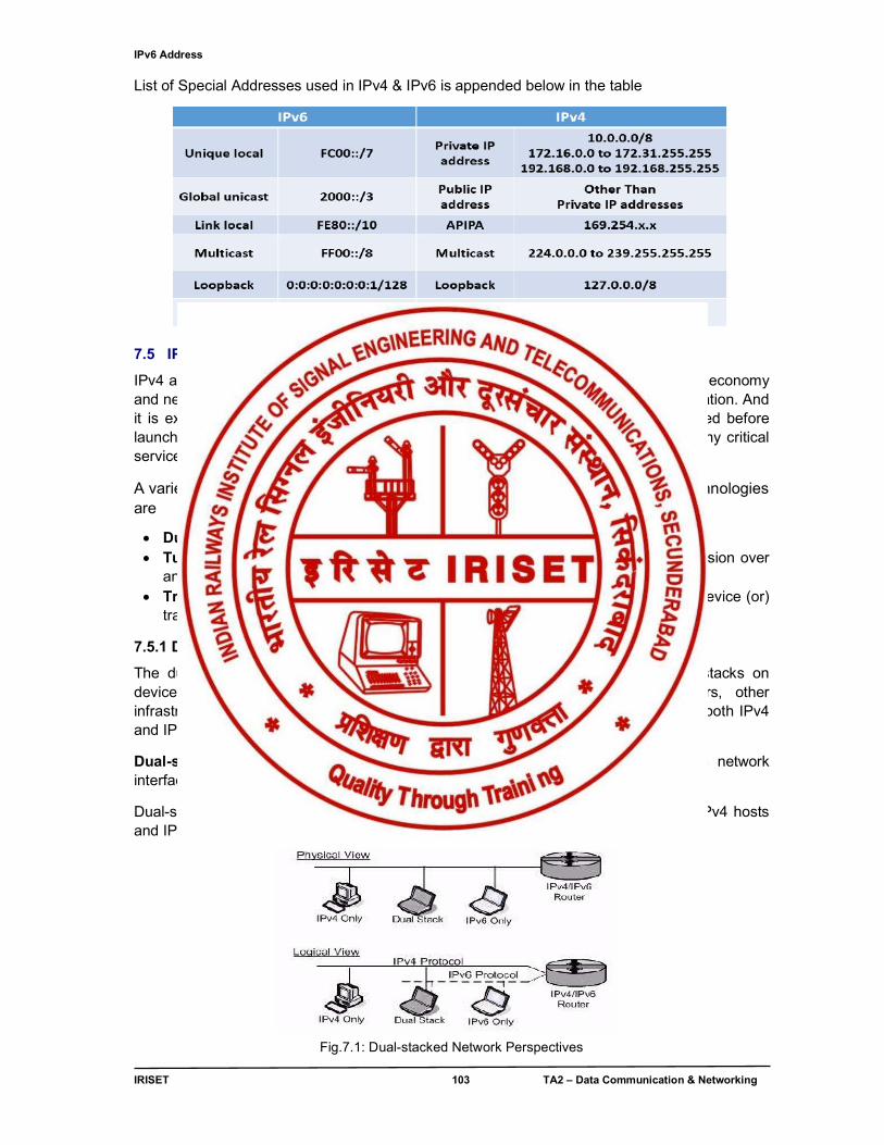
IPv6 Address
IRISET 103 TA2 – Data Communication & Networking
List of Special Addresses used in IPv4 & IPv6 is appended below in the table
7.5 IPv6 Migration:
IPv4 and IPv6 will continue to coexist, for some years, the true potential of the digital economy and next-generation services can only be realized once operators plan their IPv6 migration. And it is extremely important that all software and hardware aspects are clearly evaluated before launching a migration, as any gaps can have direct impact on the availability of many critical services.
A variety of technologies are available to facilitate the migration to IPv6. These technologies are
Dual stack – support of both IPv4 and IPv6 on network devices Tunneling – encapsulation of an IPv6 packet within an IPv4 packet for transmission over
an IPv4 network Translation – address (or) port translation of addresses such as via a gateway device (or)
translation code in the TCP/IP code of the host (or) router
7.5.1 Dual-Stack Approach:
The dual-stack approach consists of implementing both IPv4 and IPv6 protocol stacks on devices requiring access to both network-layer technologies, including routers, other infrastructure devices and end-user devices. Such devices would be configured with both IPv4 and IPv6 addresses as shown in fig .7.1
Dual-stack deployment: Deployment of dual-stacked devices sharing a common network interface implies the operation of both IPv4 and IPv6 over the same physical link.
Dual-stacked routers support IPv4 and IPv6 and route IPv4 packets among native IPv4 hosts and IPv6 packets among IPv6-capable hosts.
Fig.7.1: Dual-stacked Network Perspectives
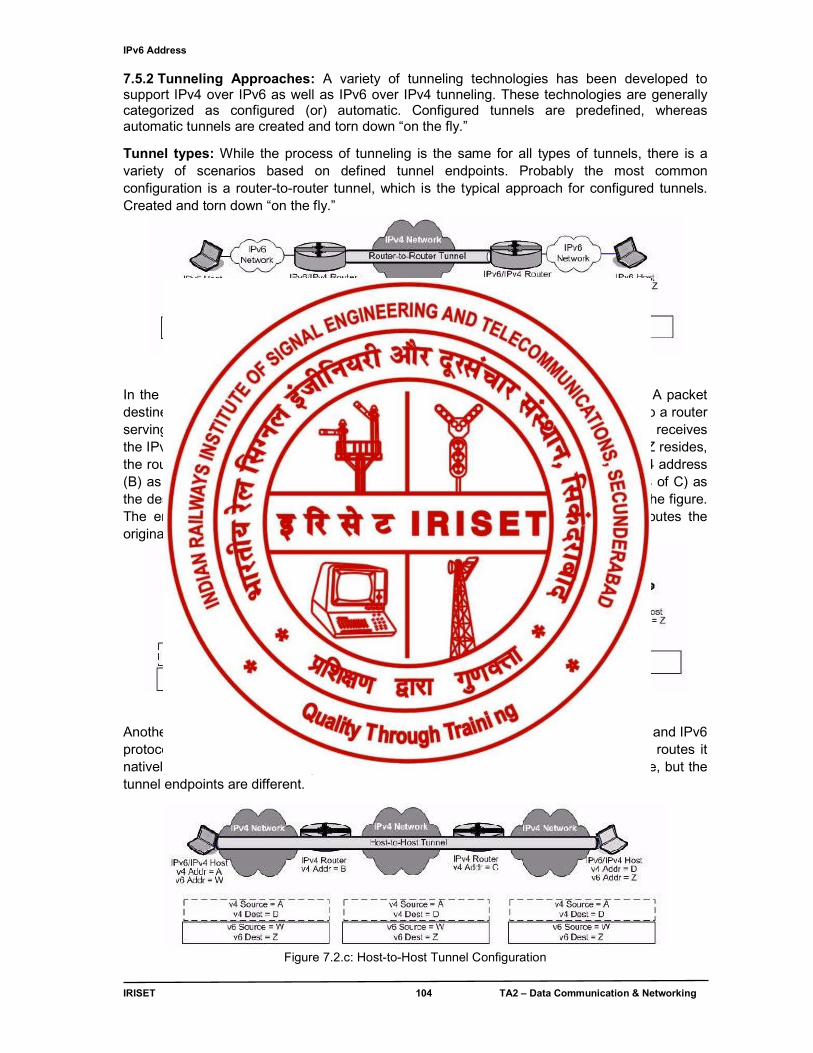
IPv6 Address
IRISET 104 TA2 – Data Communication & Networking
7.5.2 Tunneling Approaches: A variety of tunneling technologies has been developed to support IPv4 over IPv6 as well as IPv6 over IPv4 tunneling. These technologies are generally categorized as configured (or) automatic. Configured tunnels are predefined, whereas automatic tunnels are created and torn down “on the fly.”
Tunnel types: While the process of tunneling is the same for all types of tunnels, there is a variety of scenarios based on defined tunnel endpoints. Probably the most common configuration is a router-to-router tunnel, which is the typical approach for configured tunnels. Created and torn down “on the fly.”
Figure 7.2 a : Router-to-Router Tunnel
In the above figure, the originating IPv6 host on the left has an IPv6 address of W. A packet destined for the host on the far end of the diagram with an IPv6 address of Z is sent to a router serving the subnet. This router (with an IPv4 address of B and an IPv6 address of X) receives the IPv6 packet. Configured to tunnel packets destined for the network on which host Z resides, the router encapsulates the IPv6 packet with an IPv4 header. The router uses its IPv4 address (B) as the source IPv4 address and the tunnel endpoint router (with an IPv4 address of C) as the destination address, which is depicted beneath the IPv4 network in the center of the figure. The endpoint router decapsulates the packet, stripping off the IPv4 header and routes the original IPv6 packet to its intended destination (Z).
Figure 7.2 b: Host-to-Router Tunneling Configuration
Another tunneling scenario features an IPv6/IPv4 host capable of supporting both IPv4 and IPv6 protocols, tunneling a packet to a router, which in turn decapsulates the packet and routes it natively via IPv6. The tunneling mechanism is the same as in the router-to-router case, but the tunnel endpoints are different.
Figure 7.2.c: Host-to-Host Tunnel Configuration
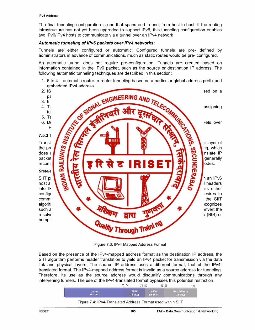
IPv6 Address
IRISET 105 TA2 – Data Communication & Networking
The final tunneling configuration is one that spans end-to-end, from host-to-host. If the routing infrastructure has not yet been upgraded to support IPv6, this tunneling configuration enables two IPv6/IPv4 hosts to communicate via a tunnel over an IPv4 network
Automatic tunneling of IPv6 packets over IPv4 networks:
Tunnels are either configured or automatic. Configured tunnels are pre- defined by administrators in advance of communications, much as static routes would be pre- configured.
An automatic tunnel does not require pre-configuration. Tunnels are created based on information contained in the IPv6 packet, such as the source or destination IP address. The following automatic tunneling techniques are described in this section:
1. 6 to 4 – automatic router-to-router tunneling based on a particular global address prefix and embedded IPv4 address
2. ISATAP – automatic host-to-router, router-to-host or host-to-host tunneling based on a particular IPv6 address format with inclusion of an embedded IPv4 address
3. 6 over 4 – automatic host-to-host tunneling using IPv4 multicasting 4. Tunnel Brokers – automatic tunnel setup by a server acting as a tunnel broker in assigning
tunnel gateway resources on behalf of hosts requiring tunneling 5. Teredo – automatic tunneling through NAT firewalls over IPv4 networks 6. Dual-Stack Transition Mechanism – enables automatic tunneling of IPv4 packets over IPv6 networks
7.5.3 Translation Approaches:
Translation techniques perform IPv4-to-IPv6 translation (and vice versa) at a particular layer of the protocol stack, typically the network, transport or application layer. Unlike tunneling, which does not alter the tunneled data packet; translation mechanisms do modify or translate IP packets commutatively between IPv4 and IPv6. Translation approaches are generally recommended in an environment with IPv6-only nodes communicating with IPv4-only nodes.
Stateless IP/ICMP Translation (SIIT) algorithm:
SIIT provides translation of IP packet headers between IPv4 and IPv6. SIIT resides on an IPv6 host and converts outgoing IPv6 packet headers into IPv4 headers, and incoming IPv4 headers into IPv6. To perform this task, the IPv6 host must be assigned an IPv4 address either configured on the host or obtained via a network service. When the IPv6 host desires to communicate with an IPv4 host, based on DNS resolution to an IPv4 address, the SIIT algorithm would convert the IPv6 packet header into IPv4 format. The SIIT algorithm recognizes such a case when the IPv6 address is an IPv4-mapped address, the mechanism to convert the resolved IPv4 address into an IPv4-mapped address is provided by bump-in-the-stack (BIS) or bump-in-the-API (BIA) techniques.
Figure 7.3: IPv4 Mapped Address Format
Based on the presence of the IPv4-mapped address format as the destination IP address, the SIIT algorithm performs header translation to yield an IPv4 packet for transmission via the data link and physical layers. The source IP address uses a different format, that of the IPv4-translated format. The IPv4-mapped address format is invalid as a source address for tunneling. Therefore, its use as the source address would disqualify communications through any intervening tunnels. The use of the IPv4-translated format bypasses this potential restriction.
Figure 7.4: IPv4-Translated Address Format used within SIIT
Annexure
IRISET 106 TA2 – Data Communication & Networking
ANNEXURE 1
LINE ENCODING & BLOCK CODING
Line encoding
The waveform pattern of voltage or current used to represent the 1s and 0s of a digital signal on a transmission link is called line encoding. The common types of line encoding techniques as shown in fig Annex.1.1 are Unipolar, Polar, Bipolar and Multi level.
Fig.Annex.1.1 Line encoding techniques
A . Unipolar Encoding
Fig.Annex.1.2(a) Unipolar encoding Unipolar encoding as shown in fig. Annex.1.2(a) has 2 voltage states, with one of the states being 0 volts. Since unipolar line encoding has one of its states at 0 Volts, it is also called Return to Zero (RTZ).
The average amplitude of unipolar encoded signal is non-zero. This creates a direct (DC) component (a component with zero frequency). When a signal contains a DC component, it cannot travel through media that cannot handle DC components.
Unipolar line encoding works well for inside machines—where the signal path is short—but is unsuitable for long distances, due to the presence of stray capacitance in the transmission medium. On long transmission paths, the constant level shift from 0 to 5 volts, which causes the stray capacitance to charge up. There will be a “stray” capacitor effect between any two conductors as shown in fig Annex.1.2(b) that are in close proximity to each other. For example, parallel running cables or wires are very suspect to stray capacitance.
Fig.Annex,1. 2(b) Stray capacitance effects
Annexure
IRISET 107 TA2 – Data Communication & Networking
If there is sufficient capacitance on the line (and a sufficient stream of 1s) a DC voltage component will be added to the data stream. Instead of returning to 0 volts, it would only return to 2 or 3 volts, as shown in fig Annex.1.2(c). The receiving station may not recognize a digital low at voltage of 2 volts due to base lines wander.
Fig. Annex.1.2(c) Base lines wander
Fig.Annex. 1.2(d) Drifting of synchronization
Unipolar line encoding can have synchronization problems between the transmitter and receiver’s clock oscillator. The receiver’s clock oscillator locks on to the transmitted signal’s level shifts (logic changes from 0 to 1) if there is a long series of logical 1s or 0s in a row. There is no level shift for the receiver’s oscillator to lock to. The receiver oscillator’s frequency may drift and become unsynchronized as shown in fig Annex. 1.2(d) it could lose track, of where the receiver is supposed to sample the transmitted data.
B. Polar Encoding When the digital encoding is symmetrical—around 0 Volts—it is called a Polar Code. For example, the RS-232D interface uses Polar line encoding as shown in fig. Annex.1.3(a) The signal does not return to zero; it is either a +ve voltage or a -ve voltage. Polar line encoding is also called None Return to Zero (NRZ).
Fig. Annex. 1.3(a) RS 232D Polar encoding
Polar line encoding is the simplest pattern that eliminates most of the residual DC problem. Variation of Voltage levels for Polar encoding at Transmitter & Receiver end is shown in fig. Annex.1.3(b)
Annexure
IRISET 108 TA2 – Data Communication & Networking
Fig.Annex. 1.3(b) Variation of Voltage levels
There is still a small residual DC problem, but Polar line encoding is a great improvement over Uni polar line encoding. Polar encoding has an added benefit in that it reduces the power required to transmit the signal by one-half.
i. NRZ Non return to Zero
1 = signal on 0 = signal off (no signal)
NRZ is used on low speed links, such as serial ports. Its problems are lack of clock recovery during long string of 0 or 1 bits and it has a DC component resulting in “baseline wander” during long strings of 0 or 1 bits as shown if fig Annex. 1.4
Fig.Annex. 1.4 NRZ Signal
ii. NRZ I (Non return to Zero Inverted)
1 = change of signal level (on-off or off-on) 0 = no change of signal level
NRZI is a differential encoding used in 4B/5B on fast Ethernet. It fixes problems in clocking during long strings of 1 bit as shown in fig Annex. 1.5. The problems are the DC component and the lack of clock recovery during long string of 0 bits.
Fig Annex.1,5 NRZ I Signal
iii. Manchester Line Encoding In Manchester Line Encoding, there is a transition at the middle of each bit period. The mid-bit transition serves as a clocking mechanism (and also as data): a low to high transition represents a 1 and a high to low transition represents a 0as shown in the fig Annex.1.6 (a)
Annexure
IRISET 109 TA2 – Data Communication & Networking
Fig. Annex. 1.6(a) Manchester line encoded Signal Manchester line encoding has no DC component and there is always a transition available for synchronizing receives and transmits clocks. Manchester line encoding is also called self-clocking line encoding. It has the added benefit of requiring the least amount of bandwidth compared to the other line encoding. Widely used with 10 base T legacy Ethernets. Manchester line encoding requires 2 frequencies the base carrier and 2 x the carrier frequency. All others require a range from 0 hertz to the maximum transfer rate frequency as shown in fig Annex. 1.6(b)
Fig.Annex.1.6(b) Manchester line encoded Signal with base frequency Manchester line encoding can detect errors during transmission: a transition is expected during every bit period. Therefore, the absence of a transition would indicate an error condition.
C. Bipolar Line Encoding
i. Alternate Mark Inversion (AMI) Bipolar line encoding has 3 voltage levels. A low or 0 is represented by a 0 Volt level and a 1 is represented by alternating polarity pulses. By alternating the polarity of the pulses for 1s, the residual DC component cancels as shown in fig Annex. 1.7
Bipolar line encoding is also called Alternate Mark Inversion (AMI). Bipolar line encoding is also called Alternate Mark Inversion (AMI).
Fig. Annex. 1.7 Bipolar AMI Signal
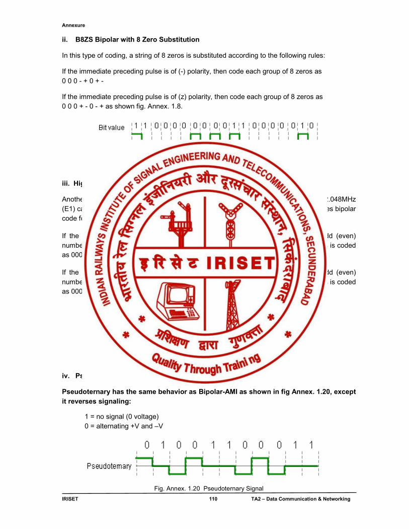
Annexure
IRISET 110 TA2 – Data Communication & Networking
ii. B8ZS Bipolar with 8 Zero Substitution In this type of coding, a string of 8 zeros is substituted according to the following rules: If the immediate preceding pulse is of (-) polarity, then code each group of 8 zeros as 0 0 0 - + 0 + - If the immediate preceding pulse is of (z) polarity, then code each group of 8 zeros as 0 0 0 + - 0 - + as shown fig. Annex. 1.8.
Fig. Annex 1.8 B8Z8 Signal
iii. High Density Bipolar 3 (HDB3) Another coding scheme is HDB3, high density bipolar 3, used primarily in Europe for 2.048MHz (E1) carriers as shown in fig Annex 1.9. This code is similar to BNZS in that it substitutes bipolar code for 4 consecutive zeros according to the following rules: If the polarity of the immediate preceding pulse is (-) and there have been an odd (even) number of logic 1 pulses since the last substitution, each group of 4 consecutive zeros is coded as 000-(+00+).
If the polarity of the immediate preceding pulse is (+) and there have been an odd (even) number of logic 1 pulses since the last substitution, each group of 4 consecutive zeros is coded as 000+(-00-).
Fig. Annex.1.9 HDB3 Signal
iv. Pseudoternary Pseudoternary has the same behavior as Bipolar-AMI as shown in fig Annex. 1.20, except it reverses signaling:
1 = no signal (0 voltage) 0 = alternating +V and –V
Fig. Annex. 1.20 Pseudoternary Signal
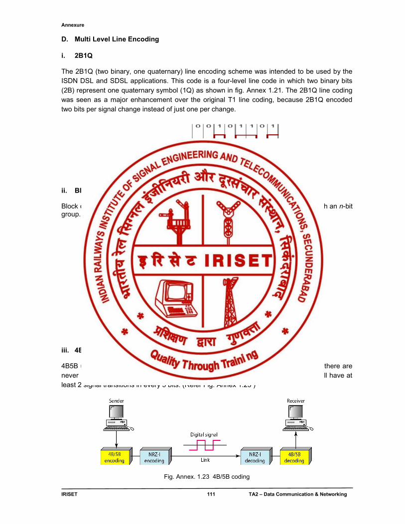
Annexure
IRISET 111 TA2 – Data Communication & Networking
D. Multi Level Line Encoding i. 2B1Q The 2B1Q (two binary, one quaternary) line encoding scheme was intended to be used by the ISDN DSL and SDSL applications. This code is a four-level line code in which two binary bits (2B) represent one quaternary symbol (1Q) as shown in fig. Annex 1.21. The 2B1Q line coding was seen as a major enhancement over the original T1 line coding, because 2B1Q encoded two bits per signal change instead of just one per change.
Fig. Annex. 1.21 2B1Q Signal ii. Block Coding Block coding is normally referred to as mB/nB coding; it replaces each m-bit group with an n-bit group. Block coding concept is shown below (Fig Annex. 1.22)
.
Fig. Annex. 1.22 Block coding concept
iii. 4B5B (4 Bit / 5 Bit) 4B5B uses 5 bit signals for each 4 data bit. The 5 bit sequences are chosen so that there are never more than 3 consecutive zeros in the output stream. When used with NRZI, will have at least 2 signal transitions in every 5 bits. (Refer Fig. Annex 1.23 )
Fig. Annex. 1.23 4B/5B coding
Annexure
IRISET 112 TA2 – Data Communication & Networking
iv. 8B10B (8Bit/10Bit)
8B10B coding is used in interfaces as PCI Express, Fiber Channel and others. In these applications 8B10B transmission code provides the following functions:
● Improves transmission characteristics ● Enables bit- level clock recovery ● Improves error detection ● Separates data symbols from control symbols ● Derives bit and word synchronization
The data bytes are encoded into 10-bit data characters resulting into 1024 possible characters. 2x256=512 is reserved for the data byte transfers. One character representative has more 1’s; the other has more 0's and is selected according to the current disparity (see below). 12 special characters are defined for special signaling. The rest of the 1024-512-12 are not allowed for transmission and indicate transmission errors or unsynchronized status once they are received at the destination. Ordered sets are flexible building blocks which may be used for in-band and or out-of-band protocol functions.
8B10B code recognizes the idea of a Running Disparity (the difference between the number of 1’s and 0’s transmitted). The sender keeps the running disparity around zero, the receiver checks the data stream according to this rules and is thus able to detect some transmission errors. Other neighboring coding schemes like 64B66B are available and are used in certain applications.
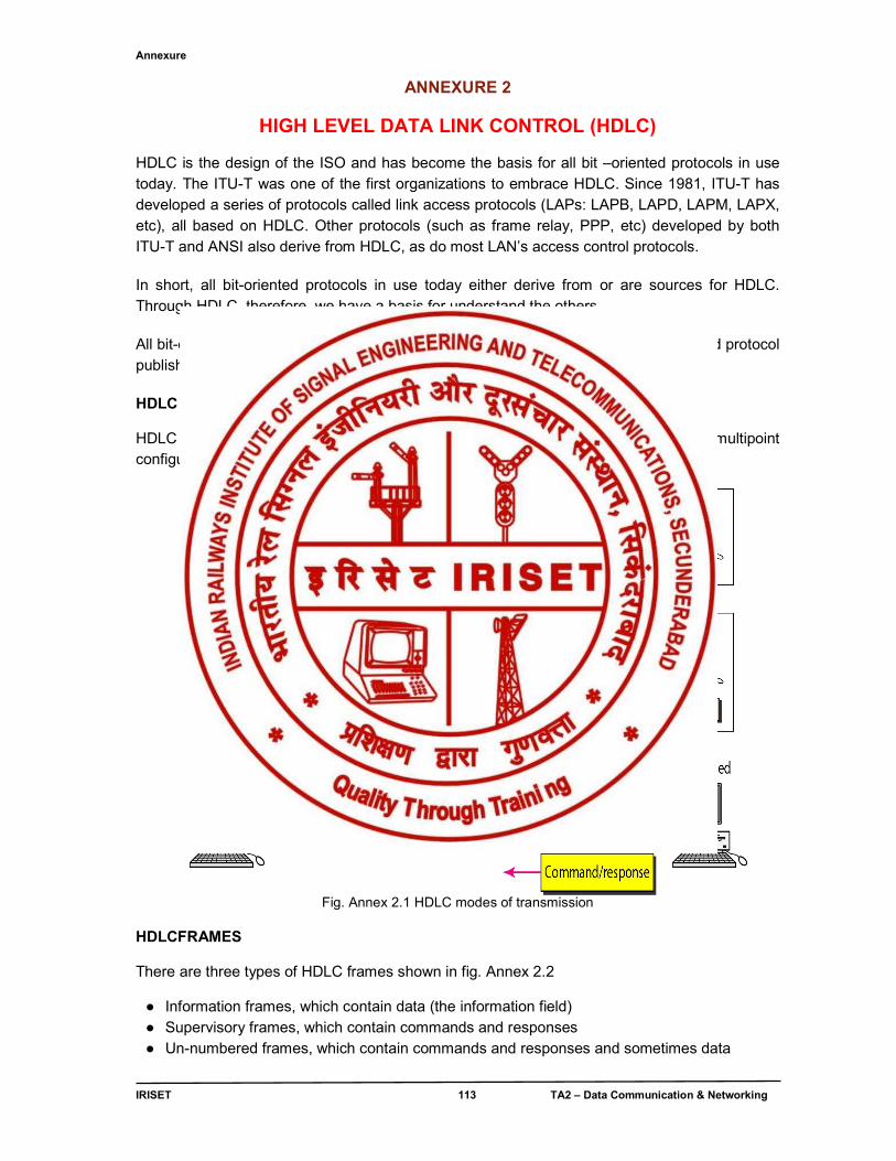
Annexure
IRISET 113 TA2 – Data Communication & Networking
ANNEXURE 2
HIGH LEVEL DATA LINK CONTROL (HDLC)
HDLC is the design of the ISO and has become the basis for all bit –oriented protocols in use today. The ITU-T was one of the first organizations to embrace HDLC. Since 1981, ITU-T has developed a series of protocols called link access protocols (LAPs: LAPB, LAPD, LAPM, LAPX, etc), all based on HDLC. Other protocols (such as frame relay, PPP, etc) developed by both ITU-T and ANSI also derive from HDLC, as do most LAN’s access control protocols.
In short, all bit-oriented protocols in use today either derive from or are sources for HDLC. Through HDLC, therefore, we have a basis for understand the others.
All bit-oriented protocols are related to high-level data link control (HDLC) a bit-oriented protocol published by ISO.
HDLC Modes of transmission
HDLC supports both half-duplex and full-duplex modes in point-to-point and multipoint configurations (Refer Fig. Annex 2.1)
Fig. Annex 2.1 HDLC modes of transmission
HDLCFRAMES There are three types of HDLC frames shown in fig. Annex 2.2
● Information frames, which contain data (the information field) ● Supervisory frames, which contain commands and responses ● Un-numbered frames, which contain commands and responses and sometimes data
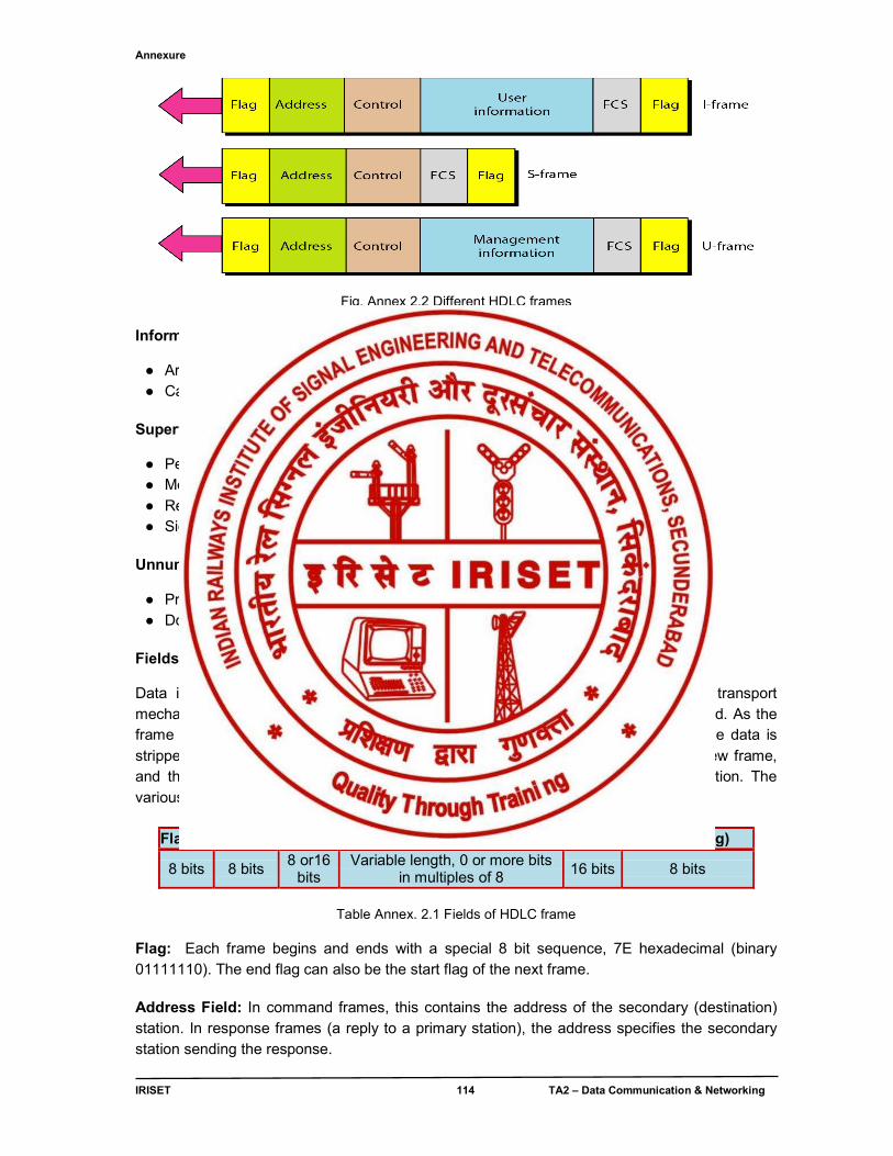
Annexure
IRISET 114 TA2 – Data Communication & Networking
Fig. Annex 2.2 Different HDLC frames
Information frames (I-frame)
● Are sequentially numbered ● Carry data, message acknowledgements, poll and final bits
Supervisory Frames (s-frame)
● Perform link supervisory control ● Message acknowledgements ● Retransmit requests ● Signal temporary hold on receipt on I frames (if secondary is busy)
Unnumbered Frames (U-frame)
● Provide flexible format for additional link control ● Do not have sequence numbers
Fields of HDLC frames
Data is packaged into frames to be sent across the HDLC link. Frames are a transport mechanism; their sole purpose is to transport the data across one link, not end to end. As the frame arrives at the other end of the link, it is checked to errors, and if it’s okay, the data is stripped out of the frame, a new frame generated for it, the data inserted into the new frame, and then transmitted on the next link and so on until the data reaches its destination. The various fields of a frame are shown in table Annex. 2.1
Flag Address Control Information FCS (Optional Flag)
8 bits 8 bits 8 or16
bits Variable length, 0 or more bits
in multiples of 8 16 bits 8 bits
Table Annex. 2.1 Fields of HDLC frame
Flag: Each frame begins and ends with a special 8 bit sequence, 7E hexadecimal (binary 01111110). The end flag can also be the start flag of the next frame.
Address Field: In command frames, this contains the address of the secondary (destination) station. In response frames (a reply to a primary station), the address specifies the secondary station sending the response.
Annexure
IRISET 115 TA2 – Data Communication & Networking
Control Field: as shown in fig Annex. 2.3, this field holds commands and responses. Examples are sequence numbers (frames are numbered to ensure delivery), and poll (must reply) and final (this is the last frame) bits. Information Field: This field contains the data. It can contain any sequence of bits. It normal practice it is a multiple of 8 bits.
Frame Check Sequence Field: This field contains a 32 bit Cyclic Redundancy Check (CRC) which covers the A, C and I fields.
Control field format of HDLC frame.
Fig. Annex. 2.3 Control field format for different HDLC frames
HDLC link Configurations
Link configurations can be categorized as being either:
● Unbalanced, which consists of one primary terminal, and one or more secondary terminals. ● Balanced, which consists of two peer terminals.
The three link configurations are:
Normal Response Mode (NRM) is an unbalanced configuration in which only the primary terminal may initiate data transfer. The secondary terminal transmits data only in response to commands from the primary terminal. The primary terminal polls the secondary terminal(s) to determine whether they have data to transmit, and then selects one to transmit.
Asynchronous Response Mode (ARM) is an unbalanced configuration in which secondary terminals may transmit without permission from the primary terminal. However, the primary terminal still retains responsibility for line initialization, error recovery, and logical disconnect.
Asynchronous Balanced Mode (ABM) is a balanced configuration in which either station may initiate the transmission.
Annexure
IRISET 116 TA2 – Data Communication & Networking
ANNEXURE - 3 QoS (Quality of Service)
In telephony field, quality of service is a service that covers all aspects of necessity in the use of telecommunication service. The necessities include service response time, loss, signal-to-noise ratio, echo, interrupts, frequency response, loudness level, and so on.
In the computer networking field, QoS is defined as the ability of the network to provide a service at an assured service level.
In Internet, QoS is a technology that acts as additional support to the best-effort service in handling data transfer during load congestions and superiorly response to more problems, such as latency, corrupted files, lost connection, jitter, out-of-order delivery, data loss or insufficient bandwidth.
QoS provides priority to different applications, users or data flow based on the load service requirements, and network conditions to ensure that the most important data reach the destination first.
A defined quality of service may be desired or required for certain types of network traffic, for example:
● Streaming media specifically ● IP telephony also known as Voice over IP (VoIP) ● Videoconferencing ● Circuit Emulation Service ● Safety-critical applications such as remote surgery where availability issues can be
hazardous ● Network operations support systems either for the network itself, or for customers' business
critical needs ● Online games where real-time lag can be a factor ● Industrial control systems protocols such as Ethernet/IP which are used for real-time control
of machinery
These types of service are called inelastic, meaning that they require a certain minimum level of bandwidth and a certain maximum latency to function. By contrast, elastic applications can take advantage of however much or little bandwidth is available. Bulk file transfer applications that rely on TCP are generally elastic
Circuit switched networks, especially those intended for voice transmission, such as Asynchronous Transfer Mode (ATM) or GSM, have QoS in the core protocol and do not need additional procedures to achieve it. Shorter data units and built-in QoS were some of the unique selling points of ATM for applications such as video on demand. End-to-end quality of service
End-to-end quality of service can require a method of coordinating resource allocation between one autonomous system and another.
The Internet Engineering Task Force (IETF) defined the Resource Reservation Protocol s(RSVP) for bandwidth reservation. RSVP is an end-to-end bandwidth reservation protocol. The traffic engineering version, RSVP-TE, is used in many networks to establish traffic-engineered Multiprotocol Label Switching (MPLS) label-switched paths. The IETF also defined Next Steps in Signaling (NSIS) with QoS signaling as a target. NSIS is a development and simplification of RSVP.
Annexure
IRISET 117 TA2 – Data Communication & Networking
ANNEXURE - 4
BLUETOOTH & RoIP
Bluetooth is an open wireless protocol for exchanging data over short distances (using short length radio waves) from fixed and mobile devices, creating personal area networks (PANs). It was originally conceived as a wireless alternative to RS-232 data cables. It can connect several devices, overcoming problems of synchronization. It is an alternative wireless network technology that followed a different development path than the 802.11 family. Bluetooth supports a very short range (approximately 10 meters) and relatively low bandwidth (1-3 Mbps in practice) designed for low-power network devices like handhelds as shown in fig Annex.4.1, but it is rarely used for general-purpose WLAN networking due to the range and speed considerations. Bluetooth uses a radio technology called frequency-hopping spread spectrum, which chops up the data being sent and transmits chunks of it on up to 79 bands of 1 MHz width in the range 2402-2480 MHz. This is in the globally unlicensed Industrial, Scientific and Medical (ISM) 2.4 GHz short-range radio frequency band
Fig. Annex. 4.1, Typical Bluetooth setup In its basic rate (BR) mode, the modulation is Gaussian frequency-shift keying (GFSK). It can achieve a gross data rate of 1 Mbit/s. In extended data rate (EDR) π/4-DQPSK and 8DPSK are used, giving 2, and 3 Mbit/s respectively. Bluetooth provides a secure way to connect and exchange information between devices such as mobile phones, telephones, laptops, personal computers, printers, Global Positioning System (GPS) receivers, digital cameras, and video game consoles.
Radio Over IP (RoIP) Radio over Internet Protocol (RoIP) is a method of transmitting and receiving radio communications via Internet Protocol (IP), a data communications standard used to power the Internet as well as home and business computer networks. RoIP, is similar to VoIP, it uses standard VoIP techniques to transfer the analog audio, used by Land Mobile Radio systems, digitally over the Internet (or LAN), with an added command layer
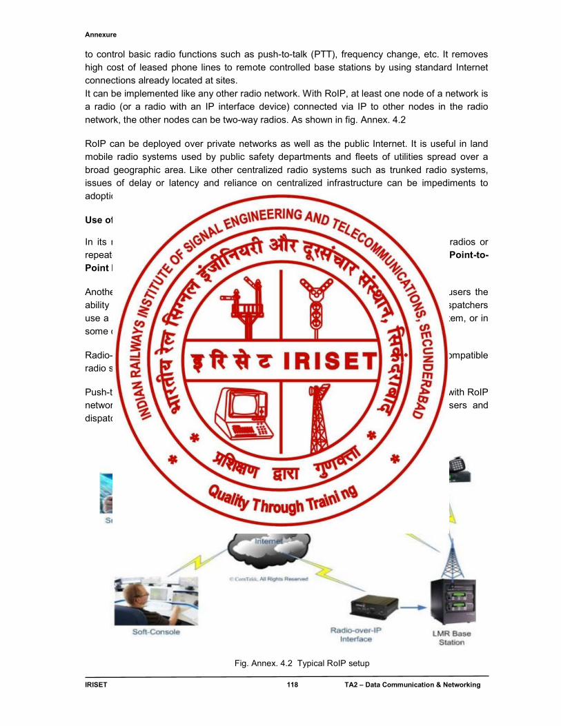
Annexure
IRISET 118 TA2 – Data Communication & Networking
to control basic radio functions such as push-to-talk (PTT), frequency change, etc. It removes high cost of leased phone lines to remote controlled base stations by using standard Internet connections already located at sites. It can be implemented like any other radio network. With RoIP, at least one node of a network is a radio (or a radio with an IP interface device) connected via IP to other nodes in the radio network, the other nodes can be two-way radios. As shown in fig. Annex. 4.2
RoIP can be deployed over private networks as well as the public Internet. It is useful in land mobile radio systems used by public safety departments and fleets of utilities spread over a broad geographic area. Like other centralized radio systems such as trunked radio systems, issues of delay or latency and reliance on centralized infrastructure can be impediments to adoption by public safety agencies. Use of RoIP In its most basic form, RoIP technology provides a method of linking two or more radios or repeaters using a LAN/WAN or Internet connection. This is known as Site Linking or Point-to-Point linking. Another common application is IP Dispatch or remote base station. This allows users the ability to operate transceivers remotely, but distance is not limited by cable length. Dispatchers use a software-based IP Console which typically runs on the Windows operating system, or in some cases Linux. Radio-over-IP has become a major enabler of interoperability, allowing otherwise incompatible radio systems to communicate seamlessly, sharing a common data connection. Push-to-talk for mobile phones and PDAs, known as P2T may be used in conjunction with RoIP networks. This allows Smart Phone users to communicate directly with radio users and dispatchers.
Fig. Annex. 4.2 Typical RoIP setup
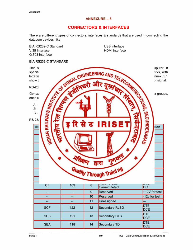
Annexure
IRISET 119 TA2 – Data Communication & Networking
ANNEXURE – 5
CONNECTORS & INTERFACES There are different types of connectors, interfaces & standards that are used in connecting the datacom devices, like
EIA RS232-C Standard V.35 Interface G.703 Interface
USB interface HDMI interface
EIA RS232-C STANDARD
This standard is used to connect serial devices like Modems to a Personal Computer. It specifies a 25 pin connector as the standard interface in data communication networks, with lettering pin designations for ground, data, and control and timing circuits. The table Annex. 5.1 show the designations for each of the 25 pins of the standard and the direction of flow of signal.
RS-232 Signals Functional Description
General: The first letter of the EIA signal name categorizes the signal into one of five groups, each representing a different "circuit":
A - Ground B - Data C - Control
D - Timing S - Secondary channel
RS 232C standard 25 pin description
INTERCHANGE CIRCUIT No. PIN No. DESCRIPTION Direction
AA 101 1 Protective Ground --
BA 103 2 Transmit Data DTE DCE
BB 104 3 Receive Data DTE DCE
CA 105 4 Request To Send DTE DCE
CB 106 5 Clear To Send DTE DCE
CC 107 6 Data Set Ready DTE DCE
AB 102 7 Signal Ground ---
CF 109 8 Receive Line Carrier Detect
DTE DCE
-- -- 9 Reserved +12V for test
-- -- 10 Reserved -12v for test
-- -- 11 Unassigned ---
SCF 122 12 Secondary RLSD DTE DCE
SCB 121 13 Secondary CTS DTE DCE
SBA 118 14 Secondary TD DTE DCE
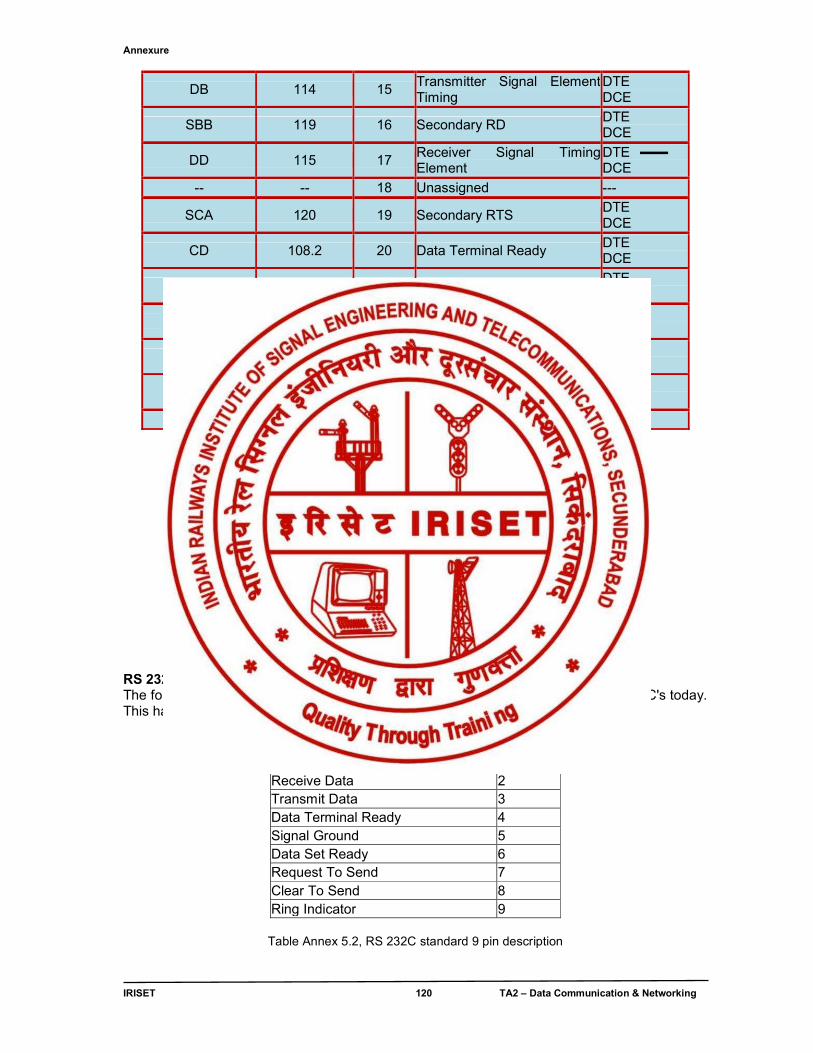
Annexure
IRISET 120 TA2 – Data Communication & Networking
DB 114 15 Transmitter Signal Element Timing
DTE DCE
SBB 119 16 Secondary RD DTE DCE
DD 115 17 Receiver Signal Timing Element
DTE DCE
-- -- 18 Unassigned ---
SCA 120 19 Secondary RTS DTE DCE
CD 108.2 20 Data Terminal Ready DTE DCE
CG 110 21 Signal Quality Detector DTE DCE
CE 125 22 Ring Indicator DTE DCE
CH/CI 111/112 23 Data Signal Rate Selector DTE DCE
DA 113 24 Transmit Signal Element Timing
DTE DCE
-- -- 25 Unassigned ---
Table Annex.5.1, RS 232C standard 25 pin description
Fig Annex. 5.1 RS-232 connectors 25 pins
RS 232C standard 9 pin SERIAL COMMUNICATION description The following table Annex 5.2 illustrates the 9 pin serial connector as found on most PC's today. This has all but replaced the previous 25 pin connector found on earlier PC's.
SIGNAL PIN No. Carrier Detect 1 Receive Data 2 Transmit Data 3 Data Terminal Ready 4 Signal Ground 5 Data Set Ready 6 Request To Send 7 Clear To Send 8 Ring Indicator 9
Table Annex 5.2, RS 232C standard 9 pin description
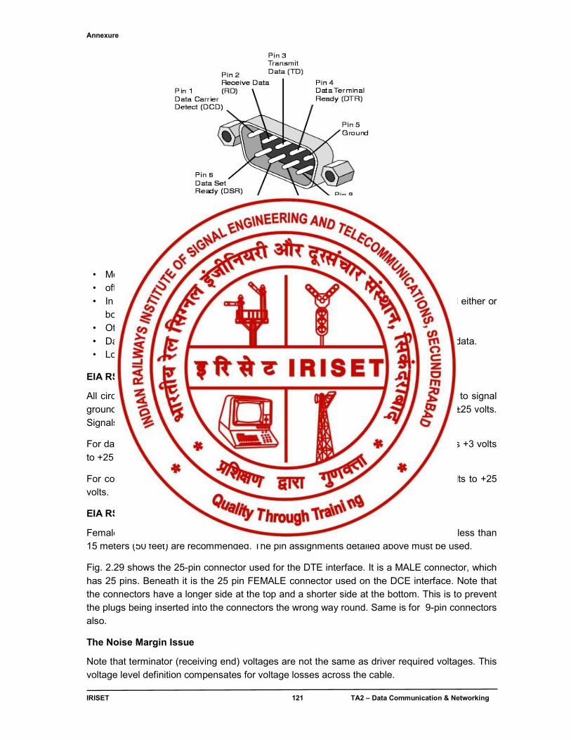
Annexure
IRISET 121 TA2 – Data Communication & Networking
Fig. Annex. 5.2 RS-232 connectors 9 pins
• Most PCs have a DB9 male plug for RS-232 serial asynchronous communications • often COM1 on a PC • In most cases, it is sufficient to use a 2 or 3 - wire connection, ground (pin 5) and either or
both receive and transmit (pins 2 and 3) • Other controls available, but seldom used • Data transmitted one bit at a time, with protocols establishing how one represents data. • Low speed (most common is 9600 bits/sec)
EIA RS232-C Electrical Standard
All circuits carry bi-polar low-voltage signals, measured at the connector with respect to signal ground (AB), and may not exceed ±25 volts. Signals are valid in the range ±3 volts to ±25 volts. Signals within the range -3 volts to +3 volts are considered invalid.
For data lines, binary 1 (a high) is represented by -3 volts to -25 volts, whilst binary 0 is +3 volts to +25 volts.
For control lines, OFF is represented by -3 volts to -25 volts, whilst binary 0 is +3 volts to +25 volts.
EIA RS232-C Mechanical Standard & connectors
Female connector is connected to DCE and male connector to DTE. Short cables of less than 15 meters (50 feet) are recommended. The pin assignments detailed above must be used.
Fig. 2.29 shows the 25-pin connector used for the DTE interface. It is a MALE connector, which has 25 pins. Beneath it is the 25 pin FEMALE connector used on the DCE interface. Note that the connectors have a longer side at the top and a shorter side at the bottom. This is to prevent the plugs being inserted into the connectors the wrong way round. Same is for 9-pin connectors also.
The Noise Margin Issue
Note that terminator (receiving end) voltages are not the same as driver required voltages. This voltage level definition compensates for voltage losses across the cable.
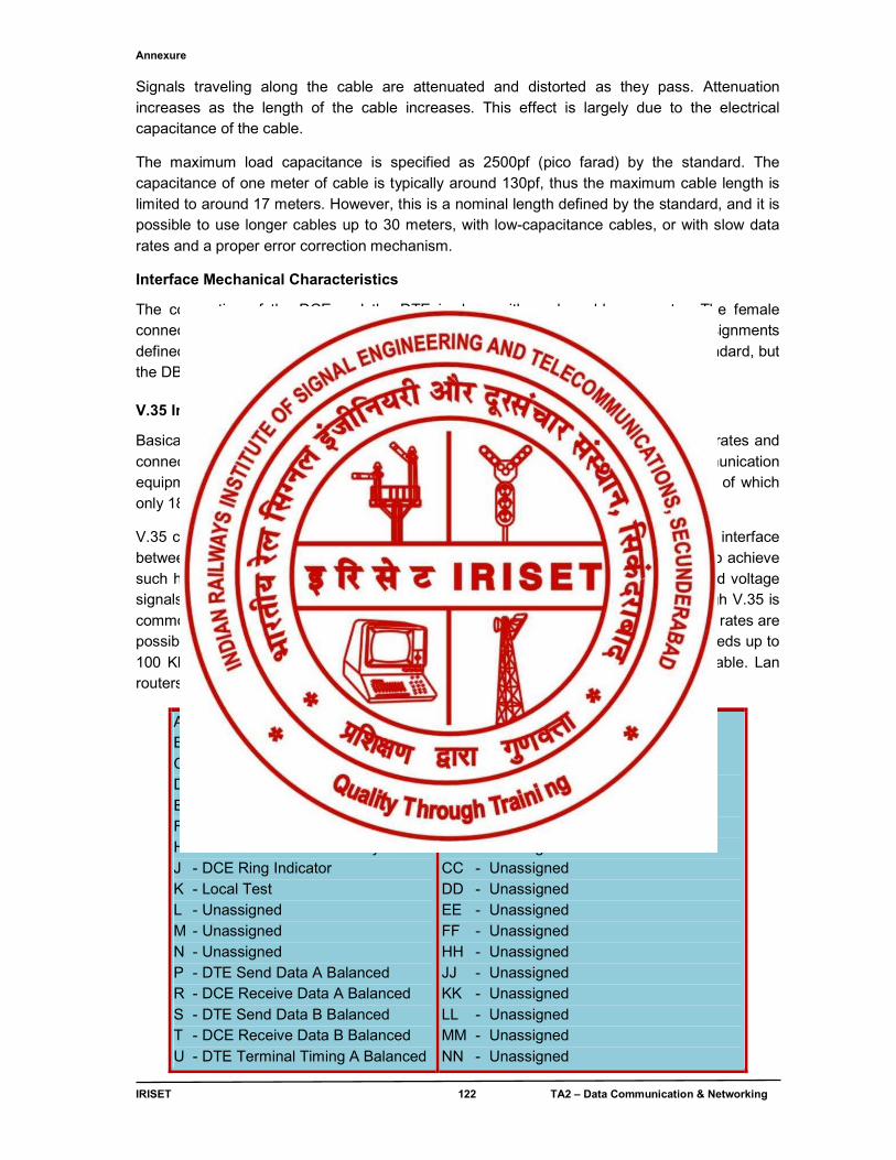
Annexure
IRISET 122 TA2 – Data Communication & Networking
Signals traveling along the cable are attenuated and distorted as they pass. Attenuation increases as the length of the cable increases. This effect is largely due to the electrical capacitance of the cable.
The maximum load capacitance is specified as 2500pf (pico farad) by the standard. The capacitance of one meter of cable is typically around 130pf, thus the maximum cable length is limited to around 17 meters. However, this is a nominal length defined by the standard, and it is possible to use longer cables up to 30 meters, with low-capacitance cables, or with slow data rates and a proper error correction mechanism.
Interface Mechanical Characteristics
The connection of the DCE and the DTE is done with a pluggable connector. The female connector should be associated with the DCE. The following table lists the pin assignments defined by the standard. The type of connector to be used is not mentioned in the standard, but the DB-25 (or on IBM-AT's, a minimal DB-9) connectors are almost always used. V.35 Interface
Basically, V.35 is a high-speed serial interface designed to support both higher data rates and connectivity between DTEs (data-terminal equipment) or DCEs (data-communication equipment) over digital lines.V.35 interface recognizable by its 34-pin connector, out of which only 18 pins are used. Its pin layout & connector is shown in fig Annex. 5.3
V.35 combines the bandwidth of several telephone circuits to provide the high-speed interface between a DTE or DCE and a CSU/DSU (Channel Service Unit/Data Service Unit). To achieve such high speeds and great distances, V.35 combines both balanced and unbalanced voltage signals on the same interface. Transmission is using a synchronous protocol. Although V.35 is commonly used to support speeds ranging anywhere from 48 to 64 Kbps, much higher rates are possible. V.35 cable distances theoretically can range up to 4000 feet (1200 m) at speeds up to 100 Kbps. Actual distances will depend on your equipment and the quality of the cable. Lan routers often come equipped with a V.35 electrical interface.
A - Common Chassis Ground B - Common Signal Ground C - DTE Request to Send D - DCE Clear to Send E - DCE Data Set Ready F - DCE Data Carrier Detect H - DTE Data Terminal Ready J - DCE Ring Indicator K - Local Test L - Unassigned M - Unassigned N - Unassigned P - DTE Send Data A Balanced R - DCE Receive Data A Balanced S - DTE Send Data B Balanced T - DCE Receive Data B Balanced U - DTE Terminal Timing A Balanced
V - DCE Receive Timing A Balanced W - DTE Terminal Timing B Balanced X - DCE Receive Timing B Balanced Y - DCE Send Timing A Balanced Z - Unassigned AA - DCE Send Timing B Balanced BB - Unassigned CC - Unassigned DD - Unassigned EE - Unassigned FF - Unassigned HH - Unassigned JJ - Unassigned KK - Unassigned LL - Unassigned MM - Unassigned NN - Unassigned
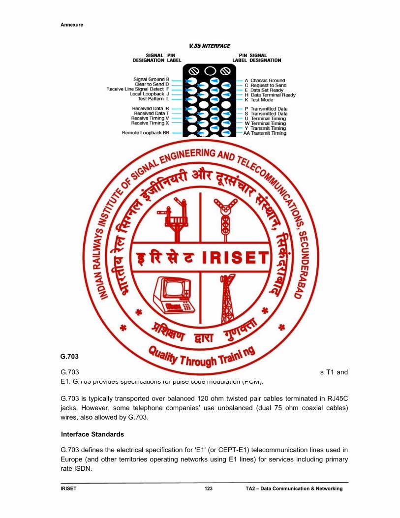
Annexure
IRISET 123 TA2 – Data Communication & Networking
Fig. Annex. 5.3 V.35 interface pin layout & connector
G.703 Interface G.703 is an ITU-T standard for transmitting voice or data over digital carriers such as T1 and E1. G.703 provides specifications for pulse code modulation (PCM). G.703 is typically transported over balanced 120 ohm twisted pair cables terminated in RJ45C jacks. However, some telephone companies’ use unbalanced (dual 75 ohm coaxial cables) wires, also allowed by G.703. Interface Standards
G.703 defines the electrical specification for 'E1' (or CEPT-E1) telecommunication lines used in Europe (and other territories operating networks using E1 lines) for services including primary rate ISDN.
Annexure
IRISET 124 TA2 – Data Communication & Networking
Interface Characteristics E1
E1 is a differential communications interface using either two pairs (TX and RX) connected through a single RJ-48C connector (also frequently written as RJ48, RJ-48 or RJ48c and also often incorrectly called RJ-45 or RJ45 - it is an RJ connector with 8 contacts assigned according to specification RJ-48C) or using two coaxial connections (TX and RX) via two BNC connectors. To enable reliable transmission and reception over thousands of meters of cable between customer premises and telephone exchanges, the data is encoded using HDB3 to produce a bipolar signal with the required characteristics. Note that timing information (i.e. the bit clock) is encoded within the signal to enable the receiver to recover a clock and correctly decode the received data. Interface Applications
Telecommunications companies (in the relevant territories) provide and support E1 or T1 services to end-users (usually business customers) in a variety of channel configurations with associated price structures. The organization of data carried using E1 or T1 services is defined within the G.704 standard. E1 and T1 lines are used for a VERY wide variety of uses including Voice, Internet Access, X.25, Multiplexed data, ISDN. Both E1 and T1 lines are frequently connected to V.35 connections by network interface converters before connection to the communications equipment. DTE – DCE interface DATA COMMUNICATIONS EQUIPMENT (DCE) An example of a DCE is a modem. A DCE is fitted with a 25 pin female connector. DATA TERMINAL EQUIPMENT (DTE) An example of a DTE is a computer terminal. A DTE is fitted with a 25 pin male connector. How to exchange information between a DCE and DTE Now, let’s look at the sequence that occurs when data is transferred between a DTE and a DCE. The data can only be transferred after the correct sequence of signals is followed, for instance, there is no point sending data if the modem is turned off. Let’s go through each of the steps involved (i.e., signal line assertions required) to transmit and receive characters across the RS232 interface. TRANSMITTING DATA (DTE to DCE)
• Assert DTR and RTS • Wait for DSR • Wait for CTS • Transmit the data
Step 1 and 2 are essential to ensure that the modem is on-line and connected to another modem. Waiting for DSR checks that the modem is on-line.
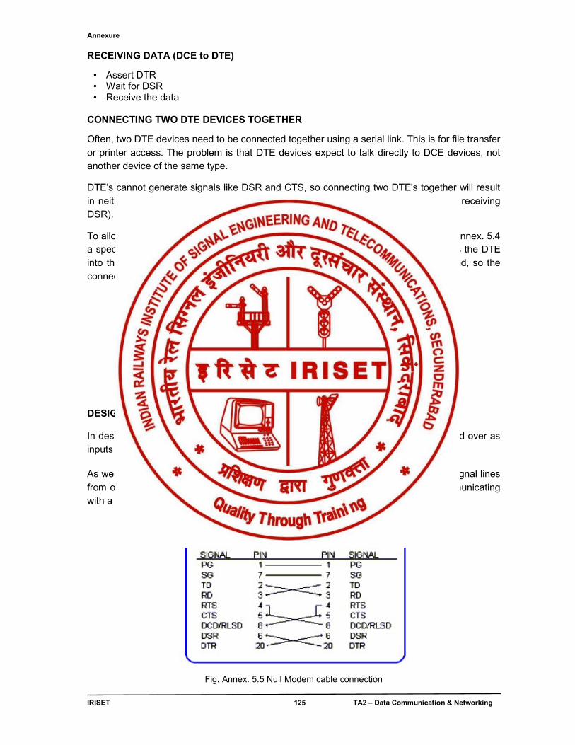
Annexure
IRISET 125 TA2 – Data Communication & Networking
RECEIVING DATA (DCE to DTE)
• Assert DTR • Wait for DSR • Receive the data
CONNECTING TWO DTE DEVICES TOGETHER
Often, two DTE devices need to be connected together using a serial link. This is for file transfer or printer access. The problem is that DTE devices expect to talk directly to DCE devices, not another device of the same type.
DTE's cannot generate signals like DSR and CTS, so connecting two DTE's together will result in neither getting permission to send, and thinking that the modem is off-line (by not receiving DSR).
To allow the interconnection of two DTE devices without using DCE's as shown in fig Annex. 5.4 a special type of cable must be used. This is called a Null Modem Cable, which fools the DTE into thinking that it is connected to a DCE device. In this case, modems are not used, so the connection looks like.
Fig. Annex. 5.4 Interconnection of two DTEs DESIGNING A NULL-MODEM CABLE In designing a NULL-MODEM cable, the DTE signals from one computer are swapped over as inputs to supply the DCE expected signals on the other DTE. As we can see from the fig Annex.5.5 When two DTE's are connected together, the signal lines from one DTE are transposed to the other DTE, fooling it into thinking that it is communicating with a DCE
Fig. Annex. 5.5 Null Modem cable connection
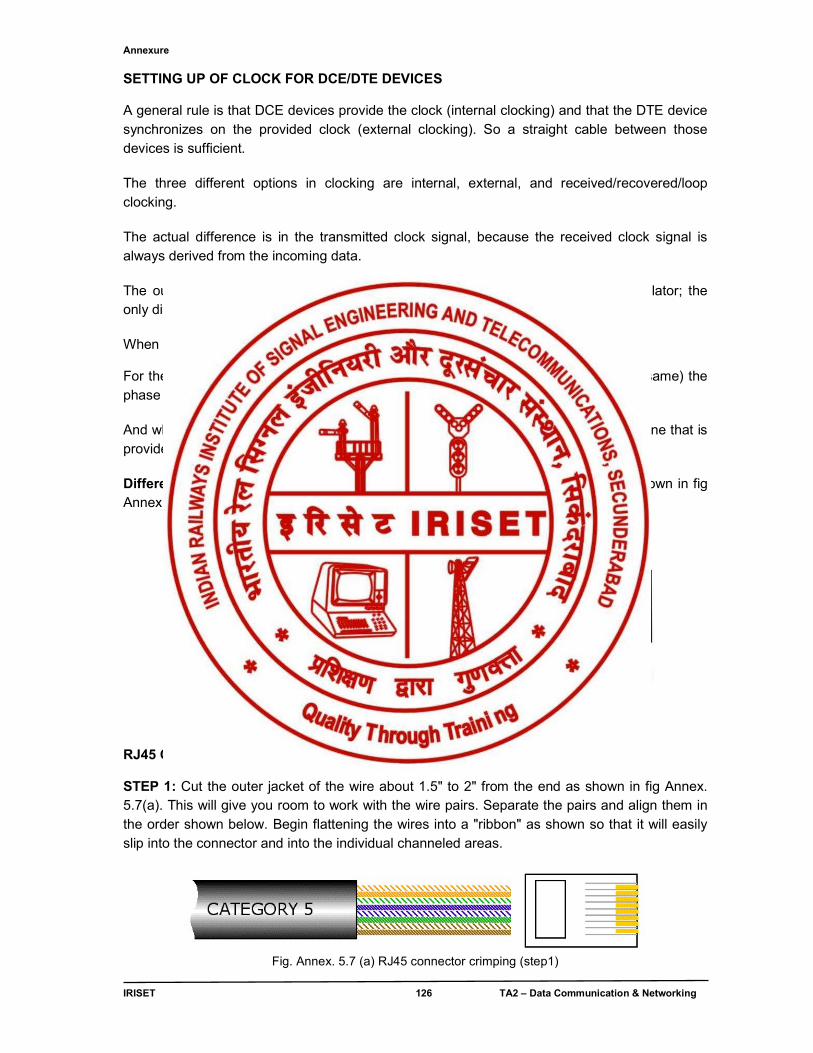
Annexure
IRISET 126 TA2 – Data Communication & Networking
SETTING UP OF CLOCK FOR DCE/DTE DEVICES
A general rule is that DCE devices provide the clock (internal clocking) and that the DTE device synchronizes on the provided clock (external clocking). So a straight cable between those devices is sufficient.
The three different options in clocking are internal, external, and received/recovered/loop clocking.
The actual difference is in the transmitted clock signal, because the received clock signal is always derived from the incoming data.
The outgoing clock (transmitted clock) will always be generated by an internal oscillator; the only difference between the three options is what is used as the phase reference.
When internal clocking is used the Tx clock is phase locked to the internal oscillator.
For the received/recovered/loop clocking (all those terms are used and all mean the same) the phase of the Tx clock is locked to the clock derived from the incoming data.
And when external clocking is used the phase of the Tx clock is phase locked to the one that is provided through the Rx clock.
Different types of RJ45 connectors (Jacks, Sockets) and their pin numbering is shown in fig Annex.5.6 below.
(a) (b) (c)
Fig. Annex. 5.6 RJ45 connector (a) Jack (b) Socket (c) Pin numbering
RJ45 Connections & Crimping STEP 1: Cut the outer jacket of the wire about 1.5" to 2" from the end as shown in fig Annex. 5.7(a). This will give you room to work with the wire pairs. Separate the pairs and align them in the order shown below. Begin flattening the wires into a "ribbon" as shown so that it will easily slip into the connector and into the individual channeled areas.
Fig. Annex. 5.7 (a) RJ45 connector crimping (step1)
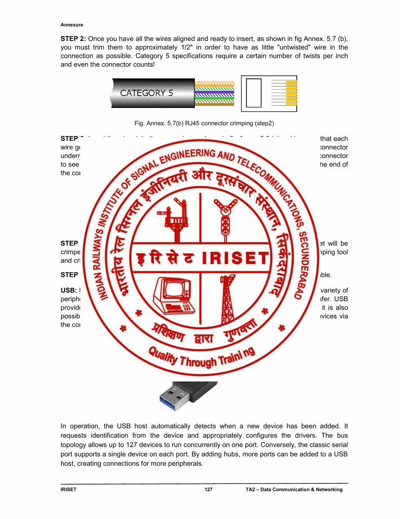
Annexure
IRISET 127 TA2 – Data Communication & Networking
STEP 2: Once you have all the wires aligned and ready to insert, as shown in fig Annex. 5.7 (b), you must trim them to approximately 1/2" in order to have as little "untwisted" wire in the connection as possible. Category 5 specifications require a certain number of twists per inch and even the connector counts!
Fig. Annex. 5.7(b) RJ45 connector crimping (step2) STEP 3: Insert the wires into the connector as shown in fig Annex.5.8 (c) making sure that each wire goes into its appropriate "channel" and extends all the way to the end of the the connector underneath the gold crimping connectors. Sometimes you can look at the end of the connector to see the copper wires if you're using solid copper cable. If the wires don't extend to the end of the connector, the crimp may not make contact.
Fig.Annex. 5.8 (c) RJ45 connector crimping (step3) STEP 4: Press the cable and the jacket into the connector firmly so that the jacket will be crimped by the plastic wedge near the rear of the connector, and insert it into your crimping tool and crimp the cable. RE-CRIMP the cable to make sure all connections are made.
STEP 5: Repeat steps 1 thru 4 for the other end of the cable for a standard Ethernet cable. USB: Universal Serial Bus, it is one of the most common interfaces for connecting a variety of peripherals to computers and providing relatively local and small levels of data transfer. USB provides a sufficiently fast serial data transfer mechanism for data communications, it is also possible to obtain power through the connector making it possible to power small devices via the connector and this makes it even more convenient to use, especially ‘on-the-go’.
In operation, the USB host automatically detects when a new device has been added. It requests identification from the device and appropriately configures the drivers. The bus topology allows up to 127 devices to run concurrently on one port. Conversely, the classic serial port supports a single device on each port. By adding hubs, more ports can be added to a USB host, creating connections for more peripherals.
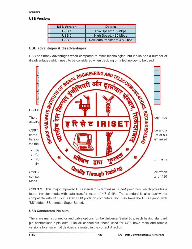
Annexure
IRISET 128 TA2 – Data Communication & Networking
USB Versions
USB Version Details USB 1 Low Speed: 1.5 Mbps USB 2 High Speed: 480 Mbps USB 3 Raw data transfer of 4.8 Gbps
USB advantages & disadvantages USB has many advantages when compared to other technologies, but it also has a number of disadvantages which need to be considered when deciding on a technology to be used.
USB Universal Serial Bus Standards There have been several USB, Universal Serial Bus standards as the technology has developed: USB 1.1, USB 2.0 and USB 3.0 / 3.1, each adding to the performance. USB1.1: This was the original version of the USB. It provided a Master / Slave interface and a tiered star topology which was capable of supporting up to 127 devices and a maximum of six tiers or hubs. The master or "Host" device is normally a PC with the slaves or "Devices" linked via the cable. The limitations are
Data transfer rates Low speed: 1.5 Mbps , Full speed: 12 Mbps Cable length is limited to 5 meters Power consumption specification allows each device to take up to 500mA, although this is
limited to 100mA during start-up. USB 2.0: The USB 2.0 standard is a development of USB 1.1. The main difference when compared to USB 1.1 was the data transfer speed increase up to a "High Speed" rate of 480 Mbps. USB 3.0: This major improved USB standard is termed as SuperSpeed bus, which provides a fourth transfer mode with data transfer rates of 4.8 Gbit/s. The standard is also backwards compatible with USB 2.0. Often USB ports on computers, etc. may have the USB symbol with 'SS' added. SS denotes Super Speed. USB Connectors Pin outs There are many connector and cable options for the Universal Serial Bus, each having standard pin connections / pin outs. Like all connectors, those used for USB have male and female versions to ensure that devices are mated in the correct direction.
Advantages Disadvantages Ease of use Data transfer not as fast as some other systems Acceptable data rate for many applications
Limited capability & overall performance
Robost connector system
Variety of connector types/sizes available
Low cost
Annexure
IRISET 129 TA2 – Data Communication & Networking
USB connector types
There are seven USB connector types: Type A, Type B, Mini-A, Mini-B, Micro-A, Micro-B and Micro-AB. Types A and B have 4 pins within the connector, Mini and Micro A and B connectors have five pins. USB type A connector outlines
A USB cable can have one of two forms of connector in the original system. These are designated the "A" and "B" connectors. The connections to the connectors are given below. The female connector or receptacle is the type found on the host, e.g. computer, etc, whereas the male will be seen on items like flash memories, mouse connector, keyboard connector, etc..
USB type B connector outlines
A second connector type known as the Type B was often used for smaller peripherals. This had slightly different pin out arrangement.
USB Type A & B pinouts / connections
The basic USB pinouts for the connectors are given in the table below. Apart from the USB connector pinouts, the table also gives the wire colours used within the cables.
PIN WIRE COLOUR SIGNAL NAMES 1 Red Vbus (4.75 – 5.25 V) 2 White Data - 3 Green Data + 4 Black Ground
Shell Drain wire Shield
The connectors used for USB are designed to enable the power and ground connections to be made first applying power to the device before the signal lines are connected. This prevents the possibility of the signal lines being connected first with the possibility of power being drawn through them that could cause damage to the device. USB mini connector
With the reduction in size of many items of electronic equipment, even the Type-B connector was too large. As a result a USB Mini connector was devised and this is used on many cameras and mobile phones where space is at a premium. Two versions are available, namely the USB mini-A and the USB Mini-B. These USB mini connectors, both the Mini-A and Mini-B provide very compact connectivity, while also being able to provide a robust connector solution. The Mini-A and Mini-B plugs are approximately 3 by 7 mm
Annexure
IRISET 130 TA2 – Data Communication & Networking
USB micro connector
With space being even more confined on may items like today's modern cell-phones, an even smaller connector solution was needed and accordingly developed. Known as the USB micro connector, again both USB Micro-A and USB Micro-B versions are available.
The micro-A connector is 6.85 by 1.8 mm and it has a maximum over-mould size of 11.7 by 8.5 mm. The micro-B connector is 6.85 by 1.8 mm and this one has a maximum over-mould size of 10.6 by 8.5 mm.
Mini-USB used with digital cameras and computer peripherals .Micro-USB used to connect computer peripherals, video game controllers, and for charging smart phones. Mini and Micro USB connector pinouts
PIN WIRE COLOUR SIGNAL NAMES 1 Red Vbus (4.75 – 5.25 V) 2 White Data - 3 Green Data + 4 Not connected, it can sometimes be
ground or used as a presence indicator 5 Black Ground
Shell Drain wire Shield USB Data Transfer & Protocol, signaling and data transfer basics The data transfer methodology and protocol for USB provides an effective method of transferring the data across the interface in an effective and reliable manner. For USB 1 and 2 a four wire system is employed. The cables carry power, ground and then there is a twisted pair for the differential data transfer. The lines are designated data+ and data - The data uses an NRZI system, i.e. non-return to zero . In terms of operation, when the USB host powers up, it polls each of the slave devices in turn. There are four basic types of data transaction that can be made within USB.
Control: This type of data transaction within the overall USB protocol is used by the host to send commands or query parameters. The packet lengths are defined within the protocol as 8 bytes for Low speed, 8-64 bytes for Full, and 64 bytes for High Speed devices.
Interrupt: The USB protocol defines an interrupt message. This is often used by devices sending small amounts of data, e.g. mice or keyboards. It is a polled message from the host which has to request specific data of the remote device
Bulk: This USB protocol message is used by devices like printers for which much larger amounts of data are required. In this form of data transfer, variable length blocks of data are
Annexure
IRISET 131 TA2 – Data Communication & Networking
sent or requested by the Host. The maximum length is 64-byte for full speed Devices or 512 bytes for high speed ones. The data integrity is verified using cyclic redundancy checking, CRC and an acknowledgement is sent. This USB data transfer mechanism is not used by time critical peripherals because it utilizes bandwidth not used by the other mechanisms.
Isochronous: This form of data transfer is used to stream real time data and is used for applications like live audio channels, etc. It does not use and data checking, as there is not time to resend any data packets with errors - lost data can be accommodated better than the delays incurred by resending data. Packet sizes can be up to 1024 bytes.
USB cables - length and type
USB cables are available in multiple lengths, from around 3 feet to a little over 16-feet. The maximum length of a USB cable is 16 feet 5 inches (5 meters) for high-speed devices and 9 feet 10 inches (3 meters) for low-speed devices. These maximum lengths are due to data transfer timing and the risk of data loss if using longer cable lengths. However, by using USB hubs, you can connect two USB cables to effectively extend the distance between the two devices being connected. However, you should still avoid extending the cable beyond the 16-feet 5-inches total maximum length limit (unless you're using a USB hub). High Definition Multimedia Interface (HDMI)
HDMI (High-Definition Multimedia Interface) is a proprietary audio/video interface for transmitting uncompressed video data and compressed or uncompressed digital audio data from an HDMI-compliant source device, such as a display controller, to a compatible computer monitor, video projector, digital television, or digital audio device. HDMI is a digital replacement for analog video standards. HDMI implements the EIA/CEA-861 standards, which define video formats and waveforms, transport of compressed and uncompressed LPCM audio, auxiliary data, and implementations of the VESA EDID. CEA-861 signals carried by HDMI are electrically compatible with the CEA-861 signals used by the Digital Visual Interface (DVI). No signal conversion is necessary, nor is there a loss of video quality when a DVI-to-HDMI adapter is used. The CEC (Consumer Electronics Control) capability allows HDMI devices to control each other when necessary and allows the user to operate multiple devices with one handheld remote control device. Specification
The HDMI specification defines the protocols, signals, electrical interfaces and mechanical requirements of the standard. The maximum pixel clock rate for HDMI 1.0 is 165 MHz, which is sufficient to allow 1080p and WUXGA (1920×1200) at 60 Hz. HDMI 1.3 increases that to 340 MHz, which allows for higher resolution (such as WQXGA, 2560×1600) across a single digital link. An HDMI connection can either be single-link (type A/C/D) or dual-link (type B) and can have a video pixel rate of 25 MHz to 340 MHz (for a single-link connection) or 25 MHz to 680 MHz (for a dual-link connection). Video formats with rates below 25 MHz (e.g., 13.5 MHz for 480i/NTSC) are transmitted using a pixel-repetition scheme. HDMI versions
In the first specification of the HDMI interface HDMI 1.0, these speeds were directly copied from the DVI interface. Newer versions of HDMI allow higher pixel rates with 340 megapixel/sec starting with HDMI 1.3. Just as with DVI, two channels may be combined in a dual channel configuration giving a total of 680 megapixel/sec.
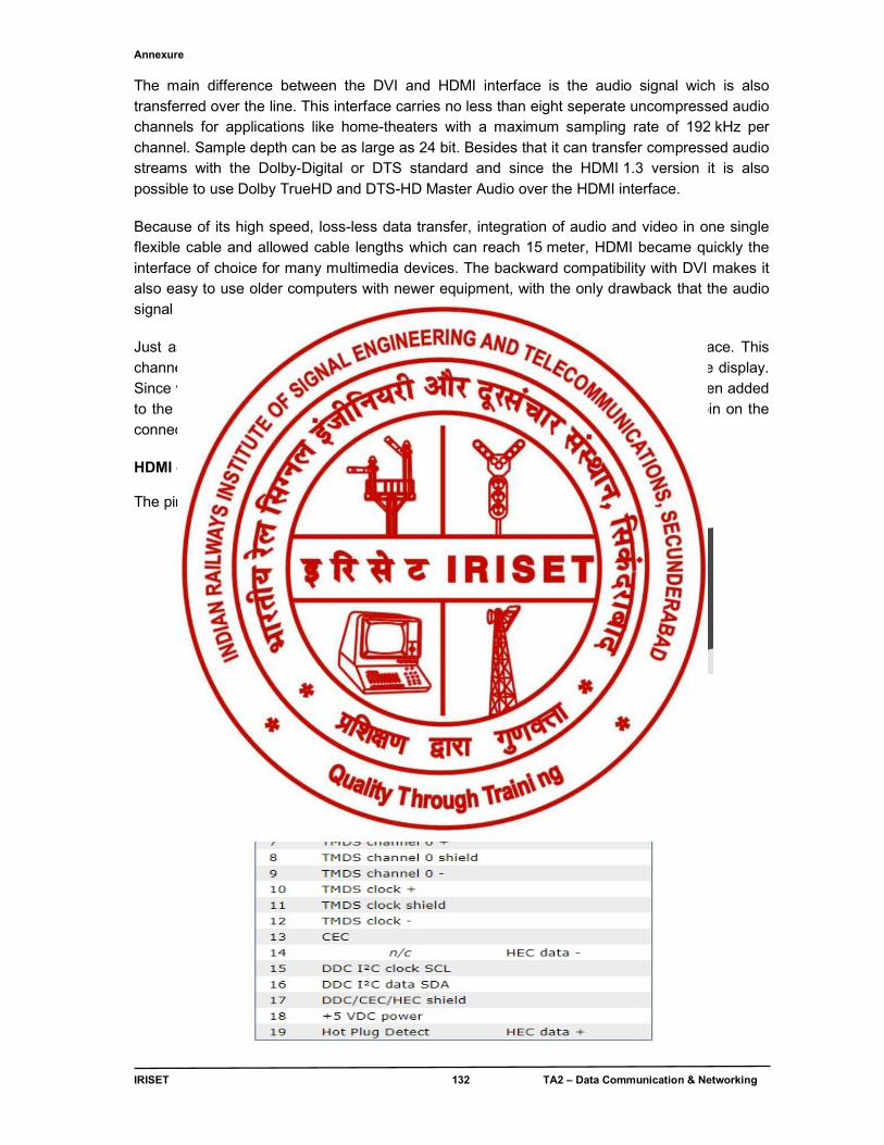
Annexure
IRISET 132 TA2 – Data Communication & Networking
The main difference between the DVI and HDMI interface is the audio signal wich is also transferred over the line. This interface carries no less than eight seperate uncompressed audio channels for applications like home-theaters with a maximum sampling rate of 192 kHz per channel. Sample depth can be as large as 24 bit. Besides that it can transfer compressed audio streams with the Dolby-Digital or DTS standard and since the HDMI 1.3 version it is also possible to use Dolby TrueHD and DTS-HD Master Audio over the HDMI interface. Because of its high speed, loss-less data transfer, integration of audio and video in one single flexible cable and allowed cable lengths which can reach 15 meter, HDMI became quickly the interface of choice for many multimedia devices. The backward compatibility with DVI makes it also easy to use older computers with newer equipment, with the only drawback that the audio signal should be connected over a different cable. Just as with VGA and DVI, an I²C compatible DDC channel is present on the interface. This channel can be used for control purposes and query the available video modes on the display. Since version HDMI 1.4 of the standard, a half-duplex ethernet communication has been added to the interface. To accomplish this, the hot-plug detection input and the last spare pin on the connector have been used for the differential lines of this ethernet channel. HDMI connector pin-out The pin layout of the HDMI interface connector is shown in the figure below.
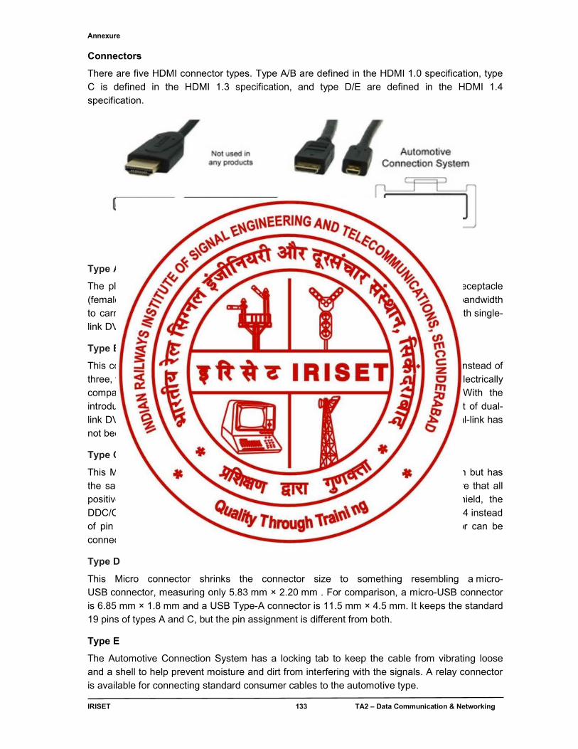
Annexure
IRISET 133 TA2 – Data Communication & Networking
Connectors
There are five HDMI connector types. Type A/B are defined in the HDMI 1.0 specification, type C is defined in the HDMI 1.3 specification, and type D/E are defined in the HDMI 1.4 specification.
Type A
The plug (male) connectors outside dimensions are 13.9 mm × 4.45 mm, and the receptacle (female) connector inside dimensions are 14 mm × 4.55 mm. There are 19 pins, with bandwidth to carry all SDTV, EDTV, HDTV, UHD, and 4K modes. It is electrically compatible with single-link DVI-D.
Type B
This connector is 21.2 mm × 4.45 mm and has 29 pins, carrying six differential pairs instead of three, for use with very high-resolution displays such as WQUXGA (3840×2400). It is electrically compatible with dual-link DVI-D, but has not yet been used in any products. With the introduction of HDMI 1.3, the maximum bandwidth of single-link HDMI exceeded that of dual-link DVI-D. As of HDMI 1.4, the pixel clock rate crossover frequency from single to dual-link has not been defined.
Type C
This Mini connector is smaller than the type A plug, measuring 10.42 mm × 2.42 mm but has the same 19-pin configuration. It is intended for portable devices. The differences are that all positive signals of the differential pairs are swapped with their corresponding shield, the DDC/CEC Ground is assigned to pin 13 instead of pin 17, the CEC is assigned to pin 14 instead of pin 13, and the reserved pin is 17 instead of pin 14. The type C Mini connector can be connected to a type A connector using a type A-to-type C cable.
Type D
This Micro connector shrinks the connector size to something resembling a micro-USB connector, measuring only 5.83 mm × 2.20 mm . For comparison, a micro-USB connector is 6.85 mm × 1.8 mm and a USB Type-A connector is 11.5 mm × 4.5 mm. It keeps the standard 19 pins of types A and C, but the pin assignment is different from both.
Type E
The Automotive Connection System has a locking tab to keep the cable from vibrating loose and a shell to help prevent moisture and dirt from interfering with the signals. A relay connector is available for connecting standard consumer cables to the automotive type.
Annexure
IRISET 134 TA2 – Data Communication & Networking
The HDMI alternate mode lets a user connect the reversible USB-C connector with the HDMI source devices (mobile, tablet, laptop). This cable connects to video display/sink devices using any of the native HDMI connectors. This is an HDMI cable, in this case a USB-C to HDMI cable. Cables An HDMI cable is composed of four shielded twisted pairs, with impedance of the order of 100 Ω (±15%), plus seven separate conductors. HDMI cables with Ethernet differ in that three of the separate conductors instead form an additional shielded twisted pair (with the CEC/DDC ground as a shield). Although no maximum length for an HDMI cable is specified, signal attenuation (dependent on the cable's construction quality and conducting materials) limits usable lengths in practice and certification is difficult to achieve for lengths beyond 13 m.
Annexure
IRISET 135 TA2 – Data Communication & Networking
ANNEXURE - 6 CARE AND HANDLING PRECAUTIONS OF ADAPTER, CONNECTORS, CHORDS,
PLUGS AND RECEPTACLES All adapter connectors, chords, plugs and receptacles require careful handling to avoid damage and interconnection problems which are very difficult to troubleshoot. To achieve optimum performance and to prolong the life, observe the following handling precautions:
1. Avoid Torque Forces (Twisting) while individual cables within the test adapter have some rotational freedom, twisting as a unit, with one end held stationary, may damage or severely degrade performance.
2. Avoid Sharp Cable Bends Never bend cables into a radius of 26 mm or less. Never bend cables greater than 90°. Single or multiple cable bends must be kept within this limit. Bending the cables less than a 26mm radius will permanently damage or severely degrade test adapter performance.
3. Avoid Cable Tension (Pull Forces) Never apply tension (pull forces) to an individual coaxial cable that is greater than 2.3 kg To avoid applying tension use adjustable elevation stands
4. Independently support instrument cables or accessories that are OEM approved. Always use standard accessories. Use of non standard male plugs for connections on the equipments receptacles can lead to wear and tear of costly low ohmic loss contacts made of gold and lead to malfunction.
5. Making and breaking connections while the sets are ON can cause damage of memory components and lead to system failure. Breaking of connections cause inrush current so it is favorable to follow the method told by OEM or withdraw connections after the system is put off.
6. Blind use of connectors that are power enabled can lead to the damage of adapters’ .While dealing with POE and Power enabled USB we need to be cautious.
7. While transportation proper care must be taken to carry them in suitable enclosures and packing to avoid ingress of water or moisture and mechanical damage.
8. Labeling and marking at the ends of the chords like DTE, DCE, clocked etc. should be marked to avoid chaos during testing.
Question Bank
IRISET 136 TA2 – Data Communication & Networking
QUESTION BANK Objective: Chapter 1
1) The _______ is the physical path over which a message travels. a) Protocol b) Medium c) Signal d) Network 2) Frequency of failure and network recovery time after a failure are measured as a) Performance b) Reliability c) Security d) Feasibility 3) Which topology requires a multipoint connection? a) Mesh b) Star c) Bus d) Ring 4) _______ refers to the structure or format of the data, meaning the order in which they
are presented. a) Semantics b) Syntax c) Timing d) encoding 5) Data flow between two devices can occur in both directions simultaneously in a _______
method. a) simplex b) half-duplex c) full-duplex d) quadruplex 6) _____ refers to the physical or logical arrangement of a network. a) Data flow b) Mode of operation c) Topology d) protocol 7) ________ is a collection of many separate networks. a) WAN b) Internet c) LAN d) MAN 8) The process-to-process delivery of the entire message is the responsibility of the __ layer. a) Network b) Transport c) Application d) Physical 9) Mail services are available to network users through the _______ layer. a) Data link b) Physical c) Transport d) Application 10) As the data packet moves from the upper to the lower layers, headers are _______. a) Added b) Removed c) Rearranged d) Modified
11) When a host on network A, sends a message to a host on network B, which address does
the router look at? a) Port b) Logical c) Physical 12) The ______ layer is responsible for moving frames from one hop (node) to the next. a) Physical b) Data link c) Transport Chapter 2 1. ________ is a type of transmission impairment in which the signal loses strength due to the
different propagation speeds of each frequency that makes up the signal. a) Attenuation b) Distortion c) Noise d) Decibel 2. A _________ signal is a composite analog signal with an infinite bandwidth. a) Digital b) Analog
3. Which encoding method uses alternating positive and negative values for 1s? a) NRZ-I b) RZ c) Manchester d) AMI
Question Bank
IRISET 137 TA2 – Data Communication & Networking
4. In a _____ scheme, all the signal levels are on one side of the time axis, either above or below.
a) Polar b) Bipolar c) Unipolar 5. In ______ schemes, the voltages are on the both sides of the time axis. For example, the
voltage level for 0 can be positive and the voltage level for 1 can be negative. a) Polar b) Bipolar c) Unipolar 6. In _____ the level of the voltage determines the value of the bit. a) NRZ-I b) NRZ-L 7. In Manchester and differential Manchester encoding, the transition at the middle of the bit is
used for __________. a) Bit transfer b) Baud transfer c) Synchronization 8. In _______encoding, we use three levels: positive, zero, and negative. a) Unipolar b) Bipolar c) Polar 9. ______ substitutes four consecutive zeros with 000V a) B4B8 b) HDB3 c) B8ZS
Chapter 3
1. HDLC is an acronym for _______.
a) High-duplex line communication b) Half-duplex digital link combination c) High-level data link control d) Host double-level circuit 2. Flow control is needed to prevent ________.
a) Overflow of the sender buffer b) Overflow of the receiver buffer c) Bit errors d) Collision between sender and receiver 3. Which error detection method uses ones complement arithmetic?
a) Simple parity check b) Checksum c) Two-dimensional parity check d) CRC 4. Which error detection method consists of just one redundant bit per data unit?
a) Two-dimensional parity check b) CRC c) Simple parity check d) Checksum 5. Which error detection method involves polynomials?
a) CRC b) Simple parity check c) Two-dimensional parity check d) Checksum 6. If an Ethernet destination address is 07-01-02-03-04-05, then this is a ______ address.
a) Unicast b) Broadcast c) Multicast d) IP address
Chapter 4
1. Identify the class of IP address 191.1.2.3. a) Class A b) Class B c) Class C d) Class D
2. A subnet mask in class B has nineteen 1s. How many subnets does it define? a) 128 b) 8 c) 32 d) 64
3. Given the IP address 18.250.31.14 and the subnet mask 255.255.0.0, what is the subnet / network address? a) 18.9.0.14 b) 18.0.0.14 c) 18.31.0.14 d) 18.250.0.0
4. _______ is a client-server program that provides an IP address, subnet mask, IP address of a router, and IP address of a name server to a computer. a) NAT b) DHCP c) CIDR d) ISP
Question Bank
IRISET 138 TA2 – Data Communication & Networking
5. In ______ routing, the mask and destination addresses are both 0.0.0.0 in the routing table. a) Default b) Next-hop c) Network-specific d) Host-specific
6. A routing table contains _______. a) The destination network ID b) The hop count to reach the network
c) The router ID of the next hop d) All the above
7. An area border router can be connected to _______ a) Only another router b) Only another network c) Only another area border router d) Another router or another network
8 OSPF is based on _______. a) Distance vector routing b) Path vector routing
c) Link state routing d) (a) and (b)
9. RIP is based on _______. a) Link state routing b) Dijkstra's algorithm
c) Path vector routing d) Distance vector routing
Chapter 5
1. Dial-up modems are
a. Synchronous b) Simplex c) Asynchronous
2. Modem pair required for WAN connectivity over leased lines are a. Asynchronous V.35 + G.703 b) Synchronous V.35 + G.703 c) Synchronous V.35 + V.35 d) None of the above
3. ADSL modem uses modulation method a. QAM + FDM b) TDM+FSK c) FDM+FSK d) All above
4. HDSL modem uses line coding technique
a. HDB3 b) 2B1Q c) Manchester d) AMI
5. Modulation technique adopted for DSL modems are a. Frequency shift keying b) Discrete multi tone c) QPSK d) None of the above
6. DSLAM stands for ----------------------------------------
7. ADSL stands for ---------------------------------------------
Chapter 6
1. IEEE standard for WLAN is
a) 802.11 b) 802.2 c) 802.3 d) 802.10 2. Access Protocol for WLAN is
a) CSMA b) CSMA / CD
c) CSMA / CA d) None of the above
3. BSSID of access point is
a) 48 bit IP address b) 32 bit MAC address
c) 48 bit MAC address d) None of the above
4. RF band used for WLAN is
a) 0.4 GHz b) 2.4 GHz
c) 1.2 GHz d) None of the above
Question Bank
IRISET 139 TA2 – Data Communication & Networking
5. The bandwidth available in 802.11a WLAN is a) 2 Mbps b) 54 Mbps c) 11 Mbps d) 108 Mbps
Chapter 7
1. The no. of bits used in IPv6 address is ------------------------- a) 32 bits b) 48 bits c) 64 bits d) 128 bits
2. IPv6 addresses are represented using ----------------------- notation a) Dotted decimal notation b) Colon Hex notation c) Dotted hex notation d) Colon decimal notation
3. In IPv6 leading zeros in a quartet are omitted
a) TRUE b) FALSE
4. In IPv6 consecutive sections of zeros are omitted using_______ a) Single colon ( : ) b) Comma (,) c) Double colon (::) d) dot (.)
5. In IPv6 the unique local address is represented as --------------------- a) FC00::/7 b) 2000::/3 c) FE80::/10 d) FF00::/8
6. In IPv6 the link local address is represented as --------------------- a) FC00::/7 b) 2000::/3 c) FE80::/10 d) FF00::/8
7. IPv6 the global unicast address is represented as --------------------- a) FC00::/7 b) 2000::/3 c) FE80::/10 d) FF00::/8
8. IPv6 the multicast address is represented as --------------------- a) FC00::/7 b) 2000::/3 c) FE80::/10 d) FF00::/8
9. The loop back address of IPv6 is represented as --------------------- a) ::/128 b) ::1/128 c) ::2/128 d) ::3/128
10. The default address in IPv6 is represented as --------------------- a) ::/0 b) ::/64 c) ::/48 d) ::/64
11. IPv6 addresses support --------------------.
a) broadcast address b) multicast address
12. Link-local address is ----------------------- a) Routable b) Non-routable
13. In IPv6 migration, dual stack approach consists of both IPv4 & IPv6 addresses a) TRUE b) FALSE
SUBJECTIVE:
Chapter 1
1. What are the factors that make data communication effective? 2. What are the five (5) components of data communication? 3. Mention the modes of data flow between sender & receiver? 4. What are factors that affect network? 5. What is the OSI model and why it should be learnt? 6. Discuss OSI layers, its relevance with Network, functions and associated protocols for data
communication?
Question Bank
IRISET 140 TA2 – Data Communication & Networking
7. What are data transmission modes? a. Describe Serial / Parallel b. Describe Synchronous / Asynchronous?
8. What is topology? What are different topologies of networking? 9. What are the categories of network? Discuss? 10. What are protocols? What are the factors that establish protocols? Discuss the relevance of
protocols in Networking? 11. Write summary of the function of all layers in ISO’s OSI model. Chapter 2
1. What is information, Data, Signal? Discuss the difference between them? 2. Why encoding of signal is required? Discuss the different methods? 3. What is meant by line coding & block coding? What is its relevance? Discuss its benefits? 4. Name two (2) major categories of transmission media? Discuss twisted pair category wise? Chapter 3
1. What are the different steps followed in Data link control? Describe flow control? 2. Discuss cyclic redundancy check (CRC) & Checksum? What for these are used? 3. What is Ethernet? Mention the standard that is equivalent to Ethernet? Draw the frame
structure? 4. Why is Ethernet told to be scalable? How is it most suitable LAN technologies? 5. How multiple accesses are resolved over the media on data link layer? Explain CSMA / CD
& CSMA / CA 6. What are EIA / TIA 568A & 568B wiring standards? On which media it is used? 7. Differentiate between a L-2 and L-3 switch . 8. Write a short note on VLAN . 9. State the advantages of using VLANS. Chapter 4
1. What is Internet protocol IP) ? How it is related to functioning of a network ? 1. Discuss IP addressing scheme in detail? 2. Why sub netting is required in Networks? Mention the methods for the same? 3. What is Internet Protocol (IP)? How it is related to functioning 4. What is routing? How routing is accomplished in Networks? Mention different methods of
routing? 5. Draw & explain IP datagram structure? 6. Explain how Router is a WAN device? What functions it performs in Networks? 7. How Routers are intelligent? Mention the elements that make the Router to decide the
routes for movement of packets? 8. What is MPLS? Explain briefly? Chapter 5
1. What is Modem? Why it is required in long distance data transmission? 2. What is Digital Subscriber Line (DSL)? Explain the working of ADSL modems with a
suitable diagram?
Question Bank
IRISET 141 TA2 – Data Communication & Networking
Chapter 6
1. Describe the WLAN standards? 2. Write short notes on WLAN security protocols? 3. Describe how to secure access points both administrator & user prospective? Chapter 7
1. What is the necessity of deviating (replacing) from IPv4 address to IPv6 address? 2. What is IPv6 address format and mention the rules for abbreviation ? 3. What are the differences between IPv4 and IPv6 addresses? 4. What are the other advantages of using IPv6 besides increased address space? 5. What are the different classifications of IPv6 addresses? 6. What is the different Special address used in IPv6, mention their ranges? 7. What are the different approaches for IPv6 Migration? KEY to OBJECTIVE QUESTIONS Chapter 1
1) b 2) b 3) c 4 ) b 5) c 6) c 7) b 8) b 9) d 10) a 11) b 12) b
Chapter 2
1) a 2) a 3) d 4 ) c 5) a 6) b 7) c 8) b 9) b
Chapter 3
1) c 2) b 3) b 4 ) c 5) a 6) a Chapter 4
1) b 2) b 3) d 4 ) b 5) a 6) d 7) c 8) c 9) d
Chapter 5
1) c 2) b 3) a 4 ) b 5) b 6 ) Digital Subscriber Line Access Multiplexer 7) Asymmetric Digital Subscriber Line
Chapter 6
1) a 2) c 3) c 4 ) b 5) b Chapter 7
1) d 2) b 3) a 4 ) c 5) a 6) c 7) b 8) d 9) b 10) a 11) b 12) b 13) a
Abbreviations/Acronyms
IRISET 142 TA2 – Data Communication & Networking
ABBREVIATIONS/ACRONYMS
A
AAL application adaptation layer ABM asynchronous balanced mode ACK acknowledgment ACL asynchronous connectionless link ADSL asymmetric digital subscriber line AES Advanced Encryption Standard AH Authentication Header AM amplitude modulation AMPS Advanced Mobile Phone System ANSI American National Standards Institute ARP Address Resolution Protocol ARPA Advanced Research Projects Agency ARPANET Advanced Research Projects Agency Network ARQ automatic repeat request AS authentication server AS autonomous system ASCII American Standard Code for Information Interchange ASK amplitude shift keying ATM Asynchronous Transfer Mode AUI attachment unit interface AMI alternate mark inversion AP access point B
BER Basic Encoding Rules BGP Border Gateway Protocol BOOTP Bootstrap Protocol BSS basic service set B8ZS bipolar with 8-zero substitution C
CA Certification Authority CBR constant bit rate CBT Core-Based Tree CCITT Consultative Committee for International Telegraphy and Telephony CCK complementary code keying CDMA code division multiple access CGI Common Gateway Interface CHAP Challenge Handshake Authentication Protocol CIDR Classless InterDomain Routing CIR committed Information rate CMTS cable modem transmission system CRC cyclic redundancy check CSMA carrier sense multiple access CSMA/CA carrier sense mUltiple access with collision avoidance CSMA/CD carrier sense multiple access with collision detection D
D-AMPS digital AMPS DARPA Defense Advanced Research Projects Agency dB decibel
Abbreviations/Acronyms
IRISET 143 TA2 – Data Communication & Networking
DDNS Dynamic Domain Name System DDS digital data service DEMUX demultiplexer DES data encryption standard DHCP Dynamic Host Configuration Protocol DLCI data link connection identifier DMT discrete multitone technique DNS Domain Name System DES data encryption standard DEMUX demultiplexer DDS digital data service Spectrum DDNS Dynamic Domain Name System DCF distributed coordination function DLCI data link connection identifier DMT discrete multitone technique D-AMPS digital AMPS DS digital signal DSL digital subscriber line DSLAM digital subscriber line access multiplexer DSSS direct sequence spread spectrum DVMRP Distance Vector Multicast Routing Protocol DWDM dense wave-division multiplexing E
ESS Extended Service Set EIA Electronics Industries Association F
FDM frequency-division multiplexing FTP File Transfer Protocol FSK frequency shift keying FECN forward explicit congestion notification FDMA frequency-division multiple access FHSS frequency hopping spread spectrum FM frequency modulation FIFO first-in, first-out FQDN fully qualified domain name G
GPS Global Positioning System GSM Global System for Mobile Communication H
HDLC High-level Data Link Control HDSL high bit rate digital subscriber line HR-DSSS High Rate Direct Sequence Spread HTML HyperText Markup Language HTTP HyperText Transfer Protocol Hz hertz I
IANA Internet Assigned Numbers Authority ICANN Internet Corporation for Assigned Names and Numbers
Abbreviations/Acronyms
IRISET 144 TA2 – Data Communication & Networking
ICMP Internet Control Message Protocol lAB Internet Architecture Board IEEE Institute of Electrical and Electronics Engineers ICMPv6 Internet Control Message Protocol, version 6 IETF Internet Engineering Task Force IGMP Internet Group Management Protocol IP Internet Protocol IMAP4 Internet Mail Access Protocol, version 4 IPng Internet Protocol next generation IPSec IP Security INTERNIC Internet Network Information Center IPv4 Internet Protocol version 4 IPv6 Internet Protocol, version 6 IRTF Internet Research Task Force IPEG Joint Photographic Experts Group ISO International Organization of Standardization ISOC Internet Society ITU-T International Telecommunications Union-Telecommunication Standardization sector ITM-2000 Internet Mobile Communication J, K
JPEG Joint Photographic Experts group L
LAN local area network LCP Link Control Protocol LEO low earth orbit LLC logical link control LSA link state advertisement LSP link state packet L2CAP Logical Link Control and Adaptation Protocol M
MAC medium access control sublayer MA multiple access MAC message authentication code MAN metropolitan area network MEO medium Earth orbit MIB Management Information Base MLT-3 multiline transmission, 3-level MPEG motion picture experts group MOSPF Multicast Open Shortest Path First MSC mobile switching center MTU maximum transfer unit MUX multiplexer N
NAP network access point NAT network address translation NAV network allocation vector NCP Network Control Protocol NIC network interface card NNI network-to-network interface
Abbreviations/Acronyms
IRISET 145 TA2 – Data Communication & Networking
NRM nonnal response mode NRZ nonreturn to zero NRZ-I nonreturn to zero, invert O
OC optical carrier OFDM orthogonal frequency division multiplexing OSI Open Systems Interconnection OSPF open shortest path first P
PAM pulse amplitude modulation PAP Password Authentication Protocol PCM pulse code modulation PCS personal communication system PIM Protocol Independent Multicast PKI public key infrastructure PM phase modulation PN pseudorandom noise POP point of presence POP3 Post Office Protocol, version 3 POTS plain old telephone system PSK phase shift keying PVC permanent virtual circuit PPP Point-to-Point Protocol Q
QAM quadrature amplitude modulation QoS quality of service R
RADSL rate adaptive asymmetrical digital subscriber line RARP Reverse Address Resolution Protocol RFC Request for Comment RIP Routing Information Protocol ROM read-only memory RPB reverse path broadcasting RPF reverse path forwarding RPM reverse path multicasting RSVP Resource Reservation Protocol RTCP Real-time Transport Control Protocol RTP Real-time Transport Protocol RTSP Real-Time Streaming Protocol RTT round-trip time RZ return to zero S
SA Security Association SIP Session Initiation Protocol SNMP Simple Network Management Protocol SMTP Simple Mail Transfer Protocol SPE synchronous payload envelope SONET Synchronous Optical Network

Abbreviations/Acronyms
IRISET 146 TA2 – Data Communication & Networking
SNR signal-to-noise ratio SCTP Stream Control Transmission Protocol SDH Synchronous Digital Hierarchy SCP server control point SAR segmentation and reassembly SCCP signaling connection control point SDSL symmetric digital subscriber line SSL Secure Socket Layer SS7 Signaling System Seven SPI security parameter index SPE synchronous payload envelope STS synchronous transport signal STP shielded twisted-pair SVC switched virtual circuit STM synchronous transport module T
TCP Transmission Control Protocol TCP/IP Transmission Control Protocol/ Internetworking Protocol TDMA time division multiple access TDD-TDMA time division Duplexing TDMA TELNET Terminal Network TFTP Trivial File Transfer Protocol TOS type of service TCAP transaction capabilities application port TLS Transport Layer Security TSI time-slot interchange TTL time to live U
UDP User Datagram Protocol UNI user network interface UTP unshielded twisted-pair URL Uniform Resource Locator USB Unspecified bit rate USB Universal Serial Bus V
VBR variable bit rate VC virtual circuit VDSL very high bit rate digital subscriber VLAN virtual local area network VPN virtual private network VT virtual tributary W X Y Z
WAN wide area network WDM wave-division multiplexing WWW World Wide Web

Glossary
IRISET 147 TA2 – Data Communication & Networking
GLOSSARY
A
accuracy 2, 7
acknowledgment 30, 31
acronym 52, 80
adapter 90
addresses 17, 18, 20, 39, 47, 50, 58, 59, 60,
61, 62, 63, 64, 65, 70, 72, 73, 74, 97, 99,
100, 101, 102, 103, 104
administrative 50, 51
aggregate 94
algorithms 64, 98
aligned 92
amplitude 42, 83
analog 22, 23, 25, 26, 27, 42, 80, 84
ansi 13
anycast 101, 103
architecture 13, 15, 16, 29, 90, 91, 92, 93,
99
asymmetric 85, 87, 88
asynchronous 5, 6, 70, 82, 83
attenuation 24, 81, 83, 87
authentication 79
autonomous 68
B
bandwidth 8, 22, 23, 24, 25, 26, 28, 29, 38,
47, 48, 51, 67, 84, 85, 89, 92, 98
baseband 23, 25, 41
baud 25, 26
beacons 93
binary 1, 4, 16, 35, 57, 59, 80
block 27, 31, 32, 33, 34, 48, 59, 61, 63, 92,
93, 102
bps 24, 26, 80, 81, 82, 83
bridge 46, 50, 51, 70
broadcast 38, 39, 47, 49, 50, 51, 58, 59, 64,
69, 71, 91, 96, 101
browser 10, 15, 19, 20, 21, 48
buffer 31, 36, 37
burst 31
bytes 5, 38, 48, 54, 56, 57, 58
C
cable 2, 9, 12, 17, 23, 28, 29, 40, 41, 42, 43,
44, 45, 46, 84, 85, 87, 89, 95, 97, 98
cache 70
cell 78
checksum 6, 7, 34, 35, 36, 48, 54, 56, 57
classful 60, 61, 62
classless 60, 62, 63
client 53, 91, 93, 96
clock 4, 38, 82, 83
coaxial 2, 28, 41, 87
codeword 32, 33
collisions 40, 47, 48, 90
colon 99
configuration 42, 48, 60, 65, 68, 70, 75, 87,
91, 101, 102, 103, 105, 106
connectionless 55, 58, 98
console 46, 48, 90
D
decibel 24
decryption 19
duplex 3, 36, 47, 48, 82, 87, 88
E
embedded 44, 48, 97, 106
enable 26, 46, 51, 53, 89, 90
encapsulate 75
Glossary
IRISET 148 TA2 – Data Communication & Networking
encoder 34
encrypted 79, 97
encryption 19, 79, 91, 95, 96, 97
equalizer 83
ethernet 47
F
ff00 99
fiber 2, 29, 41, 87, 89
firewall 11, 72, 73, 97
G
gateway 20, 21, 67, 71, 72, 93, 104, 106
H
hackers 97
hexadecimal 39, 99
hotspot 97
http 13, 14, 53
https 21
hub 46, 47
I
iec 14
ieee 13
ietf 14
impairment 24, 81
ingress 76
intranet 9, 10
intrinsic 99
iso 13
J
jitter 2
K
kbps 85, 87
L
label 75, 76, 77, 78
loopback 64, 99, 103
M
metric 67
microwave 91
migration 104
modem 14, 80, 81, 82, 83, 84, 85, 86, 87
modulation 25, 42, 81, 82, 83, 84, 85, 91
modulator 81
multicast 38, 39, 47, 59, 64, 101, 103
multimode 89
multiplexing 23, 81, 82
multipoint 12, 83, 97
multiport 46
N
neighboring 70, 71
null0 66
nyquist 25
O
octet 54, 55, 61, 62
offset 55, 57, 83
operapability 15
ospf 64
P
packet 2, 6, 7, 31, 36, 40, 46, 48, 56, 60, 65,
70, 71, 73, 74, 75, 76, 77, 88, 96, 101,
104, 105, 106
parity 82
password 94, 95, 96
ping 64
pixels 1
polynomial 33
preamble 38, 41
Glossary
IRISET 149 TA2 – Data Communication & Networking
prefix 66, 76, 101, 102, 103, 106
private 13, 62, 64, 68, 72, 73, 79, 81, 103
processor 1
programs 1, 96
proprietary 51
protocol 2, 14, 15, 18, 19, 20, 30, 36, 37, 38,
40, 47, 48, 50, 52, 54, 55, 57, 59, 66, 67,
68, 71, 72, 74, 75, 76, 77, 84, 90, 91, 96,
97, 98, 99, 101, 104, 106
pseudo 77, 84, 93
R
repeater 12, 87
router 48, 49, 51, 65, 66, 67, 68, 69, 70, 71,
75, 76, 77, 101, 103, 104, 105, 106
S
scrambling 27
serial 4, 5, 6, 14, 48, 70, 71
spectrum 91, 98
stub 103
subnetting 100
switches 1, 42, 44, 47, 48, 49, 50, 51, 70
symmetric 87
syntax 19
T
telnet 48
terminal 70, 81
terrestrial 28
throughput 26, 57, 94
timeliness 2
topology 11, 12, 13, 48, 65
transceiver 89
transmit 3, 6, 21, 30, 31, 37, 40, 81, 82, 83,
88, 91
tunneling 78, 79, 105, 106
twisted 2, 29, 43, 85, 87, 88, 89
U
unicast 47, 100, 101, 103
universal 91, 103
unnumbered 37
upstream 85, 86, 87
V
virtual 36, 49, 75, 77, 79, 103
W
wildcard 75
wireless 1, 2, 28, 41, 90, 91, 93, 94, 95, 96,
97, 98
workstation 2, 7, 73
References
IRISET 150 TA2 – Data Communication & Networking
References
1. Data Communication & Networking – Behrouz Forouzan. 2. Computer Networks – Andrew Tannenbaum 3. Understanding Data Communication Gilbert Held 4. EIA standards RS-232-C, 5. Data and Computer Communications, Stallings, W. Fourth Edition 6. Metropolitan Area Networks: Concepts, Standards, and Service, Kessler, G. and
Train, D. 7. Data Network Design, Spohn, D. 8. Data Networks: Concepts, Theory, and Practice, Black, U. 9. Data Communication Principles, Gitlin, R. D., Hayes, J. F., and Weinstein, S. B. 10. Principles of Data Communication, Martin, J. and Leben 11. WIKIPEDIA
References
IRISET 151 TA2 – Data Communication & Networking
For any suggestions mail to [email protected]/[email protected]
www.iriset.indianrailways.gov.in
भारतीय रेल सगनल इंिज नयर व दरूसचंार सं थान
तारनाका रोड, सकंदराबाद – 500 017
FAX: 070-89888(Rly), 040-27823922(BSNL), Ph: 040-27820315 © IRISET
VISION: TO MAKE IRISET AN INSTITUTE OF INTERNATIONAL REPUTE, SETTING ITS OWN STANDARDS AND BENCHMARKS. MISSION: TO ENHANCE QUALITY AND INCREASE PRODUCTIVITY OF SIGNALLING & TELECOMMUNICATION PERSONNEL THROUGH TRAINING
इ रसेट IRISET QUALITY THROUGH TRAINING श ण ारा गुणव ा


