Embed Size (px)
Citation preview
Deep excavation in urban areas – defects of surrounding buildings at various stages of construction
Jarosław Rybak1,*, Alexander Ivannikov2, Elena Kulikova2 , and Tomasz Żyrek3
1Wroclaw University of Science and Technology, Faculty of Civil Engineering, 50-370 Wrocław, Wyb Wyspianskiego 27, Poland 2MISiS National University of Science and Technology, Department of Underground Construction, Leninsky Ave, 4, Moskva, Russia, 119049 3Silesian University of Technology, Faculty of Civil Engineering, 44-100 Gliwice, Akademicka 2A, Poland
Abstract. Deep excavation and tunnelling works in city centres always bring some risks to surrounding structures, especially in the case of old town centres, where the technical condition and structural stiffness of historical buildings is rather doubtful. When the new desired excavation depth goes deeper than the foundation of the surrounding buildings or when tunnelling works are conducted directly under them, the existing objects are subject to stress, vibrations and displacements imposed at almost every stage of building the new construction. The presented paper outlines, on the basis of the authors’ experience, the typical damages appearing during the supporting wall construction (sheet pile driving, piling and formation of diaphragm walls) and tunnelling works. Other damages appear due to soil mass unloading (caused by excavation stages) and horizontal loading during pre-stressing of struts or ground anchors. The selected case studies of steel sheet pile wall installation is given with regard to typical failures caused by an unplanned excavation and its impact on neighbouring structures.
1 Introduction – the need for development of infrastructure Constant development of town centres, accompanied by earthworks and tunnelling, brings about many problems that need resolving. Some interesting experiences from Warsaw (Poland) were presented in recent works by Siemińska-Lewandowska [1, 2]. Both, tunnelling and deep excavation works, create some risks to the surrounding area [3]. In the old city centres, investors are required to ensure respective number of parking bays, which in turn demands 2-3 storeys of underground car parks. Apart from engineering problems, very stringent requirements of heritage conservator supervision are also raised. The problems with ensuring stability of excavation walls must be solved by examining foundations of neighbouring structures and possible strengthening them at all the stages of
* Corresponding author: [email protected]
© The Authors, published by EDP Sciences. This is an open access article distributed under the terms of the Creative Commons Attribution License 4.0 (http://creativecommons.org/licenses/by/4.0/).
MATEC Web of Conferences 146, 02012 (2018) https://doi.org/10.1051/matecconf/201814602012Building Defects 2017
earthworks, i.e. installation of the excavation protection walls, the excavation works themselves, and constructing basement storeys. Another problem refers to constructing underground storeys below the level of groundwater. Brief summery of those problems was given by Kulikova [4]. This requires efficient cutting-off or long-term lowering of water table inside the excavation with possibly limited intervention in hydrological regime beyond the project in progress. In the typical case of old cities in river valleys such “hoarding off” the excavation and cutting off groundwater leads to temporary or permanent disturbances of groundwater flow and possible local swellings. Contemporary technologies make it possible to protect vertical fault and simultaneously to cut-off groundwater inflow by means of steel sheet pilings, diaphragm walls or secant pile walls. Using them, we are able to construct monolithic reinforced concrete structures of underground tunnels or storeys thus ensuring both their tightness and high rigidity of foundation in the neighbourhood. Many examples of case studies concerning the geological risks related to tunnelling works can be found also in the references.
2 Design and execution problems at subsequent stages Every project starts from an outline proposal and preliminary design. Usually, the amount of field data at this stage is limited, so the structural engineer must rely on parametric studies. Interesting examples of such procedure were given by Mitew-Czajewska in work [5] and recently [6] where very sophisticated hypoplastic constitutive model of soil body was implemented to Finite Element Model computations in clays. Once the construction starts, it is possible to verify primary assumptions by means of continuous monitoring of displacements. That leads to a so-called “observational method” of design, where the design model may be currently updated on the basis of displacement monitoring. An example of such procedure was given by Gorska in articles [7, 8], on the basis of steel sheet pile wall design. Data for model updating may be provided by various monitoring systems, usually based on standard surveying techniques like geometrical precise levelling for vertical, and structural monitoring for horizontal displacement. Structural monitoring makes it possible to record automatically the state of the structure, cyclically at predefined time intervals. The obtained values of displacement are compared with the permissible values, visualized and sent remotely to relevant supervisory bodies. The main component of such a system is the motorized electronic total stations, which offer the precise measurement of the angles and distances. These total stations have the function of the automatic targets detection (indicated by means of geodetic prisms). Recent developments can be found in works of Drusa [9], Bednarski [10] and Muszyński [11], where the suitability of terrestrial laser scanning for the control of deep excavation support was examined. Recommendations concerning inclinometric measurements of soil mass displacements (slope stability) can be found in references given by Segalini [12] and Drusa [13].
Another group of problems is related to the vertical soil support installation. Most of the methods of sheet pile embedment (driving, vibratory driving) as well as other technologies impose some dynamic impact on the surrounding area by means of single blows or continuous vibrations. Wide studies on this impact and the formal limitations given by various codes of practice were gathered in works of Rybak [14], Brząkała [15, 16] and Oliveira [17]. In the current study however, only the static effects of deep excavations will be presented and examined.
Various factors may affect the safety of deep excavation: improper soil parameters taken for the design, unexpected surcharge load, changing water levels, and last but not least, the static scheme taken for a structural analysis. This last factor is often neglected, which brings serious threats, especially for cantilever structures that relay only on embedment.
2
MATEC Web of Conferences 146, 02012 (2018) https://doi.org/10.1051/matecconf/201814602012Building Defects 2017
earthworks, i.e. installation of the excavation protection walls, the excavation works themselves, and constructing basement storeys. Another problem refers to constructing underground storeys below the level of groundwater. Brief summery of those problems was given by Kulikova [4]. This requires efficient cutting-off or long-term lowering of water table inside the excavation with possibly limited intervention in hydrological regime beyond the project in progress. In the typical case of old cities in river valleys such “hoarding off” the excavation and cutting off groundwater leads to temporary or permanent disturbances of groundwater flow and possible local swellings. Contemporary technologies make it possible to protect vertical fault and simultaneously to cut-off groundwater inflow by means of steel sheet pilings, diaphragm walls or secant pile walls. Using them, we are able to construct monolithic reinforced concrete structures of underground tunnels or storeys thus ensuring both their tightness and high rigidity of foundation in the neighbourhood. Many examples of case studies concerning the geological risks related to tunnelling works can be found also in the references.
2 Design and execution problems at subsequent stages Every project starts from an outline proposal and preliminary design. Usually, the amount of field data at this stage is limited, so the structural engineer must rely on parametric studies. Interesting examples of such procedure were given by Mitew-Czajewska in work [5] and recently [6] where very sophisticated hypoplastic constitutive model of soil body was implemented to Finite Element Model computations in clays. Once the construction starts, it is possible to verify primary assumptions by means of continuous monitoring of displacements. That leads to a so-called “observational method” of design, where the design model may be currently updated on the basis of displacement monitoring. An example of such procedure was given by Gorska in articles [7, 8], on the basis of steel sheet pile wall design. Data for model updating may be provided by various monitoring systems, usually based on standard surveying techniques like geometrical precise levelling for vertical, and structural monitoring for horizontal displacement. Structural monitoring makes it possible to record automatically the state of the structure, cyclically at predefined time intervals. The obtained values of displacement are compared with the permissible values, visualized and sent remotely to relevant supervisory bodies. The main component of such a system is the motorized electronic total stations, which offer the precise measurement of the angles and distances. These total stations have the function of the automatic targets detection (indicated by means of geodetic prisms). Recent developments can be found in works of Drusa [9], Bednarski [10] and Muszyński [11], where the suitability of terrestrial laser scanning for the control of deep excavation support was examined. Recommendations concerning inclinometric measurements of soil mass displacements (slope stability) can be found in references given by Segalini [12] and Drusa [13].
Another group of problems is related to the vertical soil support installation. Most of the methods of sheet pile embedment (driving, vibratory driving) as well as other technologies impose some dynamic impact on the surrounding area by means of single blows or continuous vibrations. Wide studies on this impact and the formal limitations given by various codes of practice were gathered in works of Rybak [14], Brząkała [15, 16] and Oliveira [17]. In the current study however, only the static effects of deep excavations will be presented and examined.
Various factors may affect the safety of deep excavation: improper soil parameters taken for the design, unexpected surcharge load, changing water levels, and last but not least, the static scheme taken for a structural analysis. This last factor is often neglected, which brings serious threats, especially for cantilever structures that relay only on embedment.
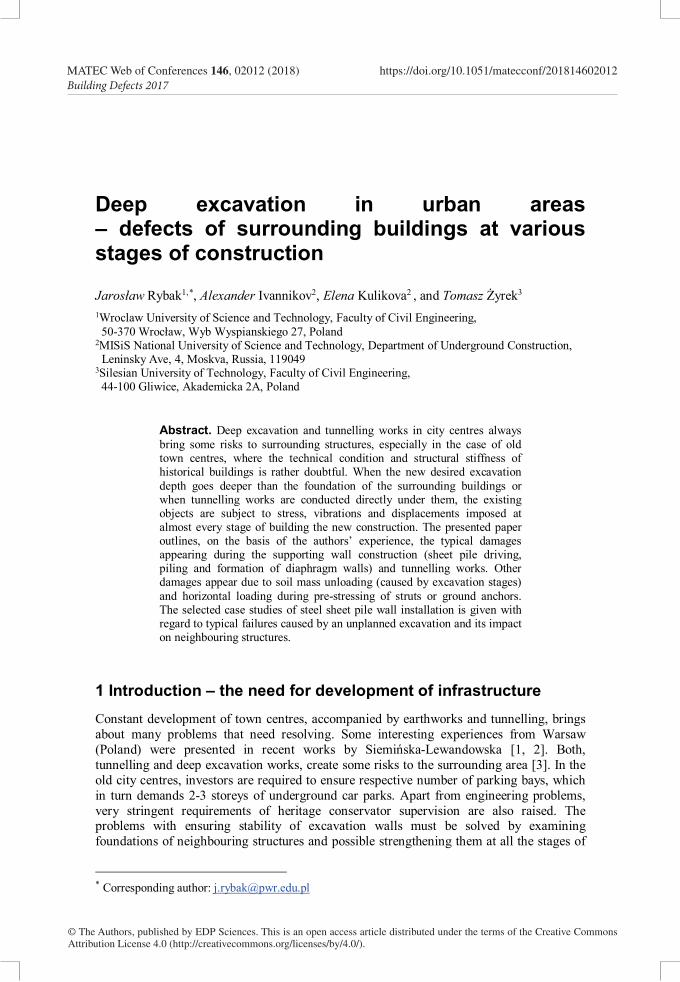
3 Case study – the consequences of an unplanned overdig The presented case study is taken from the building site in southern Poland. The excavation was necessary for the planned underground storey (car-park). Due to the limited depth of the excavation (4.0m to 4.5m) and for the simplicity of works, the designed scheme of the sheet pile wall was just the cantilever system with embedment providing stability and necessary stiffness of the support.
Geotechnical conditions presented on geological cross-section (Figure 1) were constituted by anthropogenic fill layer to the depth of around 1.5m. The underlying sand layers consisted of medium sands (MSa) with a free water table and deeper layers of hard plastic and stiff clays. The designers had sufficient data for proper static computation of required length and profile of sheet piles. Depending on the local geological profiles, the designed lengths of the sheet piles varied from 8.0m to 10.0m.
Fig. 1. Geological cross-section with anthropogenic deposits (Nn), sands (green) and clays (brown).
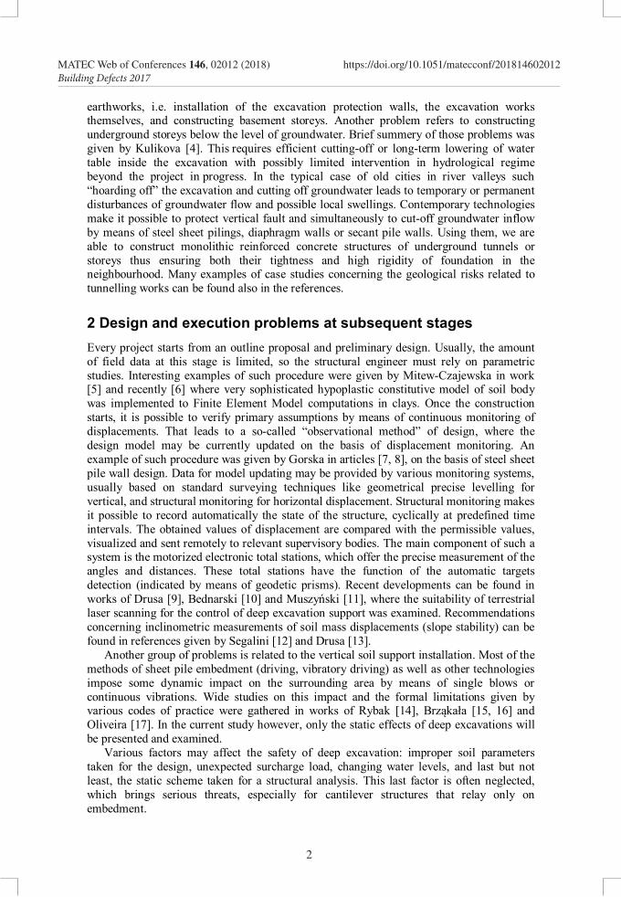
Just after the proper completion of earthworks (excavation) to the designed depth of 4.5m, the contractor made partially an additional excavation for the foundation plate of a crane lift. Unfortunately, the unplanned overdig (4.0m wide and 0.8m deep inside the excavation) was located adjacent to the wall which simply lost its designed embedment. Due to this unfortunate decision the measured horizontal displacement of the sheet pile wall reached in this region almost 0.3m (immediately – Figure 2) and went up to 0.5m due to swelling in the next days. Such large deformations caused problems on both sides of the wall. First – for the stability of the structures in the vicinity of the excavation. Second, even more difficult to solve, was related to the insufficient space for the designed basement walls.
3
MATEC Web of Conferences 146, 02012 (2018) https://doi.org/10.1051/matecconf/201814602012Building Defects 2017
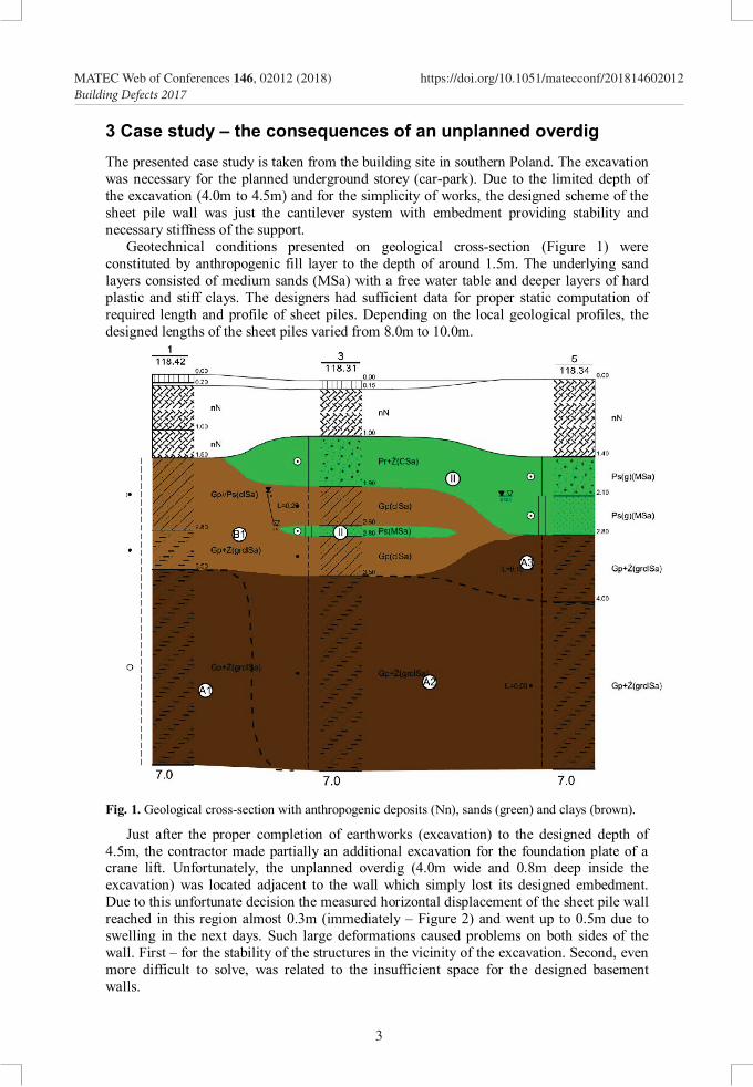
The scheme of the measured horizontal displacements around the excavation is given on Figure 2. One may notice that values measured in the situations corresponding to design assumptions (ROB1, ROB3, ROB4) fitted very well the preliminary assumptions (corresponding with the proper depth of 4.5m) presented on Figure 3a. Only in measuring point ROB2, the current displacement reached almost 0.3m.
Fig. 2. Monitoring of horizontal displacements of sheet pile heads at ground level.
Fig. 3. Computed horizontal displacements of wall at ground level a) for H=4.5m, b) for H=5.3m.
4
MATEC Web of Conferences 146, 02012 (2018) https://doi.org/10.1051/matecconf/201814602012Building Defects 2017
The scheme of the measured horizontal displacements around the excavation is given on Figure 2. One may notice that values measured in the situations corresponding to design assumptions (ROB1, ROB3, ROB4) fitted very well the preliminary assumptions (corresponding with the proper depth of 4.5m) presented on Figure 3a. Only in measuring point ROB2, the current displacement reached almost 0.3m.
Fig. 2. Monitoring of horizontal displacements of sheet pile heads at ground level.
Fig. 3. Computed horizontal displacements of wall at ground level a) for H=4.5m, b) for H=5.3m.
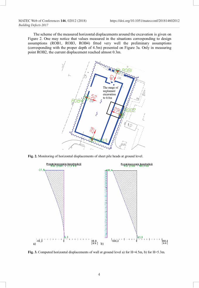
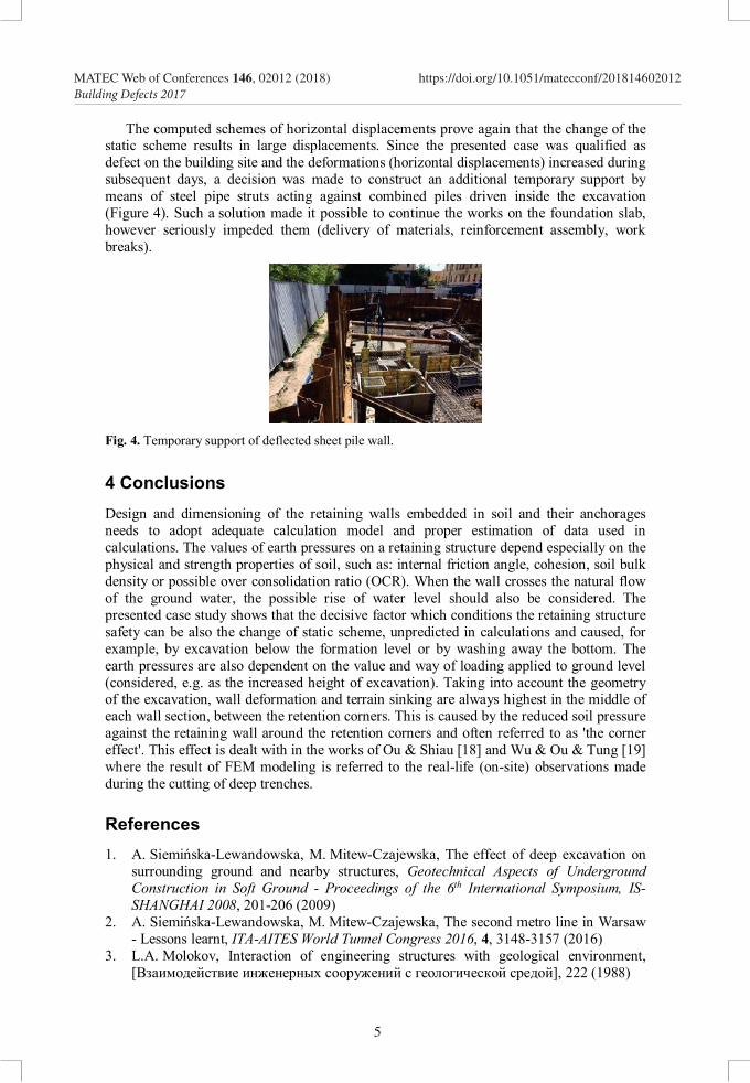
The computed schemes of horizontal displacements prove again that the change of the static scheme results in large displacements. Since the presented case was qualified as defect on the building site and the deformations (horizontal displacements) increased during subsequent days, a decision was made to construct an additional temporary support by means of steel pipe struts acting against combined piles driven inside the excavation (Figure 4). Such a solution made it possible to continue the works on the foundation slab, however seriously impeded them (delivery of materials, reinforcement assembly, work breaks).
Fig. 4. Temporary support of deflected sheet pile wall.
4 Conclusions Design and dimensioning of the retaining walls embedded in soil and their anchorages needs to adopt adequate calculation model and proper estimation of data used in calculations. The values of earth pressures on a retaining structure depend especially on the physical and strength properties of soil, such as: internal friction angle, cohesion, soil bulk density or possible over consolidation ratio (OCR). When the wall crosses the natural flow of the ground water, the possible rise of water level should also be considered. The presented case study shows that the decisive factor which conditions the retaining structure safety can be also the change of static scheme, unpredicted in calculations and caused, for example, by excavation below the formation level or by washing away the bottom. The earth pressures are also dependent on the value and way of loading applied to ground level (considered, e.g. as the increased height of excavation). Taking into account the geometry of the excavation, wall deformation and terrain sinking are always highest in the middle of each wall section, between the retention corners. This is caused by the reduced soil pressure against the retaining wall around the retention corners and often referred to as 'the corner effect'. This effect is dealt with in the works of Ou & Shiau [18] and Wu & Ou & Tung [19] where the result of FEM modeling is referred to the real-life (on-site) observations made during the cutting of deep trenches.
References 1. A. Siemińska-Lewandowska, M. Mitew-Czajewska, The effect of deep excavation on
surrounding ground and nearby structures, Geotechnical Aspects of Underground Construction in Soft Ground - Proceedings of the 6th International Symposium, IS-SHANGHAI 2008, 201-206 (2009)
2. A. Siemińska-Lewandowska, M. Mitew-Czajewska, The second metro line in Warsaw - Lessons learnt, ITA-AITES World Tunnel Congress 2016, 4, 3148-3157 (2016)
3. L.A. Molokov, Interaction of engineering structures with geological environment, [Взаимодействие инженерных сооружений с геологической средой], 222 (1988)
5
MATEC Web of Conferences 146, 02012 (2018) https://doi.org/10.1051/matecconf/201814602012Building Defects 2017
4. E.Y. Kulikova, Filtration reliability of structures of urban underground structures, [Фильтрационная надежность конструкций городских подземных сооружений], Издательство «Мир горной книги», 316 (2007)
5. M. Mitew-Czajewska, Numerical analysis of a 36m deep diaphragm wall - Parametric study, Geotechnical Aspects of Underground Construction in Soft Ground - Proceedings of the 8th Int. Symposium on Geotechnical Aspects of Underground Construction in Soft Ground, TC204 ISSMGE - IS-SEOUL 2014, 257-262 (2014)
6. M. Mitew-Czajewska, FEM modelling of deep excavation - Parametric study, Hypoplastic Clay model verification, MATEC Web of Conferences 117, 00121
7. K. Gorska, Z. Muszyński, J. Rybak, Displacement monitoring and sensitivity analysis in the observational method, Studia Geotechnica et Mechanica 35, No 3, 25-43 (2013)
8. K. Gorska, M. Wyjadłowski, An analysis of excavation support safety based on experimental studies, Studia Geotechnica et Mechanica 37 (3), 19-29 (2015)
9. M. Drusa, V. Chebeň, R. Bulko, New technologies implemented in geotechnical monitoring on transport constructions, 14th International Multidisciplinary Scientific GeoConference Surveying Geology and Mining Ecology Management, SGEM, 2 (1), 651-656 (2014)
10. Bednarski Ł., Sieńko R., Howiacki T.: Supporting historical structures technical condition assessment by monitoring of selected physical quantities, Procedia Engineering 195, 32-39 (2017)
11. Z. Muszyński, Assessment of suitability of terrestrial laser scanning for determining horizontal displacements of cofferdam during modernization works on the Rędzin sluice. 14th International Multidisciplinary Scientific GeoConference, SGEM 2014: GeoConference on informatics, geoinformatics and remote sensing, 2, 81-88 (2014).
12. A. Segalini, L. Chiapponi, M. Drusa, B. Pastarini, New inclinometer device for monitoring of underground displacements and landslide activity. Komunikácie 16 (4), 58-62 (2014)
13. M. Drusa, V. Chebeň, P. Prohovníková, Functionality of TDR piezometers and inclinometers for monitoring of slope deformations. SGEM GeoConference on science and technologies in geology, exploration and mining: 13th int. multidisciplinary scientific geoconference, Vol. II, Sofia: STEF92 Technology, 157-164 (2013)
14. W. Brząkała, A. Herbut, J. Rybak, Recommendations for ground vibrations survey in course of geotechnical works. 14th International Multidisciplinary Scientific GeoConference SGEM 2014: 2, Hydrogeology, engineering geology and geotechnics. Sofia : STEF92 Technology, 747-754 (2014)
15. W. Brząkała, M. Baca, The measurement and control of building vibrations in course of sheet pile wall and Franki pile driving, 17th Int. Multidisciplinary Scientific GeoConference, SGEM 2017 12, Science and technologies in geology, exploration and mining, 929-936 (2017)
16. F. Oliveira, I. Fernandes, Influence of geotechnical works on neighboring structures, 17th Int. Multidisciplinary Scientific GeoConference, SGEM 2017 12, Science and technologies in geology, exploration and mining, 993-1001 (2017)
17. J. Rybak, K. Schabowicz, Survey of vibrations generated in course of geotechnical works. NDE for Safety: 40th int. conf. and NDT exhibition: proceedings, Czech Republic, Brno University of Technology, 237-246 (2010)
18. Chang-Yu Ou, Bor-Yuan Shiau, Analysis of the corner effect on excavation behaviors. Canadian Geotechnical Journal; Jun 1998; 35, 3 ProQuest Central, 532 – 540 (1998)
19. Chao-Hui Wu, Chang-Yu Ou, N. Tung, Corner effects in deep excavations – establisment of a forecast model for Taibei Basin T2 Zone. Journal of Marine Science and Technology, 18 (1), 1-11 (2010)
6
MATEC Web of Conferences 146, 02012 (2018) https://doi.org/10.1051/matecconf/201814602012Building Defects 2017


