Embed Size (px)
Citation preview
Publ. S5-ML 4200-A, replaces S5-ML420-B
DENISON HYDRAULICSProportional Throttle Valve Series F5Cand Compensators Series R5A, R5P

SERVICEINFORMATIONF5C
2
F5C

SERVICEINFORMATIONF5C
3

SERVICEINFORMATIONF5C
4
SERVICEINFORMATIONF5C
5

SERVICEINFORMATIONF5C
6

MODEL CODE FOR F5C – PROPORTIONAL THROTTLE VALVE
7
Note:
F5C = Proportional Throttle Valve (without compensator)
F5C + R5A Compensator = 2-Port Proportional Flow Control Valve
F5C + R5P Compensator = 3-Port Proportional Flow Control Valve
Model Number: F5C .. ( . ) . . . 1 . . B . .− − − −
1 SeriesF5C = Proportional Throttle Valve
2 Size06 = 3/4HH ( 95 l/min)08 = 1HH (190 l/min)10 = 11/4HH (380 l/min)
3 Pilot Flow & ResponseA =
see table belowB = k
4 Max. Pressure3 = 210 bar (with internal check valve only)4 = 270 bar (without internal check valve)
5 Body3 = X3, Y2 ports = G 1/4HH4 = X3, Y2 ports = SAE-4 (7/16HH-20 UNF)
6 SpoolA = 23 l/min (for size code 06)B = 45 l/min (for size codes 06, 08)1 = 95 l/min (for size codes 06, 08, 10)2 = 190 l/min (for size codes 08, 10)3 = 380 l/min (for size code 10)
7 Adjusting Device1 = Proportional solenoid
8 Pilot Connection2 = internal PD − internal PP3 = external PD − external PP, (without plug in X1)4 = external PD − external PP, (with plug in X1)5 = external PD − internal PP, (without plug in X1)6 = external PD − internal PP, (with plug in X1)
9 Accessories0 = withoutC = with internal check valve (max. 210 bar)
10 Design Letter
11 Seal Class1 = NBR (Buna N) Standard4 = EPDM5 = FPM (Viton `)
12 Modification
1 2 3 4 5 6 7 8 9 0 1 2
Pilot Flow and Response Selection
Model Code Input Current Pilot Flow Max. Response (typical) Comments
F5C...(Std.) D.C. + A.C. Dither 1 l/min 350 ms Standard valve for low pilot flow loss notrecommended for use without A.C. Dither
F5C...A D.C. + A.C. Dither 2 l/min 250 ms Recommended for best overall performance
F5C...B D.C. + A.C. Dither 2 l/min 150 ms Maximum spool response but with maximumspool overshoot
SERVICEINFORMATIONR5A
8
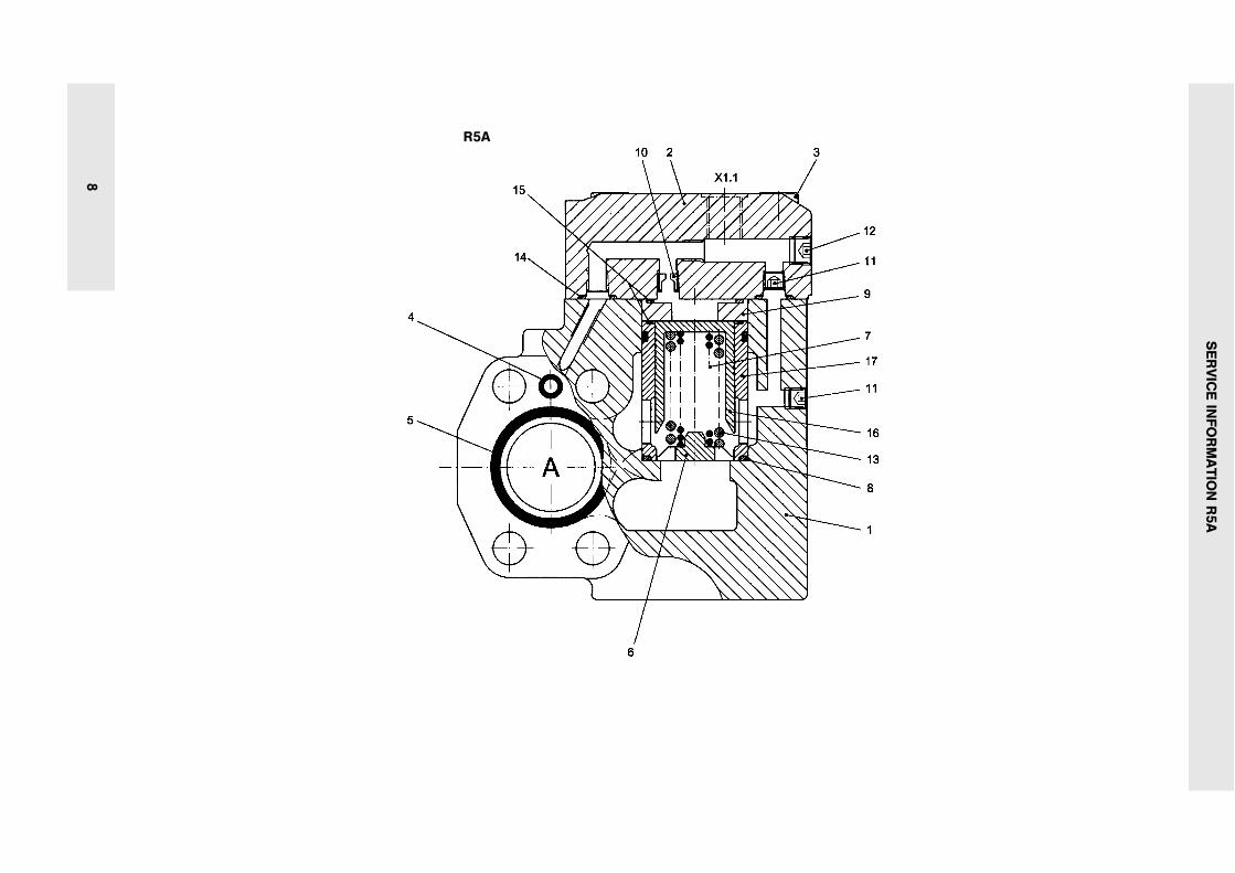
R5A

SERVICEINFORMATIONR5A
9

SERVICEINFORMATIONR5A
10

MODEL CODE FOR R5A – 2 PORT COMPENSATOR
11
Note:
R5A + F5C = 2-Port Proportional Flow Control Valve
Model Number: R5A .. . . . .. B .− − −
1 SeriesR5A = 2-Port Compensator
2 Size06 = 3/4HH08 = 1HH10 = 11/4HH
3 Max. Pressure (w/o F5C)0 = 350 bar (for cartridge only)4 = 280 bar, for 11/4HH body valve only5 = 350 bar, for 3/4HH & 1HH body valve only k SAE 61
4 Body0 = Cartridge4 = 2-port body
5 Top Cap1 = without X1.1 port (plain cap) (for pilot connection code 01)2 = X1.1 port = G 1/4HH (for pilot connection code 03)3 = X1.1 port = SAE-4 (7/16HH-20 UNF) (for pilot connection code 03)
6 Pilot Connection01 = Internal PP (port X1) 1)03 = External PP (port X1.1)1) Internal PP connection on flange face to link with inlet portof flow control valve F5C
7 Design Letter
8 Seal Class1 = NBR (Buna N) Standard4 = EPDM5 = FPM (Viton `)
9 Modification
1 2 3 4 5 6 7 8 9

SERVICEINFORMATIONR5P
12
R5P

SERVICEINFORMATIONR5P
13

SERVICEINFORMATIONR5P
14
SERVICEINFORMATIONR5P
15

MODEL CODE FOR R5P – 3 PORT COMPENSATOR
16
Note:R5P + F5C = 3-Port Proportional Flow Control Valve
omitfor version
without VV01& without P2
Model Number: R5P .. . . . . . .. ... A .− − − − − −
1 SeriesR5P = 3-Port Compensator
2 Size06 = 3/4HH08 = 1HH10 = 11/4HH
3 Max. Pressure (w/o F5C)0 = 350 bar (for cartridge only)4 = 280 bar, for 11/4HH body valve only5 = 350 bar, for 3/4HH & 1HH body valve only k SAE 61
4 Body Mounting
Cartridge with pilot head:0 = without Y1.1 port (plain cap, only with Pilot Connection code 2)E = Y1.1 port = G 1/4HH (only with Pilot Connection code 4)F = Y1.1 port = SAE-4 (only with Pilot Connection code 4)
Flange body with pilot head (Y1 port plugged):3 = X2.2, Y1.13) and M ports = SAE-49 = X2.2, Y1.13) and M ports = G1/4HH k 3) for Pilot Connection
codes 4 and 6 only
Flange body with pilot head (Y1 port open):P = X2.2, Y1.13) and M ports = G 1/4HHS = X2.2, Y1.13) and M ports = SAE-4 k 3) for Pilot Connection
codes 4 and 6 only
5 Pressure Setting Range1 = 7...105 bar3 = 7...210 bar5 = 7...350 bar
6 Adjusting Device1 = Hand knob 32 mm dia.2 = Hand knob 50 mm dia. (not for version with vent valve VV01 or P2)3 = Acorn nut with lead seal4 = Adjusting device with key lock, key order no. 700-70619-8
7 Pilot Connection2 = Internal PD − internal PP 1) plain cap, X2.2 plugged; X2 open4 = External PD − external PP Y1.1, X2.2 open; X2 plugged5 = Internal PD − external PP plain cap, X2 plugged; X2.2 open6 = External PD − internal PP 1) Y1.1, X2 open ; X2.2 plugged
1) Internal PP connection on flange face to link with outlet port of flow control valve F5C.
8 3-way Vent Valve VV0109 = with manual override Solenoid de-energized: open to tank10 = without manual override k Solenoid energized: vent line blocked11 = with manual override Solenoid de-energized: vent line blocked12 = without manual override k Solenoid energized: open to tank
9 Electric Proportional Pressure Control (12 V DC only)P2 = Solenoid de-energized: open to tank. Solenoid energized: valve in function.Only with Pilot Connection codes 4 & 6 (external drain port Y1.1.)
0 Solenoid Voltage and CurrentW01 = 115 V / 60 Hz 2) G0R = 12 VW02 = 230 V / 60 Hz G0Q = 24 V DCW06 = 115 V / 50 Hz
ACG0H = 48 V
W07 = 230 V / 50 Hz 2) R5P . . . P2 = 12 VDC onlyk k
1 Design Letter
2 Seal Class1 = NBR (Buna N) Standard4 = EPDM5 = FPM (Viton `)
3 Modifications
1 2 3 4 5 6 7 8 0 1 2 3
9


