Embed Size (px)
Citation preview
Elastic Storage ServerVersion 5.1
Deploying the Elastic Storage Server
SC27-6659-07
IBM

Elastic Storage ServerVersion 5.1
Deploying the Elastic Storage Server
SC27-6659-07
IBM

NoteBefore using this information and the product it supports, read the information in “Notices” on page 147.
This edition applies to version 5.x of the Elastic Storage Server (ESS) for Power, to version 4 release 2 modification 3of the following product, and to all subsequent releases and modifications until otherwise indicated in new editions:v IBM Spectrum Scale RAID (product number 5641-GRS)
Significant changes or additions to the text and illustrations are indicated by a vertical line (|) to the left of thechange.
IBM welcomes your comments; see the topic “How to submit your comments” on page x. When you sendinformation to IBM, you grant IBM a nonexclusive right to use or distribute the information in any way it believesappropriate without incurring any obligation to you.
© Copyright IBM Corporation 2014, 2017.US Government Users Restricted Rights – Use, duplication or disclosure restricted by GSA ADP Schedule Contractwith IBM Corp.
Contents
Figures . . . . . . . . . . . . . . . v
Tables . . . . . . . . . . . . . . . vii
About this information . . . . . . . . ixWho should read this information . . . . . . . ixPrerequisite and related information . . . . . . ixConventions used in this information . . . . . . xHow to submit your comments . . . . . . . . x
Chapter 1. Before you start . . . . . . 1
Chapter 2. Introducing the ElasticStorage Server for Power . . . . . . . 3Building-block configurations . . . . . . . . . 5The ESS storage enclosures . . . . . . . . . 12
The DCS3700 storage enclosure . . . . . . . 13The IBM Power Systems EXP24S I/O Drawer . . 16
Chapter 3. Planning for the ElasticStorage Server . . . . . . . . . . . 19Installation prerequisites . . . . . . . . . . 19
Chapter 4. Installing the ESS software 21
Chapter 5. Installing the ESS GUI . . . 53
Appendix A. Installation: reference . . 57
Appendix B. Upgrading the ElasticStorage Server . . . . . . . . . . . 71
Appendix C. Additional procedures . . 79Rebuilding a management server node as part of therecovery process . . . . . . . . . . . . . 79Installing IPMI Management Utilities on Windows 80Changing static FSP IP address to dynamic IPaddress . . . . . . . . . . . . . . . . 80Accessing ASMI remotely when campus connectionto EMS exists . . . . . . . . . . . . . . 81
Appendix D. Troubleshooting . . . . . 83
Appendix E. Best practices . . . . . . 89
Appendix F. Restrictions . . . . . . . 91
Appendix G. Cabling the ElasticStorage Server . . . . . . . . . . . 93Cabling schema . . . . . . . . . . . . . 93
Appendix H. ESS commands. . . . . 101gssaddnode command . . . . . . . . . . 103gsscheckdisks command. . . . . . . . . . 105gsscallhomeconf script . . . . . . . . . . 109gssfindmissingdisks command. . . . . . . . 111gssgencluster command . . . . . . . . . . 113gssgenclusterrgs command . . . . . . . . . 115gssgennetworks command . . . . . . . . . 118gssgenvdisks command . . . . . . . . . . 122gssinstallcheck command . . . . . . . . . 125gssnettest command . . . . . . . . . . . 127gssprecheck command . . . . . . . . . . 129gssstoragequickcheck command . . . . . . . 132gssutils command . . . . . . . . . . . . 134
Appendix I. ESS scripts . . . . . . . 135gssdelvdisks script . . . . . . . . . . . 136gssdeploy script . . . . . . . . . . . . 137gssinstall script . . . . . . . . . . . . . 139gsssnap script . . . . . . . . . . . . . 141gssupg510.sh script . . . . . . . . . . . 143
Appendix J. ESS environmentvariables . . . . . . . . . . . . . 145
Notices . . . . . . . . . . . . . . 147Trademarks . . . . . . . . . . . . . . 148
Glossary . . . . . . . . . . . . . 151
Index . . . . . . . . . . . . . . . 157
© Copyright IBM Corp. 2014, 2017 iii
|

iv Deploying ESS 5.1 for Power
Figures
1. Sample GL2 configurations. . . . . . . . 62. Sample GL4 configurations. . . . . . . . 73. Sample GL6 configurations. . . . . . . . 84. Sample GS1 configurations . . . . . . . . 95. Sample GS2 configurations . . . . . . . 106. Sample GS4 configurations . . . . . . . 117. Sample GS6 configurations . . . . . . . 128. A front view of the DCS3700 . . . . . . . 139. Components of the DCS3700 storage enclosure 14
10. A back view of the DCS3700 . . . . . . . 1511. Drive drawer mapping for the DCS3700 1512. Disk drive mapping for the DCS3700 . . . . 1613. DCS3700 disk population with 58 HDDs and
two SSDs . . . . . . . . . . . . . 1614. EXP24S I/O Drawer: front view. . . . . . 1715. A 2U drawer with SSDs in slots 1 through 24 1716. A 2U drawer with SSDs in slots 1 and 24 17
17. The management and provisioning networkand the service network: a logical view(PPC64BE) . . . . . . . . . . . . . 22
18. The management and provisioning networkand the service network: a logical view(PPC64LE) . . . . . . . . . . . . . 22
19. The ESS GUI login page . . . . . . . . 5420. PCIe adapter placement: 2U . . . . . . . 9321. SAS adapter port assignments . . . . . . 9422. Port assignments: 4U . . . . . . . . . 9523. SSD locations: 4U . . . . . . . . . . 9624. Port assignments and SSD locations: 2U 9625. GS1 cabling rules . . . . . . . . . . 9726. GL2 and GS2 cabling rules . . . . . . . 9827. GL4 and GS4 cabling rules . . . . . . . 9928. GL6 and GS6 cabling rules . . . . . . . 101
© Copyright IBM Corp. 2014, 2017 v

vi Deploying ESS 5.1 for Power

Tables
1. Conventions . . . . . . . . . . . . x2. Pre-installation tasks . . . . . . . . . 24
3. Known issues in ESS 5.1 . . . . . . . . 844. ESS environment variables . . . . . . . 145
© Copyright IBM Corp. 2014, 2017 vii
||

viii Deploying ESS 5.1 for Power
About this information
This information guides you in planning for and deploying the Elastic Storage Server (ESS) Version 5.xfor Power® and all subsequent modifications of and fixes for this release.
Who should read this informationThis information is intended for system operators and service technicians who have extensive knowledgeof networking and Serial Attached SCSI (SAS) technology.
See Chapter 1, “Before you start,” on page 1 for more information.
Prerequisite and related informationESS information
The ESS 5.1 library consists of these information units:v Deploying the Elastic Storage Server, SC27-6659v Elastic Storage Server: Quick Deployment Guide, SC27-8580v Elastic Storage Server: Problem Determination Guide, SA23-1457v IBM Spectrum Scale RAID: Administration, SC27-6658v IBM ESS Expansion: Quick Installation Guide (Model 084), SC27-4627v IBM ESS Expansion: Installation and User Guide (Model 084), SC27-4628
For more information, see IBM® Knowledge Center:
http://www-01.ibm.com/support/knowledgecenter/SSYSP8_5.1.0/sts51_welcome.html
For the latest support information about IBM Spectrum Scale™ RAID, see the IBM Spectrum Scale RAIDFAQ in IBM Knowledge Center:
http://www.ibm.com/support/knowledgecenter/SSYSP8/sts_welcome.html
Related information
For information about:v IBM Spectrum Scale, see IBM Knowledge Center:
http://www.ibm.com/support/knowledgecenter/STXKQY/ibmspectrumscale_welcome.html
v IBM POWER8® servers, see IBM Knowledge Center:http://www.ibm.com/support/knowledgecenter/POWER8/p8hdx/POWER8welcome.htm
v The DCS3700 storage enclosure, see:– System Storage® DCS3700 Quick Start Guide, GA32-0960-03:
http://www.ibm.com/support/docview.wss?uid=ssg1S7004915
– IBM System Storage DCS3700 Storage Subsystem and DCS3700 Storage Subsystem with PerformanceModule Controllers: Installation, User's, and Maintenance Guide , GA32-0959-07:http://www.ibm.com/support/docview.wss?uid=ssg1S7004920
v The IBM Power Systems™ EXP24S I/O Drawer (FC 5887), see IBM Knowledge Center :http://www.ibm.com/support/knowledgecenter/8247-22L/p8ham/p8ham_5887_kickoff.htm
v Extreme Cluster/Cloud Administration Toolkit (xCAT), go to the xCAT website :
© Copyright IBM Corp. 2014, 2017 ix
|
|

http://sourceforge.net/p/xcat/wiki/Main_Page/
Conventions used in this informationTable 1 describes the typographic conventions used in this information. UNIX file name conventions areused throughout this information.
Table 1. Conventions
Convention Usage
bold Bold words or characters represent system elements that you must use literally, such ascommands, flags, values, and selected menu options.
Depending on the context, bold typeface sometimes represents path names, directories, or filenames.
bold underlined bold underlined keywords are defaults. These take effect if you do not specify a differentkeyword.
constant width Examples and information that the system displays appear in constant-width typeface.
Depending on the context, constant-width typeface sometimes represents path names,directories, or file names.
italic Italic words or characters represent variable values that you must supply.
Italics are also used for information unit titles, for the first use of a glossary term, and forgeneral emphasis in text.
<key> Angle brackets (less-than and greater-than) enclose the name of a key on the keyboard. Forexample, <Enter> refers to the key on your terminal or workstation that is labeled with theword Enter.
\ In command examples, a backslash indicates that the command or coding example continueson the next line. For example:
mkcondition -r IBM.FileSystem -e "PercentTotUsed > 90" \-E "PercentTotUsed < 85" -m p "FileSystem space used"
{item} Braces enclose a list from which you must choose an item in format and syntax descriptions.
[item] Brackets enclose optional items in format and syntax descriptions.
<Ctrl-x> The notation <Ctrl-x> indicates a control character sequence. For example, <Ctrl-c> meansthat you hold down the control key while pressing <c>.
item... Ellipses indicate that you can repeat the preceding item one or more times.
| In synopsis statements, vertical lines separate a list of choices. In other words, a vertical linemeans Or.
In the left margin of the document, vertical lines indicate technical changes to theinformation.
How to submit your commentsYour feedback is important in helping us to produce accurate, high-quality information. You can addcomments about this information in IBM Knowledge Center:
http://www.ibm.com/support/knowledgecenter/SSYSP8/sts_welcome.html
To contact the IBM Spectrum Scale development organization, send your comments to the followingemail address:
x Deploying ESS 5.1 for Power

Chapter 1. Before you start
Before you begin to deploy or upgrade the Elastic Storage Server at your site, read through the followingfrequently-asked questions and the corresponding answers.
Q: What skills and knowledge do I need to have in order to deploy or upgrade the ESS?
A: See “Installation prerequisites” on page 19 for more information.
See the Elastic Storage Server: Quick Deployment Guide for a brief set of instructions.
Q: What are the prerequisites for deploying the ESS?
A: See “Installation prerequisites” on page 19 for more information.
Q: What are some of the best practices for deploying the ESS?
A: See Appendix E, “Best practices,” on page 89 for more information.
See the Elastic Storage Server: Quick Deployment Guide for a brief set of instructions.
Q: Where can I find the latest support information about IBM Spectrum Scale RAID?
A: See the IBM Spectrum Scale RAID FAQ in IBM Knowledge Center:
http://www.ibm.com/support/knowledgecenter/SSYSP8/sts_welcome.html
Q: How can I download the ESS 5.0 image?
A: You can find the ESS 5.0 image for your architecture on the Fix Central website:
http://www.ibm.com/support/fixcentral
Note: The following example steps are for PPC64BE.1. Sign in with your IBM ID and password.2. On the Find product tab:
a. In the Product selector field, type: IBM Spectrum Scale RAID and click on the arrow to the right.b. On the Installed Version drop-down menu, select: 5.0.0.c. On the Platform drop-down menu, select: Linux 64-bit,pSeries.d. Click on Continue.
3. On the Select fixes page, select the ESS Advanced or ESS Standard fix pack, depending on whichedition of IBM Spectrum Scale you plan to use.
4. Click on Continue.5. On the Download options page, select the radio button to the left of your preferred downloading
method. Make sure the check box to the left of Include prerequisites and co-requisite fixes (youcan select the ones you need later) has a check mark in it.
6. Click on Continue to go to the Download files... page and download the fix pack files.
If you are deploying a new ESS system, skip to the next topic: Chapter 2, “Introducing the ElasticStorage Server for Power,” on page 3.
© Copyright IBM Corporation © IBM 2014, 2017 1

If you are upgrading or applying a fix, continue reading:
Q: How do I upgrade my ESS system?
A: See Appendix B, “Upgrading the Elastic Storage Server,” on page 71 for more information.
Q: Where can I find firmware updates?
A: The gpfs.gss.firmware RPM includes firmware for the SAS host adapter, disk enclosures, and drives.Update the firmware with guidance from the IBM Support Center. You can find the firmware on the FixCentral website:
http://www.ibm.com/support/fixcentral
1. Sign in with your IBM ID and password.2. On the Find product tab:
a. In the Product selector field, type: IBM Spectrum Scale RAID and click on the arrow to the right.b. On the Installed Version drop-down menu, select: 5.0.0.c. On the Platform drop-down menu, select: Linux 64-bit,pSeries.d. Click on Continue.
3. On the Select fixes page, select the most current fix pack.4. Click on Continue.5. On the Download options page, select the radio button to the left of your preferred downloading
method. Make sure the check box to the left of Include prerequisites and co-requisite fixes (youcan select the ones you need later) has a check mark in it.
6. Click on Continue to go to the Download files... page and download the fix pack files.
Q: How can I check which levels of firmware I have installed?
A: To determine the firmware versions in the Elastic Storage Server, use the mmlsfirmware command. SeeIBM Spectrum Scale RAID: Administration for more information.
Q: How do I update the firmware?
A: Update the firmware with guidance from the IBM Support Center. Use the mmchfirmware command toapply the firmware. See IBM Spectrum Scale RAID: Administration for more information.
Update the host adapter firmware while IBM Spectrum Scale is active on the I/O server nodes.
The enclosure and drive firmware can be loaded while IBM Spectrum Scale is active, but will load fasterif IBM Spectrum Scale has been shut down.
2 Deploying ESS 5.1 for Power
Chapter 2. Introducing the Elastic Storage Server for Power
The components of the IBM Elastic Storage Server (ESS) for Power are described as follows:
The Elastic Storage Server is a high-performance, GPFS™ network shared disk (NSD) solution that ismade up of one or more building blocks. A building block is a pair of servers with shared disk enclosuresattached. See “Building-block configurations” on page 5 for more information.
An Elastic Storage Server for Power system is available in these models:v 5146-GL2v 5146-GL4v 5146-GL6v 5146-GS1v 5146-GS2v 5146-GS4v 5146-GS6
Throughout this document, these models are referred to as: GL2, GL4, GL6, GS1, GS2, GS4, GS6.
GL2 and GL4 systems must be installed in a rack with a front door, rear door, and side panels forelectromagnetic interference (EMI) compliance.
IBM Elastic Storage Server (5146-GLx and 5146-GSx) [PPC64BE]
An ESS system consists of the following components:v IBM Power System S822L servers: 8247-22L (default) or 8284-22A (alternative).
These servers are called I/O server nodes. Two I/O server nodes are required for each building block.v An IBM Power System S821L server for xCAT (8247-21L).
This server is called the management server. An xCAT server is required to discover the I/O servernodes (working with the HMC), provision the operating system (OS) on the I/O server nodes, anddeploy the ESS software on the management node and I/O server nodes. One management server isrequired for each ESS system composed of one or more building blocks.You need a management server as part of your ESS system. Typically, the management server isordered with the initial building block (though you can use an existing customer system). Additionalbuilding blocks ordered that are to be added to an existing building block do not require an additionalmanagement server. A single management server can support multiple building blocks in the sameGPFS cluster.Typically, the ESS GUI is installed on the management server. The GUI uses the management server toacccess hardware-related information about the I/O server nodes. The management server also servesas a third GPFS quorum node in a configuration with one building block.
v One or more client nodes of various supported IBM Spectrum Scale operating systems andarchitectures.
v An IBM 7042-CR8 Rack-mounted Hardware Management Console (HMC).An HMC is required to manage the hardware. The HMC manages such POWER8 I/O resources asprocessor, memory, and I/O slots. It also provides access to a console window.The management server works closely with the HMC to discover hardware, provide a hardwareinventory, and manage such hardware-related tasks as rebooting and power-cycling of the nodes.An HMC is optionally included in your order. If an HMC is not ordered with ESS, you will need toprovide an HMC.
© Copyright IBM Corporation © IBM 2014, 2017 3

v Storage interface: three LSI 9206-16e Quad-port 6 Gbps SAS adapters (A3F2) per I/O server node.v I/O networking options:
– 2-port Dual 10 G Mellanox ConnectX-2 adapter (EC27/EC29)– 2-port Dual 40 G Mellanox ConnectX-3 adapter (EC3A)– 2-port Dual FDR Mellanox ConnectX3 Pro adapter– 2-port Mellanox MT27600 Connect-IB adapter (up to three per server).
v Supported I/O adapter configurations (up to three per server):(3 x SAS) + any combination of three of the following adapters:InfiniBand (EL3D), 10 GbE (EL27/EL2Z/EL3X/EL40), 40 GbE (EC3A).
v MPT SAS SCSI controller cards: SAS2308 PCI-Express (three per server).v RAID controllers: IBM PCI-E IPR SAS Adapter. One IPR adapter is installed per server. This adapter
provides RAID 10 capability for the OS boot drive. The management server and all I/O server nodesare configured with a RAID 10 boot drive.
v Switches:ESS is compatible with industry-standard InfiniBand and Ethernet switches. The following switches canbe ordered along with your ESS order.– One or more 1 Gigabit Ethernet (GbE) switches or virtual local-area networks (VLANs) providing
two isolated subnets: IBM RackSwitch G7028 (7120-24L) or IBM RackSwitch G8052 (7120-48E).These networks are used for the xCAT network and the service network. The xCAT network isrequired for the management server to communicate with the HMC and target I/O server nodes forinstallation and management. The service network is required by the HMC to communicate with theI/O server nodes and the management server's flexible service processor (FSP).
– A high-speed 10 GbE or 40 GbE switch for the cluster network: IBM 10/40 GbE RackSwitch G8264(7120-64C).
– A high-speed InfiniBand switch.v Rack console: IBM 7316-TF4v Enterprise rack: IBM 7014 Rack Model T42 (7014-T42)v Building block rack: IBM 7042 Rack Model T42 (7042-T42)v 4 to 12 SAS cables for attaching I/O server nodes to storage enclosures.v 8 to 24 SAS cables per ESS building block.v One to six DCS3700 JBOD 60-drive enclosures or EXP24S JBOD 24-drive enclosures:
– DCS3700 disk enclosures (1818-80E, 60 drive slots)- GL2: (58 x 2 2TB 7.2K NL-SAS HDDs) + (2 x 400GB SSDs)- GL2: (58 x 2 4TB 7.2K NL-SAS HDDs) + (2 x 400GB SSDs)- GL2: (58 x 2 6TB 7.2K NL-SAS HDDs) + (2 x 400GB SSDs)- GL4: (58 x 4 2TB 7.2K NL-SAS HDDs) + (2 x 400GB SSDs)- GL4: (58 x 4 4TB 7.2K NL-SAS HDDs) + (2 x 400GB SSDs)- GL4: (58 x 4 6TB 7.2K NL-SAS HDDs) + (2 x 400GB SSDs)- GL6: (58 x 6 2TB 7.2K NL-SAS HDDs) + (2 x 400GB SSDs)- GL6: (58 x 6 4TB 7.2K NL-SAS HDDs) + (2 x 400GB SSDs)- GL6: (58 x 6 6TB 7.2K NL-SAS HDDs) + (2 x 400GB SSDs)
– IBM Power Systems EXP24S I/O Drawers (FC 5887, 24 drive slots)- GS1: (24 x 400 GB 2.5-inch SSDs)- GS1: (24 x 800 GB 2.5-inch SSDs)- GS2: (48 x 400 GB 2.5-inch SSDs)- GS2: (48 x 800 GB 2.5-inch SSDs)
4 Deploying ESS 5.1 for Power
- GS2: (46 x 1.2 TB 10K SAS 2.5-inch HDDs) + (2 x 200 GB 2.5-inch SSDs)- GS4: (96 x 400 GB 2.5-inch SSDs)- GS4: (96 x 800 GB 2.5-inch SSDs)- GS4: (94 x 1.2 TB 10K SAS 2.5-inch HDDs) + (2 x 200 GB 2.5-inch SSDs)- GS6: (142 x 1.2 TB 10K SAS 2.5-inch HDDs) + (2 x 400 GB 2.5-inch SSDs)
The available space per disk varies, depending on the disk size. For example: 4 TB disk size = 3.63 TiBavailable space.The type and number of enclosures supported depends on the model. The type and storage ofindividual disks also depends on the model. For more information, see “The ESS storage enclosures”on page 12.
v Operating system: Red Hat Enterprise Linux 7.2 (installed on the management server and the I/Oserver nodes)
v Storage management software: Advanced Edition or Standard Edition of IBM Spectrum Scale 4.2.3,with the most current fixes (see the release notes for the fix levels). IBM Spectrum Scale RAID isincluded. For more information, see IBM Spectrum Scale RAID: Administration.
Building-block configurationsAn Elastic Storage Server for Power system is available in various building-block configurations.
There are several different ESS models: GL2, GL4, GL6, GS1, GS2, GS4, and GS6.
The memory size is optional in the various building-block configurations. 256 GB is the recommendedmemory size for models GL4 and GL6.
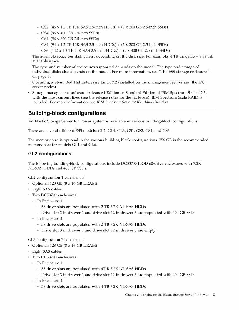
GL2 configurations
The following building-block configurations include DCS3700 JBOD 60-drive enclosures with 7.2KNL-SAS HDDs and 400 GB SSDs.
GL2 configuration 1 consists of:v Optional: 128 GB (8 x 16 GB DRAM)v Eight SAS cablesv Two DCS3700 enclosures
– In Enclosure 1:- 58 drive slots are populated with 2 TB 7.2K NL-SAS HDDs- Drive slot 3 in drawer 1 and drive slot 12 in drawer 5 are populated with 400 GB SSDs
– In Enclosure 2:- 58 drive slots are populated with 2 TB 7.2K NL-SAS HDDs- Drive slot 3 in drawer 1 and drive slot 12 in drawer 5 are empty
GL2 configuration 2 consists of:v Optional: 128 GB (8 x 16 GB DRAM)v Eight SAS cablesv Two DCS3700 enclosures
– In Enclosure 1:- 58 drive slots are populated with 4T B 7.2K NL-SAS HDDs- Drive slot 3 in drawer 1 and drive slot 12 in drawer 5 are populated with 400 GB SSDs
– In Enclosure 2:- 58 drive slots are populated with 4 TB 7.2K NL-SAS HDDs
Chapter 2. Introducing the Elastic Storage Server for Power 5
- Drive slot 3 in drawer 1 and drive slot 12 in drawer 5 are empty
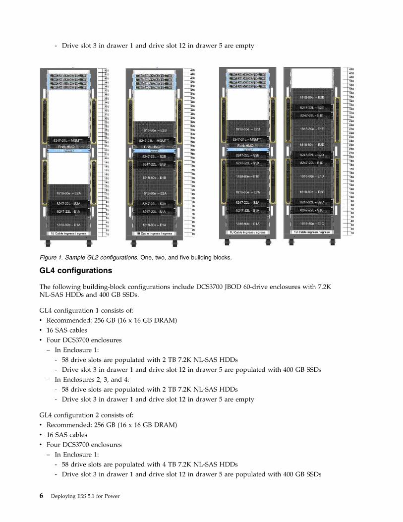
GL4 configurations
The following building-block configurations include DCS3700 JBOD 60-drive enclosures with 7.2KNL-SAS HDDs and 400 GB SSDs.
GL4 configuration 1 consists of:v Recommended: 256 GB (16 x 16 GB DRAM)v 16 SAS cablesv Four DCS3700 enclosures
– In Enclosure 1:- 58 drive slots are populated with 2 TB 7.2K NL-SAS HDDs- Drive slot 3 in drawer 1 and drive slot 12 in drawer 5 are populated with 400 GB SSDs
– In Enclosures 2, 3, and 4:- 58 drive slots are populated with 2 TB 7.2K NL-SAS HDDs- Drive slot 3 in drawer 1 and drive slot 12 in drawer 5 are empty
GL4 configuration 2 consists of:v Recommended: 256 GB (16 x 16 GB DRAM)v 16 SAS cablesv Four DCS3700 enclosures
– In Enclosure 1:- 58 drive slots are populated with 4 TB 7.2K NL-SAS HDDs- Drive slot 3 in drawer 1 and drive slot 12 in drawer 5 are populated with 400 GB SSDs
Figure 1. Sample GL2 configurations. One, two, and five building blocks.
6 Deploying ESS 5.1 for Power
– In Enclosures 2, 3, and 4:- 58 drive slots are populated with 4 TB 7.2K NL-SAS HDDs- Drive slot 3 in drawer 1 and drive slot 12 in drawer 5 are empty
GL6 configurations
The following building-block configurations include DCS3700 JBOD 60-drive enclosures with 7.2KNL-SAS HDDs and 400 GB SSDs.
GL6 configuration 1 consists of:v Recommended: 256 GB (16 x 16 GB DRAM)v 24 SAS cablesv Six DCS3700 enclosures
– In Enclosure 1:- 58 drive slots are populated with 2 TB 7.2K NL-SAS HDDs- Drive slot 3 in drawer 1 and drive slot 12 in drawer 5 are populated with 400 GB SSDs
– In Enclosures 2, 3, 4, 5, and 6:- 58 drive slots are populated with 2 TB 7.2K NL-SAS HDDs- Drive slot 3 in drawer 1 and drive slot 12 in drawer 5 are empty
GL6 configuration 2 consists of:v Recommended: 256 GB (16 x 16 GB DRAM)v 24 SAS cablesv Six DCS3700 enclosures
– In Enclosure 1:- 58 drive slots are populated with 4 TB 7.2K NL-SAS HDDs- Drive slot 3 in drawer 1 and drive slot 12 in drawer 5 are populated with 400 GB SSDs
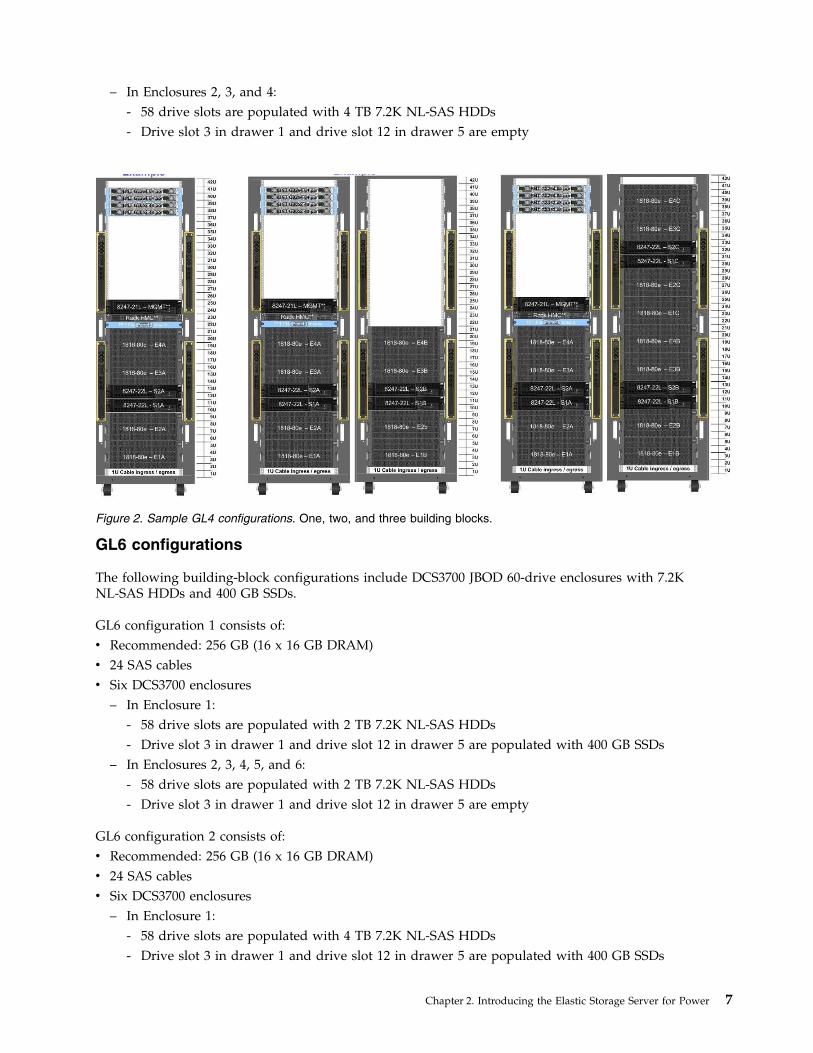
Figure 2. Sample GL4 configurations. One, two, and three building blocks.
Chapter 2. Introducing the Elastic Storage Server for Power 7
– In Enclosures 2, 3, 4, 5, and 6:- 58 drive slots are populated with 4 TB 7.2K NL-SAS HDDs- Drive slot 3 in drawer 1 and drive slot 12 in drawer 5 are empty
GS1 configurations
The following building-block configurations include an EXP24S JBOD 24-drive enclosure with 2.5-inchSSDs.
GS1 configuration 1 consists of:v Optional: 128 GB (8 x 16 GB DRAM)v Four SAS cablesv One EXP24S enclosure, in which all 24 drive slots are populated with 400 GB 2.5-inch SSDs
GS1 configuration 2 consists of:v Optional: 128 GB (8 x 16 GB DRAM)v Four SAS cablesv One EXP24S enclosure, in which all 24 drive slots are populated with 800 GB 2.5-inch SSDs
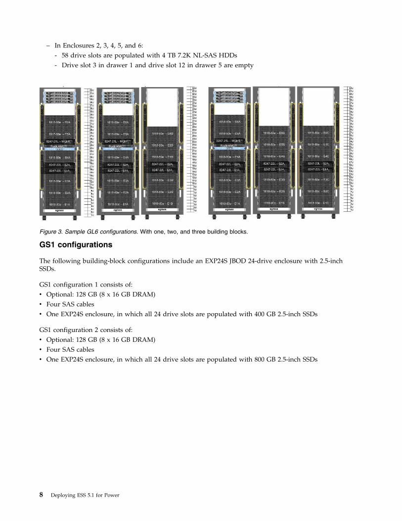
Figure 3. Sample GL6 configurations. With one, two, and three building blocks.
8 Deploying ESS 5.1 for Power
GS2 configurations
The following building-block configurations include EXP24S JBOD 24-drive enclosures with 2.5-inchSSDs.
GS2 configuration 1 consists of:v Optional: 128 GB (8 x 16 GB DRAM)v Eight SAS cablesv Two EXP24S enclosures, in each of which all 24 drive slots are populated with 400 GB 2.5-inch SSDs
GS2 configuration 2 consists of:v Optional: 128 GB (8 x 16GB DRAM)v Eight SAS cablesv Two EXP24S enclosures, in each of which all 24 drive slots are populated with 800 GB 2.5-inch SSDs
GS2 configuration 3 consists of:v Optional: 128 GB (8 x 16 GB DRAM)v Eight SAS cablesv Two EXP24S enclosures
– In Enclosure 1:- Drive slots 1 and 24 are populated with 400 GB 2.5-inch SSDs- Drive slots 2 through 23 are populated with 1.2 TB 10K SAS 2.5-inch HDDs
– In Enclosure 2, all 24 drive slots are populated with 1.2 TB 10K SAS 2.5-inch HDDs
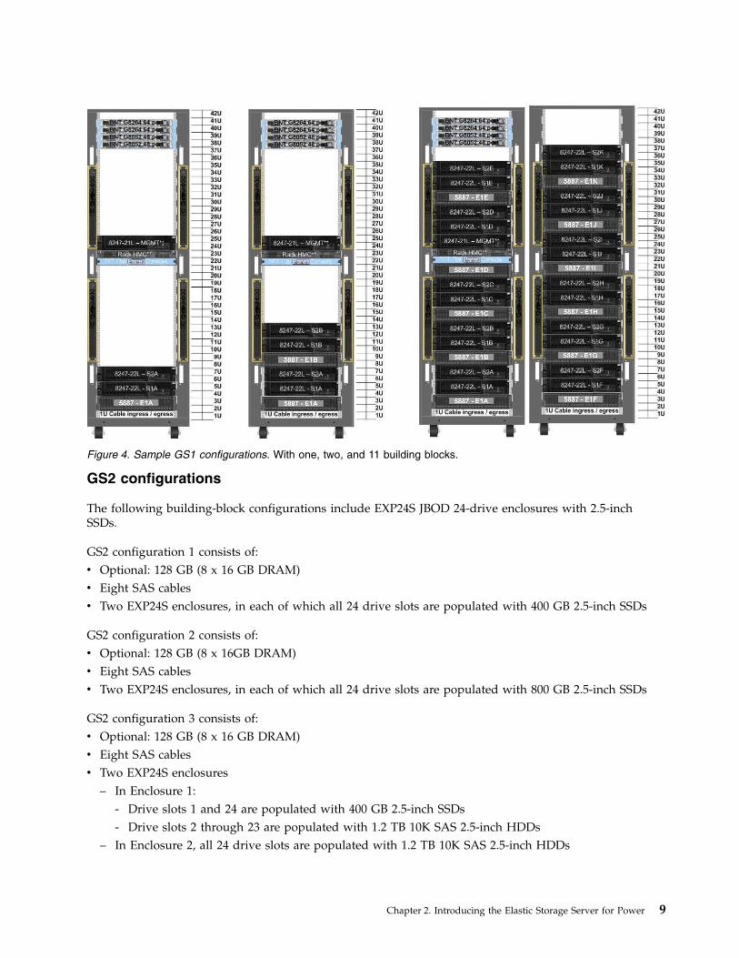
Figure 4. Sample GS1 configurations. With one, two, and 11 building blocks.
Chapter 2. Introducing the Elastic Storage Server for Power 9
GS4 configurations
The following building-block configurations include EXP24S JBOD 24-drive enclosures with 2.5-inchSSDs.
GS4 configuration 1 consists of:v Optional: 256 GB (8 x 16 GB DRAM)v 16 SAS cablesv Four EXP24S enclosures, in which all 96 drive slots are populated with 400 GB 2.5-inch SSDs
GS4 configuration 2 consists of:v Optional: 256 GB (8 x 16 GB DRAM)v 16 SAS cablesv Four EXP24S enclosures, in which all 96 drive slots are populated with 800 GB 2.5-inch SSDs
GS4 configuration 3 consists of:v Optional: 256 GB (8 x 16 GB DRAM)v 16 SAS cablesv Four EXP24S enclosures
– In Enclosure 1:- Drive slots 1 and 24 are populated with 400 GB 2.5-inch SSDs- Drive slots 2 through 23 are populated with 1.2TB 10K SAS 2.5-inch HDDs
– In Enclosures 2, 3, and 4, all 24 drive slots are populated with 1.2TB 10K SAS 2.5-inch HDDs
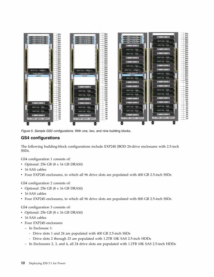
Figure 5. Sample GS2 configurations. With one, two, and nine building blocks.
10 Deploying ESS 5.1 for Power
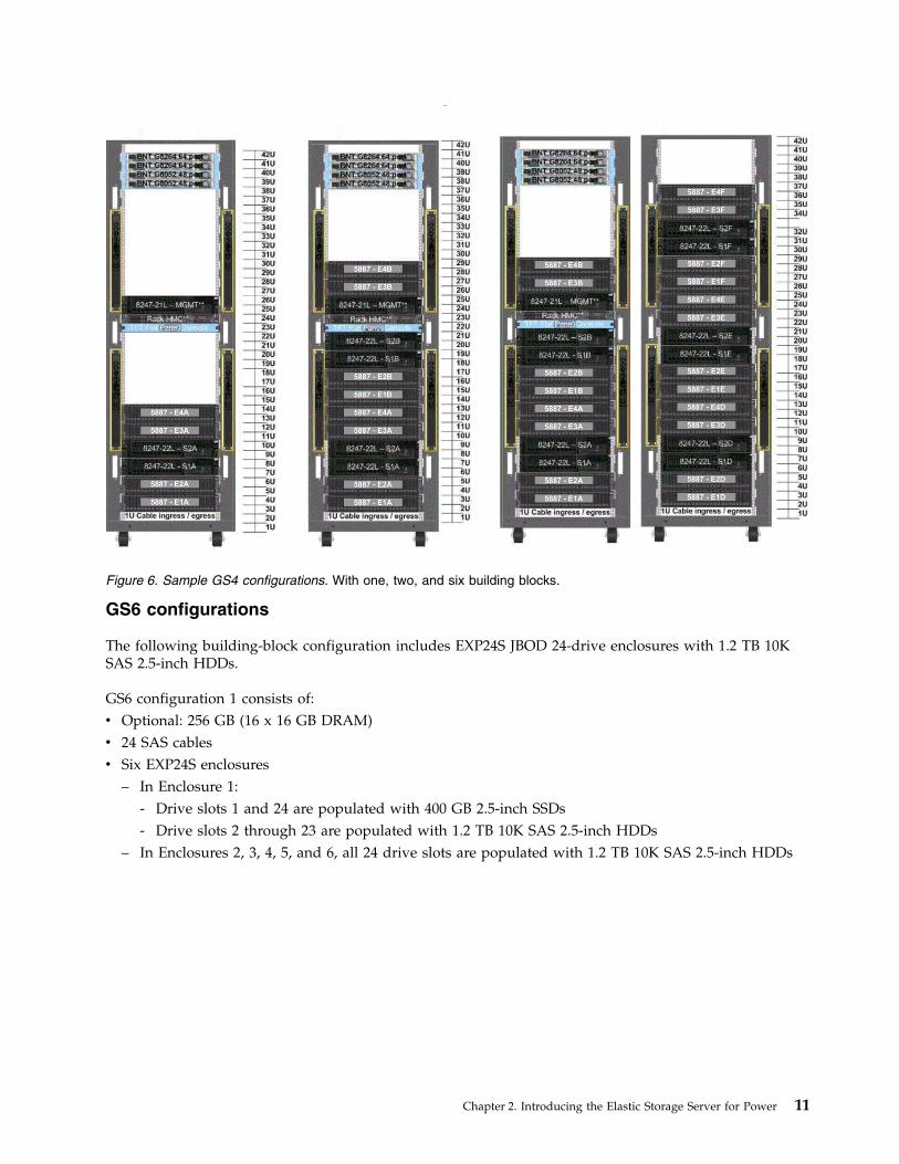
GS6 configurations
The following building-block configuration includes EXP24S JBOD 24-drive enclosures with 1.2 TB 10KSAS 2.5-inch HDDs.
GS6 configuration 1 consists of:v Optional: 256 GB (16 x 16 GB DRAM)v 24 SAS cablesv Six EXP24S enclosures
– In Enclosure 1:- Drive slots 1 and 24 are populated with 400 GB 2.5-inch SSDs- Drive slots 2 through 23 are populated with 1.2 TB 10K SAS 2.5-inch HDDs
– In Enclosures 2, 3, 4, 5, and 6, all 24 drive slots are populated with 1.2 TB 10K SAS 2.5-inch HDDs
Figure 6. Sample GS4 configurations. With one, two, and six building blocks.
Chapter 2. Introducing the Elastic Storage Server for Power 11
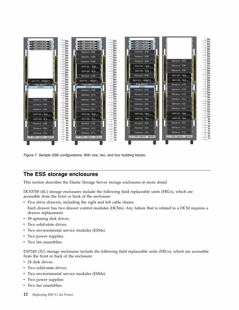
The ESS storage enclosuresThis section describes the Elastic Storage Server storage enclosures in more detail.
DCS3700 (4U) storage enclosures include the following field replaceable units (FRUs), which areaccessible from the front or back of the enclosure:v Five drive drawers, including the right and left cable chains.
Each drawer has two drawer control modules (DCMs). Any failure that is related to a DCM requires adrawer replacement.
v 58 spinning disk drives.v Two solid-state drives.v Two environmental service modules (ESMs).v Two power supplies.v Two fan assemblies.
EXP24S (2U) storage enclosures include the following field replaceable units (FRUs), which are accessiblefrom the front or back of the enclosure:v 24 disk drives.v Two solid-state drives.v Two environmental service modules (ESMs).v Two power supplies.v Two fan assemblies.
Figure 7. Sample GS6 configurations. With one, two, and four building blocks.
12 Deploying ESS 5.1 for Power
You can use the hot-swap features of the Elastic Storage Server to remove and replace power supplieswithout turning off the storage enclosure. You can maintain the availability of your system while ahot-swap device is removed, installed, or replaced.
Note: Most of the hardware-specific instructions apply to 4U storage enclosures. The general principlesapply to 2U storage enclosures.
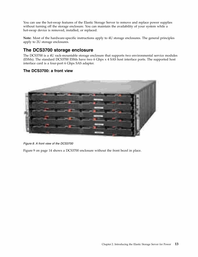
The DCS3700 storage enclosureThe DCS3700 is a 4U rack-mountable storage enclosure that supports two environmental service modules(ESMs). The standard DCS3700 ESMs have two 6 Gbps x 4 SAS host interface ports. The supported hostinterface card is a four-port 6 Gbps SAS adapter.
The DCS3700: a front view
Figure 9 on page 14 shows a DCS3700 enclosure without the front bezel in place.
Figure 8. A front view of the DCS3700
Chapter 2. Introducing the Elastic Storage Server for Power 13

Figure 9. Components of the DCS3700 storage enclosure
14 Deploying ESS 5.1 for Power
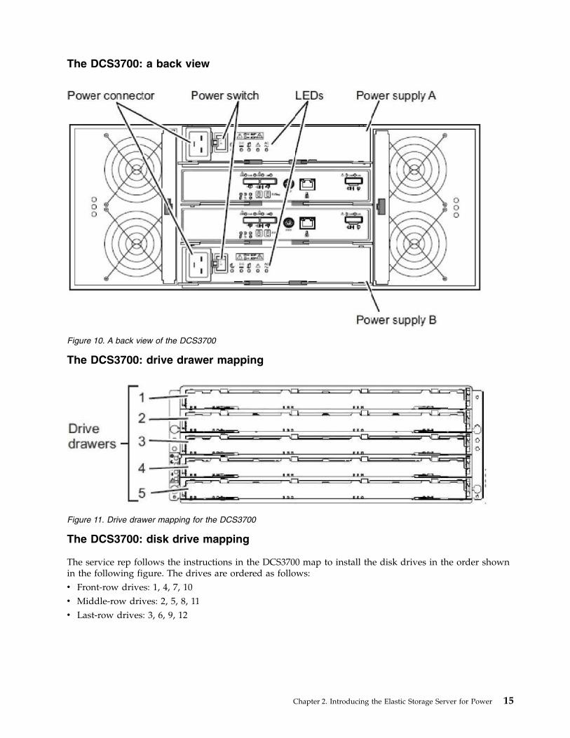
The DCS3700: a back view
The DCS3700: drive drawer mapping
The DCS3700: disk drive mapping
The service rep follows the instructions in the DCS3700 map to install the disk drives in the order shownin the following figure. The drives are ordered as follows:v Front-row drives: 1, 4, 7, 10v Middle-row drives: 2, 5, 8, 11v Last-row drives: 3, 6, 9, 12
Figure 10. A back view of the DCS3700
Figure 11. Drive drawer mapping for the DCS3700
Chapter 2. Introducing the Elastic Storage Server for Power 15

In a 4U building-block configuration, the two SSDs go in Enclosure 1, which is at the bottom of the rack.SSD 1 goes in Slot 3 in Drawer 1 (at the top of Enclosure 1). SSD 2 goes in Slot 12 in Drawer 5 (at thebottom of Enclosure 1). The placement of the two SSDs is shown in the following figure.
The IBM Power Systems EXP24S I/O DrawerThe IBM Power Systems EXP24S I/O Drawer (FC 5887) is a 2U rack-mountable storage enclosure thatsupports two environmental service modules (ESMs). The standard EXP24S ESMs have two 6 Gbps x 4SAS host interface ports. The supported host interface card is a four-port 6 Gbps SAS adpater.
Front-row
drives
2
3
5
6
8
9
11
1
4
7
10
12
Figure 12. Disk drive mapping for the DCS3700
Figure 13. DCS3700 disk population with 58 HDDs and two SSDs
16 Deploying ESS 5.1 for Power

Figure 14 shows a front view of the EXP24S I/O Drawer.
Figure 15 shows a 2U drawer with SSDs in slots 1 through 24.
In a 2U building-block configuration with two SSDs, the two SSDs go in the left-most slot (slot 1) and theright-most slot (slot 24) of the first storage enclosure, which is at the bottom of the rack, as shown in thefollowing figure.
Figure 16 shows a 2U drawer with SSDs in slots 1 and 24.
Figure 14. EXP24S I/O Drawer: front view
SS
D1
SS
D2
SS
D3
SS
D4
SS
D5
SS
D6
SS
D7
SS
D8
SS
D9
SS
D1
0
SS
D11
SS
D1
2
SS
D1
3
SS
D1
4
SS
D1
5
SS
D1
6
SS
D1
7
SS
D1
8
SS
D1
9
SS
D2
0
SS
D2
1
SS
D2
2
SS
D2
3
SS
D2
4
Figure 15. A 2U drawer with SSDs in slots 1 through 24
SS
D1
HD
D1
HD
D2
HD
D3
HD
D4
HD
D5
HD
D6
HD
D7
HD
D8
HD
D9
HD
D1
0
HD
D1
1
HD
D1
2
HD
D1
3
HD
D1
4
HD
D1
5
HD
D1
6
HD
D1
7
HD
D1
8
HD
D1
9
HD
D2
0
HD
D2
1
HD
D2
2
SS
D2
Figure 16. A 2U drawer with SSDs in slots 1 and 24
Chapter 2. Introducing the Elastic Storage Server for Power 17

18 Deploying ESS 5.1 for Power
Chapter 3. Planning for the Elastic Storage Server
You must follow specific planning instructions to activate the ESS.
For ESS hardware planning information, see Planning for the system on IBM Knowledge Center:
http://www.ibm.com/support/knowledgecenter/POWER8/p8ehb/p8ehb_storage_kickoff.htm
Installation prerequisitesThis section includes software, firmware, and skills prerequisites for installing and deploying ESS 5.0.
With regard to prerequisite skills, you should be familiar with ESS concepts and terminology and have ageneral understanding of the following:v IBM Power Systems serversv IBM Spectrum Scalev Extreme Cluster/Cloud Administration Toolkit (xCAT)v Red Hat Enterprise Linuxv Networking technologyv Serial Attached SCSI (SAS) technology.
The prerequisite procedures and packages for installing ESS are the following:v SSR sign off on the ESS system after cabling, disk configuration, and networking configuration.v The following packages must be available and placed in the required directories before installation:
– Red Hat Enterprise Linux 7.x ISO image– ESS software archive– Kernel package– The mpt3sas driver package (PPC64LE only)
In addition to these packages, you must purchase the required ESS license.
You can find the most current IBM hardware, firmware, and software on the Fix Central website:
http://www.ibm.com/support/fixcentral
The ESS software is packaged as a packed, compressed tar (.tgz) file. The release notes provided withESS contain detailed descriptions of the levels of the firmware and packages.
© Copyright IBM Corp. 2014, 2017 19

20 Deploying ESS 5.1 for Power
Chapter 4. Installing the ESS software
Use this information to install and configure ESS 5.0 with one or more building blocks.
To install the ESS software, you need to have a working knowledge of Power Systems servers, IBMSpectrum Scale, and xCAT.
For information about upgrading to ESS 5.0, see Appendix B, “Upgrading the Elastic Storage Server,” onpage 71.
Networking requirements
Note: The references to HMC are not applicable for the PPC64LE platform.
The following networks are required:v Service network
This network connects the flexible service processor (FSP) on the management server and I/O servernodes (with or without the HMC, depending on the platform) as shown in blue in Figure 17 on page22 and Figure 18 on page 22. On PPC64BE, the HMC runs the Dynamic Host Configuration Protocol(DHCP) server on this network. If the HMC is not included in the solution order, a customer-suppliedHMC is used.
v Management and provisioning network
This network connects the management server to the I/O server nodes (and HMCs, depending on theplatform) as shown as yellow in Figure 17 on page 22 and Figure 18 on page 22. The managementserver runs DHCP on the management and provisioning network. If a management server is notincluded in the solution order, a customer-supplied management server is used.
v Clustering network
This high-speed network is used for clustering and client node access. It can be a 10 Gigabit Ethernet(GbE), 40 GbE, or InfiniBand network. It might not be included in the solution order.
v External and campus management network
This public network is used for external and campus management of the management server, the HMC(if applicable, depending on the platform), or both.
The management and provisioning network and the service network must run as two non-overlappingnetworks implemented as two separate physical networks or two separate virtual local-area networks(VLANs).
The HMC, the management server, and the switches (1 GbE switches and high-speed switches) might notbe included in a solution order in which an existing or customer-supplied HMC or management server isused. Perform any advance planning tasks that might be needed to access and use these solutioncomponents.
Figure 17 on page 22 is a high-level logical view of the management and provisioning network and theservice network for an ESS building block (PPC64BE).
© Copyright IBM Corporation © IBM 2014, 2017 21
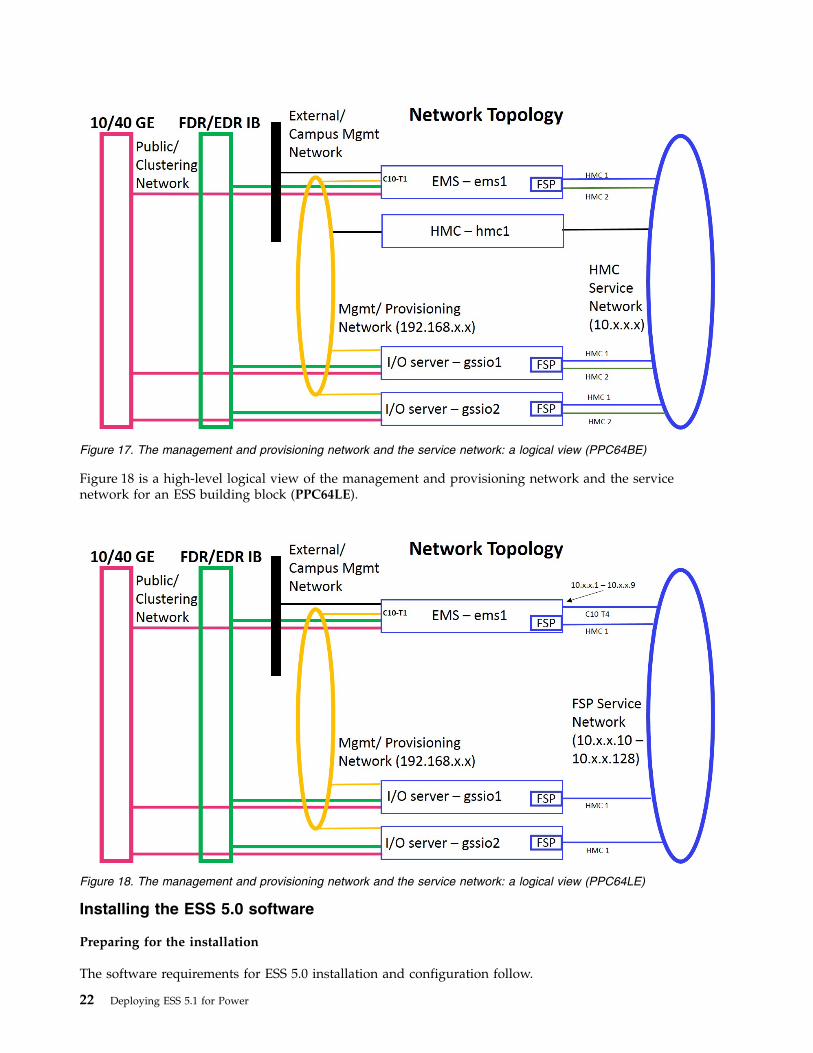
Figure 18 is a high-level logical view of the management and provisioning network and the servicenetwork for an ESS building block (PPC64LE).
Installing the ESS 5.0 software
Preparing for the installation
The software requirements for ESS 5.0 installation and configuration follow.
Figure 17. The management and provisioning network and the service network: a logical view (PPC64BE)
Figure 18. The management and provisioning network and the service network: a logical view (PPC64LE)
22 Deploying ESS 5.1 for Power

1. The ESS software archive (For example, gss_install-5.0.0_ppc64le_advanced_20161115T110206Z.tgzor gss_install-5.0.0_ppc64_advanced_20161115T110206Z.tgz) from FixCentral athttp://www-933.ibm.com/support/fixcentral/swg/selectFixes?parent=Software%2Bdefined%2Bstorage&product=ibm/StorageSoftware/IBM+Spectrum+Scale+RAID&release=All&platform=All&function=all.To download from Fix Central, you must have entitlement for the given installation package. Checkwith your IBM representative if you have questions.
2. The Red Hat Enterprise Linux 7.2 ISO image file (For example, RHEL-7.2-20151030.0-Server-ppc64le-dvd1.iso or RHEL-7.2-20151030.0-Server-ppc64-dvd1.iso) or DVD for 64-bit IBM Power Systemsarchitecture. The ISO or DVD is used to upgrade EMS node as well as upgrade or deploy I/O Servernodes.For more information, see the Red Hat Enterprise Linux website:http://access.redhat.com/products/red-hat-enterprise-linux/
3. The required Kernel Errata stated in http://www-01.ibm.com/support/docview.wss?uid=ssg1S1005719
4. The mpt3sas driver package (mpt3sas-13.100.00.00-1.el7_2.src.rpm). This is not applicable for thePPC64BE platform.
Note: The Kernel Errata and the mpt3sas driver packages are available in the /home/deploy directory bydefault. If required, you can use the contact information on the following support page to request forthese packages: http://www-01.ibm.com/support/docview.wss?uid=ssg1S1005719.
Perform the following tasks and gather all required information before starting the installation process.Table 2 on page 24 includes information about components that must be set up before you start installingthe ESS 5.0 software.
For tips about how to name nodes, see “Node name considerations” on page 57.
Note: The references to HMC are not applicable for the PPC64LE platform.
Chapter 4. Installing the ESS software 23
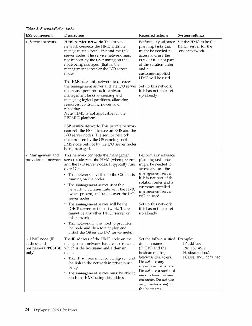
Table 2. Pre-installation tasks
ESS component Description Required actions System settings
1. Service network HMC service network: This privatenetwork connects the HMC with themanagement server's FSP and the I/Oserver nodes. The service network mustnot be seen by the OS running on thenode being managed (that is, themanagement server or the I/O servernode).
The HMC uses this network to discoverthe management server and the I/O servernodes and perform such hardwaremanagement tasks as creating andmanaging logical partitions, allocatingresources, controlling power, andrebooting.Note: HMC is not applicable for thePPC64LE platform.
FSP service network: This private networkconnects the FSP interface on EMS and theI/O server nodes. The service networkmust be seen by the OS running on theEMS node but not by the I/O server nodesbeing managed.
Perform any advanceplanning tasks thatmight be needed toaccess and use theHMC if it is not partof the solution orderand acustomer-suppliedHMC will be used.
Set up this networkif it has not been setup already.
Set the HMC to be theDHCP server for theservice network.
2. Management andprovisioning network
This network connects the managementserver node with the HMC (when present)and the I/O server nodes. It typically runsover 1Gb.
v This network is visible to the OS that isrunning on the nodes.
v The management server uses thisnetwork to communicate with the HMC(when present) and to discover the I/Oserver nodes.
v The management server will be theDHCP server on this network. Therecannot be any other DHCP server onthis network.
v This network is also used to provisionthe node and therefore deploy andinstall the OS on the I/O server nodes.
Perform any advanceplanning tasks thatmight be needed toaccess and use themanagement serverif it is not part of thesolution order and acustomer-suppliedmanagement serverwill be used.
Set up this networkif it has not been setup already.
3. HMC node (IPaddress andhostname) (PPC64BEonly)
The IP address of the HMC node on themanagement network has a console name,which is the hostname and a domainname.
v This IP address must be configured andthe link to the network interface mustbe up.
v The management server must be able toreach the HMC using this address.
Set the fully-qualifieddomain name(FQDN) and thehostname usinglowercase characters.Do not use anyuppercase characters.Do not use a suffix of-enx, where x is anycharacter. Do not usean _ (underscore) inthe hostname.
Example:IP address:192.168.45.9Hostname: hmc1FQDN: hmc1.gpfs.net
24 Deploying ESS 5.1 for Power
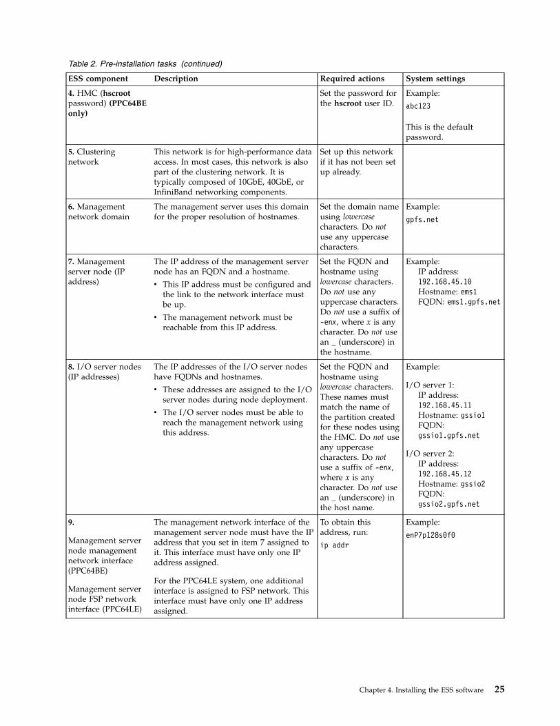
Table 2. Pre-installation tasks (continued)
ESS component Description Required actions System settings
4. HMC (hscrootpassword) (PPC64BEonly)
Set the password forthe hscroot user ID.
Example:
abc123
This is the defaultpassword.
5. Clusteringnetwork
This network is for high-performance dataaccess. In most cases, this network is alsopart of the clustering network. It istypically composed of 10GbE, 40GbE, orInfiniBand networking components.
Set up this networkif it has not been setup already.
6. Managementnetwork domain
The management server uses this domainfor the proper resolution of hostnames.
Set the domain nameusing lowercasecharacters. Do notuse any uppercasecharacters.
Example:
gpfs.net
7. Managementserver node (IPaddress)
The IP address of the management servernode has an FQDN and a hostname.
v This IP address must be configured andthe link to the network interface mustbe up.
v The management network must bereachable from this IP address.
Set the FQDN andhostname usinglowercase characters.Do not use anyuppercase characters.Do not use a suffix of-enx, where x is anycharacter. Do not usean _ (underscore) inthe hostname.
Example:IP address:192.168.45.10Hostname: ems1FQDN: ems1.gpfs.net
8. I/O server nodes(IP addresses)
The IP addresses of the I/O server nodeshave FQDNs and hostnames.
v These addresses are assigned to the I/Oserver nodes during node deployment.
v The I/O server nodes must be able toreach the management network usingthis address.
Set the FQDN andhostname usinglowercase characters.These names mustmatch the name ofthe partition createdfor these nodes usingthe HMC. Do not useany uppercasecharacters. Do notuse a suffix of -enx,where x is anycharacter. Do not usean _ (underscore) inthe host name.
Example:
I/O server 1:IP address:192.168.45.11Hostname: gssio1FQDN:gssio1.gpfs.net
I/O server 2:IP address:192.168.45.12Hostname: gssio2FQDN:gssio2.gpfs.net
9.
Management servernode managementnetwork interface(PPC64BE)
Management servernode FSP networkinterface (PPC64LE)
The management network interface of themanagement server node must have the IPaddress that you set in item 7 assigned toit. This interface must have only one IPaddress assigned.
For the PPC64LE system, one additionalinterface is assigned to FSP network. Thisinterface must have only one IP addressassigned.
To obtain thisaddress, run:
ip addr
Example:
enP7p128s0f0
Chapter 4. Installing the ESS software 25
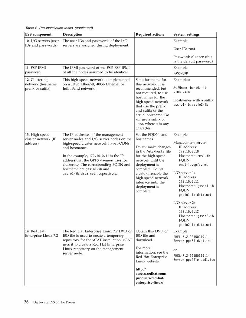
Table 2. Pre-installation tasks (continued)
ESS component Description Required actions System settings
10. I/O servers (userIDs and passwords)
The user IDs and passwords of the I/Oservers are assigned during deployment.
Example:
User ID: root
Password: cluster (thisis the default password)
11. FSP IPMIpassword
The IPMI password of the FSP. FSP IPMIof all the nodes assumed to be identical.
Example:
PASSW0RD
12. Clusteringnetwork (hostnameprefix or suffix)
This high-speed network is implementedon a 10Gb Ethernet, 40Gb Ethernet orInfiniBand network.
Set a hostname forthis network. It isrecommended, butnot required, to usehostnames for thehigh-speed networkthat use the prefixand suffix of theactual hostname. Donot use a suffix of-enx, where x is anycharacter.
Examples:
Suffixes: -bond0, -ib,-10G, -40G
Hostnames with a suffix:gssio1-ib, gssio2-ib
13. High-speedcluster network (IPaddress)
The IP addresses of the managementserver nodes and I/O server nodes on thehigh-speed cluster network have FQDNsand hostnames.
In the example, 172.10.0.11 is the IPaddress that the GPFS daemon uses forclustering. The corresponding FQDN andhostname are gssio1-ib andgssio1-ib.data.net, respectively.
Set the FQDNs andhostnames.
Do not make changesin the /etc/hosts filefor the high-speednetwork until thedeployment iscomplete. Do notcreate or enable thehigh-speed networkinterface until thedeployment iscomplete.
Example:
Management server:IP address:172.10.0.10Hostname: ems1-ibFQDN:ems1-ib.gpfs.net
I/O server 1:IP address:172.10.0.11Hostname: gssio1-ibFQDN:gssio1-ib.data.net
I/O server 2:IP address:172.10.0.12Hostname: gssio2-ibFQDN:gssio2-ib.data.net
14. Red HatEnterprise Linux 7.2
The Red Hat Enterprise Linux 7.2 DVD orISO file is used to create a temporaryrepository for the xCAT installation. xCATuses it to create a Red Hat EnterpriseLinux repository on the managementserver node.
Obtain this DVD orISO file anddownload.
For moreinformation, see theRed Hat EnterpriseLinux website:
http://access.redhat.com/products/red-hat-enterprise-linux/
Example:
RHEL-7.2-20150219.1-Server-ppc64-dvd1.iso
or
RHEL-7.2-20150219.1-Server-ppc64le-dvd1.iso
26 Deploying ESS 5.1 for Power
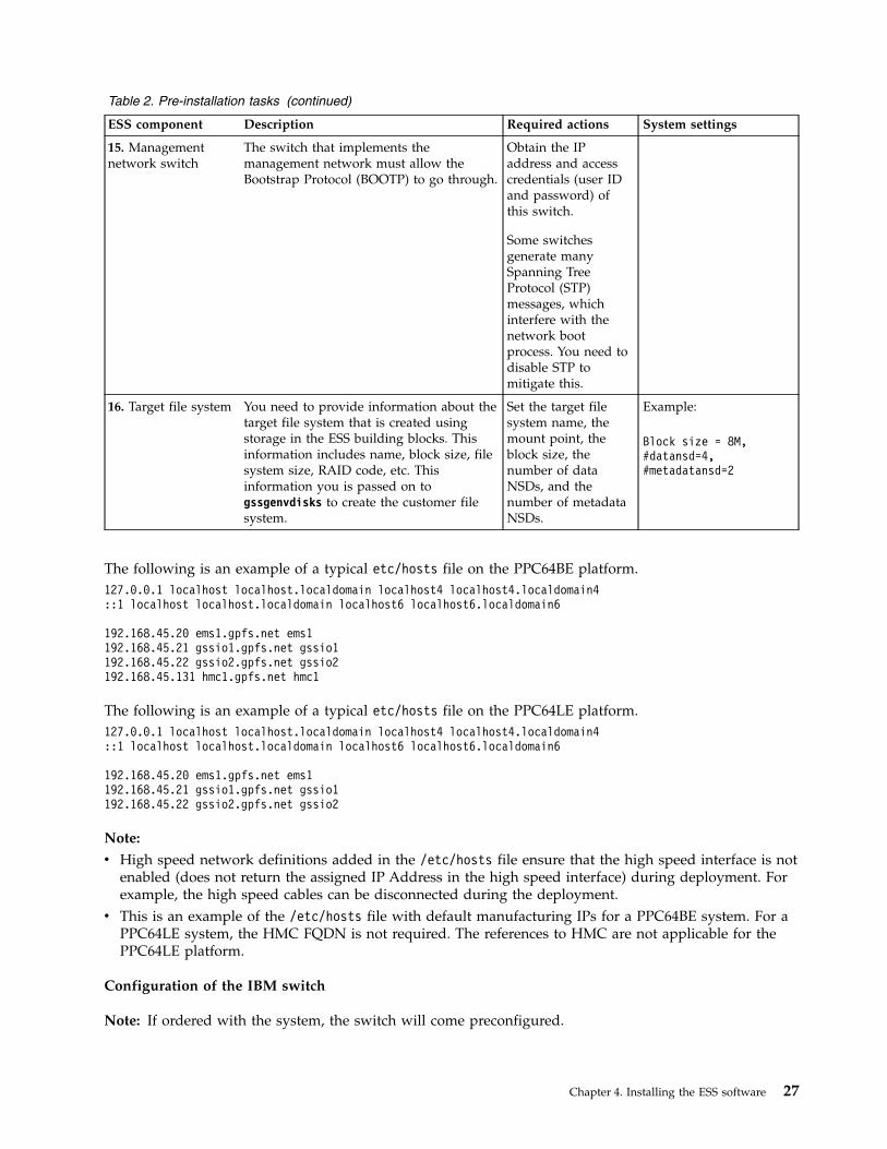
Table 2. Pre-installation tasks (continued)
ESS component Description Required actions System settings
15. Managementnetwork switch
The switch that implements themanagement network must allow theBootstrap Protocol (BOOTP) to go through.
Obtain the IPaddress and accesscredentials (user IDand password) ofthis switch.
Some switchesgenerate manySpanning TreeProtocol (STP)messages, whichinterfere with thenetwork bootprocess. You need todisable STP tomitigate this.
16. Target file system You need to provide information about thetarget file system that is created usingstorage in the ESS building blocks. Thisinformation includes name, block size, filesystem size, RAID code, etc. Thisinformation you is passed on togssgenvdisks to create the customer filesystem.
Set the target filesystem name, themount point, theblock size, thenumber of dataNSDs, and thenumber of metadataNSDs.
Example:
Block size = 8M,#datansd=4,#metadatansd=2
The following is an example of a typical etc/hosts file on the PPC64BE platform.127.0.0.1 localhost localhost.localdomain localhost4 localhost4.localdomain4::1 localhost localhost.localdomain localhost6 localhost6.localdomain6
192.168.45.20 ems1.gpfs.net ems1192.168.45.21 gssio1.gpfs.net gssio1192.168.45.22 gssio2.gpfs.net gssio2192.168.45.131 hmc1.gpfs.net hmc1
The following is an example of a typical etc/hosts file on the PPC64LE platform.127.0.0.1 localhost localhost.localdomain localhost4 localhost4.localdomain4::1 localhost localhost.localdomain localhost6 localhost6.localdomain6
192.168.45.20 ems1.gpfs.net ems1192.168.45.21 gssio1.gpfs.net gssio1192.168.45.22 gssio2.gpfs.net gssio2
Note:
v High speed network definitions added in the /etc/hosts file ensure that the high speed interface is notenabled (does not return the assigned IP Address in the high speed interface) during deployment. Forexample, the high speed cables can be disconnected during the deployment.
v This is an example of the /etc/hosts file with default manufacturing IPs for a PPC64BE system. For aPPC64LE system, the HMC FQDN is not required. The references to HMC are not applicable for thePPC64LE platform.
Configuration of the IBM switch
Note: If ordered with the system, the switch will come preconfigured.
Chapter 4. Installing the ESS software 27
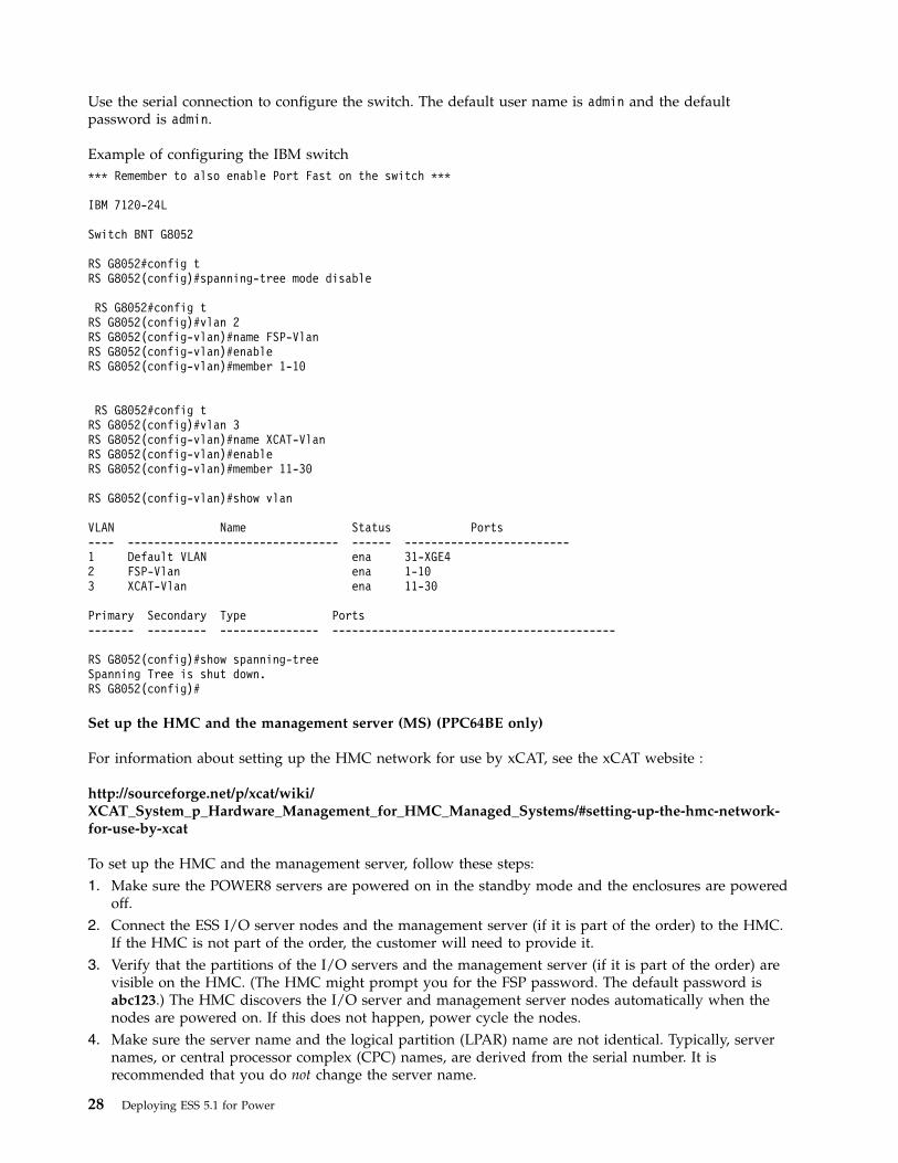
Use the serial connection to configure the switch. The default user name is admin and the defaultpassword is admin.
Example of configuring the IBM switch*** Remember to also enable Port Fast on the switch ***
IBM 7120-24L
Switch BNT G8052
RS G8052#config tRS G8052(config)#spanning-tree mode disable
RS G8052#config tRS G8052(config)#vlan 2RS G8052(config-vlan)#name FSP-VlanRS G8052(config-vlan)#enableRS G8052(config-vlan)#member 1-10
RS G8052#config tRS G8052(config)#vlan 3RS G8052(config-vlan)#name XCAT-VlanRS G8052(config-vlan)#enableRS G8052(config-vlan)#member 11-30
RS G8052(config-vlan)#show vlan
VLAN Name Status Ports---- -------------------------------- ------ -------------------------1 Default VLAN ena 31-XGE42 FSP-Vlan ena 1-103 XCAT-Vlan ena 11-30
Primary Secondary Type Ports------- --------- --------------- -------------------------------------------
RS G8052(config)#show spanning-treeSpanning Tree is shut down.RS G8052(config)#
Set up the HMC and the management server (MS) (PPC64BE only)
For information about setting up the HMC network for use by xCAT, see the xCAT website :
http://sourceforge.net/p/xcat/wiki/XCAT_System_p_Hardware_Management_for_HMC_Managed_Systems/#setting-up-the-hmc-network-for-use-by-xcat
To set up the HMC and the management server, follow these steps:1. Make sure the POWER8 servers are powered on in the standby mode and the enclosures are powered
off.2. Connect the ESS I/O server nodes and the management server (if it is part of the order) to the HMC.
If the HMC is not part of the order, the customer will need to provide it.3. Verify that the partitions of the I/O servers and the management server (if it is part of the order) are
visible on the HMC. (The HMC might prompt you for the FSP password. The default password isabc123.) The HMC discovers the I/O server and management server nodes automatically when thenodes are powered on. If this does not happen, power cycle the nodes.
4. Make sure the server name and the logical partition (LPAR) name are not identical. Typically, servernames, or central processor complex (CPC) names, are derived from the serial number. It isrecommended that you do not change the server name.
28 Deploying ESS 5.1 for Power

5. The default partition names follow.v Management server: ems1
v I/O server 1: gssio1
v I/O server 2: gssio2
v If there are more building blocks in the same order, the additional I/O server node partition namesare: gssio3, gssio4, gssio5, ... gssion, where n is the total number of I/O servers.
6. The management server nodes and I/O server nodes are shipped from IBM with Red Hat EnterpriseLinux 7.2 installed in an R10 disk array. The I/O server nodes are redeployed (including reinstallationof Red Hat Enterprise Linux 7.2) at the customer location from the management server node. Themanagement server node typically does not need to be reinstalled at the customer location unlessthere is an emergency situation. Typically, redeploying the I/O server nodes takes approximately 30minutes to complete. Completion of this process ensures that the installation is consistent with varioussite-specific parameters. It also minimizes configuration mismatches and incompatibilities between themanagement server nodes and I/O server nodes.There is no need to reinstall the management server. It is reinstalled only if the OS cannot boot anymore due to hardware damage or failure. See “Installing Red Hat Enterprise Linux on themanagement server ” on page 57 to reinstall the management server if needed.
7. Verify that you can access the management server console using the HMC. After network connectivityis established to the management server node (see the next section), it is recommended that youaccess the management server over the network using an available secure shell (SSH) client such asPuTTY.
Note: The references to HMC are not applicable for the PPC64LE platform.
Configure an IP address for the xCAT network on the management server using the HMC console
1. Log in to the system as root. The default root password from IBM is cluster.2. List the available interfaces, which should begin with a prefix of enP7:
ip link show | egrep "P7.*state UP"
If you do not see any interfaces with a state of UP, check your network connections before proceeding.Also, verify that the correct interface is UP.
3. Select the interface that ends with a suffix of f0. For example:enP7p128s0f0
By default, enP7p128s0f0 is C10-port 0 and is configured at IBM with an IP address of 192.168.45.10,192.168.45.11, or 192.168.45.20.If enP7p128s0f0 is not up and another link is up, move the cable.
4. Edit the network configuration for this interface and change it as needed. The file name is:/etc/sysconfig/network-scripts/ifcfg-enP7p128s0f0
In this file, change the value of BOOTPROTO from dhcp to static and set the value of ONBOOT toyes if it is not set already:
BOOTPROTO=staticONBOOT=yes
5. Add or change the management server's IP address and netmask as needed. For example:
IPADDR=192.168.45.20NETMASK=255.255.255.0
6. Restart network services if the address is changed:
systemctl restart network
Chapter 4. Installing the ESS software 29
7. Verify that the management server's management network interface is up. For example, run:ping 192.168.45.20
8. After the interface is configured, you can log in to the management server node using an SSH client.
For detailed instructions on installing ESS, see the following topics in the Elastic Storage Server: QuickDeployment Guide and perform the documented steps in this order:1. Install the ESS system.2. Deploy the I/O server nodes.
After performing these steps, continue with the following steps to complete the procedure.
Apply Red Hat updates
After deployment is complete, you can apply Red Hat updates as needed. Note that kernel and OFEDcomponents are matched with the ESS software stack and are therefore locked during deployment toprevent unintended changes during update.
Check the system hardware
Now that the software is installed on the I/O server nodes, the next step is to verify the hardwareconfiguration. In the next several steps, you will check and validate the hardware configuration andhealth of the hardware including correct adapter locations, SAS connectivity, and disks installed in theJBOD enclosures. You can run all of the gss* commands from the management server. You will run thefollowing commands during the system check:1. gssstoragequickcheck checks the server, adapter, and storage configuration quickly.2. gssfindmissingdisks checks the disk paths and connectivity.3. gsscheckdisks checks for disk errors under various I/O operations.
Note: The example output shown in the following hardware check sections is for a GL2 system. Theoutput will be different in other ESS environments such as GSx and GFx environments.
Power on JBODs
After the I/O server nodes have been installed successfully, power on the JBODs. Wait approximately 5to 10 minutes from power on to discover the disks before moving on to the next step.
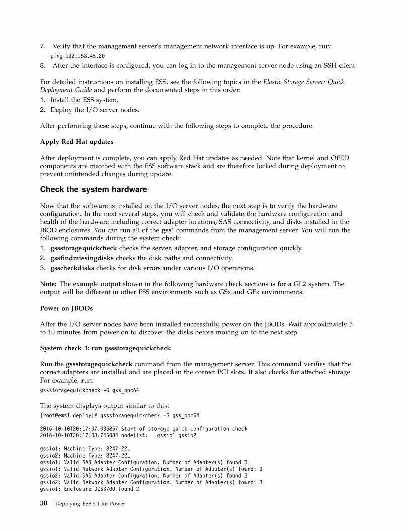
System check 1: run gssstoragequickcheck
Run the gssstoragequickcheck command from the management server. This command verifies that thecorrect adapters are installed and are placed in the correct PCI slots. It also checks for attached storage.For example, run:gssstoragequickcheck -G gss_ppc64
The system displays output similar to this:[root@ems1 deploy]# gssstoragequickcheck -G gss_ppc64
2016-10-10T20:17:07.036867 Start of storage quick configuration check2016-10-10T20:17:08.745084 nodelist: gssio1 gssio2
gssio1: Machine Type: 8247-22Lgssio2: Machine Type: 8247-22Lgssio1: Valid SAS Adapter Configuration. Number of Adapter(s) found 3gssio1: Valid Network Adapter Configuration. Number of Adapter(s) found: 3gssio2: Valid SAS Adapter Configuration. Number of Adapter(s) found 3gssio2: Valid Network Adapter Configuration. Number of Adapter(s) found: 3gssio1: Enclosure DCS3700 found 2
30 Deploying ESS 5.1 for Power

gssio1: Disk ST2000NM0023 found 116gssio1: SSD PX02SMF040 found 2gssio1: Total disk found 116, expected 116gssio1: Total SSD found 2, expected 2gssio2: Enclosure DCS3700 found 2gssio2: Disk ST2000NM0023 found 116gssio2: SSD PX02SMF040 found 2gssio2: Total disk found 116, expected 116gssio2: Total SSD found 2, expected 2
2015-06-15T20:17:25.670645 End of storage quick configuration check
If the attached SCSI devices are not found, try running modprobe on each of the I/O server nodes on theSAS driver:xdsh gss_ppc64 "modprobe mpt2sas"
After running modprobe, run gssstoragequickcheck again.
See “gssstoragequickcheck command” on page 132 for more information about this command.
System check 1a: run lsifixnv
The lsifixnv utility that sets up NVRAM for the SAS adapter. If it is not set properly, the I/O could failintermittently. From the management server node, run the following command. This will run lsifixnv oneach I/O server node. The lsifixnv utility is called by the gss_sashba script.xdsh gss_ppc64 "/xcatpost/gss_sashba"
System check 1b: Check the RAID firmware
Check the local RAID adapters' firmware level.xdsh ems1,gss_ppc64 "for IOA in \$(lsscsi -g | grep SISIOA | awk ’{print \$NF}’);do iprconfig -c query-ucode-level \$IOA; done"
The system displays output similar to this:[root@ems1 deploy]# xdsh ems1,gss_ppc64 "for IOA in \$(lsscsi -g | grep SISIOA |awk ’{print \$NF}’); do iprconfig -c query-ucode-level \$IOA; done"
ems1: 12511700gssio2: 12511700gssio1: 12511700
If this system is upgraded from a previous version, you might see a RAID firmware level of 12511400.
If the RAID adapter firmware is not at the correct level, contact the IBM Support Center for updateinstructions.
System check 1c: Make sure 64-bit DMA is enabled for InfiniBand slots
Note: This check is applicable only the system firmware level is earlier than 860. Configuring 64-bitDMA is not required if the firmware level is FW860.10 (SV860_056) or later.
Check the management server and I/O servers to make sure 64-bit direct memory access (DMA) isenabled for slots populated with the Connect-IB adapter. There should be one line for each adapter. Inthis example, there are three adapters in each I/O server node and one adapter in the management servernode. Run:xdsh gss_ppc64,bgqess-mgt1 journalctl -b | grep 64-bit | grep -v dma_rw | grep mlx
The system displays output similar to this:
Chapter 4. Installing the ESS software 31

[root@ems1 gss]# xdsh gss_ppc64,bgqess-mgt1 journalctl -b | grep 64-bit | grep -v dma_rw | grep mlx
gssio1: Feb 13 09:28:34 bgqess-gpfs02.scinet.local kernel: mlx5_core 0000:01:00.0: Using 64-bit direct DMA at offset 800000000000000gssio1: Feb 13 09:29:02 bgqess-gpfs02.scinet.local kernel: mlx5_core 0004:01:00.0: Using 64-bit direct DMA at offset 800000000000000gssio1: Feb 13 09:29:30 bgqess-gpfs02.scinet.local kernel: mlx5_core 0009:01:00.0: Using 64-bit direct DMA at offset 800000000000000gssio2: Jan 30 16:46:55 bgqess-gpfs01.scinet.local kernel: mlx5_core 0000:01:00.0: Using 64-bit direct DMA at offset 800000000000000gssio2: Jan 30 16:47:23 bgqess-gpfs01.scinet.local kernel: mlx5_core 0004:01:00.0: Using 64-bit direct DMA at offset 800000000000000gssio2: Jan 30 16:47:50 bgqess-gpfs01.scinet.local kernel: mlx5_core 0009:01:00.0: Using 64-bit direct DMA at offset 800000000000000mgt1: Jan 26 16:55:41 bgqess-mgt1 kernel: mlx5_core 0004:01:00.0: Using 64-bit direct DMA at offset 800000000000000
Make sure you see all of the InfiniBand devices in this list. This sample output includes the followingdevice numbers: 0000:01:00.0, 0004:01:00.0, and 0009:01:00.0. The slot-to-device assignments for theConnect-IB adapter follow:
Slot Device
C5 0009:01:00.0
C6 0004:01:00.0
C7 0000:01:00.0
If a device for a slot where the Connect-IB adapter is installed is not displayed in the xdsh output, followthese steps:1. Make sure the OS or partition is shut down.2. Click on server on the HMC GUI -> Operations -> Launch ASM.3. On the Welcome pane, specify your user ID and password. The default user ID is admin. The default
password is abc123.4. In the navigation area, expand System Configuration -> System -> I/O Adapter Enlarged Capacity.5. Select Enable and specify I/O Adapter Enlarged Capacity 11. This specifies all slots, because the I/O
server nodes have 11 slots.6. Save your settings.7. Restart the server so the changes will take effect.
System check 2: run gssfindmissingdisks
Run the gssfindmissingdisks command to verify that the I/O server nodes are cabled properly. Thiscommand reports the status of the disk paths. See “gssfindmissingdisks command” on page 111 for moreinformation about this command.
In this example, there are no missing drive paths. Run:gssfindmissingdisks -G gss_ppc64
The system displays output similar to this:[root@ems1 deploy]# gssfindmissingdisks -G gss_ppc64
2016-10-10T20:27:18.793026 Start find missing disk paths2016-10-10T20:27:20.556384 nodelist: gssio1 gssio22016-10-10T20:27:20.556460 May take long time to complete search of all drive paths2016-10-10T20:27:20.556501 Checking missing disk paths from node gssio1gssio1 Enclosure SV45221140 (number 1):gssio1 Enclosure SV45222733 (number 2):gssio1: GSS configuration: 2 enclosures, 2 SSDs, 2 empty slots, 118 disks total, 6 NVRAM partitions2016-10-10T20:27:37.698284 Checking missing disk paths from node gssio2gssio2 Enclosure SV45221140 (number 1):gssio2 Enclosure SV45222733 (number 2):gssio2: GSS configuration: 2 enclosures, 2 SSDs, 2 empty slots, 118 disks total, 6 NVRAM partitions2016-10-10T20:27:54.827175 Finish search for missing disk paths. Number of missing disk paths: 0
When there are missing drive paths, the command reports possible configuration or hardware errors:
32 Deploying ESS 5.1 for Power
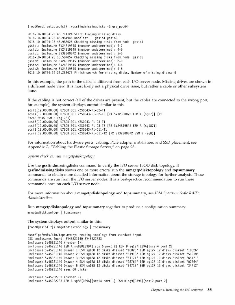
[root@ems1 setuptools]# ./gssfindmissingdisks -G gss_ppc64
2016-10-10T04:23:45.714124 Start finding missing disks2016-10-10T04:23:46.984946 nodelist: gssio1 gssio22016-10-10T04:23:46.985026 Checking missing disks from node gssio1gssio1: Enclosure SV24819545 (number undetermined): 4-7gssio1: Enclosure SV24819545 (number undetermined): 4-9gssio1: Enclosure SV32300072 (number undetermined): 5-52016-10-10T04:25:10.587857 Checking missing disks from node gssio2gssio2: Enclosure SV24819545 (number undetermined): 2-9gssio2: Enclosure SV24819545 (number undetermined): 3-4gssio2: Enclosure SV24819545 (number undetermined): 4-62016-10-10T04:26:33.253075 Finish search for missing disks. Number of missing disks: 6
In this example, the path to the disks is different from each I/O server node. Missing drives are shown ina different node view. It is most likely not a physical drive issue, but rather a cable or other subsystemissue.
If the cabling is not correct (all of the drives are present, but the cables are connected to the wrong port,for example), the system displays output similar to this:scsi3[19.00.00.00] U78CB.001.WZS0043-P1-C2-T1scsi4[19.00.00.00] U78CB.001.WZS0043-P1-C2-T2 [P1 SV32300072 ESM A (sg67)] [P2SV24819545 ESM B (sg126)]scsi5[19.00.00.00] U78CB.001.WZS0043-P1-C3-T1scsi6[19.00.00.00] U78CB.001.WZS0043-P1-C3-T2 [P2 SV24819545 ESM A (sg187)]scsi1[19.00.00.00] U78CB.001.WZS0043-P1-C11-T1scsi2[19.00.00.00] U78CB.001.WZS0043-P1-C11-T2 [P2 SV32300072 ESM B (sg8)]
For information about hardware ports, cabling, PCIe adapter installation, and SSD placement, seeAppendix G, “Cabling the Elastic Storage Server,” on page 93.
System check 2a: run mmgetpdisktopology
Use the gssfindmissingdisks command to verify the I/O server JBOD disk topology. Ifgssfindmissingdisks shows one or more errors, run the mmgetpdisktopology and topsummarycommands to obtain more detailed information about the storage topology for further analysis. Thesecommands are run from the I/O server nodes. It is a best-practice recommendation to run thesecommands once on each I/O server node.
For more information about mmgetpdisktopology and topsummary, see IBM Spectrum Scale RAID:Administration.
Run mmgetpdisktopology and topsummary together to produce a configuration summary:mmgetpdisktopology | topsummary
The system displays output similar to this:[root@gssio1 ~]# mmgetpdisktopology | topsummary
/usr/lpp/mmfs/bin/topsummary: reading topology from standard inputGSS enclosures found: SV45221140 SV45222733Enclosure SV45221140 (number 1):Enclosure SV45221140 ESM A sg188[039A][scsi6 port 2] ESM B sg127[039A][scsi4 port 2]Enclosure SV45221140 Drawer 1 ESM sg188 12 disks diskset "10026" ESM sg127 12 disks diskset "10026"Enclosure SV45221140 Drawer 2 ESM sg188 12 disks diskset "51918" ESM sg127 12 disks diskset "51918"Enclosure SV45221140 Drawer 3 ESM sg188 12 disks diskset "64171" ESM sg127 12 disks diskset "64171"Enclosure SV45221140 Drawer 4 ESM sg188 12 disks diskset "02764" ESM sg127 12 disks diskset "02764"Enclosure SV45221140 Drawer 5 ESM sg188 12 disks diskset "34712" ESM sg127 12 disks diskset "34712"Enclosure SV45221140 sees 60 disks
Enclosure SV45222733 (number 2):Enclosure SV45222733 ESM A sg68[039A][scsi4 port 1] ESM B sg9[039A][scsi2 port 2]
Chapter 4. Installing the ESS software 33

Enclosure SV45222733 Drawer 1 ESM sg68 11 disks diskset "28567" ESM sg9 11 disks diskset "28567"Enclosure SV45222733 Drawer 2 ESM sg68 12 disks diskset "04142" ESM sg9 12 disks diskset "04142"Enclosure SV45222733 Drawer 3 ESM sg68 12 disks diskset "29724" ESM sg9 12 disks diskset "29724"Enclosure SV45222733 Drawer 4 ESM sg68 12 disks diskset "31554" ESM sg9 12 disks diskset "31554"Enclosure SV45222733 Drawer 5 ESM sg68 11 disks diskset "13898" ESM sg9 11 disks diskset "13898"Enclosure SV45222733 sees 58 disks
GSS configuration: 2 enclosures, 2 SSDs, 2 empty slots, 118 disks total, 6 NVRAM partitions
scsi3[20.00.02.00] U78CB.001.WZS06M2-P1-C2-T1scsi4[20.00.02.00] U78CB.001.WZS06M2-P1-C2-T2 [P1 SV45222733 ESM A (sg68)] [P2 SV45221140 ESM B (sg127)]scsi5[20.00.02.00] U78CB.001.WZS06M2-P1-C3-T1scsi6[20.00.02.00] U78CB.001.WZS06M2-P1-C3-T2 [P2 SV45221140 ESM A (sg188)]scsi0[20.00.02.00] U78CB.001.WZS06M2-P1-C11-T1scsi2[20.00.02.00] U78CB.001.WZS06M2-P1-C11-T2 [P2 SV45222733 ESM B (sg9)]
Depending on the model and configuration you may see references to enclosure numbers up to 6. Thissummary is produced by analyzing the SAS physical topology.
Some tips when reading the output follow:1. The first line, is a list of the enclosure mid-plane serial numbers, for some enclosure type (DCS3700,
for example). This serial number does not appear anywhere on the enclosure itself. The second lineshows the enclosure ordering based on the cabling. A system with incorrect cabling will show that theenclosure number is undetermined. The third line shows the enclosure's serial number, then ESM Aand ESM B, each followed by a SCSI generic device number that is assigned by the host:Enclosure SV45221140 ESM A sg188[039A][scsi6 port 2] ESM B sg127[039A][scsi4 port 2]
The number in the first set of brackets is the code level of the ESM. The ports of the SCSI device areenclosed in the second set of brackets. The SCSI generic device number (sg188 or sg127, for example)is also shown in the gsscheckdisk path output of drive performance and error counter.
2. Enclosures are numbered physically from bottom to top within a building block. Enclosure 1 is thebottom enclosure; enclosure 6 is the top enclosure.
3. Analyze the output:Enclosure SV45221140 (number 1):Enclosure SV45221140 ESM A sg188[039A][scsi6 port 2] ESM B sg127[039A][scsi4 port 2]Enclosure SV45221140 Drawer 1 ESM sg188 12 disks diskset "10026" ESM sg127 12 disks diskset "10026"
^ ^
Each line shows two disk-set numbers, one from ESM A and the other from ESM B.The disk-set number is the checksum of the serial numbers of the drives seen on that path.Checksums that don't match indicate an issue with that path involving an adapter, SAS cable,enclosure ESM, or expanders in the enclosures. If only one disk set is shown, this indicates a completelack of path, such as a missing cable or ESM.
The end of the topsummary output shows the cable attachment to the SAS adapters:
scsi3[20.00.02.00] U78CB.001.WZS06M2-P1-C2-T1scsi4[20.00.02.00] U78CB.001.WZS06M2-P1-C2-T2 [P1 SV45222733 ESM A (sg68)] [P2 SV45221140 ESM B (sg127)]scsi5[20.00.02.00] U78CB.001.WZS06M2-P1-C3-T1scsi6[20.00.02.00] U78CB.001.WZS06M2-P1-C3-T2 [P2 SV45221140 ESM A (sg188)]scsi0[20.00.02.00] U78CB.001.WZS06M2-P1-C11-T1scsi2[20.00.02.00] U78CB.001.WZS06M2-P1-C11-T2 [P2 S45222V733 ESM B (sg9)]
The first two lines represent the SAS adapter in slot C2. There are two SAS 2300 SCSI Controllers in eachadapter card, indicated by T1 and T2.
The mapping of ports on the SAS adapter follows:
34 Deploying ESS 5.1 for Power

T1 P1 = Port 0T1 P2 = Port 1T2 P1 = Port 2T2 P2 = Port 3
This shows that Port 2 of the adapter in slot C2 is connected to ESM A of enclosure SV45222733.Similarly, Port 2 of the adapter in slot C11 is connected to ESM B of enclosure 45222V733. See Figure 20on page 93 and Figure 21 on page 94 for the physical location of ports and ESMs.
System check 3: run gsscheckdisks
The gsscheckdisks command initiates I/O to the drives and can be used to identify marginal drives. Thiscommand must be run on a system where there is no GPFS cluster configured. If it is run with a writetest on a system where a GPFS cluster is already configured, it will overwrite the cluster configurationdata stored in the disk, resulting in cluster and data loss. This command can be run from themanagement server node or from an I/O server node. The default duration is to run for 30 seconds foreach I/O test for each path. For a more thorough test, set the duration to run for 5 minutes (300 seconds)or more.
Note: gsscheckdisks must not be run on a system that has GPFS recovery groups. The GSSENVenvironment variable must be set to INSTALL or MFG to indicate that you are running this command ona system in a manufacturing environment or in an installation and deployment environment. Thefollowing message is displayed if this environment variable is not set.[root@ems1 deploy]# gsscheckdisks -G gss_ppc64 --disk-list sdx,sdc --iotest a --write-enable
2016-10-10T20:35:53.408621 Start running check disksgsscheckdisks must run in INSTALL or MFG environment. It may result in data lossif run in a configured system.Please rerun with environment GSSENV=INSTALL or GSSENV=MFG to indicate that it isrun in install or manufacturing environment.Example:
GSSENV=INSTALL gsscheckdisks -N gss_ppc64 --show-enclosure-list
Run gsscheckdisks to verify that disks are in a good state.
To run the command from all I/O server nodes (all nodes of the group, for example), select all attachedenclosures and all I/O operations for testing:GSSENV=INSTALL gsscheckdisks -G gss_ppc64 --encl all --iotest a --write-enable
The system displays output similar to this:[root@gssio1 ~]# GSSENV=INSTALL gsscheckdisks -G gss_ppc64 --encl all --iotest a --write-enable
2014-11-26T05:30:42.401514 Start running check disksList of Enclosures foundSV32300072SV24819545Taking inventory of disks in enclosure SV32300072.Taking inventory of disks in enclosure SV24819545.2016-10-10T05:34:48.317358 Starting r test for 118 of 118 disks. Path: 0, duration 30 secs2016-10-10T05:35:25.216815 Check disk analysis for r test Complete2016-10-10T05:35:25.218802 Starting w test for 118 of 118 disks. Path: 0, duration 30 secs2016-10-10T05:36:02.247192 Check disk analysis for w test Complete2016-10-10T05:36:02.249225 Starting R test for 118 of 118 disks. Path: 0, duration 30 secs2016-10-10T05:36:39.384888 Check disk analysis for R test Complete2016-10-10T05:36:39.386868 Starting W test for 118 of 118 disks. Path: 0, duration 30 secs2016-10-10T05:37:16.515254 Check disk analysis for W test Complete2016-10-10T05:37:16.517218 Starting r test for 118 of 118 disks. Path: 1, duration 30 secs2016-10-10T05:37:53.407486 Check disk analysis for r test Complete2016-10-10T05:37:53.409601 Starting w test for 118 of 118 disks. Path: 1, duration 30 secs2016-10-10T05:38:30.421883 Check disk analysis for w test Complete2016-10-10T05:38:30.423763 Starting R test for 118 of 118 disks. Path: 1, duration 30 secs
Chapter 4. Installing the ESS software 35

2016-10-10T05:39:07.548179 Check disk analysis for R test Complete2016-10-10T05:39:07.550328 Starting W test for 118 of 118 disks. Path: 1, duration 30 secs2016-10-10T05:39:44.675574 Check disk analysis for W test Complete
gsscheckdisks displays an error count if any of the drives under test (and path) experience I/O errors. Ifthere are errors on any disks, the output identifes the failing disks. The output details the performanceand errors seen by the drives and is saved in the /tmp/checkdisk directory of the management servernode (or I/O server node if it is called from there) for further analysis. There are three files in thisdirectory.
hostdiskana[0-1].csv contains summary results of disk I/O throughput of each device every second anda one-line summary of each device showing throughput and error count.
In each I/O server node, it also stores the following files.v diskiostat.csv contains details of the /proc/iostat data for every second for offline detailed analysis
of disk performance. The format of the data is: column 1: time epoch, column 2: node where run,column 3: device. Columns 4 through 11 are a dump of /proc/iostat.
v deviceerr.csv contains the drive error count. The format of the data: column 1: time epoch, column 2:node where run, column 3: device, column 4: I/O issued, column 5: I/O completed, column 6: io error.
Note: With a default test duration of 30 for each test case and a batch size of 60 drives, it can take up to20 minutes per node for a GL4 system.
See “gsscheckdisks command” on page 105 for more information about this command.
Set up high-speed networking
Set up the high-speed network that will be used for cluster data communication. See “Networking:creating a bonded interface” on page 63 for more information.v Choose the hostname that will be associated with the high-speed network IP address. Typically, the
hostname associated with the high-speed network is derived from the xCAT hostname using the prefixand suffix. Before you create the GPFS cluster, high-speed networking must be configured with theproper IP address and hostname. See “Node name considerations” on page 57 for more information.
v Update your /etc/hosts with high-speed network entries showing the high-speed IP address andcorresponding host name. Copy the modified /etc/hosts to the I/O Server nodes of the cluster.
v Add the high-speed network to the xCAT networks table. Run:makedns
Set up the high-speed network
With the Ethernet high-speed network, you can use the gssgennetworks script to create a bondedEthernet interface over active (up) high-speed network interfaces. You cannot use gssgennetworks IPoIBconfigurations. See Appendix A: Appendix A, “Installation: reference,” on page 57 for creating bondednetwork interface with IP over IB.1. To see the current set of active (up) interfaces on all nodes, run:
gssgennetworks -G ems1,gss_ppc64 --suffix=-hs
2. To create a bonded Ethernet interface, in all nodes run:gssgennetworks -G ems1,gss_ppc64 --suffix=-hs --create-bond
The script sets miimon to 100, the bonding node to 802.3ad (LACP), and xmit_hash_policy tolayer2+3. The other bond options keep the default values, including lacp-_rate (the default is slow).For proper network operation, the Ethernet switch setting in the networking infrastructure mustmatch the I/O server node interface bond settings.
36 Deploying ESS 5.1 for Power
Check the installed software and firmware
Run the gssinstallcheck command to check the installed software and firmware.
See “gssinstallcheck command” on page 125 for more information about this command.
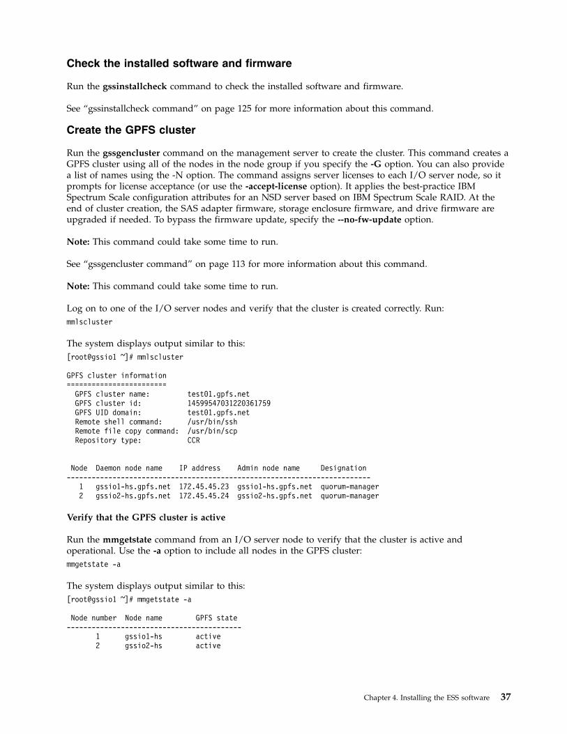
Create the GPFS cluster
Run the gssgencluster command on the management server to create the cluster. This command creates aGPFS cluster using all of the nodes in the node group if you specify the -G option. You can also providea list of names using the -N option. The command assigns server licenses to each I/O server node, so itprompts for license acceptance (or use the -accept-license option). It applies the best-practice IBMSpectrum Scale configuration attributes for an NSD server based on IBM Spectrum Scale RAID. At theend of cluster creation, the SAS adapter firmware, storage enclosure firmware, and drive firmware areupgraded if needed. To bypass the firmware update, specify the --no-fw-update option.
Note: This command could take some time to run.
See “gssgencluster command” on page 113 for more information about this command.
Note: This command could take some time to run.
Log on to one of the I/O server nodes and verify that the cluster is created correctly. Run:mmlscluster
The system displays output similar to this:[root@gssio1 ~]# mmlscluster
GPFS cluster information========================
GPFS cluster name: test01.gpfs.netGPFS cluster id: 14599547031220361759GPFS UID domain: test01.gpfs.netRemote shell command: /usr/bin/sshRemote file copy command: /usr/bin/scpRepository type: CCR
Node Daemon node name IP address Admin node name Designation-------------------------------------------------------------------------
1 gssio1-hs.gpfs.net 172.45.45.23 gssio1-hs.gpfs.net quorum-manager2 gssio2-hs.gpfs.net 172.45.45.24 gssio2-hs.gpfs.net quorum-manager
Verify that the GPFS cluster is active
Run the mmgetstate command from an I/O server node to verify that the cluster is active andoperational. Use the -a option to include all nodes in the GPFS cluster:mmgetstate -a
The system displays output similar to this:[root@gssio1 ~]# mmgetstate -a
Node number Node name GPFS state------------------------------------------
1 gssio1-hs active2 gssio2-hs active
Chapter 4. Installing the ESS software 37

After the /etc/hosts file is properly set with high-speed IP addresses and corresponding hostnames, youcan use the gssgennetworks script to create a bonded Ethernet network. Note that this script cannot beused to create a bond with the IP over an IB network.
To see the current set of active (up) interfaces, run:gssgennetworks -G gss_ppc64
To create a bonded interface, run:gssgennetworks -G gss_ppc64 --create-bond
The script sets miimon to 100, the bonding mode to 802.3ad (LACP), and xmit_hash_policy to layer3+4.The other bond options keep the default values, including lacp_rate (the default is slow). For propernetwork operation, the Ethernet switch settings in the networking infrastructure must match the I/Oserver node interface bond settings.
Create the recovery groups
The gssgenclusterrgs command creates the recovery groups (RGs) and declustered arrays (DAs), as wellas the associated log tip VDisk, log backup VDisk, and log home VDisk. For each RG, three arrays arecreated: NVRAM, SSD, and DAn. By default for ESS 3.5, only one DA is created, in which all HDDs (andSSDs for SSD models) belong to this single DA (DA1, for example). If you want to use multiple DAs(assuming there are enough disks), specify the --multi-da option.
The gssgenclusterrgs command can create NSDs and file systems for simple configurations that requireone file system. More flexibility can be achieved using gssgenclusterrgs to create the recovery groupsonly and using gssgenvdisks (the preferred method) to create data VDisks, metadata VDisks, NSDs, andfile systems. For backward compatibility, the gssgenclusterrgs command continues to support vdisk,NSD, and file system creation.
The gssgenclusterrgs command creates and saves the stanza files for the data and metadata VDisks andNSD. The stanza files are located in the /tmp directory of the first node of the first building block withnames node1_node2_vdisk.cfg.save and node1_node2_nsd.cfg.save. These files can be edited for furthercustomization.
If a customized recovery stanza file is available, it can be used to create the recovery group. The filesmust be located on the first node (in the node list) of each building block in /tmp. Their names must be inthe format xxxxL.stanza and yyyyR.stanza, where L is for the left recovery group and R is for the rightrecovery group. The name of the recovery group is derived from the I/O server node's short name (withprefix and suffix) by adding a prefix of rg_. When the --create-nsds option is specified, by default, 1% ofthe space is left as reserved and the remaining space is used to create the NSDs. The amount of reservedspace is user-selectable and the default is 1% of the total raw space. Note that the percentage of reservedspace is based on the total raw space (not on the available space) before any redundancy overhead isapplied.
If the system already contains recovery groups and log VDisks (created in the previous steps), theircreation can be skipped using the appropriate options. This can be useful when NSDs are recreated (for achange in the number of NSDs or block size, for example).
Note 1: This command could take some time to complete.
Note 2: NSDs in a building block are assigned to the same failure group by default. If you have multiplebuilding blocks, the NSDs defined in each building block will have a different failure group for eachbuilding block. Carefully consider this information and change the failure group assignment when youare configuring the system for metadata and data replication.
For example, to create recovery groups, run:
38 Deploying ESS 5.1 for Power
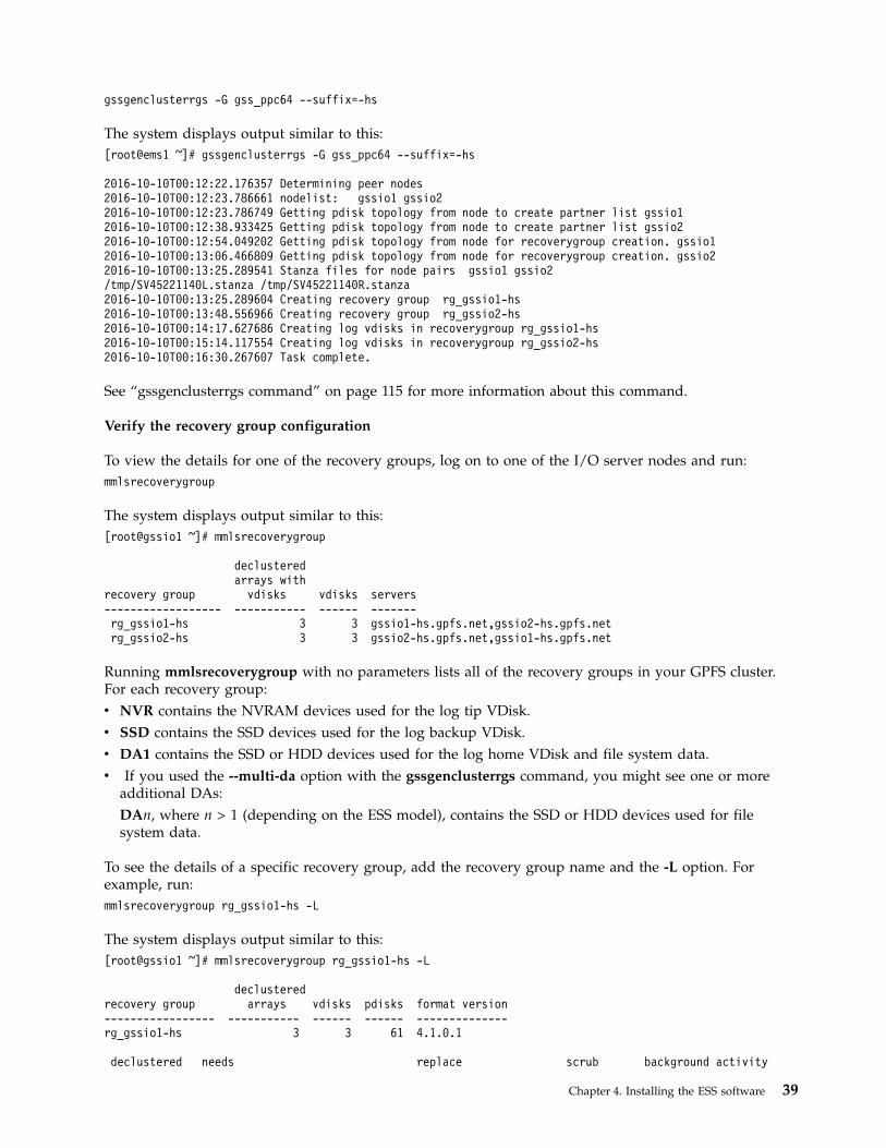
gssgenclusterrgs -G gss_ppc64 --suffix=-hs
The system displays output similar to this:[root@ems1 ~]# gssgenclusterrgs -G gss_ppc64 --suffix=-hs
2016-10-10T00:12:22.176357 Determining peer nodes2016-10-10T00:12:23.786661 nodelist: gssio1 gssio22016-10-10T00:12:23.786749 Getting pdisk topology from node to create partner list gssio12016-10-10T00:12:38.933425 Getting pdisk topology from node to create partner list gssio22016-10-10T00:12:54.049202 Getting pdisk topology from node for recoverygroup creation. gssio12016-10-10T00:13:06.466809 Getting pdisk topology from node for recoverygroup creation. gssio22016-10-10T00:13:25.289541 Stanza files for node pairs gssio1 gssio2/tmp/SV45221140L.stanza /tmp/SV45221140R.stanza2016-10-10T00:13:25.289604 Creating recovery group rg_gssio1-hs2016-10-10T00:13:48.556966 Creating recovery group rg_gssio2-hs2016-10-10T00:14:17.627686 Creating log vdisks in recoverygroup rg_gssio1-hs2016-10-10T00:15:14.117554 Creating log vdisks in recoverygroup rg_gssio2-hs2016-10-10T00:16:30.267607 Task complete.
See “gssgenclusterrgs command” on page 115 for more information about this command.
Verify the recovery group configuration
To view the details for one of the recovery groups, log on to one of the I/O server nodes and run:mmlsrecoverygroup
The system displays output similar to this:[root@gssio1 ~]# mmlsrecoverygroup
declusteredarrays with
recovery group vdisks vdisks servers------------------ ----------- ------ -------rg_gssio1-hs 3 3 gssio1-hs.gpfs.net,gssio2-hs.gpfs.netrg_gssio2-hs 3 3 gssio2-hs.gpfs.net,gssio1-hs.gpfs.net
Running mmlsrecoverygroup with no parameters lists all of the recovery groups in your GPFS cluster.For each recovery group:v NVR contains the NVRAM devices used for the log tip VDisk.v SSD contains the SSD devices used for the log backup VDisk.v DA1 contains the SSD or HDD devices used for the log home VDisk and file system data.v If you used the --multi-da option with the gssgenclusterrgs command, you might see one or more
additional DAs:DAn, where n > 1 (depending on the ESS model), contains the SSD or HDD devices used for filesystem data.
To see the details of a specific recovery group, add the recovery group name and the -L option. Forexample, run:mmlsrecoverygroup rg_gssio1-hs -L
The system displays output similar to this:[root@gssio1 ~]# mmlsrecoverygroup rg_gssio1-hs -L
declusteredrecovery group arrays vdisks pdisks format version----------------- ----------- ------ ------ --------------rg_gssio1-hs 3 3 61 4.1.0.1
declustered needs replace scrub background activity
Chapter 4. Installing the ESS software 39
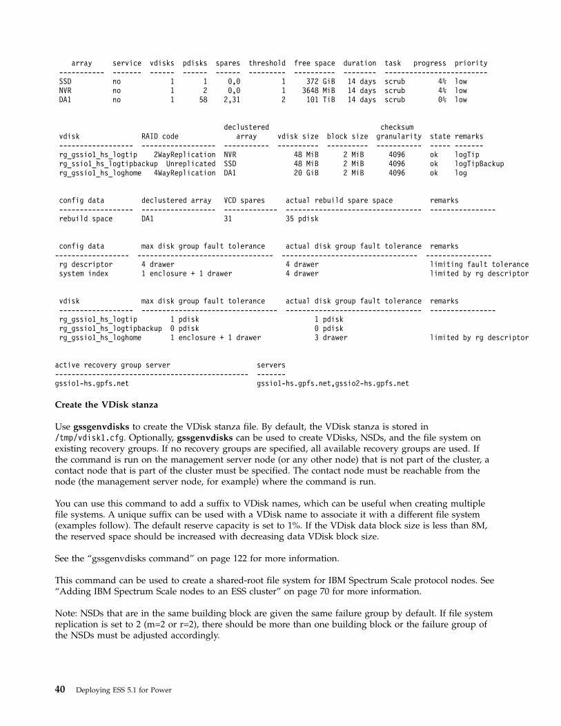
array service vdisks pdisks spares threshold free space duration task progress priority----------- ------- ------ ------ ------ --------- ---------- -------- -------------------------SSD no 1 1 0,0 1 372 GiB 14 days scrub 4% lowNVR no 1 2 0,0 1 3648 MiB 14 days scrub 4% lowDA1 no 1 58 2,31 2 101 TiB 14 days scrub 0% low
declustered checksumvdisk RAID code array vdisk size block size granularity state remarks------------------ ------------------ ----------- ---------- ---------- ----------- ----- -------rg_gssio1_hs_logtip 2WayReplication NVR 48 MiB 2 MiB 4096 ok logTiprg_ssio1_hs_logtipbackup Unreplicated SSD 48 MiB 2 MiB 4096 ok logTipBackuprg_gssio1_hs_loghome 4WayReplication DA1 20 GiB 2 MiB 4096 ok log
config data declustered array VCD spares actual rebuild spare space remarks------------------ ------------------ ------------- --------------------------------- ----------------rebuild space DA1 31 35 pdisk
config data max disk group fault tolerance actual disk group fault tolerance remarks------------------ --------------------------------- --------------------------------- ----------------rg descriptor 4 drawer 4 drawer limiting fault tolerancesystem index 1 enclosure + 1 drawer 4 drawer limited by rg descriptor
vdisk max disk group fault tolerance actual disk group fault tolerance remarks------------------ --------------------------------- --------------------------------- ----------------rg_gssio1_hs_logtip 1 pdisk 1 pdiskrg_gssio1_hs_logtipbackup 0 pdisk 0 pdiskrg_gssio1_hs_loghome 1 enclosure + 1 drawer 3 drawer limited by rg descriptor
active recovery group server servers----------------------------------------------- -------gssio1-hs.gpfs.net gssio1-hs.gpfs.net,gssio2-hs.gpfs.net
Create the VDisk stanza
Use gssgenvdisks to create the VDisk stanza file. By default, the VDisk stanza is stored in/tmp/vdisk1.cfg. Optionally, gssgenvdisks can be used to create VDisks, NSDs, and the file system onexisting recovery groups. If no recovery groups are specified, all available recovery groups are used. Ifthe command is run on the management server node (or any other node) that is not part of the cluster, acontact node that is part of the cluster must be specified. The contact node must be reachable from thenode (the management server node, for example) where the command is run.
You can use this command to add a suffix to VDisk names, which can be useful when creating multiplefile systems. A unique suffix can be used with a VDisk name to associate it with a different file system(examples follow). The default reserve capacity is set to 1%. If the VDisk data block size is less than 8M,the reserved space should be increased with decreasing data VDisk block size.
See the “gssgenvdisks command” on page 122 for more information.
This command can be used to create a shared-root file system for IBM Spectrum Scale protocol nodes. See“Adding IBM Spectrum Scale nodes to an ESS cluster” on page 70 for more information.
Note: NSDs that are in the same building block are given the same failure group by default. If file systemreplication is set to 2 (m=2 or r=2), there should be more than one building block or the failure group ofthe NSDs must be adjusted accordingly.
40 Deploying ESS 5.1 for Power

In ESS 3.0 and later, the gssgenvdisks command includes an option for specifying the data VDisk sizeand the metadata VDisk size in GiB. When the metadata NSD size (due to a one-to-one mapping ofNSDs to VDisks) and the metadata percentage are specified, the metadata NSD size takes precedence.
Reserved space considerations
When all available space is allocated, the reserved space should be increased with decreasing data VDiskblock size. A default reserved space of 1% works well for a block size of up to 4 MB. For a 2 MB blocksize, 2% should be reserved. For a 1 MB block size, reserved space should be increased to 3%.
Example 1:
Create two file systems, one with 20 TB (two VDisks, 10 TB each), and the other with 40 TB (two VDisks,20 TB each) with a RAID code of 8+3p.
To create a file system called fs1, run:gssgenvdisks --contact-node gssio1 --create-vdisk --create-nsds --create-filesystem--vdisk-suffix=_fs1 --filesystem-name fs1 --data-vdisk-size 10240
The system displays output similar to this:[root@ems1 ~]# gssgenvdisks --contact-node gssio1 --create-vdisk --create-nsds --create-filesystem--vdisk-suffix=_fs1 --filesystem-name fs1 --data-vdisk-size 10240
2016-10-10T00:50:37.254906 Start creating vdisk stanzavdisk stanza saved in gssio1:/tmp/vdisk1.cfg2016-10-10T00:50:51.809024 Generating vdisks for nsd creation2016-10-10T00:51:27.409034 Creating nsds2016-10-10T00:51:35.266776 Creating filesystemFilesystem successfully created. Verify failure group of nsds and change as needed.2016-10-10T00:51:46.688937 Applying data placement policy2016-10-10T00:51:51.637243 Task complete.
Filesystem Size Used Avail Use% Mounted on/dev/sda3 246G 2.9G 244G 2% /devtmpfs 60G 0 60G 0% /devtmpfs 60G 0 60G 0% /dev/shmtmpfs 60G 43M 60G 1% /runtmpfs 60G 0 60G 0% /sys/fs/cgroup/dev/sda2 497M 161M 336M 33% /boot/dev/fs1 21T 160M 21T 1% /gpfs/fs1
The last line shows that file system fs1 was created.
To create a file system called fs2, run:gssgenvdisks --contact-node gssio1 --create-vdisk --create-nsds --create-filesystem--vdisk-suffix=_fs2 --filesystem-name fs2 --data-vdisk-size 20480 --raid-code 8+3p
The system displays output similar to this:[root@ems1 ~]# gssgenvdisks --contact-node gssio1 --create-vdisk --create-nsds --create-filesystem--vdisk-suffix=_fs2 --filesystem-name fs2 --data-vdisk-size 20480 --raid-code 8+3p
2016-10-10T01:06:59.929580 Start creating vdisk stanzavdisk stanza saved in gssio1:/tmp/vdisk1.cfg2016-10-10T01:07:13.019100 Generating vdisks for nsd creation2016-10-10T01:07:56.688530 Creating nsds2016-10-10T01:08:04.516814 Creating filesystemFilesystem successfully created. Verify failure group of nsds and change as needed.2016-10-10T01:08:16.613198 Applying data placement policy2016-10-10T01:08:21.637298 Task complete.
Filesystem Size Used Avail Use% Mounted on
Chapter 4. Installing the ESS software 41
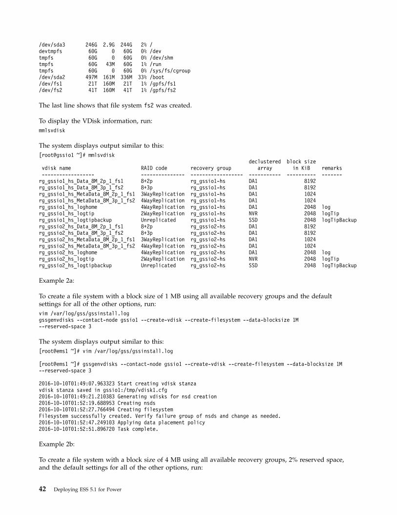
/dev/sda3 246G 2.9G 244G 2% /devtmpfs 60G 0 60G 0% /devtmpfs 60G 0 60G 0% /dev/shmtmpfs 60G 43M 60G 1% /runtmpfs 60G 0 60G 0% /sys/fs/cgroup/dev/sda2 497M 161M 336M 33% /boot/dev/fs1 21T 160M 21T 1% /gpfs/fs1/dev/fs2 41T 160M 41T 1% /gpfs/fs2
The last line shows that file system fs2 was created.
To display the VDisk information, run:mmlsvdisk
The system displays output similar to this:[root@gssio1 ~]# mmlsvdisk
declustered block sizevdisk name RAID code recovery group array in KiB remarks------------------ --------------- ------------------ ----------- ---------- -------rg_gssio1_hs_Data_8M_2p_1_fs1 8+2p rg_gssio1-hs DA1 8192rg_gssio1_hs_Data_8M_3p_1_fs2 8+3p rg_gssio1-hs DA1 8192rg_gssio1_hs_MetaData_8M_2p_1_fs1 3WayReplication rg_gssio1-hs DA1 1024rg_gssio1_hs_MetaData_8M_3p_1_fs2 4WayReplication rg_gssio1-hs DA1 1024rg_gssio1_hs_loghome 4WayReplication rg_gssio1-hs DA1 2048 logrg_gssio1_hs_logtip 2WayReplication rg_gssio1-hs NVR 2048 logTiprg_gssio1_hs_logtipbackup Unreplicated rg_gssio1-hs SSD 2048 logTipBackuprg_gssio2_hs_Data_8M_2p_1_fs1 8+2p rg_gssio2-hs DA1 8192rg_gssio2_hs_Data_8M_3p_1_fs2 8+3p rg_gssio2-hs DA1 8192rg_gssio2_hs_MetaData_8M_2p_1_fs1 3WayReplication rg_gssio2-hs DA1 1024rg_gssio2_hs_MetaData_8M_3p_1_fs2 4WayReplication rg_gssio2-hs DA1 1024rg_gssio2_hs_loghome 4WayReplication rg_gssio2-hs DA1 2048 logrg_gssio2_hs_logtip 2WayReplication rg_gssio2-hs NVR 2048 logTiprg_gssio2_hs_logtipbackup Unreplicated rg_gssio2-hs SSD 2048 logTipBackup
Example 2a:
To create a file system with a block size of 1 MB using all available recovery groups and the defaultsettings for all of the other options, run:vim /var/log/gss/gssinstall.loggssgenvdisks --contact-node gssio1 --create-vdisk --create-filesystem --data-blocksize 1M--reserved-space 3
The system displays output similar to this:[root@ems1 ~]# vim /var/log/gss/gssinstall.log
[root@ems1 ~]# gssgenvdisks --contact-node gssio1 --create-vdisk --create-filesystem --data-blocksize 1M--reserved-space 3
2016-10-10T01:49:07.963323 Start creating vdisk stanzavdisk stanza saved in gssio1:/tmp/vdisk1.cfg2016-10-10T01:49:21.210383 Generating vdisks for nsd creation2016-10-10T01:52:19.688953 Creating nsds2016-10-10T01:52:27.766494 Creating filesystemFilesystem successfully created. Verify failure group of nsds and change as needed.2016-10-10T01:52:47.249103 Applying data placement policy2016-10-10T01:52:51.896720 Task complete.
Example 2b:
To create a file system with a block size of 4 MB using all available recovery groups, 2% reserved space,and the default settings for all of the other options, run:
42 Deploying ESS 5.1 for Power

gssgenvdisks --contact-node gssio1 --create-vdisk --create-filesystem --data-blocksize 4M --reserved-space 2
The system displays output similar to this:
[root@ems1 ~]# gssgenvdisks --contact-node gssio1 --create-vdisk --create-filesystem --data-blocksize 4M--reserved-space 2
2016-10-10T01:25:54.455588 Start creating vdisk stanzavdisk stanza saved in gssio1:/tmp/vdisk1.cfg2016-10-10T01:26:07.443263 Generating vdisks for nsd creation2016-10-10T01:27:46.671050 Creating nsds2016-10-10T01:27:54.296765 Creating filesystemFilesystem successfully created. Verify failure group of nsds and change as needed.2016-10-10T01:28:07.279192 Applying data placement policy2016-10-10T01:28:11.836822 Task complete.
Example 3:
Suppose you want to create three file systems. The first file system is called fsystem0. Keep 66% of thespace reserved for future file system creation. For the second file system, fsystem1, keep 33% reserved.For the third file system, fsystem2, keep 1% reserved. Because you are going to create multiple filesystems, you must specify a unique suffix for vdisk creation. Specify _fs0 as the suffix of the vdisk namefor the first file system. Specify a RAID code of 8+3p for data vdisks.
First, run:
gssgenvdisks --create-vdisk --vdisk-suffix _fs0 --raid-code 8+3p --create-filesystem--filesystem-name fsystem0 --reserved-space-percent 66
The system displays output similar to this:[root@ems1 ~]# gssgenvdisks --create-vdisk --vdisk-suffix _fs0 --raid-code 8+3p --create-filesystem--filesystem-name fsystem0 --reserved-space-percent 66
2016-10-10T07:04:12.703294 Start creating vdisk stanza2016-10-10T07:04:12.703364 No contact node provided. Using current node. ems1vdisk stanza saved in ems1:/tmp/vdisk1.cfg2016-10-10T07:04:33.088067 Generating vdisks for nsd creation2016-10-10T07:05:44.648360 Creating nsds2016-10-10T07:05:53.517659 Creating filesystemFilesystem successfully created. Verify failure group of nsds and change as needed.2016-10-10T07:06:07.416392 Applying data placement policy2016-10-10T07:06:12.748168 Task complete.
Next, run:
gssgenvdisks --create-vdisk --vdisk-suffix _fs1 --raid-code 8+3p --create-filesystem--filesystem-name fsystem1 --reserved-space-percent 33
The system displays output similar to this:[root@ems1 ~]# gssgenvdisks --create-vdisk --vdisk-suffix _fs1 --raid-code 8+3p --create-filesystem--filesystem-name fsystem1 --reserved-space-percent 33
2016-10-10T07:11:14.649102 Start creating vdisk stanza2016-10-10T07:11:14.649189 No contact node provided. Using current node. ems1vdisk stanza saved in ems1:/tmp/vdisk1.cfg2016-10-10T07:11:34.998352 Generating vdisks for nsd creation2016-10-10T07:12:46.858365 Creating nsds2016-10-10T07:12:55.416322 Creating filesystemFilesystem successfully created. Verify failure group of nsds and change as needed.2016-10-10T07:13:09.488075 Applying data placement policy2016-10-10T07:13:14.756651 Task complete.
Chapter 4. Installing the ESS software 43
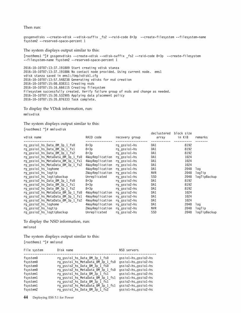
Then run:
gssgenvdisks --create-vdisk --vdisk-suffix _fs2 --raid-code 8+3p --create-filesystem --filesystem-namefsystem2 --reserved-space-percent 1
The system displays output similar to this:[root@ems1 ~]# gssgenvdisks --create-vdisk --vdisk-suffix _fs2 --raid-code 8+3p --create-filesystem--filesystem-name fsystem2 --reserved-space-percent 1
2016-10-10T07:13:37.191809 Start creating vdisk stanza2016-10-10T07:13:37.191886 No contact node provided. Using current node. ems1vdisk stanza saved in ems1:/tmp/vdisk1.cfg2016-10-10T07:13:57.548238 Generating vdisks for nsd creation2016-10-10T07:15:08.838311 Creating nsds2016-10-10T07:15:16.666115 Creating filesystemFilesystem successfully created. Verify failure group of nsds and change as needed.2016-10-10T07:15:30.532905 Applying data placement policy2016-10-10T07:15:35.876333 Task complete.
To display the VDisk information, run:mmlsvdisk
The system displays output similar to this:[root@ems1 ~]# mmlsvdisk
declustered block sizevdisk name RAID code recovery group array in KiB remarks------------------ --------------- ------------------ ----------- ---------- -------rg_gssio1_hs_Data_8M_3p_1_fs0 8+3p rg_gssio1-hs DA1 8192rg_gssio1_hs_Data_8M_3p_1_fs1 8+3p rg_gssio1-hs DA1 8192rg_gssio1_hs_Data_8M_3p_1_fs2 8+3p rg_gssio1-hs DA1 8192rg_gssio1_hs_MetaData_8M_3p_1_fs0 4WayReplication rg_gssio1-hs DA1 1024rg_gssio1_hs_MetaData_8M_3p_1_fs1 4WayReplication rg_gssio1-hs DA1 1024rg_gssio1_hs_MetaData_8M_3p_1_fs2 4WayReplication rg_gssio1-hs DA1 1024rg_gssio1_hs_loghome 4WayReplication rg_gssio1-hs DA1 2048 logrg_gssio1_hs_logtip 2WayReplication rg_gssio1-hs NVR 2048 logTiprg_gssio1_hs_logtipbackup Unreplicated rg_gssio1-hs SSD 2048 logTipBackuprg_gssio2_hs_Data_8M_3p_1_fs0 8+3p rg_gssio2-hs DA1 8192rg_gssio2_hs_Data_8M_3p_1_fs1 8+3p rg_gssio2-hs DA1 8192rg_gssio2_hs_Data_8M_3p_1_fs2 8+3p rg_gssio2-hs DA1 8192rg_gssio2_hs_MetaData_8M_3p_1_fs0 4WayReplication rg_gssio2-hs DA1 1024rg_gssio2_hs_MetaData_8M_3p_1_fs1 4WayReplication rg_gssio2-hs DA1 1024rg_gssio2_hs_MetaData_8M_3p_1_fs2 4WayReplication rg_gssio2-hs DA1 1024rg_gssio2_hs_loghome 4WayReplication rg_gssio2-hs DA1 2048 logrg_gssio2_hs_logtip 2WayReplication rg_gssio2-hs NVR 2048 logTiprg_gssio2_hs_logtipbackup Unreplicated rg_gssio2-hs SSD 2048 logTipBackup
To display the NSD information, run:mmlsnsd
The system displays output similar to this:[root@ems1 ~]# mmlsnsd
File system Disk name NSD servers---------------------------------------------------------------------------fsystem0 rg_gssio1_hs_Data_8M_3p_1_fs0 gssio1-hs,gssio2-hsfsystem0 rg_gssio1_hs_MetaData_8M_3p_1_fs0 gssio1-hs,gssio2-hsfsystem0 rg_gssio2_hs_Data_8M_3p_1_fs0 gssio2-hs,gssio1-hsfsystem0 rg_gssio2_hs_MetaData_8M_3p_1_fs0 gssio2-hs,gssio1-hsfsystem1 rg_gssio1_hs_Data_8M_3p_1_fs1 gssio1-hs,gssio2-hsfsystem1 rg_gssio1_hs_MetaData_8M_3p_1_fs1 gssio1-hs,gssio2-hsfsystem1 rg_gssio2_hs_Data_8M_3p_1_fs1 gssio2-hs,gssio1-hsfsystem1 rg_gssio2_hs_MetaData_8M_3p_1_fs1 gssio2-hs,gssio1-hsfsystem2 rg_gssio1_hs_Data_8M_3p_1_fs2 gssio1-hs,gssio2-hs
44 Deploying ESS 5.1 for Power
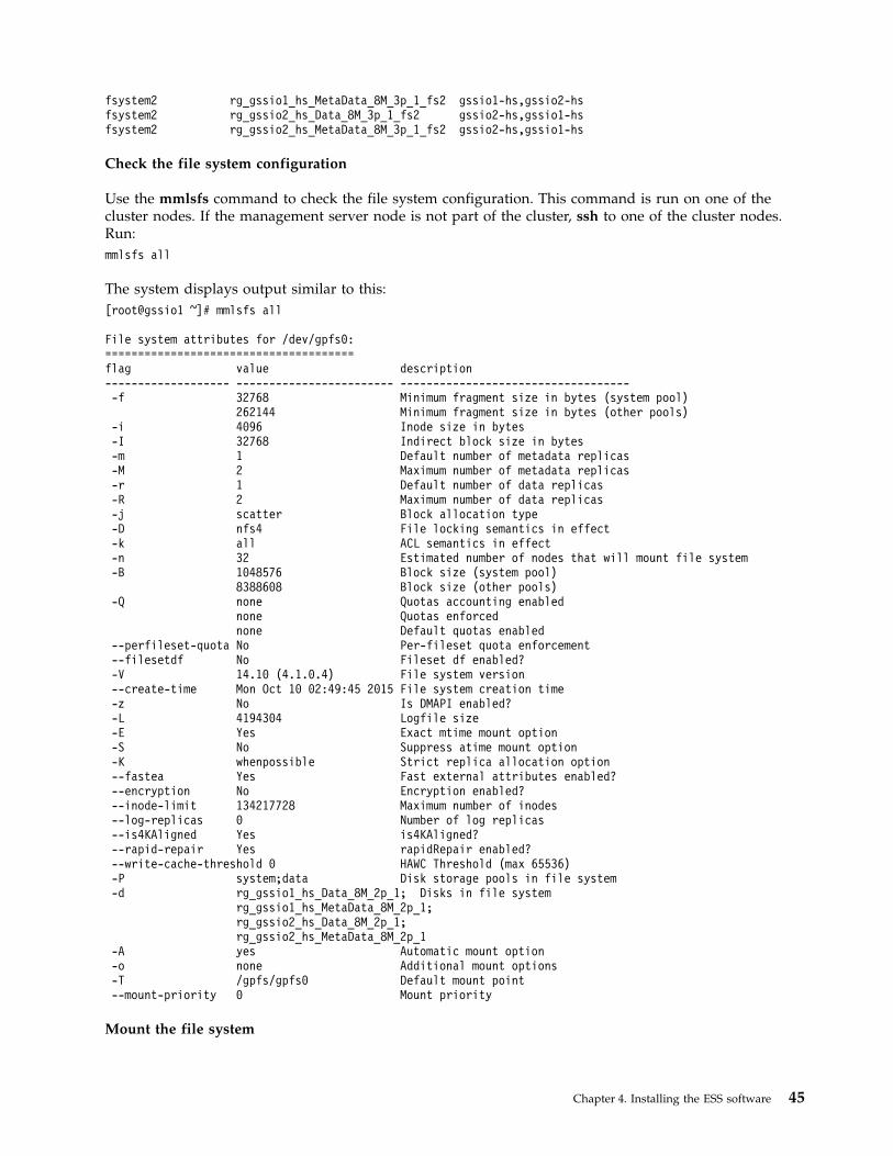
fsystem2 rg_gssio1_hs_MetaData_8M_3p_1_fs2 gssio1-hs,gssio2-hsfsystem2 rg_gssio2_hs_Data_8M_3p_1_fs2 gssio2-hs,gssio1-hsfsystem2 rg_gssio2_hs_MetaData_8M_3p_1_fs2 gssio2-hs,gssio1-hs
Check the file system configuration
Use the mmlsfs command to check the file system configuration. This command is run on one of thecluster nodes. If the management server node is not part of the cluster, ssh to one of the cluster nodes.Run:mmlsfs all
The system displays output similar to this:[root@gssio1 ~]# mmlsfs all
File system attributes for /dev/gpfs0:======================================flag value description------------------- ------------------------ ------------------------------------f 32768 Minimum fragment size in bytes (system pool)
262144 Minimum fragment size in bytes (other pools)-i 4096 Inode size in bytes-I 32768 Indirect block size in bytes-m 1 Default number of metadata replicas-M 2 Maximum number of metadata replicas-r 1 Default number of data replicas-R 2 Maximum number of data replicas-j scatter Block allocation type-D nfs4 File locking semantics in effect-k all ACL semantics in effect-n 32 Estimated number of nodes that will mount file system-B 1048576 Block size (system pool)
8388608 Block size (other pools)-Q none Quotas accounting enabled
none Quotas enforcednone Default quotas enabled
--perfileset-quota No Per-fileset quota enforcement--filesetdf No Fileset df enabled?-V 14.10 (4.1.0.4) File system version--create-time Mon Oct 10 02:49:45 2015 File system creation time-z No Is DMAPI enabled?-L 4194304 Logfile size-E Yes Exact mtime mount option-S No Suppress atime mount option-K whenpossible Strict replica allocation option--fastea Yes Fast external attributes enabled?--encryption No Encryption enabled?--inode-limit 134217728 Maximum number of inodes--log-replicas 0 Number of log replicas--is4KAligned Yes is4KAligned?--rapid-repair Yes rapidRepair enabled?--write-cache-threshold 0 HAWC Threshold (max 65536)-P system;data Disk storage pools in file system-d rg_gssio1_hs_Data_8M_2p_1; Disks in file system
rg_gssio1_hs_MetaData_8M_2p_1;rg_gssio2_hs_Data_8M_2p_1;rg_gssio2_hs_MetaData_8M_2p_1
-A yes Automatic mount option-o none Additional mount options-T /gpfs/gpfs0 Default mount point--mount-priority 0 Mount priority
Mount the file system
Chapter 4. Installing the ESS software 45

Mounting of the file system is performed for testing purposes only. Use the mmmount command tomount the file system:mmmount device -a
where device is the name of the file system. The default file system name is gpfs0. For example, run:mmmount gpfs0 -a
To check whether the file system is mounted properly, run:mmlsmount gpfs0 -L
The system displays output similar to this:[root@gssio1 ~]# mmlsmount gpfs0 -L
File system gpfs0 is mounted on 2 nodes:
172.45.45.23 gssio1-hs172.45.45.24 gssio2-hs
To check file system space usage, run:df
The system displays output similar to this:[root@gssio1 ~]# df
Filesystem 1K-blocks Used Available Use% Mounted on/dev/sda3 257922000 2943152 254978848 2% /devtmpfs 62265728 0 62265728 0% /devtmpfs 62302080 0 62302080 0% /dev/shmtmpfs 62302080 43584 62258496 1% /runtmpfs 62302080 0 62302080 0% /sys/fs/cgroup/dev/sda2 508588 164580 344008 33% /boot/dev/gpfs0 154148405248 163840 154148241408 1% /gpfs/gpfs0
Initially after creation, you might see that the file system use is at 99%, temporarily.
Test the file system using gpfsperf
Use the gpfsperf script to run some basic I/O tests on the file system to measure the performance of thefile system using a variety of I/O patterns. The results you obtain from this script are limited to theextent to which you use such components as disks, interconnect, clients, and bonding. The gpfsperf scriptis included with IBM Spectrum Scale. To run a basic I/O test by first sequentially creating a file, run thiscommand:/usr/lpp/mmfs/samples/perf/gpfsperf create seq /gpfs/gpfs0/testfile1 -n 200G -r 16M -th 4
The system displays output similar to this:[root@gssio1 ~]# /usr/lpp/mmfs/samples/perf/gpfsperf create seq /gpfs/gpfs0/testfile1 -n 200G -r 16M -th 32
/usr/lpp/mmfs/samples/perf/gpfsperf create seq /gpfs/gpfs0/testfile1recSize 16M nBytes 200G fileSize 16GnProcesses 1 nThreadsPerProcess 32file cache flushed before testnot using direct I/Ooffsets accessed will cycle through the same file segmentnot using shared memory buffernot releasing byte-range token after openno fsync at end of testData rate was 4689394.83 Kbytes/sec, thread utilization 0.925
The block size must match the data vdisk block size.
46 Deploying ESS 5.1 for Power
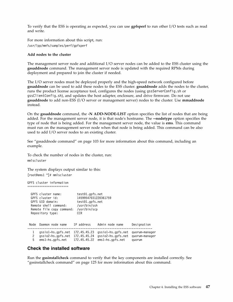
To verify that the ESS is operating as expected, you can use gpfsperf to run other I/O tests such as readand write.
For more information about this script, run:/usr/lpp/mmfs/samples/perf/gpfsperf
Add nodes to the cluster
The management server node and additional I/O server nodes can be added to the ESS cluster using thegssaddnode command. The management server node is updated with the required RPMs duringdeployment and prepared to join the cluster if needed.
The I/O server nodes must be deployed properly and the high-speed network configured beforegssaddnode can be used to add these nodes to the ESS cluster. gssaddnode adds the nodes to the cluster,runs the product license acceptance tool, configures the nodes (using gssServerConfig.sh orgssClientConfig.sh), and updates the host adapter, enclosure, and drive firmware. Do not usegssaddnode to add non-ESS (I/O server or management server) nodes to the cluster. Use mmaddnodeinstead.
On the gssaddnode command, the -N ADD-NODE-LIST option specifies the list of nodes that are beingadded. For the management server node, it is that node's hostname. The --nodetype option specifies thetype of node that is being added. For the management server node, the value is ems. This commandmust run on the management server node when that node is being added. This command can be alsoused to add I/O server nodes to an existing cluster.
See “gssaddnode command” on page 103 for more information about this command, including anexample.
To check the number of nodes in the cluster, run:mmlscluster
The system displays output similar to this:[root@ems1 ~]# mmlscluster
GPFS cluster information========================
GPFS cluster name: test01.gpfs.netGPFS cluster id: 14599547031220361759GPFS UID domain: test01.gpfs.netRemote shell command: /usr/bin/sshRemote file copy command: /usr/bin/scpRepository type: CCR
Node Daemon node name IP address Admin node name Designation-------------------------------------------------------------------------
1 gssio1-hs.gpfs.net 172.45.45.23 gssio1-hs.gpfs.net quorum-manager2 gssio2-hs.gpfs.net 172.45.45.24 gssio2-hs.gpfs.net quorum-manager5 ems1-hs.gpfs.net 172.45.45.22 ems1-hs.gpfs.net quorum
Check the installed software
Run the gssinstallcheck command to verify that the key components are installed correctly. See“gssinstallcheck command” on page 125 for more information about this command.
Chapter 4. Installing the ESS software 47
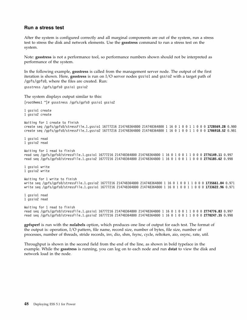
Run a stress test
After the system is configured correctly and all marginal components are out of the system, run a stresstest to stress the disk and network elements. Use the gssstress command to run a stress test on thesystem.
Note: gssstress is not a performance tool, so performance numbers shown should not be interpreted asperformance of the system.
In the following example, gssstress is called from the management server node. The output of the firstiteration is shown. Here, gssstress is run on I/O server nodes gssio1 and gssio2 with a target path of/gpfs/gpfs0, where the files are created. Run:gssstress /gpfs/gpfs0 gssio1 gssio2
The system displays output similar to this:[root@ems1 ~]# gssstress /gpfs/gpfs0 gssio1 gssio2
1 gssio1 create1 gssio2 create
Waiting for 1 create to finishcreate seq /gpfs/gpfs0/stressFile.1.gssio1 16777216 214748364800 214748364800 1 16 0 1 0 0 1 1 0 0 0 1728569.28 0.980create seq /gpfs/gpfs0/stressFile.1.gssio2 16777216 214748364800 214748364800 1 16 0 1 0 0 1 1 0 0 0 1706918.52 0.981
1 gssio1 read1 gssio2 read
Waiting for 1 read to finishread seq /gpfs/gpfs0/stressFile.1.gssio1 16777216 214748364800 214748364800 1 16 0 1 0 0 1 1 0 0 0 2776149.11 0.997read seq /gpfs/gpfs0/stressFile.1.gssio2 16777216 214748364800 214748364800 1 16 0 1 0 0 1 1 0 0 0 2776185.62 0.998
1 gssio1 write1 gssio2 write
Waiting for 1 write to finishwrite seq /gpfs/gpfs0/stressFile.1.gssio2 16777216 214748364800 214748364800 1 16 0 1 0 0 1 1 0 0 0 1735661.04 0.971write seq /gpfs/gpfs0/stressFile.1.gssio1 16777216 214748364800 214748364800 1 16 0 1 0 0 1 1 0 0 0 1733622.96 0.971
1 gssio1 read1 gssio2 read
Waiting for 1 read to finishread seq /gpfs/gpfs0/stressFile.1.gssio1 16777216 214748364800 214748364800 1 16 0 1 0 0 1 1 0 0 0 2774776.83 0.997read seq /gpfs/gpfs0/stressFile.1.gssio2 16777216 214748364800 214748364800 1 16 0 1 0 0 1 1 0 0 0 2770247.35 0.998
gpfsperf is run with the nolabels option, which produces one line of output for each test. The format ofthe output is: operation, I/O pattern, file name, record size, number of bytes, file size, number ofprocesses, number of threads, stride records, inv, dio, shm, fsync, cycle, reltoken, aio, osync, rate, util.
Throughput is shown in the second field from the end of the line, as shown in bold typeface in theexample. While the gssstress is running, you can log on to each node and run dstat to view the disk andnetwork load in the node.
48 Deploying ESS 5.1 for Power
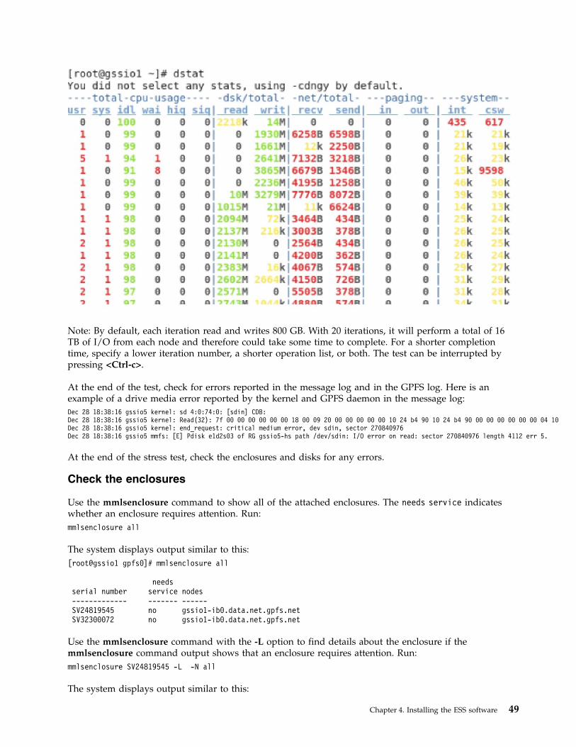
Note: By default, each iteration read and writes 800 GB. With 20 iterations, it will perform a total of 16TB of I/O from each node and therefore could take some time to complete. For a shorter completiontime, specify a lower iteration number, a shorter operation list, or both. The test can be interrupted bypressing <Ctrl-c>.
At the end of the test, check for errors reported in the message log and in the GPFS log. Here is anexample of a drive media error reported by the kernel and GPFS daemon in the message log:Dec 28 18:38:16 gssio5 kernel: sd 4:0:74:0: [sdin] CDB:Dec 28 18:38:16 gssio5 kernel: Read(32): 7f 00 00 00 00 00 00 18 00 09 20 00 00 00 00 00 10 24 b4 90 10 24 b4 90 00 00 00 00 00 00 04 10Dec 28 18:38:16 gssio5 kernel: end_request: critical medium error, dev sdin, sector 270840976Dec 28 18:38:16 gssio5 mmfs: [E] Pdisk e1d2s03 of RG gssio5-hs path /dev/sdin: I/O error on read: sector 270840976 length 4112 err 5.
At the end of the stress test, check the enclosures and disks for any errors.
Check the enclosures
Use the mmlsenclosure command to show all of the attached enclosures. The needs service indicateswhether an enclosure requires attention. Run:mmlsenclosure all
The system displays output similar to this:[root@gssio1 gpfs0]# mmlsenclosure all
needsserial number service nodes------------- ------- ------SV24819545 no gssio1-ib0.data.net.gpfs.netSV32300072 no gssio1-ib0.data.net.gpfs.net
Use the mmlsenclosure command with the -L option to find details about the enclosure if themmlsenclosure command output shows that an enclosure requires attention. Run:mmlsenclosure SV24819545 -L -N all
The system displays output similar to this:
Chapter 4. Installing the ESS software 49
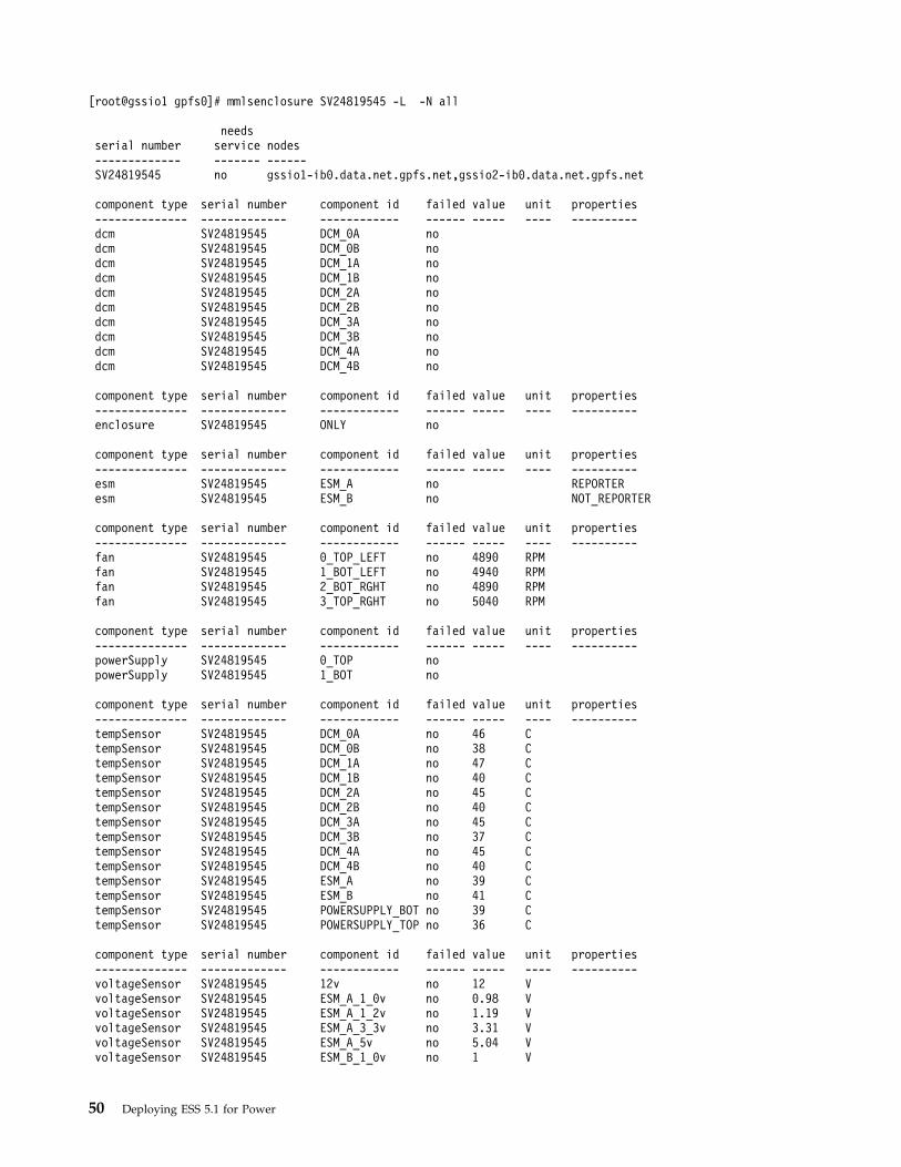
[root@gssio1 gpfs0]# mmlsenclosure SV24819545 -L -N all
needsserial number service nodes------------- ------- ------SV24819545 no gssio1-ib0.data.net.gpfs.net,gssio2-ib0.data.net.gpfs.net
component type serial number component id failed value unit properties-------------- ------------- ------------ ------ ----- ---- ----------dcm SV24819545 DCM_0A nodcm SV24819545 DCM_0B nodcm SV24819545 DCM_1A nodcm SV24819545 DCM_1B nodcm SV24819545 DCM_2A nodcm SV24819545 DCM_2B nodcm SV24819545 DCM_3A nodcm SV24819545 DCM_3B nodcm SV24819545 DCM_4A nodcm SV24819545 DCM_4B no
component type serial number component id failed value unit properties-------------- ------------- ------------ ------ ----- ---- ----------enclosure SV24819545 ONLY no
component type serial number component id failed value unit properties-------------- ------------- ------------ ------ ----- ---- ----------esm SV24819545 ESM_A no REPORTEResm SV24819545 ESM_B no NOT_REPORTER
component type serial number component id failed value unit properties-------------- ------------- ------------ ------ ----- ---- ----------fan SV24819545 0_TOP_LEFT no 4890 RPMfan SV24819545 1_BOT_LEFT no 4940 RPMfan SV24819545 2_BOT_RGHT no 4890 RPMfan SV24819545 3_TOP_RGHT no 5040 RPM
component type serial number component id failed value unit properties-------------- ------------- ------------ ------ ----- ---- ----------powerSupply SV24819545 0_TOP nopowerSupply SV24819545 1_BOT no
component type serial number component id failed value unit properties-------------- ------------- ------------ ------ ----- ---- ----------tempSensor SV24819545 DCM_0A no 46 CtempSensor SV24819545 DCM_0B no 38 CtempSensor SV24819545 DCM_1A no 47 CtempSensor SV24819545 DCM_1B no 40 CtempSensor SV24819545 DCM_2A no 45 CtempSensor SV24819545 DCM_2B no 40 CtempSensor SV24819545 DCM_3A no 45 CtempSensor SV24819545 DCM_3B no 37 CtempSensor SV24819545 DCM_4A no 45 CtempSensor SV24819545 DCM_4B no 40 CtempSensor SV24819545 ESM_A no 39 CtempSensor SV24819545 ESM_B no 41 CtempSensor SV24819545 POWERSUPPLY_BOT no 39 CtempSensor SV24819545 POWERSUPPLY_TOP no 36 C
component type serial number component id failed value unit properties-------------- ------------- ------------ ------ ----- ---- ----------voltageSensor SV24819545 12v no 12 VvoltageSensor SV24819545 ESM_A_1_0v no 0.98 VvoltageSensor SV24819545 ESM_A_1_2v no 1.19 VvoltageSensor SV24819545 ESM_A_3_3v no 3.31 VvoltageSensor SV24819545 ESM_A_5v no 5.04 VvoltageSensor SV24819545 ESM_B_1_0v no 1 V
50 Deploying ESS 5.1 for Power
voltageSensor SV24819545 ESM_B_1_2v no 1.19 VvoltageSensor SV24819545 ESM_B_3_3v no 3.31 VvoltageSensor SV24819545 ESM_B_5v no 5.07 V
Check for failed disks
To find failed pdisks, use the mmlspdisk all command with the --not-ok option. Run:mmlspdisk all --not-ok
The system displays output similar to this:[root@gssio1]# mmlspdisk all --not-ok
pdisk:
replacementPriority = 7.34name = "e1d2s01"device = ""recoveryGroup = "gssio1"declusteredArray = "DA1"state = "failing/noPath/systemDrain/noRGD/noVCD/noData"capacity = 2000381018112freeSpace = 1999307276288fru = "42D0768"location = "SV12616682-2-1"WWN = "naa.5000C500262630DF"server = "gssio1.gpfs.net"reads = 295writes = 915bytesReadInGiB = 0.576bytesWrittenInGiB = 1.157IOErrors = 0IOTimeouts = 0mediaErrors = 0checksumErrors = 0pathErrors = 0relativePerformance = 1.003dataBadness = 0.000rgIndex = 9userLocation = "Enclosure SV12616682 Drawer 2 Slot 1"userCondition = "replaceable"hardware = "IBM-ESXS ST32000444SS BC2B 9WM40AQ10000C1295TH8"hardwareType = Rotating 7200nPaths = 0 active 0 total
mmlspdisk displays the details of the failed or failing disk, including the pdisk name, the enclosure(serial number), and the location of the disk.
Replacing a disk
If a disk fails and needs to be replaced, follow the proper disk replacement procedure. Improper diskreplacement could greatly increase the possibility of data loss. Use the mmchcarrier command to replacea failed pdisk. This command updates the firmware automatically when replacing a disk. For moreinformation about mmchcarrier, see IBM Spectrum Scale RAID: Administration.
Run gnrhealthcheck
After the stress test is complete, use the gnrhealthcheck script to make sure there are no new issues. Run:gnrhealthcheck
The system displays output similar to this:
Chapter 4. Installing the ESS software 51

[root@gssio1 gpfs0]# gnrhealthcheck
################################################################# Beginning topology checks.################################################################Topology checks successful.################################################################# Beginning enclosure checks.################################################################Enclosure checks successful.################################################################# Beginning recovery group checks.################################################################Recovery group checks successful.################################################################# Beginning pdisk checks.################################################################Pdisk checks successful.
See IBM Spectrum Scale RAID: Administration for more information about this script.
Collecting data
At the end of a successful configuration, collect configuration and service data. Use the gsssnapcommand to collect VDisk information. Save the output with an identifier so that it can be mapped to theinstalled system. Run the following command from any I/O server node:gsssnap
The configuration and service data collected at the end of the installation can be very valuable duringfuture problem determination and troubleshooting. Send the collected service data to your IBMrepresentative.
See “gsssnap script” on page 141 for more information about this command.
Cleaning up the system
If you need to perform a quick cleanup of the system, follow these steps:1. ssh to any I/O server node.2. To delete the log VDisks and recovery groups, use the mmdelvdisk and mmdelrecoverygroup commands3. To delete the file system and the associated NSDs and VDisks, run:
/opt/ibm/gss/tools/samples/gssdelvdisks
4. To shut down IBM Spectrum Scale and delete the cluster, run:mmshutdown -ammdelnode -N all
52 Deploying ESS 5.1 for Power
Chapter 5. Installing the ESS GUI
ESS 5.1 installs the necessary GUI RPMs during the installation process.1. Generate performance collector in the management server node. The management server node must
be part of the ESS cluster and node name must be the node name used in the cluster (e.g., esm1-hs).Run:
mmperfmon config generate --collectors ems1-hs
2. Set up the nodes in the ems nodeclass and gss_ppc64 nodeclass for performance monitoring. Run:mmchnode --perfmon -N ems,gss_ppc64
3. Enable capacity and fileset quota monitoring that are not enabled in the GUI by default.a. To enable capacity and fileset quota run the following command:
mmperfmon config update GPFSDiskCap.restrict=<EMS nodename> GPFSDiskCap.period=<period in sec>
Here the management server node name must be the name shown in the mmlscluster output.b. Verify that the GPFSDiskCap.period is set correctly in /opt/IBM/zimon/ZIMonSensors.cfg. If it is not
set correctly, verify that the management server node is correctly provided. The following exampleshows what it should look like when period is set to 86400 sec (one day) and the task only runs inthe ems-hs (mmlscluster output showing ems1-hs.gpfs.net) node.{
name = "GPFSDiskCap"period = 86400restrict = "ems1-hs.gpfs.net"
}
Note: To enable quota the filesystem quota checking must be enabled. Refer to mmchfs -Q andmmcheckquota commands in the IBM Spectrum Scale: Command and Programming Reference.
4. Start performance collector in the management server node:systemctl start pmcollector
5. Enable and start gpfsgui:systemctl enable gpfsgui.servicesystemctl start gpfsgui
6. Obtain the systemd update and apply it on each node.The systemd update is available in the /home/deploy directory of newly shipped systems. You canalso download it from the Red Hat Network. For more information, see Elastic Storage Server: QuickDeployment Guide.
Complete the system setup wizard.
Logging in to the ESS GUI
You can log in to the GUI using one of these web browsers:v Google Chrome 45v Microsoft Internet Explorer 10v Microsoft Internet Explorer 11v Mozilla Firefox 41v Mozilla Firefox Extended Support Release (ESR) 38
To launch the ESS GUI in a browser, go to:
© Copyright IBM Corp. 2014, 2017 53
|
|||
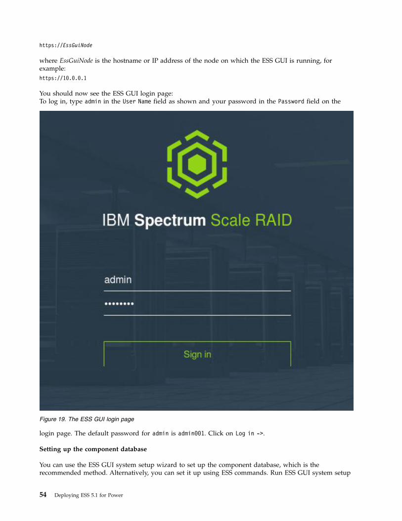
https://EssGuiNode
where EssGuiNode is the hostname or IP address of the node on which the ESS GUI is running, forexample:https://10.0.0.1
You should now see the ESS GUI login page:To log in, type admin in the User Name field as shown and your password in the Password field on the
login page. The default password for admin is admin001. Click on Log in ->.
Setting up the component database
You can use the ESS GUI system setup wizard to set up the component database, which is therecommended method. Alternatively, you can set it up using ESS commands. Run ESS GUI system setup
Figure 19. The ESS GUI login page
54 Deploying ESS 5.1 for Power

and enter the rack locations of servers and enclosures, the IP or hostname of the xCAT server, and otherconfiguration information. For setting up component database using RAID commands, see IBM SpectrumScale RAID: Administration.
Related information
For information about ESS GUI messages, see IBM Spectrum Scale RAID: Administration .
Chapter 5. Installing the ESS GUI 55

56 Deploying ESS 5.1 for Power

Appendix A. Installation: reference
The information in this topic is provided to aid the installation process and debug any issuesencountered.
Node name considerations
Carefully select the hostname, suffix, and prefix of the management server and I/O server so that thehostname used in the high-speed network and by the ESS cluster can be generated from the suffix orprefix.
High-speed host names
Example 1:a-bcd-edf-1a-bcd-edf-2a-bcd-edf-3a-bcd-edf-4
Here, a-bcd- is the prefix and edf-1, edf-2, edf-3, and edf-4 are the xCAT names of the nodes.
Example 2:1-a-bcd-edf2-b-bcd-edf3-c-bcd-edf4-d_bcd_edf
Here, -edf is the suffix and 1-a-bcd, 2-a-bcd, 3-a-bcd, and 4-a-bcd are the xCAT names of the nodes.
If possible, avoid using high-speed node names with variations at the beginning and the end, such as:A-a-bcd-edf-1B-b-bdc-edf-2C-c-bcd-edf-3D-d-bcd-edf-4
In such cases, use the -N option and specify the node list with the gssgencluster and gssgenclusterrgscommands. The node names must be reachable from the management server node. xCAT requires thatthe target nodes be part of a node group and a warning might be issued if the hostname is not defined asan xCAT object.
Example:
1. The xCAT host names are gssio1, gssio2, gssio3, and gssio4.2. The high-speed host names are A-test1, B-test2, C-test3, D-test4. These host names are reachable from
the management server node. They are not defined in xCAT.
Run:gssgencluster -C test01 -N A-test1,B-test2,C-test3,D-test4
Installing Red Hat Enterprise Linux on the management server
Preparing to install the management server
© Copyright IBM Corporation © IBM 2014, 2017 57

To improve availability, a RAID 10 disk array is used on the management server for the operating systeminstallation. The hardware for the management server, if was not configured before shipping, is shippedwith two RAID 0 disk arrays. ESS requires that the disks be reformatted as a single RAID 10 disk array.
Note: If there are two IBM Power RAID (IPR) adapters installed on the management server, one of theadapters must be removed using the HMC or physically removed before installing the operating system.
Note: HMC is only available with ESS 5.0 on PPC64 (Big Endian).
Create the RAID 10 array for OS installation
1. Perform a minimal installation of Red Hat Enterprise Linux on a RAID 0 disk array if Red HatEnterprise Linux is not installed already. This allows you to run the RAID utility iprconfig. To get thisutility, download the iprutils tools package, which includes the iprconfig utility and libraries, to aUSB device or a DVD. Go to:http://www14.software.ibm.com/support/customercare/sas/f/lopdiags/redhat/hmcmanaged/rhel7.html#
2. When the minimal installation is complete, continue to the next step.
Management server RAID 10 configuration
1. When the installation is complete, reboot the node and log in using the console from the HMC.2. Insert the DVD or USB device with the iprconfig utility.3. Start the iprconfig utility to create the RAID 10 array. Go to the directory where you copied the
iprconfig utility and run:./iprconfig
Attention: After you have begun the iprconfig utility, do not leave iprconfig until the RAID buildis complete.
4. Select option 2 - work with disk arrays.5. Select option 3 - delete a disk array.6. Type the number 1 so there is a 1 to the left of both of the disk devices (sda, sdb).7. Press Enter, then press Enter again. This operation deletes the RAID 0 devices on the disks. Now
create the new RAID 10 device.8. Select option 2 - create a disk array.9. Type the number 1 to select the array, then press Enter.
10. Select all of the disks (using 1), then press Enter.11. Make sure the array type is RAID 10, then press Enter to start formatting.
At this point, the iprconfig utility returns to the main menu. The RAID rebuild is not done. Waituntil the RAID build completes before continuing.To see the rebuild statistics, select 1 from the menu and press Enter.It is possible that you might not see the RAID build complete because the console becomes filledwith file system errors. You are reformatting the file system that the operating system is installed on,so this is to be expected. Using a visual inspection, you can tell when the RAID build is complete.When the RAID build is running, the first two drives in the Power Systems server have the greenlights on solid or flashing one drive and then the other (blinking from drive to drive).
12. When the RAID rebuild is complete, prepare the partition to install Red Hat Enterprise Linux.13. Close the terminal window. In the Tasks pane on the HMC, select Console Window -> Close
Terminal Connection.14. Power down the partition. In the Tasks pane on the HMC, select Operations -> Shut Down.15. In the Shut Down dialog, select Immediate and select OK.16. Select Yes to shutting down.
58 Deploying ESS 5.1 for Power

17. Select No to replacing the cache battery.18. You are now ready to install Red Hat Enterprise Linux on the management server.
Installing Red Hat Enterprise Linux
Before you start this step, make sure the RAID 10 disk array is created and the Red Hat Enterprise Linux7.2 Disk 1 DVD is available.1. Place the Red Hat Enterprise Linux DVD (Disk 1) in the management server.2. Log in to the HMC.3. Under Systems Management -> Servers select the name of the management server.4. Click the check box next to the partition on the management server.5. At the bottom of the screen (under Tasks), select Operations -> Activate -> Profile
6. In the Activate Logical Partition dialog, select the profile of choice, then Advanced
7. In the Activate Logical Partition - Advanced dialog, select SMS for the Boot mode:, and then selectOK to close the dialog
8. Select the check box for Open a terminal window..., then click OK.You might see Java™ or runtime security warnings. Accept any messages.
9. Verify that the System Management Services (SMS) window is displayed.10. In the SMS utility:
a. Type the number 5 (for Select Boot Options), then press Enter.b. Type the number 1 (for Select Install /boot Device), then press Enter.c. Type the number 2 (for CD/DVD), then press Enter.d. Type the number 4 (for SATA), then press Enter.e. Type the number of the SATA CD-ROM device (should be 1), then press Enter.f. Again, type the number of the SATA CD-ROM device (should be 1), then press Enter.g. Type the number 2 (for Normal Mode Boot), then press Enter.h. To exit the SMS utility, type the number 1 (for yes), then press Enter.
Performing a text-based installation
To perform a text-based installation, follow these steps:1. At the boot: prompt, type linux and press Enter:
boot: linux
The system boots to the first installation menu. You can proceed with the installation when options 1,2, 3, 4, 5, and 7 have an [x] indicator next to them.
2. Set the time zone. Work through the menus, typing the numbers of your selections and pressingEnter.
3. If this is a management server installation to configure RAID, you can ignore Software Selection (2)and Installation Source (3).If this is the final management server installation enter the number 2 (for Infrastructure Server).Note: It could take a few minutes until the indicators for 2 and 3 change to an [x] after making aupdate. It should change after you set the installation destination.
4. Set the installation destination (5).If this is a management server installation to configure RAID 10, select the first device:Quick List: Select First device -> use all space -> Standard PartitioningIf this is the final management server installation, you should see only one device (the RAID 10device):
Appendix A. Installation: reference 59

Quick List: Select First device -> use all space -> Standard Partitioning5. You do not need to create a user (6). When you complete option 7, an [x] indicator appears next to
option 6 whether you create a user or not.6. Set a root password (7).7. If all of the options (1 to 7) have an [x] indicator next to them, you are ready to continue with the
installation. Type the letter b to begin the installation and press Enter. This step could take some timeto complete.
8. When the installation is complete, reboot the node.
Performing a GUI-based installation using VNC
To perform a GUI-based installation using VNC, follow these steps:1. At the boot: prompt, enter this linux command with the appropriate IP address and netmask:
boot: linux vnc ip=IpAddress netmask=Netmask
You will see a VNC IP address and display to connect to.2. Bring up the VNC client and enter this information.3. After you are in the client, you will see a WELCOME TO RED HAT ENTERPRISE LINUX 7.2.
screen. Select the language (English, for example) and click Continue.4. Select Software selection.5. Keep Minimal installation, then click Enter in the upper left area of the screen.6. Click Installation destination, then click Done in upper top left area of the screen.7. For network and hostname, turn off any interfaces that are not needed (the non-xCAT interfaces, for
now).8. Click Done.9. Click Begin installation in the lower right area of the screen.
10. Click Root password, set a password for root, then click Done.11. After the installation is complete, click Reboot. Your VNC session will end.12. From the HMC console window, set an IP address for an interface so that you can telnet with a
terminal window.13. ssh to the node using the IP address you just set.14. Start the iprconfig utility to configure the RAID array.
a. Run:iprconfig
Attention: Do not leave iprconfig until all tasks are complete.
b. Select option 2 - work with disk arrays.c. Select option 3 - delete a disk array.d. Type the number 1, then press Enter.e. Press Enter again.f. Select option 2 - create a disk array.g. Type the number 1, then press Enter.h. Select all of the disks (using 1), then press Enter.i. Change array type to RAID 10, then press Enter to start the formatting.j. After the formatting is complete, select option 2 - work with disk arrays, then press Enter.k. Select option 1 to show the array status. It should show RAID 10.
60 Deploying ESS 5.1 for Power

15. Exit iprconfig and reboot the partition, with the DVD in the drive. The ssh session will end. Usingthe HMC, click on the profile of your choice, select the check box for open a terminal window...,then click OK (similar to step 5).
16. Keep pressing 1 to enter the SMS menu. When you are in the in SMS menu, follow these steps:a. Type the number 5 (for Select Boot Options), then press Enter.b. Type the number 1 (for Select Install /boot Device), then press Enter.c. Type the number 3 (for CD/DVD), then press Enter.d. Type the number 9 (for List all devices), then press Enter.e. Type the number for the SATA CD-ROM device, then press Enter.f. Type the number 2 (for Normal Mode Boot), press Enter, type the number 1 (for yes), and press
Enter again.17. At the boot: prompt, enter this linux command with the appropriate IP address and netmask:
boot: linux vnc ip=IpAddress netmask=Netmask
You will see a VNC IP address and display to connect to.18. Bring up the VNC client and enter this information.19. After you are in the client, you will see a WELCOME TO RED HAT ENTERPRISE LINUX 7.2.
screen.a. Select the language (English, for example) and click Continue.b. Select Software selection.c. Select Server with GUI, then click Done in the upper left area of the screen.d. Select Software selection.e. Select the I will configure partitioning radio button, then click Done.f. Under Mount points will use the following..., select Standard Partitioning.g. Select Have Red Hat create partitions automatically .h. Select Done and accept the changes.i. For network and hostname, turn off any interfaces that are not needed (the non-xCAT interfaces,
for now).20. Start the installation. After the installation is complete, configure any network interfaces that are
needed, such as one for the management network.
Creating an HMC profile for the ESS node
Note: HMC is only available with ESS 5.0 on PPC64 (Big Endian).1. Log in to the HMC on the console or using the web interface. To use the web interface, open a
browser window and enter the IP address of the HMC:https://IpAddressOfHMC
Using either method, select Log on and launch the Hardware Management Console webapplication. When prompted, log in to the HMC using the hscroot user and password. The defaultHMC user name is hscroot and the default password is abc123.
2. Select Systems Management -> Servers.
Check attributes of each management server and I/O server node
1. First, confirm that each server has only one RAID adapter:a. Click on a server.b. If the server is not on, power it on.
1) Click operations in the Tasks pane (lower pane).2) Click Power on, then click OK.
Appendix A. Installation: reference 61

3) Wait approximately five minutes for the server to boot to STANDBY.2. Click properties in the Tasks pane (lower pane).
a. Under the General tab, uncheck the box for Power off the system partition after all the logical....b. Under the I/O tab, make sure RAID Controller is in slots C14 and C15. You can determine the
slot number by looking at the suffix of the identifier in the Slot column (*-C14, for example).c. If there is more than one RAID adapter in the system, proceed to Section 1.d. If there is one RAID adapter in the system, proceed to Section 2.
3. Click OK.4. Click the box next to the partition (there should be only one in the pane above Tasks). If the state is
currently Running, you need to shut down. Click operations (under Tasks), then Shutdown.a. Click the radio button for immediate.b. Click OK.c. Click Yes.d. Click No.
Section 1: Multiple RAID adapters
If the server has multiple RAID adapters, you need to rename the partition and the profile, then removethe C14 RAID controller for the installation to work properly.
Renaming the partition and the profile
1. Click properties (assuming the check box next to the partition is already checked).2. Under the General tab, name the partition (gssio1 or ems1, for example).3. Click OK.4. Click configuration -> manage profiles.5. Do not check any boxes. Click actions -> new.6. Make sure the profile name is the same as the partition name (gssio1 or ems1, for example).7. Click next.8. Click dedicated.9. Make sure the desired and maximum number of processors match the total number of processors,
then click next.10. Make sure the desired, minimum, and maximum memory are less than or equal to the current
memory available for partition usage, then click next.11. For I/O, click the box to select all of the boxes. Deselect the C14 RAID controller. Then, click Add as
required.12. Click next.13. Click next again.14. Click finish.15. Click the box next to the partition again, then click manage profiles.16. Click on the server (left pane), then click properties.17. Under the General tab, select your newly-created profile from the service partition drop-down
menu and click OK.18. Click the check box next to the partition for that server, then click manage profiles (under Tasks,
lower right).19. Click the box next to the original partition (not the new one), then click actions -> delete.20. Accept any messages and click OK.
Section 2: Single adapters
62 Deploying ESS 5.1 for Power

In the case of single adapters, you only need to rename the partition and the profile.1. Click properties (assuming the check box next to the partition is already checked).2. Under the General tab, name the partition (gssio1 or ems1, for example).3. Click OK.4. Click configuration -> manage profiles.5. Click the box next to the profile, then click actions -> edit. Make sure the profile name is the same as
the partition name (gssio1 or ems1, for example).Note: You should see output stating that this system is using all of the system resources.
6. Click OK.
Networking: creating a bonded interface
A bonded interface with Ethernet
Starting with ESS 3.5, you can use a script to help you quickly create a bonded interface with Ethernet.See “gssgennetworks command” on page 118 for more information. Otherwise, complete the followingsteps.
Connect the network cables to the corresponding switch. Check that the links are up at the device level.To create a bonding, add connections for the master, add connections for the slave, bring up theconnection for the slaves, and then bring up the connection for the master (bond). Run:ibdev2netdev
The system displays output similar to this:[root@gssio2 ~]# ibdev2netdev
mlx4_0 port 1 ==> enp1s0 (Up)mlx4_0 port 2 ==> enp1s0d1 (Up)mlx5_0 port 1 ==> ib0 (Down)mlx5_0 port 2 ==> ib1 (Down)mlx5_1 port 1 ==> ib2 (Down)mlx5_1 port 2 ==> ib3 (Down)
This example shows two 10 GbE network ports that are up and are connected to the switch properly.Now you will create a bond with these two ports.
Check the connection and make sure there are no connections defined for these ports. You can do thisusing network manager connection and device commands.
To check the connection, run:nmcli -p c
The system displays output similar to this:[root@gssio2 ~]# nmcli -p c
======================================================================================NetworkManager connection profiles
======================================================================================NAME UUID TYPE DEVICE--------------------------------------------------------------------------------------enp1s0d1 6d459dc7-db53-43d4-9236-8257ee900aae 802-3-ethernet --enP7p128s0f2 72b6533e-6eaa-4763-98fa-0b4ed372e377 802-3-ethernet --enP7p128s0f3 1b0a97e7-1b90-4d26-89cf-8f4fc8e5a00e 802-3-ethernet --enP7p128s0f1 5dffee0e-b0b6-4472-864e-acc2dc0cc043 802-3-ethernet --enp1s0 060d342f-3388-4e9f-91bb-13c3aa30847f 802-3-ethernet --GSS enP7p128s0f0 5f755525-2340-7e18-ef9d-0d4bfdba4c30 802-3-ethernet enP7p128s0f0
Appendix A. Installation: reference 63
To check the device, run:nmcli -p d
The system displays output similar to this:[root@gssio2 ~]# nmcli -p d
==========================================================Status of devices
==========================================================DEVICE TYPE STATE CONNECTION----------------------------------------------------------enP7p128s0f0 ethernet connected GSS enP7p128s0f0enP7p128s0f1 ethernet disconnected --enP7p128s0f2 ethernet disconnected --enP7p128s0f3 ethernet disconnected --enp1s0 ethernet disconnected --enp1s0d1 ethernet disconnected --ib0 infiniband disconnected --ib1 infiniband disconnected --ib2 infiniband disconnected --ib3 infiniband disconnected --lo loopback unmanaged --
As you can see, there is no connection defined for the devices and the device state is down. Add aconnection for the bond bond0. In this case, specify 802.3ad for the Link Aggregation Control Protocol(LACP) and an IPv4 address of 172.16.45.22/24.
Note: If you cannot use LACP (802.3ad) for some reason, using balanced-alb is the next bestrecommendation.
For the bonding parameters, specify a miimon value of 100 milliseconds (msec).[root@gssio2 ~]# nmcli c add type bond ifname bond0 miimon 100 mode 802.3ad ip4 172.16.45.22/24
Connection ’bond-bond0’ (c929117b-6d92-488d-8bcb-d98e7e0c8b91) successfully added.
Note: By default, xmit_hash_policy is set to layer2. For optimal performance, you might want to set it tolayer2+3, as follows:nmcli c mod bond-bond0 +bond.option xmit_hash_policy=layer2+3
To view the connection properties, run:nmcli c show bond-bond0
Add connections for the slaves:[root@gssio2 ~]# nmcli c add type bond-slave ifname enp1s0 master bond0
Connection ’bond-slave-enp1s0’ (d9e21d55-86ea-4551-9371-1fc24d674751) successfully added.
[root@gssio2 ~]# nmcli c add type bond-slave ifname enp1s0d1 master bond0
Connection ’bond-slave-enp1s0d1’ (8432645a-5ddc-44fe-b5fb-2884031c790c) successfully added.
Bring the connection up for the slaves:[root@gssio2 ~]# nmcli c up bond-slave-enp1s0d1
Connection successfully activated (D-Bus active path:/org/freedesktop/NetworkManager/ActiveConnection/4)
64 Deploying ESS 5.1 for Power
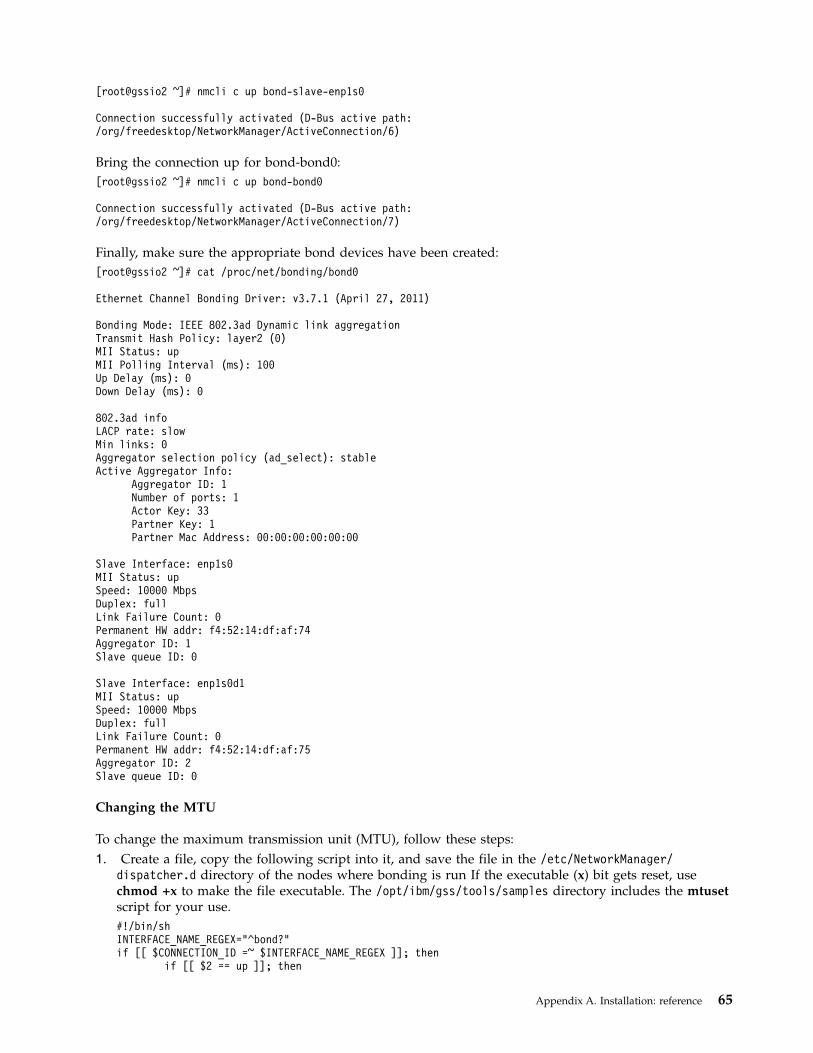
[root@gssio2 ~]# nmcli c up bond-slave-enp1s0
Connection successfully activated (D-Bus active path:/org/freedesktop/NetworkManager/ActiveConnection/6)
Bring the connection up for bond-bond0:[root@gssio2 ~]# nmcli c up bond-bond0
Connection successfully activated (D-Bus active path:/org/freedesktop/NetworkManager/ActiveConnection/7)
Finally, make sure the appropriate bond devices have been created:[root@gssio2 ~]# cat /proc/net/bonding/bond0
Ethernet Channel Bonding Driver: v3.7.1 (April 27, 2011)
Bonding Mode: IEEE 802.3ad Dynamic link aggregationTransmit Hash Policy: layer2 (0)MII Status: upMII Polling Interval (ms): 100Up Delay (ms): 0Down Delay (ms): 0
802.3ad infoLACP rate: slowMin links: 0Aggregator selection policy (ad_select): stableActive Aggregator Info:
Aggregator ID: 1Number of ports: 1Actor Key: 33Partner Key: 1Partner Mac Address: 00:00:00:00:00:00
Slave Interface: enp1s0MII Status: upSpeed: 10000 MbpsDuplex: fullLink Failure Count: 0Permanent HW addr: f4:52:14:df:af:74Aggregator ID: 1Slave queue ID: 0
Slave Interface: enp1s0d1MII Status: upSpeed: 10000 MbpsDuplex: fullLink Failure Count: 0Permanent HW addr: f4:52:14:df:af:75Aggregator ID: 2Slave queue ID: 0
Changing the MTU
To change the maximum transmission unit (MTU), follow these steps:1. Create a file, copy the following script into it, and save the file in the /etc/NetworkManager/
dispatcher.d directory of the nodes where bonding is run If the executable (x) bit gets reset, usechmod +x to make the file executable. The /opt/ibm/gss/tools/samples directory includes the mtusetscript for your use.#!/bin/shINTERFACE_NAME_REGEX="^bond?"if [[ $CONNECTION_ID =~ $INTERFACE_NAME_REGEX ]]; then
if [[ $2 == up ]]; then
Appendix A. Installation: reference 65
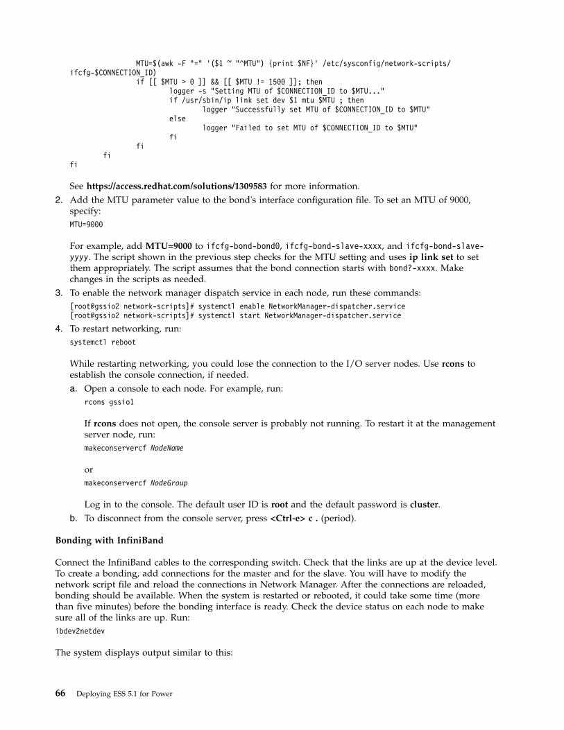
MTU=$(awk -F "=" ’($1 ~ "^MTU") {print $NF}’ /etc/sysconfig/network-scripts/ifcfg-$CONNECTION_ID)
if [[ $MTU > 0 ]] && [[ $MTU != 1500 ]]; thenlogger -s "Setting MTU of $CONNECTION_ID to $MTU..."if /usr/sbin/ip link set dev $1 mtu $MTU ; then
logger "Successfully set MTU of $CONNECTION_ID to $MTU"else
logger "Failed to set MTU of $CONNECTION_ID to $MTU"fi
fifi
fi
See https://access.redhat.com/solutions/1309583 for more information.2. Add the MTU parameter value to the bond's interface configuration file. To set an MTU of 9000,
specify:MTU=9000
For example, add MTU=9000 to ifcfg-bond-bond0, ifcfg-bond-slave-xxxx, and ifcfg-bond-slave-yyyy. The script shown in the previous step checks for the MTU setting and uses ip link set to setthem appropriately. The script assumes that the bond connection starts with bond?-xxxx. Makechanges in the scripts as needed.
3. To enable the network manager dispatch service in each node, run these commands:[root@gssio2 network-scripts]# systemctl enable NetworkManager-dispatcher.service[root@gssio2 network-scripts]# systemctl start NetworkManager-dispatcher.service
4. To restart networking, run:systemctl reboot
While restarting networking, you could lose the connection to the I/O server nodes. Use rcons toestablish the console connection, if needed.a. Open a console to each node. For example, run:
rcons gssio1
If rcons does not open, the console server is probably not running. To restart it at the managementserver node, run:makeconservercf NodeName
ormakeconservercf NodeGroup
Log in to the console. The default user ID is root and the default password is cluster.b. To disconnect from the console server, press <Ctrl-e> c . (period).
Bonding with InfiniBand
Connect the InfiniBand cables to the corresponding switch. Check that the links are up at the device level.To create a bonding, add connections for the master and for the slave. You will have to modify thenetwork script file and reload the connections in Network Manager. After the connections are reloaded,bonding should be available. When the system is restarted or rebooted, it could take some time (morethan five minutes) before the bonding interface is ready. Check the device status on each node to makesure all of the links are up. Run:ibdev2netdev
The system displays output similar to this:
66 Deploying ESS 5.1 for Power

[root@gssio2 ~]# ibdev2netdev
mlx5_0 port 1 ==> ib0 (Up)mlx5_0 port 2 ==> ib1 (Up)mlx5_1 port 1 ==> ib2 (Up)mlx5_1 port 2 ==> ib3 (Up)mlx5_2 port 1 ==> ib4 (Up)mlx5_2 port 2 ==> ib5 (Up)
You can also use ibstat.
Check the connection using nmcli c and make sure there is no existing bond already defined in theseinterfaces. Add the bond connection first. In this example, active-backup mode is selected. In IP overInfiniBand (IPoIB), only active-backup bond is supported. Run:nmcli c add type bond ifname bond0 mode
The system displays output similar to this:[root@gssio2 network-scripts]# nmcli c add type bond ifname bond0 mode
active-backup ip4 172.16.45.22/24Connection ’bond-bond0’ (66f182d1-d0da-42cf-b4c9-336d5266bbe7) successfullyadded.
Add the slave connections as follows. In this example, ib0 and ib1 are the slave devices. Makeappropriate changes as needed. First, run:nmcli c add type bond-slave ifname ib0 master bond0
The system displays output similar to this:[root@gssio2 network-scripts]# nmcli c add type bond-slave ifname ib0 master bond0
Connection ’bond-slave-ib0’ (86c0af63-4b6c-475c-a724-0fb074dc9092) successfully added.
Next, run:nmcli c add type bond-slave ifname ib1 master bond0
The system displays output similar to this:
[root@gssio2 network-scripts]# nmcli c add type bond-slave ifname ib1 master bond0
Connection ’bond-slave-ib1’ (1d0cb5c3-268d-487c-9e40-7c0cf268150f) successfully added.
To check the connections, run:nmcli c
The system displays output similar to this:[root@gssio2 network-scripts]# nmcli c
NAME UUID TYPE DEVICEGSS enP7p128s0f0 5f755525-2340-7e18-ef9d-0d4bfdba4c30 802-3-ethernet enP7p128s0f0bond-slave-ib1 1d0cb5c3-268d-487c-9e40-7c0cf268150f 802-3-ethernet --bond-slave-ib0 86c0af63-4b6c-475c-a724-0fb074dc9092 802-3-ethernet --bond-bond0 66f182d1-d0da-42cf-b4c9-336d5266bbe7 bond bond0enP7p128s0f1 2eb8617f-5c7d-4d68-a7fe-88a030fdb28b 802-3-ethernet --enP7p128s0f3 7dea32aa-caa1-4016-9414-a47c62de27e9 802-3-ethernet --enP7p128s0f2 4416229e-2233-414f-b3ad-929c54c15f27 802-3-ethernet --
You can see that the slave connections are created, but there are no devices for these connections.
To check the devices, run:
Appendix A. Installation: reference 67
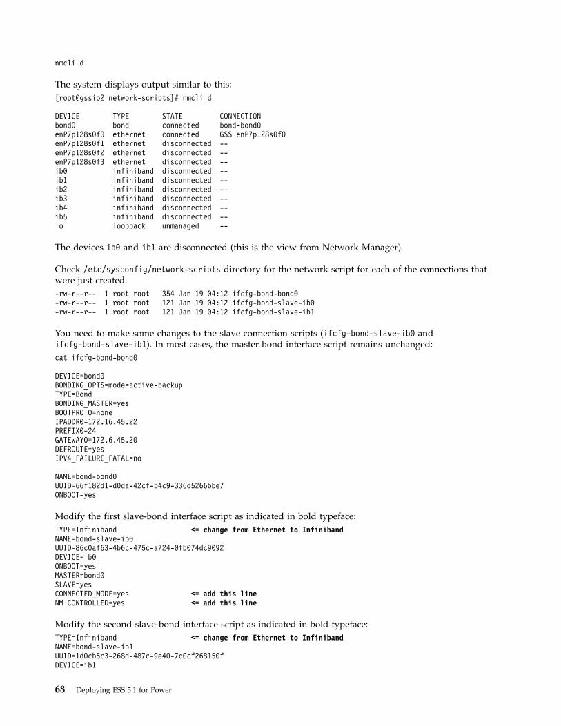
nmcli d
The system displays output similar to this:[root@gssio2 network-scripts]# nmcli d
DEVICE TYPE STATE CONNECTIONbond0 bond connected bond-bond0enP7p128s0f0 ethernet connected GSS enP7p128s0f0enP7p128s0f1 ethernet disconnected --enP7p128s0f2 ethernet disconnected --enP7p128s0f3 ethernet disconnected --ib0 infiniband disconnected --ib1 infiniband disconnected --ib2 infiniband disconnected --ib3 infiniband disconnected --ib4 infiniband disconnected --ib5 infiniband disconnected --lo loopback unmanaged --
The devices ib0 and ib1 are disconnected (this is the view from Network Manager).
Check /etc/sysconfig/network-scripts directory for the network script for each of the connections thatwere just created.-rw-r--r-- 1 root root 354 Jan 19 04:12 ifcfg-bond-bond0-rw-r--r-- 1 root root 121 Jan 19 04:12 ifcfg-bond-slave-ib0-rw-r--r-- 1 root root 121 Jan 19 04:12 ifcfg-bond-slave-ib1
You need to make some changes to the slave connection scripts (ifcfg-bond-slave-ib0 andifcfg-bond-slave-ib1). In most cases, the master bond interface script remains unchanged:cat ifcfg-bond-bond0
DEVICE=bond0BONDING_OPTS=mode=active-backupTYPE=BondBONDING_MASTER=yesBOOTPROTO=noneIPADDR0=172.16.45.22PREFIX0=24GATEWAY0=172.6.45.20DEFROUTE=yesIPV4_FAILURE_FATAL=no
NAME=bond-bond0UUID=66f182d1-d0da-42cf-b4c9-336d5266bbe7ONBOOT=yes
Modify the first slave-bond interface script as indicated in bold typeface:TYPE=Infiniband <= change from Ethernet to InfinibandNAME=bond-slave-ib0UUID=86c0af63-4b6c-475c-a724-0fb074dc9092DEVICE=ib0ONBOOT=yesMASTER=bond0SLAVE=yesCONNECTED_MODE=yes <= add this lineNM_CONTROLLED=yes <= add this line
Modify the second slave-bond interface script as indicated in bold typeface:TYPE=Infiniband <= change from Ethernet to InfinibandNAME=bond-slave-ib1UUID=1d0cb5c3-268d-487c-9e40-7c0cf268150fDEVICE=ib1
68 Deploying ESS 5.1 for Power
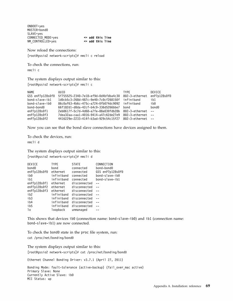
ONBOOT=yesMASTER=bond0SLAVE=yesCONNECTED_MODE=yes <= add this lineNM_CONTROLLED=yes <= add this line
Now reload the connections:[root@gssio2 network-scripts]# nmcli c reload
To check the connections, run:nmcli c
The system displays output similar to this:[root@gssio2 network-scripts]# nmcli c
NAME UUID TYPE DEVICEGSS enP7p128s0f0 5f755525-2340-7e18-ef9d-0d4bfdba4c30 802-3-ethernet enP7p128s0f0bond-slave-ib1 1d0cb5c3-268d-487c-9e40-7c0cf268150f infiniband ib1bond-slave-ib0 86c0af63-4b6c-475c-a724-0fb074dc9092 infiniband ib0bond-bond0 66f182d1-d0da-42cf-b4c9-336d5266bbe7 bond bond0enP7p128s0f1 2eb8617f-5c7d-4d68-a7fe-88a030fdb28b 802-3-ethernet --enP7p128s0f3 7dea32aa-caa1-4016-9414-a47c62de27e9 802-3-ethernet --enP7p128s0f2 4416229e-2233-414f-b3ad-929c54c15f27 802-3-ethernet --
Now you can see that the bond slave connections have devices assigned to them.
To check the devices, run:nmcli d
The system displays output similar to this:[root@gssio2 network-scripts]# nmcli d
DEVICE TYPE STATE CONNECTIONbond0 bond connected bond-bond0enP7p128s0f0 ethernet connected GSS enP7p128s0f0ib0 infiniband connected bond-slave-ib0ib1 infiniband connected bond-slave-ib1enP7p128s0f1 ethernet disconnected --enP7p128s0f2 ethernet disconnected --enP7p128s0f3 ethernet disconnected --ib2 infiniband disconnected --ib3 infiniband disconnected --ib4 infiniband disconnected --ib5 infiniband disconnected --lo loopback unmanaged --
This shows that devices ib0 (connection name: bond-slave-ib0) and ib1 (connection name:bond-slave-ib1) are now connected.
To check the bond0 state in the proc file system, run:cat /proc/net/bonding/bond0
The system displays output similar to this:[root@gssio2 network-scripts]# cat /proc/net/bonding/bond0
Ethernet Channel Bonding Driver: v3.7.1 (April 27, 2011)
Bonding Mode: fault-tolerance (active-backup) (fail_over_mac active)Primary Slave: NoneCurrently Active Slave: ib0MII Status: up
Appendix A. Installation: reference 69
MII Polling Interval (ms): 100Up Delay (ms): 0Down Delay (ms): 0
Slave Interface: ib0MII Status: upSpeed: 40000 MbpsDuplex: fullLink Failure Count: 0Permanent HW addr: a0:00:00:27:fe:80Slave queue ID: 0
Slave Interface: ib1MII Status: upSpeed: 40000 MbpsDuplex: fullLink Failure Count: 0Permanent HW addr: a0:00:00:29:fe:80Slave queue ID: 0
To ping the other node on the same bonded network, run:ping 172.16.45.22
The system displays output similar to this:[root@gssio1 ~]# ping 172.16.45.22
PING 172.16.45.22 (172.16.45.22) 56(84) bytes of data.64 bytes from 172.16.45.22: icmp_seq=1 ttl=64 time=8.52 ms64 bytes from 172.16.45.22: icmp_seq=2 ttl=64 time=0.059 ms64 bytes from 172.16.45.22: icmp_seq=3 ttl=64 time=0.055 ms64 bytes from 172.16.45.22: icmp_seq=4 ttl=64 time=0.042 ms64 bytes from 172.16.45.22: icmp_seq=5 ttl=64 time=0.043 ms64 bytes from 172.16.45.22: icmp_seq=6 ttl=64 time=0.040 ms
Adding IBM Spectrum Scale nodes to an ESS cluster
IBM Spectrum Scale node configuration is optimized for running Spectrum Scale RAID functions.1. ESS cluster node configuration is optimized for running Spectrum Scale RAID functions. Protocols,
other gateways, or any other non-ESS services must not be run on ESS management server nodes orI/O server nodes. In a cluster with high IO load, avoid using ESS nodes as cluster manager orfilesystem manager. For optimal performance the NSD client nodes accessing ESS nodes should beproperly configured. ESS ships with gssClientConfig.sh script located in /usr/lpp/mmfs/samples/gss/directory. This script can be used to configure the client as follows:/usr/lpp/mmfs/samples/gss/gssClientConfig.sh <Comma Separated list ofclient nodes or nodeclass>
You can run the following to see configuration parameter settings without setting them:/usr/lpp/mmfs/samples/gss/gssClientConfig.sh -D
After running this script, restart GPFS on the affected nodes for the optimized configuration settingsto take effect.
2. When IBM Spectrum Scale nodes deployed with protocols are added to the ESS cluster, quorum,cluster manager, and file system manager functions should be moved from the ESS to the protocolnodes after adding protocol nodes to the cluster.
For information about adding an IBM Spectrum Scale protocol node to an ESS cluster, see:v Preparing a cluster that contains ESS for adding protocolsv Spectrum Scale Protocols Quick Overview
70 Deploying ESS 5.1 for Power
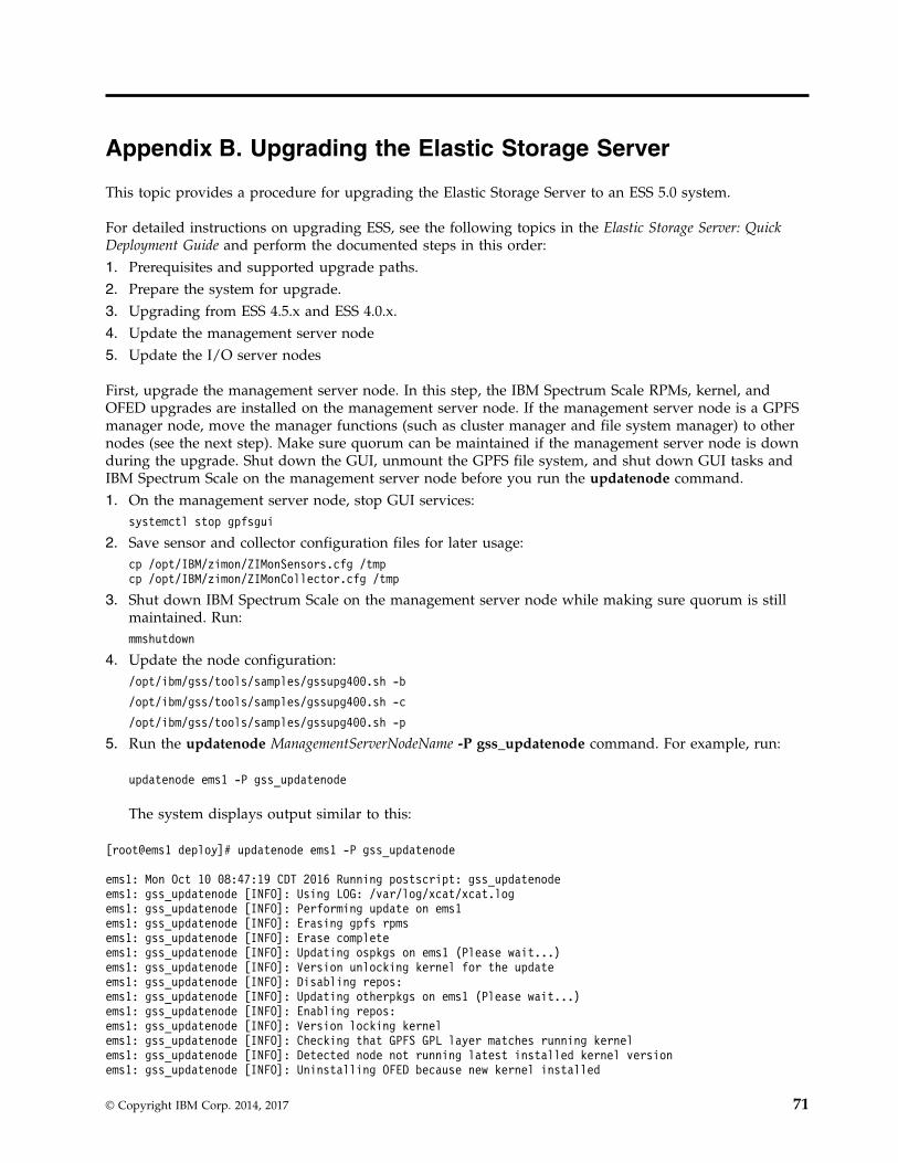
Appendix B. Upgrading the Elastic Storage Server
This topic provides a procedure for upgrading the Elastic Storage Server to an ESS 5.0 system.
For detailed instructions on upgrading ESS, see the following topics in the Elastic Storage Server: QuickDeployment Guide and perform the documented steps in this order:1. Prerequisites and supported upgrade paths.2. Prepare the system for upgrade.3. Upgrading from ESS 4.5.x and ESS 4.0.x.4. Update the management server node5. Update the I/O server nodes
First, upgrade the management server node. In this step, the IBM Spectrum Scale RPMs, kernel, andOFED upgrades are installed on the management server node. If the management server node is a GPFSmanager node, move the manager functions (such as cluster manager and file system manager) to othernodes (see the next step). Make sure quorum can be maintained if the management server node is downduring the upgrade. Shut down the GUI, unmount the GPFS file system, and shut down GUI tasks andIBM Spectrum Scale on the management server node before you run the updatenode command.1. On the management server node, stop GUI services:
systemctl stop gpfsgui
2. Save sensor and collector configuration files for later usage:cp /opt/IBM/zimon/ZIMonSensors.cfg /tmpcp /opt/IBM/zimon/ZIMonCollector.cfg /tmp
3. Shut down IBM Spectrum Scale on the management server node while making sure quorum is stillmaintained. Run:mmshutdown
4. Update the node configuration:/opt/ibm/gss/tools/samples/gssupg400.sh -b
/opt/ibm/gss/tools/samples/gssupg400.sh -c
/opt/ibm/gss/tools/samples/gssupg400.sh -p
5. Run the updatenode ManagementServerNodeName -P gss_updatenode command. For example, run:
updatenode ems1 -P gss_updatenode
The system displays output similar to this:
[root@ems1 deploy]# updatenode ems1 -P gss_updatenode
ems1: Mon Oct 10 08:47:19 CDT 2016 Running postscript: gss_updatenodeems1: gss_updatenode [INFO]: Using LOG: /var/log/xcat/xcat.logems1: gss_updatenode [INFO]: Performing update on ems1ems1: gss_updatenode [INFO]: Erasing gpfs rpmsems1: gss_updatenode [INFO]: Erase completeems1: gss_updatenode [INFO]: Updating ospkgs on ems1 (Please wait...)ems1: gss_updatenode [INFO]: Version unlocking kernel for the updateems1: gss_updatenode [INFO]: Disabling repos:ems1: gss_updatenode [INFO]: Updating otherpkgs on ems1 (Please wait...)ems1: gss_updatenode [INFO]: Enabling repos:ems1: gss_updatenode [INFO]: Version locking kernelems1: gss_updatenode [INFO]: Checking that GPFS GPL layer matches running kernelems1: gss_updatenode [INFO]: Detected node not running latest installed kernel versionems1: gss_updatenode [INFO]: Uninstalling OFED because new kernel installed
© Copyright IBM Corp. 2014, 2017 71
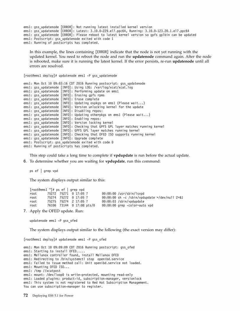
ems1: gss_updatenode [ERROR]: Not running latest installed kernel versionems1: gss_updatenode [ERROR]: Latest: 3.10.0-229.el7.ppc64, Running: 3.10.0-123.20.1.el7.ppc64ems1: gss_updatenode [ERROR]: Please reboot to latest kernel version so gpfs gplbin can be updatedems1: Postscript: gss_updatenode exited with code 1ems1: Running of postscripts has completed.
In this example, the lines containing [ERROR] indicate that the node is not yet running with theupdated kernel. You need to reboot the node and run the updatenode command again. After the nodeis rebooted, make sure it is running the latest kernel. If the error persists, re-run updatenode until allerrors are resolved.
[root@ems1 deploy]# updatenode ems1 -P gss_updatenode
ems1: Mon Oct 10 09:03:16 CDT 2016 Running postscript: gss_updatenodeems1: gss_updatenode [INFO]: Using LOG: /var/log/xcat/xcat.logems1: gss_updatenode [INFO]: Performing update on ems1ems1: gss_updatenode [INFO]: Erasing gpfs rpmsems1: gss_updatenode [INFO]: Erase completeems1: gss_updatenode [INFO]: Updating ospkgs on ems1 (Please wait...)ems1: gss_updatenode [INFO]: Version unlocking kernel for the updateems1: gss_updatenode [INFO]: Disabling repos:ems1: gss_updatenode [INFO]: Updating otherpkgs on ems1 (Please wait...)ems1: gss_updatenode [INFO]: Enabling repos:ems1: gss_updatenode [INFO]: Version locking kernelems1: gss_updatenode [INFO]: Checking that GPFS GPL layer matches running kernelems1: gss_updatenode [INFO]: GPFS GPL layer matches running kernelems1: gss_updatenode [INFO]: Checking that OFED ISO supports running kernelems1: gss_updatenode [INFO]: Upgrade completeems1: Postscript: gss_updatenode exited with code 0ems1: Running of postscripts has completed.
This step could take a long time to complete if vpdupdate is run before the actual update.6. To determine whether you are waiting for vpdupdate, run this command:
ps ef | grep vpd
The system displays output similar to this:
[root@ems1 ~]# ps ef | grep vpdroot 75272 75271 0 17:05 ? 00:00:00 /usr/sbin/lsvpdroot 75274 75272 0 17:05 ? 00:00:00 sh -c /sbin/vpdupdate >/dev/null 2>&1root 75275 75274 2 17:05 ? 00:00:03 /sbin/vpdupdateroot 76106 73144 0 17:08 pts/0 00:00:00 grep -color=auto vpd
7. Apply the OFED update. Run:
updatenode ems1 -P gss_ofed
The system displays output similar to the following (the exact version may differ):
[root@ems1 deploy]# updatenode ems1 -P gss_ofed
ems1: Mon Oct 10 09:09:09 CDT 2016 Running postscript: gss_ofedems1: Starting to install OFED.....ems1: Mellanox controller found, install Mellanox OFEDems1: Redirecting to /bin/systemctl stop openibd.serviceems1: Failed to issue method call: Unit openibd.service not loaded.ems1: Mounting OFED ISO...ems1: /tmp //xcatpostems1: mount: /dev/loop0 is write-protected, mounting read-onlyems1: Loaded plugins: product-id, subscription-manager, versionlockems1: This system is not registered to Red Hat Subscription Management.You can use subscription-manager to register.
72 Deploying ESS 5.1 for Power
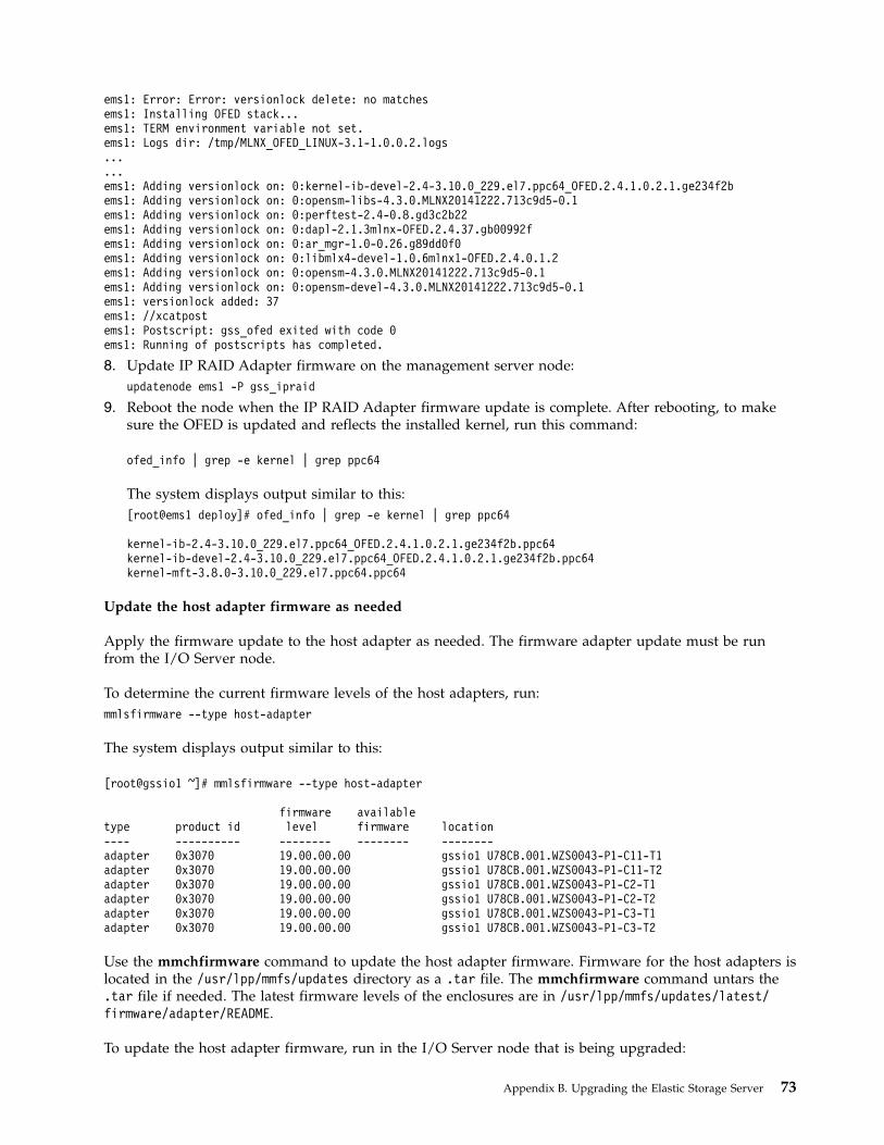
ems1: Error: Error: versionlock delete: no matchesems1: Installing OFED stack...ems1: TERM environment variable not set.ems1: Logs dir: /tmp/MLNX_OFED_LINUX-3.1-1.0.0.2.logs......ems1: Adding versionlock on: 0:kernel-ib-devel-2.4-3.10.0_229.el7.ppc64_OFED.2.4.1.0.2.1.ge234f2bems1: Adding versionlock on: 0:opensm-libs-4.3.0.MLNX20141222.713c9d5-0.1ems1: Adding versionlock on: 0:perftest-2.4-0.8.gd3c2b22ems1: Adding versionlock on: 0:dapl-2.1.3mlnx-OFED.2.4.37.gb00992fems1: Adding versionlock on: 0:ar_mgr-1.0-0.26.g89dd0f0ems1: Adding versionlock on: 0:libmlx4-devel-1.0.6mlnx1-OFED.2.4.0.1.2ems1: Adding versionlock on: 0:opensm-4.3.0.MLNX20141222.713c9d5-0.1ems1: Adding versionlock on: 0:opensm-devel-4.3.0.MLNX20141222.713c9d5-0.1ems1: versionlock added: 37ems1: //xcatpostems1: Postscript: gss_ofed exited with code 0ems1: Running of postscripts has completed.
8. Update IP RAID Adapter firmware on the management server node:updatenode ems1 -P gss_ipraid
9. Reboot the node when the IP RAID Adapter firmware update is complete. After rebooting, to makesure the OFED is updated and reflects the installed kernel, run this command:
ofed_info | grep -e kernel | grep ppc64
The system displays output similar to this:[root@ems1 deploy]# ofed_info | grep -e kernel | grep ppc64
kernel-ib-2.4-3.10.0_229.el7.ppc64_OFED.2.4.1.0.2.1.ge234f2b.ppc64kernel-ib-devel-2.4-3.10.0_229.el7.ppc64_OFED.2.4.1.0.2.1.ge234f2b.ppc64kernel-mft-3.8.0-3.10.0_229.el7.ppc64.ppc64
Update the host adapter firmware as needed
Apply the firmware update to the host adapter as needed. The firmware adapter update must be runfrom the I/O Server node.
To determine the current firmware levels of the host adapters, run:mmlsfirmware --type host-adapter
The system displays output similar to this:
[root@gssio1 ~]# mmlsfirmware --type host-adapter
firmware availabletype product id level firmware location---- ---------- -------- -------- --------adapter 0x3070 19.00.00.00 gssio1 U78CB.001.WZS0043-P1-C11-T1adapter 0x3070 19.00.00.00 gssio1 U78CB.001.WZS0043-P1-C11-T2adapter 0x3070 19.00.00.00 gssio1 U78CB.001.WZS0043-P1-C2-T1adapter 0x3070 19.00.00.00 gssio1 U78CB.001.WZS0043-P1-C2-T2adapter 0x3070 19.00.00.00 gssio1 U78CB.001.WZS0043-P1-C3-T1adapter 0x3070 19.00.00.00 gssio1 U78CB.001.WZS0043-P1-C3-T2
Use the mmchfirmware command to update the host adapter firmware. Firmware for the host adapters islocated in the /usr/lpp/mmfs/updates directory as a .tar file. The mmchfirmware command untars the.tar file if needed. The latest firmware levels of the enclosures are in /usr/lpp/mmfs/updates/latest/firmware/adapter/README.
To update the host adapter firmware, run in the I/O Server node that is being upgraded:
Appendix B. Upgrading the Elastic Storage Server 73

mmchfirmware --type host-adapter
The system displays output similar to this:[root@gssio1 ~]# mmchfirmware --type host-adapter
Mon Oct 10 02:49:57 CDT 2016: mmchfirmware: Processing node gssio1-hs.gpfs.netgssio1-hs: update-directory /usr/lpp/mmfs/updates/latest/firmware/adapter/.gssio1-hs: [I] Found adapter firmware update-id firmwareTable version 4.1.0.4.gssio1-hs: [I] No updates performed, the firmware is already at the latest levels.
Update the GPFS configuration parameters
To update the GPFS configuration parameters on the current I/O server node that is being upgraded,run:/opt/ibm/gss/tools/samples/gssupg350.sh -s CurrentIoServer
Check that the SAS adapter phy mapping is properly set
From the EMS node, run:gssinstallcheck -N <IO Server> --phy-mapping
Apply any updates referenced as known issues
Apply any updates that are needed to the I/O Server node before starting the IBM Spectrum Scaledaemon.
Start IBM Spectrum Scale on the updated node
To start IBM Spectrum Scale on the updated node, run:mmstartup -N <IO Server>
The system displays output similar to this:[root@ESS01 ~]# mmstartup
Mon Oct 10 07:28:43 MST 2015: mmstartup: Starting GPFS ...
Wait five minutes after starting GPFS before initiating the move of the recovery groups and managertasks back to the node that was just upgraded. Check that both nodes are now serving I/O if this is anI/O server node. After the system is stable, perform the same set of tasks on the peer node to upgradethe peer node.1. Free up the node from management operations.2. Move the recovery group to the other node.3. Shut down the node.4. Upgrade the node.5. Apply any required patches and restore the node settings.6. Check for a successful upgrade.7. Start IBM Spectrum Scale.8. Move the recovery group back to the original primary server. Wait five minutes after starting IBM
Spectrum Scale before initiating the move of the recovery group.9. After the upgrade is complete on I/O server node 1, move management operations back to the
primary server or another manager.
74 Deploying ESS 5.1 for Power
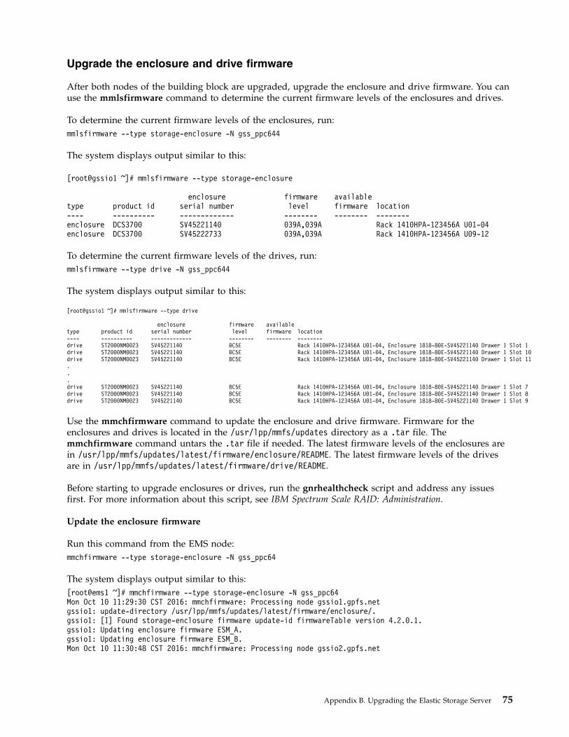
Upgrade the enclosure and drive firmware
After both nodes of the building block are upgraded, upgrade the enclosure and drive firmware. You canuse the mmlsfirmware command to determine the current firmware levels of the enclosures and drives.
To determine the current firmware levels of the enclosures, run:mmlsfirmware --type storage-enclosure -N gss_ppc644
The system displays output similar to this:
[root@gssio1 ~]# mmlsfirmware --type storage-enclosure
enclosure firmware availabletype product id serial number level firmware location---- ---------- ------------- -------- -------- --------enclosure DCS3700 SV45221140 039A,039A Rack 1410HPA-123456A U01-04enclosure DCS3700 SV45222733 039A,039A Rack 1410HPA-123456A U09-12
To determine the current firmware levels of the drives, run:mmlsfirmware --type drive -N gss_ppc644
The system displays output similar to this:
[root@gssio1 ~]# mmlsfirmware --type drive
enclosure firmware availabletype product id serial number level firmware location---- ---------- ------------- -------- -------- --------drive ST2000NM0023 SV45221140 BC5E Rack 1410HPA-123456A U01-04, Enclosure 1818-80E-SV45221140 Drawer 1 Slot 1drive ST2000NM0023 SV45221140 BC5E Rack 1410HPA-123456A U01-04, Enclosure 1818-80E-SV45221140 Drawer 1 Slot 10drive ST2000NM0023 SV45221140 BC5E Rack 1410HPA-123456A U01-04, Enclosure 1818-80E-SV45221140 Drawer 1 Slot 11...drive ST2000NM0023 SV45221140 BC5E Rack 1410HPA-123456A U01-04, Enclosure 1818-80E-SV45221140 Drawer 1 Slot 7drive ST2000NM0023 SV45221140 BC5E Rack 1410HPA-123456A U01-04, Enclosure 1818-80E-SV45221140 Drawer 1 Slot 8drive ST2000NM0023 SV45221140 BC5E Rack 1410HPA-123456A U01-04, Enclosure 1818-80E-SV45221140 Drawer 1 Slot 9
Use the mmchfirmware command to update the enclosure and drive firmware. Firmware for theenclosures and drives is located in the /usr/lpp/mmfs/updates directory as a .tar file. Themmchfirmware command untars the .tar file if needed. The latest firmware levels of the enclosures arein /usr/lpp/mmfs/updates/latest/firmware/enclosure/README. The latest firmware levels of the drivesare in /usr/lpp/mmfs/updates/latest/firmware/drive/README.
Before starting to upgrade enclosures or drives, run the gnrhealthcheck script and address any issuesfirst. For more information about this script, see IBM Spectrum Scale RAID: Administration.
Update the enclosure firmware
Run this command from the EMS node:mmchfirmware --type storage-enclosure -N gss_ppc64
The system displays output similar to this:[root@ems1 ~]# mmchfirmware --type storage-enclosure -N gss_ppc64Mon Oct 10 11:29:30 CST 2016: mmchfirmware: Processing node gssio1.gpfs.netgssio1: update-directory /usr/lpp/mmfs/updates/latest/firmware/enclosure/.gssio1: [I] Found storage-enclosure firmware update-id firmwareTable version 4.2.0.1.gssio1: Updating enclosure firmware ESM_A.gssio1: Updating enclosure firmware ESM_B.Mon Oct 10 11:30:48 CST 2016: mmchfirmware: Processing node gssio2.gpfs.net
Appendix B. Upgrading the Elastic Storage Server 75
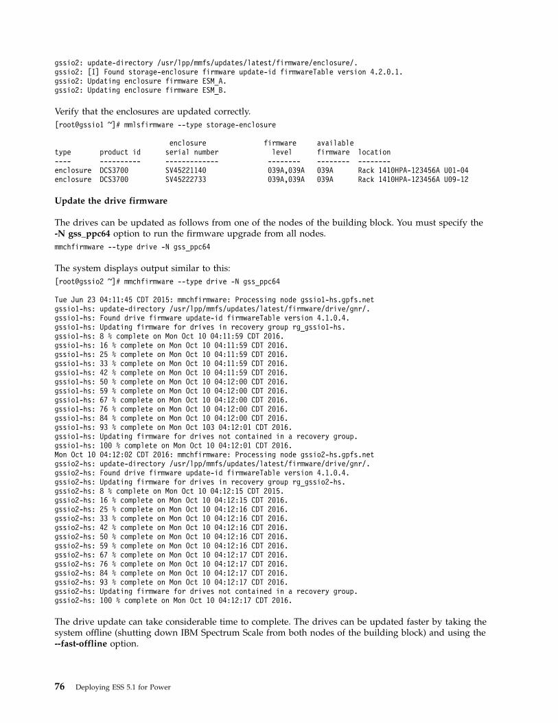
gssio2: update-directory /usr/lpp/mmfs/updates/latest/firmware/enclosure/.gssio2: [I] Found storage-enclosure firmware update-id firmwareTable version 4.2.0.1.gssio2: Updating enclosure firmware ESM_A.gssio2: Updating enclosure firmware ESM_B.
Verify that the enclosures are updated correctly.[root@gssio1 ~]# mmlsfirmware --type storage-enclosure
enclosure firmware availabletype product id serial number level firmware location---- ---------- ------------- -------- -------- --------enclosure DCS3700 SV45221140 039A,039A 039A Rack 1410HPA-123456A U01-04enclosure DCS3700 SV45222733 039A,039A 039A Rack 1410HPA-123456A U09-12
Update the drive firmware
The drives can be updated as follows from one of the nodes of the building block. You must specify the-N gss_ppc64 option to run the firmware upgrade from all nodes.mmchfirmware --type drive -N gss_ppc64
The system displays output similar to this:[root@gssio2 ~]# mmchfirmware --type drive -N gss_ppc64
Tue Jun 23 04:11:45 CDT 2015: mmchfirmware: Processing node gssio1-hs.gpfs.netgssio1-hs: update-directory /usr/lpp/mmfs/updates/latest/firmware/drive/gnr/.gssio1-hs: Found drive firmware update-id firmwareTable version 4.1.0.4.gssio1-hs: Updating firmware for drives in recovery group rg_gssio1-hs.gssio1-hs: 8 % complete on Mon Oct 10 04:11:59 CDT 2016.gssio1-hs: 16 % complete on Mon Oct 10 04:11:59 CDT 2016.gssio1-hs: 25 % complete on Mon Oct 10 04:11:59 CDT 2016.gssio1-hs: 33 % complete on Mon Oct 10 04:11:59 CDT 2016.gssio1-hs: 42 % complete on Mon Oct 10 04:11:59 CDT 2016.gssio1-hs: 50 % complete on Mon Oct 10 04:12:00 CDT 2016.gssio1-hs: 59 % complete on Mon Oct 10 04:12:00 CDT 2016.gssio1-hs: 67 % complete on Mon Oct 10 04:12:00 CDT 2016.gssio1-hs: 76 % complete on Mon Oct 10 04:12:00 CDT 2016.gssio1-hs: 84 % complete on Mon Oct 10 04:12:00 CDT 2016.gssio1-hs: 93 % complete on Mon Oct 103 04:12:01 CDT 2016.gssio1-hs: Updating firmware for drives not contained in a recovery group.gssio1-hs: 100 % complete on Mon Oct 10 04:12:01 CDT 2016.Mon Oct 10 04:12:02 CDT 2016: mmchfirmware: Processing node gssio2-hs.gpfs.netgssio2-hs: update-directory /usr/lpp/mmfs/updates/latest/firmware/drive/gnr/.gssio2-hs: Found drive firmware update-id firmwareTable version 4.1.0.4.gssio2-hs: Updating firmware for drives in recovery group rg_gssio2-hs.gssio2-hs: 8 % complete on Mon Oct 10 04:12:15 CDT 2015.gssio2-hs: 16 % complete on Mon Oct 10 04:12:15 CDT 2016.gssio2-hs: 25 % complete on Mon Oct 10 04:12:16 CDT 2016.gssio2-hs: 33 % complete on Mon Oct 10 04:12:16 CDT 2016.gssio2-hs: 42 % complete on Mon Oct 10 04:12:16 CDT 2016.gssio2-hs: 50 % complete on Mon Oct 10 04:12:16 CDT 2016.gssio2-hs: 59 % complete on Mon Oct 10 04:12:16 CDT 2016.gssio2-hs: 67 % complete on Mon Oct 10 04:12:17 CDT 2016.gssio2-hs: 76 % complete on Mon Oct 10 04:12:17 CDT 2016.gssio2-hs: 84 % complete on Mon Oct 10 04:12:17 CDT 2016.gssio2-hs: 93 % complete on Mon Oct 10 04:12:17 CDT 2016.gssio2-hs: Updating firmware for drives not contained in a recovery group.gssio2-hs: 100 % complete on Mon Oct 10 04:12:17 CDT 2016.
The drive update can take considerable time to complete. The drives can be updated faster by taking thesystem offline (shutting down IBM Spectrum Scale from both nodes of the building block) and using the--fast-offline option.
76 Deploying ESS 5.1 for Power
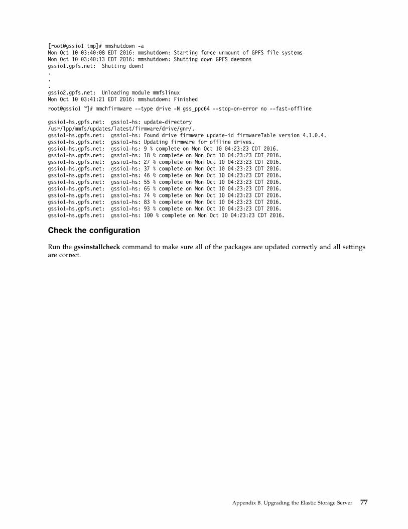
[root@gssio1 tmp]# mmshutdown -aMon Oct 10 03:40:08 EDT 2016: mmshutdown: Starting force unmount of GPFS file systemsMon Oct 10 03:40:13 EDT 2016: mmshutdown: Shutting down GPFS daemonsgssio1.gpfs.net: Shutting down!...gssio2.gpfs.net: Unloading module mmfslinuxMon Oct 10 03:41:21 EDT 2016: mmshutdown: Finished
root@gssio1 ~]# mmchfirmware --type drive -N gss_ppc64 --stop-on-error no --fast-offline
gssio1-hs.gpfs.net: gssio1-hs: update-directory/usr/lpp/mmfs/updates/latest/firmware/drive/gnr/.gssio1-hs.gpfs.net: gssio1-hs: Found drive firmware update-id firmwareTable version 4.1.0.4.gssio1-hs.gpfs.net: gssio1-hs: Updating firmware for offline drives.gssio1-hs.gpfs.net: gssio1-hs: 9 % complete on Mon Oct 10 04:23:23 CDT 2016.gssio1-hs.gpfs.net: gssio1-hs: 18 % complete on Mon Oct 10 04:23:23 CDT 2016.gssio1-hs.gpfs.net: gssio1-hs: 27 % complete on Mon Oct 10 04:23:23 CDT 2016.gssio1-hs.gpfs.net: gssio1-hs: 37 % complete on Mon Oct 10 04:23:23 CDT 2016.gssio1-hs.gpfs.net: gssio1-hs: 46 % complete on Mon Oct 10 04:23:23 CDT 2016.gssio1-hs.gpfs.net: gssio1-hs: 55 % complete on Mon Oct 10 04:23:23 CDT 2016.gssio1-hs.gpfs.net: gssio1-hs: 65 % complete on Mon Oct 10 04:23:23 CDT 2016.gssio1-hs.gpfs.net: gssio1-hs: 74 % complete on Mon Oct 10 04:23:23 CDT 2016.gssio1-hs.gpfs.net: gssio1-hs: 83 % complete on Mon Oct 10 04:23:23 CDT 2016.gssio1-hs.gpfs.net: gssio1-hs: 93 % complete on Mon Oct 10 04:23:23 CDT 2016.gssio1-hs.gpfs.net: gssio1-hs: 100 % complete on Mon Oct 10 04:23:23 CDT 2016.
Check the configuration
Run the gssinstallcheck command to make sure all of the packages are updated correctly and all settingsare correct.
Appendix B. Upgrading the Elastic Storage Server 77

78 Deploying ESS 5.1 for Power

Appendix C. Additional procedures
Rebuilding a management server node as part of the recovery processYou might need to rebuild the management server node (EMS) in cases such as internal disks failure orcomplete replacement of server with disks.
Use these steps to install an EMS node as a part of recovery.1. Put the Red Hat Enterprise Linux operating system DVD in the EMS drive.2. Connect your laptop directly to the HMC port 2 on EMS. This port displays as eth1 in ASMI.3. Set IP address on your laptop interface to 169.254.3.1/24.4. Ping the default IP on the HMC port 2 (169.254.3.147).5. Bring up the ASMI interface as follows:
a. In the browser address bar, enter https://169.254.3.147.b. Enter the login credentials.
The default login is admin and the default password is abc123.6. Connect using ipmiutil on Windows or ipmitool on Linux. For information on installing ipmiutil
on Windows, see “Installing IPMI Management Utilities on Windows” on page 80.7. Close any current IPMI Serial Over LAN (SOL) system console sessions:v On Windows, enter:
ipmiutil sol -d -r -N fsp_ip_address -P ipmi_password -F lan2
v On Linux, enter:ipmitool -I lanplus -P ipmi_password -H fsp_ip_address sol deactivate
8. Power down the box:v On Windows, enter:
ipmiutil power -d -N fsp_ip_address -P ipmi_password -F lan2
v On Linux, enter:ipmitool -H fsp_ip_address -I lanplus -P ipmi_password chassis power off
9. Power on the box:v On Windows, enter:
ipmiutil power -u -N fsp_ip_address -P ipmi_password -F lan2
v On Linux, enter:ipmitool -H fsp_ip_address -I lanplus -P ipmi_password chassis power on
10. Activate the SOL system console session:v On Windows, enter:
ipmiutil sol -a -r -N fsp_ip_address -P ipmi_password -F lan2
v On Linux, enter:ipmitool -I lanplus -P ipmi_password -H fsp_ip_address sol activate
You can use the ~ key to quit a SOL system console session.11. Configure your boot loader to enable booting from the DVD drive.
For example, use the following steps on the Petitboot boot loader:a. On the Petitboot System Configuration window, clear the boot order.b. On the Petitboot Add device screen, select Any CD/DVD device and then press Enter.c. Select OK and press Enter.d. After rescan, under CD/DVD, select Install Red Hat Enterprise Linux 7.2.
© Copyright IBM Corp. 2014, 2017 79
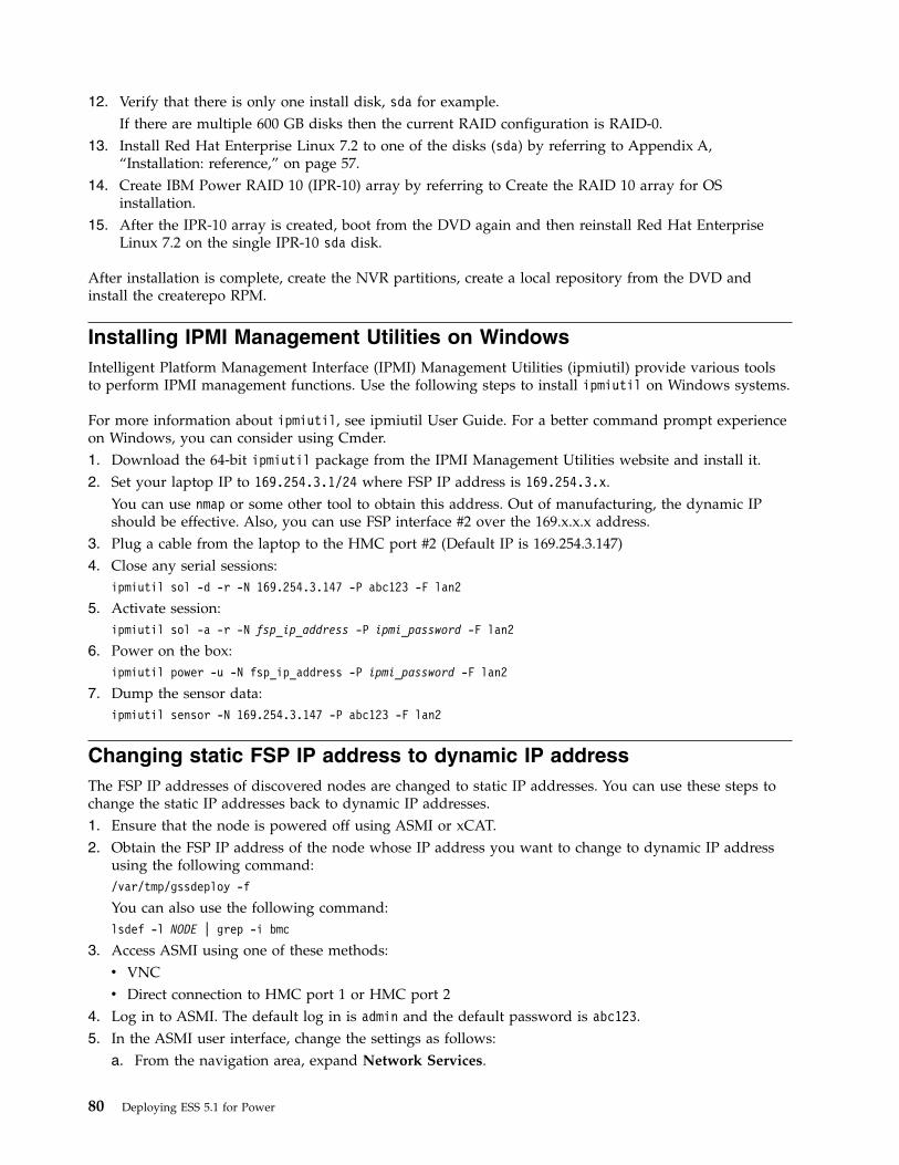
12. Verify that there is only one install disk, sda for example.If there are multiple 600 GB disks then the current RAID configuration is RAID-0.
13. Install Red Hat Enterprise Linux 7.2 to one of the disks (sda) by referring to Appendix A,“Installation: reference,” on page 57.
14. Create IBM Power RAID 10 (IPR-10) array by referring to Create the RAID 10 array for OSinstallation.
15. After the IPR-10 array is created, boot from the DVD again and then reinstall Red Hat EnterpriseLinux 7.2 on the single IPR-10 sda disk.
After installation is complete, create the NVR partitions, create a local repository from the DVD andinstall the createrepo RPM.
Installing IPMI Management Utilities on WindowsIntelligent Platform Management Interface (IPMI) Management Utilities (ipmiutil) provide various toolsto perform IPMI management functions. Use the following steps to install ipmiutil on Windows systems.
For more information about ipmiutil, see ipmiutil User Guide. For a better command prompt experienceon Windows, you can consider using Cmder.1. Download the 64-bit ipmiutil package from the IPMI Management Utilities website and install it.2. Set your laptop IP to 169.254.3.1/24 where FSP IP address is 169.254.3.x.
You can use nmap or some other tool to obtain this address. Out of manufacturing, the dynamic IPshould be effective. Also, you can use FSP interface #2 over the 169.x.x.x address.
3. Plug a cable from the laptop to the HMC port #2 (Default IP is 169.254.3.147)4. Close any serial sessions:
ipmiutil sol -d -r -N 169.254.3.147 -P abc123 -F lan2
5. Activate session:ipmiutil sol -a -r -N fsp_ip_address -P ipmi_password -F lan2
6. Power on the box:ipmiutil power -u -N fsp_ip_address -P ipmi_password -F lan2
7. Dump the sensor data:ipmiutil sensor -N 169.254.3.147 -P abc123 -F lan2
Changing static FSP IP address to dynamic IP addressThe FSP IP addresses of discovered nodes are changed to static IP addresses. You can use these steps tochange the static IP addresses back to dynamic IP addresses.1. Ensure that the node is powered off using ASMI or xCAT.2. Obtain the FSP IP address of the node whose IP address you want to change to dynamic IP address
using the following command:/var/tmp/gssdeploy -f
You can also use the following command:lsdef -l NODE | grep -i bmc
3. Access ASMI using one of these methods:v VNCv Direct connection to HMC port 1 or HMC port 2
4. Log in to ASMI. The default log in is admin and the default password is abc123.5. In the ASMI user interface, change the settings as follows:
a. From the navigation area, expand Network Services.
80 Deploying ESS 5.1 for Power
b. Click Network Configuration.c. From the Network Configuration display, select IPv4, and click Continue.d. In the section labeled Network interface eth0, do the following changes:
1) Select the Configure this interface? check box.2) Change Type of IP Address to Dynamic.
e. Click Continue.f. Click Save Settings.
6. If you lose connectivity, wait for a minute and then log in again using the last known IP address.a. In the navigation area, expand System Service Aids.b. Select Reset Service Processor.c. Click Continue to perform the reboot.
7. Monitor the status of the DHCP server:systemctl status dhcpd
8. Discover the node with its, potentially, changed IP address:/var/tmp/gssdeploy -f
You might need make the following changes:v Restart DHCPv Change the bmc=<IP> entry for the node in xCATv Change the IPMI password again:
a. Access the ASMI menu.b. From the main menu, select Login Profile > Change Passwords.c. Select IPMI from the list of user IDs.d. Enter the current password for the administrator and then enter and confirm a password for
IPMI.e. Click Continue.
Accessing ASMI remotely when campus connection to EMS existsAdvanced System Management Interface (ASMI) is a graphical interface that is part of the serviceprocessor firmware. Use these steps to access ASMI remotely when a campus connection to EMS exists.1. Log in to the EMS node using ssh.2. Install VNC Server:
yum -y install vnc*
3. Install KDE Desktop:yum -y groupinstall "KDE"
4. Install Firefox:yum -y install firefox
5. Type vncserver and then enter the password when prompted.6. Using VNC Viewer on your laptop, connect to the EMS campus network IP address. The Linux
desktop screen displays.7. Right-click on the desktop and select Konsole.8. Type firefox and press Enter.9. In the browser address bar, enter the IP address, prefixed with https://, of the IO node that you
want to access.You can obtain the IP address from xCAT using the following command:lsdef -l NODE | grep -i bmc
Appendix C. Additional procedures 81

The ASMI screen displays.10. Log in to ASMI. The default login is admin and the default password is abc123.
82 Deploying ESS 5.1 for Power
Appendix D. Troubleshooting
This topic includes troubleshooting information for ESS.
Gathering data to solve problems
See “gsssnap script” on page 141 for more information.
If I/O server node installation fails
If the installation of the I/O server nodes fails for any reason, fix the problem and then restart theinstallation on the management server by running these commands:
makeconservercfnodeset gss_ppc64 osimage=rhels7.1-ppc64-install-gssrnetboot gss_ppc64 -V
Red Hat Enterprise Linux update considerations
ESS 5.0 supports Red Hat Enterprise Linux 7.2 (kernel release 3.10.0-327.36.3.el7.ppc64le or3.10.0-327.36.3.el7.ppc64). You can update Red Hat Enterprise Linux as needed to address securityupdates. It is highly recommended that you limit errata updates applied to the Red Hat Enterprise Linuxoperating system used in the ESS solution to security errata or errata updates requested by service.
Information about a possible update issue follows.
Issue: A yum update command upgrades the Red Hat Enterprise Linux version.
If you are subscribed to Red Hat updates and run yum update, the redhat-release-server package mightbe updated as well. This could cause issues with OFED installation (mlnxofedinstall, for example) onESS nodes, because the Red Hat version is not in the installer's supported distribution list.
See Red Hat's solution articles for information about this behavior:
https://access.redhat.com/solutions/33807
https://access.redhat.com/solutions/10185
Resolution:
If the redhat-release-server package has been updated, you can downgrade this package. Run thiscommand:yum downgrade redhat-release-server
Prevention:
If possible, limit running yum update to security-related errata.
See Red Hat's solution article about applying security updates only:
https://access.redhat.com/solutions/10021
© Copyright IBM Corp. 2014, 2017 83
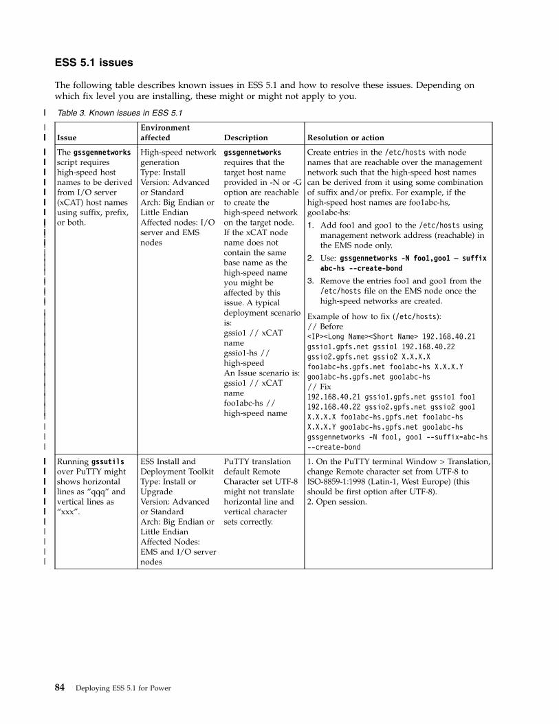
ESS 5.1 issues
The following table describes known issues in ESS 5.1 and how to resolve these issues. Depending onwhich fix level you are installing, these might or might not apply to you.
Table 3. Known issues in ESS 5.1
IssueEnvironmentaffected Description Resolution or action
The gssgennetworksscript requireshigh-speed hostnames to be derivedfrom I/O server(xCAT) host namesusing suffix, prefix,or both.
High-speed networkgenerationType: InstallVersion: Advancedor StandardArch: Big Endian orLittle EndianAffected nodes: I/Oserver and EMSnodes
gssgennetworksrequires that thetarget host nameprovided in -N or -Goption are reachableto create thehigh-speed networkon the target node.If the xCAT nodename does notcontain the samebase name as thehigh-speed nameyou might beaffected by thisissue. A typicaldeployment scenariois:gssio1 // xCATnamegssio1-hs //high-speedAn Issue scenario is:gssio1 // xCATnamefoo1abc-hs //high-speed name
Create entries in the /etc/hosts with nodenames that are reachable over the managementnetwork such that the high-speed host namescan be derived from it using some combinationof suffix and/or prefix. For example, if thehigh-speed host names are foo1abc-hs,goo1abc-hs:
1. Add foo1 and goo1 to the /etc/hosts usingmanagement network address (reachable) inthe EMS node only.
2. Use: gssgennetworks -N foo1,goo1 – suffixabc-hs --create-bond
3. Remove the entries foo1 and goo1 from the/etc/hosts file on the EMS node once thehigh-speed networks are created.
Example of how to fix (/etc/hosts):// Before<IP><Long Name><Short Name> 192.168.40.21gssio1.gpfs.net gssio1 192.168.40.22gssio2.gpfs.net gssio2 X.X.X.Xfoo1abc-hs.gpfs.net foo1abc-hs X.X.X.Ygoo1abc-hs.gpfs.net goo1abc-hs// Fix192.168.40.21 gssio1.gpfs.net gssio1 foo1192.168.40.22 gssio2.gpfs.net gssio2 goo1X.X.X.X foo1abc-hs.gpfs.net foo1abc-hsX.X.X.Y goo1abc-hs.gpfs.net goo1abc-hsgssgennetworks -N foo1, goo1 --suffix=abc-hs--create-bond
Running gssutilsover PuTTY mightshows horizontallines as “qqq” andvertical lines as“xxx”.
ESS Install andDeployment ToolkitType: Install orUpgradeVersion: Advancedor StandardArch: Big Endian orLittle EndianAffected Nodes:EMS and I/O servernodes
PuTTY translationdefault RemoteCharacter set UTF-8might not translatehorizontal line andvertical charactersets correctly.
1. On the PuTTY terminal Window > Translation,change Remote character set from UTF-8 toISO-8859-1:1998 (Latin-1, West Europe) (thisshould be first option after UTF-8).2. Open session.
84 Deploying ESS 5.1 for Power
||
|||||
||||||||
||||||||||
|||||||||||||||||||||||||||
|||||||
|||
||
|||
||||||||||||||
||||||
|||||||||||
|||||||
|||||
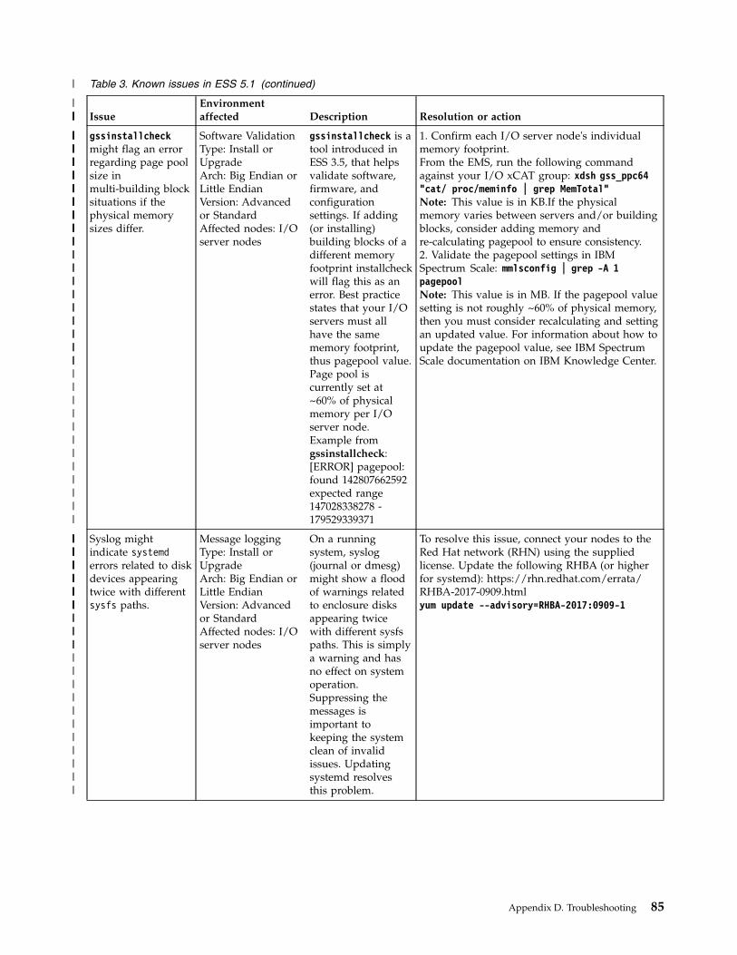
Table 3. Known issues in ESS 5.1 (continued)
IssueEnvironmentaffected Description Resolution or action
gssinstallcheckmight flag an errorregarding page poolsize inmulti-building blocksituations if thephysical memorysizes differ.
Software ValidationType: Install orUpgradeArch: Big Endian orLittle EndianVersion: Advancedor StandardAffected nodes: I/Oserver nodes
gssinstallcheck is atool introduced inESS 3.5, that helpsvalidate software,firmware, andconfigurationsettings. If adding(or installing)building blocks of adifferent memoryfootprint installcheckwill flag this as anerror. Best practicestates that your I/Oservers must allhave the samememory footprint,thus pagepool value.Page pool iscurrently set at~60% of physicalmemory per I/Oserver node.Example fromgssinstallcheck:[ERROR] pagepool:found 142807662592expected range147028338278 -179529339371
1. Confirm each I/O server node's individualmemory footprint.From the EMS, run the following commandagainst your I/O xCAT group: xdsh gss_ppc64"cat/ proc/meminfo | grep MemTotal"Note: This value is in KB.If the physicalmemory varies between servers and/or buildingblocks, consider adding memory andre-calculating pagepool to ensure consistency.2. Validate the pagepool settings in IBMSpectrum Scale: mmlsconfig | grep -A 1pagepoolNote: This value is in MB. If the pagepool valuesetting is not roughly ~60% of physical memory,then you must consider recalculating and settingan updated value. For information about how toupdate the pagepool value, see IBM SpectrumScale documentation on IBM Knowledge Center.
Syslog mightindicate systemderrors related to diskdevices appearingtwice with differentsysfs paths.
Message loggingType: Install orUpgradeArch: Big Endian orLittle EndianVersion: Advancedor StandardAffected nodes: I/Oserver nodes
On a runningsystem, syslog(journal or dmesg)might show a floodof warnings relatedto enclosure disksappearing twicewith different sysfspaths. This is simplya warning and hasno effect on systemoperation.Suppressing themessages isimportant tokeeping the systemclean of invalidissues. Updatingsystemd resolvesthis problem.
To resolve this issue, connect your nodes to theRed Hat network (RHN) using the suppliedlicense. Update the following RHBA (or higherfor systemd): https://rhn.redhat.com/errata/RHBA-2017-0909.htmlyum update --advisory=RHBA-2017:0909-1
Appendix D. Troubleshooting 85
|
|||||
||||||||
|||||||||
||||||||||||||||||||||||||||||
||||||||||||||||||
||||||
|||||||||
||||||||||||||||||||
||||||
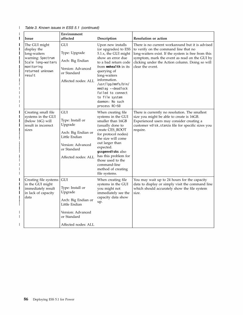
Table 3. Known issues in ESS 5.1 (continued)
IssueEnvironmentaffected Description Resolution or action
The GUI mightdisplay thelong-waiterswarning: SpectrumScale long-waitersmonitoringreturned unknownresult
GUI
Type: Upgrade
Arch: Big Endian
Version: Advancedor Standard
Affected nodes: ALL
Upon new installs(or upgrades) to ESS5.1.x, the GUI mightshow an error dueto a bad return codefrom mmhealth in itsquerying oflong-waitersinformation./usr/lpp/mmfs/bin/mmdiag --deadlockFailed to connectto file systemdaemon: No suchprocess RC=50
There is no current workaround but it is advisedto verify on the command line that nolong-waiters exist. If the system is free from thissymptom, mark the event as read on the GUI byclicking under the Action column. Doing so willclear the event.
Creating small filesystems in the GUI(below 16G) willresult in incorrectsizes
GUI
Type: Install orUpgrade
Arch: Big Endian orLittle Endian
Version: Advancedor Standard
Affected nodes: ALL
When creating filesystems in the GUIsmaller than 16GB(usually done tocreate CES_ROOTfor protocol nodes)the size will comeout larger thanexpected.gssgenvdisks alsohas this problem forthose used to thecommand-linemethod of creatingfile systems.
There is currently no resolution. The smallestsize you might be able to create is 16GB.Experienced users may consider creating acustomer vdisk.stanza file for specific sizes yourequire.
Creating file systemsin the GUI mightimmediately resultin lack of capacitydata
GUI
Type: Install orUpgrade
Arch: Big Endian orLittle Endian
Version: Advancedor Standard
Affected nodes: ALL
When creating filesystems in the GUIyou might notimmediately see thecapacity data showup.
You may wait up to 24 hours for the capacitydata to display or simply visit the command linewhich should accurately show the file systemsize.
86 Deploying ESS 5.1 for Power
|
|||||
||||||||
|
|
|
||
|
|||||||||||||||
||||||
|||||
|
||
||
||
|
|||||||||||||||
|||||
|||||
|
||
||
||
|
||||||
||||
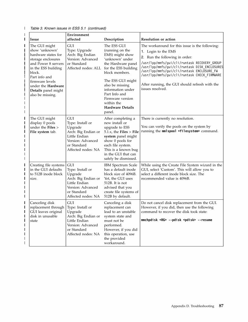
Table 3. Known issues in ESS 5.1 (continued)
IssueEnvironmentaffected Description Resolution or action
The GUI mightshow ‘unknown’hardware states forstorage enclosuresand Power 8 serversin the ESS buildingblock.Part info andfirmware levelsunder the HardwareDetails panel mightalso be missing.
GUIType: UpgradeArch: Big EndianVersion: Advancedor StandardAffected nodes: ALL
The ESS GUI(running on theEMS) might show‘unknown’ underthe Hardware panelfor the ESS buildingblock members.
The ESS GUI mightalso be missinginformation underPart Info andFirmware versionwithin theHardware Detailspanel.
The workaround for this issue is the following:
1. Login to the EMS
2. Run the following in order:
/usr/lpp/mmfs/gui/cli/runtask RECOVERY_GROUP/usr/lpp/mmfs/gui/cli/runtask DISK_ENCLOSURES/usr/lpp/mmfs/gui/cli/runtask ENCLOSURE_FW/usr/lpp/mmfs/gui/cli/runtask CHECK_FIRMWARE
After running, the GUI should refresh with theissues resolved.
The GUI mightdisplay 0 poolsunder the Files >File system tab.
GUIType: Install orUpgradeArch: Big Endian orLittle EndianVersion: Advancedor StandardAffected nodes: NA
After completing anew install orupgrade to ESS5.1.x, the Files > Filesystem panel mightshow 0 pools foreach file system.This is a known bugin the GUI that cansafely be dismissed.
There is currently no resolution.
You can verify the pools on the system byrunning the mmlspool <filesystem> command.
Creating file systemsin the GUI defaultsto 512B inode blocksize.
GUIType: Install orUpgradeArch: Big Endian orLittle EndianVersion: Advancedor StandardAffected nodes: NA
IBM Spectrum Scalehas a default inodeblock size of 4096B.Yet, the GUI uses512B. It is notadvised that youcreate file systems of512B by default.
While using the Create File System wizard in theGUI, select ‘Custom’. This will allow you toselect a different inode block size. Therecommended value is 4096B.
Canceling diskreplacement throughGUI leaves originaldisk in unusablestate
GUIType: Install orUpgradeArch: Big Endian orLittle EndianVersion: Advancedor StandardAffected nodes: NA
Canceling a diskreplacement canlead to an unstablesystem state andmust not beperformed.However, if you didthis operation, usethe providedworkaround.
Do not cancel disk replacement from the GUI.However, if you did, then use the followingcommand to recover the disk took state:
mmchpdisk <RG> --pdisk <pdisk> --resume
Appendix D. Troubleshooting 87
|
|||||
||||||||||||
||||||
|||||||
||||||||
|
|
|
||||
||
||||
||||||||
||||||||||
|
||
||||
||||||||
||||||||
||||
|||||
||||||||
||||||||||
|||
|

Table 3. Known issues in ESS 5.1 (continued)
IssueEnvironmentaffected Description Resolution or action
Under Monitoring >Hardware details,you might seeenclosures missinglocation information.
GUIType: Install orUpgradeArch: Big Endian orLittle EndianVersion: Advancedor StandardAffected nodes: NA
After install orupgrade to ESS5.1.x, you might seemissing locationinformation for theenclosures in yoursystem. This is notreflective of the trueframe U locationwhich can beobserved in theMonitoring >Hardware detailspanel.
The current workaround is to wait up to 24hours for the GUI services to refresh. After thisperiod you will see the enclosure locationinformation fill in.
The GUI wizardmight start againafter completing theinitial setup.
GUIType: InstallArch: Big EndianVersion: Advancedor StandardAffected nodes: NA
After completing theGUI wizard setupon ESS 5.1.0 BigEndian, you mightsee the start screenagain.
If you see the GUI wizard start screen a secondtime, type the address of the EMS into thebrowser and press enter.
https://<ip of EMS over management network>
You will then be taken to the GUI home screen.
Upon upgrades toESS 5.1.0 BigEndian, you mightnotice missing poolsand users in theMonitoring >Capacity GUI panel
GUIType: UpgradeArch: Big EndianVersion: Advancedor StandardAffected nodes: NA
You might noticeone or more missingpools or users afterupgrading to ESS5.1.0 Big Endian inthe Monitoring >Capacity GUI panel.You may also seemissing capacity andthroughput dataunder theMonitoring > Nodespanel.
There is currently no resolution orworkaround.Try waiting 24 hours for the GUI torefresh. To confirm your pools are available, runthe mmlspool <filesystem> command.
Upon upgrades toESS 5.1.0 BigEndian, you mightsee nodes in thedegraded state yetno events show anyissue.
GUIType: UpgradeArch: Big EndianVersion: Advancedor StandardAffected nodes: I/Oserver nodes
Under theMonitoring > Nodespanel, you might seeyour I/O servernodes in thedegraded state.Upon clicking eachnode, you willnotice no serviceableevents.
There is currently no resolution orworkaround.Try waiting 24 hours for the GUI torefresh its internal data.
88 Deploying ESS 5.1 for Power
|
|||||
|||||
||||||||
||||||||||||||
||||
||||
||||||
||||||
|||
|
|
|||||||
||||||
|||||||||||||
||||
|||||||
|||||||
||||||||||
|||
|

Appendix E. Best practices
When a user creates a cluster using gssgencluster or adds a node using gssaddnode, the networking andmemory are automatically detected to properly set optimal settings for the environment. ThegssServerConfigxxx.sh script (where xxx is the version of ESS) is executed that applies the optimal IBMSpectrum Scale RAID or IBM Spectrum Scale parameters. Also, for performing upgrade when you runthe gssupgXXX.sh script, the values of these settings are modified to the new version of ESS to which youhave upgraded.
Additionally, you can do the following steps:v Use gssinstallcheck to ensure the required software and best practice configuration is in place.v For client nodes, run gssClientConfig.sh on a new cluster to apply optimal settings.v For old clusters, review any performance parameters and consider using gssClientConfig.sh if you
want to change them.
For some best-practice recommendations:v Related to data collection, see “Collecting data ” on page 52.v Related to IBM Spectrum Scale RAID, see Best-practice recommendations for IBM Spectrum Scale RAID in
IBM Spectrum Scale RAID: Administration.
© Copyright IBM Corp. 2014, 2017 89

90 Deploying ESS 5.1 for Power
Appendix F. Restrictions
Some ESS restrictions follow:v IBM Spectrum Scale nodes that are to be used for protocol deployment can be added to an ESS 3.0 (or
later) cluster only. Do not run protocols, other gateways, or any other non-ESS services on ESSmanagement server nodes or I/O server nodes. Instead, set up separate protocol, gateway, or servicenodes.Do not use the ESS gssaddnode command to add the IBM Spectrum Scale protocol nodes to the ESScluster. Instead, use the IBM Spectrum Scale mmaddnode command.
Attention:
The ESS xCAT setup is designed to install and deploy management server and I/O server nodes only. Insome cases, it might be beneficial for deploying OSs on other nodes serving as client or protocol.However, use caution if doing so. xCAT scripts are unaware of dependencies on core GPFS RPMs andthus they might cause issues with upgrade. It is advised that upgrades outside of the management serverand I/O server nodes be done with the tools specific to that function. For protocol nodes, this wouldinvolve a combination of manual upgrade steps along with use of the IBM Spectrum Scale installationtoolkit.
© Copyright IBM Corp. 2014, 2017 91

92 Deploying ESS 5.1 for Power
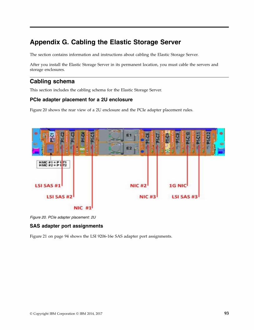
Appendix G. Cabling the Elastic Storage Server
The section contains information and instructions about cabling the Elastic Storage Server.
After you install the Elastic Storage Server in its permanent location, you must cable the servers andstorage enclosures.
Cabling schemaThis section includes the cabling schema for the Elastic Storage Server.
PCIe adapter placement for a 2U enclosure
Figure 20 shows the rear view of a 2U enclosure and the PCIe adapter placement rules.
SAS adapter port assignments
Figure 21 on page 94 shows the LSI 9206-16e SAS adapter port assignments.
Figure 20. PCIe adapter placement: 2U
© Copyright IBM Corporation © IBM 2014, 2017 93
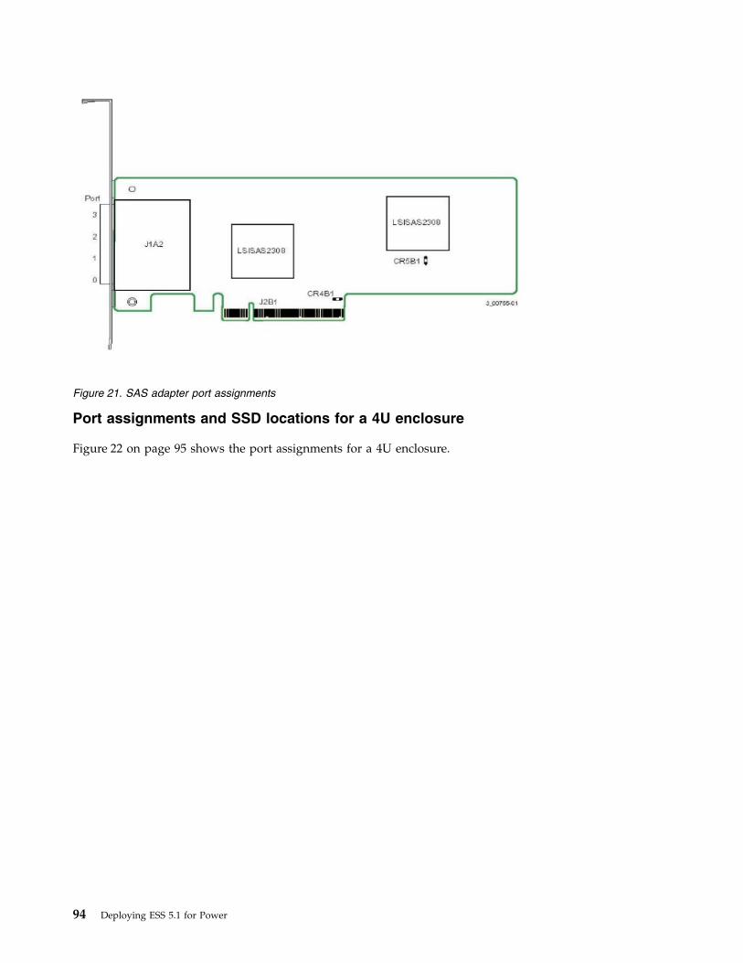
Port assignments and SSD locations for a 4U enclosure
Figure 22 on page 95 shows the port assignments for a 4U enclosure.
Figure 21. SAS adapter port assignments
94 Deploying ESS 5.1 for Power
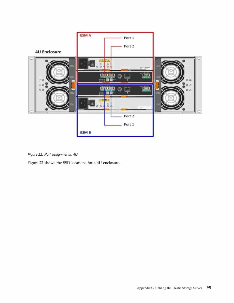
Figure 22 shows the SSD locations for a 4U enclosure.
Figure 22. Port assignments: 4U
Appendix G. Cabling the Elastic Storage Server 95
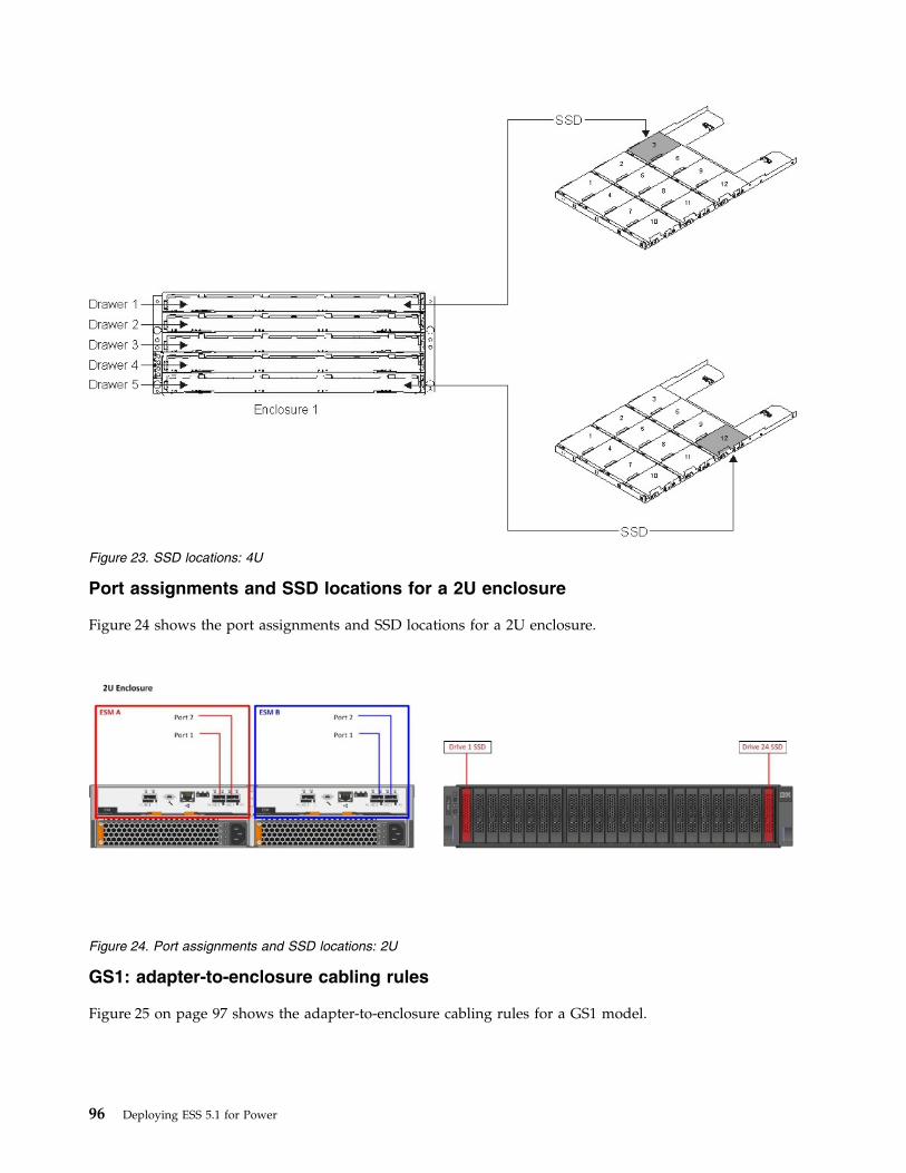
Port assignments and SSD locations for a 2U enclosure
Figure 24 shows the port assignments and SSD locations for a 2U enclosure.
GS1: adapter-to-enclosure cabling rules
Figure 25 on page 97 shows the adapter-to-enclosure cabling rules for a GS1 model.
Figure 23. SSD locations: 4U
Figure 24. Port assignments and SSD locations: 2U
96 Deploying ESS 5.1 for Power
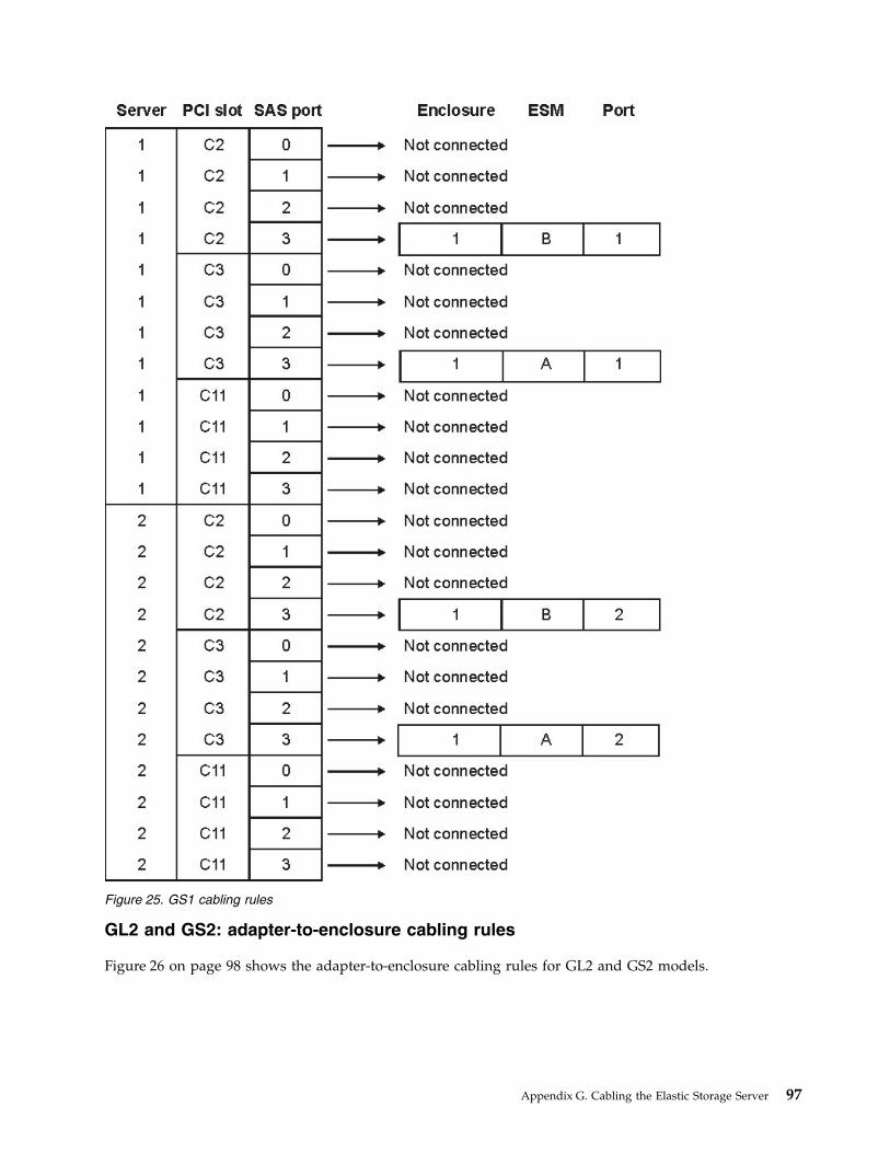
GL2 and GS2: adapter-to-enclosure cabling rules
Figure 26 on page 98 shows the adapter-to-enclosure cabling rules for GL2 and GS2 models.
Figure 25. GS1 cabling rules
Appendix G. Cabling the Elastic Storage Server 97
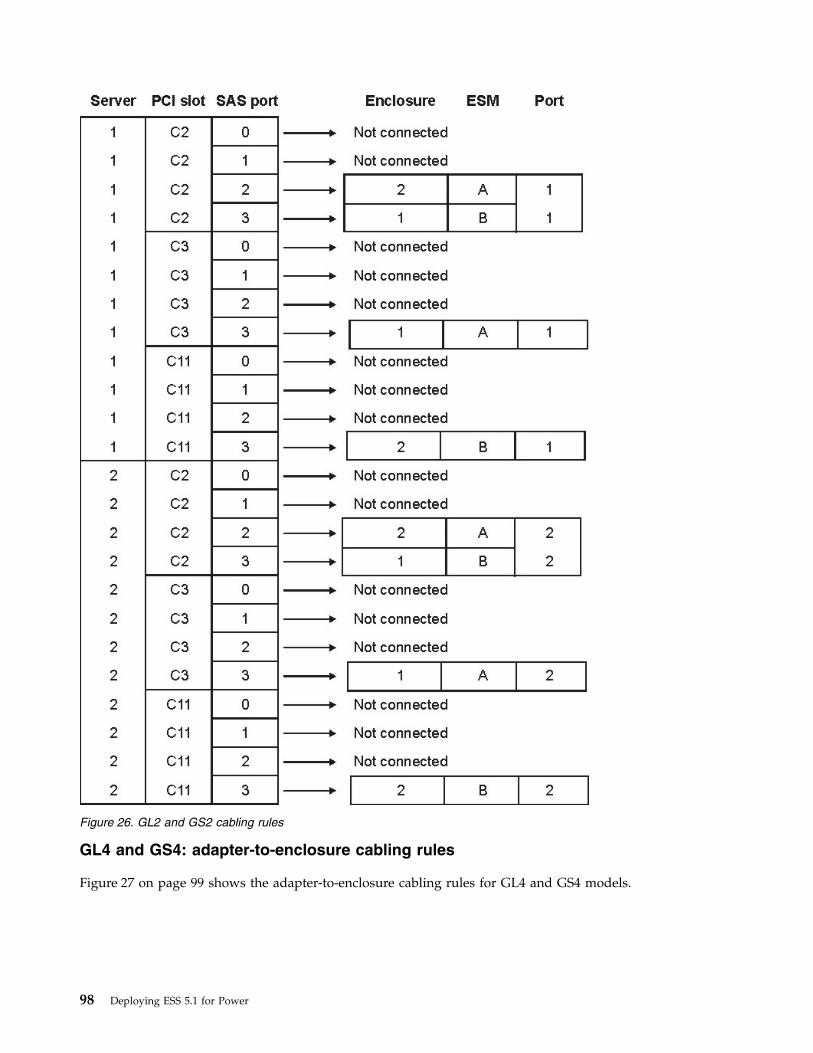
GL4 and GS4: adapter-to-enclosure cabling rules
Figure 27 on page 99 shows the adapter-to-enclosure cabling rules for GL4 and GS4 models.
Figure 26. GL2 and GS2 cabling rules
98 Deploying ESS 5.1 for Power
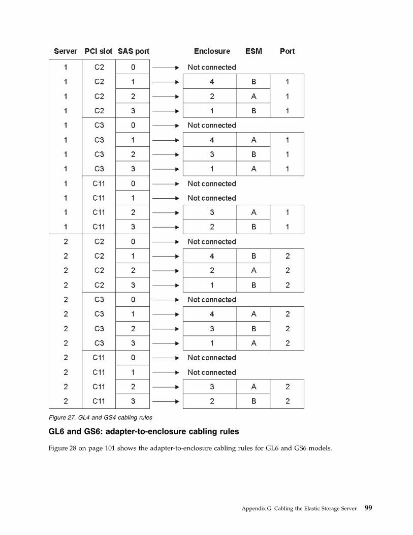
GL6 and GS6: adapter-to-enclosure cabling rules
Figure 28 on page 101 shows the adapter-to-enclosure cabling rules for GL6 and GS6 models.
Figure 27. GL4 and GS4 cabling rules
Appendix G. Cabling the Elastic Storage Server 99

100 Deploying ESS 5.1 for Power
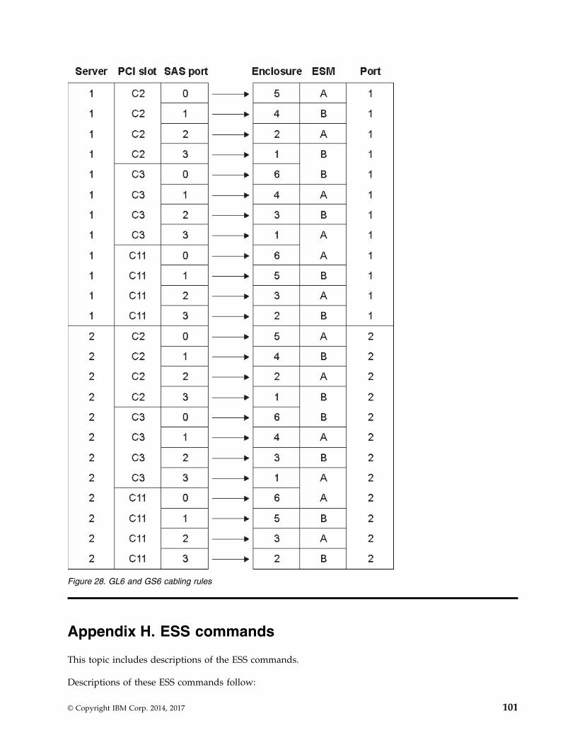
Appendix H. ESS commands
This topic includes descriptions of the ESS commands.
Descriptions of these ESS commands follow:
Figure 28. GL6 and GS6 cabling rules
© Copyright IBM Corp. 2014, 2017 101
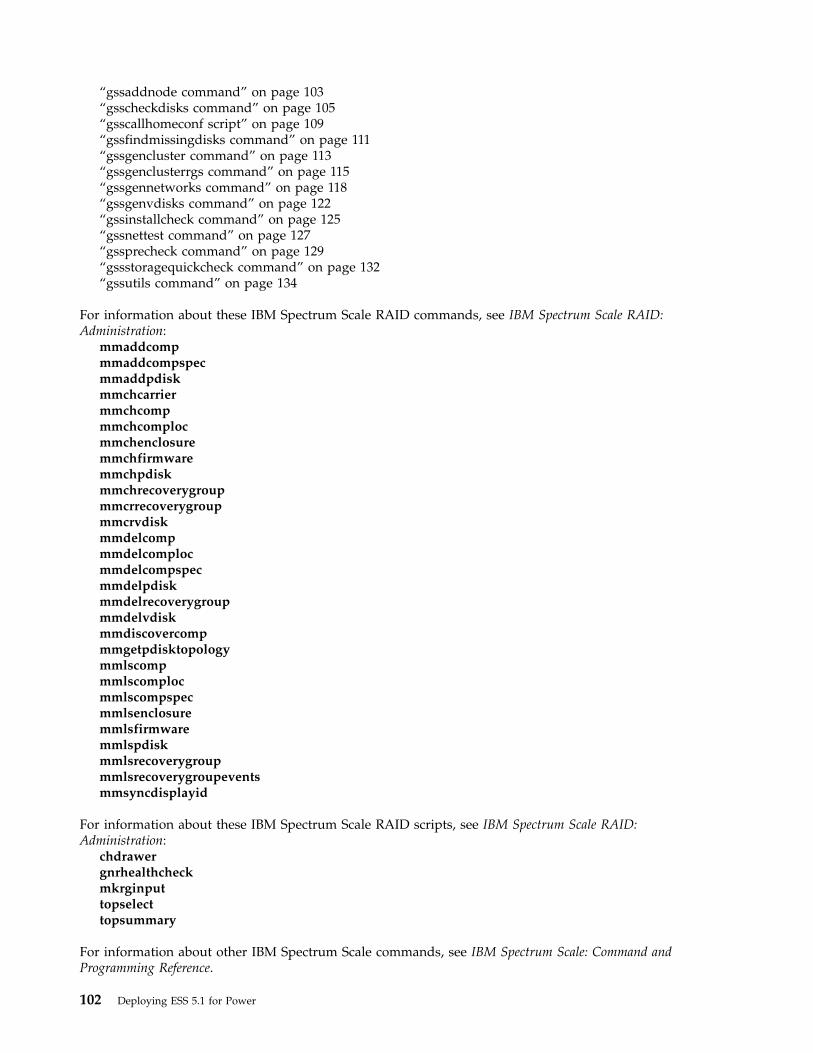
“gssaddnode command” on page 103“gsscheckdisks command” on page 105“gsscallhomeconf script” on page 109“gssfindmissingdisks command” on page 111“gssgencluster command” on page 113“gssgenclusterrgs command” on page 115“gssgennetworks command” on page 118“gssgenvdisks command” on page 122“gssinstallcheck command” on page 125“gssnettest command” on page 127“gssprecheck command” on page 129“gssstoragequickcheck command” on page 132“gssutils command” on page 134
For information about these IBM Spectrum Scale RAID commands, see IBM Spectrum Scale RAID:Administration:
mmaddcompmmaddcompspecmmaddpdiskmmchcarriermmchcompmmchcomplocmmchenclosuremmchfirmwaremmchpdiskmmchrecoverygroupmmcrrecoverygroupmmcrvdiskmmdelcompmmdelcomplocmmdelcompspecmmdelpdiskmmdelrecoverygroupmmdelvdiskmmdiscovercompmmgetpdisktopologymmlscompmmlscomplocmmlscompspecmmlsenclosuremmlsfirmwaremmlspdiskmmlsrecoverygroupmmlsrecoverygroupeventsmmsyncdisplayid
For information about these IBM Spectrum Scale RAID scripts, see IBM Spectrum Scale RAID:Administration:
chdrawergnrhealthcheckmkrginputtopselecttopsummary
For information about other IBM Spectrum Scale commands, see IBM Spectrum Scale: Command andProgramming Reference.
102 Deploying ESS 5.1 for Power

gssaddnode commandAdds a node (e.g. EMS) to a GPFS cluster.
Synopsisgssaddnode -N ADD-NodeList { --cluster-node ClusterNode | --cluster-node-group ClusterNodeGroup }
[ --nodetype NodeType ] [ --prefix Prefix ] [ --suffix Suffix ][--accept-license] [--no-fw-update] [ --contact-node ContactNode ][ -h | --help ]
Availability
Available with the Elastic Storage Server.
Description
The gssaddnode command adds nodes to a GPFS cluster. It can be used to add an EMS or IO Servernode to the cluster. This command must run on EMS node when EMS node is being added to the cluster.The EMS node must be upgraded to correct software levels (such as RHEL, xCAT and GPFS) beforeadding the node to the cluster. This command updates firmware levels in the SAS host adapter, firmwarein the enclosure and drives.
Parameters
-N ADD-NodeListProvides a comma separated list of nodes to add to an existing GPFS cluster. In case of EMS node itshould be the host name of the EMS (For example, ems1).
--cluster-node ClusterNodeProvides the name of a node that exists in a GPFS cluster where nodes will be added. This node mustbe able to run GPFS administrative commands. For example, --cluster-node gssio1 where gssio1 is anexisting node in the cluster. Either --cluster-node or --cluster-group must be provided.
--cluster-node-group ClusterNodeGroupProvides the xCAT node group name of the existing cluster. Add node command is run in the firstnode of the group. For example, --cluster-node-group gss_ppc64 where gss_ppc64 is an existing xCATgroup. Either --cluster-node or --cluster-node-group must be provided.
--nodetype NodeTypeIndicates the type of the node being added. Supported node types include ems and gss. Defaultnodetype is ems.
--prefix PrefixProvides the hostname prefix. PREFIX is used with the node names provided in theADD-NODE-LIST to create the actual node names. Use = between --prefix and value if the valuestarts with -.
--suffix SuffixProvides the hostname suffix. SUFFIX is used with the node namess in the ADD-NODE-LIST tocreate the actual node names. For example, with a addnodelist of gssio1,gssio2 and prefix A- andsuffix -ib node names A-gssio1-ib and A-gssio2-ib is used to form the actual node names. The nodename must re resolvable. Use = between --suffix and value if the value starts with -.
--accept-license Provides the --accept-license indicating that the applicable licensing terms are accepted. If notprovided user will be prompted for license acceptance after addition of the node.
--no-fw-update This option skips SAS adapter, storage enclosure and drive firmware update after addition of thenodes into the cluster.
Appendix H. ESS commands 103
--contact-node ContactNodeProvides a node name where the command is run. The contact node must be reachable over sshwithout password if it is not member of a xCAT group.
-h | --helpDisplays usage information about this command and exits.
Exit status
0 Successful completion.
nonzeroA failure has occurred.
Security
You must have root authority to run the gssaddnode command.
Examples
This example shows EMS node ems1 being added to the cluster. In the first example, group name of theexisting cluster nodes is provided. In the second example a node of the existing cluster is provided.
gssaddnode -N ems1 --cluster-node-group gss_ppc64 --nodetype ems --accept-licensegssaddnode -N ems1 --cluster-node gssio1 --nodetype ems --accept-license
See also
See also the following Deploying the Elastic Storage Server topics:v “Node name considerations” on page 57
See also the following IBM Spectrum Scale: Command and Programming Reference topics:v mmaddnode
v mmchconfig
v mmchlicense
v mmcrnodeclass
v mmstartup
Location
/opt/ibm/gss/tools/bin
104 Deploying ESS 5.1 for Power

gsscheckdisks commandChecks for disk errors under various I/O operations.
Synopsisgsscheckdisks { -N NodeList | -G NodeGroup }
[ --prefix Prefix ] [ --suffix Suffix ]{ --enclosure-list Enclosure-List | --disk-list DiskList | --show-enclosure-list }[ --iotest Io-Test ] [ --batch-size Batch-Size ][ --duration Test-Duration] [--write-enable] [ --iopath io-path ] [--local][ -h | --help ]
Availability
Available with the Elastic Storage Server.
Description
The gsscheckdisks command checks for disk errors under various I/O operations. You can use thiscommand to test attached drives before configuring them. At the end of the test, the comnmand reportsthe net performance and the number of errors per device.
Parameters
-N NodeListSpecifies a list of nodes on which to run the test.
You must specify the -N or -G parameter.
-G NodeGroupSpecifies the name of the node group. This parameter cannot be used in conjunction with the --localparameter.
You must specify the -N or -G parameter.
--prefix PrefixSpecifies the node name prefix.
--suffix SuffixSpecifies the node name suffix.
--enclosure-list { EnclosureList }Specifies a list of enclosures to be tested. Specify all to test all attached enclosures.
You must specify the --enclosure-list, --disk-list, or --show-enclosure-list parameter.
--disk-list DiskListSpecifies a list of disks to be tested, for example: sdh, sdx, sdm.
You must specify the --enclosure-list, --disk-list, or --show-enclosure-list parameter.
--show-enclosure-list Displays a list of the attached enclosures and exits.
You must specify the --enclosure-list, --disk-list, or --show-enclosure-list parameter.
--iotest IoTestSpecifies a comma-separated list of I/O operations for testing. Valid values are: r (sequential read), w(sequential write), R (random read), W (random write), and a (all). The default is r.
--batch-size Batch-SizeSpecifies the batch size of the test. Specify 0 for all. The default batch size is 60.
Appendix H. ESS commands 105
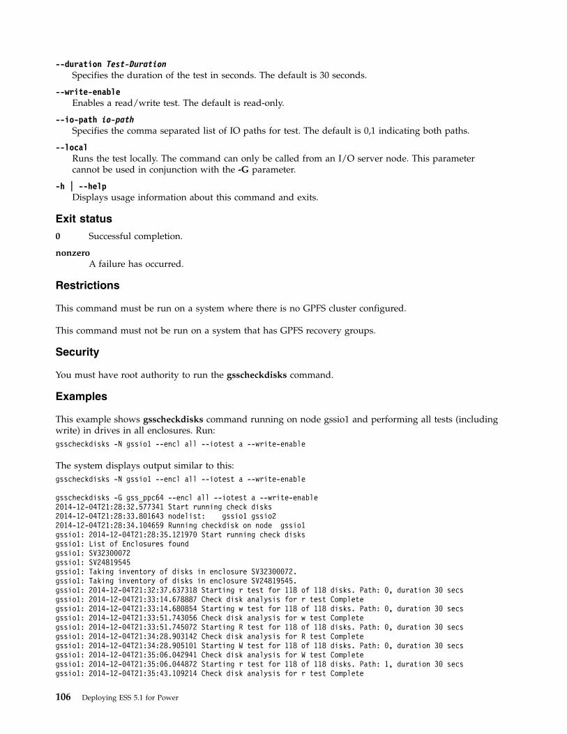
--duration Test-DurationSpecifies the duration of the test in seconds. The default is 30 seconds.
--write-enable Enables a read/write test. The default is read-only.
--io-path io-pathSpecifies the comma separated list of IO paths for test. The default is 0,1 indicating both paths.
--localRuns the test locally. The command can only be called from an I/O server node. This parametercannot be used in conjunction with the -G parameter.
-h | --helpDisplays usage information about this command and exits.
Exit status
0 Successful completion.
nonzeroA failure has occurred.
Restrictions
This command must be run on a system where there is no GPFS cluster configured.
This command must not be run on a system that has GPFS recovery groups.
Security
You must have root authority to run the gsscheckdisks command.
Examples
This example shows gsscheckdisks command running on node gssio1 and performing all tests (includingwrite) in drives in all enclosures. Run:gsscheckdisks -N gssio1 --encl all --iotest a --write-enable
The system displays output similar to this:gsscheckdisks -N gssio1 --encl all --iotest a --write-enable
gsscheckdisks -G gss_ppc64 --encl all --iotest a --write-enable2014-12-04T21:28:32.577341 Start running check disks2014-12-04T21:28:33.801643 nodelist: gssio1 gssio22014-12-04T21:28:34.104659 Running checkdisk on node gssio1gssio1: 2014-12-04T21:28:35.121970 Start running check disksgssio1: List of Enclosures foundgssio1: SV32300072gssio1: SV24819545gssio1: Taking inventory of disks in enclosure SV32300072.gssio1: Taking inventory of disks in enclosure SV24819545.gssio1: 2014-12-04T21:32:37.637318 Starting r test for 118 of 118 disks. Path: 0, duration 30 secsgssio1: 2014-12-04T21:33:14.678887 Check disk analysis for r test Completegssio1: 2014-12-04T21:33:14.680854 Starting w test for 118 of 118 disks. Path: 0, duration 30 secsgssio1: 2014-12-04T21:33:51.743056 Check disk analysis for w test Completegssio1: 2014-12-04T21:33:51.745072 Starting R test for 118 of 118 disks. Path: 0, duration 30 secsgssio1: 2014-12-04T21:34:28.903142 Check disk analysis for R test Completegssio1: 2014-12-04T21:34:28.905101 Starting W test for 118 of 118 disks. Path: 0, duration 30 secsgssio1: 2014-12-04T21:35:06.042941 Check disk analysis for W test Completegssio1: 2014-12-04T21:35:06.044872 Starting r test for 118 of 118 disks. Path: 1, duration 30 secsgssio1: 2014-12-04T21:35:43.109214 Check disk analysis for r test Complete
106 Deploying ESS 5.1 for Power
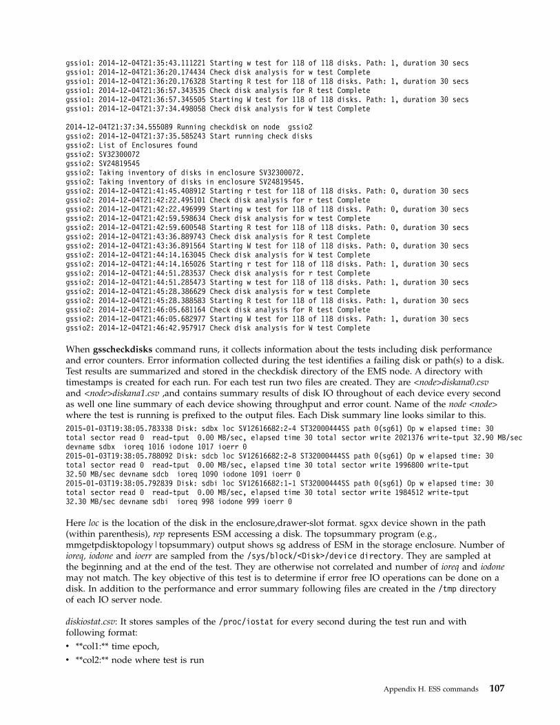
gssio1: 2014-12-04T21:35:43.111221 Starting w test for 118 of 118 disks. Path: 1, duration 30 secsgssio1: 2014-12-04T21:36:20.174434 Check disk analysis for w test Completegssio1: 2014-12-04T21:36:20.176328 Starting R test for 118 of 118 disks. Path: 1, duration 30 secsgssio1: 2014-12-04T21:36:57.343535 Check disk analysis for R test Completegssio1: 2014-12-04T21:36:57.345505 Starting W test for 118 of 118 disks. Path: 1, duration 30 secsgssio1: 2014-12-04T21:37:34.498058 Check disk analysis for W test Complete
2014-12-04T21:37:34.555089 Running checkdisk on node gssio2gssio2: 2014-12-04T21:37:35.585243 Start running check disksgssio2: List of Enclosures foundgssio2: SV32300072gssio2: SV24819545gssio2: Taking inventory of disks in enclosure SV32300072.gssio2: Taking inventory of disks in enclosure SV24819545.gssio2: 2014-12-04T21:41:45.408912 Starting r test for 118 of 118 disks. Path: 0, duration 30 secsgssio2: 2014-12-04T21:42:22.495101 Check disk analysis for r test Completegssio2: 2014-12-04T21:42:22.496999 Starting w test for 118 of 118 disks. Path: 0, duration 30 secsgssio2: 2014-12-04T21:42:59.598634 Check disk analysis for w test Completegssio2: 2014-12-04T21:42:59.600548 Starting R test for 118 of 118 disks. Path: 0, duration 30 secsgssio2: 2014-12-04T21:43:36.889743 Check disk analysis for R test Completegssio2: 2014-12-04T21:43:36.891564 Starting W test for 118 of 118 disks. Path: 0, duration 30 secsgssio2: 2014-12-04T21:44:14.163045 Check disk analysis for W test Completegssio2: 2014-12-04T21:44:14.165026 Starting r test for 118 of 118 disks. Path: 1, duration 30 secsgssio2: 2014-12-04T21:44:51.283537 Check disk analysis for r test Completegssio2: 2014-12-04T21:44:51.285473 Starting w test for 118 of 118 disks. Path: 1, duration 30 secsgssio2: 2014-12-04T21:45:28.386629 Check disk analysis for w test Completegssio2: 2014-12-04T21:45:28.388583 Starting R test for 118 of 118 disks. Path: 1, duration 30 secsgssio2: 2014-12-04T21:46:05.681164 Check disk analysis for R test Completegssio2: 2014-12-04T21:46:05.682977 Starting W test for 118 of 118 disks. Path: 1, duration 30 secsgssio2: 2014-12-04T21:46:42.957917 Check disk analysis for W test Complete
When gsscheckdisks command runs, it collects information about the tests including disk performanceand error counters. Error information collected during the test identifies a failing disk or path(s) to a disk.Test results are summarized and stored in the checkdisk directory of the EMS node. A directory withtimestamps is created for each run. For each test run two files are created. They are <node>diskana0.csvand <node>diskana1.csv ,and contains summary results of disk IO throughout of each device every secondas well one line summary of each device showing throughput and error count. Name of the node <node>where the test is running is prefixed to the output files. Each Disk summary line looks similar to this.2015-01-03T19:38:05.783338 Disk: sdbx loc SV12616682:2-4 ST32000444SS path 0(sg61) Op w elapsed time: 30total sector read 0 read-tput 0.00 MB/sec, elapsed time 30 total sector write 2021376 write-tput 32.90 MB/secdevname sdbx ioreq 1016 iodone 1017 ioerr 02015-01-03T19:38:05.788092 Disk: sdcb loc SV12616682:2-8 ST32000444SS path 0(sg61) Op w elapsed time: 30total sector read 0 read-tput 0.00 MB/sec, elapsed time 30 total sector write 1996800 write-tput32.50 MB/sec devname sdcb ioreq 1090 iodone 1091 ioerr 02015-01-03T19:38:05.792839 Disk: sdbi loc SV12616682:1-1 ST32000444SS path 0(sg61) Op w elapsed time: 30total sector read 0 read-tput 0.00 MB/sec, elapsed time 30 total sector write 1984512 write-tput32.30 MB/sec devname sdbi ioreq 998 iodone 999 ioerr 0
Here loc is the location of the disk in the enclosure,drawer-slot format. sgxx device shown in the path(within parenthesis), rep represents ESM accessing a disk. The topsummary program (e.g.,mmgetpdisktopology|topsummary) output shows sg address of ESM in the storage enclosure. Number ofioreq, iodone and ioerr are sampled from the /sys/block/<Disk>/device directory. They are sampled atthe beginning and at the end of the test. They are otherwise not correlated and number of ioreq and iodonemay not match. The key objective of this test is to determine if error free IO operations can be done on adisk. In addition to the performance and error summary following files are created in the /tmp directoryof each IO server node.
diskiostat.csv: It stores samples of the /proc/iostat for every second during the test run and withfollowing format:v **col1:** time epoch,v **col2:** node where test is run
Appendix H. ESS commands 107

v **col3:** device
The rest of the 11 columns are dumps of /proc/iostat. deviceerr.csv: It sores number of drive error countand sampled once every second.v **col1:** time epochv **col2:** node where runv **col3:** devicev **col4:** io issued
Location
/opt/ibm/gss/tools/bin
108 Deploying ESS 5.1 for Power

gsscallhomeconf scriptPerforms ESS HW Callhome Configuration
Synopsisgsscallhomeconf { [ -N NODE-LIST | -G NODE-GROUP ] } [ --show ] [ --prefix PREFIX][ --suffix SUFFIX ] -E ESA-AGENT [ --register { node,all } ] [ --crvpd ] [ --serial SOLN-SERIAL ][ --model SOLN-MODEL ] [ --verbose ] [ -h | --help ]
Availability
Available with the Elastic Storage Server.
Description
You can use the gsscallhomeconf script to configure ESS for callhome event generation using theElectronic Service Agent™ (ESA). This script can be run only on the ESS models with ppc64 architecture.With IBM Spectrum Scale RAID running on the ESS nodes, callback events about disk failures aregenerated on ppc64 architecture in the attached enclosure requiring replacement. In response to thecallback events, gsscallhomeconf or gsscallhomeevent initiates a callhome request to ESA over REST API.ESA is installed in the EMS node, and callhome events when initiated by the gsscallhomeconf orgsscallhomeevent. The gsscallhomeconf and gsscallhomeevent scripts run on IO Server nodes and EMSnode. This release supports disk replacement events for attached enclosures only.
Parameters
-N NODE-LISTProvides a list of nodes to configure.
-G NODE-GROUPProvides the name of node group.
--showShows the callhome configuration details.
--prefix PREFIXProvides the hostname prefix. Use = between --prefix and value if the value starts with -.
--suffix SUFFIXProvides the hostname suffix. Use = between --suffix and value if the value starts with -.
-E ESA-AGENTProvides the nodename for esa agent node.
--register {node,all}Registers the endpoints (nodes, enclosure or all) with ESA.
--crvpdCreates the vpd file.
--serial SOLN-SERIALProvides the ESS solution serial number.
--model SOLN-MODELProvides the ESS model.
--verboseProvides the verbose output.
-h | --helpDisplays usage information about this script and exits.
Appendix H. ESS commands 109
Exit status
0 Successful completion.
nonzeroA failure has occurred.
Security
You must have root authority to run the gsscallhomeconf script.
Example
The following example shows configuring the callhome:[root@ems3 ~]# gsscallhomeconf -E ems3 -N ems3,gss_ppc64 --suffix=-te --register=all
2017-01-23T05:34:42.005215 Generating node list...2017-01-23T05:34:42.827295 nodelist: ems3 essio31 essio322017-01-23T05:34:42.827347 suffix used for endpoint hostname: -teEnd point ems3-te registered sucessfully with systemid 37e5c23f98090750226f400722645655End point essio31-te registered sucessfully with systemid 35ae41e0388e08fd01378ae5c9a6ffefEnd point essio32-te registered sucessfully with systemid 9ea632b549434d57baef7c999dbf9479End point enclosure SV50321280 registered sucessfully with systemid 600755dc0aa2014526fe5945981b0e08End point enclosure SV50918672 registered sucessfully with systemid 92aa6428102b44a4a1c9a293402b324cESA configuration for ESS Callhome is complete.
Location
/opt/ibm/gss/tools/bin
110 Deploying ESS 5.1 for Power

gssfindmissingdisks commandChecks the disk paths and connectivity.
Synopsisgssfindmissingdisks { -N NodeList | -G NodeGroup }
[ --prefix Prefix ] [ --suffix Suffix ] [ -h | --help ]
Availability
Available with the Elastic Storage Server.
Description
The gssfindmissingdisks command checks the disk paths and connectivity.
Parameters
-N NodeListSpecifies a list of nodes for the disk path check.
You must specify the -N or -G parameter.
-G NodeGroupSpecifies the name of the node group.
You must specify the -N or -G parameter.
--prefix PrefixSpecifies the hostname prefix.
--suffix SuffixSpecifies the hostname suffix.
-h | --helpDisplays usage information about this command and exits.
Exit status
0 Successful completion.
nonzeroA failure has occurred.
Security
You must have root authority to run the gssfindmissingdisks command.
Examples
In this example, there are no missing drive paths; however, cables are not connected properly. Run:gssfindmissingdisks -G gss_ppc64
Following example shows gssfindmissingdisks running on node gssio1gssfindmissingdisks -N gssio1
The system displays output similar to this:[root@ems1 deploy]# gssfindmissingdisks -G gss_ppc64
gssfindmissingdisks -G gss_ppc64
Appendix H. ESS commands 111

2015-06-10T19:17:28.058805 Start find missing disk paths2015-06-10T19:17:29.905278 nodelist: gssio1 gssio22015-06-10T19:17:29.905351 May take long time to complete search of all drive paths2015-06-10T19:17:29.905384 Checking missing disk paths from node gssio1gssio1 Enclosure SV45221140 (number 1):gssio1 Enclosure SV45222733 (number 2):gssio1: GSS configuration: 2 enclosures, 2 SSDs, 2 empty slots, 118 disks total, 6 NVRAM partitions2015-06-10T19:17:48.272489 Checking missing disk paths from node gssio2gssio2 Enclosure SV45221140 (number 1):gssio2 Enclosure SV45222733 (number 2):gssio2: GSS configuration: 2 enclosures, 2 SSDs, 2 empty slots, 118 disks total, 6 NVRAM partitions2015-06-10T19:18:04.740198 Finish search for missing disk paths. Number of missing disk paths: 0
Location
/opt/ibm/gss/tools/bin
112 Deploying ESS 5.1 for Power

gssgencluster commandCreates a GSS cluster from a node-list or node-group
Synopsisgssgencluster -C ClusterName { -N NodeList | -G NodeGroup }
[ --subnet SubnetList ] [ --prefix Prefix ] [ --suffix Suffix ][--accept-license] [--no-fw-update][ --change-configuration ChangeConfig ] [--delete-cluster] [ --contact-node ContactNode ][ -h | --help ]
Availability
Available with the Elastic Storage Server.
Description
Use the gssgencluster to create a GSS cluster containing the servers listed in NODE-LIST orNODE-GROUP. This command creates the cluster, apply applicable license acceptance, applyconfiguration changes for GSS application, create a node⌂class with the group name (xCAT group) of thenodes, update host-adapter, storage enclosure and disk firmware. At the successful completion themember nodes are also started.
Parameters
-C ClusterNameSpecifies the name of the cluster. You must specify this parameter.
-N NodeListSpecifies a list of nodes for the disk path check.
You must specify the -N or -G parameter.
-G NodeGroupSpecifies the name of the node group.
You must specify the -N or -G parameter.
--subnet SubnetListSpecifies one or more subnet names in a comma-separated list.
--prefix PrefixSpecifies the hostname prefix. Use an equal sign (=) between --prefix and Prefix if the prefix beginswith a hyphen (-).
--suffix SuffixSpecifies the hostname suffix. Use an equal sign (=) between --suffix and Suffix if the suffix beginswith a hyphen (-).
--accept-license Indicates that you accept the applicable licensing terms.
--no-fw-update Indicates that you do not want to apply firmware updates for the host adapter, storage enclosures,and drives.
--change-configuration ChangeConfigChanges the cluster configuration options from default setting. The default is None. Enclose withquotation marks (' or ") if there are spaces within the configuration options. See the mmchconfigcommand for available configuration options.
Appendix H. ESS commands 113
--delete-cluster Indicates that nodes will be deleted from the existing GPFS cluster and reused for the new clustercreation.
--contact-node ContactNodeSpecifies the name of the node where the command is run, --contact-node gssio1, for example.
-h | --helpDisplays usage information about this command and exits.
Exit status
0 Successful completion.
nonzeroA failure has occurred.
Security
You must have root authority to run the gssgencluster command.
Examples
This example shows generation of cluster test01 using node group gss_ppc64. Here the node list for thecluster creation is obtained from the xCAT group gss_ppc64. If the gss_ppc64 contains nodes gssio1 andgssio2 then cluster will be formed using these nodes.
gssgencluster -C test01 -G gss_ppc64
The node names in the NODE-GROUP gss_ppc64 are typically used for management tasks. High speednetwork such an Infiniband or 10Gbit Ethernet is used for the data/clustering network. In such a caseyou can create the cluster as follows:
gssgencluster -C test01 -G gss_ppc64 --suffix=-10g
Here node names gssio1-10g and gssio2-10g is used for the cluster creation. Where gssio1-10g andgssio2-10g must be resolvable into a valid IP addresses in the high speed network.
gssgencluster -C test01 -G gss_ppc64 --suffix=-10g --accept-license --change-configuration verbsRdmaSend=no
Here license is accepted and verbsRdmsSend is disabled.
See also
See also the following IBM Spectrum Scale: Command and Programming Reference topics:v mmchconfig
Location
/opt/ibm/gss/tools/bin
114 Deploying ESS 5.1 for Power

gssgenclusterrgs commandCreates recovery groups.
Synopsisgssgenclusterrgs { -N NodeList | -G NodeGroup }
[ --prefix Prefix ] [ --suffix Suffix ] [ --verify Verify ][ --rgversion RgVersion ] [--use-rgstanza] [--use-cur-recoverygroups]
[--no-log-vdisk] [--no-meta-and-data-vdisk] [--create-nsds] [--create-filesystem][ --filesystem-name Device ] [ --filesystem-mount FileSystemMount ][ --filesystem-options FileSystemOptions ][ --num-of-metadata-nsds NumberOfMetadataNsds ] [ --num-of-data-nsds NumberOfDataNsds ][ --metadata-blocksize MetadataBlockSize ] [ --data-blocksize DataBlockSize ][ --metadata-percent MetadataPercent ] [ --raid-code RaidCode ][ --reserved-space-percent ReservedSpacePercent ] [--verbose] [ --contact-node ContactNode ] [--multi-da]
[ --compat ] [ -h | --help ]
Availability
Available with the Elastic Storage Server.
Description
The gssgenclusterrgs command creates recovery groups. By default, this command creates a singledeclustered array in a recovery group.
This command also creates log, log backup, and log tip vdisks; however, these functions are deprecated.Use the gssgenvdisks command instead.
Parameters
-N NodeListSpecifies a list of nodes for recovery group creation.
You must specify the -N or -G parameter.
-G NodeGroupSpecifies the name of the node group for recovery group creation.
You must specify the -N or -G parameter.
--prefix PrefixSpecifies the hostname prefix. Use an equal sign (=) between --prefix and Prefix if the prefix beginswith a hyphen (-).
--suffix SuffixSpecifies the hostname suffix. Use an equal sign (=) between --suffix and Suffix if the suffix beginswith a hyphen (-).
--verify VerifyVerifies whether the pdisk was formatted previously. Valid values are: yes, no. The default is yes.
--rgversion RgVersionSpecifies the RG version string. Specify a version string or LATEST.
--use-rgstanza Uses the stanza files provided for RG creation. The stanza files must be located in the /tmp dir of thefirst I/O server of the corresponding building block. The names of the stanza files should follow thisnaming convention: xxxxR.stanza, yyyyL.stanza.
Appendix H. ESS commands 115
--use-cur-recoverygroups Uses the current (existing) recovery groups. This is useful if you rerun the command and do not wantto delete and recreate the RGs.
--no-log-vdisk Specifies that log vdisks are not created.
--no-meta-and-data-vdisk Specifies that data and metadata vdisks are not created.
--create-nsds Creates NSDs from vdisks.
--create-filesystem Creates a filesystem using NSDs.
--filesystem-name DeviceSpecifies the file system name. The default is gpfs0.
--filesystem-mount FileSystemMountSpecifies the file system mount point. The default is /gpfs.
--filesystem-options FileSystemOptionsSpecifies other file system creation options. The default is None. Enclose with quotation marks (' or ")if there are blank spaces within the options.
See the mmcrfs command description in the IBM Spectrum Scale: Command and Programming Referencefor valid file system creation options.
--num-of-metadata-nsds NumberOfMetadataNsdsSpecifies the number of metadata NSDs per DA. The default is 1.
--num-of-data-nsds NumberOfDataNsdsSpecifies the number of data NSDs per DA. The default is 1.
--metadata-blocksize MetadataBlockSizeSpecifies the block size of the metadata NSDs. The default is 1M.
--data-blocksize DataBlockSizeSpecifies the block size of the data NSDs. The default is 8M.
--metadata-percent MetadataPercentSpecifies the metadata NSD capacity as a percentage of the overall usable capacity. The default is 5percent.
--raid-code RaidCodeSpecifies the RAID code. The default is 8+2p.
--reserved-space-percent ReservedSpacePercentSpecifies the percentage of total space to reserve. The default is 1 percent.
--verboseProvides more details.
--contact-node ContactNodeSpecifies the name of the node where the command is run, --contact-node gssio1, for example.
--multi-daCreates multiple declustered arrays in a recovery group.
--compatProvides compatibility mode of loghome vdisk.
-h | --helpDisplays usage information about this command and exits.
116 Deploying ESS 5.1 for Power
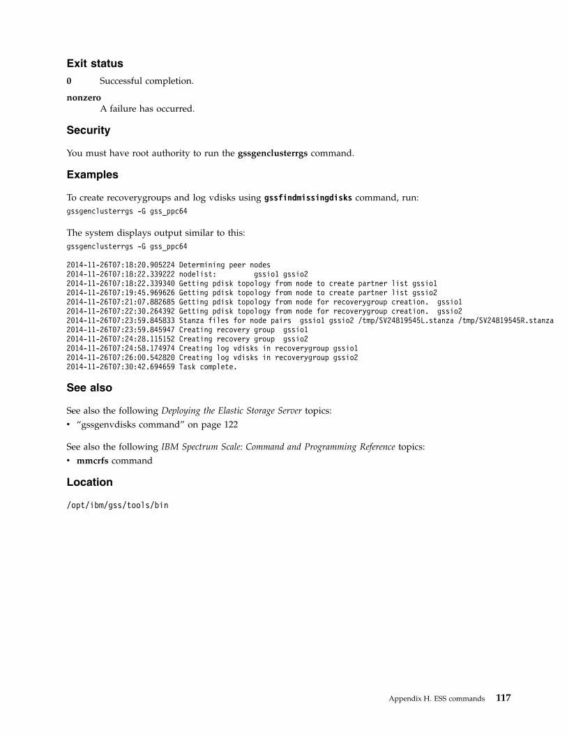
Exit status
0 Successful completion.
nonzeroA failure has occurred.
Security
You must have root authority to run the gssgenclusterrgs command.
Examples
To create recoverygroups and log vdisks using gssfindmissingdisks command, run:gssgenclusterrgs -G gss_ppc64
The system displays output similar to this:gssgenclusterrgs -G gss_ppc64
2014-11-26T07:18:20.905224 Determining peer nodes2014-11-26T07:18:22.339222 nodelist: gssio1 gssio22014-11-26T07:18:22.339340 Getting pdisk topology from node to create partner list gssio12014-11-26T07:19:45.969626 Getting pdisk topology from node to create partner list gssio22014-11-26T07:21:07.882685 Getting pdisk topology from node for recoverygroup creation. gssio12014-11-26T07:22:30.264392 Getting pdisk topology from node for recoverygroup creation. gssio22014-11-26T07:23:59.845833 Stanza files for node pairs gssio1 gssio2 /tmp/SV24819545L.stanza /tmp/SV24819545R.stanza2014-11-26T07:23:59.845947 Creating recovery group gssio12014-11-26T07:24:28.115152 Creating recovery group gssio22014-11-26T07:24:58.174974 Creating log vdisks in recoverygroup gssio12014-11-26T07:26:00.542820 Creating log vdisks in recoverygroup gssio22014-11-26T07:30:42.694659 Task complete.
See also
See also the following Deploying the Elastic Storage Server topics:v “gssgenvdisks command” on page 122
See also the following IBM Spectrum Scale: Command and Programming Reference topics:v mmcrfs command
Location
/opt/ibm/gss/tools/bin
Appendix H. ESS commands 117

gssgennetworks commandCreate a bonded ESS network
Synopsisgssgennetworks { -N Node-List | -G Node-Group } [ --prefix Prefix ] [ --suffix Suffix ]
[ --interface Interface ] [ --create-bond | --add-slave ] [ --gateway Gateway ] [ --bond Bond ][ --mode { balance-rr,active-backup,balance-xor,broadcast,802.3ad,balance-tlb,balance-alb}][ --hash-policy {layer2+3,layer3+4}][ --crid Crid ] [ --verbose ] [ -h | --help ]
Availability
Available with the Elastic Storage Server.
Description
The gssgennetworks script helps in creating high-speed network using the nmcli command. It is onlyapplicable for networks with Ethernet interfaces. It analyzes /etc/hosts file in the EMS node and createsa bonded connection on the high-speed interfaces that are up in the target node. If new slave interfacesare up or added since the bond is created they can be added to the bond.
By default, the script sets miimon to 100, the bonding mode to 802.3ad (LACP), xmit_hash_policy tolayer2+3. The other bond options are left with the default values, including lacp_rate (the default is slow).
For proper network operation, the Ethernet switch settings in the networking infrastructure must matchthe I/O server node interface bond settings. The gssgennetworks ignores Infiniband interfaces.
Parameters
-N Node-ListSpecifies a list of nodes to run the check.
-G Node-GroupSpecifies the name of the node group to run the check.
--prefix PrefixSpecifies the hostname prefix.
Use an equal sign (=) between --prefix and Prefix if Prefix starts with a hyphen (-).
--suffix SuffixSpecifies the hostname suffix.
Use an equal sign (=) between --suffix and Suffix if Suffix starts with a hyphen (-).
--interface InterfaceSpecifies a list of interfaces for bonding. If the list is not provided, by default all high-speed interfacesare taken.
--create-bondCreates a bonded interface.
--add-slaveAdds the slave interfaces to an existing bond. This is useful when additional high-speed links are upor added since the bond creation.
--gateway GatewaySpecifies a gateway for the network.
--bond BondSpecifies the name of the bond. The default is bond0.
118 Deploying ESS 5.1 for Power

--modeSpecifies mode for the bonded interface. The default is 802.3ab (recommended). The bonding optionxmit_hash_policy is set to layer2+3 when 802.3ab or balance-xor is selected.
--hash-policy {layer2+3,layer3+4}Specifies the xmit hash policy for 802.3ad and balanced-xor. The default value is layer2+3.
--crid CridSpecifies the CRID for the interface. The default is /24.
--verboseProvides more verbose output. The default is false.
-h | --helpDisplays usage information about this script and exits.
Exit status
0 Successful completion.
nonzeroA failure has occurred.
Security
You must have root authority to run the gssgennetworks script.
Examples1. This example shows how to run the gssgennetworks to obtain information of high-speed interfaces IP
address assigned to the bond:[root@ems1 ~]# gssgennetworks -G gss_ppc64 --suffix=-te0 --verbose
2016-01-25T16:05:14.184397 Starting network generation2016-01-25T16:05:15.782794 nodelist: gssio1 gssio22016-01-25T16:05:15.782846 suffix used for network hostname: -te0mlx4_0 port 1 ==> enp1s0 (Down)mlx4_0 port 2 ==> enp1s0d1 (Down)mlx4_1 port 1 ==> enP4p1s0 (Up)mlx4_1 port 2 ==> enP4p1s0d1 (Down)mlx4_2 port 1 ==> enP9p1s0 (Down)mlx4_2 port 2 ==> enP9p1s0d1 (Down)
Interface list for node gssio1Down interface enp1s0Down interface enp1s0d1Up interface enP4p1s0Down interface enP4p1s0d1Down interface enP9p1s0Down interface enP9p1s0d1mlx4_0 port 1 ==> enp1s0 (Down)mlx4_0 port 2 ==> enp1s0d1 (Down)mlx4_1 port 1 ==> enP4p1s0 (Up)mlx4_1 port 2 ==> enP4p1s0d1 (Down)mlx4_2 port 1 ==> enP9p1s0 (Down)mlx4_2 port 2 ==> enP9p1s0d1 (Down)
Interface list for node gssio2Down interface enp1s0Down interface enp1s0d1Up interface enP4p1s0Down interface enP4p1s0d1Down interface enP9p1s0Down interface enP9p1s0d1Node: gssio1-te0, IP Address: 11.1.202.13Node: gssio2-te0, IP Address: 11.1.202.14
Appendix H. ESS commands 119
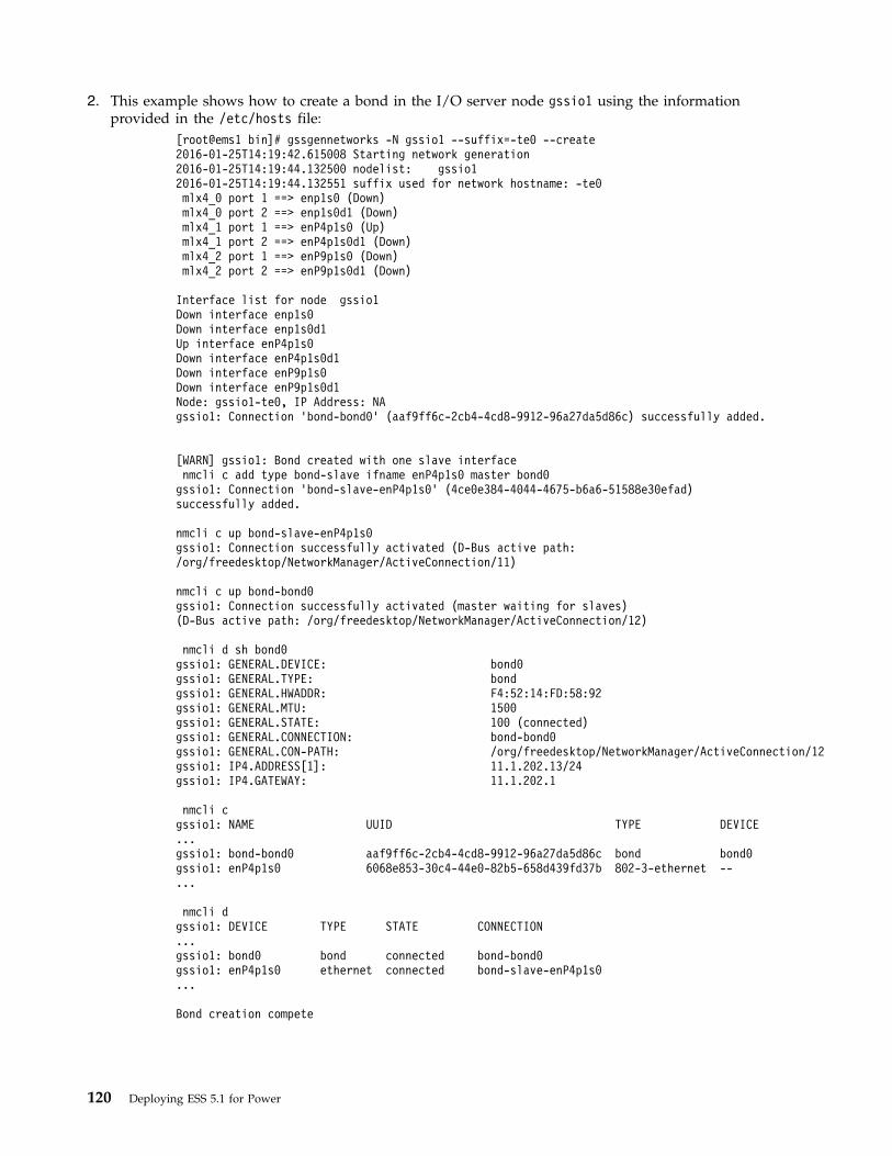
2. This example shows how to create a bond in the I/O server node gssio1 using the informationprovided in the /etc/hosts file:
[root@ems1 bin]# gssgennetworks -N gssio1 --suffix=-te0 --create2016-01-25T14:19:42.615008 Starting network generation2016-01-25T14:19:44.132500 nodelist: gssio12016-01-25T14:19:44.132551 suffix used for network hostname: -te0mlx4_0 port 1 ==> enp1s0 (Down)mlx4_0 port 2 ==> enp1s0d1 (Down)mlx4_1 port 1 ==> enP4p1s0 (Up)mlx4_1 port 2 ==> enP4p1s0d1 (Down)mlx4_2 port 1 ==> enP9p1s0 (Down)mlx4_2 port 2 ==> enP9p1s0d1 (Down)
Interface list for node gssio1Down interface enp1s0Down interface enp1s0d1Up interface enP4p1s0Down interface enP4p1s0d1Down interface enP9p1s0Down interface enP9p1s0d1Node: gssio1-te0, IP Address: NAgssio1: Connection ’bond-bond0’ (aaf9ff6c-2cb4-4cd8-9912-96a27da5d86c) successfully added.
[WARN] gssio1: Bond created with one slave interfacenmcli c add type bond-slave ifname enP4p1s0 master bond0
gssio1: Connection ’bond-slave-enP4p1s0’ (4ce0e384-4044-4675-b6a6-51588e30efad)successfully added.
nmcli c up bond-slave-enP4p1s0gssio1: Connection successfully activated (D-Bus active path:/org/freedesktop/NetworkManager/ActiveConnection/11)
nmcli c up bond-bond0gssio1: Connection successfully activated (master waiting for slaves)(D-Bus active path: /org/freedesktop/NetworkManager/ActiveConnection/12)
nmcli d sh bond0gssio1: GENERAL.DEVICE: bond0gssio1: GENERAL.TYPE: bondgssio1: GENERAL.HWADDR: F4:52:14:FD:58:92gssio1: GENERAL.MTU: 1500gssio1: GENERAL.STATE: 100 (connected)gssio1: GENERAL.CONNECTION: bond-bond0gssio1: GENERAL.CON-PATH: /org/freedesktop/NetworkManager/ActiveConnection/12gssio1: IP4.ADDRESS[1]: 11.1.202.13/24gssio1: IP4.GATEWAY: 11.1.202.1
nmcli cgssio1: NAME UUID TYPE DEVICE...gssio1: bond-bond0 aaf9ff6c-2cb4-4cd8-9912-96a27da5d86c bond bond0gssio1: enP4p1s0 6068e853-30c4-44e0-82b5-658d439fd37b 802-3-ethernet --...
nmcli dgssio1: DEVICE TYPE STATE CONNECTION...gssio1: bond0 bond connected bond-bond0gssio1: enP4p1s0 ethernet connected bond-slave-enP4p1s0...
Bond creation compete
120 Deploying ESS 5.1 for Power

Location
/opt/ibm/gss/tools/bin
Appendix H. ESS commands 121

gssgenvdisks commandCreates vdisks, vdisk stanza files, NSDs, and filesystems.
Synopsisgssgenvdisks [ --contact-node ContactNode ] [ --recovery-group RecoveryGroup ]
[ --vdisk-stanza VdiskStanza ] [ --vdisk-suffix VdiskSuffix ][--create-vdisk] [--create-nsds] [--create-filesystem][ --filesystem-name Device ] [ --filesystem-mount FileSystemMount ][ --filesystem-options FileSystemOptions ][ --num-of-metadata-nsds NumberOfMetadataNsds ] [ --num-of-data-nsds NumberOfDataNsds ][ --metadata-vdisk-size MetadataVdiskSize ] [ --data-vdisk-size DataVdiskSize ][ --metadata-blocksize MetadataBlockSize ] [ --data-blocksize DataBlockSize ][ --metadata-percent MetadataPercent ][ --raid-code RaidCode ] [ --failure-group FailureGroup ][ --reserved-space-percent ReservedSpacePercent ] [ --compat ] [--verbose]
[ -h | --help ]
Availability
Available with the Elastic Storage Server.
Description
The gssgenvdisks command generates vdisk stanza files and creates NSDs, and filesystems.
Parameters
--contact-node ContactNodeSpecifies the name of the node where the command is run (for example: --contact-node gssio1).Ensure that the node name is reachable by the system
--recovery-group RecoveryGroupSpecifies a list of recovery groups. If specific recovery groups are not provided all recovery groupsare used to generate vdisk stanza.
--vdisk-stanza VdiskStanzaSpecifies the path name of the vdisk stanza file to create. The default is /tmp/vdisk1.cfg. The vdiskstanza file is saved in the contact node when provided.
--vdisk-suffix VdiskSuffixSpecifies the suffix for the vdisk names. The valid characters that can be used in the suffix are: a to z,A to Z, 0 to 9, and _ (underscore).
--create-vdisk Creates the vdisks. Without this option, only the vdisk stanza is created.
--create-nsds Creates NSDs from vdisks.
--create-filesystem Creates a filesystem using NSDs.
--filesystem-name DeviceSpecifies the file system name. The default is gpfs0.
--filesystem-mount FileSystemMountSpecifies the file system mount point. The default is /gpfs.
--filesystem-options FileSystemOptionsSpecifies other file system creation options. The default is None. Enclose with quotation marks (' or ")if there are blank spaces within the options.
122 Deploying ESS 5.1 for Power
|
||
||
See the mmcrfs command description in the IBM Spectrum Scale: Command and Programming Referencefor valid file system creation options.
--num-of-metadata-nsds NumberOfMetadataNsdsSpecifies the number of metadata NSDs per DA. The default values are:v 1 for GS1, GS2, and GL2 systemsv 2 for GS4 and GL4 systemsv 3 for GS6 and GL6 systems
The space available for the metadata is equally divided between the metadata NSDs.
--num-of-data-nsds NumberOfDataNsdsSpecifies the number of data NSDs per DA. The default values are:v 1 for GS1, GS2, and GL2 systemsv 2 for GS4 and GL4 systemsv 3 for GS6 and GL6 systems
The space available for the data is equally divided between the data NSDs.
--metadata-vdisk-size MetadataVdiskSizeSpecifies the size of the metadata vdisks in GiB.
When specified, this option is used (instead of the --metadata-percent option) to calculate the vdisksize. If no data vdisks are being configured (the value of NumberOfDataNsds is 0), DataVdiskSizeshould be set to a non-zero number (for example: 1000) to set the metadata vdisk size correctly.Otherwise, the metadata vdisk size is set to 0 in the vdisk stanza file. To work around this, anon-zero DataVdiskSize should be provided (with a NumberOfDataNsds value of 0) when metadatavdisks only are configured.
--data-vdisk-size DataVdiskSizeSpecifies the size of the data vdisks in GiB. If --data-vdisk-size is zero or not provided, the vdisksize is determined from the available space after removing the reserved space.
--metadata-blocksize MetadataBlockSizeSpecifies the block size of the metadata NSDs. The default is 1M.
--data-blocksize DataBlockSizeSpecifies the block size of the data NSDs. The default is 8M.
--metadata-percent MetadataPercentSpecifies the metadata NSD capacity as a percentage of the overall usable capacity. The default is 5.The estimate is based on usable capacity (after redundancy overhead, for example: 8+2p for data and3wayreplicated for metadata). When metadata-vdisk-size is provided this option is ignored.
--raid-code RaidCodeSpecifies the RAID code. The default is 8+2p. Acceptable raid-codes are 8+2p and 8+3p. The3wayreplicated code is used for metadata vdisks. The raid code for data vdisks is 8+2p. The4wayreplicated code is used for metadata vdisk. The raid code for data vdisks is 8+3p.
--failure-group FailureGroupSpecifies the NSD base failure group. All NSDs in a building block are provided with the samefailure group. If two or more building blocks are present, NSDs in each building block are assignedincreasing failure group numbers, starting with the base failure group number. The default basefailure group is 30.
--reserved-space-percent ReservedSpacePercentSpecifies the percentage of total space to reserve. The default is 1.
--compatProvides compatibility mode.
Appendix H. ESS commands 123
|
|
|
|
|
|
||
|||
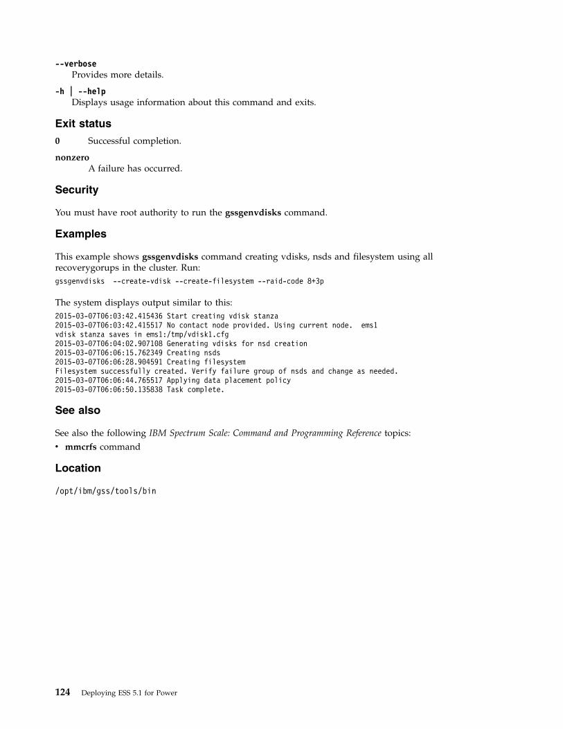
--verboseProvides more details.
-h | --helpDisplays usage information about this command and exits.
Exit status
0 Successful completion.
nonzeroA failure has occurred.
Security
You must have root authority to run the gssgenvdisks command.
Examples
This example shows gssgenvdisks command creating vdisks, nsds and filesystem using allrecoverygorups in the cluster. Run:gssgenvdisks --create-vdisk --create-filesystem --raid-code 8+3p
The system displays output similar to this:2015-03-07T06:03:42.415436 Start creating vdisk stanza2015-03-07T06:03:42.415517 No contact node provided. Using current node. ems1vdisk stanza saves in ems1:/tmp/vdisk1.cfg2015-03-07T06:04:02.907108 Generating vdisks for nsd creation2015-03-07T06:06:15.762349 Creating nsds2015-03-07T06:06:28.904591 Creating filesystemFilesystem successfully created. Verify failure group of nsds and change as needed.2015-03-07T06:06:44.765517 Applying data placement policy2015-03-07T06:06:50.135838 Task complete.
See also
See also the following IBM Spectrum Scale: Command and Programming Reference topics:v mmcrfs command
Location
/opt/ibm/gss/tools/bin
124 Deploying ESS 5.1 for Power

gssinstallcheck commandPerforms ESS
Synopsisgssinstallcheck { -N NodeList | -G NodeGroup } [ --prefix Prefix ] [ --get-version ] [ --suffix Suffix ]
[--syslog] [ --phy-mapping ] [ --srv-events ] [ --net-errors ] [ --errthld ERROR-THRESHOLD ][--dropthld DROP-THRESHOLD ] [ --monitor ] [ -h | --help ]
Availability
Available with the Elastic Storage Server.
Description
The gssinstallcheck command checks various aspects of the installation. By default, this commandperforms a comprehensive check and does not send information to syslog.
Parameters
-N NodeListProvides a list of nodes to run the check.
-G NodeGroupProvides a name of the node group to run the check.
--prefix PrefixProvides a hostname prefix. Use = between --suffix and value if the value starts with -.
--get-version Provides the ESS package version.
--suffix SuffixProvide the hostname suffix. Use = between --suffix and value if the value starts with -.
--syslogLogs output to syslog (/var/log/messages). Default no logging to syslog.
--phy-mappingCheck only phy mapping. When selected only this option is run.
--srv-eventsShows the serviceable events. When selected, only this option is run.
--net-errorsChecks for the network error counts. When selected, only this option is run.
--errthld ERROR-THRESHOLDProvides packet error threshold in percent during net-errors check.
--dropthld DROP-THRESHOLDProvides packet drop threshold in percent during net-errors check.
--monitorIn this mode outputs are only logged in to syslog. The stdout is turned off.
-h | --helpDisplays usage information about this command and exits.
Exit status
0 Successful completion.
Appendix H. ESS commands 125
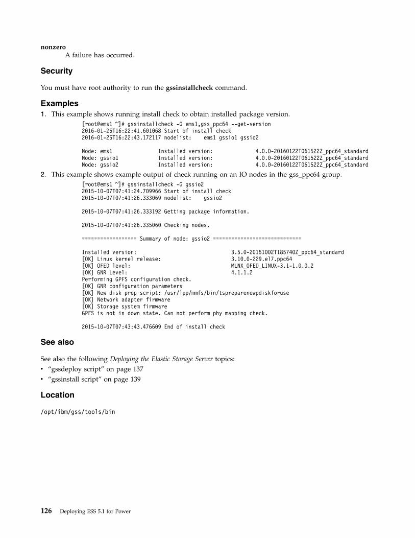
nonzeroA failure has occurred.
Security
You must have root authority to run the gssinstallcheck command.
Examples1. This example shows running install check to obtain installed package version.
[root@ems1 ~]# gssinstallcheck -G ems1,gss_ppc64 --get-version2016-01-25T16:22:41.601068 Start of install check2016-01-25T16:22:43.172117 nodelist: ems1 gssio1 gssio2
Node: ems1 Installed version: 4.0.0-20160122T061522Z_ppc64_standardNode: gssio1 Installed version: 4.0.0-20160122T061522Z_ppc64_standardNode: gssio2 Installed version: 4.0.0-20160122T061522Z_ppc64_standard
2. This example shows example output of check running on an IO nodes in the gss_ppc64 group.[root@ems1 ~]# gssinstallcheck -G gssio22015-10-07T07:41:24.709966 Start of install check2015-10-07T07:41:26.333069 nodelist: gssio2
2015-10-07T07:41:26.333192 Getting package information.
2015-10-07T07:41:26.335060 Checking nodes.
================== Summary of node: gssio2 =============================
Installed version: 3.5.0-20151002T185740Z_ppc64_standard[OK] Linux kernel release: 3.10.0-229.el7.ppc64[OK] OFED level: MLNX_OFED_LINUX-3.1-1.0.0.2[OK] GNR Level: 4.1.1.2Performing GPFS configuration check.[OK] GNR configuration parameters[OK] New disk prep script: /usr/lpp/mmfs/bin/tspreparenewpdiskforuse[OK] Network adapter firmware[OK] Storage system firmwareGPFS is not in down state. Can not perform phy mapping check.
2015-10-07T07:43:43.476609 End of install check
See also
See also the following Deploying the Elastic Storage Server topics:v “gssdeploy script” on page 137v “gssinstall script” on page 139
Location
/opt/ibm/gss/tools/bin
126 Deploying ESS 5.1 for Power
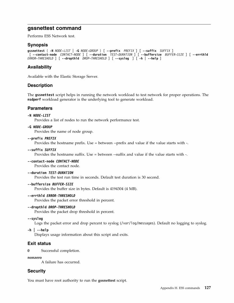
gssnettest commandPerforms ESS Network test.
Synopsisgssnettest { -N NODE-LIST | -G NODE-GROUP } [ --prefix PREFIX ] [ --suffix SUFFIX ][ --contact-node CONTACT-NODE ] [ --duration TEST-DURATION ] [ --buffersize BUFFER-SIZE ] [ --errthld
ERROR-THRESHOLD ] [ --dropthld DROP-THRESHOLD ] [ --syslog ] [ -h | --help ]
Availability
Available with the Elastic Storage Server.
Description
The gssnettest script helps in running the network workload to test network for proper operations. Thensdperf workload generator is the underlying tool to generate workload.
Parameters
-N NODE-LISTProvides a list of nodes to run the network performance test.
-G NODE-GROUPProvides the name of node group.
--prefix PREFIXProvides the hostname prefix. Use = between --prefix and value if the value starts with -.
--suffix SUFFIXProvides the hostname suffix. Use = between --suffix and value if the value starts with -.
--contact-node CONTACT-NODEProvides the contact node.
--duration TEST-DURATIONProvides the test run time in seconds. Default test duration is 30 second.
--buffersize BUFFER-SIZEProvides the buffer size in bytes. Default is 4194304 (4 MB).
--errthld ERROR-THRESHOLDProvides the packet error threshold in percent.
--dropthld DROP-THRESHOLDProvides the packet drop threshold in percent.
--syslogLogs the packet error and drop percent to syslog (/var/log/messages). Default no logging to syslog.
-h | --helpDisplays usage information about this script and exits.
Exit status
0 Successful completion.
nonzeroA failure has occurred.
Security
You must have root authority to run the gssnettest script.
Appendix H. ESS commands 127

Location
/opt/ibm/gss/tools/bin
128 Deploying ESS 5.1 for Power

gssprecheck commandPerforms the ESS install or upgrade precheck.
Synopsisgssprecheck {-N NODE-LIST | -G NODE-GROUP}{--install | --upgrade}{--file CONFIG_FILE}[--syslog][--monitor][--verbose][--pre][-h | --help]
Availability
Available with the Elastic Storage Server.
Description
The gssprecheck command checks for common errors upon new installs or upgrades.
Parameters
-h --helpDisplays usage information about this command and exits.
-N NODE-LISTProvide a list of node to run the check.
-G NODE-GROUPProvide name of the node group to run the check.
--file CONFIG_FILEProvide the location of gssdeploy.cfg file for parsing.
--installPrechecks for install related items only.
--upgradePrechecks for upgrade related items only.
--syslogLogs the output to syslog (/var/log/messages). Default no logging to syslog.
--monitorIn this mode outputs are only logged in to syslog. The stdout is turned off.
--verboseIndicates Verbose mode.
--preDoes the initial check prior to running the gssdeploy -x.
-h --helpDisplays usage information about this command and exits.
Exit status
0 Successful completion.
nonzeroA failure has occurred.
Security
You must have root authority to run the gssprecheck command.
Appendix H. ESS commands 129
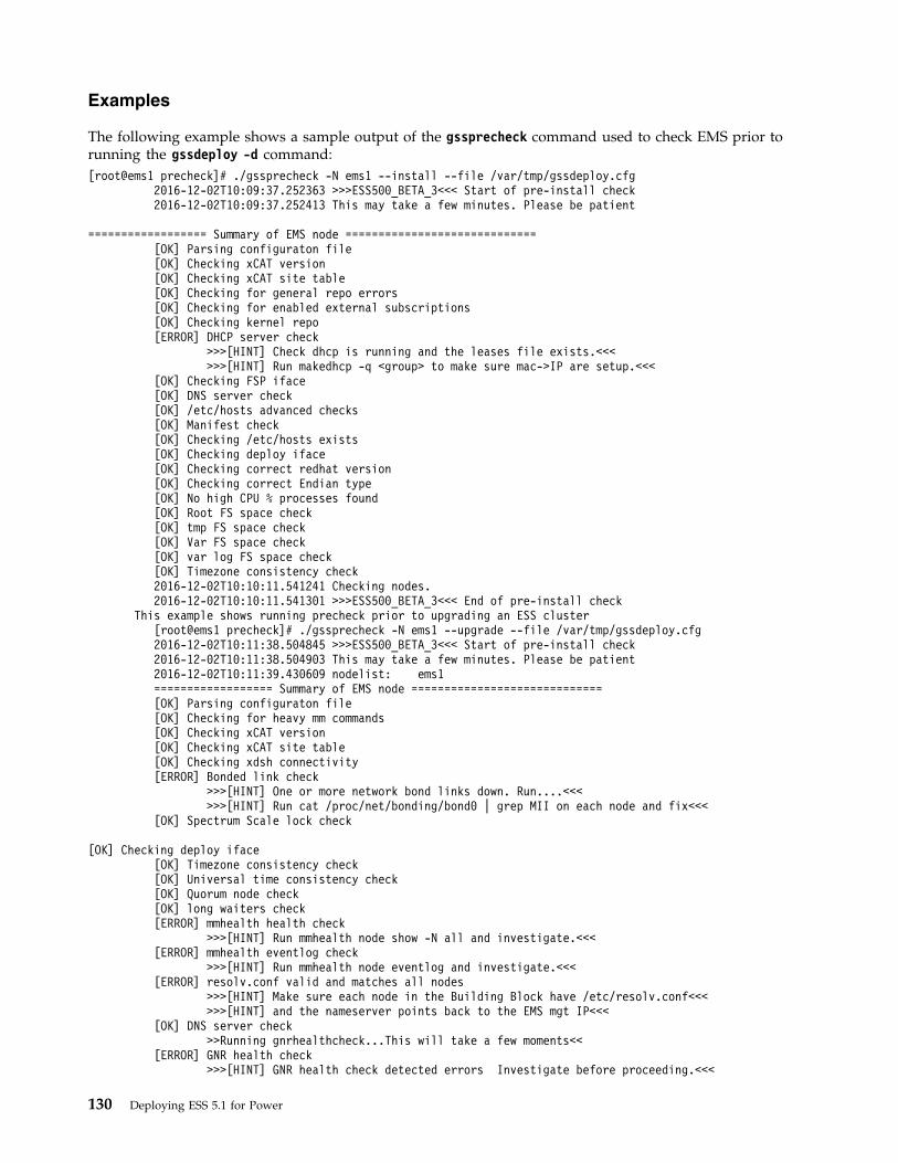
Examples
The following example shows a sample output of the gssprecheck command used to check EMS prior torunning the gssdeploy -d command:[root@ems1 precheck]# ./gssprecheck -N ems1 --install --file /var/tmp/gssdeploy.cfg
2016-12-02T10:09:37.252363 >>>ESS500_BETA_3<<< Start of pre-install check2016-12-02T10:09:37.252413 This may take a few minutes. Please be patient
================== Summary of EMS node =============================[OK] Parsing configuraton file[OK] Checking xCAT version[OK] Checking xCAT site table[OK] Checking for general repo errors[OK] Checking for enabled external subscriptions[OK] Checking kernel repo[ERROR] DHCP server check
>>>[HINT] Check dhcp is running and the leases file exists.<<<>>>[HINT] Run makedhcp -q <group> to make sure mac->IP are setup.<<<
[OK] Checking FSP iface[OK] DNS server check[OK] /etc/hosts advanced checks[OK] Manifest check[OK] Checking /etc/hosts exists[OK] Checking deploy iface[OK] Checking correct redhat version[OK] Checking correct Endian type[OK] No high CPU % processes found[OK] Root FS space check[OK] tmp FS space check[OK] Var FS space check[OK] var log FS space check[OK] Timezone consistency check2016-12-02T10:10:11.541241 Checking nodes.2016-12-02T10:10:11.541301 >>>ESS500_BETA_3<<< End of pre-install check
This example shows running precheck prior to upgrading an ESS cluster[root@ems1 precheck]# ./gssprecheck -N ems1 --upgrade --file /var/tmp/gssdeploy.cfg2016-12-02T10:11:38.504845 >>>ESS500_BETA_3<<< Start of pre-install check2016-12-02T10:11:38.504903 This may take a few minutes. Please be patient2016-12-02T10:11:39.430609 nodelist: ems1================== Summary of EMS node =============================[OK] Parsing configuraton file[OK] Checking for heavy mm commands[OK] Checking xCAT version[OK] Checking xCAT site table[OK] Checking xdsh connectivity[ERROR] Bonded link check
>>>[HINT] One or more network bond links down. Run....<<<>>>[HINT] Run cat /proc/net/bonding/bond0 | grep MII on each node and fix<<<
[OK] Spectrum Scale lock check
[OK] Checking deploy iface[OK] Timezone consistency check[OK] Universal time consistency check[OK] Quorum node check[OK] long waiters check[ERROR] mmhealth health check
>>>[HINT] Run mmhealth node show -N all and investigate.<<<[ERROR] mmhealth eventlog check
>>>[HINT] Run mmhealth node eventlog and investigate.<<<[ERROR] resolv.conf valid and matches all nodes
>>>[HINT] Make sure each node in the Building Block have /etc/resolv.conf<<<>>>[HINT] and the nameserver points back to the EMS mgt IP<<<
[OK] DNS server check>>Running gnrhealthcheck...This will take a few moments<<
[ERROR] GNR health check>>>[HINT] GNR health check detected errors Investigate before proceeding.<<<
130 Deploying ESS 5.1 for Power
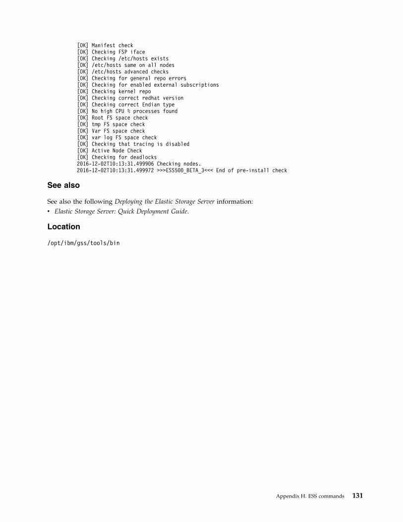
[OK] Manifest check[OK] Checking FSP iface[OK] Checking /etc/hosts exists[OK] /etc/hosts same on all nodes[OK] /etc/hosts advanced checks[OK] Checking for general repo errors[OK] Checking for enabled external subscriptions[OK] Checking kernel repo[OK] Checking correct redhat version[OK] Checking correct Endian type[OK] No high CPU % processes found[OK] Root FS space check[OK] tmp FS space check[OK] Var FS space check[OK] var log FS space check[OK] Checking that tracing is disabled[OK] Active Node Check[OK] Checking for deadlocks2016-12-02T10:13:31.499906 Checking nodes.2016-12-02T10:13:31.499972 >>>ESS500_BETA_3<<< End of pre-install check
See also
See also the following Deploying the Elastic Storage Server information:v Elastic Storage Server: Quick Deployment Guide.
Location
/opt/ibm/gss/tools/bin
Appendix H. ESS commands 131

gssstoragequickcheck commandQuickly checks the attached configuration.
Synopsisgssstoragequickcheck { -N NodeList | -G NodeGroup }
[ --component Component-List ] [ --prefix Prefix ] [ --suffix Suffix ][ -h | --help ]
Availability
Available with the Elastic Storage Server.
Description
The gssstoragequickcheck command is used to perform a high level check of the storage connectivityand configuration. It is run from the EMS.
Parameters
-N NodeList
Specifies a comma separated list of nodes.
-G NodeGroup
Specifies a xCAT node group name. Either a NODE-LIST or a NODE-GROUP must be provided.
--component Component-List
Provides a component list to limit the scope of check. The options are as follows:v server - to check IO Server nodev adapter - to check installed network andv storage adapters storage - to check attached enclosures and disks
--prefix Prefix
Provides a host name prefix. PREFIX is used with the NODE-LIST to generate node names where thecheck is run. Use = between --prefix and value if the value starts with a -.
--suffix Suffix
Provides a host name suffix. SUFFIX is used with NODE-LIST to generate node names where thecheck is run. For example, a with a node list of gssio1,gssio2 and prefix A- and suffix -ib nodenamesA-gssio1-ib and A-gssio2-ib will be used to run the test. The newly formed node name must beresolvable to corresponding IP address. Use = between --suffix and value if the value starts with -.
-h | --helpDisplays usage information about this command and exits.
Exit status
0 Successful completion.
nonzeroA failure has occurred.
Security
You must have root authority to run the gssstoragequickcheck command.
132 Deploying ESS 5.1 for Power
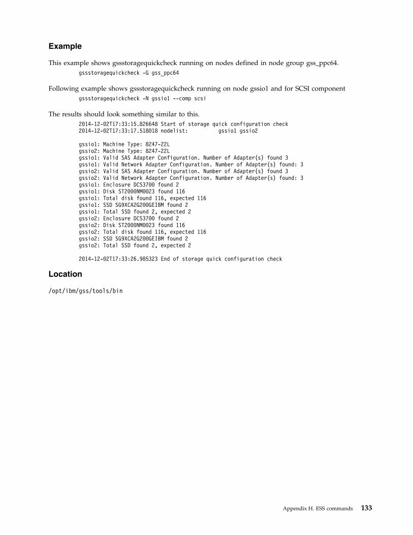
Example
This example shows gssstoragequickcheck running on nodes defined in node group gss_ppc64.gssstoragequickcheck -G gss_ppc64
Following example shows gssstoragequickcheck running on node gssio1 and for SCSI componentgssstoragequickcheck -N gssio1 --comp scsi
The results should look something similar to this.2014-12-02T17:33:15.826648 Start of storage quick configuration check2014-12-02T17:33:17.518018 nodelist: gssio1 gssio2
gssio1: Machine Type: 8247-22Lgssio2: Machine Type: 8247-22Lgssio1: Valid SAS Adapter Configuration. Number of Adapter(s) found 3gssio1: Valid Network Adapter Configuration. Number of Adapter(s) found: 3gssio2: Valid SAS Adapter Configuration. Number of Adapter(s) found 3gssio2: Valid Network Adapter Configuration. Number of Adapter(s) found: 3gssio1: Enclosure DCS3700 found 2gssio1: Disk ST2000NM0023 found 116gssio1: Total disk found 116, expected 116gssio1: SSD SG9XCA2G200GEIBM found 2gssio1: Total SSD found 2, expected 2gssio2: Enclosure DCS3700 found 2gssio2: Disk ST2000NM0023 found 116gssio2: Total disk found 116, expected 116gssio2: SSD SG9XCA2G200GEIBM found 2gssio2: Total SSD found 2, expected 2
2014-12-02T17:33:26.985323 End of storage quick configuration check
Location
/opt/ibm/gss/tools/bin
Appendix H. ESS commands 133

gssutils commandInstalls and deploys ESS
Synopsisgssutils {-N NODE-LIST | -G NODE-GROUP }[ --prefix PREFIX ] [ --suffix SUFFIX ] [ -h | --help ]
Availability
Available with the Elastic Storage Server.
Description
gssutils is an ESS installation and deployment toolkit, and is a collection of tools and utilities tofacilitate install and deploy tasks. gssutils provides a set of task menus related to install and deployactivities. When a task is selected from the menu a command is issued to the system for that task. Thistoolkit requires a minimum of 80 x 24 character window to operate. At the bottom of the screen thecommand for the task with the options are displayed. To change the options, you can enter c. A dialogwindow opens to enter new or modified options. Select exit or press Esc key to close the screen. Thistoolkit can be run on an ESS Management Server (EMS) node or on an IO Server node.
Parameters
-N NODE-LISTProvides a list of nodes. If node list or groupname is not provided it assumes -N localhost.
-G NODE-GROUPProvides the name of node group. Nodes in the NODE-LIST are members of the NODE-GROUP.
--prefix PREFIXProvides the hostname prefix. Use = between --prefix and value if the value starts with -.
--suffix SUFFIXProvides the hostname suffix. Use = between --suffix and value if the value starts with -.
-h | --helpDisplays usage information about this script and exits.
Exit status
0 Successful completion.
nonzeroA failure has occurred.
Security
You must have root authority to run the gssutlis script.
Location
/opt/ibm/gss/tools/bin
134 Deploying ESS 5.1 for Power
Appendix I. ESS scripts
This section includes descriptions of the ESS scripts.
Descriptions of these ESS scripts follow:v “gssdelvdisks script” on page 136v “gssdeploy script” on page 137v “gssinstall script” on page 139v “gsssnap script” on page 141v “gssupg510.sh script” on page 143
ESS also includes the mtuset script in /opt/ibm/gss/tools/samples for changing the MTU.
For information about ESS commands, see Appendix H, “ESS commands,” on page 101.
For information about IBM Spectrum Scale RAID commands and scripts, see IBM Spectrum Scale RAID:Administration.
For information about other IBM Spectrum Scale commands, see IBM Spectrum Scale: Command andProgramming Reference.
© Copyright IBM Corporation © IBM 2014, 2017 135
|
gssdelvdisks scriptDeletes the file system and the associated NSDs and vdisks.
Synopsisgssdelvdisks [ -h | --help ]
Availability
Available with the Elastic Storage Server.
Description
The gssdelvdisks script deletes the file system and the associated NSDs and vdisks.
Parameters
-h | --helpDisplays usage information about this script and exits.
Exit status
0 Successful completion.
nonzeroA failure has occurred.
Security
You must have root authority to run the gssdelvdisks script.
Location
/opt/ibm/gss/install/samples
136 Deploying ESS 5.1 for Power
gssdeploy scriptInstalls the ESS software packages.
Synopsisgssdeploy [ -c | --clean ] [ -d | --deploy ] [ { -r | --restore } Directory ] [ -s | --silent ] [ -x | --xcat ]
[ -V | --version ] [ -h | --help ]
Availability
Available with the Elastic Storage Server.
Description
The gssdeploy script installs the ESS software packages.
Parameters
-c | --clean Performs an interactive management server xCAT dumpxCATdb operation and cleanup of previousmanagement server xCAT installation and ESS installed RPM packages.
-d | --deploy Performs an interactive deployment of the configured I/O servers.
{ -r | --restore } DirectorySpecifies an xCAT database dump directory. When it is used in conjunction with the --clean (or -c)option, the xCAT database is saved to the specified directory. When it is used in conjunction with the--xcat (or -x) option, an xCAT database restore operation is performed using data from the specifieddirectory.
-s | --silentPerforms the selected operation non-interactively.
-x | --xcat Performs an interactive management server xCAT and ESS package installation.
-V | --version Displays the program's version number and exits.
-h | --helpDisplays usage information about this script and exits.
Exit status
0 Successful completion.
nonzeroA failure has occurred.
Security
You must have root authority to run the gssdeploy script.
See also
See also the following Deploying the Elastic Storage Server topics:v “gssinstall script” on page 139v “gssinstallcheck command” on page 125
Appendix I. ESS scripts 137

Location
/opt/ibm/gss/install/samples
138 Deploying ESS 5.1 for Power
gssinstall scriptSets up the ESS software packages for installation.
Synopsisgssinstall [ [ { -a | --archive } Archive ] | [ { -d | --directory } Directory ] |
[ { -m | --manifest } Manifest ] ] [ { -c | --config } configFile ][ { -N | --nodes } NodeList ] [ -s | --silent ] [ -u | --update ][ -v | --verbose ] [ -V | --version ] [ -h | --help ]
Availability
Available with the Elastic Storage Server.
Description
The gssinstall command sets up the ESS software packages for installation.
Parameters
{ -a | --archive } ArchiveSpecifies an archive file for version comparison. There is no default.
{ -d | --directory } DirectorySpecifies a directory of RPMs for version comparison. There is no default.
{ -m | --manifest } ManifestSpecifies a manifest file for version comparison. There is no default.
{ -c | --config } configFileSpecifies a configuration file. There is no default.
{ -N | --nodes } NodeListSpecifies a comma-separated I/O node list on which to operate. There is no default.
-s | --silentPerforms the update non-interactively. The default is False.
-u | --updateUpdates the software repository with the specified archive. The default is False.
-v | --verboseSpecifies the level of detail. The default level is 0. The maximum level is 1.
-V | --version Displays the program's version number and exits.
-h | --helpDisplays usage information about this command and exits.
Exit status
0 Successful completion.
nonzeroA failure has occurred.
Security
You must have root authority to run the gssinstall command.
Appendix I. ESS scripts 139

See also
See also the following Deploying the Elastic Storage Server topics:v “gssdeploy script” on page 137v “gssinstallcheck command” on page 125
Location
/opt/ibm/gss/install/installer
140 Deploying ESS 5.1 for Power

gsssnap scriptGathers preliminary data when an ESS problem is encountered.
Synopsisgsssnap [ { -N | --nodes } NodeList ] [ -g | --gpfs ] [ -V | --version ] [ -h | --help ]
Availability
Available with the Elastic Storage Server.
Description
The gsssnap script creates an informational system snapshot at a single point in time. This systemsnapshot consists of cluster configuration, disk configuration, network configuration, network status, ESSlogs, dumps, and traces. Use the gsssnap script as one of the main tools to gather preliminary data whenan ESS problem is encountered, such as a hung ESS script. The information that is gathered with thegsssnap script can be used in conjunction with other information (for example, ESS internal dumps,traces, and kernel thread dumps) to solve an ESS problem.
By default, the gsssnap script collects snapshot information from the management server node.
Parameters
{ -N | --nodes } NodeListSpecficies a comma-separated list of nodes from which to collect snapshot information.
-g | --gpfs Takes a GPFS snapshot.
-V, --version Displays the program's version number and exits.
-h | --helpDisplays usage information about this script and exits.
Exit status
0 Successful completion.
nonzeroA failure has occurred.
Security
You must have root authority to run the gsssnap script.
Example
To collect snapshot information from I/O server nodes gssio1 and gssio2, run:gsssnap -N gssio1,gssio2
The system displays output similar to this:# gsssnap -N gssio1,gssio2
gsssnap [INFO]: Collecting xcat snapgsssnap [INFO]: Collecting sosreports for node(s): ems1,gssio1,gssio2gsssnap [INFO]: Collecting GSS snap###############################################################################
Appendix I. ESS scripts 141

gsssnap tar file: /tmp/gsssnap.20151013T213843Z.tgzMD5 file: /tmp/gsssnap.20151013T213843Z.tgz.md5Please provide tar file to IBM service###############################################################################
Location
/opt/ibm/gss/xcat/bin/gsssnap
142 Deploying ESS 5.1 for Power

gssupg510.sh scriptSpecifies settings on the ESS 5.1 nodes after an upgrade.
Synopsisgssupg510.sh { -a | -b | -s { NodeName | NodeClass } | -c { NodeName | NodeClass } | -p | -h }
Availability
Available with the Elastic Storage Server.
Description
The gssupg510.sh script specifies settings on the ESS 5.1 nodes after an upgrade.
Parameters
-a Perform all supplemental tasks
(IO Server node config setting of gss_ppc64 nodeclass,
EMS node config setting of ems nodeclass,
perform GNR Callback settings,
copy prepare new disk script)
-b Specifies IBM Spectrum Scale RAID callback settings.
-s { NodeName | NodeClass } Specifies the I/O server node configuration settings, optional nodename or nodeclass.
-c { NodeName | NodeClass }Specifies the management server node configuration settings, optional nodename or nodeclass.
-p Copies the new disk preparation script.
-h Displays usage information about this script and exits.
Exit status
0 Successful completion.
nonzeroA failure has occurred.
Security
You must have root authority to run this script.
See also
See also the following Elastic Storage Server: Quick Deployment Guide topic:v Upgrade the ESS system
Location
/opt/ibm/gss/tools/samples
Appendix I. ESS scripts 143
|
|
|

144 Deploying ESS 5.1 for Power
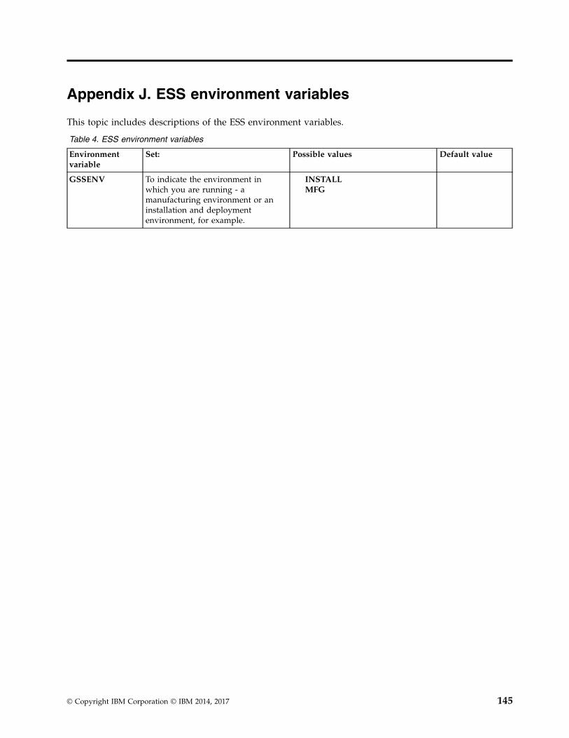
Appendix J. ESS environment variables
This topic includes descriptions of the ESS environment variables.
Table 4. ESS environment variables
Environmentvariable
Set: Possible values Default value
GSSENV To indicate the environment inwhich you are running - amanufacturing environment or aninstallation and deploymentenvironment, for example.
INSTALLMFG
© Copyright IBM Corporation © IBM 2014, 2017 145

146 Deploying ESS 5.1 for Power

Notices
This information was developed for products and services offered in the U.S.A.
IBM may not offer the products, services, or features discussed in this document in other countries.Consult your local IBM representative for information on the products and services currently available inyour area. Any reference to an IBM product, program, or service is not intended to state or imply thatonly that IBM product, program, or service may be used. Any functionally equivalent product, program,or service that does not infringe any IBM intellectual property right may be used instead. However, it isthe user's responsibility to evaluate and verify the operation of any non-IBM product, program, orservice.
IBM may have patents or pending patent applications covering subject matter described in thisdocument. The furnishing of this document does not grant you any license to these patents. You can sendlicense inquiries, in writing, to:
IBM Director of Licensing IBM Corporation North Castle Drive Armonk, NY 10504-1785 U.S.A.
For license inquiries regarding double-byte (DBCS) information, contact the IBM Intellectual PropertyDepartment in your country or send inquiries, in writing, to:
Intellectual Property Licensing Legal and Intellectual Property Law IBM Japan Ltd. 19-21,
Nihonbashi-Hakozakicho, Chuo-ku Tokyo 103-8510, Japan
The following paragraph does not apply to the United Kingdom or any other country where suchprovisions are inconsistent with local law:
INTERNATIONAL BUSINESS MACHINES CORPORATION PROVIDES THIS PUBLICATION "AS IS"WITHOUT WARRANTY OF ANY KIND, EITHER EXPRESS OR IMPLIED, INCLUDING, BUT NOTLIMITED TO, THE IMPLIED WARRANTIES OF NON-INFRINGEMENT, MERCHANTABILITY ORFITNESS FOR A PARTICULAR PURPOSE. Some states do not allow disclaimer of express or impliedwarranties in certain transactions, therefore, this statement may not apply to you.
This information could include technical inaccuracies or typographical errors. Changes are periodicallymade to the information herein; these changes will be incorporated in new editions of the publication.IBM may make improvements and/or changes in the product(s) and/or the program(s) described in thispublication at any time without notice.
Any references in this information to non-IBM Web sites are provided for convenience only and do not inany manner serve as an endorsement of those Web sites. The materials at those Web sites are not part ofthe materials for this IBM product and use of those Web sites is at your own risk.
IBM may use or distribute any of the information you supply in any way it believes appropriate withoutincurring any obligation to you.
Licensees of this program who wish to have information about it for the purpose of enabling: (i) theexchange of information between independently created programs and other programs (including thisone) and (ii) the mutual use of the information which has been exchanged, should contact:
IBM CorporationDept. 30ZA/Building 707Mail Station P300
© Copyright IBM Corp. 2014, 2017 147
2455 South Road,Poughkeepsie, NY 12601-5400U.S.A.
Such information may be available, subject to appropriate terms and conditions, including in some cases,payment or a fee.
The licensed program described in this document and all licensed material available for it are providedby IBM under terms of the IBM Customer Agreement, IBM International Program License Agreement orany equivalent agreement between us.
Any performance data contained herein was determined in a controlled environment. Therefore, theresults obtained in other operating environments may vary significantly. Some measurements may havebeen made on development-level systems and there is no guarantee that these measurements will be thesame on generally available systems. Furthermore, some measurements may have been estimated throughextrapolation. Actual results may vary. Users of this document should verify the applicable data for theirspecific environment.
Information concerning non-IBM products was obtained from the suppliers of those products, theirpublished announcements or other publicly available sources. IBM has not tested those products andcannot confirm the accuracy of performance, compatibility or any other claims related to non-IBMproducts. Questions on the capabilities of non-IBM products should be addressed to the suppliers ofthose products.
This information contains examples of data and reports used in daily business operations. To illustratethem as completely as possible, the examples include the names of individuals, companies, brands, andproducts. All of these names are fictitious and any similarity to the names and addresses used by anactual business enterprise is entirely coincidental.
COPYRIGHT LICENSE:
This information contains sample application programs in source language, which illustrate programmingtechniques on various operating platforms. You may copy, modify, and distribute these sample programsin any form without payment to IBM, for the purposes of developing, using, marketing or distributingapplication programs conforming to the application programming interface for the operating platform forwhich the sample programs are written. These examples have not been thoroughly tested under allconditions. IBM, therefore, cannot guarantee or imply reliability, serviceability, or function of theseprograms. The sample programs are provided "AS IS", without warranty of any kind. IBM shall not beliable for any damages arising out of your use of the sample programs.
If you are viewing this information softcopy, the photographs and color illustrations may not appear.
TrademarksIBM, the IBM logo, and ibm.com are trademarks or registered trademarks of International BusinessMachines Corp., registered in many jurisdictions worldwide. Other product and service names might betrademarks of IBM or other companies. A current list of IBM trademarks is available on the Web at“Copyright and trademark information” at www.ibm.com/legal/copytrade.shtml.
Intel is a trademark of Intel Corporation or its subsidiaries in the United States and other countries.
Java and all Java-based trademarks and logos are trademarks or registered trademarks of Oracle and/orits affiliates.
Linux is a registered trademark of Linus Torvalds in the United States, other countries, or both.
148 Deploying ESS 5.1 for Power

Microsoft, Windows, and Windows NT are trademarks of Microsoft Corporation in the United States,other countries, or both.
UNIX is a registered trademark of The Open Group in the United States and other countries.
Notices 149

150 Deploying ESS 5.1 for Power

Glossary
This glossary provides terms and definitions forthe ESS solution.
The following cross-references are used in thisglossary:v See refers you from a non-preferred term to the
preferred term or from an abbreviation to thespelled-out form.
v See also refers you to a related or contrastingterm.
For other terms and definitions, see the IBMTerminology website (opens in new window):
http://www.ibm.com/software/globalization/terminology
B
building blockA pair of servers with shared diskenclosures attached.
BOOTPSee Bootstrap Protocol (BOOTP).
Bootstrap Protocol (BOOTP)A computer networking protocol thst isused in IP networks to automaticallyassign an IP address to network devicesfrom a configuration server.
C
CEC See central processor complex (CPC).
central electronic complex (CEC)See central processor complex (CPC).
central processor complex (CPC) A physical collection of hardware thatconsists of channels, timers, main storage,and one or more central processors.
clusterA loosely-coupled collection ofindependent systems, or nodes, organizedinto a network for the purpose of sharingresources and communicating with eachother. See also GPFS cluster.
cluster managerThe node that monitors node status usingdisk leases, detects failures, drivesrecovery, and selects file system
managers. The cluster manager is thenode with the lowest node numberamong the quorum nodes that areoperating at a particular time.
compute nodeA node with a mounted GPFS file systemthat is used specifically to run a customerjob. ESS disks are not directly visible fromand are not managed by this type ofnode.
CPC See central processor complex (CPC).
D
DA See declustered array (DA).
datagramA basic transfer unit associated with apacket-switched network.
DCM See drawer control module (DCM).
declustered array (DA)A disjoint subset of the pdisks in arecovery group.
dependent filesetA fileset that shares the inode space of anexisting independent fileset.
DFM See direct FSP management (DFM).
DHCP See Dynamic Host Configuration Protocol(DHCP).
direct FSP management (DFM)The ability of the xCAT software tocommunicate directly with the PowerSystems server's service processor withoutthe use of the HMC for management.
drawer control module (DCM)Essentially, a SAS expander on a storageenclosure drawer.
Dynamic Host Configuration Protocol (DHCP)A standardized network protocol that isused on IP networks to dynamicallydistribute such network configurationparameters as IP addresses for interfacesand services.
E
Elastic Storage Server (ESS)A high-performance, GPFS NSD solution
© Copyright IBM Corporation © IBM 2014, 2017 151

made up of one or more building blocksthat runs on IBM Power Systems servers.The ESS software runs on ESS nodes -management server nodes and I/O servernodes.
encryption keyA mathematical value that allowscomponents to verify that they are incommunication with the expected server.Encryption keys are based on a public orprivate key pair that is created during theinstallation process. See also file encryptionkey (FEK), master encryption key (MEK).
ESS See Elastic Storage Server (ESS).
environmental service module (ESM)Essentially, a SAS expander that attachesto the storage enclosure drives. In thecase of multiple drawers in a storageenclosure, the ESM attaches to drawercontrol modules.
ESM See environmental service module (ESM).
Extreme Cluster/Cloud Administration Toolkit(xCAT)
Scalable, open-source cluster managementsoftware. The management infrastructureof ESS is deployed by xCAT.
F
failbackCluster recovery from failover followingrepair. See also failover.
failover(1) The assumption of file system dutiesby another node when a node fails. (2)The process of transferring all control ofthe ESS to a single cluster in the ESSwhen the other clusters in the ESS fails.See also cluster. (3) The routing of alltransactions to a second controller whenthe first controller fails. See also cluster.
failure groupA collection of disks that share commonaccess paths or adapter connection, andcould all become unavailable through asingle hardware failure.
FEK See file encryption key (FEK).
file encryption key (FEK)A key used to encrypt sectors of anindividual file. See also encryption key.
file systemThe methods and data structures used tocontrol how data is stored and retrieved.
file system descriptorA data structure containing keyinformation about a file system. Thisinformation includes the disks assigned tothe file system (stripe group), the currentstate of the file system, and pointers tokey files such as quota files and log files.
file system descriptor quorumThe number of disks needed in order towrite the file system descriptor correctly.
file system managerThe provider of services for all the nodesusing a single file system. A file systemmanager processes changes to the state ordescription of the file system, controls theregions of disks that are allocated to eachnode, and controls token managementand quota management.
fileset A hierarchical grouping of files managedas a unit for balancing workload across acluster. See also dependent fileset,independent fileset.
fileset snapshotA snapshot of an independent fileset plusall dependent filesets.
flexible service processor (FSP)Firmware that provices diagnosis,initialization, configuration, runtime errordetection, and correction. Connects to theHMC.
FQDNSee fully-qualified domain name (FQDN).
FSP See flexible service processor (FSP).
fully-qualified domain name (FQDN)The complete domain name for a specificcomputer, or host, on the Internet. TheFQDN consists of two parts: the hostnameand the domain name.
G
GPFS clusterA cluster of nodes defined as beingavailable for use by GPFS file systems.
GPFS portability layerThe interface module that each
152 Deploying ESS 5.1 for Power

installation must build for its specifichardware platform and Linuxdistribution.
GPFS Storage Server (GSS)A high-performance, GPFS NSD solutionmade up of one or more building blocksthat runs on System x servers.
GSS See GPFS Storage Server (GSS).
H
Hardware Management Console (HMC)Standard interface for configuring andoperating partitioned (LPAR) and SMPsystems.
HMC See Hardware Management Console (HMC).
I
IBM Security Key Lifecycle Manager (ISKLM)For GPFS encryption, the ISKLM is usedas an RKM server to store MEKs.
independent filesetA fileset that has its own inode space.
indirect blockA block that contains pointers to otherblocks.
inode The internal structure that describes theindividual files in the file system. There isone inode for each file.
inode spaceA collection of inode number rangesreserved for an independent fileset, whichenables more efficient per-filesetfunctions.
Internet Protocol (IP)The primary communication protocol forrelaying datagrams across networkboundaries. Its routing function enablesinternetworking and essentiallyestablishes the Internet.
I/O server nodeAn ESS node that is attached to the ESSstorage enclosures. It is the NSD serverfor the GPFS cluster.
IP See Internet Protocol (IP).
IP over InfiniBand (IPoIB)Provides an IP network emulation layeron top of InfiniBand RDMA networks,which allows existing applications to runover InfiniBand networks unmodified.
IPoIB See IP over InfiniBand (IPoIB).
ISKLMSee IBM Security Key Lifecycle Manager(ISKLM).
J
JBOD arrayThe total collection of disks andenclosures over which a recovery grouppair is defined.
K
kernel The part of an operating system thatcontains programs for such tasks asinput/output, management and control ofhardware, and the scheduling of usertasks.
L
LACP See Link Aggregation Control Protocol(LACP).
Link Aggregation Control Protocol (LACP)Provides a way to control the bundling ofseveral physical ports together to form asingle logical channel.
logical partition (LPAR)A subset of a server's hardware resourcesvirtualized as a separate computer, eachwith its own operating system. See alsonode.
LPAR See logical partition (LPAR).
M
management networkA network that is primarily responsiblefor booting and installing the designatedserver and compute nodes from themanagement server.
management server (MS)An ESS node that hosts the ESS GUI andxCAT and is not connected to storage. Itcan be part of a GPFS cluster. From asystem management perspective, it is thecentral coordinator of the cluster. It alsoserves as a client node in an ESS buildingblock.
master encryption key (MEK)A key that is used to encrypt other keys.See also encryption key.
Glossary 153

maximum transmission unit (MTU)The largest packet or frame, specified inoctets (eight-bit bytes), that can be sent ina packet- or frame-based network, such asthe Internet. The TCP uses the MTU todetermine the maximum size of eachpacket in any transmission.
MEK See master encryption key (MEK).
metadataA data structure that contains accessinformation about file data. Suchstructures include inodes, indirect blocks,and directories. These data structures arenot accessible to user applications.
MS See management server (MS).
MTU See maximum transmission unit (MTU).
N
Network File System (NFS)A protocol (developed by SunMicrosystems, Incorporated) that allowsany host in a network to gain access toanother host or netgroup and their filedirectories.
Network Shared Disk (NSD)A component for cluster-wide disknaming and access.
NSD volume IDA unique 16-digit hexadecimal numberthat is used to identify and access allNSDs.
node An individual operating-system imagewithin a cluster. Depending on the way inwhich the computer system is partitioned,it can contain one or more nodes. In aPower Systems environment, synonymouswith logical partition.
node descriptorA definition that indicates how IBMSpectrum Scale uses a node. Possiblefunctions include: manager node, clientnode, quorum node, and non-quorumnode.
node numberA number that is generated andmaintained by IBM Spectrum Scale as thecluster is created, and as nodes are addedto or deleted from the cluster.
node quorumThe minimum number of nodes that mustbe running in order for the daemon tostart.
node quorum with tiebreaker disksA form of quorum that allows IBMSpectrum Scale to run with as little as onequorum node available, as long as there isaccess to a majority of the quorum disks.
non-quorum nodeA node in a cluster that is not counted forthe purposes of quorum determination.
O
OFED See OpenFabrics Enterprise Distribution(OFED).
OpenFabrics Enterprise Distribution (OFED)An open-source software stack includessoftware drivers, core kernel code,middleware, and user-level interfaces.
P
pdisk A physical disk.
PortFastA Cisco network function that can beconfigured to resolve any problems thatcould be caused by the amount of timeSTP takes to transition ports to theForwarding state.
R
RAID See redundant array of independent disks(RAID).
RDMASee remote direct memory access (RDMA).
redundant array of independent disks (RAID)A collection of two or more disk physicaldrives that present to the host an imageof one or more logical disk drives. In theevent of a single physical device failure,the data can be read or regenerated fromthe other disk drives in the array due todata redundancy.
recoveryThe process of restoring access to filesystem data when a failure has occurred.Recovery can involve reconstructing dataor providing alternative routing through adifferent server.
154 Deploying ESS 5.1 for Power

recovery group (RG)A collection of disks that is set up by IBMSpectrum Scale RAID, in which each diskis connected physically to two servers: aprimary server and a backup server.
remote direct memory access (RDMA)A direct memory access from the memoryof one computer into that of anotherwithout involving either one's operatingsystem. This permits high-throughput,low-latency networking, which isespecially useful in massively-parallelcomputer clusters.
RGD See recovery group data (RGD).
remote key management server (RKM server)A server that is used to store masterencryption keys.
RG See recovery group (RG).
recovery group data (RGD)Data that is associated with a recoverygroup.
RKM serverSee remote key management server (RKMserver).
S
SAS See Serial Attached SCSI (SAS).
secure shell (SSH) A cryptographic (encrypted) networkprotocol for initiating text-based shellsessions securely on remote computers.
Serial Attached SCSI (SAS)A point-to-point serial protocol thatmoves data to and from such computerstorage devices as hard drives and tapedrives.
service network A private network that is dedicated tomanaging POWER8 servers. ProvidesEthernet-based connectivity among theFSP, CPC, HMC, and management server.
SMP See symmetric multiprocessing (SMP).
Spanning Tree Protocol (STP)A network protocol that ensures aloop-free topology for any bridgedEthernet local-area network. The basicfunction of STP is to prevent bridge loopsand the broadcast radiation that resultsfrom them.
SSH See secure shell (SSH).
STP See Spanning Tree Protocol (STP).
symmetric multiprocessing (SMP)A computer architecture that provides fastperformance by making multipleprocessors available to completeindividual processes simultaneously.
T
TCP See Transmission Control Protocol (TCP).
Transmission Control Protocol (TCP)A core protocol of the Internet ProtocolSuite that provides reliable, ordered, anderror-checked delivery of a stream ofoctets between applications running onhosts communicating over an IP network.
V
VCD See vdisk configuration data (VCD).
vdisk A virtual disk.
vdisk configuration data (VCD)Configuration data that is associated witha virtual disk.
X
xCAT See Extreme Cluster/Cloud AdministrationToolkit.
Glossary 155

156 Deploying ESS 5.1 for Power
Index
Aaudience ix
Bbefore you start 1best practices 89building block
configurations 5
Ccabling 93cabling schema 93command
gsscallhomeconf 109gssnettest 127gssutils 134
commands 101gssaddnode 103gsscheckdisks 105gssfindmissingdisks 111gssgencluster 113gssgenclusterrgs 115gssgenvdisks 122gssinstallcheck 125gssprecheck 129gssstoragequickcheck 132
comments xconfiguration
reference 57tasks 21
configurationsbuilding block 5
Ddata
gathering to solve problems 141documentation
on web ix
EElastic Storage Server
best practices 89environment variables
GSSENV 145ESS
commandgssgennetworks 118
commands 101gssaddnode 103gsscheckdisks 105gssfindmissingdisks 111gssgencluster 113gssgenclusterrgs 115gssgenvdisks 122gssinstall 139
ESS (continued)commands (continued)
gssinstallcheck 125gssprecheck 129gssstoragequickcheck 132
scripts 135gssdelvdisks 136gssdeploy 137gsssnap 141gssupg510.sh 143mtuset 135
upgrading 71ESS GUI 53
Ffirmware versions
determining 1
GGL2 5GL4 5GL6 5GS1 5GS2 5GS4 5GS6 5gssaddnode 103gsscallhomeconf 109gsscheckdisks 105gssdelvdisks 136gssdelvdisks script 52gssdeploy script 137GSSENV environment variable 145gssfindmissingdisks 111gssgencluster 113gssgenclusterrgs 115gssgennetworks command 118gssgenvdisks 122gssinstall script 139gssinstallcheck command 125gssnettest 127gssprecheck 129gsssnap 141gssstoragequickcheck 132gssupg510.sh script 143gssutils 134GUI 53
Iinformation overview ixinstallation
prerequisites 19reference 57tasks 21
installing 53
© Copyright IBM Corp. 2014, 2017 157
Llicense inquiries 147
MMTU
changing 135mtuset script 65, 135
Nnotices 147
Ooverview
of information ixof solution 3
Ppatent information 147preface ixprerequisites
for installation 19problems
gathering data to solve 141
Rrecommendations
best-practice 89resources
on web ixrestrictions 91
Sscripts 135
gssdelvdisks 52, 136gssdeploy 137gssgennetworks 118gssinstall 139gsssnap 141gssupg510.sh 143mtuset 65
snapshots 141solution overview 3submitting xsystem snapshots 141
Ttrademarks 148
Uupgrade procedure 71
Wweb
documentation ixresources ix
158 Deploying ESS 5.1 for Power


IBM®
Printed in USA
SC27-6659-07


